Embed Size (px)
Citation preview
TÜV Rheinland Energie und Umwelt GmbH Solar Energy
Test Report Prüfbericht
Qualification of a Solar Collector in accordance with Qualifizierung eines Solarkollektors nach
DIN EN 12975-1: 2006; DIN EN 12975-2: 2006
TÜV Report No.: 21218491_EN_P1_FK500L
Cologne, 21 September 2012
Publication or distribution of this report to third parties is only permissible in its complete and unabridged form. Publication or dissemination of extracts, appraisals or any other revision and adaptation hereof, in particular for advertising purposes, is
only permissible on receipt of prior written agreement by the TÜV Rheinland Group.
The test results presented in this report refer only to the test item.
Veröffentlichung und Weitergabe an Dritte ist nur in vollständiger, ungekürzter Form zulässig. Veröffentlichung oder Verbreitung von Auszügen, Zusammenfassungen, Wertungen oder sonstigen Bearbeitungen und Umgestaltungen, insbesondere zu Werbezwecken, ist
nur mit vorheriger schriftlicher Zustimmung der TÜV Rheinland Group zulässig.
Die in diesem Bericht dargestellten Prüfergebnisse beziehen sich ausschließlich auf den Prüfgegenstand.
TÜV Rheinland Energie und Umwelt GmbH Am Grauen Stein, 51105 Köln, Germany, Tel.: +49 221 806-2477, Fax: +49 221 806-1350
2 / 22
TÜV Rheinland Energie und Umwelt GmbH Solar Energy
21218491_EN_P1_FK500L_Report.doc
Report-No.: 21218491_P1_FK500L
on
Qualification of a Solar Collector in accordance with Qualifizierung eines Solarkollektors nach
DIN EN 12975-1: 2006; DIN EN 12975-2: 2006
Client: Kunde
Solfex Ltd. Energy Arena, Units 3 - 5 Charnley Fold Industrial Estate, Bamber Bridge PR5 6PS Preston United Kingdom
TÜV Quotation No.: Angebotsnummer
435/ 1420120131
TÜV Order No.: Auftragsnummer
21218491
Order of: Datum der Beauftragung
17 September 2012
Date of Receipt of Test Item: Anlieferdatum Prüfmuster
16 December 2011
Commencement of Test: Testbeginn
22 December 2011
TÜV Client No.: Kundennummer
3199004
Inspector: Prüfer
J. Sommer (Tel.: +49 221 806-2021)
Business Field: Geschäftsfeld
Solar Energy
No of Pages: Seitenzahl
22
Appendix: Anhang
19 to 22
3 / 22
TÜV Rheinland Energie und Umwelt GmbH Solar Energy
21218491_EN_P1_FK500L_Report.doc
List of Contents Inhaltsverzeichnis
1 Summary of test results Zusammenfassung............................................................ 4
2 Setting of tasks; Aufgabenstellung ........................................................................... 6
3 Basis of testing; Grundlagen ..................................................................................... 6
4 Sampling; Probenahme ............................................................................................. 7
5 Description of the collector construction; Beschreibung der
Kollektorkonstruktion ................................................................................................ 7
6 Execution and evaluation; Durchführung und Auswertung ...................................12
6.1 Visual inspection; Sichtprüfung ..........................................................................12
7 Measuring results of thermal performance testing; Prüfergebnisse der
Leistungsprüfung von Sonnenkollektoren ..............................................................13
7.1 Test method according to DIN EN 12975-2:2006 chapter 6.1; Prüfgrundlage
entsprechend DIN EN 12975-2:2006 Kapitel 6.1 ................................................13
7.2 Test conditions; Prüfbedingungen ......................................................................13
7.3 Measuring results of time constant testing; Prüfergebnisse der Ermittlung der
Zeitkonstante .....................................................................................................15
7.4 Calculated effective thermal capacity ; Berechnete effektive Wärmekapazität ....16
7.5 Collector incident angle modifier; Prüfergebnisse der Ermittlung des
Einfallswinkel-Korrekturfaktors ...........................................................................17
8 General remarks; Bemerkungen ..............................................................................18
List of Contents – Appendix Inhaltsverzeichnis - Anhang
Appendix 1: Thermal performance test results 19 Appendix 2: Photo documentation 22
4 / 22
TÜV Rheinland Energie und Umwelt GmbH Solar Energy
21218491_EN_P1_FK500L_Report.doc
1 Summary of test results Zusammenfassung
Qualification of a Solar Collector in accordance with Qualifizierung eines Solarkollektors nach
DIN EN 12975-1: 2006; DIN EN 12975-2: 2006 Manufacturer Hersteller
: Solfex Ltd.
Energy Arena, Units 3 - 5 Charnley Fold Industrial Estate, Bamber Bridge PR5 6PS Preston United Kingdom
Brand Handelsname
: Solfex
Collector type Kollektortyp
: FK500L
Basis of testing Prüfgrundlage
: DIN EN 12975-2:2006
Test Date Summary of main test results Zusammenfassung der Hauptergebnisse
Start End Thermal performance Wärmeleistung
30 Dec 2011 30 Dec 2011 No visual damages
All above listed tests of the standard DIN EN 12975-2:2006 were passed successfully in ac-cordance with the criteria. Alle oben aufgeführten Tests der DIN EN 12975-2:2006 wurden entsprechend der Kriterien bestanden. Cologne, 21 September 2012
Responsible for collector testing Director Technical Competence Center Solar Thermal
Dipl.-Ing. J. Sommer Dipl.-Ing. U. Fritzsche
5 / 22
TÜV Rheinland Energie und Umwelt GmbH Solar Energy
21218491_EN_P1_FK500L_Report.doc
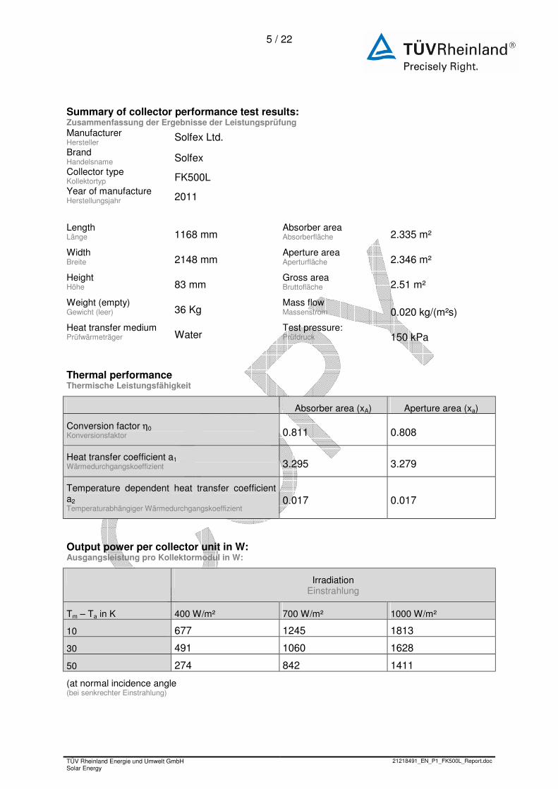
Summary of collector performance test results: Zusammenfassung der Ergebnisse der Leistungsprüfung Manufacturer Hersteller
Solfex Ltd.
Brand Handelsname Solfex Collector type Kollektortyp FK500L Year of manufacture Herstellungsjahr 2011
Length Länge 1168 mm
Absorber area Absorberfläche 2.335 m²
Width Breite 2148 mm
Aperture area Aperturfläche 2.346 m²
Height Höhe 83 mm
Gross area Bruttofläche 2.51 m²
Weight (empty) Gewicht (leer) 36 Kg
Mass flow Massenstrom 0.020 kg/(m²s)
Heat transfer medium Prüfwärmeträger Water
Test pressure: Prüfdruck 150 kPa
Thermal performance Thermische Leistungsfähigkeit
Absorber area (xA) Aperture area (xa)
Conversion factor η0 Konversionsfaktor 0.811 0.808
Heat transfer coefficient a1 Wärmedurchgangskoeffizient 3.295 3.279
Temperature dependent heat transfer coefficient a2 Temperaturabhängiger Wärmedurchgangskoeffizient
0.017 0.017
Output power per collector unit in W: Ausgangsleistung pro Kollektormodul in W:
Irradiation Einstrahlung
Tm – Ta in K 400 W/m² 700 W/m² 1000 W/m²
10 677 1245 1813
30 491 1060 1628
50 274 842 1411
(at normal incidence angle (bei senkrechter Einstrahlung)
6 / 22
1 Determinate by test laboratory 2 reviewed manufacturer information 3 according to manufacturer information
TÜV Rheinland Energie und Umwelt GmbH Solar Energy
21218491_EN_P1_FK500L_Report.doc
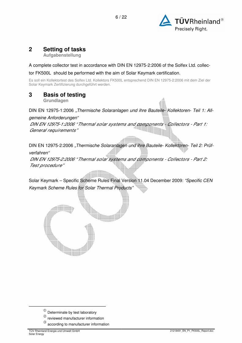
2 Setting of tasks; Aufgabenstellung
A complete collector test in accordance with DIN EN 12975-2:2006 of the Solfex Ltd. collec-
tor FK500L should be performed with the aim of Solar Keymark certification.
Es soll ein Kollektortest des Solfex Ltd. Kollektors FK500L entsprechend DIN EN 12975-2:2006 mit dem Ziel der Solar Keymark Zertifizierung durchgeführt werden.
3 Basis of testing; Grundlagen
DIN EN 12975-1:2006 „Thermische Solaranlagen und ihre Bauteile- Kollektoren- Teil 1: All-
gemeine Anforderungen“
DIN EN 12975-1:2006 “ Thermal solar systems and components - Collectors - Part 1:
General requirements”
DIN EN 12975-2:2006 „Thermische Solaranlagen und ihre Bauteile- Kollektoren- Teil 2: Prüf-
verfahren“
DIN EN 12975-2:2006 “ Thermal solar systems and components - Collectors - Part 2:
Test procedure”
Solar Keymark – Specific Scheme Rules Final Version 11.04 December 2009: “Specific CEN
Keymark Scheme Rules for Solar Thermal Products”
1 Determinate by test laboratory 2 reviewed manufacturer information 3 according to manufacturer information
TÜV Rheinland Energie und Umwelt GmbH Solar Energy
21218491_EN_P1_FK500L_Report.doc
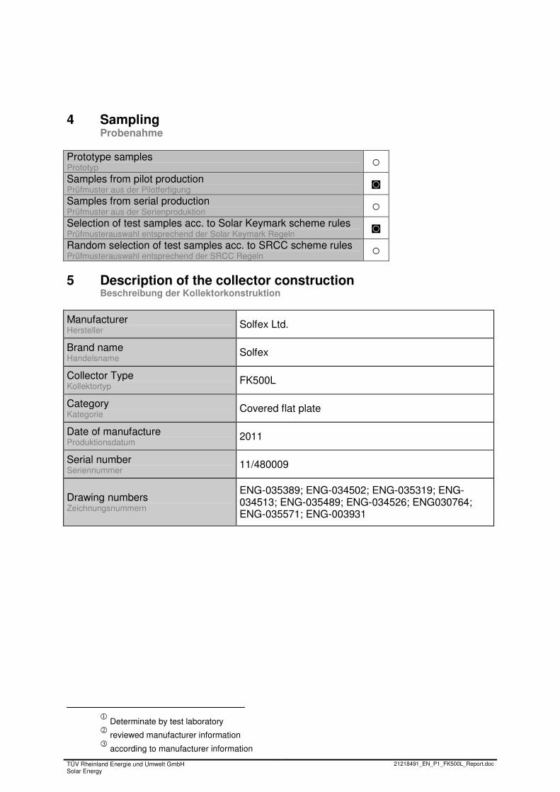
4 Sampling; Probenahme
Prototype samples Prototyp ○ Samples from pilot production Prüfmuster aus der Pilotfertigung ◙ Samples from serial production Prüfmuster aus der Serienproduktion ○ Selection of test samples acc. to Solar Keymark scheme rules Prüfmusterauswahl entsprechend der Solar Keymark Regeln ◙ Random selection of test samples acc. to SRCC scheme rules Prüfmusterauswahl entsprechend der SRCC Regeln ○
5 Description of the collector construction; Beschreibung der Kollektorkonstruktion
Manufacturer Hersteller
Solfex Ltd.
Brand name Handelsname
Solfex
Collector Type Kollektortyp
FK500L
Category Kategorie
Covered flat plate
Date of manufacture Produktionsdatum
2011
Serial number Seriennummer
11/480009
Drawing numbers Zeichnungsnummern
ENG-035389; ENG-034502; ENG-035319; ENG-034513; ENG-035489; ENG-034526; ENG030764; ENG-035571; ENG-003931
1 Determinate by test laboratory 2 reviewed manufacturer information 3 according to manufacturer information
TÜV Rheinland Energie und Umwelt GmbH Solar Energy
21218491_EN_P1_FK500L_Report.doc
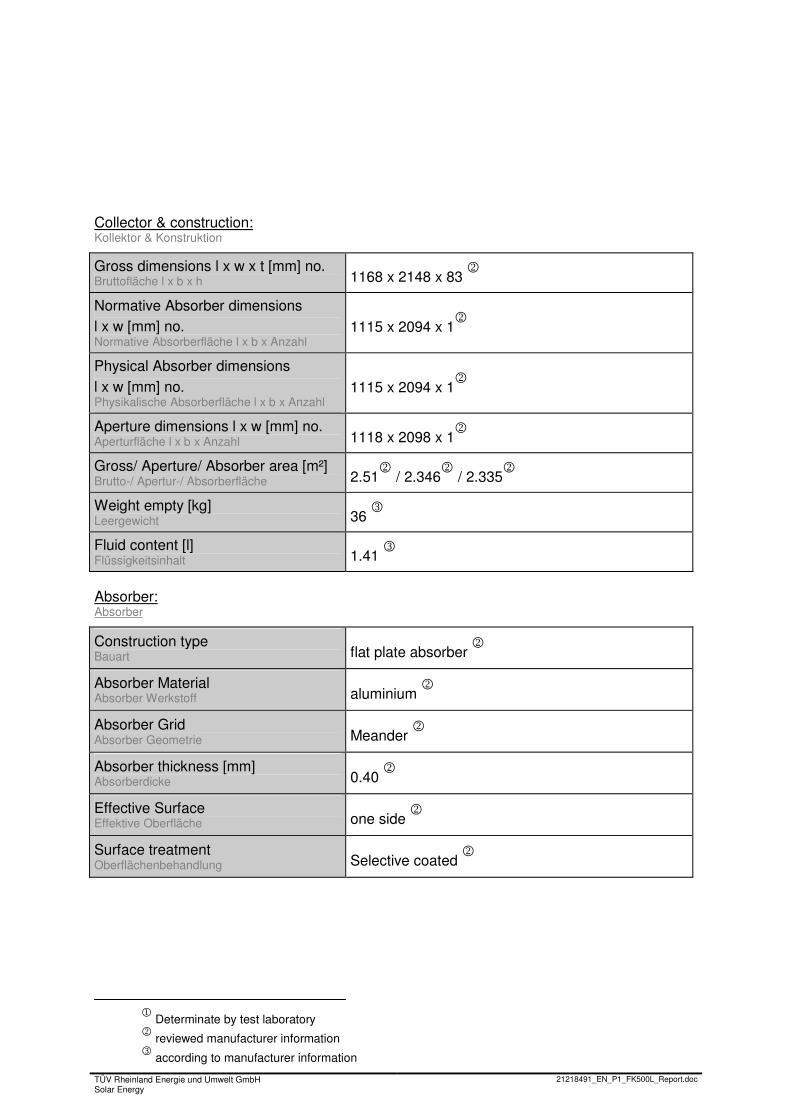
Collector & construction: Kollektor & Konstruktion
Gross dimensions l x w x t [mm] no. Bruttofläche l x b x h 1168 x 2148 x 83
2
Normative Absorber dimensions l x w [mm] no. Normative Absorberfläche l x b x Anzahl
1115 x 2094 x 12
Physical Absorber dimensions
l x w [mm] no. Physikalische Absorberfläche l x b x Anzahl
1115 x 2094 x 12
Aperture dimensions l x w [mm] no. Aperturfläche l x b x Anzahl 1118 x 2098 x 1
2
Gross/ Aperture/ Absorber area [m²] Brutto-/ Apertur-/ Absorberfläche 2.51
2 / 2.346
2 / 2.335
2
Weight empty [kg] Leergewicht 36
3
Fluid content [l] Flüssigkeitsinhalt 1.41
3
Absorber: Absorber
Construction type Bauart flat plate absorber
2
Absorber Material Absorber Werkstoff aluminium
2
Absorber Grid Absorber Geometrie Meander
2
Absorber thickness [mm] Absorberdicke 0.40
2
Effective Surface Effektive Oberfläche one side
2
Surface treatment Oberflächenbehandlung Selective coated
2
1 Determinate by test laboratory 2 reviewed manufacturer information 3 according to manufacturer information
TÜV Rheinland Energie und Umwelt GmbH Solar Energy
21218491_EN_P1_FK500L_Report.doc
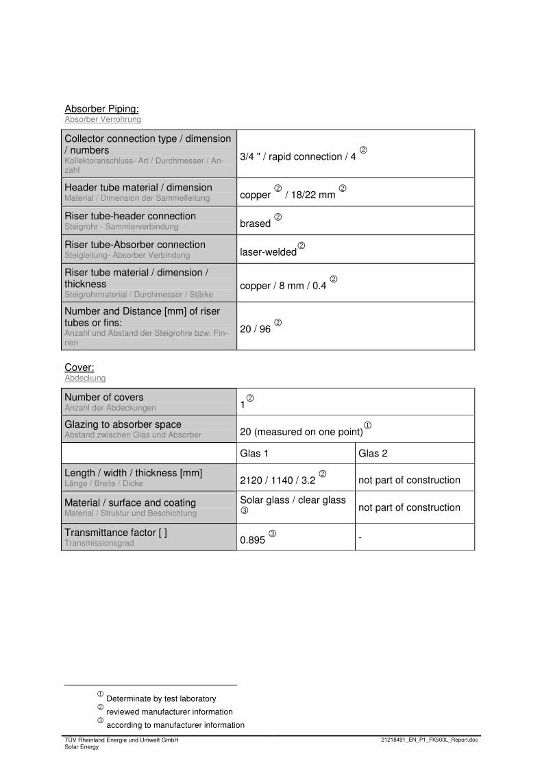
Absorber Piping: Absorber Verrohrung
Collector connection type / dimension / numbers Kollektoranschluss- Art / Durchmesser / An-zahl
3/4 " / rapid connection / 4 2
Header tube material / dimension Material / Dimension der Sammelleitung copper
2 / 18/22 mm
2
Riser tube-header connection Steigrohr - Sammlerverbindung brased
2
Riser tube-Absorber connection Steigleitung- Absorber Verbindung laser-welded
2
Riser tube material / dimension / thickness Steigrohrmaterial / Durchmesser / Stärke
copper / 8 mm / 0.4 2
Number and Distance [mm] of riser tubes or fins: Anzahl und Abstand der Steigrohre bzw. Fin-nen
20 / 96 2
Cover: Abdeckung
Number of covers Anzahl der Abdeckungen 1
2
Glazing to absorber space Abstand zwischen Glas und Absorber 20 (measured on one point)
1
Glas 1 Glas 2
Length / width / thickness [mm] Länge / Breite / Dicke 2120 / 1140 / 3.2
2 not part of construction
Material / surface and coating Material / Struktur und Beschichtung
Solar glass / clear glass 3
not part of construction
Transmittance factor [ ] Transmissionsgrad 0.895
3 -
1 Determinate by test laboratory 2 reviewed manufacturer information 3 according to manufacturer information
TÜV Rheinland Energie und Umwelt GmbH Solar Energy
21218491_EN_P1_FK500L_Report.doc
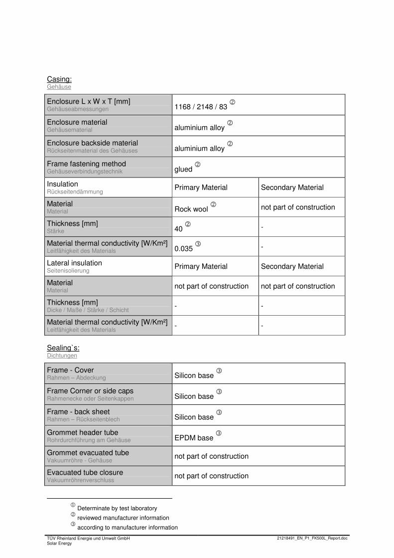
Casing: Gehäuse
Enclosure L x W x T [mm] Gehäuseabmessungen 1168 / 2148 / 83
2
Enclosure material Gehäusematerial aluminium alloy
2
Enclosure backside material Rückseitenmaterial des Gehäuses aluminium alloy
2
Frame fastening method Gehäuseverbindungstechnik glued
2
Insulation Rückseitendämmung Primary Material Secondary Material
Material Material Rock wool
2 not part of construction
Thickness [mm] Stärke 40
2 -
Material thermal conductivity [W/Km²] Leitfähigkeit des Materials 0.035
3 -
Lateral insulation Seitenisolierung Primary Material Secondary Material
Material Material not part of construction not part of construction
Thickness [mm] Dicke / Maße / Stärke / Schicht - -
Material thermal conductivity [W/Km²] Leitfähigkeit des Materials - -
Sealing`s: Dichtungen
Frame - Cover Rahmen – Abdeckung Silicon base
3
Frame Corner or side caps Rahmenecke oder Seitenkappen Silicon base
3
Frame - back sheet Rahmen – Rückseitenblech Silicon base
3
Grommet header tube Rohrdurchführung am Gehäuse EPDM base
3
Grommet evacuated tube Vakuumröhre - Gehäuse not part of construction
Evacuated tube closure Vakuumröhrenverschluss not part of construction
1 Determinate by test laboratory 2 reviewed manufacturer information 3 according to manufacturer information
TÜV Rheinland Energie und Umwelt GmbH Solar Energy
21218491_EN_P1_FK500L_Report.doc
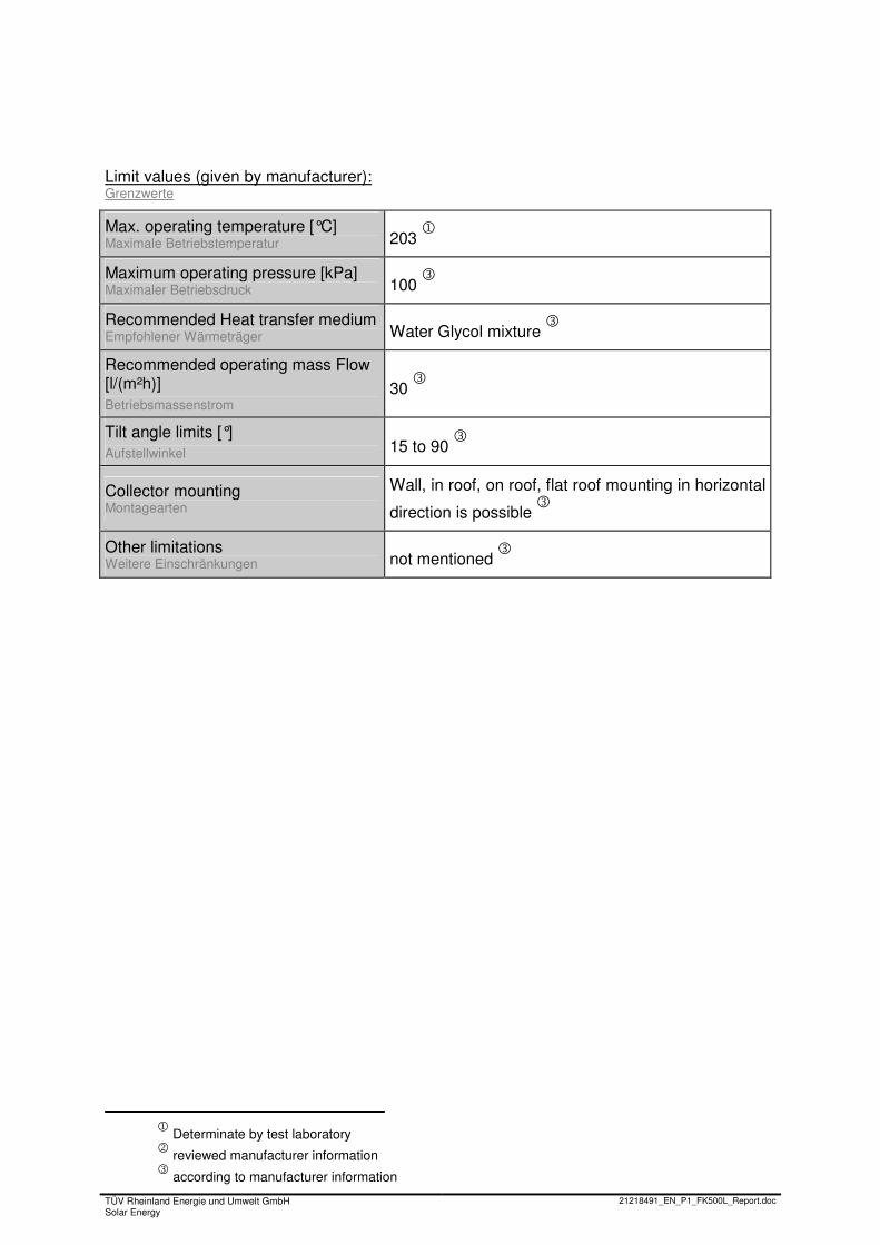
Limit values (given by manufacturer): Grenzwerte
Max. operating temperature [°C] Maximale Betriebstemperatur 203
1
Maximum operating pressure [kPa] Maximaler Betriebsdruck 100
3
Recommended Heat transfer medium Empfohlener Wärmeträger Water Glycol mixture
3
Recommended operating mass Flow [l/(m²h)] Betriebsmassenstrom
30 3
Tilt angle limits [°] Aufstellwinkel 15 to 90
3
Collector mounting Montagearten
Wall, in roof, on roof, flat roof mounting in horizontal
direction is possible 3
Other limitations Weitere Einschränkungen not mentioned
3
12 / 22
TÜV Rheinland Energie und Umwelt GmbH Solar Energy
21218491_EN_P1_FK500L_Report.doc
6 Execution and evaluation; Durchführung und Auswertung
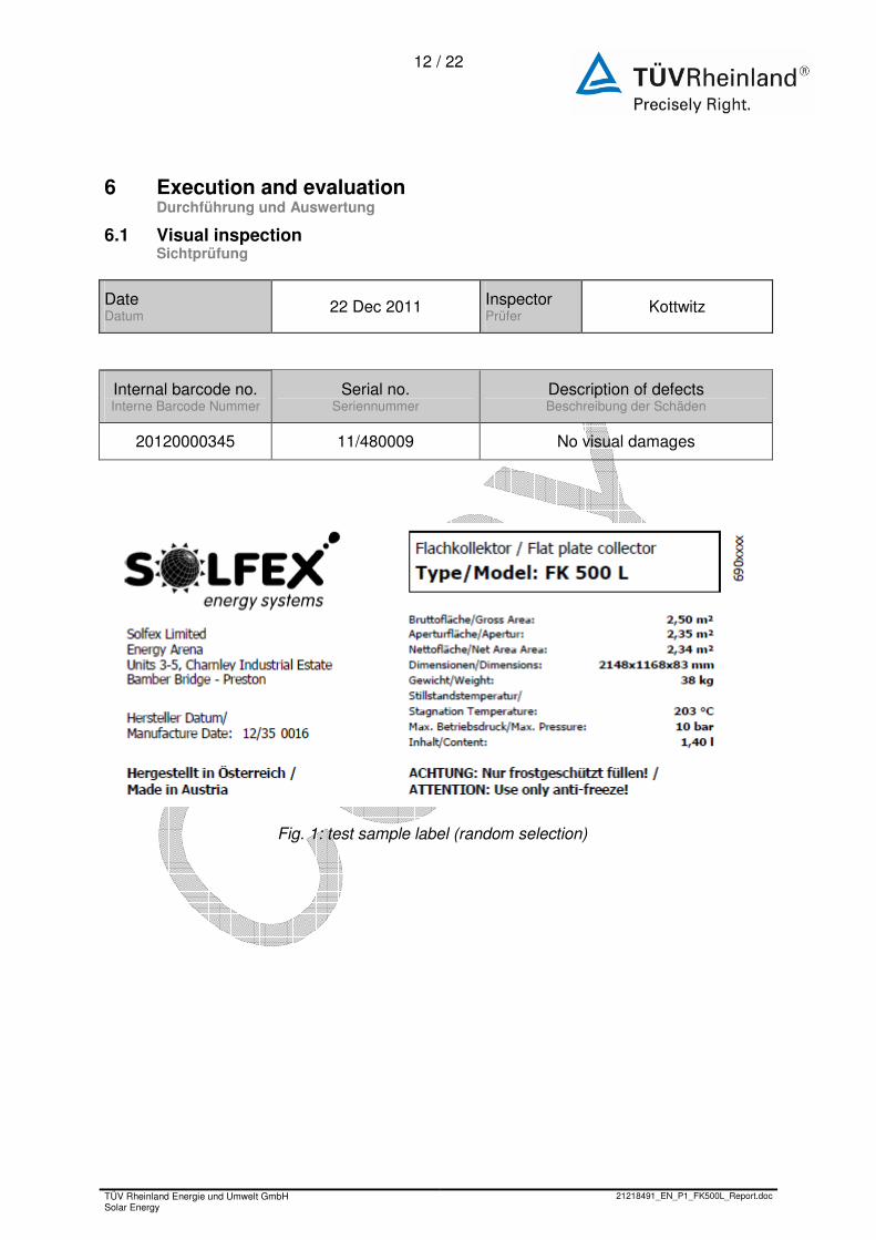
6.1 Visual inspection; Sichtprüfung
Date Datum
22 Dec 2011 Inspector Prüfer
Kottwitz
Internal barcode no. Interne Barcode Nummer
Serial no. Seriennummer
Description of defects Beschreibung der Schäden
20120000345 11/480009 No visual damages
Fig. 1: test sample label (random selection)
13 / 22
TÜV Rheinland Energie und Umwelt GmbH Solar Energy
21218491_EN_P1_FK500L_Report.doc
7 Measuring results of thermal performance testing; Prüfergebnisse der Leistungsprüfung von Sonnenkollektoren
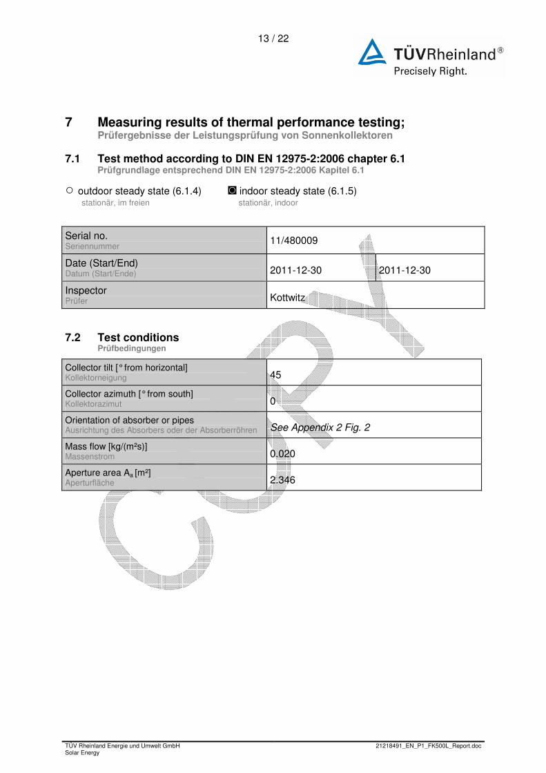
7.1 Test method according to DIN EN 12975-2:2006 chapter 6.1; Prüfgrundlage entsprechend DIN EN 12975-2:2006 Kapitel 6.1
○ outdoor steady state (6.1.4) ◙ indoor steady state (6.1.5) stationär, im freien stationär, indoor
Serial no. Seriennummer
11/480009
Date (Start/End) Datum (Start/Ende) 2011-12-30 2011-12-30
Inspector Prüfer Kottwitz
7.2 Test conditions; Prüfbedingungen
Collector tilt [° from horizontal] Kollektorneigung 45
Collector azimuth [° from south] Kollektorazimut 0
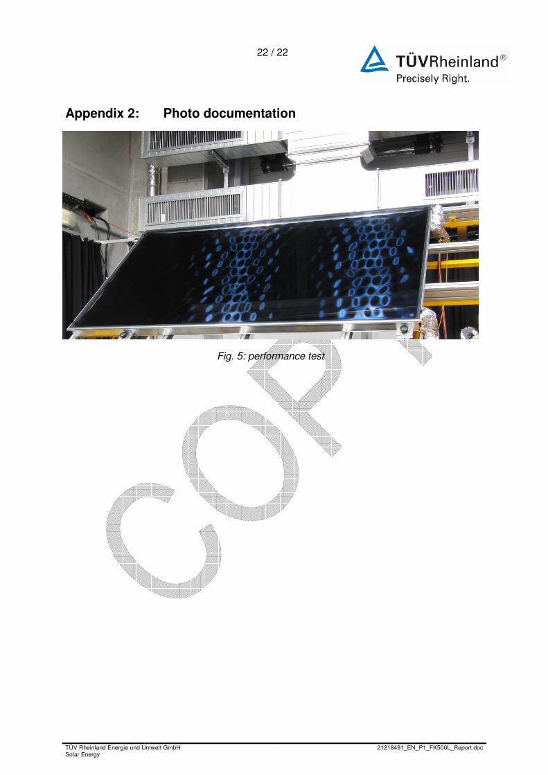
Orientation of absorber or pipes Ausrichtung des Absorbers oder der Absorberröhren See Appendix 2 Fig. 2
Mass flow [kg/(m²s)] Massenstrom 0.020
Aperture area Aa [m²] Aperturfläche 2.346
14 / 22
TÜV Rheinland Energie und Umwelt GmbH Solar Energy
21218491_EN_P1_FK500L_Report.doc
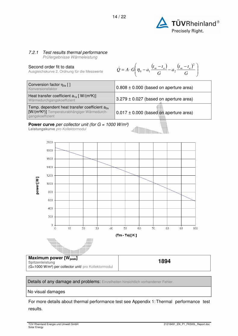
7.2.1 Test results thermal performance; Prüfergebnisse Wärmeleistung
Second order fit to data Ausgleichskurve 2. Ordnung für die Messwerte
( ) ( )
−−
−−⋅=
G
tta
G
ttaGAQ amam
2
210η&
Conversion factor η0a [ ] Konversionsfaktor 0.808 ± 0.000 (based on aperture area)
Heat transfer coefficient a1a [ W/(m²K)] Wärmedurchgangskoeffizient 3.279 ± 0.027 (based on aperture area)
Temp. dependent heat transfer coefficient a2a [W/(m²K²)] Temperaturabhängiger Wärmedurch-gangskoeffizient
0.017 ± 0.000 (based on aperture area)
Power curve per collector unit (for G = 1000 W/m²) Leistungskurve pro Kollektormodul
Maximum power [Wpeak] Spitzenleistung (G=1000 W/m²) per collector unit/ pro Kollektormodul
1894
Details of any damage and problems: Einzelheiten hinsichtlich vorhandener Fehler.
No visual damages
For more details about thermal performance test see Appendix 1: Thermal performance test
results.
15 / 22
TÜV Rheinland Energie und Umwelt GmbH Solar Energy
21218491_EN_P1_FK500L_Report.doc
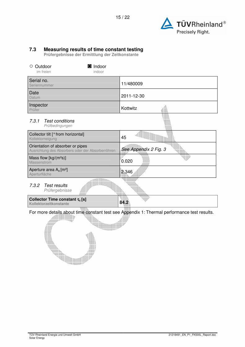
7.3 Measuring results of time constant testing; Prüfergebnisse der Ermittlung der Zeitkonstante
○ Outdoor ◙ Indoor im freien indoor
Serial no. Seriennummer 11/480009
Date Datum 2011-12-30
Inspector Prüfer Kottwitz
7.3.1 Test conditions; Prüfbedingungen
Collector tilt [° from horizontal] Kollektorneigung 45
Orientation of absorber or pipes Ausrichtung des Absorbers oder der Absorberröhren See Appendix 2 Fig. 3
Mass flow [kg/(m²s)] Massenstrom 0.020
Aperture area Aa [m²] Aperturfläche 2.346
7.3.2 Test results; Prüfergebnisse
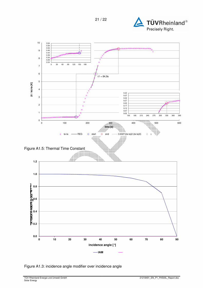
Collector Time constant ττττc [s] Kollektorzeitkonstante 84.2
For more details about time constant test see Appendix 1: Thermal performance test results.
16 / 22
TÜV Rheinland Energie und Umwelt GmbH Solar Energy
21218491_EN_P1_FK500L_Report.doc
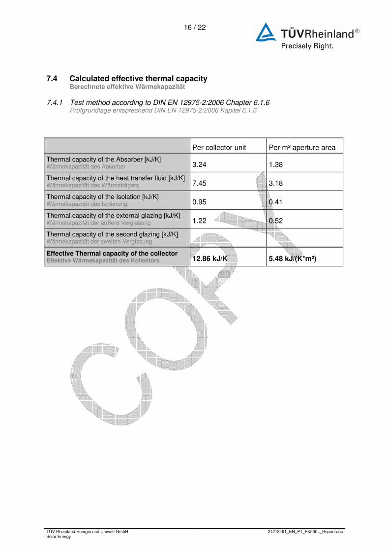
7.4 Calculated effective thermal capacity ; Berechnete effektive Wärmekapazität
7.4.1 Test method according to DIN EN 12975-2:2006 Chapter 6.1.6; Prüfgrundlage entsprechend DIN EN 12975-2:2006 Kapitel 6.1.6
Per collector unit Per m² aperture area
Thermal capacity of the Absorber [kJ/K] Wärmekapazität des Absorber 3.24 1.38
Thermal capacity of the heat transfer fluid [kJ/K] Wärmekapazität des Wärmeträgers 7.45 3.18
Thermal capacity of the Isolation [kJ/K] Wärmekapazität des Isolierung 0.95 0.41
Thermal capacity of the external glazing [kJ/K] Wärmekapazität der äußere Verglasung 1.22 0.52
Thermal capacity of the second glazing [kJ/K] Wärmekapazität der zweiten Verglasung
Effective Thermal capacity of the collector Effektive Wärmekapazität des Kollektors 12.86 kJ/K 5.48 kJ/(K*m²)
17 / 22
TÜV Rheinland Energie und Umwelt GmbH Solar Energy
21218491_EN_P1_FK500L_Report.doc
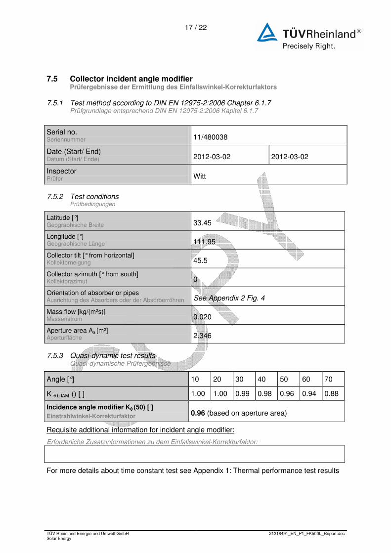
7.5 Collector incident angle modifier; Prüfergebnisse der Ermittlung des Einfallswinkel-Korrekturfaktors
7.5.1 Test method according to DIN EN 12975-2:2006 Chapter 6.1.7; Prüfgrundlage entsprechend DIN EN 12975-2:2006 Kapitel 6.1.7
Serial no. Seriennummer 11/480038
Date (Start/ End) Datum (Start/ Ende) 2012-03-02 2012-03-02
Inspector Prüfer Witt
7.5.2 Test conditions; Prüfbedingungen
Latitude [°] Geographische Breite 33.45
Longitude [°] Geographische Länge 111.95
Collector tilt [° from horizontal] Kollektorneigung 45.5
Collector azimuth [° from south] Kollektorazimut 0
Orientation of absorber or pipes Ausrichtung des Absorbers oder der Absorberröhren See Appendix 2 Fig. 4
Mass flow [kg/(m²s)] Massenstrom 0.020
Aperture area Aa [m²] Aperturfläche 2.346
7.5.3 Quasi-dynamic test results; Quasi-dynamische Prüfergebnisse
Angle [°] 10 20 30 40 50 60 70
K θ b IAM () [ ] 1.00 1.00 0.99 0.98 0.96 0.94 0.88
Incidence angle modifier Kθ θ θ θ (50) [ ] Einstrahlwinkel-Korrekturfaktor 0.96 (based on aperture area)
Requisite additional information for incident angle modifier:
Erforderliche Zusatzinformationen zu dem Einfallswinkel-Korrekturfaktor:
For more details about time constant test see Appendix 1: Thermal performance test results
18 / 22
TÜV Rheinland Energie und Umwelt GmbH Solar Energy
21218491_EN_P1_FK500L_Report.doc
8 General remarks; Bemerkungen
All results only refer to the test samples that were subjected to testing.
The extended total measuring uncertainty for the outdoor performance test is:
η ≤ ± 2.8 % (for irradiation levels above 700 W/m²)
The extended total measuring uncertainty for the indoor performance test is:
η ≤ ± 2 %
The following tests were performed at TUV Rheinland PTL and documented in report
RK-1 TEU111208-0838, March 2012:
• Incident angle modifier detection
The IAM detection was made with the nearly similar collector model FK8250.
All results are related to21218491_EN_P1_FK8257L4M-FL (2012-03-27).
19 / 22
TÜ
V R
heinland Energie und U
mw
elt Gm
bH
S
olar Energy
21218491_EN
_P1_F
K50
0L_Report.doc
19
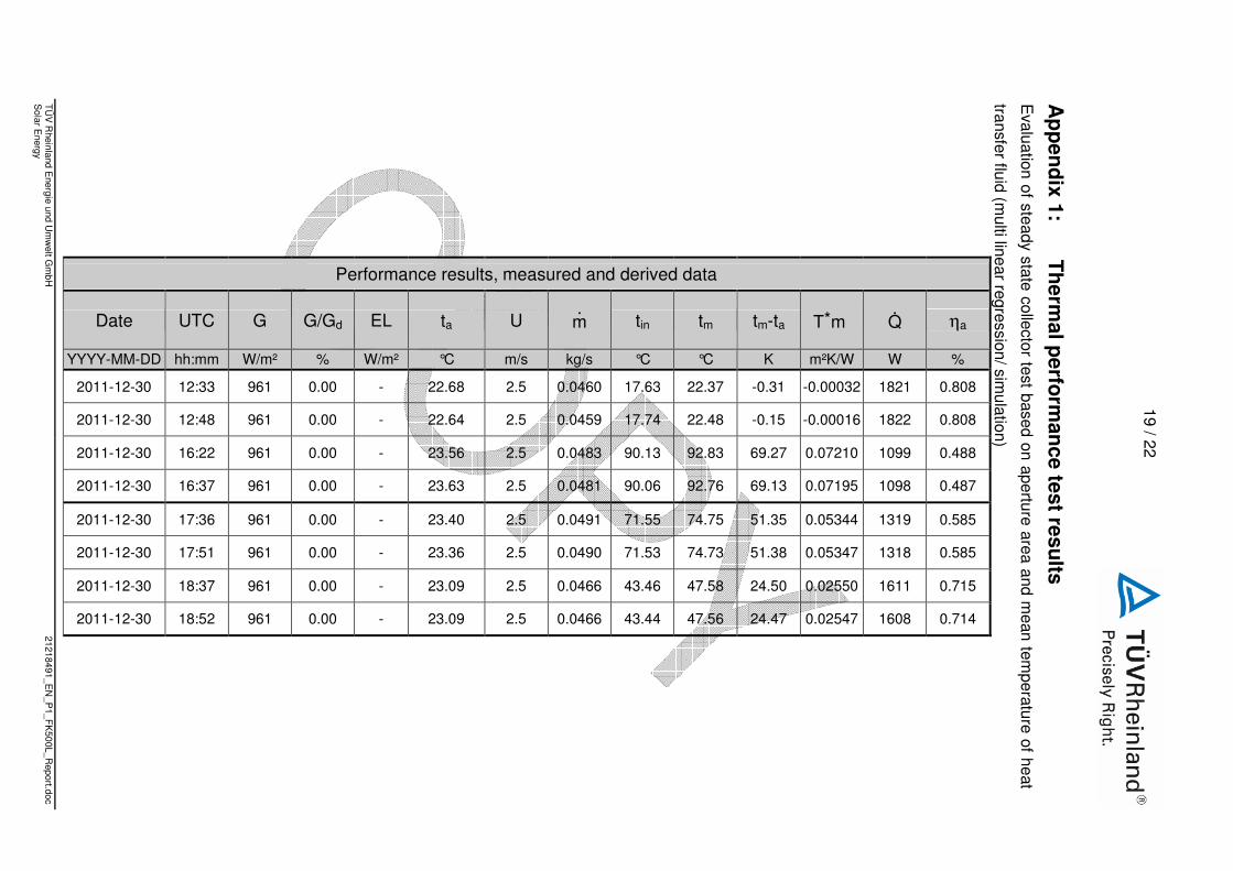
Ap
pen
dix 1:
Th
ermal p
erform
ance test resu
lts E
valuation of steady state collector test based on aperture area and mean tem
perature of heat
transfer fluid (multi linear regression/ sim
ulation)
Performance results, measured and derived data
ηa
%
0.808
0.808
0.488
0.487
0.585
0.585
0.715
0.714
Q
W
1821
1822
1099
1098
1319
1318
1611
1608
T*m
m²K/W
-0.00032
-0.00016
0.07210
0.07195
0.05344
0.05347
0.02550
0.02547
tm-ta
K
-0.31
-0.15
69.27
69.13
51.35
51.38
24.50
24.47
tm
°C
22.37
22.48
92.83
92.76
74.75
74.73
47.58
47.56
tin
°C
17.63
17.74
90.13
90.06
71.55
71.53
43.46
43.44
m
kg/s
0.0460
0.0459
0.0483
0.0481
0.0491
0.0490
0.0466
0.0466
U
m/s
2.5
2.5
2.5
2.5
2.5
2.5
2.5
2.5
ta
°C
22.68
22.64
23.56
23.63
23.40
23.36
23.09
23.09
EL
W/m²
-
-
-
-
-
-
-
-
G/Gd
%
0.00
0.00
0.00
0.00
0.00
0.00
0.00
0.00
G
W/m²
961
961
961
961
961
961
961
961
UTC
hh:mm
12:33
12:48
16:22
16:37
17:36
17:51
18:37
18:52
Date
YYYY-MM-DD
2011-12-30
2011-12-30
2011-12-30
2011-12-30
2011-12-30
2011-12-30
2011-12-30
2011-12-30
20 / 22
TÜV Rheinland Energie und Umwelt GmbH Solar Energy
21218491_EN_P1_FK500L_Report.doc
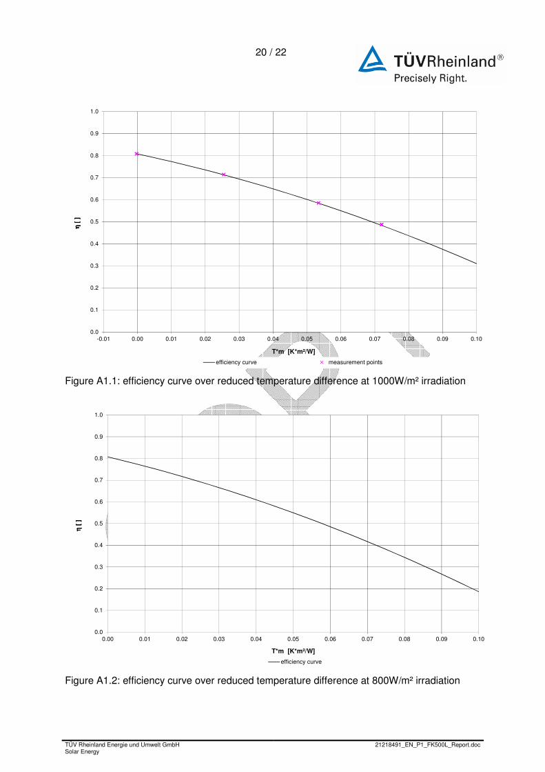
0.0
0.1
0.2
0.3
0.4
0.5
0.6
0.7
0.8
0.9
1.0
-0.01 0.00 0.01 0.02 0.03 0.04 0.05 0.06 0.07 0.08 0.09 0.10
η [
]η
[ ]
η [
]η
[ ]
T*m [K*m²/W]
efficiency curve measurement points Figure A1.1: efficiency curve over reduced temperature difference at 1000W/m² irradiation
0.0
0.1
0.2
0.3
0.4
0.5
0.6
0.7
0.8
0.9
1.0
0.00 0.01 0.02 0.03 0.04 0.05 0.06 0.07 0.08 0.09 0.10
η [
]η
[ ]
η [
]η
[ ]
T*m [K*m²/W]
efficiency curve
Figure A1.2: efficiency curve over reduced temperature difference at 800W/m² irradiation
21 / 22
TÜV Rheinland Energie und Umwelt GmbH Solar Energy
21218491_EN_P1_FK500L_Report.doc
τ1 = 84,9s
0
1
2
3
4
5
6
7
8
9
10
0 100 200 300 400 500 600
(ti /
te)
-ta
[K]
time [s]
te-ta REG start end 0.632*((te-ta)2-(te-ta)0) τ
0.240.290.340.390.440.490.540.590.64
0 30 60 90 120 150 180
9.02
9.07
9.12
9.17
9.22
9.27
9.32
9.37
9.42
155 185 215 245 275 305 335 365 395
Figure A1.5: Thermal Time Constant
0.0
0.2
0.4
0.6
0.8
1.0
1.2
0 10 20 30 40 50 60 70 80 90
incidence angle modifier [ ]
incidence angle [°]
IAM
Figure A1.3: incidence angle modifier over incidence angle
22 / 22
TÜV Rheinland Energie und Umwelt GmbH Solar Energy
21218491_EN_P1_FK500L_Report.doc
Appendix 2: Photo documentation
Fig. 5: performance test


![Larbert High School Faculty of Mathematics24453]Higher_Past...2009 P1 Q15 2009 P1 Q21 2010 P1 Q1 2010 P1 Q8 2010 P1 Q21 2010 P1 Q23 2011 P1 Q2 2011 P1 Q8 2011 P1 Q21 2012 P1 Q4 2012](https://img.dokumen.tips/doc/110x75/60bd9bf2b65aaa2b316d3bc9/larbert-high-school-faculty-of-mathematics-24453higherpast-2009-p1-q15-2009.jpg)