Embed Size (px)
Citation preview
CHALLENGE CUP SERIES, INC. 3 Ledgemont Drive Fairport. NY 14450-2607 USA www.challengecupseries.com
1
2016 CHALLENGE CUP SERIES
TECHNICIAL SPECIFICATIONS AND EQUIPMENT SAFETY REGULATIONS MANUAL
ADOPTED FROM THE SPORTS CAR CLUB OF AMERICA, INC.’S (SCCA) GENERAL COMPETITION RULES (GCR) 2015 EDITION FOR FORMULA VEE (FV) & F1200 RACING AND GENERAL RACING PROCEDURES WITH THEIR PERMISSION. THE ALL GENERAL COMPETITION RULES INCLUDING SAFETY EQUIPMENT REGULATIONS FOR THE 2016 CHALLENGE CUP SERIES RACE SEASON WILL FOLLOW THE SCCA’S GCR 2016 EDITION WITHOUT CHANGE. THE TECHINICAL SPECIFICATIONS FOR THE 2016 CHALLENGE CUP SERIES RACE SEASON WILL FOLLOW THE SCCA’S GCR 2016 EDITION AS MODIFIED BELOW.
CHALLENGE CUP SERIES, INC. 3 Ledgemont Drive Fairport. NY 14450-2607 USA www.challengecupseries.com
2
9.1.1 Formula Vee (FV) Specifications C. FORMULA VEE PREPARATION RULES 1. Background A. History and philosophy of the class Formula Vee (FV) was recognized by SCCA in 1963. The class is highly restricted, originally requiring the use of genuine VW parts “from the Standard Volkswagen 1200 Sedan Series type 1, US model sedan as Imported by VW” in the engine, drivetrain and suspension. Over the Years, the rules have changed slowly to maintain parts availability and allow a gradual evolution of the class. However, the focus remains the same: to provide a cost effective, highly competitive class that, through consistent and tightly controlled component and preparation Rules, emphasizes driver ability rather than technological development of the car. Today, as throughout its long history, FV is one of the most highly subscribed classes in SCCA. The goal of these rules is to maintain both the competitiveness and cost effectiveness of the class. B. Definition A formula for single seat, open wheel racing cars based on standard Volkswagen 1200 series Type 1, U.S. model sedan (imported by VW) Components, and restrictive in specifications so as to emphasize driver Ability and preparation rather than design and technology of the car. Formula Vee is a Restricted Class. Therefore, any allowable modification, changes, or additions are as stated herein. There are no exceptions. IF IN DOUBT, DON’T. Homologation is required for all cars registered after January 1, 1983. No component of the engine, power train, front suspension and brakes shall be altered, modified, or substituted unless specifically authorized. Mass-produced, direct replacement components may be substituted for the following as long as they are of the same material and dimensionally identical to the original VW components they replace: • VW transmission components • Rear axle components • Front suspension • Brake components These replacement parts must be generally available to all competitors and must offer no competitive advantage over the original VW parts. Replacement engine components are allowed as described in section C.5.
CHALLENGE CUP SERIES, INC. 3 Ledgemont Drive Fairport. NY 14450-2607 USA www.challengecupseries.com
3
Any external surface of the suspension, brakes, and transmission/ rear axle may be painted, plated, or anodized. Engine components shall be assembled in standard configuration. Exceeding the wear limits specified in the VW manual or other official VW guides is allowed provided that tolerances, dimensions, and specifications stated in the GCR are met. 2. Weight and Dimensions Minimum weight as qualified or raced, with driver: 1075 lbs. Wheel base, minimum: 81.5” Wheel base, maximum: 83.5” Overall length, minimum: 123” (includes exhaust) Specifics: Diamond Wheels/Magnum Tire: Falken Azonic RT 615 (no suffix) or suffix K 95/60/R14 Wheel: Steel 14" X 6" with minimum weight of 12 lbs. No spacers, shims or adapters. Adjusted minimum weight: 1075 lbs. Adjusted track: Front 54 1/2", plus/minus 1/4", Rear 52 5/8", plus 7/8", minus 5/8" Body height at firewall (bottom of frame to top of bodywork), Minimum: 25” 3. Suspension A. The front suspension and steering shall be standard VW Sedan as Defined herein, or an exact replica of the same material and dimension.
1. Removal or modification of spring packs including the use of ride height adjusters incorporated into the front beam provided they are not adjustable from the cockpit. At least one spring pack shall be retained as the primary spring media for the front suspension. 2. The use of any anti sway bar(s), mounting hardware, and trailing arm locating spacers. 3. The use of any direct acting, tube type shock absorber(s) mounted in a longitudinal, vertical plane and acting through the standard mounting points. Spring shocks and linkage activated shocks are prohibited. 4. Relocation of the steering gearbox to any position utilizing an appropriate mounting structure and replacements of the tie rods. Steering damper mount and/or the steering box locating bumps may be removed. 5. Any desired pitman arm may be used. 6. Steering column may be altered or replaced and any steering wheel may be used.
CHALLENGE CUP SERIES, INC. 3 Ledgemont Drive Fairport. NY 14450-2607 USA www.challengecupseries.com
4
7. Standard steering arms may be altered or replaced and speedometer cable hole may be plugged. No other modification of the wheel spindle is permitted. Non-VW replacement spindles shall maintain the same bearing dimensions and locations and shall maintain the geometric relationship between the spindle and the king pin bore and boss. Wheel tethers are recommended. If wheel tethers are used, a hole may be drilled in the spindle for the purpose of attachment. 8. The rubber portion of the bump stop and any portion or all of the bump stop horn may be removed up to its base at the beam upright. 9. Caster, camber, and toe in/out settings are unrestricted. Offset link pin suspension bushings and alternate locating spacers are permitted. Shims/spacers used solely for camber adjustment are open. Clearance of the link pin carrier and/or trailing arms to eliminate binding is permitted. No other modifications to the link pin carrier are permitted. 10. No structure, item, or component (including the battery) other than bodywork, can protrude further forward than ten (10) inches from the front of the lower axle beam tube. Any item protruding further than eight (8) inches must include a vertical safety plate. This plate must be constructed of no less than .060” 6061-T-6 aluminum or no less than 16 gauge steel. The plate shall have a minimum frontal surface area of 42 square inches, and shall have a height of not less than four (4) inches and a width of not less than six (6) inches. The plate may have no more than ½ inch curvature or deflection from the Vertical plane, and shall be attached to the chassis (frame) at all four corners. The lower braces shall not exceed a 15-degree upward angle when measured from the horizontal plane of the lower frame tubes. If a vented lead acid battery is mounted in front of the axle beam, it shall be encased in a marine-type container. It is recommended that the front area of the nose be filled with foam to aid in impact absorption. 11. Alternate spindle from cip1.com part number C26-412-020 and alternate spindle carrier C26-412-025 are allowed.
B. The rear axle assembly shall be standard VW sedan as defined herein with axle location provided by a single locating arm on each axle.
1. The rear axle tube may be rotated about its axis.
CHALLENGE CUP SERIES, INC. 3 Ledgemont Drive Fairport. NY 14450-2607 USA www.challengecupseries.com
5
2. Coil spring(s) shall provide the primary springing medium, with telescopic shock absorber(s) mounted inside the spring(s). Cables, straps, or other positive stops may be used to limit positive camber. An anti-roll bar or camber control device may also be used. When said anti roll bar or camber control device is removed, the required coil springs shall continue to perform functionally. 3. The shock absorber mounts may be modified.
C. Wheels/rims Specifics: Diamond Wheels/Magnum Tire: Falken Azenis RT 615 (no suffix) or suffix K 95/60/R14 Wheel: Steel 14" X 6" with minimum weight of 12 lbs. No spacers, shims or adapters. Adjusted minimum weight: 1075 lbs. Adjusted track: Front 54 1/2", plus/minus 1/4", Rear 52 5/8", plus 7/8", minus 5/8" 4. Brakes A. Brake drums, backing plates, and wheel cylinders shall be standard VW Sedan as defined herein, or an exact replica of the same material and dimensionally identical. Ribbed type rear drums (VW Part # N113-501 615 D or ICP Part # 113 501 615 D) may be used in Place of the 1200 series rear brake drums. Rear backing plates may be from any Type 1 model year. B. These cars shall be equipped with a dual braking system operated by a single control. In case of a leak or failure at any point in the system, effective braking power shall be maintained on at least two wheels. Any master cylinder(s) may be used. C. A separate hand brake (emergency brake) is not required. Removal of the hand brake and operating mechanism is permitted. 5. Engine A. The engine shall be a standard VW power plant, as normally fitted To VW sedans as defined herein. Any engine part(s), listed by the Manufacturer (VW) as a current, superseding, replacement part for The standard VW 1200 series, Type 1, U.S. model sedan and interchangeable with the original part(s), may be used. Turbocharging is not permitted. B. The engine/transmission shall be mounted in the chassis with the transmission to the rear. C. The following component parts may be replaced with that of other manufacture, provided said part is of the same material, is dime- signally identical, and meets all other tolerances and specifications stated in the GCR. 1. Engine Case – Type I or Type III style single or dual relief cases only 2. Cylinder Heads
CHALLENGE CUP SERIES, INC. 3 Ledgemont Drive Fairport. NY 14450-2607 USA www.challengecupseries.com
6
3. Cylinders (an O ring for centering is permitted). 4. Pistons and wrist pins minimum combined weight without clips or piston rings = 330.0 grams.
a. Piston material shall be cast aluminum with steel inserts. b. Maximum distance from bottom of wrist pin bore to top of #1 (top) compression ring groove: 1.655 inches (20 mm Wrist pin bore assumed). c. Width of #1 and #2 (compression) ring grooves: .100+.003 inches or -.023 inches (2.0-2.5mm nominal). d. Width of #3 (oil) ring groove: .158 +/- .003 inches (4.0mm nominal). e. Wrist pin offset from centerline: .059 +/- .005 inches. f. Eccentricity of piston below the oil ring groove: .012 +/- .008 inches. Eccentricity shall be defined as the difference between the largest diameter and smallest diameter Measured at the same distance from the crown of the piston and below the oil ring grove.
5. Cam followers Minimum weight = 60.0 grams 6. Connecting rods with bolts and small end bushing minimum weight = 425.0 grams. Crower part #SP93280B is allowed as a direct replacement connecting rod but must meet the same minimum weight requirement as the OEM part. 7. Oil pump exact replica of any standard VW oil pump 8. Distributor 9. Ignition points or drop-in ignition triggering module (e.g., Petronas) 10. Distributor cap 11. Fuel pump any standard type VW fuel pump which can be fitted without modification of any other part 12. Crankshaft minimum weight sixteen (16) lbs. 13. Crankshaft gear 14. Flywheel minimum weight twelve (12) lbs. 15. Pressure plate, or alternate SACHS 211 141 025 DAM press- sure plate 16. Clutch disc – 180mm nominal diameter only 17. Throw out bearing 18. Push rods 19. Push rod tubes D. Allowed Modifications 1. Replacement of standard exhaust system with any exhaust system terminating one (1) to three (3) inches behind the rear- most part of the body. 2. Lightening of the flywheel to a minimum of twelve (12) lbs. 3. Balancing of all moving parts of the engine, provided such balancing does not remove more material than is necessary to achieve the balance except on those component parts where weights are specified. 4. The crankshaft may be ground and the case may be machined to accommodate the use of standard factory oversize/under- size crankshaft bearings, provided the crankshaft location is not changed.
CHALLENGE CUP SERIES, INC. 3 Ledgemont Drive Fairport. NY 14450-2607 USA www.challengecupseries.com
7
FCS
5. Where minimum weights are specified, any lightening is permits- sable provided the original part complied with the dimensional restrictions set forth. 6. The following standard dimensions and tolerances of engine components are included as information and shall be observed:
a. Maximum bore: 3.040 inches b. Stroke: 2.520 inches +/ 0.005 inch. c. Minimum capacity of combustion chamber in head: 43.0cc (Polishing and/or tooling is prohibited.) d. Minimum depth, top of cylinder barrel to top of piston: 0.039 inch.
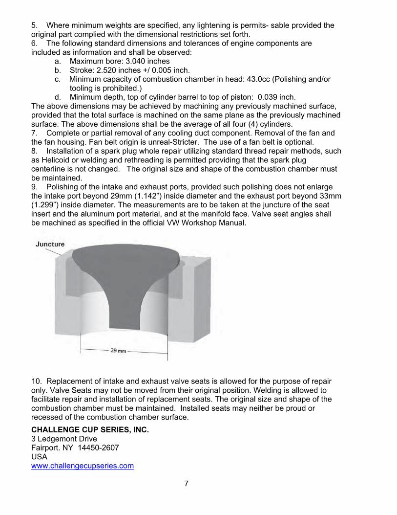
The above dimensions may be achieved by machining any previously machined surface, provided that the total surface is machined on the same plane as the previously machined surface. The above dimensions shall be the average of all four (4) cylinders. 7. Complete or partial removal of any cooling duct component. Removal of the fan and the fan housing. Fan belt origin is unreal-Stricter. The use of a fan belt is optional. 8. Installation of a spark plug whole repair utilizing standard thread repair methods, such as Helicoid or welding and rethreading is permitted providing that the spark plug centerline is not changed. The original size and shape of the combustion chamber must be maintained. 9. Polishing of the intake and exhaust ports, provided such polishing does not enlarge the intake port beyond 29mm (1.142”) inside diameter and the exhaust port beyond 33mm (1.299”) inside diameter. The measurements are to be taken at the juncture of the seat insert and the aluminum port material, and at the manifold face. Valve seat angles shall be machined as specified in the official VW Workshop Manual.
10. Replacement of intake and exhaust valve seats is allowed for the purpose of repair only. Valve Seats may not be moved from their original position. Welding is allowed to facilitate repair and installation of replacement seats. The original size and shape of the combustion chamber must be maintained. Installed seats may neither be proud or recessed of the combustion chamber surface.
CHALLENGE CUP SERIES, INC. 3 Ledgemont Drive Fairport. NY 14450-2607 USA www.challengecupseries.com
8
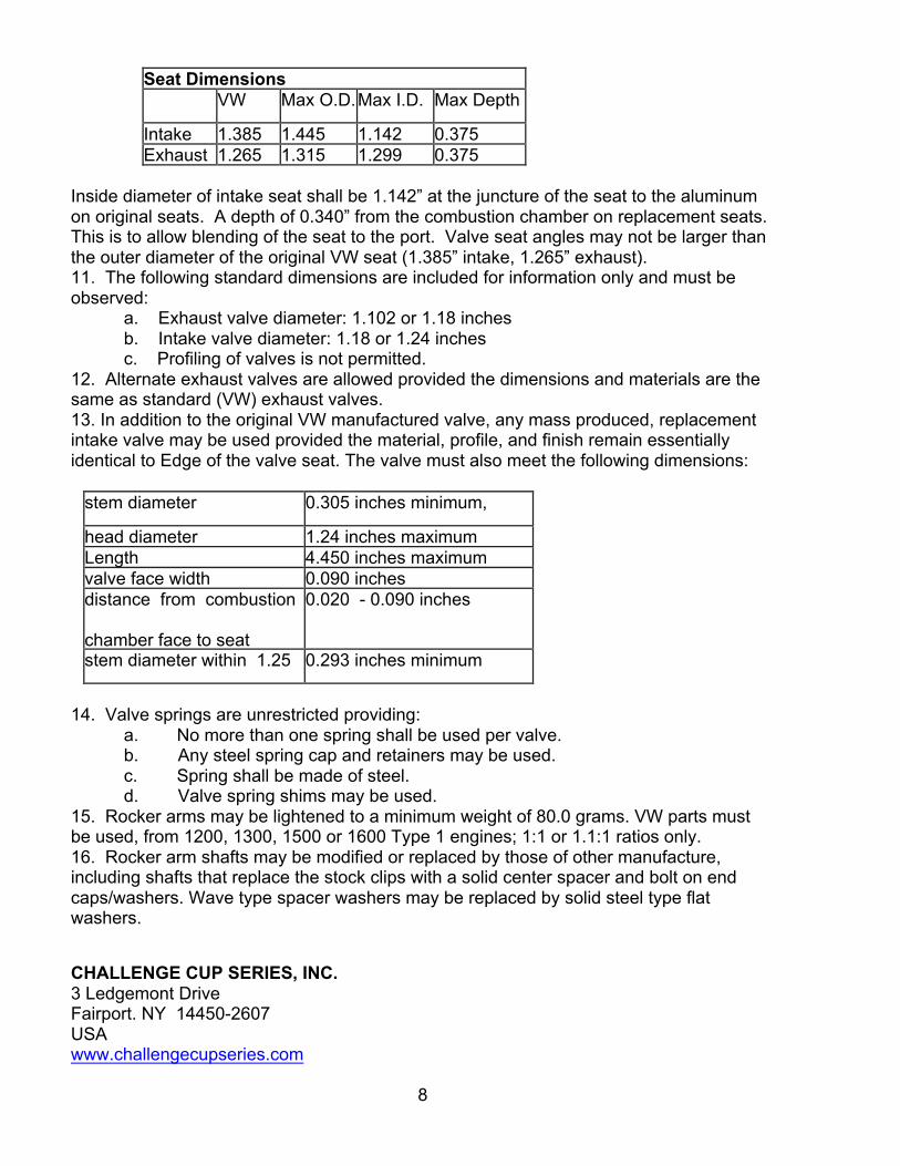
Seat Dimensions VW
O.D.
(inches
)
Max O.D.
(inches)
Max I.D.
(inches)
Max Depth
(inches) Intake 1.385 1.445 1.142 0.375 Exhaust 1.265 1.315 1.299 0.375
Inside diameter of intake seat shall be 1.142” at the juncture of the seat to the aluminum on original seats. A depth of 0.340” from the combustion chamber on replacement seats. This is to allow blending of the seat to the port. Valve seat angles may not be larger than the outer diameter of the original VW seat (1.385” intake, 1.265” exhaust). 11. The following standard dimensions are included for information only and must be observed: a. Exhaust valve diameter: 1.102 or 1.18 inches b. Intake valve diameter: 1.18 or 1.24 inches c. Profiling of valves is not permitted. 12. Alternate exhaust valves are allowed provided the dimensions and materials are the same as standard (VW) exhaust valves. 13. In addition to the original VW manufactured valve, any mass produced, replacement intake valve may be used provided the material, profile, and finish remain essentially identical to Edge of the valve seat. The valve must also meet the following dimensions:
stem diameter 0.305 inches minimum,
measured just below the
keeper grooves
head diameter 1.24 inches maximum Length 4.450 inches maximum valve face width 0.090 inches distance from combustion
chamber face to seat
surface (including any
chamfer at valve head)
0.020 - 0.090 inches
stem diameter within 1.25
inches of the head of the
valve
0.293 inches minimum
14. Valve springs are unrestricted providing:
a. No more than one spring shall be used per valve. b. Any steel spring cap and retainers may be used. c. Spring shall be made of steel. d. Valve spring shims may be used.
15. Rocker arms may be lightened to a minimum weight of 80.0 grams. VW parts must be used, from 1200, 1300, 1500 or 1600 Type 1 engines; 1:1 or 1.1:1 ratios only. 16. Rocker arm shafts may be modified or replaced by those of other manufacture, including shafts that replace the stock clips with a solid center spacer and bolt on end caps/washers. Wave type spacer washers may be replaced by solid steel type flat washers.
CHALLENGE CUP SERIES, INC. 3 Ledgemont Drive Fairport. NY 14450-2607 USA www.challengecupseries.com
9
FC
17. The rocker arm shaft assembly may be shimmed out on the cylinder head mounting studs by placing appropriate shims between the cylinder head mounting boss and the blocks on the rocker arm shaft assembly. 18. Valve covers are unrestricted and may be bolted on. 19. Fitting of any standard Solex 28 PCI or 28 PICT carburetor and any jets and emulsion tube may be used. Any venturi of standard VW/Solex dimensions may be fitted without alteration to the carburetor body. The venturi shall be fitted in the standard position, but its internal diameter may be machined. The carburetor may be rotated 180 degrees about its vertical axis. Modification of the float is allowed as long as no change is made to the float chamber and/or float valve. The carburetor must remain untouched with the following exceptions:
a. No material shall be added. b. Bead blasting is permitted for cleaning only. c. Throttle shaft shall be a minimum of 0.185” with throttle plate installed. Machined sides shall remain flat and parallel with no chamfering or radiusing. d. Throttle Plate shall be a minimum of 0.053”, flat and parallel with no chamfering or radiusing. Diameter shall be a minimum of 1.095 inches. e. Carburetor Top the junction of the bowl and bore may be radiused. The bore beneath the radius shall be a maximum of 1.120 inches. Accelerator pump boss shall remain rig- final. The orifice in the base of the accelerator pump boss shall not allow a #56 (0.046 in.) drill bit to pass through (maximum hole diameter shall be less than 0.046 in.). f. Carburetor Body the removal of mold flashing from cast surfaces, including the emulsion tube carrier (holder), is permitted, but no additional material is to be removed. The emulsion tube carrier (holder) must not be otherwise modified. Bore diameter from throttle shaft down shall not exceed 1.110 inches. g. Carburetor air cleaner and choke mechanism may be removed. Choke shaft holes may be plugged. Plugs may not protrude into the choke bowl.
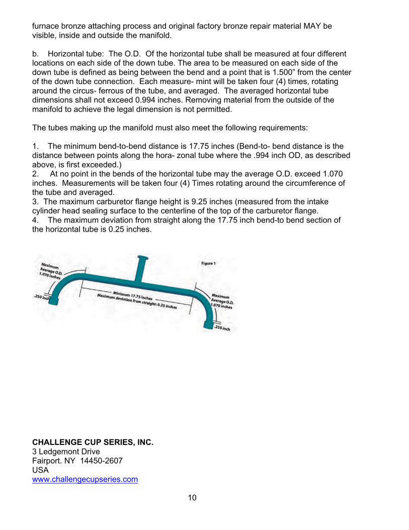
20. US imported VW Type 1, 1200 sedan manifold must be used. The manifold heat riser tube and heat sink shall be removed. Removal of metal from the interior of the intake manifold and the interior rust-proofed is permitted provided that the following dimensions are not exceeded. See Figures 1 and 2 at the end of this subsection for Applica- ton of certain measurements specified herein. a. Down Tube: The O.D. of the down tube shall be measured at two different locations within an area between 0.500” and 2.00” above the horizontal manifold tube. Each measurement shall be taken four times rotating around the circumference of the tube, and averaged. The averaged O.D. of the down tube shall not exceed 1.140 inches. Removing material from the outside of the manifold to achieve the legal dimension is not permitted. Removal of the manifold down tube from the horizontal tube is prohibit- tied. The original factory
CHALLENGE CUP SERIES, INC. 3 Ledgemont Drive Fairport. NY 14450-2607 USA www.challengecupseries.com
10
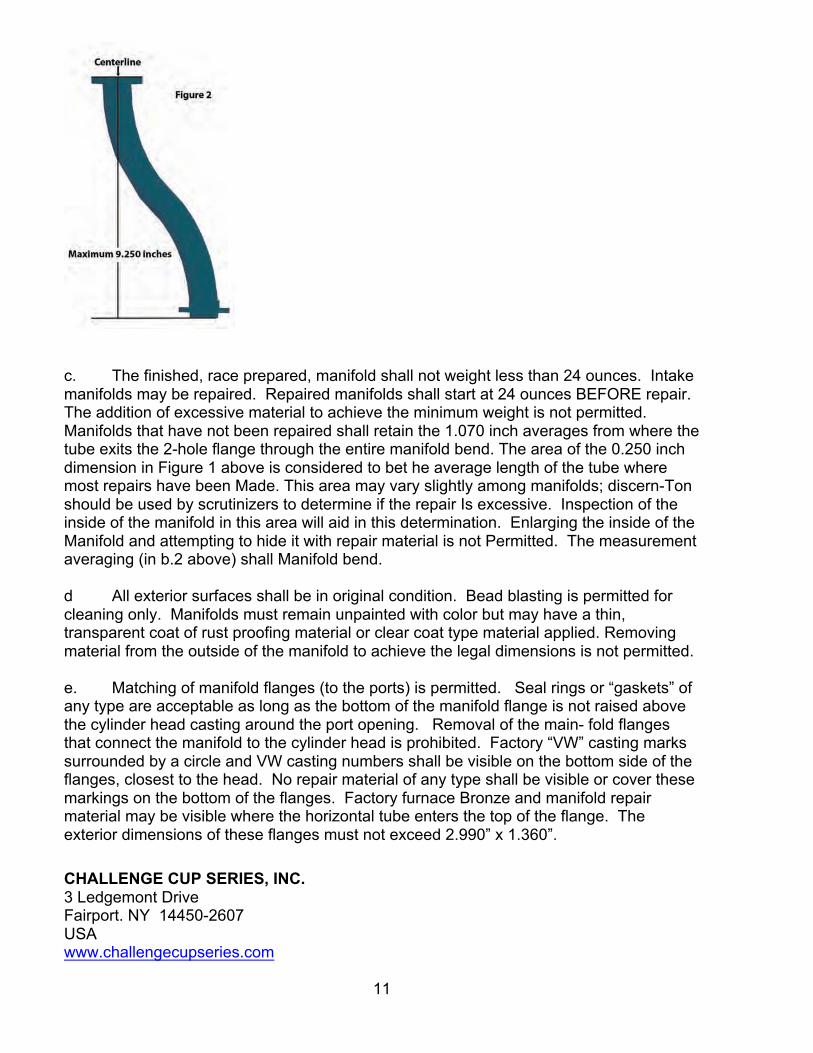
furnace bronze attaching process and original factory bronze repair material MAY be visible, inside and outside the manifold. b. Horizontal tube: The O.D. Of the horizontal tube shall be measured at four different locations on each side of the down tube. The area to be measured on each side of the down tube is defined as being between the bend and a point that is 1.500” from the center of the down tube connection. Each measure- mint will be taken four (4) times, rotating around the circus- ferrous of the tube, and averaged. The averaged horizontal tube dimensions shall not exceed 0.994 inches. Removing material from the outside of the manifold to achieve the legal dimension is not permitted. The tubes making up the manifold must also meet the following requirements: 1. The minimum bend-to-bend distance is 17.75 inches (Bend-to- bend distance is the distance between points along the hora- zonal tube where the .994 inch OD, as described above, is first exceeded.) 2. At no point in the bends of the horizontal tube may the average O.D. exceed 1.070 inches. Measurements will be taken four (4) Times rotating around the circumference of the tube and averaged. 3. The maximum carburetor flange height is 9.25 inches (measured from the intake cylinder head sealing surface to the centerline of the top of the carburetor flange. 4. The maximum deviation from straight along the 17.75 inch bend-to bend section of the horizontal tube is 0.25 inches.
CHALLENGE CUP SERIES, INC. 3 Ledgemont Drive Fairport. NY 14450-2607 USA www.challengecupseries.com
11
c. The finished, race prepared, manifold shall not weight less than 24 ounces. Intake manifolds may be repaired. Repaired manifolds shall start at 24 ounces BEFORE repair. The addition of excessive material to achieve the minimum weight is not permitted. Manifolds that have not been repaired shall retain the 1.070 inch averages from where the tube exits the 2-hole flange through the entire manifold bend. The area of the 0.250 inch dimension in Figure 1 above is considered to bet he average length of the tube where most repairs have been Made. This area may vary slightly among manifolds; discern-Ton should be used by scrutinizers to determine if the repair Is excessive. Inspection of the inside of the manifold in this area will aid in this determination. Enlarging the inside of the Manifold and attempting to hide it with repair material is not Permitted. The measurement averaging (in b.2 above) shall Manifold bend. d All exterior surfaces shall be in original condition. Bead blasting is permitted for cleaning only. Manifolds must remain unpainted with color but may have a thin, transparent coat of rust proofing material or clear coat type material applied. Removing material from the outside of the manifold to achieve the legal dimensions is not permitted. e. Matching of manifold flanges (to the ports) is permitted. Seal rings or “gaskets” of any type are acceptable as long as the bottom of the manifold flange is not raised above the cylinder head casting around the port opening. Removal of the main- fold flanges that connect the manifold to the cylinder head is prohibited. Factory “VW” casting marks surrounded by a circle and VW casting numbers shall be visible on the bottom side of the flanges, closest to the head. No repair material of any type shall be visible or cover these markings on the bottom of the flanges. Factory furnace Bronze and manifold repair material may be visible where the horizontal tube enters the top of the flange. The exterior dimensions of these flanges must not exceed 2.990” x 1.360”.
CHALLENGE CUP SERIES, INC. 3 Ledgemont Drive Fairport. NY 14450-2607 USA www.challengecupseries.com
12
21. Voltage regulator, generator, and/or generator stand may be removed. 22. Fitting of any standard VW distributor (not restricted to 1200, series) may be used. Use of any standard 6- or 12-volt non transistorized ignition coil is allowed. Coil mounting location is unrestricted. 23. A VW “D” camshaft, Part Numbers 113 109 015D, 113 109 017D, 113 109 019D, 113 109 021D, 113 109 023D, 113 109 025D, 13 109 027D, or an exact replica of the same material and dimensionally identical shall be used. The maximum Lift at the valve spring collar with zero valve clearance is as follows: a. Intake .354” + 0.000” b. Exhaust .3365” + 0.000” The camshaft profile shall match those which are specified by the official SCCA camshaft plots, plus or minus .002 inch. It is permitted to regrind the camshaft to duplicate the official SCCA profile. In so doing, the relationship between the centerlines of peak lift at the exhaust/intake lobes shall remain at 214 degrees fifteen (15) minutes, plus or minus 1degree. (Reference the Official SCCA Camshaft Checking Procedure). The camshaft timing may be changed in relationship to the crankshaft by utilizing an offset key at the crankshaft timing gear. The camshaft timing may also be changed in its relationship to the crankshaft by utilizing an adjustable cam gear that retains the existing helical gear thrust angle and that is statically adjustable only (e.g., no dynamic adjustment mechanisms that respond to engines speed changes) camshaft timing is unrestricted within the restrictions provided as authorized above. The camshaft profile shall be checked using the official procedure published by the SCCA. 24. The crankcase may be machined to permit the use of standard VW camshaft bearing inserts, provided that camshaft location is not changed. 25. Crankshaft pulley is unrestricted and may be fitted with an oil seal. The engine case may be machined to facilitate the installation of an oil seal. 26. The installation of baffles housed completely within the original oil sump and crankcase. 27. The use of any oil temperature indicating device. 28. The oil pump cover may be modified or replaced. 29. An oil sump extension may be fitted to the engine with a maximum internal volume not to exceed 1500cc. In operation, all movement of oil and crankcase air in and out of the extent- son shall be through the original oil strainer cover opening of the engine case. No additional openings in the extension are allowed above the plane of the oil strainer flange of the engine case. The oil pump pickup pipe may be extended into the sump extension. Any baffling is allowed within the extension and may extend between the engine case and the sump extension through the original oil strainer opening. Any sump may not extend below the frame rails of the chassis when viewed from the side. Accumulators (Accusump) may be fitted. 30. Replacement of oil galley plugs with threaded plugs. 31. A single standard automotive oil filter of not more than one quart total capacity, and a suitable mounting bracket and by-pass valve may be installed. Modification to the
CHALLENGE CUP SERIES, INC. 3 Ledgemont Drive Fairport. NY 14450-2607 USA www.challengecupseries.com
13
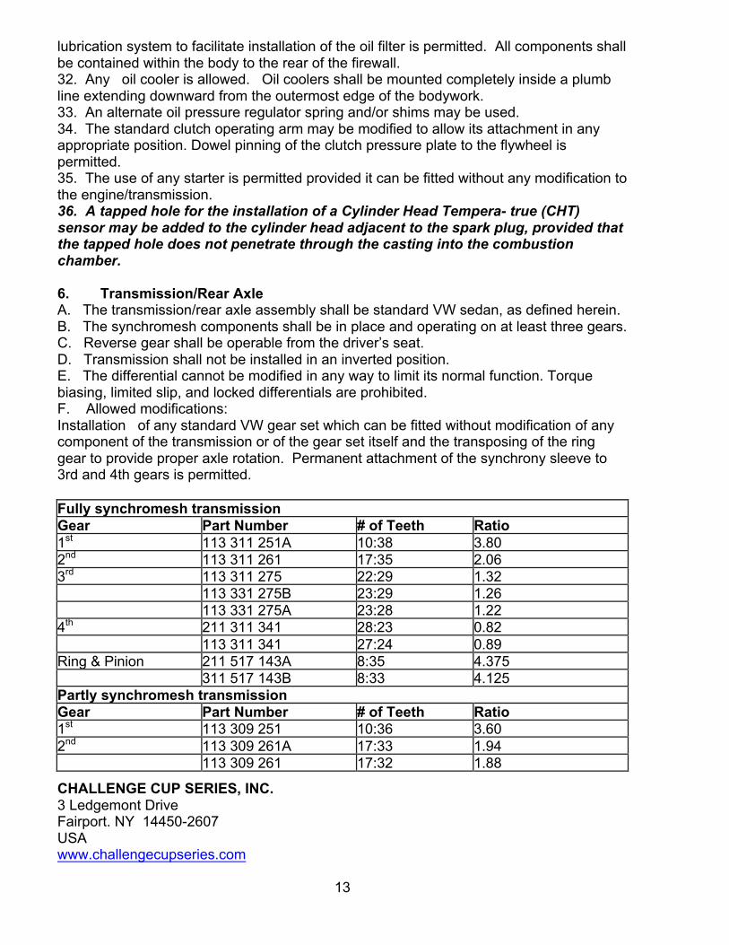
lubrication system to facilitate installation of the oil filter is permitted. All components shall be contained within the body to the rear of the firewall. 32. Any oil cooler is allowed. Oil coolers shall be mounted completely inside a plumb line extending downward from the outermost edge of the bodywork. 33. An alternate oil pressure regulator spring and/or shims may be used. 34. The standard clutch operating arm may be modified to allow its attachment in any appropriate position. Dowel pinning of the clutch pressure plate to the flywheel is permitted. 35. The use of any starter is permitted provided it can be fitted without any modification to the engine/transmission. 36. A tapped hole for the installation of a Cylinder Head Tempera- true (CHT) sensor may be added to the cylinder head adjacent to the spark plug, provided that the tapped hole does not penetrate through the casting into the combustion chamber. 6. Transmission/Rear Axle A. The transmission/rear axle assembly shall be standard VW sedan, as defined herein. B. The synchromesh components shall be in place and operating on at least three gears. C. Reverse gear shall be operable from the driver’s seat. D. Transmission shall not be installed in an inverted position. E. The differential cannot be modified in any way to limit its normal function. Torque biasing, limited slip, and locked differentials are prohibited. F. Allowed modifications: Installation of any standard VW gear set which can be fitted without modification of any component of the transmission or of the gear set itself and the transposing of the ring gear to provide proper axle rotation. Permanent attachment of the synchrony sleeve to 3rd and 4th gears is permitted. Fully synchromesh transmission Gear Part Number # of Teeth Ratio 1st 113 311 251A 10:38 3.80 2nd 113 311 261 17:35 2.06 3rd 113 311 275 22:29 1.32 113 331 275B 23:29 1.26 113 331 275A 23:28 1.22 4th 211 311 341 28:23 0.82 113 311 341 27:24 0.89 Ring & Pinion 211 517 143A 8:35 4.375 311 517 143B 8:33 4.125 Partly synchromesh transmission Gear Part Number # of Teeth Ratio 1st 113 309 251 10:36 3.60 2nd 113 309 261A 17:33 1.94 113 309 261 17:32 1.88
CHALLENGE CUP SERIES, INC. 3 Ledgemont Drive Fairport. NY 14450-2607 USA www.challengecupseries.com
14
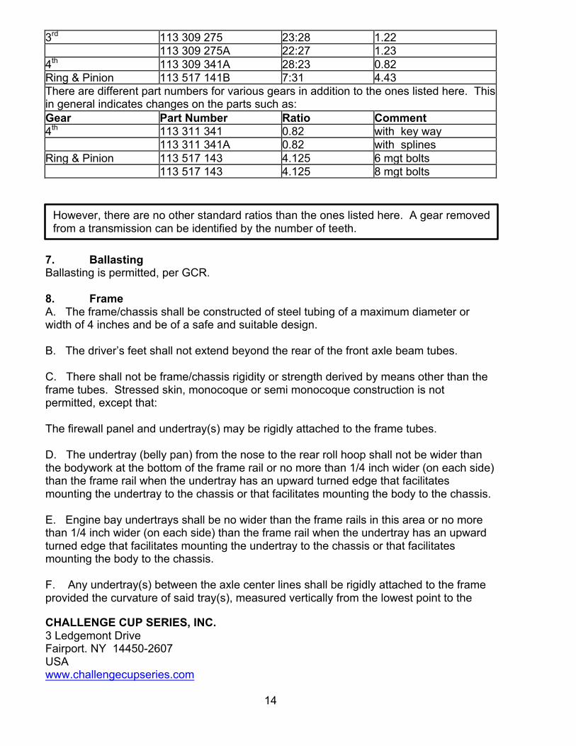
3rd 113 309 275 23:28 1.22 113 309 275A 22:27 1.23 4th 113 309 341A 28:23 0.82 Ring & Pinion 113 517 141B 7:31 4.43 There are different part numbers for various gears in addition to the ones listed here. This in general indicates changes on the parts such as: Gear Part Number Ratio Comment 4th 113 311 341 0.82 with key way 113 311 341A 0.82 with splines Ring & Pinion 113 517 143 4.125 6 mgt bolts 113 517 143 4.125 8 mgt bolts
7. Ballasting Ballasting is permitted, per GCR. 8. Frame A. The frame/chassis shall be constructed of steel tubing of a maximum diameter or width of 4 inches and be of a safe and suitable design. B. The driver’s feet shall not extend beyond the rear of the front axle beam tubes. C. There shall not be frame/chassis rigidity or strength derived by means other than the frame tubes. Stressed skin, monocoque or semi monocoque construction is not permitted, except that: The firewall panel and undertray(s) may be rigidly attached to the frame tubes. D. The undertray (belly pan) from the nose to the rear roll hoop shall not be wider than the bodywork at the bottom of the frame rail or no more than 1/4 inch wider (on each side) than the frame rail when the undertray has an upward turned edge that facilitates mounting the undertray to the chassis or that facilitates mounting the body to the chassis. E. Engine bay undertrays shall be no wider than the frame rails in this area or no more than 1/4 inch wider (on each side) than the frame rail when the undertray has an upward turned edge that facilitates mounting the undertray to the chassis or that facilitates mounting the body to the chassis. F. Any undertray(s) between the axle center lines shall be rigidly attached to the frame provided the curvature of said tray(s), measured vertically from the lowest point to the
However, there are no other standard ratios than the ones listed here. A gear removed from a transmission can be identified by the number of teeth.
CHALLENGE CUP SERIES, INC. 3 Ledgemont Drive Fairport. NY 14450-2607 USA www.challengecupseries.com
15
highest point at their attachments to the frame rail members at their sides, shall not exceed 1 inch and have no downward turned edges. G. Transmission undertrays or cars with a rear sub frame shall be no wider than the sub frame or no more than 1/4 inch wider (on each side) than the sub frame when the undertray has an upward turned edge that facilitates mounting the undertray to the sub frame or that facilitates mounting the body to the sub frame or 16 inches, whichever is wider. For cars without a sub frame, the tray shall be no wider than 16 inches and shall not deviate more than 1 inch from the horizontal plane. Undertray must be firmly attached and have no downward turned edges. H. The area between the upper and lower main frame tubes from the front instrument/dash roll hoop bulkhead to the rear roll hoop bulk- head shall be protected by at least one of the following methods to prevent the intrusion of objects into the cockpit. Panels may extend to the forward most bulkhead, but must otherwise comply with these regulations 1. Panel(s), minimum of either .060 inch heat treated aluminum (6061-T6 or equivalent) or 18 gauge steel, attached to the outside of the main frame tubes. 2. Reinforced body, consisting of at least two layers of 5 ounce, bi-directional, laminated Kevlar material incorporated into the body which shall be securely fastened to the frame. (5 or more Layers are highly recommended.) For either method, fasteners shall be no closer than 6 inch centers (no stress-bearing panels). The material used for the chassis braces in this area shall be at least equivalent to the roll hoop brace material. 3. Flat composite panels of uniform thickness and construction attached to the outside of the main frame tubes. Shaping of these panels to conform to the outer perimeter of the main frame tubes is permitted. Carbon fiber is permitted; however, it must be used in conjunction with another “anti-ballistic” type material (e.g., Kevlar, Zylon, etc). Such material shall be at least 1.5mm (.060 inches) in thickness not including the carbon fiber. Composite anti-intrusion panels shall be attached with no more than eight fasteners per side. Fasteners shall be AN or superior grade of not more than 0.25 inch diameter. Two flat or countersunk Mil Spec or SAE washers of no more than 1 inch diameter may be employed with each fastener. Ten fasteners per side are permitted if the panels extend to the front bulkhead. Alternatively, FIA mounting is permitted as follows: One panel shall be permitted per side. It shall be fastened to the frame at its extreme corners, the upper, lower, forward and rearward edge halfway between the corners,
CHALLENGE CUP SERIES, INC. 3 Ledgemont Drive Fairport. NY 14450-2607 USA www.challengecupseries.com
16
and halfway along each diagonal tube. The attachment should consist of an 8mm U-bolt and an aluminum plate 3mm thick, 20mm wide and 12mm longer than the U-bolt span. Composite panel mounting must comply with one or the other above prescribed methods. It may not be a combination of the two. 9. Body A. The chart (figure - Section C.12) illustrates both the intended minimum frontal area and car configuration. B. The rear bodywork shall enclose the engine by surrounding it from a point no higher than the lower edge of the intake manifold and extending from the front of the engine to its rear on each side. C. The rear bodywork must have the ability to enclose the original Volkswagen fan shroud mounted in its stock location (see illustrate- ton in Section C.12). D. The top of the rear bodywork shall extend from the back of the firewall to a point at least 16 inches to the rear of the centerline of the rear axle. E. Any bodywork forward of the center of the torsion bar tubes shall not extend outward beyond the centerline of the shock towers (maximum width of 31.75 inches or 80.645cm). F. No part of the frame or bodywork shall project beyond a plane connecting the vertical centerline of the front and rear tires. G. The driver’s seat shall be capable of being entered without the removal or manipulation of any part or panel, with the exception of the steering wheel and/or drivers head surround. The steering wheel and the surround must be removable by the driver and/ or safety workers without the use of any tools. Readily legible removal instructions for safety workers are recommended. Bead seats are recommended. H. Wings (airfoils) are prohibited. I. Floor and safety equipment shall conform to Section 9 of the GCR. J. A firewall to prevent passage of flame and debris between the engine area and driver’s compartment shall extend the full width of the cockpit and be at least equal to the top of the carburetor in vertical height. K. Air ducting may be attached to the carburetor and/or the engine. Brake ducts are not permitted.
CHALLENGE CUP SERIES, INC. 3 Ledgemont Drive Fairport. NY 14450-2607 USA www.challengecupseries.com
17
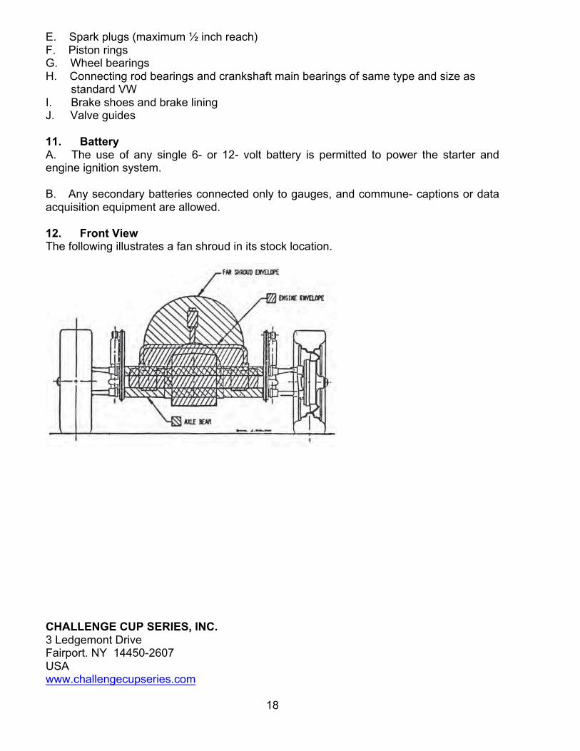
L. Forward facing air ducts may be installed for the purpose of deli- erring cooling air directly to the engine, cylinder heads, oil cooler, and/or carburetor. If these ducts are within the profile area defined in Section C.12, then the ducted air must make a 90 degree bend within the bodywork. M. Air duct openings may be located within the cockpit area, and/or penetrate the firewall, provided the duct is baffled or the firewall is extended to prevent flame and debris from reaching the driver. Any shape may be used to form firewall extension. Any other firewall inlet shall also prohibit passage of flame and debris. (Recommended: All of this extension be the same width as the firewall, allowing for bodywork contour limitations, and extend in a horizontal plane back 2 inches, minimum, past the carburetor body.) N. The bottom of any bodywork that extends below the frame members shall be on the same flat plane as the under tray (ref. C.8) and shall not deviate from that flat plane by more than 1 inch front to rear effective for any newly registered cars after January 1,1983. O. The space between the rear locating arm and axle tube up to the outer casting flange may be enclosed in bodywork for the purpose of streamlining. The enclosing bodywork may not extend above or below the triangular space nor beyond the axle tube or locating arm away from the triangular space so enclosed except that the panels may be wrapped tightly around the locating arm or axle tube as a method of location or attachment. The panels shall be securely attached. Brackets and fasteners used for attachment shall serve no aerodynamic purpose. P. The front suspension upright(s) (shock absorber mounts), shock absorbers, and/or trailing arms shall not be faired in by covering or shrouding away from the airstream except that the front shocks may be mounted behind the shock uprights. Q. Bodywork shall be defined as all panels external to the chassis/ frame and licked directly by the air stream. This includes the floor pan. All bodywork shall be securely attached to the chassis and shall not move relative to the chassis while the car is in operation, except where specifically allowed in the FV rules. For the purposes of this definition, the rigid portion of the front beam is considered part of the chassis/frame. 10. Non-Standard Parts The use of the following nonstandard replacement parts is permitted provided that no unauthorized modification of any other component results. A. Fasteners (nuts, bolts, screws, etc,) B. Wiring C. Gaskets and seals D. Brake lines and fuel line
CHALLENGE CUP SERIES, INC. 3 Ledgemont Drive Fairport. NY 14450-2607 USA www.challengecupseries.com
18
E. Spark plugs (maximum ½ inch reach) F. Piston rings G. Wheel bearings H. Connecting rod bearings and crankshaft main bearings of same type and size as standard VW I. Brake shoes and brake lining J. Valve guides 11. Battery A. The use of any single 6- or 12- volt battery is permitted to power the starter and engine ignition system. B. Any secondary batteries connected only to gauges, and commune- captions or data acquisition equipment are allowed. 12. Front View The following illustrates a fan shroud in its stock location.