Embed Size (px)
Citation preview

Accession No: 73600-73604
Invitation to Bid for 20150210- 10241825
SSO 700 OPERATIONAL IMPROVEMENTS PROJECT ID 10241825
- VOLUME TWO -
Project Schedule (unless amended):
Bid Documents Available: 02/10/2015
Deadline for Questions: 1:30 PM, Tuesday, February 24, 2015
Bid Open: 1:30 PM, 03/03/2015
SET No.: __________

c. >
INSTRUMENTATION & CONTROLS UPGRADES
SSO 700 Operational Improvements
Specifications
BlACK & VEATCH
ONONNATI, OHIO
PROJECT NO. 185998
PREPARED FOR
Metropolitan Sewer District of Greater Cincinnati, Ohio
10 DECEMBER 2014
10241825_100 DRP_Specifications, 1/354
DC RCVD 12/11/2014

10241825_100 DRP_Specifications, 2/354
DC RCVD 12/11/2014

THE METROPOLITAN SEWER DISTRICT OF GREATER CINCINNATI
TABLE OF CONTENTS
Section Number Description
MSDGC 00 01 10 - SSO 700 -1- B&V PN 185998 Instrumentation & Controls Upgrades 12/10/2014
1
00 01 01 Project Title Page 00 01 10 Table of Contents
Division 01 - General Requirements 01 11 00 Summary of Project 01 12 16 Construction Sequence 01 14 00 Control of Work 01 20 00 Measurement and Payment 01 26 00 Contract Considerations 01 31 19 Project Meetings 01 31 21 Site Safety Plan 01 32 16 Construction Progress Schedule 01 33 00 Submittals 01 33 19 Reference Forms 01 33 23 Installation and Erection Data 01 35 00 Special Provisions 01 42 19 Applicable Codes 01 45 29 Testing Laboratory Services 01 50 00 Temporary Facilities 01 60 00 Delivery, Storage and Handling 01 61 16 General Equipment Stipulations 01 61 23 Equipment and Valve Identification 01 66 00 Material and Equipment 01 71 23 Field Engineering 01 71 33 Restoration of Improvements 01 73 29 Cutting and Patching 01 74 00 Cleaning 01 77 00 Contract Closeout
10241825_100 DRP_Specifications, 3/354
DC RCVD 12/11/2014

THE METROPOLITAN SEWER DISTRICT OF GREATER CINCINNATI
TABLE OF CONTENTS
Section Number Description
MSDGC 00 01 10 - SSO 700 -2- B&V PN 185998 Instrumentation & Controls Upgrades 12/10/2014
2
01 77 19 Substantial Completion 01 78 23 Equipment Operating and Maintenance Manual
Information 01 78 36 Manufacturer Product Warranties 01 78 39 Record Documents 01 78 43 Spare Parts and Maintenance Materials 01 79 00 Training Division 03 - Concrete 03 30 53 Miscellaneous Cast-In-Place Concrete
Division 26 - Electrical 26 05 11 Electrical
26 05 11-F2 Cable Data 26 05 11-F4 Cable Data
Division 31 - Earthwork 31 23 33 Trenching and Backfilling 31 23 33-F1 Embedments for Conduits 31 23 33-F2 Protective System Design Certificate
Division 40 - Process Integration 40 05 31 Miscellaneous Plastic Pipe, Tubing,
and Accessories 40 05 56 Valve and Gate Actuators 40 05 63.33 Miscellaneous Ball Valves 40 61 13 Instrumentation and Control System 40 61 13 A Instrument Device Schedule 40 64 00 Programmable Logic Controller
10241825_100 DRP_Specifications, 4/354
DC RCVD 12/11/2014

THE METROPOLITAN SEWER DISTRICT OF GREATER CINCINNATI
TABLE OF CONTENTS
Section Number Description
MSDGC 00 01 10 - SSO 700 -3- B&V PN 185998 Instrumentation & Controls Upgrades 12/10/2014
3
Modifications 40 64 00 A I/O List 40 66 33 Network Cable 40 68 83 Software Control Block Descriptions 40 71 00 40 73 00
Flow Instruments Pressure and Level Instruments
40 95 11 Panels, Consoles, and Appurtenances 40 95 11-S01 Free Standing Panel Schedule
10241825_100 DRP_Specifications, 5/354
DC RCVD 12/11/2014

THIS PAGE LEFT BLANK INTENTIONALLY
10241825_100 DRP_Specifications, 6/354
DC RCVD 12/11/2014

MSDGC 01 11 00 SSO 700 -1- B&V PN 185998 Instrumentation & Controls Upgrades 12/10/14
SECTION 01 11 00 SUMMARY OF PROJECT PART 1 - GENERAL
1. SECTION INCLUDES -
A. Project – Work covered by all Contract Documents
B. Electrical (Electrical and Instrumentation & Controls)
C. Contract Milestones and other General Provisions
2. RELATED DOCUMENTS
A. Storage Tank Repairs, CH2M Hill, 2010
B. SSO 700 New Screen Installation, CH2M Hill, 2008
C. Sanitary Sewer Overflow 700 Storage and Treatment Facilities Sewer No. 5431 CIP No. 2002-07 Record Drawings 2007, BBS Corporation
D. Reports and Tests of Subsurface Conditions at or Contiguous to the Site – Refer to City-Contractor Agreement.
E. Reports and Drawings Related to Environmental Conditions at the Site – Refer to City-Contractor Agreement.
3. PROJECT – WORK COVERED BY ALL CONTRACT DOCUMENTS
A. Work of the Project includes construction of: Instrument and Control (I&C) system upgrades, including upgrades to a single SCADA I/O
network and complete elimination of the existing DeviceNet and three other networks. New valve and gate electric actuator control units, including installation of control units and
supports out of underground vaults for thirteen (13) existing valves. Electrical system improvements including new conduit, ductbanks, conduit supports,
excavation, backfill, concrete, structure penetrations and connections, and restoration to support I&C upgrades.
The Work shall be performed for the CITY in accordance with the Contract Documents. The Work includes, but is not limited to, demolition, removal, replacement, installation of new equipment and/or modifications to existing equipment at SSO 700 Storage & Treatment Facility
4. ELECTRICAL (ELECTRICAL AND INSTRUMENTATION & CONTROLS)
A. The work to be performed shall include all necessary demolition, the furnishing of all materials, equipment and tools; and performing all necessary labor and supervision, for the complete
10241825_100 DRP_Specifications, 7/354
DC RCVD 12/11/2014

MSDGC 01 11 00 SSO 700 -2- B&V PN 185998 Instrumentation & Controls Upgrades 12/10/14
construction of the Electrical and Instrumentation & Controls Work and all other work appurtenant thereto.
B. The major items of work to be performed include, but are not limited to:
1. Perform all work associated with:
a. Drawings
b. Division 1 – General Requirements
c. Division 3 – Concrete
d. Division 26 – Electrical
e. Division 31 – Earthwork
f. Division 40 – Process Integration
2. The CONTRACTOR shall furnish all cast in place anchors, sleeves, hangers, inserts, and accessories required for the proper installation of all wiring and equipment to be installed. The CONTRACTOR shall furnish all necessary setting drawings for such anchors, sleeves, hangers, inserts, and accessories, and shall be responsible for their proper location.
3. The CONTRACTOR shall provide all openings required in new and existing concrete, masonry, and roofing in connection with the Work to be performed. The CONTRACTOR shall furnish and install all concrete, masonry, and roofing patch work required around pipe sleeves, wall pipes, frames and other items installed in such openings. The CONTRACTOR shall install all embedded items in new concrete, masonry, and roofing applicable to the work.
4. Perform all electrical demolition work shown or referenced on the drawings or required by the specifications.
5. Perform all electrical demolition of control panels, instruments, wiring, conduit, lighting and electrical accessories for process equipment removed as shown on the drawings or required by the specifications.
6. Set in place, install, and wire all electrical and instrumentation systems and components, as required for, and in connection with the equipment furnished.
7. Furnish and install all caulking and grouting work required for and in connection with the Work to be performed.
8. Perform all patch and spot painting of damaged shop painted surfaces of materials and equipment installed.
9. Perform all tests, repairs, adjustments, etc., as required and as specified for Work.
10. Perform all cleanup work and remove from the Work and plant site all waste materials and
10241825_100 DRP_Specifications, 8/354
DC RCVD 12/11/2014

MSDGC 01 11 00 SSO 700 -3- B&V PN 185998 Instrumentation & Controls Upgrades 12/10/14
debris resulting from the Work performed.
11. The CONTRACTOR shall be responsible to receive, inspect, unload, store, secure, install, and wire all electrical and instrumentation equipment, components and accessories.
C. All Work shall be performed as stipulated in the Contract Specifications, and as indicated by and detailed on the Contract Drawings.
5. REFERENCE SPECIFICATIONS/GENERAL
A. To the extent the technical specifications in the Contract Documents reference the State of Ohio, Department of Transportation, Construction and Material Specifications (the "ODOT Specifications"), the Work shall be performed in accordance with the requirements of the applicable ODOT Specifications, unless the applicable ODOT Specifications are modified by the City of Cincinnati, Supplement to the State of Ohio, Department of Transportation, Construction and Material Specifications (the "City Supplement"). If the ODOT Specifications are modified by the City Supplement, the Work shall be performed in accordance with the City Supplement. Finally, to the extent that either the ODOT Specifications or the City Supplement is inconsistent with the Contract Documents, the Work shall be performed in accordance with the Contract Documents.
6. SEQUENCE OF WORK
A. The CONTRACTOR shall schedule the Work to conform to the general construction sequencing requirements described in Section 01 12 16.
7. CONTRACTOR’S USE OF SITE
A. The CONTRACTOR shall locate field offices, store materials and equipment and confine his construction activities to areas so indicated on the Drawings or as directed by the CITY. The CONTRACTOR shall also comply with all applicable Special Right-of-Way provisions in Section 01 14 00.
8. CONSTRUCTION PROCEDURE
A. It shall be the CONTRACTOR's responsibility during the construction of the Project to work equipment around poles, trees, or other obstructions which permit the passage of the bucket and boom but prevent passage of other portions of the equipment and, if necessary, to excavate from both sides of the poles, trees, or other obstruction, and to remove materials by hand labor, tunneling, or by other means, all at the CONTRACTOR’s own expense.
9. REQUESTS FOR SUPPLEMENTARY INFORMATION
A. It shall be the responsibility of the CONTRACTOR to make timely requests of the CITY for any additional information not already in the CONTRACTOR’s possession and which should be furnished by the CITY under the terms of the Contract Documents, and which will be required in the planning and execution of the work. Such requests may be submitted from time to time as the
10241825_100 DRP_Specifications, 9/354
DC RCVD 12/11/2014

MSDGC 01 11 00 SSO 700 -4- B&V PN 185998 Instrumentation & Controls Upgrades 12/10/14
need approaches, but each shall be filed in ample time to permit appropriate action to be taken by all parties involved so as to avoid delay.
B. Each request shall be in writing, and list the various items and the latest day by which each will be required by the CONTRACTOR. The first list shall be submitted within two (2) weeks after contract award and shall be as complete as possible at that time. The CONTRACTOR shall, if required, furnish promptly any assistance and information the OWNER may require in responding to these requests of the CONTRACTOR. The CONTRACTOR shall be fully responsible for any delay in work, or to the work of others, arising from failure to comply with the provisions of this section.
10. PERMITS
A. The CONTRACTOR shall be responsible to obtain and incur the cost of all required permits unless otherwise noted, including but not limited to Mechanical, Plumbing, Fire Protection, HVAC, Electrical, Groundwater Discharge, and any permit required for local governments.
B. The CONTRACTOR shall comply with provisions of all permits and make any necessary submittals as detailed in Section 01 14 00.
C. All CONTRACTORS and Subcontractors of any tier, shall comply with all applicable standards,
orders, regulations and permits, including but not limited to the Clean Water Act of 1970 (42 U.S.C. 1857, et seq.), the Federal Water Pollution Control Act (33 U.S.C. 1251, et seq.) as amended, Permits to Install, and NPDES 401 and 404 Permit requirements.
PART 2 - PRODUCTS
NOT USED PART 3 - EXECUTION
NOT USED END OF SECTION 01 11 00
10241825_100 DRP_Specifications, 10/354
DC RCVD 12/11/2014

MSDGC 01 12 16 SSO 700 -1- B&V PN 185998 Instrumentation & Controls Upgrades 12/10/2014
SECTION 01 12 16 CONSTRUCTION SEQUENCE PART 1 - GENERAL
1.01 SECTION INCLUDES
A. Site Conditions.
B. Construction Constraints.
C. Suggested Construction Sequence.
1.02 RELATED SECTIONS
A. Construction Progress Schedule Section 01 32 16
B. Special Provisions Section 01 35 00
C. Temporary Facilities Section 01 50 00
D. Drawings and general provisions of the contract, including General Conditions, Special Provisions, and other Division 1 Specification Sections, apply to this Section.
1.03 SITE CONDITIONS
A. CONTRACTOR shall coordinate with the Plant Operating Personnel, as designated by the CITY, to accomplish a logical order to maintain the process flow through the plant and to allow construction to be completed within the time allowed by Contract Documents. Coordinate the activities with the other contractors, if any, to allow orderly and timely completion of all the Work.
B. When access through construction areas must be disrupted, CONTRACTOR shall provide alternate acceptable access for the plant operators or other contractors.
C. CONTRACTOR shall coordinate all activities in the interface or common areas with other contractors and the plant operators. Submit to the CITY a description and schedule as to how the common areas will be utilized, recognizing the required coordination with other contractors and the plant operators.
D. If a partial power shutdown is required, make every effort necessary to minimize the shutdown time and coordinate with the plant operating personnel and/or utility authorities prior to attempting any such power shutdown. Furthermore, provide any corrective measure or temporary facilities
10241825_100 DRP_Specifications, 11/354
DC RCVD 12/11/2014

MSDGC 01 12 16 SSO 700 -2- B&V PN 185998 Instrumentation & Controls Upgrades 12/10/2014
necessary to perform the work at no additional cost to the CITY and without interrupting the plant operation.
E. When the Work requires an existing facility to be taken out of operation, temporarily or permanently, notify the CITY in writing and plant operators at least one (1) week in advance.
F. The CONTRACTOR may be allowed to use, if available, non-potable plant water after express approval from the CITY at no charge. The CITY reserves the right to restrict access or charge for plant water service if CONTRACTOR abuses his right of use, including water wastage or excessive use.
1.04 CONSTRUCTION CONSTRAINTS
A. The following is a list of constraints to consider in developing the overall plan of construction. This list is not intended to release the CONTRACTOR from the responsibility to coordinate the Work in any manner which will ensure Project completion within the time allowed.
1. Load and size restrictions exist on the normal access to the facility from Cavett Drive. CONTRACTOR shall consider these restrictions and obtain alternative site access as required to support the construction activities. Refer to drawings for normal access restrictions.
2. Ongoing remediation work at the adjacent Pristine Superfund site shall not be impacted by CONTRACTOR.
3. Existing monitoring wells on the site shall not be impacted by CONTRACTOR.
4. Work shall not be performed within the floodway, including staging of equipment and materials.
1.05 SUGGESTED CONSTRUCTION SEQUENCE
A. Before starting any work, the CONTRACTOR shall attend a Pre-Construction Meeting with the CITY, as detailed in Section 01 31 19. The CONTRACTOR will be notified of the date and the time of the meeting, and shall submit a construction schedule meeting the requirements of 01 32 16.
B. The following areas are not necessarily listed in their required sequence of construction. A suggested sequence within each area, where necessary, is included. This sequence is not intended to release the CONTRACTOR from the responsibility to coordinate the Work in any manner which will ensure Project completion within the time allowed or as shown on the Project Documents. The CONTRACTOR is ultimately responsible for the sequence and execution of Work.
1. Verify field conditions and determine if any adjustments are needed to the design.
2. If adjustments are needed, submit to CITY in writing.
3. Incorporate I&C and electrical improvements.
4. Perform all necessary restoration.
10241825_100 DRP_Specifications, 12/354
DC RCVD 12/11/2014

MSDGC 01 12 16 SSO 700 -3- B&V PN 185998 Instrumentation & Controls Upgrades 12/10/2014
5. Complete commissioning activities.
6. Perform all site cleanup.
PART 2 - PRODUCTS NOT USED PART 3 - EXECUTION NOT USED
END OF SECTION 01 12 16
10241825_100 DRP_Specifications, 13/354
DC RCVD 12/11/2014

THIS PAGE LEFT BLANK INTENTIONALLY
10241825_100 DRP_Specifications, 14/354
DC RCVD 12/11/2014

MSDGC 01 14 00 SSO 700 -1- B&V PN 185998 Instrumentation & Controls Upgrades 12/10/2014
SECTION 01 14 00
CONTROL OF WORK PART 1 - GENERAL
1.01 SECTION INCLUDES
A. Scope.
B. Use of Premises.
C. Right-of-Way.
D. Construction Layout.
E. Protection of Trees.
F. Open Excavations.
G. Care and Protection of Property.
H. Protection and Relocation of Existing Structures and Utilities.
I. Water for Construction Purposes.
J. Dust Control.
K. Pollution Control.
L. Maintenance of Flow.
M. Cooperation within this Contract.
N. Cleanup and Disposal of Excess Material.
O. Noise Control
1.02 NOT USED.
1.03 SCOPE
A. The CONTRACTOR shall furnish plant facilities and equipment which will be efficient, appropriate and large enough to secure a satisfactory quality of work and a rate of progress which will ensure the completion of the work within the Time for Completion required by the Contract
10241825_100 DRP_Specifications, 15/354
DC RCVD 12/11/2014

MSDGC 01 14 00 SSO 700 -2- B&V PN 185998 Instrumentation & Controls Upgrades 12/10/2014
Documents. If at any time such plant facilities and equipment appears to be inefficient, inappropriate or insufficient for securing the quality of work required or for producing the rate of progress aforesaid, the CITY may order the CONTRACTOR to increase the efficiency, change the character or increase the plant facilities equipment and the CONTRACTOR shall conform to such order at no cost to the CITY. Failure of the CITY to give such order shall in no way relieve the CONTRACTOR of his obligations to secure the quality of the work and rate of progress required by the Contract Documents.
1.04 USE OF PREMISES
A. The CONTRACTOR shall not trespass upon or in any way disturb property outside the street right-of-way, or outside the limits of construction, without first obtaining written permission from the property owner to do so. A copy of such written permission shall be furnished to the CITY.
1.05 NOT USED
1.06 RIGHT-OF-WAY
A. All permanent and temporary Right-of-Way has been acquired for this Project. Copies of signed easement drawings and agreements are on file at the Department of Sewers, 1600 Gest Street, Cincinnati, OH 45204.
1.07 NOT USED
1.08 NOT USED
1.09 NOT USED
1.10 NOT USED
1.11 NOT USED
1.12 PROTECTION OF TREES
A. The CONTRACTOR shall take precautions to avoid any unnecessary damage to trees. Branches which overhang the construction limits and which interfere with the operation of equipment shall be tied back to avoid damage, if possible. Where injury to branches is unavoidable, the branches shall be sawed off neatly at the trunk or main branch and the cut area shall be painted with approved tree paint immediately. Any trees damaged beyond saving shall be removed by the CONTRACTOR at no additional cost to the CITY, and in the case of trees located on private property, the CONTRACTOR shall make restitution to the property owner.
B. The CONTRACTOR shall take extra measures to protect trees designated to be preserved, such as erecting barricades, trimming to prevent damage from construction equipment, and installing pipe and other Work by means of hand excavation or tunneling methods. Such trees shall not be endangered by stockpiling excavated material or storing equipment against their trunks.
10241825_100 DRP_Specifications, 16/354
DC RCVD 12/11/2014

MSDGC 01 14 00 SSO 700 -3- B&V PN 185998 Instrumentation & Controls Upgrades 12/10/2014
C. Two days prior to cleaing and grubbing, the construction limits shall be marked and the CONTRACTOR shall walk the project with the CITY personnel to locate trees to be saved and trees to be removed.
1. If any digging is done within a distance of seven times the tree diameter, that tree (including stump) will need to be removed by a certified arborist. If the CONTRACTOR needs a tree removed, the CONTRACTOR shall give the CITY at least 3 working days notice so that the CITY can contact Davey Tree Expert Company at (513) 575-1733 and schedule the tree and stump removal. Tree and stump removal is paid directly to Davey Tree Expert Company by the CITY and will not be measured for payment to the CONTRACTOR. Any delays caused by the failure of the CONTRACTOR to meet these requirements are considered incidental to the contract and will not be measured for payment or a reason to extend construction time.
1.13 OPEN EXCAVATIONS
A. The CONTRACTOR shall adequately safeguard all open excavations by providing temporary barricades, caution signs, lights and other means to prevent accidents to persons and damage to property. Provide suitable and safe bridges and other crossings for accommodating travel by pedestrians and workmen. Remove bridges provided for access during construction when no longer required. The length or size of excavation will be controlled by the particular surrounding conditions, but shall always be confined to the limits prescribed by the CITY or the authority having jurisdiction of any rights-of-way being occupied by the construction. If the excavation becomes a hazard, or if it excessively restricts traffic at any point, the CITY may require special construction procedures such as limiting the length of the open trench, prohibiting stacking excavated material in the street and requiring that the trench shall not remain open overnight.
B. The CONTRACTOR shall take precautions to prevent injury to the public due to open trenches. Provide adequate light at all trenches, excavated material, equipment, or other obstacles which could be dangerous to the public at night.
1.14 NOT USED
1.15 CARE AND PROTECTION OF PROPERTY
A. The CONTRACTOR will be responsible for the preservation of all public and private property and use every precaution necessary to prevent damage thereto. If any direct or indirect damage is done to public or private property by or on account of any act, omission, neglect, or misconduct in the execution of the work on the part of the CONTRACTOR, restore such property to a condition similar or equal to that existing before the damage was done, or make good on the damage in other manners acceptable to the CITY.
B. Where CONTRACTOR contemplates removal of small structures such as mailboxes, signposts, fencing, guardrails, and culverts that interfere with CONTRACTOR’s operations, the CONTRACTOR shall obtain approval of property owner and the CITY. Move mailboxes to temporary locations accessible to postal service. Replace items removed in their original location and a condition equal to or better than original. This shall be considered as part of the sewer installation and replacement shall be done immediately after the installation and backfiling of the sewer. The costs for the removal, relocation, and replacement shall be included with the price bid
10241825_100 DRP_Specifications, 17/354
DC RCVD 12/11/2014

MSDGC 01 14 00 SSO 700 -4- B&V PN 185998 Instrumentation & Controls Upgrades 12/10/2014
for various contract items.
1.16 PROTECTION AND RELOCATION OF EXISTING STRUCTURES AND UTILITIES
A. The CONTRACTOR shall assume full responsibility for the protection of all buildings, structures, and utilities, public or private, including poles, signs, services to buildings, utilities, gas pipes, water pipes, hydrants, sewers, drains and electric and telephone cables, whether or not they are shown on the Drawings. Carefully support and protect all such structures and utilities from injury of any kind. Immediately repair any damage resulting from the construction operations, at no additional cost to the CITY. The CONTRACTOR shall assume that there is at least one water, gas, underground electric, telephone, etc., branch serving each building.
B. Assistance will be given the CONTRACTOR in determining the location of existing services. The CONTRACTOR, however, shall bear full responsibility for obtaining all locations of underground structures and utilities (including existing water services, drain lines and sewers). Maintain services to buildings and pay costs or charges resulting from damage thereto.
C. The CONTRACTOR shall notify all utility companies in writing at least forty-eight (48) hours (excluding Saturdays, Sundays and Legal holidays) before excavating in any public way. Also notify the Ohio Utilities Protection Service at least forty-eight (48) hours prior to start of work.
D. If, in the opinion of the CITY, permanent relocation of a utility owned by the CITY is required, the CITY may direct the CONTRACTOR, in accordance with Article 10 of the General Conditions, to perform the Work. Work so ordered will be paid for at the Contract unit prices, if applicable, or as extra work under Article 11 of the General Conditions. If relocation of a privately owned utility is required, the CITY will notify the Utility to perform the work as expeditiously as possible. The CONTRACTOR shall fully cooperate with the CITY and other utilities. No claim for delay will be allowed due to such relocation.
1.17 WATER FOR CONSTRUCTION PURPOSES
A. The CONTRACTOR may be allowed to use, if available, non-potable plant water after express approval from the CITY at no charge. The CITY reserves the right to restrict access or charge for plant water service if CONTRACTOR abuses his right of use, including water wastage or excessive use.
B. Waste of water shall be sufficient cause for withdrawing the privilege of use. Hydrants shall only be operated with proper approval from the CITY and water utility. It is the CONTRACTOR’s responsibility to obtain approval from the water utility and comply with all requirements provided by the water utility.
1.18 DUST CONTROL
A. CONTRACTOR shall take reasonable measures to prevent unnecessary dust. Earth surfaces subject to dusting shall be kept moist with water or by application of a chemical dust suppressant. When practical, dusty materials in piles or in transit shall be covered to prevent blowing dust.
B. Buildings or operating facilities which may be affected adversely by dust shall be adequately
10241825_100 DRP_Specifications, 18/354
DC RCVD 12/11/2014

MSDGC 01 14 00 SSO 700 -5- B&V PN 185998 Instrumentation & Controls Upgrades 12/10/2014
protected from dust. Existing or new machinery, motors, instrument panels, or similar equipment shall be protected by suitable dust screens. Proper ventilation shall be included with dust screens.
1.19 POLLUTION CONTROL
A. CONTRACTOR shall prevent the pollution of drains and watercourses by sanitary wastes, sediment, debris, and other substances resulting from construction activities. No sanitary wastes shall be permitted to enter any drain or watercourse other than sanitary sewers. No sediment, debris, or other substance shall be permitted to enter sanitary sewers, and reasonable measures shall be taken to prevent such materials from entering any drain or watercourse.
1.20 MAINTENANCE OF FLOW
A. The existing 42-inch diameter interceptor sewer upstream and downstream of the facility is routed through the facility’s diversion chamber. The CONTRACTOR shall maintain sewage flow within these existing interceptor sewers at all times during construction. The existing 42 inch diameter sewer conveys dry weather flow during dry weather periods and dry and wet weather flows during and after rain events.
B. Dry weather flow shall be maintained from the existing 42 inch diameter sewer to the existing 42 inch diameter sewer at all times. A minimum of 7,000 gallons per minute (15.6 cubic feet per second) peak dry weather flow shall be maintained.
C. The cost of this work shall be included in the unit price bid for the various contract items.
1.21 COOPERATION WITHIN THIS CONTRACT
A. All firms or persons authorized to perform any work under the Contract Documents shall cooperate with CONTRACTORS and Subcontractors or trades and assist in incorporating the work of other trades where necessary or required.
B. Cutting and patching, drilling and fitting shall be carried out where required by the trade or
subcontractor having jurisdiction, unless otherwise indicated herein or directed by the CITY.
1.22 CLEANUP AND DISPOSAL OF EXCESS MATERIAL
A. During the course of the Work, the CONTRACTOR shall keep the site of operations as clean and neat as possible. Dispose of all residues resulting from the construction Work and, at the conclusion of the Work, remove and haul away any surplus broken pavement, equipment, temporary structures and any other refuse remaining from the construction operations and leave the entire site of the work in a neat and orderly condition. Material cleanup and disposal shall be in accordance with the Soils Management Plan.
B. In order to prevent environmental pollution arising from the construction activities related to the
performance of the Work under the Contract Documents, the CONTRACTOR and Subcontractors shall comply with all applicable Federal, State and local laws and regulations concerning waste
10241825_100 DRP_Specifications, 19/354
DC RCVD 12/11/2014

MSDGC 01 14 00 SSO 700 -6- B&V PN 185998 Instrumentation & Controls Upgrades 12/10/2014
material disposal, as well as the specific requirements stated in this Section and in other related Sections.
C. Disposal of excess excavated material in wetlands, stream corridors and plains is strictly prohibited
even if the permission of the property owner is obtained. Any violation of this restriction by the CONTRACTOR or any person employed by him will be brought to the immediate attention of the responsible regulatory agencies, with a request that appropriate action be taken against the offending parties. The CONTRACTOR will be required to remove the fill and restore the area impacted at no increase in the Contract Sum.
D. The CITY reserves the right to instruct specific cleanup, relocation of equipment, or disposal of
material at any time.
1.23 NOISE CONTROL
A. CONTRACTOR shall take reasonable measures to prevent unnecessary noise. Such measures shall be appropriate for the normal ambient sound levels in the area during working hours. All construction machinery and vehicles shall be equipped with practical sound-muffling devices, and operated in a manner to cause the least noise consistent with efficient performance of the Work.
B. CONTRACTOR shall provide acoustical barriers effective in reducing noise so noise emanating from tools or equipment will not exceed legal noise levels.
C. During construction activities on or adjacent to occupied buildings, and when appropriate, CONTRACTOR shall erect screens or barriers effective in reducing noise in the building and shall conduct operations to avoid unnecessary noise which might interfere with the activities of building occupants.
1.24 NOT USED.
1.25 NOT USED.
1.26 NOT USED. PART 2 – PRODUCTS NOT USED PART 3 – EXECUTION NOT USED END OF SECTION 011400
10241825_100 DRP_Specifications, 20/354
DC RCVD 12/11/2014

MSDGC 01 20 00 SSO 700 -1- B&V PN 185998 Instrumentation & Controls Upgrades 12/10/14
SECTION 01 20 00 MEASUREMENT AND PAYMENT PART 1 - GENERAL
1.01 SECTION INCLUDES
A. Scope.
B. Bid Items by Reference Number (Ref. No.) and item description.
C. Final Payment Considerations
1.02 RELATED DOCUMENTS
A. Drawings and general provisions of the Contract, including Division 1 Specification Sections, apply to this Section.
B. Retainage to be held is in Section 00 52 01 “City-Contractor Agreement”.
1.03 SCOPE
A. CONTRACTOR shall furnish all labor, materials, tools, equipment, appurtenances and services, including operation and maintenance manuals and training and start-up services necessary to perform all work required, at the lump sum or unit prices for the items listed herein and such lump sum and unit prices shall represent full compensation for such work.
B. The bid items listed herein constitute all of the Items under which payment will be made. No direct or separate payment will be made for providing miscellaneous temporary or accessory works, plant services, sanitary requirements, testing safety devices, approval and record drawings, water supplies, power, removal of waste, watchmen, bonds (except Performance Bond), insurance, project coordination and all other requirements of the Contract Documents. Compensation for all such services and materials shall be included in the prices stipulated for the lump sum and unit price Items listed herein.
C. Furthermore, all work shown on the Drawings shall be a part of the Documents whether specifically noted elsewhere in Contract Documents or not.
10241825_100 DRP_Specifications, 21/354
DC RCVD 12/11/2014

MSDGC 01 20 00 SSO 700 -2- B&V PN 185998 Instrumentation & Controls Upgrades 12/10/14
D. The CITY will determine the actual quantities and classifications of Unit Price Work performed by CONTRACTOR. The CITY will review with CONTRACTOR the CITY’s preliminary determina-tions on such matters before rendering a written decision thereon (by recommendation of an Application for Payment or otherwise). The CITY’s written decision thereon will be final and binding (except as modified by the CITY to reflect changed factual conditions or more accurate data) upon the CITY and CONTRACTOR, subject to the provisions of Article 10, Paragraph 10.05 Changes In The Work; Claims of Section 00 72 00 General Conditions.
1.04 PARTIAL PAYMENTS – Not used.
1.05 BID ITEMS BY REFERENCE NUMBER (REF. NO.) AND ITEM DESCRIPTION
A. Spec (Ref No. E1) – Electrical Work: This item includes the completion of all Work required as shown on the Drawings and in accordance with all Sections under all Divisions. Payment will be made based on the lump sum price Bid.
B. Spec (Ref. No. E2) – Actuator Motor Replacement Allowance: The CONTRACTOR shall include an allowance of $10,000 in their Bid for replacement of existing valve and gate actuator motors with new motors in the instance that the existing motors are found to be damaged or unsuitable for continued use as determined by CITY staff. The allowance amount includes furnishing of all associated labor and materials and any overhead or profit for the CONTRACTOR and any subcontractors involved, in conformance with that specified in the General Conditions. Material costs including shipping and handling to job site and escalation to construction in 2015 as provided by Rawdon Myers, Inc. are itemized below:
Qty Item Number Description Unit Price Compatible Actuator
1 Z006.460 MOTOR VD90-2/40 .75KW 460V 60HZ $1,450.00 SA 10.1-108B 1 Z006.413 MOTOR VD63-4/45 .09KW 460V 60HZ $785.00 SA 14.1-26A 1 Z006.457 MOTOR AD63-2/80 .75KW 460V 60HZ $975.00 SA 07.5-13B 1 Z006.434 MOTOR AD63-4/80 .37KW 460V 60HZ $775.00 SA 07.5-108B 1 Z006.457 MOTOR AD63-2/80 .75KW 460V 60HZ $975.00 SA 07.5-54B 1 Z006.466 MOTOR AD71-2/80 1.5KW 460V 60HZ $1,115.00 SA 07.5-216B
C. Spec (Ref. No. E3) – Performance Bond: The CONTRACTOR shall include the cost of his/her Performance Bond in the Bid. The cost entered in the Bid should not exceed one percent of the official total bid price. This item shall be included for payment on the first partial estimate. In the event the cost entered in the Bid exceeds one percent, all costs over the one percent will be paid with the Final Payment.
1.06 FINAL PAYMENT
A. Comply with the requirements for Final Payment contained in the Contract Documents, including Article 14.07 of Section 00 72 00 General Conditions and Section 01 77 00 Contract Closeout.
B. Before final payment is made to the Contractor, the Contractor shall submit to the CITY a release, in writing, from all the property owners whose property has been used by the Contractor outside
10241825_100 DRP_Specifications, 22/354
DC RCVD 12/11/2014

MSDGC 01 20 00 SSO 700 -3- B&V PN 185998 Instrumentation & Controls Upgrades 12/10/14
the limits of construction and/or Right-of-Way. PART 2 - PRODUCTS
NOT USED PART 3 – EXECUTION
A. Comply with the requirements for Final Payment contained in Article 14.07 of the Modified Standard General Conditions.
END OF SECTION 01 20 00
10241825_100 DRP_Specifications, 23/354
DC RCVD 12/11/2014

THIS PAGE LEFT BLANK INTENTIONALLY
10241825_100 DRP_Specifications, 24/354
DC RCVD 12/11/2014

MSDGC 01 26 00 SSO 700 -1- B&V PN 185998 Instrumentation & Controls Upgrades 12/10/14
SECTION 01 26 00
CONTRACT CONSIDERATIONS PART 1 - GENERAL
1.01 SECTION INCLUDES
A. Schedule of Values.
B. Application for Payment.
C. Contract Modification Procedures.
D. Change Order Procedures.
1.02 RELATED SECTIONS
A. Submittals Section 01 33 00.
B. Drawings and general provisions of the contract, including General Conditions, Special Provisions, and other Division 1 Specification Sections, apply to this Section.
1.03 SCHEDULE OF VALUES
A. SCOPE : The Schedule of Values is an itemized list that established the value or cost of each Pay Item that is part of the Work. The Schedule of Values shall be used as the basis for preparing Application for Payments and may be used as a basis of negotiations concerning additional work or credits which may arise during the construction. Quantities and unit prices shall be included in the schedule when approved by or required by the CITY.
B. PREPARATION: The Schedule of Values shall correspond to a WBS rollup from the approved cost loaded schedule. The Schedule of Values shall include the following:
1. Show breakdown of labor, materials equipment and other costs used by CONTRACTOR in preparation of the Bid for the Project.
2. Prepare Schedule of Values on 8-1/2" by 11" format.
3. Upon request by the CITY, CONTRACTOR shall provide data that will substantiate the amounts in the Schedule of Values.
4. The sum of the individual values shown on the Schedule of Values must equal the individual Pay Item included in the CONTRACTOR's Bid.
5. The manner in which overhead and profit are shown shall be approved by the CITY.
6. The Schedule of Values shall show the purchase costs for materials and
10241825_100 DRP_Specifications, 25/354
DC RCVD 12/11/2014

MSDGC 01 26 00 SSO 700 -2- B&V PN 185998 Instrumentation & Controls Upgrades 12/10/14
equipment to be stored on site prior to installation that the CONTRACTOR anticipates he shall request payment for prior to their installation.
C. SUBMISSION
1. Submit six (6) copies of Schedule of Values to CITY for review at the Preconstruction Conference and before work commences on the Project. After review by the CITY, revise and resubmit Schedule of Values as required until it is accepted.
1.04 APPLICATIONS FOR PAYMENT
A. CONTRACTOR shall submit Applications for Payment in accordance with the Contract Documents, including this Section and Paragraph 14.02 of the General Conditions.
B. CONTRACTOR shall submit two (2) copies of each Application for Payment on CITY’s “Application and Certificate for Payment Summary Sheet” and “Continuation Sheet”; CONTRACTOR’s electronic media printout containing similar information will be considered as a substitute for CITY’s “Continuation Sheet.
C. A current updated version of the CONTRACTOR’s Construction Schedule shall accompany each Application for Payment in accordance with specification section 01 32 16.
D. Use approved Schedule of Values including a list of approved Change Orders with each Application for Payment.
E. Payment Period: In accordance with the requirements in Paragraph 14.02 of the General Conditions.
Include CITY’s “Stored Materials and Equipment” form when requesting payment for stored materials and equipment not yet incorporated into the Work. Five percent (5%) of the equipment value will be withheld until an acceptable temporarily bound copy of the O&M manual has been received, (see Section 01 33 00 Submittals).
1.05 CONTRACT INFORMATION / NOTIFICATION PROCEDURES
A. Request for Information (RFI): CONTRACTOR shall use CITY’s RFI form, included with the Contract Documents in Specification Section 01 33 09, to request information, interpretations, clarifications, and changes in the Work. CONTRACTOR shall number RFI’s consecutively and add a consecutive letter to RFI number on modified submittals of the same item (i.e., RFI-4A); CITY will respond on the same form in ten (10) calendar days.
B. Field Order: CITY will advise of minor changes in the Work not involving an adjustment to Contract Sum or Contract Times with a Field Order as provided in Article 9 of the General Conditions. CONTRACTOR shall use CITY's Field Order Form included in Specification Section 01 33 19.
10241825_100 DRP_Specifications, 26/354
DC RCVD 12/11/2014

MSDGC 01 26 00 SSO 700 -3- B&V PN 185998 Instrumentation & Controls Upgrades 12/10/14
C. Request for Proposal (RFP): CITY may request a written proposal from CONTRACTOR for changes in the Work. The CITY will issue an RFP describing the scope of the proposed change(s) and provide any back-up documentation required. The CONTRACTOR will respond to the RFP with twenty-one (21) calendar days of the date the RFP was issued by the CITY with a detailed cost and schedule impact associated with the proposed change(s) in accordance with Articles 10, 11 and 12 of the General Conditions. The CITY may use the Request for Proposal Form included in Specification Section 01 33 19.
1.06 CHANGE ORDER PROCEDURES
A. DEFINITIONS
1. Work Directive Change (WDC): When it is necessary that changes in the Work proceed before the change in Contract Price and Contract Times can be agreed upon, CITY will issue a WDC which will authorize and direct CONTRACTOR to proceed with the Work in accordance with Article 10 of the General Conditions. When changes in Contract Price and Contract Times are to be based upon the cost of the Work, maintain and submit cost records in accordance with Article 11 of the General Conditions.
2. Change Order (CO): The CITY will issue CO’s as needed which will authorize and direct CONTRACTOR to proceed with approved and negotiated changes in the Work. Proceed with such Work in accordance with Article 10 of the General Conditions. Proposed Changes for which a WDC has been issued will be included in a Change Order after the Contract Price and Contract Times have been determined.
B. PRELIMINARY PROCEDURES
1. The CITY may initiate changes by submitting a Request for Proposal (RFP) to CONTRACTOR. The RFP will include:
a. Detailed description of the change, Products and location of the change in the Project.
2. Supplementary or revised Drawings and Specifications.
3. The projected time span for making the change and a specific statement as to whether overtime work is, or is not, authorized.
4. A specific period of time during which the requested price will be considered valid.
5. Such request is for information only and is not an instruction to execute the changes, nor to stop work in progress.
6. CONTRACTOR may request a change by submitting a written request to the CITY, containing:
a. Description of the proposed change(s).
b. Statement of the reason for requesting the change(s).
c. Statement of the effect on the Contract Sum and the Contract Time.
10241825_100 DRP_Specifications, 27/354
DC RCVD 12/11/2014

MSDGC 01 26 00 SSO 700 -4- B&V PN 185998 Instrumentation & Controls Upgrades 12/10/14
d. Statement of the effect on the Work of separate contractors.
e. Documentation supporting any change in Contract Sum or Contract Time, as appropriate.
7. Nothing in this section relieves the CONTRACTOR from its obligations under the claims procedure in the Contract Documents, including, but not limited to Paragraph 10.05 of the General Conditions.
C. WORK DIRECTIVE CHANGE AUTHORIZATION
1. Work Directive Change (WDC): When it is necessary that work representing a potential change in the Contract proceed before the terms of a Change Order can be agreed upon, the CITY may issue a WDC. A WDC will not change the Contract Sum or Contract Time, but is evidence that the parties expect that the change ordered or documented by the WDC will be incorporated in a subsequently issued Change Order following negotiations by the parties as to its effect, if any, on the Contract Sum or Contract Times.
2. The Work Directive Change will describe changes in the Work, both additions and deletions, with attachments of revised Contract Documents to define details of the change and will designate the method of determining any change in the Contract Sum and any change in Contract Time. Work Directive Changes will be issued on the Work Directive Change Form included in Specification Section 01 33 19.
3. The CITY will sign and date the Work Directive Change as authorization for the CONTRACTOR to proceed with the changes.
4. CONTRACTOR shall sign and date the Work Directive Change to indicate agreement with the terms therein.
D. DOCUMENTATION OF RESPONSES TO REQUEST FOR PROPOSALS AND CLAIMS
1. The requirements of this section are in addition to the other requirements in the Contract Documents, including, but not limited to the requirements of Article 10 of General Conditions and the Statement of Claim Form in Specification Section 00 63 64.
2. Support each lump-sum proposal and each unit price proposal, which has not previously been established, with sufficient substantiating data to allow the CITY to evaluate the quotation.
3. On request by the CITY, CONTRACTOR shall provide additional data to support time and cost computations, including, but not limited to the following:
a. Labor required.
b. Equipment required.
c. Products required.
10241825_100 DRP_Specifications, 28/354
DC RCVD 12/11/2014

MSDGC 01 26 00 SSO 700 -5- B&V PN 185998 Instrumentation & Controls Upgrades 12/10/14
1) Recommended source of purchase and unit cost.
2) Quantities required.
d. Taxes, insurance and bonds.
e. Credit for work deleted from Contract, similarly documented.
f. Overhead and profit.
g. Justification for any change in Contract Time should be based upon results of a Time Impact Analysis (TIA) as defined in Section 01 32 16, Construction Progress Schedule.
4. Support each claim for additional costs and or additional time, with documentation as required for a lump-sum proposal, plus additional information.
a. Name of the CITY’s authorized representative who authorized the work and date of the authorization.
b. Dates and times work was performed and by whom.
c. Time record, summary of hours worked and hourly rates paid.
d. Receipts and invoices for:
1) Equipment used, listing dates and times of use.
2) Products used, listing of quantities.
3) Subcontracts.
PART 2 - PRODUCTS NOT USED PART 3 - EXECUTION NOT USED
END OF SECTION 01 26 00
10241825_100 DRP_Specifications, 29/354
DC RCVD 12/11/2014

THIS PAGE LEFT BLANK INTENTIONALLY
10241825_100 DRP_Specifications, 30/354
DC RCVD 12/11/2014

MSDGC 01 31 19 SSO 700 -1- B&V PN 185998 Instrumentation & Controls Upgrades 12/10/14
SECTION 01 31 19
PROJECT MEETINGS PART 1 - GENERAL
1.01 SECTION INCLUDES
A. Pre-Construction Meeting.
B. Progress Meetings.
C. Cut In Meetings.
1.02 RELATED SECTIONS
A. Submittals are included in Section 01 33 00.
B. Drawings and general provisions of the contract, including General Conditions, Special Provisions, and other Division 1 Specification Sections, apply to this Section.
1.03 PRE-CONSTRUCTION MEETING
A. A pre-construction meeting will be scheduled by the CITY after award of the Contract.
B. The standard agenda for the meeting includes the following items:
1. Introduction of responsible personnel and contact information
a. Construction Manager
b. Construction Inspector
c. Contractor Superintendent
2. Contract Compliance
a. Signed contracts
b. Equal Employment Opportunity (EEO)
c. Subcontractors
d. Prevailing Wage Rates
e. Assignment of Contract (if applicable)
f. Insurance
g. Pay estimates
10241825_100 DRP_Specifications, 31/354
DC RCVD 12/11/2014

MSDGC 01 31 19 SSO 700 -2- B&V PN 185998 Instrumentation & Controls Upgrades 12/10/14
3. Safety Plan per section 01 31 21 “Site Safety Plan”– Contractor to submit three (3) days prior to the Preconstruction Meeting
4. Document Control
a. Processing of Requests for Information (RFI) (this process will be unique to each project), Work Directive Change (WDC), and Change Order Requests (COR)
b. Processing of Submittals (this process will be unique to each project)
5. Contractor’s Performance Rating
6. Contract Documents
7. Construction Schedule – Contractor to submit at the Preconstruction Meeting per section 01 32 16 “Construction Progress Schedule”
8. Notice to Proceed (NTP) date determination
9. Home Owner / Business Notification
10. Schedule of Values – In accordance with Paragraph 2.05(A)(3) of the General Conditions
11. Coordination with local entities
12. Coordination with existing utilities
13. Permits (as applicable, see section 01 11 00 “Summary of Project” and section 01 14 00 “Control of Work”)
a. Erosion Control Plan
b. Storm Water Pollution Prevention Plan
c. Building Permit
d. Electrical Permit
e. Street Closing Permit
f. ODOT Permit
g. Other
14. Testing (both CQC and acceptance) – soil compaction, concrete, pipe deflection, manholes, other
15. Use of Premise
16. Restoration
17. CCTV of sewers (if applicable)
18. Record Drawings.
C. It is mandatory the CITY and CONTRACTOR attend this meeting. Other regulatory or financial personnel may be requested to attend, along with major subcontractors and suppliers.
D. This meeting will be chaired by the CITY, who will record and distribute meeting minutes.
10241825_100 DRP_Specifications, 32/354
DC RCVD 12/11/2014

MSDGC 01 31 19 SSO 700 -3- B&V PN 185998 Instrumentation & Controls Upgrades 12/10/14
1.04 PROGRESS MEETINGS
A. The CITY shall, at a prescribed time and place, hold project progress meetings each month, to coordinate the Work and discuss Work status, as well as problems that may arise concerning proper timing and execution of the Work.
1. Additional meetings may be requested and scheduled by the CITY or CONTRACTOR as the need arises.
2. Responsible representatives of the CONTRACTOR and the CITY shall attend each progress meeting. Subcontractors may occasionally be asked to attend.
3. The CITY shall preside and take minutes of each entire meeting, and subsequently reproduce and distribute such minutes to all parties concerned within one (1) week following each meeting.
4. The only active audio or video recording device permitted will be that of the person presiding at the meeting. If used, the recording media shall be maintained as a Record Document, as outlined in Section 01 78 39.
5. Suggested Progress Meeting Agenda:
a. Review and approval of minutes of previous meeting
b. Review of work progress since previous meeting
c. Field observations, problems, and conflicts
d. Problems which impede construction schedule
e. Review of off-site fabrication, delivery schedules
f. Corrective measures and procedures to regain projected schedule
g. Revisions to Construction Progress Schedule
h. Progress, schedule, during succeeding work period
i. Coordination of schedules
j. Review submittal schedules; expedite as required
k. Maintenance of quality standards
l. Pending changes and substitutions
m. Review proposed changes for:
1) Effect on construction schedule and on completion date
2) Effect on other contracts of the Project
n. Other business
B. Immediately prior to commencing Work on each new phase of Project construction, CONTRACTOR’s Project superintendent shall hold a coordination meeting with the trade
10241825_100 DRP_Specifications, 33/354
DC RCVD 12/11/2014

MSDGC 01 31 19 SSO 700 -4- B&V PN 185998 Instrumentation & Controls Upgrades 12/10/14
foreman who will supervise or perform the new phase of work, to review Drawings and Specifications. CONTRACTOR shall advise the CITY of the date of such meetings and who will be in attendance. After the meeting is held, CONTRACTOR shall promptly submit a written report to the CITY.
C. CONTRACTOR shall schedule weekly job progress meetings between himself and major subcontractors. CONTRACTOR shall coordinate with the CITY on the time and place of the meeting, which shall be the same day and hour of the week for the duration of the work, except upon instructions of the CITY; the meetings may be increased or decreased as required by the progress of the work.
D. CONTRACTOR shall be responsible for notifying all subcontractors of the time and place of job meetings, when the participation of the subcontractor is requested by the CONTRACTOR or by the CITY.
E. Conduct meetings in a manner that will best resolve coordination issues.
F. CONTRACTOR shall conduct the job meetings. The CONTRACTOR will take notes on discussions and conclusions and will distribute with seventy-two (72) hours, excluding Saturdays, Sundays, and holidays, sufficient printed copies to those others concerned; two copies shall be furnished to the CITY.
1.05 CUT-IN MEETINGS
A. CONTRACTOR shall schedule and coordinate shutdowns and tie-ins at least two (2) weeks in advance with CITY.
B. CONTRACTOR shall submit for approval the Cut-In-Form, included in Specification Section 01 33 19, at least two (2) weeks in advance of scheduled Work.
PART 2 - PRODUCTS
NOT USED PART 3 - EXECUTION NOT USED END OF SECTION 01 31 19
10241825_100 DRP_Specifications, 34/354
DC RCVD 12/11/2014

MSDGC 01 31 21 SSO 700 -1- B&V PN 185998 Instrumentation & Controls Upgrades 12/10/14
SECTION 01 31 21
SITE SAFETY PLAN PART 1 - GENERAL
1.01 SECTION INCLUDES
A. Scope.
1.02 RELATED SECTIONS
A. Project Meetings are included in Section 01 31 19.
B. Submittals are included in Section 01 33 00.
C. Drawings and general provisions of the contract, including General Conditions, Special Provisions, and other Division 1 Specification Sections, apply to this Section.
1.03 SCOPE
A. File with the CITY’s representative prior to start of work a Site Safety Plan, which at a minimum:
1. Lists key personnel and alternates responsible for site safety along with means of contacting these personnel at all times.
2. Names one person as a Competent Person responsible for site safety activities and includes a resume of their qualifications to be a Competent Person.
3. Describes the risks associated with each operation conducted.
4. Confirms that personnel are adequately trained to perform their job responsibilities and to handle the specified hazardous situations they may encounter.
5. Describes the protective clothing and equipment personnel will wear during various site operations.
6. Describes any site-specific medical surveillance requirements (hazardous waste or material sites only).
7. Describes the program for periodic air monitoring, personnel monitoring, and environmental sampling, if needed (hazardous waste or material sites only).
8. Describes the actions to be taken to mitigate existing hazards (e.g., containment of contaminated materials) to render the work environment less hazardous.
9. Defines site control measures and includes a site map.
10. Establishes decontamination procedures for personnel and equipment (hazardous waste or material sites only).
B. Sets forth a Contingency Plan for safe and effective response to emergencies.
10241825_100 DRP_Specifications, 35/354
DC RCVD 12/11/2014

MSDGC 01 31 21 SSO 700 -2- B&V PN 185998 Instrumentation & Controls Upgrades 12/10/14
C. Sets forth the site's Standard Operating Procedures (SOPS). SOPS are those standardized activities that use a checklist. The procedures should be:
1. Prepared in advance.
2. Based on the best available information, operational principles, and technical
guidance.
3. Field-tested by qualified health and safety professionals and revised as appropriate.
4. Appropriate to the types of risk at that site.
5. Formulated to be easy to understand and practice.
6. Provided in writing to all site personnel who should be briefed on their use.
7. Included in training programs for site personnel.
D. Display a copy of the Site Safety Plan at the work site at all times.
E. In addition, supply to the Engineer any safety information or documentation any state or federal agency requires under law.
PART 2 - PRODUCTS
NOT USED
PART 3 - EXECUTION
NOT USED
END OF SECTION 01 31 21
10241825_100 DRP_Specifications, 36/354
DC RCVD 12/11/2014

MSDGC 01 32 16 SSO 700 -1- B&V PN 185998 Instrumentation & Controls Upgrades 12/10/14
SECTION 01 32 16
CONSTRUCTION PROGRESS SCHEDULE
PART 1 – GENERAL
1.01 SECTION INCLUDES
A. Scope.
B. Software/Interface Requirements.
C. Non-Compliance.
1.02 RELATED SECTIONS
A. General Conditions are included in Section 00 72 00, including Paragraph 6.04.
B. Submittals are included in Section 01 33 00.
C. Project Meetings are included in Section 01 31 19.
1.03 SCOPE
A. A clear and complete Schedule is required for the Project. Most importantly, the Schedule shall be a tool which the CONTRACTOR and his agents will use to manage their Work and scope of the Project. The schedule must provide a tool that all parties involved in the Project can use to understand the status of and intended Project plan throughout the execution of the Project.
B. The CONTRACTOR shall manage the work following the sequence defined by the Schedule, and it shall be the document from which Project progress is measured.
C. The schedule shall reflect the activities of the CONTRACTOR and all subcontractors.
1.04 SOFTWARE/INTERFACE REQUIREMENTS
A. The CONTRACTOR shall use software which can be reduced to an electronic format to produce the Project schedule, including a summary Gantt Chart and any narrative or summary reports which identify critical activities in support of the Gantt Chart.
1.05 NON-COMPLIANCE
A. Pending an acceptable submission of the schedule, no partial payment will be made except in such amounts as may be approved by the CITY for materials received at the Project Site, plus any additional amounts that the CITY decides to release.
10241825_100 DRP_Specifications, 37/354
DC RCVD 12/11/2014

MSDGC 01 32 16 SSO 700 -2- B&V PN 185998 Instrumentation & Controls Upgrades 12/10/14
PART 2 - PRODUCTS
2.01 CONSTRUCTION PROGRESS SCHEDULES GENERAL CRITERIA
A. The CONTRACTOR shall submit one (1) copy of all Project Schedules to MSD Document Control. In addition, the CONTRACTOR shall submit one (1) CD including the schedule in PDF format and any “native files” of electronic software used to generate the Project Schedule and Gantt Chart PDF.
B. The Project Schedule shall show the breakdown of Work into activities to the extent required to effectively manage the project. The initial project schedule (baseline schedule) shall specify the progression of the Work from the estimated Notice to Proceed (NTP) to the completion of the Work and shall be logically linked to include all milestones.
C. The CONTRACTOR’s schedule shall be based upon lead times for all procurement related activities that lead to the delivery of permanent materials to the site. Procurement activities include, but are not limited to, preparation of Submittals, review and acceptance of Submittals, materials fabrication, and materials delivery and shall comply with the requirements of the Contract Documents.
2.02 CONSTRUCTION PROGRESS SCHEDULE BASELINE SUBMISSION
A. The CONTRACTOR shall prepare and submit a Baseline Construction Progress Schedule for review at or prior to the Pre-Construction Meeting.
B. The CONTRACTOR’s Baseline Schedule shall consist of the following as a minimum:
1. A Gantt chart plot, which must clearly and legibly show all activities and predecessors and shall display each activity’s identification number, description and duration.
2. The schedule packet, comprised of the Gantt chart and accompanying narrative shall clearly relate the sequence and interdependence of activities required for complete performance of the work, beginning with the expected Notice to Proceed (NTP) and concluding with the Contract Completion Date (CCD).
C. When the CONTRACTOR’s Baseline is reviewed and approved by the CITY, it becomes the “Approved Baseline” . Any changes to the Baseline Schedule, other than status updates, require the approval of the CITY.
2.03 CONSTRUCTION PROGRESS SCHEDULE UPDATE
A. The CONTRACTOR shall provide an updated schedule packet as requested by the CITY.
B. Updating the schedule packet shall consist of manually reflecting: actual start, physical percent complete, remaining duration, actual finish, and data date. Updates shall also incorporate corrections or comments from the last submittal.
C. In the event that an update indicates slippage in contract completion date (CCD) in excess of 10 working days, the CONTRACTOR will be required to submit a Recovery Schedule reflecting changes in logic, duration, or sequencing required to recover lost time. Upon approval by the CITY of the Recovery Schedule, that schedule becomes the new project Baseline Schedule.
10241825_100 DRP_Specifications, 38/354
DC RCVD 12/11/2014

MSDGC 01 32 16 SSO 700 -3- B&V PN 185998 Instrumentation & Controls Upgrades 12/10/14
2.04 CONSTRUCTION PROGRESS SCHEDULE NARRATIVE
A. The Schedule Narrative shall accompany the initial submittal of the CONTRACTOR’s schedule. The Narrative shall support and augment the Gantt Chart. It shall include, but is not limited to the following:
1. An explanation of the general sequence of the Work.
2. An explanation of the critical activities such as shop drawing activity, procurement purchase order releases and expected deliveries resulting there from, etc,
3. An explanation of physical constraints to completing the Work.
B. A Narrative shall accompany each update to the CONTRACTOR’s Schedule Packet and shall, at a minimum, address the following:
1. Milestones Completed.
2. Any actual or anticipated problems with delivery of materials or equipment.
3. Any corrective action undertaken by the CONTRACTOR to address schedule problems.
4. Anything impacting critical path, milestones, and contractual completion.
2.05 CONSTRUCTION PROGRESS SCHEDULE – TIME IMPACT ANALYSIS
If the contractor experiences a delay, through no fault of his own, he may request a time extension. The Contractor shall provide to the City, a notice of any delay, extending the duration of the overall project, within 5 working days of the event that has caused that delay. The contractor must submit to City, in accordance with the Document Control submittal process, a narrative giving sufficient detail as to the nature of the delay, why the contractor did not have control over the delay, and justification for the amount of additional time requested. MSD will review the request and, within 5 working days of receipt, will either accept; deny; or request additional information
10241825_100 DRP_Specifications, 39/354
DC RCVD 12/11/2014

MSDGC 01 32 16 SSO 700 -4- B&V PN 185998 Instrumentation & Controls Upgrades 12/10/14
PART 3 – EXECUTION
3.01 CONSTRUCTION PROGRESS SCHEDULE SUBMISSION AND REPORTING REQUIREMENTS TABLE:
A. The reports required by this section are to be prepared and submitted by the CONTRACTOR in accordance with Table 01 32 16-1 below.
Table 01 32 16-1: Table of Schedule Submittal Requirements .
END OF SECTION 01 32 16
No. DESCRIPTION
SUBMITTED AT PRE-CON
SUBMITTED AS SPECIFIED
1. Baseline Construction Progress Schedule v
2. Construction Progress Schedule Updates
v
3. Revised Construction Schedules/ Recovery Schedules
v
4. Time Impact Analysis v
5. Schedule Narrative report v v
10241825_100 DRP_Specifications, 40/354
DC RCVD 12/11/2014

MSDGC 01 33 00 SSO 700 -1- B&V PN 185998 Instrumentation & Controls Upgrades 12/10/14
SECTION 01 33 00
SUBMITTALS PART 1 - GENERAL 1.01 SECTION INCLUDES
A. Scope.
B. CONTRACTOR’s Responsibilities.
C. Categories of Submittals.
D. Transmittal Procedure.
E. Review Procedure.
F. Effect of Review of CONTRACTOR’s Submittals 1.02 RELATED SECTIONS
A. Project Meetings are included in Section 01 31 19.
B. Operating and Maintenance Information is included in Section 01 78 23.
C. Drawings and general provisions of the contract, including General Conditions, Special Provisions, and other Division 1 Specification Sections, apply to this Section.
1.03 SCOPE
A. Submittals covered by these requirements include manufacturers’ information, shop drawings, test procedures, test results, samples, requests for substitutions, and miscellaneous work-related submittals.
B. Submittals shall also include, but not be limited to, all mechanical, electrical and electronic
equipment and systems, materials, reinforcing steel, fabricated items, and piping and conduit details.
C. The CONTRACTOR shall furnish all drawings, specifications, descriptive data, certificates, samples, tests, methods, schedules, and manufacturer's installation and other instructions as specifically required in the Contract Documents and as required by the CITY, to demonstrate fully that the materials and equipment to be furnished and the methods of work comply with the provisions and intent of the Contract Documents.
10241825_100 DRP_Specifications, 41/354
DC RCVD 12/11/2014

MSDGC 01 33 00 SSO 700 -2- B&V PN 185998 Instrumentation & Controls Upgrades 12/10/14
D. Where a Submittal is required by the Contract Documents, any related Work performed by CONTRACTOR prior to the CITY's review and approval of the Submittal shall be at the sole expense and responsibility of CONTRACTOR.
1.04 CONTRACTOR’s RESPONSIBILITIES
A. The CONTRACTOR shall be responsible for the accuracy and completeness of the information contained in each Submittal and shall assure that the material, equipment or method of work shall be as described in the Submittal. Data shown on the Submittal shall be complete with respect to quantities, dimensions, specified performance and design criteria, materials and similar data. Samples shall be accompanied by sufficient information to identify the supplier and pertinent data such as catalog numbers.
B. The CONTRACTOR shall verify that all features of all products identified in Submittals conform to
the specified requirements.
C. Submittal documents shall be clearly edited to indicate only those items, models, or series of equipment, which are being submitted for review.
D. All extraneous materials shall be crossed out or otherwise obliterated from Submittals.
E. The CONTRACTOR shall ensure that there is no conflict with other Submittals and notify the CITY
in each case where a Submittal may affect the Work of another CONTRACTOR or the CITY.
F. The CONTRACTOR shall coordinate Submittals with the Work so that the Work will not be delayed. CONTRACTOR shall coordinate and schedule different categories of Submittals, so that one will not be delayed for lack of coordination with another. No extension of time will be allowed because of failure to properly schedule Submittals.
G. The CONTRACTOR shall not proceed with Work related to a Submittal until the Submittal process
is complete. This requires that Submittals for review and comment shall be returned from the CITY to the CONTRACTOR stamped “No Exceptions Taken” or “Make Corrections Noted.”
H. The CONTRACTOR shall certify on each Submittal document that CONTRACTOR has reviewed
the Submittal, verified field conditions, and complied with the Contract Documents. CONTRACTOR shall also determine and verify:
1. All field measurements, quantities, dimensions, specified performance and design
criteria, installation requirements, materials, catalog numbers and similar information;
2. The suitability of all materials with respect to the intended use, fabrication, shipping, handling, storage, assembly and installation pertaining to the performance of the Work; and
3. All information relative to CONTRACTOR's means, methods, techniques, sequences
and procedures of construction and safety precautions and programs incident thereto.
10241825_100 DRP_Specifications, 42/354
DC RCVD 12/11/2014

MSDGC 01 33 00 SSO 700 -3- B&V PN 185998 Instrumentation & Controls Upgrades 12/10/14
I. The CONTRACTOR may authorize in writing a material or equipment supplier to deal directly with the CITY with regard to a Submittal. These dealings shall be limited to interpretations of the Contract Documents to clarify and expedite the Work.
J. CONTRACTOR shall submit to the CITY all Operation and Maintenance manuals and related
Product Data and Submittal information required in all applicable Specification Sections a minimum of three (3) weeks prior to arrival of delivered equipment to the Plant Site. No payment for equipment will be released to the CONTRACTOR until Operation and Maintenance manuals and other specified Product Data and Submittal information are received, complete, based on the contract document requirements, by the CITY.
PART 2 - PRODUCTS NOT USED PART 3 - EXECUTION 3.01 CATEGORIES OF SUBMITTALS
A. GENERAL: Submittals fall into two general categories; submittals for review and comment, and submittals which are primarily for information only. Submittals which are for information only are generally specified as PRODUCT DATA in Part 2 of applicable specification sections. CONTRACTOR shall provide two separate lists: submittals for review and comment and product data (submittals) for information only.
B. SUBMITTALS FOR REVIEW AND COMMENT: All submittals except where specified to be submitted as product data for information only shall be submitted by the CONTRACTOR to the CITY or the CITY’s representative for review and comment.
C. SUBMITTALS (PRODUCT DATA) FOR INFORMATION ONLY: Where specified, the
CONTRACTOR shall furnish submittals (product data) to the CITY or the CITY’s representative for Information only. Submittal requirements for operation and maintenance manuals, which are included in this category, are specified in Section 01 78 23 Operating and Maintenance Information.
3.02 TRANSMITTAL PROCEDURE
A. GENERAL: In addition to the Contractor Submittal Cover Sheet, unless otherwise specified, Submittals regarding material and equipment shall be accompanied by O & M Transmittal Form in Reference Forms, specified in Section 01 33 19. Submittals for operation and maintenance manuals, information and data shall be accompanied by Transmittal Form 01 78 23-A specified in Reference Forms, Section 01 33 19. A separate form shall be used for each specific item, class of material, equipment, and items specified in separate, discrete sections, for which the Submittal is required. Submittal documents common to more than one piece of equipment shall be identified with all the appropriate equipment numbers. Submittals for various items shall be made with a single form when the items taken together constitute a manufacturer's package or are so functionally related that
10241825_100 DRP_Specifications, 43/354
DC RCVD 12/11/2014

MSDGC 01 33 00 SSO 700 -4- B&V PN 185998 Instrumentation & Controls Upgrades 12/10/14
expediency indicates checking or review of the group or package as a whole.
B. SUBMITTAL NUMBER: A unique number, sequentially assigned, shall be noted on the transmittal form accompanying each item submitted. Original Submittal numbers shall have the following format: “XXX”; where “XXX” is the sequential number assigned by the CONTRACTOR. Resubmittals shall have the following format: “XXX-Y”; where “XXX” is the originally assigned Submittal number and "Y" is a sequential letter assigned for resubmittals, i.e., A, B, or C being the 1st, 2nd, and 3rd resubmittals, respectively. Submittal 25B, for example, is the second resubmittal of submittal 25.
C. DEVIATION FROM CONTRACT: If the CONTRACTOR proposes to provide material,
equipment, or method of work which deviates from the Contract Documents, the CONTRACTOR shall indicate so under “deviations” on the transmittal form accompanying the Submittal copies.
D. SUBMITTAL COMPLETENESS: Submittals which do not have all the information required to
be submitted, including deviations, are not acceptable and will be returned without review.
E. DOCUMENT CONTROL. All Submittals shall be transmitted to MSD Document Control. Document Control will log and distribute submittals.
3.03 REVIEW PROCEDURE
A. GENERAL: Submittals are specified for those features and characteristics of materials, equipment, and methods of operation which can be selected based on the CONTRACTOR’s judgment of their conformance to the specified requirements. Other features and characteristics are specified in a manner which enables the CONTRACTOR to determine acceptable options without Submittals. The review procedure is based on the CONTRACTOR’s guarantee that all features and characteristics not requiring Submittals conform as specified. Review shall not extend to means, methods, techniques, sequences or procedures of construction, or to verifying quantities, dimensions, weights or gages, or fabrication processes (except where specifically indicated or required by the Contract Documents) or to safety precautions or programs incident thereto. Review of a separate item, as such, will not indicate approval of the assembly in which the item functions. When the Contract Documents require a Submittal, the CONTRACTOR shall submit the specified information as follows:
1. One copy in electronic PDF format or an original copy shall be submitted to MSD Document
Control.
B. SUBMITTALS FOR REVIEW AND COMMENT: Unless otherwise specified, within thirty five (35) calendar days after receipt of a Submittal for review and comment, the CITY or CITY’s representative shall review the Submittal and return electronic copies reflecting all review comments. The reproducible original will be retained by the CITY. The returned Submittal shall indicate one of the following actions:
1. If the review indicates that the material, equipment or work method complies with the Contract
Documents, Submittal copies will be marked “NO EXCEPTIONS TAKEN.” In this event, the CONTRACTOR may begin to implement the Work method or incorporate the material or
10241825_100 DRP_Specifications, 44/354
DC RCVD 12/11/2014

MSDGC 01 33 00 SSO 700 -5- B&V PN 185998 Instrumentation & Controls Upgrades 12/10/14
equipment covered by the Submittal.
2. If the review indicates limited corrections are required, copies will be marked “MAKE CORRECTIONS NOTED.” The CONTRACTOR may begin implementing the work method or incorporating the material and equipment covered by the Submittal in accordance with the noted corrections. Where Submittal information will be incorporated in O&M data, a corrected copy shall be provided.
3. If the review reveals that the Submittal is insufficient or contains incorrect data, copies will be marked “AMEND AND RESUBMIT.” Except at his own risk, the CONTRACTOR shall not undertake Work covered by this Submittal until it has been revised, resubmitted and returned marked either “NO EXCEPTIONS TAKEN” or “MAKE CORRECTIONS NOTED.”
4. If the review indicates that the material, equipment, or work method does not comply with the Contract Documents, copies of the Submittal will be marked “REJECTED - SEE REMARKS.” Submittals with deviations which have not been identified clearly may be rejected. Except at his own risk, the CONTRACTOR shall not undertake the Work covered by such Submittals until a new Submittal is made and returned marked either “NO EXCEPTIONS TAKEN” or “MAKE CORRECTIONS NOTED.”
C. SUBMITTALS (PRODUCT DATA) FOR INFORMATION ONLY: Such information is not subject to Submittal review procedures and shall be provided as part of the Work under the Contract Documents and its acceptability determined under normal inspection procedures.
D. RESUBMITTAL PROCEDURES: CONTRACTOR shall make corrections required OWNER or
OWNER's representative and shall return the required number of corrected copies of the Submittal to OWNER for review. CONTRACTOR shall direct specific attention in writing to revisions other than the corrections called for by OWNER or OWNER's representative on previous Submittals.
3.04 EFFECT OF REVIEW OF CONTRACTOR’S SUBMITTALS
A. Review of Contract Documents, including the drawings, methods of work, or information regarding materials or equipment the CONTRACTOR proposes to provide, shall not relieve the CONTRACTOR of responsibility for errors therein and shall not be regarded as an assumption of risks or liability by the CITY or the CITY’s representative, or by any officer or employee thereof, and the CONTRACTOR shall have no claim under the Contract Documents on account of the failure, or partial failure, of the method of work, material, or equipment so reviewed.
B. A mark of “NO EXCEPTIONS TAKEN” or “MAKE CORRECTIONS NOTED” shall mean that the CITY has no objection to the CONTRACTOR, upon his own responsibility, using the plan or method of work proposed, or providing the materials or equipment proposed.
END OF SECTION 01 33 00
10241825_100 DRP_Specifications, 45/354
DC RCVD 12/11/2014

THIS PAGE LEFT BLANK INTENTIONALLY
10241825_100 DRP_Specifications, 46/354
DC RCVD 12/11/2014

MSDGC 01 35 00 SSO 700 -1- B&V PN 185998 Instrumentation & Controls Upgrades 12/10/14
SECTION 01 35 00 SPECIAL PROVISIONS PART 1 - GENERAL
1.01 SECTION INCLUDES
A. Installation of Equipment.
B. Grease, Oil and Fuel.
C. Tools.
D. Spare Parts.
1.02 RELATED SECTIONS
A. Submittals Section 01 33 00.
B. Drawings and general provisions of the contract, including General Conditions, Special Provisions, and other Division 1 Specification Sections, apply to this Section.
1.03 INSTALLATION OF EQUIPMENT
A. Contractor shall coordinate with subconsultants for complete and proper installation of equipment.
B. Special care shall be taken to ensure proper alignment of all equipment with particular reference to the pumps and electric drives. All equipment shall be carefully aligned on their foundations by qualified millwrights after their sole plates have been shimmed to true alignment at the anchor bolts. The anchor bolts shall be set in place and the nuts tightened against the shims. After the foundation alignments have been approved by the CITY, the bedplates or wing feet of the equipment shall be securely bolted in place. The alignment of equipment shall be further checked after securing to the foundations, and after conformation of all alignments, the sole plates shall be finally grouted in place. The CONTRACTOR shall be responsible for the exact alignment of equipment with associated piping and under no circumstances, will "pipe springing" be allowed.
C. All wedges, shims, filling pieces, keys, packing, grout, or other materials necessary to properly align, level and secure apparatus in place shall be furnished by the CONTRACTOR. All parts intended to be plumb or level must be proven exactly so. Perform all grinding necessary to bring parts to proper bearing after erection.
1.04 GREASE, OIL AND FUEL
10241825_100 DRP_Specifications, 47/354
DC RCVD 12/11/2014

MSDGC 01 33 19 SSO 700 -1- B&V PN 185998 Instrumentation & Controls Upgrades 12/10/14
SECTION 01 33 19
REFERENCE FORMS
The forms listed below and included in this section are referenced from other sections of the project manual:
Form No. Title 01 26 00-A 01 26 00-B 01 26 00-C 01 26 00-D 01 31 19-A
Work Directive Change Form Request for Information Field Order Request for Proposal Cut-in Schedule Form
01 33 00-A Submittal Transmittal Form 01 75 03-A Equipment Test Report Form 01 78 23-A Operation and Maintenance Transmittal Form 01 78 23-B Equipment Record Form 01 78 23-C Equipment Record Form 26 00 00-A Cable Test Data Form 26 00 00-B Wire and Cable Resistance Test Data Form 26 00 00-C Installed Motor Test Data Form 26 00 00-D Dry Transformer Test Data Form 26 00 00-E Motor Control Center Test Form 26 00 00-F Circuit Breaker Schedule 40 00 00-A Loop Wiring and Insulation Resistance Test Data Form 40 00 00-B Control Circuit Piping Leak Test Form 40 00 00-C Controller Calibration Test Data Form 40 00 00-D Calibration Sheet 40 00 00-E Miscellaneous Instrument Calibration Test Data Form 40 00 00-F Individual Loop Test Data Form 40 00 00-G Loop Commissioning Test Data Form 44 00 00-A Manufacturer's Installation Certification Form 44 00 00-B Manufacturer's Instruction Certification Form 44 00 00-C Unit Responsibility Certification Form 44 00 00-D Motor Data Form
10241825_100 DRP_Specifications, 48/354
DC RCVD 12/11/2014

MSDGC 01 33 19 SSO 700 -2- B&V PN 185998 Instrumentation & Controls Upgrades 12/10/14
FORM INSTRUCTIONS
Work Directive Change (WDC) Form
These instructions offer step-by-step directions, including definition of terms, for completing the above referenced form. Please fill out the form legibly or enter the data directly into the document. Completed form must be submitted to Document Control.
Purpose of Form Use the Work Directive Change form to direct the Contractor to complete work for unforeseen conditions or as a directive for changed work provided prior to issuance of a Change Order. Specific Instructions Fill out the form using the following guidelines for each area listed below. Preparer – Authorized Representative of the CITY completing the form. Contractor – Enter the name of contracting company performing the construction work (Standard Entry). Project Name & Number – Enter the MSD Project name and number. The project number can be obtained from the MSD Document Control if not readily available. Date – The date the form is being completed should be entered here. WDC# - The WDC number will be assigned by Document Control to this specific form. Typically the number will include the Project number and a sequential WDC number from the previous submittal (i.e., 10170780- WDC-0001, 10170780- WDC-0002, and so on). SUBJECT - The Preparer should provide a brief description of the work and location. For Example, IR WINDOWS IN THE MCC’S BODY OF FORM - The Preparer shall provide a thorough summary of the description and purpose of the work. All back up documentation, e.g. Drawings or Proposed Contract Modification Forms shall be attached or included with the form for transmittal to the Contractor. Routing – Routing of the form will be dependant on the Preparer or reason as follows:
Field Personnel – Providing the document for unforeseen site conditions or emergency. The Authorized Representative of the CITY will issue the WDC directly to the Contractor. However, prior to providing the WDC to the Contractor, Document Control shall be contacted to provide a WDC number. All WDC’s issued in the field shall be provided to Document Control within the following business day. Construction Manager/Project Manager – Providing the WDC to issue additional work prior to the generation of a Change Order. Document Control will distribute the WDC to the Contractor. Additionally the document(s) will be uploaded to SharePoint and/or distributed to all applicable MSD personnel, PMC Change Management, and the Consulting Engineer.
How to Submit After completion of the WDC form, the preparer should ensure they have signed the Title Block “Issued By.” Please include any supporting documentation (i.e., proposed costs, drawings, etc) with the Work Directive Change. If the WDC is based on T&M all supporting documentation shall be obtained from the Contractor and submitted to Document Control on a regular basis. When the WDC is submitted to the Contractor it is expected that the Contractor is to sign and date the document. A copy of the Contractor signed WDC shall be provided to Document Control. Please direct any questions regarding this form to Document Control at the following address: [email protected]
10241825_100 DRP_Specifications, 49/354
DC RCVD 12/11/2014

MSDGC 01 33 19 SSO 700 -3- B&V PN 185998 Instrumentation & Controls Upgrades 12/10/14
WDC – 001
WORK DIRECTIVE CHANGE
CONTRACTOR PROJECT NAME & NO.
DATE
SSO 700 Instrumentation & Controls Upgrades
SUBJECT: In accordance with the Contract Documents detailing the Work Directive Change requirements, you are directed to perform the following work: Daily time sheets are to be submitted for verification by the CITY’s inspection personnel at the end of each day on which the work is performed. A sample Daily Time Sheet is attached for your reference. Please note this WDC is not to exceed $XX,XXX, and the CITY shall be notified when the proposed total equals 75% of the not to exceed amount. Feel free to call (513) XXX-XXXX if you have any questions or comments. Upon completion of the work a Change Order will be negotiated in accordance with the Contract Documents. Attachments: Sample Daily Time Sheet cc: MSD DOCUMENT CONTROL MSD CONSTRUCTION MANAGER MSD PROJECT MANAGER
Please acknowledge receipt of this memorandum by signing and returning one copy.
CONTRACTOR'S RECEIPT MSD CONSTRUCTION
RECEIVED BY: ISSUED BY: TITLE: TITLE: DATE: TIME: REVIEWED: (MSD)
10241825_100 DRP_Specifications, 50/354
DC RCVD 12/11/2014
MSDGC 01 33 19 SSO 700 -4- B&V PN 185998 Instrumentation & Controls Upgrades 12/10/14
REQUEST FOR INFORMATION
Date: Project Number: 10241825
Contract Number:
RFI Number:
10241825-RFI- To:
MSDGC 1600 Gest Street Cincinnati, Ohio 45204
Attn: Document Control
From: Originator:
Reference or Affected Design Document(s):
Spec. Section:
Dwg. No.:
Subject: Description of Request:
Additional information attached Yes No Response needed by: Submitted by: Designer Response:
Prepared by: Company: Date:
10241825_100 DRP_Specifications, 51/354
DC RCVD 12/11/2014

MSDGC 01 33 19 SSO 700 -5- B&V PN 185998 Instrumentation & Controls Upgrades 12/10/14
RFI Number: 10241825-RFI-
MSD WWT Response:
Prepared by: Company: Date:
Project Manager Response:
Prepared by: Company: Date:
1. Response Resolution Required Yes No
2. Propose to Change Contract Drawings Yes No
3. Additional Information Attached Yes No
Distribution (following disposition)
Project Manager Field Designer Contractor Document Control
10241825_100 DRP_Specifications, 52/354
DC RCVD 12/11/2014

MSDGC 01 33 19 SSO 700 -6- B&V PN 185998 Instrumentation & Controls Upgrades 12/10/14
FORM INSTRUCTIONS
Field Order (FO) Form
These instructions offer step-by-step directions, including definition of terms, for completing the above referenced form. Please fill out the form legibly or enter the data d l h d C l d f b b d C lPurpose of Form
A written order issued which orders minor changes in the work but which does not involve a change in the contract price or the contract time. Specific Instructions Fill out the form using the following guidelines for each area listed below. Preparer – Authorized Representative of the CITY. Date – The date the form is being completed should be entered here. To – Enter the name of contracting company performing the construction work (Standard Entry). Project Number – Enter the MSD Project number associated with the Project site. Contract Number – Enter the MSD contract number associated with the Project name. This number can be obtained from the MSD Document Control if not readily available. From – The form should always come from MSDGC. This field should remain unchanged. Originator – see “Preparer” above. FO# - The Field Order number will be assigned by Document Control to this specific form. Typically the number will be the Project Number followed by sequential order from the previous FO (i.e., 10170780- FO-0001 and so on). Subject - The Preparer should provide a brief description of the work and location. For Example, DELETE IR WINDOWS IN THE MCC Description - The preparer shall provide a thorough summary of the work to be completed by the
Contractor. In addition any supporting contract requirements should be included. Routing – Distribution of the form will be dependant on the preparer or reason as follows:
Field Personnel – Providing the document for clarification of field discussion or issues. The Authorized Representative of the CITY will issue the FO directly to the Contractor. All FO’s issued in the field shall be provided to Document Control within the following business day, Document Control will number and distribute to all applicable personnel. Consulting Engineer/Project Manager – Providing the FO as a clarification to correspondence from the Contractor. Document Control will distribute the FO to the Contractor. Additionally the document(s) will be uploaded to SharePoint and distributed to all applicable including; MSD personnel, PMC Change Management, and the Consulting Engineer.
How to Submit After completion of the Field Order form, the preparer should ensure they have signed the Title Block “Issued By”. Please include any supporting documentation (i.e., proposed costs, drawings, etc) with the Field Order. When the Field Order is submitted to the Contractor it is expected that the Contractor is to sign and date the document. A copy of the Contractor signed Field Order shall be provided to Document Control. Please direct any questions regarding this form to Document Control at the following address: [email protected]
10241825_100 DRP_Specifications, 53/354
DC RCVD 12/11/2014

MSDGC 01 33 19 SSO 700 -7- B&V PN 185998 Instrumentation & Controls Upgrades 12/10/14
FIELD ORDER
Date: Project Number: 10241825
Contract Number:
Number: <Inserted by Doc. Control>
10241825 -FO- To:
From: MSDGC 1600 Gest Street Cincinnati, Ohio 45204
Originator:
Reference or Affected Design Document(s):
Spec. Section:
Dwg. No.:
The Field Order is issued in accordance with Contract Documents for the purpose of: interpret/clarify the Contract requirements, order minor changes in the Work and/or document trade-off agreements. MSDGC and the Contractor hereby agree that the work described by this Field Order is to be accomplished without change in Contract Price or Contract Time or claims of other costs. Contractor is to execute this Field Order and return it to the <Field Inspector/Construction Manager> for execution within 24 hours of the time of receipt. Subject (for tracking purposes): Description: Distribution (following disposition) Project Manager Field Designer Contractor Document Control
Please acknowledge receipt of this memorandum by signing and returning one copy.
CONTRACTOR'S RECEIPT
MSDGC RECEIVED BY:
ISSUED BY:
TITLE:
TITLE:
10241825_100 DRP_Specifications, 54/354
DC RCVD 12/11/2014

MSDGC 01 33 19 SSO 700 -8- B&V PN 185998 Instrumentation & Controls Upgrades 12/10/14
DATE: REVIEWED:
10241825_100 DRP_Specifications, 55/354
DC RCVD 12/11/2014

MSDGC 01 33 19 SSO 700 -9- B&V PN 185998 Instrumentation & Controls Upgrades 12/10/14
FORM INSTRUCTIONS
Request for (Contractor) Proposal (RFP) Form
These instructions offer step-by-step directions, including definition of terms, for completing the above referenced form. Please fill out the form legibly or enter the data
d l h d C l d f b b d C l fPurpose of Form Use the Request for Proposal form to request a written proposal from the Contractor for changes in the work. Specific Instructions Fill out the form using the following guidelines for each area listed below. Preparer – Individual or entity completing the form typically the Project Manager. Contractor – Enter the name of contracting company performing the construction work. Contract Number – Enter the MSD contract number associated with the Project name. This number can be obtained from the MSD Document Control if not readily available. Date – The date the form is being completed should be entered here. RFP# - The RFP number will be assigned by Document Control to this specific form. Typically the number will be the Project Number followed by sequential order from the previous RFP (i.e., 10170780- RFP-0001, 10170780- RFP-0002 and so on). SUBJECT - The Preparer should provide a brief description of the work and location. For Example, IR WINDOWS IN THE MCC’S
BODY OF FORM - This section of the document shall provide a thorough summary of the description and purpose of the work. All back up documentation, e.g. Drawings or Proposed Contract Modification Forms. shall be attached or included with the form for transmittal to the Contractor. Routing – The Preparer will send the completed document to MSD Document Control for distribution. Upon receipt of the Contractor’s proposal or other response, Document Control will upload the document to SharePoint and distribute the documents to applicable MSD personnel, PMC Change Management, and the Consulting Engineer. How to Submit After completion of the RFP form, the preparer should ensure they have signed the Title Block – “Issued By.” Please include any supporting documentation (i.e., proposed costs, drawings, etc) with the Request for Proposal. The Contractor should be informed the RFP is to be submitted to Document Control. Next, the document, and any supporting documentation, should be provided to MSD Document Control for distribution. The Contractor may be advised that if they have any questions regarding the form, they may contact Document Control at the following address: [email protected]
10241825_100 DRP_Specifications, 56/354
DC RCVD 12/11/2014

MSDGC 01 33 19 SSO 700 -10- B&V PN 185998 Instrumentation & Controls Upgrades 12/10/14
REQUEST FOR PROPOSAL
CONTRACTOR PROJECT NAME & NO. DATE
SSO 700 Instrumentation & Controls Upgrades
SUBJECT: In accordance with the Contract Documents you are requested to provide a proposal for the following:
The Contractor’s proposal shall include the following information: 1. Labor required 2. Equipment required. 3. Products required.
a. Recommended source of purchase and unit cost b. Quantities required.
4. Any insurance, and bonds costs. 5. Credit for work deleted from Contract, similarly documented. 6. Overhead and profit. 7. Justification for any change in Contract Time.
The Contractor’s proposal is due twenty one (21) days after the CITY issues this FRP. Upon MSD’s -receipt of the proposal a negotiation meeting will be scheduled. Please feel free to call me at (513) XXX-XXXX if you have any questions. cc: MSD DOCUMENT CONTROL MSD CONSTRUCTION MANAGER
Please acknowledge receipt of this memorandum by signing and returning one copy.
CONTRACTOR'S RECEIPT MSD PROJECT MANAGER
RECEIVED BY: ISSUED BY: TITLE: TITLE: DATE: TIME: REVIEWED: (MSD)
10241825_100 DRP_Specifications, 57/354
DC RCVD 12/11/2014

MSDGC 01 33 19 SSO 700 -11- B&V PN 185998 Instrumentation & Controls Upgrades 12/10/14
Form 01 31 19-A
Metropolitan Sewer District of Greater Cincinnati SSO 700 Instrumentation & Controls Upgrades
Contract No.________________________
CUT-IN SCHEDULE NO. _____________
Contractor:___________________________________________________________________ Description of Work:___________________________________________________________ ______________________________________________________________________________ ______________________________________________________________________________ Description of Operations to be Interrupted: _______________________________________ ______________________________________________________________________________ ______________________________________________________________________________ Method of Work: ______________________________________________________________ ______________________________________________________________________________ Starting Date: ______________________ Starting Time: ______________________ Estimated Duration: __________ Days__________ Hours______________ _____________________________________________________________________________
APPROVALS
__________________________________ _________________________________________ Contractor Date The CITY’s Field Rep. Date __________________________________ _________________________________________ The CITY Date Date
10241825_100 DRP_Specifications, 58/354
DC RCVD 12/11/2014

MSDGC 01 33 19 SSO 700 -12- B&V PN 185998 Instrumentation & Controls Upgrades 12/10/14
CONTRACTOR SUBMITTAL COVER SHEET Metropolitan Sewer District of Greater Cincinnati
To: Attn:
Plans Procedures Shop Drawings Supplier’s Data Samples Other____________________
Submittal No.
Spec Section Sequence No. Rev.
From:
Date:
New Submittal Resubmitted
Project ID No.:
Contract No.:
No. of Copies
Spec and Paragraph No.
Drawing Brochure
No. TITLE/DESCRIPTION
(Use a separate cover sheet for each submittal)
Items are transmitted as checked below: For information only For review & comment Other: Contractor’s Remark/Comments ____________________________________________________________ __________________________________________________________________________________________ __________________________________________________________________________________________ __________________________________________________________________________________________ __________________________________________________________________________________________ __________________________________________________________________________________________ __________________________________________________________________________________________ This certifies that all items submitted herewith have been checked by the Contractor, and are in conformance with the requirements of the Contract Documents.
Signature: _______________________________ Title: ___________________________________ Company: ___________________________________
Deviations/Variations/(if yes attach additional comments to explain) Yes No
Consultant Recommended Action Code
NET
MCN
A&R
R
Signature: _________________ _____________ Date:____________________
MSD WWT Action Code Concurrence
NET
MCN
A&R
R
Signature: _________________________________ Date:____________________
MSD PM Action Code Concurrence
NET
MCN
A&R
R
Signature:______________________________ Date:________________
ACTION CODES NET – NO EXCEPTION TAKEN MCN – MAKE CORRECTIONS NOTED A&R – AMEND AND RESUBMIT R - REJECTED – SEE REMARKS
Form 01 33 00-A. See section 01 33 00 for action code descriptions and guidance.
10241825_100 DRP_Specifications, 59/354
DC RCVD 12/11/2014

MSDGC 01 33 19 SSO 700 -13- B&V PN 185998 Instrumentation & Controls Upgrades 12/10/14
10241825_100 DRP_Specifications, 60/354
DC RCVD 12/11/2014

MSDGC 01 33 19 SSO 700 -14- B&V PN 185998 Instrumentation & Controls Upgrades 12/10/14
EQUIPMENT TEST REPORT FORM Form 01 75 03-A Page 1 of 4 NOTE: This example equipment test report is provided for the benefit of the CONTRACTOR and is not
specific to any piece of equipment to be installed as a part of this project. The example is furnished as a means of illustrating the level of detail required for the preparation of equipment test report forms for this project.
SSO 700 Instrumentation & Controls Upgrades
________________________________ , CONTRACTOR
EQUIPMENT TEST REPORT Equipment Name: Equipment Number: Specification Ref: Location:
CONTRACTOR Engineer Verified Date Verified Date
PREOPERATIONAL CHECKLIST Mechanical
Lubrication Alignment Anchor bolts Seal water system operational Equipment rotates freely Safety guards Valves operational Hopper purge systems operational Sedimentation tank/hopper clean O&M manual information complete Manufacturer's installation certificate complete
10241825_100 DRP_Specifications, 61/354
DC RCVD 12/11/2014

MSDGC 01 33 19 SSO 700 -15- B&V PN 185998 Instrumentation & Controls Upgrades 12/10/14
Form 01 75 03-A Page 2 of 4
CONTRACTOR Engineer Verified Date Verified Date
Electrical (circuit ring-out and high-pot tests)
Circuits: Power to MCC Control to HOA Indicators at MCC:
Red (running) Green (power) Amber (auto)
Indicators at local control panel
Wiring labels complete Nameplates:
MCC Control station Control panel
Equipment bumped for rotation Piping Systems
Cleaned and flushed: Suction Discharge
Pressure tests Temp.piping screens in place
Instrumentation and Controls
Flowmeter calibration Calibration Report No.__________
Flow recorder calibrated against transmitter VFD speed indicator calibrated against independent reference Discharge overpressure shutdown switch calibration Simulate discharge overpressure Shutdown
10241825_100 DRP_Specifications, 62/354
DC RCVD 12/11/2014

MSDGC 01 33 19 SSO 700 -16- B&V PN 185998 Instrumentation & Controls Upgrades 12/10/14
Form 01 75 03-A Page 3 of 4
CONTRACTOR Engineer Verified Date Verified Date
FUNCTIONAL TESTS Mechanical
Motor operation temperature satisfactory
Pump operating temperature Satisfactory
Unusual noise, etc? Pump operation:
Measurement: Flow Pressure _______________ Test gage number __________________
Alignment hot Dowelled in
Remarks: Electrical
Local switch function: Runs in HAND No control power in OFF Timer control in AUTO
Overpressure protection switch functional in both HAND and AUTO Overpressure protection switch set at 75 psig set at 24-hour cycle, 25 min ON
OPERATIONAL TEST 48-hour continuous test. Pump cycles as specified, indicators functional, con- trols functional, pump maintains capac- ity, overpressure protection remains functional, hour meter functional
10241825_100 DRP_Specifications, 63/354
DC RCVD 12/11/2014

MSDGC 01 33 19 SSO 700 -17- B&V PN 185998 Instrumentation & Controls Upgrades 12/10/14
01 75 03-A Page 4 of 4 RECOMMENDED FOR BENEFICIAL OCCUPANCY Engineer Date ACCEPTED FOR BENEFICIAL OCCUPANCY The CITY’s Representative Date
10241825_100 DRP_Specifications, 64/354
DC RCVD 12/11/2014

MSDGC 01 33 19 SSO 700 -18- Instrumentation & Controls Upgrades DRAFT – NOT FOR CONSTRUCTION
01 78 23-A. OPERATION AND MAINTENANCE TRANSMITTAL FORM: Date: Submittal No:1
To: Contract No:
Spec. Section:
Submittal Description:
From:
Attention:
CONTRACTOR Engineer
Checklist Satisfactory N/A Accept Deficient
1. Table of contents
2. Equipment record forms
3. Manufacturer information
4. Vendor information
5. Safety precautions
6. Operator prestart
7. Start-up, shutdown, and postshutdown procedures
8. Normal operations
9. Emergency operations
10. Operator service requirements
11. Environmental conditions
12. Lubrication data
13. Preventive maintenance plan and schedule
14. Troubleshooting guides and diagnostic techniques
15. Wiring diagrams and control diagrams
16. Maintenance and repair procedures
17. Removal and replacement instructions
18. Spare parts and supply list
19. Corrective maintenance man-hours
20. Parts identification
21. Warranty information
22. Personnel training requirements
23. Testing equipment and special tool information Remarks:
CONTRACTOR’s Signature 1See paragraph 01 33 00, Transmittal Procedure.
10241825_100 DRP_Specifications, 65/354
DC RCVD 12/11/2014

MSDGC 01 33 19 SSO 700 -19- Instrumentation & Controls Upgrades DRAFT – NOT FOR CONSTRUCTION
01 78 23-B. EQUIPMENT RECORD FORM: EQUIP DESCRIP EQUIP LOC
EQUIP NO. SHOP DWG NO. DATE INST COST
MFR MFR CONTACT
MFR ADDRESS PHONE
VENDOR VENDOR CONTACT VENDOR ADDRESS PHONE
MAINTENANCE REQUIREMENTS D W M Q S A Hours
LUBRICANTS: RECOMMENDED:
ALTERNATIVE:
MISC. NOTES:
RECOMMENDED SPARE PARTS ELECTRICAL NAMEPLATE DATA
PART NO.
QUAN.
PART NAME COST EQUIP
MAKE
SERIAL NO. ID NO.
MODEL NO. FRAME NO.
HP V AMP HZ
PH RPM SF DUTY
CODE INSL. CL DES TYPE
NEMA DES
C AMB TEMP RISE RATING
MISC.
MECHANICAL NAMEPLATE DATA
EQUIP
MAKE
SERIAL NO. ID NO.
MODEL NO. FRAME NO.
HP RPM CAP SIZE
TDH IMP SZ BELT NO. CFM
PSI ASSY NO. CASE NO.
MISC
10241825_100 DRP_Specifications, 66/354
DC RCVD 12/11/2014

MSDGC 01 33 19 SSO 700 -20- Instrumentation & Controls Upgrades DRAFT – NOT FOR CONSTRUCTION
01 78 23-C. EQUIPMENT RECORD FORM: EQUIP DESCRIP EQUIP LOC
EQUIP NO. SHOP DWG NO. DATE INST COST
MFR MFR CONTACT
MFR ADDRESS PHONE
VENDOR VENDOR CONTACT
VENDOR ADDRESS PHONE
MAINTENANCE REQUIREMENTS D W M Q S A Hours
10241825_100 DRP_Specifications, 67/354
DC RCVD 12/11/2014

MSDGC 01 33 19 SSO 700 -21- Instrumentation & Controls Upgrades DRAFT – NOT FOR CONSTRUCTION
26 00 00-A, CABLE TEST DATA FORM Project and Location: SSO 700 420 Cavett Drive Project No.10241825 Reading, OH 45215 Circuit Designation ______________________ Date______________________
Application of Test Voltage The initially applied direct-current voltage shall be not greater than 3.0 times the rated alternating-current voltage. The rate of increase from the initially applied voltage to the specified test voltage shall be not over 100 percent in 10 seconds nor less than 100 percent in 60 seconds. The duration of the direct-current voltage test shall be 15 minutes for shielded cables and 5 minutes for non shielded cables.
Test Curve
Current in
Microamperes
1 2 3 4 5 6 7 8 9 10 11 12 13 14 Time in Minutes After 100% Test Voltage is Applied NOTES: 1. Plot results of test on all three phases on this graph. 2. Assign and indicate values for each division on the microamperes scale as required for the circuit being tested.
DC TEST DATA Time in Minutes After 100% Test Voltage is Applied
Current pA Phase A Phase B Phase C
1 2 3 4 5 6 7 8 9 10 11 12 13 14 15
kV dc after 1 min Decay
Project No. 10241825 Date: _______________________________ DC Test Voltage ___________________________ Cable Installation New ____ Used ____ Years ____ Cable Size ______________ Length _____________ Open kv _____ Grounded _____ Ungrounded _____ Rated Cable Voltage ____________________________ Insulation Wall ________________________________ (Type & Thickness) Conductor Jacket Wall __________________________ (Type & Thickness) Shield _______________________________________ (Type) Cable Manufacturer ____________________________ Temperature _____________ Humidity ___________ Type of Termination ___________________________ Type of Splice & Location _______________________ _____________________________________________ Remarks _____________________________________
10241825_100 DRP_Specifications, 68/354
DC RCVD 12/11/2014

MSDGC 01 33 19 SSO 700 -22- Instrumentation & Controls Upgrades DRAFT – NOT FOR CONSTRUCTION
26 00 00-B. WIRE AND CABLE RESISTANCE TEST DATA FORM: Wire or Cable No.: Temperature, oF
Insulation Resistance,
Location of Test megohms 1. 2. 3. 4. 5. 6. 7. CERTIFIED Date
CONTRACTOR’s Representative WITNESSED Date
The CITY’s Representative
10241825_100 DRP_Specifications, 69/354
DC RCVD 12/11/2014

MSDGC 01 33 19 SSO 700 -23- Instrumentation & Controls Upgrades DRAFT – NOT FOR CONSTRUCTION
26 00 00-C. INSTALLED MOTOR TEST FORM: Motor Equipment Number Date of test Equipment Driven MCC Location
Ambient temp _______oF Resistance:
Insulation resistance phase-to-ground, megohms:
Phase A , Phase B , Phase C Current at Full Load:
Phase Current, amps
Phase Current, amps
Phase Current, amps Thermal Overload Device: Manufacturer/catalog # Amperes Circuit breaker (MCP) setting: Motor Nameplate Markings:
Mfr Mfr type __ Frame ______ HP_____
Volts _______ Phase _______ RPM _______ **Service factor ________
Amps ______ Freq ______ Ambient temp rating _______ oC
Time rating **Design letter (NEMA 1-10.35) (NEMA MG-1.16)
Code letter Insulation class **Required for 3-phase squirrel cage induction motors only.
CERTIFIED Date CONTRACTOR’s Representative
WITNESSED Date
The CITY’s Representative
10241825_100 DRP_Specifications, 70/354
DC RCVD 12/11/2014

MSDGC 01 33 19 SSO 700 -24- Instrumentation & Controls Upgrades DRAFT – NOT FOR CONSTRUCTION
26 00 00-D. DRY TRANSFORMER TEST DATA FORM: Equipment No. Temperature Location Winding: Primary Secondary
A. INSULATION-RESISTANCE TEST:
The test shall be made with a megohmmeter at the test voltage for a period of 1 minute.
Test results (megohms) Voltage rating Test voltage Phase Phase 0-600 1000 A-GRD _____ A-B ____ 601-5000 2500 B-GRD _____ B-C ____ 5000+ 5000 C-GRD _____ C-A ____
Resistance readings less than the manufacturer's recommended value or less than 10 megohms shall immediately be brought to the attention of the Engineer.
B. DIELECTRIC-ABSORPTION TEST:
The test shall be made with a megohmmeter at the test voltage for a period of 10 minutes.
1. TEST RESULTS: Phase Phase
(megohms) A-GRD _____ A-B _____ B-GRD _____ B-C _____ C-GRD _____ C-A _____
2. POLARIZATION INDEX:
(from paragraph “A” above) Phase Phase A-GRD _____ A-B ____ B-GRD _____ B-C ____ C-GRD _____ C-A ____ Polarization index values less than 2 shall be immediately brought to the attention of the Engineer. CERTIFIED Date
CONTRACTOR’s Representative WITNESSED Date
The CITY’s Representative
index onpolarizati = reading minute 1
reading minute 10
10241825_100 DRP_Specifications, 71/354
DC RCVD 12/11/2014

MSDGC 01 33 19 SSO 700 -25- Instrumentation & Controls Upgrades DRAFT – NOT FOR CONSTRUCTION
26 00 00-E. MOTOR CONTROL CENTER TEST FORM: Equipment No. Ambient room temperature Location
A. MECHANICAL CHECK: All bolted connections, either bus to bus or cable to bus, shall be tightened according to the documented
torque recommendation of the manufacturer.
B. ELECTRICAL TESTS: 1. Measure insulation resistance of each bus section phase to phase and phase to ground
for 1 minute using a megohmmeter at 1000 volts.
Test results (megohms) Phase Phase A-GRD A-B B-GRD B-C C-GRD C-A 2. Set the circuit breaker in the starter unit to comply with the requirements of NEC,
Article 430-52 and Table 430-152. 3. Motor overload heater elements shall be sized and installed based on the actual
nameplate full load amperes of the motor connected to the starter.
CERTIFIED Date
CONTRACTOR’s Representative WITNESSED Date
The CITY’s Representative
10241825_100 DRP_Specifications, 72/354
DC RCVD 12/11/2014

MSDGC 01 33 19 SSO 700 -26- Instrumentation & Controls Upgrades DRAFT – NOT FOR CONSTRUCTION
26 00 00-F CIRCUIT BREAKER SCHEDULE
Westinghouse
Type
G. E. Type
Square D
Type
Max, Amps
Type Trips
Interrupting Rating Sys. RMS Amps
120V
208/240V
480V
(I) Interchangeable Trips (N) Noninterchangeable Trips (A) Adjustable Magnetic Trips (G) With built-in ground fault protection (S) Circuit breaker with adjustable pickup and delay for long-time, short-time, instantaneous And ground fault with fault indication. * Magnetic only for individual motor circuits only.
10241825_100 DRP_Specifications, 73/354
DC RCVD 12/11/2014

MSDGC 01 33 19 SSO 700 -27- B&V PN 185998 Instrumentation & Controls Upgrades 12/10/2014
40 00 00-A. LOOP WIRING AND INSULATION RESISTANCE TEST DATA FORM: Loop No.: List all wiring associated with a loop in table below. Make applicable measurements as indicated after disconnecting wiring. Continuity Resistance a Insulation Resistance b Wire Panel Field Cond./ Cond./ Shield/ Shield/ Cond./ Shield/ No. Tie TB Cond. Shield Gnd. Cond. Gnd. Shield A -- (A/SH) B (A/B) -- C (A/C) -- D (A/D) -- (Etc.) a. Continuity Test. Connect ohmmeter leads between wires A and B and jumper
opposite ends together. Record resistance in table. Repeat procedure between A and C, A and D, etc. Any deviation of +2 ohms between any reading and the average of a particular run indicates a poor conductor, and corrective action shall be taken before continuing with the loop test.
b. Insulation Test. Connect one end of a 500 volt megger to the panel ground bus and
the other sequentially to each completely disconnected wire and shield. Test the insulation resistance and record each reading.
CERTIFIED Date
CONTRACTOR’s Representative WITNESSED Date
The CITY’s Representative
10241825_100 DRP_Specifications, 74/354
DC RCVD 12/11/2014

MSDGC 01 33 19 SSO 700 -28- B&V PN 185998 Instrumentation & Controls Upgrades 12/10/2014
40 00 00-B. CONTROL CIRCUIT PIPING LEAK TEST FORM: Loop No.: List tubing associated with loop in table below. Make applicable measurements after isolating any air consuming pilots from circuit.
Tube No.
Tubing Equivalent Length of 1/4-Inch
Coppera Test Period (seconds)
Permitted Pressure Drop (psi)b
Measured Pressure Drop
(psi) A B C D (Etc.)
a. Convert actual tubing and air motor volume to equivalent 1/4-inch copper tubing. b. Pressure drop shall not exceed 1 psi per hundred feet 1/4-inch tubing per 5 seconds. CERTIFIED Date
CONTRACTOR’s Representative WITNESSED Date
The CITY’s Representative
10241825_100 DRP_Specifications, 75/354
DC RCVD 12/11/2014

MSDGC 01 33 19 SSO 700 -29- B&V PN 185998 Instrumentation & Controls Upgrades 12/10/2014
40 00 00-C. CONTROLLER CALIBRATION TEST DATA FORM: Tag No. and Description: Make and Model No.:________________________________ Serial No.:________________________ Input:_________________________________ Process Variable (PV) Scale: _______________________ Output:________________________________ Output Scale: ___________________________________ PV Scale Calibration Expected Actual
% of Range Input Reading Reading % Deviation
0 50 100
% Deviation Allowed: Connect output to PV for following tests:
Set Point (SP) Indicator Accuracy Output Meter Accuracy Controller Accuracy
SP PV
Reading Expected % Dev.
Actual Reading
Expected Reading
Actual % Dev. Output Output % Dev.
(0%) (50%) (100%)
%Dev. Allowed: __________ % Dev. Allowed:___________ % Dev. Allowed:___________
CERTIFIED Date
CONTRACTOR’s Representative WITNESSED Date
The CITY’s Representative
10241825_100 DRP_Specifications, 76/354
DC RCVD 12/11/2014

MSDGC 01 33 19 SSO 700 -30- B&V PN 185998 Instrumentation & Controls Upgrades 12/10/2014
40 00 00-D. CALIBRATION SHEET Location Number: Asset Number: Loop / Unit: Location:
Description:
Tag I.D.: P&ID: Loop Diagram:
Mfg.: Model Number: Serial Number:
Adjustable Range: Calibration Range:
Comments:
0BU
Calibration Check:U % Deviation Allowed: ________________
Before Calibration After Calibration Input
(Units) Expected Output
Actual Output
% Deviation Expected Output
Actual Output % Deviation
0% 25% 50% 75%
100% 75% 50% 25% 0%
PC reading = Instrument reading = Switch or relay Test:
Switch / Relay Point Setting Deadband Setting Upscale Downscale
1BTrip point 1 Trip point 2 Trip point 3
I hereby certify that the above information is true, and that the above instrument / Loop have been
tested and calibrated in accordance with manufacturer’s recommendations. Calibrator Signature Date Calibration Witnessed: Yes No Witness Signature Reviewer Date MSD - 03/08/2010
10241825_100 DRP_Specifications, 77/354
DC RCVD 12/11/2014

MSDGC 01 33 19 SSO 700 -31- B&V PN 185998 Instrumentation & Controls Upgrades 12/10/2014
40 00 00-E. MISCELLANEOUS INSTRUMENT CALIBRATION TEST DATA FORM: (For instruments not covered by any of the preceding test forms, the CONTRACTOR shall create a form containing all necessary information and calibration procedures.) CERTIFIED Date
CONTRACTOR’s Representative WITNESSED Date
The CITY’s Representative
10241825_100 DRP_Specifications, 78/354
DC RCVD 12/11/2014

MSDGC 01 33 19 SSO 700 -32- B&V PN 185998 Instrumentation & Controls Upgrades 12/10/2014
40 00 00-F. INDIVIDUAL LOOP TEST DATA FORM: Loop No.: Description: (Give complete description of loop's function using tag numbers where appropriate.) P&ID No.: (Attach copy of P&ID.) a. Wiring tested: (Attach test form 13000-A) b. Instrumentation tubing/piping tested: (Attach test form 13000-B) c. Instruments calibrated: (Attach test forms 13000-C through I) d. List step-by-step procedures for testing loop parameters. Test loop with instruments,
including transmitters and control valves, connected and functioning. If it is not possible to produce a real process variable, then a simulated signal may be used with the Engineer’s approval.
CERTIFIED Date
CONTRACTOR’s Representative WITNESSED Date
The CITY’s Representative
10241825_100 DRP_Specifications, 79/354
DC RCVD 12/11/2014

MSDGC 01 33 19 SSO 700 -33- B&V PN 185998 Instrumentation & Controls Upgrades 12/10/2014
40 00 00-G. LOOP COMMISSIONING TEST DATA FORM: Loop No.: a. Loop tested: (Attach test form 13000-J) b. Controlled or connected equipment tests confirmed: c. Give complete description of loop's interface with process. d. With associated equipment and process in operation, provide annotated chart trace of loop
response to changes in set points for verification of performance. This chart should demonstrate 1/4-amplitude damping as output adjusts to set point change. Show set points, starting and finishing times on chart, as well as any other pertinent data.
Connect 2-pen recorder to process variable (PV) and to controller output. Use 1 inch/second
chart speed. Pen 1 – PV – Connections: Pen 2 – Output – Connections: CERTIFIED_______________________________ Date ____________________ CONTRACTOR’s Representative WITNESSED ______________________________ Date: _____________________ The CITY’s Representative
10241825_100 DRP_Specifications, 80/354
DC RCVD 12/11/2014

MSDGC 01 33 19 SSO 700 -34- B&V PN 185998 Instrumentation & Controls Upgrades 12/10/2014
44 00 00-A. MANUFACTURER'S INSTALLATION CERTIFICATION FORM: Contract No: Specification Section: Equipment name: CONTRACTOR: Manufacturer of equipment item:
The undersigned manufacturer of the equipment item described above hereby certifies that he has checked the installation of the equipment and that the equipment, as specified in the Contract Documents, has been provided in accordance with the manufacturer's recommendations, and that the trial operation of the equipment item has been satisfactory. Comments: Date Manufacturer
Signature of Authorized Representative Date CONTRACTOR
Signature of Authorized Representative
10241825_100 DRP_Specifications, 81/354
DC RCVD 12/11/2014

MSDGC 01 33 19 SSO 700 -35- B&V PN 185998 Instrumentation & Controls Upgrades 12/10/2014
44 00 00-B. MANUFACTURER'S INSTRUCTION CERTIFICATION FORM: Contract No: Specification section: __________________ Equipment name: CONTRACTOR: Manufacturer of equipment item:
The undersigned manufacturer certifies that a service engineer has instructed the designated the City personnel in the proper maintenance and operation of the equipment designated herein. Operations Check List (check appropriate spaces)
Start-up procedure reviewed Shutdown procedure reviewed Normal operation procedure reviewed
Others:
Maintenance Check List (check appropriate spaces)
Described normal oil changes (frequency) Described special tools required Described normal items to be reviewed for wear Described preventive maintenance instructions Described greasing frequency
Others:
Date Manufacturer
Signature of Authorized Representative Date Signature of the CITY’s Representative Date Signature of CONTRACTOR’s Representative
10241825_100 DRP_Specifications, 82/354
DC RCVD 12/11/2014

MSDGC 01 33 19 SSO 700 -36- B&V PN 185998 Instrumentation & Controls Upgrades 12/10/2014
44 00 00-C. UNIT RESPONSIBILITY CERTIFICATION FORM
(Job Title)
CERTIFICATE OF UNIT RESPONSIBILITY for Specification Section
(Section title)
In accordance with the contract documents, the undersigned manufacturer accepts unit responsibility for all components of equipment furnished under specification Section . We hereby certify that these components are compatible and comprise a functional unit suitable for the specified performance and design requirements.
Notary Public Name of Corporation Commission expiration date Address Seal: By:
Duly Authorized Official
Legal Title of Official
Date:
10241825_100 DRP_Specifications, 83/354
DC RCVD 12/11/2014

MSDGC 01 33 19 SSO 700 -37- B&V PN 185998 Instrumentation & Controls Upgrades 12/10/2014
44 00 00-D. MOTOR DATA FORM: Equipment Name Equipment No. (s) Site Location Nameplate Markings
Mfr Mfr Model Frame HP Volts Phase RPM Service factor FLA LRA Freq Amb temp rating ______degrees C Time rating Design letter
(NEMA MG1-10.35) (NEMA MG-1.16)
KVA code letter Insulation class The following information is required for explosion proof motors only:
A. Approved by UL for installation in Class _____, Div _______ B. UL frame temperature code ______; Group _______ Atmosphere
(NEC Tables 500-2 and 500-2(b)) The following information is required for all motors 1/2 horsepower and larger:
A. Guaranteed minimum efficiency (paragraph 11060-2.04 G)
B. Nameplate or nominal efficiency Data Not Necessarily Marked on Nameplate
Type of enclosure Enclosure material
Temp rise degrees C (NEMA MG1-12.41,42)
Space heater included?_______ Yes _______ No; If Yes: ______watts ______volts
Type of motor winding overtemperature protection, if specified:
Use the space below to provide additional information on other motor modifications, if specified:
10241825_100 DRP_Specifications, 84/354
DC RCVD 12/11/2014

MSDGC 01 35 00 SSO 700 -1- B&V PN 185998 Instrumentation & Controls Upgrades 12/10/14
SECTION 01 35 00 SPECIAL PROVISIONS PART 1 - GENERAL
1.01 SECTION INCLUDES
A. Installation of Equipment.
B. Grease, Oil and Fuel.
C. Tools.
D. Spare Parts.
1.02 RELATED SECTIONS
A. Submittals Section 01 33 00.
B. Drawings and general provisions of the contract, including General Conditions, Special Provisions, and other Division 1 Specification Sections, apply to this Section.
1.03 INSTALLATION OF EQUIPMENT
A. Contractor shall coordinate with subconsultants for complete and proper installation of equipment.
B. Special care shall be taken to ensure proper alignment of all equipment with particular reference to the pumps and electric drives. All equipment shall be carefully aligned on their foundations by qualified millwrights after their sole plates have been shimmed to true alignment at the anchor bolts. The anchor bolts shall be set in place and the nuts tightened against the shims. After the foundation alignments have been approved by the CITY, the bedplates or wing feet of the equipment shall be securely bolted in place. The alignment of equipment shall be further checked after securing to the foundations, and after conformation of all alignments, the sole plates shall be finally grouted in place. The CONTRACTOR shall be responsible for the exact alignment of equipment with associated piping and under no circumstances, will "pipe springing" be allowed.
C. All wedges, shims, filling pieces, keys, packing, grout, or other materials necessary to properly align, level and secure apparatus in place shall be furnished by the CONTRACTOR. All parts intended to be plumb or level must be proven exactly so. Perform all grinding necessary to bring parts to proper bearing after erection.
1.04 GREASE, OIL AND FUEL
10241825_100 DRP_Specifications, 85/354
DC RCVD 12/11/2014

MSDGC 01 35 00 SSO 700 -2- B&V PN 185998 Instrumentation & Controls Upgrades 12/10/14
A. All grease, oil and fuel required for testing of equipment shall be furnished with the respective equipment. The CONTRACTOR shall furnish to the CITY a year's supply of required lubricants including grease and oil of the type recommended by the manufacturer with each item of equipment supplied under Divisions 2 through 48.
1.05 TOOLS A. Any special tools (including grease guns or other lubricating devices) which may be necessary for
the adjustment, operation and maintenance of any equipment shall be furnished by CONTRACTOR to the CITY with the respective equipment.
B. Tools shall be furnished by CONTRACTOR in heavy steel tool boxes complete with lock and
duplicate keys.
1.06 SPARE PARTS
A. Where spare parts are specified in the Contract Documents, CONTRACTOR shall furnish all spare parts recommended by the manufacturer or system supplier for one year of service. In addition, CONTRACTOR shall furnish all spare parts itemized in each Specification Section.
B. CONTRACTOR shall collect and store all spare parts in an area to be designated by the CITY.
CONTRACTOR shall furnish the CITY with an inventory listing all spare parts, the equipment they are associated with, the name and address of the supplier and the delivered cost of each item. Copies of actual invoices for each item shall be furnished by CONTRACTOR with the inventory to substantiate the delivery cost.
C. Spare parts shall be packed in cartons, properly labeled with indelible markings with complete
descriptive information including manufacturer, part number, part name and equipment for which the part is to be used and shall be properly treated for one year of storage.
1.07 WEATHER PROTECTION A. In the event of inclement weather, the CONTRACTOR, and his subcontractors, shall protect the
Work and materials from damage or injury from the weather. If, in the opinion of the CITY, any portion of the Work or materials has been damaged by reason of failure on the part of the CONTRACTOR, or his subcontractors, to so protect the Work, such Work and materials shall be removed and replaced with new materials and Work to the satisfaction of the CITY.
PART 2 – PRODUCTS
NOT USED
PART 3 – EXECUTION
NOT USED
END OF SECTION 01 35 00
10241825_100 DRP_Specifications, 86/354
DC RCVD 12/11/2014

MSDGC 01 42 19 SSO 700 -1- B&V PN 185998 Instrumentation & Controls Upgrades 12/10/14
SECTION 01 42 19 APPLICABLE CODES PART 1 - GENERAL
1.01 SECTION INCLUDES
A. Scope.
1.02 RELATED SECTIONS
A. Drawings and general provisions of the contract, including General Conditions, Special Provisions, and other Division 1 Specification Sections, apply to this Section.
1.03 SCOPE
A. All materials, equipment, products and construction procedures used during the execution of the Contract Documents or incorporated in the Work shall comply with the latest provisions of applicable codes, regulations, and standards. A partial listing includes the following: 1. Ohio Basic Building Code. 2. Local Building Codes. 3. National Fire Codes. 4. Regulations and Standards of the Occupational Safety and Health Act (OSHA), of the U.S.
Department of Labor, and of the State. 5. National Electrical Code. 6. Underwriter's Laboratories, Inc. 7. National Electrical Manufacturer's Association. 8. American National Standards Institute. 9. American Society for Testing Materials. 10. American Society of Heating, Refrigerating and Air Conditioning Engineers. 11. American Society of Mechanical Engineers. 12. Institute of Electrical and Electronics Engineers. 13. All other applicable codes, regulations listed in the Specifications, and standards of utility
companies.
B. Specific provisions of codes, regulations and standards may be referenced in the Contract Documents to assist the CONTRACTOR and identify options selected for the design of the Project. Such references do not relieve the CONTRACTOR from compliance with other applicable provisions of the codes, regulations and standards not specifically referenced in the Contract Documents.
10241825_100 DRP_Specifications, 87/354
DC RCVD 12/11/2014

MSDGC 01 42 19 SSO 700 -2- B&V PN 185998 Instrumentation & Controls Upgrades 12/10/14
C. In case of discrepancy, applicable codes shall govern over the Contract Documents. The CONTRACTOR shall notify the CITY in writing of any discrepancy(ies) noted before proceeding with the related Work.
PART 2 - PRODUCTS
NOT USED PART 3 - EXECUTION
NOT USED
END OF SECTION 01 42 19
10241825_100 DRP_Specifications, 88/354
DC RCVD 12/11/2014

MSDGC 01 45 29 SSO 700 -1- B&V PN 185998 Instrumentation & Controls Upgrades 12/10/14
SECTION 01 45 29 TESTING LABORATORY SERVICES PART 1 - GENERAL
1.01 SECTION INCLUDES
A. Scope.
B. Description
C. Contractor’s Responsibilities.
D. Submittals
1.02 RELATED SECTIONS
A. Drawings and general provisions of the contract, including General Conditions, Special Provisions, and other Division 1 Specification Sections, apply to this Section.
1.03 SCOPE
A. This section addresses the requirements and responsibilities of the CONTRACTOR and the CITY, with respect to testing laboratory services for materials used on the Project (the "Materials"). Drawings and general provisions of the Contract Documents, including General Conditions, Special Provisions, and other Division 1 Specification Sections.
1.04 DESCRIPTION
A. All Materials must conform to Work requirements in the Contract Documents. The CONTRACTOR has the obligation to demonstrate that all Materials conform to the requirements of the Contract Documents.
B. All Materials are subject to sampling, inspection and testing. CONTRACTOR shall provide and deliver, at no additional cost to the CITY, any samples needed for testing. Include samples in the Work if suitable and applicable.
C. CONTRACTOR shall submit Certification of Material Compliance for any Material before incorporating in the Work. Such certification shall include, at a minimum, the following:
1. Project name.
2. Material Description.
3. Material Supplier including address, phone number and contact.
4. Intended use of Material.
10241825_100 DRP_Specifications, 89/354
DC RCVD 12/11/2014

MSDGC 01 45 29 SSO 700 -2- B&V PN 185998 Instrumentation & Controls Upgrades 12/10/14
5. Location and date of Material Production.
6. Applicable standards, tests and results thereof
7. Statements declaring the Material conforms to the Contract Requirements.
D. The CONTRACTOR shall obtain the services of an approved independent testing laboratory to perform and report the tests listed below:
1. Concrete material and mix designs.
2. Repeat tests required because of the CONTRACTOR's negligence or nonperformance.
3. Tests made for the CONTRACTOR's convenience.
E. The CONTRACTOR shall pay for all testing listed in 1.04.D above. Repeat tests requested by the CITY which do not indicate the CONTRACTOR's negligence or noncompliance with requirements of the Contract Documents shall be paid for by the CITY.
F. The testing laboratory shall be acceptable to OWNER and shall be the same throughout the Project unless a change is requested in writing by the CONTRACTOR and approved by the CITY, or a change is requested in writing by the CITY.
G. Three printed copies of all test reports shall be submitted to the CITY as soon as is practical following the completion of each test. Concurrently, one additional copy of each test report shall be submitted electronically to the CITY in PDF format.
H. The testing laboratory shall be available to attend Project progress meetings when requested in order to provide their input and opinions regarding construction procedures or problems.
I. The testing laboratory is not authorized to approve or accept any portion of the Work; rescind, alter or augment the requirements of the Contract Documents; or perform any duties of the CONTRACTOR not outlined in this section.
J. The work of the testing laboratory shall in no way relieve the CONTRACTOR of any obligation to perform work in accord with the Contract Documents.
1.05 CONTRACTOR'S RESPONSIBILITIES
A. Cooperate with laboratory personnel; provide access to Work Site, processes and to manufacturer's operations.
B. Provide to laboratory, preliminary representative samples of Materials to be tested, in required quantities, and properly identified and dated.
C. Furnish copies of mill test reports.
D. Furnish labor and facilities:
10241825_100 DRP_Specifications, 90/354
DC RCVD 12/11/2014

MSDGC 01 45 29 SSO 700 -3- B&V PN 185998 Instrumentation & Controls Upgrades 12/10/14
1. To provide access to Work to be tested.
2. To obtain and handle samples at the Site.
3. To facilitate and coordinate inspections and tests.
4. For laboratory's exclusive use for storage and curing of test samples.
5. Forms for preparing concrete test beams and cylinders.
E. Notify laboratory and the CITY sufficiently in advance of testing operations to allow for assignment of personnel and scheduling of tests.
F. Arrange with laboratory and pay for, additional samples and tests required for CONTRACTOR's convenience.
1.06 SUBMITTALS
A. The CONTRACTOR shall furnish complete identification and qualification information to the CITY, for consideration of approval, regarding the proposed testing laboratory. Such information shall include current staffing, testing equipment, inventory and calibration data, and shall be sufficient to demonstrate the laboratory's ability to perform all tests required by the Contract Documents.
PART 2 - PRODUCTS
NOT USED PART 3 - EXECUTION
NOT USED
END OF SECTION 01 45 29
10241825_100 DRP_Specifications, 91/354
DC RCVD 12/11/2014

THIS PAGE LEFT BLANK INTENTIONALLY
10241825_100 DRP_Specifications, 92/354
DC RCVD 12/11/2014
MSDGC 01 50 00 SSO 700 -1- B&V PN 185998 Instrumentation & Controls Upgrades 12/10/14
SECTION 01 50 00
TEMPORARY FACILITIES
PART 1 - GENERAL
1.01 SECTION INCLUDES
A. Scope.
B. Temporary Light and Power.
C. Maintenance.
D. Temporary Heat.
E. Weather Protection.
F. Temporary Air, Steam and Water.
G. Temporary Sanitary Facilities.
H. Fire Extinguishers.
1.02 RELATED SECTIONS – NOT USED
1.03 SCOPE
A. CONTRACTOR’s temporary offices shall be established on the job site in a trailer where approved or directed by the CITY, adequately furnished, and maintained in a clean, orderly condition by the CONTRACTOR. The CONTRACTOR or an authorized representative shall be present in the field office at all times while Work is in progress. Instructions received there from the CITY shall be considered as delivered to the CONTRACTOR.
B. Not Used.
C. The CONTRACTOR is responsible for establishing utilities, including power, phone, and Internet access if required by the CITY.
1.04 TEMPORARY LIGHT AND POWER
A. The CONTRACTOR shall provide connections to existing facilities sized to provide service required for power and lighting.
10241825_100 DRP_Specifications, 93/354
DC RCVD 12/11/2014

MSDGC 01 50 00 SSO 700 -2- B&V PN 185998 Instrumentation & Controls Upgrades 12/10/14
B. Where adequate electric service and lighting from the CITY’s facilities is not available or adequate for CONTRACTOR needs, the CONTRACTOR shall furnish temporary light and power, including 220 Volt service for welding, complete with wiring, lamps and similar equipment as required to adequately light all work areas and with sufficient power capacity to meet the reasonable needs of all subcontractors. Make all necessary arrangements with the local electric company for temporary electric service and pay all expenses in connection therewith.
C. The CONTRACTOR shall install circuit(s) and branch wiring with area distribution boxes located so that power and lighting is available throughout the Site by use of construction type power cords where existing plant service is not available or where lighting is necessary.
D. The CONTRACTOR shall provide properly configured NEMA polarized outlets to prevent insertion of 110-120 Volt plugs into higher voltage outlets. For connection of power tools and equipment, provide outlets equipped with ground-fault circuit interrupters, reset button and pilot light.
E. The CONTRACTOR shall provide grounded extension cords. Use "hard-service" cords where exposed to abrasion and traffic. Provide waterproof connectors to connect separate lengths of electric cords if more than one length is required.
F. The CONTRACTOR shall provide general service incandescent lamps as required for adequate illumination where necessary. Provide guard cages or tempered glass enclosures where exposed to breakage. Provide exterior fixtures where exposed to moisture.
1.05 WEATHER PROTECTION
A. The CONTRACTOR shall furnish, install and maintain temporary heat and enclosures to provide adequate working areas for personnel during the months of November through March.
B. The CONTRACTOR shall furnish temporary heating units that shall have been tested and labeled by UL, FM, or other recognized association related to the type of fuel being used, and maintain reasonable temperatures within the temporary enclosures.
1.06 TEMPORARY AIR, STEAM AND WATER
A. The CONTRACTOR shall provide all air, steam and water, including temporary piping and appurtenances required for cleaning and testing pipelines and equipment. Remove temporary piping and appurtenances upon approval of equipment being tested.
1.07 TEMPORARY SANITARY FACILITIES
A. The CONTRACTOR shall provide self-contained, single occupant toilet units of the chemical, aerated recirculation, or combustion type, properly vented and fully enclosed in a fiberglass or
10241825_100 DRP_Specifications, 94/354
DC RCVD 12/11/2014

MSDGC 01 50 00 SSO 700 -3- B&V PN 185998 Instrumentation & Controls Upgrades 12/10/14
other approved non-absorbent shell.
B. The CONTRACTOR is responsible for maintaining temporary sanitary facilities, including coordinating and paying for periodic disposal of contents, and removing it at Final Completion.
1.08 FIRE EXTINGUISHERS
A. The CONTRACTOR shall provide portable UL-rated, Class A fire extinguishers for temporary offices and similar spaces. In other locations, provide portable UL-rated Class ABC dry chemical extinguishers or a combination of NFPA recommended Classes for the exposure. Comply with NFPA 10 and 241 for classification, extinguishing agent and size required by location and class of fire exposure.
PART 2 – PRODUCTS
NOT USED PART 3 – EXECUTION END OF SECTION 01 50 00
10241825_100 DRP_Specifications, 95/354
DC RCVD 12/11/2014

THIS PAGE LEFT BLANK INTENTIONALLY
10241825_100 DRP_Specifications, 96/354
DC RCVD 12/11/2014

MSDGC 01 60 00 SSO 700 -1- B&V PN 185998 Instrumentation & Controls Upgrades 12/10/14
SECTION 01 60 00 DELIVERY, STORAGE AND HANDLING
PART 1 – GENERAL
1.01 SECTION INCLUDES
A. Scope.
B. Transportation and Delivery.
C. Storage and Protection.
1.02 RELATED SECTIONS
A. Submittals Section 01 33 00.
B. Drawings and general provisions of the contract, including General Conditions, Special Provisions, and other Division 1 Specification Sections, apply to this Section.
1.03 SCOPE
A. This Specification Section specifies the general requirements for the delivery, handling, storage and protection for all items required for the performance of the Work. Specific requirements, if any, are specified with the related item.
1.04 TRANSPORTATION AND DELIVERY
A. Transport and handle items in accordance with manufacturer's instructions.
B. Schedule delivery to reduce long term on-site storage prior to installation and/or operation. Under no circumstances shall equipment be delivered to the site more than one (1) month prior to installation without written authorization from the CITY.
C. Coordinate delivery with installation to ensure minimum holding time for items that are
hazardous, flammable, easily damaged or sensitive to deterioration.
D. Deliver products to the Site in manufacturer's original sealed containers or other packing systems, complete with instructions for handling, storing, unpacking, protecting and installing.
E. All items delivered to the Site shall be unloaded and placed in a manner which will not hamper
the CONTRACTOR's normal construction operation or those of subcontractors and other contractors and will not interfere with the flow of necessary traffic.
10241825_100 DRP_Specifications, 97/354
DC RCVD 12/11/2014

MSDGC 01 60 00 SSO 700 -2- B&V PN 185998 Instrumentation & Controls Upgrades 12/10/14
F. Provide necessary equipment and personnel to unload all items delivered to the Site.
G. Promptly inspect shipment to assure that products comply with requirements, quantities are
correct and items are undamaged. For items furnished by others (i.e. the CITY, other subcontractors), perform inspection in the presence of the CITY. Notify the CITY verbally, and in writing, of any problems.
1.05 STORAGE AND PROTECTION
A. Store and protect products in accordance with the manufacturer's instructions, with seals and labels intact and legible. Storage instruction shall be studied by the CONTRACTOR and reviewed with the CITY or CITY’s representative, when requested. Instruction shall be carefully followed and a written record of this kept by the CONTRACTOR. Arrange storage to permit access for inspection.
B. Store loose granular materials on solid flat surfaces in a well-drained area. Prevent mixing with
foreign matter.
C. Cement and lime shall be stored under a roof and off the ground and shall be kept completely dry at all times. All structural, miscellaneous and reinforcing steel shall be stored off the ground or otherwise to prevent accumulations of dirt or grease and in a position to prevent accumulations of standing water and to minimize rusting. Beams shall be stored with the webs vertical. Precast concrete shall be handled and stored in a manner to prevent accumulations of dirt, standing water, staining, chipping or cracking. Brick, block and similar masonry products shall be handled and stored in a manner to reduce breakage, cracking and spalling to a minimum.
D. All mechanical and electrical equipment and instruments subject to corrosive damage by the
atmosphere if stored outdoors (even though covered by canvas) shall be stored in a weathertight building to prevent injury. The building may be a temporary structure on the Site or elsewhere, but it must be satisfactory to the CITY. Building shall be provided with adequate ventilation to prevent condensation. Maintain temperature and humidity within range required by manufacturer.
1. All equipment shall be stored fully lubricated with oil, grease and other lubricants unless
otherwise instructed by the manufacturer.
2. Moving parts shall be rotated a minimum of once weekly to ensure proper lubrication and to avoid metal-to-metal "welding". Upon installation of the equipment, the CONTRACTOR shall start the equipment, at least half load, once weekly for an adequate period of time to ensure that the equipment does not deteriorate from lack of use.
3. Lubricants shall be changed upon completion of installation and as frequently as required
thereafter during the period between installation and acceptance. New lubricants shall be put into the equipment at the time of acceptance.
10241825_100 DRP_Specifications, 98/354
DC RCVD 12/11/2014

MSDGC 01 60 00 SSO 700 -3- B&V PN 185998 Instrumentation & Controls Upgrades 12/10/14
4. Prior to acceptance of the equipment, the CONTRACTOR shall have the manufacturer inspect the equipment and certify that its condition has not been detrimentally affected by the long storage period. Such certifications by the manufacturer shall be deemed to mean that the equipment is judged by the manufacturer to be in a condition equal to that of equipment that has been shipped, installed, tested and accepted in a minimum time period. As such, the manufacturer will guaranty the equipment equally in both instances. This guarantee is in addition to all other warranties and guarantees in the Contract Documents. If such a certification is not given, the equipment shall be judged to be defective. It shall be removed and replaced at the CONTRACTOR's expense.
PART 2 – PRODUCTS
NOT USED
PART 3 – EXECUTION
NOT USED
END OF SECTION 01 60 00
10241825_100 DRP_Specifications, 99/354
DC RCVD 12/11/2014

THIS PAGE LEFT BLANK INTENTIONALLY
10241825_100 DRP_Specifications, 100/354
DC RCVD 12/11/2014

MSGDC 01 61 16 SSO 700 -1- B&V PN 185998 Instrumentation & Controls Upgrades 12/10/14
Section 01 61 16
GENERAL EQUIPMENT STIPULATIONS
1. SCOPE. When an equipment specification section in this Contract references this section, the equipment shall conform to the general stipulations set forth in this section and the Material and Equipment section, except as otherwise specified in other sections. 2. COORDINATION. Contractor shall coordinate all details of the equipment with other related parts of the Work, including verification that all structures, piping, wiring, and equipment components are compatible. Contractor shall be responsible for all structural and other alterations in the Work required to accommodate equipment differing in dimensions or other characteristics from that contemplated in the Contract Drawings or Specifications. 3. MANUFACTURER'S EXPERIENCE. Unless specifically named in the Specifications, a manufacturer shall have furnished equipment of the type and size specified which has been in successful operation for not less than the past 5 years. 4. WORKMANSHIP AND MATERIALS. Contractor shall guarantee all equipment against faulty or inadequate design, improper assembly or erection, defective workmanship or materials, and leakage, breakage, or other failure. Materials shall be suitable for service conditions. All equipment shall be designed, fabricated, and assembled in accordance with recognized and acceptable engineering and shop practice. Individual parts shall be manufactured to standard sizes and thicknesses so that repair parts, furnished at any time, can be installed in the field. Like parts of duplicate units shall be interchangeable. Equipment shall not have been in service at any time prior to delivery, except as required by tests. Except where otherwise specified, structural and miscellaneous fabricated steel used in equipment shall conform to AISC standards. All structural members shall be designed for shock or vibratory loads. Unless otherwise specified, all steel which will be submerged, all or in part, during normal operation of the equipment shall be at least 1/4 inch thick. When dissimilar metal components are used, consideration shall be given to prevention of galvanic corrosion. 5. LUBRICATION. Equipment shall be adequately lubricated by systems which require attention no more frequently than weekly during continuous operation. Lubrication systems shall not require attention during startup or shutdown and shall not waste lubricants.
10241825_100 DRP_Specifications, 101/354
DC RCVD 12/11/2014

MSGDC 01 61 16 SSO 700 -2- B&V PN 185998 Instrumentation & Controls Upgrades 12/10/14
Lubricants of the types recommended by the equipment manufacturer shall be provided in sufficient quantities to fill all lubricant reservoirs and to replace all consumption during testing, startup, and operation prior to acceptance of equipment by Owner. Lubricants for equipment where the lubricants may come in contact with water before or during a potable water treatment process or with potable water, shall be food grade lubricants. This includes lubricants for equipment not normally in contact with water, but where accidental leakage of the lubricants may contaminate the water. Lubrication facilities shall be convenient and accessible. Oil drains and fill openings shall be easily accessible from the normal operating area or platform. Drains shall allow for convenient collection of waste oil in containers from the normal operating area or platform without removing the unit from its normal installed position. 6. ANCHOR BOLTS. Equipment suppliers shall furnish suitable anchor bolts for each item of equipment. Anchor bolts, together with templates or setting drawings, shall be delivered sufficiently early to permit setting the anchor bolts when the structural concrete is placed. Anchor bolt material and sleeves shall be provided as indicated on the drawings. Unless otherwise specified, anchor bolts shall be at least 3/4 inch in diameter. Unless otherwise indicated or specified, anchor bolts for items of equipment mounted on baseplates shall be long enough to permit 1-1/2 inches of grout beneath the baseplate and to provide adequate anchorage into structural concrete. 7. EQUIPMENT BASES. Unless otherwise indicated or specified, all equipment shall be installed on concrete bases at least 6 inches high. Cast iron or welded steel baseplates shall be provided for pumps, compressors, and other equipment. Each unit and its drive assembly shall be supported on a single baseplate of neat design. Baseplates shall have pads for anchoring all components, and adequate grout holes. Baseplates for pumps shall have a means for collecting leakage and a threaded drain connection. Baseplates shall be anchored to the concrete base with suitable anchor bolts and the space beneath filled with grout per the drawings. 8. SPECIAL TOOLS AND ACCESSORIES. Equipment requiring periodic repair and adjustment shall be furnished complete with all special tools, instruments, and accessories required for proper maintenance. Equipment requiring special devices for lifting or handling shall be furnished complete with those devices. 14. SHOP PAINTING. All iron and steel surfaces of the equipment shall be protected with suitable protective coatings applied in the shop. Surfaces of the equipment that will be inaccessible after assembly shall be protected for the life of the equipment. Coatings shall be suitable for the environment where the
10241825_100 DRP_Specifications, 102/354
DC RCVD 12/11/2014

MSGDC 01 61 16 SSO 700 -3- B&V PN 185998 Instrumentation & Controls Upgrades 12/10/14
equipment is installed. Exposed surfaces shall be finished, thoroughly cleaned, and filled as necessary to provide a smooth, uniform base for painting. Electric motors, speed reducers, starters, and other self-contained or enclosed components shall be shop primed or finished with an epoxy or polyurethane enamel or universal type primer suitable for top coating in the field with a universal primer and aliphatic polyurethane system. Surfaces to be coated after installation shall be prepared for painting as recommended by the paint manufacturer for the intended service, and then shop painted with one or more coats of a universal primer. Machined, polished, and nonferrous surfaces which are not to be painted shall be coated with rust-preventive compound as recommended by the equipment manufacturer. 15. PREPARATION FOR SHIPMENT. Equipment shall be prepared for shipment as specified in the Delivery, Storage and Handling Requirements section. 16. STORAGE. Handling and storage of equipment shall be as specified in the Delivery, Storage and Handling Requirements section. 17. INSTALLATION AND OPERATION. Installation and operation shall be as specified in respective equipment sections. 18. OBSERVATION OF PERFORMANCE TESTS. Where the Specifications require the presence of Engineer, initial tests shall be observed or witnessed by Engineer. Owner shall be reimbursed by Contractor for all costs of subsequent visits by Engineer to witness or observe incomplete tests, retesting, or subsequent tests. 19. PROGRAMMING SOFTWARE. Programming software shall be provided for any equipment which includes a programmable logic controller (PLC) or other digital controller that is user-programmable. The software shall be suitable for loading and running on a laptop personal computer operating with a Windows-based operating system. A copy of the manufacturer's original operating logic program shall be provided for use in maintaining and troubleshooting the equipment. Where multiple pieces of equipment, from the same or different vendors, use the same programming software, only one copy of the software need be provided.
End of Section
10241825_100 DRP_Specifications, 103/354
DC RCVD 12/11/2014

THIS PAGE LEFT BLANK INTENTIONALLY
10241825_100 DRP_Specifications, 104/354
DC RCVD 12/11/2014

MSDGC 01 61 23 SSO 700 -1- B&V PN 185998 Instrumentation & Controls Upgrades 12/10/14
Section 01 61 23
EQUIPMENT AND VALVE IDENTIFICATION
PART 1 – GENERAL
1-1. SCOPE. This section covers the furnishing and installation of nameplates and tags for identification of equipment, valves, panels, and instruments. 1-2. GENERAL. Except as otherwise specified in equipment, valve, and instrumentation sections, nameplates and tags shall be as specified herein. Nameplates or tags shall be provided for all equipment, valves, operator interfaces, control and electrical panels, cabinets, instruments, and instrument racks that have been named and/or tagged on the Drawings. 1-3. SUBMITTALS. Drawings and data shall be submitted for each type of tag provided including materials, colors, sizes, letter sizes, and installation instructions. PART 2 - PRODUCTS 2-1. EQUIPMENT NUMBER PLATES. All equipment tagged on the drawings, except for submerged equipment shall be provided with number plates bearing the equipment tag number identified on the Drawings. Number plates shall be bevelled, 1/8th inch thick laminated black phenolic plastic engraving stock with white core. Lettering on number plates shall be capitalized block letters 3/4 inch high. Number plate height shall be twice the letter height. Number plate length shall be as needed, with suitable margins all around. Lettering shall be placed in one row where practicable; however, where necessary due to excessive length, lettering shall be placed on more than one row and centered. Number plates shall be attached with stainless steel panhead screws, rivets, or drive screws. When a number plate cannot be installed due to the physical size, space, or mounting surface geometry of the equipment, the Contractor shall provide a 12 gauge stainless steel tag with engraved or imprinted equipment tag number. Lettering on tags shall be 1/4 inch high. Tags shall be rectangular with smooth edges, and shall be fastened to the equipment with stainless steel mechanical fasteners or with a stainless steel chain. 2-2. EQUIPMENT INFORMATION PLATES. Equipment shall be provided with engraved or stamped equipment information plates securely affixed with mechanical fasteners to the equipment in an accessible and visible location.
10241825_100 DRP_Specifications, 105/354
DC RCVD 12/11/2014

MSDGC 01 61 23 SSO 700 -2- B&V PN 185998 Instrumentation & Controls Upgrades 12/10/14
Equipment information plates shall be in addition to the number plates specified. Equipment information plates shall indicate the manufacturer’s name, address, product name, catalog number, serial number, capacity, operating and power characteristics, labels of tested compliances, and any other pertinent design data. Equipment information plates listing the distributing agent only will not be acceptable. 2-3. VALVE AND GATE TAGS. 2-3.01. Temporary Tags. Each valve and gate with an identifying number indicated on the Drawings or listed in the valve or gate schedule, shall be tagged or marked in the factory with the identifying number. 2-3.02. Permanent Tags. All valves and gates, except buried or submerged valves, that have been assigned a number on the Drawings or in the valve or gate schedule, shall be provided with a permanent number plate. Tags shall be permanently attached to valves and gates with stainless steel mechanical fasteners or with stainless steel chains. Numerals shall be 3/4 inch high and shall be black baked enamel on an anodized aluminum plate. All buried valves shall be tagged with a brass plate cast into a 6-inch by 6 inch concrete pad at grade next to the valve box. The valve number shall be engraved in the brass plate with lettering and numerals at least 1 inch high. 2-4. PANEL NAMEPLATES. Nameplates shall be provided on the face of each panel and cabinet. Panel identification nameplates shall be mounted at the top of the panel shall include the panel descriptive name and tag number as indicated on the Drawings, in two or three lines of text. Lettering shall be 3/4 inch high. Nameplates for devices mounted on or in the panel shall be inscribed with the text as indicated on the Drawings. Where nameplate information is not indicated on the Drawings, inscriptions shall be in accordance with information in the supplier’s submittal drawings as guided by information in the relevant specification section. Panel device nameplates shall have engraved letters 3/16 inch high. Nameplate material and size shall be as specified above for equipment number plates. Nameplates shall be secured to the panel with stainless steel panhead screws.
10241825_100 DRP_Specifications, 106/354
DC RCVD 12/11/2014

MSDGC 01 61 23 SSO 700 -3- B&V PN 185998 Instrumentation & Controls Upgrades 12/10/14
2-5. INSTRUMENT TAGS. 2-5.01. Temporary Tags. Where instruments are not provided with permanent tags furnished from the factory, instruments shall be tagged or marked in the factory with the instrument tag number indicated on the Drawings. 2-5.02. Permanent Tags. Instruments shall be tagged with the instrument tag number indicated on the Drawings. Tags shall be 12 gauge stainless steel with engraved or imprinted symbols. Lettering on tags shall be1/4 inch high. Tags shall be rectangular with smooth edges, and shall be fastened to the instrument with stainless steel mechanical fasteners or with a stainless steel chain. PART 3 – EXECUTION Not used.
End of Section
10241825_100 DRP_Specifications, 107/354
DC RCVD 12/11/2014

THIS PAGE LEFT BLANK INTENTIONALLY
10241825_100 DRP_Specifications, 108/354
DC RCVD 12/11/2014

MSDGC 01 66 00 SSO 700 -1- B&V PN 185998 Instrumentation & Controls Upgrades 12/10/14
SECTION 01 66 00 MATERIAL AND EQUIPMENT PART 1 - GENERAL
1.01 SECTION INCLUDES
A. Products.
B. Transportation and handling.
C. Storage and protection.
D. Product options.
E. Material and Equipment Checklist.
1.02 RELATED SECTIONS
A. Submittals Section 01 33 00.
B. Drawings and general provisions of the contract, including General Conditions, Special Provisions, and other Division 1 Specification Sections, apply to this Section.
1.03 PRODUCTS
A. For the purpose of standardization, equipment of any one type shall be products of one manufacturer.
B. Do not use secondhand or salvaged materials and equipment whether removed from an existing premises or from another source, except as specifically permitted by the Contract Documents.
C. Provide interchangeable components of the same manufacture for components being replaced.
D. Meet these requirements and those in the General Equipment Stipulations section.
1.04 NOISE CRITERIA
A. Unless otherwise specified, noise levels for all operating equipment shall not exceed 82 dB at 5 feet from the equipment when measured on the A scale of a calibrated sound level meter at slow response.
B. Noise criteria shall be met without the use of special external barriers or enclosures.
10241825_100 DRP_Specifications, 109/354
DC RCVD 12/11/2014

MSDGC 01 66 00 SSO 700 -2- B&V PN 185998 Instrumentation & Controls Upgrades 12/10/14
1.05 TRANSPORTATION AND HANDLING
A. Transport and handle products in accordance with manufacturer's instructions.
B. Promptly inspect shipments to ensure that products comply with requirements, quantities are correct, and products are undamaged.
C. Provide equipment and personnel to handle products by methods to prevent soiling, disfigurement, or damage.
1.06 STORAGE AND PROTECTION
A. Store and protect products in accordance with manufacturers' instructions.
B. Store with seals and labels intact and legible.
C. Store sensitive products in weather tight, climate controlled, enclosures in an environment favorable to product.
D. For exterior storage of fabricated products, place on sloped supports above ground.
E. Cover products subject to deterioration with impervious sheet covering. Provide ventilation to prevent condensation and degradation of products.
F. Store loose granular materials on solid flat surfaces in a well-drained area. Prevent mixing with foreign matter.
G. Provide equipment and personnel to store products by methods to prevent soiling, disfigurement, or damage.
H. Arrange storage of products to permit access for inspection. Periodically inspect to verify products are undamaged and are maintained in acceptable condition.
I. Provide lubricants and perform initial lubrication and all subsequent lubrication until Substantial Completion. Lubricants and lubrication shall be in accordance with equipment manufacturer's instructions.
J. Limit size and maintain stockpiles of construction materials in such a manner that they will not block existing drainage or be hazardous to pedestrian or vehicular traffic in any way. The limitation relative to the stockpiling of construction materials shall be controlled by the CITY. In the event CONTRACTOR fails to satisfactorily modify his operations relative to the stockpiling of construction materials upon order of the CITY, all Work except cleanup operations will be stopped, and remain stopped, until the order of the CITY has been complied with.
1.07 PRODUCT OPTIONS
A. Products Specified by Reference Standards or by Description Only: Any product meeting those
10241825_100 DRP_Specifications, 110/354
DC RCVD 12/11/2014

MSDGC 01 66 00 SSO 700 -3- B&V PN 185998 Instrumentation & Controls Upgrades 12/10/14
standards or description.
B. Products Specified by Naming One or More Manufacturers: Products of manufacturers named and meeting specifications, no options or substitutions allowed.
C. Products Specified by Naming One or More Manufacturers with a Provision for Or As Approved: Submit a request for consideration of any manufacturer not named in accordance with Article 6.05 of the General Conditions.
1.08 SCHEDULE
A. Manufacturer’s field services, including equipment installation checks and training, and operation and maintenance manuals shall be provided for the items of equipment indicated in the following schedule:
Spec. Section Type of Equip.
Spare Parts Mfr’s. Field Services
O&M Manual Training by Mfr
40 61 13 Instrumentation and Control Systems
40 61 13 40 61 13 01 33 00 01 78 23
40 61 13
PART 2 - PRODUCTS
NOT USED
PART 3 - EXECUTION
NOT USED
END OF SECTION 01 66 00
10241825_100 DRP_Specifications, 111/354
DC RCVD 12/11/2014

THIS PAGE LEFT BLANK INTENTIONALLY
10241825_100 DRP_Specifications, 112/354
DC RCVD 12/11/2014

MSDGC 01 71 23 SSO 700 -1- B&V PN 185998 Instrumentation & Controls Upgrades 12/10/14
SECTION 01 71 23
FIELD ENGINEERING PART 1 - GENERAL
1.01 SECTION INCLUDES
A. Scope.
B. Description
C. Field Engineering.
1.02 RELATED SECTIONS
A. Drawings and general provisions of the contract, including General Conditions, Special Provisions and other Division 1 Specification Sections, apply to this Section.
1.03 SCOPE
A. This section addresses the requirements and responsibilities of the CONTRACTOR, with respect to onsite engineering tasks performed during performance of the Work.
1.04 DESCRIPTION
A. Field tests required by this Section are additional to the start-up and field test services required elsewhere in the Contract Documents.
1.05 FIELD ENGINEERING
A. CONTRACTOR shall employ and retain at the Site of the Work a field engineer capable of performing all engineering tasks required of the CONTRACTOR. Engineering tasks shall include:
1. Daily reports submitted each day when requested by the CITY with all pertinent information pertaining to the Project including: numbers of employees, subcontractor employees, breakdown of employees by trade, major equipment and materials installed, major construction equipment utilized, location of all Work areas and materials and equipment received.
2. Maintain field office files and drawings, record drawings, and coordinate engineering services with subcontractors. Prepare layout and coordination drawings for
10241825_100 DRP_Specifications, 113/354
DC RCVD 12/11/2014

MSDGC 01 71 23 SSO 700 -2- B&V PN 185998 Instrumentation & Controls Upgrades 12/10/14
construction purposes.
3. Review and coordinate work for conflicts and interferences and immediately advise the CITY of all discrepancies noted.
4. Cooperate and participate with the CITY in field inspections as required and requested.
5. At Project start, set temporary markers to indicate the construction limits where the Work is in process. Replace the markers as necessary throughout construction, and remove the markers upon Final Completion of the Project.
6. Note the location of all field tile, utilities and other underground structures on a field set of drawings, to be shown on the as-built drawings.
PART 2 - PRODUCTS
NOT USED
PART 3 - EXECUTION
NOT USED
END OF SECTION 01 71 23
10241825_100 DRP_Specifications, 114/354
DC RCVD 12/11/2014

MSDGC 01 71 33 SSO 700 -1- B&V PN 185998 Instrumentation & Controls Upgrades 12/10/14
SECTION 01 71 33
RESTORATION OF IMPROVEMENTS
PART 1 - GENERAL
1.01 SECTION INCLUDES
A. Structures and Facilities.
B. Roads, Streets, and Other Paved Surfaces.
C. Cultivated Areas and Other Surface Improvements.
1.02 RELATED SECTIONS
A. Submittals are included in Section 01 33 00.
1.03 STRUCTURES AND FACILITIES
A. The CONTRACTOR shall take all precautions necessary to protect the integrity and usefulness of all existing facilities. The CONTRACTOR may, with the approval of the CITY, remove such existing structures, including but not limited to, curbs, gutters, conduits, pipelines, vaults, manholes, cables and conduits and poles as may be necessary for the performance of the Work, and shall re-build the structures thus removed in as good a condition as found in accordance with the regulatory requirements and the Contract Documents. The CONTRACTOR shall also repair existing structures which may be damaged as a result of the Work under the Contract Documents, to the satisfaction of the owner.
1.04 ROADS, STREETS, AND OTHER PAVED SURFACES
A. Unless otherwise specified, roads and streets in which the surface is removed, broken, or damaged during the Work under the Contract Documents, shall be resurfaced and brought to the original grade and section. Roadways used by the CONTRACTOR shall be cleaned and repaired. Before resurfacing material is placed, edges of pavements shall be trimmed back far enough to provide clean, solid, vertical faces, and shall be free of loose material. All paved surfaces shall be cut with a pavement saw. Rough cuts are not allowed. Repair work shall conform to the paving specifications in the Contract Documents.
10241825_100 DRP_Specifications, 115/354
DC RCVD 12/11/2014

MSDGC 01 71 33 SSO 700 -2- B&V PN 185998 Instrumentation & Controls Upgrades 12/10/14
1.05 CULTIVATED AREAS AND OTHER SURFACE IMPROVEMENTS
A. Cultivated or planted areas and other surface improvements which are damaged by actions of the CONTRACTOR shall be restored as nearly as possible to their original condition.
PART 2 - PRODUCTS
NOT USED
PART 3 - EXECUTION
3.01 INSTALLATION
A. All restoration shall be completed in strict accordance with the appropriate items of the Specifications, as directed by the CITY. All disturbed areas shall be restored as nearly as practical to the condition they were prior to construction within thirty (30) days of pipe installation, at the direction of the CITY. All drainage ditches disturbed by the CONTRACTOR’s Work shall be restored, reshaped, and graded to drain properly, with a 2 foot wide strip of sod at the bottom.
B. Pavement restoration shall be in accordance with the “Typical Restoration Section” on the Drawings and provisions of the Governing Agency responsible for the particular road, as directed by the CITY.
C. The restoration of sunken trenches shall be the CONTRACTOR’s responsibility. Sunken areas shall be backfilled and compacted to meet adjoining grades and the surface area reseeded, or resurfaced with asphalt or concrete matching the existing surface. The CONTRACTOR’s responsibility for this item shall be under the terms of, and for the duration of, the guarantee defined in Section 00 72 00 General Conditions, Article 13.07 “Correction Period”.
D. The CONTRACTOR shall restore unpaved areas by seeding and mulching in accordance with Item 659 of the Ohio Department of Transportation Construction and Material Specifications (ODOT CMS) unless otherwise noted herein. Commercial fertilizer shall be used and shall have a chemical analysis of 10-20-10. The fertilizer shall be delivered to the Project Site in manufacturer's containers, unopened. The container, or an attached tag, shall have printed upon it the manufacturer's name and the chemical analysis of the contents.
E. NOT USED.
F. All landscaping that results in seeding in the months of June, July, and August shall be done between September 1 and September 15.
G. NOT USED.
H. NOT USED.
I. NOT USED.
10241825_100 DRP_Specifications, 116/354
DC RCVD 12/11/2014

MSDGC 01 71 33 SSO 700 -3- B&V PN 185998 Instrumentation & Controls Upgrades 12/10/14
J. The cost of all restoration of streets, drives, walks, sod, curbs, etc., shall be included in the various items of the Contract Documents. When restoring walks, curb ramps shall be constructed at intersections where the existing walk has been disturbed. Contact the jurisdictional agency for curb ramp requirements.
END OF SECTION 01 71 33
10241825_100 DRP_Specifications, 117/354
DC RCVD 12/11/2014

THIS PAGE LEFT BLANK INTENTIONALLY
10241825_100 DRP_Specifications, 118/354
DC RCVD 12/11/2014

MSDGC 01 73 29 SSO 700 -1- B&V PN 185998 Instrumentation & Controls Upgrades 12/10/14
SECTION 01 73 29 CUTTING AND PATCHING PART 1 – GENERAL
1.01 SECTION INCLUDES
A. Scope.
B. Submittals
1.02 RELATED SECTIONS
A. Restoration of Improvements is included in Section 01 71 33.
B. Submittals are included in Section 01 33 00.
C. Drawings and general provisions of the contract, including General Conditions, Special Provisions, and other Division 1 Specification Sections, apply to this Section.
D. Division 3 – Concrete
1.03 SCOPE
A. Provide all cutting, fitting and patching, including attendant excavation and backfill, required to complete the Work or to:
1. Make parts fit together properly.
2. Uncover portions of the Work as necessary or as directed by the CITY.
3. Remove and replace defective work.
4. Remove and replace Work not conforming to requirements of Contract Documents.
5. Remove samples of installed work as specified for testing.
6. Provide routine penetrations of non-structural surfaces for installation of piping and electrical conduit.
1.04 SUBMITTALS
A. Submit, in accordance with Section 01 33 00, a written request well in advance of executing any cutting or alteration which affects:
10241825_100 DRP_Specifications, 119/354
DC RCVD 12/11/2014

MSDGC 01 73 29 SSO 700 -2- B&V PN 185998 Instrumentation & Controls Upgrades 12/10/14
1. Work of the CITY or any separate CONTRACTOR.
2. Structural value or integrity of any element of the Project.
3. Integrity or effectiveness of weather-exposed or moisture-resistant elements or systems.
4. Efficiency, operational life, maintenance or safety of operational elements.
5. Visual qualities of sight-exposed elements.
B. Request shall include:
1. Identification of the Project.
2. Description of affected Work.
3. The necessity for cutting, alteration or excavation.
4. Effect on Work of the CITY or any separate CONTRACTOR, or on structural or weatherproof integrity of Project.
5. Description of proposed Work:
a. Scope of cutting, patching, alteration, or excavation. b. Trades who will execute the Work. c. Products proposed to be used and associated standards. d. Extent of refinishing to be done.
6. Alternatives to cutting and patching.
7. Cost proposal, when applicable.
8. Written permission of any separate CONTRACTOR whose Work will be affected.
C. Submit written notice to the CITY designating the date and the time the Work will be performed.
PART 2 - PRODUCTS
2.01 MATERIALS
A. Comply with specifications and standards for each specific product involved.
PART 3 - EXECUTION
3.01 INSPECTION
A. Inspect existing conditions of Project, including elements subject to damage or to movement during cutting and patching.
10241825_100 DRP_Specifications, 120/354
DC RCVD 12/11/2014

MSDGC 01 73 29 SSO 700 -3- B&V PN 185998 Instrumentation & Controls Upgrades 12/10/14
B. After uncovering work, inspect conditions affecting installation of products, or performance of Work.
C. Report unsatisfactory or questionable conditions to the CITY in writing; do not proceed with Work until the CITY or the CITY’s representative has provided further instructions.
3.02 PREPARATION
A. Provide adequate temporary support as necessary to assure structural value or integrity of affected portion of Work.
B. Provide devices and methods to protect other portions of Project from damage.
C. Provide protection from elements for that portion of the Project which may be exposed by cutting
and patching work, and maintain excavations free from water.
3.03 PERFORMANCE
A. Execute cutting and demolition by methods which will prevent damage to other Work and will provide proper surfaces to receive installation of repairs.
B. Execute excavating and backfilling by methods which will prevent settlement or damage to other Work.
C. Employ original installer or fabricator to perform cutting and patching for:
1. Weather-exposed or moisture-resistant elements.
2. Sight-exposed finished surfaces.
D. Execute fitting and adjustment of products to provide a finished installation to comply with specified products, functions, tolerances and finishes.
E. Restore Work which has been cut or removed; install new products to provide completed Work in accordance with requirements of Contract Documents.
F. Fit work airtight to pipes, sleeves, ducts, conduit and other penetrations through surfaces.
G. Refinish entire surfaces as necessary to provide an even finish to match adjacent finishes:
1. For continuous surfaces, refinish to nearest intersection.
2. For an assembly, refinish entire unit.
END OF SECTION 01 73 29
10241825_100 DRP_Specifications, 121/354
DC RCVD 12/11/2014

THIS PAGE LEFT BLANK INTENTIONALLY
10241825_100 DRP_Specifications, 122/354
DC RCVD 12/11/2014

MSDGC 01 74 00 SSO 700 -1- B&V PN 185998 Instrumentation & Controls Upgrades 12/10/14
SECTION 01 74 00 CLEANING
PART 1 - GENERAL
1.01 SECTION INCLUDES
A. Scope.
1.02 RELATED SECTIONS
A. Drawings and general provisions of the contract, including General Conditions, Special Provisions, and other Division 1 Specification Sections, apply to this Section.
1.03 SCOPE
A. CONTRACTOR shall keep the premises free from accumulations of waste materials and rubbish at all times. CONTRACTOR shall provide adequate trash receptacles about the Site and shall promptly empty the containers when filled, or as directed by the CITY.
B. Construction materials such as concrete forms and timbering shall be neatly stacked by CONTRACTOR when not in use. CONTRACTOR shall promptly remove splattered concrete, asphalt, oil, paint, corrosives, or cleaning solutions from surfaces to prevent marring or other damage.
C. Wastes shall not be buried or burned on the Site, nor disposed of into storm drains, sanitary sewers, streams or waterways. All wastes shall be removed from the Site and disposed of in a manner complying with local ordinances and laws.
PART 2 - PRODUCTS
2.01 MATERIALS
A. Provide all required personnel, equipment, and materials needed to maintain cleanliness.
B. Use only the cleaning materials and equipment which are compatible with the surface being cleaned, as recommended by the manufacturer of the material or as reviewed by the CITY.
10241825_100 DRP_Specifications, 123/354
DC RCVD 12/11/2014

MSDGC 01 74 00 SSO 700 -2- B&V PN 185998 Instrumentation & Controls Upgrades 12/10/14
PART 3 - EXECUTION
3.01 PROGRESS CLEANING
A. General: Retain all stored items in an orderly arrangement allowing maximum access, not impeding drainage or traffic, and providing the required protection of materials. Do not allow the accumulation of scrap, debris, waste material, and other items not required for performance of the Work. Provide adequate storage for all items awaiting removal from job Site, observing all requirements for fire protection and protection of the environment.
3.02 FINAL CLEANING
A. General: Prior to Final Completion of the Work, remove from the job Site all tools, surplus materials, equipment, scrap, debris and waste.
B. Site: Unless otherwise specifically directed by the CITY, broom clean all paved areas on the Site and all public paved areas directly adjacent to the Site. Completely remove all resultant debris.
C. Timing: Schedule final cleaning as approved by the CITY to enable the CITY to accept a completely clean Project.
END OF SECTION 01 74 00
10241825_100 DRP_Specifications, 124/354
DC RCVD 12/11/2014

MSDGC 01 77 00 SSO 700 -1- B&V PN 185998 Instrumentation & Controls Upgrades 12/10/14
SECTION 01 77 00
CONTRACT CLOSEOUT PART 1 - GENERAL
1.01 SECTIONS INCLUDES
A. Closeout Procedures.
1.02 RELATED SECTIONS
A. Drawings and general provisions of the contract, including General Conditions, Special Provisions, and other Division 1 Specification Sections, apply to this Section.
B. Substantial Completion is included in Section 01 77 19.
C. Warranties and Bonds are included in Section 01 78 36.
D. Record Documents are included in Section 01 78 39.
1.03 CLOSEOUT PROCEDURES
A. Upon Substantial Completion, as determined in accordance with section 01 77 19 of the specifications, the CITY will issue to the CONTRACTOR a written punch list of minor work required as a condition of final acceptance. The CITY’s punch list will stipulate a reasonable time, if different than 30 days, to complete the required work. Failure of the CONTRACTOR to complete the punch list items by the stipulated term, normally 30 days, will result in an administrative fee of $100 per calendar day for every day beyond the stipulated time period the punch list work remains incomplete.
B. CONTRACTOR shall submit written certification that Contract Documents have been reviewed, Work has been inspected and that Work is complete in accordance with Contract Documents and ready for CITY inspection. The CITY will inspect the improvement, and if items remain which the CONTRACTOR must complete or remedy, perform the work immediately. When the CONTRACTOR corrects such items, the CITY will make final inspection. The work must pass final inspection before the CITY will accept it.
C. Provide submittals to the CITY or the CITY’s representative that are required by governing or other authorities.
D. Submit Application for Final Payment, in accordance with article 14.07 of section 00 72 00 General Conditions. Application for Final Payment shall include all Record Documents in accordance with section 01 78 39 of the specifications, and identify total adjusted Contract Sum, previous payments and sum remaining due.
10241825_100 DRP_Specifications, 125/354
DC RCVD 12/11/2014

MSDGC 01 77 00 SSO 700 -2- B&V PN 185998 Instrumentation & Controls Upgrades 12/10/14
E. CONTRACTOR shall repair defective land, areas, or Work during the Correction Period in accordance with article 13.07 of section 01 72 00 General Conditions and as stipulated in Contract Documents.
PART 2 – PRODUCTS NOT USED PART 3 – EXECUTION NOT USED END OF SECTION 01 77 00
10241825_100 DRP_Specifications, 126/354
DC RCVD 12/11/2014

MSDGC 01 77 19 SSO 700 -1- B&V PN 185998 Instrumentation & Controls Upgrades 12/10/14
SECTION 01 77 19
SUBSTANTIAL COMPLETION
PART 1 - GENERAL
1.01 SECTION INCLUDES
A. Scope.
B. Partial Utilization.
1.02 RELATED SECTIONS
A. Drawings and general provisions of the contract, including General Conditions, Special Provisions, and other Division 1 Specification Sections, apply to this Section.
B. Summary of Project is included in Section 01 11 00.
C. Cleaning is included in Section 01 74 00.
1.03 SCOPE
A. When CONTRACTOR considers the entire Work ready for its intended use, CONTRACTOR shall, in writing to CITY, certify that the entire Work is Substantially Complete as defined below and request that CITY issue a letter or Certificate of Substantial Completion. Within fourteen (14) calendar days after receipt of such notice from the CONTRACTOR, CITY and the CONTRACTOR shall make an inspection of the Work to determine the status of the Work. If CITY does not consider the Work Substantially Complete, CONTRACTOR will be notified in writing giving reasons therefore. If CITY considers the Work Substantially Complete, a letter or Certificate of Substantial Completion will be prepared by CITY which shall fix the date of Substantial Completion. There shall be attached to the letter or Certificate of Substantial Completion, a final list of items to be completed or corrected before Final Completion and final payment. If appropriate, CITY will deliver to the CONTRACTOR a written recommendation as to division of responsibilities pending final payment between CITY and CONTRACTOR with respect to security, operation, safety, maintenance, heat, utilities and insurance.
B. Substantial Completion occurs when all startup and testing has been performed on the Project in accordance with the Contract Documents or the CITY has beneficial occupancy of the Project, whichever comes later. Substantial Completion shall also mean that all elements of the Project, including all systems incorporated into the Project, are operational and will perform as specified in the Contract Documents; that the Project, including all systems incorporated into the Project, will in no way become a public nuisance; that the Project, including all systems incorporated into the Project, in no way will adversely affect the public health, welfare or safety; that the operation of the system, including all systems incorporated into the Project, may be conducted in a safe and efficient manner; and that safe, all-weather access be assured in order that any equipment
10241825_100 DRP_Specifications, 127/354
DC RCVD 12/11/2014

MSDGC 01 77 19 SSO 700 -2- B&V PN 185998 Instrumentation & Controls Upgrades 12/10/14
necessary for the normal activities associated with operation of the Project, including all systems incorporated into the Project, may have free continual ingress and egress. In addition, all O&M manuals and “as-built” drawings shall have been received and approved and any training that is required by the Contract Documents shall have been provided. In addition, all elements of the Work to be automated shall operate automatically as a complete system under automated control.
C. The inspection to verify Substantial Completion shall include, but not be limited to: 1. All Work performed under the original Contract Documents and any additional Work
performed in accordance with approved changes to the Contract Documents. 2. All equipment and systems tested and shown operational in the presence of the CITY and/or
the CITY’s designated representatives and stakeholders.
D. CITY shall have the right to exclude items from the Work after the date of Substantial Completion, but CITY shall allow CONTRACTOR reasonable access to complete or correct items on the list attached to the letter or Certificate of Substantial Completion. CONTRACTOR shall also have reasonable access to make corrections during the one year Correction Period in accordance with Paragraph 13.07 of the General Conditions included in the Contract Documents.
1.04 PARTIAL UTILIZATION
A. Prior to Substantial Completion of all the Work, CITY may request CONTRACTOR in writing to permit CITY to use a specified part of the Work which CITY believes to be Substantially Complete and which may be used without significant interference with Work of the other parts of the Project. If CONTRACTOR agrees, he will certify to CITY that said part of the Work is Substantially Complete and request CITY to issue a letter or Certificate of Substantial Completion for that part of the Work. Within fourteen (14) calendar days of this request by the CONTRACTOR, the CITY and CONTRACTOR shall make an inspection of that part of the Work to determine its status of completion and shall issue a letter or Certificate of Substantial Completion as described in Paragraph 1.03.A in this Specification Section.
B. In lieu of the issuance of a letter or Certificate of Substantial Completion as to part of the Work, CITY may take over operation of a facility constituting part of the Work whether or not it is Substantially Complete if such facility is functional and separately useable; provided that prior to any such take over, the CITY and CONTRACTOR have agreed as to the division of responsibilities for security, operation, safety, maintenance, correction period, heat, utilities and insurance with respect to such facility. The Correction Period, described in Paragraph 13.07 of the General Conditions, shall be interrupted if the equipment is out of service for repairs during the Correction Period.
1.05 FINAL COMPLETION
10241825_100 DRP_Specifications, 128/354
DC RCVD 12/11/2014

MSDGC 01 77 19 SSO 700 -3- B&V PN 185998 Instrumentation & Controls Upgrades 12/10/14
A. Final completion occurs at a point in time after Substantial Completion has been attained. At Final Completion any contractual obligation, outstanding at Substantial Completion, has been satisfied; all punch list items have been satisfactorily completed to the City’s requirements; and all restoration, seeding, final cleaning, and site demobilization have occurred.
B. At Final Completion, all closeout submittals, final adjustment of accounts, and the final payment request have been submitted and approved.
PART 2 - PRODUCTS
NOT USED
PART 3 - EXECUTION
3.01 EQUIPMENT CHECKLIST – Not used.
3.02 INSPECTION
A. If the inspection by OWNER and CONTRACTOR confirms that the Work is Substantially Complete, the CITY or the CITY’s representative shall: 1. Prepare, and submit to the CONTRACTOR, a list of items to be completed or corrected, as
determined by the inspection, along with the designated timeframe for completion. 2. Prepare and issue a letter or Certificate of Substantial Completion, containing:
a. The date of substantial completion. b. A list of items to be completed or corrected by the CONTRACTOR. c. The timeframe within which the CONTRACTOR shall complete or correct the Work of
the above listed items. d. The time and date the CITY will assume possession of the Work or designated portion
thereof. e. The responsibilities of the CONTRACTOR for:
1) Operation of mechanical, electrical and other systems. 2) Maintenance and cleaning. 3) Security.
f. The signature of the: 1) CITYCONTRACTOR
3.03 FINAL COMPLETION CHECKLIST – Not used.
END OF SECTION 01 77 19
10241825_100 DRP_Specifications, 129/354
DC RCVD 12/11/2014

THIS PAGE LEFT BLANK INTENTIONALLY
10241825_100 DRP_Specifications, 130/354
DC RCVD 12/11/2014

MSDGC 01 78 23 SSO 700 -1- B&V PN 185998 Instrumentation & Controls Upgrades 12/10/14
SECTION 01 78 23
EQUIPMENT OPERATING AND MAINTENANCE MANUAL INFORMATION
PART 1 - GENERAL
1.01 SECTION INCLUDES
A. Scope.
B. Definitions.
C. Contractor Responsibilities.
D. Schedule of Submittals.
E. Types of Information Required.
1.02 RELATED SECTIONS
A. Drawings and general provisions of the contract, including General Conditions, Special Provisions, and other Division 1 Specification Sections, apply to this Section.
B. Submittals are included in Section 01 33 00.
1.03 SCOPE
A. Equipment Operation and Maintenance (O&M) Manuals shall be provided in accordance with this section and Contract Documents. O&M Manuals shall be provided for each maintainable piece of equipment, equipment assembly or subassembly, and material provided or modified under the Contract Documents.
B. O&M Manuals must be submitted and accepted before on-site training may start.
1.04 DEFINITIONS
A. Preliminary Operation and Maintenance Manual: The Preliminary O&M Manual will be provided by the CONTRACTOR. The Preliminary O&M Manual will incorporate the Submittal review comments and contain the necessary preventive maintenance tasks, assembly/disassembly procedures, parts lists, special tools, storage requirements, emergency start-up and shutdown procedures, and wiring diagrams to service the equipment and order replacement parts until the Final O&M Manual is compiled.
B. Final Operation and Maintenance Manual: The Final O&M Manual shall be produced by the CONTRACTOR upon completion and approval of all field testing. Distribution of the Final O&M Manual shall be withheld until the product warranty documents, field test records, and as-
10241825_100 DRP_Specifications, 131/354
DC RCVD 12/11/2014

MSDGC 01 78 23 SSO 700 -2- B&V PN 185998 Instrumentation & Controls Upgrades 12/10/14
built information have been completed, submitted to the CITY, approved and inserted into the Final O&M Manual.
1.05 CONTRACTOR RESPONSIBILITES
A. Operation and Maintenance Manuals as defined in Paragraph 1.04 above will be compiled by the CONTRACTOR. The CONTRACTOR shall furnish to the OWNER electronic and hard copies of the O&M Manuals to the CITY as specified in 1.04 of this section.
1.06 SCHEDULE OF SUBMITTALS
A. Preliminary O&M Manual Information: Within thirty (30) days after approval of any equipment Submittal by the CITY, the CONTRACTOR shall submit six (6) preliminary hard copies, one (1) electronic copy (pdf) and one (1) electronic copy (native file) of the Preliminary O&M Manual information to the CITY for approval.
B. The CITY will review the Preliminary O&M Manual information and will return one copy with pertinent comments to the CONTRACTOR, as defined in 01 33 00 – Submittals, for inclusion in the Final O&M Manual.
C. Final O&M Manual: Distribution of Final O&M Manual shall be withheld until the Preliminary O&M Manual information has been accepted and the CONTRACTOR has provided all field test records, and as-built information has been completed by the CONTRACTOR and approved by the CITY for insertion in the Final O&M Manuals, and the manufacturer’s product warranties are active. The CONTRACTOR shall submit six (6) hard copies, one (1) electronic copy (pdf), and one (1) electronic copy (native) of the Final O&M Manual to the CITY.
1.07 TYPES OF INFORMATION REQUIRED
A. GENERAL: O&M information shall contain the names, addresses, and telephone numbers of the manufacturer, the nearest representative(s) of the manufacturer, and the nearest supplier(s) of the manufacturer's equipment and parts. In addition, one or more of the following items of information shall be provided as applicable.
B. OPERATING INSTRUCTIONS: Specific instructions, procedures, and illustrations shall be provided for the following phases of operations:
1. SAFETY PRECAUTIONS: List personnel hazards for equipment, personal protective equipment (PPE), and list safety precautions for all operating conditions.
2. OPERATOR PRESTART: Provide requirements to set up and prepare each system for use.
3. START-UP, SHUTDOWN, AND POST-SHUTDOWN PROCEDURES: Provide a control sequence for each of these operations.
4. NORMAL OPERATIONS: Provide control diagrams with data to explain operation and control of systems and specific equipment.
10241825_100 DRP_Specifications, 132/354
DC RCVD 12/11/2014

MSDGC 01 78 23 SSO 700 -3- B&V PN 185998 Instrumentation & Controls Upgrades 12/10/14
5. EMERGENCY OPERATIONS: Provide emergency procedures for equipment malfunctions to permit a short period of continued operation or to shut down the equipment to prevent further damage to systems and equipment. Include emergency shutdown instructions for fire, explosion, spills, or other foreseeable contingencies. Provide guidance on emergency operations of all utility systems including valve locations and portions of systems controlled.
6. OPERATOR SERVICE REQUIREMENTS: Provide instructions for services to be performed by the operator such as lubrication, adjustments, and inspection.
7. ENVIRONMENTAL CONDITIONS: Provide a list of environmental conditions (temperature, humidity, and other relevant data) which are best suited for each product or piece of equipment and describe conditions under which equipment should not be allowed to run.
C. PREVENTIVE MAINTENANCE: The following information shall be provided for preventive and scheduled maintenance to minimize corrective maintenance and repair:
1. LUBRICATION DATA: Provide lubrication data as required below.
a. A table showing recommended lubricants for specific temperature ranges and applications;
b. Charts with a schematic diagram of the equipment showing lubrication points, recommended types and grades of lubricants, and capacities; and
c. A lubrication schedule showing service interval frequency.
2. PREVENTIVE MAINTENANCE PLAN AND SCHEDULE: Provide manufacturer's schedule for routine preventive maintenance, inspections, tests, and adjustments required to ensure proper and economical operation and to minimize corrective maintenance and repair. Provide manufacturer's projection of preventive maintenance man-hours on a daily, weekly, monthly, and annual basis including craft requirements by type of craft.
D. CORRECTIVE MAINTENANCE: Manufacturer’s recommendations shall be provided on procedures and instructions for correcting problems and making repairs.
1. TROUBLESHOOTING GUIDES AND DIAGNOSTIC TECHNIQUES: Provide step-by-step procedures to promptly isolate the cause of typical malfunctions. Describe clearly why the checkout is performed and what conditions are to be sought. Identify tests or inspections and test equipment required to determine whether parts and equipment may be reused or require replacement.
2. WIRING DIAGRAMS AND CONTROL DIAGRAMS: Wiring diagrams and control diagrams shall be point-to-point drawings of wiring and control circuits including factory-field interfaces. Provide a complete and accurate depiction of the actual job-specific wiring and control work. On diagrams, number electrical and electronic wiring and pneumatic control tubing and the terminals for each type identically to actual installation numbering.
3. MAINTENANCE AND REPAIR PROCEDURES: Provide instructions and list tools required to restore product or equipment to proper condition or operating standards.
4. REMOVAL AND REPLACEMENT INSTRUCTIONS: Provide step-by-step procedures and list required tools and supplies for removal, replacement, disassembly, and assembly of
10241825_100 DRP_Specifications, 133/354
DC RCVD 12/11/2014

MSDGC 01 78 23 SSO 700 -4- B&V PN 185998 Instrumentation & Controls Upgrades 12/10/14
components, assemblies, subassemblies, accessories, and attachments. Provide tolerances, dimensions, settings, and adjustments required. Instructions shall include a combination of test and illustrations.
5. Provide replacement cost information for all equipment included in the O&M Manual.
6. SPARE PARTS AND SUPPLY LISTS: Provide lists of spare parts and supplies required for maintenance and repair to ensure continued service or operation without unreasonable delays. Special consideration is required for facilities at remote locations. List spare parts and supplies that have a long lead time to obtain. Provide list of recommended spare parts on separate sheet in O&M Manual. Provide price and availability information for spare parts.
7. Provide a spare parts table including part description, part number, reorder information, cost, lead time, supplier contact information, and reference to assembly drawing for all equipment included in the O&M Manual.
8. CORRECTIVE MAINTENANCE MANHOURS: Provide manufacturer’s projection of corrective maintenance man-hours including craft requirements by type of craft. Corrective maintenance that requires participation of the equipment manufacturer shall be identified and tabulated separately.
E. APPENDICES: The following information shall be provided. Include information not specified in the preceding paragraphs but pertinent to the maintenance or operation of the product or equipment.
1. PARTS IDENTIFICATION: Provide identification and coverage for all parts of each component, assembly, subassembly, and accessory of the end items subject to replacement. Include special hardware requirements, such as the requirement to use high-strength bolts and nuts. Identify parts by make, model, serial number, and source of supply to allow reordering without further identification. Provide clear and legible illustrations, drawings, and exploded views to enable easy identification of the items. When illustrations omit the part numbers and description, both the illustrations and separate listings shall show the index, reference, or key number which will cross-reference the illustrated part to the listed part. Parts shown in the listings shall be grouped by components, assemblies, and subassemblies.
2. WARRANTY INFORMATION: List and explain the various product warranties and include the servicing and technical precautions prescribed by the manufacturers or Contract Documents to keep warranties in force.
3. PERSONNEL TRAINING REQUIREMENTS: Provide information available from the manufacturers to use in training designated personnel to operate and maintain the equipment and systems properly.
4. TESTING EQUIPMENT AND SPECIAL TOOL INFORMATION: Provide information on test equipment required to perform specified tests and on special tools needed for the operation, maintenance, and repair of components.
PART 2 - PRODUCTS NOT USED
10241825_100 DRP_Specifications, 134/354
DC RCVD 12/11/2014

MSDGC 01 78 23 SSO 700 -5- B&V PN 185998 Instrumentation & Controls Upgrades 12/10/14
PART 3 - EXECUTION
3.01 TRANSMITTAL PROCEDURE
A. Unless otherwise specified, O&M Manuals, information, and data shall be transmitted in accordance with Section 01 33 00 accompanied by Transmittal Form 01 78 23-A and Equipment Record Forms 01 78 23-B and/or 01 78 23-C, as appropriate, all as specified in Section 01 33 19. The transmittal form shall be used as a checklist to ensure the O&M Manual is complete. Only complete sets of O&M Manuals will be reviewed for acceptance. Operation and maintenance manuals shall be comprised of equipment manufacturers’ original printed material and literature. No reproductions will be accepted except as required to reduce the original documents to the specified size.
B. For ease of identification, each manufacturer’s brochure and manual shall be appropriately labeled with the equipment name and equipment number as it appears in the Contract Documents. The information shall be organized in numerical order by the equipment numbers assigned in the Contract Documents.
C. If manufacturers’ standard brochures and manuals are used to describe O&M procedures, such brochures and manuals shall be modified to reflect only the model or series of equipment used on the Project. Extraneous material shall be crossed out neatly or otherwise annotated or eliminated.
3.02 FIELD CHANGES
A. Following the acceptable installation and operation of an equipment item, the item’s instructions and procedures shall be modified and supplemented by the CONTRACTOR to reflect any field changes or information requiring field data. These changes will be incorporated into the Final O&M Manual as required by paragraph 1.06.C, Schedule of Submittals above.
END OF SECTION 01 78 23
10241825_100 DRP_Specifications, 135/354
DC RCVD 12/11/2014

THIS PAGE LEFT BLANK INTENTIONALLY
10241825_100 DRP_Specifications, 136/354
DC RCVD 12/11/2014

MSDGC 01 78 36 SSO 700 -1- B&V PN 185998 Instrumentation & Controls Upgrades 12/10/14
SECTION 01 78 36 MANUFACTURER PRODUCT WARRANTIES PART 1 - GENERAL
1.01 SECTION INCLUDES
A. Scope.
B. Submittals.
C. Schedule of Warranties.
D. Warranty Requirements.
E. Manufacturer’s Certifications.
F. Definitions
1.02 RELATED SECTIONS
A. Drawings and general provisions of the contract, including General Conditions, Special Provisions, and other Division 1 Specification Sections, apply to this Section.
B. General Closeout or Contract Closeout requirements are included in Section 01 77 00.
C. Substantial Completion is included in Section 01 77 19.
D. Divisions 26 & 40.
1.03 SCOPE
A. This Section specifies general administrative and procedural requirements for manufacturer warranties required by the Contract Documents, including manufacturer’s standard product and equipment warranties ("Standard Product Warranties") and special product and equipment warranties from manufacturers ("Special Product Warranties").
B. All products and equipment shall be warranted by the manufacturer for a period of twelve (12) months following Substantial Completion of the Project. If a Standard Product Warranty from a product or equipment manufacturer does not meet this requirement, CONTRACTOR shall provide, at no additional cost to the CITY, extended warranties for products and equipment to meet the warranty requirements in this Section.
C. This Section shall in no way limit the CONTRACTOR's general warranty obligations specified in
10241825_100 DRP_Specifications, 137/354
DC RCVD 12/11/2014

MSDGC 01 78 36 SSO 700 -2- B&V PN 185998 Instrumentation & Controls Upgrades 12/10/14
Article 6 of the General Conditions of the Contract Documents.
1.04 SUBMITTALS
A. Submit written product and equipment warranties to the CITY prior to Substantial Completion.
B. When a Special Product Warranty is required to be executed by the CONTRACTOR, or the CONTRACTOR and a subcontractor, supplier or manufacturer, prepare a written document that contains appropriate terms and identification, ready for execution by the required parties. Submit a draft to the CITY for approval prior to final execution.
C. Refer to individual Sections of these Specifications for specific content requirements, and particular requirements for Submittals of Special Product Warranties.
D. When operating and maintenance manuals are required for warranted construction, provide additional copies of each required warranty, as necessary, for inclusion in each required manual. Coordinate this work with the requirements of Section 01 78 23.
1.05 SCHEDULE OF WARRANTIES
A. All products and equipment shall be warranted by the manufacturer for a period of 12-months, which shall begin at the date Substantial Completion is attained for the Project. The manufacturer warranties are in addition to all other warranties included in the Contract Documents.
B. CONTRACTOR shall provide extended warranties for products and equipment, as needed, so that all warranties comply with this Section. This cost shall be included in the cost of the Work in the Schedule of Values.
C. Refer to technical requirements found elsewhere in the Contract Documents for the products and equipment to be warranted by the manufacturer.
1.06 MANUFACTURER WARRANTY REQUIREMENTS
A. Related Damages and Losses: When correcting Work warranted by a manufacturer that has failed, CONTRACTOR and/or the manufacturer shall remove and replace other Work that has been damaged as a result of such failure or that must be removed and replaced to provide access for correction of warranted Work.
B. Reinstatement of a Manufacturer's Product Warranty: When Work covered by either a Standard or Special Product Warranty has failed and has been corrected by replacement or rebuilding, the CONTRACTOR and the manufacturer shall reinstate the warranty by written endorsement from the CONTRACTOR and the manufacturer to the CITY. The reinstated warranty shall be equal to the original warranty in duration and coverage.
C. Replacement Cost: Upon determination that Work covered by a either a Standard or Special Product Warranty has failed within the warranty period, CONTRACTOR and/or manufacture shall replace or rebuild the Work to an acceptable condition complying with requirements of Contract
10241825_100 DRP_Specifications, 138/354
DC RCVD 12/11/2014

MSDGC 01 78 36 SSO 700 -3- B&V PN 185998 Instrumentation & Controls Upgrades 12/10/14
Documents. The CONTRACTOR is responsible for the entire cost of replacing or rebuilding defective work regardless of whether the CITY has benefited from use of the Work through a portion of its anticipated useful service life.
D. CITY’s Recourse: Written Standard or Special Product Warranties made to the CITY are in addition to CONTRACTOR's other warranty obligations included in the Contract Documents and implied warranties, and shall not limit the duties, obligations, rights and remedies otherwise available under the law, nor shall warranty periods be interpreted as limitations on time in which the CITY can enforce such other warranties, duties, obligations, rights, or remedies.
E. Rejection of Warranties: The CITY will consider the warranty provisions in reviewing the product Submittals and reserves the right to reject Submittals based solely upon the warranties’ compliance to the Contract Documents. The CITY also reserves the right to limit selections to products with warranties not in conflict with requirements of the Contract Documents.
F. Disclaimers and Limitations: Manufacturer's disclaimers and limitations on product Standard or Special Product Warranties do not relieve the CONTRACTOR of the warranty on the Work that incorporates the products, nor does it relieve suppliers, manufacturers and subcontractors required to countersign Special Product Warranties with the CONTRACTOR.
1.07 MANUFACTURERS’ CERTIFICATIONS
A. Where required, the CONTRACTOR shall supply evidence, satisfactory to the CITY, that the CONTRACTOR can obtain manufacturers’ certifications as to the CONTRACTOR’s installation of equipment.
1.08 DEFINITIONS
A. Standard Product Warranties are preprinted written warranties published by individual manufacturers for particular products and are specifically endorsed by the CONTRACTOR and/or Subcontractor, Supplier or manufacturer to the CITY.
B. Special Product Warranties are written warranties required by or incorporated in the Contract Documents, either to extend time limits provided by Standard Product Warranties or to provide greater rights for the CITY as required by the Contract Documents.
PART 2 - PRODUCTS NOT USED PART 3 - EXECUTION NOT USED
END OF SECTION 01 78 36
10241825_100 DRP_Specifications, 139/354
DC RCVD 12/11/2014

THIS PAGE LEFT BLANK INTENTIONALLY
10241825_100 DRP_Specifications, 140/354
DC RCVD 12/11/2014

MSDGC 01 78 39 SSO 700 -1- B&V PN 185998 Instrumentation & Controls Upgrades 12/10/14
SECTION 01 78 39 RECORD DOCUMENTS PART 1 - GENERAL.
1.01 SECTION INCLUDES
A. Scope.
B. Description.
1.02 RELATED SECTIONS
A. Drawings and general provisions of the contract, including General Conditions, Special Provisions, and other Division 1 Specification Sections, apply to this Section.
B. Contract Closeout is included in Section 01 77 00.
1.03 SCOPE
A. This section addresses the requirements and responsibilities of the CONTRACTOR, with respect to record documents to be maintained in the field by the CONTRACTOR. Drawings and general provisions of the Contract Documents, including General Conditions, and Division 1 Specification Sections, including Section 01 35 00 – Special Provisions, apply to this Section.
1.04 DESCRIPTION
A. CONTRACTOR shall maintain and provide the CITY with record documents as specified as follows, except as otherwise specified or modified in Divisions 2 through 48 of the Specifications.
B. Maintenance of Record Documents:
1. Maintain in clean, dry legible condition the following: Contract Drawings, Specification, Addenda, Approved Shop Drawings and Submittals, Change Orders, other Modifications of Contract, Progress Meeting Minutes, Test Records, Survey Data, and all other documents pertinent to the Work of the CONTRACTOR (collectively referred to as the "Record Documents").
2. Provide for proper storage and easy access. File in accordance with filing format acceptable to the CITY.
3. Make documents available at all times for inspection by the CITY.
4. Record Documents shall not be used for any other purpose and shall not be removed from the Project Site without the approval of the CITY.
C. Marking System: Provide and maintain colored pencils for making changes, revisions, additions
10241825_100 DRP_Specifications, 141/354
DC RCVD 12/11/2014

MSDGC 01 78 39 SSO 700 -2- B&V PN 185998 Instrumentation & Controls Upgrades 12/10/14
and deletions, to the record set of Contract Drawings. Document and maintain a consistent color code.
D. Recording:
1. Label each document "PROJECT RECORD" in 2 inch high printed letters.
2. Keep record documents current.
3. All pertinent and required information shall be collected and recorded before the related work becomes inaccessible.
4. Contract Drawings: Legibly mark to record actual Work including:
a. Depths of various elements of foundation in relation to datum.
b. Horizontal and vertical location of underground utilities and appurtenances referenced to permanent surface improvements.
c. Location of internal utilities and appurtenances concealed in Work referenced to visible and accessible features of structure.
d. Field verifications and changes of dimension and detail.
e. Changes made by Change Order or Field Order.
f. Pertinent details not on original Contract Drawings.
5. Specification and Addenda: Legibly mark up each Section to record:
a. Manufacturer, trade name, catalog number, and supplier of each product and item of equipment actually installed.
b. Changes made by Change Order or Field Order.
c. Other installation additions or changes not originally specified.
6. Submittals: Maintain Submittals, including shop drawings, as Record Documents and legibly annotate drawings to record changes made after review and after installation.
E. Submittals:
1. At completion of Project, submit Record Documents to the CITY in accordance with the requirements of Section 01 33 00.
2. Accompany Submittal with transmittal letter containing:
a. Date of Submittal.
b. Project identification, including title, Project ID (Number), and sewer number (if applicable).
c. CONTRACTOR's identification, including name and address.
d. Title and document identification number for each Record Document provided.
e. Certification that each Record Document as submitted is complete and accurate.
f. Signature of CONTRACTOR, or authorized representative.
10241825_100 DRP_Specifications, 142/354
DC RCVD 12/11/2014

MSDGC 01 78 39 SSO 700 -3- B&V PN 185998 Instrumentation & Controls Upgrades 12/10/14
PART 2 - PRODUCTS
NOT USED PART 3 - EXECUTION
NOT USED
END OF SECTION 01 78 39
10241825_100 DRP_Specifications, 143/354
DC RCVD 12/11/2014

THIS PAGE LEFT BLANK INTENTIONALLY
10241825_100 DRP_Specifications, 144/354
DC RCVD 12/11/2014

MSDGC 01 78 43 SSO 700 -1- B&V PN 185998 Instrumentation & Controls Upgrades 12/10/14
SECTION 01 78 43
SPARE PARTS AND MAINTENANCE MATERIALS PART 1 - GENERAL
1.01 SECTION INCLUDES
A. Scope.
1.02 RELATED SECTIONS
A. Drawings and general provisions of the contract, including General Conditions, Special Provisions, and other Division 1 Specification Sections, apply to this Section.
B. Operating and Maintenance information is included in Section 01 78 23.
C. Submittals are included in Section 01 33 00.
1.03 SCOPE
A. CONTRACTOR shall furnish spare parts and maintenance materials as specified in the individual Sections and in accordance with the requirements of the approved O & M manual.
B. Parts and materials shall be furnished in manufacturer's unopened cartons, boxes, crates or other protective covering suitable for preventing corrosion or deterioration for the maximum length of storage which may be normally anticipated. They shall be clearly marked and identified as to their contents and storage instructions.
C. Parts and materials shall be delivered to the CITY upon completion of the Work or when the CITY assumes Partial Utilization in accordance with Specification Section 01 77 19.
D. Provide a letter of transmittal including the following:
1. Date of letter and transfer of parts and material.
2. Contract title and project number.
3. CONTRACTOR's name and address.
4. A complete inventory of the parts and material listing the applicable Specification Section for each.
5. A place for the CITY to sign and signify receipt of the parts and materials.
E. CONTRACTOR shall be fully responsible for loss or damage to parts and materials until they are received by the CITY.
10241825_100 DRP_Specifications, 145/354
DC RCVD 12/11/2014

MSDGC 01 78 43 SSO 700 -2- B&V PN 185998 Instrumentation & Controls Upgrades 12/10/14
PART 2 - PRODUCTS
NOT USED PART 3 - EXECUTION
NOT USED
END OF SECTION 01 78 43
10241825_100 DRP_Specifications, 146/354
DC RCVD 12/11/2014

MSDGC 01 79 00 SSO 700 -1- B&V PN 185998 Instrumentation & Controls Upgrades 12/10/14
SECTION 01 79 00
TRAINING
PART 1 - GENERAL
1.01 SECTION INCLUDES
A. Scope.
B. Quality Assurance.
C. Submittals.
D. Minimum Training Requirements.
1.02 RELATED SECTIONS
A. Submittals are included in Section 01 33 00.
B. Divisions 26 & 40.
1.03 SCOPE
A. This section contains requirements for training the CITY’s personnel, by persons retained by the CONTRACTOR specifically for the purpose, in the proper operation and maintenance of the equipment and systems installed under the Contract Documents.
1.04 QUALITY ASSURANCE
A. Where required by the Contract Documents, the CONTRACTOR shall provide on-the-job training of the CITY’s personnel. The training sessions shall be conducted by qualified, experienced, factory-trained representatives of the various equipment manufacturers. Training shall include instruction in both operation and maintenance of the subject equipment.
1.05 SUBMITTALS
A. The following information shall be submitted to the CITY or the CITY’s representative in accordance with the provisions of Section 01 33 00-Submittals. The materials shall be reviewed and accepted by the CITY or the CITY’s representative as a condition precedent to receiving progress payments in excess of fifty percent of the Contract Sum and not less than three (3) weeks prior to performing the training. 1. Lesson plans for each training session, to be conducted by the manufacturer's representative.
10241825_100 DRP_Specifications, 147/354
DC RCVD 12/11/2014

MSDGC 01 79 00 SSO 700 -2- B&V PN 185998 Instrumentation & Controls Upgrades 12/10/14
2. Training documents, including manuals, handouts, visual aids, and other reference materials as recommended and needed.
3. Subject, date and time of each training session. 4. Identity and qualifications of each individual to be conducting the training session.
1.06 MINIMUM TRAINING REQUIREMENTS
Minimum Instruction Required
Section Equipment/Item (Hrs) Remarks
26 05 11 Electrical 8 Two 4 hour sessions 40 05 56 Valve and Gate Actuators 4 One 4 hour session 40 61 13 Instrumentation and Control Systems 40 Five 8 hour sessions
PART 2 - PRODUCTS
2.01 GENERAL
A. Where specified, the CONTRACTOR shall conduct training sessions for the CITY’s personnel to instruct the staff on the proper operation, care, and maintenance of the equipment and systems installed under the Contract Documents. Training shall take place at the location of the Work and under the conditions specified in the following paragraphs. Training shall be scheduled and provided to accommodate each of the operation and maintenance shifts of the CITY -- one training session for each shift for each system or equipment item requiring training. Unless approved by the CITY, each training session shall be presented in its entirety, in a contiguous time frame. Approved operation and maintenance manuals shall be available at least thirty (30) days prior to the date scheduled for the first individual training session.
2.02 LOCATION
A. Preferably, training sessions shall take place at or near the Project Site, or at an alternative location mutually agreeable to the CONTRACTOR and CITY.
2.03 LESSON PLANS
A. Formal written lesson plans shall be prepared for each training session. Lesson plans shall contain an outline of the material to be presented along with a description of visual aids to be utilized during the session. Each plan shall contain a time allocation for each subject. Time shall also be allocated for brief breaks.
B. One complete set of originals of the lesson plans, training manuals, handouts, visual aids, and reference material shall be the property of the CITY and shall be suitably bound for proper
10241825_100 DRP_Specifications, 148/354
DC RCVD 12/11/2014

MSDGC 01 79 00 SSO 700 -3- B&V PN 185998 Instrumentation & Controls Upgrades 12/10/14
organization and easy reproduction. The CONTRACTOR shall furnish ten (10) copies of necessary training manuals, handouts, visual aids and reference materials at least one (1) week prior to each training session.
2.04 FORMAT AND CONTENT
A. Each training session shall be comprised of time spent both in the classroom and at the specific location of the subject equipment or system. Attendee interaction and open dialogue with the instructor shall be expected and accommodated. As a minimum, training session shall cover the following subjects for each item of equipment or system: 1. Familiarization
a. Review catalog, parts lists, drawings, etc., which have been previously provided for the plant files and operation and maintenance manuals.
b. Check out the installation of the specific equipment items.
c. Demonstrate the unit and indicate how all parts of the specifications are met.
d. Answer questions.
2. Safety
a. Using material previously provided, review safety references.
b. Discuss proper precautions around equipment.
3. Operation
a. Using material previously provided, review reference literature.
b. Explain all modes of operation (including emergency).
c. Check out the CITY’s personnel on proper use of the equipment.
4. Preventive Maintenance
a. Using material previously provided, review Preventive Maintenance ("PM") lists including:
1) Reference material.
2) Daily, weekly, monthly, quarterly, semiannual, and annual jobs.
b. Demonstrate and discuss Preventive Maintenance procedures.
c. Demonstrate and discuss possible indications of equipment problems.
5. Corrective Maintenance
a. List possible problems.
b. Discuss repairs--point out usual and unique problems.
c. Disassemble equipment and demonstrate procedures, where practical.
10241825_100 DRP_Specifications, 149/354
DC RCVD 12/11/2014

MSDGC 01 79 00 SSO 700 -4- B&V PN 185998 Instrumentation & Controls Upgrades 12/10/14
6. Parts
a. Show how to use previously provided parts list and order parts.
b. Verify and check over spare parts on hand. Make recommendations regarding additional parts that should be available, or which usually incur extensive lead times.
7. Local Representatives
a. Where to order parts: name, address, telephone.
b. Service problems:
1) Who to call.
2) How to get emergency help.
8. Operation and Maintenance Manuals
a. Review any other material submitted.
b. Update material, as required.
2.05 AUDIO/VIDEO RECORDING:
A. The CITY intends to retain the services of a commercial audio/video (A/V) recording service to record each training session. After recording, the material will be edited and supplemented with professionally produced graphics to provide a permanent record. The CONTRACTOR shall advise all manufacturers providing training sessions that the training sessions will be recorded. The CONTRACTOR shall assure that each manufacturer representative shall optimally utilize, facilitate and accommodate the recording production equipment, as well as coordinate with the persons responsible for the recording of the session. The manufacturer’s representative shall provide contact information to the recording service, and shall respond to specific requests for clarification, as necessary during post production.
PART 3 - EXECUTION
3.01 DESCRIPTION
A. Training shall be conducted in conjunction with the operational testing and commissioning periods. Classes shall be scheduled such that classroom sessions are interspersed with field instruction in logical sequence. Training sessions for each shift, as required in 01 79 00, Paragraph 2.01, shall be identical in content and method. The CONTRACTOR shall arrange to have the training conducted on consecutive days, with no more than six (6) hours of sessions scheduled for any one day. Concurrent classes shall not be allowed. Training shall be certified on Form 44 00 00-B - Manufacturer's Instruction Certification Form, as specified in Section 01 33 19.
B. CONTRACTOR shall provide acceptable preliminary operation and maintenance manuals for the
10241825_100 DRP_Specifications, 150/354
DC RCVD 12/11/2014
MSDGC 01 79 00 SSO 700 -5- B&V PN 185998 Instrumentation & Controls Upgrades 12/10/14
specific equipment shall be provided to the CITY prior to the start of any training. Audio/video recording shall take place concurrently with all training sessions.
C. The following services shall be provided for each item of equipment or system as required in individual specification sections. Additional services shall be provided, where specifically required in individual Specification Sections. 1. At a minimum, classroom equipment and system training for operations personnel will
include:
a. Slides, drawings, presentations and discussions of the specific location in the facility of the equipment or system, as well as an operational overview.
b. Present and discuss the purpose and functions of the equipment or systems.
c. Present a working knowledge of the operating theory of the equipment or systems.
d. Start-up, shutdown, normal operation, and emergency operating procedures, including detailed discussions of the system integration and electrical interlocks, if applicable.
e. Identify and discuss safety items and procedures.
f. Routine Preventative Maintenance, including specific details on lubrication and maintenance of corrosion protection of the equipment and ancillary components.
g. Operator detection, without test instruments, of specific equipment trouble symptoms and recommended correction procedures.
h. Required equipment exercise procedures and intervals.
i. Routine disassembly and assembly of equipment or system, if applicable, (as judged by the CITY on a case-by-case basis) for purposes such as operator inspection of equipment.
j. Manufacturer Warranty requirements and expectations.
2. As a minimum, hands-on equipment training for operations personnel will include:
a. Identify location of equipment and systems, and review the purpose.
b. Identify piping and flow options.
c. Identify valves and their purpose.
d. Identify instrumentation:
1) Location of primary element.
2) Location of instrument readout.
3) Discuss purpose, basic operation, and information interpretation.
e. Discuss, demonstrate, and perform standard operating procedures and round checks.
f. Discuss and perform the Preventative Maintenance procedures.
g. Discuss and perform start-up and shutdown procedures.
h. Perform the required equipment exercise procedures.
i. Perform routine disassembly and assembly of equipment and systems if applicable.
10241825_100 DRP_Specifications, 151/354
DC RCVD 12/11/2014

MSDGC 01 79 00 SSO 700 -6- B&V PN 185998 Instrumentation & Controls Upgrades 12/10/14
j. Identify and review safety items and perform safety procedures, if feasible.
3. Classroom equipment training for the maintenance and repair personnel will include:
a. Theory of operation.
b. Description and function of equipment.
Start-up and shutdown procedures.
c. Normal and major repair procedures.
d. Equipment and system inspection, problem indications and troubleshooting procedures including the use of applicable test instruments and the "pass" and "no pass" test instrument readings.
e. Routine and long-term calibration procedures.
f. Safety procedures.
g. Preventative Maintenance such as lubrication; normal maintenance such as belt, seal, and bearing replacement; and up to major repairs such as replacement of major equipment part(s) with the use of special tools, bridge cranes, welding jigs, etc.
h. Manufacturer Warranty requirements and expectations.
4. Hands-on equipment training for maintenance and repair personnel shall include:
a. Locate and identify equipment or system components.
b. Review the equipment or system function and theory of operation.
c. Review normal repair procedures.
d. Perform start-up and shutdown procedures.
e. Review and perform the safety procedures.
f. Perform the CITY approved practice maintenance and repair procedures, including mechanical and electrical adjustments, and calibration, problem identification, troubleshooting and correction procedures.
END OF SECTION 01 79 00
10241825_100 DRP_Specifications, 152/354
DC RCVD 12/11/2014

MSDGC 03 30 53 SSO 700 -1- B&V PN 185998 Electrical & Instrumentation Upgrades 12/10/14
Section 03 30 53
MISCELLANEOUS CAST-IN-PLACE CONCRETE
PART 1 - GENERAL 1-1. SCOPE. This section covers all cast-in-place concrete, including reinforcing steel, forms, finishing, curing, and appurtenant work. 1-2. SUBMITTALS. All submittals of drawings and data shall be in accordance with the Submittals Procedures section. PART 2 - PRODUCTS 2-1. LIMITING REQUIREMENTS. Unless otherwise specified, concrete shall be controlled within the following limiting requirements:
Cement Content At least 526 lbs per cubic yard.
Maximum Water-Cement Ratio
The maximum water-cement ratio shall be 0.45 on a weight basis, or, if fly ash is used, the combined mass of cement plus fly ash shall be used to determine the water-cementitious materials ratio.
Fly Ash Content At the option of Contractor, fly ash may be substituted for up to 25 percent of the Portland cement, on the basis of 1.0 lbs of fly ash added for each lb of cement reduction.
Concrete Strength 4,000 psi minimum compressive strength at 28 days.
Air Content 6 percent ±1.5 percent.
Coarse Aggregate Maximum nominal coarse aggregate size, 1 inch.
Admixtures A water-reducing admixture and an air-entraining admixture shall be included in all concrete. No calcium chloride or admixture containing chloride from sources other than impurities in admixture ingredients will be
10241825_100 DRP_Specifications, 153/354
DC RCVD 12/11/2014

MSDGC 03 30 53 SSO 700 -2- B&V PN 185998 Electrical & Instrumentation Upgrades 12/10/14
acceptable.
Consistency Workable, without segregation, with slump not more than 5 inches when concrete is placed.
Mixing In accordance with ASTM C94.
2-2. MATERIALS.
Cement ASTM C150, Type I or II.
Fly Ash ASTM C618, Class F, except loss on ignition shall not exceed 4 percent.
Fine Aggregate Non-reactive, clean, natural sand, ASTM C33.
Coarse Aggregate Non-reactive crushed rock, washed gravel, or other inert granular material conforming to ASTM C33, class 4S, except that clay and shale particles shall not exceed 1 percent.
Water Potable.
Admixtures
Water-Reducing ASTM C494, Type A or D.
Air-Entraining ASTM C260.
Superplasticizing ASTM C494, Type F or G.
Reinforcing Steel
Bars ASTM A615, Grade 60, deformed.
Welded Wire Fabric ASTM A185 or A497.
Bar Supports CRSI Class 1, plastic protected; or Class 2, stainless steel protected.
Mechanical Connector (Couplers or Form Savers)
Classified Type 2 per ACI 318. Use only where indicated on the drawings.
10241825_100 DRP_Specifications, 154/354
DC RCVD 12/11/2014

MSDGC 03 30 53 SSO 700 -3- B&V PN 185998 Electrical & Instrumentation Upgrades 12/10/14
Form Coating Nonstaining and nontoxic after 30 days. Product shall not exceed VOC limits established by the federal, state, or local regulatory agency having jurisdiction over the project site.
Evaporation Reducer Dayton Superior “AquaFilm Concentrate J74”, Euclid "Eucobar", L&M Chemical "E-Con", BASF "Confilm", or Sika "SikaFilm".
Membrane Curing Compound and Floor Sealer
ASTM C1315, Type I, Class A, minimum 25 percent solids, acrylic, non-yellowing, unit moisture loss 0.40 kg/m2 maximum in 72 hours. Product shall not exceed VOC limits established by the federal, state, or local regulatory agency having jurisdiction over the project site.
Polyethylene Film Product Standard PS17 or ASTM D4397, 6 mils or thicker.
2-3. PRELIMINARY REVIEW. Reports covering the source and quality of concrete materials and the concrete proportions proposed for the work shall be submitted to Engineer for review before any concrete is placed. 2-4. FORMS. Forms shall be designed to produce hardened concrete having the shape, lines, and dimensions indicated on the drawings. Forms shall be substantial and sufficiently tight to prevent leakage of mortar and shall be maintained in proper position and accurate alignment. Forms shall be thoroughly cleaned and coated before concrete is placed and shall not be removed until the concrete has attained sufficient strength to safely support all loads without damage. 2-5. REINFORCEMENT. Reinforcement shall be accurately formed and positioned, and shall be maintained in proper position while the concrete is being placed and compacted. Reinforcement shall be free from dirt, loose rust, scale, and contaminants. Mechanical connectors shall be used only as indicated on the drawings. PART 3 - EXECUTION
10241825_100 DRP_Specifications, 155/354
DC RCVD 12/11/2014

MSDGC 03 30 53 SSO 700 -4- B&V PN 185998 Electrical & Instrumentation Upgrades 12/10/14
3-1. PLACEMENT. Concrete shall be conveyed to the point of final deposit and placed by methods which will prevent segregation or loss of the ingredients. During and immediately after placement, concrete shall be thoroughly compacted and worked around all reinforcement and embedments and into the corners of the forms. Unless otherwise authorized, compaction shall be by immersion-type vibrators. The use of "jitterbug" tampers to compact concrete flatwork will not be permitted. 3-1.01. Polyethylene Film. Where concrete is placed against gravel or crushed rock which does not contain at least 25 percent material passing a No. 4 sieve, such surfaces shall be covered with polyethylene film. Joints in the film shall be lapped at least 4 inches and taped. 3-2. FINISHING. Fins and other surface projections shall be removed from all formed surfaces, except exterior surfaces that will be in contact with earth backfill. Surface voids and recesses resulting from removal of form ties shall be filled with mortar. Unless otherwise specified, unformed surfaces shall be given a float finish. 3-2.01. Application of Evaporation Reducer. Concrete flatwork subject to rapid evaporation due to hot weather, drying winds, and sunlight may be protected with an evaporation reducer. The evaporation reducer shall form a continuous film on the surface of fresh, plastic concrete to reduce evaporation. Immediately following screeding, evaporation reducer shall be sprayed over the entire surface of fresh, plastic concrete flatwork at a rate of not less than 200 square feet per gallon, in accordance with the manufacturer's recommendations. The spray equipment shall have sufficient capacity to continuously spray the product at approximately 40 psi with a suitable nozzle as recommended by the manufacturer. The sprayable solution shall be prepared as recommended by the manufacturer. Under severe drying conditions, additional applications of evaporation reducer may be required following each floating or troweling, except the last finishing operation. 3-2.02. Sidewalks. Concrete surfaces shall be screeded to the proper elevation and contour. All aggregates shall be completely embedded in mortar. Screeded surfaces shall be given an initial float finish as soon as the concrete has stiffened sufficiently for proper working. Any piece of coarse aggregate which is disturbed by the float or which causes a surface irregularity shall be removed and replaced with mortar. Initial floating shall produce a surface of uniform texture and appearance, with no unnecessary working of the surface. Initial floating shall be followed by a second floating at the time of initial set.
10241825_100 DRP_Specifications, 156/354
DC RCVD 12/11/2014

MSDGC 03 30 53 SSO 700 -5- B&V PN 185998 Electrical & Instrumentation Upgrades 12/10/14
Floated surfaces shall be given a light broom finish, using a horsehair broom, to provide a nonslip surface. Brooming shall be done at right angles to the length of the walk. Sidewalks shall be edged using a 3 or 4 inch wide edging tool with a 1/8 inch corner radius. Edger lap marks at corners of each slab shall be carefully removed. False joints shall be provided at right angles to the length of the walk, using a grooving tool with 1/8 inch radius. The finished edge on each side of the joint shall be the same width as the edging tool used. False joints shall divide each sidewalk into square sections. The finished surface of all sidewalks shall be neat in appearance, shall be sloped to drain, and shall not pond water. 3-2.03. Curb and Gutter. Curb and gutter shall be finished to the shape indicated on the drawings. After the forms have been removed, all exposed edges shall be rounded, using an edging tool with a 1/8 inch corner radius. Exposed surfaces shall be float finished and given a light broom finish applied at right angles to the curb at the time of initial set, using a horsehair broom. 3-3. CURING. Concrete shall be protected from loss of moisture for at least 7 days by membrane curing or by water curing. Membrane curing compound shall be applied as recommended by the manufacturer. Water curing shall be in accordance with ACI 308.1. Concrete shall be protected against freezing for at least 7 days following placement.
End of Section
10241825_100 DRP_Specifications, 157/354
DC RCVD 12/11/2014

THIS PAGE LEFT BLANK INTENTIONALLY
10241825_100 DRP_Specifications, 158/354
DC RCVD 12/11/2014

MSDGC 26 05 11 SSO 700 -1- B&V PN 185998 Instrumentation & Controls Upgrades 12/10/14
Section 26 05 11 ELECTRICAL
PART 1 - GENERAL 1-1. SCOPE. This section covers the furnishing and installation of all equipment and materials needed for the electrical requirements of this Contract. It also covers conduit, wiring, and terminations for electrical equipment installed under Electrical Equipment Installation section and modifications to the existing MCC and existing stand-alone adjustable frequency drive for removing DeviceNet based control and monitoring and installing hard-wired based monitoring and control from a new remote I/O panel. This section covers the installation and interconnection of electrical equipment furnished under other sections, except electrical items designated to be installed under those sections. 1-2. GENERAL. Electrical apparatus on all equipment shall be installed complete and placed in readiness for proper operation. Electrical materials furnished and installed under this section shall be fabricated, assembled, erected, and placed in proper operating condition in full conformity with the Drawings, Specifications, engineering data, instructions, and recommendations of the equipment manufacturer, unless exceptions are noted by Engineer. 1-2.01. General Equipment Stipulations. The General Equipment Stipulations section shall apply to all equipment provided under this section. If requirements in this section differ from those in the General Equipment Stipulations section, the requirements specified herein shall take precedence 1-2.02. Coordination. Electrical work shall conform to the construction schedule and the progress of other trades. 1-2.03. Anchor Bolts and Expansion Anchors. All anchor bolts, nuts, washers, and expansion anchors shall comply with Anchorage in Concrete and Masonry section, except smaller than 3/4 inch [19 mm] will be permitted to match NEMA standard size bolt holes on motors and electrical equipment. 1-2.04. Drawings. Supplementing this section, the Drawings indicate locations of equipment and enclosures and provide one-line and schematic diagrams regarding the connection and interaction with other equipment.
10241825_100 DRP_Specifications, 159/354
DC RCVD 12/11/2014

MSDGC 26 05 11 SSO 700 -2- B&V PN 185998 Instrumentation & Controls Upgrades 12/10/14
1-3. CODES AND PERMITS. All work shall be performed and materials shall be furnished in accordance with the NEC - National Electrical Code, the NESC - National Electrical Safety Code, and the following standards where applicable:
ANSI American National Standards Institute.
ASTM American Society for Testing and Materials.
AWG American Wire Gauge.
Fed Spec Federal Specification.
ICEA Insulated Cable Engineers Association.
IEEE Institute of Electrical and Electronics Engineers.
IESNA Illuminating Engineering Society of North America.
NEIS National Electrical Installation Standards
NEMA National Electrical Manufacturers Association.
NFPA National Fire Protection Association.
UL Underwriters' Laboratories. Equipment covered by this section shall be listed by UL, or by a nationally recognized third party testing laboratory. All costs associated with obtaining the listing shall be the responsibility of Contractor. If no third-party testing laboratory provides the required listing, an independent test shall be performed at Contractor’s expense. Before the test is conducted, Contractor shall submit a copy of the testing procedure to be used. 1-4. IDENTIFICATION. 1-4.01. Conduit. Conduits in manholes, handholes, building entrance pull boxes, junction boxes, and equipment shall be provided with identification tags. Identification tags shall be 19 gage [1 mm thick] stainless steel, with 1/2 inch [13 mm] stamped letters and numbers as indicated on the Drawings. Identification tags shall be attached to conduits with nylon tie wraps and shall be positioned to be readily visible. 1-4.02. Conductors. All conductors in power, control, and instrumentation circuits shall be identified and color coded as described herein. 1-4.02.01. Conductor Identification Number. Except for lighting and receptacle circuits, each individual conductor in power, control, and instrumentation circuits shall be provided with wire identification markers at the point of termination. The wire markers shall be of the heat-shrinkable tube type, with custom typed identification numbers.
10241825_100 DRP_Specifications, 160/354
DC RCVD 12/11/2014

MSDGC 26 05 11 SSO 700 -3- B&V PN 185998 Instrumentation & Controls Upgrades 12/10/14
The wire numbers shall be as indicated on the equipment manufacturer's drawings. The wire markers shall be positioned to be readily visible for inspection. 1-4.02.02. Conductor Color Coding. Power conductors shall be color coded as indicated below. For conductors 6 AWG and smaller, the color coding shall be the insulation finish color. For sizes larger than 6 AWG, the color coding may be by marking tape. The equipment grounding conductor shall be green or green with one or more yellow stripes if the conductor is insulated. The following color coding system shall be used:
120/240V single-phase — black, red, and white 120/208V, three-phase — black, red, blue, and white 120/240V, three-phase — black, orange, blue, and white 277/480V, three-phase — brown, orange, yellow, and gray
Where 120/240 and 120/208 volt systems share the same conduit or enclosure, the neutral for either the 120/240 volt system or the 208 volt system shall be white with a permanent identifiable violet stripe. Control and instrumentation circuit conductors shall be color coded as indicated in the Cable Data Figures at the end of this section. 1-4.03. Motor Starters. Not used. 1-4.04. Control Stations. Not used. 1-4.05. Circuit Breakers. Not used. 1-4.06. Disconnect Switches. Not used. 1-4.07. Arc Flash Hazard Labels. Lighting panels, power panels, power centers, and meter socket enclosures shall be provided with permanent labels warning the risk of arc flash and shock hazard. Labels shall be designed in accordance with ANSI Z535.4-1998 and shall include the following:
WARNING Arc Flash and Shock Hazard
Appropriate personal protection equipment (PPE) required. SEE NFPA 70E.
Equipment must be accessed by qualified personnel only. Turn off all power sources prior to working on or inside equipment.
10241825_100 DRP_Specifications, 161/354
DC RCVD 12/11/2014

MSDGC 26 05 11 SSO 700 -4- B&V PN 185998 Instrumentation & Controls Upgrades 12/10/14
Additional information shall be provided on the labels where specified in the Arc Flash Hazard Analysis section of this section. 1-5. SUBMITTALS. Complete assembly, foundation, and installation drawings, together with complete engineering data covering the materials used, parts, devices, and accessories forming a part of the work performed by the Contractor, shall be submitted in accordance with the Submittals section. The drawings and data shall include, but shall not be limited to, the following:
Drawings and data. Operating manuals. Samples.
1-5.01. Submittal Identification. Information covering all materials and equipment shall be submitted for review in accordance with the Submittalssection. Each sheet of descriptive literature submitted shall be clearly marked to identify the material or equipment as follows:
a. Lamp fixture descriptive sheets shall show the fixture schedule letter, number, or symbol for which the sheet applies.
b. Equipment and materials descriptive literature and drawings shall show the specification paragraph for which the equipment applies.
c. Sheets or drawings covering more than the item being considered shall have all inapplicable information crossed out.
d. A suitable notation shall identify equipment and materials descriptive literature not readily cross-referenced with the Drawings or Specifications.
e. Schematics and connection diagrams for all electrical equipment shall be submitted for review. A manufacturer's standard connection diagram or schematic showing more than one scheme of connection will not be accepted, unless it is clearly marked to show the intended connections.
Within 90 days after the Notice to Proceed, Contractor shall furnish a submittal for all types of cable and conduit to be provided. The submittal shall include the cable manufacturer and type, and sufficient data to indicate that the cable and conduit meet the specified requirements. In addition to the complete specifications and descriptive literature, a sample of the largest size of each type of cable shall be submitted for review before installation. Each sample shall include legible and complete surface printing of the cable identification.
10241825_100 DRP_Specifications, 162/354
DC RCVD 12/11/2014

MSDGC 26 05 11 SSO 700 -5- B&V PN 185998 Instrumentation & Controls Upgrades 12/10/14
1-6. PROTECTION AND STORAGE. During construction, the insulation on all electrical equipment shall be protected against absorption of moisture, and metallic components shall be protected against corrosion by strip heaters, lamps, or other suitable means. This protection shall be provided immediately upon receipt of the equipment and shall be maintained continuously. PART 2 - PRODUCTS 2-1. POWER SERVICE ENTRANCE. Not used. 2-2. TELEPHONE SERVICE ENTRANCE. Not used. 2-3. CABLE. All cables of each type (such as lighting cable or 600 volt power cable) shall be from the same manufacturer. All types of cable shall conform to the Cable Data Figures at the end of this section and as described herein. 2-3.01. Lighting Cable. Not used. 2-3.02. 600 Volt Power Cable. Cable in power, control, indication, and alarm circuits operating at 600 volts or less, except where lighting, multiconductor control, and instrument cables are required, shall be 600 volt (Figure 2-26 05 11 XHHW-2) power cable. 2-3.03. Instrument Cable. Cable for electronic circuits to instrumentation, metering, and other signaling and control equipment shall be two- or three-conductor instrument cable twisted for magnetic noise rejection and protected from electrostatic noise by a total coverage shield. Types of instrument cables shall be (Figure 4-26 05 11 single pair). 2.3.04. Multiconductor Control Cable. Not used. 2-3.05. Medium Voltage Power Cable. Not used. 2-3.06. Tray Cable. Not used. 2-4. CONDUIT. Conduit and raceways shall be as described in the following paragraphs: 2-4.01. Rigid Steel Conduit. Not used. 2-4.02. Intermediate Metal Conduit (IMC). Not used.
10241825_100 DRP_Specifications, 163/354
DC RCVD 12/11/2014

MSDGC 26 05 11 SSO 700 -6- B&V PN 185998 Instrumentation & Controls Upgrades 12/10/14
2-4.03. Liquidtight Flexible Metal Conduit. Liquidtight flexible metal conduit shall be hot-dip galvanized steel, shall be covered with a moistureproof polyvinyl chloride jacket, and shall be UL labeled. 2-4.04. Utility (PVC) Duct. Not used. 2-4.05. Rigid Nonmetallic (PVC) Conduit. PVC conduit shall be heavy wall, Schedule 40, UL labeled for aboveground and underground uses, and shall conform to NEMA TC-2 and UL 651. 2-4.06. PVC-Coated Rigid Steel Conduit. The conduit shall be rigid steel. Before the PVC coating is applied, the hot-dip galvanized surfaces shall be coated with a primer to obtain a bond between the steel substrate and the coating. The PVC coating shall be bonded to the primed outer surface of the conduit. The bond on conduit and fittings shall be stronger than the tensile strength of the PVC coating. The thickness of the PVC coating shall be at least 40 mils [1000 µm]. A chemically cured two-part urethane coating, at a nominal 2 mil [50 µm] thickness, shall be applied to the interior of all conduit and fittings. The coating shall be sufficiently flexible to permit field bending the conduit without cracking or flaking of the coating. Every female conduit opening shall have a PVC sleeve extending one conduit diameter or 2 inches [50 mm], whichever is less, beyond the opening. The inside diameter of the sleeve shall be the same as the outside diameter of the conduit before coating. The wall thickness of the sleeve shall be at least 40 mils [1000 µm]. All fittings, condulets, mounting hardware, and accessories shall be PVC-coated. All hollow conduit fittings shall be coated with the interior urethane coating described above. The screw heads on condulets shall be encapsulated by the manufacturer with a corrosion-resistant material. PVC coated rigid steel conduit shall be manufactured by Ocal, Perma-Cote, or Robroy. 2-4.07. Electrical Metallic Tubing (EMT). Not used. 2-4.08. Rigid Aluminum Conduit (RAC). Rigid aluminum conduit and fittings shall be manufactured of 6063-T1 alloy, shall conform to ANSI C80.5, and shall be manufactured in accordance with UL 6. 2-5. WIRING DEVICES, BOXES, AND FITTINGS. Concealed conduit systems shall have flush-mounted switches and convenience outlets. Exposed conduit systems shall have surface-mounted switches and convenience outlets.
10241825_100 DRP_Specifications, 164/354
DC RCVD 12/11/2014

MSDGC 26 05 11 SSO 700 -7- B&V PN 185998 Instrumentation & Controls Upgrades 12/10/14
2-5.01. Conduit Boxes and Fittings.
a. Aluminum and aluminum alloy threaded and fittings shall be manufactured by Crouse-Hinds, Appleton, or O Z Gedney. In applications utilizing aluminum conduit systems, aluminum boxes and fittings manufactured by Crouse-Hinds, Appleton, or O Z Gedney shall be installed.
b. Rigid PVC device boxes and fittings shall be manufactured by Carlon or Cantex.
c. Aluminum and aluminum alloy device boxes shall be manufactured by Appleton, Raco, or Steel City.
d. PVC coated device boxes shall be manufactured by Ocal, Perma-Cote, or Robroy Industries.
e. Hub arrangements on threaded fittings shall be the most appropriate for the conduit arrangement to avoid unnecessary bends and fittings.
2-5.02. Device Plates.
a. Stainless steel or aluminum device plates shall be used on surface mounted outlet boxes where weatherproof plates are not required.
b. Device plates on flush mounted outlet boxes where weatherproof plates are not required shall be AISI Type 302 stainless steel, Eagle "93nnn series", Hubbell "S series", or Leviton "840nn-40 series"; nylon or polycarbonate, Eagle "513nV series", Hubbell "Pn series", or Leviton "807nn-I series".
c. Device plate mounting hardware shall be countersunk and finished to match the plate.
d. Device plates for switches outdoors or indicated as weatherproof shall have provisions for padlocking switches "On" and "Off", and shall be Appleton "FSK-1VS", Crouse-Hinds "DS185" or O Z Gedney "FS-1-WSCA".
e. Device plates for receptacles indicated as weatherproof shall be Appleton "FSK-WRD", Crouse-Hinds "WLRD1", or O Z Gedney "FS-1-WDCA.
f. Flush-mounted, weatherproof plates shall be provided with adapter plates, Appleton "FSK-SBA" or Crouse-Hinds "FS031".
g. Device plates for ground fault interrupter receptacles indicated to be weatherproof shall be Appleton "FSK-WGFI", Eagle "966", or O Z Gedney "FS-1-GFCA".
10241825_100 DRP_Specifications, 165/354
DC RCVD 12/11/2014

MSDGC 26 05 11 SSO 700 -8- B&V PN 185998 Instrumentation & Controls Upgrades 12/10/14
h. Receptacle covers outdoors or otherwise indicated to be weatherproof while in-use shall be die cast aluminum and shall include a padlock eye. Covers for standard convenience outlets shall be Hubbell “WP8M” or Thomas and Betts Red Dot “CKMUV”. Covers for ground fault interrupter receptacles shall be Hubbell “WP26M” or Thomas and Betts Red Dot “CKMUV”.
i. Engraved device plates, where required, shall be manufactured by Leviton, or equal.
j. Device plates on PVC conduit fittings shall be Carlon "E98 Series" or Cantex "513300 Series".
2-5.03. Wall Switches.
a. Switches on ac lighting panel load circuits through 277 volts shall be 20 amperes, 120/277 volts, Eagle "2221V" through "2224V", Hubbell "HBL 1221I" through "HBL 1224I", or Leviton "1221-2I" through "1224-2I".
b. Switches for pulse control of lighting contactors shall be 20 amperes, 120/277 volts, momentary, double-throw, center "Off", Eagle "2220V", Hubbell "1557I" or Leviton "1257-I".
c. Switches on ac lighting panel load circuits through 277 volts in Class I, Division 1 and Division 2, Group D hazardous areas indicated on the Drawings shall be 20 ampere, 120/277 volts. Hazardous area switches shall be factory sealed tumbler switches, Appleton “EDS” or Killark “FXS”.
2-5.04. Receptacles.
a. Standard convenience outlets shall be duplex, three-wire, grounding, 20 amperes, 125 volts, Eagle "5362V", Hubbell "5362I" or Leviton "5362-I" for 120 volt circuits, and 250 volts, Eagle "5462V", Hubbell "5462I" or Leviton "5462-I" for 240 volt circuits.
b. Ground fault circuit interrupter receptacles shall be duplex, 20 amperes, 125 volts, Eagle "GF8300V", Hubbell "GF5362I" or Leviton "7899-I".
c. Welding receptacles shall be 30 amperes, 600 volts, 3 phase, with grounding conductors connected through a fourth pole, Appleton "ACRE3034-100", Crouse-Hinds "AR348" plus "ARRC33" and "AR30" or Leviton " 430MI5W". One matching plug, Appleton "ACP3034BC", Crouse-Hinds "APJ3485" or Leviton "430P5W" with appropriate woven grip and plug cap, shall be furnished for the cable size directed by Owner.
10241825_100 DRP_Specifications, 166/354
DC RCVD 12/11/2014

MSDGC 26 05 11 SSO 700 -9- B&V PN 185998 Instrumentation & Controls Upgrades 12/10/14
d. Welding receptacles shall be 60 amperes, 240 volts, 3 phase, with grounding conductors connected through a fourth pole, Appleton "ACRE6035-150", Crouse-Hinds "AREA6485" or Leviton "460MI9W". One matching plug, Appleton "ACP6034BC", Crouse-Hinds "APJ6485" or Leviton "460P9W" with appropriate woven grip and plug cap, shall be furnished for the cable size directed by Owner.
e. Receptacles in Class I, Division 1 and Division 2, Group D hazardous areas indicated on the Drawings shall be three-wire, grounding, 20 amperes, 125 volts. Hazardous area receptacles shall be factory sealed, with an integral switch that is only activated when an approved matching plug is fully inserted and rotated into the engaged position. Hazardous area receptacles shall be Appleton “ENR”, Crouse-Hinds “ENR”, or Killark “UGR”.
2-5.05. Special Outlets. Not used. 2-6. JUNCTION BOXES, PULL BOXES, AND WIRING GUTTERS. Indoor boxes (larger than switch, receptacle, or fixture type) and gutters shall be constructed of stainless steel, and shall be rigidly supported by stainless steel hardware and framing materials, including nuts and bolts. Indoor boxes and gutters in corrosive areas indicated on the Drawings and outdoor boxes and gutters shall be NEMA Type 4X, ABS or stainless steel and shall be rigidly supported by PVC-coated or stainless steel framing materials. Mounting hardware, which includes nuts, bolts, and anchors, shall be stainless steel. All damaged coatings shall be repaired according to the manufacturer's instructions. Bolt-on junction box covers 3 feet [900 mm] square or larger, or heavier than 25 lbs [11 kg], shall have rigid handles. Covers larger than 3 by 4 feet [900 by 1200 mm] shall be split. Where indicated on the Drawings, junction and pull boxes with a removable side opposite the underground conduits shall be provided over building ends of underground conduit banks. Boxes shall be sized in accordance with the National Electrical Code, including space for full size continuations of all underground conduits not originally continued. Conduit arrangement shall leave maximum space for future conduits. 2-7. LIGHTING FIXTURES. Not used.Not Used. 2-8. LIGHTING PANELS. Not used. 2-9. POWER PANELS. Not used
10241825_100 DRP_Specifications, 167/354
DC RCVD 12/11/2014

MSDGC 26 05 11 SSO 700 -10- B&V PN 185998 Instrumentation & Controls Upgrades 12/10/14
2-10. SURGE PROTECTIVE DEVICES. Not used. 2-11. SEPARATELY ENCLOSED MOTOR STARTERS. Not used. 2-12. SEPARATELY ENCLOSED MANUAL STARTERS. Not used. 2-13. CONTROL STATIONS. Control stations shall be provided as indicated on the one-line diagrams or schematics or as required by the equipment furnished. Control stations shall be furnished for valves VBM-273890 and VBM-273895. Pilot devices shall be 30.5 mm heavy-duty, oiltight construction, and shall perform the functions indicated. Pilot lights shall be full voltage type with LED lamps. Indoor control stations shall have NEMA Type 13 enclosures. Control stations outdoors or indicated to be weatherproof shall have NEMA Type 4X stainless steel enclosures with protective caps on the control devices. Control stations in NEC Class I, Division 1 and Division 2, Group D hazardous areas shall have NEMA Type 7 enclosures, or be factory sealed type, Appleton “Contender Series” or Killark “Seal-X Series”. 2-14. SEPARATELY ENCLOSED CIRCUIT BREAKERS. Not used. 2-15. DISCONNECT SWITCHES. Not used. 2-16. LIGHTING AND AUXILIARY POWER TRANSFORMERS. Not used. 2-17. POWER CENTERS. Not used. 2-18. POWER FACTOR CORRECTION CAPACITORS. Not used. 2-19. LIGHTING CONTACTORS. Not used. 2-20. PHOTOELECTRIC CONTROLS. Not used. 2-21. RELAY ENCLOSURES. Not used. 2-22. ALARM HORN AND BEACON. Not used. 2-23. HEAT-TRACED PIPING. Not used. 2-24. MOTOR CONTROL CENTER MODIFICATIONS. Existing motor control center (SSO 700 MCC) shall be modified as indicated on the drawings and in conformance with the following. The existing MCC is an Eaton/Cutler-Hammer Freedom 2100, G.O. #LDY01566 dated 2005. Modifications shall include removal of all DeviceNet modules, cables, and appurtenances and modifying each MCC cubicle for hardwired control and monitoring as detailed on drawings PI04 through PI16 and E8 and E9 and the
10241825_100 DRP_Specifications, 168/354
DC RCVD 12/11/2014

MSDGC 26 05 11 SSO 700 -11- B&V PN 185998 Instrumentation & Controls Upgrades 12/10/14
Input/Output listing in the specifications. Provide relays, terminals, and other components as necessary to provide the inputs and outputs to the new Remote I/O panel provided under this project. Types of equipment to be modified include Reduced Voltage Solid State Starters, Adjustable Frequency Drives, NEMA Combination Motor Starters, an Active Harmonic Filter, and a TVSS Unit. 2-25. ADJUSTABLE FREQUENCY DRIVE MODIFICATIONS. Existing adjustable frequency drive (AFD) shall be modified as indicated on the drawings and in conformance with the following. The existing AFD is an Eaton/Cutler-Hammer SV9000, G.O. #LDY01566 dated 2005. Modifications shall include removal of all DeviceNet modules, cables, and appurtenances and modifying the AFD for hardwired control and monitoring as detailed on drawings PI05 and E8 and the Input/Output listing in the specifications. Provide relays, terminals, and other components as necessary to provide the inputs and outputs to the new Remote I/O panel provided under this project. PART 3 - EXECUTION 3-1. INSTALLATION, TESTING, AND COMMISSIONING. All material, equipment, and components specified herein shall be installed, tested, and commissioned for operation in compliance with NECA 1000 – NEIS Specification System. Where required in NECA 1000, testing and commissioning procedures shall be followed prior to energizing equipment. 3-2. ARC FLASH HAZARD ANALYSIS. Not used. 3-3. COORDINATION STUDY. Not used. 3-4. POWER AND SERVICE ENTRANCE INSTALLATION. Not used. 3-5. TELEPHONE SERVICE ENTRANCE INSTALLATION. Not used. 3-6. CABLE INSTALLATION. 3-6.01. General. Except as otherwise specified or indicated on the Drawings, cable shall be installed according to the following procedures, taking care to protect the cable and to avoid kinking the conductors, cutting or puncturing the jacket, contamination by oil or grease, or any other damage. Circuits to supply electric power and control to equipment and devices, communication and signal circuits as indicated on the one-line diagrams shall be installed continuous and may not be spliced unless approved by the Engineer.
10241825_100 DRP_Specifications, 169/354
DC RCVD 12/11/2014

MSDGC 26 05 11 SSO 700 -12- B&V PN 185998 Instrumentation & Controls Upgrades 12/10/14
a. Stranded conductor cable shall be terminated by lugs or pressure type connectors. Wrapping stranded cables around screw type terminals is not acceptable.
b. Stranded conductor cable shall be spliced by crimp type connectors. Twist-on wire connectors may be used for splicing solid cable and for terminations at lighting fixtures.
c. Splices may be made only at readily accessible locations.
d. Cable terminations and splices shall be made as recommended by the cable manufacturer for the particular cable and service conditions. All shielded cable stress cone terminations shall be IEEE Class 1 molded rubber type. Shielded cable splices shall be tape or molded rubber type as required. Shielded cable splices and stress cone terminations shall be made by qualified splicers. Materials shall be by 3M Company, Plymouth/Bishop, or Raychem Electric Power Products.
e. Cable shall not be pulled tight against bushings nor pressed heavily against enclosures.
f. Cable-pulling lubricant shall be compatible with all cable jackets; shall not contain wax, grease, or silicone; and shall be Polywater "Type J".
g. Cables operating at more than 2000 volts shall be fireproofed in all cable vaults, manholes, and handholes. Fireproofing shall be applied with a half-lapped layer of 3M "Scotch 77 Arc-Proofing Tape", anchored at each end with a double wrap of 3M "Scotch 69 Glass Cloth Tape" or with equivalent tape by Anixter or Plymouth/Bishop.
h. Where necessary to prevent heavy loading on cable connections, in vertical risers, the cable shall be supported by Kellems, or equal, woven grips.
i. Spare cable ends shall be taped, coiled, and identified.
j. Cables shall not be bent to a radius less than the minimum recommended by the manufacturer. For cables rated higher than 600 volts, the minimum radius shall be 8 diameters for nonshielded cable and 12 diameters for shielded cable.
k. All cables in one conduit, over 1 foot [305 mm] long, or with any bends, shall be pulled in or out simultaneously.
l. Circuits to supply electric power and control to equipment and devices are indicated on the one-line diagrams. Conductors in designated numbers and sizes shall be installed in conduit of designated size. Circuits shall not be combined to reduce conduit requirements unless acceptable to Engineer.
10241825_100 DRP_Specifications, 170/354
DC RCVD 12/11/2014
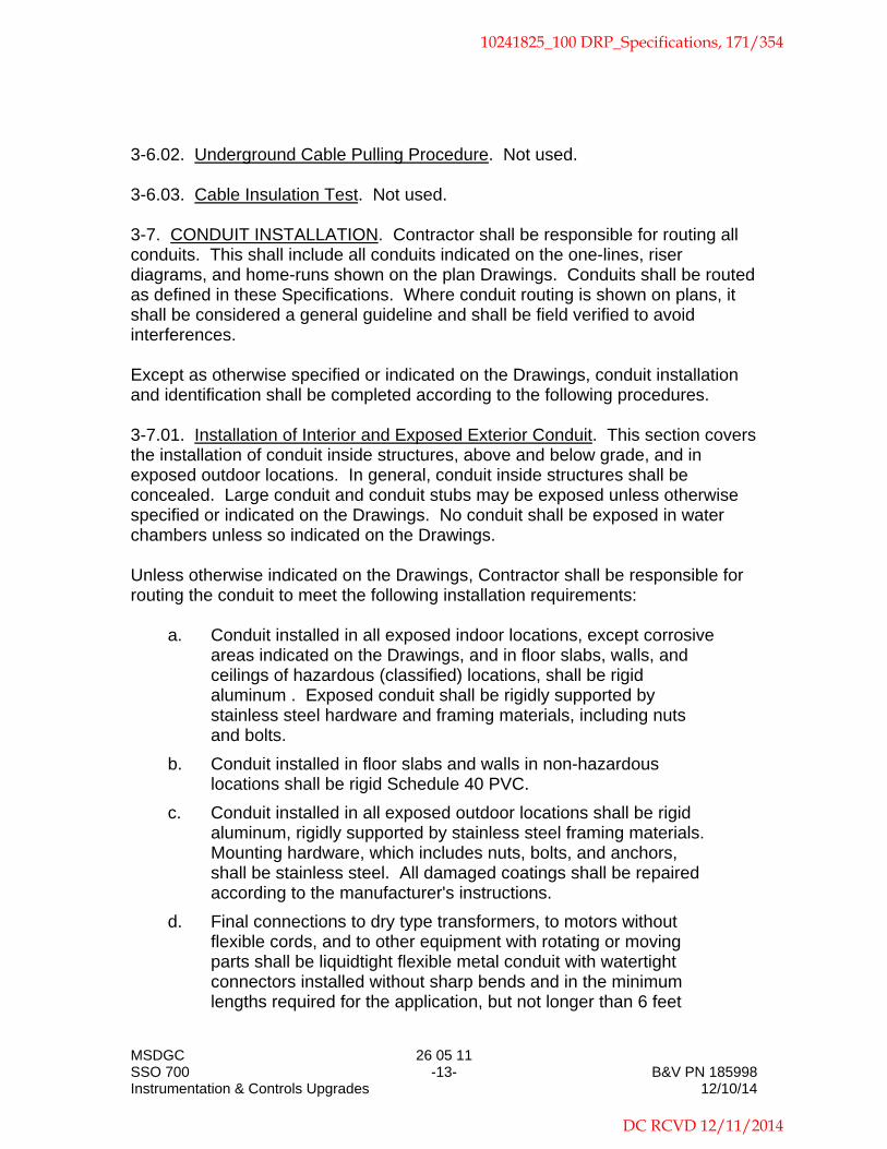
MSDGC 26 05 11 SSO 700 -13- B&V PN 185998 Instrumentation & Controls Upgrades 12/10/14
3-6.02. Underground Cable Pulling Procedure. Not used. 3-6.03. Cable Insulation Test. Not used. 3-7. CONDUIT INSTALLATION. Contractor shall be responsible for routing all conduits. This shall include all conduits indicated on the one-lines, riser diagrams, and home-runs shown on the plan Drawings. Conduits shall be routed as defined in these Specifications. Where conduit routing is shown on plans, it shall be considered a general guideline and shall be field verified to avoid interferences. Except as otherwise specified or indicated on the Drawings, conduit installation and identification shall be completed according to the following procedures. 3-7.01. Installation of Interior and Exposed Exterior Conduit. This section covers the installation of conduit inside structures, above and below grade, and in exposed outdoor locations. In general, conduit inside structures shall be concealed. Large conduit and conduit stubs may be exposed unless otherwise specified or indicated on the Drawings. No conduit shall be exposed in water chambers unless so indicated on the Drawings. Unless otherwise indicated on the Drawings, Contractor shall be responsible for routing the conduit to meet the following installation requirements:
a. Conduit installed in all exposed indoor locations, except corrosive areas indicated on the Drawings, and in floor slabs, walls, and ceilings of hazardous (classified) locations, shall be rigid aluminum . Exposed conduit shall be rigidly supported by stainless steel hardware and framing materials, including nuts and bolts.
b. Conduit installed in floor slabs and walls in non-hazardous locations shall be rigid Schedule 40 PVC.
c. Conduit installed in all exposed outdoor locations shall be rigid aluminum, rigidly supported by stainless steel framing materials. Mounting hardware, which includes nuts, bolts, and anchors, shall be stainless steel. All damaged coatings shall be repaired according to the manufacturer's instructions.
d. Final connections to dry type transformers, to motors without flexible cords, and to other equipment with rotating or moving parts shall be liquidtight flexible metal conduit with watertight connectors installed without sharp bends and in the minimum lengths required for the application, but not longer than 6 feet
10241825_100 DRP_Specifications, 171/354
DC RCVD 12/11/2014

MSDGC 26 05 11 SSO 700 -14- B&V PN 185998 Instrumentation & Controls Upgrades 12/10/14
[1.8 m] unless otherwise acceptable to Engineer.
e. Terminations and connections of rigid steel conduit shall be taper threaded. Conduits shall be reamed free of burrs and shall be terminated with conduit bushings.
f. Exposed conduit shall be installed either parallel or perpendicular to structural members and surfaces.
g. Two or more conduits in the same general routing shall be parallel, with symmetrical bends.
h. Conduits shall be at least 6 inches [150 mm] from high temperature piping, ducts, and flues.
i. Conduit installed in corrosive chemical feed and storage areas as indicated by Area Type on the Drawings shall be rigid Schedule 80 PVC.
j. Rigid Schedule 40 PVC conduit shall have supports and provisions for expansion as required by NEC Article 352.
k. Metallic conduit connections to sheet metal enclosures shall be securely fastened by locknuts inside and outside.
l. Rigid Schedule 40 PVC conduit shall be secured to sheet metal device boxes using a male terminal adapter with a locknut inside or by using a box adapter inserted through the knockout and cemented into a coupling.
m. Conduits in walls or slabs, which have reinforcement in both faces, shall be installed between the reinforcing steel. In slabs with only a single layer of reinforcing steel, conduits shall be placed under the reinforcement. Conduits larger than 1/3 of the slab thickness shall be concrete encased under the slab.
n. Conduits that cross structural joints where structural movement is allowed shall be fitted with concrete-tight and watertight expansion/deflection couplings, suitable for use with metallic conduits and rigid Schedule 40 PVC conduits. The couplings shall be Appleton Type DF, Crouse-Hinds Type XD, or O-Z Type DX.
o. Conduit shall be clear of structural openings and indicated future openings.
p. Conduits through roofs or metal walls shall be flashed and sealed watertight.
q. Conduit installed through any openings cut into non-fire rated concrete or masonry structure elements shall be neatly grouted. Conduit penetrations of fire rated structure elements shall be sealed in a manner that maintains the fire rating as indicated on
10241825_100 DRP_Specifications, 172/354
DC RCVD 12/11/2014

MSDGC 26 05 11 SSO 700 -15- B&V PN 185998 Instrumentation & Controls Upgrades 12/10/14
the Architectural Drawings.
r. Conduits shall be capped during construction to prevent entrance of dirt, trash, and water.
s. Exposed conduit stubs for future use shall be terminated with galvanized pipe caps.
t. Concealed conduit for future use shall be terminated in equipment or fitted with couplings plugged flush with structural surfaces.
u. Where the Drawings indicate future duplication of equipment wired hereunder, concealed portions of conduits for future equipment shall be provided.
v. Horizontal conduit shall be installed to allow at least 7 feet [2.1 m] of headroom, except along structures, piping, and equipment or in other areas where headroom cannot be maintained.
w. Conduit shall not be routed across the surface of a floor, roof, or walkway unless approved by Engineer.
x. PVC-coated rigid steel conduit shall be threaded and installed as recommended by the conduit manufacturer's installation procedure using appropriate tools.
y. All conduits that enter enclosures shall be terminated with acceptable fittings that will not affect the NEMA rating of the enclosure.
z. Nonmetallic conduit, which turns out of concrete slabs or walls, shall be connected to a 90 degree elbow of PVC-coated rigid steel conduit before it emerges. Conduits shall have PVC-coated rigid steel coupling embedded a minimum of 3 inches when emerging from slabs or walls and the coupling shall extend 2 inches from the wall.
ab. Power conductors to and from adjustable frequency drives shall be installed in steel conduit.
3-7.02. Underground Conduit Installation. All excavation, backfilling, and concrete work shall conform to the respective sections of these Specifications. Underground conduit shall conform to the following requirements:
a. All underground conduits shall be concrete encased unless indicated otherwise on the Drawings. Concrete encasement within 15 feet of building entrances, under and within 5 feet of roadways, and within 10 feet of indicated future excavations shall be reinforced as detailed on the Drawings.
10241825_100 DRP_Specifications, 173/354
DC RCVD 12/11/2014

MSDGC 26 05 11 SSO 700 -16- B&V PN 185998 Instrumentation & Controls Upgrades 12/10/14
b. Concrete encased conduit shall be schedule 40 PVC unless indicted otherwise on the drawings. Conduits shall have PVC-coated rigid steel coupling embedded a minimum of 3 inches when emerging from walls and the coupling shall extend 2 inches from the wall. All PVC joints shall be solvent welded in accordance with the recommendations of the manufacturer.
c. Concrete encasement on exposed outdoor conduit risers shall continue to 6 inches [150 mm] above grade, with top crowned and edges chamfered.
d. Conduit and concrete encasement installed underground for future extension shall be terminated flush at the bulkhead with a coupling and a screw plug. The termination of the duct bank shall be reinforced with bars 100 diameters long that shall be terminated 2 inches [50 mm] from the bulkhead. Matching splice bars shall be 50 bar diameters long. Each longitudinal bar shall be provided with a Lenton "Form Saver" coupler and plate or a Dayton "Superior DBR" coupler at the bulkhead. The coupler shall be threaded to accept a dowel of like diameter in the future. Threads shall be protected with screw-in plastic caps. A 1-3/4 by 3/4 inch [45 by 20 mm] deep horizontal shear key shall be formed in the concrete encasement above and below the embedded conduits. After concrete placement, conduit and bar connector ends shall be cleaned and coated with two coats of thixotropic coal tar.
e. Underground conduits indicated not to be concrete encased shall be rigid Schedule 40 PVC.
f. Underground conduit bend radius shall be at least 2 feet [600 mm] at vertical risers and at least 3 feet [900 mm] elsewhere.
g. Underground conduits and conduit banks shall have at least 2 feet [600 mm] of earth cover, except where indicated otherwise.
h. Underground conduit banks through building walls shall be cast in place, or concreted into boxouts, with water stops on all sides of the boxout. Water stops are specified in the Cast-In-Place Concrete section.
i. Underground nonmetallic conduits, which turn out of concrete or earth in outdoor locations, shall be connected to 90 degree elbows of PVC-coated rigid steel conduit before they emerge. When transitioning from concrete encased rigid steel conduit to exposed rigid aluminum conduit install an isolation coupling to eliminate dissimilar metal contact. PVC coated rigid aluminum elbow may be substituted for PVC coated rigid steel elbow and
10241825_100 DRP_Specifications, 174/354
DC RCVD 12/11/2014

MSDGC 26 05 11 SSO 700 -17- B&V PN 185998 Instrumentation & Controls Upgrades 12/10/14
coupling
j. Conduits not encased in concrete and passing through walls, which have one side in contact with earth, shall be sealed watertight with special rubber-gasketed sleeve and joint assemblies or with sleeves and modular rubber sealing elements.
k. Underground conduits shall be sloped to drain from buildings to manholes.
l. Each 5 kV or higher voltage cable, each 250 kcmil [120 mm2] or larger cable, and each conduit group of smaller cables shall be supported from manhole walls by Kindorf "D-990" or Unistrut "P-3259" inserts, with Kindorf "F-721-24" or Unistrut "P-2544" brackets and Unistrut "P1753" or "P1754" fiberglass reinforced polyester cable saddles.
m. Telephone cables shall not be installed in raceways, conduits, boxes, manholes, or handholes containing other types of circuits.
n. Intercommunication and instrument cables shall be separated the maximum possible distance from all power wiring in pull-boxes, manholes, and handholes.
3-7.03. Sealing of Conduits. After cable has been installed and connected, conduit ends shall be sealed by forcing nonhardening sealing compound into the conduits to a depth at least equal to the conduit diameter. This method shall be used for sealing all conduits at handholes, manholes, and building entrance junction boxes, and for 1 inch [25 mm] and larger conduit connections to equipment. Conduits entering chlorine feed and storage rooms shall be sealed in a junction box or conduit body adjacent to the point of entrance. Conduits entering hazardous (classified) areas and submersible or explosion proof enclosures shall have Appleton "Type ESU" or Crouse-Hinds "EYS" sealing fittings with sealing compound. 3-7.04. Reuse of Existing Conduits. Existing conduits may be reused subject to the concurrence of Engineer and compliance with the following requirements:
a. A wire brush shall be pulled through the conduit to remove any loose debris.
b. A mandrel shall be pulled through the conduit to remove sharp edges and burrs.
3-8. WIRING DEVICES, BOXES, AND FITTINGS INSTALLATION. Metallic and nonmetallic conduit boxes and fittings shall be installed in the following locations:
10241825_100 DRP_Specifications, 175/354
DC RCVD 12/11/2014

MSDGC 26 05 11 SSO 700 -18- B&V PN 185998 Instrumentation & Controls Upgrades 12/10/14
3-8.01. Conduit Boxes and Fittings.
a. Galvanized or cadmium plated, threaded, malleable iron boxes and fittings shall be installed in concrete walls, ceilings, and floors; in the outdoor faces of masonry walls; and in all locations where weatherproof device covers are required. These boxes and fittings shall also be installed in exposed rigid steel and intermediate metal conduit systems.
b. Galvanized or cadmium plated sheet steel boxes shall be installed in the indoor faces of masonry walls, in interior partition walls, and in joist supported ceilings.
c. Rigid PVC device boxes shall be installed in exposed nonmetallic conduit systems.
d. PVC coated boxes and fittings shall be installed in PVC coated conduit systems.
e. Telephone conduit shall be provided with separate junction boxes and pull fittings.
3-8.02. Device Plates. Oversized plates shall be installed where standard-sized plates do not fully cover the wall opening. 3-8.03. Wall Switches.
a. Wall switches shall be mounted 3'-6" [1.05 m] above floor or grade.
b. After circuits are energized, all wall switches shall be tested for proper operation.
3-8.04. Receptacles.
a. Convenience outlets shall be 18 inches [450 mm] above the floor unless otherwise required.
b. Convenience outlets outdoors and in garages; in basements, shops, storerooms, and rooms where equipment may be hosed down; shall be 4 feet [1.2 m] above floor or grade.
c. Welding receptacles shall be surface-mounted 4 feet [1.2 m] above the floor.
d. After circuits are energized, each receptacle shall be tested for correct polarity and each GFCI receptacle shall be tested for proper operation.
10241825_100 DRP_Specifications, 176/354
DC RCVD 12/11/2014

MSDGC 26 05 11 SSO 700 -19- B&V PN 185998 Instrumentation & Controls Upgrades 12/10/14
e. Conduit and wire for convenience outlet installation is not shown on the Drawings and shall be sized, furnished, and installed by Contractor. Conductors shall be minimum 12 AWG and conduit shall be minimum 3/4 inch for convenience outlet installation.
3-9. EQUIPMENT INSTALLATION. Except as otherwise specified or indicated on the Drawings, the following procedures shall be used in performing electrical work. 3-9.01. Setting of Equipment. All equipment, boxes, and gutters shall be installed level and plumb. Boxes, equipment enclosures, metal raceways, and similar items mounted on water- or earth-bearing walls shall be separated from the wall by at least 1/4 inch [6 mm] thick corrosion-resistant spacers. Where boxes, enclosures, and raceways are installed at locations where walls are not suitable or available for mounting, concrete equipment pads, framing material, and associated hardware shall be provided. 3-9.02. Sealing of Equipment. All outdoor substation, switchgear, motor control center, and similar equipment shall be permanently sealed at the base, and all openings into equipment shall be screened or sealed with concrete grout to keep out rodents and insects the size of wasps and mud daubers. Small cracks and openings shall be sealed from inside with silicone sealant, Dow-Corning "795" or General Electric "SCS1200". 3-10. GROUNDING. 3-10.01. General. The electrical system and equipment shall be grounded in compliance with the National Electrical Code and the following requirements:
a. All ground conductors shall be at least 12 AWG [4 mm2] soft drawn copper cable or bar, bare or green-insulated in accordance with the National Electrical Code.
b. Ground cable splices and joints, ground rod connections, and equipment bonding connections shall meet the requirements of IEEE 837, and shall be exothermic weld connections or irreversible high-compression connections, Cadweld "Exothermic" or Burndy "Hyground". Mechanical connectors will not be acceptable. Cable connections to bus bars shall be made with high-compression two-hole lugs.
c. Ground cable through exterior building walls shall enter within 3 feet [900 mm] below finished grade and shall be provided with a water stop. Unless otherwise indicated, installation of the water stop shall include filling the space between the strands with solder and soldering a 12 inch [300 mm] copper disc over the cable.
10241825_100 DRP_Specifications, 177/354
DC RCVD 12/11/2014

MSDGC 26 05 11 SSO 700 -20- B&V PN 185998 Instrumentation & Controls Upgrades 12/10/14
d. Ground cable near the base of a structure shall be installed in earth and as far from the structure as the excavation permits, but not closer than 24 inches [600 mm]. The tops of ground rods and ground cable interconnecting ground rods shall be buried a minimum of 30 inches [750 mm] below grade, or below the frost line, whichever is deeper.
e. All powered equipment, including lighting fixtures and receptacles, shall be grounded by a copper ground conductor in addition to the conduit connection.
f. Ground connections to equipment and ground buses shall be made with copper or high conductivity copper alloy ground lugs or clamps. Connections to enclosures not provided with ground buses or ground terminals shall be made with irreversible high-compression type lugs inserted under permanent assembly bolts or under new bolts drilled and inserted through enclosures, other than explosion proof enclosures, or by grounding locknuts or bushings. Ground cable connections to anchor bolts; against gaskets, paint, or varnish; or on bolts holding removable access covers will not be acceptable.
g. The grounding system shall be bonded to the station piping by connecting to the first flange inside the building, on either a suction or discharge pipe, with a copper bar or strap. The flange shall be drilled and tapped to provide a bolted connection.
h. Ground conductors shall be routed as directly as possible, avoiding unnecessary bends. Ground conductor installations for equipment ground connections to the grounding system shall have turns with minimum bend radii of 12 inches [300 mm].
i. Ground rods not described elsewhere shall be a minimum of 3/4 inch [19 mm] in diameter by 10 feet [3 m] long, with a copper jacket bonded to a steel core.
3-10.02. Grounding System Resistance. The ground system resistance shall comply with National Electrical Code. 3-10.03. Grounding System Testing. Not used. 3-11. LIGHTING FIXTURE INSTALLATION. Not used. 3-12. POWER FACTOR CORRECTION CAPACITOR INSTALLATION. Not used.
10241825_100 DRP_Specifications, 178/354
DC RCVD 12/11/2014

MSDGC 26 05 11 SSO 700 -21- B&V PN 185998 Instrumentation & Controls Upgrades 12/10/14
3-13. MODIFICATIONS TO EXISTING EQUIPMENT. Modifications to existing equipment shall be completed as specified herein and indicated on the Drawings. All existing facilities shall be kept in service during construction. Temporary power or relocation of existing power and control wiring, equipment, and devices shall be provided as required during construction. Coordination and timing of outages shall be as specified in other sections of these Specifications. Electrical power interruptions will only be allowed where agreed upon in advance with Owner, and scheduling at times of low demand may be required. 3-13.01. Demolition. Unless otherwise specified or indicated on the Drawings, all cable and all exposed conduit for power and control signals of equipment indicated to be removed shall be demolished. Conduit supports and electrical equipment mounting hardware shall be removed, and holes or damage remaining shall be grouted or sealed flush. Conduit partially concealed shall be removed where exposed, and plugged with expanding grout flush with the floor or wall. Repairs shall be refinished to match the existing surrounding surfaces. Demolished equipment shall be discarded or salvaged as indicated on the Drawings and as specified in other sections of these Specifications.
End of Section
10241825_100 DRP_Specifications, 179/354
DC RCVD 12/11/2014

STANDARD SPECIFICATIONS REFERENCE: ICEA S-95-658 (NEMA WC 70). CONDUCTOR: Concentric-lay, uncoated copper; strand Class B. Wet/dry maximum operating temperature 90°C. INSULATION: Cross-linked thermosetting polyethylene, ICEA S-95-658, Paragraph 3.6. SHIELD: None. JACKET: None. FACTORY TESTS: Cable shall meet the requirements of ICEA S-95-658.
Cable Details
Size Number of Strands
Conductor Insulation Thickness*
Maximum Outside Diameter
AWG or kcmil
mm2
in.
µm
in.
mm
14 2.5 7 0.030 760 0.17 4.32
12 4.0 7 0.030 760 0.19 4.83
10 6.0 7 0.030 760 0.21 5.33
8 10.0 7 0.045 1140 0.27 6.86
6 16.0 7 0.045 1140 0.31 7.87
4 25.0 7 0.045 1140 0.36 9.14
2 35.0 7 0.045 1140 0.42 10.67
1 40.0 19 0.055 1400 0.48 12.19
1/0 50.0 19 0.055 1400 0.52 13.21
2/0 70.0 19 0.055 1400 0.57 14.48
4/0 95.0 19 0.055 1400 0.68 17.27
250 120.0 37 0.065 1650 0.75 19.05
350 185.0 37 0.065 1650 0.85 21.59
500 300.0 37 0.065 1650 0.98 24.89
750 400.0 61 0.080 2030 1.22 31.00
1,000 500.0 61 0.080 2030 1.37 34.80
*The average thickness shall be not less than that indicated above. The minimum thickness shall be not less than 90 percent of the values indicated above. A durable marking shall be provided on the surface of the cable at intervals not exceeding 24 inches (600 mm). Marking shall include manufacturer's name, XLP, XHHW-2, conductor size, and voltage class.
600 Volt, Single Conductor Lighting/Power Cable (600-1-XLP-NONE-XHHW-2)
BLACK & VEATCH Cable Data Figure 2-26 05 11
10241825_100 DRP_Specifications, 180/354
DC RCVD 12/11/2014

STANDARD SPECIFICATIONS REFERENCE: UL 62, UL 1277. CONDUCTOR: 16 AWG (1.5 mm2), 7-strand, concentric-lay, uncoated copper. Maximum operating temperature 90°C
dry, 75°C wet. INSULATION: Polyvinyl chloride, not less than 15 mils (380 µm) average thickness; 13 mils (330 µm) minimum
thickness, UL 62, Type TFN. LAY: Twisted pair with 1-1/2 inch to 2-1/2 inch (38.10 mm - 63.5 mm) lay. SHIELD: Cable assembly, combination aluminum-polyester tape and 7-strand, 20 AWG (0.5 mm2) minimum size,
tinned copper drain wire, shield applied to achieve 100 percent cover over insulated conductors. JACKET: Conductor: Nylon, 4 mils (100 µm) minimum thickness, UL 62. Cable assembly: Black, flame-retardant polyvinyl chloride, UL 1277, applied over tape-wrapped cable
core. CONDUCTOR One conductor black, one conductor white. IDENTIFICATION: FACTORY TESTS: Insulated conductors shall meet the requirements of UL 62 for Type TFN. Assembly jacket shall meet
the requirements of UL 1277. Cable shall meet the vertical-tray flame test requirements of UL 1277.
Cable Details
Assembly Jacket Thickness*
Maximum Outside Diameter
in. µm in. mm
Single Pair 0.045 1140 0.34 8.64
*The average thickness shall be not less than that indicated above. The minimum thickness shall be not less than 80 percent of the value indicated above. A durable marking shall be provided on the surface of the cable at intervals not exceeding 24 inches (600 mm). Marking shall include manufacturer's name, Type TC, Type TFN, conductor size, single pair, and voltage class.
600 Volt, Single Pair, Shielded Instrument Cable (600-SINGLE-PAIR-SH-INSTR)
BLACK & VEATCH Cable Data Figure 4-26 05 11
10241825_100 DRP_Specifications, 181/354
DC RCVD 12/11/2014

THIS PAGE LEFT BLANK INTENTIONALLY
10241825_100 DRP_Specifications, 182/354
DC RCVD 12/11/2014

MSDGC 31 23 33 SSO 700 -1- B&V PN 185889 Instrumentation & Controls Upgrades 12/10/2014
Section 31 23 33
TRENCHING AND BACKFILLING
PART 1 - GENERAL 1-1. SCOPE. This section covers clearing, grubbing, and preparation of the site; removal and disposal of all debris; excavation and trenching;; all necessary sheeting, shoring, and protection work; preparation of subgrades; pumping and dewatering as necessary; backfilling; pipe embedment; and other appurtenant work. 1-2. GENERAL. With reference to the terms and conditions of the construction standards for excavations set forth in OSHA "Safety and Health Regulations for Construction", Chapter XVII of Title 29, CFR, Part 1926, Contractor shall employ a competent person and, when necessary based on the regulations, a registered professional engineer, to act upon all pertinent matters of the work of this section. 1-3. SUBMITTALS. Drawings, specifications, and data covering the proposed materials shall be submitted in accordance with the Submittals section. At least 30 days before starting construction on the sheeting and shoring, the sheeting and shoring design engineer shall complete and submit to Engineer the Protection System Design Certificate (Figure 2-31 23 33) and the Contractor shall use the sheeting and shoring design. A separate certificate shall be submitted for each unique design. The certificate shall be signed and sealed by the registered professional engineer that designed the protection system. The professional engineer shall be licensed or registered in the state where the protection system is located. 1-4. INSURANCE. Professional Liability insurance shall be provided as specified in the General Conditions. PART 2 - PRODUCTS 2-1. MATERIALS. 2-1.01. Filter Fabric. Not used.
2-1.02. Polyethylene Film. Polyethylene film beneath concrete slabs or slab base course material shall be Product Standard PS17, 6 mil [150 mm] minimum thickness.
2-1.03. Tunnel Liner Plates. Not used.
10241825_100 DRP_Specifications, 183/354
DC RCVD 12/11/2014

MSDGC 31 23 33 SSO 700 -2- B&V PN 185889 Instrumentation & Controls Upgrades 12/10/2014
2-1.04. Smooth Steel Pipe. Not used.
2-1.05. Wood Skids. Not used. 2-1.06. Casing Insulators. Not used. 2-1.07. Stabilized Sand Backfill. Not used. 2-1.08. End Closure. Not used. 2-1.09. Inundated Sand Fill. Sand fill shall be clean, with not more than 25 percent retained on a No. 4 [4.75 mm] sieve and not more than 7 percent passing a No. 200 [75 μm] sieve, and shall have an effective size between 0.10 and 0.30 mm. 2-1.10. Graded Gravel Fill. Graded gravel for compacted trench backfill shall conform to the following gradation:
Sieve Size Percent Passing by Weight
1 inch [25 mm] 100
3/4 inch [19 mm] 85 – 100
3/8 inch [9.5 mm] 50 – 80
No. 4 [4.75 mm] 35 – 60
No. 40 [425 μm] 15 – 30
No. 200 [75 μm] 5 – 10
The gravel mixture shall contain no clay lumps or organic matter. The fraction passing the No. 4 [4.75 mm] sieve shall have a liquid limit not greater than 25 and a plasticity index not greater than 5. 2-1.11. Controlled Low Strength Material (CLSM) Fill. Not used. 2-1.12. Granular Fill. Granular fill material shall be crushed rock or gravel. Granular fill shall be free from dust, clay, and trash; hard, durable, non-friable; and shall be graded 3/4 inch to No. 4 [19 to 4.75 mm] as defined in ASTM C33 for No. 67 coarse aggregate. Granular fill shall meet the quality requirements for ASTM C33 coarse aggregate. 2-2. MATERIALS TESTING. 2-2.01. Preliminary Review of Materials. Refer to Quality Control.
10241825_100 DRP_Specifications, 184/354
DC RCVD 12/11/2014

MSDGC 31 23 33 SSO 700 -3- B&V PN 185889 Instrumentation & Controls Upgrades 12/10/2014
2-2.02. Field Testing Expense. All moisture-density (Proctor) tests and relative density tests on the materials, and all in-place field density tests, shall be made by an independent testing laboratory at the expense of Contractor. Contractor shall provide access to the materials and work area and shall assist the laboratory as needed in obtaining representative samples. 2-2.03. Required Tests. For planning purposes, the following guidelines shall be used for frequency of field tests. Additional tests shall be performed as necessary for job conditions and number of failed tests. Test results shall be submitted as indicated in the Submittals section.
a. Two moisture density (Proctor) tests in accordance with ASTM D698 (or, when required, ASTM D1557), or two relative density tests in accordance with ASTM D4253 and D4254 for each type of general fill, designated fill, backfill, or other material proposed.
b. In-place field density and moisture tests at intervals of 1000 feet [300 m] maximum along the trench.
c. One in-place field density and moisture test for every 200 cubic yards [153 m3] of backfill.
d. One in-place density and moisture test whenever there is a suspicion of a change in the quality of moisture control or effectiveness of compaction.
e. Additional gradation, Proctor, and relative density tests whenever the source or quality of material changes.
PART 3 - EXECUTION 3-1. CLEARING. All clearing shall be performed as necessary for access, stringing of pipeline materials, and construction of the pipeline and appurtenant structures. 3-2. EXCAVATION. Excavations shall provide adequate working space and clearances for the work to be performed therein and for installation and removal of concrete forms. In no case shall excavation faces be undercut for extended footings. Subgrade surfaces shall be clean and free of loose material of any kind when concrete is placed thereon. Except where exterior surfaces are specified to be damp-proofed, monolithic concrete manholes and other concrete structures or parts thereof, which do not have footings that extend beyond the outside face of exterior walls, may be placed directly against excavation faces without the use of outer forms, provided that such faces are stable and also provided that a layer of polyethylene film is placed between the earth and the concrete.
10241825_100 DRP_Specifications, 185/354
DC RCVD 12/11/2014

MSDGC 31 23 33 SSO 700 -4- B&V PN 185889 Instrumentation & Controls Upgrades 12/10/2014
Excavations for manholes and similar structures constructed of masonry units shall have such horizontal dimensions that not less than 6 inches [150 mm] clearance is provided for outside plastering.
3-2.01. Classification of Excavated Materials. No classification of excavated materials will be made for payment purposes. Excavation and trenching work shall include the removal and subsequent handling of all materials excavated or otherwise removed in performance of the work, regardless of the type, character, composition, or condition thereof.
3-2.02. Preservation of Trees. No trees shall be removed outside excavated or filled areas, unless their removal is authorized by Owner. Trees left standing shall be adequately protected from permanent damage by construction operations. For limits of tree removal along pipeline routes, see Control of Work section 3-2.03. Blasting. Blasting or other use of explosives for excavation will not be permitted. 3-2.04. Dewatering. Dewatering equipment shall be provided to remove and dispose of all surface water and groundwater entering excavations, trenches, or other parts of the work. Each excavation shall be kept dry during subgrade preparation and continually thereafter until the structure to be built, or the pipe to be installed therein, is completed to the extent that no damage from hydrostatic pressure, flotation, or other cause will result. All excavations for concrete structures or trenches which extend down to or below groundwater shall be dewatered by lowering and keeping the groundwater level to the minimum depth of 12 inches [300 mm], beneath such excavations. The specified dewatering depth shall be maintained below the prevailing bottom of excavation at all times. Surface water shall be diverted or otherwise prevented from entering excavations or trenches to the greatest extent possible without causing damage to adjacent property. Contractor shall be responsible for the condition of any pipe or conduit which he may use for drainage purposes, and all such pipe or conduit shall be left clean and free of sediment. Contractor shall obtain from the appropriate agencies and authorities, the dewatering and stormwater discharge permits required to remove and dispose of groundwater, surface water, and any other water used in Contractor's operations. The permits shall be obtained prior to start of construction.
10241825_100 DRP_Specifications, 186/354
DC RCVD 12/11/2014

MSDGC 31 23 33 SSO 700 -5- B&V PN 185889 Instrumentation & Controls Upgrades 12/10/2014
3-2.05. Sheeting and Shoring. Except where banks are cut back on a stable slope, excavations for structures and trenches shall be supported with steel sheet piling and shoring as necessary to prevent caving or sliding. Sheet piling or other excavation support systems shall be installed as necessary to limit the extent of excavations for deeper structures and to protect adjacent structures and facilities from damage due to excavation and subsequent construction. Contractor shall assume complete responsibility for, and shall install adequate protection systems for prevention of damage to existing facilities. Sheeting, shoring and excavation support systems shall be designed by a professional engineer registered in the state where the project is located. Trench sheeting may be removed if the pipe strength is sufficient to carry trench loads based on trench width to the back of sheeting. Trench sheeting shall not be pulled after backfilling. Where trench sheeting is left in place, it shall not be braced against the pipe, but shall be supported in a manner which will preclude concentrated loads or horizontal thrusts on the pipe. Cross braces installed above the pipe to support sheeting may be removed after pipe embedment has been completed. Trench sheeting shall be removed unless otherwise permitted by Engineer. Trench sheeting will not be removed, if in the opinion of Engineer, removal of the sheeting will cause damage to the facility it is protecting. If left in place, the sheeting shall cut off 12 inches below finished grade. The design of the support system shall be such as to permit complete removal while maintaining safety and stability at all times. 3-2.06. Stabilization. Sub-grades for concrete structures and trench bottoms shall be firm, dense, and thoroughly compacted and consolidated; shall be free from mud and muck; and shall be sufficiently stable to remain firm and intact under the feet of the workers. Sub-grades for concrete structures or trench bottoms which are otherwise solid, but which become mucky on top due to construction operations, shall be reinforced with crushed rock or gravel as specified for granular fills. The stabilizing material shall be placed in a manner that no voids remain in the granular fill. All excess granular fill with unfilled void space shall be removed. The finished elevation of stabilized sub-grades shall not be above sub-grade elevations indicated on the drawings. 3-3. TRENCH EXCAVATION. No more trench shall be opened in advance of pipe laying than is necessary to expedite the work. One block or 400 feet [120 m], whichever is the shorter, shall be the maximum length of open trench on any line under construction. Except where tunneling is indicated on the drawings, is specified, or is permitted by Engineer, all trench excavation shall be open cut from the surface.
10241825_100 DRP_Specifications, 187/354
DC RCVD 12/11/2014

MSDGC 31 23 33 SSO 700 -6- B&V PN 185889 Instrumentation & Controls Upgrades 12/10/2014
3-3.01. Alignment, Grade, and Minimum Cover. The alignment and grade or elevation of each pipeline shall be fixed and determined from offset stakes. Vertical and horizontal alignment of pipes, and the maximum joint deflection used in connection therewith, shall be in conformity with requirements of the section covering installation of pipe. Where pipe grades or elevations are not definitely fixed by the contract drawings, trenches shall be excavated to a depth sufficient to provide a minimum depth of backfill cover over the top of the pipe of 24 inchesmm over pipes below paved and graded streets and, of 36 inchesmm over pipes in other locations. Greater pipe cover depths may be necessary on vertical curves or to provide adequate clearance beneath existing pipes, conduits, drains, drainage structures, or other obstructions encountered at normal pipe grades. Measurement of pipe cover depth shall be made vertically from the outside top of pipe to finished ground or pavement surface elevation, except where future surface elevations are indicated on the drawings.
3-3.02. Maximum Trench Widths. Maximum trench widths shall be limited as indicated in Schedule 02202-S01 for designated conduits. Trenches shall be excavated to a width which will provide adequate working space and sidewall clearances for proper pipe installation, jointing, and embedment. However, the limiting trench widths from the bottom of the trench to an elevations 12 inches [300 mm] above the top of installed pipe, and the minimum permissible sidewall clearances between the installed pipe and each trench wall, shall be as indicated in Schedule 02202-S01 or on the drawings. Specified minimum sidewall clearances are not minimum average clearances but are minimum clear distances which will be required to the trench excavation or the trench protective system. Cutting trench banks on slopes to reduce earth load to prevent sliding and caving shall be used only in areas where the increased trench width will not interfere with surface features or encroach on right-of-way limits. Slopes shall not extend lower than 12 inches [300 mm] above the top of the pipe. If, for any reason, the width of the lower portion of the trench, as excavated at any point, exceeds the maximum permitted, pipe of adequate strength, special pipe embedment, or concrete arch encasement, for the applicable loading conditions and with the concurrence of Engineer, shall be furnished and installed by and at the expense of Contractor.
3-3.03. Minimum Trench Widths. Except when maximum trench width is required for certain conduits, trenches shall be excavated to the minimum trench widths indicated in the following table. Trenches shall be excavated to a width
10241825_100 DRP_Specifications, 188/354
DC RCVD 12/11/2014

MSDGC 31 23 33 SSO 700 -7- B&V PN 185889 Instrumentation & Controls Upgrades 12/10/2014
which will provide adequate working space and sidewall clearances for proper pipe installation, jointing, and embedment.
Nominal Pipe Size Minimum Trench Width Clearance
Less than 27 in [700 mm]
Pipe OD plus 24 in [600 mm] 12 in [300 mm]
27 in through 60 in [700 mm through 1,500 mm]
Pipe OD plus nominal pipe size ID/2
Greater than 60 in [1,500 mm]
Pipe OD plus 70 in [1800 mm] 30 in [750 mm]
Clearance = Minimum sidewall clearance OD = Outside diameter (or span) of conduit ID = Inside diameter (or span) of conduit.
Specified minimum sidewall clearances are not minimum average clearances but are minimum clear distances which will be required to the trench excavation or the trench protective system. Cutting trench banks on slopes to reduce earth load to prevent sliding and caving shall be used only in areas where the increased trench width will not interfere with surface features or encroach on right-of-way limits. 3-3.04. Mechanical Excavation. The use of mechanical equipment will not be permitted in locations where its operation would cause damage to trees, buildings, culverts, or other existing property, utilities, or structures above or below ground. In all such locations, hand excavating methods shall be used. Mechanical equipment used for trench excavation shall be of a type, design, and construction, and shall be so operated, that the rough trench excavation bottom elevation can be controlled, and that trench alignment is such that pipe, when accurately laid to specified alignment, will be centered in the trench with adequate sidewall clearance. Undercutting the trench sidewall to obtain sidewall clearance will not be permitted. In locations where maximum trench widths are required for designated rigid conduits, mechanical equipment shall be operated so that uniform trench widths and vertical sidewalls are obtained at least from an elevation 12 inches [300 mm] above the top of the installed pipe to the bottom of the trench. 3-3.05. Cutting Concrete Surface Construction. Cuts in concrete pavement and concrete base pavements shall be no larger than necessary to provide adequate working space for proper installation of pipe and appurtenances. Cutting shall be started with a concrete saw in a manner which will provide a clean groove at
10241825_100 DRP_Specifications, 189/354
DC RCVD 12/11/2014

MSDGC 31 23 33 SSO 700 -8- B&V PN 185889 Instrumentation & Controls Upgrades 12/10/2014
least 1-1/2 inches [40 mm] deep along each side of the trench and along the perimeter of cuts for structures. Concrete pavement and concrete base pavement over trenches excavated for pipelines shall be removed so that a shoulder not less than 6 inches [150 mm] in width at any point is left between the cut edge of the pavement and the top edge of the trench. Trench width at the bottom shall not be greater than at the top and no undercutting will be permitted. Pavement cuts shall be made to and between straight or accurately marked curved lines which, unless otherwise required, shall be parallel to the center line of the trench. Pavement removal for connections to existing lines or structures shall not exceed the extent necessary for the installation. Where the trench parallels the length of concrete walks, and the trench location is all or partially under the walk, the entire walk shall be removed and replaced. Where the trench crosses drives, walks, curbs, or other surface construction, the surface construction shall be removed and subsequently replaced between existing joints or between saw cuts as specified for pavement. 3-3.06. Excavation Below Pipe Sub-grade. Except where otherwise required, pipe trenches shall be excavated below the underside of the pipe, as indicated on Figure 1-31 23 33, to provide for the installation of granular embedment. Bell holes shall provide adequate clearance for tools and methods used for installing pipe. No part of any bell or coupling shall be in contact with the trench bottom, trench walls, or granular embedment when the pipe is jointed. 3-3.07. Artificial Foundations in Trenches. Whenever unsuitable or unstable soil conditions are encountered, trenches shall be excavated below grade and the trench bottom shall be brought to grade with suitable material. In such cases, adjustments will be made in the Contract Price in accordance with the provisions of the General Conditions.
3-4. PIPE EMBEDMENT. Embedment materials both below and above the bottom of the pipe, classes of embedment to be used, and placement and compaction of embedment materials shall conform to the requirements indicated on Figure 1-31 23 33 and to the following supplementary requirements. Embedment material shall contain no cinders, clay lumps, or other material which may cause pipe corrosion. 3-4.01. Embedment Classes.
a. Class C Bedding. Class C bedding shall be used for all reinforced
10241825_100 DRP_Specifications, 190/354
DC RCVD 12/11/2014

MSDGC 31 23 33 SSO 700 -9- B&V PN 185889 Instrumentation & Controls Upgrades 12/10/2014
concrete and prestressed concrete pipelines.
3-4.02. Embedment for Ductile Iron, Steel, FRP, and PVC Pipelines. Not used. 3-4.03. Placement and Compaction. Granular embedment material shall be spread and the surface graded to provide a uniform and continuous support beneath the pipe at all points between bell holes or pipe joints. It will be permissible to slightly disturb the finished subgrade surface by withdrawal of pipe slings or other lifting tackle. After each pipe has been graded, aligned, and placed in final position on the bedding material, and shoved home, sufficient pipe embedment material shall be deposited and compacted under and around each side of the pipe and back of the bell or end thereof by shovel slicing or other suitable methods to hold the pipe in proper position and alignment during subsequent pipe jointing and embedment operations. Embedment material shall be deposited and compacted uniformly and simultaneously on each side of the pipe to prevent lateral displacement. Class C embedment shall be compacted to the top of the pipe in all areas where compacted backfill is specified and also around the restrained pipe sections. Each lift of granular embedment material shall be vibrated with a mechanical probe type vibrator or shovel sliced during placement to ensure that all spaces beneath the pipe are filled. Granular embedment shall be placed in maximum lift thickness of 6 inches [150 mm] and compacted. Each lift of embedment material shall be compacted with three passes (round trip) of a platform type vibrating compactor.
Where indicated on the drawings, migration of soil into the embedment material shall be prevented with filter fabric Type A or by use of inundated sand embedment. Filter fabric shall be placed on the trench surfaces so that it completely surrounds the embedment material. Joints shall be lapped 12 inches [300 mm]. 3-4.04. Groundwater Barrier. Continuity of embedment material shall be interrupted by low permeability groundwater barriers to impede passage of water through the embedment. Groundwater barriers for sewer lines that contain manholes with cast-in-place bases shall be compacted soil around each manhole, extending through any granular material beneath the manhole, and meeting ASTM D2487 soil classification GC, SC, CL, or ML-CL and shall be compacted to 95 percent of maximum density at near the optimum moisture content (ASTM D698). Material may be finely divided, suitable job excavated material, free from stones, organic matter, and debris.
10241825_100 DRP_Specifications, 191/354
DC RCVD 12/11/2014

MSDGC 31 23 33 SSO 700 -10- B&V PN 185889 Instrumentation & Controls Upgrades 12/10/2014
Groundwater barriers for sewer lines that contain manholes with precast (developed) bases and for all other pipelines shall be soil plugs of 3 feet [1 m] in width, extending the full depth and width of granular material, and spaced not more than 400 feet [120 m] apart. The soil plugs shall be constructed from soil meeting ASTM D2487 classification GC, SC, CL, or ML, and compacted to 95 percent of maximum density at near the optimum moisture content (ASTM D698). 3-5. TRENCH BACKFILL. All trench backfill above pipe embedment shall conform to the following requirements. A layer of backfill material not more than 8 inches [200 mm] deep may be placed over concrete arch encasement or concrete reaction blocking after the concrete has reached its initial set, to aid curing. No additional backfill shall be placed over arch encasement or blocking until the concrete has been in place for at least 3 days.
3-5.01. Compacted Backfill. Compacted backfill will be required for the full depth of the trench above the embedment in the following locations:
Where beneath pavements, surfacings, driveways, curbs, gutters, walks, or other surface construction or structures.
Where in street, road, or highway shoulders.
In established lawn areas.
The top portion of backfill beneath established lawn areas shall be finished with at least 12 inches [300 mm] of topsoil corresponding to, or better than that which is underlying adjoining lawn areas. Trench backfill material shall be suitable job excavated material graded gravel, graded gravel, ordinary backfill, or structure backfill and shall be as specified herein. 3-5.01.01. Job Excavated Material. Job excavated material may be used for compacted backfill when the job excavated material is finely divided and free from debris, organic material, cinders, any corrosive material, and stones larger than 3 inches [75 mm] in greatest dimension. Masses of moist, stiff clay shall not be used. Job excavated materials shall be placed in uniform layers not exceeding 8 inches [200 mm] in uncompacted thickness. Each layer of material shall have the best possible moisture content for satisfactory compaction. The material in each layer shall be wetted or dried as needed and thoroughly mixed to ensure uniform moisture content and adequate compaction. Increased layer thickness may be permitted for noncohesive material if Contractor demonstrates to the satisfaction of Engineer that the specified compacted density will be obtained. The method of compaction and the equipment used shall be
10241825_100 DRP_Specifications, 192/354
DC RCVD 12/11/2014

MSDGC 31 23 33 SSO 700 -11- B&V PN 185889 Instrumentation & Controls Upgrades 12/10/2014
appropriate for the material to be compacted and shall not transmit damaging shocks to the pipe. Job excavated material shall be compacted to 100 percent of maximum dry density at a moisture content within 2 percent of the optimum moisture content, as determined by ASTM D698 when that test is appropriate, or to 70 percent relative density as determined by ASTM D4253 and D4254 when those tests are appropriate. 3-5.01.02. Inundated Sand. Not used. 3-5.01.03. Graded Gravel. Gravel backfill shall be deposited in uniform layers not exceeding 12 inches [300 mm] in uncompacted thickness. The backfill shall be compacted with a suitable vibratory roller or platform vibrator to at least 70 percent relative density as determined by ASTM D4253 and D4254. Groundwater barriers specified under pipe embedment shall extend to the top of the graded gravel backfill. 3-5.02. Ordinary Backfill. Compaction of trench backfill above pipe embedment in locations other than those specified will not be required except to the extent necessary to prevent future settlement. Contractor shall be responsible for backfill settlement as specified. Ordinary earth backfill material to be placed above embedments shall be free of brush, roots more than 2 inches [50 mm] in diameter, debris, cinders, and any corrosive material, but may contain rubble and detritus from rock excavation, stones, and boulders in certain portions of the trench depth. Backfill material above embedments shall be placed by methods which will not impose excessive concentrated or unbalanced loads, shock, or impact on installed pipe, and which will not result in displacement of the pipe. Compact masses of stiff clay or other consolidated material more than 1 cubic foot [0.03 m3] in volume shall not be permitted to fall more than 5 feet [1.5 m] into the trench, unless cushioned by at least 2 feet [600 mm] of loose backfill above pipe embedment. No trench backfill material containing rocks or rock excavation detritus shall be placed in the upper 18 inches [450 mm] of the trench, nor shall any stone larger than 8 inches [200 mm] in its greatest dimension be placed within 3 feet [900 mm] of the top of pipe. Large stones may be placed in the remainder of the trench backfill only if well separated and so arranged that no interference with backfill settlement will result. 3-5.03. Water-Settled Earth Backfill. Settlement or consolidation of trench backfill using water jetting or ponding shall not be performed.
10241825_100 DRP_Specifications, 193/354
DC RCVD 12/11/2014

MSDGC 31 23 33 SSO 700 -12- B&V PN 185889 Instrumentation & Controls Upgrades 12/10/2014
3-5.04. Structure Backfill. Backfill around manholes and small concrete vaults shall meet the requirements specified for compacted trench backfill. 3-5.05. Controlled Low Strength Material (CLSM). Not used. 3-6. TUNNEL EXCAVATION. Not used. 3-7. DRAINAGE MAINTENANCE. Trenches across roadways, driveways, walks, or other trafficways adjacent to drainage ditches or watercourses shall not be backfilled prior to completion of backfilling the trench on the upstream side of the trafficway, to prevent impounding water after the pipe has been laid. Bridges and other temporary structures required to maintain traffic across such unfilled trenches shall be constructed and maintained by Contractor. Backfilling shall be done so that water will not accumulate in unfilled or partially filled trenches. All material deposited in roadway ditches or other watercourses crossed by the line of trench shall be removed immediately after backfilling is completed, and the original section, grades, and contours of ditches or watercourses shall be restored. Surface drainage shall not be obstructed longer than necessary.
3-8. PROTECTION OF TRENCH BACKFILL IN DRAINAGE COURSES. Where trenches are constructed in ditches or other watercourses, backfill shall be protected from surface erosion. Where the grade of the ditch exceeds 1 percent, or as otherwise required, ditch checks shall be installed. Unless otherwise indicated on the drawings, ditch checks shall be concrete. Ditch checks shall extend at least 2 feet [600 mm] below the original ditch or watercourse bottom for the full bottom width and at least 18 inches [450 mm] into the side slopes, and shall be at least 12 inches [300 mm] thick.
3-9. FINAL GRADING AND PLACEMENT OF TOPSOIL. After other outside work has been finished, and backfilling and embankments completed and settled, all areas which are to be graded shall be brought to grade at the indicated elevations, slopes, and contours. All cuts, fills, embankments, and other areas which have been disturbed or damaged by construction operations shall be surfaced with topsoil to a depth of at least 4 inches [100 mm]. Topsoil shall be of a quality at least equal to the existing topsoil in adjacent areas, free from trash, stones, and debris, and well suited to support plant growth. Use of graders or other power equipment will be permitted for final grading and dressing of slopes, provided the result is uniform and equivalent to manual methods. All surfaces shall be graded to secure effective drainage. Unless otherwise indicated, a slope of at least 1 percent shall be provided. Final grades and surfaces shall be smooth, even, and free from clods and stones, weeds, brush, and other debris.
10241825_100 DRP_Specifications, 194/354
DC RCVD 12/11/2014

MSDGC 31 23 33 SSO 700 -13- B&V PN 185889 Instrumentation & Controls Upgrades 12/10/2014
3-10. DISPOSAL OF EXCESS EXCAVATED MATERIALS. Disposal of excess material from trench excavations on plant and major facility construction sites shall be accomplished as indicated in the Excavation and Fill for Structures section of the specifications for the major construction. Disposal of excess material from other trench excavation sites shall be as follows. Except as otherwise permitted, all excess excavated materials shall be disposed of on site in a method approved by the Owner, unless otherwise noted. Broken concrete and other debris resulting from pavement or sidewalk removal, excavated rock in excess of the amount permitted to be installed in trench backfill, debris encountered in excavation work, and other similar waste materials shall be disposed of away from the site. Excess earth from excavations located in unimproved property may be distributed directly over the pipe trench and within the pipeline right-of-way to a maximum depth of 6 inches [150 mm] above the original ground surface elevation at and across the trench and sloping uniformly each way. Material thus wasted shall be carefully finished with a drag, blade machine, or other suitable tool to a smooth, uniform surface without obstructing drainage at any point. Wasting of excess excavated material in the above manner will not be permitted where the line of trench crosses or is within a railroad, public road, or highway right-of-way. The disposal of waste and excess excavated materials, including hauling, handling, grading, and surfacing, shall be a subsidiary obligation of Contractor and no separate payment will be made therefore. 3-11. VEGETATION. All established vegetation areas cut by the line of trench, by excavation, or damaged during the work shall be revegetated, after completion of construction, to the complete satisfaction of the property owner and Owner. All vegetation used shall be the same type as removed or damaged. Erosion and sediment control measures shall be employed in cut areas until vegetation has been established. 3-12. SETTLEMENT. Contractor shall be responsible for all settlement of trench backfill which may occur within the correction period stipulated in the General Conditions. Contractor shall make, or cause to be made, all repairs or replacements made necessary by settlement within 30 days after notice from Engineer or Owner.
End of Section
10241825_100 DRP_Specifications, 195/354
DC RCVD 12/11/2014

v
-.1 ~ I
i::l ~
::J::IO -0 CIO '-- ::C::
~ -· ... .,..(Q~
v ......
~ ~ ll.i !til ll.i (!I
v
v
D -
REINFORCING STEEL WHEN REQUIRED i"
a:~ 1 1/4 Be 0 o
f2~gm;J 8~IN / ;~~ / / / / / /~ / ';'""~
;~~·.~ .. r~~ ENCASEMENT
::~;:~;:~;:~;:~;:J ) H:~::~::~::~::~; MAY BE ~ /~±~~~~~ PLACED TO t~ ,..d FULL
TRENCH
CLASS A WIDTH
ARCH ENCASEMENT
"" ~ ~
/ / \/ / / /_ ~
"""'=111 /// -... /// ~ /// 0
:~~:~: ~ 10 --.....
~.4 ::c:: . ...
(Q~
~ CLASS 8 CLASS B SPECIAL
WHERE PIPING IS RESTRAINED, "" PROVIDE COMPACTED EMBEDMENT
FOR RESTRAINED JOINT LENGTH
~
//// ///
CLASS C
TABLE OF EMBEDMENT DEPTHS BELOW PIPE
a a - -MIN SOIL MIN ROCK
in mm in mm
27" (675 mm) & SMALLER 3 75 6 150 30" (750 mm) TO 60" (1500 mm) 4 100 9 225 66"(1650 mm) & LARGER 6 150 12 300
NOTES:
1. GRANULAR EMBEDMENT MATERIAL SHALL BE CRUSHED ROCK OR PEA GRAVEL COARSE AGGREGATE SIZE NUMBER 7 (13 TO 4. 75) ASTM C33. EMBEDMENT MATERIAL SHALL BE PLACED IN LAYERS NOT MORE THAN 6" (150mm) DEEP AND COMPACTED AS SPECIFIED.
2. HAND PLACED EMBEDMENT SHALL BE FINELY DIVIDED MATERIAL FREE FROM DEBRIS AND STONES.
3. COMPACTED EMBEDMENT SHALL BE FINELY DIVIDED JOB EXCAVATED MATERIAL FREE FROM DEBRIS, ORGANIC MATERIAL, AND STONES, PLACED IN UNIFORM LAYERS NOT MORE THAN 8" THICK, AND COMPACTED TO 95% MAXIMUM DENSITY AS DETERMINED BY ASTM D698; INUNDATED SAND; OR GRADED GRAVEL. GRANULAR EMBEDMENT MAY BE SUBSTITUTED FOR ALL OR PART OF THE COMPACTED EMBEDMENT.
4. EMBEDMENT ABOVE THE TOP OF THE PIPE SHALL BE AN UNCOMPACTED LAYER FOR ALL INSTALLATIONS •
5. REFER TO SPECIFICATIONS FOR GEOTECHNICAL FABRIC OR SPECIAL EMBEDMENT REQUIREMENTS FOR TRENCHES IN FINE SOILS EXTENDING BELOW GROUNDWATER LEVEL.
6. TRENCH OUTLINES DO NOT INDICATE ACTUAL TRENCH EXCAVATION SHAPE, SOIL CONDITIONS, OR PRESENCE OF SHEETING LEFT IN PLACE. EMBEDMENT MATERIAL SHALL EXTEND THE FULL WIDTH OF THE ACTUAL TRENCH EXCAVATION.
7. FOR RESTRAINED JOINT PIPE LENGTH WITH CLASS C EMBEDMENT THE BACKFILL ABOVE THE GRANULAR EMBEDMENT AND BELOW THE TOP OF THE PIPE SHALL BE COMPACTED EMBEDMENT.
LEGEND
Be OUTSIDE DIAMETER OF PIPE H COVER ABOVE TOP OF PIPE D NOMINAL PIPE SIZE a EMBEDMENT BELOW PIPE (SEE TABLE)
D HAND PLACED EMBEDMENT *
1/ / / / / ~ COMPACTED EMBEDMENT * /////~
liiiiiiiii~I GRANULAR EMBEDMENT
D CONCRETE
* OR GRANULAR EMBEDMENT
EMBEDMENTS FOR CONDUITS
BLACK & VEATCH FIG 1-02202
REV. 2 - 9/22/0!
10241825_100 DRP_Specifications, 196/354
DC RCVD 12/11/2014

PROTECTIVE SYSTEM DESIGN CERTIFICATE
I undersigned engineer, hereby certify that the protection system for (trench location) has been designed by me and is in compliance with the Contract Documents. Name: State of Registration: Signature: P.E. Number Date: (Seal)
FIGURE 2-31 23 33
10241825_100 DRP_Specifications, 197/354
DC RCVD 12/11/2014

THIS PAGE LEFT BLANK INTENTIONALLY
10241825_100 DRP_Specifications, 198/354
DC RCVD 12/11/2014

MSDGC 40 05 31 SSO 700 -1- B&V PN 185998 Instrumentation & Controls Upgrades 12/10/14
Section 40 05 31
MISCELLANEOUS PLASTIC PIPE, TUBING, AND ACCESSORIES PART 1 - GENERAL 1-1. SCOPE. This section covers the furnishing of miscellaneous plastic pipe, tubing, and accessories. Pipe and tubing shall be furnished complete with all fittings, flanges, unions, jointing materials and other necessary appurtenances. 1-2. SUBMITTALS. 1-2.01. Drawings and Data. Complete specifications, data and catalog cuts or drawings shall be submitted in accordance with the submittals section. Submittals are required for all piping, fittings, gaskets, sleeves, and accessories, and shall include the following data:
Name of Manufacturer Type and model Construction materials, thickness, and finishes Pressure and temperature ratings
Contractor shall obtain and submit a written statement from the gasket material manufacturer certifying that the gasket materials are compatible with the joints specified herein and are recommended for the specified field test pressures and service conditions. 1-3. DELIVERY, STORAGE, AND HANDLING. Delivery, storage, and handling shall be in accordance with the Delivery, Storage, and Handling section. All materials shall be stored in a sheltered location above the ground, separated by type, and shall be supported to prevent sagging or bending. Pipe, tubing, and fittings shall be stored between 40°F and 90°F [4°C and 32°C]. PART 2 - PRODUCTS 2-1. FRP PIPE. Not used. 2-2. PVC PIPE MATERIALS. PVC pipe materials and services shall be as specified herein. 2-2.01. Material Classification PVC-1. Not used.
10241825_100 DRP_Specifications, 199/354
DC RCVD 12/11/2014

MSDGC 40 05 31 SSO 700 -2- B&V PN 185998 Instrumentation & Controls Upgrades 12/10/14
2-2.02. Material Classification PVC-2.
PVC-2 – Schedule 80 PVC Pipe with Solvent Welded Joints. Neat polymer and polymer solution piping. Polyaluminum chloride piping.
Pipe Fittings
ASTM D1785, Cell Classification 12454, bearing NSF seal, Schedule 80. ASTM D2467, Cell Classification 12454, bearing NSF seal. Flanges or unions shall be provided where needed to facilitate disassembly of equipment or valves. Flanges or unions shall be joined to the pipe by a solvent weld. When acceptable to Engineer, threaded joints may be used instead of solvent welded joints in exposed interior locations for the purpose of facilitating assembly. The use of threaded joints in this system shall be held to a minimum.
2-2.03. Material Classification PVC-3. Not used. 2-2.04. Material Classification PVC-4. Not used. 2-2.05. Material Classification PVC-5. Not used. 2-2.06. Material Classification PVC-6. Not used. 2-2.07. Material Classification PVC-7. Not used. 2-2.08. Material Classification PVC-8. Not used.
10241825_100 DRP_Specifications, 200/354
DC RCVD 12/11/2014

MSDGC 40 05 31 SSO 700 -3- B&V PN 185998 Instrumentation & Controls Upgrades 12/10/14
2-2.09. Accessory Materials. Accessory materials for the PVC Pipe systems shall be as indicated.
Flanges Diameter and drilling shall conform to ANSI/ASME B16.5, Class 150.
Schedule 80 for DWV systems.
Flange Bolts and Nuts ASTM A307, Grade B, length such that, after installation, the bolts will project 1/8 to 3/8 inch [3 to 10 mm] beyond outer face of the nut.
Stainless steel for DWV and chemical feed systems, galvanized steel for all other systems.
Flat Washers ANSI B18.22.1, plain. Same material as bolts and nuts.
Flange Gaskets Full face, 1/8 inch [3 mm] thick, chemical-resistant elastomeric material suitable for the specified service.
Expansion Joints Edlon "Thermo-molded TFE" or Resistoflex "Style R6905" molded expansion joint.
2-3. CPVC PIPE. Not used. 2-4. PE PIPE. Not used. 2-5. POLYPROPYLENE PIPE. Not used 2-6. PVDF PIPE. Not used. 2-7. REINFORCED PLASTIC TUBING. Not used. PART 3 - EXECUTION 3-1. INSTALLATION. Materials furnished under this section will be installed in accordance with the Miscellaneous Piping and Accessories Installation section.
End of Section
10241825_100 DRP_Specifications, 201/354
DC RCVD 12/11/2014

THIS PAGE LEFT BLANK INTENTIONALLY
10241825_100 DRP_Specifications, 202/354
DC RCVD 12/11/2014

MSDGC 40 05 56 SSO 700 -1- B&V PN 185998 Instrumentation & Controls Upgrades 12/10/14
Section 40 05 56
VALVE AND GATE ACTUATORS
PART 1 - GENERAL 1-1. SCOPE. This section covers furnishing components and materials to modify powered valve and gate actuators and accessories as specified herein. A valve actuator supplier shall modify existing actuators and accessories for the existing electric-actuated valves and gates by replacing the existing control unit and control head with new control heads and control units to make the units a non-intrusive style actuator. All actuators currently installed below grade in valve vaults shall be modified to include a remotely mounted control head which includes all control modules and power and control wiring terminals. The existing actuators are Auma SA/SAR series and are installed on existing quarter-turn valves and multi-turn gates. There are twenty-two actuators to be modified, thirteen of which are located below grade in valve vaults. See drawings for actuator location and service. 1-2. GENERAL. Equipment provided under this section shall be fabricated and assembled in full conformity with Drawings, specifications, engineering data, instructions, and recommendations of the equipment manufacturer, unless exceptions are noted by Engineer. Actuators shall be furnished with all necessary parts and accessories indicated on the Drawings, specified, or otherwise required for a complete, properly operating installation and shall be the latest standard products of a manufacturer regularly engaged in the production of actuators. 1-2.01. General Equipment Stipulations. The General Equipment Stipulations shall apply to all equipment furnished under this section. If requirements in this specification differ from those in the General Equipment Stipulations, the requirements specified herein shall take precedence. 1-2.02. Governing Standards. Except as modified or supplemented herein, cylinder and vane type actuators shall conform to applicable requirements of ANSI/AWWA C541. Except as modified or supplemented herein, electric motor actuators shall conform to applicable requirements of ANSI/AWWA C542. Except as modified or supplemented herein, actuators for butterfly and eccentric plug valves shall conform to the applicable requirements of ANSI/AWWA C504.
10241825_100 DRP_Specifications, 203/354
DC RCVD 12/11/2014

MSDGC 40 05 56 SSO 700 -2- B&V PN 185998 Instrumentation & Controls Upgrades 12/10/14
Except as modified or supplemented herein, manual actuators for ball valves shall conform to the applicable requirements of ANSI/AWWA C507. Except as modified or supplemented herein, actuators for cast-iron slide gates shall conform to the applicable requirements of ANSI/AWWA C560. Except as modified or supplemented herein, actuators for open channel slide gates and weir gates shall conform to the applicable requirements of ANSI/AWWA C513. Except as modified or supplemented herein, actuators for stainless steel slide gates shall conform to the applicable requirements of ANSI/AWWA C563.
1-2.03. Power Supply. Power supply to electric actuators will be as shown on the drawings. 1-2.04. Marking. Each actuator shall be marked with the manufacturer's name, model number, and the country of origin. An identifying serial number shall be stamped on a corrosion-resistant plate attached to the actuator. 1-2.05. Temporary Number Plates. Each actuator shall be factory tagged or marked to identify the actuator and the applicable valve or gate by number or service as shown on the drawings. 1-3. SUBMITTALS. Complete drawings, details, and specifications covering the actuators and their appurtenances shall be submitted in accordance with the Submittals section. Submittal drawings shall clearly indicate the country of origin of each actuator and its components. Submittal drawings shall include separate wiring diagrams for each electrically operated or controlled actuator and the electrical control equipment. Each actuator drawing shall be identified with the respective valve number or name. For electric or cylinder actuators, certified copies of reports covering proof-of-design testing of the actuators as set forth in Section 5 of ANSI/AWWA C542 or ANSI/AWWA C541 respectively, together with an affidavit of compliance as indicated in Section 6.3 of ANSI/AWWA C542 or ANSI/AWWA C542 respectively, shall be submitted to Engineer before the actuators are shipped. PART 2 - PRODUCTS 2-1. PERFORMANCE AND DESIGN REQUIREMENTS.
10241825_100 DRP_Specifications, 204/354
DC RCVD 12/11/2014

MSDGC 40 05 56 SSO 700 -3- B&V PN 185998 Instrumentation & Controls Upgrades 12/10/14
2-1.01. General. Actuators and appurtenances shall be designed for the conditions and requirements as shown on the drawings. Liberal factors of safety shall be used throughout the design, especially in the design of parts subject to intermittent or alternating stresses. In general, working stresses shall not exceed one-third of the yield point or one-fifth of the ultimate strength of each material. 2-1.02. Valve Actuators. Each actuator shall be designed to open or close the valve under all operating conditions. Actuators shall be designed for the maximum pressure differential across the valve and maximum velocities through the valve as shown on the drawings. Valve actuators shall be coordinated with the requirements of the existing or new valves, and the valve manufacturer shall be consulted as required. Actuator mounting arrangements and positions shall facilitate operation and maintenance and shall be determined by the valve actuator supplier unless indicated otherwise on the Drawings or directed by Engineer.
2-1.03. Gate Actuators. Actuators shall be sized to produce the torque or thrust required to operate the gate when subject to the seating and unseating operating heads as shown on the drawings. Both the design head and the operating head shall be measured from the surface of the liquid to the center line of the gate.
2-1.04. Limit Switches. Limit switches shall be provided as indicated on the Drawings. Limit switches for intelligent and standard electric actuators shall be as indicated in their respective paragraphs. 2-2. MATERIALS. Except as modified or supplemented herein, materials used in the manufacture of actuators shall conform to the requirements of ANSI/AWWA C504 and C540. 2-3. VALVE MANUAL ACTUATORS. Not used. 2-4. GATE MANUAL ACTUATORS. Not used. 2-5. INTELLIGENT ELECTRIC ACTUATORS.
2-5.01. General. Intelligent electric actuators as shown on the drawings shall be modified by the Auma actuator manufacturer.
10241825_100 DRP_Specifications, 205/354
DC RCVD 12/11/2014

MSDGC 40 05 56 SSO 700 -4- B&V PN 185998 Instrumentation & Controls Upgrades 12/10/14
Intelligent electric actuators shall be capable of non-intrusive configuration without requiring removal of any actuator covers. Configuration of actuator functions shall be by use of a hand held infrared linked device, laptop or PDA with compatible wireless communication capability, or by local control switches and 32-character LCD display mounted on the actuator housing. The display language shall be English .
Each intelligent electric actuator shall be furnished complete with a motor, gearing, handwheel, configurable output relays, torque sensors, lubricants, wiring, and terminals. Each actuator shall be constructed as a self-contained unit with a ductile iron or aluminum alloy housing, of a type to match the existing actuators, and shall be integrally assembled on the applicable valve or gate by the valve or gate manufacturer. Housings shall have two O-ring seals, one on the controls compartment and one on the terminal cover. Actuators shall be designed to cycle the valve or gate from the fully open to the fully closed position or the reverse in approximately 60 seconds. Actuator motors may be mounted horizontally adjacent to or vertically above the reduction gearing. All gearing shall be oil or grease lubricated. 2-5.02. Motors. Motors shall be totally enclosed, high torque design made expressly for valve and gate actuator service, capable of operating the valve or gate under full differential pressure for two complete strokes or one complete cycle of travel without overheating. Motors shall be designed in accordance with NEMA standards and shall operate successfully at any voltage within 10 percent above or below rated voltage. Motor bearings shall be permanently lubricated. Motors shall be provided with stall, temperature, loss of phase, and reverse phase protection. Actuators shall be capable of indicating phase loss. 2-5.03. Power Gearing. Power gearing shall consist of hardened steel spur or helical gears and alloy bronze or hardened steel worm gear, all suitably lubricated, designed for 100 percent overload, and effectively sealed against entrance of foreign matter. Steel gears shall be hardened to at least 350 Brinell. Planetary or cycloidal gearing, aluminum, mild steel, or nonmetallic gears will not be acceptable. Gearing shall be designed to be self-locking so that actuation of a torque switch or electronic torque protection device by a torque overload condition will not allow the actuator to restart until the torque overload has been eliminated. If a secondary gearbox is required, it shall be designed to withstand the locked rotor torque of the actuator.
2-5.04. Handwheel Mechanism. The handwheel shall not rotate during motor operation. During handwheel operation the motor shall not affect the actuator operation. The actuator shall be responsive to electrical power and control at all times and, when under electrical control, shall instantly disengage the handwheel. The handwheel shall rotate counterclockwise to open the valve. An
10241825_100 DRP_Specifications, 206/354
DC RCVD 12/11/2014

MSDGC 40 05 56 SSO 700 -5- B&V PN 185998 Instrumentation & Controls Upgrades 12/10/14
arrow indicating the opening direction and the word "Open" shall be cast on the handwheel. The force required to operate the handwheel shall not exceed 80 lbs [350 N]. The handwheel shall have a padlockable declutch lever. 2-5.05. Torque Sensing. Torque and thrust loads in both closing and opening directions shall be limited by a torque sensing device. Torque settings shall be adjustable and shall be indicated locally. The adjustment shall permit a variation of 40 to 100 percent of rated torque. 2-5.06. Terminal Facilities. Terminal facilities for connection to motor leads, switches, and control and indication signals shall be provided in a readily accessible terminal compartment. The terminal compartment shall have at least two openings for external electrical conduits, one sized at least 3/4 inch [19 mm] and the other at least 1-1/4 inches [31 mm]. Each terminal compartment shall be large enough to allow easy routing and termination of fifteen 12 AWG [4 mm2] conductors.
2-5.07. Controls Compartment. Each actuator shall be furnished with a sealed compartment containing a reversing controller, multi tap transformer, electronic controls, and monitoring and protection modules. Reversing controllers shall be both mechanically and electrically interlocked and provided with the necessary direct-operated auxiliary contacts for required interlocking and control. The multi tap transformer shall provide power for all internal circuits, and shall provide 120 VAC supply for remote controls as shown in the schematics on the Drawings. Where not networked, actuators for valves or gates listed for modulating service as shown on the drawings shall be provided with a control module for position modulating type service. The control module shall be mounted within the controls compartment. The module shall accept a standard 4-20 mA dc analog input signal with a load impedance of not greater than 400 ohms. The control module shall contain adjustments for span, zero, gain, and deadband. Non-networked modulating actuators shall have a 4 to 20 mA output signal proportional to valve or gate position. 2-5.08. Local Controls. Each actuator shall have controller devices mounted on the actuator as shown on the drawings. 2-5.09. Remote Indication and Controls. Valve or gate position and actuator status indication for non-networked valves shall be provided by four configurable output relay contacts which can be selected to indicate any position of the valve or gate. Relays shall be configurable to the normally open or normally closed states. Relays shall maintain and update position indication during handwheel operation. Contacts shall be rated 5 A, 250 VAC, 30 VDC. The following signal capability shall be provided by the modified actuators:
10241825_100 DRP_Specifications, 207/354
DC RCVD 12/11/2014

MSDGC 40 05 56 SSO 700 -6- B&V PN 185998 Instrumentation & Controls Upgrades 12/10/14
Valve or gate Full Open.
Valve or gate Full Closed.
Valve or gate Torque Alarm on Opening.
Valve or gate Torque Alarm on Closing.
Remote mode selected.
General Fault (Local Display shall indicate specific fault).
Valve or gate In Service (shall be provided by aux contact in local power disconnect)
2-6. STANDARD ELECTRIC ACTUATORS. Not used.
2-7. HYDRAULIC CYLINDER ACTUATORS. Not used. 2-8. AIR CYLINDER ACTUATORS. Not used. 2-9. VANE TYPE PNEUMATIC ACTUATORS. Not used.
2-10. AIR-OIL CYLINDER ACTUATORS. Not used. 2-11. PORTABLE ELECTRIC ACTUATORS. Not used. 2-12. PORTABLE HYDRAULIC ACTUATORS. Not used. 2-13. ACTUATOR ACCESSORIES. Not Used.
2-14. SHOP PAINTING. All ferrous metal surfaces, except bearing and finished surfaces and stainless steel components of valve actuators and accessories, shall be shop painted for corrosion protection. The valve manufacturer's standard coating will be acceptable, provided it is functionally equivalent to the specified coating and is compatible with the specified field painting. The following surfaces shall be painted:
Polished or Machined Surfaces Rust-preventive compound.
Other Surfaces Epoxy.
Actuators and Accessories Universal primer.
PART 3 - EXECUTION 3-1. INSPECTION. Actuators for existing actuated valves and actuated gates will be inspected. Primary gearboxes will be removed and inspected to
10241825_100 DRP_Specifications, 208/354
DC RCVD 12/11/2014

MSDGC 40 05 56 SSO 700 -7- B&V PN 185998 Instrumentation & Controls Upgrades 12/10/14
determine if they can be reused. If the valve actuator supplier determines the gearbox to be suitable for reuse then they will be refilled with grease. If the gearbox is determined to be unfit for reuse it will be replaced by the Contractor. 3-2. INSTALLATION. Actuators will be installed on the valves and gates in accordance with the specifications and manufacturer’s recommendations. Actuators and accessories shall be installed in an orientation to avoid conflicts and facilitate operation and maintenance.
End of Section
10241825_100 DRP_Specifications, 209/354
DC RCVD 12/11/2014

THIS PAGE LEFT BLANK INTENTIONALLY
10241825_100 DRP_Specifications, 210/354
DC RCVD 12/11/2014

MSDGC 40 05 63.33 SSO 700 -1- B&V PN 185998 Instrumentation & Controls Upgrades 12/10/14
Section 40 05 63.33
MISCELLANEOUS BALL VALVES
PART 1 - GENERAL
1-1. SCOPE. This section covers the furnishing of manually operated or remote activated two position (open-close) ball valves as specified herein. Miscellaneous ball valves shall be provided where AWWA type ball valves are not required. Piping, pipe supports, insulation, and accessories that are not an integral part of the valves or are not specified herein are covered in other sections. 1-2. GENERAL. 1-2.01. General Equipment Stipulations. The General Equipment Stipulations shall apply to all equipment and materials furnished under this section. If the requirements in this section are different from those in the General Equipment Stipulations, the requirements in the section shall take precedence. 1-2.02. Permanent Number Plates. All miscellaneous ball valves, except buried or submerged valves, that have been assigned a number on the drawings, shall be provided with a permanent number plate. The location of number plates and the method of fastening shall be acceptable to Engineer. Numerals shall be at least 1 inch [25 mm] high and shall be black baked enamel on anodized aluminum plate. Permanent number plates shall be as specified in Miscellaneous Specialties section. 1-3. SUBMITTALS. Complete drawings, details, and specifications covering the valves and their appurtenances shall be submitted in accordance with the Submittals section. Included in the submittal shall be drawings by the valve manufacturer to indicate the position of the valve actuator and valve shaft. 1-4. DELIVERY, STORAGE, AND HANDLING. Shipping, handling and storage shall be in accordance with the Delivery, Storage and Handling section. PART 2 - PRODUCTS 2-1. CONSTRUCTION. Ball valves shown on the drawing, but not specified herein, shall be selected to match piping material they are installed in.
2-1.01. Valves Type VB-1 through VB-10. Not used.
10241825_100 DRP_Specifications, 211/354
DC RCVD 12/11/2014

MSDGC 40 05 63.33 SSO 700 -2- B&V PN 185998 Instrumentation & Controls Upgrades 12/10/14
2-1.02. Valves Type VB-11.
VB-11
Service as specified in
Miscellaneous Plastic Pipe, Tubing, and Accessories
section and for Coag Recycle
Valves on PI14
4 inch and
smaller
Flanged
Rating Type Body/Bonnet Trim Seat Ball Stem Thrust Washer Stem Seal Body Seals End Connection Temp. Limitations Valve Operator Manufacturers
150 psig [1.0 MPa] nonshock cold WOG In-line, true union, full port (Schedule 80) PVC or CPVC to match piping system Teflon PVC or CPVC to match piping system PVC or CPVC to match piping system Teflon Viton O-ring Viton O-rings Flanged, ASME B16.5, Class 150, raised face 0 to 140°F [-18 to 60°C] Lever Hayward Plastic Products "True Union Ball Valve"; Nibco "Chemtrol TU Series Tru-Bloc Ball Valve"; Spears Manufacturing Co. "True Union 2000 Standard Series 3600 Ball Valve"
2-1.03. Valves Type VB-12 through VB-17. Not used.
2-1.04. Length Tolerance. Unless otherwise specified, the actual length of valves shall be within plus or minus 1/16 inch [1.6 mm] of the specified or theoretical length. 2-1.05. Shop Coatings. All ferrous metal surfaces of valves and accessories, both interior and exterior, shall be shop coated for corrosion protection. The valve manufacturer’s standard coating will be acceptable, provided it is functionally equivalent to the specified coating.
10241825_100 DRP_Specifications, 212/354
DC RCVD 12/11/2014

MSDGC 40 05 63.33 SSO 700 -3- B&V PN 185998 Instrumentation & Controls Upgrades 12/10/14
Coating Materials
Coal Tar Epoxy High-build coal tar epoxy; Ameron "Amercoat 78HB Coal Tar Epoxy", Carboline "Bitumastic 300 M", Tnemec "46H-413 Hi-Build Tneme-Tar", or Sherwin-Williams "Hi-Mil Sher-Tar Epoxy".
Epoxy Enamel (for liquid service) Ameron "Amerlock 400 High-Solids Epoxy Coating", Carboline "Carboguard 891", or Tnemec "Series N140 Pota-Pox Plus".
Rust-Preventive Compound As recommended by the manufacturer.
Surfaces To Be Coated
Unfinished Surfaces
Interior Surfaces
Liquid Service Epoxy enamel.
Exterior Surfaces of Valves To Be Buried, Submerged, or Installed in Manholes or Valve Vaults
Coal tar epoxy.
Exterior Surfaces of all other valves
Universal primer.
2-2. VALVE ACTUATORS. Ball valve, except those which are equipped with power actuators or are designed for automatic operation, shall be provided with manual actuators. Unless otherwise specified or indicated on the drawings, each manual actuator shall be equipped with a lever operator. Ball valves with center lines more than 7’-6” [2.3m] above the floor shall be provided with chain levers. Valves indicated to be electric motor operated on the drawings (VBM-273890 and VBM-273895) shall have reversible electric motor operators designed for 120 volt ac, single phase operation. Actuators shall include integral thermal overload protection and a declutchable manual override. Actuators shall be equipped with motor operation limit switches and two additional single-pole, double-throw limit switches for auxiliary open and closed indication. An internal heater and thermostat shall be provided in each actuator housing to prevent condensation. Actuators in Class I, Division 1 and Division 2, Group D hazardous areas indicated on the drawings shall have NEMA Type 7 housings. Actuators in other areas shall have NEMA Type 4X housings.
10241825_100 DRP_Specifications, 213/354
DC RCVD 12/11/2014

MSDGC 40 05 63.33 SSO 700 -4- B&V PN 185998 Instrumentation & Controls Upgrades 12/10/14
2-3. ACCESSORIES. If the drawings indicate the need for extension stems, stem guides; position indicator; floor boxes; valve boxes; or operating stands, refer to the Valve and Gate Actuator section. PART 3 - EXECUTION 3-1. INSTALLATION. Materials furnished under this section shall be installed in accordance with the drawings and manufacturer’s recommendations.
End of Section
10241825_100 DRP_Specifications, 214/354
DC RCVD 12/11/2014

MSDGC 40 61 13 SSO 700 -1- B&V PN 185998 Instrumentation & Controls Upgrades 12/10/14
Section 40 61 13
INSTRUMENTATION AND CONTROL SYSTEM
PART 1 – GENERAL
1-1. SCOPE. This section covers the modifications to an existing instrumentation and control system for the Sanitary Sewer Overflow 700 Facility Improvements project. In addition to new equipment/devices being added to the control system, the existing control system input/output (I/O) bus networks (DeviceNet, Foundation Fieldbus, and Modbus) shall be replaced with hardwired I/O signals. The system shall be furnished as specified, complete with all software, human machine interface (HMI) hardware, input/output hardware, instrumentation, and all devices, accessories, appurtenances, testing, and training necessary for proper operation.
1-1.02. Associated Sections. This section also includes the equipment and services specified in the following sections.
Section 40 64 00 PROGRAMMABLE LOGIC CONTROLLER MODIFICATIONS
Section 40 68 83 SOFTWARE CONTROL BLOCK DESCRIPTIONS
Section 40 71 00 FLOW INSTRUMENTS
Section 40 73 00 PRESSURE AND LEVEL INSTRUMENTS
Section 40 95 11 PANELS, CONSOLES, AND APPURTENANCES
Section 40 66 33 NETWORK CABLE
1-2. GENERAL. Equipment furnished and installed under this section shall be fabricated, assembled, erected, and placed in proper operating condition in full conformity with the drawings, specifications, engineering data, instructions, and recommendations of the equipment manufacturer, unless exceptions are noted by Engineer. 1-2.01. General Equipment Stipulations. The General Equipment Stipulations shall apply to all equipment and materials furnished under this section. If requirements in this specification differ from those in the General Equipment Stipulations, the requirements specified herein shall take precedence.
1-2.02. Drawings. The drawings indicate locations and arrangements of equipment and may include installation details and block and one-line diagrams showing connections and interfaces with other equipment. The input/output (I/O) lists are attached as an appendix to the Programmable Logic Controllers section.
10241825_100 DRP_Specifications, 215/354
DC RCVD 12/11/2014

MSDGC 40 61 13 SSO 700 -2- B&V PN 185998 Instrumentation & Controls Upgrades 12/10/14
Principal components of the instrumentation systems shall be as indicated on the P&ID drawings and instrument device schedule attached to this section.
1-2.03. Codes, Permits and Agency Approvals. All work performed and all materials used shall be in accordance with the National Electrical Code, and with applicable local regulations and ordinances. Where mandated by codes, panels, assemblies, materials, and equipment shall be listed by Underwriters' Laboratories. Contractor shall, as part of their work, arrange for and obtain all necessary permits, inspections, and approvals by the authorities having local jurisdiction of such work. This shall include any third-party inspections and testing of panels and equipment. 1-2.04. Supplier’s Qualifications. Equipment and software furnished under this section and under other related sections listed in the Scope paragraph above shall be designed, coordinated, and supplied by a single manufacturer or supplier, hereinafter referred to as the System Supplier. The System Supplier shall be regularly engaged in the business of supplying computer-based monitoring, control, and data acquisition systems. The Contractor shall utilize the services of the System Supplier to coordinate all control system related items, to check-out and calibrate instruments, and to perform all testing, training, and startup activities specified to be provided. The System Supplier shall have the following minimum qualifications:
The supplier shall maintain a design office staffed with qualified technical design personnel.
The supplier shall maintain competent and experienced service personnel to service the hardware and software furnished for this project.
The supplier shall have as a minimum 5 years of experience in the design, coordination and supply of computer-based monitoring, control, and data acquisition systems.
1-2.05. Coordination. Systems supplied under this section shall be designed and coordinated by System Supplier for proper operation with related equipment and materials furnished by other suppliers under other sections of these specifications, under other contracts, and, where applicable, with related existing equipment. All equipment shall be designed and installed in full conformity with the drawings, specifications, engineering data, instructions, and recommendations of the manufacturer, and the manufacturer of the related equipment. 1-2.06. Related Equipment and Materials. Related equipment and materials may include, but will not be limited to, instrumentation, motor controllers, valve actuators, chemical feeders, analytical measuring devices, conduit, cable, and piping as described in other sections or furnished under other contracts.
10241825_100 DRP_Specifications, 216/354
DC RCVD 12/11/2014

MSDGC 40 61 13 SSO 700 -3- B&V PN 185998 Instrumentation & Controls Upgrades 12/10/14
1-2.07. Device Tag Numbering System. All devices shall be provided with permanent identification tags. The tag numbers shall agree with System Supplier’s equipment drawings and shall be as close as practical to the tag numbers used on the project drawings and device schedules. All field-mounted transmitters and devices shall have stamped stainless steel identification tags. Panel, subpanel, and rack-mounted devices shall have laminated phenolic identification tags securely fastened to the device. Hand-lettered or tape labels will not be acceptable. 1-3. GENERAL REQUIREMENTS. The drawings and specifications indicate the extent and general arrangement of the systems. If any departures from the drawings or specifications are deemed necessary by System Supplier, details of such departures and the reasons shall be submitted to Engineer for review with or before the first stage submittal. No departures shall be made without prior written acceptance. The specifications describe the minimum requirements for hardware and software. Where System Supplier’s standard configuration includes additional items of equipment or software features not specifically described herein, such equipment or features shall be furnished as a part of the system and shall be warranted as specified herein. 1-3.01. Governing Standards. Equipment furnished under this section shall be designed, constructed, and tested in accordance with IEEE 519, ANSI C37.90, FCC Part 15 - Class A, and NEMA ICS-1-109.60. 1-3.02. Dimensional Restrictions. Layout dimensions will vary between manufacturers and the layout area indicated on the drawings is based on typical values. The System Supplier shall review the contract drawings, the manufacturer's layout drawings and installation requirements, and make any modifications requisite for proper installation subject to acceptance by Engineer. At least three feet of clear access space shall be provided in front of all instrumentation and control system components. 1-3.03. Workmanship and Materials. System Supplier shall guarantee all equip-ment against faulty or inadequate design, improper assembly or erection, defective workmanship or materials, and leakage, breakage, or other failure. Materials shall be suitable for service conditions. All equipment shall be designed, fabricated, and assembled in accordance with recognized and acceptable engineering and shop practice. Individual parts shall be manufactured to standard sizes and thicknesses so that repair parts, furnished at any time, can be installed in the field. Like parts of duplicate units shall be interchangeable. Equipment shall not have been in service at any time prior to delivery, except for testing.
10241825_100 DRP_Specifications, 217/354
DC RCVD 12/11/2014

MSDGC 40 61 13 SSO 700 -4- B&V PN 185998 Instrumentation & Controls Upgrades 12/10/14
1-3.04. Corrosive Fluids. All parts, which are exposed to corrosive conditions, shall be made from corrosion resistant materials. System Supplier shall submit certification that the instrument manufacturer approves the selection of materials of primary elements that are in contact with the specified process fluid to be inert to the effects of the process fluid. 1-3.05. Appurtenances. Signal converters, signal boosters, amplifiers, special power supplies, special cable, special grounding, and isolation devices shall be furnished as needed for proper performance of the equipment. 1-3.06. Programming Devices. A programming or system-configuring device shall be provided for systems that contain any equipment that requires such a device for routine calibration, maintenance, and troubleshooting. The programming device shall be complete, newly purchased for this project, and shall be in like-new condition when turned over to Owner at completion of startup. 1-4. SUBMITTALS. Complete dimensional, assembly, and installation drawings, wiring and schematic diagrams; and details, specifications, and data covering the materials used and the parts, devices and accessories forming a part of the system furnished, shall be submitted in accordance with the submittals section. Submittal data shall be grouped and submitted in three separate stages. The submittal for each stage shall be substantially complete. Individual drawings and data sheets submitted at random intervals will not be accepted for review. Equipment tag numbers or identifications used on the drawings shall be referenced where applicable. 1-4.01. First Stage Submittal. The first stage submittal shall include the following items.
a. A detailed list of any exceptions, functional differences, or discrepancies between the system proposed by System Supplier and this specification.
b. Product catalog cut sheets and ISA S20 style data sheets on all hardware and software items, clearly marked to show the model number, optional features, and intended service of each device.
c. A brief, concise description of the proposed system, including major hardware and software components and personnel training.
d. A block diagram or schematic drawing showing the principal items of equipment furnished, including model numbers, and their interrelationships.
e. Drawings showing floor space or desktop area requirements for all equipment items, including allowances for door swings and maintenance access.
10241825_100 DRP_Specifications, 218/354
DC RCVD 12/11/2014

MSDGC 40 61 13 SSO 700 -5- B&V PN 185998 Instrumentation & Controls Upgrades 12/10/14
f. Environmental and power requirements, including heat release information for each equipment item.
g. Standard field termination drawings for all process input/output equipment, showing typical terminations for each type of point available in the system.
h. A copy of the proposed software licenses for all software associated with the system.
i, Outline for training classes.
j. Additional Requirements identified in other Division 40 sections.
1-4.02. Second Stage Submittal. Before any equipment is released for shipment to the site and before factory testing is scheduled, the following data shall be submitted. At System Supplier’s option, the first and second stage submittals may be combined.
a. Detailed functional descriptions of all software modules specified and furnished as part of System Supplier’s standard system. The descriptions shall be identified with the applicable specification paragraph.
b. Complete panel fabrication drawings and details of panel wiring, piping, and painting. Panel and subpanel drawings shall be to scale and shall include overall dimensions, metal thickness, door swing, mounting details, weight, and front of panel arrangement to show general appearance, with spacing and mounting height of instruments and control devices.
c. Wiring and installation drawings for all interconnecting wiring between components of the system and between related equipment and the equipment furnished under this section. Wiring diagrams shall show complete circuits and indicate all connections. If panel terminal designations, interdevice connections, device features and options, or other features are modified during the fabrication or factory testing, revised drawings shall be submitted before shipment of the equipment to the site.
d. Review of drawings submitted prior to the final determination of related equipment shall not relieve System Supplier from supplying systems in full compliance with the specific requirements of the related equipment.
e. Input/output listings showing point names, numbers, and addresses. Input/output identification numbers from the contract documents shall be cross-referenced in this submittal.
10241825_100 DRP_Specifications, 219/354
DC RCVD 12/11/2014

MSDGC 40 61 13 SSO 700 -6- B&V PN 185998 Instrumentation & Controls Upgrades 12/10/14
f. Proposed lesson plans or outlines for all training courses specified
herein, including schedule, instructors' qualifications and experience, and recommended prerequisites.
g. Standard system engineering and user manuals describing the use of the system and application programming techniques for creating reports, graphics, database, historical records, and adding new process I/O nodes to the system.
h. Additional Requirements identified in other Division 40 sections.
1-4.03. Third Stage Submittal. Complete system documentation, in the form of Operation and Maintenance Manuals, shall be submitted before the commence-ment of field acceptance testing. Operation and Maintenance Manuals shall include complete instruction books for each item of equipment and software furnished. Where instruction booklets cover more than one specific model or range of device, product data sheets shall be included which indicate the device model number and other special features. A complete set of "as-built" wiring, fabrication, and interconnection drawings shall be included with the manuals. If field-wiring modifications are made after these drawings are submitted, the affected drawings shall be revised and resubmitted. Additional requirements are identified in other Division 40 specification sections. 1-5. PREPARATION FOR SHIPMENT. All electronic equipment and instruments shall be suitably packaged to facilitate handling and to protect against damage during transit and storage. All equipment shall be boxed, crated, or otherwise completely enclosed and protected during shipment, handling, and storage. All equipment shall be protected from exposure to the elements, shall be kept dry at all times, and shall not be exposed to adverse ambient conditions. Painted surfaces shall be protected against impact, abrasion, discoloration, and other damage. Painted surfaces that are damaged prior to acceptance of equipment shall be repainted to the satisfaction of Engineer. Each shipment shall include an appropriate shipping list that indicates the contents of the package, including the specific instrument tags. The shipping list shall be accessible without exposing the instruments to the atmosphere. The shipping list shall also contain any cautionary notes regarding storage of the instruments, including requirements to protect the instrument from static discharge, desensitizing chemicals (solvents, paints, etc.), or ambient atmospheric conditions. Individual instruments shall be appropriately tagged or labeled to positively identify the device. All identification shall be visible without the need to unpack the instrument from its protective packaging.
10241825_100 DRP_Specifications, 220/354
DC RCVD 12/11/2014

MSDGC 40 61 13 SSO 700 -7- B&V PN 185998 Instrumentation & Controls Upgrades 12/10/14
Instrument shipment and storage requirements shall be coordinated with Engineer or Owner prior to shipment. System Supplier shall provide adequate storage and be ready to accept the shipment before shipping any equipment to the site. Additional shipping and storage requirements shall be as detailed in the individual instrument specifications. Components which are shipped loose due to transportation limitations shall be assembled and disassembled by the manufacturer prior to shipment to assure that all components fit together and are adequately supported. 1-6. DELIVERY, STORAGE, AND SHIPPING. Delivery, storage, and handling shall be in accordance with the Delivery, Storage, and Handling section.
1-7. SPARE PARTS. Spare parts and consumable items are specified in other sections. 1-7.01. Packaging. All spare parts shall be delivered to Owner before final acceptance of the system. Packaging of spare parts shall provide protection against dust and moisture and shall be suitable for storage. Circuit boards and other electronic parts shall be enclosed in anti-static material. All packages shall be clearly marked with the manufacturer's name, part number or other identifi-cation, date of manufacture, and approximate shelf life. 1-7.02. Replacement. System Supplier may utilize spare parts and supplies during system installation, de-bugging, startup, or training, but shall restore all such materials and supplies to the specified quantities before final acceptance of the systems. PART 2 - PRODUCTS 2-1. GENERAL REQUIREMENTS. All equipment furnished under each section referenced in SCOPE is a part of this section and shall be selected by System Supplier for its superior quality and intended performance. Equipment and materials used shall be subject to review. 2-1.01. Standard Products. The systems furnished shall be standard products. Where two or more units of the same type of equipment are supplied, they shall be the products of the same manufacturer; however, all components of the systems furnished hereunder need not be the products of one manufacturer unless specified herein. To the extent possible, instruments used for similar types of functions and services shall be of the same brand and model line. Similar components of dif-ferent instruments shall be the products of the same manufacturer to facilitate maintenance and stocking of repair parts. Whenever possible, identical units
10241825_100 DRP_Specifications, 221/354
DC RCVD 12/11/2014

MSDGC 40 61 13 SSO 700 -8- B&V PN 185998 Instrumentation & Controls Upgrades 12/10/14
shall be furnished. 2-2. PERFORMANCE AND DESIGN REQUIREMENTS. The design of the systems furnished hereunder shall utilize concepts, techniques and features that provide maximum reliability and ease of maintenance and repair. The systems shall include board-level devices such as light emitting diodes or other indicators to facilitate quick diagnosis and repair. Diagnostic software shall be furnished to facilitate system-level troubleshooting. Where redundant hardware is provided, the system shall be capable of performing all specified functions, without reconfiguring hardware or software, with only one device of each category in service. 2-2.01. Factory Assembly. Equipment shall be shipped completely factory assembled, except where its physical size, arrangement, configuration, or shipping and handling limitations make the shipment of completely assembled units impracticable. 2-3. POWER SUPPLY AND INSTRUMENT SIGNAL. Power supply to all control system equipment will be 120 volts, 60 Hz, single phase. System Supplier shall be responsible for distribution of power among enclosures, consoles, peripherals, and other components of the system from the power supply receptacles and junction boxes indicated on the drawings. Power distribution hardware shall include cables and branch circuit overcurrent protection installed in accordance with the electrical section. Unless otherwise indicated, power supply to the instrumentation will be unregulated 120 volts ac. Unless otherwise indicated, all transmitted electronic analog instrument signals shall be 4-20 mA dc and shall be linear with the measured variable. 2-3.01. Facility Distribution System. Equipment not indicated to be powered from an uninterruptible power source shall be suitable for being supplied from the facility distribution system and shall be capable of withstanding voltage variations of 10 percent and harmonics up to the limits of IEEE 519 without affecting operation. System Supplier shall provide voltage conditioning or filtering equipment if necessary to meet the requirements specified. 2-3.02. Power Supplies. Power supplies for voltages other than those listed above shall be an integral part of the equipment furnished. Internal power supplies shall be regulated, current limiting, and self-protected. 2-3.03. Surge Withstand. All equipment shall meet all surge withstand capability tests as defined in ANSI C37.90 without damage to the equipment.
10241825_100 DRP_Specifications, 222/354
DC RCVD 12/11/2014

MSDGC 40 61 13 SSO 700 -9- B&V PN 185998 Instrumentation & Controls Upgrades 12/10/14
2-3.04. Uninterruptible Power Supply. An uninterruptible power supply (UPS) shall be furnished hereunder to power the equipment indicated on the drawings or will be furnished under another section. System Supplier shall be responsible for coordinating the size of the UPS unit with the equipment furnished hereunder, and shall advise Engineer if a unit of higher capacity is necessary. 2-4. SERVICE CONDITIONS AND ENVIRONMENTAL REQUIREMENTS. The equipment provided for the instrumentation and control system shall be suitable for the service conditions specified in the attached equipment sections. All equipment shall be designed and selected to operate without degradation in performance throughout the environmental extremes specified. Equipment shall be designed to prevent the generation of electromagnetic and radio frequency interference and shall be in compliance with FCC Rules and Regulations, Part 15, for Class A computing devices.
2-4.01. Ambient Temperature and Elevation. All system equipment located in air conditioned rooms shall be suitable for operation in ambient temperatures from 10°C to 35°C and a relative humidity of 10 to 80 percent, noncondensing. All equipment located in non air conditioned indoor areas shall be suitable for an ambient temperature range of 0°C to 50°C and a relative humidity of 10 to 95 percent, noncondensing. All equipment located outdoors shall be suitable for operation in an ambient temperature range 0°C to 60°C and a relative humidity of 5 to 100 percent. Heaters and air conditioning/cooling equipment shall be provided where essential to maintain equipment within its manufacturer-recommended operating ranges. All equipment and instruments shall be designed to operate at the site elevation of approximately 550 ft. 2-4.02. Deleterious Effects. All system equipment will be installed in areas without anti-static floor construction and without any provisions for control of particulates or corrosive gases other than ordinary office-type HVAC filtering. System Supplier shall furnish any additional air cleaning equipment, anti-static chair pads, or other protective measures necessary for proper operation of the system. All input/output hardware shall meet or exceed, without false operation, all requirements of NEMA ICS-1-109.60, Electrical Noise Tests. 2-4.03. Noise Level. The equivalent "A" weighted sound level for any system equipment located in the control room, except printers, shall not exceed 35 dBA. The sound level for printers shall not exceed 65 dBA. Sound reduction enclosures shall be provided where necessary to comply with these limits.
10241825_100 DRP_Specifications, 223/354
DC RCVD 12/11/2014

MSDGC 40 61 13 SSO 700 -10- B&V PN 185998 Instrumentation & Controls Upgrades 12/10/14
2-4.04. Lightning Protection. In addition to other environmental protection specified herein, the entire system shall be provided with lightning protection. Lightning protection measures shall include the following. 2-4.04.01. Grounding. All major components of the system shall have a low resistance ground connection. Grounding system provisions indicated on the drawings shall be modified as recommended by System Supplier.
2-4.04.02. Surge Suppressors. Surge and lightning supressors shall be non-faulting, non-interrupting, and shall protect against line-to-line and line-to-ground surges. Devices shall be solid-state metal oxide varistor (MOV) or silicon junction type, with a response time of less than 50 nanoseconds. Surge protective devices shall be applied for the following:
a. All 120 VAC power connections to PLCs, RIO units, instruments and control room equipment. Surge arresters shall be Transtector "ACP-100-HW Series", Power Integrity Corporation “ZTA Series”, Phoenix Contact “Mains PlugTrab”, or MCG Surge Protection “400 Series”.
b. All connections to coaxial-based networked equipment (including CCTV, CATV, Ethernet, Arcnet, and satellite) where any part of the circuit is outside of the building envelope. Surge arresters shall be Telematic “VP08”, Transtector CCTV-PTZ Series”, Phoenix Contact “CoaxTrab Series”, or Northern Technologies “TCS-CP3 Series”.
c. All analog signal circuits where any part of the circuit is outside of the building envelope. Circuits shall be protected at both the transmitter and the control system end of the circuit. Surge protection devices shall not impede or interfere with the use of smart transmitter calibration/communication. Protection devices located near the transmitter shall be Telematic “TP48.” Protection devices in control panels shall be Transtector “PDS Series or FSP Series”, Telematic “SD Series”, Phoenix Contact “PipeTrab Series”, or Citel “BP1-24.”
d. All metallic pair (twisted and untwisted) conductor local area network and data highway termination points, where any part of the data highway cable is routed outside of the building envelope. Single-port protective devices shall be Phoenix Contact “PlugTrab Series”, Transtector “FSP” Series”, or Telematic “NP Series.”
e. All serial, PLC data highway, and remote I/O network termination points where any part of the circuit is routed outside of the building envelope. Surge protection devices shall be Transtector “DRDC Series” (RS-232); Transtector “FSP Series” (RS-422), Phoenix Contact “PlugTrab Series” or Citel “E280 Series”.
2-5. SOFTWARE DOCUMENTATION. System Supplier shall furnish complete documentation on all software supplied with the systems specified herein.
10241825_100 DRP_Specifications, 224/354
DC RCVD 12/11/2014

MSDGC 40 61 13 SSO 700 -11- B&V PN 185998 Instrumentation & Controls Upgrades 12/10/14
Operating systems, compilers, assemblers, and utility and diagnostic programs that are standard commercial products of third parties need not be included in the optical media backup. Software documentation shall consist of the following principal items.
a. One backup set of any integrated circuit or solid-state memory-based plug-in firmware used.
b. Two complete back up copies of system and application software in executable format on optical media compatible with the system furnished.
c. Three sets of user reference manuals for all standard system and application software.
d. One set of user reference manuals for all operating system software.
e. Three sets of printed as-built reference documentation for any special software provided specifically for this contract.
f. For each licensed software product, all documentation provided by the product manufacturer shall be provided. This includes all reference manuals and any other documents that were provided by the manufacturer. One set of this documentation shall be supplied for each and every piece of equipment provided. Multiple pieces of similar equipment or software require multiple copies of this documentation.
2-6. SOFTWARE LICENSE. All software programs supplied as a standard part of System Supplier’s products for this project shall be licensed to Owner for use on the system specified herein. Such license shall not restrict Owner from using the software on the system provided hereunder or its replacement. Owner shall have the right to make copies of the software for use on the system provided. Specific requirements of System Supplier’s software license are subject to review and approval by Owner and Engineer. 2-7. INSTALLATION TEST EQUIPMENT. All necessary testing equipment for calibration and checking of system components shall be provided by System Supplier. System Supplier shall also furnish calibration and maintenance records for all testing and calibration equipment used on the site if requested by Engineer. 2-8. PROGRAMMING SOFTWARE. The following programming software shall be provided for the instruments specified in other sections:
Instruments Requiring Programming Software
Number of Copies of Programming Software
Pressure, flow, and level instruments One (1) of each type
10241825_100 DRP_Specifications, 225/354
DC RCVD 12/11/2014

MSDGC 40 61 13 SSO 700 -12- B&V PN 185998 Instrumentation & Controls Upgrades 12/10/14
PART 3 – EXECUTION 3-1. INSTALLATION REQUIREMENTS. The installation of equipment furnished hereunder shall be by the Contractor or their assigned subcontractors. 3-1.01. Field Wiring. Field wiring materials and installation shall be in accordance with the electrical section. 3-1.02. Instrument Installation. Instruments shall be mounted so that they can be easily read and serviced and so that all appurtenant devices can be easily operated. Installation details for some instruments are indicated on the drawings. All outdoor instrumentation shall be protected from direct sun exposure. Instruments shall be placed in locations to limit south and west sun exposure. Sunshades shall be provided on instruments that are subject to the direct sun exposure. Sunshades shall be located so the opening faces north or east where possible. Sunshades shall be provided as shown on the drawings. 3-1.03. Salvage of Existing Equipment. Existing equipment and materials removed or replaced under this contract shall be delivered to Owner at a location designated by Owner, or shall be properly disposed of at Owner’s discretion. Care shall be taken to avoid damage to equipment delivered to Owner. Any mounting brackets, enclosures, stilling wells, piping, conduits, wiring, or openings that remain after removal of equipment and support hardware shall be removed or repaired in a manner acceptable to Owner and Engineer. Transmitters or switches containing mercury shall be removed and disposed of by personnel trained in the handling of hazardous materials and using approved procedures.
3-2. SYSTEM SOFTWARE CONFIGURATION. The system software will be modified by Engineer or Owner. 3-2.01. Existing System Summary. The existing control system is comprised of an Allen-Bradley ControlLogix PLC controller and I/O hardware as well as an operator workstation computer running Intellution’s iFIX Dynamics software. The operator workstation is used for graphical display of the plant processes, trending, historical trending, and reporting. The PLC cabinet and operator workstation computer are located in the existing High Rate Treatment Control Building, Electrical & Control Room. System Supplier shall be responsible for the following configuration support tasks:
a. Furnish and install any necessary operating system software, utilities, or standard software packages. All software provided shall
10241825_100 DRP_Specifications, 226/354
DC RCVD 12/11/2014

MSDGC 40 61 13 SSO 700 -13- B&V PN 185998 Instrumentation & Controls Upgrades 12/10/14
be fully configured for use as specified herein and in related sections. This configuration should include but not limited to, modifications to Operator functions, printing functions (including graphics, reports, system documentation parameters, etc.), reporting functions, and historical interface and historical data accessibility.
b. Furnish and apply all standard communications software and develop any custom communications software needed for the components of the system to communicate information as indicated on the functional block diagram on the drawings.
c. Configure the hardware and provide any necessary firmware or software programming associated with the hardware configuration such as PLC device address assignments.
d. Provide the services of an experienced applications engineer for two (2) 8-hour day visits, at Owner’s or Engineer’s facilities, to assist with the configuration. One of these visits shall be scheduled to coincide with the delivery of equipment for configuration. The remaining visits shall be scheduled with Engineer and Owner.
e. Provide the services of the applications engineer for telephone consultation and trouble shooting from System Supplier’s facility for sixteen (16) hours.
f. Provide early shipment of the hardware equipment for configuration of the system as listed below:
All required PLC racks, power supplies, communication modules, and interconnecting cables.
This equipment shall be delivered to Owner’s selected software programmer’s offices within 90 days of award of contract, but not before submittal information and drawings for the equipment have been approved. The equipment shall be delivered to the address provided after the award of contract. System Supplier shall also be responsible for subsequent transport of this equipment to the project site.
g. Provide complete start-up, checkout, and calibration of all system hardware and I/O specified herein.
h. Provide any programming requisite to implementing the features and functions described herein that are not a standard part of the system software.
3-3. SYSTEMS CHECK. System Supplier shall provide the services of a trained and experienced field supervisor to assist the installation contractor during installation, and to calibrate, test, and advise others of the procedures for installation, adjustment, and operation.
10241825_100 DRP_Specifications, 227/354
DC RCVD 12/11/2014
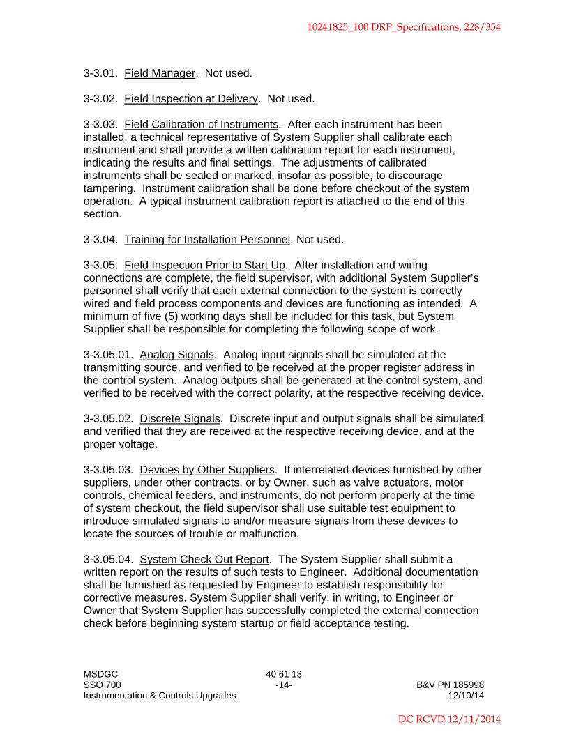
MSDGC 40 61 13 SSO 700 -14- B&V PN 185998 Instrumentation & Controls Upgrades 12/10/14
3-3.01. Field Manager. Not used. 3-3.02. Field Inspection at Delivery. Not used. 3-3.03. Field Calibration of Instruments. After each instrument has been installed, a technical representative of System Supplier shall calibrate each instrument and shall provide a written calibration report for each instrument, indicating the results and final settings. The adjustments of calibrated instruments shall be sealed or marked, insofar as possible, to discourage tampering. Instrument calibration shall be done before checkout of the system operation. A typical instrument calibration report is attached to the end of this section. 3-3.04. Training for Installation Personnel. Not used. 3-3.05. Field Inspection Prior to Start Up. After installation and wiring connections are complete, the field supervisor, with additional System Supplier’s personnel shall verify that each external connection to the system is correctly wired and field process components and devices are functioning as intended. A minimum of five (5) working days shall be included for this task, but System Supplier shall be responsible for completing the following scope of work. 3-3.05.01. Analog Signals. Analog input signals shall be simulated at the transmitting source, and verified to be received at the proper register address in the control system. Analog outputs shall be generated at the control system, and verified to be received with the correct polarity, at the respective receiving device. 3-3.05.02. Discrete Signals. Discrete input and output signals shall be simulated and verified that they are received at the respective receiving device, and at the proper voltage. 3-3.05.03. Devices by Other Suppliers. If interrelated devices furnished by other suppliers, under other contracts, or by Owner, such as valve actuators, motor controls, chemical feeders, and instruments, do not perform properly at the time of system checkout, the field supervisor shall use suitable test equipment to introduce simulated signals to and/or measure signals from these devices to locate the sources of trouble or malfunction. 3-3.05.04. System Check Out Report. The System Supplier shall submit a written report on the results of such tests to Engineer. Additional documentation shall be furnished as requested by Engineer to establish responsibility for corrective measures. System Supplier shall verify, in writing, to Engineer or Owner that System Supplier has successfully completed the external connection check before beginning system startup or field acceptance testing.
10241825_100 DRP_Specifications, 228/354
DC RCVD 12/11/2014

MSDGC 40 61 13 SSO 700 -15- B&V PN 185998 Instrumentation & Controls Upgrades 12/10/14
3-3.06. Start Up Assistance. After the field supervisor has completed the system check and submitted his report, System Supplier shall supply a factory-trained technician to provide on site start up assistance. During the startup period, these personnel shall thoroughly check all equipment, correct any deficiencies, and verify the proper operation of all components. Fifteen (15) working days shall be included for this task. 3-4. TESTING. The system shall be acceptance tested at the factory and on site. System Supplier shall prepare a testing procedure to be approved by Owner and Engineer that shall demonstrate that the system conforms to the specifications. The testing procedure shall be submitted at least 30 days in advance of testing. The testing shall be conducted by System Supplier as well as witnessed and approved by Owner and Engineer. System Supplier shall notify Engineer and Owner in writing at least 14 days before the proposed testing date. If the factory acceptance test is concluded unsuccessfully, the test shall be repeated. System Supplier shall reimburse Owner and Engineer for all expenses incurred in connection with attending repeated factory or site testing necessitated by system failure or inadequate preparation.
3-4.01. Factory Acceptance Testing. After system assembly and debugging at System Supplier’s facility, the system shall be tested before the system is shipped to the site. The factory test shall be conducted on complete system, including all field I/O devices, communications and network equipment, and peripherals. The entire system, including all peripherals and associated software, shall be factory tested under simulated operating conditions. Both normal operating sequences and fault conditions shall be simulated. All basic functions shall be demonstrated, including I/O processing, communications, alarm handling, as well as the specific functions listed herein. The test procedure shall also include at a least four-hour period for discretionary tests to be conducted by Engineer or Owner. For systems with software configuration by Engineer/Owner, a preliminary version of such configured software may be used as part of the factory acceptance test. 3-4.02. Site Acceptance Testing. After installation and checkout by System Supplier’s personnel, the system shall be subjected to an acceptance test.
10241825_100 DRP_Specifications, 229/354
DC RCVD 12/11/2014

MSDGC 40 61 13 SSO 700 -16- B&V PN 185998 Instrumentation & Controls Upgrades 12/10/14
Site acceptance testing shall be scheduled after receipt of the System Check Out Report and System Supplier shall verify that all field signal changes are reflected in the proper address locations in the system database. The site acceptance testing shall operate without loss of basic functions. The number of working days of continuous operation for the test shall be seven (7). The operational demonstration shall confirm that the status, alarm, and process variable signals are valid and are being updated appropriately, and that the discrete and analog output signals from the control system are being correctly transmitted and implemented. Any errors or abnormal occurrences shall be recorded by System Supplier’s field representative. System Supplier’s field representative need not be continuously present during the site acceptance testing, but shall be available to respond to the site within one hour of notification. The representative shall inspect the system for faults at least once every 24 hours and shall log or record any noted problems. The log shall include a description of the problem, its apparent cause, and any corrective action taken. 3-4.02.01. Hardware Test. Processors, processor modules, and peripheral devices associated with the system shall be assembled together and shall be tested. The test shall demonstrate proper operation of each hardware device and communications among devices, and shall include verification of selected analog and discrete inputs and outputs. 3-4.02.02. Software Test. All system software modules specified herein shall be demonstrated. Software tests shall include running all diagnostics, debugging routines, and system test routines. The operating system, advanced process control language compiler, and all associated drivers shall be fully tested and operable for the system test. Software "patches" or changes to bypass failed or flawed modules during the test will not be acceptable. 3-4.02.03. Failure of Redundant Equipment. Failure of redundant equipment shall not be considered downtime provided that automatic failover occurs as specified and, in the opinion of Engineer, the failure was not caused by deficiency in design or installation. In the event of repeated failure of any hardware component or software module, the acceptance test shall be terminated and re-started. 3-4.02.04. Completion of Test. Successful completion of the site acceptance test, including the operational demonstration, is prerequisite to Substantial Completion as specified in the Modified Standard General Conditions. 3-5. TRAINING. Not used.
End of Section
10241825_100 DRP_Specifications, 230/354
DC RCVD 12/11/2014

INSTRUMENT NAME & SERVICE:
BRAND & MODEL NO.:
TAG OR LOOP NO.:
INPUT/OUTPUT RANGE:
INPUT
ACTUAL OUTPUT
DESIRED OUTPUT
PROPORTIONAL BAND:
RESET:
POSITION OF SWITCHES, JUMPERS, ETC.
COMMENTS:
DATE OF CALIBRATION: CALIBRATED BY:
Black & Veatch INSTRUMENT CALIBRATION REPORT
Figure 1-40 61 13
10241825_100 DRP_Specifications, 231/354
DC RCVD 12/11/2014

Item Tag Loop Service Description Device Type Remarks Size Output Type Output Range Power Specification PID Drawing
1 LIT 101005 Diversion Chamber - Upstream Interceptor - Level Radar Level Transmitter Modify Existing Unit Exist. 4-20 mA 0-22 FT. 4-WIRE40 73 00 and
40 95 11 PI04
2 LSH 101006 Diversion Chamber - Upstream Interceptor - Level High Fixed-Mount Float Switch w/ Intrinsically Safe Relay Dry ContactTrip @ ELE. 544.00 FT. N/A
40 73 00 and 40 95 11 PI04
3 LIT 101010 Diversion Chamber - Downstream Interceptor - Level Radar Level Transmitter Modify Existing Unit Exist. 4-20 mA 0-22 FT. 4-WIRE40 73 00 and
40 95 11 PI04
4 LSLL 101035 Raw Influent Sample Pump - Level Low Fixed-Mount Float Switch w/ Intrinsically Safe Relay Dry ContactTrip @ ELE. 533.00 FT. N/A
40 73 00 and 40 95 11 PI04
5 LFIT 101040 Diversion Chamber - Facility Influent Weir - Flow Radar Level Transmitter Modify Existing Unit Exist. 4-20 mA 0-1.25 FT. 4-WIRE40 73 00 and
40 95 11 PI04
6 LIT 101060 Influent Pump Station - Wet Well - Level Radar Level Transmitter Modify Existing Unit Exist. 4-20 mA 0-35 FT. 4-WIRE40 73 00 and
40 95 11 PI05
7 LSLL 101060 Influent Pump Station - Wet Well - Level Low-Low Fixed-Mount Float Switch w/ Intrinsically Safe Relay Dry ContactTrip @ ELE. 527.00 FT. N/A
40 73 00 and 40 95 11 PI05
8 LSHH 101060 Influent Pump Station - Wet Well - Level High-High Fixed-Mount Float Switch w/ Intrinsically Safe Relay Dry ContactTrip @ ELE. 538.00 FT. N/A
40 73 00 and 40 95 11 PI05
9 LSLL 101065 Wet Well Drainage Pump - Level Low Fixed-Mount Float Switch w/ Intrinsically Safe Relay Dry ContactTrip @ ELE. 522.00 FT. N/A
40 73 00 and 40 95 11 PI05
10 LSL 101065 Wet Well Drainage Pump - Level Stop Fixed-Mount Float Switch w/ Intrinsically Safe Relay Dry ContactTrip @ ELE. 522.50 FT. N/A
40 73 00 and 40 95 11 PI05
11 LSH 101075 Influent Pump Station - Valve Vault - Level High Flood Level Switch w/ Intrinsically Safe Relay Dry ContactTrip @ 1" above
finished floor N/A40 73 00 and
40 95 11 PI05
12 LI 152101 Storage Tank No. 1 - Level Remote Level Display Replace as Required. N/A 0-35 FT. N/A 40 73 00 PI06
13 LIT 152101 Storage Tank No. 1 - Level Pulse Radar Level Transmitter Modify Existing Unit Exist. 4-20 mA 0-35 FT. 4-WIRE40 73 00 and
40 95 11 PI06
14 LSL 152101 Storage Tank No. 1 - Level Low Fixed-Mount Float Switch w/ Intrinsically Safe Relay Dry ContactTrip @ ELE. 556.42 FT. N/A
40 73 00 and 40 95 11 PI06
15 LI 152201 Storage Tank No. 2 - Level Remote Level Display Replace as Required. N/A 0-35 FT. N/A 40 73 00 PI07
16 LIT 152201 Storage Tank No. 2 - Level Pulse Radar Level Transmitter Modify Existing Unit 4-20 mA 0-35 FT. 4-WIRE40 73 00 and
40 95 11 PI07
17 LFI 152202 Storage Tank No. 2 - Level (Flow) Remote Level Display Replace as Required. N/A 0-2.0 FT. N/A 40 73 00 PI07
18 LFIT 152202 Storage Tank No. 2 - Level (Flow) Pulse Radar Level Transmitter Modify Existing Unit 4-20 mA 0-2.0 FT. 4-WIRE40 73 00 and
40 95 11 PI07
19 LSL 152201 Storage Tank No. 2 - Level Low Fixed-Mount Float Switch w/ Intrinsically Safe Relay Dry ContactTrip @ ELE. 556.42 FT. N/A
40 73 00 and 40 95 11 PI07
20 LI 152301 Storage Tank No. 3 - Level Remote Level Display Replace as Required. N/A 0-35 FT. N/A 40 73 00 PI07
21 LIT 152301 Storage Tank No. 3 - Level Pulse Radar Level Transmitter Modify Existing Unit 4-20 mA 0-35 FT. 4-WIRE40 73 00 and
40 95 11 PI07
22 LFI 152302 Storage Tank No. 3 - Level (Flow) Remote Level Display Replace as Required. N/A 0-2.0 FT. N/A 40 73 00 PI07
23 LFIT 152302 Storage Tank No. 3 - Level (Flow) Pulse Radar Level Transmitter Modify Existing Unit 4-20 mA 0-2.0 FT. 4-WIRE40 73 00 and
40 95 11 PI07
24 LSL 152301 Storage Tank No. 3 - Level Low Fixed-Mount Float Switch w/ Intrinsically Safe Relay Dry ContactTrip @ ELE. 556.42 FT. N/A
40 73 00 and 40 95 11 PI07
Instrument Device Schedule - Legend/Description Sheet
Power. This will typically be either '2-wire' for loop powered devices or '4-wire' for 120 volt powered devices.
PID Drawing. This is the drawing number of the P&ID where the device is shown.Spec. This is the section in the specifications where the device is specified.
Tag. This is the ISA (or similar) alpha tag representing the function of the instrument.Loop. This is the numeric (or alphanumeric) loop designation for the instrument.Service Description. This is the description of the instrument service (i.e. Filter No. 1 Loss-of-Head).
Output Type. This generally will be '4-20 mA' or "Dry Contact'. It could also be a serial output for smart devices (such as HART or FLD-BUS) but only if the serial output is the primary I/O interface.
Device Type & Size. This is the instrument device type and should match the description as listed in the specification. Where appropriate, the size of the device (such as diameter of flowmeters) will be listed.Remarks. This column may include a cross reference to another specification section where applicable or to a note which provides additional information. Notes are appended to the end of the device schedule listings.
Output Range. This is the calibrated range for analog devices or the trip point(s) for discrete devices.
MSDGCSSO 700Instrumentation and Controls Upgrades
40 61 13 A-1
B PN 18599812/10/14
10241825_100 DRP_Specifications, 232/354
DC RCVD 12/11/2014

Item Tag Loop Service Description Device Type Remarks Size Output Type Output Range Power Specification PID Drawing
25 LSH 273100 CEHRS - Screen No. 1 - Inlet Channel - Level High Fixed-Mount Float Switch w/ Intrinsically Safe Relay Dry ContactTrip @ ELE. 565.42 FT. N/A
40 73 00 and 40 95 11 PI08
26 LSH 273200 CEHRS - Screen No. 2 - Inlet Channel - Level High Fixed-Mount Float Switch w/ Intrinsically Safe Relay Dry ContactTrip @ ELE. 565.42 FT. N/A
40 73 00 and 40 95 11 PI08
27 LSLL 273010 CEHRS - Influent Sample Pump - Level Low Fixed-Mount Float Switch w/ Intrinsically Safe Relay Dry ContactTrip @ ELE. 550.00 FT. N/A
40 73 00 and 40 95 11 PI08
28 LSLL 273015 CEHRS - Chemical Induction Unit - Level Low (Minimum Level) Fixed-Mount Float Switch w/ Intrinsically Safe Relay Dry ContactTrip @ ELE. 559.00 FT. N/A
40 73 00 and 40 95 11 PI08
29 LSLL 273035 CEHRS - Settling Tank Collector - Level Low (Minimum Level) Fixed-Mount Float Switch w/ Intrinsically Safe Relay Dry ContactTrip @ ELE. 561.00 FT. N/A
40 73 00 and 40 95 11 PI09
30 LSLL 273045 CEHRS - Effluent Sample Pump - Level Low Fixed-Mount Float Switch w/ Intrinsically Safe Relay Dry ContactTrip @ ELE. 557.83 FT. N/A
40 73 00 and 40 95 11 PI09
31 LIT 404010B UV Disinfection - Channel - Level Pulse Radar Level Transmitter Modify Existing Unit 4-20 mA 0-3.5 FT. 4-WIRE 40 73 00 PI10
32 FE 404015 UV Disinfection - Channel - Flow Open Channel Ultrasonic Flow Meter N/A see Transmitter N/A 40 71 00 PI10
33 FQIT 404015 UV Disinfection - Channel - Flow Open Channel Ultrasonic Flow Transmitter 4-20 mA 0-15.0 MGD 4-WIRE 40 71 00 PI10
34 LSLL 415005 Total Effluent Chamber - Sample Pump - Level Low Fixed-Mount Float Switch w/ Intrinsically Safe Relay Dry ContactTrip @ ELE. 545.00 FT. N/A
40 73 00 and 40 95 11 PI10
35 LSH 273495 CEHRS - Basement Drain Sump - Level High Flood Level Switch w/ Intrinsically Safe Relay Dry ContactTrip @ 1" below
finished floor N/A40 73 00 and
40 95 11 PI11
36 LSH 273896 Coagulant Metering Pumps Containment Area - Level High Flood Level Switch w/ Intrinsically Safe Relay Dry ContactTrip @ 1" below
finished floor N/A40 73 00 and
40 95 11 PI14
MSDGCSSO 700Instrumentation and Controls Upgrades
40 61 13 A-2
B PN 18599812/10/14
10241825_100 DRP_Specifications, 233/354
DC RCVD 12/11/2014

THIS PAGE LEFT BLANK INTENTIONALLY
10241825_100 DRP_Specifications, 234/354
DC RCVD 12/11/2014

MSDGC 40 64 00 SSO 700 -1- B&V PN 185998 Instrumentation & Controls Upgrades 12/10/14
Section 40 64 00
PROGRAMMABLE LOGIC CONTROLLER MODIFICATIONS
PART 1 - GENERAL 1-1. SCOPE. This section covers additions and modifications to programmable logic controllers (PLCs), including associated input/output hardware to control process equipment and serve as the interface to field devices. A new remote I/O panel shall be provided and connected to the facility’s existing PLC using ControlNet communications. A new Central Processor Unit (CPU) shall be provided to replace the existing CPU in the existing PLC panel. A new discrete input module shall be provided and installed in a spare slot in the UV System PLC panel. Terminals shall be provided and installed for interfacing field wiring with the new discrete input module. 1-1.01. Control System. The Instrumentation and Control System section shall apply to all equipment furnished under this section. Additional PLC software requirements are indicated in Software Control Block Descriptions section.
1-2. GENERAL. Equipment furnished and installed under this section shall be fabricated, assembled, erected, and placed in proper operating condition in full conformity with the drawings, specifications, engineering data, instructions, and recommendations of the equipment manufacturer, unless exceptions are noted by Engineer. 1-2.01. General Equipment Stipulations. The General Equipment Stipulations shall apply to all equipment and materials furnished under this section. If requirements in this specification differ from those in the General Equipment Stipulations, the requirements specified herein shall take precedence. 1-2.02. Drawings. Supplementing this section, the drawings indicate the number and types of PLCs, locations of PLCs, and provide diagrams and schematics regarding connection and interaction with other equipment. All hardware, including power supplies, special cables, and other appurtenant equipment, shall be provided to meet the functional requirements described herein and indicated on the drawings. 1-2.03. I/O List. An input/output (I/O) field device signal listing is included as an appendix attached to this section. 1-3. SUBMITTALS. Submittals shall be as specified in the Instrumentation and Control System section. 1-4. DELIVERY, STORAGE, AND SHIPPING. Delivery, storage and shipping
10241825_100 DRP_Specifications, 235/354
DC RCVD 12/11/2014
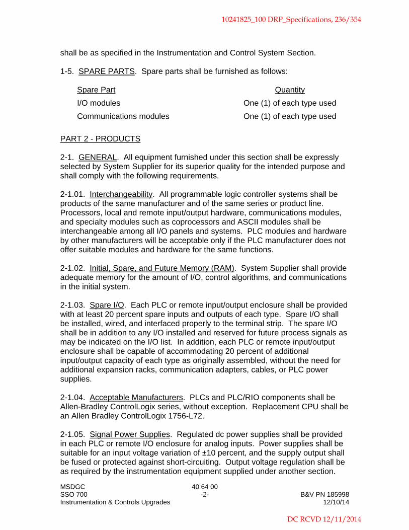
MSDGC 40 64 00 SSO 700 -2- B&V PN 185998 Instrumentation & Controls Upgrades 12/10/14
shall be as specified in the Instrumentation and Control System Section. 1-5. SPARE PARTS. Spare parts shall be furnished as follows:
Spare Part Quantity
I/O modules One (1) of each type used
Communications modules One (1) of each type used
PART 2 - PRODUCTS 2-1. GENERAL. All equipment furnished under this section shall be expressly selected by System Supplier for its superior quality for the intended purpose and shall comply with the following requirements. 2-1.01. Interchangeability. All programmable logic controller systems shall be products of the same manufacturer and of the same series or product line. Processors, local and remote input/output hardware, communications modules, and specialty modules such as coprocessors and ASCII modules shall be interchangeable among all I/O panels and systems. PLC modules and hardware by other manufacturers will be acceptable only if the PLC manufacturer does not offer suitable modules and hardware for the same functions.
2-1.02. Initial, Spare, and Future Memory (RAM). System Supplier shall provide adequate memory for the amount of I/O, control algorithms, and communications in the initial system. 2-1.03. Spare I/O. Each PLC or remote input/output enclosure shall be provided with at least 20 percent spare inputs and outputs of each type. Spare I/O shall be installed, wired, and interfaced properly to the terminal strip. The spare I/O shall be in addition to any I/O installed and reserved for future process signals as may be indicated on the I/O list. In addition, each PLC or remote input/output enclosure shall be capable of accommodating 20 percent of additional input/output capacity of each type as originally assembled, without the need for additional expansion racks, communication adapters, cables, or PLC power supplies. 2-1.04. Acceptable Manufacturers. PLCs and PLC/RIO components shall be Allen-Bradley ControlLogix series, without exception. Replacement CPU shall be an Allen Bradley ControlLogix 1756-L72.
2-1.05. Signal Power Supplies. Regulated dc power supplies shall be provided in each PLC or remote I/O enclosure for analog inputs. Power supplies shall be suitable for an input voltage variation of ±10 percent, and the supply output shall be fused or protected against short-circuiting. Output voltage regulation shall be as required by the instrumentation equipment supplied under another section.
10241825_100 DRP_Specifications, 236/354
DC RCVD 12/11/2014

MSDGC 40 64 00 SSO 700 -3- B&V PN 185998 Instrumentation & Controls Upgrades 12/10/14
The loop power supply shall be separate from the power supply circuit for the processor and racks. The power source for all digital inputs from field devices shall be separately fused for each digital input module. Unless otherwise noted, all field devices will be provided with dry contacts that close to provide an input to the PLC. 2-1.06. Appurtenances. The PLC processor, RIO units, and I/O hardware shall be provided as complete systems, as shown on the block diagram drawings. The PLCs and/or RIO units shall include all necessary hardware and software for a complete working system. All special rack or panel mounted power supplies, special interconnecting and programming cables, special grounding hardware, or isolation devices shall be furnished for proper operation of the equipment. Signal converters, signal boosters, amplifiers, special power supplies, special cable, special grounding, intrinsically safe relays and current repeaters, surge suppression devices, and isolation devices shall be furnished and installed for proper operation of the equipment. 2-1.07. PLC Arrangement. The RIO units shall be distributed and arranged as indicated on the drawings. 2-1.08. Service Conditions. RIO units will be installed in air conditioned rooms.
2-2. PLC/RIO EQUIPMENT REQUIREMENTS. 2-2.01. Communications. Each RIO unit shall be furnished complete with communication modules for local and remote input/output hardware communications, communications with other programmable controllers, and communication with host computers as shown on the block diagram. 2-2.02. Hardware Configuration. RIO units shall be configured for standard rack mounting. Each RIO unit shall include integral communications ports for remote communications interfaces. 2-2.03. Input/Output Hardware. Input/output hardware shall be arranged as indicated on the drawings. Programmable logic controller systems shall support the following types of input/output modules.
120 volt ac digital input and output.
4-20 mA dc analog input and output.
All digital input/output hardware shall include isolation against surges of at least 1500 volts. All output hardware connected to inductive loads shall be supplied with surge suppression devices and recommended by the PLC manufacturer to
10241825_100 DRP_Specifications, 237/354
DC RCVD 12/11/2014

MSDGC 40 64 00 SSO 700 -4- B&V PN 185998 Instrumentation & Controls Upgrades 12/10/14
prevent damage to output hardware. Combination input/output modules will be acceptable if they meet the following requirements. 2-2.03.01. Wiring Terminals. All input/output modules shall utilize easily removable plug-in or hinged field wiring terminals to allow removal of modules without disconnecting individual wires. 2-2.03.02. I/O Circuit Power Supply. Outputs for motor driven equipment will typically be powered from the driven equipment. Digital outputs for miscellaneous equipment shall be powered either from the controlled equipment or the PLC enclosure as indicated on the drawings or as coordinated with the controlled equipment supplier. Outputs that control process equipment specified under other sections or provided under other contracts shall be fully isolated or shall operate either interposing relays or relay-type digital output modules in the PLC cabinet.
2-2.03.03. Digital Input Modules. Digital input modules shall sense voltages between 100 and 130 volts ac and shall have LED indicators for each point to display the status of the field contact. Each input module shall be suitable for being connected to a separate voltage source and return. Digital input modules shall provide complete electrical isolation between individual inputs. Digital input modules shall have multiple inputs. Digital input modules shall be Allen-Bradley ControlLogix “1756-IA16”, without exception.
2-2.03-04. Digital Output Modules. Not used. 2-2.03.05. Relay Digital Output Modules. Where indicated on the PLC input/output listing, digital output modules shall have dry contact relay type outputs suitable to control voltages from 24 to 110 volts dc and 24 to 230 volts ac and shall be rated at least 2 amperes. Outputs have LED indicators to display output status. Digital outputs for motor driven equipment shall be powered by the driven equipment. Outputs shall withstand a surge of at least 80 amperes for 15 milliseconds. Relay digital output modules shall have multiple outputs. Relay digital output modules shall be Allen-Bradley ControlLogix “1756-OW16I”, without exception.
2-2.03.06. Analog Input Modules. Analog input modules shall accept linear 4-20 mA dc signals from field transmitters. Analog to digital conversion accuracy shall be at least 12-bit (0-4095 count) resolution. Analog input modules shall have multiple inputs. Each input shall be fully isolated from the other inputs. Analog input modules shall be Allen-Bradley ControlLogix “1756-IF6I”, without exception. 2-2.03.07. Analog Output Modules. Analog output modules shall transmit linear 4-20 mA dc signals to field devices. Loop power for all analog outputs shall be provided by regulated power supplies in each input/output enclosure and shall be
10241825_100 DRP_Specifications, 238/354
DC RCVD 12/11/2014

MSDGC 40 64 00 SSO 700 -5- B&V PN 185998 Instrumentation & Controls Upgrades 12/10/14
capable of driving a 0 to 600 ohm load. Digital to analog conversion accuracy shall be at least 12-bit (0-4095 count) resolution. Analog output modules shall have multiple outputs. Analog output modules shall be Allen-Bradley ControlLogix “1756-OF6CI”, without exception. 2-2.03.08. Panel Terminations. All PLC input/output signals for field connections shall be terminated through panel enclosure terminal strips. Direct connection of field wiring to the I/O module terminals is not acceptable. 2-2.03.09. Interposing Relays. Interposing relays shall be incorporated on all I/O circuits as shown on the PLC input/output listing, where required by the application of isolate foreign power sources, where the continuous output rating of the PLC relay digital or output module is not sufficient to power the connected device or equipment, or where otherwise required by the System Supplier’s equipment. Interposing relays shall be provided for any digital output module output signal that leaves the PLC enclosure. Interposing relays shall be mounted in the PLC enclosure containing the output module that activates the relays.
2-3. MINI PLC PROCESSOR. Not used. 2-4. COMMUNICATIONS. Each programmable controller or remote I/O system shall be furnished complete with communication hardware modules for local input/output hardware andremote input/output hardware. Communication hardware shall be compatible with the cable, data highway, fiber optic, or radio communication media. Ethernet components and cable are specified in other specification sections. 2-4.01. Addressability. Each programmable logic controller shall be individually addressable so that only the selected controller responds when queried. Designation of a controller's network address may be either a software or hardware function. 2-4.02. Communications Hardware. System Supplier shall provide all necessary communications hardware. Hardware shall be included for, but not be limited to, remote I/O. 2-4.02.01. PLC to PLC Communications Hardware. Not used. 2-4.02.02. PLC to Remote Communications Hardware. The master PLC shall communicate with the remote PLC rack over a ControlNET communications network. System Supplier shall include all rack mounted, enclosure mounted, or desktop mounted communications modules required for a complete working system. New ControlNet modules (2) shall be provided for the existing PLC enclosure to ensure compatibility with new modules being provided for the new I/O panel.
10241825_100 DRP_Specifications, 239/354
DC RCVD 12/11/2014

MSDGC 40 64 00 SSO 700 -6- B&V PN 185998 Instrumentation & Controls Upgrades 12/10/14
2-4.02.03. PLC to Host Communications Hardware. Not used. 2-4.03. Communications Media. System Supplier shall provide all necessary cabling for the PLC remote I/O communications network. Communications cables shall meet the requirements of the manufacturers of the PLCs and communications modules. PLC communications media shall be as specified under the Network Systems section. 2-5. MEDIA CONVERTERS. Not Used. 2-6. TELEPHONE NETWORKS. Not used. 2-7. SERIAL NETWORKS. Not Used.
2-8. PROGRAMMING DEVICE HARDWARE. Not used. 2-9. PROGRAMMING SOFTWARE. Not used. 2-10. SYSTEM ENCLOSURES. Remote input/output hardware shall be housed in shop-assembled panels as indicated on the drawings and/or as described in the Panels, Consoles, and Appurtenances section. 2-11. OPERATOR INTERFACE TERMINALS. Not Used. PART 3 - EXECUTION 3-1. INSTALLATION REQUIREMENTS. PLC and RIO unit installation requirements are specified in Instrumentation and Control System section except as described herein. Field check, testing, and training shall be as specified in the Instrumentation and Control System section. 3-2. CONFIGURATION. 3-2.01. PLC Programming and Configuration. Configuration services are specified in the Instrumentation and Control System section. 3-2.02. Communications Configuration. The communications shall be fully configured and installed by System Supplier. Communications shall be configured as shown on the drawings.
End of Section
10241825_100 DRP_Specifications, 240/354
DC RCVD 12/11/2014

Item Type Description I/O Block Field Device Controller ID Rack Slot PointAnalog
Signal TypeAnalog
Calibrated Analog PowerDigital Signal
Type Digital Closed StateDigital Power
SourceDigital Interp
Relay Remarks PID Drawing
1 AICoagulant Pump No.1 Speed Signal From I/I Isolator In SSO 700 Treatment Facilities Control Panel SI-273850 PHS-273850 PLC SSO 700 0 10 0 4-20 mA 0-100% 4-WIRE N/A N/A N/A N/A Existing PI14
2 AIPolymer Pump No.1 Speed Signal From I/I Isolator In SSO 700 Treatment Facilities Control Panel SI-273950 PPS-273950 PLC SSO 700 0 10 1 4-20 mA 0-100% 4-WIRE N/A N/A N/A N/A Existing PI15
3 AICoagulant Tank Level 0 to 11 Feet is scaled 0 to 100 % inradar for former FieldBus Conversion. LI-273820 LIT-273820 PLC SSO 700 0 10 2 4-20 mA 0 - 11 FT 4-WIRE N/A N/A N/A N/A Existing PI13
4 AI CEHRS Influent Flow 0 to 15 MGD FQI-273005 FQIT-273005 PLC SSO 700 0 10 3 4-20 mA 0 -15 MGD 4-WIRE N/A N/A N/A N/A Existing PI08
5 AI Storage Tank #1 Influent Flow$N0 to XX MGD FI-152104 FIT-152104 PLC SSO 700 0 10 4 4-20 mA 0 - XX MGD 4-WIRE N/A N/A N/A N/A Existing N/A
6 AI Storage Tank #2 Influent Flow$N0 to XX MGD FI-152204 FIT-152204 PLC SSO 700 0 10 5 4-20 mA 0 - XX MGD 4-WIRE N/A N/A N/A N/A Existing N/A
7 AICoagulant Pump No.2 Speed Signal From I/I Isolator In SSO 700 Treatment Facilities Control Panel SI-273870 PHS-273870 PLC SSO 700 0 11 0 4-20 mA 0-100% 4-WIRE N/A N/A N/A N/A Existing PI14
8 AIPolymer Pump No.2 Speed Signal From I/I Isolator In SSO 700 Treatment Facilities Control Panel SI-273970 PPS-273970 PLC SSO 700 0 11 1 4-20 mA 0-100% 4-WIRE N/A N/A N/A N/A Existing PI15
9 AITotal Effluent pH Signal From pH Analyzer AIT-502 In UV Disinfection Room AI-415116A AIT-415116A PLC SSO 700 0 11 2 4-20 mA 0 - 14 pH 4-WIRE N/A N/A N/A N/A Existing PI12
10 AITotal Effluent Temp Signal From pH Analyzer AIT-502 In UV Disinfection Room AI-415116B AIT-415116B PLC SSO 700 0 11 3 4-20 mA 0 - 30 DEG C 4-WIRE N/A N/A N/A N/A Existing PI12
11 AI Spare Analog Input PLC SSO 700 0 11 4 4-20 mA N/A N/A N/A N/A N/A N/A Existing N/A
12 AI Spare Analog Input PLC SSO 700 0 11 5 4-20 mA N/A N/A N/A N/A N/A N/A Existing N/A
13 AICher's Influent pH Signal From pH Analyzer AIT-308 In UV Disinfection Room AI-273316 AIT-273316 PLC SSO 700 0 12 0 4-20 mA 0 - 14 pH 4-WIRE N/A N/A N/A N/A Existing PI12
14 AICher's Influent Turbidity Signal From Turbidity Analyzer AIT-310 In UV Disinfection Room AI-273317 AIT-273317 PLC SSO 700 0 12 1 4-20 mA 0 - 800 NTU 4-WIRE N/A N/A N/A N/A Existing PI12
15 AICher's Effluent pH Signal From pH Analyzer AIT-309 In UV Disinfection Room AI-273336 AIT-273336 PLC SSO 700 0 12 2 4-20 mA 0 - 14 pH 4-WIRE N/A N/A N/A N/A Existing PI12
16 AICher's Effluent Turbidity Signal From Turbidity Analyzer AIT-311 In UV Disinfection Room AI-273337 AIT-273337 PLC SSO 700 0 12 3 4-20 mA 0 - 500 NTU 4-WIRE N/A N/A N/A N/A Existing PI12
17 AITreatment Facility KW Signal From Digital Power Monitor In MCC JI-997205B JIT-997205B PLC SSO 700 0 12 4 4-20 mA 0 - 900 KW 4-WIRE N/A N/A N/A N/A Existing PI16
18 AI Spare Analog Input PLC SSO 700 0 12 5 4-20 mA N/A N/A N/A N/A N/A N/A Existing N/A
19 AI Spare Analog Input PLC SSO 700 0 13 0 4-20 mA N/A N/A N/A N/A N/A N/A Existing N/A
20 AI Spare Analog Input PLC SSO 700 0 13 1 4-20 mA N/A N/A N/A N/A N/A N/A Existing N/A
21 AI Spare Analog Input PLC SSO 700 0 13 2 4-20 mA N/A N/A N/A N/A N/A N/A Existing N/A
22 AI Spare Analog Input PLC SSO 700 0 13 3 4-20 mA N/A N/A N/A N/A N/A N/A Existing N/A
23 AI Spare Analog Input PLC SSO 700 0 13 4 4-20 mA N/A N/A N/A N/A N/A N/A Existing N/A
24 AI Spare Analog Input PLC SSO 700 0 13 5 4-20 mA N/A N/A N/A N/A N/A N/A Existing N/A
1 AOSpeed Control Signal To I/I Isolator In SSO 700 TreatmentFacilities Control Panel For Coagulant Feed Pump No.1 SC-273850 PHS-273850 PLC SSO 700 0 15 0 4-20 mA 0-100% 4-WIRE N/A N/A N/A N/A Existing PI14
2 AOSpeed Control Signal To I/I Isolator In SSO 700 TreatmentFacilities Control Panel For Polymer Feed Pump No.1 SC-273950 PPS-273950 PLC SSO 700 0 15 1 4-20 mA 0-100% 4-WIRE N/A N/A N/A N/A Existing PI15
3 AO Flow Pace Signal To Raw Influent Sampler In UV Room FC-101710 SAMP-101710 PLC SSO 700 0 15 2 0-20 mA 0 - 40 MGD 4-WIRE N/A N/A N/A N/A Existing PI12
4 AO Flow Pace Signal To Total Effluent Sampler In UV Room FC-415110 SAMP-415110 PLC SSO 700 0 15 3 0-20 mA 0 - 30 MGD 4-WIRE N/A N/A N/A N/A Existing PI12
5 AO Spare Analog Output PLC SSO 700 0 15 4 4-20 mA N/A 4-WIRE N/A N/A N/A N/A Existing N/A
6 AO Spare Analog Output PLC SSO 700 0 15 5 4-20 mA N/A 4-WIRE N/A N/A N/A N/A Existing N/A
7 AOSpeed Control Signal To I/I Isolator In SSO 700 TreatmentFacilities Control Panel For Coagulant Feed Pump No.2 SC-273870 PHS-273870 PLC SSO 700 0 16 0 4-20 mA 0-100% 4-WIRE N/A N/A N/A N/A Existing PI14
Input/Output List
NOTES:
MSDGCSSO 700Instrumentation and Controls Upgrades
40 64 00 A-1
B PN 18599812/10/14
10241825_100 DRP_Specifications, 241/354
DC RCVD 12/11/2014

Item Type Description I/O Block Field Device Controller ID Rack Slot PointAnalog
Signal TypeAnalog
Calibrated Analog PowerDigital Signal
Type Digital Closed StateDigital Power
SourceDigital Interp
Relay Remarks PID Drawing
8 AOSpeed Control Signal To I/I Isolator In SSO 700 TreatmentFacilities Control Panel For Polymer Feed Pump No.2 SC-273970 PPS-273970 PLC SSO 700 0 16 1 4-20 mA 0-100% 4-WIRE N/A N/A N/A N/A Existing PI15
9 AO Flow Pace Signal To Cher's Influent Sampler In UV Room FC-273310 SAMP-273310 PLC SSO 700 0 16 2 4-20 mA 0 - 15 MGD 4-WIRE N/A N/A N/A N/A Existing PI12
10 AO Flow Pace Signal To Cher's Effluent Sampler In UV Room FC-273330 SAMP-273330 PLC SSO 700 0 16 3 4-20 mA 0 - 15 MGD 4-WIRE N/A N/A N/A N/A Existing PI12
11 AOFlow Pace Signal To UV Disinfection System Control Panel In UV Room FC-404010 UV-404010 PLC SSO 700 0 16 4 4-20 mA 0 - 15 MGD 4-WIRE N/A N/A N/A N/A Existing PI10
12 AO Spare Analog Output PLC SSO 700 0 16 5 4-20 mA N/A 4-WIRE N/A N/A N/A N/A Existing N/A
1 DI Pump Station Wet Well Low Level LALL 101060 LSLL 101060 PLC SSO 700 1 2 0 N/A N/A N/A 120 VAC Normal Field Yes Existing PI05
2 DI Pump Station Wet Well High Level LAHH-101060 LSHH-101060 PLC SSO 700 1 2 1 N/A N/A N/A 120 VAC Normal Field Yes Existing PI05
3 DI Hydraulic Power Pack In Remote Mode HS-152140A HPU-152140 PLC SSO 700 1 2 2 N/A N/A N/A 120 VAC In Remote PLC No Existing PI06
4 DI Hydraulic Power Pack In Manual Mode HS-152140B HPU-152140 PLC SSO 700 1 2 3 N/A N/A N/A 120 VAC In Manual PLC No Existing PI06
5 DI Hydraulic Power Pack Running YI-152140B HPU-152140 PLC SSO 700 1 2 4 N/A N/A N/A 120 VAC Running PLC No Existing PI06
6 DI Hydraulic Power Pack High Oil Temp YA-152140B HPU-152140 PLC SSO 700 1 2 5 N/A N/A N/A 120 VAC Alarm PLC No Existing PI06
7 DI Hydraulic Power Pack Low Oil Level YA-152140D HPU-152140 PLC SSO 700 1 2 6 N/A N/A N/A 120 VAC Alarm PLC No Existing PI06
8 DI Hydraulic Power Pack Low Oil Pressure YA-152140C HPU-152140 PLC SSO 700 1 2 7 N/A N/A N/A 120 VAC Alarm PLC No Existing PI06
9 DI Hydraulic Power Pack Overload YA-152140A HPU-152140 PLC SSO 700 1 2 8 N/A N/A N/A 120 VAC Overload PLC No Existing PI06
10 DI Hydraulic Power Pack In Service YI-152140A HPU-152140 PLC SSO 700 1 2 9 N/A N/A N/A 120 VAC In Service PLC No Existing PI06
11 DI Storage Tank #1 Flush Gate #1 Manual Open HS-152105 HPU-152140 PLC SSO 700 1 2 10 N/A N/A N/A 120 VAC Open Request PLC No Existing PI06
12 DI Storage Tank #1 Flush Gate #2 Manual Open HS-152110 HPU-152140 PLC SSO 700 1 2 11 N/A N/A N/A 120 VAC Open Request PLC No Existing PI06
13 DI Storage Tank #1 Flush Gate #3 Manual Open HS-152115 HPU-152140 PLC SSO 700 1 2 12 N/A N/A N/A 120 VAC Open Request PLC No Existing PI06
14 DI Storage Tank #1 Flush Gate #4 Manual Open HS-152120 HPU-152140 PLC SSO 700 1 2 13 N/A N/A N/A 120 VAC Open Request PLC No Existing PI06
15 DI Storage Tank #1 Flush Gate #5 Manual Open HS-152125 HPU-152140 PLC SSO 700 1 2 14 N/A N/A N/A 120 VAC Open Request PLC No Existing PI06
16 DI Storage Tank #1 Flush Gate #6 Manual Open HS-152130 HPU-152140 PLC SSO 700 1 2 15 N/A N/A N/A 120 VAC Open Request PLC No Existing PI06
17 DI Storage Tank #2 Flush Gate #1 Manual Open HS-152205 HPU-152140 PLC SSO 700 1 3 0 N/A N/A N/A 120 VAC Open Request PLC No Existing PI07
18 DI Storage Tank #2 Flush Gate #2 Manual Open HS-152210 HPU-152140 PLC SSO 700 1 3 1 N/A N/A N/A 120 VAC Open Request PLC No Existing PI07
19 DI Storage Tank #2 Flush Gate #3 Manual Open HS-152215 HPU-152140 PLC SSO 700 1 3 2 N/A N/A N/A 120 VAC Open Request PLC No Existing PI07
20 DI Storage Tank #2 Flush Gate #4 Manual Open HS-152220 HPU-152140 PLC SSO 700 1 3 3 N/A N/A N/A 120 VAC Open Request PLC No Existing PI07
21 DI Storage Tank #2 Flush Gate #5 Manual Open HS-152225 HPU-152140 PLC SSO 700 1 3 4 N/A N/A N/A 120 VAC Open Request PLC No Existing PI07
22 DI Storage Tank #2 Flush Gate #6 Manual Open HS-152230 HPU-152140 PLC SSO 700 1 3 5 N/A N/A N/A 120 VAC Open Request PLC No Existing PI07
23 DI Storage Tank #3 Flush Gate #1 Manual Open HS-152305 HPU-152140 PLC SSO 700 1 3 6 N/A N/A N/A 120 VAC Open Request PLC No Existing PI07
24 DI Storage Tank #3 Flush Gate #2 Manual Open HS-152310 HPU-152140 PLC SSO 700 1 3 7 N/A N/A N/A 120 VAC Open Request PLC No Existing PI07
25 DI Storage Tank #3 Flush Gate #3 Manual Open HS-152315 HPU-152140 PLC SSO 700 1 3 8 N/A N/A N/A 120 VAC Open Request PLC No Existing PI07
26 DI Storage Tank #3 Flush Gate #4 Manual Open HS-152320 HPU-152140 PLC SSO 700 1 3 9 N/A N/A N/A 120 VAC Open Request PLC No Existing PI07
27 DI Storage Tank #3 Flush Gate #5 Manual Open HS-152325 HPU-152140 PLC SSO 700 1 3 10 N/A N/A N/A 120 VAC Open Request PLC No Existing PI07
28 DI Storage Tank #3 Flush Gate #6 Manual Open HS-152330 HPU-152140 PLC SSO 700 1 3 11 N/A N/A N/A 120 VAC Open Request PLC No Existing PI07
29 DI Drainage Pump Low Level LALL-101065 LSLL-101065 PLC SSO 700 1 3 12 N/A N/A N/A 120 VAC Normal PLC No Existing PI05
MSDGCSSO 700Instrumentation and Controls Upgrades
40 64 00 A-2
B PN 18599812/10/14
10241825_100 DRP_Specifications, 242/354
DC RCVD 12/11/2014

Item Type Description I/O Block Field Device Controller ID Rack Slot PointAnalog
Signal TypeAnalog
Calibrated Analog PowerDigital Signal
Type Digital Closed StateDigital Power
SourceDigital Interp
Relay Remarks PID Drawing
30 DI Drainage Pump Stop Level LAL-101065 LSL-101065 PLC SSO 700 1 3 13 N/A N/A N/A 120 VAC Normal PLC No Existing PI05
31 DI Raw Influent Sample Pump Low Level LALL-101035 LSLL-101035 PLC SSO 700 1 3 14 N/A N/A N/A 120 VAC Normal PLC No Existing PI04
32 DI Diversion Chamber High Level LAH-101006 LSH-101006 PLC SSO 700 1 3 15 N/A N/A N/A 120 VAC Normal PLC No Existing PI04
33 DI Chemical Induction Unit In PC Mode HS-273015A CIU-273015 PLC SSO 700 1 4 0 N/A N/A N/A 120 VAC PC Mode PLC No Existing PI08
34 DI Chemical Induction Unit Running YI-273015B CIU-273015 PLC SSO 700 1 4 1 N/A N/A N/A 120 VAC Running PLC No Existing PI08
35 DI Chemical Induction Unit Fault YA-273015B CIU-273015 PLC SSO 700 1 4 2 N/A N/A N/A 120 VAC Fault PLC No Existing PI08
36 DI Chemical Induction Unit Overload YA-273015A CIU-273015 PLC SSO 700 1 4 3 N/A N/A N/A 120 VAC Overload PLC No Existing PI08
37 DI Chemical Induction Unit In Service YI-273015A CIU-273015 PLC SSO 700 1 4 4 N/A N/A N/A 120 VAC In Service PLC No Existing PI08
38 DI Chemical Induction Unit Minimum Level YI-273015C LSLL-273015 PLC SSO 700 1 4 5 N/A N/A N/A 120 VAC Normal PLC No Existing PI08
39 DI Coagulant Feed Pump #1 In Auto Mode HS-273850A PHS-273850 PLC SSO 700 1 4 6 N/A N/A N/A 120 VAC PC Mode PLC No Existing PI14
40 DI Coagulant Feed Pump #1 Running YI-273850 PHS-273850 PLC SSO 700 1 4 7 N/A N/A N/A 120 VAC Running PLC No Existing PI14
41 DI Coagulant Feed Pump #1 Hose Leak YA-273850 PHS-273850 PLC SSO 700 1 4 8 N/A N/A N/A 120 VAC Hose Leak PLC No Existing PI14
42 DI Coagulant Feed Pump #1 High Discharge Pressure PAH-273855 PHS-273850 PLC SSO 700 1 4 9 N/A N/A N/A 120 VAC Normal PLC No Existing PI14
43 DI Polymer Feed Pump #1 In Auto Mode HS-273950A PPS-273950 PLC SSO 700 1 4 10 N/A N/A N/A 120 VAC PC Mode PLC No Existing PI15
44 DI Polymer Feed Pump #1 Running YI-273950 PPS-273950 PLC SSO 700 1 4 11 N/A N/A N/A 120 VAC Running PLC No Existing PI15
45 DI Polymer Feed Pump #1 Hose Leak YA-273950 PPS-273950 PLC SSO 700 1 4 12 N/A N/A N/A 120 VAC Hose Leak PLC No Existing PI15
46 DI Polymer Feed Pump #1 High Discharge Pressure PAH-273950 PPS-273950 PLC SSO 700 1 4 13 N/A N/A N/A 120 VAC Normal PLC No Existing PI15
47 DI Spare Discrete Input PLC SSO 700 1 4 14 N/A N/A N/A 120 VAC N/A PLC No Existing N/A
48 DI Spare Discrete Input PLC SSO 700 1 4 15 N/A N/A N/A 120 VAC N/A PLC No Existing N/A
49 DI Coagulant Feed Pump #2 In Auto Mode HS-273870A PHS-273870 PLC SSO 700 1 5 0 N/A N/A N/A 120 VAC PC Mode PLC No Existing PI14
50 DI Coagulant Feed Pump #2 Running YI-273870 PHS-273870 PLC SSO 700 1 5 1 N/A N/A N/A 120 VAC Running PLC No Existing PI14
51 DI Coagulant Feed Pump #2 Hose Leak YA-273870 PHS-273870 PLC SSO 700 1 5 2 N/A N/A N/A 120 VAC Hose Leak PLC No Existing PI14
52 DI Coagulant Feed Pump #2 High Discharge Pressure PAH-273875 PHS-273870 PLC SSO 700 1 5 3 N/A N/A N/A 120 VAC Normal PLC No Existing PI14
53 DI Polymer Feed Pump # 2 In Auto Mode HS-273970A PPS-273970 PLC SSO 700 1 5 4 N/A N/A N/A 120 VAC PC Mode PLC No Existing PI15
54 DI Polymer Feed Pump # 2 Running YI-273970 PPS-273970 PLC SSO 700 1 5 5 N/A N/A N/A 120 VAC Running PLC No Existing PI15
55 DI Polymer Feed Pump #2 Hose Leak YA-273970 PPS-273970 PLC SSO 700 1 5 6 N/A N/A N/A 120 VAC Hose Leak PLC No Existing PI15
56 DI Polymer Feed Pump #2 High Discharge Pressure PAH-273975 PPS-273970 PLC SSO 700 1 5 7 N/A N/A N/A 120 VAC Normal PLC No Existing PI15
57 DI CEHRS Collector Hi Torque Alarm WAH-273035 WSH-273035 PLC SSO 700 1 5 8 N/A N/A N/A 120 VAC Alarm PLC No Existing PI09
58 DI CEHRS Collector Hi Torque ShutdownWAHH-273035 WSHH-273035 PLC SSO 700 1 5 9 N/A N/A N/A 120 VAC Alarm PLC No Existing PI09
59 DI CEHRS Tank Minimum Level LALL-273035 LSLL-273035 PLC SSO 700 1 5 10 N/A N/A N/A 120 VAC Normal PLC No Existing PI09
60 DI Polymer Preparation System Ready YI-273905B PAC-273905 PLC SSO 700 1 5 11 N/A N/A N/A 120 VAC Ready PLC No Existing PI15
61 DI Polymer Preparation System Alarm YA-273905 PAC-273905 PLC SSO 700 1 5 12 N/A N/A N/A 120 VAC Alarm PLC No Existing PI15
62 DI Polymer Preparation System Running YI-273905A PAC-273905 PLC SSO 700 1 5 13 N/A N/A N/A 120 VAC Running PLC No Existing PI15
63 DI Dry Polymer Hopper Low Level LAL-273905 PAC-273905 PLC SSO 700 1 5 14 N/A N/A N/A 120 VAC Normal PLC No Existing PI15
MSDGCSSO 700Instrumentation and Controls Upgrades
40 64 00 A-3
B PN 18599812/10/14
10241825_100 DRP_Specifications, 243/354
DC RCVD 12/11/2014

Item Type Description I/O Block Field Device Controller ID Rack Slot PointAnalog
Signal TypeAnalog
Calibrated Analog PowerDigital Signal
Type Digital Closed StateDigital Power
SourceDigital Interp
Relay Remarks PID Drawing
64 DI Spare Discrete Input PLC SSO 700 1 5 15 N/A N/A N/A 120 VAC N/A PLC No Existing N/A
65 DI Transfer Switch In Normal Position ZI-996005A TRS-996005 PLC SSO 700 1 6 0 N/A N/A N/A 120 VAC Normal PLC No Existing PI16
66 DI Transfer Switch in Emergency Position ZI-996005B TRS-996005 PLC SSO 700 1 6 1 N/A N/A N/A 120 VAC Generator PLC No Existing PI16
67 DI Spare Discrete Input PLC SSO 700 1 6 2 N/A N/A N/A 120 VAC N/A PLC No Existing N/A
68 DI Transfer Switch Pre-Transfer To Opposite State YI-996005A TRS-996005 PLC SSO 700 1 6 3 N/A N/A N/A 120 VAC Ready to Transfer PLC No Existing PI16
69 DI Generator Running YI-996010A GEN-996010 PLC SSO 700 1 6 4 N/A N/A N/A 120 VAC Running PLC No Existing PI16
70 DI Generator Alarm YA-996010A GEN-996010 PLC SSO 700 1 6 5 N/A N/A N/A 120 VAC Alarm PLC No Existing PI16
71 DI Generator Low Fuel Alarm YA-996010B GEN-996010 PLC SSO 700 1 6 6 N/A N/A N/A 120 VAC Alarm PLC No Existing PI16
72 DI Security Gate Request To Open YI-977030A SCG-977030 PLC SSO 700 1 6 7 N/A N/A N/A 120 VAC Request to Open PLC No Existing PI16
73 DI Security Gate Full Open ZI-977030A SCG-977030 PLC SSO 700 1 6 8 N/A N/A N/A 120 VAC Open PLC No Existing PI16
74 DI Security Gate Full Closed ZI-977030B SCG-977030 PLC SSO 700 1 6 9 N/A N/A N/A 120 VAC Closed PLC No Existing PI16
75 DI Security Gate Run Alarm YA-977030B SCG-977030 PLC SSO 700 1 6 10 N/A N/A N/A 120 VAC Alarm PLC No Existing PI16
76 DI Security Gate Obstruction Alarm YA-977030A SCG-977030 PLC SSO 700 1 6 11 N/A N/A N/A 120 VAC Alarm PLC No Existing PI16
77 DI Storage Tank #1 Low Level LAL-152101 LSL-152101 PLC SSO 700 1 6 12 N/A N/A N/A 120 VAC Normal PLC No Existing PI06
78 DI Storage Tank #2 Low Level LAL-152201 LSL-152201 PLC SSO 700 1 6 13 N/A N/A N/A 120 VAC Normal PLC No Existing PI07
79 DI Storage Tank #3 Low Level LAL-152301 LSL-152301 PLC SSO 700 1 6 14 N/A N/A N/A 120 VAC Normal PLC No Existing PI07
80 DI Spare Discrete Input PLC SSO 700 1 6 15 N/A N/A N/A 120 VAC N/A PLC No Existing N/A
81 DI Facility Fire Alarm YA-977010 FACP-977010 PLC SSO 700 1 7 0 N/A N/A N/A 120 VAC Alarm PLC No Existing PI16
82 DI Facility Intrusion Alarm YA-977020 SSCP-977020 PLC SSO 700 1 7 1 N/A N/A N/A 120 VAC Alarm PLC No Existing PI16
83 DI Coagulant Containment Sump High Level LAH-273895 LSH-273895 PLC SSO 700 1 7 2 N/A N/A N/A 120 VAC Normal PLC No Existing PI14
84 DI Treatment Facilities KWHR Pulse Input YI-997205 MCC-997205 PLC SSO 700 1 7 3 N/A N/A N/A 120 VAC KWHR Pulse PLC No Existing PI16
85 DI UV System Power Failure YA-404010A UV-404010 PLC SSO 700 1 7 4 N/A N/A N/A 120 VAC Alarm PLC No Existing PI10
86 DI UV System High Priority Alarm YA-404010B UV-404010 PLC SSO 700 1 7 5 N/A N/A N/A 120 VAC Alarm PLC No Existing PI10
87 DI UV System Low Priority Alarm YA-404010C UV-404010 PLC SSO 700 1 7 6 N/A N/A N/A 120 VAC Alarm PLC No Existing PI10
88 DI UV System Critical Instrumentation Alarm YA-404010D UV-404010 PLC SSO 700 1 7 7 N/A N/A N/A 120 VAC Alarm PLC No Existing PI10
89 DI UV System UV Dosage Failure YA-404010E UV-404010 PLC SSO 700 1 7 8 N/A N/A N/A 120 VAC Failure PLC No Existing PI10
90 DI UV System Lamp Failure YA-404010F UV-404010 PLC SSO 700 1 7 9 N/A N/A N/A 120 VAC Failure PLC No Existing PI10
91 DI UV Intensity Low Alarm YA-404010G UV-404010 PLC SSO 700 1 7 10 N/A N/A N/A 120 VAC Alarm PLC No Existing PI10
92 DI SSO 700 Treatment Facilities Control Panel On YI-977100A PLC-977100 PLC SSO 700 1 7 11 N/A N/A N/A 120 VAC Power On PLC No Existing PI16
93 DI SSO 700 Treatment Facilities Control Panel Open YI-977100B PLC-977100 PLC SSO 700 1 7 12 N/A N/A N/A 120 VAC Closed PLC No Existing PI16
94 DI SSO 700 Treatment Facilities Control Panel High Temp YA-977100 PLC-977100 PLC SSO 700 1 7 13 N/A N/A N/A 120 VAC Normal PLC No Existing PI16
95 DI Basement High Level Float LAH-273495 LSH-273495 PLC SSO 700 1 7 14 N/A N/A N/A 120 VAC Normal PLC No Existing PI11
96 DI Backflow Preventer Area Low Temp N/A N/A PLC SSO 700 1 7 15 N/A N/A N/A 120 VAC Normal PLC No Existing N/A
97 DI Utility Available YI-996005B TRS-996005 PLC SSO 700 1 8 0 N/A N/A N/A 120 VACUtility Power
Available PLC No Existing PI16
MSDGCSSO 700Instrumentation and Controls Upgrades
40 64 00 A-4
B PN 18599812/10/14
10241825_100 DRP_Specifications, 244/354
DC RCVD 12/11/2014

Item Type Description I/O Block Field Device Controller ID Rack Slot PointAnalog
Signal TypeAnalog
Calibrated Analog PowerDigital Signal
Type Digital Closed StateDigital Power
SourceDigital Interp
Relay Remarks PID Drawing
98 DI Generator Available YI-996005C TRS-996005 PLC SSO 700 1 8 1 N/A N/A N/A 120 VACGenerator Power
Available PLC No Existing PI16
99 DI Transfer Switch Fault YA-996005 TRS-996005 PLC SSO 700 1 8 2 N/A N/A N/A 120 VAC Fault PLC No Existing PI16
100 DI Screen 1 Inlet Gate Auto Mode HS-273105 GSC-273105 PLC SSO 700 1 8 3 N/A N/A N/A 120 VAC PC Mode PLC No Existing PI08
101 DI Screen 1 Inlet Gate Open Status ZI-273105A GSC-273105 PLC SSO 700 1 8 4 N/A N/A N/A 120 VAC Open PLC No Existing PI08
102 DI Screen 1 Inlet Gate Close Status ZI-273105B GSC-273105 PLC SSO 700 1 8 5 N/A N/A N/A 120 VAC Closed PLC No Existing PI08
103 DI Screen 1 Inlet Gate Open Torq Alarm YA-273105A GSC-273105 PLC SSO 700 1 8 6 N/A N/A N/A 120 VAC Alarm PLC No Existing PI08
104 DI Screen 1 Inlet Gate Close Torq Alarm YA-273105B GSC-273105 PLC SSO 700 1 8 7 N/A N/A N/A 120 VAC Alarm PLC No Existing PI08
105 DI Screen 1 Inlet Gate In Service YI-273105 GSC-273105 PLC SSO 700 1 8 8 N/A N/A N/A 120 VAC In Service PLC No Existing PI08
106 DI Screen 1 Outlet Gate Auto Mode HS-273110 GSC-273110 PLC SSO 700 1 8 9 N/A N/A N/A 120 VAC PC Mode PLC No Existing PI08
107 DI Screen 1 Outlet Gate Open Status ZI-273110A GSC-273110 PLC SSO 700 1 8 10 N/A N/A N/A 120 VAC Open PLC No Existing PI08
108 DI Screen 1 Outlet Gate Close Status ZI-273110B GSC-273110 PLC SSO 700 1 8 11 N/A N/A N/A 120 VAC Closed PLC No Existing PI08
109 DI Screen 1 Outlet Gate Open Torq Alarm YA-273110A GSC-273110 PLC SSO 700 1 8 12 N/A N/A N/A 120 VAC Alarm PLC No Existing PI08
110 DI Screen 1 Outlet Gate Close Torq Alarm YA-273110B GSC-273110 PLC SSO 700 1 8 13 N/A N/A N/A 120 VAC Alarm PLC No Existing PI08
111 DI Screen 1 Outlet Gate In Service YI-273110 GSC-273110 PLC SSO 700 1 8 14 N/A N/A N/A 120 VAC In Service PLC No Existing PI08
112 DI Fine Screen 1 High Level Alarm LAH-273100 LSH-273100 PLC SSO 700 1 8 15 N/A N/A N/A 120 VAC Normal PLC No Existing PI08
113 DI Screen 2 Inlet Gate Auto Mode HS-273205 GSC-273205 PLC SSO 700 1 9 0 N/A N/A N/A 120 VAC PC Mode PLC No Existing PI08
114 DI Screen 2 Inlet Gate Open Status ZI-273205A GSC-273205 PLC SSO 700 1 9 1 N/A N/A N/A 120 VAC Open PLC No Existing PI08
115 DI Screen 2 Inlet Gate Close Status ZI-273205B GSC-273205 PLC SSO 700 1 9 2 N/A N/A N/A 120 VAC Closed PLC No Existing PI08
116 DI Screen 2 Inlet Gate Open Torq Alarm YA-273205A GSC-273205 PLC SSO 700 1 9 3 N/A N/A N/A 120 VAC Alarm PLC No Existing PI08
117 DI Screen 2 Inlet Gate Close Torq Alarm YA-273205B GSC-273205 PLC SSO 700 1 9 4 N/A N/A N/A 120 VAC Alarm PLC No Existing PI08
118 DI Screen 2 Inlet Gate In Service YI-273205 GSC-273205 PLC SSO 700 1 9 5 N/A N/A N/A 120 VAC In Service PLC No Existing PI08
119 DI Screen 2 Outlet Gate Auto Mode HS-273210 GSC-273210 PLC SSO 700 1 9 6 N/A N/A N/A 120 VAC PC Mode PLC No Existing PI08
120 DI Screen 2 Outlet Gate Open Status ZI-273210A GSC-273210 PLC SSO 700 1 9 7 N/A N/A N/A 120 VAC Open PLC No Existing PI08
121 DI Screen 2 Outlet Gate Close Status ZI-273210B GSC-273210 PLC SSO 700 1 9 8 N/A N/A N/A 120 VAC Closed PLC No Existing PI08
122 DI Screen 2 Outlet Gate Open Torq Alarm YA-273210A GSC-273210 PLC SSO 700 1 9 9 N/A N/A N/A 120 VAC Alarm PLC No Existing PI08
123 DI Screen 2 Outlet Gate Close Torq Alarm YA-273210B GSC-273210 PLC SSO 700 1 9 10 N/A N/A N/A 120 VAC Alarm PLC No Existing PI08
124 DI Screen 2 Outlet Gate In Service YI-273210 GSC-273210 PLC SSO 700 1 9 11 N/A N/A N/A 120 VAC In Service PLC No Existing PI08
125 DI Fine Screen 2 High Level Alarm LAH-273200 LSH-273200 PLC SSO 700 1 9 12 N/A N/A N/A 120 VAC Normal PLC No Existing PI08
126 DI Screens Compactor Safety Cord Stop YI-237305 COS-273300 PLC SSO 700 1 9 13 N/A N/A N/A 120 VAC Safety Stop PLC No Existing PI08
127 DI Spare Discrete Input PLC SSO 700 1 9 14 N/A N/A N/A 120 VAC N/A PLC No Existing N/A
128 DI Spare Discrete Input PLC SSO 700 1 9 15 N/A N/A N/A 120 VAC N/A PLC No Existing N/A
1 DO To Hydraulic Dump Valve Solenoid (PC Energize) ZC-152140 HPU-152140 PLC SSO 700 1 11 0 N/A N/A N/A 120 VAC Open Command Field Yes Existing PI06
2 DO To Storage Tank #1 Flush Gate #1 Solenoid (PC Energize) ZC-152105 GFL-152105 PLC SSO 700 1 11 1 N/A N/A N/A 120 VAC Open Command Field Yes Existing PI06
3 DO To Storage Tank #1 Flush Gate #2 Solenoid (PC Energize) ZC-152110 GFL-152110 PLC SSO 700 1 11 2 N/A N/A N/A 120 VAC Open Command Field Yes Existing PI06
MSDGCSSO 700Instrumentation and Controls Upgrades
40 64 00 A-5
B PN 18599812/10/14
10241825_100 DRP_Specifications, 245/354
DC RCVD 12/11/2014

Item Type Description I/O Block Field Device Controller ID Rack Slot PointAnalog
Signal TypeAnalog
Calibrated Analog PowerDigital Signal
Type Digital Closed StateDigital Power
SourceDigital Interp
Relay Remarks PID Drawing
4 DO To Storage Tank #1 Flush Gate #3 Solenoid (PC Energize) ZC-152115 GFL-152115 PLC SSO 700 1 11 3 N/A N/A N/A 120 VAC Open Command Field Yes Existing PI06
5 DO To Storage Tank #1 Flush Gate #4 Solenoid (PC Energize) ZC-152120 GFL-152120 PLC SSO 700 1 11 4 N/A N/A N/A 120 VAC Open Command Field Yes Existing PI06
6 DO To Storage Tank #1 Flush Gate #5 Solenoid (PC Energize) ZC-152125 GFL-152125 PLC SSO 700 1 11 5 N/A N/A N/A 120 VAC Open Command Field Yes Existing PI06
7 DO To Storage Tank #1 Flush Gate #6 Solenoid (PC Energize) ZC-152130 GFL-152130 PLC SSO 700 1 11 6 N/A N/A N/A 120 VAC Open Command Field Yes Existing PI06
8 DOTo Hydraulic Power Pack Pump Control Circuit (PC Start/Stop) HS-152140C HPU-152140 PLC SSO 700 1 11 7 N/A N/A N/A 120 VAC Start Command Field Yes Existing PI06
9 DO To Coagulant Feed Pump #1 Control Circuit (PC Start/Stop) HS-273850B PHS-273850 PLC SSO 700 1 11 8 N/A N/A N/A 120 VAC Start Command Field Yes Existing PI14
10 DO To Polymer Feed Pump #1 Control Circuit (PC Start/Stop) HS-273950B PPS-273950 PLC SSO 700 1 11 9 N/A N/A N/A 120 VAC Start Command Field Yes Existing PI15
11 DOTo Raw Influent Sample Through Flushing Solenoid (PC Energize) ZC-101720 VPL-101720 PLC SSO 700 1 11 10 N/A N/A N/A 120 VAC Open Command Field Yes Existing PI12
12 DOTo Total Effluent Sample Through Flushing Solenoid (PC Energize) ZC-415120 VPL-415120 PLC SSO 700 1 11 11 N/A N/A N/A 120 VAC Open Command Field Yes Existing PI12
13 DOTo CEHRS Influent Sample Through Flushing Solenoid (PC Energize) ZC-273320 VPL-273320 PLC SSO 700 1 11 12 N/A N/A N/A 120 VAC Open Command Field Yes Existing PI12
14 DOTo CEHRS Effluent Sample Through Flushing Solenoid (PC Energize) ZC-273340 VPL-273340 PLC SSO 700 1 11 13 N/A N/A N/A 120 VAC Open Command Field Yes Existing PI12
15 DO Spare Discrete Output PLC SSO 700 1 11 14 N/A N/A N/A 120 VAC N/A Field Yes Existing N/A
16 DO Spare Discrete Output PLC SSO 700 1 11 15 N/A N/A N/A 120 VAC N/A Field Yes Existing N/A
17 DO To Storage Tank #2 Flush Gate #1 Solenoid (PC Energize) ZC-152205 GFL-152205 PLC SSO 700 1 12 0 N/A N/A N/A 120 VAC Open Command Field Yes Existing PI07
18 DO To Storage Tank #2 Flush Gate #2 Solenoid (PC Energize) ZC-152210 GFL-152210 PLC SSO 700 1 12 1 N/A N/A N/A 120 VAC Open Command Field Yes Existing PI07
19 DO To Storage Tank #2 Flush Gate #3 Solenoid (PC Energize) ZC-152215 GFL-152215 PLC SSO 700 1 12 2 N/A N/A N/A 120 VAC Open Command Field Yes Existing PI07
20 DO To Storage Tank #2 Flush Gate #4 Solenoid (PC Energize) ZC-152220 GFL-152220 PLC SSO 700 1 12 3 N/A N/A N/A 120 VAC Open Command Field Yes Existing PI07
21 DO To Storage Tank #2 Flush Gate #5 Solenoid (PC Energize) ZC-152225 GFL-152225 PLC SSO 700 1 12 4 N/A N/A N/A 120 VAC Open Command Field Yes Existing PI07
22 DO To Storage Tank #2 Flush Gate #6 Solenoid (PC Energize) ZC-152230 GFL-152230 PLC SSO 700 1 12 5 N/A N/A N/A 120 VAC Open Command Field Yes Existing PI07
23 DO To Storage Tank #3 Flush Gate #1 Solenoid (PC Energize) ZC-152305 GFL-152305 PLC SSO 700 1 12 6 N/A N/A N/A 120 VAC Open Command Field Yes Existing PI07
24 DO To Storage Tank #3 Flush Gate #2 Solenoid (PC Energize) ZC-152310 GFL-152310 PLC SSO 700 1 12 7 N/A N/A N/A 120 VAC Open Command Field Yes Existing PI07
25 DO To Storage Tank #3 Flush Gate #3 Solenoid (PC Energize) ZC-152315 GFL-152315 PLC SSO 700 1 12 8 N/A N/A N/A 120 VAC Open Command Field Yes Existing PI07
26 DO To Storage Tank #3 Flush Gate #4 Solenoid (PC Energize) ZC-152320 GFL-152320 PLC SSO 700 1 12 9 N/A N/A N/A 120 VAC Open Command Field Yes Existing PI07
27 DO To Storage Tank #3 Flush Gate #5 Solenoid (PC Energize) ZC-152325 GFL-152325 PLC SSO 700 1 12 10 N/A N/A N/A 120 VAC Open Command Field Yes Existing PI07
28 DO To Storage Tank #3 Flush Gate #6 Solenoid (PC Energize) ZC-152330 GFL-152330 PLC SSO 700 1 12 11 N/A N/A N/A 120 VAC Open Command Field Yes Existing PI07
29 DO To Coagulant Feed Pump #2 Control Circuit (PC Start/Stop) HS-273870B PHS-273870 PLC SSO 700 1 12 12 N/A N/A N/A 120 VAC Start Command Field Yes Existing PI14
30 DO To Polymer Feed Pump #2 Control Circuit (PC Start/Stop) HS-273970B PPS-273970 PLC SSO 700 1 12 13 N/A N/A N/A 120 VAC Start Command Field Yes Existing PI15
31 DO To Chemical Induction Unit Control Circuit (PC Start/Stop) HS-273015B CIU-273015 PLC SSO 700 1 12 14 N/A N/A N/A 120 VAC Start Command Field Yes Existing PI08
32 DO To Security Gate Control Panel (PC Open) ZC-977030 SCG-977030 PLC SSO 700 1 12 15 N/A N/A N/A 120 VAC Open Command Field Yes Existing PI16
33 DO Automatic Transfer Switch PC Power Transfer ZC-996005 TRS-996005 PLC SSO 700 1 13 0 N/A N/A N/A 120 VAC Transfer Field Yes Existing PI16
34 DO Polymer System Batch Enable/Disable HS-273905 PAC-273905 PLC SSO 700 1 13 1 N/A N/A N/A 120 VAC Enabled Field Yes Existing PI15
35 DO Screen 1 Inlet Gate Open Command ZC-273105A GSC-273105 PLC SSO 700 1 13 2 N/A N/A N/A 120 VAC Open Command Field Yes Existing PI08
36 DO Screen 1 Inlet Gate Close Command ZC-273105B GSC-273105 PLC SSO 700 1 13 3 N/A N/A N/A 120 VAC Close Command Field Yes Existing PI08
37 DO Screen 1 Outlet Gate Open Command ZC-273110A GSC-273110 PLC SSO 700 1 13 4 N/A N/A N/A 120 VAC Open Command Field Yes Existing PI08
MSDGCSSO 700Instrumentation and Controls Upgrades
40 64 00 A-6
B PN 18599812/10/14
10241825_100 DRP_Specifications, 246/354
DC RCVD 12/11/2014

Item Type Description I/O Block Field Device Controller ID Rack Slot PointAnalog
Signal TypeAnalog
Calibrated Analog PowerDigital Signal
Type Digital Closed StateDigital Power
SourceDigital Interp
Relay Remarks PID Drawing
38 DO Screen 1 Outlet Gate Close Command ZC-273110B GSC-273110 PLC SSO 700 1 13 5 N/A N/A N/A 120 VAC Close Command Field Yes Existing PI08
39 DO Screen 2 Inlet Gate Open Command ZC-273205A GSC-273205 PLC SSO 700 1 13 6 N/A N/A N/A 120 VAC Open Command Field Yes Existing PI08
40 DO Screen 1 Inlet Gate Close Command ZC-273205B GSC-273205 PLC SSO 700 1 13 7 N/A N/A N/A 120 VAC Close Command Field Yes Existing PI08
41 DO Screen 2 Outlet Gate Open Command ZC-273210A GSC-273210 PLC SSO 700 1 13 8 N/A N/A N/A 120 VAC Open Command Field Yes Existing PI08
42 DO Screen 2 Outlet Gate Close Command ZC-273210B GSC-273210 PLC SSO 700 1 13 9 N/A N/A N/A 120 VAC Close Command Field Yes Existing PI08
43 DO Fine Screen 1 Start/Stop HS-273100 SCRA-273100 PLC SSO 700 1 13 10 N/A N/A N/A 120 VAC Start Command Field Yes Existing PI08
44 DO Fine Screen 2 Start/Stop HS-237200 SCRA-237200 PLC SSO 700 1 13 11 N/A N/A N/A 120 VAC Start Command Field Yes Existing PI08
45 DO Spare Discrete Output PLC SSO 700 1 13 12 N/A N/A N/A 120 VAC N/A Field Yes Existing N/A
46 DO Spare Discrete Output PLC SSO 700 1 13 13 N/A N/A N/A 120 VAC N/A Field Yes Existing N/A
47 DO Flushgate Hydraulic Pump Start/Stop HS-152140D HPU-152140 PLC SSO 700 1 13 14 N/A N/A N/A 120 VAC Ready to Flush Field Yes Existing PI06
48 DO UV Shutdown Command to UV System HS-404010 UV-404010 PLC SSO 700 1 13 15 N/A N/A N/A 120 VAC UV System Enabled Field Yes Existing PI10
1 AIDiversion Chamber - Flow Control Sluice Gate - Position Feedback ZI-101010C GSC-101010 RIO SSO 700 2 1 0 4-20 mA 0-100% N/A N/A N/A N/A N/A PI04
2 AIInfluent Pump Station - Inlet Sluice Gate No. 1 - Position Feedback ZI-101045C GSC-101045 RIO SSO 700 2 1 1 4-20 mA 0-100% N/A N/A N/A N/A N/A PI04
3 AI Diversion Chamber - Facility Influent Weir - Flow LFI-101040 LFIT-101040 RIO SSO 700 2 1 2 4-20 mA 0-1.25 FT. 4-WIRE N/A N/A N/A N/A PI04
4 AI Diversion Chamber - Upstream Interceptor - Level LI-101005 LIT-101005 RIO SSO 700 2 1 3 4-20 mA 0-22 FT. 4-WIRE N/A N/A N/A N/A PI04
5 AI Diversion Chamber - Downstream Interceptor - Level LI-101010 LIT-101010 RIO SSO 700 2 1 4 4-20 mA 0-22 FT. 4-WIRE N/A N/A N/A N/A PI04
6 AI Spare Analog Input RIO SSO 700 2 1 5 4-20 mA N/A N/A N/A N/A N/A N/A N/A
7 AIInfluent Pump Station - Inlet Sluice Gate No. 2 - Position Feedback ZI-101050C GSC-101050 RIO SSO 700 2 2 0 4-20 mA 0-100% N/A N/A N/A N/A N/A PI04
8 AI Influent Pump Station - Wet Well - Level LI-101060 LIT-101060 RIO SSO 700 2 2 1 4-20 mA 0-35 FT. 4-WIRE N/A N/A N/A N/A PI05
9 AIInfluent Pump Station - Raw Sewage Pump No. 1 - Motor Amps II-121100 PSM-121100 RIO SSO 700 2 2 2 4-20 mA 0-200 A 4-WIRE N/A N/A N/A N/A PI05
10 AIInfluent Pump Station - Raw Sewage Pump No. 1 - Speed Feedback SI-121100 PSM-121100 RIO SSO 700 2 2 3 4- 20 mA 0-100% 4-WIRE N/A N/A N/A N/A PI05
11 AI Spare Analog Input RIO SSO 700 2 2 4 4-20 mA N/A N/A N/A N/A N/A N/A N/A
12 AI Spare Analog Input RIO SSO 700 2 2 5 4- 20 mA N/A N/A N/A N/A N/A N/A N/A
13 AI Storage Tank No. 1 - Level LI-152101 LIT-152101 RIO SSO 700 2 3 0 4- 20 mA 0-35 FT. 4-WIRE N/A N/A N/A N/A PI06
14 AI Storage Tanks - Drainage Control Valve - Position Feedback ZI-152510C VPN-152510 RIO SSO 700 2 3 1 4-20 mA 0-100% N/A N/A N/A N/A N/A PI06
15 AI Storage Tank No. 2 - Overflow Weir - Level (Flow) LFI-152202 LFIT-152202 RIO SSO 700 2 3 2 4-20 mA 0-2.0 FT 4-WIRE N/A N/A N/A N/A PI07
16 AI Storage Tank No. 3 - Overflow Weir - Level (Flow) LFI-152302 LFIT-152302 RIO SSO 700 2 3 3 4-20 mA 0-2.0 FT 4-WIRE N/A N/A N/A N/A PI07
17 AI Spare Analog Input RIO SSO 700 2 3 4 4-20 mA N/A N/A N/A N/A N/A N/A N/A
18 AI Storage Tank No. 2 - Level LI-152201 LIT-152201 RIO SSO 700 2 4 5 4-20 mA 0-35 FT. 4-WIRE N/A N/A N/A N/A PI07
19 AI Storage Tank No. 3 - Level LI-152301 LIT-152301 RIO SSO 700 2 4 0 4-20 mA 0-35 FT. 4-WIRE N/A N/A N/A N/A PI07
20 AI CEHRS - Influent Valve - Position Feedback ZI-273005C VPN-273005 RIO SSO 700 2 4 1 4-20 mA 0-100% N/A N/A N/A N/A N/A PI08
21 AI CEHRS - Flocculation Tank Mixer - Motor Amps II-273030 FLM-273030 RIO SSO 700 2 4 2 4-20 mA 0-10.0 A N/A N/A N/A N/A N/A PI09
22 AI CEHRS - Flocculation Tank Mixer - Speed Feedback SI-273030 FLM-273030 RIO SSO 700 2 4 3 4-20 mA 0-100% N/A N/A N/A N/A N/A PI09
23 AI CEHRS - Settling Tank Collector - Motor Amps II-273035 SLC-273035 RIO SSO 700 2 4 4 4-20 mA 0-3.0 A N/A N/A N/A N/A N/A PI09
MSDGCSSO 700Instrumentation and Controls Upgrades
40 64 00 A-7
B PN 18599812/10/14
10241825_100 DRP_Specifications, 247/354
DC RCVD 12/11/2014

Item Type Description I/O Block Field Device Controller ID Rack Slot PointAnalog
Signal TypeAnalog
Calibrated Analog PowerDigital Signal
Type Digital Closed StateDigital Power
SourceDigital Interp
Relay Remarks PID Drawing
24 AI Spare Analog Input RIO SSO 700 2 4 5 4-20 mA N/A N/A N/A N/A N/A N/A N/A
25 AI CEHRS - Settling Tank Collector - Speed Feedback SI-273035 SLC-273035 RIO SSO 700 2 5 0 4-20 mA 0-100% N/A N/A N/A N/A N/A PI09
26 AI UV Disinfection - Channel - Flow FQI-404015 FQIT-404015 RIO SSO 700 2 5 1 4-20 mA 0-15 MGD 4-WIRE N/A N/A N/A N/A PI10
27 AI Spare Analog Input RIO SSO 700 2 5 2 4-20 mA N/A N/A N/A N/A N/A N/A N/A
28 AI Spare Analog Input RIO SSO 700 2 5 3 4-20 mA N/A N/A N/A N/A N/A N/A N/A
29 AI Total Effluent Sample Trough - Dissolved Oxygen AI-415117 AIT-415117 RIO SSO 700 2 5 4 4-20 mA 0-10 mg/L 4-WIRE N/A N/A N/A N/A PI12
30 AI Spare Analog Input RIO SSO 700 2 5 5 4-20 mA N/A N/A N/A N/A N/A N/A N/A
1 AODiversion Chamber - Flow Control Sluice Gate - Position Setpoint ZC-101010 GSC-101010 RIO SSO 700 2 8 0 4-20 mA 0-100% N/A N/A N/A N/A N/A PI04
2 AOInfluent Pump Station - Inlet Sluice Gate No. 1 - Position Setpoint ZC-101045 GSC-101045 RIO SSO 700 2 8 1 4-20 mA 0-100% N/A N/A N/A N/A N/A PI04
3 AOInfluent Pump Station - Raw Sewage Pump No. 1 - Speed Setpoint SC-121100 PSM-121100 RIO SSO 700 2 8 2 4- 20 mA 0-100% N/A N/A N/A N/A N/A PI05
4 AO Storage Tanks - Drainage Control Valve - Position Setpoint ZC-152510 VPN-152510 RIO SSO 700 2 8 3 4-20 mA 0-100% N/A N/A N/A N/A N/A PI06
5 AO CEHRS - Influent Valve - Position Setpoint ZC-273005 VPN-273005 RIO SSO 700 2 8 4 4-20 mA 0-100% N/A N/A N/A N/A N/A PI08
6 AO Spare Analog Input RIO SSO 700 2 8 5 4-20 mA N/A N/A N/A N/A N/A N/A N/A
7 AOInfluent Pump Station - Inlet Sluice Gate No. 2 - Position Setpoint ZC-101050 GSC-101050 RIO SSO 700 2 9 0 4-20 mA 0-100% N/A N/A N/A N/A N/A PI04
8 AO CEHRS - Flocculation Tank Mixer - Speed Setpoint SC-273030 FLM-273030 RIO SSO 700 2 9 1 4-20 mA 0-100% N/A N/A N/A N/A N/A PI09
9 AO CEHRS - Settling Tank Collector - Speed Setpoint SC-273035 SLC-273035 RIO SSO 700 2 9 2 4-20 mA 0-100% N/A N/A N/A N/A N/A PI09
10 AO UV Disinfection - Level Control Gate - Position Setpoint ZC-404020 GSC-404020 RIO SSO 700 2 9 3 4-20 mA 0-100% N/A N/A N/A N/A N/A PI10
11 AO Spare Analog Input RIO SSO 700 2 9 4 4-20 mA N/A N/A N/A N/A N/A N/A N/A
12 AO Spare Analog Input RIO SSO 700 2 9 5 4-20 mA N/A N/A N/A N/A N/A N/A N/A
1 DI Diversion Chamber - Flow Control Sluice Gate - In Remote HS-101010 GSC-101010 RIO SSO 700 3 1 0 N/A N/A N/A 120 VAC In Remote PLC No PI04
2 DI Diversion Chamber - Flow Control Sluice Gate - Open ZI-101010A GSC-101010 RIO SSO 700 3 1 1 N/A N/A N/A 120 VAC Open PLC No PI04
3 DI Diversion Chamber - Flow Control Sluice Gate - Closed ZI-101010B GSC-101010 RIO SSO 700 3 1 2 N/A N/A N/A 120 VAC Closed PLC No PI04
4 DI Diversion Chamber - Flow Control Sluice Gate - In Service YI-101010 GSC-101010 RIO SSO 700 3 1 3 N/A N/A N/A 120 VAC In Service PLC No PI04
5 DIDiversion Chamber - Flow Control Sluice Gate - Opening Torque Alarm YA-101010A GSC-101010 RIO SSO 700 3 1 4 N/A N/A N/A 120 VAC Alarm PLC No PI04
6 DIDiversion Chamber - Flow Control Sluice Gate - Closing Torque Alarm YA-101010B GSC-101010 RIO SSO 700 3 1 5 N/A N/A N/A 120 VAC Alarm PLC No PI04
7 DIDiversion Chamber - Flow Control Sluice Gate - General Fault YA-101010C GSC-101010 RIO SSO 700 3 1 6 N/A N/A N/A 120 VAC Alarm PLC No PI04
8 DI Influent Pump Station - Inlet Sluice Gate No. 1 - In Remote HS-101045 GSC-101045 RIO SSO 700 3 1 7 N/A N/A N/A 120 VAC In Remote PLC No PI04
9 DI Influent Pump Station - Inlet Sluice Gate No. 1 - Open ZI-101045A GSC-101045 RIO SSO 700 3 1 8 N/A N/A N/A 120 VAC Open PLC No PI04
10 DI Influent Pump Station - Inlet Sluice Gate No. 1 - Closed ZI-101045B GSC-101045 RIO SSO 700 3 1 9 N/A N/A N/A 120 VAC Closed PLC No PI04
11 DI Influent Pump Station - Inlet Sluice Gate No. 1 - In Service YI-101045 GSC-101045 RIO SSO 700 3 1 10 N/A N/A N/A 120 VAC In Service PLC No PI04
12 DIInfluent Pump Station - Inlet Sluice Gate No. 1 - Opening Torque Alarm YA-101045A GSC-101045 RIO SSO 700 3 1 11 N/A N/A N/A 120 VAC Alarm PLC No PI04
13 DIInfluent Pump Station - Inlet Sluice Gate No. 1 - Closing Torque Alarm YA-101045B GSC-101045 RIO SSO 700 3 1 12 N/A N/A N/A 120 VAC Alarm PLC No PI04
14 DI Influent Pump Station - Inlet Sluice Gate No. 1 - General Fault YA-101045C GSC-101045 RIO SSO 700 3 1 13 N/A N/A N/A 120 VAC Alarm PLC No PI04
15 DI Spare Discrete Input RIO SSO 700 3 1 14 N/A N/A N/A 120 VAC N/A PLC No N/A
MSDGCSSO 700Instrumentation and Controls Upgrades
40 64 00 A-8
B PN 18599812/10/14
10241825_100 DRP_Specifications, 248/354
DC RCVD 12/11/2014

Item Type Description I/O Block Field Device Controller ID Rack Slot PointAnalog
Signal TypeAnalog
Calibrated Analog PowerDigital Signal
Type Digital Closed StateDigital Power
SourceDigital Interp
Relay Remarks PID Drawing
16 DI Spare Discrete Input RIO SSO 700 3 1 15 N/A N/A N/A 120 VAC N/A PLC No N/A
17 DI Raw Influent Sample Pump - In Remote HS-101035A PSA-101035 RIO SSO 700 3 2 0 N/A N/A N/A 120 VAC In Remote PLC No PI04
18 DI Raw Influent Sample Pump - Motor Overload YA-101035 PSA-101035 RIO SSO 700 3 2 1 N/A N/A N/A 120 VAC Motor Overload PLC No PI04
19 DI Raw Influent Sample Pump - In Service YI-101035A PSA-101035 RIO SSO 700 3 2 2 N/A N/A N/A 120 VAC In Service PLC No PI04
20 DI Raw Influent Sample Pump - Running YI-101035B PSA-101035 RIO SSO 700 3 2 3 N/A N/A N/A 120 VAC Running PLC No PI04
21 DI Influent Pump Station - Valve Vault High Level (Flood) LAH-101075 LSH-101075 RIO SSO 700 3 2 4 N/A N/A N/A 120 VAC High Level PLC No PI05
22 DI Influent Pump Station - Wet Well Drainage Pump - In Remote HS-101065A PSA-101065 RIO SSO 700 3 2 5 N/A N/A N/A 120 VAC In Remote PLC No PI05
23 DIInfluent Pump Station - Wet Well Drainage Pump - Motor Overload YA-101065A PSA-101065 RIO SSO 700 3 2 6 N/A N/A N/A 120 VAC Motor Overload PLC No PI05
24 DI Influent Pump Station - Inlet Sluice Gate No. 2 - In Remote HS-101050 GSC-101050 RIO SSO 700 3 2 7 N/A N/A N/A 120 VAC In Remote PLC No PI04
25 DI Influent Pump Station - Inlet Sluice Gate No. 2 - Open ZI-101050A GSC-101050 RIO SSO 700 3 2 8 N/A N/A N/A 120 VAC Open PLC No PI04
26 DI Influent Pump Station - Inlet Sluice Gate No. 2 - Closed ZI-101050B GSC-101050 RIO SSO 700 3 2 9 N/A N/A N/A 120 VAC Closed PLC No PI04
27 DI Influent Pump Station - Inlet Sluice Gate No. 2 - In Service YI-101050 GSC-101050 RIO SSO 700 3 2 10 N/A N/A N/A 120 VAC In Service PLC No PI04
28 DIInfluent Pump Station - Inlet Sluice Gate No. 2 - Opening Torque Alarm YA-101050A GSC-101050 RIO SSO 700 3 2 11 N/A N/A N/A 120 VAC Alarm PLC No PI04
29 DIInfluent Pump Station - Inlet Sluice Gate No. 2 - Closing Torque Alarm YA-101050B GSC-101050 RIO SSO 700 3 2 12 N/A N/A N/A 120 VAC Alarm PLC No PI04
30 DI Influent Pump Station - Inlet Sluice Gate No. 2 - General Fault YA-101050C GSC-101050 RIO SSO 700 3 2 13 N/A N/A N/A 120 VAC Alarm PLC No PI04
31 DI Spare Discrete Input RIO SSO 700 3 2 14 N/A N/A N/A 120 VAC N/A PLC No N/A
32 DI Spare Discrete Input RIO SSO 700 3 2 15 N/A N/A N/A 120 VAC N/A PLC No N/A
33 DIInfluent Pump Station - Wet Well Drainage Pump - High Motor Temperature YA-101065B PSA-101065 RIO SSO 700 3 3 0 N/A N/A N/A 120 VAC
High Motor Temperature PLC No PI05
34 DI Influent Pump Station - Wet Well Drainage Pump - In Service YI-101065A PSA-101065 RIO SSO 700 3 3 1 N/A N/A N/A 120 VAC In Service PLC No PI05
35 DI Influent Pump Station - Wet Well Drainage Pump - Running YI-101065B PSA-101065 RIO SSO 700 3 3 2 N/A N/A N/A 120 VAC Running PLC No PI05
36 DI Influent Pump Station - Raw Sewage Pump No. 1 - In Remote HS-121100A PSM-121100 RIO SSO 700 3 3 3 N/A N/A N/A 120 VAC In Remote PLC No PI05
37 DIInfluent Pump Station - Raw Sewage Pump No. 1 - Motor Overload Alarm YA-121100A PSM-121100 RIO SSO 700 3 3 4 N/A N/A N/A 120 VAC
Motor Overload Alarm PLC No PI05
38 DI Influent Pump Station - Raw Sewage Pump No. 1 - VFD Fault YA-121100B PSM-121100 RIO SSO 700 3 3 5 N/A N/A N/A 120 VAC VFD Fault PLC No PI05
39 DIInfluent Pump Station - Raw Sewage Pump No. 1 - High Motor Temperature YA-121100C PSM-121100 RIO SSO 700 3 3 6 N/A N/A N/A 120 VAC
High Motor Temperature PLC No PI05
40 DIInfluent Pump Station - Raw Sewage Pump No. 1 - High Bearing Temperature YA-121100D PSM-121100 RIO SSO 700 3 3 7 N/A N/A N/A 120 VAC
High Bearing Temperature PLC No PI05
41 DIInfluent Pump Station - Raw Sewage Pump No. 1 - Seal Leak Alarm YA-121100E PSM-121100 RIO SSO 700 3 3 8 N/A N/A N/A 120 VAC Seal Leak Alarm PLC No PI05
42 DI Influent Pump Station - Raw Sewage Pump No. 1 - In Service YI-121100A PSM-121100 RIO SSO 700 3 3 9 N/A N/A N/A 120 VAC In Service PLC No PI05
43 DI Influent Pump Station - Raw Sewage Pump No. 1 - Running YI-121100B PSM-121100 RIO SSO 700 3 3 10 N/A N/A N/A 120 VAC Running PLC No PI05
44 DI Influent Pump Station - Wet Well Ventilator - Fault YA-101070 VNT-101070 RIO SSO 700 3 3 11 N/A N/A N/A 120 VAC Fault PLC No PI05
45 DI Influent Pump Station - Wet Well Ventilator - Running YI-101070 VNT-101070 RIO SSO 700 3 3 12 N/A N/A N/A 120 VAC Running PLC No PI05
46 DI Spare Discrete Input RIO SSO 700 3 3 13 N/A N/A N/A 120 VAC N/A PLC No N/A
47 DI Spare Discrete Input RIO SSO 700 3 3 14 N/A N/A N/A 120 VAC N/A PLC No N/A
48 DI Spare Discrete Input RIO SSO 700 3 3 15 N/A N/A N/A 120 VAC N/A PLC No N/A
49 DI Influent Pump Station - Raw Sewage Pump No. 2 - In Remote HS-121200A PSM-121200 RIO SSO 700 3 4 0 N/A N/A N/A 120 VAC In Remote PLC No PI05
MSDGCSSO 700Instrumentation and Controls Upgrades
40 64 00 A-9
B PN 18599812/10/14
10241825_100 DRP_Specifications, 249/354
DC RCVD 12/11/2014

Item Type Description I/O Block Field Device Controller ID Rack Slot PointAnalog
Signal TypeAnalog
Calibrated Analog PowerDigital Signal
Type Digital Closed StateDigital Power
SourceDigital Interp
Relay Remarks PID Drawing
50 DI Influent Pump Station - Raw Sewage Pump No. 2 - Fault YA-121200A PSM-121200 RIO SSO 700 3 4 1 N/A N/A N/A 120 VAC Fault PLC No PI05
51 DIInfluent Pump Station - Raw Sewage Pump No. 2 - High Motor Temperature YA-121200B PSM-121200 RIO SSO 700 3 4 2 N/A N/A N/A 120 VAC
High Motor Temperature PLC No PI05
52 DIInfluent Pump Station - Raw Sewage Pump No. 2 - High Bearing Temperature YA-121200C PSM-121200 RIO SSO 700 3 4 3 N/A N/A N/A 120 VAC
High Bearing Temperature PLC No PI05
53 DIInfluent Pump Station - Raw Sewage Pump No. 2 - Seal Leak Alarm YA-121200D PSM-121200 RIO SSO 700 3 4 4 N/A N/A N/A 120 VAC Seal Leak Alarm PLC No PI05
54 DI Influent Pump Station - Raw Sewage Pump No. 2 - In Service YI-121200A PSM-121200 RIO SSO 700 3 4 5 N/A N/A N/A 120 VAC In Service PLC No PI05
55 DI Influent Pump Station - Raw Sewage Pump No. 2 - Running YI-121200B PSM-121200 RIO SSO 700 3 4 6 N/A N/A N/A 120 VAC Running PLC No PI05
56 DIInfluent Pump Station - Raw Sewage Pump No. 2 - Motor at Speed YI-121200C PSM-121200 RIO SSO 700 3 4 7 N/A N/A N/A 120 VAC Motor At Speed PLC No PI05
57 DIInfluent Pump Station - Raw Sewage Pump No. 2 - Requested YI-121200D PSM-121200 RIO SSO 700 3 4 8 N/A N/A N/A 120 VAC Requested PLC No PI05
58 DIInfluent Pump Station - Pump Discharge Header Drain Valve -In Remote HS-121610 VPG-121610 RIO SSO 700 3 4 9 N/A N/A N/A 120 VAC In Remote PLC No PI05
59 DIInfluent Pump Station - Pump Discharge Header Drain Valve -Open ZI-121610A VPG-121610 RIO SSO 700 3 4 10 N/A N/A N/A 120 VAC Open PLC No PI05
60 DIInfluent Pump Station - Pump Discharge Header Drain Valve -Closed ZI-121610B VPG-121610 RIO SSO 700 3 4 11 N/A N/A N/A 120 VAC Closed PLC No PI05
61 DIInfluent Pump Station - Pump Discharge Header Drain Valve -In Service YI-121610 VPG-121610 RIO SSO 700 3 4 12 N/A N/A N/A 120 VAC In Service PLC No PI05
62 DIInfluent Pump Station - Pump Discharge Header Drain Valve -Opening Torque Alarm YA-121610A VPG-121610 RIO SSO 700 3 4 13 N/A N/A N/A 120 VAC Alarm PLC No PI05
63 DIInfluent Pump Station - Pump Discharge Header Drain Valve -Closing Torque Alarm YA-121610B VPG-121610 RIO SSO 700 3 4 14 N/A N/A N/A 120 VAC Alarm PLC No PI05
64 DIInfluent Pump Station - Pump Discharge Header Drain Valve -General Fault YA-121610C VPG-121610 RIO SSO 700 3 4 15 N/A N/A N/A 120 VAC Alarm PLC No PI05
65 DI Influent Pump Station - Raw Sewage Pump No. 3 - In Remote HS-121300A PSM-121300 RIO SSO 700 3 5 0 N/A N/A N/A 120 VAC In Remote PLC No PI05
66 DI Influent Pump Station - Raw Sewage Pump No. 3 - Fault YA-121300A PSM-121300 RIO SSO 700 3 5 1 N/A N/A N/A 120 VAC Fault PLC No PI05
67 DIInfluent Pump Station - Raw Sewage Pump No. 3 - High Motor Temperature YA-121300B PSM-121300 RIO SSO 700 3 5 2 N/A N/A N/A 120 VAC
High Motor Temperature PLC No PI05
68 DIInfluent Pump Station - Raw Sewage Pump No. 3 - High Bearing Temperature YA-121300C PSM-121300 RIO SSO 700 3 5 3 N/A N/A N/A 120 VAC
High Bearing Temperature PLC No PI05
69 DIInfluent Pump Station - Raw Sewage Pump No. 3 - Seal Leak Alarm YA-121300D PSM-121300 RIO SSO 700 3 5 4 N/A N/A N/A 120 VAC Seal Leak Alarm PLC No PI05
70 DI Influent Pump Station - Raw Sewage Pump No. 3 - In Service YI-121300A PSM-121300 RIO SSO 700 3 5 5 N/A N/A N/A 120 VAC In Service PLC No PI05
71 DI Influent Pump Station - Raw Sewage Pump No. 3 - Running YI-121300B PSM-121300 RIO SSO 700 3 5 6 N/A N/A N/A 120 VAC Running PLC No PI05
72 DIInfluent Pump Station - Raw Sewage Pump No. 3 - Motor at Speed YI-121300C PSM-121300 RIO SSO 700 3 5 7 N/A N/A N/A 120 VAC Motor At Speed PLC No PI05
73 DIInfluent Pump Station - Raw Sewage Pump No. 3 - Requested YI-121300D PSM-121300 RIO SSO 700 3 5 8 N/A N/A N/A 120 VAC Requested PLC No PI05
74 DI Storage Tank No. 1 - Inlet Valve - In Remote HS-121705 VPG-121705 RIO SSO 700 3 5 9 N/A N/A N/A 120 VAC In Remote PLC No PI06
75 DI Storage Tank No. 1 - Inlet Valve - Open ZI-121705A VPG-121705 RIO SSO 700 3 5 10 N/A N/A N/A 120 VAC Open PLC No PI06
76 DI Storage Tank No. 1 - Inlet Valve - Closed ZI-121705B VPG-121705 RIO SSO 700 3 5 11 N/A N/A N/A 120 VAC Closed PLC No PI06
77 DI Storage Tank No. 1 - Inlet Valve - In Service YI-121705 VPG-121705 RIO SSO 700 3 5 12 N/A N/A N/A 120 VAC In Service PLC No PI06
78 DI Storage Tank No. 1 - Inlet Valve - Opening Torque Alarm YA-121705A VPG-121705 RIO SSO 700 3 5 13 N/A N/A N/A 120 VAC Alarm PLC No PI06
79 DI Storage Tank No. 1 - Inlet Valve - Closing Torque Alarm YA-121705B VPG-121705 RIO SSO 700 3 5 14 N/A N/A N/A 120 VAC Alarm PLC No PI06
80 DI Storage Tank No. 1 - Inlet Valve - General Fault YA-121705C VPG-121705 RIO SSO 700 3 5 15 N/A N/A N/A 120 VAC Alarm PLC No PI06
81 DI Influent Pump Station - Raw Sewage Pump No. 4 - In Remote HS-121400A PSM-121400 RIO SSO 700 3 6 0 N/A N/A N/A 120 VAC In Remote PLC No PI05
82 DI Influent Pump Station - Raw Sewage Pump No. 4 - Fault YA-121400A PSM-121400 RIO SSO 700 3 6 1 N/A N/A N/A 120 VAC Fault PLC No PI05
83 DIInfluent Pump Station - Raw Sewage Pump No. 4 - High Motor Temperature YA-121400B PSM-121400 RIO SSO 700 3 6 2 N/A N/A N/A 120 VAC
High Motor Temperature PLC No PI05
MSDGCSSO 700Instrumentation and Controls Upgrades
40 64 00 A-10
B PN 18599812/10/14
10241825_100 DRP_Specifications, 250/354
DC RCVD 12/11/2014

Item Type Description I/O Block Field Device Controller ID Rack Slot PointAnalog
Signal TypeAnalog
Calibrated Analog PowerDigital Signal
Type Digital Closed StateDigital Power
SourceDigital Interp
Relay Remarks PID Drawing
84 DIInfluent Pump Station - Raw Sewage Pump No. 4 - High Bearing Temperature YA-121400C PSM-121400 RIO SSO 700 3 6 3 N/A N/A N/A 120 VAC
High Bearing Temperature PLC No PI05
85 DIInfluent Pump Station - Raw Sewage Pump No. 4 - Seal Leak Alarm YA-121400D PSM-121400 RIO SSO 700 3 6 4 N/A N/A N/A 120 VAC Seal Leak Alarm PLC No PI05
86 DI Influent Pump Station - Raw Sewage Pump No. 4 - In Service YI-121400A PSM-121400 RIO SSO 700 3 6 5 N/A N/A N/A 120 VAC In Service PLC No PI05
87 DI Influent Pump Station - Raw Sewage Pump No. 4 - Running YI-121400B PSM-121400 RIO SSO 700 3 6 6 N/A N/A N/A 120 VAC Running PLC No PI05
88 DIInfluent Pump Station - Raw Sewage Pump No. 4 - Motor at Speed YI-121400C PSM-121400 RIO SSO 700 3 6 7 N/A N/A N/A 120 VAC Motor At Speed PLC No PI05
89 DIInfluent Pump Station - Raw Sewage Pump No. 4 - Requested YI-121400D PSM-121400 RIO SSO 700 3 6 8 N/A N/A N/A 120 VAC Requested PLC No PI05
90 DI Storage Tank No. 2 - Inlet Valve - In Remote HS-121710 VPG-121710 RIO SSO 700 3 6 9 N/A N/A N/A 120 VAC In Remote PLC No PI06
91 DI Storage Tank No. 2 - Inlet Valve - Open ZI-121710A VPG-121710 RIO SSO 700 3 6 10 N/A N/A N/A 120 VAC Open PLC No PI06
92 DI Storage Tank No. 2 - Inlet Valve - Closed ZI-121710B VPG-121710 RIO SSO 700 3 6 11 N/A N/A N/A 120 VAC Closed PLC No PI06
93 DI Storage Tank No. 2 - Inlet Valve - In Service YI-121710 VPG-121710 RIO SSO 700 3 6 12 N/A N/A N/A 120 VAC In Service PLC No PI06
94 DI Storage Tank No. 2 - Inlet Valve - Opening Torque Alarm YA-121710A VPG-121710 RIO SSO 700 3 6 13 N/A N/A N/A 120 VAC Alarm PLC No PI06
95 DI Storage Tank No. 2 - Inlet Valve - Closing Torque Alarm YA-121710B VPG-121710 RIO SSO 700 3 6 14 N/A N/A N/A 120 VAC Alarm PLC No PI06
96 DI Storage Tank No. 2 - Inlet Valve - General Fault YA-121710C VPG-121710 RIO SSO 700 3 6 15 N/A N/A N/A 120 VAC Alarm PLC No PI06
97 DI Storage Tanks - Bypass Valve - In Remote HS-121715 VPG-121715 RIO SSO 700 3 7 0 N/A N/A N/A 120 VAC In Remote PLC No PI06
98 DI Storage Tanks - Bypass Valve - Open ZI-121715A VPG-121715 RIO SSO 700 3 7 1 N/A N/A N/A 120 VAC Open PLC No PI06
99 DI Storage Tanks - Bypass Valve - Closed ZI-121715B VPG-121715 RIO SSO 700 3 7 2 N/A N/A N/A 120 VAC Closed PLC No PI06
100 DI Storage Tanks - Bypass Valve - In Service YI-121715 VPG-121715 RIO SSO 700 3 7 3 N/A N/A N/A 120 VAC In Service PLC No PI06
101 DI Storage Tanks - Bypass Valve - Opening Torque Alarm YA-121715A VPG-121715 RIO SSO 700 3 7 4 N/A N/A N/A 120 VAC Alarm PLC No PI06
102 DI Storage Tanks - Bypass Valve - Closing Torque Alarm YA-121715B VPG-121715 RIO SSO 700 3 7 5 N/A N/A N/A 120 VAC Alarm PLC No PI06
103 DI Storage Tanks - Bypass Valve - General Fault YA-121715C VPG-121715 RIO SSO 700 3 7 6 N/A N/A N/A 120 VAC Alarm PLC No PI06
104 DI Storage Tank No. 1 - Effluent Valve - In Remote HS-152150 VPG-152150 RIO SSO 700 3 7 7 N/A N/A N/A 120 VAC In Remote PLC No PI06
105 DI Storage Tank No. 1 - Effluent Valve - Open ZI-152150A VPG-152150 RIO SSO 700 3 7 8 N/A N/A N/A 120 VAC Open PLC No PI06
106 DI Storage Tank No. 1 - Effluent Valve - Closed ZI-152150B VPG-152150 RIO SSO 700 3 7 9 N/A N/A N/A 120 VAC Closed PLC No PI06
107 DI Storage Tank No. 1 - Effluent Valve - In Service YI-152150 VPG-152150 RIO SSO 700 3 7 10 N/A N/A N/A 120 VAC In Service PLC No PI06
108 DI Storage Tank No. 1 - Effluent Valve - Opening Torque Alarm YA-152150A VPG-152150 RIO SSO 700 3 7 11 N/A N/A N/A 120 VAC Alarm PLC No PI06
109 DI Storage Tank No. 1 - Effluent Valve - Closing Torque Alarm YA-152150B VPG-152150 RIO SSO 700 3 7 12 N/A N/A N/A 120 VAC Alarm PLC No PI06
110 DI Storage Tank No. 1 - Effluent Valve - General Fault YA-152150C VPG-152150 RIO SSO 700 3 7 13 N/A N/A N/A 120 VAC Alarm PLC No PI06
111 DI Storage Tank No. 1 - Ventilator - Fault YA-152103 VNT-152103 RIO SSO 700 3 7 14 N/A N/A N/A 120 VAC Fault PLC No PI06
112 DI Storage Tank No. 1 - Ventilator - Running YI-152103 VNT-152103 RIO SSO 700 3 7 15 N/A N/A N/A 120 VAC Running PLC No PI06
113 DI Storage Tank No. 1 - Drain Valve - In Remote HS-152160 VPG-152160 RIO SSO 700 3 8 0 N/A N/A N/A 120 VAC In Remote PLC No PI06
114 DI Storage Tank No. 1 - Drain Valve - Open ZI-152160A VPG-152160 RIO SSO 700 3 8 1 N/A N/A N/A 120 VAC Open PLC No PI06
115 DI Storage Tank No. 1 - Drain Valve - Closed ZI-152160B VPG-152160 RIO SSO 700 3 8 2 N/A N/A N/A 120 VAC Closed PLC No PI06
116 DI Storage Tank No. 1 - Drain Valve - In Service YI-152160 VPG-152160 RIO SSO 700 3 8 3 N/A N/A N/A 120 VAC In Service PLC No PI06
117 DI Storage Tank No. 1 - Drain Valve - Opening Torque Alarm YA-152160A VPG-152160 RIO SSO 700 3 8 4 N/A N/A N/A 120 VAC Alarm PLC No PI06
MSDGCSSO 700Instrumentation and Controls Upgrades
40 64 00 A-11
B PN 18599812/10/14
10241825_100 DRP_Specifications, 251/354
DC RCVD 12/11/2014

Item Type Description I/O Block Field Device Controller ID Rack Slot PointAnalog
Signal TypeAnalog
Calibrated Analog PowerDigital Signal
Type Digital Closed StateDigital Power
SourceDigital Interp
Relay Remarks PID Drawing
118 DI Storage Tank No. 1 - Drain Valve - Closing Torque Alarm YA-152160B VPG-152160 RIO SSO 700 3 8 5 N/A N/A N/A 120 VAC Alarm PLC No PI06
119 DI Storage Tank No. 1 - Drain Valve - General Fault YA-152160C VPG-152160 RIO SSO 700 3 8 6 N/A N/A N/A 120 VAC Alarm PLC No PI06
120 DI Storage Tank No. 2 - Effluent Valve - In Remote HS-152250 VPG-152250 RIO SSO 700 3 8 7 N/A N/A N/A 120 VAC In Remote PLC No PI06
121 DI Storage Tank No. 2 - Effluent Valve - Open ZI-152250A VPG-152250 RIO SSO 700 3 8 8 N/A N/A N/A 120 VAC Open PLC No PI06
122 DI Storage Tank No. 2 - Effluent Valve - Closed ZI-152250B VPG-152250 RIO SSO 700 3 8 9 N/A N/A N/A 120 VAC Closed PLC No PI06
123 DI Storage Tank No. 2 - Effluent Valve - In Service YI-152250 VPG-152250 RIO SSO 700 3 8 10 N/A N/A N/A 120 VAC In Service PLC No PI06
124 DI Storage Tank No. 2 - Effluent Valve - Opening Torque Alarm YA-152250A VPG-152250 RIO SSO 700 3 8 11 N/A N/A N/A 120 VAC Alarm PLC No PI06
125 DI Storage Tank No. 2 - Effluent Valve - Closing Torque Alarm YA-152250B VPG-152250 RIO SSO 700 3 8 12 N/A N/A N/A 120 VAC Alarm PLC No PI06
126 DI Storage Tank No. 2 - Effluent Valve - General Fault YA-152250C VPG-152250 RIO SSO 700 3 8 13 N/A N/A N/A 120 VAC Alarm PLC No PI06
127 DI Spare Discrete Input RIO SSO 700 3 8 14 N/A N/A N/A 120 VAC N/A PLC No N/A
128 DI Spare Discrete Input RIO SSO 700 3 8 15 N/A N/A N/A 120 VAC N/A PLC No N/A
129 DI Storage Tank No. 2 - Drain Valve - In Remote HS-152260 VPG-152260 RIO SSO 700 3 9 0 N/A N/A N/A 120 VAC In Remote PLC No PI06
130 DI Storage Tank No. 2 - Drain Valve - Open ZI-152260A VPG-152260 RIO SSO 700 3 9 1 N/A N/A N/A 120 VAC Open PLC No PI06
131 DI Storage Tank No. 2 - Drain Valve - Closed ZI-152260B VPG-152260 RIO SSO 700 3 9 2 N/A N/A N/A 120 VAC Closed PLC No PI06
132 DI Storage Tank No. 2 - Drain Valve - In Service YI-152260 VPG-152260 RIO SSO 700 3 9 3 N/A N/A N/A 120 VAC In Service PLC No PI06
133 DI Storage Tank No. 2 - Drain Valve - Opening Torque Alarm YA-152260A VPG-152260 RIO SSO 700 3 9 4 N/A N/A N/A 120 VAC Alarm PLC No PI06
134 DI Storage Tank No. 2 - Drain Valve - Closing Torque Alarm YA-152260B VPG-152260 RIO SSO 700 3 9 5 N/A N/A N/A 120 VAC Alarm PLC No PI06
135 DI Storage Tank No. 2 - Drain Valve - General Fault YA-152260C VPG-152260 RIO SSO 700 3 9 6 N/A N/A N/A 120 VAC Alarm PLC No PI06
136 DI CEHRS - Influent Valve - In Remote HS-273005 VPN-273005 RIO SSO 700 3 9 7 N/A N/A N/A 120 VAC In Remote PLC No PI08
137 DI CEHRS - Influent Valve - Open ZI-273005A VPN-273005 RIO SSO 700 3 9 8 N/A N/A N/A 120 VAC Open PLC No PI08
138 DI CEHRS - Influent Valve - Closed ZI-273005B VPN-273005 RIO SSO 700 3 9 9 N/A N/A N/A 120 VAC Closed PLC No PI08
139 DI CEHRS - Influent Valve - In Service YI-273005 VPN-273005 RIO SSO 700 3 9 10 N/A N/A N/A 120 VAC In Service PLC No PI08
140 DI CEHRS - Influent Valve - Opening Torque Alarm YA-273005A VPN-273005 RIO SSO 700 3 9 11 N/A N/A N/A 120 VAC Alarm PLC No PI08
141 DI CEHRS - Influent Valve - Closing Torque Alarm YA-273005B VPN-273005 RIO SSO 700 3 9 12 N/A N/A N/A 120 VAC Alarm PLC No PI08
142 DI CEHRS - Influent Valve - General Fault YA-273005C VPN-273005 RIO SSO 700 3 9 13 N/A N/A N/A 120 VAC Alarm PLC No PI08
143 DI Storage Tank No. 2 - Ventilator - Fault YA-152203 VNT-152203 RIO SSO 700 3 9 14 N/A N/A N/A 120 VAC Fault PLC No PI07
144 DI Storage Tank No. 2 - Ventilator - Running YI-152203 VNT-152203 RIO SSO 700 3 9 15 N/A N/A N/A 120 VAC Running PLC No PI07
145 DI Storage Tank No. 3 - Drain Valve - In Remote HS-152360 VPG-152360 RIO SSO 700 3 10 0 N/A N/A N/A 120 VAC In Remote PLC No PI06
146 DI Storage Tank No. 3 - Drain Valve - Open ZI-152360A VPG-152360 RIO SSO 700 3 10 1 N/A N/A N/A 120 VAC Open PLC No PI06
147 DI Storage Tank No. 3 - Drain Valve - Closed ZI-152360B VPG-152360 RIO SSO 700 3 10 2 N/A N/A N/A 120 VAC Closed PLC No PI06
148 DI Storage Tank No. 3 - Drain Valve - In Service YI-152360 VPG-152360 RIO SSO 700 3 10 3 N/A N/A N/A 120 VAC In Service PLC No PI06
149 DI Storage Tank No. 3 - Drain Valve - Opening Torque Alarm YA-152360A VPG-152360 RIO SSO 700 3 10 4 N/A N/A N/A 120 VAC Alarm PLC No PI06
150 DI Storage Tank No. 3 - Drain Valve - Closing Torque Alarm YA-152360B VPG-152360 RIO SSO 700 3 10 5 N/A N/A N/A 120 VAC Alarm PLC No PI06
151 DI Storage Tank No. 3 - Drain Valve - General Fault YA-152360C VPG-152360 RIO SSO 700 3 10 6 N/A N/A N/A 120 VAC Alarm PLC No PI06
MSDGCSSO 700Instrumentation and Controls Upgrades
40 64 00 A-12
B PN 18599812/10/14
10241825_100 DRP_Specifications, 252/354
DC RCVD 12/11/2014

Item Type Description I/O Block Field Device Controller ID Rack Slot PointAnalog
Signal TypeAnalog
Calibrated Analog PowerDigital Signal
Type Digital Closed StateDigital Power
SourceDigital Interp
Relay Remarks PID Drawing
152 DI Storage Tanks - Drainage Control Valve - In Remote HS-152510 VPN-152510 RIO SSO 700 3 10 7 N/A N/A N/A 120 VAC In Remote PLC No PI06
153 DI Storage Tanks - Drainage Control Valve - Open ZI-152510A VPN-152510 RIO SSO 700 3 10 8 N/A N/A N/A 120 VAC Open PLC No PI06
154 DI Storage Tanks - Drainage Control Valve - Closed ZI-152510B VPN-152510 RIO SSO 700 3 10 9 N/A N/A N/A 120 VAC Closed PLC No PI06
155 DI Storage Tanks - Drainage Control Valve - In Service YI-152510 VPN-152510 RIO SSO 700 3 10 10 N/A N/A N/A 120 VAC In Service PLC No PI06
156 DIStorage Tanks - Drainage Control Valve - Opening Torque Alarm YA-152510A VPN-152510 RIO SSO 700 3 10 11 N/A N/A N/A 120 VAC Alarm PLC No PI06
157 DIStorage Tanks - Drainage Control Valve - Closing Torque Alarm YA-152510B VPN-152510 RIO SSO 700 3 10 12 N/A N/A N/A 120 VAC Alarm PLC No PI06
158 DI Storage Tanks - Drainage Control Valve - General Fault YA-152510C VPN-152510 RIO SSO 700 3 10 13 N/A N/A N/A 120 VAC Alarm PLC No PI06
159 DI Storage Tank No. 3 - Ventilator - Fault YA-152303 VNT-152303 RIO SSO 700 3 10 14 N/A N/A N/A 120 VAC Fault PLC No PI07
160 DI Storage Tank No. 3 - Ventilator - Running YI-152303 VNT-152303 RIO SSO 700 3 10 15 N/A N/A N/A 120 VAC Running PLC No PI07
161 DI Storage Tanks - Drainage to Pump Station Valve - In Remote HS-152505 VPG-152505 RIO SSO 700 3 11 0 N/A N/A N/A 120 VAC In Remote PLC No PI06
162 DI Storage Tanks - Drainage to Pump Station Valve - Open ZI-152505A VPG-152505 RIO SSO 700 3 11 1 N/A N/A N/A 120 VAC Open PLC No PI06
163 DI Storage Tanks - Drainage to Pump Station Valve - Closed ZI-152505B VPG-152505 RIO SSO 700 3 11 2 N/A N/A N/A 120 VAC Closed PLC No PI06
164 DI Storage Tanks - Drainage to Pump Station Valve - In Service YI-152505 VPG-152505 RIO SSO 700 3 11 3 N/A N/A N/A 120 VAC In Service PLC No PI06
165 DIStorage Tanks - Drainage to Pump Station Valve - Opening Torque Alarm YA-152505A VPG-152505 RIO SSO 700 3 11 4 N/A N/A N/A 120 VAC Alarm PLC No PI06
166 DIStorage Tanks - Drainage to Pump Station Valve - Closing Torque Alarm YA-152505B VPG-152505 RIO SSO 700 3 11 5 N/A N/A N/A 120 VAC Alarm PLC No PI06
167 DIStorage Tanks - Drainage to Pump Station Valve - General Fault YA-152505C VPG-152505 RIO SSO 700 3 11 6 N/A N/A N/A 120 VAC Alarm PLC No PI06
168 DI CEHRS - Screenings Transpactor - Fault YA-273300A COS-273300 RIO SSO 700 3 11 7 N/A N/A N/A 120 VAC Fault PLC No PI08
169 DI CEHRS - Screenings Transpactor - Motion Fault YA-273300B COS-273300 RIO SSO 700 3 11 8 N/A N/A N/A 120 VAC Motion Fault PLC No PI08
170 DI CEHRS - Screenings Transpactor - Running YI-273300 COS-273300 RIO SSO 700 3 11 9 N/A N/A N/A 120 VAC Running PLC No PI08
171 DI CEHRS - Injection Tank Mixer - In Remote HS-273025A MXR-273025 RIO SSO 700 3 11 10 N/A N/A N/A 120 VAC In Remote PLC No PI08
172 DI CEHRS - Injection Tank Mixer - Motor Overload YA-273025 MXR-273025 RIO SSO 700 3 11 11 N/A N/A N/A 120 VAC Motor Overload PLC No PI08
173 DI CEHRS - Injection Tank Mixer - In Service YI-273025A MXR-273025 RIO SSO 700 3 11 12 N/A N/A N/A 120 VAC In Service PLC No PI08
174 DI CEHRS - Injection Tank Mixer - Running YI-273025B MXR-273025 RIO SSO 700 3 11 13 N/A N/A N/A 120 VAC Running PLC No PI08
175 DI Spare Discrete Input RIO SSO 700 3 11 14 N/A N/A N/A 120 VAC N/A PLC No N/A
176 DI Spare Discrete Input RIO SSO 700 3 11 15 N/A N/A N/A 120 VAC N/A PLC No N/A
177 DI CEHRS - Influent Sample Pump - In Remote HS-273010A PSA-273010 RIO SSO 700 3 12 0 N/A N/A N/A 120 VAC In Remote PLC No PI08
178 DI CEHRS - Influent Sample Pump - Motor Overload YA-273010 PSA-273010 RIO SSO 700 3 12 1 N/A N/A N/A 120 VAC Motor Overload PLC No PI08
179 DI CEHRS - Influent Sample Pump - In Service YI-273010A PSA-273010 RIO SSO 700 3 12 2 N/A N/A N/A 120 VAC In Service PLC No PI08
180 DI CEHRS - Influent Sample Pump - Running YI-273010B PSA-273010 RIO SSO 700 3 12 3 N/A N/A N/A 120 VAC Running PLC No PI08
181 DI CEHRS - Screen No. 1 - Fault YA-273100 SCRA-273100 RIO SSO 700 3 12 4 N/A N/A N/A 120 VAC Fault PLC No PI08
182 DI CEHRS - Screen No. 1 - Running YI-273100 SCRA-273100 RIO SSO 700 3 12 5 N/A N/A N/A 120 VAC Running PLC No PI08
183 DI CEHRS - Screen No. 2 - Fault YA-273200 SCRA-273200 RIO SSO 700 3 12 6 N/A N/A N/A 120 VAC Fault PLC No PI08
184 DI CEHRS - Screen No. 2 - Running YI-273200 SCRA-273200 RIO SSO 700 3 12 7 N/A N/A N/A 120 VAC Running PLC No PI08
185 DI CEHRS - Flocculation Tank Mixer - In Remote HS-273030A FLM-273030 RIO SSO 700 3 12 8 N/A N/A N/A 120 VAC In Remote PLC No PI09
MSDGCSSO 700Instrumentation and Controls Upgrades
40 64 00 A-13
B PN 18599812/10/14
10241825_100 DRP_Specifications, 253/354
DC RCVD 12/11/2014

Item Type Description I/O Block Field Device Controller ID Rack Slot PointAnalog
Signal TypeAnalog
Calibrated Analog PowerDigital Signal
Type Digital Closed StateDigital Power
SourceDigital Interp
Relay Remarks PID Drawing
186 DI CEHRS - Flocculation Tank Mixer - Motor Overload YA-273030A FLM-273030 RIO SSO 700 3 12 9 N/A N/A N/A 120 VAC Motor Overload PLC No PI09
187 DI CEHRS - Flocculation Tank Mixer - VFD Fault YA-273030B FLM-273030 RIO SSO 700 3 12 10 N/A N/A N/A 120 VAC VFD Fault PLC No PI09
188 DI CEHRS - Flocculation Tank Mixer - In Service YI-273030A FLM-273030 RIO SSO 700 3 12 11 N/A N/A N/A 120 VAC In Service PLC No PI09
189 DI CEHRS - Flocculation Tank Mixer - Running YI-273030B FLM-273030 RIO SSO 700 3 12 12 N/A N/A N/A 120 VAC Running PLC No PI09
190 DI Spare Discrete Input RIO SSO 700 3 12 13 N/A N/A N/A 120 VAC N/A PLC No N/A
191 DI Spare Discrete Input RIO SSO 700 3 12 14 N/A N/A N/A 120 VAC N/A PLC No N/A
192 DI Spare Discrete Input RIO SSO 700 3 12 15 N/A N/A N/A 120 VAC N/A PLC No N/A
193 DI CEHRS - Effluent Sample Pump - In Remote HS-273045A PSA-273045 RIO SSO 700 3 13 0 N/A N/A N/A 120 VAC In Remote PLC No PI09
194 DI CEHRS - Effluent Sample Pump - Motor Overload YA-273045 PSA-273045 RIO SSO 700 3 13 1 N/A N/A N/A 120 VAC Motor Overload PLC No PI09
195 DI CEHRS - Effluent Sample Pump - In Service YI-273045A PSA-273045 RIO SSO 700 3 13 2 N/A N/A N/A 120 VAC In Service PLC No PI09
196 DI CEHRS - Effluent Sample Pump - Running YI-273045B PSA-273045 RIO SSO 700 3 13 3 N/A N/A N/A 120 VAC Running PLC No PI09
197 DI CEHRS - Settling Tank Collector - In Remote HS-273035A SLC-273035 RIO SSO 700 3 13 4 N/A N/A N/A 120 VAC In Remote PLC No PI09
198 DI CEHRS - Settling Tank Collector - Motor Overload YA-273035A SLC-273035 RIO SSO 700 3 13 5 N/A N/A N/A 120 VAC Motor Overload PLC No PI09
199 DI CEHRS - Settling Tank Collector - VFD Fault YA-273035B SLC-273035 RIO SSO 700 3 13 6 N/A N/A N/A 120 VAC VFD Fault PLC No PI09
200 DI CEHRS - Settling Tank Collector - In Service YI-273035A SLC-273035 RIO SSO 700 3 13 7 N/A N/A N/A 120 VAC In Service PLC No PI09
201 DI CEHRS - Settling Tank Collector - Running YI-273035B SLC-273035 RIO SSO 700 3 13 8 N/A N/A N/A 120 VAC Running PLC No PI09
202 DI CEHRS - Recycle Valve - In Remote HS-273050 VPG-273050 RIO SSO 700 3 13 9 N/A N/A N/A 120 VAC In Remote PLC No PI09
203 DI CEHRS - Recycle Valve - Open ZI-273050A VPG-273050 RIO SSO 700 3 13 10 N/A N/A N/A 120 VAC Open PLC No PI09
204 DI CEHRS - Recycle Valve - Closed ZI-273050B VPG-273050 RIO SSO 700 3 13 11 N/A N/A N/A 120 VAC Closed PLC No PI09
205 DI CEHRS - Recycle Valve - In Service YI-273050 VPN-273050 RIO SSO 700 3 13 12 N/A N/A N/A 120 VAC In Service PLC No PI09
206 DI CEHRS - Recycle Valve - Opening Torque Alarm YA-273050A VPN-273050 RIO SSO 700 3 13 13 N/A N/A N/A 120 VAC Alarm PLC No PI09
207 DI CEHRS - Recycle Valve - Closing Torque Alarm YA-273050B VPN-273050 RIO SSO 700 3 13 14 N/A N/A N/A 120 VAC Alarm PLC No PI09
208 DI CEHRS - Recycle Valve - General Fault YA-273050C VPN-273050 RIO SSO 700 3 13 15 N/A N/A N/A 120 VAC Alarm PLC No PI09
209 DI UV Disinfection - Inlet Gate - In Remote HS-404005 GSC-404005 RIO SSO 700 3 14 0 N/A N/A N/A 120 VAC In Remote PLC No PI10
210 DI UV Disinfection - Inlet Gate - Open ZI-404005A GSC-404005 RIO SSO 700 3 14 1 N/A N/A N/A 120 VAC Open PLC No PI10
211 DI UV Disinfection - Inlet Gate - Closed ZI-404005B GSC-404005 RIO SSO 700 3 14 2 N/A N/A N/A 120 VAC Closed PLC No PI10
212 DI UV Disinfection - Inlet Gate - In Service YI-404005 GSC-404005 RIO SSO 700 3 14 3 N/A N/A N/A 120 VAC In Service PLC No PI10
213 DI UV Disinfection - Inlet Gate - Opening Torque Alarm YA-404005A GSC-404005 RIO SSO 700 3 14 4 N/A N/A N/A 120 VAC Alarm PLC No PI10
214 DI UV Disinfection - Inlet Gate - Closing Torque Alarm YA-404005B GSC-404005 RIO SSO 700 3 14 5 N/A N/A N/A 120 VAC Alarm PLC No PI10
215 DI UV Disinfection - Inlet Gate - General Fault YA-404005C GSC-404005 RIO SSO 700 3 14 6 N/A N/A N/A 120 VAC Alarm PLC No PI10
216 DITotal Effluent Chamber - Total Effluent to Mill Creek Gate - In Remote HS-415010 GSC-415010 RIO SSO 700 3 14 7 N/A N/A N/A 120 VAC In Remote PLC No PI10
217 DITotal Effluent Chamber - Total Effluent to Mill Creek Gate - Open ZI-415010A GSC-415010 RIO SSO 700 3 14 8 N/A N/A N/A 120 VAC Open PLC No PI10
218 DITotal Effluent Chamber - Total Effluent to Mill Creek Gate - Closed ZI-415010B GSC-415010 RIO SSO 700 3 14 9 N/A N/A N/A 120 VAC Closed PLC No PI10
219 DITotal Effluent Chamber - Total Effluent to Mill Creek Gate - In Service YI-415010 GSC-415010 RIO SSO 700 3 14 10 N/A N/A N/A 120 VAC In Service PLC No PI10
MSDGCSSO 700Instrumentation and Controls Upgrades
40 64 00 A-14
B PN 18599812/10/14
10241825_100 DRP_Specifications, 254/354
DC RCVD 12/11/2014

Item Type Description I/O Block Field Device Controller ID Rack Slot PointAnalog
Signal TypeAnalog
Calibrated Analog PowerDigital Signal
Type Digital Closed StateDigital Power
SourceDigital Interp
Relay Remarks PID Drawing
220 DITotal Effluent Chamber - Total Effluent to Mill Creek Gate - Opening Torque Alarm YA-415010A GSC-415010 RIO SSO 700 3 14 11 N/A N/A N/A 120 VAC Alarm PLC No PI10
221 DITotal Effluent Chamber - Total Effluent to Mill Creek Gate - Closing Torque Alarm YA-415010B GSC-415010 RIO SSO 700 3 14 12 N/A N/A N/A 120 VAC Alarm PLC No PI10
222 DITotal Effluent Chamber - Total Effluent to Mill Creek Gate - General Fault YA-415010C GSC-415010 RIO SSO 700 3 14 13 N/A N/A N/A 120 VAC Alarm PLC No PI10
223 DI Spare Discrete Input RIO SSO 700 3 14 14 N/A N/A N/A 120 VAC N/A PLC No N/A
224 DI Spare Discrete Input RIO SSO 700 3 14 15 N/A N/A N/A 120 VAC N/A PLC No N/A
225 DI Spare Discrete Input RIO SSO 700 4 1 0 N/A N/A N/A 120 VAC N/A PLC No N/A
226 DI Spare Discrete Input RIO SSO 700 4 1 1 N/A N/A N/A 120 VAC N/A PLC No N/A
227 DI Spare Discrete Input RIO SSO 700 4 1 2 N/A N/A N/A 120 VAC N/A PLC No N/A
228 DI Spare Discrete Input RIO SSO 700 4 1 3 N/A N/A N/A 120 VAC N/A PLC No N/A
229 DI Spare Discrete Input RIO SSO 700 4 1 4 N/A N/A N/A 120 VAC N/A PLC No N/A
230 DI Spare Discrete Input RIO SSO 700 4 1 5 N/A N/A N/A 120 VAC N/A PLC No N/A
231 DI Spare Discrete Input RIO SSO 700 4 1 6 N/A N/A N/A 120 VAC N/A PLC No N/A
232 DITotal Effluent Chamber - Total Effluent to Interceptor Gate - In Remote HS-415015 GSC-415015 RIO SSO 700 4 1 7 N/A N/A N/A 120 VAC In Remote PLC No PI10
233 DITotal Effluent Chamber - Total Effluent to Interceptor Gate - Open ZI-415015A GSC-415015 RIO SSO 700 4 1 8 N/A N/A N/A 120 VAC Open PLC No PI10
234 DITotal Effluent Chamber - Total Effluent to Interceptor Gate - Closed ZI-415015B GSC-415015 RIO SSO 700 4 1 9 N/A N/A N/A 120 VAC Closed PLC No PI10
235 DITotal Effluent Chamber - Total Effluent to Interceptor Gate - In Service YI-415015 GSC-415015 RIO SSO 700 4 1 10 N/A N/A N/A 120 VAC In Service PLC No PI10
236 DITotal Effluent Chamber - Total Effluent to Interceptor Gate - Opening Torque Alarm YA-415015A GSC-415015 RIO SSO 700 4 1 11 N/A N/A N/A 120 VAC Alarm PLC No PI10
237 DITotal Effluent Chamber - Total Effluent to Interceptor Gate - Closing Torque Alarm YA-415015B GSC-415015 RIO SSO 700 4 1 12 N/A N/A N/A 120 VAC Alarm PLC No PI10
238 DITotal Effluent Chamber - Total Effluent to Interceptor Gate - General Fault YA-415015C GSC-415015 RIO SSO 700 4 1 13 N/A N/A N/A 120 VAC Alarm PLC No PI10
239 DI Spare Discrete Input RIO SSO 700 4 1 14 N/A N/A N/A 120 VAC N/A PLC No N/A
240 DI Spare Discrete Input RIO SSO 700 4 1 15 N/A N/A N/A 120 VAC N/A PLC No N/A
241 DI Total Effluent Chamber - Sample Pump - In Remote HS-415005A PSA-415005 RIO SSO 700 4 2 0 N/A N/A N/A 120 VAC In Remote PLC No PI10
242 DI Total Effluent Chamber - Sample Pump - Motor Overload YA-415005 PSA-415005 RIO SSO 700 4 2 1 N/A N/A N/A 120 VAC Motor Overload PLC No PI10
243 DI Total Effluent Chamber - Sample Pump - In Service YI-415005A PSA-415005 RIO SSO 700 4 2 2 N/A N/A N/A 120 VAC In Service PLC No PI10
244 DI Total Effluent Chamber - Sample Pump - Running YI-415005B PSA-415005 RIO SSO 700 4 2 3 N/A N/A N/A 120 VAC Running PLC No PI10
245 DI CEHRS Sludge to Pump Station Valve - In Remote HS-213706 VPG-213706 RIO SSO 700 4 2 4 N/A N/A N/A 120 VAC In Remote PLC No PI12
246 DI CEHRS Sludge to Pump Station Valve - Open ZI-213706A VPG-213706 RIO SSO 700 4 2 5 N/A N/A N/A 120 VAC Open PLC No PI12
247 DI CEHRS Sludge to Pump Station Valve - Closed ZI-213706B VPG-213706 RIO SSO 700 4 2 6 N/A N/A N/A 120 VAC Closed PLC No PI12
248 DI CEHRS Sludge to Pump Station Valve - In Service YI-213706 VPG-213706 RIO SSO 700 4 2 7 N/A N/A N/A 120 VAC In Service PLC No PI12
249 DICEHRS Sludge to Pump Station Valve - Opening Torque Alarm YA-213706A VPG-213706 RIO SSO 700 4 2 8 N/A N/A N/A 120 VAC Alarm PLC No PI12
250 DICEHRS Sludge to Pump Station Valve - Closing Torque Alarm YA-213706B VPG-213706 RIO SSO 700 4 2 9 N/A N/A N/A 120 VAC Alarm PLC No PI12
251 DI CEHRS Sludge to Pump Station Valve - General Fault YA-213706C VPG-213706 RIO SSO 700 4 2 10 N/A N/A N/A 120 VAC Alarm PLC No PI12
252 DI Active Harmonic Filter Control Unit - Fault YA-996015A AHF-996015 RIO SSO 700 4 2 11 N/A N/A N/A 120 VAC Fault PLC No PI16
253 DI Active Harmonic Filter Control Unit - Maximum Capacity YA-996015B AHF-996015 RIO SSO 700 4 2 12 N/A N/A N/A 120 VAC Maximum Capacity PLC No PI16
MSDGCSSO 700Instrumentation and Controls Upgrades
40 64 00 A-15
B PN 18599812/10/14
10241825_100 DRP_Specifications, 255/354
DC RCVD 12/11/2014

Item Type Description I/O Block Field Device Controller ID Rack Slot PointAnalog
Signal TypeAnalog
Calibrated Analog PowerDigital Signal
Type Digital Closed StateDigital Power
SourceDigital Interp
Relay Remarks PID Drawing
254 DI Active Harmonic Filter Control Unit - Power On YI-996015A AHF-996015 RIO SSO 700 4 2 13 N/A N/A N/A 120 VAC Power On PLC No PI16
255 DI Active Harmonic Filter Control Unit - Running YI-996015B AHF-996015 RIO SSO 700 4 2 14 N/A N/A N/A 120 VAC Running PLC No PI16
256 DI MCC TVSS - Alarm YA-997205 MCC-997205 RIO SSO 700 4 2 15 N/A N/A N/A 120 VAC Alarm PLC No PI16
257 DICEHRS Sand/Sludge Recirculation Pump No. 1 - Seal Water Flow High FAH-273400 PCL-273400 RIO SSO 700 4 3 0 N/A N/A N/A 120 VAC
Seal Water Flow High PLC No PI11
258 DI CEHRS Sand/Sludge Recirculation Pump No. 1 - In Remote HS-273400A PCL-273400 RIO SSO 700 4 3 1 N/A N/A N/A 120 VAC In Remote PLC No PI11
259 DICEHRS Sand/Sludge Recirculation Pump No. 1 - Discharge Pressure Low PAL-273400 PCL-273400 RIO SSO 700 4 3 2 N/A N/A N/A 120 VAC
Discharge Pressure Low PLC No PI11
260 DICEHRS Sand/Sludge Recirculation Pump No. 1 - Motor Overload YA-273400A PCL-273400 RIO SSO 700 4 3 3 N/A N/A N/A 120 VAC Motor Overload PLC No PI11
261 DI CEHRS Sand/Sludge Recirculation Pump No. 1 - In Service YI-273400A PCL-273400 RIO SSO 700 4 3 4 N/A N/A N/A 120 VAC In Service PLC No PI11
262 DI CEHRS Sand/Sludge Recirculation Pump No. 1 - Running YI-273400B PCL-273400 RIO SSO 700 4 3 5 N/A N/A N/A 120 VAC Running PLC No PI11
263 DI CEHRS Sludge to Interceptor Valve - In Remote HS-213707 VPG-213707 RIO SSO 700 4 3 6 N/A N/A N/A 120 VAC In Remote PLC No PI12
264 DI CEHRS Sludge to Interceptor Valve - Open ZI-213707A VPG-213707 RIO SSO 700 4 3 7 N/A N/A N/A 120 VAC Open PLC No PI12
265 DI CEHRS Sludge to Interceptor Valve - Closed ZI-213707B VPG-213707 RIO SSO 700 4 3 8 N/A N/A N/A 120 VAC Closed PLC No PI12
266 DI CEHRS Sludge to Interceptor Valve - In Service YI-213707 VPG-213707 RIO SSO 700 4 3 9 N/A N/A N/A 120 VAC In Service PLC No PI12
267 DI CEHRS Sludge to Interceptor Valve - Opening Torque Alarm YA-213707A VPG-213707 RIO SSO 700 4 3 10 N/A N/A N/A 120 VAC Alarm PLC No PI12
268 DI CEHRS Sludge to Interceptor Valve - Closing Torque Alarm YA-213707B VPG-213707 RIO SSO 700 4 3 11 N/A N/A N/A 120 VAC Alarm PLC No PI12
269 DI CEHRS Sludge to Interceptor Valve - General Fault YA-213707C VPG-213707 RIO SSO 700 4 3 12 N/A N/A N/A 120 VAC Alarm PLC No PI12
270 DI Coagulant Storage Area - Containment Sump High Level LAH-273896 LSH-273896 RIO SSO 700 4 3 13 N/A N/A N/A 120 VAC Alarm PLC No PI14
271 DI Spare Discrete Input RIO SSO 700 4 3 14 N/A N/A N/A 120 VAC N/A PLC No N/A
272 DI Spare Discrete Input RIO SSO 700 4 3 15 N/A N/A N/A 120 VAC N/A PLC No N/A
273 DICEHRS Sand/Sludge Recirculation Pump No. 2 - Seal Water Flow High FAH-273500 PCL-273500 RIO SSO 700 4 4 0 N/A N/A N/A 120 VAC
Seal Water Flow High PLC No PI11
274 DI CEHRS Sand/Sludge Recirculation Pump No. 2 - In Remote HS-273500A PCL-273500 RIO SSO 700 4 4 1 N/A N/A N/A 120 VAC In Remote PLC No PI11
275 DICEHRS Sand/Sludge Recirculation Pump No. 2 - Discharge Pressure Low PAL-273500 PCL-273500 RIO SSO 700 4 4 2 N/A N/A N/A 120 VAC
Discharge Pressure Low PLC No PI11
276 DICEHRS Sand/Sludge Recirculation Pump No. 2 - Motor Overload YA-273500A PCL-273500 RIO SSO 700 4 4 3 N/A N/A N/A 120 VAC Motor Overload PLC No PI11
277 DI CEHRS Sand/Sludge Recirculation Pump No. 2 - In Service YI-273500A PCL-273500 RIO SSO 700 4 4 4 N/A N/A N/A 120 VAC In Service PLC No PI11
278 DI CEHRS Sand/Sludge Recirculation Pump No. 2 - Running YI-273500B PCL-273500 RIO SSO 700 4 4 5 N/A N/A N/A 120 VAC Running PLC No PI11
279 DI Spare Discrete Input RIO SSO 700 4 4 6 N/A N/A N/A 120 VAC N/A PLC No N/A
280 DI Spare Discrete Input RIO SSO 700 4 4 7 N/A N/A N/A 120 VAC N/A PLC No N/A
281 DI Spare Discrete Input RIO SSO 700 4 4 8 N/A N/A N/A 120 VAC N/A PLC No N/A
282 DI Spare Discrete Input RIO SSO 700 4 4 9 N/A N/A N/A 120 VAC N/A PLC No N/A
283 DI Spare Discrete Input RIO SSO 700 4 4 10 N/A N/A N/A 120 VAC N/A PLC No N/A
284 DI Spare Discrete Input RIO SSO 700 4 4 11 N/A N/A N/A 120 VAC N/A PLC No N/A
285 DI Spare Discrete Input RIO SSO 700 4 4 12 N/A N/A N/A 120 VAC N/A PLC No N/A
286 DI Spare Discrete Input RIO SSO 700 4 4 13 N/A N/A N/A 120 VAC N/A PLC No N/A
287 DI Spare Discrete Input RIO SSO 700 4 4 14 N/A N/A N/A 120 VAC N/A PLC No N/A
MSDGCSSO 700Instrumentation and Controls Upgrades
40 64 00 A-16
B PN 18599812/10/14
10241825_100 DRP_Specifications, 256/354
DC RCVD 12/11/2014

Item Type Description I/O Block Field Device Controller ID Rack Slot PointAnalog
Signal TypeAnalog
Calibrated Analog PowerDigital Signal
Type Digital Closed StateDigital Power
SourceDigital Interp
Relay Remarks PID Drawing
288 DI Spare Discrete Input RIO SSO 700 4 4 15 N/A N/A N/A 120 VAC N/A PLC No N/A
289 DICEHRS Sand/Sludge Recirculation Pump No. 3 - Seal Water Flow High FAH-273600 PCL-273600 RIO SSO 700 4 5 0 N/A N/A N/A 120 VAC
Seal Water Flow High PLC No PI11
290 DI CEHRS Sand/Sludge Recirculation Pump No. 3 - In Remote HS-273600A PCL-273600 RIO SSO 700 4 5 1 N/A N/A N/A 120 VAC In Remote PLC No PI11
291 DICEHRS Sand/Sludge Recirculation Pump No. 3 - Discharge Pressure Low PAL-273600 PCL-273600 RIO SSO 700 4 5 2 N/A N/A N/A 120 VAC
Discharge Pressure Low PLC No PI11
292 DICEHRS Sand/Sludge Recirculation Pump No. 3 - Motor Overload YA-273600A PCL-273600 RIO SSO 700 4 5 3 N/A N/A N/A 120 VAC Motor Overload PLC No PI11
293 DI CEHRS Sand/Sludge Recirculation Pump No. 3 - In Service YI-273600A PCL-273600 RIO SSO 700 4 5 4 N/A N/A N/A 120 VAC In Service PLC No PI11
294 DI CEHRS Sand/Sludge Recirculation Pump No. 3 - Running YI-273600B PCL-273600 RIO SSO 700 4 5 5 N/A N/A N/A 120 VAC Running PLC No PI11
295 DI Spare Discrete Input RIO SSO 700 4 5 6 N/A N/A N/A 120 VAC N/A PLC No N/A
296 DI Spare Discrete Input RIO SSO 700 4 5 7 N/A N/A N/A 120 VAC N/A PLC No N/A
297 DI Spare Discrete Input RIO SSO 700 4 5 8 N/A N/A N/A 120 VAC N/A PLC No N/A
298 DI Spare Discrete Input RIO SSO 700 4 5 9 N/A N/A N/A 120 VAC N/A PLC No N/A
299 DI Spare Discrete Input RIO SSO 700 4 5 10 N/A N/A N/A 120 VAC N/A PLC No N/A
300 DI Spare Discrete Input RIO SSO 700 4 5 11 N/A N/A N/A 120 VAC N/A PLC No N/A
301 DI Spare Discrete Input RIO SSO 700 4 5 12 N/A N/A N/A 120 VAC N/A PLC No N/A
302 DI Spare Discrete Input RIO SSO 700 4 5 13 N/A N/A N/A 120 VAC N/A PLC No N/A
303 DI Spare Discrete Input RIO SSO 700 4 5 14 N/A N/A N/A 120 VAC N/A PLC No N/A
304 DI Spare Discrete Input RIO SSO 700 4 5 15 N/A N/A N/A 120 VAC N/A PLC No N/A
305 DI Coagulant Storage Recycle Valve In-Remote YI-273895 VBM-273895 RIO SSO 700 4 6 0 N/A N/A N/A 120 VAC In Remote PLC No PI14
306 DI Coagulant Storage Recycle Valve Open ZI-273895A VBM-273895 RIO SSO 700 4 6 1 N/A N/A N/A 120 VAC Open PLC No PI14
307 DI Coagulant Storage Recycle Valve Closed ZI-273895B VBM-273895 RIO SSO 700 4 6 2 N/A N/A N/A 120 VAC Closed PLC No PI14
308 DI Spare Discrete Input RIO SSO 700 4 6 3 N/A N/A N/A 120 VAC N/A PLC No N/A
309 DI Spare Discrete Input RIO SSO 700 4 6 4 N/A N/A N/A 120 VAC N/A PLC No N/A
310 DI Spare Discrete Input RIO SSO 700 4 6 5 N/A N/A N/A 120 VAC N/A PLC No N/A
311 DI Spare Discrete Input RIO SSO 700 4 6 6 N/A N/A N/A 120 VAC N/A PLC No N/A
312 DI Spare Discrete Input RIO SSO 700 4 6 7 N/A N/A N/A 120 VAC N/A PLC No N/A
313 DI Spare Discrete Input RIO SSO 700 4 6 8 N/A N/A N/A 120 VAC N/A PLC No N/A
314 DI Spare Discrete Input RIO SSO 700 4 6 9 N/A N/A N/A 120 VAC N/A PLC No N/A
315 DI Spare Discrete Input RIO SSO 700 4 6 10 N/A N/A N/A 120 VAC N/A PLC No N/A
316 DI Spare Discrete Input RIO SSO 700 4 6 11 N/A N/A N/A 120 VAC N/A PLC No N/A
317 DI Spare Discrete Input RIO SSO 700 4 6 12 N/A N/A N/A 120 VAC N/A PLC No N/A
318 DI Spare Discrete Input RIO SSO 700 4 6 13 N/A N/A N/A 120 VAC N/A PLC No N/A
319 DI Spare Discrete Input RIO SSO 700 4 6 14 N/A N/A N/A 120 VAC N/A PLC No N/A
320 DI Spare Discrete Input RIO SSO 700 4 6 15 N/A N/A N/A 120 VAC N/A PLC No N/A
321 DI Coagulant Storage Feed Valve In-Remote YI-273890 VBM-273890 RIO SSO 700 4 7 0 N/A N/A N/A 120 VAC In Remote PLC No PI14
MSDGCSSO 700Instrumentation and Controls Upgrades
40 64 00 A-17
B PN 18599812/10/14
10241825_100 DRP_Specifications, 257/354
DC RCVD 12/11/2014

Item Type Description I/O Block Field Device Controller ID Rack Slot PointAnalog
Signal TypeAnalog
Calibrated Analog PowerDigital Signal
Type Digital Closed StateDigital Power
SourceDigital Interp
Relay Remarks PID Drawing
322 DI Coagulant Storage Feed Valve Open ZI-273890A VBM-273890 RIO SSO 700 4 7 1 N/A N/A N/A 120 VAC Open PLC No PI14
323 DI Coagulant Storage Feed Valve Closed ZI-273890B VBM-273890 RIO SSO 700 4 7 2 N/A N/A N/A 120 VAC Closed PLC No PI14
324 DI Spare Discrete Input RIO SSO 700 4 7 3 N/A N/A N/A 120 VAC N/A PLC No N/A
325 DI Spare Discrete Input RIO SSO 700 4 7 4 N/A N/A N/A 120 VAC N/A PLC No N/A
326 DI Spare Discrete Input RIO SSO 700 4 7 5 N/A N/A N/A 120 VAC N/A PLC No N/A
327 DI Spare Discrete Input RIO SSO 700 4 7 6 N/A N/A N/A 120 VAC N/A PLC No N/A
328 DI Spare Discrete Input RIO SSO 700 4 7 7 N/A N/A N/A 120 VAC N/A PLC No N/A
329 DI Spare Discrete Input RIO SSO 700 4 7 8 N/A N/A N/A 120 VAC N/A PLC No N/A
330 DI Spare Discrete Input RIO SSO 700 4 7 9 N/A N/A N/A 120 VAC N/A PLC No N/A
331 DI Spare Discrete Input RIO SSO 700 4 7 10 N/A N/A N/A 120 VAC N/A PLC No N/A
332 DI Spare Discrete Input RIO SSO 700 4 7 11 N/A N/A N/A 120 VAC N/A PLC No N/A
333 DI Spare Discrete Input RIO SSO 700 4 7 12 N/A N/A N/A 120 VAC N/A PLC No N/A
334 DI Spare Discrete Input RIO SSO 700 4 7 13 N/A N/A N/A 120 VAC N/A PLC No N/A
335 DI Spare Discrete Input RIO SSO 700 4 7 14 N/A N/A N/A 120 VAC N/A PLC No N/A
336 DI Spare Discrete Input RIO SSO 700 4 7 15 N/A N/A N/A 120 VAC N/A PLC No N/A
1 DO Raw Influent Sample Pump - Run Command HS-101035B PSA-101035 RIO SSO 700 4 11 0 N/A N/A N/A 120 VAC Run Command Field Yes PI04
2 DOInfluent Pump Station - Wet Well Drainage Pump - Run Command HS-101065B PSA-101065 RIO SSO 700 4 11 1 N/A N/A N/A 120 VAC Run Command Field Yes PI05
3 DOInfluent Pump Station - Wet Well Drainage Pump - High Motor Temperature Reset YAC-101065 PSA-101065 RIO SSO 700 4 11 2 N/A N/A N/A 120 VAC
High Motor Temp Reset Field Yes PI05
4 DOInfluent Pump Station - Raw Sewage Pump No. 1 - Run Command HS-121100B PSM-121100 RIO SSO 700 4 11 3 N/A N/A N/A 120 VAC Run Command Field Yes PI05
5 DOInfluent Pump Station - Raw Sewage Pump No. 1 - High Motor Temperature Reset YAC-121100 PSM-121100 RIO SSO 700 4 11 4 N/A N/A N/A 120 VAC
High Motor Temp Reset Field Yes PI05
6 DOInfluent Pump Station - Pump Discharge Header Drain Valve -Open Command ZC-121610A VPG-121610 RIO SSO 700 4 11 5 N/A N/A N/A 120 VAC Open Command Field Yes PI05
7 DOInfluent Pump Station - Pump Discharge Header Drain Valve -Close Command ZC-121610B VPG-121610 RIO SSO 700 4 11 6 N/A N/A N/A 120 VAC Close Command Field Yes PI05
8 DO Storage Tank No. 1 - Inlet Valve - Open Command ZC-121705A VPG-121705 RIO SSO 700 4 11 7 N/A N/A N/A 120 VAC Open Command Field Yes PI06
9 DO Storage Tank No. 1 - Inlet Valve - Close Command ZC-121705B VPG-121705 RIO SSO 700 4 11 8 N/A N/A N/A 120 VAC Close Command Field Yes PI06
10 DO Storage Tank No. 1 - Effluent Valve - Open Command ZC-152150A VPG-152150 RIO SSO 700 4 11 9 N/A N/A N/A 120 VAC Open Command Field Yes PI06
11 DO Storage Tank No. 1 - Effluent Valve - Close Command ZC-152150B VPG-152150 RIO SSO 700 4 11 10 N/A N/A N/A 120 VAC Close Command Field Yes PI06
12 DO Storage Tank No. 1 - Drain Valve - Open Command ZC-152160A VPG-152160 RIO SSO 700 4 11 11 N/A N/A N/A 120 VAC Open Command Field Yes PI06
13 DO Storage Tank No. 1 - Drain Valve - Close Command ZC-152160B VPG-152160 RIO SSO 700 4 11 12 N/A N/A N/A 120 VAC Close Command Field Yes PI06
14 DO Spare Discrete Output RIO SSO 700 4 11 13 N/A N/A N/A 120 VAC N/A Field Yes N/A
15 DO Spare Discrete Output RIO SSO 700 4 11 14 N/A N/A N/A 120 VAC N/A Field Yes N/A
16 DO Spare Discrete Output RIO SSO 700 4 11 15 N/A N/A N/A 120 VAC N/A Field Yes N/A
17 DOInfluent Pump Station - Raw Sewage Pump No. 2 - Run Command HS-121200B PSM-121200 RIO SSO 700 4 12 0 N/A N/A N/A 120 VAC Run Command Field Yes PI05
18 DOInfluent Pump Station - Raw Sewage Pump No. 2 - High Motor Temperature Reset YAC-121200 PSM-121200 RIO SSO 700 4 12 1 N/A N/A N/A 120 VAC
High Motor Temp Reset Field Yes PI05
19 DO Storage Tank No. 2 - Inlet Valve - Open Command ZC-121710A VPG-121710 RIO SSO 700 4 12 2 N/A N/A N/A 120 VAC Open Command Field Yes PI06
MSDGCSSO 700Instrumentation and Controls Upgrades
40 64 00 A-18
B PN 18599812/10/14
10241825_100 DRP_Specifications, 258/354
DC RCVD 12/11/2014

Item Type Description I/O Block Field Device Controller ID Rack Slot PointAnalog
Signal TypeAnalog
Calibrated Analog PowerDigital Signal
Type Digital Closed StateDigital Power
SourceDigital Interp
Relay Remarks PID Drawing
20 DO Storage Tank No. 2 - Inlet Valve - Close Command ZC-121710B VPG-121710 RIO SSO 700 4 12 3 N/A N/A N/A 120 VAC Close Command Field Yes PI06
21 DO Storage Tank No. 2 - Effluent Valve - Open Command ZC-152250A VPG-152250 RIO SSO 700 4 12 4 N/A N/A N/A 120 VAC Open Command Field Yes PI06
22 DO Storage Tank No. 2 - Effluent Valve - Close Command ZC-152250B VPG-152250 RIO SSO 700 4 12 5 N/A N/A N/A 120 VAC Close Command Field Yes PI06
23 DO Storage Tank No. 2 - Drain Valve - Open Command ZC-152260A VPG-152260 RIO SSO 700 4 12 6 N/A N/A N/A 120 VAC Open Command Field Yes PI06
24 DO Storage Tank No. 2 - Drain Valve - Close Command ZC-152260B VPG-152260 RIO SSO 700 4 12 7 N/A N/A N/A 120 VAC Close Command Field Yes PI06
25 DO CEHRS - Injection Tank Mixer - Run Command HS-273025B MXR-273025 RIO SSO 700 4 12 8 N/A N/A N/A 120 VAC Run Command Field Yes PI08
26 DO CEHRS - Influent Sample Pump - Run Command HS-273010B PSA-273010 RIO SSO 700 4 12 9 N/A N/A N/A 120 VAC Run Command Field Yes PI08
27 DO CEHRS - Flocculation Tank Mixer - Run Command HS-273030B FLM-273030 RIO SSO 700 4 12 10 N/A N/A N/A 120 VAC Run Command Field Yes PI09
28 DO CEHRS - Effluent Sample Pump - Run Command HS-273045B PSA-273045 RIO SSO 700 4 12 11 N/A N/A N/A 120 VAC Run Command Field Yes PI09
29 DO CEHRS - Settling Tank Collector - Run Command HS-273035B SLC-273035 RIO SSO 700 4 12 12 N/A N/A N/A 120 VAC Run Command Field Yes PI09
30 DO Spare Discrete Output RIO SSO 700 4 12 13 N/A N/A N/A 120 VAC N/A Field Yes N/A
31 DO Spare Discrete Output RIO SSO 700 4 12 14 N/A N/A N/A 120 VAC N/A Field Yes N/A
32 DO Spare Discrete Output RIO SSO 700 4 12 15 N/A N/A N/A 120 VAC N/A Field Yes N/A
33 DOInfluent Pump Station - Raw Sewage Pump No. 3 - Run Command HS-121300B PSM-121300 RIO SSO 700 4 13 0 N/A N/A N/A 120 VAC Run Command Field Yes PI05
34 DOInfluent Pump Station - Raw Sewage Pump No. 3 - High Motor Temperature Reset YAC-121300 PSM-121300 RIO SSO 700 4 13 1 N/A N/A N/A 120 VAC
High Motor Temp Reset Field Yes PI05
35 DO Storage Tank No. 3 - Drain Valve - Open Command ZC-152360A VPG-152360 RIO SSO 700 4 13 2 N/A N/A N/A 120 VAC Open Command Field Yes PI06
36 DO Storage Tank No. 3 - Drain Valve - Close Command ZC-152360B VPG-152360 RIO SSO 700 4 13 3 N/A N/A N/A 120 VAC Close Command Field Yes PI06
37 DO Storage Tanks - Bypass Valve - Open Command ZC-121715A VPG-121715 RIO SSO 700 4 13 4 N/A N/A N/A 120 VAC Open Command Field Yes PI06
38 DO Storage Tanks - Bypass Valve - Close Command ZC-121715B VPG-121715 RIO SSO 700 4 13 5 N/A N/A N/A 120 VAC Close Command Field Yes PI06
39 DO CEHRS - Recycle Valve - Open Command ZC-273050A VPG-273050 RIO SSO 700 4 13 6 N/A N/A N/A 120 VAC Open Command Field Yes PI09
40 DO CEHRS - Recycle Valve - Close Command ZC-273050B VPG-273050 RIO SSO 700 4 13 7 N/A N/A N/A 120 VAC Close Command Field Yes PI09
41 DO UV Disinfection - Inlet Gate - Open Command ZC-404005A GSC-404005 RIO SSO 700 4 13 8 N/A N/A N/A 120 VAC Open Command Field Yes PI10
42 DO UV Disinfection - Inlet Gate - Close Command ZC-404005B GSC-404005 RIO SSO 700 4 13 9 N/A N/A N/A 120 VAC Close Command Field Yes PI10
43 DOTotal Effluent Chamber - Total Effluent to Mill Creek Gate - Open Command ZC-415010A GSC-415010 RIO SSO 700 4 13 10 N/A N/A N/A 120 VAC Open Command Field Yes PI10
44 DOTotal Effluent Chamber - Total Effluent to Mill Creek Gate - Close Command ZC-415010B GSC-415010 RIO SSO 700 4 13 11 N/A N/A N/A 120 VAC Close Command Field Yes PI10
45 DO Total Effluent Chamber - Sample Pump - Run Command HS-415005B PSA-415005 RIO SSO 700 4 13 12 N/A N/A N/A 120 VAC Run Command Field Yes PI10
46 DOCEHRS Sand/Sludge Recirculation Pump No. 1 - Run Command HS-273400B PCL-273400 RIO SSO 700 4 13 13 N/A N/A N/A 120 VAC Run Command Field Yes PI11
47 DO Spare Discrete Output RIO SSO 700 4 13 14 N/A N/A N/A 120 VAC N/A Field Yes N/A
48 DO Spare Discrete Output RIO SSO 700 4 13 15 N/A N/A N/A 120 VAC N/A Field Yes N/A
49 DOInfluent Pump Station - Raw Sewage Pump No. 4 - Run Command HS-121400B PSM-121400 RIO SSO 700 4 14 0 N/A N/A N/A 120 VAC Run Command Field Yes PI05
50 DOInfluent Pump Station - Raw Sewage Pump No. 4 - High Motor Temperature Reset YAC-121400 PSM-121400 RIO SSO 700 4 14 1 N/A N/A N/A 120 VAC
High Motor Temp Reset Field Yes PI05
51 DOStorage Tanks - Drainage to Pump Station Valve - Open Command ZC-152505A VPG-152505 RIO SSO 700 4 14 2 N/A N/A N/A 120 VAC Open Command Field Yes PI06
52 DOStorage Tanks - Drainage to Pump Station Valve - Close Command ZC-152505B VPG-152505 RIO SSO 700 4 14 3 N/A N/A N/A 120 VAC Close Command Field Yes PI06
53 DOTotal Effluent Chamber - Total Effluent to Interceptor Gate - Open Command ZC-415015A GSC-415015 RIO SSO 700 4 14 4 N/A N/A N/A 120 VAC Open Command Field Yes PI10
MSDGCSSO 700Instrumentation and Controls Upgrades
40 64 00 A-19
B PN 18599812/10/14
10241825_100 DRP_Specifications, 259/354
DC RCVD 12/11/2014

Item Type Description I/O Block Field Device Controller ID Rack Slot PointAnalog
Signal TypeAnalog
Calibrated Analog PowerDigital Signal
Type Digital Closed StateDigital Power
SourceDigital Interp
Relay Remarks PID Drawing
54 DOTotal Effluent Chamber - Total Effluent to Interceptor Gate - Close Command ZC-415015B GSC-415015 RIO SSO 700 4 14 5 N/A N/A N/A 120 VAC Close Command Field Yes PI10
55 DOCEHRS Sand/Sludge Recirculation Pump No. 2 - Run Command HS-273500B PCL-273500 RIO SSO 700 4 14 6 N/A N/A N/A 120 VAC Run Command Field Yes PI11
56 DO CEHRS Sludge to Pump Station Valve - Open Command ZC-213706A VPG-213706 RIO SSO 700 4 14 7 N/A N/A N/A 120 VAC Open Command Field Yes PI12
57 DO CEHRS Sludge to Pump Station Valve - Close Command ZC-213706B VPG-213706 RIO SSO 700 4 14 8 N/A N/A N/A 120 VAC Close Command Field Yes PI12
58 DO Coagulant Storage Recycle Valve Open Command ZC-273895A VBM-273895 RIO SSO 700 4 14 9 N/A N/A N/A 120 VAC Open Command PLC Yes PI14
59 DO Coagulant Storage Recycle Valve Closed Command ZC-273895B VBM-273895 RIO SSO 700 4 14 10 N/A N/A N/A 120 VAC Close Command PLC Yes PI14
60 DO Spare Discrete Output RIO SSO 700 4 14 11 N/A N/A N/A 120 VAC N/A Field Yes N/A
61 DO Spare Discrete Output RIO SSO 700 4 14 12 N/A N/A N/A 120 VAC N/A Field Yes N/A
62 DO Spare Discrete Output RIO SSO 700 4 14 13 N/A N/A N/A 120 VAC N/A Field Yes N/A
63 DO Spare Discrete Output RIO SSO 700 4 14 14 N/A N/A N/A 120 VAC N/A Field Yes N/A
64 DO Spare Discrete Output RIO SSO 700 4 14 15 N/A N/A N/A 120 VAC N/A Field Yes N/A
65 DOCEHRS Sand/Sludge Recirculation Pump No. 3 - Run Command HS-273600B PCL-273600 RIO SSO 700 4 15 0 N/A N/A N/A 120 VAC Run Command Field Yes PI11
66 DO CEHRS Sludge to Interceptor Valve - Open Command ZC-213707A VPG-213707 RIO SSO 700 4 15 1 N/A N/A N/A 120 VAC Open Command Field Yes PI12
67 DO CEHRS Sludge to Interceptor Valve - Close Command ZC-213707B VPG-213707 RIO SSO 700 4 15 2 N/A N/A N/A 120 VAC Close Command Field Yes PI12
68 DO Coagulant Storage Feed Valve Open Command ZC-273890A VBM-273890 RIO SSO 700 4 15 3 N/A N/A N/A 120 VAC Open Command PLC Yes PI14
69 DO Coagulant Storage Feed Valve Closed Command ZC-273890B VBM-273890 RIO SSO 700 4 15 4 N/A N/A N/A 120 VAC Close Command PLC Yes PI14
70 DO Spare Discrete Output RIO SSO 700 4 15 5 N/A N/A N/A 120 VAC N/A Field Yes N/A
71 DO Spare Discrete Output RIO SSO 700 4 15 6 N/A N/A N/A 120 VAC N/A Field Yes N/A
72 DO Spare Discrete Output RIO SSO 700 4 15 7 N/A N/A N/A 120 VAC N/A Field Yes N/A
73 DO Spare Discrete Output RIO SSO 700 4 15 8 N/A N/A N/A 120 VAC N/A Field Yes N/A
74 DO Spare Discrete Output RIO SSO 700 4 15 9 N/A N/A N/A 120 VAC N/A Field Yes N/A
75 DO Spare Discrete Output RIO SSO 700 4 15 10 N/A N/A N/A 120 VAC N/A Field Yes N/A
76 DO Spare Discrete Output RIO SSO 700 4 15 11 N/A N/A N/A 120 VAC N/A Field Yes N/A
77 DO Spare Discrete Output RIO SSO 700 4 15 12 N/A N/A N/A 120 VAC N/A Field Yes N/A
78 DO Spare Discrete Output RIO SSO 700 4 15 13 N/A N/A N/A 120 VAC N/A Field Yes N/A
79 DO Spare Discrete Output RIO SSO 700 4 15 14 N/A N/A N/A 120 VAC N/A Field Yes N/A
80 DO Spare Discrete Output RIO SSO 700 4 15 15 N/A N/A N/A 120 VAC N/A Field Yes N/A
1 AI UV Disinfection - Channel - Level LI-404010A LIT-404010AUV PLC SSO 700 0 N/A N/A 4-20 mA 0-4.0 FT. 2-WIRE N/A N/A N/A N/A Existing PI10
2 AI UV Disinfection - Channel - Level LI-404010B LIT-404010BUV PLC SSO 700 0 N/A N/A 4-20 mA 0-3.5 FT. 4-WIRE N/A N/A N/A N/A
Wire to Existing AI PI10
3 AI UV Disinfection - Level Control Gate - Position Feedback ZI-404020C GSC-404020UV PLC SSO 700 0 N/A N/A 4-20 mA 0-100% N/A N/A N/A N/A N/A
Wire to Existing AI PI10
1 AO UV Disinfection - Level Control Gate - Position Setpoint ZC-404020 GSC-404020UV PLC SSO 700 0 N/A N/A 4-20 mA 0-100% N/A N/A N/A N/A N/A
Wire to Existing AO PI10
1 DI UV Disinfection - Level Control Gate - In Remote HS-404020 GSC-404020UV PLC SSO 700 0 11 0 N/A N/A N/A 120 VAC In Remote PLC No
Wire to New DI PI10
2 DI UV Disinfection - Level Control Gate - Open ZI-404020A GSC-404020UV PLC SSO 700 0 11 1 N/A N/A N/A 120 VAC Open PLC No
Wire to New DI PI10
3 DI UV Disinfection - Level Control Gate - Closed ZI-404020B GSC-404020UV PLC SSO 700 0 11 2 N/A N/A N/A 120 VAC Closed PLC No
Wire to New DI PI10
MSDGCSSO 700Instrumentation and Controls Upgrades
40 64 00 A-20
B PN 18599812/10/14
10241825_100 DRP_Specifications, 260/354
DC RCVD 12/11/2014
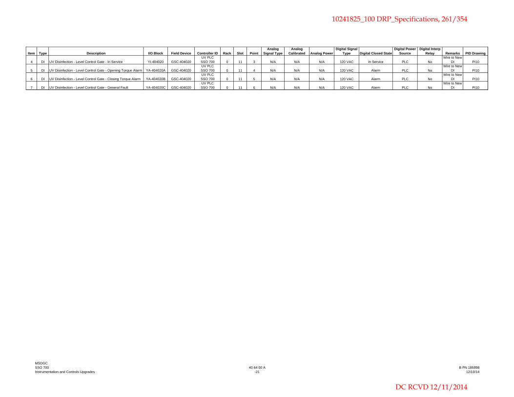
Item Type Description I/O Block Field Device Controller ID Rack Slot PointAnalog
Signal TypeAnalog
Calibrated Analog PowerDigital Signal
Type Digital Closed StateDigital Power
SourceDigital Interp
Relay Remarks PID Drawing
4 DI UV Disinfection - Level Control Gate - In Service YI-404020 GSC-404020UV PLC SSO 700 0 11 3 N/A N/A N/A 120 VAC In Service PLC No
Wire to New DI PI10
5 DI UV Disinfection - Level Control Gate - Opening Torque Alarm YA-404020A GSC-404020UV PLC SSO 700 0 11 4 N/A N/A N/A 120 VAC Alarm PLC No
Wire to New DI PI10
6 DI UV Disinfection - Level Control Gate - Closing Torque Alarm YA-404020B GSC-404020UV PLC SSO 700 0 11 5 N/A N/A N/A 120 VAC Alarm PLC No
Wire to New DI PI10
7 DI UV Disinfection - Level Control Gate - General Fault YA-404020C GSC-404020UV PLC SSO 700 0 11 6 N/A N/A N/A 120 VAC Alarm PLC No
Wire to New DI PI10
MSDGCSSO 700Instrumentation and Controls Upgrades
40 64 00 A-21
B PN 18599812/10/14
10241825_100 DRP_Specifications, 261/354
DC RCVD 12/11/2014

THIS PAGE LEFT BLANK INTENTIONALLY
10241825_100 DRP_Specifications, 262/354
DC RCVD 12/11/2014

MSDGC 40 66 33 SSO 700 -1- B&V PN 185998 Instrumentation & Controls Upgrades 12/10/14
Section 40 66 33
NETWORK CABLE
PART 1 - GENERAL 1-1. SCOPE. The Network Cable section covers the furnishing and installation of cable systems to provide communications for the instrumentation and control system as indicated on the drawings. Accessories and appurtenances shall be provided as specified herein to provide a complete and properly operating system. Equipment and services provided under this section shall be subject to the General Computer Control System Requirements specified in the Instrumentation and Control System Section. Supplementing the Network Cable section, network data, special requirements, and options are indicated on the drawings. 1-2. SUBMITTALS. Submittals shall be made as specified in the Instrumentation and Control System section. 1-3. SHIPMENT, PROTECTION, AND STORAGE. Equipment provided under this section shall be shipped, protected, and stored in accordance with the requirements of the Instrumentation and Control System section.
PART 2 - PRODUCTS 2-1. GENERAL. All cable, hardware and accessories shall be designed, assembled and connected in accordance with the requirements of these specifications and the drawings. 2-2. ETHERNET UNSHIELDED TWISTED PAIR (UTP) CABLE. Cable shall meet the following characteristics: 2-2.01. Category 5e UTP Cable. Cat-5e cable shall meet the following requirements:
a. 24 AWG
b. 4 pair solid conductor
c. 100 Ohm impedance
d. 1-100 MHz frequency range
e. Min attenuation 22 dB
10241825_100 DRP_Specifications, 263/354
DC RCVD 12/11/2014

MSDGC 40 66 33 SSO 700 -2- B&V PN 185998 Instrumentation & Controls Upgrades 12/10/14
f. 100 Ohm impedance
g. Min NEXT 35.3dB/100MHz
h. Min PS-NEXT 32.3dB/100MHz
i. Min ELFEXT 23.8dB/100MHz
j. Min PS-ELFEXT 20.8dB/100MHz
k. Min return loss 20.1 dB/100 MHz
l. Max delay skew 45 ns
m. Max propagation delay 540 ns Plenum rated cable shall have FEP insulation jacketing and FEP insulation for conductors. Non plenum rated cable shall have PVC insulation jacketing and polyethylene insulation for conductors. Cat-5e cable shall be Belden 1583A (Non-plenum) and 1585A (plenum) or equal. 2-2.02. Category 6 UTP Cable. Not used. 2-2.03. Ethernet Patch Cables. Not used. 2-3. FIBER OPTIC CABLE. Not used. 2-4. PLC COMMUNICATIONS MEDIA. System Supplier shall provide all necessary cabling for the PLC communications network and PLC remote I/O communications network. Communications cables shall meet the requirements of the manufacturers of the PLCs and communications modules. 2-4.01. Allen-Bradley ControlNet Cable. Cable shall be coaxial cable. Standard jacketed cable shall meet the following requirements:
a. Coaxial 18 AWG, solid bare copper-covered steel
b. Polyethylene insulation, color-coded black
c. 24 AWG stranded tinned copper drain wire
d. 4-layer aluminum foil shield/braid
e. PVC jacket ControlNet cable shall be Belden "3092A". 2-4.02. Appurtenances. All necessary cable connectors, taps, power supplies and line terminators shall be provided as required for the ControlNet network. PART 3 - EXECUTION
10241825_100 DRP_Specifications, 264/354
DC RCVD 12/11/2014

MSDGC 40 66 33 SSO 700 -3- B&V PN 185998 Instrumentation & Controls Upgrades 12/10/14
3-1. INSTALLATION. The System Supplier shall be responsible for the coordination of the installation of all cable furnished hereunder. The System Supplier shall be responsible for the termination of all cable furnished hereunder. 3-2. CABLE TESTING. After the network cabling has been installed, each network cable shall be tested. 3-2.01. Test Equipment. Unless specified otherwise, all test equipment for the calibration and checking of system components shall be provided by System Supplier for the duration of the testing work and this test equipment will remain the property of System Supplier.
End of Section
10241825_100 DRP_Specifications, 265/354
DC RCVD 12/11/2014

THIS PAGE LEFT BLANK INTENTIONALLY
10241825_100 DRP_Specifications, 266/354
DC RCVD 12/11/2014

MSDGC 40 68 83 SSO 700 -1- B&V PN 185998 Instrumentation & Controls Upgrades 12/10/14
Section 40 68 83
SOFTWARE CONTROL BLOCK DESCRIPTIONS
PART 1 - GENERAL 1-1. SCOPE. This section provides functional descriptions of the PLC and computer software requirements for the Instrumentation and Control System as indicated on the drawings. These descriptions are intended to provide an overview of the operating concept of the plant process equipment rather than describing in detail every operating feature or interlock. 1-1.01. Control System. The Instrumentation and Control System section shall apply to all systems described in this section. 1-2. WORK BY OTHERS. This section is provided for information only. The software configuration will be provided by others.
PART 2 – PRODUCTS 2-1. GENERAL. The descriptions are applicable to the system software configuration (modification) requirements specified in the Instrumentation and Control System section. PART 3 - EXECUTION 3-1. PLC PROGRAMMING FUNCTIONAL REQUIREMENTS. The following paragraphs describe general configuration tasks that are required for the system PLC(s). These tasks shall be programmed in any applicable PLC. Each PLC may have multiple instances of each of these tasks, or may have no instances of some or all of these tasks. The input/output lists (located in these documents as specified in the Instrumentation and Control System section) and detailed equipment control descriptions (included herein) shall be referenced to determine the requirements for each PLC. Several existing pieces of equipment shall be reconfigured to operate using hardwired I/O control signals rather than the currently configured networked I/O control signals. The existing equipment shall operate as currently configured in the control system, except where configuration of new equipment requires modifications to the existing control system for acceptable operation of all equipment. The following paragraphs cover functional requirements of the software, which are generic and may or may not be related to any specific control loop.
10241825_100 DRP_Specifications, 267/354
DC RCVD 12/11/2014

MSDGC 40 68 83 SSO 700 -2- B&V PN 185998 Instrumentation & Controls Upgrades 12/10/14
3-1.01. Available Process Values. All PLC-generated process alarm, equipment status, and process variable values shall be available at any operator workstation. 3-1.02. Flow Values. Flow values shall be integrated, totalized, and stored in the PLC registers so the values displayed on the HMI computers and on the field processor will be identical. 3-1.03. System Failure. Failure of a PLC shall result in safe shutdown of associated process equipment. Interposing relays shall be provided where required to assure that equipment will revert to its fail-safe condition. Failure of any PLC or its communication shall be alarmed on the HMI computer. 3-1.04. HMI Computers. The HMI computers shall function as a monitoring system, not as a controller, for the process equipment. The computer shall download set points and other information to the PLCs, and the PLCs shall perform all control algorithms, so a temporary failure of the any HMI computer will not disrupt plant control. 3-1.05. Rack/Module Configuration. The rack and module definitions for each PLC, as well as the PLC communications configuration shall be completely configured to allow proper addressing of all field connected I/O points. This shall include configuration of any remote input/output (RIO) racks. 3-1.06. PLC Database Definition. The PLC database will include both field I/O points and internally generated points required for programming. All field I/O points and internal programming points shall be fully defined according to database naming conventions approved by Owner. As a minimum, each database point shall be provided with a tag name, engineering unit, alarm parameters, and description. 3-1.07. Analog Scaling. Each analog input and output will be appropriately scaled for use in internal PLC programming, monitoring by the HMI computers, or transmission to other PLCs. Requirements for raw count values shall be coordinated with the operator interface software to ensure compatibility. 3-1.08. Equipment Runtimes. For each equipment item whose "run" status is monitored by a PLC, an internal equipment runtime shall be accumulated by the respective PLC. The runtime procedure will monitor the status of the equipment "run" contact and, when the equipment is running, increment a software timer that maintains equipment runtime to within a one-minute resolution. The timer shall stop incrementing, but not reset, when the "run" contact indicates that the equipment is not running. The timer value shall increment an hour counter that maintains an integer value representing the equipment run time in hours. The counter value shall be available for display on the HMI computer. A manual reset
10241825_100 DRP_Specifications, 268/354
DC RCVD 12/11/2014

MSDGC 40 68 83 SSO 700 -3- B&V PN 185998 Instrumentation & Controls Upgrades 12/10/14
of the runtime value shall be available at the HMI computers for personnel at the supervisor level and above. 3-1.09. Change-of-State Alarms. While equipment is controllable from the PLC ("in remote"), discrete output commands shall be compared to their respective process feedback status signal (where available) to verify proper execution. If the feedback status does not match the most recent output command (after an adjustable 2 to 300 second time delay), an alarm message shall be displayed on the HMI computer and the condition shall be logged as an alarm, requiring operator acknowledgment. The alarm shall remain energized until the proper discrete condition is sensed or until the operator resets the alarm through the HMI computer. 3-1.10. Equipment Availability. In general, equipment with PLC control has been provided with a local selector switch that transfers control to the PLC. The PLC shall monitor the position of this switch to determine if the equipment is available for PLC control. If the equipment is not available, the PLC program shall not attempt to implement remote manual or automatic status changes for the equipment. The PLC program may, however, need to implement special routines if equipment unavailability affects a sequence (as described in the detailed equipment descriptions). 3-1.11. Maintained/Momentary Outputs. The need for maintained or momentary control outputs shall be determined from the input/output listing and the electrical schematics. In general, equipment with only one control output indicated in the I/O list shall be programmed for a maintained control output. Equipment with two (or more) control outputs shall be programmed for momentary outputs. Provisions shall be made, in either case, to remove the active state (start, open, forward, initiate, etc.) control output when an equipment failure is sensed or when the equipment transitions from available to unavailable (local switch change). 3-1.12. Equipment Mode Changes. Unless otherwise indicated in the equipment control descriptions, equipment in automatic mode shall be transitioned to manual mode (and stopped) if the equipment fails or becomes unavailable or if the PLC processor resets. 3-1.13. Manual/Auto Bumpless Transfer. Unless otherwise indicated in the equipment control descriptions, equipment changes from automatic to manual control shall be bumpless. Equipment running or stopped in automatic mode shall remain running or stopped when manual mode is selected. 3-2. HMI FUNCTIONAL REQUIREMENTS. The following paragraphs describe general configuration tasks that are required for the HMI and related software. 3-2.01. Database. The system database, including field I/O and internal points shall be established according to the database point naming conventions
10241825_100 DRP_Specifications, 269/354
DC RCVD 12/11/2014

MSDGC 40 68 83 SSO 700 -4- B&V PN 185998 Instrumentation & Controls Upgrades 12/10/14
approved by Owner. Database generation for field I/O shall include all required coordination with PLC level addresses. If no Owner database point naming conventions are available, the database names shall utilize an ISA or ISA-like tag name. 3-2.02. Trend Displays. Trend displays shall be developed to present real-time and historical process data in an X-Y graph format. Real-time trends shall utilize current process values to generate temporary graphs that do not retain data values. Historical trends shall utilize historically collected data and shall access the data files directly for use in the trend display. Historical trends shall allow paging forward and back to the limits of the collected data. The trending package shall be configured to automatically retrieve historical data from the proper data file to accommodate the paging functions. Content of the trends will be determined after meeting with Owner. 3-2.03. Alarms. Complete system alarming shall be configured. This shall include configuration of graphical alarm displays, and configuration of audible alarms through the HMI speakers. All process or system alarms shall appear on an alarm summary screen and the alarm banner of each process graphic. Alarms and events shall be color coded on the alarm summary screen, with initial colors based on Owner conventions or the default colors associated with the graphics package. The colors may be adjusted after meeting with Owner. Alarm prioritizing and area assignments (if any) shall be coordinated with Owner at the first configuration meeting. For LOW or LOW-LOW analog or discrete alarms which do not apply if associated equipment is not operating, provisions shall be made to prevent/Lock generation of the alarm unless the associated equipment is operating. This shall include alarms such as low amperage alarms for pumps that are not running. This may also include low flows or pressures when associated pumps are not operating (this will only apply if periodic operation of the equipment is considered normal). All alarms/events shall be time stamped when displayed or printed. Unacknowledged alarms shall not automatically clear from the alarm summary if they return to normal before being acknowledged.
3-2.04. Reporting. System reporting shall be accomplished using the standard operator interface software-reporting package. All necessary report development, including macro development in spreadsheets, shall be supplied to access real-time and historical data for reporting. 3-2.05. Historical Data Collection. System data shall be collected for historical archiving and for use in trending and reporting functions. Requirements for data collection shall be as needed to support the trends and reports developed.
10241825_100 DRP_Specifications, 270/354
DC RCVD 12/11/2014

MSDGC 40 68 83 SSO 700 -5- B&V PN 185998 Instrumentation & Controls Upgrades 12/10/14
3-2.06. Manual Entry of Data. The human machine interface (HMI) computers shall allow manual entry of laboratory data and other variables, which shall then be available for display and use in reports. Operator entered commands from any of the HMI computers shall be logged at all HMI computers. 3-3. EQUIPMENT CONTROL AND CONTROL MODE OVERVIEW. The following paragraphs explain the general format and control modes that are used in the detailed equipment descriptions. These paragraphs apply to the attached, project specific, equipment control descriptions included herein. 3-3.01. General. Appended to this section are the equipment control programming requirements, with requirements for both PLC programming and the minimum operator interface functions. The HMI requirements represent the anticipated display generation requirements and shall be adjusted if the PLC programming warrants adjustment. 3-3.02. Control Modes. There are two general control modes available for the process equipment: 1) remote manual, and 2) remote auto. Remote manual control provides a means for operators to adjust equipment status or setpoint, through the HMI, using manually initiated commands. Remote automatic control provides a means for automatically changing equipment status or setpoint based on measured process parameters, calculated values, or operator setpoints. Some equipment may have more than one remote auto mode.
Descriptions for local control are included in the detailed equipment control descriptions. They are provided primarily for documentation purposes and for information. These controls are hardwired and require no programming effort.
3-4. DETAILED EQUIPMENT CONTROL DESCRIPTIONS. The following paragraphs describe specific function requirements for various software control blocks in the control system. These descriptions are intended to provide an overview of the operational concept for the facilities, rather than describing in detail every operating feature or interlock. 3-4.01. Diversion Chamber Flow Control Sluice Gate. Associated P&ID(s): PI04 Associated PLC(s): PLC SSO 700 (RIO SSO 700) Associated Equipment: GSC-101010 (Diversion Chamber Flow Control Sluice Gate) LIT-101010 (Downstream Interceptor Level Transmitter)
10241825_100 DRP_Specifications, 271/354
DC RCVD 12/11/2014

MSDGC 40 68 83 SSO 700 -6- B&V PN 185998 Instrumentation & Controls Upgrades 12/10/14
Remote Manual Mode: Remote manual control of the gate shall be provided through the PLC via the HMI graphics screen. When the Hand-Off-PC (H-O-P) selector switch (at the gate actuator) is in the PC position and MANUAL is selected at the HMI, the gate shall be positioned remotely from an operator entered GATE POSITION SETPOINT (operator adjustable from 0 to 100% open). Remote Auto Mode: Remote automatic control of the gate shall be provided through the PLC via the HMI graphics screen. When the H-O-P selector switch is in the PC position and AUTO is selected at the HMI, the gate shall be automatically modulated (PID controlled) by the PLC to maintain an operator entered DOWNSTREAM INTERCEPTOR LEVEL SETPOINT (operator adjustable, initially set at EL. 543.57 feet). Alarms:
In remote manual mode or remote automatic mode, if the PLC commands the gate to move (greater than +/- 10% from the current position) and the position feedback does not match the command within an adjustable time (0-5 min, initially set at 1 min), the PLC shall generate a gate fail alarm.
Status Indications:
Gate In Remote Gate Open Gate Closed Gate Position Feedback
PLC Power Up and Power Failure/Restoration: The gate shall be initially set in the remote automatic mode when status of the equipment is set to remote. HMI Requirements: An HMI graphics screen depicting the diversion chamber flow control sluice gate, and any associated instruments and/or equipment shall be provided and configured such that all status and alarm signals shall be displayed. The gate shall be a selectable target which retrieves the respective control overlay display. The overlay display shall contain control targets which allow selection of gate remote manual control (GATE POSITION SETPOINT), remote automatic control (DOWNSTREAM INTERCEPTOR LEVEL SETPOINT), and shall duplicate status and alarm indications as shown on the main display. 3-4.02. Raw Influent Sample Pump. Note: The sample pump shall be hardwire interlocked with the associated low level float switch to prevent/stop operation of the sample pump when the float switch is not activated.
10241825_100 DRP_Specifications, 272/354
DC RCVD 12/11/2014

MSDGC 40 68 83 SSO 700 -7- B&V PN 185998 Instrumentation & Controls Upgrades 12/10/14
Associated P&ID(s): PI04 Associated PLC(s): PLC SSO 700 (RIO SSO 700) Associated Equipment: PSA-101035 (Raw Influent Sample Pump) LSLL-101035 (Sample Pump Low Level Relay) LFIT-101040 (Diversion Chamber Flow Transmitter) Remote Manual Mode: Remote manual control of the pump shall be provided through the PLC via the HMI graphics screen. When the On-Off-Remote (O-O-R) selector switch (at the Raw Sewage Pump Station LCP) is in the REMOTE position, the O-O-P selector switch (at the Raw Influent Sampler LCP) is in the PC position, and MANUAL is selected at the HMI the pump shall be available for remote start/stop from the PLC via the HMI graphics screen (RUN COMMAND). Remote Auto Mode: Remote automatic control of the pump shall be provided through the PLC via the HMI graphics screen. When the O-O-R selector switch is in the REMOTE position, the O-O-P selector switch is in the PC position, and AUTO is selected at the HMI the pump shall automatically start whenever the level in the Raw Sewage Wet Well is above the LEAD PUMP START LEVEL SETPOINT (see Raw Sewage Pumps Control Description). The sample pump shall then run continuously until flow over the Diversion Chamber Flow Control Weir (measured by LFIT-101040) has stopped for a TIME SETPOINT (operator adjustable from 0 to 300 minutes, initially set at 30 minutes). Alarms:
In remote manual mode or remote automatic mode, if the PLC commands the pump to start and the status feedback does not match the command within an adjustable time (0-60 sec, initially set at 10 sec), the PLC shall generate a pump fail alarm.
Sample Pump Motor Overload Status Indications:
Sample Pump In Remote Sample Pump In Service Sample Pump Running
PLC Power Up and Power Failure/Restoration: The pump shall be initially set in the remote automatic mode when status of the equipment is set to remote.
10241825_100 DRP_Specifications, 273/354
DC RCVD 12/11/2014

MSDGC 40 68 83 SSO 700 -8- B&V PN 185998 Instrumentation & Controls Upgrades 12/10/14
HMI Requirements: An HMI graphics screen depicting the sample pump, and any associated instruments and/or equipment shall be provided and configured such that all status and alarm signals shall be displayed. The pump shall be a selectable target which retrieves the respective control overlay display. The overlay display shall contain control targets which allow selection of pump remote manual control (RUN COMMAND), remote automatic control (LEAD PUMP START LEVEL SETPOINT; TIME SETPOINT), and shall duplicate status and alarm indications as shown on the main display. 3-4.03. Pump Station Inlet Sluice Gates. Associated P&ID(s): PI04 Associated PLC(s): PLC SSO 700 (RIO SSO 700) Associated Equipment: GSC-101045 (Pump Station Inlet Sluice Gate No. 1) GSC-101050 (Pump Station Inlet Sluice Gate No. 2) LIT-101060 (Influent Pump Station Wet Well Level Transmitter) Remote Manual Mode: Remote manual control of each gate shall be provided through the PLC via the HMI graphics screen. When the Hand-Off-PC (H-O-P) selector switch (at the gate actuator) is in the PC position and MANUAL is selected at the HMI, the gate shall be positioned remotely from an operator entered GATE POSITION SETPOINT (operator adjustable from 0 to 100% open). Each gate shall operate independently from the other. Remote Auto Mode: Remote automatic control of the gates shall be provided through the PLC via the HMI graphics screen. When the H-O-P selector switch is in the PC position and AUTO is selected at the HMI, the gates shall be automatically positioned by the PLC to prevent overflow of the influent wet well. When the rate-of-rise or the level in the influent wet well exceeds an operator setpoint, the gates shall operate as described below:
When CEHRS treatment has not been initiated, if the influent wet well rate-of-rise exceeds an operator entered STORAGE MODE HIGH RATE-OF-RISE SETPOINT (operator adjustable from 0.25 to 5.0 ft/min in 0.25 ft/min increments, initially set at 2.0 ft/min) for an operator entered STORAGE MODE TIME PERIOD SETPOINT (operator adjustable from 0 to 5 minutes, initially set at 1 minute), the gates shall close in steps. These setpoints shall be used only when CEHRS treatment has not been initiated.
10241825_100 DRP_Specifications, 274/354
DC RCVD 12/11/2014

MSDGC 40 68 83 SSO 700 -9- B&V PN 185998 Instrumentation & Controls Upgrades 12/10/14
During CEHRS treatment operation, if the influent wet well rate-of-rise
exceeds an operator entered TREATMENT MODE HIGH RATE-OF-RISE SETPOINT (operator adjustable from 0.25 to 5.0 ft/min in 0.25 ft/min increments, initially set at 1.0 ft/min) for an operator entered TREATMENT MODE TIME PERIOD SETPOINT (operator adjustable from 0 to 5 minutes, initially set at 2 minutes), the gates shall close in steps. These setpoints shall be used only when CEHRS treatment has been initiated.
During any operation, if the influent wet well level reaches an operator
entered HIGH LEVEL SETPOINT (operator adjustable from EL. 533.00 feet to EL. 537.00 feet, initially set at EL. 535.00 feet) for an operator entered LEVEL TIME PERIOD SETPOINT (operator adjustable from 0 to 5 minutes, initially set at 1 minute), the gates shall close in steps.
If the gates are commanded to close, they shall be closed in a sequence of steps. After each step, if the rate-of-rise or level still exceeds the setpoint for another time period associated with that setpoint, the next step shall be initiated.
Assume starting with both gates fully open. 1. The first gate shall be positioned to 50% open. 2. The first gate shall be fully closed. 3. The second gate shall be positioned to 50% open. 4. Both gates shall be fully closed, and an alarm shall be displayed on the
HMI indicating the reason why both influent gates have been closed. If after an operator entered TIME DELAY SETPOINT (operator adjustable from 5 to 60 minutes, initially set at 10 minutes) the next step has not been initiated and the rate-of-rise/high level setpoint is within normal conditions, the gates shall be positioned to the previous step. The process shall be repeated until the gates are both fully open. Alarms:
In remote manual mode or remote automatic mode, if the PLC commands the gate to move and the position feedback does not match the command within an adjustable time (0-5 min, initially set at 1 min), the PLC shall generate a gate fail alarm.
If both gates are in the closed position, an alarm shall be generated by the PLC.
Status Indications:
Gate In Remote Gate Open Gate Closed Gate Position Feedback
10241825_100 DRP_Specifications, 275/354
DC RCVD 12/11/2014

MSDGC 40 68 83 SSO 700 -10- B&V PN 185998 Instrumentation & Controls Upgrades 12/10/14
PLC Power Up and Power Failure/Restoration: The gate shall be initially set in the remote automatic mode when status of the equipment is set to remote. HMI Requirements: An HMI graphics screen depicting the pump station influent sluice gates, and any associated instruments and/or equipment shall be provided and configured such that all status and alarm signals shall be displayed. The gates shall be selectable targets which retrieve the respective control overlay display. The overlay display shall contain control targets which allow selection of gate remote manual control (GATE POSITION SETPOINT), remote automatic control (STORAGE MODE HIGH RATE-OF-RISE SETPOINT, STORAGE MODE TIME PERIOD SETPOINT; TREATMENT MODE HIGH RATE-OF-RISE SETPOINT, TREATMENT MODE TIME PERIOD SETPOINT; HIGH LEVEL SETPOINT, LEVEL TIME PERIOD SETPOINT; TIME DELAY SETPOINT), and shall duplicate status and alarm indications as shown on the main display. 3-4.04. Raw Sewage Pumps: Note: The pumps are hardwire interlocked with the associated low level float switch to prevent/stop operation of the pumps when the float switch is not activated. Associated P&ID(s): PI05 PI07 Associated PLC(s): PLC SSO 700 (RIO SSO 700) Associated Equipment: PSM-121100 (Raw Sewage Pump No. 1) PSM-121200 (Raw Sewage Pump No. 2) PSM-121300 (Raw Sewage Pump No. 3) PSM-121400 (Raw Sewage Pump No. 4) LIT-101060 (Influent Pump Station Wet Well Level Transmitter) LSLL-101060 (Influent Pump Station Wet Well Low Level Relay) LIT-152201 (Storage Tank No. 2 Level Transmitter) Remote Manual Mode: Remote manual control of the pump shall be provided through the PLC via the HMI graphics screen. When the On-Off-Remote (O-O-R) selector switch (at the Raw Sewage Pump Station LCP) is in the REMOTE position, the O-O-P selector switch (at the Raw Sewage Pump No. 1 VFD) is in the PC position, and MANUAL is selected at the HMI the pump shall be available for remote start/stop from the PLC via the HMI graphics screen (RUN COMMAND). Raw Sewage Pump No. 1 shall be available for remote speed control from the PLC via the HMI
10241825_100 DRP_Specifications, 276/354
DC RCVD 12/11/2014

MSDGC 40 68 83 SSO 700 -11- B&V PN 185998 Instrumentation & Controls Upgrades 12/10/14
graphics screen. The speed shall be an operator entered SPEED SETPOINT (operator adjustable from 0% to 100% capacity). Remote Auto Mode: Remote automatic control of the pumps shall be provided through the PLC via the HMI graphics screen. When the O-O-R selector switch is in the REMOTE position, the O-O-P selector switch is in the PC position, and AUTO is selected at the HMI the pumps shall operate in lead/lag/lag-lag/standby operation. Raw Sewage Pump No. 1 (VFD) shall always be designated as the lead pump. Raw Sewage Pump Nos. 2, 3, and 4 shall be automatically alternated through the lag, lag-lag, and standby positions. The PLC shall store pump runtimes in order to automatically assign each pump for lag (lowest runtime), lag-lag (second lowest runtime), or standby (highest runtime) operation. If a pump fails to start, it shall be placed “out of service” and removed from remote control modes until reset by an operator. If the Pump Station Influent Wet Well level reaches a low level and the pumps are tripped off (via the hardwired interlock), an alarm shall be generated to notify an operator that there is insufficient flow to maintain the setpoint level. The pumps shall be re-enabled once the Pump Station Influent Wet Well level reaches the operator entered LEAD PUMP START LEVEL SETPOINT (see Storage Tank Filling Mode) and operation shall continue as described herein. During Storage Tank Filling Mode operation, the pumps shall operate based on influent wet well level (measured by LIT-101060) control setpoints entered by an operator. After the storage tanks are filled and during CEHRS Treatment Mode operation, the pumps shall operate based on the level in the storage tanks in a manner to keep the storage tanks full, but not overflowing. Each of these control modes is described below: Storage Tank Filling Mode: The pumps shall operate to maintain an operator entered WET WELL LEVEL SETPOINT (operator adjustable from EL. 529.00 feet to EL. 536.00 feet, initially set at EL. 532.50 feet). The pumps shall operate as described below:
When the Pump Station Influent Wet Well level reaches an operator
entered LEAD PUMP START LEVEL SETPOINT (operator adjustable from the WET WELL LEVEL SETPOINT up to EL. 536.50 feet, initially set at EL. 533.50 feet) for an operator entered LEAD PUMP START TIME DELAY SETPOINT (operator adjustable from 0 to 10 minutes, initially set at 1 minute), the lead pump shall start. The pump speed shall automatically modulate (based on the water level measured in the wet well) between the minimum and maximum speed (capacity), linearly proportional to the elevation difference between the WET WELL LEVEL SETPOINT and LAG PUMP START LEVEL SETPOINT.
10241825_100 DRP_Specifications, 277/354
DC RCVD 12/11/2014

MSDGC 40 68 83 SSO 700 -12- B&V PN 185998 Instrumentation & Controls Upgrades 12/10/14
When the Pump Station Influent Wet Well level reaches an operator
entered LAG PUMP START LEVEL SETPOINT (operator adjustable from the LEAD PUMP START LEVEL SETPOINT up to EL. 537.00 feet, initially set at EL. 535.50 feet) for an operator entered LAG PUMP START TIME DELAY SETPOINT (operator adjustable from 0 to 10 minutes, initially set at 1 minute), the lag pump shall start. The lead pump speed shall then automatically modulate (based on the water level measured in the wet well) between the minimum and maximum speed (capacity), linearly proportional to the elevation difference between the WET WELL LEVEL SETPOINT and the LAG-LAG PUMP START LEVEL SETPOINT.
When the Pump Station Influent Wet Well level reaches an operator
entered LAG-LAG PUMP START LEVEL SETPOINT (operator adjustable from the LAG PUMP START LEVEL SETPOINT up to EL. 537.50 feet, initially set at EL. 537.50 feet) for an operator entered LAG-LAG PUMP START TIME DELAY SETPOINT (operator adjustable from 0 to 10 minutes, initially set at 1 minute), the lag-lag pump shall start. The lead pump speed shall then automatically modulate (based on the water level measured in the wet well) between the minimum and maximum speed (capacity), linearly proportional to the level difference between the WET WELL LEVEL SETPOINT and EL. 538.00 feet.
When the Pump Station Influent Wet Well level reaches an operator
entered LAG-LAG PUMP STOP LEVEL SETPOINT (operator adjustable from EL. 528.50 feet up to the WET WELL LEVEL SETPOINT, initially set at EL. 531.50 feet), the lag-lag pump shall stop. The lead pump speed shall then automatically modulate (based on the water level measured in the wet well) between the minimum and maximum speed (capacity), linearly proportional to the level difference between the WET WELL LEVEL SETPOINT and the LAG-LAG PUMP START LEVEL SETPOINT.
When the Pump Station Influent Wet Well level reaches an operator
entered LAG PUMP STOP LEVEL SETPOINT (operator adjustable from EL. 528.00 feet up to the LAG-LAG PUMP STOP LEVEL SETPOINT, initially set at EL. 529.50 feet), the lag pump shall stop. The lead pump speed shall then automatically modulate (based on the water level measured in the wet well) between the minimum and maximum speed (capacity), linearly proportional to the level difference between the WET WELL LEVEL SETPOINT and the LAG PUMP START LEVEL SETPOINT.
When the Pump Station Influent Wet Well level reaches an operator
entered LEAD PUMP STOP LEVEL SETPOINT (operator adjustable from EL. 527.50 feet up to the LAG PUMP STOP LEVEL SETPOINT, initially set at EL. 527.50 feet), the lead pump shall stop.
10241825_100 DRP_Specifications, 278/354
DC RCVD 12/11/2014

MSDGC 40 68 83 SSO 700 -13- B&V PN 185998 Instrumentation & Controls Upgrades 12/10/14
CEHRS Treatment Mode: The Raw Sewage Pumps shall fill the Storage Tanks in a sequential manner. When Storage Tank Nos. 2 and 3 are full, the raw sewage pumps shall operate to keep the storage tanks full during operation of the CEHRS treatment system as described below:
When the level in Storage Tank No. 2 reaches an operator entered
STORAGE TANK TREATMENT MODE LEVEL SETPOINT (operator adjustable from EL. 578.50 feet to EL. 584.00 feet, initially set at EL. 581.50 feet) for an operator entered STORAGE TANK TREATMENT MODE TIME DELAY SETPOINT (operator adjustable from 0 to 10 minutes, initially set at 1 minute), the pumps shall slowly transition to the CEHRS treatment mode, as described below:
o The lead pump shall slowly reduce to minimum speed (capacity).
Once the lead pump has reached the minimum speed (capacity) for an operator entered LEAD PUMP MIN SPEED TIME DELAY SETPOINT (operator adjustable from 0 to 10 minutes, initially set at 1 minute), the lag-lag pump shall stop.
o Once the lag-lag pump has shutdown for an operator entered LAG-
LAG PUMP OFF TIME DELAY (operator adjustable from 0 to 10 minutes, initially set at 1 minute), the lag pump shall stop.
o The lead pump shall continue to operate. The pump speed shall
automatically modulate (based on the water level measured in Storage Tank No. 2) between the minimum and maximum speed (capacity), linearly proportional to the elevation difference between the STORAGE TANK TREATMENT MODE LEVEL SETPOINT and LAG PUMP START LEVEL SETPOINT2.
When the Storage Tank No. 2 level falls to an operator entered LAG PUMP
START LEVEL SETPOINT2 (operator adjustable from EL. 566.00 feet up to 2 feet below the STORAGE TANK TREATMENT MODE LEVEL SETPOINT, initially set at EL. 573.00 feet) for an operator entered LAG PUMP START TIME DELAY SETPOINT2 (operator adjustable from 0 to 10 minutes, initially set at 1 minute), the lag pump shall start. The lead pump speed shall then automatically modulate (based on the water level measured in Storage Tank No. 2) between the minimum and maximum speed (capacity), linearly proportional to the elevation difference between the STORAGE TANK TREATMENT MODE LEVEL SETPOINT and EL. 566.00 feet.
When the Storage Tank No. 2 level reaches the operator entered
STORAGE TANK TREATMENT MODE LEVEL SETPOINT, the lag pump shall stop. The lead pump speed shall then automatically modulate (based
10241825_100 DRP_Specifications, 279/354
DC RCVD 12/11/2014

MSDGC 40 68 83 SSO 700 -14- B&V PN 185998 Instrumentation & Controls Upgrades 12/10/14
on the water level measured in Storage Tank No. 2) between the minimum and maximum speed (capacity), linearly proportional to the elevation difference between the STORAGE TANK TREATMENT MODE LEVEL SETPOINT and LAG PUMP START LEVEL SETPOINT2.
If the Storage Tank No. 2 level reaches an operator entered TANK 2 HIGH
LEVEL SETPOINT (operator adjustable from EL. 580.00 feet to EL. 586.90 feet, initially set at EL. 586.50 feet) for an operator entered TANK 2 TIME DELAY SETPOINT (operator adjustable from 0 to 5 minutes, initially set at 1 minute), the raw sewages pumps shall all stop and an alarm shall be generated to the operator that storage tank capacity is full. The pumps shall be re-enabled when the level in Storage Tank No. 2 falls to the STORAGE TANK TREATMENT MODE LEVEL SETPOINT.
Alarms:
Motor/VFD Fault High Motor Temperature High Bearing Temperature Seal Leak Alarm
Status Indications:
Pump In Remote Pump In Service Pump Requested (Constant Speed Pumps) Pump Running Motor at Speed (Constant Speed Pumps) Motor Amps (VFD Pump) Speed Feedback (VFD Pump) Influent Pump Station Wet Well Level Influent Pump Station Wet Well Level High Influent Pump Station Wet Well Level Low
PLC Power Up and Power Failure/Restoration: The pumps shall be initially set to the remote auto mode and in the “off” state when status of the equipment is set to remote. HMI Requirements: An HMI graphics screen depicting the pumps, and any associated instruments and/or equipment shall be provided and configured such that all status and alarm signals shall be displayed. Each pump shall be a selectable target which retrieves the respective control overlay display. The overlay display shall contain control targets which allow selection of pump remote manual control (RUN_CMD; SPEED SETPOINT), remote automatic control (WET WELL LEVEL SETPOINT; LEAD PUMP START LEVEL SETPOINT, LEAD PUMP START TIME DELAY SETPOINT, LEAD PUMP STOP LEVEL SETPOINT; LAG PUMP START LEVEL SETPOINT, LAG PUMP START TIME DELAY SETPOINT, LAG PUMP STOP
10241825_100 DRP_Specifications, 280/354
DC RCVD 12/11/2014

MSDGC 40 68 83 SSO 700 -15- B&V PN 185998 Instrumentation & Controls Upgrades 12/10/14
LEVEL SETPOINT; LAG-LAG PUMP START LEVEL SETPOINT, LAG-LAG PUMP START TIME DELAY SETPOINT, and LAG-LAG PUMP STOP LEVEL SETPOINT; STORAGE TANK TREATMENT MODE LEVEL SETPOINT, STORAGE TANK TREATMENT MODE TIME DELAY SETPOINT, LEAD PUMP MIN SPEED TIME DELAY SETPOINT, LAG-LAG PUMP OFF TIME DELAY, LAG PUMP START LEVEL SETPOINT2, LAG PUMP START TIME DELAY SETPOINT2, TANK 2 HIGH LEVEL SETPOINT, and TANK 2 TIME DELAY SETPOINT), general pump setpoints (PUMP START DELAY SETPOINT and HIGH TEMP RESET DELAY SETPOINT), and shall duplicate status and alarm indications as shown on the main display. Special Considerations:
The time between each pump start shall be an operator entered PUMP START DELAY SETPOINT (operator adjustable from 0 seconds to 180 seconds, initially set at 60 seconds).
Raw Sewage Pump No. 1 shall be stopped on a high motor or high bearing
temperature condition. Raw Sewage Pump Nos. 2, 3, and 4 shall be stopped on a high motor temperature condition. After an operator entered HIGH TEMP RESET DELAY SETPOINT (operator adjustable from 0 to 60 minutes, initially set at 10 minutes), each pump shall accept a remote high motor temperature reset command once within a 24-hour period from the HMI graphics screen.
3-4.05. Wet Well Drainage Pump: Note: The pump is hardwire interlocked with the associated low level float switch to prevent/stop operation of the pump when the float switch is not activated. Associated P&ID(s): PI05 Associated PLC(s): PLC SSO 700 (RIO SSO 700) Associated Equipment: PCH-101065 (Wet Well Drainage Pump) PSM-121100 (Raw Sewage Pump No. 1) PSM-121200 (Raw Sewage Pump No. 2) PSM-121300 (Raw Sewage Pump No. 3) PSM-121400 (Raw Sewage Pump No. 4) LSL-101065 (Drainage Pump Stop Level Relay) LSLL-101065 (Drainage Pump Low Level Relay) Remote Manual Mode: Remote manual control of the pump shall be provided through the PLC via the
10241825_100 DRP_Specifications, 281/354
DC RCVD 12/11/2014

MSDGC 40 68 83 SSO 700 -16- B&V PN 185998 Instrumentation & Controls Upgrades 12/10/14
HMI graphics screen. When the On-Off-Remote (O-O-R) selector switch (at the Raw Sewage Pump Station LCP) is in the REMOTE position, the O-O-P selector switch (at the MCC) is in the PC position, and MANUAL is selected at the HMI the pump shall be available for remote start/stop from the PLC via the HMI graphics screen (RUN COMMAND). Remote Auto Mode: Remote automatic control of the pump shall be provided through the PLC via the HMI graphics screen. When the O-O-R selector switch is in the REMOTE position, the O-O-P selector switch is in the PC position, and AUTO is selected at the HMI the pump shall be automatically controlled via two modes of operation: Intermittent Mode and Continuous Mode. Intermittent Mode: The pump shall start when the level in the Influent Wet Well reaches an operator entered INTERMITTENT START LEVEL SETPOINT (operator adjustable from EL. 525.00 to EL. 536.00 feet, initially set at EL. 528.00 feet). The pump shall then run for an operator entered INTERMITTENT RUN DURATION DELAY SETPOINT (operator adjustable from 1 to 10 minutes, initially set at 5 minutes). After the pump has run the duration of the setpoint, it shall stop. The pump shall then re-start after an operator entered INTERMITTENT RUN FREQUENCY DELAY SETPOINT (operator adjustable from 30 to 90 minutes, initially set at 30 minutes). This process shall repeat. Continuous Mode: The pump shall enter continuous mode once all the raw sewages pumps have been confirmed stopped for an operator entered CONTINUOUS START TIME DELAY SETPOINT (operator adjustable from 30 to 240 minutes, initially set at 60 minutes). The pump shall continue to operate until the stop level float switch (LSL-101065) stops the pump. If during Continuous Mode any raw sewage pump starts, the pump shall enter into Intermittent Mode. Alarms:
In remote manual mode or remote automatic mode, if the PLC commands the pump to start and the status feedback does not match the command within an adjustable time (0-60 sec, initially set at 10 sec), the PLC shall generate a pump fail alarm.
Drainage Pump Motor Overload Drainage Pump High Temperature
Status Indications:
Drainage Pump In Remote Drainage Pump In Service Drainage Pump Running Drainage Pump Level Low Drainage Pump Level Stop
10241825_100 DRP_Specifications, 282/354
DC RCVD 12/11/2014

MSDGC 40 68 83 SSO 700 -17- B&V PN 185998 Instrumentation & Controls Upgrades 12/10/14
PLC Power Up and Power Failure/Restoration: The pump shall be initially set in the remote automatic mode when status of the equipment is set to remote. HMI Requirements: An HMI graphics screen depicting the drainage pump, and any associated instruments and/or equipment shall be provided and configured such that all status and alarm signals shall be displayed. The pump shall be a selectable target which retrieves the respective control overlay display. The overlay display shall contain control targets which allow selection of pump remote manual control (RUN COMMAND), remote automatic control (INTERMITTENT START LEVEL SETPOINT, INTERMITTENT RUN DURATION DELAY SETPOINT, INTERMITTENT RUN FREQUENCY DELAY SETPOINT, and CONTINUOUS START TIME DELAY SETPOINT), general pump setpoints (HIGH TEMP RESET DELAY SETPOINT), and shall duplicate status and alarm indications as shown on the main display. Special Considerations:
The drainage pump shall be stopped on a high motor temperature condition. After an operator entered HIGH TEMP RESET DELAY SETPOINT (operator adjustable from 0-60 min, initially set at 10 minutes), the pump shall accept a remote high motor temperature reset command once within a 24-hour period from the HMI graphics screen.
The drainage pump shall be stopped anytime a raw sewage pump is
running. 3-4.06. Pump Discharge Header Drain Valve. Associated P&ID(s): PI05 Associated PLC(s): PLC SSO 700 (RIO SSO 700) Associated Equipment: VPG-121610 (Pump Discharge Header Drain Valve) PCH-101065 (Wet Well Drainage Pump) Remote Manual Mode: Remote manual control of the valve shall be provided through the PLC via the HMI graphics screen. When the Hand-Off-PC (H-O-P) selector switch (at the valve actuator) is in the PC position and MANUAL is selected at the HMI, the gate shall be available for remote open/close from the PLC via the HMI graphics
10241825_100 DRP_Specifications, 283/354
DC RCVD 12/11/2014

MSDGC 40 68 83 SSO 700 -18- B&V PN 185998 Instrumentation & Controls Upgrades 12/10/14
screen (OPEN COMMAND and CLOSE COMMAND). Remote Auto Mode: Remote automatic control of the valve shall be provided through the PLC via the HMI graphics screen. When the H-O-P selector switch is in the PC position and AUTO is selected at the HMI, the valve shall automatically open when the Wet Well Drainage Pump is running. The valve shall automatically close when the Wet Well Drainage Pump is off. Alarms:
In remote manual mode or remote automatic mode, if the PLC commands the valve to move and the position feedback does not match the command within an adjustable time (0-5 min, initially set at 1 min), the PLC shall generate a valve fail alarm.
If the valve is in the open position when any raw sewage pump is running, an alarm shall be generated on the HMI graphics screen.
Status Indications:
Valve In Remote Valve Open Valve Closed
PLC Power Up and Power Failure/Restoration: The valve shall be initially set in the remote automatic mode and in the closed position when status of the equipment is set to remote. HMI Requirements: An HMI graphics screen depicting the discharge header drain valve, and any associated instruments and/or equipment shall be provided and configured such that all status and alarm signals shall be displayed. The valve shall be a selectable target which retrieves the respective control overlay display. The overlay display shall contain control targets which allow selection of valve remote manual control (OPEN COMMAND, CLOSE COMMAND), remote automatic control, and shall duplicate status and alarm indications as shown on the main display. 3-4.07. Storage Tank Inlet Valves. Associated P&ID(s): PI06 PI07 Associated PLC(s): PLC SSO 700 (RIO SSO 700) Associated Equipment:
10241825_100 DRP_Specifications, 284/354
DC RCVD 12/11/2014

MSDGC 40 68 83 SSO 700 -19- B&V PN 185998 Instrumentation & Controls Upgrades 12/10/14
VPG-121705 (Storage Tank No. 1 Inlet Valve) LIT-152101 (Storage Tank No. 1 Level Transmitter) VPG-121710 (Storage Tank No. 2 Inlet Valve) LIT-152201 (Storage Tank No. 2 Level Transmitter) VPG-152260 (Storage Tank No. 2 Drain Valve) LIT-152301 (Storage Tank No. 3 Level Transmitter) VPG-152360 (Storage Tank No. 3 Drain Valve) Remote Manual Mode: Remote manual control of the valve shall be provided through the PLC via the HMI graphics screen. When the Hand-Off-PC (H-O-P) selector switch (at the valve actuator) is in the PC position and MANUAL is selected at the HMI, the valve shall be available for remote open/close from the PLC via the HMI graphics screen (OPEN COMMAND and CLOSE COMMAND). Remote Auto Mode: Remote automatic control of the valves shall be provided through the PLC via the HMI graphics screen. When the H-O-P selector switch is in the PC position and AUTO is selected at the HMI, the valves shall be automatically positioned according to the level in each storage tank, as described below. When the level in Storage Tank No. 1 is less than an operator entered TANK 1 HIGH LEVEL SETPOINT (operator adjustable from EL. 580.00 feet to EL. 588.00 feet, initially set at EL. 586.00 feet), the inlet valve to Storage Tank No. 1 shall be open and the inlet valve to Storage Tank No. 2 shall be closed. The valves shall be positioned sequentially to prevent flow between tanks. When the level in Storage Tank No. 1 reaches the operator entered TANK 1 HIGH LEVEL SETPOINT for an operator entered TANK 1 TIME DELAY SETPOINT (operator adjustable from 0 to 5 minutes, initially set at 0 minutes), the inlet valve to Storage Tank No. 2 shall open. When the inlet valve to Storage Tank No. 2 has been confirmed open, the inlet valve to Storage Tank No. 1 shall be closed. The contents of Storage Tank No. 1 shall remain captured in Storage Tank No. 1 during the CEHRS treatment event and discharged back to the interceptor when sufficient capacity has returned to the interceptor after the wet-weather event. When Storage Tank No. 2 reaches the operator entered SHARED STORAGE TANKS LEVEL SETPOINT (operator adjustable from EL. 562.00 feet to EL. 580.00 feet, initially set at EL. 576.00 feet), the drain valves between Storage Tank No. 2 and Storage Tank No. 3 shall be opened to allow the two tanks to “float” together. When Storage Tank No. 2 reaches an operator entered ENABLE CEHRS START LEVEL SETPOINT (operator adjustable from the SHARED STORAGE TANKS LEVEL SETPOINT to EL. 580.00 feet, initially set at EL. 576.00 feet), an
10241825_100 DRP_Specifications, 285/354
DC RCVD 12/11/2014

MSDGC 40 68 83 SSO 700 -20- B&V PN 185998 Instrumentation & Controls Upgrades 12/10/14
alarm shall be generated in the PLC and the operator shall be prompted for a remote manual start of the CEHRS treatment process. When Storage Tank No. 2 reaches the operator entered CEHRS AUTO START LEVEL SETPOINT (operator adjustable from the ENABLE CEHRS START LEVEL SETPOINT to EL. 584.00 feet, initially set at EL. 580.00 feet), the PLC shall begin a remote automatic start of the CEHRS treatment process if the operator has not already initiated operation via a remote manual start. Note that influent to the CEHRS treatment process shall be taken only from Storage Tank No. 2 through its effluent valve. The inlet valve to Storage Tank No. 2 shall be closed after a wet-weather event has ended. Alarms:
In remote manual mode or remote automatic mode, if the PLC commands the valve to move and the position feedback does not match the command within an adjustable time (0-5 min, initially set at 1 min), the PLC shall generate a valve fail alarm.
Status Indications:
Valve In Remote Valve Open Valve Closed
PLC Power Up and Power Failure/Restoration: The valves shall be initially set in the remote automatic mode when status of the equipment is set to remote. The inlet valve to Storage Tank No. 1 shall be initially set to the open position and the inlet valve to Storage Tank No. 2 shall be initially set to the closed position. HMI Requirements: An HMI graphics screen depicting the inlet valve, and any associated instruments and/or equipment shall be provided and configured such that all status and alarm signals shall be displayed. The valve shall be a selectable target which retrieves the respective control overlay display. The overlay display shall contain control targets which allow selection of valve remote manual control (OPEN COMMAND, CLOSE COMMAND), remote automatic control (TANK 1 HIGH LEVEL SETPOINT, TANK 1 TIME DELAY SETPOINT), and shall duplicate status and alarm indications as shown on the main display. 3-4.08. Storage Tanks Bypass Valve. Associated P&ID(s): PI06
10241825_100 DRP_Specifications, 286/354
DC RCVD 12/11/2014

MSDGC 40 68 83 SSO 700 -21- B&V PN 185998 Instrumentation & Controls Upgrades 12/10/14
Associated PLC(s): PLC SSO 700 (RIO SSO 700) Associated Equipment: VPG-121715 (Storage Tanks Bypass Valve) Remote Manual Mode: Remote manual control of the valve shall be provided through the PLC via the HMI graphics screen. When the Hand-Off-PC (H-O-P) selector switch (at the valve actuator) is in the PC position, the valve shall be available for remote open/close from the PLC via the HMI graphics screen (OPEN COMMAND and CLOSE COMMAND). Remote Auto Mode: N/A Alarms:
In remote manual mode, if the PLC commands the valve to move and the position feedback does not match the command within an adjustable time (0-5 min, initially set at 1 min), the PLC shall generate a valve fail alarm.
Status Indications:
Valve In Remote Valve Open Valve Closed
PLC Power Up and Power Failure/Restoration: The valve shall be initially set in the remote manual mode and in the closed position when status of the equipment is set to remote. HMI Requirements: An HMI graphics screen depicting the bypass valve, and any associated instruments and/or equipment shall be provided and configured such that all status and alarm signals shall be displayed. The valve shall be a selectable target which retrieves the respective control overlay display. The overlay display shall contain control targets which allow selection of valve remote manual control (OPEN COMMAND, CLOSE COMMAND) and shall duplicate status and alarm indications as shown on the main display. 3-4.09. Storage Tank Effluent Valves. Associated P&ID(s): PI06 PI08 Associated PLC(s):
10241825_100 DRP_Specifications, 287/354
DC RCVD 12/11/2014

MSDGC 40 68 83 SSO 700 -22- B&V PN 185998 Instrumentation & Controls Upgrades 12/10/14
PLC SSO 700 (RIO SSO 700) Associated Equipment: VPG-152150 (Storage Tank No. 1 Effluent Valve) VPG-152250 (Storage Tank No. 2 Effluent Valve) LIT-152201 (Storage Tank No. 2 Level Transmitter) FQIT-273005 (CEHRS Influent Flow Transmitter) VPN-273005 (CEHRS Influent Flow Control Valve) Remote Manual Mode: Remote manual control of the valve shall be provided through the PLC via the HMI graphics screen. When the Hand-Off-PC (H-O-P) selector switch (at the valve actuator) is in the PC position and MANUAL is selected at the HMI, the valve shall be available for remote open/close from the PLC via the HMI graphics screen (OPEN COMMAND and CLOSE COMMAND). Remote Auto Mode: Remote automatic control of the valves shall be provided through the PLC via the HMI graphics screen. When the H-O-P selector switch is in the PC position and AUTO is selected at the HMI, the valves shall be automatically positioned according to the level in Storage Tank No. 2. The effluent valve from Storage Tank No. 1 shall remain closed during the storage and treatment portion of each event. The contents shall be discharged back to the interceptor after the wet-weather event when sufficient capacity has returned to the interceptor. When the level in Storage Tank No. 2 is less than the operator entered ENABLE CEHRS START LEVEL SETPOINT (see 3-4.07, Storage Tank Inlet Valves), the effluent valves from Storage Tank Nos. 1 and 2 shall both be closed. When the level in Storage Tank No. 2 reaches the operator entered CEHRS AUTO START LEVEL SETPOINT (see 3-4.07, Storage Tank Inlet Valves) for an operator entered CEHRS AUTO START TIME DELAY SETPOINT (operator adjustable from 0 to 5 minutes, initially set at 1 minute), the effluent valve from Storage Tank No. 2 shall be open to initiate the CEHRS treatment process. The valve shall remain open until both of the following conditions have occurred:
CEHRS Influent Flow Control Valve is fully open. Flow to the CEHRS facilities is less than an operator entered CEHRS
MINIUMUM FLOW SETPOINT (operator adjustable from 0 to 5 MGD, initially set at 3 MGD) for an operator entered CEHRS MIN FLOW TIME DELAY SETPOINT (operator adjustable from 0 to 60 minutes, initially set at 10 minutes).
10241825_100 DRP_Specifications, 288/354
DC RCVD 12/11/2014

MSDGC 40 68 83 SSO 700 -23- B&V PN 185998 Instrumentation & Controls Upgrades 12/10/14
Alarms: In remote manual mode or remote automatic mode, if the PLC commands
the valve to move and the position feedback does not match the command within an adjustable time (0-5 min, initially set at 1 min), the PLC shall generate a valve fail alarm.
Status Indications:
Valve In Remote Valve Open Valve Closed
PLC Power Up and Power Failure/Restoration: The valves shall be initially set in the remote automatic mode and in the closed position when status of the equipment is set to remote. HMI Requirements: An HMI graphics screen depicting the effluent valves, and any associated instruments and/or equipment shall be provided and configured such that all status and alarm signals shall be displayed. Each valve shall be a selectable target which retrieves the respective control overlay display. The overlay display shall contain control targets which allow selection of valve remote manual control (OPEN COMMAND, CLOSE COMMAND), remote automatic control (TANK 2 HIGH LEVEL SETPOINT, TANK 2 TIME DELAY SETPOINT; CEHRS MINIUMUM FLOW SETPOINT, CEHRS MIN FLOW TIME DELAY SETPOINT), and shall duplicate status and alarm indications as shown on the main display. 3-4.10. Storage Tanks Flushing Gates and Hydraulic Power Pack. Associated P&ID(s): PI06 PI07 Associated PLC(s): PLC SSO 700 (RIO SSO 700) Associated Equipment: PSM-121100 (Raw Sewage Pump No. 1) PSM-121200 (Raw Sewage Pump No. 2) PSM-121300 (Raw Sewage Pump No. 3) PSM-121400 (Raw Sewage Pump No. 4) VPG-121705 (Storage Tank No. 1 Inlet Valve) VPG-121710 (Storage Tank No. 2 Inlet Valve) VPG-152160 (Storage Tank No. 1 Drain Valve) VPG-152260 (Storage Tank No. 2 Drain Valve) VPG-152360 (Storage Tank No. 3 Drain Valve) GFL-152105 (Storage Tank No. 1, Flushing Gate No. 1)
10241825_100 DRP_Specifications, 289/354
DC RCVD 12/11/2014

MSDGC 40 68 83 SSO 700 -24- B&V PN 185998 Instrumentation & Controls Upgrades 12/10/14
GFL-152110 (Storage Tank No. 1, Flushing Gate No. 2) GFL-152115 (Storage Tank No. 1, Flushing Gate No. 3) GFL-152120 (Storage Tank No. 1, Flushing Gate No. 4) GFL-152125 (Storage Tank No. 1, Flushing Gate No. 5) GFL-152130 (Storage Tank No. 1, Flushing Gate No. 6) LIT-152101 (Storage Tank No. 1 Level Transmitter) LSL-152101 (Storage Tank No. 1 Low Level Relay) GFL-152205 (Storage Tank No. 2, Flushing Gate No. 1) GFL-152210 (Storage Tank No. 2, Flushing Gate No. 2) GFL-152215 (Storage Tank No. 2, Flushing Gate No. 3) GFL-152220 (Storage Tank No. 2, Flushing Gate No. 4) GFL-152225 (Storage Tank No. 2, Flushing Gate No. 5) GFL-152230 (Storage Tank No. 2, Flushing Gate No. 6) LIT-152201 (Storage Tank No. 2 Level Transmitter) LSL-152201 (Storage Tank No. 2 Low Level Relay) GFL-152305 (Storage Tank No. 3, Flushing Gate No. 1) GFL-152310 (Storage Tank No. 3, Flushing Gate No. 2) GFL-152315 (Storage Tank No. 3, Flushing Gate No. 3) GFL-152320 (Storage Tank No. 3, Flushing Gate No. 4) GFL-152325 (Storage Tank No. 3, Flushing Gate No. 5) GFL-152330 (Storage Tank No. 3, Flushing Gate No. 6) LSL-152301 (Storage Tank No. 3 Low Level Relay) Remote Manual Mode: Remote manual control of each flushing gate (and the hydraulic power pack dump valve) shall be provided through the PLC via the HMI graphics screen. When the On-Off-PC (O-O-P) selector switch (at the Flushing Gates Control Panel) is in the PC position and MANUAL is selected at the HMI, the hydraulic power pack shall be available for remote start/stop from the PLC via the HMI graphics screen (RUN COMMAND). Each gate shall be available for remote open/close (energize/de-energize) from the PLC via the HMI graphics screen (OPEN COMMAND). The PLC shall automatically open the hydraulic power pack dump valve anytime a flushing gate is not open and shall automatically close the dump valve anytime a flushing gate is commanded to open. Remote Auto Mode: Remote automatic control of each gate shall be provided through the PLC via the HMI graphics screen. When the O-O-P selector switch is in the PC position and AUTO is selected at the HMI, the hydraulic power pack and the flushing gates shall operate as follows:
The flushing gate system shall consist of eighteen (18) total gates divided into three (3) subsystems (Tank No. 1, Tank No. 2, and Tank No. 3), with six (6) gates for each subsystem.
10241825_100 DRP_Specifications, 290/354
DC RCVD 12/11/2014

MSDGC 40 68 83 SSO 700 -25- B&V PN 185998 Instrumentation & Controls Upgrades 12/10/14
Subsystem No. 1 shall be enabled when any raw sewage pump is
operating and the inlet and drain valves for Storage Tank No. 1 are open.
Subsystem No. 2 shall be enabled when any raw sewage pump is operating and the inlet and drain valves to Storage Tank No. 2 are open.
Subsystem No. 3 shall be enabled when the level in Storage Tank No. 3
has reached the operator entered TANK 3 FLUSH ENABLED LEVEL SETPOINT and the drain valve for Storage Tank No. 3 is open.
After an event has ended, any subsystem that has been enabled shall be
initiated to flush when the storage tank (subsystem) level is below the tank low level float switch. The six (6) flushing gates: 1, 2, 3, 4, 5 and 6 shall be cycled in that order for each enabled system. The subsystems initiation sequence shall be Subsystem No. 3, followed by Subsystem No. 2 and Subsystem No. 1.
When a subsystem is initiated, the hydraulic power pack shall start
automatically and each gate shall be cycled through opening and closing.
As flushing occurs, the tank level will rise above the tank low level float switch. The actuation of each subsequent gate shall not occur until the level drops to below the tank low level float switch.
The hydraulic power pack shall continue to operate until the flushing
sequence for a subsystem is complete.
The dump valve shall be opened between each gate actuation.
Only one gate (within each subsystem) shall be flushing at a time. Alarms:
In remote manual mode or remote automatic mode, if the PLC commands the hydraulic power pack to start the feedback status does not match the command within an adjustable time (0-60 seconds, initially set at 10 seconds), the PLC shall generate a hydraulic power pack fail alarm.
Hydraulic Power Pack Overload Hydraulic Power Pack Oil Temperature High Hydraulic Power Pack Oil Pressure Low Hydraulic Power Pack Oil Level Low
Status Indications:
Hydraulic Power Pack In Remote Hydraulic Power Pack In Service Hydraulic Power Pack Running
10241825_100 DRP_Specifications, 291/354
DC RCVD 12/11/2014

MSDGC 40 68 83 SSO 700 -26- B&V PN 185998 Instrumentation & Controls Upgrades 12/10/14
Storage Tank Low Level PLC Power Up and Power Failure/Restoration: The flushing gate system shall be initially set in the remote automatic mode when status of the equipment is set to remote. HMI Requirements: An HMI graphics screen depicting the flushing gate system, and any associated instruments and/or equipment shall be provided and configured such that all status and alarm signals shall be displayed. The hydraulic power pack and valve/gates shall be selectable targets which retrieve the respective control overlay display. The overlay display shall contain control targets which allow selection of hydraulic power pack remote manual control (RUN COMMAND), flushing gate remote manual control (OPEN COMMAND, FLUSHING GATE OPEN DELAY SETPOINT), remote automatic control, and shall duplicate status and alarm indications as shown on the main display. 3-4.11. Storage Tank Drain Valves and Drainage Diversion Valves. Associated P&ID(s): PI06 Associated PLC(s): PLC SSO 700 (RIO SSO 700) Associated Equipment: VPG-152160 (Storage Tank No. 1 Drain Valve) VPG-152260 (Storage Tank No. 2 Drain Valve) VPG-152360 (Storage Tank No. 3 Drain Valve) VPG-152505 (Storage Tanks Drain to Pump Station Valve) VPN-152510 (Storage Tanks Drainage Control Valve) LFIT-101040 (Diversion Chamber Flow Transmitter) LIT-101010 (Downstream Interceptor Level Transmitter) VPG-152150 (Storage Tank No. 1 Effluent Valve) VPG-152250 (Storage Tank No. 2 Effluent Valve) VPG-121715 (Storage Tanks Bypass Valve) LSHH-101060 (Influent Wet Well High Level Relay) LIT-152101 (Storage Tank No. 1 Level Transmitter) LSL-152101 (Storage Tank No. 1 Low Level Relay) LIT-152201 (Storage Tank No. 2 Level Transmitter) LSL-152201 (Storage Tank No. 2 Low Level Relay) LIT-152301 (Storage Tank No. 3 Level Transmitter) LSL-152301 (Storage Tank No. 3 Low Level Relay)
10241825_100 DRP_Specifications, 292/354
DC RCVD 12/11/2014

MSDGC 40 68 83 SSO 700 -27- B&V PN 185998 Instrumentation & Controls Upgrades 12/10/14
Remote Manual Mode: Remote manual control of the storage tank drain valves and the drain to pump station valve shall be provided through the PLC via the HMI graphics screen. When the respective Hand-Off-PC (H-O-P) selector switch (at the valve actuator) is in the PC position and MANUAL is selected at the HMI, the valve shall be available for remote open/close from the PLC via the HMI graphics screen (OPEN COMMAND and CLOSE COMMAND). Remote manual control of the drainage control valve to the downstream interceptor shall be provided through the PLC via the HMI graphics screen. When the H-O-P selector switch (at the valve actuator) is in the PC position and MANUAL is selected at the HMI, the valve shall be available for remote positioning from the PLC via the HMI graphics screen (POSITION SETPOINT). Remote Auto Mode: Remote automatic control of the valves shall be provided through the PLC via the HMI graphics screen. When the H-O-P selector switch is in the PC position and AUTO is selected at the HMI, then an operator shall select whether the drainage from the storage tanks shall be diverted to either the Downstream Interceptor or the Pump Station Wet Well after an event has ended. An event has ended when all of the following conditions are met:
Measured flow at the Diversion Chamber Flow Control Weir is at 0 MGD for
an operator entered TIME SETPOINT (operator adjustable from 0 to 120 minutes, initially set at 30 minutes).
Downstream interceptor level is below an operator entered LOW DS
INTERCEPTOR LEVEL SETPOINT (operator adjustable from EL. 540.00 feet to EL. 548.00 feet, initially set at EL. 543.00 feet).
The effluent valves for Storage Tank No. 1 and Storage Tank No. 2 and the
Storage Tanks Bypass Valve are all closed.
The Influent Wet Well Drainage Pump has drained the wet well until the stop level float switch (LSL-101065) stops the pump
After selection of diverted flow, the valves shall operate based on one of the following control schemes: Drainage to Downstream Interceptor: If drainage is to be diverted to the downstream interceptor, the drainage to pump station valve shall remain fully closed at all times. The valves shall then operate as described below:
The Storage Tanks Drainage Control Valve shall open when any of the storage tank drain valves are open.
10241825_100 DRP_Specifications, 293/354
DC RCVD 12/11/2014

MSDGC 40 68 83 SSO 700 -28- B&V PN 185998 Instrumentation & Controls Upgrades 12/10/14
After an event has ended, the storage tank drain valves shall all be initially
closed. Each storage tank drain valve shall be opened, one at a time, if the tank level is above the associated tank low level float switch. The drain valve shall remain opened if the associated storage tank’s flushing system has been enabled.
Storage tanks shall be drained starting with Storage Tank No. 3, followed
by Storage Tank No. 2, and then Storage Tank No. 1.
A storage tank drain valve shall close after the storage tank has been flushed and the tank level is below the associated low level float switch.
The Storage Tanks Drainage Control Valve shall be automatically
modulated (PID controlled) by the PLC to maintain the operator entered DOWNSTREAM INTERCEPTOR LEVEL SETPOINT (see 3-4.01, Diversion Chamber Flow Control Sluice Gate).
The Storage Tanks Drainage Control Valve shall automatically close after
all storage tanks have been drained. Drainage to Pump Station Wet Well: If drainage is to be diverted to the pump station wet well, the drainage to downstream interceptor valve shall remain fully closed at all times. The valves shall then operate as described below:
The Drain to Pump Station Valve shall open when any of the storage tank drain valves are open.
The Drain to Pump Station Valve shall close if a high level alarm condition
occurs in the Pump Station Wet Well.
After an event has ended, the storage tank drain valves shall all be initially closed. Each storage tank drain valve shall be opened, one at a time, if the tank level is above the tank low level float switch. The drain valve shall remain opened if the associated storage tank’s flushing system has been enabled.
Storage tanks shall be drained starting with Storage Tank No. 3, followed
by Storage Tank No. 2, and then Storage Tank No. 1.
A storage tank drain valve shall close after the storage tank has been flushed and the tank level is below the associated low level float switch.
The Drain to Pump Station Valve shall automatically close after all storage
tanks have been drained.
10241825_100 DRP_Specifications, 294/354
DC RCVD 12/11/2014

MSDGC 40 68 83 SSO 700 -29- B&V PN 185998 Instrumentation & Controls Upgrades 12/10/14
Alarms:
In remote manual mode or remote automatic mode, if the PLC commands a valve to move (greater than +/- 10% from the current position) and the position feedback does not match the command within an adjustable time (0-5 min, initially set at 1 min), the PLC shall generate a valve fail alarm.
Status Indications:
Valve In Remote Valve Open Valve Closed Valve Position Feedback
PLC Power Up and Power Failure/Restoration: The valves shall be initially set in the remote automatic mode and in the closed position when status of the equipment is set to remote. HMI Requirements: An HMI graphics screen depicting the storage tank drain valves, the drainage to pump station valve, the drainage to downstream interceptor control valve, and any associated instruments and/or equipment shall be provided and configured such that all status and alarm signals shall be displayed. The valves shall each be a selectable target which retrieves the respective control overlay display. The overlay display shall contain control targets which allow selection of valve remote manual control (OPEN COMMAND and CLOSE COMMAND; POSITION SETPOINT), remote automatic control (LOW DS INTERCEPTOR LEVEL SETPOINT; DOWNSTREAM INTERCEPTOR LEVEL SETPOINT), and shall duplicate status and alarm indications as shown on the main display. 3-4.12. CEHRS Influent Flow Control Valve. Associated P&ID(s): PI08 Associated PLC(s): PLC SSO 700 (RIO SSO 700) Associated Equipment: VPN-273005 (CEHRS Influent Flow Control Valve) FQIT-273005 (CEHRS Influent Flow Transmitter) LFIT-101040 (Diversion Chamber Flow Transmitter) LIT-152201 (Storage Tank No. 2 Level Transmitter) Remote Manual Mode: Remote manual control of the CEHRS Influent Flow Control Valve shall be provided through the PLC via the HMI graphics screen. When the Hand-Off-PC
10241825_100 DRP_Specifications, 295/354
DC RCVD 12/11/2014

MSDGC 40 68 83 SSO 700 -30- B&V PN 185998 Instrumentation & Controls Upgrades 12/10/14
(H-O-P) selector switch (at the valve actuator) is in the PC position and MANUAL is selected at the HMI, the valve shall be available for remote positioning from the PLC via the HMI graphics screen (POSITION SETPOINT). Remote Automatic Mode: Remote automatic control of the CEHRS Influent Flow Control Valve shall be provided through the PLC via the HMI graphics screen. When the H-O-P selector switch is in the PC position and AUTO is selected at the HMI, the valve shall be automatically modulated (PID controlled) by the PLC to maintain operator entered flow setpoint. During startup of the CEHRS treatment process (see 3-4.09, Storage Tank Effluent Valves), the valve shall modulate (PID controlled) to maintain an operator entered CEHRS STARTUP FLOW SETPOINT (operator adjustable from 1 MGD to 6 MGD, initially set at 3 MGD) for an operator adjustable CEHRS STARTUP TIME SETPOINT (operator adjustable from 0 to 120 minutes, initially set at 30 minutes). After the initial startup of the CEHRS treatment process, the valve shall modulate (PID controlled) to match the incoming flow measured over the Diversion Chamber Flow Control Weir, but shall not allow the flow to the CEHRS facilities to drop below 3MGD or exceed 15 MGD at any time. In addition, the valve shall not modulate to adjust flow more than 1 MGD/minute. Alarms:
In remote manual mode or remote automatic mode, if the PLC commands the valve to move (greater than +/- 10% from the current position) and the position feedback does not match the command within an adjustable time (0-5 min, initially set at 1 min), the PLC shall generate a valve fail alarm.
If the CEHRS treatment process is initiated (see 3-4.09, Storage Tank Effluent Valves) and the valve is not in the remote auto mode (i.e. - in local or remote manual mode), an alarm shall be generated to notify the operator that manual operation of the valve is required unless remote auto mode is enabled.
Status Indications:
Valve In Remote Valve Open Valve Closed Valve Position Feedback
PLC Power Up and Power Failure/Restoration: The valve shall be initially set in the remote automatic mode and in the fully opened position when status of the equipment is set to remote. HMI Requirements:
10241825_100 DRP_Specifications, 296/354
DC RCVD 12/11/2014

MSDGC 40 68 83 SSO 700 -31- B&V PN 185998 Instrumentation & Controls Upgrades 12/10/14
An HMI graphics screen depicting the CEHRS Influent Flow Control Valve, and any associated instruments and/or equipment shall be provided and configured such that all status and alarm signals shall be displayed. The valve shall each be a selectable target which retrieves the respective control overlay display. The overlay display shall contain control targets which allow selection of valve remote manual control (POSITION SETPOINT), remote automatic control (CEHRS STARTUP FLOW SETPOINT, CEHRS STARTUP TIME SETPOINT, TANK 2 LOW LEVEL SETPOINT), and shall duplicate status and alarm indications as shown on the main display. 3-4.13. Fine Screen Sluice Gates. Associated P&ID(s): PI08 Associated PLC(s): PLC SSO 700 (RIO SSO 700) Associated Equipment: SCRA-273100 (Fine Screen No. 1) GSC-273105 (Fine Screen No. 1 Inlet Sluice Gate) GSC-273110 (Fine Screen No. 1 Outlet Sluice Gate) SCRA-273200 (Fine Screen No. 2) GSC-273205 (Fine Screen No. 2 Inlet Sluice Gate) GSC-273210 (Fine Screen No. 2 Outlet Sluice Gate) Remote Manual Mode: Remote manual control of the gates shall be provided through the PLC via the HMI graphics screen. When the respective Hand-Off-PC (H-O-P) selector switch (at the gate actuator) is in the PC position and MANUAL is selected at the HMI, the valve shall be available for remote open/close from the PLC via the HMI graphics screen (OPEN COMMAND and CLOSE COMMAND). Remote Auto Mode: Remote automatic control of the gates shall be provided through the PLC via the HMI graphics screen. When the H-O-P selector switch is in the PC position and AUTO is selected at the HMI, the gates shall be automatically positioned by the PLC based on duty/standby operation of the fine screens. The operator selection of the duty fine screen (see Fine Screens Control Description) shall automatically position the associated inlet and outlet sluice gates in the open position. The standby fine screen inlet and outlet sluice gates shall be in the closed position. Alarms:
In remote manual mode or remote automatic mode, if the PLC commands a gate to move and the position feedback does not match the command
10241825_100 DRP_Specifications, 297/354
DC RCVD 12/11/2014
MSDGC 40 68 83 SSO 700 -32- B&V PN 185998 Instrumentation & Controls Upgrades 12/10/14
within an adjustable time (0-10 min, initially set at 3 min), the PLC shall generate a gate fail alarm.
If the CEHRS treatment process is initiated (see 3-4.09, Storage Tank Effluent Valves) and the gates are not in the remote auto mode (i.e. - in local or remote manual mode), an alarm shall be generated to notify the operator that manual operation of the gates is required unless remote auto mode is enabled.
Status Indications:
Gate In Remote Gate Open Gate Closed
PLC Power Up and Power Failure/Restoration: The gates shall be initially set in the remote automatic mode when status of the equipment is set to remote. HMI Requirements: An HMI graphics screen depicting the fine screen sluice gates, and any associated instruments and/or equipment shall be provided and configured such that all status and alarm signals shall be displayed. Each gate shall be a selectable target which retrieves the respective control overlay display. The overlay display shall contain control targets which allow selection of gate remote manual control (OPEN COMMAND, CLOSE COMMAND), remote automatic control, and shall duplicate status and alarm indications as shown on the main display. 3-4.14. Fine Screens. Note: When the rotating brush Hand-Off-Auto (H-O-A) selector switch (at the Screen LCP) is in the AUTO position, the brush will operate whenever the associated fine screen operates. When the transpactor H-O-A selector switch (at the Screen LCP) is in the AUTO position, the transpactor will operate whenever either fine screen operates. The transpactor shall continue to operate for an operator entered TRANSPACTOR OFF TIME DELAY SETPOINT (operator adjustable from 0 to 10 minutes, initially set at 2 minutes) after both fine screens have stopped. Associated P&ID(s): PI08 Associated PLC(s): PLC SSO 700 (RIO SSO 700) Associated Equipment: SCRA-273100 (Fine Screen No. 1) LSH-273100 (Fine Screen No. 1 High Level Relay)
10241825_100 DRP_Specifications, 298/354
DC RCVD 12/11/2014

MSDGC 40 68 83 SSO 700 -33- B&V PN 185998 Instrumentation & Controls Upgrades 12/10/14
GSC-273105 (Fine Screen No. 1 Inlet Sluice Gate) GSC-273110 (Fine Screen No. 1 Outlet Sluice Gate) SCRA-273200 (Fine Screen No. 2) LSH-273200 (Fine Screen No. 2 High Level Relay) GSC-273205 (Fine Screen No. 2 Inlet Sluice Gate) GSC-273210 (Fine Screen No. 2 Outlet Sluice Gate) COS-273300 (Transpactor) FQIT-273005 (CEHRS Influent Flow Transmitter) Remote Manual Mode: Remote manual control of the screens shall be provided through the PLC via the HMI graphics screen. When the respective Hand-Off-Auto (H-O-A) selector switch (at the Screen LCP) is in the AUTO position and MANUAL is selected at the HMI, the screen shall be available for remote start/stop from the PLC via the HMI graphics screen (RUN COMMAND). Remote Auto Mode: Remote automatic control of the screens shall be provided through the PLC via the HMI graphics screen. When the H-O-A selector switch is in the AUTO position and AUTO is selected at the HMI, the screens shall be automatically started and stopped by the PLC based on flow through the CEHRS facilities and level in the fine screen inlet channel, as described below:
The operator shall enter a selection for the duty screen (FINE SCREEN NO. 1 or FINE SCREEN NO. 2) in order to position the fine screen sluice gates accordingly.
When the flow through the CEHRS influent control valve has reached an
operator entered SCREENING MIN FLOW SETPOINT (operator adjustable from 0 to 5 MGD, initially set at 0.5 MGD) for an operator entered SCREENING MIN FLOW TIME DELAY SETPOINT (operator adjustable from 0 to 10 minutes, initially set at 1 minute), the duty fine screen shall run continuously.
The duty fine screen shall cease running when flow through the CEHRS
influent control valve has dropped to the operator entered SCREENING MIN FLOW SETPOINT for the operator entered SCREENING MIN FLOW TIME DELAY SETPOINT.
If the duty fine screen fails to operate or a high level condition occurs in the
duty fine screen inlet channel, the screen shall be placed out of service and the standby screen shall be placed in service as the duty screen.
10241825_100 DRP_Specifications, 299/354
DC RCVD 12/11/2014

MSDGC 40 68 83 SSO 700 -34- B&V PN 185998 Instrumentation & Controls Upgrades 12/10/14
o If after the standby fine screen has been placed in service as the duty fine screen a high level condition occurs in the fine screen inlet channel for an operator entered SCREENING HIGH LEVEL TIME DELAY SETPOINT (operator adjustable from 0 minutes to 10 minutes, initially set at 2 minutes) or both fine screens fail to operate, the CEHRS Influent Flow Control Valve shall fully close and an alarm shall be displayed on the HMI graphics screen.
Alarms:
In remote manual mode or remote automatic mode, if the PLC commands equipment to start and the feedback status does not match the command within an adjustable time (0-10 min, initially set at 1 min), the PLC shall generate a fail alarm.
If the CEHRS treatment process is initiated (see 3-4.09, Storage Tank Effluent Valves) and the screens are not in the remote auto mode (i.e. - in local or remote manual mode), an alarm shall be generated to notify the operator that manual operation of the screens is required unless remote auto mode is enabled.
Screen Inlet Channel Level High Screen Fault Transpactor Fault Transpactor Motion Fault Transpactor Safety Pull-wire Activated
Status Indications:
Screen Running Transpactor Running CEHRS Influent Flow
PLC Power Up and Power Failure/Restoration: The equipment shall be initially set in the remote automatic mode when status of the equipment is set to remote. HMI Requirements: An HMI graphics screen depicting the fine screens, and any associated instruments and/or equipment shall be provided and configured such that all status and alarm signals shall be displayed. Each screen shall be a selectable target which retrieves the respective control overlay display. The overlay display shall contain control targets which allow selection of screen remote manual control (RUN COMMAND, TRANSPACTOR OFF TIME DELAY SETPOINT), remote automatic control (FINE SCREEN NO. 1 or FINE SCREEN NO. 2; SCREENING MIN FLOW SETPOINT, SCREENING MIN FLOW TIME DELAY SETPOINT; SCREENING HIGH LEVEL TIME DELAY SETPOINT; TRANSPACTOR OFF TIME DELAY SETPOINT), and shall duplicate status and alarm indications as shown on the main display.
10241825_100 DRP_Specifications, 300/354
DC RCVD 12/11/2014

MSDGC 40 68 83 SSO 700 -35- B&V PN 185998 Instrumentation & Controls Upgrades 12/10/14
3-4.15. CEHRS Influent Sample Pump. Note: The sample pump is hardwire interlocked with the associated low level float switch to prevent/stop operation of the sample pump when the float switch is not activated. Associated P&ID(s): PI08 Associated PLC(s): PLC SSO 700 (RIO SSO 700) Associated Equipment: PSA-273010 (CEHRS Influent Sample Pump) LSLL-273010 (CEHRS Influent Sample Pump Low Level Relay) FQIT-273005 (CEHRS Influent Flow Transmitter) Remote Manual Mode: Remote manual control of the pump shall be provided through the PLC via the HMI graphics screen. When the On-Off-Remote (O-O-R) selector switch (at the CEHRS Equipment LCP) is in the REMOTE position, the O-O-P selector switch (at the CEHRS Influent Sampler LCP) is in the PC position, and MANUAL is selected at the HMI the pump shall be available for remote start/stop from the PLC via the HMI graphics screen (RUN COMMAND). Remote Auto Mode: Remote automatic control of the pump shall be provided through the PLC via the HMI graphics screen. When the O-O-R selector switch is in the REMOTE position, the O-O-P selector switch is in the PC position, and AUTO is selected at the HMI the pump shall automatically start whenever the flow to the CEHRS facilities is more than the operator entered SAMPLE PUMP MIN FLOW SETPOINT (operator adjustable from 0 to 5 MGD, initially set at 0.5 MGD) for an operator entered SAMPLE PUMP MIN FLOW TIME DELAY SETPOINT (operator adjustable from 0 to 60 minutes, initially set at 10 minutes). The sample pump shall then run continuously until flow to the CEHRS facilities has dropped to the operator entered SAMPLE PUMP MIN FLOW SETPOINT for the operator entered SAMPLE PUMP MIN FLOW TIME DELAY SETPOINT. Alarms:
In remote manual mode or remote automatic mode, if the PLC commands the pump to start and the status feedback does not match the command within an adjustable time (0-60 sec, initially set at 10 sec), the PLC shall generate a pump fail alarm.
Sample Pump Motor Overload Status Indications:
Sample Pump In Remote
10241825_100 DRP_Specifications, 301/354
DC RCVD 12/11/2014

MSDGC 40 68 83 SSO 700 -36- B&V PN 185998 Instrumentation & Controls Upgrades 12/10/14
Sample Pump In Service Sample Pump Running
PLC Power Up and Power Failure/Restoration: The pump shall be initially set in the remote automatic mode when status of the equipment is set to remote. HMI Requirements: An HMI graphics screen depicting the sample pump, and any associated instruments and/or equipment shall be provided and configured such that all status and alarm signals shall be displayed. The pump shall be a selectable target which retrieves the respective control overlay display. The overlay display shall contain control targets which allow selection of pump remote manual control (RUN COMMAND), remote automatic control (SAMPLE PUMP MIN FLOW SETPOINT, SAMPLE PUMP MIN FLOW TIME DELAY SETPOINT), and shall duplicate status and alarm indications as shown on the main display. 3-4.16. CEHRS Chemical Induction Unit. Note: The chemical induction unit is hardwire interlocked with the associated low level float switch to prevent/stop operation of the chemical induction unit when the float switch is not activated. Associated P&ID(s): PI08 Associated PLC(s): PLC SSO 700 (RIO SSO 700) Associated Equipment: CIU-273015 (CEHRS Chemical Induction Unit) LSLL-273015 (CEHRS Chemical Induction Unit Minimum Level Relay) PHS-273850 (Coagulant Metering Pump No. 1) PHS-273870 (Coagulant Metering Pump No. 2) Remote Manual Mode: Remote manual control of the unit shall be provided through the PLC via the HMI graphics screen. When the On-Off-PC (O-O-P) selector switch (at the CEHRS Chemical Induction Unit LCP) is in the PC position and MANUAL is selected at the HMI, the unit shall be available for remote start/stop from the PLC via the HMI graphics screen (RUN COMMAND). Remote Auto Mode: Remote automatic control of the unit shall be provided through the PLC via the HMI graphics screen. When the O-O-P selector switch is in the PC position and AUTO is selected at the HMI, the unit shall be automatically started and run continuously whenever a Coagulant Chemical Metering Pump is running. An
10241825_100 DRP_Specifications, 302/354
DC RCVD 12/11/2014

MSDGC 40 68 83 SSO 700 -37- B&V PN 185998 Instrumentation & Controls Upgrades 12/10/14
alarm shall be generated if the chemical induction unit is not running and a coagulant chemical metering pump operating. Alarms:
In remote manual mode or remote automatic mode, if the PLC commands the unit to start and the status feedback does not match the command within an adjustable time (0-60 sec, initially set at 10 sec), the PLC shall generate a unit fail alarm.
If the CEHRS treatment process is initiated (see 3-4.09, Storage Tank Effluent Valves) and the unit is not in the remote auto mode (i.e. - in local or remote manual mode), an alarm shall be generated to notify the operator that manual operation of the unit is required unless remote auto mode is enabled.
Unit Motor Overload Unit Motor Fault
Status Indications:
Unit In Remote Unit In Service Unit Running Unit Minimum Level
PLC Power Up and Power Failure/Restoration: The unit shall be initially set in the remote automatic mode when status of the equipment is set to remote. HMI Requirements: An HMI graphics screen depicting the chemical induction unit, and any associated instruments and/or equipment shall be provided and configured such that all status and alarm signals shall be displayed. The unit shall be a selectable target which retrieves the respective control overlay display. The overlay display shall contain control targets which allow selection of unit remote manual control (RUN COMMAND), remote automatic control, and shall duplicate status and alarm indications as shown on the main display. 3-4.17. CEHRS Injection Tank Mixer. Note: The injection tank mixer shall be software interlocked with the low level float switch (associated with the CEHRS Settling Tank) to prevent/stop operation of the mixer when the float switch is not activated. Associated P&ID(s): PI08 PI09 Associated PLC(s): PLC SSO 700 (RIO SSO 700)
10241825_100 DRP_Specifications, 303/354
DC RCVD 12/11/2014

MSDGC 40 68 83 SSO 700 -38- B&V PN 185998 Instrumentation & Controls Upgrades 12/10/14
Associated Equipment: MXR-273025 (CEHRS Injection Tank Mixer) PCL-273400 (Sand/Sludge Recirculation Pump No. 1) PCL-273500 (Sand/Sludge Recirculation Pump No. 2) PCL-273600 (Sand/Sludge Recirculation Pump No. 3) FLM-273030 (CEHRS Flocculation Tank Mixer) SLC-273035 (CEHRS High Rate Settling Tank Collector Drive) LSLL-273035 (CEHRS High Rate Settling Tank Minimum Level Relay) FQIT-273005 (CEHRS Influent Flow Transmitter) Remote Manual Mode: Remote manual control of the mixer shall be provided through the PLC via the HMI graphics screen. When the On-Off-Remote (O-O-R) selector switch (at the CEHRS Equipment LCP) is in the REMOTE position, the O-O-P selector switch (at the MCC) is in the PC position, and MANUAL is selected at the HMI the mixer shall be available for remote start/stop from the PLC via the HMI graphics screen (RUN COMMAND). Remote Auto Mode: Remote automatic control of the mixer shall be provided through the PLC via the HMI graphics screen. When the O-O-R selector switch is in the REMOTE position, the O-O-P selector switch is in the PC position, and AUTO is selected at the HMI the mixer shall operate after a system start sequence has been initiated and the following equipment is verified to be operating:
Sand/Sludge Recirculation Pump (lead pump) CEHRS High Rate Settling Tank Collector Drive CEHRS Flocculation Tank Mixer
A system start sequence shall be automatically initiated when the flow into the CEHRS facilities is above an operator entered CEHRS TREATMENT MIN FLOW SETPOINT (operator adjustable from 0 to 5 MGD, initially set at 0.5 MGD) for an operator entered CEHRS TREATMENT START MIN FLOW TIME DELAY SETPOINT (operator adjustable from 0 to 60 minutes, initially set at 10 minutes) and the minimum level float switch for the High Rate Settling Tank has been activated. A system shutdown sequence shall be automatically initiated when the flow into the CEHRS facilities is below the operator entered CEHRS TREATMENT MIN FLOW SETPOINT for an operator entered CEHRS TREATMENT STOP MIN FLOW TIME DELAY SETPOINT (operator adjustable from 0 to 120 minutes, initially set at 45 minutes). After a system shutdown sequence has been initiated, the injection tank mixer shall shutdown immediately.
10241825_100 DRP_Specifications, 304/354
DC RCVD 12/11/2014

MSDGC 40 68 83 SSO 700 -39- B&V PN 185998 Instrumentation & Controls Upgrades 12/10/14
Alarms:
In remote manual mode or remote automatic mode, if the PLC commands the mixer to start and the status feedback does not match the command within an adjustable time (0-60 sec, initially set at 10 sec), the PLC shall generate a mixer fail alarm.
If the CEHRS treatment process is initiated (see 3-4.09, Storage Tank Effluent Valves) and the mixer is not in the remote auto mode (i.e. - in local or remote manual mode), an alarm shall be generated to notify the operator that manual operation of the mixer is required unless remote auto mode is enabled.
Mixer Motor Overload Status Indications:
Mixer In Remote Mixer In Service Mixer Running High Rate Settling Tank Minimum Level
PLC Power Up and Power Failure/Restoration: The mixer shall be initially set in the remote automatic mode when status of the equipment is set to remote. HMI Requirements: An HMI graphics screen depicting the injection tank mixer, and any associated instruments and/or equipment shall be provided and configured such that all status and alarm signals shall be displayed. The mixer shall be a selectable target which retrieves the respective control overlay display. The overlay display shall contain control targets which allow selection of mixer remote manual control (RUN COMMAND), remote automatic control (CEHRS TREATMENT MIN FLOW SETPOINT, CEHRS TREATMENT START MIN FLOW TIME DELAY SETPOINT, CEHRS TREATMENT STOP MIN FLOW TIME DELAY SETPOINT), and shall duplicate status and alarm indications as shown on the main display. 3-4.18. CEHRS Flocculation Tank Mixer. Note: The flocculation tank mixer shall be software interlocked with the low level float switch (associated with the CEHRS Settling Tank) to prevent/stop operation of the mixer when the float switch is not activated. Associated P&ID(s): PI09 Associated PLC(s): PLC SSO 700 (RIO SSO 700) Associated Equipment:
10241825_100 DRP_Specifications, 305/354
DC RCVD 12/11/2014

MSDGC 40 68 83 SSO 700 -40- B&V PN 185998 Instrumentation & Controls Upgrades 12/10/14
FLM-273030 (CEHRS Flocculation Tank Mixer) PCL-273400 (Sand/Sludge Recirculation Pump No. 1) PCL-273500 (Sand/Sludge Recirculation Pump No. 2) PCL-273600 (Sand/Sludge Recirculation Pump No. 3) SLC-273035 (CEHRS High Rate Settling Tank Collector Drive) LSLL-273035 (CEHRS High Rate Settling Tank Minimum Level Relay) FQIT-273005 (CEHRS Influent Flow Transmitter) Remote Manual Mode: Remote manual control of the mixer shall be provided through the PLC via the HMI graphics screen. When the On-Off-Remote (O-O-R) selector switch (at the CEHRS Equipment LCP) is in the REMOTE position, the O-O-P selector switch (at the Flocculation Tank Mixer VFD) is in the PC position, and MANUAL is selected at the HMI the mixer shall be available for remote start/stop from the PLC via the HMI graphics screen (RUN COMMAND). The mixer shall be available for remote speed control from the PLC via the HMI graphics screen. The speed shall be an operator entered SPEED SETPOINT (operator adjustable from 0% to 100%). Remote Auto Mode: Remote automatic control of the mixer shall be provided through the PLC via the HMI graphics screen. When the O-O-R selector switch is in the REMOTE position, the O-O-P selector switch is in the PC position, and AUTO is selected at the HMI the mixer shall operate after a system start sequence has been initiated and the following equipment is verified to be operating:
Sand/Sludge Recirculation Pump (lead pump) CEHRS High Rate Settling Tank Collector Drive
A system start sequence shall be automatically initiated when the flow into the CEHRS facilities is above an operator entered CEHRS TREATMENT MIN FLOW SETPOINT (operator adjustable from 0 to 5 MGD, initially set at 0.5 MGD) for an operator entered CEHRS TREATMENT START MIN FLOW TIME DELAY SETPOINT (operator adjustable from 0 to 60 minutes, initially set at 10 minutes) and the minimum level float switch for the High Rate Settling Tank has been activated. A system shutdown sequence shall be automatically initiated when the flow into the CEHRS facilities is below the operator entered CEHRS TREATMENT MIN FLOW SETPOINT for an operator entered CEHRS TREATMENT STOP MIN FLOW TIME DELAY SETPOINT (operator adjustable from 0 to 120 minutes, initially set at 45 minutes). After a system shutdown sequence has been initiated, the flocculation tank mixer shall shutdown directly after the injection tank mixer has shut down.
10241825_100 DRP_Specifications, 306/354
DC RCVD 12/11/2014
MSDGC 40 68 83 SSO 700 -41- B&V PN 185998 Instrumentation & Controls Upgrades 12/10/14
Alarms: In remote manual mode or remote automatic mode, if the PLC commands
the mixer to start and the status feedback does not match the command within an adjustable time (0-60 sec, initially set at 10 sec), the PLC shall generate a mixer fail alarm.
If the CEHRS treatment process is initiated (see 3-4.09, Storage Tank Effluent Valves) and the mixer is not in the remote auto mode (i.e. - in local or remote manual mode), an alarm shall be generated to notify the operator that manual operation of the mixer is required unless remote auto mode is enabled.
Mixer Motor Overload Mixer VFD Fault
Status Indications:
Mixer In Remote Mixer In Service Mixer Running Mixer Motor Amps Mixer Speed Feedback High Rate Settling Tank Minimum Level
PLC Power Up and Power Failure/Restoration: The mixer shall be initially set in the remote automatic mode when status of the equipment is set to remote. HMI Requirements: An HMI graphics screen depicting the flocculation tank mixer, and any associated instruments and/or equipment shall be provided and configured such that all status and alarm signals shall be displayed. The mixer shall be a selectable target which retrieves the respective control overlay display. The overlay display shall contain control targets which allow selection of mixer remote manual control (RUN COMMAND, SPEED SETPOINT), remote automatic control (CEHRS TREATMENT MIN FLOW SETPOINT, CEHRS TREATMENT START MIN FLOW TIME DELAY SETPOINT, CEHRS TREATMENT STOP MIN FLOW TIME DELAY SETPOINT), and shall duplicate status and alarm indications as shown on the main display. 3-4.19. CEHRS High Rate Settling Tank Collector Drive. Note: The high rate settling tank collector drive shall be software interlocked with the low level float switch (associated with the CEHRS Settling Tank) to prevent/stop operation of the collector drive when the float switch is not activated. Associated P&ID(s): PI09 Associated PLC(s):
10241825_100 DRP_Specifications, 307/354
DC RCVD 12/11/2014

MSDGC 40 68 83 SSO 700 -42- B&V PN 185998 Instrumentation & Controls Upgrades 12/10/14
PLC SSO 700 (RIO SSO 700) Associated Equipment: SLC-273035 (CEHRS High Rate Settling Tank Collector Drive) LSLL-273035 (CEHRS High Rate Settling Tank Minimum Level Relay) PCL-273400 (Sand/Sludge Recirculation Pump No. 1) PCL-273500 (Sand/Sludge Recirculation Pump No. 2) PCL-273600 (Sand/Sludge Recirculation Pump No. 3) FQIT-273005 (CEHRS Influent Flow Transmitter) Remote Manual Mode: Remote manual control of the drive shall be provided through the PLC via the HMI graphics screen. When the On-Off-Remote (O-O-R) selector switch (at the CEHRS Equipment LCP) is in the REMOTE position, the O-O-P selector switch (at the High Rate Settling Tank Collector VFD) is in the PC position, and MANUAL is selected at the HMI the drive shall be available for remote start/stop from the PLC via the HMI graphics screen (RUN COMMAND). The drive shall be available for remote speed control from the PLC via the HMI graphics screen. The speed shall be an operator entered SPEED SETPOINT (operator adjustable from 0% to 100%). Remote Auto Mode: Remote automatic control of the drive shall be provided through the PLC via the HMI graphics screen. When the O-O-R selector switch is in the REMOTE position, the O-O-P selector switch is in the PC position, and AUTO is selected at the HMI the drive shall operate after a system start sequence has been initiated and the lead sand/sludge recirculation pump has been operating for an operator entered DRIVE TIME DELAY SETPOINT (operator adjustable from 0 to 60 seconds, initially set at 10 seconds). The collector drive speed shall automatically modulate between the minimum and maximum speed, linearly proportional to the minimum and maximum flow rate into the CEHRS facilities. A system start sequence shall be automatically initiated when the flow into the CEHRS facilities is above an operator entered CEHRS TREATMENT MIN FLOW SETPOINT (operator adjustable from 0 to 5 MGD, initially set at 0.5 MGD) for an operator entered CEHRS TREATMENT START MIN FLOW TIME DELAY SETPOINT (operator adjustable from 0 to 60 minutes, initially set at 10 minutes) and the minimum level float switch for the High Rate Settling Tank has been activated. A system shutdown sequence shall be automatically initiated when the flow into the CEHRS facilities is below the operator entered CEHRS TREATMENT MIN FLOW SETPOINT for an operator entered CEHRS TREATMENT STOP MIN FLOW TIME DELAY SETPOINT (operator adjustable from 0 to 120 minutes, initially set at 45 minutes).
10241825_100 DRP_Specifications, 308/354
DC RCVD 12/11/2014

MSDGC 40 68 83 SSO 700 -43- B&V PN 185998 Instrumentation & Controls Upgrades 12/10/14
After a system shutdown sequence has been initiated, the collector drive shall shutdown directly after the flocculation tank mixer has shut down and an operator entered COLLECTOR DRIVE SHUTDOWN DELAY SETPOINT (operator adjustable from 0 to 60 minutes, initially set at 30 minutes) has expired. Alarms:
In remote manual mode or remote automatic mode, if the PLC commands the drive to start and the status feedback does not match the command within an adjustable time (0-60 sec, initially set at 10 sec), the PLC shall generate a drive fail alarm.
If the CEHRS treatment process is initiated (see 3-4.09, Storage Tank Effluent Valves) and the drive is not in the remote auto mode (i.e. - in local or remote manual mode), an alarm shall be generated to notify the operator that manual operation of the drive is required unless remote auto mode is enabled.
Drive Motor Overload Drive VFD Fault Drive High Torque Alarm Drive High Torque Shutdown
Status Indications:
Drive In Remote Drive In Service Drive Running Drive Motor Amps Drive Speed Feedback High Rate Settling Tank Minimum Level
PLC Power Up and Power Failure/Restoration: The drive shall be initially set in the remote automatic mode when status of the equipment is set to remote. HMI Requirements: An HMI graphics screen depicting the high rate settling tank collector drive, and any associated instruments and/or equipment shall be provided and configured such that all status and alarm signals shall be displayed. The drive shall be a selectable target which retrieves the respective control overlay display. The overlay display shall contain control targets which allow selection of drive remote manual control (RUN COMMAND, SPEED SETPOINT), remote automatic control (DRIVE TIME DELAY SETPOINT; CEHRS TREATMENT MIN FLOW SETPOINT, CEHRS TREATMENT START MIN FLOW TIME DELAY SETPOINT, CEHRS TREATMENT STOP MIN FLOW TIME DELAY SETPOINT, COLLECTOR DRIVE SHUTDOWN DELAY SETPOINT), and shall duplicate status and alarm indications as shown on the main display. 3-4.20. Sand/Sludge Recirculation Pumps:
10241825_100 DRP_Specifications, 309/354
DC RCVD 12/11/2014

MSDGC 40 68 83 SSO 700 -44- B&V PN 185998 Instrumentation & Controls Upgrades 12/10/14
Note: The pumps are hardwire interlocked with the associated seal water low flow switch and discharge low pressure switch to prevent/stop operation of the pumps when either switch is not activated. Associated P&ID(s): PI11 Associated PLC(s): PLC SSO 700 (RIO SSO 700) Associated Equipment: PCL-273400 (Sand/Sludge Recirculation Pump No. 1) VSL-273412 (Sand/Sludge Recirculation Pump No. 1 Seal Water Valve) FSH-273420 (Sand/Sludge Recirculation Pump No. 1 Seal Water Relay) PSL-273430 (Sand/Sludge Recirculation Pump No. 1 Discharge Pressure Relay) PCL-273500 (Sand/Sludge Recirculation Pump No. 2) VSL-273512 (Sand/Sludge Recirculation Pump No. 2 Seal Water Valve) FSH-273520 (Sand/Sludge Recirculation Pump No. 2 Seal Water Relay) PSL-273530 (Sand/Sludge Recirculation Pump No. 2 Discharge Pressure Relay) PCL-273600 (Sand/Sludge Recirculation Pump No. 3) VSL-273612 (Sand/Sludge Recirculation Pump No. 3 Seal Water Valve) FSH-273620 (Sand/Sludge Recirculation Pump No. 3 Seal Water Relay) PSL-273630 (Sand/Sludge Recirculation Pump No. 3 Discharge Pressure Relay) FQIT-273005 (CEHRS Influent Flow Transmitter) Remote Manual Mode: Remote manual control of the pump shall be provided through the PLC via the HMI graphics screen. When the On-Off-Remote (O-O-R) selector switch (at the Sand/Sludge Recirculation Pump LCP) is in the REMOTE position, the O-O-P selector switch (at the Sand/Sludge Recirculation Pump MCC) is in the PC position, and MANUAL is selected at the HMI the pump shall be available for remote start/stop from the PLC via the HMI graphics screen (RUN COMMAND). Remote Auto Mode: Remote automatic control of the pumps shall be provided through the PLC via the HMI graphics screen. When the O-O-R selector switch is in the REMOTE position, the O-O-P selector switch is in the PC position, and AUTO is selected at the HMI the pumps shall operate in lead/lag/standby operation. The pumps shall be automatically alternated through the lead, lag, and standby positions. The PLC shall store pump runtimes in order to automatically assign each pump for lead (lowest runtime), lag (second lowest runtime), or standby (highest runtime) operation. If a pump fails to start, it shall be placed “out of
10241825_100 DRP_Specifications, 310/354
DC RCVD 12/11/2014

MSDGC 40 68 83 SSO 700 -45- B&V PN 185998 Instrumentation & Controls Upgrades 12/10/14
service” and removed from remote control modes until reset by an operator. During CEHRS treatment operation, the pumps shall operate based on operator entered flow setpoints as described below:
The lead sand pump shall operate (at full speed) after a system start sequence has been initiated.
The lag sand pump shall operate after the lead sand pump has been
started and CEHRS facilities flow has reached an operator entered LAG SAND PUMP START FLOW SETPOINT (operator adjustable from the CEHRS TREATMENT MIN FLOW SETPOINT and 15 MGD, initially set at 7.5 MGD) for an operator entered LAG SAND PUMP START TIME DELAY (operator adjustable from 0 to 10 min, initially set at 1 minute).
When the CEHRS facilities flow drops to the operator entered LAG SAND
PUMP START FLOW SETPOINT for the operator entered LAG SAND PUMP START TIME DELAY, the lag pump shall stop.
A system start sequence shall be automatically initiated when the flow into the CEHRS facilities is above an operator entered CEHRS TREATMENT MIN FLOW SETPOINT (operator adjustable from 0 to 5 MGD, initially set at 0.5 MGD) for an operator entered CEHRS TREATMENT START MIN FLOW TIME DELAY SETPOINT (operator adjustable from 0 to 60 minutes, initially set at 10 minutes) and the minimum level float switch for the High Rate Settling Tank has been activated. A system shutdown sequence shall be automatically initiated when the flow into the CEHRS facilities is below the operator entered CEHRS TREATMENT MIN FLOW SETPOINT for an operator entered CEHRS TREATMENT STOP MIN FLOW TIME DELAY SETPOINT (operator adjustable from 0 to 120 minutes, initially set at 45 minutes). After a system shutdown sequence has been initiated, the lead sand pump shall shutdown directly after the high rate settling tank collector drive has shut down and an operator entered LEAD SAND PUMP SHUTDOWN DELAY SETPOINT (operator adjustable from 0 to 60 minutes, initially set at 5 minutes) has expired. Alarms:
In remote manual mode or remote automatic mode, if the PLC commands the pump to start and the status feedback does not match the command within an adjustable time (0-60 sec, initially set at 10 sec), the PLC shall generate a pump fail alarm.
If the CEHRS treatment process is initiated (see 3-4.09, Storage Tank Effluent Valves) and the pumps are not in the remote auto mode (i.e. - in local or remote manual mode), an alarm shall be generated to notify the
10241825_100 DRP_Specifications, 311/354
DC RCVD 12/11/2014

MSDGC 40 68 83 SSO 700 -46- B&V PN 185998 Instrumentation & Controls Upgrades 12/10/14
operator that manual operation of the pumps is required unless remote auto mode is enabled.
Motor/VFD Fault Motor Overload Low Discharge Pressure Alarm Seal Water Low Flow Alarm
Status Indications:
Pump In Remote Pump In Service Pump Running Pump Seal Water Flow High Motor Amps Speed Feedback CEHRS Influent Flow
PLC Power Up and Power Failure/Restoration: The pumps shall be initially set to the remote auto mode and in the “off” state when status of the equipment is set to remote. HMI Requirements: An HMI graphics screen depicting the pumps, and any associated instruments and/or equipment shall be provided and configured such that all status and alarm signals shall be displayed. Each pump shall be a selectable target which retrieves the respective control overlay display. The overlay display shall contain control targets which allow selection of pump remote manual control (RUN COMMAND, SPEED SETPOINT), remote automatic control (CEHRS TREATMENT MIN FLOW SETPOINT, CEHRS TREATMENT START MIN FLOW TIME DELAY SETPOINT, CEHRS TREATMENT STOP MIN FLOW TIME DELAY SETPOINT; LAG SAND PUMP START FLOW SETPOINT, LAG SAND PUMP START TIME DELAY; LAG-LAG SAND PUMP START FLOW SETPOINT, LAG-LAG SAND PUMP START TIME DELAY SETPOINT; LEAD SAND PUMP SHUTDOWN DELAY SETPOINT), and shall duplicate status and alarm indications as shown on the main display. 3-4.21. CEHRS Effluent Sample Pump. Note: The sample pump is hardwire interlocked with the associated low level float switch to prevent/stop operation of the sample pump when the float switch is not activated. Associated P&ID(s): PI09 Associated PLC(s): PLC SSO 700 (RIO SSO 700)
10241825_100 DRP_Specifications, 312/354
DC RCVD 12/11/2014

MSDGC 40 68 83 SSO 700 -47- B&V PN 185998 Instrumentation & Controls Upgrades 12/10/14
Associated Equipment: PSA-273045 (CEHRS Effluent Sample Pump) LSLL-273045 (CEHRS Effluent Sample Pump Low Level Relay) FQIT-273005 (CEHRS Influent Flow Transmitter) Remote Manual Mode: Remote manual control of the pump shall be provided through the PLC via the HMI graphics screen. When the On-Off-Remote (O-O-R) selector switch (at the CEHRS Equipment LCP) is in the REMOTE position, the O-O-P selector switch (at the CEHRS Effluent Sampler LCP) is in the PC position, and MANUAL is selected at the HMI the pump shall be available for remote start/stop from the PLC via the HMI graphics screen (RUN COMMAND). Remote Auto Mode: Remote automatic control of the pump shall be provided through the PLC via the HMI graphics screen. When the O-O-R selector switch is in the REMOTE position, the O-O-P selector switch is in the PC position, and AUTO is selected at the HMI the pump shall automatically start whenever the flow to the CEHRS facilities is more than the operator entered SAMPLE PUMP MIN FLOW SETPOINT (see CEHRS Influent Sample Pump Control Description) for the operator entered SAMPLE PUMP MIN FLOW TIME DELAY SETPOINT (see CEHRS Influent Sample Pump Control Description). The sample pump shall then run continuously until flow to the CEHRS facilities has dropped to the operator entered SAMPLE PUMP MIN FLOW SETPOINT for the operator entered SAMPLE PUMP MIN FLOW TIME DELAY SETPOINT. Alarms:
In remote manual mode or remote automatic mode, if the PLC commands the pump to start and the status feedback does not match the command within an adjustable time (0-60 sec, initially set at 10 sec), the PLC shall generate a pump fail alarm.
Sample Pump Motor Overload Status Indications:
Sample Pump In Remote Sample Pump In Service Sample Pump Running
PLC Power Up and Power Failure/Restoration: The pump shall be initially set in the remote automatic mode when status of the equipment is set to remote. HMI Requirements:
10241825_100 DRP_Specifications, 313/354
DC RCVD 12/11/2014

MSDGC 40 68 83 SSO 700 -48- B&V PN 185998 Instrumentation & Controls Upgrades 12/10/14
An HMI graphics screen depicting the sample pump, and any associated instruments and/or equipment shall be provided and configured such that all status and alarm signals shall be displayed. The pump shall be a selectable target which retrieves the respective control overlay display. The overlay display shall contain control targets which allow selection of pump remote manual control (RUN COMMAND), remote automatic control (SAMPLE PUMP MIN FLOW SETPOINT, SAMPLE PUMP MIN FLOW TIME DELAY SETPOINT), and shall duplicate status and alarm indications as shown on the main display. 3-4.22. CEHRS Recycle Valve. Associated P&ID(s): PI09 Associated PLC(s): PLC SSO 700 (RIO SSO 700) Associated Equipment: VPG-273050 (CEHRS Recycle Valve) Remote Manual Mode: Remote manual control of the valve shall be provided through the PLC via the HMI graphics screen. When the Hand-Off-PC (H-O-P) selector switch (at the valve actuator) is in the PC position, the valve shall be available for remote open/close from the PLC via the HMI graphics screen (OPEN COMMAND and CLOSE COMMAND). Remote Auto Mode: Remote automatic control of the valve shall be provided through the PLC via the HMI graphics screen. When the H-O-P selector switch is in the PC position and AUTO is selected at the HMI, the valve shall be positioned as described below:
The operator shall enter a default selection for CEHRS effluent flow to be recycled back to the influent pump station or directed to the UV disinfection facilities (RECYCLE FLOW or UV DISINFECTION FLOW).
If the CEHRS effluent flow is to be recycled back to the influent pump
station, the recycle valve shall be fully opened at all times.
If the CEHRS effluent flow is to be directed to the UV disinfection facilities, the recycle valve shall be fully closed after the UV disinfection inlet sluice gate has been confirmed open. The recycle valve and UV disinfection inlet sluice gate shall not be left in the open or closed position at the same time.
Alarms:
10241825_100 DRP_Specifications, 314/354
DC RCVD 12/11/2014

MSDGC 40 68 83 SSO 700 -49- B&V PN 185998 Instrumentation & Controls Upgrades 12/10/14
In remote manual mode or remote automatic mode, if the PLC commands the valve to move and the position feedback does not match the command within an adjustable time (0-5 min, initially set at 1 min), the PLC shall generate a valve fail alarm.
Status Indications:
Valve In Remote Valve Open Valve Closed
PLC Power Up and Power Failure/Restoration: The valve shall be initially set in the remote automatic mode and in the closed position when status of the equipment is set to remote. HMI Requirements: An HMI graphics screen depicting the recycle valve, and any associated instruments and/or equipment shall be provided and configured such that all status and alarm signals shall be displayed. The valve shall be a selectable target which retrieves the respective control overlay display. The overlay display shall contain control targets which allow selection of valve remote manual control (OPEN COMMAND, CLOSE COMMAND), remote automatic control (RECYCLE FLOW, UV DISINFECTION FLOW), and shall duplicate status and alarm indications as shown on the main display. 3-4.23. UV Disinfection Inlet Sluice Gate. Associated P&ID(s): PI10 Associated PLC(s): PLC SSO 700 (RIO SSO 700) Associated Equipment: GSC-404005 (UV Disinfection Inlet Sluice Gate) FQIT-273005 (CEHRS Influent Flow Transmitter) AIT-273337 (CEHRS Effluent Turbidity Transmitter) Remote Manual Mode: Remote manual control of the gate shall be provided through the PLC via the HMI graphics screen. When the Hand-Off-PC (H-O-P) selector switch (at the gate actuator) is in the PC position, the gate shall be available for remote open/close from the PLC via the HMI graphics screen (OPEN COMMAND and CLOSE COMMAND). Remote Auto Mode: Remote automatic control of the gate shall be provided through the PLC via the
10241825_100 DRP_Specifications, 315/354
DC RCVD 12/11/2014

MSDGC 40 68 83 SSO 700 -50- B&V PN 185998 Instrumentation & Controls Upgrades 12/10/14
HMI graphics screen. When the H-O-P selector switch is in the PC position and AUTO is selected at the HMI, the gate shall be positioned as described below:
The operator shall enter a default selection for CEHRS effluent flow to be recycled back to the influent pump station or directed to the UV disinfection facilities (RECYCLE FLOW or UV DISINFECTION FLOW).
If the CEHRS effluent flow is to be recycled back to the influent pump
station, the recycle valve shall be fully opened at all times.
If the CEHRS effluent flow is to be directed to the UV disinfection facilities, the recycle valve shall be fully closed after the UV disinfection inlet sluice gate has been confirmed open. The UV disinfection inlet sluice gate shall open automatically when flow to the CEHRS facilities is greater than the operator entered CEHRS TREATMENT MIN FLOW SETPOINT (See 3-4.18, CEHRS Injection Tank Mixer) for an operator entered UV DISINFECTION START TIME DELAY SETPOINT (operator adjustable from 0 to 120 minutes, initially set at 15 minutes) and the CEHRS facilities effluent turbidity is below an operator entered CEHRS EFFLUENT TURBIDITY SETPOINT (operator adjustable from 0 to 20 NTU, initially set at 10 NTU).
If the CEHRS effluent flow is to be directed to the UV disinfection facilities
and the gate does not open automatically within an operator entered UV DISINFECTION START FAULT TIME DELAY SETPOINT (operator adjustable from 0 to 60 minutes, initially set at 15 minutes), an alarm shall be generated and displayed on the HMI graphics screen.
Once the UV disinfection inlet sluice gate has opened automatically, it shall
remain open until flow to the CEHRS facilities is equal to or less than the operator entered CEHRS TREATMENT MIN FLOW SETPOINT for an operator entered UV DISINFECTION STOP TIME DELAY SETPOINT (operator adjustable from 0 to 60 minutes, initially set at 15 minutes).
Both the recycle valve and UV disinfection inlet sluice gate shall not be left
in the open or closed position at the same time. Alarms:
In remote manual mode or remote automatic mode, if the PLC commands the gate to move and the position feedback status does not match the command within an adjustable time (0-5 min, initially set at 1 min), the PLC shall generate a gate fail alarm.
Status Indications:
Gate In Remote Gate Open
10241825_100 DRP_Specifications, 316/354
DC RCVD 12/11/2014

MSDGC 40 68 83 SSO 700 -51- B&V PN 185998 Instrumentation & Controls Upgrades 12/10/14
Gate Closed PLC Power Up and Power Failure/Restoration: The gate shall be initially set in the remote automatic mode when status of the equipment is set to remote. HMI Requirements: An HMI graphics screen depicting the UV disinfection inlet sluice gate, and any associated instruments and/or equipment shall be provided and configured such that all status and alarm signals shall be displayed. The gate shall be a selectable target which retrieves the respective control overlay display. The overlay display shall contain control targets which allow selection of gate remote manual control (OPEN COMMAND, CLOSE COMMAND), remote automatic control (RECYCLE FLOW, UV DISINFECTION FLOW; CEHRS TREATMENT MIN FLOW SETPOINT, UV DISINFECTION START TIME DELAY SETPOINT, CEHRS EFFLUENT TURBIDITY SETPOINT, UV DISINFECTION STOP TIME DELAY SETPOINT, UV DISINFECTION START FAULT TIME DELAY SETPOINT), and shall duplicate status and alarm indications as shown on the main display. 3-4.24. UV Disinfection System. The UV system will be run locally and automatically by the UV system. The PLC shall send the CEHRS influent flow value to the UV Disinfection System. Associated P&ID(s): PI10 Associated PLC(s): PLC SSO 700 (RIO SSO 700) Associated Equipment: UVL-404010A (UV Disinfection Bank A) UVL-404010B (UV Disinfection Bank B) Alarms:
UV System Power Failure UV System High Priority Alarm UV System Low Priority Alarm UV System Instrumentation Alarm UV System UV Dosage Failure UV System Lamp Failure UV System Intensity Low Alarm
Status Indications:
UV System Level UV System Flow
10241825_100 DRP_Specifications, 317/354
DC RCVD 12/11/2014

MSDGC 40 68 83 SSO 700 -52- B&V PN 185998 Instrumentation & Controls Upgrades 12/10/14
HMI Requirements: An HMI graphics screen depicting the UV disinfection system, and any associated instruments and/or equipment shall be provided and configured such that all status and alarm signals shall be displayed. 3-4.25. UV Disinfection Level Control Sluice Gate. Associated P&ID(s): PI10 Associated PLC(s): PLC SSO 700 (RIO SSO 700) Associated Equipment: GSC-404020 (UV Disinfection Level Control Sluice Gate) LT-404010 (UV Disinfection Level Transmitter—Primary) LIT-404010 (UV Disinfection Level Transmitter—Secondary) Remote Manual Mode: Remote manual control of the gate shall be provided through the PLC via the HMI graphics screen. When the Hand-Off-PC (H-O-P) selector switch (at the gate actuator) is in the PC position and MANUAL is selected at the HMI, the gate shall be positioned remotely from an operator entered GATE POSITION SETPOINT (operator adjustable from 0 to 100% open). Remote Auto Mode: Remote automatic control of the gate shall be provided through the PLC via the HMI graphics screen. When the H-O-P selector switch is in the PC position and AUTO is selected at the HMI, the gate shall be automatically modulated (PID controlled) by the PLC to maintain a programmed UV DISINFECTION SYSTEM LEVEL SETPOINT (fixed at EL. 560.50 feet). Alarms:
In remote manual mode or remote automatic mode, if the PLC commands the gate to move (greater than +/- 10% from the current position) and the position feedback does not match the command within an adjustable time (0-5 min, initially set at 1 min), the PLC shall generate a gate fail alarm.
Status Indications:
Gate In Remote Gate Open Gate Closed Gate Position Feedback
PLC Power Up and Power Failure/Restoration:
10241825_100 DRP_Specifications, 318/354
DC RCVD 12/11/2014

MSDGC 40 68 83 SSO 700 -53- B&V PN 185998 Instrumentation & Controls Upgrades 12/10/14
The gate shall be initially set in the remote automatic mode when status of the equipment is set to remote. HMI Requirements: An HMI graphics screen depicting the UV disinfection level control sluice gate, and any associated instruments and/or equipment shall be provided and configured such that all status and alarm signals shall be displayed. The gate shall be a selectable target which retrieves the respective control overlay display. The overlay display shall contain control targets which allow selection of gate remote manual control (GATE POSITION SETPOINT), remote automatic control (UV DISINFECTION SYSTEM LEVEL SETPOINT), and shall duplicate status and alarm indications as shown on the main display. 3-4.26. Total Effluent Sample Pump. Note: The sample pump is hardwire interlocked with the associated low level float switch to prevent/stop operation of the sample pump when the float switch is not activated. Associated P&ID(s): PI10 Associated PLC(s): PLC SSO 700 (RIO SSO 700) Associated Equipment: PSA-415005 (Total Effluent Sample Pump) LSLL-415005 (Total Effluent Sample Pump Low Level Relay) FQIT-273005 (CEHRS Influent Flow Transmitter) LSLL-273035 (CEHRS High Rate Settling Tank Minimum Level Relay) GSC-404005 (UV Disinfection Inlet Sluice Gate) LFIT-152202 (Storage Tank No. 2 Overflow Weir Flow Transmitter) LFIT-152302 (Storage Tank No. 3 Overflow Weir Flow Transmitter) LFIT-152402 (Storage Tank No. 4 Overflow Weir Flow Transmitter) Remote Manual Mode: Remote manual control of the pump shall be provided through the PLC via the HMI graphics screen. When the On-Off-Remote (O-O-R) selector switch (at the Total Effluent Sample Pump LCP) is in the REMOTE position, the O-O-P selector switch (at the Total Effluent Sampler LCP) is in the PC position, and MANUAL is selected at the HMI the pump shall be available for remote start/stop from the PLC via the HMI graphics screen (RUN COMMAND). Remote Auto Mode: Remote automatic control of the pump shall be provided through the PLC via the
10241825_100 DRP_Specifications, 319/354
DC RCVD 12/11/2014

MSDGC 40 68 83 SSO 700 -54- B&V PN 185998 Instrumentation & Controls Upgrades 12/10/14
HMI graphics screen. When the O-O-R selector switch is in the REMOTE position, the O-O-P selector switch is in the PC position, and AUTO is selected at the HMI the pump shall automatically start when all of the following occurs:
Flow to the CEHRS facilities is more than the operator entered SAMPLE PUMP MIN FLOW SETPOINT (see CEHRS Influent Sample Pump Control Description) for the operator entered SAMPLE PUMP MIN FLOW TIME DELAY SETPOINT (see CEHRS Influent Sample Pump Control Description).
The minimum level float switch for the High Rate Settling Tank has been
activated.
The UV disinfection system inlet sluice gate is in the open position.
The sample pump shall also automatically start when any storage tank overflow flow value is above an operator entered STORAGE TANK OVERFLOW FLOW HIGH SETPOINT (operator adjustable from 0 to 5 MGD, initially set at 0.5 MGD) for an operator entered STORAGE TANK OVERFLOW FLOW TIME DELAY SETPOINT (operator adjustable from 0 to 10 minutes, initially set at 1 minute). The sample pump shall automatically stop when the storage tank overflow flow value is below the operator entered STORAGE TANK OVERFLOW FLOW HIGH SETPOINT for the operator entered STORAGE TANK OVERFLOW FLOW TIME DELAY SETPOINT and the UV disinfection system inlet sluice gate is closed.
Alarms:
In remote manual mode or remote automatic mode, if the PLC commands the pump to start and the status feedback does not match the command within an adjustable time (0-60 sec, initially set at 10 sec), the PLC shall generate a pump fail alarm.
Sample Pump Motor Overload Status Indications:
Sample Pump In Remote Sample Pump In Service Sample Pump Running
PLC Power Up and Power Failure/Restoration: The pump shall be initially set in the remote automatic mode when status of the equipment is set to remote. HMI Requirements:
10241825_100 DRP_Specifications, 320/354
DC RCVD 12/11/2014
MSDGC 40 68 83 SSO 700 -55- B&V PN 185998 Instrumentation & Controls Upgrades 12/10/14
An HMI graphics screen depicting the sample pump, and any associated instruments and/or equipment shall be provided and configured such that all status and alarm signals shall be displayed. The pump shall be a selectable target which retrieves the respective control overlay display. The overlay display shall contain control targets which allow selection of pump remote manual control (RUN COMMAND), remote automatic control (SAMPLE PUMP MIN FLOW SETPOINT, SAMPLE PUMP MIN FLOW TIME DELAY SETPOINT; STORAGE TANK OVERFLOW FLOW HIGH SETPOINT, STORAGE TANK OVERFLOW FLOW TIME DELAY SETPOINT), and shall duplicate status and alarm indications as shown on the main display. 3-4.27. Total Effluent Sluice Gates. Associated P&ID(s): PI10 Associated PLC(s): PLC SSO 700 (RIO SSO 700) Associated Equipment: GSC-415010 (Effluent to Mill Creek Sluice Gate) GSC-415015 (Effluent to Interceptor Sluice Gate) Remote Manual Mode: Remote manual control of the gate shall be provided through the PLC via the HMI graphics screen. When the Hand-Off-PC (H-O-P) selector switch (at the gate actuator) is in the PC position, the gate shall be available for remote open/close from the PLC via the HMI graphics screen (OPEN COMMAND and CLOSE COMMAND). Remote Auto Mode: Remote automatic control of the gate shall be provided through the PLC via the HMI graphics screen. When the H-O-P selector switch is in the PC position and AUTO is selected at the HMI, the gate shall be positioned as described below:
The operator shall enter a default selection for total effluent flow to be directed to the interceptor or to the Mill Creek stream (INTERCEPTOR or MILL CREEK STREAM).
If the total effluent flow is to be directed to the interceptor, the effluent to
interceptor sluice gate shall open and the effluent to mill creek sluice gate shall close after the effluent to interceptor sluice gate has reached its full open position.
If the total effluent flow is to be directed to the mill creek stream, the effluent
to mill creek sluice gate shall open and the effluent to interceptor sluice gate
10241825_100 DRP_Specifications, 321/354
DC RCVD 12/11/2014

MSDGC 40 68 83 SSO 700 -56- B&V PN 185998 Instrumentation & Controls Upgrades 12/10/14
shall close after the effluent to mill creek sluice gate has reached its full open position.
Both the effluent to interceptor sluice gate and effluent to mill creek sluice
gate shall not be left in the open or closed position at the same time. Alarms:
In remote manual mode or remote automatic mode, if the PLC commands the gate to move and the position feedback status does not match the command within an adjustable time (0-5 min, initially set at 1 min), the PLC shall generate a gate fail alarm.
Status Indications:
Gate In Remote Gate Open Gate Closed
PLC Power Up and Power Failure/Restoration: The gate shall be initially set in the remote automatic mode when status of the equipment is set to remote. HMI Requirements: An HMI graphics screen depicting the total effluent sluice gates, and any associated instruments and/or equipment shall be provided and configured such that all status and alarm signals shall be displayed. Each gate shall be a selectable target which retrieves the respective control overlay display. The overlay display shall contain control targets which allow selection of gate remote manual control (OPEN COMMAND, CLOSE COMMAND), remote automatic control (INTERCEPTOR, MILL CREEK STREAM), and shall duplicate status and alarm indications as shown on the main display. 3-4.28. CEHRS Sludge Valves. Associated P&ID(s): PI04 PI12 Associated PLC(s): PLC SSO 700 (RIO SSO 700) Associated Equipment: VPG-213706 (CEHRS Sludge to Pump Station Valve) VPG-213707 (CEHRS Sludge to Interceptor Valve) LIT-101010 (Downstream Interceptor Level Transmitter)
10241825_100 DRP_Specifications, 322/354
DC RCVD 12/11/2014

MSDGC 40 68 83 SSO 700 -57- B&V PN 185998 Instrumentation & Controls Upgrades 12/10/14
Remote Manual Mode: Remote manual control of the valve shall be provided through the PLC via the HMI graphics screen. When the Hand-Off-PC (H-O-P) selector switch (at the valve actuator) is in the PC position and MANUAL is selected at the HMI, the gate shall be available for remote open/close from the PLC via the HMI graphics screen (OPEN COMMAND and CLOSE COMMAND). Remote Auto Mode: None Alarms:
In remote manual mode or remote automatic mode, if the PLC commands the valve to move and the position feedback status does not match the command within an adjustable time (0-5 min, initially set at 1 min), the PLC shall generate a valve fail alarm.
Status Indications:
Valve In Remote Valve Open Valve Closed
PLC Power Up and Power Failure/Restoration: The valves shall be initially set in the remote automatic mode when status of the equipment is set to remote. HMI Requirements: An HMI graphics screen depicting the CEHRS sludge valves, and any associated instruments and/or equipment shall be provided and configured such that all status and alarm signals shall be displayed. Each valve shall be a selectable target which retrieves the respective control overlay display. The overlay display shall contain control targets which allow selection of valve remote manual control (OPEN COMMAND, CLOSE COMMAND), remote automatic control (DOWNSTREAM INTERCEPTOR HIGH LEVEL SETPOINT, DOWNSTREAM INTERCEPTOR HIGH LEVEL TIME DELAY SETPOINT;), and shall duplicate status and alarm indications as shown on the main display. 3-4.29. Sampling System. Associated P&ID(s): PI12 Associated PLC(s): PLC SSO 700 (RIO SSO 700) Associated Equipment:
10241825_100 DRP_Specifications, 323/354
DC RCVD 12/11/2014

MSDGC 40 68 83 SSO 700 -58- B&V PN 185998 Instrumentation & Controls Upgrades 12/10/14
SAMP-101710 (Raw Influent Sampler) VPL-101720 (Raw Influent Sampler Trough Flushing Valve) LFIT-101040 (Diversion Chamber Flow Transmitter) SAMP-273310 (CEHRS Influent Sampler) VPL-273320 (CEHRS Influent Sampler Trough Flushing Valve) AIT-273316 (CEHRS Influent pH Transmitter) AIT-273317 (CEHRS Influent Turbidity Transmitter) FQIT-273005 (CEHRS Influent Flow Transmitter) SAMP-273330 (CEHRS Effluent Sampler) VPL-273340 (CEHRS Effluent Sampler Trough Flushing Valve) AIT-273336 (CEHRS Effluent pH Transmitter) AIT-273337 (CEHRS Effluent Turbidity Transmitter) FQIT-273005 (CEHRS Influent Flow Transmitter) SAMP-415110 (Total Effluent Sampler) VPL-415120 (Total Effluent Sampler Trough Flushing Valve) AIT-415116 (Total Effluent pH+Temperature Transmitter) AIT-415117 (Total Effluent Dissolved Oxygen Transmitter) FQIT-404015 (UV Disinfection System Flow) Remote Auto Mode: Remote automatic control of the sampler system shall be provided through the PLC via the HMI graphics screen. The samplers shall operate based on flow pacing signals sent from the PLC. The PLC shall transmit the diversion chamber flow value to the Raw Influent Sampler via an analog output signal. The PLC shall transmit the CEHRS influent flow value to the CEHRS Influent Sampler, the CEHRS Effluent Sampler, and the UV Disinfection System via separate analog output signals. The PLC shall transmit the UV disinfection system flow value to the Total Effluent Sampler via an analog output signal. The PLC shall request that the respective sample trough flushing solenoid valve be open (energized) after an operator entered SAMPLE TROUGH FLUSHING FREQUENCY SETPOINT (operator adjustable from 0 to 14 days, initially set at 7 days) for an operator entered SAMPLE TROUGH FLUSHING TIME SETPOINT (operator adjustable from 0 to 15 minutes, initially set at 5 minutes). The PLC shall wait to open (energize) the solenoid valve until after the respective sample pump stops running. Status Indications:
10241825_100 DRP_Specifications, 324/354
DC RCVD 12/11/2014

MSDGC 40 68 83 SSO 700 -59- B&V PN 185998 Instrumentation & Controls Upgrades 12/10/14
CEHRS Influent Sample Trough pH CEHRS Influent Sample Trough Turbidity CEHRS Effluent Sample Trough pH CEHRS Effluent Sample Trough Turbidity Total Effluent Sample Trough pH Total Effluent Sample Trough Temperature Total Effluent Sample Trough Dissolved Oxygen
HMI Requirements: An HMI graphics screen depicting the samplers, and any associated instruments and/or equipment shall be provided and configured such that all status and alarm signals shall be displayed. Each sampler shall be a selectable target which retrieves the respective control overlay display. The overlay display shall contain control targets which allow selection of sampler remote automatic control (SAMPLE TROUGH FLUSHING FREQUENCY SETPOINT, SAMPLE TROUGH FLUSHING TIME SETPOINT), and shall duplicate status and alarm indications as shown on the main display. 3-4.30. Coagulant Feed System. Note: The metering pumps are hardwire interlocked with the chemical induction unit low level float switch to prevent/stop operation of the metering pumps when the float switch is not activated. In addition, the metering pumps are hardwire interlocked with the associated discharge high pressure switch to prevent/stop operation of the metering pumps when the pressure switch is activated. Associated P&ID(s): PI13 PI14 Associated PLC(s): PLC SSO 700 (RIO SSO 700) Associated Equipment: PHS-273850 (Coagulant Metering Pump No. 1) PSH-273855 (Coagulant Metering Pump No. 1 Discharge Pressure Relay) PHS-273870 (Coagulant Metering Pump No. 2) PSH-273875 (Coagulant Metering Pump No. 2 Discharge Pressure Relay) LSLL-273015 (CEHRS Chemical Induction Unit Minimum Level Relay) FQIT-273005 (CEHRS Influent Flow Transmitter) AIT-273317 (CEHRS Influent Turbidity Transmitter) Remote Manual Mode: Remote manual control of the pump shall be provided through the PLC via the HMI graphics screen. When the Manual-Auto (M-A) selector switch (at the
10241825_100 DRP_Specifications, 325/354
DC RCVD 12/11/2014
MSDGC 40 68 83 SSO 700 -60- B&V PN 185998 Instrumentation & Controls Upgrades 12/10/14
Coagulant Metering Pump LCP) is in the AUTO position and MANUAL is selected at the HMI, the pump shall be available for remote start/stop from the PLC via the HMI graphics screen (RUN COMMAND). The pump shall be available for remote speed control from the PLC via the HMI graphics screen. The speed shall be an operator entered SPEED SETPOINT (operator adjustable from 0% to 100% capacity). Remote Auto Mode: Remote automatic control of the pumps shall be provided through the PLC via the HMI graphics screen. When the M-A selector switch is in the AUTO position and AUTO is selected at the HMI, the pumps shall be controlled via calculations described herein. The HMI shall provide selectable targets to allow the operator to assign each pump in a duty/standby configuration. The pump shall operate when the CEHRS influent flow has reached the operator entered TREATMENT MIN FLOW SETPOINT (see 3-4.18, CEHRS Injection Tank Mixer) for the operator entered CEHRS TREATMENT START MIN FLOW TIME DELAY SETPOINT (see 3-4.18, CEHRS Injection Tank Mixer). The pump speed shall be automatically modulated based on the CEHRS influent flow rate and trimmed by the CEHRS influent turbidity. The pump shall stop running when the CEHRS influent flow falls below the operator entered TREATMENT MIN FLOW SETPOINT for the operator entered COAGULANT FEED STOP TIME DELAY SETPOINT (operator adjustable from 0 to 60 minutes, initially set at 10 minutes). Calculations: The following calculations shall be programmed into the PLC: Feed Rate Calculation: Dosage – Operator entered value as a neat PACL DOSAGE Flowrate – Process flow at feed point (MGD)
Density – Chemical density expressed as pounds per gallon (adjustable at the HMI), initially set at 48.5%.
FR – Feed Rate (gallons per hour) FR = [Dosage x 8.34 x Flowrate] / [Density x 24] Pump Speed Calculation: FR(Max) – Pump capacity (gallons/hour, adjustable at the HMI) SP – Speed (strokes/minute) SP(Max) – Maximum stroke speed (strokes/minute) SP = [FR x SP(Max) x 100%] / [FR(Max)] Alarms:
In remote manual mode or remote automatic mode, if the PLC commands the pump to start and the status feedback does not match the command within an adjustable time (0-60 sec, initially set at 10 sec), the PLC shall
10241825_100 DRP_Specifications, 326/354
DC RCVD 12/11/2014

MSDGC 40 68 83 SSO 700 -61- B&V PN 185998 Instrumentation & Controls Upgrades 12/10/14
generate a pump fail alarm. If the CEHRS treatment process is initiated (see 3-4.09, Storage Tank
Effluent Valves) and the pumps are not in the remote auto mode (i.e. - in local or remote manual mode), an alarm shall be generated to notify the operator that manual operation of the pumps is required unless remote auto mode is enabled.
Pump Leak Detected Pump Discharge Pressure High
Status Indications:
Pump In Remote Pump Running Pump Speed Feedback Coagulant Storage Tank Level
PLC Power Up and Power Failure/Restoration: The pump shall be initially set in the remote automatic mode when status of the equipment is set to remote. HMI Requirements: An HMI graphics screen depicting the coagulant metering pumps, and any associated instruments and/or equipment shall be provided and configured such that all status and alarm signals shall be displayed. Each pump shall be a selectable target which retrieves the respective control overlay display. The overlay display shall contain control targets which allow selection of pump remote manual control (RUN COMMAND, SPEED SETPOINT), remote automatic control (TREATMENT MIN FLOW SETPOINT, CEHRS TREATMENT START MIN FLOW TIME DELAY SETPOINT, COAGULANT FEED STOP TIME DELAY SETPOINT), and shall duplicate status and alarm indications as shown on the main display. 3-4.31. Polymer Metering Pumps. Note: The metering pumps shall be hardwire interlocked with the associated discharge high pressure switch to prevent/stop operation of the metering pumps when the pressure switch is activated. Associated P&ID(s): PI15 Associated PLC(s): PLC SSO 700 Associated Equipment: PPS-273950 (Polymer Metering Pump No. 1) PSH-273950 (Polymer Metering Pump No. 1 Discharge Pressure Switch)
10241825_100 DRP_Specifications, 327/354
DC RCVD 12/11/2014

MSDGC 40 68 83 SSO 700 -62- B&V PN 185998 Instrumentation & Controls Upgrades 12/10/14
PPS-273970 (Polymer Metering Pump No. 2) PSH-273970 (Polymer Metering Pump No. 2 Discharge Pressure Switch) FQIT-273005 (CEHRS Influent Flow Transmitter) Remote Manual Mode: Remote manual control of the pump shall be provided through the PLC via the HMI graphics screen. When the Manual-Auto (M-A) selector switch (at the Polymer Metering Pump LCP) is in the AUTO position and MANUAL is selected at the HMI, the pump shall be available for remote start/stop from the PLC via the HMI graphics screen (RUN COMMAND). The pump shall be available for remote feed rate control from the PLC via the HMI graphics screen. The feed rate shall be an operator entered FEED RATE SETPOINT (operator adjustable from 0.11 to 4.0 gallons per hour). Remote Auto Mode: Remote automatic control of the pumps shall be provided through the PLC via the HMI graphics screen. When the M-A selector switch is in the AUTO position and AUTO is selected at the HMI, the pump shall operate when the CEHRS influent flow has reached the operator entered TREATMENT MIN FLOW SETPOINT (see CEHRS Injection Tank Mixer Control Description) for the operator entered CEHRS TREATMENT START MIN FLOW TIME DELAY SETPOINT (see CEHRS Injection Tank Mixer Control Description). The pump feed rate shall be automatically modulated based on the CEHRS influent flow rate, as described by the below calculations. The pump shall stop running when the CEHRS influent flow falls below the operator entered TREATMENT MIN FLOW SETPOINT for the operator entered POLYMER FEED STOP TIME DELAY SETPOINT (operator adjustable from 0 to 60 minutes, initially set at 10 minutes). Calculations: The following calculations shall be programmed into the PLC: Feed Rate Calculation: Dosage – Chemical dosage (adjustable from 0.5 to 2.0 ppm at the HMI) Flowrate – Process flow at feed point (MGD, via FQIT-273005)
Conc – Polymer concentration expressed as decimal (adjustable from 0 to 100% at the HMI) Density – Chemical density (adjustable at the HMI, initially set at 8.5 lbs/gal) FR – Feed rate (gallons/hour) FR = [Dosage x 8.34 x Flowrate] / [Conc x Density x 24]
Alarms:
In remote manual mode or remote automatic mode, if the PLC commands
10241825_100 DRP_Specifications, 328/354
DC RCVD 12/11/2014
MSDGC 40 68 83 SSO 700 -63- B&V PN 185998 Instrumentation & Controls Upgrades 12/10/14
the pump to start and the status feedback does not match the command within an adjustable time (0-60 sec, initially set at 10 sec), the PLC shall generate a pump fail alarm.
If the CEHRS treatment process is initiated (see 3-4.09, Storage Tank Effluent Valves) and the pumps are not in the remote auto mode (i.e. - in local or remote manual mode), an alarm shall be generated to notify the operator that manual operation of the pumps is required unless remote auto mode is enabled.
Pump Fault Pump Dilution Water Pressure Low
Status Indications:
Pump In Remote Pump Running
PLC Power Up and Power Failure/Restoration: The pump shall be initially set in the remote automatic mode when status of the equipment is set to remote. HMI Requirements: An HMI graphics screen depicting the polymer feeder/blender units, and any associated instruments and/or equipment shall be provided and configured such that all status and alarm signals shall be displayed. Each pump shall be a selectable target which retrieves the respective control overlay display. The overlay display shall contain control targets which allow selection of pump remote manual control (RUN COMMAND, FEED RATE SETPOINT), remote automatic control (TREATMENT MIN FLOW SETPOINT, CEHRS TREATMENT START MIN FLOW TIME DELAY SETPOINT, POLYMER FEED STOP TIME DELAY SETPOINT), and shall duplicate status and alarm indications as shown on the main display. 3-4.32. Generator and Transfer Switch. Associated P&ID(s): PI16 Associated PLC(s): PLC SSO 700 (RIO SSO 700) Associated Equipment: TRS-996005 (Transfer Switch) GEN-996010 (Engine Generator) Remote Manual Mode: Remote manual control of the generator and transfer switch shall be provided through the PLC via the HMI graphics screen. The transfer switch and generator
10241825_100 DRP_Specifications, 329/354
DC RCVD 12/11/2014

MSDGC 40 68 83 SSO 700 -64- B&V PN 185998 Instrumentation & Controls Upgrades 12/10/14
shall be available for remote switch and start/stop for maintenance only. Remote Auto Mode: Remote automatic control of the generator and transfer switch shall be provided through the PLC via the HMI graphics screen. When the facility is not treating the flow from an event and the raw sewage pumps are not running, the facility shall be powered from the utility. When the treatment facility kilowatt (KW) usage exceeds an operator entered KILOWATT USAGE HIGH SETPOINT (operator adjustable from 0 to 800 kilowatts, initially set at 300 kilowatts) for an operator entered KILOWATT USAGE HIGH TIME DELAY SETPOINT (operator adjustable from 0 to 30 minutes, initially set at 3 minutes), the PLC shall request that the transfer switch change its power source from the utility to the generator as described below:
When the PLC receives a “Transfer Switch Pre-Transfer to Standby” signal from the transfer switch, it shall shut down any raw sewage pumps that are running. The raw sewage pumps shall be allowed to ramp down to a complete stop.
When the PLC receives a “Transfer Switch to Generator” signal, it shall
restart the raw sewage pumps, as needed according to the control descriptions outlined herein, and any additionally required equipment.
When the treatment facility kilowatt (KW) usage falls below an operator entered KILOWATT USAGE LOW SETPOINT (operator adjustable from 0 to 800 kilowatts, initially set at 250 kilowatts) for an operator entered KILOWATT USAGE LOW TIME DELAY SETPOINT (operator adjustable from 0 to 30 minutes, initially set at 5 minutes), the PLC shall request the transfer switch change its power source from the generator to the utility as described below:
When the PLC receives a “Transfer Switch Pre-Transfer to Utility” signal from the transfer switch, it shall shut down any raw sewage pumps that are running. The raw sewage pumps shall be allowed to ramp down to a complete stop.
When the PLC receives a “Transfer Switch to Utility” signal, it shall restart
the raw sewage pumps, as needed according to the control descriptions outlined herein, and any additionally required equipment.
Alarms:
Transfer Switch Fault Generator Common Fault Generator Low Fuel Alarm Generator Battery Charger Fault Generator Battery Low Alarm
10241825_100 DRP_Specifications, 330/354
DC RCVD 12/11/2014

MSDGC 40 68 83 SSO 700 -65- B&V PN 185998 Instrumentation & Controls Upgrades 12/10/14
Status Indications:
Transfer Switch In Normal Transfer Switch In Emergency Transfer Switch Pre-Transfer Generator Available Generator Running Utility Power Available
HMI Requirements: An HMI graphics screen depicting the generator and transfer switch, and any associated instruments and/or equipment shall be provided and configured such that all status and alarm signals shall be displayed. The system shall be a selectable target which retrieves the respective control overlay display. The overlay display shall contain control targets which allow selection of system remote automatic control (KILOWATT USAGE HIGH SETPOINT, USAGE HIGH TIME DELAY SETPOINT; KILOWATT USAGE LOW SETPOINT, KILOWATT USAGE LOW TIME DELAY SETPOINT), and shall duplicate status and alarm indications as shown on the main display. 3-4.33. Facility Entrance Security Gate. Associated P&ID(s): PI16 Associated PLC(s): PLC SSO 700 (RIO SSO 700) Associated Equipment: SCG-977030 (Security Gate) Remote Manual Mode: Remote manual control of the gate shall be provided through the PLC via the HMI graphics screen. The gate shall be available for remote open/close from the PLC via the HMI graphics screen (OPEN COMMAND and CLOSE COMMAND). Remote Auto Mode: Remote automatic control of the valve shall be provided through the PLC via the HMI graphics screen. The gate shall automatically open when the PLC receives a “Security Gate Request to Open” digital input signal. The gate shall automatically close when the PLC receives a “Security Gate Full Closed” digital input signal. Status Indications:
Security Gate Request to Open by LCP Security Gate Request to Open by PC
10241825_100 DRP_Specifications, 331/354
DC RCVD 12/11/2014

MSDGC 40 68 83 SSO 700 -66- B&V PN 185998 Instrumentation & Controls Upgrades 12/10/14
Security Gate Full Open Security Gate Full Closed Security Gate Running
HMI Requirements: An HMI graphics screen depicting the security gate, and any associated instruments and/or equipment shall be provided and configured such that all status and alarm signals shall be displayed. The gate shall be a selectable target which retrieves the respective control overlay display. The overlay display shall contain control targets which allow selection of system remote manual control (OPEN COMMAND, CLOSE COMMAND) automatic control, and shall duplicate status and alarm indications as shown on the main display.
End of Section
10241825_100 DRP_Specifications, 332/354
DC RCVD 12/11/2014

MSDGC 40 71 00 SSO 700 -1- B&V PN 185998 Instrumentation & Controls Upgrades 12/10/14
Section 40 71 00
FLOW INSTRUMENTS
PART 1 - GENERAL 1-1. SCOPE. The Flow Instrument Section covers the furnishing of flow instruments and accessories required for the Instrumentation and Control System as specified herein or as indicated on the Drawings. Equipment and services provided under this section shall be subject to the Instrumentation and Control System section. This section shall be used and referenced only in conjunction with the Instrumentation and Control System section. Supplementing the Instrumentation and Control System section, instrument data, special requirements, and options are indicated on the Drawings or the Instrument Device Schedule. When multiple instruments of a particular type are specified, and each requires different features, the required features are described on the Drawings or the Instrument Device Schedule. 1-2. DESIGN CRITERIA. Each device shall be a pre-assembled, packaged unit. Upon delivery to the work site, each device or system shall be ready for installation with only minor piping and electrical connections required by Contractor. Primary elements shall derive any required power from the transmitter, unless otherwise indicated. The instruments shall be installed to measure, monitor, or display the specified process at the ranges and service conditions indicated on the Drawings or as indicated in the Instrument Device Schedule. The instruments shall be installed at the locations indicated on the Drawings or in the Instrument Device Schedule. Where possible, each instrument shall be factory wet flow calibrated to the full scale flow range of the sensors or calibration ranges indicated on the Drawings or in the Instrument Device Schedule. Transmitters or similar measurement instruments shall be calibrated using National Institute of Standards and Technology (NIST) approved bench calibration procedures, when such procedures exist for the instrument type. Calibration and configuration data shall be stored digitally in each device, including the instrument tag designation indicated on the Drawings or Instrument Device Schedule. 1-3. SUBMITTALS. Submittals shall be made as specified in the Instrumentation and Control System section.
10241825_100 DRP_Specifications, 333/354
DC RCVD 12/11/2014

MSDGC 40 71 00 SSO 700 -2- B&V PN 185998 Instrumentation & Controls Upgrades 12/10/14
1-4. SHIPMENT, PROTECTION, AND STORAGE. Equipment provided under this section shall be shipped, protected, and stored as specified in the Instrumentation and Control System section. Identification of packaging shall be as specified in the Instrumentation and Control System section. PART 2 - PRODUCTS 2-1. GENERAL. The following paragraphs provide minimum device requirements. The Drawings or Instrument Device Schedule shall be used to determine any additional instrument options, requirements, or service conditions. 2-1.01. Interconnecting Cable. For instruments where the primary element and transmitter are physically separated, interconnecting cable from the element to the transmitter shall be provided. The cable shall be the type approved by the instrument manufacturer for the intended purpose of interfacing the element to the transmitter. Length of cable shall be a minimum of three meters or as indicated on the Drawings or in the Instrument Device Schedule. The interconnecting cable shall be provided in the length necessary for installation. Splices shall not be allowed in the installed cable. 2-1.02. Programming Device. For instruments that require a dedicated programming device for calibration, maintenance, or troubleshooting, one such programming device shall be provided for each Owner facility (quantity required shall be as indicated in the Instrumentation and Control System section). The programming device shall include appropriate operation manuals and shall be included in the training requirements. For systems that allow the programming device functions to be implemented in software, running on a laptop computer, the software shall be provided instead of the programming device. 2-1.03. Configuration Software/Serial Interface. Devices indicated as requiring a serial interface shall be provided with all accessories required to properly communicate over the serial link. As a minimum, an appropriate cable shall be provided to allow the transmitter serial interface to be connected to a personal computer. One licensed copy of the diagnostic/interface software shall be provided for each Owner facility (quantity required shall be as indicated in the Instrumentation and Control System section). Software shall be capable of running under the Windows 7/64 operating system. If the software furnished performs the same functions as the programming device, specified elsewhere, then the programming device shall not be furnished.
2-2. FLOW INSTRUMENTATION. 2-2.01. Differential Pressure Flow Transmitters. Not used.
10241825_100 DRP_Specifications, 334/354
DC RCVD 12/11/2014

MSDGC 40 71 00 SSO 700 -3- B&V PN 185998 Instrumentation & Controls Upgrades 12/10/14
2-2.02. Magnetic Flowmeters, Signal Converters, and Accessories. 2-2.02.01. Magnetic Flowmeter. Not used.
2-2.03. Open Channel Ultrasonic Flow meters. Each ultrasonic flowmeter shall be a microprocessor-based electronic unit consisting of a sensor assembly, a signal converter/transmitter, and an interconnecting cable. The sensor shall be encapsulated in a chemical- and corrosion-resistant material such as kynar or CPVC, and shall be suitable for operation over a temperature range of -20 to +150°F [-28 to +66°C], with a relative humidity of 10 to 100 percent. Sensors shall be compatible with the process media being measured. The sensor shall be mounted directly over the flume or weir channel and shall measure the fluid level by means of reflected high frequency sound waves. Where indicate on the Drawings or in the Instrument Device Schedule, the sensor shall be an explosion-proof or intrinsically safe design suitable for use in all hazardous areas. Sensors mounted in direct sunlight shall be provided with sunshades. The supplier shall coordinate the sensor mounting requirements and shall furnish drawings, complete with dimensions and elevations, to ensure a proper and satisfactory installation. General installation requirements are indicated on the Drawings. The ultrasonic flowmeter shall have automatic compensation for changes in air temperature at the sensor location. If separate temperature sensing probes are provided, they shall be mounted with or adjacent to the ultrasonic sensor, as recommended by the manufacturer. The transmitter shall have a four-digit LCD display scaled to read in engineering units of flow. Digit height shall be approximately 0.5 inch [12.7 mm]. The transmitter shall be designed to ignore momentary level spikes, false targets, or momentary loss-of-echo. A loss-of-echo condition shall be indicated on the transmitter unit and shall be available as an alarm contact output. The transmitter output shall be an isolated 4-20 mA dc signal linearly proportional to flow. The signal converter shall use a microprocessor-based digital flow linearizer circuit that can be easily changed in the field. Calibration parameters shall be stored in nonvolatile EEPROM memory. Accuracy of the transmitted signal shall be ±1 percent of the flow range. A sufficient length of sensor-to-transmitter signal cable shall be furnished with the instrument to locate the sensor 25 to 200 feet [7.6 to 61 m] from the signal converter. When indoor installation is required, the signal converter electronics shall be housed in a NEMA Type 4X enclosure suitable for wall or pipestand mounting and for operating temperatures of +30 to +120F [-1 to +49C]. The signal converter shall be of the ac-powered type.
10241825_100 DRP_Specifications, 335/354
DC RCVD 12/11/2014

MSDGC 40 71 00 SSO 700 -4- B&V PN 185998 Instrumentation & Controls Upgrades 12/10/14
The signal converter shall contain a six-digit, non-reset flow totalizer and an integral flow integrator that produces a scaled pulse contact type output suitable for operating a remote totalizer. The ultrasonic flow transmitter shall be Ametek/Drexelbrook “Model 505-1300”, Siemens "LUT-400", Endress+Hauser “Prosonic”, Pulsar “Ultra 5”, or STI/Magnetrol "Echotel 345". 2-2.04. Open Channel Admittance Probe Flowmeters. Not used.
2-2.05. Doppler Ultrasonic Flowmeters. Not used.
2-2.06. In-Line Type Ultrasonic Flowmeters (Single Path). Not used. 2-2.07. In-Line Type Ultrasonic Flowmeters (Multi-Path). Not used.
2-2.08. Averaging Pitot Type Flow Elements. Not used.
2-2.09. Thermal Dispersion Flowmeters. Not used. 2-2.10. Propeller Flowmeters. Not used.
2-2.11. Turbine Flowmeters. Not used. 2-2.12. Orifice Plates. Not used. 2-2.13. Differential Pressure Flow Indicators. Not used. 2-2.14. Gas Service Rotameters. Not used. 2-2.15. Liquid Service Rotameters. Not used. 2-2.16. Target-Type Flow Switches. Not used.
2-2.17. Coriolis Mass Flowmeters. Not used.
PART 3 - EXECUTION 3-1. FIELD SERVICES. Manufacturer's field services shall be provided for installation, field calibration, startup, and training as specified in the Instrumentation and Control System section. Instruments shall not be shipped to the Work Site until two weeks prior to the scheduled installation. The System Supplier shall be responsible for coordinating the installation schedule with the Installation Contractor. Each shipment shall
10241825_100 DRP_Specifications, 336/354
DC RCVD 12/11/2014

MSDGC 40 71 00 SSO 700 -5- B&V PN 185998 Instrumentation & Controls Upgrades 12/10/14
contain a listing of protective measures required to maintain sensor operation, including a listing of any common construction or cleaning chemicals that may affect instrument operation.
End of Section
10241825_100 DRP_Specifications, 337/354
DC RCVD 12/11/2014

THIS PAGE LEFT BLANK INTENTIONALLY
10241825_100 DRP_Specifications, 338/354
DC RCVD 12/11/2014

MSDGC 40 73 00 SSO 700 -1- B&V PN 185998 Instrumentation & Controls Upgrades 12/10/14
Section 40 73 00
PRESSURE AND LEVEL INSTRUMENTS
PART 1 - GENERAL 1-1. SCOPE. The Pressure and Level Instruments section covers the furnishing of pressure and level instruments and accessories required for the Instrumentation and Control System as specified herein or as indicated on the drawings. The existing Radar level and flow transmitters shall be modified by replacing the internal circuit boards that currently communicate to the facility PLC using Foundation Fieldbus with new circuit boards that provide a 4-20 mA analog output signal that will be hardwired to a new remote I/O panel. All of the existing Radar level and flow transmitters are manufactured by Ohmart Vega. Equipment and services provided under this section shall be subject to the Instrumentation and Control System section. This section shall be used and referenced only in conjunction with the Instrumentation and Control System section. Supplementing the Instrumentation and Control System section, instrument data, special requirements, and options are indicated on the drawings or the Instrument Device Schedule. When multiple instruments of a particular type are specified, and each requires different features, the required features are described on the drawings or the Instrument Device Schedule. 1-2. DESIGN CRITERIA. Each device shall be a pre-assembled, packaged unit. Upon delivery to the work site, each device or system shall be ready for installation with only minor piping and electrical connections required by Contractor. Primary elements shall derive any required power from the transmitter, unless otherwise indicated. The instruments shall be installed to measure, monitor, or display the specified process at the ranges and service conditions indicated on the drawings or as indicated in the Instrument Device Schedule. The instruments shall be installed at the locations indicated on the drawings or in the Instrument Device Schedule. Where possible, each instrument shall be factory calibrated to the calibration ranges indicated in the drawings or in the Instrument Device Schedule. Transmitters or similar measurement instruments shall be calibrated using National Institute of Standards and Technology (NIST) approved bench calibration procedures, when such procedures exist for the instrument type.
10241825_100 DRP_Specifications, 339/354
DC RCVD 12/11/2014

MSDGC 40 73 00 SSO 700 -2- B&V PN 185998 Instrumentation & Controls Upgrades 12/10/14
Calibration data shall be stored digitally in each device, including the instrument tag designation indicated on the drawings and/or Instrument Device Schedule. 1-3. SUBMITTALS. Submittals shall be made as specified in the Instrumentation and Control System section. 1-4. SHIPMENT, PROTECTION, AND STORAGE. Equipment provided under this section shall be shipped, protected, and stored in accordance with the requirements of the Instrumentation and Control System section. Identification of packaging shall be as described in the Instrumentation and Control System section. PART 2 - PRODUCTS 2-1. GENERAL. The following paragraphs provide minimum device stipulations. The drawings or Instrument Device Schedule shall be used to determine any additional instrument options, requirements, or service conditions. 2-1.01. Interconnecting Cable. For systems where the primary element and transmitter are physically separated, interconnecting cable from the element to the transmitter shall be provided. The cable shall be the type approved by the instrument manufacturer for the intended purpose of interfacing the element to the transmitter. Length of cable shall be a minimum of three meters or as indicated in the drawings or Instrument Device Schedule. 2-1.02. Programming Device. For systems that require a dedicated programming device for calibration, maintenance, or troubleshooting, one such programming device shall be provided for each Owner facility (quantity required shall be as indicated in the Instrumentation and Control System section.) The programming device shall include appropriate operation manuals and shall be included in the training requirements. For systems that allow the programming device functions to be implemented in software, running on a laptop computer, the software shall be provided instead of the programming device. 2-1.03. Configuration Software/Serial Interface. Devices indicated as requiring a serial interface shall be provided with all accessories required to properly communicate over the serial link. An appropriate cable shall be provided to allow the transmitter serial interface to be connected to a personal computer. One licensed copy of the diagnostic/interface software shall be provided for each Owner facility (quantity required shall be as indicated in the Instrumentation and Control System section). Software shall be capable of running under Microsoft’s Windows XP operating system. If the software furnished performs the same functions as the programming device, specified elsewhere, then the programming device shall not be furnished.
10241825_100 DRP_Specifications, 340/354
DC RCVD 12/11/2014

MSDGC 40 73 00 SSO 700 -3- B&V PN 185998 Instrumentation & Controls Upgrades 12/10/14
2-2. PRESSURE AND LEVEL INSTRUMENTATION.
2-2.01. Pressure and Pressure Sensing Level Transmitters. Not used. 2-2.02. Premium Accuracy Pressure and Pressure Sensing Level Transmitters. Not used.
2-2.03. Differential Pressure Transmitters. Not used. 2-2.04. Premium Accuracy Differential Pressure Transmitters. Not used.
2-2.05. Flange-Mounted Pressure Sensing Level Transmitters. Not used.
2-2.06. Ultrasonic Level Transmitters. Not used.
2-2.07. Admittance Probe Level Transmitters. Not used.
2-2.08. Submersible Pressure Sensing Level Transmitters. Not used. 2-2.09. Bubbler System Components. Not used.
2-2.10. Fixed-Mount Float Type Level Switches. Not used.
2-2.11. Weighted Float Type Level Switches. Each level switch shall consist of a single-pole, double-throw non-mercury type switch, rated not less than 3 amp ac, sealed and housed in a chemical-resistant polypropylene casing. The switch assembly shall be weighted and suspended on a waterproof, three-conductor, synthetic covered flexible cable with19 AWG conductors and of such length that no splice or junction box is required in the wet well. Switches shall be suitable for operation at up to 150 V ac within an ambient temperature range of 0 to 60°C. Switches shall be suitable for use in a sanitary wastewater wet well. Adjustable mounting hardware shall be provided for supporting each level switch. Switches shall be Flygt "Type ENM-10" or Warrick Controls "Series M".
2-2.12. Adjustable Deadband Float Type Level Switches. Not used. 2-2.13. Electrode/Conductance Relay Level Switches. Not used. 2-2.14. Flange-Mounted Displacement Float Type Level Switches. Not used. 2-2.15. Pressure Switches. Not used. 2-2.16. Flood Level Switches. The flood detecting level switches shall be float actuated and shall be suitable for wall bracket or sump mounting, as indicated on the drawings or in the Instrument Device Schedule. The switch float mechanism shall actuate when the water level rises to 1 inch above the bottom of the
10241825_100 DRP_Specifications, 341/354
DC RCVD 12/11/2014

MSDGC 40 73 00 SSO 700 -4- B&V PN 185998 Instrumentation & Controls Upgrades 12/10/14
housing. The switch contacts shall be hermetically sealed, rated for 0.1 amp at 120 V ac, and shall be field changeable from normally open to normally closed. Flood switches shall be U.S. Filter Control Systems "Model 101G". 2-2.17. Ultrasonic Level Switches. Not used.
2-2.18. Field-Mount Pressure Gauges. Not used. 2-2.19. Annular Type Pressure Sensors. Not Used. 2-2.20. Pulse Radar Level Transmitters (Reference Only). Each radar level transmitter shall be a microprocessor-based electronic unit consisting of a signal converter/transmitter with an antenna cone. The sensor shall be encapsulated in a chemical and corrosion-resistant material such as PTFE, and shall be suitable for operation over a temperature range of -20° to +150°F and a relative humidity of 10 to 100 percent. The sensor shall be compatible with the process media being measured. Where indicated on the drawings or in the Instrument Device Schedule, the sensor shall be an explosion-proof or intrinsically safe design suitable for use in all hazardous areas. Sensors mounted in areas subject to freezing shall be provided with special transducers or protected against icing by heaters. Sensors mounted in direct sunlight shall be provided with sunshades. The supplier shall coordinate the sensor mounting requirements and furnish drawings complete with dimensions and elevations. General installation requirements are indicated on the drawings. The transmitter shall have a four-digit LCD display scaled to read in engineering units. Digit height shall be approximately 1/2 inch. The transmitter shall be designed to ignore momentary level spikes, false targets, or momentary loss-of-echo. A loss-of-echo condition shall be indicated on the transmitter unit and shall be available as an alarm contact output. The transmitter output shall be an isolated 4-20 mA dc signal linearly proportional to the measured level range, or where indicated on the drawings or in the Instrument Device Schedule, shall be characterized to be proportional to the tank volume. Calibration parameters shall be entered through a keypad on the unit and shall be stored in nonvolatile EEPROM memory. Accuracy of the transmitted signal shall be ±0.4 inches of full range. Where indicated on the drawings or in the Instrument Device Schedule, the transmitter shall contain four independently adjustable level alarm contact outputs. Contacts shall be single-pole, single-throw, or double pole where indicated in the device schedule, rated not less than 5 amperes at 120 V ac. Where indicated on the drawings or in the Instrument Device Schedule, the transmitter shall be provided with a remote level display unit to display level indication remotely.
10241825_100 DRP_Specifications, 342/354
DC RCVD 12/11/2014

MSDGC 40 73 00 SSO 700 -5- B&V PN 185998 Instrumentation & Controls Upgrades 12/10/14
The transmitter shall operate on 120 Vac, 60 Hz power. The radar level transmitters shall be Ohmart Vega “Vegapuls66”, or approved equal. The radar level (flow) transmitter shall be Ohmart Vega “Vegapuls62”, or approved equal. Remote level display units shall be Ohmart Vega “Vegadis61”, or approved equal. PART 3 - EXECUTION 3-1. FIELD SERVICES. Manufacturer's field services shall be provided for installation, field calibration, startup, and training as specified in the Instrumentation and Control System section. Instruments shall not be shipped to the Work Site until two weeks prior to the scheduled installation. System Supplier shall be responsible for coordinating the installation schedule with the Installation Contractor. Each shipment shall contain a listing of protective measures required to maintain sensor operation, including a listing of any common construction or cleaning chemicals that may affect instrument operation.
End of Section
10241825_100 DRP_Specifications, 343/354
DC RCVD 12/11/2014

THIS PAGE LEFT BLANK INTENTIONALLY
10241825_100 DRP_Specifications, 344/354
DC RCVD 12/11/2014

MSDGC 40 95 11 SSO 700 -1- B&V PN 185998 Instrumentation & Controls Upgrades 12/10/14
Section 40 95 11
PANELS, CONSOLES, AND APPURTENANCES
PART 1 - GENERAL
1-1. SCOPE. The Panels, Consoles and Appurtenances section covers the furnishing of panels, consoles, and appurtenances as specified herein. 1-1.01. Control System. The Instrumentation and Control System section shall apply to all equipment furnished under the Panels, Consoles and Appurtenances section. 1-2. GENERAL. Equipment furnished and installed under this section shall be fabricated and assembled in full conformity with the drawings, specifications, engineering data, instructions, and recommendations of the equipment manufacturer, unless exceptions are noted by Engineer. 1-2.01. General Equipment Stipulations. The General Equipment Stipulations shall apply to all equipment and materials provided under this section. If requirements in this specification differ from those in the General Equipment Stipulations, the requirements specified herein shall take precedence. 1-2.02. Drawings. General dimensions and arrangements are indicated on the drawings or specified herein. System Supplier shall be responsible for coordinating the console and enclosure sizes and arrangements to accommodate the equipment provided. 1-3. SUBMITTALS. Submittals shall be made as specified in the Instrumentation and Control System section. 1-4. DELIVERY, STORAGE, AND SHIPPING. Delivery, storage and shipping shall be as per The Instrumentation and Control System section.
PART 2 - PRODUCTS. 2-1. PANEL DESIGN AND FABRICATION FEATURES. All panels furnished shall conform to the stipulations of NEMA ICS-6-1993 and shall be UL listed. Unless indicated otherwise on the drawings, the following paragraphs describe general fabrication specifications for the PLC cabinets, instrument panels, consoles, enclosures, and subpanels. 2-1.01. Power Supplies. Regulated dc power supplies for instrument loops shall be designed and arranged so that loss of one supply does not affect more than one instrument loop or system. Power supplies shall be suitable for an input
10241825_100 DRP_Specifications, 345/354
DC RCVD 12/11/2014

MSDGC 40 95 11 SSO 700 -2- B&V PN 185998 Instrumentation & Controls Upgrades 12/10/14
voltage variation of ±10 percent, and the supply output shall be fused or shortcircuit protected. Output voltage regulation shall be by the instrumentation equipment supplied. Multiloop or multisystem power supplies will be acceptable if backup power supply units are provided which will automatically supply the load upon failure of the primary supply. The backup supply systems shall be designed so either the primary or the backup supply can be removed, repaired, and returned to service without disrupting the instrument system operation. Multiloop power supply connections shall be individually fused so a fault in one instrument loop will be isolated from the other loops being fed from the same supply. Fuses shall be clearly labeled and shall be located for easy access. Multiloop supply systems shall be oversized for an additional 10 percent future load. Failure of a multiloop supply shall be indicated on the respective instrument panel or enclosure. 2-1.02. Relays. Relays indicated to be provided in panels, enclosures, or systems furnished under this section shall be of the plug-in socket base type with dustproof plastic enclosures unless noted otherwise. Relays shall be UL recognized and shall have not less than double-pole, double-throw contacts. Control circuit relays shall have silver cadmium oxide contacts rated 10 amperes at 120 V ac. Electronic switching-duty relays shall have gold-plated or gold alloy contacts suitable for use with low-level signals. Relays used for computer input, alarm input, or indicating light service shall have contacts rated at least 3 amperes. Time delay relays shall have dials or switch settings engraved in seconds and shall have timing repeatability of ±2 percent of setting. Latching and special purpose relays shall be for the specific application. Unless otherwise indicated, all relays shall have an integral pilot light that illuminates to indicate an energized condition. Relays shall be Eagle Signal "Series 22, 80"; IDEC "Series RR"; Potter & Brumfield "Series KRP, CB"; or Struthers-Dunn "Series A3, A4". 2-1.03. Intrinsically Safe Barriers and Relays. Relays shall be solid-state electronic type in which the energy level of the sensing or actuation circuit is low enough to allow safe use in hazardous areas. Relays shall be located in non-hazardous areas. Relays shall be Consolidated Electric or Gems “Safe-Pak”. Barriers shall be solid-state electronic type in which the energy level of the sensing or actuation circuit is low enough to allow safe use in hazardous areas. Barriers shall be located in non-hazardous areas. Barriers shall be manufactured by MTL, R. Stahl, Inc., or Turck. 2-1.04. Electronic Signal Booster/Isolators. Electronic signal boosters and isolators shall have all solid-state circuitry and complete electrical isolation between the power supply and the input and output signals. Accuracy shall be +/-0.15 percent of span. Isolators shall be manufactured by Acromag, Moore, Phoenix Contact or R.I.S. 2-1.05. Switches, Lights, and Push Buttons.
10241825_100 DRP_Specifications, 346/354
DC RCVD 12/11/2014

MSDGC 40 95 11 SSO 700 -3- B&V PN 185998 Instrumentation & Controls Upgrades 12/10/14
2-1.05.01. Selector Switches. Selector switches shall be 30.5-mm, heavy-duty, oil-tight type with gloved-hand or wing level operators. Position legends shall be engraved on the switch faceplate. Switches for electric circuits shall have silver butting or sliding contacts, rated 10 amperes continuous at 120 V ac. Contact configuration shall be as indicated on the drawings or for the application. Switches used in electronic signal circuits shall have contacts suitable for that duty. Switches shall be Eaton/Cutler-Hammer “10250T”, General Electric “CR104P”, or Allen-Bradley “800T”. 2-1.05.02. Indicating Lights. Indicating lights shall be 30.5-mm, heavy-duty, oil-tight type with full voltage LED lamps. Legends shall be engraved on the lens or on a legend faceplate. Lights shall be push-to-test type. Indicating lights shall be Eaton/Cutler-Hammer “10250T”, General Electric “CR104P”, or Allen-Bradley “800T”. 2-1.05.03. Push Buttons. Push buttons shall be 30.5-mm, heavy-duty, oil-tight type. Legends shall be engraved on the push-button faceplate. Contacts shall be rated 10 amperes continuous at 120 V ac. Push buttons shall be Eaton/Cutler-Hammer “10250T”, General Electric “CR104P”, or Allen-Bradley “800T”. 2-1.05.04. Alarm Horns. Horns shall be high-decibel, panel-mount, vibrating type designed for heavy-duty use. Horn volume shall be field-adjustable from 78 to 103 dB at 10 feet. Horns shall operate at 120 volts ac. Horns shall be weatherproof NEMA Type 4X. Horns shall be panel front mounted and shall be supplied with a gasket. Horns shall be Edward Signals “870P Series”. 2-1.06. Adjustable Deadband Signal Monitors. Signal monitors shall accept an electronic analog input signal and shall provide an electrically isolated contact output when the input exceeds a predetermined value. Circuitry shall be all solid-state. Set point shall be fully adjustable and shall have a resolution of 0.1 percent of span. Trip point repeatability shall be 0.1 percent of span. Deadband shall be adjustable from 1 to 99 percent by means of a potentiometer. Output relay contacts shall be single-pole, double-throw, and rated 5 amperes at 120 V ac. Where standard deadband is not adjustable up to 99 percent, a dual alarm unit wired to a seal-in relay may be used as an alternate. The dual alarm set points shall be clearly marked "On/Off" or "Upper/Lower" set point. Signal monitors shall be manufactured by Acromag, Ametek Power Instruments, Moore Industries-International, Inc., or Phoenix Contact. 2-1.07. Power Entrance. The power entrance to each panel shall be provided with a surge protection device. Refer to the Instrumentation and Controls section for surge suppression requirements.
10241825_100 DRP_Specifications, 347/354
DC RCVD 12/11/2014

MSDGC 40 95 11 SSO 700 -4- B&V PN 185998 Instrumentation & Controls Upgrades 12/10/14
2-1.08. Power Wiring. Power distribution wiring on the line side of panel fuses shall be minimum 12 AWG. Secondary power distribution wiring shall be minimum 14 AWG. Wiring for ac power distribution, dc power distribution, and control circuits shall have different colors and shall agree with the color-coding legend on System Supplier's panel wiring diagrams. With the exception of electronic circuits, all interconnecting wiring and wiring to terminals for external connection shall be stranded copper, insulated for not less than 600 volts, with a moisture resistant and flame retardant covering rated for not less than 90°C. 2-1.09. Instrument and Control Wiring. All internal panel wiring shall be type MTW stranded copper wiring rated not less than 600 volts. Electronic analog circuits shall be twisted and shielded pairs rated not less than 300 volts. Analog circuits shall be separated from ac power circuits. Wires within the panel shall conform to the minimum size as shown in the table below.
Type Min. Wire Size Color
AC Control 16 AWG Red DC Control 16 AWG Blue Analog Circuits 18 AWG Twisted Pair
All wiring shall be grouped or cabled and firmly supported inside the panel. Each individual wire in power, control, and instrumentation circuits shall be provided with identification markers at each point of termination. The wire markers shall be positioned to be readily visible for inspection and the identification numbers shall match the identification on the supplier's panel wiring drawings. Wiring shall be bundled in groups and bound with nylon cable ties or routed in Panduit or similar nonmetallic slotted ducts. Ducts shall be readily accessible within the panel, with removable covers, and with space equal to at least 40 percent of the depth of the duct remaining available for future use after completion of installation and field wiring. Sufficient space shall be provided between cable groups or ducts and terminal blocks for easy installation or removal of cables. 2-1.10. Terminal Blocks. Terminal blocks for external connections shall be suitable for 12 AWG wire and shall be rated 30 amperes at not less than 300 volts. Terminal blocks shall be fabricated complete with marking strip, covers, and pressure connectors. Terminals shall be labeled to agree with identification shown on the supplier's submittal drawings. A terminal shall be provided for each conductor of external circuits, plus one ground for each shielded cable. Not less than 8 inches of clearance shall be provided between the terminal strips and the base of vertical panels for conduit and wiring space. Not less than 25 percent spare terminals shall be provided. Each control loop or system shall be individually fused, and all fuses or circuit breakers shall be clearly labeled and located for easy maintenance. 2-1.11. UPS for PLC Enclosures. Each UPS shall accept incoming 120 volts AC, 60Hz, single-phase utility power, apply surge protection, and supply power to
10241825_100 DRP_Specifications, 348/354
DC RCVD 12/11/2014

MSDGC 40 95 11 SSO 700 -5- B&V PN 185998 Instrumentation & Controls Upgrades 12/10/14
the connected loads. The UPS shall be a double-conversion (“on-line”) type to provide a breakless transfer to backup power. In the event of incoming power failure, the UPS shall provide 120 volts AC, 60 Hz, single-phase power to its connected loads by inverting power stored within integral storage batteries. The UPS shall have at least two integral NEMA 5-15R receptacles for connection of battery-backed loads. Upon restoration of incoming power, the UPS shall recharge the batteries and return its connected loads to the incoming power source. The factory-installed line cord and plug shall not be altered. The UPS output shall be connected by plug and line cord to terminal blocks as necessary to distribute power to loads not having a power cord and plug; all other loads shall be connected directly to the UPS’s integral receptacles or to permanently installed receptacles fed from the UPS output. The UPS shall maintain a temperature-compensated, float charge voltage on the batteries when utility power is available. Overcurrent protection when utility power is available shall be from a circuit breaker internal to the UPS. The UPS shall be intrinsically current-limiting when the unit is on battery. The UPS shall meet the following requirements.
Capacity, minimum 2000 VA / 1500 watts
Filtering and surge Meets IEEE/ANSI C62.41 Category B Protection (IEEE 587)
(on utility power)
Voltage, output 120 volts ±3 percent (on battery)
Voltage, output Nominal ±3 percent (on-line)
Frequency and waveform, 60 ± 0.3 Hz, true sine-wave output (on battery)
Efficiency, minimum (on-line) 90 percent Operating environment 32 to 104ºF; 0 to 95 percent
relative humidity, non-condensing
Backup time, minimum at 10 minutes half of rated load
Recharge time, maximum 12 hours to 90 percent of full charge
10241825_100 DRP_Specifications, 349/354
DC RCVD 12/11/2014

MSDGC 40 95 11 SSO 700 -6- B&V PN 185998 Instrumentation & Controls Upgrades 12/10/14
The UPS shall have spare capacity of at least 30 percent based on actual connected loads. The Control System Supplier shall advise the Engineer if the UPS capacity needs to be higher than specified above to meet this requirement. The UPS shall have a visual status indicator for low (or faulty) battery and incoming ac power failure. The UPS shall emit an audible signal when the UPS is operating on battery power. A relay shall be installed within the panel and its coil connected across the UPS input power as a means of providing a contact for remote indication of a power failure condition. The UPS shall be furnished with an Ethernet network card with RJ-45 connector for communicating status and alarm conditions to the Instrumentation and Control System HMI. Communication shall be via 10/100-BaseT Ethernet and shall use SNMP to transfer the information into the HMI database for display and alarming. Special software or drivers necessary to complete the communications link shall be furnished with the UPS systems. One copy of any special software or drivers necessary to allow monitoring over the network shall be provided for all UPSs furnished under this section. Batteries shall be sealed maintenance-free, gelled electrolyte lead-acid, or valve-regulated, maintenance-free, lead-acid. Flooded-electrolyte type batteries will not be acceptable. The UPS shall be Toshiba with RemoteEye Ethernet adapter, APC with Ethernet adapter, or Minuteman Power Technologies with Ethernet adapter. UPS Ethernet communication link shall be compatible with Toshiba RemoteEye SNMP. 2-1.12. Device Tag Numbering System. All devices shall be provided with permanent identification tags. The tag numbers shall agree with the Instrument Device Schedule and with the supplier's equipment drawings. All field-mounted transmitters and devices shall have stamped stainless steel identification tags. Panel, subpanel, and rack-mounted devices shall have laminated phenolic identification tags securely fastened to the device. Hand-lettered labels or tape labels will not be permitted. 2-1.13. Nameplates. Nameplates shall be provided on the face of the panel or on the individual device. Panel nameplates shall have approximate dimensions and legends, as indicated on the drawings, and shall be made of laminated phenolic material having engraved letters approximately 3/16 inch high extending through the black face into the white layer. Nameplates shall be secured firmly to the panel. Panel face nameplates do not replace the requirement for device identification tags as specified under the Device Tag Numbering System paragraph.
10241825_100 DRP_Specifications, 350/354
DC RCVD 12/11/2014

MSDGC 40 95 11 SSO 700 -7- B&V PN 185998 Instrumentation & Controls Upgrades 12/10/14
2-1.14. Painting. Interior and exterior surfaces of all panels shall be thoroughly cleaned and painted with rust inhibitive (universal) primer. The panel interior shall be painted white with the manufacturer's standard coating. All pits and blemishes in the exterior surface shall be filled. Exterior surfaces shall be painted with one or more finish coats of the manufacturer's standard coating. Finish coats shall have a dry film thickness of at least 4 mils. Color samples shall be submitted to Engineer for color selection. One quart [1 liter] of paint shall be furnished with the panels for future touchup painting. 2-1.15. Factory Test. Panels shall be factory tested electrically and pneumatically by the panel fabricator before shipment. 2-1.16. Panel Cooling Unit. A cabinet cooler shall be provided which utilizes an air-to-air heat exchanger and an inside fan and an outside fan. The cooler shall be sized to provide a 10 deg. F temperature difference and provide cooling to the enclosure. The cabinet cooler shall be Noren Products High Power Flush Mount type. The cooler shall be NEMA type 4X. 2-2. FREESTANDING VERTICAL PANELS. The following paragraphs specify the freestanding vertical panels: 2-2.01. Construction. Panel construction shall be an indoor, dust tight, completely enclosed cubicle formed from steel structural members and steel plates. The base shall be formed of steel channels, with flanges extending upwards. The base shall be provided with 1/2 inch diameter holes at 12 inch centers so that the base can be bolted to the concrete equipment base. Welds, seams, and edges on all exposed surfaces shall be ground smooth. Suitable lifting facilities shall be provided for handling and shipment. 2-2.02. Structure. Panel structure shall be suitably braced and of sufficient strength to support all equipment mounted on or within, to withstand handling and shipment, to remain in proper alignment, and to be rigid and freestanding. Top, sides, and back shall be fabricated from USS 10 gage or heavier stainless steel sheets, with stationary back suitable for back to wall installation, or designed for rear access with hinged back doors. Doors shall not be greater than 24 inches wide or spaced not greater than 36 inches center to center. Rear access doors shall be fabricated from USS 14 gage or heavier stainless steel. 2-2.03. Panel Front. The front shall be a hinged door, or doors, fabricated from USS 10 gage stainless steel sheet and suitably braced and supported to maintain alignment. Panels with hinged fronts shall be of sufficient width to permit door opening without interference with rear projection of flush mounted instruments. 2-2.04. Doors. Doors shall be essentially full height, having turned back edges and additional bracing to ensure rigidity and prevent sagging. Doors shall be
10241825_100 DRP_Specifications, 351/354
DC RCVD 12/11/2014

MSDGC 40 95 11 SSO 700 -8- B&V PN 185998 Instrumentation & Controls Upgrades 12/10/14
mounted with strong, continuous, piano type hinges. Positive latches, acting from a common door handle, shall hold doors securely compressed at top, side, and bottom against rubber gaskets. 2-2.05. Mounted Instruments. Not used. 2-2.06. Conduit Entrance. The bottom shall be open, and components shall be arranged for external wiring conduit and piping to enter from below. The top shall be provided with nominal 1 square foot removable access plates, which may be drilled to accommodate external wiring and conduit to be installed from above. 2-2.07. Size and Arrangement. Panel dimensions shall be as indicated in the schedule attached to this section. 2-2.08. Interior Lighting. Illumination of panel interiors shall be provided by ceiling mounted lamp fixtures spaced at approximately 2'-6" and near the door. Fixtures shall be 100 watt, incandescent or fluorescent tube type, with a common "On-Off" switch near each end door. Duplex-grounded receptacles shall be provided for service and maintenance tools at spacing not greater than 5 feet throughout the length of a panel. The lighting and receptacle circuit shall be fused separately from the instrumentation systems. 2-3. FILTER CONSOLES. Not used.
2-4. WALL-MOUNTED CABINETS. Not used. 2-5. FIBER OPTIC TERMINATION CABINETS (FOTC). Not used. 2-6. FREE STANDING EIA 19-INCH RACK ENCLOSURES. Not used. 2-7. DATA SERVER ENCLOSURES. Not used. 2-8. WALL MOUNTED INSTRUMENT SUBPANELS. Not used.
2-9. CONTROL SYSTEM CONSOLES AND ENCLOSURES. Not used. 2-10. CONTROL SYSTEM FURNITURE. Not used. PART 3 - EXECUTION 3-1. GENERAL INSTALLATION REQUIREMENTS. Installation requirements are specified in the Instrumentation and Control System section. In addition, equipment furnished under this section shall conform to the following manufacturing stipulations.
10241825_100 DRP_Specifications, 352/354
DC RCVD 12/11/2014

MSDGC 40 95 11 SSO 700 -9- B&V PN 185998 Instrumentation & Controls Upgrades 12/10/14
3-1.01. Piping. All tubing shall be run in horizontal and vertical planes and shall be rigidly supported to withstand handling and shipment. Flexible polyethylene tubing shall be used to connect devices mounted on hinged doors. 3-1.02. Wiring. All wiring shall be grouped or cabled and firmly supported inside the panel. Wiring shall be bundled in groups and routed in Panduit or similar nonmetallic slotted ducts. Ducts shall be readily accessible within the panel with removable covers and shall have a space of at least 40 percent of the depth of the duct available for future use after installation is complete and all field wiring installed. Sufficient space shall be provided between cable groups or ducts and terminal blocks for easy installation or removal of cables. 3-1.03. More Than One Panel. Where signal or loop wiring must be routed to more than one panel or device, the required circuit routing shall be as indicated on the one-line diagrams. The panel fabricator shall provide such additional circuits as may be indicated on the electrical schematic drawings.
End of Section
10241825_100 DRP_Specifications, 353/354
DC RCVD 12/11/2014

MSDGC 40 95 11 - S01 SSO 700 -1- B&V PN 185998 Instrumentation & Controls Upgrades 12/10/14
Equipment Schedule 40 95 11 – Schedule 1
PANELS
1.000 General
1.010 Specification Section 40 95 11
2.000 Panels
2.010 Tag Number RIO-977100
2.015 Panel Description RIO SSO 700
2.020 Structure
Type of enclosure Freestanding
Hinged front doors X
Back to wall X
Panel size (approx.) 90”H x 72” W x 24” D
2.030 Conduit entrance
Bottom open X
Removable top plates X
3.000 Exceptions, Clarifications, and Comments
3.010 Panel Cooler X
10241825_100 DRP_Specifications, 354/354
DC RCVD 12/11/2014