Embed Size (px)
DESCRIPTION
This is a case example of slug occurrence in subsea pipeline for refence and inforamtion onl
Citation preview
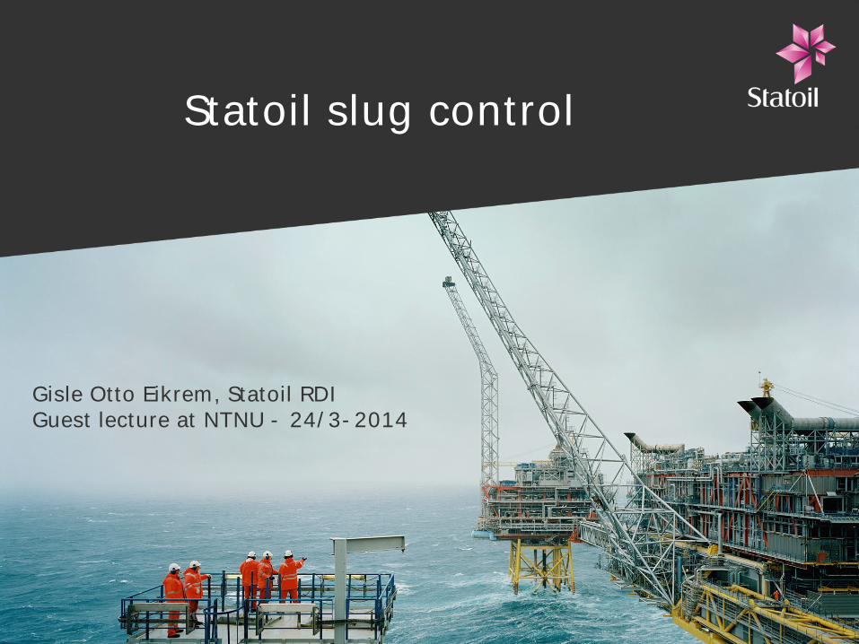
Statoil slug control
Gisle Otto Eikrem, Statoil RDIGuest lecture at NTNU - 24/3-2014
Outline
•Riser slugging
•Slugging in gas-lift wells
•Slug control
•Slug control at Åsgard A
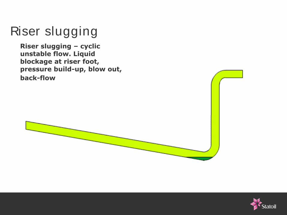
Riser sluggingRiser slugging – cyclic unstable flow. Liquid blockage at riser foot, pressure build-up, blow out, back-flow
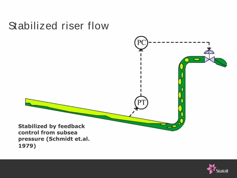
Stabilized riser flow
Stabilized by feedback control from subsea pressure (Schmidt et.al. 1979)
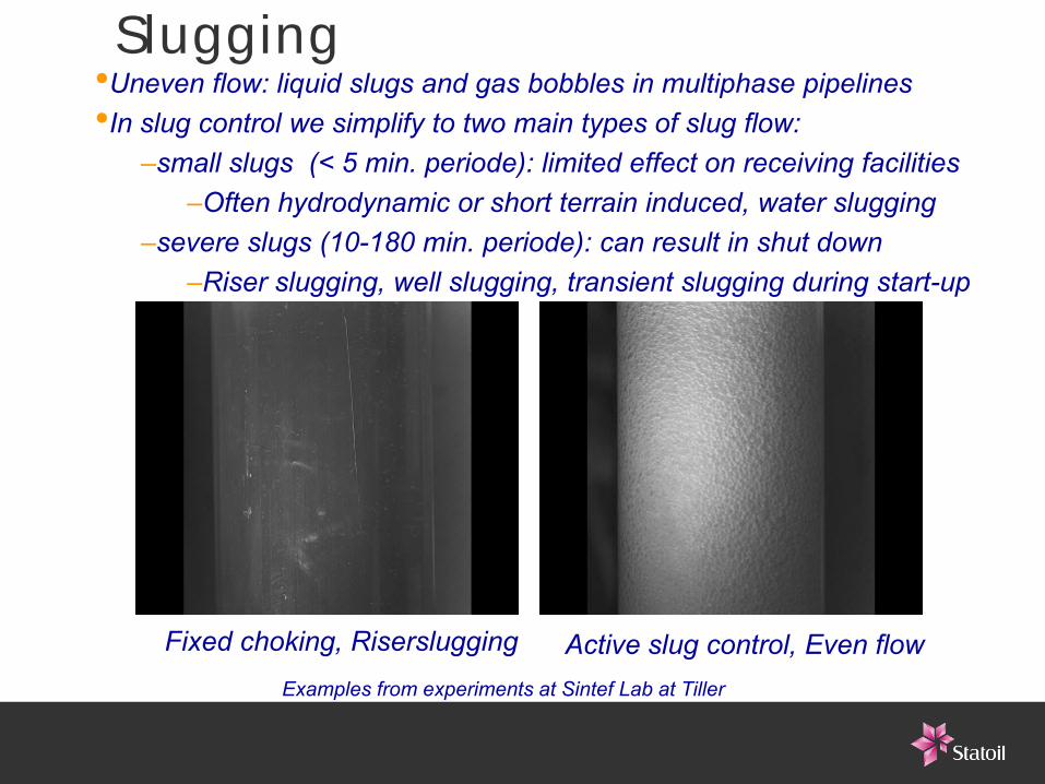
Slugging
Fixed choking, Riserslugging Active slug control, Even flow Examples from experiments at Sintef Lab at Tiller
•Uneven flow: liquid slugs and gas bobbles in multiphase pipelines•In slug control we simplify to two main types of slug flow:
–small slugs (< 5 min. periode): limited effect on receiving facilities–Often hydrodynamic or short terrain induced, water slugging
–severe slugs (10-180 min. periode): can result in shut down–Riser slugging, well slugging, transient slugging during start-up
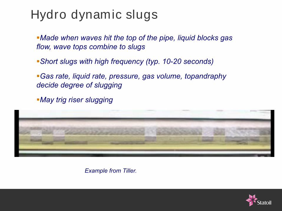
Hydro dynamic slugsMade when waves hit the top of the pipe, liquid blocks gas flow, wave tops combine to slugs
Short slugs with high frequency (typ. 10-20 seconds)
Gas rate, liquid rate, pressure, gas volume, topandraphy decide degree of slugging
May trig riser slugging
Example from Tiller.
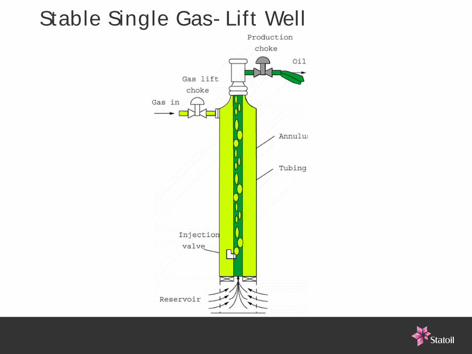
Stable Single Gas-Lift Well
Multiphase Video IVideo of controlled multiphase flow
Stable flow
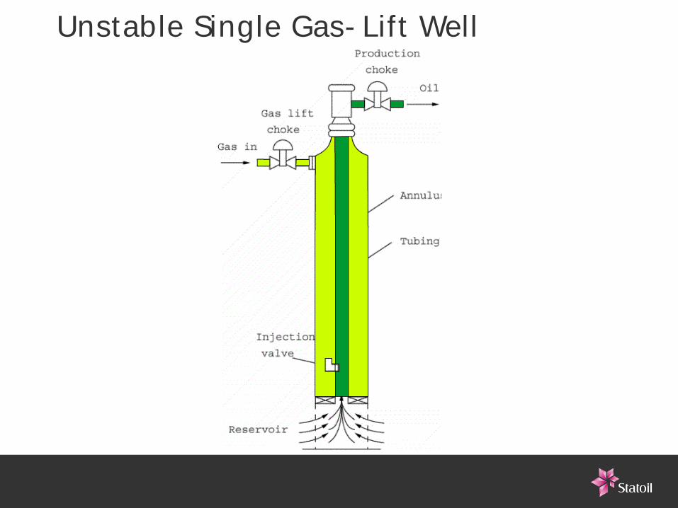
Unstable Single Gas-Lift Well
Multiphase Video IIVideo of severe slugging in gas lift well
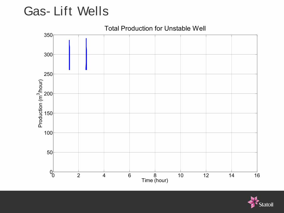
Gas-Lift Wells
0 2 4 6 8 10 12 14 160
50
100
150
200
250
300
350Total Production for Unstable Well
Time (hour)
Pro
duct
ion
(m3 /h
our)
Effects of slug flow•Reduced production•Large variations in liquid rates into 1st stage separator
–Level variations: alarms, shut downs–Bad separation/water cleaning:
•WiO: carry-over, emulsions•OiW: hydro cyclones do no handle rate variations well
–Pressure pulses, vibrations and eqipment wear–Fiscal rate metering problems
•Variations in gas rate–Pressure variations – high pressure protection gives shut down–Liquid carry over into gas system–Flaring–Fiscal gas rate measuring problems
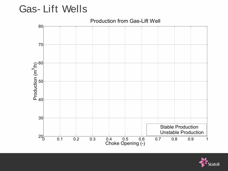
Gas-Lift Wells
0 0.1 0.2 0.3 0.4 0.5 0.6 0.7 0.8 0.9 120
30
40
50
60
70
80Production from Gas-Lift Well
Pro
duct
ion
(m3 /h
)
Choke Opening (-)
Stable ProductionUnstable Production
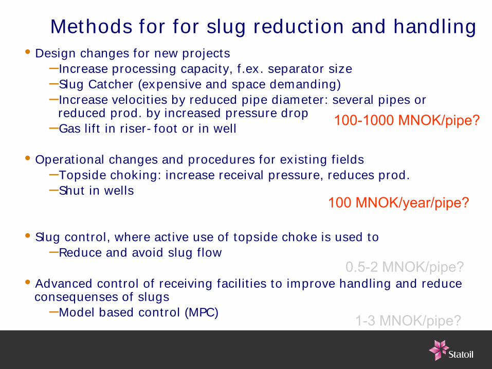
Methods for for slug reduction and handling•Design changes for new projects
–Increase processing capacity, f.ex. separator size–Slug Catcher (expensive and space demanding)–Increase velocities by reduced pipe diameter: several pipes or
reduced prod. by increased pressure drop–Gas lift in riser-foot or in well
•Operational changes and procedures for existing fields–Topside choking: increase receival pressure, reduces prod. –Shut in wells
•Slug control, where active use of topside choke is used to–Reduce and avoid slug flow
•Advanced control of receiving facilities to improve handling and reduce consequenses of slugs
–Model based control (MPC)
0.5-2 MNOK/pipe?
1-3 MNOK/pipe?
100-1000 MNOK/pipe?
100 MNOK/year/pipe?
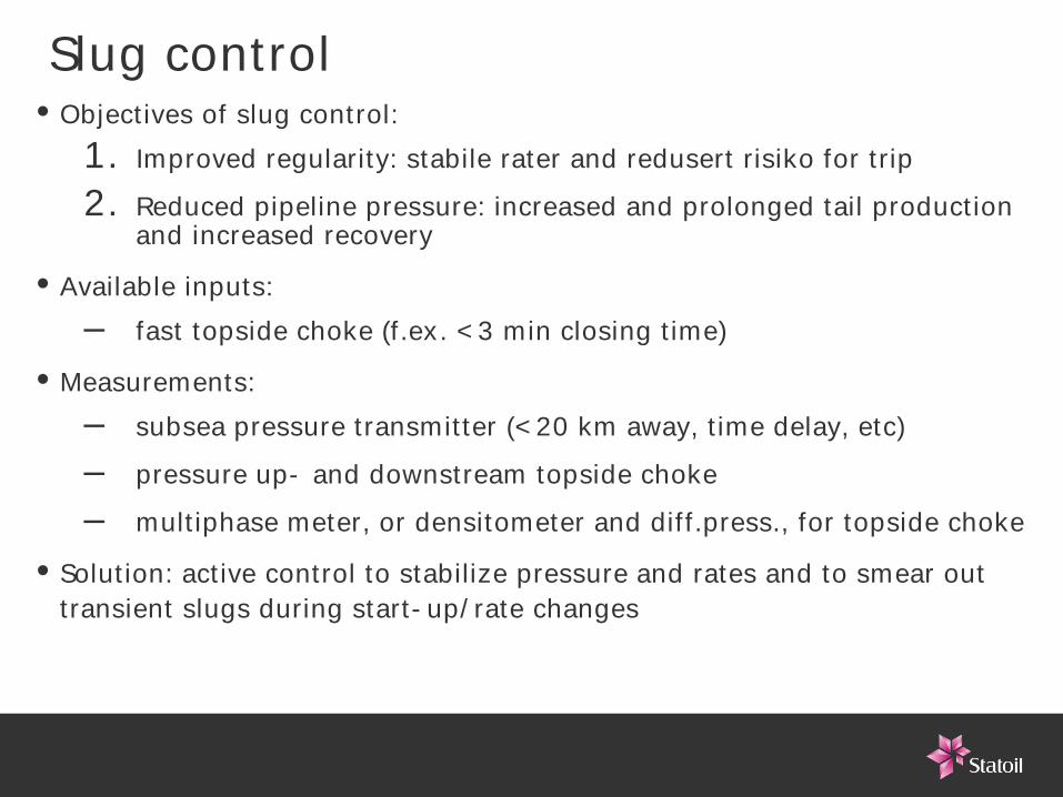
Slug control•Objectives of slug control:
1. Improved regularity: stabile rater and redusert risiko for trip2. Reduced pipeline pressure: increased and prolonged tail production
and increased recovery
•Available inputs: – fast topside choke (f.ex. <3 min closing time)
•Measurements:– subsea pressure transmitter (<20 km away, time delay, etc)– pressure up- and downstream topside choke– multiphase meter, or densitometer and diff.press., for topside choke
•Solution: active control to stabilize pressure and rates and to smear out transient slugs during start-up/rate changes
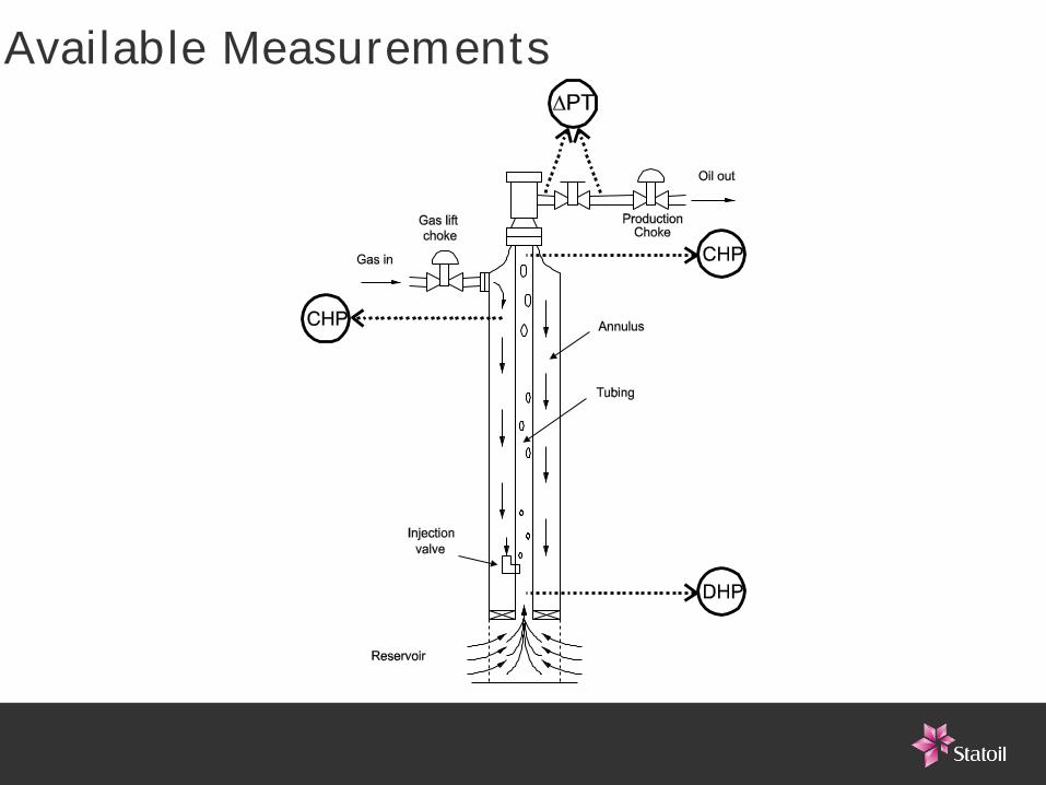
Available Measurements
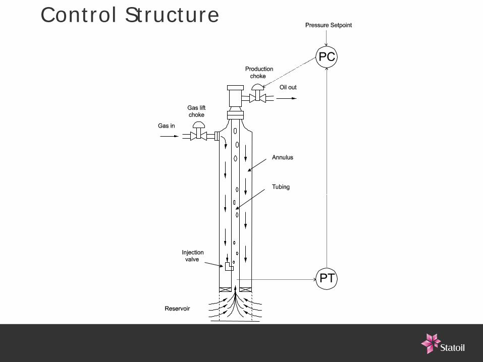
Control Structure
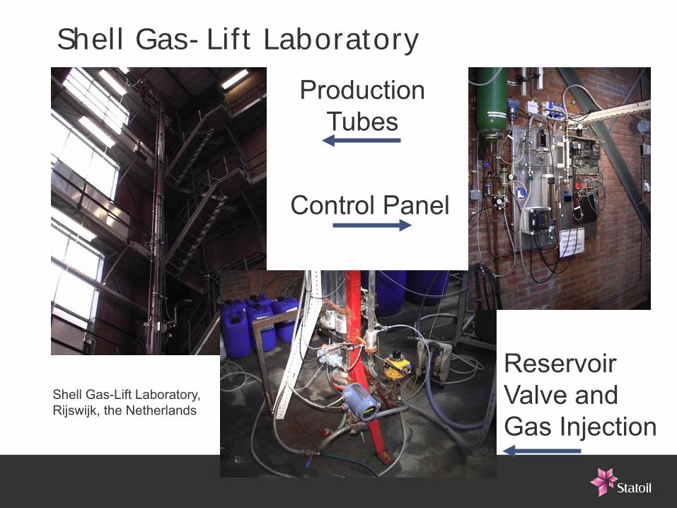
Shell Gas-Lift LaboratoryProduction
Tubes
Control Panel
ReservoirValve and Gas Injection
Shell Gas-Lift Laboratory, Rijswijk, the Netherlands
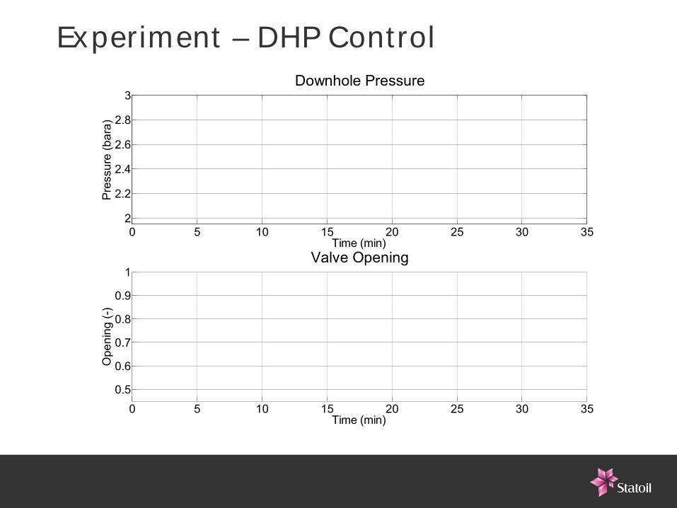
Experiment – DHP Control
0 5 10 15 20 25 30 352
2.2
2.4
2.6
2.8
3Downhole Pressure
Time (min)
Pre
ssur
e (b
ara)
0 5 10 15 20 25 30 350.5
0.6
0.7
0.8
0.9
1Valve Opening
Ope
ning
(-)
Time (min)
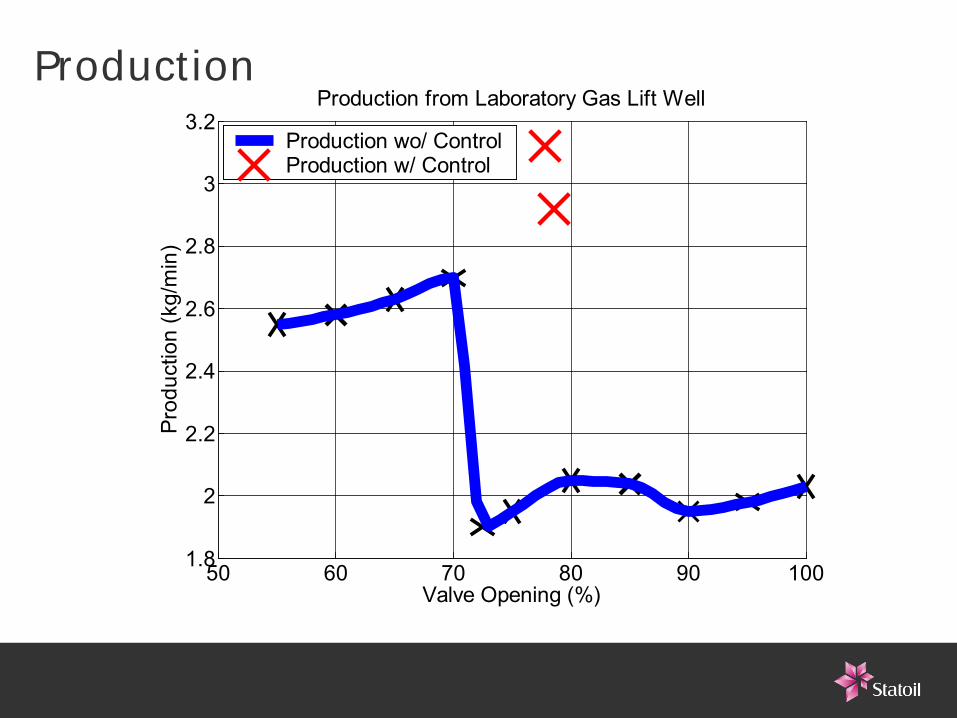
Production
50 60 70 80 90 1001.8
2
2.2
2.4
2.6
2.8
3
3.2Production from Laboratory Gas Lift Well
Prod
uctio
n (k
g/m
in)
Valve Opening (%)
Production wo/ ControlProduction w/ Control
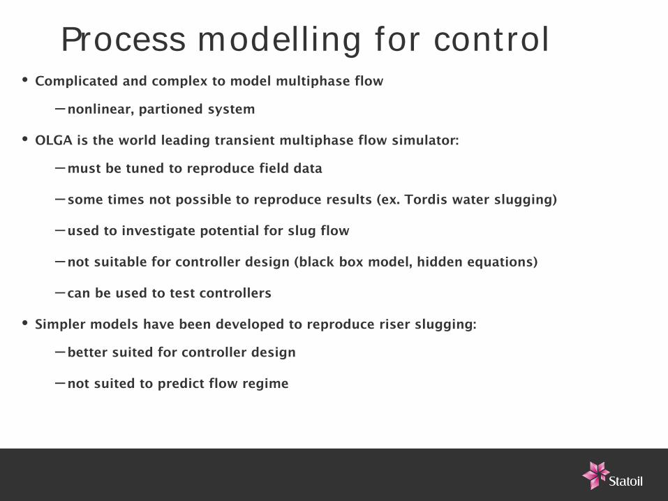
Process modelling for control•Complicated and complex to model multiphase flow
–nonlinear, partioned system
•OLGA is the world leading transient multiphase flow simulator:
–must be tuned to reproduce field data
–some times not possible to reproduce results (ex. Tordis water slugging)
–used to investigate potential for slug flow
–not suitable for controller design (black box model, hidden equations)
– can be used to test controllers
• Simpler models have been developed to reproduce riser slugging:
–better suited for controller design
–not suited to predict flow regime
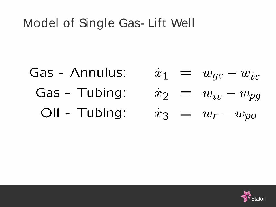
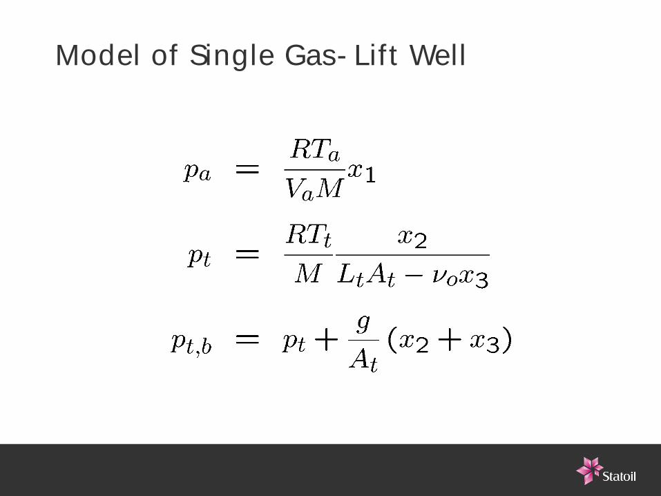
Model of Single Gas-Lift Well
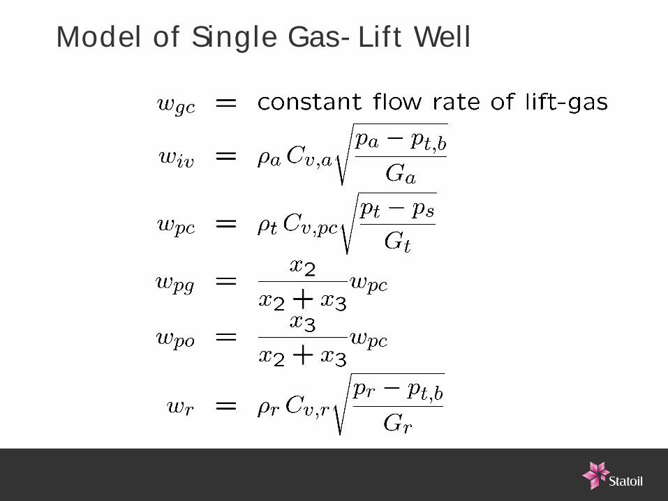
Model of Single Gas-Lift Well
Model of Single Gas-Lift Well
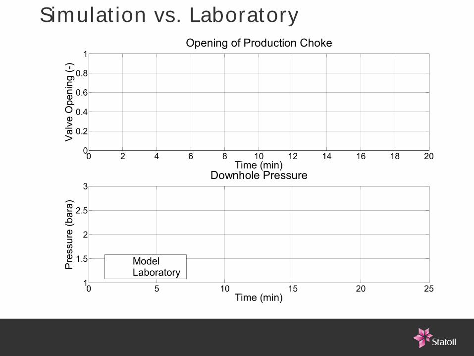
Simulation vs. Laboratory
0 2 4 6 8 10 12 14 16 18 200
0.2
0.4
0.6
0.8
1Opening of Production Choke
Val
ve O
peni
ng (-
)
Time (min)
0 5 10 15 20 251
1.5
2
2.5
3Downhole Pressure
Time (min)
Pre
ssur
e (b
ara)
ModelLaboratory
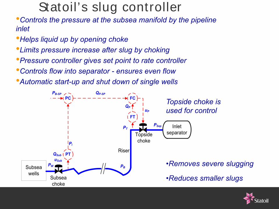
Statoil’s slug controller
•Removes severe slugging
•Reduces smaller slugs
•Controls the pressure at the subsea manifold by the pipeline inlet•Helps liquid up by opening choke •Limits pressure increase after slug by choking•Pressure controller gives set point to rate controller•Controls flow into separator - ensures even flow•Automatic start-up and shut down of single wells
Subsea wells
Inlet separator
FT
FCQP-SP
uP
Riser
Topsidechoke
PT
PCPB-SP
PB
Subseachoke
QP
Pi
PW
uSub
PTPSep
QSub
Topside choke is used for control
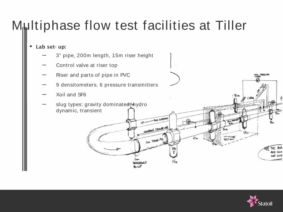
Multiphase flow test facilities at Tiller
Laboppsett3" rør, 200m, 15 m riserReguleringsventil på toppen av riserRiser og flere rørstrekk i PVC (gjennomsiktig)9 tetthetsmåler, 6 trykktransmittereXoil, SF6.sluggtyper (tyngdedominert, hydrodynamisk, transient)
• Lab set- up:
– 3” pipe, 200m length, 15m riser height
– Control valve at riser top
– Riser and parts of pipe in PVC
– 9 densitometers, 6 pressure transmitters
– Xoil and SF6
– slug types: gravity dominated, hydro dynamic, transient
Results from Tiller•Control of inlet pressure, volumetric rate and cascade control.•OLGA slug periode 50-200 sec verified experimentally•Flow map and valve characteristics•Controller tuning•Control based only on topside measurements, i.e. without inlet
pressure•”Slow” ventiler: max closing time?
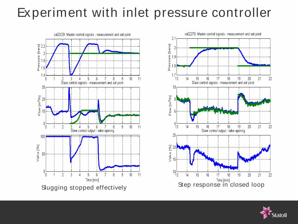
Experiment with inlet pressure controller
Slugging stopped effectively Step response in closed loop
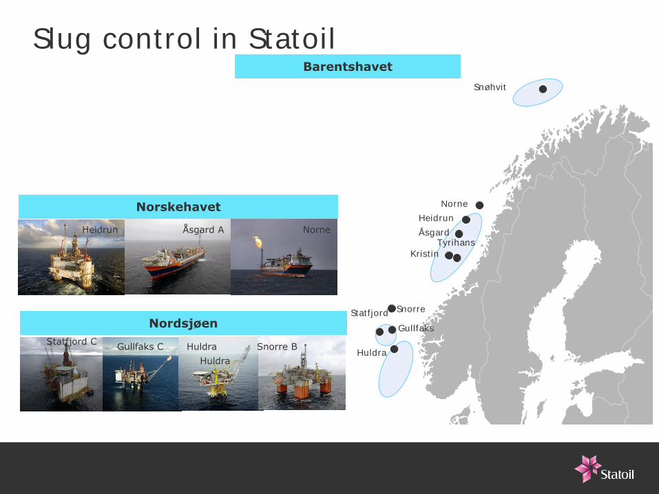
Statfjord
Huldra
Snøhvit
Kristin
Barentshavet
Norskehavet
Nordsjøen
Tyrihans
Slug control in Statoil
ÅsgardHeidrun
Norne
Gullfaks
Heidrun Åsgard A Norne
HuldraGullfaks CStatfjord C Snorre BHuldra
Snorre
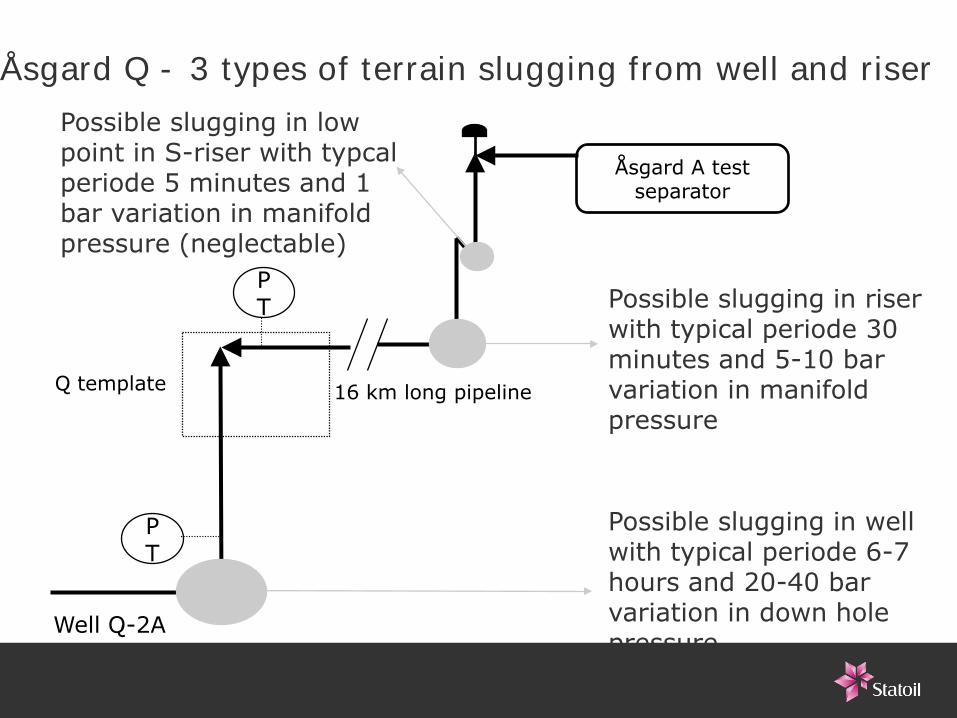
Åsgard Q - 3 types of terrain slugging from well and riser
Åsgard A test separator
PT
PT
Q template
Well Q-2A
16 km long pipeline
Possible slugging in well with typical periode 6-7 hours and 20-40 bar variation in down hole pressure
Possible slugging in riser with typical periode 30 minutes and 5-10 bar variation in manifold pressure
Possible slugging in low point in S-riser with typcal periode 5 minutes and 1 bar variation in manifold pressure (neglectable)
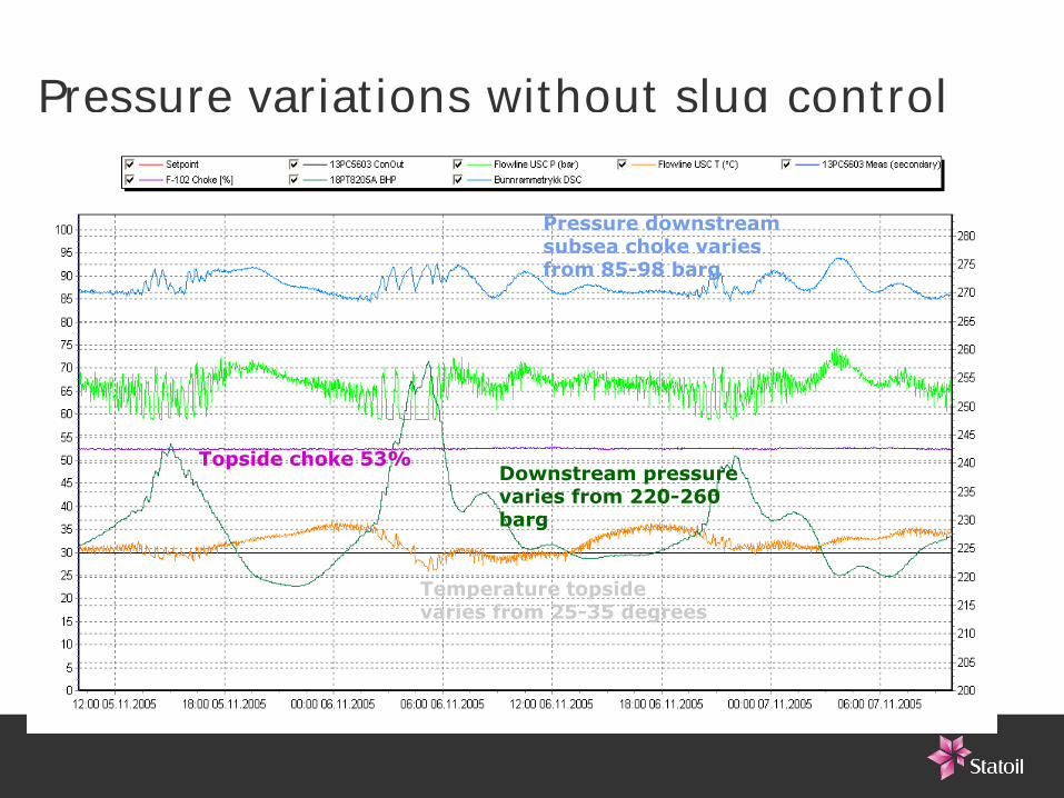
Pressure variations without slug control
Downstream pressure varies from 220-260 barg
Temperature topside varies from 25-35 degrees
Topside choke 53%
Pressure downstream subsea choke varies from 85-98 barg
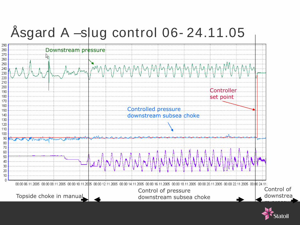
Åsgard A –slug control 06-24.11.05
Control of pressure downstream subsea chokeTopside choke in manual
Control of downstream pressure
Downstream pressure
Controller set point
Controlled pressure downstream subsea choke
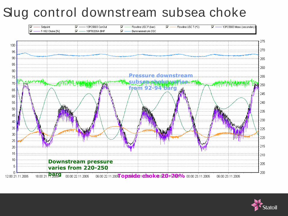
Slug control downstream subsea choke
Pressure downstream subsea choke varies from 92-94 barg
Topside choke 20-70%
Downstream pressure varies from 220-250 barg
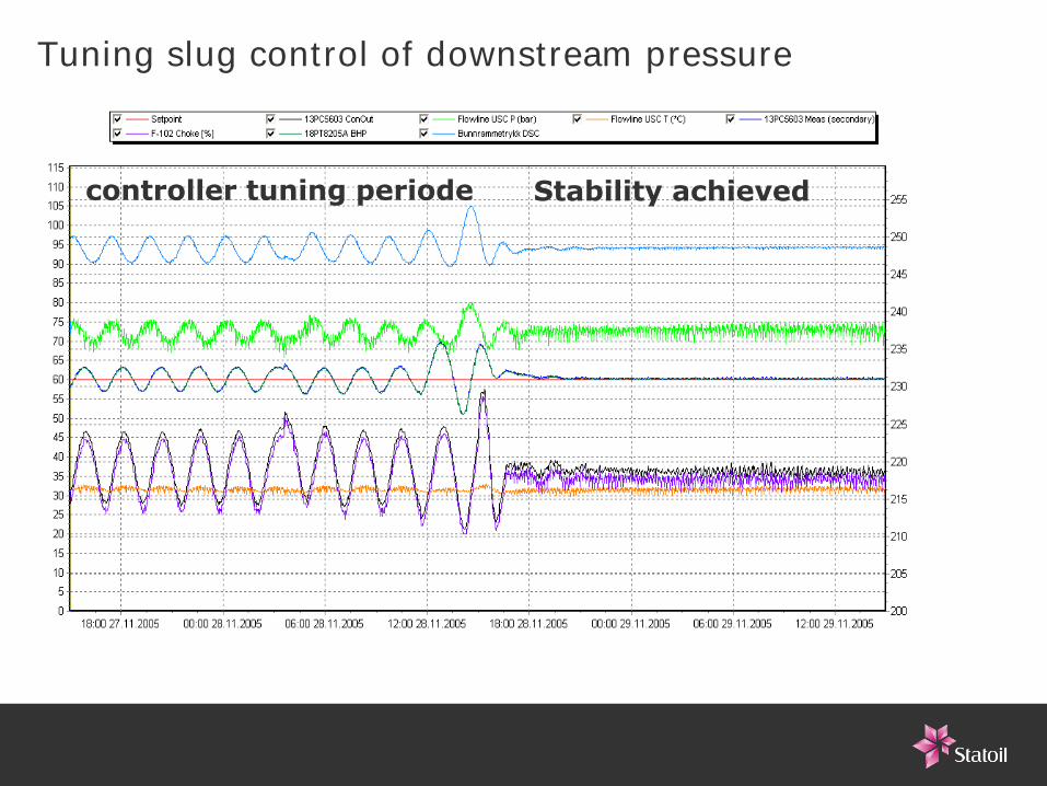
Tuning slug control of downstream pressure
controller tuning periode Stability achieved
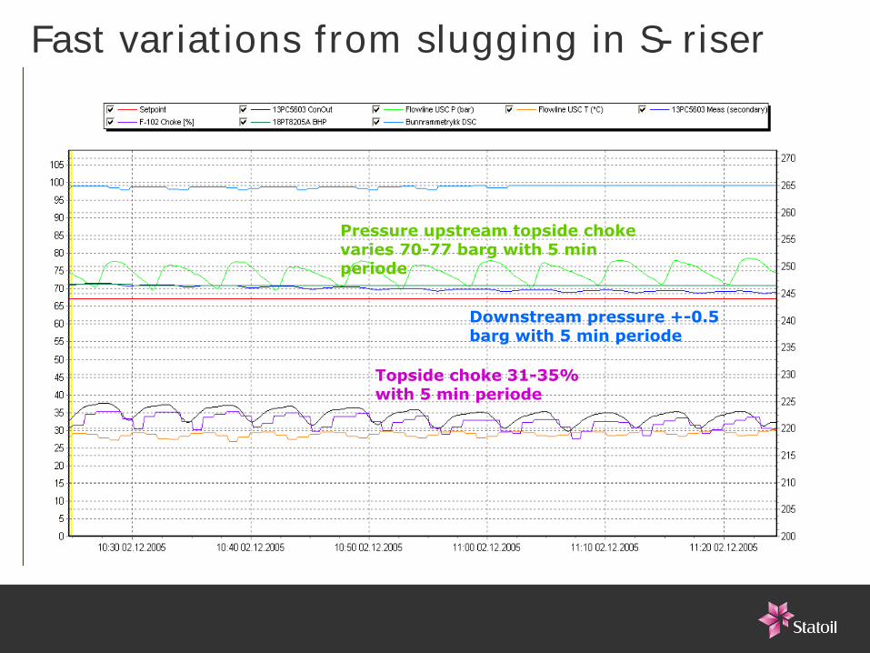
Fast variations from slugging in S-riser
Topside choke 31-35% with 5 min periode
Pressure upstream topside choke varies 70-77 barg with 5 min periode
Downstream pressure +-0.5 barg with 5 min periode
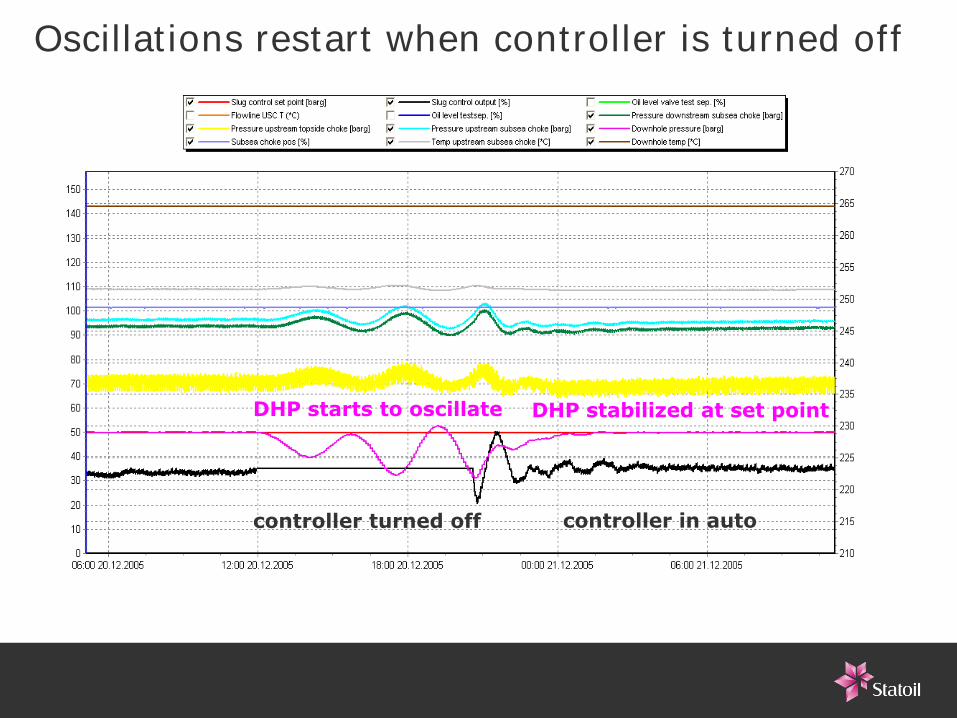
Oscillations restart when controller is turned off
controller turned off
DHP starts to oscillate
controller in auto
DHP stabilized at set point
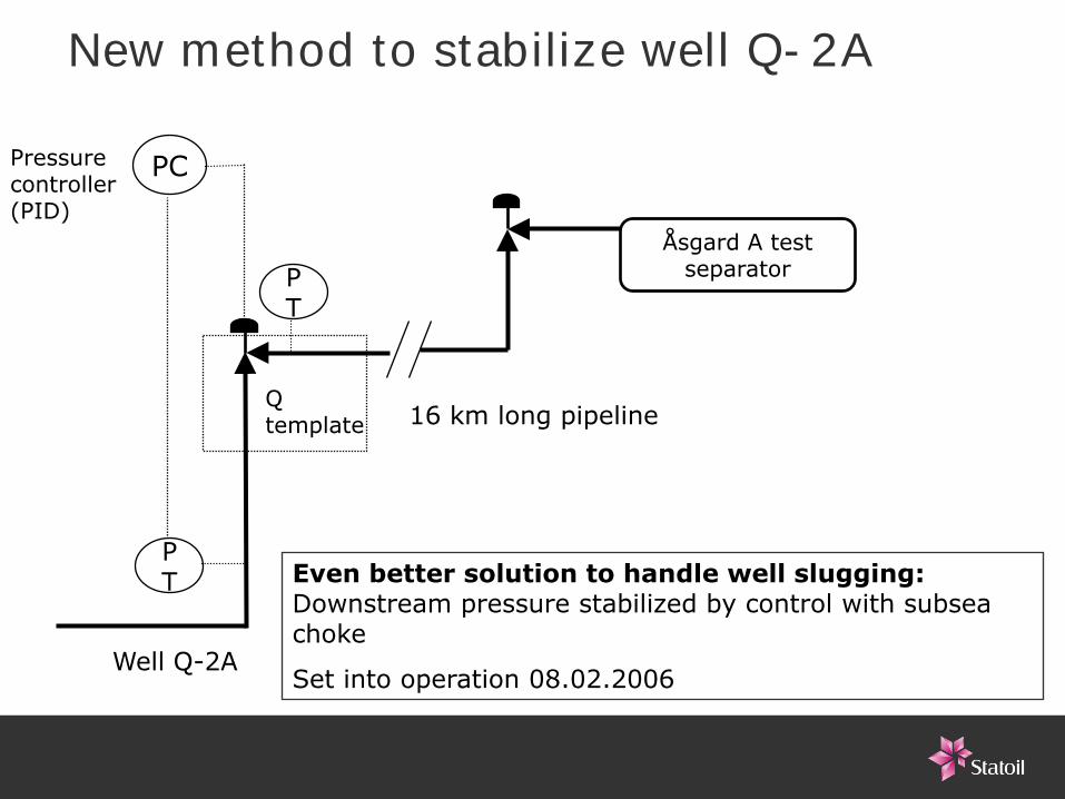
Åsgard A test separator
PC
PT
PT
Q template
Well Q-2A
16 km long pipeline
Even better solution to handle well slugging:Downstream pressure stabilized by control with subsea choke
Set into operation 08.02.2006
Pressure controller (PID)
New method to stabilize well Q-2A
Summary• Good results achived at several offshore installations from 2001 with simple PI-
controllers that control inlet (subsea) pressure and rate into receiving facilities with topside choke – simple and inexpensive solution
• Qualified technology after more than 5 years in operation• Achives even rates and reduced pipeline pressure and improves regularity and makes
it possible to increase and prolonge production, since it then is possible to operate closer to given constraints, f.ex. bubble point pressure, max sand free rate, hydrate temp., etc.
• Well: results indicate that it is possible to stabilize wells by control of the downstream pressure with topside or subsea choke and a PI controller
• Extended to handle other types of flow:– Gas dominated flow with surge waves
– Start-up slugs
• Subsea production facilities