Embed Size (px)
DESCRIPTION
http://preview.gea.com/global/en/binaries/2012-05_Solution%20Crystallization_sm2_tcm11-21921.pdf
Citation preview

engineering for a better world GEA Process Engineering
Mass Crystallizationfrom solutions

2
Content04
05
06
10
13
16
18
19
GEA Messo PT in the field of crystallization
Crystallization in history and presence
Crystallization in theory and practice
Types of crystallizers
Forced circulation crystallizer
DTB crystallizer
OSLO crystallizer
Peripheral components
Application examples
Surface cooling crystallization
Vacuum cooling crystallization
Evaporative crystallization
Modern applications
Flue gas desulfurization (FGD)
Recovery of caffeine
Salt from secondary aluminum slag
Ammonium sulfate from the caprolactam process
Research and development services
Product experience

3
Individual plants for the chemical, pharmaceutical and food processing industries
(Unit operation, evaporation, crystallization, thermocompression)
— Crystallization plants
— Evaporation plants (for concentration of solutions prone to formation of scaling)
Crystallization and evaporation technologies for the chemical, pharmaceutical
and food processing industries, e.g.:
(Entire technology concepts, based on precipitation, evaporation, crystallization)
— Common salt production plants
— Reaction crystallization plants for several base/acid reactions
Plants for environmental protection
(Based on precipitation, evaporation, crystallization)
— Pickling bath liquor recycling plants
— Landfill leachates concentration plants
— Industrial waste water ZLD plants
— Treatment plants for slags from the secondary aluminum industries
Range of Products
We know how!
4
GEA Messo PT is well established as globally recognized technology supplier and plant
constructor in the field of solution and melt crystallization and related concentration tech-
nologies with focus on business activities to a selected range of industrial applications.
GEA Messo PT has been established as a recent merger of the German based GEA Messo GmbH and
the Netherlands based GEA Niro PT B.V.. GEA Messo PT combines the two technology centers for
solution crystallization (MESSO) and melt crystallization/freeze concentration (NIRO PT) allowing
to use all cross-fertilizing synergies between solution and melt crystallization. At the same time,
our customers profit from a better support out of larger and consolidated departments in sales,
project management, services and administration. Experience counts for a lot in the implementati-
on of crystallization systems and our combined track record makes GEA Messo PT the supplier of
choice for many of our customers.
IN THE FIELD OF MASS CRYSTALLIZATION FROM SOLUTIONS, GEA MESSO PT’S EXPERTISE
encompasses all basic types of crystallizers for the crystallization from solutions, such as the forced
circulation or draft-tube (MSMPR) crystallizer, the turbulence (DTB) crystallizer, and the fluidized
bed (OSLO) crystallizer. GEA Messo PT is thus in an unique position to address the special needs of
each of its clients, depending on the required product crystal quality and size. GEA Messo PT rou-
tinely supplies upstream and downstream components, such as the preconcentration (in multiple
effect, mechanical vapour recompression, flash, and other evaporator configurations), the debrining
(thickening, filtration or centrifugation), drying, solids handling and packaging. GEA Messo PT
also supplies piping and instrumentation and process control systems for its plants, installations
in prefabricated and modularized sections as required by the client.
GEA Messo PT Synonym for Crystallization

5
GEA Messo PT is a leader in its field through in-depth reviews of its operating installations and
research and development. The Research and Development Department of GEA Messo PT is
housed in a three-hundred-square meter facility, equipped with test units that simulate batch and
continuous operation of all basic types and configurations of crystallizers. It has in-house ana-
lytical capabilities for direct determination of concentration, supersaturation, and other physical
properties of the subject process liquors. Not only the design of crystallizers but the development
of optimized separation processes for our clients’ needs is in the focus of GEA Messo PT chemists
and engineers.
In antiquity, settlements developed around, and exploited sites where salt was easily available,
whether as rock, brine, or derived from solar evaporation. For example, salt was produced in
the Pharaonic Egypt at the Nile Delta; similarly, the Romans recovered salt at Ostia seacoast
(near Rome) and the same happened all over the world (e.g. in China). These and many other pro-
duction sites prove that crystallization from solution is one of the oldest unit operations practiced
by humankind.
While crystallization in solar ponds is still in regions with plentiful sunshine, its low production
rate and mediocre product purity prevents this technology to be used generally. As the world
developed through industrial age, the demand for crystalline chemicals increased in variety, quan-
tity, and quality. This led to the birth of crystallization technology that aimed at improving the
methods and equipment used in crystallization operations. Modern crystallizers can boost specific
production rates that are several orders of magnitude higher than solar ponds, have low manpower
requirements, and low production costs.
The specific requirements of a crystallizer can vary widely, depending on the nature of the pro-
duct, and its intended use: pharmaceutical and food products require higher purity, for example,
while fertilizers need larger crystal size; the crystal size and final moisture are not as important in
crystallization systems which produce an intermediate compound. There are cases where the real
product of the crystallizer is the solvent: crystallization is used to separate from the solvent the
compounds that make it impure. Further, there are cases where crystallization is used to concen-
trate a solution, by crystallizing and removing the solvent (freeze concentration). One quality that
is present in all crystallization systems, regardless of the final use of the solvent or the crystal, is
the ability to separate the crystals from the mother liquor. This ability is a function of the crystal
size, and, by extension, a function of the separation equipment that can be used. Centrifugation is
by far the most efficient separation method, if the average crystal size is large enough. It is there-
fore logical to expect that of the characteristics of a crystallizer, the crystal size it produces is of
great importance. The possible crystal size of a given compound is dependent on its chemical and
physical properties, and those of the solution in which it is dissolved. In parallel, the crystal size
is dependent on the equipment used to crystallize it, and the method by which the equipment is
operated. The crystallizer used can contribute to improving the crystal size, within physical and
energy boundaries, by controlling the nucleation, the attrition, and the growth rate of crystals, and
by destroying a fraction of the smaller crystals present in the crystallizer itself. Inattention of these
parameters, on the other hand, can contribute to a degradation of the crystal size.
– A 16th century salt works
Crystallization in History and Presence
6
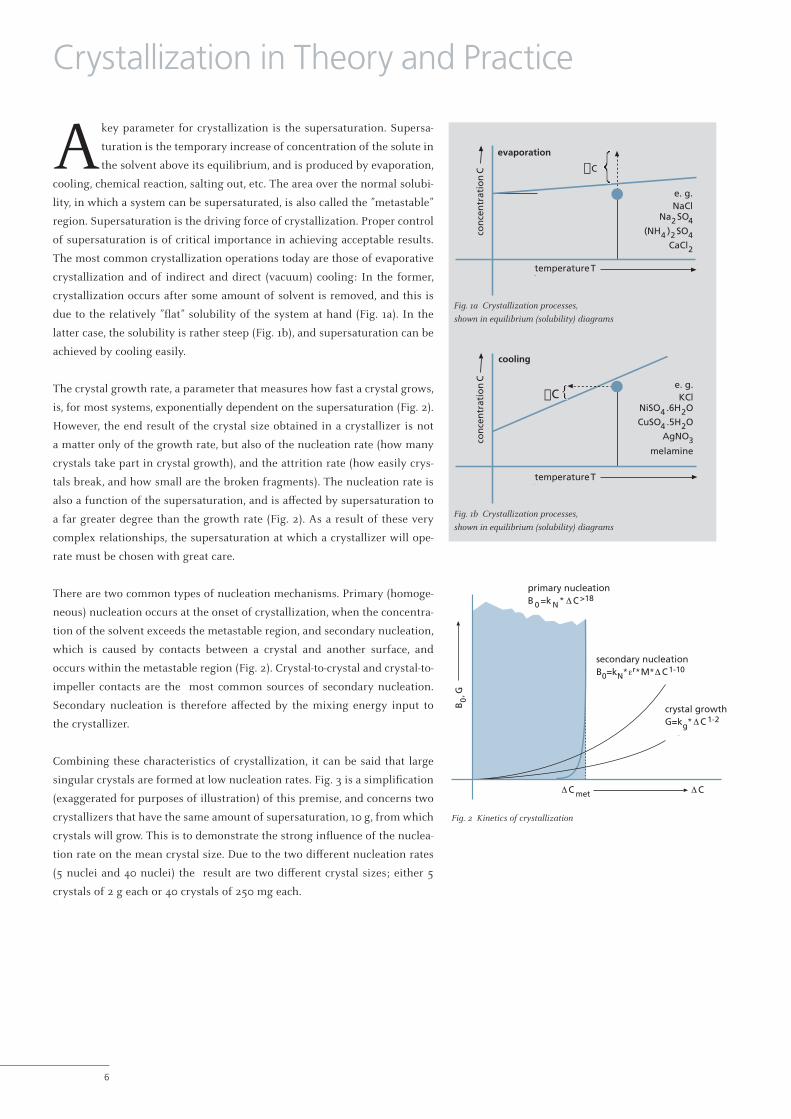
Akey parameter for crystallization is the supersaturation. Supersa-
turation is the temporary increase of concentration of the solute in
the solvent above its equilibrium, and is produced by evaporation,
cooling, chemical reaction, salting out, etc. The area over the normal solubi-
lity, in which a system can be supersaturated, is also called the ”metastable”
region. Supersaturation is the driving force of crystallization. Proper control
of supersaturation is of critical importance in achieving acceptable results.
The most common crystallization operations today are those of evaporative
crystallization and of indirect and direct (vacuum) cooling: In the former,
crystallization occurs after some amount of solvent is removed, and this is
due to the relatively ”flat” solubility of the system at hand (Fig. 1a). In the
latter case, the solubility is rather steep (Fig. 1b), and supersaturation can be
achieved by cooling easily.
The crystal growth rate, a parameter that measures how fast a crystal grows,
is, for most systems, exponentially dependent on the supersaturation (Fig. 2).
However, the end result of the crystal size obtained in a crystallizer is not
a matter only of the growth rate, but also of the nucleation rate (how many
crystals take part in crystal growth), and the attrition rate (how easily crys-
tals break, and how small are the broken fragments). The nucleation rate is
also a function of the supersaturation, and is affected by supersaturation to
a far greater degree than the growth rate (Fig. 2). As a result of these very
complex relationships, the supersaturation at which a crystallizer will ope-
rate must be chosen with great care.
There are two common types of nucleation mechanisms. Primary (homoge-
neous) nucleation occurs at the onset of crystallization, when the concentra-
tion of the solvent exceeds the metastable region, and secondary nucleation,
which is caused by contacts between a crystal and another surface, and
occurs within the metastable region (Fig. 2). Crystal-to-crystal and crystal-to-
impeller contacts are the most common sources of secondary nucleation.
Secondary nucleation is therefore affected by the mixing energy input to
the crystallizer.
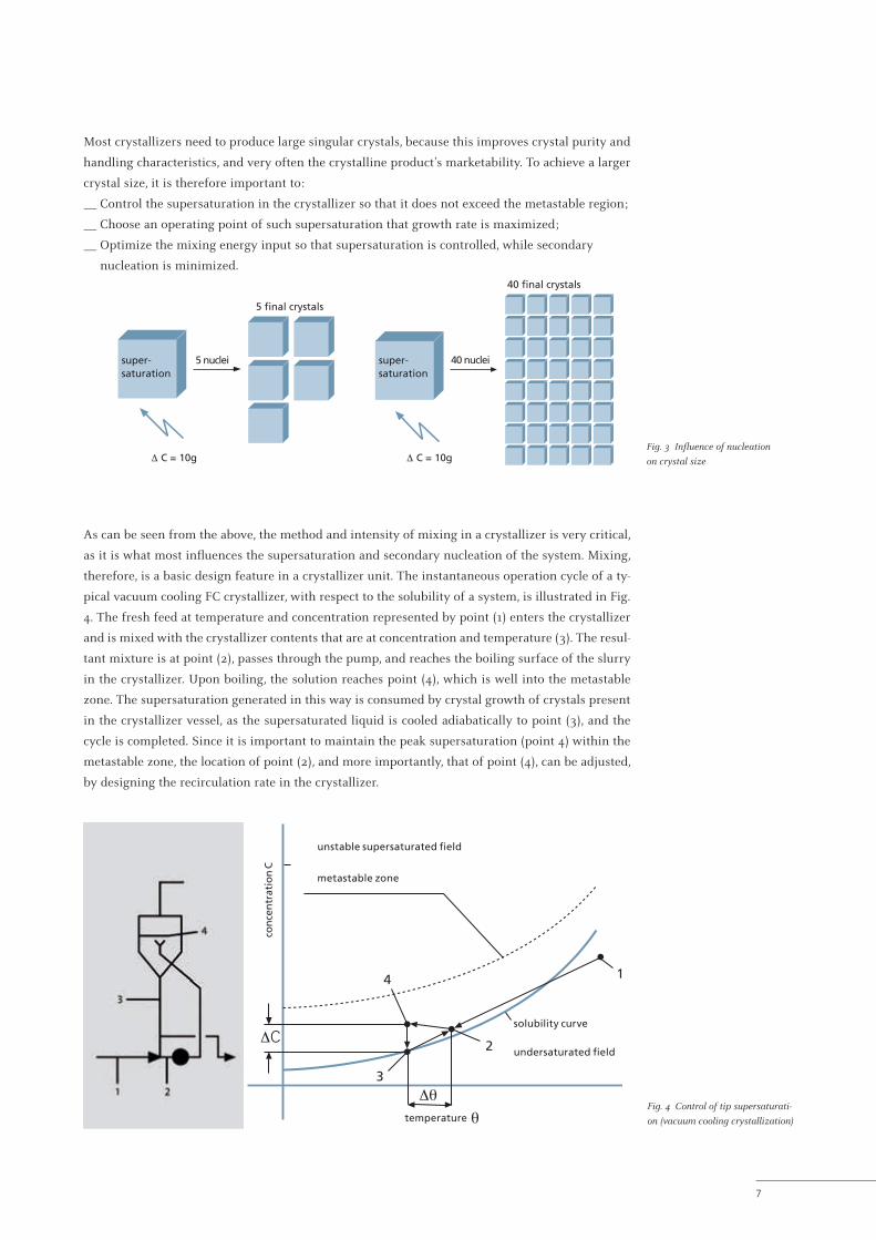
Combining these characteristics of crystallization, it can be said that large
singular crystals are formed at low nucleation rates. Fig. 3 is a simplification
(exaggerated for purposes of illustration) of this premise, and concerns two
crystallizers that have the same amount of supersaturation, 10 g, from which
crystals will grow. This is to demonstrate the strong influence of the nuclea-
tion rate on the mean crystal size. Due to the two different nucleation rates
(5 nuclei and 40 nuclei) the result are two different crystal sizes; either 5
crystals of 2 g each or 40 crystals of 250 mg each.
e. g.NaCl
Na2SO4(NH4)2SO4
CaCl2con
cen
trat
ion
C
temperature T
Cevaporation
Fig. 1b Crystallization processes,
shown in equilibrium (solubility) diagrams
Fig. 1a Crystallization processes,
shown in equilibrium (solubility) diagrams
Crystallization in Theory and Practice
B0,
G
Δ C met Δ C
primary nucleationB0=kN*Δ C>18
secondary nucleationB0=kn*εr*M*Δ C1-10
crystal growthG=kg*Δ C1-2
Fig. 2 Kinetics of crystallization
B0
, G
primary nucleationB 0 =k N * Δ C >18
secondary nucleationB0=kN* * *r Δ CM 1-10ε
crystal growth
metΔ C Δ C
G=kg* Δ C 1-2
B0
, G
primary nucleationB 0 =k N * Δ C >18
secondary nucleationB0=kN* * *r Δ CM 1-10ε
crystal growth
metΔ C Δ C
G=kg* Δ C 1-2
B0
, G
primary nucleationB 0 =k N * Δ C >18
secondary nucleationB0=kN* * *r Δ CM 1-10ε
crystal growth
metΔ C Δ C
G=kg* Δ C 1-2
B0
, G
primary nucleationB 0 =k N * Δ C >18
secondary nucleationB0=kN* * *r Δ CM 1-10ε
crystal growth
metΔ C Δ C
G=kg* Δ C 1-2
B0
, G
primary nucleationB 0 =k N * Δ C >18
secondary nucleationB0=kN* * *r Δ CM 1-10ε
crystal growth
metΔ C Δ C
G=kg* Δ C 1-2
B0
, G
primary nucleationB 0 =k N * Δ C >18
secondary nucleationB0=kN* * *r Δ CM 1-10ε
crystal growth
metΔ C Δ C
G=kg* Δ C 1-2
B0
, G
e. g.NaCl
Na2 SO4(NH4 )2 SO4
CaCl2
con
cen
trat
ion
C
temperature T
C
evaporation
B0
, G
e. g.NaCl
Na2 SO4(NH4 )2 SO4
CaCl2
con
cen
trat
ion
C
temperature T
C
evaporation
B0
, Ge. g.NaCl
Na2 SO4(NH4 )2 SO4
CaCl2
con
cen
trat
ion
C
temperature T
C
evaporation
B0
, G
e. g.NaCl
Na2 SO4(NH4 )2 SO4
CaCl2
con
cen
trat
ion
C
temperature T
C
evaporation
e. g.KCl
NiSO4.6H2OCuSO4.5H2O
AgNO3melamineco
nce
ntr
atio
n C
temperature T
C
cooling
C
e. g.KCl
NiSO4 .6H2O
CuSO4 .5H2O
AgNO3melamine
cooling
C
e. g.KCl
NiSO4 .6H2O
CuSO4 .5H2O
AgNO3melamine
coolingB0
, Ge. g.NaCl
Na2 SO4(NH4 )2 SO4
CaCl2
con
cen
trat
ion
C
temperature T
C
evaporation
B0
, G
e. g.NaCl
Na2 SO4(NH4 )2 SO4
CaCl2
con
cen
trat
ion
C
temperature T
C
evaporation
B0
, G
e. g.NaCl
Na2 SO4(NH4 )2 SO4
CaCl2
con
cen
trat
ion
C
temperature T
C
evaporation
7
Most crystallizers need to produce large singular crystals, because this improves crystal purity and
handling characteristics, and very often the crystalline product’s marketability. To achieve a larger
crystal size, it is therefore important to:
— Control the supersaturation in the crystallizer so that it does not exceed the metastable region;
— Choose an operating point of such supersaturation that growth rate is maximized;
— Optimize the mixing energy input so that supersaturation is controlled, while secondary
nucleation is minimized.
Fig. 4 Control of tip supersaturati-
on (vacuum cooling crystallization)
Fig. 3 Influence of nucleation
on crystal size
As can be seen from the above, the method and intensity of mixing in a crystallizer is very critical,
as it is what most influences the supersaturation and secondary nucleation of the system. Mixing,
therefore, is a basic design feature in a crystallizer unit. The instantaneous operation cycle of a ty-
pical vacuum cooling FC crystallizer, with respect to the solubility of a system, is illustrated in Fig.
4. The fresh feed at temperature and concentration represented by point (1) enters the crystallizer
and is mixed with the crystallizer contents that are at concentration and temperature (3). The resul-
tant mixture is at point (2), passes through the pump, and reaches the boiling surface of the slurry
in the crystallizer. Upon boiling, the solution reaches point (4), which is well into the metastable
zone. The supersaturation generated in this way is consumed by crystal growth of crystals present
in the crystallizer vessel, as the supersaturated liquid is cooled adiabatically to point (3), and the
cycle is completed. Since it is important to maintain the peak supersaturation (point 4) within the
metastable zone, the location of point (2), and more importantly, that of point (4), can be adjusted,
by designing the recirculation rate in the crystallizer.
conc
entr
atio
n C
unstable supersaturated field
metastable zone
solubility curve
temperature θ
ΔC
4
3
2
Δθ
1
undersaturatedfield
unstable supersaturated field
metastable zone
solubility curve
undersaturated field2
4 1
3
temperature
con
cen
trat
ion
Δ C = 10g
5 nuclei
40 nuclei
super-saturation
super-saturation
5 final crystals
40 final crystals
Δ C = 10g
5 nuclei
40 nuclei
super-saturation
super-saturation
5 final crystals
40 final crystals
Δ C = 10g
5 nuclei
40 nuclei
super-saturation
super-saturation
5 final crystals
40 final crystals
Δ C = 10g
5 nuclei
40 nuclei
super-saturation
super-saturation
5 final crystals
40 final crystals
Δ C = 10g
5 nuclei
40 nuclei
super-saturation
super-saturation
5 final crystals
40 final crystals
Δ C = 10g
5 nuclei
40 nuclei
super-saturation
super-saturation
5 final crystals
40 final crystals
Δ C = 10g
5 nuclei
40 nuclei
super-saturation
super-saturation
5 final crystals
40 final crystals
Δ C = 10g
5 nuclei
40 nuclei
super-saturation
super-saturation
5 final crystals
40 final crystals
B0
, G
e. g.NaCl
Na2 SO4(NH4 )2 SO4
CaCl2
con
cen
trat
ion
C
temperature T
C
evaporation
8
If the supersaturation generated in one cycle is not completely consumed by the end of the
cycle, the starting point for the next cycle will be somewhat further from the saturation curve.
After some time, the whole cycle will migrate so far into or even above the metastable zone,
that it will adversely affect crystal growth and nucleation. It is therefore important to provide suf-
ficient opportunity (efficient mixing) and suitable sites (sufficient crystal surface) for the supersa-
turation to be consumed. Otherwise, the crystal size will suffer, and the crystallizer will be subject
to incrustations.
These ideas are embodied in the two kinetic equations below. The mass deposition rate (dm/dt)
resp. the consumed supersaturation per cycle time is dependent on the surface of suspended crys-
tals (A) and on the level of supersaturation (ΔC).
V
Crystallization in Theory and Practice

9
Secondary nucleation B0 depends on dissipated mixing energy ( , suspension density (m) and level
of supersaturation (ΔC):
Crystal size is influenced by the time that the crystal stays in the crystallizer (retention time), whe-
re, under proper operating conditions, it may grow. There is, however, a competing quality in this
arrangement that affects the crystal size adversely. Mechanical attrition (Ga) is the rate of removal
of material from a crystal (as opposed to Gk, the linear, kinetic crystal growth rate), and it is depen-
dent on the crystal retention time, the magma density, the mixing energy and the hydrodynamic
design of the system. It is therefore to be expected that under certain conditions, crystal size will
peak at a certain retention time, and will thereafter become smaller, as Ga overpowers Gk and the
effective crystal growth rate is minimized.
Crystallization in Theory and Practice
– MESSO-type crystallizers; FC, DTB, OSLO
Geff = Gk + Ga

10
All this is considered in modern types of continuous crystallizers. Crystallizers with longer retention
times are operated with less specific energy input, resulting in lower nucleation rates. The impacts
between crystals and the impeller pump blades are the most effective source for the nuclei produc-
tion. These impacts are at least 100fold more effective than crystal/wall and crystal/crystal impacts. Therefore,
types of crystallizers differ mainly in design and the position of the impeller pump.
Types of Crystallizers
FCd´ = 0.2 – 0.6 mm
OSLOd’ > 1.5 mm
Turbulence (DTB)d’ = 0.5 – 1.5 mm
Fig. 7 OSLO crystallizer
OSLOd’ > 1.5 mm
Fig. 6 Turbulence (DTB) cystallizer
Turbulence (DTB)d’ = 0.5 – 1.5 mm
Fig. 5 Forced circulation (FC) crystallizer
FCd’ = 0.2 – 0.6 mm

11
Forced Circulation CrystallizerThe forced circulation (“FC”) crystallizer (Fig. 5) is the most common type of crystallizer in the
industry. The average FC crystallizer evaporates solvent, thus increasing the supersaturation in the
process liquor, and causing crystallization to occur. Most conventional FC units operate under va-
cuum, or at slight super atmospheric pressure. The FC consists of four basic components: the crys-
tallizer vessel, which provides most of the volume dictated by the residence time requirements, the
circulating pump, which provides the mixing energy, the heat exchanger, which supplies energy
to the crystallizer (in a typical evaporative crystallization operation), and the vacuum equipment,
which handles the vapours generated in the crystallizer. Slurry from the crystallizer vessel is cir-
culated, in plug flow fashion, through the heat exchanger, and returned to the crystallizer vessel
again, where its supersaturation is relieved by deposition of material on the crystals present in the
slurry. The supersaturation is controlled so as to avoid spontaneous nucleation, by sufficient circu-
lation capacity.The evaporated solvent is conducted to the vacuum system, where it is condensed
and removed.The FC crystallizer is used for general, simple crystallization operations, where large
crystal size is not a requirement. The FC design aims to protect the crystal size from reduction from
the crystallizer environment,but has no features to aggressively increase the crystal size.
Turbulence (DTB) CrystallizerThe GEA Messo PT DTB crystallizer (Fig. 6) is the typical modern type of crystallizer in the in-
dustry. This crystallizer has been named so because it provides for two discharge streams, one of
slurry that contains the product crystals, and another, that is mother liquor (saturated solvent)
with a small amount of fines. The configuration of the crystallizer is such that it promotes crystal
growth, and can generate crystals of a larger average size than could be achieved in an FC. Most
conventional DTB crystallizers operate under vacuum, or at slight super atmospheric pressure.
DTB crystallizers have been studied widely in crystallization theory, and can be modelled with
accuracy. Its distinct zones of growth and clarified mother liquor make it possible to define in
terms of kinetic parameters, and thus growth and nucleation rates can be determined. These
features make the DTB crystallizer very suitable to mathematical description, and thus subject to
good operating control.
OSLO CrystallizerThis crystallizer type (Fig. 7) originally represented the first major step in modern crystallization
technology and equipment design. It was invented by F. Jeremiassen of Krystal A/S, Oslo, Norway,
in 1924, and it took the name of the city in which the design originated. It is also referred to as
“growth-“, “fluid-bed-”, and “Krystal-” type. As the successor of Davy Powergas’ and A. W. Bamforth’s
crystallization technology, MESSO owns all documentation of OSLO installations built by these
two companies. This background, added to MESSO’s own extensive experience makes MESSO the
premier designer of OSLO crystallizers in the world. The primary advantage of the OSLO crystalli-
zer until today is the ability to grow crystals in a fluidized bed, which is not subject to mechanical
circulation methods. A crystal in an OSLO unit will grow unhindered, to the size that its residence
time in the fluid bed will allow. The result is that an OSLO crystallizer will grow the largest crystals,
as compared to other crystallizer types. The slurry is removed from the crystallizer’s fluidized bed
and sent to typical centrifugation sections. Clear liquor may also be purged from the crystallizer’s
clarification zone, if necessary. From each of these basic types of crystallizers a number of different
applications are designed from MESSO engineers to fulfil the special needs of the customers.
– Planning model of an evaporative
crystallization plant (Abu Dhabi)

12
Peripheral Components The crystallizer is the heart of a crystallization system, but there are several components, in the
periphery, that need to be considered before the final product can be collected. The suspension
from the crystallizer has to be separated, the crystals have to be dried and packed. The vapours
have to be condensed and the non condensables to be extracted by vacuum pumps. Fig. 8 shows
a simplified flow sheet of a complete crystallization plant operated on the principle of evaporative
crystallization under vacuum. Depending on process considerations (crystal size, evaporative duty,
etc.) one of several types of crystallizer can be installed instead of the FC crystallizer shown, inclu-
ding multiple-effect units. Instead of using steam for heating (as shown), one could utilize mecha-
nical or thermal vapour recompression. In the illustration, the vapours from the (last) crystallizer
are condensed in a surface condenser; however, a mixing condenser could be chosen, instead.
The suspension in the crystallizer can be withdrawn by overflow, as shown, or pumped out, using
pumps with special specifications. Because suspension densities are usually between 15 to 25%wt.
in the crystallizer, while a centrifuge operates best at 50 to 60%wt. suspension, the suspension is
preconcentrated in thickeners or hydrocyclones. The underflow of the thickener or hydrocyclone
is sent to the centrifuge for separation.
Depending on the product CSD (and to a lesser degree on the physical properties of the suspensi-
on) there is a choice between types of centrifuges: generally, the decanter and peeler are used for
smaller particles, and the screen bowl and the pusher for larger particles. In some cases of very
small particle sizes or very fragile crystals, filters are used, instead of centrifuges. Filters, however,
are usually not as efficient as centrifuges in separating the solvent from the crystals. The small
amount of residual solvent left on the crystals after the separation step, is removed in a dryer. The-
re are several types of dryers that are used, depending on crystal size, crystal chemistry (reactive
nature, tendency to decompose, oxidize, etc.), crystal fragility, and initial solvent content. The most
common types of dryers used are fluid bed (stationary or vibrating), and the flash dryer.
prethickener
crystallizer
cooling water
steam
feed
drier
centrifuge
product
Fig. 8 Simplified flow sheet

13
The selection of equipment and the design of a crystallization operation is dependent on, and
influenced by several process-specific factors. The following examples illustrate how these factors
influence the choice of crystallizer type:
Surface Cooling CrystallizationSurface cooling crystallization will be selected if the solubility of the substance to be crystallized
is strongly dependent on temperature, and if vacuum cooling crystallization cannot be chosen, e.g.
the vapour pressure required to achieve the endpoint temperature is too low for the plant utilities,
or too expensive.
Vacuum Cooling CrystallizationVacuum cooling crystallization is usually chosen if the solubility of the substance to be crystallized
is strongly dependent on temperature, and if the vapour pressure of the solvent is high enough
for this application to allow the use of conventional vacuum equipment. Vacuum cooling crystalli-
zation is the preferred cooling crystallization method for continuous operation conditions, due to
the fact that the supersaturation is generated by adiabatic cooling of the solvent at the liquor level.
This means that the energy is removed from the crystallizer at a location that is far less prone to en-
crustations, and with a method that requires far less mixing energy input to the crystallizer slurry.
Application Examples
– Spin bath regeneration plant
– Details from a picking bath
liquor regeneration unit
– Loop crystallizer for applications in
surface cooling crystallization

14
This example in Fig. 9 shows the recrystallization of potassium chloride in industrial grade from
fertilizer quality. The crude KCl is dissolved at elevated temperatures in a recycled stream of
mother liquor. The resulting solution, now saturated with potassium chloride, is fed to a multiple-
stage, vacuum cooling crystallizer train. In order to fulfil the requirement of coarser crystals,
the type selected is the DTB crystallizer. Fines dissolving is possible, by adding water to each
crystallizer’s clear liquor overflow. The number of stages is optimized on the basis of maximum
heat recovery (the recycled mother liquor is reheated in condensers using the vapours leaving the
hotter crystallizers). Barometric (direct-contact) condensers are usually employed, so that the water
content of the mother liquor is increased, and thus its dissolving capacity is improved. Steam is
used (in separate heat exchangers) to heat the recycled, and diluted, mother liquor to the tempe-
rature required by the dissolver step, and the loop is closed by returning the mother liquor to the
dissolver. The crystals are separated in pusher centrifuges, washed and dried. The typical crystal
sizes averages are 0.8 to 1.0 mm.
Recovery of Pickling Bath Effluent LiquorsVacuum cooling crystallization can also be used to purify solutions, by crystallization of the solute.
The pickling of mild steel sheets with sulfuric acid produces an aqueous waste stream containing
ferrous sulfate and sulfuric acid. Cooling of that solution forces ferrous sulfate to crystallize as
FeSO4.7H2O. From the viewpoint of the mother liquor composition, this is a way to purify the
solution. At the same time, the seven molecules of water that is removed with the crystallized
ferrous sulfate causes the reconcentration of the sulfuric acid. The solution thus treated can be re-
cycled to the pickling bath. The vacuum cooling is achieved in a single-effect draft-tube crystallizer
which is operated together with a high-vacuum generator (a steam ejector or chilled water surface
condenser). This modern process may be operated for a couple of months without interruptions
for washouts.
– Vacuum evaporators for
brine concentration
Fig. 9 Potassium chloride refinery for industrial grade quality, triple-effect vacuum cooling crystallization
cooling brinecompressed air
steamcondensateto boilerhouse
hot dissolving station filtration crystallization and recovery separtion and drying station silo
process water
crude kci
steam
– Details from a picking bath liquor
regeneration unit
Vacuum Cooling Crystallization of Potassium Chloride (Hot Leach)
15
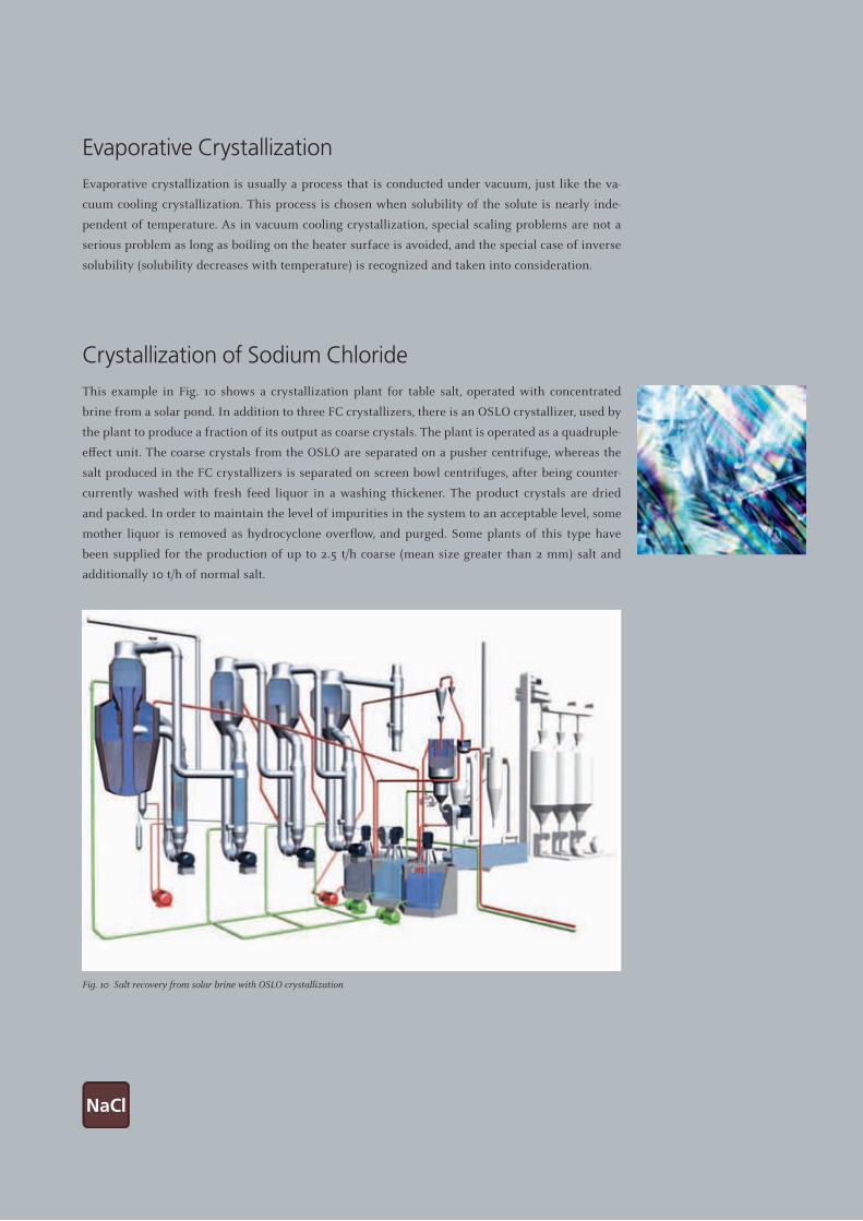
Evaporative CrystallizationEvaporative crystallization is usually a process that is conducted under vacuum, just like the va-
cuum cooling crystallization. This process is chosen when solubility of the solute is nearly inde-
pendent of temperature. As in vacuum cooling crystallization, special scaling problems are not a
serious problem as long as boiling on the heater surface is avoided, and the special case of inverse
solubility (solubility decreases with temperature) is recognized and taken into consideration.
Crystallization of Sodium ChlorideThis example in Fig. 10 shows a crystallization plant for table salt, operated with concentrated
brine from a solar pond. In addition to three FC crystallizers, there is an OSLO crystallizer, used by
the plant to produce a fraction of its output as coarse crystals. The plant is operated as a quadruple-
effect unit. The coarse crystals from the OSLO are separated on a pusher centrifuge, whereas the
salt produced in the FC crystallizers is separated on screen bowl centrifuges, after being counter-
currently washed with fresh feed liquor in a washing thickener. The product crystals are dried
and packed. In order to maintain the level of impurities in the system to an acceptable level, some
mother liquor is removed as hydrocyclone overflow, and purged. Some plants of this type have
been supplied for the production of up to 2.5 t/h coarse (mean size greater than 2 mm) salt and
additionally 10 t/h of normal salt.
Fig. 10 Salt recovery from solar brine with OSLO crystallization

16
Flue Gas Desulfurization (FGD): Scrubber EffluentConcentration of scrubber effluents from FGD systems in thermal Power Plants has been practiced
for about four decades. Plants for concentration of these wastewaters to dryness (ZLD) are in fact
evaporative crystallization units, but should not be designed as simple evaporation units. Usually,
FGD concentration units are combined with pre-treatment facilities, such as heavy metals precipi-
tation, in order that it may be possible to recover a brine or a product salt pure enough for re-use.
A typical installation for the zero-liquid-discharge (ZLD) of the liquid effluent from a flue gas
cleaning system in garbage fired power station consists of a heavy metals precipitation and a
double-effect evaporative crystallization unit, with two FC crystallizers supplied to recover sodium
chloride or calcium chloride dihydrate salt. In the case of Calcium chloride the first stage is a gyp-
sum-seeded pre-concentrator, and the second stage is the calcium chloride crystallizer. The crystal
product is separated on a screen bowl centrifuge, dried, packed and reused in another industrial
application.
Recovery of CaffeineWhen caffeine is extracted from coffee by the supercritical carbon dioxide method, a caffeine con-
taining waste water is produced. Evaporation, combined with a surface cooling crystallization sepa-
rates this waste water into a caffeine of food grade quality, and pure distillate which can be reused
for the decaffeination process. Short residence times at the higher temperatures is important in
the evaporative step of this process, in order to minimize caffeine decomposition. The process
encompasses active carbon treatment used to remove impurities that influence the product colour,
followed by a two-stage falling film evaporator driven by process vapours compressed to a higher
pressure by a single mechanical compressor. In order to minimize residence time in the evapora-
tors, the final concentrate is produced in a separate, smaller unit. This concentrate is finally cooled
to ambient temperature in a surface cooled loop crystallizer, to crystallize caffeine monohydrate.
The crystals are calcined to remove the water of hydration, and packed. This caffeine product is
used in the manufacturing of soft drinks.
Modern Applications in Environmental Protection
– Wastewater ZLD plant for the liquid
effluent from FGD in a garbage fired
power station
– Typical needle-shaped Caffeine
monohydrate crystal

17
– Triple-effect four stage evaporation
crystallization of ammonium sulfate
in DTB (caprolactam process)
with after-crystallization (FC)
Salt from Secondary Aluminum SlagWhen aluminum scrap is molten down, the liquefied aluminum must be protected from exposure
to the atmosphere to avoid its oxidation. This protection is provided by a layer of molten sodium
chloride / potassium chloride that float over the aluminum. This salt remains as slag after the re-
covery of the aluminum. This slag is very reactive. Humidity causes evolution of poisonous and
explosive gases, the leachate is saturated with salts. Consequently, processes had to be developed
to solve this environmental problem. The slag is fed to a cascade leaching process to achieve de-
gassing under controlled process conditions and to dissolve the salts. The gases evolved are fed to
an incinerator that allows the plant to recover the combustion energy. The remaining residue is
separated from the salt solution by filtration and given to landfill. The solution is fed to a MVR
driven evaporative FC crystallizer. The mixed salt product is separated, dried and reused in the
same process).
Ammonium Sulfate from the Caprolactam ProcessAmmonium sulfate is a by-product of the synthesis of caprolactam. Multiple-effect evaporative
crystallization is the well-established process to recover crystalline ammonium sulfate and market
it as fertilizer. In the last few years, the fertilizer marketplace has seen an in-creased demand for
larger crystals, and for a narrower size distribution.
The example that follows shows a triple-effect evaporative crystallization plant using DTB crys-
tallizers for the production ammonium sulfate of an average crystal size of ≥ 2 mm. The solution
is fed counter-currently in order to im-prove crystal growth conditions by combining the highest
process temperature and highest impurity concentration. The Messo DTB crystallizers use bottom-
entry agitators, which provide superior mixing characteristics at a lower power requirement than
common agitators. The product crystal size is enhanced by fines destruction systems. Each DTB
crystallizer discharges slurry to a common slurry collection tank. The slurry is then fed to pusher
centrifuges, where the crystals are washed and separated from the mother liquor. The centrifuged
crystals are dried and screened, and the undersize fraction is recycled for recrystallization.

18
The GEA Messo PT chemical laboratory and pilot plant facility is available to develop the
basic information necessary for the design of crystallization plants as well as the most
appropriate overall processes for our clients. The chemical laboratory is able to define phy-
sical properties to the crystallizer designer, such as the metastable zone width (supersaturation),
desupersaturation rates, viscosity, density of a range of compositions, the system solubility, forma-
tion of mixed crystals, as well as the chemical compositions of solutions and minerals.
Our research and development facility has equipment that accurately represents most types of
crystallizers, and this is used as necessary to simulate the specific design envisioned for our clients.
These process designs can be tested in small pilot plants brought together according to the specific
process requirements, and samples can be produced for further (market) tests. In case of products
that are too sensitive to be shipped to our facility, or that require special handling (due to safety or
health concerns) our team may perform the necessary tests or investigations in our clients’ facili-
ties. We are proud to have developed and optimized production processes for the chemical, phar-
maceutical and food industry jointly with our customers and tailor-made for the individual project.
We continue to improve – for the benefit of our customers.
Research and Development Services
Chemical laboratory and
Pilot Plant Facilities
19
Among a lot of others from A to Z:
Acetylsalicylic acid & salts
Adipic acid
Ammonium bromide
Ammonium dimolybdate
Ammonium hydrogenfluoride
Ammonium sulfate (also by reaction)
Ammonium thiosulfate
Ascorbic acid & salts
Benzoic acid & salts
Bisphenol A
Caffeine
Calcium chloride
Calcium formate
Calcium tartrate
Carnallite
Citric acid & salts
Cooling Tower Blowdown
Copper chloride
Copper sulfate
Dextrose (Glucose)
Dichlorobenzene
Dicyandiamide
Dipentarythritol
Epichloro hydrine process
effluent ZLD
Ferrous sulfate from process effluents
Ferrous sulfate from TiO2
Fumaric acid & salts
Glutamic acid & salts
Guanidine nitrate
Hexachlorocyclohexane
Isomaltulose
Ketogulonic acid & salts
Lactic salts
Lactose
Landfill Leachate
Concentration & ZLD
Lauryllactam
Magnesium ammonium sulfate
Magnesium chloride
Magnesium hexafluorosilicate
Magnesium sulfate
Malic acid & salts
Methionine
Nickel acetate
Nickel nitrate
Pentaerythritol
Potash from various sources
Potassium bromide
Potassium carbonate
Potassium chlorate
Potassium chloride
Potassium dichromate
Potassium hydrogencarbonate
Potassium nitrate
Potassium permanganate
Potassium phosphate (Industrial)
Potassium sulfate
Potassium sulfate from
Na2SO4 & KCl (conversion)
Salicylic acid & salts
Salt (based on sea salt
respectively brines)
Silver nitrate
Sodium acetate
Sodium ascorbate
Sodium carbonate
Sodium chlorate
Sodium chloride from sea salt
Sodium chromate (& Na2SO4)
Sodium cyanide
Sodium dichromate
Sodium disulfite
Sodium dithionite
Sodium fluoride salts
Sodium formate
Sodium glutamate
Sodium ketogulonate
Sodium nitrite (waste)
Sodium perborate
Sodium perchlorate
Sodium phosphates (industrial)
Sodium salicylate
Sodium sulfate
Sodium tartrate
Sodium thiocyanate
Sorbic acid & salts
Sulfanilic acid & salts
Tartaric acid & salts
TMP
Trimellitic acid
Urea
Vinasse evaporation
Yeast effluent processing
Zinc sulfate 6-hydrate
Zinc sulfate 7-hydrate
Our Product Experience

Excellence Passion Integrity Responsibility GEA-versity
GEA Group is a global mechanical engineering company with multi-billion euro sales and operations in more than 50 countries. Founded in 1881, the company is one of the largest providers of innovative equipment and process technology. GEA Group is listed in the STOXX Europe 600 Index.
GEA Messo PT
GEA Messo GmbH
Friedrich-Ebert-Straße 134, 47229 Duisburg, GermanyPhone: +49 2065 903 0, Fax: +49 2065 903 [email protected], www.gea-messo-pt.com
GEA Niro PT B.V.
De Beverspijken 7b, 5221 EE ‘s-Hertogenbosch, The NetherlandsPhone: +31 73 6390 390, Fax: +31 73 6312 [email protected], www.gea-messo-pt.com
© G
EA G
roup
AG
. All
right
s re
serv
ed. H
il m
axim
fuga
ut d
unt d
elis
dis
sim
etur
. 05/
2012


![[SM2] 소셜스튜디오 소개서- Social Listening](https://img.dokumen.tips/doc/110x75/58f1a5881a28ab646e8b460f/sm2-social-listening.jpg)