Embed Size (px)
Citation preview

7/23/2019 2011 Pawlak Jureczko Czapla Modeling the Structural
http://slidepdf.com/reader/full/2011-pawlak-jureczko-czapla-modeling-the-structural 1/6
Journal of KO NES Powertrai n and Transport, Vol . 18, No. 2 2011
MODELING THE STRUCTURAL DYNAMICS
OF CHOSEN COMPONENTS
OF THE HORIZONTAL AXIS WIND TURBINE
Mariusz Pawlak, Mariola Jureczko, Tomasz Czapla
The Si lesian U niversity of Technology, Department of Appl ied M echanicsKonarskiego Str eet 18 A, 43-190 Gl iwice, Poland
tel.: + 48 32 2372847, fax: + 48 32 2371309e-mail: M ari [email protected], M ari [email protected], [email protected]
Abstract
As the horizontal axis wind turbines are getting larger, their dynamic behaviour is becoming more important.Dynamic analysis gives knowledge how to improve efficiency and safety also in small wind turbines. This articledescribes numerical models of chosen components of upwind, three-bladed wind turbine. Geometry of eachcomponent is generated separately and then assembled together by transformation matrices. Material of the blades iscomposite, the hub is assumed to be made of steel and material of the planet carrier is casted iron. These mentionedcomponents are modelled by shell elements. The numerical model of the hub takes into account aerodynamic andgravity loads of blades, inertia forces due to rotation of the rotor and aerodynamic damping. The aerodynamic loads,calculated according to the modified Blade Element Momentum theory, are attached to aerodynamic centres. Windconditions were assumed for I-class wind turbine according to Germanischer Lloyd. Stress Reserve Factors werecalculated for DLC 6.1 load case according to Germanischer Lloyd, too. As a first step, numerical strength analysiswith using AnSYS software was performed with maximum values of principal stresses as an output. Then, based onFEM analysis results, Stress Reserve Factors were calculated. SRF values show that analyzed hub and planet carrierhave sufficient strength for extreme loads. Methodology of safety margin evaluation presented in this paper allows
assessing i f the object ful fi ls r elevant standards demanding.
Keywords: HAWT, Hub, Planet Car ri er, Blade Element M omentum theory, Str ess Reserve Factor s
1. Introduction
The most important component of the wind turbine is a rotor. Wind turbine power, rotationalspeed and its size depend on the rotor. Based on wind turbine configuration, other components,like gearbox, bearings, generator and tower height are selected.
For numeric calculations, three-blade horizontal axis upwind turbine with pitch regulation wastaken. Blade length was 45 meters and tip speed ratio =6. Blade was divided for 23 parts, each
one having other airfoil, thick at the root and more narrow at the tip. Numerical model containedFFA-W3-xxx and RISØ airfoils series with different aerodynamic properties and differentthickness/chord ratios. The thickness/chord ratio depends on used aerodynamic profiles. Nearthe root of the blade there are used circular profiles with t/c ratio equal to 100%, smoothlydecreasing to the 14% on the tip of the blade.
2. Loads calculation
Local coordinate systems were based on PN – IEC 61400 - 1, according to Guidelines (2002). Thefixed coordinate system used for load and stress assessment of the planet carrier and the hub is shownon Fig. 1. Coordinates system centre location is the same as hub centre. The x-axis is co-linear tomain shaft axis. The x-axis has a downwind direction. The z-axis is tangent to main shaft axis ina vertical plane containing the shaft axis. The y-axis is tangent to main shaft axis and belongs tohorizontal plane. The coordinate system is rotating together with the main shaft of the wind turbine.

7/23/2019 2011 Pawlak Jureczko Czapla Modeling the Structural
http://slidepdf.com/reader/full/2011-pawlak-jureczko-czapla-modeling-the-structural 2/6
M. Pawlak, M. Jureczko, T. Czapla
Fi g. 1. Coordi nate system used for l oads calculat ion of chosen components of the wind turbi ne
In numerical analysis of hub and planet carrier was applied the following loads:- M y , flap-wise moment,- M x , edge-wise moment,- M z , moment,- Fx , thrust force in main shaft direction,- Fy , tangential force in rotor plane,
- Fz , force along the blade axis.The most important for stress analysis of the planet carrier is torsional load M x , so that load
case with highest M x value was taken for strength calculation.Loads calculated for given coordinate systems and load case DLC 6.1, according to Alternative
(2005), is listed in Tab. 1. The wind turbine is parked (standstill or idling), with extreme windspeed model and recurrence period 50 years.
Tab. 1. Calculated loads of planet carrier and the hub of the wind turbine
Hub
Blade no 1 Blade no 2 Blade no 3Rotor
Fx [kN] 300 -350 -150 40
Fy [kN] -70 20 40 314
Fz [kN] -65 80 -15 -470
M x [kNm] 2400 -200 -370 330M y [kNm] -7500 5700 1700 3600
M z [kNm] -80 20 -25 580
Planet carrier is subjected for torsion, transferred from the main shaft, to satellite axes coupledwith sun and ring gears of the gearbox. In the model used for described calculation, loads weretransferred through the main shaft.
3. Numerical analysis of chosen components of the wind turbine
The front end of the main shaft was attached to the ground with using displacement on a front plane. Rear end of the main shaft was attached to the planet carrier with using bonded contact.Torsion was applied to the planet axes holes (Fig. 2 ).
350

7/23/2019 2011 Pawlak Jureczko Czapla Modeling the Structural
http://slidepdf.com/reader/full/2011-pawlak-jureczko-czapla-modeling-the-structural 3/6
Modeling the Structural Dynamics of Chosen Components of the Horizontal Axis wind Turbine
Fi g. 2. Di splacement and l oads applied to the numeri cal model of the planet carri er
FEM calculation results are stress levels for each node. Stress patterns are shown on Fig. 3.
a) b)
c) d)
Fig. 3. Stress patterns for the planet carrier: a) front view, b) rear view, c) stress relief cut area, d) planet axes holes
The numerical model of the hub with one of load cases (M y bending moment with loadsapplied with using pressure in blades bearings) is presented on Fig. 4.
The strength analysis results performed in AnSYS are stress values for all nodes. Load patternfor hub model is shown on Fig. 5.
351

7/23/2019 2011 Pawlak Jureczko Czapla Modeling the Structural
http://slidepdf.com/reader/full/2011-pawlak-jureczko-czapla-modeling-the-structural 4/6
M. Pawlak, M. Jureczko, T. Czapla
The highest principal stress value in the hub, ||max=140 MPa, is on internal surface of blade1 flange. The highest stress in the planet carrier can be seen on the main shaft contact area.The stress value is 274 MPa. Highest stress for stress relief cut is 150 MPa. The highest stressfor planet axes holes is 120 MPa. Strength analysis was performed basing on FEM stress results.Strength for extreme loads was calculated.
Fig. 4. Loads applied to the numerical model of the hub
Fi g. 5. Maximum pri ncipal stress distri bution | |max for the hub
4. Calculation of Stress Reserve Factors
After FEM analysis resulting in maximum absolute values of principal stresses ||max, strengthanalysis was performed according to the Guideline (2003).
The SRF was calculated according to:
max
eR
n m f
SRF , (1)
where:f - Load factor [-],m - Material factor [-],n - Consequence of failure factor [-],|max - Absolute maximum principal stress [MPa],R e - yield strength for planet carrier material EN-GJS-700-2U: Re = 380 [MPa],R e - yield strength for hub material EN-GJS-400-18U-LT: Re = 220 [MPa].
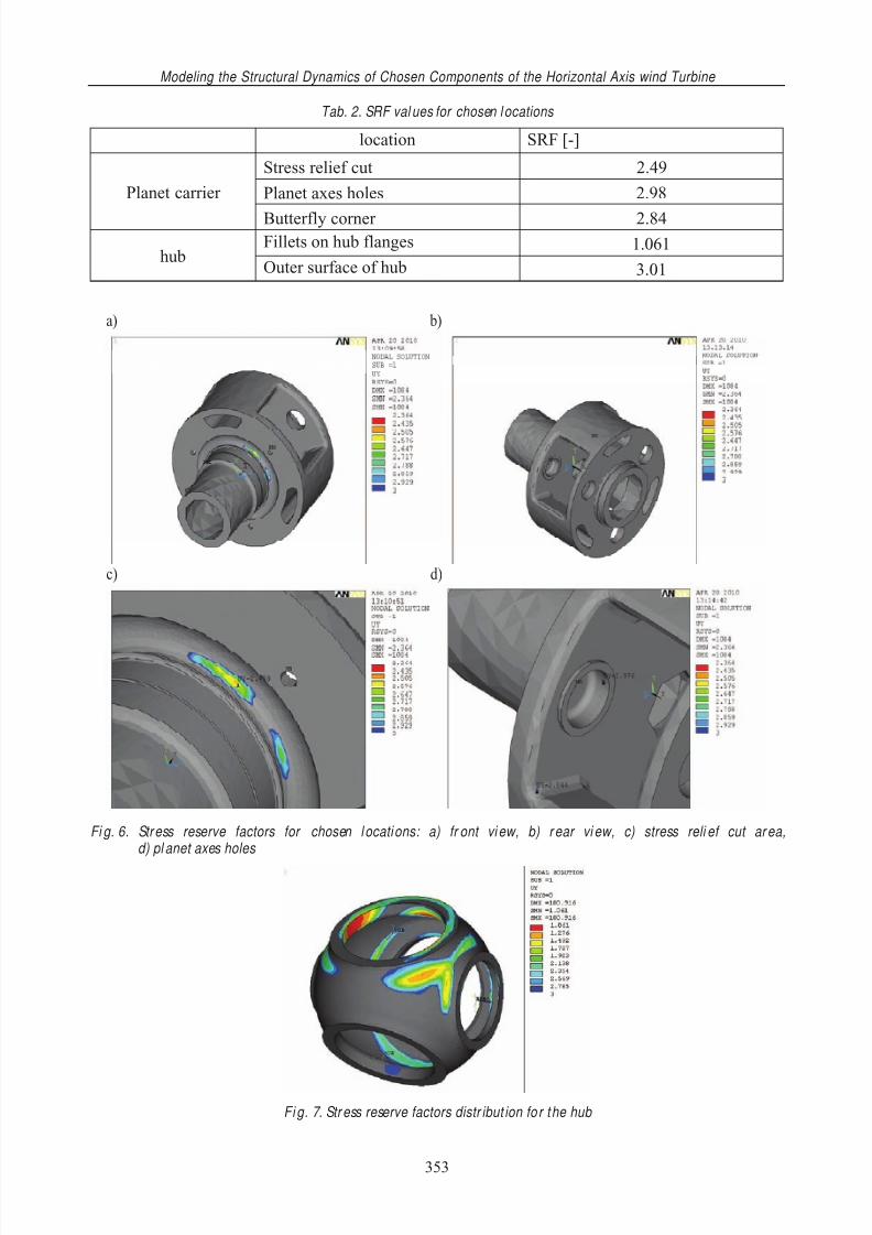
The lowest values of SRF in nodes with highest principal stresses values ||max are listedin Table 2. On Fig. 6 and Fig. 7, SRF patterns for planet carrier and hub are shown.
352
7/23/2019 2011 Pawlak Jureczko Czapla Modeling the Structural
http://slidepdf.com/reader/full/2011-pawlak-jureczko-czapla-modeling-the-structural 5/6
Modeling the Structural Dynamics of Chosen Components of the Horizontal Axis wind Turbine
Tab. 2. SRF val ues for chosen l ocations
location SRF [-]
Stress relief cut 2.49
Planet axes holes 2.98Planet carrier
Butterfly corner 2.84Fillets on hub flanges 1.061
hubOuter surface of hub 3.01
a) b)
c) d)
Fi g. 6. Stress reserve factors for chosen l ocations: a) fr ont vi ew, b) r ear vi ew, c) stress reli ef cut ar ea,d) pl anet axes holes
Fi g. 7. Str ess reserve factors distr ibut ion fo r the hub
353

7/23/2019 2011 Pawlak Jureczko Czapla Modeling the Structural
http://slidepdf.com/reader/full/2011-pawlak-jureczko-czapla-modeling-the-structural 6/6
M. Pawlak, M. Jureczko, T. Czapla
5. Results analysis and conclusions
The analysis shows that for chosen components, extreme loads strength is sufficient.Strength analysis results show that for all locations in the planet carrier, calculated SRF factors
are above 2.0. That will be useful in case of increasing the wind turbine power.
In preliminary analysis the SRF value of hub was below 0.4, and modifications in geometrywere needed. On edges of hub flange were applied fillets, increased hub shell thickness andredesigned hub flanges. After each modification results were reviewed and some conclusions werereceived. Fillets on edges of hub flanges increase SRF value up to 0.45. Increasing hub shellthickness didn’t have sufficient influence on SRF value on the hub flange. The total mass of thehub highly increased, what could result in higher cost of manufacturing. That is why the total hubshell thickness was set to previous value t=0.05 m. By increasing hub flange thickness from 0.2 mup to 0.4 m the lowest SRF value increased from 0.4 to 0.92. Further modifications were made
by changing the height of hub flanges from 0.25m to 0.28 m what finally resulted in the lowestSRF =1.061. SRF expresses the reserve between the occurring maximum stress and the yieldstrength and estimates if a single load will lead to the instant failure of wind turbine components.
References
[1] Alternative interpretation of load case DLC 6.1 of IEC 61400-1 , Edition 2 applying EN61400-1, DWL-An-Extern-001, Rev. 1, 2005.
[2] Guideline for The Cert ifi cation of Wind Turbines , Germanischer Lloyd WindEnergie GmBH,Edition 2003.
[3] Guidelines for Design of Wind Turbines , Publication from DNV/Risø, 2002.[4] Hansen Martin, O. L., Aerodynamics of wind turbines. Published by James & James, London
2002.[5] Maalawi, K. Y., Negm, H. M., Optimal frequency design of wind turbine blades . Journal of
Wind Engineering and Industrial Aerodynamics, 90, pp. 961-986, 2002.[6] Pawlak, M., Myk, A., Modeling the structural dynamics of horizontal axis wind turbine,
ISMA 2006 International Conference on Noise and Vibration Engineering, September 2006.[7] Troen, I., Petersen, E. L., European Wind Atlas . Risø National Laboratory, Roskilde.
Denmark 1989.
354