Embed Size (px)
DESCRIPTION
2010 Model Year MaxxForce DT, 9 and 10 Engine Diagnostic Manual
Citation preview
DIAGNOSTIC/TROUBLESHOOTING MANUAL
DIAGNOSTIC/TROUBLESHOOTING MANUAL
EGES-455
2010
EGES-455Read all safety instructions in the "Safety Information" section of this Manual before doing any procedures.
Follow all warnings, cautions, and notes.©2010 Navistar, Inc. All rights reserved


DIAGNOSTIC/TROUBLESHOOTING MANUAL I
Table of Contents
Foreword.. . . . . . . . . . . . . . . . . . . . . . . . . . . . . . . . . . . . . . . . . . . . . . . . . . . . . . . . . . . . . . . . . . . . . . . . . . . . . . . . . . . . . . . . . . . . . . . . . . . . . . . . . . . . . . . . . .1
Service Diagnosis. . . . . . . . . . . . . . . . . . . . . . . . . . . . . . . . . . . . . . . . . . . . . . . . . . . . . . . . . . . . . . . . . . . . . . . . . . . . . . . . . . . . . . . . . . . . . . . . . . . . . . . .2
Safety Information. . . . . . . . . . . . . . . . . . . . . . . . . . . . . . . . . . . . . . . . . . . . . . . . . . . . . . . . . . . . . . . . . . . . . . . . . . . . . . . . . . . . . . . . . . . . . . . . . . . . . . . .3
Engine Systems.. . . . . . . . . . . . . . . . . . . . . . . . . . . . . . . . . . . . . . . . . . . . . . . . . . . . . . . . . . . . . . . . . . . . . . . . . . . . . . . . . . . . . . . . . . . . . . . . . . . . . . . . . .5
Engine Controlled Features. . . . . . . . . . . . . . . . . . . . . . . . . . . . . . . . . . . . . . . . . . . . . . . . . . . . . . . . . . . . . . . . . . . . . . . . . . . . . . . . . . . . . . . . . . .59
Diagnostic Software Operation. . . . . . . . . . . . . . . . . . . . . . . . . . . . . . . . . . . . . . . . . . . . . . . . . . . . . . . . . . . . . . . . . . . . . . . . . . . . . . . . . . . . . . .67
Engine Symptoms Diagnostics. . . . . . . . . . . . . . . . . . . . . . . . . . . . . . . . . . . . . . . . . . . . . . . . . . . . . . . . . . . . . . . . . . . . . . . . . . . . . . . . . . . . . . .73
Hard Start and No Start Diagnostics. . . . . . . . . . . . . . . . . . . . . . . . . . . . . . . . . . . . . . . . . . . . . . . . . . . . . . . . . . . . . . . . . . . . . . . . . . . . . . . . .97
Performance Diagnostics . . . . . . . . . . . . . . . . . . . . . . . . . . . . . . . . . . . . . . . . . . . . . . . . . . . . . . . . . . . . . . . . . . . . . . . . . . . . . . . . . . . . . . . . . . . .125
Electronic Control Systems Diagnostics. . . . . . . . . . . . . . . . . . . . . . . . . . . . . . . . . . . . . . . . . . . . . . . . . . . . . . . . . . . . . . . . . . . . . . . . . .149
Diagnostic Trouble Code Index.. . . . . . . . . . . . . . . . . . . . . . . . . . . . . . . . . . . . . . . . . . . . . . . . . . . . . . . . . . . . . . . . . . . . . . . . . . . . . . . . . . . . .417
Diagnostic Tools and Accessories. . . . . . . . . . . . . . . . . . . . . . . . . . . . . . . . . . . . . . . . . . . . . . . . . . . . . . . . . . . . . . . . . . . . . . . . . . . . . . . . . .427
Abbreviations and Acronyms.. . . . . . . . . . . . . . . . . . . . . . . . . . . . . . . . . . . . . . . . . . . . . . . . . . . . . . . . . . . . . . . . . . . . . . . . . . . . . . . . . . . . . . .451
Terminology.. . . . . . . . . . . . . . . . . . . . . . . . . . . . . . . . . . . . . . . . . . . . . . . . . . . . . . . . . . . . . . . . . . . . . . . . . . . . . . . . . . . . . . . . . . . . . . . . . . . . . . . . . . . .457
Appendix A: Performance Specifications. . . . . . . . . . . . . . . . . . . . . . . . . . . . . . . . . . . . . . . . . . . . . . . . . . . . . . . . . . . . . . . . . . . . . . . . .469
Appendix B: Signal Values. . . . . . . . . . . . . . . . . . . . . . . . . . . . . . . . . . . . . . . . . . . . . . . . . . . . . . . . . . . . . . . . . . . . . . . . . . . . . . . . . . . . . . . . . . .505
Appendix C: Technical Service Information (TSI). . . . . . . . . . . . . . . . . . . . . . . . . . . . . . . . . . . . . . . . . . . . . . . . . . . . . . . . . . . . . . . .511
EGES-455Read all safety instructions in the "Safety Information" section of this Manual before doing any procedures.
Follow all warnings, cautions, and notes.©2010 Navistar, Inc. All rights reserved
II DIAGNOSTIC/TROUBLESHOOTING MANUAL
EGES-455Read all safety instructions in the "Safety Information" section of this Manual before doing any procedures.
Follow all warnings, cautions, and notes.©2010 Navistar, Inc. All rights reserved
DIAGNOSTIC/TROUBLESHOOTING MANUAL 1
ForewordNavistar, Inc. is committed to continuous researchand development to improve products and introducetechnological advances. Procedures, specifications,and parts defined in published technical serviceliterature may be altered.
NOTE: Photo illustrations identify specific parts orassemblies that support text and procedures; otherareas in a photo illustration may not be exact.
This manual includes necessary information andspecifications for technicians to maintain Navistardiesel engines. See vehicle manuals and TechnicalService Information (TSI) bulletins for additionalinformation.
Technical Service Literature
1171999R1 MaxxForce® DT, 9, and 10 EngineOperation and MaintenanceManual
EGES-450 MaxxForce® DT, 9, and 10 ServiceManual
EGES-455 MaxxForce® DT, 9, and 10Diagnostic Manual
EGED-460 MaxxForce® DT, 9, and 10 HardStart and No Start DiagnosticsForm
EGED-460 MaxxForce® DT, 9, and 10Performance Diagnostics Form
EGED-495 MaxxForce® DT, 9, and 10Electronic Control Systems Form
Technical Service Literature is revised periodicallyand mailed automatically to “Revision Service”subscribers. If a technical publication is ordered, thelatest revision will be supplied.
NOTE: To order technical service literature, contactyour International® dealer.
EGES-455Read all safety instructions in the "Safety Information" section of this Manual before doing any procedures.
Follow all warnings, cautions, and notes.©2010 Navistar, Inc. All rights reserved
2 DIAGNOSTIC/TROUBLESHOOTING MANUAL
Service DiagnosisService diagnosis is an investigative procedure thatmust be followed to find and correct an engineapplication problem or an engine problem.
If the problem is engine application, see specificvehicle manuals for further diagnostic information.
If the problem is the engine, see specific EngineDiagnostic Manual for further diagnostic information.
Prerequisites for Effective Diagnosis
• Availability of gauges and diagnostic testequipment
• Availability of current information for engineapplication and engine systems
• Knowledge of the principles of operation forengine application and engine systems
• Knowledge to understand and do procedures indiagnostic and service publications
Technical Service Literature required for EffectiveDiagnosis
• Engine Service Manual
• Engine Diagnostic Manual
• Diagnostics Forms
• Electronic Control Systems Diagnostics Forms
• Service Bulletins
EGES-455Read all safety instructions in the "Safety Information" section of this Manual before doing any procedures.
Follow all warnings, cautions, and notes.©2010 Navistar, Inc. All rights reserved
DIAGNOSTIC/TROUBLESHOOTING MANUAL 3
Safety Information
This manual provides general and specificmaintenance procedures essential for reliable engineoperation and your safety. Since many variations inprocedures, tools, and service parts are involved,advice for all possible safety conditions and hazardscannot be stated.
Read safety instructions before doing any service andtest procedures for the engine or vehicle. See relatedapplication manuals for more information.
Disregard for Safety Instructions, Warnings, Cautions,and Notes in this manual can lead to injury, death ordamage to the engine or vehicle.
Safety Terminology
Three terms are used to stress your safety and safeoperation of the engine: Warning, Caution, and Note
Warning: A warning describes actions necessary toprevent or eliminate conditions, hazards, and unsafepractices that can cause personal injury or death.
Caution: A caution describes actions necessaryto prevent or eliminate conditions that can causedamage to the engine or vehicle.
Note: A note describes actions necessary for correct,efficient engine operation.
Safety Instructions
Work Area
• Keep work area clean, dry, and organized.
• Keep tools and parts off the floor.
• Make sure the work area is ventilated and well lit.
• Make sure a First Aid Kit is available.
Safety Equipment
• Use correct lifting devices.
• Use safety blocks and stands.
Protective Measures
• Wear protective safety glasses and shoes.
• Wear correct hearing protection.
• Wear cotton work clothing.
• Wear sleeved heat protective gloves.
• Do not wear rings, watches or other jewelry.
• Restrain long hair.
Vehicle
• Make sure the vehicle is in neutral, the parkingbrake is set, and the wheels are blocked beforeservicing engine.
• Clear the area before starting the engine.
Engine
• The engine should be operated or serviced onlyby qualified individuals.
• Provide necessary ventilation when operatingengine in a closed area.
• Keep combustible material away from engineexhaust system and exhaust manifolds.
• Install all shields, guards, and access coversbefore operating engine.
• Do not run engine with unprotected air inlets orexhaust openings. If unavoidable for servicereasons, put protective screens over all openingsbefore servicing engine.
• Shut engine off and relieve all pressure in thesystem before removing panels, housing covers,and caps.
• If an engine is not safe to operate, tag the engineand ignition key.
Fire Prevention
• Make sure charged fire extinguishers are in thework area.
NOTE: Check the classification of each fireextinguisher to ensure that the following fire typescan be extinguished.
1. Type A — Wood, paper, textiles, and rubbish
2. Type B — Flammable liquids
3. Type C — Electrical equipment
Batteries
• Always disconnect the main negative batterycable first.
• Always connect the main negative battery cablelast.
• Avoid leaning over batteries.
• Protect your eyes.
EGES-455Read all safety instructions in the "Safety Information" section of this Manual before doing any procedures.
Follow all warnings, cautions, and notes.©2010 Navistar, Inc. All rights reserved
4 DIAGNOSTIC/TROUBLESHOOTING MANUAL
• Do not expose batteries to open flames or sparks.
• Do not smoke in workplace.
Compressed Air
• Use an OSHA approved blow gun rated at 207kPa (30 psi).
• Limit shop air pressure to 207 kPa (30 psi).
• Wear safety glasses or goggles.
• Wear hearing protection.
• Use shielding to protect others in the work area.
• Do not direct compressed air at body or clothing.
Tools
• Make sure all tools are in good condition.
• Make sure all standard electrical tools aregrounded.
• Check for frayed power cords before using powertools.
Fluids Under Pressure
• Use extreme caution when working on systemsunder pressure.
• Follow approved procedures only.
Fuel
• Do not over fill the fuel tank. Over fill creates a firehazard.
• Do not smoke in the work area.
• Do not refuel the tank when the engine is running.
Removal of Tools, Parts, and Equipment
• Reinstall all safety guards, shields, and coversafter servicing the engine.
• Make sure all tools, parts, and service equipmentare removed from the engine and vehicle after allwork is done.
EGES-455Read all safety instructions in the "Safety Information" section of this Manual before doing any procedures.
Follow all warnings, cautions, and notes.©2010 Navistar, Inc. All rights reserved
1 ENGINE SYSTEMS 5
Table of Contents
Engine Identification. . . . . . . . . . . . . . . . . . . . . . . . . . . . . . . . . . . . . . . . . . . . . . . . . . . . . . . . . . . . . . . . . . . . . . . . . . . . . . . . . . . . . . . . . . . . . . . . . . . . .7Engine Serial Number. . . . . . . . . . . . . . . . . . . . . . . . . . . . . . . . . . . . . . . . . . . . . . . . . . . . . . . . . . . . . . . . . . . . . . . . . . . . . . . . . . . . . . . . . .7Engine Emission Label. . . . . . . . . . . . . . . . . . . . . . . . . . . . . . . . . . . . . . . . . . . . . . . . . . . . . . . . . . . . . . . . . . . . . . . . . . . . . . . . . . . . . . . . .7Engine Accessory Labels. . . . . . . . . . . . . . . . . . . . . . . . . . . . . . . . . . . . . . . . . . . . . . . . . . . . . . . . . . . . . . . . . . . . . . . . . . . . . . . . . . . . . .7Engine Description. . . . . . . . . . . . . . . . . . . . . . . . . . . . . . . . . . . . . . . . . . . . . . . . . . . . . . . . . . . . . . . . . . . . . . . . . . . . . . . . . . . . . . . . . . . . . .8
Standard Features. . . . . . . . . . . . . . . . . . . . . . . . . . . . . . . . . . . . . . . . . . . . . . . . . . . . . . . . . . . . . . . . . . . . . . . . . . . . . . . . . . . . .9Optional Features. . . . . . . . . . . . . . . . . . . . . . . . . . . . . . . . . . . . . . . . . . . . . . . . . . . . . . . . . . . . . . . . . . . . . . . . . . . . . . . . . . . .10Chassis Mounted Features. . . . . . . . . . . . . . . . . . . . . . . . . . . . . . . . . . . . . . . . . . . . . . . . . . . . . . . . . . . . . . . . . . . . . . . . .10
Engine Component Locations (245 hp and above). . . . . . . . . . . . . . . . . . . . . . . . . . . . . . . . . . . . . . . . . . . . . . . . . . . . . .11
Air Management System (AMS). . . . . . . . . . . . . . . . . . . . . . . . . . . . . . . . . . . . . . . . . . . . . . . . . . . . . . . . . . . . . . . . . . . . . . . . . . . . . . . . . . . . . . .16Air Flow – Pre Combustion. . . . . . . . . . . . . . . . . . . . . . . . . . . . . . . . . . . . . . . . . . . . . . . . . . . . . . . . . . . . . . . . . . . . . . . . . . . . . . . . . . .17Air Flow – Post Combustion. . . . . . . . . . . . . . . . . . . . . . . . . . . . . . . . . . . . . . . . . . . . . . . . . . . . . . . . . . . . . . . . . . . . . . . . . . . . . . . . .17Air Management Components. . . . . . . . . . . . . . . . . . . . . . . . . . . . . . . . . . . . . . . . . . . . . . . . . . . . . . . . . . . . . . . . . . . . . . . . . . . . . . .17
Turbochargers. . . . . . . . . . . . . . . . . . . . . . . . . . . . . . . . . . . . . . . . . . . . . . . . . . . . . . . . . . . . . . . . . . . . . . . . . . . . . . . . . . . . . . . .17Interstage Cooler (ISC). . . . . . . . . . . . . . . . . . . . . . . . . . . . . . . . . . . . . . . . . . . . . . . . . . . . . . . . . . . . . . . . . . . . . . . . . . . . . .18High-pressure Charge Air Cooler (HPCAC). . . . . . . . . . . . . . . . . . . . . . . . . . . . . . . . . . . . . . . . . . . . . . . . . . . . . .19Turbocharger 2 Wastegate Control (TC2WC) Valve. . . . . . . . . . . . . . . . . . . . . . . . . . . . . . . . . . . . . . . . . . . .19Exhaust Gas Recirculation (EGR) System.. . . . . . . . . . . . . . . . . . . . . . . . . . . . . . . . . . . . . . . . . . . . . . . . . . . . . .20Crankcase Ventilation System.. . . . . . . . . . . . . . . . . . . . . . . . . . . . . . . . . . . . . . . . . . . . . . . . . . . . . . . . . . . . . . . . . . . .22
Aftertreatment (AFT) System.. . . . . . . . . . . . . . . . . . . . . . . . . . . . . . . . . . . . . . . . . . . . . . . . . . . . . . . . . . . . . . . . . . . . . . . . . . . . . . .23
Fuel Management System.. . . . . . . . . . . . . . . . . . . . . . . . . . . . . . . . . . . . . . . . . . . . . . . . . . . . . . . . . . . . . . . . . . . . . . . . . . . . . . . . . . . . . . . . . . . .26ICP System.. . . . . . . . . . . . . . . . . . . . . . . . . . . . . . . . . . . . . . . . . . . . . . . . . . . . . . . . . . . . . . . . . . . . . . . . . . . . . . . . . . . . . . . . . . . . . . . . . . . . .27
High-Pressure Oil Flow.. . . . . . . . . . . . . . . . . . . . . . . . . . . . . . . . . . . . . . . . . . . . . . . . . . . . . . . . . . . . . . . . . . . . . . . . . . . . .28ICP Closed Loop System.. . . . . . . . . . . . . . . . . . . . . . . . . . . . . . . . . . . . . . . . . . . . . . . . . . . . . . . . . . . . . . . . . . . . . . . . . .28ICP Control System.. . . . . . . . . . . . . . . . . . . . . . . . . . . . . . . . . . . . . . . . . . . . . . . . . . . . . . . . . . . . . . . . . . . . . . . . . . . . . . . . .29Fuel Injector. . . . . . . . . . . . . . . . . . . . . . . . . . . . . . . . . . . . . . . . . . . . . . . . . . . . . . . . . . . . . . . . . . . . . . . . . . . . . . . . . . . . . . . . . . .30
Fuel Supply System.. . . . . . . . . . . . . . . . . . . . . . . . . . . . . . . . . . . . . . . . . . . . . . . . . . . . . . . . . . . . . . . . . . . . . . . . . . . . . . . . . . . . . . . . . . . . . . . . . . . .32Fuel Supply System Flow.. . . . . . . . . . . . . . . . . . . . . . . . . . . . . . . . . . . . . . . . . . . . . . . . . . . . . . . . . . . . . . . . . . . . . . . . . . . . . . . . . . .33
Engine Lubrication System.. . . . . . . . . . . . . . . . . . . . . . . . . . . . . . . . . . . . . . . . . . . . . . . . . . . . . . . . . . . . . . . . . . . . . . . . . . . . . . . . . . . . . . . . . . .36Oil Flow.. . . . . . . . . . . . . . . . . . . . . . . . . . . . . . . . . . . . . . . . . . . . . . . . . . . . . . . . . . . . . . . . . . . . . . . . . . . . . . . . . . . . . . . . . . . . . . . . . . . . . . . . .37
Engine Cooling System.. . . . . . . . . . . . . . . . . . . . . . . . . . . . . . . . . . . . . . . . . . . . . . . . . . . . . . . . . . . . . . . . . . . . . . . . . . . . . . . . . . . . . . . . . . . . . . .39Cooling System Description. . . . . . . . . . . . . . . . . . . . . . . . . . . . . . . . . . . . . . . . . . . . . . . . . . . . . . . . . . . . . . . . . . . . . . . . . . . . . . . . .39Cooling System Components. . . . . . . . . . . . . . . . . . . . . . . . . . . . . . . . . . . . . . . . . . . . . . . . . . . . . . . . . . . . . . . . . . . . . . . . . . . . . . .40
Coolant Heater (optional). . . . . . . . . . . . . . . . . . . . . . . . . . . . . . . . . . . . . . . . . . . . . . . . . . . . . . . . . . . . . . . . . . . . . . . . . . .40Thermostat Operation. . . . . . . . . . . . . . . . . . . . . . . . . . . . . . . . . . . . . . . . . . . . . . . . . . . . . . . . . . . . . . . . . . . . . . . . . . . . . . .40Low Temperature Radiator (LTR) Thermostat Operation. . . . . . . . . . . . . . . . . . . . . . . . . . . . . . . . . . . . . .42
Electronic Control System.. . . . . . . . . . . . . . . . . . . . . . . . . . . . . . . . . . . . . . . . . . . . . . . . . . . . . . . . . . . . . . . . . . . . . . . . . . . . . . . . . . . . . . . . . . . .43Electronic Control System Components. . . . . . . . . . . . . . . . . . . . . . . . . . . . . . . . . . . . . . . . . . . . . . . . . . . . . . . . . . . . . . . . . .43
Operation and Function. . . . . . . . . . . . . . . . . . . . . . . . . . . . . . . . . . . . . . . . . . . . . . . . . . . . . . . . . . . . . . . . . . . . . . . . . . . . .44Reference Voltage (VREF). . . . . . . . . . . . . . . . . . . . . . . . . . . . . . . . . . . . . . . . . . . . . . . . . . . . . . . . . . . . . . . . . . . . . . . . . .44
EGES-455Read all safety instructions in the "Safety Information" section of this Manual before doing any procedures.
Follow all warnings, cautions, and notes.©2010 Navistar, Inc. All rights reserved
6 1 ENGINE SYSTEMS
Microprocessor. . . . . . . . . . . . . . . . . . . . . . . . . . . . . . . . . . . . . . . . . . . . . . . . . . . . . . . . . . . . . . . . . . . . . . . . . . . . . . . . . . . . . . .44Actuator Control. . . . . . . . . . . . . . . . . . . . . . . . . . . . . . . . . . . . . . . . . . . . . . . . . . . . . . . . . . . . . . . . . . . . . . . . . . . . . . . . . . . . . .44
Actuators. . . . . . . . . . . . . . . . . . . . . . . . . . . . . . . . . . . . . . . . . . . . . . . . . . . . . . . . . . . . . . . . . . . . . . . . . . . . . . . . . . . . . . . . . . . . . . . . . . . . . . . .44Exhaust Gas Recirculation (EGR) Valve. . . . . . . . . . . . . . . . . . . . . . . . . . . . . . . . . . . . . . . . . . . . . . . . . . . . . . . . . .44Intake Air Heater (IAH) Relay. . . . . . . . . . . . . . . . . . . . . . . . . . . . . . . . . . . . . . . . . . . . . . . . . . . . . . . . . . . . . . . . . . . . . . .44Engine Throttle Valve (ETV) and Position Sensor. . . . . . . . . . . . . . . . . . . . . . . . . . . . . . . . . . . . . . . . . . . . . .44Turbocharger 2Wastegate Control (TC2WC) valve (turbocharger wastegate actuator). . .45Exhaust Back Pressure Valve (EBPV). . . . . . . . . . . . . . . . . . . . . . . . . . . . . . . . . . . . . . . . . . . . . . . . . . . . . . . . . . . .45Engine Compression Brake (ECB) valve. . . . . . . . . . . . . . . . . . . . . . . . . . . . . . . . . . . . . . . . . . . . . . . . . . . . . . . . .45Injection Pressure Regulator (IPR) valve. . . . . . . . . . . . . . . . . . . . . . . . . . . . . . . . . . . . . . . . . . . . . . . . . . . . . . . .45
Engine and Vehicle Sensors. . . . . . . . . . . . . . . . . . . . . . . . . . . . . . . . . . . . . . . . . . . . . . . . . . . . . . . . . . . . . . . . . . . . . . . . . . . . . . . . .46Temperature Sensors. . . . . . . . . . . . . . . . . . . . . . . . . . . . . . . . . . . . . . . . . . . . . . . . . . . . . . . . . . . . . . . . . . . . . . . . . . . . . . . .46Variable Capacitance Sensors. . . . . . . . . . . . . . . . . . . . . . . . . . . . . . . . . . . . . . . . . . . . . . . . . . . . . . . . . . . . . . . . . . . . .47Magnetic Pickup Sensors. . . . . . . . . . . . . . . . . . . . . . . . . . . . . . . . . . . . . . . . . . . . . . . . . . . . . . . . . . . . . . . . . . . . . . . . . . .48High-pressure Sensors. . . . . . . . . . . . . . . . . . . . . . . . . . . . . . . . . . . . . . . . . . . . . . . . . . . . . . . . . . . . . . . . . . . . . . . . . . . . . .49Potentiometer. . . . . . . . . . . . . . . . . . . . . . . . . . . . . . . . . . . . . . . . . . . . . . . . . . . . . . . . . . . . . . . . . . . . . . . . . . . . . . . . . . . . . . . . .50Switches. . . . . . . . . . . . . . . . . . . . . . . . . . . . . . . . . . . . . . . . . . . . . . . . . . . . . . . . . . . . . . . . . . . . . . . . . . . . . . . . . . . . . . . . . . . . . . .51
Engine Throttle Valve Control System.. . . . . . . . . . . . . . . . . . . . . . . . . . . . . . . . . . . . . . . . . . . . . . . . . . . . . . . . . . . . . . . . . . . .52
Exhaust and Engine Brake System.. . . . . . . . . . . . . . . . . . . . . . . . . . . . . . . . . . . . . . . . . . . . . . . . . . . . . . . . . . . . . . . . . . . . . . . . . . . . . . . . .53Exhaust Brake. . . . . . . . . . . . . . . . . . . . . . . . . . . . . . . . . . . . . . . . . . . . . . . . . . . . . . . . . . . . . . . . . . . . . . . . . . . . . . . . . . . . . . . . . . . . . . . . . .53Engine Brake. . . . . . . . . . . . . . . . . . . . . . . . . . . . . . . . . . . . . . . . . . . . . . . . . . . . . . . . . . . . . . . . . . . . . . . . . . . . . . . . . . . . . . . . . . . . . . . . . . .54
Operation. . . . . . . . . . . . . . . . . . . . . . . . . . . . . . . . . . . . . . . . . . . . . . . . . . . . . . . . . . . . . . . . . . . . . . . . . . . . . . . . . . . . . . . . . . . . . .55Operation Modes. . . . . . . . . . . . . . . . . . . . . . . . . . . . . . . . . . . . . . . . . . . . . . . . . . . . . . . . . . . . . . . . . . . . . . . . . . . . . . . . . . . . .56
EGES-455Read all safety instructions in the "Safety Information" section of this Manual before doing any procedures.
Follow all warnings, cautions, and notes.©2010 Navistar, Inc. All rights reserved
1 ENGINE SYSTEMS 7
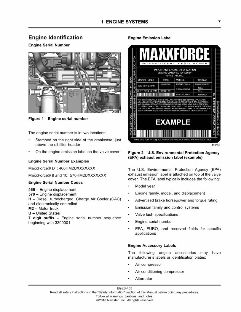
Engine IdentificationEngine Serial Number
Figure 1 Engine serial number
The engine serial number is in two locations:
• Stamped on the right side of the crankcase, justabove the oil filter header
• On the engine emission label on the valve cover
Engine Serial Number Examples
MaxxForce® DT: 466HM2UXXXXXXX
MaxxForce® 9 and 10: 570HM2UXXXXXXX
Engine Serial Number Codes
466 – Engine displacement570 – Engine displacementH – Diesel, turbocharged, Charge Air Cooler (CAC)and electronically controlledM2 – Motor truckU – United States7 digit suffix – Engine serial number sequencebeginning with 3300001
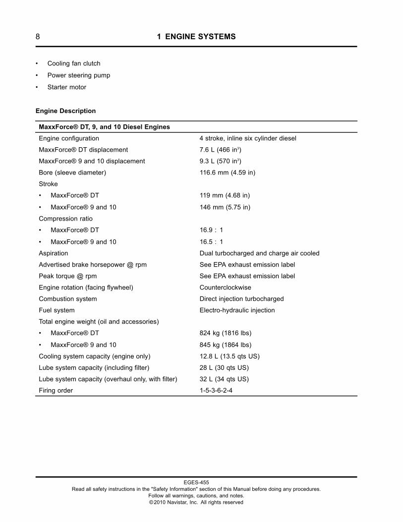
Engine Emission Label
Figure 2 U.S. Environmental Protection Agency(EPA) exhaust emission label (example)
The U.S. Environmental Protection Agency (EPA)exhaust emission label is attached on top of the valvecover. The EPA label typically includes the following:
• Model year
• Engine family, model, and displacement
• Advertised brake horsepower and torque rating
• Emission family and control systems
• Valve lash specifications
• Engine serial number
• EPA, EURO, and reserved fields for specificapplications
Engine Accessory Labels
The following engine accessories may havemanufacturer’s labels or identification plates:
• Air compressor
• Air conditioning compressor
• Alternator
EGES-455Read all safety instructions in the "Safety Information" section of this Manual before doing any procedures.
Follow all warnings, cautions, and notes.©2010 Navistar, Inc. All rights reserved
8 1 ENGINE SYSTEMS
• Cooling fan clutch
• Power steering pump
• Starter motor
Engine Description
MaxxForce® DT, 9, and 10 Diesel Engines
Engine configuration 4 stroke, inline six cylinder diesel
MaxxForce® DT displacement 7.6 L (466 in3)
MaxxForce® 9 and 10 displacement 9.3 L (570 in3)
Bore (sleeve diameter) 116.6 mm (4.59 in)
Stroke
• MaxxForce® DT
• MaxxForce® 9 and 10
119 mm (4.68 in)
146 mm (5.75 in)
Compression ratio
• MaxxForce® DT
• MaxxForce® 9 and 10
16.9 : 1
16.5 : 1
Aspiration Dual turbocharged and charge air cooled
Advertised brake horsepower @ rpm See EPA exhaust emission label
Peak torque @ rpm See EPA exhaust emission label
Engine rotation (facing flywheel) Counterclockwise
Combustion system Direct injection turbocharged
Fuel system Electro-hydraulic injection
Total engine weight (oil and accessories)
• MaxxForce® DT
• MaxxForce® 9 and 10
824 kg (1816 lbs)
845 kg (1864 lbs)
Cooling system capacity (engine only) 12.8 L (13.5 qts US)
Lube system capacity (including filter) 28 L (30 qts US)
Lube system capacity (overhaul only, with filter) 32 L (34 qts US)
Firing order 1-5-3-6-2-4
EGES-455Read all safety instructions in the "Safety Information" section of this Manual before doing any procedures.
Follow all warnings, cautions, and notes.©2010 Navistar, Inc. All rights reserved
1 ENGINE SYSTEMS 9
Standard Features
MaxxForce® DT, 9, and 10 diesel engines aredesigned for increased durability, reliability, and easeof maintenance.
The cylinder head has four valves per cylinder withcentrally located fuel injectors directing fuel overthe pistons. This configuration provides improvedperformance and reduces emissions.
The camshaft is supported by four insert bushingspressed into the crankcase. The camshaft gear isdriven from the front of the engine. A thrust flangeis located between the camshaft and the drive gear.The overhead valve train includes mechanical rollerlifters, push rods, rocker arms, and dual valves thatopen using a valve bridge.
MaxxForce® DT engines use one-piece aluminumalloy pistons. MaxxForce® 9 and 10 engines useone-piece steel pistons. All pistons have zero pinoffset and centered combustion bowls; therefore,pistons can be installed safely without orientation:there is NO front-of-engine arrow or “CAMSIDE”marking on the piston crown to indicate a necessarypiston direction.
The one piece crankcase uses replaceable wetcylinder sleeves that are sealed by a single creviceseal ring. Some applications include a crankcaseladder which is designed to support heavier loadsand reduce engine noise.
The crankshaft has seven main bearings with foreand aft thrust controlled at the rear bearing. Onefractured cap connecting rod is attached at eachcrankshaft journal. A piston pin moves freely insidethe connecting rod and piston. Piston pin retainingrings secure the piston pin in the piston. The rear oilseal carrier is part of the flywheel housing.
A lube oil pump is mounted on the front cover and isdriven by the crankshaft. Pressurized oil is suppliedto engine components and the high-pressure injectionsystem. All MaxxForce® DT, 9, and 10 engines usean engine oil cooler and spin-on engine oil filter.
The coolant supply housing serves as the mountingbracket for the refrigerant compressor. Mountingcapabilities for a dual refrigerant compressor areavailable as an option. The pad mounting design ofthe alternator and refrigerant compressor bracketsprovide easy removal and improved durability.
The electric low-pressure fuel supply pump drawsfuel from the fuel tank through the fuel filter assembly.The assembly includes a strainer, filter, drain valve,Water in Fuel (WIF) sensor, and Fuel DeliveryPressure (FDP) sensor. If equipped, an optionalfuel heater element is installed in the fuel filterassembly. Conditioned fuel is pumped through theintake manifold and cylinder head to the fuel injectors.
The WIF sensor detects water in the fuel system.When water reaches the level of the sensor locatedin the fuel filter assembly, the instrument panel’samber FUEL FILTER lamp will illuminate. Thecollected water must be removed immediately. Wateris drained by opening the drain valve on the fuel filterassembly.
The fuel injection system is electro-hydraulic. Thesystem includes an under-valve-cover high-pressureoil manifold, fuel injectors, and a high-pressure oilpump. The injectors are installed in the cylinder head,under the high-pressure oil manifold.
MaxxForce® DT, 9, and 10 engines use dualturbochargers with an air-to-air High Pressure ChargeAir Cooler (HPCAC) after the second stage. Aninterstage cooler is used after the first stage forapplications with 245 hp and above.
The Inlet Air Heater (IAH) system warms the incomingair to aid cold engine starting and to reduce whitesmoke and engine noise. The IAH system will initiallyilluminate the WAIT TO START lamp located on theinstrument panel. When the lamp turns off, the enginecan be started.
The Exhaust Gas Recirculation (EGR) systemcirculates cooled exhaust into the intake air streamin the intake manifold. This cools the combustionprocess and reduces the formation of NOX engineemissions.
A closed crankcase breather system uses an enginemounted oil separator to return oil to the crankcaseand vent crankcase pressure into the intake system.
The Down Stream Injection (DSI) system aidesin controlling emissions by injecting fuel into theexhaust stream. The fuel causes an exothermicreaction which increases the temperature of theexhaust gas. This increase in temperature allows formore efficient conversion of soot into ash withinthe Diesel Particulate Filter (DPF). Along withDSI, the Diesel Oxidation Catalyst (DOC) aids increating the required exothermic reaction. DSI
EGES-455Read all safety instructions in the "Safety Information" section of this Manual before doing any procedures.
Follow all warnings, cautions, and notes.©2010 Navistar, Inc. All rights reserved
10 1 ENGINE SYSTEMS
consists of the Aftertreatment Control Module (ACM),Downstream Injection (DSI) assembly, hydrocarboninjector assembly, fuel lines, and coolant lines. TheElectronic Control Module (ECM) communicates withthe ACM to control the timing and quantity of fuelsprayed from the hydrocarbon injector assembly. TheECM signals the exhaust brake valve assembly tocontrol the position of the exhaust back pressurevalve to increase or decrease the exhaust gas backpressure and temperature to allow the DOC and DPFto function efficiently.
The exhaust back pressure valve acts asan aftertreatment device to manage exhausttemperature. The resulting rise in back pressure,increases exhaust temperature.
Optional Features
Optional features include the following:
• Air compressor
• Hydraulic pump
• Engine brake
• Exhaust brake
An air compressor is available for applications thatrequire air brakes or air suspension.
A hydraulic power steering pump can be used with orwithout the air compressor.
Engine brake and exhaust brake systems areavailable for applications that could benefit fromadded speed reduction capability.
Optional Cold Climate Features
Optional cold climate features include the following:
• Oil pan heater
• Coolant heater
• Fuel heater
All three heaters use an electric element to warmengine fluids in cold weather.
The oil pan heater warms engine oil to ensureoptimum oil flow.
The coolant heater warms engine coolant surroundingthe cylinders. Warmed engine coolant aids in coldengine start-up and performance.
The fuel heater is installed in the fuel filter assemblyand warms the supply fuel. Warmed supply fuelprevents waxing, and improves performance and fueleconomy during cold weather start-up.
Chassis Mounted Features
A Charge Air Cooler (CAC) is an air-to-air heatexchanger, which increases the density of the aircharge.
The Aftertreatment System, part of the larger exhaustsystem, processes engine exhaust to meet tailpipeemission requirements.
• The Pre-Diesel Oxidation Catalyst (PDOC) aids increating the required exothermic reaction beforethe exhaust gas enters the Diesel OxidationCatalyst (DOC).
• The Diesel Oxidation Catalyst (DOC) oxidizescarbon monoxide, hydrocarbons, and smallamounts of nitrogen oxide in the exhaust stream.
• The Diesel Particulate Filter (DPF) captures andoxidizes particulates in the exhaust stream andstores non-combustible ash.
EGES-455Read all safety instructions in the "Safety Information" section of this Manual before doing any procedures.
Follow all warnings, cautions, and notes.©2010 Navistar, Inc. All rights reserved
1 ENGINE SYSTEMS 11
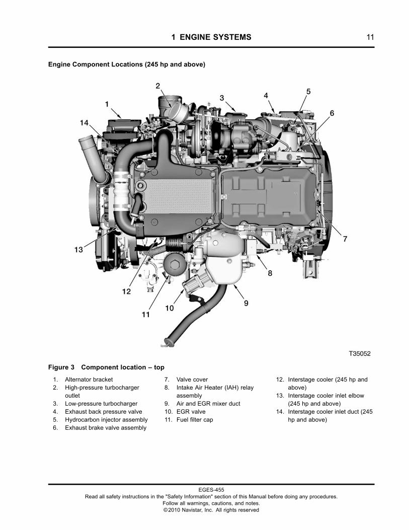
Engine Component Locations (245 hp and above)
Figure 3 Component location – top
1. Alternator bracket2. High-pressure turbocharger
outlet3. Low-pressure turbocharger4. Exhaust back pressure valve5. Hydrocarbon injector assembly6. Exhaust brake valve assembly
7. Valve cover8. Intake Air Heater (IAH) relay
assembly9. Air and EGR mixer duct10. EGR valve11. Fuel filter cap
12. Interstage cooler (245 hp andabove)
13. Interstage cooler inlet elbow(245 hp and above)
14. Interstage cooler inlet duct (245hp and above)
EGES-455Read all safety instructions in the "Safety Information" section of this Manual before doing any procedures.
Follow all warnings, cautions, and notes.©2010 Navistar, Inc. All rights reserved
12 1 ENGINE SYSTEMS
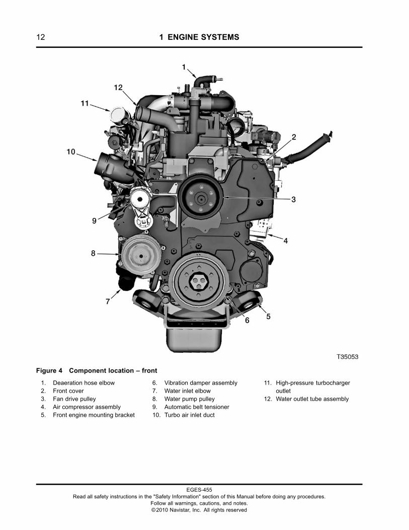
Figure 4 Component location – front
1. Deaeration hose elbow2. Front cover3. Fan drive pulley4. Air compressor assembly5. Front engine mounting bracket
6. Vibration damper assembly7. Water inlet elbow8. Water pump pulley9. Automatic belt tensioner10. Turbo air inlet duct
11. High-pressure turbochargeroutlet
12. Water outlet tube assembly
EGES-455Read all safety instructions in the "Safety Information" section of this Manual before doing any procedures.
Follow all warnings, cautions, and notes.©2010 Navistar, Inc. All rights reserved
1 ENGINE SYSTEMS 13
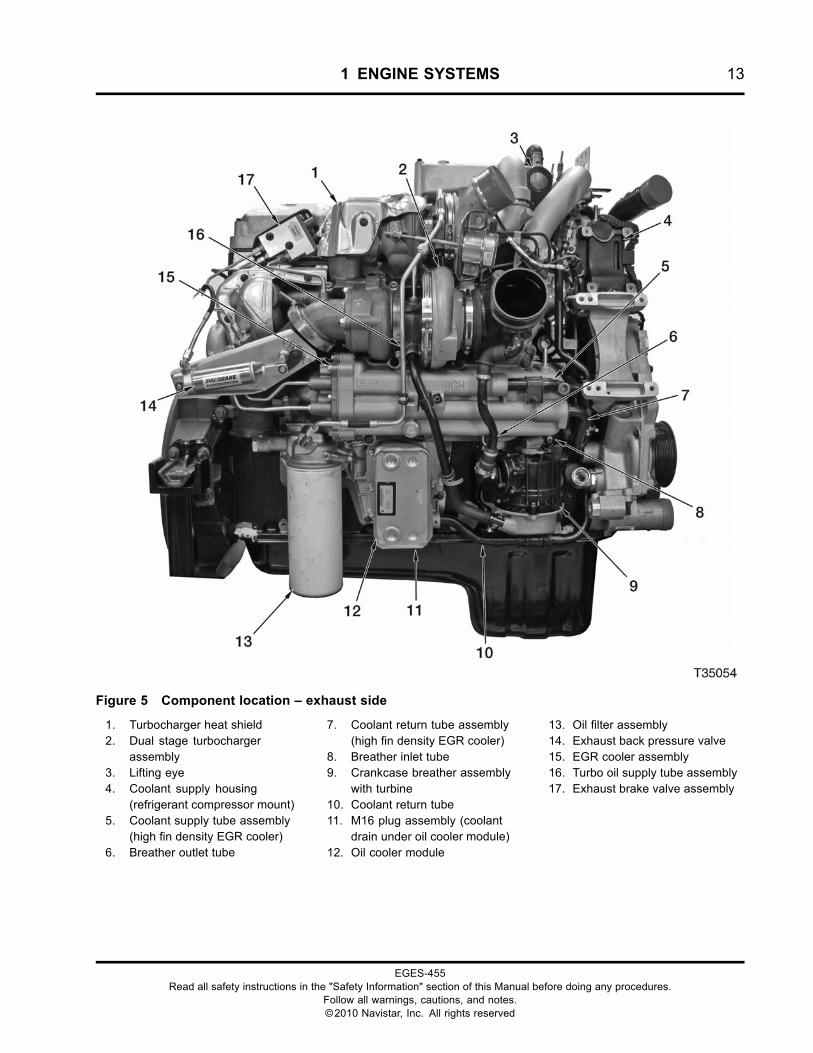
Figure 5 Component location – exhaust side
1. Turbocharger heat shield2. Dual stage turbocharger
assembly3. Lifting eye4. Coolant supply housing
(refrigerant compressor mount)5. Coolant supply tube assembly
(high fin density EGR cooler)6. Breather outlet tube
7. Coolant return tube assembly(high fin density EGR cooler)
8. Breather inlet tube9. Crankcase breather assembly
with turbine10. Coolant return tube11. M16 plug assembly (coolant
drain under oil cooler module)12. Oil cooler module
13. Oil filter assembly14. Exhaust back pressure valve15. EGR cooler assembly16. Turbo oil supply tube assembly17. Exhaust brake valve assembly
EGES-455Read all safety instructions in the "Safety Information" section of this Manual before doing any procedures.
Follow all warnings, cautions, and notes.©2010 Navistar, Inc. All rights reserved
14 1 ENGINE SYSTEMS
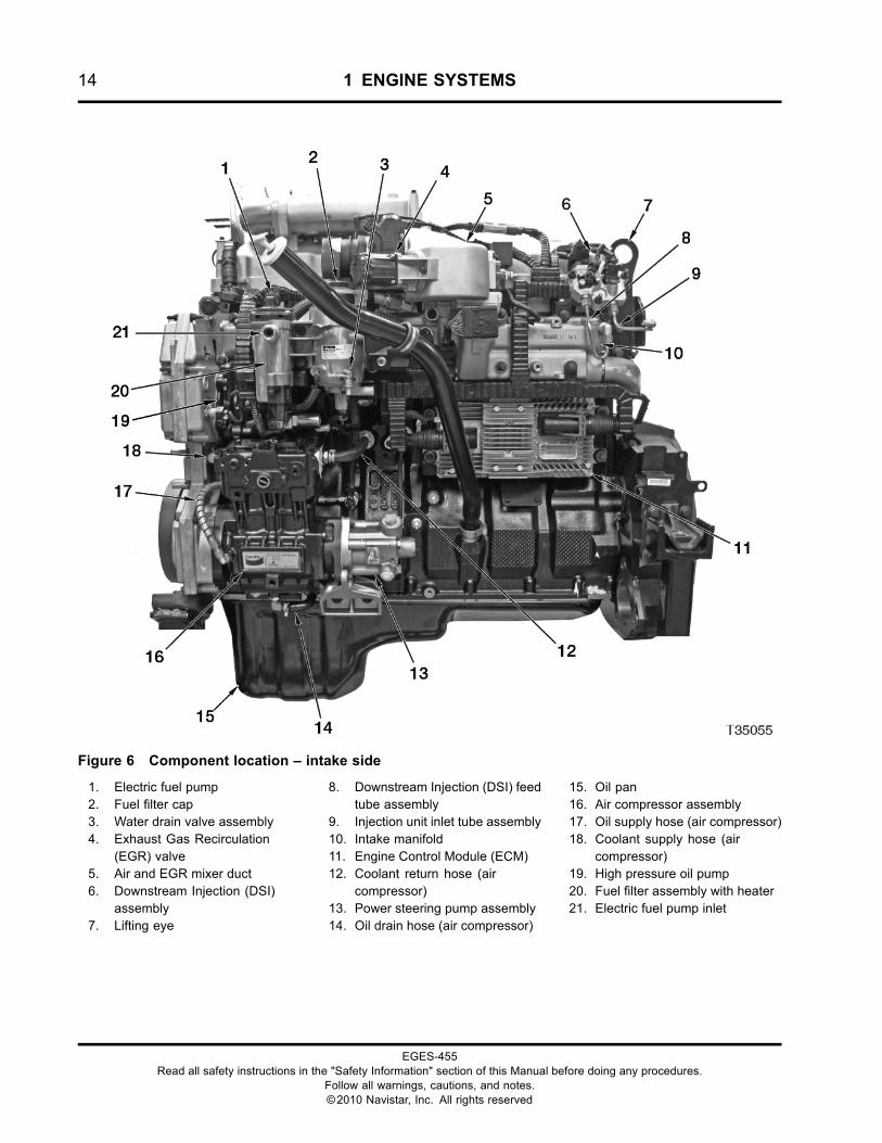
Figure 6 Component location – intake side
1. Electric fuel pump2. Fuel filter cap3. Water drain valve assembly4. Exhaust Gas Recirculation
(EGR) valve5. Air and EGR mixer duct6. Downstream Injection (DSI)
assembly7. Lifting eye
8. Downstream Injection (DSI) feedtube assembly
9. Injection unit inlet tube assembly10. Intake manifold11. Engine Control Module (ECM)12. Coolant return hose (air
compressor)13. Power steering pump assembly14. Oil drain hose (air compressor)
15. Oil pan16. Air compressor assembly17. Oil supply hose (air compressor)18. Coolant supply hose (air
compressor)19. High pressure oil pump20. Fuel filter assembly with heater21. Electric fuel pump inlet
EGES-455Read all safety instructions in the "Safety Information" section of this Manual before doing any procedures.
Follow all warnings, cautions, and notes.©2010 Navistar, Inc. All rights reserved
1 ENGINE SYSTEMS 15
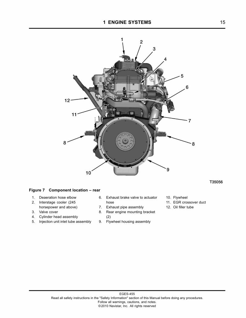
Figure 7 Component location – rear
1. Deaeration hose elbow2. Interstage cooler (245
horsepower and above)3. Valve cover4. Cylinder head assembly5. Injection unit inlet tube assembly
6. Exhaust brake valve to actuatorhose
7. Exhaust pipe assembly8. Rear engine mounting bracket
(2)9. Flywheel housing assembly
10. Flywheel11. EGR crossover duct12. Oil filler tube
EGES-455Read all safety instructions in the "Safety Information" section of this Manual before doing any procedures.
Follow all warnings, cautions, and notes.©2010 Navistar, Inc. All rights reserved
16 1 ENGINE SYSTEMS
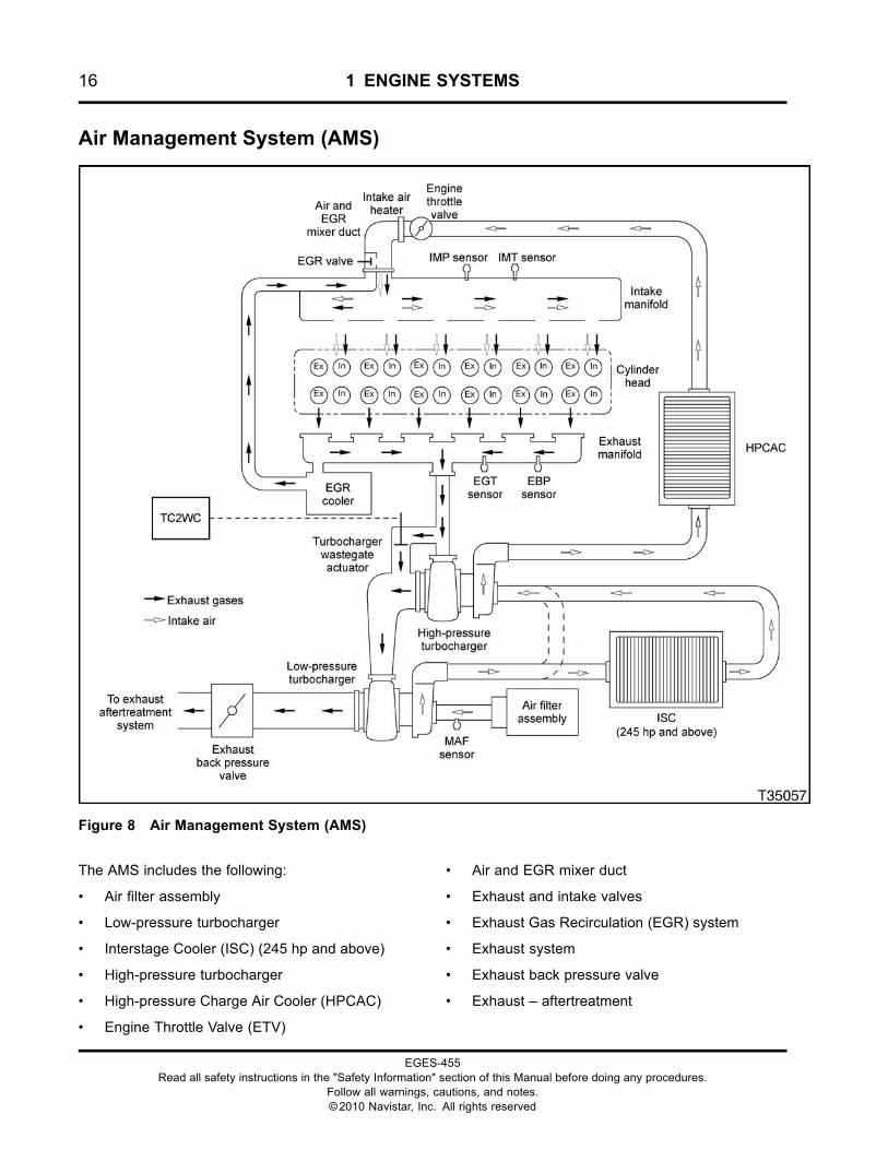
Air Management System (AMS)
Figure 8 Air Management System (AMS)
The AMS includes the following:
• Air filter assembly
• Low-pressure turbocharger
• Interstage Cooler (ISC) (245 hp and above)
• High-pressure turbocharger
• High-pressure Charge Air Cooler (HPCAC)
• Engine Throttle Valve (ETV)
• Air and EGR mixer duct
• Exhaust and intake valves
• Exhaust Gas Recirculation (EGR) system
• Exhaust system
• Exhaust back pressure valve
• Exhaust – aftertreatment
EGES-455Read all safety instructions in the "Safety Information" section of this Manual before doing any procedures.
Follow all warnings, cautions, and notes.©2010 Navistar, Inc. All rights reserved
1 ENGINE SYSTEMS 17
Air Flow – Pre Combustion
Fresh air from the air filter enters the low-pressurecompressor where it is compressed and directedinto the ISC (245 hp and above ratings), if equipped.If not equipped with ISC, compressed air from thelow-pressure compressor is piped directly to thehigh-pressure compressor inlet. The high-pressureturbocharger further increases the intake air pressure.The hot compressed air flows into the HPCAC whereit is cooled, then through the Engine Throttle Valve(ETV) on the air and EGR mixer duct.
If the EGR valve is open, exhaust gas enters the highfin density EGR cooler from the rear of the exhaustmanifold and is transferred to the intake manifoldvia the EGR crossover duct. The exhaust gas thenpasses through a port in the intake manifold to theair and EGR mixer duct where it is mixed with filteredintake air. This mixture then flows through the intakemanifold and into the cylinder head.
If the EGR valve is closed, only filtered intake air flowsthrough the ETV, air and EGR mixer duct, and into theintake manifold.
Air Flow – Post Combustion
After combustion, gases exit through the cylinderhead exhaust valves and ports. Exhaust gas is forcedthrough the exhaust manifold where, dependingon the EGR valve position, it is split between theEGR system and the high-pressure turbocharger,
low-pressure turbocharger and the exhaust backpressure valve assembly.
The exhaust back pressure valve acts asan aftertreatment device to regulate exhausttemperatures.
Exhaust gases flow from the engine through thevehicle aftertreatment system to the exhaust tail pipe.
Air Management Components
Turbochargers
MaxxForce® DT, 9, and 10 engines are equipped withan electronically controlled two stage turbochargingsystem. This system provides high levels of charge airpressure to improve engine performance and to helpreduce emissions. Because of its ability to generatevery high charge air pressure levels, and to avoidCharge Air Cooler (CAC) overloading conditions, thesystem is fitted with a spring loaded turbochargerwastegate.
The turbocharger wastegate is actuated by chargeair pressure. The air pressure to the turbochargerwastegate actuator is controlled by the Turbocharger2 Wastegate Control (TC2WC) valve. The TC2WCvalve is controlled by Pulse Width Modulation (PWM)signals from the Electronic Control Module (ECM).
The high and low-pressure turbochargers are installedas an assembly on the exhaust manifold, on right sideof engine.
EGES-455Read all safety instructions in the "Safety Information" section of this Manual before doing any procedures.
Follow all warnings, cautions, and notes.©2010 Navistar, Inc. All rights reserved
18 1 ENGINE SYSTEMS
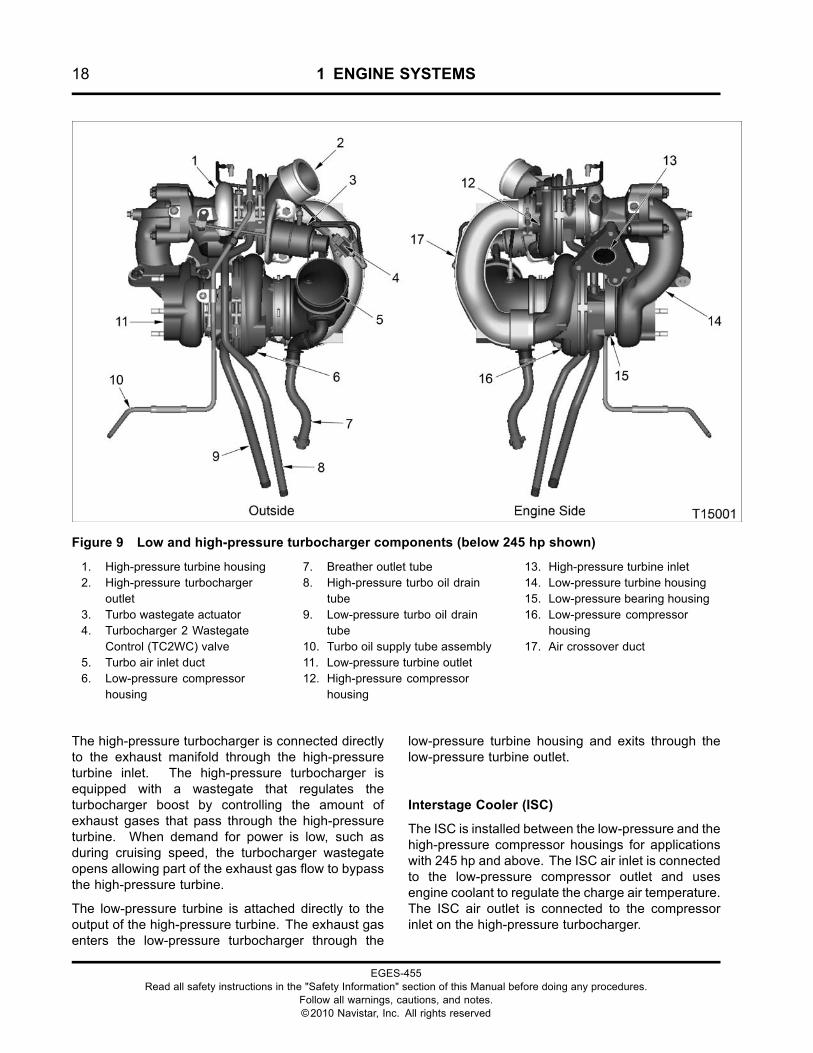
Figure 9 Low and high-pressure turbocharger components (below 245 hp shown)
1. High-pressure turbine housing2. High-pressure turbocharger
outlet3. Turbo wastegate actuator4. Turbocharger 2 Wastegate
Control (TC2WC) valve5. Turbo air inlet duct6. Low-pressure compressor
housing
7. Breather outlet tube8. High-pressure turbo oil drain
tube9. Low-pressure turbo oil drain
tube10. Turbo oil supply tube assembly11. Low-pressure turbine outlet12. High-pressure compressor
housing
13. High-pressure turbine inlet14. Low-pressure turbine housing15. Low-pressure bearing housing16. Low-pressure compressor
housing17. Air crossover duct
The high-pressure turbocharger is connected directlyto the exhaust manifold through the high-pressureturbine inlet. The high-pressure turbocharger isequipped with a wastegate that regulates theturbocharger boost by controlling the amount ofexhaust gases that pass through the high-pressureturbine. When demand for power is low, such asduring cruising speed, the turbocharger wastegateopens allowing part of the exhaust gas flow to bypassthe high-pressure turbine.
The low-pressure turbine is attached directly to theoutput of the high-pressure turbine. The exhaust gasenters the low-pressure turbocharger through the
low-pressure turbine housing and exits through thelow-pressure turbine outlet.
Interstage Cooler (ISC)
The ISC is installed between the low-pressure and thehigh-pressure compressor housings for applicationswith 245 hp and above. The ISC air inlet is connectedto the low-pressure compressor outlet and usesengine coolant to regulate the charge air temperature.The ISC air outlet is connected to the compressorinlet on the high-pressure turbocharger.
EGES-455Read all safety instructions in the "Safety Information" section of this Manual before doing any procedures.
Follow all warnings, cautions, and notes.©2010 Navistar, Inc. All rights reserved
1 ENGINE SYSTEMS 19
High-pressure Charge Air Cooler (HPCAC)
The HPCAC is installed between the high-pressureturbocharger and the Engine Throttle Valve (ETV).The HPCAC air inlet is connected to the high-pressurecompressor outlet and uses air-to-air to regulate thecharge air temperature. The HPCAC air outlet isconnected directly to the ETV body.
Turbocharger 2 Wastegate Control (TC2WC) Valve
The TC2WC valve controls the turbochargerwastegate actuator by regulating the amount ofcharge air pressure supplied to the wastegate
actuator. The Pulse Width Modulated (PWM) signalssent to the TC2WC valve by the Electronic ControlModule (ECM) are based on input signals from theExhaust Back Pressure (EBP) sensor.
When demand for power is high, such as duringacceleration, the TC2WC valve opens the wastegatewhich allows exhaust gas to enter the HPturbocharger in addition to the LP turbocharger.Once the vehicle reaches cruising speed, the TC2WCvalve will close the wastegate and direct exhaust gasaway from the HP turbocharger and only through theLP turbocharger.
EGES-455Read all safety instructions in the "Safety Information" section of this Manual before doing any procedures.
Follow all warnings, cautions, and notes.©2010 Navistar, Inc. All rights reserved
20 1 ENGINE SYSTEMS
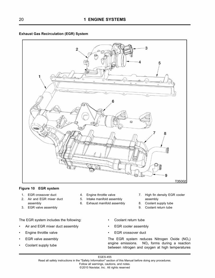
Exhaust Gas Recirculation (EGR) System
Figure 10 EGR system
1. EGR crossover duct2. Air and EGR mixer duct
assembly3. EGR valve assembly
4. Engine throttle valve5. Intake manifold assembly6. Exhaust manifold assembly
7. High fin density EGR coolerassembly
8. Coolant supply tube9. Coolant return tube
The EGR system includes the following:
• Air and EGR mixer duct assembly
• Engine throttle valve
• EGR valve assembly
• Coolant supply tube
• Coolant return tube
• EGR cooler assembly
• EGR crossover duct
The EGR system reduces Nitrogen Oxide (NOX)engine emissions. NOX forms during a reactionbetween nitrogen and oxygen at high temperatures
EGES-455Read all safety instructions in the "Safety Information" section of this Manual before doing any procedures.
Follow all warnings, cautions, and notes.©2010 Navistar, Inc. All rights reserved
1 ENGINE SYSTEMS 21
during combustion. Combustion starts when fuel isinjected into the compressed combustion chamber.
EGR Flow
When EGR is commanded, the EGR valve opens andallows exhaust gas from the exhaust manifold to flowinto the EGR cooler for cooling. This cooled exhaustgas is directed through the EGR crossover duct into aport in the intake manifold and directed to the air andEGR mixer duct where it is mixed with filtered intakeair.
EGR Valve
The EGR valve consists of three major components,a valve, an actuator motor, and an Integrated Circuit(IC).
The EGR valve is installed in the air and EGR mixerduct assembly on the intake side of the engine.
The EGR valve uses a DC motor to control positionof the valve assembly. The motor pushes directly onthe valve stem to open. The valve assembly has twopoppets on a common shaft.
The IC has three hall effect position sensors to monitorvalve movement.
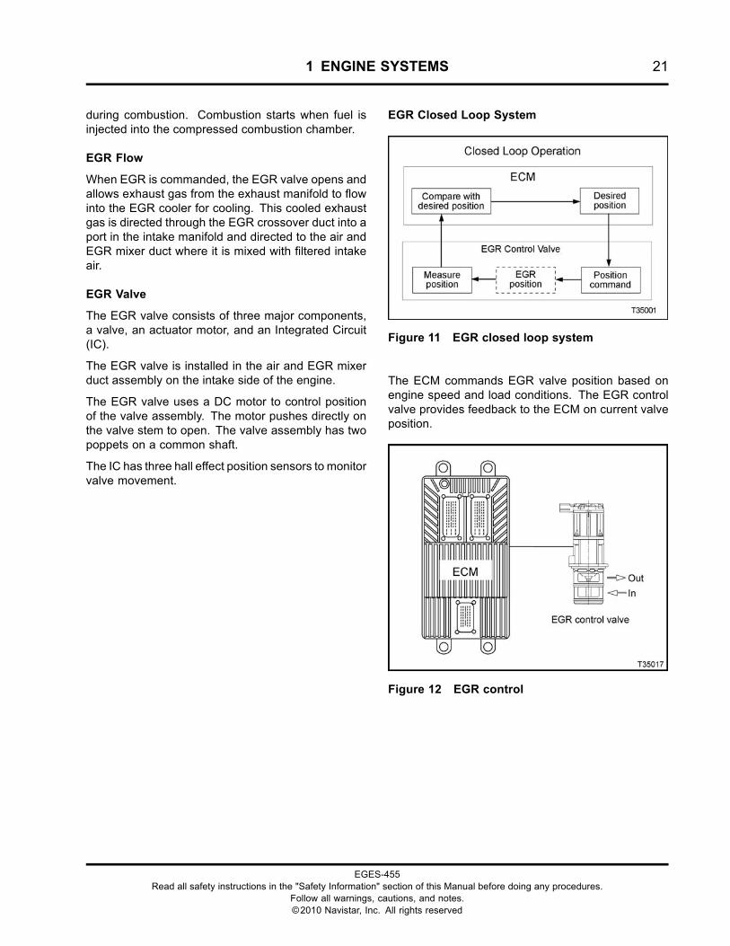
EGR Closed Loop System
Figure 11 EGR closed loop system
The ECM commands EGR valve position based onengine speed and load conditions. The EGR controlvalve provides feedback to the ECM on current valveposition.
Figure 12 EGR control
EGES-455Read all safety instructions in the "Safety Information" section of this Manual before doing any procedures.
Follow all warnings, cautions, and notes.©2010 Navistar, Inc. All rights reserved
22 1 ENGINE SYSTEMS
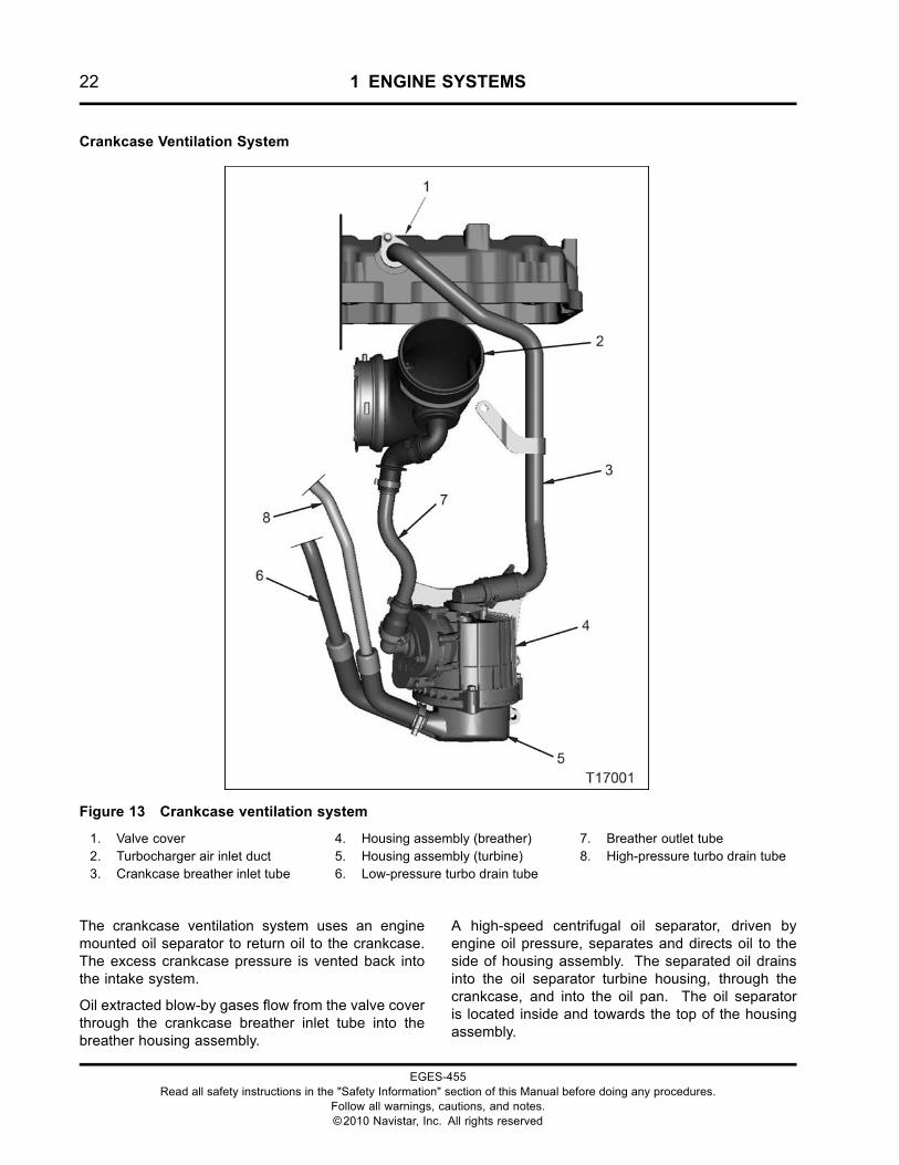
Crankcase Ventilation System
Figure 13 Crankcase ventilation system
1. Valve cover2. Turbocharger air inlet duct3. Crankcase breather inlet tube
4. Housing assembly (breather)5. Housing assembly (turbine)6. Low-pressure turbo drain tube
7. Breather outlet tube8. High-pressure turbo drain tube
The crankcase ventilation system uses an enginemounted oil separator to return oil to the crankcase.The excess crankcase pressure is vented back intothe intake system.
Oil extracted blow-by gases flow from the valve coverthrough the crankcase breather inlet tube into thebreather housing assembly.
A high-speed centrifugal oil separator, driven byengine oil pressure, separates and directs oil to theside of housing assembly. The separated oil drainsinto the oil separator turbine housing, through thecrankcase, and into the oil pan. The oil separatoris located inside and towards the top of the housingassembly.
EGES-455Read all safety instructions in the "Safety Information" section of this Manual before doing any procedures.
Follow all warnings, cautions, and notes.©2010 Navistar, Inc. All rights reserved
1 ENGINE SYSTEMS 23
The turbine housing also provides oil drainage fromthe low-pressure and high-pressure turbochargers.The low-pressure and high-pressure turbo oil draintubes direct turbocharger drain oil into the turbinehousing. The oil drains out of the turbine housing,through the crankcase, and into the oil pan.
Blow-by gases are directed through the breather outlettube and into the turbocharger air inlet duct.
Aftertreatment (AFT) System
Figure 14 Aftertreatment (AFT) system
The AFT System, part of the larger exhaust system,processes engine exhaust to meet emissionsrequirements. The AFT system traps particulatematter (soot) and prevents it from leaving the tailpipe.
AFT Control System
The control system performs the following functions:
• Monitors exhaust gases, the aftertreatmentsystem, and controls engine operatingparameters for emission processing and failurerecognition
• Cancels regeneration in the event of catalyst orsensor failure
• Monitors exhaust pressure before and afterthe Diesel Particulate Filter (DPF) and adaptsengine operating characteristics to compensatefor increased back pressure
• Controls engine operating parameters to makeregeneration automatic
• Maintains vehicle and engine performance duringregeneration
Sensors
Sensors output an electronic signal based ontemperature or pressure. The signals are usedby the control system to regulate the aftertreatmentfunction.
The sensors measure the temperature and pressureat the center of the exhaust flow.
EGES-455Read all safety instructions in the "Safety Information" section of this Manual before doing any procedures.
Follow all warnings, cautions, and notes.©2010 Navistar, Inc. All rights reserved
24 1 ENGINE SYSTEMS
Exhaust Back Pressure Valve
The exhaust back pressure valve also acts asan aftertreatment device to manage exhausttemperatures. The ECM will signal the exhaust backpressure valve to change the amount of air passingthrough the valve into the exhaust and through theDOC and DPF. The ECM interprets the increasedback pressure as an increased load. In response tothe increased pressure/load, the engine increasesspeed to meet the demand, resulting in increasedexhaust temperature.
Pre-Diesel Oxidation Catalyst (PDOC)
The PDOC does the following:
• Aids in creating an exothermic reaction to improveexhaust emissions
• Allows for more efficient operation of theaftertreatment system
Diesel Oxidation Catalyst (DOC)
The DOC does the following:
• Oxidizes hydrocarbons and carbon monoxide(CO) in exhaust stream
• Provides heat for exhaust system warm-up
• Aids in system temperature management for theDPF
Diesel Particulate Filter (DPF)
The DPF does the following:
• Captures and temporarily stores carbon-basedparticulates in a filter
• Allows for oxidation (regeneration) of storedparticulates once back pressure increases to apredetermined level
• Stores noncombustible ash
AFT Conditions and Responses
The operator is alerted audibly or with instrumentpanel indicators of system status. Automatic ormanual regeneration is required when levels of sootexceed acceptable limits. For additional informationsee the applicable Vehicle Operator Manual and thevehicle visor placard.
EGES-455Read all safety instructions in the "Safety Information" section of this Manual before doing any procedures.
Follow all warnings, cautions, and notes.©2010 Navistar, Inc. All rights reserved
1 ENGINE SYSTEMS 25
Downstream Injection System
Figure 15 Aftertreatment (AFT) system
1. Downstream Injection (DSI)assembly
2. Injection unit inlet tube assembly
3. Hydrocarbon injector assembly4. Injector coolant outlet tube5. Injector coolant inlet tube
6. Downstream Injection (DSI) feedtube assembly
The downstream injection system includes thefollowing:
• Aftertreatment Control Module (ACM)
• Hydrocarbon injector assembly
• Downstream Injection (DSI) assembly
• Coolant lines
• Fuel lines
The Aftertreatment Control Module (ACM) is mountedon the chassis of the vehicle. The ACM receivessignals from the ECM and then signals the DSIassembly.
The DSI assembly is installed on the left rear of theengine above the intake manifold.
When the ACM signals the shutoff valve to open,fuel pressure increases in the upstream cavity ofthe DSI assembly housing. The upstream pressuresensor immediately signals the ACM that pressure isincreased by available fuel. The ACM then signalsthe dosing valve to open, allowing a specific amountof fuel to be injected into the injector unit inlet tubeassembly to the hydrocarbon injector assembly.
Fuel is injected into the exhaust stream from thehydrocarbon injector assembly which increases thetemperature inside the Diesel Particulate Filter (DPF)in order to convert soot to ash more efficiently.
The hydrocarbon injector assembly is cooled withengine coolant from the EGR cooler assembly.
EGES-455Read all safety instructions in the "Safety Information" section of this Manual before doing any procedures.
Follow all warnings, cautions, and notes.©2010 Navistar, Inc. All rights reserved
26 1 ENGINE SYSTEMS
Fuel Management System
Figure 16 Fuel management system
The fuel management system includes the following:
• Lubrication system
• Injection Control Pressure (ICP) system
• Engine Compression Brake (ECB)
• Fuel supply system
• Fuel injectors
• Electronic control system
EGES-455Read all safety instructions in the "Safety Information" section of this Manual before doing any procedures.
Follow all warnings, cautions, and notes.©2010 Navistar, Inc. All rights reserved
1 ENGINE SYSTEMS 27
ICP System
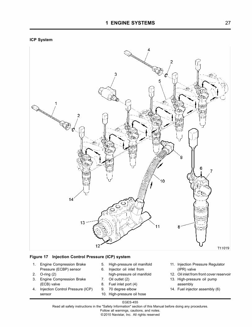
Figure 17 Injection Control Pressure (ICP) system
1. Engine Compression BrakePressure (ECBP) sensor
2. O-ring (2)3. Engine Compression Brake
(ECB) valve4. Injection Control Pressure (ICP)
sensor
5. High-pressure oil manifold6. Injector oil inlet from
high-pressure oil manifold7. Oil outlet (2)8. Fuel inlet port (4)9. 70 degree elbow10. High-pressure oil hose
11. Injection Pressure Regulator(IPR) valve
12. Oil inlet from front cover reservoir13. High-pressure oil pump
assembly14. Fuel injector assembly (6)
EGES-455Read all safety instructions in the "Safety Information" section of this Manual before doing any procedures.
Follow all warnings, cautions, and notes.©2010 Navistar, Inc. All rights reserved
28 1 ENGINE SYSTEMS
High-Pressure Oil Flow
The lubrication system supplies the oil reservoirlocated in the front cover. The reservoir provides oilfor the high-pressure oil pump. The pump is mountedon the backside of the front cover and is gear drivenby the upper idler gear.
High-pressure oil is directed to the high-pressure oilhose, cylinder head passage, and high-pressure oilmanifold.
High-pressure oil is used by the fuel injectors topressurize and inject fuel in the cylinders. This occurswhen the OPEN coil for each fuel injector is energized.
Excess high-pressure oil is directed to the crankcasesump by the Injection Pressure Regulator (IPR) valve.The IPR valve is controlled by the Electronic ControlModule (ECM) to maintain a desired injection controlpressure.
If equipped with the optional engine brake, somehigh-pressure oil is directed internally to the enginebrake pistons when the engine compression brake isactivated. Since these two systems share a commongallery, a problem with the engine compression brakesystem can adversely affect injection control pressureand vise versa.
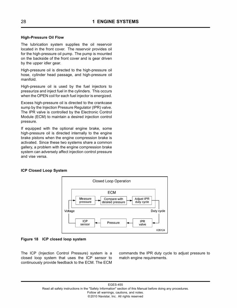
ICP Closed Loop System
Figure 18 ICP closed loop system
The ICP (Injection Control Pressure) system is aclosed loop system that uses the ICP sensor tocontinuously provide feedback to the ECM. The ECM
commands the IPR duty cycle to adjust pressure tomatch engine requirements.
EGES-455Read all safety instructions in the "Safety Information" section of this Manual before doing any procedures.
Follow all warnings, cautions, and notes.©2010 Navistar, Inc. All rights reserved
1 ENGINE SYSTEMS 29
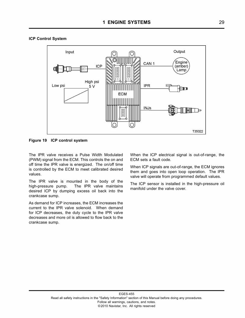
ICP Control System
Figure 19 ICP control system
The IPR valve receives a Pulse Width Modulated(PWM) signal from the ECM. This controls the on andoff time the IPR valve is energized. The on/off timeis controlled by the ECM to meet calibrated desiredvalues.
The IPR valve is mounted in the body of thehigh-pressure pump. The IPR valve maintainsdesired ICP by dumping excess oil back into thecrankcase sump.
As demand for ICP increases, the ECM increases thecurrent to the IPR valve solenoid. When demandfor ICP decreases, the duty cycle to the IPR valvedecreases and more oil is allowed to flow back to thecrankcase sump.
When the ICP electrical signal is out-of-range, theECM sets a fault code.
When ICP signals are out-of-range, the ECM ignoresthem and goes into open loop operation. The IPRvalve will operate from programmed default values.
The ICP sensor is installed in the high-pressure oilmanifold under the valve cover.
EGES-455Read all safety instructions in the "Safety Information" section of this Manual before doing any procedures.
Follow all warnings, cautions, and notes.©2010 Navistar, Inc. All rights reserved
30 1 ENGINE SYSTEMS
Fuel Injector
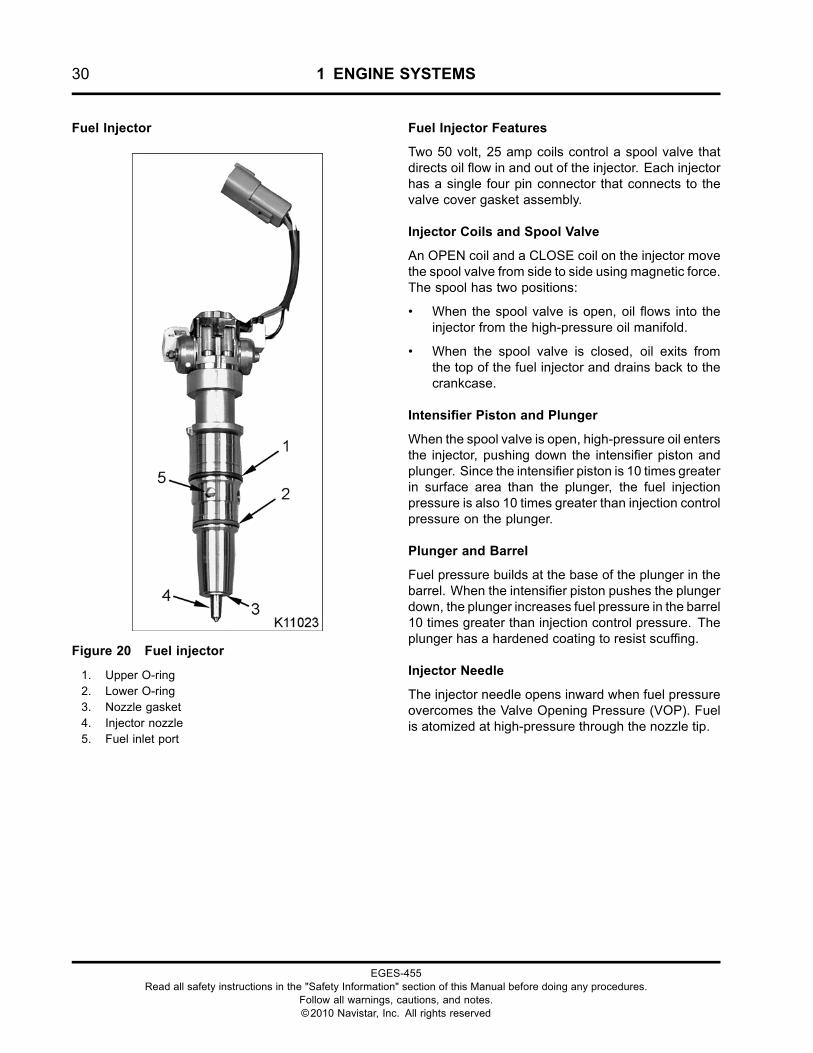
Figure 20 Fuel injector
1. Upper O-ring2. Lower O-ring3. Nozzle gasket4. Injector nozzle5. Fuel inlet port
Fuel Injector Features
Two 50 volt, 25 amp coils control a spool valve thatdirects oil flow in and out of the injector. Each injectorhas a single four pin connector that connects to thevalve cover gasket assembly.
Injector Coils and Spool Valve
An OPEN coil and a CLOSE coil on the injector movethe spool valve from side to side using magnetic force.The spool has two positions:
• When the spool valve is open, oil flows into theinjector from the high-pressure oil manifold.
• When the spool valve is closed, oil exits fromthe top of the fuel injector and drains back to thecrankcase.
Intensifier Piston and Plunger
When the spool valve is open, high-pressure oil entersthe injector, pushing down the intensifier piston andplunger. Since the intensifier piston is 10 times greaterin surface area than the plunger, the fuel injectionpressure is also 10 times greater than injection controlpressure on the plunger.
Plunger and Barrel
Fuel pressure builds at the base of the plunger in thebarrel. When the intensifier piston pushes the plungerdown, the plunger increases fuel pressure in the barrel10 times greater than injection control pressure. Theplunger has a hardened coating to resist scuffing.
Injector Needle
The injector needle opens inward when fuel pressureovercomes the Valve Opening Pressure (VOP). Fuelis atomized at high-pressure through the nozzle tip.
EGES-455Read all safety instructions in the "Safety Information" section of this Manual before doing any procedures.
Follow all warnings, cautions, and notes.©2010 Navistar, Inc. All rights reserved
1 ENGINE SYSTEMS 31
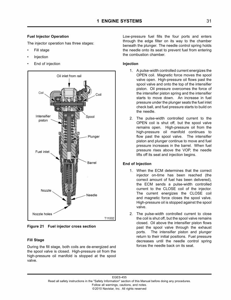
Fuel Injector Operation
The injector operation has three stages:
• Fill stage
• Injection
• End of injection
Figure 21 Fuel injector cross section
Fill Stage
During the fill stage, both coils are de-energized andthe spool valve is closed. High-pressure oil from thehigh-pressure oil manifold is stopped at the spoolvalve.
Low-pressure fuel fills the four ports and entersthrough the edge filter on its way to the chamberbeneath the plunger. The needle control spring holdsthe needle onto its seat to prevent fuel from enteringthe combustion chamber.
Injection
1. A pulse-width controlled current energizes theOPEN coil. Magnetic force moves the spoolvalve open. High-pressure oil flows past thespool valve and onto the top of the intensifierpiston. Oil pressure overcomes the force ofthe intensifier piston spring and the intensifierstarts to move down. An increase in fuelpressure under the plunger seats the fuel inletcheck ball, and fuel pressure starts to build onthe needle.
2. The pulse-width controlled current to theOPEN coil is shut off, but the spool valveremains open. High-pressure oil from thehigh-pressure oil manifold continues toflow past the spool valve. The intensifierpiston and plunger continue to move and fuelpressure increases in the barrel. When fuelpressure rises above the VOP, the needlelifts off its seat and injection begins.
End of Injection
1. When the ECM determines that the correctinjector on-time has been reached (thecorrect amount of fuel has been delivered),the ECM sends a pulse-width controlledcurrent to the CLOSE coil of the injector.The current energizes the CLOSE coiland magnetic force closes the spool valve.High-pressure oil is stopped against the spoolvalve.
2. The pulse-width controlled current to closethe coil is shut off, but the spool valve remainsclosed. Oil above the intensifier piston flowspast the spool valve through the exhaustports. The intensifier piston and plungerreturn to their initial positions. Fuel pressuredecreases until the needle control springforces the needle back on its seat.
EGES-455Read all safety instructions in the "Safety Information" section of this Manual before doing any procedures.
Follow all warnings, cautions, and notes.©2010 Navistar, Inc. All rights reserved

32 1 ENGINE SYSTEMS
Fuel Supply System
Figure 22 Low-pressure fuel system
1. Cylinder Head2. Fuel injector assembly (6)3. Fuel filter cap4. M8 x 75 stud bolt (3)5. Diagnostic coupling assembly
and dust cap6. Water drain valve assembly7. M8 x 75 bolt
8. Water In Fuel (WIF) sensor9. 250 watt heater assembly
(optional)10. Voss® Stop Flow adapter
assembly (fuel inlet)11. Fuel filter assembly (with
optional heater)12. Electric fuel pump assembly
13. Low pressure fuel rail (cast inintake manifold)
EGES-455Read all safety instructions in the "Safety Information" section of this Manual before doing any procedures.
Follow all warnings, cautions, and notes.©2010 Navistar, Inc. All rights reserved
1 ENGINE SYSTEMS 33
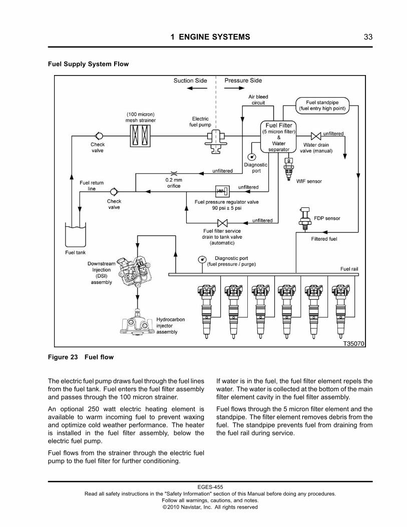
Fuel Supply System Flow
Figure 23 Fuel flow
The electric fuel pump draws fuel through the fuel linesfrom the fuel tank. Fuel enters the fuel filter assemblyand passes through the 100 micron strainer.
An optional 250 watt electric heating element isavailable to warm incoming fuel to prevent waxingand optimize cold weather performance. The heateris installed in the fuel filter assembly, below theelectric fuel pump.
Fuel flows from the strainer through the electric fuelpump to the fuel filter for further conditioning.
If water is in the fuel, the fuel filter element repels thewater. The water is collected at the bottom of the mainfilter element cavity in the fuel filter assembly.
Fuel flows through the 5 micron filter element and thestandpipe. The filter element removes debris from thefuel. The standpipe prevents fuel from draining fromthe fuel rail during service.
EGES-455Read all safety instructions in the "Safety Information" section of this Manual before doing any procedures.
Follow all warnings, cautions, and notes.©2010 Navistar, Inc. All rights reserved
34 1 ENGINE SYSTEMS
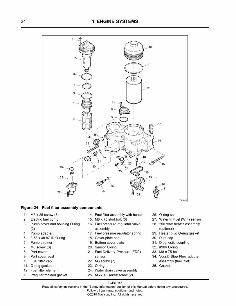
Figure 24 Fuel filter assembly components
1. M5 x 25 screw (3)2. Electric fuel pump3. Pump cover and housing O-ring
(2)4. Pump adapter5. 3.53 x 40.87 ID O-ring6. Pump strainer7. M6 screw (3)8. Port cover9. Port cover seal10. Fuel filter cap11. O-ring gasket12. Fuel filter element13. Irregular molded gasket
14. Fuel filter assembly with heater15. M8 x 75 stud bolt (3)16. Fuel pressure regulator valve
assembly17. Fuel pressure regulator spring18. Cover plate seal19. Bottom cover plate20. Sensor O-ring21. Fuel Delivery Pressure (FDP)
sensor22. M6 screw (7)23. O-ring24. Water drain valve assembly25. M5 x 18 Torx® screw (2)
26. O-ring seal27. Water In Fuel (WIF) sensor28. 250 watt heater assembly
(optional)29. Heater plug O-ring gasket30. Dust cap31. Diagnostic coupling32. #906 O-ring33. M8 x 75 bolt34. Voss® Stop Flow adapter
assembly (fuel inlet)35. Gasket
EGES-455Read all safety instructions in the "Safety Information" section of this Manual before doing any procedures.
Follow all warnings, cautions, and notes.©2010 Navistar, Inc. All rights reserved
1 ENGINE SYSTEMS 35
When the maximum amount of water is collected inthe element cavity, the WIF sensor sends a signalto the Electronic Control Module (ECM). The ECMturns on the amber Water In Fuel lamp located on theinstrument panel.
A water drain valve is located on the fuel filterassembly and can be opened to drain contaminants(usually water) from the assembly.
A fuel pressure regulator valve is built into the fuel filterassembly. The regulator valve is calibrated to relieveexcessive fuel pressure. Excess fuel is sent througha fuel return line back to the fuel tank. Return fuel isnot filtered.
Fuel continuously flows from the top of the filterelement cavity, through a 0.2 mm air bleed orifice(filter center tube feature), and into the return fuel line.This aids in removing trapped air from the elementcavity as a result of servicing.
When the fuel filter is removed, a drain-to-tank portvalve is opened. Fuel present in the filter assembly
then drains out and back to the tank to provideimproved cleanliness during servicing. When fuellines are removed, a check valve eliminates spillageand ensures fuel line cleanliness.
The Fuel Delivery Pressure (FDP) sensor detectslow fuel pressure caused by a fuel restriction or dirtyfuel filter. The FDP sensor sends a signal to theECM when pressure is below programmed valuesfor various engine conditions. The ECM turns on anamber FUEL FILTER lamp located on the instrumentpanel.
Filtered fuel flows from the fuel filter assembly into thefuel rail. The fuel rail is an integral part of the intakemanifold. Fuel flows into six cylinder head passagesto each fuel injector.
When the fuel injectors are activated, fuel flows fromthe fuel passages through the injector inlet ports andinto the fuel injectors.
EGES-455Read all safety instructions in the "Safety Information" section of this Manual before doing any procedures.
Follow all warnings, cautions, and notes.©2010 Navistar, Inc. All rights reserved
36 1 ENGINE SYSTEMS
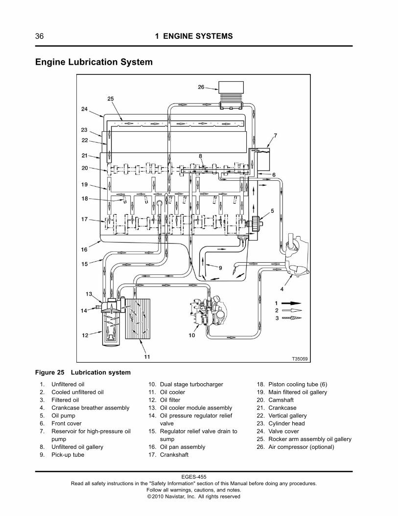
Engine Lubrication System
Figure 25 Lubrication system
1. Unfiltered oil2. Cooled unfiltered oil3. Filtered oil4. Crankcase breather assembly5. Oil pump6. Front cover7. Reservoir for high-pressure oil
pump8. Unfiltered oil gallery9. Pick-up tube
10. Dual stage turbocharger11. Oil cooler12. Oil filter13. Oil cooler module assembly14. Oil pressure regulator relief
valve15. Regulator relief valve drain to
sump16. Oil pan assembly17. Crankshaft
18. Piston cooling tube (6)19. Main filtered oil gallery20. Camshaft21. Crankcase22. Vertical gallery23. Cylinder head24. Valve cover25. Rocker arm assembly oil gallery26. Air compressor (optional)
EGES-455Read all safety instructions in the "Safety Information" section of this Manual before doing any procedures.
Follow all warnings, cautions, and notes.©2010 Navistar, Inc. All rights reserved
1 ENGINE SYSTEMS 37
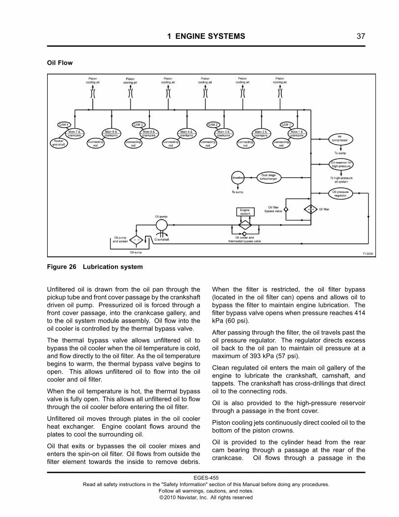
Oil Flow
Figure 26 Lubrication system
Unfiltered oil is drawn from the oil pan through thepickup tube and front cover passage by the crankshaftdriven oil pump. Pressurized oil is forced through afront cover passage, into the crankcase gallery, andto the oil system module assembly. Oil flow into theoil cooler is controlled by the thermal bypass valve.
The thermal bypass valve allows unfiltered oil tobypass the oil cooler when the oil temperature is cold,and flow directly to the oil filter. As the oil temperaturebegins to warm, the thermal bypass valve begins toopen. This allows unfiltered oil to flow into the oilcooler and oil filter.
When the oil temperature is hot, the thermal bypassvalve is fully open. This allows all unfiltered oil to flowthrough the oil cooler before entering the oil filter.
Unfiltered oil moves through plates in the oil coolerheat exchanger. Engine coolant flows around theplates to cool the surrounding oil.
Oil that exits or bypasses the oil cooler mixes andenters the spin-on oil filter. Oil flows from outside thefilter element towards the inside to remove debris.
When the filter is restricted, the oil filter bypass(located in the oil filter can) opens and allows oil tobypass the filter to maintain engine lubrication. Thefilter bypass valve opens when pressure reaches 414kPa (60 psi).
After passing through the filter, the oil travels past theoil pressure regulator. The regulator directs excessoil back to the oil pan to maintain oil pressure at amaximum of 393 kPa (57 psi).
Clean regulated oil enters the main oil gallery of theengine to lubricate the crankshaft, camshaft, andtappets. The crankshaft has cross-drillings that directoil to the connecting rods.
Oil is also provided to the high-pressure reservoirthrough a passage in the front cover.
Piston cooling jets continuously direct cooled oil to thebottom of the piston crowns.
Oil is provided to the cylinder head from the rearcam bearing through a passage at the rear of thecrankcase. Oil flows through a passage in the
EGES-455Read all safety instructions in the "Safety Information" section of this Manual before doing any procedures.
Follow all warnings, cautions, and notes.©2010 Navistar, Inc. All rights reserved
38 1 ENGINE SYSTEMS
cylinder head and rear rocker shaft support, thenenters the hollow rocker shaft, which lubricates therocker arms.
The crankcase breather assembly oil separator isdriven by unfiltered oil pressure taken from the rightside of the crankcase. Oil flows from the crankcaseinto the breather assembly oil separator. Passagesdirect the oil through a pressed brass nozzle thatcontrols oil flow into the drive oil separator wheel.Oil drains into the base and mixes with oil from thebreather system. The collected oil drains into thecrankcase and then into the oil pan.
The turbocharger is lubricated with filtered oil froma supply tube assembly that connects the oil cooler
module assembly to the center housing of eachturbocharger. Oil drains back to the crankcasethrough drain tubes connected to the base of thebreather housing assembly.
The optional air compressor is lubricated with filteredengine oil through a flexible hose. The hose isconnected to a tee on the left side of the crankcasenear the Engine Oil Pressure (EOP) sensor. Oil drainsinto the front cover and to the oil pan. Oil can alsodrain from the bottom of the air compressor througha tube into the crankcase.
The front gear train is splash lubricated with oilthat drains from the high-pressure reservoir and theoptional air compressor.
EGES-455Read all safety instructions in the "Safety Information" section of this Manual before doing any procedures.
Follow all warnings, cautions, and notes.©2010 Navistar, Inc. All rights reserved
1 ENGINE SYSTEMS 39
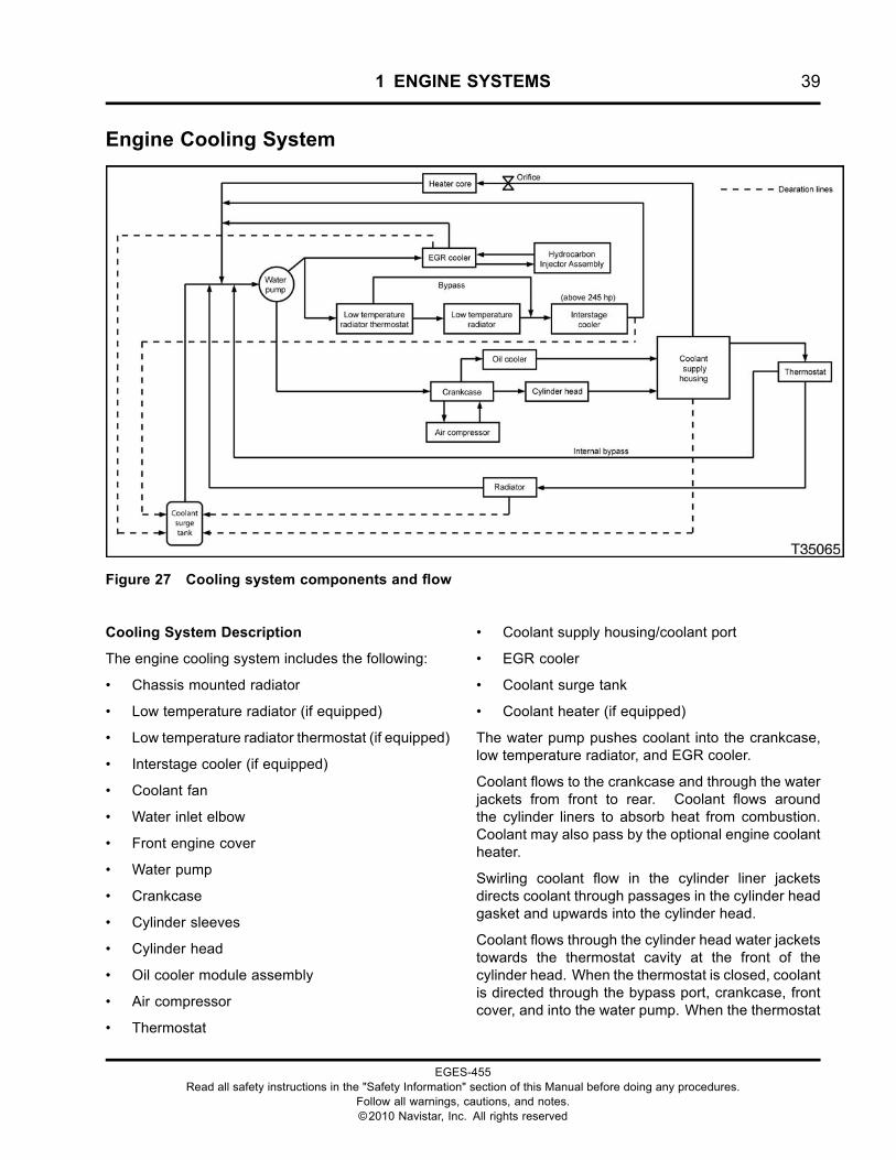
Engine Cooling System
Figure 27 Cooling system components and flow
Cooling System Description
The engine cooling system includes the following:
• Chassis mounted radiator
• Low temperature radiator (if equipped)
• Low temperature radiator thermostat (if equipped)
• Interstage cooler (if equipped)
• Coolant fan
• Water inlet elbow
• Front engine cover
• Water pump
• Crankcase
• Cylinder sleeves
• Cylinder head
• Oil cooler module assembly
• Air compressor
• Thermostat
• Coolant supply housing/coolant port
• EGR cooler
• Coolant surge tank
• Coolant heater (if equipped)
The water pump pushes coolant into the crankcase,low temperature radiator, and EGR cooler.
Coolant flows to the crankcase and through the waterjackets from front to rear. Coolant flows aroundthe cylinder liners to absorb heat from combustion.Coolant may also pass by the optional engine coolantheater.
Swirling coolant flow in the cylinder liner jacketsdirects coolant through passages in the cylinder headgasket and upwards into the cylinder head.
Coolant flows through the cylinder head water jacketstowards the thermostat cavity at the front of thecylinder head. When the thermostat is closed, coolantis directed through the bypass port, crankcase, frontcover, and into the water pump. When the thermostat
EGES-455Read all safety instructions in the "Safety Information" section of this Manual before doing any procedures.
Follow all warnings, cautions, and notes.©2010 Navistar, Inc. All rights reserved
40 1 ENGINE SYSTEMS
is open, the bypass port is blocked, and coolant isdirected through the radiator.
Coolant passes through the radiator and is cooled bymoving air from the coolant fan. Coolant returns to theengine through the inlet elbow and front cover.
The air compressor is cooled with engine coolantsupplied by a hose from the left side of the crankcase.Coolant passes through the air compressor andreturns to the cylinder head through a passage in thecrankcase.
The oil cooler module assembly receives coolantfrom a passage in the crankcase. Coolant passesbetween the oil cooler plates and returns through atube connected to the coolant supply housing.
The EGR cooler receives coolant from the waterpump through a supply tube at the rear of the frontcover. Coolant passing through the EGR cooler, flowsthrough the cooler plates, cools the exhaust gas, andexits through a tube to the rear of the front cover thatreturns coolant to the pump inlet. The hydrocarboninjector assembly receives and returns coolant to theEGR cooler.
The EGR coolant supply tube also branches off tothe low temperature radiator and to the interstagecooler (above 245 hp), if equipped. For engines withratings above 245 hp, the coolant is routed throughthe low temperature thermostat, then through thelow temperature radiator to the interstage cooler.Coolant is regulated by the low temperature radiatorthermostat. Warm coolant is directed to the lowtemperature radiator and into the interstage cooler.Cold coolant bypasses the low temperature radiatorand moves directly into the interstage cooler.
The interstage cooler uses coolant to lowerthe charged air temperature that exits from theturbocharger low-pressure compressor and entersthe turbocharger high-pressure compressor.
The surge tank provides expansion space for coolantand deaerates the cooling system. The following fourvents provide coolant to the tank:
• Engine vent (top of coolant supply housing)
• EGR vent (top of EGR cooler)
• Main radiator vent (top of radiator)
• Interstage cooler vent (top of interstage cooler)
The surge tank returns coolant through the surge line,back to the water pump inlet.
Cab heat is provided by the heater core, whichreceives warmed coolant from the coolant supplyhousing.
Cooling System Components
Coolant Heater (optional)
An optional coolant heater is available to warm enginecoolant in cold weather. The coolant heater warms thecoolant surrounding the cylinders. Warmed enginecoolant aids in cold engine start-up and performance.The coolant heater is installed on the left side of thecrankcase, in front of the Electronic Control Module(ECM).
Thermostat Operation
Coolant travels through two ports after it passesthrough the thermostat. One port directs coolantto the radiator when the engine is at operatingtemperature. The other port directs coolant to thewater pump until the engine reaches operatingtemperature. The thermostat begins to open at 88 °C(190 °F) and is fully open at 96 °C (205 °F).
EGES-455Read all safety instructions in the "Safety Information" section of this Manual before doing any procedures.
Follow all warnings, cautions, and notes.©2010 Navistar, Inc. All rights reserved
1 ENGINE SYSTEMS 41
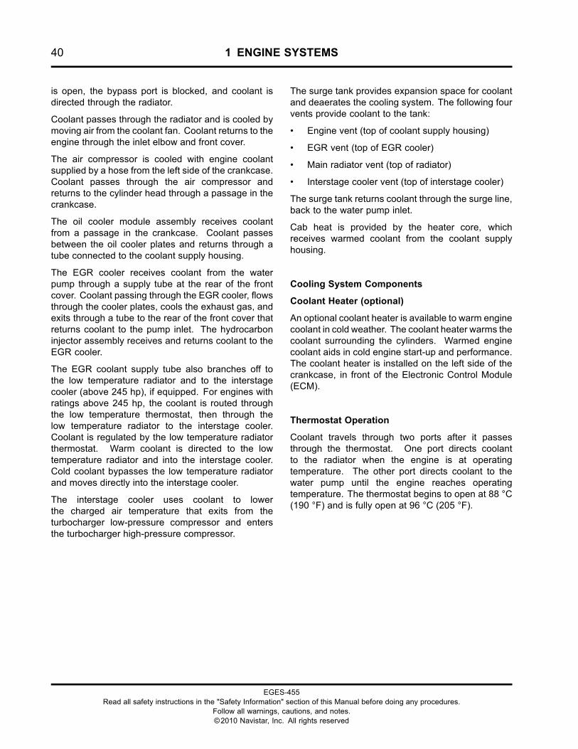
Figure 28 Thermostat closed
1. Coolant flow to heater port2. Coolant in from engine3. Bypass to water pump
When engine coolant is below 88 °C (190 °F), thethermostat is closed, blocking flow to the radiator.Coolant is forced to flow through a bypass port backto the water pump.
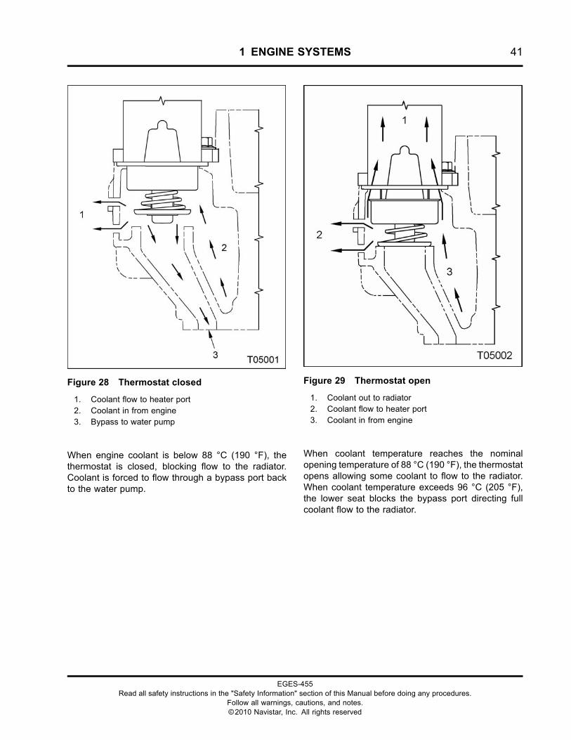
Figure 29 Thermostat open
1. Coolant out to radiator2. Coolant flow to heater port3. Coolant in from engine
When coolant temperature reaches the nominalopening temperature of 88 °C (190 °F), the thermostatopens allowing some coolant to flow to the radiator.When coolant temperature exceeds 96 °C (205 °F),the lower seat blocks the bypass port directing fullcoolant flow to the radiator.
EGES-455Read all safety instructions in the "Safety Information" section of this Manual before doing any procedures.
Follow all warnings, cautions, and notes.©2010 Navistar, Inc. All rights reserved
42 1 ENGINE SYSTEMS
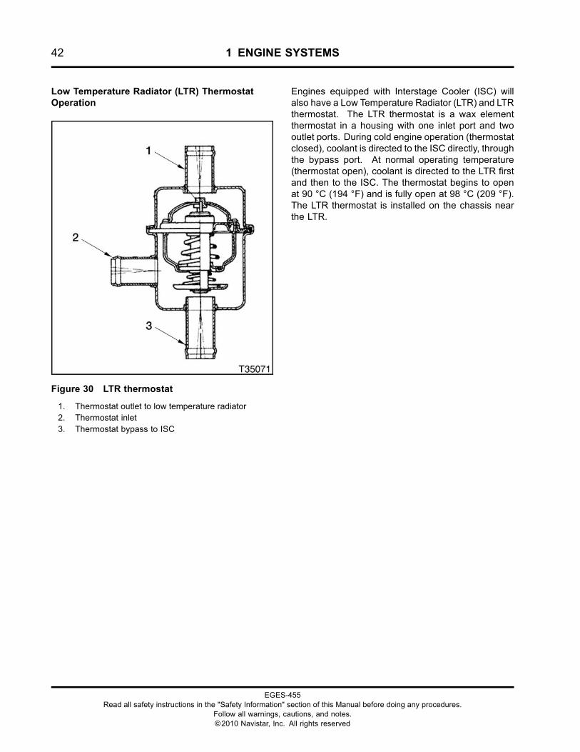
Low Temperature Radiator (LTR) ThermostatOperation
Figure 30 LTR thermostat
1. Thermostat outlet to low temperature radiator2. Thermostat inlet3. Thermostat bypass to ISC
Engines equipped with Interstage Cooler (ISC) willalso have a Low Temperature Radiator (LTR) and LTRthermostat. The LTR thermostat is a wax elementthermostat in a housing with one inlet port and twooutlet ports. During cold engine operation (thermostatclosed), coolant is directed to the ISC directly, throughthe bypass port. At normal operating temperature(thermostat open), coolant is directed to the LTR firstand then to the ISC. The thermostat begins to openat 90 °C (194 °F) and is fully open at 98 °C (209 °F).The LTR thermostat is installed on the chassis nearthe LTR.
EGES-455Read all safety instructions in the "Safety Information" section of this Manual before doing any procedures.
Follow all warnings, cautions, and notes.©2010 Navistar, Inc. All rights reserved
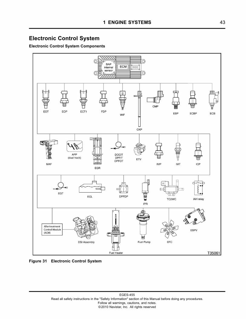
1 ENGINE SYSTEMS 43
Electronic Control SystemElectronic Control System Components
Figure 31 Electronic Control System
EGES-455Read all safety instructions in the "Safety Information" section of this Manual before doing any procedures.
Follow all warnings, cautions, and notes.©2010 Navistar, Inc. All rights reserved
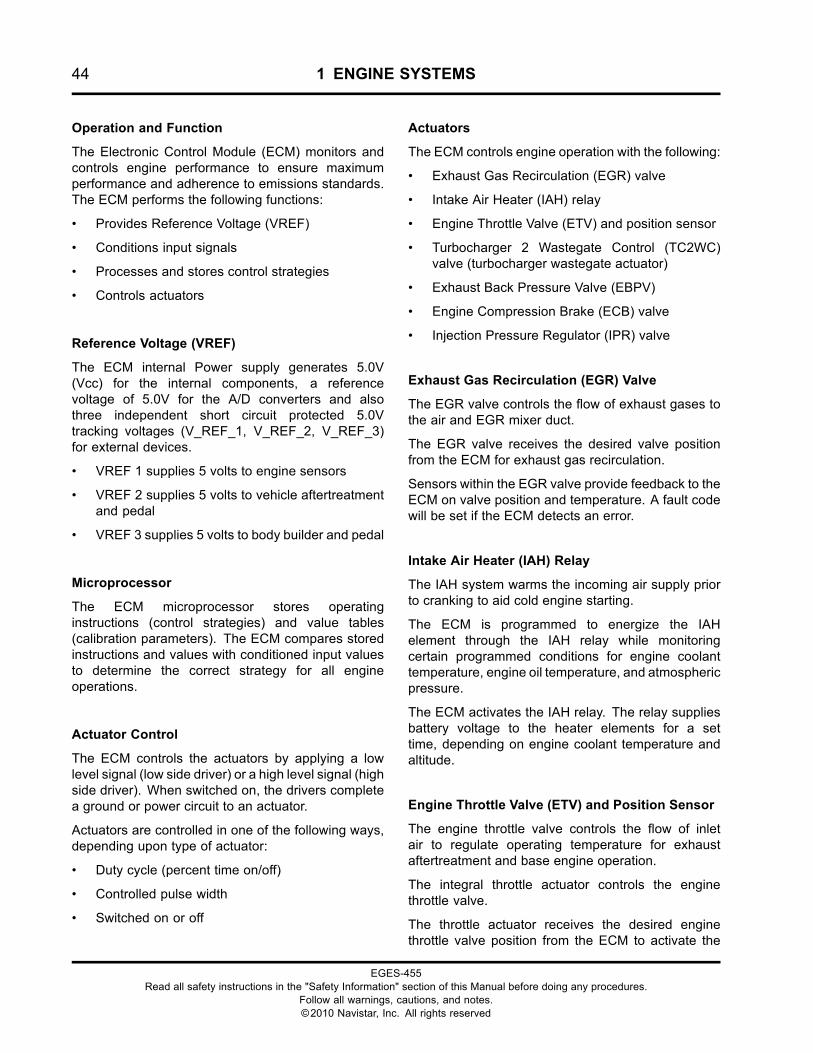
44 1 ENGINE SYSTEMS
Operation and Function
The Electronic Control Module (ECM) monitors andcontrols engine performance to ensure maximumperformance and adherence to emissions standards.The ECM performs the following functions:
• Provides Reference Voltage (VREF)
• Conditions input signals
• Processes and stores control strategies
• Controls actuators
Reference Voltage (VREF)
The ECM internal Power supply generates 5.0V(Vcc) for the internal components, a referencevoltage of 5.0V for the A/D converters and alsothree independent short circuit protected 5.0Vtracking voltages (V_REF_1, V_REF_2, V_REF_3)for external devices.
• VREF 1 supplies 5 volts to engine sensors
• VREF 2 supplies 5 volts to vehicle aftertreatmentand pedal
• VREF 3 supplies 5 volts to body builder and pedal
Microprocessor
The ECM microprocessor stores operatinginstructions (control strategies) and value tables(calibration parameters). The ECM compares storedinstructions and values with conditioned input valuesto determine the correct strategy for all engineoperations.
Actuator Control
The ECM controls the actuators by applying a lowlevel signal (low side driver) or a high level signal (highside driver). When switched on, the drivers completea ground or power circuit to an actuator.
Actuators are controlled in one of the following ways,depending upon type of actuator:
• Duty cycle (percent time on/off)
• Controlled pulse width
• Switched on or off
Actuators
The ECM controls engine operation with the following:
• Exhaust Gas Recirculation (EGR) valve
• Intake Air Heater (IAH) relay
• Engine Throttle Valve (ETV) and position sensor
• Turbocharger 2 Wastegate Control (TC2WC)valve (turbocharger wastegate actuator)
• Exhaust Back Pressure Valve (EBPV)
• Engine Compression Brake (ECB) valve
• Injection Pressure Regulator (IPR) valve
Exhaust Gas Recirculation (EGR) Valve
The EGR valve controls the flow of exhaust gases tothe air and EGR mixer duct.
The EGR valve receives the desired valve positionfrom the ECM for exhaust gas recirculation.
Sensors within the EGR valve provide feedback to theECM on valve position and temperature. A fault codewill be set if the ECM detects an error.
Intake Air Heater (IAH) Relay
The IAH system warms the incoming air supply priorto cranking to aid cold engine starting.
The ECM is programmed to energize the IAHelement through the IAH relay while monitoringcertain programmed conditions for engine coolanttemperature, engine oil temperature, and atmosphericpressure.
The ECM activates the IAH relay. The relay suppliesbattery voltage to the heater elements for a settime, depending on engine coolant temperature andaltitude.
Engine Throttle Valve (ETV) and Position Sensor
The engine throttle valve controls the flow of inletair to regulate operating temperature for exhaustaftertreatment and base engine operation.
The integral throttle actuator controls the enginethrottle valve.
The throttle actuator receives the desired enginethrottle valve position from the ECM to activate the
EGES-455Read all safety instructions in the "Safety Information" section of this Manual before doing any procedures.
Follow all warnings, cautions, and notes.©2010 Navistar, Inc. All rights reserved
1 ENGINE SYSTEMS 45
throttle valve. The throttle position sensor providesfeedback to the ECM on the throttle valve position.
Turbocharger 2 Wastegate Control (TC2WC) valve(turbocharger wastegate actuator)
The turbocharger wastegate actuator regulates thecharge air pressure by controlling the amount ofexhaust gases that pass through the high-pressureturbine.
The TC2WC valve receives the command signal fromthe ECM. When the charge air pressure demand islow, the TC2WC valve opens, allowing control air tothe turbocharger wastegate actuator. The actuatoropens allowing part of the exhaust gas flow to bypassthe high-pressure turbine.
Exhaust Back Pressure Valve (EBPV)
The Exhaust Back Pressure Valve (EBPV) controlsthe position of the exhaust valve increasing
or decreasing exhaust gas back pressure andtemperature to allow the DOC and DPF to functionefficiently.
Engine Compression Brake (ECB) valve
The Engine Compression Brake (ECB) valve controlspressure entering the brake oil gallery from theinjector oil gallery. This activates the brake actuatorpistons and opens the exhaust valves. The ECBvalve is installed in the center of the high-pressure oilmanifold.
Injection Pressure Regulator (IPR) valve
The Injection Pressure Regulator (IPR) valve is usedto maintain desired injection control pressure. Excesshigh-pressure oil is directed to the crankcase sump bythe IPR valve.
EGES-455Read all safety instructions in the "Safety Information" section of this Manual before doing any procedures.
Follow all warnings, cautions, and notes.©2010 Navistar, Inc. All rights reserved
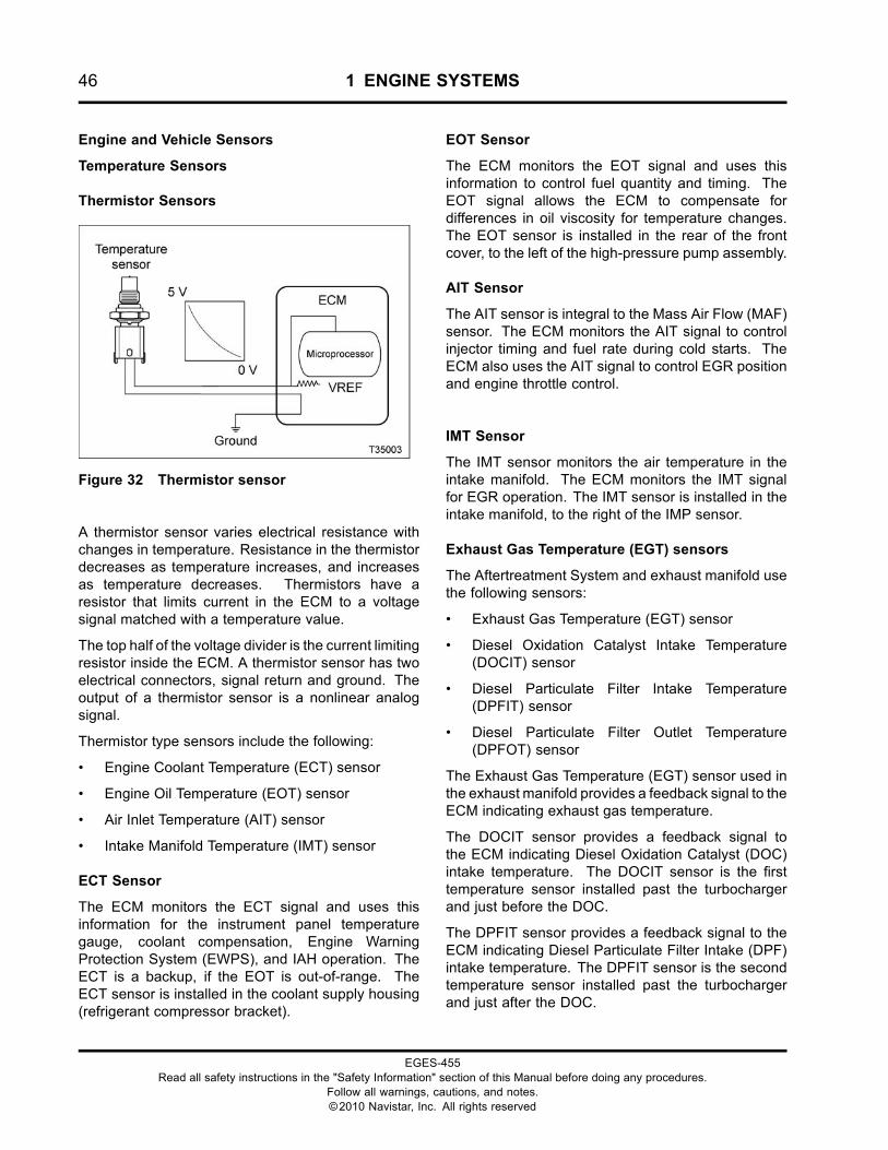
46 1 ENGINE SYSTEMS
Engine and Vehicle Sensors
Temperature Sensors
Thermistor Sensors
Figure 32 Thermistor sensor
A thermistor sensor varies electrical resistance withchanges in temperature. Resistance in the thermistordecreases as temperature increases, and increasesas temperature decreases. Thermistors have aresistor that limits current in the ECM to a voltagesignal matched with a temperature value.
The top half of the voltage divider is the current limitingresistor inside the ECM. A thermistor sensor has twoelectrical connectors, signal return and ground. Theoutput of a thermistor sensor is a nonlinear analogsignal.
Thermistor type sensors include the following:
• Engine Coolant Temperature (ECT) sensor
• Engine Oil Temperature (EOT) sensor
• Air Inlet Temperature (AIT) sensor
• Intake Manifold Temperature (IMT) sensor
ECT Sensor
The ECM monitors the ECT signal and uses thisinformation for the instrument panel temperaturegauge, coolant compensation, Engine WarningProtection System (EWPS), and IAH operation. TheECT is a backup, if the EOT is out-of-range. TheECT sensor is installed in the coolant supply housing(refrigerant compressor bracket).
EOT Sensor
The ECM monitors the EOT signal and uses thisinformation to control fuel quantity and timing. TheEOT signal allows the ECM to compensate fordifferences in oil viscosity for temperature changes.The EOT sensor is installed in the rear of the frontcover, to the left of the high-pressure pump assembly.
AIT Sensor
The AIT sensor is integral to the Mass Air Flow (MAF)sensor. The ECM monitors the AIT signal to controlinjector timing and fuel rate during cold starts. TheECM also uses the AIT signal to control EGR positionand engine throttle control.
IMT Sensor
The IMT sensor monitors the air temperature in theintake manifold. The ECM monitors the IMT signalfor EGR operation. The IMT sensor is installed in theintake manifold, to the right of the IMP sensor.
Exhaust Gas Temperature (EGT) sensors
The Aftertreatment System and exhaust manifold usethe following sensors:
• Exhaust Gas Temperature (EGT) sensor
• Diesel Oxidation Catalyst Intake Temperature(DOCIT) sensor
• Diesel Particulate Filter Intake Temperature(DPFIT) sensor
• Diesel Particulate Filter Outlet Temperature(DPFOT) sensor
The Exhaust Gas Temperature (EGT) sensor used inthe exhaust manifold provides a feedback signal to theECM indicating exhaust gas temperature.
The DOCIT sensor provides a feedback signal tothe ECM indicating Diesel Oxidation Catalyst (DOC)intake temperature. The DOCIT sensor is the firsttemperature sensor installed past the turbochargerand just before the DOC.
The DPFIT sensor provides a feedback signal to theECM indicating Diesel Particulate Filter Intake (DPF)intake temperature. The DPFIT sensor is the secondtemperature sensor installed past the turbochargerand just after the DOC.
EGES-455Read all safety instructions in the "Safety Information" section of this Manual before doing any procedures.
Follow all warnings, cautions, and notes.©2010 Navistar, Inc. All rights reserved
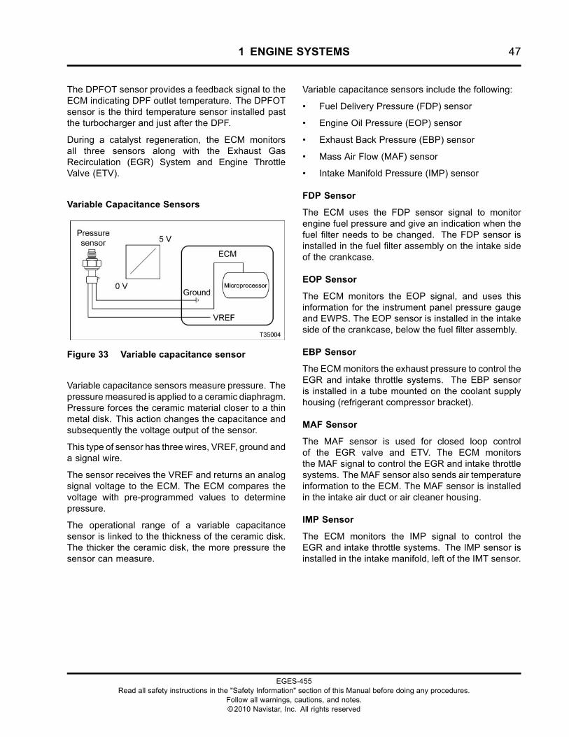
1 ENGINE SYSTEMS 47
The DPFOT sensor provides a feedback signal to theECM indicating DPF outlet temperature. The DPFOTsensor is the third temperature sensor installed pastthe turbocharger and just after the DPF.
During a catalyst regeneration, the ECM monitorsall three sensors along with the Exhaust GasRecirculation (EGR) System and Engine ThrottleValve (ETV).
Variable Capacitance Sensors
Figure 33 Variable capacitance sensor
Variable capacitance sensors measure pressure. Thepressuremeasured is applied to a ceramic diaphragm.Pressure forces the ceramic material closer to a thinmetal disk. This action changes the capacitance andsubsequently the voltage output of the sensor.
This type of sensor has three wires, VREF, ground anda signal wire.
The sensor receives the VREF and returns an analogsignal voltage to the ECM. The ECM compares thevoltage with pre-programmed values to determinepressure.
The operational range of a variable capacitancesensor is linked to the thickness of the ceramic disk.The thicker the ceramic disk, the more pressure thesensor can measure.
Variable capacitance sensors include the following:
• Fuel Delivery Pressure (FDP) sensor
• Engine Oil Pressure (EOP) sensor
• Exhaust Back Pressure (EBP) sensor
• Mass Air Flow (MAF) sensor
• Intake Manifold Pressure (IMP) sensor
FDP Sensor
The ECM uses the FDP sensor signal to monitorengine fuel pressure and give an indication when thefuel filter needs to be changed. The FDP sensor isinstalled in the fuel filter assembly on the intake sideof the crankcase.
EOP Sensor
The ECM monitors the EOP signal, and uses thisinformation for the instrument panel pressure gaugeand EWPS. The EOP sensor is installed in the intakeside of the crankcase, below the fuel filter assembly.
EBP Sensor
The ECMmonitors the exhaust pressure to control theEGR and intake throttle systems. The EBP sensoris installed in a tube mounted on the coolant supplyhousing (refrigerant compressor bracket).
MAF Sensor
The MAF sensor is used for closed loop controlof the EGR valve and ETV. The ECM monitorsthe MAF signal to control the EGR and intake throttlesystems. The MAF sensor also sends air temperatureinformation to the ECM. The MAF sensor is installedin the intake air duct or air cleaner housing.
IMP Sensor
The ECM monitors the IMP signal to control theEGR and intake throttle systems. The IMP sensor isinstalled in the intake manifold, left of the IMT sensor.
EGES-455Read all safety instructions in the "Safety Information" section of this Manual before doing any procedures.
Follow all warnings, cautions, and notes.©2010 Navistar, Inc. All rights reserved
48 1 ENGINE SYSTEMS
Magnetic Pickup Sensors
Figure 34 Magnetic pickup sensors
A magnetic pickup sensor contains a permanentmagnet core that is surrounded by a coil of wire.The sensor generates a voltage signal through thecollapse of a magnetic field that is created by amoving metal trigger. The movement of the triggerthen creates an AC voltage in the sensor coil.
Magnetic pickup sensors used include the following:
• Crankshaft Position (CKP) sensor
• Camshaft Position (CMP) sensor
• Vehicle Speed Sensor (VSS)
CKP Sensor
The CKP sensor provides the ECM with a signalthat indicates crankshaft speed and position. As thecrankshaft turns, the CKP sensor detects a 60-toothtiming disk on the crankshaft. Teeth 59 and 60 aremissing. By comparing the CKP signal with the CMPsignal, the ECM calculates engine rpm and timingrequirements. The CKP sensor is installed in the topleft side of the flywheel housing.
CMP Sensor
The CMP sensor provides the ECM with a signal thatindicates camshaft position. As the cam rotates, thesensor identifies the position of the cam by locating apeg on the cam. The CMP sensor is installed in thefront cover, above and to the right of the water pumppulley.
VSS
The VSS provides the ECMwith transmission tail shaftspeed by sensing the rotation of a 16-tooth gear onthe rear of the transmission. The detected sine wavesignal (AC), received by the ECM, is used with tire sizeand axle ratio to calculate vehicle speed. The VSS ison the left side of the transmission.
EGES-455Read all safety instructions in the "Safety Information" section of this Manual before doing any procedures.
Follow all warnings, cautions, and notes.©2010 Navistar, Inc. All rights reserved
1 ENGINE SYSTEMS 49
High-pressure Sensors
Figure 35 High-pressure sensor
High-pressure sensors convert pressure to a linearanalog voltage output of 0–5 volts. Pressure to bemeasured exerts force on a diaphragm with a straingauge bonded to it. This diaphragm stretches andcompresses to change mechanical motion into anelectrical signal.
This type of sensor has three wires, VREF, ground anda signal wire.
The sensor is powered by VREF from the ECMand is grounded through the ECM to a commonsensor ground. The ECM compares the voltage withpre-programmed values to determine pressure.
High-pressure sensors include the following:
• Diesel Particulate Filter Differential Pressure(DPFDP) sensor
• Engine Compression Brake Pressure (ECBP)sensor
• Injection Control Pressure (ICP) sensor
DPFDP Sensor
The DPFDP sensor provides a feedback signal to theECM indicating the pressure difference between the
inlet and outlet of the Diesel Particulate Filter (DPF).During a catalyst regeneration, the ECM monitorsthis sensor along with three Aftertreatment Systemthermistor sensors, the EGR System, and the EngineThrottle Valve (ETV).
ECBP
The ECM monitors the ECBP signal to determine oilpressure in the brake gallery of the high-pressure oilmanifold. The ECBP sensor is under the valve cover,forward of the No. 2 fuel injector in the high-pressureoil manifold.
ICP
The ECM monitors the ICP sensor to determineinjection control pressure for engine operation. TheICP sensor is used to control the IPR valve. It providesfeedback to the ECM for Closed Loop IPR control.The ICP sensor is located under the valve cover,forward of the No. 6 fuel injector in the high-pressureoil manifold.
EGES-455Read all safety instructions in the "Safety Information" section of this Manual before doing any procedures.
Follow all warnings, cautions, and notes.©2010 Navistar, Inc. All rights reserved
50 1 ENGINE SYSTEMS
Potentiometer
Figure 36 Potentiometer
A potentiometer is a variable voltage divider thatsenses the position of a mechanical component.A reference voltage is applied to one end of thepotentiometer. Mechanical rotary or linear motionmoves the wiper along the resistance material,changing voltage at each point along the resistivematerial. Voltage is proportional to the amount ofmechanical movement.
APP
The APP provides the ECM with a feedback signal(linear analog voltage) that indicates the operator’sdemand for power. There are two potentiometerswithin the APP sensor. The APP is installed in thecab on the accelerator pedal.
EGES-455Read all safety instructions in the "Safety Information" section of this Manual before doing any procedures.
Follow all warnings, cautions, and notes.©2010 Navistar, Inc. All rights reserved
1 ENGINE SYSTEMS 51
Switches
Figure 37 Switch
Switch sensors indicate position, level, or status.They operate open or closed, regulating the flow ofcurrent. A switch sensor can be a voltage input switchor a grounding switch. A voltage input switch suppliesthe ECM with a voltage when it is closed. A groundingswitch grounds the circuit when closed, causing azero voltage signal. Grounding switches are usuallyinstalled in series with a current limiting resistor.
Switches include the following:
• Driveline Disengagement Switch (DDS)
• Engine Coolant Level (ECL)
• Water In Fuel (WIF)
DDS
The DDS determines if a vehicle is in gear. Formanual transmissions, the clutch switch serves asthe DDS. For automatic transmissions, the neutralindicator switch or datalink communication functionsas the DDS.
ECL
ECL is part of the Engine Warning Protection System(EWPS). The ECL switch is used in plastic deaerationtanks. When a magnetic switch is open, the tank isfull.
If engine coolant is low, the switch closes and the redENGINE lamp on the instrument panel is illuminated.
WIF
AWater In Fuel (WIF) sensor in the fuel filter assemblyis used to detect water in the fuel. The resistance oftheWIF sensor circuit changes when the water level inthe fuel filter assembly reaches the sensor. The ECMthen sends a message to illuminate the amber waterin fuel lamp, alerting the operator. TheWIF is installedin the side of the fuel filter assembly.
EGES-455Read all safety instructions in the "Safety Information" section of this Manual before doing any procedures.
Follow all warnings, cautions, and notes.©2010 Navistar, Inc. All rights reserved
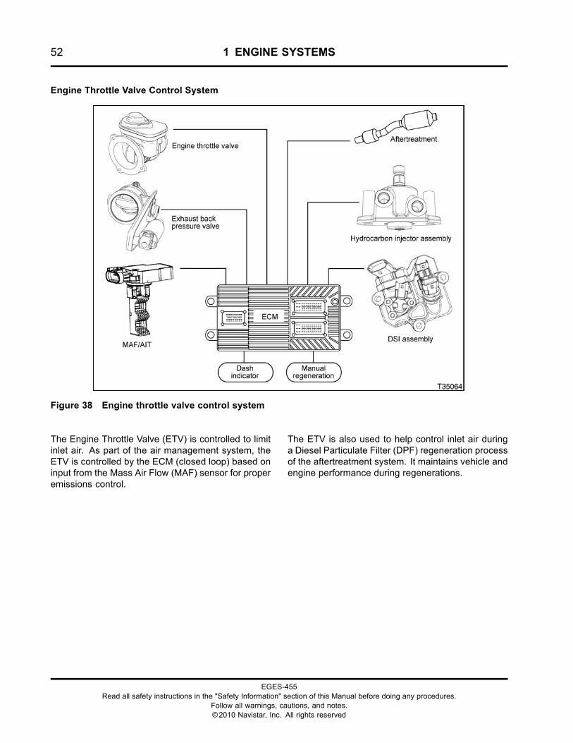
52 1 ENGINE SYSTEMS
Engine Throttle Valve Control System
Figure 38 Engine throttle valve control system
The Engine Throttle Valve (ETV) is controlled to limitinlet air. As part of the air management system, theETV is controlled by the ECM (closed loop) based oninput from the Mass Air Flow (MAF) sensor for properemissions control.
The ETV is also used to help control inlet air duringa Diesel Particulate Filter (DPF) regeneration processof the aftertreatment system. It maintains vehicle andengine performance during regenerations.
EGES-455Read all safety instructions in the "Safety Information" section of this Manual before doing any procedures.
Follow all warnings, cautions, and notes.©2010 Navistar, Inc. All rights reserved
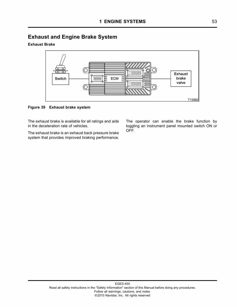
1 ENGINE SYSTEMS 53
Exhaust and Engine Brake SystemExhaust Brake
Figure 39 Exhaust brake system
The exhaust brake is available for all ratings and aidsin the deceleration rate of vehicles.
The exhaust brake is an exhaust back pressure brakesystem that provides improved braking performance.
The operator can enable the brake function bytoggling an instrument panel mounted switch ON orOFF.
EGES-455Read all safety instructions in the "Safety Information" section of this Manual before doing any procedures.
Follow all warnings, cautions, and notes.©2010 Navistar, Inc. All rights reserved
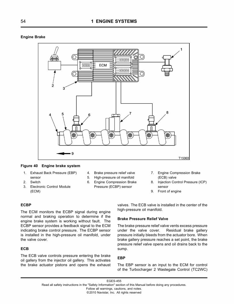
54 1 ENGINE SYSTEMS
Engine Brake
Figure 40 Engine brake system
1. Exhaust Back Pressure (EBP)sensor
2. Switch3. Electronic Control Module
(ECM)
4. Brake pressure relief valve5. High-pressure oil manifold6. Engine Compression Brake
Pressure (ECBP) sensor
7. Engine Compression Brake(ECB) valve
8. Injection Control Pressure (ICP)sensor
9. Front of engine
ECBP
The ECM monitors the ECBP signal during enginenormal and braking operation to determine if theengine brake system is working without fault. TheECBP sensor provides a feedback signal to the ECMindicating brake control pressure. The ECBP sensoris installed in the high-pressure oil manifold, underthe valve cover.
ECB
The ECB valve controls pressure entering the brakeoil gallery from the injector oil gallery. This activatesthe brake actuator pistons and opens the exhaust
valves. The ECB valve is installed in the center of thehigh-pressure oil manifold.
Brake Pressure Relief Valve
The brake pressure relief valve vents excess pressureunder the valve cover. Residual brake gallerypressure initially bleeds from the actuator bore. Whenbrake gallery pressure reaches a set point, the brakepressure relief valve opens and oil drains back to thesump.
EBP
The EBP sensor is an input to the ECM for controlof the Turbocharger 2 Wastegate Control (TC2WC)
EGES-455Read all safety instructions in the "Safety Information" section of this Manual before doing any procedures.
Follow all warnings, cautions, and notes.©2010 Navistar, Inc. All rights reserved
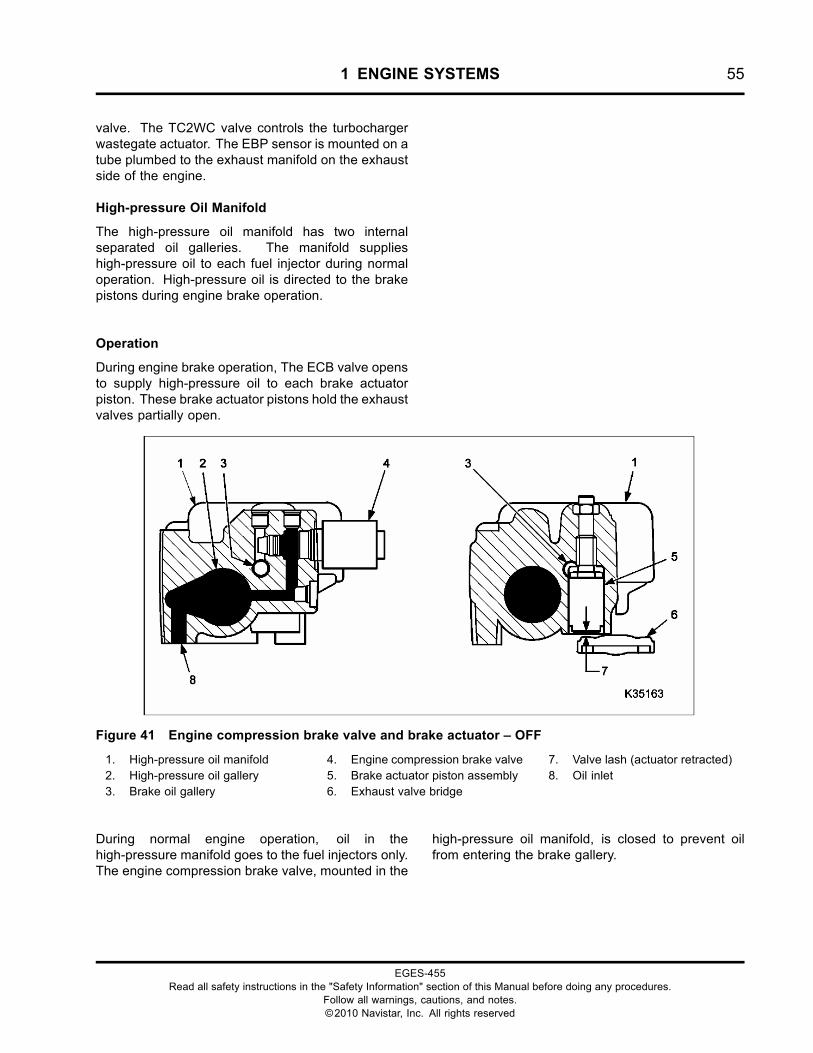
1 ENGINE SYSTEMS 55
valve. The TC2WC valve controls the turbochargerwastegate actuator. The EBP sensor is mounted on atube plumbed to the exhaust manifold on the exhaustside of the engine.
High-pressure Oil Manifold
The high-pressure oil manifold has two internalseparated oil galleries. The manifold supplieshigh-pressure oil to each fuel injector during normaloperation. High-pressure oil is directed to the brakepistons during engine brake operation.
Operation
During engine brake operation, The ECB valve opensto supply high-pressure oil to each brake actuatorpiston. These brake actuator pistons hold the exhaustvalves partially open.
Figure 41 Engine compression brake valve and brake actuator – OFF
1. High-pressure oil manifold2. High-pressure oil gallery3. Brake oil gallery
4. Engine compression brake valve5. Brake actuator piston assembly6. Exhaust valve bridge
7. Valve lash (actuator retracted)8. Oil inlet
During normal engine operation, oil in thehigh-pressure manifold goes to the fuel injectors only.The engine compression brake valve, mounted in the
high-pressure oil manifold, is closed to prevent oilfrom entering the brake gallery.
EGES-455Read all safety instructions in the "Safety Information" section of this Manual before doing any procedures.
Follow all warnings, cautions, and notes.©2010 Navistar, Inc. All rights reserved
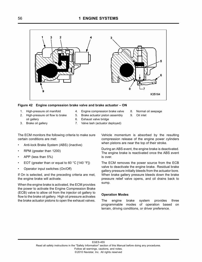
56 1 ENGINE SYSTEMS
Figure 42 Engine compression brake valve and brake actuator – ON
1. High-pressure oil manifold2. High-pressure oil flow to brake
oil gallery3. Brake oil gallery
4. Engine compression brake valve5. Brake actuator piston assembly6. Exhaust valve bridge7. Valve lash (actuator deployed)
8. Normal oil seepage9. Oil inlet
The ECM monitors the following criteria to make surecertain conditions are met:
• Anti-lock Brake System (ABS) (inactive)
• RPM (greater than 1200)
• APP (less than 5%)
• EOT (greater than or equal to 60 °C [140 °F])
• Operator input switches (On/Off)
If On is selected, and the preceding criteria are met,the engine brake will activate.
When the engine brake is activated, the ECM providesthe power to activate the Engine Compression Brake(ECB) valve to allow oil from the injector oil gallery toflow to the brake oil gallery. High oil pressure activatesthe brake actuator pistons to open the exhaust valves.
Vehicle momentum is absorbed by the resultingcompression release of the engine power cylinderswhen pistons are near the top of their stroke.
During an ABS event, the engine brake is deactivated.The engine brake is reactivated once the ABS eventis over.
The ECM removes the power source from the ECBvalve to deactivate the engine brake. Residual brakegallery pressure initially bleeds from the actuator bore.When brake gallery pressure bleeds down the brakepressure relief valve opens, and oil drains back tosump.
Operation Modes
The engine brake system provides threeprogrammable modes of operation based onterrain, driving conditions, or driver preference.
EGES-455Read all safety instructions in the "Safety Information" section of this Manual before doing any procedures.
Follow all warnings, cautions, and notes.©2010 Navistar, Inc. All rights reserved
1 ENGINE SYSTEMS 57
Coast Mode
When the coast mode is programmed, the brakesystem will activate only when the driver appliesthe vehicle service brake. The coast mode allowsthe vehicle to coast without automatic brake systemactivation.
Latched Mode
When the latch mode is programmed, the brakesystem will activate when the driver releases theaccelerator pedal. The brake system will deactivate
when the driver depresses the accelerator or clutchpedals. The brake system will also deactivate whenthe engine speed is below a pre-programmed rpm.
Cruise Mode
When the cruise mode is programmed, the brakesystem performs similar to latch mode under normaldriving conditions. When cruise control is used thebrake system will activate when the vehicle travelsdown a grade. The brake system helps the cruisecontrol system maintain the set vehicle speed.
EGES-455Read all safety instructions in the "Safety Information" section of this Manual before doing any procedures.
Follow all warnings, cautions, and notes.©2010 Navistar, Inc. All rights reserved
58 1 ENGINE SYSTEMS
EGES-455Read all safety instructions in the "Safety Information" section of this Manual before doing any procedures.
Follow all warnings, cautions, and notes.©2010 Navistar, Inc. All rights reserved
2 ENGINE CONTROLLED FEATURES 59
Table of Contents
Standard Features. . . . . . . . . . . . . . . . . . . . . . . . . . . . . . . . . . . . . . . . . . . . . . . . . . . . . . . . . . . . . . . . . . . . . . . . . . . . . . . . . . . . . . . . . . . . . . . . . . . . . . .61Electronic Governor Control. . . . . . . . . . . . . . . . . . . . . . . . . . . . . . . . . . . . . . . . . . . . . . . . . . . . . . . . . . . . . . . . . . . . . . . . . . . . . . . . .61SAE J1939 Communication Datalink. . . . . . . . . . . . . . . . . . . . . . . . . . . . . . . . . . . . . . . . . . . . . . . . . . . . . . . . . . . . . . . . . . . . . . .61American Trucking Association (ATA) Datalink. . . . . . . . . . . . . . . . . . . . . . . . . . . . . . . . . . . . . . . . . . . . . . . . . . . . . . . . . .61Service Diagnostics. . . . . . . . . . . . . . . . . . . . . . . . . . . . . . . . . . . . . . . . . . . . . . . . . . . . . . . . . . . . . . . . . . . . . . . . . . . . . . . . . . . . . . . . . . .61Event Logging System.. . . . . . . . . . . . . . . . . . . . . . . . . . . . . . . . . . . . . . . . . . . . . . . . . . . . . . . . . . . . . . . . . . . . . . . . . . . . . . . . . . . . . . .61Electronic Speedometer and Tachometer. . . . . . . . . . . . . . . . . . . . . . . . . . . . . . . . . . . . . . . . . . . . . . . . . . . . . . . . . . . . . . . . .61Aftertreatment System.. . . . . . . . . . . . . . . . . . . . . . . . . . . . . . . . . . . . . . . . . . . . . . . . . . . . . . . . . . . . . . . . . . . . . . . . . . . . . . . . . . . . . . .61Engine Fuel Pressure (EFP) Monitor. . . . . . . . . . . . . . . . . . . . . . . . . . . . . . . . . . . . . . . . . . . . . . . . . . . . . . . . . . . . . . . . . . . . . . .62Inlet Air Heater (IAH). . . . . . . . . . . . . . . . . . . . . . . . . . . . . . . . . . . . . . . . . . . . . . . . . . . . . . . . . . . . . . . . . . . . . . . . . . . . . . . . . . . . . . . . . .62Fast Idle Advance.. . . . . . . . . . . . . . . . . . . . . . . . . . . . . . . . . . . . . . . . . . . . . . . . . . . . . . . . . . . . . . . . . . . . . . . . . . . . . . . . . . . . . . . . . . . . .62Cold Ambient Protection (CAP). . . . . . . . . . . . . . . . . . . . . . . . . . . . . . . . . . . . . . . . . . . . . . . . . . . . . . . . . . . . . . . . . . . . . . . . . . . . .62Coolant Temperature Compensation. . . . . . . . . . . . . . . . . . . . . . . . . . . . . . . . . . . . . . . . . . . . . . . . . . . . . . . . . . . . . . . . . . . . . . .62Engine Crank Inhibit (ECI). . . . . . . . . . . . . . . . . . . . . . . . . . . . . . . . . . . . . . . . . . . . . . . . . . . . . . . . . . . . . . . . . . . . . . . . . . . . . . . . . . . .62
Optional Features. . . . . . . . . . . . . . . . . . . . . . . . . . . . . . . . . . . . . . . . . . . . . . . . . . . . . . . . . . . . . . . . . . . . . . . . . . . . . . . . . . . . . . . . . . . . . . . . . . . . . . .63Road Speed Limiting (RSL). . . . . . . . . . . . . . . . . . . . . . . . . . . . . . . . . . . . . . . . . . . . . . . . . . . . . . . . . . . . . . . . . . . . . . . . . . . . . . . . . .63Cruise Control. . . . . . . . . . . . . . . . . . . . . . . . . . . . . . . . . . . . . . . . . . . . . . . . . . . . . . . . . . . . . . . . . . . . . . . . . . . . . . . . . . . . . . . . . . . . . . . . . .63Traction Control. . . . . . . . . . . . . . . . . . . . . . . . . . . . . . . . . . . . . . . . . . . . . . . . . . . . . . . . . . . . . . . . . . . . . . . . . . . . . . . . . . . . . . . . . . . . . . . .63Exhaust Brake. . . . . . . . . . . . . . . . . . . . . . . . . . . . . . . . . . . . . . . . . . . . . . . . . . . . . . . . . . . . . . . . . . . . . . . . . . . . . . . . . . . . . . . . . . . . . . . . . .63Engine Brake. . . . . . . . . . . . . . . . . . . . . . . . . . . . . . . . . . . . . . . . . . . . . . . . . . . . . . . . . . . . . . . . . . . . . . . . . . . . . . . . . . . . . . . . . . . . . . . . . . .63Engine Warning Protection System (EWPS). . . . . . . . . . . . . . . . . . . . . . . . . . . . . . . . . . . . . . . . . . . . . . . . . . . . . . . . . . . . . .63Idle Shutdown Timer (IST). . . . . . . . . . . . . . . . . . . . . . . . . . . . . . . . . . . . . . . . . . . . . . . . . . . . . . . . . . . . . . . . . . . . . . . . . . . . . . . . . . . .63Electronic Fan (EFAN). . . . . . . . . . . . . . . . . . . . . . . . . . . . . . . . . . . . . . . . . . . . . . . . . . . . . . . . . . . . . . . . . . . . . . . . . . . . . . . . . . . . . . . . .64Radiator Shutter Enable (RSE). . . . . . . . . . . . . . . . . . . . . . . . . . . . . . . . . . . . . . . . . . . . . . . . . . . . . . . . . . . . . . . . . . . . . . . . . . . . . .64In Cab Power Take Off (PTO) Control. . . . . . . . . . . . . . . . . . . . . . . . . . . . . . . . . . . . . . . . . . . . . . . . . . . . . . . . . . . . . . . . . . . . . .64Remote Accelerator Pedal Position (RAPP). . . . . . . . . . . . . . . . . . . . . . . . . . . . . . . . . . . . . . . . . . . . . . . . . . . . . . . . . . . . . . .65Change Engine Oil Interval Message.. . . . . . . . . . . . . . . . . . . . . . . . . . . . . . . . . . . . . . . . . . . . . . . . . . . . . . . . . . . . . . . . . . . . . .65Fuel Heater. . . . . . . . . . . . . . . . . . . . . . . . . . . . . . . . . . . . . . . . . . . . . . . . . . . . . . . . . . . . . . . . . . . . . . . . . . . . . . . . . . . . . . . . . . . . . . . . . . . . . .65
EGES-455Read all safety instructions in the "Safety Information" section of this Manual before doing any procedures.
Follow all warnings, cautions, and notes.©2010 Navistar, Inc. All rights reserved

60 2 ENGINE CONTROLLED FEATURES
EGES-455Read all safety instructions in the "Safety Information" section of this Manual before doing any procedures.
Follow all warnings, cautions, and notes.©2010 Navistar, Inc. All rights reserved
2 ENGINE CONTROLLED FEATURES 61
Standard FeaturesElectronic Governor Control
The governor controls engine rpm within a safe andstable operating range.
The low idle governor prevents engine rpm fromdropping below a stable speed to prevent stallingwhen various loads are demanded on the engine.
The high idle governor prevents engine rpm fromgoing above a safe speed that would cause enginedamage.
SAE J1939 Communication Datalink
Vehicles are equipped with the SAE J1939 connectorfor communication between the Engine ControlModule (ECM) and the Electronic Service Tool (EST).
The SAE J1939 datalink supports:
• Transmission of engine parameter data.
• Transmission and clearing of Diagnostic TroubleCodes (DTCs).
• Diagnostics and troubleshooting.
• Programming performance parameter values.
• Programming engine and vehicle features.
• Programming calibrations and strategies in theECM.
For additional information, see J1939 Data Link(page 390) in “ELECTRONIC CONTROL SYSTEMDIAGNOSTICS” section in this manual.
American Trucking Association (ATA) Datalink
This link is supported for legacy diagnostic purposesonly. It is no longer the programming link, nor does itsupport the aftertreatment.
Service Diagnostics
NOTE: 2010 model year vehicles no longer utilizeDTC identification by number. DTCs are nowidentified using the SPN and FMI identifiers only.
The EST provides diagnostic information using theSAE J1939 datalink. The recommended EST is theEZ-Tech® with ServiceMaxx™ diagnostic softwareprovided by Navistar.
Faults from sensors, actuators, electroniccomponents, and engine systems are detected bythe ECM and sent to the EST as DTCs. Effectiveengine diagnostics require and rely on DTCs.
DTC identification is accomplished using two faultcode identifiers. These two identifiers, known as theSuspect Parameter Number (SPN) and the FailureMode Indicator (FMI) are displayed in the DTCwindow.
• Suspect Parameter Number (SPN) The SuspectParameter Number (SPN) identifies the individualcomponent causing the DTC.
• Failure Mode Indicator (FMI) The Failure ModeIndicator (FMI) identifies the fault or conditioneffecting the individual component.
Event Logging System
The event logging system records engine operationabove maximum rpm (overspeed), low coolant level,high coolant temperature, or low oil pressure. Thereadings for the odometer and hourmeter are storedin the ECM memory at the time of an event and canbe retrieved using the EST.
Electronic Speedometer and Tachometer
The engine control system calibrates vehicle speedup to 157 pulses per mile. Any new speed calibrationinformation must be programmed with an EST.
The tachometer signal is generated by the ECM,by computing signals for the Camshaft position(CMP) sensor and Crankshaft Position (CKP)sensor. Calculations for each sensor are sent tothe instrument panel and to the EST.
Aftertreatment System
The engine and vehicle exhaust piping includes anAftertreatment System to capture soot and otherparticulates before they exit the exhaust pipe. Thesoot is captured by the Diesel Particulate Filter (DPF)and is periodically converted to carbon dioxide (CO2)by a Regeneration (Regen) process.
For additional information, see AFT System (page194) in “ELECTRONIC CONTROL SYSTEMDIAGNOSTICS” section of this manual.
EGES-455Read all safety instructions in the "Safety Information" section of this Manual before doing any procedures.
Follow all warnings, cautions, and notes.©2010 Navistar, Inc. All rights reserved
62 2 ENGINE CONTROLLED FEATURES
Engine Fuel Pressure (EFP) Monitor
The EFP monitors fuel pressure and indicates whenthe fuel filter needs to be serviced by illuminating thefuel filter indicator lamp on the Instrument Panel. Foradditional information, see FDP Sensor (page 334) orWIF Sensor (page 413) in “ELECTRONIC CONTROLSYSTEM DIAGNOSTICS” section of this manual.
Inlet Air Heater (IAH)
The Inlet Air Heater (IAH) system warms the incomingair supply to aid cold engine starting and reduce whitesmoke during warm-up. The ECM controls the intakeair heater and monitors the engine temperature.When the engine is ready for cranking, the ECMsends a message to shut off the WAIT TO STARTlamp.
For additional information, see IAH System (page345) in “ELECTRONIC CONTROL SYSTEMDIAGNOSTICS” section of this manual.
Fast Idle Advance
Fast idle advance increases engine idle speed up to875 rpm for faster warm up to operating temperature.This occurs when the ECMmonitors ECT sensor inputand adjusts the fuel injector operation accordingly.
Low idle speed is increased proportionally when theengine coolant temperature is below 70 °C (158 °F) at700 rpm to below -10 °C (14 °F) at 875 rpm maximum.
Cold Ambient Protection (CAP)
CAP safeguards the engine from damage caused byprolonged idle at no load during cold weather. CAPalso improves cab warm-up.
CAP maintains engine coolant temperature byincreasing engine rpm to a programmed valuewhen ambient air temperature is below 20 °C (68°F), coolant temperature is below 70 °C (158 °F),and engine has been idling at no load for over fiveminutes.
Engine speed will ramp up to 1400 rpm and willmaintain at 1400 rpm until coolant temperature hasreached 75 °C (167 °F).
• Engine load is greater than 45%
• Brake pedal is applied or brake switch fault isdetected
• Clutch pedal is depressed or clutch pedalswitch fault is detected (manual transmissions, ifequipped with a clutch switch)
• Shift selector is moved from neutral (automatictransmissions). Shift selector must be in neutralfor CAP to work
• Power Takeoff (PTO) switch, also used for electrichand throttle, is turned on and actively controlsengine speed
• Accelerator pedal is depressed or AcceleratorPedal Sensor (APS) fault is detected
• Idle Shutdown Timer (IST) is enabled
• Engine Coolant Temperature (ECT) sensor fault isdetected
• Intake Air Temperature (IAT) ambient temperaturesensor fault is detected
Coolant Temperature Compensation
Coolant temperature compensation reduces fueldelivery if the engine coolant temperature is abovecooling system specifications.
Before standard engine warning or optionalwarning/protection systems engage, the ECM beginsreducing fuel delivery when the engine coolanttemperature reaches approximately 107 °C (225 °F).A rapid reduction of 20 percent is commanded whenengine coolant temperature reaches approximately110 °C (230 °F).
NOTE: Coolant temperature compensation isdisabled in emergency vehicles and school busesthat require 100 percent power on demand.
Engine Crank Inhibit (ECI)
ECI will not allow the starting motor to crank when theengine is running or the automatic transmission is ingear.
For additional information, see ECI System (page281) in “ELECTRONIC CONTROL SYSTEMDIAGNOSTICS” section of this manual.
EGES-455Read all safety instructions in the "Safety Information" section of this Manual before doing any procedures.
Follow all warnings, cautions, and notes.©2010 Navistar, Inc. All rights reserved
2 ENGINE CONTROLLED FEATURES 63
Optional FeaturesRoad Speed Limiting (RSL)
Road Speed Limiting (RSL) is a feature designed toregulate the maximum vehicle speed as controlled bythe accelerator pedal.
Customer programmable parameters within the ECMprovide vehicle speed governor related options thatcan be adjusted to suit the customer’s needs. Aparameter is used to set the maximum acceleratorcontrolled vehicle speed.
Additional programming flexibility is included to allowa trade-off to be made between performance and fueleconomy.
Cruise Control
The ECM controls the cruise control feature. Thecruise control system functions similarly for allelectronic engines. Maximum and minimum allowablecruise control speeds will vary based on model. Tooperate cruise control, see appropriate truck modelOperator’s Manual.
Traction Control
Traction control is a system that identifies when awheel is going faster than the other wheels duringacceleration.
When a traction control condition occurs, a datalinkmessage is sent to the ECM to limit fuel for thepurpose of reducing engine torque.
Vehicles must have a transmission and an AntilockBraking System (ABS) that supports traction control.
Exhaust Brake
The exhaust brake increases exhaust back-pressureto aid in the deceleration rate of the vehicle. Thisoption is placed in the exhaust piping after theturbochargers. This option cannot be combined withthe engine brake.
Engine Brake
The engine brake is a compression release brakesystem to aid in the deceleration rate of the vehicle.This option is built into the high-pressure oil manifold
under the engine valve cover. This option cannot becombined with the exhaust brake.
Engine Warning Protection System (EWPS)
The EWPS safeguards the engine from undesirableoperating conditions to prevent engine damage andto prolong engine life. The ECM will illuminate the redENGINE lamp and sound the warning buzzer whenthe ECM detects:
• High coolant temperature
• Low oil pressure
• Low coolant level (3-way system only)
When the protection feature is enabled and a criticalengine condition occurs, the on-board electronicswill shut the engine down (3-way protection). Anevent logging feature will record the event in enginehours and odometer readings. After the engine hasshutdown, and the critical condition remains, theengine can be started for a 30-second run time.
For complete EWPS description and additionalinformation, see EWPS (page 329) inthe “ELECTRONIC CONTROL SYSTEMDIAGNOSTICS” section of this manual.
Idle Shutdown Timer (IST)
GOVERNMENT REGULATION: Stateand local regulations may limit engineidle time. The vehicle owner or operatoris responsible for compliance with thoseregulations.
The IST allows the Engine Control Module (ECM) toshut down the engine during extended engine idletimes.
Thirty seconds before IST-defined engine shutdown,a vehicle instrument panel indicator activates. Thereare two types of indicators:
• Amber flashing idle shutdown indicator formultiplex electrical systems
• Red flashing indicator with audible alarm fornon-multiplex electrical systems
EGES-455Read all safety instructions in the "Safety Information" section of this Manual before doing any procedures.
Follow all warnings, cautions, and notes.©2010 Navistar, Inc. All rights reserved
64 2 ENGINE CONTROLLED FEATURES
This continues until the engine shuts down or the lowidle shutdown timer is reset
IST for California ESS Compliant Engines
Beginning in 2008 MY, all International® MaxxForce®engines certified for sale in the state of California willconform to mandatory California Air Resources Board(CARB) Engine Shutdown System (ESS) regulations.
Engine idle duration is limited for California EngineShutdown System (ESS) compliant engines asfollows:
• When vehicle parking brake is set, the idleshutdown time is limited to the California AirResources Board (CARB) requirement of fiveminutes
• When vehicle parking brake is released, the idleshutdown time is limited to the CARB requirementof 15 minutes
The duration of CARB mandated values canbe reduced by programming the customer ISTprogrammable parameter to a value lower than 15minutes.
Engine Idle Shutdown Timer (IST forFederal–Optional)
Idle time can be programmed from 5 to 120 minutes.While the EST is installed, the IST function will beactive with the programmed shutdown time in effect.Parking brake transitions reset the idle timer. If the ISTis enabled, the Cold Ambient Protection (CAP) will notfunction.
For additional information, see IST System (page387) in “ELECTRONIC CONTROL SYSTEMDIAGNOSTICS” section of this manual.
Electronic Fan (EFAN)
Engine electronics allow for the operation of anelectronic fan or an air fan solenoid. The electronicfan commands higher airflow through the radiatorwhen the Air Conditioner (A/C) is on or when thecoolant or inlet air temperature goes above a settemperature. For additional information, see EFC(page 300) in “ELECTRONIC CONTROL SYSTEMDIAGNOSTICS” section of this manual.
Radiator Shutter Enable (RSE)
The Radiator Shutter Enable (RSE) feature providesa signal to open or close the radiator shutters. Closingthe shutters will keep the engine warm during coldweather operation. This provides faster warm up ofthe passenger cab and enables faster windshielddefrosting.
In Cab Power Take Off (PTO) Control
The engine speed control feature, commonly referredto as Power Take-off (PTO), provides a method for anoperator to set and maintain a constant engine speedwithout using the accelerator pedal. It is commonlyused for powering auxiliary devices.
Customer programmable parameters within the ECMprovide in-cab engine speed control related optionsthat can be adjusted to suit the customer’s needs.Choosing whether the operator is allowed to increasethe engine speed using the accelerator pedal withoutdisengaging the PTO is an example.
EGES-455Read all safety instructions in the "Safety Information" section of this Manual before doing any procedures.
Follow all warnings, cautions, and notes.©2010 Navistar, Inc. All rights reserved
2 ENGINE CONTROLLED FEATURES 65
Remote Accelerator Pedal Position (RAPP)
This engine speed control feature, commonly referredto as PTO, provides a method for an operator toset and maintain engine speed without using theaccelerator pedal. It is commonly used for poweringauxiliary devices.
When control over engine speed is required fromoutside the vehicle’s cab, remote mounted switchesmust be used to turn on PTO engine speed control andselect the desired engine speed. This functionality isreferred to as remote engine speed control (RESC).
The engine speed can be ramped up and down withRESC similar to the way the in-cab PTO featureworks, however, the RESC feature includes twoadditional switches (remote preset and remotevariable), which allow the operator to choose themode of engine speed control operation.
Customer programmable parameters within the ECMprovide RESC related options that can be adjustedto suit the customer’s needs. Choosing whether aremote throttle pedal is used for PTO operation is anexample.
Change Engine Oil Interval Message
The service interval feature is designed to provide avisual reminder to the operator that the oil changeinterval has expired and that routine maintenanceprocedures should be performed.
The term “interval” in this case is used to describethe distance, time, or fuel used between the lastmaintenance performed on the vehicle and the nextmaintenance, which is due.
It is essential that operators are trained to know themaintenance schedules and instructions regardingthe operation and reset functionality of the serviceinterval for the feature to be effective.
The change engine oil interval message can beprogrammed with the EST for mileage, hours, oramount of fuel used. The change oil messagetimer can be reset using the CRUISE ON andRESUME/ACCEL switches or the EST.
Fuel Heater
The fuel heater is installed in the fuel filter assembly.The heater warms the supply fuel to prevent waxingduring cold conditions.
EGES-455Read all safety instructions in the "Safety Information" section of this Manual before doing any procedures.
Follow all warnings, cautions, and notes.©2010 Navistar, Inc. All rights reserved

66 2 ENGINE CONTROLLED FEATURES
EGES-455Read all safety instructions in the "Safety Information" section of this Manual before doing any procedures.
Follow all warnings, cautions, and notes.©2010 Navistar, Inc. All rights reserved
3 DIAGNOSTIC SOFTWARE OPERATION 67
Table of Contents
Session Files. . . . . . . . . . . . . . . . . . . . . . . . . . . . . . . . . . . . . . . . . . . . . . . . . . . . . . . . . . . . . . . . . . . . . . . . . . . . . . . . . . . . . . . . . . . . . . . . . . . . . . . . . . . . .69
Diagnostic Trouble Codes (DTCs). . . . . . . . . . . . . . . . . . . . . . . . . . . . . . . . . . . . . . . . . . . . . . . . . . . . . . . . . . . . . . . . . . . . . . . . . . . . . . . . . . . .69Suspect Parameter Number (SPN) . . . . . . . . . . . . . . . . . . . . . . . . . . . . . . . . . . . . . . . . . . . . . . . . . . . . . . . . . . . . . . . . . . . . . . . . .69Failure Mode Indicator (FMI). . . . . . . . . . . . . . . . . . . . . . . . . . . . . . . . . . . . . . . . . . . . . . . . . . . . . . . . . . . . . . . . . . . . . . . . . . . . . . . . .69Active. . . . . . . . . . . . . . . . . . . . . . . . . . . . . . . . . . . . . . . . . . . . . . . . . . . . . . . . . . . . . . . . . . . . . . . . . . . . . . . . . . . . . . . . . . . . . . . . . . . . . . . . . . . .69Previously Active. . . . . . . . . . . . . . . . . . . . . . . . . . . . . . . . . . . . . . . . . . . . . . . . . . . . . . . . . . . . . . . . . . . . . . . . . . . . . . . . . . . . . . . . . . . . . .69
ECM Programmable Parameters. . . . . . . . . . . . . . . . . . . . . . . . . . . . . . . . . . . . . . . . . . . . . . . . . . . . . . . . . . . . . . . . . . . . . . . . . . . . . . . . . . . . . .69
Connecting EST with ServiceMaxx™ Software to Engine. . . . . . . . . . . . . . . . . . . . . . . . . . . . . . . . . . . . . . . . . . . . . . . . . . . . . . .69
Service Bay Tests. . . . . . . . . . . . . . . . . . . . . . . . . . . . . . . . . . . . . . . . . . . . . . . . . . . . . . . . . . . . . . . . . . . . . . . . . . . . . . . . . . . . . . . . . . . . . . . . . . . . . . .69Key On, Engine Off (KOEO) Tests. . . . . . . . . . . . . . . . . . . . . . . . . . . . . . . . . . . . . . . . . . . . . . . . . . . . . . . . . . . . . . . . . . . . . . . . . .69
KOEO Standard Test. . . . . . . . . . . . . . . . . . . . . . . . . . . . . . . . . . . . . . . . . . . . . . . . . . . . . . . . . . . . . . . . . . . . . . . . . . . . . . . . .70KOEO Injector Test. . . . . . . . . . . . . . . . . . . . . . . . . . . . . . . . . . . . . . . . . . . . . . . . . . . . . . . . . . . . . . . . . . . . . . . . . . . . . . . . . . .70KOEO Output State Low Test. . . . . . . . . . . . . . . . . . . . . . . . . . . . . . . . . . . . . . . . . . . . . . . . . . . . . . . . . . . . . . . . . . . . . .70KOEO Output State High Test. . . . . . . . . . . . . . . . . . . . . . . . . . . . . . . . . . . . . . . . . . . . . . . . . . . . . . . . . . . . . . . . . . . . . .70KOEO Output State Intake Air Heater Test. . . . . . . . . . . . . . . . . . . . . . . . . . . . . . . . . . . . . . . . . . . . . . . . . . . . . . .70KOEO Continuous Monitor Test. . . . . . . . . . . . . . . . . . . . . . . . . . . . . . . . . . . . . . . . . . . . . . . . . . . . . . . . . . . . . . . . . . .70Relative Compression Test. . . . . . . . . . . . . . . . . . . . . . . . . . . . . . . . . . . . . . . . . . . . . . . . . . . . . . . . . . . . . . . . . . . . . . . . .70
Key On, Engine Running (KOER) Tests. . . . . . . . . . . . . . . . . . . . . . . . . . . . . . . . . . . . . . . . . . . . . . . . . . . . . . . . . . . . . . . . . . . .71KOER Standard Test. . . . . . . . . . . . . . . . . . . . . . . . . . . . . . . . . . . . . . . . . . . . . . . . . . . . . . . . . . . . . . . . . . . . . . . . . . . . . . . . .71KOER Air Management Test. . . . . . . . . . . . . . . . . . . . . . . . . . . . . . . . . . . . . . . . . . . . . . . . . . . . . . . . . . . . . . . . . . . . . . . .71Cylinder Cutout Test. . . . . . . . . . . . . . . . . . . . . . . . . . . . . . . . . . . . . . . . . . . . . . . . . . . . . . . . . . . . . . . . . . . . . . . . . . . . . . . . .71Onboard Filter Cleanliness Test. . . . . . . . . . . . . . . . . . . . . . . . . . . . . . . . . . . . . . . . . . . . . . . . . . . . . . . . . . . . . . . . . . .71
Service Tool Procedures. . . . . . . . . . . . . . . . . . . . . . . . . . . . . . . . . . . . . . . . . . . . . . . . . . . . . . . . . . . . . . . . . . . . . . . . . . . . . . . . . . . . . . . . . . . . . . .72MAF Sensor Calibrate. . . . . . . . . . . . . . . . . . . . . . . . . . . . . . . . . . . . . . . . . . . . . . . . . . . . . . . . . . . . . . . . . . . . . . . . . . . . . . .72
EGES-455Read all safety instructions in the "Safety Information" section of this Manual before doing any procedures.
Follow all warnings, cautions, and notes.©2010 Navistar, Inc. All rights reserved

68 3 DIAGNOSTIC SOFTWARE OPERATION
EGES-455Read all safety instructions in the "Safety Information" section of this Manual before doing any procedures.
Follow all warnings, cautions, and notes.©2010 Navistar, Inc. All rights reserved
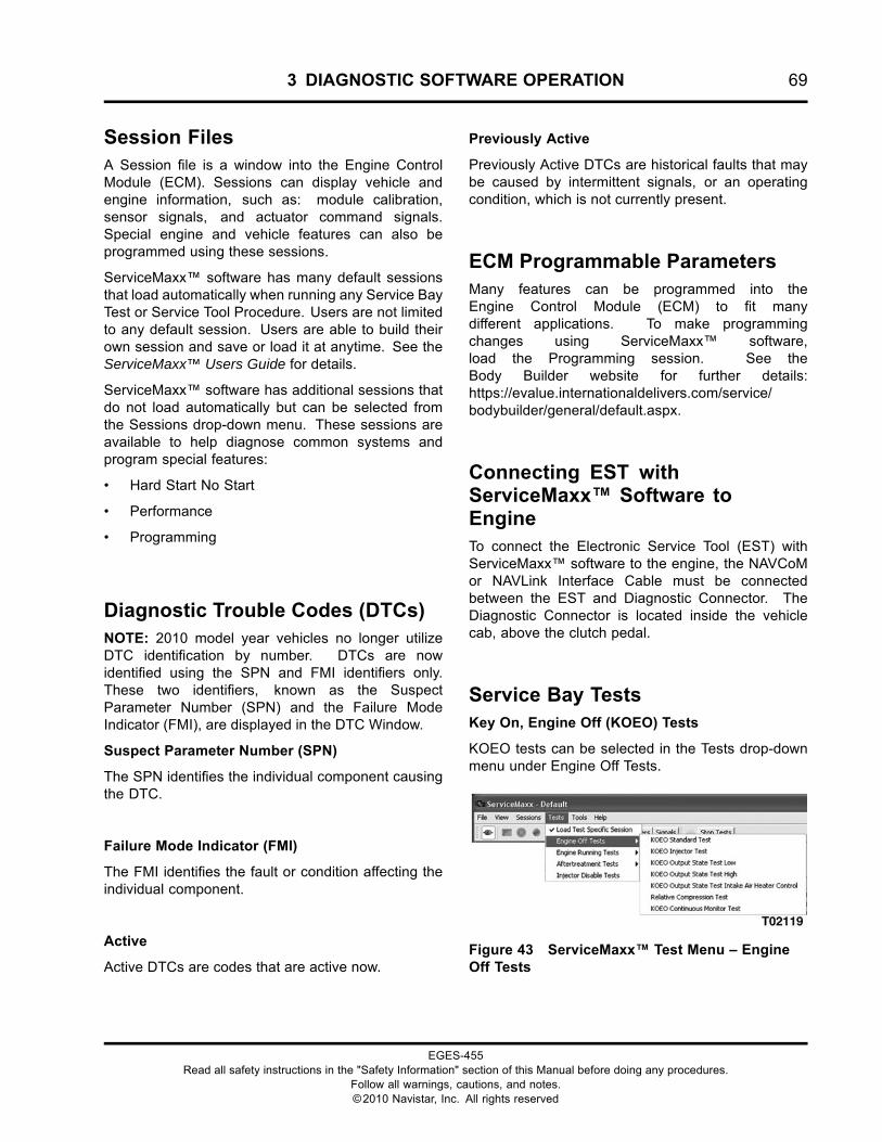
3 DIAGNOSTIC SOFTWARE OPERATION 69
Session FilesA Session file is a window into the Engine ControlModule (ECM). Sessions can display vehicle andengine information, such as: module calibration,sensor signals, and actuator command signals.Special engine and vehicle features can also beprogrammed using these sessions.
ServiceMaxx™ software has many default sessionsthat load automatically when running any Service BayTest or Service Tool Procedure. Users are not limitedto any default session. Users are able to build theirown session and save or load it at anytime. See theServiceMaxx™ Users Guide for details.
ServiceMaxx™ software has additional sessions thatdo not load automatically but can be selected fromthe Sessions drop-down menu. These sessions areavailable to help diagnose common systems andprogram special features:
• Hard Start No Start
• Performance
• Programming
Diagnostic Trouble Codes (DTCs)NOTE: 2010 model year vehicles no longer utilizeDTC identification by number. DTCs are nowidentified using the SPN and FMI identifiers only.These two identifiers, known as the SuspectParameter Number (SPN) and the Failure ModeIndicator (FMI), are displayed in the DTC Window.
Suspect Parameter Number (SPN)
The SPN identifies the individual component causingthe DTC.
Failure Mode Indicator (FMI)
The FMI identifies the fault or condition affecting theindividual component.
Active
Active DTCs are codes that are active now.
Previously Active
Previously Active DTCs are historical faults that maybe caused by intermittent signals, or an operatingcondition, which is not currently present.
ECM Programmable ParametersMany features can be programmed into theEngine Control Module (ECM) to fit manydifferent applications. To make programmingchanges using ServiceMaxx™ software,load the Programming session. See theBody Builder website for further details:https://evalue.internationaldelivers.com/service/bodybuilder/general/default.aspx.
Connecting EST withServiceMaxx™ Software toEngineTo connect the Electronic Service Tool (EST) withServiceMaxx™ software to the engine, the NAVCoMor NAVLink Interface Cable must be connectedbetween the EST and Diagnostic Connector. TheDiagnostic Connector is located inside the vehiclecab, above the clutch pedal.
Service Bay TestsKey On, Engine Off (KOEO) Tests
KOEO tests can be selected in the Tests drop-downmenu under Engine Off Tests.
Figure 43 ServiceMaxx™ Test Menu – EngineOff Tests
EGES-455Read all safety instructions in the "Safety Information" section of this Manual before doing any procedures.
Follow all warnings, cautions, and notes.©2010 Navistar, Inc. All rights reserved
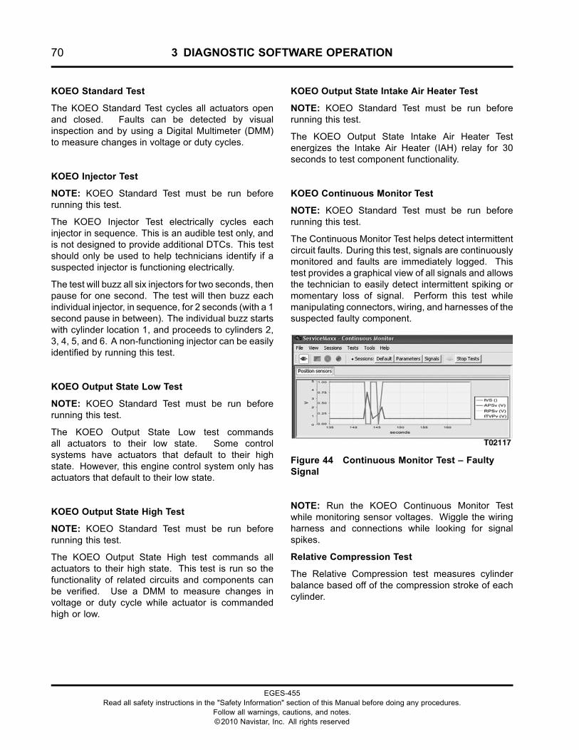
70 3 DIAGNOSTIC SOFTWARE OPERATION
KOEO Standard Test
The KOEO Standard Test cycles all actuators openand closed. Faults can be detected by visualinspection and by using a Digital Multimeter (DMM)to measure changes in voltage or duty cycles.
KOEO Injector Test
NOTE: KOEO Standard Test must be run beforerunning this test.
The KOEO Injector Test electrically cycles eachinjector in sequence. This is an audible test only, andis not designed to provide additional DTCs. This testshould only be used to help technicians identify if asuspected injector is functioning electrically.
The test will buzz all six injectors for two seconds, thenpause for one second. The test will then buzz eachindividual injector, in sequence, for 2 seconds (with a 1second pause in between). The individual buzz startswith cylinder location 1, and proceeds to cylinders 2,3, 4, 5, and 6. A non-functioning injector can be easilyidentified by running this test.
KOEO Output State Low Test
NOTE: KOEO Standard Test must be run beforerunning this test.
The KOEO Output State Low test commandsall actuators to their low state. Some controlsystems have actuators that default to their highstate. However, this engine control system only hasactuators that default to their low state.
KOEO Output State High Test
NOTE: KOEO Standard Test must be run beforerunning this test.
The KOEO Output State High test commands allactuators to their high state. This test is run so thefunctionality of related circuits and components canbe verified. Use a DMM to measure changes involtage or duty cycle while actuator is commandedhigh or low.
KOEO Output State Intake Air Heater Test
NOTE: KOEO Standard Test must be run beforerunning this test.
The KOEO Output State Intake Air Heater Testenergizes the Intake Air Heater (IAH) relay for 30seconds to test component functionality.
KOEO Continuous Monitor Test
NOTE: KOEO Standard Test must be run beforerunning this test.
The Continuous Monitor Test helps detect intermittentcircuit faults. During this test, signals are continuouslymonitored and faults are immediately logged. Thistest provides a graphical view of all signals and allowsthe technician to easily detect intermittent spiking ormomentary loss of signal. Perform this test whilemanipulating connectors, wiring, and harnesses of thesuspected faulty component.
Figure 44 Continuous Monitor Test – FaultySignal
NOTE: Run the KOEO Continuous Monitor Testwhile monitoring sensor voltages. Wiggle the wiringharness and connections while looking for signalspikes.
Relative Compression Test
The Relative Compression test measures cylinderbalance based off of the compression stroke of eachcylinder.
EGES-455Read all safety instructions in the "Safety Information" section of this Manual before doing any procedures.
Follow all warnings, cautions, and notes.©2010 Navistar, Inc. All rights reserved
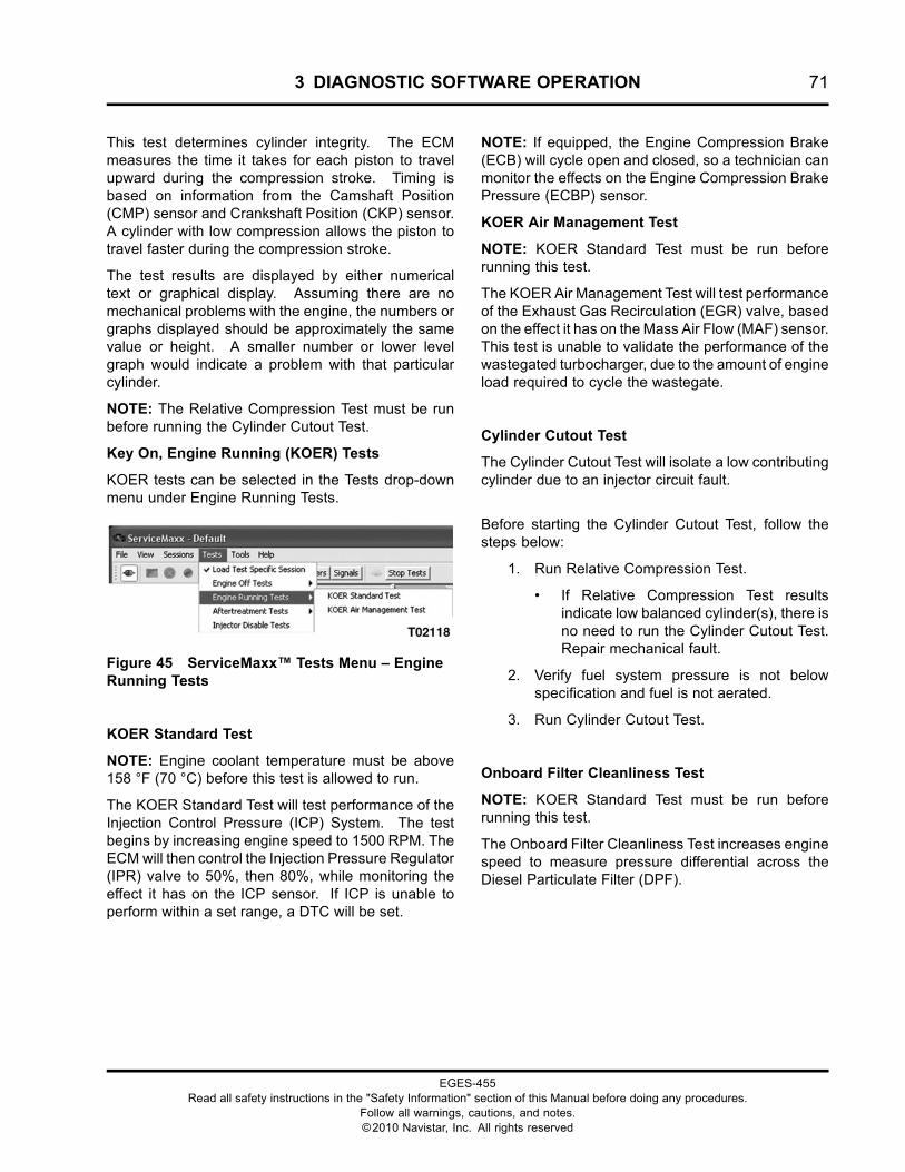
3 DIAGNOSTIC SOFTWARE OPERATION 71
This test determines cylinder integrity. The ECMmeasures the time it takes for each piston to travelupward during the compression stroke. Timing isbased on information from the Camshaft Position(CMP) sensor and Crankshaft Position (CKP) sensor.A cylinder with low compression allows the piston totravel faster during the compression stroke.
The test results are displayed by either numericaltext or graphical display. Assuming there are nomechanical problems with the engine, the numbers orgraphs displayed should be approximately the samevalue or height. A smaller number or lower levelgraph would indicate a problem with that particularcylinder.
NOTE: The Relative Compression Test must be runbefore running the Cylinder Cutout Test.
Key On, Engine Running (KOER) Tests
KOER tests can be selected in the Tests drop-downmenu under Engine Running Tests.
Figure 45 ServiceMaxx™ Tests Menu – EngineRunning Tests
KOER Standard Test
NOTE: Engine coolant temperature must be above158 °F (70 °C) before this test is allowed to run.
The KOER Standard Test will test performance of theInjection Control Pressure (ICP) System. The testbegins by increasing engine speed to 1500 RPM. TheECM will then control the Injection Pressure Regulator(IPR) valve to 50%, then 80%, while monitoring theeffect it has on the ICP sensor. If ICP is unable toperform within a set range, a DTC will be set.
NOTE: If equipped, the Engine Compression Brake(ECB) will cycle open and closed, so a technician canmonitor the effects on the Engine Compression BrakePressure (ECBP) sensor.
KOER Air Management Test
NOTE: KOER Standard Test must be run beforerunning this test.
The KOER Air Management Test will test performanceof the Exhaust Gas Recirculation (EGR) valve, basedon the effect it has on the Mass Air Flow (MAF) sensor.This test is unable to validate the performance of thewastegated turbocharger, due to the amount of engineload required to cycle the wastegate.
Cylinder Cutout Test
The Cylinder Cutout Test will isolate a low contributingcylinder due to an injector circuit fault.
Before starting the Cylinder Cutout Test, follow thesteps below:
1. Run Relative Compression Test.
• If Relative Compression Test resultsindicate low balanced cylinder(s), there isno need to run the Cylinder Cutout Test.Repair mechanical fault.
2. Verify fuel system pressure is not belowspecification and fuel is not aerated.
3. Run Cylinder Cutout Test.
Onboard Filter Cleanliness Test
NOTE: KOER Standard Test must be run beforerunning this test.
The Onboard Filter Cleanliness Test increases enginespeed to measure pressure differential across theDiesel Particulate Filter (DPF).
EGES-455Read all safety instructions in the "Safety Information" section of this Manual before doing any procedures.
Follow all warnings, cautions, and notes.©2010 Navistar, Inc. All rights reserved
72 3 DIAGNOSTIC SOFTWARE OPERATION
Service Tool ProceduresThese procedures are not Service Bay Tests, butspecial ECM controls that will allow the technician toperform specific procedures. The MaxxForce® DT,9, and 10 engines have one special procedure, MAFSensor Calibrate.
Procedures can be selected in the Proceduresdrop-down menu.
MAF Sensor Calibrate
NOTE: KOER Standard Test must be run beforerunning this test.
The MAF Sensor Calibrate procedure calibrates theMass Air Flow (MAF) sensor. Anytime the air filter orMAF sensor is replaced, this procedure needs to beperformed.
EGES-455Read all safety instructions in the "Safety Information" section of this Manual before doing any procedures.
Follow all warnings, cautions, and notes.©2010 Navistar, Inc. All rights reserved
4 ENGINE SYMPTOMS DIAGNOSTICS 73
Table of Contents
Description. . . . . . . . . . . . . . . . . . . . . . . . . . . . . . . . . . . . . . . . . . . . . . . . . . . . . . . . . . . . . . . . . . . . . . . . . . . . . . . . . . . . . . . . . . . . . . . . . . . . . . . . . . . . . . .75
Coolant System.. . . . . . . . . . . . . . . . . . . . . . . . . . . . . . . . . . . . . . . . . . . . . . . . . . . . . . . . . . . . . . . . . . . . . . . . . . . . . . . . . . . . . . . . . . . . . . . . . . . . . . . . .75Coolant Over Flow.. . . . . . . . . . . . . . . . . . . . . . . . . . . . . . . . . . . . . . . . . . . . . . . . . . . . . . . . . . . . . . . . . . . . . . . . . . . . . . . . . . . . . . . . . . . .75Coolant Leak to Exhaust/Intake. . . . . . . . . . . . . . . . . . . . . . . . . . . . . . . . . . . . . . . . . . . . . . . . . . . . . . . . . . . . . . . . . . . . . . . . . . . . .78
Interstage Cooler Inspection. . . . . . . . . . . . . . . . . . . . . . . . . . . . . . . . . . . . . . . . . . . . . . . . . . . . . . . . . . . . . . . . . . . . . . .78EGR Cooler Inspection. . . . . . . . . . . . . . . . . . . . . . . . . . . . . . . . . . . . . . . . . . . . . . . . . . . . . . . . . . . . . . . . . . . . . . . . . . . . . .79Injector Sleeve Inspection. . . . . . . . . . . . . . . . . . . . . . . . . . . . . . . . . . . . . . . . . . . . . . . . . . . . . . . . . . . . . . . . . . . . . . . . . .80Cylinder Head Leak Test. . . . . . . . . . . . . . . . . . . . . . . . . . . . . . . . . . . . . . . . . . . . . . . . . . . . . . . . . . . . . . . . . . . . . . . . . . . .81
Coolant in Lube Oil. . . . . . . . . . . . . . . . . . . . . . . . . . . . . . . . . . . . . . . . . . . . . . . . . . . . . . . . . . . . . . . . . . . . . . . . . . . . . . . . . . . . . . . . . . . .82Coolant System Inspection. . . . . . . . . . . . . . . . . . . . . . . . . . . . . . . . . . . . . . . . . . . . . . . . . . . . . . . . . . . . . . . . . . . . . . . . .82Front Cover Inspection. . . . . . . . . . . . . . . . . . . . . . . . . . . . . . . . . . . . . . . . . . . . . . . . . . . . . . . . . . . . . . . . . . . . . . . . . . . . . .84
Coolant Over-Temperature. . . . . . . . . . . . . . . . . . . . . . . . . . . . . . . . . . . . . . . . . . . . . . . . . . . . . . . . . . . . . . . . . . . . . . . . . . . . . . . . . . .85Coolant System Inspection. . . . . . . . . . . . . . . . . . . . . . . . . . . . . . . . . . . . . . . . . . . . . . . . . . . . . . . . . . . . . . . . . . . . . . . . .85Temperature Sensor Validation Test. . . . . . . . . . . . . . . . . . . . . . . . . . . . . . . . . . . . . . . . . . . . . . . . . . . . . . . . . . . . . .87Cooling System Operating Pressure Test. . . . . . . . . . . . . . . . . . . . . . . . . . . . . . . . . . . . . . . . . . . . . . . . . . . . . . .87Coolant Over-Temperature – Charge Air Cooling. . . . . . . . . . . . . . . . . . . . . . . . . . . . . . . . . . . . . . . . . . . . . .88
Lubrication System.. . . . . . . . . . . . . . . . . . . . . . . . . . . . . . . . . . . . . . . . . . . . . . . . . . . . . . . . . . . . . . . . . . . . . . . . . . . . . . . . . . . . . . . . . . . . . . . . . . . .89Low Oil Pressure. . . . . . . . . . . . . . . . . . . . . . . . . . . . . . . . . . . . . . . . . . . . . . . . . . . . . . . . . . . . . . . . . . . . . . . . . . . . . . . . . . . . . . . . . . . . . . .89
Lubrication System Inspection. . . . . . . . . . . . . . . . . . . . . . . . . . . . . . . . . . . . . . . . . . . . . . . . . . . . . . . . . . . . . . . . . . . .89Oil Pressure Regulator Inspection. . . . . . . . . . . . . . . . . . . . . . . . . . . . . . . . . . . . . . . . . . . . . . . . . . . . . . . . . . . . . . . .90Oil and Crankcase Inspection. . . . . . . . . . . . . . . . . . . . . . . . . . . . . . . . . . . . . . . . . . . . . . . . . . . . . . . . . . . . . . . . . . . . . .91Oil Pump Inspection. . . . . . . . . . . . . . . . . . . . . . . . . . . . . . . . . . . . . . . . . . . . . . . . . . . . . . . . . . . . . . . . . . . . . . . . . . . . . . . . .92Front Cover Inspection. . . . . . . . . . . . . . . . . . . . . . . . . . . . . . . . . . . . . . . . . . . . . . . . . . . . . . . . . . . . . . . . . . . . . . . . . . . . . .93
Lube Oil in Coolant. . . . . . . . . . . . . . . . . . . . . . . . . . . . . . . . . . . . . . . . . . . . . . . . . . . . . . . . . . . . . . . . . . . . . . . . . . . . . . . . . . . . . . . . . . . .95Fuel in Lube.. . . . . . . . . . . . . . . . . . . . . . . . . . . . . . . . . . . . . . . . . . . . . . . . . . . . . . . . . . . . . . . . . . . . . . . . . . . . . . . . . . . . . . . . . . . . . . . . . . . .95
EGES-455Read all safety instructions in the "Safety Information" section of this Manual before doing any procedures.
Follow all warnings, cautions, and notes.©2010 Navistar, Inc. All rights reserved
74 4 ENGINE SYMPTOMS DIAGNOSTICS
EGES-455Read all safety instructions in the "Safety Information" section of this Manual before doing any procedures.
Follow all warnings, cautions, and notes.©2010 Navistar, Inc. All rights reserved
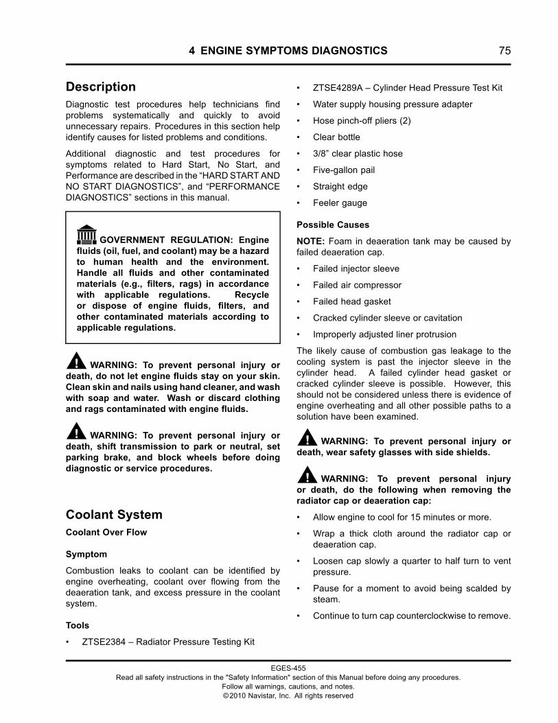
4 ENGINE SYMPTOMS DIAGNOSTICS 75
DescriptionDiagnostic test procedures help technicians findproblems systematically and quickly to avoidunnecessary repairs. Procedures in this section helpidentify causes for listed problems and conditions.
Additional diagnostic and test procedures forsymptoms related to Hard Start, No Start, andPerformance are described in the “HARDSTART ANDNO START DIAGNOSTICS”, and “PERFORMANCEDIAGNOSTICS” sections in this manual.
GOVERNMENT REGULATION: Enginefluids (oil, fuel, and coolant) may be a hazardto human health and the environment.Handle all fluids and other contaminatedmaterials (e.g., filters, rags) in accordancewith applicable regulations. Recycleor dispose of engine fluids, filters, andother contaminated materials according toapplicable regulations.
WARNING: To prevent personal injury ordeath, do not let engine fluids stay on your skin.Clean skin and nails using hand cleaner, and washwith soap and water. Wash or discard clothingand rags contaminated with engine fluids.
WARNING: To prevent personal injury ordeath, shift transmission to park or neutral, setparking brake, and block wheels before doingdiagnostic or service procedures.
Coolant SystemCoolant Over Flow
Symptom
Combustion leaks to coolant can be identified byengine overheating, coolant over flowing from thedeaeration tank, and excess pressure in the coolantsystem.
Tools
• ZTSE2384 – Radiator Pressure Testing Kit
• ZTSE4289A – Cylinder Head Pressure Test Kit
• Water supply housing pressure adapter
• Hose pinch-off pliers (2)
• Clear bottle
• 3/8” clear plastic hose
• Five-gallon pail
• Straight edge
• Feeler gauge
Possible Causes
NOTE: Foam in deaeration tank may be caused byfailed deaeration cap.
• Failed injector sleeve
• Failed air compressor
• Failed head gasket
• Cracked cylinder sleeve or cavitation
• Improperly adjusted liner protrusion
The likely cause of combustion gas leakage to thecooling system is past the injector sleeve in thecylinder head. A failed cylinder head gasket orcracked cylinder sleeve is possible. However, thisshould not be considered unless there is evidence ofengine overheating and all other possible paths to asolution have been examined.
WARNING: To prevent personal injury ordeath, wear safety glasses with side shields.
WARNING: To prevent personal injuryor death, do the following when removing theradiator cap or deaeration cap:
• Allow engine to cool for 15 minutes or more.
• Wrap a thick cloth around the radiator cap ordeaeration cap.
• Loosen cap slowly a quarter to half turn to ventpressure.
• Pause for a moment to avoid being scalded bysteam.
• Continue to turn cap counterclockwise to remove.
EGES-455Read all safety instructions in the "Safety Information" section of this Manual before doing any procedures.
Follow all warnings, cautions, and notes.©2010 Navistar, Inc. All rights reserved
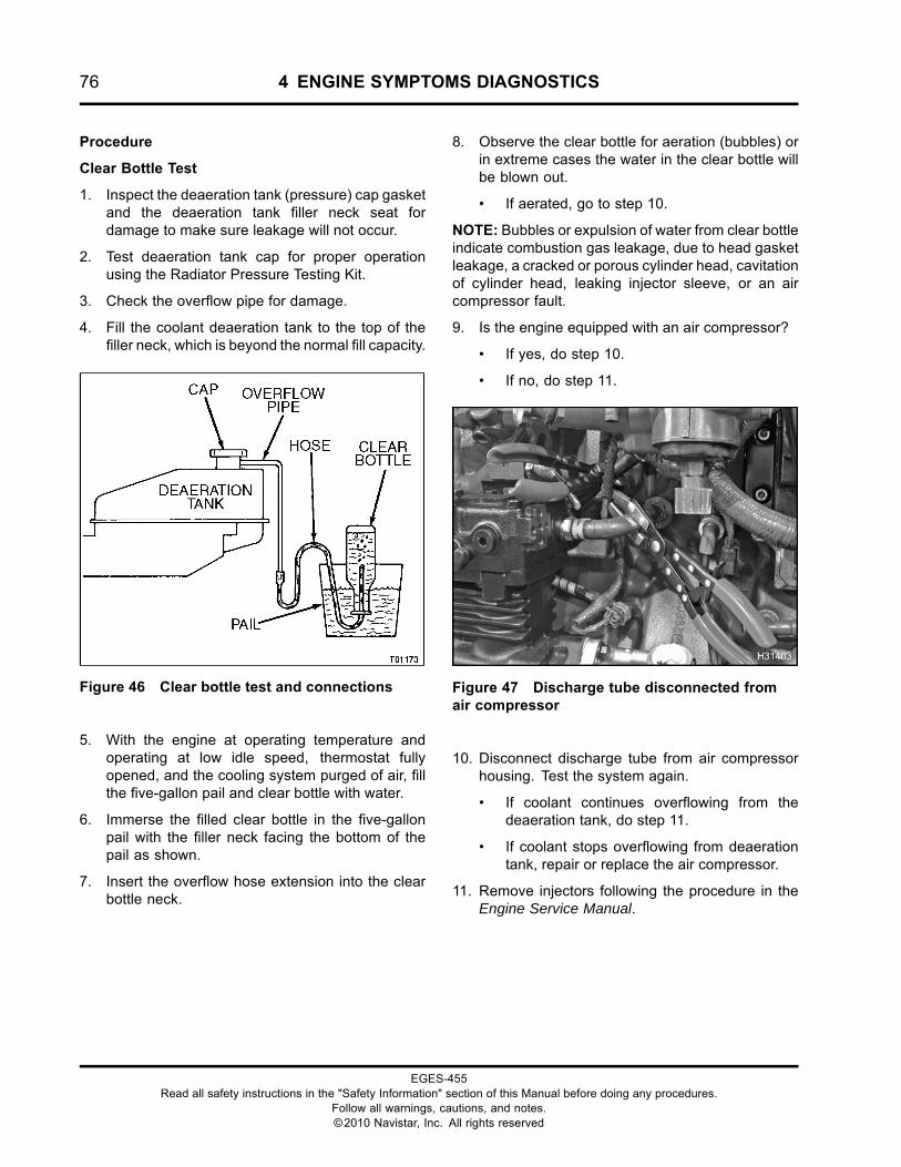
76 4 ENGINE SYMPTOMS DIAGNOSTICS
Procedure
Clear Bottle Test
1. Inspect the deaeration tank (pressure) cap gasketand the deaeration tank filler neck seat fordamage to make sure leakage will not occur.
2. Test deaeration tank cap for proper operationusing the Radiator Pressure Testing Kit.
3. Check the overflow pipe for damage.
4. Fill the coolant deaeration tank to the top of thefiller neck, which is beyond the normal fill capacity.
Figure 46 Clear bottle test and connections
5. With the engine at operating temperature andoperating at low idle speed, thermostat fullyopened, and the cooling system purged of air, fillthe five-gallon pail and clear bottle with water.
6. Immerse the filled clear bottle in the five-gallonpail with the filler neck facing the bottom of thepail as shown.
7. Insert the overflow hose extension into the clearbottle neck.
8. Observe the clear bottle for aeration (bubbles) orin extreme cases the water in the clear bottle willbe blown out.
• If aerated, go to step 10.
NOTE: Bubbles or expulsion of water from clear bottleindicate combustion gas leakage, due to head gasketleakage, a cracked or porous cylinder head, cavitationof cylinder head, leaking injector sleeve, or an aircompressor fault.
9. Is the engine equipped with an air compressor?
• If yes, do step 10.
• If no, do step 11.
Figure 47 Discharge tube disconnected fromair compressor
10. Disconnect discharge tube from air compressorhousing. Test the system again.
• If coolant continues overflowing from thedeaeration tank, do step 11.
• If coolant stops overflowing from deaerationtank, repair or replace the air compressor.
11. Remove injectors following the procedure in theEngine Service Manual.
EGES-455Read all safety instructions in the "Safety Information" section of this Manual before doing any procedures.
Follow all warnings, cautions, and notes.©2010 Navistar, Inc. All rights reserved
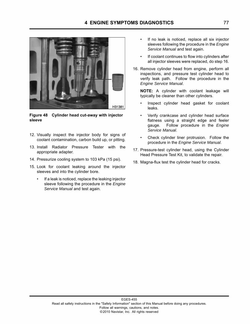
4 ENGINE SYMPTOMS DIAGNOSTICS 77
Figure 48 Cylinder head cut-away with injectorsleeve
12. Visually inspect the injector body for signs ofcoolant contamination, carbon build up, or pitting.
13. Install Radiator Pressure Tester with theappropriate adapter.
14. Pressurize cooling system to 103 kPa (15 psi).
15. Look for coolant leaking around the injectorsleeves and into the cylinder bore.
• If a leak is noticed, replace the leaking injectorsleeve following the procedure in the EngineService Manual and test again.
• If no leak is noticed, replace all six injectorsleeves following the procedure in the EngineService Manual and test again.
• If coolant continues to flow into cylinders afterall injector sleeves were replaced, do step 16.
16. Remove cylinder head from engine, perform allinspections, and pressure test cylinder head toverify leak path. Follow the procedure in theEngine Service Manual.
NOTE: A cylinder with coolant leakage willtypically be cleaner than other cylinders.
• Inspect cylinder head gasket for coolantleaks.
• Verify crankcase and cylinder head surfaceflatness using a straight edge and feelergauge. Follow procedure in the EngineService Manual.
• Check cylinder liner protrusion. Follow theprocedure in the Engine Service Manual.
17. Pressure-test cylinder head, using the CylinderHead Pressure Test Kit, to validate the repair.
18. Magna-flux test the cylinder head for cracks.
EGES-455Read all safety instructions in the "Safety Information" section of this Manual before doing any procedures.
Follow all warnings, cautions, and notes.©2010 Navistar, Inc. All rights reserved
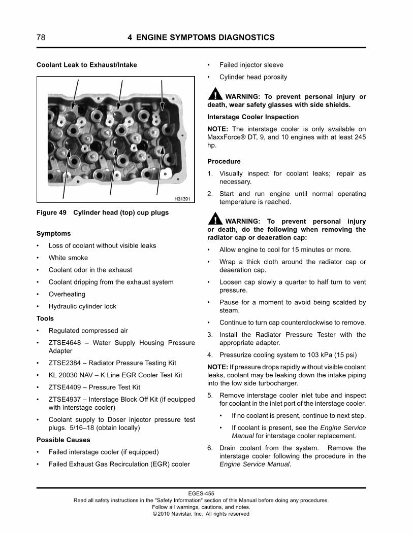
78 4 ENGINE SYMPTOMS DIAGNOSTICS
Coolant Leak to Exhaust/Intake
Figure 49 Cylinder head (top) cup plugs
Symptoms
• Loss of coolant without visible leaks
• White smoke
• Coolant odor in the exhaust
• Coolant dripping from the exhaust system
• Overheating
• Hydraulic cylinder lock
Tools
• Regulated compressed air
• ZTSE4648 – Water Supply Housing PressureAdapter
• ZTSE2384 – Radiator Pressure Testing Kit
• KL 20030 NAV – K Line EGR Cooler Test Kit
• ZTSE4409 – Pressure Test Kit
• ZTSE4937 – Interstage Block Off Kit (if equippedwith interstage cooler)
• Coolant supply to Doser injector pressure testplugs. 5/16–18 (obtain locally)
Possible Causes
• Failed interstage cooler (if equipped)
• Failed Exhaust Gas Recirculation (EGR) cooler
• Failed injector sleeve
• Cylinder head porosity
WARNING: To prevent personal injury ordeath, wear safety glasses with side shields.
Interstage Cooler Inspection
NOTE: The interstage cooler is only available onMaxxForce® DT, 9, and 10 engines with at least 245hp.
Procedure
1. Visually inspect for coolant leaks; repair asnecessary.
2. Start and run engine until normal operatingtemperature is reached.
WARNING: To prevent personal injuryor death, do the following when removing theradiator cap or deaeration cap:
• Allow engine to cool for 15 minutes or more.
• Wrap a thick cloth around the radiator cap ordeaeration cap.
• Loosen cap slowly a quarter to half turn to ventpressure.
• Pause for a moment to avoid being scalded bysteam.
• Continue to turn cap counterclockwise to remove.
3. Install the Radiator Pressure Tester with theappropriate adapter.
4. Pressurize cooling system to 103 kPa (15 psi)
NOTE: If pressure drops rapidly without visible coolantleaks, coolant may be leaking down the intake pipinginto the low side turbocharger.
5. Remove interstage cooler inlet tube and inspectfor coolant in the inlet port of the interstage cooler.
• If no coolant is present, continue to next step.
• If coolant is present, see the Engine ServiceManual for interstage cooler replacement.
6. Drain coolant from the system. Remove theinterstage cooler following the procedure in theEngine Service Manual.
EGES-455Read all safety instructions in the "Safety Information" section of this Manual before doing any procedures.
Follow all warnings, cautions, and notes.©2010 Navistar, Inc. All rights reserved
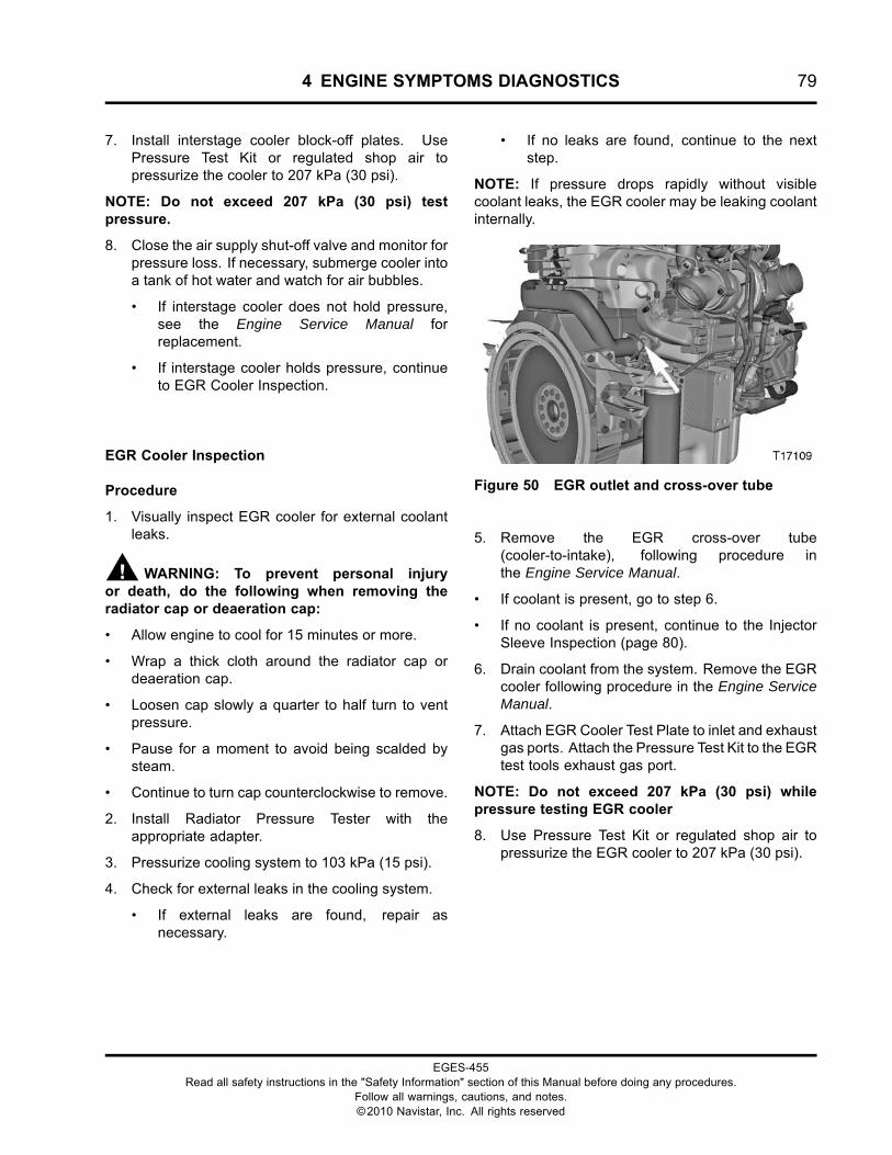
4 ENGINE SYMPTOMS DIAGNOSTICS 79
7. Install interstage cooler block-off plates. UsePressure Test Kit or regulated shop air topressurize the cooler to 207 kPa (30 psi).
NOTE: Do not exceed 207 kPa (30 psi) testpressure.
8. Close the air supply shut-off valve and monitor forpressure loss. If necessary, submerge cooler intoa tank of hot water and watch for air bubbles.
• If interstage cooler does not hold pressure,see the Engine Service Manual forreplacement.
• If interstage cooler holds pressure, continueto EGR Cooler Inspection.
EGR Cooler Inspection
Procedure
1. Visually inspect EGR cooler for external coolantleaks.
WARNING: To prevent personal injuryor death, do the following when removing theradiator cap or deaeration cap:
• Allow engine to cool for 15 minutes or more.
• Wrap a thick cloth around the radiator cap ordeaeration cap.
• Loosen cap slowly a quarter to half turn to ventpressure.
• Pause for a moment to avoid being scalded bysteam.
• Continue to turn cap counterclockwise to remove.
2. Install Radiator Pressure Tester with theappropriate adapter.
3. Pressurize cooling system to 103 kPa (15 psi).
4. Check for external leaks in the cooling system.
• If external leaks are found, repair asnecessary.
• If no leaks are found, continue to the nextstep.
NOTE: If pressure drops rapidly without visiblecoolant leaks, the EGR cooler may be leaking coolantinternally.
Figure 50 EGR outlet and cross-over tube
5. Remove the EGR cross-over tube(cooler-to-intake), following procedure inthe Engine Service Manual.
• If coolant is present, go to step 6.
• If no coolant is present, continue to the InjectorSleeve Inspection (page 80).
6. Drain coolant from the system. Remove the EGRcooler following procedure in the Engine ServiceManual.
7. Attach EGR Cooler Test Plate to inlet and exhaustgas ports. Attach the Pressure Test Kit to the EGRtest tools exhaust gas port.
NOTE: Do not exceed 207 kPa (30 psi) whilepressure testing EGR cooler
8. Use Pressure Test Kit or regulated shop air topressurize the EGR cooler to 207 kPa (30 psi).
EGES-455Read all safety instructions in the "Safety Information" section of this Manual before doing any procedures.
Follow all warnings, cautions, and notes.©2010 Navistar, Inc. All rights reserved
80 4 ENGINE SYMPTOMS DIAGNOSTICS
9. Close the air supply shut-off valve and monitor forpressure loss. Submerge cooler into a tank of hotwater and watch for escaping air.
• If EGR cooler maintains pressure (with nopressure plate leaks) for 15 minutes withouta pressure drop of more than 34 kPa (5 psi),continue to the Injector Sleeve Inspection(page 80).
• If EGR cooler does not hold pressure and airbubbles appear, replace EGR cooler followingprocedure in the Engine Service Manual.
CAUTION: If coolant or lube oil enters the exhaustsystem, past the turbocharger outlet elbow of theturbocharger, a Diesel Particulate Filter (DPF)inspection must be done. If Aftertreatment Systemproblems are found, make necessary repairs.
For Aftertreatment System diagnostics, see AFTSystem (page 194)in “ELECTRONIC CONTROLSYSTEM DIAGNOSTICS”. For the removal ofthe Aftertreatment System, see the AftertreatmentService Manual.
Injector Sleeve Inspection
WARNING: To prevent personal injury ordeath, wear safety glasses with side shields.
Procedure
1. Remove injectors following the procedure inEngine Service Manual.
2. Inspect injector sleeves for signs of coolantleakage. Plug in the coolant heater to warm thecoolant.
3. Install Radiator Pressure Tester with theappropriate adapter.
4. Pressurize cooling system to 103 kPa (15 psi).
5. Inspect injector sleeves again for coolant leakage.Check for coolant entering each cylinder.
• If a leak is occurring at an injector sleeve,replace the sleeve following the procedure inthe Engine Service Manual.
Test again to validate repair.
• If no leaks are apparent, but coolant isentering a cylinder, replace the cylinderinjector sleeve following the procedure in theEngine Service Manual.
Test again to validate repair.
If leak continues, go to Cylinder Head LeakTest.
• If available, a bore scope inserted throughinjector sleeve may aid identification ofcoolant-washed cylinder prior to cylinderhead removal.
EGES-455Read all safety instructions in the "Safety Information" section of this Manual before doing any procedures.
Follow all warnings, cautions, and notes.©2010 Navistar, Inc. All rights reserved
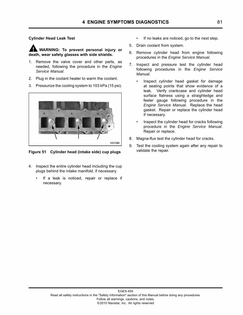
4 ENGINE SYMPTOMS DIAGNOSTICS 81
Cylinder Head Leak Test
WARNING: To prevent personal injury ordeath, wear safety glasses with side shields.
1. Remove the valve cover and other parts, asneeded, following the procedure in the EngineService Manual.
2. Plug in the coolant heater to warm the coolant.
3. Pressurize the cooling system to 103 kPa (15 psi).
Figure 51 Cylinder head (intake side) cup plugs
4. Inspect the entire cylinder head including the cupplugs behind the intake manifold, if necessary.
• If a leak is noticed, repair or replace ifnecessary.
• If no leaks are noticed, go to the next step.
5. Drain coolant from system.
6. Remove cylinder head from engine followingprocedures in the Engine Service Manual.
7. Inspect and pressure test the cylinder headfollowing procedures in the Engine ServiceManual.
• Inspect cylinder head gasket for damageat sealing points that show evidence of aleak. Verify crankcase and cylinder headsurface flatness using a straightedge andfeeler gauge following procedure in theEngine Service Manual. Replace the headgasket. Repair or replace the cylinder headif necessary.
• Inspect the cylinder head for cracks followingprocedure in the Engine Service Manual.Repair or replace.
8. Magna-flux test the cylinder head for cracks.
9. Test the cooling system again after any repair tovalidate the repair.
EGES-455Read all safety instructions in the "Safety Information" section of this Manual before doing any procedures.
Follow all warnings, cautions, and notes.©2010 Navistar, Inc. All rights reserved
82 4 ENGINE SYMPTOMS DIAGNOSTICS
Coolant in Lube Oil
Symptom
When the crankcase lube oil is contaminated withcoolant, the oil will have a light-gray or black sludgyappearance. The crankcase may also be overfilled.
Tools
• ZTSE2384 – Radiator Pressure Testing Kit
• ZTSE 4289A – Cylinder Head Pressure Test Kit
• ZTSE4648 – Water Supply Housing PressureAdapter
• ZTSE4647 – Thermostat Opening PressureAdapter (cylinder head)
• Straight edge
• Feeler gauge
Possible Causes
• Failed interstage cooler (if equipped)
• Cylinder head cup plug failure
• Crevice seal (liner O-ring) failure
• Cylinder head gasket leak
• Front cover gasket damage
• Failed oil cooler
NOTE: Oil cooler coolant leakage to oil will occur onlywhen coolant pressure is higher than oil pressure.Diagnosis and repairs will not be authorized basedsolely on oil analysis.
Prior to pursuing diagnosis and repair of a coolant in oilcomplaint, the technician must complete the following:
• Visually examine an oil sample, taken through thedrain plug, for coolant-in-oil contamination.
• If there is no visible evidence of coolant-in-oil, nofurther action is necessary.
• If there is visible presence of coolant in the engineoil sample, then the technician may proceed withdiagnosis to identify the cause. Contact technicalsupport if necessary.
If the complaint is one of general coolant loss, thenthe following may be considered prior to releasing thevehicle to the customer:
• External leaks
• Coolant in air tank(s)
• Coolant in exhaust
• Skewed record due to periodic coolant overfilling;this could cause loss through the overflow tank(e.g., driver fills the coolant tank to the MAX linewhen engine is cold). The service department isadvised to request records showing the quantityof coolant added over time and engine hoursof operation. The complaint must alwaysbe independently confirmed by the servicedepartment.
Coolant System Inspection
WARNING: To prevent personal injury ordeath, wear safety glasses with side shields.
WARNING: To prevent personal injuryor death, do the following when removing theradiator cap or deaeration cap:
• Allow engine to cool for 15 minutes or more.
• Wrap a thick cloth around the radiator cap ordeaeration cap.
• Loosen cap slowly a quarter to half turn to ventpressure.
• Pause for a moment to avoid being scalded bysteam.
• Continue to turn cap counterclockwise to remove.
Procedure
1. Check oil level and quality to verify oilcontamination complaint.
• The presence of coolant in the oil willgenerally give the oil a light-gray or blacksludgy appearance.
2. If oil contamination is verified, determine if theengine is equipped with an air compressor.
• If yes, do steps 3 through 7.
• If no, continue with step 8.
3. Install Radiator Pressure Tester with theappropriate adapter.
4. Plug in cylinder block heater to warm coolant
EGES-455Read all safety instructions in the "Safety Information" section of this Manual before doing any procedures.
Follow all warnings, cautions, and notes.©2010 Navistar, Inc. All rights reserved
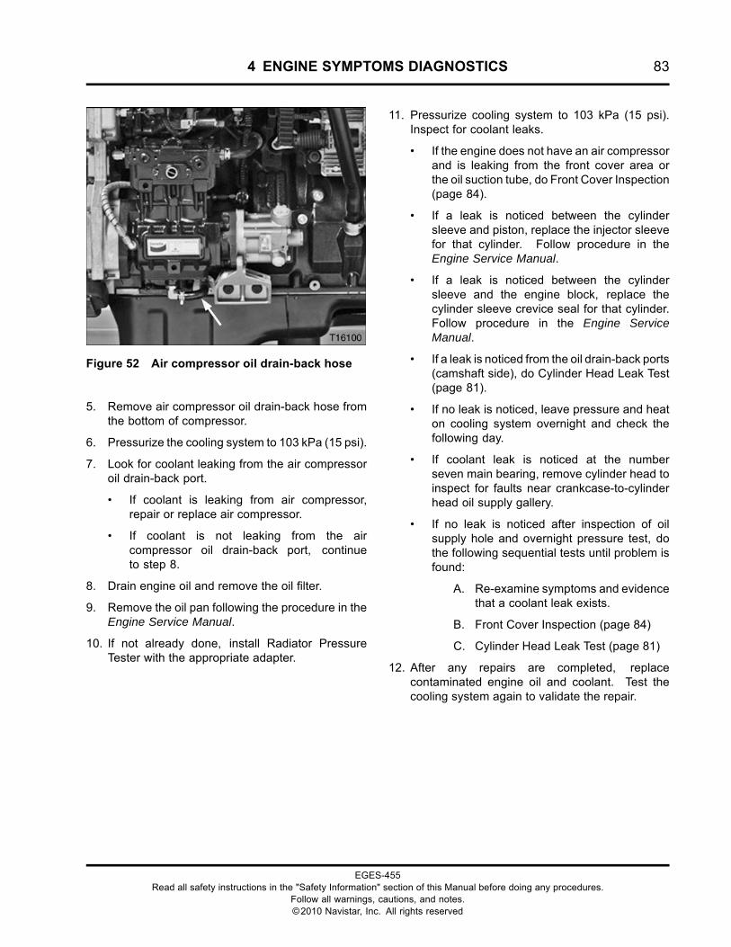
4 ENGINE SYMPTOMS DIAGNOSTICS 83
Figure 52 Air compressor oil drain-back hose
5. Remove air compressor oil drain-back hose fromthe bottom of compressor.
6. Pressurize the cooling system to 103 kPa (15 psi).
7. Look for coolant leaking from the air compressoroil drain-back port.
• If coolant is leaking from air compressor,repair or replace air compressor.
• If coolant is not leaking from the aircompressor oil drain-back port, continueto step 8.
8. Drain engine oil and remove the oil filter.
9. Remove the oil pan following the procedure in theEngine Service Manual.
10. If not already done, install Radiator PressureTester with the appropriate adapter.
11. Pressurize cooling system to 103 kPa (15 psi).Inspect for coolant leaks.
• If the engine does not have an air compressorand is leaking from the front cover area orthe oil suction tube, do Front Cover Inspection(page 84).
• If a leak is noticed between the cylindersleeve and piston, replace the injector sleevefor that cylinder. Follow procedure in theEngine Service Manual.
• If a leak is noticed between the cylindersleeve and the engine block, replace thecylinder sleeve crevice seal for that cylinder.Follow procedure in the Engine ServiceManual.
• If a leak is noticed from the oil drain-back ports(camshaft side), do Cylinder Head Leak Test(page 81).
• If no leak is noticed, leave pressure and heaton cooling system overnight and check thefollowing day.
• If coolant leak is noticed at the numberseven main bearing, remove cylinder head toinspect for faults near crankcase-to-cylinderhead oil supply gallery.
• If no leak is noticed after inspection of oilsupply hole and overnight pressure test, dothe following sequential tests until problem isfound:
A. Re-examine symptoms and evidencethat a coolant leak exists.
B. Front Cover Inspection (page 84)
C. Cylinder Head Leak Test (page 81)
12. After any repairs are completed, replacecontaminated engine oil and coolant. Test thecooling system again to validate the repair.
EGES-455Read all safety instructions in the "Safety Information" section of this Manual before doing any procedures.
Follow all warnings, cautions, and notes.©2010 Navistar, Inc. All rights reserved
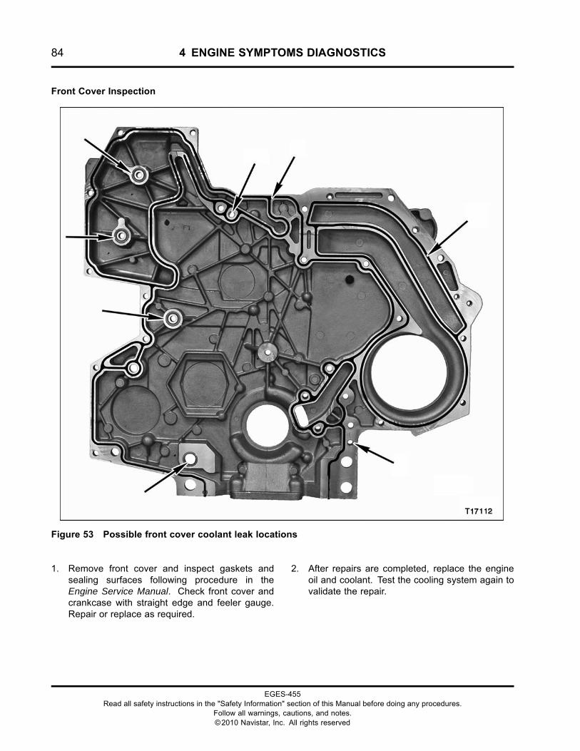
84 4 ENGINE SYMPTOMS DIAGNOSTICS
Front Cover Inspection
Figure 53 Possible front cover coolant leak locations
1. Remove front cover and inspect gaskets andsealing surfaces following procedure in theEngine Service Manual. Check front cover andcrankcase with straight edge and feeler gauge.Repair or replace as required.
2. After repairs are completed, replace the engineoil and coolant. Test the cooling system again tovalidate the repair.
EGES-455Read all safety instructions in the "Safety Information" section of this Manual before doing any procedures.
Follow all warnings, cautions, and notes.©2010 Navistar, Inc. All rights reserved
4 ENGINE SYMPTOMS DIAGNOSTICS 85
Coolant Over-Temperature
NOTE: 2010 model year and above no longerutilize DTC identification by number. DTCs are nowidentified using the Suspect Parameter Number(SPN) and the Failure Mode Indicator (FMI) identifiersonly.
Symptoms
When coolant temperature is above 107° C (224°F), Diagnostic Trouble Codes (DTCs) will be set, thecontrol system will command less fuel, and a powerloss will occur.
When coolant temperature is above 109° C (228° F),the red ENGINE lamp will be illuminated and a DTCwill be set.
When coolant temperature is above 112° C (234° F),the red ENGINE lamp will flash, an audible alarm willsound, and a DTC will be set. If the vehicle has thewarning protection feature enabled, the engine willshutdown after 30 seconds.
Tools
• ZTSE2384 – Radiator Pressure Testing Kit
• Regulated compressed air
• Electronic Service Tool (EST) with ServiceMaxx™software
• NAVCoM or NAVLink Interface Kit
• Infared thermometer (locally obtained)
Possible Causes
• Defective radiator cap
• Low engine coolant level
• Internal or external coolant leaks
• Internal or external radiator blockage
• Broken/worn accessory drive belt
• Accessory belt tensioner failure
• Coolant thermostat stuck closed
• Slipping cooling fan drive clutch
• Water pump failure
• Cooling fan blade assembly wrong/damaged
• Instrument panel gauge error
• Engine Coolant Temperature (ECT) sensorbiased
• Incorrect radiator
• Chassis effects, transmission, after-marketequipment
Coolant System Inspection
WARNING: To prevent personal injury ordeath, wear safety glasses with side shields.
WARNING: To prevent personal injuryor death, do the following when removing theradiator cap or deaeration cap:
• Allow engine to cool for 15 minutes or more.
• Wrap a thick cloth around the radiator cap ordeaeration cap.
• Loosen cap slowly a quarter to half turn to ventpressure.
• Pause for a moment to avoid being scalded bysteam.
• Continue to turn cap counterclockwise to remove.
• Do not substitute water for coolant.
EGES-455Read all safety instructions in the "Safety Information" section of this Manual before doing any procedures.
Follow all warnings, cautions, and notes.©2010 Navistar, Inc. All rights reserved

86 4 ENGINE SYMPTOMS DIAGNOSTICS
Figure 54 Deaeration tank (typical)
1. Check coolant deaeration tank for contaminationand correct fill level.
• If coolant level is low, do step 2.
• If coolant level is correct, do step 6.
• If coolant is contaminated with oil, go to LubeOil in Coolant (page 95).
2. Pressure test deaeration tank cap.
3. Fill cooling system to the maximum coolant levelmark.
4. Inspect for coolant leaks. Check for externalleaks from coolant hoses, radiator, heater core,deaeration tank, deaeration tank, cap, engine, orcylinder head cup plugs. Check for coolant in oil.
• If any external leaks are found, repairand fill cooling system. Test again forover-temperature condition.
• If oil is contaminated with coolant, go toCoolant in Lube Oil (page 82).
• If no leaks are found, continue with step 5.
5. Start engine.
6. Test again for over-temperature condition
• If the engine is not running over-temperature,continue with step 7.
• If the engine continues overheating, do step8.
WARNING: To prevent personal injury ordeath, wear safety glasses with side shields.
7. Install Radiator Pressure Tester with theappropriate adapter.
8. Pressurize the cooling system to 103 kPa (15 psi).
• If coolant is leaking externally, identify the leakand repair. Repeat the test to verify repair.
• If coolant is not leaking externally, but thepressure is dropping, see Coolant Leak toExhaust/Intake (page 78) and Coolant in LubeOil (page 82).
9. Inspect the following items: cooling fan blade,shroud, accessory drive belt, accessory drive belttensioner, cooling fan drive clutch, operation ofelectric or air fan, thermostat, and radiator.
CAUTION: To prevent radiator damage, whenusing high-pressure washer, be careful not to getthe wand too close to radiator fins.
• If vehicle is new or recently repaired, verifythe correct part number for any componentrelated to the cooling system.
• If the radiator cooling fins are blocked due to abuild-up of dirt or debris, use a power washerto clean blockage from radiator fins or anydebris on the cooling fan and fan drive clutch.
NOTE: If heat exchangers are stacked,separation of each cooler is necessary for propercleaning.
• If no problems are identified, continue toTemperature Sensor Validation Test in thissection.
EGES-455Read all safety instructions in the "Safety Information" section of this Manual before doing any procedures.
Follow all warnings, cautions, and notes.©2010 Navistar, Inc. All rights reserved
4 ENGINE SYMPTOMS DIAGNOSTICS 87
Temperature Sensor Validation Test
NOTE: 2010 model year and above no longerutilize DTC identification by number. DTCs are nowidentified using the Suspect Parameter Number(SPN) and the Failure Mode Indicator (FMI) identifiersonly.
1. Install Electronic Service Tool (EST) withServiceMaxx™ software and check for activeand inactive DTCs related to engine coolantover-temperature conditions.
• If any DTCs remain relating to coolantover-temperature condition, correct DTCsbefore continuing.
• If no DTCs exist, continue with step 2.
NOTE: The following test is only accurate if done aftera cold soak of at least 8 hours on the engine.
2. Using the Electronic Service Tool (EST)with ServiceMaxx™ software, compareEngine Coolant Temperature (ECT1), EngineOil Temperature (EOT), Exhaust ManifoldTemperature (EMT), and Intake ManifoldTemperature (IMT) with Key-On Engine-Off.
3. Run engine up to operating temperature. Try toduplicate the operator’s coolant over-temperatureconcern. Monitor the ECT1 using the ElectronicService Tool (EST) with ServiceMaxx™ softwareand the instrument panel coolant temperaturegauge.
• If instrument panel coolant temperaturegauge reads a different temperature thanthe Electronic Service Tool (EST) withServiceMaxx™ software and test gauge,repair instrument panel coolant temperaturegauge fault.
• If gauge is reading correctly, watch forgauge to drop down to make sure thethermostat is opening at desired temperature.If temperature rises steadily without droppingdown, thermostat is possibly stuck closed.Replace thermostat, and recheck.
Cooling System Operating Pressure Test
WARNING: To prevent personal injury ordeath, wear safety glasses with side shields.
WARNING: To prevent personal injuryor death, do the following when removing theradiator cap or deaeration cap:
• Allow engine to cool for 15 minutes or more.
• Wrap a thick cloth around the radiator cap ordeaeration cap.
• Loosen cap slowly a quarter to half turn to ventpressure.
• Pause for a moment to avoid being scalded bysteam.
• Continue to turn cap counterclockwise to remove.
1. Install the Radiator Pressure Tester on thedeaeration tank and run engine at elevatedidle. Monitor the pressure in the system usingthe tester gauge to see if pressure rises abovenormal value of deaeration tank cap.
• If the pressure is higher than specification andboth upper and lower radiator hoses are atengine operating temperature, then continueto Coolant Over Flow (page 75).
• If the pressure is lower than specificationand upper and lower radiator hoses areat different engine operating temperatures,replace thermostat.
EGES-455Read all safety instructions in the "Safety Information" section of this Manual before doing any procedures.
Follow all warnings, cautions, and notes.©2010 Navistar, Inc. All rights reserved
88 4 ENGINE SYMPTOMS DIAGNOSTICS
Coolant Over-Temperature – Charge Air Cooling
Procedure
1. Connect Electronic Service Tool (EST) withServiceMaxx™ software.
2. Start engine and allow to reach operatingtemperature.
3. Using an infrared thermometer, measure andrecord coolant inlet and outlet temperatures atthe secondary radiator.
4. Using Electronic Service Tool (EST) withServiceMaxx™ software, monitor and recordtemperature readings from ECT, ECT2, andAIT2 sensors. Record the readings on thePerformance Diagnostics Form.
5. Calculate secondary radiator cooling bysubtracting the coolant inlet temperature fromthe outlet temperature. Record this number assecondary radiator difference.
6. Calculate CAC cooling by subtracting the ECT2sensor temperature from the AIT2 sensortemperature. Record this number as coolertemperature difference.
7. Use the recorded data to determine if the coolantflow and coolant mixing valves are operatingcorrectly.
• If the cooler difference is higher than thesecondary radiator difference, or is within -15˚C (5 ˚F) of the secondary radiator difference,the Coolant Flow Valve (CFV) is stuck in thefully closed position. Install a new CoolantControl Valve (CCV) assembly following theprocedure in the Engine Service Manual.
• If the ambient temp is lower than 4 ˚C (39 ˚F)then add -16 ˚C (4 ˚F) to the ECT and AIT2.
If the ECT sensor reading is higher than AIT2sensor reading by less than -7 ˚C (20 ˚F), theCoolant Mixer Valve (CMV) is stuck in the fullyclosed position. Install a new CCV assemblyfollowing the procedure in the Engine ServiceManual.
• If cooler difference is lower than secondaryradiator difference and ECT sensor reading ishigher than AIT2 reading by -7˚ C (20 ˚F), theCCV is functioning normally. Proceed to thenext step.
8. If over-temperature condition remains, removesecondary radiator and have flow checked atradiator repair facility.
Retest engine for over-temperature condition withrepaired or replaced secondary radiator.
EGES-455Read all safety instructions in the "Safety Information" section of this Manual before doing any procedures.
Follow all warnings, cautions, and notes.©2010 Navistar, Inc. All rights reserved
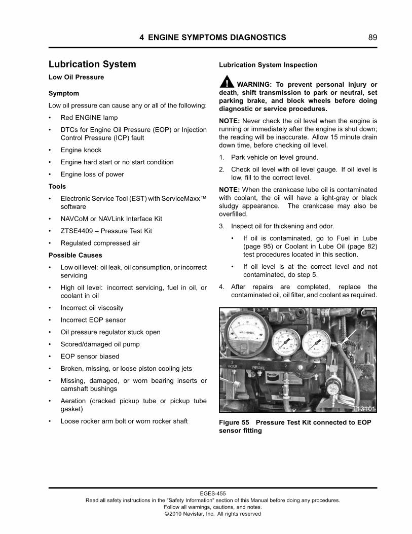
4 ENGINE SYMPTOMS DIAGNOSTICS 89
Lubrication SystemLow Oil Pressure
Symptom
Low oil pressure can cause any or all of the following:
• Red ENGINE lamp
• DTCs for Engine Oil Pressure (EOP) or InjectionControl Pressure (ICP) fault
• Engine knock
• Engine hard start or no start condition
• Engine loss of power
Tools
• Electronic Service Tool (EST) with ServiceMaxx™software
• NAVCoM or NAVLink Interface Kit
• ZTSE4409 – Pressure Test Kit
• Regulated compressed air
Possible Causes
• Low oil level: oil leak, oil consumption, or incorrectservicing
• High oil level: incorrect servicing, fuel in oil, orcoolant in oil
• Incorrect oil viscosity
• Incorrect EOP sensor
• Oil pressure regulator stuck open
• Scored/damaged oil pump
• EOP sensor biased
• Broken, missing, or loose piston cooling jets
• Missing, damaged, or worn bearing inserts orcamshaft bushings
• Aeration (cracked pickup tube or pickup tubegasket)
• Loose rocker arm bolt or worn rocker shaft
Lubrication System Inspection
WARNING: To prevent personal injury ordeath, shift transmission to park or neutral, setparking brake, and block wheels before doingdiagnostic or service procedures.
NOTE: Never check the oil level when the engine isrunning or immediately after the engine is shut down;the reading will be inaccurate. Allow 15 minute draindown time, before checking oil level.
1. Park vehicle on level ground.
2. Check oil level with oil level gauge. If oil level islow, fill to the correct level.
NOTE: When the crankcase lube oil is contaminatedwith coolant, the oil will have a light-gray or blacksludgy appearance. The crankcase may also beoverfilled.
3. Inspect oil for thickening and odor.
• If oil is contaminated, go to Fuel in Lube(page 95) or Coolant in Lube Oil (page 82)test procedures located in this section.
• If oil level is at the correct level and notcontaminated, do step 5.
4. After repairs are completed, replace thecontaminated oil, oil filter, and coolant as required.
Figure 55 Pressure Test Kit connected to EOPsensor fitting
EGES-455Read all safety instructions in the "Safety Information" section of this Manual before doing any procedures.
Follow all warnings, cautions, and notes.©2010 Navistar, Inc. All rights reserved
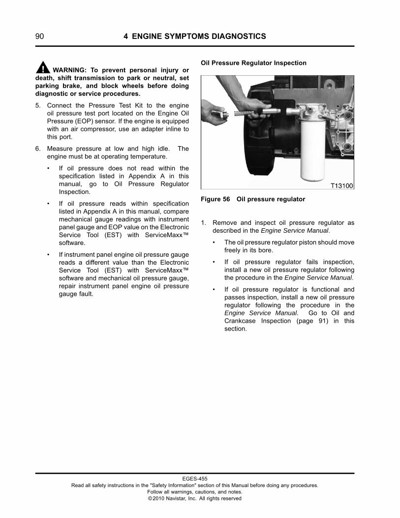
90 4 ENGINE SYMPTOMS DIAGNOSTICS
WARNING: To prevent personal injury ordeath, shift transmission to park or neutral, setparking brake, and block wheels before doingdiagnostic or service procedures.
5. Connect the Pressure Test Kit to the engineoil pressure test port located on the Engine OilPressure (EOP) sensor. If the engine is equippedwith an air compressor, use an adapter inline tothis port.
6. Measure pressure at low and high idle. Theengine must be at operating temperature.
• If oil pressure does not read within thespecification listed in Appendix A in thismanual, go to Oil Pressure RegulatorInspection.
• If oil pressure reads within specificationlisted in Appendix A in this manual, comparemechanical gauge readings with instrumentpanel gauge and EOP value on the ElectronicService Tool (EST) with ServiceMaxx™software.
• If instrument panel engine oil pressure gaugereads a different value than the ElectronicService Tool (EST) with ServiceMaxx™software and mechanical oil pressure gauge,repair instrument panel engine oil pressuregauge fault.
Oil Pressure Regulator Inspection
Figure 56 Oil pressure regulator
1. Remove and inspect oil pressure regulator asdescribed in the Engine Service Manual.
• The oil pressure regulator piston should movefreely in its bore.
• If oil pressure regulator fails inspection,install a new oil pressure regulator followingthe procedure in the Engine Service Manual.
• If oil pressure regulator is functional andpasses inspection, install a new oil pressureregulator following the procedure in theEngine Service Manual. Go to Oil andCrankcase Inspection (page 91) in thissection.
EGES-455Read all safety instructions in the "Safety Information" section of this Manual before doing any procedures.
Follow all warnings, cautions, and notes.©2010 Navistar, Inc. All rights reserved
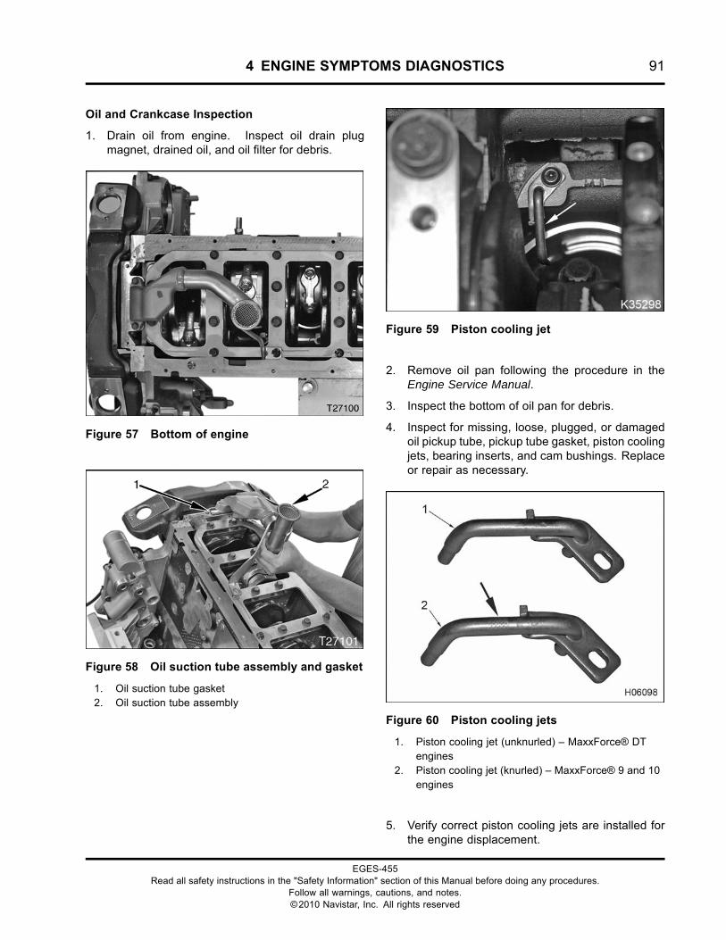
4 ENGINE SYMPTOMS DIAGNOSTICS 91
Oil and Crankcase Inspection
1. Drain oil from engine. Inspect oil drain plugmagnet, drained oil, and oil filter for debris.
Figure 57 Bottom of engine
Figure 58 Oil suction tube assembly and gasket
1. Oil suction tube gasket2. Oil suction tube assembly
Figure 59 Piston cooling jet
2. Remove oil pan following the procedure in theEngine Service Manual.
3. Inspect the bottom of oil pan for debris.
4. Inspect for missing, loose, plugged, or damagedoil pickup tube, pickup tube gasket, piston coolingjets, bearing inserts, and cam bushings. Replaceor repair as necessary.
Figure 60 Piston cooling jets
1. Piston cooling jet (unknurled) – MaxxForce® DTengines
2. Piston cooling jet (knurled) – MaxxForce® 9 and 10engines
5. Verify correct piston cooling jets are installed forthe engine displacement.
EGES-455Read all safety instructions in the "Safety Information" section of this Manual before doing any procedures.
Follow all warnings, cautions, and notes.©2010 Navistar, Inc. All rights reserved
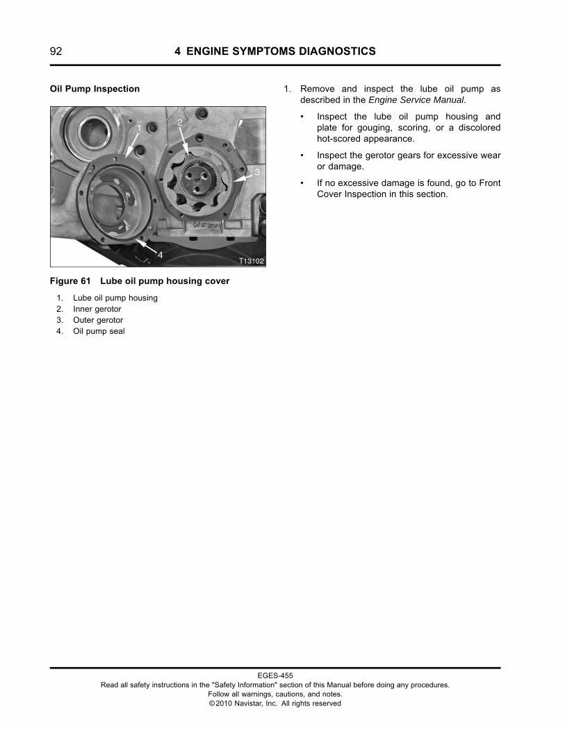
92 4 ENGINE SYMPTOMS DIAGNOSTICS
Oil Pump Inspection
Figure 61 Lube oil pump housing cover
1. Lube oil pump housing2. Inner gerotor3. Outer gerotor4. Oil pump seal
1. Remove and inspect the lube oil pump asdescribed in the Engine Service Manual.
• Inspect the lube oil pump housing andplate for gouging, scoring, or a discoloredhot-scored appearance.
• Inspect the gerotor gears for excessive wearor damage.
• If no excessive damage is found, go to FrontCover Inspection in this section.
EGES-455Read all safety instructions in the "Safety Information" section of this Manual before doing any procedures.
Follow all warnings, cautions, and notes.©2010 Navistar, Inc. All rights reserved
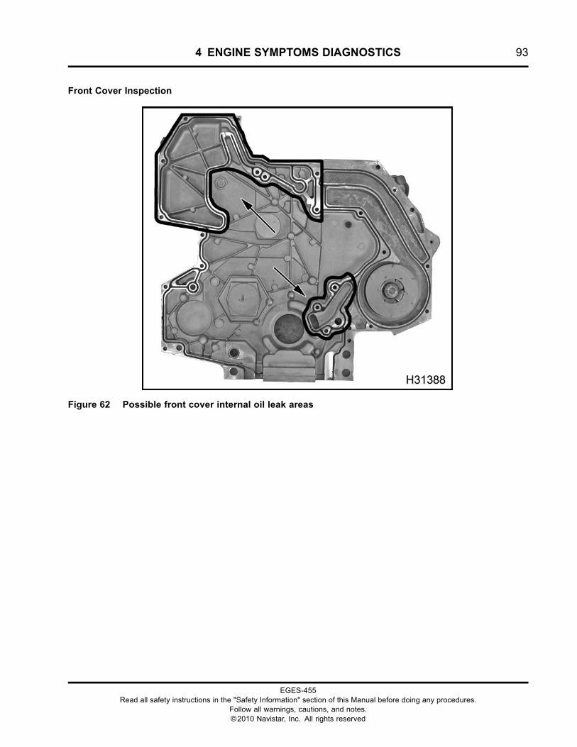
4 ENGINE SYMPTOMS DIAGNOSTICS 93
Front Cover Inspection
Figure 62 Possible front cover internal oil leak areas
EGES-455Read all safety instructions in the "Safety Information" section of this Manual before doing any procedures.
Follow all warnings, cautions, and notes.©2010 Navistar, Inc. All rights reserved
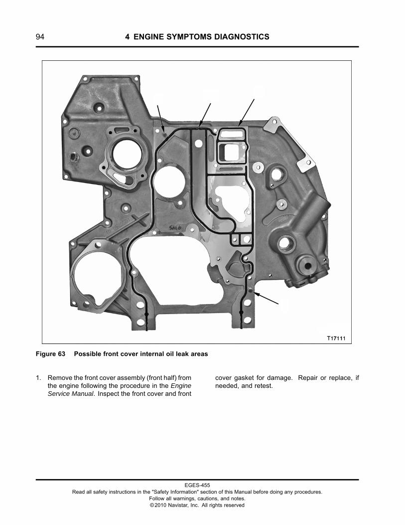
94 4 ENGINE SYMPTOMS DIAGNOSTICS
Figure 63 Possible front cover internal oil leak areas
1. Remove the front cover assembly (front half) fromthe engine following the procedure in the EngineService Manual. Inspect the front cover and front
cover gasket for damage. Repair or replace, ifneeded, and retest.
EGES-455Read all safety instructions in the "Safety Information" section of this Manual before doing any procedures.
Follow all warnings, cautions, and notes.©2010 Navistar, Inc. All rights reserved
4 ENGINE SYMPTOMS DIAGNOSTICS 95
Lube Oil in Coolant
Symptom
Coolant contaminated with lube oil will have oil in thedeaeration tank.
Tools
• ZTSE4939 – Oil Cooler Pressure Test Plate
• ZTSE4409 – Pressure Test Kit
• Regulated compressed air
Possible Causes
• Failed oil cooler
Procedure
WARNING: To prevent personal injury ordeath, do not smoke and keep fuel away fromflames and sparks.
WARNING: To prevent personal injury ordeath, wear safety glasses with side shields.
WARNING: To prevent personal injuryor death, do the following when removing theradiator cap or deaeration cap:
• Allow engine to cool for 15 minutes or more.
• Wrap a thick cloth around the radiator cap ordeaeration cap.
• Loosen cap slowly a quarter to half turn to ventpressure.
• Pause for a moment to avoid being scalded bysteam.
• Continue to turn cap counterclockwise to remove.
1. Check for coolant contamination by inspectingdeaeration tank for presence of oil.
2. Place a coolant drain pan under the oil coolermodule.
3. Remove the coolant drain plug installed in thebottom of the oil cooler module. Drain coolant.This procedure will drain the entire coolingsystem.
NOTE: Install a new O-ring before installing thecoolant drain plug.
4. Remove the oil cooler following the procedure inthe Engine Service Manual.
5. Pressure test the oil cooler following theprocedure in the Engine Service Manual. If aleak is noticed, replace the oil cooler. If there isno visible leak, no repair is necessary.
6. After repair is made, flush cooling systemcompletely and monitor for contaminants. Repeatas necessary.
Fuel in Lube
Symptom
Oil contaminated with diesel fuel will cause the oil levelin engine to increase.
Tools
None
Possible Causes
• Engine performance or start issues (misfire, roughidle, low power, poor start ability)
• Leaking fuel injector or injector O-ring (A leakinginjector sleeve or injector tip could causecontaminated engine oil, but would most likely beidentified as a performance problem.)
Procedure
1. Verify oil contamination.
2. Remove the oil level dipstick. Capture an oil dropon a clean paper towel.
High fuel content will be indicated by anexpanding ring of fuel moving outwards fromthe oil drop.
• If excessive fuel is present, check for relatediKnow letters and service bulletins usingISIS® system, or contact International®Technical Services at 1-800-336-4500.
• If no excessive fuel is noted, no repair isrequired.
EGES-455Read all safety instructions in the "Safety Information" section of this Manual before doing any procedures.
Follow all warnings, cautions, and notes.©2010 Navistar, Inc. All rights reserved
96 4 ENGINE SYMPTOMS DIAGNOSTICS
EGES-455Read all safety instructions in the "Safety Information" section of this Manual before doing any procedures.
Follow all warnings, cautions, and notes.©2010 Navistar, Inc. All rights reserved
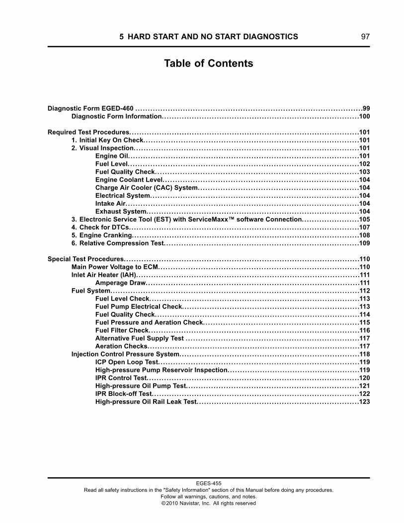
5 HARD START AND NO START DIAGNOSTICS 97
Table of Contents
Diagnostic Form EGED-460 . . . . . . . . . . . . . . . . . . . . . . . . . . . . . . . . . . . . . . . . . . . . . . . . . . . . . . . . . . . . . . . . . . . . . . . . . . . . . . . . . . . . . . . . . . .99Diagnostic Form Information. . . . . . . . . . . . . . . . . . . . . . . . . . . . . . . . . . . . . . . . . . . . . . . . . . . . . . . . . . . . . . . . . . . . . . . . . . . . . . .100
Required Test Procedures. . . . . . . . . . . . . . . . . . . . . . . . . . . . . . . . . . . . . . . . . . . . . . . . . . . . . . . . . . . . . . . . . . . . . . . . . . . . . . . . . . . . . . . . . . . .1011. Initial Key On Check.. . . . . . . . . . . . . . . . . . . . . . . . . . . . . . . . . . . . . . . . . . . . . . . . . . . . . . . . . . . . . . . . . . . . . . . . . . . . . . . . . . . . .1012. Visual Inspection. . . . . . . . . . . . . . . . . . . . . . . . . . . . . . . . . . . . . . . . . . . . . . . . . . . . . . . . . . . . . . . . . . . . . . . . . . . . . . . . . . . . . . . . . .101
Engine Oil. . . . . . . . . . . . . . . . . . . . . . . . . . . . . . . . . . . . . . . . . . . . . . . . . . . . . . . . . . . . . . . . . . . . . . . . . . . . . . . . . . . . . . . . . . . .101Fuel Level. . . . . . . . . . . . . . . . . . . . . . . . . . . . . . . . . . . . . . . . . . . . . . . . . . . . . . . . . . . . . . . . . . . . . . . . . . . . . . . . . . . . . . . . . . . .102Fuel Quality Check.. . . . . . . . . . . . . . . . . . . . . . . . . . . . . . . . . . . . . . . . . . . . . . . . . . . . . . . . . . . . . . . . . . . . . . . . . . . . . . . .103Engine Coolant Level. . . . . . . . . . . . . . . . . . . . . . . . . . . . . . . . . . . . . . . . . . . . . . . . . . . . . . . . . . . . . . . . . . . . . . . . . . . . . .104Charge Air Cooler (CAC) System.. . . . . . . . . . . . . . . . . . . . . . . . . . . . . . . . . . . . . . . . . . . . . . . . . . . . . . . . . . . . . . .104Electrical System.. . . . . . . . . . . . . . . . . . . . . . . . . . . . . . . . . . . . . . . . . . . . . . . . . . . . . . . . . . . . . . . . . . . . . . . . . . . . . . . . . .104Intake Air. . . . . . . . . . . . . . . . . . . . . . . . . . . . . . . . . . . . . . . . . . . . . . . . . . . . . . . . . . . . . . . . . . . . . . . . . . . . . . . . . . . . . . . . . . . . .104Exhaust System.. . . . . . . . . . . . . . . . . . . . . . . . . . . . . . . . . . . . . . . . . . . . . . . . . . . . . . . . . . . . . . . . . . . . . . . . . . . . . . . . . . . .104
3. Electronic Service Tool (EST) with ServiceMaxx™ software Connection. . . . . . . . . . . . . . . . . . . . . . .1054. Check for DTCs. . . . . . . . . . . . . . . . . . . . . . . . . . . . . . . . . . . . . . . . . . . . . . . . . . . . . . . . . . . . . . . . . . . . . . . . . . . . . . . . . . . . . . . . . . . .1075. Engine Cranking.. . . . . . . . . . . . . . . . . . . . . . . . . . . . . . . . . . . . . . . . . . . . . . . . . . . . . . . . . . . . . . . . . . . . . . . . . . . . . . . . . . . . . . . . . .1086. Relative Compression Test. . . . . . . . . . . . . . . . . . . . . . . . . . . . . . . . . . . . . . . . . . . . . . . . . . . . . . . . . . . . . . . . . . . . . . . . . . . . . .109
Special Test Procedures. . . . . . . . . . . . . . . . . . . . . . . . . . . . . . . . . . . . . . . . . . . . . . . . . . . . . . . . . . . . . . . . . . . . . . . . . . . . . . . . . . . . . . . . . . . . . .110Main Power Voltage to ECM.. . . . . . . . . . . . . . . . . . . . . . . . . . . . . . . . . . . . . . . . . . . . . . . . . . . . . . . . . . . . . . . . . . . . . . . . . . . . . . .110Inlet Air Heater (IAH). . . . . . . . . . . . . . . . . . . . . . . . . . . . . . . . . . . . . . . . . . . . . . . . . . . . . . . . . . . . . . . . . . . . . . . . . . . . . . . . . . . . . . . . .111
Amperage Draw.. . . . . . . . . . . . . . . . . . . . . . . . . . . . . . . . . . . . . . . . . . . . . . . . . . . . . . . . . . . . . . . . . . . . . . . . . . . . . . . . . . . .111Fuel System.. . . . . . . . . . . . . . . . . . . . . . . . . . . . . . . . . . . . . . . . . . . . . . . . . . . . . . . . . . . . . . . . . . . . . . . . . . . . . . . . . . . . . . . . . . . . . . . . . .112
Fuel Level Check. . . . . . . . . . . . . . . . . . . . . . . . . . . . . . . . . . . . . . . . . . . . . . . . . . . . . . . . . . . . . . . . . . . . . . . . . . . . . . . . . . . .113Fuel Pump Electrical Check.. . . . . . . . . . . . . . . . . . . . . . . . . . . . . . . . . . . . . . . . . . . . . . . . . . . . . . . . . . . . . . . . . . . . . .113Fuel Quality Check.. . . . . . . . . . . . . . . . . . . . . . . . . . . . . . . . . . . . . . . . . . . . . . . . . . . . . . . . . . . . . . . . . . . . . . . . . . . . . . . . .114Fuel Pressure and Aeration Check. . . . . . . . . . . . . . . . . . . . . . . . . . . . . . . . . . . . . . . . . . . . . . . . . . . . . . . . . . . . . .115Fuel Filter Check.. . . . . . . . . . . . . . . . . . . . . . . . . . . . . . . . . . . . . . . . . . . . . . . . . . . . . . . . . . . . . . . . . . . . . . . . . . . . . . . . . . .116Alternative Fuel Supply Test . . . . . . . . . . . . . . . . . . . . . . . . . . . . . . . . . . . . . . . . . . . . . . . . . . . . . . . . . . . . . . . . . . . . .117Aeration Checks.. . . . . . . . . . . . . . . . . . . . . . . . . . . . . . . . . . . . . . . . . . . . . . . . . . . . . . . . . . . . . . . . . . . . . . . . . . . . . . . . . . . .117
Injection Control Pressure System.. . . . . . . . . . . . . . . . . . . . . . . . . . . . . . . . . . . . . . . . . . . . . . . . . . . . . . . . . . . . . . . . . . . . . . .118ICP Open Loop Test. . . . . . . . . . . . . . . . . . . . . . . . . . . . . . . . . . . . . . . . . . . . . . . . . . . . . . . . . . . . . . . . . . . . . . . . . . . . . . . .119High-pressure Pump Reservoir Inspection. . . . . . . . . . . . . . . . . . . . . . . . . . . . . . . . . . . . . . . . . . . . . . . . . . . . .119IPR Control Test. . . . . . . . . . . . . . . . . . . . . . . . . . . . . . . . . . . . . . . . . . . . . . . . . . . . . . . . . . . . . . . . . . . . . . . . . . . . . . . . . . . . .120High-pressure Oil Pump Test. . . . . . . . . . . . . . . . . . . . . . . . . . . . . . . . . . . . . . . . . . . . . . . . . . . . . . . . . . . . . . . . . . . . .121IPR Block-off Test. . . . . . . . . . . . . . . . . . . . . . . . . . . . . . . . . . . . . . . . . . . . . . . . . . . . . . . . . . . . . . . . . . . . . . . . . . . . . . . . . . .122High-pressure Oil Rail Leak Test. . . . . . . . . . . . . . . . . . . . . . . . . . . . . . . . . . . . . . . . . . . . . . . . . . . . . . . . . . . . . . . . .123
EGES-455Read all safety instructions in the "Safety Information" section of this Manual before doing any procedures.
Follow all warnings, cautions, and notes.©2010 Navistar, Inc. All rights reserved
98 5 HARD START AND NO START DIAGNOSTICS
EGES-455Read all safety instructions in the "Safety Information" section of this Manual before doing any procedures.
Follow all warnings, cautions, and notes.©2010 Navistar, Inc. All rights reserved
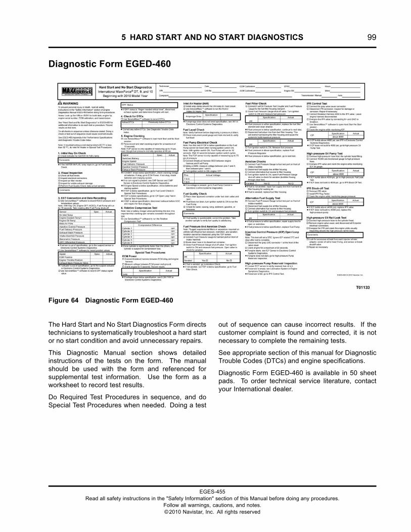
5 HARD START AND NO START DIAGNOSTICS 99
Diagnostic Form EGED-460
Figure 64 Diagnostic Form EGED-460
The Hard Start and No Start Diagnostics Form directstechnicians to systematically troubleshoot a hard startor no start condition and avoid unnecessary repairs.
This Diagnostic Manual section shows detailedinstructions of the tests on the form. The manualshould be used with the form and referenced forsupplemental test information. Use the form as aworksheet to record test results.
Do Required Test Procedures in sequence, and doSpecial Test Procedures when needed. Doing a test
out of sequence can cause incorrect results. If thecustomer complaint is found and corrected, it is notnecessary to complete the remaining tests.
See appropriate section of this manual for DiagnosticTrouble Codes (DTCs) and engine specifications.
Diagnostic Form EGED-460 is available in 50 sheetpads. To order technical service literature, contactyour International dealer.
EGES-455Read all safety instructions in the "Safety Information" section of this Manual before doing any procedures.
Follow all warnings, cautions, and notes.©2010 Navistar, Inc. All rights reserved
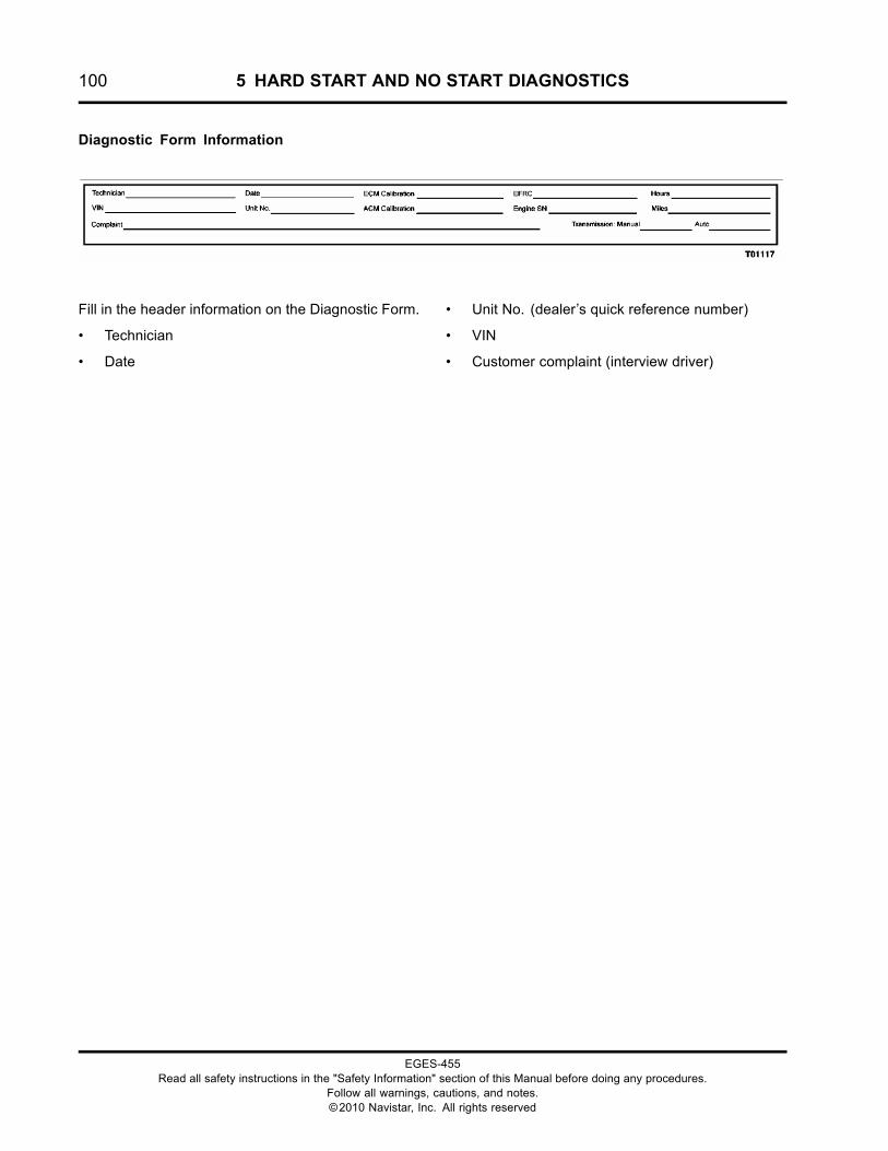
100 5 HARD START AND NO START DIAGNOSTICS
Diagnostic Form Information
Fill in the header information on the Diagnostic Form.
• Technician
• Date
• Unit No. (dealer’s quick reference number)
• VIN
• Customer complaint (interview driver)
EGES-455Read all safety instructions in the "Safety Information" section of this Manual before doing any procedures.
Follow all warnings, cautions, and notes.©2010 Navistar, Inc. All rights reserved
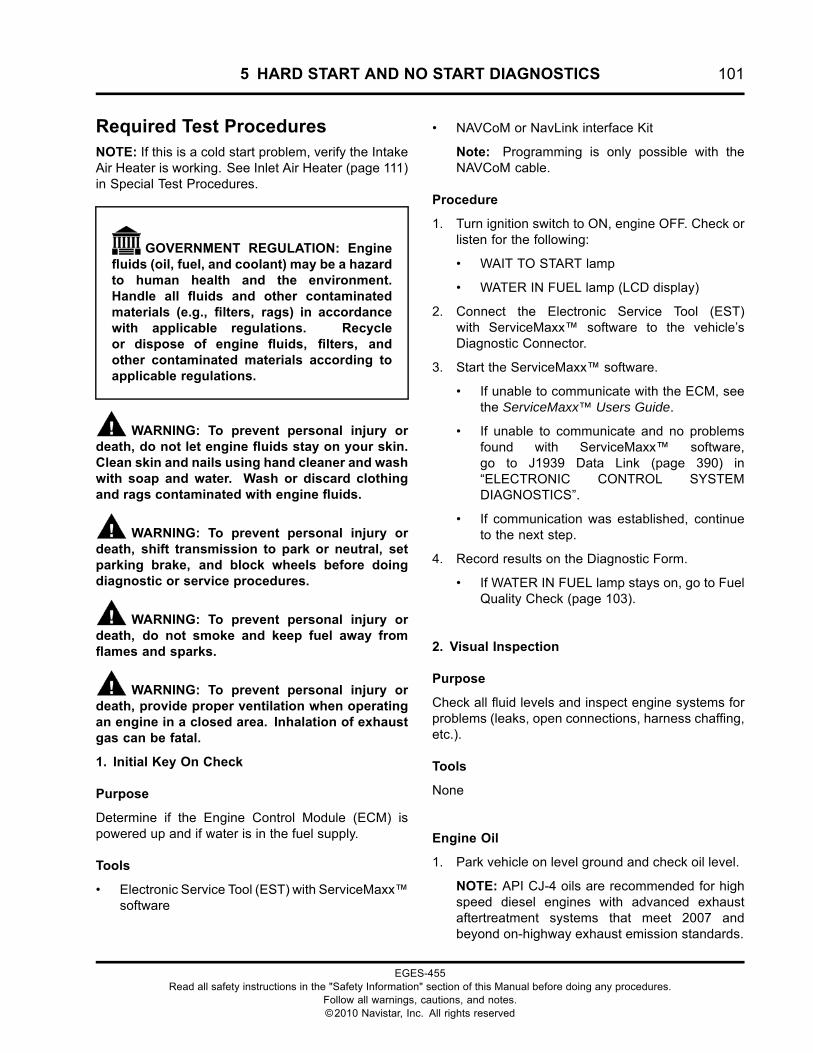
5 HARD START AND NO START DIAGNOSTICS 101
Required Test ProceduresNOTE: If this is a cold start problem, verify the IntakeAir Heater is working. See Inlet Air Heater (page 111)in Special Test Procedures.
GOVERNMENT REGULATION: Enginefluids (oil, fuel, and coolant) may be a hazardto human health and the environment.Handle all fluids and other contaminatedmaterials (e.g., filters, rags) in accordancewith applicable regulations. Recycleor dispose of engine fluids, filters, andother contaminated materials according toapplicable regulations.
WARNING: To prevent personal injury ordeath, do not let engine fluids stay on your skin.Clean skin and nails using hand cleaner and washwith soap and water. Wash or discard clothingand rags contaminated with engine fluids.
WARNING: To prevent personal injury ordeath, shift transmission to park or neutral, setparking brake, and block wheels before doingdiagnostic or service procedures.
WARNING: To prevent personal injury ordeath, do not smoke and keep fuel away fromflames and sparks.
WARNING: To prevent personal injury ordeath, provide proper ventilation when operatingan engine in a closed area. Inhalation of exhaustgas can be fatal.
1. Initial Key On Check
Purpose
Determine if the Engine Control Module (ECM) ispowered up and if water is in the fuel supply.
Tools
• Electronic Service Tool (EST) with ServiceMaxx™software
• NAVCoM or NavLink interface Kit
Note: Programming is only possible with theNAVCoM cable.
Procedure
1. Turn ignition switch to ON, engine OFF. Check orlisten for the following:
• WAIT TO START lamp
• WATER IN FUEL lamp (LCD display)
2. Connect the Electronic Service Tool (EST)with ServiceMaxx™ software to the vehicle’sDiagnostic Connector.
3. Start the ServiceMaxx™ software.
• If unable to communicate with the ECM, seethe ServiceMaxx™ Users Guide.
• If unable to communicate and no problemsfound with ServiceMaxx™ software,go to J1939 Data Link (page 390) in“ELECTRONIC CONTROL SYSTEMDIAGNOSTICS”.
• If communication was established, continueto the next step.
4. Record results on the Diagnostic Form.
• If WATER IN FUEL lamp stays on, go to FuelQuality Check (page 103).
2. Visual Inspection
Purpose
Check all fluid levels and inspect engine systems forproblems (leaks, open connections, harness chaffing,etc.).
Tools
None
Engine Oil
1. Park vehicle on level ground and check oil level.
NOTE: API CJ-4 oils are recommended for highspeed diesel engines with advanced exhaustaftertreatment systems that meet 2007 andbeyond on-highway exhaust emission standards.
EGES-455Read all safety instructions in the "Safety Information" section of this Manual before doing any procedures.
Follow all warnings, cautions, and notes.©2010 Navistar, Inc. All rights reserved

102 5 HARD START AND NO START DIAGNOSTICS
Figure 66 Lube oil requirements label
NOTE: Turn engine OFF. Wait 15 minutes for oillevel to stabilize.
2. Use oil level gauge (dipstick) to verify engine oillevel.
3. Record results on Diagnostic Form.
• If level is below specification, inspect forleaks, oil consumption, or improper servicing.If engine oil level is low, fill to specification.
• If level is above specification, inspect forimproper servicing, coolant contamination,or fuel dilution. If engine oil level is abovespecification, drain to specification.
• If oil is contaminated, determine source ofcontamination, repair as required. Replace oiland filter after repair.
Fuel Level
WARNING: To prevent personal injury ordeath, do not smoke and keep fuel away fromflames and sparks.
1. Park vehicle on level ground.
2. Check instrument panel gauge and visually lookinto fuel tank to verify fuel level.
• If gauge reads above empty, but tank isempty, diagnose dash gauge. Verify sufficientfuel level before diagnosing a pressureproblem.
• If fuel tank is empty, add fuel and prime fuelsystem by cycling the ignition switch ON andOFF a few times.
NOTE: The fuel pump will run for 10 seconds.Wait 10 seconds between switch cycles.
EGES-455Read all safety instructions in the "Safety Information" section of this Manual before doing any procedures.
Follow all warnings, cautions, and notes.©2010 Navistar, Inc. All rights reserved

5 HARD START AND NO START DIAGNOSTICS 103
Fuel Quality Check
Purpose
Check fuel quality and for signs of contamination.
Tools
• ZTSE4925 – Clean Fuel Supply
Procedure
Figure 67 Fuel requirements label
NOTE: Instrument panel Water In Fuel (WIF) lampshould cycle on, then off, if there is no water in thesystem. Lamp will stay on if water is detected.
Figure 68 Fuel sample
1. Place clear diesel fuel container under fuel drainvalve.
2. Open fuel drain valve, to fill container.
NOTE: If fuel does not drain, turn ignition switchON to run the electric fuel pump. Electric fuelpump will run for 10 seconds with ignition switchON.
3. Check for water, waxing, icing, sediment,gasoline, or kerosene by shaking fuel samplecontainer and letting contents settle.
• Sediments will fall to the bottom of the fuelsample container.
• Gasoline and kerosene will separate from thediesel fuel.
• Waxing or icing will prevent diesel fuel fromflowing out of the fuel drain valve.
• If the fuel quality is questionable, correct theproblem. Take another sample to verify fuelquality is satisfactory.
• If the fuel quality is satisfactory, continue tonext test.
EGES-455Read all safety instructions in the "Safety Information" section of this Manual before doing any procedures.
Follow all warnings, cautions, and notes.©2010 Navistar, Inc. All rights reserved
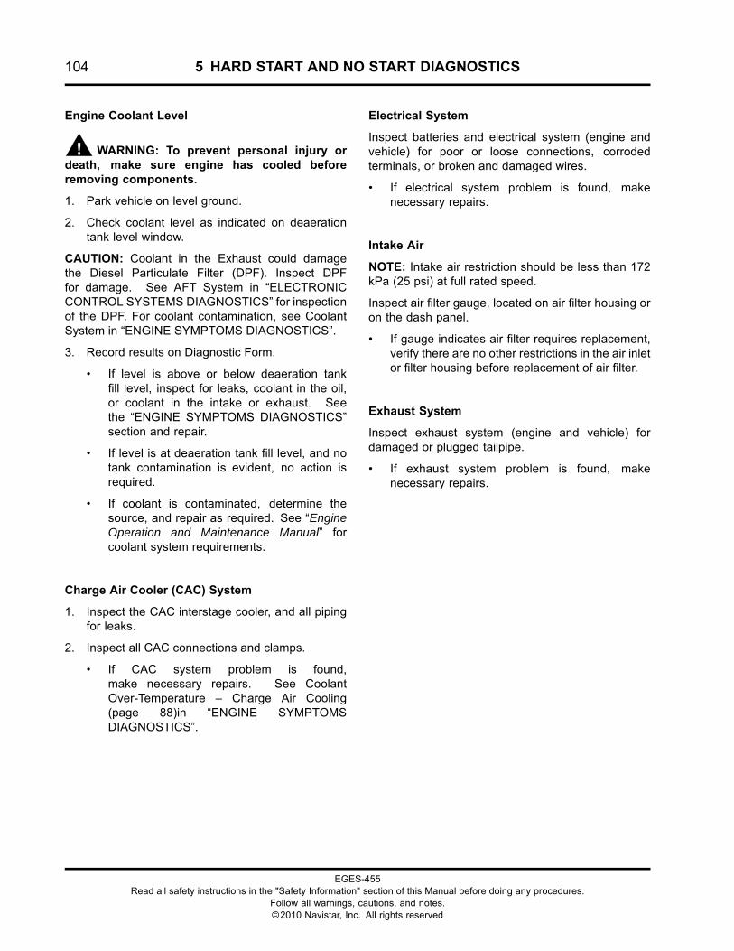
104 5 HARD START AND NO START DIAGNOSTICS
Engine Coolant Level
WARNING: To prevent personal injury ordeath, make sure engine has cooled beforeremoving components.
1. Park vehicle on level ground.
2. Check coolant level as indicated on deaerationtank level window.
CAUTION: Coolant in the Exhaust could damagethe Diesel Particulate Filter (DPF). Inspect DPFfor damage. See AFT System in “ELECTRONICCONTROL SYSTEMS DIAGNOSTICS” for inspectionof the DPF. For coolant contamination, see CoolantSystem in “ENGINE SYMPTOMS DIAGNOSTICS”.
3. Record results on Diagnostic Form.
• If level is above or below deaeration tankfill level, inspect for leaks, coolant in the oil,or coolant in the intake or exhaust. Seethe “ENGINE SYMPTOMS DIAGNOSTICS”section and repair.
• If level is at deaeration tank fill level, and notank contamination is evident, no action isrequired.
• If coolant is contaminated, determine thesource, and repair as required. See “EngineOperation and Maintenance Manual” forcoolant system requirements.
Charge Air Cooler (CAC) System
1. Inspect the CAC interstage cooler, and all pipingfor leaks.
2. Inspect all CAC connections and clamps.
• If CAC system problem is found,make necessary repairs. See CoolantOver-Temperature – Charge Air Cooling(page 88)in “ENGINE SYMPTOMSDIAGNOSTICS”.
Electrical System
Inspect batteries and electrical system (engine andvehicle) for poor or loose connections, corrodedterminals, or broken and damaged wires.
• If electrical system problem is found, makenecessary repairs.
Intake Air
NOTE: Intake air restriction should be less than 172kPa (25 psi) at full rated speed.
Inspect air filter gauge, located on air filter housing oron the dash panel.
• If gauge indicates air filter requires replacement,verify there are no other restrictions in the air inletor filter housing before replacement of air filter.
Exhaust System
Inspect exhaust system (engine and vehicle) fordamaged or plugged tailpipe.
• If exhaust system problem is found, makenecessary repairs.
EGES-455Read all safety instructions in the "Safety Information" section of this Manual before doing any procedures.
Follow all warnings, cautions, and notes.©2010 Navistar, Inc. All rights reserved
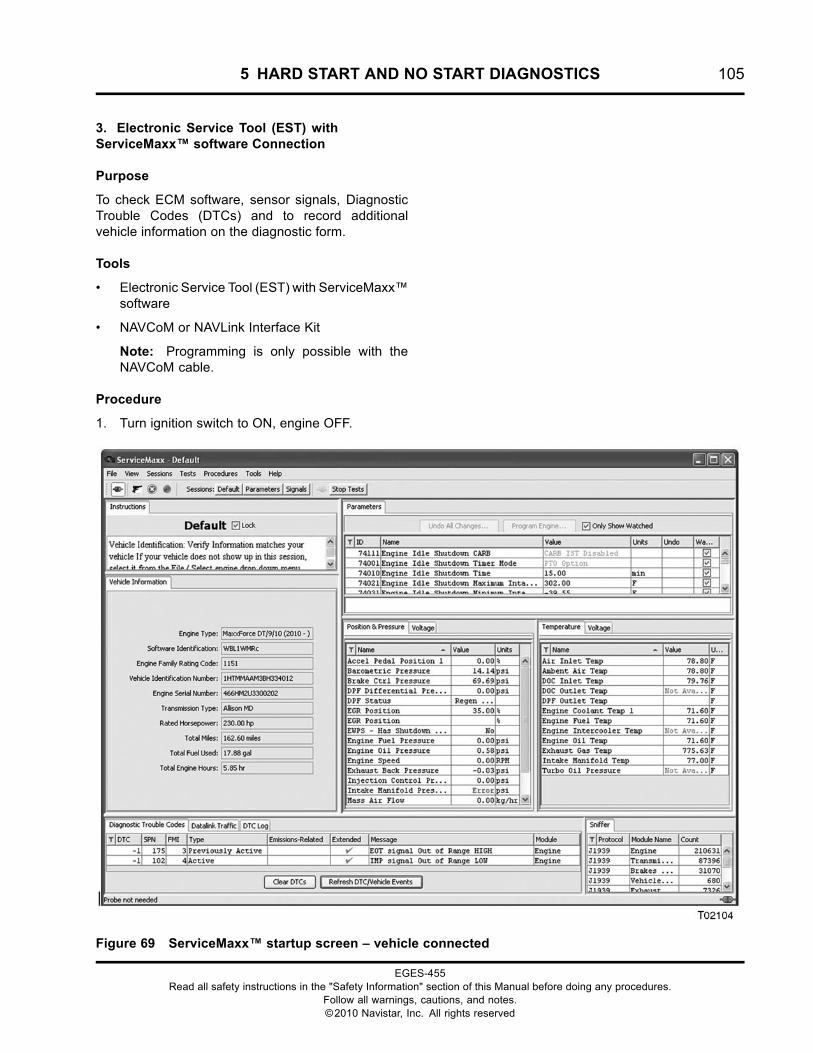
5 HARD START AND NO START DIAGNOSTICS 105
3. Electronic Service Tool (EST) withServiceMaxx™ software Connection
Purpose
To check ECM software, sensor signals, DiagnosticTrouble Codes (DTCs) and to record additionalvehicle information on the diagnostic form.
Tools
• Electronic Service Tool (EST) with ServiceMaxx™software
• NAVCoM or NAVLink Interface Kit
Note: Programming is only possible with theNAVCoM cable.
Procedure
1. Turn ignition switch to ON, engine OFF.
Figure 69 ServiceMaxx™ startup screen – vehicle connected
EGES-455Read all safety instructions in the "Safety Information" section of this Manual before doing any procedures.
Follow all warnings, cautions, and notes.©2010 Navistar, Inc. All rights reserved
106 5 HARD START AND NO START DIAGNOSTICS
2. Connect the Electronic Service Tool (EST)with ServiceMaxx™ software to the vehicle’sDiagnostic Connector.
3. Start the ServiceMaxx™ software.
• If unable to communicate with the ECM, seethe ServiceMaxx™ Users Guide.
• If unable to communicate and no problemsfound with ServiceMaxx™ software,go to J1939 Data Link (page 390) in“ELECTRONIC CONTROL SYSTEMDIAGNOSTICS”.
• If communication was established, continueto the next step.
4. Verify the following vehicle informationmatches the ServiceMaxx™ software displayedinformation and record on Diagnostic Form.
• Vehicle Identification Number (VIN)
• Software Identification
• Rated Horsepower (HP)
• Engine Family Rating Code (EFRC)
• Transmission
• Odometer (miles)
• Engine Hours
• Engine Serial Number (ESN)
NOTE: The engine serial number is located on theright side of the crankcase, just above the oil filterheader. It is also on the engine emission label onthe valve cover.
5. Record the following Key ON, Engine OFF(KOEO) temperature sensor values on theDiagnostic Form.
NOTE: If ECT1 is below -1 °C (30 °F), verify IntakeAir Heater is working before continuing. See InletAir Heater (page 111) in Special Test Procedures.
• Air Intake Temperature (AIT)
• Engine Coolant Temperature 1 (ECT1)
• Engine Oil Temperature (EOT)
6. Record the following KOEO pressure and flowsensor values on the Diagnostic Form:
• Mass Air Flow (MAF)
• Injection Control Pressure (ICP)
• Fuel Delivery Pressure (FDP)
• Exhaust Back Pressure (EBP)
• TC2 Turbine Outlet Pressure (TC2TOP)
• Intake Manifold Pressure (IMP)
• Barometric Absolute Pressure (BARO)
• DPF Differential Pressure (DPFDP)
7. Cycle ignition switch OFF, then back ON whilemonitoring FDP.
•
NOTE: The electric fuel pump will time out after10 seconds unless engine speed is present. Ifelectric fuel pump times out, wait 10 secondsbetween switch cycles to reset timer.
NOTE: The Fuel Delivery Pressure sensor is onlycapable of measuring up to 517 kPa (75 psi) ofpressure, even though fuel pressure normallyoperates at 621 kPa (90 psi).
8. Record results on the Diagnostic Form.
• If Fuel Delivery Pressure (FDP) is below 517kPa (75 psi), go to Fuel System (page 113) inSpecial Test Procedures.
9. Look for sensor values that are out ofspecification. A sensor out of specification couldcause the ECM to command lower then normalstarting pressure on certain systems.
• If sensor is out of specification, go tothe suspect sensor in the “ELECTRONICCONTROL SYSTEM DIAGNOSTICS”section of this manual.
10. Record the following Key ON, Engine OFF(KOEO) position signal values on the DiagnosticForm:
• Exhaust Gas Recirculation Valve Position(EGRVP)
NOTE: The EGR Position signal displays dutycycle and not actual valve position. EGR valveclosed is 35%, and valve open is 90%.
• Engine Throttle Valve (ETV)
• Exhaust Back Pressure Valve (EBPV)
EGES-455Read all safety instructions in the "Safety Information" section of this Manual before doing any procedures.
Follow all warnings, cautions, and notes.©2010 Navistar, Inc. All rights reserved
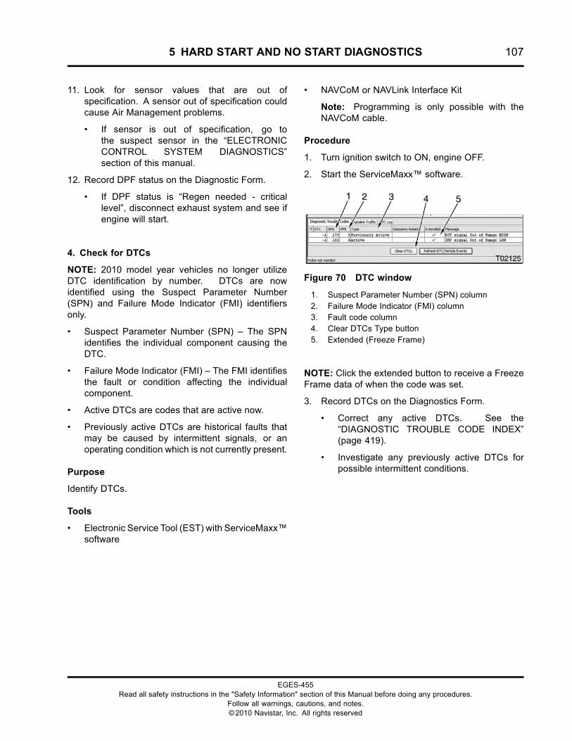
5 HARD START AND NO START DIAGNOSTICS 107
11. Look for sensor values that are out ofspecification. A sensor out of specification couldcause Air Management problems.
• If sensor is out of specification, go tothe suspect sensor in the “ELECTRONICCONTROL SYSTEM DIAGNOSTICS”section of this manual.
12. Record DPF status on the Diagnostic Form.
• If DPF status is “Regen needed - criticallevel”, disconnect exhaust system and see ifengine will start.
4. Check for DTCs
NOTE: 2010 model year vehicles no longer utilizeDTC identification by number. DTCs are nowidentified using the Suspect Parameter Number(SPN) and Failure Mode Indicator (FMI) identifiersonly.
• Suspect Parameter Number (SPN) – The SPNidentifies the individual component causing theDTC.
• Failure Mode Indicator (FMI) – The FMI identifiesthe fault or condition affecting the individualcomponent.
• Active DTCs are codes that are active now.
• Previously active DTCs are historical faults thatmay be caused by intermittent signals, or anoperating condition which is not currently present.
Purpose
Identify DTCs.
Tools
• Electronic Service Tool (EST) with ServiceMaxx™software
• NAVCoM or NAVLink Interface Kit
Note: Programming is only possible with theNAVCoM cable.
Procedure
1. Turn ignition switch to ON, engine OFF.
2. Start the ServiceMaxx™ software.
Figure 70 DTC window
1. Suspect Parameter Number (SPN) column2. Failure Mode Indicator (FMI) column3. Fault code column4. Clear DTCs Type button5. Extended (Freeze Frame)
NOTE: Click the extended button to receive a FreezeFrame data of when the code was set.
3. Record DTCs on the Diagnostics Form.
• Correct any active DTCs. See the“DIAGNOSTIC TROUBLE CODE INDEX”(page 419).
• Investigate any previously active DTCs forpossible intermittent conditions.
EGES-455Read all safety instructions in the "Safety Information" section of this Manual before doing any procedures.
Follow all warnings, cautions, and notes.©2010 Navistar, Inc. All rights reserved
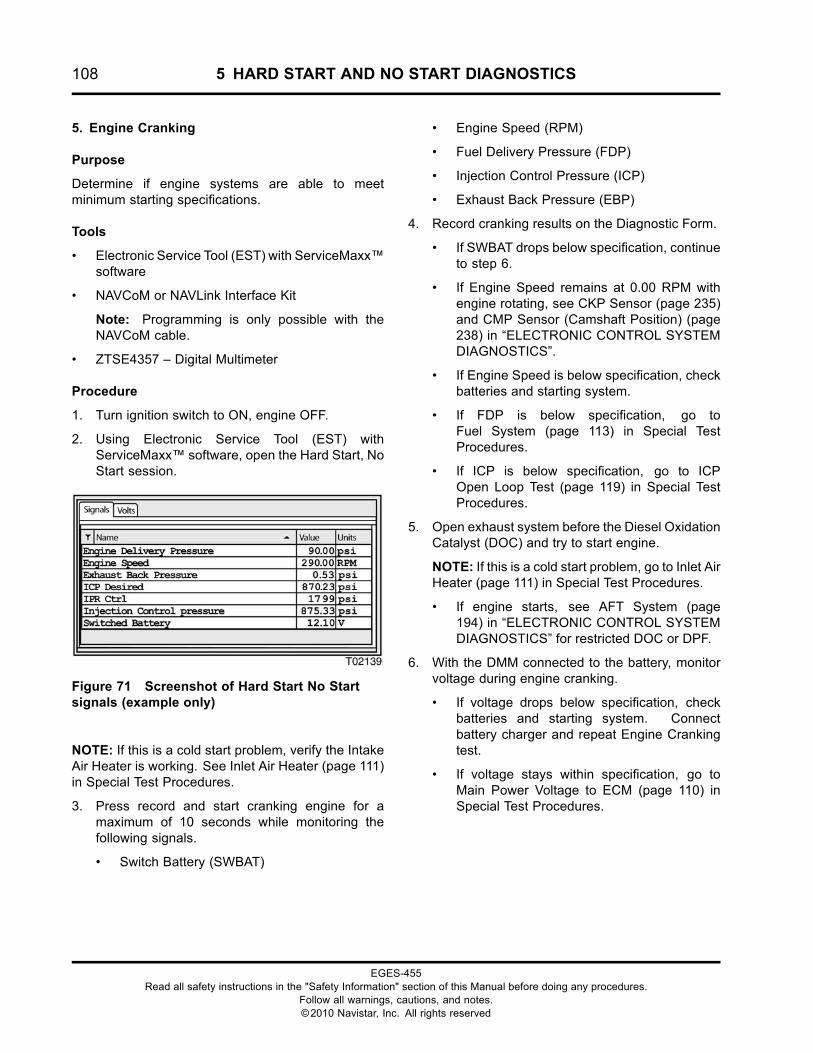
108 5 HARD START AND NO START DIAGNOSTICS
5. Engine Cranking
Purpose
Determine if engine systems are able to meetminimum starting specifications.
Tools
• Electronic Service Tool (EST) with ServiceMaxx™software
• NAVCoM or NAVLink Interface Kit
Note: Programming is only possible with theNAVCoM cable.
• ZTSE4357 – Digital Multimeter
Procedure
1. Turn ignition switch to ON, engine OFF.
2. Using Electronic Service Tool (EST) withServiceMaxx™ software, open the Hard Start, NoStart session.
Figure 71 Screenshot of Hard Start No Startsignals (example only)
NOTE: If this is a cold start problem, verify the IntakeAir Heater is working. See Inlet Air Heater (page 111)in Special Test Procedures.
3. Press record and start cranking engine for amaximum of 10 seconds while monitoring thefollowing signals.
• Switch Battery (SWBAT)
• Engine Speed (RPM)
• Fuel Delivery Pressure (FDP)
• Injection Control Pressure (ICP)
• Exhaust Back Pressure (EBP)
4. Record cranking results on the Diagnostic Form.
• If SWBAT drops below specification, continueto step 6.
• If Engine Speed remains at 0.00 RPM withengine rotating, see CKP Sensor (page 235)and CMP Sensor (Camshaft Position) (page238) in “ELECTRONIC CONTROL SYSTEMDIAGNOSTICS”.
• If Engine Speed is below specification, checkbatteries and starting system.
• If FDP is below specification, go toFuel System (page 113) in Special TestProcedures.
• If ICP is below specification, go to ICPOpen Loop Test (page 119) in Special TestProcedures.
5. Open exhaust system before the Diesel OxidationCatalyst (DOC) and try to start engine.
NOTE: If this is a cold start problem, go to Inlet AirHeater (page 111) in Special Test Procedures.
• If engine starts, see AFT System (page194) in “ELECTRONIC CONTROL SYSTEMDIAGNOSTICS” for restricted DOC or DPF.
6. With the DMM connected to the battery, monitorvoltage during engine cranking.
• If voltage drops below specification, checkbatteries and starting system. Connectbattery charger and repeat Engine Crankingtest.
• If voltage stays within specification, go toMain Power Voltage to ECM (page 110) inSpecial Test Procedures.
EGES-455Read all safety instructions in the "Safety Information" section of this Manual before doing any procedures.
Follow all warnings, cautions, and notes.©2010 Navistar, Inc. All rights reserved
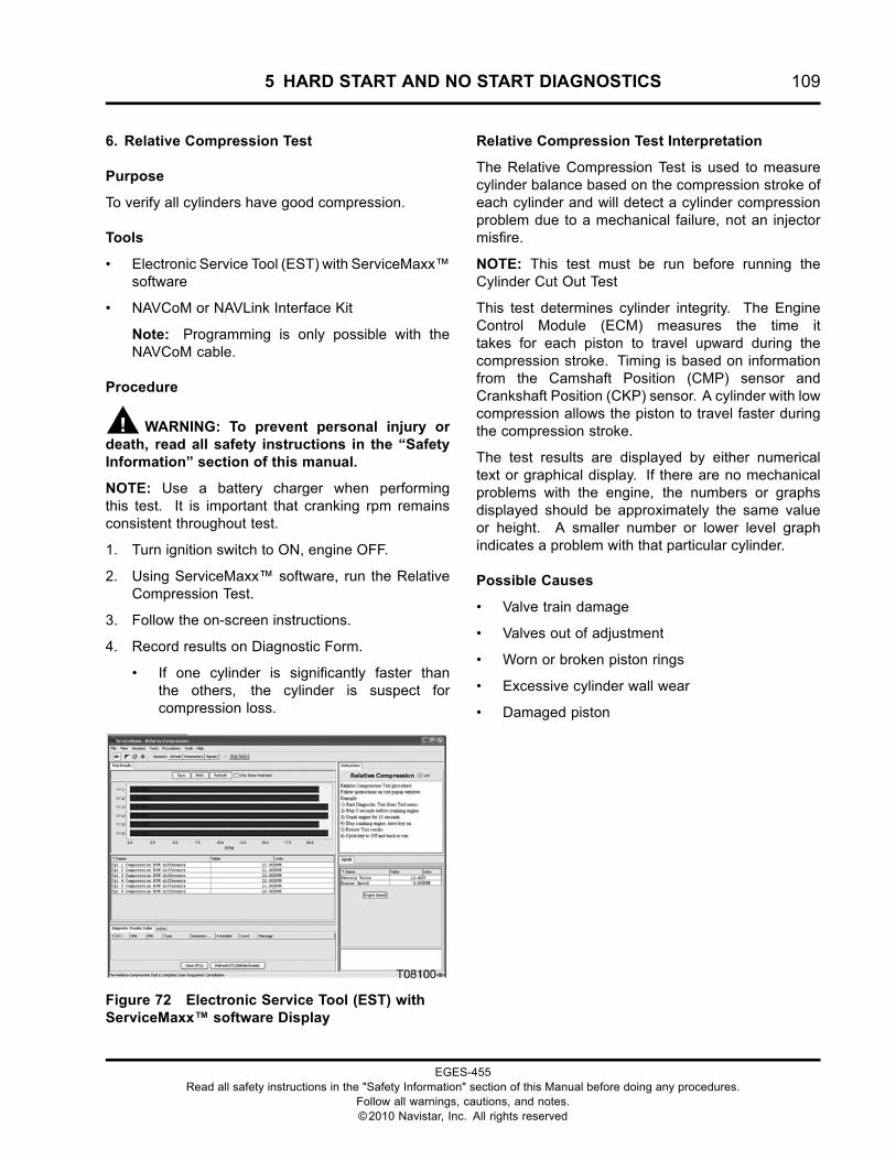
5 HARD START AND NO START DIAGNOSTICS 109
6. Relative Compression Test
Purpose
To verify all cylinders have good compression.
Tools
• Electronic Service Tool (EST) with ServiceMaxx™software
• NAVCoM or NAVLink Interface Kit
Note: Programming is only possible with theNAVCoM cable.
Procedure
WARNING: To prevent personal injury ordeath, read all safety instructions in the “SafetyInformation” section of this manual.
NOTE: Use a battery charger when performingthis test. It is important that cranking rpm remainsconsistent throughout test.
1. Turn ignition switch to ON, engine OFF.
2. Using ServiceMaxx™ software, run the RelativeCompression Test.
3. Follow the on-screen instructions.
4. Record results on Diagnostic Form.
• If one cylinder is significantly faster thanthe others, the cylinder is suspect forcompression loss.
Figure 72 Electronic Service Tool (EST) withServiceMaxx™ software Display
Relative Compression Test Interpretation
The Relative Compression Test is used to measurecylinder balance based on the compression stroke ofeach cylinder and will detect a cylinder compressionproblem due to a mechanical failure, not an injectormisfire.
NOTE: This test must be run before running theCylinder Cut Out Test
This test determines cylinder integrity. The EngineControl Module (ECM) measures the time ittakes for each piston to travel upward during thecompression stroke. Timing is based on informationfrom the Camshaft Position (CMP) sensor andCrankshaft Position (CKP) sensor. A cylinder with lowcompression allows the piston to travel faster duringthe compression stroke.
The test results are displayed by either numericaltext or graphical display. If there are no mechanicalproblems with the engine, the numbers or graphsdisplayed should be approximately the same valueor height. A smaller number or lower level graphindicates a problem with that particular cylinder.
Possible Causes
• Valve train damage
• Valves out of adjustment
• Worn or broken piston rings
• Excessive cylinder wall wear
• Damaged piston
EGES-455Read all safety instructions in the "Safety Information" section of this Manual before doing any procedures.
Follow all warnings, cautions, and notes.©2010 Navistar, Inc. All rights reserved
110 5 HARD START AND NO START DIAGNOSTICS
Special Test Procedures
GOVERNMENT REGULATION: Enginefluids (oil, fuel, and coolant) may be a hazardto human health and the environment.Handle all fluids and other contaminatedmaterials (e.g. filters, rags) in accordancewith applicable regulations. Recycleor dispose of engine fluids, filters, andother contaminated materials according toapplicable regulations.
WARNING: To prevent personal injury ordeath, read all safety instructions in the “SafetyInformation” section of this manual.
Main Power Voltage to ECM
Purpose
Inspect for incorrect power supplied to operate theECM.
Tools
• Breakout Harness 4674 (ECM Relay)
• Digital Multimeter (DMM)
Procedure
CAUTION: To prevent engine damage, turn ignitionswitch OFF before removing the main power relayor any ECM connector supplying power to the ECM.Failure to turn ignition switch OFF will cause a voltagespike and damage electrical components.
1. Remove ECM relay from the engine harness.
2. Install Breakout Harness 4674 between ECMrelay and the engine harness.
3. Turn ignition switch to ON, engine OFF.
4. Connect DMM leads to breakout harness 4674(between ECM PWR circuit and ground).
5. Crank the engine for 5 seconds.
6. Record results on Diagnostics Form. If voltagedrops below specification, see ECM PWR (page289) in “ELECTRONIC CONTROL SYSTEMDIAGNOSTICS”.
EGES-455Read all safety instructions in the "Safety Information" section of this Manual before doing any procedures.
Follow all warnings, cautions, and notes.©2010 Navistar, Inc. All rights reserved
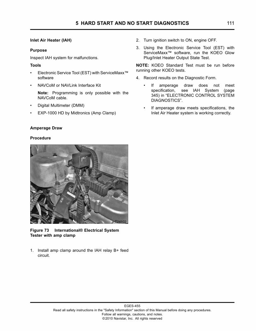
5 HARD START AND NO START DIAGNOSTICS 111
Inlet Air Heater (IAH)
Purpose
Inspect IAH system for malfunctions.
Tools
• Electronic Service Tool (EST) with ServiceMaxx™software
• NAVCoM or NAVLink Interface Kit
Note: Programming is only possible with theNAVCoM cable.
• Digital Multimeter (DMM)
• EXP-1000 HD by Midtronics (Amp Clamp)
Amperage Draw
Procedure
Figure 73 International® Electrical SystemTester with amp clamp
1. Install amp clamp around the IAH relay B+ feedcircuit.
2. Turn ignition switch to ON, engine OFF.
3. Using the Electronic Service Tool (EST) withServiceMaxx™ software, run the KOEO GlowPlug/Inlet Heater Output State Test.
NOTE: KOEO Standard Test must be run beforerunning other KOEO tests.
4. Record results on the Diagnostic Form.
• If amperage draw does not meetspecification, see IAH System (page345) in “ELECTRONIC CONTROL SYSTEMDIAGNOSTICS”.
• If amperage draw meets specifications, theInlet Air Heater system is working correctly.
EGES-455Read all safety instructions in the "Safety Information" section of this Manual before doing any procedures.
Follow all warnings, cautions, and notes.©2010 Navistar, Inc. All rights reserved
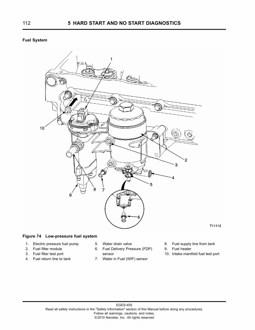
112 5 HARD START AND NO START DIAGNOSTICS
Fuel System
Figure 74 Low-pressure fuel system
1. Electric pressure fuel pump2. Fuel filter module3. Fuel filter test port4. Fuel return line to tank
5. Water drain valve6. Fuel Delivery Pressure (FDP)
sensor7. Water in Fuel (WIF) sensor
8. Fuel supply line from tank9. Fuel heater10. Intake manifold fuel test port
EGES-455Read all safety instructions in the "Safety Information" section of this Manual before doing any procedures.
Follow all warnings, cautions, and notes.©2010 Navistar, Inc. All rights reserved
5 HARD START AND NO START DIAGNOSTICS 113
Fuel Level Check
Purpose
Check for low fuel level.
NOTE: Always verify fuel level before diagnosing apressure problem.
Tools
None
Procedure
1. Park vehicle on level ground.
2. Check instrument panel gauge and visually lookinto tank to verify fuel level.
NOTE: The fuel pump will time out after 10seconds unless engine speed is present. If fuelpump times out, wait 10 seconds between switchcycles to reset timer.
• If gauge reads full but tank is empty, add fueland prime fuel system by cycling the ignitionswitch ON and OFF a few times.
• If gauge is inaccurate, repair as necessary.
Fuel Pump Electrical Check
Purpose
Verify Fuel Pump has power.
Tools
Breakout Harness 6023 (Fuel Pump)
Possible Causes
• Blown fuse
• Failed relay
• Circuit fault
• Failed Fuel Pump
Procedure
NOTE: Run this test if Fuel Delivery Pressure (FDP) isbelow specification or the Fuel Pump can not be heardwhen turning the ignition switch ON.
1. Connect Breakout Harness 6023 between engineharness and fuel pump.
2. Using a DMM, measure voltage between pins 1and 4, then between pins 1 and 6.
3. Turn ignition switch to ON, engine OFF.
NOTE: The fuel pump will time out after 10 secondsunless engine speed is present. Wait 10 secondsbetween switch cycles to reset timer.
• If no voltage is present, go to FPC (page339) in “ELECTRONIC CONTROL SYSTEMDIAGNOSTICS”.
EGES-455Read all safety instructions in the "Safety Information" section of this Manual before doing any procedures.
Follow all warnings, cautions, and notes.©2010 Navistar, Inc. All rights reserved
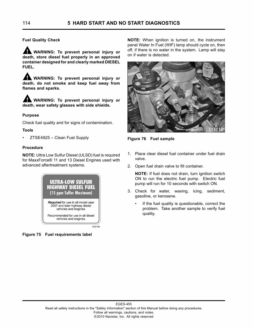
114 5 HARD START AND NO START DIAGNOSTICS
Fuel Quality Check
WARNING: To prevent personal injury ordeath, store diesel fuel properly in an approvedcontainer designed for and clearlymarked DIESELFUEL.
WARNING: To prevent personal injury ordeath, do not smoke and keep fuel away fromflames and sparks.
WARNING: To prevent personal injury ordeath, wear safety glasses with side shields.
Purpose
Check fuel quality and for signs of contamination.
Tools
• ZTSE4925 – Clean Fuel Supply
Procedure
NOTE: Ultra Low Sulfur Diesel (ULSD) fuel is requiredfor MaxxForce® 11 and 13 Diesel Engines used withadvanced aftertreatment systems.
Figure 75 Fuel requirements label
NOTE: When ignition is turned on, the instrumentpanel Water In Fuel (WIF) lamp should cycle on, thenoff, if there is no water in the system. Lamp will stayon if water is detected.
Figure 76 Fuel sample
1. Place clear diesel fuel container under fuel drainvalve.
2. Open fuel drain valve to fill container.
NOTE: If fuel does not drain, turn ignition switchON to run the electric fuel pump. Electric fuelpump will run for 10 seconds with switch ON.
3. Check for water, waxing, icing, sediment,gasoline, or kerosene.
• If the fuel quality is questionable, correct theproblem. Take another sample to verify fuelquality.
EGES-455Read all safety instructions in the "Safety Information" section of this Manual before doing any procedures.
Follow all warnings, cautions, and notes.©2010 Navistar, Inc. All rights reserved
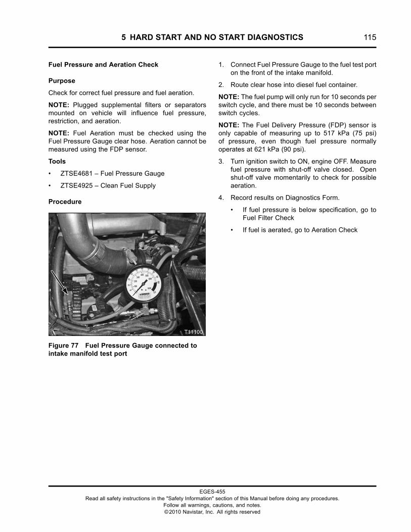
5 HARD START AND NO START DIAGNOSTICS 115
Fuel Pressure and Aeration Check
Purpose
Check for correct fuel pressure and fuel aeration.
NOTE: Plugged supplemental filters or separatorsmounted on vehicle will influence fuel pressure,restriction, and aeration.
NOTE: Fuel Aeration must be checked using theFuel Pressure Gauge clear hose. Aeration cannot bemeasured using the FDP sensor.
Tools
• ZTSE4681 – Fuel Pressure Gauge
• ZTSE4925 – Clean Fuel Supply
Procedure
Figure 77 Fuel Pressure Gauge connected tointake manifold test port
1. Connect Fuel Pressure Gauge to the fuel test porton the front of the intake manifold.
2. Route clear hose into diesel fuel container.
NOTE: The fuel pump will only run for 10 seconds perswitch cycle, and there must be 10 seconds betweenswitch cycles.
NOTE: The Fuel Delivery Pressure (FDP) sensor isonly capable of measuring up to 517 kPa (75 psi)of pressure, even though fuel pressure normallyoperates at 621 kPa (90 psi).
3. Turn ignition switch to ON, engine OFF. Measurefuel pressure with shut-off valve closed. Openshut-off valve momentarily to check for possibleaeration.
4. Record results on Diagnostics Form.
• If fuel pressure is below specification, go toFuel Filter Check
• If fuel is aerated, go to Aeration Check
EGES-455Read all safety instructions in the "Safety Information" section of this Manual before doing any procedures.
Follow all warnings, cautions, and notes.©2010 Navistar, Inc. All rights reserved
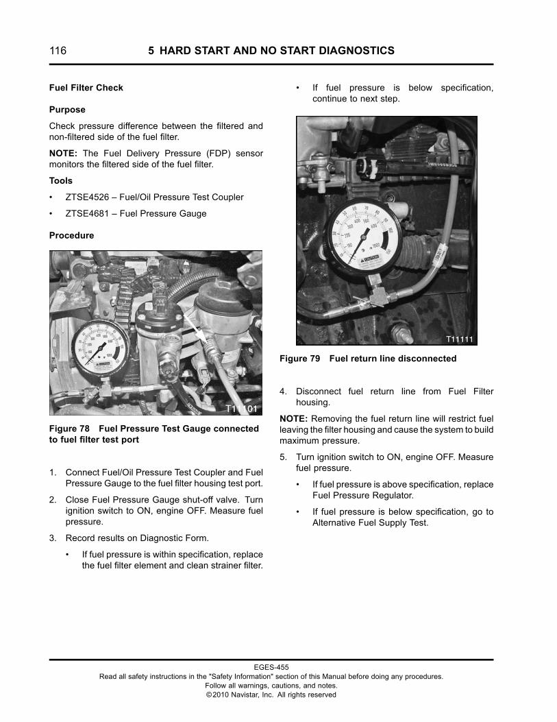
116 5 HARD START AND NO START DIAGNOSTICS
Fuel Filter Check
Purpose
Check pressure difference between the filtered andnon-filtered side of the fuel filter.
NOTE: The Fuel Delivery Pressure (FDP) sensormonitors the filtered side of the fuel filter.
Tools
• ZTSE4526 – Fuel/Oil Pressure Test Coupler
• ZTSE4681 – Fuel Pressure Gauge
Procedure
Figure 78 Fuel Pressure Test Gauge connectedto fuel filter test port
1. Connect Fuel/Oil Pressure Test Coupler and FuelPressure Gauge to the fuel filter housing test port.
2. Close Fuel Pressure Gauge shut-off valve. Turnignition switch to ON, engine OFF. Measure fuelpressure.
3. Record results on Diagnostic Form.
• If fuel pressure is within specification, replacethe fuel filter element and clean strainer filter.
• If fuel pressure is below specification,continue to next step.
Figure 79 Fuel return line disconnected
4. Disconnect fuel return line from Fuel Filterhousing.
NOTE: Removing the fuel return line will restrict fuelleaving the filter housing and cause the system to buildmaximum pressure.
5. Turn ignition switch to ON, engine OFF. Measurefuel pressure.
• If fuel pressure is above specification, replaceFuel Pressure Regulator.
• If fuel pressure is below specification, go toAlternative Fuel Supply Test.
EGES-455Read all safety instructions in the "Safety Information" section of this Manual before doing any procedures.
Follow all warnings, cautions, and notes.©2010 Navistar, Inc. All rights reserved
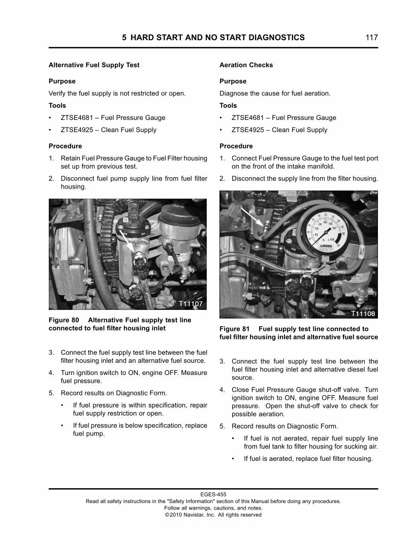
5 HARD START AND NO START DIAGNOSTICS 117
Alternative Fuel Supply Test
Purpose
Verify the fuel supply is not restricted or open.
Tools
• ZTSE4681 – Fuel Pressure Gauge
• ZTSE4925 – Clean Fuel Supply
Procedure
1. Retain Fuel Pressure Gauge to Fuel Filter housingset up from previous test.
2. Disconnect fuel pump supply line from fuel filterhousing.
Figure 80 Alternative Fuel supply test lineconnected to fuel filter housing inlet
3. Connect the fuel supply test line between the fuelfilter housing inlet and an alternative fuel source.
4. Turn ignition switch to ON, engine OFF. Measurefuel pressure.
5. Record results on Diagnostic Form.
• If fuel pressure is within specification, repairfuel supply restriction or open.
• If fuel pressure is below specification, replacefuel pump.
Aeration Checks
Purpose
Diagnose the cause for fuel aeration.
Tools
• ZTSE4681 – Fuel Pressure Gauge
• ZTSE4925 – Clean Fuel Supply
Procedure
1. Connect Fuel Pressure Gauge to the fuel test porton the front of the intake manifold.
2. Disconnect the supply line from the filter housing.
Figure 81 Fuel supply test line connected tofuel filter housing inlet and alternative fuel source
3. Connect the fuel supply test line between thefuel filter housing inlet and alternative diesel fuelsource.
4. Close Fuel Pressure Gauge shut-off valve. Turnignition switch to ON, engine OFF. Measure fuelpressure. Open the shut-off valve to check forpossible aeration.
5. Record results on Diagnostic Form.
• If fuel is not aerated, repair fuel supply linefrom fuel tank to filter housing for sucking air.
• If fuel is aerated, replace fuel filter housing.
EGES-455Read all safety instructions in the "Safety Information" section of this Manual before doing any procedures.
Follow all warnings, cautions, and notes.©2010 Navistar, Inc. All rights reserved
118 5 HARD START AND NO START DIAGNOSTICS
Injection Control Pressure System
Figure 82 ICP System
1. High-pressure oil manifold2. Injection Control Pressure (ICP)
sensor3. High-pressure oil hose
4. High-pressure oil pump5. Injection Pressure Regulator
(IPR) Valve
6. Oil inlet from front cover reservoir(with screen filter)
7. Fuel injector (6)
EGES-455Read all safety instructions in the "Safety Information" section of this Manual before doing any procedures.
Follow all warnings, cautions, and notes.©2010 Navistar, Inc. All rights reserved
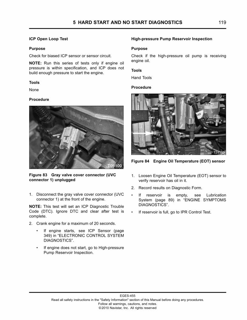
5 HARD START AND NO START DIAGNOSTICS 119
ICP Open Loop Test
Purpose
Check for biased ICP sensor or sensor circuit.
NOTE: Run this series of tests only if engine oilpressure is within specification, and ICP does notbuild enough pressure to start the engine.
Tools
None
Procedure
Figure 83 Gray valve cover connector (UVCconnector 1) unplugged
1. Disconnect the gray valve cover connector (UVCconnector 1) at the front of the engine.
NOTE: This test will set an ICP Diagnostic TroubleCode (DTC). Ignore DTC and clear after test iscomplete.
2. Crank engine for a maximum of 20 seconds.
• If engine starts, see ICP Sensor (page349) in “ELECTRONIC CONTROL SYSTEMDIAGNOSTICS”.
• If engine does not start, go to High-pressurePump Reservoir Inspection.
High-pressure Pump Reservoir Inspection
Purpose
Check if the high-pressure oil pump is receivingengine oil.
Tools
Hand Tools
Procedure
Figure 84 Engine Oil Temperature (EOT) sensor
1. Loosen Engine Oil Temperature (EOT) sensor toverify reservoir has oil in it.
2. Record results on Diagnostic Form.
• If reservoir is empty, see LubricationSystem (page 89) in “ENGINE SYMPTOMSDIAGNOSTICS”.
• If reservoir is full, go to IPR Control Test.
EGES-455Read all safety instructions in the "Safety Information" section of this Manual before doing any procedures.
Follow all warnings, cautions, and notes.©2010 Navistar, Inc. All rights reserved
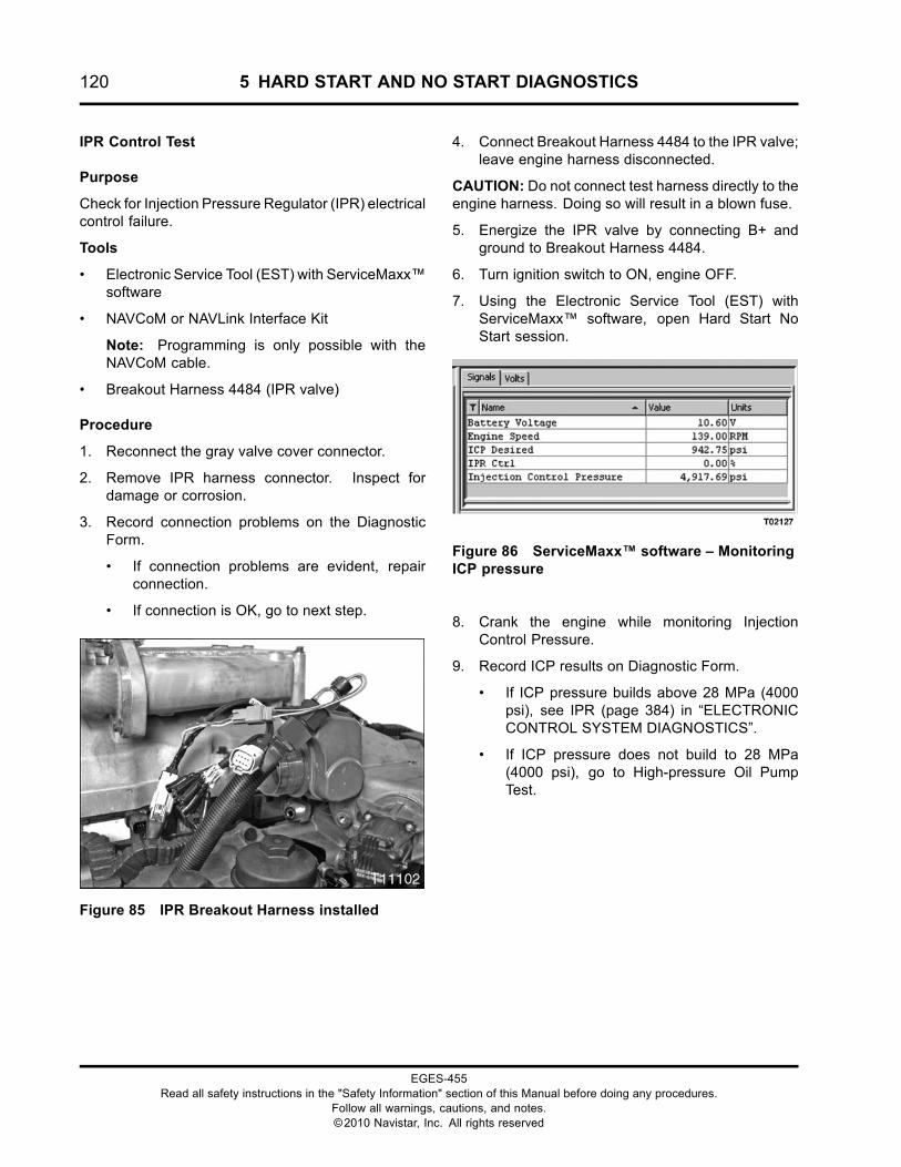
120 5 HARD START AND NO START DIAGNOSTICS
IPR Control Test
Purpose
Check for Injection Pressure Regulator (IPR) electricalcontrol failure.
Tools
• Electronic Service Tool (EST) with ServiceMaxx™software
• NAVCoM or NAVLink Interface Kit
Note: Programming is only possible with theNAVCoM cable.
• Breakout Harness 4484 (IPR valve)
Procedure
1. Reconnect the gray valve cover connector.
2. Remove IPR harness connector. Inspect fordamage or corrosion.
3. Record connection problems on the DiagnosticForm.
• If connection problems are evident, repairconnection.
• If connection is OK, go to next step.
Figure 85 IPR Breakout Harness installed
4. Connect Breakout Harness 4484 to the IPR valve;leave engine harness disconnected.
CAUTION: Do not connect test harness directly to theengine harness. Doing so will result in a blown fuse.
5. Energize the IPR valve by connecting B+ andground to Breakout Harness 4484.
6. Turn ignition switch to ON, engine OFF.
7. Using the Electronic Service Tool (EST) withServiceMaxx™ software, open Hard Start NoStart session.
Figure 86 ServiceMaxx™ software – MonitoringICP pressure
8. Crank the engine while monitoring InjectionControl Pressure.
9. Record ICP results on Diagnostic Form.
• If ICP pressure builds above 28 MPa (4000psi), see IPR (page 384) in “ELECTRONICCONTROL SYSTEM DIAGNOSTICS”.
• If ICP pressure does not build to 28 MPa(4000 psi), go to High-pressure Oil PumpTest.
EGES-455Read all safety instructions in the "Safety Information" section of this Manual before doing any procedures.
Follow all warnings, cautions, and notes.©2010 Navistar, Inc. All rights reserved
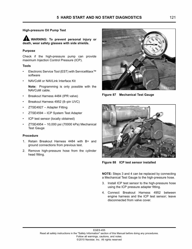
5 HARD START AND NO START DIAGNOSTICS 121
High-pressure Oil Pump Test
WARNING: To prevent personal injury ordeath, wear safety glasses with side shields.
Purpose
Check if the high-pressure pump can providemaximum Injection Control Pressure (ICP).
Tools
• Electronic Service Tool (EST) with ServiceMaxx™software
• NAVCoM or NAVLink Interface Kit
Note: Programming is only possible with theNAVCoM cable.
• Breakout Harness 4484 (IPR valve)
• Breakout Harness 4952 (8–pin UVC)
• ZTSE4927 – Adapter Fitting
• ZTSE4594 – ICP System Test Adapter
• ICP test sensor (locally obtained)
• ZTSE4954 – 10,000 psi (70000 kPa) MechanicalTest Gauge
Procedure
1. Retain Breakout Harness 4484 with B+ andground connections from previous test.
2. Remove high-pressure hose from the cylinderhead fitting.
Figure 87 Mechanical Test Gauge
Figure 88 ICP test sensor installed
NOTE: Steps 3 and 4 can be replaced by connectinga Mechanical Test Gauge to the high-pressure hose.
3. Install ICP test sensor to the high-pressure hoseusing the ICP pressure adapter fitting.
4. Connect Breakout Harness 4952 betweenengine harness and the ICP test sensor; leavedisconnected from valve cover.
EGES-455Read all safety instructions in the "Safety Information" section of this Manual before doing any procedures.
Follow all warnings, cautions, and notes.©2010 Navistar, Inc. All rights reserved
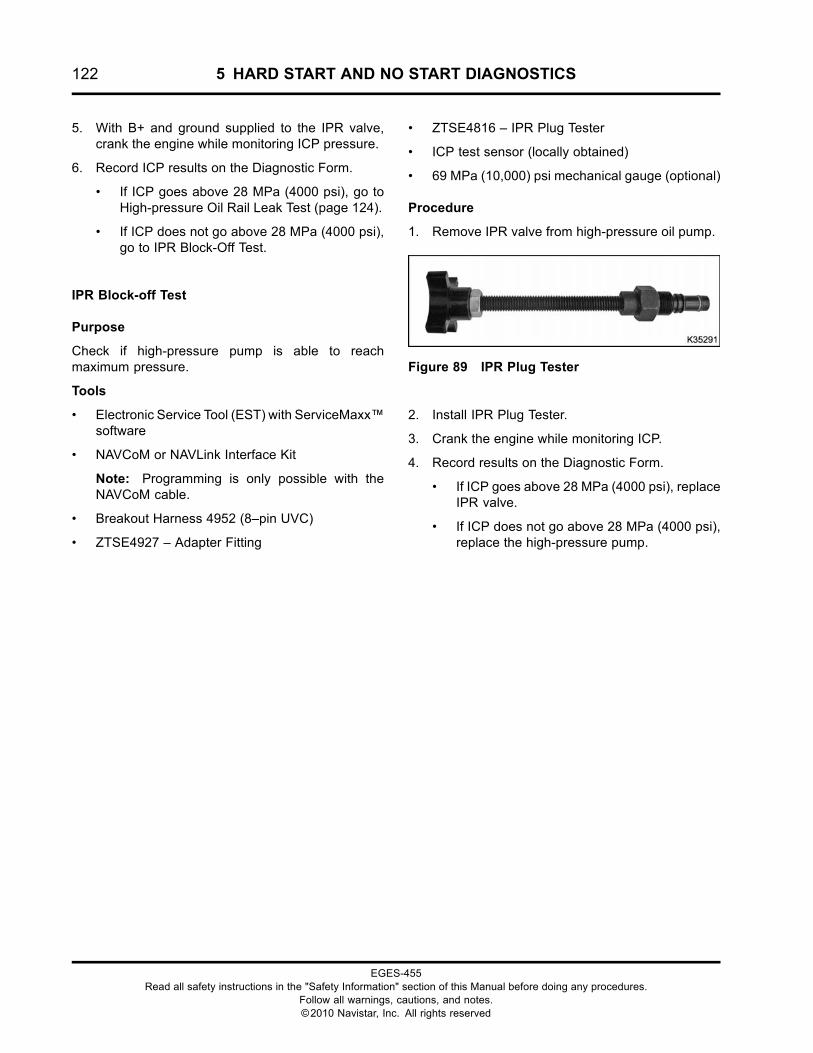
122 5 HARD START AND NO START DIAGNOSTICS
5. With B+ and ground supplied to the IPR valve,crank the engine while monitoring ICP pressure.
6. Record ICP results on the Diagnostic Form.
• If ICP goes above 28 MPa (4000 psi), go toHigh-pressure Oil Rail Leak Test (page 124).
• If ICP does not go above 28 MPa (4000 psi),go to IPR Block-Off Test.
IPR Block-off Test
Purpose
Check if high-pressure pump is able to reachmaximum pressure.
Tools
• Electronic Service Tool (EST) with ServiceMaxx™software
• NAVCoM or NAVLink Interface Kit
Note: Programming is only possible with theNAVCoM cable.
• Breakout Harness 4952 (8–pin UVC)
• ZTSE4927 – Adapter Fitting
• ZTSE4816 – IPR Plug Tester
• ICP test sensor (locally obtained)
• 69 MPa (10,000) psi mechanical gauge (optional)
Procedure
1. Remove IPR valve from high-pressure oil pump.
Figure 89 IPR Plug Tester
2. Install IPR Plug Tester.
3. Crank the engine while monitoring ICP.
4. Record results on the Diagnostic Form.
• If ICP goes above 28 MPa (4000 psi), replaceIPR valve.
• If ICP does not go above 28 MPa (4000 psi),replace the high-pressure pump.
EGES-455Read all safety instructions in the "Safety Information" section of this Manual before doing any procedures.
Follow all warnings, cautions, and notes.©2010 Navistar, Inc. All rights reserved
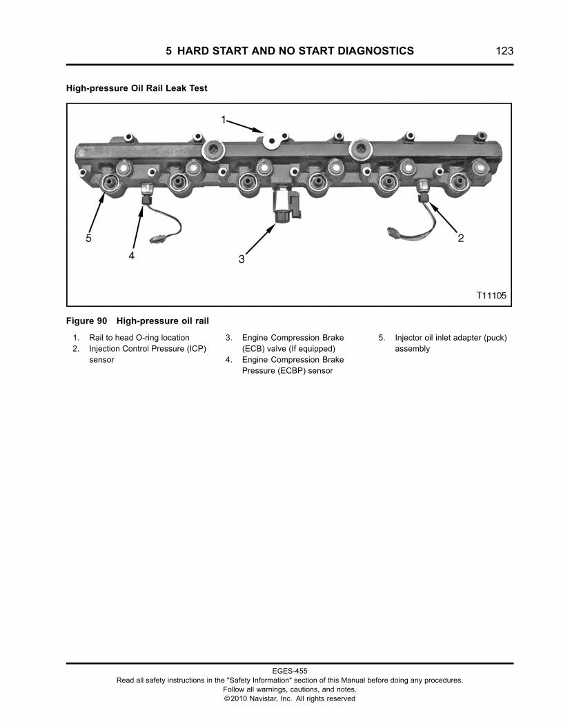
5 HARD START AND NO START DIAGNOSTICS 123
High-pressure Oil Rail Leak Test
Figure 90 High-pressure oil rail
1. Rail to head O-ring location2. Injection Control Pressure (ICP)
sensor
3. Engine Compression Brake(ECB) valve (If equipped)
4. Engine Compression BrakePressure (ECBP) sensor
5. Injector oil inlet adapter (puck)assembly
EGES-455Read all safety instructions in the "Safety Information" section of this Manual before doing any procedures.
Follow all warnings, cautions, and notes.©2010 Navistar, Inc. All rights reserved
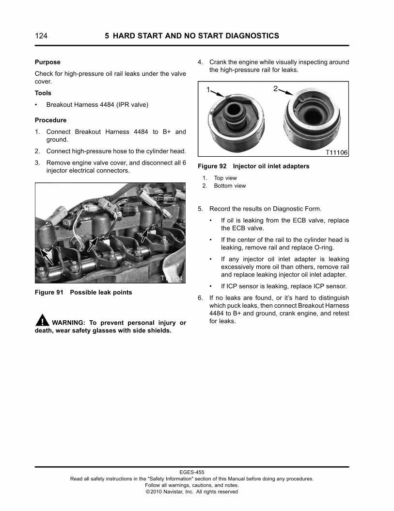
124 5 HARD START AND NO START DIAGNOSTICS
Purpose
Check for high-pressure oil rail leaks under the valvecover.
Tools
• Breakout Harness 4484 (IPR valve)
Procedure
1. Connect Breakout Harness 4484 to B+ andground.
2. Connect high-pressure hose to the cylinder head.
3. Remove engine valve cover, and disconnect all 6injector electrical connectors.
Figure 91 Possible leak points
WARNING: To prevent personal injury ordeath, wear safety glasses with side shields.
4. Crank the engine while visually inspecting aroundthe high-pressure rail for leaks.
Figure 92 Injector oil inlet adapters
1. Top view2. Bottom view
5. Record the results on Diagnostic Form.
• If oil is leaking from the ECB valve, replacethe ECB valve.
• If the center of the rail to the cylinder head isleaking, remove rail and replace O-ring.
• If any injector oil inlet adapter is leakingexcessively more oil than others, remove railand replace leaking injector oil inlet adapter.
• If ICP sensor is leaking, replace ICP sensor.
6. If no leaks are found, or it’s hard to distinguishwhich puck leaks, then connect Breakout Harness4484 to B+ and ground, crank engine, and retestfor leaks.
EGES-455Read all safety instructions in the "Safety Information" section of this Manual before doing any procedures.
Follow all warnings, cautions, and notes.©2010 Navistar, Inc. All rights reserved
6 PERFORMANCE DIAGNOSTICS 125
Table of Contents
Diagnostic Form EGED-460. . . . . . . . . . . . . . . . . . . . . . . . . . . . . . . . . . . . . . . . . . . . . . . . . . . . . . . . . . . . . . . . . . . . . . . . . . . . . . . . . . . . . . . . . .127Diagnostics Form Header Information. . . . . . . . . . . . . . . . . . . . . . . . . . . . . . . . . . . . . . . . . . . . . . . . . . . . . . . . . . . . . . . . . . . .128
Required Test Procedures. . . . . . . . . . . . . . . . . . . . . . . . . . . . . . . . . . . . . . . . . . . . . . . . . . . . . . . . . . . . . . . . . . . . . . . . . . . . . . . . . . . . . . . . . . . .1291. Initial Key On Check.. . . . . . . . . . . . . . . . . . . . . . . . . . . . . . . . . . . . . . . . . . . . . . . . . . . . . . . . . . . . . . . . . . . . . . . . . . . . . . . . . . . . .1292. Visual Inspection. . . . . . . . . . . . . . . . . . . . . . . . . . . . . . . . . . . . . . . . . . . . . . . . . . . . . . . . . . . . . . . . . . . . . . . . . . . . . . . . . . . . . . . . . .130
Engine Oil. . . . . . . . . . . . . . . . . . . . . . . . . . . . . . . . . . . . . . . . . . . . . . . . . . . . . . . . . . . . . . . . . . . . . . . . . . . . . . . . . . . . . . . . . . . .130Fuel Level. . . . . . . . . . . . . . . . . . . . . . . . . . . . . . . . . . . . . . . . . . . . . . . . . . . . . . . . . . . . . . . . . . . . . . . . . . . . . . . . . . . . . . . . . . . .130Fuel Quality Check.. . . . . . . . . . . . . . . . . . . . . . . . . . . . . . . . . . . . . . . . . . . . . . . . . . . . . . . . . . . . . . . . . . . . . . . . . . . . . . . .131Engine Coolant Level. . . . . . . . . . . . . . . . . . . . . . . . . . . . . . . . . . . . . . . . . . . . . . . . . . . . . . . . . . . . . . . . . . . . . . . . . . . . . .132Charge Air Cooler (CAC) System.. . . . . . . . . . . . . . . . . . . . . . . . . . . . . . . . . . . . . . . . . . . . . . . . . . . . . . . . . . . . . . .132Electrical System.. . . . . . . . . . . . . . . . . . . . . . . . . . . . . . . . . . . . . . . . . . . . . . . . . . . . . . . . . . . . . . . . . . . . . . . . . . . . . . . . . .132Intake Air. . . . . . . . . . . . . . . . . . . . . . . . . . . . . . . . . . . . . . . . . . . . . . . . . . . . . . . . . . . . . . . . . . . . . . . . . . . . . . . . . . . . . . . . . . . . .132Exhaust System.. . . . . . . . . . . . . . . . . . . . . . . . . . . . . . . . . . . . . . . . . . . . . . . . . . . . . . . . . . . . . . . . . . . . . . . . . . . . . . . . . . . .132
3. Electronic Service Tool (EST) with ServiceMaxx™ software Connection. . . . . . . . . . . . . . . . . . . . . . .1334. Check for DTCs. . . . . . . . . . . . . . . . . . . . . . . . . . . . . . . . . . . . . . . . . . . . . . . . . . . . . . . . . . . . . . . . . . . . . . . . . . . . . . . . . . . . . . . . . . . .1355. KOER Standard Test. . . . . . . . . . . . . . . . . . . . . . . . . . . . . . . . . . . . . . . . . . . . . . . . . . . . . . . . . . . . . . . . . . . . . . . . . . . . . . . . . . . . . .1366. Fuel Aeration Check.. . . . . . . . . . . . . . . . . . . . . . . . . . . . . . . . . . . . . . . . . . . . . . . . . . . . . . . . . . . . . . . . . . . . . . . . . . . . . . . . . . . . .1367. Engine Low Idle to High Idle. . . . . . . . . . . . . . . . . . . . . . . . . . . . . . . . . . . . . . . . . . . . . . . . . . . . . . . . . . . . . . . . . . . . . . . . . . . .1378. Torque Converter Stall Test (Automatic Transmission Only). . . . . . . . . . . . . . . . . . . . . . . . . . . . . . . . . . . . . .1389. ICP System Test. . . . . . . . . . . . . . . . . . . . . . . . . . . . . . . . . . . . . . . . . . . . . . . . . . . . . . . . . . . . . . . . . . . . . . . . . . . . . . . . . . . . . . . . . . .13810. KOER Air Management Test. . . . . . . . . . . . . . . . . . . . . . . . . . . . . . . . . . . . . . . . . . . . . . . . . . . . . . . . . . . . . . . . . . . . . . . . . . .13911. Exhaust Back Pressure Valve Test. . . . . . . . . . . . . . . . . . . . . . . . . . . . . . . . . . . . . . . . . . . . . . . . . . . . . . . . . . . . . . . . . . .14012. Turbocharger 2 Wastegate Control (TC2WC). . . . . . . . . . . . . . . . . . . . . . . . . . . . . . . . . . . . . . . . . . . . . . . . . . . . . . .141
Operational Test. . . . . . . . . . . . . . . . . . . . . . . . . . . . . . . . . . . . . . . . . . . . . . . . . . . . . . . . . . . . . . . . . . . . . . . . . . . . . . . . . . . . .141Turbocharger 2 Wastegate Control Solenoid Test. . . . . . . . . . . . . . . . . . . . . . . . . . . . . . . . . . . . . . . . . . . .142Isolated Actuator Test . . . . . . . . . . . . . . . . . . . . . . . . . . . . . . . . . . . . . . . . . . . . . . . . . . . . . . . . . . . . . . . . . . . . . . . . . . . . .142
13. Oil Breather Separator Test. . . . . . . . . . . . . . . . . . . . . . . . . . . . . . . . . . . . . . . . . . . . . . . . . . . . . . . . . . . . . . . . . . . . . . . . . . . .14314. Crankcase Pressure Test. . . . . . . . . . . . . . . . . . . . . . . . . . . . . . . . . . . . . . . . . . . . . . . . . . . . . . . . . . . . . . . . . . . . . . . . . . . . . . .14315. Relative Compression Test. . . . . . . . . . . . . . . . . . . . . . . . . . . . . . . . . . . . . . . . . . . . . . . . . . . . . . . . . . . . . . . . . . . . . . . . . . . .14516. Cylinder Cut Out Test. . . . . . . . . . . . . . . . . . . . . . . . . . . . . . . . . . . . . . . . . . . . . . . . . . . . . . . . . . . . . . . . . . . . . . . . . . . . . . . . . . .14617. Road Test (Full load, Rated Speed). . . . . . . . . . . . . . . . . . . . . . . . . . . . . . . . . . . . . . . . . . . . . . . . . . . . . . . . . . . . . . . . . . .147
EGES-455Read all safety instructions in the "Safety Information" section of this Manual before doing any procedures.
Follow all warnings, cautions, and notes.©2010 Navistar, Inc. All rights reserved

126 6 PERFORMANCE DIAGNOSTICS
EGES-455Read all safety instructions in the "Safety Information" section of this Manual before doing any procedures.
Follow all warnings, cautions, and notes.©2010 Navistar, Inc. All rights reserved
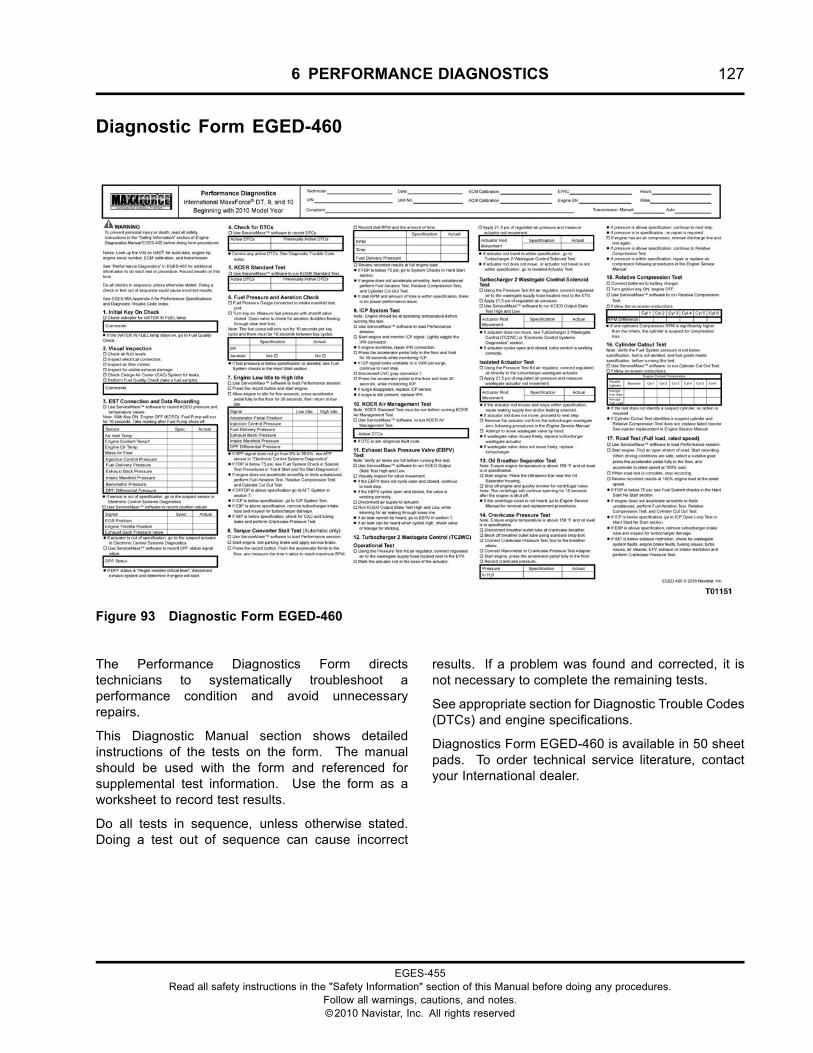
6 PERFORMANCE DIAGNOSTICS 127
Diagnostic Form EGED-460
Figure 93 Diagnostic Form EGED-460
The Performance Diagnostics Form directstechnicians to systematically troubleshoot aperformance condition and avoid unnecessaryrepairs.
This Diagnostic Manual section shows detailedinstructions of the tests on the form. The manualshould be used with the form and referenced forsupplemental test information. Use the form as aworksheet to record test results.
Do all tests in sequence, unless otherwise stated.Doing a test out of sequence can cause incorrect
results. If a problem was found and corrected, it isnot necessary to complete the remaining tests.
See appropriate section for Diagnostic Trouble Codes(DTCs) and engine specifications.
Diagnostics Form EGED-460 is available in 50 sheetpads. To order technical service literature, contactyour International dealer.
EGES-455Read all safety instructions in the "Safety Information" section of this Manual before doing any procedures.
Follow all warnings, cautions, and notes.©2010 Navistar, Inc. All rights reserved
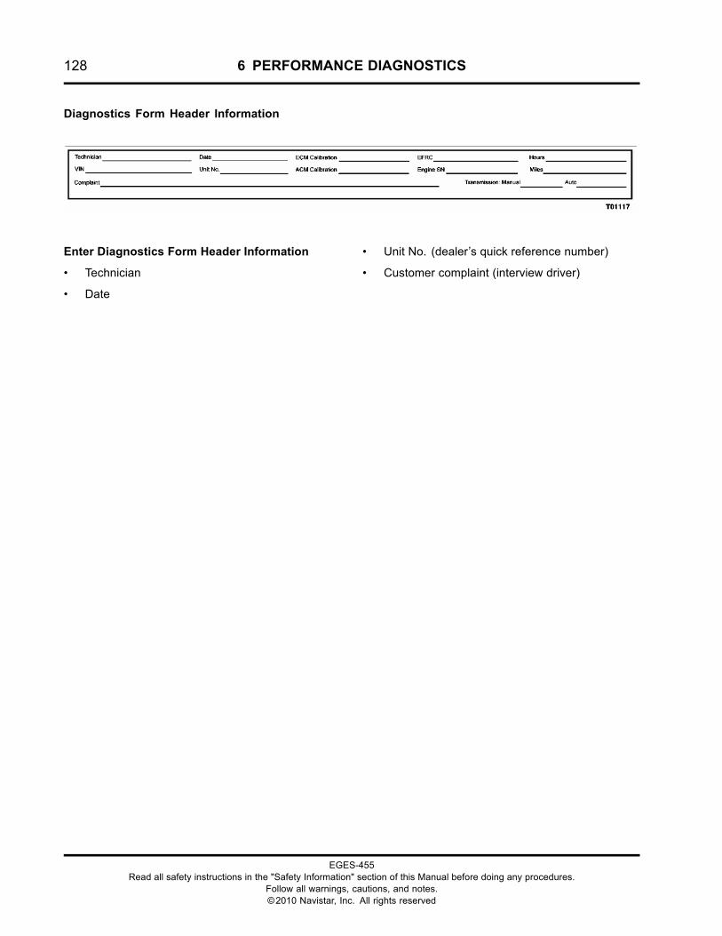
128 6 PERFORMANCE DIAGNOSTICS
Diagnostics Form Header Information
Enter Diagnostics Form Header Information
• Technician
• Date
• Unit No. (dealer’s quick reference number)
• Customer complaint (interview driver)
EGES-455Read all safety instructions in the "Safety Information" section of this Manual before doing any procedures.
Follow all warnings, cautions, and notes.©2010 Navistar, Inc. All rights reserved
6 PERFORMANCE DIAGNOSTICS 129
Required Test Procedures
GOVERNMENT REGULATION: Enginefluids (oil, fuel, and coolant) may be a hazardto human health and the environment.Handle all fluids and other contaminatedmaterials (e.g. filters, rags) in accordancewith applicable regulations. Recycleor dispose of engine fluids, filters, andother contaminated materials according toapplicable regulations.
WARNING: To prevent personal injury ordeath, do not let engine fluids stay on your skin.Clean skin and nails using hand cleaner and washwith soap and water. Wash or discard clothingand rags contaminated with engine fluids.
WARNING: To prevent personal injury ordeath, shift transmission to park or neutral, setparking brake, and block wheels before doingdiagnostic or service procedures.
WARNING: To prevent personal injury ordeath, do not smoke and keep fuel away fromflames and sparks.
WARNING: To prevent personal injury ordeath, provide proper ventilation when operatingan engine in a closed area. Inhalation of exhaustgas can be fatal.
Performance Specification Information See“APPENDIX A: PERFORMANCE SPECIFICATIONS”in this manual, or TSI to obtain the requiredspecification information:
NOTE: Performance specifications are periodicallypublished in a Technical Service Information (TSI)format to support new model year products. Checkservice bulletin repository on ISIS for appropriatemodel year application.
1. Initial Key On Check
Purpose
Determine if the Engine Control Module (ECM) ispowered up and if water is in the fuel supply.
Tools
• Electronic Service Tool (EST) with ServiceMaxx™software
• NAVCoM or NavLink interface Kit
Note: Programming is only possible with theNAVCoM cable.
Procedure
1. Turn ignition switch to ON, engine OFF. Check orlisten for the following:
• WAIT TO START lamp
• WATER IN FUEL lamp (LCD display)
2. Connect the Electronic Service Tool (EST)with ServiceMaxx™ software to the vehicle’sDiagnostic Connector.
3. Start the ServiceMaxx™ software.
• If unable to communicate with the ECM, seethe ServiceMaxx™ Users Guide.
• If unable to communicate and no problemsfound with ServiceMaxx™ software,go to J1939 Data Link (page 390) in“ELECTRONIC CONTROL SYSTEMDIAGNOSTICS”.
• If communication was established, continueto the next step.
4. Record results on the Diagnostic Form.
• If WATER IN FUEL lamp stays on, go to FuelQuality Check (page 131).
EGES-455Read all safety instructions in the "Safety Information" section of this Manual before doing any procedures.
Follow all warnings, cautions, and notes.©2010 Navistar, Inc. All rights reserved
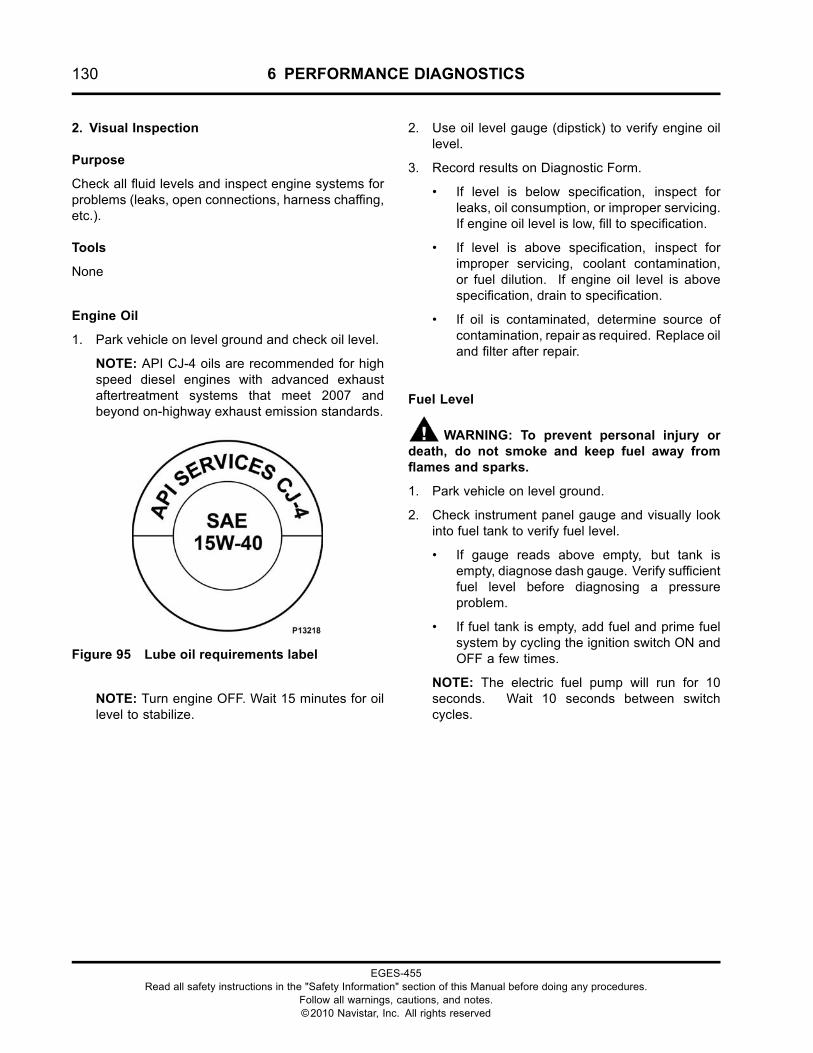
130 6 PERFORMANCE DIAGNOSTICS
2. Visual Inspection
Purpose
Check all fluid levels and inspect engine systems forproblems (leaks, open connections, harness chaffing,etc.).
Tools
None
Engine Oil
1. Park vehicle on level ground and check oil level.
NOTE: API CJ-4 oils are recommended for highspeed diesel engines with advanced exhaustaftertreatment systems that meet 2007 andbeyond on-highway exhaust emission standards.
Figure 95 Lube oil requirements label
NOTE: Turn engine OFF. Wait 15 minutes for oillevel to stabilize.
2. Use oil level gauge (dipstick) to verify engine oillevel.
3. Record results on Diagnostic Form.
• If level is below specification, inspect forleaks, oil consumption, or improper servicing.If engine oil level is low, fill to specification.
• If level is above specification, inspect forimproper servicing, coolant contamination,or fuel dilution. If engine oil level is abovespecification, drain to specification.
• If oil is contaminated, determine source ofcontamination, repair as required. Replace oiland filter after repair.
Fuel Level
WARNING: To prevent personal injury ordeath, do not smoke and keep fuel away fromflames and sparks.
1. Park vehicle on level ground.
2. Check instrument panel gauge and visually lookinto fuel tank to verify fuel level.
• If gauge reads above empty, but tank isempty, diagnose dash gauge. Verify sufficientfuel level before diagnosing a pressureproblem.
• If fuel tank is empty, add fuel and prime fuelsystem by cycling the ignition switch ON andOFF a few times.
NOTE: The electric fuel pump will run for 10seconds. Wait 10 seconds between switchcycles.
EGES-455Read all safety instructions in the "Safety Information" section of this Manual before doing any procedures.
Follow all warnings, cautions, and notes.©2010 Navistar, Inc. All rights reserved
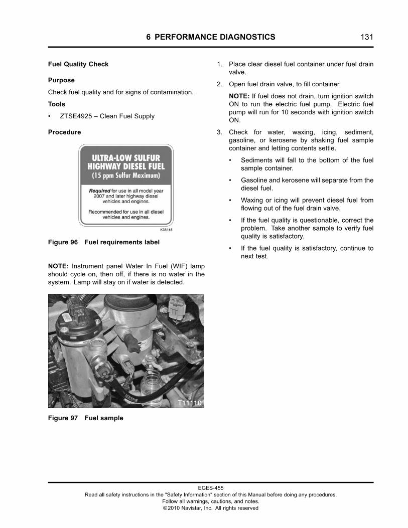
6 PERFORMANCE DIAGNOSTICS 131
Fuel Quality Check
Purpose
Check fuel quality and for signs of contamination.
Tools
• ZTSE4925 – Clean Fuel Supply
Procedure
Figure 96 Fuel requirements label
NOTE: Instrument panel Water In Fuel (WIF) lampshould cycle on, then off, if there is no water in thesystem. Lamp will stay on if water is detected.
Figure 97 Fuel sample
1. Place clear diesel fuel container under fuel drainvalve.
2. Open fuel drain valve, to fill container.
NOTE: If fuel does not drain, turn ignition switchON to run the electric fuel pump. Electric fuelpump will run for 10 seconds with ignition switchON.
3. Check for water, waxing, icing, sediment,gasoline, or kerosene by shaking fuel samplecontainer and letting contents settle.
• Sediments will fall to the bottom of the fuelsample container.
• Gasoline and kerosene will separate from thediesel fuel.
• Waxing or icing will prevent diesel fuel fromflowing out of the fuel drain valve.
• If the fuel quality is questionable, correct theproblem. Take another sample to verify fuelquality is satisfactory.
• If the fuel quality is satisfactory, continue tonext test.
EGES-455Read all safety instructions in the "Safety Information" section of this Manual before doing any procedures.
Follow all warnings, cautions, and notes.©2010 Navistar, Inc. All rights reserved

132 6 PERFORMANCE DIAGNOSTICS
Engine Coolant Level
WARNING: To prevent personal injury ordeath, make sure engine has cooled beforeremoving components.
1. Park vehicle on level ground.
2. Check coolant level as indicated on deaerationtank level window.
CAUTION: Coolant in the Exhaust could damagethe Diesel Particulate Filter (DPF). Inspect DPFfor damage. See AFT System in “ELECTRONICCONTROL SYSTEMS DIAGNOSTICS” for inspectionof the DPF. For coolant contamination, see CoolantSystem in “ENGINE SYMPTOMS DIAGNOSTICS”.
3. Record results on Diagnostic Form.
• If level is above or below deaeration tankfill level, inspect for leaks, coolant in the oil,or coolant in the intake or exhaust. Seethe “ENGINE SYMPTOMS DIAGNOSTICS”section and repair.
• If level is at deaeration tank fill level, and notank contamination is evident, no action isrequired.
• If coolant is contaminated, determine thesource, and repair as required. See “EngineOperation and Maintenance Manual” forcoolant system requirements.
Charge Air Cooler (CAC) System
1. Inspect the CAC interstage cooler, and all pipingfor leaks.
2. Inspect all CAC connections and clamps.
• If CAC system problem is found,make necessary repairs. See CoolantOver-Temperature – Charge Air Cooling(page 88) in “ENGINE SYMPTOMSDIAGNOSTICS”.
Electrical System
Inspect batteries and electrical system (engine andvehicle) for poor or loose connections, corrodedterminals, or broken and damaged wires.
• If electrical system problem is found, makenecessary repairs.
Intake Air
NOTE: Intake air restriction should be less than 172kPa (25 psi) at full rated speed.
Inspect air filter gauge, located on air filter housing oron the dash panel.
• If gauge indicates air filter requires replacement,verify there are no other restrictions in the air inletor filter housing before replacement of air filter.
Exhaust System
Inspect exhaust system (engine and vehicle) fordamaged or plugged tailpipe.
• If exhaust system problem is found, makenecessary repairs.
EGES-455Read all safety instructions in the "Safety Information" section of this Manual before doing any procedures.
Follow all warnings, cautions, and notes.©2010 Navistar, Inc. All rights reserved
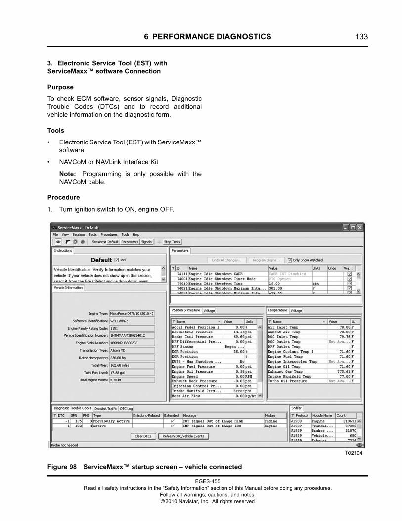
6 PERFORMANCE DIAGNOSTICS 133
3. Electronic Service Tool (EST) withServiceMaxx™ software Connection
Purpose
To check ECM software, sensor signals, DiagnosticTrouble Codes (DTCs) and to record additionalvehicle information on the diagnostic form.
Tools
• Electronic Service Tool (EST) with ServiceMaxx™software
• NAVCoM or NAVLink Interface Kit
Note: Programming is only possible with theNAVCoM cable.
Procedure
1. Turn ignition switch to ON, engine OFF.
Figure 98 ServiceMaxx™ startup screen – vehicle connected
EGES-455Read all safety instructions in the "Safety Information" section of this Manual before doing any procedures.
Follow all warnings, cautions, and notes.©2010 Navistar, Inc. All rights reserved
134 6 PERFORMANCE DIAGNOSTICS
2. Connect the Electronic Service Tool (EST)with ServiceMaxx™ software to the vehicle’sDiagnostic Connector.
3. Start the ServiceMaxx™ software.
• If unable to communicate with the ECM, seethe ServiceMaxx™ Users Guide.
• If unable to communicate and no problemsfound with ServiceMaxx™ software,go to J1939 Data Link (page 390) in“ELECTRONIC CONTROL SYSTEMDIAGNOSTICS”.
• If communication was established, continueto the next step.
4. Verify the following vehicle informationmatches the ServiceMaxx™ software displayedinformation and record on Diagnostic Form.
• Vehicle Identification Number (VIN)
• Software Identification
• Rated Horsepower (HP)
• Engine Family Rating Code (EFRC)
• Transmission
• Odometer (miles)
• Engine Hours
• Engine Serial Number (ESN)
NOTE: The engine serial number is located on theright side of the crankcase, just above the oil filterheader. It is also on the engine emission label onthe valve cover.
5. Record the following Key ON, Engine OFF(KOEO) temperature sensor values on theDiagnostic Form.
NOTE: If ECT1 is below -1 °C (30 °F), verify IntakeAir Heater is working before continuing. See InletAir Heater (page 111) in “HARD START AND NOSTART DIAGNOSTICS”.
• Air Intake Temperature (AIT)
• Engine Coolant Temperature 1 (ECT1)
• Engine Oil Temperature (EOT)
6. Record the following KOEO pressure and flowsensor values on the Diagnostic Form:
• Mass Air Flow (MAF)
• Injection Control Pressure (ICP)
• Fuel Delivery Pressure (FDP)
• Exhaust Back Pressure (EBP)
• TC2 Turbine Outlet Pressure (TC2TOP)
• Intake Manifold Pressure (IMP)
• Barometric Absolute Pressure (BARO)
• DPF Differential Pressure (DPFDP)
7. Cycle ignition switch OFF, then back ON whilemonitoring FDP.
•
NOTE: The electric fuel pump will time out after10 seconds unless engine speed is present. Ifelectric fuel pump times out, wait 10 secondsbetween switch cycles to reset timer.
NOTE: The Fuel Delivery Pressure sensor is onlycapable of measuring up to 517 kPa (75 psi) ofpressure, even though fuel pressure normallyoperates at 621 kPa (90 psi).
8. Record results on the Diagnostic Form.
• If Fuel Delivery Pressure (FDP) is below517 kPa (75 psi), go to Fuel System (page113) in “HARD START AND NO STARTDIAGNOSTICS”.
9. Look for sensor values that are out ofspecification. A sensor out of specification couldcause the ECM to command lower then normalstarting pressure on certain systems.
• If sensor is out of specification, go tothe suspect sensor in the “ELECTRONICCONTROL SYSTEM DIAGNOSTICS”section of this manual.
10. Record the following Key ON, Engine OFF(KOEO) position signal values on the DiagnosticForm:
• Exhaust Gas Recirculation Valve Position(EGRVP)
NOTE: The EGR Position signal displays dutycycle and not actual valve position. EGR valveclosed is 35%, and valve open is 90%.
• Engine Throttle Valve (ETV)
• Exhaust Back Pressure Valve (EBPV)
EGES-455Read all safety instructions in the "Safety Information" section of this Manual before doing any procedures.
Follow all warnings, cautions, and notes.©2010 Navistar, Inc. All rights reserved
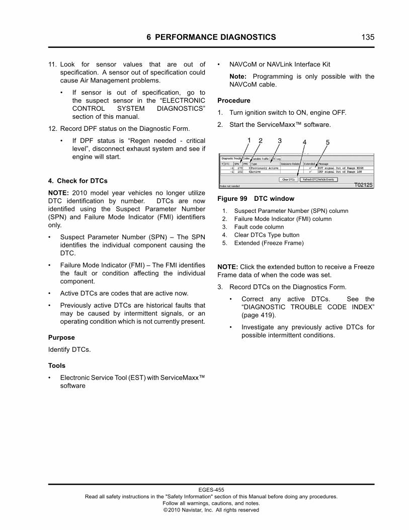
6 PERFORMANCE DIAGNOSTICS 135
11. Look for sensor values that are out ofspecification. A sensor out of specification couldcause Air Management problems.
• If sensor is out of specification, go tothe suspect sensor in the “ELECTRONICCONTROL SYSTEM DIAGNOSTICS”section of this manual.
12. Record DPF status on the Diagnostic Form.
• If DPF status is “Regen needed - criticallevel”, disconnect exhaust system and see ifengine will start.
4. Check for DTCs
NOTE: 2010 model year vehicles no longer utilizeDTC identification by number. DTCs are nowidentified using the Suspect Parameter Number(SPN) and Failure Mode Indicator (FMI) identifiersonly.
• Suspect Parameter Number (SPN) – The SPNidentifies the individual component causing theDTC.
• Failure Mode Indicator (FMI) – The FMI identifiesthe fault or condition affecting the individualcomponent.
• Active DTCs are codes that are active now.
• Previously active DTCs are historical faults thatmay be caused by intermittent signals, or anoperating condition which is not currently present.
Purpose
Identify DTCs.
Tools
• Electronic Service Tool (EST) with ServiceMaxx™software
• NAVCoM or NAVLink Interface Kit
Note: Programming is only possible with theNAVCoM cable.
Procedure
1. Turn ignition switch to ON, engine OFF.
2. Start the ServiceMaxx™ software.
Figure 99 DTC window
1. Suspect Parameter Number (SPN) column2. Failure Mode Indicator (FMI) column3. Fault code column4. Clear DTCs Type button5. Extended (Freeze Frame)
NOTE: Click the extended button to receive a FreezeFrame data of when the code was set.
3. Record DTCs on the Diagnostics Form.
• Correct any active DTCs. See the“DIAGNOSTIC TROUBLE CODE INDEX”(page 419).
• Investigate any previously active DTCs forpossible intermittent conditions.
EGES-455Read all safety instructions in the "Safety Information" section of this Manual before doing any procedures.
Follow all warnings, cautions, and notes.©2010 Navistar, Inc. All rights reserved
136 6 PERFORMANCE DIAGNOSTICS
5. KOER Standard Test
Purpose
To validate the performance of the ICP system (ifequipped with an engine compression brake).
Tools
• Electronic Service Tool (EST) with ServiceMaxx™software
• NAVCoM or NAVLink Interface Kit
• ZTSE4357 – Digital Multimeter
WARNING: To prevent personal injury ordeath, shift transmission to park or neutral, setparking brake, and block wheels before doingdiagnostic or service procedures.
Procedure
1. Turn ignition switch to ON, engine OFF.
2. Using Electronic Service Tool (EST) withServiceMaxx™ software, run KOER StandardTest.
NOTE: Engine Coolant Temperature must be above70 °C (158 °F) to run this test.
3. Record results on diagnostic form.
• If DTC is set, see the “DIAGNOSTIC TROUBLECODE INDEX” (page 419).
6. Fuel Aeration Check
Purpose
Check for aerated fuel.
Tools
• ZTSE4681 – Fuel Pressure Gauge
• ZTSE4925 – Clean Fuel Supply
Procedure
1. Connect the Fuel Pressure Gauge to the fuel testport on the front of the intake manifold.
2. Route a clear and clean plastic hose from the fuelpressure gauge into a clear and clean diesel fuelcontainer.
3. Turn ignition switch to ON, engine OFF.
NOTE: The electric fuel pump will time out after10 seconds unless engine speed is present. Ifelectric fuel pump times out, wait 10 secondsbetween key cycles to reset timer.
4. Measure fuel pressure with Fuel Pressure Gaugeshut-off valve closed. Open the shut-off valvemomentarily to check for possible aeration.
5. Record result on diagnostic form.
If fuel pressure is below specification or aerated,see Fuel System (page 113) in “HARD STARTAND NO START DIAGNOSTICS”.
EGES-455Read all safety instructions in the "Safety Information" section of this Manual before doing any procedures.
Follow all warnings, cautions, and notes.©2010 Navistar, Inc. All rights reserved
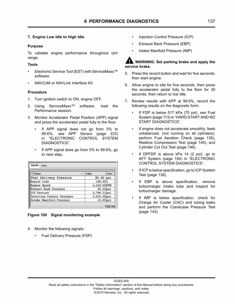
6 PERFORMANCE DIAGNOSTICS 137
7. Engine Low Idle to High Idle
Purpose
To validate engine performance throughout rpmrange.
Tools
• Electronic Service Tool (EST) with ServiceMaxx™software
• NAVCoM or NAVLink Interface Kit
Procedure
1. Turn ignition switch to ON, engine OFF.
2. Using ServiceMaxx™ software, load thePerformance session.
3. Monitor Accelerator Pedal Position (APP) signaland press the accelerator pedal fully to the floor.
• If APP signal does not go from 0% to99.6%, see APP Sensor (page 223)in “ELECTRONIC CONTROL SYSTEMDIAGNOSTICS”.
• If APP signal does go from 0% to 99.6%, goto next step.
Figure 100 Signal monitoring example
4. Monitor the following signals:
• Fuel Delivery Pressure (FDP)
• Injection Control Pressure (ICP)
• Exhaust Back Pressure (EBP)
• Intake Manifold Pressure (IMP)
WARNING: Set parking brake and apply theservice brake.
5. Press the record button and wait for five seconds,then start engine.
6. Allow engine to idle for five seconds, then pressthe accelerator pedal fully to the floor for 30seconds, then return to low idle.
7. Review results with APP at 99.6%, record thefollowing results on the diagnostic form.
• If FDP is below 517 kPa (75 psi), see FuelSystem (page 113) in “HARDSTARTANDNOSTART DIAGNOSTICS”.
• If engine does not accelerate smoothly, feelsunbalanced, (not running on all cylinders),perform Fuel Aeration Check (page 136),Relative Compression Test (page 145), andCylinder Cut Out Test (page 146).
• If DPFDP is above kPa 14 (2 psi), go toAFT System (page 194) in “ELECTRONICCONTROL SYSTEM DIAGNOSTICS”.
• If ICP is below specification, go to ICP SystemTest (page 138).
• If EBP is above specification, removeturbocharger intake tube and inspect forturbocharger damage.
• If IMP is below specification, check forCharge Air Cooler (CAC) and tubing leaksand perform the Crankcase Pressure Test(page 143).
EGES-455Read all safety instructions in the "Safety Information" section of this Manual before doing any procedures.
Follow all warnings, cautions, and notes.©2010 Navistar, Inc. All rights reserved
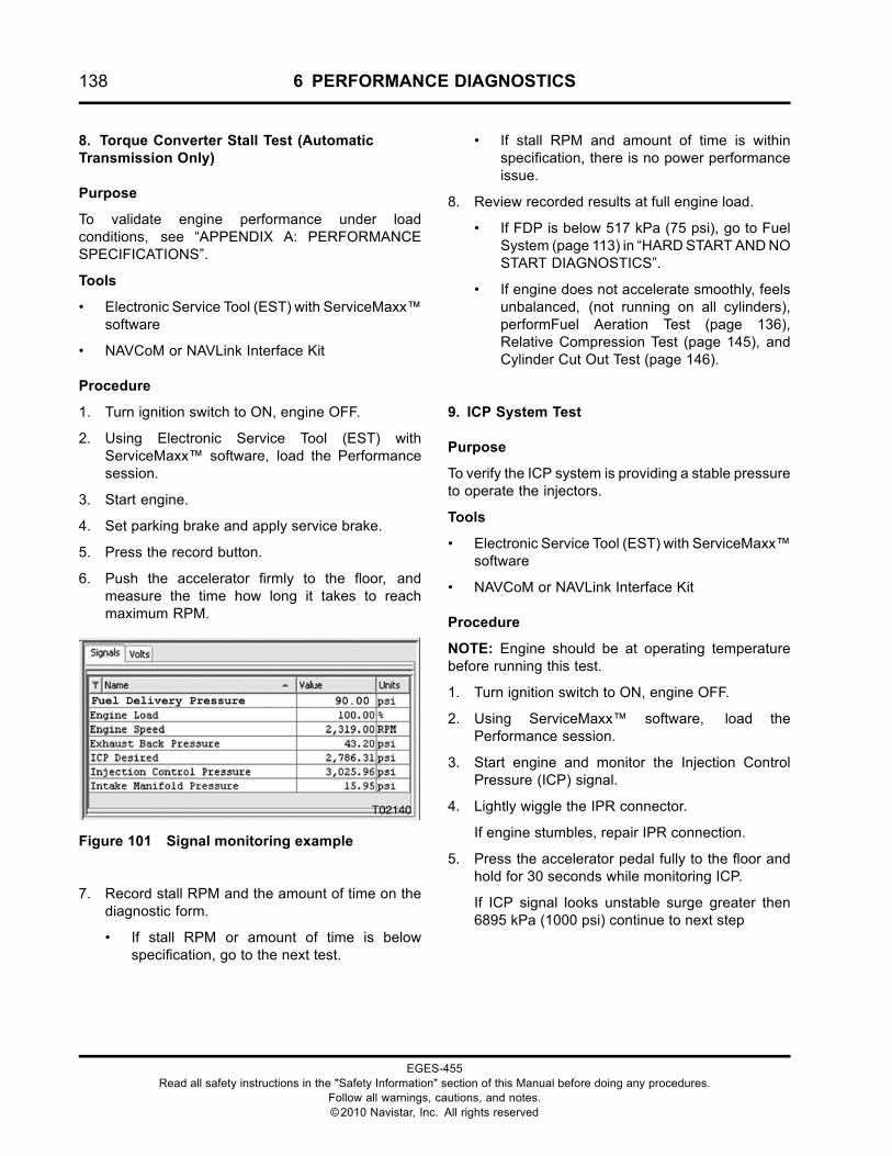
138 6 PERFORMANCE DIAGNOSTICS
8. Torque Converter Stall Test (AutomaticTransmission Only)
Purpose
To validate engine performance under loadconditions, see “APPENDIX A: PERFORMANCESPECIFICATIONS”.
Tools
• Electronic Service Tool (EST) with ServiceMaxx™software
• NAVCoM or NAVLink Interface Kit
Procedure
1. Turn ignition switch to ON, engine OFF.
2. Using Electronic Service Tool (EST) withServiceMaxx™ software, load the Performancesession.
3. Start engine.
4. Set parking brake and apply service brake.
5. Press the record button.
6. Push the accelerator firmly to the floor, andmeasure the time how long it takes to reachmaximum RPM.
Figure 101 Signal monitoring example
7. Record stall RPM and the amount of time on thediagnostic form.
• If stall RPM or amount of time is belowspecification, go to the next test.
• If stall RPM and amount of time is withinspecification, there is no power performanceissue.
8. Review recorded results at full engine load.
• If FDP is below 517 kPa (75 psi), go to FuelSystem (page 113) in “HARDSTARTANDNOSTART DIAGNOSTICS”.
• If engine does not accelerate smoothly, feelsunbalanced, (not running on all cylinders),performFuel Aeration Test (page 136),Relative Compression Test (page 145), andCylinder Cut Out Test (page 146).
9. ICP System Test
Purpose
To verify the ICP system is providing a stable pressureto operate the injectors.
Tools
• Electronic Service Tool (EST) with ServiceMaxx™software
• NAVCoM or NAVLink Interface Kit
Procedure
NOTE: Engine should be at operating temperaturebefore running this test.
1. Turn ignition switch to ON, engine OFF.
2. Using ServiceMaxx™ software, load thePerformance session.
3. Start engine and monitor the Injection ControlPressure (ICP) signal.
4. Lightly wiggle the IPR connector.
If engine stumbles, repair IPR connection.
5. Press the accelerator pedal fully to the floor andhold for 30 seconds while monitoring ICP.
If ICP signal looks unstable surge greater then6895 kPa (1000 psi) continue to next step
EGES-455Read all safety instructions in the "Safety Information" section of this Manual before doing any procedures.
Follow all warnings, cautions, and notes.©2010 Navistar, Inc. All rights reserved
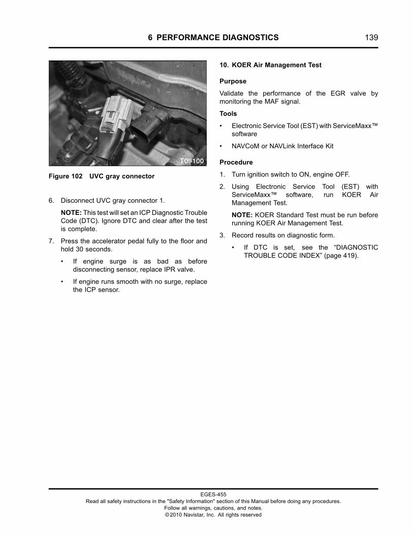
6 PERFORMANCE DIAGNOSTICS 139
Figure 102 UVC gray connector
6. Disconnect UVC gray connector 1.
NOTE: This test will set an ICPDiagnostic TroubleCode (DTC). Ignore DTC and clear after the testis complete.
7. Press the accelerator pedal fully to the floor andhold 30 seconds.
• If engine surge is as bad as beforedisconnecting sensor, replace IPR valve.
• If engine runs smooth with no surge, replacethe ICP sensor.
10. KOER Air Management Test
Purpose
Validate the performance of the EGR valve bymonitoring the MAF signal.
Tools
• Electronic Service Tool (EST) with ServiceMaxx™software
• NAVCoM or NAVLink Interface Kit
Procedure
1. Turn ignition switch to ON, engine OFF.
2. Using Electronic Service Tool (EST) withServiceMaxx™ software, run KOER AirManagement Test.
NOTE: KOER Standard Test must be run beforerunning KOER Air Management Test.
3. Record results on diagnostic form.
• If DTC is set, see the “DIAGNOSTICTROUBLE CODE INDEX” (page 419).
EGES-455Read all safety instructions in the "Safety Information" section of this Manual before doing any procedures.
Follow all warnings, cautions, and notes.©2010 Navistar, Inc. All rights reserved
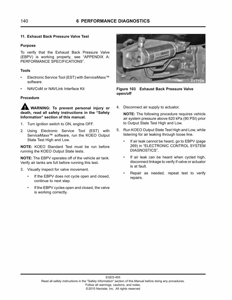
140 6 PERFORMANCE DIAGNOSTICS
11. Exhaust Back Pressure Valve Test
Purpose
To verify that the Exhaust Back Pressure Valve(EBPV) is working properly, see “APPENDIX A:PERFORMANCE SPECIFICATIONS”.
Tools
• Electronic Service Tool (EST) with ServiceMaxx™software
• NAVCoM or NAVLink Interface Kit
Procedure
WARNING: To prevent personal injury ordeath, read all safety instructions in the “SafetyInformation” section of this manual.
1. Turn ignition switch to ON, engine OFF.
2. Using Electronic Service Tool (EST) withServiceMaxx™ software, run the KOEO OutputState Test High and Low.
NOTE: KOEO Standard Test must be run beforerunning the KOEO Output State tests.
NOTE: The EBPV operates off of the vehicle air tank.Verify air tanks are full before running this test.
3. Visually inspect for valve movement.
• If the EBPV does not cycle open and closed,continue to next step.
• If the EBPV cycles open and closed, the valveis working correctly.
Figure 103 Exhaust Back Pressure Valveopen/off
4. Disconnect air supply to actuator.
NOTE: The following procedure requires vehicleair system pressure above 620 kPa (90 PSI) priorto Output State Test High and Low.
5. Run KOEOOutput State Test High and Low, whilelistening for air leaking through loose line.
• If air leak cannot be heard, go to EBPV (page269) in “ELECTRONIC CONTROL SYSTEMDIAGNOSTICS”.
• If air leak can be heard when cycled high,disconnect linkage to verify if valve or actuatoris at fault.
• Repair as needed, repeat test to verifyrepairs.
EGES-455Read all safety instructions in the "Safety Information" section of this Manual before doing any procedures.
Follow all warnings, cautions, and notes.©2010 Navistar, Inc. All rights reserved
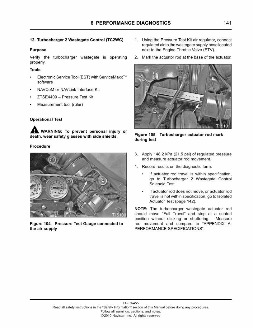
6 PERFORMANCE DIAGNOSTICS 141
12. Turbocharger 2 Wastegate Control (TC2WC)
Purpose
Verify the turbocharger wastegate is operatingproperly.
Tools
• Electronic Service Tool (EST) with ServiceMaxx™software
• NAVCoM or NAVLink Interface Kit
• ZTSE4409 – Pressure Test Kit
• Measurement tool (ruler)
Operational Test
WARNING: To prevent personal injury ordeath, wear safety glasses with side shields.
Procedure
Figure 104 Pressure Test Gauge connected tothe air supply
1. Using the Pressure Test Kit air regulator, connectregulated air to the wastegate supply hose locatednext to the Engine Throttle Valve (ETV).
2. Mark the actuator rod at the base of the actuator.
Figure 105 Turbocharger actuator rod markduring test
3. Apply 148.2 kPa (21.5 psi) of regulated pressureand measure actuator rod movement.
4. Record results on the diagnostic form.
• If actuator rod travel is within specification,go to Turbocharger 2 Wastegate ControlSolenoid Test.
• If actuator rod does not move, or actuator rodtravel is not within specification, go to IsolatedActuator Test (page 142).
NOTE: The turbocharger wastegate actuator rodshould move “Full Travel” and stop at a seatedposition without sticking or shuttering. Measurerod movement and compare to “APPENDIX A:PERFORMANCE SPECIFICATIONS”.
EGES-455Read all safety instructions in the "Safety Information" section of this Manual before doing any procedures.
Follow all warnings, cautions, and notes.©2010 Navistar, Inc. All rights reserved
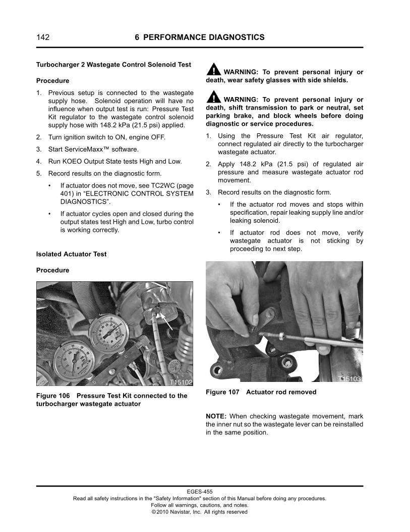
142 6 PERFORMANCE DIAGNOSTICS
Turbocharger 2 Wastegate Control Solenoid Test
Procedure
1. Previous setup is connected to the wastegatesupply hose. Solenoid operation will have noinfluence when output test is run: Pressure TestKit regulator to the wastegate control solenoidsupply hose with 148.2 kPa (21.5 psi) applied.
2. Turn ignition switch to ON, engine OFF.
3. Start ServiceMaxx™ software.
4. Run KOEO Output State tests High and Low.
5. Record results on the diagnostic form.
• If actuator does not move, see TC2WC (page401) in “ELECTRONIC CONTROL SYSTEMDIAGNOSTICS”.
• If actuator cycles open and closed during theoutput states test High and Low, turbo controlis working correctly.
Isolated Actuator Test
Procedure
Figure 106 Pressure Test Kit connected to theturbocharger wastegate actuator
WARNING: To prevent personal injury ordeath, wear safety glasses with side shields.
WARNING: To prevent personal injury ordeath, shift transmission to park or neutral, setparking brake, and block wheels before doingdiagnostic or service procedures.
1. Using the Pressure Test Kit air regulator,connect regulated air directly to the turbochargerwastegate actuator.
2. Apply 148.2 kPa (21.5 psi) of regulated airpressure and measure wastegate actuator rodmovement.
3. Record results on the diagnostic form.
• If the actuator rod moves and stops withinspecification, repair leaking supply line and/orleaking solenoid.
• If actuator rod does not move, verifywastegate actuator is not sticking byproceeding to next step.
Figure 107 Actuator rod removed
NOTE: When checking wastegate movement, markthe inner nut so the wastegate lever can be reinstalledin the same position.
EGES-455Read all safety instructions in the "Safety Information" section of this Manual before doing any procedures.
Follow all warnings, cautions, and notes.©2010 Navistar, Inc. All rights reserved
6 PERFORMANCE DIAGNOSTICS 143
4. Remove the actuator rod from the turbochargerwastegate arm, following the procedures in theEngine Service Manual. Check the turbochargerwastegate valve by hand.
• If wastegate valve moves freely, replaceturbocharger wastegate actuator.
• If wastegate valve does not move freely,replace turbocharger.
13. Oil Breather Separator Test
Purpose
To verify the oil separator is functioning properly.
Tools
• ZTSE4000 – Ultrasonic Ear
Procedure
WARNING: To prevent personal injury ordeath, make sure the parking brake is set, thetransmission is in neutral or park, and the wheelsare blocked when running the engine in theservice bay.
NOTE: Ensure engine is at normal operatingtemperature of 70 °C (158 °F) and oil level is inspecification, before performing this test.
1. Start engine.
2. Place the Ultrasonic Ear near the Oil Separatorhousing.
3. Shut off engine and quickly monitor for centrifugalnoise.
NOTE: The centrifuge will continue spinning for15 seconds after the engine is shut off.
• If the centrifuge noise is not heard, go toEngine Service Manual for removal andreplacement procedures.
14. Crankcase Pressure Test
Purpose
Determine if engine repair is required due to wear.Verify the operation of the air compressor. Check forworn or damaged parts.
Tools
• ZTSE4039 – Crankcase Pressure Test Tool
• ZTSE2217A – Water Manometer
• ZTSE2217 – Digital Manometer – Alternative toWater Manometer
• Standard shop bolt to plug intake tube
Procedure
NOTE: Ensure engine is at normal operatingtemperature of 70 °C (158 °F) and oil level is inspecification, before performing this test.
1. Verify the Crankcase breather is functioningproperly before running this test by performingthe Oil Breather Separator Test (page 143).
2. Disconnect breather outlet tube at crankcasebreather.
3. Block off breather outlet tube using standard shopbolt, to prevent dirt ingestion.
4. Connect Crankcase Pressure Test Tool to thebreather elbow.
EGES-455Read all safety instructions in the "Safety Information" section of this Manual before doing any procedures.
Follow all warnings, cautions, and notes.©2010 Navistar, Inc. All rights reserved
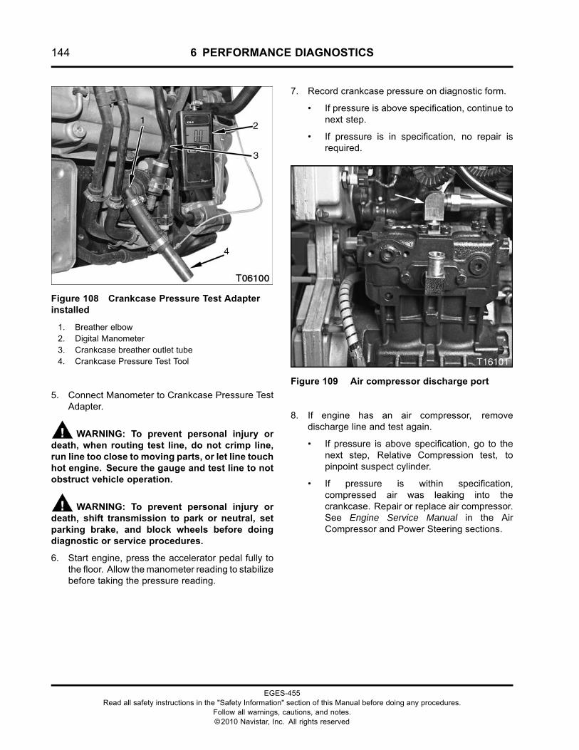
144 6 PERFORMANCE DIAGNOSTICS
Figure 108 Crankcase Pressure Test Adapterinstalled
1. Breather elbow2. Digital Manometer3. Crankcase breather outlet tube4. Crankcase Pressure Test Tool
5. Connect Manometer to Crankcase Pressure TestAdapter.
WARNING: To prevent personal injury ordeath, when routing test line, do not crimp line,run line too close to moving parts, or let line touchhot engine. Secure the gauge and test line to notobstruct vehicle operation.
WARNING: To prevent personal injury ordeath, shift transmission to park or neutral, setparking brake, and block wheels before doingdiagnostic or service procedures.
6. Start engine, press the accelerator pedal fully tothe floor. Allow themanometer reading to stabilizebefore taking the pressure reading.
7. Record crankcase pressure on diagnostic form.
• If pressure is above specification, continue tonext step.
• If pressure is in specification, no repair isrequired.
Figure 109 Air compressor discharge port
8. If engine has an air compressor, removedischarge line and test again.
• If pressure is above specification, go to thenext step, Relative Compression test, topinpoint suspect cylinder.
• If pressure is within specification,compressed air was leaking into thecrankcase. Repair or replace air compressor.See Engine Service Manual in the AirCompressor and Power Steering sections.
EGES-455Read all safety instructions in the "Safety Information" section of this Manual before doing any procedures.
Follow all warnings, cautions, and notes.©2010 Navistar, Inc. All rights reserved
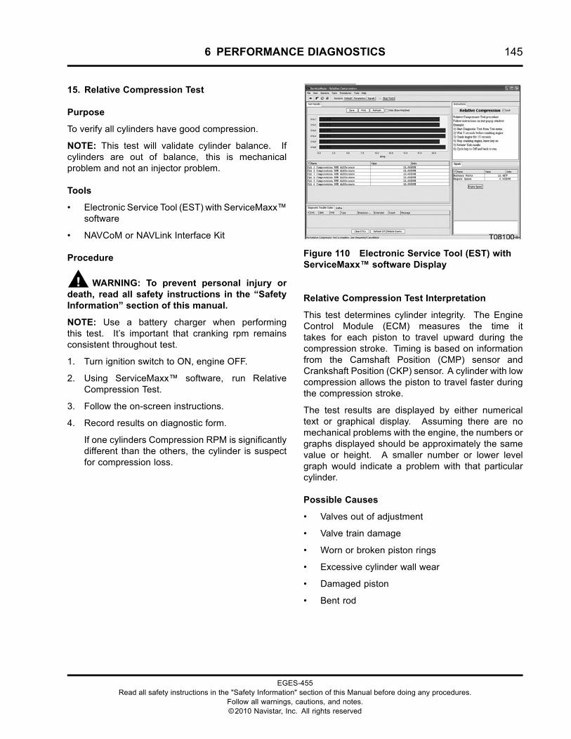
6 PERFORMANCE DIAGNOSTICS 145
15. Relative Compression Test
Purpose
To verify all cylinders have good compression.
NOTE: This test will validate cylinder balance. Ifcylinders are out of balance, this is mechanicalproblem and not an injector problem.
Tools
• Electronic Service Tool (EST) with ServiceMaxx™software
• NAVCoM or NAVLink Interface Kit
Procedure
WARNING: To prevent personal injury ordeath, read all safety instructions in the “SafetyInformation” section of this manual.
NOTE: Use a battery charger when performingthis test. It’s important that cranking rpm remainsconsistent throughout test.
1. Turn ignition switch to ON, engine OFF.
2. Using ServiceMaxx™ software, run RelativeCompression Test.
3. Follow the on-screen instructions.
4. Record results on diagnostic form.
If one cylinders Compression RPM is significantlydifferent than the others, the cylinder is suspectfor compression loss.
Figure 110 Electronic Service Tool (EST) withServiceMaxx™ software Display
Relative Compression Test Interpretation
This test determines cylinder integrity. The EngineControl Module (ECM) measures the time ittakes for each piston to travel upward during thecompression stroke. Timing is based on informationfrom the Camshaft Position (CMP) sensor andCrankshaft Position (CKP) sensor. A cylinder with lowcompression allows the piston to travel faster duringthe compression stroke.
The test results are displayed by either numericaltext or graphical display. Assuming there are nomechanical problems with the engine, the numbers orgraphs displayed should be approximately the samevalue or height. A smaller number or lower levelgraph would indicate a problem with that particularcylinder.
Possible Causes
• Valves out of adjustment
• Valve train damage
• Worn or broken piston rings
• Excessive cylinder wall wear
• Damaged piston
• Bent rod
EGES-455Read all safety instructions in the "Safety Information" section of this Manual before doing any procedures.
Follow all warnings, cautions, and notes.©2010 Navistar, Inc. All rights reserved
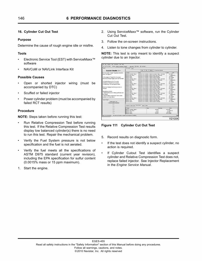
146 6 PERFORMANCE DIAGNOSTICS
16. Cylinder Cut Out Test
Purpose
Determine the cause of rough engine idle or misfire.
Tools
• Electronic Service Tool (EST) with ServiceMaxx™software
• NAVCoM or NAVLink Interface Kit
Possible Causes
• Open or shorted injector wiring (must beaccompanied by DTC)
• Scuffed or failed injector
• Power cylinder problem (must be accompanied byfailed RCT results)
Procedure
NOTE: Steps taken before running this test:
• Run Relative Compression Test before runningthis test. If the Relative Compression Test resultsdisplay low balanced cylinder(s) there is no needto run this test. Repair the mechanical problem.
• Verify the Fuel System pressure is not belowspecification and the fuel is not aerated.
• Verify the fuel meets all the specifications ofASTM D975 standard (current year revision),including the EPA specification for sulfur content(0.0015% mass or 15 ppm maximum).
1. Start the engine.
2. Using ServiceMaxx™ software, run the CylinderCut Out Test.
3. Follow the on-screen instructions.
4. Listen to tone changes from cylinder to cylinder.
NOTE: This test is only meant to identify a suspectcylinder due to an Injector.
Figure 111 Cylinder Cut Out Test
5. Record results on diagnostic form.
• If the test does not identify a suspect cylinder, noaction is required.
• If Cylinder Cutout Test identifies a suspectcylinder and Relative Compression Test does not,replace failed injector. See Injector Replacementin the Engine Service Manual.
EGES-455Read all safety instructions in the "Safety Information" section of this Manual before doing any procedures.
Follow all warnings, cautions, and notes.©2010 Navistar, Inc. All rights reserved
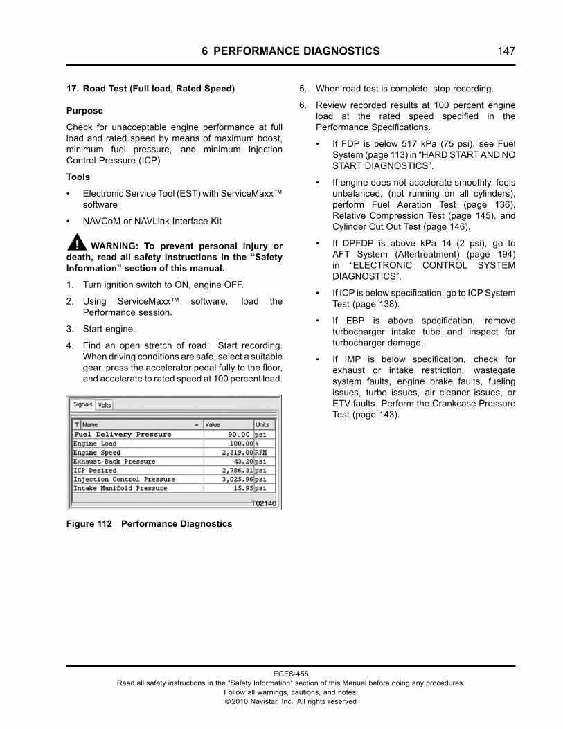
6 PERFORMANCE DIAGNOSTICS 147
17. Road Test (Full load, Rated Speed)
Purpose
Check for unacceptable engine performance at fullload and rated speed by means of maximum boost,minimum fuel pressure, and minimum InjectionControl Pressure (ICP)
Tools
• Electronic Service Tool (EST) with ServiceMaxx™software
• NAVCoM or NAVLink Interface Kit
WARNING: To prevent personal injury ordeath, read all safety instructions in the “SafetyInformation” section of this manual.
1. Turn ignition switch to ON, engine OFF.
2. Using ServiceMaxx™ software, load thePerformance session.
3. Start engine.
4. Find an open stretch of road. Start recording.When driving conditions are safe, select a suitablegear, press the accelerator pedal fully to the floor,and accelerate to rated speed at 100 percent load.
Figure 112 Performance Diagnostics
5. When road test is complete, stop recording.
6. Review recorded results at 100 percent engineload at the rated speed specified in thePerformance Specifications.
• If FDP is below 517 kPa (75 psi), see FuelSystem (page 113) in “HARDSTARTANDNOSTART DIAGNOSTICS”.
• If engine does not accelerate smoothly, feelsunbalanced, (not running on all cylinders),perform Fuel Aeration Test (page 136),Relative Compression Test (page 145), andCylinder Cut Out Test (page 146).
• If DPFDP is above kPa 14 (2 psi), go toAFT System (Aftertreatment) (page 194)in “ELECTRONIC CONTROL SYSTEMDIAGNOSTICS”.
• If ICP is below specification, go to ICP SystemTest (page 138).
• If EBP is above specification, removeturbocharger intake tube and inspect forturbocharger damage.
• If IMP is below specification, check forexhaust or intake restriction, wastegatesystem faults, engine brake faults, fuelingissues, turbo issues, air cleaner issues, orETV faults. Perform the Crankcase PressureTest (page 143).
EGES-455Read all safety instructions in the "Safety Information" section of this Manual before doing any procedures.
Follow all warnings, cautions, and notes.©2010 Navistar, Inc. All rights reserved
148 6 PERFORMANCE DIAGNOSTICS
EGES-455Read all safety instructions in the "Safety Information" section of this Manual before doing any procedures.
Follow all warnings, cautions, and notes.©2010 Navistar, Inc. All rights reserved
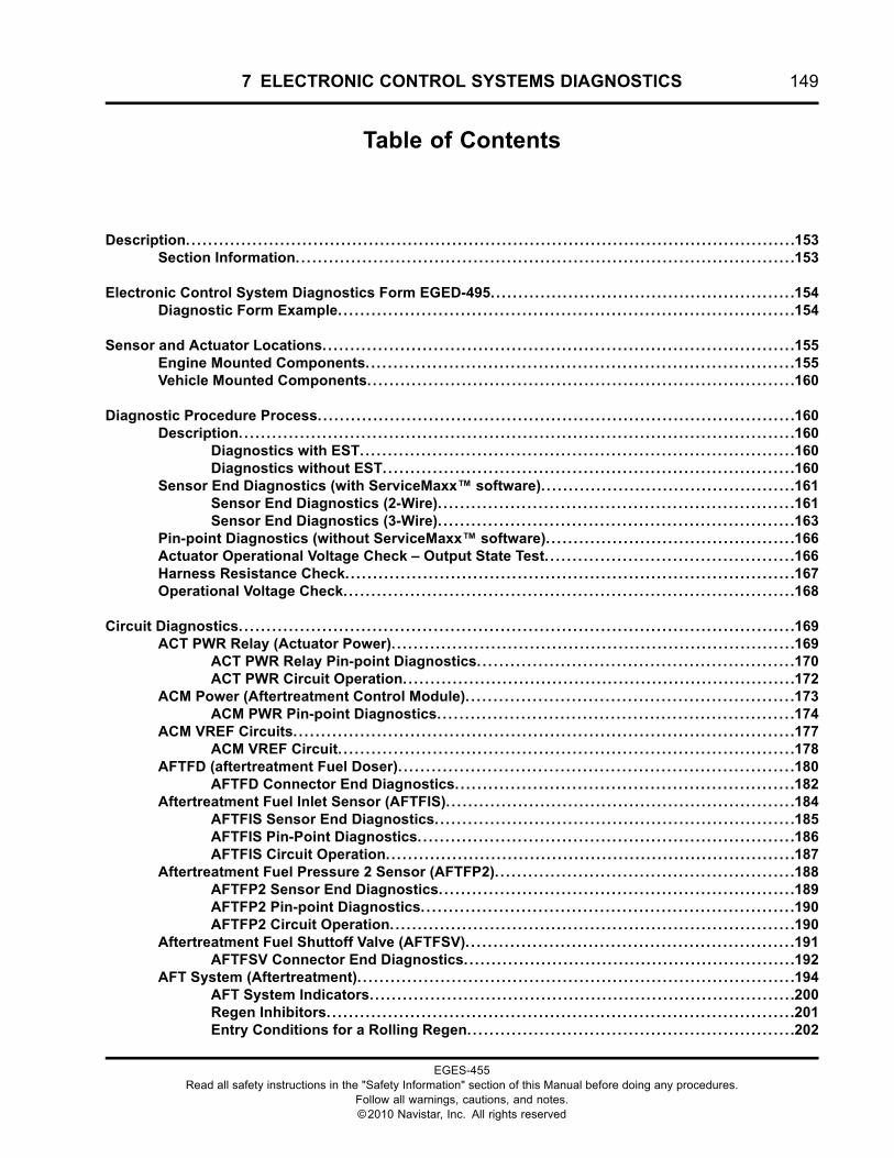
7 ELECTRONIC CONTROL SYSTEMS DIAGNOSTICS 149
Table of Contents
Description. . . . . . . . . . . . . . . . . . . . . . . . . . . . . . . . . . . . . . . . . . . . . . . . . . . . . . . . . . . . . . . . . . . . . . . . . . . . . . . . . . . . . . . . . . . . . . . . . . . . . . . . . . . . . .153Section Information. . . . . . . . . . . . . . . . . . . . . . . . . . . . . . . . . . . . . . . . . . . . . . . . . . . . . . . . . . . . . . . . . . . . . . . . . . . . . . . . . . . . . . . . . .153
Electronic Control System Diagnostics Form EGED-495. . . . . . . . . . . . . . . . . . . . . . . . . . . . . . . . . . . . . . . . . . . . . . . . . . . . . . .154Diagnostic Form Example. . . . . . . . . . . . . . . . . . . . . . . . . . . . . . . . . . . . . . . . . . . . . . . . . . . . . . . . . . . . . . . . . . . . . . . . . . . . . . . . . .154
Sensor and Actuator Locations. . . . . . . . . . . . . . . . . . . . . . . . . . . . . . . . . . . . . . . . . . . . . . . . . . . . . . . . . . . . . . . . . . . . . . . . . . . . . . . . . . . . .155Engine Mounted Components. . . . . . . . . . . . . . . . . . . . . . . . . . . . . . . . . . . . . . . . . . . . . . . . . . . . . . . . . . . . . . . . . . . . . . . . . . . . .155Vehicle Mounted Components. . . . . . . . . . . . . . . . . . . . . . . . . . . . . . . . . . . . . . . . . . . . . . . . . . . . . . . . . . . . . . . . . . . . . . . . . . . . .160
Diagnostic Procedure Process.. . . . . . . . . . . . . . . . . . . . . . . . . . . . . . . . . . . . . . . . . . . . . . . . . . . . . . . . . . . . . . . . . . . . . . . . . . . . . . . . . . . . .160Description. . . . . . . . . . . . . . . . . . . . . . . . . . . . . . . . . . . . . . . . . . . . . . . . . . . . . . . . . . . . . . . . . . . . . . . . . . . . . . . . . . . . . . . . . . . . . . . . . . . .160
Diagnostics with EST. . . . . . . . . . . . . . . . . . . . . . . . . . . . . . . . . . . . . . . . . . . . . . . . . . . . . . . . . . . . . . . . . . . . . . . . . . . . . .160Diagnostics without EST. . . . . . . . . . . . . . . . . . . . . . . . . . . . . . . . . . . . . . . . . . . . . . . . . . . . . . . . . . . . . . . . . . . . . . . . . .160
Sensor End Diagnostics (with ServiceMaxx™ software). . . . . . . . . . . . . . . . . . . . . . . . . . . . . . . . . . . . . . . . . . . . . .161Sensor End Diagnostics (2-Wire). . . . . . . . . . . . . . . . . . . . . . . . . . . . . . . . . . . . . . . . . . . . . . . . . . . . . . . . . . . . . . . .161Sensor End Diagnostics (3-Wire). . . . . . . . . . . . . . . . . . . . . . . . . . . . . . . . . . . . . . . . . . . . . . . . . . . . . . . . . . . . . . . .163
Pin-point Diagnostics (without ServiceMaxx™ software). . . . . . . . . . . . . . . . . . . . . . . . . . . . . . . . . . . . . . . . . . . . .166Actuator Operational Voltage Check – Output State Test. . . . . . . . . . . . . . . . . . . . . . . . . . . . . . . . . . . . . . . . . . . . .166Harness Resistance Check.. . . . . . . . . . . . . . . . . . . . . . . . . . . . . . . . . . . . . . . . . . . . . . . . . . . . . . . . . . . . . . . . . . . . . . . . . . . . . . . .167Operational Voltage Check.. . . . . . . . . . . . . . . . . . . . . . . . . . . . . . . . . . . . . . . . . . . . . . . . . . . . . . . . . . . . . . . . . . . . . . . . . . . . . . . .168
Circuit Diagnostics. . . . . . . . . . . . . . . . . . . . . . . . . . . . . . . . . . . . . . . . . . . . . . . . . . . . . . . . . . . . . . . . . . . . . . . . . . . . . . . . . . . . . . . . . . . . . . . . . . . .169ACT PWR Relay (Actuator Power). . . . . . . . . . . . . . . . . . . . . . . . . . . . . . . . . . . . . . . . . . . . . . . . . . . . . . . . . . . . . . . . . . . . . . . . .169
ACT PWR Relay Pin-point Diagnostics. . . . . . . . . . . . . . . . . . . . . . . . . . . . . . . . . . . . . . . . . . . . . . . . . . . . . . . . .170ACT PWR Circuit Operation. . . . . . . . . . . . . . . . . . . . . . . . . . . . . . . . . . . . . . . . . . . . . . . . . . . . . . . . . . . . . . . . . . . . . . .172
ACM Power (Aftertreatment Control Module). . . . . . . . . . . . . . . . . . . . . . . . . . . . . . . . . . . . . . . . . . . . . . . . . . . . . . . . . . .173ACM PWR Pin-point Diagnostics. . . . . . . . . . . . . . . . . . . . . . . . . . . . . . . . . . . . . . . . . . . . . . . . . . . . . . . . . . . . . . . .174
ACM VREF Circuits. . . . . . . . . . . . . . . . . . . . . . . . . . . . . . . . . . . . . . . . . . . . . . . . . . . . . . . . . . . . . . . . . . . . . . . . . . . . . . . . . . . . . . . . . .177ACM VREF Circuit. . . . . . . . . . . . . . . . . . . . . . . . . . . . . . . . . . . . . . . . . . . . . . . . . . . . . . . . . . . . . . . . . . . . . . . . . . . . . . . . . .178
AFTFD (aftertreatment Fuel Doser). . . . . . . . . . . . . . . . . . . . . . . . . . . . . . . . . . . . . . . . . . . . . . . . . . . . . . . . . . . . . . . . . . . . . . .180AFTFD Connector End Diagnostics. . . . . . . . . . . . . . . . . . . . . . . . . . . . . . . . . . . . . . . . . . . . . . . . . . . . . . . . . . . . .182
Aftertreatment Fuel Inlet Sensor (AFTFIS). . . . . . . . . . . . . . . . . . . . . . . . . . . . . . . . . . . . . . . . . . . . . . . . . . . . . . . . . . . . . . .184AFTFIS Sensor End Diagnostics. . . . . . . . . . . . . . . . . . . . . . . . . . . . . . . . . . . . . . . . . . . . . . . . . . . . . . . . . . . . . . . . .185AFTFIS Pin-Point Diagnostics. . . . . . . . . . . . . . . . . . . . . . . . . . . . . . . . . . . . . . . . . . . . . . . . . . . . . . . . . . . . . . . . . . . .186AFTFIS Circuit Operation. . . . . . . . . . . . . . . . . . . . . . . . . . . . . . . . . . . . . . . . . . . . . . . . . . . . . . . . . . . . . . . . . . . . . . . . . .187
Aftertreatment Fuel Pressure 2 Sensor (AFTFP2). . . . . . . . . . . . . . . . . . . . . . . . . . . . . . . . . . . . . . . . . . . . . . . . . . . . . .188AFTFP2 Sensor End Diagnostics. . . . . . . . . . . . . . . . . . . . . . . . . . . . . . . . . . . . . . . . . . . . . . . . . . . . . . . . . . . . . . . .189AFTFP2 Pin-point Diagnostics. . . . . . . . . . . . . . . . . . . . . . . . . . . . . . . . . . . . . . . . . . . . . . . . . . . . . . . . . . . . . . . . . . .190AFTFP2 Circuit Operation. . . . . . . . . . . . . . . . . . . . . . . . . . . . . . . . . . . . . . . . . . . . . . . . . . . . . . . . . . . . . . . . . . . . . . . . .190
Aftertreatment Fuel Shuttoff Valve (AFTFSV). . . . . . . . . . . . . . . . . . . . . . . . . . . . . . . . . . . . . . . . . . . . . . . . . . . . . . . . . . .191AFTFSV Connector End Diagnostics. . . . . . . . . . . . . . . . . . . . . . . . . . . . . . . . . . . . . . . . . . . . . . . . . . . . . . . . . . . .192
AFT System (Aftertreatment). . . . . . . . . . . . . . . . . . . . . . . . . . . . . . . . . . . . . . . . . . . . . . . . . . . . . . . . . . . . . . . . . . . . . . . . . . . . . . .194AFT System Indicators. . . . . . . . . . . . . . . . . . . . . . . . . . . . . . . . . . . . . . . . . . . . . . . . . . . . . . . . . . . . . . . . . . . . . . . . . . . . .200Regen Inhibitors. . . . . . . . . . . . . . . . . . . . . . . . . . . . . . . . . . . . . . . . . . . . . . . . . . . . . . . . . . . . . . . . . . . . . . . . . . . . . . . . . . . .201Entry Conditions for a Rolling Regen.. . . . . . . . . . . . . . . . . . . . . . . . . . . . . . . . . . . . . . . . . . . . . . . . . . . . . . . . . .202
EGES-455Read all safety instructions in the "Safety Information" section of this Manual before doing any procedures.
Follow all warnings, cautions, and notes.©2010 Navistar, Inc. All rights reserved
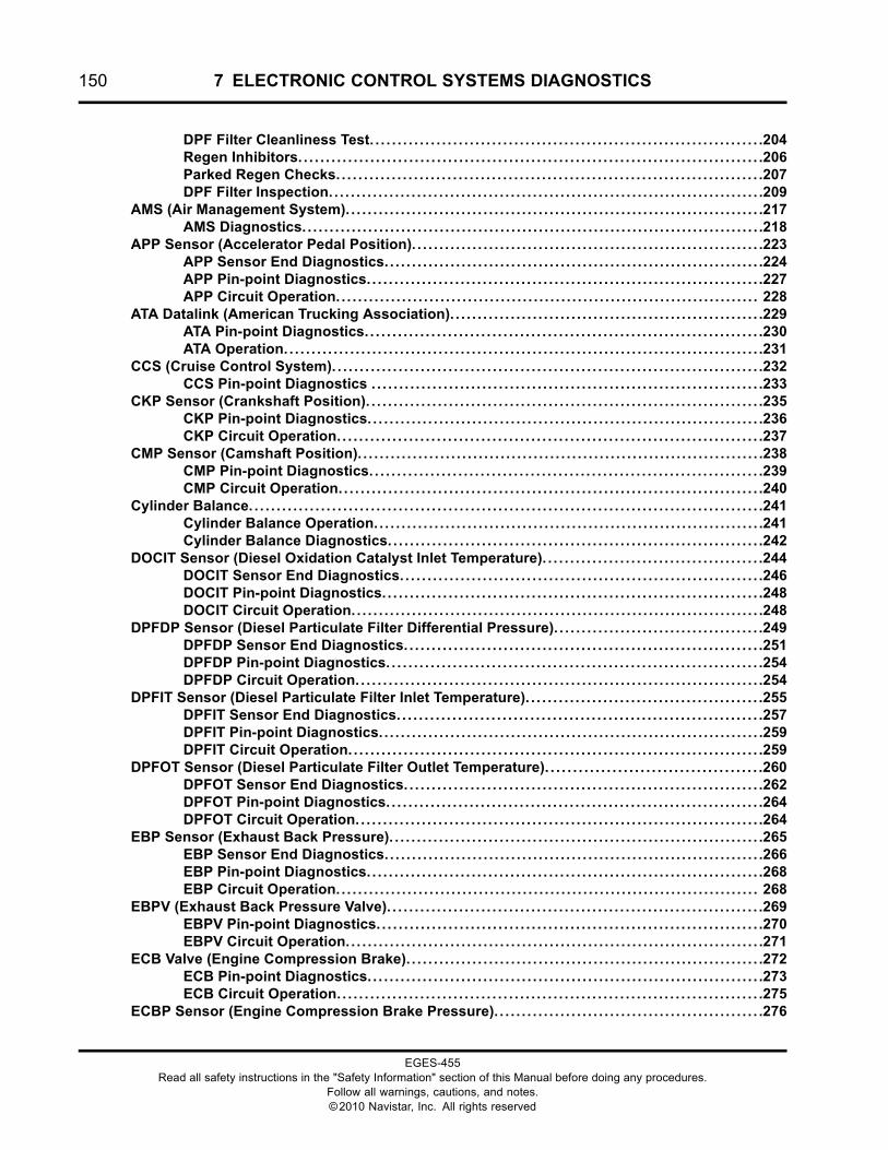
150 7 ELECTRONIC CONTROL SYSTEMS DIAGNOSTICS
DPF Filter Cleanliness Test. . . . . . . . . . . . . . . . . . . . . . . . . . . . . . . . . . . . . . . . . . . . . . . . . . . . . . . . . . . . . . . . . . . . . . .204Regen Inhibitors. . . . . . . . . . . . . . . . . . . . . . . . . . . . . . . . . . . . . . . . . . . . . . . . . . . . . . . . . . . . . . . . . . . . . . . . . . . . . . . . . . . .206Parked Regen Checks. . . . . . . . . . . . . . . . . . . . . . . . . . . . . . . . . . . . . . . . . . . . . . . . . . . . . . . . . . . . . . . . . . . . . . . . . . . . .207DPF Filter Inspection. . . . . . . . . . . . . . . . . . . . . . . . . . . . . . . . . . . . . . . . . . . . . . . . . . . . . . . . . . . . . . . . . . . . . . . . . . . . . . .209
AMS (Air Management System). . . . . . . . . . . . . . . . . . . . . . . . . . . . . . . . . . . . . . . . . . . . . . . . . . . . . . . . . . . . . . . . . . . . . . . . . . . .217AMS Diagnostics. . . . . . . . . . . . . . . . . . . . . . . . . . . . . . . . . . . . . . . . . . . . . . . . . . . . . . . . . . . . . . . . . . . . . . . . . . . . . . . . . . . .218
APP Sensor (Accelerator Pedal Position). . . . . . . . . . . . . . . . . . . . . . . . . . . . . . . . . . . . . . . . . . . . . . . . . . . . . . . . . . . . . . . .223APP Sensor End Diagnostics. . . . . . . . . . . . . . . . . . . . . . . . . . . . . . . . . . . . . . . . . . . . . . . . . . . . . . . . . . . . . . . . . . . . .224APP Pin-point Diagnostics. . . . . . . . . . . . . . . . . . . . . . . . . . . . . . . . . . . . . . . . . . . . . . . . . . . . . . . . . . . . . . . . . . . . . . . .227APP Circuit Operation. . . . . . . . . . . . . . . . . . . . . . . . . . . . . . . . . . . . . . . . . . . . . . . . . . . . . . . . . . . . . . . . . . . . . . . . . . . . . 228
ATA Datalink (American Trucking Association). . . . . . . . . . . . . . . . . . . . . . . . . . . . . . . . . . . . . . . . . . . . . . . . . . . . . . . . .229ATA Pin-point Diagnostics. . . . . . . . . . . . . . . . . . . . . . . . . . . . . . . . . . . . . . . . . . . . . . . . . . . . . . . . . . . . . . . . . . . . . . . .230ATA Operation. . . . . . . . . . . . . . . . . . . . . . . . . . . . . . . . . . . . . . . . . . . . . . . . . . . . . . . . . . . . . . . . . . . . . . . . . . . . . . . . . . . . . . .231
CCS (Cruise Control System). . . . . . . . . . . . . . . . . . . . . . . . . . . . . . . . . . . . . . . . . . . . . . . . . . . . . . . . . . . . . . . . . . . . . . . . . . . . . .232CCS Pin-point Diagnostics . . . . . . . . . . . . . . . . . . . . . . . . . . . . . . . . . . . . . . . . . . . . . . . . . . . . . . . . . . . . . . . . . . . . . . .233
CKP Sensor (Crankshaft Position). . . . . . . . . . . . . . . . . . . . . . . . . . . . . . . . . . . . . . . . . . . . . . . . . . . . . . . . . . . . . . . . . . . . . . . .235CKP Pin-point Diagnostics. . . . . . . . . . . . . . . . . . . . . . . . . . . . . . . . . . . . . . . . . . . . . . . . . . . . . . . . . . . . . . . . . . . . . . . .236CKP Circuit Operation. . . . . . . . . . . . . . . . . . . . . . . . . . . . . . . . . . . . . . . . . . . . . . . . . . . . . . . . . . . . . . . . . . . . . . . . . . . . .237
CMP Sensor (Camshaft Position). . . . . . . . . . . . . . . . . . . . . . . . . . . . . . . . . . . . . . . . . . . . . . . . . . . . . . . . . . . . . . . . . . . . . . . . . .238CMP Pin-point Diagnostics. . . . . . . . . . . . . . . . . . . . . . . . . . . . . . . . . . . . . . . . . . . . . . . . . . . . . . . . . . . . . . . . . . . . . . .239CMP Circuit Operation. . . . . . . . . . . . . . . . . . . . . . . . . . . . . . . . . . . . . . . . . . . . . . . . . . . . . . . . . . . . . . . . . . . . . . . . . . . . .240
Cylinder Balance. . . . . . . . . . . . . . . . . . . . . . . . . . . . . . . . . . . . . . . . . . . . . . . . . . . . . . . . . . . . . . . . . . . . . . . . . . . . . . . . . . . . . . . . . . . . .241Cylinder Balance Operation. . . . . . . . . . . . . . . . . . . . . . . . . . . . . . . . . . . . . . . . . . . . . . . . . . . . . . . . . . . . . . . . . . . . . . .241Cylinder Balance Diagnostics. . . . . . . . . . . . . . . . . . . . . . . . . . . . . . . . . . . . . . . . . . . . . . . . . . . . . . . . . . . . . . . . . . . .242
DOCIT Sensor (Diesel Oxidation Catalyst Inlet Temperature). . . . . . . . . . . . . . . . . . . . . . . . . . . . . . . . . . . . . . . .244DOCIT Sensor End Diagnostics. . . . . . . . . . . . . . . . . . . . . . . . . . . . . . . . . . . . . . . . . . . . . . . . . . . . . . . . . . . . . . . . . .246DOCIT Pin-point Diagnostics. . . . . . . . . . . . . . . . . . . . . . . . . . . . . . . . . . . . . . . . . . . . . . . . . . . . . . . . . . . . . . . . . . . . .248DOCIT Circuit Operation. . . . . . . . . . . . . . . . . . . . . . . . . . . . . . . . . . . . . . . . . . . . . . . . . . . . . . . . . . . . . . . . . . . . . . . . . . .248
DPFDP Sensor (Diesel Particulate Filter Differential Pressure). . . . . . . . . . . . . . . . . . . . . . . . . . . . . . . . . . . . . .249DPFDP Sensor End Diagnostics. . . . . . . . . . . . . . . . . . . . . . . . . . . . . . . . . . . . . . . . . . . . . . . . . . . . . . . . . . . . . . . . .251DPFDP Pin-point Diagnostics. . . . . . . . . . . . . . . . . . . . . . . . . . . . . . . . . . . . . . . . . . . . . . . . . . . . . . . . . . . . . . . . . . . .254DPFDP Circuit Operation. . . . . . . . . . . . . . . . . . . . . . . . . . . . . . . . . . . . . . . . . . . . . . . . . . . . . . . . . . . . . . . . . . . . . . . . . .254
DPFIT Sensor (Diesel Particulate Filter Inlet Temperature). . . . . . . . . . . . . . . . . . . . . . . . . . . . . . . . . . . . . . . . . . .255DPFIT Sensor End Diagnostics. . . . . . . . . . . . . . . . . . . . . . . . . . . . . . . . . . . . . . . . . . . . . . . . . . . . . . . . . . . . . . . . . .257DPFIT Pin-point Diagnostics. . . . . . . . . . . . . . . . . . . . . . . . . . . . . . . . . . . . . . . . . . . . . . . . . . . . . . . . . . . . . . . . . . . . . .259DPFIT Circuit Operation. . . . . . . . . . . . . . . . . . . . . . . . . . . . . . . . . . . . . . . . . . . . . . . . . . . . . . . . . . . . . . . . . . . . . . . . . . .259
DPFOT Sensor (Diesel Particulate Filter Outlet Temperature). . . . . . . . . . . . . . . . . . . . . . . . . . . . . . . . . . . . . . .260DPFOT Sensor End Diagnostics. . . . . . . . . . . . . . . . . . . . . . . . . . . . . . . . . . . . . . . . . . . . . . . . . . . . . . . . . . . . . . . . .262DPFOT Pin-point Diagnostics. . . . . . . . . . . . . . . . . . . . . . . . . . . . . . . . . . . . . . . . . . . . . . . . . . . . . . . . . . . . . . . . . . . .264DPFOT Circuit Operation. . . . . . . . . . . . . . . . . . . . . . . . . . . . . . . . . . . . . . . . . . . . . . . . . . . . . . . . . . . . . . . . . . . . . . . . . .264
EBP Sensor (Exhaust Back Pressure). . . . . . . . . . . . . . . . . . . . . . . . . . . . . . . . . . . . . . . . . . . . . . . . . . . . . . . . . . . . . . . . . . . .265EBP Sensor End Diagnostics. . . . . . . . . . . . . . . . . . . . . . . . . . . . . . . . . . . . . . . . . . . . . . . . . . . . . . . . . . . . . . . . . . . . .266EBP Pin-point Diagnostics. . . . . . . . . . . . . . . . . . . . . . . . . . . . . . . . . . . . . . . . . . . . . . . . . . . . . . . . . . . . . . . . . . . . . . . .268EBP Circuit Operation. . . . . . . . . . . . . . . . . . . . . . . . . . . . . . . . . . . . . . . . . . . . . . . . . . . . . . . . . . . . . . . . . . . . . . . . . . . . . 268
EBPV (Exhaust Back Pressure Valve). . . . . . . . . . . . . . . . . . . . . . . . . . . . . . . . . . . . . . . . . . . . . . . . . . . . . . . . . . . . . . . . . . . .269EBPV Pin-point Diagnostics. . . . . . . . . . . . . . . . . . . . . . . . . . . . . . . . . . . . . . . . . . . . . . . . . . . . . . . . . . . . . . . . . . . . . .270EBPV Circuit Operation. . . . . . . . . . . . . . . . . . . . . . . . . . . . . . . . . . . . . . . . . . . . . . . . . . . . . . . . . . . . . . . . . . . . . . . . . . . .271
ECB Valve (Engine Compression Brake). . . . . . . . . . . . . . . . . . . . . . . . . . . . . . . . . . . . . . . . . . . . . . . . . . . . . . . . . . . . . . . . .272ECB Pin-point Diagnostics. . . . . . . . . . . . . . . . . . . . . . . . . . . . . . . . . . . . . . . . . . . . . . . . . . . . . . . . . . . . . . . . . . . . . . . .273ECB Circuit Operation. . . . . . . . . . . . . . . . . . . . . . . . . . . . . . . . . . . . . . . . . . . . . . . . . . . . . . . . . . . . . . . . . . . . . . . . . . . . .275
ECBP Sensor (Engine Compression Brake Pressure). . . . . . . . . . . . . . . . . . . . . . . . . . . . . . . . . . . . . . . . . . . . . . . . .276
EGES-455Read all safety instructions in the "Safety Information" section of this Manual before doing any procedures.
Follow all warnings, cautions, and notes.©2010 Navistar, Inc. All rights reserved
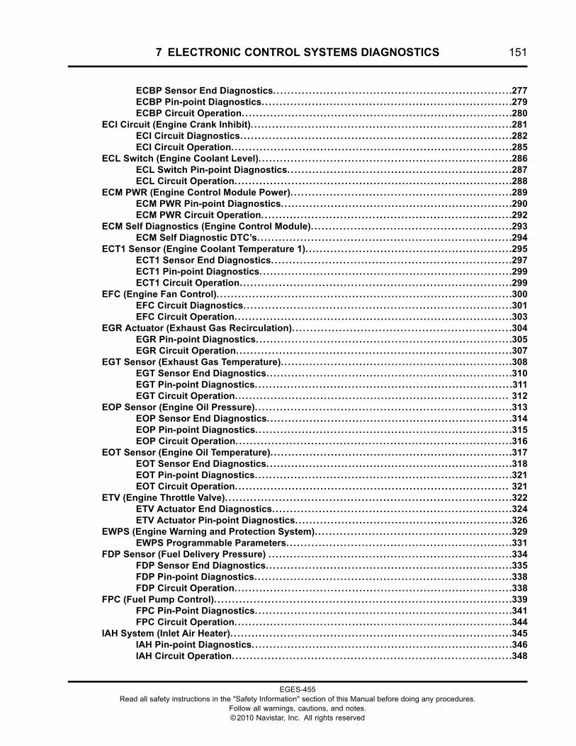
7 ELECTRONIC CONTROL SYSTEMS DIAGNOSTICS 151
ECBP Sensor End Diagnostics. . . . . . . . . . . . . . . . . . . . . . . . . . . . . . . . . . . . . . . . . . . . . . . . . . . . . . . . . . . . . . . . . . .277ECBP Pin-point Diagnostics. . . . . . . . . . . . . . . . . . . . . . . . . . . . . . . . . . . . . . . . . . . . . . . . . . . . . . . . . . . . . . . . . . . . . .279ECBP Circuit Operation. . . . . . . . . . . . . . . . . . . . . . . . . . . . . . . . . . . . . . . . . . . . . . . . . . . . . . . . . . . . . . . . . . . . . . . . . . . .280
ECI Circuit (Engine Crank Inhibit). . . . . . . . . . . . . . . . . . . . . . . . . . . . . . . . . . . . . . . . . . . . . . . . . . . . . . . . . . . . . . . . . . . . . . . . .281ECI Circuit Diagnostics. . . . . . . . . . . . . . . . . . . . . . . . . . . . . . . . . . . . . . . . . . . . . . . . . . . . . . . . . . . . . . . . . . . . . . . . . . . .282ECI Circuit Operation. . . . . . . . . . . . . . . . . . . . . . . . . . . . . . . . . . . . . . . . . . . . . . . . . . . . . . . . . . . . . . . . . . . . . . . . . . . . . . .285
ECL Switch (Engine Coolant Level). . . . . . . . . . . . . . . . . . . . . . . . . . . . . . . . . . . . . . . . . . . . . . . . . . . . . . . . . . . . . . . . . . . . . . .286ECL Switch Pin-point Diagnostics. . . . . . . . . . . . . . . . . . . . . . . . . . . . . . . . . . . . . . . . . . . . . . . . . . . . . . . . . . . . . . .287ECL Circuit Operation. . . . . . . . . . . . . . . . . . . . . . . . . . . . . . . . . . . . . . . . . . . . . . . . . . . . . . . . . . . . . . . . . . . . . . . . . . . . . .288
ECM PWR (Engine Control Module Power). . . . . . . . . . . . . . . . . . . . . . . . . . . . . . . . . . . . . . . . . . . . . . . . . . . . . . . . . . . . . .289ECM PWR Pin-point Diagnostics. . . . . . . . . . . . . . . . . . . . . . . . . . . . . . . . . . . . . . . . . . . . . . . . . . . . . . . . . . . . . . . . .290ECM PWR Circuit Operation. . . . . . . . . . . . . . . . . . . . . . . . . . . . . . . . . . . . . . . . . . . . . . . . . . . . . . . . . . . . . . . . . . . . . .292
ECM Self Diagnostics (Engine Control Module). . . . . . . . . . . . . . . . . . . . . . . . . . . . . . . . . . . . . . . . . . . . . . . . . . . . . . . .293ECM Self Diagnostic DTC’s. . . . . . . . . . . . . . . . . . . . . . . . . . . . . . . . . . . . . . . . . . . . . . . . . . . . . . . . . . . . . . . . . . . . . . .294
ECT1 Sensor (Engine Coolant Temperature 1). . . . . . . . . . . . . . . . . . . . . . . . . . . . . . . . . . . . . . . . . . . . . . . . . . . . . . . . . .295ECT1 Sensor End Diagnostics. . . . . . . . . . . . . . . . . . . . . . . . . . . . . . . . . . . . . . . . . . . . . . . . . . . . . . . . . . . . . . . . . . .297ECT1 Pin-point Diagnostics. . . . . . . . . . . . . . . . . . . . . . . . . . . . . . . . . . . . . . . . . . . . . . . . . . . . . . . . . . . . . . . . . . . . . . .299ECT1 Circuit Operation. . . . . . . . . . . . . . . . . . . . . . . . . . . . . . . . . . . . . . . . . . . . . . . . . . . . . . . . . . . . . . . . . . . . . . . . . . . .299
EFC (Engine Fan Control). . . . . . . . . . . . . . . . . . . . . . . . . . . . . . . . . . . . . . . . . . . . . . . . . . . . . . . . . . . . . . . . . . . . . . . . . . . . . . . . . . .300EFC Circuit Diagnostics. . . . . . . . . . . . . . . . . . . . . . . . . . . . . . . . . . . . . . . . . . . . . . . . . . . . . . . . . . . . . . . . . . . . . . . . . . .301EFC Circuit Operation. . . . . . . . . . . . . . . . . . . . . . . . . . . . . . . . . . . . . . . . . . . . . . . . . . . . . . . . . . . . . . . . . . . . . . . . . . . . . .303
EGR Actuator (Exhaust Gas Recirculation). . . . . . . . . . . . . . . . . . . . . . . . . . . . . . . . . . . . . . . . . . . . . . . . . . . . . . . . . . . . .304EGR Pin-point Diagnostics. . . . . . . . . . . . . . . . . . . . . . . . . . . . . . . . . . . . . . . . . . . . . . . . . . . . . . . . . . . . . . . . . . . . . . . .305EGR Circuit Operation. . . . . . . . . . . . . . . . . . . . . . . . . . . . . . . . . . . . . . . . . . . . . . . . . . . . . . . . . . . . . . . . . . . . . . . . . . . . .307
EGT Sensor (Exhaust Gas Temperature). . . . . . . . . . . . . . . . . . . . . . . . . . . . . . . . . . . . . . . . . . . . . . . . . . . . . . . . . . . . . . . . .308EGT Sensor End Diagnostics. . . . . . . . . . . . . . . . . . . . . . . . . . . . . . . . . . . . . . . . . . . . . . . . . . . . . . . . . . . . . . . . . . . . .310EGT Pin-point Diagnostics. . . . . . . . . . . . . . . . . . . . . . . . . . . . . . . . . . . . . . . . . . . . . . . . . . . . . . . . . . . . . . . . . . . . . . . .311EGT Circuit Operation. . . . . . . . . . . . . . . . . . . . . . . . . . . . . . . . . . . . . . . . . . . . . . . . . . . . . . . . . . . . . . . . . . . . . . . . . . . . . 312
EOP Sensor (Engine Oil Pressure). . . . . . . . . . . . . . . . . . . . . . . . . . . . . . . . . . . . . . . . . . . . . . . . . . . . . . . . . . . . . . . . . . . . . . . .313EOP Sensor End Diagnostics. . . . . . . . . . . . . . . . . . . . . . . . . . . . . . . . . . . . . . . . . . . . . . . . . . . . . . . . . . . . . . . . . . . . .314EOP Pin-point Diagnostics. . . . . . . . . . . . . . . . . . . . . . . . . . . . . . . . . . . . . . . . . . . . . . . . . . . . . . . . . . . . . . . . . . . . . . . .315EOP Circuit Operation. . . . . . . . . . . . . . . . . . . . . . . . . . . . . . . . . . . . . . . . . . . . . . . . . . . . . . . . . . . . . . . . . . . . . . . . . . . . .316
EOT Sensor (Engine Oil Temperature). . . . . . . . . . . . . . . . . . . . . . . . . . . . . . . . . . . . . . . . . . . . . . . . . . . . . . . . . . . . . . . . . . . .317EOT Sensor End Diagnostics. . . . . . . . . . . . . . . . . . . . . . . . . . . . . . . . . . . . . . . . . . . . . . . . . . . . . . . . . . . . . . . . . . . . .318EOT Pin-point Diagnostics. . . . . . . . . . . . . . . . . . . . . . . . . . . . . . . . . . . . . . . . . . . . . . . . . . . . . . . . . . . . . . . . . . . . . . . .321EOT Circuit Operation. . . . . . . . . . . . . . . . . . . . . . . . . . . . . . . . . . . . . . . . . . . . . . . . . . . . . . . . . . . . . . . . . . . . . . . . . . . . . 321
ETV (Engine Throttle Valve). . . . . . . . . . . . . . . . . . . . . . . . . . . . . . . . . . . . . . . . . . . . . . . . . . . . . . . . . . . . . . . . . . . . . . . . . . . . . . . .322ETV Actuator End Diagnostics. . . . . . . . . . . . . . . . . . . . . . . . . . . . . . . . . . . . . . . . . . . . . . . . . . . . . . . . . . . . . . . . . . .324ETV Actuator Pin-point Diagnostics. . . . . . . . . . . . . . . . . . . . . . . . . . . . . . . . . . . . . . . . . . . . . . . . . . . . . . . . . . . . .326
EWPS (Engine Warning and Protection System). . . . . . . . . . . . . . . . . . . . . . . . . . . . . . . . . . . . . . . . . . . . . . . . . . . . . . .329EWPS Programmable Parameters. . . . . . . . . . . . . . . . . . . . . . . . . . . . . . . . . . . . . . . . . . . . . . . . . . . . . . . . . . . . . . .331
FDP Sensor (Fuel Delivery Pressure) . . . . . . . . . . . . . . . . . . . . . . . . . . . . . . . . . . . . . . . . . . . . . . . . . . . . . . . . . . . . . . . . . . . .334FDP Sensor End Diagnostics. . . . . . . . . . . . . . . . . . . . . . . . . . . . . . . . . . . . . . . . . . . . . . . . . . . . . . . . . . . . . . . . . . . . .335FDP Pin-point Diagnostics. . . . . . . . . . . . . . . . . . . . . . . . . . . . . . . . . . . . . . . . . . . . . . . . . . . . . . . . . . . . . . . . . . . . . . . .338FDP Circuit Operation. . . . . . . . . . . . . . . . . . . . . . . . . . . . . . . . . . . . . . . . . . . . . . . . . . . . . . . . . . . . . . . . . . . . . . . . . . . . . .338
FPC (Fuel Pump Control). . . . . . . . . . . . . . . . . . . . . . . . . . . . . . . . . . . . . . . . . . . . . . . . . . . . . . . . . . . . . . . . . . . . . . . . . . . . . . . . . . .339FPC Pin-Point Diagnostics. . . . . . . . . . . . . . . . . . . . . . . . . . . . . . . . . . . . . . . . . . . . . . . . . . . . . . . . . . . . . . . . . . . . . . . .341FPC Circuit Operation. . . . . . . . . . . . . . . . . . . . . . . . . . . . . . . . . . . . . . . . . . . . . . . . . . . . . . . . . . . . . . . . . . . . . . . . . . . . . .344
IAH System (Inlet Air Heater). . . . . . . . . . . . . . . . . . . . . . . . . . . . . . . . . . . . . . . . . . . . . . . . . . . . . . . . . . . . . . . . . . . . . . . . . . . . . . .345IAH Pin-point Diagnostics. . . . . . . . . . . . . . . . . . . . . . . . . . . . . . . . . . . . . . . . . . . . . . . . . . . . . . . . . . . . . . . . . . . . . . . . .346IAH Circuit Operation. . . . . . . . . . . . . . . . . . . . . . . . . . . . . . . . . . . . . . . . . . . . . . . . . . . . . . . . . . . . . . . . . . . . . . . . . . . . . .348
EGES-455Read all safety instructions in the "Safety Information" section of this Manual before doing any procedures.
Follow all warnings, cautions, and notes.©2010 Navistar, Inc. All rights reserved
152 7 ELECTRONIC CONTROL SYSTEMS DIAGNOSTICS
ICP Sensor (Injection Control Pressure). . . . . . . . . . . . . . . . . . . . . . . . . . . . . . . . . . . . . . . . . . . . . . . . . . . . . . . . . . . . . . . . .349ICP Sensor End Diagnostics. . . . . . . . . . . . . . . . . . . . . . . . . . . . . . . . . . . . . . . . . . . . . . . . . . . . . . . . . . . . . . . . . . . . . .350ICP Pin-point Diagnostics. . . . . . . . . . . . . . . . . . . . . . . . . . . . . . . . . . . . . . . . . . . . . . . . . . . . . . . . . . . . . . . . . . . . . . . . .352ICP Circuit Operation. . . . . . . . . . . . . . . . . . . . . . . . . . . . . . . . . . . . . . . . . . . . . . . . . . . . . . . . . . . . . . . . . . . . . . . . . . . . . . .353
ICP System (Injection Control Pressure). . . . . . . . . . . . . . . . . . . . . . . . . . . . . . . . . . . . . . . . . . . . . . . . . . . . . . . . . . . . . . . . .354ICP System Diagnostics. . . . . . . . . . . . . . . . . . . . . . . . . . . . . . . . . . . . . . . . . . . . . . . . . . . . . . . . . . . . . . . . . . . . . . . . . . .356ICP System Operation. . . . . . . . . . . . . . . . . . . . . . . . . . . . . . . . . . . . . . . . . . . . . . . . . . . . . . . . . . . . . . . . . . . . . . . . . . . . . .358
IMP Sensor (Intake Manifold Pressure). . . . . . . . . . . . . . . . . . . . . . . . . . . . . . . . . . . . . . . . . . . . . . . . . . . . . . . . . . . . . . . . . . .360IMP Sensor End Diagnostics. . . . . . . . . . . . . . . . . . . . . . . . . . . . . . . . . . . . . . . . . . . . . . . . . . . . . . . . . . . . . . . . . . . . .362IMP Pin-point Diagnostics. . . . . . . . . . . . . . . . . . . . . . . . . . . . . . . . . . . . . . . . . . . . . . . . . . . . . . . . . . . . . . . . . . . . . . . . .364IMP Circuit Operation. . . . . . . . . . . . . . . . . . . . . . . . . . . . . . . . . . . . . . . . . . . . . . . . . . . . . . . . . . . . . . . . . . . . . . . . . . . . . .364
IMT Sensor (Intake Manifold Temperature). . . . . . . . . . . . . . . . . . . . . . . . . . . . . . . . . . . . . . . . . . . . . . . . . . . . . . . . . . . . . .365IMT Sensor End Diagnostics. . . . . . . . . . . . . . . . . . . . . . . . . . . . . . . . . . . . . . . . . . . . . . . . . . . . . . . . . . . . . . . . . . . . . .366IMT Pin-point Diagnostics. . . . . . . . . . . . . . . . . . . . . . . . . . . . . . . . . . . . . . . . . . . . . . . . . . . . . . . . . . . . . . . . . . . . . . . . .368IMT Circuit Operation. . . . . . . . . . . . . . . . . . . . . . . . . . . . . . . . . . . . . . . . . . . . . . . . . . . . . . . . . . . . . . . . . . . . . . . . . . . . . .368
Injector Circuits. . . . . . . . . . . . . . . . . . . . . . . . . . . . . . . . . . . . . . . . . . . . . . . . . . . . . . . . . . . . . . . . . . . . . . . . . . . . . . . . . . . . . . . . . . . . . . .369Injector 1 Checks. . . . . . . . . . . . . . . . . . . . . . . . . . . . . . . . . . . . . . . . . . . . . . . . . . . . . . . . . . . . . . . . . . . . . . . . . . . . . . . . . . .371Injector 2 Checks. . . . . . . . . . . . . . . . . . . . . . . . . . . . . . . . . . . . . . . . . . . . . . . . . . . . . . . . . . . . . . . . . . . . . . . . . . . . . . . . . . .373Injector 3 Checks. . . . . . . . . . . . . . . . . . . . . . . . . . . . . . . . . . . . . . . . . . . . . . . . . . . . . . . . . . . . . . . . . . . . . . . . . . . . . . . . . . .375Injector 4 Checks. . . . . . . . . . . . . . . . . . . . . . . . . . . . . . . . . . . . . . . . . . . . . . . . . . . . . . . . . . . . . . . . . . . . . . . . . . . . . . . . . . .377Injector 5 Checks. . . . . . . . . . . . . . . . . . . . . . . . . . . . . . . . . . . . . . . . . . . . . . . . . . . . . . . . . . . . . . . . . . . . . . . . . . . . . . . . . . .379Injector 6 Checks. . . . . . . . . . . . . . . . . . . . . . . . . . . . . . . . . . . . . . . . . . . . . . . . . . . . . . . . . . . . . . . . . . . . . . . . . . . . . . . . . . .381Injector Circuit Operation. . . . . . . . . . . . . . . . . . . . . . . . . . . . . . . . . . . . . . . . . . . . . . . . . . . . . . . . . . . . . . . . . . . . . . . . .383
IPR (Injection Pressure Regulator). . . . . . . . . . . . . . . . . . . . . . . . . . . . . . . . . . . . . . . . . . . . . . . . . . . . . . . . . . . . . . . . . . . . . . . .384IPR Pin-point Diagnostics. . . . . . . . . . . . . . . . . . . . . . . . . . . . . . . . . . . . . . . . . . . . . . . . . . . . . . . . . . . . . . . . . . . . . . . . .385IPR Circuit Operation. . . . . . . . . . . . . . . . . . . . . . . . . . . . . . . . . . . . . . . . . . . . . . . . . . . . . . . . . . . . . . . . . . . . . . . . . . . . . . .386
IST System (Idle Shutdown Timer). . . . . . . . . . . . . . . . . . . . . . . . . . . . . . . . . . . . . . . . . . . . . . . . . . . . . . . . . . . . . . . . . . . . . . . .387Function. . . . . . . . . . . . . . . . . . . . . . . . . . . . . . . . . . . . . . . . . . . . . . . . . . . . . . . . . . . . . . . . . . . . . . . . . . . . . . . . . . . . . . . . . . . . . .387
J1939 Data Link. . . . . . . . . . . . . . . . . . . . . . . . . . . . . . . . . . . . . . . . . . . . . . . . . . . . . . . . . . . . . . . . . . . . . . . . . . . . . . . . . . . . . . . . . . . . . . .390J1939 Data Link Pin-point Diagnostics. . . . . . . . . . . . . . . . . . . . . . . . . . . . . . . . . . . . . . . . . . . . . . . . . . . . . . . . .391J1939 Data Link Circuit Operation. . . . . . . . . . . . . . . . . . . . . . . . . . . . . . . . . . . . . . . . . . . . . . . . . . . . . . . . . . . . . . .392
MAF Sensor (Mass Air Flow)/Air Intake Temperature Sensor (AIT). . . . . . . . . . . . . . . . . . . . . . . . . . . . . . . . .394MAF/AIT Sensor End Diagnostics. . . . . . . . . . . . . . . . . . . . . . . . . . . . . . . . . . . . . . . . . . . . . . . . . . . . . . . . . . . . . . .395MAF Pin-point Diagnostics. . . . . . . . . . . . . . . . . . . . . . . . . . . . . . . . . . . . . . . . . . . . . . . . . . . . . . . . . . . . . . . . . . . . . . . .399MAF Circuit Operation. . . . . . . . . . . . . . . . . . . . . . . . . . . . . . . . . . . . . . . . . . . . . . . . . . . . . . . . . . . . . . . . . . . . . . . . . . . . .400
TC2WC Solenoid (Turbocharger 2 Wastegate Control). . . . . . . . . . . . . . . . . . . . . . . . . . . . . . . . . . . . . . . . . . . . . . . .401Service Interval Messages. . . . . . . . . . . . . . . . . . . . . . . . . . . . . . . . . . . . . . . . . . . . . . . . . . . . . . . . . . . . . . . . . . . . . . . .402TC2WC Pin-point Diagnostics. . . . . . . . . . . . . . . . . . . . . . . . . . . . . . . . . . . . . . . . . . . . . . . . . . . . . . . . . . . . . . . . . . . .403TC2WC Circuit Operation. . . . . . . . . . . . . . . . . . . . . . . . . . . . . . . . . . . . . . . . . . . . . . . . . . . . . . . . . . . . . . . . . . . . . . . . . .404
VREF (Reference Voltage). . . . . . . . . . . . . . . . . . . . . . . . . . . . . . . . . . . . . . . . . . . . . . . . . . . . . . . . . . . . . . . . . . . . . . . . . . . . . . . . . .405VREF Pin-point Diagnostics. . . . . . . . . . . . . . . . . . . . . . . . . . . . . . . . . . . . . . . . . . . . . . . . . . . . . . . . . . . . . . . . . . . . . .407VREF Circuit Operation. . . . . . . . . . . . . . . . . . . . . . . . . . . . . . . . . . . . . . . . . . . . . . . . . . . . . . . . . . . . . . . . . . . . . . . . . . . .412
WIF Sensor (Water In Fuel). . . . . . . . . . . . . . . . . . . . . . . . . . . . . . . . . . . . . . . . . . . . . . . . . . . . . . . . . . . . . . . . . . . . . . . . . . . . . . . . .413WIF Pin-point Diagnostics. . . . . . . . . . . . . . . . . . . . . . . . . . . . . . . . . . . . . . . . . . . . . . . . . . . . . . . . . . . . . . . . . . . . . . . . .414WIF Circuit Operation. . . . . . . . . . . . . . . . . . . . . . . . . . . . . . . . . . . . . . . . . . . . . . . . . . . . . . . . . . . . . . . . . . . . . . . . . . . . . .416
EGES-455Read all safety instructions in the "Safety Information" section of this Manual before doing any procedures.
Follow all warnings, cautions, and notes.©2010 Navistar, Inc. All rights reserved
7 ELECTRONIC CONTROL SYSTEMS DIAGNOSTICS 153
DescriptionSection Information
All electrical faults in the engine control system canbe diagnosed in this section. All components aredivided into separate test procedures and contain thefollowing information:
• DTC with possible cause
• Circuit diagram
• Component function
• Circuit operation
• Component location
• Diagnostic tool list
• Sensor End Diagnostics (with ServiceMaxx™software)
• Pin-point Diagnostics (without ServiceMaxx™software)
• Harness resistance check
• Operational voltage check (most components)
EGES-455Read all safety instructions in the "Safety Information" section of this Manual before doing any procedures.
Follow all warnings, cautions, and notes.©2010 Navistar, Inc. All rights reserved
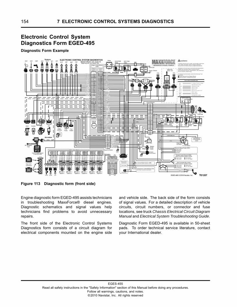
154 7 ELECTRONIC CONTROL SYSTEMS DIAGNOSTICS
Electronic Control SystemDiagnostics Form EGED-495Diagnostic Form Example
Figure 113 Diagnostic form (front side)
Engine diagnostic form EGED-495 assists techniciansin troubleshooting MaxxForce® diesel engines.Diagnostic schematics and signal values helptechnicians find problems to avoid unnecessaryrepairs.
The front side of the Electronic Control SystemsDiagnostics form consists of a circuit diagram forelectrical components mounted on the engine side
and vehicle side. The back side of the form consistsof signal values. For a detailed description of vehiclecircuits, circuit numbers, or connector and fuselocations, see truck Chassis Electrical Circuit DiagramManual and Electrical System Troubleshooting Guide.
Diagnostic Form EGED-495 is available in 50-sheetpads. To order technical service literature, contactyour International dealer.
EGES-455Read all safety instructions in the "Safety Information" section of this Manual before doing any procedures.
Follow all warnings, cautions, and notes.©2010 Navistar, Inc. All rights reserved
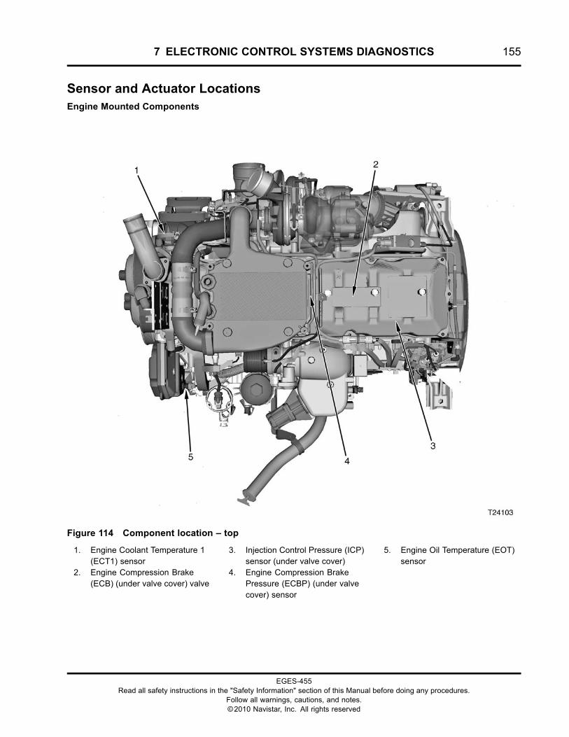
7 ELECTRONIC CONTROL SYSTEMS DIAGNOSTICS 155
Sensor and Actuator LocationsEngine Mounted Components
Figure 114 Component location – top
1. Engine Coolant Temperature 1(ECT1) sensor
2. Engine Compression Brake(ECB) (under valve cover) valve
3. Injection Control Pressure (ICP)sensor (under valve cover)
4. Engine Compression BrakePressure (ECBP) (under valvecover) sensor
5. Engine Oil Temperature (EOT)sensor
EGES-455Read all safety instructions in the "Safety Information" section of this Manual before doing any procedures.
Follow all warnings, cautions, and notes.©2010 Navistar, Inc. All rights reserved
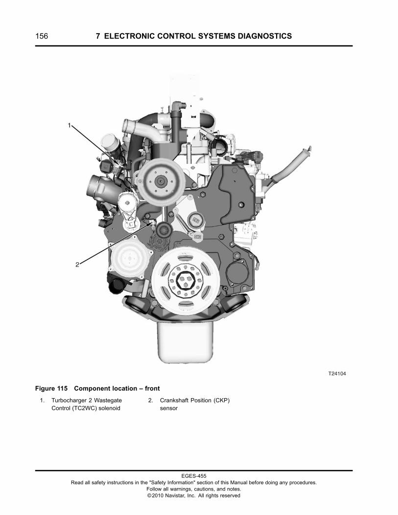
156 7 ELECTRONIC CONTROL SYSTEMS DIAGNOSTICS
Figure 115 Component location – front
1. Turbocharger 2 WastegateControl (TC2WC) solenoid
2. Crankshaft Position (CKP)sensor
EGES-455Read all safety instructions in the "Safety Information" section of this Manual before doing any procedures.
Follow all warnings, cautions, and notes.©2010 Navistar, Inc. All rights reserved
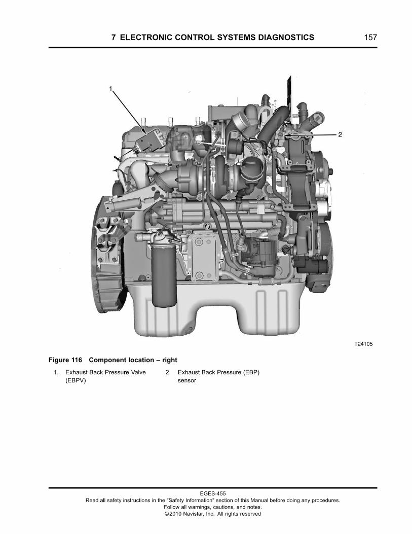
7 ELECTRONIC CONTROL SYSTEMS DIAGNOSTICS 157
Figure 116 Component location – right
1. Exhaust Back Pressure Valve(EBPV)
2. Exhaust Back Pressure (EBP)sensor
EGES-455Read all safety instructions in the "Safety Information" section of this Manual before doing any procedures.
Follow all warnings, cautions, and notes.©2010 Navistar, Inc. All rights reserved
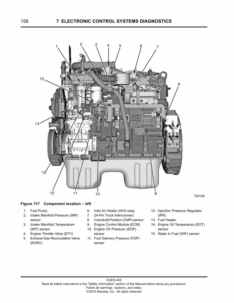
158 7 ELECTRONIC CONTROL SYSTEMS DIAGNOSTICS
Figure 117 Component location – left
1. Fuel Pump2. Intake Manifold Pressure (IMP)
sensor3. Intake Manifold Temperature
(IMT) sensor4. Engine Throttle Valve (ETV)5. Exhaust Gas Recirculation Valve
(EGRV)
6. Inlet Air Heater (IAH) relay7. 24-Pin Truck Interconnect8. Camshaft Position (CMP) sensor9. Engine Control Module (ECM)10. Engine Oil Pressure (EOP)
sensor11. Fuel Delivery Pressure (FDP)
sensor
12. Injection Pressure Regulator(IPR)
13. Fuel Heater14. Engine Oil Temperature (EOT)
sensor15. Water In Fuel (WIF) sensor
EGES-455Read all safety instructions in the "Safety Information" section of this Manual before doing any procedures.
Follow all warnings, cautions, and notes.©2010 Navistar, Inc. All rights reserved
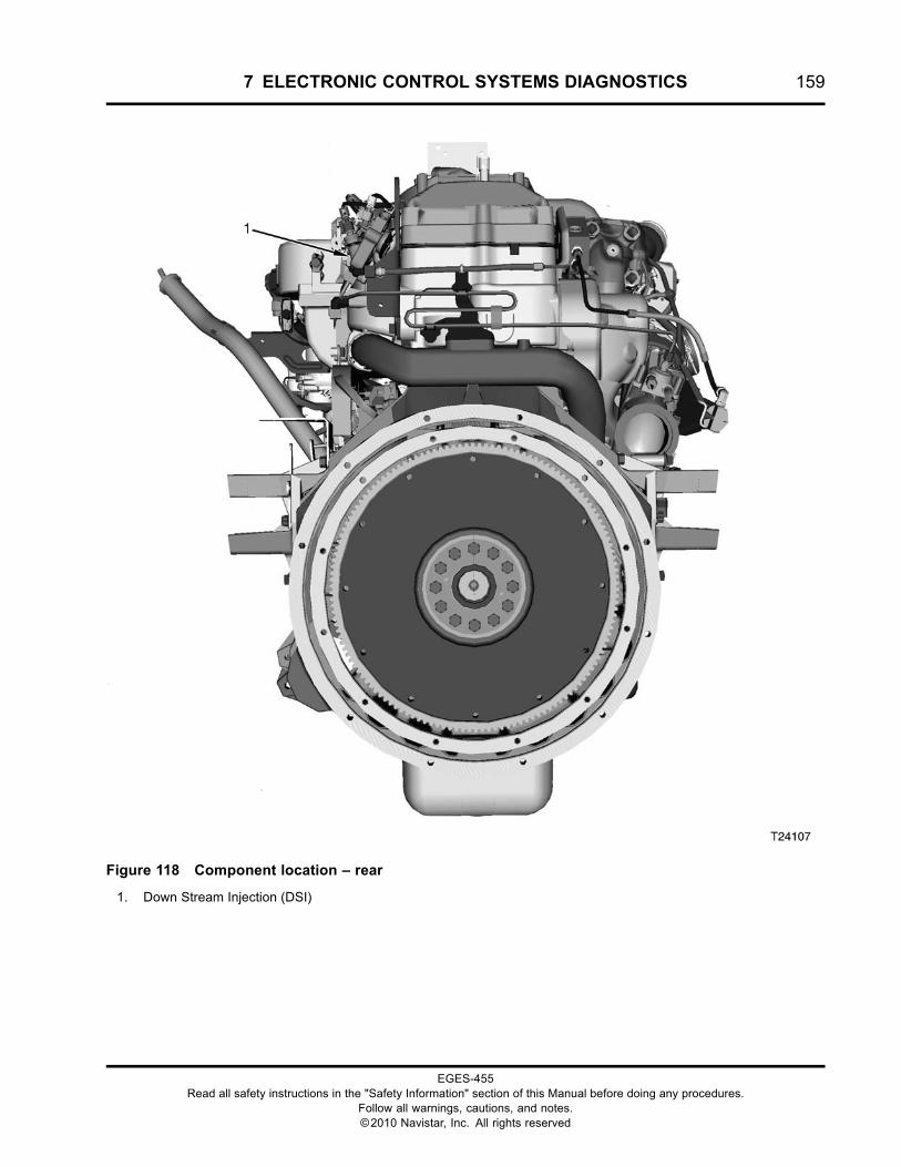
7 ELECTRONIC CONTROL SYSTEMS DIAGNOSTICS 159
Figure 118 Component location – rear
1. Down Stream Injection (DSI)
EGES-455Read all safety instructions in the "Safety Information" section of this Manual before doing any procedures.
Follow all warnings, cautions, and notes.©2010 Navistar, Inc. All rights reserved
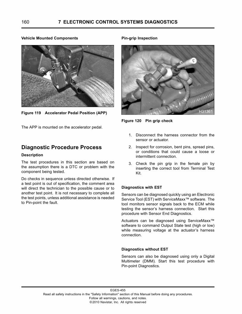
160 7 ELECTRONIC CONTROL SYSTEMS DIAGNOSTICS
Vehicle Mounted Components
Figure 119 Accelerator Pedal Position (APP)
The APP is mounted on the accelerator pedal.
Diagnostic Procedure ProcessDescription
The test procedures in this section are based onthe assumption there is a DTC or problem with thecomponent being tested.
Do checks in sequence unless directed otherwise. Ifa test point is out of specification, the comment areawill direct the technician to the possible cause or toanother test point. It is not necessary to complete allthe test points, unless additional assistance is neededto Pin-point the fault.
Pin-grip Inspection
Figure 120 Pin grip check
1. Disconnect the harness connector from thesensor or actuator.
2. Inspect for corrosion, bent pins, spread pins,or conditions that could cause a loose orintermittent connection.
3. Check the pin grip in the female pin byinserting the correct tool from Terminal TestKit.
Diagnostics with EST
Sensors can be diagnosed quickly using an ElectronicService Tool (EST) with ServiceMaxx™ software. Thetool monitors sensor signals back to the ECM whiletesting the sensor’s harness connection. Start thisprocedure with Sensor End Diagnostics.
Actuators can be diagnosed using ServiceMaxx™software to command Output State test (high or low)while measuring voltage at the actuator’s harnessconnection.
Diagnostics without EST
Sensors can also be diagnosed using only a DigitalMultimeter (DMM). Start this test procedure withPin-point Diagnostics.
EGES-455Read all safety instructions in the "Safety Information" section of this Manual before doing any procedures.
Follow all warnings, cautions, and notes.©2010 Navistar, Inc. All rights reserved
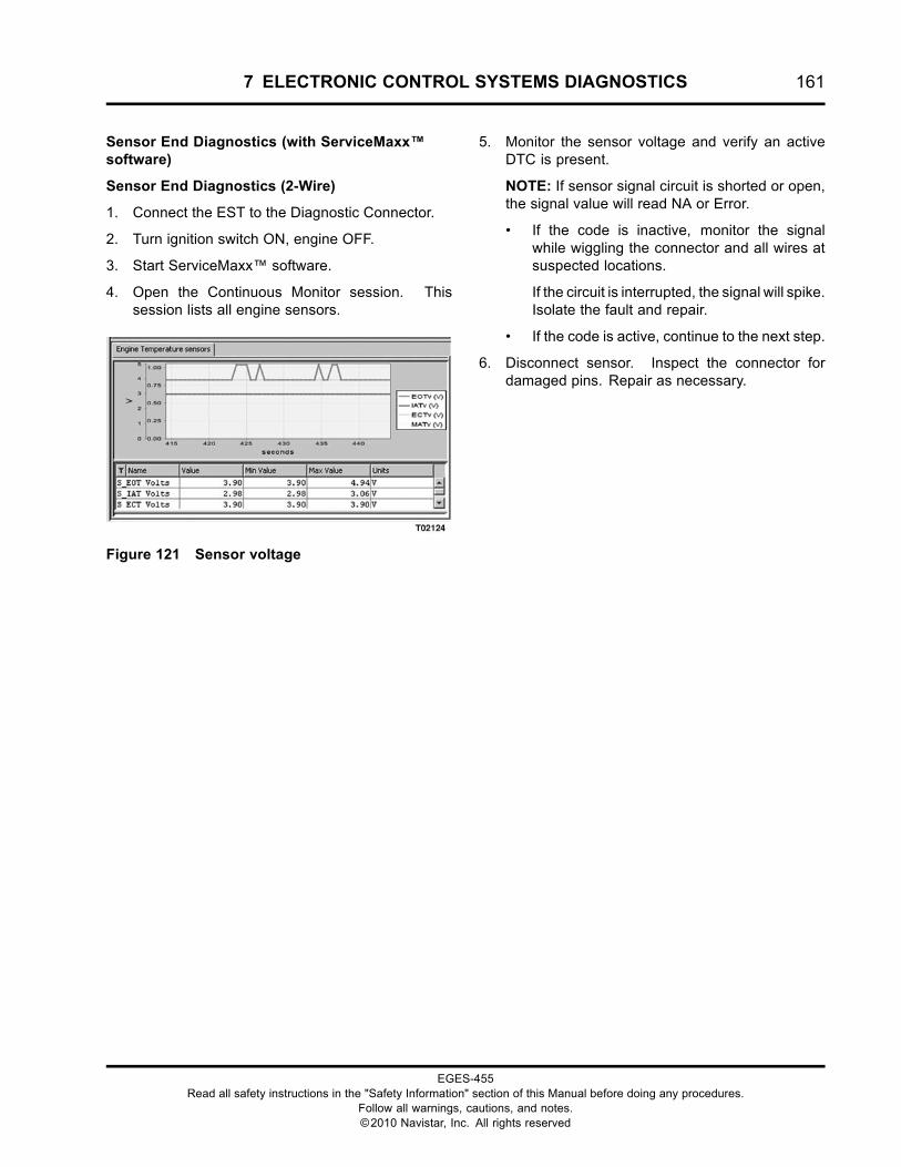
7 ELECTRONIC CONTROL SYSTEMS DIAGNOSTICS 161
Sensor End Diagnostics (with ServiceMaxx™software)
Sensor End Diagnostics (2-Wire)
1. Connect the EST to the Diagnostic Connector.
2. Turn ignition switch ON, engine OFF.
3. Start ServiceMaxx™ software.
4. Open the Continuous Monitor session. Thissession lists all engine sensors.
Figure 121 Sensor voltage
5. Monitor the sensor voltage and verify an activeDTC is present.
NOTE: If sensor signal circuit is shorted or open,the signal value will read NA or Error.
• If the code is inactive, monitor the signalwhile wiggling the connector and all wires atsuspected locations.
If the circuit is interrupted, the signal will spike.Isolate the fault and repair.
• If the code is active, continue to the next step.
6. Disconnect sensor. Inspect the connector fordamaged pins. Repair as necessary.
EGES-455Read all safety instructions in the "Safety Information" section of this Manual before doing any procedures.
Follow all warnings, cautions, and notes.©2010 Navistar, Inc. All rights reserved
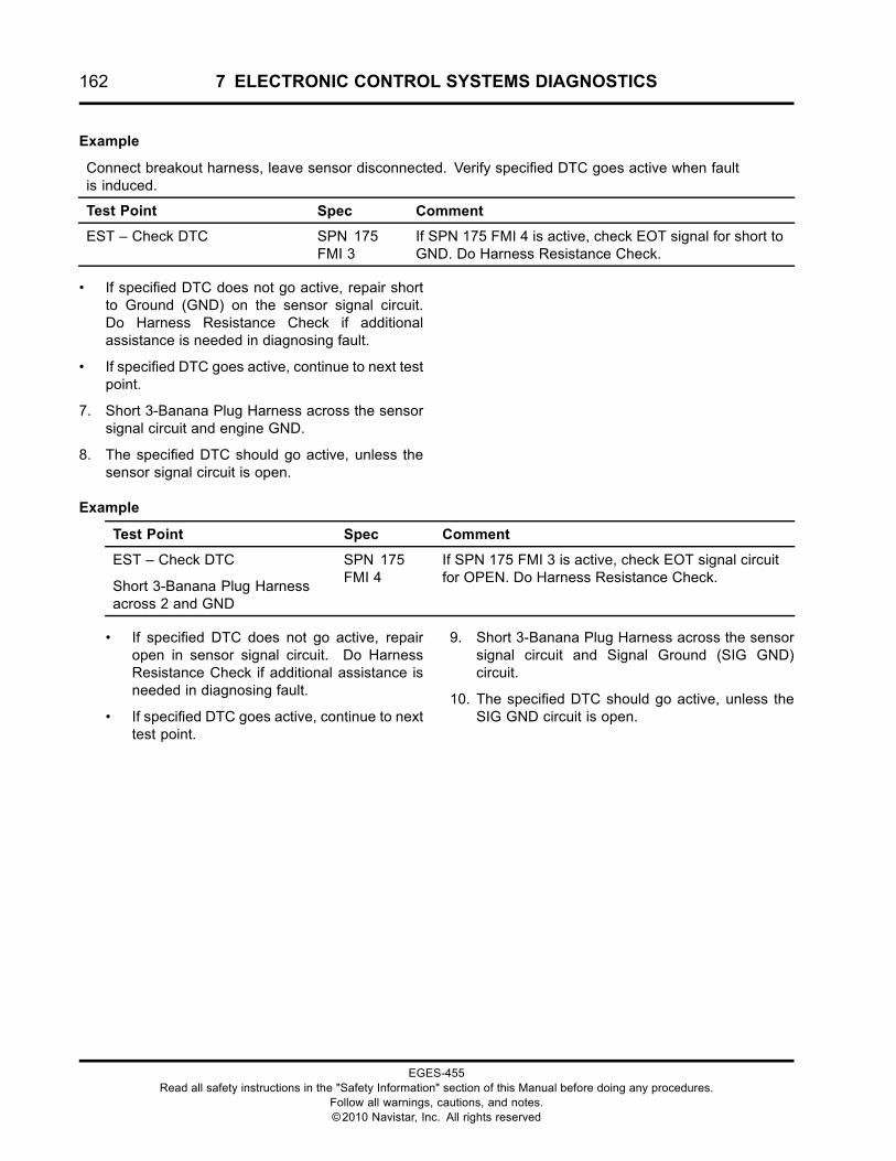
162 7 ELECTRONIC CONTROL SYSTEMS DIAGNOSTICS
Example
Connect breakout harness, leave sensor disconnected. Verify specified DTC goes active when faultis induced.
Test Point Spec Comment
EST – Check DTC SPN 175FMI 3
If SPN 175 FMI 4 is active, check EOT signal for short toGND. Do Harness Resistance Check.
• If specified DTC does not go active, repair shortto Ground (GND) on the sensor signal circuit.Do Harness Resistance Check if additionalassistance is needed in diagnosing fault.
• If specified DTC goes active, continue to next testpoint.
7. Short 3-Banana Plug Harness across the sensorsignal circuit and engine GND.
8. The specified DTC should go active, unless thesensor signal circuit is open.
Example
Test Point Spec Comment
EST – Check DTC
Short 3-Banana Plug Harnessacross 2 and GND
SPN 175FMI 4
If SPN 175 FMI 3 is active, check EOT signal circuitfor OPEN. Do Harness Resistance Check.
• If specified DTC does not go active, repairopen in sensor signal circuit. Do HarnessResistance Check if additional assistance isneeded in diagnosing fault.
• If specified DTC goes active, continue to nexttest point.
9. Short 3-Banana Plug Harness across the sensorsignal circuit and Signal Ground (SIG GND)circuit.
10. The specified DTC should go active, unless theSIG GND circuit is open.
EGES-455Read all safety instructions in the "Safety Information" section of this Manual before doing any procedures.
Follow all warnings, cautions, and notes.©2010 Navistar, Inc. All rights reserved
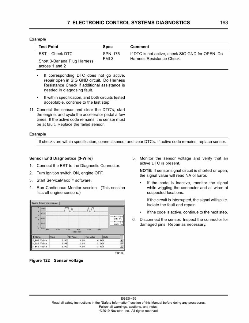
7 ELECTRONIC CONTROL SYSTEMS DIAGNOSTICS 163
Example
Test Point Spec Comment
EST – Check DTC
Short 3-Banana Plug Harnessacross 1 and 2
SPN 175FMI 3
If DTC is not active, check SIG GND for OPEN. DoHarness Resistance Check.
• If corresponding DTC does not go active,repair open in SIG GND circuit. Do HarnessResistance Check if additional assistance isneeded in diagnosing fault.
• If within specification, and both circuits testedacceptable, continue to the last step.
11. Connect the sensor and clear the DTC’s, startthe engine, and cycle the accelerator pedal a fewtimes. If the active code remains, the sensor mustbe at fault. Replace the failed sensor.
Example
If checks are within specification, connect sensor and clear DTCs. If active code remains, replace sensor.
Sensor End Diagnostics (3-Wire)
1. Connect the EST to the Diagnostic Connector.
2. Turn ignition switch ON, engine OFF.
3. Start ServiceMaxx™ software.
4. Run Continuous Monitor session. (This sessionlists all engine sensors.)
Figure 122 Sensor voltage
5. Monitor the sensor voltage and verify that anactive DTC is present.
NOTE: If sensor signal circuit is shorted or open,the signal value will read NA or Error.
• If the code is inactive, monitor the signalwhile wiggling the connector and all wires atsuspected locations.
If the circuit is interrupted, the signal will spike.Isolate the fault and repair.
• If the code is active, continue to the next step.
6. Disconnect the sensor. Inspect the connector fordamaged pins. Repair as necessary.
EGES-455Read all safety instructions in the "Safety Information" section of this Manual before doing any procedures.
Follow all warnings, cautions, and notes.©2010 Navistar, Inc. All rights reserved
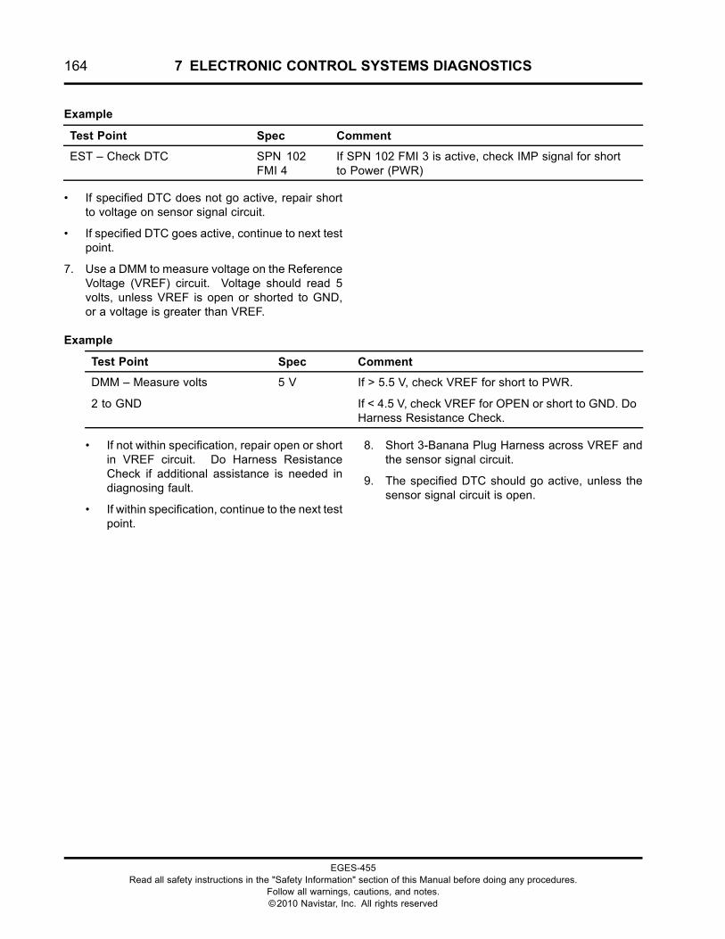
164 7 ELECTRONIC CONTROL SYSTEMS DIAGNOSTICS
Example
Test Point Spec Comment
EST – Check DTC SPN 102FMI 4
If SPN 102 FMI 3 is active, check IMP signal for shortto Power (PWR)
• If specified DTC does not go active, repair shortto voltage on sensor signal circuit.
• If specified DTC goes active, continue to next testpoint.
7. Use a DMM to measure voltage on the ReferenceVoltage (VREF) circuit. Voltage should read 5volts, unless VREF is open or shorted to GND,or a voltage is greater than VREF.
Example
Test Point Spec Comment
DMM – Measure volts
2 to GND
5 V If > 5.5 V, check VREF for short to PWR.
If < 4.5 V, check VREF for OPEN or short to GND. DoHarness Resistance Check.
• If not within specification, repair open or shortin VREF circuit. Do Harness ResistanceCheck if additional assistance is needed indiagnosing fault.
• If within specification, continue to the next testpoint.
8. Short 3-Banana Plug Harness across VREF andthe sensor signal circuit.
9. The specified DTC should go active, unless thesensor signal circuit is open.
EGES-455Read all safety instructions in the "Safety Information" section of this Manual before doing any procedures.
Follow all warnings, cautions, and notes.©2010 Navistar, Inc. All rights reserved
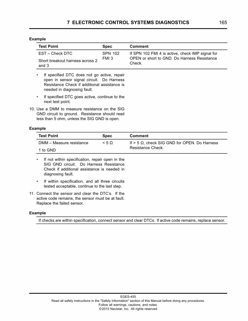
7 ELECTRONIC CONTROL SYSTEMS DIAGNOSTICS 165
Example
Test Point Spec Comment
EST – Check DTC
Short breakout harness across 2and 3
SPN 102FMI 3
If SPN 102 FMI 4 is active, check IMP signal forOPEN or short to GND. Do Harness ResistanceCheck.
• If specified DTC does not go active, repairopen in sensor signal circuit. Do HarnessResistance Check if additional assistance isneeded in diagnosing fault.
• If specified DTC goes active, continue to thenext test point.
10. Use a DMM to measure resistance on the SIGGND circuit to ground. Resistance should readless than 5 ohm, unless the SIG GND is open.
Example
Test Point Spec Comment
DMM – Measure resistance
1 to GND
< 5 Ω If > 5 Ω, check SIG GND for OPEN. Do HarnessResistance Check.
• If not within specification, repair open in theSIG GND circuit. Do Harness ResistanceCheck if additional assistance is needed indiagnosing fault.
• If within specification, and all three circuitstested acceptable, continue to the last step.
11. Connect the sensor and clear the DTC’s. If theactive code remains, the sensor must be at fault.Replace the failed sensor.
Example
If checks are within specification, connect sensor and clear DTCs. If active code remains, replace sensor.
EGES-455Read all safety instructions in the "Safety Information" section of this Manual before doing any procedures.
Follow all warnings, cautions, and notes.©2010 Navistar, Inc. All rights reserved
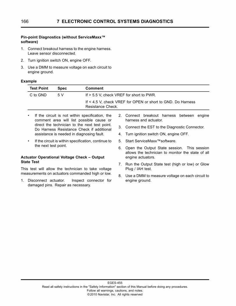
166 7 ELECTRONIC CONTROL SYSTEMS DIAGNOSTICS
Pin-point Diagnostics (without ServiceMaxx™software)
1. Connect breakout harness to the engine harness.Leave sensor disconnected.
2. Turn ignition switch ON, engine OFF.
3. Use a DMM to measure voltage on each circuit toengine ground.
Example
Test Point Spec Comment
C to GND 5 V If > 5.5 V, check VREF for short to PWR.
If < 4.5 V, check VREF for OPEN or short to GND. Do HarnessResistance Check.
• If the circuit is not within specification, thecomment area will list possible cause ordirect the technician to the next test point.Do Harness Resistance Check if additionalassistance is needed in diagnosing fault.
• If the circuit is within specification, continue tothe next test point.
Actuator Operational Voltage Check – OutputState Test
This test will allow the technician to take voltagemeasurements on actuators commanded high or low.
1. Disconnect actuator. Inspect connector fordamaged pins. Repair as necessary.
2. Connect breakout harness between engineharness and actuator.
3. Connect the EST to the Diagnostic Connector.
4. Turn ignition switch ON, engine OFF.
5. Start ServiceMaxx™software.
6. Open the Output State session. This sessionallows the technician to monitor the state of allengine actuators.
7. Run the Output State test (high or low) or GlowPlug / IAH test.
8. Use a DMM to measure voltage on each circuit toengine ground.
EGES-455Read all safety instructions in the "Safety Information" section of this Manual before doing any procedures.
Follow all warnings, cautions, and notes.©2010 Navistar, Inc. All rights reserved
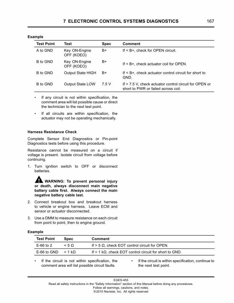
7 ELECTRONIC CONTROL SYSTEMS DIAGNOSTICS 167
Example
Test Point Test Spec Comment
A to GND Key ON-EngineOFF (KOEO)
B+ If < B+, check for OPEN circuit.
B to GND Key ON-EngineOFF (KOEO)
B+If < B+, check actuator coil for OPEN.
B to GND Output State HIGH B+ If < B+, check actuator control circuit for short toGND.
B to GND Output State LOW 7.5 V If > 7.5 V, check actuator control circuit for OPEN orshort to PWR or failed across coil.
• If any circuit is not within specification, thecomment area will list possible cause or directthe technician to the next test point.
• If all circuits are within specification, theactuator may not be operating mechanically.
Harness Resistance Check
Complete Sensor End Diagnostics or Pin-pointDiagnostics tests before using this procedure.
Resistance cannot be measured on a circuit ifvoltage is present. Isolate circuit from voltage beforecontinuing.
1. Turn ignition switch to OFF or disconnectbatteries.
WARNING: To prevent personal injuryor death, always disconnect main negativebattery cable first. Always connect the mainnegative battery cable last.
2. Connect breakout box and breakout harnessto vehicle or engine harness. Leave ECM andsensor or actuator disconnected.
3. Use a DMM to measure resistance on each circuitfrom point to point, then to engine ground.
Example
Test Point Spec Comment
E-66 to 2 < 5 Ω If > 5 Ω, check EOT control circuit for OPEN.
E-66 to GND > 1 kΩ If < 1 kΩ, check EOT control circuit for short to GND.
• If the circuit is not within specification, thecomment area will list possible circuit faults.
• If the circuit is within specification, continue tothe next test point.
EGES-455Read all safety instructions in the "Safety Information" section of this Manual before doing any procedures.
Follow all warnings, cautions, and notes.©2010 Navistar, Inc. All rights reserved
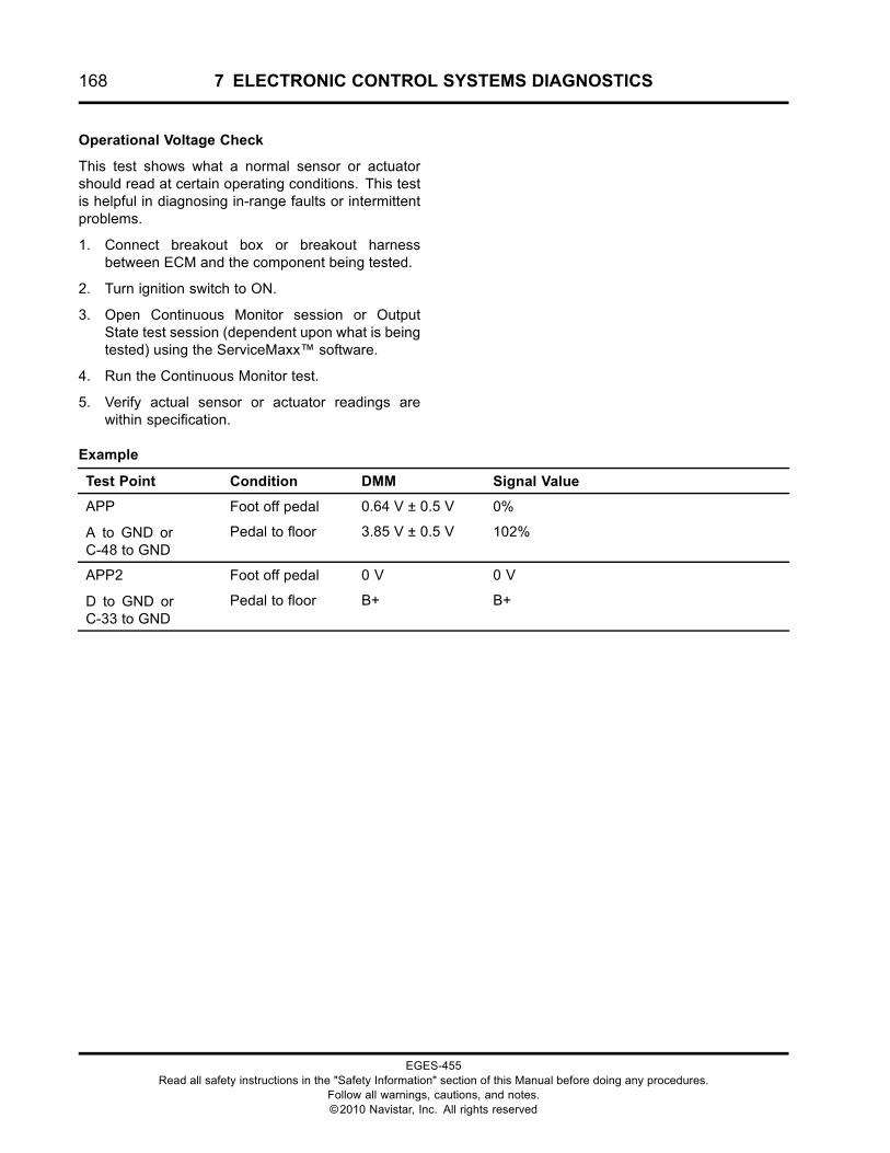
168 7 ELECTRONIC CONTROL SYSTEMS DIAGNOSTICS
Operational Voltage Check
This test shows what a normal sensor or actuatorshould read at certain operating conditions. This testis helpful in diagnosing in-range faults or intermittentproblems.
1. Connect breakout box or breakout harnessbetween ECM and the component being tested.
2. Turn ignition switch to ON.
3. Open Continuous Monitor session or OutputState test session (dependent upon what is beingtested) using the ServiceMaxx™ software.
4. Run the Continuous Monitor test.
5. Verify actual sensor or actuator readings arewithin specification.
Example
Test Point Condition DMM Signal Value
Foot off pedal 0.64 V ± 0.5 V 0%APP
A to GND orC-48 to GND
Pedal to floor 3.85 V ± 0.5 V 102%
Foot off pedal 0 V 0 VAPP2
D to GND orC-33 to GND
Pedal to floor B+ B+
EGES-455Read all safety instructions in the "Safety Information" section of this Manual before doing any procedures.
Follow all warnings, cautions, and notes.©2010 Navistar, Inc. All rights reserved
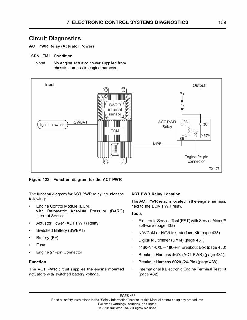
7 ELECTRONIC CONTROL SYSTEMS DIAGNOSTICS 169
Circuit DiagnosticsACT PWR Relay (Actuator Power)
SPN FMI Condition
None No engine actuator power supplied fromchassis harness to engine harness.
Figure 123 Function diagram for the ACT PWR
The function diagram for ACT PWR relay includes thefollowing:
• Engine Control Module (ECM)with Barometric Absolute Pressure (BARO)Internal Sensor
• Actuator Power (ACT PWR) Relay
• Switched Battery (SWBAT)
• Battery (B+)
• Fuse
• Engine 24–pin Connector
Function
The ACT PWR circuit supplies the engine mountedactuators with switched battery voltage.
ACT PWR Relay Location
The ACT PWR relay is located in the engine harness,next to the ECM PWR relay.
Tools
• Electronic Service Tool (EST) with ServiceMaxx™software (page 432)
• NAVCoM or NAVLink Interface Kit (page 433)
• Digital Multimeter (DMM) (page 431)
• 1180-N4-0X0 – 180-Pin Breakout Box (page 430)
• Breakout Harness 4674 (ACT PWR) (page 434)
• Breakout Harness 6020 (24-Pin) (page 438)
• International® Electronic Engine Terminal Test Kit(page 432)
EGES-455Read all safety instructions in the "Safety Information" section of this Manual before doing any procedures.
Follow all warnings, cautions, and notes.©2010 Navistar, Inc. All rights reserved
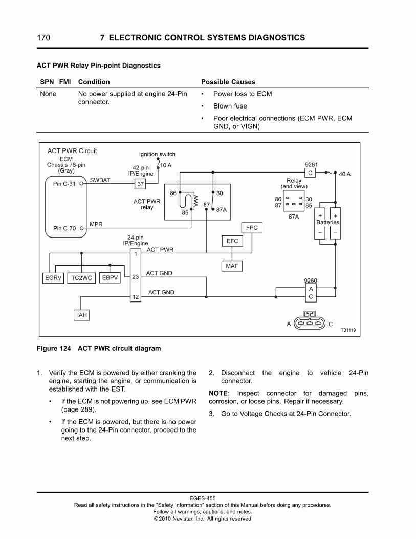
170 7 ELECTRONIC CONTROL SYSTEMS DIAGNOSTICS
ACT PWR Relay Pin-point Diagnostics
SPN FMI Condition Possible Causes
None No power supplied at engine 24-Pinconnector.
• Power loss to ECM
• Blown fuse
• Poor electrical connections (ECM PWR, ECMGND, or VIGN)
Figure 124 ACT PWR circuit diagram
1. Verify the ECM is powered by either cranking theengine, starting the engine, or communication isestablished with the EST.
• If the ECM is not powering up, see ECM PWR(page 289).
• If the ECM is powered, but there is no powergoing to the 24-Pin connector, proceed to thenext step.
2. Disconnect the engine to vehicle 24-Pinconnector.
NOTE: Inspect connector for damaged pins,corrosion, or loose pins. Repair if necessary.
3. Go to Voltage Checks at 24-Pin Connector.
EGES-455Read all safety instructions in the "Safety Information" section of this Manual before doing any procedures.
Follow all warnings, cautions, and notes.©2010 Navistar, Inc. All rights reserved
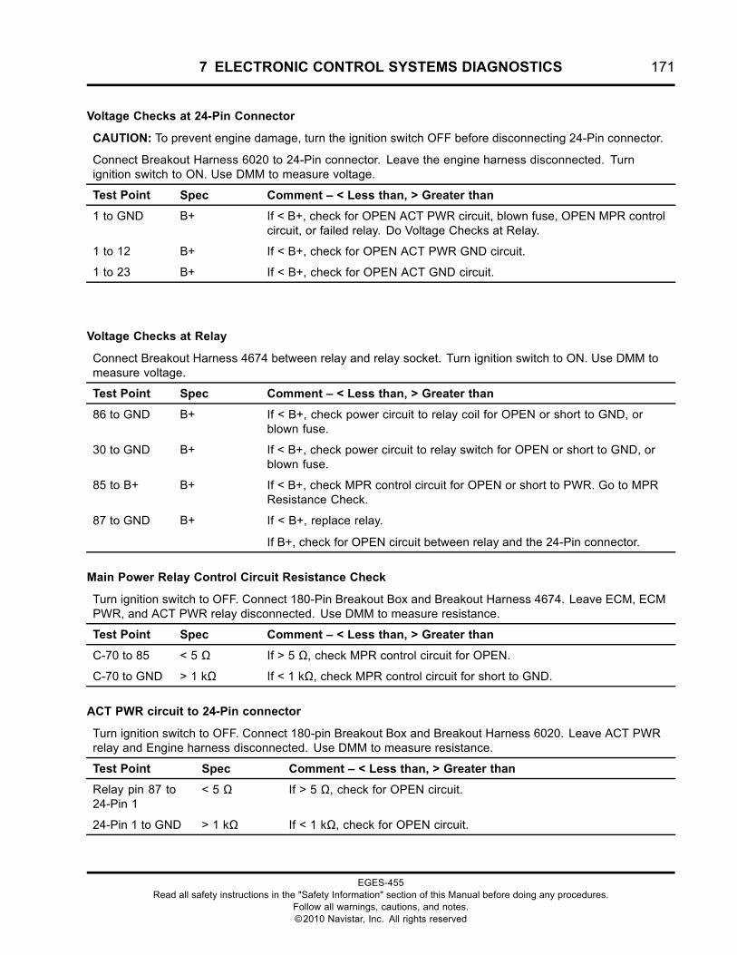
7 ELECTRONIC CONTROL SYSTEMS DIAGNOSTICS 171
Voltage Checks at 24-Pin Connector
CAUTION: To prevent engine damage, turn the ignition switch OFF before disconnecting 24-Pin connector.
Connect Breakout Harness 6020 to 24-Pin connector. Leave the engine harness disconnected. Turnignition switch to ON. Use DMM to measure voltage.
Test Point Spec Comment – < Less than, > Greater than
1 to GND B+ If < B+, check for OPEN ACT PWR circuit, blown fuse, OPEN MPR controlcircuit, or failed relay. Do Voltage Checks at Relay.
1 to 12 B+ If < B+, check for OPEN ACT PWR GND circuit.
1 to 23 B+ If < B+, check for OPEN ACT GND circuit.
Voltage Checks at Relay
Connect Breakout Harness 4674 between relay and relay socket. Turn ignition switch to ON. Use DMM tomeasure voltage.
Test Point Spec Comment – < Less than, > Greater than
86 to GND B+ If < B+, check power circuit to relay coil for OPEN or short to GND, orblown fuse.
30 to GND B+ If < B+, check power circuit to relay switch for OPEN or short to GND, orblown fuse.
85 to B+ B+ If < B+, check MPR control circuit for OPEN or short to PWR. Go to MPRResistance Check.
87 to GND B+ If < B+, replace relay.
If B+, check for OPEN circuit between relay and the 24-Pin connector.
Main Power Relay Control Circuit Resistance Check
Turn ignition switch to OFF. Connect 180-Pin Breakout Box and Breakout Harness 4674. Leave ECM, ECMPWR, and ACT PWR relay disconnected. Use DMM to measure resistance.
Test Point Spec Comment – < Less than, > Greater than
C-70 to 85 < 5 Ω If > 5 Ω, check MPR control circuit for OPEN.
C-70 to GND > 1 kΩ If < 1 kΩ, check MPR control circuit for short to GND.
ACT PWR circuit to 24-Pin connector
Turn ignition switch to OFF. Connect 180-pin Breakout Box and Breakout Harness 6020. Leave ACT PWRrelay and Engine harness disconnected. Use DMM to measure resistance.
Test Point Spec Comment – < Less than, > Greater than
Relay pin 87 to24-Pin 1
< 5 Ω If > 5 Ω, check for OPEN circuit.
24-Pin 1 to GND > 1 kΩ If < 1 kΩ, check for OPEN circuit.
EGES-455Read all safety instructions in the "Safety Information" section of this Manual before doing any procedures.
Follow all warnings, cautions, and notes.©2010 Navistar, Inc. All rights reserved
172 7 ELECTRONIC CONTROL SYSTEMS DIAGNOSTICS
ACT PWR Circuit Operation
The ACT PWR relay is controlled by the ECM, similarto the way the ECM controls its other relays. Whenthe ECM receives the VIGN signal from the ignitionswitch, the ECM will enable the ECM relay and theACT PWR relay.
The ECM receives SWBAT power at Pin C-45. Thissignals the ECM to provide a ground path from PinC-70 to 85 to switch the ACT PWR relay. Switchingthe relay provides power from the battery positive
terminal through a fuse and relay contacts 30 and 87to Pin 1 and Pin 3 on the 24-Pin connector.
Pin 23 and Pin 12 on the 24-Pin connector are ACTGND circuits.
Fault Detection / Management
No DTC’s are set for ACT PWR circuit failure. If ACTPWR is lost, the EGR will set KOEO Standard TestDTC’s.
EGES-455Read all safety instructions in the "Safety Information" section of this Manual before doing any procedures.
Follow all warnings, cautions, and notes.©2010 Navistar, Inc. All rights reserved
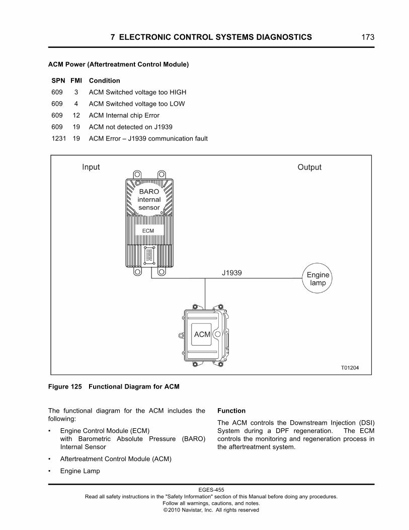
7 ELECTRONIC CONTROL SYSTEMS DIAGNOSTICS 173
ACM Power (Aftertreatment Control Module)
SPN FMI Condition
609 3 ACM Switched voltage too HIGH
609 4 ACM Switched voltage too LOW
609 12 ACM Internal chip Error
609 19 ACM not detected on J1939
1231 19 ACM Error – J1939 communication fault
Figure 125 Functional Diagram for ACM
The functional diagram for the ACM includes thefollowing:
• Engine Control Module (ECM)with Barometric Absolute Pressure (BARO)Internal Sensor
• Aftertreatment Control Module (ACM)
• Engine Lamp
Function
The ACM controls the Downstream Injection (DSI)System during a DPF regeneration. The ECMcontrols the monitoring and regeneration process inthe aftertreatment system.
EGES-455Read all safety instructions in the "Safety Information" section of this Manual before doing any procedures.
Follow all warnings, cautions, and notes.©2010 Navistar, Inc. All rights reserved
174 7 ELECTRONIC CONTROL SYSTEMS DIAGNOSTICS
Component Location
The ACM is installed underneath the cab just belowthe driver’s floorboard.
Tools
• Electronic Service Tool (EST) with ServiceMaxx™software (page 432)
• NAVCoM or NAVLink Interface Kit (page 433)
• Digital Multimeter (DMM) (page 431)
• International® Electronic Engine Terminal Test Kit(page 432)
ACM PWR Pin-point Diagnostics
SPN FMI Condition Possible Causes
609 3 ACM Switched voltage too HIGH • Jump start using more than system voltage
• Batteries wired incorrectly
609 4 ACM Switched voltage too LOW • Low discharge batteries
• Charging system failure
• High resistance in ACM powering circuits
609 12 ACM Internal chip Error • Internal ACM fault, replace module
609 19 ACM not detected on J1939 • J1939 circuit fault between ECM and ACM
• ACM power or ground circuit faults
• Failed ACM
1231 19 ACM Error - J1939 communicationfault
• ACM J1939 communication circuit fault
EGES-455Read all safety instructions in the "Safety Information" section of this Manual before doing any procedures.
Follow all warnings, cautions, and notes.©2010 Navistar, Inc. All rights reserved
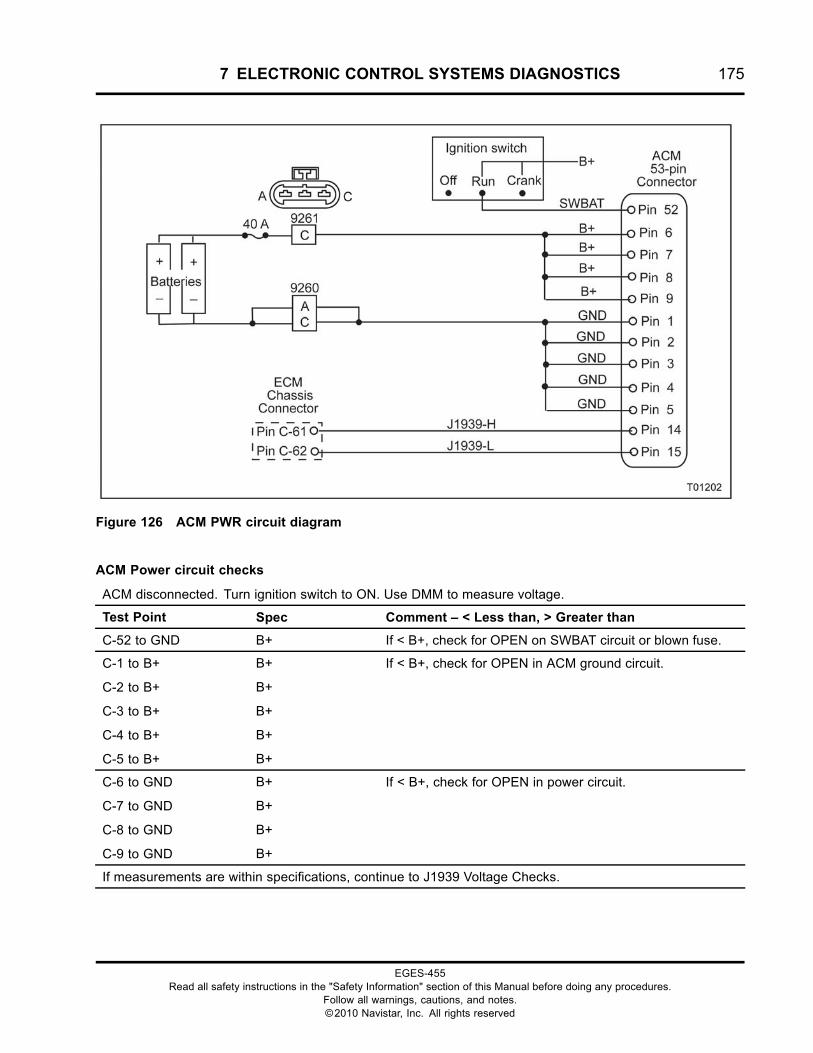
7 ELECTRONIC CONTROL SYSTEMS DIAGNOSTICS 175
Figure 126 ACM PWR circuit diagram
ACM Power circuit checks
ACM disconnected. Turn ignition switch to ON. Use DMM to measure voltage.
Test Point Spec Comment – < Less than, > Greater than
C-52 to GND B+ If < B+, check for OPEN on SWBAT circuit or blown fuse.
C-1 to B+
C-2 to B+
C-3 to B+
C-4 to B+
C-5 to B+
B+
B+
B+
B+
B+
If < B+, check for OPEN in ACM ground circuit.
C-6 to GND
C-7 to GND
C-8 to GND
C-9 to GND
B+
B+
B+
B+
If < B+, check for OPEN in power circuit.
If measurements are within specifications, continue to J1939 Voltage Checks.
EGES-455Read all safety instructions in the "Safety Information" section of this Manual before doing any procedures.
Follow all warnings, cautions, and notes.©2010 Navistar, Inc. All rights reserved
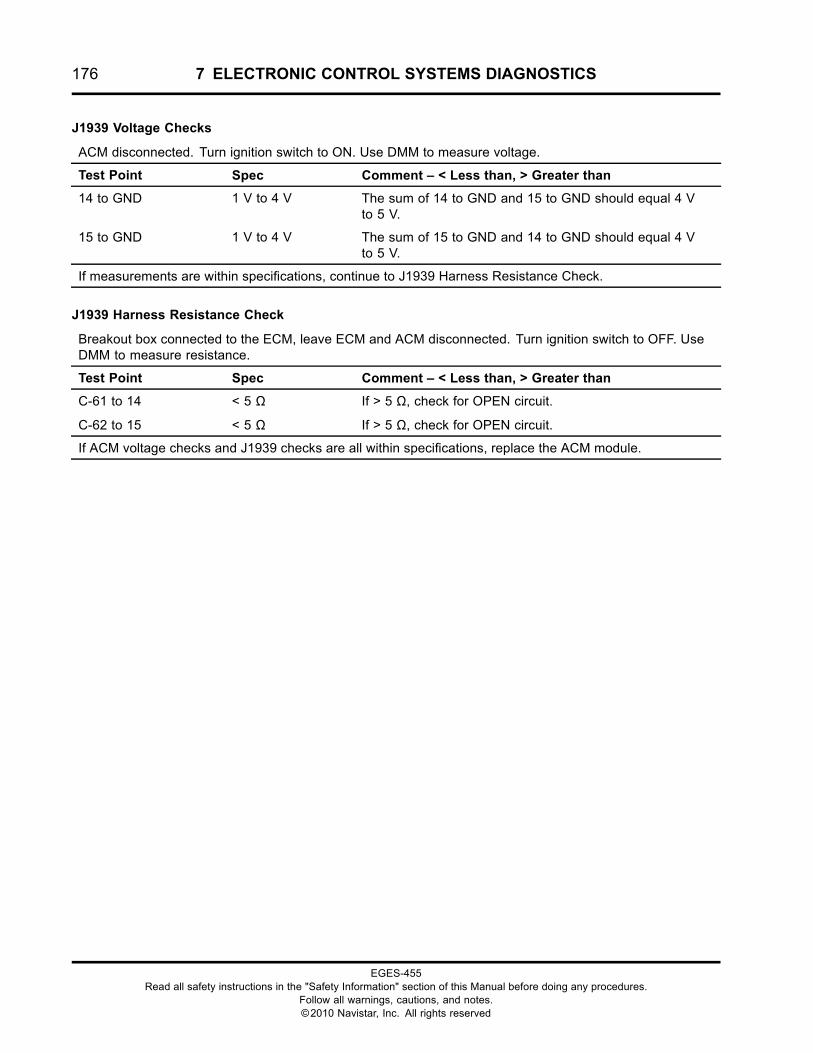
176 7 ELECTRONIC CONTROL SYSTEMS DIAGNOSTICS
J1939 Voltage Checks
ACM disconnected. Turn ignition switch to ON. Use DMM to measure voltage.
Test Point Spec Comment – < Less than, > Greater than
14 to GND 1 V to 4 V The sum of 14 to GND and 15 to GND should equal 4 Vto 5 V.
15 to GND 1 V to 4 V The sum of 15 to GND and 14 to GND should equal 4 Vto 5 V.
If measurements are within specifications, continue to J1939 Harness Resistance Check.
J1939 Harness Resistance Check
Breakout box connected to the ECM, leave ECM and ACM disconnected. Turn ignition switch to OFF. UseDMM to measure resistance.
Test Point Spec Comment – < Less than, > Greater than
C-61 to 14
C-62 to 15
< 5 Ω
< 5 Ω
If > 5 Ω, check for OPEN circuit.
If > 5 Ω, check for OPEN circuit.
If ACM voltage checks and J1939 checks are all within specifications, replace the ACM module.
EGES-455Read all safety instructions in the "Safety Information" section of this Manual before doing any procedures.
Follow all warnings, cautions, and notes.©2010 Navistar, Inc. All rights reserved
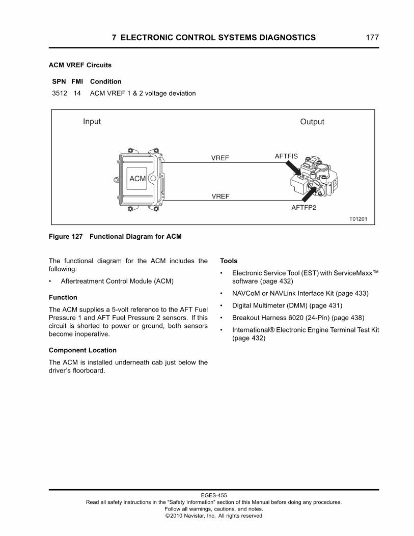
7 ELECTRONIC CONTROL SYSTEMS DIAGNOSTICS 177
ACM VREF Circuits
SPN FMI Condition
3512 14 ACM VREF 1 & 2 voltage deviation
Figure 127 Functional Diagram for ACM
The functional diagram for the ACM includes thefollowing:
• Aftertreatment Control Module (ACM)
Function
The ACM supplies a 5-volt reference to the AFT FuelPressure 1 and AFT Fuel Pressure 2 sensors. If thiscircuit is shorted to power or ground, both sensorsbecome inoperative.
Component Location
The ACM is installed underneath cab just below thedriver’s floorboard.
Tools
• Electronic Service Tool (EST) with ServiceMaxx™software (page 432)
• NAVCoM or NAVLink Interface Kit (page 433)
• Digital Multimeter (DMM) (page 431)
• Breakout Harness 6020 (24-Pin) (page 438)
• International® Electronic Engine Terminal Test Kit(page 432)
EGES-455Read all safety instructions in the "Safety Information" section of this Manual before doing any procedures.
Follow all warnings, cautions, and notes.©2010 Navistar, Inc. All rights reserved
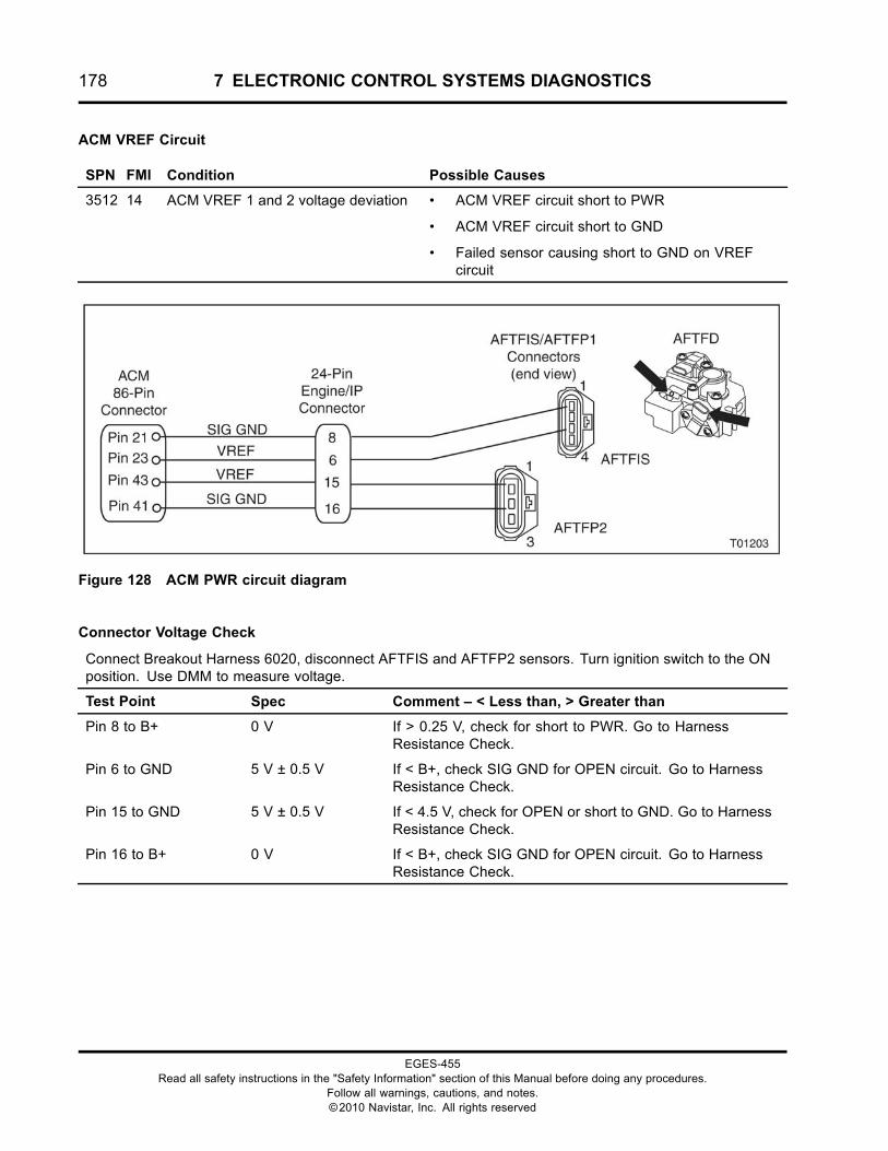
178 7 ELECTRONIC CONTROL SYSTEMS DIAGNOSTICS
ACM VREF Circuit
SPN FMI Condition Possible Causes
3512 14 ACM VREF 1 and 2 voltage deviation • ACM VREF circuit short to PWR
• ACM VREF circuit short to GND
• Failed sensor causing short to GND on VREFcircuit
Figure 128 ACM PWR circuit diagram
Connector Voltage Check
Connect Breakout Harness 6020, disconnect AFTFIS and AFTFP2 sensors. Turn ignition switch to the ONposition. Use DMM to measure voltage.
Test Point Spec Comment – < Less than, > Greater than
Pin 8 to B+ 0 V If > 0.25 V, check for short to PWR. Go to HarnessResistance Check.
Pin 6 to GND 5 V ± 0.5 V If < B+, check SIG GND for OPEN circuit. Go to HarnessResistance Check.
Pin 15 to GND 5 V ± 0.5 V If < 4.5 V, check for OPEN or short to GND. Go to HarnessResistance Check.
Pin 16 to B+ 0 V If < B+, check SIG GND for OPEN circuit. Go to HarnessResistance Check.
EGES-455Read all safety instructions in the "Safety Information" section of this Manual before doing any procedures.
Follow all warnings, cautions, and notes.©2010 Navistar, Inc. All rights reserved
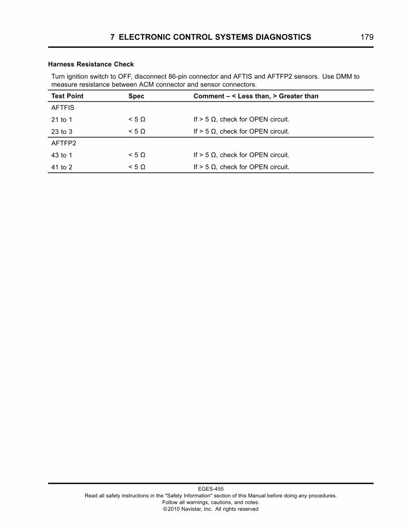
7 ELECTRONIC CONTROL SYSTEMS DIAGNOSTICS 179
Harness Resistance Check
Turn ignition switch to OFF, disconnect 86-pin connector and AFTIS and AFTFP2 sensors. Use DMM tomeasure resistance between ACM connector and sensor connectors.
Test Point Spec Comment – < Less than, > Greater than
AFTFIS
21 to 1
23 to 3
< 5 Ω
< 5 Ω
If > 5 Ω, check for OPEN circuit.
If > 5 Ω, check for OPEN circuit.
AFTFP2
43 to 1
41 to 2
< 5 Ω
< 5 Ω
If > 5 Ω, check for OPEN circuit.
If > 5 Ω, check for OPEN circuit.
EGES-455Read all safety instructions in the "Safety Information" section of this Manual before doing any procedures.
Follow all warnings, cautions, and notes.©2010 Navistar, Inc. All rights reserved
180 7 ELECTRONIC CONTROL SYSTEMS DIAGNOSTICS
AFTFD (aftertreatment Fuel Doser)
SPN FMI Condition
3471 1 Fuel Pressure 1 below desired (Lowsystem pressure)
3471 7 AFT Fuel Doser valve not responding asexpected
3471 10 AFT Fuel Doser valve abnormal rate ofchange
3479 3 AFT Fuel Doser Valve Short to PWR
3479 4 AFT Fuel Doser Valve Short to GND
Figure 129 Functional diagram for AFTFD
The functional diagram for the AFTFD includes thefollowing:
• Aftertreatment Control Module (ACM)
• Down Stream Injection (DSI) unit
• Aftertreatment Fuel Pressure 2 (AFTFP2)
• Aftertreatment Fuel Doser (AFTFD)
Function
Pressurized fuel is supplied to the AFTFD throughthe fuel filter housing assembly. When the conditionsrequired for regeneration are met, the ACM sends
EGES-455Read all safety instructions in the "Safety Information" section of this Manual before doing any procedures.
Follow all warnings, cautions, and notes.©2010 Navistar, Inc. All rights reserved
7 ELECTRONIC CONTROL SYSTEMS DIAGNOSTICS 181
voltage to the AFTFD to open and inject fuel into theturbo exhaust pipe.
Component Location
The AFTFD is integrated into the Down StreamInjection (DSI) unit located on the left side of theengine, to the rear of fuel filter module.
Tools
• Electronic Service Tool (EST) with ServiceMaxx™software (page 432)
• NAVCoM or NAVLink Interface Kit (page 433)
• Digital Multimeter (DMM) (page 431)
• Breakout Harness 4828 (AFTFD) (page 435)
• International® Electronic Engine Terminal Test Kit(page 432)
Figure 130 AFTFD circuit diagram
EGES-455Read all safety instructions in the "Safety Information" section of this Manual before doing any procedures.
Follow all warnings, cautions, and notes.©2010 Navistar, Inc. All rights reserved
182 7 ELECTRONIC CONTROL SYSTEMS DIAGNOSTICS
AFTFD Connector End Diagnostics
SPN FMI Condition Possible Causes
3471 1 Fuel Pressure 1 below desired (Lowsystem pressure)
• Low Fuel Delivery Pressure
• Restricted Fuel Filter
• AFT Fuel Shutoff Valve failure
• Biased AFT Fuel Pressure 1 sensor or circuit
3471 7 AFT Fuel Doser valve not respondingas expected
• Lower fuel delivery pressure.
• Restricted fuel filter.
• AFT Fuel Shutoff Valve failure.
• Biased AFT Fuel Pressure 1 sensor or circuit
3471 10 AFT Fuel Doser valve abnormal rateof change
• AFT Fuel Doser failure
3479 3 AFT Fuel Doser Valve Short to PWR • AFTFD circuit short to PWR
• Failed AFTFD
3479 4 AFT Fuel Doser Valve Short to GND • AFTFD circuit short to GND
• Failed AFTFD
NOTE: The KOEO Standard Test or KOEO OutputState HIGH or LOW does not cycle this actuator.
NOTE: The sensors connected to the AftertreatmentControl Module (ACM) cannot be monitored usingServiceMaxx™. If a DTC is set for this actuator, allyou can do is verify that there is not a circuit fault.If circuits check out acceptable, then replace theactuator.
Connector Voltage Check
Connect Breakout Harness 4828 to engine harness and leave AFTFD disconnected. Turn ignition switchto ON. Use DMM to measure voltage.
Test Point Spec Comment – < Less than, > Greater than
1 to GND 6.0 V +/- 1.0 V If < 5.0 V, check for OPEN circuit or short to GND, go toHarness Resistance Check (page 183).
If > 7.0 V, check for short to PWR, go to Harness ResistanceCheck.
2 to B+ B+ If < B+, check for OPEN circuit. Do Harness ResistanceCheck (page 183).
If measurements are within specifications, then replace the AFT Fuel Doser.
EGES-455Read all safety instructions in the "Safety Information" section of this Manual before doing any procedures.
Follow all warnings, cautions, and notes.©2010 Navistar, Inc. All rights reserved
7 ELECTRONIC CONTROL SYSTEMS DIAGNOSTICS 183
Harness Resistance Check
Turn ignition switch to OFF. Connect Breakout Harness 4828 to engine harness and leave AFTFD and ACMdisconnected. Use DMM to measure resistance between AFTFD connector and ACM connector.
Test Point Spec Comment – < Less than, > Greater than
1 to GND
1 to Pin 10
> 1 kΩ
< 5 Ω
If < 1k Ω, check for short to GND.
If > 5 Ω, check for OPEN circuit.
2 to GND
2 to Pin 30
> 1 kΩ
< 5 Ω
If < 1k Ω, check for short to GND.
If > 5 Ω, check for OPEN circuit.
EGES-455Read all safety instructions in the "Safety Information" section of this Manual before doing any procedures.
Follow all warnings, cautions, and notes.©2010 Navistar, Inc. All rights reserved
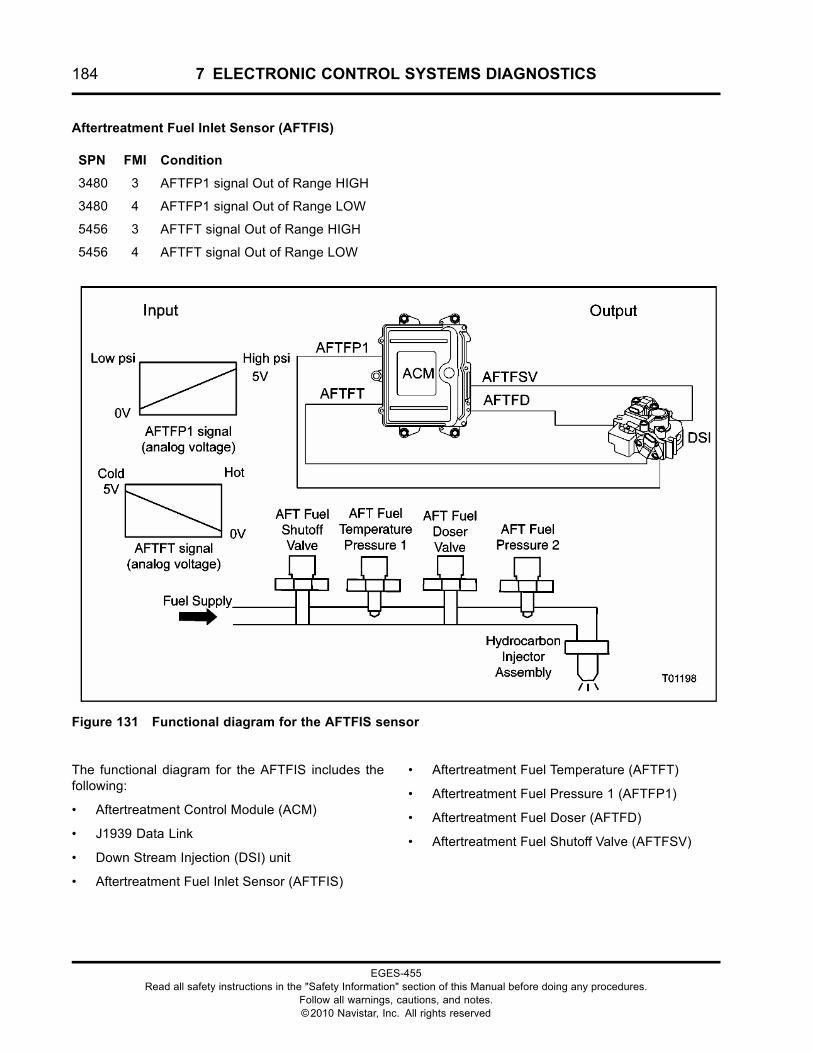
184 7 ELECTRONIC CONTROL SYSTEMS DIAGNOSTICS
Aftertreatment Fuel Inlet Sensor (AFTFIS)
SPN FMI Condition
3480 3 AFTFP1 signal Out of Range HIGH
3480 4 AFTFP1 signal Out of Range LOW
5456 3 AFTFT signal Out of Range HIGH
5456 4 AFTFT signal Out of Range LOW
Figure 131 Functional diagram for the AFTFIS sensor
The functional diagram for the AFTFIS includes thefollowing:
• Aftertreatment Control Module (ACM)
• J1939 Data Link
• Down Stream Injection (DSI) unit
• Aftertreatment Fuel Inlet Sensor (AFTFIS)
• Aftertreatment Fuel Temperature (AFTFT)
• Aftertreatment Fuel Pressure 1 (AFTFP1)
• Aftertreatment Fuel Doser (AFTFD)
• Aftertreatment Fuel Shutoff Valve (AFTFSV)
EGES-455Read all safety instructions in the "Safety Information" section of this Manual before doing any procedures.
Follow all warnings, cautions, and notes.©2010 Navistar, Inc. All rights reserved
7 ELECTRONIC CONTROL SYSTEMS DIAGNOSTICS 185
Function
The AFTFIS is comprised of a fuel temperature andfuel pressure sensor. The AFTFIS monitors fuelpressure and fuel temperature in the aftertreatmentfuel system and provides a feedback signal to theACM.
Sensor Location
The AFTFIS is integrated into the Down StreamInjection (DSI) unit located on the left side of theengine, to the rear of fuel filter module.
• Electronic Service Tool (EST) with ServiceMaxx™software (page 432)
• NAVCoM or NAVLink Interface Kit (page 433)
• Digital Multimeter (DMM) (page 431)
• Breakout Harness 6027 (AFTFIS) (page 439)
• International® Electronic Engine Terminal Test Kit(page 432)
AFTFIS Sensor End Diagnostics
SPN FMI Condition Possible Causes
3480 3 AFTFP1 signal Out of Range HIGH • AFTFP1 signal circuit OPEN or short to PWR
• Failed AFTFIS
3480 4 AFTFP1 signal Out of Range LOW • AFTFP1 signal circuit short to GND
• Failed AFTFIS
5456 3 AFTFT signal Out of Range HIGH • AFTFT signal circuit OPEN or short to PWR
• Failed AFTFIS
5456 4 AFTFT signal Out of Range LOW • AFTFT signal circuit short to GND
• Failed AFTFIS
EGES-455Read all safety instructions in the "Safety Information" section of this Manual before doing any procedures.
Follow all warnings, cautions, and notes.©2010 Navistar, Inc. All rights reserved
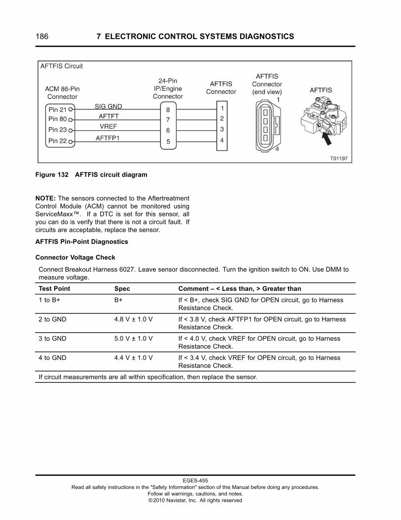
186 7 ELECTRONIC CONTROL SYSTEMS DIAGNOSTICS
Figure 132 AFTFIS circuit diagram
NOTE: The sensors connected to the AftertreatmentControl Module (ACM) cannot be monitored usingServiceMaxx™. If a DTC is set for this sensor, allyou can do is verify that there is not a circuit fault. Ifcircuits are acceptable, replace the sensor.
AFTFIS Pin-Point Diagnostics
Connector Voltage Check
Connect Breakout Harness 6027. Leave sensor disconnected. Turn the ignition switch to ON. Use DMM tomeasure voltage.
Test Point Spec Comment – < Less than, > Greater than
1 to B+ B+ If < B+, check SIG GND for OPEN circuit, go to HarnessResistance Check.
2 to GND 4.8 V ± 1.0 V If < 3.8 V, check AFTFP1 for OPEN circuit, go to HarnessResistance Check.
3 to GND 5.0 V ± 1.0 V If < 4.0 V, check VREF for OPEN circuit, go to HarnessResistance Check.
4 to GND 4.4 V ± 1.0 V If < 3.4 V, check VREF for OPEN circuit, go to HarnessResistance Check.
If circuit measurements are all within specification, then replace the sensor.
EGES-455Read all safety instructions in the "Safety Information" section of this Manual before doing any procedures.
Follow all warnings, cautions, and notes.©2010 Navistar, Inc. All rights reserved
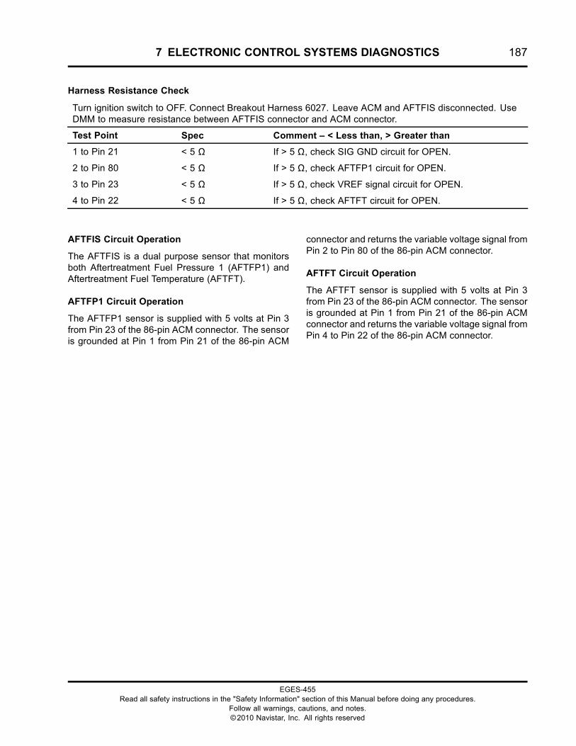
7 ELECTRONIC CONTROL SYSTEMS DIAGNOSTICS 187
Harness Resistance Check
Turn ignition switch to OFF. Connect Breakout Harness 6027. Leave ACM and AFTFIS disconnected. UseDMM to measure resistance between AFTFIS connector and ACM connector.
Test Point Spec Comment – < Less than, > Greater than
1 to Pin 21 < 5 Ω If > 5 Ω, check SIG GND circuit for OPEN.
2 to Pin 80 < 5 Ω If > 5 Ω, check AFTFP1 circuit for OPEN.
3 to Pin 23 < 5 Ω If > 5 Ω, check VREF signal circuit for OPEN.
4 to Pin 22 < 5 Ω If > 5 Ω, check AFTFT circuit for OPEN.
AFTFIS Circuit Operation
The AFTFIS is a dual purpose sensor that monitorsboth Aftertreatment Fuel Pressure 1 (AFTFP1) andAftertreatment Fuel Temperature (AFTFT).
AFTFP1 Circuit Operation
The AFTFP1 sensor is supplied with 5 volts at Pin 3from Pin 23 of the 86-pin ACM connector. The sensoris grounded at Pin 1 from Pin 21 of the 86-pin ACM
connector and returns the variable voltage signal fromPin 2 to Pin 80 of the 86-pin ACM connector.
AFTFT Circuit Operation
The AFTFT sensor is supplied with 5 volts at Pin 3from Pin 23 of the 86-pin ACM connector. The sensoris grounded at Pin 1 from Pin 21 of the 86-pin ACMconnector and returns the variable voltage signal fromPin 4 to Pin 22 of the 86-pin ACM connector.
EGES-455Read all safety instructions in the "Safety Information" section of this Manual before doing any procedures.
Follow all warnings, cautions, and notes.©2010 Navistar, Inc. All rights reserved
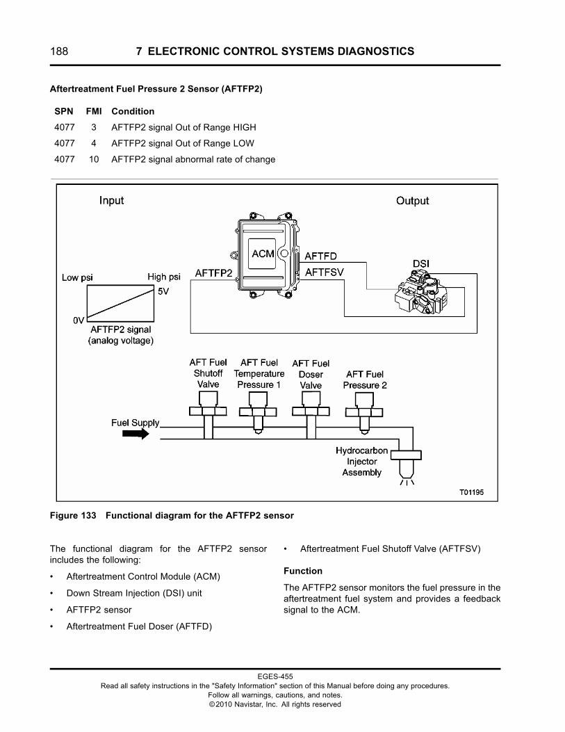
188 7 ELECTRONIC CONTROL SYSTEMS DIAGNOSTICS
Aftertreatment Fuel Pressure 2 Sensor (AFTFP2)
SPN FMI Condition
4077 3 AFTFP2 signal Out of Range HIGH
4077 4 AFTFP2 signal Out of Range LOW
4077 10 AFTFP2 signal abnormal rate of change
Figure 133 Functional diagram for the AFTFP2 sensor
The functional diagram for the AFTFP2 sensorincludes the following:
• Aftertreatment Control Module (ACM)
• Down Stream Injection (DSI) unit
• AFTFP2 sensor
• Aftertreatment Fuel Doser (AFTFD)
• Aftertreatment Fuel Shutoff Valve (AFTFSV)
Function
The AFTFP2 sensor monitors the fuel pressure in theaftertreatment fuel system and provides a feedbacksignal to the ACM.
EGES-455Read all safety instructions in the "Safety Information" section of this Manual before doing any procedures.
Follow all warnings, cautions, and notes.©2010 Navistar, Inc. All rights reserved
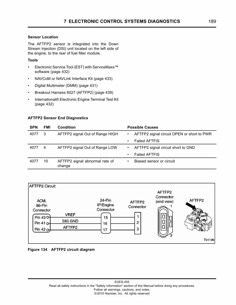
7 ELECTRONIC CONTROL SYSTEMS DIAGNOSTICS 189
Sensor Location
The AFTFP2 sensor is integrated into the DownStream Injection (DSI) unit located on the left side ofthe engine, to the rear of fuel filter module.
Tools
• Electronic Service Tool (EST) with ServiceMaxx™software (page 432)
• NAVCoM or NAVLink Interface Kit (page 433)
• Digital Multimeter (DMM) (page 431)
• Breakout Harness 6027 (AFTFP2) (page 439)
• International® Electronic Engine Terminal Test Kit(page 432)
AFTFP2 Sensor End Diagnostics
SPN FMI Condition Possible Causes
4077 3 AFTFP2 signal Out of Range HIGH • AFTFP2 signal circuit OPEN or short to PWR
• Failed AFTFIS
4077 4 AFTFP2 signal Out of Range LOW • AFTFP2 signal circuit short to GND
• Failed AFTFIS
4077 10 AFTFP2 signal abnormal rate ofchange
• Biased sensor or circuit
Figure 134 AFTFP2 circuit diagram
EGES-455Read all safety instructions in the "Safety Information" section of this Manual before doing any procedures.
Follow all warnings, cautions, and notes.©2010 Navistar, Inc. All rights reserved
190 7 ELECTRONIC CONTROL SYSTEMS DIAGNOSTICS
NOTE: The sensors connected to the AftertreatmentControl Module (ACM) cannot be monitored usingServiceMaxx™. If a DTC is set for this sensor, allyou can do is verify that there is not a circuit fault.If circuits check out acceptable, then replace thesensor.
Connector Voltage Check
Connect Breakout Harness 6027. Leave sensor disconnected. Turn the ignition switch to ON. Use DMM tomeasure voltage.
Test Point Spec Comment – < Less than, > Greater than
1 to GND 5.0V +/- 1.0V If < 4.0V, check VREF for OPEN circuit, go to HarnessResistance Check.
2 to B+ B+ If < B+, check SIG GND for OPEN circuit, go to HarnessResistance Check.
3 to GND 5.4V +/- 1.0V If < 4.4V, check AFTFP2 for OPEN circuit, go to HarnessResistance Check.
If circuit measurements are all within specification, then replace the sensor.
AFTFP2 Pin-point Diagnostics
Harness Resistance Check
Turn ignition switch to OFF. Connect Breakout Harness 6027. Leave ACM and AFTFP2 sensordisconnected. Use DMM to measure resistance between AFTFP2 connector and ACM connector.
Test Point Spec Comment – < Less than, > Greater than
1 to Pin 43 < 5 Ω If > 5 Ω, check VREF signal circuit for OPEN.
2 to Pin 41 < 5 Ω If > 5 Ω, check SIG GND circuit for OPEN.
3 to Pin 42 < 5 Ω If > 5 Ω, check AFTFP2 circuit for OPEN.
AFTFP2 Circuit Operation
The AFTFP2 sensor is a pressure sensor that issupplied with 5 volts at Pin 1 from ACM Pin 43. The
sensor is grounded at Pin 2 from ACM Pin 41 andreturns a variable voltage signal from Pin 3 to ACMPin 42.
EGES-455Read all safety instructions in the "Safety Information" section of this Manual before doing any procedures.
Follow all warnings, cautions, and notes.©2010 Navistar, Inc. All rights reserved
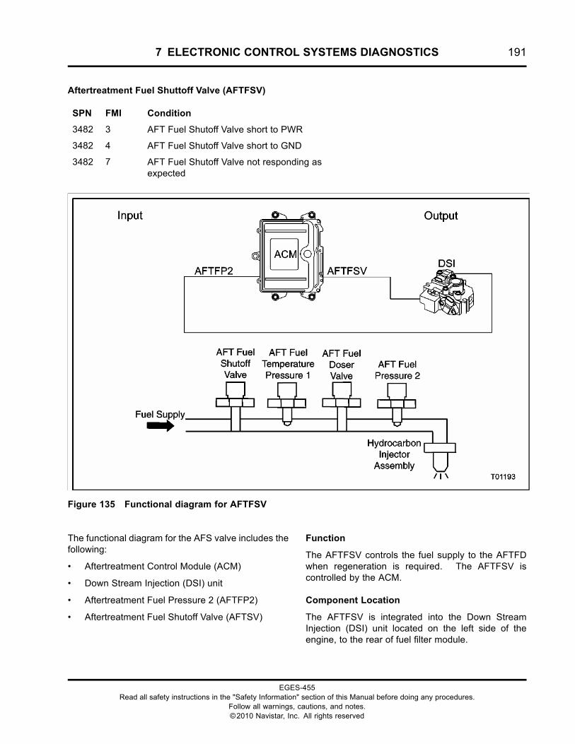
7 ELECTRONIC CONTROL SYSTEMS DIAGNOSTICS 191
Aftertreatment Fuel Shuttoff Valve (AFTFSV)
SPN FMI Condition
3482 3 AFT Fuel Shutoff Valve short to PWR
3482 4 AFT Fuel Shutoff Valve short to GND
3482 7 AFT Fuel Shutoff Valve not responding asexpected
Figure 135 Functional diagram for AFTFSV
The functional diagram for the AFS valve includes thefollowing:
• Aftertreatment Control Module (ACM)
• Down Stream Injection (DSI) unit
• Aftertreatment Fuel Pressure 2 (AFTFP2)
• Aftertreatment Fuel Shutoff Valve (AFTSV)
Function
The AFTFSV controls the fuel supply to the AFTFDwhen regeneration is required. The AFTFSV iscontrolled by the ACM.
Component Location
The AFTFSV is integrated into the Down StreamInjection (DSI) unit located on the left side of theengine, to the rear of fuel filter module.
EGES-455Read all safety instructions in the "Safety Information" section of this Manual before doing any procedures.
Follow all warnings, cautions, and notes.©2010 Navistar, Inc. All rights reserved
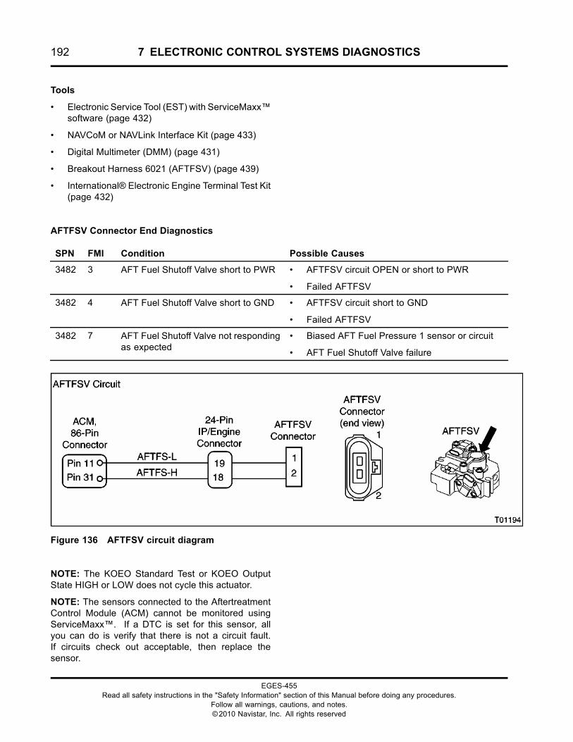
192 7 ELECTRONIC CONTROL SYSTEMS DIAGNOSTICS
Tools
• Electronic Service Tool (EST) with ServiceMaxx™software (page 432)
• NAVCoM or NAVLink Interface Kit (page 433)
• Digital Multimeter (DMM) (page 431)
• Breakout Harness 6021 (AFTFSV) (page 439)
• International® Electronic Engine Terminal Test Kit(page 432)
AFTFSV Connector End Diagnostics
SPN FMI Condition Possible Causes
3482 3 AFT Fuel Shutoff Valve short to PWR • AFTFSV circuit OPEN or short to PWR
• Failed AFTFSV
3482 4 AFT Fuel Shutoff Valve short to GND • AFTFSV circuit short to GND
• Failed AFTFSV
3482 7 AFT Fuel Shutoff Valve not respondingas expected
• Biased AFT Fuel Pressure 1 sensor or circuit
• AFT Fuel Shutoff Valve failure
Figure 136 AFTFSV circuit diagram
NOTE: The KOEO Standard Test or KOEO OutputState HIGH or LOW does not cycle this actuator.
NOTE: The sensors connected to the AftertreatmentControl Module (ACM) cannot be monitored usingServiceMaxx™. If a DTC is set for this sensor, allyou can do is verify that there is not a circuit fault.If circuits check out acceptable, then replace thesensor.
EGES-455Read all safety instructions in the "Safety Information" section of this Manual before doing any procedures.
Follow all warnings, cautions, and notes.©2010 Navistar, Inc. All rights reserved
7 ELECTRONIC CONTROL SYSTEMS DIAGNOSTICS 193
Connector Voltage Check
Connect Breakout Harness 6021 to engine harness and leave AFTFSV disconnected. Turn ignition switch toON. Use DMM to measure voltage after 60 seconds.
Test Point Spec Comment – < Less than, > Greater than
1 to GND 6.0 V +/- 1.0 V If < 5.0 V, check for OPEN circuit or short to GND, go toHarness Resistance Check.
If > 7.0 V, check for short to PWR, Do Harness ResistanceCheck.
2 to B+ B+ If < B+, check for OPEN circuit. go to Harness ResistanceCheck (page 193).
If measurements are within specifications, replace AFT Fuel Shutoff Valve.
Harness Resistance Check
Turn ignition switch to OFF. Connect Breakout Harness 6021 to engine harness and leave AFTFSV andACM disconnected. Use DMM to measure resistance between AFTFSV connector and ACM connector.
Test Point Spec Comment – < Less than, > Greater than
1 to GND
1 to 19
> 1 kΩ
< 5 Ω
If < 1k Ω, check for short to GND.
If > 5 Ω, check for OPEN circuit.
2 to GND
2 to 18
> 1 kΩ
< 5 Ω
If < 1k Ω, check for short to GND.
If > 5 Ω, check for OPEN circuit.
EGES-455Read all safety instructions in the "Safety Information" section of this Manual before doing any procedures.
Follow all warnings, cautions, and notes.©2010 Navistar, Inc. All rights reserved
194 7 ELECTRONIC CONTROL SYSTEMS DIAGNOSTICS
AFT System (Aftertreatment)
SPN FMI Condition
3246 20 DPF over temperature - (possible filterdamage)
3251 2 DPFDP above or below desired level
3251 21 DPFDP excessively LOW (sensor/circuitfault or missing DPF)
3556 0 AFT Fuel Pressure 2 excessively high(restricted injection)
3556 1 AFT Fuel Pressure 2 below desired(possible system leak)
3556 7 AFT Fuel Injector not responding asexpected
3719 0 DPF Soot Load - Highest (level 3/3)
3719 15 DPF Soot Load - Lowest (level 1/3)
3719 16 DPF Soot Load - Moderate (level 2/3)
3936 0 DPF Soot Load - Severe De-Rate
3936 2 DPF Test - test unsuccessful
3936 14 DPF - Regen duration above limit
EGES-455Read all safety instructions in the "Safety Information" section of this Manual before doing any procedures.
Follow all warnings, cautions, and notes.©2010 Navistar, Inc. All rights reserved
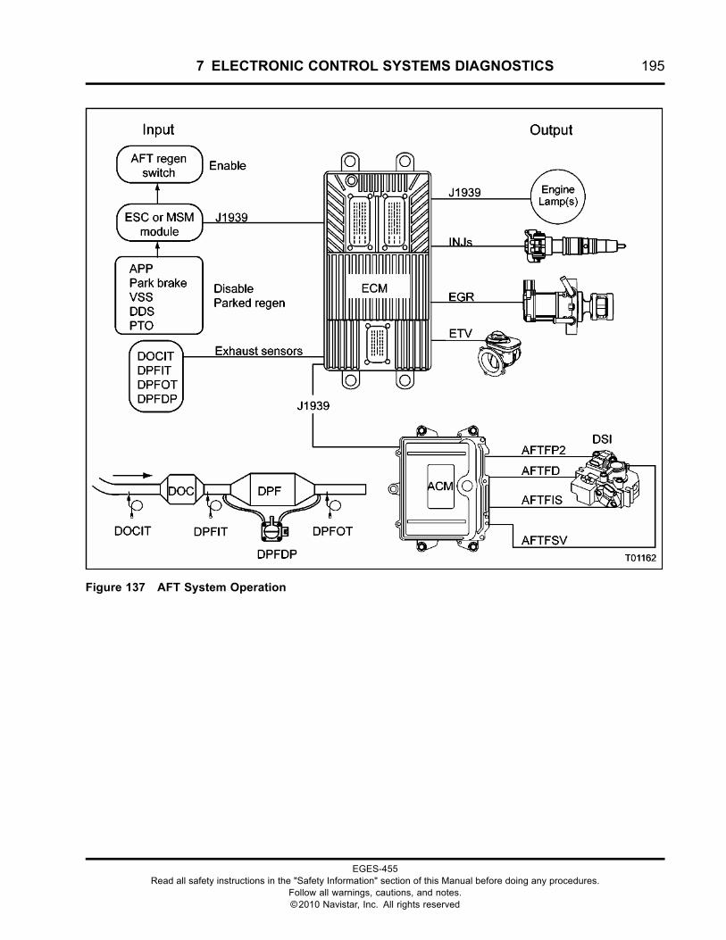
7 ELECTRONIC CONTROL SYSTEMS DIAGNOSTICS 195
Figure 137 AFT System Operation
EGES-455Read all safety instructions in the "Safety Information" section of this Manual before doing any procedures.
Follow all warnings, cautions, and notes.©2010 Navistar, Inc. All rights reserved
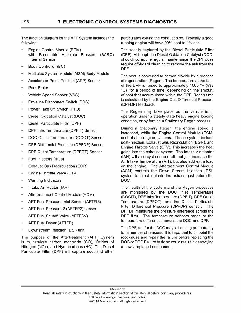
196 7 ELECTRONIC CONTROL SYSTEMS DIAGNOSTICS
The function diagram for the AFT System includes thefollowing:
• Engine Control Module (ECM)with Barometric Absolute Pressure (BARO)Internal Sensor
• Body Controller (BC)
• Multiplex System Module (MSM) Body Module
• Accelerator Pedal Position (APP) Sensor
• Park Brake
• Vehicle Speed Sensor (VSS)
• Driveline Disconnect Switch (DDS)
• Power Take Off Switch (PTO)
• Diesel Oxidation Catalyst (DOC)
• Diesel Particulate Filter (DPF)
• DPF Inlet Temperature (DPFIT) Sensor
• DOC Outlet Temperature (DOCOT) Sensor
• DPF Differential Pressure (DPFDP) Sensor
• DPF Outlet Temperature (DPFOT) Sensor
• Fuel Injectors (INJs)
• Exhaust Gas Recirculation (EGR)
• Engine Throttle Valve (ETV)
• Warning Indicators
• Intake Air Heater (IAH)
• Aftertreatment Control Module (ACM)
• AFT Fuel Pressure Inlet Sensor (AFTFIS)
• AFT Fuel Pressure 2 (AFTFP2) sensor
• AFT Fuel Shutoff Valve (AFTFSV)
• AFT Fuel Doser (AFTFD)
• Downstream Injection (DSI) unit
The purpose of the Aftertreatment (AFT) Systemis to catalyze carbon monoxide (CO), Oxides ofNitrogen (NOx), and Hydrocarbons (HC). The DieselParticulate Filter (DPF) will capture soot and other
particulates exiting the exhaust pipe. Typically a goodrunning engine will have 99% soot to 1% ash.
The soot is captured by the Diesel Particulate Filter(DPF). Although the Diesel Oxidation Catalyst (DOC)should not require regular maintenance, the DPF doesrequire off-board cleaning to remove the ash from theDPF.
The soot is converted to carbon dioxide by a processof regeneration (Regen). The temperature at the faceof the DPF is raised to approximately 1000 °F (538°C), for a period of time, depending on the amountof soot that accumulated within the DPF. Regen timeis calculated by the Engine Gas Differential Pressure(DPFDP) feedback.
The Regen may take place as the vehicle is inoperation under a steady state heavy engine loadingcondition, or by forcing a Stationary Regen process.
During a Stationary Regen, the engine speed isincreased, while the Engine Control Module (ECM)controls the engine systems. These system includepost-injection, Exhaust Gas Recirculation (EGR), andEngine Throttle Valve (ETV). This increases the heatgoing into the exhaust system. The Intake Air Heater(IAH) will also cycle on and off, not just increase theAir Intake Temperature (AIT), but also add extra loadon the engine. The Atfertreatment Control Module(ACM) controls the Down Stream Injection (DSI)system to inject fuel into the exhaust just before theDOC.
The health of the system and the Regen processesare monitored by the DOC Inlet Temperature(DOCIT), DPF Inlet Temperature (DPFIT), DPF OutletTemperature (DPFOT), and the Diesel ParticulateFilter Differential Pressure (DPFDP) sensor. TheDPFDP measures the pressure difference across theDPF filter. The temperature sensors measure thetemperature differences across the DOC and DPF.
The DPF, and/or the DOCmay fail or plug prematurelyfor a number of reasons. It is important to pinpoint theroot cause and repair the failure before replacing theDOC or DPF. Failure to do so could result in destroyinga newly replaced component.
EGES-455Read all safety instructions in the "Safety Information" section of this Manual before doing any procedures.
Follow all warnings, cautions, and notes.©2010 Navistar, Inc. All rights reserved
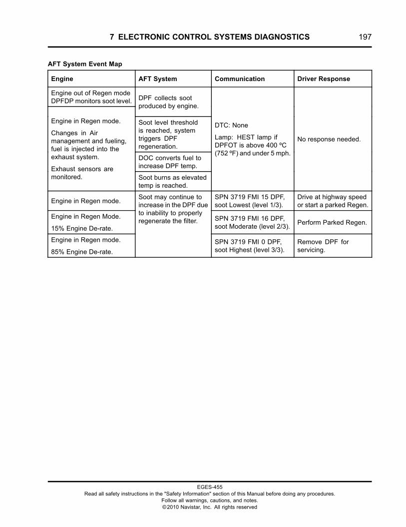
7 ELECTRONIC CONTROL SYSTEMS DIAGNOSTICS 197
AFT System Event Map
Engine AFT System Communication Driver Response
Engine out of Regen modeDPFDP monitors soot level. DPF collects soot
produced by engine.
Soot level thresholdis reached, systemtriggers DPFregeneration.
DOC converts fuel toincrease DPF temp.
Engine in Regen mode.
Changes in Airmanagement and fueling,fuel is injected into theexhaust system.
Exhaust sensors aremonitored. Soot burns as elevated
temp is reached.
DTC: None
Lamp: HEST lamp ifDPFOT is above 400 ºC(752 ºF) and under 5 mph.
No response needed.
Engine in Regen mode.SPN 3719 FMI 15 DPF,soot Lowest (level 1/3).
Drive at highway speedor start a parked Regen.
Engine in Regen Mode.
15% Engine De-rate.
SPN 3719 FMI 16 DPF,soot Moderate (level 2/3).
Perform Parked Regen.
Engine in Regen mode.
85% Engine De-rate.
Soot may continue toincrease in the DPF dueto inability to properlyregenerate the filter.
SPN 3719 FMI 0 DPF,soot Highest (level 3/3).
Remove DPF forservicing.
EGES-455Read all safety instructions in the "Safety Information" section of this Manual before doing any procedures.
Follow all warnings, cautions, and notes.©2010 Navistar, Inc. All rights reserved
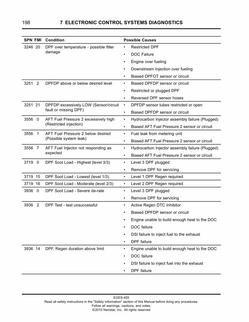
198 7 ELECTRONIC CONTROL SYSTEMS DIAGNOSTICS
SPN FMI Condition Possible Causes
3246 20 DPF over temperature - possible filterdamage
• Restricted DPF
• DOC Failure
• Engine over fueling
• Downstream Injection over fueling
• Biased DPFOT sensor or circuit
3251 2 DPFDP above or below desired level • Biased DPFDP sensor or circuit
• Restricted or plugged DPF
• Reversed DPF sensor hoses
3251 21 DPFDP excessively LOW (Sensor/circuitfault or missing DPF)
• DPFDP sensor tubes restricted or open
• Biased DPFDP sensor or circuit
3556 0 AFT Fuel Pressure 2 excessively high(Restricted injection)
• Hydrocarbon Injector assembly failure (Plugged)
• Biased AFT Fuel Pressure 2 sensor or circuit
3556 1 AFT Fuel Pressure 2 below desired(Possible system leak)
• Fuel leak from metering unit
• Biased AFT Fuel Pressure 2 sensor or circuit
3556 7 AFT Fuel Injector not responding asexpected
• Hydrocarbon Injector assembly failure (Plugged)
• Biased AFT Fuel Pressure 2 sensor or circuit
3719 0 DPF Soot Load - Highest (level 3/3) • Level 3 DPF plugged
• Remove DPF for servicing
3719 15 DPF Soot Load - Lowest (level 1/3) • Level 1 DPF Regen required
3719 16 DPF Soot Load - Moderate (level 2/3) • Level 2 DPF Regen required
3936 0 DPF Soot Load - Severe de-rate • Level 3 DPF plugged
• Remove DPF for servicing
3936 2 DPF Test - test unsuccessful • Active Regen DTC Inhibitor
• Biased DPFDP sensor or circuit
• Engine unable to build enough heat to the DOC
• DOC failure
• DSI failure to inject fuel to the exhaust
• DPF failure
3936 14 DPF, Regen duration above limit • Engine unable to build enough heat to the DOC
• DOC failure
• DSI failure to inject fuel into the exhaust
• DPF failure
EGES-455Read all safety instructions in the "Safety Information" section of this Manual before doing any procedures.
Follow all warnings, cautions, and notes.©2010 Navistar, Inc. All rights reserved
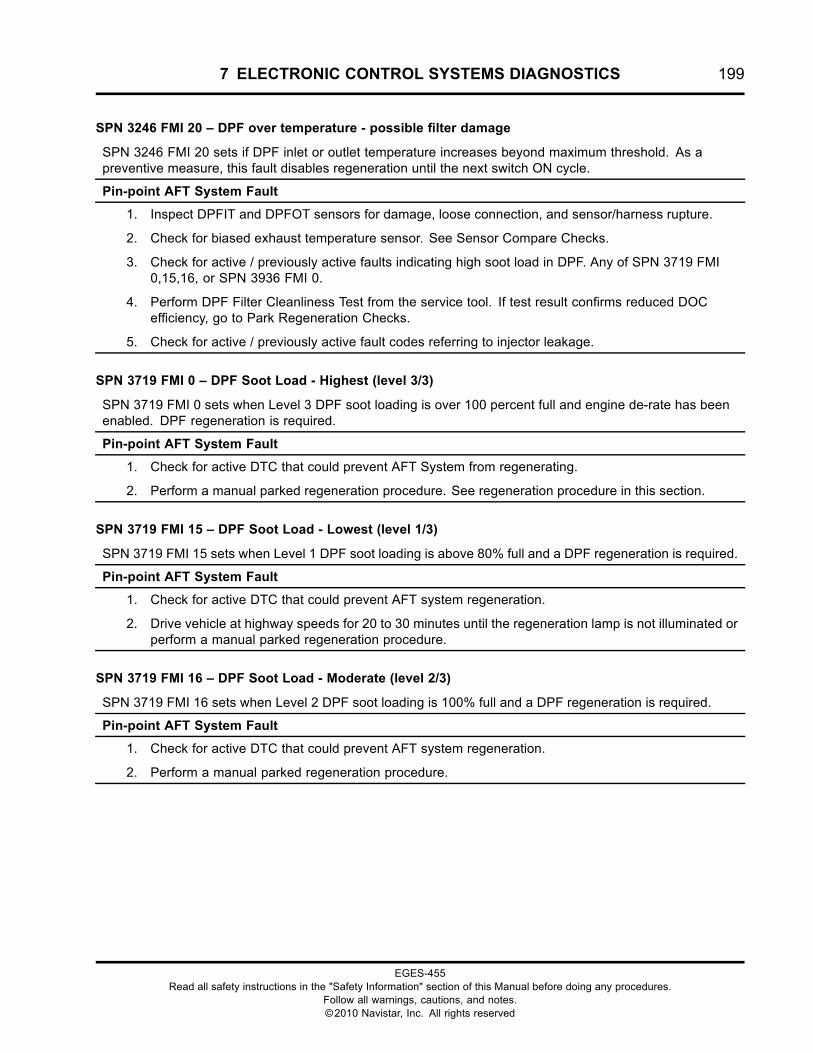
7 ELECTRONIC CONTROL SYSTEMS DIAGNOSTICS 199
SPN 3246 FMI 20 – DPF over temperature - possible filter damage
SPN 3246 FMI 20 sets if DPF inlet or outlet temperature increases beyond maximum threshold. As apreventive measure, this fault disables regeneration until the next switch ON cycle.
Pin-point AFT System Fault
1. Inspect DPFIT and DPFOT sensors for damage, loose connection, and sensor/harness rupture.
2. Check for biased exhaust temperature sensor. See Sensor Compare Checks.
3. Check for active / previously active faults indicating high soot load in DPF. Any of SPN 3719 FMI0,15,16, or SPN 3936 FMI 0.
4. Perform DPF Filter Cleanliness Test from the service tool. If test result confirms reduced DOCefficiency, go to Park Regeneration Checks.
5. Check for active / previously active fault codes referring to injector leakage.
SPN 3719 FMI 0 – DPF Soot Load - Highest (level 3/3)
SPN 3719 FMI 0 sets when Level 3 DPF soot loading is over 100 percent full and engine de-rate has beenenabled. DPF regeneration is required.
Pin-point AFT System Fault
1. Check for active DTC that could prevent AFT System from regenerating.
2. Perform a manual parked regeneration procedure. See regeneration procedure in this section.
SPN 3719 FMI 15 – DPF Soot Load - Lowest (level 1/3)
SPN 3719 FMI 15 sets when Level 1 DPF soot loading is above 80% full and a DPF regeneration is required.
Pin-point AFT System Fault
1. Check for active DTC that could prevent AFT system regeneration.
2. Drive vehicle at highway speeds for 20 to 30 minutes until the regeneration lamp is not illuminated orperform a manual parked regeneration procedure.
SPN 3719 FMI 16 – DPF Soot Load - Moderate (level 2/3)
SPN 3719 FMI 16 sets when Level 2 DPF soot loading is 100% full and a DPF regeneration is required.
Pin-point AFT System Fault
1. Check for active DTC that could prevent AFT system regeneration.
2. Perform a manual parked regeneration procedure.
EGES-455Read all safety instructions in the "Safety Information" section of this Manual before doing any procedures.
Follow all warnings, cautions, and notes.©2010 Navistar, Inc. All rights reserved
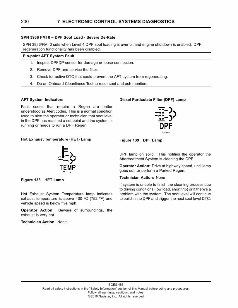
200 7 ELECTRONIC CONTROL SYSTEMS DIAGNOSTICS
SPN 3936 FMI 0 – DPF Soot Load - Severe De-Rate
SPN 3936/FMI 0 sets when Level 4 DPF soot loading is overfull and engine shutdown is enabled. DPFregeneration functionality has been disabled.
Pin-point AFT System Fault
1. Inspect DPFDP sensor for damage or loose connection.
2. Remove DPF and service the filter.
3. Check for active DTC that could prevent the AFT system from regenerating.
4. Do an Onboard Cleanliness Test to reset soot and ash monitors.
AFT System Indicators
Fault codes that require a Regen are betterunderstood as Alert codes. This is a normal conditionused to alert the operator or technician that soot levelin the DPF has reached a set point and the system isrunning or needs to run a DPF Regen.
Hot Exhaust Temperature (HET) Lamp
Figure 138 HET Lamp
Hot Exhaust System Temperature lamp indicatesexhaust temperature is above 400 ºC (752 ºF) andvehicle speed is below five mph.
Operator Action: Beware of surroundings, theexhaust is very hot.
Technician Action: None
Diesel Particulate Filter (DPF) Lamp
Figure 139 DPF Lamp
DPF lamp on solid. This notifies the operator theAftertreatment System is cleaning the DPF.
Operator Action: Drive at highway speed, until lampgoes out, or perform a Parked Regen.
Technician Action: None
If system is unable to finish the cleaning process dueto driving conditions (low load, short trip) or if there’s aproblem with the system. The soot level will continueto build in the DPF and trigger the next soot level DTC.
EGES-455Read all safety instructions in the "Safety Information" section of this Manual before doing any procedures.
Follow all warnings, cautions, and notes.©2010 Navistar, Inc. All rights reserved
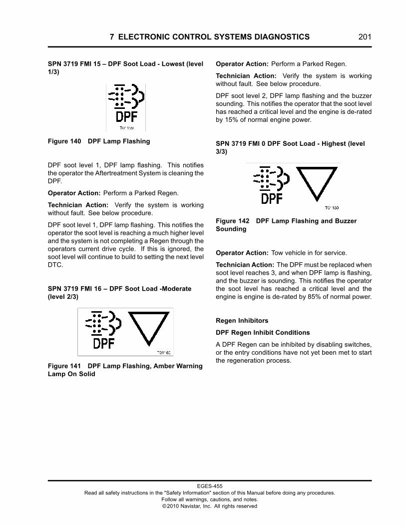
7 ELECTRONIC CONTROL SYSTEMS DIAGNOSTICS 201
SPN 3719 FMI 15 – DPF Soot Load - Lowest (level1/3)
Figure 140 DPF Lamp Flashing
DPF soot level 1, DPF lamp flashing. This notifiesthe operator the Aftertreatment System is cleaning theDPF.
Operator Action: Perform a Parked Regen.
Technician Action: Verify the system is workingwithout fault. See below procedure.
DPF soot level 1, DPF lamp flashing. This notifies theoperator the soot level is reaching a much higher leveland the system is not completing a Regen through theoperators current drive cycle. If this is ignored, thesoot level will continue to build to setting the next levelDTC.
SPN 3719 FMI 16 – DPF Soot Load -Moderate(level 2/3)
Figure 141 DPF Lamp Flashing, Amber WarningLamp On Solid
Operator Action: Perform a Parked Regen.
Technician Action: Verify the system is workingwithout fault. See below procedure.
DPF soot level 2, DPF lamp flashing and the buzzersounding. This notifies the operator that the soot levelhas reached a critical level and the engine is de-ratedby 15% of normal engine power.
SPN 3719 FMI 0 DPF Soot Load - Highest (level3/3)
Figure 142 DPF Lamp Flashing and BuzzerSounding
Operator Action: Tow vehicle in for service.
Technician Action: The DPF must be replaced whensoot level reaches 3, and when DPF lamp is flashing,and the buzzer is sounding. This notifies the operatorthe soot level has reached a critical level and theengine is engine is de-rated by 85% of normal power.
Regen Inhibitors
DPF Regen Inhibit Conditions
A DPF Regen can be inhibited by disabling switches,or the entry conditions have not yet been met to startthe regeneration process.
EGES-455Read all safety instructions in the "Safety Information" section of this Manual before doing any procedures.
Follow all warnings, cautions, and notes.©2010 Navistar, Inc. All rights reserved
202 7 ELECTRONIC CONTROL SYSTEMS DIAGNOSTICS
Entry Conditions for a Rolling Regen
When driving at high speeds or with heavy loads, theexhaust is hot enough to convert the soot to ash.
When driving at lower speeds or when carrying lighterloads, the exhaust is typically is not hot enough toconvert the soot to ash. In these situations, the enginecontrol system will increase the exhaust temperatureand the particulate matter can be converted to ash.
Automatic regeneration occurs when driving. Theoperator is not required to do anything to startregeneration.
An automatic regeneration is not possible duringfrequent stops or low operating speeds. If aregeneration is required in these conditions, a manualparked regeneration must be done.
When the ECM determines the soot level threshold is reached, the system triggers DPF Regen.
NOTE: Short trips, stop and go driving could prevent a successful Regen.
The following conditions are required for a Rolling Regen:
• DPF Status signal displaying: Regen Needed
• Red stop engine lamp not on
• Engine Coolant Temperature at or above 75 ºC (170 ºF)
• Inhibiting DTCs must not be active (See Fault Code Inhibitors in this section of manual.)
• Regen Inhibit switch not active (switch must be off)
• PTO not active (switch must be off)
• Exhaust Temperature sensors below safe thresholds
• DOCIT below 500 °C (932 °F)
• DPFIT below 650 °C (1202 °F)
• DPFOT below 750 °C (1382 °F)
If DPF Status displays "Regen needed" and vehicle is unable to perform a Rolling Regen, perform theDiagnostic Test Procedure.
EGES-455Read all safety instructions in the "Safety Information" section of this Manual before doing any procedures.
Follow all warnings, cautions, and notes.©2010 Navistar, Inc. All rights reserved
7 ELECTRONIC CONTROL SYSTEMS DIAGNOSTICS 203
Entry Conditions for a Parked Regen
A Parked Regen can only be performed when the DPF soot level threshold is reached. The DPF lamp willflash or stay on solid, signaling the need for Regen.
The following conditions are required for a Parked Regen:
• Engine Running
• DPF lamp on
• Parked Regen switch on
• DPF Status signal displaying: Regen Needed
• Red stop engine lamp not on
• Engine Coolant Temperature at or above 75 ºC (170 ºF)
• Vehicle speed not rolling
• Inhibiting DTCs must not be active (See Fault Code Inhibitors in this section of manual.)
• Regen Inhibit switch not active (switch must be off)
• PTO not active (switch must be off)
• Exhaust Temperature sensors below safe thresholds
• DOCIT below 500 °C (932 °F)
• DOCOT below 650 °C (1202 °F)
• DPFOT below 750 °C (1382 °F)
If DPF Status displays “Regen needed” and vehicle is unable to perform a Rolling Regen, PerformDiagnostic Test Procedure.
EGES-455Read all safety instructions in the "Safety Information" section of this Manual before doing any procedures.
Follow all warnings, cautions, and notes.©2010 Navistar, Inc. All rights reserved
204 7 ELECTRONIC CONTROL SYSTEMS DIAGNOSTICS
DPF Filter Cleanliness Test
This test checks the status of the DPF if the soot level is within a Regen Needed limit. The test willautomatically start a Parked Regen.
NOTE: The KOER Standard Test must be run before performing this test.
Engine speed is ramped up to increase exhaust flow through the DPF while the DPFDP sensor monitors thepressure difference across the DPF. The test runs for about 15 minutes. If a Regen is needed, the engineramps up for another 15 minutes, but this time to run DPF Regen cycle.
The following conditions are required for an Onboard Filter Cleanliness Test:
• Engine Running
• Engine Coolant temperature above 75 ºC (170 ºF)
• Vehicle stationary
• Inhibit DTCs must not be active: Refer to the Fault Code Inhibitors
• PTO not active (switch must be off)
• Regen inhibit switch not active (switch must be off)
• Parking brake must be applied
• Brake pedal not depressed
• Accelerator pedal not depressed
• Driveline disengaged
• If the soot level is within normal range, the test completes and displays “Test Completed Successful.”No further action is required.
• If the soot level is above the threshold, the engine idles down for three seconds, sets a DTC, then rampsup the rpm again and starts a Parked Regen.
• If the test is aborted, perform the Diagnostic Test Procedure.
EGES-455Read all safety instructions in the "Safety Information" section of this Manual before doing any procedures.
Follow all warnings, cautions, and notes.©2010 Navistar, Inc. All rights reserved
7 ELECTRONIC CONTROL SYSTEMS DIAGNOSTICS 205
Sensor Compare Checks
Turn switch ON, engine OFF.
Using ServiceMaxx™ software, open the Continues Monitor session.
NOTE: Voltage values need to be measured after cold soak at about 21 ºC (70 ºF)
Checks Specifications Comment – < Less than, > Greater than
S_DOCITVolts
0.88 V +/-0.10 V
If voltage is much higher or lower than the other AFT exhaust sensors, seeDOCIT Sensor (page 244).
S_DPFITVolts
0.88 V +/-0.10 V
If voltage is much higher or lower than the other AFT exhaust sensors, seeDPFIT Sensor (page 255).
S_DPFOTVolts
0.88 V +/-0.10 V
If voltage is much higher or lower than the other AFT exhaust sensors, seeDPFOT Sensor (page 260).
S_DPFDPVolts
0.70 V +/-0.10 V
If not within specification, see DPFDP Sensor (page 249).
S_EBP Volts 0.70 V +/-0.10 V
If not within specification, see EBP Sensor (page 265).
If sensors are within specifications, go to “DIAGNOSTIC TROUBLE CODE INDEX” (page 419) and checkDPF Status.
Exhaust Restriction Test
Connect EST, open the Performance session.
NOTE: Run engine at high idle while monitoring Exhaust Back Pressure and DPF Differential Pressure.
Checks Specifications Comment – < Less than, > Greater than
DPFDP < 1.5 psi If > 1.5 psi, the DPF is plugged. Go to Parked Regen.
EBP < 45 psi Check the exhaust back pressure valve operation.
If above tests do not find a problem, then remove DOC and inspect forface plugging.
If EBP and DPFDP are within expected range, but the DPF Status reads “Regen Needed”, go to ParkedRegen Checks.
If the DPF is face plugged, measure the distance between the filter and outlet. If not within specification, thefilter must be replaced.
EGES-455Read all safety instructions in the "Safety Information" section of this Manual before doing any procedures.
Follow all warnings, cautions, and notes.©2010 Navistar, Inc. All rights reserved
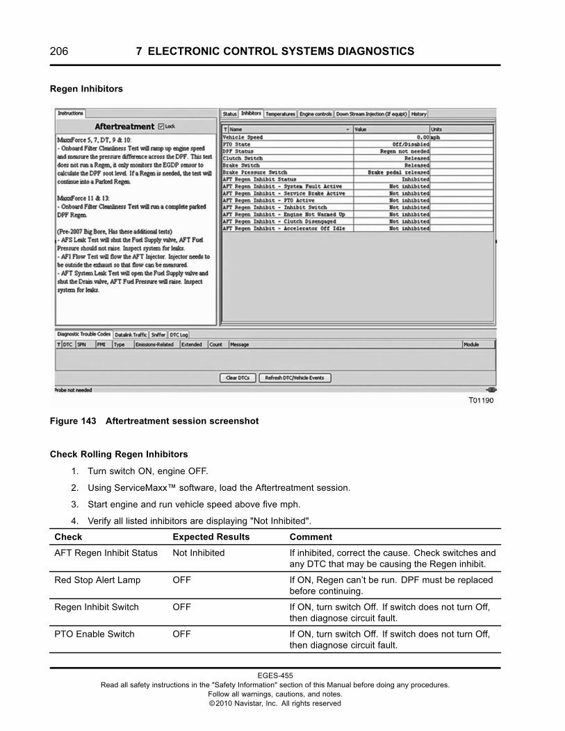
206 7 ELECTRONIC CONTROL SYSTEMS DIAGNOSTICS
Regen Inhibitors
Figure 143 Aftertreatment session screenshot
Check Rolling Regen Inhibitors
1. Turn switch ON, engine OFF.
2. Using ServiceMaxx™ software, load the Aftertreatment session.
3. Start engine and run vehicle speed above five mph.
4. Verify all listed inhibitors are displaying "Not Inhibited".
Check Expected Results Comment
AFT Regen Inhibit Status Not Inhibited If inhibited, correct the cause. Check switches andany DTC that may be causing the Regen inhibit.
Red Stop Alert Lamp OFF If ON, Regen can’t be run. DPF must be replacedbefore continuing.
Regen Inhibit Switch OFF If ON, turn switch Off. If switch does not turn Off,then diagnose circuit fault.
PTO Enable Switch OFF If ON, turn switch Off. If switch does not turn Off,then diagnose circuit fault.
EGES-455Read all safety instructions in the "Safety Information" section of this Manual before doing any procedures.
Follow all warnings, cautions, and notes.©2010 Navistar, Inc. All rights reserved
7 ELECTRONIC CONTROL SYSTEMS DIAGNOSTICS 207
Check Rolling Regen Inhibitors (cont.)
PTO Switch OFF If ON, turn switch Off. If switch does not turn Off,then diagnose circuit fault.
If no inhibitors are active and Regen is required, go to Parked Regen Checks.
Check Rolling Regen Inhibitors
1. Turn ignition switch ON, engine OFF.
2. Using ServiceMaxx™ software, load the Aftertreatment session.
3. Verify all listed Inhibitors are displaying "Not Inhibited".
Checks Expected Results Comment
AFT Regen Inhibit Status Not Inhibited If inhibited, correct the cause. Check switches andany DTC that may be causing the Regen inhibit.
Red Stop Alert Lamp OFF If ON, Regen can’t be run. DPF must be replacedbefore continuing.
Regen Inhibit Switch OFF If ON, turn switch Off. If switch does not turn Off,then diagnose circuit fault.
PTO Enable Switch OFF If ON, turn switch Off. If switch does not turn Off,then diagnose circuit fault.
PTO Switch OFF If ON, turn switch Off. If switch does not turn Off,then diagnose circuit fault.
Parking Brake Switch OFF If Off, set parking brake, if switch does not turnOn, then diagnose circuit fault.
Brake Pedal Switch OFF If ON and foot is off pedal, then diagnose circuitfault.
Accelerator Pedal Position 0% If above 0%, and foot is off pedal, then diagnosecircuit fault.
Clutch Pedal Switch OFF If ON and foot is off pedal, then diagnose circuitfault.
Transmission Position Park or Neutral If engaged, disengage, or diagnose circuit fault.
If no inhibitors and a Regen is needed, go to Parked Regen Checks.
Parked Regen Checks
During a Parked Regen, the engine speed will rampup to 1200-1800 rpm.
Typical readings:
• ETV: 80% (closed).
• EGR Position: 0% (closed)
• DOCIT: 250 - 300 °C (482 - 572 °F)
• DPFIT: 550 - 600 °C (1022 -1112 °F (after 5-10minutes)
• DPFOT: 600 - 650 °C (1022 -1202 °F) (after 10-15minutes)
• DPFDP: Decreasing steadily once DPFIT andDPFOT are steady and above 550 °C (1022 °F).
Connect the EST, open the Aftertreatment session.Start a Parked Regen and monitor signals.
EGES-455Read all safety instructions in the "Safety Information" section of this Manual before doing any procedures.
Follow all warnings, cautions, and notes.©2010 Navistar, Inc. All rights reserved
208 7 ELECTRONIC CONTROL SYSTEMS DIAGNOSTICS
Parked Regen Checks
Connect the EST, open the Aftertreatment session. Open the inhibitors tab and check for Inhibitors.
Checks Expected Results Comment
Engine condition Smooth, not stumbling If engine does not run smoothly, diagnose engineperformance problem. See “PERFORMANCEDIAGNOSTICS”.
DPF Status Regen Needed If signal reads “Not needed”, then a Regen cannotbe commanded to run.
Engine Coolant Temp Above 66 ºC (150 ºF) If below 66 ºC (150 ºF), warm engine above setpoint.
AFT Regen Status Active If signal reads “Not Active”, go to Fault codeinhibitors and Parked Regen Inhibitors.
EGR Position Closed If not closed, see EGR Valve in “ELECTRONICSYSTEM DIAGNOSTICS”.
ETV Position 80% +/- 5% If not within spec, see ETV in “ELECTRONICCONTROL SYSTEM DIAGNOSTICS”.
DOCIT 250 ºC to 300 ºC (482 ºFto 572 ºF)
If below 250 ºC (482 ºF), go to KOER StandardTest and KOER Air Management Test.
If above 300 ºC (572 ºF), check for proper ITVoperation, and if engine is over fueling.
DOCOT After 5-10 minutes above530 ºC (986 ºF)
If below 530 ºC (986 ºF), replace DOC, andinspect DPF for soot leaking through the filter.
DPFOT Below 700 ºC (1292 ºF) If above 700 ºC (1292 ºF), replace DPF.
DPFDP Below 0.5 psi If above 0.5 psi, after the system completes a fullParked Regen, replace the DPF.
If the DPF is face plugged, measure the distance between the filter and outlet. If not within specification,the filter cannot be cleaned and must be replaced.
EGES-455Read all safety instructions in the "Safety Information" section of this Manual before doing any procedures.
Follow all warnings, cautions, and notes.©2010 Navistar, Inc. All rights reserved
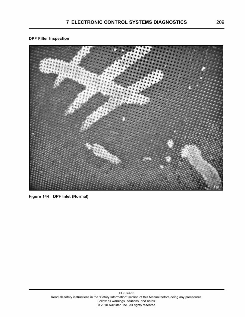
7 ELECTRONIC CONTROL SYSTEMS DIAGNOSTICS 209
DPF Filter Inspection
Figure 144 DPF Inlet (Normal)
EGES-455Read all safety instructions in the "Safety Information" section of this Manual before doing any procedures.
Follow all warnings, cautions, and notes.©2010 Navistar, Inc. All rights reserved
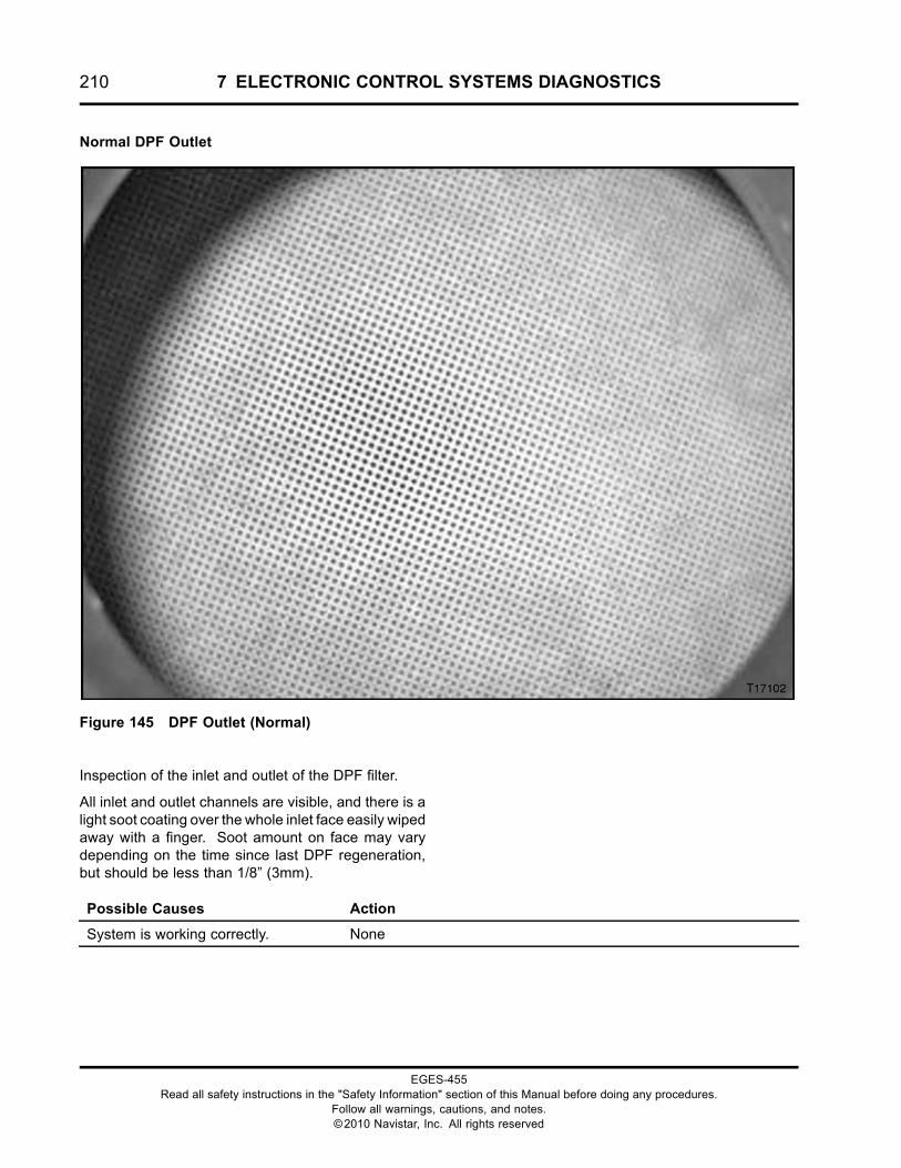
210 7 ELECTRONIC CONTROL SYSTEMS DIAGNOSTICS
Normal DPF Outlet
Figure 145 DPF Outlet (Normal)
Inspection of the inlet and outlet of the DPF filter.
All inlet and outlet channels are visible, and there is alight soot coating over the whole inlet face easily wipedaway with a finger. Soot amount on face may varydepending on the time since last DPF regeneration,but should be less than 1/8” (3mm).
Possible Causes Action
System is working correctly. None
EGES-455Read all safety instructions in the "Safety Information" section of this Manual before doing any procedures.
Follow all warnings, cautions, and notes.©2010 Navistar, Inc. All rights reserved
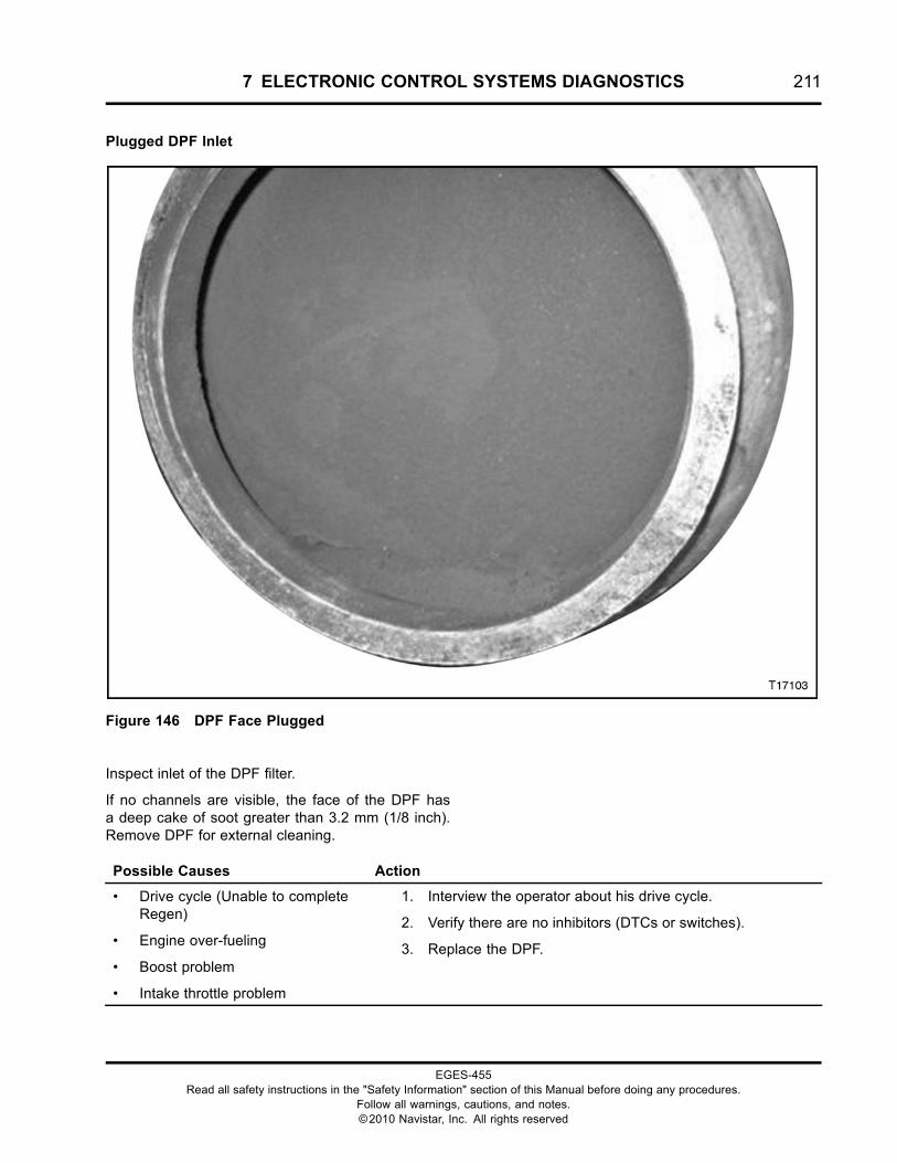
7 ELECTRONIC CONTROL SYSTEMS DIAGNOSTICS 211
Plugged DPF Inlet
Figure 146 DPF Face Plugged
Inspect inlet of the DPF filter.
If no channels are visible, the face of the DPF hasa deep cake of soot greater than 3.2 mm (1/8 inch).Remove DPF for external cleaning.
Possible Causes Action
• Drive cycle (Unable to completeRegen)
• Engine over-fueling
• Boost problem
• Intake throttle problem
1. Interview the operator about his drive cycle.
2. Verify there are no inhibitors (DTCs or switches).
3. Replace the DPF.
EGES-455Read all safety instructions in the "Safety Information" section of this Manual before doing any procedures.
Follow all warnings, cautions, and notes.©2010 Navistar, Inc. All rights reserved
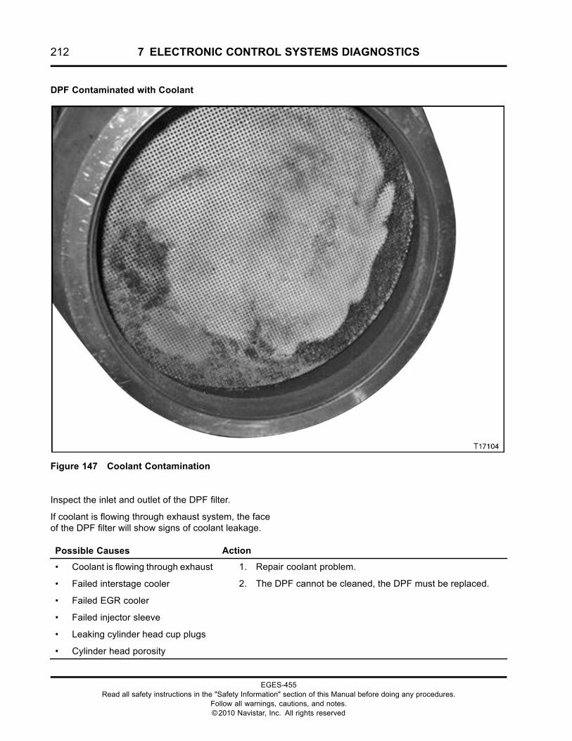
212 7 ELECTRONIC CONTROL SYSTEMS DIAGNOSTICS
DPF Contaminated with Coolant
Figure 147 Coolant Contamination
Inspect the inlet and outlet of the DPF filter.
If coolant is flowing through exhaust system, the faceof the DPF filter will show signs of coolant leakage.
Possible Causes Action
• Coolant is flowing through exhaust
• Failed interstage cooler
• Failed EGR cooler
• Failed injector sleeve
• Leaking cylinder head cup plugs
• Cylinder head porosity
1. Repair coolant problem.
2. The DPF cannot be cleaned, the DPF must be replaced.
EGES-455Read all safety instructions in the "Safety Information" section of this Manual before doing any procedures.
Follow all warnings, cautions, and notes.©2010 Navistar, Inc. All rights reserved
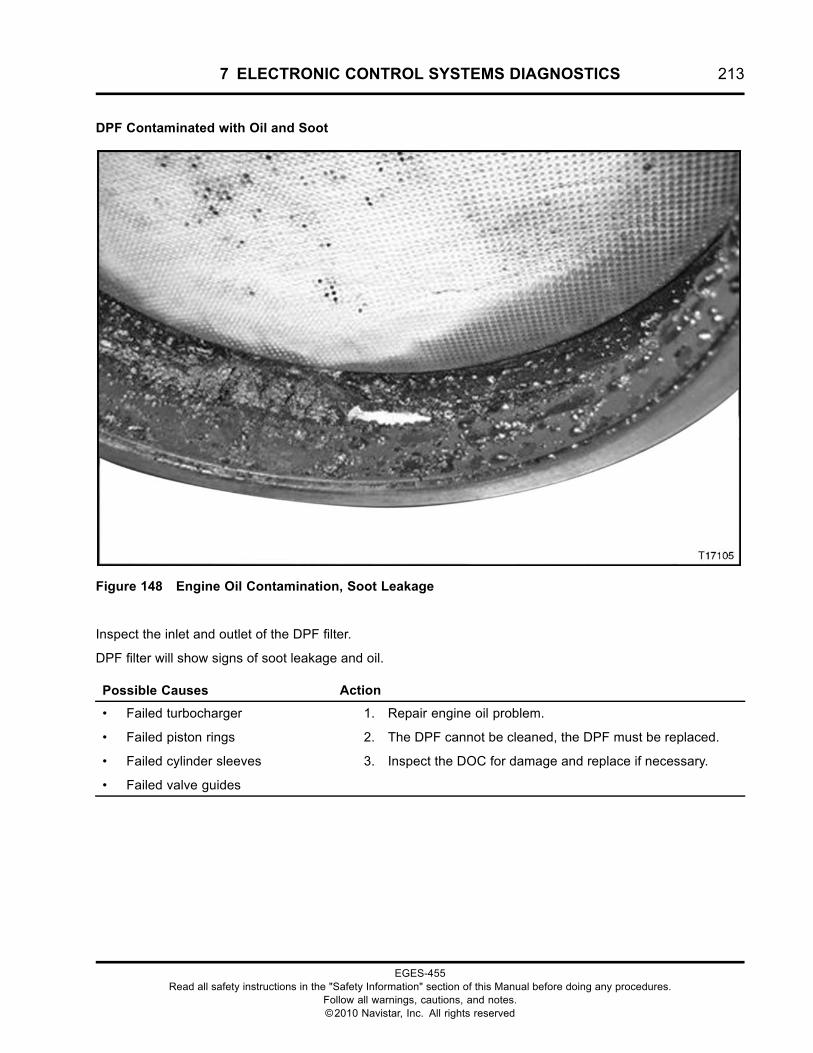
7 ELECTRONIC CONTROL SYSTEMS DIAGNOSTICS 213
DPF Contaminated with Oil and Soot
Figure 148 Engine Oil Contamination, Soot Leakage
Inspect the inlet and outlet of the DPF filter.
DPF filter will show signs of soot leakage and oil.
Possible Causes Action
• Failed turbocharger
• Failed piston rings
• Failed cylinder sleeves
• Failed valve guides
1. Repair engine oil problem.
2. The DPF cannot be cleaned, the DPF must be replaced.
3. Inspect the DOC for damage and replace if necessary.
EGES-455Read all safety instructions in the "Safety Information" section of this Manual before doing any procedures.
Follow all warnings, cautions, and notes.©2010 Navistar, Inc. All rights reserved
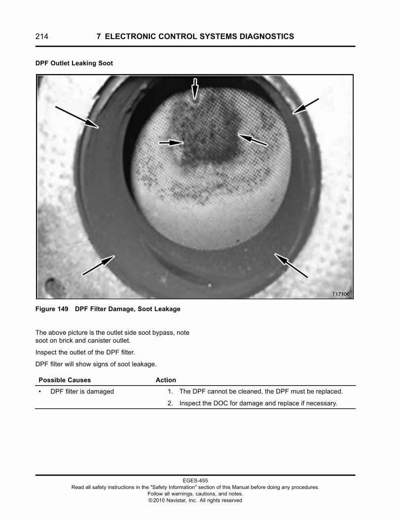
214 7 ELECTRONIC CONTROL SYSTEMS DIAGNOSTICS
DPF Outlet Leaking Soot
Figure 149 DPF Filter Damage, Soot Leakage
The above picture is the outlet side soot bypass, notesoot on brick and canister outlet.
Inspect the outlet of the DPF filter.
DPF filter will show signs of soot leakage.
Possible Causes Action
• DPF filter is damaged 1. The DPF cannot be cleaned, the DPF must be replaced.
2. Inspect the DOC for damage and replace if necessary.
EGES-455Read all safety instructions in the "Safety Information" section of this Manual before doing any procedures.
Follow all warnings, cautions, and notes.©2010 Navistar, Inc. All rights reserved
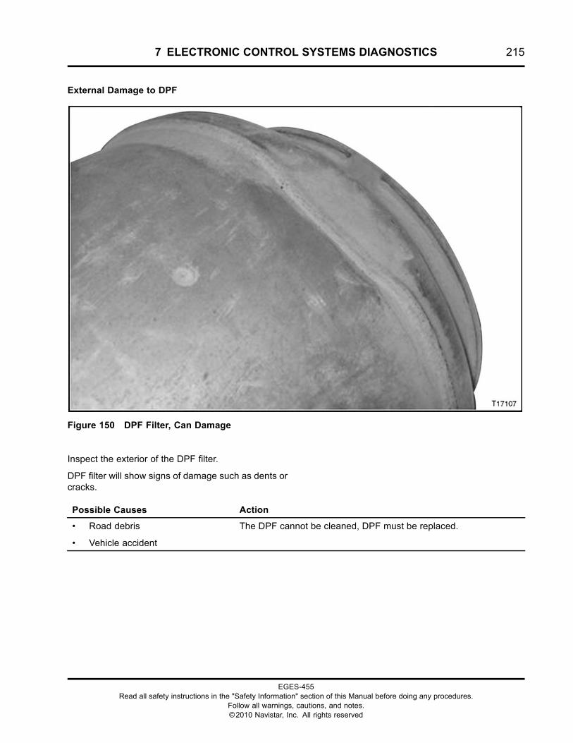
7 ELECTRONIC CONTROL SYSTEMS DIAGNOSTICS 215
External Damage to DPF
Figure 150 DPF Filter, Can Damage
Inspect the exterior of the DPF filter.
DPF filter will show signs of damage such as dents orcracks.
Possible Causes Action
• Road debris
• Vehicle accident
The DPF cannot be cleaned, DPF must be replaced.
EGES-455Read all safety instructions in the "Safety Information" section of this Manual before doing any procedures.
Follow all warnings, cautions, and notes.©2010 Navistar, Inc. All rights reserved
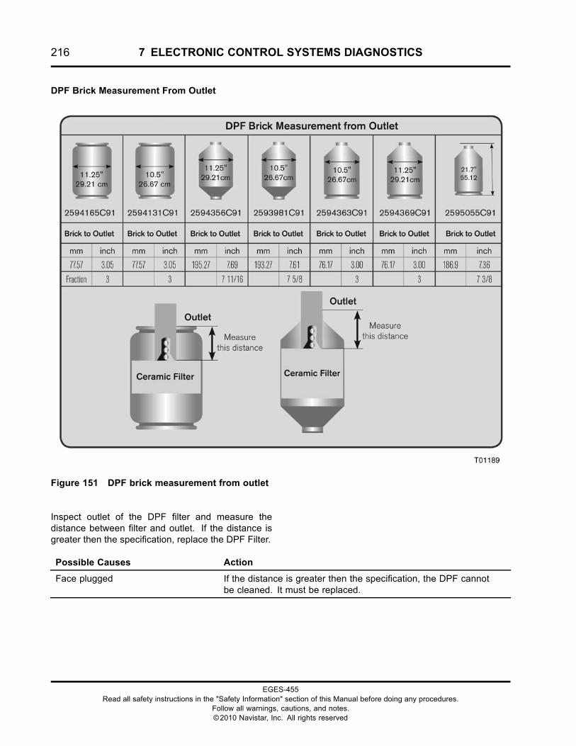
216 7 ELECTRONIC CONTROL SYSTEMS DIAGNOSTICS
DPF Brick Measurement From Outlet
Figure 151 DPF brick measurement from outlet
Inspect outlet of the DPF filter and measure thedistance between filter and outlet. If the distance isgreater then the specification, replace the DPF Filter.
Possible Causes Action
Face plugged If the distance is greater then the specification, the DPF cannotbe cleaned. It must be replaced.
EGES-455Read all safety instructions in the "Safety Information" section of this Manual before doing any procedures.
Follow all warnings, cautions, and notes.©2010 Navistar, Inc. All rights reserved
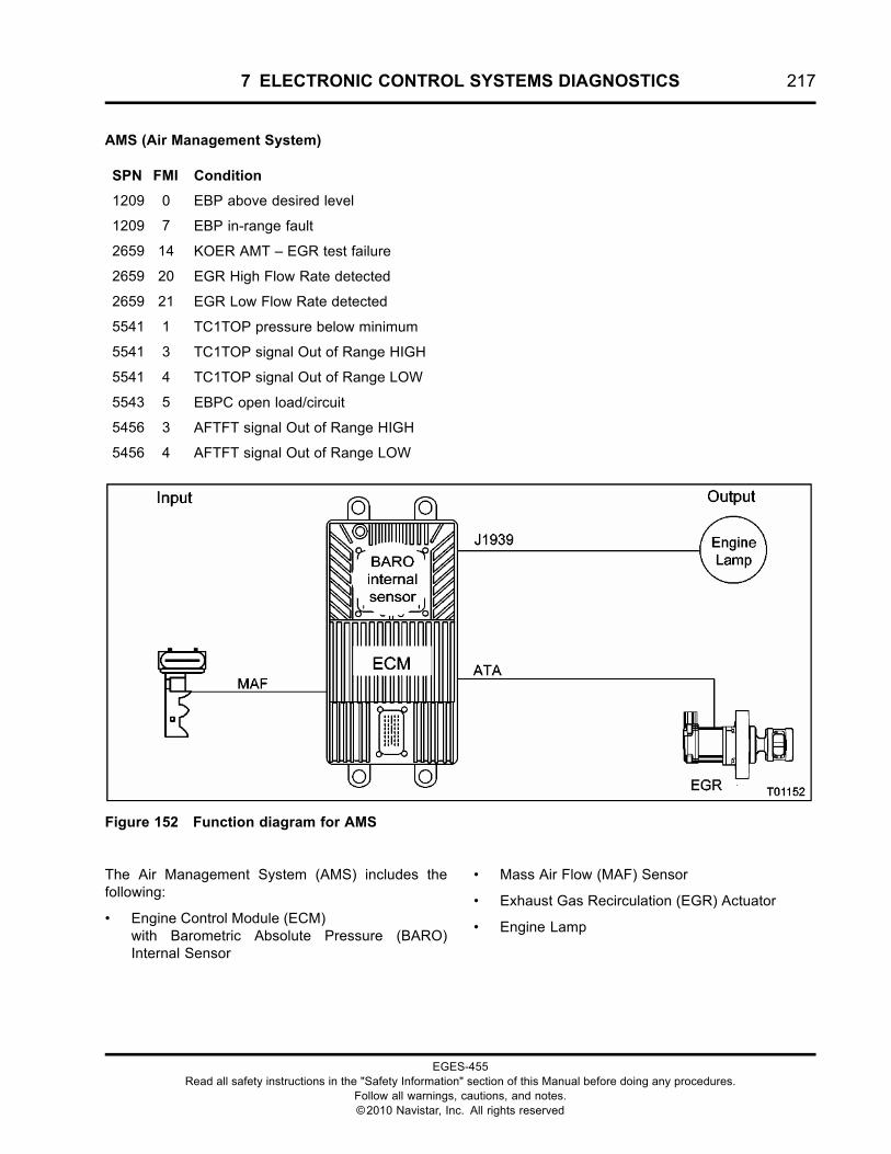
7 ELECTRONIC CONTROL SYSTEMS DIAGNOSTICS 217
AMS (Air Management System)
SPN FMI Condition
1209 0 EBP above desired level
1209 7 EBP in-range fault
2659 14 KOER AMT – EGR test failure
2659 20 EGR High Flow Rate detected
2659 21 EGR Low Flow Rate detected
5541 1 TC1TOP pressure below minimum
5541 3 TC1TOP signal Out of Range HIGH
5541 4 TC1TOP signal Out of Range LOW
5543 5 EBPC open load/circuit
5456 3 AFTFT signal Out of Range HIGH
5456 4 AFTFT signal Out of Range LOW
Figure 152 Function diagram for AMS
The Air Management System (AMS) includes thefollowing:
• Engine Control Module (ECM)with Barometric Absolute Pressure (BARO)Internal Sensor
• Mass Air Flow (MAF) Sensor
• Exhaust Gas Recirculation (EGR) Actuator
• Engine Lamp
EGES-455Read all safety instructions in the "Safety Information" section of this Manual before doing any procedures.
Follow all warnings, cautions, and notes.©2010 Navistar, Inc. All rights reserved
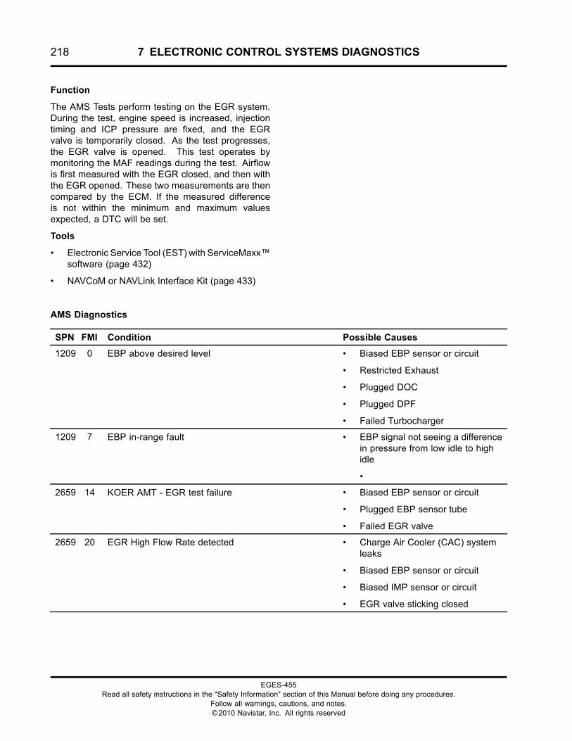
218 7 ELECTRONIC CONTROL SYSTEMS DIAGNOSTICS
Function
The AMS Tests perform testing on the EGR system.During the test, engine speed is increased, injectiontiming and ICP pressure are fixed, and the EGRvalve is temporarily closed. As the test progresses,the EGR valve is opened. This test operates bymonitoring the MAF readings during the test. Airflowis first measured with the EGR closed, and then withthe EGR opened. These two measurements are thencompared by the ECM. If the measured differenceis not within the minimum and maximum valuesexpected, a DTC will be set.
Tools
• Electronic Service Tool (EST) with ServiceMaxx™software (page 432)
• NAVCoM or NAVLink Interface Kit (page 433)
AMS Diagnostics
SPN FMI Condition Possible Causes
1209 0 EBP above desired level • Biased EBP sensor or circuit
• Restricted Exhaust
• Plugged DOC
• Plugged DPF
• Failed Turbocharger
1209 7 EBP in-range fault • EBP signal not seeing a differencein pressure from low idle to highidle
•
2659 14 KOER AMT - EGR test failure • Biased EBP sensor or circuit
• Plugged EBP sensor tube
• Failed EGR valve
2659 20 EGR High Flow Rate detected • Charge Air Cooler (CAC) systemleaks
• Biased EBP sensor or circuit
• Biased IMP sensor or circuit
• EGR valve sticking closed
EGES-455Read all safety instructions in the "Safety Information" section of this Manual before doing any procedures.
Follow all warnings, cautions, and notes.©2010 Navistar, Inc. All rights reserved
7 ELECTRONIC CONTROL SYSTEMS DIAGNOSTICS 219
2659 21 EGR Low Flow Rate detected • Restricted airflow (intake orexhaust)
• Restricted EGR cooler
• Biased EBP sensor or circuit
• Plugged EBP sensor tube
• Biased IMP sensor or circuit
• EGR valve sticking closed
5541 1 TC1TOP pressure below minimum • Failed Exhaust Back Pressurevalve (Stuck open)
5541 3 TC1TOP signal Out of Range HIGH • TC1TOP signal circuit OPEN orshort to PWR
• SIG GND circuit OPEN
• Failed TC1TOP sensor
5541 4 TC1TOP signal Out of Range LOW • TC1TOP signal circuit short toGND
• Failed TC1TOP sensor
5543 5 EBPC open load/circuit • EBPC circuit OPEN
• Failed EBPC valve
5456 3 AFTFT signal Out of Range HIGH • AFTFT signal circuit OPEN orshort to PWR
• Failed AFTFIS
5456 4 AFTFT signal Out of Range LOW • AFTFT signal circuit short to GND
• Failed AFTFIS
EGES-455Read all safety instructions in the "Safety Information" section of this Manual before doing any procedures.
Follow all warnings, cautions, and notes.©2010 Navistar, Inc. All rights reserved
220 7 ELECTRONIC CONTROL SYSTEMS DIAGNOSTICS
SPN 1209 FMI 0 - EBP above desired level
The code will set when EBP is 10 psi (69 kPa) above desired level.
SPN 1209 FMI 0 - EBP above desired level
Estimated EGR percent is less than the minimum limit for the operating conditions.
The code will set when EBP is 10 psi (69 kPa) above.
Pin-point AMS Fault
1. Check for other active or inactive EBP, MAF, IMP, or EGR faults. Repair any fault before continuingwith this procedure.
2. Check for biased sensor. Verify BARO, MAF, IMP, and EBP are within KOEO specification. SeeKOEO in “APPENDIX A: PERFORMANCE SPECIFICATIONS”.
3. Check the back pressure valve operation. See EBPV in this section.
4. Check for restricted EGR cooler. See Restricted EGR Cooler in “ENGINE SYMPTOMSDIAGNOSTICS”.
5. Check EGR operation. Monitor EGRP signal and run KOEO Output State test HIGH and LOW. See“EGR Actuator (Exhaust Gas Recirculation)”.
6. Check for restricted exhaust. See performance specification at full load rated speed.
SPN 1209 FMI 1 - EBP below desired level
This code will set when EBP is 10 psi (69 kPa) below desired level.
SPN 1209 FMI 1- EBP below desired level
Estimated EGR percent is less than the minimum limit for the operating conditions.
Pin-point AMS Fault
1. Check for other active or inactive EBP, MAF, IMP, or EGR faults. Repair any fault before continuingwith this procedure.
2. Check for biased sensor. Verify BARO, MAF, IMP, and EBP are within KOEO Specification. SeeKOEO in “APPENDIX A: PERFORMANCE SPECIFICATIONS”.
3. Check for plugged EBP or tubing.
4. Check the exhaust back-pressure valve operation. See the EBPV in this section.
EGES-455Read all safety instructions in the "Safety Information" section of this Manual before doing any procedures.
Follow all warnings, cautions, and notes.©2010 Navistar, Inc. All rights reserved
7 ELECTRONIC CONTROL SYSTEMS DIAGNOSTICS 221
SPN 2659 FMI 14 - AMS - KOER AMT - EGR test failure
This DTC is set if EBP does not meet expected response during the Air Management Test.
Pin-point AMS Fault
1. Check for active or inactive EBP DTC’s. See EBP Sensor in this section of manual and check EBPKOEO specification.
2. Check for plugged EBP sensor or tubing.
3. Check for active or inactive DTC’s. See appropriate Pin-point test.
4. Check EGR operation. Monitor EGR position (EGRP) while running KOEO Output State test HIGHand LOW. See “EGR Actuator (Exhaust Gas Recirculation)” in this section of manual.
5. Check for restricted exhaust system.
SPN 2659 FMI 20 - EGR flow excessive - EGR High Flow Rate detected
The DTC will set when EBP is 10 psi (69 kPa) below desired level.
Estimated EGR percent is greater than the maximum limit for the operating conditions.
Pin-point AMS Fault
1. Check for other active or inactive EBP, MAF, IMP, or EGR faults. Repair any fault before continuingwith this procedure.
2. Check for biased sensor. Verify BARO, MAF, IMP, and EBP are within KOEO Specification. SeeKOEO in “APPENDIX A : PERFORMANCE SPECIFICATIONS”.
3. Check the plugged EBP sensor or tubing.
4. Check EGR operation. Monitor EGR position (EGRP) while running KOEO Output State test HIGHand LOW. See “EGR Actuator (Exhaust Gas Recirculation)” in this section of manual.
SPN 2659 FMI 21 - AMS - EGR Low Flow Rate detected
This DTC is set if EBP does not meet expected response during the EGR portion of the AMS test.
Pin-point AMS Fault
1. Check for other active or inactive EBP, MAF, IMP, or EGR faults. Repair any faults before continuingwith this procedure.
2. Check for biased sensor. Verify that BARO, MAF, IMP, and EBP are within KOEO specification. SeeKOEO in “APPENDIX A : PERFORMANCE SPECIFICATIONS”.
3. Check for restricted EGR cooler. See Restricted EGR Cooler in “ENGINE SYMPTOMSDIAGNOSTICS” section of this manual.
4. Check EGR operation. Monitor EGR position (EGRP) while running KOEO Output State test HIGHand LOW. See “EGR Actuator (Exhaust Gas Recirculation)” in this section of manual.
EGES-455Read all safety instructions in the "Safety Information" section of this Manual before doing any procedures.
Follow all warnings, cautions, and notes.©2010 Navistar, Inc. All rights reserved
222 7 ELECTRONIC CONTROL SYSTEMS DIAGNOSTICS
AMS Operation
The AMS test checks the operation of the EGR byactuating each component open and closed whilemonitoring the effect it has on intake airflow usingthe MAF sensor. The test sequence is carried out asfollows:
• The ECM monitors the BARO sensor as a baseline for zeroing the IMP and EBP signals.
EGR portion
• With the EGR valve still closed, the ECMincreases engine idle speed to 1000 rpm, andMAF is allowed to stabilize (MAF is expected toincrease).
• The EGR is then commanded open and MAF isallowed to stabilize (MAF is expected to drop).
• The EGR is then commanded closed, and isallowed to stabilize (MAF is expected to increase).If pressure results do not match expected valuesfor either position, a DTC is set, the engine willreturn to 700 rpm, and the test is complete.
EGES-455Read all safety instructions in the "Safety Information" section of this Manual before doing any procedures.
Follow all warnings, cautions, and notes.©2010 Navistar, Inc. All rights reserved
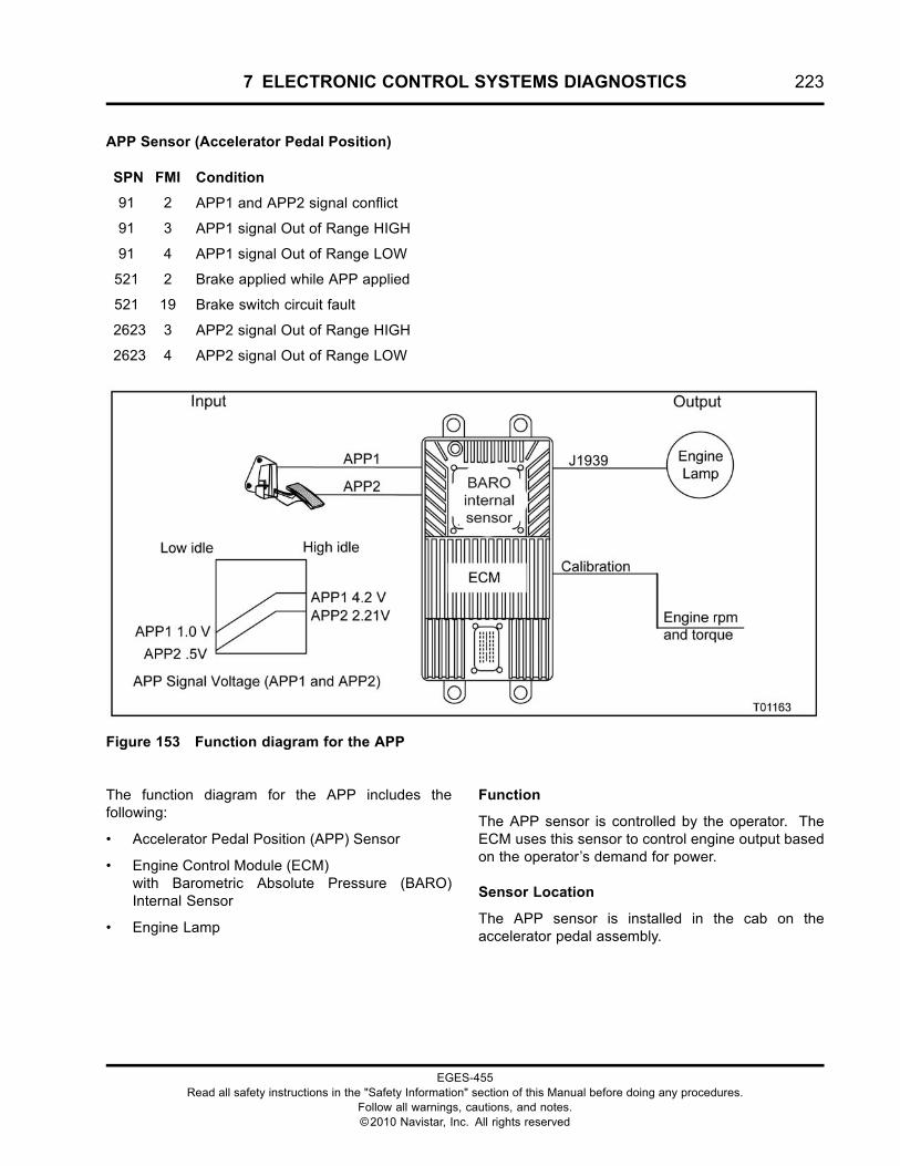
7 ELECTRONIC CONTROL SYSTEMS DIAGNOSTICS 223
APP Sensor (Accelerator Pedal Position)
SPN FMI Condition
91 2 APP1 and APP2 signal conflict
91 3 APP1 signal Out of Range HIGH
91 4 APP1 signal Out of Range LOW
521 2 Brake applied while APP applied
521 19 Brake switch circuit fault
2623 3 APP2 signal Out of Range HIGH
2623 4 APP2 signal Out of Range LOW
Figure 153 Function diagram for the APP
The function diagram for the APP includes thefollowing:
• Accelerator Pedal Position (APP) Sensor
• Engine Control Module (ECM)with Barometric Absolute Pressure (BARO)Internal Sensor
• Engine Lamp
Function
The APP sensor is controlled by the operator. TheECM uses this sensor to control engine output basedon the operator’s demand for power.
Sensor Location
The APP sensor is installed in the cab on theaccelerator pedal assembly.
EGES-455Read all safety instructions in the "Safety Information" section of this Manual before doing any procedures.
Follow all warnings, cautions, and notes.©2010 Navistar, Inc. All rights reserved
224 7 ELECTRONIC CONTROL SYSTEMS DIAGNOSTICS
Tools
• Electronic Service Tool (EST) with ServiceMaxx™software (page 432)
• NAVCoM or NAVLink Interface Kit (page 433)
• Digital Multimeter (DMM) (page 431)
• 1180-N4-0X0 – 180-Pin Breakout Box (page 430)
• 3-Banana Plug Harness (page 433)
• Breakout Harness 4485A (APP) (page 434)
• International® Electronic Engine Terminal Test Kit(page 432)
APP Sensor End Diagnostics
SPN FMI Condition Possible Causes
91 2 APP1 and APP2 signal conflict • APP1 and APP2 mis-matched
• Biased sensor or circuit
91 3 APP1 signal Out of Range HIGH • APP1 signal circuit short to PWR
• SIG GND circuit OPEN
• Failed APP sensor
91 4 APP1 signal Out of Range LOW • APP1 signal circuit OPEN or short to GND
• VREF circuit OPEN
• Failed APP sensor
521 2 Brake applied while APP applied • The Operator was applying Accelerator Pedaland brake pedal at the same time
• APP1 sensor or circuit fault
• Brake Pedal switch or circuit fault
521 19 Brake switch circuit fault • Brake Pedal switch or circuit fault
2623 3 APP2 signal Out of Range HIGH • APP2 signal circuit short to PWR
• SIG GND circuit OPEN
• Failed sensor
2623 4 APP2 signal Out of Range LOW • APP2 signal circuit OPEN or short to GND
• VREF circuit OPEN
• Failed sensor
EGES-455Read all safety instructions in the "Safety Information" section of this Manual before doing any procedures.
Follow all warnings, cautions, and notes.©2010 Navistar, Inc. All rights reserved
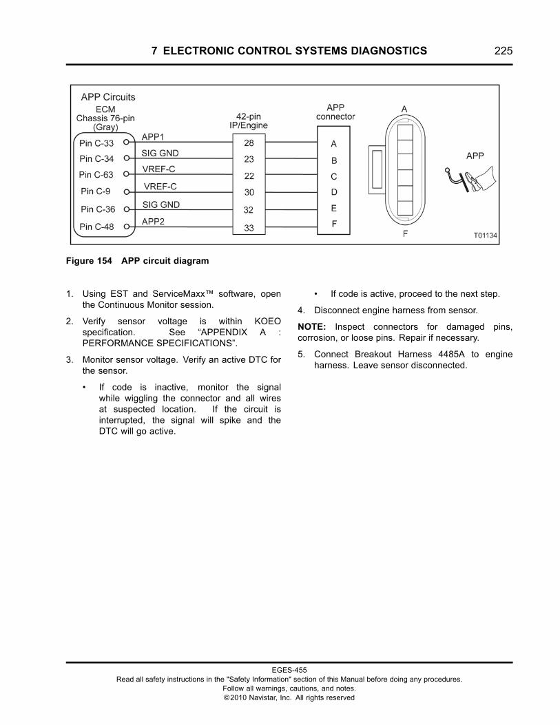
7 ELECTRONIC CONTROL SYSTEMS DIAGNOSTICS 225
Figure 154 APP circuit diagram
1. Using EST and ServiceMaxx™ software, openthe Continuous Monitor session.
2. Verify sensor voltage is within KOEOspecification. See “APPENDIX A :PERFORMANCE SPECIFICATIONS”.
3. Monitor sensor voltage. Verify an active DTC forthe sensor.
• If code is inactive, monitor the signalwhile wiggling the connector and all wiresat suspected location. If the circuit isinterrupted, the signal will spike and theDTC will go active.
• If code is active, proceed to the next step.
4. Disconnect engine harness from sensor.
NOTE: Inspect connectors for damaged pins,corrosion, or loose pins. Repair if necessary.
5. Connect Breakout Harness 4485A to engineharness. Leave sensor disconnected.
EGES-455Read all safety instructions in the "Safety Information" section of this Manual before doing any procedures.
Follow all warnings, cautions, and notes.©2010 Navistar, Inc. All rights reserved
226 7 ELECTRONIC CONTROL SYSTEMS DIAGNOSTICS
Sensor Circuit Check
Connect Breakout Harness 4485A to engine harness. Leave sensor disconnected. Turn ignition switchto ON. Use EST to verify correct DTC goes active when corresponding fault is induced. Use DMM tomeasure circuits.
Test Point Spec Comment – < Less than, > Greater than
EST – Check DTC
Sensor Disconnected
SPN 91 FMI4
SPN 2623FMI 4
If SPN 91 FMI 3 is active, check APP1 signal for shortto PWR.
If SPN 2623 FMI 3 is active, check APP1 for short toPWR.
DMM – Measure volts
C to GND
5 V ± 0.5 V If > 5.5 V, check VREF for short to PWR.
If < 4.5 V, check VREF for OPEN or short to GND. Go toHarness Resistance Check.
DMM – Measure volts
D to GND
5 V ± 0.5 V If > 5.5 V, check VREF for short to PWR.
If < 4.5 V, check VREF for OPEN or short to GND. Go toHarness Resistance Check.
EST – Check DTC
Short Pin A to C
SPN 91 FMI3
SPN 2623FMI 4
If SPN 91 FMI 4 is active, check APP1 circuit for OPEN.Go to Harness Resistance check.
EST – Check DTC
Short Pin D to F
SPN 91 FMI4
SPN 2623FMI 3
If SPN 2623 FMI 4 is active, check APP2 circuit forOPEN. Go to Harness Resistance check.
DMM – Measure volts
B to B+
B+ If < B+, check SIG GND for OPEN. Go to HarnessResistance Check.
DMM – Measure volts
E to B+
B+ If < B+, check SIG GND for OPEN. Go to HarnessResistance Check.
If checks are within specification, connect sensor, clear DTC’s, and cycle the pedal a few times. If activecode returns, replace sensor.
EGES-455Read all safety instructions in the "Safety Information" section of this Manual before doing any procedures.
Follow all warnings, cautions, and notes.©2010 Navistar, Inc. All rights reserved
7 ELECTRONIC CONTROL SYSTEMS DIAGNOSTICS 227
APP Pin-point Diagnostics
Harness Resistance Check
Turn ignition switch to OFF. Disconnect both battery GND cables. Connect 180-Pin Breakout Box andBreakout Harness 4485A. Leave ECM and sensor disconnected. Use DMM to measure resistance.
Test Point Spec Comment – < Less than, > Greater than
A to C-33 < 5 Ω If > 5 Ω, check APP1 signal circuit for OPEN.
B to C-34 < 5 Ω If > 5 Ω, check SIG GND circuit for OPEN.
C to C-63 < 5 Ω If > 5 Ω, check VREF-C circuit for OPEN.
D to C-9 < 5 Ω If > 5 Ω, check VREF-C circuit for OPEN.
E to C-36 < 5 Ω If > 5 Ω, check SIG GND circuit for OPEN.
F to C-48 < 5 Ω If > 5 Ω, check APP2 signal circuit for OPEN.
Operational Voltage Check
Connect 180-Pin Breakout Box and Breakout Harness 4485A between ECM and sensor. Turn ignitionswitch to ON. Use DMM to measure voltage and EST to read signal.
Test Point Condition DMM EST Value
Foot off pedal 1.14 V ± 0.25 V 0%APP1
A to GND orC-33 to GND
Pedal to floor 4.32 V ± 0.25 V 99.6%
Foot off pedal 0.56 V ± 0.25 V 0%APP2
F to GND orC-48 to GND
Pedal to floor 2.16 V ± 0.25 V 99.6%
EGES-455Read all safety instructions in the "Safety Information" section of this Manual before doing any procedures.
Follow all warnings, cautions, and notes.©2010 Navistar, Inc. All rights reserved
228 7 ELECTRONIC CONTROL SYSTEMS DIAGNOSTICS
APP Circuit Operation
The APP contains two position sensors. The twosensors (APP1 and APP2) are integrated into thissingle component and mounted on the acceleratorpedal.
The ECM determines accelerator pedal position byprocessing input signals from APP1 and APP2.
APP
The APP is a dual potentiometer sensor supplied withtwo 5 V VREF circuits. 5V reference is supplied to PinC from ECM Pin C-63, and to Pin D from ECM PinC-9. The sensor is grounded using Pin B from ECMPin C-34 and Pin E from ECM Pin C-36. The sensorreturns a variable voltage signal from Pin A (APP1) toECM Pin C-33, and from Pin F (APP2) to ECM PinC-48.
APP Auto-Calibration
The ECM auto-calibrates the APP signals every timethe ignition switch is turned on. The ECM “learns”the lowest and highest pedal positions allowing formaximum pedal sensitivity. When the switch is turnedoff, this information is lost until the next switch cyclewhere the process is repeated. No accelerator pedaladjustment is needed with this feature.
Fault Detection / Management
When the ignition switch is on, the ECM continuouslymonitors the APP circuits for expected voltages. Italso compares APP and APP2 signals for conflict. Ifa conflict occurs, the ECM will set a DTC.
Any malfunction of the APP circuits will illuminatethe Warn Engine Lamp (WEL). If the ECM detectsan Out-of-Range signal condition for either APPsignal, the ECM will ignore the faulty APP signal. TheECM will continue to operate using only the properlyfunctioning sensor.
If a disagreement in the state of APP1 and APP2 isdetected, the ECM will allow only a maximum of 50percent power to be commanded. If APP1 and APP2signals are both detected as Out of Range, the enginewill be allowed to operate at low idle only.
NOTE: If multiple APP DTC’s are present, verify theAPP part number is correct for the specific vehiclemodel.
NOTE: If elevated low idle rpm is experienced afterreplacing the pedal assembly or APP sensor, andthere are no DTCs present, check pedal assembly orAPP sensor part numbers for correctness.
EGES-455Read all safety instructions in the "Safety Information" section of this Manual before doing any procedures.
Follow all warnings, cautions, and notes.©2010 Navistar, Inc. All rights reserved
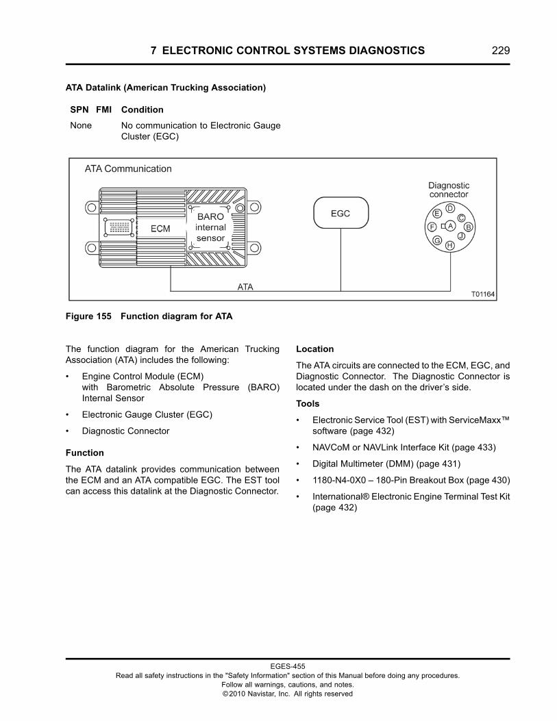
7 ELECTRONIC CONTROL SYSTEMS DIAGNOSTICS 229
ATA Datalink (American Trucking Association)
SPN FMI Condition
None No communication to Electronic GaugeCluster (EGC)
Figure 155 Function diagram for ATA
The function diagram for the American TruckingAssociation (ATA) includes the following:
• Engine Control Module (ECM)with Barometric Absolute Pressure (BARO)Internal Sensor
• Electronic Gauge Cluster (EGC)
• Diagnostic Connector
Function
The ATA datalink provides communication betweenthe ECM and an ATA compatible EGC. The EST toolcan access this datalink at the Diagnostic Connector.
Location
The ATA circuits are connected to the ECM, EGC, andDiagnostic Connector. The Diagnostic Connector islocated under the dash on the driver’s side.
Tools
• Electronic Service Tool (EST) with ServiceMaxx™software (page 432)
• NAVCoM or NAVLink Interface Kit (page 433)
• Digital Multimeter (DMM) (page 431)
• 1180-N4-0X0 – 180-Pin Breakout Box (page 430)
• International® Electronic Engine Terminal Test Kit(page 432)
EGES-455Read all safety instructions in the "Safety Information" section of this Manual before doing any procedures.
Follow all warnings, cautions, and notes.©2010 Navistar, Inc. All rights reserved
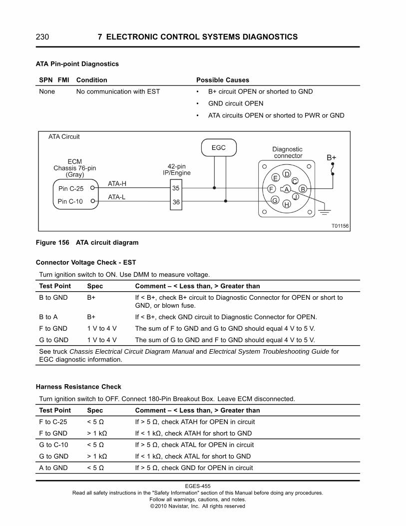
230 7 ELECTRONIC CONTROL SYSTEMS DIAGNOSTICS
ATA Pin-point Diagnostics
SPN FMI Condition Possible Causes
None No communication with EST • B+ circuit OPEN or shorted to GND
• GND circuit OPEN
• ATA circuits OPEN or shorted to PWR or GND
Figure 156 ATA circuit diagram
Connector Voltage Check - EST
Turn ignition switch to ON. Use DMM to measure voltage.
Test Point Spec Comment – < Less than, > Greater than
B to GND B+ If < B+, check B+ circuit to Diagnostic Connector for OPEN or short toGND, or blown fuse.
B to A B+ If < B+, check GND circuit to Diagnostic Connector for OPEN.
F to GND 1 V to 4 V The sum of F to GND and G to GND should equal 4 V to 5 V.
G to GND 1 V to 4 V The sum of G to GND and F to GND should equal 4 V to 5 V.
See truck Chassis Electrical Circuit Diagram Manual and Electrical System Troubleshooting Guide forEGC diagnostic information.
Harness Resistance Check
Turn ignition switch to OFF. Connect 180-Pin Breakout Box. Leave ECM disconnected.
Test Point Spec Comment – < Less than, > Greater than
F to C-25 < 5 Ω If > 5 Ω, check ATAH for OPEN in circuit
F to GND > 1 kΩ If < 1 kΩ, check ATAH for short to GND
G to C-10 < 5 Ω If > 5 Ω, check ATAL for OPEN in circuit
G to GND > 1 kΩ If < 1 kΩ, check ATAL for short to GND
A to GND < 5 Ω If > 5 Ω, check GND for OPEN in circuit
EGES-455Read all safety instructions in the "Safety Information" section of this Manual before doing any procedures.
Follow all warnings, cautions, and notes.©2010 Navistar, Inc. All rights reserved
7 ELECTRONIC CONTROL SYSTEMS DIAGNOSTICS 231
ATA Operation
Diagnostic Connector
The fuse protected B+ signal is supplied to theDiagnostic Connector through Pin B, and GND isthrough Pin A. American Trucking Association High(ATAH) signal runs from ECMPin C-25 and DiagnosticConnector Pin F. American Trucking Association Low(ATAL) signal runs from ECM Pin C-10 and DiagnosticConnector Pin G.
EGC
There are two types of EGC modules, one usesJ1939 Data Link communication and the other usesATA communication. The following information is sentthrough data communication:
• Engine lamp (red)
• Engine lamp
• Coolant level lamp
• Wait to start lamp
• Water In Fuel (WIF) lamp
• Speedometer
• Tachometer (TACH)
• Odometer / Hourmeter
• Change oil message
• Oil pressure gauge
• Engine Oil Temperature (EOT) gauge
• Engine Coolant Temperature (ECT) gauge
Fault Detection / Management
There are no engine DTC’s for ATA communicationfaults. See truck Truck Chassis ElectricalCircuit Diagram Manual and Electrical SystemTroubleshooting Guide.
Repair Information
The ATA circuits use a twisted wire pair. All repairsmust maintain one complete twist per inch along theentire length of the circuit. This circuit is polarized,one positive and one negative. Reversing the polarityof this circuit will disrupt communication.
EGES-455Read all safety instructions in the "Safety Information" section of this Manual before doing any procedures.
Follow all warnings, cautions, and notes.©2010 Navistar, Inc. All rights reserved
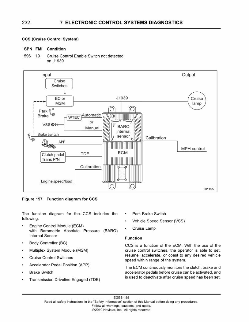
232 7 ELECTRONIC CONTROL SYSTEMS DIAGNOSTICS
CCS (Cruise Control System)
SPN FMI Condition
596 19 Cruise Control Enable Switch not detectedon J1939
Figure 157 Function diagram for CCS
The function diagram for the CCS includes thefollowing:
• Engine Control Module (ECM)with Barometric Absolute Pressure (BARO)Internal Sensor
• Body Controller (BC)
• Multiplex System Module (MSM)
• Cruise Control Switches
• Accelerator Pedal Position (APP)
• Brake Switch
• Transmission Driveline Engaged (TDE)
• Park Brake Switch
• Vehicle Speed Sensor (VSS)
• Cruise Lamp
Function
CCS is a function of the ECM. With the use of thecruise control switches, the operator is able to set,resume, accelerate, or coast to any desired vehiclespeed within range of the system.
The ECM continuously monitors the clutch, brake andaccelerator pedals before cruise can be activated, andis used to deactivate after cruise speed has been set.
EGES-455Read all safety instructions in the "Safety Information" section of this Manual before doing any procedures.
Follow all warnings, cautions, and notes.©2010 Navistar, Inc. All rights reserved
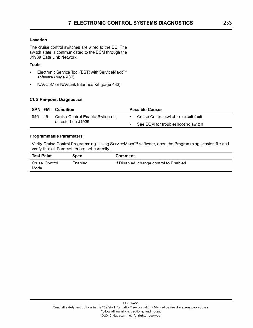
7 ELECTRONIC CONTROL SYSTEMS DIAGNOSTICS 233
Location
The cruise control switches are wired to the BC. Theswitch state is communicated to the ECM through theJ1939 Data Link Network.
Tools
• Electronic Service Tool (EST) with ServiceMaxx™software (page 432)
• NAVCoM or NAVLink Interface Kit (page 433)
CCS Pin-point Diagnostics
SPN FMI Condition Possible Causes
596 19 Cruise Control Enable Switch notdetected on J1939
• Cruise Control switch or circuit fault
• See BCM for troubleshooting switch
Programmable Parameters
Verify Cruise Control Programming. Using ServiceMaxx™ software, open the Programming session file andverify that all Parameters are set correctly.
Test Point Spec Comment
Cruse ControlMode
Enabled If Disabled, change control to Enabled
EGES-455Read all safety instructions in the "Safety Information" section of this Manual before doing any procedures.
Follow all warnings, cautions, and notes.©2010 Navistar, Inc. All rights reserved
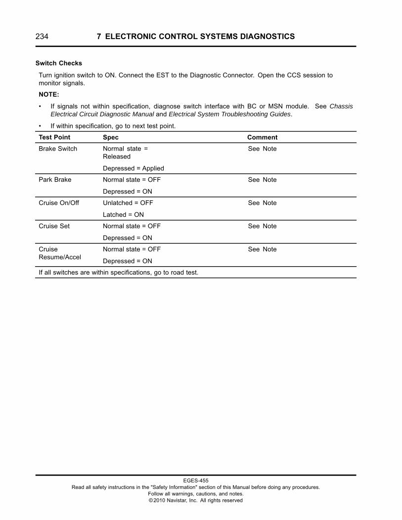
234 7 ELECTRONIC CONTROL SYSTEMS DIAGNOSTICS
Switch Checks
Turn ignition switch to ON. Connect the EST to the Diagnostic Connector. Open the CCS session tomonitor signals.
NOTE:
• If signals not within specification, diagnose switch interface with BC or MSN module. See ChassisElectrical Circuit Diagnostic Manual and Electrical System Troubleshooting Guides.
• If within specification, go to next test point.
Test Point Spec Comment
Brake Switch Normal state =Released
Depressed = Applied
See Note
Park Brake Normal state = OFF
Depressed = ON
See Note
Cruise On/Off Unlatched = OFF
Latched = ON
See Note
Cruise Set Normal state = OFF
Depressed = ON
See Note
CruiseResume/Accel
Normal state = OFF
Depressed = ON
See Note
If all switches are within specifications, go to road test.
EGES-455Read all safety instructions in the "Safety Information" section of this Manual before doing any procedures.
Follow all warnings, cautions, and notes.©2010 Navistar, Inc. All rights reserved
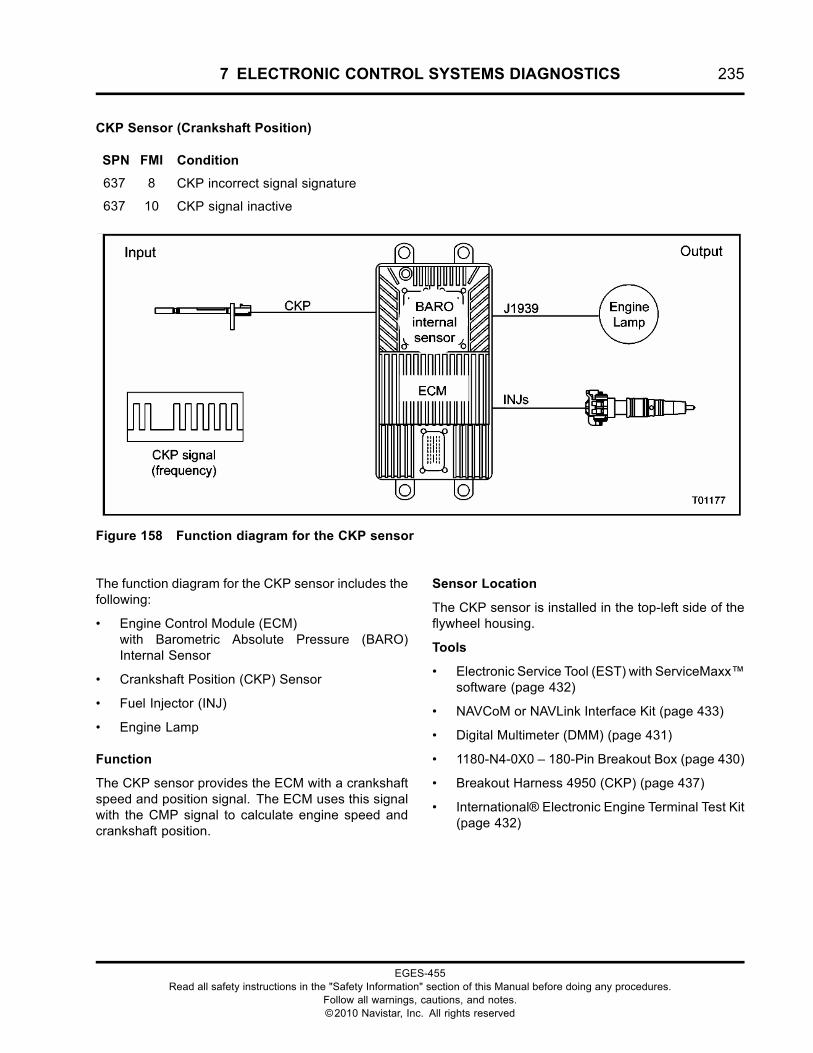
7 ELECTRONIC CONTROL SYSTEMS DIAGNOSTICS 235
CKP Sensor (Crankshaft Position)
SPN FMI Condition
637 8 CKP incorrect signal signature
637 10 CKP signal inactive
Figure 158 Function diagram for the CKP sensor
The function diagram for the CKP sensor includes thefollowing:
• Engine Control Module (ECM)with Barometric Absolute Pressure (BARO)Internal Sensor
• Crankshaft Position (CKP) Sensor
• Fuel Injector (INJ)
• Engine Lamp
Function
The CKP sensor provides the ECM with a crankshaftspeed and position signal. The ECM uses this signalwith the CMP signal to calculate engine speed andcrankshaft position.
Sensor Location
The CKP sensor is installed in the top-left side of theflywheel housing.
Tools
• Electronic Service Tool (EST) with ServiceMaxx™software (page 432)
• NAVCoM or NAVLink Interface Kit (page 433)
• Digital Multimeter (DMM) (page 431)
• 1180-N4-0X0 – 180-Pin Breakout Box (page 430)
• Breakout Harness 4950 (CKP) (page 437)
• International® Electronic Engine Terminal Test Kit(page 432)
EGES-455Read all safety instructions in the "Safety Information" section of this Manual before doing any procedures.
Follow all warnings, cautions, and notes.©2010 Navistar, Inc. All rights reserved
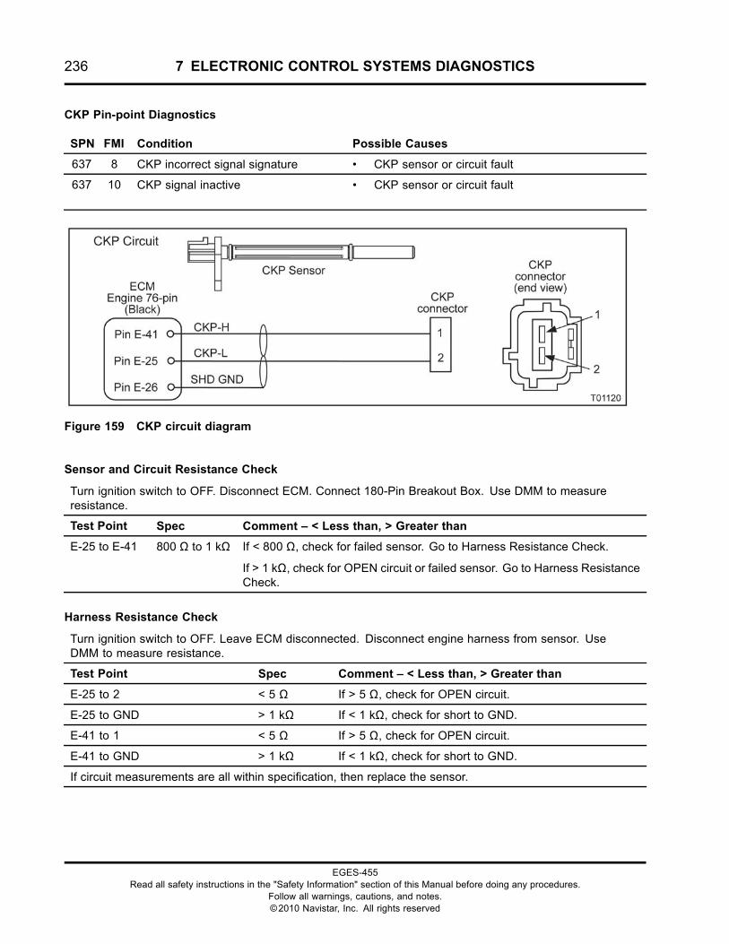
236 7 ELECTRONIC CONTROL SYSTEMS DIAGNOSTICS
CKP Pin-point Diagnostics
SPN FMI Condition Possible Causes
637 8 CKP incorrect signal signature • CKP sensor or circuit fault
637 10 CKP signal inactive • CKP sensor or circuit fault
Figure 159 CKP circuit diagram
Sensor and Circuit Resistance Check
Turn ignition switch to OFF. Disconnect ECM. Connect 180-Pin Breakout Box. Use DMM to measureresistance.
Test Point Spec Comment – < Less than, > Greater than
E-25 to E-41 800 Ω to 1 kΩ If < 800 Ω, check for failed sensor. Go to Harness Resistance Check.
If > 1 kΩ, check for OPEN circuit or failed sensor. Go to Harness ResistanceCheck.
Harness Resistance Check
Turn ignition switch to OFF. Leave ECM disconnected. Disconnect engine harness from sensor. UseDMM to measure resistance.
Test Point Spec Comment – < Less than, > Greater than
E-25 to 2 < 5 Ω If > 5 Ω, check for OPEN circuit.
E-25 to GND > 1 kΩ If < 1 kΩ, check for short to GND.
E-41 to 1 < 5 Ω If > 5 Ω, check for OPEN circuit.
E-41 to GND > 1 kΩ If < 1 kΩ, check for short to GND.
If circuit measurements are all within specification, then replace the sensor.
EGES-455Read all safety instructions in the "Safety Information" section of this Manual before doing any procedures.
Follow all warnings, cautions, and notes.©2010 Navistar, Inc. All rights reserved
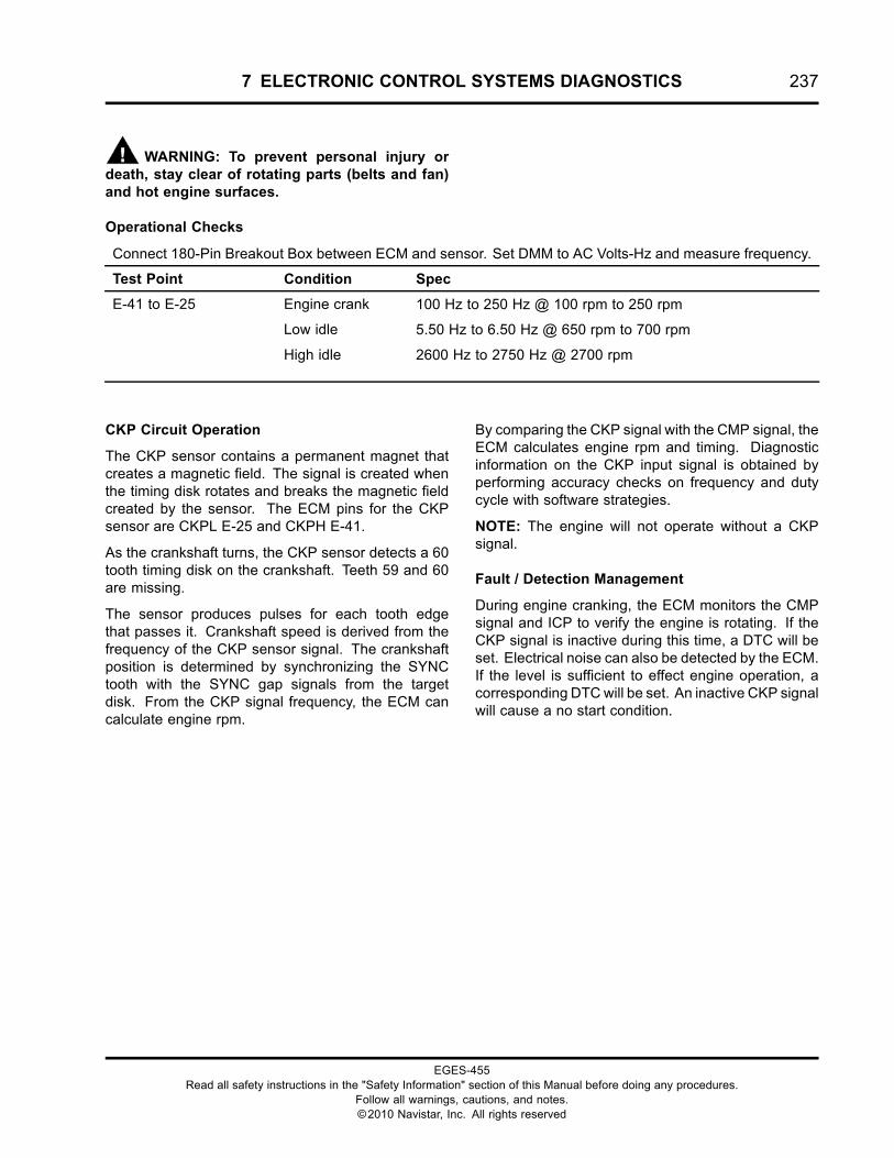
7 ELECTRONIC CONTROL SYSTEMS DIAGNOSTICS 237
WARNING: To prevent personal injury ordeath, stay clear of rotating parts (belts and fan)and hot engine surfaces.
Operational Checks
Connect 180-Pin Breakout Box between ECM and sensor. Set DMM to AC Volts-Hz and measure frequency.
Test Point Condition Spec
Engine crank 100 Hz to 250 Hz @ 100 rpm to 250 rpm
Low idle 5.50 Hz to 6.50 Hz @ 650 rpm to 700 rpm
E-41 to E-25
High idle 2600 Hz to 2750 Hz @ 2700 rpm
CKP Circuit Operation
The CKP sensor contains a permanent magnet thatcreates a magnetic field. The signal is created whenthe timing disk rotates and breaks the magnetic fieldcreated by the sensor. The ECM pins for the CKPsensor are CKPL E-25 and CKPH E-41.
As the crankshaft turns, the CKP sensor detects a 60tooth timing disk on the crankshaft. Teeth 59 and 60are missing.
The sensor produces pulses for each tooth edgethat passes it. Crankshaft speed is derived from thefrequency of the CKP sensor signal. The crankshaftposition is determined by synchronizing the SYNCtooth with the SYNC gap signals from the targetdisk. From the CKP signal frequency, the ECM cancalculate engine rpm.
By comparing the CKP signal with the CMP signal, theECM calculates engine rpm and timing. Diagnosticinformation on the CKP input signal is obtained byperforming accuracy checks on frequency and dutycycle with software strategies.
NOTE: The engine will not operate without a CKPsignal.
Fault / Detection Management
During engine cranking, the ECM monitors the CMPsignal and ICP to verify the engine is rotating. If theCKP signal is inactive during this time, a DTC will beset. Electrical noise can also be detected by the ECM.If the level is sufficient to effect engine operation, acorresponding DTCwill be set. An inactive CKP signalwill cause a no start condition.
EGES-455Read all safety instructions in the "Safety Information" section of this Manual before doing any procedures.
Follow all warnings, cautions, and notes.©2010 Navistar, Inc. All rights reserved
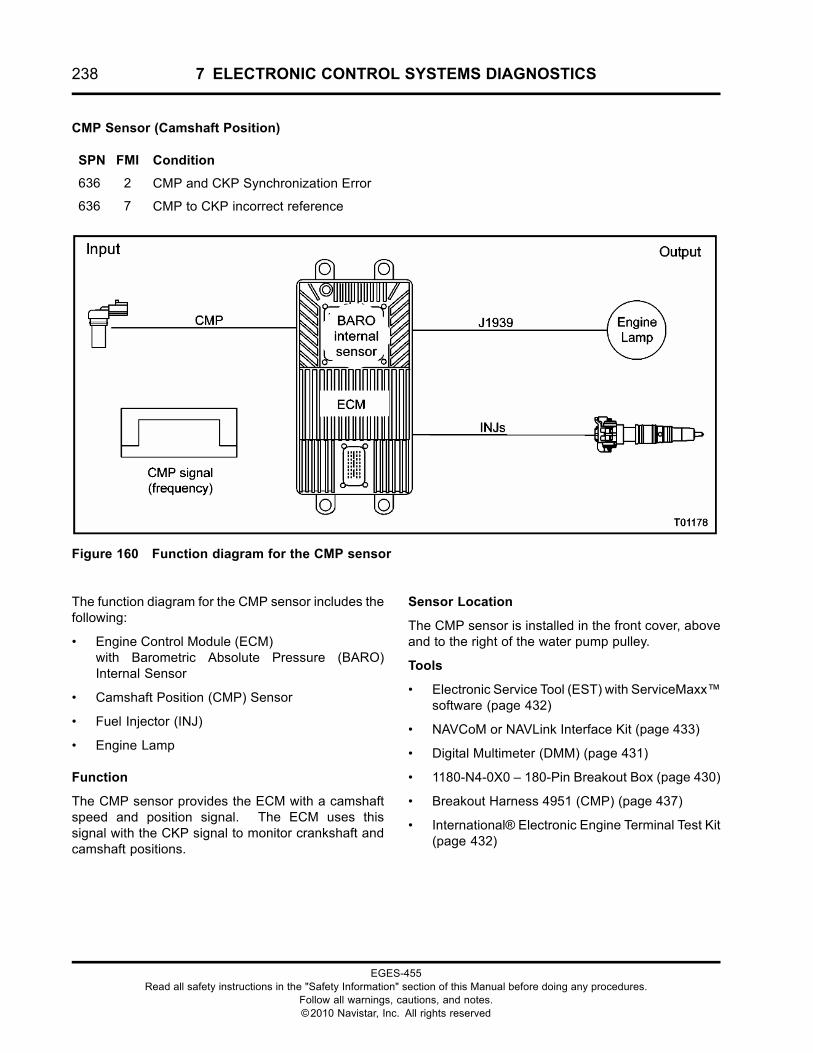
238 7 ELECTRONIC CONTROL SYSTEMS DIAGNOSTICS
CMP Sensor (Camshaft Position)
SPN FMI Condition
636 2 CMP and CKP Synchronization Error
636 7 CMP to CKP incorrect reference
Figure 160 Function diagram for the CMP sensor
The function diagram for the CMP sensor includes thefollowing:
• Engine Control Module (ECM)with Barometric Absolute Pressure (BARO)Internal Sensor
• Camshaft Position (CMP) Sensor
• Fuel Injector (INJ)
• Engine Lamp
Function
The CMP sensor provides the ECM with a camshaftspeed and position signal. The ECM uses thissignal with the CKP signal to monitor crankshaft andcamshaft positions.
Sensor Location
The CMP sensor is installed in the front cover, aboveand to the right of the water pump pulley.
Tools
• Electronic Service Tool (EST) with ServiceMaxx™software (page 432)
• NAVCoM or NAVLink Interface Kit (page 433)
• Digital Multimeter (DMM) (page 431)
• 1180-N4-0X0 – 180-Pin Breakout Box (page 430)
• Breakout Harness 4951 (CMP) (page 437)
• International® Electronic Engine Terminal Test Kit(page 432)
EGES-455Read all safety instructions in the "Safety Information" section of this Manual before doing any procedures.
Follow all warnings, cautions, and notes.©2010 Navistar, Inc. All rights reserved
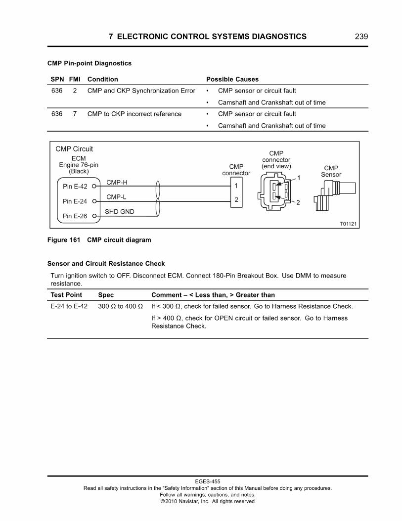
7 ELECTRONIC CONTROL SYSTEMS DIAGNOSTICS 239
CMP Pin-point Diagnostics
SPN FMI Condition Possible Causes
636 2 CMP and CKP Synchronization Error • CMP sensor or circuit fault
• Camshaft and Crankshaft out of time
636 7 CMP to CKP incorrect reference • CMP sensor or circuit fault
• Camshaft and Crankshaft out of time
Figure 161 CMP circuit diagram
Sensor and Circuit Resistance Check
Turn ignition switch to OFF. Disconnect ECM. Connect 180-Pin Breakout Box. Use DMM to measureresistance.
Test Point Spec Comment – < Less than, > Greater than
E-24 to E-42 300 Ω to 400 Ω If < 300 Ω, check for failed sensor. Go to Harness Resistance Check.
If > 400 Ω, check for OPEN circuit or failed sensor. Go to HarnessResistance Check.
EGES-455Read all safety instructions in the "Safety Information" section of this Manual before doing any procedures.
Follow all warnings, cautions, and notes.©2010 Navistar, Inc. All rights reserved
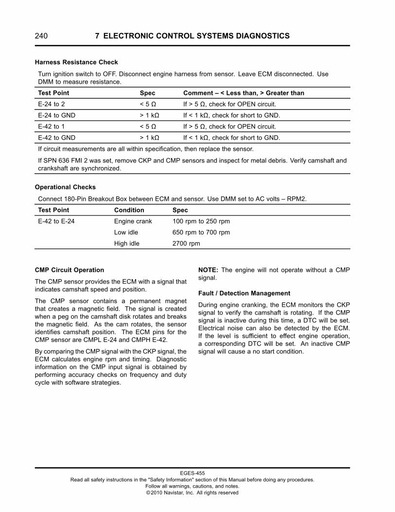
240 7 ELECTRONIC CONTROL SYSTEMS DIAGNOSTICS
Harness Resistance Check
Turn ignition switch to OFF. Disconnect engine harness from sensor. Leave ECM disconnected. UseDMM to measure resistance.
Test Point Spec Comment – < Less than, > Greater than
E-24 to 2 < 5 Ω If > 5 Ω, check for OPEN circuit.
E-24 to GND > 1 kΩ If < 1 kΩ, check for short to GND.
E-42 to 1 < 5 Ω If > 5 Ω, check for OPEN circuit.
E-42 to GND > 1 kΩ If < 1 kΩ, check for short to GND.
If circuit measurements are all within specification, then replace the sensor.
If SPN 636 FMI 2 was set, remove CKP and CMP sensors and inspect for metal debris. Verify camshaft andcrankshaft are synchronized.
Operational Checks
Connect 180-Pin Breakout Box between ECM and sensor. Use DMM set to AC volts – RPM2.
Test Point Condition Spec
Engine crank 100 rpm to 250 rpm
Low idle 650 rpm to 700 rpm
E-42 to E-24
High idle 2700 rpm
CMP Circuit Operation
The CMP sensor provides the ECM with a signal thatindicates camshaft speed and position.
The CMP sensor contains a permanent magnetthat creates a magnetic field. The signal is createdwhen a peg on the camshaft disk rotates and breaksthe magnetic field. As the cam rotates, the sensoridentifies camshaft position. The ECM pins for theCMP sensor are CMPL E-24 and CMPH E-42.
By comparing the CMP signal with the CKP signal, theECM calculates engine rpm and timing. Diagnosticinformation on the CMP input signal is obtained byperforming accuracy checks on frequency and dutycycle with software strategies.
NOTE: The engine will not operate without a CMPsignal.
Fault / Detection Management
During engine cranking, the ECM monitors the CKPsignal to verify the camshaft is rotating. If the CMPsignal is inactive during this time, a DTC will be set.Electrical noise can also be detected by the ECM.If the level is sufficient to effect engine operation,a corresponding DTC will be set. An inactive CMPsignal will cause a no start condition.
EGES-455Read all safety instructions in the "Safety Information" section of this Manual before doing any procedures.
Follow all warnings, cautions, and notes.©2010 Navistar, Inc. All rights reserved
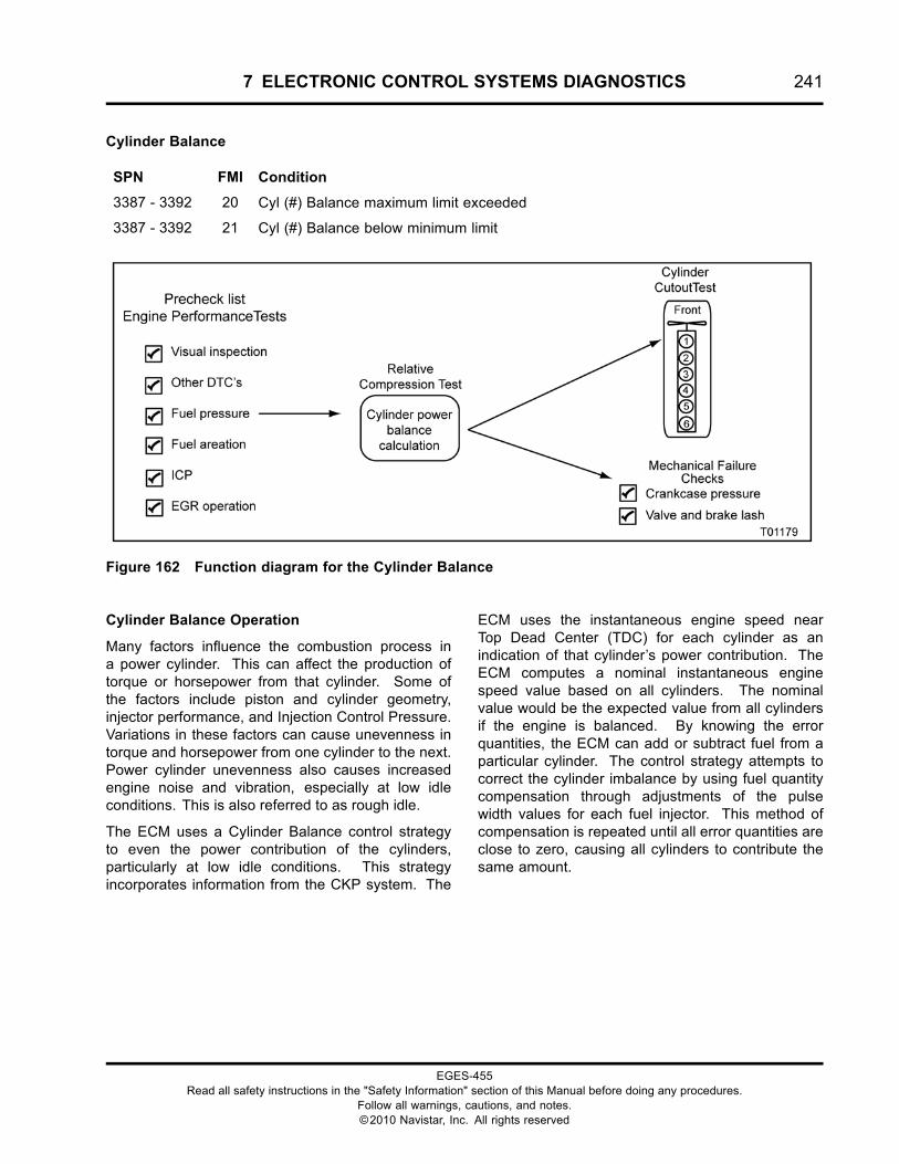
7 ELECTRONIC CONTROL SYSTEMS DIAGNOSTICS 241
Cylinder Balance
SPN FMI Condition
3387 - 3392 20 Cyl (#) Balance maximum limit exceeded
3387 - 3392 21 Cyl (#) Balance below minimum limit
Figure 162 Function diagram for the Cylinder Balance
Cylinder Balance Operation
Many factors influence the combustion process ina power cylinder. This can affect the production oftorque or horsepower from that cylinder. Some ofthe factors include piston and cylinder geometry,injector performance, and Injection Control Pressure.Variations in these factors can cause unevenness intorque and horsepower from one cylinder to the next.Power cylinder unevenness also causes increasedengine noise and vibration, especially at low idleconditions. This is also referred to as rough idle.
The ECM uses a Cylinder Balance control strategyto even the power contribution of the cylinders,particularly at low idle conditions. This strategyincorporates information from the CKP system. The
ECM uses the instantaneous engine speed nearTop Dead Center (TDC) for each cylinder as anindication of that cylinder’s power contribution. TheECM computes a nominal instantaneous enginespeed value based on all cylinders. The nominalvalue would be the expected value from all cylindersif the engine is balanced. By knowing the errorquantities, the ECM can add or subtract fuel from aparticular cylinder. The control strategy attempts tocorrect the cylinder imbalance by using fuel quantitycompensation through adjustments of the pulsewidth values for each fuel injector. This method ofcompensation is repeated until all error quantities areclose to zero, causing all cylinders to contribute thesame amount.
EGES-455Read all safety instructions in the "Safety Information" section of this Manual before doing any procedures.
Follow all warnings, cautions, and notes.©2010 Navistar, Inc. All rights reserved
242 7 ELECTRONIC CONTROL SYSTEMS DIAGNOSTICS
Cylinder Balance Diagnostics
SPN FMI Condition Possible Causes
3387–3392
3387–3392
20
21
Cyl (#) Balance maximum limit exceeded
Cyl (#) Balance below minimum limit
• Low Fuel Pressure
• Aerated fuel
• Contaminated fuel
• Base engine compressionimbalance
• Failed injector (Mechanical)
SPN 3387 - 3392 FMI 20 – Cylinder (#) balance maximum limit exceeded
SPN 3387 - 3392 FMI 21 – Cylinder (#) balance below minimum limit
The ECM continuously calculates the balance of each cylinder during normal engine operation. If a cylinderis over - or under - performing, a cylinder balance DTC will set.
Pin-point Cylinder Balance Fault
1. Visually inspect engine for damaged or disconnected components.
• Check all fluid levels.
• Check engine and control system for electrical or mechanical damage.
2. Check for other active DTC’s.
• If injector circuit faults SPN 651 through 656 are set, go to Injector circuit diagnostic.
3. Check fuel pressure, fuel aeration, and possible fuel contamination.
Note: These checks can be verified quickly by using the Fuel Pressure Test Gauge with shutoffvalve. See Fuel Pressure and Aeration test in the “HARD START AND NO START DIAGNOSTICS”section of this manual.
4. Check ICP voltage at switch ON, engine OFF.
• Using ServiceMaxx™ software, open the Continuous Monitor session and verify S_ICP Volt iswithin KOEO specification.
• If not within specification, see ICP sensor in the “ELECTRONIC CONTROL SYSTEMSDIAGNOSTICS” section of this manual.
5. Inspect EGR valve. Verify valve is not stuck open.
• Using ServiceMaxx™ software, run KOEO Output State High and Low Test while monitoringthe signal state. Verify EGR valve is working within Specification. See “APPENDIX A:PERFORMANCE SPECIFICATIONS”.
6. Run Relative Compression Test to verify if cylinder imbalance is mechanical problem and not aninjector problem.
• Check crankcase pressure.
• Check valve lash and brake lash. See Engine Service Manual.
EGES-455Read all safety instructions in the "Safety Information" section of this Manual before doing any procedures.
Follow all warnings, cautions, and notes.©2010 Navistar, Inc. All rights reserved

7 ELECTRONIC CONTROL SYSTEMS DIAGNOSTICS 243
7. Run Cylinder Cutout Test to verify which cylinder is not contributing.
• If a cylinder fails the Relative Compression Test, the problem is not a bad injector, but is acylinder compression failure. Diagnose the mechanical failure.
Note: Only replace an injector if the following checks were made without finding a problem.
• Water In Fuel
• Aerated Fuel
• Fuel Pressure
• EGR Valve Stuck Open
• Injector Electrical Faults
• Relative Compression
EGES-455Read all safety instructions in the "Safety Information" section of this Manual before doing any procedures.
Follow all warnings, cautions, and notes.©2010 Navistar, Inc. All rights reserved
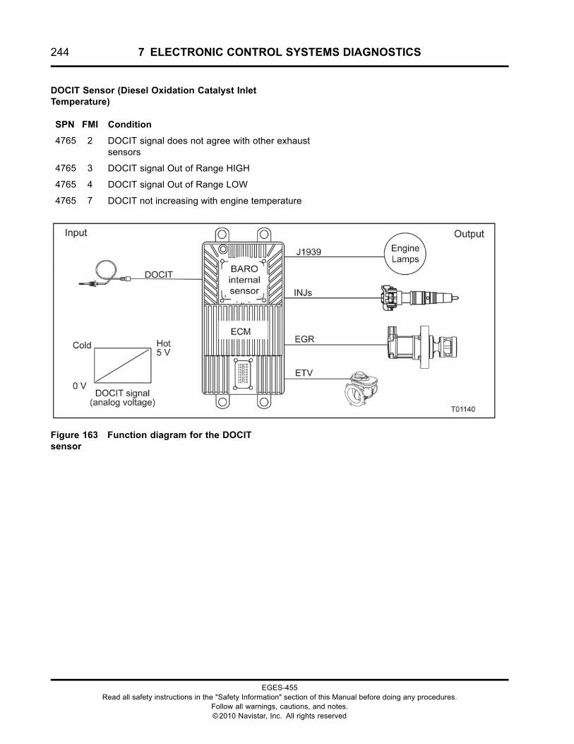
244 7 ELECTRONIC CONTROL SYSTEMS DIAGNOSTICS
DOCIT Sensor (Diesel Oxidation Catalyst InletTemperature)
SPN FMI Condition
4765 2 DOCIT signal does not agree with other exhaustsensors
4765 3 DOCIT signal Out of Range HIGH
4765 4 DOCIT signal Out of Range LOW
4765 7 DOCIT not increasing with engine temperature
Figure 163 Function diagram for the DOCITsensor
EGES-455Read all safety instructions in the "Safety Information" section of this Manual before doing any procedures.
Follow all warnings, cautions, and notes.©2010 Navistar, Inc. All rights reserved
7 ELECTRONIC CONTROL SYSTEMS DIAGNOSTICS 245
The function diagram for the DOCIT sensor includesthe following:
• Engine Control Module (ECM)with Barometric Absolute Pressure (BARO)Internal Sensor
• DOC Inlet Temperature (DOCIT) Sensor
• Exhaust Gas Recirculation (EGR) Valve
• Engine Throttle Valve (ETV)
• Fuel Injector (INJ)
• Engine Lamps
Function
The DOCIT sensor provides a feedback signalto the ECM indicating Diesel Oxidation Catalystinlet temperature. Before and during a catalystregeneration, the ECM will monitor this sensor alongwith the DPFIT, DPFOT, DPFDP, EGRP, and ETVP.
Sensor Location
The DOCIT sensor is the first exhaust temperaturesensor installed down stream of the turbocharger andjust before the DOC.
Tools
• Electronic Service Tool (EST) with ServiceMaxx™software (page 432)
• NAVCoM or NAVLink Interface Kit (page 433)
• Digital Multimeter (DMM) (page 431)
• 1180-N4-0X0 – 180-Pin Breakout Box (page 430)
• 3-Banana Plug Harness (page 433)
• Breakout Harness 4760A (DOCIT) (page 435)
• International® Electronic Engine Terminal Test Kit(page 432)
EGES-455Read all safety instructions in the "Safety Information" section of this Manual before doing any procedures.
Follow all warnings, cautions, and notes.©2010 Navistar, Inc. All rights reserved
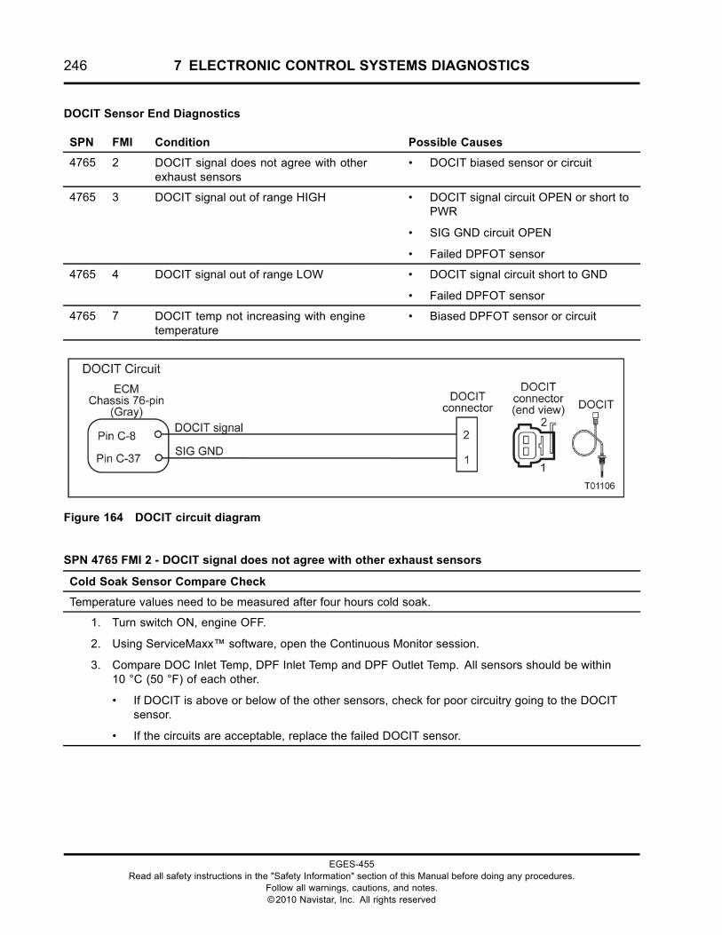
246 7 ELECTRONIC CONTROL SYSTEMS DIAGNOSTICS
DOCIT Sensor End Diagnostics
SPN FMI Condition Possible Causes
4765 2 DOCIT signal does not agree with otherexhaust sensors
• DOCIT biased sensor or circuit
4765 3 DOCIT signal out of range HIGH • DOCIT signal circuit OPEN or short toPWR
• SIG GND circuit OPEN
• Failed DPFOT sensor
4765 4 DOCIT signal out of range LOW • DOCIT signal circuit short to GND
• Failed DPFOT sensor
4765 7 DOCIT temp not increasing with enginetemperature
• Biased DPFOT sensor or circuit
Figure 164 DOCIT circuit diagram
SPN 4765 FMI 2 - DOCIT signal does not agree with other exhaust sensors
Cold Soak Sensor Compare Check
Temperature values need to be measured after four hours cold soak.
1. Turn switch ON, engine OFF.
2. Using ServiceMaxx™ software, open the Continuous Monitor session.
3. Compare DOC Inlet Temp, DPF Inlet Temp and DPF Outlet Temp. All sensors should be within10 °C (50 °F) of each other.
• If DOCIT is above or below of the other sensors, check for poor circuitry going to the DOCITsensor.
• If the circuits are acceptable, replace the failed DOCIT sensor.
EGES-455Read all safety instructions in the "Safety Information" section of this Manual before doing any procedures.
Follow all warnings, cautions, and notes.©2010 Navistar, Inc. All rights reserved
7 ELECTRONIC CONTROL SYSTEMS DIAGNOSTICS 247
SPN 4765 FMI 7 - DOCIT not increasing with engine temperature
Cold Soak Sensor Compare Check
Temperature values need to be measured after four hours of cold soak.
1. Turn switch ON, engine OFF.
2. Using ServiceMaxx™ software, open the Continuous Monitor session.
3. Compare DOC Inlet Temp, DPF Inlet Temp, and DPF Outlet Temp. All sensors should be within10 °C (50 °F) of each other.
• If DOCIT is above or below the other sensors, check for poor circuitry going to the DOCIT sensor.
• If the circuits are okay, then replace the failed DOCIT sensor.
WARNING: To prevent personal injury ordeath, stay clear of rotating parts (belts and fan)and hot engine surfaces.
1. Using EST with ServiceMaxx™ software, openthe Continuous Monitor Session.
2. Monitor sensor voltage. Verify an active DTC forthe sensor.
• If code is inactive, monitor the signalwhile wiggling the connector and all wiresat suspected location. If the circuit isinterrupted, the signal will spike and theDTC will go active.
• If code is active, proceed to the next step.
3. Disconnect chassis harness from sensor.
NOTE: Inspect connectors for damaged pins,corrosion, or loose pins. Repair if necessary.
4. Connect Breakout Harness 4760A to chassisharness. Leave sensor disconnected.
EGES-455Read all safety instructions in the "Safety Information" section of this Manual before doing any procedures.
Follow all warnings, cautions, and notes.©2010 Navistar, Inc. All rights reserved
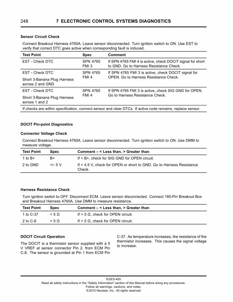
248 7 ELECTRONIC CONTROL SYSTEMS DIAGNOSTICS
Sensor Circuit Check
Connect Breakout Harness 4760A. Leave sensor disconnected. Turn ignition switch to ON. Use EST toverify that correct DTC goes active when corresponding fault is induced.
Test Point Spec Comment
EST - Check DTC SPN 4765FMI 3
If SPN 4765 FMI 4 is active, check DOCIT signal for shortto GND. Go to Harness Resistance Check.
EST - Check DTC
Short 3-Banana Plug Harnessacross 2 and GND
SPN 4765FMI 4
If SPN 4765 FMI 3 is active, check DOCIT signal forOPEN. Go to Harness Resistance Check.
EST - Check DTC
Short 3-Banana Plug Harnessacross 1 and 2
SPN 4765FMI 4
If SPN 4765 FMI 3 is active, check SIG GND for OPEN.Go to Harness Resistance Check.
If checks are within specification, connect sensor and clear DTCs. If active code remains, replace sensor.
DOCIT Pin-point Diagnostics
Connector Voltage Check
Connect Breakout Harness 4760A. Leave sensor disconnected. Turn ignition switch to ON. Use DMM tomeasure voltage.
Test Point Spec Comment – < Less than, > Greater than
1 to B+ B+ If < B+, check for SIG GND for OPEN circuit.
2 to GND +/- 5 V If < 4.5 V, check for OPEN or short to GND. Go to Harness ResistanceCheck.
Harness Resistance Check
Turn ignition switch to OFF. Disconnect ECM. Leave sensor disconnected. Connect 180-Pin Breakout Boxand Breakout Harness 4760A. Use DMM to measure resistance.
Test Point Spec Comment – < Less than, > Greater than
1 to C-37 < 5 Ω If > 5 Ω, check for OPEN circuit.
2 to C-8 < 5 Ω If > 5 Ω, check for OPEN circuit.
DOCIT Circuit Operation
The DOCIT is a thermistor sensor supplied with a 5V VREF at sensor connector Pin 2, from ECM PinC-8. The sensor is grounded at Pin 1 from ECM Pin
C-37. As temperature increases, the resistance of thethermistor increases. This causes the signal voltageto increase.
EGES-455Read all safety instructions in the "Safety Information" section of this Manual before doing any procedures.
Follow all warnings, cautions, and notes.©2010 Navistar, Inc. All rights reserved
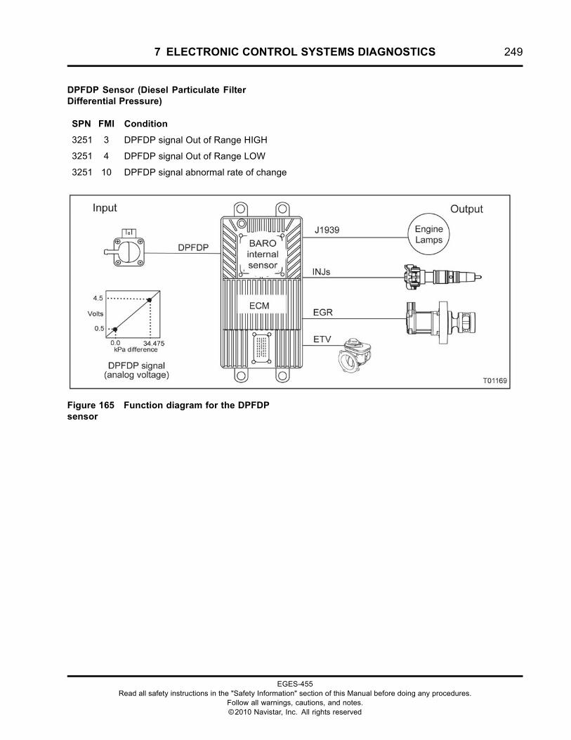
7 ELECTRONIC CONTROL SYSTEMS DIAGNOSTICS 249
DPFDP Sensor (Diesel Particulate FilterDifferential Pressure)
SPN FMI Condition
3251 3 DPFDP signal Out of Range HIGH
3251 4 DPFDP signal Out of Range LOW
3251 10 DPFDP signal abnormal rate of change
Figure 165 Function diagram for the DPFDPsensor
EGES-455Read all safety instructions in the "Safety Information" section of this Manual before doing any procedures.
Follow all warnings, cautions, and notes.©2010 Navistar, Inc. All rights reserved
250 7 ELECTRONIC CONTROL SYSTEMS DIAGNOSTICS
The function diagram for the DPFDP sensor includesthe following:
• Engine Control Module (ECM)with Barometric Absolute Pressure (BARO)Internal Sensor
• DPF Differential Pressure (DPFDP) Sensor
• Exhaust Gas Recirculation (EGR)
• Engine Throttle Valve (ETV)
• Fuel Injector (INJ)
• Engine Lamps
• Regeneration Lamp
Function
The DPFDP sensor provides a feedback signal tothe ECM, indicating the pressure difference betweenthe inlet and outlet of the Diesel Particulate Filter.Before and during a catalyst regeneration, the ECMwill monitor this sensor along with the DOCIT, DPFIT,DPFOT, EGRP, and ETVP.
Sensor Location
The DPFDP sensor is a differential pressure sensorwith two tap-offs installed past the turbocharger. Atap-off is located before and after the DPF.
Tools
• Electronic Service Tool (EST) with ServiceMaxx™software (page 432)
• NAVCoM or NAVLink Interface Kit (page 433)
• Digital Multimeter (DMM) (page 431)
• 1180-N4-0X0 – 180-Pin Breakout Box (page 430)
• 3-Banana Plug Harness (page 433)
• Breakout Harness 4761A (DPFDP) (page 435)
• International® Electronic Engine Terminal Test Kit(page 432)
EGES-455Read all safety instructions in the "Safety Information" section of this Manual before doing any procedures.
Follow all warnings, cautions, and notes.©2010 Navistar, Inc. All rights reserved
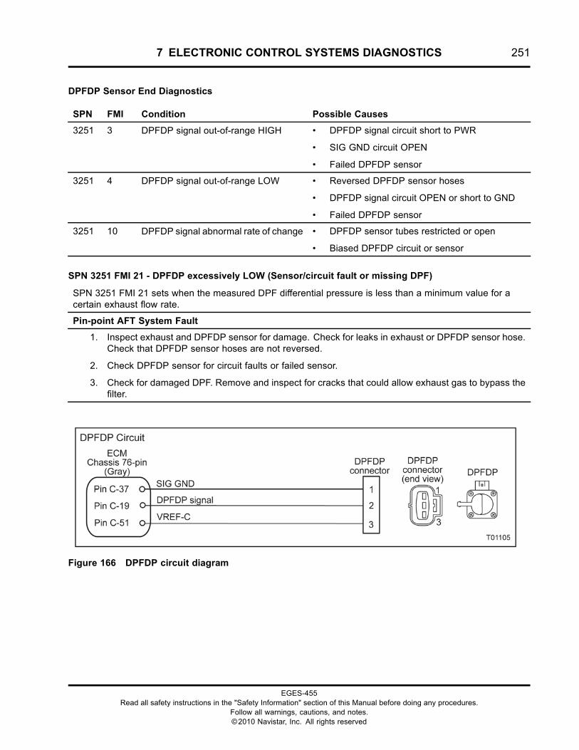
7 ELECTRONIC CONTROL SYSTEMS DIAGNOSTICS 251
DPFDP Sensor End Diagnostics
SPN FMI Condition Possible Causes
3251 3 DPFDP signal out-of-range HIGH • DPFDP signal circuit short to PWR
• SIG GND circuit OPEN
• Failed DPFDP sensor
3251 4 DPFDP signal out-of-range LOW • Reversed DPFDP sensor hoses
• DPFDP signal circuit OPEN or short to GND
• Failed DPFDP sensor
3251 10 DPFDP signal abnormal rate of change • DPFDP sensor tubes restricted or open
• Biased DPFDP circuit or sensor
SPN 3251 FMI 21 - DPFDP excessively LOW (Sensor/circuit fault or missing DPF)
SPN 3251 FMI 21 sets when the measured DPF differential pressure is less than a minimum value for acertain exhaust flow rate.
Pin-point AFT System Fault
1. Inspect exhaust and DPFDP sensor for damage. Check for leaks in exhaust or DPFDP sensor hose.Check that DPFDP sensor hoses are not reversed.
2. Check DPFDP sensor for circuit faults or failed sensor.
3. Check for damaged DPF. Remove and inspect for cracks that could allow exhaust gas to bypass thefilter.
Figure 166 DPFDP circuit diagram
EGES-455Read all safety instructions in the "Safety Information" section of this Manual before doing any procedures.
Follow all warnings, cautions, and notes.©2010 Navistar, Inc. All rights reserved
252 7 ELECTRONIC CONTROL SYSTEMS DIAGNOSTICS
SPN 3251 FMI 2 - DPFDP above or below desired level
1. Verify DPFDP sensor hoses are not disconnected, are leaking or plumbed backwards.
2. Turn switch ON, engine OFF.
3. Using ServiceMaxx™ software, open the Continuous Monitor session.
4. Verify S_DPFDP Volts are within specification. See “APPENDIX A: PERFORMANCESPECIFICATIONS” in this manual.
• If voltage is not within specification, check circuitry for poor continuity. If circuits are okay,replace EBP sensor.
SPN 3251 FMI 10 - DPFDP signal abnormal rate of change
1. Verify DPFDP sensor hoses are not disconnected, leaking or plumb backwards.
2. Turn switch ON, engine OFF
3. Using ServiceMaxx™ software, open the Continuous Monitor session.
4. Verify S_DPFDP Volts are within specification. See “APPENDIX A: PERFORMANCESPECIFICATIONS” in this manual.
• If voltage is not within specification, check circuitry for poor continuity. If circuits are okay,replace EBP sensor.
SPN 3251 FMI 21 - DPFDP excessively LOW (Sensor/circuit fault or missing DPF)
1. Verify DPFDP sensor hoses are not disconnected, leaking or plumb backwards.
2. Turn switch ON, engine OFF
3. Using ServiceMaxx™ software, open the Continuous Monitor session.
4. Verify S_DPFDP Volts are within specification. See “APPENDIX A: PERFORMANCESPECIFICATIONS” in this manual.
• If voltage is not within specification, check circuitry for poor continuity. If circuits are okay,replace EBP sensor.
EGES-455Read all safety instructions in the "Safety Information" section of this Manual before doing any procedures.
Follow all warnings, cautions, and notes.©2010 Navistar, Inc. All rights reserved

7 ELECTRONIC CONTROL SYSTEMS DIAGNOSTICS 253
WARNING: To prevent personal injury ordeath, stay clear of rotating parts (belts and fan)and hot engine surfaces.
NOTE: For FMI 4 or 10, verify sensor pressure hosesare not restricted, reversed, or disconnected.
1. Using EST with ServiceMaxx™ software, openthe Continuous Monitor session.
2. Monitor sensor voltage. Verify an active DTC forthe sensor.
• If code is inactive, monitor the signalwhile wiggling the connector and all wiresat suspected locations. If the circuit isinterrupted, the signal will spike and theDTC will go active.
• If code is active, proceed to the next step.
3. Disconnect chassis harness from sensor.
NOTE: Inspect connectors for damaged pins,corrosion, or loose pins. Repair if necessary.
4. Connect Breakout Harness 4761A to chassisharness. Leave sensor disconnected.
Sensor Circuit Check
Connect Breakout Harness 4761A. Leave sensor disconnected. Turn ignition switch to ON. Use EST toverify correct DTC goes active when corresponding fault is induced. Use DMM to measure circuits.
Test Point Spec Comment – < Less than, > Greater than
EST - Check DTC SPN 3251FMI 4
If SPN 3251 FMI 3 is active, check DPFDP signal forshort to PWR.
DMM - Measure volts
3 to GND
5 V ± 0.5 V If > 5.5 V, check VREF for short to PWR.
If < 4.5 V, check VREF for OPEN or short to GND. Go toHarness Resistance Check.
EST - Check DTC
Short breakout harness across 2and 3
SPN 3251FMI 3
If SPN 3251 FMI 4 is active, check DPFDP signal forOPEN. Go to Harness Resistance Check.
DMM - Measure Volts
1 to B+
B+ If < B+, check SIG GND for OPEN. Go to HarnessResistance Check.
If checks are within specification, connect sensor and clear DTCs. If active code remains, replace sensor.
EGES-455Read all safety instructions in the "Safety Information" section of this Manual before doing any procedures.
Follow all warnings, cautions, and notes.©2010 Navistar, Inc. All rights reserved
254 7 ELECTRONIC CONTROL SYSTEMS DIAGNOSTICS
DPFDP Pin-point Diagnostics
Connector Voltage Check
Connect Breakout Harness 4761A . Leave sensor disconnected. Turn ignition switch to ON. Use DMM tomeasure voltage.
Test Point Spec Comment – < Less than, > Greater than
1 to B+ B+ If < B+, check for short to PWR. Go to Harness Resistance Check.
3 to GND 5 V ± 0.5 V If > 5.5 V, check VREF for short to PWR.
If < 4.5 V, check VREF for OPEN or short to GND. Go to HarnessResistance Check.
2 to B+ B+ If < B+, check for short to PWR. Go to Harness Resistance Check.
Harness Resistance Check
Turn ignition switch to OFF. Disconnect ECM. Leave sensor disconnected. Connect 180-Pin Breakout Boxand Breakout Harness 4761A . Use DMM to measure resistance.
Test Point Spec Comment – < Less than, > Greater than
1 to C-37 < 5 Ω If > 5 Ω, check SIG GND circuit for OPEN
2 to C-19 < 5 Ω If > 5 Ω, check DPFDP signal circuit for OPEN
3 to C-51 < 5 Ω If > 5 Ω, check VREF circuit for OPEN
DPFDP Circuit Operation
The DPFDP is a differential pressure sensor that issupplied with a 5 V VREF at Pin 3 from ECM Pin C-51.
The sensor is grounded at Pin 1 from ECM Pin C-37.The sensor returns a variable voltage signal from Pin2 to ECM Pin C-19.
EGES-455Read all safety instructions in the "Safety Information" section of this Manual before doing any procedures.
Follow all warnings, cautions, and notes.©2010 Navistar, Inc. All rights reserved
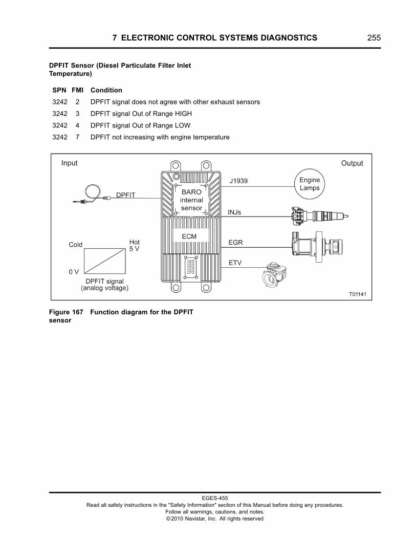
7 ELECTRONIC CONTROL SYSTEMS DIAGNOSTICS 255
DPFIT Sensor (Diesel Particulate Filter InletTemperature)
SPN FMI Condition
3242 2 DPFIT signal does not agree with other exhaust sensors
3242 3 DPFIT signal Out of Range HIGH
3242 4 DPFIT signal Out of Range LOW
3242 7 DPFIT not increasing with engine temperature
Figure 167 Function diagram for the DPFITsensor
EGES-455Read all safety instructions in the "Safety Information" section of this Manual before doing any procedures.
Follow all warnings, cautions, and notes.©2010 Navistar, Inc. All rights reserved
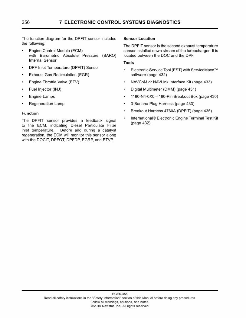
256 7 ELECTRONIC CONTROL SYSTEMS DIAGNOSTICS
The function diagram for the DPFIT sensor includesthe following:
• Engine Control Module (ECM)with Barometric Absolute Pressure (BARO)Internal Sensor
• DPF Inlet Temperature (DPFIT) Sensor
• Exhaust Gas Recirculation (EGR)
• Engine Throttle Valve (ETV)
• Fuel Injector (INJ)
• Engine Lamps
• Regeneration Lamp
Function
The DPFIT sensor provides a feedback signalto the ECM, indicating Diesel Particulate Filterinlet temperature. Before and during a catalystregeneration, the ECM will monitor this sensor alongwith the DOCIT, DPFOT, DPFDP, EGRP, and ETVP.
Sensor Location
The DPFIT sensor is the second exhaust temperaturesensor installed down stream of the turbocharger. It islocated between the DOC and the DPF.
Tools
• Electronic Service Tool (EST) with ServiceMaxx™software (page 432)
• NAVCoM or NAVLink Interface Kit (page 433)
• Digital Multimeter (DMM) (page 431)
• 1180-N4-0X0 – 180-Pin Breakout Box (page 430)
• 3-Banana Plug Harness (page 433)
• Breakout Harness 4760A (DPFIT) (page 435)
• International® Electronic Engine Terminal Test Kit(page 432)
EGES-455Read all safety instructions in the "Safety Information" section of this Manual before doing any procedures.
Follow all warnings, cautions, and notes.©2010 Navistar, Inc. All rights reserved
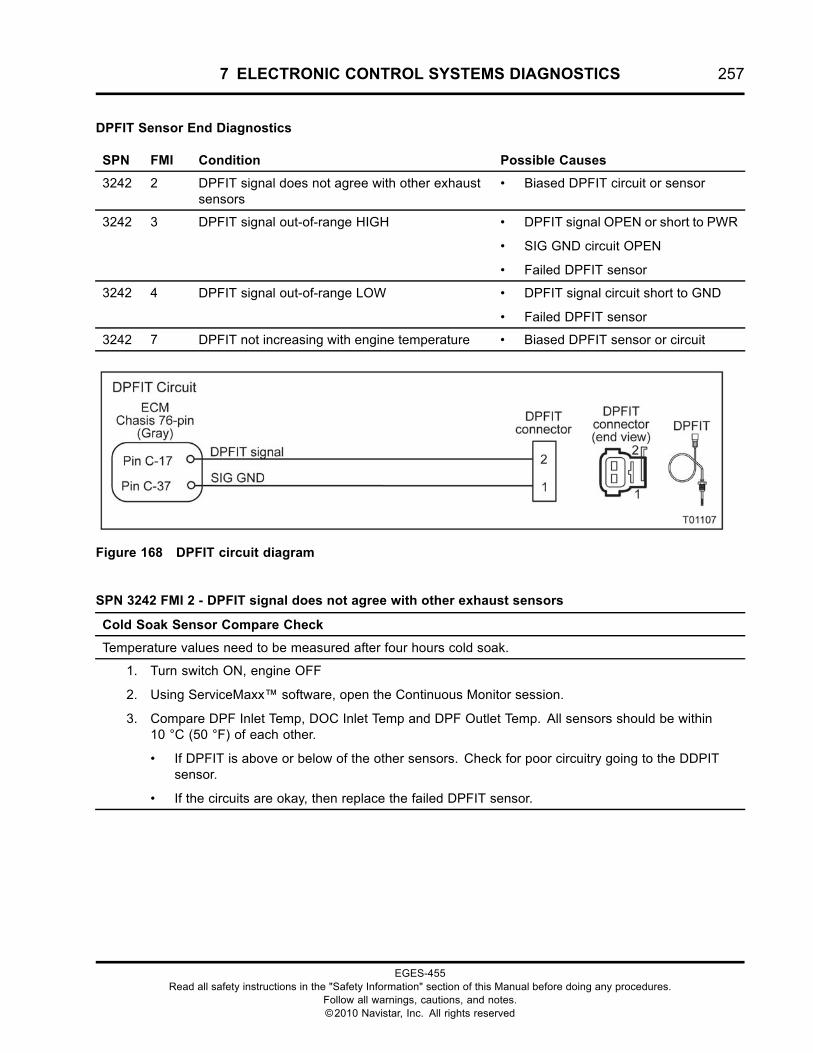
7 ELECTRONIC CONTROL SYSTEMS DIAGNOSTICS 257
DPFIT Sensor End Diagnostics
SPN FMI Condition Possible Causes
3242 2 DPFIT signal does not agree with other exhaustsensors
• Biased DPFIT circuit or sensor
3242 3 DPFIT signal out-of-range HIGH • DPFIT signal OPEN or short to PWR
• SIG GND circuit OPEN
• Failed DPFIT sensor
3242 4 DPFIT signal out-of-range LOW • DPFIT signal circuit short to GND
• Failed DPFIT sensor
3242 7 DPFIT not increasing with engine temperature • Biased DPFIT sensor or circuit
Figure 168 DPFIT circuit diagram
SPN 3242 FMI 2 - DPFIT signal does not agree with other exhaust sensors
Cold Soak Sensor Compare Check
Temperature values need to be measured after four hours cold soak.
1. Turn switch ON, engine OFF
2. Using ServiceMaxx™ software, open the Continuous Monitor session.
3. Compare DPF Inlet Temp, DOC Inlet Temp and DPF Outlet Temp. All sensors should be within10 °C (50 °F) of each other.
• If DPFIT is above or below of the other sensors. Check for poor circuitry going to the DDPITsensor.
• If the circuits are okay, then replace the failed DPFIT sensor.
EGES-455Read all safety instructions in the "Safety Information" section of this Manual before doing any procedures.
Follow all warnings, cautions, and notes.©2010 Navistar, Inc. All rights reserved
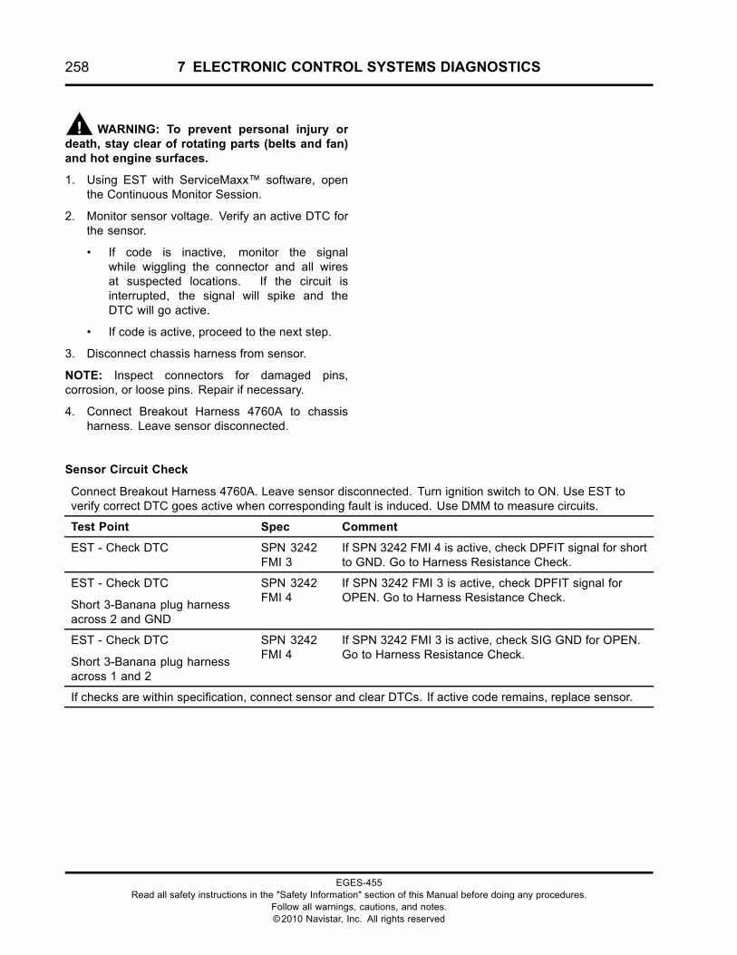
258 7 ELECTRONIC CONTROL SYSTEMS DIAGNOSTICS
WARNING: To prevent personal injury ordeath, stay clear of rotating parts (belts and fan)and hot engine surfaces.
1. Using EST with ServiceMaxx™ software, openthe Continuous Monitor Session.
2. Monitor sensor voltage. Verify an active DTC forthe sensor.
• If code is inactive, monitor the signalwhile wiggling the connector and all wiresat suspected locations. If the circuit isinterrupted, the signal will spike and theDTC will go active.
• If code is active, proceed to the next step.
3. Disconnect chassis harness from sensor.
NOTE: Inspect connectors for damaged pins,corrosion, or loose pins. Repair if necessary.
4. Connect Breakout Harness 4760A to chassisharness. Leave sensor disconnected.
Sensor Circuit Check
Connect Breakout Harness 4760A. Leave sensor disconnected. Turn ignition switch to ON. Use EST toverify correct DTC goes active when corresponding fault is induced. Use DMM to measure circuits.
Test Point Spec Comment
EST - Check DTC SPN 3242FMI 3
If SPN 3242 FMI 4 is active, check DPFIT signal for shortto GND. Go to Harness Resistance Check.
EST - Check DTC
Short 3-Banana plug harnessacross 2 and GND
SPN 3242FMI 4
If SPN 3242 FMI 3 is active, check DPFIT signal forOPEN. Go to Harness Resistance Check.
EST - Check DTC
Short 3-Banana plug harnessacross 1 and 2
SPN 3242FMI 4
If SPN 3242 FMI 3 is active, check SIG GND for OPEN.Go to Harness Resistance Check.
If checks are within specification, connect sensor and clear DTCs. If active code remains, replace sensor.
EGES-455Read all safety instructions in the "Safety Information" section of this Manual before doing any procedures.
Follow all warnings, cautions, and notes.©2010 Navistar, Inc. All rights reserved
7 ELECTRONIC CONTROL SYSTEMS DIAGNOSTICS 259
DPFIT Pin-point Diagnostics
Connector Voltage Check
Connect Breakout Harness 4760A. Leave sensor disconnected. Turn ignition switch to ON. Use DMM tomeasure voltage.
Test Point Spec Comment – < Less than, > Greater than
1 to B+ B+ If < B+, check for short to PWR.
2 to GND 5 V If < 5 V, check for OPEN or short to GND. Go to Harness Resistance Check.
Harness Resistance Check
Turn ignition switch to OFF. Disconnect ECM. Leave sensor disconnected. Connect 180-Pin Breakout Boxand Breakout Harness 4760A. Use DMM to measure resistance.
Test Point Spec Comment – < Less than, > Greater than
1 to C-37 < 5 Ω If > 5 Ω, check for OPEN circuit.
2 to C-17 < 5 Ω If > 5 Ω, check for OPEN circuit.
DPFIT Circuit Operation
The DPFIT is a thermistor sensor supplied witha 5 V VREF at Pin 2 from ECM Pin C-17. Thesensor is grounded at Pin 1 from ECM Pin C-37.
As temperature increases, the resistance of thethermistor decreases. This causes the signal voltageto increase.
EGES-455Read all safety instructions in the "Safety Information" section of this Manual before doing any procedures.
Follow all warnings, cautions, and notes.©2010 Navistar, Inc. All rights reserved
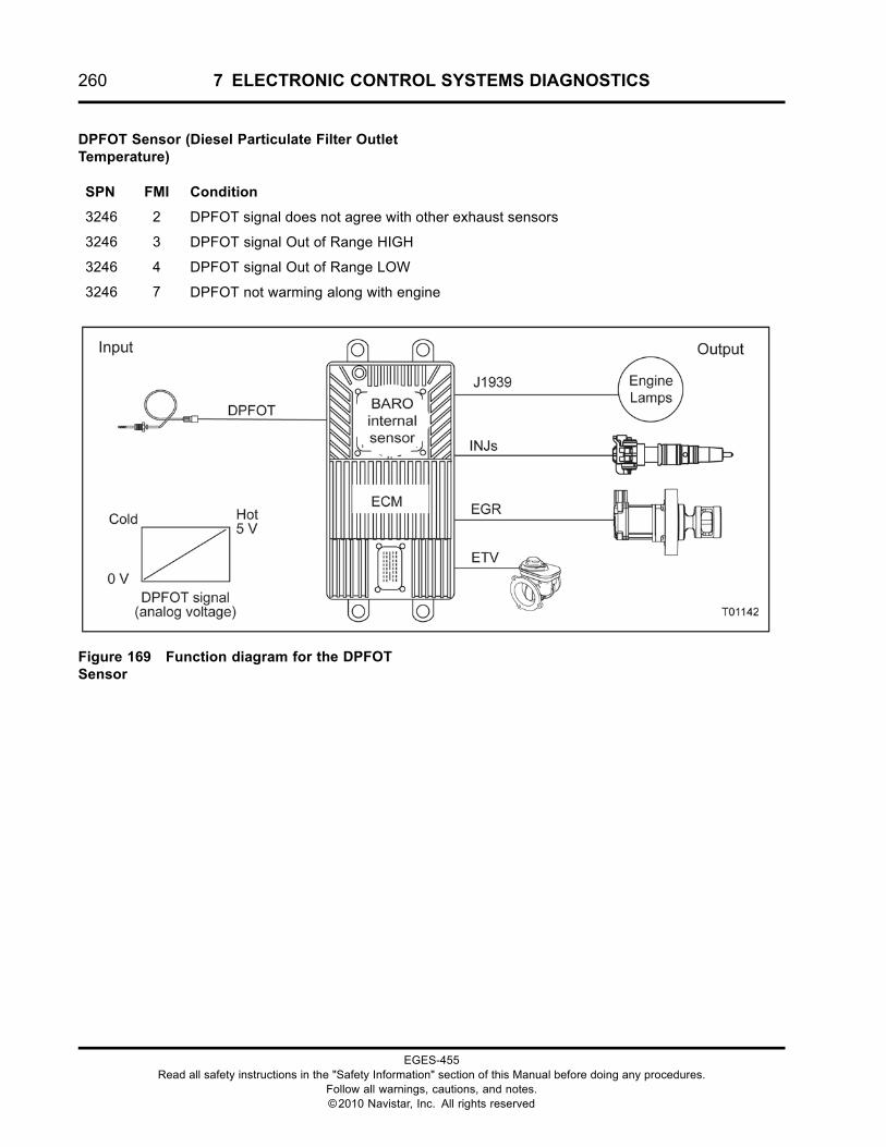
260 7 ELECTRONIC CONTROL SYSTEMS DIAGNOSTICS
DPFOT Sensor (Diesel Particulate Filter OutletTemperature)
SPN FMI Condition
3246 2 DPFOT signal does not agree with other exhaust sensors
3246 3 DPFOT signal Out of Range HIGH
3246 4 DPFOT signal Out of Range LOW
3246 7 DPFOT not warming along with engine
Figure 169 Function diagram for the DPFOTSensor
EGES-455Read all safety instructions in the "Safety Information" section of this Manual before doing any procedures.
Follow all warnings, cautions, and notes.©2010 Navistar, Inc. All rights reserved
7 ELECTRONIC CONTROL SYSTEMS DIAGNOSTICS 261
The function diagram for the DPFOT sensor includesthe following:
• Engine Control Module (ECM)with Barometric Absolute Pressure (BARO)Internal Sensor
• DPF Outlet Temperature (DPFOT) Sensor
• Exhaust Gas Recirculation (EGR)
• Engine Throttle Valve (ETV)
• Fuel Injector (INJ)
• Engine Lamps
Function
The DPFOT sensor provides a feedback signalto the ECM, indicating Diesel Particulate Filteroutlet temperature. Before and during a catalystregeneration, the ECM will monitor this sensor alongwith the DOCIT, DPFIT, DPFDP, EGRP, and ETV.
Sensor Location
The DPFOT sensor is the third exhaust temperaturesensor installed down stream of the turbocharger. It islocated just after the DPF.
Tools
• Electronic Service Tool (EST) with ServiceMaxx™software (page 432)
• NAVCoM or NAVLink Interface Kit (page 433)
• Digital Multimeter (DMM) (page 431)
• 1180-N4-0X0 – 180-Pin Breakout Box (page 430)
• 3-Banana Plug Harness (page 433)
• Breakout Harness 4760A (DPFOT) (page 435)
• International® Electronic Engine Terminal Test Kit(page 432)
EGES-455Read all safety instructions in the "Safety Information" section of this Manual before doing any procedures.
Follow all warnings, cautions, and notes.©2010 Navistar, Inc. All rights reserved
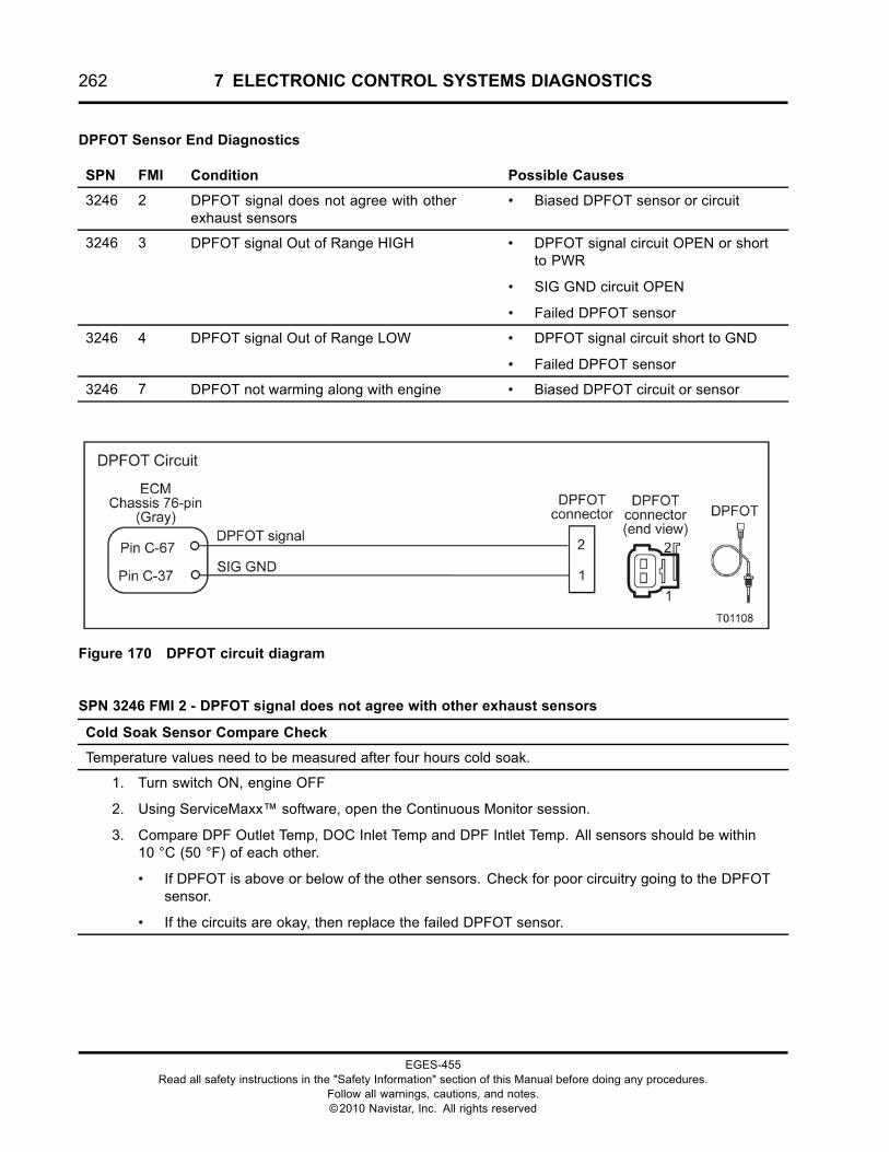
262 7 ELECTRONIC CONTROL SYSTEMS DIAGNOSTICS
DPFOT Sensor End Diagnostics
SPN FMI Condition Possible Causes
3246 2 DPFOT signal does not agree with otherexhaust sensors
• Biased DPFOT sensor or circuit
3246 3 DPFOT signal Out of Range HIGH • DPFOT signal circuit OPEN or shortto PWR
• SIG GND circuit OPEN
• Failed DPFOT sensor
3246 4 DPFOT signal Out of Range LOW • DPFOT signal circuit short to GND
• Failed DPFOT sensor
3246 7 DPFOT not warming along with engine • Biased DPFOT circuit or sensor
Figure 170 DPFOT circuit diagram
SPN 3246 FMI 2 - DPFOT signal does not agree with other exhaust sensors
Cold Soak Sensor Compare Check
Temperature values need to be measured after four hours cold soak.
1. Turn switch ON, engine OFF
2. Using ServiceMaxx™ software, open the Continuous Monitor session.
3. Compare DPF Outlet Temp, DOC Inlet Temp and DPF Intlet Temp. All sensors should be within10 °C (50 °F) of each other.
• If DPFOT is above or below of the other sensors. Check for poor circuitry going to the DPFOTsensor.
• If the circuits are okay, then replace the failed DPFOT sensor.
EGES-455Read all safety instructions in the "Safety Information" section of this Manual before doing any procedures.
Follow all warnings, cautions, and notes.©2010 Navistar, Inc. All rights reserved
7 ELECTRONIC CONTROL SYSTEMS DIAGNOSTICS 263
SPN 3246 FMI 7 - DPFOT not warming along with engine
Cold Soak Sensor Compare Check
Temperature values need to be measured after four hours cold soak.
1. Turn switch ON, engine OFF
2. Using ServiceMaxx™ software, open the Continuous Monitor session.
3. Compare DPF Outlet Temp, DOC Inlet Temp and DPF Intlet Temp. All sensors should be within10 °C (50 °F) of each other.
• If DPFOT is above or below of the other sensors. Check for poor circuitry going to the DPFOTsensor.
• If the circuits are okay, then replace the failed DPFOT sensor.
WARNING: To prevent personal injury ordeath, stay clear of rotating parts (belts and fan)and hot engine surfaces.
1. Using EST with ServiceMaxx™ software, openthe Continuous Monitor Session.
2. Monitor sensor voltage. Verify an active DTC forthe sensor.
• If code is inactive, monitor the signalwhile wiggling the connector and all wiresat suspected location. If the circuit isinterrupted, the signal will spike and theDTC will go active.
• If code is active, proceed to the next step.
3. Disconnect chassis harness from sensor.
NOTE: Inspect connectors for damaged pins,corrosion, or loose pins. Repair if necessary.
4. Connect Breakout Harness 4760A to chassisharness. Leave sensor disconnected.
EGES-455Read all safety instructions in the "Safety Information" section of this Manual before doing any procedures.
Follow all warnings, cautions, and notes.©2010 Navistar, Inc. All rights reserved
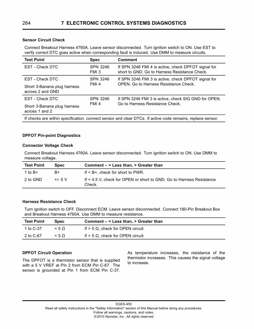
264 7 ELECTRONIC CONTROL SYSTEMS DIAGNOSTICS
Sensor Circuit Check
Connect Breakout Harness 4760A. Leave sensor disconnected. Turn ignition switch to ON. Use EST toverify correct DTC goes active when corresponding fault is induced. Use DMM to measure circuits.
Test Point Spec Comment
EST - Check DTC SPN 3246FMI 3
If SPN 3246 FMI 4 is active, check DPFOT signal forshort to GND. Go to Harness Resistance Check.
EST - Check DTC
Short 3-Banana plug harnessacross 2 and GND
SPN 3246FMI 4
If SPN 3246 FMI 3 is active, check DPFOT signal forOPEN. Go to Harness Resistance Check.
EST - Check DTC
Short 3-Banana plug harnessacross 1 and 2
SPN 3246FMI 4
If SPN 3246 FMI 3 is active, check SIG GND for OPEN.Go to Harness Resistance Check.
If checks are within specification, connect sensor and clear DTCs. If active code remains, replace sensor.
DPFOT Pin-point Diagnostics
Connector Voltage Check
Connect Breakout Harness 4760A. Leave sensor disconnected. Turn ignition switch to ON. Use DMM tomeasure voltage.
Test Point Spec Comment – < Less than, > Greater than
1 to B+ B+ If < B+, check for short to PWR.
2 to GND +/- 5 V If < 4.5 V, check for OPEN or short to GND. Go to Harness ResistanceCheck.
Harness Resistance Check
Turn ignition switch to OFF. Disconnect ECM. Leave sensor disconnected. Connect 180-Pin Breakout Boxand Breakout Harness 4760A. Use DMM to measure resistance.
Test Point Spec Comment – < Less than, > Greater than
1 to C-37 < 5 Ω If > 5 Ω, check for OPEN circuit.
2 to C-67 < 5 Ω If > 5 Ω, check for OPEN circuit.
DPFOT Circuit Operation
The DPFOT is a thermistor sensor that is suppliedwith a 5 V VREF at Pin 2 from ECM Pin C-67. Thesensor is grounded at Pin 1 from ECM Pin C-37.
As temperature increases, the resistance of thethermistor increases. This causes the signal voltageto increase.
EGES-455Read all safety instructions in the "Safety Information" section of this Manual before doing any procedures.
Follow all warnings, cautions, and notes.©2010 Navistar, Inc. All rights reserved
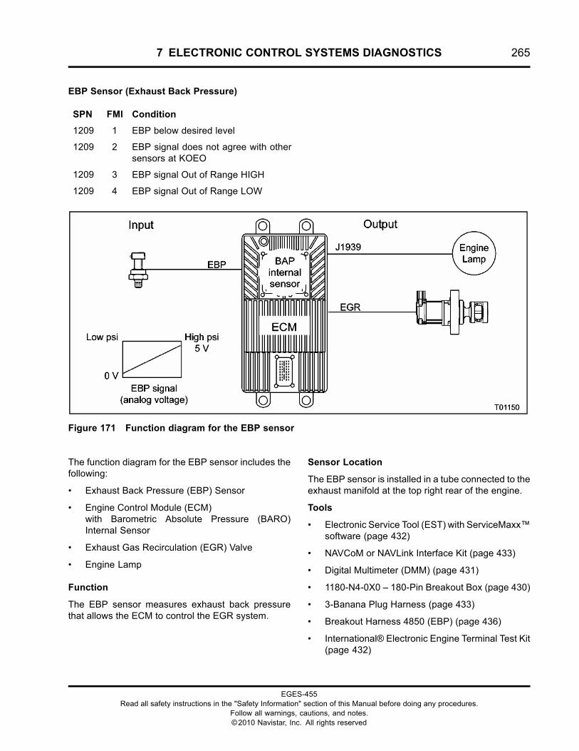
7 ELECTRONIC CONTROL SYSTEMS DIAGNOSTICS 265
EBP Sensor (Exhaust Back Pressure)
SPN FMI Condition
1209 1 EBP below desired level
1209 2 EBP signal does not agree with othersensors at KOEO
1209 3 EBP signal Out of Range HIGH
1209 4 EBP signal Out of Range LOW
Figure 171 Function diagram for the EBP sensor
The function diagram for the EBP sensor includes thefollowing:
• Exhaust Back Pressure (EBP) Sensor
• Engine Control Module (ECM)with Barometric Absolute Pressure (BARO)Internal Sensor
• Exhaust Gas Recirculation (EGR) Valve
• Engine Lamp
Function
The EBP sensor measures exhaust back pressurethat allows the ECM to control the EGR system.
Sensor Location
The EBP sensor is installed in a tube connected to theexhaust manifold at the top right rear of the engine.
Tools
• Electronic Service Tool (EST) with ServiceMaxx™software (page 432)
• NAVCoM or NAVLink Interface Kit (page 433)
• Digital Multimeter (DMM) (page 431)
• 1180-N4-0X0 – 180-Pin Breakout Box (page 430)
• 3-Banana Plug Harness (page 433)
• Breakout Harness 4850 (EBP) (page 436)
• International® Electronic Engine Terminal Test Kit(page 432)
EGES-455Read all safety instructions in the "Safety Information" section of this Manual before doing any procedures.
Follow all warnings, cautions, and notes.©2010 Navistar, Inc. All rights reserved
266 7 ELECTRONIC CONTROL SYSTEMS DIAGNOSTICS
EBP Sensor End Diagnostics
SPN FMI Condition Possible Causes
1209 1 EBP below desired level • Biased EBP sensor or circuit
• Plugged EBP sensor tube
• Failed Turbocharger
1209 2 EBP signal does not agree with othersensors at KOEO
• Biased EBP sensor or circuit
1209 3 EBP signal Out of Range HIGH • EBP signal circuit OPEN or short to PWR
• SIG GND circuit OPEN
• Failed EBP sensor
1209 4 EBP signal Out of Range LOW • EBP signal circuit short to GND
• VREF circuit OPEN
• Failed EBP sensor
Figure 172 EBP circuit diagram
SPN 1209 FMI 2 - EBP signal does not agree with other sensors at KOEO
Check for Biased sensor or circuit
1. Turn switch ON, engine OFF
2. Using ServiceMaxx™ software, open the Continuous Monitor session.
3. Verify S_EBP Volts are within specification. See “APPENDIX A: PERFORMANCESPECIFICATIONS” in this manual.
• If voltage is not within specification, check circuitry for poor continuity. If circuits are okay,replace EBP sensor.
EGES-455Read all safety instructions in the "Safety Information" section of this Manual before doing any procedures.
Follow all warnings, cautions, and notes.©2010 Navistar, Inc. All rights reserved
7 ELECTRONIC CONTROL SYSTEMS DIAGNOSTICS 267
WARNING: To prevent personal injury ordeath, stay clear of rotating parts (belts and fan)and hot engine surfaces.
1. Using EST with ServiceMaxx™ software, openthe Continuous Monitor session.
2. Monitor sensor voltage. Verify an active DTC forthe sensor.
• If code is inactive, monitor the signalwhile wiggling the connector and all wiresat suspected location. If the circuit isinterrupted, the signal will spike and theDTC will go active.
• If code is active, proceed to the next step.
3. Disconnect engine harness from sensor.
NOTE: Inspect connectors for damaged pins,corrosion, or loose pins. Repair if necessary.
4. Connect breakout harness to engine harness.Leave sensor disconnected.
Sensor Circuit Check
Connect Breakout Harness 4850 to engine harness. Leave sensor disconnected. Turn ignition switchto ON. Use EST to verify correct DTC goes active when corresponding fault is induced. Use DMM tomeasure circuits.
Test Point Spec Comment – < Less than, > Greater than
EST – Check DTC SPN 1209FMI 4
If SPN 1209 FMI 3 is active, check EBP signal for shortto PWR.
DMM – Measure volts
2 to GND
5 V ± 0.5 V If > 5.5 V, check VREF for short to PWR.
If < 4.5 V, check VREF for OPEN or short to GND. Go toHarness Resistance Check.
EST – Check DTC
Short breakout harness across 2and 3
SPN 1209FMI 3
If SPN 1209 FMI 4 is active, check EBP signal for OPENor short to GND. Go to Harness Resistance Check.
DMM – Measure Volts
1 to B+
B+ If < B+, check SIG GND for OPEN. Go to HarnessResistance Check.
If checks are within specification, connect sensor and clear DTCs. If active code remains, replace sensor.
EGES-455Read all safety instructions in the "Safety Information" section of this Manual before doing any procedures.
Follow all warnings, cautions, and notes.©2010 Navistar, Inc. All rights reserved
268 7 ELECTRONIC CONTROL SYSTEMS DIAGNOSTICS
EBP Pin-point Diagnostics
Connector Voltage Check
Connect Breakout Harness 4850. Leave sensor disconnected. Turn ignition switch to ON. Use DMM tomeasure voltage.
Test Point Spec Comment – < Less than, > Greater than
1 to B+ B+ If < B+, check for short to PWR.
2 to GND 5 V ± 0.5 V If > 5.5 V, check VREF for short to PWR.
If < 4.5 V, check VREF for OPEN or short to GND. Go to HarnessResistance Check.
3 to B+ B+ If < B+, check for short to PWR.
Harness Resistance Check
Turn ignition switch to OFF. Disconnect ECM. Leave sensor disconnected. Connect 180–Pin Breakout Boxand Breakout Harness 4850. Use DMM to measure resistance.
Test Point Spec Comment – < Less than, > Greater than
1 to E-28 < 5 Ω If > 5 Ω, check SIG GND circuit for OPEN.
2 to E-35 < 5 Ω If > 5 Ω, check VREF circuit for OPEN.
3 to E-20 < 5 Ω If > 5 Ω, check EBP signal circuit for OPEN.
EBP Circuit Operation
The EBP sensor is a variable capacitance sensorsupplied with a 5 V reference voltage at Pin 2 fromECM Pin E-35. The sensor is grounded at Pin 1 fromECM Pin E-28. The sensor returns a variable voltagesignal from Pin 3 to ECM Pin E-20.
Fault Detection / Management
The ECMmonitors the BARO sensor as a baseline forzeroing the MAP and EBP signals.
The ECM continuously monitors the control system.If the sensor signal is higher or lower than expected,the ECM disregards the sensor signal and uses acalibrated default value. The ECM will set a DTC, turnon the warning lamp, and run the engine in a defaultrange.
EGES-455Read all safety instructions in the "Safety Information" section of this Manual before doing any procedures.
Follow all warnings, cautions, and notes.©2010 Navistar, Inc. All rights reserved
7 ELECTRONIC CONTROL SYSTEMS DIAGNOSTICS 269
EBPV (Exhaust Back Pressure Valve)
SPN FMI Condition
5543 3 EBPC short to PWR
5543 4 EBPC short to GND
Figure 173 Function diagram for the EBPV
The function diagram for the EBPV includes thefollowing:
• Engine Control Module (ECM)with Barometric Absolute Pressure (BARO)Internal Sensor
• Exhaust Back Pressure Valve (EBPV)
• Intake Manifold Pressure (IMP) Sensor
Function
The ECM commands the EBPV to control the ExhaustBrake.
Location
The EBPV is installed in the exhaust pipe.
Tools
• Electronic Service Tool (EST) with ServiceMaxx™software (page 432)
• NAVCoM or NAVLink Interface Kit (page 433)
• Digital Multimeter (DMM) (page 431)
• International® Electronic Engine Terminal Test Kit(page 432)
EGES-455Read all safety instructions in the "Safety Information" section of this Manual before doing any procedures.
Follow all warnings, cautions, and notes.©2010 Navistar, Inc. All rights reserved
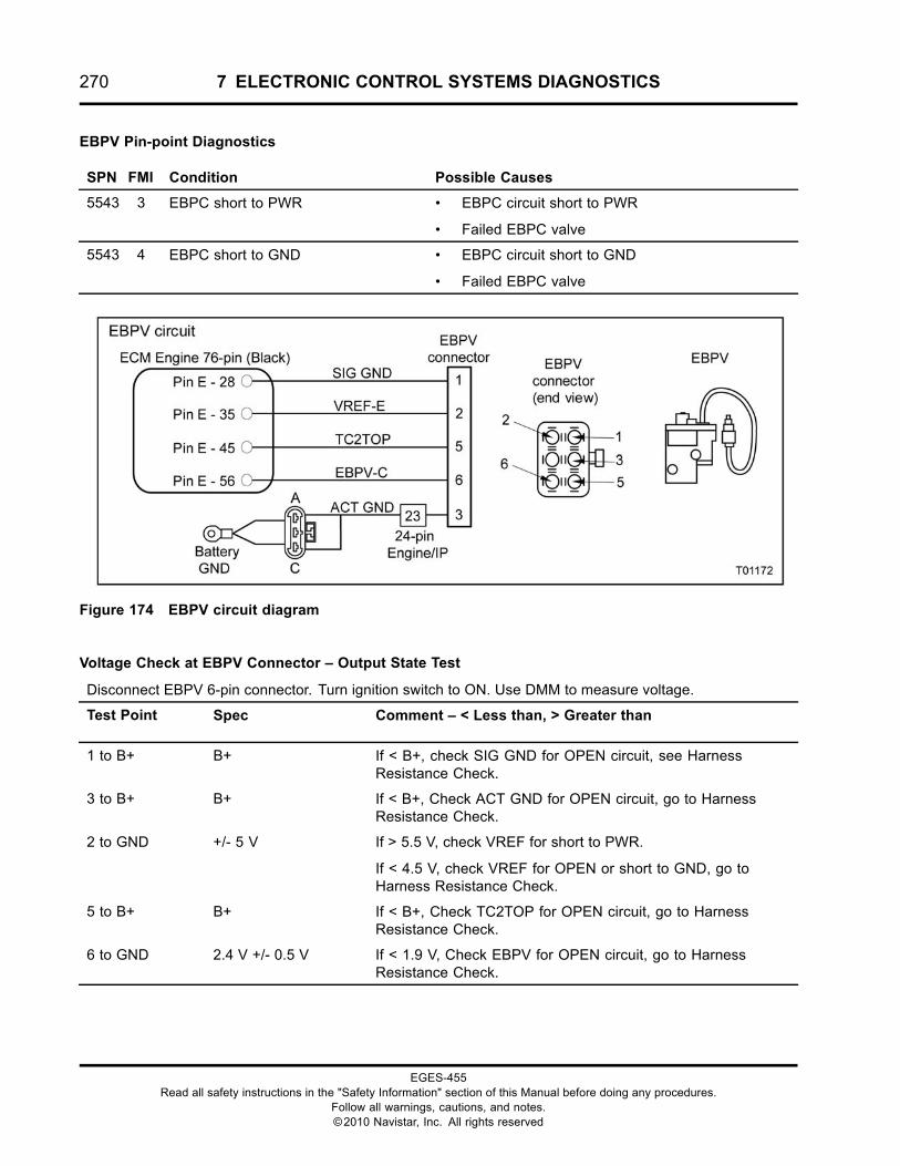
270 7 ELECTRONIC CONTROL SYSTEMS DIAGNOSTICS
EBPV Pin-point Diagnostics
SPN FMI Condition Possible Causes
5543 3 EBPC short to PWR • EBPC circuit short to PWR
• Failed EBPC valve
5543 4 EBPC short to GND • EBPC circuit short to GND
• Failed EBPC valve
Figure 174 EBPV circuit diagram
Voltage Check at EBPV Connector – Output State Test
Disconnect EBPV 6-pin connector. Turn ignition switch to ON. Use DMM to measure voltage.
Test Point Spec Comment – < Less than, > Greater than
1 to B+ B+ If < B+, check SIG GND for OPEN circuit, see HarnessResistance Check.
3 to B+ B+ If < B+, Check ACT GND for OPEN circuit, go to HarnessResistance Check.
2 to GND +/- 5 V If > 5.5 V, check VREF for short to PWR.
If < 4.5 V, check VREF for OPEN or short to GND, go toHarness Resistance Check.
5 to B+ B+ If < B+, Check TC2TOP for OPEN circuit, go to HarnessResistance Check.
6 to GND 2.4 V +/- 0.5 V If < 1.9 V, Check EBPV for OPEN circuit, go to HarnessResistance Check.
EGES-455Read all safety instructions in the "Safety Information" section of this Manual before doing any procedures.
Follow all warnings, cautions, and notes.©2010 Navistar, Inc. All rights reserved
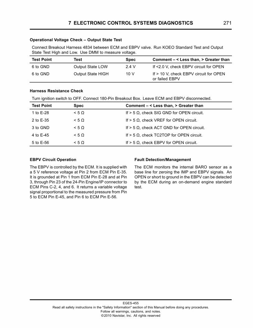
7 ELECTRONIC CONTROL SYSTEMS DIAGNOSTICS 271
Operational Voltage Check – Output State Test
Connect Breakout Harness 4834 between ECM and EBPV valve. Run KOEO Standard Test and OutputState Test High and Low. Use DMM to measure voltage.
Test Point Test Spec Comment – < Less than, > Greater than
6 to GND Output State LOW 2.4 V If <2.0 V, check EBPV circuit for OPEN
6 to GND Output State HIGH 10 V If > 10 V, check EBPV circuit for OPENor failed EBPV
Harness Resistance Check
Turn ignition switch to OFF. Connect 180-Pin Breakout Box. Leave ECM and EBPV disconnected.
Test Point Spec Comment – < Less than, > Greater than
1 to E-28
2 to E-35
3 to GND
4 to E-45
5 to E-56
< 5 Ω
< 5 Ω
< 5 Ω
< 5 Ω
< 5 Ω
If > 5 Ω, check SIG GND for OPEN circuit.
If > 5 Ω, check VREF for OPEN circuit.
If > 5 Ω, check ACT GND for OPEN circuit.
If > 5 Ω, check TC2TOP for OPEN circuit.
If > 5 Ω, check EBPV for OPEN circuit.
EBPV Circuit Operation
The EBPV is controlled by the ECM. It is supplied witha 5 V reference voltage at Pin 2 from ECM Pin E-35.It is grounded at Pin 1 from ECM Pin E-28 and at Pin3, through Pin 23 of the 24-Pin Engine/IP connector toECM Pins C-2, 4, and 6. It returns a variable voltagesignal proportional to the measured pressure from Pin5 to ECM Pin E-45, and Pin 6 to ECM Pin E-56.
Fault Detection/Management
The ECM monitors the internal BARO sensor as abase line for zeroing the IMP and EBPV signals. AnOPEN or short to ground in the EBPV can be detectedby the ECM during an on-demand engine standardtest.
EGES-455Read all safety instructions in the "Safety Information" section of this Manual before doing any procedures.
Follow all warnings, cautions, and notes.©2010 Navistar, Inc. All rights reserved
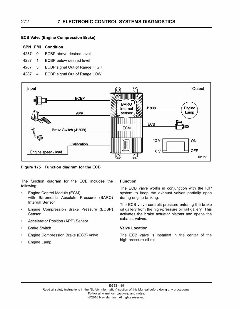
272 7 ELECTRONIC CONTROL SYSTEMS DIAGNOSTICS
ECB Valve (Engine Compression Brake)
SPN FMI Condition
4287 0 ECBP above desired level
4287 1 ECBP below desired level
4287 3 ECBP signal Out of Range HIGH
4287 4 ECBP signal Out of Range LOW
Figure 175 Function diagram for the ECB
The function diagram for the ECB includes thefollowing:
• Engine Control Module (ECM)with Barometric Absolute Pressure (BARO)Internal Sensor
• Engine Compression Brake Pressure (ECBP)Sensor
• Accelerator Position (APP) Sensor
• Brake Switch
• Engine Compression Brake (ECB) Valve
• Engine Lamp
Function
The ECB valve works in conjunction with the ICPsystem to keep the exhaust valves partially openduring engine braking.
The ECB valve controls pressure entering the brakeoil gallery from the high-pressure oil rail gallery. Thisactivates the brake actuator pistons and opens theexhaust valves.
Valve Location
The ECB valve is installed in the center of thehigh-pressure oil rail.
EGES-455Read all safety instructions in the "Safety Information" section of this Manual before doing any procedures.
Follow all warnings, cautions, and notes.©2010 Navistar, Inc. All rights reserved
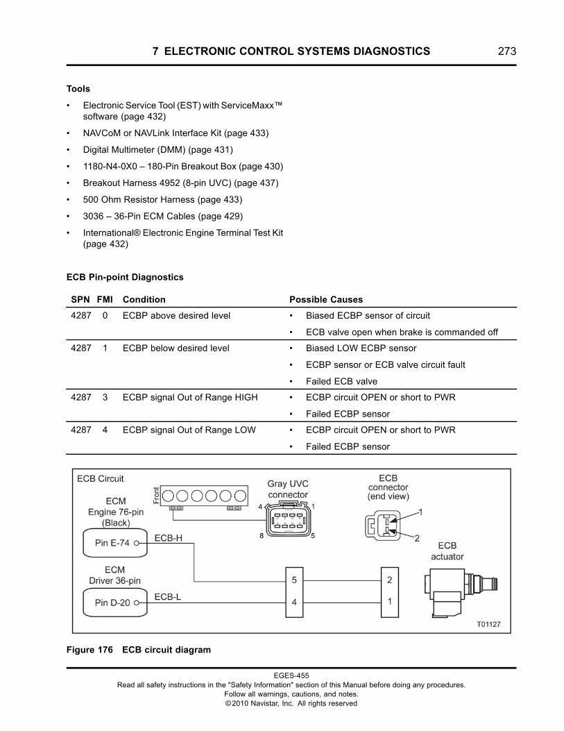
7 ELECTRONIC CONTROL SYSTEMS DIAGNOSTICS 273
Tools
• Electronic Service Tool (EST) with ServiceMaxx™software (page 432)
• NAVCoM or NAVLink Interface Kit (page 433)
• Digital Multimeter (DMM) (page 431)
• 1180-N4-0X0 – 180-Pin Breakout Box (page 430)
• Breakout Harness 4952 (8-pin UVC) (page 437)
• 500 Ohm Resistor Harness (page 433)
• 3036 – 36-Pin ECM Cables (page 429)
• International® Electronic Engine Terminal Test Kit(page 432)
ECB Pin-point Diagnostics
SPN FMI Condition Possible Causes
4287 0 ECBP above desired level • Biased ECBP sensor of circuit
• ECB valve open when brake is commanded off
4287 1 ECBP below desired level • Biased LOW ECBP sensor
• ECBP sensor or ECB valve circuit fault
• Failed ECB valve
4287 3 ECBP signal Out of Range HIGH • ECBP circuit OPEN or short to PWR
• Failed ECBP sensor
4287 4 ECBP signal Out of Range LOW • ECBP circuit OPEN or short to PWR
• Failed ECBP sensor
Figure 176 ECB circuit diagram
EGES-455Read all safety instructions in the "Safety Information" section of this Manual before doing any procedures.
Follow all warnings, cautions, and notes.©2010 Navistar, Inc. All rights reserved
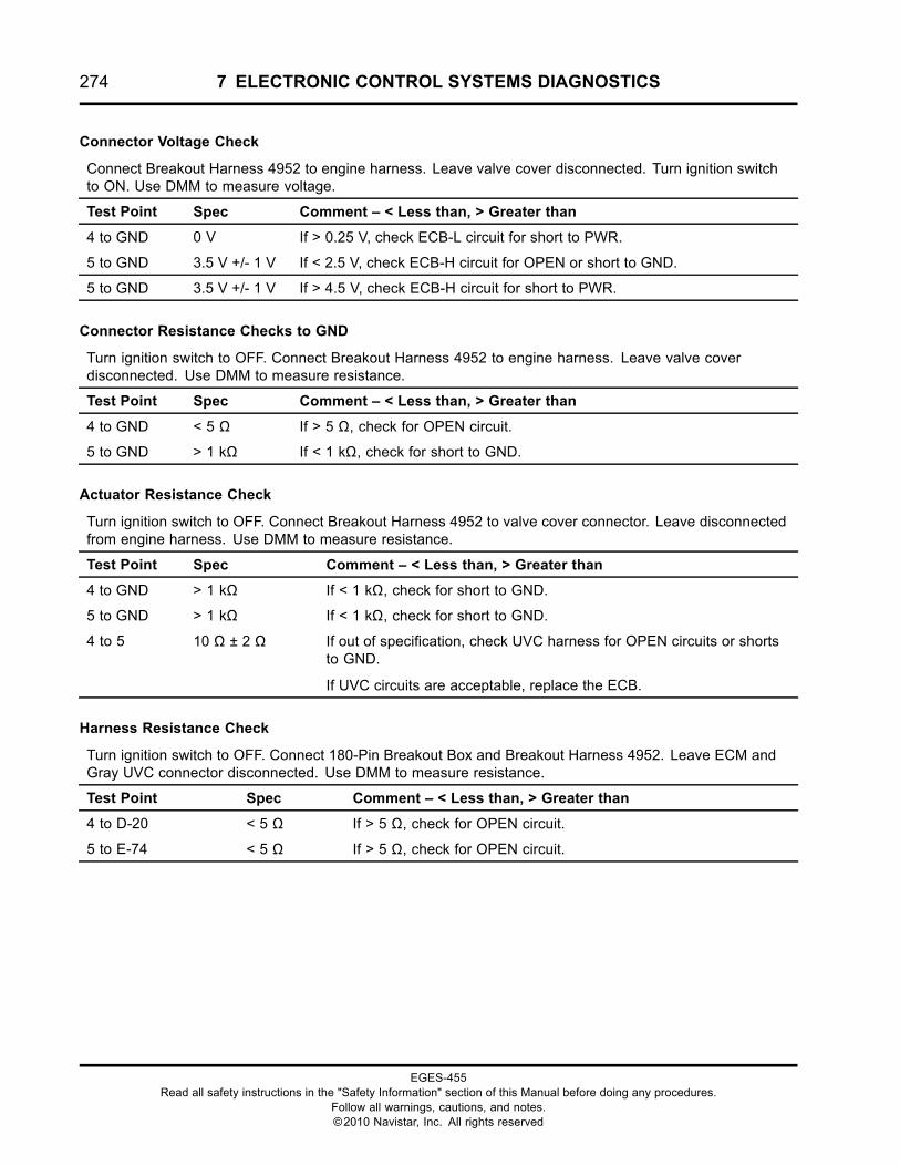
274 7 ELECTRONIC CONTROL SYSTEMS DIAGNOSTICS
Connector Voltage Check
Connect Breakout Harness 4952 to engine harness. Leave valve cover disconnected. Turn ignition switchto ON. Use DMM to measure voltage.
Test Point Spec Comment – < Less than, > Greater than
4 to GND 0 V If > 0.25 V, check ECB-L circuit for short to PWR.
5 to GND 3.5 V +/- 1 V If < 2.5 V, check ECB-H circuit for OPEN or short to GND.
5 to GND 3.5 V +/- 1 V If > 4.5 V, check ECB-H circuit for short to PWR.
Connector Resistance Checks to GND
Turn ignition switch to OFF. Connect Breakout Harness 4952 to engine harness. Leave valve coverdisconnected. Use DMM to measure resistance.
Test Point Spec Comment – < Less than, > Greater than
4 to GND < 5 Ω If > 5 Ω, check for OPEN circuit.
5 to GND > 1 kΩ If < 1 kΩ, check for short to GND.
Actuator Resistance Check
Turn ignition switch to OFF. Connect Breakout Harness 4952 to valve cover connector. Leave disconnectedfrom engine harness. Use DMM to measure resistance.
Test Point Spec Comment – < Less than, > Greater than
4 to GND > 1 kΩ If < 1 kΩ, check for short to GND.
5 to GND > 1 kΩ If < 1 kΩ, check for short to GND.
4 to 5 10 Ω ± 2 Ω If out of specification, check UVC harness for OPEN circuits or shortsto GND.
If UVC circuits are acceptable, replace the ECB.
Harness Resistance Check
Turn ignition switch to OFF. Connect 180-Pin Breakout Box and Breakout Harness 4952. Leave ECM andGray UVC connector disconnected. Use DMM to measure resistance.
Test Point Spec Comment – < Less than, > Greater than
4 to D-20 < 5 Ω If > 5 Ω, check for OPEN circuit.
5 to E-74 < 5 Ω If > 5 Ω, check for OPEN circuit.
EGES-455Read all safety instructions in the "Safety Information" section of this Manual before doing any procedures.
Follow all warnings, cautions, and notes.©2010 Navistar, Inc. All rights reserved
7 ELECTRONIC CONTROL SYSTEMS DIAGNOSTICS 275
ECB Circuit Operation
The ECB consists of a solenoid / valve assembly andis installed in the high-pressure rail between the ICPoil gallery and the brake oil gallery.
The ECB valve is supplied with ground at Pin 1,through Pin 4 of gray UVC connector, from ECMPin D-20. The ECM controls the engine brake bysupplying 12 volts at sensor connector Pin 2, throughPin 5 of gray UVC connector, from ECM Pin E-74.
When the engine brake is activated, the ECM providespower to activate the ECB and allows oil from theinjector oil gallery to flow into the brake oil gallery.High-pressure oil activates the brake actuator pistonsto open the exhaust valves.
The ECM deactivates the engine brake by shutting offpower to the ECB. Residual brake gallery pressureinitially bleeds from the actuator bore. When brakegallery pressure reaches 6.9 MPa (1000 psi), thebrake pressure relief valve opens and oil drains backto the sump.
Fault Detection / Management
When the engine is running, the ECM comparesengine brake control pressure to injection controlpressure and ECBP desired. When the brake isactivated, brake control pressure equals injectioncontrol pressure.
If the brake control pressure does not match injectioncontrol pressure, the ECM disables the engine brake,a DTC is set, and the engine lamp is illuminated.
When the engine brake is not active and the ECMdetects an undesired value, the ECM will set a DTCand the engine lamp will be illuminated.
The Output Circuit Check (OCC) can detect open orshorted circuits to the ECB during KOEO StandardTest.
A bias ECBP sensor can also cause a fault. The brakeshutoff valve and the ECBP sensor circuit should bothbe diagnosed.
EGES-455Read all safety instructions in the "Safety Information" section of this Manual before doing any procedures.
Follow all warnings, cautions, and notes.©2010 Navistar, Inc. All rights reserved
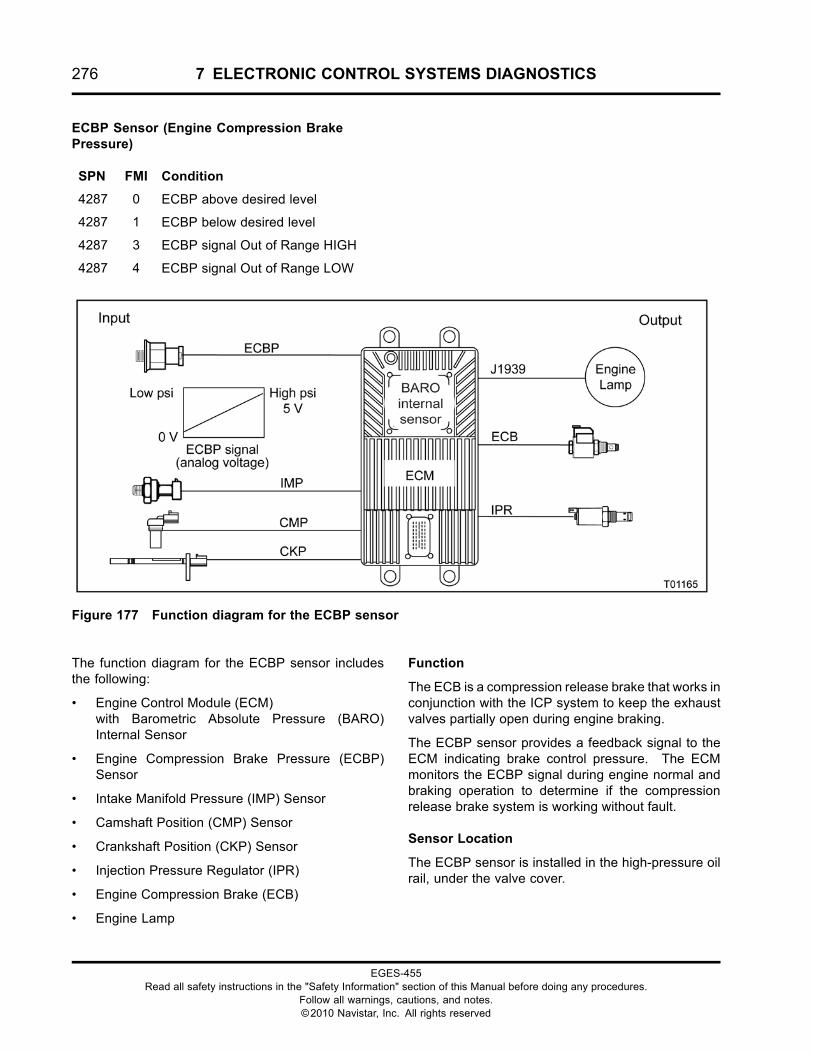
276 7 ELECTRONIC CONTROL SYSTEMS DIAGNOSTICS
ECBP Sensor (Engine Compression BrakePressure)
SPN FMI Condition
4287 0 ECBP above desired level
4287 1 ECBP below desired level
4287 3 ECBP signal Out of Range HIGH
4287 4 ECBP signal Out of Range LOW
Figure 177 Function diagram for the ECBP sensor
The function diagram for the ECBP sensor includesthe following:
• Engine Control Module (ECM)with Barometric Absolute Pressure (BARO)Internal Sensor
• Engine Compression Brake Pressure (ECBP)Sensor
• Intake Manifold Pressure (IMP) Sensor
• Camshaft Position (CMP) Sensor
• Crankshaft Position (CKP) Sensor
• Injection Pressure Regulator (IPR)
• Engine Compression Brake (ECB)
• Engine Lamp
Function
The ECB is a compression release brake that works inconjunction with the ICP system to keep the exhaustvalves partially open during engine braking.
The ECBP sensor provides a feedback signal to theECM indicating brake control pressure. The ECMmonitors the ECBP signal during engine normal andbraking operation to determine if the compressionrelease brake system is working without fault.
Sensor Location
The ECBP sensor is installed in the high-pressure oilrail, under the valve cover.
EGES-455Read all safety instructions in the "Safety Information" section of this Manual before doing any procedures.
Follow all warnings, cautions, and notes.©2010 Navistar, Inc. All rights reserved
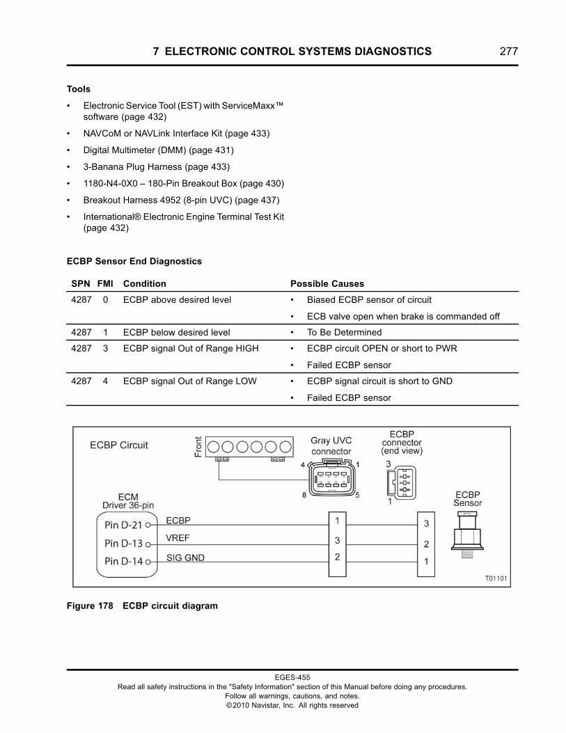
7 ELECTRONIC CONTROL SYSTEMS DIAGNOSTICS 277
Tools
• Electronic Service Tool (EST) with ServiceMaxx™software (page 432)
• NAVCoM or NAVLink Interface Kit (page 433)
• Digital Multimeter (DMM) (page 431)
• 3-Banana Plug Harness (page 433)
• 1180-N4-0X0 – 180-Pin Breakout Box (page 430)
• Breakout Harness 4952 (8-pin UVC) (page 437)
• International® Electronic Engine Terminal Test Kit(page 432)
ECBP Sensor End Diagnostics
SPN FMI Condition Possible Causes
4287 0 ECBP above desired level • Biased ECBP sensor of circuit
• ECB valve open when brake is commanded off
4287 1 ECBP below desired level • To Be Determined
4287 3 ECBP signal Out of Range HIGH • ECBP circuit OPEN or short to PWR
• Failed ECBP sensor
4287 4 ECBP signal Out of Range LOW • ECBP signal circuit is short to GND
• Failed ECBP sensor
Figure 178 ECBP circuit diagram
EGES-455Read all safety instructions in the "Safety Information" section of this Manual before doing any procedures.
Follow all warnings, cautions, and notes.©2010 Navistar, Inc. All rights reserved
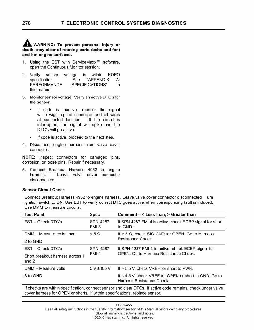
278 7 ELECTRONIC CONTROL SYSTEMS DIAGNOSTICS
WARNING: To prevent personal injury ordeath, stay clear of rotating parts (belts and fan)and hot engine surfaces.
1. Using the EST with ServiceMaxx™ software,open the Continuous Monitor session.
2. Verify sensor voltage is within KOEOspecification. See “APPENDIX A:PERFORMANCE SPECIFICATIONS” inthis manual.
3. Monitor sensor voltage. Verify an active DTC’s forthe sensor.
• If code is inactive, monitor the signalwhile wiggling the connector and all wiresat suspected location. If the circuit isinterrupted, the signal will spike and theDTC’s will go active.
• If code is active, proceed to the next step.
4. Disconnect engine harness from valve coverconnector.
NOTE: Inspect connectors for damaged pins,corrosion, or loose pins. Repair if necessary.
5. Connect Breakout Harness 4952 to engineharness. Leave valve cover connectordisconnected.
Sensor Circuit Check
Connect Breakout Harness 4952 to engine harness. Leave valve cover connector disconnected. Turnignition switch to ON. Use EST to verify correct DTC goes active when corresponding fault is induced.Use DMM to measure circuits.
Test Point Spec Comment – < Less than, > Greater than
EST – Check DTC’s SPN 4287FMI 3
If SPN 4287 FMI 4 is active, check ECBP signal for shortto GND.
DMM – Measure resistance
2 to GND
< 5 Ω If > 5 Ω, check SIG GND for OPEN. Go to HarnessResistance Check.
EST – Check DTC’s
Short breakout harness across 1and 2
SPN 4287FMI 4
If SPN 4287 FMI 3 is active, check ECBP signal forOPEN. Go to Harness Resistance Check.
DMM – Measure volts
3 to GND
5 V ± 0.5 V If > 5.5 V, check VREF for short to PWR.
If < 4.5 V, check VREF for OPEN or short to GND. Go toHarness Resistance Check.
If checks are within specification, connect sensor and clear DTCs. If active code remains, check under valvecover harness for OPEN or shorts. If within specifications, replace sensor.
EGES-455Read all safety instructions in the "Safety Information" section of this Manual before doing any procedures.
Follow all warnings, cautions, and notes.©2010 Navistar, Inc. All rights reserved
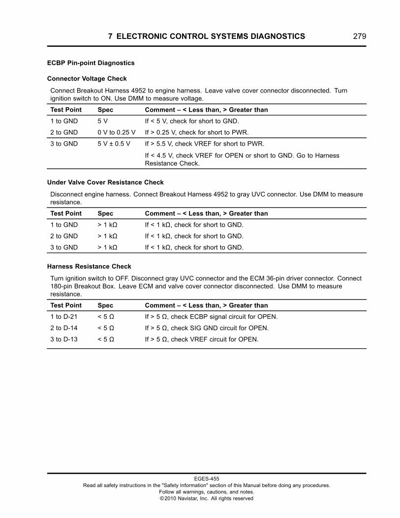
7 ELECTRONIC CONTROL SYSTEMS DIAGNOSTICS 279
ECBP Pin-point Diagnostics
Connector Voltage Check
Connect Breakout Harness 4952 to engine harness. Leave valve cover connector disconnected. Turnignition switch to ON. Use DMM to measure voltage.
Test Point Spec Comment – < Less than, > Greater than
1 to GND 5 V If < 5 V, check for short to GND.
2 to GND 0 V to 0.25 V If > 0.25 V, check for short to PWR.
3 to GND 5 V ± 0.5 V If > 5.5 V, check VREF for short to PWR.
If < 4.5 V, check VREF for OPEN or short to GND. Go to HarnessResistance Check.
Under Valve Cover Resistance Check
Disconnect engine harness. Connect Breakout Harness 4952 to gray UVC connector. Use DMM to measureresistance.
Test Point Spec Comment – < Less than, > Greater than
1 to GND > 1 kΩ If < 1 kΩ, check for short to GND.
2 to GND > 1 kΩ If < 1 kΩ, check for short to GND.
3 to GND > 1 kΩ If < 1 kΩ, check for short to GND.
Harness Resistance Check
Turn ignition switch to OFF. Disconnect gray UVC connector and the ECM 36-pin driver connector. Connect180-pin Breakout Box. Leave ECM and valve cover connector disconnected. Use DMM to measureresistance.
Test Point Spec Comment – < Less than, > Greater than
1 to D-21 < 5 Ω If > 5 Ω, check ECBP signal circuit for OPEN.
2 to D-14 < 5 Ω If > 5 Ω, check SIG GND circuit for OPEN.
3 to D-13 < 5 Ω If > 5 Ω, check VREF circuit for OPEN.
EGES-455Read all safety instructions in the "Safety Information" section of this Manual before doing any procedures.
Follow all warnings, cautions, and notes.©2010 Navistar, Inc. All rights reserved
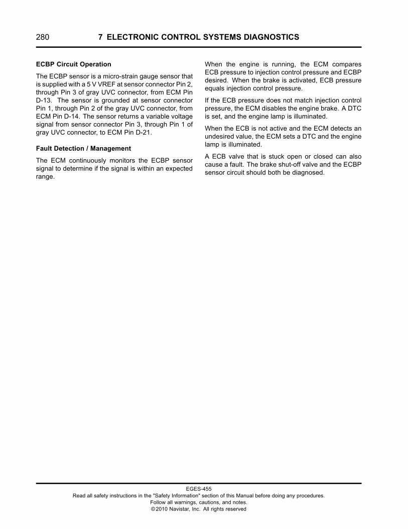
280 7 ELECTRONIC CONTROL SYSTEMS DIAGNOSTICS
ECBP Circuit Operation
The ECBP sensor is a micro-strain gauge sensor thatis supplied with a 5 V VREF at sensor connector Pin 2,through Pin 3 of gray UVC connector, from ECM PinD-13. The sensor is grounded at sensor connectorPin 1, through Pin 2 of the gray UVC connector, fromECM Pin D-14. The sensor returns a variable voltagesignal from sensor connector Pin 3, through Pin 1 ofgray UVC connector, to ECM Pin D-21.
Fault Detection / Management
The ECM continuously monitors the ECBP sensorsignal to determine if the signal is within an expectedrange.
When the engine is running, the ECM comparesECB pressure to injection control pressure and ECBPdesired. When the brake is activated, ECB pressureequals injection control pressure.
If the ECB pressure does not match injection controlpressure, the ECM disables the engine brake. A DTCis set, and the engine lamp is illuminated.
When the ECB is not active and the ECM detects anundesired value, the ECM sets a DTC and the enginelamp is illuminated.
A ECB valve that is stuck open or closed can alsocause a fault. The brake shut-off valve and the ECBPsensor circuit should both be diagnosed.
EGES-455Read all safety instructions in the "Safety Information" section of this Manual before doing any procedures.
Follow all warnings, cautions, and notes.©2010 Navistar, Inc. All rights reserved
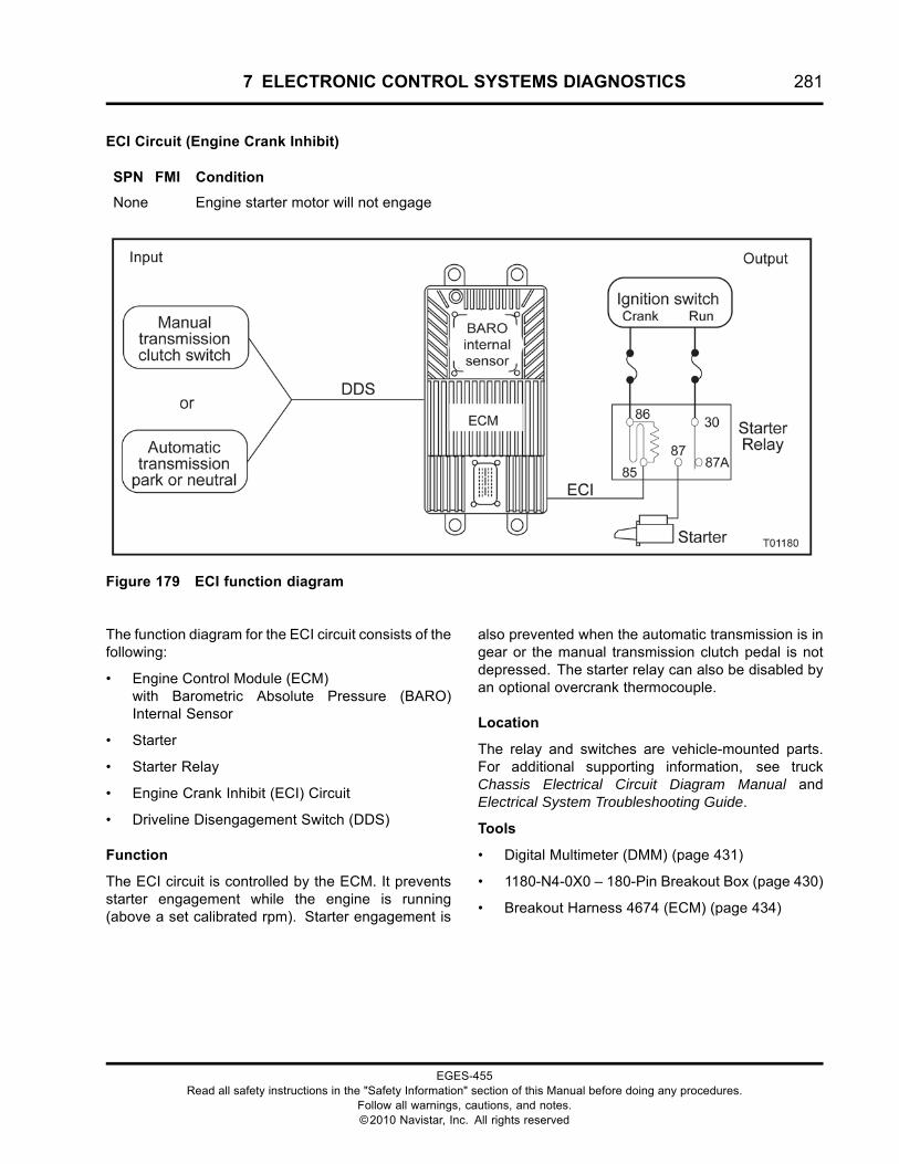
7 ELECTRONIC CONTROL SYSTEMS DIAGNOSTICS 281
ECI Circuit (Engine Crank Inhibit)
SPN FMI Condition
None Engine starter motor will not engage
Figure 179 ECI function diagram
The function diagram for the ECI circuit consists of thefollowing:
• Engine Control Module (ECM)with Barometric Absolute Pressure (BARO)Internal Sensor
• Starter
• Starter Relay
• Engine Crank Inhibit (ECI) Circuit
• Driveline Disengagement Switch (DDS)
Function
The ECI circuit is controlled by the ECM. It preventsstarter engagement while the engine is running(above a set calibrated rpm). Starter engagement is
also prevented when the automatic transmission is ingear or the manual transmission clutch pedal is notdepressed. The starter relay can also be disabled byan optional overcrank thermocouple.
Location
The relay and switches are vehicle-mounted parts.For additional supporting information, see truckChassis Electrical Circuit Diagram Manual andElectrical System Troubleshooting Guide.
Tools
• Digital Multimeter (DMM) (page 431)
• 1180-N4-0X0 – 180-Pin Breakout Box (page 430)
• Breakout Harness 4674 (ECM) (page 434)
EGES-455Read all safety instructions in the "Safety Information" section of this Manual before doing any procedures.
Follow all warnings, cautions, and notes.©2010 Navistar, Inc. All rights reserved
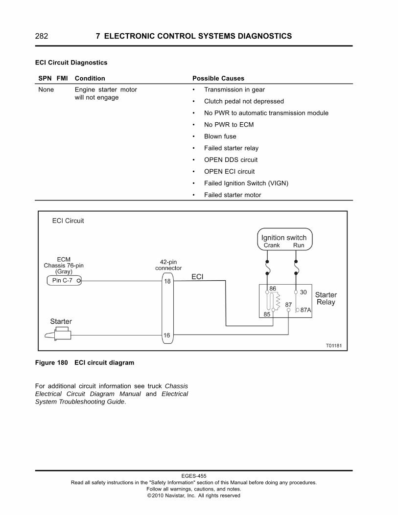
282 7 ELECTRONIC CONTROL SYSTEMS DIAGNOSTICS
ECI Circuit Diagnostics
SPN FMI Condition Possible Causes
None Engine starter motorwill not engage
• Transmission in gear
• Clutch pedal not depressed
• No PWR to automatic transmission module
• No PWR to ECM
• Blown fuse
• Failed starter relay
• OPEN DDS circuit
• OPEN ECI circuit
• Failed Ignition Switch (VIGN)
• Failed starter motor
Figure 180 ECI circuit diagram
For additional circuit information see truck ChassisElectrical Circuit Diagram Manual and ElectricalSystem Troubleshooting Guide.
EGES-455Read all safety instructions in the "Safety Information" section of this Manual before doing any procedures.
Follow all warnings, cautions, and notes.©2010 Navistar, Inc. All rights reserved
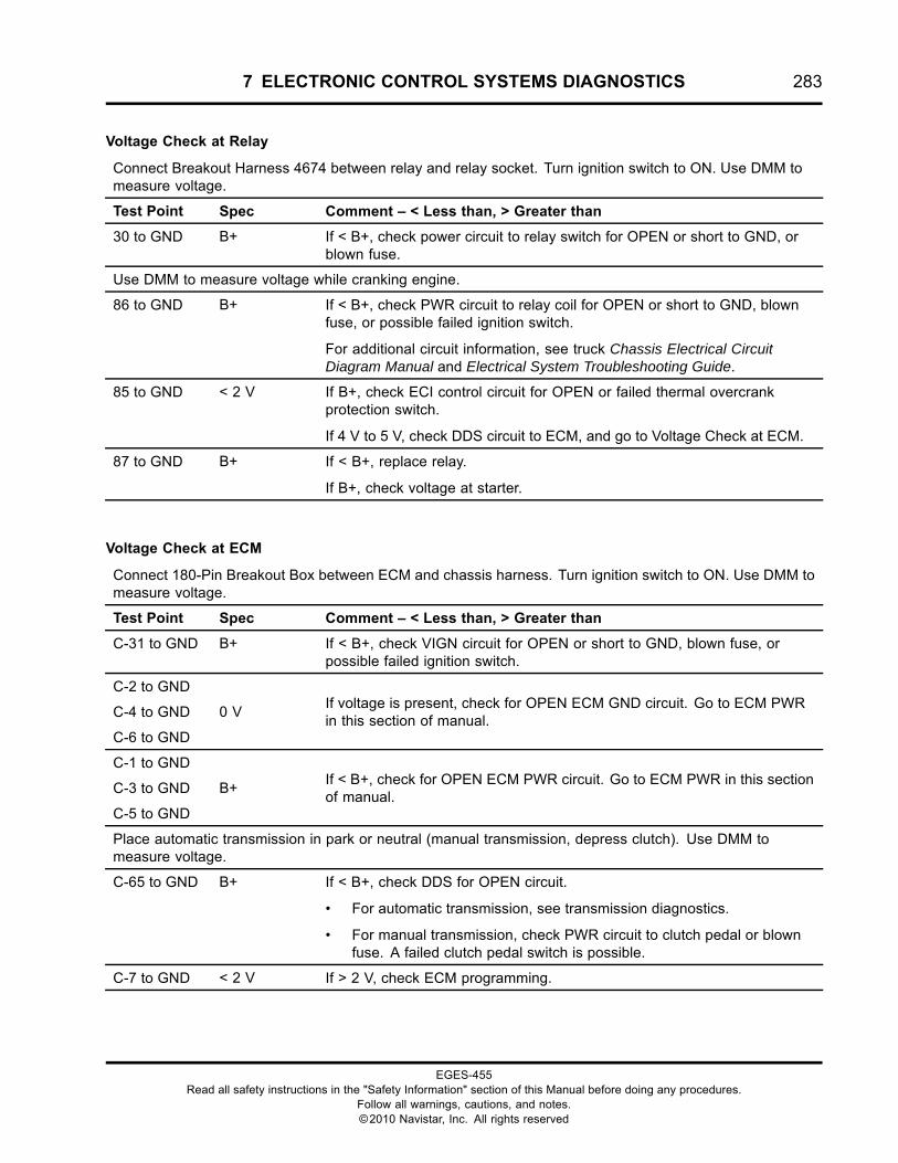
7 ELECTRONIC CONTROL SYSTEMS DIAGNOSTICS 283
Voltage Check at Relay
Connect Breakout Harness 4674 between relay and relay socket. Turn ignition switch to ON. Use DMM tomeasure voltage.
Test Point Spec Comment – < Less than, > Greater than
30 to GND B+ If < B+, check power circuit to relay switch for OPEN or short to GND, orblown fuse.
Use DMM to measure voltage while cranking engine.
86 to GND B+ If < B+, check PWR circuit to relay coil for OPEN or short to GND, blownfuse, or possible failed ignition switch.
For additional circuit information, see truck Chassis Electrical CircuitDiagram Manual and Electrical System Troubleshooting Guide.
85 to GND < 2 V If B+, check ECI control circuit for OPEN or failed thermal overcrankprotection switch.
If 4 V to 5 V, check DDS circuit to ECM, and go to Voltage Check at ECM.
87 to GND B+ If < B+, replace relay.
If B+, check voltage at starter.
Voltage Check at ECM
Connect 180-Pin Breakout Box between ECM and chassis harness. Turn ignition switch to ON. Use DMM tomeasure voltage.
Test Point Spec Comment – < Less than, > Greater than
C-31 to GND B+ If < B+, check VIGN circuit for OPEN or short to GND, blown fuse, orpossible failed ignition switch.
C-2 to GND
C-4 to GND
C-6 to GND
0 VIf voltage is present, check for OPEN ECM GND circuit. Go to ECM PWRin this section of manual.
C-1 to GND
C-3 to GND
C-5 to GND
B+If < B+, check for OPEN ECM PWR circuit. Go to ECM PWR in this sectionof manual.
Place automatic transmission in park or neutral (manual transmission, depress clutch). Use DMM tomeasure voltage.
C-65 to GND B+ If < B+, check DDS for OPEN circuit.
• For automatic transmission, see transmission diagnostics.
• For manual transmission, check PWR circuit to clutch pedal or blownfuse. A failed clutch pedal switch is possible.
C-7 to GND < 2 V If > 2 V, check ECM programming.
EGES-455Read all safety instructions in the "Safety Information" section of this Manual before doing any procedures.
Follow all warnings, cautions, and notes.©2010 Navistar, Inc. All rights reserved
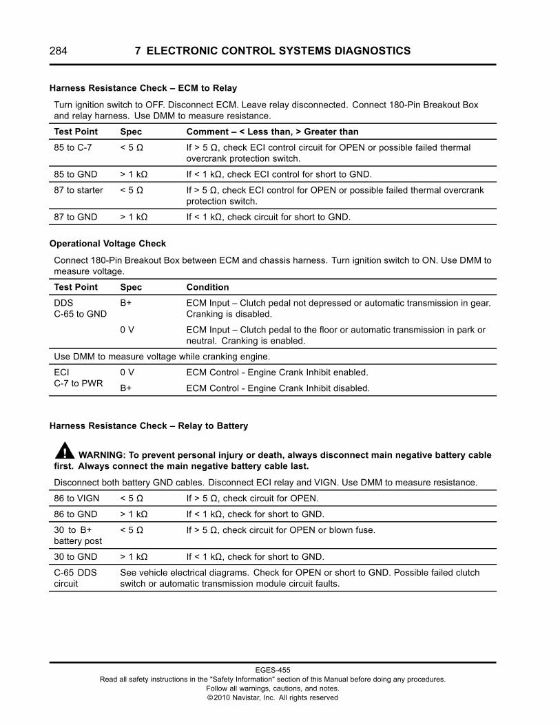
284 7 ELECTRONIC CONTROL SYSTEMS DIAGNOSTICS
Harness Resistance Check – ECM to Relay
Turn ignition switch to OFF. Disconnect ECM. Leave relay disconnected. Connect 180-Pin Breakout Boxand relay harness. Use DMM to measure resistance.
Test Point Spec Comment – < Less than, > Greater than
85 to C-7 < 5 Ω If > 5 Ω, check ECI control circuit for OPEN or possible failed thermalovercrank protection switch.
85 to GND > 1 kΩ If < 1 kΩ, check ECI control for short to GND.
87 to starter < 5 Ω If > 5 Ω, check ECI control for OPEN or possible failed thermal overcrankprotection switch.
87 to GND > 1 kΩ If < 1 kΩ, check circuit for short to GND.
Operational Voltage Check
Connect 180-Pin Breakout Box between ECM and chassis harness. Turn ignition switch to ON. Use DMM tomeasure voltage.
Test Point Spec Condition
B+ ECM Input – Clutch pedal not depressed or automatic transmission in gear.Cranking is disabled.
DDSC-65 to GND
0 V ECM Input – Clutch pedal to the floor or automatic transmission in park orneutral. Cranking is enabled.
Use DMM to measure voltage while cranking engine.
0 V ECM Control - Engine Crank Inhibit enabled.ECIC-7 to PWR B+ ECM Control - Engine Crank Inhibit disabled.
Harness Resistance Check – Relay to Battery
WARNING: To prevent personal injury or death, always disconnect main negative battery cablefirst. Always connect the main negative battery cable last.
Disconnect both battery GND cables. Disconnect ECI relay and VIGN. Use DMM to measure resistance.
86 to VIGN < 5 Ω If > 5 Ω, check circuit for OPEN.
86 to GND > 1 kΩ If < 1 kΩ, check for short to GND.
30 to B+battery post
< 5 Ω If > 5 Ω, check circuit for OPEN or blown fuse.
30 to GND > 1 kΩ If < 1 kΩ, check for short to GND.
C-65 DDScircuit
See vehicle electrical diagrams. Check for OPEN or short to GND. Possible failed clutchswitch or automatic transmission module circuit faults.
EGES-455Read all safety instructions in the "Safety Information" section of this Manual before doing any procedures.
Follow all warnings, cautions, and notes.©2010 Navistar, Inc. All rights reserved
7 ELECTRONIC CONTROL SYSTEMS DIAGNOSTICS 285
ECI Circuit Operation
The ECM controls the starting system. The clutchswitch or transmission neutral switch provides inputto the ECM. Both switches prevent the starter frombeing engaged unless the automatic transmission isin park or neutral, or the manual transmission clutchis depressed.
DDS Circuit
The ECMmonitors the DDS on Pin C-65. B+ indicatesthe drivetrain is disengaged and the engine is readyto start. Zero volts indicates the drivetrain is engagedand the engine is not ready to start. The sourceof this signal depends on the vehicle’s hardwareconfiguration. See appropriate electrical diagramswhen diagnosing this circuit.
Ignition Switch
VIGN is supplied to the starter relay coil (Pin 86) whenengine is cranked.
ECI Circuit
The ECM controls starter disable with the ECI circuit,pin C-7 to starter relay coil Pin 85. Open or B+ willdisable the relay. A 0 V (GND) will enable the relay.
Engine Control Module (ECM)
When the ECM recognizes that the engine is notrunning and the driveline is not engaged, the ECMwill ground Pin C-7. This provides a current pathfor the ECI relay to close when the Start switch isengaged or the starter button is depressed.
When the ECM recognizes that the engine is runningor the driveline is engaged, the ECM will open PinC-7. This prevents the ECI relay from closing and thestarter motor from engaging.
Starter Relay
The engine starter relay controls voltage to the startermotor. Turning the ignition switch to the start position
supplies current to energize the starter relay at Pin86. If the engine is not running and the driveline isnot engaged, ECM Pin C-7 will enable the relay bysupplying a ground to Pin 85 of the relay. When therelay is closed, current passes through the relay to thestarter solenoid.
Clutch Switch
Manual transmissions use the clutch switch to supplya signal to the ECM indicating the driveline isdisengaged. A 12 V signal on the DDS circuitindicates the clutch is disengaged. A 0 V signalindicates the clutch is engaged.
Neutral Switch
Allison LCT transmissions use the neutral positionswitch to supply power to the starter relay and a signalto the ECM that the driveline is disengaged. Vehiclesprogrammed for Allison AT/MT transmissions receivea 12 V signal on the DDS circuit indicating thetransmission is out of gear. A 0 V signal indicates thetransmission is in gear. When the transmission is ingear, no power is available to the starter relay.
WTEC MD with Auto Neutral
Allison MD World Transmission ElectronicallyControlled (WTEC) transmissions (with optionalAuto Neutral) have a crank inhibit system with anadditional relay. The relay inhibits cranking whenthe transmission is in auto neutral. Pin 6 of thetransmission module controls 12 V to Pin 86 of thestarter relay. Pin C-65 of the ECM receives 12 V fromthe WTEC auto neutral relay when the transmissionis shifted to neutral or auto neutral.
Fault Detection / Management
There are no DTC’s associated with the ECI system.
EGES-455Read all safety instructions in the "Safety Information" section of this Manual before doing any procedures.
Follow all warnings, cautions, and notes.©2010 Navistar, Inc. All rights reserved

286 7 ELECTRONIC CONTROL SYSTEMS DIAGNOSTICS
ECL Switch (Engine Coolant Level)
SPN FMI Condition
111 2 ECL In-Range circuit Fault
Figure 181 Functional diagram for the ECL switch
The functional diagram for the ECL switch includes thefollowing:
• Engine Control Module (ECM)with Barometric Absolute Pressure (BARO)Internal Sensor
• Engine Coolant Level (ECL) Switch
• J1939 Datalink
• Engine Lamp(s)
Function
The ECM monitors engine coolant level and alertsthe operator when coolant is low. The ECM can beprogrammed to shut the engine off when coolant islow.
Coolant level monitoring is a customer programmablefeature that can be programmed by the EST. The
coolant level feature is operational if programmed for3-way warning or 3-way protection.
Location
The ECL switch is installed in the vehicle plasticdeaeration tank.
Tools
• Electronic Service Tool (EST) with ServiceMaxx™software (page 432)
• NAVCoM or NAVLink Interface Kit (page 433)
• Digital Multimeter (DMM) (page 431)
• 96-Pin Breakout Box – DLC II
EGES-455Read all safety instructions in the "Safety Information" section of this Manual before doing any procedures.
Follow all warnings, cautions, and notes.©2010 Navistar, Inc. All rights reserved
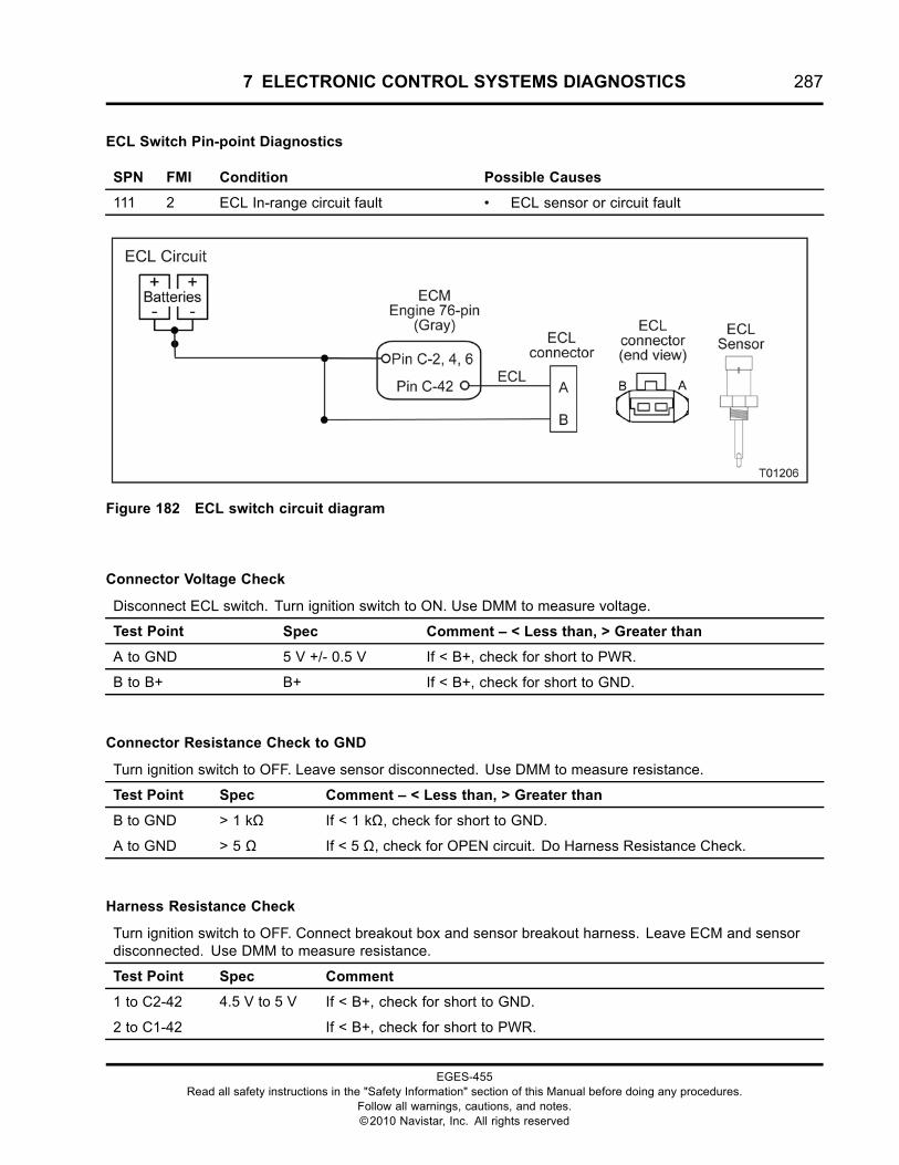
7 ELECTRONIC CONTROL SYSTEMS DIAGNOSTICS 287
ECL Switch Pin-point Diagnostics
SPN FMI Condition Possible Causes
111 2 ECL In-range circuit fault • ECL sensor or circuit fault
Figure 182 ECL switch circuit diagram
Connector Voltage Check
Disconnect ECL switch. Turn ignition switch to ON. Use DMM to measure voltage.
Test Point Spec Comment – < Less than, > Greater than
A to GND 5 V +/- 0.5 V If < B+, check for short to PWR.
B to B+ B+ If < B+, check for short to GND.
Connector Resistance Check to GND
Turn ignition switch to OFF. Leave sensor disconnected. Use DMM to measure resistance.
Test Point Spec Comment – < Less than, > Greater than
B to GND > 1 kΩ If < 1 kΩ, check for short to GND.
A to GND > 5 Ω If < 5 Ω, check for OPEN circuit. Do Harness Resistance Check.
Harness Resistance Check
Turn ignition switch to OFF. Connect breakout box and sensor breakout harness. Leave ECM and sensordisconnected. Use DMM to measure resistance.
Test Point Spec Comment
1 to C2-42 4.5 V to 5 V If < B+, check for short to GND.
2 to C1-42 If < B+, check for short to PWR.
EGES-455Read all safety instructions in the "Safety Information" section of this Manual before doing any procedures.
Follow all warnings, cautions, and notes.©2010 Navistar, Inc. All rights reserved
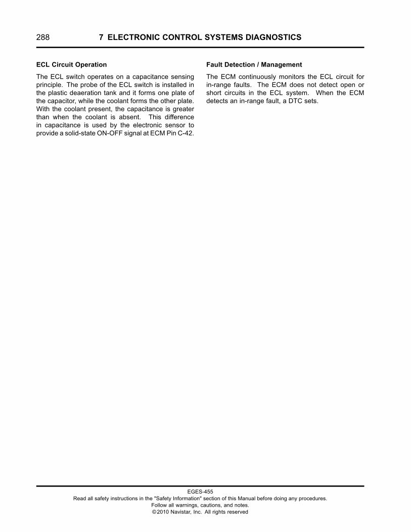
288 7 ELECTRONIC CONTROL SYSTEMS DIAGNOSTICS
ECL Circuit Operation
The ECL switch operates on a capacitance sensingprinciple. The probe of the ECL switch is installed inthe plastic deaeration tank and it forms one plate ofthe capacitor, while the coolant forms the other plate.With the coolant present, the capacitance is greaterthan when the coolant is absent. This differencein capacitance is used by the electronic sensor toprovide a solid-state ON-OFF signal at ECM Pin C-42.
Fault Detection / Management
The ECM continuously monitors the ECL circuit forin-range faults. The ECM does not detect open orshort circuits in the ECL system. When the ECMdetects an in-range fault, a DTC sets.
EGES-455Read all safety instructions in the "Safety Information" section of this Manual before doing any procedures.
Follow all warnings, cautions, and notes.©2010 Navistar, Inc. All rights reserved
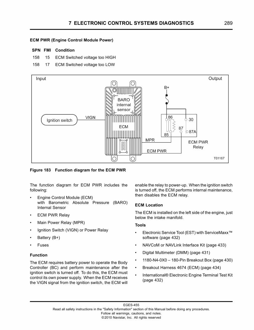
7 ELECTRONIC CONTROL SYSTEMS DIAGNOSTICS 289
ECM PWR (Engine Control Module Power)
SPN FMI Condition
158 15 ECM Switched voltage too HIGH
158 17 ECM Switched voltage too LOW
Figure 183 Function diagram for the ECM PWR
The function diagram for ECM PWR includes thefollowing:
• Engine Control Module (ECM)with Barometric Absolute Pressure (BARO)Internal Sensor
• ECM PWR Relay
• Main Power Relay (MPR)
• Ignition Switch (VIGN) or Power Relay
• Battery (B+)
• Fuses
Function
The ECM requires battery power to operate the BodyController (BC) and perform maintenance after theignition switch is turned off. To do this, the ECM mustcontrol its own power supply. When the ECM receivesthe VIGN signal from the ignition switch, the ECM will
enable the relay to power-up. When the ignition switchis turned off, the ECM performs internal maintenance,then disables the ECM relay.
ECM Location
The ECM is installed on the left side of the engine, justbelow the intake manifold.
Tools
• Electronic Service Tool (EST) with ServiceMaxx™software (page 432)
• NAVCoM or NAVLink Interface Kit (page 433)
• Digital Multimeter (DMM) (page 431)
• 1180-N4-0X0 – 180-Pin Breakout Box (page 430)
• Breakout Harness 4674 (ECM) (page 434)
• International® Electronic Engine Terminal Test Kit(page 432)
EGES-455Read all safety instructions in the "Safety Information" section of this Manual before doing any procedures.
Follow all warnings, cautions, and notes.©2010 Navistar, Inc. All rights reserved
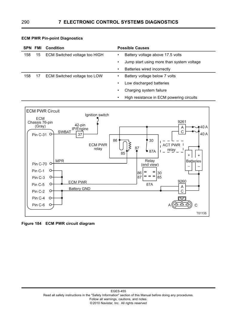
290 7 ELECTRONIC CONTROL SYSTEMS DIAGNOSTICS
ECM PWR Pin-point Diagnostics
SPN FMI Condition Possible Causes
158 15 ECM Switched voltage too HIGH • Battery voltage above 17.5 volts
• Jump start using more than system voltage
• Batteries wired incorrectly
158 17 ECM Switched voltage too LOW • Battery voltage below 7 volts
• Low discharged batteries
• Charging system failure
• High resistance in ECM powering circuits
Figure 184 ECM PWR circuit diagram
EGES-455Read all safety instructions in the "Safety Information" section of this Manual before doing any procedures.
Follow all warnings, cautions, and notes.©2010 Navistar, Inc. All rights reserved
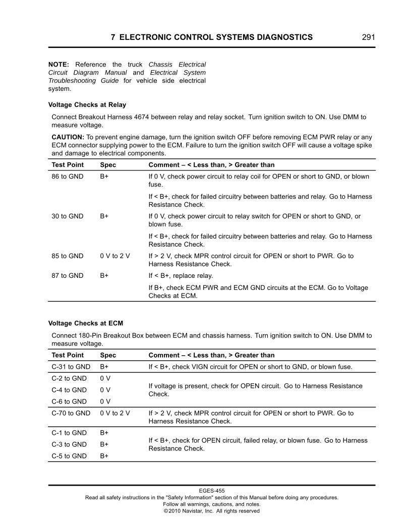
7 ELECTRONIC CONTROL SYSTEMS DIAGNOSTICS 291
NOTE: Reference the truck Chassis ElectricalCircuit Diagram Manual and Electrical SystemTroubleshooting Guide for vehicle side electricalsystem.
Voltage Checks at Relay
Connect Breakout Harness 4674 between relay and relay socket. Turn ignition switch to ON. Use DMM tomeasure voltage.
CAUTION: To prevent engine damage, turn the ignition switch OFF before removing ECM PWR relay or anyECM connector supplying power to the ECM. Failure to turn the ignition switch OFF will cause a voltage spikeand damage to electrical components.
Test Point Spec Comment – < Less than, > Greater than
86 to GND B+ If 0 V, check power circuit to relay coil for OPEN or short to GND, or blownfuse.
If < B+, check for failed circuitry between batteries and relay. Go to HarnessResistance Check.
30 to GND B+ If 0 V, check power circuit to relay switch for OPEN or short to GND, orblown fuse.
If < B+, check for failed circuitry between batteries and relay. Go to HarnessResistance Check.
85 to GND 0 V to 2 V If > 2 V, check MPR control circuit for OPEN or short to PWR. Go toHarness Resistance Check.
87 to GND B+ If < B+, replace relay.
If B+, check ECM PWR and ECM GND circuits at the ECM. Go to VoltageChecks at ECM.
Voltage Checks at ECM
Connect 180-Pin Breakout Box between ECM and chassis harness. Turn ignition switch to ON. Use DMM tomeasure voltage.
Test Point Spec Comment – < Less than, > Greater than
C-31 to GND B+ If < B+, check VIGN circuit for OPEN or short to GND, or blown fuse.
C-2 to GND 0 V
C-4 to GND 0 V
C-6 to GND 0 V
If voltage is present, check for OPEN circuit. Go to Harness ResistanceCheck.
C-70 to GND 0 V to 2 V If > 2 V, check MPR control circuit for OPEN or short to PWR. Go toHarness Resistance Check.
C-1 to GND B+
C-3 to GND B+
C-5 to GND B+
If < B+, check for OPEN circuit, failed relay, or blown fuse. Go to HarnessResistance Check.
EGES-455Read all safety instructions in the "Safety Information" section of this Manual before doing any procedures.
Follow all warnings, cautions, and notes.©2010 Navistar, Inc. All rights reserved
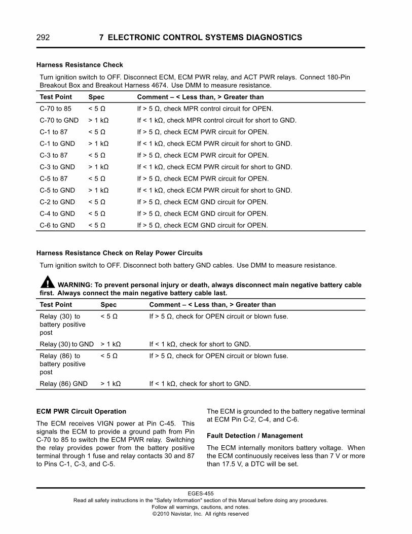
292 7 ELECTRONIC CONTROL SYSTEMS DIAGNOSTICS
Harness Resistance Check
Turn ignition switch to OFF. Disconnect ECM, ECM PWR relay, and ACT PWR relays. Connect 180-PinBreakout Box and Breakout Harness 4674. Use DMM to measure resistance.
Test Point Spec Comment – < Less than, > Greater than
C-70 to 85 < 5 Ω If > 5 Ω, check MPR control circuit for OPEN.
C-70 to GND > 1 kΩ If < 1 kΩ, check MPR control circuit for short to GND.
C-1 to 87 < 5 Ω If > 5 Ω, check ECM PWR circuit for OPEN.
C-1 to GND > 1 kΩ If < 1 kΩ, check ECM PWR circuit for short to GND.
C-3 to 87 < 5 Ω If > 5 Ω, check ECM PWR circuit for OPEN.
C-3 to GND > 1 kΩ If < 1 kΩ, check ECM PWR circuit for short to GND.
C-5 to 87 < 5 Ω If > 5 Ω, check ECM PWR circuit for OPEN.
C-5 to GND > 1 kΩ If < 1 kΩ, check ECM PWR circuit for short to GND.
C-2 to GND < 5 Ω If > 5 Ω, check ECM GND circuit for OPEN.
C-4 to GND < 5 Ω If > 5 Ω, check ECM GND circuit for OPEN.
C-6 to GND < 5 Ω If > 5 Ω, check ECM GND circuit for OPEN.
Harness Resistance Check on Relay Power Circuits
Turn ignition switch to OFF. Disconnect both battery GND cables. Use DMM to measure resistance.
WARNING: To prevent personal injury or death, always disconnect main negative battery cablefirst. Always connect the main negative battery cable last.
Test Point Spec Comment – < Less than, > Greater than
Relay (30) tobattery positivepost
< 5 Ω If > 5 Ω, check for OPEN circuit or blown fuse.
Relay (30) to GND > 1 kΩ If < 1 kΩ, check for short to GND.
Relay (86) tobattery positivepost
< 5 Ω If > 5 Ω, check for OPEN circuit or blown fuse.
Relay (86) GND > 1 kΩ If < 1 kΩ, check for short to GND.
ECM PWR Circuit Operation
The ECM receives VIGN power at Pin C-45. Thissignals the ECM to provide a ground path from PinC-70 to 85 to switch the ECM PWR relay. Switchingthe relay provides power from the battery positiveterminal through 1 fuse and relay contacts 30 and 87to Pins C-1, C-3, and C-5.
The ECM is grounded to the battery negative terminalat ECM Pin C-2, C-4, and C-6.
Fault Detection / Management
The ECM internally monitors battery voltage. Whenthe ECM continuously receives less than 7 V or morethan 17.5 V, a DTC will be set.
EGES-455Read all safety instructions in the "Safety Information" section of this Manual before doing any procedures.
Follow all warnings, cautions, and notes.©2010 Navistar, Inc. All rights reserved
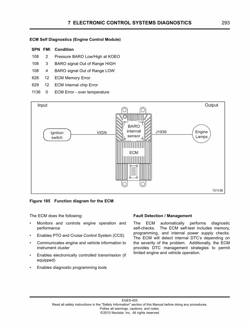
7 ELECTRONIC CONTROL SYSTEMS DIAGNOSTICS 293
ECM Self Diagnostics (Engine Control Module)
SPN FMI Condition
108 2 Pressure BARO Low/High at KOEO
108 3 BARO signal Out of Range HIGH
108 4 BARO signal Out of Range LOW
628 12 ECM Memory Error
629 12 ECM Internal chip Error
1136 0 ECM Error - over temperature
Figure 185 Function diagram for the ECM
The ECM does the following:
• Monitors and controls engine operation andperformance
• Enables PTO and Cruise Control System (CCS)
• Communicates engine and vehicle information toinstrument cluster
• Enables electronically controlled transmission (ifequipped)
• Enables diagnostic programming tools
Fault Detection / Management
The ECM automatically performs diagnosticself-checks. The ECM self-test includes memory,programming, and internal power supply checks.The ECM will detect internal DTC’s depending onthe severity of the problem. Additionally, the ECMprovides DTC management strategies to permitlimited engine and vehicle operation.
EGES-455Read all safety instructions in the "Safety Information" section of this Manual before doing any procedures.
Follow all warnings, cautions, and notes.©2010 Navistar, Inc. All rights reserved
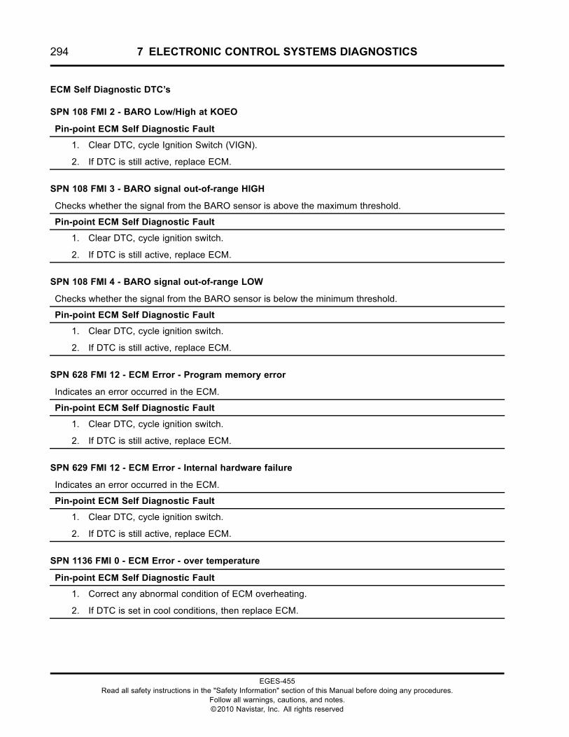
294 7 ELECTRONIC CONTROL SYSTEMS DIAGNOSTICS
ECM Self Diagnostic DTC’s
SPN 108 FMI 2 - BARO Low/High at KOEO
Pin-point ECM Self Diagnostic Fault
1. Clear DTC, cycle Ignition Switch (VIGN).
2. If DTC is still active, replace ECM.
SPN 108 FMI 3 - BARO signal out-of-range HIGH
Checks whether the signal from the BARO sensor is above the maximum threshold.
Pin-point ECM Self Diagnostic Fault
1. Clear DTC, cycle ignition switch.
2. If DTC is still active, replace ECM.
SPN 108 FMI 4 - BARO signal out-of-range LOW
Checks whether the signal from the BARO sensor is below the minimum threshold.
Pin-point ECM Self Diagnostic Fault
1. Clear DTC, cycle ignition switch.
2. If DTC is still active, replace ECM.
SPN 628 FMI 12 - ECM Error - Program memory error
Indicates an error occurred in the ECM.
Pin-point ECM Self Diagnostic Fault
1. Clear DTC, cycle ignition switch.
2. If DTC is still active, replace ECM.
SPN 629 FMI 12 - ECM Error - Internal hardware failure
Indicates an error occurred in the ECM.
Pin-point ECM Self Diagnostic Fault
1. Clear DTC, cycle ignition switch.
2. If DTC is still active, replace ECM.
SPN 1136 FMI 0 - ECM Error - over temperature
Pin-point ECM Self Diagnostic Fault
1. Correct any abnormal condition of ECM overheating.
2. If DTC is set in cool conditions, then replace ECM.
EGES-455Read all safety instructions in the "Safety Information" section of this Manual before doing any procedures.
Follow all warnings, cautions, and notes.©2010 Navistar, Inc. All rights reserved
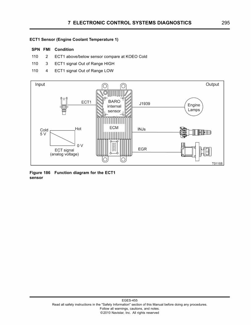
7 ELECTRONIC CONTROL SYSTEMS DIAGNOSTICS 295
ECT1 Sensor (Engine Coolant Temperature 1)
SPN FMI Condition
110 2 ECT1 above/below sensor compare at KOEO Cold
110 3 ECT1 signal Out of Range HIGH
110 4 ECT1 signal Out of Range LOW
Figure 186 Function diagram for the ECT1sensor
EGES-455Read all safety instructions in the "Safety Information" section of this Manual before doing any procedures.
Follow all warnings, cautions, and notes.©2010 Navistar, Inc. All rights reserved
296 7 ELECTRONIC CONTROL SYSTEMS DIAGNOSTICS
The function diagram for the ECT1 sensor includesthe following:
• Engine Control Module (ECM)with Barometric Absolute Pressure (BARO)Internal Sensor
• Engine Coolant Temperature 1 (ECT1) Sensor
• Exhaust Gas Recirculation (EGR) Valve
• Fuel Injector (INJ)
• Engine Lamps
Function
The ECT sensor provides a feedback signal to theECM indicating engine coolant temperature. Duringengine operation, the ECM will monitor the ECT signalto control the following features:
• Engine Warning and Protection System (EWPS)
• Cold Ambient Protection (CAP)
• Idle Shutdown Timer (IST)
• Cold idle advance
• Coolant compensation
The EWPS is an optional feature that can be enabledor disabled. When the EWPS is enabled, theoperator is warned of an overheat condition and,if programmed, will shutdown the engine.
Sensor Location
The ECT1 sensor is installed in the water supplyhousing (refrigerant compressor mount), right of theflat idler pulley assembly.
Tools
• Electronic Service Tool (EST) with ServiceMaxx™software (page 432)
• NAVCoM or NAVLink Interface Kit (page 433)
• Digital Multimeter (DMM) (page 431)
• 1180-N4-0X0 – 180-Pin Breakout Box (page 430)
• 3-Banana Plug Harness (page 433)
• Breakout Harness 4602 (ECT1) (page 434)
EGES-455Read all safety instructions in the "Safety Information" section of this Manual before doing any procedures.
Follow all warnings, cautions, and notes.©2010 Navistar, Inc. All rights reserved
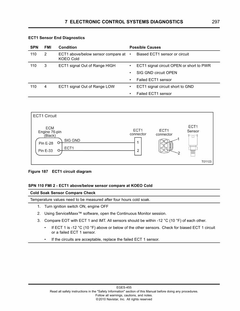
7 ELECTRONIC CONTROL SYSTEMS DIAGNOSTICS 297
ECT1 Sensor End Diagnostics
SPN FMI Condition Possible Causes
110 2 ECT1 above/below sensor compare atKOEO Cold
• Biased ECT1 sensor or circuit
110 3 ECT1 signal Out of Range HIGH • ECT1 signal circuit OPEN or short to PWR
• SIG GND circuit OPEN
• Failed ECT1 sensor
110 4 ECT1 signal Out of Range LOW • ECT1 signal circuit short to GND
• Failed ECT1 sensor
Figure 187 ECT1 circuit diagram
SPN 110 FMI 2 - ECT1 above/below sensor compare at KOEO Cold
Cold Soak Sensor Compare Check
Temperature values need to be measured after four hours cold soak.
1. Turn ignition switch ON, engine OFF
2. Using ServiceMaxx™ software, open the Continuous Monitor session.
3. Compare EOT with ECT 1 and IMT. All sensors should be within -12 °C (10 °F) of each other.
• If ECT 1 is -12 °C (10 °F) above or below of the other sensors. Check for biased ECT 1 circuitor a failed ECT 1 sensor.
• If the circuits are acceptable, replace the failed ECT 1 sensor.
EGES-455Read all safety instructions in the "Safety Information" section of this Manual before doing any procedures.
Follow all warnings, cautions, and notes.©2010 Navistar, Inc. All rights reserved
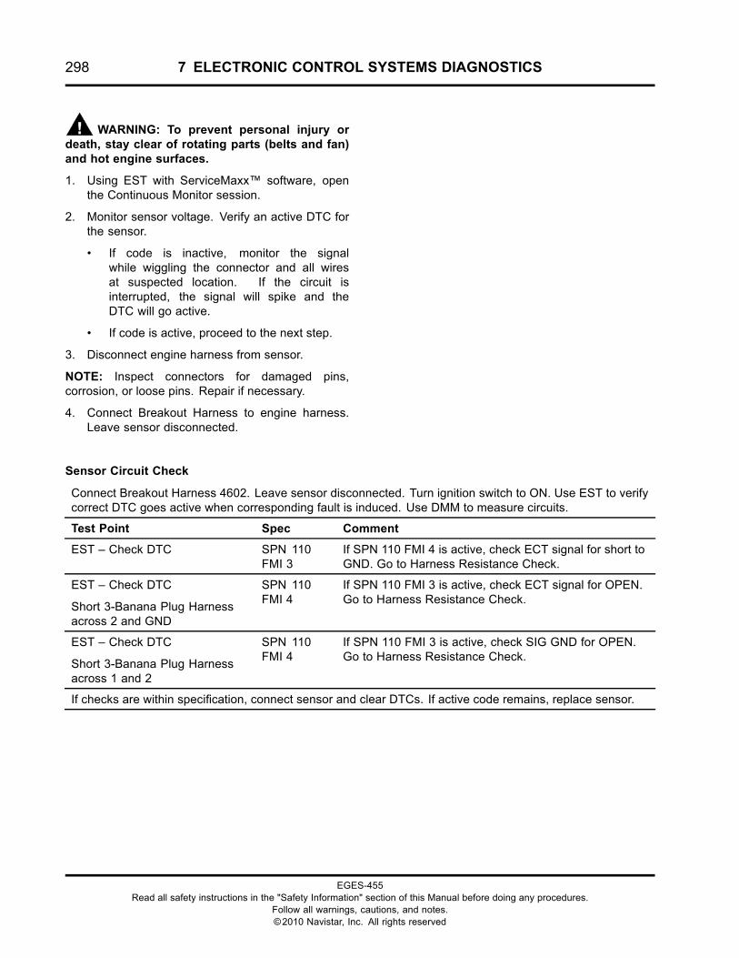
298 7 ELECTRONIC CONTROL SYSTEMS DIAGNOSTICS
WARNING: To prevent personal injury ordeath, stay clear of rotating parts (belts and fan)and hot engine surfaces.
1. Using EST with ServiceMaxx™ software, openthe Continuous Monitor session.
2. Monitor sensor voltage. Verify an active DTC forthe sensor.
• If code is inactive, monitor the signalwhile wiggling the connector and all wiresat suspected location. If the circuit isinterrupted, the signal will spike and theDTC will go active.
• If code is active, proceed to the next step.
3. Disconnect engine harness from sensor.
NOTE: Inspect connectors for damaged pins,corrosion, or loose pins. Repair if necessary.
4. Connect Breakout Harness to engine harness.Leave sensor disconnected.
Sensor Circuit Check
Connect Breakout Harness 4602. Leave sensor disconnected. Turn ignition switch to ON. Use EST to verifycorrect DTC goes active when corresponding fault is induced. Use DMM to measure circuits.
Test Point Spec Comment
EST – Check DTC SPN 110FMI 3
If SPN 110 FMI 4 is active, check ECT signal for short toGND. Go to Harness Resistance Check.
EST – Check DTC
Short 3-Banana Plug Harnessacross 2 and GND
SPN 110FMI 4
If SPN 110 FMI 3 is active, check ECT signal for OPEN.Go to Harness Resistance Check.
EST – Check DTC
Short 3-Banana Plug Harnessacross 1 and 2
SPN 110FMI 4
If SPN 110 FMI 3 is active, check SIG GND for OPEN.Go to Harness Resistance Check.
If checks are within specification, connect sensor and clear DTCs. If active code remains, replace sensor.
EGES-455Read all safety instructions in the "Safety Information" section of this Manual before doing any procedures.
Follow all warnings, cautions, and notes.©2010 Navistar, Inc. All rights reserved
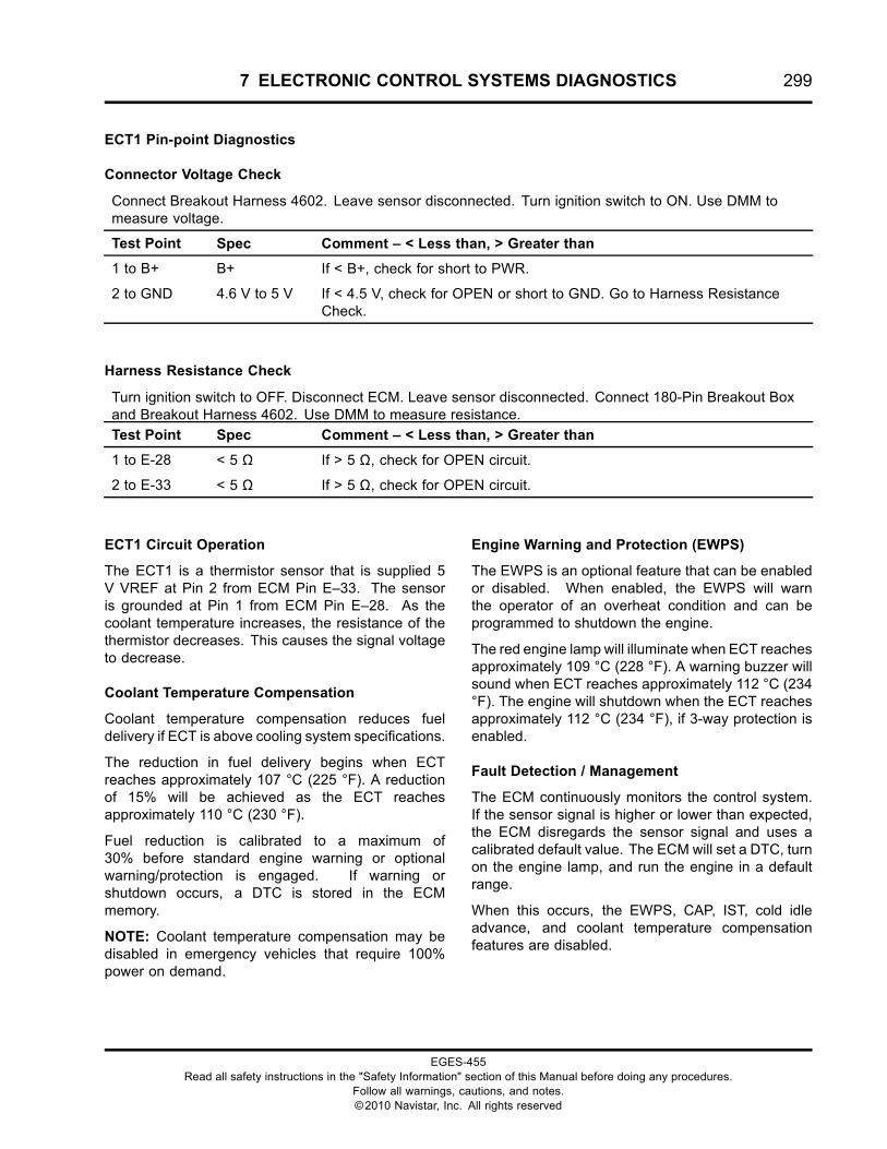
7 ELECTRONIC CONTROL SYSTEMS DIAGNOSTICS 299
ECT1 Pin-point Diagnostics
Connector Voltage Check
Connect Breakout Harness 4602. Leave sensor disconnected. Turn ignition switch to ON. Use DMM tomeasure voltage.
Test Point Spec Comment – < Less than, > Greater than
1 to B+ B+ If < B+, check for short to PWR.
2 to GND 4.6 V to 5 V If < 4.5 V, check for OPEN or short to GND. Go to Harness ResistanceCheck.
Harness Resistance Check
Turn ignition switch to OFF. Disconnect ECM. Leave sensor disconnected. Connect 180-Pin Breakout Boxand Breakout Harness 4602. Use DMM to measure resistance.
Test Point Spec Comment – < Less than, > Greater than
1 to E-28 < 5 Ω If > 5 Ω, check for OPEN circuit.
2 to E-33 < 5 Ω If > 5 Ω, check for OPEN circuit.
ECT1 Circuit Operation
The ECT1 is a thermistor sensor that is supplied 5V VREF at Pin 2 from ECM Pin E–33. The sensoris grounded at Pin 1 from ECM Pin E–28. As thecoolant temperature increases, the resistance of thethermistor decreases. This causes the signal voltageto decrease.
Coolant Temperature Compensation
Coolant temperature compensation reduces fueldelivery if ECT is above cooling system specifications.
The reduction in fuel delivery begins when ECTreaches approximately 107 °C (225 °F). A reductionof 15% will be achieved as the ECT reachesapproximately 110 °C (230 °F).
Fuel reduction is calibrated to a maximum of30% before standard engine warning or optionalwarning/protection is engaged. If warning orshutdown occurs, a DTC is stored in the ECMmemory.
NOTE: Coolant temperature compensation may bedisabled in emergency vehicles that require 100%power on demand.
Engine Warning and Protection (EWPS)
The EWPS is an optional feature that can be enabledor disabled. When enabled, the EWPS will warnthe operator of an overheat condition and can beprogrammed to shutdown the engine.
The red engine lamp will illuminate when ECT reachesapproximately 109 °C (228 °F). A warning buzzer willsound when ECT reaches approximately 112 °C (234°F). The engine will shutdown when the ECT reachesapproximately 112 °C (234 °F), if 3-way protection isenabled.
Fault Detection / Management
The ECM continuously monitors the control system.If the sensor signal is higher or lower than expected,the ECM disregards the sensor signal and uses acalibrated default value. The ECM will set a DTC, turnon the engine lamp, and run the engine in a defaultrange.
When this occurs, the EWPS, CAP, IST, cold idleadvance, and coolant temperature compensationfeatures are disabled.
EGES-455Read all safety instructions in the "Safety Information" section of this Manual before doing any procedures.
Follow all warnings, cautions, and notes.©2010 Navistar, Inc. All rights reserved
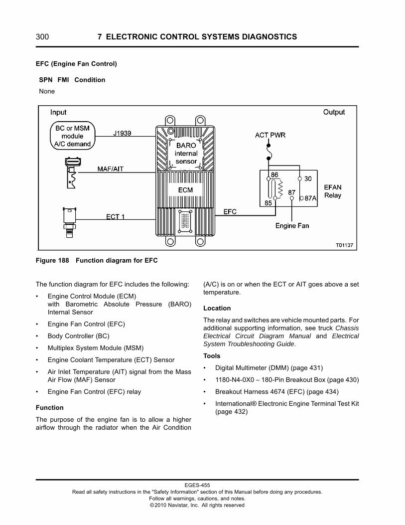
300 7 ELECTRONIC CONTROL SYSTEMS DIAGNOSTICS
EFC (Engine Fan Control)
SPN FMI Condition
None
Figure 188 Function diagram for EFC
The function diagram for EFC includes the following:
• Engine Control Module (ECM)with Barometric Absolute Pressure (BARO)Internal Sensor
• Engine Fan Control (EFC)
• Body Controller (BC)
• Multiplex System Module (MSM)
• Engine Coolant Temperature (ECT) Sensor
• Air Inlet Temperature (AIT) signal from the MassAir Flow (MAF) Sensor
• Engine Fan Control (EFC) relay
Function
The purpose of the engine fan is to allow a higherairflow through the radiator when the Air Condition
(A/C) is on or when the ECT or AIT goes above a settemperature.
Location
The relay and switches are vehicle mounted parts. Foradditional supporting information, see truck ChassisElectrical Circuit Diagram Manual and ElectricalSystem Troubleshooting Guide.
Tools
• Digital Multimeter (DMM) (page 431)
• 1180-N4-0X0 – 180-Pin Breakout Box (page 430)
• Breakout Harness 4674 (EFC) (page 434)
• International® Electronic Engine Terminal Test Kit(page 432)
EGES-455Read all safety instructions in the "Safety Information" section of this Manual before doing any procedures.
Follow all warnings, cautions, and notes.©2010 Navistar, Inc. All rights reserved
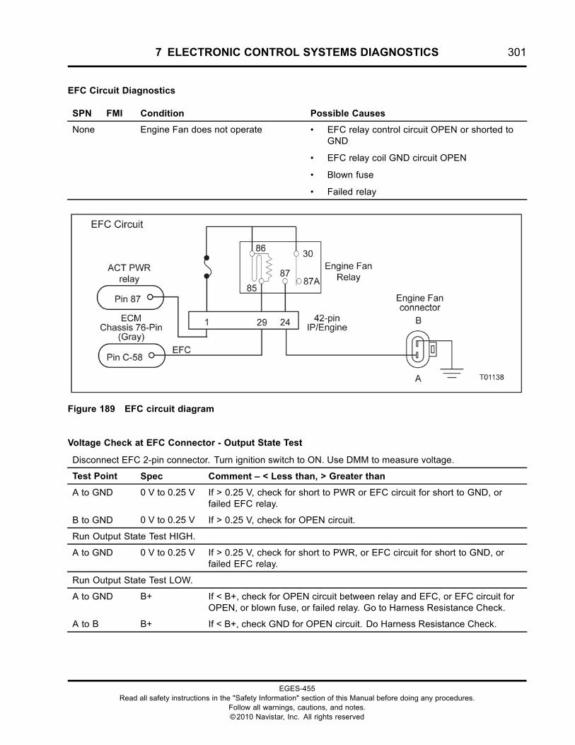
7 ELECTRONIC CONTROL SYSTEMS DIAGNOSTICS 301
EFC Circuit Diagnostics
SPN FMI Condition Possible Causes
None Engine Fan does not operate • EFC relay control circuit OPEN or shorted toGND
• EFC relay coil GND circuit OPEN
• Blown fuse
• Failed relay
Figure 189 EFC circuit diagram
Voltage Check at EFC Connector - Output State Test
Disconnect EFC 2-pin connector. Turn ignition switch to ON. Use DMM to measure voltage.
Test Point Spec Comment – < Less than, > Greater than
A to GND 0 V to 0.25 V If > 0.25 V, check for short to PWR or EFC circuit for short to GND, orfailed EFC relay.
B to GND 0 V to 0.25 V If > 0.25 V, check for OPEN circuit.
Run Output State Test HIGH.
A to GND 0 V to 0.25 V If > 0.25 V, check for short to PWR, or EFC circuit for short to GND, orfailed EFC relay.
Run Output State Test LOW.
A to GND B+ If < B+, check for OPEN circuit between relay and EFC, or EFC circuit forOPEN, or blown fuse, or failed relay. Go to Harness Resistance Check.
A to B B+ If < B+, check GND for OPEN circuit. Do Harness Resistance Check.
EGES-455Read all safety instructions in the "Safety Information" section of this Manual before doing any procedures.
Follow all warnings, cautions, and notes.©2010 Navistar, Inc. All rights reserved
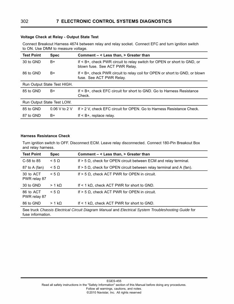
302 7 ELECTRONIC CONTROL SYSTEMS DIAGNOSTICS
Voltage Check at Relay - Output State Test
Connect Breakout Harness 4674 between relay and relay socket. Connect EFC and turn ignition switchto ON. Use DMM to measure voltage.
Test Point Spec Comment – < Less than, > Greater than
30 to GND B+ If < B+, check PWR circuit to relay switch for OPEN or short to GND, orblown fuse. See ACT PWR Relay.
86 to GND B+ If < B+, check PWR circuit to relay coil for OPEN or short to GND, or blownfuse. See ACT PWR Relay.
Run Output State Test HIGH.
85 to GND B+ If < B+, check EFC circuit for short to GND. Go to Harness ResistanceCheck.
Run Output State Test LOW.
85 to GND 0.06 V to 2 V If > 2 V, check EFC circuit for OPEN. Go to Harness Resistance Check.
87 to GND B+ If < B+, replace relay.
Harness Resistance Check
Turn ignition switch to OFF. Disconnect ECM. Leave relay disconnected. Connect 180-Pin Breakout Boxand relay harness.
Test Point Spec Comment – < Less than, > Greater than
C-58 to 85 < 5 Ω If > 5 Ω, check for OPEN circuit between ECM and relay terminal.
87 to A (fan) < 5 Ω If > 5 Ω, check for OPEN circuit between relay terminal and A (fan).
30 to ACTPWR relay 87
< 5 Ω If > 5 Ω, check ACT PWR for OPEN in circuit.
30 to GND > 1 kΩ If < 1 kΩ, check ACT PWR for short to GND.
86 to ACTPWR relay 87
< 5 Ω If > 5 Ω, check ACT PWR for OPEN in circuit.
86 to GND > 1 kΩ If < 1 kΩ, check ACT PWR for short to GND.
See truck Chassis Electrical Circuit Diagram Manual and Electrical System Troubleshooting Guide forfuse information.
EGES-455Read all safety instructions in the "Safety Information" section of this Manual before doing any procedures.
Follow all warnings, cautions, and notes.©2010 Navistar, Inc. All rights reserved
7 ELECTRONIC CONTROL SYSTEMS DIAGNOSTICS 303
EFC Circuit Operation
The default state of the EFC is ON. B+ is needed toturn the fan OFF.
ECM Pin C-58 controls the EFC to shut off bysupplying a ground path to the EFC relay coil Pin 85.ACT PWR powers the other side of the relay coil, Pin86. ACT PWR is sent through the relay switch, whichdeactivates the EFC.
EFC Programmable Parameters
By using an EST, an authorized service technician canprogram the ECM to turn the EFC on for any desiredtemperature.
• Engine fan control - indicates to the on-boardelectronics whether or not the truck has theelectronic engine fan control feature.
• A/C fan activation - allows fan activation throughthe ECM when requested from the BC during A/Coperation.
• Disable - enables or disables the EFC feature.
• Fan on temperature - indicates at what coolanttemperature the fan will be electronicallyactivated.
• Fan off temperature - indicates at what coolanttemperature the fan will be electronicallydeactivated.
Fault Detection / Management
An open or short to GND in the EFC can be detectedby the ECM during an on-demand engine standardtest. The AIT and ECT are continuously monitored.If a DTC is detected in the AIT or ECT circuit, the EFCis disabled and the engine fan remains on.
NOTE: Before diagnosing, verify that the vehicle hasan electronic fan and that the ECM is programmedcorrectly.
EGES-455Read all safety instructions in the "Safety Information" section of this Manual before doing any procedures.
Follow all warnings, cautions, and notes.©2010 Navistar, Inc. All rights reserved
304 7 ELECTRONIC CONTROL SYSTEMS DIAGNOSTICS
EGR Actuator (Exhaust Gas Recirculation)
SPN FMI Condition
27 0 EGRP fault: over temperature
27 3 EGRP signal Out of Range HIGH
27 4 EGRP signal Out of Range LOW
27 7 EGRP does not agree with commanded position
27 14 EGR internal circuit failure
2791 2 EGR valve communication fault
2791 8 EGR valve not receiving ECM PWM signal
Figure 190 Function diagram for the EGR Actuator
The function diagram for the EGR Actuator includesthe following:
• Engine Control Module (ECM)with Barometric Absolute Pressure (BARO)Internal Sensor
• Exhaust Gas Recirculation (EGR) Actuator
• Engine Lamp
• Mass Air Flow (MAF) Sensor
• J1939 Data Link
Function
Nitrogen oxides (NOX) in the atmosphere contributeto the production of smog. NOX is formed whentemperatures in the combustion chamber get too hot.
The EGR system is used to reduce the amount ofNOX created by the engine. Exhaust gases that havealready burned do not burn again. The EGR valverecirculates exhaust back into the intake stream.This will cool the combustion process and reduce theformation of NOX.
Component Location
The EGR valve is installed in the EGR manifoldbetween the throttle body and the intake manifold.
EGES-455Read all safety instructions in the "Safety Information" section of this Manual before doing any procedures.
Follow all warnings, cautions, and notes.©2010 Navistar, Inc. All rights reserved
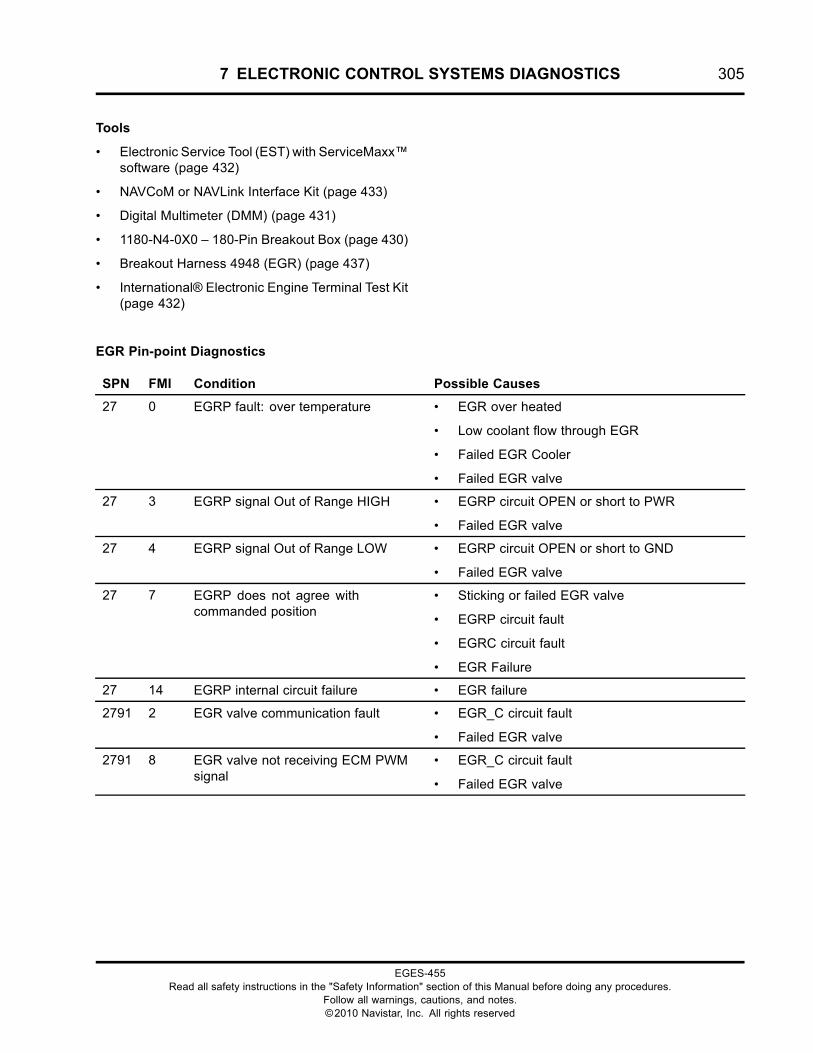
7 ELECTRONIC CONTROL SYSTEMS DIAGNOSTICS 305
Tools
• Electronic Service Tool (EST) with ServiceMaxx™software (page 432)
• NAVCoM or NAVLink Interface Kit (page 433)
• Digital Multimeter (DMM) (page 431)
• 1180-N4-0X0 – 180-Pin Breakout Box (page 430)
• Breakout Harness 4948 (EGR) (page 437)
• International® Electronic Engine Terminal Test Kit(page 432)
EGR Pin-point Diagnostics
SPN FMI Condition Possible Causes
27 0 EGRP fault: over temperature • EGR over heated
• Low coolant flow through EGR
• Failed EGR Cooler
• Failed EGR valve
27 3 EGRP signal Out of Range HIGH • EGRP circuit OPEN or short to PWR
• Failed EGR valve
27 4 EGRP signal Out of Range LOW • EGRP circuit OPEN or short to GND
• Failed EGR valve
27 7 EGRP does not agree withcommanded position
• Sticking or failed EGR valve
• EGRP circuit fault
• EGRC circuit fault
• EGR Failure
27 14 EGRP internal circuit failure • EGR failure
2791 2 EGR valve communication fault • EGR_C circuit fault
• Failed EGR valve
2791 8 EGR valve not receiving ECM PWMsignal
• EGR_C circuit fault
• Failed EGR valve
EGES-455Read all safety instructions in the "Safety Information" section of this Manual before doing any procedures.
Follow all warnings, cautions, and notes.©2010 Navistar, Inc. All rights reserved
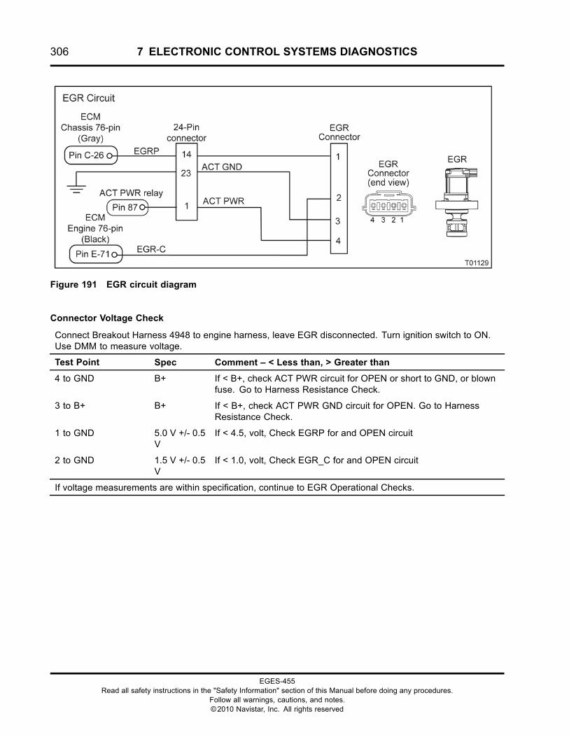
306 7 ELECTRONIC CONTROL SYSTEMS DIAGNOSTICS
Figure 191 EGR circuit diagram
Connector Voltage Check
Connect Breakout Harness 4948 to engine harness, leave EGR disconnected. Turn ignition switch to ON.Use DMM to measure voltage.
Test Point Spec Comment – < Less than, > Greater than
4 to GND B+ If < B+, check ACT PWR circuit for OPEN or short to GND, or blownfuse. Go to Harness Resistance Check.
3 to B+ B+ If < B+, check ACT PWR GND circuit for OPEN. Go to HarnessResistance Check.
1 to GND 5.0 V +/- 0.5V
If < 4.5, volt, Check EGRP for and OPEN circuit
2 to GND 1.5 V +/- 0.5V
If < 1.0, volt, Check EGR_C for and OPEN circuit
If voltage measurements are within specification, continue to EGR Operational Checks.
EGES-455Read all safety instructions in the "Safety Information" section of this Manual before doing any procedures.
Follow all warnings, cautions, and notes.©2010 Navistar, Inc. All rights reserved
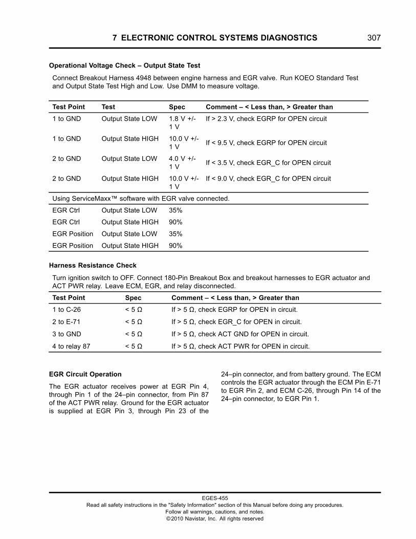
7 ELECTRONIC CONTROL SYSTEMS DIAGNOSTICS 307
Operational Voltage Check – Output State Test
Connect Breakout Harness 4948 between engine harness and EGR valve. Run KOEO Standard Testand Output State Test High and Low. Use DMM to measure voltage.
Test Point Test Spec Comment – < Less than, > Greater than
1 to GND Output State LOW 1.8 V +/-1 V
If > 2.3 V, check EGRP for OPEN circuit
1 to GND Output State HIGH 10.0 V +/-1 V
If < 9.5 V, check EGRP for OPEN circuit
2 to GND Output State LOW 4.0 V +/-1 V
If < 3.5 V, check EGR_C for OPEN circuit
2 to GND Output State HIGH 10.0 V +/-1 V
If < 9.0 V, check EGR_C for OPEN circuit
Using ServiceMaxx™ software with EGR valve connected.
EGR Ctrl Output State LOW 35%
EGR Ctrl Output State HIGH 90%
EGR Position Output State LOW 35%
EGR Position Output State HIGH 90%
Harness Resistance Check
Turn ignition switch to OFF. Connect 180-Pin Breakout Box and breakout harnesses to EGR actuator andACT PWR relay. Leave ECM, EGR, and relay disconnected.
Test Point Spec Comment – < Less than, > Greater than
1 to C-26
2 to E-71
3 to GND
4 to relay 87
< 5 Ω
< 5 Ω
< 5 Ω
< 5 Ω
If > 5 Ω, check EGRP for OPEN in circuit.
If > 5 Ω, check EGR_C for OPEN in circuit.
If > 5 Ω, check ACT GND for OPEN in circuit.
If > 5 Ω, check ACT PWR for OPEN in circuit.
EGR Circuit Operation
The EGR actuator receives power at EGR Pin 4,through Pin 1 of the 24–pin connector, from Pin 87of the ACT PWR relay. Ground for the EGR actuatoris supplied at EGR Pin 3, through Pin 23 of the
24–pin connector, and from battery ground. The ECMcontrols the EGR actuator through the ECM Pin E-71to EGR Pin 2, and ECM C-26, through Pin 14 of the24–pin connector, to EGR Pin 1.
EGES-455Read all safety instructions in the "Safety Information" section of this Manual before doing any procedures.
Follow all warnings, cautions, and notes.©2010 Navistar, Inc. All rights reserved
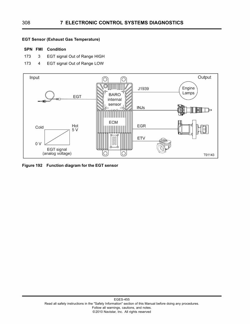
308 7 ELECTRONIC CONTROL SYSTEMS DIAGNOSTICS
EGT Sensor (Exhaust Gas Temperature)
SPN FMI Condition
173 3 EGT signal Out of Range HIGH
173 4 EGT signal Out of Range LOW
Figure 192 Function diagram for the EGT sensor
EGES-455Read all safety instructions in the "Safety Information" section of this Manual before doing any procedures.
Follow all warnings, cautions, and notes.©2010 Navistar, Inc. All rights reserved
7 ELECTRONIC CONTROL SYSTEMS DIAGNOSTICS 309
The function diagram for the EGT sensor includes thefollowing:
• Engine Control Module (ECM)with Barometric Absolute Pressure (BARO)Internal Sensor
• Exhaust Gas Temperature (EGT) Sensor
• J1939 Data Link
• Injectors (INJs)
• Exhaust Gas Recirculation (EGR) Valve
• Engine Throttle Valve (ETV)
• Engine Lamps
Sensor Location
The EGT sensor is located in the exhaust manifold, infront of the turbocharger.
Tools
• Electronic Service Tool (EST) with ServiceMaxx™software (page 432)
• NAVCoM or NAVLink Interface Kit (page 433)
• Digital Multimeter (DMM) (page 431)
• 1180-N4-0X0 – 180-Pin Breakout Box (page 430)
• 3-Banana Plug Harness (page 433)
• Breakout Harness 4946 (EGT) (page 436)
• International® Electronic Engine Terminal Test Kit(page 432)
EGES-455Read all safety instructions in the "Safety Information" section of this Manual before doing any procedures.
Follow all warnings, cautions, and notes.©2010 Navistar, Inc. All rights reserved
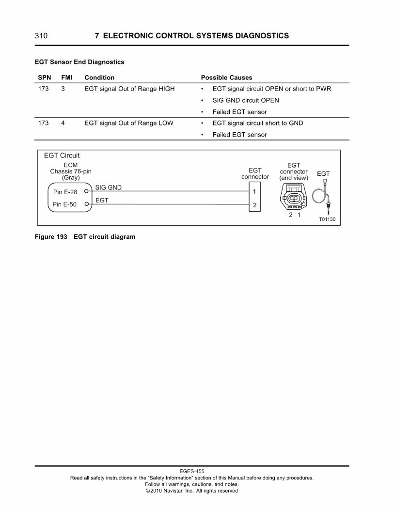
310 7 ELECTRONIC CONTROL SYSTEMS DIAGNOSTICS
EGT Sensor End Diagnostics
SPN FMI Condition Possible Causes
173 3 EGT signal Out of Range HIGH • EGT signal circuit OPEN or short to PWR
• SIG GND circuit OPEN
• Failed EGT sensor
173 4 EGT signal Out of Range LOW • EGT signal circuit short to GND
• Failed EGT sensor
Figure 193 EGT circuit diagram
EGES-455Read all safety instructions in the "Safety Information" section of this Manual before doing any procedures.
Follow all warnings, cautions, and notes.©2010 Navistar, Inc. All rights reserved
7 ELECTRONIC CONTROL SYSTEMS DIAGNOSTICS 311
WARNING: To prevent personal injury ordeath, stay clear of rotating parts (belts and fan)and hot engine surfaces.
1. Using EST with ServiceMaxx™ software, openthe Continuous Monitor Session.
2. Monitor sensor voltage. Verify an active DTC forthe sensor.
• If code is inactive, monitor the signalwhile wiggling the connector and all wiresat suspected location. If the circuit isinterrupted, the signal will spike and theDTC will go active.
• If code is active, proceed to the next step.
3. Disconnect engine harness from sensor.
NOTE: Inspect connectors for damaged pins,corrosion, or loose pins. Repair if necessary.
4. Connect Breakout Harness 4946 to engineharness. Leave sensor disconnected.
EGT Pin-point Diagnostics
Connector Voltage Check
NOTE: It is normal for the EGT sensor to display 413 °C (775 °F ) when the engine is cool. The sensor doesnot start measuring correctly until the engine is warm.
Connect sensor Breakout Harness 4946 to engine harness. Leave sensor disconnected. Turn ignition switchto ON. Use DMM to measure voltage.
Test Point Spec Comment – < Less than, > Greater than
1 to B+ B+ If < B+, check for OPEN or short to PWR.
2 to GND 4.6 V to 5 V If < 4.5 V, check for OPEN or short to GND. Go to Harness ResistanceCheck.
Harness Resistance Check
Turn ignition switch to OFF. Connect 180-pin Breakout Box and sensor Breakout Harness 4946. LeaveECM and sensor disconnected.
Test Point Spec Comment – < Less than, > Greater than
1 to E-28 < 5 Ω If > 5 Ω, check for OPEN circuit.
2 to E-50 < 5 Ω If > 5 Ω, check for OPEN circuit.
EGES-455Read all safety instructions in the "Safety Information" section of this Manual before doing any procedures.
Follow all warnings, cautions, and notes.©2010 Navistar, Inc. All rights reserved
312 7 ELECTRONIC CONTROL SYSTEMS DIAGNOSTICS
EGT Circuit Operation
The EGT is a thermistor sensor supplied with a 5V VREF at Pin 1 from ECM Pin E–50. The sensoris grounded at Pin 2 from ECM Pin E–28. Asthe temperature increases, the resistance of thethermistor decreases. This causes the signal voltageto decrease.
Fault Detection / Management
The ECM continuously monitors the control system.If the sensor signal is higher or lower than expected,the ECM disregards the sensor signal and uses acalibrated default value. The ECM will set a DTC, turnon the engine lamp, and run the engine in a defaultrange.
EGES-455Read all safety instructions in the "Safety Information" section of this Manual before doing any procedures.
Follow all warnings, cautions, and notes.©2010 Navistar, Inc. All rights reserved
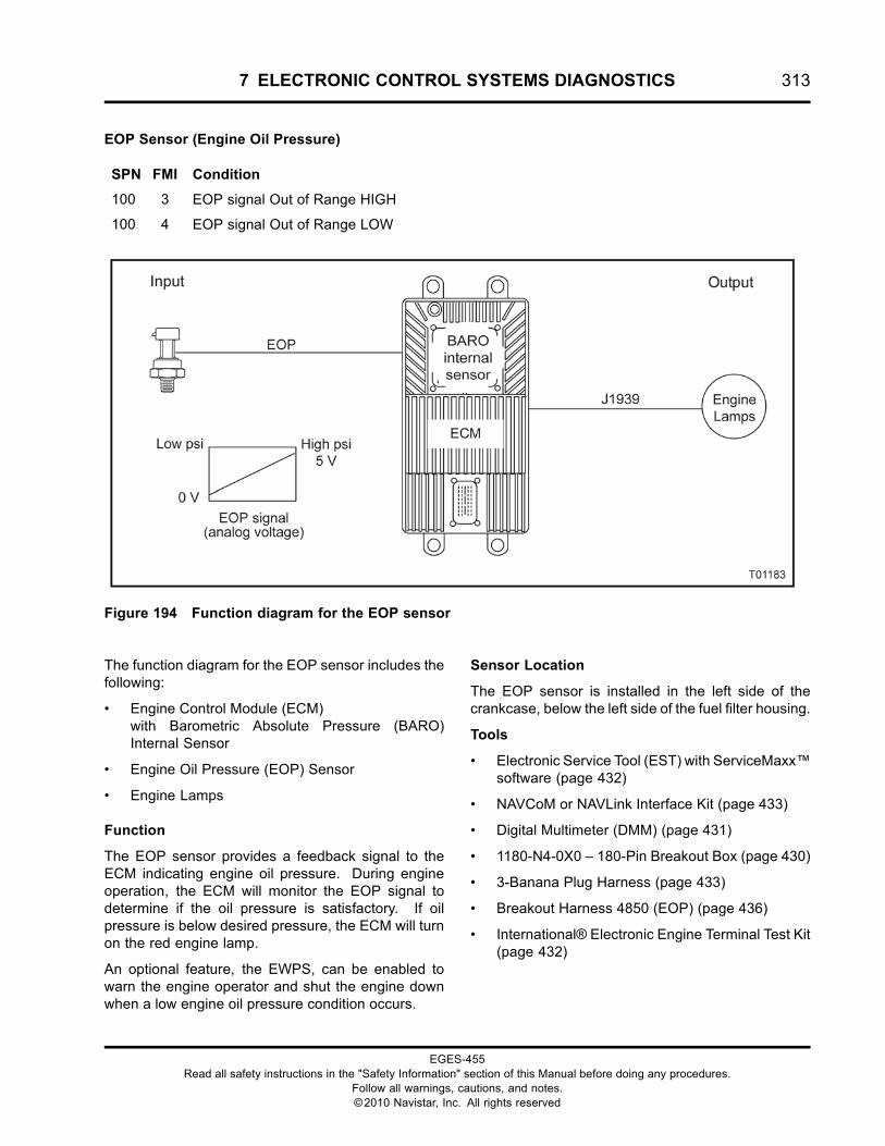
7 ELECTRONIC CONTROL SYSTEMS DIAGNOSTICS 313
EOP Sensor (Engine Oil Pressure)
SPN FMI Condition
100 3 EOP signal Out of Range HIGH
100 4 EOP signal Out of Range LOW
Figure 194 Function diagram for the EOP sensor
The function diagram for the EOP sensor includes thefollowing:
• Engine Control Module (ECM)with Barometric Absolute Pressure (BARO)Internal Sensor
• Engine Oil Pressure (EOP) Sensor
• Engine Lamps
Function
The EOP sensor provides a feedback signal to theECM indicating engine oil pressure. During engineoperation, the ECM will monitor the EOP signal todetermine if the oil pressure is satisfactory. If oilpressure is below desired pressure, the ECM will turnon the red engine lamp.
An optional feature, the EWPS, can be enabled towarn the engine operator and shut the engine downwhen a low engine oil pressure condition occurs.
Sensor Location
The EOP sensor is installed in the left side of thecrankcase, below the left side of the fuel filter housing.
Tools
• Electronic Service Tool (EST) with ServiceMaxx™software (page 432)
• NAVCoM or NAVLink Interface Kit (page 433)
• Digital Multimeter (DMM) (page 431)
• 1180-N4-0X0 – 180-Pin Breakout Box (page 430)
• 3-Banana Plug Harness (page 433)
• Breakout Harness 4850 (EOP) (page 436)
• International® Electronic Engine Terminal Test Kit(page 432)
EGES-455Read all safety instructions in the "Safety Information" section of this Manual before doing any procedures.
Follow all warnings, cautions, and notes.©2010 Navistar, Inc. All rights reserved
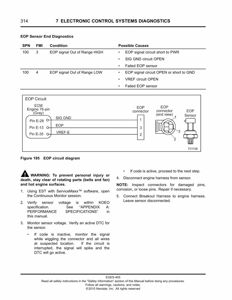
314 7 ELECTRONIC CONTROL SYSTEMS DIAGNOSTICS
EOP Sensor End Diagnostics
SPN FMI Condition Possible Causes
100 3 EOP signal Out of Range HIGH • EOP signal circuit short to PWR
• SIG GND circuit OPEN
• Failed EOP sensor
100 4 EOP signal Out of Range LOW • EOP signal circuit OPEN or short to GND
• VREF circuit OPEN
• Failed EOP sensor
Figure 195 EOP circuit diagram
WARNING: To prevent personal injury ordeath, stay clear of rotating parts (belts and fan)and hot engine surfaces.
1. Using EST with ServiceMaxx™ software, openthe Continuous Monitor session.
2. Verify sensor voltage is within KOEOspecification. See “APPENDIX A:PERFORMANCE SPECIFICATIONS” inthis manual.
3. Monitor sensor voltage. Verify an active DTC forthe sensor.
• If code is inactive, monitor the signalwhile wiggling the connector and all wiresat suspected location. If the circuit isinterrupted, the signal will spike and theDTC will go active.
• If code is active, proceed to the next step.
4. Disconnect engine harness from sensor.
NOTE: Inspect connectors for damaged pins,corrosion, or loose pins. Repair if necessary.
5. Connect Breakout Harness to engine harness.Leave sensor disconnected.
EGES-455Read all safety instructions in the "Safety Information" section of this Manual before doing any procedures.
Follow all warnings, cautions, and notes.©2010 Navistar, Inc. All rights reserved
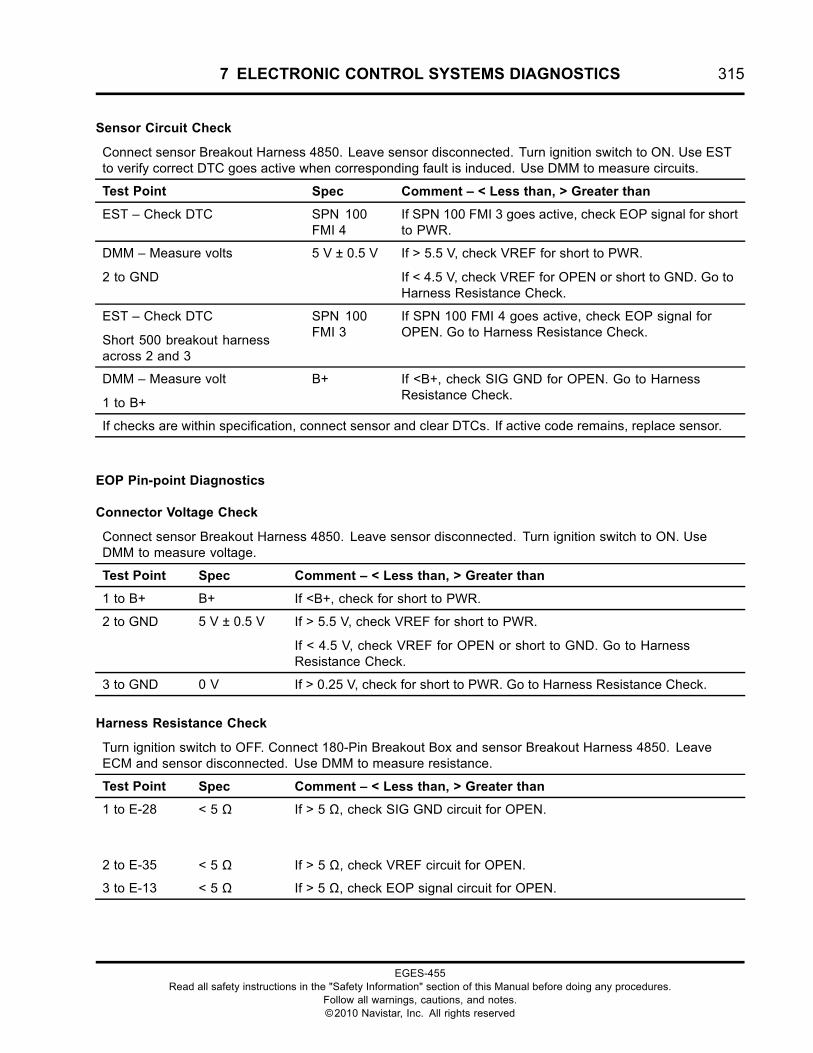
7 ELECTRONIC CONTROL SYSTEMS DIAGNOSTICS 315
Sensor Circuit Check
Connect sensor Breakout Harness 4850. Leave sensor disconnected. Turn ignition switch to ON. Use ESTto verify correct DTC goes active when corresponding fault is induced. Use DMM to measure circuits.
Test Point Spec Comment – < Less than, > Greater than
EST – Check DTC SPN 100FMI 4
If SPN 100 FMI 3 goes active, check EOP signal for shortto PWR.
DMM – Measure volts
2 to GND
5 V ± 0.5 V If > 5.5 V, check VREF for short to PWR.
If < 4.5 V, check VREF for OPEN or short to GND. Go toHarness Resistance Check.
EST – Check DTC
Short 500 breakout harnessacross 2 and 3
SPN 100FMI 3
If SPN 100 FMI 4 goes active, check EOP signal forOPEN. Go to Harness Resistance Check.
DMM – Measure volt
1 to B+
B+ If <B+, check SIG GND for OPEN. Go to HarnessResistance Check.
If checks are within specification, connect sensor and clear DTCs. If active code remains, replace sensor.
EOP Pin-point Diagnostics
Connector Voltage Check
Connect sensor Breakout Harness 4850. Leave sensor disconnected. Turn ignition switch to ON. UseDMM to measure voltage.
Test Point Spec Comment – < Less than, > Greater than
1 to B+ B+ If <B+, check for short to PWR.
2 to GND 5 V ± 0.5 V If > 5.5 V, check VREF for short to PWR.
If < 4.5 V, check VREF for OPEN or short to GND. Go to HarnessResistance Check.
3 to GND 0 V If > 0.25 V, check for short to PWR. Go to Harness Resistance Check.
Harness Resistance Check
Turn ignition switch to OFF. Connect 180-Pin Breakout Box and sensor Breakout Harness 4850. LeaveECM and sensor disconnected. Use DMM to measure resistance.
Test Point Spec Comment – < Less than, > Greater than
1 to E-28 < 5 Ω If > 5 Ω, check SIG GND circuit for OPEN.
2 to E-35 < 5 Ω If > 5 Ω, check VREF circuit for OPEN.
3 to E-13 < 5 Ω If > 5 Ω, check EOP signal circuit for OPEN.
EGES-455Read all safety instructions in the "Safety Information" section of this Manual before doing any procedures.
Follow all warnings, cautions, and notes.©2010 Navistar, Inc. All rights reserved
316 7 ELECTRONIC CONTROL SYSTEMS DIAGNOSTICS
EOP Circuit Operation
The EOP sensor is a variable capacitance sensorsupplied with a 5 V VREF at Pin 2 from ECM PinE-35. The sensor is grounded at Pin 1 from ECM PinE-28. The sensor returns a variable voltage signalfrom Pin 3 to ECM Pin E-13.
Fault Detection / Management
The ECM continuously monitors the control system. Ifthe sensor signal is higher or lower than expected, theECM will disable the EWPS, set a DTC, and turn onthe warning lamp.
EGES-455Read all safety instructions in the "Safety Information" section of this Manual before doing any procedures.
Follow all warnings, cautions, and notes.©2010 Navistar, Inc. All rights reserved
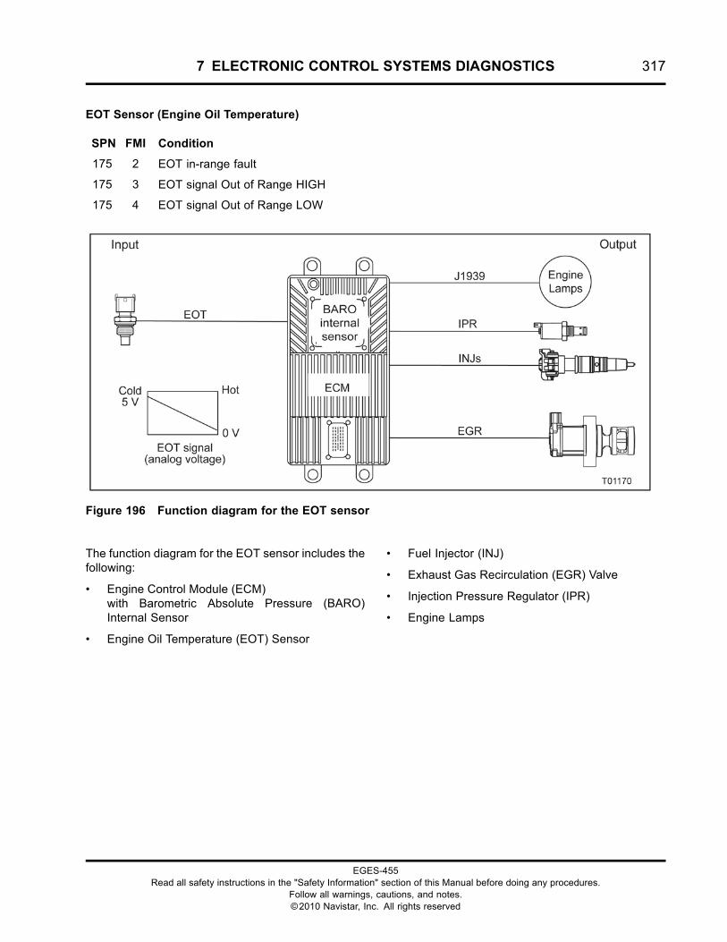
7 ELECTRONIC CONTROL SYSTEMS DIAGNOSTICS 317
EOT Sensor (Engine Oil Temperature)
SPN FMI Condition
175 2 EOT in-range fault
175 3 EOT signal Out of Range HIGH
175 4 EOT signal Out of Range LOW
Figure 196 Function diagram for the EOT sensor
The function diagram for the EOT sensor includes thefollowing:
• Engine Control Module (ECM)with Barometric Absolute Pressure (BARO)Internal Sensor
• Engine Oil Temperature (EOT) Sensor
• Fuel Injector (INJ)
• Exhaust Gas Recirculation (EGR) Valve
• Injection Pressure Regulator (IPR)
• Engine Lamps
EGES-455Read all safety instructions in the "Safety Information" section of this Manual before doing any procedures.
Follow all warnings, cautions, and notes.©2010 Navistar, Inc. All rights reserved
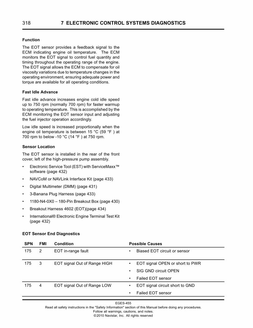
318 7 ELECTRONIC CONTROL SYSTEMS DIAGNOSTICS
Function
The EOT sensor provides a feedback signal to theECM indicating engine oil temperature. The ECMmonitors the EOT signal to control fuel quantity andtiming throughout the operating range of the engine.The EOT signal allows the ECM to compensate for oilviscosity variations due to temperature changes in theoperating environment, ensuring adequate power andtorque are available for all operating conditions.
Fast Idle Advance
Fast idle advance increases engine cold idle speedup to 750 rpm (normally 700 rpm) for faster warmupto operating temperature. This is accomplished by theECM monitoring the EOT sensor input and adjustingthe fuel injector operation accordingly.
Low idle speed is increased proportionally when theengine oil temperature is between 15 °C (59 °F ) at700 rpm to below -10 °C (14 °F ) at 750 rpm.
Sensor Location
The EOT sensor is installed in the rear of the frontcover, left of the high-pressure pump assembly.
• Electronic Service Tool (EST) with ServiceMaxx™software (page 432)
• NAVCoM or NAVLink Interface Kit (page 433)
• Digital Multimeter (DMM) (page 431)
• 3-Banana Plug Harness (page 433)
• 1180-N4-0X0 – 180-Pin Breakout Box (page 430)
• Breakout Harness 4602 (EOT)(page 434)
• International® Electronic Engine Terminal Test Kit(page 432)
EOT Sensor End Diagnostics
SPN FMI Condition Possible Causes
175 2 EOT in-range fault • Biased EOT circuit or sensor
175 3 EOT signal Out of Range HIGH • EOT signal OPEN or short to PWR
• SIG GND circuit OPEN
• Failed EOT sensor
175 4 EOT signal Out of Range LOW • EOT signal circuit short to GND
• Failed EOT sensor
EGES-455Read all safety instructions in the "Safety Information" section of this Manual before doing any procedures.
Follow all warnings, cautions, and notes.©2010 Navistar, Inc. All rights reserved
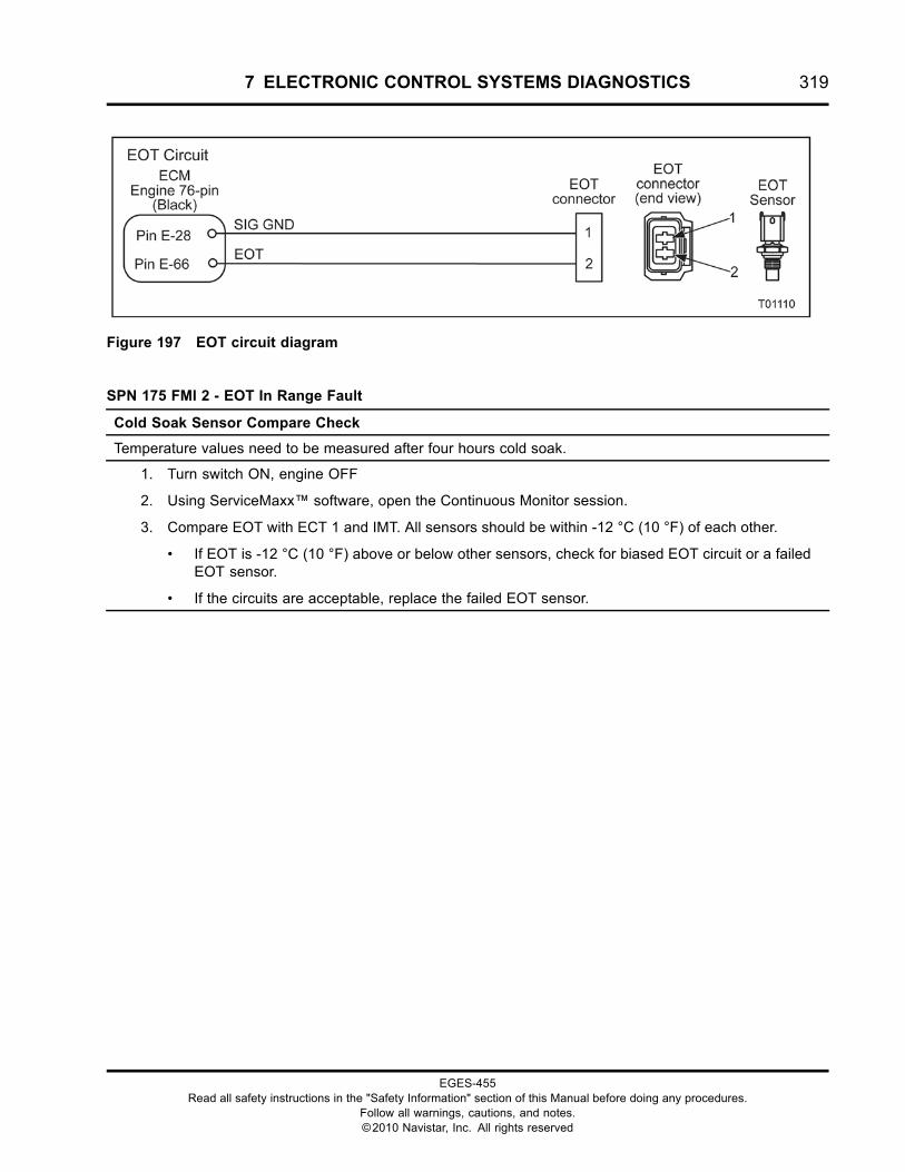
7 ELECTRONIC CONTROL SYSTEMS DIAGNOSTICS 319
Figure 197 EOT circuit diagram
SPN 175 FMI 2 - EOT In Range Fault
Cold Soak Sensor Compare Check
Temperature values need to be measured after four hours cold soak.
1. Turn switch ON, engine OFF
2. Using ServiceMaxx™ software, open the Continuous Monitor session.
3. Compare EOT with ECT 1 and IMT. All sensors should be within -12 °C (10 °F) of each other.
• If EOT is -12 °C (10 °F) above or below other sensors, check for biased EOT circuit or a failedEOT sensor.
• If the circuits are acceptable, replace the failed EOT sensor.
EGES-455Read all safety instructions in the "Safety Information" section of this Manual before doing any procedures.
Follow all warnings, cautions, and notes.©2010 Navistar, Inc. All rights reserved
320 7 ELECTRONIC CONTROL SYSTEMS DIAGNOSTICS
WARNING: To prevent personal injury ordeath, stay clear of rotating parts (belts and fan)and hot engine surfaces.
1. Using EST with ServiceMaxx™ software, openthe Continuous Monitor session.
2. Monitor sensor voltage. Verify an active DTC forthe sensor.
• If code is inactive, monitor the signalwhile wiggling the connector and all wiresat suspected location. If the circuit isinterrupted, the signal will spike and theDTC will go active.
• If code is active, proceed to the next step.
3. Disconnect engine harness from sensor.
NOTE: Inspect connectors for damaged pins,corrosion, or loose pins. Repair if necessary.
4. Connect Breakout Harness to engine harness.Leave sensor disconnected.
Sensor Circuit Check
Connect sensor breakout harness. Leave sensor disconnected. Turn ignition switch to ON. Use EST toverify correct DTC goes active when corresponding fault is induced. Use DMM to measure circuits.
Test Point Spec Comment
EST – Check DTC SPN 175FMI 3
If SPN 175 FMI 4 goes active, check EOT signal for shortto GND. Go to Harness Resistance Check.
EST – Check DTC
Short 3-Banana plug harnessacross 2 and GND
SPN 175FMI 4
If SPN 175 FMI 3 goes active, check EOT signal forOPEN. Go to Harness Resistance Check.
EST – Check DTC
Short 3-Banana plug harnessacross 1 and 2
SPN 175FMI 4
If SPN 175 FMI 3 goes active, check SIG GND for OPEN.Go to Harness Resistance Check.
If checks are within specification, connect sensor and clear DTCs. If active code remains, replace sensor.
EGES-455Read all safety instructions in the "Safety Information" section of this Manual before doing any procedures.
Follow all warnings, cautions, and notes.©2010 Navistar, Inc. All rights reserved
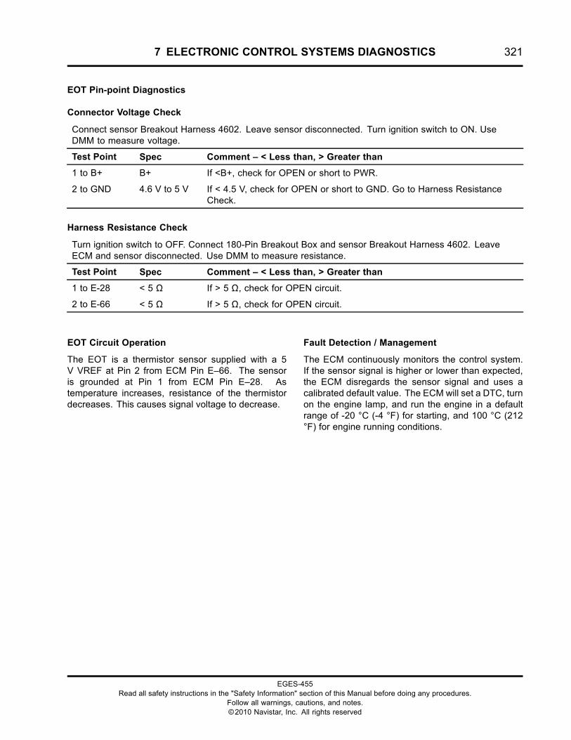
7 ELECTRONIC CONTROL SYSTEMS DIAGNOSTICS 321
EOT Pin-point Diagnostics
Connector Voltage Check
Connect sensor Breakout Harness 4602. Leave sensor disconnected. Turn ignition switch to ON. UseDMM to measure voltage.
Test Point Spec Comment – < Less than, > Greater than
1 to B+ B+ If <B+, check for OPEN or short to PWR.
2 to GND 4.6 V to 5 V If < 4.5 V, check for OPEN or short to GND. Go to Harness ResistanceCheck.
Harness Resistance Check
Turn ignition switch to OFF. Connect 180-Pin Breakout Box and sensor Breakout Harness 4602. LeaveECM and sensor disconnected. Use DMM to measure resistance.
Test Point Spec Comment – < Less than, > Greater than
1 to E-28 < 5 Ω If > 5 Ω, check for OPEN circuit.
2 to E-66 < 5 Ω If > 5 Ω, check for OPEN circuit.
EOT Circuit Operation
The EOT is a thermistor sensor supplied with a 5V VREF at Pin 2 from ECM Pin E–66. The sensoris grounded at Pin 1 from ECM Pin E–28. Astemperature increases, resistance of the thermistordecreases. This causes signal voltage to decrease.
Fault Detection / Management
The ECM continuously monitors the control system.If the sensor signal is higher or lower than expected,the ECM disregards the sensor signal and uses acalibrated default value. The ECM will set a DTC, turnon the engine lamp, and run the engine in a defaultrange of -20 °C (-4 °F) for starting, and 100 °C (212°F) for engine running conditions.
EGES-455Read all safety instructions in the "Safety Information" section of this Manual before doing any procedures.
Follow all warnings, cautions, and notes.©2010 Navistar, Inc. All rights reserved
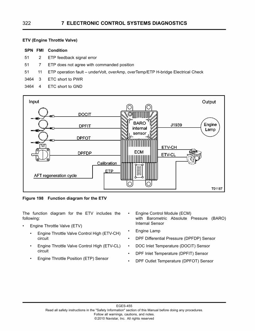
322 7 ELECTRONIC CONTROL SYSTEMS DIAGNOSTICS
ETV (Engine Throttle Valve)
SPN FMI Condition
51 2 ETP feedback signal error
51 7 ETP does not agree with commanded position
51 11 ETP operation fault – underVolt, overAmp, overTemp/ETP H-bridge Electrical Check
3464 3 ETC short to PWR
3464 4 ETC short to GND
Figure 198 Function diagram for the ETV
The function diagram for the ETV includes thefollowing:
• Engine Throttle Valve (ETV)
• Engine Throttle Valve Control High (ETV-CH)circuit
• Engine Throttle Valve Control High (ETV-CL)circuit
• Engine Throttle Position (ETP) Sensor
• Engine Control Module (ECM)with Barometric Absolute Pressure (BARO)Internal Sensor
• Engine Lamp
• DPF Differential Pressure (DPFDP) Sensor
• DOC Inlet Temperature (DOCIT) Sensor
• DPF Inlet Temperature (DPFIT) Sensor
• DPF Outlet Temperature (DPFOT) Sensor
EGES-455Read all safety instructions in the "Safety Information" section of this Manual before doing any procedures.
Follow all warnings, cautions, and notes.©2010 Navistar, Inc. All rights reserved
7 ELECTRONIC CONTROL SYSTEMS DIAGNOSTICS 323
Function
The ETV is used to control air/fuel mixture during aregeneration process of the AFT system. The ETVis also used to insure a smooth engine shutdown byrestricting airflow to the engine at shutdown.
Component Location
The ETV is installed on the air intake between the airfilter housing and EGR mixer duct.
Tools
• Electronic Service Tool (EST) with ServiceMaxx™software (page 432)
• NAVCoM or NAVLink Interface Kit (page 433)
• Digital Multimeter (DMM) (page 431)
• 1180-N4-0X0 – 180-Pin Breakout Box (page 430)
• 3-Banana Plug Harness (page 433)
• Breakout Harness 4735A (ETV) (page 434)
• International® Electronic Engine Terminal Test Kit(page 432)
EGES-455Read all safety instructions in the "Safety Information" section of this Manual before doing any procedures.
Follow all warnings, cautions, and notes.©2010 Navistar, Inc. All rights reserved
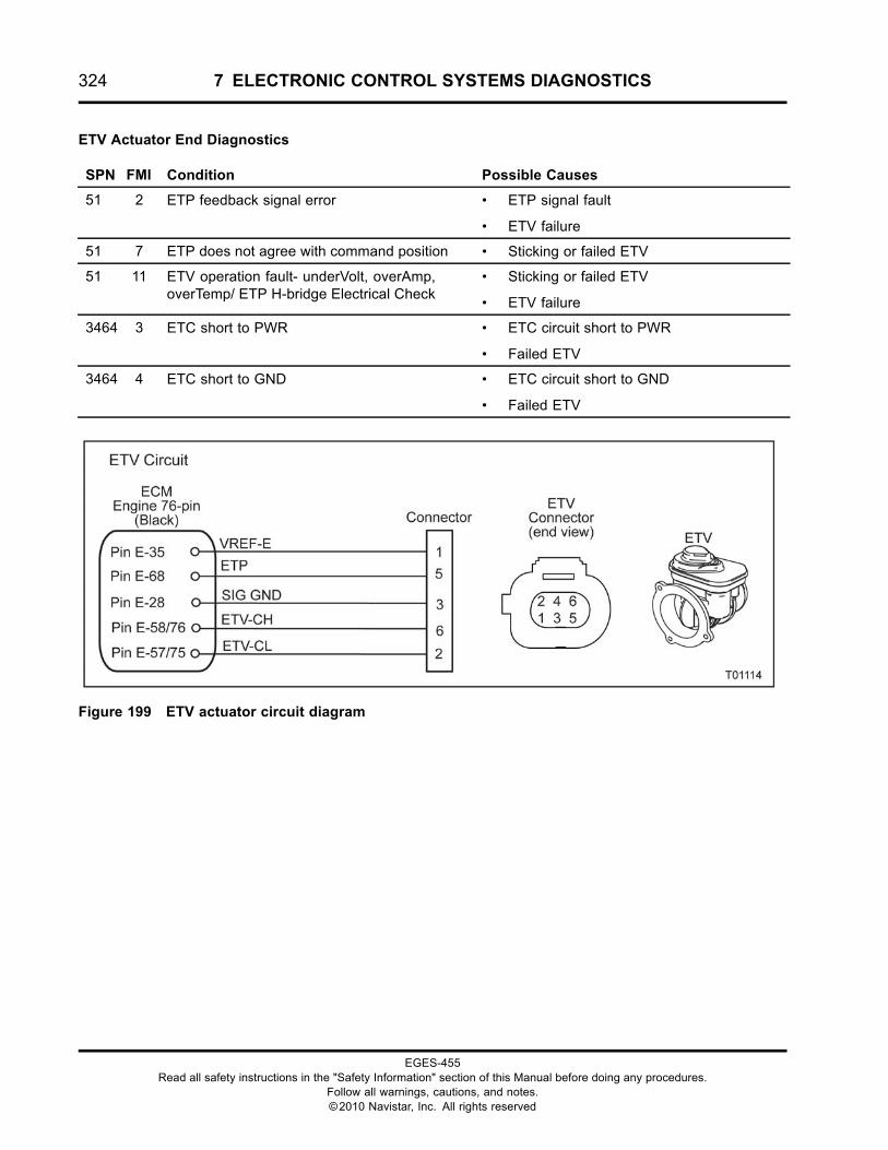
324 7 ELECTRONIC CONTROL SYSTEMS DIAGNOSTICS
ETV Actuator End Diagnostics
SPN FMI Condition Possible Causes
51 2 ETP feedback signal error • ETP signal fault
• ETV failure
51 7 ETP does not agree with command position • Sticking or failed ETV
51 11 ETV operation fault- underVolt, overAmp,overTemp/ ETP H-bridge Electrical Check
• Sticking or failed ETV
• ETV failure
3464 3 ETC short to PWR • ETC circuit short to PWR
• Failed ETV
3464 4 ETC short to GND • ETC circuit short to GND
• Failed ETV
Figure 199 ETV actuator circuit diagram
EGES-455Read all safety instructions in the "Safety Information" section of this Manual before doing any procedures.
Follow all warnings, cautions, and notes.©2010 Navistar, Inc. All rights reserved
7 ELECTRONIC CONTROL SYSTEMS DIAGNOSTICS 325
WARNING: To prevent personal injury ordeath, stay clear of rotating parts (belts and fan)and hot engine surfaces.
1. Using EST with ServiceMaxx™ software, openthe Continuous Monitor session.
2. Verify sensor voltage is within KOEOspecification. See “APPENDIX A:PERFORMANCE SPECIFICATIONS” inthis manual.
3. Monitor sensor voltage. Verify an active DTC forthe sensor.
• If code is inactive, monitor the signalwhile wiggling the connector and all wiresat suspected location. If the circuit isinterrupted, the signal will spike and theDTC will go active.
• If code is active, proceed to the next step.
4. Disconnect engine harness from sensor.
NOTE: Inspect connectors for damaged pins,corrosion, or loose pins. Repair if necessary.
5. Connect breakout harness to engine harness.Leave sensor disconnected.
EGES-455Read all safety instructions in the "Safety Information" section of this Manual before doing any procedures.
Follow all warnings, cautions, and notes.©2010 Navistar, Inc. All rights reserved

326 7 ELECTRONIC CONTROL SYSTEMS DIAGNOSTICS
ETV Actuator Circuit Check
Connect breakout harness. Leave ETV disconnected. Turn ignition switch to ON. Use EST to monitor signaland DMM to measure voltage during Continuous Monitor test.
Test Point Spec Comment – < Less than, > Greater than
EST - Check DTC SPN 3464FMI 4
If SPN 3464 FMI 3, check ETP signal for short to PWR.
DMM - Measure volts
1 to GND
5 V ± 0.5 V If > 5.5 V, check VREF for short to PWR.
If < 4.5 V, check VREF for OPEN or short to GND. Go toHarness Resistance Check.
EST - Check DTC
Short breakout harness across 5and 1
SPN 3464FMI 3
If SPN 3464 FMI 4, check ETP signal for OPEN. Go toHarness Resistance Check.
DMM - Measure volts
3 to B+
B+ If < B+, check SIG GND for OPEN. Go to HarnessResistance Check.
DMM - Measure volts
2 to GND
B+ If < B+, check ETV-CL for OPEN or short to GND. Go toHarness Resistance Check.
DMM - Measure volts
6 to GND
B+ If < B+, check ETV-CH for OPEN or short to GND. Go toHarness Resistance Check.
ETV Actuator Pin-point Diagnostics
Connector Voltage Check
Connect breakout harness. Leave actuator disconnected. Turn ignition switch to ON. Use DMM to measurevoltage.
Test Point Spec Comment – < Less than, > Greater than
3 to GND 0 V If > 0.25 V, check SIG GND for short to PWR.
1 to GND 5 V ± 0.5 V If > 5.5 V, check VREF for short to PWR.
If < 4.5 V, check VREF for OPEN or short to GND. Go to HarnessResistance Check.
5 to GND 0 V If > 0.25 V, check ETP for short to PWR. Go to Harness Resistance Check.
2 to GND B+ If < B+, check ETV–CL for OPEN or short to GND. Go to HarnessResistance Check.
6 to GND B+ If < B+, check ETV–CH for OPEN or short to GND. Go to HarnessResistance Check.
If checks are within specification, go to Connector Resistance Check to GND.
EGES-455Read all safety instructions in the "Safety Information" section of this Manual before doing any procedures.
Follow all warnings, cautions, and notes.©2010 Navistar, Inc. All rights reserved
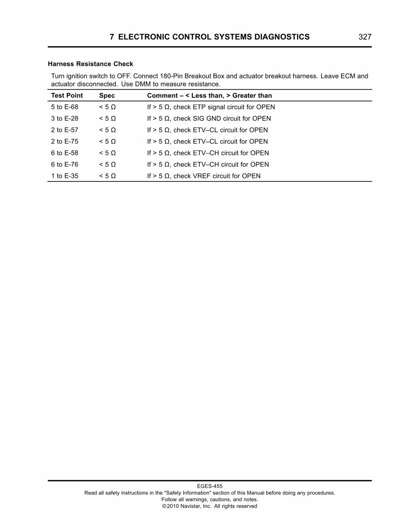
7 ELECTRONIC CONTROL SYSTEMS DIAGNOSTICS 327
Harness Resistance Check
Turn ignition switch to OFF. Connect 180-Pin Breakout Box and actuator breakout harness. Leave ECM andactuator disconnected. Use DMM to measure resistance.
Test Point Spec Comment – < Less than, > Greater than
5 to E-68 < 5 Ω If > 5 Ω, check ETP signal circuit for OPEN
3 to E-28 < 5 Ω If > 5 Ω, check SIG GND circuit for OPEN
2 to E-57 < 5 Ω If > 5 Ω, check ETV–CL circuit for OPEN
2 to E-75 < 5 Ω If > 5 Ω, check ETV–CL circuit for OPEN
6 to E-58 < 5 Ω If > 5 Ω, check ETV–CH circuit for OPEN
6 to E-76 < 5 Ω If > 5 Ω, check ETV–CH circuit for OPEN
1 to E-35 < 5 Ω If > 5 Ω, check VREF circuit for OPEN
EGES-455Read all safety instructions in the "Safety Information" section of this Manual before doing any procedures.
Follow all warnings, cautions, and notes.©2010 Navistar, Inc. All rights reserved
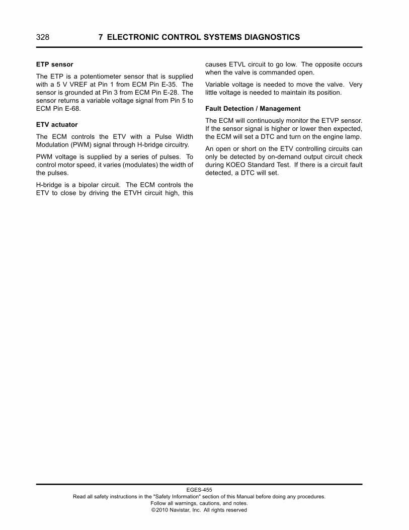
328 7 ELECTRONIC CONTROL SYSTEMS DIAGNOSTICS
ETP sensor
The ETP is a potentiometer sensor that is suppliedwith a 5 V VREF at Pin 1 from ECM Pin E-35. Thesensor is grounded at Pin 3 from ECM Pin E-28. Thesensor returns a variable voltage signal from Pin 5 toECM Pin E-68.
ETV actuator
The ECM controls the ETV with a Pulse WidthModulation (PWM) signal through H-bridge circuitry.
PWM voltage is supplied by a series of pulses. Tocontrol motor speed, it varies (modulates) the width ofthe pulses.
H-bridge is a bipolar circuit. The ECM controls theETV to close by driving the ETVH circuit high, this
causes ETVL circuit to go low. The opposite occurswhen the valve is commanded open.
Variable voltage is needed to move the valve. Verylittle voltage is needed to maintain its position.
Fault Detection / Management
The ECM will continuously monitor the ETVP sensor.If the sensor signal is higher or lower then expected,the ECM will set a DTC and turn on the engine lamp.
An open or short on the ETV controlling circuits canonly be detected by on-demand output circuit checkduring KOEO Standard Test. If there is a circuit faultdetected, a DTC will set.
EGES-455Read all safety instructions in the "Safety Information" section of this Manual before doing any procedures.
Follow all warnings, cautions, and notes.©2010 Navistar, Inc. All rights reserved
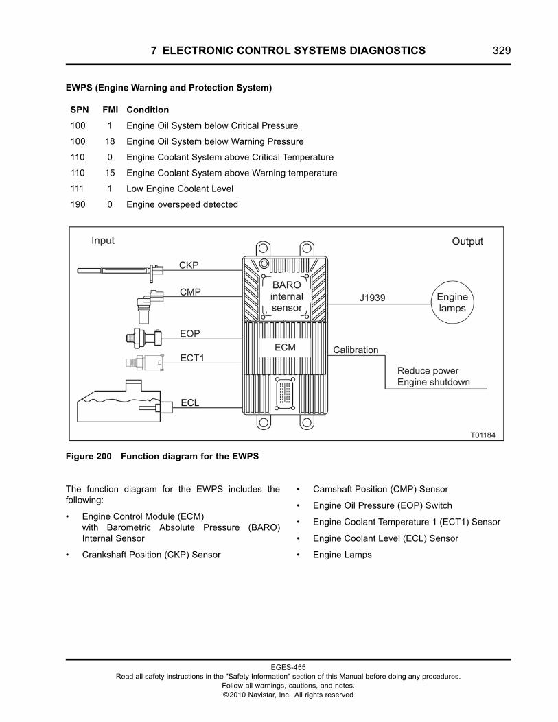
7 ELECTRONIC CONTROL SYSTEMS DIAGNOSTICS 329
EWPS (Engine Warning and Protection System)
SPN FMI Condition
100 1 Engine Oil System below Critical Pressure
100 18 Engine Oil System below Warning Pressure
110 0 Engine Coolant System above Critical Temperature
110 15 Engine Coolant System above Warning temperature
111 1 Low Engine Coolant Level
190 0 Engine overspeed detected
Figure 200 Function diagram for the EWPS
The function diagram for the EWPS includes thefollowing:
• Engine Control Module (ECM)with Barometric Absolute Pressure (BARO)Internal Sensor
• Crankshaft Position (CKP) Sensor
• Camshaft Position (CMP) Sensor
• Engine Oil Pressure (EOP) Switch
• Engine Coolant Temperature 1 (ECT1) Sensor
• Engine Coolant Level (ECL) Sensor
• Engine Lamps
EGES-455Read all safety instructions in the "Safety Information" section of this Manual before doing any procedures.
Follow all warnings, cautions, and notes.©2010 Navistar, Inc. All rights reserved
330 7 ELECTRONIC CONTROL SYSTEMS DIAGNOSTICS
Function
The Engine Warning Protection System (EWPS)warns the operator of conditions that can damage theengine.
The Standard Warning System is the base systemwith which all engines are equipped. If one of thesefaults is detected, the ECM will illuminate the redOIL/WATER (OWL) lamp and set a correspondingDTC.
Standard Warning – No engine shutdown available.
• RPM - Engine over-speed warning
• ECT - Engine over-heat warning
The following optional features of the base systemprovide added warning or protection.
2-way Warning – No engine shutdown available.
• ECT - Engine over-heat warning
• EOP - Low engine oil pressure warning
3-way Warning – No engine shutdown available.
• ECT - Engine over-heat warning
• EOP - Low engine oil pressure warning
• ECL - Low engine coolant level warning
3-way Protection – Engine shutdown is available ifcritical condition is detected.
• ECT, EOP, ECL - Same as 3-way Warning
• ECT - Engine over-heat critical protection
• EOP - Low engine oil pressure critical protection
• ECL - Low engine coolant level critical protection
Warning – Temperature above specific threshold willsound a buzzer, illuminate the red OWL and set aDTC.
Critical – Temperature above specific threshold willshutdown the engine and set a DTC. The operatorhas 30 seconds to safely pull vehicle off the roadbefore the engine shuts off. A red STOP ENGINEwarning lamp will illuminate when engine shutdownis approaching. The ECM allows the engine to berestarted and run for 30-second periods.
Event log – This feature will log occurrences of theevent according to the engine hours and odometerreadings.
EGES-455Read all safety instructions in the "Safety Information" section of this Manual before doing any procedures.
Follow all warnings, cautions, and notes.©2010 Navistar, Inc. All rights reserved
7 ELECTRONIC CONTROL SYSTEMS DIAGNOSTICS 331
EWPS Programmable Parameters
ENG-PROT-MODE
• 0 = Standard Warning
• 1 = 3-way Warning
• 2 = 3-way Protection
• 3 = 2-way Warning
Engine Coolant Warning Temp – Specifiestemperature threshold. An OWL and warning buzzerwill be turned on.
Engine Coolant Warning Temp – Specifiestemperature threshold. An engine shutdown willbe commanded.
EOP RPM Boundary 1 – Specifies at what RPM aspecified oil pressure (engine oil critical pressure forregion 1) should be detected.
EOP RPM Boundary 2 – Specifies at what RPM aspecified oil pressure (engine oil critical pressure forregion 2) should be detected.
EOP RPM Boundary 3 – Specifies at what RPM aspecified oil pressure (engine oil critical pressure forregion 3) should be detected.
EOP Warning Pressure Region 1 – Specifies theminimum oil pressure with engine speed greater than
EOP RPM Boundary 1. Failure to meet set point willturn on the OIL/WATER lamp and warning buzzer.
EOP Warning Pressure Region 2 – Specifies theminimum oil pressure with engine speed greaterthan EOP RPM Boundary 1 but less than EOP RPMBoundary 2. Failure to meet set point will turn on theOWL and warning buzzer.
EOP Warning Pressure Region 3 – Specifies theminimum oil pressure with engine speed greaterthan EOP RPM Boundary 2 but less than EOP RPMBoundary 3. Failure to meet set point will turn on theOWL and warning buzzer.
Engine oil critical pressure for region 1 – Specifiesthe minimum oil pressure with engine speed greaterthan EOP RPM Boundary 1. Failure to meet set pointwill command an engine shutdown.
Engine oil critical pressure for region 2 – Specifiesthe minimum oil pressure with engine speed greaterthan EOP RPM Boundary 1 but less than EOP RPMBoundary 2. Failure to meet set point will commandan engine shutdown.
Engine oil critical pressure for region 3 – Specifiesthe minimum oil pressure with engine speed greaterthan EOP RPM Boundary 2 but less than EOP RPMBoundary 3. Failure to meet set point will commandan engine shutdown.
EGES-455Read all safety instructions in the "Safety Information" section of this Manual before doing any procedures.
Follow all warnings, cautions, and notes.©2010 Navistar, Inc. All rights reserved
332 7 ELECTRONIC CONTROL SYSTEMS DIAGNOSTICS
SPN 100 FMI 1Engine Oil System below critical pressure
• SPN 100 FMI 1 is set by the ECM, when theengine oil pressure drops below the critical levelwhile the engine is running. The specificationsare:
• 14 kPa (2 psi) @ 700 rpm
• 34 kPa (5 psi) @ 1400 rpm
• 152 kPa (22 psi) @ 2000 rpm
• For diagnostics, see Low Oil Pressure in“ENGINE SYMPTOMS DIAGNOSTICS”.
• SPN 100 FMI 1 can be set by an open, circuit shortto voltage source in the EOP circuit, a loose orfailed EOP switch, or low oil pressure.
• When SPN 100 FMI 1 is active, the red lampflashes and sounds an audible signal.
SPN 100 FMI 18Engine Oil System below warning pressure
• SPN 100 FMI 18 is set by the ECM, when engineoil pressure is lower than expected while theengine is running. The specifications for thewarning are:
• 34 kPa (5 psi) @ 700 rpm
• 69 kPa (10 psi) @ 1400 rpm
• 138 kPa (20 psi) @ 2000 rpm
• For diagnostics, see Low Oil PressureDiagnostics in the “ENGINE SYMPTOMSDIAGNOSTICS”.
• SPN 100 FMI 18 can be set by an open, circuitshort to voltage source in the EOP circuit, a looseor failed EOP switch, or low oil pressure.
• When SPN 100 FMI 18 is active, the red lamp isilluminated.
SPN 110 FMI 0Engine Coolant System above CriticalTemperature
• SPN 110 FMI 0 is set by the ECM when theengine coolant temperature is above 116 °C (240°F). The ECM illuminates the red lamp. Whenthe temperature drops below 116 °C (240 °F),the DTC will become inactive. For diagnostics,see Coolant Over-Temperature in the “ENGINESYMPTOMS DIAGNOSTICS” section of thismanual.
• For high altitude applications 103 kPa (15 psi)radiator cap, SPN 110 FMI 0 is set by the ECMwhen the engine coolant temperature is above119 °C (246 °F). When the temperature dropsbelow 119 °C (246 °F), the DTC will becomeinactive.
SPN 110 FMI 15Coolant System above warning temperature
• SPN 110 FMI 15 is set by the ECM when theengine coolant temperature is above 113 °C (235°F). The ECM illuminates the red lamp (OWLfor CF). When the temperature drops below 113°C (235 °F) the DTC will become inactive. Fordiagnostics, see Coolant Over-Temperature in the“ENGINE SYMPTOMS DIAGNOSTICS” sectionof this manual.
• For high altitude applications 103 kPa (15 psi)radiator cap, SPN 110 FMI 15 is set by the ECMwhen the engine coolant temperature is above116 °C (240 °F). When the temperature dropsbelow 116 °C (240 °F), the DTC will becomeinactive.
EGES-455Read all safety instructions in the "Safety Information" section of this Manual before doing any procedures.
Follow all warnings, cautions, and notes.©2010 Navistar, Inc. All rights reserved
7 ELECTRONIC CONTROL SYSTEMS DIAGNOSTICS 333
SPN 111 FMI 1Low Engine Coolant Level
• SPN 111 FMI 1 is set by the ECM when coolant islow. When the EWPS mode is 3-way protectionand SPN 111 FMI 1 is active, the engine willshutdown. The ECM will log the engine hoursand odometer reading at the time of occurrence.After the shutdown, the engine can be restartedfor thirty seconds. When the coolant has returnedto correct levels, SPN 111 FMI 1 will becomeactive.
NOTE: If the coolant level is correct, do ECLConnector Voltage Test in this section. An ECLsignal shorted to ground can cause SPN 111 FMI 1.
SPN 190 FMI 0Engine overspeed detected
• SPN 190 FMI 0 is set by the ECMwhen the enginerpm has exceeded 3200 rpm.
• SPN 190 FMI 0 can be set due to any of thefollowing conditions:
• Excessive engine speed in an unintendeddownshift.
• Steep acceleration downhill without correctbrake application.
• External fuel source being ingested into airintake system.
• When SPN 190 FMI 0 is active, the lamp will notilluminate, but the engine hours and miles of thelast two overspeed occurrences will be recordedin the engine event log.
EGES-455Read all safety instructions in the "Safety Information" section of this Manual before doing any procedures.
Follow all warnings, cautions, and notes.©2010 Navistar, Inc. All rights reserved
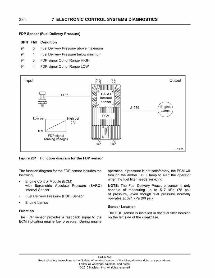
334 7 ELECTRONIC CONTROL SYSTEMS DIAGNOSTICS
FDP Sensor (Fuel Delivery Pressure)
SPN FMI Condition
94 0 Fuel Delivery Pressure above maximum
94 1 Fuel Delivery Pressure below minimum
94 3 FDP signal Out of Range HIGH
94 4 FDP signal Out of Range LOW
Figure 201 Function diagram for the FDP sensor
The function diagram for the FDP sensor includes thefollowing:
• Engine Control Module (ECM)with Barometric Absolute Pressure (BARO)Internal Sensor
• Fuel Delivery Pressure (FDP) Sensor
• Engine Lamps
Function
The FDP sensor provides a feedback signal to theECM indicating engine fuel pressure. During engine
operation, if pressure is not satisfactory, the ECM willturn on the amber FUEL lamp to alert the operatorwhen the fuel filter needs servicing.
NOTE: The Fuel Delivery Pressure sensor is onlycapable of measuring up to 517 kPa (75 psi)of pressure, even though fuel pressure normallyoperates at 621 kPa (90 psi).
Sensor Location
The FDP sensor is installed in the fuel filter housingon the left side of the crankcase.
EGES-455Read all safety instructions in the "Safety Information" section of this Manual before doing any procedures.
Follow all warnings, cautions, and notes.©2010 Navistar, Inc. All rights reserved
7 ELECTRONIC CONTROL SYSTEMS DIAGNOSTICS 335
Tools
• Electronic Service Tool (EST) with ServiceMaxx™software (page 432)
• NAVCoM or NAVLink Interface Kit (page 433)
• Digital Multimeter (DMM) (page 431)
• 1180-N4-0X0 – 180-Pin Breakout Box (page 430)
• 3-Banana Plug Harness (page 433)
• Breakout Harness 4850 (FDP) (page 436)
• International® Electronic Engine Terminal Test Kit(page 432)
FDP Sensor End Diagnostics
SPN FMI Condition Possible Causes
94 0 Fuel Delivery Pressure abovemaximum
• FDP above 145 psi with engine running
• Restricted Fuel Regulator
• Restricted Fuel Return line
• Biased FDP sensor or circuit
94 1 Fuel Delivery Pressure below minimum • Dirty fuel filter
• Aerated Fuel
• Restricted or open fuel supply line
• Low or empty fuel supply tank
• Biased FDP sensor or circuit
• Failed Fuel Pump
94 3 FDP signal Out-of-Range HIGH • FDP signal circuit short to PWR
• Failed FDP sensor
94 4 FDP signal Out-of-Range LOW • FDP signal circuit OPEN or short to GND
• VREF circuit OPEN
• Failed FDP sensor
EGES-455Read all safety instructions in the "Safety Information" section of this Manual before doing any procedures.
Follow all warnings, cautions, and notes.©2010 Navistar, Inc. All rights reserved
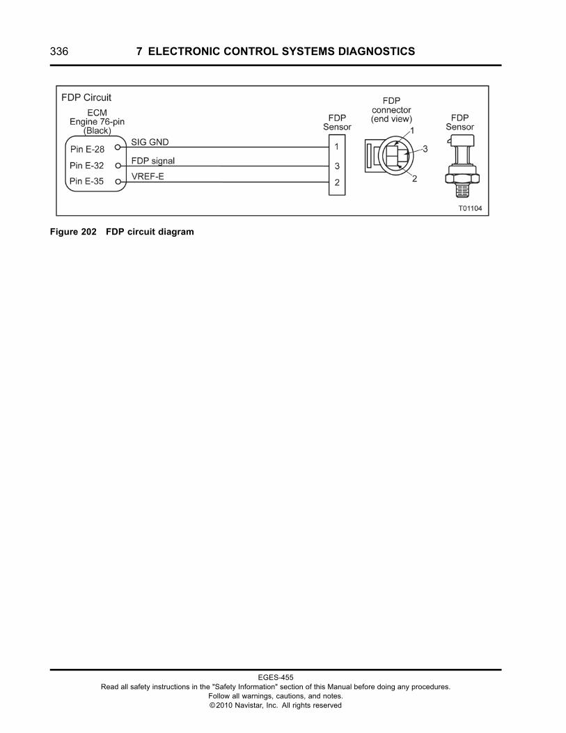
336 7 ELECTRONIC CONTROL SYSTEMS DIAGNOSTICS
Figure 202 FDP circuit diagram
EGES-455Read all safety instructions in the "Safety Information" section of this Manual before doing any procedures.
Follow all warnings, cautions, and notes.©2010 Navistar, Inc. All rights reserved
7 ELECTRONIC CONTROL SYSTEMS DIAGNOSTICS 337
WARNING: To prevent personal injury ordeath, stay clear of rotating parts (belts and fan)and hot engine surfaces.
1. Using EST and ServiceMaxx™ software, openthe Continuous Monitor session.
2. Verify sensor voltage is within KOEOspecification. See “APPENDIX A:PERFORMANCE SPECIFICATIONS” inthis manual.
3. Monitor sensor voltage. Verify an active DTC forthe sensor.
• If code is inactive, monitor the signalwhile wiggling the connector and all wiresat suspected location. If the circuit isinterrupted, the signal will spike and theDTC will go active.
• If code is active, proceed to the next step.
4. Disconnect engine harness from sensor.
NOTE: Inspect connectors for damaged pins,corrosion, or loose pins. Repair if necessary.
5. Connect Breakout Harness 4850 to engineharness. Leave sensor disconnected.
Sensor Circuit Check
Connect Breakout Harness 4850. Leave sensor disconnected. Turn ignition switch to ON. Use EST to verifycorrect DTC goes active when corresponding fault is induced. Use DMM to measure circuits.
Test Point Spec Comment – < Less than, > Greater than
EST – Check DTC SPN 94FMI 4
If SPN 94 FMI 3 is active, check EFP signal for short toPWR.
DMM – Measure volts
2 to GND
5 V ± 0.5 V If > 5.5 V, check VREF for short to PWR.
If < 4.5 V, check VREF for OPEN or short to GND. Go toHarness Resistance Check.
EST – Check DTC
Short breakout harnessacross 2 and 3
SPN 94FMI 3
If SPN 94 FMI 4 is active, check FDP signal for OPEN orshort to GND. Go to Harness Resistance Check.
DMM – Measure volt
1 to B+
+B If <B+, check SIG GND for OPEN. Go to HarnessResistance Check.
If checks are within specification, connect sensor and clear DTCs. If active code remains, replace sensor.
EGES-455Read all safety instructions in the "Safety Information" section of this Manual before doing any procedures.
Follow all warnings, cautions, and notes.©2010 Navistar, Inc. All rights reserved
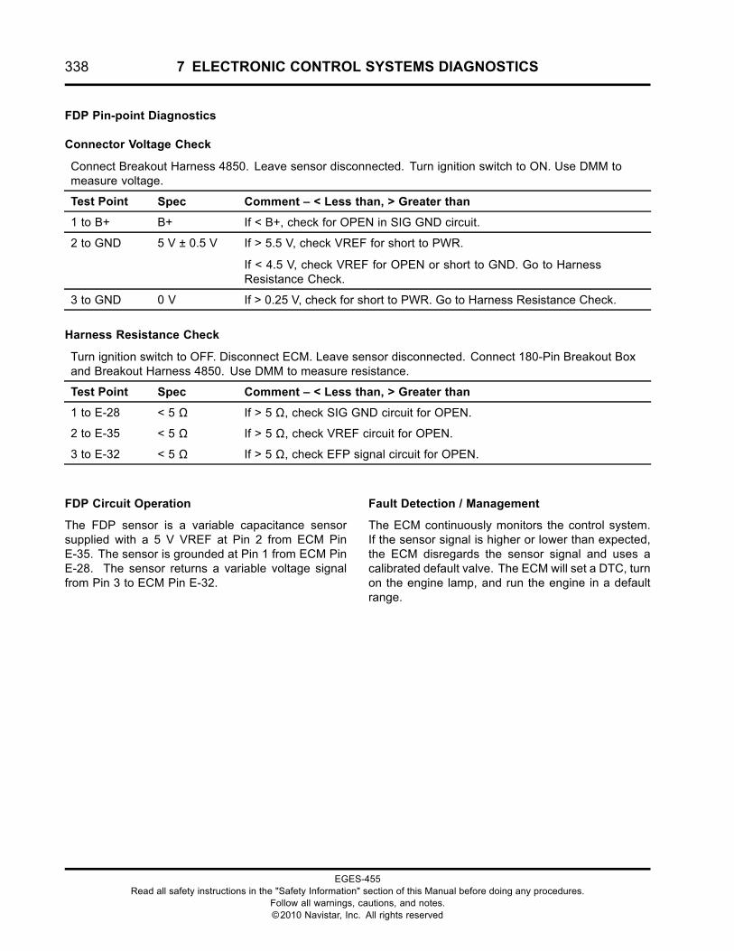
338 7 ELECTRONIC CONTROL SYSTEMS DIAGNOSTICS
FDP Pin-point Diagnostics
Connector Voltage Check
Connect Breakout Harness 4850. Leave sensor disconnected. Turn ignition switch to ON. Use DMM tomeasure voltage.
Test Point Spec Comment – < Less than, > Greater than
1 to B+ B+ If < B+, check for OPEN in SIG GND circuit.
2 to GND 5 V ± 0.5 V If > 5.5 V, check VREF for short to PWR.
If < 4.5 V, check VREF for OPEN or short to GND. Go to HarnessResistance Check.
3 to GND 0 V If > 0.25 V, check for short to PWR. Go to Harness Resistance Check.
Harness Resistance Check
Turn ignition switch to OFF. Disconnect ECM. Leave sensor disconnected. Connect 180-Pin Breakout Boxand Breakout Harness 4850. Use DMM to measure resistance.
Test Point Spec Comment – < Less than, > Greater than
1 to E-28 < 5 Ω If > 5 Ω, check SIG GND circuit for OPEN.
2 to E-35 < 5 Ω If > 5 Ω, check VREF circuit for OPEN.
3 to E-32 < 5 Ω If > 5 Ω, check EFP signal circuit for OPEN.
FDP Circuit Operation
The FDP sensor is a variable capacitance sensorsupplied with a 5 V VREF at Pin 2 from ECM PinE-35. The sensor is grounded at Pin 1 from ECM PinE-28. The sensor returns a variable voltage signalfrom Pin 3 to ECM Pin E-32.
Fault Detection / Management
The ECM continuously monitors the control system.If the sensor signal is higher or lower than expected,the ECM disregards the sensor signal and uses acalibrated default valve. The ECM will set a DTC, turnon the engine lamp, and run the engine in a defaultrange.
EGES-455Read all safety instructions in the "Safety Information" section of this Manual before doing any procedures.
Follow all warnings, cautions, and notes.©2010 Navistar, Inc. All rights reserved
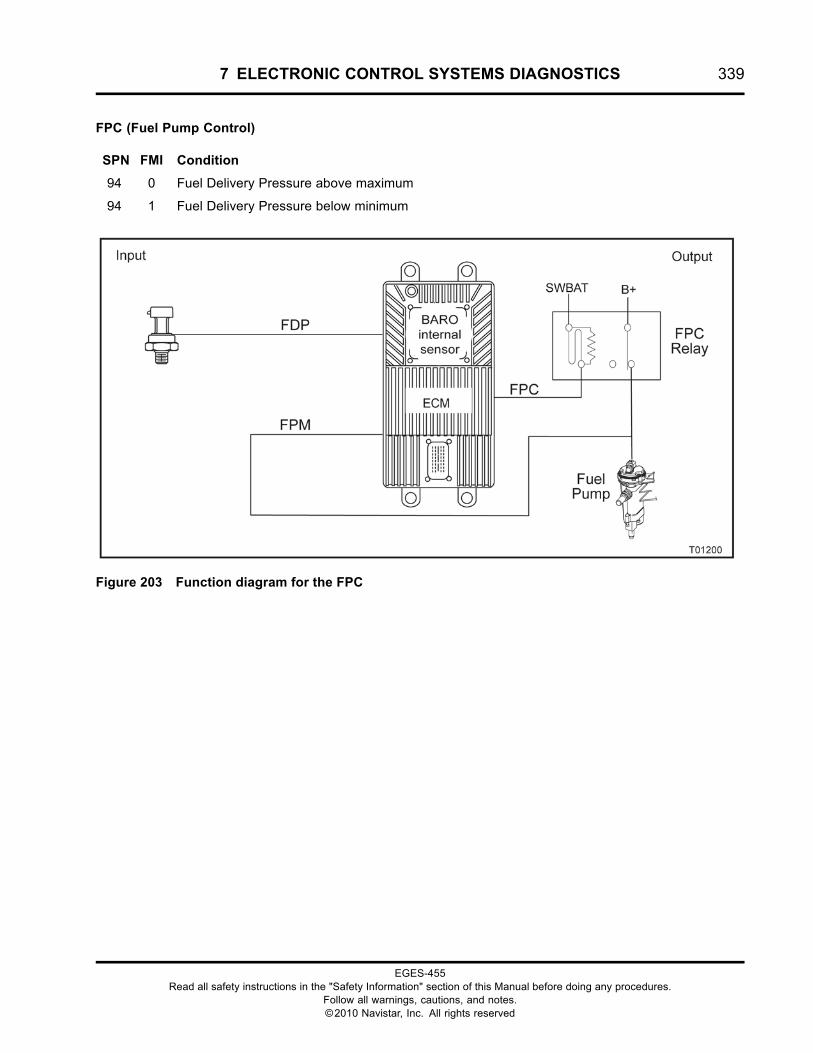
7 ELECTRONIC CONTROL SYSTEMS DIAGNOSTICS 339
FPC (Fuel Pump Control)
SPN FMI Condition
94 0 Fuel Delivery Pressure above maximum
94 1 Fuel Delivery Pressure below minimum
Figure 203 Function diagram for the FPC
EGES-455Read all safety instructions in the "Safety Information" section of this Manual before doing any procedures.
Follow all warnings, cautions, and notes.©2010 Navistar, Inc. All rights reserved
340 7 ELECTRONIC CONTROL SYSTEMS DIAGNOSTICS
The function diagram for the FPC includes thefollowing:
• Engine Control Module (ECM)with Barometric Absolute Pressure (BARO)Internal Sensor
• Fuel Pump Control (FPC)
• Fuel Pump Monitor (FPM)
• FDP Sensor
Function
The FPC supplies fuel to the engine at approximately620 kPa (90 psi). The ECM drives the fuel pumpdirectly, using H-Bridge driver.
NOTE: The Fuel Delivery Pressure (FDP) sensor isonly capable of measuring up to 517 kPa (75 psi)of pressure, even though fuel pressure normallyoperates at 621 kPa (90 psi).
Fuel Pump Location
The fuel pump is located in the fuel filter module.
Tools
• Electronic Service Tool (EST) with ServiceMaxx™software (page 432)
• NAVCoM or NAVLink Interface Kit (page 433)
• Digital Multimeter (DMM) (page 431)
• 1180-N4-0X0 – 180-Pin Breakout Box (page 430)
• Breakout Harness 6023 (FPC) (page 439)
• Breakout Harness 4674 (Relay) (page 434)
• International® Electronic Engine Terminal Test Kit(page 432)
EGES-455Read all safety instructions in the "Safety Information" section of this Manual before doing any procedures.
Follow all warnings, cautions, and notes.©2010 Navistar, Inc. All rights reserved
7 ELECTRONIC CONTROL SYSTEMS DIAGNOSTICS 341
FPC Pin-Point Diagnostics
SPN FMI Condition Possible Causes
94 0 FDP above maximum • Fuel regulator stuck closed or blocked with debris
• Fuel return line restriction between fuel filterhousing and fuel tank
94 1 FDP below minimum • Dirty fuel filter
• Aerated fuel
• Restricted or open fuel supply line
• Low or empty fuel supply tank
• EDP sensor or circuit fault
• Failed fuel pump
SPN 94 FMI 0 – Fuel Delivery Pressure above maximum
Fuel Delivery Pressure Check
1. Connect Fuel Pressure Gauge to the Fuel Pressure Test port at the intake manifold.
2. Using ServiceMaxx™ software, monitor the Fuel Delivery Pressure signal.
3. Turn the ignition switch ON, the fuel pump will only run for 10 seconds before commanded off.
4. Check measurement after the fuel pump is commanded off.
• If fuel pressure gauge indicates below 206 kPa (30 psi) and ServiceMaxx™ software isdisplaying above 482 kPa (70 psi), check FDP sensor / circuit for fault. See FDP sensorin this section.
• If fuel pressure gauge indicates above 206 kPa (30 psi), then check for restricted fuel regulatoror fuel return line. See Fuel System in “HARD START AND NO START” section this manual
SPN 94 FMI 1 – Fuel Delivery Pressure below minimum
Fuel Delivery Pressure Check
1. Connect Fuel Pressure Gauge to the Fuel Pressure Test port at the intake manifold.
2. Using ServiceMaxx™ software, monitor the Fuel Delivery Pressure signal.
3. Turn the ignition switch ON, the fuel pump will only run for 10 seconds before commanded off.
4. Check measurement when the fuel pump is commanded on.
• If fuel pressure gauge indicates above 517 kPa (75 psi) and ServiceMaxx™ software isdisplaying below 482 kPa (70 psi), check FDP sensor/circuit for fault. See EDP sensor inthis section.
• If fuel pressure gauge is display below 482 kPa (70 psi), continue to Fuel Pump OperationalCheck.
EGES-455Read all safety instructions in the "Safety Information" section of this Manual before doing any procedures.
Follow all warnings, cautions, and notes.©2010 Navistar, Inc. All rights reserved
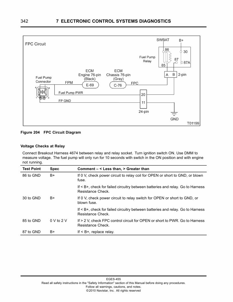
342 7 ELECTRONIC CONTROL SYSTEMS DIAGNOSTICS
Figure 204 FPC Circuit Diagram
Voltage Checks at Relay
Connect Breakout Harness 4674 between relay and relay socket. Turn ignition switch ON. Use DMM tomeasure voltage. The fuel pump will only run for 10 seconds with switch in the ON position and with enginenot running.
Test Point Spec Comment – < Less than, > Greater than
86 to GND B+ If 0 V, check power circuit to relay coil for OPEN or short to GND, or blownfuse.
If < B+, check for failed circuitry between batteries and relay. Go to HarnessResistance Check.
30 to GND B+ If 0 V, check power circuit to relay switch for OPEN or short to GND, orblown fuse.
If < B+, check for failed circuitry between batteries and relay. Go to HarnessResistance Check.
85 to GND 0 V to 2 V If > 2 V, check FPC control circuit for OPEN or short to PWR. Go to HarnessResistance Check.
87 to GND B+ If < B+, replace relay.
EGES-455Read all safety instructions in the "Safety Information" section of this Manual before doing any procedures.
Follow all warnings, cautions, and notes.©2010 Navistar, Inc. All rights reserved
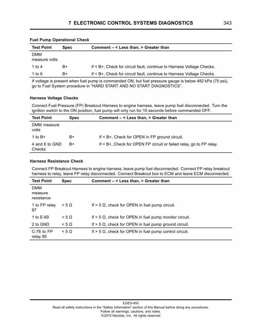
7 ELECTRONIC CONTROL SYSTEMS DIAGNOSTICS 343
Fuel Pump Operational Check
Test Point Spec Comment – < Less than, > Greater than
DMMmeasure volts
1 to 4 B+ If < B+, Check for circuit fault, continue to Harness Voltage Checks.
1 to 6 B+ If < B+, Check for circuit fault, continue to Harness Voltage Checks.
If voltage is present when fuel pump is commanded ON, but fuel pressure gauge is below 482 kPa (70 psi),go to Fuel System procedure in “HARD START AND NO START DIAGNOSTICS”.
Harness Voltage Checks
Connect Fuel Pressure (FP) Breakout Harness to engine harness, leave pump fuel disconnected. Turn theignition switch to the ON position, fuel pump will only run for 10 seconds before commanded OFF.
Test Point Spec Comment – < Less than, > Greater than
DMM measurevolts
1 to B+ B+ If < B+, Check for OPEN in FP ground circuit.
4 and 6 to GNDChecks
B+ If < B+, Check for OPEN FP circuit or failed relay, go to FP relay.
Harness Resistance Check
Connect FP Breakout Harness to engine harness, leave pump fuel disconnected. Connect FP relay breakoutharness to relay, leave FP relay disconnected. Connect Breakout box to ECM and leave ECM disconnected.
Test Point Spec Comment – < Less than, > Greater than
DMMmeasureresistance
1 to FP relay87
< 5 Ω If > 5 Ω, check for OPEN in fuel pump circuit.
1 to E-69 < 5 Ω If > 5 Ω, check for OPEN in fuel pump monitor circuit.
2 to GND < 5 Ω If > 5 Ω, check for OPEN in fuel pump ground circuit.
C-76 to FPrelay 85
< 5 Ω If > 5 Ω, check for OPEN in fuel pump control circuit.
EGES-455Read all safety instructions in the "Safety Information" section of this Manual before doing any procedures.
Follow all warnings, cautions, and notes.©2010 Navistar, Inc. All rights reserved
344 7 ELECTRONIC CONTROL SYSTEMS DIAGNOSTICS
FPC Circuit Operation
The FDP sensor is a variable capacitance sensorsupplied with a 5 V VREF at Pin 2 from ECM PinE-35. The sensor is grounded at Pin 1 from ECM PinE-28. The sensor returns a variable voltage signalfrom Pin 3 to ECM Pin E-32.
Fault Detection / Management
The ECM continuously monitors the control system.If the sensor signal is higher or lower than expected,the ECM disregards the sensor signal and uses acalibrated default valve. The ECM will set a DTC, turnon the engine lamp, and run the engine in a defaultrange.
EGES-455Read all safety instructions in the "Safety Information" section of this Manual before doing any procedures.
Follow all warnings, cautions, and notes.©2010 Navistar, Inc. All rights reserved
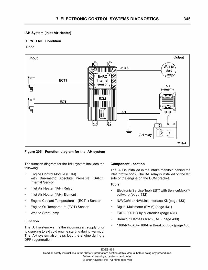
7 ELECTRONIC CONTROL SYSTEMS DIAGNOSTICS 345
IAH System (Inlet Air Heater)
SPN FMI Condition
None
Figure 205 Function diagram for the IAH system
The function diagram for the IAH system includes thefollowing:
• Engine Control Module (ECM)with Barometric Absolute Pressure (BARO)Internal Sensor
• Inlet Air Heater (IAH) Relay
• Inlet Air Heater (IAH) Element
• Engine Coolant Temperature 1 (ECT1) Sensor
• Engine Oil Temperature (EOT) Sensor
• Wait to Start Lamp
Function
The IAH system warms the incoming air supply priorto cranking to aid cold engine starting during warmup.The IAH system also helps load the engine during aDPF regeneration.
Component Location
The IAH is installed in the intake manifold behind theinlet throttle body. The IAH relay is installed on the leftside of the engine on the ECM bracket.
Tools
• Electronic Service Tool (EST) with ServiceMaxx™software (page 432)
• NAVCoM or NAVLink Interface Kit (page 433)
• Digital Multimeter (DMM) (page 431)
• EXP-1000 HD by Midtronics (page 431)
• Breakout Harness 6025 (IAH) (page 439)
• 1180-N4-0X0 – 180-Pin Breakout Box (page 430)
EGES-455Read all safety instructions in the "Safety Information" section of this Manual before doing any procedures.
Follow all warnings, cautions, and notes.©2010 Navistar, Inc. All rights reserved
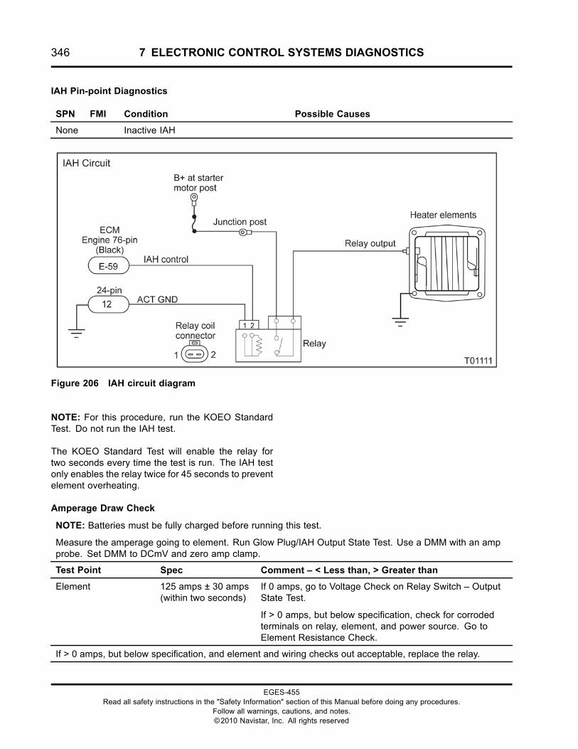
346 7 ELECTRONIC CONTROL SYSTEMS DIAGNOSTICS
IAH Pin-point Diagnostics
SPN FMI Condition Possible Causes
None Inactive IAH
Figure 206 IAH circuit diagram
NOTE: For this procedure, run the KOEO StandardTest. Do not run the IAH test.
The KOEO Standard Test will enable the relay fortwo seconds every time the test is run. The IAH testonly enables the relay twice for 45 seconds to preventelement overheating.
Amperage Draw Check
NOTE: Batteries must be fully charged before running this test.
Measure the amperage going to element. Run Glow Plug/IAH Output State Test. Use a DMM with an ampprobe. Set DMM to DCmV and zero amp clamp.
Test Point Spec Comment – < Less than, > Greater than
Element 125 amps ± 30 amps(within two seconds)
If 0 amps, go to Voltage Check on Relay Switch – OutputState Test.
If > 0 amps, but below specification, check for corrodedterminals on relay, element, and power source. Go toElement Resistance Check.
If > 0 amps, but below specification, and element and wiring checks out acceptable, replace the relay.
EGES-455Read all safety instructions in the "Safety Information" section of this Manual before doing any procedures.
Follow all warnings, cautions, and notes.©2010 Navistar, Inc. All rights reserved
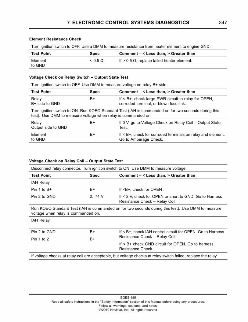
7 ELECTRONIC CONTROL SYSTEMS DIAGNOSTICS 347
Element Resistance Check
Turn ignition switch to OFF. Use a DMM to measure resistance from heater element to engine GND.
Test Point Spec Comment – < Less than, > Greater than
Elementto GND
< 0.5 Ω If > 0.5 Ω, replace failed heater element.
Voltage Check on Relay Switch – Output State Test
Turn ignition switch to OFF. Use DMM to measure voltage on relay B+ side.
Test Point Spec Comment – < Less than, > Greater than
RelayB+ side to GND
B+ If < B+, check large PWR circuit to relay for OPEN,corroded terminal, or blown fuse link.
Turn ignition switch to ON. Run KOEO Standard Test (IAH is commanded on for two seconds during thistest). Use DMM to measure voltage when relay is commanded on.
RelayOutput side to GND
B+ If 0 V, go to Voltage Check on Relay Coil – Output StateTest.
Elementto GND
B+ If < B+, check for corroded terminals on relay and element.Go to Amperage Check.
Voltage Check on Relay Coil – Output State Test
Disconnect relay connector. Turn ignition switch to ON. Use DMM to measure voltage.
Test Point Spec Comment – < Less than, > Greater than
IAH Relay
Pin 1 to B+ B+ If <B+, check for OPEN .
Pin 2 to GND 2. 74 V If < 2 V, check for OPEN or short to GND. Go to HarnessResistance Check – Relay Coil.
Run KOEO Standard Test (IAH is commanded on for two seconds during this test). Use DMM to measurevoltage when relay is commanded on.
IAH Relay
Pin 2 to GND
Pin 1 to 2
B+
B+
If < B+, check IAH control circuit for OPEN. Go to HarnessResistance Check – Relay Coil.
If < B+ check GND circuit for OPEN. Go to harnessResistance Check.
If voltage checks at relay coil are acceptable, but voltage checks at relay switch failed, replace the relay.
EGES-455Read all safety instructions in the "Safety Information" section of this Manual before doing any procedures.
Follow all warnings, cautions, and notes.©2010 Navistar, Inc. All rights reserved
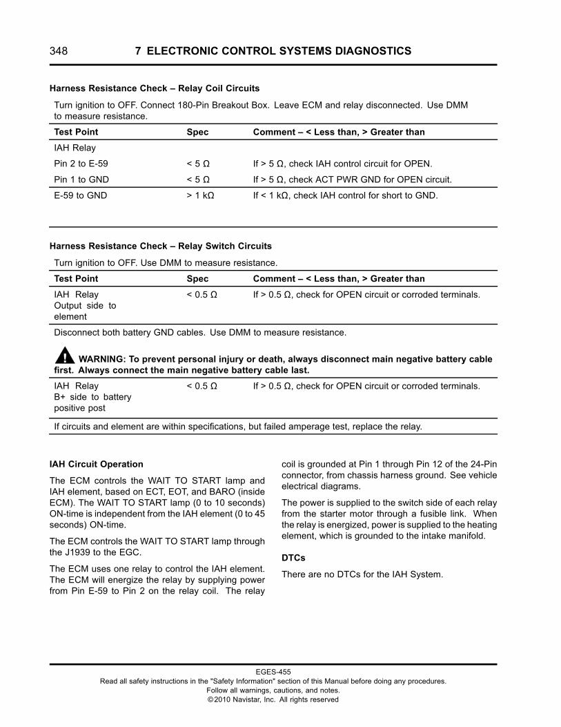
348 7 ELECTRONIC CONTROL SYSTEMS DIAGNOSTICS
Harness Resistance Check – Relay Coil Circuits
Turn ignition to OFF. Connect 180-Pin Breakout Box. Leave ECM and relay disconnected. Use DMMto measure resistance.
Test Point Spec Comment – < Less than, > Greater than
IAH Relay
Pin 2 to E-59 < 5 Ω If > 5 Ω, check IAH control circuit for OPEN.
Pin 1 to GND < 5 Ω If > 5 Ω, check ACT PWR GND for OPEN circuit.
E-59 to GND > 1 kΩ If < 1 kΩ, check IAH control for short to GND.
Harness Resistance Check – Relay Switch Circuits
Turn ignition to OFF. Use DMM to measure resistance.
Test Point Spec Comment – < Less than, > Greater than
IAH RelayOutput side toelement
< 0.5 Ω If > 0.5 Ω, check for OPEN circuit or corroded terminals.
Disconnect both battery GND cables. Use DMM to measure resistance.
WARNING: To prevent personal injury or death, always disconnect main negative battery cablefirst. Always connect the main negative battery cable last.
IAH RelayB+ side to batterypositive post
< 0.5 Ω If > 0.5 Ω, check for OPEN circuit or corroded terminals.
If circuits and element are within specifications, but failed amperage test, replace the relay.
IAH Circuit Operation
The ECM controls the WAIT TO START lamp andIAH element, based on ECT, EOT, and BARO (insideECM). The WAIT TO START lamp (0 to 10 seconds)ON-time is independent from the IAH element (0 to 45seconds) ON-time.
The ECM controls the WAIT TO START lamp throughthe J1939 to the EGC.
The ECM uses one relay to control the IAH element.The ECM will energize the relay by supplying powerfrom Pin E-59 to Pin 2 on the relay coil. The relay
coil is grounded at Pin 1 through Pin 12 of the 24-Pinconnector, from chassis harness ground. See vehicleelectrical diagrams.
The power is supplied to the switch side of each relayfrom the starter motor through a fusible link. Whenthe relay is energized, power is supplied to the heatingelement, which is grounded to the intake manifold.
DTCs
There are no DTCs for the IAH System.
EGES-455Read all safety instructions in the "Safety Information" section of this Manual before doing any procedures.
Follow all warnings, cautions, and notes.©2010 Navistar, Inc. All rights reserved
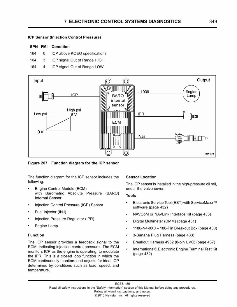
7 ELECTRONIC CONTROL SYSTEMS DIAGNOSTICS 349
ICP Sensor (Injection Control Pressure)
SPN FMI Condition
164 0 ICP above KOEO specifications
164 3 ICP signal Out of Range HIGH
164 4 ICP signal Out of Range LOW
Figure 207 Function diagram for the ICP sensor
The function diagram for the ICP sensor includes thefollowing:
• Engine Control Module (ECM)with Barometric Absolute Pressure (BARO)Internal Sensor
• Injection Control Pressure (ICP) Sensor
• Fuel Injector (INJ)
• Injection Pressure Regulator (IPR)
• Engine Lamp
Function
The ICP sensor provides a feedback signal to theECM, indicating injection control pressure. The ECMmonitors ICP as the engine is operating, to modulatethe IPR. This is a closed loop function in which theECM continuously monitors and adjusts for ideal ICPdetermined by conditions such as load, speed, andtemperature.
Sensor Location
The ICP sensor is installed in the high-pressure oil rail,under the valve cover.
Tools
• Electronic Service Tool (EST) with ServiceMaxx™software (page 432)
• NAVCoM or NAVLink Interface Kit (page 433)
• Digital Multimeter (DMM) (page 431)
• 1180-N4-0X0 – 180-Pin Breakout Box (page 430)
• 3-Banana Plug Harness (page 433)
• Breakout Harness 4952 (8-pin UVC) (page 437)
• International® Electronic Engine Terminal Test Kit(page 432)
EGES-455Read all safety instructions in the "Safety Information" section of this Manual before doing any procedures.
Follow all warnings, cautions, and notes.©2010 Navistar, Inc. All rights reserved
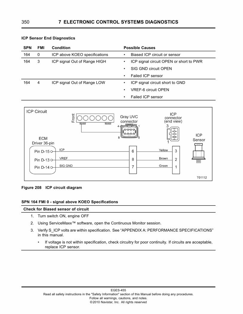
350 7 ELECTRONIC CONTROL SYSTEMS DIAGNOSTICS
ICP Sensor End Diagnostics
SPN FMI Condition Possible Causes
164 0 ICP above KOEO specifications • Biased ICP circuit or sensor
164 3 ICP signal Out of Range HIGH • ICP signal circuit OPEN or short to PWR
• SIG GND circuit OPEN
• Failed ICP sensor
164 4 ICP signal Out of Range LOW • ICP signal circuit short to GND
• VREF-6 circuit OPEN
• Failed ICP sensor
Figure 208 ICP circuit diagram
SPN 164 FMI 0 - signal above KOEO Specifications
Check for Biased sensor of circuit
1. Turn switch ON, engine OFF
2. Using ServiceMaxx™ software, open the Continuous Monitor session.
3. Verify S_ICP volts are within specification. See “APPENDIX A: PERFORMANCE SPECIFICATIONS”in this manual.
• If voltage is not within specification, check circuitry for poor continuity. If circuits are acceptable,replace ICP sensor.
EGES-455Read all safety instructions in the "Safety Information" section of this Manual before doing any procedures.
Follow all warnings, cautions, and notes.©2010 Navistar, Inc. All rights reserved
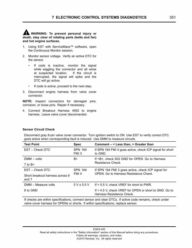
7 ELECTRONIC CONTROL SYSTEMS DIAGNOSTICS 351
WARNING: To prevent personal injury ordeath, stay clear of rotating parts (belts and fan)and hot engine surfaces.
1. Using EST with ServiceMaxx™ software, openthe Continuous Monitor session.
2. Monitor sensor voltage. Verify an active DTC forthe sensor.
• If code is inactive, monitor the signalwhile wiggling the connector and all wiresat suspected location. If the circuit isinterrupted, the signal will spike and theDTC will go active.
• If code is active, proceed to the next step.
3. Disconnect engine harness from valve coverconnector.
NOTE: Inspect connectors for damaged pins,corrosion, or loose pins. Repair if necessary.
4. Connect Breakout Harness 4952 to engineharness. Leave valve cover disconnected.
Sensor Circuit Check
Disconnect gray 8-pin valve cover connector. Turn ignition switch to ON. Use EST to verify correct DTCgoes active when corresponding fault is induced. Use DMM to measure circuits.
Test Point Spec Comment – < Less than, > Greater than
EST – Check DTC SPN 164FMI 3
If SPN 164 FMI 4 goes active, check ICP signal for shortto GND.
DMM – volts
7 to B+
B+ If <B+, check SIG GND for OPEN. Go to HarnessResistance Check.
EST – Check DTC
Short breakout harness across 6and 7
SPN 164FMI 4
If SPN 164 FMI 3 goes active, check ICP signal forOPEN. Go to Harness Resistance Check.
DMM – Measure volts
8 to GND
5 V ± 0.5 V If > 5.5 V, check VREF for short to PWR.
If < 4.5 V, check VREF for OPEN or short to GND. Go toHarness Resistance Check.
If checks are within specifications, connect sensor and clear DTCs. If active code remains, check undervalve cover harness for OPENs or shorts. If within specifications, replace sensor.
EGES-455Read all safety instructions in the "Safety Information" section of this Manual before doing any procedures.
Follow all warnings, cautions, and notes.©2010 Navistar, Inc. All rights reserved
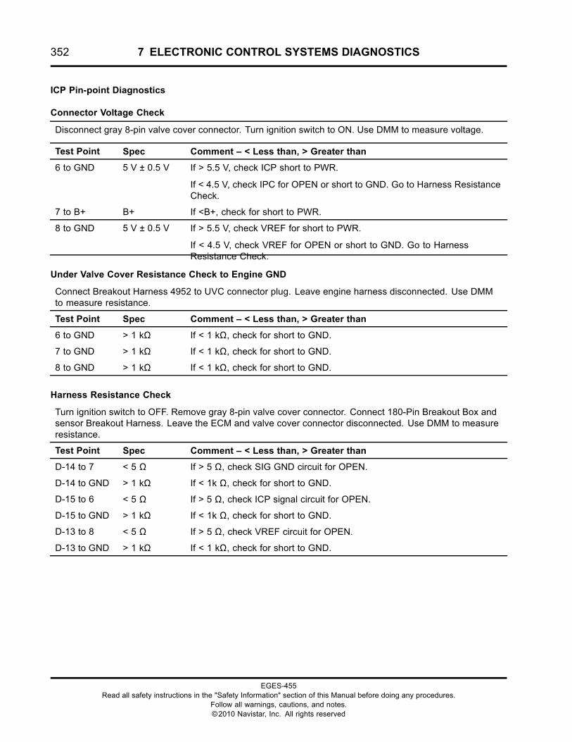
352 7 ELECTRONIC CONTROL SYSTEMS DIAGNOSTICS
ICP Pin-point Diagnostics
Connector Voltage Check
Disconnect gray 8-pin valve cover connector. Turn ignition switch to ON. Use DMM to measure voltage.
Test Point Spec Comment – < Less than, > Greater than
6 to GND 5 V ± 0.5 V If > 5.5 V, check ICP short to PWR.
If < 4.5 V, check IPC for OPEN or short to GND. Go to Harness ResistanceCheck.
7 to B+ B+ If <B+, check for short to PWR.
8 to GND 5 V ± 0.5 V If > 5.5 V, check VREF for short to PWR.
If < 4.5 V, check VREF for OPEN or short to GND. Go to HarnessResistance Check.
Under Valve Cover Resistance Check to Engine GND
Connect Breakout Harness 4952 to UVC connector plug. Leave engine harness disconnected. Use DMMto measure resistance.
Test Point Spec Comment – < Less than, > Greater than
6 to GND > 1 kΩ If < 1 kΩ, check for short to GND.
7 to GND > 1 kΩ If < 1 kΩ, check for short to GND.
8 to GND > 1 kΩ If < 1 kΩ, check for short to GND.
Harness Resistance Check
Turn ignition switch to OFF. Remove gray 8-pin valve cover connector. Connect 180-Pin Breakout Box andsensor Breakout Harness. Leave the ECM and valve cover connector disconnected. Use DMM to measureresistance.
Test Point Spec Comment – < Less than, > Greater than
D-14 to 7 < 5 Ω If > 5 Ω, check SIG GND circuit for OPEN.
D-14 to GND > 1 kΩ If < 1k Ω, check for short to GND.
D-15 to 6 < 5 Ω If > 5 Ω, check ICP signal circuit for OPEN.
D-15 to GND > 1 kΩ If < 1k Ω, check for short to GND.
D-13 to 8 < 5 Ω If > 5 Ω, check VREF circuit for OPEN.
D-13 to GND > 1 kΩ If < 1 kΩ, check for short to GND.
EGES-455Read all safety instructions in the "Safety Information" section of this Manual before doing any procedures.
Follow all warnings, cautions, and notes.©2010 Navistar, Inc. All rights reserved
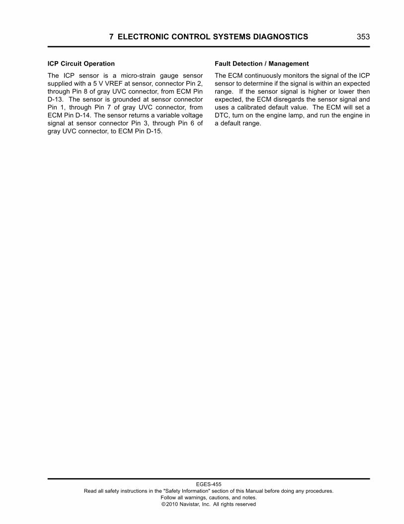
7 ELECTRONIC CONTROL SYSTEMS DIAGNOSTICS 353
ICP Circuit Operation
The ICP sensor is a micro-strain gauge sensorsupplied with a 5 V VREF at sensor, connector Pin 2,through Pin 8 of gray UVC connector, from ECM PinD-13. The sensor is grounded at sensor connectorPin 1, through Pin 7 of gray UVC connector, fromECM Pin D-14. The sensor returns a variable voltagesignal at sensor connector Pin 3, through Pin 6 ofgray UVC connector, to ECM Pin D-15.
Fault Detection / Management
The ECM continuously monitors the signal of the ICPsensor to determine if the signal is within an expectedrange. If the sensor signal is higher or lower thenexpected, the ECM disregards the sensor signal anduses a calibrated default value. The ECM will set aDTC, turn on the engine lamp, and run the engine ina default range.
EGES-455Read all safety instructions in the "Safety Information" section of this Manual before doing any procedures.
Follow all warnings, cautions, and notes.©2010 Navistar, Inc. All rights reserved
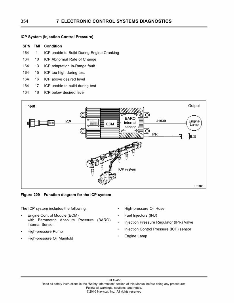
354 7 ELECTRONIC CONTROL SYSTEMS DIAGNOSTICS
ICP System (Injection Control Pressure)
SPN FMI Condition
164 1 ICP unable to Build During Engine Cranking
164 10 ICP Abnormal Rate of Change
164 13 ICP adaptation In-Range fault
164 15 ICP too high during test
164 16 ICP above desired level
164 17 ICP unable to build during test
164 18 ICP below desired level
Figure 209 Function diagram for the ICP system
The ICP system includes the following:
• Engine Control Module (ECM)with Barometric Absolute Pressure (BARO)Internal Sensor
• High-pressure Pump
• High-pressure Oil Manifold
• High-pressure Oil Hose
• Fuel Injectors (INJ)
• Injection Pressure Regulator (IPR) Valve
• Injection Control Pressure (ICP) sensor
• Engine Lamp
EGES-455Read all safety instructions in the "Safety Information" section of this Manual before doing any procedures.
Follow all warnings, cautions, and notes.©2010 Navistar, Inc. All rights reserved
7 ELECTRONIC CONTROL SYSTEMS DIAGNOSTICS 355
Function
The ICP system is a mechanical hydraulic system,electronically controlled by the ECM to intensify fuelpressure in the fuel injectors. The ECM controls theIPR valve while monitoring the ICP sensor to providethe engine with the desired starting and operatingpressures.
System Component Location
The IPR valve is installed in the high-pressure pumpassembly, which is mounted on the rear of the front
cover (left side of engine). The high-pressure oilmanifold is installed under the valve cover, directlyover the injectors. The ICP sensor is installed on thehigh-pressure oil manifold.
Tools
• Electronic Service Tool (EST) with ServiceMaxx™software (page 432)
• NAVCoM or NAVLink Interface Kit (page 433)
EGES-455Read all safety instructions in the "Safety Information" section of this Manual before doing any procedures.
Follow all warnings, cautions, and notes.©2010 Navistar, Inc. All rights reserved
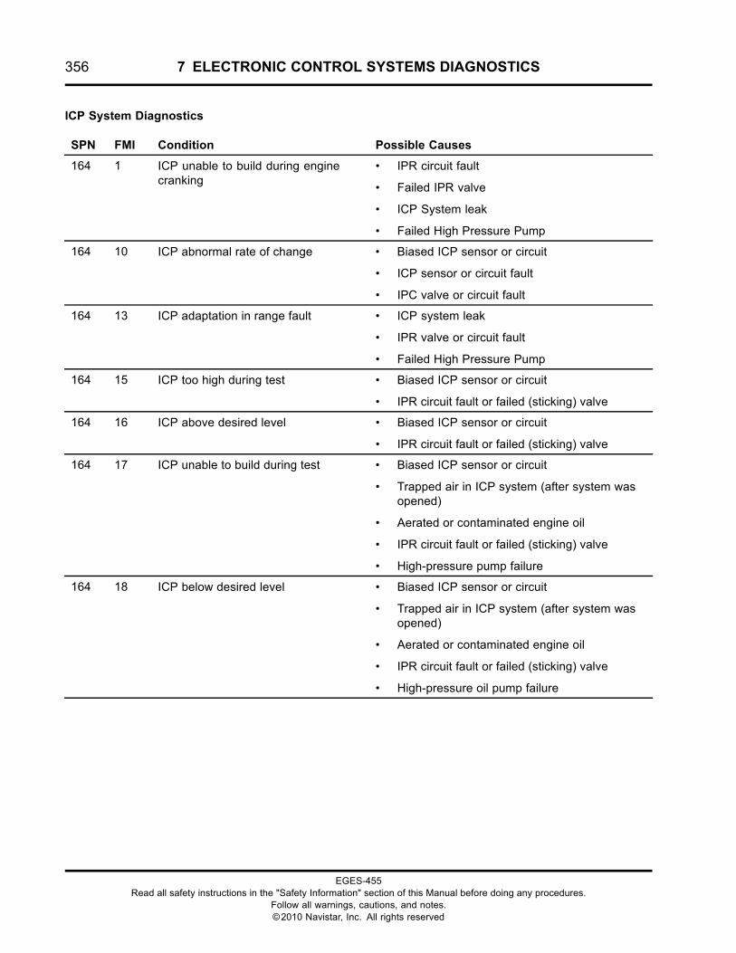
356 7 ELECTRONIC CONTROL SYSTEMS DIAGNOSTICS
ICP System Diagnostics
SPN FMI Condition Possible Causes
164 1 ICP unable to build during enginecranking
• IPR circuit fault
• Failed IPR valve
• ICP System leak
• Failed High Pressure Pump
164 10 ICP abnormal rate of change • Biased ICP sensor or circuit
• ICP sensor or circuit fault
• IPC valve or circuit fault
164 13 ICP adaptation in range fault • ICP system leak
• IPR valve or circuit fault
• Failed High Pressure Pump
164 15 ICP too high during test • Biased ICP sensor or circuit
• IPR circuit fault or failed (sticking) valve
164 16 ICP above desired level • Biased ICP sensor or circuit
• IPR circuit fault or failed (sticking) valve
164 17 ICP unable to build during test • Biased ICP sensor or circuit
• Trapped air in ICP system (after system wasopened)
• Aerated or contaminated engine oil
• IPR circuit fault or failed (sticking) valve
• High-pressure pump failure
164 18 ICP below desired level • Biased ICP sensor or circuit
• Trapped air in ICP system (after system wasopened)
• Aerated or contaminated engine oil
• IPR circuit fault or failed (sticking) valve
• High-pressure oil pump failure
EGES-455Read all safety instructions in the "Safety Information" section of this Manual before doing any procedures.
Follow all warnings, cautions, and notes.©2010 Navistar, Inc. All rights reserved
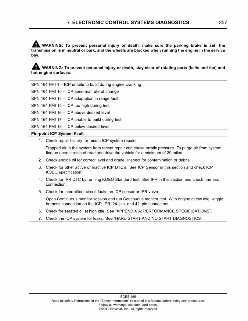
7 ELECTRONIC CONTROL SYSTEMS DIAGNOSTICS 357
WARNING: To prevent personal injury or death, make sure the parking brake is set, thetransmission is in neutral or park, and the wheels are blocked when running the engine in the servicebay.
WARNING: To prevent personal injury or death, stay clear of rotating parts (belts and fan) andhot engine surfaces.
SPN 164 FMI 1 – ICP unable to build during engine cranking
SPN 164 FMI 10 – ICP abnormal rate of change
SPN 164 FMI 13 – ICP adaptation in range fault
SPN 164 FMI 15 – ICP too high during test
SPN 164 FMI 16 – ICP above desired level
SPN 164 FMI 17 – ICP unable to build during test
SPN 164 FMI 18 – ICP below desired level
Pin-point ICP System Fault
1. Check repair history for recent ICP system repairs.
Trapped air in the system from recent repair can cause erratic pressure. To purge air from system,find an open stretch of road and drive the vehicle for a minimum of 20 miles.
2. Check engine oil for correct level and grade. Inspect for contamination or debris.
3. Check for other active or inactive ICP DTC’s. See ICP Sensor in this section and check ICPKOEO specification.
4. Check for IPR DTC by running KOEO Standard test. See IPR in this section and check harnessconnection.
5. Check for intermittent circuit faults on ICP sensor or IPR valve.
Open Continuous monitor session and run Continuous monitor test. With engine at low idle, wiggleharness connection on the ICP, IPR, 24–pin, and 42–pin connectors.
6. Check for aerated oil at high idle. See “APPENDIX A: PERFORMANCE SPECIFICATIONS”.
7. Check the ICP system for leaks. See “HARD START AND NO START DIAGNOSTICS”.
EGES-455Read all safety instructions in the "Safety Information" section of this Manual before doing any procedures.
Follow all warnings, cautions, and notes.©2010 Navistar, Inc. All rights reserved
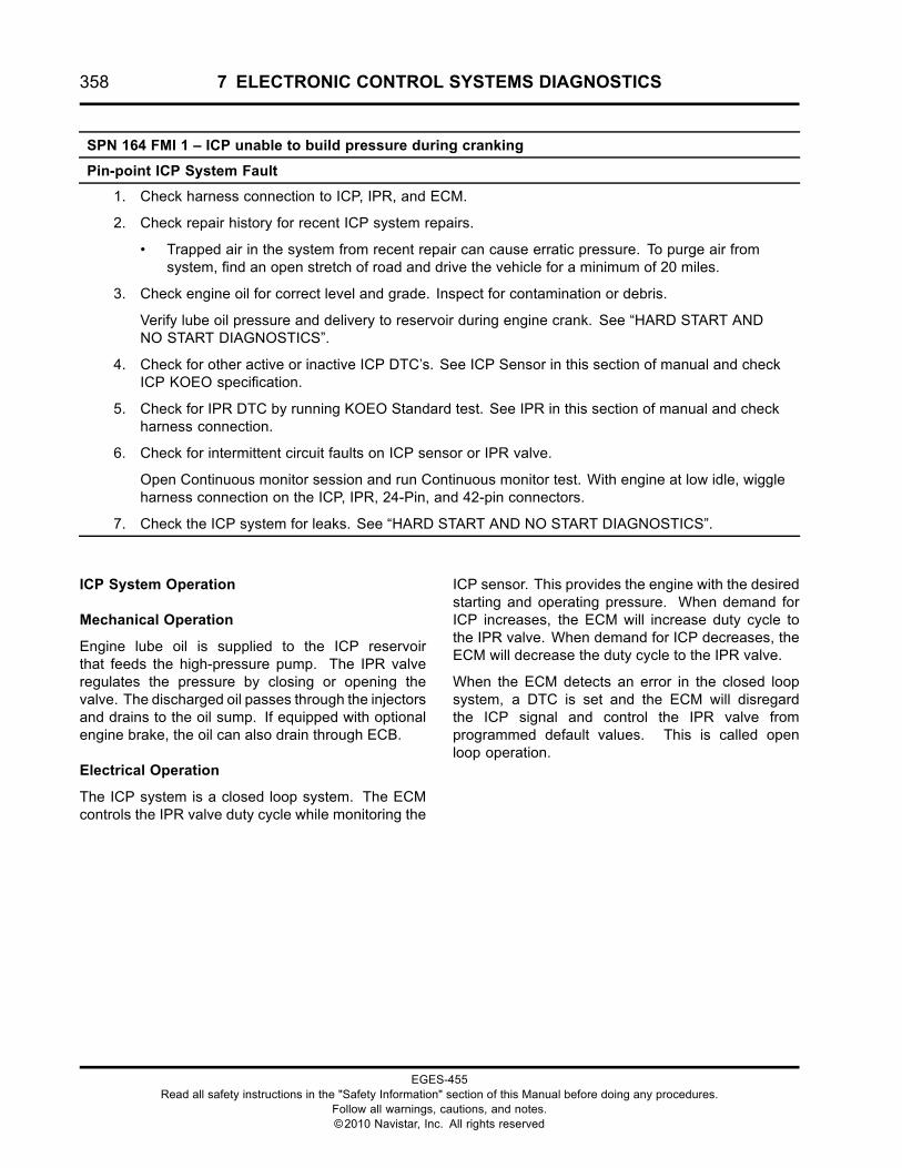
358 7 ELECTRONIC CONTROL SYSTEMS DIAGNOSTICS
SPN 164 FMI 1 – ICP unable to build pressure during cranking
Pin-point ICP System Fault
1. Check harness connection to ICP, IPR, and ECM.
2. Check repair history for recent ICP system repairs.
• Trapped air in the system from recent repair can cause erratic pressure. To purge air fromsystem, find an open stretch of road and drive the vehicle for a minimum of 20 miles.
3. Check engine oil for correct level and grade. Inspect for contamination or debris.
Verify lube oil pressure and delivery to reservoir during engine crank. See “HARD START ANDNO START DIAGNOSTICS”.
4. Check for other active or inactive ICP DTC’s. See ICP Sensor in this section of manual and checkICP KOEO specification.
5. Check for IPR DTC by running KOEO Standard test. See IPR in this section of manual and checkharness connection.
6. Check for intermittent circuit faults on ICP sensor or IPR valve.
Open Continuous monitor session and run Continuous monitor test. With engine at low idle, wiggleharness connection on the ICP, IPR, 24-Pin, and 42-pin connectors.
7. Check the ICP system for leaks. See “HARD START AND NO START DIAGNOSTICS”.
ICP System Operation
Mechanical Operation
Engine lube oil is supplied to the ICP reservoirthat feeds the high-pressure pump. The IPR valveregulates the pressure by closing or opening thevalve. The discharged oil passes through the injectorsand drains to the oil sump. If equipped with optionalengine brake, the oil can also drain through ECB.
Electrical Operation
The ICP system is a closed loop system. The ECMcontrols the IPR valve duty cycle while monitoring the
ICP sensor. This provides the engine with the desiredstarting and operating pressure. When demand forICP increases, the ECM will increase duty cycle tothe IPR valve. When demand for ICP decreases, theECM will decrease the duty cycle to the IPR valve.
When the ECM detects an error in the closed loopsystem, a DTC is set and the ECM will disregardthe ICP signal and control the IPR valve fromprogrammed default values. This is called openloop operation.
EGES-455Read all safety instructions in the "Safety Information" section of this Manual before doing any procedures.
Follow all warnings, cautions, and notes.©2010 Navistar, Inc. All rights reserved
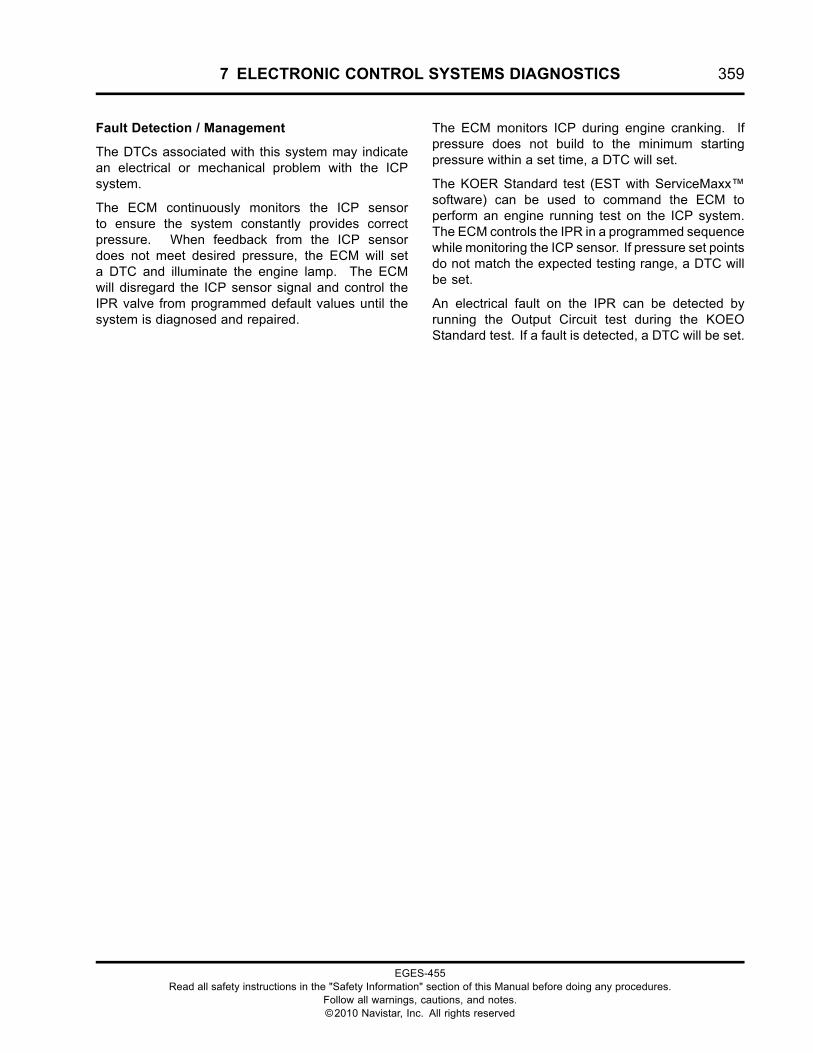
7 ELECTRONIC CONTROL SYSTEMS DIAGNOSTICS 359
Fault Detection / Management
The DTCs associated with this system may indicatean electrical or mechanical problem with the ICPsystem.
The ECM continuously monitors the ICP sensorto ensure the system constantly provides correctpressure. When feedback from the ICP sensordoes not meet desired pressure, the ECM will seta DTC and illuminate the engine lamp. The ECMwill disregard the ICP sensor signal and control theIPR valve from programmed default values until thesystem is diagnosed and repaired.
The ECM monitors ICP during engine cranking. Ifpressure does not build to the minimum startingpressure within a set time, a DTC will set.
The KOER Standard test (EST with ServiceMaxx™software) can be used to command the ECM toperform an engine running test on the ICP system.The ECM controls the IPR in a programmed sequencewhile monitoring the ICP sensor. If pressure set pointsdo not match the expected testing range, a DTC willbe set.
An electrical fault on the IPR can be detected byrunning the Output Circuit test during the KOEOStandard test. If a fault is detected, a DTC will be set.
EGES-455Read all safety instructions in the "Safety Information" section of this Manual before doing any procedures.
Follow all warnings, cautions, and notes.©2010 Navistar, Inc. All rights reserved
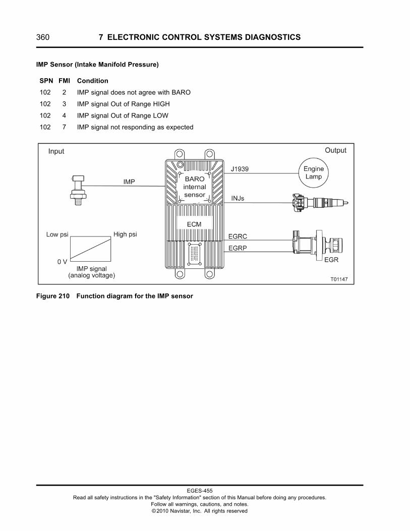
360 7 ELECTRONIC CONTROL SYSTEMS DIAGNOSTICS
IMP Sensor (Intake Manifold Pressure)
SPN FMI Condition
102 2 IMP signal does not agree with BARO
102 3 IMP signal Out of Range HIGH
102 4 IMP signal Out of Range LOW
102 7 IMP signal not responding as expected
Figure 210 Function diagram for the IMP sensor
EGES-455Read all safety instructions in the "Safety Information" section of this Manual before doing any procedures.
Follow all warnings, cautions, and notes.©2010 Navistar, Inc. All rights reserved
7 ELECTRONIC CONTROL SYSTEMS DIAGNOSTICS 361
The function diagram for the IMP sensor includes thefollowing:
• Engine Control Module (ECM)with Barometric Absolute Pressure (BARO)Internal Sensor
• Intake Manifold Pressure (IMP) Sensor
• Exhaust Gas Recirculation (EGR)
• Fuel Injector (INJ)
• Engine Lamp
Function
The ECM uses the IMP sensor signal to assistin calculation of the EGR percentage. The ECMmonitors the IMP signal to determine intake manifold(boost) pressure. From this information, the ECM canoptimize fuel rate and injection timing for all engineoperating conditions.
Sensor Location
The IMP sensor is installed in the intake manifold, leftof the IMT sensor.
Tools
• Electronic Service Tool (EST) with ServiceMaxx™software (page 432)
• NAVCoM or NAVLink Interface Kit (page 433)
• Digital Multimeter (DMM) (page 431)
• 1180-N4-0X0 – 180-Pin Breakout Box (page 430)
• 3-Banana Plug Harness (page 433)
• Breakout Harness 4850 (IMP) (page 436)
• International® Electronic Engine Terminal Test Kit(page 432)
EGES-455Read all safety instructions in the "Safety Information" section of this Manual before doing any procedures.
Follow all warnings, cautions, and notes.©2010 Navistar, Inc. All rights reserved
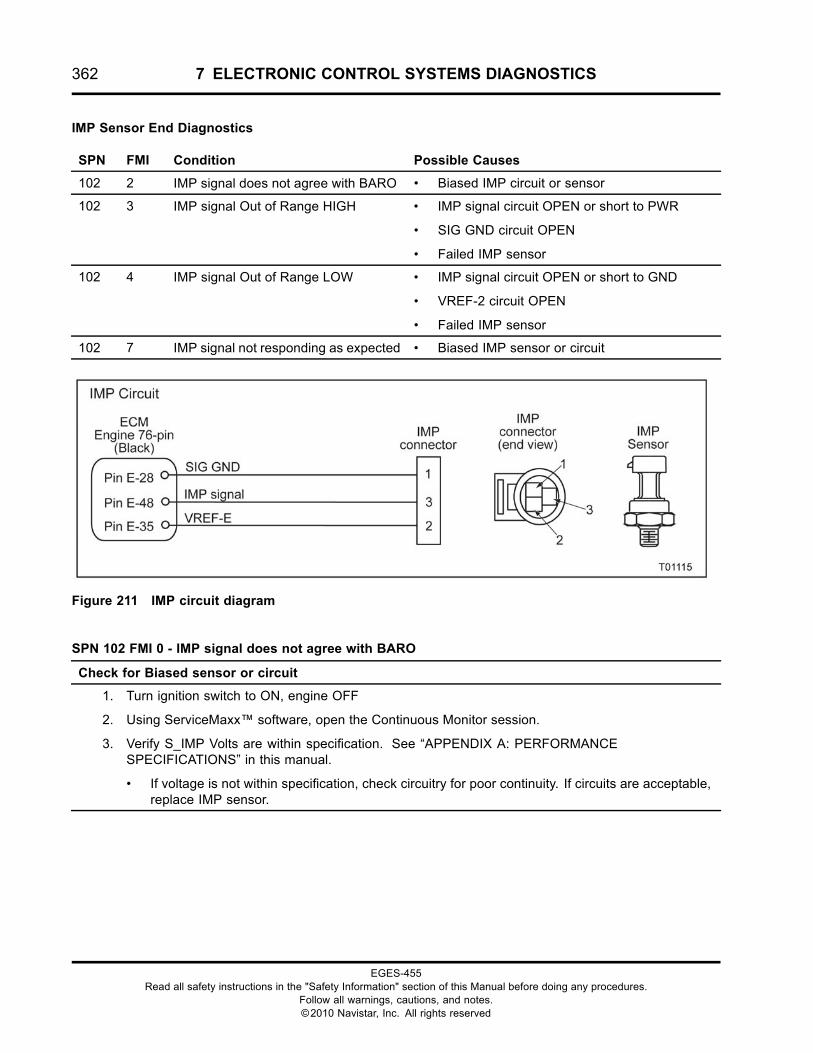
362 7 ELECTRONIC CONTROL SYSTEMS DIAGNOSTICS
IMP Sensor End Diagnostics
SPN FMI Condition Possible Causes
102 2 IMP signal does not agree with BARO • Biased IMP circuit or sensor
102 3 IMP signal Out of Range HIGH • IMP signal circuit OPEN or short to PWR
• SIG GND circuit OPEN
• Failed IMP sensor
102 4 IMP signal Out of Range LOW • IMP signal circuit OPEN or short to GND
• VREF-2 circuit OPEN
• Failed IMP sensor
102 7 IMP signal not responding as expected • Biased IMP sensor or circuit
Figure 211 IMP circuit diagram
SPN 102 FMI 0 - IMP signal does not agree with BARO
Check for Biased sensor or circuit
1. Turn ignition switch to ON, engine OFF
2. Using ServiceMaxx™ software, open the Continuous Monitor session.
3. Verify S_IMP Volts are within specification. See “APPENDIX A: PERFORMANCESPECIFICATIONS” in this manual.
• If voltage is not within specification, check circuitry for poor continuity. If circuits are acceptable,replace IMP sensor.
EGES-455Read all safety instructions in the "Safety Information" section of this Manual before doing any procedures.
Follow all warnings, cautions, and notes.©2010 Navistar, Inc. All rights reserved
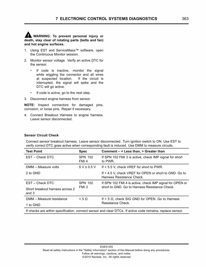
7 ELECTRONIC CONTROL SYSTEMS DIAGNOSTICS 363
WARNING: To prevent personal injury ordeath, stay clear of rotating parts (belts and fan)and hot engine surfaces.
1. Using EST and ServiceMaxx™ software, openthe Continuous Monitor session.
2. Monitor sensor voltage. Verify an active DTC forthe sensor.
• If code is inactive, monitor the signalwhile wiggling the connector and all wiresat suspected location. If the circuit isinterrupted, the signal will spike and theDTC will go active.
• If code is active, go to the next step.
3. Disconnect engine harness from sensor.
NOTE: Inspect connectors for damaged pins,corrosion, or loose pins. Repair if necessary.
4. Connect Breakout Harness to engine harness.Leave sensor disconnected.
Sensor Circuit Check
Connect sensor breakout harness. Leave sensor disconnected. Turn ignition switch to ON. Use EST toverify correct DTC goes active when corresponding fault is induced. Use DMM to measure circuits.
Test Point Spec Comment – < Less than, > Greater than
EST – Check DTC SPN 102FMI 4
If SPN 102 FMI 3 is active, check IMP signal for shortto PWR.
DMM – Measure volts
2 to GND
5 V ± 0.5 V If > 5.5 V, check VREF for short to PWR.
If < 4.5 V, check VREF for OPEN or short to GND. Go toHarness Resistance Check.
EST – Check DTC
Short breakout harness across 2and 3
SPN 102FMI 3
If SPN 102 FMI 4 is active, check IMP signal for OPEN orshort to GND. Go to Harness Resistance Check.
DMM – Measure resistance
1 to GND
< 5 Ω If > 5 Ω, check SIG GND for OPEN. Go to HarnessResistance Check.
If checks are within specification, connect sensor and clear DTCs. If active code remains, replace sensor.
EGES-455Read all safety instructions in the "Safety Information" section of this Manual before doing any procedures.
Follow all warnings, cautions, and notes.©2010 Navistar, Inc. All rights reserved
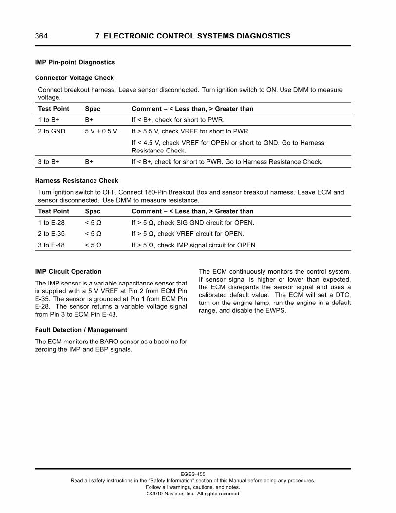
364 7 ELECTRONIC CONTROL SYSTEMS DIAGNOSTICS
IMP Pin-point Diagnostics
Connector Voltage Check
Connect breakout harness. Leave sensor disconnected. Turn ignition switch to ON. Use DMM to measurevoltage.
Test Point Spec Comment – < Less than, > Greater than
1 to B+ B+ If < B+, check for short to PWR.
2 to GND 5 V ± 0.5 V If > 5.5 V, check VREF for short to PWR.
If < 4.5 V, check VREF for OPEN or short to GND. Go to HarnessResistance Check.
3 to B+ B+ If < B+, check for short to PWR. Go to Harness Resistance Check.
Harness Resistance Check
Turn ignition switch to OFF. Connect 180-Pin Breakout Box and sensor breakout harness. Leave ECM andsensor disconnected. Use DMM to measure resistance.
Test Point Spec Comment – < Less than, > Greater than
1 to E-28 < 5 Ω If > 5 Ω, check SIG GND circuit for OPEN.
2 to E-35 < 5 Ω If > 5 Ω, check VREF circuit for OPEN.
3 to E-48 < 5 Ω If > 5 Ω, check IMP signal circuit for OPEN.
IMP Circuit Operation
The IMP sensor is a variable capacitance sensor thatis supplied with a 5 V VREF at Pin 2 from ECM PinE-35. The sensor is grounded at Pin 1 from ECM PinE-28. The sensor returns a variable voltage signalfrom Pin 3 to ECM Pin E-48.
Fault Detection / Management
The ECMmonitors the BARO sensor as a baseline forzeroing the IMP and EBP signals.
The ECM continuously monitors the control system.If sensor signal is higher or lower than expected,the ECM disregards the sensor signal and uses acalibrated default value. The ECM will set a DTC,turn on the engine lamp, run the engine in a defaultrange, and disable the EWPS.
EGES-455Read all safety instructions in the "Safety Information" section of this Manual before doing any procedures.
Follow all warnings, cautions, and notes.©2010 Navistar, Inc. All rights reserved
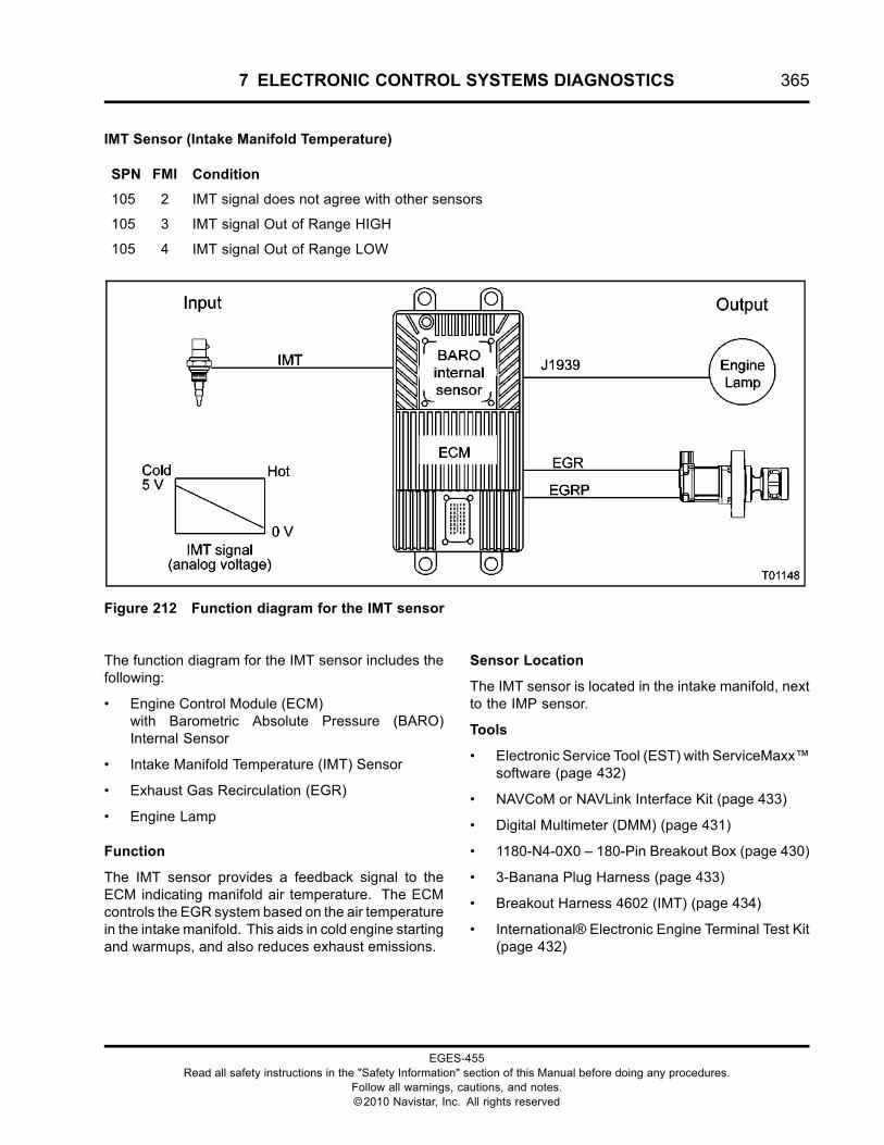
7 ELECTRONIC CONTROL SYSTEMS DIAGNOSTICS 365
IMT Sensor (Intake Manifold Temperature)
SPN FMI Condition
105 2 IMT signal does not agree with other sensors
105 3 IMT signal Out of Range HIGH
105 4 IMT signal Out of Range LOW
Figure 212 Function diagram for the IMT sensor
The function diagram for the IMT sensor includes thefollowing:
• Engine Control Module (ECM)with Barometric Absolute Pressure (BARO)Internal Sensor
• Intake Manifold Temperature (IMT) Sensor
• Exhaust Gas Recirculation (EGR)
• Engine Lamp
Function
The IMT sensor provides a feedback signal to theECM indicating manifold air temperature. The ECMcontrols the EGR system based on the air temperaturein the intake manifold. This aids in cold engine startingand warmups, and also reduces exhaust emissions.
Sensor Location
The IMT sensor is located in the intake manifold, nextto the IMP sensor.
Tools
• Electronic Service Tool (EST) with ServiceMaxx™software (page 432)
• NAVCoM or NAVLink Interface Kit (page 433)
• Digital Multimeter (DMM) (page 431)
• 1180-N4-0X0 – 180-Pin Breakout Box (page 430)
• 3-Banana Plug Harness (page 433)
• Breakout Harness 4602 (IMT) (page 434)
• International® Electronic Engine Terminal Test Kit(page 432)
EGES-455Read all safety instructions in the "Safety Information" section of this Manual before doing any procedures.
Follow all warnings, cautions, and notes.©2010 Navistar, Inc. All rights reserved
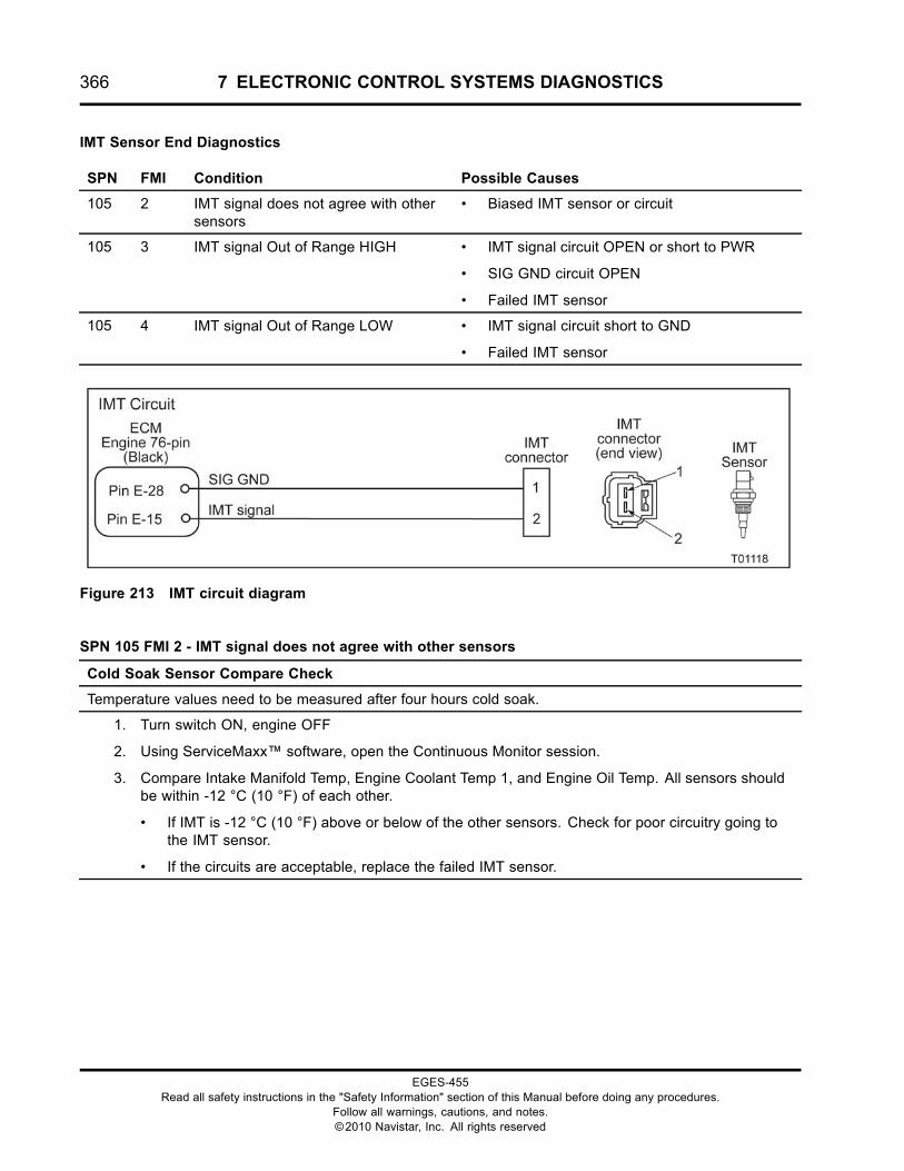
366 7 ELECTRONIC CONTROL SYSTEMS DIAGNOSTICS
IMT Sensor End Diagnostics
SPN FMI Condition Possible Causes
105 2 IMT signal does not agree with othersensors
• Biased IMT sensor or circuit
105 3 IMT signal Out of Range HIGH • IMT signal circuit OPEN or short to PWR
• SIG GND circuit OPEN
• Failed IMT sensor
105 4 IMT signal Out of Range LOW • IMT signal circuit short to GND
• Failed IMT sensor
Figure 213 IMT circuit diagram
SPN 105 FMI 2 - IMT signal does not agree with other sensors
Cold Soak Sensor Compare Check
Temperature values need to be measured after four hours cold soak.
1. Turn switch ON, engine OFF
2. Using ServiceMaxx™ software, open the Continuous Monitor session.
3. Compare Intake Manifold Temp, Engine Coolant Temp 1, and Engine Oil Temp. All sensors shouldbe within -12 °C (10 °F) of each other.
• If IMT is -12 °C (10 °F) above or below of the other sensors. Check for poor circuitry going tothe IMT sensor.
• If the circuits are acceptable, replace the failed IMT sensor.
EGES-455Read all safety instructions in the "Safety Information" section of this Manual before doing any procedures.
Follow all warnings, cautions, and notes.©2010 Navistar, Inc. All rights reserved
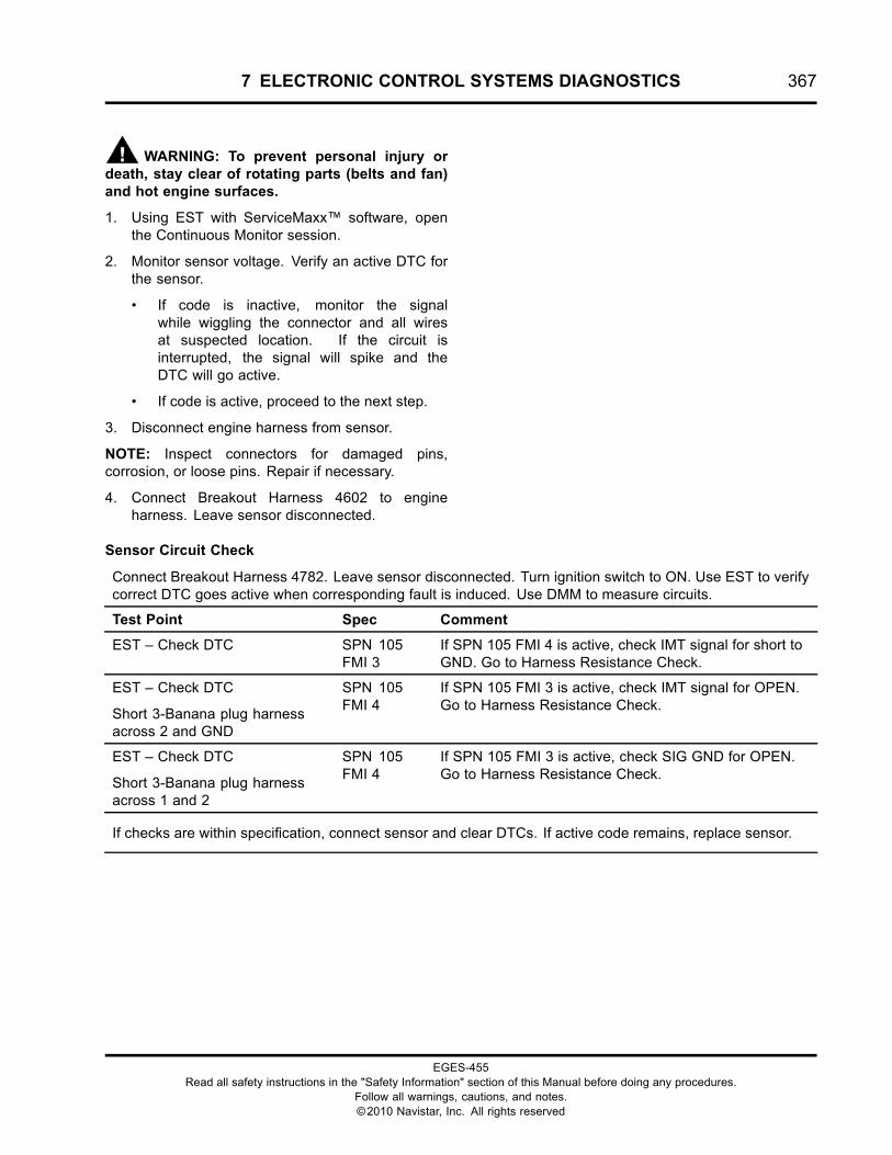
7 ELECTRONIC CONTROL SYSTEMS DIAGNOSTICS 367
WARNING: To prevent personal injury ordeath, stay clear of rotating parts (belts and fan)and hot engine surfaces.
1. Using EST with ServiceMaxx™ software, openthe Continuous Monitor session.
2. Monitor sensor voltage. Verify an active DTC forthe sensor.
• If code is inactive, monitor the signalwhile wiggling the connector and all wiresat suspected location. If the circuit isinterrupted, the signal will spike and theDTC will go active.
• If code is active, proceed to the next step.
3. Disconnect engine harness from sensor.
NOTE: Inspect connectors for damaged pins,corrosion, or loose pins. Repair if necessary.
4. Connect Breakout Harness 4602 to engineharness. Leave sensor disconnected.
Sensor Circuit Check
Connect Breakout Harness 4782. Leave sensor disconnected. Turn ignition switch to ON. Use EST to verifycorrect DTC goes active when corresponding fault is induced. Use DMM to measure circuits.
Test Point Spec Comment
EST – Check DTC SPN 105FMI 3
If SPN 105 FMI 4 is active, check IMT signal for short toGND. Go to Harness Resistance Check.
EST – Check DTC
Short 3-Banana plug harnessacross 2 and GND
SPN 105FMI 4
If SPN 105 FMI 3 is active, check IMT signal for OPEN.Go to Harness Resistance Check.
EST – Check DTC
Short 3-Banana plug harnessacross 1 and 2
SPN 105FMI 4
If SPN 105 FMI 3 is active, check SIG GND for OPEN.Go to Harness Resistance Check.
If checks are within specification, connect sensor and clear DTCs. If active code remains, replace sensor.
EGES-455Read all safety instructions in the "Safety Information" section of this Manual before doing any procedures.
Follow all warnings, cautions, and notes.©2010 Navistar, Inc. All rights reserved
368 7 ELECTRONIC CONTROL SYSTEMS DIAGNOSTICS
IMT Pin-point Diagnostics
Connector Voltage Check
Connect Breakout Harness 4602. Leave sensor disconnected. Turn ignition switch to ON. Use DMM tomeasure voltage.
Test Point Spec Comment – < Less than, > Greater than
1 to B+ B+ If < B+, check for short to PWR.
2 to GND 4.6 V to 5 V If < 4.5 V, check for OPEN or short to GND. Go to Harness ResistanceCheck.
Harness Resistance Check
Turn ignition switch to OFF. Connect 180-Pin Breakout Box and Breakout Harness 4782. Leave ECM andsensor disconnected. Use DMM to measure resistance.
Test Point Spec Comment – < Less than, > Greater than
1 to E-28 < 5 Ω If > 5 Ω, check for OPEN circuit.
2 to E-15 < 5 Ω If > 5 Ω, check for OPEN circuit.
IMT Circuit Operation
The IMT is a thermistor sensor that is supplied witha 5 V VREF at Pin 2 from ECM Pin E–15. Thesensor is grounded at Pin 1 from ECM Pin E–28.As the temperature increases, the resistance of thethermistor decreases. This causes the signal voltageto decrease.
Fault Detection / Management
The ECM continuously monitors the control system.If the sensor signal is higher or lower than expected,the ECM disregards the sensor signal and uses acalibrated default value. The ECM will set a DTC, turnon the engine lamp, and run the engine in a defaultrange.
EGES-455Read all safety instructions in the "Safety Information" section of this Manual before doing any procedures.
Follow all warnings, cautions, and notes.©2010 Navistar, Inc. All rights reserved
7 ELECTRONIC CONTROL SYSTEMS DIAGNOSTICS 369
Injector Circuits
SPN FMI Condition Possible Causes
651 -656
4 Injector (#) open coil - short circuit • Injector (#) open coil circuit short to GND
• Injector (#) open coil circuit OPEN
651 -656
5 Injector (#) open coil - open circuit • Injector (#) open coil circuit short to GND
• Injector (#) open coil circuit OPEN
2797 3 Injector Control Group 1 open coilshort
• Open coil short circuit on Injectors 1, 2 or 3
2797 4 Injector Control Group 1 close coilshort
• Closed coil short circuit on Injectors 1, 2 or 3
2798 3 Injector Control Group 2 open coilshort
• Open coil short circuit on Injectors 4, 5 or 6
2798 4 Injector Control Group 2 close coilshort
• Closed coil short circuit on Injectors 4, 5 or 6
3659 4 Injector 1 close coil – short circuit • Injector closed coil circuit short to GND
3659 5 Injector 1 close coil – open circuit • Injector closed coil circuit OPEN
3660 4 Injector 2 close coil – short circuit • Injector closed coil circuit short to GND
3660 5 Injector 2 close coil – open circuit • Injector closed coil circuit OPEN
3661 4 Injector 3 close coil – short circuit • Injector closed coil circuit short to GND
3661 5 Injector 3 close coil – open circuit • Injector closed coil circuit OPEN
3662 4 Injector 4 close coil – short circuit • Injector closed coil circuit short to GND
3662 5 Injector 4 close coil – open circuit • Injector closed coil circuit OPEN
3663 4 Injector 5 close coil – short circuit • Injector closed coil circuit short to GND
3663 5 Injector 5 close coil – open circuit • Injector closed coil circuit OPEN
3664 4 Injector 6 close coil – short circuit • Close coil or open circuit fault
3664 5 Injector 6 close coil – open circuit • Injector closed coil circuit OPEN
EGES-455Read all safety instructions in the "Safety Information" section of this Manual before doing any procedures.
Follow all warnings, cautions, and notes.©2010 Navistar, Inc. All rights reserved
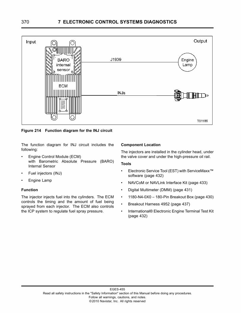
370 7 ELECTRONIC CONTROL SYSTEMS DIAGNOSTICS
Figure 214 Function diagram for the INJ circuit
The function diagram for INJ circuit includes thefollowing:
• Engine Control Module (ECM)with Barometric Absolute Pressure (BARO)Internal Sensor
• Fuel injectors (INJ)
• Engine Lamp
Function
The injector injects fuel into the cylinders. The ECMcontrols the timing and the amount of fuel beingsprayed from each injector. The ECM also controlsthe ICP system to regulate fuel spray pressure.
Component Location
The injectors are installed in the cylinder head, underthe valve cover and under the high-pressure oil rail.
Tools
• Electronic Service Tool (EST) with ServiceMaxx™software (page 432)
• NAVCoM or NAVLink Interface Kit (page 433)
• Digital Multimeter (DMM) (page 431)
• 1180-N4-0X0 – 180-Pin Breakout Box (page 430)
• Breakout Harness 4952 (page 437)
• International® Electronic Engine Terminal Test Kit(page 432)
EGES-455Read all safety instructions in the "Safety Information" section of this Manual before doing any procedures.
Follow all warnings, cautions, and notes.©2010 Navistar, Inc. All rights reserved
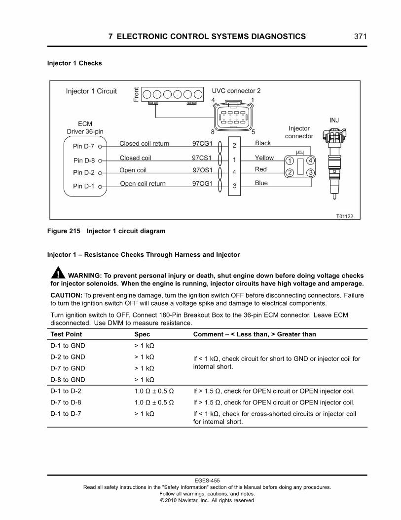
7 ELECTRONIC CONTROL SYSTEMS DIAGNOSTICS 371
Injector 1 Checks
Figure 215 Injector 1 circuit diagram
Injector 1 – Resistance Checks Through Harness and Injector
WARNING: To prevent personal injury or death, shut engine down before doing voltage checksfor injector solenoids. When the engine is running, injector circuits have high voltage and amperage.
CAUTION: To prevent engine damage, turn the ignition switch OFF before disconnecting connectors. Failureto turn the ignition switch OFF will cause a voltage spike and damage to electrical components.
Turn ignition switch to OFF. Connect 180-Pin Breakout Box to the 36-pin ECM connector. Leave ECMdisconnected. Use DMM to measure resistance.
Test Point Spec Comment – < Less than, > Greater than
D-1 to GND > 1 kΩ
D-2 to GND > 1 kΩ
D-7 to GND > 1 kΩ
D-8 to GND > 1 kΩ
If < 1 kΩ, check circuit for short to GND or injector coil forinternal short.
D-1 to D-2 1.0 Ω ± 0.5 Ω If > 1.5 Ω, check for OPEN circuit or OPEN injector coil.
D-7 to D-8 1.0 Ω ± 0.5 Ω If > 1.5 Ω, check for OPEN circuit or OPEN injector coil.
D-1 to D-7 > 1 kΩ If < 1 kΩ, check for cross-shorted circuits or injector coilfor internal short.
EGES-455Read all safety instructions in the "Safety Information" section of this Manual before doing any procedures.
Follow all warnings, cautions, and notes.©2010 Navistar, Inc. All rights reserved
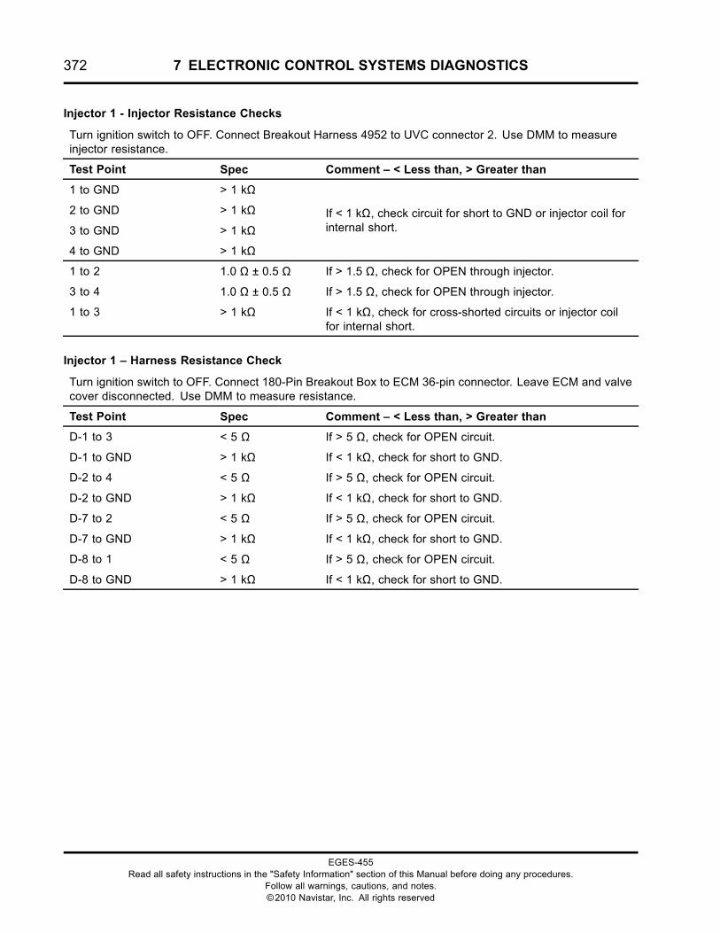
372 7 ELECTRONIC CONTROL SYSTEMS DIAGNOSTICS
Injector 1 - Injector Resistance Checks
Turn ignition switch to OFF. Connect Breakout Harness 4952 to UVC connector 2. Use DMM to measureinjector resistance.
Test Point Spec Comment – < Less than, > Greater than
1 to GND > 1 kΩ
2 to GND > 1 kΩ
3 to GND > 1 kΩ
4 to GND > 1 kΩ
If < 1 kΩ, check circuit for short to GND or injector coil forinternal short.
1 to 2 1.0 Ω ± 0.5 Ω If > 1.5 Ω, check for OPEN through injector.
3 to 4 1.0 Ω ± 0.5 Ω If > 1.5 Ω, check for OPEN through injector.
1 to 3 > 1 kΩ If < 1 kΩ, check for cross-shorted circuits or injector coilfor internal short.
Injector 1 – Harness Resistance Check
Turn ignition switch to OFF. Connect 180-Pin Breakout Box to ECM 36-pin connector. Leave ECM and valvecover disconnected. Use DMM to measure resistance.
Test Point Spec Comment – < Less than, > Greater than
D-1 to 3 < 5 Ω If > 5 Ω, check for OPEN circuit.
D-1 to GND > 1 kΩ If < 1 kΩ, check for short to GND.
D-2 to 4 < 5 Ω If > 5 Ω, check for OPEN circuit.
D-2 to GND > 1 kΩ If < 1 kΩ, check for short to GND.
D-7 to 2 < 5 Ω If > 5 Ω, check for OPEN circuit.
D-7 to GND > 1 kΩ If < 1 kΩ, check for short to GND.
D-8 to 1 < 5 Ω If > 5 Ω, check for OPEN circuit.
D-8 to GND > 1 kΩ If < 1 kΩ, check for short to GND.
EGES-455Read all safety instructions in the "Safety Information" section of this Manual before doing any procedures.
Follow all warnings, cautions, and notes.©2010 Navistar, Inc. All rights reserved

7 ELECTRONIC CONTROL SYSTEMS DIAGNOSTICS 373
Injector 2 Checks
Figure 216 Injector 2 circuit diagram
Injector 2 – Resistance Through Valve Cover Check
WARNING: To prevent personal injury or death, shut engine down before doing voltage checksfor injector solenoids. When the engine is running, injector circuits have high voltage and amperage.
CAUTION: To prevent engine damage, turn the ignition switch OFF before disconnecting connectors. Failureto turn the ignition switch OFF will cause a voltage spike and damage to electrical components.
Turn ignition switch to OFF. Connect Breakout Harness 4952 to the valve cover connector. Use DMMto measure resistance.
Test Point Spec Comment – < Less than, > Greater than
5 to GND > 1 kΩ
6 to GND > 1 kΩ
7 to GND > 1 kΩ
8 to GND > 1 kΩ
If < 1 kΩ, check circuit for short to GND or injector coil forinternal short.
Injector 2 – Coil Resistance Check
Turn ignition switch to OFF. Connect Breakout Harness 4952 to the valve cover connector. Use DMMto measure resistance.
Test Point Spec Comment – < Less than, > Greater than
5 to 6 0.5 Ω to 1.5 Ω If > 1.5 Ω, check for OPEN circuit or OPEN injector coil.
7 to 8 0.5 Ω to 1.5 Ω If > 1.5 Ω, check for OPEN circuit or OPEN injector coil.
5 to 7 > 1 kΩ If < 1 kΩ, check for cross shorted circuits or injector coilfor internal short.
EGES-455Read all safety instructions in the "Safety Information" section of this Manual before doing any procedures.
Follow all warnings, cautions, and notes.©2010 Navistar, Inc. All rights reserved
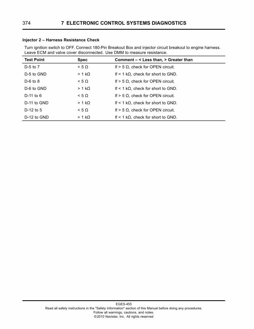
374 7 ELECTRONIC CONTROL SYSTEMS DIAGNOSTICS
Injector 2 – Harness Resistance Check
Turn ignition switch to OFF. Connect 180-Pin Breakout Box and injector circuit breakout to engine harness.Leave ECM and valve cover disconnected. Use DMM to measure resistance.
Test Point Spec Comment – < Less than, > Greater than
D-5 to 7 < 5 Ω If > 5 Ω, check for OPEN circuit.
D-5 to GND > 1 kΩ If < 1 kΩ, check for short to GND.
D-6 to 8 < 5 Ω If > 5 Ω, check for OPEN circuit.
D-6 to GND > 1 kΩ If < 1 kΩ, check for short to GND.
D-11 to 6 < 5 Ω If > 5 Ω, check for OPEN circuit.
D-11 to GND > 1 kΩ If < 1 kΩ, check for short to GND.
D-12 to 5 < 5 Ω If > 5 Ω, check for OPEN circuit.
D-12 to GND > 1 kΩ If < 1 kΩ, check for short to GND.
EGES-455Read all safety instructions in the "Safety Information" section of this Manual before doing any procedures.
Follow all warnings, cautions, and notes.©2010 Navistar, Inc. All rights reserved
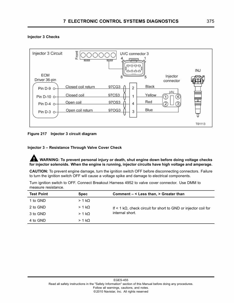
7 ELECTRONIC CONTROL SYSTEMS DIAGNOSTICS 375
Injector 3 Checks
Figure 217 Injector 3 circuit diagram
Injector 3 – Resistance Through Valve Cover Check
WARNING: To prevent personal injury or death, shut engine down before doing voltage checksfor injector solenoids. When the engine is running, injector circuits have high voltage and amperage.
CAUTION: To prevent engine damage, turn the ignition switch OFF before disconnecting connectors. Failureto turn the ignition switch OFF will cause a voltage spike and damage to electrical components.
Turn ignition switch to OFF. Connect Breakout Harness 4952 to valve cover connector. Use DMM tomeasure resistance.
Test Point Spec Comment – < Less than, > Greater than
1 to GND > 1 kΩ
2 to GND > 1 kΩ
3 to GND > 1 kΩ
4 to GND > 1 kΩ
If < 1 kΩ, check circuit for short to GND or injector coil forinternal short.
EGES-455Read all safety instructions in the "Safety Information" section of this Manual before doing any procedures.
Follow all warnings, cautions, and notes.©2010 Navistar, Inc. All rights reserved
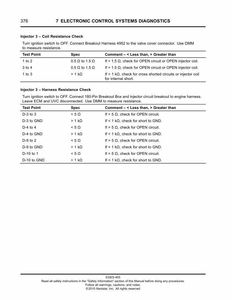
376 7 ELECTRONIC CONTROL SYSTEMS DIAGNOSTICS
Injector 3 – Coil Resistance Check
Turn ignition switch to OFF. Connect Breakout Harness 4952 to the valve cover connector. Use DMMto measure resistance.
Test Point Spec Comment – < Less than, > Greater than
1 to 2 0.5 Ω to 1.5 Ω If > 1.5 Ω, check for OPEN circuit or OPEN injector coil.
3 to 4 0.5 Ω to 1.5 Ω If > 1.5 Ω, check for OPEN circuit or OPEN injector coil.
1 to 3 > 1 kΩ If < 1 kΩ, check for cross shorted circuits or injector coilfor internal short.
Injector 3 – Harness Resistance Check
Turn ignition switch to OFF. Connect 180-Pin Breakout Box and injector circuit breakout to engine harness.Leave ECM and UVC disconnected. Use DMM to measure resistance.
Test Point Spec Comment – < Less than, > Greater than
D-3 to 3 < 5 Ω If > 5 Ω, check for OPEN circuit.
D-3 to GND > 1 kΩ If < 1 kΩ, check for short to GND.
D-4 to 4 < 5 Ω If > 5 Ω, check for OPEN circuit.
D-4 to GND > 1 kΩ If < 1 kΩ, check for short to GND.
D-9 to 2 < 5 Ω If > 5 Ω, check for OPEN circuit.
D-9 to GND > 1 kΩ If < 1 kΩ, check for short to GND.
D-10 to 1 < 5 Ω If > 5 Ω, check for OPEN circuit.
D-10 to GND > 1 kΩ If < 1 kΩ, check for short to GND.
EGES-455Read all safety instructions in the "Safety Information" section of this Manual before doing any procedures.
Follow all warnings, cautions, and notes.©2010 Navistar, Inc. All rights reserved
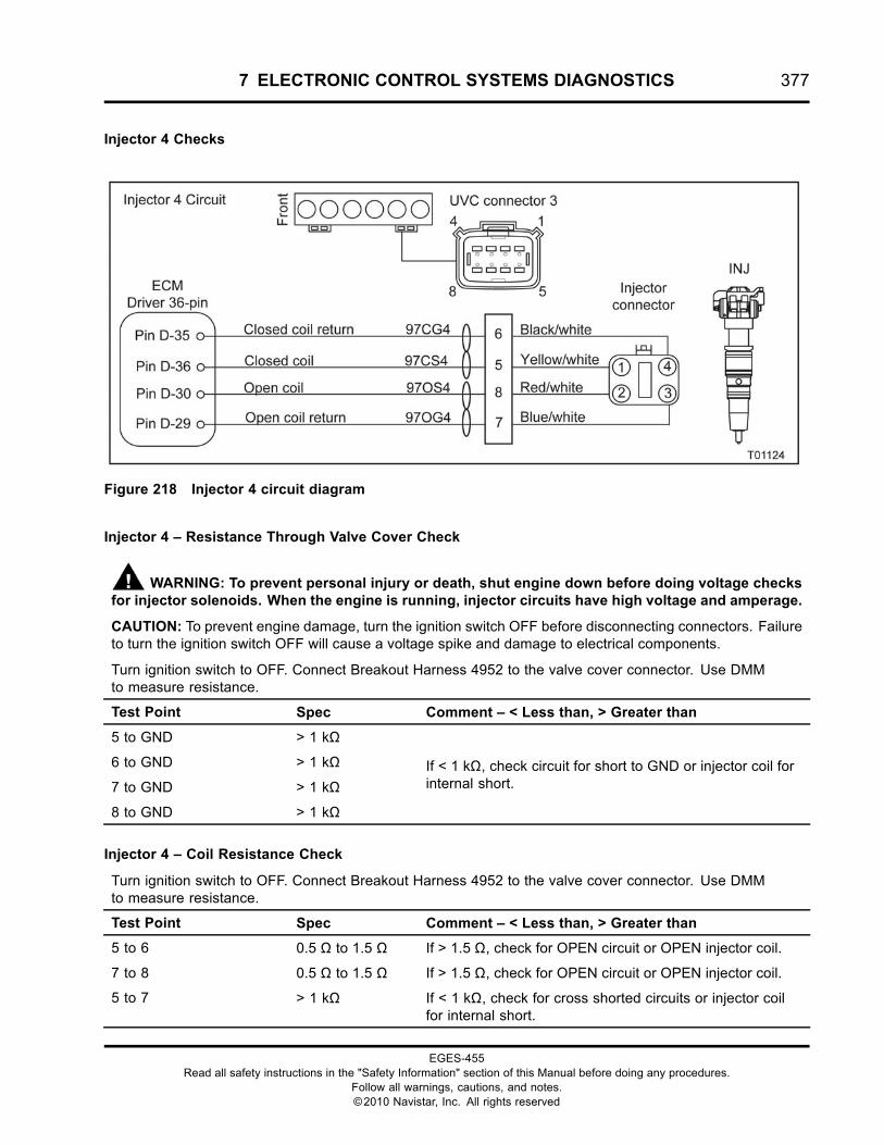
7 ELECTRONIC CONTROL SYSTEMS DIAGNOSTICS 377
Injector 4 Checks
Figure 218 Injector 4 circuit diagram
Injector 4 – Resistance Through Valve Cover Check
WARNING: To prevent personal injury or death, shut engine down before doing voltage checksfor injector solenoids. When the engine is running, injector circuits have high voltage and amperage.
CAUTION: To prevent engine damage, turn the ignition switch OFF before disconnecting connectors. Failureto turn the ignition switch OFF will cause a voltage spike and damage to electrical components.
Turn ignition switch to OFF. Connect Breakout Harness 4952 to the valve cover connector. Use DMMto measure resistance.
Test Point Spec Comment – < Less than, > Greater than
5 to GND > 1 kΩ
6 to GND > 1 kΩ
7 to GND > 1 kΩ
8 to GND > 1 kΩ
If < 1 kΩ, check circuit for short to GND or injector coil forinternal short.
Injector 4 – Coil Resistance Check
Turn ignition switch to OFF. Connect Breakout Harness 4952 to the valve cover connector. Use DMMto measure resistance.
Test Point Spec Comment – < Less than, > Greater than
5 to 6 0.5 Ω to 1.5 Ω If > 1.5 Ω, check for OPEN circuit or OPEN injector coil.
7 to 8 0.5 Ω to 1.5 Ω If > 1.5 Ω, check for OPEN circuit or OPEN injector coil.
5 to 7 > 1 kΩ If < 1 kΩ, check for cross shorted circuits or injector coilfor internal short.
EGES-455Read all safety instructions in the "Safety Information" section of this Manual before doing any procedures.
Follow all warnings, cautions, and notes.©2010 Navistar, Inc. All rights reserved

378 7 ELECTRONIC CONTROL SYSTEMS DIAGNOSTICS
Injector 4 – Harness Resistance Check
Turn ignition switch to OFF. Connect 180-Pin Breakout Box and injector circuit breakout to engine harness.Leave ECM and UVC disconnected. Use DMM to measure resistance.
Test Point Spec Comment – < Less than, > Greater than
D-29 to 7 < 5 Ω If > 5 Ω, check for OPEN circuit.
D-29 to GND > 1 kΩ If < 1 kΩ, check for short to GND.
D-30 to 8 < 5 Ω If > 5 Ω, check for OPEN circuit.
D-30 to GND > 1 kΩ If < 1 kΩ, check for short to GND.
D-35 to 6 < 5 Ω If > 5 Ω, check for OPEN circuit.
D-35 to GND > 1 kΩ If < 1 kΩ, check for short to GND.
D-36 to 5 < 5 Ω If > 5 Ω, check for OPEN circuit.
D-36 to GND > 1 kΩ If < 1 kΩ, check for short to GND.
EGES-455Read all safety instructions in the "Safety Information" section of this Manual before doing any procedures.
Follow all warnings, cautions, and notes.©2010 Navistar, Inc. All rights reserved
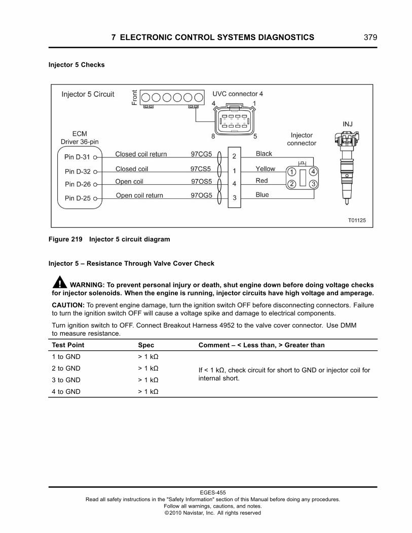
7 ELECTRONIC CONTROL SYSTEMS DIAGNOSTICS 379
Injector 5 Checks
Figure 219 Injector 5 circuit diagram
Injector 5 – Resistance Through Valve Cover Check
WARNING: To prevent personal injury or death, shut engine down before doing voltage checksfor injector solenoids. When the engine is running, injector circuits have high voltage and amperage.
CAUTION: To prevent engine damage, turn the ignition switch OFF before disconnecting connectors. Failureto turn the ignition switch OFF will cause a voltage spike and damage to electrical components.
Turn ignition switch to OFF. Connect Breakout Harness 4952 to the valve cover connector. Use DMMto measure resistance.
Test Point Spec Comment – < Less than, > Greater than
1 to GND > 1 kΩ
2 to GND > 1 kΩ
3 to GND > 1 kΩ
4 to GND > 1 kΩ
If < 1 kΩ, check circuit for short to GND or injector coil forinternal short.
EGES-455Read all safety instructions in the "Safety Information" section of this Manual before doing any procedures.
Follow all warnings, cautions, and notes.©2010 Navistar, Inc. All rights reserved
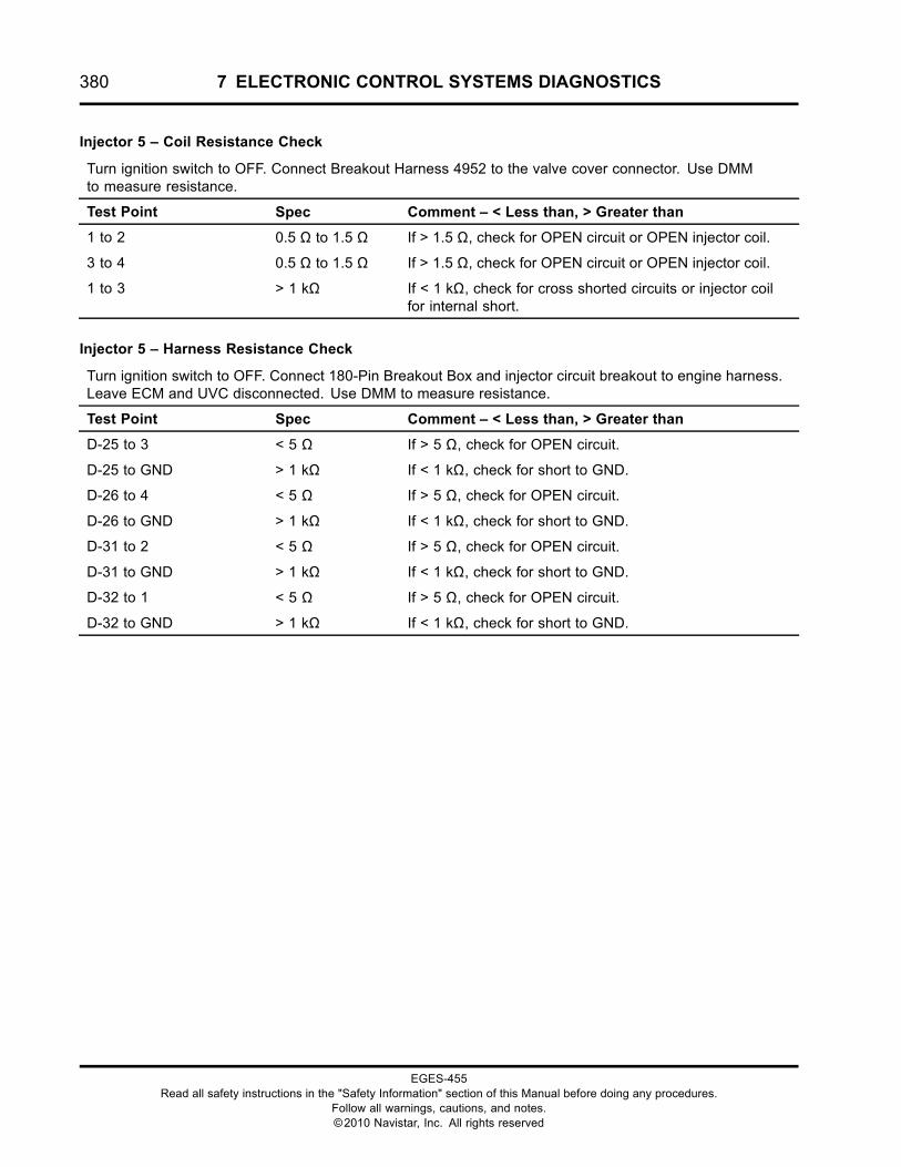
380 7 ELECTRONIC CONTROL SYSTEMS DIAGNOSTICS
Injector 5 – Coil Resistance Check
Turn ignition switch to OFF. Connect Breakout Harness 4952 to the valve cover connector. Use DMMto measure resistance.
Test Point Spec Comment – < Less than, > Greater than
1 to 2 0.5 Ω to 1.5 Ω If > 1.5 Ω, check for OPEN circuit or OPEN injector coil.
3 to 4 0.5 Ω to 1.5 Ω If > 1.5 Ω, check for OPEN circuit or OPEN injector coil.
1 to 3 > 1 kΩ If < 1 kΩ, check for cross shorted circuits or injector coilfor internal short.
Injector 5 – Harness Resistance Check
Turn ignition switch to OFF. Connect 180-Pin Breakout Box and injector circuit breakout to engine harness.Leave ECM and UVC disconnected. Use DMM to measure resistance.
Test Point Spec Comment – < Less than, > Greater than
D-25 to 3 < 5 Ω If > 5 Ω, check for OPEN circuit.
D-25 to GND > 1 kΩ If < 1 kΩ, check for short to GND.
D-26 to 4 < 5 Ω If > 5 Ω, check for OPEN circuit.
D-26 to GND > 1 kΩ If < 1 kΩ, check for short to GND.
D-31 to 2 < 5 Ω If > 5 Ω, check for OPEN circuit.
D-31 to GND > 1 kΩ If < 1 kΩ, check for short to GND.
D-32 to 1 < 5 Ω If > 5 Ω, check for OPEN circuit.
D-32 to GND > 1 kΩ If < 1 kΩ, check for short to GND.
EGES-455Read all safety instructions in the "Safety Information" section of this Manual before doing any procedures.
Follow all warnings, cautions, and notes.©2010 Navistar, Inc. All rights reserved
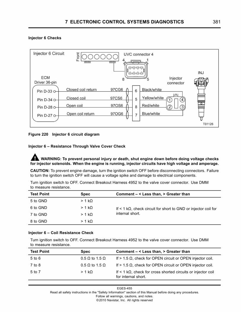
7 ELECTRONIC CONTROL SYSTEMS DIAGNOSTICS 381
Injector 6 Checks
Figure 220 Injector 6 circuit diagram
Injector 6 – Resistance Through Valve Cover Check
WARNING: To prevent personal injury or death, shut engine down before doing voltage checksfor injector solenoids. When the engine is running, injector circuits have high voltage and amperage.
CAUTION: To prevent engine damage, turn the ignition switch OFF before disconnecting connectors. Failureto turn the ignition switch OFF will cause a voltage spike and damage to electrical components.
Turn ignition switch to OFF. Connect Breakout Harness 4952 to the valve cover connector. Use DMMto measure resistance.
Test Point Spec Comment – < Less than, > Greater than
5 to GND > 1 kΩ
6 to GND > 1 kΩ
7 to GND > 1 kΩ
8 to GND > 1 kΩ
If < 1 kΩ, check circuit for short to GND or injector coil forinternal short.
Injector 6 – Coil Resistance Check
Turn ignition switch to OFF. Connect Breakout Harness 4952 to the valve cover connector. Use DMMto measure resistance.
Test Point Spec Comment – < Less than, > Greater than
5 to 6 0.5 Ω to 1.5 Ω If > 1.5 Ω, check for OPEN circuit or OPEN injector coil.
7 to 8 0.5 Ω to 1.5 Ω If > 1.5 Ω, check for OPEN circuit or OPEN injector coil.
5 to 7 > 1 kΩ If < 1 kΩ, check for cross shorted circuits or injector coilfor internal short.
EGES-455Read all safety instructions in the "Safety Information" section of this Manual before doing any procedures.
Follow all warnings, cautions, and notes.©2010 Navistar, Inc. All rights reserved
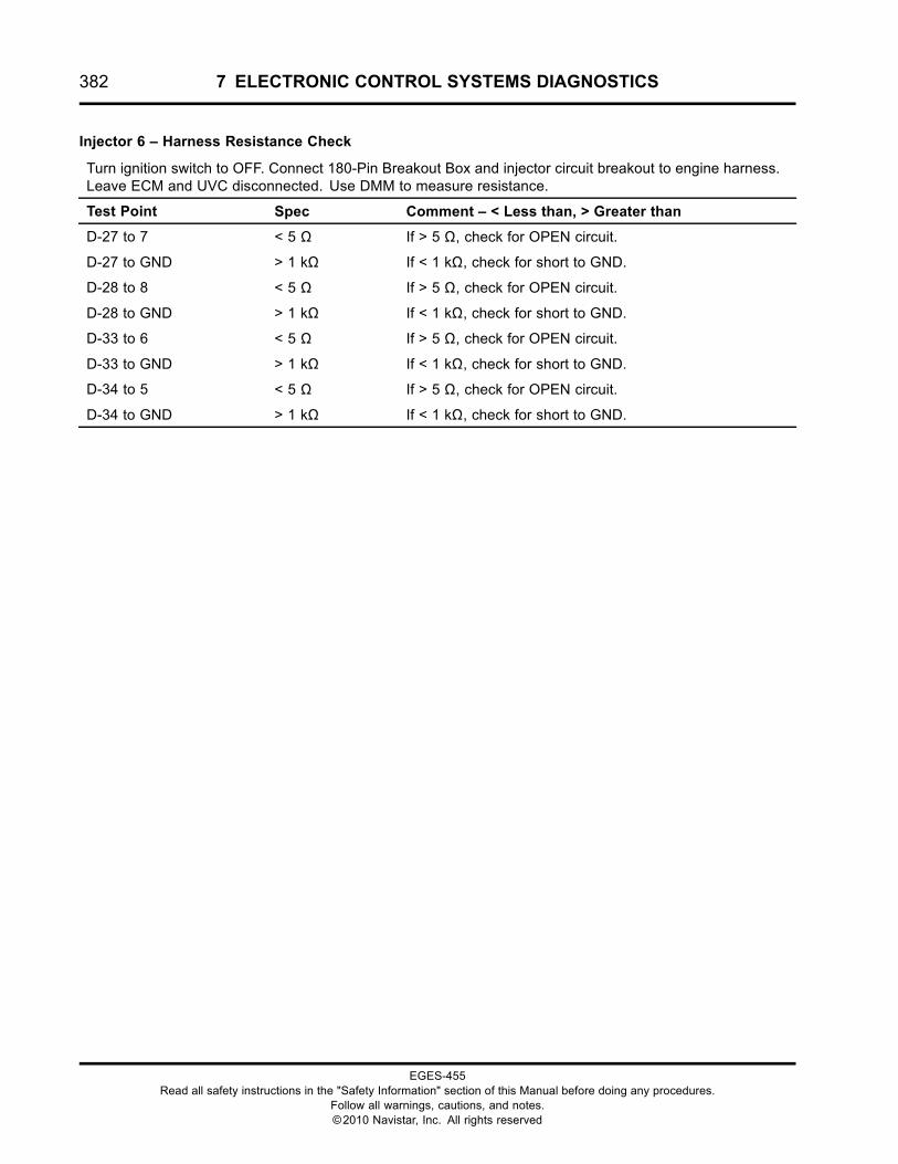
382 7 ELECTRONIC CONTROL SYSTEMS DIAGNOSTICS
Injector 6 – Harness Resistance Check
Turn ignition switch to OFF. Connect 180-Pin Breakout Box and injector circuit breakout to engine harness.Leave ECM and UVC disconnected. Use DMM to measure resistance.
Test Point Spec Comment – < Less than, > Greater than
D-27 to 7 < 5 Ω If > 5 Ω, check for OPEN circuit.
D-27 to GND > 1 kΩ If < 1 kΩ, check for short to GND.
D-28 to 8 < 5 Ω If > 5 Ω, check for OPEN circuit.
D-28 to GND > 1 kΩ If < 1 kΩ, check for short to GND.
D-33 to 6 < 5 Ω If > 5 Ω, check for OPEN circuit.
D-33 to GND > 1 kΩ If < 1 kΩ, check for short to GND.
D-34 to 5 < 5 Ω If > 5 Ω, check for OPEN circuit.
D-34 to GND > 1 kΩ If < 1 kΩ, check for short to GND.
EGES-455Read all safety instructions in the "Safety Information" section of this Manual before doing any procedures.
Follow all warnings, cautions, and notes.©2010 Navistar, Inc. All rights reserved
7 ELECTRONIC CONTROL SYSTEMS DIAGNOSTICS 383
Injector Circuit Operation
Each injector has an open and closed coil. TheECM controlling circuits run from the 36-way driverconnector, through the 8-way UVC connector, to theinjector 4-pin connector.
When a coil needs to be energized, the ECM turnson the high and low side driver. The high side outputsupplies the injectors with a power supply of 48 V DCat 20 A. The low side output supplies a return circuitto each injector coil.
High Side Drive Output
The ECM regulates the current at an average of 20 A.When the current reaches 24 A, the ECM shuts off thehigh side driver. When the current drops to 16 A, theECM turns on the high side driver.
Low Side Drive Return
The injector solenoids are grounded through the lowside return circuits. The ECM monitors the low sidereturn signal for diagnostic purposes and utilizes thefly-back current from the injector solenoids to helpcharge the drive capacitors internally to the ECM.
Fault Detection / Management
The ECM continuously monitors the amount of time(rising time) taken by each coil to draw 20 A. Thetime is compared to calibrated values and the ECMdetermines if a circuit or injector fault exists. Eachinjector has six failure modes and three DTCs. Afailure can occur on the open or closed coil circuit.When a fault is detected, a DTC will be set.
When a short to ground condition is detected on aninjector (low or high side), the ECM discontinuespower to the shorted injector and operates the engineon the remaining cylinders.
When the engine is running, the ECM can detectindividual injector coil and shorts to ground or battery.
KOEO Injector Test
This test allows the operator to enable all injector coilswhen the engine is off, to verify circuit operation.
During this test, injector solenoids will click in numericorder, not the firing order. If one or more injectors cannot be heard, the injector is not working due to a circuitfault, injector, or an ECM failure.
EGES-455Read all safety instructions in the "Safety Information" section of this Manual before doing any procedures.
Follow all warnings, cautions, and notes.©2010 Navistar, Inc. All rights reserved
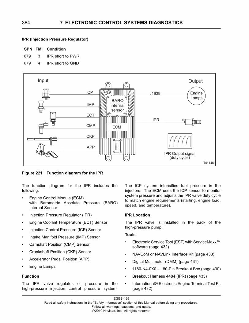
384 7 ELECTRONIC CONTROL SYSTEMS DIAGNOSTICS
IPR (Injection Pressure Regulator)
SPN FMI Condition
679 3 IPR short to PWR
679 4 IPR short to GND
Figure 221 Function diagram for the IPR
The function diagram for the IPR includes thefollowing:
• Engine Control Module (ECM)with Barometric Absolute Pressure (BARO)Internal Sensor
• Injection Pressure Regulator (IPR)
• Engine Coolant Temperature (ECT) Sensor
• Injection Control Pressure (ICP) Sensor
• Intake Manifold Pressure (IMP) Sensor
• Camshaft Position (CMP) Sensor
• Crankshaft Position (CKP) Sensor
• Accelerator Pedal Position (APP)
• Engine Lamps
Function
The IPR valve regulates oil pressure in thehigh-pressure injection control pressure system.
The ICP system intensifies fuel pressure in theinjectors. The ECM uses the ICP sensor to monitorsystem pressure and adjusts the IPR valve duty cycleto match engine requirements (starting, engine load,speed, and temperature).
IPR Location
The IPR valve is installed in the back of thehigh-pressure pump.
Tools
• Electronic Service Tool (EST) with ServiceMaxx™software (page 432)
• NAVCoM or NAVLink Interface Kit (page 433)
• Digital Multimeter (DMM) (page 431)
• 1180-N4-0X0 – 180-Pin Breakout Box (page 430)
• Breakout Harness 4484 (IPR) (page 433)
• International® Electronic Engine Terminal Test Kit(page 432)
EGES-455Read all safety instructions in the "Safety Information" section of this Manual before doing any procedures.
Follow all warnings, cautions, and notes.©2010 Navistar, Inc. All rights reserved
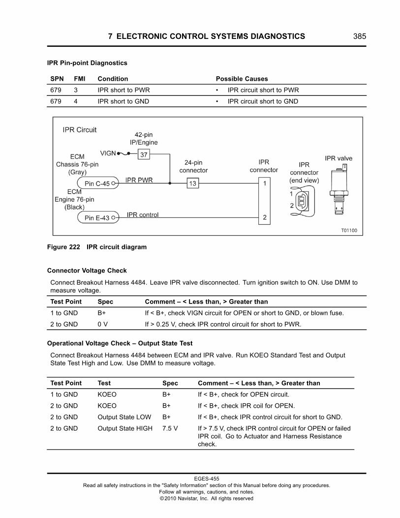
7 ELECTRONIC CONTROL SYSTEMS DIAGNOSTICS 385
IPR Pin-point Diagnostics
SPN FMI Condition Possible Causes
679 3 IPR short to PWR • IPR circuit short to PWR
679 4 IPR short to GND • IPR circuit short to GND
Figure 222 IPR circuit diagram
Connector Voltage Check
Connect Breakout Harness 4484. Leave IPR valve disconnected. Turn ignition switch to ON. Use DMM tomeasure voltage.
Test Point Spec Comment – < Less than, > Greater than
1 to GND B+ If < B+, check VIGN circuit for OPEN or short to GND, or blown fuse.
2 to GND 0 V If > 0.25 V, check IPR control circuit for short to PWR.
Operational Voltage Check – Output State Test
Connect Breakout Harness 4484 between ECM and IPR valve. Run KOEO Standard Test and OutputState Test High and Low. Use DMM to measure voltage.
Test Point Test Spec Comment – < Less than, > Greater than
1 to GND KOEO B+ If < B+, check for OPEN circuit.
2 to GND KOEO B+ If < B+, check IPR coil for OPEN.
2 to GND Output State LOW B+ If < B+, check IPR control circuit for short to GND.
2 to GND Output State HIGH 7.5 V If > 7.5 V, check IPR control circuit for OPEN or failedIPR coil. Go to Actuator and Harness Resistancecheck.
EGES-455Read all safety instructions in the "Safety Information" section of this Manual before doing any procedures.
Follow all warnings, cautions, and notes.©2010 Navistar, Inc. All rights reserved
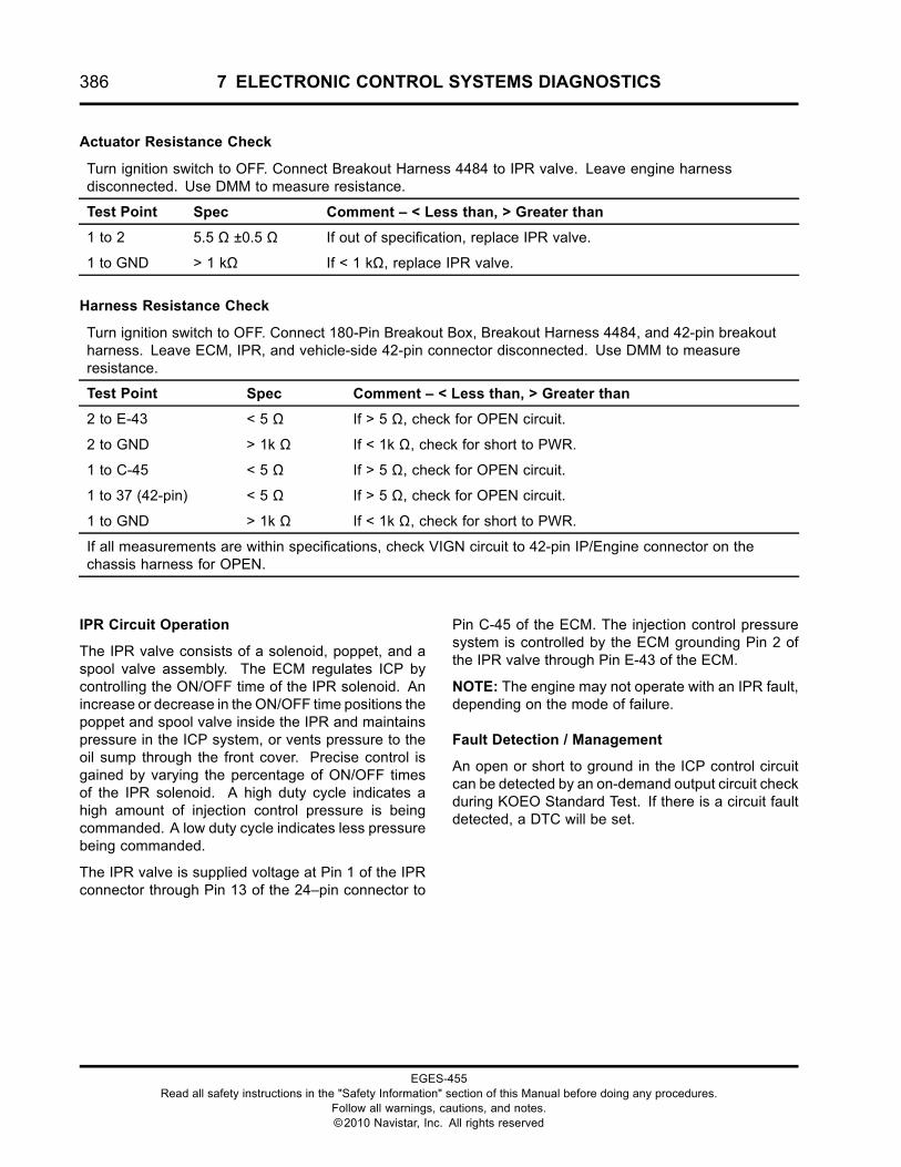
386 7 ELECTRONIC CONTROL SYSTEMS DIAGNOSTICS
Actuator Resistance Check
Turn ignition switch to OFF. Connect Breakout Harness 4484 to IPR valve. Leave engine harnessdisconnected. Use DMM to measure resistance.
Test Point Spec Comment – < Less than, > Greater than
1 to 2 5.5 Ω ±0.5 Ω If out of specification, replace IPR valve.
1 to GND > 1 kΩ If < 1 kΩ, replace IPR valve.
Harness Resistance Check
Turn ignition switch to OFF. Connect 180-Pin Breakout Box, Breakout Harness 4484, and 42-pin breakoutharness. Leave ECM, IPR, and vehicle-side 42-pin connector disconnected. Use DMM to measureresistance.
Test Point Spec Comment – < Less than, > Greater than
2 to E-43 < 5 Ω If > 5 Ω, check for OPEN circuit.
2 to GND > 1k Ω If < 1k Ω, check for short to PWR.
1 to C-45 < 5 Ω If > 5 Ω, check for OPEN circuit.
1 to 37 (42-pin) < 5 Ω If > 5 Ω, check for OPEN circuit.
1 to GND > 1k Ω If < 1k Ω, check for short to PWR.
If all measurements are within specifications, check VIGN circuit to 42-pin IP/Engine connector on thechassis harness for OPEN.
IPR Circuit Operation
The IPR valve consists of a solenoid, poppet, and aspool valve assembly. The ECM regulates ICP bycontrolling the ON/OFF time of the IPR solenoid. Anincrease or decrease in the ON/OFF time positions thepoppet and spool valve inside the IPR and maintainspressure in the ICP system, or vents pressure to theoil sump through the front cover. Precise control isgained by varying the percentage of ON/OFF timesof the IPR solenoid. A high duty cycle indicates ahigh amount of injection control pressure is beingcommanded. A low duty cycle indicates less pressurebeing commanded.
The IPR valve is supplied voltage at Pin 1 of the IPRconnector through Pin 13 of the 24–pin connector to
Pin C-45 of the ECM. The injection control pressuresystem is controlled by the ECM grounding Pin 2 ofthe IPR valve through Pin E-43 of the ECM.
NOTE: The engine may not operate with an IPR fault,depending on the mode of failure.
Fault Detection / Management
An open or short to ground in the ICP control circuitcan be detected by an on-demand output circuit checkduring KOEO Standard Test. If there is a circuit faultdetected, a DTC will be set.
EGES-455Read all safety instructions in the "Safety Information" section of this Manual before doing any procedures.
Follow all warnings, cautions, and notes.©2010 Navistar, Inc. All rights reserved
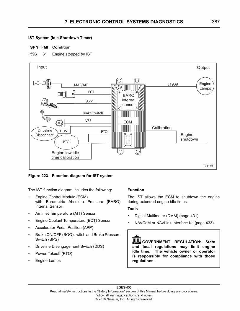
7 ELECTRONIC CONTROL SYSTEMS DIAGNOSTICS 387
IST System (Idle Shutdown Timer)
SPN FMI Condition
593 31 Engine stopped by IST
Figure 223 Function diagram for IST system
The IST function diagram includes the following:
• Engine Control Module (ECM)with Barometric Absolute Pressure (BARO)Internal Sensor
• Air Inlet Temperature (AIT) Sensor
• Engine Coolant Temperature (ECT) Sensor
• Accelerator Pedal Position (APP)
• Brake ON/OFF (BOO) switch and Brake PressureSwitch (BPS)
• Driveline Disengagement Switch (DDS)
• Power Takeoff (PTO)
• Engine Lamps
Function
The IST allows the ECM to shutdown the engineduring extended engine idle times.
Tools
• Digital Multimeter (DMM) (page 431)
• NAVCoM or NAVLink Interface Kit (page 433)
GOVERNMENT REGULATION: Stateand local regulations may limit engineidle time. The vehicle owner or operatoris responsible for compliance with thoseregulations.
EGES-455Read all safety instructions in the "Safety Information" section of this Manual before doing any procedures.
Follow all warnings, cautions, and notes.©2010 Navistar, Inc. All rights reserved
388 7 ELECTRONIC CONTROL SYSTEMS DIAGNOSTICS
Idle Shutdown Warning
Thirty seconds before IST-defined engine shutdown,a vehicle instrument panel indicator activates. Thereare two types of indicators:
• Amber flashing idle shutdown indicator formultiplex electrical systems.
• Red flashing indicator with audible alarm fornon-multiplex electrical systems.
This continues until the engine shuts down or the lowidle shutdown timer is reset.
Engine Idle Shutdown timer for California ESSCompliant Engines
MaxxForce® engines certified for sale in the state ofCalifornia (CA) conform to mandatory California AirResources Board (CARB) Engine Shutdown System(ESS) regulations. The prior function of the IST isavailable on CA ESS exempt and Federally certifiedengines (school buses, emergency, and militaryvehicles).
Engine idle duration is limited for ESS complaintengines as follows:
• When vehicle parking brake is set, the idleshutdown time is limited to the CARB requirementof 5 minutes.
• When vehicle parking brake is released, the idleshutdown time is limited to the CARB requirementof 15 minutes.
The duration of CARB mandated values canbe reduced by programming the customer ISTprogrammable parameter to a value lower than 15minutes. Adjusting this parameter reduces overallsystem shutdown time as follows:
• Adjusting parameter value between five and 15minutes reduces idle shutdown time with thevehicle parking brake released. The default valueof five minutes for the vehicle parking brake setcondition remains unaffected.
• Adjusting parameter value between two and fiveminutes reduces idle time for both the vehicleparking brake released, and set conditions.
While the EST is installed, idle shutdown time isfactory defaulted to 60 minutes and cannot beadjusted. If the IST is enabled, the Cold AmbientProtection (CAP) will not function.
NOTE: The CARB IST feature is factory programmed.Customers cannot turn IST off for ESS compliantengines.
CARB IST Conditions
The following conditions must be true for the idleshutdown timer to activate in all modes. Any changeof the true state of one or more of these conditionswill reset or disable the IST.
• Manual Diesel Particulate Filter (DPF)regeneration is inactive (not enabled).
• Steady driveline state (no transition detected). Nochange in the state of the clutch switch (manualtransmission) or transmission shifter between thein-gear position and neutral or park (Automatictransmission).
• Power Takeoff (PTO) Remote mode disabled.
• Engine coolant temperature greater than 16 °C(60 °F).
• No active coolant temperature sensor diagnosticfaults.
• No active AIT sensor diagnostic faults.
• Engine is operating in run mode or in activediagnostic tool mode.
• Vehicle speed is less than 1.25 miles/hr.
• No active vehicle speed diagnostic faults.
• PTO Control is in OFF or Standby mode.
• Engine speed less than 700 rpm.
• Steady accelerator pedal position (no transitiondetected from any pre-set position).
• Steady brake pedal state (no transition detectedfrom any pre-set state).
• Steady parking brake state (J1939) (no transitiondetected from any pre-set state).
EGES-455Read all safety instructions in the "Safety Information" section of this Manual before doing any procedures.
Follow all warnings, cautions, and notes.©2010 Navistar, Inc. All rights reserved
7 ELECTRONIC CONTROL SYSTEMS DIAGNOSTICS 389
Engine Idle Shutdown Timer (Federal - Optional)
Idle time can be programmed from 5 to 120 minutes.While the EST is installed, the IST function will beactive with the programmed shutdown time in effect.Parking brake transitions reset the idler timer. If theIST is enabled, the Cold Ambient Protection (CAP) willnot function.
Federal IST Conditions
The following conditions must be true for the idleshutdown timer to activate. Any change to the truestate of one or more of these conditions will reset ordisable the IST.
Common Enable Conditions for All Federal ISTOptions
• Manual Diesel Particulate Filter (DPF)regeneration is inactive (not enabled).
• Steady driveline state (no transition detected). Nochange in the state of the clutch switch (manualtransmission) or transmission shifter between thein-gear position and neutral or park (Automatictransmission).
• PTO Remote mode disabled.
• Intake air temperature greater than 16 °C (60 °F)(MFG Default, Customer adjustable parameter).
• Intake air temperature lower than 44 °C (112 °F)(MFG Default, Customer adjustable parameter).
• Engine coolant temperature greater than 60 °C(140 °F).
• No active coolant temperature sensor diagnosticfaults.
• No active AIT sensor diagnostic faults.
• Engine is operating in run mode or in activediagnostic tool mode.
• Vehicle speed is less than 1.25 miles/hr.
• Steady parking brake state (J1939). No transitiondetected from any pre-set state.
Additional operation options enable conditionsdepending on selected Federal IST operation mode:
Federal IST Mode 1: PTO Operation OptionEnable Conditions
• PTO Control is in Off or Standby mode.
• Engine speed less than 750 RPM.
• Accelerator pedal position is less than 2%.
• No active accelerator pedal diagnostic faults.
• Steady brake pedal state (No transition detected).
• No active brake system diagnostic faults.
Federal IST Mode 2: No Load / Light Load LimitOption Enable Conditions
• Accelerator pedal position is less than 2%.
• No active accelerator pedal diagnostic faults.
• Steady brake pedal state (no transition detected).
• No active brake system diagnostic faults.
• Engine reported fuel usage (load) is less thanECM specified limit (factory calibrated, notcustomer adjustable).
Federal IST Mode 3: Tamper Proof Option EnableConditions
• Engine reported fuel usage (load) is less thanECM specified limit (factory calibrated, notcustomer adjustable).
• Steady accelerator pedal position (no transitiondetected from any pre-set position).
• Steady brake pedal state (no transition detectedfrom any pre-set state).
Fault Detection / Management
The IST DTC does not indicate a system fault. SPN593 FMI 31 will set when Engine idle shutdown hasshutdown Engine from ECM command. The ISTfeature must be enabled for SPN 593 FMI 31 to bedisplayed.
EGES-455Read all safety instructions in the "Safety Information" section of this Manual before doing any procedures.
Follow all warnings, cautions, and notes.©2010 Navistar, Inc. All rights reserved
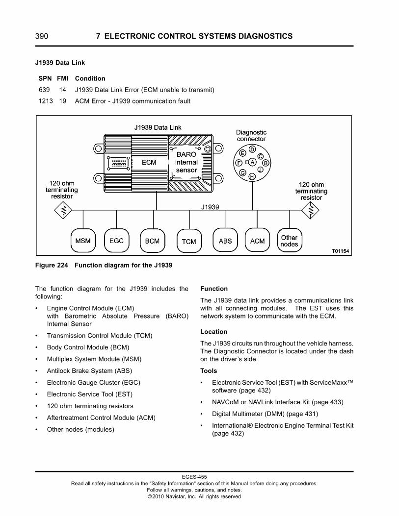
390 7 ELECTRONIC CONTROL SYSTEMS DIAGNOSTICS
J1939 Data Link
SPN FMI Condition
639 14 J1939 Data Link Error (ECM unable to transmit)
1213 19 ACM Error - J1939 communication fault
Figure 224 Function diagram for the J1939
The function diagram for the J1939 includes thefollowing:
• Engine Control Module (ECM)with Barometric Absolute Pressure (BARO)Internal Sensor
• Transmission Control Module (TCM)
• Body Control Module (BCM)
• Multiplex System Module (MSM)
• Antilock Brake System (ABS)
• Electronic Gauge Cluster (EGC)
• Electronic Service Tool (EST)
• 120 ohm terminating resistors
• Aftertreatment Control Module (ACM)
• Other nodes (modules)
Function
The J1939 data link provides a communications linkwith all connecting modules. The EST uses thisnetwork system to communicate with the ECM.
Location
The J1939 circuits run throughout the vehicle harness.The Diagnostic Connector is located under the dashon the driver’s side.
Tools
• Electronic Service Tool (EST) with ServiceMaxx™software (page 432)
• NAVCoM or NAVLink Interface Kit (page 433)
• Digital Multimeter (DMM) (page 431)
• International® Electronic Engine Terminal Test Kit(page 432)
EGES-455Read all safety instructions in the "Safety Information" section of this Manual before doing any procedures.
Follow all warnings, cautions, and notes.©2010 Navistar, Inc. All rights reserved
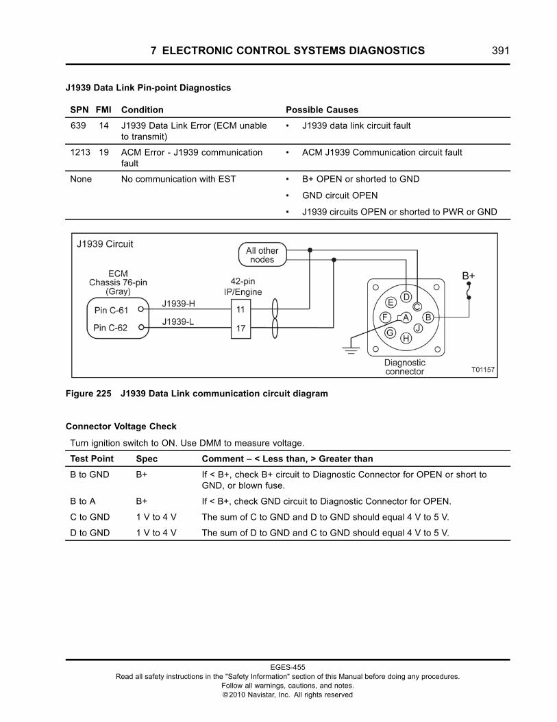
7 ELECTRONIC CONTROL SYSTEMS DIAGNOSTICS 391
J1939 Data Link Pin-point Diagnostics
SPN FMI Condition Possible Causes
639 14 J1939 Data Link Error (ECM unableto transmit)
• J1939 data link circuit fault
1213 19 ACM Error - J1939 communicationfault
• ACM J1939 Communication circuit fault
None No communication with EST • B+ OPEN or shorted to GND
• GND circuit OPEN
• J1939 circuits OPEN or shorted to PWR or GND
Figure 225 J1939 Data Link communication circuit diagram
Connector Voltage Check
Turn ignition switch to ON. Use DMM to measure voltage.
Test Point Spec Comment – < Less than, > Greater than
B to GND B+ If < B+, check B+ circuit to Diagnostic Connector for OPEN or short toGND, or blown fuse.
B to A B+ If < B+, check GND circuit to Diagnostic Connector for OPEN.
C to GND 1 V to 4 V The sum of C to GND and D to GND should equal 4 V to 5 V.
D to GND 1 V to 4 V The sum of D to GND and C to GND should equal 4 V to 5 V.
EGES-455Read all safety instructions in the "Safety Information" section of this Manual before doing any procedures.
Follow all warnings, cautions, and notes.©2010 Navistar, Inc. All rights reserved
392 7 ELECTRONIC CONTROL SYSTEMS DIAGNOSTICS
EST Communication Check
Turn ignition switch to ON. Connect EST to Diagnostic Connector. If the EST is unable to communicate withthe ECM, disconnect each module individually until communication can be established.
NOTE:
• If communication to ECM is established, check J1939 data link circuits to disconnected module for correctwiring. See truck Electrical System Troubleshooting Guide.
• If communication to ECM is not established, go to next test point.
Test Point Comment
Disconnect TCM See note.
Disconnect ABS See note.
Disconnect ESC See note.
Disconnect MSM See note.
Disconnect EGC See note.
Disconnect other nodes See note.
Harness Resistance Check
Turn ignition switch to OFF. Connect 180-Pin Breakout Box. Leave ECM disconnected.
Test Point Spec Comment – < Less than, > Greater than
C to C-61 < 5 Ω If > 5 Ω, check CANH for OPEN in circuit.
C to GND > 1 kΩ If < 1 kΩ, check CANL for short to GND.
D to C-62 < 5 Ω If > 5 Ω, check CANL for OPEN in circuit.
D to GND > 1 kΩ If < 1 kΩ, check CANH for short to GND.
A to GND < 5 Ω If > 5 Ω, check GND for OPEN in circuit.
J1939 Data Link Circuit Operation
J1939 Data Link is a broadcast serial network, alsoknown as the Drivetrain Datalink. The J1939 DataLink network provides a communication link betweenall connecting modules, sending and receiving digitalmessages.
The EST with ServiceMaxx™ software communicateswith the ECM through the Diagnostic Connector. TheEST, through the J1939 Data Link network, is able toretrieve DTC’s, run diagnostic tests, and view signalsfrom all inputs and outputs of the ECM.
J1939 Data Link supports the following functions:
• Transmission of engine parameter data
• Transmission and clearing of DTC’s
• Diagnostics and troubleshooting
• Programming performance parameter values
• Programming engine and vehicle features
• Programming calibrations and strategies in theECM
EGES-455Read all safety instructions in the "Safety Information" section of this Manual before doing any procedures.
Follow all warnings, cautions, and notes.©2010 Navistar, Inc. All rights reserved
7 ELECTRONIC CONTROL SYSTEMS DIAGNOSTICS 393
J1939 Data Link versus Private CAN
The J1939 Data Link network is setup to communicatewith many different modules. The network branchesoff into many different locations with each path endingin a module connection or a 120-ohm terminatingresistor. The termination resistors are used to reducereflections.
The private CAN system is setup to only communicatebetween the ECM and specific engine controls.
Diagnostic Connector
The Diagnostic Connector provides an interface forthe EST. The EST communicates with the joiningmodules through the J1939 Data Link networkfor diagnostics and module programming. TheDiagnostic Connector is supplied with fused B+ atPin B and GND at Pin A. CANH runs between ECMPin C-61 and Diagnostic Connector Pin C. CANLbetween ECM Pin C-62 and Diagnostic ConnectorPin D.
EGC
There are two types of EGCmodules, one uses J1939Data Link communications and the other uses ATAcommunications. The following information is sentthrough data communication:
• Engine lamp (red)
• Engine lamp
• Coolant level lamp
• Wait to start lamp
• Water In Fuel (WIF) lamp
• Speedometer
• Tachometer (TACH)
• Odometer / hourmeter
• Change oil message
• Oil pressure gauge
• Engine Oil Temperature (EOT) gauge
• Engine Coolant Temperature (ECT) gauge
BC or MSM Module
Many EGC lamps and driver-operated switches arewired to one of these modules, then communicatedthrough J1939 Data Link to the ECM or EGC. Someof these control circuits include the following:
• Wait to start lamp
• Fuel pressure lamp
• Water In Fuel (WIF) lamp
• Aftertreatment (AFT) regeneration lamp
• Cruise control (CCS)
• Self-test input (cruise switches)
• Driveline Disengagement Switch (DDS)
• Brake pedal (BC only) hard wired to the ECM onvehicles using the MSM module
• A/C Demand (ACD)
• Remote Accelerator Pedal (RPS)
• In-Cab PTO/throttle switch
• Aftertreatment (AFT) regeneration switch
Repair Information
The J1939 Data Link circuits use a twisted wire pair.All repairs must maintain one complete twist per inchalong the entire length of the circuit. This circuit ispolarized, one positive and one negative. Reversingthe polarity of this circuit will disrupt communications.
EGES-455Read all safety instructions in the "Safety Information" section of this Manual before doing any procedures.
Follow all warnings, cautions, and notes.©2010 Navistar, Inc. All rights reserved
394 7 ELECTRONIC CONTROL SYSTEMS DIAGNOSTICS
MAF Sensor (Mass Air Flow)/Air IntakeTemperature Sensor (AIT)
SPN FMI Condition
132 3 MAF signal Out of Range HIGH
132 4 MAF signal Out of Range LOW
132 11 MAF Sensor Calibration – Insufficient number of data points
132 13 MAF Sensor Calibration Needed
132 14 MAF Sensor Calibration Failed
172 2 AIT signal does not agree with other sensors
172 3 AIT signal Out of Range HIGH
172 4 AIT signal Out of Range LOW
Figure 226 MAF/AIT Sensor function diagram
The function diagram for the MAF includes thefollowing:
• Engine Control Module (ECM)with Barometric Absolute Pressure (BARO)Internal Sensor
• Mass Air Flow (MAF) Sensorw/ Air Intake Temperature (AIT) Sensor
• Engine Lamp
• EGR
Function
The MAF sensor directly monitors the air entering theengine. The MAF also houses the Intake AIT sensor,which is used with the MAF to calculate the amountand density of the incoming air.
Sensor Location
The MAF sensor is installed in the intake piping,between the engine and the air cleaner assembly.
EGES-455Read all safety instructions in the "Safety Information" section of this Manual before doing any procedures.
Follow all warnings, cautions, and notes.©2010 Navistar, Inc. All rights reserved
7 ELECTRONIC CONTROL SYSTEMS DIAGNOSTICS 395
Tools
• Electronic Service Tool (EST) with ServiceMaxx™software (page 432)
• NAVCoM or NAVLink Interface Kit (page 433)
• Digital Multimeter (DMM) (page 431)
• 1180-N4-0X0 – 180-Pin Breakout Box (page 430)
• Breakout Harness 4960 (MAF) (page 438)
• International® Electronic Engine Terminal Test Kit(page 432)
MAF/AIT Sensor End Diagnostics
SPN FMI Condition Possible Causes
132 3 MAF signal Out of Range HIGH • MAF signal circuit OPEN or short to PWR
• Failed MAF sensor
132 4 MAF signal Out of Range LOW • MAF signal circuit short to GND
• Failed MAF sensor
132 11 MAF sensor Calibration – insufficientnumber of data points
• Engine condition not stable to accept MAFcalibration
• See MAF Calibration Pre-Checks
132 13 MAF sensor calibration needed • MAF sensor needs to be calibrated
132 14 MAF sensor calibration failed • Leak in intake air system
• Leak in exhaust system
• Failed MAF/AIT sensor
172 2 AIT signal does not agree with othersensors
• Biased AIT signal or circuit
172 3 AIT signal Out of Range HIGH • AIT signal circuit OPEN or short to PWR
• SIG GND circuit OPEN
• Failed AIT sensor
172 4 AIT signal Out of Range LOW • AIT signal circuit short to GND
• Failed AIT sensor
None Engine repairs that require MAFsensor calibration
• See MAF Calibration Requirements
EGES-455Read all safety instructions in the "Safety Information" section of this Manual before doing any procedures.
Follow all warnings, cautions, and notes.©2010 Navistar, Inc. All rights reserved
396 7 ELECTRONIC CONTROL SYSTEMS DIAGNOSTICS
MAF Calibration Requirements
NOTE: Only run the MAF Calibration Procedure if one of the following conditions have occurred:
• SPN 132 FMI 13 is set
• ECM replacement
• Repair or replacement of MAF sensor or circuit
• Repair or replacement of Intake Manifold Pressure (IMP) sensor or circuit
• Repair or replacement of Intake Manifold Temperature (IMT) sensor or circuit
• Repair or replacement of intake air system
• Repair or replacement of CAC system
• Repair or replacement of turbocharger
• Repair or replacement of Engine Throttle Valve (ETV)
• Repair or replacement of EGR valve
• Repair base engine (cylinder head, pistons, camshaft)
• Engine replacement or rebuild
Continue to MAF Calibration Pre-Checks
EGES-455Read all safety instructions in the "Safety Information" section of this Manual before doing any procedures.
Follow all warnings, cautions, and notes.©2010 Navistar, Inc. All rights reserved
7 ELECTRONIC CONTROL SYSTEMS DIAGNOSTICS 397
MAF Calibration Pre-Checks
NOTE: Verify the following before running the MAF Calibration Procedure:
• No active fault codes, other than SPN 132 FMI 13
• Ambient Air Temperature (AAT) at or above 14 °C (58 °F)
• KOER Standard Test run at or above 70 °C (158 °F)
• Engine Oil Temperature (EOT) at or above 80 °C (176 °F)
• Engine Coolant Temperature (ECT) at or above 70 °C (158 °F)
• DPF Status = Regen Not Needed
• No leaks in intake air system
• No leaks in exhaust system
• No shop exhaust hose attached
• No engine performance issues
• No engine misfire issues
• Engine hood is closed
• Transmission in Park or Neutral
• Clutch disengaged
• Engine Fan OFF
• Parking brake ON
• Power Takeoff (PTO) disabled
• Air conditioning OFF
• Accelerator pedal not depressed
• MAF sensor within KOEO specification
• IMP sensor within KOEO specification
• IMT sensor within -30 °C (-22 °F) and 125 °C (257 °F)
Continue to MAF Calibration Procedure
EGES-455Read all safety instructions in the "Safety Information" section of this Manual before doing any procedures.
Follow all warnings, cautions, and notes.©2010 Navistar, Inc. All rights reserved
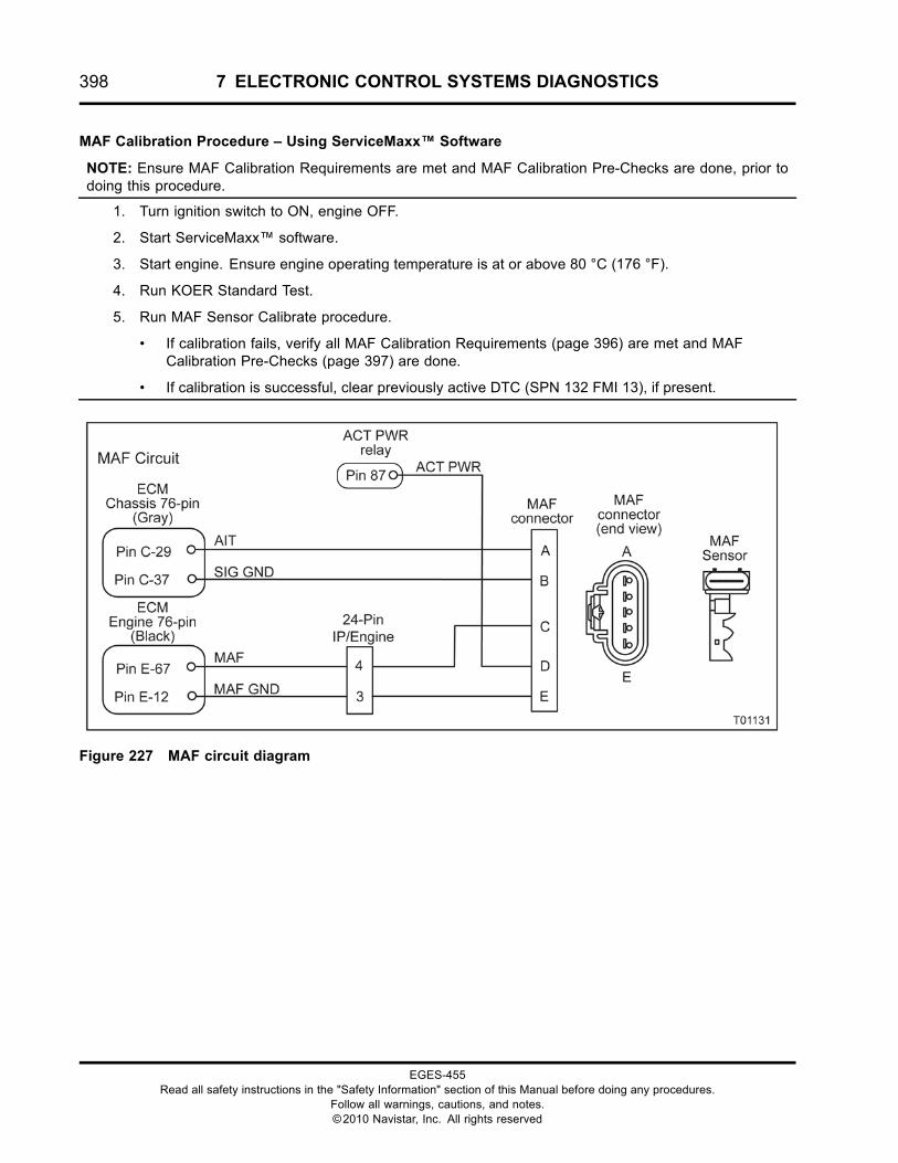
398 7 ELECTRONIC CONTROL SYSTEMS DIAGNOSTICS
MAF Calibration Procedure – Using ServiceMaxx™ Software
NOTE: Ensure MAF Calibration Requirements are met and MAF Calibration Pre-Checks are done, prior todoing this procedure.
1. Turn ignition switch to ON, engine OFF.
2. Start ServiceMaxx™ software.
3. Start engine. Ensure engine operating temperature is at or above 80 °C (176 °F).
4. Run KOER Standard Test.
5. Run MAF Sensor Calibrate procedure.
• If calibration fails, verify all MAF Calibration Requirements (page 396) are met and MAFCalibration Pre-Checks (page 397) are done.
• If calibration is successful, clear previously active DTC (SPN 132 FMI 13), if present.
Figure 227 MAF circuit diagram
EGES-455Read all safety instructions in the "Safety Information" section of this Manual before doing any procedures.
Follow all warnings, cautions, and notes.©2010 Navistar, Inc. All rights reserved
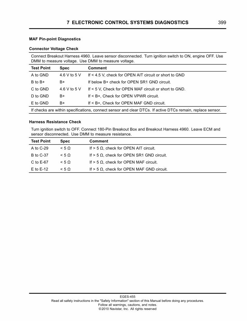
7 ELECTRONIC CONTROL SYSTEMS DIAGNOSTICS 399
MAF Pin-point Diagnostics
Connector Voltage Check
Connect Breakout Harness 4960. Leave sensor disconnected. Turn ignition switch to ON, engine OFF. UseDMM to measure voltage. Use DMM to measure voltage.
Test Point Spec Comment
A to GND 4.6 V to 5 V If < 4.5 V, check for OPEN AIT circuit or short to GND
B to B+ B+ If below B+ check for OPEN SR1 GND circuit.
C to GND 4.6 V to 5 V If < 5 V, Check for OPEN MAF circuit or short to GND.
D to GND B+ If < B+, Check for OPEN VPWR circuit.
E to GND B+ If < B+, Check for OPEN MAF GND circuit.
If checks are within specifications, connect sensor and clear DTCs. If active DTCs remain, replace sensor.
Harness Resistance Check
Turn ignition switch to OFF. Connect 180-Pin Breakout Box and Breakout Harness 4960. Leave ECM andsensor disconnected. Use DMM to measure resistance.
Test Point Spec Comment
A to C-29 < 5 Ω If > 5 Ω, check for OPEN AIT circuit.
B to C-37 < 5 Ω If > 5 Ω, check for OPEN SR1 GND circuit.
C to E-67 < 5 Ω If > 5 Ω, check for OPEN MAF circuit.
E to E-12 < 5 Ω If > 5 Ω, check for OPEN MAF GND circuit.
EGES-455Read all safety instructions in the "Safety Information" section of this Manual before doing any procedures.
Follow all warnings, cautions, and notes.©2010 Navistar, Inc. All rights reserved
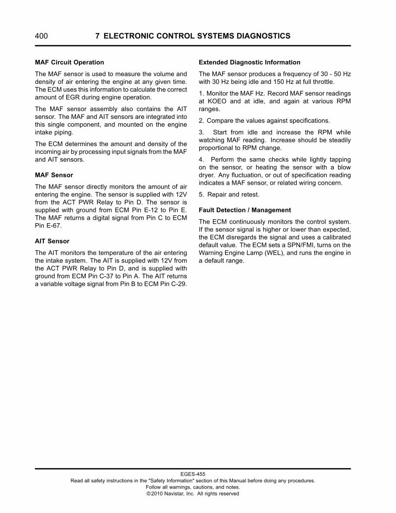
400 7 ELECTRONIC CONTROL SYSTEMS DIAGNOSTICS
MAF Circuit Operation
The MAF sensor is used to measure the volume anddensity of air entering the engine at any given time.The ECM uses this information to calculate the correctamount of EGR during engine operation.
The MAF sensor assembly also contains the AITsensor. The MAF and AIT sensors are integrated intothis single component, and mounted on the engineintake piping.
The ECM determines the amount and density of theincoming air by processing input signals from the MAFand AIT sensors.
MAF Sensor
The MAF sensor directly monitors the amount of airentering the engine. The sensor is supplied with 12Vfrom the ACT PWR Relay to Pin D. The sensor issupplied with ground from ECM Pin E-12 to Pin E.The MAF returns a digital signal from Pin C to ECMPin E-67.
AIT Sensor
The AIT monitors the temperature of the air enteringthe intake system. The AIT is supplied with 12V fromthe ACT PWR Relay to Pin D, and is supplied withground from ECM Pin C-37 to Pin A. The AIT returnsa variable voltage signal from Pin B to ECM Pin C-29.
Extended Diagnostic Information
The MAF sensor produces a frequency of 30 - 50 Hzwith 30 Hz being idle and 150 Hz at full throttle.
1. Monitor the MAF Hz. Record MAF sensor readingsat KOEO and at idle, and again at various RPMranges.
2. Compare the values against specifications.
3. Start from idle and increase the RPM whilewatching MAF reading. Increase should be steadilyproportional to RPM change.
4. Perform the same checks while lightly tappingon the sensor, or heating the sensor with a blowdryer. Any fluctuation, or out of specification readingindicates a MAF sensor, or related wiring concern.
5. Repair and retest.
Fault Detection / Management
The ECM continuously monitors the control system.If the sensor signal is higher or lower than expected,the ECM disregards the signal and uses a calibrateddefault value. The ECM sets a SPN/FMI, turns on theWarning Engine Lamp (WEL), and runs the engine ina default range.
EGES-455Read all safety instructions in the "Safety Information" section of this Manual before doing any procedures.
Follow all warnings, cautions, and notes.©2010 Navistar, Inc. All rights reserved
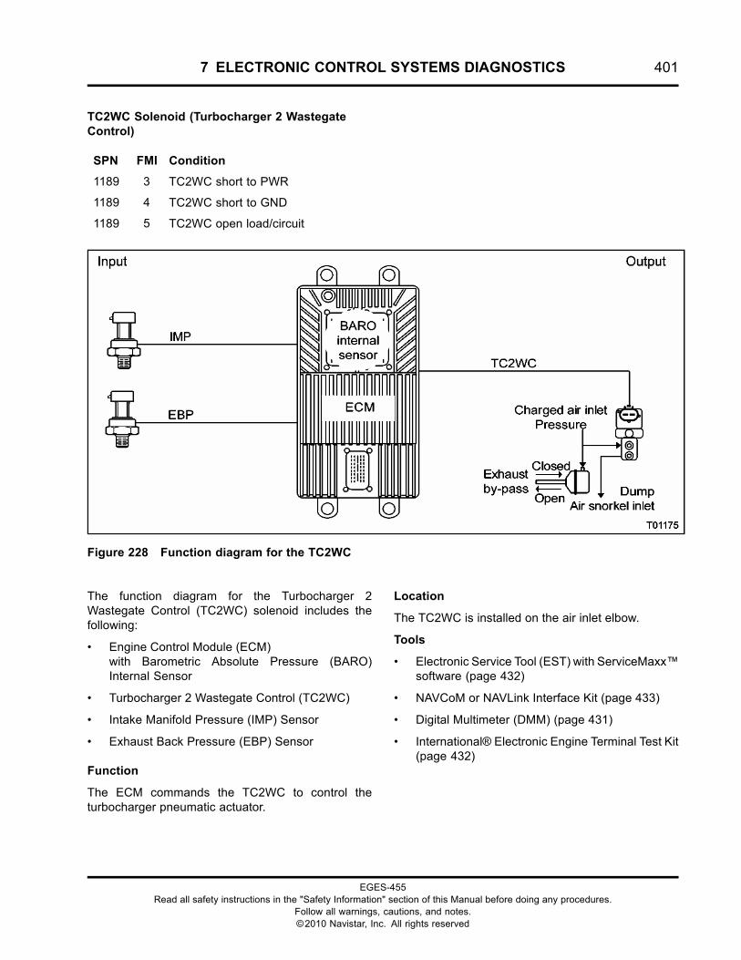
7 ELECTRONIC CONTROL SYSTEMS DIAGNOSTICS 401
TC2WC Solenoid (Turbocharger 2 WastegateControl)
SPN FMI Condition
1189 3 TC2WC short to PWR
1189 4 TC2WC short to GND
1189 5 TC2WC open load/circuit
Figure 228 Function diagram for the TC2WC
The function diagram for the Turbocharger 2Wastegate Control (TC2WC) solenoid includes thefollowing:
• Engine Control Module (ECM)with Barometric Absolute Pressure (BARO)Internal Sensor
• Turbocharger 2 Wastegate Control (TC2WC)
• Intake Manifold Pressure (IMP) Sensor
• Exhaust Back Pressure (EBP) Sensor
Function
The ECM commands the TC2WC to control theturbocharger pneumatic actuator.
Location
The TC2WC is installed on the air inlet elbow.
Tools
• Electronic Service Tool (EST) with ServiceMaxx™software (page 432)
• NAVCoM or NAVLink Interface Kit (page 433)
• Digital Multimeter (DMM) (page 431)
• International® Electronic Engine Terminal Test Kit(page 432)
EGES-455Read all safety instructions in the "Safety Information" section of this Manual before doing any procedures.
Follow all warnings, cautions, and notes.©2010 Navistar, Inc. All rights reserved
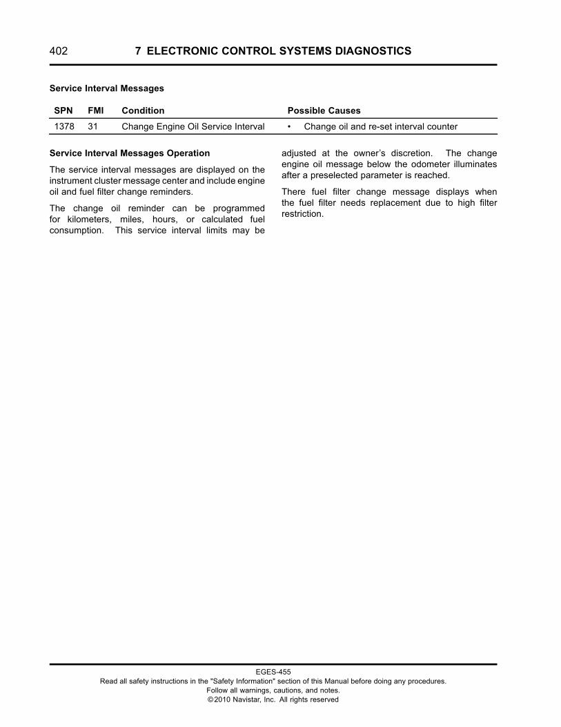
402 7 ELECTRONIC CONTROL SYSTEMS DIAGNOSTICS
Service Interval Messages
SPN FMI Condition Possible Causes
1378 31 Change Engine Oil Service Interval • Change oil and re-set interval counter
Service Interval Messages Operation
The service interval messages are displayed on theinstrument cluster message center and include engineoil and fuel filter change reminders.
The change oil reminder can be programmedfor kilometers, miles, hours, or calculated fuelconsumption. This service interval limits may be
adjusted at the owner’s discretion. The changeengine oil message below the odometer illuminatesafter a preselected parameter is reached.
There fuel filter change message displays whenthe fuel filter needs replacement due to high filterrestriction.
EGES-455Read all safety instructions in the "Safety Information" section of this Manual before doing any procedures.
Follow all warnings, cautions, and notes.©2010 Navistar, Inc. All rights reserved
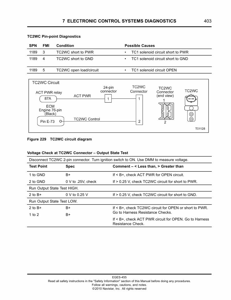
7 ELECTRONIC CONTROL SYSTEMS DIAGNOSTICS 403
TC2WC Pin-point Diagnostics
SPN FMI Condition Possible Causes
1189 3 TC2WC short to PWR • TC1 solenoid circuit short to PWR
1189 4 TC2WC short to GND • TC1 solenoid circuit short to GND
1189 5 TC2WC open load/circuit • TC1 solenoid circuit OPEN
Figure 229 TC2WC circuit diagram
Voltage Check at TC2WC Connector – Output State Test
Disconnect TC2WC 2-pin connector. Turn ignition switch to ON. Use DMM to measure voltage.
Test Point Spec Comment – < Less than, > Greater than
1 to GND
2 to GND
B+
0 V to .25V, check
If < B+, check ACT PWR for OPEN circuit.
If > 0.25 V, check TC2WC circuit for short to PWR.
Run Output State Test HIGH.
2 to B+ 0 V to 0.25 V If > 0.25 V, check TC2WC circuit for short to GND.
Run Output State Test LOW.
2 to B+
1 to 2
B+
B+
If < B+, check TC2WC circuit for OPEN or short to PWR.Go to Harness Resistance Checks.
If < B+, check ACT PWR circuit for OPEN. Go to HarnessResistance Check.
EGES-455Read all safety instructions in the "Safety Information" section of this Manual before doing any procedures.
Follow all warnings, cautions, and notes.©2010 Navistar, Inc. All rights reserved
404 7 ELECTRONIC CONTROL SYSTEMS DIAGNOSTICS
Harness Resistance Check
Turn ignition switch to OFF. Connect 180-Pin Breakout Box. Leave ECM and TC2WC disconnected.
Test Point Spec Comment – < Less than, > Greater than
E-73 to 2
E-73 to GND
< 5 Ω
> 1 kΩ
If > 5 Ω, check TC2WC for OPEN circuit.
If < 1 kΩ, check TC2WC circuit for short to GND.
1 to relay pin 87
1 to GND
< 5 Ω
> 1 k Ω
If > 5 Ω, check ACT PWR for OPEN in circuit.
If < 1 k Ω, check ACT PWR for short to GND.
TC2WC Circuit Operation
The TC2WC is supplied ACT PWR at Pin 1. The ECMgrounds Pin E-73 to control the TC2WC at Pin 2.
Fault Detection/Management
The TC2WC solenoid does not set any circuit faultcode. Only Air Management Fault Codes are usedto detect a problem with this system.
EGES-455Read all safety instructions in the "Safety Information" section of this Manual before doing any procedures.
Follow all warnings, cautions, and notes.©2010 Navistar, Inc. All rights reserved
7 ELECTRONIC CONTROL SYSTEMS DIAGNOSTICS 405
VREF (Reference Voltage)
SPN FMI Condition
3509 3 VREF Engine voltage above maximum
3509 4 VREF Engine voltage below minimum
3510 3 VREF Chassis voltage above maximum
3510 4 VREF Chassis voltage below minimum
3511 3 VREF Body voltage above maximum
3511 4 VREF Body voltage below minimum
Figure 230 Function diagram for the VREF
EGES-455Read all safety instructions in the "Safety Information" section of this Manual before doing any procedures.
Follow all warnings, cautions, and notes.©2010 Navistar, Inc. All rights reserved
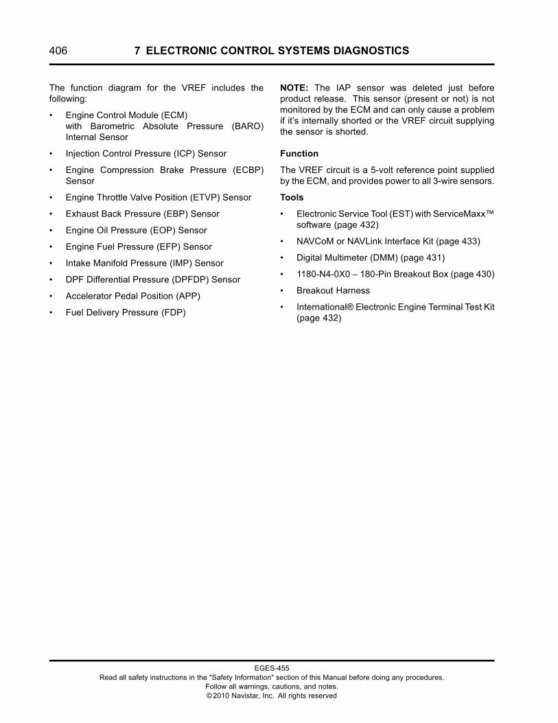
406 7 ELECTRONIC CONTROL SYSTEMS DIAGNOSTICS
The function diagram for the VREF includes thefollowing:
• Engine Control Module (ECM)with Barometric Absolute Pressure (BARO)Internal Sensor
• Injection Control Pressure (ICP) Sensor
• Engine Compression Brake Pressure (ECBP)Sensor
• Engine Throttle Valve Position (ETVP) Sensor
• Exhaust Back Pressure (EBP) Sensor
• Engine Oil Pressure (EOP) Sensor
• Engine Fuel Pressure (EFP) Sensor
• Intake Manifold Pressure (IMP) Sensor
• DPF Differential Pressure (DPFDP) Sensor
• Accelerator Pedal Position (APP)
• Fuel Delivery Pressure (FDP)
NOTE: The IAP sensor was deleted just beforeproduct release. This sensor (present or not) is notmonitored by the ECM and can only cause a problemif it’s internally shorted or the VREF circuit supplyingthe sensor is shorted.
Function
The VREF circuit is a 5-volt reference point suppliedby the ECM, and provides power to all 3-wire sensors.
Tools
• Electronic Service Tool (EST) with ServiceMaxx™software (page 432)
• NAVCoM or NAVLink Interface Kit (page 433)
• Digital Multimeter (DMM) (page 431)
• 1180-N4-0X0 – 180-Pin Breakout Box (page 430)
• Breakout Harness
• International® Electronic Engine Terminal Test Kit(page 432)
EGES-455Read all safety instructions in the "Safety Information" section of this Manual before doing any procedures.
Follow all warnings, cautions, and notes.©2010 Navistar, Inc. All rights reserved
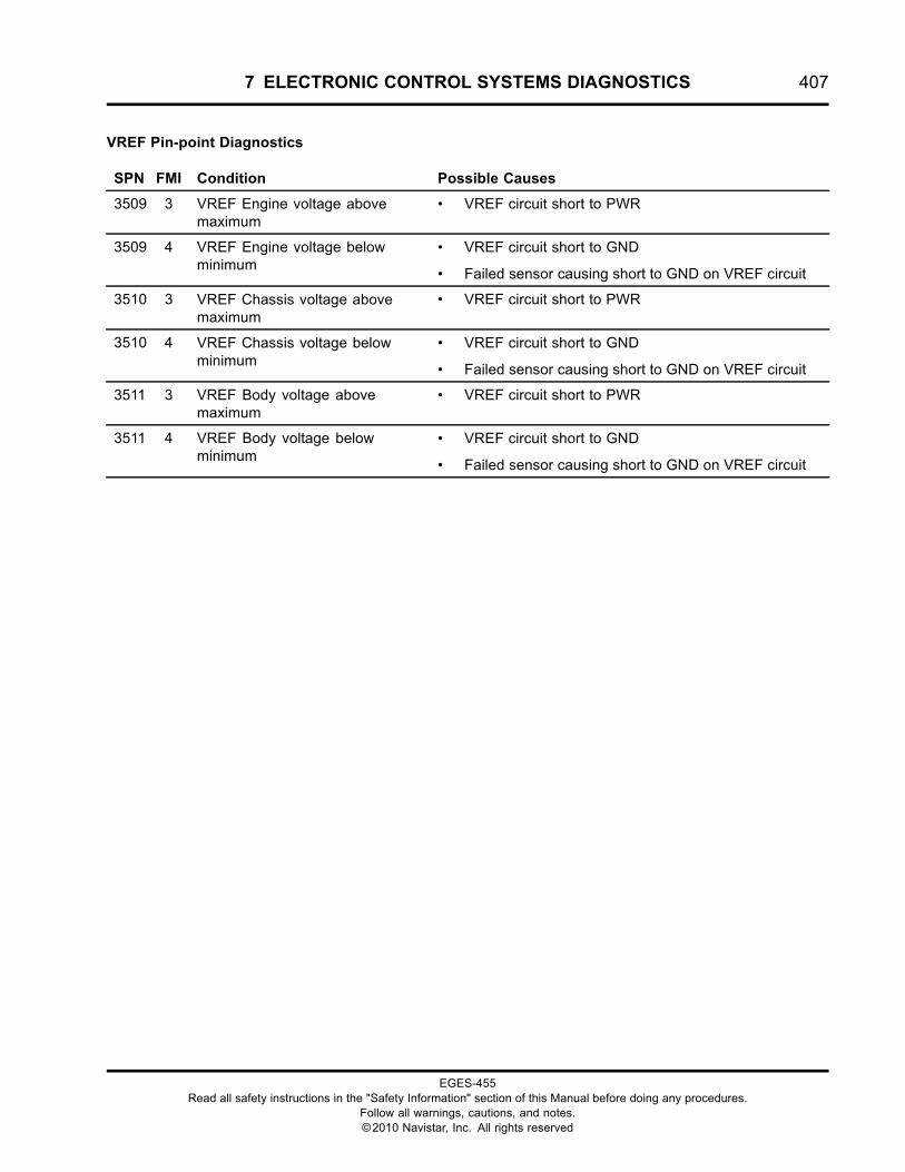
7 ELECTRONIC CONTROL SYSTEMS DIAGNOSTICS 407
VREF Pin-point Diagnostics
SPN FMI Condition Possible Causes
3509 3 VREF Engine voltage abovemaximum
• VREF circuit short to PWR
3509 4 VREF Engine voltage belowminimum
• VREF circuit short to GND
• Failed sensor causing short to GND on VREF circuit
3510 3 VREF Chassis voltage abovemaximum
• VREF circuit short to PWR
3510 4 VREF Chassis voltage belowminimum
• VREF circuit short to GND
• Failed sensor causing short to GND on VREF circuit
3511 3 VREF Body voltage abovemaximum
• VREF circuit short to PWR
3511 4 VREF Body voltage belowminimum
• VREF circuit short to GND
• Failed sensor causing short to GND on VREF circuit
EGES-455Read all safety instructions in the "Safety Information" section of this Manual before doing any procedures.
Follow all warnings, cautions, and notes.©2010 Navistar, Inc. All rights reserved
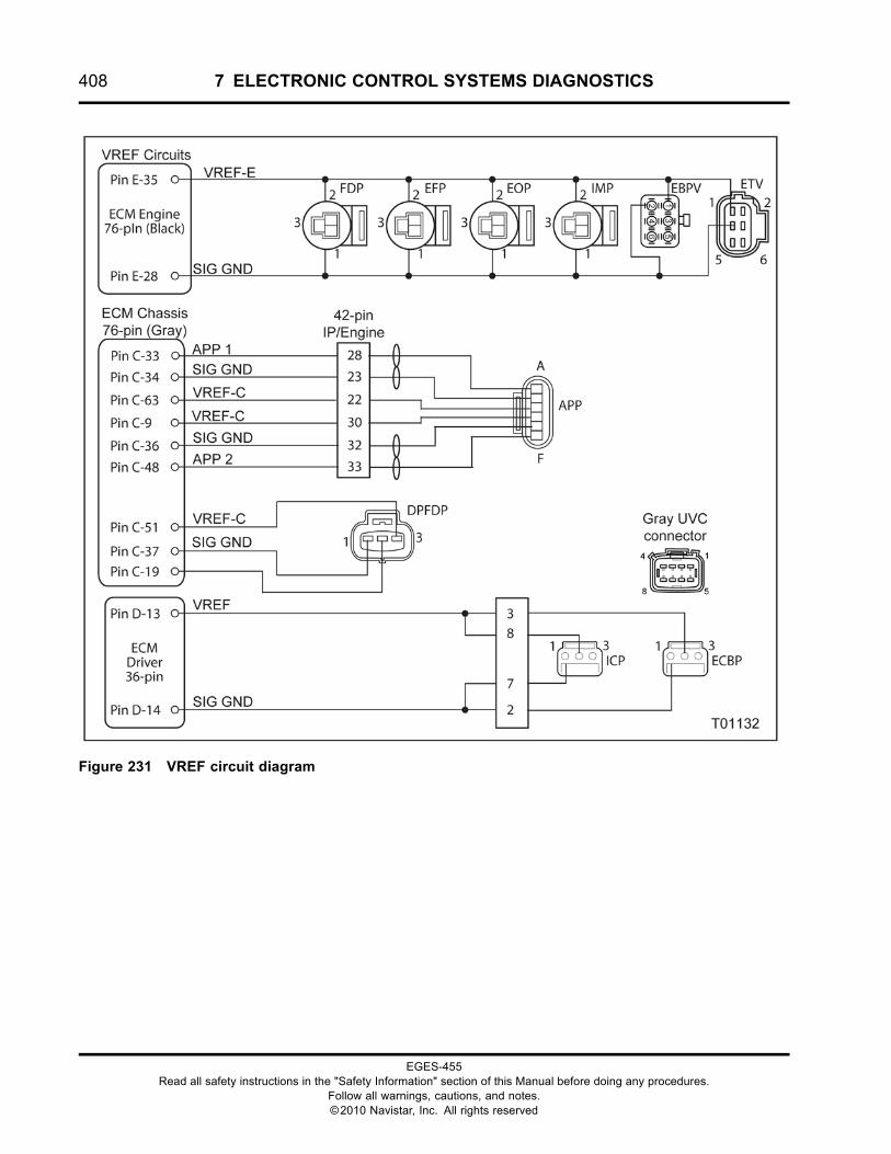
408 7 ELECTRONIC CONTROL SYSTEMS DIAGNOSTICS
Figure 231 VREF circuit diagram
EGES-455Read all safety instructions in the "Safety Information" section of this Manual before doing any procedures.
Follow all warnings, cautions, and notes.©2010 Navistar, Inc. All rights reserved
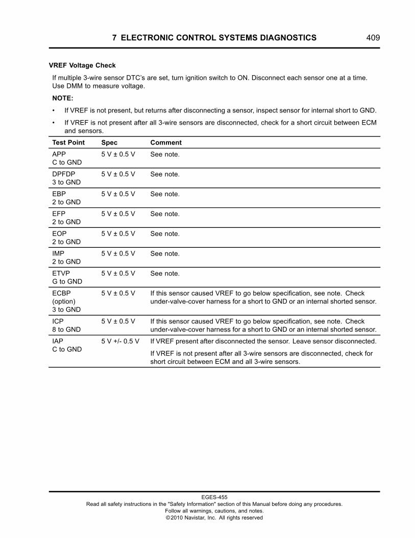
7 ELECTRONIC CONTROL SYSTEMS DIAGNOSTICS 409
VREF Voltage Check
If multiple 3-wire sensor DTC’s are set, turn ignition switch to ON. Disconnect each sensor one at a time.Use DMM to measure voltage.
NOTE:
• If VREF is not present, but returns after disconnecting a sensor, inspect sensor for internal short to GND.
• If VREF is not present after all 3-wire sensors are disconnected, check for a short circuit between ECMand sensors.
Test Point Spec Comment
APPC to GND
5 V ± 0.5 V See note.
DPFDP3 to GND
5 V ± 0.5 V See note.
EBP2 to GND
5 V ± 0.5 V See note.
EFP2 to GND
5 V ± 0.5 V See note.
EOP2 to GND
5 V ± 0.5 V See note.
IMP2 to GND
5 V ± 0.5 V See note.
ETVPG to GND
5 V ± 0.5 V See note.
ECBP(option)3 to GND
5 V ± 0.5 V If this sensor caused VREF to go below specification, see note. Checkunder-valve-cover harness for a short to GND or an internal shorted sensor.
ICP8 to GND
5 V ± 0.5 V If this sensor caused VREF to go below specification, see note. Checkunder-valve-cover harness for a short to GND or an internal shorted sensor.
IAPC to GND
5 V +/- 0.5 V If VREF present after disconnected the sensor. Leave sensor disconnected.
If VREF is not present after all 3-wire sensors are disconnected, check forshort circuit between ECM and all 3-wire sensors.
EGES-455Read all safety instructions in the "Safety Information" section of this Manual before doing any procedures.
Follow all warnings, cautions, and notes.©2010 Navistar, Inc. All rights reserved
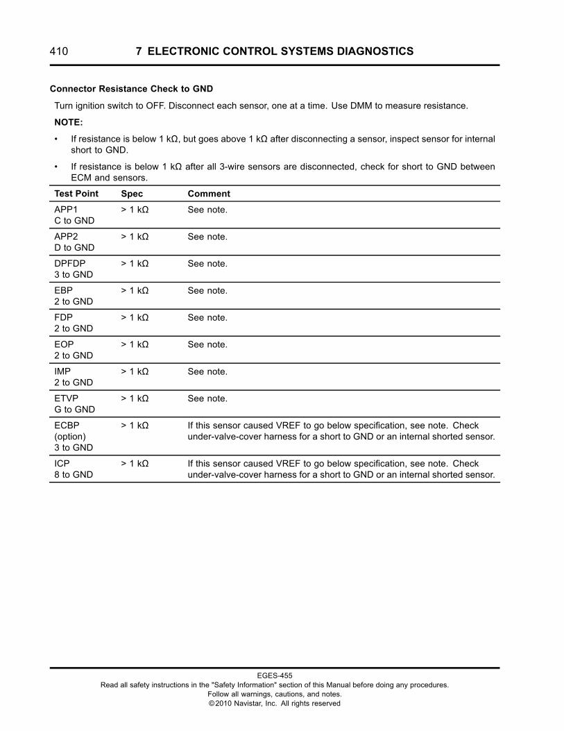
410 7 ELECTRONIC CONTROL SYSTEMS DIAGNOSTICS
Connector Resistance Check to GND
Turn ignition switch to OFF. Disconnect each sensor, one at a time. Use DMM to measure resistance.
NOTE:
• If resistance is below 1 kΩ, but goes above 1 kΩ after disconnecting a sensor, inspect sensor for internalshort to GND.
• If resistance is below 1 kΩ after all 3-wire sensors are disconnected, check for short to GND betweenECM and sensors.
Test Point Spec Comment
APP1C to GND
> 1 kΩ See note.
APP2D to GND
> 1 kΩ See note.
DPFDP3 to GND
> 1 kΩ See note.
EBP2 to GND
> 1 kΩ See note.
FDP2 to GND
> 1 kΩ See note.
EOP2 to GND
> 1 kΩ See note.
IMP2 to GND
> 1 kΩ See note.
ETVPG to GND
> 1 kΩ See note.
ECBP(option)3 to GND
> 1 kΩ If this sensor caused VREF to go below specification, see note. Checkunder-valve-cover harness for a short to GND or an internal shorted sensor.
ICP8 to GND
> 1 kΩ If this sensor caused VREF to go below specification, see note. Checkunder-valve-cover harness for a short to GND or an internal shorted sensor.
EGES-455Read all safety instructions in the "Safety Information" section of this Manual before doing any procedures.
Follow all warnings, cautions, and notes.©2010 Navistar, Inc. All rights reserved
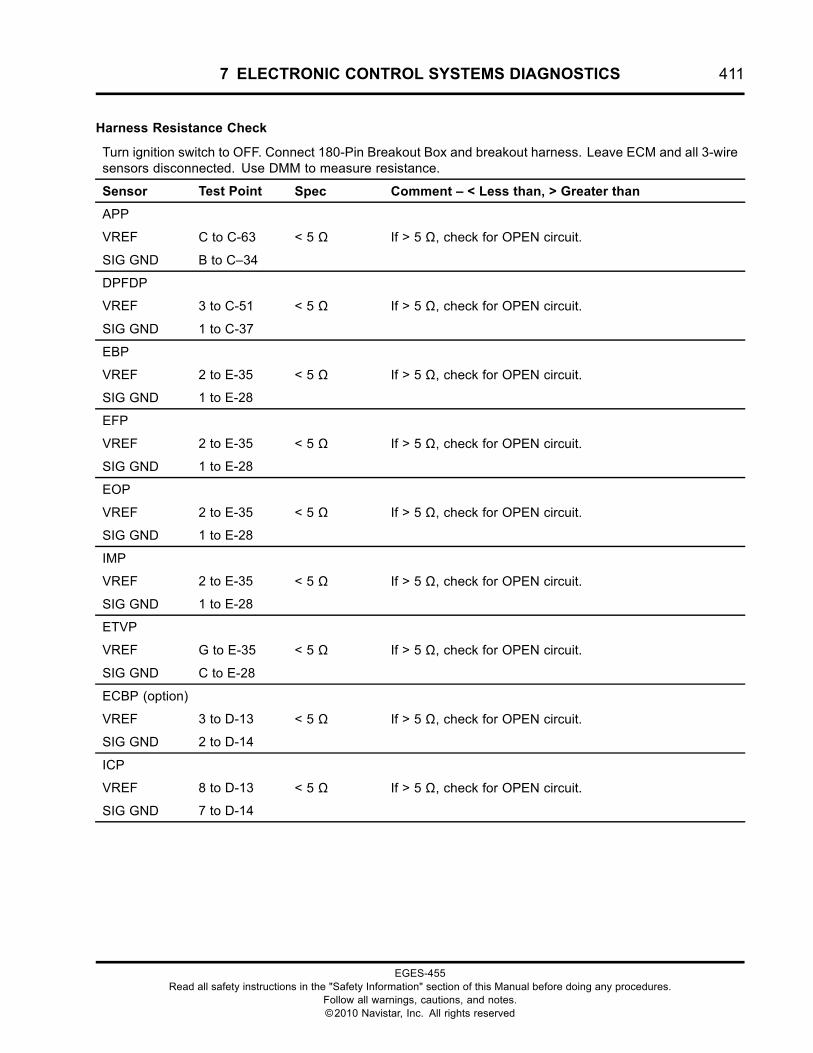
7 ELECTRONIC CONTROL SYSTEMS DIAGNOSTICS 411
Harness Resistance Check
Turn ignition switch to OFF. Connect 180-Pin Breakout Box and breakout harness. Leave ECM and all 3-wiresensors disconnected. Use DMM to measure resistance.
Sensor Test Point Spec Comment – < Less than, > Greater than
APP
VREF C to C-63
SIG GND B to C–34
< 5 Ω If > 5 Ω, check for OPEN circuit.
DPFDP
VREF 3 to C-51
SIG GND 1 to C-37
< 5 Ω If > 5 Ω, check for OPEN circuit.
EBP
VREF 2 to E-35
SIG GND 1 to E-28
< 5 Ω If > 5 Ω, check for OPEN circuit.
EFP
VREF 2 to E-35
SIG GND 1 to E-28
< 5 Ω If > 5 Ω, check for OPEN circuit.
EOP
VREF 2 to E-35
SIG GND 1 to E-28
< 5 Ω If > 5 Ω, check for OPEN circuit.
IMP
VREF 2 to E-35
SIG GND 1 to E-28
< 5 Ω If > 5 Ω, check for OPEN circuit.
ETVP
VREF G to E-35
SIG GND C to E-28
< 5 Ω If > 5 Ω, check for OPEN circuit.
ECBP (option)
VREF 3 to D-13
SIG GND 2 to D-14
< 5 Ω If > 5 Ω, check for OPEN circuit.
ICP
VREF 8 to D-13
SIG GND 7 to D-14
< 5 Ω If > 5 Ω, check for OPEN circuit.
EGES-455Read all safety instructions in the "Safety Information" section of this Manual before doing any procedures.
Follow all warnings, cautions, and notes.©2010 Navistar, Inc. All rights reserved
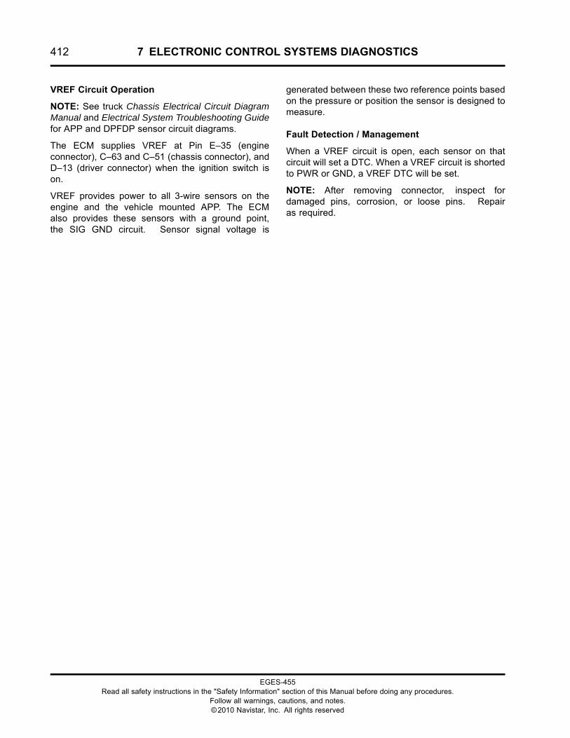
412 7 ELECTRONIC CONTROL SYSTEMS DIAGNOSTICS
VREF Circuit Operation
NOTE: See truck Chassis Electrical Circuit DiagramManual and Electrical System Troubleshooting Guidefor APP and DPFDP sensor circuit diagrams.
The ECM supplies VREF at Pin E–35 (engineconnector), C–63 and C–51 (chassis connector), andD–13 (driver connector) when the ignition switch ison.
VREF provides power to all 3-wire sensors on theengine and the vehicle mounted APP. The ECMalso provides these sensors with a ground point,the SIG GND circuit. Sensor signal voltage is
generated between these two reference points basedon the pressure or position the sensor is designed tomeasure.
Fault Detection / Management
When a VREF circuit is open, each sensor on thatcircuit will set a DTC. When a VREF circuit is shortedto PWR or GND, a VREF DTC will be set.
NOTE: After removing connector, inspect fordamaged pins, corrosion, or loose pins. Repairas required.
EGES-455Read all safety instructions in the "Safety Information" section of this Manual before doing any procedures.
Follow all warnings, cautions, and notes.©2010 Navistar, Inc. All rights reserved
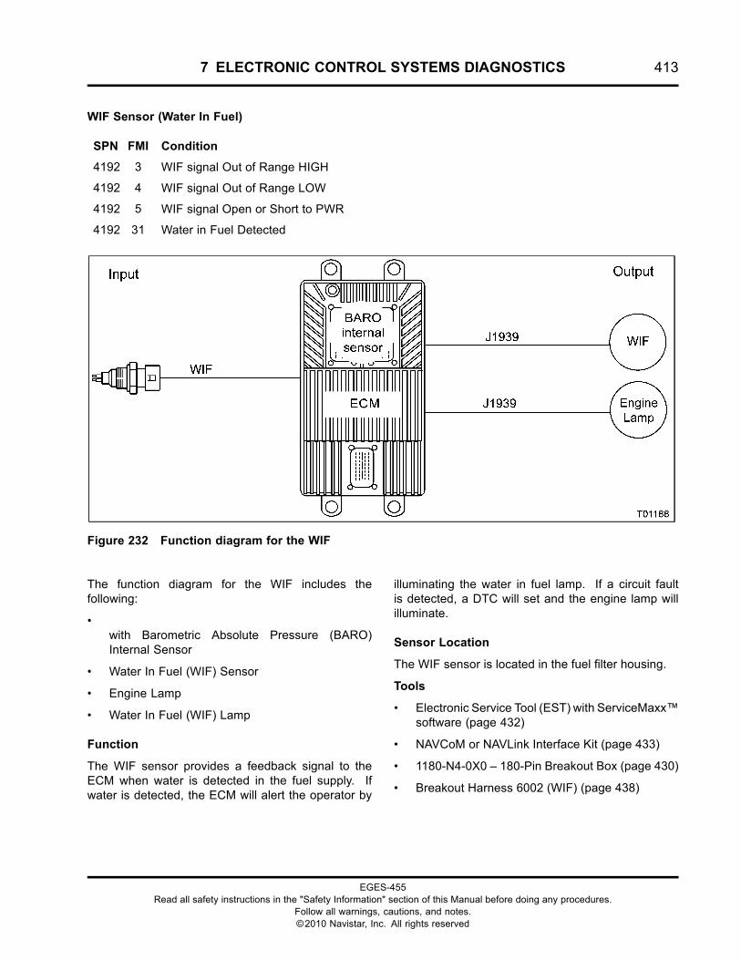
7 ELECTRONIC CONTROL SYSTEMS DIAGNOSTICS 413
WIF Sensor (Water In Fuel)
SPN FMI Condition
4192 3 WIF signal Out of Range HIGH
4192 4 WIF signal Out of Range LOW
4192 5 WIF signal Open or Short to PWR
4192 31 Water in Fuel Detected
Figure 232 Function diagram for the WIF
The function diagram for the WIF includes thefollowing:
•with Barometric Absolute Pressure (BARO)Internal Sensor
• Water In Fuel (WIF) Sensor
• Engine Lamp
• Water In Fuel (WIF) Lamp
Function
The WIF sensor provides a feedback signal to theECM when water is detected in the fuel supply. Ifwater is detected, the ECM will alert the operator by
illuminating the water in fuel lamp. If a circuit faultis detected, a DTC will set and the engine lamp willilluminate.
Sensor Location
The WIF sensor is located in the fuel filter housing.
Tools
• Electronic Service Tool (EST) with ServiceMaxx™software (page 432)
• NAVCoM or NAVLink Interface Kit (page 433)
• 1180-N4-0X0 – 180-Pin Breakout Box (page 430)
• Breakout Harness 6002 (WIF) (page 438)
EGES-455Read all safety instructions in the "Safety Information" section of this Manual before doing any procedures.
Follow all warnings, cautions, and notes.©2010 Navistar, Inc. All rights reserved
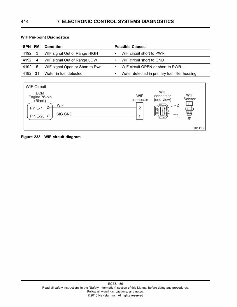
414 7 ELECTRONIC CONTROL SYSTEMS DIAGNOSTICS
WIF Pin-point Diagnostics
SPN FMI Condition Possible Causes
4192 3 WIF signal Out of Range HIGH • WIF circuit short to PWR
4192 4 WIF signal Out of Range LOW • WIF circuit short to GND
4192 5 WIF signal Open or Short to Pwr • WIF circuit OPEN or short to PWR
4192 31 Water in fuel detected • Water detected in primary fuel filter housing
Figure 233 WIF circuit diagram
EGES-455Read all safety instructions in the "Safety Information" section of this Manual before doing any procedures.
Follow all warnings, cautions, and notes.©2010 Navistar, Inc. All rights reserved
7 ELECTRONIC CONTROL SYSTEMS DIAGNOSTICS 415
1. Drain a fuel sample from the water drain valve onthe primary fuel filter housing. See Drain Waterfrom Primary Fuel Filter in “ENGINE SYMPTOMSDIAGNOSTICS”.
• If water is present, drain all the water out ofthe system.
• If no water is present in the fuel sample,continue to next step.
2. Using EST with ServiceMaxx™ software, openthe Switch Monitor session.
NOTE: The WIF signal will read YES if there iswater in the fuel filter housing, or if the WIF signalcircuit is shorted high.
• If code is inactive, monitor the signalwhile wiggling the connector and all wiresat suspected locations. If the circuit isinterrupted, the signal will change from No toYes and the DTC will go active.
• If code is active, go to the next step.
3. Disconnect engine harness from sensor.
NOTE: Inspect connectors for damaged pins,corrosion, or loose pins. Repair if necessary.
4. Connect breakout harness to engine harness.Leave sensor disconnected.
Voltage Check
Disconnect WIF sensor connector. Turn ignition switch to ON. Use DMM to measure voltage.
Test Point Spec Comment – < Less than, > Greater than
A to GND 5 V +/- 0.5 V If < 4.5 V, check for OPEN circuit.
B to GND B+ If < B+, check for OPEN short to GND.
Harness Resistance Check
Turn ignition switch to OFF. Connect 180-Pin Breakout Box and leave ECM and WIF sensor disconnected.Use DMM to measure resistance.
Test Point Spec Comment – < Less than, > Greater than
1 to GND > 1 kΩ If < 1 kΩ, check for short to GND.
1 to C2-42 < 5 Ω If > 5 Ω, check for OPEN circuit.
EGES-455Read all safety instructions in the "Safety Information" section of this Manual before doing any procedures.
Follow all warnings, cautions, and notes.©2010 Navistar, Inc. All rights reserved
416 7 ELECTRONIC CONTROL SYSTEMS DIAGNOSTICS
WIF Circuit Operation
The WIF sensor is supplied with a 5 V VREF at pin2 from the ECM pin E-7. The sensor is grounded atpin 1 from ECM pin E-28. The WIF signal is 4.6 V atnormal state and below 4.0 V when water is detected.
Fault Detection/Management
The ECM continuously monitors the WIF sensor. Ifvoltage drops below 4.0 V, a DTCwill set and the waterin fuel lamp will be illuminated. Three other DTCs areset if there is a fault with the circuit or sensor.
EGES-455Read all safety instructions in the "Safety Information" section of this Manual before doing any procedures.
Follow all warnings, cautions, and notes.©2010 Navistar, Inc. All rights reserved
8 DIAGNOSTIC TROUBLE CODE INDEX 417
Table of Contents
Diagnostic Trouble Codes. . . . . . . . . . . . . . . . . . . . . . . . . . . . . . . . . . . . . . . . . . . . . . . . . . . . . . . . . . . . . . . . . . . . . . . . . . . . . . . . . . . . . . . . . . . .419
EGES-455Read all safety instructions in the "Safety Information" section of this Manual before doing any procedures.
Follow all warnings, cautions, and notes.©2010 Navistar, Inc. All rights reserved
418 8 DIAGNOSTIC TROUBLE CODE INDEX
EGES-455Read all safety instructions in the "Safety Information" section of this Manual before doing any procedures.
Follow all warnings, cautions, and notes.©2010 Navistar, Inc. All rights reserved
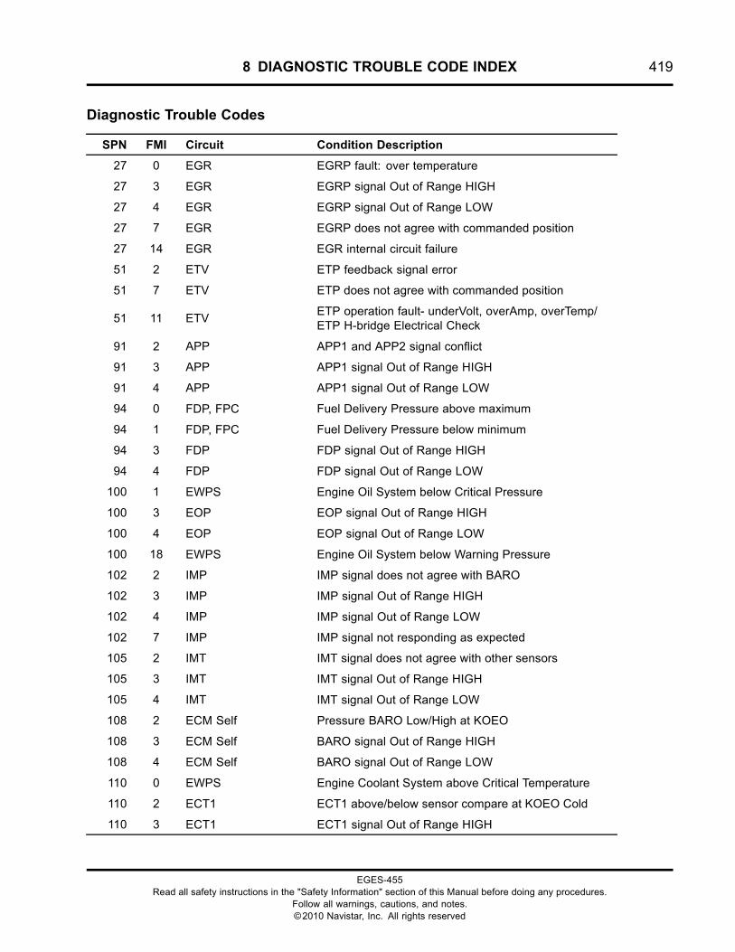
8 DIAGNOSTIC TROUBLE CODE INDEX 419
Diagnostic Trouble Codes
SPN FMI Circuit Condition Description
27 0 EGR EGRP fault: over temperature
27 3 EGR EGRP signal Out of Range HIGH
27 4 EGR EGRP signal Out of Range LOW
27 7 EGR EGRP does not agree with commanded position
27 14 EGR EGR internal circuit failure
51 2 ETV ETP feedback signal error
51 7 ETV ETP does not agree with commanded position
51 11 ETVETP operation fault- underVolt, overAmp, overTemp/ETP H-bridge Electrical Check
91 2 APP APP1 and APP2 signal conflict
91 3 APP APP1 signal Out of Range HIGH
91 4 APP APP1 signal Out of Range LOW
94 0 FDP, FPC Fuel Delivery Pressure above maximum
94 1 FDP, FPC Fuel Delivery Pressure below minimum
94 3 FDP FDP signal Out of Range HIGH
94 4 FDP FDP signal Out of Range LOW
100 1 EWPS Engine Oil System below Critical Pressure
100 3 EOP EOP signal Out of Range HIGH
100 4 EOP EOP signal Out of Range LOW
100 18 EWPS Engine Oil System below Warning Pressure
102 2 IMP IMP signal does not agree with BARO
102 3 IMP IMP signal Out of Range HIGH
102 4 IMP IMP signal Out of Range LOW
102 7 IMP IMP signal not responding as expected
105 2 IMT IMT signal does not agree with other sensors
105 3 IMT IMT signal Out of Range HIGH
105 4 IMT IMT signal Out of Range LOW
108 2 ECM Self Pressure BARO Low/High at KOEO
108 3 ECM Self BARO signal Out of Range HIGH
108 4 ECM Self BARO signal Out of Range LOW
110 0 EWPS Engine Coolant System above Critical Temperature
110 2 ECT1 ECT1 above/below sensor compare at KOEO Cold
110 3 ECT1 ECT1 signal Out of Range HIGH
EGES-455Read all safety instructions in the "Safety Information" section of this Manual before doing any procedures.
Follow all warnings, cautions, and notes.©2010 Navistar, Inc. All rights reserved
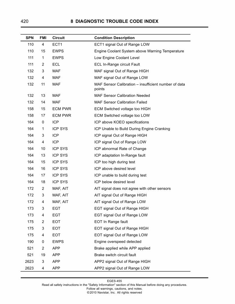
420 8 DIAGNOSTIC TROUBLE CODE INDEX
SPN FMI Circuit Condition Description
110 4 ECT1 ECT1 signal Out of Range LOW
110 15 EWPS Engine Coolant System above Warning Temperature
111 1 EWPS Low Engine Coolant Level
111 2 ECL ECL In-Range circuit Fault
132 3 MAF MAF signal Out of Range HIGH
132 4 MAF MAF signal Out of Range LOW
132 11 MAF MAF Sensor Calibration – insufficient number of datapoints
132 13 MAF MAF Sensor Calibration Needed
132 14 MAF MAF Sensor Calibration Failed
158 15 ECM PWR ECM Switched voltage too HIGH
158 17 ECM PWR ECM Switched voltage too LOW
164 0 ICP ICP above KOEO specifications
164 1 ICP SYS ICP Unable to Build During Engine Cranking
164 3 ICP ICP signal Out of Range HIGH
164 4 ICP ICP signal Out of Range LOW
164 10 ICP SYS ICP abnormal Rate of Change
164 13 ICP SYS ICP adaptation In-Range fault
164 15 ICP SYS ICP too high during test
164 16 ICP SYS ICP above desired level
164 17 ICP SYS ICP unable to build during test
164 18 ICP SYS ICP below desired level
172 2 MAF, AIT AIT signal does not agree with other sensors
172 3 MAF, AIT AIT signal Out of Range HIGH
172 4 MAF, AIT AIT signal Out of Range LOW
173 3 EGT EGT signal Out of Range HIGH
173 4 EGT EGT signal Out of Range LOW
175 2 EOT EOT In Range fault
175 3 EOT EOT signal Out of Range HIGH
175 4 EOT EOT signal Out of Range LOW
190 0 EWPS Engine overspeed detected
521 2 APP Brake applied while APP applied
521 19 APP Brake switch circuit fault
2623 3 APP APP2 signal Out of Range HIGH
2623 4 APP APP2 signal Out of Range LOW
EGES-455Read all safety instructions in the "Safety Information" section of this Manual before doing any procedures.
Follow all warnings, cautions, and notes.©2010 Navistar, Inc. All rights reserved
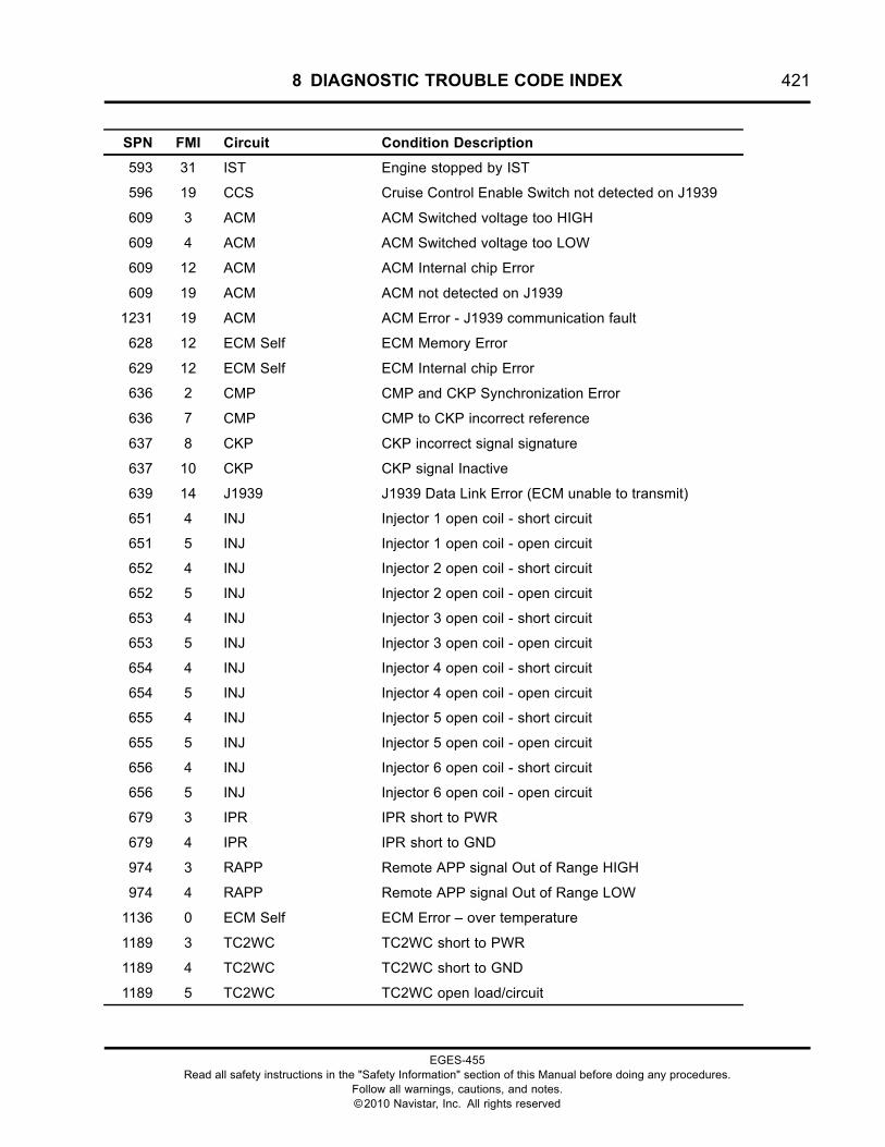
8 DIAGNOSTIC TROUBLE CODE INDEX 421
SPN FMI Circuit Condition Description
593 31 IST Engine stopped by IST
596 19 CCS Cruise Control Enable Switch not detected on J1939
609 3 ACM ACM Switched voltage too HIGH
609 4 ACM ACM Switched voltage too LOW
609 12 ACM ACM Internal chip Error
609 19 ACM ACM not detected on J1939
1231 19 ACM ACM Error - J1939 communication fault
628 12 ECM Self ECM Memory Error
629 12 ECM Self ECM Internal chip Error
636 2 CMP CMP and CKP Synchronization Error
636 7 CMP CMP to CKP incorrect reference
637 8 CKP CKP incorrect signal signature
637 10 CKP CKP signal Inactive
639 14 J1939 J1939 Data Link Error (ECM unable to transmit)
651 4 INJ Injector 1 open coil - short circuit
651 5 INJ Injector 1 open coil - open circuit
652 4 INJ Injector 2 open coil - short circuit
652 5 INJ Injector 2 open coil - open circuit
653 4 INJ Injector 3 open coil - short circuit
653 5 INJ Injector 3 open coil - open circuit
654 4 INJ Injector 4 open coil - short circuit
654 5 INJ Injector 4 open coil - open circuit
655 4 INJ Injector 5 open coil - short circuit
655 5 INJ Injector 5 open coil - open circuit
656 4 INJ Injector 6 open coil - short circuit
656 5 INJ Injector 6 open coil - open circuit
679 3 IPR IPR short to PWR
679 4 IPR IPR short to GND
974 3 RAPP Remote APP signal Out of Range HIGH
974 4 RAPP Remote APP signal Out of Range LOW
1136 0 ECM Self ECM Error – over temperature
1189 3 TC2WC TC2WC short to PWR
1189 4 TC2WC TC2WC short to GND
1189 5 TC2WC TC2WC open load/circuit
EGES-455Read all safety instructions in the "Safety Information" section of this Manual before doing any procedures.
Follow all warnings, cautions, and notes.©2010 Navistar, Inc. All rights reserved
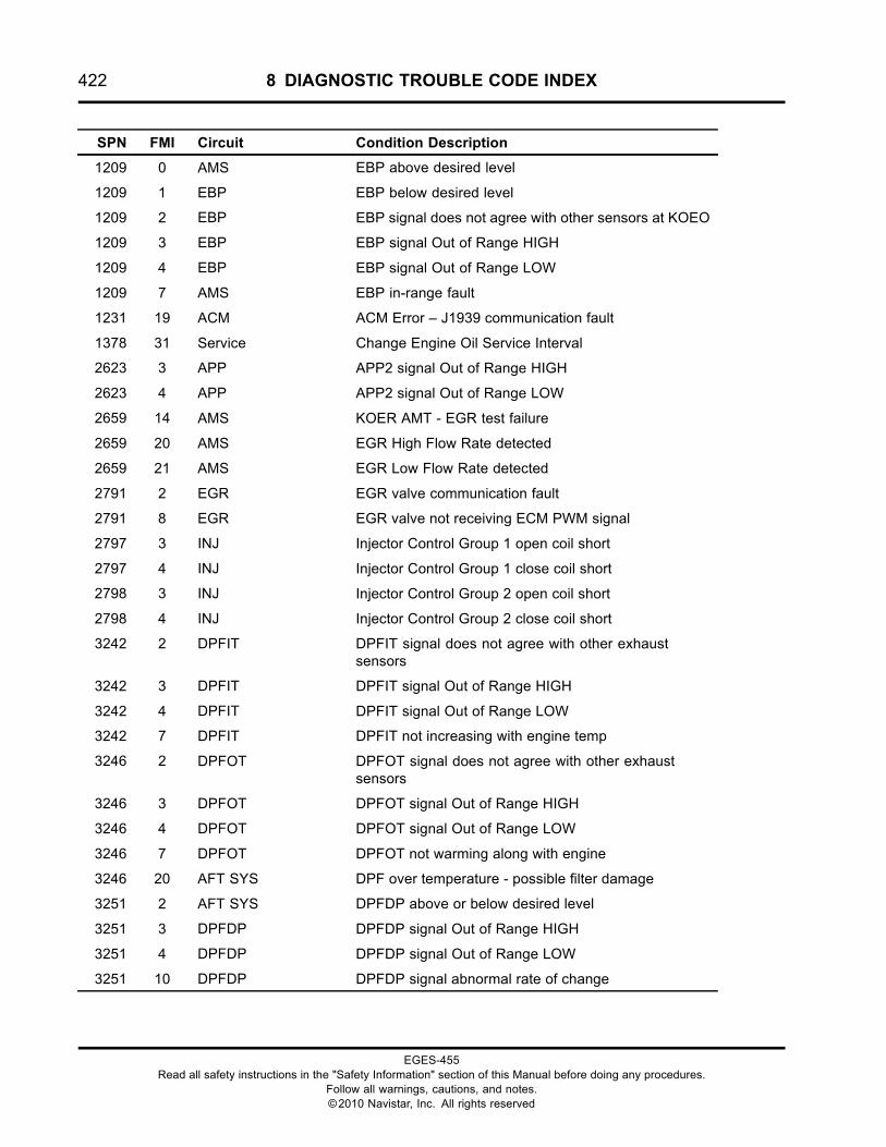
422 8 DIAGNOSTIC TROUBLE CODE INDEX
SPN FMI Circuit Condition Description
1209 0 AMS EBP above desired level
1209 1 EBP EBP below desired level
1209 2 EBP EBP signal does not agree with other sensors at KOEO
1209 3 EBP EBP signal Out of Range HIGH
1209 4 EBP EBP signal Out of Range LOW
1209 7 AMS EBP in-range fault
1231 19 ACM ACM Error – J1939 communication fault
1378 31 Service Change Engine Oil Service Interval
2623 3 APP APP2 signal Out of Range HIGH
2623 4 APP APP2 signal Out of Range LOW
2659 14 AMS KOER AMT - EGR test failure
2659 20 AMS EGR High Flow Rate detected
2659 21 AMS EGR Low Flow Rate detected
2791 2 EGR EGR valve communication fault
2791 8 EGR EGR valve not receiving ECM PWM signal
2797 3 INJ Injector Control Group 1 open coil short
2797 4 INJ Injector Control Group 1 close coil short
2798 3 INJ Injector Control Group 2 open coil short
2798 4 INJ Injector Control Group 2 close coil short
3242 2 DPFIT DPFIT signal does not agree with other exhaustsensors
3242 3 DPFIT DPFIT signal Out of Range HIGH
3242 4 DPFIT DPFIT signal Out of Range LOW
3242 7 DPFIT DPFIT not increasing with engine temp
3246 2 DPFOT DPFOT signal does not agree with other exhaustsensors
3246 3 DPFOT DPFOT signal Out of Range HIGH
3246 4 DPFOT DPFOT signal Out of Range LOW
3246 7 DPFOT DPFOT not warming along with engine
3246 20 AFT SYS DPF over temperature - possible filter damage
3251 2 AFT SYS DPFDP above or below desired level
3251 3 DPFDP DPFDP signal Out of Range HIGH
3251 4 DPFDP DPFDP signal Out of Range LOW
3251 10 DPFDP DPFDP signal abnormal rate of change
EGES-455Read all safety instructions in the "Safety Information" section of this Manual before doing any procedures.
Follow all warnings, cautions, and notes.©2010 Navistar, Inc. All rights reserved
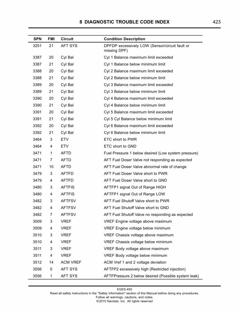
8 DIAGNOSTIC TROUBLE CODE INDEX 423
SPN FMI Circuit Condition Description
3251 21 AFT SYS DPFDP excessively LOW (Sensor/circuit fault ormissing DPF)
3387 20 Cyl Bal Cyl 1 Balance maximum limit exceeded
3387 21 Cyl Bal Cyl 1 Balance below minimum limit
3388 20 Cyl Bal Cyl 2 Balance maximum limit exceeded
3388 21 Cyl Bal Cyl 2 Balance below minimum limit
3389 20 Cyl Bal Cyl 3 Balance maximum limit exceeded
3389 21 Cyl Bal Cyl 3 Balance below minimum limit
3390 20 Cyl Bal Cyl 4 Balance maximum limit exceeded
3390 21 Cyl Bal Cyl 4 Balance below minimum limit
3391 20 Cyl Bal Cyl 5 Balance maximum limit exceeded
3391 21 Cyl Bal Cyl 5 Cyl Balance below minimum limit
3392 20 Cyl Bal Cyl 6 Balance maximum limit exceeded
3392 21 Cyl Bal Cyl 6 Balance below minimum limit
3464 3 ETV ETC short to PWR
3464 4 ETV ETC short to GND
3471 1 AFTD Fuel Pressure 1 below desired (Low system pressure)
3471 7 AFTD AFT Fuel Doser Valve not responding as expected
3471 10 AFTD AFT Fuel Doser Valve abnormal rate of change
3479 3 AFTFD AFT Fuel Doser Valve short to PWR
3479 4 AFTFD AFT Fuel Doser Valve short to GND
3480 3 AFTFIS AFTFP1 signal Out of Range HIGH
3480 4 AFTFIS AFTFP1 signal Out of Range LOW
3482 3 AFTFSV AFT Fuel Shutoff Valve short to PWR
3482 4 AFTFSV AFT Fuel Shutoff Valve short to GND
3482 7 AFTFSV AFT Fuel Shutoff Valve no responding as expected
3509 3 VREF VREF Engine voltage above maximum
3509 4 VREF VREF Engine voltage below minimum
3510 3 VREF VREF Chassis voltage above maximum
3510 4 VREF VREF Chassis voltage below minimum
3511 3 VREF VREF Body voltage above maximum
3511 4 VREF VREF Body voltage below minimum
3512 14 ACM VREF ACM Vref 1 and 2 voltage deviation
3556 0 AFT SYS AFTFP2 excessively high (Restricted injection)
3556 1 AFT SYS AFTFPressure 2 below desired (Possible system leak)
EGES-455Read all safety instructions in the "Safety Information" section of this Manual before doing any procedures.
Follow all warnings, cautions, and notes.©2010 Navistar, Inc. All rights reserved
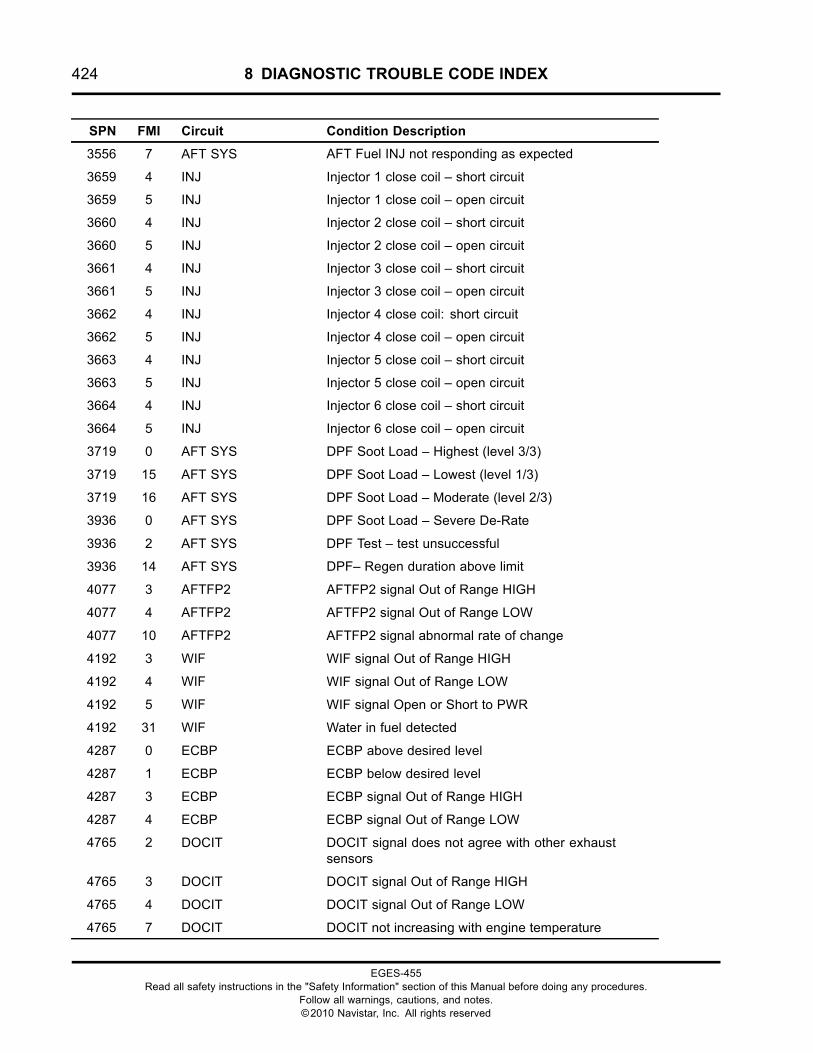
424 8 DIAGNOSTIC TROUBLE CODE INDEX
SPN FMI Circuit Condition Description
3556 7 AFT SYS AFT Fuel INJ not responding as expected
3659 4 INJ Injector 1 close coil – short circuit
3659 5 INJ Injector 1 close coil – open circuit
3660 4 INJ Injector 2 close coil – short circuit
3660 5 INJ Injector 2 close coil – open circuit
3661 4 INJ Injector 3 close coil – short circuit
3661 5 INJ Injector 3 close coil – open circuit
3662 4 INJ Injector 4 close coil: short circuit
3662 5 INJ Injector 4 close coil – open circuit
3663 4 INJ Injector 5 close coil – short circuit
3663 5 INJ Injector 5 close coil – open circuit
3664 4 INJ Injector 6 close coil – short circuit
3664 5 INJ Injector 6 close coil – open circuit
3719 0 AFT SYS DPF Soot Load – Highest (level 3/3)
3719 15 AFT SYS DPF Soot Load – Lowest (level 1/3)
3719 16 AFT SYS DPF Soot Load – Moderate (level 2/3)
3936 0 AFT SYS DPF Soot Load – Severe De-Rate
3936 2 AFT SYS DPF Test – test unsuccessful
3936 14 AFT SYS DPF– Regen duration above limit
4077 3 AFTFP2 AFTFP2 signal Out of Range HIGH
4077 4 AFTFP2 AFTFP2 signal Out of Range LOW
4077 10 AFTFP2 AFTFP2 signal abnormal rate of change
4192 3 WIF WIF signal Out of Range HIGH
4192 4 WIF WIF signal Out of Range LOW
4192 5 WIF WIF signal Open or Short to PWR
4192 31 WIF Water in fuel detected
4287 0 ECBP ECBP above desired level
4287 1 ECBP ECBP below desired level
4287 3 ECBP ECBP signal Out of Range HIGH
4287 4 ECBP ECBP signal Out of Range LOW
4765 2 DOCIT DOCIT signal does not agree with other exhaustsensors
4765 3 DOCIT DOCIT signal Out of Range HIGH
4765 4 DOCIT DOCIT signal Out of Range LOW
4765 7 DOCIT DOCIT not increasing with engine temperature
EGES-455Read all safety instructions in the "Safety Information" section of this Manual before doing any procedures.
Follow all warnings, cautions, and notes.©2010 Navistar, Inc. All rights reserved
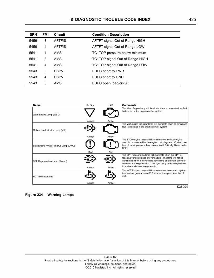
8 DIAGNOSTIC TROUBLE CODE INDEX 425
SPN FMI Circuit Condition Description
5456 3 AFTFIS AFTFT signal Out of Range HIGH
5456 4 AFTFIS AFTFT signal Out of Range LOW
5541 1 AMS TC1TOP pressure below minimum
5541 3 AMS TC1TOP signal Out of Range HIGH
5541 4 AMS TC1TOP signal Out of Range LOW
5543 3 EBPV EBPC short to PWR
5543 4 EBPV EBPC short to GND
5543 5 AMS EBPC open load/circuit
Figure 234 Warning Lamps
EGES-455Read all safety instructions in the "Safety Information" section of this Manual before doing any procedures.
Follow all warnings, cautions, and notes.©2010 Navistar, Inc. All rights reserved

426 8 DIAGNOSTIC TROUBLE CODE INDEX
EGES-455Read all safety instructions in the "Safety Information" section of this Manual before doing any procedures.
Follow all warnings, cautions, and notes.©2010 Navistar, Inc. All rights reserved
9 DIAGNOSTIC TOOLS AND ACCESSORIES 427
Table of Contents
Electrical Tools. . . . . . . . . . . . . . . . . . . . . . . . . . . . . . . . . . . . . . . . . . . . . . . . . . . . . . . . . . . . . . . . . . . . . . . . . . . . . . . . . . . . . . . . . . . . . . . . . . . . . . . . .42924-Pin IP Engine Cable. . . . . . . . . . . . . . . . . . . . . . . . . . . . . . . . . . . . . . . . . . . . . . . . . . . . . . . . . . . . . . . . . . . . . . . . . . . . . . . . . . . . . .42936-Pin Injector Driver Cable. . . . . . . . . . . . . . . . . . . . . . . . . . . . . . . . . . . . . . . . . . . . . . . . . . . . . . . . . . . . . . . . . . . . . . . . . . . . . . . .42942-Pin Engine to Chassis Interface Cable. . . . . . . . . . . . . . . . . . . . . . . . . . . . . . . . . . . . . . . . . . . . . . . . . . . . . . . . . . . . . . . .42976-Pin Engine and Chassis Cables. . . . . . . . . . . . . . . . . . . . . . . . . . . . . . . . . . . . . . . . . . . . . . . . . . . . . . . . . . . . . . . . . . . . . . . .429180-Pin Breakout Box.. . . . . . . . . . . . . . . . . . . . . . . . . . . . . . . . . . . . . . . . . . . . . . . . . . . . . . . . . . . . . . . . . . . . . . . . . . . . . . . . . . . . . . 430Amp Clamp.. . . . . . . . . . . . . . . . . . . . . . . . . . . . . . . . . . . . . . . . . . . . . . . . . . . . . . . . . . . . . . . . . . . . . . . . . . . . . . . . . . . . . . . . . . . . . . . . . . .430Digital Multimeter (DMM). . . . . . . . . . . . . . . . . . . . . . . . . . . . . . . . . . . . . . . . . . . . . . . . . . . . . . . . . . . . . . . . . . . . . . . . . . . . . . . . . . . .431EXP-1000 HD by Midtronics. . . . . . . . . . . . . . . . . . . . . . . . . . . . . . . . . . . . . . . . . . . . . . . . . . . . . . . . . . . . . . . . . . . . . . . . . . . . . . . .431EZ-Tech® Electronic Service Tool (EST). . . . . . . . . . . . . . . . . . . . . . . . . . . . . . . . . . . . . . . . . . . . . . . . . . . . . . . . . . . . . . . . .432
ServiceMaxx™ Software. . . . . . . . . . . . . . . . . . . . . . . . . . . . . . . . . . . . . . . . . . . . . . . . . . . . . . . . . . . . . . . . . . . . . . . . . . .432International® Electronic Engine Terminal Test Kit. . . . . . . . . . . . . . . . . . . . . . . . . . . . . . . . . . . . . . . . . . . . . . . . . . . .432NAVCoM Interface Kit. . . . . . . . . . . . . . . . . . . . . . . . . . . . . . . . . . . . . . . . . . . . . . . . . . . . . . . . . . . . . . . . . . . . . . . . . . . . . . . . . . . . . . . .4333-Banana Plug Harness. . . . . . . . . . . . . . . . . . . . . . . . . . . . . . . . . . . . . . . . . . . . . . . . . . . . . . . . . . . . . . . . . . . . . . . . . . . . . . . . . . . . .433500-Ohm Resistor Harness.. . . . . . . . . . . . . . . . . . . . . . . . . . . . . . . . . . . . . . . . . . . . . . . . . . . . . . . . . . . . . . . . . . . . . . . . . . . . . . . .433Breakout Harness 4484 (IPR). . . . . . . . . . . . . . . . . . . . . . . . . . . . . . . . . . . . . . . . . . . . . . . . . . . . . . . . . . . . . . . . . . . . . . . . . . . . . . .433Breakout Harness 4485A (APP). . . . . . . . . . . . . . . . . . . . . . . . . . . . . . . . . . . . . . . . . . . . . . . . . . . . . . . . . . . . . . . . . . . . . . . . . . . .434Breakout Harness 4602 (ECT, EFT, EOT, and IMT). . . . . . . . . . . . . . . . . . . . . . . . . . . . . . . . . . . . . . . . . . . . . . . . . . . . . .434Breakout Harness 4674 (ECM and ACT PWR Relays). . . . . . . . . . . . . . . . . . . . . . . . . . . . . . . . . . . . . . . . . . . . . . . . .434Breakout Harness 4735A (ETV). . . . . . . . . . . . . . . . . . . . . . . . . . . . . . . . . . . . . . . . . . . . . . . . . . . . . . . . . . . . . . . . . . . . . . . . . . . .434Breakout Harness 4760A (DOCIT, DPFIT, and DPFOT). . . . . . . . . . . . . . . . . . . . . . . . . . . . . . . . . . . . . . . . . . . . . . . . .435Breakout Harness 4761A (DPFDP). . . . . . . . . . . . . . . . . . . . . . . . . . . . . . . . . . . . . . . . . . . . . . . . . . . . . . . . . . . . . . . . . . . . . . . .435Breakout Harness 4828 (AFTFD). . . . . . . . . . . . . . . . . . . . . . . . . . . . . . . . . . . . . . . . . . . . . . . . . . . . . . . . . . . . . . . . . . . . . . . . . .435Breakout Harness 4830 (AFTFI). . . . . . . . . . . . . . . . . . . . . . . . . . . . . . . . . . . . . . . . . . . . . . . . . . . . . . . . . . . . . . . . . . . . . . . . . . . .435Breakout Harness 4831 (TC1WC). . . . . . . . . . . . . . . . . . . . . . . . . . . . . . . . . . . . . . . . . . . . . . . . . . . . . . . . . . . . . . . . . . . . . . . . . .436Breakout Harness 4834 (EBPV). . . . . . . . . . . . . . . . . . . . . . . . . . . . . . . . . . . . . . . . . . . . . . . . . . . . . . . . . . . . . . . . . . . . . . . . . . . .436Breakout Harness 4850 (IMP). . . . . . . . . . . . . . . . . . . . . . . . . . . . . . . . . . . . . . . . . . . . . . . . . . . . . . . . . . . . . . . . . . . . . . . . . . . . . .436Breakout Harness 4946 (EGT). . . . . . . . . . . . . . . . . . . . . . . . . . . . . . . . . . . . . . . . . . . . . . . . . . . . . . . . . . . . . . . . . . . . . . . . . . . . . .436Breakout Harness 4948 (EGR). . . . . . . . . . . . . . . . . . . . . . . . . . . . . . . . . . . . . . . . . . . . . . . . . . . . . . . . . . . . . . . . . . . . . . . . . . . . .437Breakout Harness 4950 (CKP). . . . . . . . . . . . . . . . . . . . . . . . . . . . . . . . . . . . . . . . . . . . . . . . . . . . . . . . . . . . . . . . . . . . . . . . . . . . . .437Breakout Harness 4951 (CMP). . . . . . . . . . . . . . . . . . . . . . . . . . . . . . . . . . . . . . . . . . . . . . . . . . . . . . . . . . . . . . . . . . . . . . . . . . . . .437Breakout Harness 4952 (ICP, ECB, and ECBP). . . . . . . . . . . . . . . . . . . . . . . . . . . . . . . . . . . . . . . . . . . . . . . . . . . . . . . . . .437Breakout Harness 4960 (MAF). . . . . . . . . . . . . . . . . . . . . . . . . . . . . . . . . . . . . . . . . . . . . . . . . . . . . . . . . . . . . . . . . . . . . . . . . . . . .438Breakout Harness 4993 (IMT). . . . . . . . . . . . . . . . . . . . . . . . . . . . . . . . . . . . . . . . . . . . . . . . . . . . . . . . . . . . . . . . . . . . . . . . . . . . . . .438Breakout Harness 6002 (WIF). . . . . . . . . . . . . . . . . . . . . . . . . . . . . . . . . . . . . . . . . . . . . . . . . . . . . . . . . . . . . . . . . . . . . . . . . . . . . .438Breakout Harness 6020 (24-pin). . . . . . . . . . . . . . . . . . . . . . . . . . . . . . . . . . . . . . . . . . . . . . . . . . . . . . . . . . . . . . . . . . . . . . . . . . .438Breakout Harness 6021 (AFTFSV). . . . . . . . . . . . . . . . . . . . . . . . . . . . . . . . . . . . . . . . . . . . . . . . . . . . . . . . . . . . . . . . . . . . . . . . .439Breakout Harness 6023 (FPC). . . . . . . . . . . . . . . . . . . . . . . . . . . . . . . . . . . . . . . . . . . . . . . . . . . . . . . . . . . . . . . . . . . . . . . . . . . . . .439Breakout Harness 6025 (IAH). . . . . . . . . . . . . . . . . . . . . . . . . . . . . . . . . . . . . . . . . . . . . . . . . . . . . . . . . . . . . . . . . . . . . . . . . . . . . . .439Breakout Harness 6027 (AFTFP). . . . . . . . . . . . . . . . . . . . . . . . . . . . . . . . . . . . . . . . . . . . . . . . . . . . . . . . . . . . . . . . . . . . . . . . . . .439
Mechanical Tools. . . . . . . . . . . . . . . . . . . . . . . . . . . . . . . . . . . . . . . . . . . . . . . . . . . . . . . . . . . . . . . . . . . . . . . . . . . . . . . . . . . . . . . . . . . . . . . . . . . . . . .440CAC Block Off Kit. . . . . . . . . . . . . . . . . . . . . . . . . . . . . . . . . . . . . . . . . . . . . . . . . . . . . . . . . . . . . . . . . . . . . . . . . . . . . . . . . . . . . . . . . . . .440Charge Air Cooler Test Kit. . . . . . . . . . . . . . . . . . . . . . . . . . . . . . . . . . . . . . . . . . . . . . . . . . . . . . . . . . . . . . . . . . . . . . . . . . . . . . . . . .440Clean Fuel Supply Tank.. . . . . . . . . . . . . . . . . . . . . . . . . . . . . . . . . . . . . . . . . . . . . . . . . . . . . . . . . . . . . . . . . . . . . . . . . . . . . . . . . . . .440Crankcase Pressure Test Tool. . . . . . . . . . . . . . . . . . . . . . . . . . . . . . . . . . . . . . . . . . . . . . . . . . . . . . . . . . . . . . . . . . . . . . . . . . . . .441
EGES-455Read all safety instructions in the "Safety Information" section of this Manual before doing any procedures.
Follow all warnings, cautions, and notes.©2010 Navistar, Inc. All rights reserved
428 9 DIAGNOSTIC TOOLS AND ACCESSORIES
Digital Manometer. . . . . . . . . . . . . . . . . . . . . . . . . . . . . . . . . . . . . . . . . . . . . . . . . . . . . . . . . . . . . . . . . . . . . . . . . . . . . . . . . . . . . . . . . . . .441EGR Mixing Bowl Guide Pins. . . . . . . . . . . . . . . . . . . . . . . . . . . . . . . . . . . . . . . . . . . . . . . . . . . . . . . . . . . . . . . . . . . . . . . . . . . . . .442EGR Valve Puller. . . . . . . . . . . . . . . . . . . . . . . . . . . . . . . . . . . . . . . . . . . . . . . . . . . . . . . . . . . . . . . . . . . . . . . . . . . . . . . . . . . . . . . . . . . . . .442Fuel Inlet Restriction and Aeration Tool. . . . . . . . . . . . . . . . . . . . . . . . . . . . . . . . . . . . . . . . . . . . . . . . . . . . . . . . . . . . . . . . . .442Fuel/Oil Pressure Test Coupler. . . . . . . . . . . . . . . . . . . . . . . . . . . . . . . . . . . . . . . . . . . . . . . . . . . . . . . . . . . . . . . . . . . . . . . . . . . .442Fuel Pressure Gauge. . . . . . . . . . . . . . . . . . . . . . . . . . . . . . . . . . . . . . . . . . . . . . . . . . . . . . . . . . . . . . . . . . . . . . . . . . . . . . . . . . . . . . . .443Fuel Pressure Test Kit. . . . . . . . . . . . . . . . . . . . . . . . . . . . . . . . . . . . . . . . . . . . . . . . . . . . . . . . . . . . . . . . . . . . . . . . . . . . . . . . . . . . . . .443Fuel Test Fitting. . . . . . . . . . . . . . . . . . . . . . . . . . . . . . . . . . . . . . . . . . . . . . . . . . . . . . . . . . . . . . . . . . . . . . . . . . . . . . . . . . . . . . . . . . . . . . .444ICP Adapter Pressure Test Fitting. . . . . . . . . . . . . . . . . . . . . . . . . . . . . . . . . . . . . . . . . . . . . . . . . . . . . . . . . . . . . . . . . . . . . . . . .444ICP System Test Adapter. . . . . . . . . . . . . . . . . . . . . . . . . . . . . . . . . . . . . . . . . . . . . . . . . . . . . . . . . . . . . . . . . . . . . . . . . . . . . . . . . . . .445ICP Test Kit. . . . . . . . . . . . . . . . . . . . . . . . . . . . . . . . . . . . . . . . . . . . . . . . . . . . . . . . . . . . . . . . . . . . . . . . . . . . . . . . . . . . . . . . . . . . . . . . . . . .445Inline Shut-off Valve. . . . . . . . . . . . . . . . . . . . . . . . . . . . . . . . . . . . . . . . . . . . . . . . . . . . . . . . . . . . . . . . . . . . . . . . . . . . . . . . . . . . . . . . . .445IPR Plug Tester. . . . . . . . . . . . . . . . . . . . . . . . . . . . . . . . . . . . . . . . . . . . . . . . . . . . . . . . . . . . . . . . . . . . . . . . . . . . . . . . . . . . . . . . . . . . . . .445K Line EGR Cooler Test Kit. . . . . . . . . . . . . . . . . . . . . . . . . . . . . . . . . . . . . . . . . . . . . . . . . . . . . . . . . . . . . . . . . . . . . . . . . . . . . . . . .446Oil Cooler Test Plate. . . . . . . . . . . . . . . . . . . . . . . . . . . . . . . . . . . . . . . . . . . . . . . . . . . . . . . . . . . . . . . . . . . . . . . . . . . . . . . . . . . . . . . . .446Pressure Test Kit. . . . . . . . . . . . . . . . . . . . . . . . . . . . . . . . . . . . . . . . . . . . . . . . . . . . . . . . . . . . . . . . . . . . . . . . . . . . . . . . . . . . . . . . . . . . .446Pressure Vacuum Module. . . . . . . . . . . . . . . . . . . . . . . . . . . . . . . . . . . . . . . . . . . . . . . . . . . . . . . . . . . . . . . . . . . . . . . . . . . . . . . . . . .447Turbo Lifting Bracket. . . . . . . . . . . . . . . . . . . . . . . . . . . . . . . . . . . . . . . . . . . . . . . . . . . . . . . . . . . . . . . . . . . . . . . . . . . . . . . . . . . . . . . .447Radiator Pressure Test Kit. . . . . . . . . . . . . . . . . . . . . . . . . . . . . . . . . . . . . . . . . . . . . . . . . . . . . . . . . . . . . . . . . . . . . . . . . . . . . . . . . .447Slack Tube® Manometer. . . . . . . . . . . . . . . . . . . . . . . . . . . . . . . . . . . . . . . . . . . . . . . . . . . . . . . . . . . . . . . . . . . . . . . . . . . . . . . . . . . .448UV Leak Detection Kit. . . . . . . . . . . . . . . . . . . . . . . . . . . . . . . . . . . . . . . . . . . . . . . . . . . . . . . . . . . . . . . . . . . . . . . . . . . . . . . . . . . . . . .449Vacuum Analyzer and Fuel Pump Tester. . . . . . . . . . . . . . . . . . . . . . . . . . . . . . . . . . . . . . . . . . . . . . . . . . . . . . . . . . . . . . . . .449
EGES-455Read all safety instructions in the "Safety Information" section of this Manual before doing any procedures.
Follow all warnings, cautions, and notes.©2010 Navistar, Inc. All rights reserved
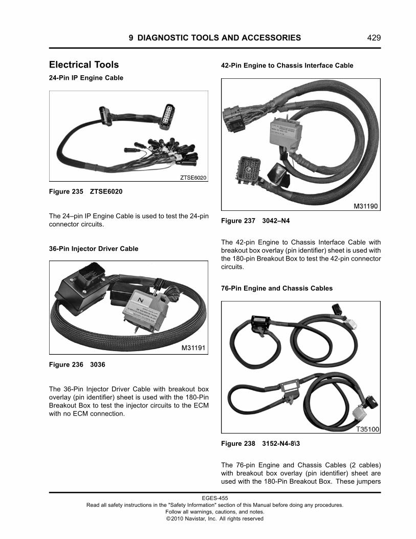
9 DIAGNOSTIC TOOLS AND ACCESSORIES 429
Electrical Tools24-Pin IP Engine Cable
Figure 235 ZTSE6020
The 24–pin IP Engine Cable is used to test the 24-pinconnector circuits.
36-Pin Injector Driver Cable
Figure 236 3036
The 36-Pin Injector Driver Cable with breakout boxoverlay (pin identifier) sheet is used with the 180-PinBreakout Box to test the injector circuits to the ECMwith no ECM connection.
42-Pin Engine to Chassis Interface Cable
Figure 237 3042–N4
The 42-pin Engine to Chassis Interface Cable withbreakout box overlay (pin identifier) sheet is used withthe 180-pin Breakout Box to test the 42-pin connectorcircuits.
76-Pin Engine and Chassis Cables
Figure 238 3152-N4-8\3
The 76-pin Engine and Chassis Cables (2 cables)with breakout box overlay (pin identifier) sheet areused with the 180-Pin Breakout Box. These jumpers
EGES-455Read all safety instructions in the "Safety Information" section of this Manual before doing any procedures.
Follow all warnings, cautions, and notes.©2010 Navistar, Inc. All rights reserved
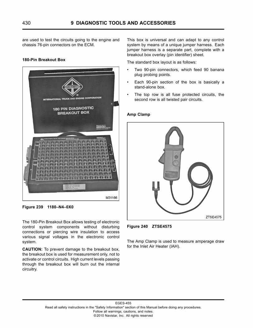
430 9 DIAGNOSTIC TOOLS AND ACCESSORIES
are used to test the circuits going to the engine andchassis 76-pin connectors on the ECM.
180-Pin Breakout Box
Figure 239 1180–N4–0X0
The 180-Pin Breakout Box allows testing of electroniccontrol system components without disturbingconnections or piercing wire insulation to accessvarious signal voltages in the electronic controlsystem.
CAUTION: To prevent damage to the breakout box,the breakout box is used for measurement only, not toactivate or control circuits. High current levels passingthrough the breakout box will burn out the internalcircuitry.
This box is universal and can adapt to any controlsystem by means of a unique jumper harness. Eachjumper harness is a separate part, complete with abreakout box overlay (pin identifier) sheet.
The standard box layout is as follows:
• Two 90-pin connectors, which feed 90 bananaplug probing points.
• Each 90-pin section of the box is basically astand-alone box.
• The top row is all fuse protected circuits, thesecond row is all twisted pair circuits.
Amp Clamp
Figure 240 ZTSE4575
The Amp Clamp is used to measure amperage drawfor the Inlet Air Heater (IAH).
EGES-455Read all safety instructions in the "Safety Information" section of this Manual before doing any procedures.
Follow all warnings, cautions, and notes.©2010 Navistar, Inc. All rights reserved
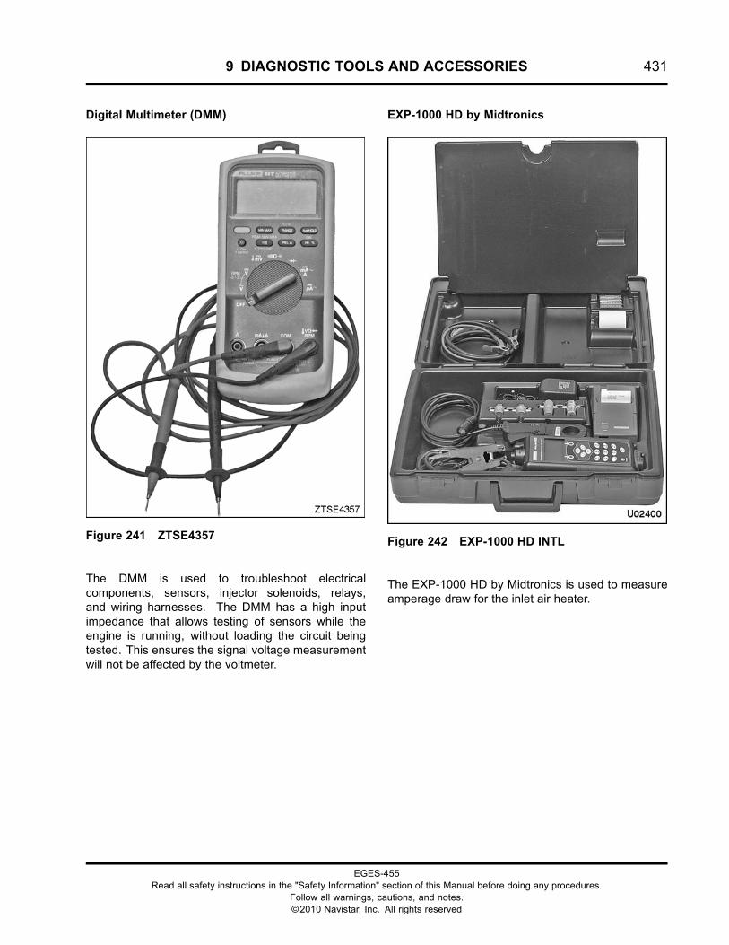
9 DIAGNOSTIC TOOLS AND ACCESSORIES 431
Digital Multimeter (DMM)
Figure 241 ZTSE4357
The DMM is used to troubleshoot electricalcomponents, sensors, injector solenoids, relays,and wiring harnesses. The DMM has a high inputimpedance that allows testing of sensors while theengine is running, without loading the circuit beingtested. This ensures the signal voltage measurementwill not be affected by the voltmeter.
EXP-1000 HD by Midtronics
Figure 242 EXP-1000 HD INTL
The EXP-1000 HD by Midtronics is used to measureamperage draw for the inlet air heater.
EGES-455Read all safety instructions in the "Safety Information" section of this Manual before doing any procedures.
Follow all warnings, cautions, and notes.©2010 Navistar, Inc. All rights reserved
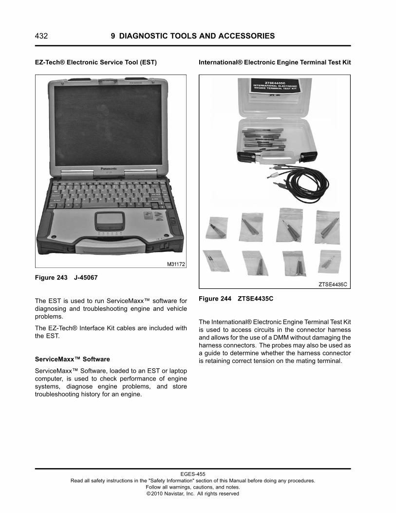
432 9 DIAGNOSTIC TOOLS AND ACCESSORIES
EZ-Tech® Electronic Service Tool (EST)
Figure 243 J-45067
The EST is used to run ServiceMaxx™ software fordiagnosing and troubleshooting engine and vehicleproblems.
The EZ-Tech® Interface Kit cables are included withthe EST.
ServiceMaxx™ Software
ServiceMaxx™ Software, loaded to an EST or laptopcomputer, is used to check performance of enginesystems, diagnose engine problems, and storetroubleshooting history for an engine.
International® Electronic Engine Terminal Test Kit
Figure 244 ZTSE4435C
The International® Electronic Engine Terminal Test Kitis used to access circuits in the connector harnessand allows for the use of a DMMwithout damaging theharness connectors. The probes may also be used asa guide to determine whether the harness connectoris retaining correct tension on the mating terminal.
EGES-455Read all safety instructions in the "Safety Information" section of this Manual before doing any procedures.
Follow all warnings, cautions, and notes.©2010 Navistar, Inc. All rights reserved
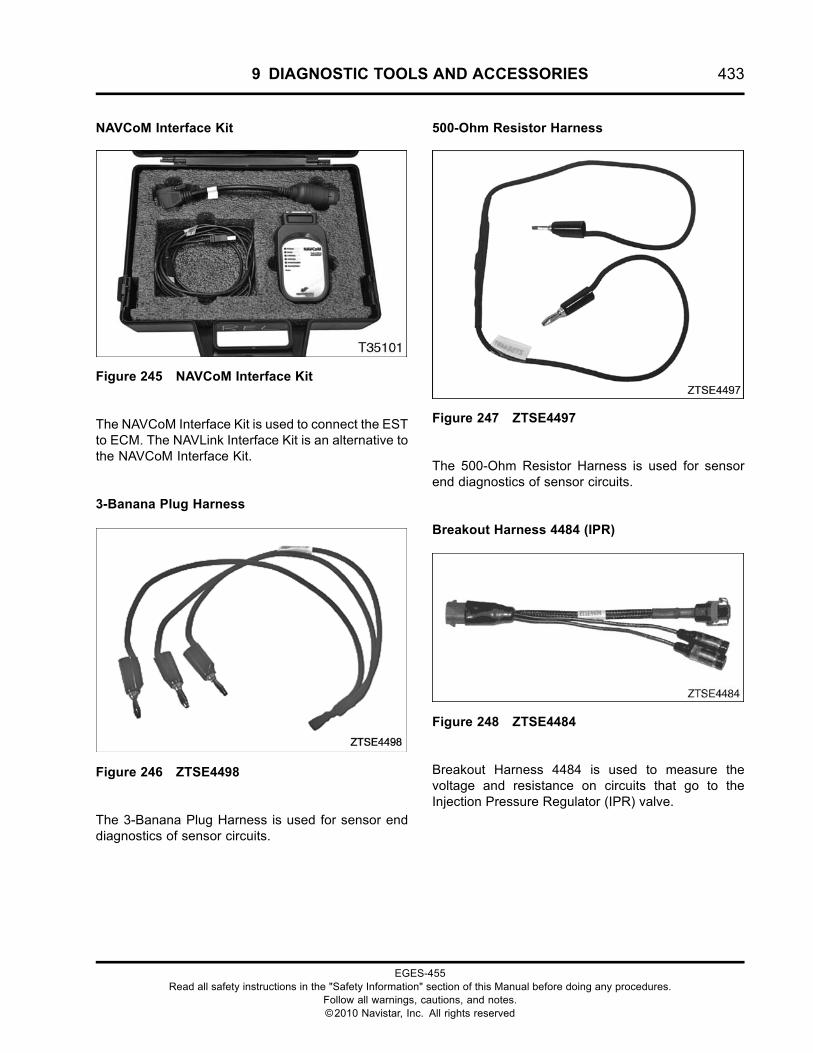
9 DIAGNOSTIC TOOLS AND ACCESSORIES 433
NAVCoM Interface Kit
Figure 245 NAVCoM Interface Kit
The NAVCoM Interface Kit is used to connect the ESTto ECM. The NAVLink Interface Kit is an alternative tothe NAVCoM Interface Kit.
3-Banana Plug Harness
Figure 246 ZTSE4498
The 3-Banana Plug Harness is used for sensor enddiagnostics of sensor circuits.
500-Ohm Resistor Harness
Figure 247 ZTSE4497
The 500-Ohm Resistor Harness is used for sensorend diagnostics of sensor circuits.
Breakout Harness 4484 (IPR)
Figure 248 ZTSE4484
Breakout Harness 4484 is used to measure thevoltage and resistance on circuits that go to theInjection Pressure Regulator (IPR) valve.
EGES-455Read all safety instructions in the "Safety Information" section of this Manual before doing any procedures.
Follow all warnings, cautions, and notes.©2010 Navistar, Inc. All rights reserved
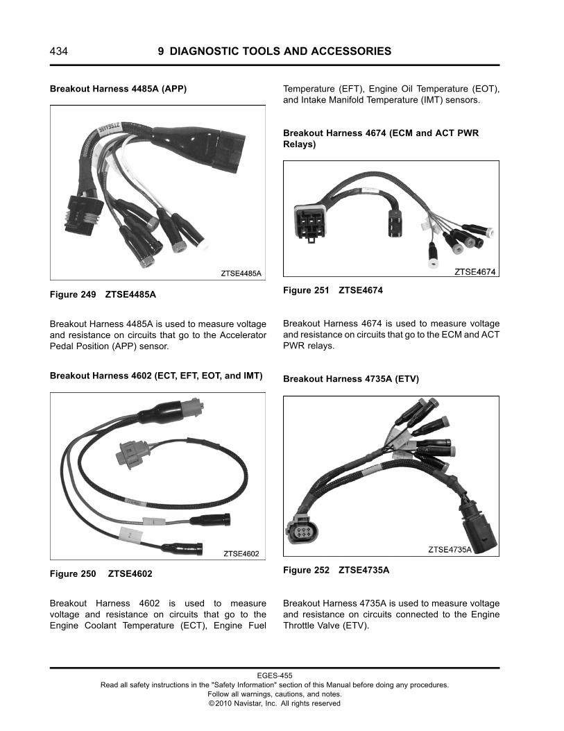
434 9 DIAGNOSTIC TOOLS AND ACCESSORIES
Breakout Harness 4485A (APP)
Figure 249 ZTSE4485A
Breakout Harness 4485A is used to measure voltageand resistance on circuits that go to the AcceleratorPedal Position (APP) sensor.
Breakout Harness 4602 (ECT, EFT, EOT, and IMT)
Figure 250 ZTSE4602
Breakout Harness 4602 is used to measurevoltage and resistance on circuits that go to theEngine Coolant Temperature (ECT), Engine Fuel
Temperature (EFT), Engine Oil Temperature (EOT),and Intake Manifold Temperature (IMT) sensors.
Breakout Harness 4674 (ECM and ACT PWRRelays)
Figure 251 ZTSE4674
Breakout Harness 4674 is used to measure voltageand resistance on circuits that go to the ECM and ACTPWR relays.
Breakout Harness 4735A (ETV)
Figure 252 ZTSE4735A
Breakout Harness 4735A is used to measure voltageand resistance on circuits connected to the EngineThrottle Valve (ETV).
EGES-455Read all safety instructions in the "Safety Information" section of this Manual before doing any procedures.
Follow all warnings, cautions, and notes.©2010 Navistar, Inc. All rights reserved
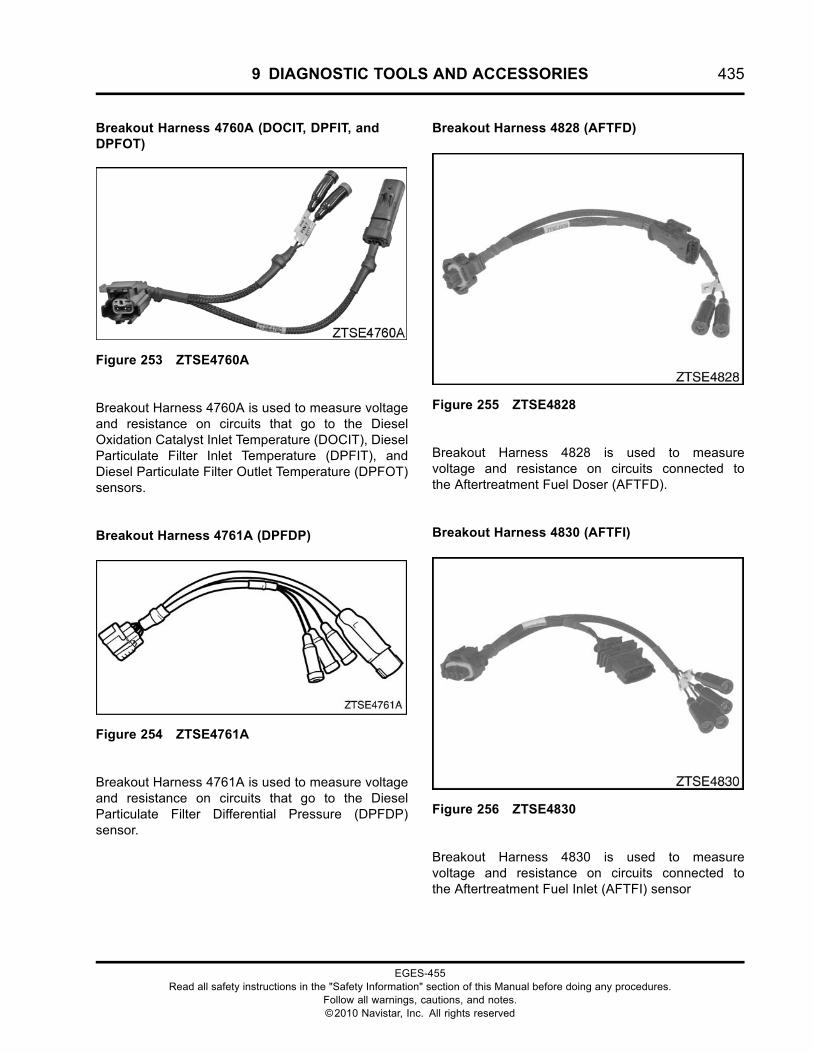
9 DIAGNOSTIC TOOLS AND ACCESSORIES 435
Breakout Harness 4760A (DOCIT, DPFIT, andDPFOT)
Figure 253 ZTSE4760A
Breakout Harness 4760A is used to measure voltageand resistance on circuits that go to the DieselOxidation Catalyst Inlet Temperature (DOCIT), DieselParticulate Filter Inlet Temperature (DPFIT), andDiesel Particulate Filter Outlet Temperature (DPFOT)sensors.
Breakout Harness 4761A (DPFDP)
Figure 254 ZTSE4761A
Breakout Harness 4761A is used to measure voltageand resistance on circuits that go to the DieselParticulate Filter Differential Pressure (DPFDP)sensor.
Breakout Harness 4828 (AFTFD)
Figure 255 ZTSE4828
Breakout Harness 4828 is used to measurevoltage and resistance on circuits connected tothe Aftertreatment Fuel Doser (AFTFD).
Breakout Harness 4830 (AFTFI)
Figure 256 ZTSE4830
Breakout Harness 4830 is used to measurevoltage and resistance on circuits connected tothe Aftertreatment Fuel Inlet (AFTFI) sensor
EGES-455Read all safety instructions in the "Safety Information" section of this Manual before doing any procedures.
Follow all warnings, cautions, and notes.©2010 Navistar, Inc. All rights reserved
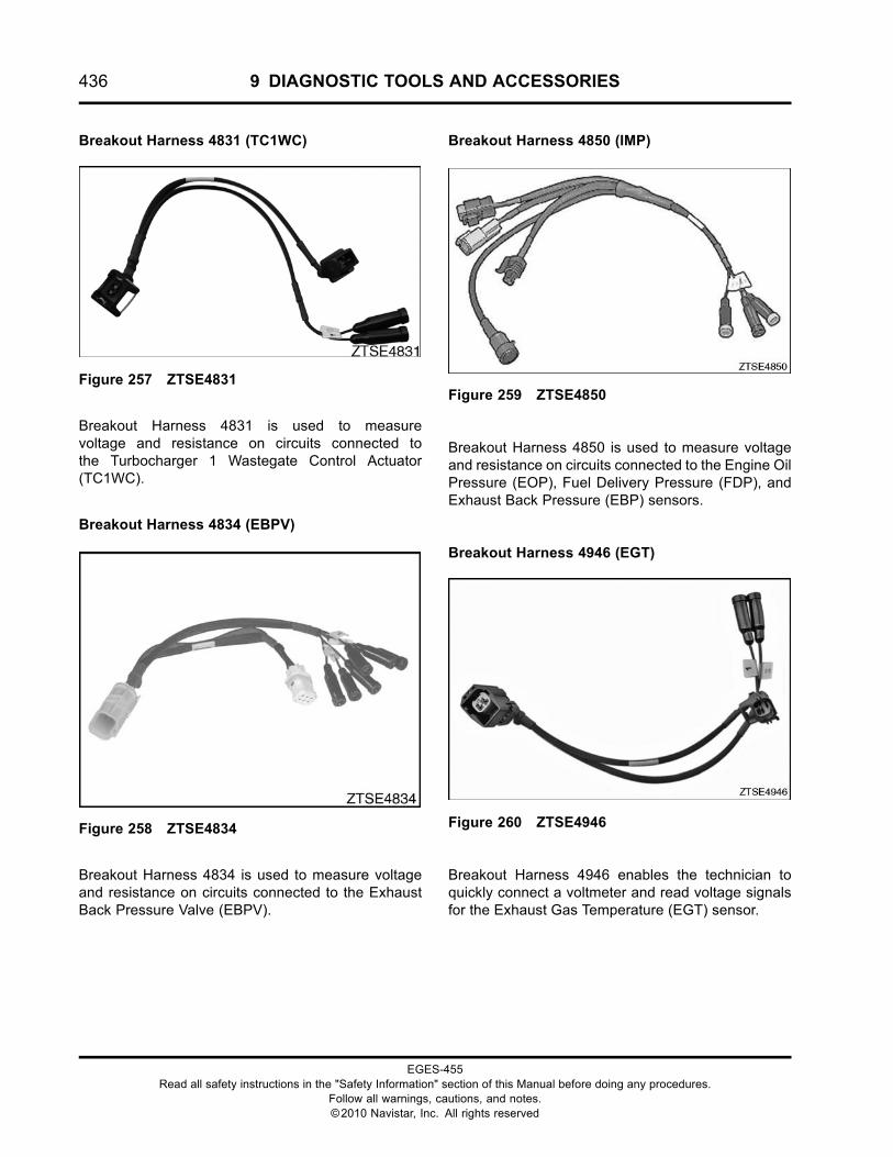
436 9 DIAGNOSTIC TOOLS AND ACCESSORIES
Breakout Harness 4831 (TC1WC)
Figure 257 ZTSE4831
Breakout Harness 4831 is used to measurevoltage and resistance on circuits connected tothe Turbocharger 1 Wastegate Control Actuator(TC1WC).
Breakout Harness 4834 (EBPV)
Figure 258 ZTSE4834
Breakout Harness 4834 is used to measure voltageand resistance on circuits connected to the ExhaustBack Pressure Valve (EBPV).
Breakout Harness 4850 (IMP)
Figure 259 ZTSE4850
Breakout Harness 4850 is used to measure voltageand resistance on circuits connected to the Engine OilPressure (EOP), Fuel Delivery Pressure (FDP), andExhaust Back Pressure (EBP) sensors.
Breakout Harness 4946 (EGT)
Figure 260 ZTSE4946
Breakout Harness 4946 enables the technician toquickly connect a voltmeter and read voltage signalsfor the Exhaust Gas Temperature (EGT) sensor.
EGES-455Read all safety instructions in the "Safety Information" section of this Manual before doing any procedures.
Follow all warnings, cautions, and notes.©2010 Navistar, Inc. All rights reserved
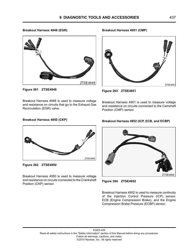
9 DIAGNOSTIC TOOLS AND ACCESSORIES 437
Breakout Harness 4948 (EGR)
Figure 261 ZTSE4948
Breakout Harness 4948 is used to measure voltageand resistance on circuits that go to the Exhaust GasRecirculation (EGR) valve.
Breakout Harness 4950 (CKP)
Figure 262 ZTSE4950
Breakout Harness 4950 is used to measure voltageand resistance on circuits connected to the CrankshaftPosition (CKP) sensor.
Breakout Harness 4951 (CMP)
Figure 263 ZTSE4951
Breakout Harness 4951 is used to measure voltageand resistance on circuits connected to the CamshaftPosition (CMP) sensor.
Breakout Harness 4952 (ICP, ECB, and ECBP)
Figure 264 ZTSE4952
Breakout Harness 4952 is used to measure continuityof the Injection Control Pressure (ICP) sensor,ECB (Engine Compression Brake), and the EngineCompression Brake Pressure (ECBP) sensor.
EGES-455Read all safety instructions in the "Safety Information" section of this Manual before doing any procedures.
Follow all warnings, cautions, and notes.©2010 Navistar, Inc. All rights reserved
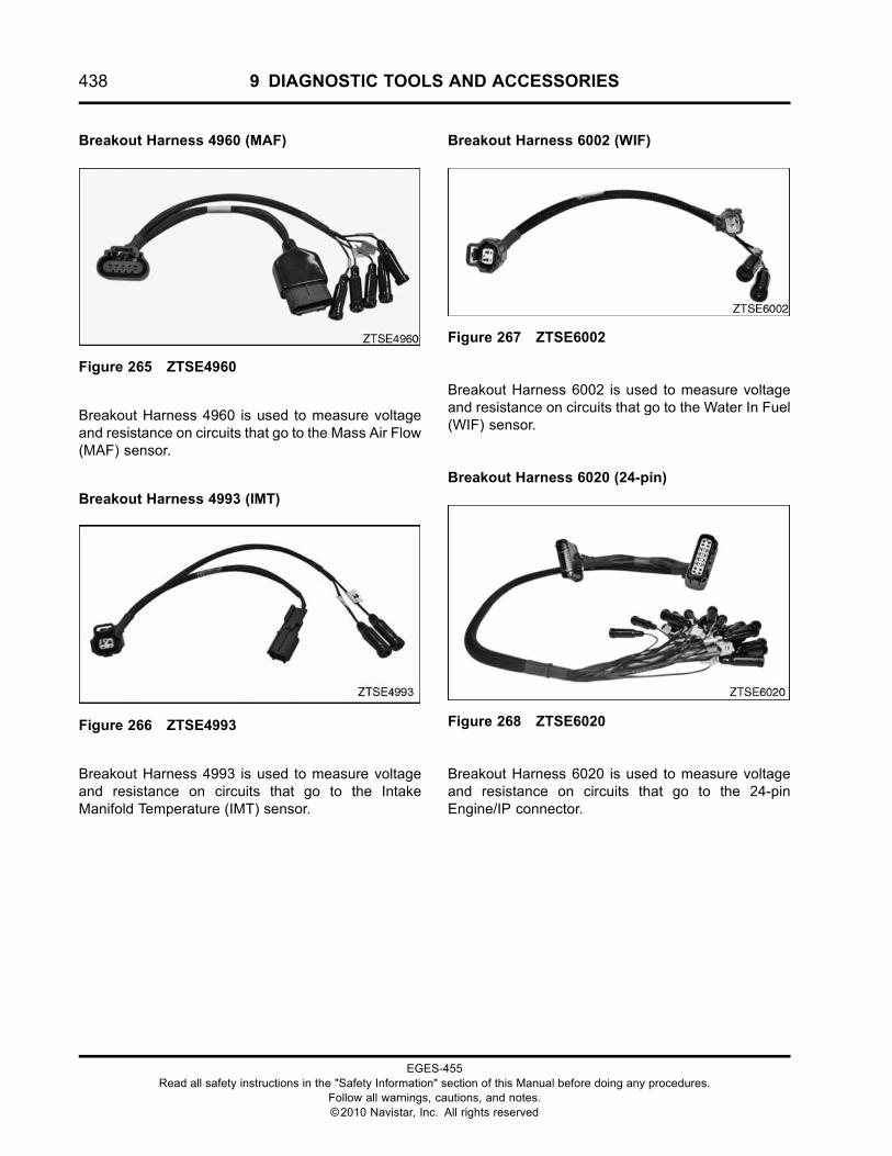
438 9 DIAGNOSTIC TOOLS AND ACCESSORIES
Breakout Harness 4960 (MAF)
Figure 265 ZTSE4960
Breakout Harness 4960 is used to measure voltageand resistance on circuits that go to the Mass Air Flow(MAF) sensor.
Breakout Harness 4993 (IMT)
Figure 266 ZTSE4993
Breakout Harness 4993 is used to measure voltageand resistance on circuits that go to the IntakeManifold Temperature (IMT) sensor.
Breakout Harness 6002 (WIF)
Figure 267 ZTSE6002
Breakout Harness 6002 is used to measure voltageand resistance on circuits that go to the Water In Fuel(WIF) sensor.
Breakout Harness 6020 (24-pin)
Figure 268 ZTSE6020
Breakout Harness 6020 is used to measure voltageand resistance on circuits that go to the 24-pinEngine/IP connector.
EGES-455Read all safety instructions in the "Safety Information" section of this Manual before doing any procedures.
Follow all warnings, cautions, and notes.©2010 Navistar, Inc. All rights reserved

9 DIAGNOSTIC TOOLS AND ACCESSORIES 439
Breakout Harness 6021 (AFTFSV)
Figure 269 ZTSE6021
Breakout Harness 6021 is used to measure voltageand resistance on circuits that go to the AFT FuelShutoff Valve (AFTFSV).
Breakout Harness 6023 (FPC)
Figure 270 ZTSE6023
Breakout Harness 6023 is used to measure voltageand resistance on circuits that go to the Fuel PumpControl (FPC).
Breakout Harness 6025 (IAH)
Figure 271 ZTSE6025
Breakout Harness 6025 is used to measure voltageand resistance on circuits that go to the Inlet Air Heater(IAH) relay.
Breakout Harness 6027 (AFTFP)
Figure 272 ZTSE6027
Breakout Harness 6027 is used to measure voltageand resistance on circuits that go to the AFT FuelPressure (AFTFP) sensor.
EGES-455Read all safety instructions in the "Safety Information" section of this Manual before doing any procedures.
Follow all warnings, cautions, and notes.©2010 Navistar, Inc. All rights reserved
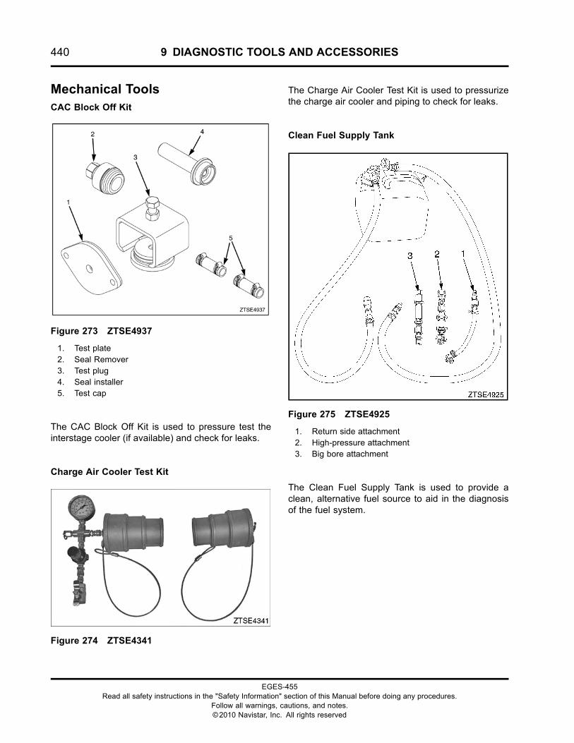
440 9 DIAGNOSTIC TOOLS AND ACCESSORIES
Mechanical ToolsCAC Block Off Kit
Figure 273 ZTSE4937
1. Test plate2. Seal Remover3. Test plug4. Seal installer5. Test cap
The CAC Block Off Kit is used to pressure test theinterstage cooler (if available) and check for leaks.
Charge Air Cooler Test Kit
Figure 274 ZTSE4341
The Charge Air Cooler Test Kit is used to pressurizethe charge air cooler and piping to check for leaks.
Clean Fuel Supply Tank
Figure 275 ZTSE4925
1. Return side attachment2. High-pressure attachment3. Big bore attachment
The Clean Fuel Supply Tank is used to provide aclean, alternative fuel source to aid in the diagnosisof the fuel system.
EGES-455Read all safety instructions in the "Safety Information" section of this Manual before doing any procedures.
Follow all warnings, cautions, and notes.©2010 Navistar, Inc. All rights reserved
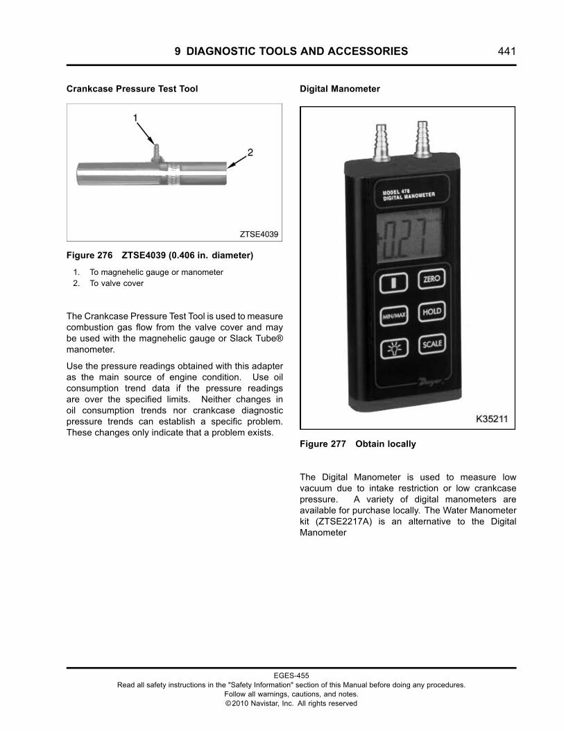
9 DIAGNOSTIC TOOLS AND ACCESSORIES 441
Crankcase Pressure Test Tool
Figure 276 ZTSE4039 (0.406 in. diameter)
1. To magnehelic gauge or manometer2. To valve cover
The Crankcase Pressure Test Tool is used to measurecombustion gas flow from the valve cover and maybe used with the magnehelic gauge or Slack Tube®manometer.
Use the pressure readings obtained with this adapteras the main source of engine condition. Use oilconsumption trend data if the pressure readingsare over the specified limits. Neither changes inoil consumption trends nor crankcase diagnosticpressure trends can establish a specific problem.These changes only indicate that a problem exists.
Digital Manometer
Figure 277 Obtain locally
The Digital Manometer is used to measure lowvacuum due to intake restriction or low crankcasepressure. A variety of digital manometers areavailable for purchase locally. The Water Manometerkit (ZTSE2217A) is an alternative to the DigitalManometer
EGES-455Read all safety instructions in the "Safety Information" section of this Manual before doing any procedures.
Follow all warnings, cautions, and notes.©2010 Navistar, Inc. All rights reserved
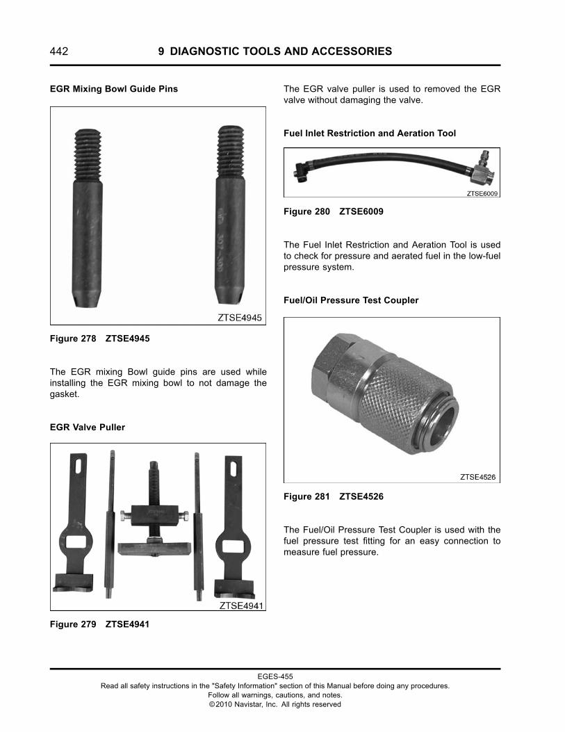
442 9 DIAGNOSTIC TOOLS AND ACCESSORIES
EGR Mixing Bowl Guide Pins
Figure 278 ZTSE4945
The EGR mixing Bowl guide pins are used whileinstalling the EGR mixing bowl to not damage thegasket.
EGR Valve Puller
Figure 279 ZTSE4941
The EGR valve puller is used to removed the EGRvalve without damaging the valve.
Fuel Inlet Restriction and Aeration Tool
Figure 280 ZTSE6009
The Fuel Inlet Restriction and Aeration Tool is usedto check for pressure and aerated fuel in the low-fuelpressure system.
Fuel/Oil Pressure Test Coupler
Figure 281 ZTSE4526
The Fuel/Oil Pressure Test Coupler is used with thefuel pressure test fitting for an easy connection tomeasure fuel pressure.
EGES-455Read all safety instructions in the "Safety Information" section of this Manual before doing any procedures.
Follow all warnings, cautions, and notes.©2010 Navistar, Inc. All rights reserved
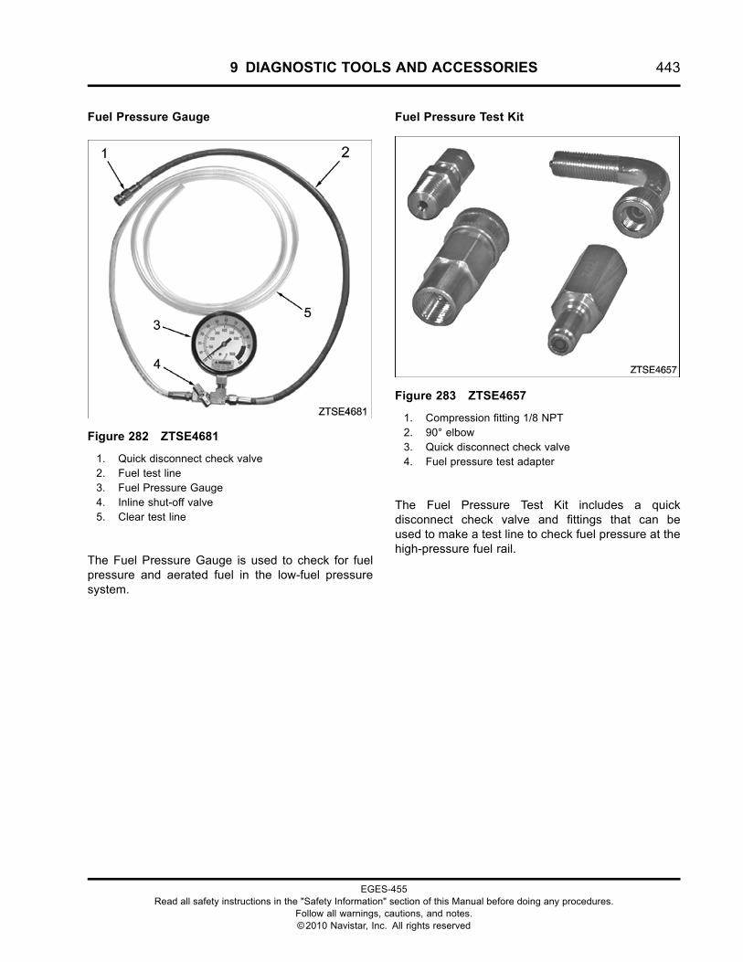
9 DIAGNOSTIC TOOLS AND ACCESSORIES 443
Fuel Pressure Gauge
Figure 282 ZTSE4681
1. Quick disconnect check valve2. Fuel test line3. Fuel Pressure Gauge4. Inline shut-off valve5. Clear test line
The Fuel Pressure Gauge is used to check for fuelpressure and aerated fuel in the low-fuel pressuresystem.
Fuel Pressure Test Kit
Figure 283 ZTSE4657
1. Compression fitting 1/8 NPT2. 90° elbow3. Quick disconnect check valve4. Fuel pressure test adapter
The Fuel Pressure Test Kit includes a quickdisconnect check valve and fittings that can beused to make a test line to check fuel pressure at thehigh-pressure fuel rail.
EGES-455Read all safety instructions in the "Safety Information" section of this Manual before doing any procedures.
Follow all warnings, cautions, and notes.©2010 Navistar, Inc. All rights reserved
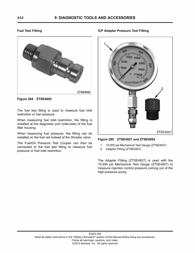
444 9 DIAGNOSTIC TOOLS AND ACCESSORIES
Fuel Test Fitting
Figure 284 ZTSE4692
The fuel test fitting is used to measure fuel inletrestriction or fuel pressure.
When measuring fuel inlet restriction, the fitting isinstalled at the diagnostic port (inlet-side) of the fuelfilter housing.
When measuring fuel pressure, the fitting can beinstalled on the fuel rail instead of the Shrader valve.
The Fuel/Oil Pressure Test Coupler can then beconnected to the fuel test fitting to measure fuelpressure or fuel inlet restriction.
ICP Adapter Pressure Test Fitting
Figure 285 ZTSE4927 and ZTSE4954
1. 10,000 psi Mechanical Test Gauge (ZTSE4927)2. Adapter Fitting (ZTSE4927)
The Adapter Fitting (ZTSE4927) is used with the10,000 psi Mechanical Test Gauge (ZTSE4927) tomeasure injection control pressure coming out of thehigh-pressure pump.
EGES-455Read all safety instructions in the "Safety Information" section of this Manual before doing any procedures.
Follow all warnings, cautions, and notes.©2010 Navistar, Inc. All rights reserved
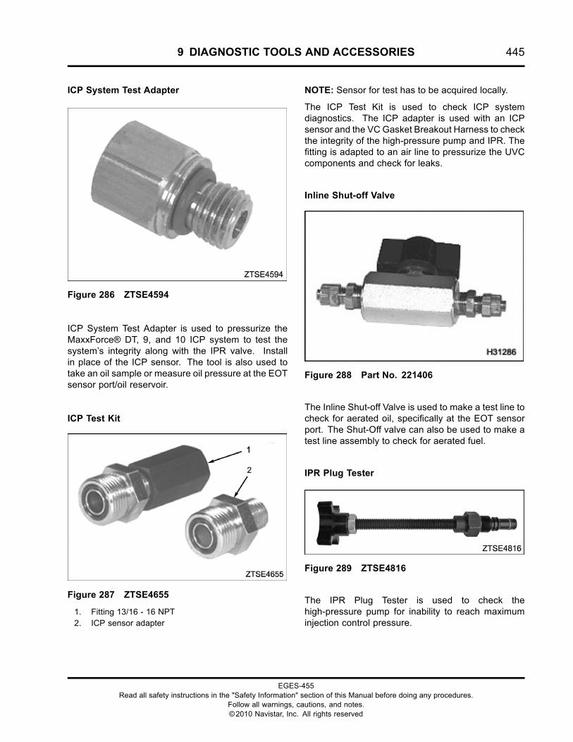
9 DIAGNOSTIC TOOLS AND ACCESSORIES 445
ICP System Test Adapter
Figure 286 ZTSE4594
ICP System Test Adapter is used to pressurize theMaxxForce® DT, 9, and 10 ICP system to test thesystem’s integrity along with the IPR valve. Installin place of the ICP sensor. The tool is also used totake an oil sample or measure oil pressure at the EOTsensor port/oil reservoir.
ICP Test Kit
Figure 287 ZTSE4655
1. Fitting 13/16 - 16 NPT2. ICP sensor adapter
NOTE: Sensor for test has to be acquired locally.
The ICP Test Kit is used to check ICP systemdiagnostics. The ICP adapter is used with an ICPsensor and the VC Gasket Breakout Harness to checkthe integrity of the high-pressure pump and IPR. Thefitting is adapted to an air line to pressurize the UVCcomponents and check for leaks.
Inline Shut-off Valve
Figure 288 Part No. 221406
The Inline Shut-off Valve is used to make a test line tocheck for aerated oil, specifically at the EOT sensorport. The Shut-Off valve can also be used to make atest line assembly to check for aerated fuel.
IPR Plug Tester
Figure 289 ZTSE4816
The IPR Plug Tester is used to check thehigh-pressure pump for inability to reach maximuminjection control pressure.
EGES-455Read all safety instructions in the "Safety Information" section of this Manual before doing any procedures.
Follow all warnings, cautions, and notes.©2010 Navistar, Inc. All rights reserved
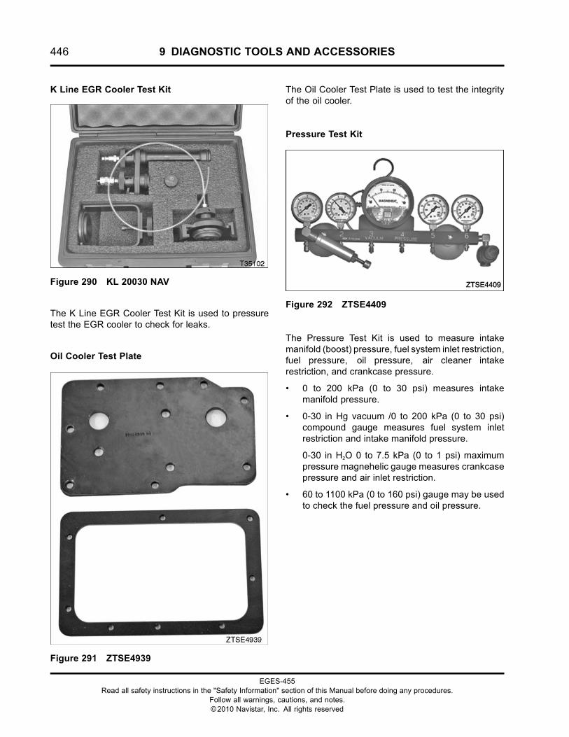
446 9 DIAGNOSTIC TOOLS AND ACCESSORIES
K Line EGR Cooler Test Kit
Figure 290 KL 20030 NAV
The K Line EGR Cooler Test Kit is used to pressuretest the EGR cooler to check for leaks.
Oil Cooler Test Plate
Figure 291 ZTSE4939
The Oil Cooler Test Plate is used to test the integrityof the oil cooler.
Pressure Test Kit
Figure 292 ZTSE4409
The Pressure Test Kit is used to measure intakemanifold (boost) pressure, fuel system inlet restriction,fuel pressure, oil pressure, air cleaner intakerestriction, and crankcase pressure.
• 0 to 200 kPa (0 to 30 psi) measures intakemanifold pressure.
• 0-30 in Hg vacuum /0 to 200 kPa (0 to 30 psi)compound gauge measures fuel system inletrestriction and intake manifold pressure.
0-30 in H2O 0 to 7.5 kPa (0 to 1 psi) maximumpressure magnehelic gauge measures crankcasepressure and air inlet restriction.
• 60 to 1100 kPa (0 to 160 psi) gauge may be usedto check the fuel pressure and oil pressure.
EGES-455Read all safety instructions in the "Safety Information" section of this Manual before doing any procedures.
Follow all warnings, cautions, and notes.©2010 Navistar, Inc. All rights reserved
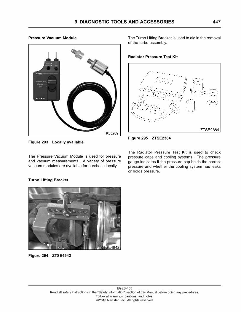
9 DIAGNOSTIC TOOLS AND ACCESSORIES 447
Pressure Vacuum Module
Figure 293 Locally available
The Pressure Vacuum Module is used for pressureand vacuum measurements. A variety of pressurevacuum modules are available for purchase locally.
Turbo Lifting Bracket
Figure 294 ZTSE4942
The Turbo Lifting Bracket is used to aid in the removalof the turbo assembly.
Radiator Pressure Test Kit
Figure 295 ZTSE2384
The Radiator Pressure Test Kit is used to checkpressure caps and cooling systems. The pressuregauge indicates if the pressure cap holds the correctpressure and whether the cooling system has leaksor holds pressure.
EGES-455Read all safety instructions in the "Safety Information" section of this Manual before doing any procedures.
Follow all warnings, cautions, and notes.©2010 Navistar, Inc. All rights reserved
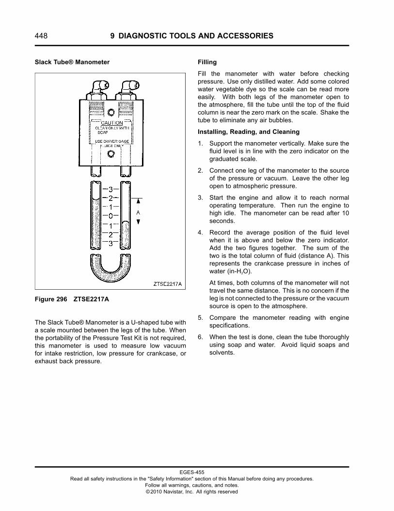
448 9 DIAGNOSTIC TOOLS AND ACCESSORIES
Slack Tube® Manometer
Figure 296 ZTSE2217A
The Slack Tube® Manometer is a U-shaped tube witha scale mounted between the legs of the tube. Whenthe portability of the Pressure Test Kit is not required,this manometer is used to measure low vacuumfor intake restriction, low pressure for crankcase, orexhaust back pressure.
Filling
Fill the manometer with water before checkingpressure. Use only distilled water. Add some coloredwater vegetable dye so the scale can be read moreeasily. With both legs of the manometer open tothe atmosphere, fill the tube until the top of the fluidcolumn is near the zero mark on the scale. Shake thetube to eliminate any air bubbles.
Installing, Reading, and Cleaning
1. Support the manometer vertically. Make sure thefluid level is in line with the zero indicator on thegraduated scale.
2. Connect one leg of the manometer to the sourceof the pressure or vacuum. Leave the other legopen to atmospheric pressure.
3. Start the engine and allow it to reach normaloperating temperature. Then run the engine tohigh idle. The manometer can be read after 10seconds.
4. Record the average position of the fluid levelwhen it is above and below the zero indicator.Add the two figures together. The sum of thetwo is the total column of fluid (distance A). Thisrepresents the crankcase pressure in inches ofwater (in-H2O).
At times, both columns of the manometer will nottravel the same distance. This is no concern if theleg is not connected to the pressure or the vacuumsource is open to the atmosphere.
5. Compare the manometer reading with enginespecifications.
6. When the test is done, clean the tube thoroughlyusing soap and water. Avoid liquid soaps andsolvents.
EGES-455Read all safety instructions in the "Safety Information" section of this Manual before doing any procedures.
Follow all warnings, cautions, and notes.©2010 Navistar, Inc. All rights reserved
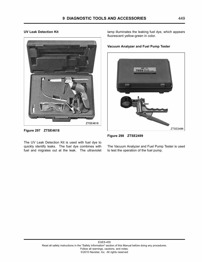
9 DIAGNOSTIC TOOLS AND ACCESSORIES 449
UV Leak Detection Kit
Figure 297 ZTSE4618
The UV Leak Detection Kit is used with fuel dye toquickly identify leaks. The fuel dye combines withfuel and migrates out at the leak. The ultraviolet
lamp illuminates the leaking fuel dye, which appearsfluorescent yellow-green in color.
Vacuum Analyzer and Fuel Pump Tester
Figure 298 ZTSE2499
The Vacuum Analyzer and Fuel Pump Tester is usedto test the operation of the fuel pump.
EGES-455Read all safety instructions in the "Safety Information" section of this Manual before doing any procedures.
Follow all warnings, cautions, and notes.©2010 Navistar, Inc. All rights reserved
450 9 DIAGNOSTIC TOOLS AND ACCESSORIES
EGES-455Read all safety instructions in the "Safety Information" section of this Manual before doing any procedures.
Follow all warnings, cautions, and notes.©2010 Navistar, Inc. All rights reserved
10 ABBREVIATIONS AND ACRONYMS 451
Table of Contents
Abbreviations and Acronyms.. . . . . . . . . . . . . . . . . . . . . . . . . . . . . . . . . . . . . . . . . . . . . . . . . . . . . . . . . . . . . . . . . . . . . . . . . . . . . . . . . . . . . . .453Abbreviations and Acronyms.. . . . . . . . . . . . . . . . . . . . . . . . . . . . . . . . . . . . . . . . . . . . . . . . . . . . . . . . . . . . . . . . . . . . . . . . . . . . .453
EGES-455Read all safety instructions in the "Safety Information" section of this Manual before doing any procedures.
Follow all warnings, cautions, and notes.©2010 Navistar, Inc. All rights reserved

452 10 ABBREVIATIONS AND ACRONYMS
EGES-455Read all safety instructions in the "Safety Information" section of this Manual before doing any procedures.
Follow all warnings, cautions, and notes.©2010 Navistar, Inc. All rights reserved
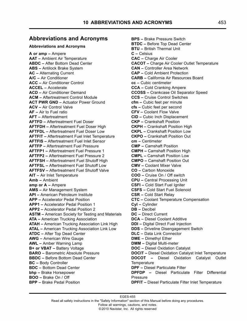
10 ABBREVIATIONS AND ACRONYMS 453
Abbreviations and AcronymsAbbreviations and Acronyms
A or amp – AmpereAAT – Ambient Air TemperatureABDC – After Bottom Dead CenterABS – Antilock Brake SystemAC – Alternating CurrentA/C – Air ConditionerACC – Air Conditioner ControlACCEL – AccelerateACD – Air Conditioner DemandACM – Aftertreatment Control ModuleACT PWR GND – Actuator Power GroundACV – Air Control ValveAF – Air to Fuel ratioAFT – AftertreatmentAFTFD – Aftertreatment Fuel DoserAFTFDH – Aftertreatment Fuel Doser HighAFTFDL – Aftertreatment Fuel Doser LowAFTFIT – Aftertreatment Fuel Inlet TemperatureAFTFIS – Aftertreatment Fuel Inlet SensorAFTFP – Aftertreatment Fuel PressureAFTFP1 – Aftertreatment Fuel Pressure 1AFTFP2 – Aftertreatment Fuel Pressure 2AFTFSH – Aftertreatment Fuel Shutoff HighAFTFSL – Aftertreatment Fuel Shutoff LowAFTFSV – Aftertreatment Fuel Shutoff ValveAIT – Air Inlet TemperatureAmb – Ambientamp or A – AmpereAMS – Air Management SystemAPI – American Petroleum InstituteAPP – Accelerator Pedal PositionAPP1 – Accelerator Pedal Position 1APP2 – Accelerator Pedal Position 2ASTM – American Society for Testing and MaterialsATA – American Trucking AssociationATAH – American Trucking Association Link HighATAL – American Trucking Association Link LowATDC – After Top Dead CenterAWG – American Wire GaugeAWL – Amber Warning LampB+ or VBAT – Battery VoltageBARO – Barometric Absolute PressureBBDC – Before Bottom Dead CenterBC – Body ControllerBDC – Bottom Dead Centerbhp – Brake HorsepowerBOO – Brake On / OffBPP – Brake Pedal Position
BPS – Brake Pressure SwitchBTDC – Before Top Dead CenterBTU – British Thermal UnitC – CelsiusCAC – Charge Air CoolerCACOT – Charge Air Cooler Outlet TemperatureCAN – Controller Area NetworkCAP – Cold Ambient ProtectionCARB – California Air Resources Boardcc – Cubic centimeterCCA – Cold Cranking AmpereCCOSS – Crankcase Oil Separator SpeedCCS – Cruise Control Switchescfm – Cubic feet per minutecfs – Cubic feet per secondCFV – Coolant Flow ValveCID – Cubic Inch DisplacementCKP – Crankshaft PositionCKPH – Crankshaft Position HighCKPL – Crankshaft Position LowCKPO – Crankshaft Position Outcm – CentimeterCMP – Camshaft PositionCMPH – Camshaft Position HighCMPL – Camshaft Position LowCMPO – Camshaft Position OutCMV – Coolant Mixer ValveCO – Carbon MonoxideCOO – Cruise On / Off switchCPU – Central Processing UnitCSFI – Cold Start Fuel IgniterCSFS – Cold Start Fuel SolenoidCSR – Cold Start RelayCTC – Coolant Temperature CompensationCyl – CylinderDB – DecibelDC – Direct CurrentDCA – Diesel Coolant AdditiveDDI – Digital Direct Fuel InjectionDDS – Driveline Disengagement SwitchDLC – Data Link ConnectorDME – Dimethyl EtherDMM – Digital Multi-meterDOC – Diesel Oxidation CatalystDOCIT – Diesel Oxidation Catalyst Inlet TemperatureDOCOT – Diesel Oxidation Catalyst OutletTemperatureDPF – Diesel Particulate FilterDPFDP – Diesel Particulate Filter DifferentialPressureDPFIT – Diesel Particulate Filter Inlet Temperature
EGES-455Read all safety instructions in the "Safety Information" section of this Manual before doing any procedures.
Follow all warnings, cautions, and notes.©2010 Navistar, Inc. All rights reserved
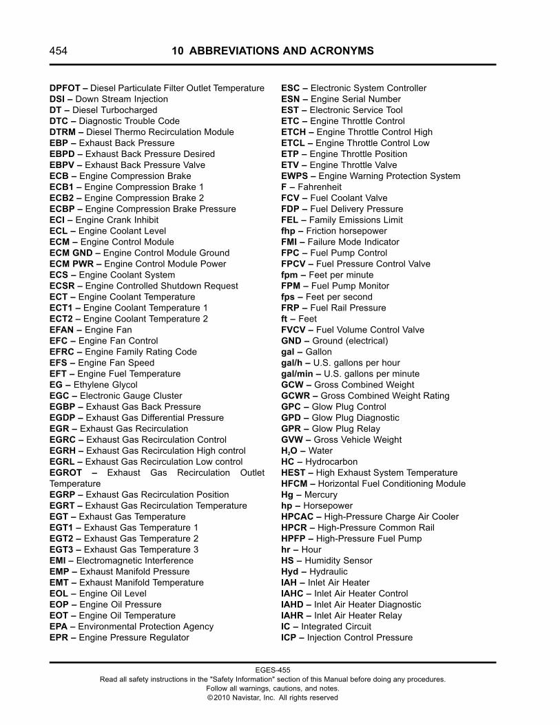
454 10 ABBREVIATIONS AND ACRONYMS
DPFOT – Diesel Particulate Filter Outlet TemperatureDSI – Down Stream InjectionDT – Diesel TurbochargedDTC – Diagnostic Trouble CodeDTRM – Diesel Thermo Recirculation ModuleEBP – Exhaust Back PressureEBPD – Exhaust Back Pressure DesiredEBPV – Exhaust Back Pressure ValveECB – Engine Compression BrakeECB1 – Engine Compression Brake 1ECB2 – Engine Compression Brake 2ECBP – Engine Compression Brake PressureECI – Engine Crank InhibitECL – Engine Coolant LevelECM – Engine Control ModuleECM GND – Engine Control Module GroundECM PWR – Engine Control Module PowerECS – Engine Coolant SystemECSR – Engine Controlled Shutdown RequestECT – Engine Coolant TemperatureECT1 – Engine Coolant Temperature 1ECT2 – Engine Coolant Temperature 2EFAN – Engine FanEFC – Engine Fan ControlEFRC – Engine Family Rating CodeEFS – Engine Fan SpeedEFT – Engine Fuel TemperatureEG – Ethylene GlycolEGC – Electronic Gauge ClusterEGBP – Exhaust Gas Back PressureEGDP – Exhaust Gas Differential PressureEGR – Exhaust Gas RecirculationEGRC – Exhaust Gas Recirculation ControlEGRH – Exhaust Gas Recirculation High controlEGRL – Exhaust Gas Recirculation Low controlEGROT – Exhaust Gas Recirculation OutletTemperatureEGRP – Exhaust Gas Recirculation PositionEGRT – Exhaust Gas Recirculation TemperatureEGT – Exhaust Gas TemperatureEGT1 – Exhaust Gas Temperature 1EGT2 – Exhaust Gas Temperature 2EGT3 – Exhaust Gas Temperature 3EMI – Electromagnetic InterferenceEMP – Exhaust Manifold PressureEMT – Exhaust Manifold TemperatureEOL – Engine Oil LevelEOP – Engine Oil PressureEOT – Engine Oil TemperatureEPA – Environmental Protection AgencyEPR – Engine Pressure Regulator
ESC – Electronic System ControllerESN – Engine Serial NumberEST – Electronic Service ToolETC – Engine Throttle ControlETCH – Engine Throttle Control HighETCL – Engine Throttle Control LowETP – Engine Throttle PositionETV – Engine Throttle ValveEWPS – Engine Warning Protection SystemF – FahrenheitFCV – Fuel Coolant ValveFDP – Fuel Delivery PressureFEL – Family Emissions Limitfhp – Friction horsepowerFMI – Failure Mode IndicatorFPC – Fuel Pump ControlFPCV – Fuel Pressure Control Valvefpm – Feet per minuteFPM – Fuel Pump Monitorfps – Feet per secondFRP – Fuel Rail Pressureft – FeetFVCV – Fuel Volume Control ValveGND – Ground (electrical)gal – Gallongal/h – U.S. gallons per hourgal/min – U.S. gallons per minuteGCW – Gross Combined WeightGCWR – Gross Combined Weight RatingGPC – Glow Plug ControlGPD – Glow Plug DiagnosticGPR – Glow Plug RelayGVW – Gross Vehicle WeightH2O – WaterHC – HydrocarbonHEST – High Exhaust System TemperatureHFCM – Horizontal Fuel Conditioning ModuleHg – Mercuryhp – HorsepowerHPCAC – High-Pressure Charge Air CoolerHPCR – High-Pressure Common RailHPFP – High-Pressure Fuel Pumphr – HourHS – Humidity SensorHyd – HydraulicIAH – Inlet Air HeaterIAHC – Inlet Air Heater ControlIAHD – Inlet Air Heater DiagnosticIAHR – Inlet Air Heater RelayIC – Integrated CircuitICP – Injection Control Pressure
EGES-455Read all safety instructions in the "Safety Information" section of this Manual before doing any procedures.
Follow all warnings, cautions, and notes.©2010 Navistar, Inc. All rights reserved
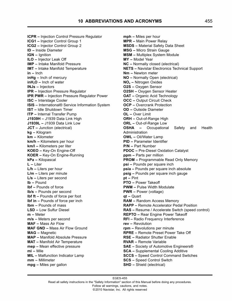
10 ABBREVIATIONS AND ACRONYMS 455
ICPR – Injection Control Pressure RegulatorICG1 – Injector Control Group 1ICG2 – Injector Control Group 2ID – Inside DiameterIGN – IgnitionILO – Injector Leak OffIMP – Intake Manifold PressureIMT – Intake Manifold Temperaturein – InchinHg – Inch of mercuryinH2O – Inch of waterINJs – InjectorsIPR – Injection Pressure RegulatorIPR PWR – Injection Pressure Regulator PowerISC – Interstage CoolerISIS – International® Service Information SystemIST – Idle Shutdown TimerITP – Internal Transfer PumpJ1939H – J1939 Data Link HighJ1939L – J1939 Data Link LowJCT – Junction (electrical)kg – Kilogramkm – Kilometerkm/h – Kilometers per hourkm/l – Kilometers per literKOEO – Key-On Engine-OffKOER – Key-On Engine-RunningkPa – KilopascalL – LiterL/h – Liters per hourL/m – Liters per minuteL/s – Liters per secondlb – Poundlbf – Pounds of forcelb/s – Pounds per secondlbf ft – Pounds of force per footlbf in – Pounds of force per inchlbm – Pounds of massLSD – Low Sulfur Dieselm – Meterm/s – Meters per secondMAF – Mass Air FlowMAF GND – Mass Air Flow GroundMAG – MagneticMAP – Manifold Absolute PressureMAT – Manifold Air Temperaturemep – Mean effective pressuremi – MileMIL – Malfunction Indicator Lampmm – Millimetermpg – Miles per gallon
mph – Miles per hourMPR – Main Power RelayMSDS – Material Safety Data SheetMSG – Micro Strain GaugeMSM – Multiplex System ModuleMY – Model YearNC – Normally closed (electrical)NETS – Navistar Electronics Technical SupportNm – Newton meterNO – Normally Open (electrical)NOX – Nitrogen OxidesO2S – Oxygen SensorO2SH – Oxygen Sensor HeaterOAT – Organic Acid TechnologyOCC – Output Circuit CheckOCP – Overcrank ProtectionOD – Outside DiameterOL – Over LimitORH – Out-of-Range HighORL – Out-of-Range LowOSHA – Occupational Safety and HealthAdministrationOWL – Oil/Water LampPID – Parameter IdentifierP/N – Part NumberPDOC – Pre-Diesel Oxidation Catalystppm – Parts per millionPROM – Programmable Read Only Memorypsi – Pounds per square inchpsia – Pounds per square inch absolutepsig – Pounds per square inch gaugept – PintPTO – Power TakeoffPWM – Pulse Width ModulatePWR – Power (voltage)qt – QuartRAM – Random Access MemoryRAPP – Remote Accelerator Pedal PositionRAS – Resume / Accelerate Switch (speed control)REPTO – Rear Engine Power TakeoffRFI – Radio Frequency Interferencerev – Revolutionrpm – Revolutions per minuteRPRE – Remote Preset Power Take OffRSE – Radiator Shutter EnableRVAR – Remote VariableSAE – Society of Automotive Engineers®SCA – Supplemental Cooling AdditiveSCCS – Speed Control Command SwitchesSCS – Speed Control SwitchSHD – Shield (electrical)
EGES-455Read all safety instructions in the "Safety Information" section of this Manual before doing any procedures.
Follow all warnings, cautions, and notes.©2010 Navistar, Inc. All rights reserved
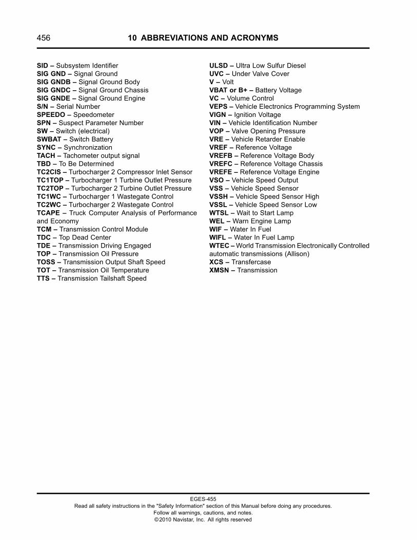
456 10 ABBREVIATIONS AND ACRONYMS
SID – Subsystem IdentifierSIG GND – Signal GroundSIG GNDB – Signal Ground BodySIG GNDC – Signal Ground ChassisSIG GNDE – Signal Ground EngineS/N – Serial NumberSPEEDO – SpeedometerSPN – Suspect Parameter NumberSW – Switch (electrical)SWBAT – Switch BatterySYNC – SynchronizationTACH – Tachometer output signalTBD – To Be DeterminedTC2CIS – Turbocharger 2 Compressor Inlet SensorTC1TOP – Turbocharger 1 Turbine Outlet PressureTC2TOP – Turbocharger 2 Turbine Outlet PressureTC1WC – Turbocharger 1 Wastegate ControlTC2WC – Turbocharger 2 Wastegate ControlTCAPE – Truck Computer Analysis of Performanceand EconomyTCM – Transmission Control ModuleTDC – Top Dead CenterTDE – Transmission Driving EngagedTOP – Transmission Oil PressureTOSS – Transmission Output Shaft SpeedTOT – Transmission Oil TemperatureTTS – Transmission Tailshaft Speed
ULSD – Ultra Low Sulfur DieselUVC – Under Valve CoverV – VoltVBAT or B+ – Battery VoltageVC – Volume ControlVEPS – Vehicle Electronics Programming SystemVIGN – Ignition VoltageVIN – Vehicle Identification NumberVOP – Valve Opening PressureVRE – Vehicle Retarder EnableVREF – Reference VoltageVREFB – Reference Voltage BodyVREFC – Reference Voltage ChassisVREFE – Reference Voltage EngineVSO – Vehicle Speed OutputVSS – Vehicle Speed SensorVSSH – Vehicle Speed Sensor HighVSSL – Vehicle Speed Sensor LowWTSL – Wait to Start LampWEL – Warn Engine LampWIF – Water In FuelWIFL – Water In Fuel LampWTEC –World Transmission Electronically Controlledautomatic transmissions (Allison)XCS – TransfercaseXMSN – Transmission
EGES-455Read all safety instructions in the "Safety Information" section of this Manual before doing any procedures.
Follow all warnings, cautions, and notes.©2010 Navistar, Inc. All rights reserved
11 TERMINOLOGY 457
Table of Contents
Terminology.. . . . . . . . . . . . . . . . . . . . . . . . . . . . . . . . . . . . . . . . . . . . . . . . . . . . . . . . . . . . . . . . . . . . . . . . . . . . . . . . . . . . . . . . . . . . . . . . . . . . . . . . . . . .459Terms.. . . . . . . . . . . . . . . . . . . . . . . . . . . . . . . . . . . . . . . . . . . . . . . . . . . . . . . . . . . . . . . . . . . . . . . . . . . . . . . . . . . . . . . . . . . . . . . . . . . . . . . . . .459
EGES-455Read all safety instructions in the "Safety Information" section of this Manual before doing any procedures.
Follow all warnings, cautions, and notes.©2010 Navistar, Inc. All rights reserved
458 11 TERMINOLOGY
EGES-455Read all safety instructions in the "Safety Information" section of this Manual before doing any procedures.
Follow all warnings, cautions, and notes.©2010 Navistar, Inc. All rights reserved
11 TERMINOLOGY 459
TerminologyTerms
Accelerator Pedal Position (APP) sensor – Apotentiometer sensor that indicates the position of thethrottle pedal.
Accessory work – The work per cycle requiredto drive engine accessories (normally, only thoseessential to engine operation).
Actuator – A device that performs work in responseto an input signal.
Actuator Control – The ECM controls the actuatorsby applying a low-level signal (low-side driver) or ahigh-level signal (high side driver). When switched on,both drivers complete a ground or power circuit to anactuator.
Aeration – The entrainment of air or combustion gasin coolant, lubricant, or fuel.
Aftercooler (Charge Air Cooler) – A heat exchangermounted in the charge air path between theturbocharger and engine intake manifold. Theaftercooler reduces the charge air temperature bytransferring heat from the charge air to a coolingmedium (usually air).
Aftertreatment Fuel Doser (AFTFD) – A part ofthe Downstream Injection (DSI) unit that sendspressurized fuel to the Aftertreatment Fuel Injector(AFI) to inject fuel into the exhaust pipe.
Aftertreatment (AFT) system – A part of the exhaustsystem that processes engine exhaust to meetemission requirements and traps particulate matter(soot) to prevent it from leaving the tailpipe.
Air Control Valve (ACV) – Contains the LPturbocharger wastegate control port, HP turbochargerwastegate control port, the EBPV control port, andthe TC1TOP port. Although these components areintegral to the ACV, each circuit is controlled by theECM. The ACV controls compressed air for eachcontrol valve.
Air Inlet Temperature (AIT) sensor – A thermistorsensor that monitors intake air temperature.
Ambient temperature – The environmental airtemperature in which a unit is operating. In general,the temperature is measured in the shade (no solarradiation) and represents the air temperature for otherengine cooling performance measurement purposes.
Air entering the radiator may or may not be the sameambient due to possible heating from other sourcesor recirculation. (SAE J1004 SEP81)
Ampere (amp) – The standard unit for measuring thestrength of an electrical current. The flow rate of acharge in a conductor or conducting medium of onecoulomb per second. (SAE J1213 NOV82)
Analog – A continuously variable voltage.
Analog to digital converter (A/D) – A device in theECM that converts an analog signal to a digital signal.
American Trucking Association (ATA) Datalink –A serial datalink specified by the American TruckingAssociation and the SAE.
Boost pressure – 1. The pressure of the charge airleaving the turbocharger.
2. Inlet manifold pressure that is greater thanatmospheric pressure. Obtained by turbocharging.
Bottom Dead Center (BDC) – The lowest position ofthe piston during the stroke.
Brake Horsepower (bhp) – The power output froman engine, not the indicated horsepower. The poweroutput of an engine, sometimes-called flywheelhorsepower, is less than the indicated horsepower bythe amount of friction horsepower consumed in theengine.
Brake Horsepower (bhp) net – Net brakehorsepower is measured with all engine components.The power of an engine when configured as a fullyequipped engine. (SAE J1349 JUN90)
Calibration – ECM programming strategy to solveengine performance equations and make decisions.Calibration values are stored in ROM and put into theprocessor during programming to allow the engine tooperate within certain parameters.
Camshaft Position (CMP) sensor – A magneticpickup sensor that provides the ECM with a camshaftspeed and position signal.
Carbon Monoxide (CO) – A colorless, odorless,highly poisonous gas that is formed by the incompletecombustion of carbon burning diesel engine. It ispresent in the exhaust gases of diesel engines.
Catalyst – A substance that produces a chemicalreaction without undergoing a chemical change itself.
EGES-455Read all safety instructions in the "Safety Information" section of this Manual before doing any procedures.
Follow all warnings, cautions, and notes.©2010 Navistar, Inc. All rights reserved
460 11 TERMINOLOGY
Catalytic converter – An antipollution device in theexhaust system that contains a catalyst for chemicallyconverting some pollutants in the exhaust gases(carbon monoxide, unburned hydrocarbons, andoxides of nitrogen) into harmless compounds.
Cavitation –A dynamic condition in a fluid system thatforms gas-filled bubbles (cavities) in the fluid.
Cetane number – 1. The auto-ignition quality ofdiesel fuel.
2. A rating applied to diesel fuel similar to octanerating for gasoline.
3. A measure of how readily diesel fuel starts to burn(self-ignites) at high compression temperature.
Diesel fuel with a high cetane number self-ignitesshortly after injection into the combustion chamber.Therefore, it has a short ignition delay time. Dieselfuel with a low cetane number resists self-ignition.Therefore, it has a longer ignition delay time.
Charge air – Dense, pressurized, heated airdischarged from the turbocharger.
Charge Air Cooler (CAC) – See Aftercooler.
Charge Air Outlet Temperature (CACOT) sensor –A thermistor sensor that monitors the temperature ofcharge air entering the intake air duct.
Closed crankcase – A crankcase ventilation thatrecycles crankcase gases through a breather, thenback to the clean air intake.
Closed loop operation – A system that uses sensorsto provide feedback to the ECM. The ECM uses thesensor input to continuously monitor variables andadjust actuators to match engine requirements.
Cloud point – The point when wax crystals occur infuel, making fuel cloudy or hazy. Usually below -12 °C(10 °F).
Cold cranking ampere rating (battery rating) – Thesustained constant current (in amperes) needed toproduce a minimum terminal voltage under a load of7.2 volts per battery after 30 seconds.
Cold Start Fuel Ignitor (CSFI) – The CSFI heats theintake air by vaporizing and igniting fuel in the air inletduct.
Cold Start Fuel Solenoid (CSFS) – As the engineis cranked, the ECM energizes the CSFS valve,introducing fuel into the CSFI, which ignites andwarms the air being drawn into the engine.
Cold Start Relay (CSR) – The CSR provides voltageto the CSFI, and is controlled by the ECM.
Controller Area Network (CAN) – A J1939 highspeed communication link.
Coolant – A fluid used to transport heat from one pointto another.
Coolant level switch – A switch sensor used tomonitor coolant level.
Coolant Flow Valve (CFV) – The CFV is ECMcontrolled and redirects coolant through the fuelcooler, based on EFT, when directed.
Coolant Mixer Valve (CMV) – Controls coolant flowthrough the low-temperature radiator.
Continuous Monitor Test – An ECM function thatcontinuously monitors the inputs and outputs toensure that readings are within set limits.
Crankcase – The housing that encloses thecrankshaft, connecting rods, and allied parts.
Crankcase breather – A vent for the crankcase torelease excess interior air pressure.
Crankcase Oil Separator Speed (CCOSS) sensor– The CCOSS sensor sends the ECM informationabout the speed of the crankcase oil separator internalcomponents.
Crankcase pressure – The force of air inside thecrankcase against the crankcase housing.
Crankshaft Position (CKP) sensor – A magneticpickup sensor that determines crankshaft position andspeed.
Current – The flow of electrons passing through aconductor. Measured in amperes.
Damper – A device that reduces the amplitude oftorsional vibration. (SAE J1479 JAN85)
Deaeration – The removal or purging of gases (air orcombustion gas) entrained in coolant or lubricating oil.
EGES-455Read all safety instructions in the "Safety Information" section of this Manual before doing any procedures.
Follow all warnings, cautions, and notes.©2010 Navistar, Inc. All rights reserved
11 TERMINOLOGY 461
Deaeration tank – A separate tank in the coolingsystem used for one or more of the following functions:
• Deaeration
• Coolant reservoir (fluid expansion and afterboil)
• Coolant retention
• Filling
• Fluid level indication (visible)
Diagnostic Trouble Code (DTC) – 2010 modelyear vehicles no longer utilize DTC identification bynumber. DTCs are now identified using the SuspectParameter Number (SPN) and Failure Mode Indicator(FMI) identifiers only.
Diesel Particulate Filter (DPF) – A diesel particulatefilter, sometimes called a DPF, is a device designedto remove diesel particulate matter or soot from theexhaust gas of a diesel engine.
Diesel Oxidation Catalyst (DOC) – A DOC is part ofthe diesel exhaust aftertreatment system. DOCs aredevices that use a chemical process to break downpollutants in the exhaust stream into less harmfulcomponents. More specifically, DOCs utilize raremetals, such as palladium and platinum, to reducehydrocarbon-based Soluble Organic Fraction (SOF)and carbon monoxide content of diesel exhaust bysimple oxidation. The DOC can be used duringan active regeneration to create higher exhausttemperatures, thereby reducing soot in the DPF.
Digital Multimeter (DMM) – An electronic meter thatuses a digital display to indicate a measured value.Preferred for use onmicroprocessor systems becauseit has a very high internal impedance and will not loaddown the circuit being measured.
Disable – A computer decision that deactivates asystem and prevents operation of the system.
Displacement – The stroke of the piston multiplied bythe area of the cylinder bore multiplied by the numberof cylinders in the engine.
Down Stream Injection (DSI) – The DSI systeminjects fuel into the exhaust system to increasetemperature of the exhaust gases and is necessaryfor DPF regeneration.
Driver (high side) – A transistor within an electronicmodule that controls the power to an actuator circuit.
Driver (low side) – A transistor within an electronicmodule that controls the ground to an actuator circuit.
Dual Stage Turbocharger – An assembly of twoturbochargers (low-pressure and high-pressure) inseries to provide a wide range of charge air pressuresefficiently.
Duty cycle – A control signal that has a controlledon/off time measurement from 0 to 100 percent.Normally used to control solenoids.
EGR Cooler – A cooler that allows heat to dissipatefrom the exhaust gasses before they enter the intakemanifold.
Engine Control Module (ECM) – An electronicprocessor that monitors and controls the engine.
Engine Back Pressure Valve (EBPV) – The ECMcommands the EBPV to control the exhaust brake.
Engine Compression Brake (ECB) valve – TheECB valve controls pressure entering the brake oilgallery from the high-pressure oil rail gallery. Thisactivates the brake actuator pistons and opens theexhaust valves.
Engine Compression Brake 1 (ECB1) solenoid –The ECB1 solenoid controls pressure entering thebrake oil gallery from the high-pressure oil rail gallery.
Engine Compression Brake 2 (ECB2) solenoid –The ECB2 solenoid controls pressure entering thebrake oil gallery from the high-pressure oil rail gallery.
Engine Compression Brake Pressure (ECBP)sensor – A high-pressure sensor that provides afeedback signal to the ECM indicating brake controlpressure.
Engine Coolant Level (ECL) sensor – A switchsensor that monitors coolant level.
Engine Coolant Temperature 1 (ECT1) sensor– A thermistor sensor that detects engine coolanttemperature.
Engine Coolant Temperature 2 (ECT2) sensor– A thermistor sensor that detects engine coolanttemperature.
Engine Fuel Temperature (EFT) sensor – Athermistor sensor that measures fuel temperature.
Engine lamp – An instrument panel lamp that comeson when DTCs are set. DTCs can be read as flashcodes (red and amber instrument panel lamps).
EGES-455Read all safety instructions in the "Safety Information" section of this Manual before doing any procedures.
Follow all warnings, cautions, and notes.©2010 Navistar, Inc. All rights reserved
462 11 TERMINOLOGY
Engine OFF tests – Tests that are done with theignition switch ON and the engine OFF.
Engine Oil Pressure (EOP) sensor – A variablecapacitance sensor that measures oil pressure.
Engine Oil Temperature (EOT) sensor – Athermistor sensor that measures oil temperature.
Engine rating – Engine rating includes Rated hp andRated rpm.
Engine RUNNING tests – Tests done with the enginerunning.
Engine Throttle Valve (ETV) and Engine ThrottlePosition Sensor – The ETV valve is used tocontrol airflow during a regeneration process of theaftertreatment system. The ETV valve is also usedto ensure a smooth engine shut down by restrictingairflow to the engine at shut down.
Engine Warning Protection System (EWPS) –Safeguards the engine from undesirable operatingconditions to prevent engine damage and to prolongengine life.
Exhaust Back Pressure (EBP) – The pressurepresent in the exhaust system during the exhaustperiod.
Exhaust Back Pressure Valve (EBPV) – A valve thatregulates the amount of air pressure applied to theEBPV pneumatic actuator.
Exhaust brake – A brake device using engineexhaust back pressure as a retarding medium.
Exhaust Gas Recirculation (EGR) – A system usedto recirculate a portion of the exhaust gases into thepower cylinder in order to reduce oxides of nitrogen.
Exhaust Gas Temperature (EGT) – The temperatureof exhaust gases.
Exhaust Gas Recirculation Temperature (EGRT)sensor – A thermistor sensor that detects the exhaustgas temperature entering the EGR cooler.
Exhaust Gas Recirculation (EGR) valve – TheEGRV controls the flow of exhaust gases to the intakemanifold. The EGRV is integrated with an EGRPosition (EGRP) sensor.
Exhaust manifold – Exhaust gases flow through theexhaust manifold to the turbocharger exhaust inlet andare directed to the EGR cooler.
Exhaust Manifold Pressure (EMP) sensor – Avariable capacitance sensor used to indicate airpressure in the exhaust manifold.
Exhaust Manifold Temperature (EMT) sensor– A thermistor style sensor used to indicate airtemperature in the exhaust manifold.
Fault detection/management – An alternate controlstrategy that reduces adverse effects that can becaused by a system failure. If a sensor fails, the ECMsubstitutes a good sensor signal or assumed sensorvalue in its place. A lit amber instrument panel lampsignals that the vehicle needs service.
Failure Mode Indicator (FMI) – Identifies the fault orcondition effecting the individual component.
Filter restriction – A blockage, usually fromcontaminants, that prevents the flow of fluid througha filter.
Flash code – See Diagnostic Trouble Code (DTC).
Fuel Delivery Pressure (FDP) sensor – A variablecapacitance sensor that monitors fuel pressurecoming from the fuel tank and sends a signal to theECM.
Fuel inlet restriction – A blockage, usually fromcontaminants, that prevents the flow of fluid throughthe fuel inlet line.
Fuel pressure – The force fuel exerts on the fuelsystem as it is pumped through the fuel system.
Fuel Pressure Control Valve (FPCV) – The FPCVcontrols the fuel pressure to the fuel rails and iscontrolled by the ECM. FPCV control depends on fuelpressure and fuel temperature.
Fuel Rail Pressure (FRP) – The amount of pressurein the fuel rail.
Fuel Rail Pressure (FRP) sensor – A variablecapacitance sensor that monitors fuel pressure in thefuel rail and sends a signal to the ECM.
Fuel strainer – A pre-filter in the fuel system thatkeeps larger contaminants from entering the fuelsystem.
EGES-455Read all safety instructions in the "Safety Information" section of this Manual before doing any procedures.
Follow all warnings, cautions, and notes.©2010 Navistar, Inc. All rights reserved
11 TERMINOLOGY 463
Fuel Volume Control Valve (FVCV) – The FVCVregulates the volume of flow sent to the HPFP.The FVCV allows a sufficient quantity of fuel to bedelivered to the HPFP depending on engine load,speed, injector quantity, fuel temperature, and numberof injections per cycle.
Fully equipped engine – A fully equipped engineis an engine equipped with only those accessoriesnecessary to perform its intended service. A fullyequipped engine does not include componentsthat are used to power auxiliary systems. If thesecomponents are integral with the engine or, for anyreason are included on the test engine, the powerabsorbed may be determined and added to the netbrake power. (SAE J1995 JUN90)
Fusible link (fuse link) – A fusible link is a specialsection of low tension cable designed to open thecircuit when subjected to an extreme current overload.(SAE J1156 APR86)
Gradeability – The maximum percent grade, whichthe vehicle can transverse for a specified time at aspecified speed. The gradeability limit is the gradeupon which the vehicle can just move forward. (SAEJ227a)
Gross Combined Weight Rating (GCWR) –Maximum combined weight of towing vehicle(including passengers and cargo) and the trailer.The GCWR indicates the maximum loaded weightthat the vehicle is allowed to tow.
Gross brake horsepower – The power of a completebasic engine, with air cleaner, without fan, andalternator, and air compressor not charging.
H-Bridge Circuit – An H-Bridge (bipolar) circuitoperates like putting a power source on one side of amotor and connecting the other side of the motor to aground. This turns the motor. By shifting the leads onthe motor, it will turn in the opposite direction.
Hall effect – The development of a transverse electricpotential gradient in a current-carrying conductor orsemiconductor when a magnetic field is applied.
Hall effect sensor – Transducer that varies its outputvoltage in response to changes in a magnetic field.Commonly used to time the speed of wheels andshafts.
High Pressure Fuel Pump (HPFP) assembly – TheHPFP is a volumetric pump that supplies fuel at highpressure. The HPFP is mounted in the rear valley onthe top of the engine and is driven by the camshaft.
High-pressure Piezo Common Rail (HPCR) – TheHPFP pumps fuel through separate tubes to eachfuel rail. Each fuel rail has four fuel tubes, one foreach injector, that maintain constant pressure from thehigh-pressure pump to each injector.
High speed digital inputs – Inputs to the ECM froma sensor that generates varying frequencies (enginespeed and vehicle speed sensors).
Horsepower (hp) – Horsepower is the unit of workdone in a given period of time, equal to 33,000 poundsmultiplied by one foot per minute. 1hp = 33,000 lb x 1ft /1 min.
Humidity Sensor (HS) – A sensor that measuresthe moisture content of filtered air entering the intakesystem.
Hydrocarbons – Organic compounds consisting ofhydrogen and carbon (fuel and oil).
Hydrocarbon Injector – Injects fuel into the exhaustsystem to increase temperature of the exhaust gases.
Injection Pressure Regulator (IPR) valve – A valvethat is used to maintain desired injection controlpressure.
Injection Control Pressure (ICP) sensor – Providesa feedback signal to the ECM indicating injectioncontrol pressure.
Inlet Air Heater (IAH) – The IAH is primarily used toassist in starting the engine during cold weather. Inaddition, it helps to reduce white smoke emissions byheating the incoming air.
Intake manifold – Engine component that evenlysupplies air to each intake port in the cylinder head(s).
Intake Manifold Pressure (IMP) sensor – A variablecapacitance sensor used to indicate air pressure in theintake manifold.
Intake Manifold Temperature (IMT) sensor – Athermistor sensor used to indicate air temperature inthe intake manifold.
EGES-455Read all safety instructions in the "Safety Information" section of this Manual before doing any procedures.
Follow all warnings, cautions, and notes.©2010 Navistar, Inc. All rights reserved
464 11 TERMINOLOGY
Internal Transfer Pump (ITP) – The ITP is part ofthe HPFP assembly and driven off the same shaftas the HPFP assembly. The ITP supplies fuel at aslightly higher pressure and flow to the HPFP thoughthe Fuel Volume Control Valve (FVCV). The ITPalso provides fuel for cooling and lubrication of theHPFP. Fuel is rerouted as pump return flow throughthe HPFP cooling and lubrication valve. Pressure ismaintained at the inlet of the HPFP piston pump byan ITP regulator.
International NGV Tool Utilized for NextGeneration Electronics (INTUNE) – Thediagnostics software for chassis related componentsand systems.
Interstage Cooler (ISC) – Uses cooled coolant tolower the charged air temperature that exits from theturbocharger low-pressure compressor and enters theturbocharger high-pressure compressor.
Low speed digital inputs – Switched sensor inputsthat generate an on/off (high/low) signal to the ECM.The input to the ECM from the sensor could be froma high input source switch (usually 5 or 12 volts) orfrom a grounding switch that grounds the signal froma current limiting resistor in the ECM that creates a lowsignal (0 volts).
Low temperature radiator thermostat – Coolantflow to the low temperature radiator is regulated bythe low temperature radiator thermostat.
Lubricity – Lubricity is the ability of a substanceto reduce friction between solid surfaces in relativemotion under loaded conditions.
Lug (engine) – A condition when the engine is run atan overly low RPM for the load being applied.
Manifold Absolute Pressure (MAP) – Boostpressure in the manifold that is a result of theturbocharger.
Manifold Absolute Pressure (MAP) sensor – Avariable capacitance sensor that measures boostpressure.
Manometer – A double-leg liquid-column gauge, or asingle inclined gauge, used to measure the differencebetween two fluid pressures. Typically, a manometerrecords in inches of water.
Mass Airflow – The intake airflow in an engine.
Mass Airflow (MAF) sensor – The MAF sensor isused for closed loop control of the EGR valve and ITV.
The ECM monitors the MAF signal so that the ECMcan control the EGR and intake throttle systems.
MasterDiagnostics® (MD) –Diagnostics software forengine related components and systems.
Magnehelic Gauge – A gauge that measurespressure in inches of water.
Magnetic Pickup Sensor – A magnetic pickupsensor generates an alternating frequency thatindicates speed. Magnetic pickups have a two-wireconnection for signal and ground. This sensor has apermanent magnetic core surrounded by a wire coil.The signal frequency is generated by the rotation ofthe gear teeth that disturb the magnetic field.
Metering unit valve assembly – The Metering unitvalve assembly provides a metered amount of fuel tothe Aftertreatment Fuel Injector (AFI).
Microprocessor – An integrated circuit in amicrocomputer that controls information flow.
Micro Strain Gauge (MSG) Sensor – A MSG sensormeasures pressure. Pressure exerts force on apressure vessel that stretches and compresses tochange resistance of strain gauges bonded to thesurface of the pressure vessel. Internal sensorelectronics convert the changes in resistance to aratiometric voltage output.
Nitrogen Oxides (NOx) – Nitrogen oxides form bya reaction between nitrogen and oxygen at hightemperatures and pressures in the combustionchamber.
Normally closed – Refers to a switch that remainsclosed when no control force is acting on it.
Normally open –Refers to a switch that remains openwhen no control force is acting on it.
Ohm (Ω) – The unit of electrical resistance. One ohmis the value of resistance through which a potential ofone volt will maintain a current of one ampere. (SAEJ1213 NOV82)
On demand test – A self-test the technician initiatesusing the EST that is run from a program in thesoftware.
Output Circuit Check (OCC) – An on-demand testdone during an Engine OFF self-test to check thecontinuity of selected actuators.
EGES-455Read all safety instructions in the "Safety Information" section of this Manual before doing any procedures.
Follow all warnings, cautions, and notes.©2010 Navistar, Inc. All rights reserved
11 TERMINOLOGY 465
Oxides of Nitrogen (NOx) – Nitrogen oxides formedby a reaction between nitrogen and oxygen at hightemperatures.
Oxygen Sensor (O2S) – A sensor that monitorsoxygen levels in the exhaust.
pH – Ameasure of the acidity or alkalinity of a solution.
Particulate matter – Particulate matter includesmostly burned particles of fuel and engine oil.
Piezometer – An instrument for measuring fluidpressure.
Power – Power is a measure of the rate at whichwork (force x distance) is done during a specific time.Compare with Torque.
Power TakeOff (PTO) – Accessory output, usuallyfrom the transmission, used to power a hydraulicpump for a special auxiliary feature (garbage packing,lift equipment, etc).
Pulse Width Modulation (PWM) – Succession ofdigital electrical pulses, rather than an analog signal.Efficient method of providing power between fully onand fully off.
Random Access Memory (RAM) – Computermemory that stores information. Information canbe written to and read from RAM. Input information(current engine speed or temperature) can be storedin RAM to be compared to values stored in Read OnlyMemory (ROM). All memory in RAM is lost when theignition switch is turned off.
Rated gross horsepower – Engine grosshorsepower at rated speed as declared by themanufacturer. (SAE J1995 JUN90)
Rated horsepower – Maximum brake horsepoweroutput of an engine as certified by the enginemanufacturer. The power of an engine whenconfigured as a basic engine. (SAE J1995 JUN90)
Rated net horsepower – Engine net horsepower atrated speed as declared by the manufacturer. (SAEJ1349 JUN90)
Rated speed – The speed, as determined by themanufacturer, at which the engine is rated. (SAEJ1995 JUN90)
Rated torque – Maximum torque produced by anengine as certified by the manufacturer.
Regeneration – Oxidation of accumulated soot(carbon-based particulates) in the Diesel ParticulateFilter (DPF). The soot is reduced to ash and stored inthe PDF.
Ratiometric Voltage – In a Micro Strain Gauge(MSG) sensor, pressure to be measured exerts forceon a pressure vessel that stretches and compressesto change resistance of strain gauges bonded tothe surface of the pressure vessel. Internal sensorelectronics convert the changes in resistance to aratiometric voltage output.
Reference voltage (VREF) – A 5 volt reference suppliedby the ECM to operate the engine sensors.
Reserve capacity – Time in minutes that a fullycharged battery can be discharged to 10.5 volts at 25amperes.
Return Fuel System – The return fuel system movesunused fuel from the fuel injectors to the fuel cooler.Excess fuel out of the FVCV and the FPCV mix withfuel from the fuel injectors on the way to the fuel cooler.
ServiceMaxx™ software – Diagnostics software forengine related components and systems.
Signal Conditioner – The signal conditioner in theinternal microprocessor converts analog signals todigital signals, squares up sine wave signals, oramplifies low-intensity signals to a level that the ECMmicroprocessor can process.
Signal ground – The common ground wire to theECM for the sensors.
Speed Control Command Switches (SCCS) – A setof switches used for cruise control, Power TakeOff(PTO), and remote hand throttle system.
Steady state condition – An engine operatingat a constant speed and load and at stabilizedtemperatures and pressures. (SAE J215 JAN80)
Strategy – A plan or set of operating instructionsthat the microprocessor follows for a desired goal.Strategy is the computer program itself, includingall equations and decision making logic. Strategy isalways stored in ROM and cannot be changed duringcalibration.
Stroke – The movement of the piston from Top DeadCenter (TDC) to Bottom Dead Center (BDC).
Substrate – Material that supports the wash coatingor catalytic materials.
EGES-455Read all safety instructions in the "Safety Information" section of this Manual before doing any procedures.
Follow all warnings, cautions, and notes.©2010 Navistar, Inc. All rights reserved
466 11 TERMINOLOGY
Suspect Parameter Number (SPN) – A 19-bitnumber used to identify the item for which diagnosticsare being reported. The SPN is used for multiplepurposes, some that are specific to diagnostics areas follows;
• Identify the least repairable subsystem that hasfailed.
• Identify subsystems or assemblies that may nothave hard failures but may be exhibiting abnormaloperating performance.
• Identify a particular event or condition that will bereported.
• Report a component and non-standard failuremode.
System restriction (air) – The static pressuredifferential that occurs at a given airflow from airentrance through air exit in a system. Usuallymeasured in inches (millimeters) of water. (SAEJ1004 SEP81)
Tachometer output signal – Engine speed signal forremote tachometers.
Thermistor – A semiconductor device. A sensingelement that changes resistance as the temperaturechanges.
Thermistor Sensor – Changes electrical resistancewith changes in temperature. Resistance in thethermistor decreases as temperature increases, andincreases as temperature decreases. Thermistorswork with a resistor that limits current to form a voltagesignal matched with a temperature value.
Thrust load – A thrust load pushes or reacts througha bearing in a direction parallel to the shaft.
Top Dead Center (TDC) – The uppermost position ofthe piston during the stroke.
Torque – A force having a twisting or turning effect.For a single force, the cross product of a vector fromsome reference point to the point of application of theforce within the force itself. Also known as moment offorce or rotation moment. Torque is a measure of theability of an engine to do work.
Truck Computer Analysis of Performance andEconomy (TCAPE) – A computer program thatsimulates the performance and fuel economy oftrucks.
Turbocharger – A turbine driven compressormounted on the exhaust manifold. The turbochargerincreases the pressure, temperature and density ofintake air to charge air.
Turbocharger 1 Turbine Outlet Pressure (TC1TOP)sensor – A variable capacitance sensor that monitorsexhaust back-pressure.
Turbocharger 2 Compressor Inlet (TC2CIS) sensor– The TC2CIS sensor includes a thermistor sensorthat monitors the temperature of charge air enteringthe HP turbocharger. This sensor also monitors boostpressure for the LP turbocharger.
TurbochargerWastegate Control (TCWC) solenoid– Controls the TCWC actuator by regulating theamount of charge air pressure supplied to the TCWCactuator. The TCWC solenoid is controlled by signalsfrom the ECM in response to engine speed, requiredfuel quantity, boost, exhaust back-pressure, andaltitude.
Turbocharger 1 Wastegate Control (TC1WC)solenoid – Controls the TC1WC actuator byregulating the amount of charge air pressure suppliedto the TC1WC actuator. The TC1WC solenoid iscontrolled by signals from the ECM in response toengine speed, required fuel quantity, boost, exhaustback-pressure, and altitude. The TC1WC actuator ispart of the turbocharger assembly.
Turbocharger 2 Wastegate Control (TC2WC)solenoid – Controls the TC2WC actuator byregulating the amount of charge air pressure suppliedto the wastegate actuator. The TC2WC solenoid iscontrolled by signals from the ECM in response toengine speed, required fuel quantity, boost, exhaustback-pressure, and altitude. The TC2WC actuator ispart of the turbocharger assembly.
Variable capacitance sensor – A variablecapacitance sensor measures pressure. Thepressure forces a ceramic material closer to a thinmetal disc in the sensor, changing the capacitance ofthe sensor.
Vehicle Electronic System Programming System –The computer system used to program electronicallycontrolled vehicles.
Vehicle Retarder Enable/Engage – Output from theECM to a vehicle retarder.
EGES-455Read all safety instructions in the "Safety Information" section of this Manual before doing any procedures.
Follow all warnings, cautions, and notes.©2010 Navistar, Inc. All rights reserved
11 TERMINOLOGY 467
Vehicle Speed Sensor (VSS) – Normally a magneticpickup sensor mounted in the tailshaft housing of thetransmission, used to indicate ground speed.
Viscosity – The internal resistance to the flow of anyfluid.
Viscous fan – A fan drive that is activated when athermostat, sensing high air temperature, forces fluidthrough a special coupling. The fluid activates the fan.
Volt (v) – A unit of electromotive force that will movea current of one ampere through a resistance of oneOhm.
Voltage – Electrical potential expressed in volts.
Voltage drop – Reduction in applied voltage from thecurrent flowing through a circuit or portion of the circuitcurrent multiplied by resistance.
Voltage ignition – Voltage supplied by the ignitionswitch when the key is ON.
Washcoat – A layer of alumina applied to thesubstrate in a monolith-type converter.
Water In Fuel (WIF) sensor – A switch sensor thatmeasures the amount of water in the fuel.
EGES-455Read all safety instructions in the "Safety Information" section of this Manual before doing any procedures.
Follow all warnings, cautions, and notes.©2010 Navistar, Inc. All rights reserved

468 11 TERMINOLOGY
EGES-455Read all safety instructions in the "Safety Information" section of this Manual before doing any procedures.
Follow all warnings, cautions, and notes.©2010 Navistar, Inc. All rights reserved
12 APPENDIX A: PERFORMANCE SPECIFICATIONS 469
Table of Contents
All Ratings. . . . . . . . . . . . . . . . . . . . . . . . . . . . . . . . . . . . . . . . . . . . . . . . . . . . . . . . . . . . . . . . . . . . . . . . . . . . . . . . . . . . . . . . . . . . . . . . . . . . . . . . . . . . . . .471
MaxxForce® DT (7.6L). . . . . . . . . . . . . . . . . . . . . . . . . . . . . . . . . . . . . . . . . . . . . . . . . . . . . . . . . . . . . . . . . . . . . . . . . . . . . . . . . . . . . . . . . . . . . . . . .476215 hp @ 2200 rpm (12NUK). . . . . . . . . . . . . . . . . . . . . . . . . . . . . . . . . . . . . . . . . . . . . . . . . . . . . . . . . . . . . . . . . . . . . . . . . . . . . . . .476230 hp @ 2200 rpm (12NUL). . . . . . . . . . . . . . . . . . . . . . . . . . . . . . . . . . . . . . . . . . . . . . . . . . . . . . . . . . . . . . . . . . . . . . . . . . . . . . . .478230 hp @ 2200 rpm (12NUM). . . . . . . . . . . . . . . . . . . . . . . . . . . . . . . . . . . . . . . . . . . . . . . . . . . . . . . . . . . . . . . . . . . . . . . . . . . . . . .480245 hp @ 2200 rpm (12NUN). . . . . . . . . . . . . . . . . . . . . . . . . . . . . . . . . . . . . . . . . . . . . . . . . . . . . . . . . . . . . . . . . . . . . . . . . . . . . . . .482260 hp @ 2200 rpm (12NUP). . . . . . . . . . . . . . . . . . . . . . . . . . . . . . . . . . . . . . . . . . . . . . . . . . . . . . . . . . . . . . . . . . . . . . . . . . . . . . . .484270 hp @ 2200 rpm (12NUR). . . . . . . . . . . . . . . . . . . . . . . . . . . . . . . . . . . . . . . . . . . . . . . . . . . . . . . . . . . . . . . . . . . . . . . . . . . . . . . .486280 hp @ 2200 rpm (12NUS). . . . . . . . . . . . . . . . . . . . . . . . . . . . . . . . . . . . . . . . . . . . . . . . . . . . . . . . . . . . . . . . . . . . . . . . . . . . . . . .488300 hp @ 2200 rpm (12NUT). . . . . . . . . . . . . . . . . . . . . . . . . . . . . . . . . . . . . . . . . . . . . . . . . . . . . . . . . . . . . . . . . . . . . . . . . . . . . . . .490
MaxxForce® 9 (9.3L). . . . . . . . . . . . . . . . . . . . . . . . . . . . . . . . . . . . . . . . . . . . . . . . . . . . . . . . . . . . . . . . . . . . . . . . . . . . . . . . . . . . . . . . . . . . . . . . . . .492300 hp @ 2000 rpm (12NUU). . . . . . . . . . . . . . . . . . . . . . . . . . . . . . . . . . . . . . . . . . . . . . . . . . . . . . . . . . . . . . . . . . . . . . . . . . . . . . . .492315 hp @ 2000 rpm (12NUV). . . . . . . . . . . . . . . . . . . . . . . . . . . . . . . . . . . . . . . . . . . . . . . . . . . . . . . . . . . . . . . . . . . . . . . . . . . . . . . .494315 hp @ 2000 rpm (12NUW). . . . . . . . . . . . . . . . . . . . . . . . . . . . . . . . . . . . . . . . . . . . . . . . . . . . . . . . . . . . . . . . . . . . . . . . . . . . . . .496
MaxxForce® 10 (9.3L). . . . . . . . . . . . . . . . . . . . . . . . . . . . . . . . . . . . . . . . . . . . . . . . . . . . . . . . . . . . . . . . . . . . . . . . . . . . . . . . . . . . . . . . . . . . . . . . .498310 hp @ 2000 rpm (12NUX). . . . . . . . . . . . . . . . . . . . . . . . . . . . . . . . . . . . . . . . . . . . . . . . . . . . . . . . . . . . . . . . . . . . . . . . . . . . . . . .498330 hp @ 2000 rpm (12NUY). . . . . . . . . . . . . . . . . . . . . . . . . . . . . . . . . . . . . . . . . . . . . . . . . . . . . . . . . . . . . . . . . . . . . . . . . . . . . . . .500350 hp @ 2000 rpm (12NUZ). . . . . . . . . . . . . . . . . . . . . . . . . . . . . . . . . . . . . . . . . . . . . . . . . . . . . . . . . . . . . . . . . . . . . . . . . . . . . . . .502
EGES-455Read all safety instructions in the "Safety Information" section of this Manual before doing any procedures.
Follow all warnings, cautions, and notes.©2010 Navistar, Inc. All rights reserved
470 12 APPENDIX A: PERFORMANCE SPECIFICATIONS
EGES-455Read all safety instructions in the "Safety Information" section of this Manual before doing any procedures.
Follow all warnings, cautions, and notes.©2010 Navistar, Inc. All rights reserved
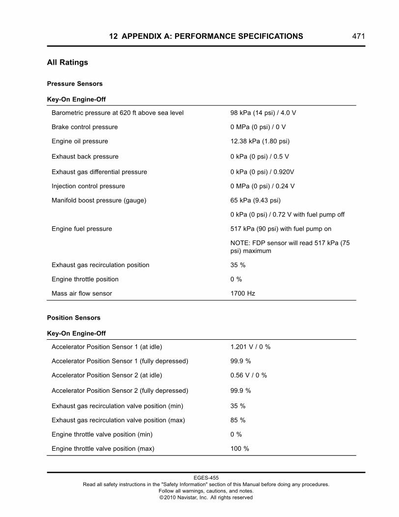
12 APPENDIX A: PERFORMANCE SPECIFICATIONS 471
All Ratings
Pressure Sensors
Key-On Engine-Off
Barometric pressure at 620 ft above sea level 98 kPa (14 psi) / 4.0 V
Brake control pressure 0 MPa (0 psi) / 0 V
Engine oil pressure 12.38 kPa (1.80 psi)
Exhaust back pressure 0 kPa (0 psi) / 0.5 V
Exhaust gas differential pressure 0 kPa (0 psi) / 0.920V
Injection control pressure 0 MPa (0 psi) / 0.24 V
Manifold boost pressure (gauge) 65 kPa (9.43 psi)
0 kPa (0 psi) / 0.72 V with fuel pump off
Engine fuel pressure 517 kPa (90 psi) with fuel pump on
NOTE: FDP sensor will read 517 kPa (75psi) maximum
Exhaust gas recirculation position 35 %
Engine throttle position 0 %
Mass air flow sensor 1700 Hz
Position Sensors
Key-On Engine-Off
Accelerator Position Sensor 1 (at idle) 1.201 V / 0 %
Accelerator Position Sensor 1 (fully depressed) 99.9 %
Accelerator Position Sensor 2 (at idle) 0.56 V / 0 %
Accelerator Position Sensor 2 (fully depressed) 99.9 %
Exhaust gas recirculation valve position (min) 35 %
Exhaust gas recirculation valve position (max) 85 %
Engine throttle valve position (min) 0 %
Engine throttle valve position (max) 100 %
EGES-455Read all safety instructions in the "Safety Information" section of this Manual before doing any procedures.
Follow all warnings, cautions, and notes.©2010 Navistar, Inc. All rights reserved
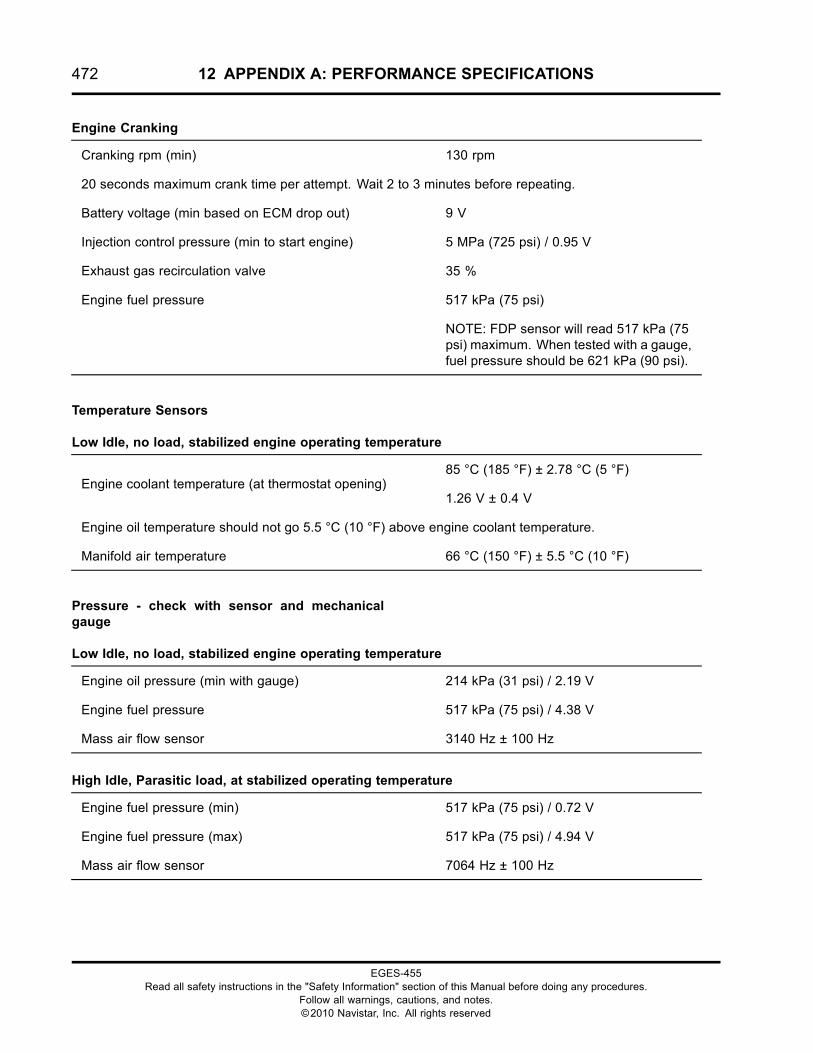
472 12 APPENDIX A: PERFORMANCE SPECIFICATIONS
Engine Cranking
Cranking rpm (min) 130 rpm
20 seconds maximum crank time per attempt. Wait 2 to 3 minutes before repeating.
Battery voltage (min based on ECM drop out) 9 V
Injection control pressure (min to start engine) 5 MPa (725 psi) / 0.95 V
Exhaust gas recirculation valve 35 %
Engine fuel pressure 517 kPa (75 psi)
NOTE: FDP sensor will read 517 kPa (75psi) maximum. When tested with a gauge,fuel pressure should be 621 kPa (90 psi).
Temperature Sensors
Low Idle, no load, stabilized engine operating temperature
85 °C (185 °F) ± 2.78 °C (5 °F)Engine coolant temperature (at thermostat opening)
1.26 V ± 0.4 V
Engine oil temperature should not go 5.5 °C (10 °F) above engine coolant temperature.
Manifold air temperature 66 °C (150 °F) ± 5.5 °C (10 °F)
Pressure - check with sensor and mechanicalgauge
Low Idle, no load, stabilized engine operating temperature
Engine oil pressure (min with gauge) 214 kPa (31 psi) / 2.19 V
Engine fuel pressure 517 kPa (75 psi) / 4.38 V
Mass air flow sensor 3140 Hz ± 100 Hz
High Idle, Parasitic load, at stabilized operating temperature
Engine fuel pressure (min) 517 kPa (75 psi) / 0.72 V
Engine fuel pressure (max) 517 kPa (75 psi) / 4.94 V
Mass air flow sensor 7064 Hz ± 100 Hz
EGES-455Read all safety instructions in the "Safety Information" section of this Manual before doing any procedures.
Follow all warnings, cautions, and notes.©2010 Navistar, Inc. All rights reserved
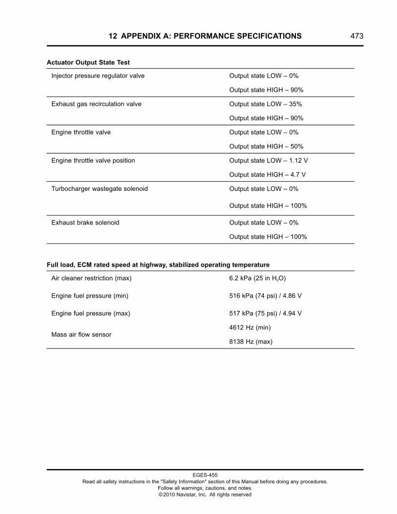
12 APPENDIX A: PERFORMANCE SPECIFICATIONS 473
Actuator Output State Test
Output state LOW – 0%Injector pressure regulator valve
Output state HIGH – 90%
Output state LOW – 35%Exhaust gas recirculation valve
Output state HIGH – 90%
Output state LOW – 0%Engine throttle valve
Output state HIGH – 50%
Output state LOW – 1.12 VEngine throttle valve position
Output state HIGH – 4.7 V
Output state LOW – 0%Turbocharger wastegate solenoid
Output state HIGH – 100%
Output state LOW – 0%Exhaust brake solenoid
Output state HIGH – 100%
Full load, ECM rated speed at highway, stabilized operating temperature
Air cleaner restriction (max) 6.2 kPa (25 in H2O)
Engine fuel pressure (min) 516 kPa (74 psi) / 4.86 V
Engine fuel pressure (max) 517 kPa (75 psi) / 4.94 V
4612 Hz (min)Mass air flow sensor
8138 Hz (max)
EGES-455Read all safety instructions in the "Safety Information" section of this Manual before doing any procedures.
Follow all warnings, cautions, and notes.©2010 Navistar, Inc. All rights reserved
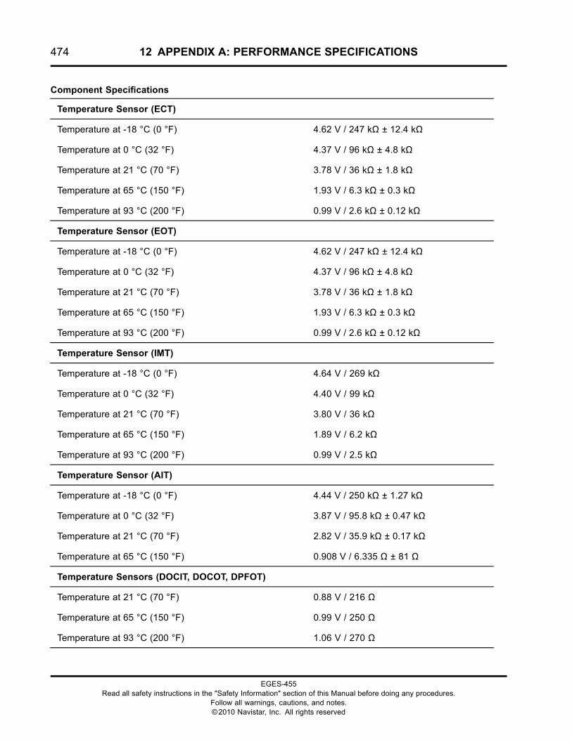
474 12 APPENDIX A: PERFORMANCE SPECIFICATIONS
Component Specifications
Temperature Sensor (ECT)
Temperature at -18 °C (0 °F) 4.62 V / 247 kΩ ± 12.4 kΩ
Temperature at 0 °C (32 °F) 4.37 V / 96 kΩ ± 4.8 kΩ
Temperature at 21 °C (70 °F) 3.78 V / 36 kΩ ± 1.8 kΩ
Temperature at 65 °C (150 °F) 1.93 V / 6.3 kΩ ± 0.3 kΩ
Temperature at 93 °C (200 °F) 0.99 V / 2.6 kΩ ± 0.12 kΩ
Temperature Sensor (EOT)
Temperature at -18 °C (0 °F) 4.62 V / 247 kΩ ± 12.4 kΩ
Temperature at 0 °C (32 °F) 4.37 V / 96 kΩ ± 4.8 kΩ
Temperature at 21 °C (70 °F) 3.78 V / 36 kΩ ± 1.8 kΩ
Temperature at 65 °C (150 °F) 1.93 V / 6.3 kΩ ± 0.3 kΩ
Temperature at 93 °C (200 °F) 0.99 V / 2.6 kΩ ± 0.12 kΩ
Temperature Sensor (IMT)
Temperature at -18 °C (0 °F) 4.64 V / 269 kΩ
Temperature at 0 °C (32 °F) 4.40 V / 99 kΩ
Temperature at 21 °C (70 °F) 3.80 V / 36 kΩ
Temperature at 65 °C (150 °F) 1.89 V / 6.2 kΩ
Temperature at 93 °C (200 °F) 0.99 V / 2.5 kΩ
Temperature Sensor (AIT)
Temperature at -18 °C (0 °F) 4.44 V / 250 kΩ ± 1.27 kΩ
Temperature at 0 °C (32 °F) 3.87 V / 95.8 kΩ ± 0.47 kΩ
Temperature at 21 °C (70 °F) 2.82 V / 35.9 kΩ ± 0.17 kΩ
Temperature at 65 °C (150 °F) 0.908 V / 6.335 Ω ± 81 Ω
Temperature Sensors (DOCIT, DOCOT, DPFOT)
Temperature at 21 °C (70 °F) 0.88 V / 216 Ω
Temperature at 65 °C (150 °F) 0.99 V / 250 Ω
Temperature at 93 °C (200 °F) 1.06 V / 270 Ω
EGES-455Read all safety instructions in the "Safety Information" section of this Manual before doing any procedures.
Follow all warnings, cautions, and notes.©2010 Navistar, Inc. All rights reserved
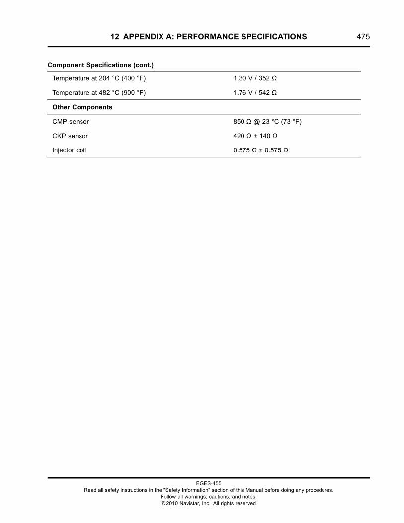
12 APPENDIX A: PERFORMANCE SPECIFICATIONS 475
Component Specifications (cont.)
Temperature at 204 °C (400 °F) 1.30 V / 352 Ω
Temperature at 482 °C (900 °F) 1.76 V / 542 Ω
Other Components
CMP sensor 850 Ω @ 23 °C (73 °F)
CKP sensor 420 Ω ± 140 Ω
Injector coil 0.575 Ω ± 0.575 Ω
EGES-455Read all safety instructions in the "Safety Information" section of this Manual before doing any procedures.
Follow all warnings, cautions, and notes.©2010 Navistar, Inc. All rights reserved
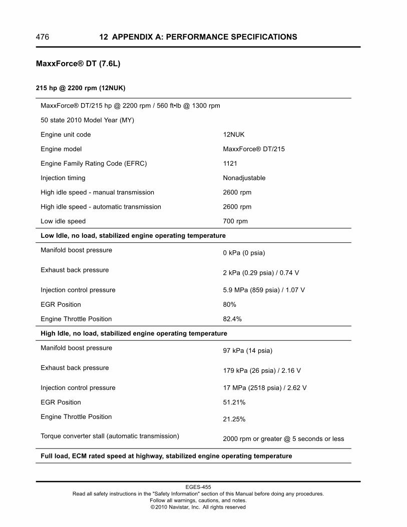
476 12 APPENDIX A: PERFORMANCE SPECIFICATIONS
MaxxForce® DT (7.6L)
215 hp @ 2200 rpm (12NUK)
MaxxForce® DT/215 hp @ 2200 rpm / 560 ft•lb @ 1300 rpm
50 state 2010 Model Year (MY)
Engine unit code 12NUK
Engine model MaxxForce® DT/215
Engine Family Rating Code (EFRC) 1121
Injection timing Nonadjustable
High idle speed - manual transmission 2600 rpm
High idle speed - automatic transmission 2600 rpm
Low idle speed 700 rpm
Low Idle, no load, stabilized engine operating temperature
Manifold boost pressure 0 kPa (0 psia)
Exhaust back pressure 2 kPa (0.29 psia) / 0.74 V
Injection control pressure 5.9 MPa (859 psia) / 1.07 V
EGR Position 80%
Engine Throttle Position 82.4%
High Idle, no load, stabilized engine operating temperature
Manifold boost pressure 97 kPa (14 psia)
Exhaust back pressure 179 kPa (26 psia) / 2.16 V
Injection control pressure 17 MPa (2518 psia) / 2.62 V
EGR Position 51.21%
Engine Throttle Position 21.25%
Torque converter stall (automatic transmission) 2000 rpm or greater @ 5 seconds or less
Full load, ECM rated speed at highway, stabilized engine operating temperature
EGES-455Read all safety instructions in the "Safety Information" section of this Manual before doing any procedures.
Follow all warnings, cautions, and notes.©2010 Navistar, Inc. All rights reserved
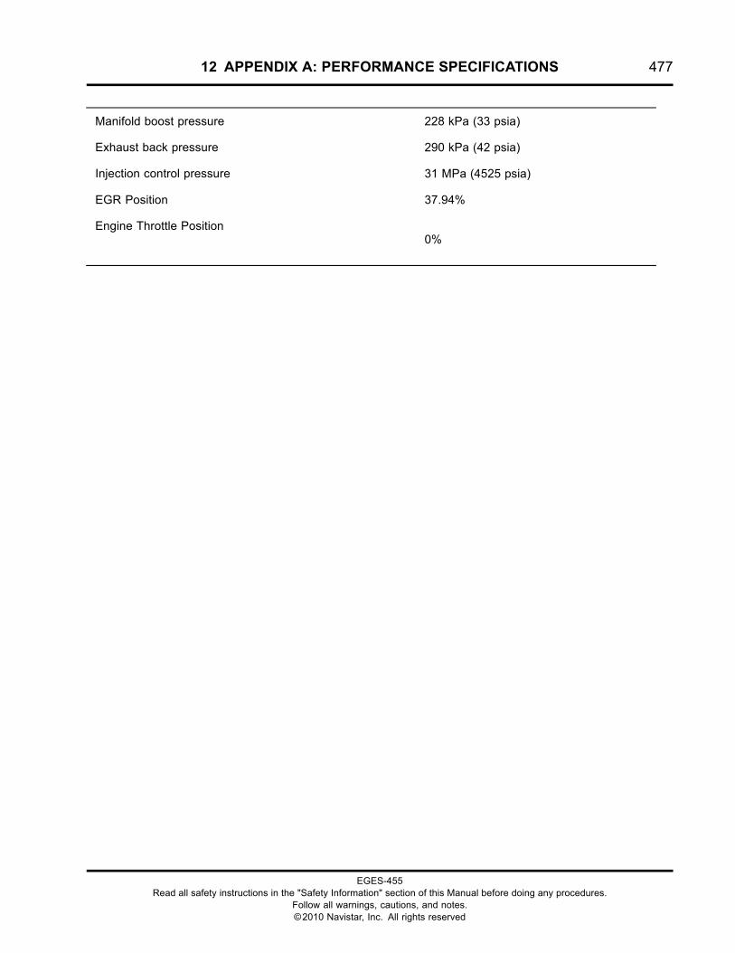
12 APPENDIX A: PERFORMANCE SPECIFICATIONS 477
Manifold boost pressure 228 kPa (33 psia)
Exhaust back pressure 290 kPa (42 psia)
Injection control pressure 31 MPa (4525 psia)
EGR Position 37.94%
Engine Throttle Position0%
EGES-455Read all safety instructions in the "Safety Information" section of this Manual before doing any procedures.
Follow all warnings, cautions, and notes.©2010 Navistar, Inc. All rights reserved

478 12 APPENDIX A: PERFORMANCE SPECIFICATIONS
230 hp @ 2200 rpm (12NUL)
MaxxForce® DT/230 hp @ 2200 rpm / 620 ft•lb @ 1300 rpm
50 state 2010 Model Year (MY)
Engine unit code 12NUL
Engine model MaxxForce® DT/230
Engine Family Rating Code (EFRC) 1141
Injection timing Nonadjustable
High idle speed - manual transmission 2600 rpm
High idle speed - automatic transmission 2600 rpm
Low idle speed 700 rpm
Low Idle, no load, stabilized engine operating temperature
Manifold boost pressure 0 kPa (0 psia)
Exhaust back pressure 1.3 kPa (0.19 psia) / 0.74 V
Injection control pressure 6 MPa (877 psi) / 1.07 V
EGR Position 80%
Engine Throttle Position 82.4%
High Idle, no load, stabilized engine operating temperature
Manifold boost pressure 60 kPa (8.7 psi)
Exhaust back pressure 118 kPa (17.1 psia) / 2.16 V
Injection control pressure 12.2 MPa (1777 psi) / 2.62 V
EGR Position 51.21%
Engine Throttle Position 0%
Torque converter stall (automatic transmission) 2000 rpm or greater @ 5 seconds or less
Full load, ECM rated speed at highway, stabilized engine operating temperature
Manifold boost pressure 159 kPa (23 psi)
Exhaust back pressure 247 kPa (35.85 psia)
EGES-455Read all safety instructions in the "Safety Information" section of this Manual before doing any procedures.
Follow all warnings, cautions, and notes.©2010 Navistar, Inc. All rights reserved
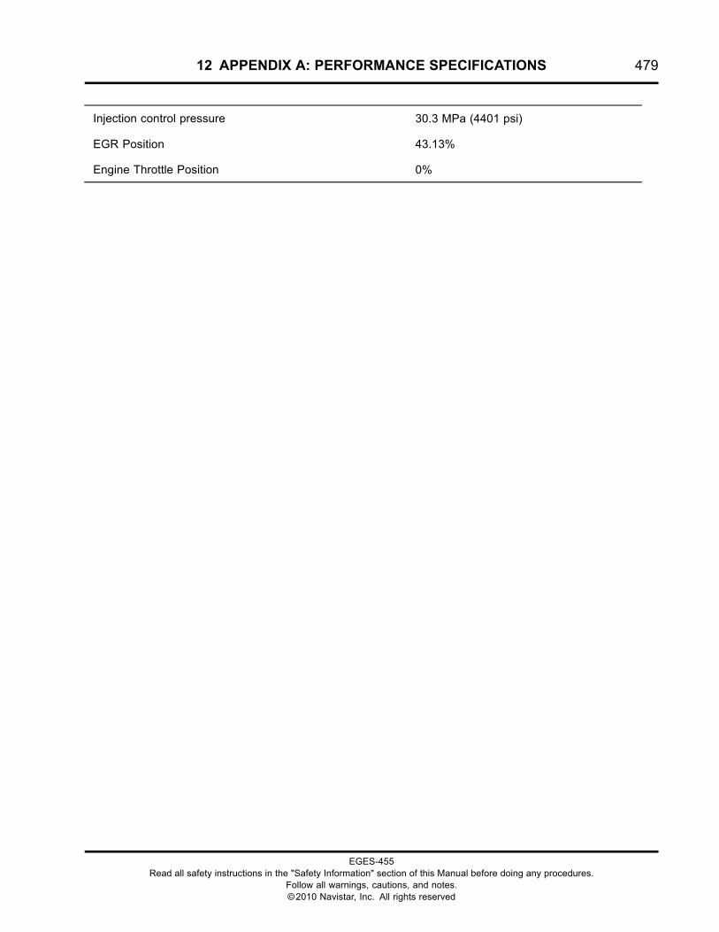
12 APPENDIX A: PERFORMANCE SPECIFICATIONS 479
Injection control pressure 30.3 MPa (4401 psi)
EGR Position 43.13%
Engine Throttle Position 0%
EGES-455Read all safety instructions in the "Safety Information" section of this Manual before doing any procedures.
Follow all warnings, cautions, and notes.©2010 Navistar, Inc. All rights reserved
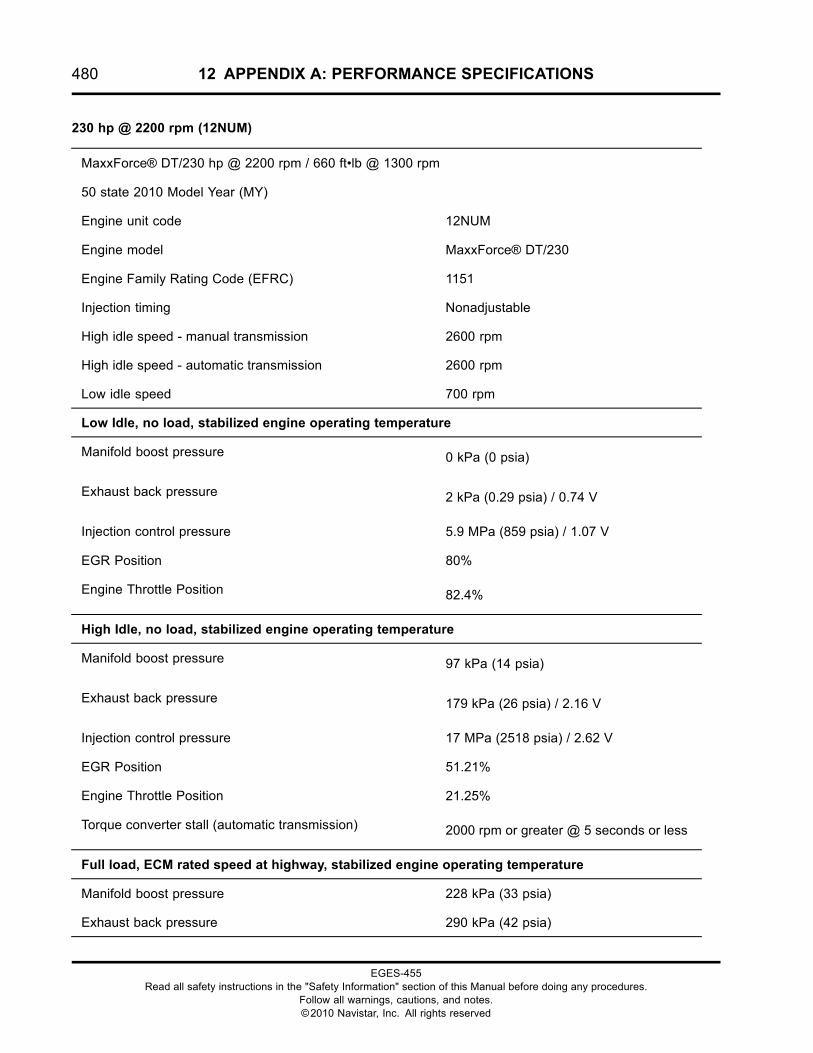
480 12 APPENDIX A: PERFORMANCE SPECIFICATIONS
230 hp @ 2200 rpm (12NUM)
MaxxForce® DT/230 hp @ 2200 rpm / 660 ft•lb @ 1300 rpm
50 state 2010 Model Year (MY)
Engine unit code 12NUM
Engine model MaxxForce® DT/230
Engine Family Rating Code (EFRC) 1151
Injection timing Nonadjustable
High idle speed - manual transmission 2600 rpm
High idle speed - automatic transmission 2600 rpm
Low idle speed 700 rpm
Low Idle, no load, stabilized engine operating temperature
Manifold boost pressure 0 kPa (0 psia)
Exhaust back pressure 2 kPa (0.29 psia) / 0.74 V
Injection control pressure 5.9 MPa (859 psia) / 1.07 V
EGR Position 80%
Engine Throttle Position 82.4%
High Idle, no load, stabilized engine operating temperature
Manifold boost pressure 97 kPa (14 psia)
Exhaust back pressure 179 kPa (26 psia) / 2.16 V
Injection control pressure 17 MPa (2518 psia) / 2.62 V
EGR Position 51.21%
Engine Throttle Position 21.25%
Torque converter stall (automatic transmission) 2000 rpm or greater @ 5 seconds or less
Full load, ECM rated speed at highway, stabilized engine operating temperature
Manifold boost pressure 228 kPa (33 psia)
Exhaust back pressure 290 kPa (42 psia)
EGES-455Read all safety instructions in the "Safety Information" section of this Manual before doing any procedures.
Follow all warnings, cautions, and notes.©2010 Navistar, Inc. All rights reserved

12 APPENDIX A: PERFORMANCE SPECIFICATIONS 481
Injection control pressure 31 MPa (4525 psia)
EGR Position 37.9%
Engine Throttle Position 0%
EGES-455Read all safety instructions in the "Safety Information" section of this Manual before doing any procedures.
Follow all warnings, cautions, and notes.©2010 Navistar, Inc. All rights reserved

482 12 APPENDIX A: PERFORMANCE SPECIFICATIONS
245 hp @ 2200 rpm (12NUN)
MaxxForce® DT/245 hp @ 2200 rpm / 660 ft•lb @ 1300 rpm
50 state 2010 Model Year (MY)
Engine unit code 12NUN
Engine model MaxxForce® DT/245
Engine Family Rating Code (EFRC) 2111
Injection timing Nonadjustable
High idle speed - manual transmission 2600 rpm
High idle speed - automatic transmission 2600 rpm
Low idle speed 700 rpm
Low Idle, no load, stabilized engine operating temperature
Manifold boost pressure 0 kPa (0 psia)
Exhaust back pressure 2 kPa (0.32 psia) / 0.74 V
Injection control pressure 7 MPa (1005 psia) / 1.21 V
EGR Position 72.45%
Engine Throttle Position 79.07%
High Idle, no load, stabilized engine operating temperature
Manifold boost pressure 76 kPa (11 psia)
Exhaust back pressure 186 kPa (27 psia) / 2.22 V
Injection control pressure 9 MPa (1244 psia) / 1.43 V
EGR Position 41.3%
Engine Throttle Position 29.1%
Torque converter stall (automatic transmission) 2000 rpm or greater @ 5 seconds or less
Full load, ECM rated speed at highway, stabilized engine operating temperature
Manifold boost pressure 303 kPa (44 psia)
Exhaust back pressure 393 kPa (57 psia)
EGES-455Read all safety instructions in the "Safety Information" section of this Manual before doing any procedures.
Follow all warnings, cautions, and notes.©2010 Navistar, Inc. All rights reserved

12 APPENDIX A: PERFORMANCE SPECIFICATIONS 483
Injection control pressure 30 MPa (4337 psia)
EGR Position 38.2%
Engine Throttle Position 0%
EGES-455Read all safety instructions in the "Safety Information" section of this Manual before doing any procedures.
Follow all warnings, cautions, and notes.©2010 Navistar, Inc. All rights reserved

484 12 APPENDIX A: PERFORMANCE SPECIFICATIONS
260 hp @ 2200 rpm (12NUP)
MaxxForce® DT/260 hp @ 2200 rpm / 660 ft•lb @ 1300 rpm
50 state 2010 Model Year (MY)
Engine unit code 12NUP
Engine model MaxxForce® DT/260
Engine Family Rating Code (EFRC) 2121
Injection timing Nonadjustable
High idle speed - manual transmission 2600 rpm
High idle speed - automatic transmission 2600 rpm
Low idle speed 700 rpm
Low Idle, no load, stabilized engine operating temperature
Manifold boost pressure 0 kPa (0 psia)
Exhaust back pressure 2 kPa (0.32 psia) / 0.74 V
Injection control pressure 7 MPa (1005 psia) / 1.21 V
EGR Position 72.45%
Engine Throttle Position 79.07%
High Idle, no load, stabilized engine operating temperature
Manifold boost pressure 76 kPa (11 psia)
Exhaust back pressure 193 kPa (28 psia) / 2.2 V
Injection control pressure 17 MPa (2480 psia) / 1.4 V
EGR Position 43%
Engine Throttle Position 30.85%
Torque converter stall (automatic transmission) 2000 rpm or greater @ 5 seconds or less
Full load, ECM rated speed at highway, stabilized engine operating temperature
Manifold boost pressure 296 kPa (43 psia)
Exhaust back pressure 386 kPa (56 psia)
EGES-455Read all safety instructions in the "Safety Information" section of this Manual before doing any procedures.
Follow all warnings, cautions, and notes.©2010 Navistar, Inc. All rights reserved

12 APPENDIX A: PERFORMANCE SPECIFICATIONS 485
Injection control pressure 31 MPa (4496 psia)
EGR Position 37.2%
Engine Throttle Position 0%
EGES-455Read all safety instructions in the "Safety Information" section of this Manual before doing any procedures.
Follow all warnings, cautions, and notes.©2010 Navistar, Inc. All rights reserved
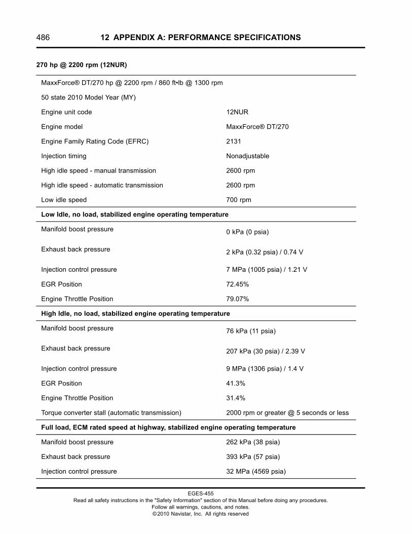
486 12 APPENDIX A: PERFORMANCE SPECIFICATIONS
270 hp @ 2200 rpm (12NUR)
MaxxForce® DT/270 hp @ 2200 rpm / 860 ft•lb @ 1300 rpm
50 state 2010 Model Year (MY)
Engine unit code 12NUR
Engine model MaxxForce® DT/270
Engine Family Rating Code (EFRC) 2131
Injection timing Nonadjustable
High idle speed - manual transmission 2600 rpm
High idle speed - automatic transmission 2600 rpm
Low idle speed 700 rpm
Low Idle, no load, stabilized engine operating temperature
Manifold boost pressure 0 kPa (0 psia)
Exhaust back pressure 2 kPa (0.32 psia) / 0.74 V
Injection control pressure 7 MPa (1005 psia) / 1.21 V
EGR Position 72.45%
Engine Throttle Position 79.07%
High Idle, no load, stabilized engine operating temperature
Manifold boost pressure 76 kPa (11 psia)
Exhaust back pressure 207 kPa (30 psia) / 2.39 V
Injection control pressure 9 MPa (1306 psia) / 1.4 V
EGR Position 41.3%
Engine Throttle Position 31.4%
Torque converter stall (automatic transmission) 2000 rpm or greater @ 5 seconds or less
Full load, ECM rated speed at highway, stabilized engine operating temperature
Manifold boost pressure 262 kPa (38 psia)
Exhaust back pressure 393 kPa (57 psia)
Injection control pressure 32 MPa (4569 psia)
EGES-455Read all safety instructions in the "Safety Information" section of this Manual before doing any procedures.
Follow all warnings, cautions, and notes.©2010 Navistar, Inc. All rights reserved
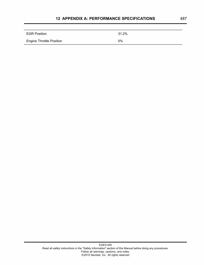
12 APPENDIX A: PERFORMANCE SPECIFICATIONS 487
EGR Position 31.2%
Engine Throttle Position 0%
EGES-455Read all safety instructions in the "Safety Information" section of this Manual before doing any procedures.
Follow all warnings, cautions, and notes.©2010 Navistar, Inc. All rights reserved

488 12 APPENDIX A: PERFORMANCE SPECIFICATIONS
280 hp @ 2200 rpm (12NUS)
MaxxForce® DT/280 hp @ 2200 rpm / 860 ft•lb @ 1300 rpm
50 state 2010 Model Year (MY)
Engine unit code 12NUS
Engine model MaxxForce® DT/280
Engine Family Rating Code (EFRC) 2141
Injection timing Nonadjustable
High idle speed - manual transmission 2600 rpm
High idle speed - automatic transmission 2600 rpm
Low idle speed 700 rpm
Low Idle, no load, stabilized engine operating temperature
Manifold boost pressure 0 kPa (0 psia)
Exhaust back pressure 2 kPa (0.32 psia) / 0.74 V
Injection control pressure 7 MPa (1005 psia) / 1.21 V
EGR Position 72.45%
Engine Throttle Position 79.07%
High Idle, no load, stabilized engine operating temperature
Manifold boost pressure 83 kPa (12 psia)
Exhaust back pressure 214 kPa (31 psia) / 2.4 V
Injection control pressure 9 MPa (1305 psia) / 1.5 V
EGR Position 40.9%
Engine Throttle Position 31.4%
Torque converter stall (automatic transmission) 2000 rpm or greater @ 5 seconds or less
Full load, ECM rated speed at highway, stabilized engine operating temperature
Manifold boost pressure 276 kPa (40 psia)
Exhaust back pressure 386 kPa (56 psia)
EGES-455Read all safety instructions in the "Safety Information" section of this Manual before doing any procedures.
Follow all warnings, cautions, and notes.©2010 Navistar, Inc. All rights reserved
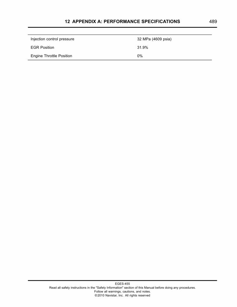
12 APPENDIX A: PERFORMANCE SPECIFICATIONS 489
Injection control pressure 32 MPa (4609 psia)
EGR Position 31.9%
Engine Throttle Position 0%
EGES-455Read all safety instructions in the "Safety Information" section of this Manual before doing any procedures.
Follow all warnings, cautions, and notes.©2010 Navistar, Inc. All rights reserved
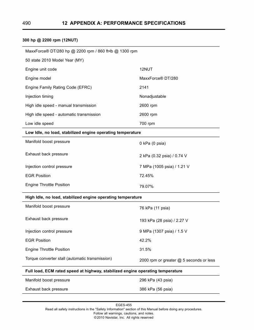
490 12 APPENDIX A: PERFORMANCE SPECIFICATIONS
300 hp @ 2200 rpm (12NUT)
MaxxForce® DT/280 hp @ 2200 rpm / 860 ft•lb @ 1300 rpm
50 state 2010 Model Year (MY)
Engine unit code 12NUT
Engine model MaxxForce® DT/280
Engine Family Rating Code (EFRC) 2141
Injection timing Nonadjustable
High idle speed - manual transmission 2600 rpm
High idle speed - automatic transmission 2600 rpm
Low idle speed 700 rpm
Low Idle, no load, stabilized engine operating temperature
Manifold boost pressure 0 kPa (0 psia)
Exhaust back pressure 2 kPa (0.32 psia) / 0.74 V
Injection control pressure 7 MPa (1005 psia) / 1.21 V
EGR Position 72.45%
Engine Throttle Position 79.07%
High Idle, no load, stabilized engine operating temperature
Manifold boost pressure 76 kPa (11 psia)
Exhaust back pressure 193 kPa (28 psia) / 2.27 V
Injection control pressure 9 MPa (1307 psia) / 1.5 V
EGR Position 42.2%
Engine Throttle Position 31.5%
Torque converter stall (automatic transmission) 2000 rpm or greater @ 5 seconds or less
Full load, ECM rated speed at highway, stabilized engine operating temperature
Manifold boost pressure 296 kPa (43 psia)
Exhaust back pressure 386 kPa (56 psia)
EGES-455Read all safety instructions in the "Safety Information" section of this Manual before doing any procedures.
Follow all warnings, cautions, and notes.©2010 Navistar, Inc. All rights reserved

12 APPENDIX A: PERFORMANCE SPECIFICATIONS 491
Injection control pressure 32 MPa (4588 psia)
EGR Position 30.9%
Engine Throttle Position 0%
EGES-455Read all safety instructions in the "Safety Information" section of this Manual before doing any procedures.
Follow all warnings, cautions, and notes.©2010 Navistar, Inc. All rights reserved

492 12 APPENDIX A: PERFORMANCE SPECIFICATIONS
MaxxForce® 9 (9.3L)
300 hp @ 2000 rpm (12NUU)
MaxxForce® 9/300 hp @ 2000 rpm / 860 ft•lb @ 1200 rpm
50 state 2010 Model Year (MY)
Engine unit code 12NUU
Engine model MaxxForce® 9/300
Engine Family Rating Code (EFRC) 5121
Injection timing Nonadjustable
High idle speed - manual transmission 2400 rpm
High idle speed - automatic transmission 2400 rpm
Low idle speed 700 rpm
Low Idle, no load, stabilized engine operating temperature
Manifold boost pressure 0 kPa (0 psia)
Exhaust back pressure 4 kPa (0.6 psia) / 0.75 V
Injection control pressure 6 MPa (853 psia) / 1.09 V
EGR Position 82.09%
Engine Throttle Position 95.43%
High Idle, no load, stabilized engine operating temperature
Manifold boost pressure 159 kPa (23 psia)
Exhaust back pressure 352 kPa (51 psia) / 3.55 V
Injection control pressure 15 MPa (2228 psia) / 2.35 V
EGR Position 23.98%
Engine Throttle Position 30.24%
Torque converter stall (automatic transmission) 2000 rpm or greater @ 5 seconds or less
Full load, ECM rated speed at highway, stabilized engine operating temperature
EGES-455Read all safety instructions in the "Safety Information" section of this Manual before doing any procedures.
Follow all warnings, cautions, and notes.©2010 Navistar, Inc. All rights reserved
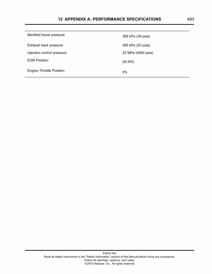
12 APPENDIX A: PERFORMANCE SPECIFICATIONS 493
Manifold boost pressure 269 kPa (39 psia)
Exhaust back pressure 365 kPa (53 psia)
Injection control pressure 32 MPa (4640 psia)
EGR Position 28.35%
Engine Throttle Position 0%
EGES-455Read all safety instructions in the "Safety Information" section of this Manual before doing any procedures.
Follow all warnings, cautions, and notes.©2010 Navistar, Inc. All rights reserved
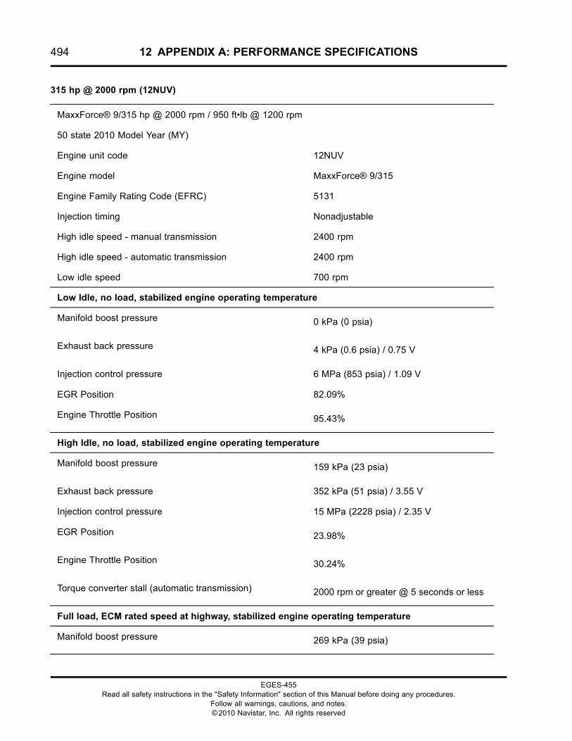
494 12 APPENDIX A: PERFORMANCE SPECIFICATIONS
315 hp @ 2000 rpm (12NUV)
MaxxForce® 9/315 hp @ 2000 rpm / 950 ft•lb @ 1200 rpm
50 state 2010 Model Year (MY)
Engine unit code 12NUV
Engine model MaxxForce® 9/315
Engine Family Rating Code (EFRC) 5131
Injection timing Nonadjustable
High idle speed - manual transmission 2400 rpm
High idle speed - automatic transmission 2400 rpm
Low idle speed 700 rpm
Low Idle, no load, stabilized engine operating temperature
Manifold boost pressure 0 kPa (0 psia)
Exhaust back pressure 4 kPa (0.6 psia) / 0.75 V
Injection control pressure 6 MPa (853 psia) / 1.09 V
EGR Position 82.09%
Engine Throttle Position 95.43%
High Idle, no load, stabilized engine operating temperature
Manifold boost pressure 159 kPa (23 psia)
Exhaust back pressure 352 kPa (51 psia) / 3.55 V
Injection control pressure 15 MPa (2228 psia) / 2.35 V
EGR Position 23.98%
Engine Throttle Position 30.24%
Torque converter stall (automatic transmission) 2000 rpm or greater @ 5 seconds or less
Full load, ECM rated speed at highway, stabilized engine operating temperature
Manifold boost pressure 269 kPa (39 psia)
EGES-455Read all safety instructions in the "Safety Information" section of this Manual before doing any procedures.
Follow all warnings, cautions, and notes.©2010 Navistar, Inc. All rights reserved
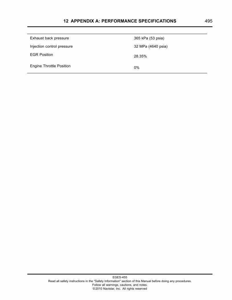
12 APPENDIX A: PERFORMANCE SPECIFICATIONS 495
Exhaust back pressure 365 kPa (53 psia)
Injection control pressure 32 MPa (4640 psia)
EGR Position 28.35%
Engine Throttle Position 0%
EGES-455Read all safety instructions in the "Safety Information" section of this Manual before doing any procedures.
Follow all warnings, cautions, and notes.©2010 Navistar, Inc. All rights reserved

496 12 APPENDIX A: PERFORMANCE SPECIFICATIONS
315 hp @ 2000 rpm (12NUW)
MaxxForce® 9/315 hp @ 2000 rpm / 950 ft•lb @ 1200 rpm
50 state 2010 Model Year (MY)
Engine unit code 12NUW
Engine model MaxxForce® 9/330
Engine Family Rating Code (EFRC) 5151
Injection timing Nonadjustable
High idle speed - manual transmission 2400 rpm
High idle speed - automatic transmission 2400 rpm
Low idle speed 700 rpm
Low Idle, no load, stabilized engine operating temperature
Manifold boost pressure 0 kPa (0 psia)
Exhaust back pressure 4 kPa (0.6 psia) / 0.75 V
Injection control pressure 6 MPa (853 psia) / 1.09 V
EGR Position 82.09%
Engine Throttle Position 95.43%
High Idle, no load, stabilized engine operating temperature
Manifold boost pressure 159 kPa (23 psia)
Exhaust back pressure 352 kPa (51 psia) / 3.55 V
Injection control pressure 15 MPa (2228 psia) / 2.35 V
EGR Position 23.98%
Engine Throttle Position 30.24%
Torque converter stall (automatic transmission) 2000 rpm or greater @ 5 seconds or less
Full load, ECM rated speed at highway, stabilized engine operating temperature
Manifold boost pressure 269 kPa (39 psia)
EGES-455Read all safety instructions in the "Safety Information" section of this Manual before doing any procedures.
Follow all warnings, cautions, and notes.©2010 Navistar, Inc. All rights reserved

12 APPENDIX A: PERFORMANCE SPECIFICATIONS 497
Exhaust back pressure 365 kPa (53 psia)
Injection control pressure 32 MPa (4640 psia)
EGR Position 28.35%
Engine Throttle Position 0%
EGES-455Read all safety instructions in the "Safety Information" section of this Manual before doing any procedures.
Follow all warnings, cautions, and notes.©2010 Navistar, Inc. All rights reserved
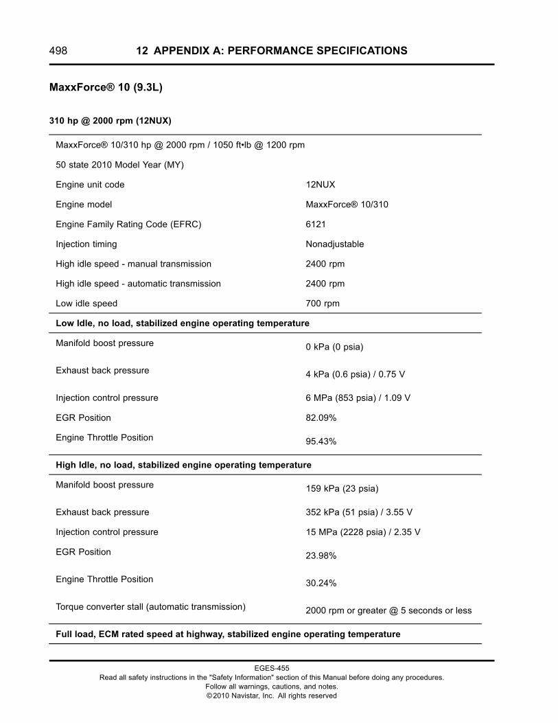
498 12 APPENDIX A: PERFORMANCE SPECIFICATIONS
MaxxForce® 10 (9.3L)
310 hp @ 2000 rpm (12NUX)
MaxxForce® 10/310 hp @ 2000 rpm / 1050 ft•lb @ 1200 rpm
50 state 2010 Model Year (MY)
Engine unit code 12NUX
Engine model MaxxForce® 10/310
Engine Family Rating Code (EFRC) 6121
Injection timing Nonadjustable
High idle speed - manual transmission 2400 rpm
High idle speed - automatic transmission 2400 rpm
Low idle speed 700 rpm
Low Idle, no load, stabilized engine operating temperature
Manifold boost pressure 0 kPa (0 psia)
Exhaust back pressure 4 kPa (0.6 psia) / 0.75 V
Injection control pressure 6 MPa (853 psia) / 1.09 V
EGR Position 82.09%
Engine Throttle Position 95.43%
High Idle, no load, stabilized engine operating temperature
Manifold boost pressure 159 kPa (23 psia)
Exhaust back pressure 352 kPa (51 psia) / 3.55 V
Injection control pressure 15 MPa (2228 psia) / 2.35 V
EGR Position 23.98%
Engine Throttle Position 30.24%
Torque converter stall (automatic transmission) 2000 rpm or greater @ 5 seconds or less
Full load, ECM rated speed at highway, stabilized engine operating temperature
EGES-455Read all safety instructions in the "Safety Information" section of this Manual before doing any procedures.
Follow all warnings, cautions, and notes.©2010 Navistar, Inc. All rights reserved

12 APPENDIX A: PERFORMANCE SPECIFICATIONS 499
Manifold boost pressure 269 kPa (39 psia)
Exhaust back pressure 365 kPa (53 psia)
Injection control pressure 32 MPa (4640 psia)
EGR Position 28.35%
Engine Throttle Position 0%
EGES-455Read all safety instructions in the "Safety Information" section of this Manual before doing any procedures.
Follow all warnings, cautions, and notes.©2010 Navistar, Inc. All rights reserved

500 12 APPENDIX A: PERFORMANCE SPECIFICATIONS
330 hp @ 2000 rpm (12NUY)
MaxxForce® 10/330 hp @ 2000 rpm / 1150 ft•lb @ 1200 rpm
50 state 2010 Model Year (MY)
Engine unit code 12NUY
Engine model MaxxForce® 10/330
Engine Family Rating Code (EFRC) 6131
Injection timing Nonadjustable
High idle speed - manual transmission 2400 rpm
High idle speed - automatic transmission 2400 rpm
Low idle speed 700 rpm
Low Idle, no load, stabilized engine operating temperature
Manifold boost pressure 0 kPa (0 psia)
Exhaust back pressure 4 kPa (0.6 psia) / 0.75 V
Injection control pressure 6 MPa (853 psia) / 1.09 V
EGR Position 82.09%
Engine Throttle Position 95.43%
High Idle, no load, stabilized engine operating temperature
Manifold boost pressure 159 kPa (23 psia)
Exhaust back pressure 352 kPa (51 psia) / 3.55 V
Injection control pressure 15 MPa (2228 psia) / 2.35 V
EGR Position 23.98%
Engine Throttle Position 30.24%
Torque converter stall (automatic transmission) 2000 rpm or greater @ 5 seconds or less
Full load, ECM rated speed at highway, stabilized engine operating temperature
Manifold boost pressure 269 kPa (39 psia)
EGES-455Read all safety instructions in the "Safety Information" section of this Manual before doing any procedures.
Follow all warnings, cautions, and notes.©2010 Navistar, Inc. All rights reserved

12 APPENDIX A: PERFORMANCE SPECIFICATIONS 501
Exhaust back pressure 365 kPa (53 psia)
Injection control pressure 32 MPa (4640 psia)
EGR Position 28.35%
Engine Throttle Position 0%
EGES-455Read all safety instructions in the "Safety Information" section of this Manual before doing any procedures.
Follow all warnings, cautions, and notes.©2010 Navistar, Inc. All rights reserved

502 12 APPENDIX A: PERFORMANCE SPECIFICATIONS
350 hp @ 2000 rpm (12NUZ)
MaxxForce® 10/350 hp @ 2000 rpm / 1150 ft•lb @ 1200 rpm
50 state 2010 Model Year (MY)
Engine unit code 12NUZ
Engine model MaxxForce® 10/350
Engine Family Rating Code (EFRC) 6151
Injection timing Nonadjustable
High idle speed - manual transmission 2400 rpm
High idle speed - automatic transmission 2400 rpm
Low idle speed 700 rpm
Low Idle, no load, stabilized engine operating temperature
Manifold boost pressure 0 kPa (0 psia)
Exhaust back pressure 4 kPa (0.6 psia) / 0.75 V
Injection control pressure 6 MPa (853 psia) / 1.09 V
EGR Position 82.09%
Engine Throttle Position 95.43%
High Idle, no load, stabilized engine operating temperature
Manifold boost pressure 159 kPa (23 psia)
Exhaust back pressure 352 kPa (51 psia) / 3.55 V
Injection control pressure 15 MPa (2228 psia) / 2.35 V
EGR Position 23.98%
Engine Throttle Position 30.24%
Torque converter stall (automatic transmission) 2000 rpm or greater @ 5 seconds or less
Full load, ECM rated speed at highway, stabilized engine operating temperature
Manifold boost pressure 269 kPa (39 psia)
EGES-455Read all safety instructions in the "Safety Information" section of this Manual before doing any procedures.
Follow all warnings, cautions, and notes.©2010 Navistar, Inc. All rights reserved

12 APPENDIX A: PERFORMANCE SPECIFICATIONS 503
Exhaust back pressure 365 kPa (53 psia)
Injection control pressure 32 MPa (4640 psia)
EGR Position 28.35%
Engine Throttle Position 0%
EGES-455Read all safety instructions in the "Safety Information" section of this Manual before doing any procedures.
Follow all warnings, cautions, and notes.©2010 Navistar, Inc. All rights reserved

504 12 APPENDIX A: PERFORMANCE SPECIFICATIONS
EGES-455Read all safety instructions in the "Safety Information" section of this Manual before doing any procedures.
Follow all warnings, cautions, and notes.©2010 Navistar, Inc. All rights reserved
13 APPENDIX B: SIGNAL VALUES 505
Table of Contents
Signal Values. . . . . . . . . . . . . . . . . . . . . . . . . . . . . . . . . . . . . . . . . . . . . . . . . . . . . . . . . . . . . . . . . . . . . . . . . . . . . . . . . . . . . . . . . . . . . . . . . . . . . . . . . . .507
EGES-455Read all safety instructions in the "Safety Information" section of this Manual before doing any procedures.
Follow all warnings, cautions, and notes.©2010 Navistar, Inc. All rights reserved

506 13 APPENDIX B: SIGNAL VALUES
EGES-455Read all safety instructions in the "Safety Information" section of this Manual before doing any procedures.
Follow all warnings, cautions, and notes.©2010 Navistar, Inc. All rights reserved
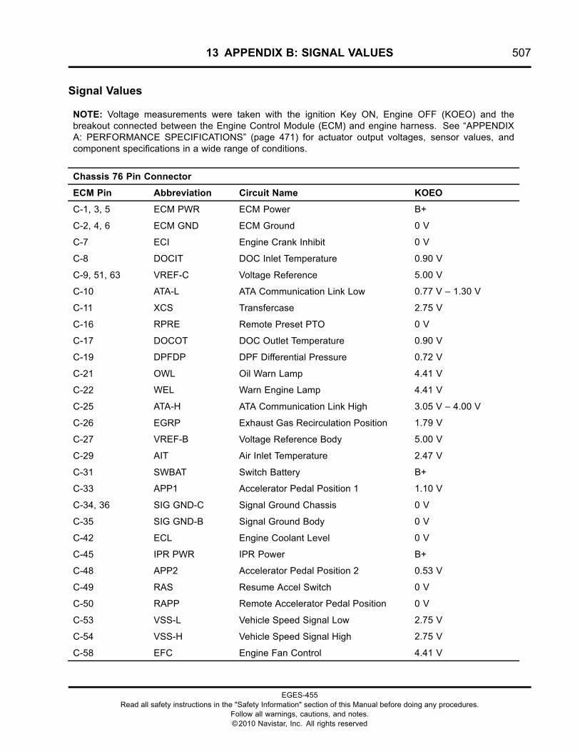
13 APPENDIX B: SIGNAL VALUES 507
Signal Values
NOTE: Voltage measurements were taken with the ignition Key ON, Engine OFF (KOEO) and thebreakout connected between the Engine Control Module (ECM) and engine harness. See “APPENDIXA: PERFORMANCE SPECIFICATIONS” (page 471) for actuator output voltages, sensor values, andcomponent specifications in a wide range of conditions.
Chassis 76 Pin Connector
ECM Pin Abbreviation Circuit Name KOEO
C-1, 3, 5 ECM PWR ECM Power B+
C-2, 4, 6 ECM GND ECM Ground 0 V
C-7 ECI Engine Crank Inhibit 0 V
C-8 DOCIT DOC Inlet Temperature 0.90 V
C-9, 51, 63 VREF-C Voltage Reference 5.00 V
C-10 ATA-L ATA Communication Link Low 0.77 V – 1.30 V
C-11 XCS Transfercase 2.75 V
C-16 RPRE Remote Preset PTO 0 V
C-17 DOCOT DOC Outlet Temperature 0.90 V
C-19 DPFDP DPF Differential Pressure 0.72 V
C-21 OWL Oil Warn Lamp 4.41 V
C-22 WEL Warn Engine Lamp 4.41 V
C-25 ATA-H ATA Communication Link High 3.05 V – 4.00 V
C-26 EGRP Exhaust Gas Recirculation Position 1.79 V
C-27 VREF-B Voltage Reference Body 5.00 V
C-29 AIT Air Inlet Temperature 2.47 V
C-31 SWBAT Switch Battery B+
C-33 APP1 Accelerator Pedal Position 1 1.10 V
C-34, 36 SIG GND-C Signal Ground Chassis 0 V
C-35 SIG GND-B Signal Ground Body 0 V
C-42 ECL Engine Coolant Level 0 V
C-45 IPR PWR IPR Power B+
C-48 APP2 Accelerator Pedal Position 2 0.53 V
C-49 RAS Resume Accel Switch 0 V
C-50 RAPP Remote Accelerator Pedal Position 0 V
C-53 VSS-L Vehicle Speed Signal Low 2.75 V
C-54 VSS-H Vehicle Speed Signal High 2.75 V
C-58 EFC Engine Fan Control 4.41 V
EGES-455Read all safety instructions in the "Safety Information" section of this Manual before doing any procedures.
Follow all warnings, cautions, and notes.©2010 Navistar, Inc. All rights reserved
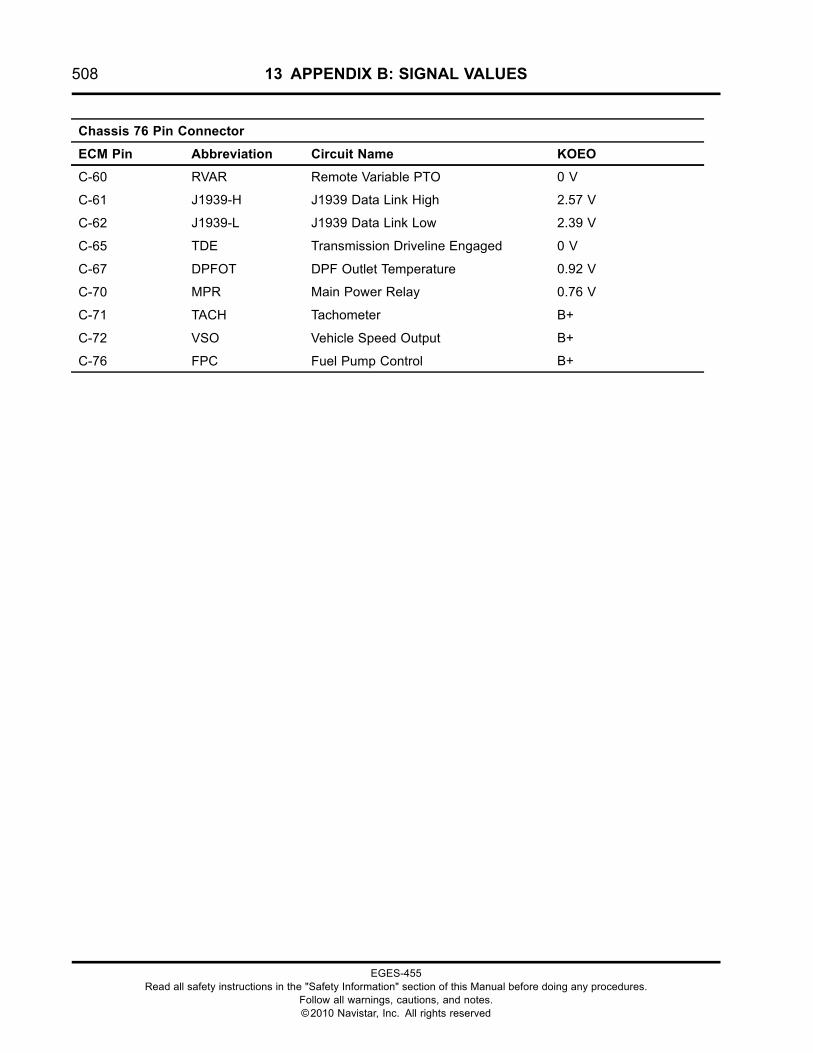
508 13 APPENDIX B: SIGNAL VALUES
Chassis 76 Pin Connector
ECM Pin Abbreviation Circuit Name KOEO
C-60 RVAR Remote Variable PTO 0 V
C-61 J1939-H J1939 Data Link High 2.57 V
C-62 J1939-L J1939 Data Link Low 2.39 V
C-65 TDE Transmission Driveline Engaged 0 V
C-67 DPFOT DPF Outlet Temperature 0.92 V
C-70 MPR Main Power Relay 0.76 V
C-71 TACH Tachometer B+
C-72 VSO Vehicle Speed Output B+
C-76 FPC Fuel Pump Control B+
EGES-455Read all safety instructions in the "Safety Information" section of this Manual before doing any procedures.
Follow all warnings, cautions, and notes.©2010 Navistar, Inc. All rights reserved
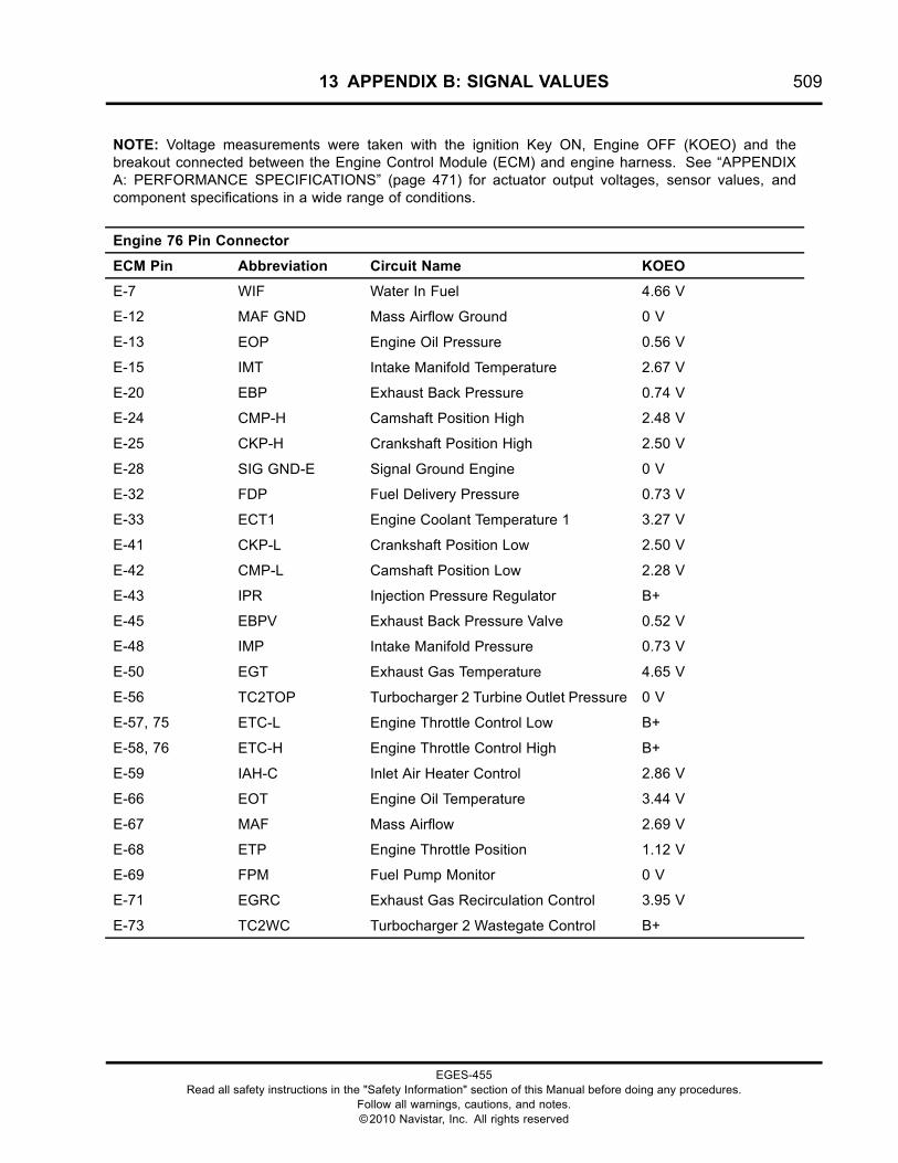
13 APPENDIX B: SIGNAL VALUES 509
NOTE: Voltage measurements were taken with the ignition Key ON, Engine OFF (KOEO) and thebreakout connected between the Engine Control Module (ECM) and engine harness. See “APPENDIXA: PERFORMANCE SPECIFICATIONS” (page 471) for actuator output voltages, sensor values, andcomponent specifications in a wide range of conditions.
Engine 76 Pin Connector
ECM Pin Abbreviation Circuit Name KOEO
E-7 WIF Water In Fuel 4.66 V
E-12 MAF GND Mass Airflow Ground 0 V
E-13 EOP Engine Oil Pressure 0.56 V
E-15 IMT Intake Manifold Temperature 2.67 V
E-20 EBP Exhaust Back Pressure 0.74 V
E-24 CMP-H Camshaft Position High 2.48 V
E-25 CKP-H Crankshaft Position High 2.50 V
E-28 SIG GND-E Signal Ground Engine 0 V
E-32 FDP Fuel Delivery Pressure 0.73 V
E-33 ECT1 Engine Coolant Temperature 1 3.27 V
E-41 CKP-L Crankshaft Position Low 2.50 V
E-42 CMP-L Camshaft Position Low 2.28 V
E-43 IPR Injection Pressure Regulator B+
E-45 EBPV Exhaust Back Pressure Valve 0.52 V
E-48 IMP Intake Manifold Pressure 0.73 V
E-50 EGT Exhaust Gas Temperature 4.65 V
E-56 TC2TOP Turbocharger 2 Turbine Outlet Pressure 0 V
E-57, 75 ETC-L Engine Throttle Control Low B+
E-58, 76 ETC-H Engine Throttle Control High B+
E-59 IAH-C Inlet Air Heater Control 2.86 V
E-66 EOT Engine Oil Temperature 3.44 V
E-67 MAF Mass Airflow 2.69 V
E-68 ETP Engine Throttle Position 1.12 V
E-69 FPM Fuel Pump Monitor 0 V
E-71 EGRC Exhaust Gas Recirculation Control 3.95 V
E-73 TC2WC Turbocharger 2 Wastegate Control B+
EGES-455Read all safety instructions in the "Safety Information" section of this Manual before doing any procedures.
Follow all warnings, cautions, and notes.©2010 Navistar, Inc. All rights reserved
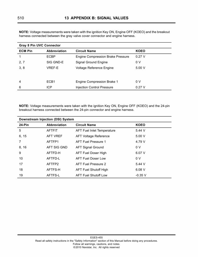
510 13 APPENDIX B: SIGNAL VALUES
NOTE: Voltage measurements were taken with the ignition Key ON, Engine OFF (KOEO) and the breakoutharness connected between the gray valve cover connector and engine harness.
Gray 8 Pin UVC Connector
ECM Pin Abbreviation Circuit Name KOEO
1 ECBP Engine Compression Brake Pressure 0.27 V
2, 7 SIG GND-E Signal Ground Engine 0 V
3, 8 VREF-E Voltage Reference Engine 5.00 V
4 ECB1 Engine Compression Brake 1 0 V
6 ICP Injection Control Pressure 0.27 V
NOTE: Voltage measurements were taken with the ignition Key ON, Engine OFF (KOEO) and the 24-pinbreakout harness connected between the 24-pin connector and engine harness.
Downstream Injection (DSI) System
24-Pin Abbreviation Circuit Name KOEO
5 AFTFIT AFT Fuel Inlet Temperature 5.44 V
6, 15 AFT VREF AFT Voltage Reference 5.00 V
7 AFTFP1 AFT Fuel Pressure 1 4.79 V
8, 16 AFT SIG GND AFT Signal Ground 0 V
9 AFTFD-H AFT Fuel Doser High 6.07 V
10 AFTFD-L AFT Fuel Doser Low 0 V
17 AFTFP2 AFT Fuel Pressure 2 5.44 V
18 AFTFS-H AFT Fuel Shutoff High 6.08 V
19 AFTFS-L AFT Fuel Shutoff Low -0.35 V
EGES-455Read all safety instructions in the "Safety Information" section of this Manual before doing any procedures.
Follow all warnings, cautions, and notes.©2010 Navistar, Inc. All rights reserved
14 APPENDIX C: TECHNICAL SERVICE INFORMATION (TSI) 511
Table of Contents
Description. . . . . . . . . . . . . . . . . . . . . . . . . . . . . . . . . . . . . . . . . . . . . . . . . . . . . . . . . . . . . . . . . . . . . . . . . . . . . . . . . . . . . . . . . . . . . . . . . . . . . . . . . . . . . .513
EGES-455Read all safety instructions in the "Safety Information" section of this Manual before doing any procedures.
Follow all warnings, cautions, and notes.©2010 Navistar, Inc. All rights reserved
512 14 APPENDIX C: TECHNICAL SERVICE INFORMATION (TSI)
EGES-455Read all safety instructions in the "Safety Information" section of this Manual before doing any procedures.
Follow all warnings, cautions, and notes.©2010 Navistar, Inc. All rights reserved
14 APPENDIX C: TECHNICAL SERVICE INFORMATION (TSI) 513
Description
Technical Service Information (TSI) letters areperiodically published to inform service technicians of
product enhancements and field service issues. FileTSIs in this section for supplemental reference.
EGES-455Read all safety instructions in the "Safety Information" section of this Manual before doing any procedures.
Follow all warnings, cautions, and notes.©2010 Navistar, Inc. All rights reserved

514 14 APPENDIX C: TECHNICAL SERVICE INFORMATION (TSI)
EGES-455Read all safety instructions in the "Safety Information" section of this Manual before doing any procedures.
Follow all warnings, cautions, and notes.©2010 Navistar, Inc. All rights reserved


Printed in the United States of America