Embed Size (px)
Citation preview
2008T Hemodialysis Machine
Operator’s Manual
Caution: Federal (US) law restricts this device to sale only by or on the order of a physician
P/N 490122 Rev O
2 2008T Machine Operator’s Manual P/N 490122 Rev O
2008T Hemodialysis Machine Operator’s Manual © Copyright 2008 - 2017 Fresenius USA, Inc.—All Rights Reserved
This document contains proprietary information of Fresenius Medical Care Renal Therapies Group, LLC and its affiliates (“Fresenius Medical Care”). The contents of this document may not be disclosed to third parties, copied, or duplicated in any form, in whole or in part, without the prior written permission of Fresenius Medical Care.
Fresenius Medical Care, the triangle logo, 2008, Clinical Data Exchange, Combiset, Twister, NaturaLyte, GranuFlo, bibag, Crit-Line, CLiC, Optiflux, DIASAFE and PURISTERIL are trademarks of Fresenius Medical Care Holdings, Inc., and/or its affiliated companies. Citrasate is a registered trademark of Advanced Renal Technologies, Inc. in the United States and used under license from Advanced Renal Technologies, Inc. All other trademarks are the property of their respective owners.
The 2008T hemodialysis machine is manufactured by: Fresenius USA, Inc. 4040 Nelson Avenue Concord, CA 94520 (800) 227-2572
Installation, maintenance, calibration and other technical information may be found in the 2008T Technician’s Manual, P/N 490130.
Contact Fresenius Medical Care Technical Support for applicable Field Service Bulletins. The spare parts manual for the model 2008T and other information may be found on our website at www.fmcna.com
Caution: Federal (US) law restricts this device to sale only by or on the order of a physician.
Caution: Frequency, duration, and parameters of treatment are to be determined by the prescribing physician.
Note: Not all features are available in all regions.
Indications for Use:
2008T Hemodialysis Machine: The 2008T hemodialysis machine is indicated for acute and chronic dialysis therapy.
bibag System (Optional): The bibag system is used with three stream proportioning hemodialysis systems equipped with the bibag module such as the 2008T Hemodialysis Machine and is intended for use in bicarbonate hemodialysis for acute and chronic renal failure. The bibag is intended for extracorporeal bicarbonate hemodialysis according to a physician’s prescription.
Crit-Line Clip Monitor (CLiC) (Optional): The Crit-Line Clip Monitor is used with the 2008T Hemodialysis Machine to non-invasively measure hematocrit, oxygen saturation and percent change in blood volume. The CLiC device measures hematocrit, percent change in blood volume and oxygen saturation in real time for application in the treatment of dialysis patients with the intended purpose of providing a more effective treatment for both the dialysis patient and the clinician. Based on the data that the monitor provides, the clinician/nurse, under physician direction, intervenes (i.e., increases or decreases the rate at which fluid is removed from the blood) in order to remove the maximum amount of fluid from the dialysis patient without the patient experiencing the common complications of dialysis which include nausea, cramping and vomiting.
2008T Machine Operator’s Manual P/N 490122 Rev O 3
Contents
About this manual… ........................................................................................................................ 7
Requirements ................................................................................................................................... 8
Related Reading ............................................................................................................................... 8
Conventions ..................................................................................................................................... 9
About Hemodialysis…................................................................................................................... 11
General Warnings .......................................................................................................................... 13
Using a Central Venous Catheter ................................................................................................... 18
CHAPTER 1
Overview ................................................................................................................................................. 19
Function of the 2008T Hemodialysis Machine .............................................................................. 19
Organization of the 2008T Hemodialysis Machine ....................................................................... 19
The Control Panel .......................................................................................................................... 22
Control Panel Keypad .................................................................................................................... 23
The Back Panel .............................................................................................................................. 30
Modules ......................................................................................................................................... 32
The Dialysate Path ......................................................................................................................... 38
IV Pole and Dialyzer Holder .......................................................................................................... 42
Moving the Machine ...................................................................................................................... 43
CHAPTER 2
Daily Preparation for Treatment ............................................................................................................. 45
Starting Point ................................................................................................................................. 45
Preparing the Dialysis Delivery System ........................................................................................ 46
Preparing the Extracorporeal Blood Circuit................................................................................... 49
Connecting the Extracorporeal Blood Circuit ................................................................................ 50
Testing the 2008T Hemodialysis Machine .................................................................................... 55
Recirculation and Final Set-Up Procedure ..................................................................................... 58
CHAPTER 3
Setting Treatment Parameters ................................................................................................................. 60
Recommended Screen Order ......................................................................................................... 60
New Treatment Key ....................................................................................................................... 61
Entering a Treatment Parameter .................................................................................................... 62
Dialysate Screen Settings ............................................................................................................... 63
Home Screen Settings .................................................................................................................... 74
4 2008T Machine Operator’s Manual P/N 490122 Rev O
Ultrafiltration ................................................................................................................................. 78
Sodium Variation System .............................................................................................................. 83
Heparin Screen Settings ................................................................................................................. 87
Test & Options Screen Settings ..................................................................................................... 92
Blood Pressure Screen Settings ..................................................................................................... 94
Starting Dialysis ............................................................................................................................. 97
CHAPTER 4
Monitoring the Treatment ....................................................................................................................... 99
Home Screen Monitoring ............................................................................................................. 100
Trends Screen Monitoring ........................................................................................................... 105
Kt/V & Access Flow Monitoring ................................................................................................. 108
Blood Temperature Monitor / Blood Volume Monitor Screen .................................................... 116
Crit-Line Screen ........................................................................................................................... 119
Blood Pressure Screen Monitoring .............................................................................................. 125
During Treatment ......................................................................................................................... 126
Blood Recirculation Procedure .................................................................................................... 128
Power Failure during Dialysis ..................................................................................................... 129
Completion of Dialysis ................................................................................................................ 132
CHAPTER 5
Disinfection and Maintenance .............................................................................................................. 136
Cleaning and Disinfection ............................................................................................................ 136
Cleaning the Exterior Surface ...................................................................................................... 140
Rinse Program .............................................................................................................................. 142
Acid Clean Program ..................................................................................................................... 143
Heat Disinfection Program .......................................................................................................... 144
Chemical/Rinse Program ............................................................................................................. 145
Chemical/Dwell Program ............................................................................................................. 147
Acid & Heat Disin (Disinfect) Program ...................................................................................... 149
CHAPTER 6
Alarms and Troubleshooting ................................................................................................................. 153
Operational Status ........................................................................................................................ 153
Troubleshooting ........................................................................................................................... 157
Replacing the Diasafe Plus Filter ................................................................................................. 218
Replacing the 9-Volt Battery ....................................................................................................... 218
APPENDIX A
Single Needle Dialysis (Optional) ........................................................................................................ 220
2008T Machine Operator’s Manual P/N 490122 Rev O 5
APPENDIX B
The CDX System (Optional) ................................................................................................................. 233
Machine Connections................................................................................................................... 235
Instructions for Clinic Information Systems Personnel ............................................................... 237
CDX PC Specifications for the Intel Atom D525 Processor ....................................................... 239
CDX PC Specifications for the Intel Atom N270 Processor ....................................................... 240
APPENDIX C
Concentrate Types ....................................................................................................................... 242
Estimated bibag disposable run times (minutes) .......................................................................... 244
Adding New Concentrates or Changing the Type ....................................................................... 245
Auto Flow and Idle Mode ............................................................................................................ 249
Auto Heat Disinfect ..................................................................................................................... 253
Creating Custom UF Profiles ....................................................................................................... 255
Testing the Dialysate.................................................................................................................... 256
Available Software & Hardware Treatment Options and Default Settings ................................. 258
Equipment Storage and Maintenance .......................................................................................... 263
Machine Specifications ................................................................................................................ 264
Manufacturer’s EMC Declaration ................................................................................................ 271
Product Improvement Policy ....................................................................................................... 274
Warranty ...................................................................................................................................... 275
Glossary ................................................................................................................................................ 276
Index ..................................................................................................................................................... 281

6 2008T Machine Operator’s Manual P/N 490122 Rev O
This page intentionally blank
About this manual…
2008T Machine Operator’s Manual P/N 490122 Rev O 7
About this manual…
The purpose of the 2008T Hemodialysis Machine Operator’s Manual is to instruct qualified patient-care staff in the function, operation, and maintenance of the 2008T hemodialysis machine. It is not intended as a guide for performing hemodialysis, a medical treatment that should only be performed under the supervision of a licensed physician.
This manual is organized to systematically guide a patient-care specialist through the set up, operation, and clean up of the 2008T hemodialysis machine in daily use. The book begins with an overview that introduces the operator to the major components and describes how they are organized on the machine. Next, the operator is guided through a daily set-up procedure. Once the machine has been prepared for daily use, a step-by-step guide to preparing the machine for a patient-specific treatment is provided. The operator is then provided a tour of the various treatment screen functions useful in monitoring the treatment, followed by instruction in terminating treatment and post-treatment clean up. Also included are sections on troubleshooting, maintenance, and treatment options.
The organization of the 2008T hemodialysis Operator’s Manual is as follows:
Preface
Identifies the intended audience, and describes how the manual is organized. It addresses various issues regarding the performance of hemodialysis and product liability, and provides information for contacting Fresenius USA, Inc.
Chapter 1—Overview
Introduces the operator to the 2008T hemodialysis machine, its features, their functions, and how they are organized on the machine through pictures and descriptions.
Chapter 2—Daily Preparation for Treatment
Provides instructions on the recommended methods of preparing the 2008T hemodialysis machine for daily, standard-dialysis operation.
Chapter 3—Setting Treatment Parameters
Describes how to enter treatment data, and guides the operator through the relevant, treatment screens to enter patient-specific, treatment parameters in their recommended order. The chapter also covers the procedure for beginning dialysis treatment.
Chapter 4—Monitoring and the Completion of Treatment
Guides the user through the screens used to monitor the dialysis treatment. It explains the features of each screen and describes the information displayed. The screens that provide a general overview of the treatment status are provided first, followed by the screens providing more in-depth data that are narrower in scope. It concludes with a description of the recommended, end-of-treatment procedure.
Chapter 5—Cleaning and Disinfection
Recommendations for scheduled cleaning and disinfection, as well as maintenance procedures that should be performed by the operator are found here.
About this manual…
8 2008T Machine Operator’s Manual P/N 490122 Rev O
Chapter 6—Alarms and Troubleshooting
This chapter is indexed by alarm messages to provide the operator a quick-reference guide for determining the cause and remedies for alarms and warning situations.
Appendices
In addition, this manual includes several appendices covering optional hemodialysis treatments, such as single-needle hemodialysis, and provides information on the setup, customizing, storage and specifications of the 2008T hemodialysis machine.
Glossary
A glossary of terms is included
Index
An index to aid the operator in referencing information is included
Requirements Operators of the 2008T hemodialysis machine must be trained to administer hemodialysis at the direction of a physician. In addition, the operator should be:
Knowledgeable of hemodialysis methodology and relevant physiology.
Proficient in healthcare procedures regarding aseptic techniques.
Thoroughly familiar with the contents of this manual.
Fully trained and qualified to operate this machine, and able to distinguish between normal and abnormal operation.
Related Reading The following documents contain information on related to the 2008T hemodialysis machine:
2008T Hemodialysis Machine bibag System Operator’s Instructions (P/N 508213)
2008T Hemodialysis Machine with CLiC User’s Guide (P/N 490206)
2008T Technicians Manual (P/N 490130)
2008T Calibration Procedures Manual (P/N 508032)
2008T Preventive Maintenance Procedures Manual (P/N 508033)
2008T Troubleshooting Guide (P/N 102297-01)
2008T Spare Parts Manual (P/N 490124)
2008T Installation Checklist (P/N 490129)
2008T Installation Checklist Instructions (P/N 508035)
2008T Field Service Bulletins may be obtained from the Fresenius Medical Care North America (FMCNA) website: www.FMCNA.com or contact your clinic for more information.
Comments are available concerning the expected increased recirculation of blood in the extracorporeal circuit during single needle treatment when using the recommended administration sets, dialyzers, catheters, and fistula needles.
About this manual…
2008T Machine Operator’s Manual P/N 490122 Rev O 9
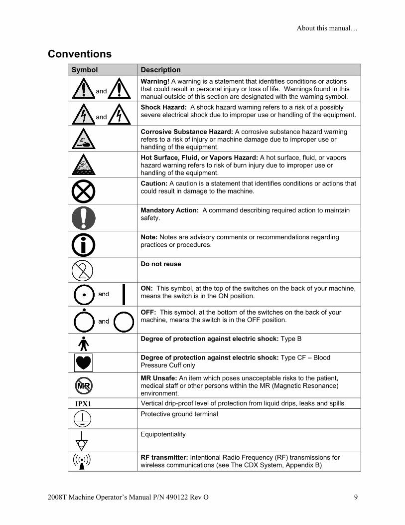
Conventions Symbol Description
and
Warning! A warning is a statement that identifies conditions or actions that could result in personal injury or loss of life. Warnings found in this manual outside of this section are designated with the warning symbol.
and
Shock Hazard: A shock hazard warning refers to a risk of a possibly severe electrical shock due to improper use or handling of the equipment.
Corrosive Substance Hazard: A corrosive substance hazard warning refers to a risk of injury or machine damage due to improper use or handling of the equipment.
Hot Surface, Fluid, or Vapors Hazard: A hot surface, fluid, or vapors hazard warning refers to risk of burn injury due to improper use or handling of the equipment.
Caution: A caution is a statement that identifies conditions or actions that could result in damage to the machine.
Mandatory Action: A command describing required action to maintain safety.
Note: Notes are advisory comments or recommendations regarding practices or procedures.
Do not reuse
ON: This symbol, at the top of the switches on the back of your machine, means the switch is in the ON position.
OFF: This symbol, at the bottom of the switches on the back of your machine, means the switch is in the OFF position.
Degree of protection against electric shock: Type B
Degree of protection against electric shock: Type CF – Blood Pressure Cuff only
MR Unsafe: An item which poses unacceptable risks to the patient, medical staff or other persons within the MR (Magnetic Resonance) environment.
IPX1 Vertical drip-proof level of protection from liquid drips, leaks and spills
Protective ground terminal
Equipotentiality
RF transmitter: Intentional Radio Frequency (RF) transmissions for wireless communications (see The CDX System, Appendix B)
About this manual…
10 2008T Machine Operator’s Manual P/N 490122 Rev O
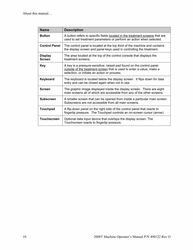
Name Description
Button A button refers to specific fields located in the treatment screens that are used to set treatment parameters or perform an action when selected.
Control Panel The control panel is located at the top third of the machine and contains the display screen and panel keys used in controlling the treatment.
Display Screen
The area located at the top of the control console that displays the treatment screens.
Key A key is a pressure-sensitive, raised pad found on the control panel outside of the treatment screen that is used to enter a value, make a selection, or initiate an action or process.
Keyboard The keyboard is located below the display screen. It flips down for data entry and can be closed again when not in use.
Screen The graphic image displayed inside the display screen. There are eight main screens all of which are accessible from any of the other screens.
Subscreen A smaller screen that can be opened from inside a particular main screen. Subscreens are not accessible from all main screens.
Touchpad A flip-down panel on the right side of the control panel that reacts to fingertip pressure. The Touchpad controls an on-screen cursor (arrow).
Touchscreen Optional data input device that overlays the display screen. The Touchscreen reacts to fingertip pressure.
About Hemodialysis…
2008T Machine Operator’s Manual P/N 490122 Rev O 11
About Hemodialysis…
Indications
Hemodialysis is prescribed by physicians for patients with acute or chronic renal failure, when conservative therapy is judged inadequate. Dialysis therapy may be intermittent or continuous.
Contraindications
There are no absolute contraindications to hemodialysis, but the passing of a patient’s blood through an extracorporeal circuit may require anticoagulation to prevent blood clotting. In addition, the parameters of dialysis should be optimized to avoid discomfort to the patient. Many patients are taking medicinal therapy prescribed by their physicians. Due to the dialysis treatment, some of the medication may be removed from the patient’s blood thereby lowering the therapeutic level in the blood. In other cases, medications may not be excreted as quickly as expected with patients with renal insufficiency and the level may be higher than expected. Therefore, the prescribing physician should determine the appropriate dosage of the medicine to obtain the desired medicinal response in the patient.
Some Side Effects of Hemodialysis
Dialysis therapy occasionally causes hypovolemia, hypervolemia, hypertension, hypotension and related symptoms, headache, nausea, cramping or other muscular discomfort in some patients. Hypothermia, hyperthermia, itching, anxiety, convulsions, seizure, and other neurologic symptoms associated with dialysis dementia may also be manifested by the patient. These symptoms are thought to occur if the patient’s blood volume or electrolyte balance is not maintained within acceptable limits. Other, more serious, complications arising from dialysis, such as hemorrhage, air embolism, or hemolysis, can cause serious patient injury or death. The prescribing physician must understand that prescribing insufficient bicarbonate may contribute to metabolic acidosis; excessive bicarbonate may contribute to metabolic alkalosis. Both conditions are associated with poor patient outcomes, including increased risk of mortality. Proper control of all elements of dialysis may prevent or control these physiological reactions or complications.
Pyrogenic reactions may occur which can result in patient injury. Generally it is thought that these may be controlled by maintaining the dialysate solution within the chemical and bacteriologic limits (see Water Quality on page 265 of the “Machine Specifications” section for more information). Failure to use these standards for water can also lead to accumulated toxic effects. A regular program for disinfection and testing of the water treatment system, piping, inlet lines, filters, concentrate feed containers or system, and the dialysate delivery machine must be established and followed. This program will vary from facility to facility.
Infections or pyrogen reactions may also result from contamination of the extracorporeal circuit or inadequate procedures used to reuse dialyzers.
About Hemodialysis…
12 2008T Machine Operator’s Manual P/N 490122 Rev O
Allergic reactions to chemical disinfectants may occur if insufficient procedures are used to remove or maintain the residual disinfectant at acceptable levels. Chemical disinfectants are used for dialyzer disinfection, machine disinfection, or for disinfection of water treatment and distribution systems.
All blood connections must be made using aseptic technique.
All tubes and connections must be secured and closely monitored to prevent loss of blood or entry of air into the extracorporeal circuit or errors in the ultrafiltration control system. The patient may require blood transfusion or other medical intervention to prevent respiratory or cardiac disorders if these occur.
The patient’s blood pressure and general physical status must be closely monitored during dialysis in order to initiate appropriate remedial measures or therapy. Of particular importance is the control of the patient’s serum potassium level to prevent cardiac dysrhythmia and the patient’s blood clotting time to prevent clotting disorders.
These instructions are for the 2008T hemodialysis machine. The machine must only be operated in accordance with these instructions. All operators of this machine must be thoroughly trained and have read this entire manual and any applicable appendices before using the machine. Improper care/use of this device may result in serious patient injury or death.
Blood Pressure Module Contraindications
The following are generally accepted contraindications for using a timed automatic blood pressure instrument utilizing the oscillometric principle:
Use of a heart lung machine
Peripheral circulation problems
Severe arrhythmia
Ectopic beats
Convulsions
Spasms
Tremors
Tachycardia
Use of incorrectly sized blood pressure cuffs may result in inaccurate blood pressure readings.
This is a guideline only. Final determination of the suitability of any medical instrument for use with any patient is the responsibility of the treating physician.
General Warnings
2008T Machine Operator’s Manual P/N 490122 Rev O 13
General Warnings
This section contains general warnings statements regarding the use and maintenance of the 2008T hemodialysis machine. It is not a complete summary, and additional warning statements specific to pertinent topics can be found within this manual.
Water
Warning! Connect water inlet according to the specifications for the machine. For further information, see Appendix C, “Machine Specifications.” The correct ionic concentration and bacterial quality can generally be achieved in the dialysate only with treated water that meets water quality standards (see Water Quality and Dialysate Quality on page 265 of the “Machine Specifications” section for more information). Be sure that all specifications are satisfied. The water source must be monitored periodically to detect fluctuations in water composition and quality that could have an adverse effect on the patient or dialysate delivery machine. Particular attention must be taken for chemicals such as aluminum, chlorine, and chloramine, as these chemicals can cause complications in dialysis patients.
Warning! Comply with all local regulations in respect of separation of devices in the water supply in case of back siphonage; an air gap must be created between the machine’s drain line and its drain.
Concentrates
Warning! The specific acid and bicarbonate concentrates, including the sodium, bicarbonate, and electrolyte compositions, must be prescribed by a physician.
Warning! Many concentrate types are available for use in dialysate delivery machines. Concentrates contain various amounts of dextrose, potassium, calcium, sodium, chloride, magnesium, and other components. Most concentrates are designed as a two-part system of acid and bicarbonate solutions which are mixed in the machine with water. Even within the subgroup of bicarbonate type concentrates, there are at least four methods of compounding the solutions. Each of these methods requires special calibrations or setups. Certain methods are not supported. It is mandatory that the acid and bicarbonate types be matched to each other. Be sure to use compatible solutions, labeling, and setups. These setups include machine calibration, special adapters for certain concentrate types, correct setting of concentrate option, and labeling. Failure to use the properly matched solutions and machine calibrations may allow improper dialysate to be delivered to the patient, resulting in patient injury or death. Verify composition, conductivity, and pH after converting to a different type of concentrate.
Warning: Acid concentrate, bicarbonate concentrate, and water must be of the appropriate quality to ensure safety and performance of the final dialysate are met (see Water Quality, Dialysate Quality, and Concentrate Quality on page 265 of the “Machine Specifications” section for more information).
Warning: The dissolved bibag bicarbonate concentrate must be used within 24 hours of connecting to the dialysis machine. Do not refill the bibag container.
General Warnings
14 2008T Machine Operator’s Manual P/N 490122 Rev O
Warning! Connection to a central acid or bicarbonate feed system requires the installation of certain mechanical parts. Contact Fresenius USA, Inc. for more information.
Warning! Bicarbonate and acid concentrates intended for other dialysate delivery machines will deliver safe dialysate solution only if the machine is set up for them. The selection of other dialysate concentrate types must be done by a qualified, authorized person. The 2008T hemodialysis machine can be set up for various concentrate types. Use Table 35 in Appendix C to ensure that you have compatible concentrates and configurations.
Warning! Acid concentrate products are used as one component in mixing dialysate bath. These acid products contain chemical compounds that, after mixing, yield acetate (and citrate in certain products) in the dialysate. (Please refer to the acid concentrate product labeling for specific acetate/citrate amounts.) After diffusion across the dialyzer membrane, acetate (and citrate when present) is metabolized by the liver to serum bicarbonate and adds to the serum bicarbonate that separately results from the diffusion of dialysate bicarbonate across the dialyzer membrane. During dialysis, the dynamic of diffusion and concentration gradients prevent serum bicarbonate concentration from exceeding the dialysate bicarbonate concentration. The bicarbonate concentration of the dialysate is the “bicarbonate” setting on the dialysis machine, and is the bicarbonate dose prescribed by the physician. On the 2008 series hemodialysis machines, the bicarbonate dose may be set in a range between 20 and 40 milliequivalents per liter, but may be set in different ranges in other machines.
When the dialysis session terminates, acetate (and citrate when present) that has not yet metabolized may remain in the blood and will be converted to serum bicarbonate after diffusion ceases, without possibility of diffusion out of the blood. The post dialysis metabolism of acetate (and citrate when present) could thus briefly increase serum bicarbonate concentration above the prescribed bicarbonate concentration of the dialysate. Physicians should consider this possibility in prescribing bicarbonate dose.
Prescription of insufficient bicarbonate may contribute to metabolic acidosis; excessive bicarbonate may contribute to metabolic alkalosis. Both conditions are associated with poor patient outcomes, including increased mortality risk.
Warning! Incorrect composition will result if the acid concentrate nozzle is not connected to the appropriate acid concentrate or the bicarbonate concentrate nozzle is not connected to the appropriate bicarbonate solution. The acid and bicarbonate concentrates must match those selected in the “Dialysate” screen. Patient injury or death may occur if incorrect dialysate solution is used. Fresenius USA, Inc. recommends the operator use the concentrate containers provided with the machine. These containers, being of different size and shape, help to reduce the chances of mismatching the acid and bicarbonate concentrates.
Warning! Test the conductivity and approximate pH of the dialysate with an independent device before beginning treatment. Test it also when changing concentrates during treatment and when switching from the bibag system to liquid bicarbonate*. The wrong conductivity or pH may cause serious injury or death.
*Note: If alternative liquid bicarbonate concentrate sources are used (jugs or central delivery) the end user must ensure the bicarbonate is of appropriate quality and is prepared per manufacturer’s instructions.
Warning! Use of an acid concentrate intended for a 1:44 mix ratio in any 1:34 proportioning dialysate delivery machine may result in a dialysate solution with a normal conductivity but without a physiological buffer. There may be no alarms in this event. Use of this improper dialysate solution may cause patient injury or death.
General Warnings
2008T Machine Operator’s Manual P/N 490122 Rev O 15
Warning! The machine must be labeled to indicate the type of concentrate for which it is configured. Check the composition (i.e., Na, Cl, K, Ca, Mg, HCO3) and pH of the dialysate solution after the machine is installed or after the machine is modified for different concentrate types. Check the conductivity and approximate pH of the dialysate solution with an independent device before initiating dialysis. Improper conductivity or pH could result in patient injury or death.
Machine
Warning! Failure to install, operate, and maintain this equipment according to the manufacturer’s instructions may cause patient injury or death.
Warning! Proper functioning of the machine must be verified prior to initiating treatment. Unidentified malfunctions or alarm failure could potentially expose a patient to a serious health risk. Alarm limits for the arterial pressure monitor, venous pressure monitor, and transmembrane pressure (TMP) monitor are automatically set and delayed for pressure stabilization. Alarm limits for temperature and conductivity are calculated for the dialysate composition and may be somewhat adjusted by the operator. These must be maintained within safe physiological limits as specified by the prescribing physician.
Warning! Never perform maintenance when a patient is connected to the machine. If possible, remove the machine from the treatment area when it is being serviced. Label the machine to ensure it is not accidentally returned to clinical use before the service work is completed. Disinfect the machine and test the dialysate for acceptable conductivity and pH values before returning the machine to clinical use. Always test the machine when maintenance is completed.
Warning! The electrical source must be single phase, three-conductor type provided with a hospital grade receptacle and a ground fault interrupter at 120 volts, 60 Hz. The proper polarity and ground integrity must be initially checked and maintained. Failure to do so may result in electrical shock or burn to the operator or patient. The machine must be plugged directly into the electrical outlet; extension cords and power strips are prohibited.
Warning! Shock hazard. Do not remove covers. Refer servicing to qualified personnel. Replace fuses only with the same type and rating.
Warning! Do not install the 9-Volt battery backwards in the machine, as it will damage the “No Power” alarm.
Warning! Do not use devices emitting strong electromagnetic radiation such as portable phones, radio equipment (walkie-talkies, etc.), radio transmitters, and like equipment near your machine. Improper operation may result.
Cellular phones and WiFi connected devices may be conditionally allowed. However, if any interference is noted, such as false pressure readings that disappear when the external signal is removed, it is recommended to move the cellular phone at least ten feet away from the 2008T hemodialysis machine when making or receiving phone calls. If a WiFi-connected device (e.g. laptop computers, tablet devices, smartphones) is found to cause interference, it is recommended to use that device at least four feet away from the 2008T hemodialysis machine.
For exact separation distance recommendation, please refer to the Manufacturer’s EMC Declaration statement on page 271.
General Warnings
16 2008T Machine Operator’s Manual P/N 490122 Rev O
Warning! Transducer protectors should be used between pressure ports and each pressure monitor line of the extracorporeal system to prevent the internal transducer protectors from getting wet. Wet transducer protectors must be replaced, as they will cause inaccurate pressure readings. If the external transducer protector and the internal transducer protector become contaminated with blood, the transducer protectors must be replaced and the transducer and associated parts must be disinfected or replaced.
Warning! A new, sterile transducer protector should be placed on all the air connections from the drip chambers to the machine pressure monitor ports. This will prevent contamination of the machine and filters air that enters the chambers through the monitor lines. If the transducer protector should get wet and air is not able to pass, replace the transducer protector and clear the monitor line.
Warning! The machine is compatible with a number of venous lines. The Level Detector module must be calibrated for the model venous line being used. In addition, verify that the venous line clamp is capable of fully occluding the model of bloodline that your facility uses.
Warning! To avoid damaging the equipment or personal injury, internal adjustments to the blood pressure module should only be made by a qualified technician.
Warning! Possible Explosion Hazard if used in the presence of flammable anesthetics.
Warning! Check all bloodlines for leaks after the treatment has started. Keep access sites uncovered and monitored. Improper bloodline connections or needle dislodgements can result in excessive blood loss, serious injury, and death. Machine alarms may not occur in every blood loss situation.
Warning! The dialysate path is a closed fluidics system. Discontinue use immediately if a fluid leak is detected. Do not attempt to administer or continue dialysis treatment with a machine which has a fluid leak, this could result in excessive fluid removal from the patient leading to serious injury or death. System leaks may also pose a slip-and-fall hazard. Clean up spills immediately.
Warning! Replace a leaking bibag disposable immediately. Spills can cause damage to carpeting and other surfaces. To contain such spills, the machine should be on a spill-tolerant surface. Spills can cause slips and falls; clean up spills immediately.
Warning! When using the bibag system, the acid and bicarbonate pressures must not exceed 10 psi when using a Central Delivery System. It may be necessary to use pressure regulators in order to reach proper conductivity. When not using the bibag system, the maximum supplied pressure is 2 psi.
Warning! High dose hydroxocobalamin (or any form of Vitamin B-12) causes discoloration of the spent dialysate. This discoloration may cause a false blood leak alarm, stopping the blood pump and preventing treatment unless the operator performs an override of the alarm. The blood leak alarm can be reset and overridden for up to three minutes repeatedly by following the blood leak alarm troubleshooting instructions in the operator’s manual in cases where a blood leak test is negative for blood in the dialysate. Discontinuation of the hemodialysis treatment could result in persistence or worsening of acidosis, hyperkalemia, and volume overload which can lead to serious injury or death.
General Warnings
2008T Machine Operator’s Manual P/N 490122 Rev O 17
Caution: Only the bags manufactured by Fresenius Medical Care may be used in the bibag connector.
Caution: System leaks may occur. Unattended operation of the machine (for example, during disinfection at night) may result in flooding and can cause property damage. Clean up spills immediately.
Caution: Be careful not to tip the machine when rolling over uneven surfaces. Push the machine from the middle when moving it.
Caution: Do not squeeze the blood pressure cuff when deflating it. Squeezing the blood pressure cuff may damage the machine's internal blood pressure module.
Note: The Diasafe Plus filter is required when the bibag system is in use.
Note: A smoke detector should be properly installed in the room used for dialysis. Follow the manufacturer’s instructions. The alarm should be tested according to the manufacturer’s instructions. Replace the battery as specified.
Note: You must follow all environmental regulations regarding waste disposal and eventual machine disposal. Contact your clinic for more information. Prior to the disposal of your machine, any possible risk of infection from blood borne pathogens must also be eliminated by appropriate disinfection.
Note: The temperature of the bloodline and the durometer of the tubing affect the ability of the bloodline/blood pump system to prime during setup. Cold tubing may not prime as readily as warm tubing.
Fresenius Medical Care manufactures bloodlines for use with the model 2008T hemodialysis machine. The performance of bloodlines not manufactured by Fresenius Medical Care cannot be guaranteed by Fresenius Medical Care and are therefore the responsibility of the prescribing physician.
Note: The following materials come into contact with purified water, dialysate, or dialysate concentrate: Dyflor (PVDF) Ethylene-propylene terpolymer (EPDM) Foraflon (PVDF) Glass Lupolen (PE) Makrolon (PC) Noryl (PPE & PS) Polyethersulfone (PES) Polyphenylene oxide (PPO) Polyphenylene oxide 20% glass fiber (PPO-GF20) Polyphenylsulfone (PPSU)
Polypropylene (PP) Polypropylene 20% glass fiber (PP-GF20) Radel 10 & 20% glass fiber (PES) Stainless steel (types 300 & 316) Silicone (Si) Teflon (PTFE) Thermocomp (PES) Titanium – TiAl 4 V6 Ultem (PEI) Ultradur+ (PBT) Victrex (PEEK) Vinyl chloride polymer (PVC)
General Warnings
18 2008T Machine Operator’s Manual P/N 490122 Rev O
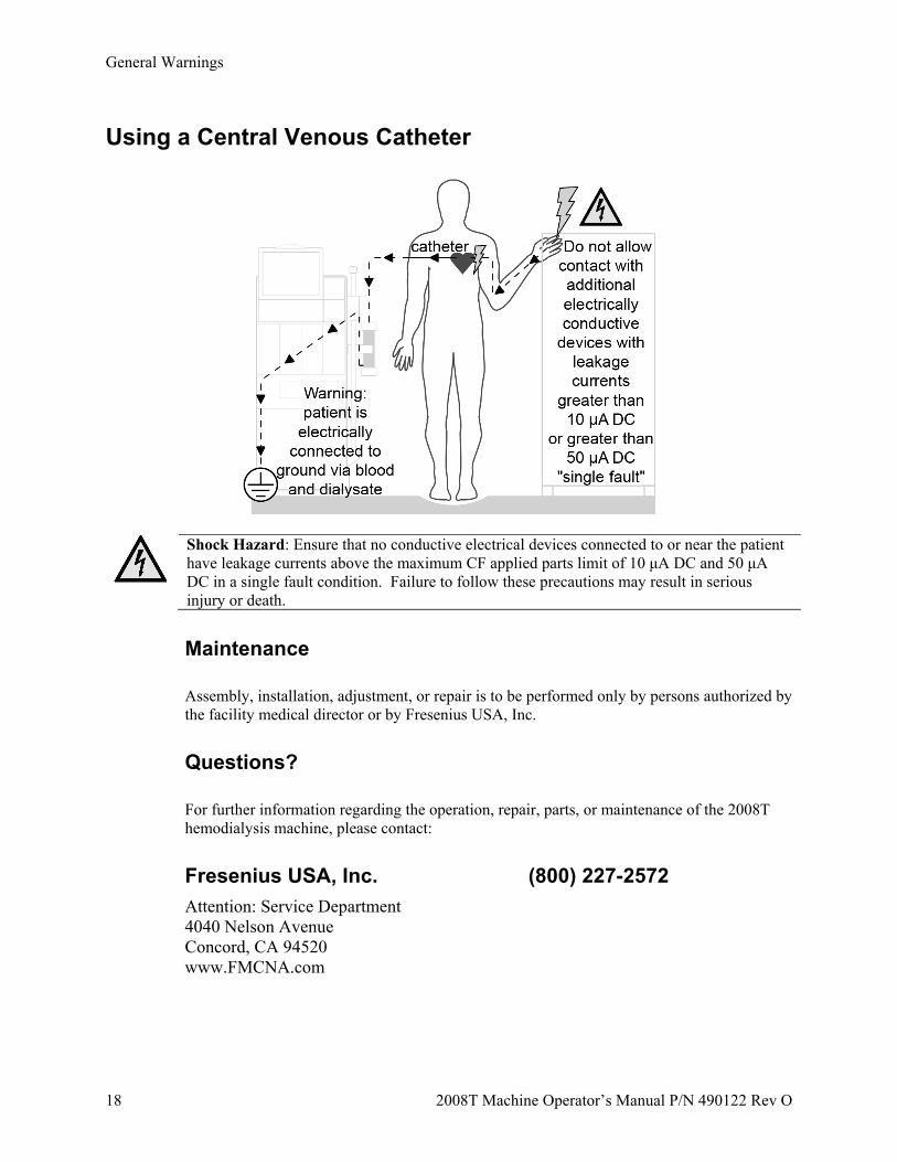
Using a Central Venous Catheter
Shock Hazard: Ensure that no conductive electrical devices connected to or near the patient have leakage currents above the maximum CF applied parts limit of 10 μA DC and 50 μA DC in a single fault condition. Failure to follow these precautions may result in serious injury or death.
Maintenance
Assembly, installation, adjustment, or repair is to be performed only by persons authorized by the facility medical director or by Fresenius USA, Inc.
Questions?
For further information regarding the operation, repair, parts, or maintenance of the 2008T hemodialysis machine, please contact:
Fresenius USA, Inc. (800) 227-2572
Attention: Service Department 4040 Nelson Avenue Concord, CA 94520 www.FMCNA.com
OV
ER
VIE
W
2008T Machine Operator’s Manual P/N 490122 Rev O 19
Chapter 1
Overview
The 2008T hemodialysis machine is designed to perform hemodialysis in hospitals and dialysis clinics. It can be used for patients suffering chronic or acute renal failure.
Function of the 2008T Hemodialysis Machine
The 2008T hemodialysis machine is designed to provide hemodialysis treatment by controlling and monitoring both the dialysate and extracorporeal blood circuits.
In the extracorporeal blood circuit, the blood is continuously circulated from the patient through a dialyzer, where toxins are filtered out through a semi-permeable membrane, before being returned to the patient. During this process, the extracorporeal blood circuit is monitored for venous and arterial blood pressures, and for the presence of air and blood. The 2008T hemodialysis machine can also administer heparin evenly throughout the treatment.
In the dialysate circuit, the dialysate concentrates are mixed with purified water, heated, degassed, and delivered to the dialyzer. Balancing chambers ensure that the incoming flow of the dialysate is volumetrically equal to the outgoing flow in order to control ultrafiltration from the patient.
Organization of the 2008T Hemodialysis Machine
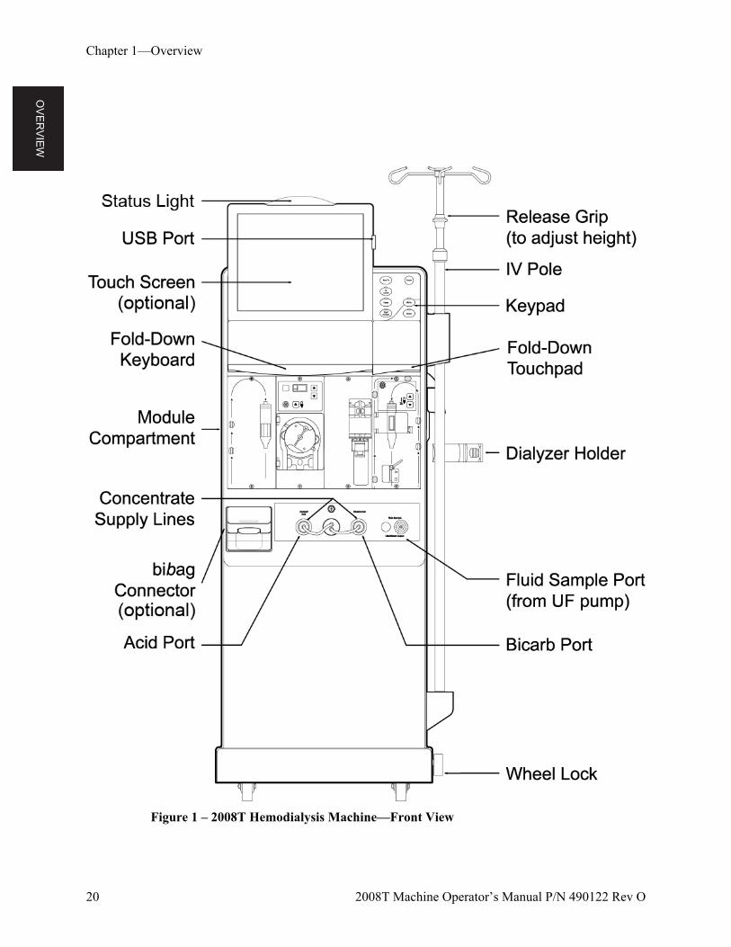
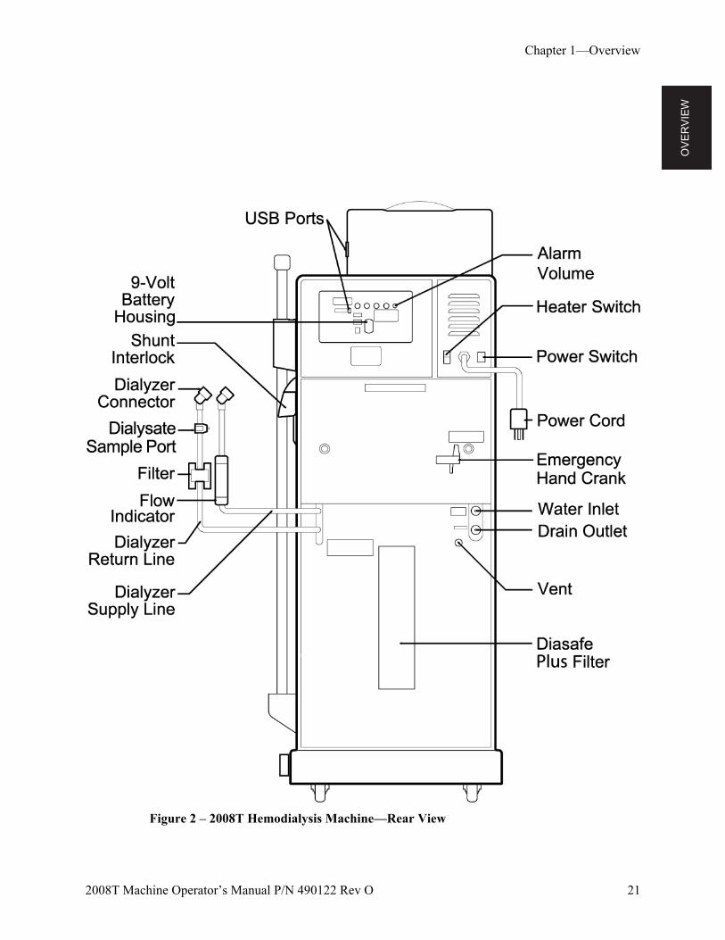
The 2008T hemodialysis machine is designed for functional efficiency. The back of the machine houses the utility connections such as water source, drain, and electrical connections. By mounting them to the back, the water lines and power cord remain out of the way during treatment.
The front of the machine contains all of the controls the operator needs access to during hemodialysis. It can be broken down into three main sections. The top section contains the control panel and houses the computer that runs the treatment program. The middle section contains the modules used for the safe transmission of the blood to and from the dialyzer. Dialysate is the primary concern of the bottom section of the 2008T hemodialysis machine. Here the concentrates used to make up the dialysate are mixed and pumped to the dialyzer.
The following pages contain front and rear views of the 2008T hemodialysis machine and a brief description of the machine’s features. You should familiarize yourself with the location and purpose of these features.
OV
ER
VIE
W
Chapter 1—Overview
20 2008T Machine Operator’s Manual P/N 490122 Rev O
Figure 1 – 2008T Hemodialysis Machine—Front View
OV
ER
VIE
W
Chapter 1—Overview
2008T Machine Operator’s Manual P/N 490122 Rev O 21
Figure 2 – 2008T Hemodialysis Machine—Rear View
OV
ER
VIE
W
Chapter 1—Overview
22 2008T Machine Operator’s Manual P/N 490122 Rev O
The Control Panel
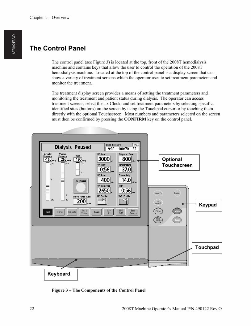
The control panel (see Figure 3) is located at the top, front of the 2008T hemodialysis machine and contains keys that allow the user to control the operation of the 2008T hemodialysis machine. Located at the top of the control panel is a display screen that can show a variety of treatment screens which the operator uses to set treatment parameters and monitor the treatment.
The treatment display screen provides a means of setting the treatment parameters and monitoring the treatment and patient status during dialysis. The operator can access treatment screens, select the Tx Clock, and set treatment parameters by selecting specific, identified sites (buttons) on the screen by using the Touchpad cursor or by touching them directly with the optional Touchscreen. Most numbers and parameters selected on the screen must then be confirmed by pressing the CONFIRM key on the control panel.
Figure 3 – The Components of the Control Panel
Keypad
Keyboard
Optional Touchscreen
Touchpad
OV
ER
VIE
W
Chapter 1—Overview
2008T Machine Operator’s Manual P/N 490122 Rev O 23
Control Panel Keypad
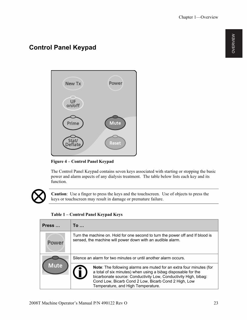
Figure 4 – Control Panel Keypad
The Control Panel Keypad contains seven keys associated with starting or stopping the basic power and alarm aspects of any dialysis treatment. The table below lists each key and its function.
Caution: Use a finger to press the keys and the touchscreen. Use of objects to press the keys or touchscreen may result in damage or premature failure.
Table 1 – Control Panel Keypad Keys
Press … To …
Turn the machine on. Hold for one second to turn the power off and If blood is sensed, the machine will power down with an audible alarm.
Silence an alarm for two minutes or until another alarm occurs.
Note: The following alarms are muted for an extra four minutes (for a total of six minutes) when using a bibag disposable for the bicarbonate source: Conductivity Low, Conductivity High, bibag: Cond Low, Bicarb Cond 2 Low, Bicarb Cond 2 High, Low Temperature, and High Temperature.
OV
ER
VIE
W
Chapter 1—Overview
24 2008T Machine Operator’s Manual P/N 490122 Rev O
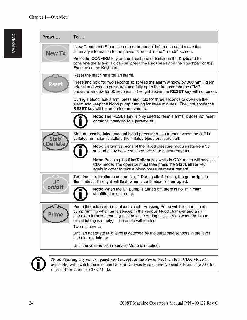
Press … To …
(New Treatment) Erase the current treatment information and move the summary information to the previous record in the “Trends” screen.
Press the CONFIRM key on the Touchpad or Enter on the Keyboard to complete the action. To cancel, press the Escape key on the Touchpad or the Esc key on the Keyboard.
Reset the machine after an alarm.
Press and hold for two seconds to spread the alarm window by 300 mm Hg for arterial and venous pressures and fully open the transmembrane (TMP) pressure window for 30 seconds. The light above the RESET key will not be on.
During a blood leak alarm, press and hold for three seconds to override the alarm and keep the blood pump running for three minutes. The light above the RESET key will be on during an override.
Note: The RESET key is only used to reset alarms; it does not reset or cancel changes to a parameter.
Start an unscheduled, manual blood pressure measurement when the cuff is deflated, or instantly deflate the inflated blood pressure cuff.
Note: Certain versions of the blood pressure module require a 30 second delay between blood pressure measurements.
Note: Pressing the Stat/Deflate key while in CDX mode will only exit CDX mode. The operator must then press the Stat/Deflate key again in order to take a blood pressure measurement.
Turn the ultrafiltration pump on or off. During ultrafiltration, the green light is illuminated. This light will flash when ultrafiltration is interrupted.
Note: When the UF pump is turned off, there is no “minimum” ultrafiltration occurring.
Prime the extracorporeal blood circuit. Pressing Prime will keep the blood pump running when air is sensed in the venous blood chamber and an air detector alarm is present (as is the case during initial set up when the blood circuit tubing is empty). The pump will run for:
Two minutes, or
Until an adequate fluid level is detected by the ultrasonic sensors in the level detector module, or
Until the volume set in Service Mode is reached.
Note: Pressing any control panel key (except for the Power key) while in CDX Mode (if available) will switch the machine back to Dialysis Mode. See Appendix B on page 233 for more information on CDX Mode.
OV
ER
VIE
W
Chapter 1—Overview
2008T Machine Operator’s Manual P/N 490122 Rev O 25
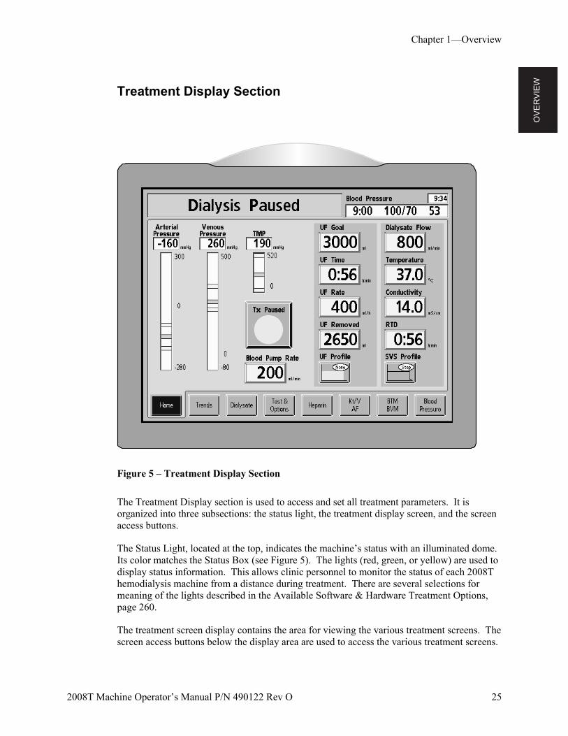
Treatment Display Section
Figure 5 – Treatment Display Section
The Treatment Display section is used to access and set all treatment parameters. It is organized into three subsections: the status light, the treatment display screen, and the screen access buttons.
The Status Light, located at the top, indicates the machine’s status with an illuminated dome. Its color matches the Status Box (see Figure 5). The lights (red, green, or yellow) are used to display status information. This allows clinic personnel to monitor the status of each 2008T hemodialysis machine from a distance during treatment. There are several selections for meaning of the lights described in the Available Software & Hardware Treatment Options, page 260.
The treatment screen display contains the area for viewing the various treatment screens. The screen access buttons below the display area are used to access the various treatment screens.
OV
ER
VIE
W
Chapter 1—Overview
26 2008T Machine Operator’s Manual P/N 490122 Rev O
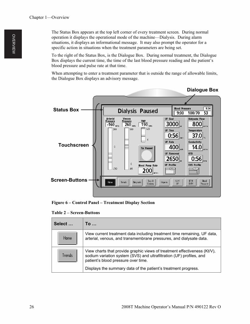
The Status Box appears at the top left corner of every treatment screen. During normal operation it displays the operational mode of the machine—Dialysis. During alarm situations, it displays an informational message. It may also prompt the operator for a specific action in situations when the treatment parameters are being set.
To the right of the Status Box, is the Dialogue Box. During normal treatment, the Dialogue Box displays the current time, the time of the last blood pressure reading and the patient’s blood pressure and pulse rate at that time.
When attempting to enter a treatment parameter that is outside the range of allowable limits, the Dialogue Box displays an advisory message.
Figure 6 – Control Panel – Treatment Display Section
Table 2 – Screen-Buttons
Select … To …
View current treatment data including treatment time remaining, UF data, arterial, venous, and transmembrane pressures, and dialysate data.
View charts that provide graphic views of treatment effectiveness (Kt/V), sodium variation system (SVS) and ultrafiltration (UF) profiles, and patient’s blood pressure over time.
Displays the summary data of the patient’s treatment progress.
Status Box
Screen-Buttons
Touchscreen
Dialogue Box
OV
ER
VIE
W
Chapter 1—Overview
2008T Machine Operator’s Manual P/N 490122 Rev O 27
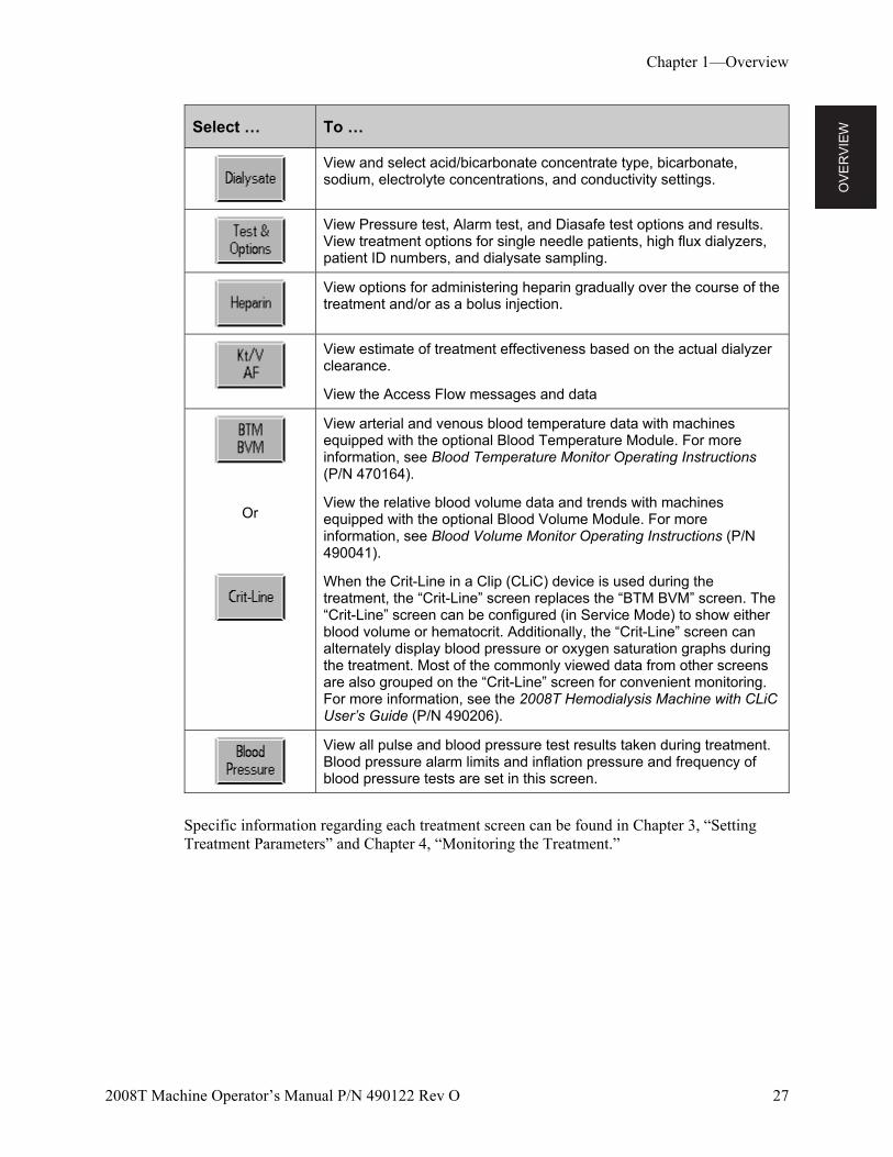
Select … To …
View and select acid/bicarbonate concentrate type, bicarbonate, sodium, electrolyte concentrations, and conductivity settings.
View Pressure test, Alarm test, and Diasafe test options and results. View treatment options for single needle patients, high flux dialyzers, patient ID numbers, and dialysate sampling.
View options for administering heparin gradually over the course of the treatment and/or as a bolus injection.
View estimate of treatment effectiveness based on the actual dialyzer clearance.
View the Access Flow messages and data
Or
View arterial and venous blood temperature data with machines equipped with the optional Blood Temperature Module. For more information, see Blood Temperature Monitor Operating Instructions (P/N 470164).
View the relative blood volume data and trends with machines equipped with the optional Blood Volume Module. For more information, see Blood Volume Monitor Operating Instructions (P/N 490041).
When the Crit-Line in a Clip (CLiC) device is used during the treatment, the “Crit-Line” screen replaces the “BTM BVM” screen. The “Crit-Line” screen can be configured (in Service Mode) to show either blood volume or hematocrit. Additionally, the “Crit-Line” screen can alternately display blood pressure or oxygen saturation graphs during the treatment. Most of the commonly viewed data from other screens are also grouped on the “Crit-Line” screen for convenient monitoring. For more information, see the 2008T Hemodialysis Machine with CLiC User’s Guide (P/N 490206).
View all pulse and blood pressure test results taken during treatment. Blood pressure alarm limits and inflation pressure and frequency of blood pressure tests are set in this screen.
Specific information regarding each treatment screen can be found in Chapter 3, “Setting Treatment Parameters” and Chapter 4, “Monitoring the Treatment.”
OV
ER
VIE
W
Chapter 1—Overview
28 2008T Machine Operator’s Manual P/N 490122 Rev O
Fold-Down Keyboard
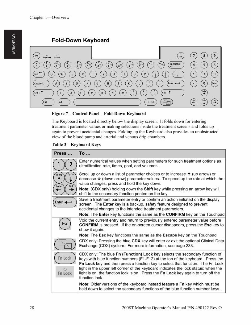
Figure 7 – Control Panel – Fold-Down Keyboard
The Keyboard is located directly below the display screen. It folds down for entering treatment parameter values or making selections inside the treatment screens and folds up again to prevent accidental changes. Folding up the Keyboard also provides an unobstructed view of the blood pump and arterial and venous drip chambers.
Table 3 – Keyboard Keys
Press … To …
Enter numerical values when setting parameters for such treatment options as ultrafiltration rate, times, goal, and volumes.
Scroll up or down a list of parameter choices or to increase (up arrow) or decrease (down arrow) parameter values. To speed up the rate at which the value changes, press and hold the key down. Note: (CDX only) holding down the Shift key while pressing an arrow key will shift to the secondary function printed on the key.
Save a treatment parameter entry or confirm an action initiated on the display screen. The Enter key is a backup, safety feature designed to prevent accidental changes to the intended treatment parameters. Note: The Enter key functions the same as the CONFIRM key on the Touchpad
Void the current entry and return to previously entered parameter value before CONFIRM is pressed. If the on-screen cursor disappears, press the Esc key to show it again. Note: The Esc key functions the same as the Escape key on the Touchpad.
CDX only: Pressing the blue CDX key will enter or exit the optional Clinical Data Exchange (CDX) system. For more information, see page 233.
CDX only: The blue Fn (Function) Lock key selects the secondary function of keys with blue function numbers (F1-F12) at the top of the keyboard. Press the Fn Lock key and then press a function key to select that function. The Fn Lock light in the upper left corner of the keyboard indicates the lock status: when the light is on, the function lock is on. Press the Fn Lock key again to turn off the function lock.
Note: Older versions of the keyboard instead feature a Fn key which must be held down to select the secondary functions of the blue function number keys.
OV
ER
VIE
W
Chapter 1—Overview
2008T Machine Operator’s Manual P/N 490122 Rev O 29
Fold-Down Touchpad
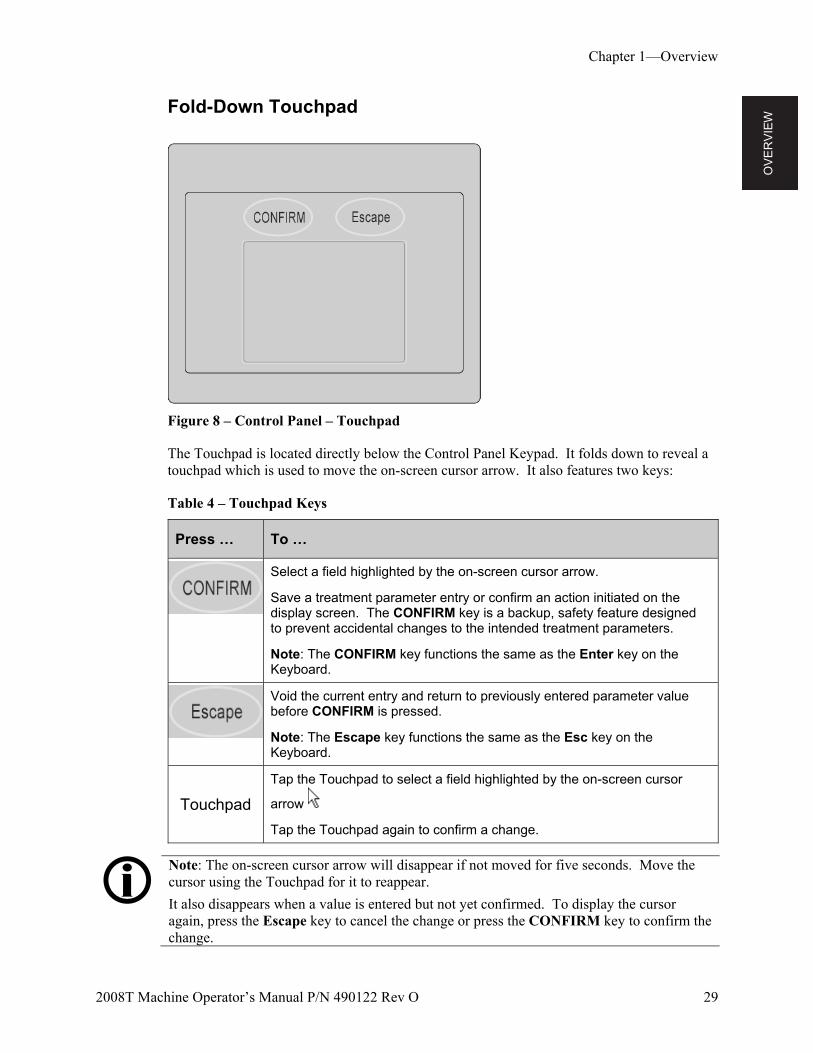
Figure 8 – Control Panel – Touchpad
The Touchpad is located directly below the Control Panel Keypad. It folds down to reveal a touchpad which is used to move the on-screen cursor arrow. It also features two keys:
Table 4 – Touchpad Keys
Press … To …
Select a field highlighted by the on-screen cursor arrow.
Save a treatment parameter entry or confirm an action initiated on the display screen. The CONFIRM key is a backup, safety feature designed to prevent accidental changes to the intended treatment parameters.
Note: The CONFIRM key functions the same as the Enter key on the Keyboard.
Void the current entry and return to previously entered parameter value before CONFIRM is pressed.
Note: The Escape key functions the same as the Esc key on the Keyboard.
Touchpad
Tap the Touchpad to select a field highlighted by the on-screen cursor
arrow
Tap the Touchpad again to confirm a change.
Note: The on-screen cursor arrow will disappear if not moved for five seconds. Move the cursor using the Touchpad for it to reappear.
It also disappears when a value is entered but not yet confirmed. To display the cursor again, press the Escape key to cancel the change or press the CONFIRM key to confirm the change.
OV
ER
VIE
W
Chapter 1—Overview
30 2008T Machine Operator’s Manual P/N 490122 Rev O
The Back Panel
Figure 9 – Back Panel
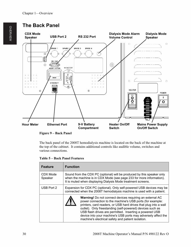
The back panel of the 2008T hemodialysis machine is located on the back of the machine at the top of the cabinet. It contains additional controls like audible volume, switches and various connections.
Table 5 – Back Panel Features
Feature Function
CDX Mode Speaker
Sound from the CDX PC (optional) will be produced by this speaker only when the machine is in CDX Mode (see page 233 for more information). It is muted when displaying Dialysis Mode treatment screens.
USB Port 2 Expansion for CDX PC (optional). Only self-powered USB devices may be connected when the 2008T hemodialysis machine is used with a patient.
Warning! Do not connect devices requiring an external AC power connection to the machine's USB ports (for example: printers, card readers, or USB hard drives that plug into a wall outlet). Only freestanding (self-powered) devices such as USB flash drives are permitted. Inserting a powered USB device into your machine's USB ports may adversely affect the machine's electrical safety and patient isolation.
Heater On/Off Switch
Mains Power Supply On/Off Switch
Hour Meter Ethernet Port
USB Port 2 RS 232 Port Dialysis Mode Alarm Volume Control
9-V Battery Compartment
Dialysis Mode Speaker
CDX Mode Speaker

OV
ER
VIE
W
Chapter 1—Overview
2008T Machine Operator’s Manual P/N 490122 Rev O 31
Feature Function
RS 232 Port Electrically isolated RS 232 serial interface connector; hard wired, used for display terminal connection.
Volume Control (Dialysis Mode Only)
Used to adjust the volume (sound pressure level) of the dialysis machine audible warnings and alarms. Warning sound is adjustable between 75 dBA and 89 dBA (at 1 meter). Alarm sound is adjustable between 67 dBA and 81 dBA (at 1 meter). Does not affect the volume from the separate CDX speaker.
Dialysis Mode Speaker
The Dialysis Mode speaker makes two different sounds: a warning sound, and an alarm sound. The two sounds are distinct; the first one is used for lower priority alarms, and the second for more important alarms.
Hour Meter This displays the number of hours the machine has run over its lifetime. See the “2008T Preventive Maintenance Procedures Manual” (P/N 508033) for information on scheduled maintenance.
Ethernet Port 10/100 Ethernet connection for the CDX PC (optional); electrically isolated.
9-V Battery (Power Failure Alarm )
9-V heavy duty alkaline battery for main power failure. A steady, audible alarm will immediately sound for seven minutes that cannot be silenced with the Mute key. It can be silenced manually, however, by removing this 9-volt battery. See Replacing the 9-Volt Battery” on page 218 for more information.
Heater On/Off Switch
This switch turns the power to the dialysate heater on or off. This switch must be in the ON position during treatment.
Mains Power Supply On/Off Switch
This switch turns the power to the whole machine on or off. This switch must be in the ON position (|) to operate the machine.
Note: Periodically check the power cord for damage (fraying, over-heating, cuts, scrapes, etc.)
OV
ER
VIE
W
Chapter 1—Overview
32 2008T Machine Operator’s Manual P/N 490122 Rev O
Modules
The modules accompanying the 2008T hemodialysis machine are located just below the control panel. The Arterial Drip Chamber, Blood Pump, Heparin Pump, and Level Detector modules contribute to the task of transmitting the blood from the patient, through the dialyzer and back to the patient. The red lines on the modules are guides for the arterial bloodline (from patient to the dialyzer). The blue lines are guides for the venous bloodline (from dialyzer to patient).
Any machine can be set up for a pre-pump or post-pump arterial chamber, or single-needle dialysis (requiring two blood pumps) by adding modules, or rearranging their order.
The preferred arrangements, shown in Figure 22 and Figure 23 on page 49, can help to simplify the routing of the blood tubing and minimize the possibility of kinking the bloodline.
Additionally, the internal blood pressure module is explained on page 37 and the shunt interlock is explained on page 34.
The Arterial Drip Chamber Module
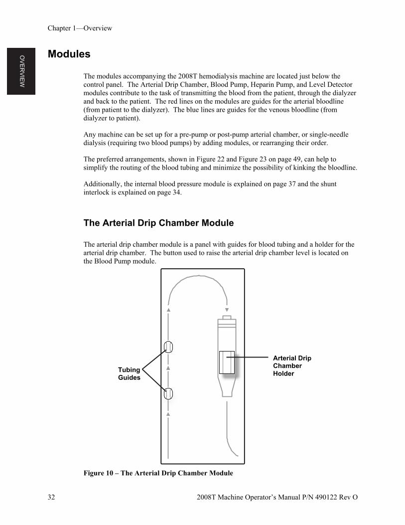
The arterial drip chamber module is a panel with guides for blood tubing and a holder for the arterial drip chamber. The button used to raise the arterial drip chamber level is located on the Blood Pump module.
Figure 10 – The Arterial Drip Chamber Module
Arterial Drip Chamber Holder Tubing
Guides
OV
ER
VIE
W
Chapter 1—Overview
2008T Machine Operator’s Manual P/N 490122 Rev O 33
The Blood Pump Module
The blood pump draws blood from the patient and pumps it to the dialyzer and back to the patient in a closed circuit. To accomplish this, the pump segment of the blood tubing is threaded through the pump housing along a circular track. As the pump rotor rotates, twin rollers squeeze the pump segment, pulling and pushing the blood through the blood pump segment. The speed of the pump can be adjusted using the arrow keys on the blood pump or the Blood Pump Rate button on the “Home” screen (see page 75 for more information). The blood pump can be stopped by pressing the Start/Stop key or by opening the blood pump door. When the door is open, the diameter of the pump segment is shown in the display window.
Pressing the single key on the Blood Pump Module activates a small pump that raises the fluid level in the arterial chamber. This key (level adjust) can be used only to raise the level of blood in the chamber, and cannot be used to lower it. This is to avoid introducing air into the blood flow.
Warning! The key (level adjust) on the Blood Pump module can only be used to raise the level in the arterial chamber. Do not press the level adjust key so long that the pressure transducer protector becomes wet. Wet transducer protectors must be replaced to avoid erroneous pressure readings.
Note: A separate hand crank is supplied with the pump at the back of the machine that can be used to return the blood to the patient in case of a power failure.
Note: The 2008T hemodialysis machine’s modules and internal hydraulics involve fluids: accidental spills can occur. Spills may cause slips and falls and can cause damage to carpeting and other surfaces. To contain such spills, the machine should be on a spill-tolerant surface. Clean up spills immediately.
OV
ER
VIE
W
Chapter 1—Overview
34 2008T Machine Operator’s Manual P/N 490122 Rev O
Figure 11 – The Blood Pump Module
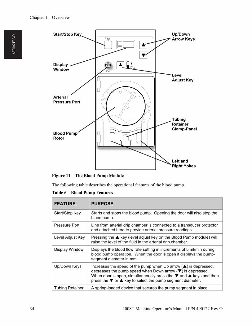
The following table describes the operational features of the blood pump.
Table 6 – Blood Pump Features
FEATURE PURPOSE
Start/Stop Key Starts and stops the blood pump. Opening the door will also stop the blood pump.
Pressure Port Line from arterial drip chamber is connected to a transducer protector and attached here to provide arterial pressure readings.
Level Adjust Key Pressing the key (level adjust key on the Blood Pump module) will raise the level of the fluid in the arterial drip chamber.
Display Window Displays the blood flow rate setting in increments of 5 ml/min during blood pump operation. When the door is open it displays the pump-segment diameter in mm.
Up/Down Keys Increases the speed of the pump when Up arrow () is depressed, decreases the pump speed when Down arrow () is depressed. When door is open, simultaneously press the and keys and then press the or key to select the pump segment diameter.
Tubing Retainer A spring-loaded device that secures the pump segment in place.
Display Window
Blood Pump Rotor
Start/Stop Key
Arterial Pressure Port
Level Adjust Key
Up/Down Arrow Keys
Tubing Retainer Clamp-Panel
Left and Right Yokes
OV
ER
VIE
W
Chapter 1—Overview
2008T Machine Operator’s Manual P/N 490122 Rev O 35
The Heparin Pump Module
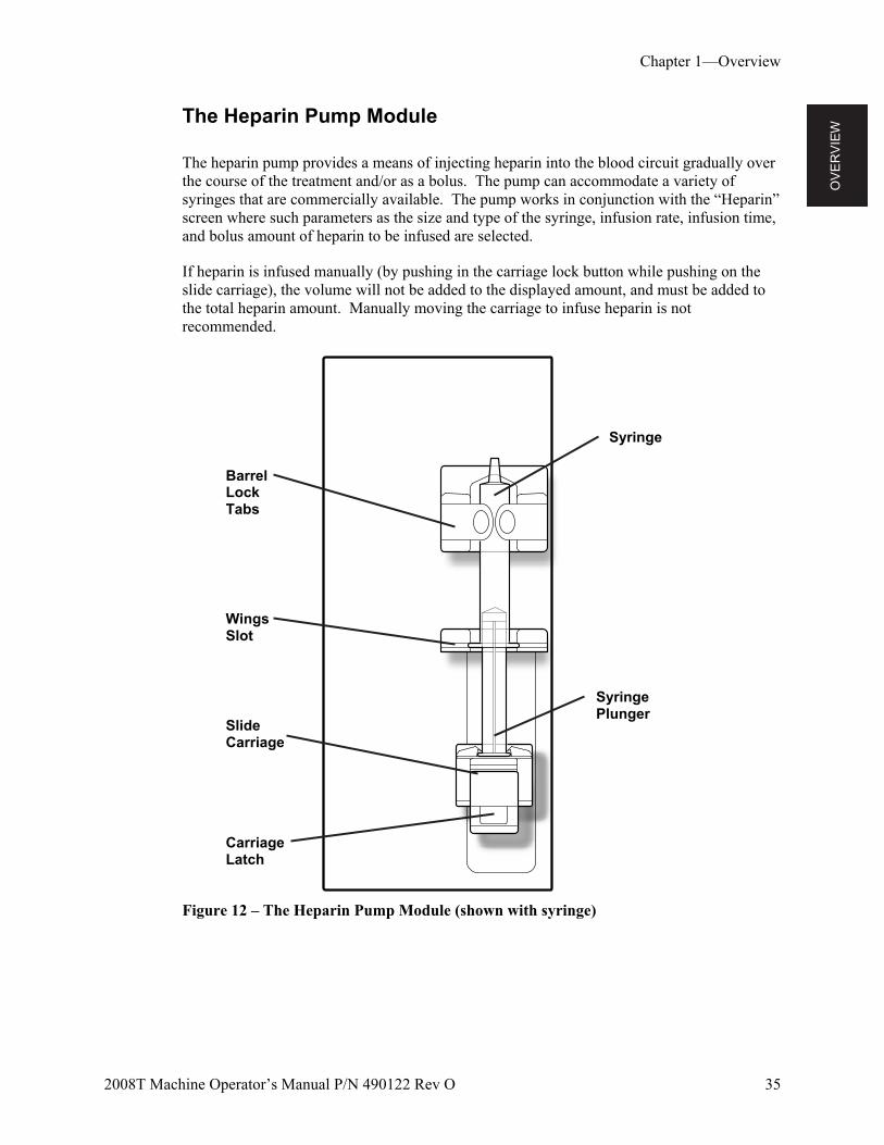
The heparin pump provides a means of injecting heparin into the blood circuit gradually over the course of the treatment and/or as a bolus. The pump can accommodate a variety of syringes that are commercially available. The pump works in conjunction with the “Heparin” screen where such parameters as the size and type of the syringe, infusion rate, infusion time, and bolus amount of heparin to be infused are selected.
If heparin is infused manually (by pushing in the carriage lock button while pushing on the slide carriage), the volume will not be added to the displayed amount, and must be added to the total heparin amount. Manually moving the carriage to infuse heparin is not recommended.
Figure 12 – The Heparin Pump Module (shown with syringe)
Carriage Latch
Slide Carriage
Syringe
Barrel Lock Tabs
Wings Slot
Syringe Plunger
OV
ER
VIE
W
Chapter 1—Overview
36 2008T Machine Operator’s Manual P/N 490122 Rev O
The Level Detector Module
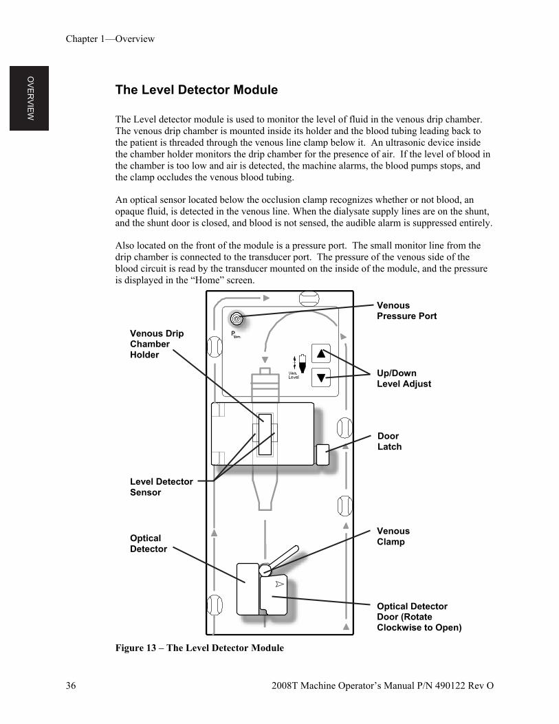
The Level detector module is used to monitor the level of fluid in the venous drip chamber. The venous drip chamber is mounted inside its holder and the blood tubing leading back to the patient is threaded through the venous line clamp below it. An ultrasonic device inside the chamber holder monitors the drip chamber for the presence of air. If the level of blood in the chamber is too low and air is detected, the machine alarms, the blood pumps stops, and the clamp occludes the venous blood tubing.
An optical sensor located below the occlusion clamp recognizes whether or not blood, an opaque fluid, is detected in the venous line. When the dialysate supply lines are on the shunt, and the shunt door is closed, and blood is not sensed, the audible alarm is suppressed entirely.
Also located on the front of the module is a pressure port. The small monitor line from the drip chamber is connected to the transducer port. The pressure of the venous side of the blood circuit is read by the transducer mounted on the inside of the module, and the pressure is displayed in the “Home” screen.
Figure 13 – The Level Detector Module
Level Detector Sensor
Venous Drip Chamber Holder
Optical Detector Door (Rotate Clockwise to Open)
Up/Down Level Adjust
Venous Clamp Optical
Detector
Venous Pressure Port
Door Latch
OV
ER
VIE
W
Chapter 1—Overview
2008T Machine Operator’s Manual P/N 490122 Rev O 37
Table 7 – Level Detector Features
FEATURE PURPOSE
Venous Pressure port (PVen.)
Line from venous drip chamber is connected to a transducer protector and attached here to provide venous blood pressure readings.
Venous Drip Chamber Holder
Holds the drip chamber and aligns it with the ultrasonic level detector sensor. Latching door secures chamber in place.
Level Adjust Keys Raises the level of the fluid in the chamber when the (up arrow) key is pressed, and lowers the level when the (down arrow) key on the level detector is pressed.
Optical Detector Secures venous blood tubing leading back to the patient and houses venous line clamp and optical detector. The optical detector distinguishes between opaque fluid (blood) and a transparent medium such as saline.
Venous Line Clamp
Automatically occludes the blood tubing leading back to the patient during blood-alarm situations.
Blood Tubing System
The dialysate delivery machine can be used with a variety of blood-tubing configurations. The modules (Arterial Drip Chamber, Blood Pump, Level Detector, and Heparin Pump) can be arranged on the 2008T hemodialysis machine in a variety of ways to allow for pre- or post-arterial pump pressure monitoring. The machine can accommodate most standard blood tubing that have pump segments ranging from 2 to 10 mm internal diameter. An additional single needle blood pump and special arterial line with two pump segments and a compliance chamber is required on a machine set up for single-needle dialysis.
Blood Pressure Module
The Blood Pressure module is located internally with the pressure tubing running from the back of the machine to the cuff. The module can automatically take the patient’s blood pressure at defined intervals, record the systolic, diastolic, MAP, and pulse values, and plot out the results on both the “Blood Pressure” screen and the “Trends” screen. The pressure cuffs come in a variety of sizes to accommodate small through large adult patients. The Adult size comes standard with the 2008T hemodialysis machine and can accommodate patients with upper arm circumferences of 25-35 centimeters. An optional large cuff is also available.
OV
ER
VIE
W
Chapter 1—Overview
38 2008T Machine Operator’s Manual P/N 490122 Rev O
The Dialysate Path
The 2008T hemodialysis machine is a three-stream dialysate delivery machine: it mixes the dialysate from three different sources and sends it to the dialyzer for treatment. The three main parts of the dialysate are: purified (RO) water, acid concentrate, and bicarbonate concentrate. After the machine heats and degasses the water, it mixes in the concentrates to form dialysate. The machine then filters the dialysate with the Diasafe Plus filter (see page 218). The ultra-pure dialysate pumps through dialysate lines to the ports on the side of the dialyzer. Meanwhile, the blood pumps through the bloodlines connected at each end of the dialyzer. The blood and dialysate meet in the dialyzer but never touch. The dialysate pulls waste from the patient’s bloodstream and then washes it out the drain. The Balancing Chamber makes sure that the incoming flow of the dialysate is equal to the volume of the outgoing flow to control ultrafiltration from the patient’s body. Ultrafiltration (UF) is the process of removing excess fluid during the treatment. The fluid that is removed is called UF Removed and the value is displayed on the machine’s “Home” screen.
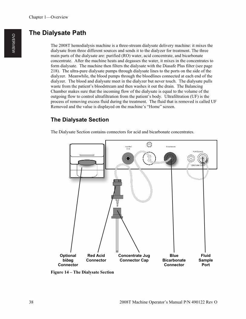
The Dialysate Section
The Dialysate Section contains connectors for acid and bicarbonate concentrates.
Optional bibag
Connector
Red Acid Connector
Concentrate Jug Connector Cap
Blue Bicarbonate Connector
Fluid Sample
Port
Figure 14 – The Dialysate Section
OV
ER
VIE
W
Chapter 1—Overview
2008T Machine Operator’s Manual P/N 490122 Rev O 39
Table 8 – Dialysate Section Features
FEATURE PURPOSE
Red acid and blue bicarbonate connectors
The concentrate connectors draw in acid and bicarbonate concentrates. The concentrate connectors pull out and connect to jugs of acid and bicarbonate concentrates or a concentrate central feed. When connecting, make certain to correctly match red to acid and blue to bicarbonate concentrates.
Concentrate Jug Connector Cap
The connector cap snaps onto the top of concentrate jugs. The Acid and Bicarbonate connectors connect to the cap so the machine can pull concentrate from the jugs.
Fluid Sample Port The Fluid Sample Port allows testing of the UF pump.
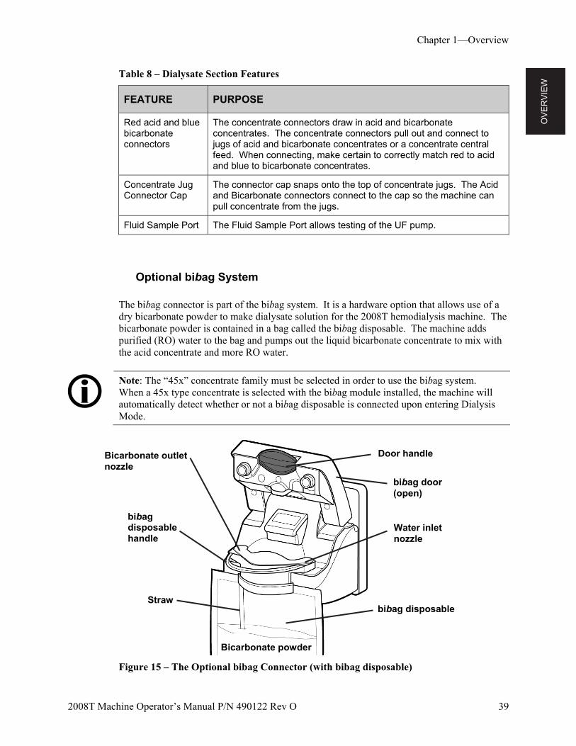
Optional bibag System
The bibag connector is part of the bibag system. It is a hardware option that allows use of a dry bicarbonate powder to make dialysate solution for the 2008T hemodialysis machine. The bicarbonate powder is contained in a bag called the bibag disposable. The machine adds purified (RO) water to the bag and pumps out the liquid bicarbonate concentrate to mix with the acid concentrate and more RO water.
Note: The “45x” concentrate family must be selected in order to use the bibag system. When a 45x type concentrate is selected with the bibag module installed, the machine will automatically detect whether or not a bibag disposable is connected upon entering Dialysis Mode.
Figure 15 – The Optional bibag Connector (with bibag disposable)
Door handle
bibag disposable
Bicarbonate outlet nozzle
Water inlet nozzle
bibag disposable handle
Straw
Bicarbonate powder
bibag door (open)
OV
ER
VIE
W
Chapter 1—Overview
40 2008T Machine Operator’s Manual P/N 490122 Rev O
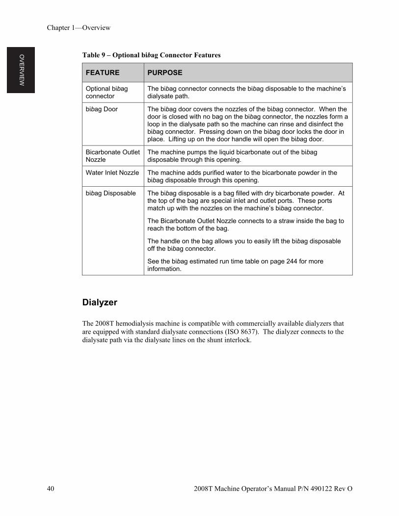
Table 9 – Optional bibag Connector Features
FEATURE PURPOSE
Optional bibag connector
The bibag connector connects the bibag disposable to the machine’s dialysate path.
bibag Door The bibag door covers the nozzles of the bibag connector. When the door is closed with no bag on the bibag connector, the nozzles form a loop in the dialysate path so the machine can rinse and disinfect the bibag connector. Pressing down on the bibag door locks the door in place. Lifting up on the door handle will open the bibag door.
Bicarbonate Outlet Nozzle
The machine pumps the liquid bicarbonate out of the bibag disposable through this opening.
Water Inlet Nozzle The machine adds purified water to the bicarbonate powder in the bibag disposable through this opening.
bibag Disposable The bibag disposable is a bag filled with dry bicarbonate powder. At the top of the bag are special inlet and outlet ports. These ports match up with the nozzles on the machine’s bibag connector.
The Bicarbonate Outlet Nozzle connects to a straw inside the bag to reach the bottom of the bag.
The handle on the bag allows you to easily lift the bibag disposable off the bibag connector.
See the bibag estimated run time table on page 244 for more information.
Dialyzer
The 2008T hemodialysis machine is compatible with commercially available dialyzers that are equipped with standard dialysate connections (ISO 8637). The dialyzer connects to the dialysate path via the dialysate lines on the shunt interlock.
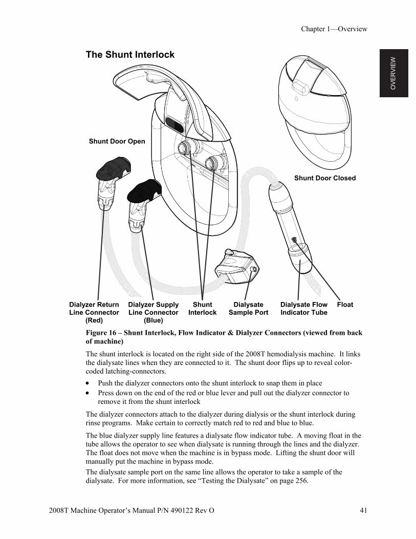
OV
ER
VIE
W
Chapter 1—Overview
2008T Machine Operator’s Manual P/N 490122 Rev O 41
The Shunt Interlock
Dialyzer Return Line Connector
(Red)
Dialyzer Supply Line Connector
(Blue)
Shunt Interlock
Dialysate Sample Port
Dialysate Flow Indicator Tube
Float
Figure 16 – Shunt Interlock, Flow Indicator & Dialyzer Connectors (viewed from back of machine)
The shunt interlock is located on the right side of the 2008T hemodialysis machine. It links the dialysate lines when they are connected to it. The shunt door flips up to reveal color-coded latching-connectors.
Push the dialyzer connectors onto the shunt interlock to snap them in place Press down on the end of the red or blue lever and pull out the dialyzer connector to
remove it from the shunt interlock
The dialyzer connectors attach to the dialyzer during dialysis or the shunt interlock during rinse programs. Make certain to correctly match red to red and blue to blue.
The blue dialyzer supply line features a dialysate flow indicator tube. A moving float in the tube allows the operator to see when dialysate is running through the lines and the dialyzer. The float does not move when the machine is in bypass mode. Lifting the shunt door will manually put the machine in bypass mode.
The dialysate sample port on the same line allows the operator to take a sample of the dialysate. For more information, see “Testing the Dialysate” on page 256.
Shunt Door Closed
Shunt Door Open
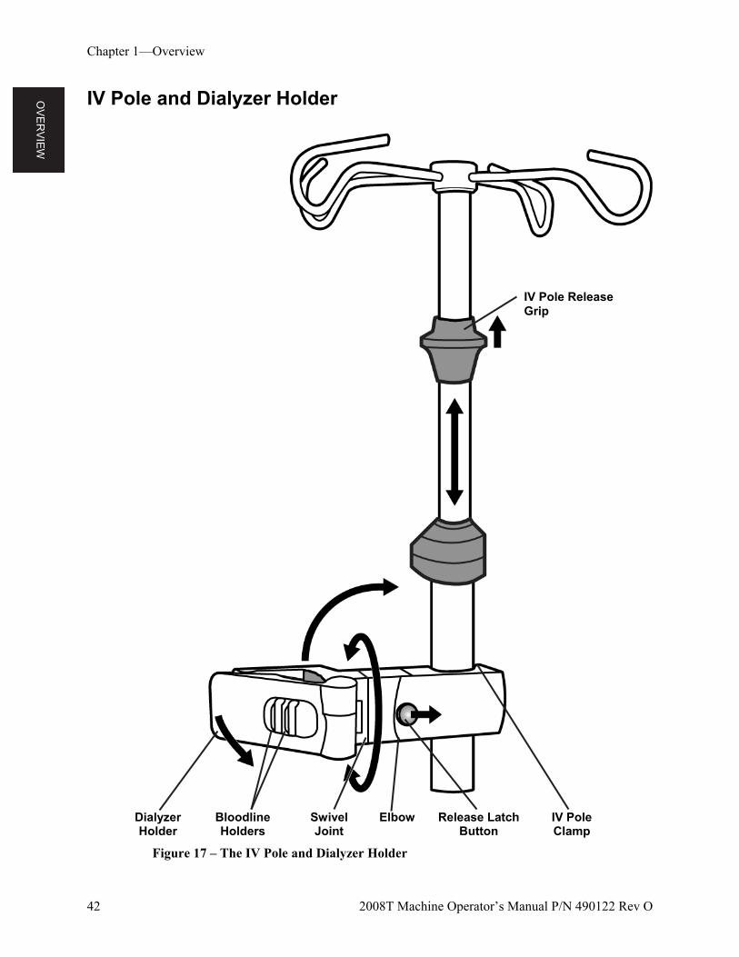
OV
ER
VIE
W
Chapter 1—Overview
42 2008T Machine Operator’s Manual P/N 490122 Rev O
IV Pole and Dialyzer Holder
Dialyzer Holder
Bloodline Holders
Swivel Joint
Elbow Release Latch Button
IV Pole Clamp
Figure 17 – The IV Pole and Dialyzer Holder
IV Pole Release Grip
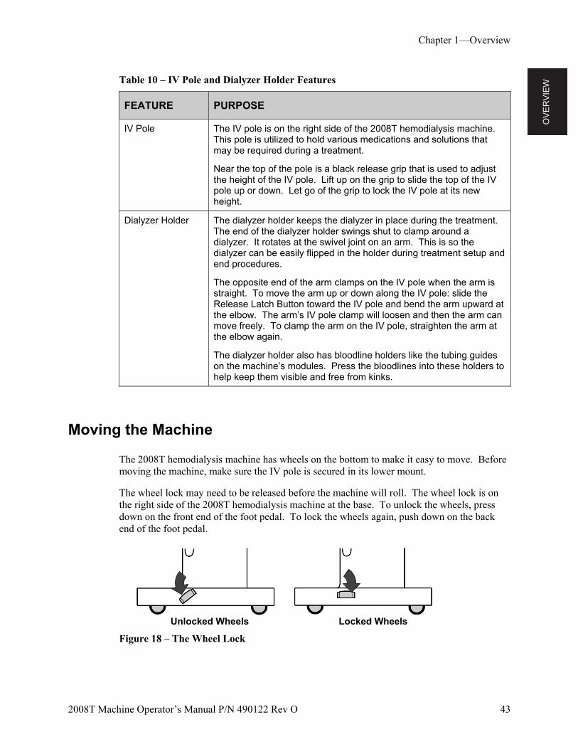
OV
ER
VIE
W
Chapter 1—Overview
2008T Machine Operator’s Manual P/N 490122 Rev O 43
Table 10 – IV Pole and Dialyzer Holder Features
FEATURE PURPOSE
IV Pole The IV pole is on the right side of the 2008T hemodialysis machine. This pole is utilized to hold various medications and solutions that may be required during a treatment.
Near the top of the pole is a black release grip that is used to adjust the height of the IV pole. Lift up on the grip to slide the top of the IV pole up or down. Let go of the grip to lock the IV pole at its new height.
Dialyzer Holder The dialyzer holder keeps the dialyzer in place during the treatment. The end of the dialyzer holder swings shut to clamp around a dialyzer. It rotates at the swivel joint on an arm. This is so the dialyzer can be easily flipped in the holder during treatment setup and end procedures.
The opposite end of the arm clamps on the IV pole when the arm is straight. To move the arm up or down along the IV pole: slide the Release Latch Button toward the IV pole and bend the arm upward at the elbow. The arm’s IV pole clamp will loosen and then the arm can move freely. To clamp the arm on the IV pole, straighten the arm at the elbow again.
The dialyzer holder also has bloodline holders like the tubing guides on the machine’s modules. Press the bloodlines into these holders to help keep them visible and free from kinks.
Moving the Machine
The 2008T hemodialysis machine has wheels on the bottom to make it easy to move. Before moving the machine, make sure the IV pole is secured in its lower mount.
The wheel lock may need to be released before the machine will roll. The wheel lock is on the right side of the 2008T hemodialysis machine at the base. To unlock the wheels, press down on the front end of the foot pedal. To lock the wheels again, push down on the back end of the foot pedal.
Unlocked Wheels Locked Wheels
Figure 18 – The Wheel Lock
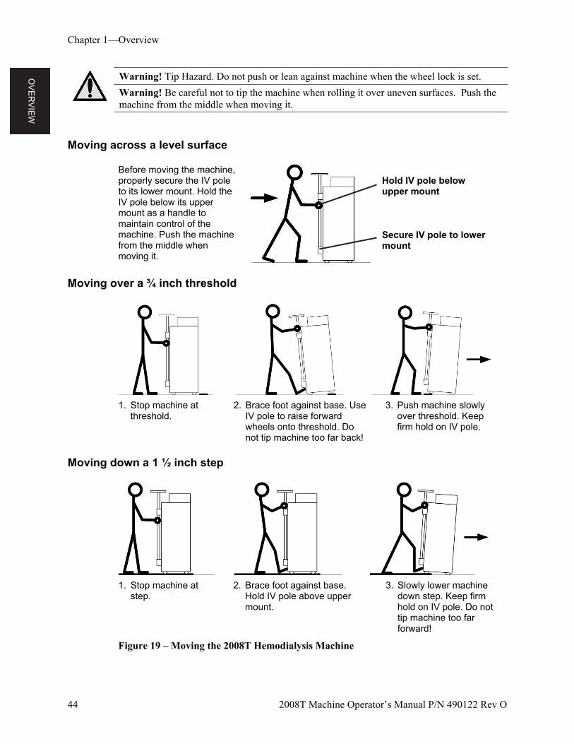
OV
ER
VIE
W
Chapter 1—Overview
44 2008T Machine Operator’s Manual P/N 490122 Rev O
Warning! Tip Hazard. Do not push or lean against machine when the wheel lock is set.
Warning! Be careful not to tip the machine when rolling it over uneven surfaces. Push the machine from the middle when moving it.
Moving across a level surface
Before moving the machine, properly secure the IV pole to its lower mount. Hold the IV pole below its upper mount as a handle to maintain control of the machine. Push the machine from the middle when moving it.
Hold IV pole below upper mount
Secure IV pole to lower mount
Moving over a ¾ inch threshold
1. Stop machine at threshold.
2. Brace foot against base. Use IV pole to raise forward wheels onto threshold. Do not tip machine too far back!
3. Push machine slowly over threshold. Keep firm hold on IV pole.
Moving down a 1 ½ inch step
1. Stop machine at step.
2. Brace foot against base. Hold IV pole above upper mount.
3. Slowly lower machine down step. Keep firm hold on IV pole. Do not tip machine too far forward!
Figure 19 – Moving the 2008T Hemodialysis Machine
TR
EA
TM
EN
T
PR
EP
AR
AT
ION
2008T Machine Operator’s Manual P/N 490122 Rev O 45
Chapter 2
Daily Preparation for Treatment
This chapter provides the qualified operator with the recommended daily procedures for preparing the 2008T hemodialysis machine for regular hemodialysis operation.
Covered here are the initial tasks that are to be performed before the patient is connected to the extracorporeal blood circuit. These tasks are not patient-specific, and are broken down into three categories:
Setting up the dialysis delivery system
Preparing the extracorporeal blood circuit
Conducting pressure and alarm tests
Starting Point
The following is a checklist of conditions that should exist after installation of the 2008T hemodialysis machine by a qualified technician. Before beginning the daily preparation procedures, visually inspect the machine to verify that:
The water supply line is connected to the water inlet and the water is turned on.
The machine’s drain line is inserted into a drain with an air gap.
The power cord is plugged into a grounded, GFI-protected wall socket, and the main power switch located on the back of the machine is in the ON position.
The heater switch is in the ON position.
The acid/acetate suction line (red connector) is inserted into the red, acid/acetate, rinse port.
The bicarbonate suction line (blue connector) is inserted into the blue, bicarbonate, rinse port.
If the machine has the optional bibag connector, check that the bibag door is firmly closed
The dialyzer supply line (blue connector) and dialyzer return line (red connector) are inserted into the matching-color connectors of the shunt interlock.
The machine has been recently disinfected and rinsed, and is ready for use.
Ensure the emergency hand crank for the blood pump is available.
If any of the conditions listed vary from those found on the machine, correct them before continuing with the daily preparation procedure.
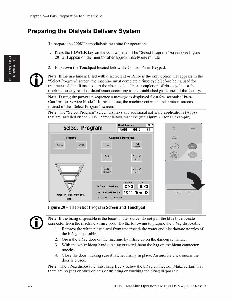
TR
EA
TM
EN
T
PR
EP
AR
AT
ION
Chapter 2—Daily Preparation for Treatment
46 2008T Machine Operator’s Manual P/N 490122 Rev O
Preparing the Dialysis Delivery System
To prepare the 2008T hemodialysis machine for operation:
1. Press the POWER key on the control panel. The “Select Program” screen (see Figure 20) will appear on the monitor after approximately one minute.
2. Flip down the Touchpad located below the Control Panel Keypad.
Note: If the machine is filled with disinfectant or Rinse is the only option that appears in the “Select Program” screen, the machine must complete a rinse cycle before being used for treatment. Select Rinse to start the rinse cycle. Upon completion of rinse cycle test the machine for any residual disinfectant according to the established guidelines of the facility.
Note: During the power up sequence a message is displayed for a few seconds: “Press Confirm for Service Mode”. If this is done, the machine enters the calibration screens instead of the “Select Program” screen.
Note: The “Select Program” screen displays any additional software applications (Apps) that are installed on the 2008T hemodialysis machine (see Figure 20 for an example).
Figure 20 – The Select Program Screen and Touchpad
Note: If the bibag disposable is the bicarbonate source, do not pull the blue bicarbonate connector from the machine’s rinse port. Do the following to prepare the bibag disposable:
1. Remove the white plastic seal from underneath the water and bicarbonate nozzles of the bibag disposable.
2. Open the bibag door on the machine by lifting up on the dark-gray handle. 3. With the white bibag handle facing outward, hang the bag on the bibag connector
nozzles. 4. Close the door, making sure it latches firmly in place. An audible click means the
door is closed.
Note: The bibag disposable must hang freely below the bibag connector. Make certain that there are no jugs or other objects obstructing or touching the bibag disposable.
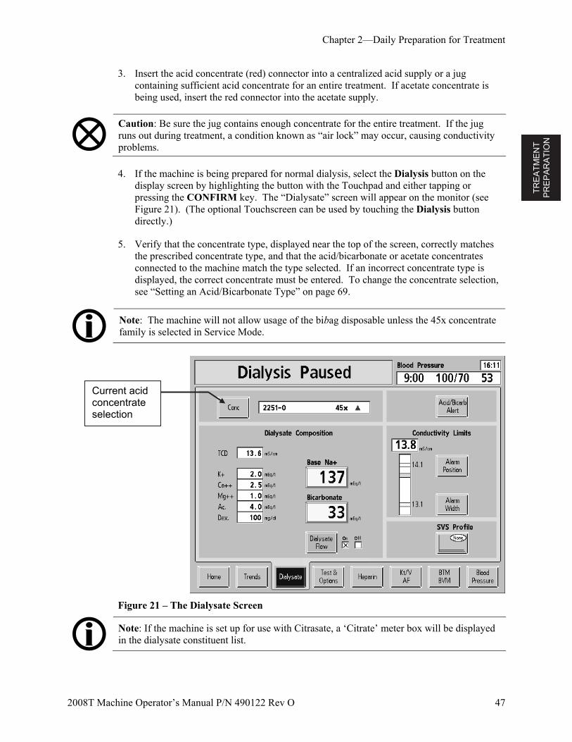
TR
EA
TM
EN
T
PR
EP
AR
AT
ION
Chapter 2—Daily Preparation for Treatment
2008T Machine Operator’s Manual P/N 490122 Rev O 47
3. Insert the acid concentrate (red) connector into a centralized acid supply or a jug containing sufficient acid concentrate for an entire treatment. If acetate concentrate is being used, insert the red connector into the acetate supply.
Caution: Be sure the jug contains enough concentrate for the entire treatment. If the jug runs out during treatment, a condition known as “air lock” may occur, causing conductivity problems.
4. If the machine is being prepared for normal dialysis, select the Dialysis button on the display screen by highlighting the button with the Touchpad and either tapping or pressing the CONFIRM key. The “Dialysate” screen will appear on the monitor (see Figure 21). (The optional Touchscreen can be used by touching the Dialysis button directly.)
5. Verify that the concentrate type, displayed near the top of the screen, correctly matches the prescribed concentrate type, and that the acid/bicarbonate or acetate concentrates connected to the machine match the type selected. If an incorrect concentrate type is displayed, the correct concentrate must be entered. To change the concentrate selection, see “Setting an Acid/Bicarbonate Type” on page 69.
Note: The machine will not allow usage of the bibag disposable unless the 45x concentrate family is selected in Service Mode.
Figure 21 – The Dialysate Screen
Note: If the machine is set up for use with Citrasate, a ‘Citrate’ meter box will be displayed in the dialysate constituent list.
Current acid concentrate selection
TR
EA
TM
EN
T
PR
EP
AR
AT
ION
Chapter 2—Daily Preparation for Treatment
48 2008T Machine Operator’s Manual P/N 490122 Rev O
6. After the concentrate displayed is correct, verify that the Base Na+ and Bicarbonate are as prescribed. Press the CONFIRM key, and then select the Home screen-button.
7. If a liquid bicarbonate is to be used for the treatment, insert the bicarbonate concentrate (blue) connector into a central bicarbonate supply or a jug containing sufficient bicarbonate concentrate for an entire treatment. Again, be sure the jug contains enough concentrate for the entire treatment.
Note: If the dry bicarbonate powder in the bibag disposable will instead be the bicarbonate source, do not pull the blue bicarbonate connector out of your machine’s bicarbonate port. Doing so will stop the flow to and from the bibag disposable.
Note: Dialysate flow must be ON in order to fill the bibag disposable with heated water.
Note: The bibag disposable contains a fixed volume of bicarbonate powder. Refer to the run time tables on page 244 to verify that enough run time (including any set-up time and potential pre-treatment delays) is available to complete a treatment using one bag.
When the machine is ready (water at minimum temperature and no air in the hydraulics), it will begin mixing the concentrates. If a bibag disposable is connected, the machine will then fill the bag with heated water to be used as a bicarbonate concentrate for dialysate production. The machine’s conductivity and temperature readings should stabilize within ten minutes. While the 2008T hemodialysis machine is preparing the dialysate, the bloodlines may be set up. Turn to the next page for instructions on preparing the extracorporeal blood circuit.
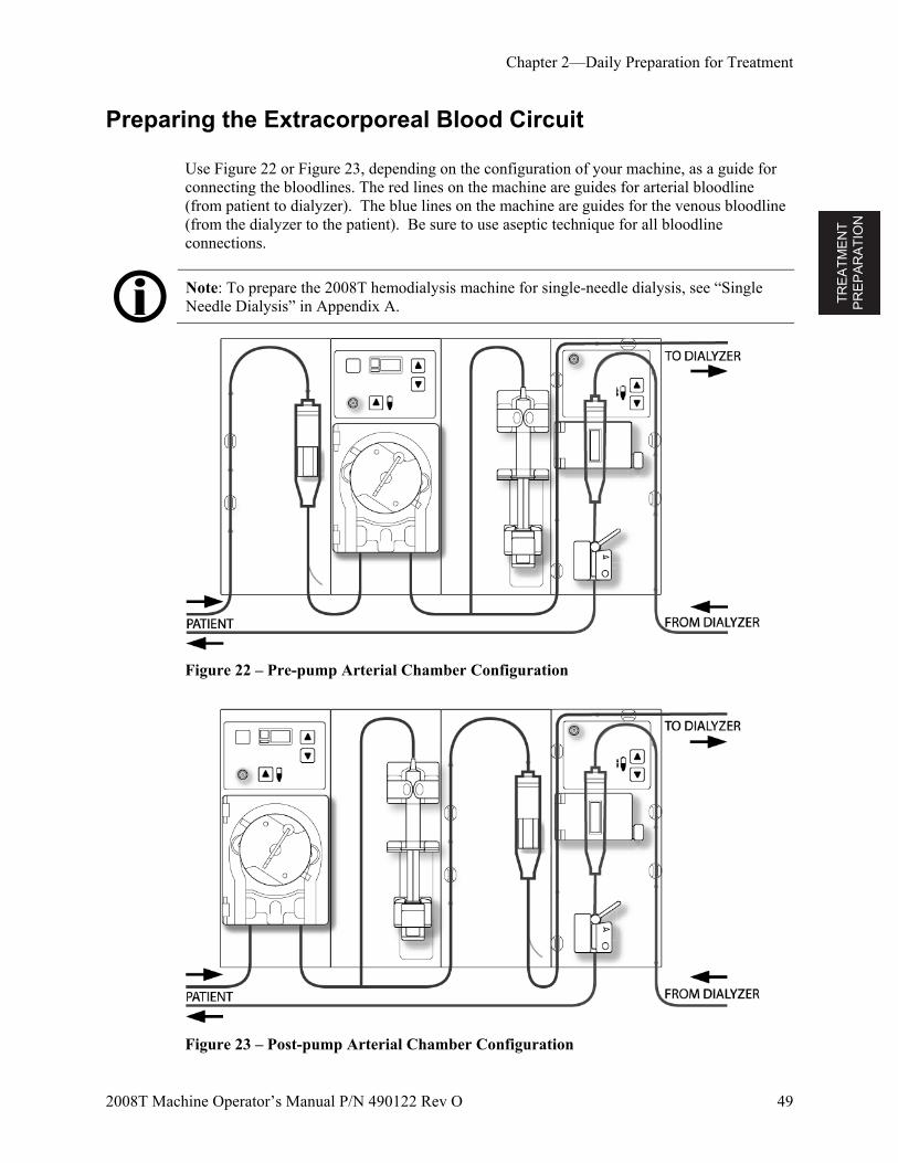
TR
EA
TM
EN
T
PR
EP
AR
AT
ION
Chapter 2—Daily Preparation for Treatment
2008T Machine Operator’s Manual P/N 490122 Rev O 49
Preparing the Extracorporeal Blood Circuit
Use Figure 22 or Figure 23, depending on the configuration of your machine, as a guide for connecting the bloodlines. The red lines on the machine are guides for arterial bloodline (from patient to dialyzer). The blue lines on the machine are guides for the venous bloodline (from the dialyzer to the patient). Be sure to use aseptic technique for all bloodline connections.
Note: To prepare the 2008T hemodialysis machine for single-needle dialysis, see “Single Needle Dialysis” in Appendix A.
Figure 22 – Pre-pump Arterial Chamber Configuration
Figure 23 – Post-pump Arterial Chamber Configuration
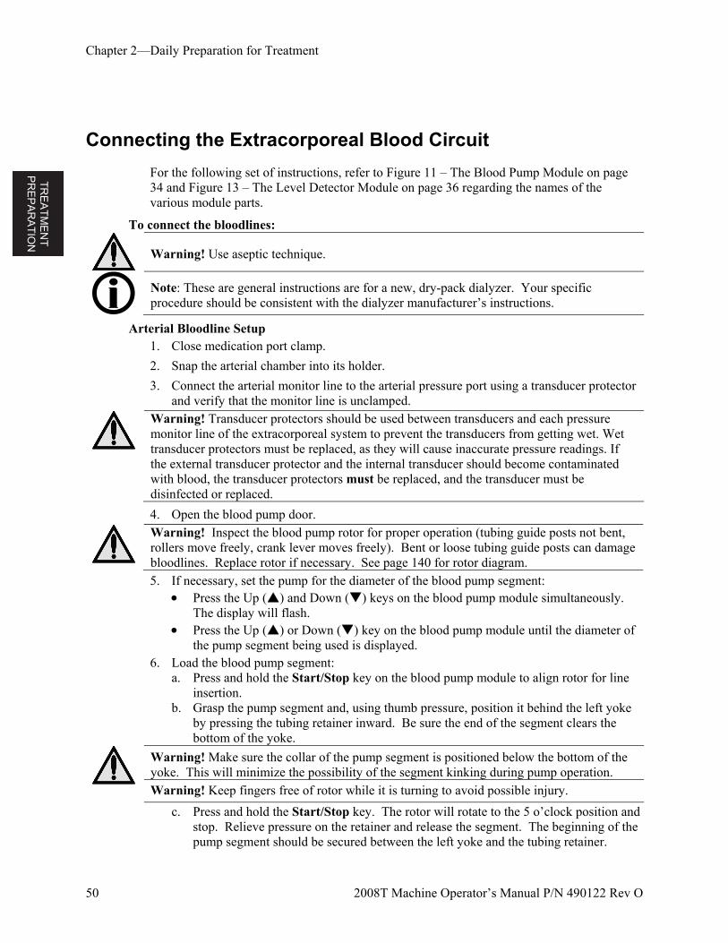
TR
EA
TM
EN
T
PR
EP
AR
AT
ION
Chapter 2—Daily Preparation for Treatment
50 2008T Machine Operator’s Manual P/N 490122 Rev O
Connecting the Extracorporeal Blood Circuit
For the following set of instructions, refer to Figure 11 – The Blood Pump Module on page 34 and Figure 13 – The Level Detector Module on page 36 regarding the names of the various module parts.
To connect the bloodlines:
Warning! Use aseptic technique.
Note: These are general instructions are for a new, dry-pack dialyzer. Your specific procedure should be consistent with the dialyzer manufacturer’s instructions.
Arterial Bloodline Setup 1. Close medication port clamp.
2. Snap the arterial chamber into its holder.
3. Connect the arterial monitor line to the arterial pressure port using a transducer protector and verify that the monitor line is unclamped.
Warning! Transducer protectors should be used between transducers and each pressure monitor line of the extracorporeal system to prevent the transducers from getting wet. Wet transducer protectors must be replaced, as they will cause inaccurate pressure readings. If the external transducer protector and the internal transducer should become contaminated with blood, the transducer protectors must be replaced, and the transducer must be disinfected or replaced.
4. Open the blood pump door.
Warning! Inspect the blood pump rotor for proper operation (tubing guide posts not bent, rollers move freely, crank lever moves freely). Bent or loose tubing guide posts can damage bloodlines. Replace rotor if necessary. See page 140 for rotor diagram. 5. If necessary, set the pump for the diameter of the blood pump segment:
Press the Up () and Down () keys on the blood pump module simultaneously. The display will flash.
Press the Up () or Down () key on the blood pump module until the diameter of the pump segment being used is displayed.
6. Load the blood pump segment: a. Press and hold the Start/Stop key on the blood pump module to align rotor for line
insertion. b. Grasp the pump segment and, using thumb pressure, position it behind the left yoke
by pressing the tubing retainer inward. Be sure the end of the segment clears the bottom of the yoke.
Warning! Make sure the collar of the pump segment is positioned below the bottom of the yoke. This will minimize the possibility of the segment kinking during pump operation. Warning! Keep fingers free of rotor while it is turning to avoid possible injury.
c. Press and hold the Start/Stop key. The rotor will rotate to the 5 o’clock position and stop. Relieve pressure on the retainer and release the segment. The beginning of the pump segment should be secured between the left yoke and the tubing retainer.
TR
EA
TM
EN
T
PR
EP
AR
AT
ION
Chapter 2—Daily Preparation for Treatment
2008T Machine Operator’s Manual P/N 490122 Rev O 51
d. Press and hold the Start/Stop key again and the rotor will rotate one full turn to automatically position the remainder of the segment within the pump housing. After loading, any extra pump segment tubing length should be on the right side of the pump.
e. Release the Start/Stop key when the pump segment has been inserted along the track inside the pump housing all the way to the right yoke.
f. Grasp the remaining portion of the segment and, using thumb pressure in a manner similar to step b, position it behind the right yoke.
g. Release the tubing retainer and close the pump door. Be sure the pump segment is free of kinks and both ends of the segment extend below the yoke.
7. Snap remaining arterial tubing in the clips along the red guidelines shown on modules.
8. Aseptically place the patient end of the arterial line into the priming bucket clip. Snap the dialyzer end of the arterial bloodline into the dialyzer holder clip.
Warning! Do not allow the ends to touch the fluid in the bucket to prevent contamination.
Venous Bloodline Setup 1. Close medication port clamp.
2. Open the level detector door and roll the venous drip chamber into its holder with the filter below the sensor heads. Close and latch the door.
Warning! The level detector must be calibrated to the venous line model being used.
Warning! If the venous chamber contains a filter, be sure the filter portion of the chamber is positioned below the ultrasonic sensor heads of the drip chamber holder.
3. Connect the venous pressure monitor line to the pressure port. Be sure to insert a transducer protector between the line and the port. Verify that the monitor line is unclamped.
Warning! Transducer protectors should be used between transducers and each pressure monitor line of the extracorporeal system to prevent the transducers from getting wet. Wet transducer protectors must be replaced, as they will cause inaccurate pressure readings. If the external transducer protector and the internal transducer should become contaminated with blood, the transducer protectors must be replaced, and the transducer must be disinfected or replaced.
4. Snap remaining venous tubing in the clips along the blue guidelines shown on modules (do not insert the venous bloodline into the venous clamp yet).
5. Snap the dialyzer end of the venous bloodline into the dialyzer holder clip.
6. Aseptically place the patient end of the venous line into the priming bucket clip.
Warning! Do not allow the ends to touch the fluid in the bucket to prevent contamination.
Dialyzer Setup
1. Mount the dialyzer in its holder, arterial-end up.
2. If the CLiC device will be used for this treatment, connect the Crit-Line Blood Chamber to the dialyzer’s arterial port at this time. For more information, see the 2008T Hemodialysis Machine with CLiC User’s Guide (P/N 490206).
TR
EA
TM
EN
T
PR
EP
AR
AT
ION
Chapter 2—Daily Preparation for Treatment
52 2008T Machine Operator’s Manual P/N 490122 Rev O
Priming the Blood Circuit
There are two different ways to prime the blood circuit on the 2008T hemodialysis machine—Standard Prime method and Prime Amount method. The Standard Prime method allows the operator to prime the blood circuit by controlling the flow of the saline manually. The Prime Amount method is a machine option that is set in the Service Mode, and limits the amount of saline used in the priming procedure to a preset volume. Prime the blood circuit according to how your machine was set up. Follow your unit protocol or dialyzer manufacturer’s instructions for priming and rinsing dialyzers.
Standard Prime Method
1. Connect the dialyzer end of the arterial bloodline to the arterial port of the dialyzer. Rotate the dialyzer to the arterial end down position.
2. Connect the dialyzer end of the venous bloodline to the venous port of the dialyzer.
3. Insert the venous line in the venous line clamp and the optical detector. Close the optical detector door.
Warning! The tubing beneath the venous drip chamber must be inserted into the venous line clamp and the optical detector.
4. Hang a saline bag and attach an administration line, if not already attached, to the saline port on the arterial bloodline. Aseptically spike the saline bag.
5. Gravity prime the patient end of the arterial bloodline below the saline “T” with saline. When primed, clamp the patient end of the arterial bloodline.
6. If the heparin pump is to be used: connect the heparin syringe, prime the heparin line with heparin, and load heparin syringe into heparin pump. If the heparin pump is not used, clamp the heparin line.
7. On the control panel keypad, press the Prime key.
8. Press the blood pump Start/Stop key and run the blood pump at a rate of 150 ml/min. Adjust the flow rate by pressing the (up) or (down) keys.
9. Fill the arterial drip chamber to an acceptable level using the key (level adjust) on the blood pump. Close the arterial pressure monitor line clamp and disconnect the line from the arterial pressure port so the port is open to atmosphere.
Warning! The Level Adjust key on the Blood Pump module can only be used to raise the level in the arterial chamber. Do not press the Level Adjust key so long that the pressure transducer protector becomes wet. Wet transducer protectors must be replaced to avoid erroneous pressure readings.
TR
EA
TM
EN
T
PR
EP
AR
AT
ION
Chapter 2—Daily Preparation for Treatment
2008T Machine Operator’s Manual P/N 490122 Rev O 53
10. Run the blood pump to flush saline through the circuit until a fluid level is detected in the venous drip chamber. The blood pump will stop when the level detector senses a level of fluid.
11. Press the RESET key on the control panel to restart the blood pump and continue flushing saline through the blood circuit in accordance with established facility protocol regarding dialyzer rinsing.
12. After the required saline amount has passed through the circuit, press the Start/Stop key on the blood pump to stop the pump.
13. Clamp the patient end of the venous bloodline.
14. Adjust the fluid levels in the drip chambers by pressing the appropriate or level adjust keys. Close the venous pressure monitor line clamp and disconnect the monitor line from the venous pressure port so the port is open to atmosphere.
15. Aseptically connect the patient end of the arterial bloodline to the patient end of the venous bloodline using a sterile recirculation piece. Unclamp both lines.
16. Set the blood pump rate to 350-400 ml/min. Press the blood pump Start/Stop key to start the pump and begin recirculation. If necessary, press the RESET key to clear any alarms.
17. Ensure that the extracorporeal circuit is free of air bubbles.
Note: The dialysate lines will have to be attached at the appropriate point during the priming process, depending on facility procedure and manufacturer’s instructions. If 1.5x or 2x dialysate flow (Auto Flow) is selected, be sure that the dialysate flow rate is at least the minimum required rate.
Prime Amount Method
1. Connect the dialyzer end of the arterial bloodline to the arterial port of the dialyzer. Rotate the dialyzer to the arterial end down position.
2. Connect the dialyzer end of the venous bloodline to the venous port of the dialyzer.
3. Hang a saline bag and attach an administration line, if not already attached, to the saline port on the arterial bloodline. Aseptically spike the saline bag.
4. Gravity prime the patient end of the arterial bloodline below the saline “T” with saline. When primed, clamp off the patient end of the arterial bloodline.
5. If the heparin pump is to be used: connect the heparin syringe, prime the heparin line with heparin, and load heparin syringe into heparin pump. If the heparin pump is not used, clamp the heparin line.
6. On the control panel keypad, press the Prime key.
7. Press the blood pump Start/Stop key and run the blood pump at a rate of 150 ml/min. Adjust the flow rate by pressing the (up) or (down) keys.
TR
EA
TM
EN
T
PR
EP
AR
AT
ION
Chapter 2—Daily Preparation for Treatment
54 2008T Machine Operator’s Manual P/N 490122 Rev O
8. Fill the arterial drip chamber to an acceptable level using the key (level adjust) key on the blood pump. Close the arterial pressure monitor line clamp and disconnect the line from the arterial pressure port so the port is open to atmosphere.
Warning! The Level Adjust key on the Blood Pump module can only be used to raise the level in the arterial chamber. Do not press the Level Adjust key so long that the pressure transducer protector becomes wet. Wet transducer protectors must be replaced to avoid erroneous pressure readings.
9. The blood pump will start and continue to run until the pre-set amount of saline has been flushed through the circuit. When blood pump stops, clamp the patient end of the venous bloodline.
10. Insert the venous bloodline into the venous line clamp and optical detector on the level detector module. Close the optical detector door.
Warning! The tubing beneath the venous drip chamber must be inserted into the venous line clamp and the optical detector.
11. Adjust the fluid levels in the drip chambers by pressing the appropriate level adjust keys. Close the venous pressure monitor line clamp and disconnect the monitor line from the venous pressure port so the port is open to atmosphere.
12. Aseptically connect the patient end of the arterial bloodline to the patient end of the venous bloodline using a sterile recirculation piece. Unclamp both lines.
13. Set the blood pump rate to 350-400 ml/min. Press the blood pump Start/Stop key to start the pump and begin recirculation. If necessary, press the RESET key to clear any alarms.
14. Ensure that the extracorporeal circuit is free of air bubbles.
Note: The dialysate lines will have to be attached at the appropriate point during the priming process, depending on facility procedure and manufacturer’s instructions. If 1.5x or 2x dialysate flow (Auto Flow) is selected, be sure that the dialysate flow rate is at least the minimum required rate.
TR
EA
TM
EN
T
PR
EP
AR
AT
ION
Chapter 2—Daily Preparation for Treatment
2008T Machine Operator’s Manual P/N 490122 Rev O 55
Testing the 2008T Hemodialysis Machine
Before beginning treatment, the machine should undergo Pressure and Alarm tests to ensure that it is functioning properly. Select the Both Tests button in the “Test & Options” screen to start the test. The 2008T hemodialysis machine can be configured so that this testing is mandatory after power up providing that the force test option is selected. In this case, the test will start on its own.
To run the test sequence, The dialyzer lines must be connected to the shunt with the interlock door closed. The machine must be in an alarm-free condition by allowing sufficient time for the
dialysate to reach proper conductivity and temperature. This takes about five minutes from the time the concentrate is confirmed on the dialysate screen (see Figure 21 on page 47).
Arterial and venous monitor lines must be clamped and removed from the pressure monitor ports so the monitor ports are open to atmosphere.
UF and SVS must be off.
Warning! It is essential that the 2008T hemodialysis machine’s balancing system is operating properly. The machine must successfully complete a Pressure test before each treatment, especially when using high-flux dialyzers.
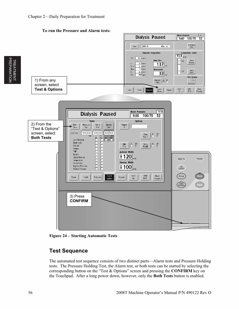
TR
EA
TM
EN
T
PR
EP
AR
AT
ION
Chapter 2—Daily Preparation for Treatment
56 2008T Machine Operator’s Manual P/N 490122 Rev O
To run the Pressure and Alarm tests:
Figure 24 – Starting Automatic Tests
Test Sequence
The automated test sequence consists of two distinct parts—Alarm tests and Pressure Holding tests. The Pressure Holding Test, the Alarm test, or both tests can be started by selecting the corresponding button on the “Test & Options” screen and pressing the CONFIRM key on the Touchpad. After a long power down, however, only the Both Tests button is enabled.
1) From any screen, select Test & Options
3) Press CONFIRM
2) From the “Test & Options” screen, select Both Tests
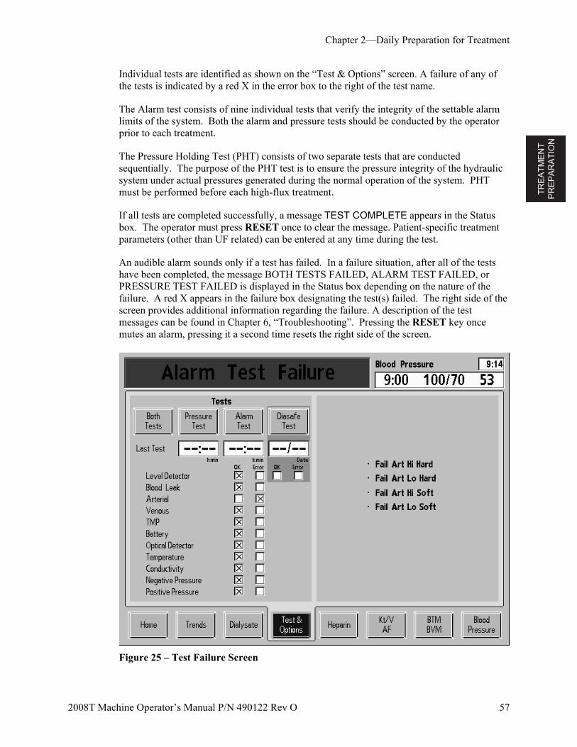
TR
EA
TM
EN
T
PR
EP
AR
AT
ION
Chapter 2—Daily Preparation for Treatment
2008T Machine Operator’s Manual P/N 490122 Rev O 57
Individual tests are identified as shown on the “Test & Options” screen. A failure of any of the tests is indicated by a red X in the error box to the right of the test name.
The Alarm test consists of nine individual tests that verify the integrity of the settable alarm limits of the system. Both the alarm and pressure tests should be conducted by the operator prior to each treatment.
The Pressure Holding Test (PHT) consists of two separate tests that are conducted sequentially. The purpose of the PHT test is to ensure the pressure integrity of the hydraulic system under actual pressures generated during the normal operation of the system. PHT must be performed before each high-flux treatment.
If all tests are completed successfully, a message TEST COMPLETE appears in the Status box. The operator must press RESET once to clear the message. Patient-specific treatment parameters (other than UF related) can be entered at any time during the test.
An audible alarm sounds only if a test has failed. In a failure situation, after all of the tests have been completed, the message BOTH TESTS FAILED, ALARM TEST FAILED, or PRESSURE TEST FAILED is displayed in the Status box depending on the nature of the failure. A red X appears in the failure box designating the test(s) failed. The right side of the screen provides additional information regarding the failure. A description of the test messages can be found in Chapter 6, “Troubleshooting”. Pressing the RESET key once mutes an alarm, pressing it a second time resets the right side of the screen.
Figure 25 – Test Failure Screen
TR
EA
TM
EN
T
PR
EP
AR
AT
ION
Chapter 2—Daily Preparation for Treatment
58 2008T Machine Operator’s Manual P/N 490122 Rev O
Warning! After selecting and confirming a test button, the machine will beep. As a test of the audible alarm system, make certain that the sound occurs. If the machine fails this or any of the Pressure, Alarm, and Diasafe tests and the cause cannot be corrected, or if it fails subsequent tests, it should not be used for treatment. Remove the machine from service and have it inspected by a qualified technician to correct the problem.
The 2008T hemodialysis machine can be set up to perform online PHTs during treatment. These tests routinely happen every 12 minutes, and check the integrity of the hydraulic system. In the event of a failure, an alarm sounds and a warning message is displayed in the status box. For more information see “Online Pressure Holding Test” on page 126.
If your machine is set up with the automatically activated Diasafe test valve, you may initiate the Diasafe test from this screen. The date of the last test and test result is displayed.
Recirculation and Final Set-Up Procedure
1. Rotate dialyzer to arterial inlet up.
2. Check the conductivity and pH of the dialysate and test for residual disinfectant before connecting the dialysate lines to the dialyzer. For more information on collecting a dialysate sample for testing, see “Testing the Dialysate” on page 256.
Warning! Always verify the conductivity and approximate pH of the dialysate solution through independent means (e.g. using a conductivity meter or pH paper or meter, as applicable) before initiating each dialysis treatment. Verify that the conductivity is reasonably close to the theoretical conductivity value (TCD) and the pH is between 6.9 and 7.6. If they are not, do not initiate dialysis.
3. Connect dialysate lines to dialyzer by matching the color of the dialyzer connector to the color of the blood tube fitting and then close the shunt door. When done correctly, the red arterial blood tubing connector and the red dialyzer connector of the dialysate line should be connected to the corresponding ports at the top of the dialyzer. This is to create a counter-current flow (blood flowing from top to bottom, dialysate flowing from bottom to top) inside the dialyzer to maximize clearance.
4. Pull on the dialyzer connectors to make sure they are firmly connected to the dialyzer.
Note: All dialyzer connectors must be fastened tightly to prevent air from entering the dialysate circuit or to prevent dialysate from leaking from the dialyzer.
5. Reconnect arterial and venous monitor lines to their respective ports. Unclamp the lines.
6. When the dialysate compartment is filled, rotate the dialyzer so the arterial inlet is down.
7. After priming the extracorporeal blood circuit, press RESET to clear all alarms. Set the blood pump rate to 350-400 ml/min and start the blood pump to begin recirculating the saline through the circuit.
TR
EA
TM
EN
T
PR
EP
AR
AT
ION
Chapter 2—Daily Preparation for Treatment
2008T Machine Operator’s Manual P/N 490122 Rev O 59
8. Press the (down) key on the Level Detector module to lower the fluid level in the drip chamber. Verify that the blood pump stops and the venous clamp occludes.
Warning! The test of the level detector system must be run as a precaution and aid to identifying potential failures. Remove the machine from service if it fails this test.
9. Press the (up) key on the Level Detector module to raise the fluid level in the drip chamber to an acceptable level.
10. Check blood tubing to ensure that there are no kinks, especially between the blood pump and the dialyzer.
Warning! Kinked lines can cause hemolysis of the blood.
Warning! If using a dialyzer that has been stored in a liquid disinfectant such as formaldehyde or Puristeril 340, test the recirculating saline solution for residual disinfectant according to established facility protocol or the manufacturer’s instructions. Special rinsing techniques must also be employed to assure the concentration of disinfectant is reduced and maintained at an appropriate level. These rinsing procedures are the responsibility of the medical director. The procedure must include a test for residual disinfectant and techniques to avoid rebound of the disinfectant. Turning the dialysate flow off when using a reused dialyzer may allow the chemical disinfectant to rebound (increase) to an unacceptable level.
11. Replace saline bag with a fresh bag if necessary.
12. Check for a normal dialysate flow by observing the rise and fall of the external flow indicator located on the dialyzer supply line. The float should drop four times in about 15 seconds for a 500 ml/min flow, or four times in 10 seconds for an 800-ml/min flow.
13. Open the shunt door and verify that the machine goes into bypass mode. In bypass mode, the float in the flow indicator of the dialyzer supply line should drop and remain at the bottom of the indicator and an audible alarm may sound.
Note: The 2008T hemodialysis machine can be configured (in Service Mode) so that audible alarms occur only when the optical detector senses blood. If this option is not selected, an audible alarm will sound when the shunt interlock door is open.
SE
TT
ING
P
AR
AM
ET
ER
S
60 2008T Machine Operator’s Manual P/N 490122 Rev O
Chapter 3
Setting Treatment Parameters
This chapter instructs the patient care specialist on the procedures for entering patient-specific treatment parameters. The procedures for preparing the machine for daily use, in Chapter 2, must be completed prior to setting treatment parameters.
Before proceeding, be sure that:
The machine has passed the alarm and pressure tests.
The dialysate is at the proper temperature, conductivity, and pH.
The dialysate has been tested and found free of residual disinfectant.
Warning! Do not connect a patient to the machine or attempt to set treatment parameters until these conditions have been met.
Warning! The values shown in pictures here are for example only. Parameters must be entered as prescribed by the patient’s physician. Failure to enter correct parameters could result in serious injury or death.
Recommended Screen Order
The process of setting patient-specific treatment parameters requires using four of the eight main screens displayed on the display screen. The table below lists the order the screens should be opened, and parameter to set in each of them.
Dialysate Screen—Access the Sodium and Bicarbonate level of the dialysate and display the constituent concentration as prescribed by the physician.
Home Screen—Access the UF and Sodium Variation System (SVS) parameters, dialysate flow, dialysate temperature, display conductivity, and later, start the treatment.
Test & Options Screen—Settings to perform single-needle dialysis or use high-flux dialyzers are activated in this screen. The patient ID (if applicable) is also entered here.
Heparin Screen—Set the parameters for administering heparin.
Kt/V AF Screen—Set the parameters for the Kt/V display and run the Access Flow measurement.
BTM/BVM Screen—If applicable, set the BTM and BVM parameters.
Blood Pressure Screen—Set pressure and interval settings to facilitate taking pulse and blood pressure readings automatically.
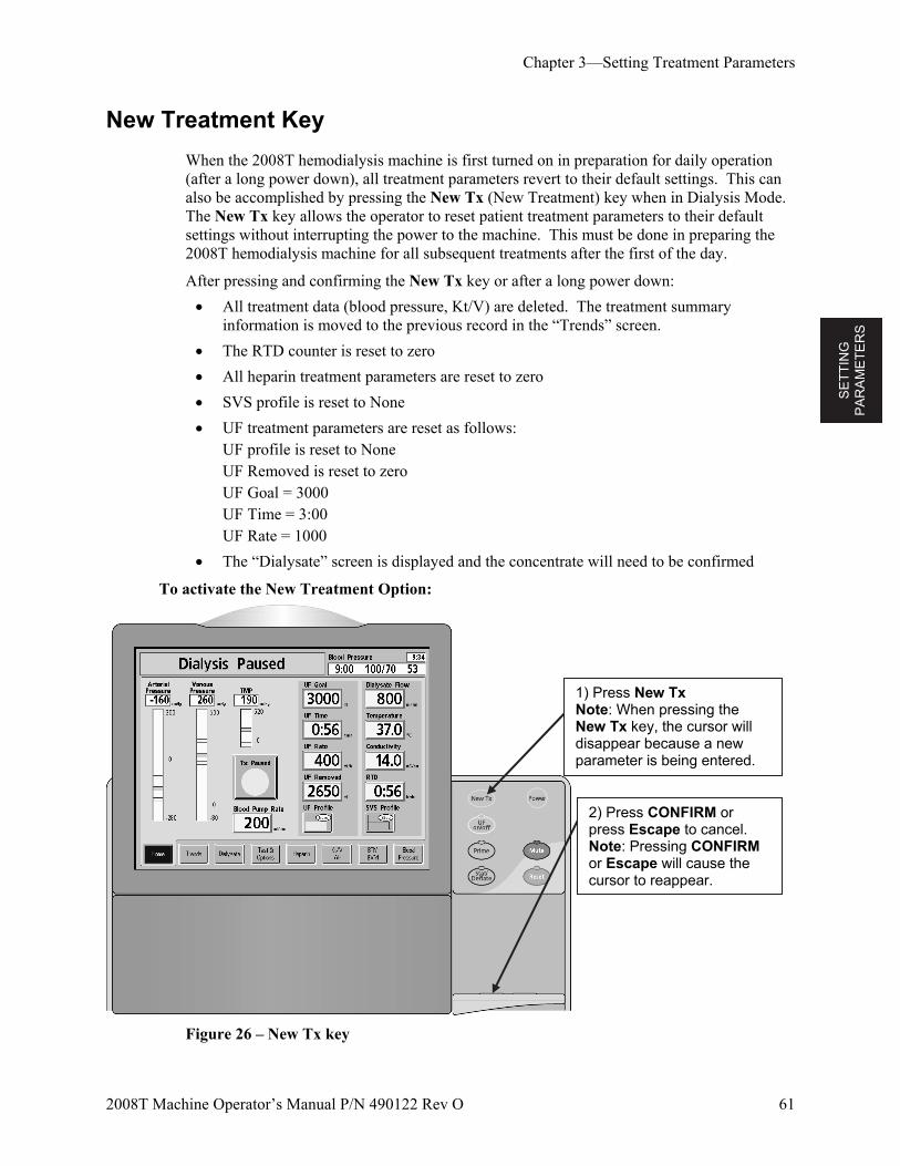
SE
TT
ING
P
AR
AM
ET
ER
S
Chapter 3—Setting Treatment Parameters
2008T Machine Operator’s Manual P/N 490122 Rev O 61
New Treatment Key
When the 2008T hemodialysis machine is first turned on in preparation for daily operation (after a long power down), all treatment parameters revert to their default settings. This can also be accomplished by pressing the New Tx (New Treatment) key when in Dialysis Mode. The New Tx key allows the operator to reset patient treatment parameters to their default settings without interrupting the power to the machine. This must be done in preparing the 2008T hemodialysis machine for all subsequent treatments after the first of the day.
After pressing and confirming the New Tx key or after a long power down:
All treatment data (blood pressure, Kt/V) are deleted. The treatment summary information is moved to the previous record in the “Trends” screen.
The RTD counter is reset to zero
All heparin treatment parameters are reset to zero
SVS profile is reset to None
UF treatment parameters are reset as follows: UF profile is reset to None UF Removed is reset to zero UF Goal = 3000 UF Time = 3:00 UF Rate = 1000
The “Dialysate” screen is displayed and the concentrate will need to be confirmed
To activate the New Treatment Option:
Figure 26 – New Tx key
2) Press CONFIRM or press Escape to cancel. Note: Pressing CONFIRM or Escape will cause the cursor to reappear.
1) Press New Tx Note: When pressing the New Tx key, the cursor will disappear because a new parameter is being entered.
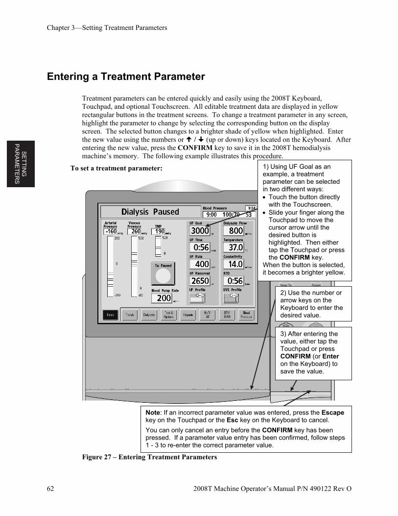
SE
TT
ING
P
AR
AM
ET
ER
S
Chapter 3—Setting Treatment Parameters
62 2008T Machine Operator’s Manual P/N 490122 Rev O
Entering a Treatment Parameter
Treatment parameters can be entered quickly and easily using the 2008T Keyboard, Touchpad, and optional Touchscreen. All editable treatment data are displayed in yellow rectangular buttons in the treatment screens. To change a treatment parameter in any screen, highlight the parameter to change by selecting the corresponding button on the display screen. The selected button changes to a brighter shade of yellow when highlighted. Enter the new value using the numbers or / (up or down) keys located on the Keyboard. After entering the new value, press the CONFIRM key to save it in the 2008T hemodialysis machine’s memory. The following example illustrates this procedure.
To set a treatment parameter:
Figure 27 – Entering Treatment Parameters
Note: If an incorrect parameter value was entered, press the Escape key on the Touchpad or the Esc key on the Keyboard to cancel.
You can only cancel an entry before the CONFIRM key has been pressed. If a parameter value entry has been confirmed, follow steps 1 - 3 to re-enter the correct parameter value.
3) After entering the value, either tap the Touchpad or press CONFIRM (or Enter on the Keyboard) to save the value.
2) Use the number or arrow keys on the Keyboard to enter the desired value.
1) Using UF Goal as an example, a treatment parameter can be selected in two different ways: Touch the button directly
with the Touchscreen. Slide your finger along the
Touchpad to move the cursor arrow until the desired button is highlighted. Then either tap the Touchpad or press the CONFIRM key.
When the button is selected, it becomes a brighter yellow.
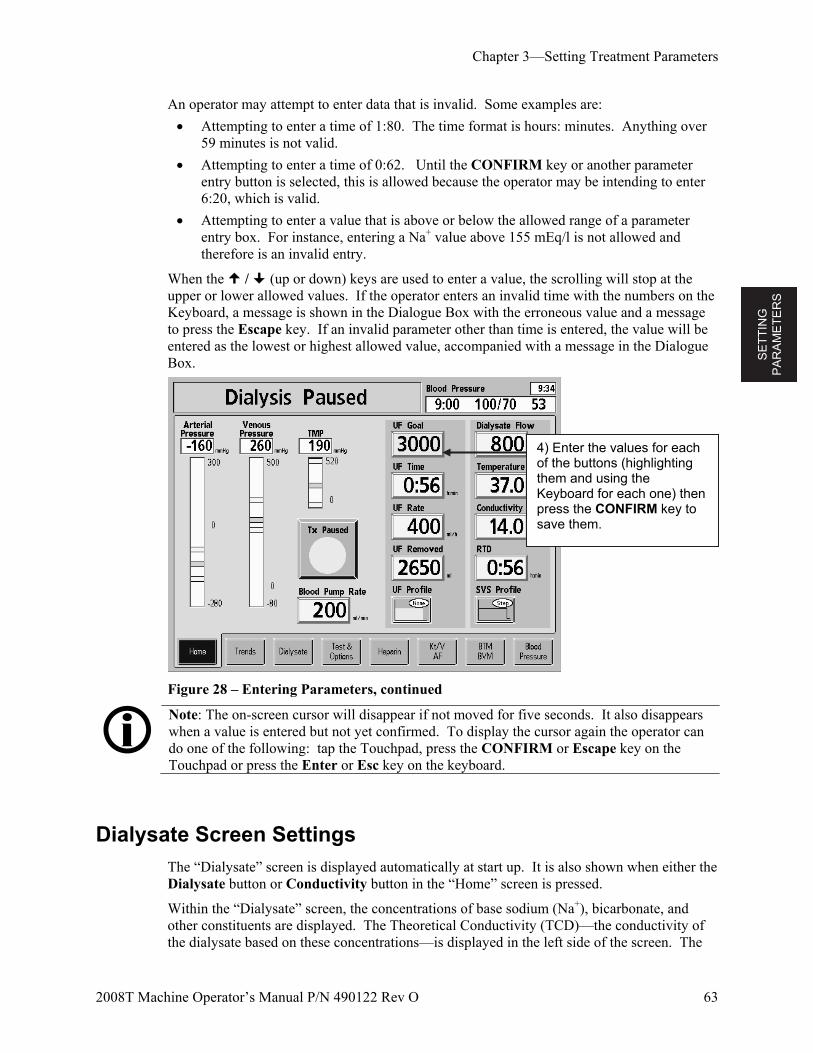
SE
TT
ING
P
AR
AM
ET
ER
S
Chapter 3—Setting Treatment Parameters
2008T Machine Operator’s Manual P/N 490122 Rev O 63
An operator may attempt to enter data that is invalid. Some examples are:
Attempting to enter a time of 1:80. The time format is hours: minutes. Anything over 59 minutes is not valid.
Attempting to enter a time of 0:62. Until the CONFIRM key or another parameter entry button is selected, this is allowed because the operator may be intending to enter 6:20, which is valid.
Attempting to enter a value that is above or below the allowed range of a parameter entry box. For instance, entering a Na+ value above 155 mEq/l is not allowed and therefore is an invalid entry.
When the / (up or down) keys are used to enter a value, the scrolling will stop at the upper or lower allowed values. If the operator enters an invalid time with the numbers on the Keyboard, a message is shown in the Dialogue Box with the erroneous value and a message to press the Escape key. If an invalid parameter other than time is entered, the value will be entered as the lowest or highest allowed value, accompanied with a message in the Dialogue Box.
Figure 28 – Entering Parameters, continued
Note: The on-screen cursor will disappear if not moved for five seconds. It also disappears when a value is entered but not yet confirmed. To display the cursor again the operator can do one of the following: tap the Touchpad, press the CONFIRM or Escape key on the Touchpad or press the Enter or Esc key on the keyboard.
Dialysate Screen Settings
The “Dialysate” screen is displayed automatically at start up. It is also shown when either the Dialysate button or Conductivity button in the “Home” screen is pressed.
Within the “Dialysate” screen, the concentrations of base sodium (Na+), bicarbonate, and other constituents are displayed. The Theoretical Conductivity (TCD)—the conductivity of the dialysate based on these concentrations—is displayed in the left side of the screen. The
4) Enter the values for each of the buttons (highlighting them and using the Keyboard for each one) then press the CONFIRM key to save them.
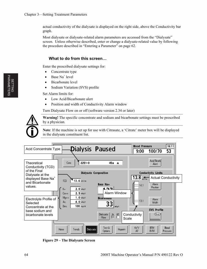
SE
TT
ING
P
AR
AM
ET
ER
S
Chapter 3—Setting Treatment Parameters
64 2008T Machine Operator’s Manual P/N 490122 Rev O
actual conductivity of the dialysate is displayed on the right side, above the Conductivity bar graph.
Most dialysate or dialysate-related alarm parameters are accessed from the “Dialysate” screen. Unless otherwise described, enter or change a dialysate-related value by following the procedure described in “Entering a Parameter” on page 62.
What to do from this screen…
Enter the prescribed dialysate settings for:
Concentrate type
Base Na+ level
Bicarbonate level
Sodium Variation (SVS) profile
Set Alarm limits for:
Low Acid/Bicarbonate alert
Position and width of Conductivity Alarm window
Turn Dialysate Flow on or off (software version 2.34 or later)
Warning! The specific concentrate and sodium and bicarbonate settings must be prescribed by a physician.
Note: If the machine is set up for use with Citrasate, a ‘Citrate’ meter box will be displayed in the dialysate constituent list.
Figure 29 – The Dialysate Screen
Conductivity Scale
Theoretical Conductivity (TCD) of the Final Dialysate at the displayed Base Na+ and Bicarbonate values.
Electrolyte Profile of Selected Concentrate at the base sodium and bicarbonate levels
Acid Concentrate Type
Alarm Window
Actual Conductivity
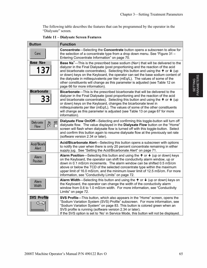
SE
TT
ING
P
AR
AM
ET
ER
S
Chapter 3—Setting Treatment Parameters
2008T Machine Operator’s Manual P/N 490122 Rev O 65
The following table describes the features that can be programmed by the operator in the “Dialysate” screen.
Table 11 – Dialysate Screen Features
Button Function
Concentrate—Selecting the Concentrate button opens a subscreen to allow for the selection of a concentrate type from a drop down menu. See “Figure 31 – Entering Concentrate Information” on page 70.
Base Na+—This is the prescribed base sodium (Na+) that will be delivered to the dialyzer in the Final Dialysate (post proportioning and the reaction of the acid and bicarbonate concentrates). Selecting this button and using the or (up or down) keys on the Keyboard, the operator can set the base sodium content of the dialysate in milliequivalents per liter (mEq/L). The values of some of the other constituents will change as this parameter is adjusted (see Table 12 on page 66 for more information).
Bicarbonate—This is the prescribed bicarbonate that will be delivered to the dialyzer in the Final Dialysate (post proportioning and the reaction of the acid and bicarbonate concentrates). Selecting this button and using the or (up or down) keys on the Keyboard, changes the bicarbonate level in milliequivalents per liter (mEq/L). The values of some of the other constituents will change as this parameter is adjusted (see Table 13 on page 67 for more information).
Dialysate Flow On/Off—Selecting and confirming this toggle-button will turn off dialysate flow. The value displayed in the Dialysate Flow button on the “Home” screen will flash when dialysate flow is turned off with this toggle-button. Select and confirm this button again to resume dialysate flow at the previously set rate (software version 2.34 or later).
Acid/Bicarbonate Alert—Selecting this button opens a subscreen with options to notify the user when there is only 20 percent concentrate remaining in either supply jug. See “Setting the Acid/Bicarbonate Alert” on page 71.
Alarm Position—Selecting this button and using the or (up or down) keys on the Keyboard, the operator can shift the conductivity alarm window, up or down in 0.1 mS/cm increments. The alarm window can be shifted 0.5 mS/cm above or below the TCD of the selected concentrate type within the maximum upper limit of 16.0 mS/cm, and the minimum lower limit of 12.5 mS/cm. For more information, see “Conductivity Limits” on page 72.
Alarm Width—Selecting this button and using the or (up or down) keys on the Keyboard, the operator can change the width of the conductivity alarm window from 0.6 to 1.0 mS/cm width. For more information, see “Conductivity Limits” on page 72.
SVS Profile—This button, which also appears in the “Home” screen, opens the “Sodium Variation System (SVS) Profile” subscreen. For more information, see “Sodium Variation System” on page 83. This button is colored green when an SVS profile is running (software version 2.34 or later). If the SVS option is set to ‘No’ in Service Mode, this button will not be displayed.
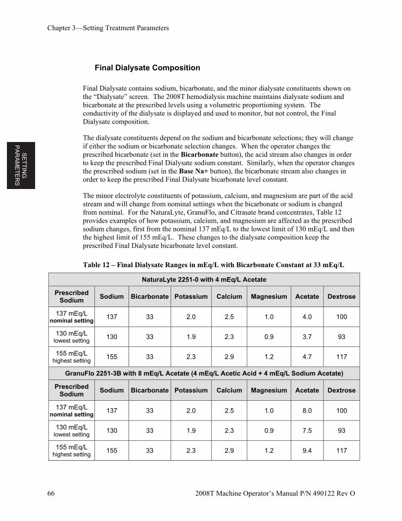
SE
TT
ING
P
AR
AM
ET
ER
S
Chapter 3—Setting Treatment Parameters
66 2008T Machine Operator’s Manual P/N 490122 Rev O
Final Dialysate Composition
Final Dialysate contains sodium, bicarbonate, and the minor dialysate constituents shown on the “Dialysate” screen. The 2008T hemodialysis machine maintains dialysate sodium and bicarbonate at the prescribed levels using a volumetric proportioning system. The conductivity of the dialysate is displayed and used to monitor, but not control, the Final Dialysate composition.
The dialysate constituents depend on the sodium and bicarbonate selections; they will change if either the sodium or bicarbonate selection changes. When the operator changes the prescribed bicarbonate (set in the Bicarbonate button), the acid stream also changes in order to keep the prescribed Final Dialysate sodium constant. Similarly, when the operator changes the prescribed sodium (set in the Base Na+ button), the bicarbonate stream also changes in order to keep the prescribed Final Dialysate bicarbonate level constant.
The minor electrolyte constituents of potassium, calcium, and magnesium are part of the acid stream and will change from nominal settings when the bicarbonate or sodium is changed from nominal. For the NaturaLyte, GranuFlo, and Citrasate brand concentrates, Table 12 provides examples of how potassium, calcium, and magnesium are affected as the prescribed sodium changes, first from the nominal 137 mEq/L to the lowest limit of 130 mEq/L and then the highest limit of 155 mEq/L. These changes to the dialysate composition keep the prescribed Final Dialysate bicarbonate level constant.
Table 12 – Final Dialysate Ranges in mEq/L with Bicarbonate Constant at 33 mEq/L
NaturaLyte 2251-0 with 4 mEq/L Acetate
Prescribed Sodium
Sodium Bicarbonate Potassium Calcium Magnesium Acetate Dextrose
137 mEq/L nominal setting 137 33 2.0 2.5 1.0 4.0 100
130 mEq/L lowest setting 130 33 1.9 2.3 0.9 3.7 93
155 mEq/L highest setting 155 33 2.3 2.9 1.2 4.7 117
GranuFlo 2251-3B with 8 mEq/L Acetate (4 mEq/L Acetic Acid + 4 mEq/L Sodium Acetate)
Prescribed Sodium
Sodium Bicarbonate Potassium Calcium Magnesium Acetate Dextrose
137 mEq/L nominal setting 137 33 2.0 2.5 1.0 8.0 100
130 mEq/L lowest setting 130 33 1.9 2.3 0.9 7.5 93
155 mEq/L highest setting 155 33 2.3 2.9 1.2 9.4 117
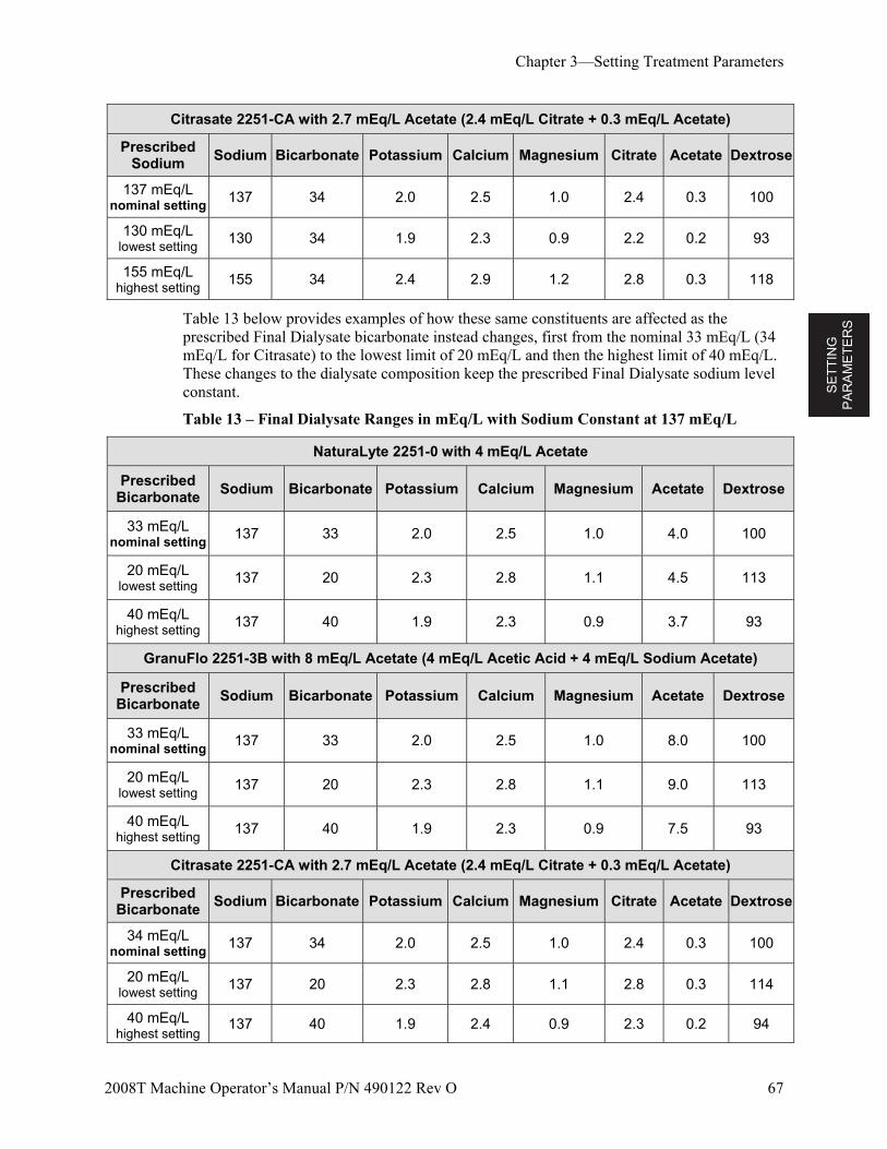
SE
TT
ING
P
AR
AM
ET
ER
S
Chapter 3—Setting Treatment Parameters
2008T Machine Operator’s Manual P/N 490122 Rev O 67
Citrasate 2251-CA with 2.7 mEq/L Acetate (2.4 mEq/L Citrate + 0.3 mEq/L Acetate)
Prescribed Sodium
Sodium Bicarbonate Potassium Calcium Magnesium Citrate Acetate Dextrose
137 mEq/L nominal setting 137 34 2.0 2.5 1.0 2.4 0.3 100
130 mEq/L lowest setting 130 34 1.9 2.3 0.9 2.2 0.2 93
155 mEq/L highest setting 155 34 2.4 2.9 1.2 2.8 0.3 118
Table 13 below provides examples of how these same constituents are affected as the prescribed Final Dialysate bicarbonate instead changes, first from the nominal 33 mEq/L (34 mEq/L for Citrasate) to the lowest limit of 20 mEq/L and then the highest limit of 40 mEq/L. These changes to the dialysate composition keep the prescribed Final Dialysate sodium level constant.
Table 13 – Final Dialysate Ranges in mEq/L with Sodium Constant at 137 mEq/L
NaturaLyte 2251-0 with 4 mEq/L Acetate
Prescribed Bicarbonate
Sodium Bicarbonate Potassium Calcium Magnesium Acetate Dextrose
33 mEq/L nominal setting 137 33 2.0 2.5 1.0 4.0 100
20 mEq/L lowest setting 137 20 2.3 2.8 1.1 4.5 113
40 mEq/L highest setting 137 40 1.9 2.3 0.9 3.7 93
GranuFlo 2251-3B with 8 mEq/L Acetate (4 mEq/L Acetic Acid + 4 mEq/L Sodium Acetate)
Prescribed Bicarbonate
Sodium Bicarbonate Potassium Calcium Magnesium Acetate Dextrose
33 mEq/L nominal setting 137 33 2.0 2.5 1.0 8.0 100
20 mEq/L lowest setting 137 20 2.3 2.8 1.1 9.0 113
40 mEq/L highest setting 137 40 1.9 2.3 0.9 7.5 93
Citrasate 2251-CA with 2.7 mEq/L Acetate (2.4 mEq/L Citrate + 0.3 mEq/L Acetate)
Prescribed Bicarbonate
Sodium Bicarbonate Potassium Calcium Magnesium Citrate Acetate Dextrose
34 mEq/L nominal setting 137 34 2.0 2.5 1.0 2.4 0.3 100
20 mEq/L lowest setting 137 20 2.3 2.8 1.1 2.8 0.3 114
40 mEq/L highest setting
137 40 1.9 2.4 0.9 2.3 0.2 94
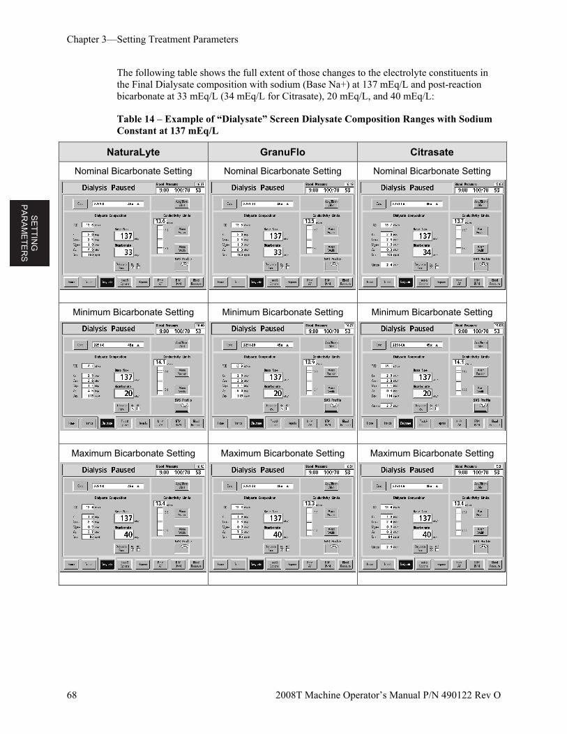
SE
TT
ING
P
AR
AM
ET
ER
S
Chapter 3—Setting Treatment Parameters
68 2008T Machine Operator’s Manual P/N 490122 Rev O
The following table shows the full extent of those changes to the electrolyte constituents in the Final Dialysate composition with sodium (Base Na+) at 137 mEq/L and post-reaction bicarbonate at 33 mEq/L (34 mEq/L for Citrasate), 20 mEq/L, and 40 mEq/L:
Table 14 – Example of “Dialysate” Screen Dialysate Composition Ranges with Sodium Constant at 137 mEq/L
NaturaLyte GranuFlo Citrasate
Nominal Bicarbonate Setting
Nominal Bicarbonate Setting Nominal Bicarbonate Setting
Minimum Bicarbonate Setting
Minimum Bicarbonate Setting Minimum Bicarbonate Setting
Maximum Bicarbonate Setting
Maximum Bicarbonate Setting Maximum Bicarbonate Setting
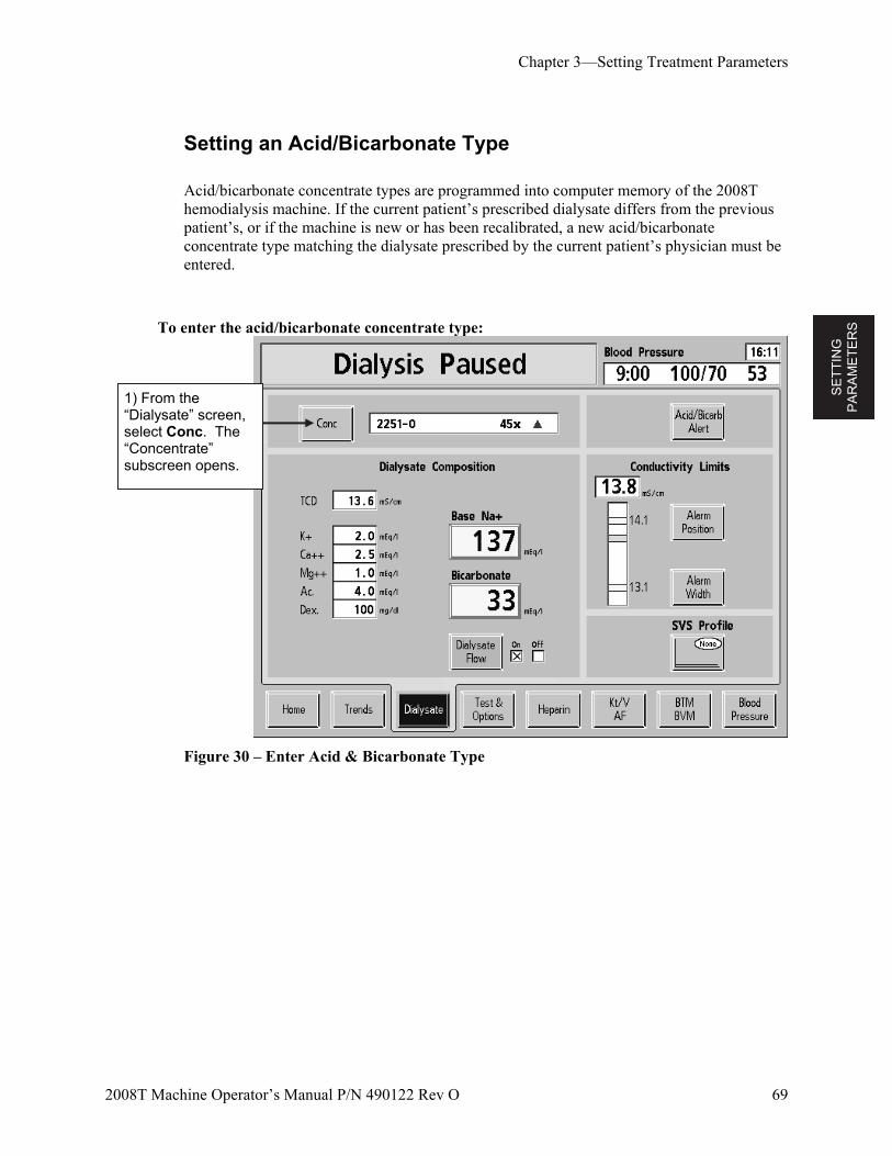
SE
TT
ING
P
AR
AM
ET
ER
S
Chapter 3—Setting Treatment Parameters
2008T Machine Operator’s Manual P/N 490122 Rev O 69
Setting an Acid/Bicarbonate Type
Acid/bicarbonate concentrate types are programmed into computer memory of the 2008T hemodialysis machine. If the current patient’s prescribed dialysate differs from the previous patient’s, or if the machine is new or has been recalibrated, a new acid/bicarbonate concentrate type matching the dialysate prescribed by the current patient’s physician must be entered.
To enter the acid/bicarbonate concentrate type:
Figure 30 – Enter Acid & Bicarbonate Type
1) From the “Dialysate” screen, select Conc. The “Concentrate” subscreen opens.
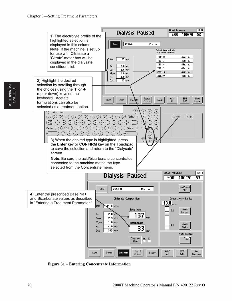
SE
TT
ING
P
AR
AM
ET
ER
S
Chapter 3—Setting Treatment Parameters
70 2008T Machine Operator’s Manual P/N 490122 Rev O
Figure 31 – Entering Concentrate Information
2) Highlight the desired selection by scrolling through the choices using the or (up or down) keys on the keyboard. Acetate formulations can also be selected as a treatment option.
3) When the desired type is highlighted, press the Enter key or CONFIRM key on the Touchpad to save the selection and return to the “Dialysate” screen.
Note: Be sure the acid/bicarbonate concentrates connected to the machine match the type selected from the Concentrate menu.
4) Enter the prescribed Base Na+ and Bicarbonate values as described in “Entering a Treatment Parameter.”
1) The electrolyte profile of the highlighted selection is displayed in this column. Note: If the machine is set up for use with Citrasate a ‘Citrate’ meter box will be displayed in the dialysate constituent list.
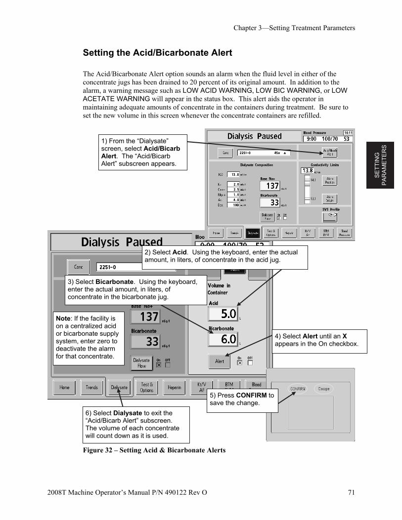
SE
TT
ING
P
AR
AM
ET
ER
S
Chapter 3—Setting Treatment Parameters
2008T Machine Operator’s Manual P/N 490122 Rev O 71
Setting the Acid/Bicarbonate Alert
The Acid/Bicarbonate Alert option sounds an alarm when the fluid level in either of the concentrate jugs has been drained to 20 percent of its original amount. In addition to the alarm, a warning message such as LOW ACID WARNING, LOW BIC WARNING, or LOW ACETATE WARNING will appear in the status box. This alert aids the operator in maintaining adequate amounts of concentrate in the containers during treatment. Be sure to set the new volume in this screen whenever the concentrate containers are refilled.
Figure 32 – Setting Acid & Bicarbonate Alerts
5) Press CONFIRM to save the change.
Note: If the facility is on a centralized acid or bicarbonate supply system, enter zero to deactivate the alarm for that concentrate.
6) Select Dialysate to exit the “Acid/Bicarb Alert” subscreen. The volume of each concentrate will count down as it is used.
2) Select Acid. Using the keyboard, enter the actual amount, in liters, of concentrate in the acid jug.
3) Select Bicarbonate. Using the keyboard, enter the actual amount, in liters, of concentrate in the bicarbonate jug.
4) Select Alert until an X appears in the On checkbox.
1) From the “Dialysate” screen, select Acid/Bicarb Alert. The “Acid/Bicarb Alert” subscreen appears.
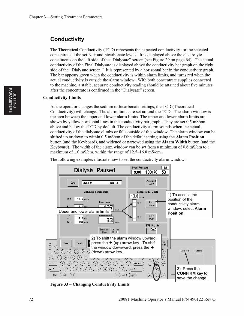
SE
TT
ING
P
AR
AM
ET
ER
S
Chapter 3—Setting Treatment Parameters
72 2008T Machine Operator’s Manual P/N 490122 Rev O
Conductivity
The Theoretical Conductivity (TCD) represents the expected conductivity for the selected concentrate at the set Na+ and bicarbonate levels. It is displayed above the electrolyte constituents on the left side of the “Dialysate” screen (see Figure 29 on page 64). The actual conductivity of the Final Dialysate is displayed above the conductivity bar graph on the right side of the “Dialysate screen.” It is represented by a horizontal bar in the conductivity graph. The bar appears green when the conductivity is within alarm limits, and turns red when the actual conductivity is outside the alarm window. With both concentrate supplies connected to the machine, a stable, accurate conductivity reading should be attained about five minutes after the concentrate is confirmed in the “Dialysate” screen.
Conductivity Limits
As the operator changes the sodium or bicarbonate settings, the TCD (Theoretical Conductivity) will change. The alarm limits are set around the TCD. The alarm window is the area between the upper and lower alarm limits. The upper and lower alarm limits are shown by yellow horizontal lines in the conductivity bar graph. They are set 0.5 mS/cm above and below the TCD by default. The conductivity alarm sounds when the actual conductivity of the dialysate climbs or falls outside of this window. The alarm window can be shifted up or down to within 0.5 mS/cm of the default setting using the Alarm Position button (and the Keyboard), and widened or narrowed using the Alarm Width button (and the Keyboard). The width of the alarm window can be set from a minimum of 0.6 mS/cm to a maximum of 1.0 mS/cm, within the range of 12.5–16.0 mS/cm.
The following examples illustrate how to set the conductivity alarm window:
Figure 33 – Changing Conductivity Limits
Upper and lower alarm limits
1) To access the position of the conductivity alarm window, select Alarm Position.
2) To shift the alarm window upward, press the (up) arrow key. To shift the window downward, press the (down) arrow key.
3) Press the CONFIRM key to save the change.
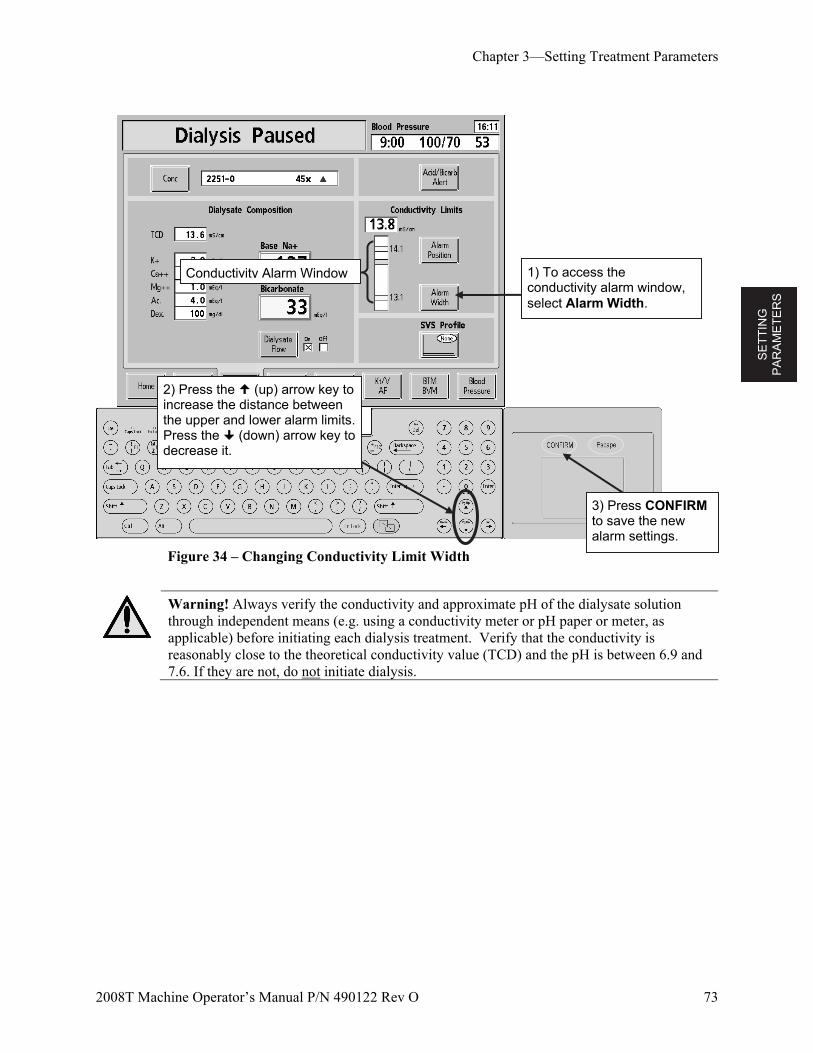
SE
TT
ING
P
AR
AM
ET
ER
S
Chapter 3—Setting Treatment Parameters
2008T Machine Operator’s Manual P/N 490122 Rev O 73
Figure 34 – Changing Conductivity Limit Width
Warning! Always verify the conductivity and approximate pH of the dialysate solution through independent means (e.g. using a conductivity meter or pH paper or meter, as applicable) before initiating each dialysis treatment. Verify that the conductivity is reasonably close to the theoretical conductivity value (TCD) and the pH is between 6.9 and 7.6. If they are not, do not initiate dialysis.
Conductivity Alarm Window 1) To access the conductivity alarm window, select Alarm Width.
2) Press the (up) arrow key to increase the distance between the upper and lower alarm limits. Press the (down) arrow key to decrease it.
3) Press CONFIRM to save the new alarm settings.
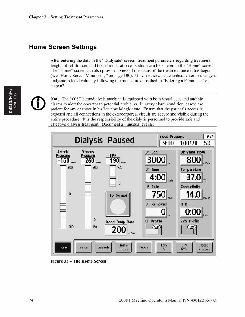
SE
TT
ING
P
AR
AM
ET
ER
S
Chapter 3—Setting Treatment Parameters
74 2008T Machine Operator’s Manual P/N 490122 Rev O
Home Screen Settings
After entering the data in the “Dialysate” screen, treatment parameters regarding treatment length, ultrafiltration, and the administration of sodium can be entered in the “Home” screen. The “Home” screen can also provide a view of the status of the treatment once it has begun (see “Home Screen Monitoring” on page 100). Unless otherwise described, enter or change a dialysate-related value by following the procedure described in “Entering a Parameter” on page 62.
Note: The 2008T hemodialysis machine is equipped with both visual cues and audible alarms to alert the operator to potential problems. In every alarm condition, assess the patient for any changes in his/her physiologic state. Ensure that the patient’s access is exposed and all connections in the extracorporeal circuit are secure and visible during the entire procedure. It is the responsibility of the dialysis personnel to provide safe and effective dialysis treatment. Document all unusual events.
Figure 35 – The Home Screen
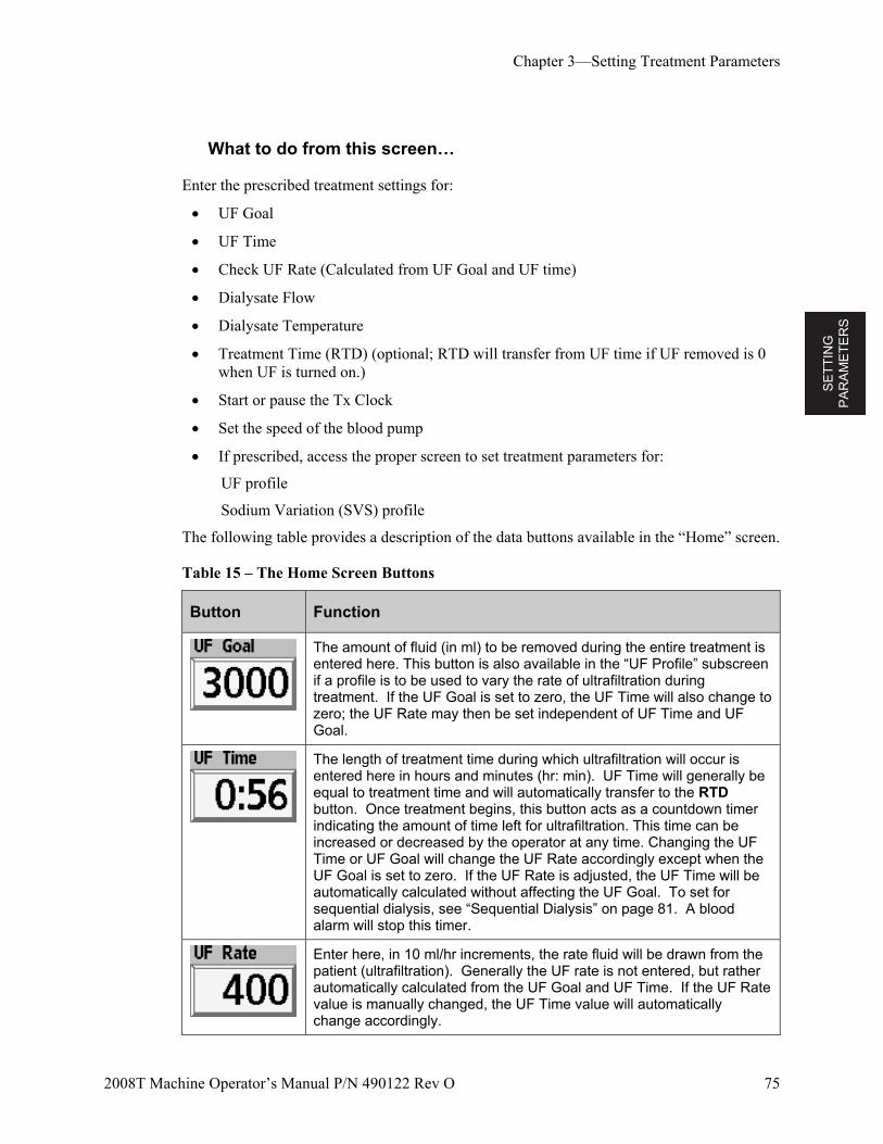
SE
TT
ING
P
AR
AM
ET
ER
S
Chapter 3—Setting Treatment Parameters
2008T Machine Operator’s Manual P/N 490122 Rev O 75
What to do from this screen…
Enter the prescribed treatment settings for:
UF Goal
UF Time
Check UF Rate (Calculated from UF Goal and UF time)
Dialysate Flow
Dialysate Temperature
Treatment Time (RTD) (optional; RTD will transfer from UF time if UF removed is 0 when UF is turned on.)
Start or pause the Tx Clock
Set the speed of the blood pump
If prescribed, access the proper screen to set treatment parameters for:
UF profile
Sodium Variation (SVS) profile
The following table provides a description of the data buttons available in the “Home” screen.
Table 15 – The Home Screen Buttons
Button Function
The amount of fluid (in ml) to be removed during the entire treatment is entered here. This button is also available in the “UF Profile” subscreen if a profile is to be used to vary the rate of ultrafiltration during treatment. If the UF Goal is set to zero, the UF Time will also change to zero; the UF Rate may then be set independent of UF Time and UF Goal.
The length of treatment time during which ultrafiltration will occur is entered here in hours and minutes (hr: min). UF Time will generally be equal to treatment time and will automatically transfer to the RTD button. Once treatment begins, this button acts as a countdown timer indicating the amount of time left for ultrafiltration. This time can be increased or decreased by the operator at any time. Changing the UF Time or UF Goal will change the UF Rate accordingly except when the UF Goal is set to zero. If the UF Rate is adjusted, the UF Time will be automatically calculated without affecting the UF Goal. To set for sequential dialysis, see “Sequential Dialysis” on page 81. A blood alarm will stop this timer.
Enter here, in 10 ml/hr increments, the rate fluid will be drawn from the patient (ultrafiltration). Generally the UF rate is not entered, but rather automatically calculated from the UF Goal and UF Time. If the UF Rate value is manually changed, the UF Time value will automatically change accordingly.
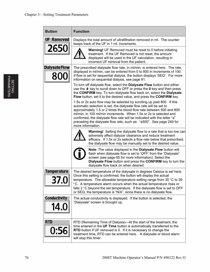
SE
TT
ING
P
AR
AM
ET
ER
S
Chapter 3—Setting Treatment Parameters
76 2008T Machine Operator’s Manual P/N 490122 Rev O
Button Function
Displays the total amount of ultrafiltration removed in ml. The counter keeps track of the UF in 1 ml. increments.
Warning! UF Removed must be reset to 0 before initiating treatment. If the UF Removed is not reset, the amount displayed will be used in the UF calculation, resulting in incorrect UF removal from the patient.
The prescribed dialysate flow rate, in ml/min, is entered here. The rate, displayed in ml/min, can be entered from 0 to 800 in increments of 100. If flow is set for sequential dialysis, the button displays ‘SEQ’. For more information on sequential dialysis, see page 81.
To turn off dialysate flow, select the Dialysate Flow button and either use the key to scroll down to OFF or press the 0 key and then press the CONFIRM key. To turn dialysate flow back on, select the Dialysate Flow button, set it to the desired value, and press the CONFIRM key.
1.5x or 2x auto flow may be selected by scrolling up past 800. If this automatic selection is set, the dialysate flow rate will be set to approximately 1.5 or 2 times the blood flow rate between 500 and 800 ml/min, in 100 ml/min increments. When 1.5x or 2x is selected and confirmed, the dialysate flow rate will be indicated with the letter “a” preceding the dialysate flow rate, such as: “a500”. See page 249 for more information.
Warning! Setting the dialysate flow to a rate that is too low can adversely affect dialyzer clearance and reduce treatment efficacy. If 1.5x or 2x selects a flow rate below that prescribed, the dialysate flow may be manually set to the desired value.
Note: The value displayed in the Dialysate Flow button will flash when dialysate flow is set to ‘OFF’ from the “Dialysate” screen (see page 65 for more information). Select the Dialysate Flow button and press the CONFIRM key to turn the dialysate flow back on when desired.
The desired temperature of the dialysate in degrees Celsius is set here. Once this setting is confirmed, the button will display the actual temperature. The allowable temperature setting range from 35 C to 39 C. A temperature alarm occurs when the actual temperature rises or falls 2 C beyond the set temperature. If the dialysate flow is set to OFF or SEQ, the temperature is “N/A”, since there is no dialysate flow.
The actual conductivity is displayed. If the button is selected, the “Dialysate” screen is brought up.
RTD (Remaining Time of Dialysis)—At the start of the treatment, the time entered in the UF Time button is automatically transferred to the RTD button if UF removed is 0. If it is necessary to change the treatment time, RTD can be entered here. A dialysate or blood alarm will stop this timer.
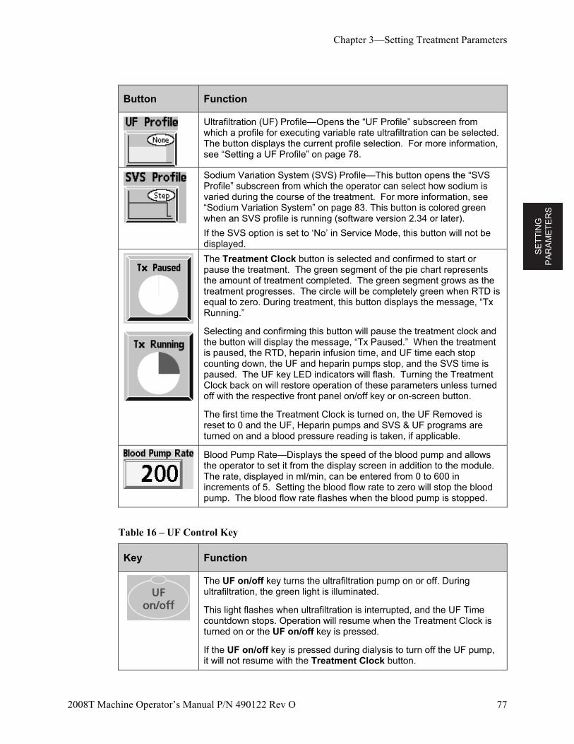
SE
TT
ING
P
AR
AM
ET
ER
S
Chapter 3—Setting Treatment Parameters
2008T Machine Operator’s Manual P/N 490122 Rev O 77
Button Function
Ultrafiltration (UF) Profile—Opens the “UF Profile” subscreen from which a profile for executing variable rate ultrafiltration can be selected. The button displays the current profile selection. For more information, see “Setting a UF Profile” on page 78.
Sodium Variation System (SVS) Profile—This button opens the “SVS Profile” subscreen from which the operator can select how sodium is varied during the course of the treatment. For more information, see “Sodium Variation System” on page 83. This button is colored green when an SVS profile is running (software version 2.34 or later).
If the SVS option is set to ‘No’ in Service Mode, this button will not be displayed.
The Treatment Clock button is selected and confirmed to start or pause the treatment. The green segment of the pie chart represents the amount of treatment completed. The green segment grows as the treatment progresses. The circle will be completely green when RTD is equal to zero. During treatment, this button displays the message, “Tx Running.”
Selecting and confirming this button will pause the treatment clock and the button will display the message, “Tx Paused.” When the treatment is paused, the RTD, heparin infusion time, and UF time each stop counting down, the UF and heparin pumps stop, and the SVS time is paused. The UF key LED indicators will flash. Turning the Treatment Clock back on will restore operation of these parameters unless turned off with the respective front panel on/off key or on-screen button.
The first time the Treatment Clock is turned on, the UF Removed is reset to 0 and the UF, Heparin pumps and SVS & UF programs are turned on and a blood pressure reading is taken, if applicable.
Blood Pump Rate—Displays the speed of the blood pump and allows the operator to set it from the display screen in addition to the module. The rate, displayed in ml/min, can be entered from 0 to 600 in increments of 5. Setting the blood flow rate to zero will stop the blood pump. The blood flow rate flashes when the blood pump is stopped.
Table 16 – UF Control Key
Key Function
The UF on/off key turns the ultrafiltration pump on or off. During ultrafiltration, the green light is illuminated.
This light flashes when ultrafiltration is interrupted, and the UF Time countdown stops. Operation will resume when the Treatment Clock is turned on or the UF on/off key is pressed.
If the UF on/off key is pressed during dialysis to turn off the UF pump, it will not resume with the Treatment Clock button.
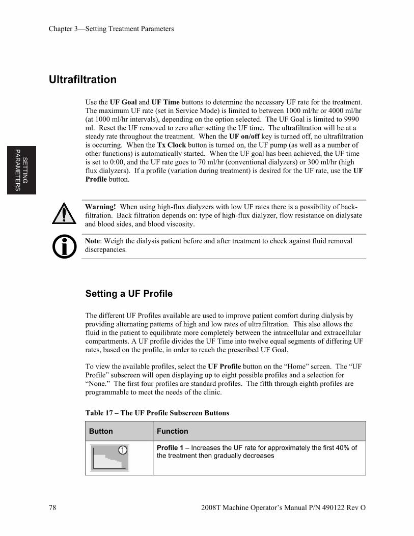
SE
TT
ING
P
AR
AM
ET
ER
S
Chapter 3—Setting Treatment Parameters
78 2008T Machine Operator’s Manual P/N 490122 Rev O
Ultrafiltration
Use the UF Goal and UF Time buttons to determine the necessary UF rate for the treatment. The maximum UF rate (set in Service Mode) is limited to between 1000 ml/hr or 4000 ml/hr (at 1000 ml/hr intervals), depending on the option selected. The UF Goal is limited to 9990 ml. Reset the UF removed to zero after setting the UF time. The ultrafiltration will be at a steady rate throughout the treatment. When the UF on/off key is turned off, no ultrafiltration is occurring. When the Tx Clock button is turned on, the UF pump (as well as a number of other functions) is automatically started. When the UF goal has been achieved, the UF time is set to 0:00, and the UF rate goes to 70 ml/hr (conventional dialyzers) or 300 ml/hr (high flux dialyzers). If a profile (variation during treatment) is desired for the UF rate, use the UF Profile button.
Warning! When using high-flux dialyzers with low UF rates there is a possibility of back-filtration. Back filtration depends on: type of high-flux dialyzer, flow resistance on dialysate and blood sides, and blood viscosity.
Note: Weigh the dialysis patient before and after treatment to check against fluid removal discrepancies.
Setting a UF Profile
The different UF Profiles available are used to improve patient comfort during dialysis by providing alternating patterns of high and low rates of ultrafiltration. This also allows the fluid in the patient to equilibrate more completely between the intracellular and extracellular compartments. A UF profile divides the UF Time into twelve equal segments of differing UF rates, based on the profile, in order to reach the prescribed UF Goal.
To view the available profiles, select the UF Profile button on the “Home” screen. The “UF Profile” subscreen will open displaying up to eight possible profiles and a selection for “None.” The first four profiles are standard profiles. The fifth through eighth profiles are programmable to meet the needs of the clinic.
Table 17 – The UF Profile Subscreen Buttons
Button Function
Profile 1 – Increases the UF rate for approximately the first 40% of the treatment then gradually decreases
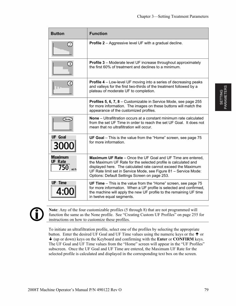
SE
TT
ING
P
AR
AM
ET
ER
S
Chapter 3—Setting Treatment Parameters
2008T Machine Operator’s Manual P/N 490122 Rev O 79
Button Function
Profile 2 – Aggressive level UF with a gradual decline.
Profile 3 – Moderate level UF increase throughout approximately the first 60% of treatment and declines to a minimum.
Profile 4 – Low-level UF moving into a series of decreasing peaks and valleys for the first two-thirds of the treatment followed by a plateau of moderate UF to completion.
Profiles 5, 6, 7, 8 – Customizable in Service Mode, see page 255 for more information. The images on these buttons will match the appearance of the customized profiles.
None – Ultrafiltration occurs at a constant minimum rate calculated from the set UF Time in order to reach the set UF Goal. It does not mean that no ultrafiltration will occur.
UF Goal – This is the value from the “Home” screen, see page 75 for more information.
Maximum UF Rate – Once the UF Goal and UF Time are entered, the Maximum UF Rate for the selected profile is calculated and displayed here. The calculated rate cannot exceed the Maximum UF Rate limit set in Service Mode, see Figure 81 – Service Mode: Options: Default Settings Screen on page 253.
UF Time – This is the value from the “Home” screen, see page 75 for more information. When a UF profile is selected and confirmed, the machine will apply the new UF profile to the remaining UF time in twelve equal segments.
Note: Any of the four customizable profiles (5 through 8) that are not programmed will function the same as the None profile. See “Creating Custom UF Profiles” on page 255 for instructions on how to customize these profiles.
To initiate an ultrafiltration profile, select one of the profiles by selecting the appropriate button. Enter the desired UF Goal and UF Time values using the numeric keys or the or (up or down) keys on the Keyboard and confirming with the Enter or CONFIRM keys. The UF Goal and UF Time values from the “Home” screen will appear in the “UF Profiles” subscreen. Once the UF Goal and UF Time are entered, the Maximum UF Rate for the selected profile is calculated and displayed in the corresponding text box on the screen.
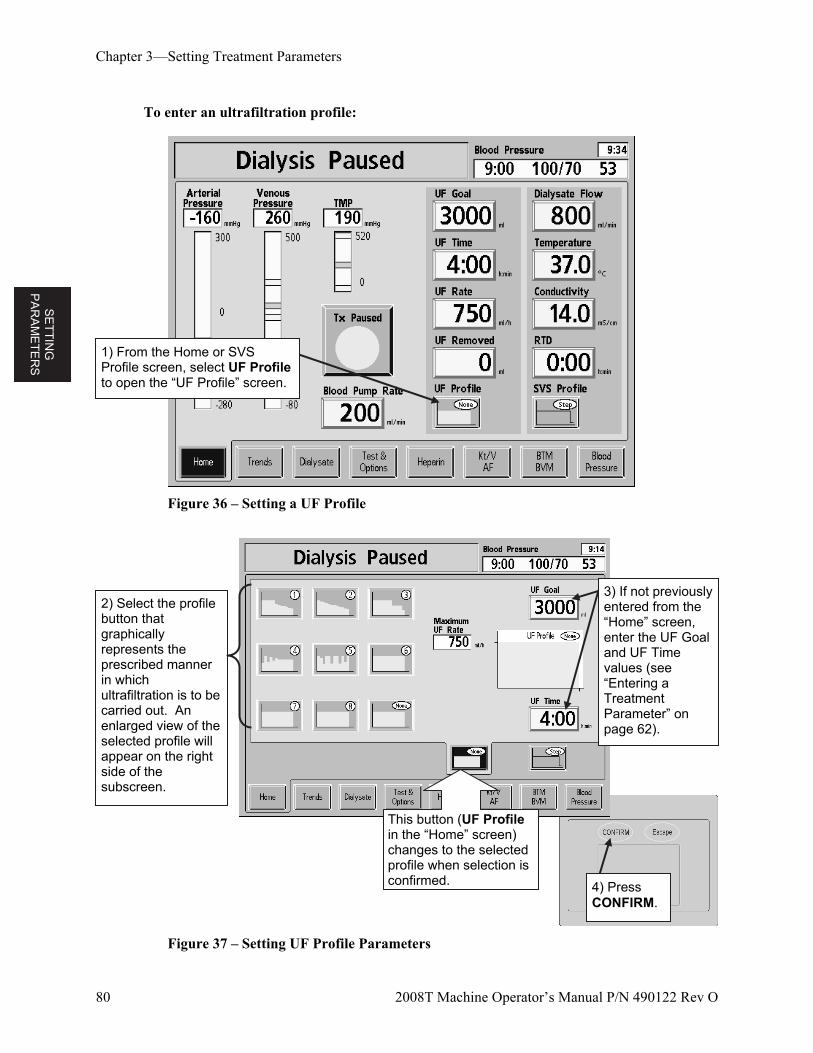
SE
TT
ING
P
AR
AM
ET
ER
S
Chapter 3—Setting Treatment Parameters
80 2008T Machine Operator’s Manual P/N 490122 Rev O
To enter an ultrafiltration profile:
Figure 36 – Setting a UF Profile
Figure 37 – Setting UF Profile Parameters
1) From the Home or SVS Profile screen, select UF Profile to open the “UF Profile” screen.
2) Select the profile button that graphically represents the prescribed manner in which ultrafiltration is to be carried out. An enlarged view of the selected profile will appear on the right side of the subscreen.
4) Press CONFIRM.
3) If not previously entered from the “Home” screen, enter the UF Goal and UF Time values (see “Entering a Treatment Parameter” on page 62).
This button (UF Profile in the “Home” screen) changes to the selected profile when selection is confirmed.
SE
TT
ING
P
AR
AM
ET
ER
S
Chapter 3—Setting Treatment Parameters
2008T Machine Operator’s Manual P/N 490122 Rev O 81
Note: The “None” profile performs ultrafiltration at a constant rate. It does not mean that no ultrafiltration will occur.
The maximum UF rate is displayed for the selected profile, UF Goal, and UF Time. If the maximum UF Rate is too high (beyond the configuration of the machine), a message appears in the Dialogue Box located in the upper, right corner of the screen. The operator has the option of increasing the UF Time, reducing the UF Goal, or selecting another profile.
To change the profile, select the corresponding profile button.
To change the time, select the UF Time button.
To change the UF goal, select the UF Goal button. The maximum ultrafiltration rate, based on the UF Goal, Time & Profile, will be calculated and displayed in the Maximum UF-Rate display.
When all ultrafiltration parameters are satisfactory, press CONFIRM to save the changes, then exit from the “UF Profile” screen. The machine will apply the new UF profile to the remaining UF time in twelve equal segments.
Sequential Dialysis
Sequential dialysis refers to a two-stage treatment in which one of the stages consists solely of ultrafiltration without dialysate flow (no diffusion). This stage of the treatment is also referred to as “pure UF,” or “no-flow dialysis,” and is often prescribed for patients suffering from excessive fluid retention. Pure UF is usually performed at the beginning of a standard dialysis treatment, although it can also be administered during treatment. The operator can start or stop the pure UF option at any time. In pure UF, Dialysate Flow is set to ‘SEQ’ (a special flow rate of 0 ml/min), and only ultrafiltration occurs. The Temperature button in the “Home” screen displays ‘N/A’.
Note: Setting and confirming the Dialysate Flow to ‘0’ will turn it OFF instead of running sequential dialysis. After five minutes of pure ultrafiltration, an alarm sounds and the warning message, “5 MINUTES FLOW OFF,” appears in the Status Box. The operator has the option of continuing pure ultrafiltration or starting dialysis. This alarm occurs only once.
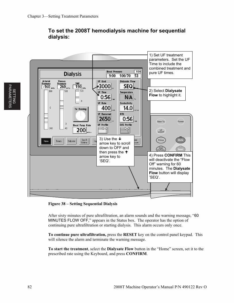
SE
TT
ING
P
AR
AM
ET
ER
S
Chapter 3—Setting Treatment Parameters
82 2008T Machine Operator’s Manual P/N 490122 Rev O
To set the 2008T hemodialysis machine for sequential dialysis:
Figure 38 – Setting Sequential Dialysis
After sixty minutes of pure ultrafiltration, an alarm sounds and the warning message, “60 MINUTES FLOW OFF,” appears in the Status box. The operator has the option of continuing pure ultrafiltration or starting dialysis. This alarm occurs only once.
To continue pure ultrafiltration, press the RESET key on the control panel keypad. This will silence the alarm and terminate the warning message.
To start the treatment, select the Dialysate Flow button in the “Home” screen, set it to the prescribed rate using the Keyboard, and press CONFIRM.
1) Set UF treatment parameters. Set the UF Time to include the combined treatment and pure UF times.
4) Press CONFIRM This will deactivate the “Flow Off” warning for 60 minutes. The Dialysate Flow button will display ’SEQ’.
3) Use the arrow key to scroll down to OFF and then press the arrow key to ‘SEQ’.
2) Select Dialysate Flow to highlight it.
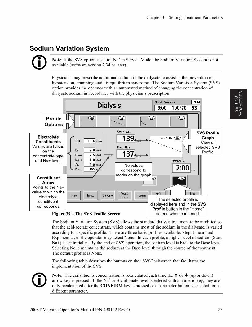
SE
TT
ING
P
AR
AM
ET
ER
S
Chapter 3—Setting Treatment Parameters
2008T Machine Operator’s Manual P/N 490122 Rev O 83
Sodium Variation System
Note: If the SVS option is set to ‘No’ in Service Mode, the Sodium Variation System is not available (software version 2.34 or later).
Physicians may prescribe additional sodium in the dialysate to assist in the prevention of hypotension, cramping, and disequilibrium syndrome. The Sodium Variation System (SVS) option provides the operator with an automated method of changing the concentration of dialysate sodium in accordance with the physician’s prescription.
Figure 39 – The SVS Profile Screen
The Sodium Variation System (SVS) allows the standard dialysis treatment to be modified so that the acid/acetate concentrate, which contains most of the sodium in the dialysate, is varied according to a specific profile. There are three basic profiles available: Step, Linear, and Exponential, or the operator may select None. In each profile, a higher level of sodium (Start Na+) is set initially. By the end of SVS operation, the sodium level is back to the Base level. Selecting None maintains the sodium at the Base level through the course of the treatment. The default profile is None.
The following table describes the buttons on the “SVS” subscreen that facilitates the implementation of the SVS.
Note: The constituents concentration is recalculated each time the or (up or down) arrow key is pressed. If the Na+ or Bicarbonate level is entered with a numeric key, they are only recalculated after the CONFIRM key is pressed or a parameter button is selected for a different parameter.
Electrolyte Constituents
Values are based on the
concentrate type and Na+ level.
No values correspond to
marks on the graph
The selected profile is displayed here and in the SVS Profile button in the “Home”
screen when confirmed.
Constituent Arrow
Points to the Na+ value to which the
electrolyte constituent
corresponds
SVS Profile Graph View of
selected SVS Profile
Profile Options
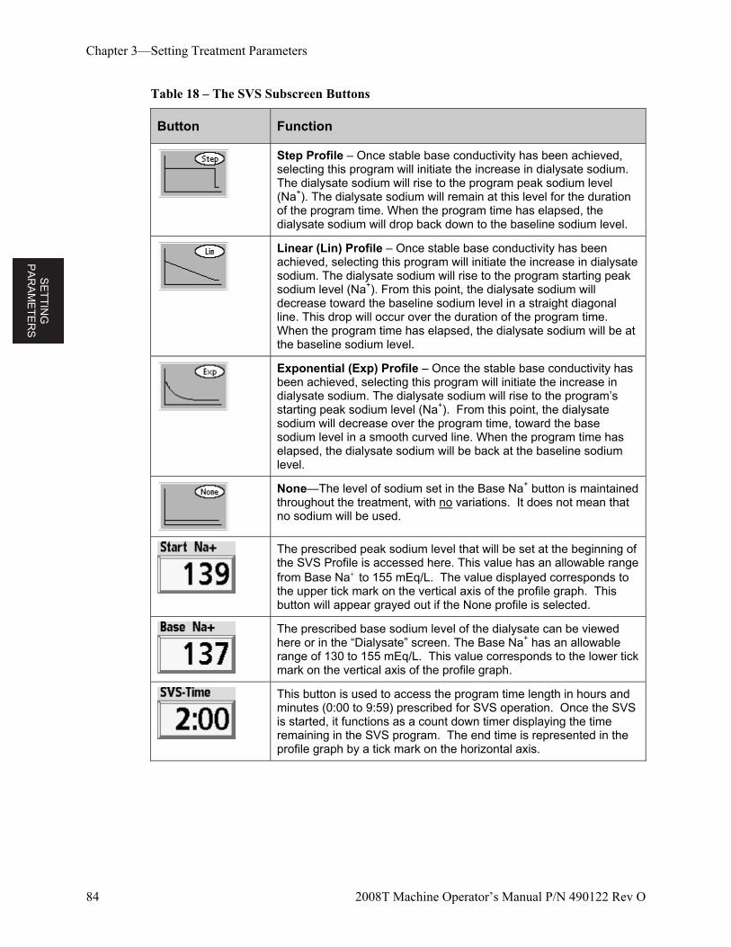
SE
TT
ING
P
AR
AM
ET
ER
S
Chapter 3—Setting Treatment Parameters
84 2008T Machine Operator’s Manual P/N 490122 Rev O
Table 18 – The SVS Subscreen Buttons
Button Function
Step Profile – Once stable base conductivity has been achieved, selecting this program will initiate the increase in dialysate sodium. The dialysate sodium will rise to the program peak sodium level (Na+). The dialysate sodium will remain at this level for the duration of the program time. When the program time has elapsed, the dialysate sodium will drop back down to the baseline sodium level.
Linear (Lin) Profile – Once stable base conductivity has been achieved, selecting this program will initiate the increase in dialysate sodium. The dialysate sodium will rise to the program starting peak sodium level (Na+). From this point, the dialysate sodium will decrease toward the baseline sodium level in a straight diagonal line. This drop will occur over the duration of the program time. When the program time has elapsed, the dialysate sodium will be at the baseline sodium level.
Exponential (Exp) Profile – Once the stable base conductivity has been achieved, selecting this program will initiate the increase in dialysate sodium. The dialysate sodium will rise to the program’s starting peak sodium level (Na+). From this point, the dialysate sodium will decrease over the program time, toward the base sodium level in a smooth curved line. When the program time has elapsed, the dialysate sodium will be back at the baseline sodium level.
None—The level of sodium set in the Base Na+ button is maintained throughout the treatment, with no variations. It does not mean that no sodium will be used.
The prescribed peak sodium level that will be set at the beginning of the SVS Profile is accessed here. This value has an allowable range from Base Na to 155 mEq/L. The value displayed corresponds to the upper tick mark on the vertical axis of the profile graph. This button will appear grayed out if the None profile is selected.
The prescribed base sodium level of the dialysate can be viewed here or in the “Dialysate” screen. The Base Na+ has an allowable range of 130 to 155 mEq/L. This value corresponds to the lower tick mark on the vertical axis of the profile graph.
This button is used to access the program time length in hours and minutes (0:00 to 9:59) prescribed for SVS operation. Once the SVS is started, it functions as a count down timer displaying the time remaining in the SVS program. The end time is represented in the profile graph by a tick mark on the horizontal axis.
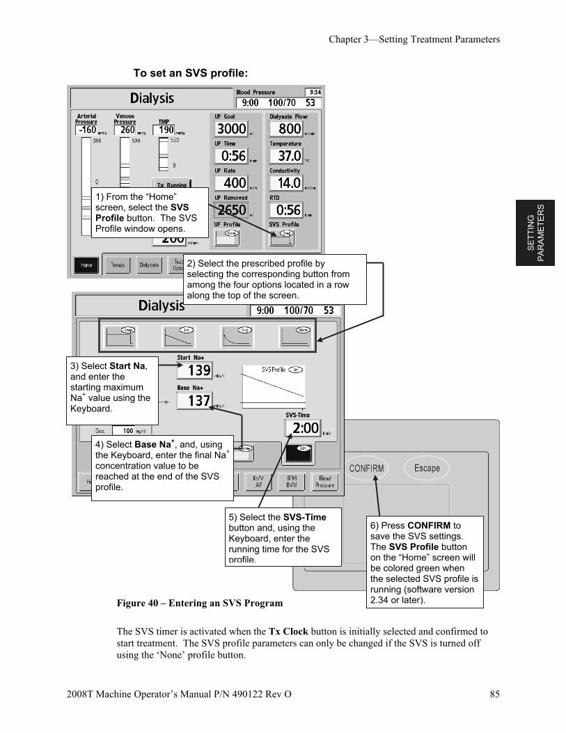
SE
TT
ING
P
AR
AM
ET
ER
S
Chapter 3—Setting Treatment Parameters
2008T Machine Operator’s Manual P/N 490122 Rev O 85
To set an SVS profile:
Figure 40 – Entering an SVS Program
The SVS timer is activated when the Tx Clock button is initially selected and confirmed to start treatment. The SVS profile parameters can only be changed if the SVS is turned off using the ‘None’ profile button.
1) From the “Home” screen, select the SVS Profile button. The SVS Profile window opens.
2) Select the prescribed profile by selecting the corresponding button from among the four options located in a row along the top of the screen.
3) Select Start Na, and enter the starting maximum Na+ value using the Keyboard.
6) Press CONFIRM to save the SVS settings. The SVS Profile button on the “Home” screen will be colored green when the selected SVS profile is running (software version 2.34 or later).
5) Select the SVS-Time button and, using the Keyboard, enter the running time for the SVS profile.
4) Select Base Na+, and, using the Keyboard, enter the final Na+ concentration value to be reached at the end of the SVS profile.
SE
TT
ING
P
AR
AM
ET
ER
S
Chapter 3—Setting Treatment Parameters
86 2008T Machine Operator’s Manual P/N 490122 Rev O
Note: During the SVS program, the actual conductivity bar, shown in bar graph on the Dialysate screen, should be centered in the alarm window. This may require shifting the position of the upper and lower alarm limits using the Alarm Position button. See “Conductivity Limits” on page 72.
Note: If any SVS parameter is changed after the program has started (SVS must be turned off to change), a new SVS program is initiated with the displayed SVS time and SVS start Na+.
The Electrolyte Constituents
The acid concentrate is the major source of electrolytes in the dialysate. Increasing the Na+ concentration in the dialysate, therefore, increases the amount of acid concentrate.
Increasing the amount of acid concentrate also increases the concentration of the other electrolytic constituents. These changes can be observed in the electrolyte constituents shown in the left side of the “SVS Profile” subscreen.
To observe the electrolyte constituents for the higher concentration of sodium, select Start Na+. The values in the left column change to reflect the increased sodium (see Figure 39 on page 83). Select Base Na+ to observe the constituents at the base concentration. The arrow indicates which of the Na+ concentrations corresponds to the values. If neither button is highlighted, the electrolyte constituents values default to the Base Na+ setting, as indicated by the arrow.
Operation
Once the SVS program is started, the maximum sodium level (Start Na+) is reached after about three minutes. The theoretical conductivity (TCD) will immediately adjust to the expected conductivity for the selected Na+ level. As the actual conductivity rises, the alarm window will also track upward, to within the maximum conductivity alarm window limit of 0.5 mS/cm above TCD. While the alarm window is rising, the TCD may be outside of the alarm limits. The machine, however, may not be in an alarm state because the limits are tracking the actual conductivity. After the tracking is complete, the alarm window moves automatically to the expected conductivity based on the selected parameters and starting alarm limits. The SVS Time starts counting down when the Start Na+ level is reached.
If an SVS program is in progress, selecting and confirming the None profile will pause the program. The conductivity will return to the Base Na+ level and the SVS-Time countdown stops. Alarms may occur as the conductivity stabilizes. The operator has two options:
Restarting the program by re-selecting the desired SVS Profile and pressing the CONFIRM key. The SVS-Time and Start Na+ may need to be adjusted.
Terminate the program by selecting the SVS Time button on the “SVS Profile” subscreen, entering zero using the Keyboard, and pressing Enter/CONFIRM or by changing profile to “None” and pressing CONFIRM
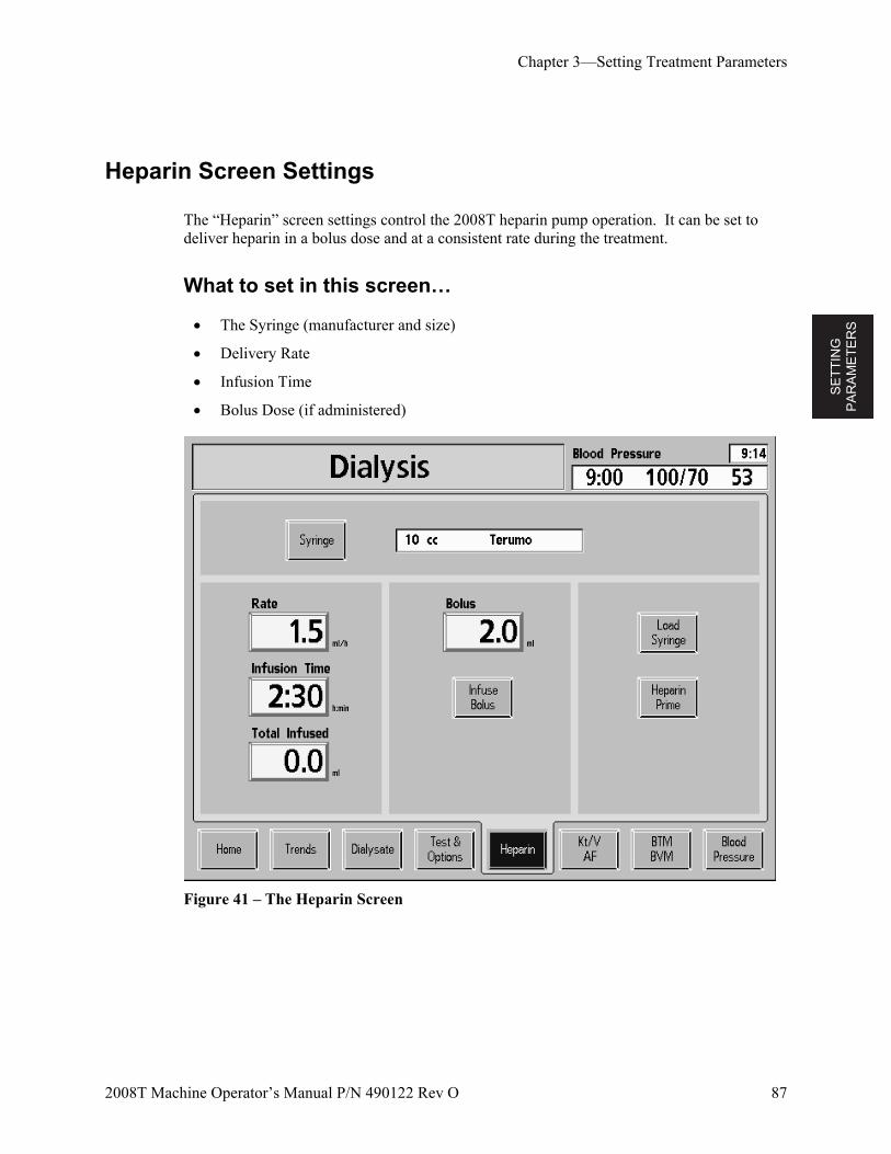
SE
TT
ING
P
AR
AM
ET
ER
S
Chapter 3—Setting Treatment Parameters
2008T Machine Operator’s Manual P/N 490122 Rev O 87
Heparin Screen Settings
The “Heparin” screen settings control the 2008T heparin pump operation. It can be set to deliver heparin in a bolus dose and at a consistent rate during the treatment.
What to set in this screen…
The Syringe (manufacturer and size)
Delivery Rate
Infusion Time
Bolus Dose (if administered)
Figure 41 – The Heparin Screen
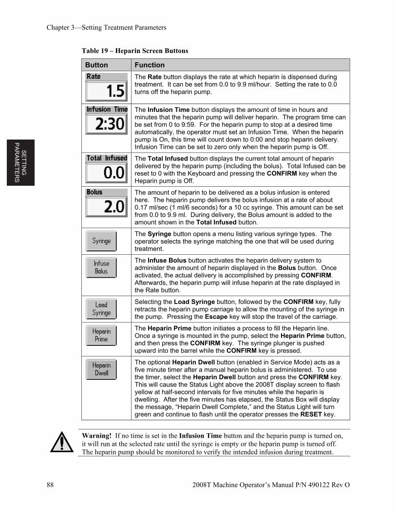
SE
TT
ING
P
AR
AM
ET
ER
S
Chapter 3—Setting Treatment Parameters
88 2008T Machine Operator’s Manual P/N 490122 Rev O
Table 19 – Heparin Screen Buttons
Button Function
The Rate button displays the rate at which heparin is dispensed during treatment. It can be set from 0.0 to 9.9 ml/hour. Setting the rate to 0.0 turns off the heparin pump.
The Infusion Time button displays the amount of time in hours and minutes that the heparin pump will deliver heparin. The program time can be set from 0 to 9:59. For the heparin pump to stop at a desired time automatically, the operator must set an Infusion Time. When the heparin pump is On, this time will count down to 0:00 and stop heparin delivery. Infusion Time can be set to zero only when the heparin pump is Off.
The Total Infused button displays the current total amount of heparin delivered by the heparin pump (including the bolus). Total Infused can be reset to 0 with the Keyboard and pressing the CONFIRM key when the Heparin pump is Off.
The amount of heparin to be delivered as a bolus infusion is entered here. The heparin pump delivers the bolus infusion at a rate of about 0.17 ml/sec (1 ml/6 seconds) for a 10 cc syringe. This amount can be set from 0.0 to 9.9 ml. During delivery, the Bolus amount is added to the amount shown in the Total Infused button.
The Syringe button opens a menu listing various syringe types. The operator selects the syringe matching the one that will be used during treatment.
The Infuse Bolus button activates the heparin delivery system to administer the amount of heparin displayed in the Bolus button. Once activated, the actual delivery is accomplished by pressing CONFIRM. Afterwards, the heparin pump will infuse heparin at the rate displayed in the Rate button.
Selecting the Load Syringe button, followed by the CONFIRM key, fully retracts the heparin pump carriage to allow the mounting of the syringe in the pump. Pressing the Escape key will stop the travel of the carriage.
The Heparin Prime button initiates a process to fill the Heparin line. Once a syringe is mounted in the pump, select the Heparin Prime button, and then press the CONFIRM key. The syringe plunger is pushed upward into the barrel while the CONFIRM key is pressed.
The optional Heparin Dwell button (enabled in Service Mode) acts as a five minute timer after a manual heparin bolus is administered. To use the timer, select the Heparin Dwell button and press the CONFIRM key. This will cause the Status Light above the 2008T display screen to flash yellow at half-second intervals for five minutes while the heparin is dwelling. After the five minutes has elapsed, the Status Box will display the message, “Heparin Dwell Complete,” and the Status Light will turn green and continue to flash until the operator presses the RESET key.
Warning! If no time is set in the Infusion Time button and the heparin pump is turned on, it will run at the selected rate until the syringe is empty or the heparin pump is turned off. The heparin pump should be monitored to verify the intended infusion during treatment.
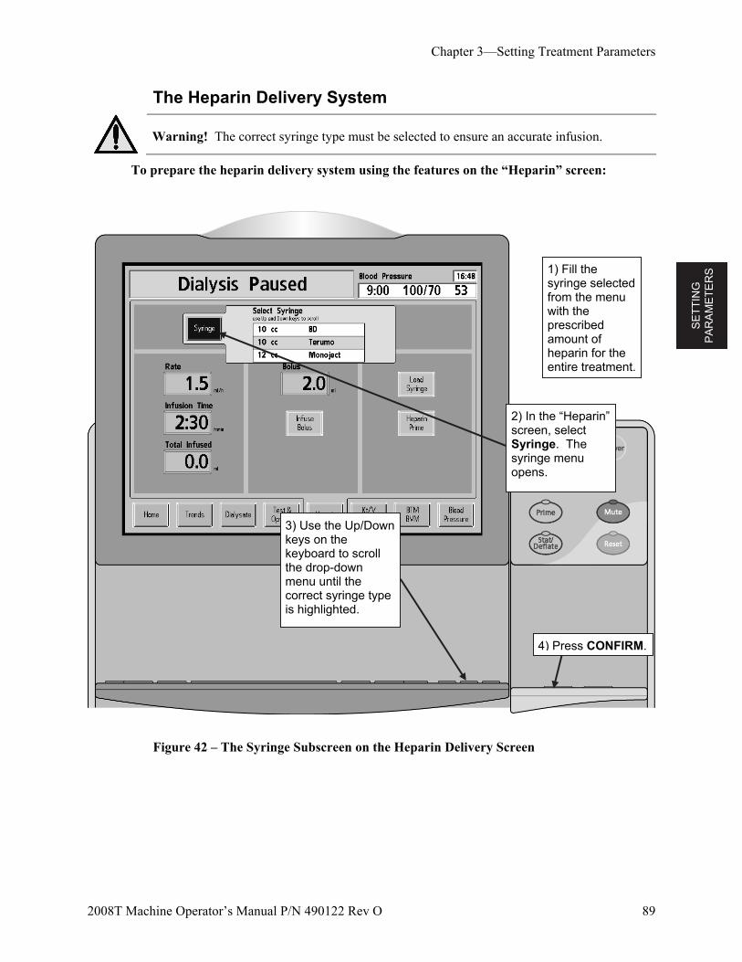
SE
TT
ING
P
AR
AM
ET
ER
S
Chapter 3—Setting Treatment Parameters
2008T Machine Operator’s Manual P/N 490122 Rev O 89
The Heparin Delivery System
Warning! The correct syringe type must be selected to ensure an accurate infusion.
To prepare the heparin delivery system using the features on the “Heparin” screen:
Figure 42 – The Syringe Subscreen on the Heparin Delivery Screen
4) Press CONFIRM.
2) In the “Heparin” screen, select Syringe. The syringe menu opens.
1) Fill the syringe selected from the menu with the prescribed amount of heparin for the entire treatment.
3) Use the Up/Down keys on the keyboard to scroll the drop-down menu until the correct syringe type is highlighted.
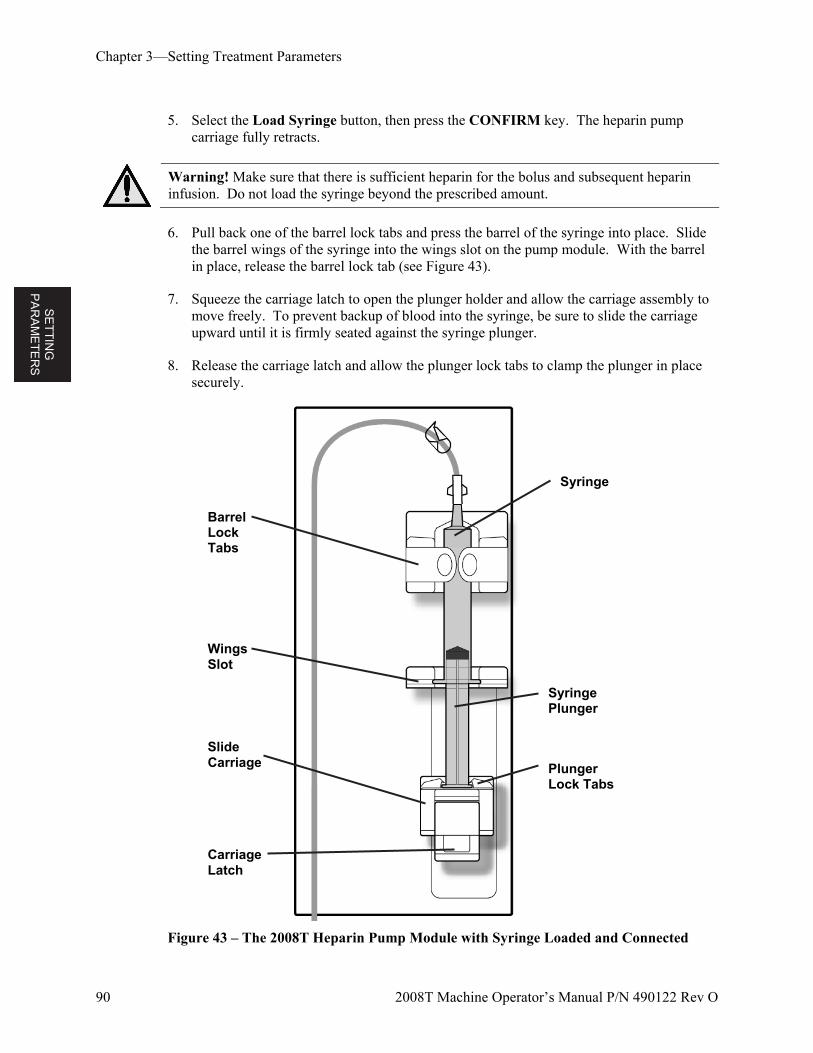
SE
TT
ING
P
AR
AM
ET
ER
S
Chapter 3—Setting Treatment Parameters
90 2008T Machine Operator’s Manual P/N 490122 Rev O
5. Select the Load Syringe button, then press the CONFIRM key. The heparin pump carriage fully retracts.
Warning! Make sure that there is sufficient heparin for the bolus and subsequent heparin infusion. Do not load the syringe beyond the prescribed amount.
6. Pull back one of the barrel lock tabs and press the barrel of the syringe into place. Slide the barrel wings of the syringe into the wings slot on the pump module. With the barrel in place, release the barrel lock tab (see Figure 43).
7. Squeeze the carriage latch to open the plunger holder and allow the carriage assembly to move freely. To prevent backup of blood into the syringe, be sure to slide the carriage upward until it is firmly seated against the syringe plunger.
8. Release the carriage latch and allow the plunger lock tabs to clamp the plunger in place securely.
Figure 43 – The 2008T Heparin Pump Module with Syringe Loaded and Connected
Carriage Latch
Slide Carriage
Syringe
Barrel Lock Tabs
Wings Slot
Syringe Plunger
Plunger Lock Tabs
SE
TT
ING
P
AR
AM
ET
ER
S
Chapter 3—Setting Treatment Parameters
2008T Machine Operator’s Manual P/N 490122 Rev O 91
9. Connect the syringe to the heparin line and unclamp the heparin line.
10. Select the Heparin Prime button, then press and hold the CONFIRM key. As the carriage moves upward, observe the heparin as it travels from the syringe through the heparin line.
11. When the air has been cleared from the heparin line, release the CONFIRM key. The pump will stop.
Warning! Clamp the heparin line closest to the “T” connection during recirculation if using reuse dialyzer.
12. In the “Heparin” screen, set the treatment parameters for Rate, Infusion Time, and Bolus as described in Figure 41 – The Heparin Screen on page 87.
The heparin administration system is now ready for patient treatment.
Warning! The heparin pump is to be used only under positive pressure conditions. Under negative pressure conditions, excessive heparin may be infused.
Note: The Heparin button is colored green when the heparin delivery system is running (software version 2.34 or later).
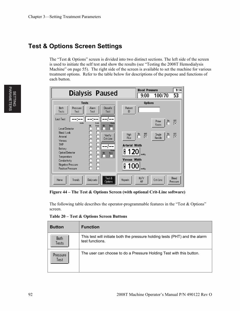
SE
TT
ING
P
AR
AM
ET
ER
S
Chapter 3—Setting Treatment Parameters
92 2008T Machine Operator’s Manual P/N 490122 Rev O
Test & Options Screen Settings
The “Test & Options” screen is divided into two distinct sections. The left side of the screen is used to initiate the self test and show the results (see “Testing the 2008T Hemodialysis Machine” on page 55). The right side of the screen is available to set the machine for various treatment options. Refer to the table below for descriptions of the purpose and functions of each button.
Figure 44 – The Test & Options Screen (with optional Crit-Line software)
The following table describes the operator-programmable features in the “Test & Options” screen.
Table 20 – Test & Options Screen Buttons
Button Function
This test will initiate both the pressure holding tests (PHT) and the alarm test functions.
The user can choose to do a Pressure Holding Test with this button.
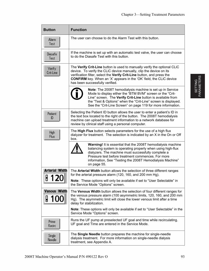
SE
TT
ING
P
AR
AM
ET
ER
S
Chapter 3—Setting Treatment Parameters
2008T Machine Operator’s Manual P/N 490122 Rev O 93
Button Function
The user can choose to do the Alarm Test with this button.
If the machine is set up with an automatic test valve, the user can choose to do the Diasafe Test with this button.
The Verify Crit-Line button is used to manually verify the optional CLiC device. To verify the CLiC device manually, clip the device on its verification filter, select the Verify Crit-Line button, and press the CONFIRM key. When an ‘X’ appears in the ‘OK’ field, the CLiC device has been successfully verified.
Note: The 2008T hemodialysis machine is set up in Service Mode to display either the “BTM BVM” screen or the “Crit-Line” screen. The Verify Crit-Line button is available from the “Test & Options” when the “Crit-Line” screen is displayed. See the “Crit-Line Screen” on page 119 for more information.
Selecting the Patient ID button allows the user to enter a patient’s ID in the text box located to the right of the button. The 2008T hemodialysis machine can upload treatment information to a network database for review by clinical staff using a personal computer.
The High Flux button selects parameters for the use of a high flux dialyzer for treatment. The selection is indicated by an X in the On or Off box.
Warning! It is essential that the 2008T hemodialysis machine balancing system is operating properly when using high-flux dialyzers. The machine must successfully complete a Pressure test before treatment commences. For more information, See “Testing the 2008T Hemodialysis Machine” on page 55.
The Arterial Width button allows the selection of three different ranges for the arterial pressure alarm (120, 160, and 200 mm Hg).
Note: These options will only be available if set to “User Selectable” in the Service Mode “Options” screen.
The Venous Width button allows the selection of four different ranges for the venous pressure alarm (100 asymmetric limits, 120, 160, and 200 mm Hg). The asymmetric limit will close the lower venous limit after a time delay for stabilization.
Note: These options will only be available if set to “User Selectable” in the Service Mode “Options” screen.
Runs the UF pump at preselected UF goal and time while recirculating. UF goal and Time are entered in the Service Mode.
The Single Needle button prepares the machine for single-needle dialysis treatment. For more information on single-needle dialysis treatment, see Appendix A.
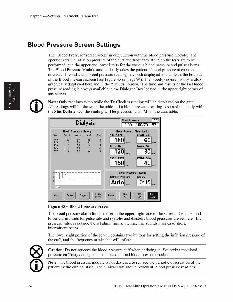
SE
TT
ING
P
AR
AM
ET
ER
S
Chapter 3—Setting Treatment Parameters
94 2008T Machine Operator’s Manual P/N 490122 Rev O
Blood Pressure Screen Settings
The “Blood Pressure” screen works in conjunction with the blood pressure module. The operator sets the inflation pressure of the cuff, the frequency at which the tests are to be performed, and the upper and lower limits for the various blood pressure and pulse alarms. The Blood Pressure Module automatically takes the patient’s blood pressure at each set interval. The pulse and blood pressure readings are both displayed in a table on the left side of the Blood Pressure screen (see Figure 45 on page 94). The blood-pressure history is also graphically displayed here and in the “Trends” screen. The time and results of the last blood pressure reading is always available in the Dialogue Box located in the upper right corner of any screen.
Note: Only readings taken while the Tx Clock is running will be displayed on the graph. All readings will be shown in the table. If a blood pressure reading is started manually with the Stat/Deflate key, the reading will be preceded with “M” in the data table.
Figure 45 – Blood Pressure Screen
The blood pressure alarm limits are set in the upper, right side of the screen. The upper and lower alarm limits for pulse rate and systolic and diastolic blood pressures are set here. If a pressure value is outside the set alarm limits, the machine sounds a series of short, intermittent beeps.
The lower right portion of the screen contains two buttons for setting the inflation pressure of the cuff, and the frequency at which it will inflate.
Caution: Do not squeeze the blood pressure cuff when deflating it. Squeezing the blood pressure cuff may damage the machine's internal blood pressure module.
Note: The blood pressure module is not designed to replace the periodic observation of the patient by the clinical staff. The clinical staff should review all blood pressure readings.
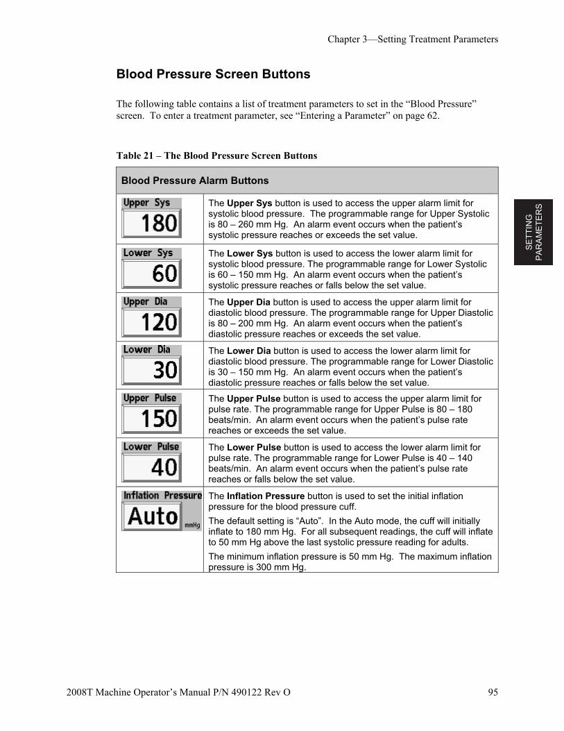
SE
TT
ING
P
AR
AM
ET
ER
S
Chapter 3—Setting Treatment Parameters
2008T Machine Operator’s Manual P/N 490122 Rev O 95
Blood Pressure Screen Buttons
The following table contains a list of treatment parameters to set in the “Blood Pressure” screen. To enter a treatment parameter, see “Entering a Parameter” on page 62.
Table 21 – The Blood Pressure Screen Buttons
Blood Pressure Alarm Buttons
The Upper Sys button is used to access the upper alarm limit for systolic blood pressure. The programmable range for Upper Systolic is 80 – 260 mm Hg. An alarm event occurs when the patient’s systolic pressure reaches or exceeds the set value.
The Lower Sys button is used to access the lower alarm limit for systolic blood pressure. The programmable range for Lower Systolic is 60 – 150 mm Hg. An alarm event occurs when the patient’s systolic pressure reaches or falls below the set value.
The Upper Dia button is used to access the upper alarm limit for diastolic blood pressure. The programmable range for Upper Diastolic is 80 – 200 mm Hg. An alarm event occurs when the patient’s diastolic pressure reaches or exceeds the set value.
The Lower Dia button is used to access the lower alarm limit for diastolic blood pressure. The programmable range for Lower Diastolic is 30 – 150 mm Hg. An alarm event occurs when the patient’s diastolic pressure reaches or falls below the set value.
The Upper Pulse button is used to access the upper alarm limit for pulse rate. The programmable range for Upper Pulse is 80 – 180 beats/min. An alarm event occurs when the patient’s pulse rate reaches or exceeds the set value.
The Lower Pulse button is used to access the lower alarm limit for pulse rate. The programmable range for Lower Pulse is 40 – 140 beats/min. An alarm event occurs when the patient’s pulse rate reaches or falls below the set value.
The Inflation Pressure button is used to set the initial inflation pressure for the blood pressure cuff.
The default setting is “Auto”. In the Auto mode, the cuff will initially inflate to 180 mm Hg. For all subsequent readings, the cuff will inflate to 50 mm Hg above the last systolic pressure reading for adults.
The minimum inflation pressure is 50 mm Hg. The maximum inflation pressure is 300 mm Hg.
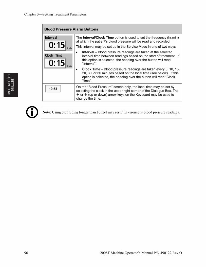
SE
TT
ING
P
AR
AM
ET
ER
S
Chapter 3—Setting Treatment Parameters
96 2008T Machine Operator’s Manual P/N 490122 Rev O
Blood Pressure Alarm Buttons
The Interval/Clock Time button is used to set the frequency (hr:min) at which the patient’s blood pressure will be read and recorded.
This interval may be set up in the Service Mode in one of two ways:
Interval – Blood pressure readings are taken at the selected interval time between readings based on the start of treatment. If this option is selected, the heading over the button will read “Interval”.
Clock Time – Blood pressure readings are taken every 5, 10, 15, 20, 30, or 60 minutes based on the local time (see below). If this option is selected, the heading over the button will read “Clock Time”.
On the “Blood Pressure” screen only, the local time may be set by selecting the clock in the upper right corner of the Dialogue Box. The or (up or down) arrow keys on the Keyboard may be used to change the time.
Note: Using cuff tubing longer than 10 feet may result in erroneous blood pressure readings.
10:51
SE
TT
ING
P
AR
AM
ET
ER
S
Chapter 3—Setting Treatment Parameters
2008T Machine Operator’s Manual P/N 490122 Rev O 97
Starting Dialysis
At this point, all treatment parameters and options should be entered. Dialysate should already be verified for absence of disinfectant, verification of prescription, conductivity, and pH should also be confirmed. It is now time to connect the patient to the 2008T hemodialysis machine via the blood tubing and begin the dialysis treatment.
Note: Follow established unit protocol regarding procedures for establishing aseptic blood connections.
1. Before starting dialysis, complete the patient assessment per unit policy.
2. Wrap the blood pressure cuff around the patient’s non-access arm.
Warning! Be sure the cuff is the correct size and placed at heart level. An improperly fitted cuff may cause inaccurate blood pressure readings due to under or over compression of the brachial artery. Each centimeter above or below heart level will cause an error of ± 0.8 mmHg.
3. If the CLiC device will be used for this treatment, clip the CLiC device on the Crit-Line Blood Chamber at this time. For more information, see the 2008T Hemodialysis Machine with CLiC User’s Guide (P/N 490206).
4. Verify that ultrafiltration is off (UF light is off), and that the UF Removed button is reset to zero. The UF removed may be reset by selecting UF Removed button and then the 0 key and confirming the change.
5. Verify that the venous line is in the venous clamp and the optical detector. Verify that the optical detector door is closed.
Warning! Do not infuse the recirculated saline prime into the patient. Discard the recirculated saline and fill the extracorporeal circuit with fresh saline prior to connecting to the patient. The volume of fresh saline used to fill the extracorporeal circuit should be equal to the volume of the dialyzer and blood tubing set in use.
6. Lower the blood pump rate to 150 ml/min and then press the blood pump Start/Stop key to stop the pump.
7. Connect the patient and initiate treatment according to unit protocol.
Warning! Check all bloodline and dialysate line connections for fluid leaks. Keep access sites uncovered and monitored. Improper bloodline connections or needle dislodgements can result in excessive blood loss, serious injury, and death. Machine alarms may not occur in every blood loss situation.
SE
TT
ING
P
AR
AM
ET
ER
S
Chapter 3—Setting Treatment Parameters
98 2008T Machine Operator’s Manual P/N 490122 Rev O
8. Start the blood pump and adjust the blood flow rate to establish dialysis and the alarm limits. Establish the prescribed blood flow rate.
9. Rotate the dialyzer to arterial inlet up.
10. Select the Tx Clock button and press CONFIRM to start the treatment.
11. Check that UF/SVS/Heparin are on, if prescribed. If applicable, a blood pressure measurement is initiated.
Warning! When establishing blood flow, ensure that air will not be infused into the patient.
Warning! Check all bloodlines for kinking. Improper blood flow may cause hemolysis of the blood.
MO
NIT
OR
ING
T
RE
AT
ME
NT
2008T Machine Operator’s Manual P/N 490122 Rev O 99
Chapter 4
Monitoring the Treatment
Several of the treatment screens available on the 2008T hemodialysis machine are particularly useful for monitoring some aspects of the patient’s condition and the effectiveness of the treatment. These screens are the:
Home screen
Trends screen
Kt/V AF screen
BTM/BVM screen
Blood Pressure screen
The “Home” screen provides a general overview of the status of the current treatment. The other screens offer a more in-depth view of specific aspects of the treatment. It should be noted, however, that certain treatment data are presented in more than one screen.
Warning! When initiating dialysis therapy with the dialysis machine, it is important to check your dialysate flow status. Flows must be set to the prescribed flow Rate. Setting the Dialysate Flow to zero for Sequential Ultrafiltration must be used only when prescribed. Treatment without dialysate flow may result in patient injury due to minimal removal of waste products in the patient’s blood.
Warning! Turning the dialysate flow off when using a reused dialyzer may allow the chemical disinfectant to rebound (increase) to an unacceptable level.
Warning! Keep bloodline/catheter or needle connection visible. Do not cover the access site, e.g. with a blanket.
Caution: If it becomes necessary to replace the concentrate jugs or to switch from a bibag disposable to liquid bicarbonate during treatment, first do the following: Make sure the optional bibag door is closed with no bibag disposable on it and turn the dialysate flow off. This must be done to avoid drawing air into the system. Drawing air into the system can cause the concentrate pumps to malfunction.
Note: The 2008T hemodialysis machine is equipped with both visual cues and audible alarms to alert the operator to potential problems. In every alarm condition, assess the patient for any changes in his/her physiologic state. Ensure that the patient’s access is exposed and all connections in the extracorporeal circuit are secure and visible during the entire procedure. It is the responsibility the dialysis personnel to provide safe and effective dialysis treatment. Document all atypical events.
Note: The SVS Profile and Heparin buttons are colored green when their systems are running (software version 2.34 or later).
Note: If a “bibag: Cond Low” alarm occurs when there is only about one inch (2.5cm) of bicarbonate left at the bottom of the bibag disposable, the bag is at the end of its useful life. Replace the bag with a fresh bag (see page 127 for instructions).
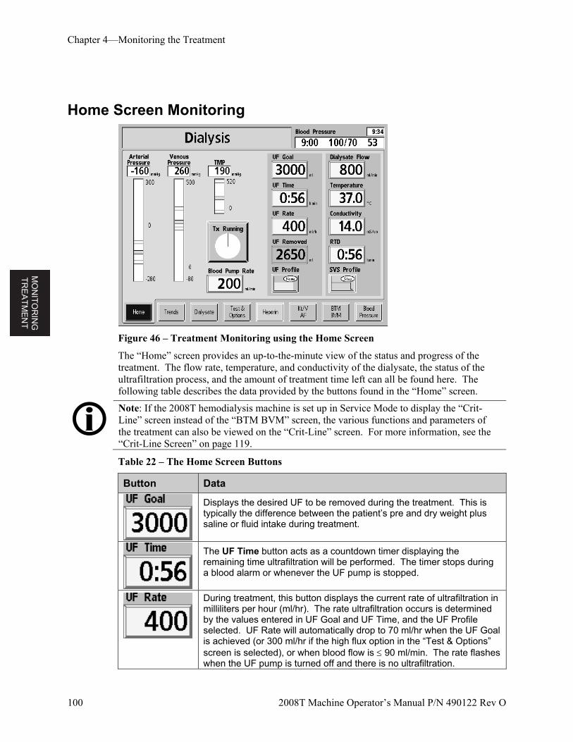
MO
NIT
OR
ING
T
RE
AT
ME
NT
Chapter 4—Monitoring the Treatment
100 2008T Machine Operator’s Manual P/N 490122 Rev O
Home Screen Monitoring
Figure 46 – Treatment Monitoring using the Home Screen
The “Home” screen provides an up-to-the-minute view of the status and progress of the treatment. The flow rate, temperature, and conductivity of the dialysate, the status of the ultrafiltration process, and the amount of treatment time left can all be found here. The following table describes the data provided by the buttons found in the “Home” screen.
Note: If the 2008T hemodialysis machine is set up in Service Mode to display the “Crit-Line” screen instead of the “BTM BVM” screen, the various functions and parameters of the treatment can also be viewed on the “Crit-Line” screen. For more information, see the “Crit-Line Screen” on page 119.
Table 22 – The Home Screen Buttons
Button Data
Displays the desired UF to be removed during the treatment. This is typically the difference between the patient’s pre and dry weight plus saline or fluid intake during treatment.
The UF Time button acts as a countdown timer displaying the remaining time ultrafiltration will be performed. The timer stops during a blood alarm or whenever the UF pump is stopped.
During treatment, this button displays the current rate of ultrafiltration in milliliters per hour (ml/hr). The rate ultrafiltration occurs is determined by the values entered in UF Goal and UF Time, and the UF Profile selected. UF Rate will automatically drop to 70 ml/hr when the UF Goal is achieved (or 300 ml/hr if the high flux option in the “Test & Options” screen is selected), or when blood flow is 90 ml/min. The rate flashes when the UF pump is turned off and there is no ultrafiltration.
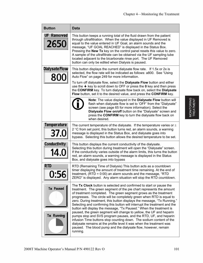
MO
NIT
OR
ING
T
RE
AT
ME
NT
Chapter 4—Monitoring the Treatment
2008T Machine Operator’s Manual P/N 490122 Rev O 101
Button Data
This button keeps a running total of the fluid drawn from the patient through ultrafiltration. When the value displayed in UF Removed is equal to the value entered in UF Goal, an alarm sounds and the message, “UF GOAL REACHED” is displayed in the Status Box. Pressing the New Tx key on the control panel resets this value to zero. A sample of the ultrafiltrate can be obtained via the UF sampling tube located adjacent to the bicarbonate rinse port. The UF Removed button can only be edited when Dialysis is paused.
This button displays the current dialysate flow rate. If 1.5x or 2x is selected, the flow rate will be indicated as follows: a800. See “Using Auto Flow” on page 249 for more information.
To turn off dialysate flow, select the Dialysate Flow button and either use the key to scroll down to OFF or press the 0 key and then press the CONFIRM key. To turn dialysate flow back on, select the Dialysate Flow button, set it to the desired value, and press the CONFIRM key.
Note: The value displayed in the Dialysate Flow button will flash when dialysate flow is set to ‘OFF’ from the “Dialysate” screen (see page 65 for more information). Select the Dialysate Flow on/off button on the “Dialysate” screen and press the CONFIRM key to turn the dialysate flow back on when desired.
The current temperature of the dialysate. If the temperature varies or 2 C from set point, this button turns red, an alarm sounds, a warning message is displayed in the Status Box, and dialysate goes into bypass. Selecting this button allows the desired temperature to be set.
This button displays the current conductivity of the dialysate. Selecting this button during treatment will open the “Dialysate” screen. If the conductivity varies outside of the alarm limits, this turns the button red, an alarm sounds, a warning message is displayed in the Status Box, and dialysate goes into bypass
RTD (Remaining Time of Dialysis) This button acts as a countdown timer displaying the amount of treatment time remaining. At the end of treatment, (RTD = 0:00) an alarm sounds and the message, “RTD ZERO” is displayed. Any alarm situation will stop the RTD countdown.
The Tx Clock button is selected and confirmed to start or pause the treatment. The green segment of the pie chart represents the amount of treatment completed. The green segment grows as the treatment progresses. The circle will be completely green when RTD is equal to zero. During treatment, this button displays the message, “Tx Running.” Selecting and confirming this button will interrupt the treatment and the button will display the message, “Tx Paused.” When the treatment is paused, the green segment will change to yellow, the UF and heparin pumps stop and SVS program pauses, and the RTD, UF, and heparin infusion Time buttons stop counting down. The sodium content of the dialysate remains at the profile level it was when the treatment was paused. The blood pump and the dialysate flow, however, remain running.
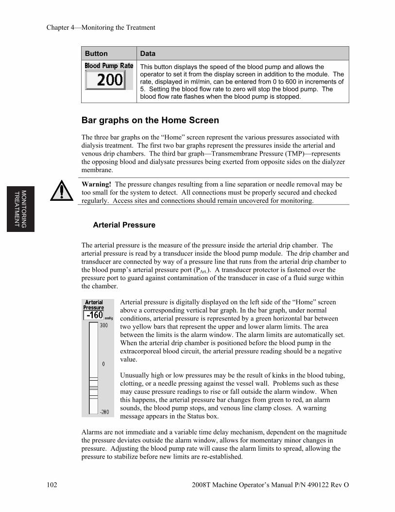
MO
NIT
OR
ING
T
RE
AT
ME
NT
Chapter 4—Monitoring the Treatment
102 2008T Machine Operator’s Manual P/N 490122 Rev O
Button Data
This button displays the speed of the blood pump and allows the operator to set it from the display screen in addition to the module. The rate, displayed in ml/min, can be entered from 0 to 600 in increments of 5. Setting the blood flow rate to zero will stop the blood pump. The blood flow rate flashes when the blood pump is stopped.
Bar graphs on the Home Screen
The three bar graphs on the “Home” screen represent the various pressures associated with dialysis treatment. The first two bar graphs represent the pressures inside the arterial and venous drip chambers. The third bar graph—Transmembrane Pressure (TMP)—represents the opposing blood and dialysate pressures being exerted from opposite sides on the dialyzer membrane.
Warning! The pressure changes resulting from a line separation or needle removal may be too small for the system to detect. All connections must be properly secured and checked regularly. Access sites and connections should remain uncovered for monitoring.
Arterial Pressure
The arterial pressure is the measure of the pressure inside the arterial drip chamber. The arterial pressure is read by a transducer inside the blood pump module. The drip chamber and transducer are connected by way of a pressure line that runs from the arterial drip chamber to the blood pump’s arterial pressure port (PArt.). A transducer protector is fastened over the pressure port to guard against contamination of the transducer in case of a fluid surge within the chamber.
Arterial pressure is digitally displayed on the left side of the “Home” screen above a corresponding vertical bar graph. In the bar graph, under normal conditions, arterial pressure is represented by a green horizontal bar between two yellow bars that represent the upper and lower alarm limits. The area between the limits is the alarm window. The alarm limits are automatically set. When the arterial drip chamber is positioned before the blood pump in the extracorporeal blood circuit, the arterial pressure reading should be a negative value.
Unusually high or low pressures may be the result of kinks in the blood tubing, clotting, or a needle pressing against the vessel wall. Problems such as these may cause pressure readings to rise or fall outside the alarm window. When this happens, the arterial pressure bar changes from green to red, an alarm sounds, the blood pump stops, and venous line clamp closes. A warning message appears in the Status box.
Alarms are not immediate and a variable time delay mechanism, dependent on the magnitude the pressure deviates outside the alarm window, allows for momentary minor changes in pressure. Adjusting the blood pump rate will cause the alarm limits to spread, allowing the pressure to stabilize before new limits are re-established.
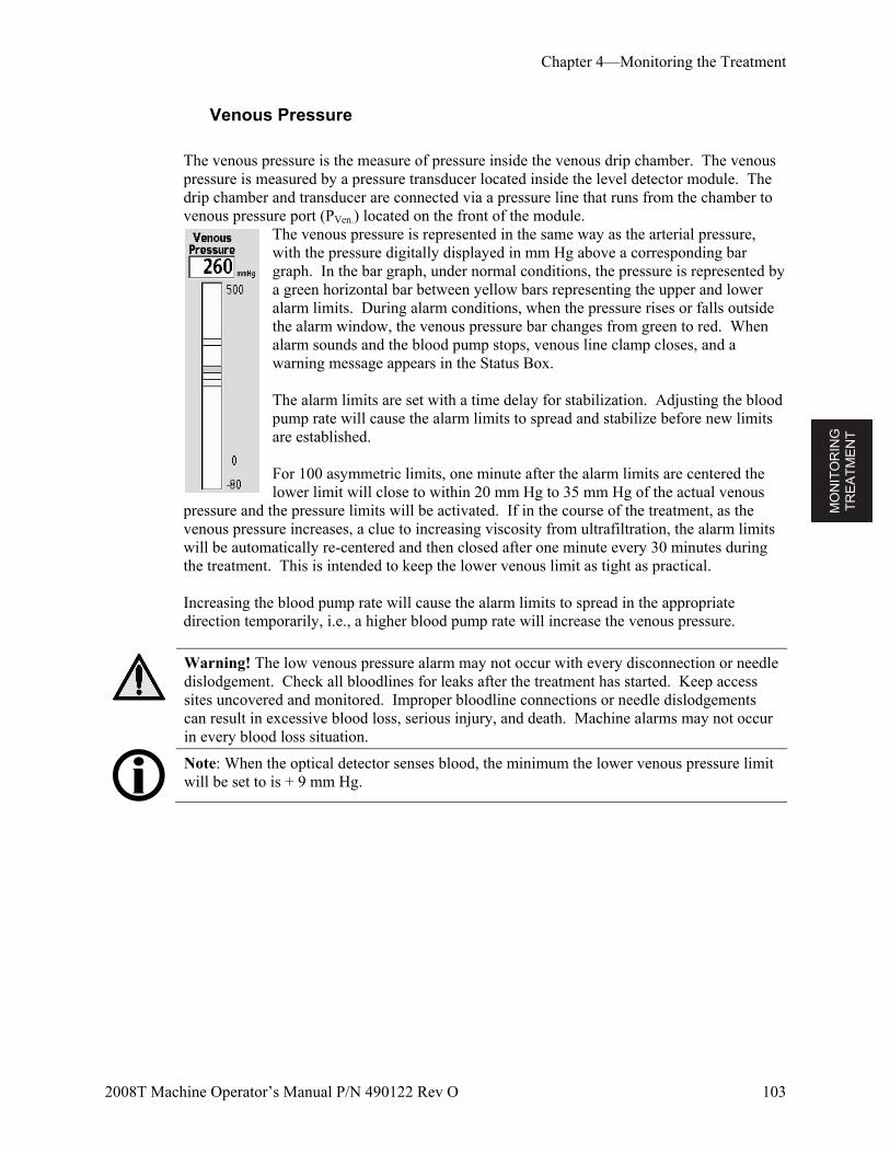
MO
NIT
OR
ING
T
RE
AT
ME
NT
Chapter 4—Monitoring the Treatment
2008T Machine Operator’s Manual P/N 490122 Rev O 103
Venous Pressure
The venous pressure is the measure of pressure inside the venous drip chamber. The venous pressure is measured by a pressure transducer located inside the level detector module. The drip chamber and transducer are connected via a pressure line that runs from the chamber to venous pressure port (PVen.) located on the front of the module.
The venous pressure is represented in the same way as the arterial pressure, with the pressure digitally displayed in mm Hg above a corresponding bar graph. In the bar graph, under normal conditions, the pressure is represented by a green horizontal bar between yellow bars representing the upper and lower alarm limits. During alarm conditions, when the pressure rises or falls outside the alarm window, the venous pressure bar changes from green to red. When alarm sounds and the blood pump stops, venous line clamp closes, and a warning message appears in the Status Box.
The alarm limits are set with a time delay for stabilization. Adjusting the blood pump rate will cause the alarm limits to spread and stabilize before new limits are established.
For 100 asymmetric limits, one minute after the alarm limits are centered the lower limit will close to within 20 mm Hg to 35 mm Hg of the actual venous
pressure and the pressure limits will be activated. If in the course of the treatment, as the venous pressure increases, a clue to increasing viscosity from ultrafiltration, the alarm limits will be automatically re-centered and then closed after one minute every 30 minutes during the treatment. This is intended to keep the lower venous limit as tight as practical. Increasing the blood pump rate will cause the alarm limits to spread in the appropriate direction temporarily, i.e., a higher blood pump rate will increase the venous pressure.
Warning! The low venous pressure alarm may not occur with every disconnection or needle dislodgement. Check all bloodlines for leaks after the treatment has started. Keep access sites uncovered and monitored. Improper bloodline connections or needle dislodgements can result in excessive blood loss, serious injury, and death. Machine alarms may not occur in every blood loss situation.
Note: When the optical detector senses blood, the minimum the lower venous pressure limit will be set to is + 9 mm Hg.
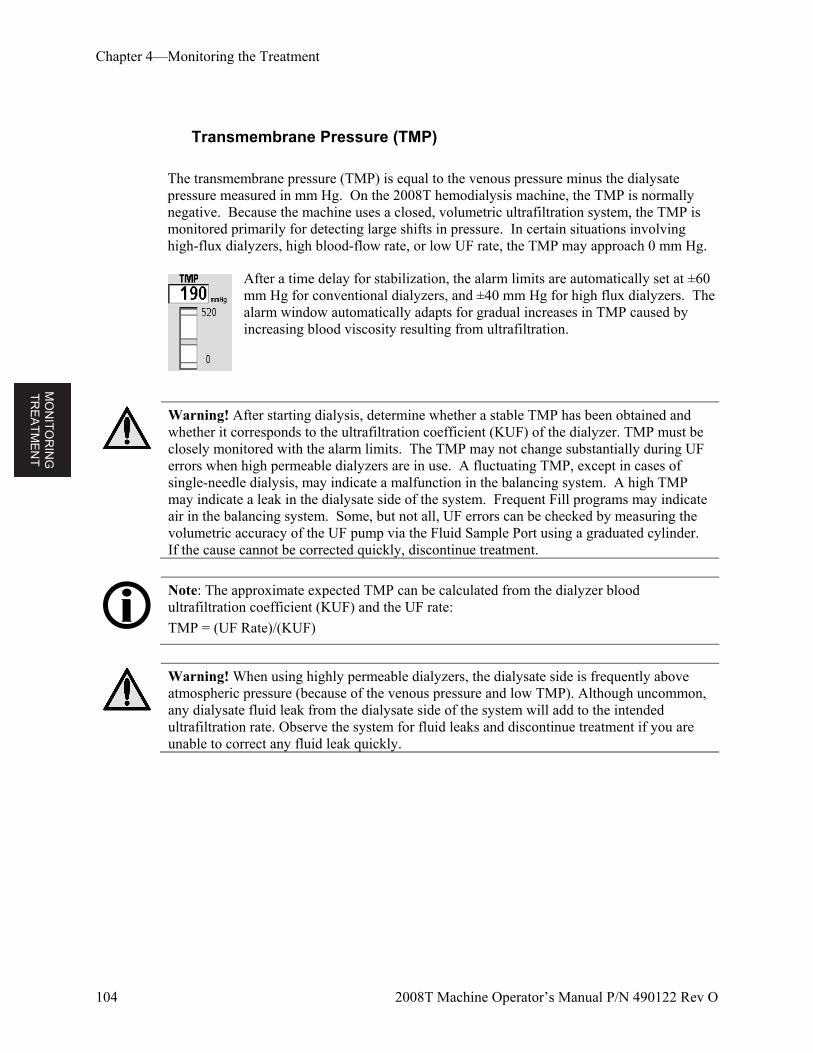
MO
NIT
OR
ING
T
RE
AT
ME
NT
Chapter 4—Monitoring the Treatment
104 2008T Machine Operator’s Manual P/N 490122 Rev O
Transmembrane Pressure (TMP)
The transmembrane pressure (TMP) is equal to the venous pressure minus the dialysate pressure measured in mm Hg. On the 2008T hemodialysis machine, the TMP is normally negative. Because the machine uses a closed, volumetric ultrafiltration system, the TMP is monitored primarily for detecting large shifts in pressure. In certain situations involving high-flux dialyzers, high blood-flow rate, or low UF rate, the TMP may approach 0 mm Hg.
After a time delay for stabilization, the alarm limits are automatically set at ±60 mm Hg for conventional dialyzers, and ±40 mm Hg for high flux dialyzers. The alarm window automatically adapts for gradual increases in TMP caused by increasing blood viscosity resulting from ultrafiltration.
Warning! After starting dialysis, determine whether a stable TMP has been obtained and whether it corresponds to the ultrafiltration coefficient (KUF) of the dialyzer. TMP must be closely monitored with the alarm limits. The TMP may not change substantially during UF errors when high permeable dialyzers are in use. A fluctuating TMP, except in cases of single-needle dialysis, may indicate a malfunction in the balancing system. A high TMP may indicate a leak in the dialysate side of the system. Frequent Fill programs may indicate air in the balancing system. Some, but not all, UF errors can be checked by measuring the volumetric accuracy of the UF pump via the Fluid Sample Port using a graduated cylinder. If the cause cannot be corrected quickly, discontinue treatment.
Note: The approximate expected TMP can be calculated from the dialyzer blood ultrafiltration coefficient (KUF) and the UF rate:
TMP = (UF Rate)/(KUF)
Warning! When using highly permeable dialyzers, the dialysate side is frequently above atmospheric pressure (because of the venous pressure and low TMP). Although uncommon, any dialysate fluid leak from the dialysate side of the system will add to the intended ultrafiltration rate. Observe the system for fluid leaks and discontinue treatment if you are unable to correct any fluid leak quickly.
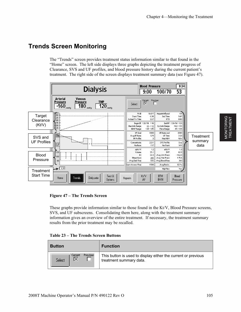
MO
NIT
OR
ING
T
RE
AT
ME
NT
Chapter 4—Monitoring the Treatment
2008T Machine Operator’s Manual P/N 490122 Rev O 105
Trends Screen Monitoring
The “Trends” screen provides treatment status information similar to that found in the “Home” screen. The left side displays three graphs depicting the treatment progress of Clearance, SVS and UF profiles, and blood pressure history during the current patient’s treatment. The right side of the screen displays treatment summary data (see Figure 47).
Figure 47 – The Trends Screen
These graphs provide information similar to those found in the Kt/V, Blood Pressure screens, SVS, and UF subscreens. Consolidating them here, along with the treatment summary information gives an overview of the entire treatment. If necessary, the treatment summary results from the prior treatment may be recalled.
Table 23 – The Trends Screen Buttons
Button Function
This button is used to display either the current or previous treatment summary data.
Target Clearance
(Kt/V)
SVS and UF Profiles
Blood Pressure
Treatment summary
data
Treatment Start Time
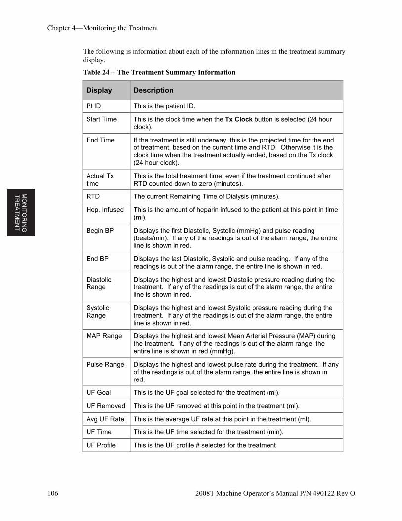
MO
NIT
OR
ING
T
RE
AT
ME
NT
Chapter 4—Monitoring the Treatment
106 2008T Machine Operator’s Manual P/N 490122 Rev O
The following is information about each of the information lines in the treatment summary display.
Table 24 – The Treatment Summary Information
Display Description
Pt ID This is the patient ID.
Start Time This is the clock time when the Tx Clock button is selected (24 hour clock).
End Time If the treatment is still underway, this is the projected time for the end of treatment, based on the current time and RTD. Otherwise it is the clock time when the treatment actually ended, based on the Tx clock (24 hour clock).
Actual Tx time
This is the total treatment time, even if the treatment continued after RTD counted down to zero (minutes).
RTD The current Remaining Time of Dialysis (minutes).
Hep. Infused This is the amount of heparin infused to the patient at this point in time (ml).
Begin BP Displays the first Diastolic, Systolic (mmHg) and pulse reading (beats/min). If any of the readings is out of the alarm range, the entire line is shown in red.
End BP Displays the last Diastolic, Systolic and pulse reading. If any of the readings is out of the alarm range, the entire line is shown in red.
Diastolic Range
Displays the highest and lowest Diastolic pressure reading during the treatment. If any of the readings is out of the alarm range, the entire line is shown in red.
Systolic Range
Displays the highest and lowest Systolic pressure reading during the treatment. If any of the readings is out of the alarm range, the entire line is shown in red.
MAP Range Displays the highest and lowest Mean Arterial Pressure (MAP) during the treatment. If any of the readings is out of the alarm range, the entire line is shown in red (mmHg).
Pulse Range Displays the highest and lowest pulse rate during the treatment. If any of the readings is out of the alarm range, the entire line is shown in red.
UF Goal This is the UF goal selected for the treatment (ml).
UF Removed This is the UF removed at this point in the treatment (ml).
Avg UF Rate This is the average UF rate at this point in the treatment (ml).
UF Time This is the UF time selected for the treatment (min).
UF Profile This is the UF profile # selected for the treatment
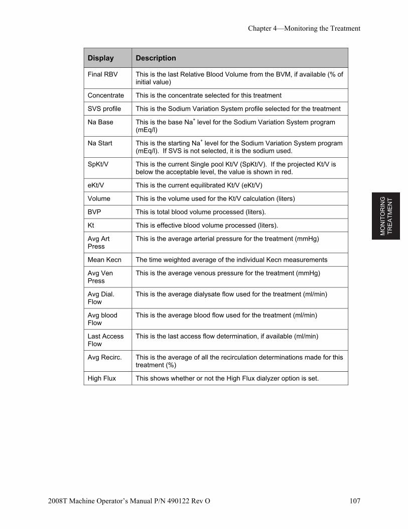
MO
NIT
OR
ING
T
RE
AT
ME
NT
Chapter 4—Monitoring the Treatment
2008T Machine Operator’s Manual P/N 490122 Rev O 107
Display Description
Final RBV This is the last Relative Blood Volume from the BVM, if available (% of initial value)
Concentrate This is the concentrate selected for this treatment
SVS profile This is the Sodium Variation System profile selected for the treatment
Na Base This is the base Na+ level for the Sodium Variation System program (mEq/l)
Na Start This is the starting Na+ level for the Sodium Variation System program (mEq/l). If SVS is not selected, it is the sodium used.
SpKt/V This is the current Single pool Kt/V (SpKt/V). If the projected Kt/V is below the acceptable level, the value is shown in red.
eKt/V This is the current equilibrated Kt/V (eKt/V)
Volume This is the volume used for the Kt/V calculation (liters)
BVP This is total blood volume processed (liters).
Kt This is effective blood volume processed (liters).
Avg Art Press
This is the average arterial pressure for the treatment (mmHg)
Mean Kecn The time weighted average of the individual Kecn measurements
Avg Ven Press
This is the average venous pressure for the treatment (mmHg)
Avg Dial. Flow
This is the average dialysate flow used for the treatment (ml/min)
Avg blood Flow
This is the average blood flow used for the treatment (ml/min)
Last Access Flow
This is the last access flow determination, if available (ml/min)
Avg Recirc. This is the average of all the recirculation determinations made for this treatment (%)
High Flux This shows whether or not the High Flux dialyzer option is set.
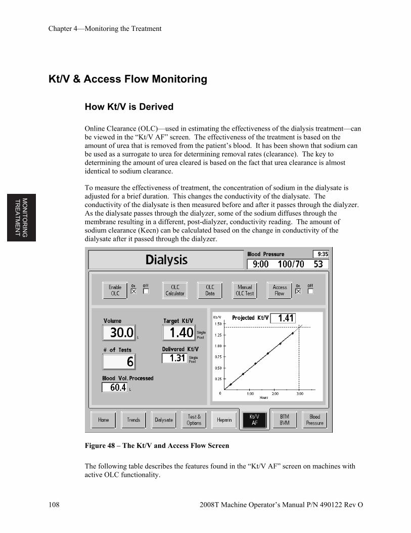
MO
NIT
OR
ING
T
RE
AT
ME
NT
Chapter 4—Monitoring the Treatment
108 2008T Machine Operator’s Manual P/N 490122 Rev O
Kt/V & Access Flow Monitoring
How Kt/V is Derived
Online Clearance (OLC)—used in estimating the effectiveness of the dialysis treatment—can be viewed in the “Kt/V AF” screen. The effectiveness of the treatment is based on the amount of urea that is removed from the patient’s blood. It has been shown that sodium can be used as a surrogate to urea for determining removal rates (clearance). The key to determining the amount of urea cleared is based on the fact that urea clearance is almost identical to sodium clearance.
To measure the effectiveness of treatment, the concentration of sodium in the dialysate is adjusted for a brief duration. This changes the conductivity of the dialysate. The conductivity of the dialysate is then measured before and after it passes through the dialyzer. As the dialysate passes through the dialyzer, some of the sodium diffuses through the membrane resulting in a different, post-dialyzer, conductivity reading. The amount of sodium clearance (Kecn) can be calculated based on the change in conductivity of the dialysate after it passed through the dialyzer.
Figure 48 – The Kt/V and Access Flow Screen
The following table describes the features found in the “Kt/V AF” screen on machines with active OLC functionality.

MO
NIT
OR
ING
T
RE
AT
ME
NT
Chapter 4—Monitoring the Treatment
2008T Machine Operator’s Manual P/N 490122 Rev O 109
Note: If the OLC functionality has been deactivated (in the Service Mode) on your machine, all features will be inactive and appear grayed out.
Table 25 – The “Kt/V AF” Screen Buttons and displays
Button Function
This button activates and deactivates the OLC option as indicated by the check box to the right. By default, OLC is enabled.
This button brings up the OLC Calculator—a useful tool for estimating the treatment effectiveness and time required based on various treatment parameters. (Not available at this time).
Selecting the OLC Data button opens the “OLC” subscreen that provides the actual results of each OLC test.
This button changes functions based on the machine status.
When there is no blood sensed and the blood pump is stopped or the dialysate lines are on the shunt, selecting this button followed by the CONFIRM key initiates the OLC Self Test.
When blood is sensed, an unscheduled clearance test is initiated. The manual test takes the place of one of the scheduled tests entered in the # of Tests button.
This button is used to allow the Access Flow test to be performed. When it is turned On, the machine will offer to do the Access Flow test following the next OLC test. If it is inconvenient to do the test early in the treatment, this button may be left in the Off position and turned On when it is convenient. Select the Manual OLC Test button and press CONFIRM after turning on the Access Flow to begin the process right away. When the test is initiated, the operator is guided through the steps necessary to perform the test.
Warning! To avoid the possibility of significant blood loss, be sure that the connections are well secured after disconnecting and reconnecting the bloodlines.
The patient’s urea-distribution volume (in liters) is entered here. This value should be determined using urea-kinetic values. Anthropometric formulae may give different results than kinetically calculated urea-distribution volume.
The prescribed target single-pool value, ranging from 0.40 to 2.50, is entered in this button. This value is reset to the default value when the New Tx key is pressed. The default value may be changed in Service Mode.
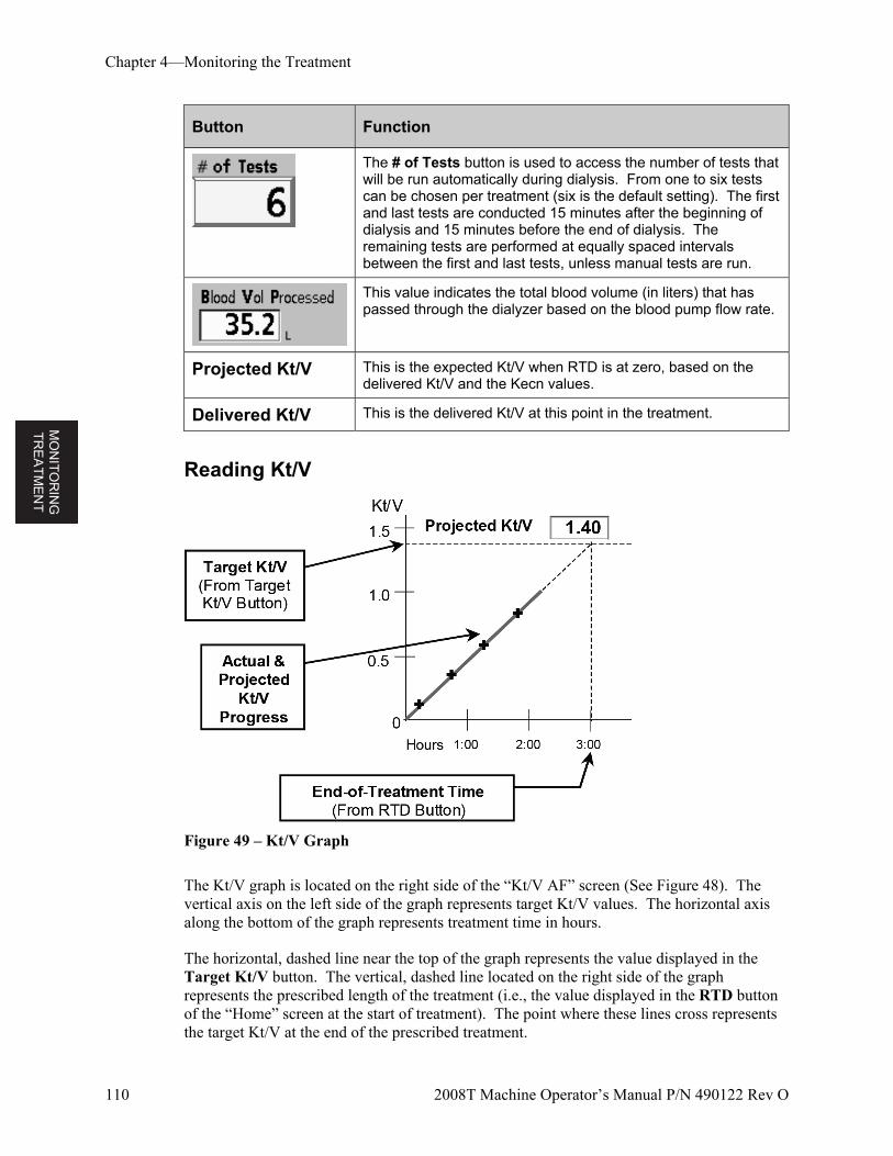
MO
NIT
OR
ING
T
RE
AT
ME
NT
Chapter 4—Monitoring the Treatment
110 2008T Machine Operator’s Manual P/N 490122 Rev O
Button Function
The # of Tests button is used to access the number of tests that will be run automatically during dialysis. From one to six tests can be chosen per treatment (six is the default setting). The first and last tests are conducted 15 minutes after the beginning of dialysis and 15 minutes before the end of dialysis. The remaining tests are performed at equally spaced intervals between the first and last tests, unless manual tests are run.
This value indicates the total blood volume (in liters) that has passed through the dialyzer based on the blood pump flow rate.
Projected Kt/V This is the expected Kt/V when RTD is at zero, based on the delivered Kt/V and the Kecn values.
Delivered Kt/V This is the delivered Kt/V at this point in the treatment.
Reading Kt/V
Figure 49 – Kt/V Graph
The Kt/V graph is located on the right side of the “Kt/V AF” screen (See Figure 48). The vertical axis on the left side of the graph represents target Kt/V values. The horizontal axis along the bottom of the graph represents treatment time in hours.
The horizontal, dashed line near the top of the graph represents the value displayed in the Target Kt/V button. The vertical, dashed line located on the right side of the graph represents the prescribed length of the treatment (i.e., the value displayed in the RTD button of the “Home” screen at the start of treatment). The point where these lines cross represents the target Kt/V at the end of the prescribed treatment.
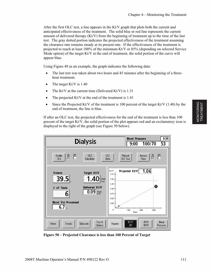
MO
NIT
OR
ING
T
RE
AT
ME
NT
Chapter 4—Monitoring the Treatment
2008T Machine Operator’s Manual P/N 490122 Rev O 111
After the first OLC test, a line appears in the Kt/V graph that plots both the current and anticipated effectiveness of the treatment. The solid blue or red line represents the current amount of delivered therapy (Kt/V) from the beginning of treatment up to the time of the last test. The gray dotted portion indicates the projected effectiveness of the treatment assuming the clearance rate remains steady at its present rate. If the effectiveness of the treatment is projected to reach at least 100% of the minimum Kt/V or 85% (depending on selected Service Mode option) of the target Kt/V at the end of treatment, the solid portion of the curve will appear blue.
Using Figure 48 as an example, the graph indicates the following data:
The last test was taken about two hours and 45 minutes after the beginning of a three-hour treatment.
The target Kt/V is 1.40
The Kt/V at the current time (Delivered Kt/V) is 1.31
The projected Kt/V at the end of the treatment is 1.41
Since the Projected Kt/V of the treatment is 100 percent of the target Kt/V (1.40) by the end of treatment, the line is blue.
If after an OLC test, the projected effectiveness for the end of the treatment is less than 100 percent of the target Kt/V, the solid portion of the plot appears red and an exclamatory icon is displayed to the right of the graph (see Figure 50 below).
Figure 50 – Projected Clearance is less than 100 Percent of Target
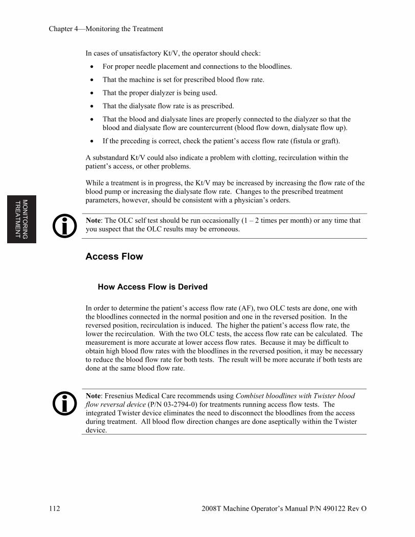
MO
NIT
OR
ING
T
RE
AT
ME
NT
Chapter 4—Monitoring the Treatment
112 2008T Machine Operator’s Manual P/N 490122 Rev O
In cases of unsatisfactory Kt/V, the operator should check:
For proper needle placement and connections to the bloodlines.
That the machine is set for prescribed blood flow rate.
That the proper dialyzer is being used.
That the dialysate flow rate is as prescribed.
That the blood and dialysate lines are properly connected to the dialyzer so that the blood and dialysate flow are countercurrent (blood flow down, dialysate flow up).
If the preceding is correct, check the patient’s access flow rate (fistula or graft).
A substandard Kt/V could also indicate a problem with clotting, recirculation within the patient’s access, or other problems.
While a treatment is in progress, the Kt/V may be increased by increasing the flow rate of the blood pump or increasing the dialysate flow rate. Changes to the prescribed treatment parameters, however, should be consistent with a physician’s orders.
Note: The OLC self test should be run occasionally (1 – 2 times per month) or any time that you suspect that the OLC results may be erroneous.
Access Flow
How Access Flow is Derived
In order to determine the patient’s access flow rate (AF), two OLC tests are done, one with the bloodlines connected in the normal position and one in the reversed position. In the reversed position, recirculation is induced. The higher the patient’s access flow rate, the lower the recirculation. With the two OLC tests, the access flow rate can be calculated. The measurement is more accurate at lower access flow rates. Because it may be difficult to obtain high blood flow rates with the bloodlines in the reversed position, it may be necessary to reduce the blood flow rate for both tests. The result will be more accurate if both tests are done at the same blood flow rate.
Note: Fresenius Medical Care recommends using Combiset bloodlines with Twister blood flow reversal device (P/N 03-2794-0) for treatments running access flow tests. The integrated Twister device eliminates the need to disconnect the bloodlines from the access during treatment. All blood flow direction changes are done aseptically within the Twister device.
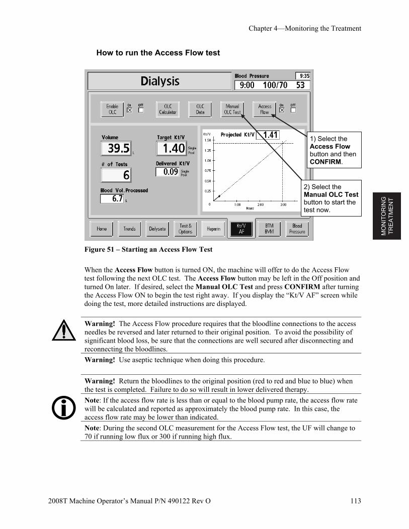
MO
NIT
OR
ING
T
RE
AT
ME
NT
Chapter 4—Monitoring the Treatment
2008T Machine Operator’s Manual P/N 490122 Rev O 113
How to run the Access Flow test
Figure 51 – Starting an Access Flow Test
When the Access Flow button is turned ON, the machine will offer to do the Access Flow test following the next OLC test. The Access Flow button may be left in the Off position and turned On later. If desired, select the Manual OLC Test and press CONFIRM after turning the Access Flow ON to begin the test right away. If you display the “Kt/V AF” screen while doing the test, more detailed instructions are displayed.
Warning! The Access Flow procedure requires that the bloodline connections to the access needles be reversed and later returned to their original position. To avoid the possibility of significant blood loss, be sure that the connections are well secured after disconnecting and reconnecting the bloodlines.
Warning! Use aseptic technique when doing this procedure.
Warning! Return the bloodlines to the original position (red to red and blue to blue) when
the test is completed. Failure to do so will result in lower delivered therapy.
Note: If the access flow rate is less than or equal to the blood pump rate, the access flow rate will be calculated and reported as approximately the blood pump rate. In this case, the access flow rate may be lower than indicated.
Note: During the second OLC measurement for the Access Flow test, the UF will change to 70 if running low flux or 300 if running high flux.
1) Select the Access Flow button and then CONFIRM.
2) Select the Manual OLC Test button to start the test now.
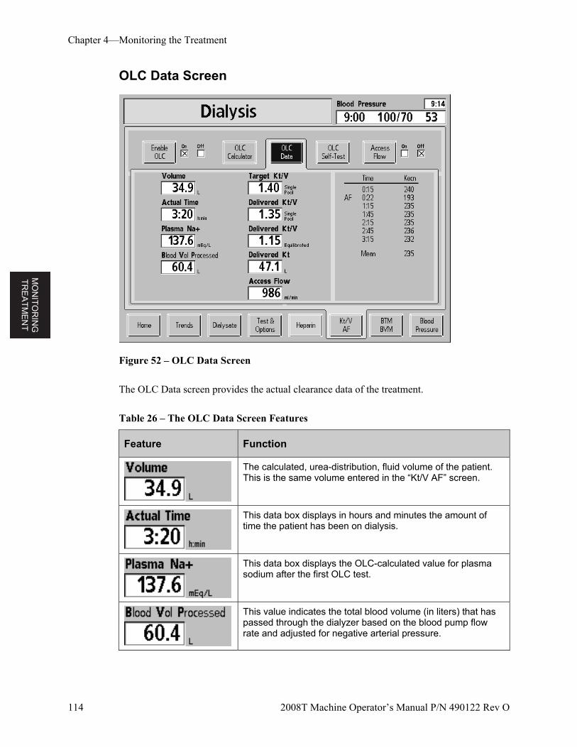
MO
NIT
OR
ING
T
RE
AT
ME
NT
Chapter 4—Monitoring the Treatment
114 2008T Machine Operator’s Manual P/N 490122 Rev O
OLC Data Screen
Figure 52 – OLC Data Screen
The OLC Data screen provides the actual clearance data of the treatment.
Table 26 – The OLC Data Screen Features
Feature Function
The calculated, urea-distribution, fluid volume of the patient. This is the same volume entered in the “Kt/V AF” screen.
This data box displays in hours and minutes the amount of time the patient has been on dialysis.
This data box displays the OLC-calculated value for plasma sodium after the first OLC test.
This value indicates the total blood volume (in liters) that has passed through the dialyzer based on the blood pump flow rate and adjusted for negative arterial pressure.
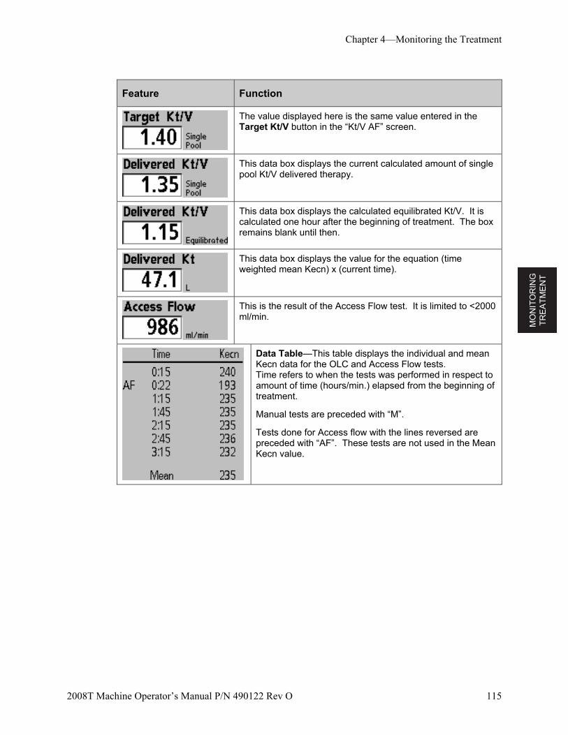
MO
NIT
OR
ING
T
RE
AT
ME
NT
Chapter 4—Monitoring the Treatment
2008T Machine Operator’s Manual P/N 490122 Rev O 115
Feature Function
The value displayed here is the same value entered in the Target Kt/V button in the “Kt/V AF” screen.
This data box displays the current calculated amount of single pool Kt/V delivered therapy.
This data box displays the calculated equilibrated Kt/V. It is calculated one hour after the beginning of treatment. The box remains blank until then.
This data box displays the value for the equation (time weighted mean Kecn) x (current time).
This is the result of the Access Flow test. It is limited to <2000 ml/min.
Data Table—This table displays the individual and mean Kecn data for the OLC and Access Flow tests. Time refers to when the tests was performed in respect to amount of time (hours/min.) elapsed from the beginning of treatment.
Manual tests are preceded with “M”.
Tests done for Access flow with the lines reversed are preceded with “AF”. These tests are not used in the Mean Kecn value.
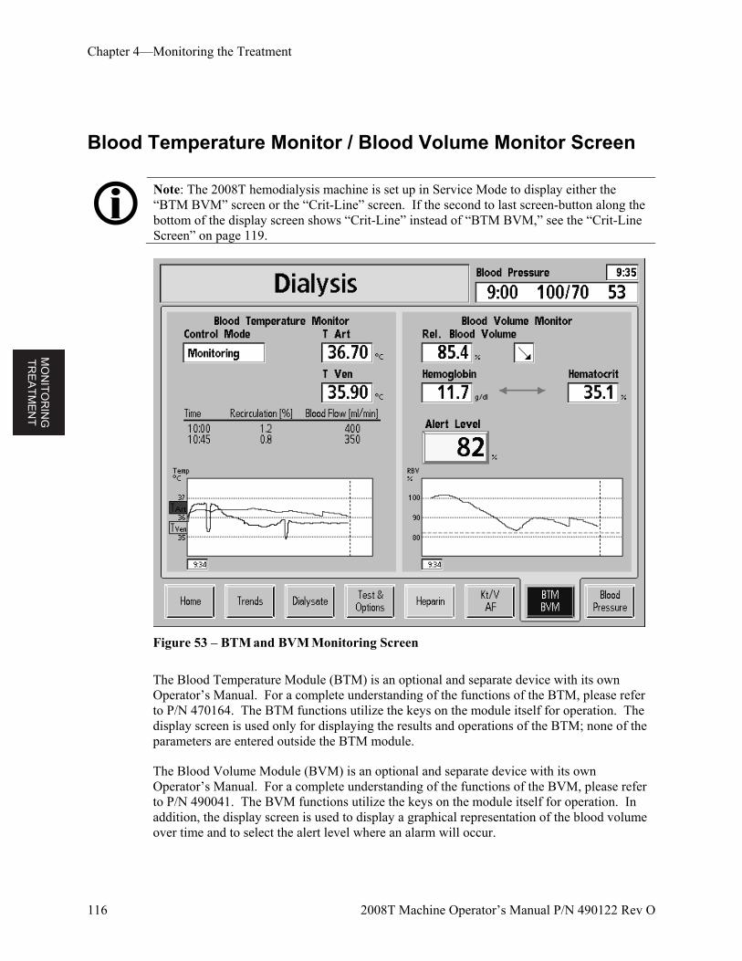
MO
NIT
OR
ING
T
RE
AT
ME
NT
Chapter 4—Monitoring the Treatment
116 2008T Machine Operator’s Manual P/N 490122 Rev O
Blood Temperature Monitor / Blood Volume Monitor Screen
Note: The 2008T hemodialysis machine is set up in Service Mode to display either the “BTM BVM” screen or the “Crit-Line” screen. If the second to last screen-button along the bottom of the display screen shows “Crit-Line” instead of “BTM BVM,” see the “Crit-Line Screen” on page 119.
Figure 53 – BTM and BVM Monitoring Screen
The Blood Temperature Module (BTM) is an optional and separate device with its own Operator’s Manual. For a complete understanding of the functions of the BTM, please refer to P/N 470164. The BTM functions utilize the keys on the module itself for operation. The display screen is used only for displaying the results and operations of the BTM; none of the parameters are entered outside the BTM module.
The Blood Volume Module (BVM) is an optional and separate device with its own Operator’s Manual. For a complete understanding of the functions of the BVM, please refer to P/N 490041. The BVM functions utilize the keys on the module itself for operation. In addition, the display screen is used to display a graphical representation of the blood volume over time and to select the alert level where an alarm will occur.
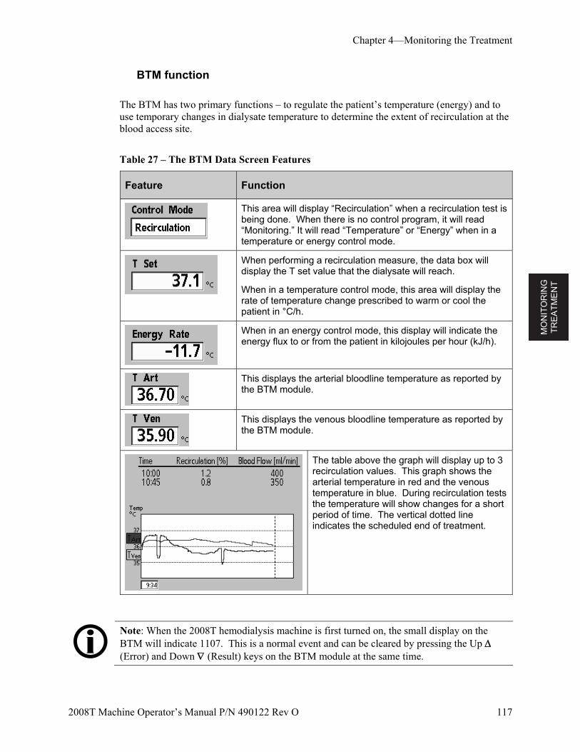
MO
NIT
OR
ING
T
RE
AT
ME
NT
Chapter 4—Monitoring the Treatment
2008T Machine Operator’s Manual P/N 490122 Rev O 117
BTM function
The BTM has two primary functions – to regulate the patient’s temperature (energy) and to use temporary changes in dialysate temperature to determine the extent of recirculation at the blood access site.
Table 27 – The BTM Data Screen Features
Feature Function
This area will display “Recirculation” when a recirculation test is being done. When there is no control program, it will read “Monitoring.” It will read “Temperature” or “Energy” when in a temperature or energy control mode.
When performing a recirculation measure, the data box will display the T set value that the dialysate will reach.
When in a temperature control mode, this area will display the rate of temperature change prescribed to warm or cool the patient in °C/h.
When in an energy control mode, this display will indicate the energy flux to or from the patient in kilojoules per hour (kJ/h).
This displays the arterial bloodline temperature as reported by the BTM module.
This displays the venous bloodline temperature as reported by the BTM module.
The table above the graph will display up to 3 recirculation values. This graph shows the arterial temperature in red and the venous temperature in blue. During recirculation tests the temperature will show changes for a short period of time. The vertical dotted line indicates the scheduled end of treatment.
Note: When the 2008T hemodialysis machine is first turned on, the small display on the BTM will indicate 1107. This is a normal event and can be cleared by pressing the Up (Error) and Down (Result) keys on the BTM module at the same time.
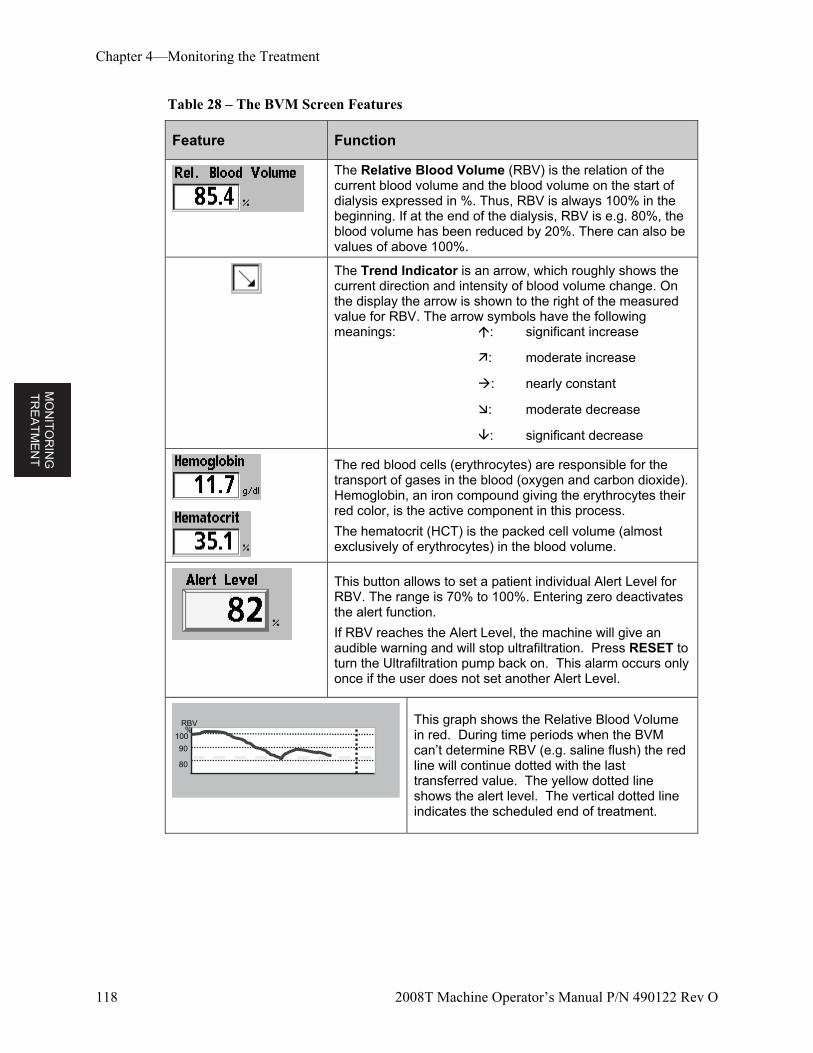
MO
NIT
OR
ING
T
RE
AT
ME
NT
Chapter 4—Monitoring the Treatment
118 2008T Machine Operator’s Manual P/N 490122 Rev O
Table 28 – The BVM Screen Features
Feature Function
The Relative Blood Volume (RBV) is the relation of the current blood volume and the blood volume on the start of dialysis expressed in %. Thus, RBV is always 100% in the beginning. If at the end of the dialysis, RBV is e.g. 80%, the blood volume has been reduced by 20%. There can also be values of above 100%.
The Trend Indicator is an arrow, which roughly shows the current direction and intensity of blood volume change. On the display the arrow is shown to the right of the measured value for RBV. The arrow symbols have the following meanings: : significant increase
: moderate increase
: nearly constant
: moderate decrease
: significant decrease
The red blood cells (erythrocytes) are responsible for the transport of gases in the blood (oxygen and carbon dioxide). Hemoglobin, an iron compound giving the erythrocytes their red color, is the active component in this process.
The hematocrit (HCT) is the packed cell volume (almost exclusively of erythrocytes) in the blood volume.
This button allows to set a patient individual Alert Level for RBV. The range is 70% to 100%. Entering zero deactivates the alert function.
If RBV reaches the Alert Level, the machine will give an audible warning and will stop ultrafiltration. Press RESET to turn the Ultrafiltration pump back on. This alarm occurs only once if the user does not set another Alert Level.
100
90
80
RBV%
100
90
80
RBV%
This graph shows the Relative Blood Volume in red. During time periods when the BVM can’t determine RBV (e.g. saline flush) the red line will continue dotted with the last transferred value. The yellow dotted line shows the alert level. The vertical dotted line indicates the scheduled end of treatment.
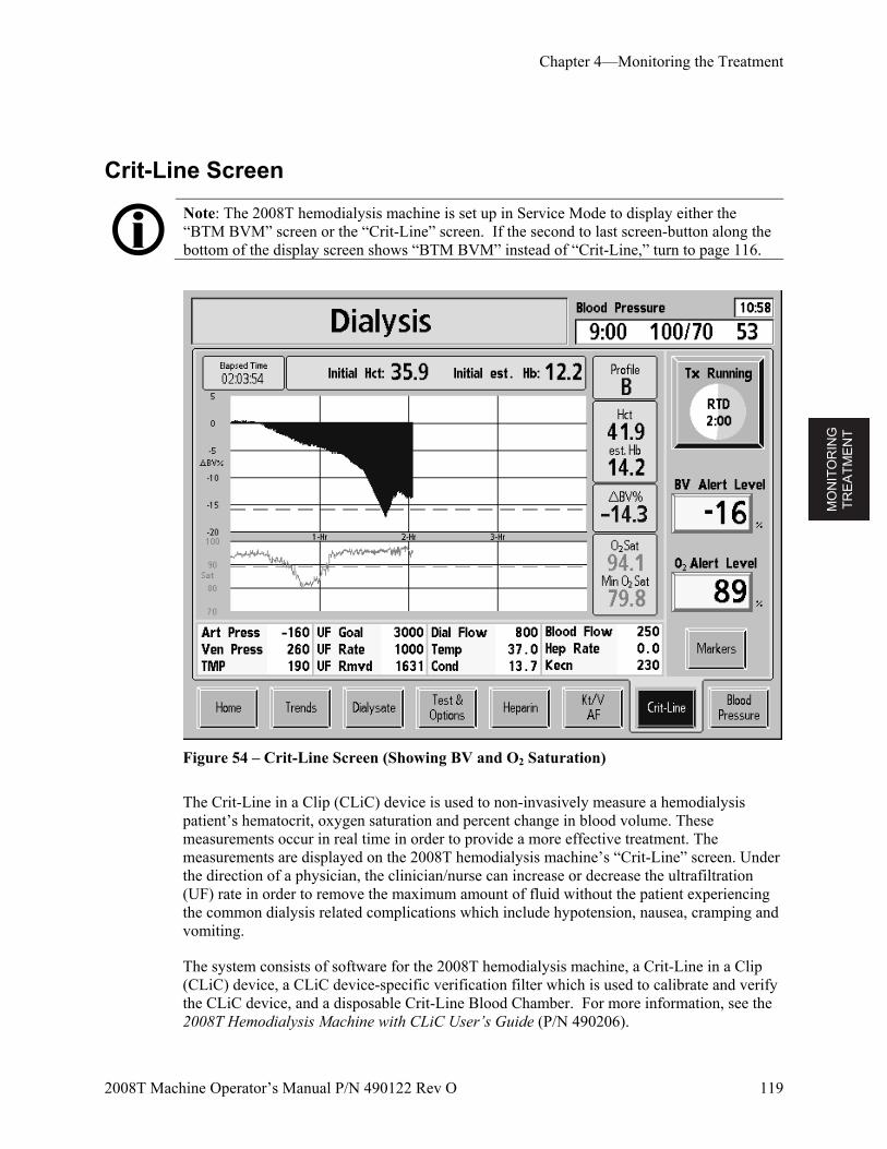
MO
NIT
OR
ING
T
RE
AT
ME
NT
Chapter 4—Monitoring the Treatment
2008T Machine Operator’s Manual P/N 490122 Rev O 119
Crit-Line Screen
Note: The 2008T hemodialysis machine is set up in Service Mode to display either the “BTM BVM” screen or the “Crit-Line” screen. If the second to last screen-button along the bottom of the display screen shows “BTM BVM” instead of “Crit-Line,” turn to page 116.
Figure 54 – Crit-Line Screen (Showing BV and O2 Saturation)
The Crit-Line in a Clip (CLiC) device is used to non-invasively measure a hemodialysis patient’s hematocrit, oxygen saturation and percent change in blood volume. These measurements occur in real time in order to provide a more effective treatment. The measurements are displayed on the 2008T hemodialysis machine’s “Crit-Line” screen. Under the direction of a physician, the clinician/nurse can increase or decrease the ultrafiltration (UF) rate in order to remove the maximum amount of fluid without the patient experiencing the common dialysis related complications which include hypotension, nausea, cramping and vomiting.
The system consists of software for the 2008T hemodialysis machine, a Crit-Line in a Clip (CLiC) device, a CLiC device-specific verification filter which is used to calibrate and verify the CLiC device, and a disposable Crit-Line Blood Chamber. For more information, see the 2008T Hemodialysis Machine with CLiC User’s Guide (P/N 490206).
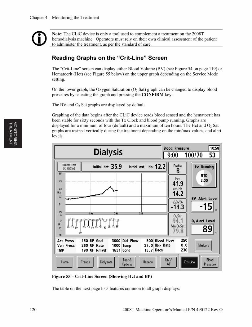
MO
NIT
OR
ING
T
RE
AT
ME
NT
Chapter 4—Monitoring the Treatment
120 2008T Machine Operator’s Manual P/N 490122 Rev O
Note: The CLiC device is only a tool used to complement a treatment on the 2008T hemodialysis machine. Operators must rely on their own clinical assessment of the patient to administer the treatment, as per the standard of care.
Reading Graphs on the “Crit-Line” Screen
The “Crit-Line” screen can display either Blood Volume (BV) (see Figure 54 on page 119) or Hematocrit (Hct) (see Figure 55 below) on the upper graph depending on the Service Mode setting.
On the lower graph, the Oxygen Saturation (O2 Sat) graph can be changed to display blood pressures by selecting the graph and pressing the CONFIRM key.
The BV and O2 Sat graphs are displayed by default.
Graphing of the data begins after the CLiC device reads blood sensed and the hematocrit has been stable for sixty seconds with the Tx Clock and blood pump running. Graphs are displayed for a minimum of four (default) and a maximum of ten hours. The Hct and O2 Sat graphs are resized vertically during the treatment depending on the min/max values, and alert levels.
Figure 55 – Crit-Line Screen (Showing Hct and BP)
The table on the next page lists features common to all graph displays:
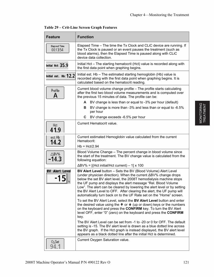
MO
NIT
OR
ING
T
RE
AT
ME
NT
Chapter 4—Monitoring the Treatment
2008T Machine Operator’s Manual P/N 490122 Rev O 121
Table 29 – Crit-Line Screen Graph Features
Feature Function
Elapsed Time – The time the Tx Clock and CLiC device are running. If the Tx Clock is paused or an event pauses the treatment (such as blood alarms), then the Elapsed Time is paused along with CLiC device data collection.
Initial Hct – The starting hematocrit (Hct) value is recorded along with the first data point when graphing begins.
Initial est. Hb – The estimated starting hemoglobin (Hb) value is recorded along with the first data point when graphing begins. It is calculated based on the hematocrit reading.
Current blood volume change profile – The profile starts calculating after the first two blood volume measurements and is computed over the previous 15 minutes of data. The profile can be:
A BV change is less than or equal to -3% per hour (default)
B BV change is more than -3% and less than or equal to -6.5% per hour
C BV change exceeds -6.5% per hour
Current Hematocrit value.
Current estimated Hemoglobin value calculated from the current Hematocrit:
Hb = Hct/2.94
Blood Volume Change – The percent change in blood volume since the start of the treatment. The BV change value is calculated from the following equation:
∆BV% = [(Hct initial/Hct current) – 1] x 100
BV Alert Level button – Sets the BV (Blood Volume) Alert Level (under physician direction). When the current ∆BV% change drops below the set BV alert level, the 2008T hemodialysis machine stops the UF pump and displays the alert message “Rel. Blood Volume Low”. The alert can be cleared by lowering the alert level or by setting the BV Alert Level to OFF. After clearing the alert, the UF pump will automatically turn back on to the UF Rate set on the “Home” screen.
To set the BV Alert Level, select the BV Alert Level button and enter the desired value using the or (up or down) keys or the numbers on the keyboard and press the CONFIRM key. To turn the BV Alert level OFF, enter “0” (zero) on the keyboard and press the CONFIRM key.
The BV Alert Level can be set from -1 to -20 or 0 for OFF. The default setting is -15. The BV alert level is drawn as a blue dotted line across the BV graph. If the Hct graph is instead displayed, the BV alert level appears as a black dotted line after the initial Hct is determined.
Current Oxygen Saturation value.
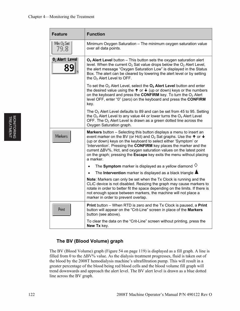
MO
NIT
OR
ING
T
RE
AT
ME
NT
Chapter 4—Monitoring the Treatment
122 2008T Machine Operator’s Manual P/N 490122 Rev O
Feature Function
Minimum Oxygen Saturation – The minimum oxygen saturation value over all data points.
O2 Alert Level button – This button sets the oxygen saturation alert level. When the current O2 Sat value drops below the O2 Alert Level, the alert message “Oxygen Saturation Low” is displayed in the Status Box. The alert can be cleared by lowering the alert level or by setting the O2 Alert Level to OFF.
To set the O2 Alert Level, select the O2 Alert Level button and enter the desired value using the or (up or down) keys or the numbers on the keyboard and press the CONFIRM key. To turn the O2 Alert level OFF, enter “0” (zero) on the keyboard and press the CONFIRM key.
The O2 Alert Level defaults to 89 and can be set from 45 to 95. Setting the O2 Alert Level to any value 44 or lower turns the O2 Alert Level OFF. The O2 Alert Level is drawn as a green dotted line across the Oxygen Saturation graph.
Markers button – Selecting this button displays a menu to insert an event marker on the BV (or Hct) and O2 Sat graphs. Use the or (up or down) keys on the keyboard to select either ‘Symptom’ or ‘Intervention’. Pressing the CONFIRM key places the marker and the current ∆BV%, Hct, and oxygen saturation values on the latest point on the graph; pressing the Escape key exits the menu without placing a marker.
The Symptom marker is displayed as a yellow diamond
The Intervention marker is displayed as a black triangle
Note: Markers can only be set when the Tx Clock is running and the CLiC device is not disabled. Resizing the graph may cause markers to rotate in order to better fit the space depending on the limits. If there is not enough space between markers, the machine will not place a marker in order to prevent overlap.
Print button – When RTD is zero and the Tx Clock is paused, a Print button will appear on the “Crit-Line” screen in place of the Markers button (see above).
To clear the data on the “Crit-Line” screen without printing, press the New Tx key.
The BV (Blood Volume) graph
The BV (Blood Volume) graph (Figure 54 on page 119) is displayed as a fill graph. A line is filled from 0 to the ΔBV% value. As the dialysis treatment progresses, fluid is taken out of the blood by the 2008T hemodialysis machine’s ultrafiltration pump. This will result in a greater percentage of the blood being red blood cells and the blood volume fill graph will trend downwards and approach the alert level. The BV alert level is drawn as a blue dotted line across the BV graph.
MO
NIT
OR
ING
T
RE
AT
ME
NT
Chapter 4—Monitoring the Treatment
2008T Machine Operator’s Manual P/N 490122 Rev O 123
Note: The BV graph is the default upper graph displayed on the “Crit-Line” screen. To display the Hct graph instead of the BV graph, call a qualified service technician.
The Hct (Hematocrit) graph
The Hct (Hematocrit) graph is a line graph (Figure 55 on page 120) drawn from the previous hematocrit value. As the dialysis treatment progresses, fluid is taken out of the blood by the 2008T hemodialysis machine’s ultrafiltration pump. This will result in a greater percentage of the blood being red blood cells and the hematocrit line graph will trend upwards and approach the alert level.
The Hematocrit Alert Level is drawn as a black dotted line across the Hct graph. The Hematocrit Alert Level cannot be set directly, but is calculated from the BV Alert Level (see the BV Alert Level button on page 121). The line will appear on the graph after the initial Hct is determined. When the alert is triggered, the 2008T hemodialysis machine stops the UF pump and displays the alert message “Rel. Blood Volume Low”. The alert can be cleared by lowering the alert level or by setting the BV Alert Level to OFF. After clearing the alert, the UF pump will automatically turn back on to the UF Rate set on the “Home” screen.
The O2 Sat (Oxygen Saturation) graph
Oxygen saturation is the default display on the “Crit-Line” screen’s bottom graph. The O2 Sat (Oxygen Saturation) graph (Figure 54 on page 119) is a line graph drawn from the previous oxygen saturation value. The O2 Alert Level is drawn as a green dotted line across the Oxygen Saturation graph.
Note: To switch between the O2 Sat graph and the BP graphs, select the graph. The message “Press Confirm to switch to O2 graph. Press Escape to return to BP graph.” or “Press Confirm to switch to Blood Pressure graph. Press Escape to return to O2 graph.” is displayed. Press the CONFIRM key to confirm the selection.
To switch back to the previous graph, select the graph again and press the CONFIRM key to confirm the selection.
The BP (Blood Pressure) graph
Similar to the Blood Pressure graph on the “Trends” and “Blood Pressure” screens, the BP (Blood Pressure) graph (Figure 55 on page 120) is drawn as a series of black dumbbells between the systolic and diastolic blood pressures. On the “Crit-Line” screen, the systolic (upper) and diastolic (lower) numbers are also displayed. If the value is out of range (as specified by the parameters on the “Blood Pressure” screen), the dumbbell will be drawn in red.
Note: If there is not enough space between blood pressure measurements, the blood pressure graph will not display a measurement in order to prevent overlap.
Note: Markers do not appear on the Blood Pressure graph.

MO
NIT
OR
ING
T
RE
AT
ME
NT
Chapter 4—Monitoring the Treatment
124 2008T Machine Operator’s Manual P/N 490122 Rev O
Monitoring the hemodialysis treatment from the “Crit-Line” screen
Most of the commonly viewed data from other screens are grouped on the “Crit-Line” screen for convenient monitoring. Listed below are the features of the “Crit-Line” screen that can also be found on other screens.
Table 30 – Crit-Line Screen Features Found on Other Screens
Feature Description
Art Press Arterial Pressure – The value displayed on the “Home” screen (mmHg)
Ven Press Venous Pressure – The value displayed on the “Home” screen (mmHg)
TMP TMP (Transmembrane Pressure) – The value displayed on the “Home” screen (mmHg)
UF Goal UF Goal – The UF goal selected for the treatment and set on the “Home” screen (ml)
UF Rate UF Rate – The UF rate selected for the treatment and set on the “Home” screen (ml/h)
UF Rmvd UF Removed – The UF removed at a given point in the treatment and displayed on the “Home” screen (ml)
Dial Flow Dialysate Flow – The dialysate flow rate selected for the treatment and set on the “Home” screen (ml/min). The dialysate flow rate can also be turned on or off from the “Dialysate” screen.
Temp Temperature – The temperature of the dialysate as displayed on the “Home” screen (°C)
Cond Conductivity – The conductivity of the dialysate as displayed on the “Home” screen (mS/cm)
Blood Flow Blood Flow Rate – The current blood pump rate (ml/min)
Hep Rate Heparin Rate – The heparin pump rate set on the “Heparin” screen (ml/h) Note: As on the “Heparin” screen, this value will flash when the heparin pump is off unless both the “Heparin” screen Rate and Infusion Time buttons are set to 0 (zero).
Kecn Kecn – The current Kecn (amount of sodium clearance) measurement. The Kecn is also displayed on the “Kt/V AF” screen’s “OLC Data” subscreen.
Treatment (Tx) Clock – This button runs or pauses the treatment and displays the Remaining Time of Dialysis (RTD). The green segment of the pie chart represents the amount of treatment completed and grows as the treatment progresses. The Tx Clock button and an RTD button to set the RTD are also located on the “Home” screen.
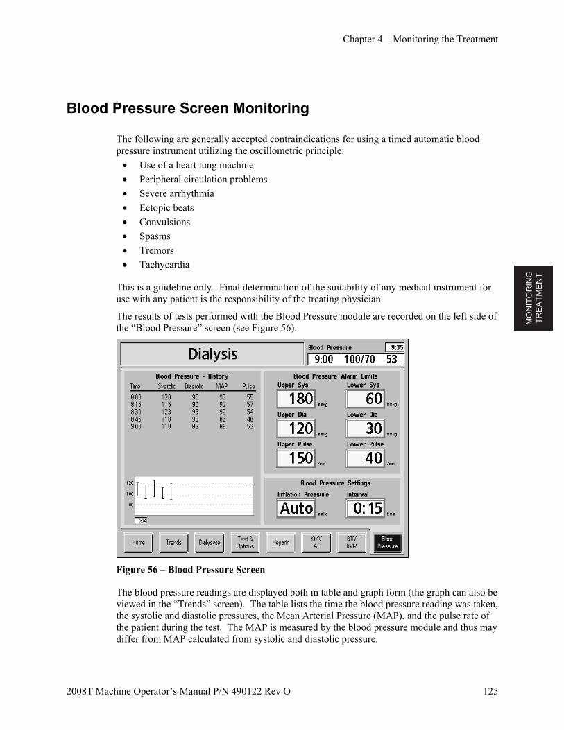
MO
NIT
OR
ING
T
RE
AT
ME
NT
Chapter 4—Monitoring the Treatment
2008T Machine Operator’s Manual P/N 490122 Rev O 125
Blood Pressure Screen Monitoring
The following are generally accepted contraindications for using a timed automatic blood pressure instrument utilizing the oscillometric principle:
Use of a heart lung machine
Peripheral circulation problems
Severe arrhythmia
Ectopic beats
Convulsions
Spasms
Tremors
Tachycardia
This is a guideline only. Final determination of the suitability of any medical instrument for use with any patient is the responsibility of the treating physician.
The results of tests performed with the Blood Pressure module are recorded on the left side of the “Blood Pressure” screen (see Figure 56).
Figure 56 – Blood Pressure Screen
The blood pressure readings are displayed both in table and graph form (the graph can also be viewed in the “Trends” screen). The table lists the time the blood pressure reading was taken, the systolic and diastolic pressures, the Mean Arterial Pressure (MAP), and the pulse rate of the patient during the test. The MAP is measured by the blood pressure module and thus may differ from MAP calculated from systolic and diastolic pressure.
MO
NIT
OR
ING
T
RE
AT
ME
NT
Chapter 4—Monitoring the Treatment
126 2008T Machine Operator’s Manual P/N 490122 Rev O
The pressure readings on the graph are represented by vertical lines with ticks at the top and bottom signifying the systolic and diastolic pressures respectively. The first pressure reading is displayed on the left side of the graph with subsequent readings appearing to the right. The table on screen displays a maximum of 10 pressure readings at a time.
The Stat/Deflate key, located on the right side of the control panel, can be used to quickly relieve the pressure from an inflated blood pressure cuff. It will also start an unscheduled blood pressure reading if the cuff is deflated. Unscheduled tests do not have any effect on the scheduled tests. For
example, if the tests were scheduled at 15-minute intervals, and a manual test was taken five minutes after the first test, the next test will still occur 15 minutes after the first one. The results of both automatic and manual tests are displayed in the table. Results appear in the graph only after the Tx Clock is started.
Note: For accurate blood pressure readings, the cuff must be the proper size and positioned at heart level. Each centimeter above or below the heart that the cuff is positioned, will result in a reading error of 0.8 mm Hg. Tests taken with the Tx Clock paused do not show up on graph.
During Treatment
Online Pressure Holding Test
The online Pressure Holding Test (PHT) automatically checks the integrity of the dialysate balancing system during dialysis when the dialyzer is connected. The online PHT detects most leaks in the hydraulics that would affect the precise volumetric control of fluid in the dialysate system.
The online PHT complements the self-test sequence; it is not a substitute. It is still necessary to perform the initial Automatic Test Sequence before each high flux treatment.
The online PHT runs every 12 minutes regardless of the other alarm conditions. Dialysate flow must be on and the machine cannot be executing a filling program or OLC test. The test runs for two balancing-chamber cycles (about seven seconds). The message “RUNNING ONLINE PHT” displays during the test. Before the test, the UF pump stops in the middle of a cycle and remains off during the two balancing chamber cycles of the online PHT. The UF green light will flash during this time. The machine is in bypass mode during the test period. The displayed TMP during this time represents pressure within the hydraulics, therefore, the TMP reading may change slightly. The TMP alarm limits are spread during the test.
MO
NIT
OR
ING
T
RE
AT
ME
NT
Chapter 4—Monitoring the Treatment
2008T Machine Operator’s Manual P/N 490122 Rev O 127
Online PHT Failure
If the machine fails the online PHT, the message “ONLINE PHT FAILED” is displayed in the Status Box. The blood pump does not stop during this alarm condition. This alarm can be cleared by pressing the RESET button.
Online PHT failures can be caused by problems that make it difficult to control the patient’s fluid balance. Some failure alarms can be caused by air entering the hydraulic system from faulty concentrate or dialyzer line connections. The operator should inspect the machine for external air intake and fluid leaks, and make the appropriate corrections if possible.
Discontinue the treatment and take the machine out of service if an online PHT failure alarm recurs. The hydraulics should be inspected by a qualified technician before returning the machine to service.
If an online PHT failure occurs once during a treatment, perform the Pressure Holding Test (from the “Test & Options” screen) before the next treatment to verify the integrity of the hydraulic system.
Changing the bibag disposable during treatment
Note: When changing the bibag disposable during treatment, the automated empty feature cannot be used so the bag will need to be emptied manually.
Note: If a bag is changed during treatment, a pause of 6-10 minutes should be expected as the new bag fills. The dialysis machine will automatically go into bypass mode until the new bag is on-line and conductivity comes into the acceptable range.
If the bibag disposable needs to be changed during the treatment, use the following steps:
1. Lift up on the dark-gray bibag door handle to open the bibag door.
2. Wait 30 seconds to relieve the pressure in the bag.
3. Lift up the bibag disposable by the handle, remove the used bag and dispose of it per unit protocol. Since the used bag is not empty of fluid, be careful to prevent spills.
Note: If disposing of leftover bicarbonate solution down a drain, be sure to run plenty of hot water down the drain too. This will help prevent bicarbonate buildup in the plumbing.
4. For the new bibag disposable, remove the white plastic seal from underneath the water and bicarbonate nozzles. Hang the bag on the machine’s bibag connector nozzles.
5. Close the bibag door, making sure it latches firmly in place. An audible click indicates the door is closed. The treatment will resume after the machine fills the bag with heated water.
MO
NIT
OR
ING
T
RE
AT
ME
NT
Chapter 4—Monitoring the Treatment
128 2008T Machine Operator’s Manual P/N 490122 Rev O
Blood Recirculation Procedure
It is the responsibility of the unit’s medical director to determine the appropriate anti-coagulation protocol and the maximum length of time for recirculating blood.
1. Return blood if possible
To recirculate blood within the extracorporeal blood circuit:
2. Select the Tx Clock button and press CONFIRM (to ‘paused’)
3. Press the blood pump Start/Stop key to stop the blood pump
4. Disconnect the arterial and venous bloodlines from access in an aseptic manner, and connect them together with a sterile recirculation connector.
Note: Infuse heparin per facility protocol.
5. Unclamp saline bag
6. Press the Start/Stop key to start the blood pump, and set the blood flow rate at 150–200 ml/min. An audible alarm will sound every five minutes to alert the operator that the Tx Clock is paused with blood sensed.
7. Press the RESET key to clear the alarm.
To reconnect the patient to machine:
1. Press the Start/Stop key to stop the blood pump.
2. Clamp the saline line.
3. Aseptically reconnect the arterial and venous bloodlines to the patient’s access sites.
4. Restart the blood pump and adjust blood pump to the prescribed flow rate.
5. Select the Tx Clock button and press CONFIRM to resume the treatment.
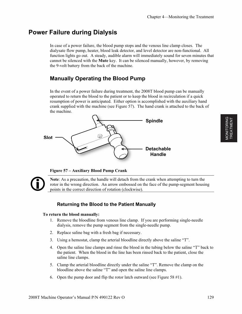
MO
NIT
OR
ING
T
RE
AT
ME
NT
Chapter 4—Monitoring the Treatment
2008T Machine Operator’s Manual P/N 490122 Rev O 129
Power Failure during Dialysis
In case of a power failure, the blood pump stops and the venous line clamp closes. The dialysate flow pump, heater, blood leak detector, and level detector are non-functional. All function lights go out. A steady, audible alarm will immediately sound for seven minutes that cannot be silenced with the Mute key. It can be silenced manually, however, by removing the 9-volt battery from the back of the machine.
Manually Operating the Blood Pump
In the event of a power failure during treatment, the 2008T blood pump can be manually operated to return the blood to the patient or to keep the blood in recirculation if a quick resumption of power is anticipated. Either option is accomplished with the auxiliary hand crank supplied with the machine (see Figure 57). The hand crank is attached to the back of the machine.
Figure 57 – Auxiliary Blood Pump Crank
Note: As a precaution, the handle will detach from the crank when attempting to turn the rotor in the wrong direction. An arrow embossed on the face of the pump-segment housing points in the correct direction of rotation (clockwise).
Returning the Blood to the Patient Manually
To return the blood manually: 1. Remove the bloodline from venous line clamp. If you are performing single-needle
dialysis, remove the pump segment from the single-needle pump.
2. Replace saline bag with a fresh bag if necessary.
3. Using a hemostat, clamp the arterial bloodline directly above the saline “T”.
4. Open the saline line clamps and rinse the blood in the tubing below the saline “T” back to the patient. When the blood in the line has been rinsed back to the patient, close the saline line clamps.
5. Clamp the arterial bloodline directly under the saline “T”. Remove the clamp on the bloodline above the saline “T” and open the saline line clamps.
6. Open the pump door and flip the rotor latch outward (see Figure 58 #1).
Slot
Spindle
Detachable Handle
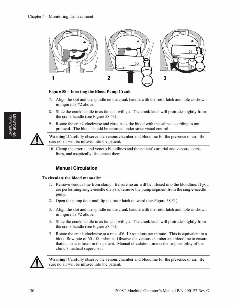
MO
NIT
OR
ING
T
RE
AT
ME
NT
Chapter 4—Monitoring the Treatment
130 2008T Machine Operator’s Manual P/N 490122 Rev O
Figure 58 – Inserting the Blood Pump Crank
7. Align the slot and the spindle on the crank handle with the rotor latch and hole as shown in Figure 58 #2 above.
8. Slide the crank handle in as far as it will go. The crank latch will protrude slightly from the crank handle (see Figure 58 #3).
9. Rotate the crank clockwise and rinse back the blood with the saline according to unit protocol. The blood should be returned under strict visual control.
Warning! Carefully observe the venous chamber and bloodline for the presence of air. Be sure no air will be infused into the patient.
10. Clamp the arterial and venous bloodlines and the patient’s arterial and venous access lines, and aseptically disconnect them.
Manual Circulation
To circulate the blood manually:
1. Remove venous line from clamp. Be sure no air will be infused into the bloodline. If you are performing single-needle dialysis, remove the pump segment from the single-needle pump.
2. Open the pump door and flip the rotor latch outward (see Figure 58 #1).
3. Align the slot and the spindle on the crank handle with the rotor latch and hole as shown in Figure 58 #2 above.
4. Slide the crank handle in as far as it will go. The crank latch will protrude slightly from the crank handle (see Figure 58 #3).
5. Rotate the crank clockwise at a rate of 6–10 rotations per minute. This is equivalent to a blood flow rate of 60–100 ml/min. Observe the venous chamber and bloodline to ensure that no air is infused in the patient. Manual circulation time is the responsibility of the clinic’s medical supervisor.
Warning! Carefully observe the venous chamber and bloodline for the presence of air. Be sure no air will be infused into the patient.
1 2 3
MO
NIT
OR
ING
T
RE
AT
ME
NT
Chapter 4—Monitoring the Treatment
2008T Machine Operator’s Manual P/N 490122 Rev O 131
Power Resumption Procedure
1. Press the POWER key to restore power to the machine. The screen displays the “Select Program” screen with the message, “POWER FAIL RECOVERY.”
2. Select the Dialysis button to enter the “Dialysate” screen.
3. In the “Dialysate” screen, check the conductivity settings (Na+, Bicarbonate, concentrate type) and alarm limits. Verify that the dialysate concentration settings are correct. If not, reset them.
4. Press CONFIRM to save the dialysate settings.
5. Select the Home button to display the “Home” screen.
6. Press the RESET key to reset any alarms. Conductivity and temperature alarms will reset automatically when acceptable limits are reached—usually in about 3–5 minutes. If the dialysate lines were disconnected, reconnect the dialysate lines when conductivity and temperature return to their prescribed limits.
7. Insert venous line in venous clamp and optical detector.
8. If not still connected, reconnect the patient per unit policy. If you are performing single-needle dialysis, re-insert the pump segment into the single-needle pump.
9. Press the blood pump Start/Stop key to restart the blood pump. Reset the blood pump to the prescribed flow rate.
10. Select the Tx Clock button to resume dialysis and then press CONFIRM.
11. If the heparin pump or the Single-Needle option were active prior to the power failure, reinitiate these functions upon power resumption.
12. The SVS program parameters are stored during a power failure. Restart the SVS Profile program by selecting and confirming the desired SVS Profile. Adjust the SVS-Time if necessary.
13. The UF treatment parameters are also saved during a power failure. Check all parameters (UF Goal, UF Time, UF Rate, UF-Removed) for correct settings and adjust if necessary.

MO
NIT
OR
ING
T
RE
AT
ME
NT
Chapter 4—Monitoring the Treatment
132 2008T Machine Operator’s Manual P/N 490122 Rev O
Completion of Dialysis
At the end of treatment, when the RTD timer has counted down to 0:00, an alarm sounds and the message, RTD = ZERO, appears in the Status box. An alarm also sounds when the set amount of ultrafiltrate has been removed. When that happens, the Status Box displays the message, UF GOAL REACHED. To reset either alarm, press the RESET key. If the UF GOAL REACHED and RTD = ZERO alarms occur simultaneously, pressing the RESET key will reset both alarms.
Returning Blood to the Patient
To return the blood to the patient:
1. Select the Tx Clock and then press CONFIRM to stop the treatment.
2. Press the Start/Stop key on the blood pump to stop the pump.
3. Replace saline bag with a fresh bag if necessary.
4. Rinse the blood in the patient end of the arterial bloodline back to the patient:
a. Using a hemostat, clamp the arterial bloodline directly above the saline “T”.
b. Open the saline line clamps and rinse the blood in the tubing below the saline “T” back to the patient. When the blood in the line has been rinsed back to the patient, close the saline line clamps.
5. Rinse the remaining blood in the bloodline back to the patient:
a. Clamp the arterial bloodline directly under the saline “T”.
b. Remove the clamp on the bloodline above the saline “T” and open the saline line clamps.
c. Start the blood pump and set a rate of 150-200 ml/min.
d. When the blood has been returned to the patient, turn the blood pump off and close the saline line clamps.
Warning! Check all bloodlines and dialysate lines for leaks. Keep access sites uncovered and monitored. Improper bloodline connections or needle dislodgements can result in excessive blood loss, serious injury, and death. Machine alarms may not occur in every blood loss situation.
6. Clamp the arterial and venous bloodlines and the patient’s arterial and venous access lines, and aseptically disconnect them.
Note: Depending on how your machine was configured, and audible alarm may sound when the saline solution reaches the optical sensor. Press RESET to silence the alarm.
MO
NIT
OR
ING
T
RE
AT
ME
NT
Chapter 4—Monitoring the Treatment
2008T Machine Operator’s Manual P/N 490122 Rev O 133
Removing the Dialyzer There are two procedures for removing the dialyzer depending on whether your facility reuses dialyzers. Follow the appropriate procedure for your situation.
If Reuse is practiced
The dialysate compartment should not be emptied prior to cleaning the dialyzer. In such cases:
1. Open the shunt door and place the dialyzer connectors on the shunt. Pull on the dialyzer connectors to make sure they are firmly connected to the shunt. Close the shunt door.
2. Cap the dialyzer ports with the caps supplied with the dialyzer and process dialyzer as per unit protocol
3. Discard the bloodlines and transducer protectors according to facility policy
4. Clean or disinfect machine according to routine cleaning and maintenance procedures described in “Disinfection and Maintenance,” on page 136.
If Reuse is not practiced
To remove the fluid in the dialysate compartment:
1. Open shunt interlock door
2. Return blue dialyzer connector to shunt interlock. Pull on the dialyzer connector to make sure it is firmly connected to the shunt.
3. Reposition the dialyzer so that the red, outlet port is at the bottom
4. Close the shunt interlock door. Message “Emptying” will be displayed.
5. Drain the dialysate compartment. The dialyzer is empty as soon as there is air in the outlet line or an “Emptying stopped” message appears.
6. Open the shunt interlock door, remove red dialyzer connector from the dialyzer and place it on the shunt. Pull on the dialyzer connector to make sure it is firmly connected to the shunt. Close the shunt interlock door.
7. Discard the bloodlines, transducer protectors, and dialyzer according to facility policy.
8. Insert the concentrate wands into their proper rinse ports. The “Select Program” screen appears on the display screen.
9. Clean or disinfect the exterior of the machine according to routine cleaning and maintenance procedures described in “Disinfection and Maintenance,” on page 136.
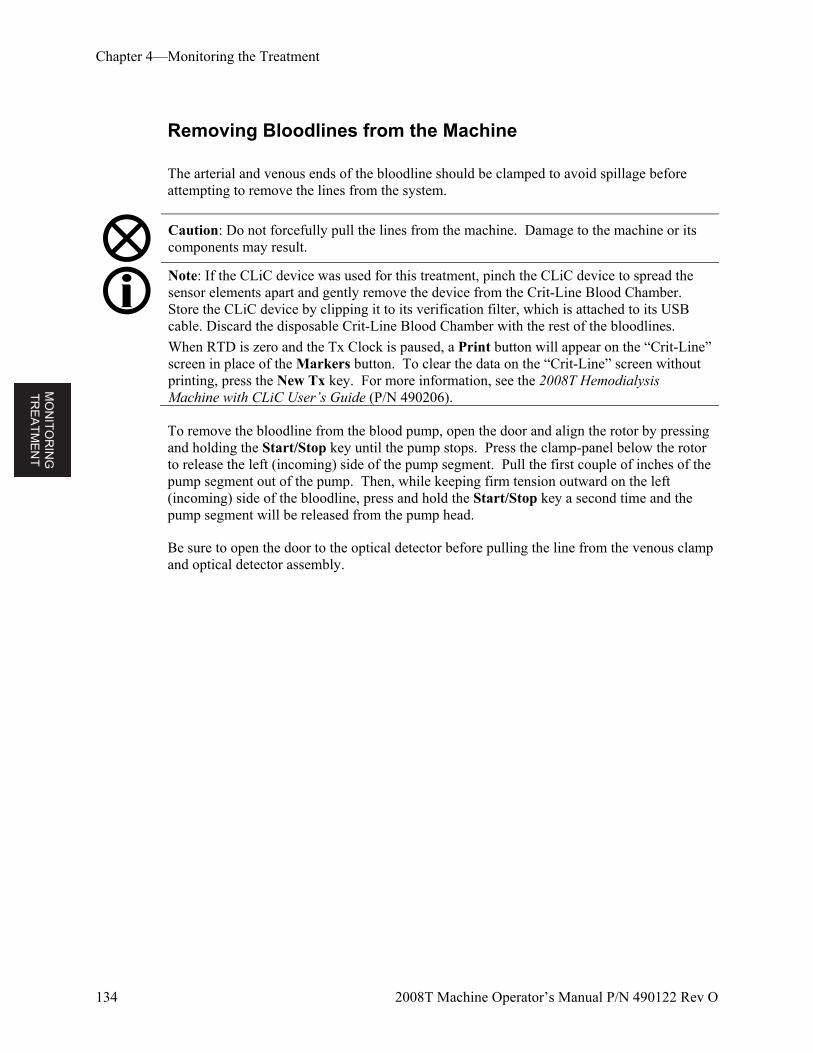
MO
NIT
OR
ING
T
RE
AT
ME
NT
Chapter 4—Monitoring the Treatment
134 2008T Machine Operator’s Manual P/N 490122 Rev O
Removing Bloodlines from the Machine
The arterial and venous ends of the bloodline should be clamped to avoid spillage before attempting to remove the lines from the system.
Caution: Do not forcefully pull the lines from the machine. Damage to the machine or its components may result.
Note: If the CLiC device was used for this treatment, pinch the CLiC device to spread the sensor elements apart and gently remove the device from the Crit-Line Blood Chamber. Store the CLiC device by clipping it to its verification filter, which is attached to its USB cable. Discard the disposable Crit-Line Blood Chamber with the rest of the bloodlines.
When RTD is zero and the Tx Clock is paused, a Print button will appear on the “Crit-Line” screen in place of the Markers button. To clear the data on the “Crit-Line” screen without printing, press the New Tx key. For more information, see the 2008T Hemodialysis Machine with CLiC User’s Guide (P/N 490206).
To remove the bloodline from the blood pump, open the door and align the rotor by pressing and holding the Start/Stop key until the pump stops. Press the clamp-panel below the rotor to release the left (incoming) side of the pump segment. Pull the first couple of inches of the pump segment out of the pump. Then, while keeping firm tension outward on the left (incoming) side of the bloodline, press and hold the Start/Stop key a second time and the pump segment will be released from the pump head.
Be sure to open the door to the optical detector before pulling the line from the venous clamp and optical detector assembly.
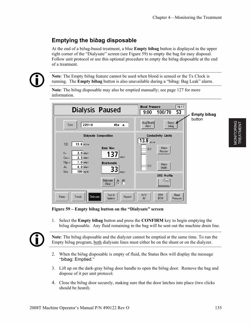
MO
NIT
OR
ING
T
RE
AT
ME
NT
Chapter 4—Monitoring the Treatment
2008T Machine Operator’s Manual P/N 490122 Rev O 135
Emptying the bibag disposable At the end of a bibag-based treatment, a blue Empty bibag button is displayed in the upper right corner of the “Dialysate” screen (see Figure 59) to empty the bag for easy disposal. Follow unit protocol or use this optional procedure to empty the bibag disposable at the end of a treatment.
Note: The Empty bibag feature cannot be used when blood is sensed or the Tx Clock is running. The Empty bibag button is also unavailable during a “bibag: Bag Leak” alarm.
Note: The bibag disposable may also be emptied manually; see page 127 for more information.
Figure 59 – Empty bibag button on the “Dialysate” screen
1. Select the Empty bibag button and press the CONFIRM key to begin emptying the bibag disposable. Any fluid remaining in the bag will be sent out the machine drain line.
Note: The bibag disposable and the dialyzer cannot be emptied at the same time. To run the Empty bibag program, both dialysate lines must either be on the shunt or on the dialyzer.
2. When the bibag disposable is empty of fluid, the Status Box will display the message “bibag: Emptied.”
3. Lift up on the dark-gray bibag door handle to open the bibag door. Remove the bag and dispose of it per unit protocol.
4. Close the bibag door securely, making sure that the door latches into place (two clicks should be heard).
Empty bibag button
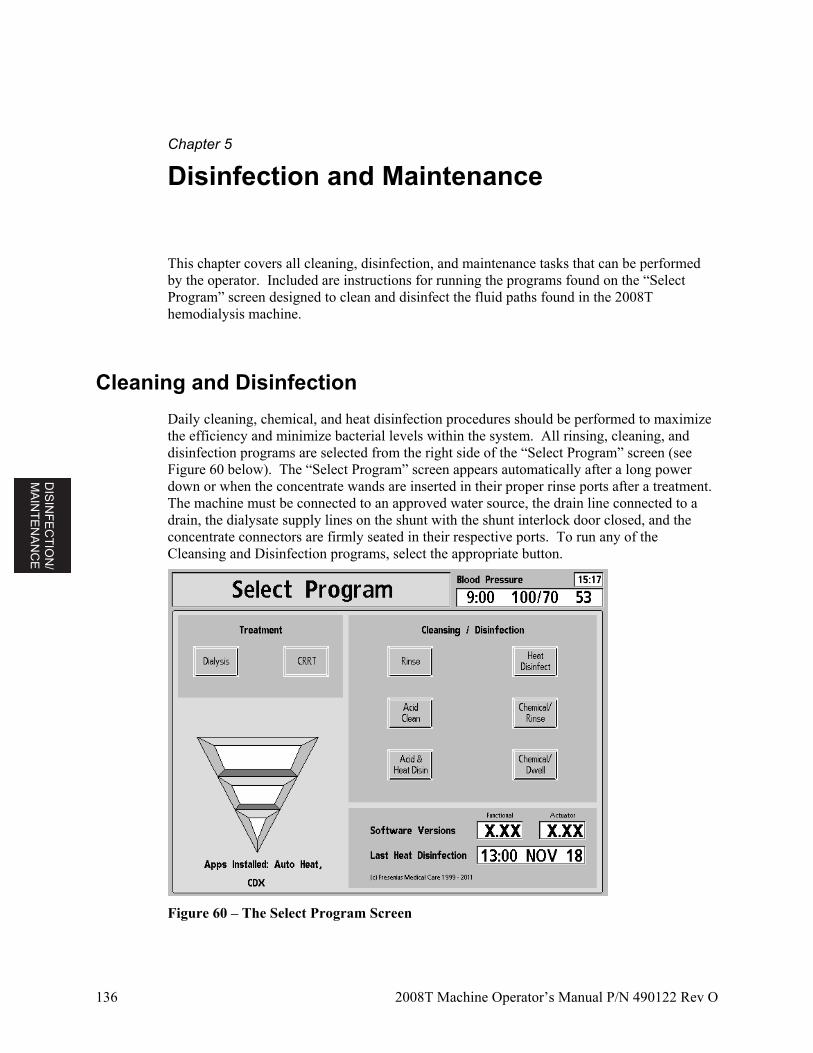
DIS
INF
EC
TIO
N/
MA
INT
EN
AN
CE
136 2008T Machine Operator’s Manual P/N 490122 Rev O
Chapter 5
Disinfection and Maintenance
This chapter covers all cleaning, disinfection, and maintenance tasks that can be performed by the operator. Included are instructions for running the programs found on the “Select Program” screen designed to clean and disinfect the fluid paths found in the 2008T hemodialysis machine.
Cleaning and Disinfection
Daily cleaning, chemical, and heat disinfection procedures should be performed to maximize the efficiency and minimize bacterial levels within the system. All rinsing, cleaning, and disinfection programs are selected from the right side of the “Select Program” screen (see Figure 60 below). The “Select Program” screen appears automatically after a long power down or when the concentrate wands are inserted in their proper rinse ports after a treatment. The machine must be connected to an approved water source, the drain line connected to a drain, the dialysate supply lines on the shunt with the shunt interlock door closed, and the concentrate connectors are firmly seated in their respective ports. To run any of the Cleansing and Disinfection programs, select the appropriate button.
Figure 60 – The Select Program Screen
DIS
INF
EC
TIO
N/
MA
INT
EN
AN
CE
Chapter 5—Disinfection and Maintenance
2008T Machine Operator’s Manual P/N 490122 Rev O 137
The fluid path of the 2008T hemodialysis machine can be disinfected chemically or with heat. The machine should be rinsed thoroughly after chemical disinfection and before introducing any other chemicals to the machine. The machine should be disinfected at least once each day it is used and rinsed per unit protocol. If the machine is not in use for more than 48 hours, it should be disinfected before the next use or put in storage (for more information on storing the machine, see “Equipment Storage and Maintenance” on page 263). If there is evidence of a blood leak into the dialysate system, the machine should be disinfected before being used in any further treatments.
The Rinse program flushes the machine with water. The Acid Clean Program flushes the machine with a mild acid to remove bicarbonate build up. There are three options for disinfecting the interior of the 2008T hemodialysis machine—Heat Disinfect, Chemical/Rinse and Chemical Dwell.
All rinse, cleaning, and disinfecting programs can be interrupted by pulling either concentrate nozzle from its rinse port or pressing the Escape key. Any Rinse or Disinfection program clears all SVS and UF parameters and resets them to default values. The ultrafiltration fluid sample port output tubing is part of the fluid pathway; therefore, flow exists during cleaning and disinfection.
The following table describes the cleaning and disinfecting options available on the “Select Program” screen. Follow the current, chemical manufacturer’s instructions for the proper use of the disinfectants.
Warning! Any machine filled with a chemical for cleaning or disinfection must be clearly labeled by the operator. The label should identify the chemical used and state that the rinsing and testing for residual chemical are required before using the machine for treatment.
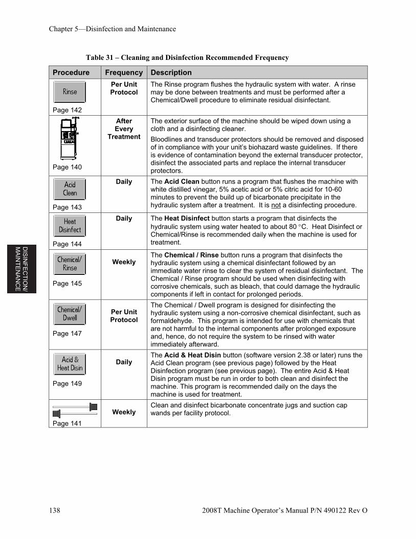
DIS
INF
EC
TIO
N/
MA
INT
EN
AN
CE
Chapter 5—Disinfection and Maintenance
138 2008T Machine Operator’s Manual P/N 490122 Rev O
Table 31 – Cleaning and Disinfection Recommended Frequency
Procedure Frequency Description
Page 142
Per Unit Protocol
The Rinse program flushes the hydraulic system with water. A rinse may be done between treatments and must be performed after a Chemical/Dwell procedure to eliminate residual disinfectant.
Page 140
After Every
Treatment
The exterior surface of the machine should be wiped down using a cloth and a disinfecting cleaner.
Bloodlines and transducer protectors should be removed and disposed of in compliance with your unit’s biohazard waste guidelines. If there is evidence of contamination beyond the external transducer protector, disinfect the associated parts and replace the internal transducer protectors.
Page 143
Daily The Acid Clean button runs a program that flushes the machine with white distilled vinegar, 5% acetic acid or 5% citric acid for 10-60 minutes to prevent the build up of bicarbonate precipitate in the hydraulic system after a treatment. It is not a disinfecting procedure.
Page 144
Daily The Heat Disinfect button starts a program that disinfects the hydraulic system using water heated to about 80 C. Heat Disinfect or Chemical/Rinse is recommended daily when the machine is used for treatment.
Page 145
Weekly The Chemical / Rinse button runs a program that disinfects the hydraulic system using a chemical disinfectant followed by an immediate water rinse to clear the system of residual disinfectant. The Chemical / Rinse program should be used when disinfecting with corrosive chemicals, such as bleach, that could damage the hydraulic components if left in contact for prolonged periods.
Page 147
Per Unit Protocol
The Chemical / Dwell program is designed for disinfecting the hydraulic system using a non-corrosive chemical disinfectant, such as formaldehyde. This program is intended for use with chemicals that are not harmful to the internal components after prolonged exposure and, hence, do not require the system to be rinsed with water immediately afterward.
Page 149
Daily The Acid & Heat Disin button (software version 2.38 or later) runs the Acid Clean program (see previous page) followed by the Heat Disinfection program (see previous page). The entire Acid & Heat Disin program must be run in order to both clean and disinfect the machine. This program is recommended daily on the days the machine is used for treatment.
Page 141
Weekly Clean and disinfect bicarbonate concentrate jugs and suction cap wands per facility protocol.
DIS
INF
EC
TIO
N/
MA
INT
EN
AN
CE
Chapter 5—Disinfection and Maintenance
2008T Machine Operator’s Manual P/N 490122 Rev O 139
Additional Disinfection Requirements
In addition to the routine cleaning and disinfection tasks listed in the previous table, additional disinfection is required for the following situations:
Each time the water treatment system is disinfected
When the water treatment system and distribution piping are disinfected, each dialysate delivery machine should be placed in the Rinse program to draw disinfectant into the machine through the inlet lines. Check for residual disinfectant prior to use for dialysis.
After contamination of transducer protector
Disinfect the connectors and replace the internal transducer protector if there is evidence of leakage past the external transducer protector on the venous or blood pump modules. Disinfect associated parts.
After a dialyzer blood leak
The machine should be disinfected prior to the next treatment if a blood leak alarm occurred.
Warning! The protocol for disinfection is determined by the facility and its medical director. When chemicals are used internally, machines must be thoroughly rinsed and tested for residual disinfectant before using the machine for treatment. Follow the instructions of the chemical manufacturer for residual testing. If the machine is chemically disinfected daily, we recommend that it also be heat disinfected at least once per week.
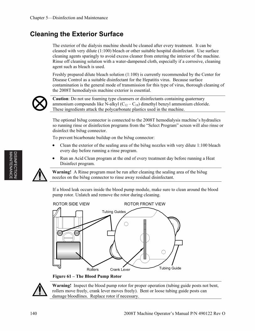
DIS
INF
EC
TIO
N/
MA
INT
EN
AN
CE
Chapter 5—Disinfection and Maintenance
140 2008T Machine Operator’s Manual P/N 490122 Rev O
Cleaning the Exterior Surface
The exterior of the dialysis machine should be cleaned after every treatment. It can be cleaned with very dilute (1:100) bleach or other suitable hospital disinfectant. Use surface cleaning agents sparingly to avoid excess cleaner from entering the interior of the machine. Rinse off cleaning solution with a water-dampened cloth, especially if a corrosive, cleaning agent such as bleach is used.
Freshly prepared dilute bleach solution (1:100) is currently recommended by the Center for Disease Control as a suitable disinfectant for the Hepatitis virus. Because surface contamination is the general mode of transmission for this type of virus, thorough cleaning of the 2008T hemodialysis machine exterior is essential.
Caution: Do not use foaming type cleansers or disinfectants containing quaternary ammonium compounds like N-alkyl (C12 – C18) dimethyl benzyl ammonium chloride. These ingredients attack the polycarbonate plastics used in the machine. The optional bibag connector is connected to the 2008T hemodialysis machine’s hydraulics so running rinse or disinfection programs from the “Select Program” screen will also rinse or disinfect the bibag connector.
To prevent bicarbonate buildup on the bibag connector:
Clean the exterior of the sealing area of the bibag nozzles with very dilute 1:100 bleach every day before running a rinse program.
Run an Acid Clean program at the end of every treatment day before running a Heat Disinfect program.
Warning! A Rinse program must be run after cleaning the sealing area of the bibag nozzles on the bibag connector to rinse away residual disinfectant.
If a blood leak occurs inside the blood pump module, make sure to clean around the blood pump rotor. Unlatch and remove the rotor during cleaning.
Figure 61 – The Blood Pump Rotor
Warning! Inspect the blood pump rotor for proper operation (tubing guide posts not bent, rollers move freely, crank lever moves freely). Bent or loose tubing guide posts can damage bloodlines. Replace rotor if necessary.
DIS
INF
EC
TIO
N/
MA
INT
EN
AN
CE
Chapter 5—Disinfection and Maintenance
2008T Machine Operator’s Manual P/N 490122 Rev O 141
Concentrate Containers
The containers used for bicarbonate concentrate should be disinfected once a week. Dilute 1:100 bleach may be used for this purpose. This is especially important when bicarbonate concentrates are used since bacteria can grow more readily in these solutions. Following disinfection, they should be rinsed thoroughly with treated water. Check for residual disinfectant before using the disinfected containers. All concentrate containers should be left empty (shake if necessary) and inverted when stored overnight.
Cleaning the Blood Pressure Cuff
Remove the rubber inflation bag from the Dacron cuff. Both may be disinfected with commercially available disinfectant soaks. Some disinfectants may cause skin irritation. Rinse thoroughly to remove any residual disinfectant. Follow the manufacturer’s instructions. Caution is advised when using dark colored soaks which may stain the cuff. Test a single cuff to ensure that no damage will occur. EtO sterilization may be used.
Caution: If a chlorine bleach solution is used to clean the blood pressure cuff, the service life of the cuff will be reduced. Do not autoclave the cuff.
Hand washing will enhance the service life of the Calibrated V-Lok cuff. Remove the natural rubber inflation bag and wash the cuff in warm soapy water; then rinse thoroughly. Allow the cuff to air dry and then insert the inflation bag. When using machine washing, be sure that the hook and loop fasteners are engaged so that the hooks do not collect lint or other fibers. These fasteners can melt at temperatures above 325 °F (132 °C), when being ironed or pressed.
Water Supply Maintenance
It is recommended that the bacterial quality of both the water and the dialysate be checked on a routine basis. These checks should take place just before routine disinfection of the system. Follow the manufacturer’s instructions for the operation and storage of reverse-osmosis (RO) and water pre-treatment equipment.
All sections of the treated water feed system and dialysate delivery machine must be disinfected regularly to minimize bacterial levels. Each time the treated water system and distribution piping are disinfected, the dialysis machines should be put into Rinse program. This allows the disinfectant chemical to feed through the inlet system. Test the water for residual disinfectant prior to use for dialysis.
Note: The water inlet line is part of the water distribution system and is not disinfected by the dialysis machine. With some RO systems, the water inlet line may be disinfected along with the RO and distribution piping by leaving the dialysis machine in Rinse mode during RO disinfection.
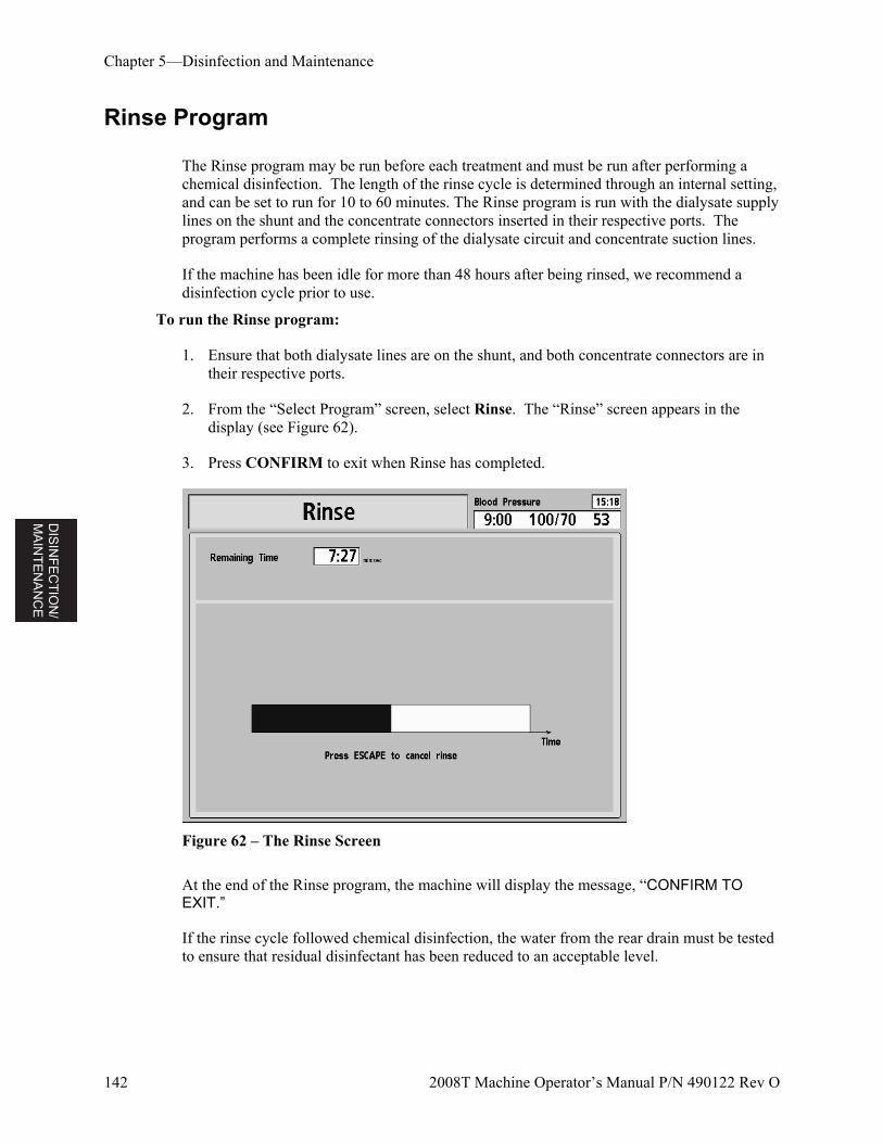
DIS
INF
EC
TIO
N/
MA
INT
EN
AN
CE
Chapter 5—Disinfection and Maintenance
142 2008T Machine Operator’s Manual P/N 490122 Rev O
Rinse Program
The Rinse program may be run before each treatment and must be run after performing a chemical disinfection. The length of the rinse cycle is determined through an internal setting, and can be set to run for 10 to 60 minutes. The Rinse program is run with the dialysate supply lines on the shunt and the concentrate connectors inserted in their respective ports. The program performs a complete rinsing of the dialysate circuit and concentrate suction lines.
If the machine has been idle for more than 48 hours after being rinsed, we recommend a disinfection cycle prior to use.
To run the Rinse program:
1. Ensure that both dialysate lines are on the shunt, and both concentrate connectors are in their respective ports.
2. From the “Select Program” screen, select Rinse. The “Rinse” screen appears in the display (see Figure 62).
3. Press CONFIRM to exit when Rinse has completed.
Figure 62 – The Rinse Screen
At the end of the Rinse program, the machine will display the message, “CONFIRM TO EXIT.”
If the rinse cycle followed chemical disinfection, the water from the rear drain must be tested to ensure that residual disinfectant has been reduced to an acceptable level.
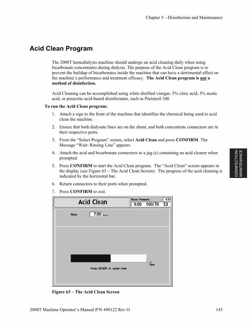
DIS
INF
EC
TIO
N/
MA
INT
EN
AN
CE
Chapter 5—Disinfection and Maintenance
2008T Machine Operator’s Manual P/N 490122 Rev O 143
Acid Clean Program
The 2008T hemodialysis machine should undergo an acid cleaning daily when using bicarbonate concentrates during dialysis. The purpose of the Acid Clean program is to prevent the buildup of bicarbonates inside the machine that can have a detrimental effect on the machine’s performance and treatment efficacy. The Acid Clean program is not a method of disinfection.
Acid Cleaning can be accomplished using white distilled vinegar, 5% citric acid, 5% acetic acid, or peracetic-acid-based disinfectants, such as Puristeril 340
To run the Acid Clean program:
1. Attach a sign to the front of the machine that identifies the chemical being used to acid clean the machine.
2. Ensure that both dialysate lines are on the shunt, and both concentrate connectors are in their respective ports.
3. From the “Select Program” screen, select Acid Clean and press CONFIRM. The Message “Wait: Rinsing Line” appears.
4. Attach the acid and bicarbonate connectors to a jug (s) containing an acid cleaner when prompted.
5. Press CONFIRM to start the Acid Clean program. The “Acid Clean” screen appears in the display (see Figure 63 – The Acid Clean Screen). The progress of the acid cleaning is indicated by the horizontal bar.
6. Return connectors to their ports when prompted.
7. Press CONFIRM to exit.
Figure 63 – The Acid Clean Screen
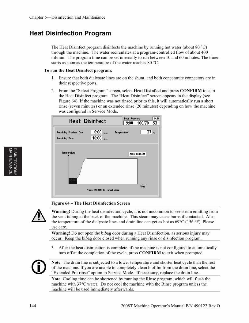
DIS
INF
EC
TIO
N/
MA
INT
EN
AN
CE
Chapter 5—Disinfection and Maintenance
144 2008T Machine Operator’s Manual P/N 490122 Rev O
Heat Disinfection Program
The Heat Disinfect program disinfects the machine by running hot water (about 80 C) through the machine. The water recirculates at a program-controlled flow of about 400 ml/min. The program time can be set internally to run between 10 and 60 minutes. The timer starts as soon as the temperature of the water reaches 80 °C.
To run the Heat Disinfect program:
1. Ensure that both dialysate lines are on the shunt, and both concentrate connectors are in their respective ports.
2. From the “Select Program” screen, select Heat Disinfect and press CONFIRM to start the Heat Disinfect program. The “Heat Disinfect” screen appears in the display (see Figure 64). If the machine was not rinsed prior to this, it will automatically run a short rinse (seven minutes) or an extended rinse (20 minutes) depending on how the machine was configured in Service Mode.
Figure 64 – The Heat Disinfection Screen
Warning! During the heat disinfection cycle, it is not uncommon to see steam emitting from the vent tubing at the back of the machine. This steam may cause burns if contacted. Also, the temperature of the dialysate lines and drain line can get as hot as 69°C (156 °F). Please use care.
Warning! Do not open the bibag door during a Heat Disinfection, as serious injury may occur. Keep the bibag door closed when running any rinse or disinfection program.
3. After the heat disinfection is complete, if the machine is not configured to automatically turn off at the completion of the cycle, press CONFIRM to exit when prompted.
Note: The drain line is subjected to a lower temperature and shorter heat cycle than the rest of the machine. If you are unable to completely clean biofilm from the drain line, select the “Extended Pre-rinse” option in Service Mode. If necessary, replace the drain line.
Note: Cooling time can be shortened by running the Rinse program, which will flush the machine with 37°C water. Do not cool the machine with the Rinse program unless the machine will be used immediately afterwards.
DIS
INF
EC
TIO
N/
MA
INT
EN
AN
CE
Chapter 5—Disinfection and Maintenance
2008T Machine Operator’s Manual P/N 490122 Rev O 145
Chemical/Rinse Program
The Chemical/Rinse program should be used when disinfecting the hydraulic system using corrosive chemicals, such as bleach or peracetic-acid-based disinfectants (e.g. Puristeril 340). The Chemical/Rinse program consists of a disinfection cycle followed by a water rinse cycle. Because bacterial growth can begin soon after the rinse cycle, the machine should be disinfected again if it has remained idle more than 48 hours after its previous disinfection.
Caution: To avoid internal damage these chemicals should not remain in contact with the machine. Rinse your machine immediately after completing the disinfection.
To run the Chemical/Rinse program:
1. Attach a sign to the front of the machine that identifies the chemical being used to disinfect the machine.
2. Ensure that both dialysate lines are on the shunt, and both concentrate connectors are in their respective ports.
3. From the “Select Program” screen, select Chemical/Rinse and press CONFIRM.
4. The “Chemical/Rinse” screen appears in the display (see Figure 65). The progress of the disinfection program is indicated by the horizontal bar. The program starts with a 45 second pre-rinse. The message, “Rinsing Lines, Please Wait” is displayed in the Status Box.
Note: If the ‘HE Leak Test’ Service Mode option is selected (software versions 2.53 and later), the machine will run a four minute pressure holding test after the 45 second pre-rinse. If the first test fails, a second test will automatically run.
If the second test fails, the machine will display a “System Leak, Can’t Run” message, meaning that the Chemical/Rinse program can no longer be run due to a leak detected in the Heat Exchanger. However, the machine will still be able to run Heat Disinfection programs and hemodialysis treatments per unit protocol. Call a qualified service technician.
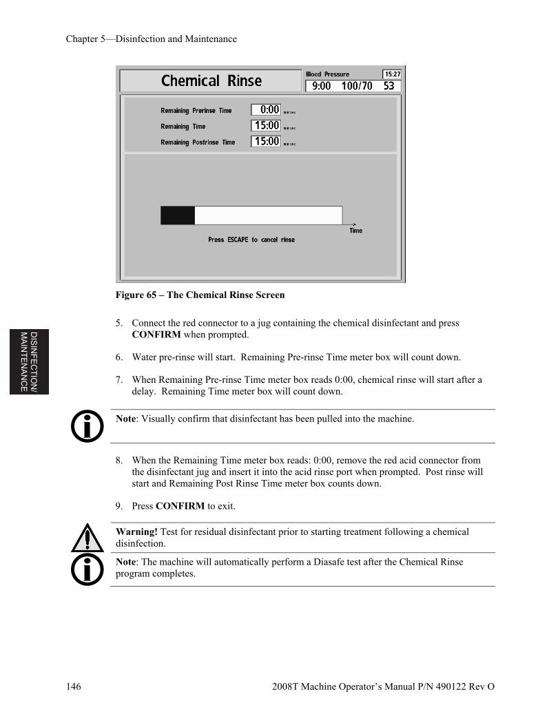
DIS
INF
EC
TIO
N/
MA
INT
EN
AN
CE
Chapter 5—Disinfection and Maintenance
146 2008T Machine Operator’s Manual P/N 490122 Rev O
Figure 65 – The Chemical Rinse Screen
5. Connect the red connector to a jug containing the chemical disinfectant and press CONFIRM when prompted.
6. Water pre-rinse will start. Remaining Pre-rinse Time meter box will count down.
7. When Remaining Pre-rinse Time meter box reads 0:00, chemical rinse will start after a delay. Remaining Time meter box will count down.
Note: Visually confirm that disinfectant has been pulled into the machine.
8. When the Remaining Time meter box reads: 0:00, remove the red acid connector from the disinfectant jug and insert it into the acid rinse port when prompted. Post rinse will start and Remaining Post Rinse Time meter box counts down.
9. Press CONFIRM to exit.
Warning! Test for residual disinfectant prior to starting treatment following a chemical disinfection.
Note: The machine will automatically perform a Diasafe test after the Chemical Rinse program completes.
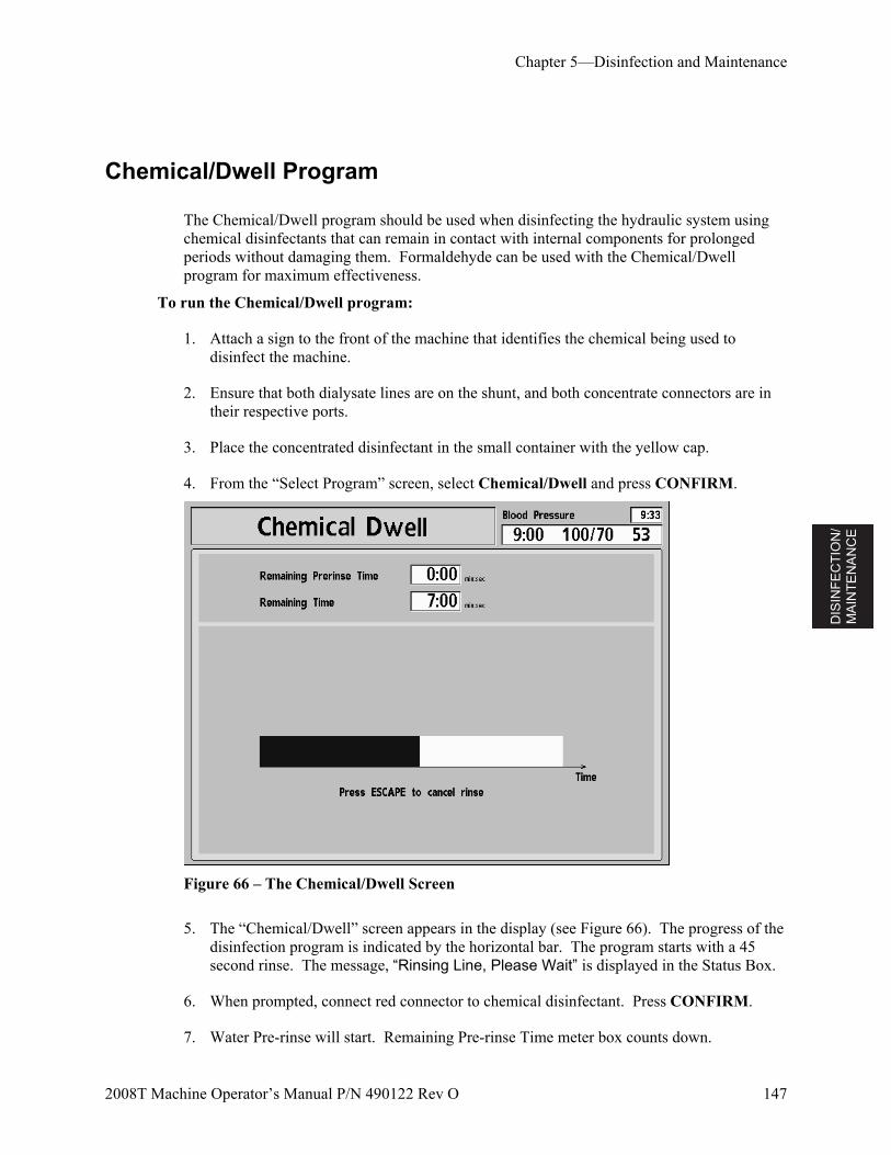
DIS
INF
EC
TIO
N/
MA
INT
EN
AN
CE
Chapter 5—Disinfection and Maintenance
2008T Machine Operator’s Manual P/N 490122 Rev O 147
Chemical/Dwell Program
The Chemical/Dwell program should be used when disinfecting the hydraulic system using chemical disinfectants that can remain in contact with internal components for prolonged periods without damaging them. Formaldehyde can be used with the Chemical/Dwell program for maximum effectiveness.
To run the Chemical/Dwell program:
1. Attach a sign to the front of the machine that identifies the chemical being used to disinfect the machine.
2. Ensure that both dialysate lines are on the shunt, and both concentrate connectors are in their respective ports.
3. Place the concentrated disinfectant in the small container with the yellow cap.
4. From the “Select Program” screen, select Chemical/Dwell and press CONFIRM.
Figure 66 – The Chemical/Dwell Screen
5. The “Chemical/Dwell” screen appears in the display (see Figure 66). The progress of the disinfection program is indicated by the horizontal bar. The program starts with a 45 second rinse. The message, “Rinsing Line, Please Wait” is displayed in the Status Box.
6. When prompted, connect red connector to chemical disinfectant. Press CONFIRM.
7. Water Pre-rinse will start. Remaining Pre-rinse Time meter box counts down.
DIS
INF
EC
TIO
N/
MA
INT
EN
AN
CE
Chapter 5—Disinfection and Maintenance
148 2008T Machine Operator’s Manual P/N 490122 Rev O
8. Chemical dwell follows after a delay. Remaining Time meter box counts down.
9. When the Remaining Time meter box reads 0:00, remove the red acid connector from the disinfectant jug and insert it into the acid rinse port. The machine will automatically run for about a minute to draw up the disinfectant left in the tubing.
Note: Visually confirm that disinfectant has been pulled into the machine.
10. Following the completion of the chemical disinfection cycle, “Press CONFIRM to exit” will display in the Status Box.
11. Press CONFIRM to exit.
Warning! The mandatory rinse cycle must be completed and a test for residual disinfectant must be performed prior to the next treatment.
DIS
INF
EC
TIO
N/
MA
INT
EN
AN
CE
Chapter 5—Disinfection and Maintenance
2008T Machine Operator’s Manual P/N 490122 Rev O 149
Acid & Heat Disin (Disinfect) Program
The 2008T hemodialysis machine should undergo an acid cleaning daily when using bicarbonate concentrates during dialysis in addition to daily disinfection on treatment days. The purpose of the Acid & Heat Disin program (software version 2.38 or later) is to prevent the buildup of bicarbonates inside the machine that can have a detrimental effect on the machine’s performance and treatment efficacy and to then disinfect the machine. The entire Acid & Heat Disin program must be run in order to both clean and disinfect the machine.
Acid Cleaning can be done using white distilled vinegar, 5% citric acid, 5% acetic acid, or peracetic-acid-based disinfectants, such as Puristeril 340.
The Heat Disinfect program disinfects the machine by running hot water (about 80 C) through the machine. The water circulates at a program-controlled flow of about 400 ml/min.
To run the Acid & Heat Disin program:
1. Attach a sign to the front of the machine that identifies the chemical being used to acid clean the machine.
2. Ensure that both dialysate lines are on the shunt, and both concentrate connectors are in their respective ports.
3. From the “Select Program” screen, select Acid & Heat Disin and press CONFIRM. The Message “Wait: Rinsing Line” appears.
4. Connect the acid and bicarbonate connectors to a jug(s) containing an acid cleaner when prompted.
5. Press CONFIRM to start the Acid Clean portion of the program. The “Acid Clean” screen appears in the display (see Figure 63 – The Acid Clean Screen). The progress of the acid cleaning is indicated by the horizontal bar.
6. Return connectors to their ports when prompted (the machine will beep every 30 seconds until the connectors are inserted back in the rinse ports). The “Heat Disinfect” screen appears next in the display (see Figure 64 – The Heat Disinfection Screen). The machine will automatically run a short rinse (seven minutes standard or ten minutes with Diasafe Plus) or an extended rinse (20 minutes) depending on how the machine was configured in Service Mode. The Heat Disinfect starts as soon as the temperature of the water reaches 80° C. The program time can be set internally to run between 10 and 60 minutes.
Warning! During the heat disinfection cycle, it is not uncommon to see steam emitting from the vent tubing at the back of the machine. This steam may cause burns if contacted. Also, the temperature of the dialysate lines and drain line can get as hot as 69°C (156 °F). Please use care.
Warning! Do not open the bibag door during a Heat Disinfection, as serious injury may occur. Keep the bibag door closed when running any rinse or disinfection program.
DIS
INF
EC
TIO
N/
MA
INT
EN
AN
CE
Chapter 5—Disinfection and Maintenance
150 2008T Machine Operator’s Manual P/N 490122 Rev O
7. After the heat disinfection is complete, if the machine is not configured to automatically turn off at the completion of the cycle, press CONFIRM to exit when prompted.
Note: The drain line is subjected to a lower temperature and shorter heat cycle than the rest of the machine. If you are unable to completely clean biofilm from the drain line, select the “Extended Pre-rinse” option in Service Mode. If necessary, replace the drain line.
Note: Cooling time can be shortened by running the Rinse program, which will flush the machine with 37°C water. Do not cool the machine with the Rinse program unless the machine will be used immediately afterwards.
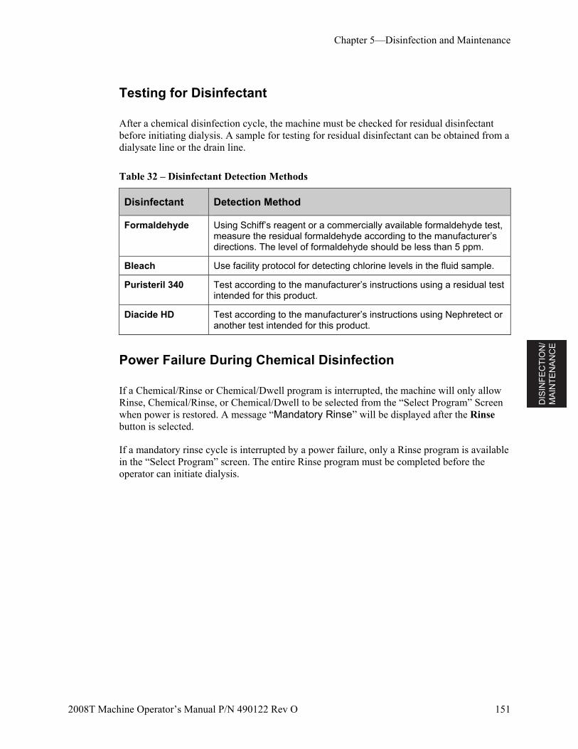
DIS
INF
EC
TIO
N/
MA
INT
EN
AN
CE
Chapter 5—Disinfection and Maintenance
2008T Machine Operator’s Manual P/N 490122 Rev O 151
Testing for Disinfectant
After a chemical disinfection cycle, the machine must be checked for residual disinfectant before initiating dialysis. A sample for testing for residual disinfectant can be obtained from a dialysate line or the drain line.
Table 32 – Disinfectant Detection Methods
Disinfectant Detection Method
Formaldehyde Using Schiff’s reagent or a commercially available formaldehyde test, measure the residual formaldehyde according to the manufacturer’s directions. The level of formaldehyde should be less than 5 ppm.
Bleach Use facility protocol for detecting chlorine levels in the fluid sample.
Puristeril 340 Test according to the manufacturer’s instructions using a residual test intended for this product.
Diacide HD Test according to the manufacturer’s instructions using Nephretect or another test intended for this product.
Power Failure During Chemical Disinfection
If a Chemical/Rinse or Chemical/Dwell program is interrupted, the machine will only allow Rinse, Chemical/Rinse, or Chemical/Dwell to be selected from the “Select Program” Screen when power is restored. A message “Mandatory Rinse” will be displayed after the Rinse button is selected.
If a mandatory rinse cycle is interrupted by a power failure, only a Rinse program is available in the “Select Program” screen. The entire Rinse program must be completed before the operator can initiate dialysis.
DIS
INF
EC
TIO
N/
MA
INT
EN
AN
CE
Chapter 5—Disinfection and Maintenance
152 2008T Machine Operator’s Manual P/N 490122 Rev O
This page intentionally blank
ALA
RM
S
TR
OU
BL
E-
SH
OO
TIN
G
2008T Machine Operator’s Manual P/N 490122 Rev O 153
Chapter 6
Alarms and Troubleshooting
This chapter covers atypical situations such as alarm and warning events that can occur during treatment. At the end of this chapter are also procedures for testing the Diasafe Filter and replacing the power failure alarm battery.
Operational Status
The 2008T hemodialysis machine is equipped with a system of electronic components and diagnostic software that monitor its operation and performance. When problems or potential problems are detected, the operator is alerted through informational messages displayed on the screen and in some cases, audible alarms. Audible alarms are suppressed however, when the dialysate supply lines are on the shunt, providing no blood is sensed.
The informational messages are displayed in two places in each treatment screen: the Status Box and the Dialogue Box. The Status Box is present in every screen. The Dialogue Box appears in place of the Time and Blood Pressure displays in situations requiring input from the operator.
The Status Box is a rectangular box found in the upper left corner of every screen (see Figure 67). The message in it describes the current mode of the machine or a problem during treatment. There are three operational conditions or statuses: Normal, Warning, and Alarm. The background color of the Status Box changes color to accentuate the operational status.
Warning! All alarms need your immediate attention. Failure to do so may cause serious injury or death.
Note: If the machine is in CDX Mode when an alarm occurs, the machine will automatically switch back to Dialysis Mode. See Appendix B on page 233 for more information on CDX Mode.
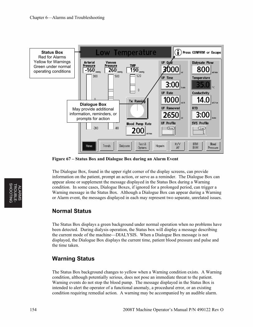
AL
AR
MS
T
RO
UB
LE-
SH
OO
TIN
G
Chapter 6—Alarms and Troubleshooting
154 2008T Machine Operator’s Manual P/N 490122 Rev O
Figure 67 – Status Box and Dialogue Box during an Alarm Event
The Dialogue Box, found in the upper right corner of the display screens, can provide information on the patient, prompt an action, or serve as a reminder. The Dialogue Box can appear alone or supplement the message displayed in the Status Box during a Warning condition. In some cases, Dialogue Boxes, if ignored for a prolonged period, can trigger a Warning message in the Status Box. Although a Dialogue Box can appear during a Warning or Alarm event, the messages displayed in each may represent two separate, unrelated issues.
Normal Status
The Status Box displays a green background under normal operation when no problems have been detected. During dialysis operation, the Status box will display a message describing the current mode of the machine—DIALYSIS. When a Dialogue Box message is not displayed, the Dialogue Box displays the current time, patient blood pressure and pulse and the time taken.
Warning Status
The Status Box background changes to yellow when a Warning condition exists. A Warning condition, although potentially serious, does not pose an immediate threat to the patient. Warning events do not stop the blood pump. The message displayed in the Status Box is intended to alert the operator of a functional anomaly, a procedural error, or an existing condition requiring remedial action. A warning may be accompanied by an audible alarm.
Status Box Red for Alarms
Yellow for Warnings Green under normal operating conditions
Dialogue Box May provide additional
information, reminders, or prompts for action
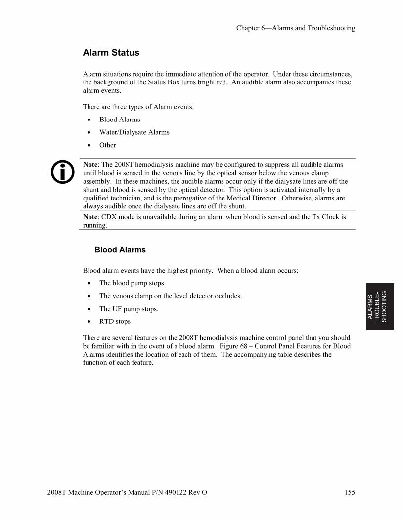
ALA
RM
S
TR
OU
BL
E-
SH
OO
TIN
G
Chapter 6—Alarms and Troubleshooting
2008T Machine Operator’s Manual P/N 490122 Rev O 155
Alarm Status
Alarm situations require the immediate attention of the operator. Under these circumstances, the background of the Status Box turns bright red. An audible alarm also accompanies these alarm events.
There are three types of Alarm events:
Blood Alarms
Water/Dialysate Alarms
Other
Note: The 2008T hemodialysis machine may be configured to suppress all audible alarms until blood is sensed in the venous line by the optical sensor below the venous clamp assembly. In these machines, the audible alarms occur only if the dialysate lines are off the shunt and blood is sensed by the optical detector. This option is activated internally by a qualified technician, and is the prerogative of the Medical Director. Otherwise, alarms are always audible once the dialysate lines are off the shunt.
Note: CDX mode is unavailable during an alarm when blood is sensed and the Tx Clock is running.
Blood Alarms
Blood alarm events have the highest priority. When a blood alarm occurs:
The blood pump stops.
The venous clamp on the level detector occludes.
The UF pump stops.
RTD stops
There are several features on the 2008T hemodialysis machine control panel that you should be familiar with in the event of a blood alarm. Figure 68 – Control Panel Features for Blood Alarms identifies the location of each of them. The accompanying table describes the function of each feature.
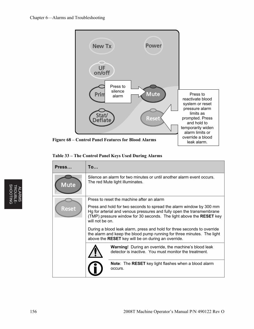
AL
AR
MS
T
RO
UB
LE-
SH
OO
TIN
G
Chapter 6—Alarms and Troubleshooting
156 2008T Machine Operator’s Manual P/N 490122 Rev O
Figure 68 – Control Panel Features for Blood Alarms
Table 33 – The Control Panel Keys Used During Alarms
Press… To…
Silence an alarm for two minutes or until another alarm event occurs. The red Mute light illuminates.
Press to reset the machine after an alarm
Press and hold for two seconds to spread the alarm window by 300 mm Hg for arterial and venous pressures and fully open the transmembrane (TMP) pressure window for 30 seconds. The light above the RESET key will not be on.
During a blood leak alarm, press and hold for three seconds to override the alarm and keep the blood pump running for three minutes. The light above the RESET key will be on during an override.
Warning! During an override, the machine’s blood leak detector is inactive. You must monitor the treatment.
Note: The RESET key light flashes when a blood alarm occurs.
Press to reactivate blood system or reset pressure alarm
limits as prompted. Press
and hold to temporarily widen
alarm limits or override a blood
leak alarm.
Press to silence alarm
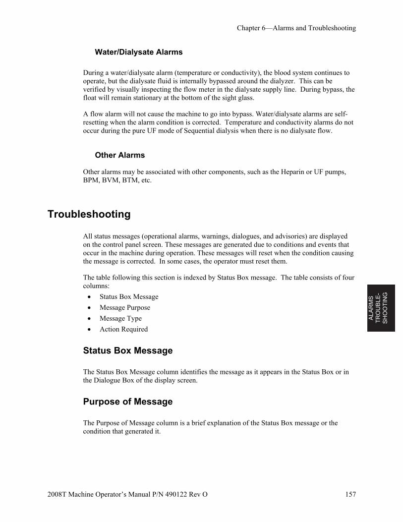
ALA
RM
S
TR
OU
BL
E-
SH
OO
TIN
G
Chapter 6—Alarms and Troubleshooting
2008T Machine Operator’s Manual P/N 490122 Rev O 157
Water/Dialysate Alarms
During a water/dialysate alarm (temperature or conductivity), the blood system continues to operate, but the dialysate fluid is internally bypassed around the dialyzer. This can be verified by visually inspecting the flow meter in the dialysate supply line. During bypass, the float will remain stationary at the bottom of the sight glass.
A flow alarm will not cause the machine to go into bypass. Water/dialysate alarms are self-resetting when the alarm condition is corrected. Temperature and conductivity alarms do not occur during the pure UF mode of Sequential dialysis when there is no dialysate flow.
Other Alarms
Other alarms may be associated with other components, such as the Heparin or UF pumps, BPM, BVM, BTM, etc.
Troubleshooting
All status messages (operational alarms, warnings, dialogues, and advisories) are displayed on the control panel screen. These messages are generated due to conditions and events that occur in the machine during operation. These messages will reset when the condition causing the message is corrected. In some cases, the operator must reset them.
The table following this section is indexed by Status Box message. The table consists of four columns:
Status Box Message
Message Purpose
Message Type
Action Required
Status Box Message
The Status Box Message column identifies the message as it appears in the Status Box or in the Dialogue Box of the display screen.
Purpose of Message
The Purpose of Message column is a brief explanation of the Status Box message or the condition that generated it.
AL
AR
MS
T
RO
UB
LE-
SH
OO
TIN
G
Chapter 6—Alarms and Troubleshooting
158 2008T Machine Operator’s Manual P/N 490122 Rev O
Type
The Type column identifies the message as an alarm, a warning, a dialog, or an advisory. An alarm message requires immediate attention. It is accompanied by a visual indicator and an audible alarm sound. A warning message notifies the user of an existing condition. It could be accompanied by an audible alarm. An advisory message prompts the operator to take a specific action in a procedure or informs the operator that a particular machine operation is in progress. Many advisories require no action on the part of the operator.
Action Required
The Action Required column provides recommended actions in response to a given Status Box message. In addition, your unit might require other patient-specific treatment actions that are not listed here. It is each care unit’s responsibility to ensure that their operators are made aware of the unit’s protocol in these matters.
If performing the recommended action does not clear the Status Box message displayed, treatment should be discontinued until the conditions causing the message are corrected and the message cleared. In rare cases, it may be necessary to turn the machine off and back on to clear an error condition. If problems persist, the machine should be referred to a qualified technician for inspection.
Warning! Performing the recommended action may or may not clear the alarm, warning or advisory messages displayed. Patient treatment shall not proceed until the conditions causing these messages are corrected and the messages cleared. If a machine must be taken out of service, the operator should return the blood to the patient if possible and disconnect the patient from the machine. Follow unit protocol to rinse back the blood using the blood pump or see “Manually Operating the Blood Pump” on page 129 for more information.
Note: Recommendations to take a machine out of service refer to assuring that the machine is not used for patient treatment until conditions causing alarms and warnings are resolved. Specific operator action in these cases is to refer the machine, and its associated problems, to a qualified local technician for inspection, testing, and troubleshooting.
Note: There are alarm messages that may be similar. Please take care that you read appropriate message to determine the “Action required” for troubleshooting.
Note: The on-screen cursor will disappear if not moved for five seconds. Simply touch the Touchpad to display the cursor again when needed. It also disappears when a value is entered but not yet confirmed. If necessary, press the Escape key to display the cursor again.
Note: If the 2008T hemodialysis machine becomes unresponsive (locks-up or ‘freezes’) or if the display screen unexpectedly turns off, turn off the machine by pressing and holding the Power key for two seconds. Press the Power key again to restart the machine.
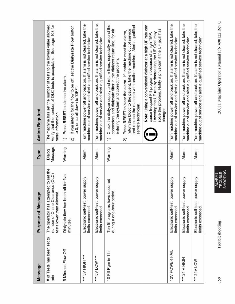
AL
AR
MS
T
RO
UB
LE
-S
HO
OT
ING
159
Tro
uble
shoo
ting
2008
T M
achi
ne O
pera
tor’
s M
anua
l P/N
490
122
Rev
O
Mes
sag
e P
urp
ose
of
Mes
sag
e T
ype
A
ctio
n R
equ
ired
# of
Tes
ts h
as b
een
set t
o m
in
The
ope
rato
r ha
s at
tem
pted
to s
et th
e nu
mbe
r of
Onl
ine
Cle
aran
ce (
OLC
) te
sts
low
er th
an a
llow
ed.
Dia
log
Mes
sage
T
he m
achi
ne h
as s
et th
e nu
mbe
r of
test
s to
the
low
est v
alue
allo
wed
. V
erify
that
the
num
ber
of O
LC te
sts
is a
ccep
tabl
e. S
ee p
age
108
for
mor
e in
form
atio
n.
5 M
inut
es F
low
Off
Dia
lysa
te fl
ow h
as b
een
off f
or fi
ve
min
utes
. W
arni
ng
1)
Pre
ss R
ES
ET
to s
ilenc
e th
e al
arm
.
2)
If yo
u in
tend
for
the
flow
to b
e of
f, se
t the
Dia
lysa
te F
low
but
ton
to 0
, or
scro
ll do
wn
to ‘O
FF
’.
***
5V H
IGH
***
E
lect
roni
c se
lf-te
st, p
ower
sup
ply
limits
exc
eede
d.
Ala
rm
Tur
n m
achi
ne p
ower
off
and
back
on.
If a
larm
is n
ot c
lear
ed, t
ake
the
mac
hine
out
of s
ervi
ce a
nd a
lert
a q
ualif
ied
serv
ice
tech
nici
an.
***
5V L
OW
***
E
lect
roni
c se
lf-te
st, p
ower
sup
ply
limits
exc
eede
d.
Ala
rm
Tur
n m
achi
ne p
ower
off
and
back
on.
If a
larm
is n
ot c
lear
ed, t
ake
the
mac
hine
out
of s
ervi
ce a
nd a
lert
a q
ualif
ied
serv
ice
tech
nici
an.
10 F
ill P
gm in
1 h
r T
en fi
ll pr
ogra
ms
have
occ
urre
d du
ring
a on
e-ho
ur p
erio
d.
War
ning
1)
C
heck
the
dial
yzer
sup
ply
and
retu
rn li
nes,
esp
ecia
lly a
roun
d th
e co
nnec
tors
and
dia
lysa
te fi
lter
in t
he d
ialy
zer
retu
rn li
ne, f
or a
ir en
terin
g th
e sy
stem
and
cor
rect
the
prob
lem
.
2)
Pre
ss R
ES
ET
to c
lear
the
alar
m.
If un
able
to r
eset
the
alar
m,
retu
rn th
e bl
ood
to th
e pa
tient
, tak
e th
e m
achi
ne o
ut o
f ser
vice
an
d re
plac
e th
e m
achi
ne w
ith a
noth
er m
achi
ne.
Ale
rt a
qua
lifie
d se
rvic
e te
chni
cian
.
N
ote
: Usi
ng a
con
vent
iona
l dia
lyze
r at
a h
igh
UF
rat
e ca
n ca
use
freq
uent
Fill
pro
gram
s be
caus
e of
a h
igh
TM
P.
Low
erin
g th
e U
F r
ate
by d
ecre
asin
g th
e U
F G
oal m
ay
solv
e th
e pr
oble
m. N
otify
a p
hysi
cian
if th
e U
F g
oal h
as
chan
ged.
12V
PO
WE
R F
AIL
E
lect
roni
c se
lf-te
st, p
ower
sup
ply
limits
exc
eede
d.
Ala
rm
Tur
n m
achi
ne p
ower
off
and
back
on.
If a
larm
is n
ot c
lear
ed, t
ake
the
mac
hine
out
of s
ervi
ce a
nd a
lert
a q
ualif
ied
serv
ice
tech
nici
an.
***
24 V
HIG
H
Ele
ctro
nic
self-
test
, pow
er s
uppl
y lim
its e
xcee
ded.
A
larm
T
urn
mac
hine
pow
er o
ff an
d ba
ck o
n. If
ala
rm is
not
cle
ared
, tak
e th
e m
achi
ne o
ut o
f ser
vice
and
ale
rt a
qua
lifie
d se
rvic
e te
chni
cian
.
***
24V
LO
W
Ele
ctro
nic
self-
test
, pow
er s
uppl
y lim
its e
xcee
ded.
A
larm
T
urn
mac
hine
pow
er o
ff an
d ba
ck o
n. If
ala
rm is
not
cle
ared
, tak
e th
e m
achi
ne o
ut o
f ser
vice
and
ale
rt a
qua
lifie
d se
rvic
e te
chni
cian
.
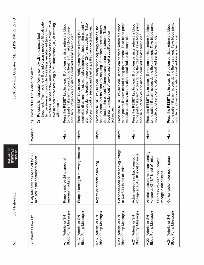
ALA
RM
S
TR
OU
BL
E-
SH
OO
TIN
G
160
Tro
uble
shoo
ting
2008
T M
achi
ne O
pera
tor’
s M
anua
l P/N
490
122
Rev
O
60 M
inut
es F
low
Off
Dia
lysa
te fl
ow h
as b
een
off f
or 6
0 m
inut
es in
the
sequ
entia
l opt
ion.
W
arni
ng
1)
Pre
ss R
ES
ET
to s
ilenc
e th
e al
arm
.
2)
Re-
esta
blis
h di
alys
ate
flow
to c
ompl
y w
ith th
e pr
escr
ibed
tr
eatm
ent.
The
mac
hine
will
go
into
byp
ass
mod
e un
til d
ialy
sate
te
mpe
ratu
re a
nd c
ondu
ctiv
ity s
ettin
gs a
re a
ttain
ed (
abou
t tw
o m
inut
es).
Dia
lysa
te fl
ow m
ust b
e re
-est
ablis
hed
for
a m
inim
um o
f fiv
e m
inut
es b
efor
e re
sum
ing
pure
ultr
afilt
ratio
n (U
F)
or w
arni
ng
will
reo
ccur
.
A.1
1 (
Art
eria
l or
SN
B
lood
Pum
p M
essa
ge)
Pum
p is
not
rea
chin
g sp
eed
at
max
imum
vol
tage
A
larm
P
ress
the
RE
SE
T k
ey to
cle
ar.
If pr
oble
m p
ersi
sts,
ret
urn
the
bloo
d to
the
patie
nt if
ala
rm o
ccur
s du
ring
trea
tmen
t. T
ake
bloo
d pu
mp
mod
ule
out o
f ser
vice
and
ale
rt a
qua
lifie
d se
rvic
e te
chni
cian
.
A.1
3 (
Art
eria
l or
SN
B
lood
Pum
p M
essa
ge)
Pum
p is
turn
ing
in th
e w
rong
dire
ctio
n A
larm
P
ress
the
RE
SE
T k
ey to
cle
ar.
Ver
ify p
ump
roto
r is
turn
ing
in a
cl
ockw
ise
dire
ctio
n. I
f not
, man
ually
ret
urn
the
bloo
d to
the
patie
nt if
al
arm
occ
urs
durin
g tr
eatm
ent (
see
page
129
for
inst
ruct
ions
). T
ake
bloo
d pu
mp
out o
f ser
vice
and
ale
rt a
qua
lifie
d se
rvic
e te
chni
cian
.
A.1
6 (
Art
eria
l or
SN
B
lood
Pum
p M
essa
ge)
Key
stu
ck o
r he
ld in
too
long
A
larm
P
ress
the
RE
SE
T k
ey to
cle
ar.
Ver
ify w
hen
adju
stin
g se
tting
s, th
e op
erat
or d
oes
not h
old
the
key
too
long
. If p
robl
em p
ersi
sts,
ret
urn
the
bloo
d to
the
patie
nt if
ala
rm o
ccur
s du
ring
the
trea
tmen
t. T
ake
bloo
d pu
mp
mod
ule
out o
f ser
vice
and
ale
rt a
qua
lifie
d se
rvic
e te
chni
cian
.
A.2
0 (
Art
eria
l or
SN
B
lood
Pum
p M
essa
ge)
Set
spe
ed-r
ead
back
ana
log
volta
ge
at X
348/
14 is
out
of l
imits
A
larm
P
ress
the
RE
SE
T k
ey to
cle
ar.
If pr
oble
m p
ersi
sts,
ret
urn
the
bloo
d to
the
patie
nt if
ala
rm o
ccur
s du
ring
the
trea
tmen
t. T
ake
bloo
d pu
mp
mod
ule
out o
f ser
vice
and
ale
rt a
qua
lifie
d se
rvic
e te
chni
cian
.
A.2
1 (
Art
eria
l or
SN
B
lood
Pum
p M
essa
ge)
Act
ual s
peed
-rea
d ba
ck a
nalo
g vo
ltage
at X
348/
10 is
out
of l
imits
A
larm
P
ress
the
RE
SE
T k
ey to
cle
ar.
If pr
oble
m p
ersi
sts,
ret
urn
the
bloo
d to
the
patie
nt if
ala
rm o
ccur
s du
ring
the
trea
tmen
t. T
ake
bloo
d pu
mp
mod
ule
out o
f ser
vice
and
ale
rt a
qua
lifie
d se
rvic
e te
chni
cian
.
A.2
2 (
Art
eria
l or
SN
B
lood
Pum
p M
essa
ge)
Art
eria
l pre
ssur
e-re
ad b
ack
anal
og
volta
ge a
t X34
8/7
is o
ut o
f lim
its
SN
pre
ssur
e-re
ad b
ack
anal
og
volta
ge is
out
of l
imits
Ala
rm
Pre
ss th
e R
ES
ET
key
to c
lear
. If
prob
lem
per
sist
s, r
etur
n th
e bl
ood
to th
e pa
tient
if a
larm
occ
urs
durin
g th
e tr
eatm
ent.
Tak
e bl
ood
pum
p m
odul
e ou
t of s
ervi
ce a
nd a
lert
a q
ualif
ied
serv
ice
tech
nici
an.
A.2
4 (
Art
eria
l or
SN
B
lood
Pum
p M
essa
ge)
Opt
ical
tach
omet
er n
ot in
ran
ge
Ala
rm
Pre
ss th
e R
ES
ET
key
to c
lear
. If
prob
lem
per
sist
s, r
etur
n th
e bl
ood
to th
e pa
tient
if a
larm
occ
urs
durin
g th
e tr
eatm
ent.
Tak
e bl
ood
pum
p m
odul
e ou
t of s
ervi
ce a
nd a
lert
a q
ualif
ied
serv
ice
tech
nici
an.
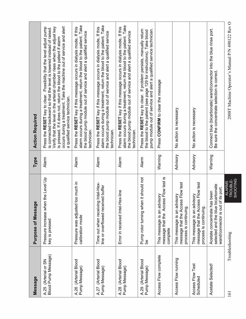
AL
AR
MS
T
RO
UB
LE
-S
HO
OT
ING
161
Tro
uble
shoo
ting
2008
T M
achi
ne O
pera
tor’
s M
anua
l P/N
490
122
Rev
O
Mes
sag
e P
urp
ose
of
Mes
sag
e T
ype
A
ctio
n R
equ
ired
A.2
5 (
Art
eria
l or
SN
B
lood
Pum
p M
essa
ge)
Pre
ssur
e in
crea
se w
hen
the
Leve
l Up
key
is p
ress
ed
Ala
rm
Pre
ss th
e R
ES
ET
key
to c
lear
. P
ossi
bilit
y th
at t
he le
vel a
djus
t pum
p is
con
nect
ed b
ackw
ard
so th
at th
e le
vel i
s lo
wer
ed in
stea
d of
rai
sed.
V
erify
that
the
leve
l in
the
arte
rial c
ham
ber
rises
whe
n th
e ad
just
key
is
pre
ssed
. If i
t doe
s no
t, re
turn
the
blo
od to
the
patie
nt if
ala
rm
occu
rs d
urin
g a
trea
tmen
t. T
ake
the
mac
hine
out
of s
ervi
ce a
nd a
lert
a
qual
ified
ser
vice
tech
nici
an.
A.2
6 (
Art
eria
l Blo
od
Pum
p M
essa
ge)
Pre
ssur
e w
as a
djus
ted
too
muc
h in
ca
libra
tion
mod
e A
larm
P
ress
the
RE
SE
T k
ey if
this
mes
sage
occ
urs
in d
ialy
sis
mod
e, If
this
al
arm
occ
urs
durin
g a
trea
tmen
t, re
turn
the
bloo
d to
the
patie
nt. T
ake
the
bloo
d pu
mp
mod
ule
out o
f ser
vice
and
ale
rt a
qua
lifie
d se
rvic
e te
chni
cian
.
A.2
7 (
Art
eria
l Blo
od
Pum
p M
essa
ge)
Tim
e ou
t whe
n re
ceiv
ing
Inte
l-Hex
-lin
e or
ove
rflo
wed
rec
eive
d bu
ffer
Ala
rm
Pre
ss th
e R
ES
ET
key
if th
is m
essa
ge o
ccur
s in
dia
lysi
s m
ode,
If th
is
alar
m o
ccur
s du
ring
a tr
eatm
ent,
retu
rn th
e bl
ood
to th
e pa
tient
. Tak
e th
e bl
ood
pum
p m
odul
e ou
t of s
ervi
ce a
nd a
lert
a q
ualif
ied
serv
ice
tech
nici
an.
A.2
8 (
Art
eria
l Blo
od
Pum
p M
essa
ge)
Err
or in
rec
eive
d In
tel-H
ex-li
ne
Ala
rm
Pre
ss th
e R
ES
ET
key
if th
is m
essa
ge o
ccur
s in
dia
lysi
s m
ode,
If th
is
alar
m o
ccur
s du
ring
a tr
eatm
ent,
retu
rn th
e bl
ood
to th
e pa
tient
. Tak
e th
e bl
ood
pum
p m
odul
e ou
t of s
ervi
ce a
nd a
lert
a q
ualif
ied
serv
ice
tech
nici
an.
A.2
9 (
Art
eria
l Blo
od
Pum
p M
essa
ge)
Pum
p ro
tor
turn
ing
whe
n it
shou
ld n
ot
be
Ala
rm
Pre
ss th
e R
ES
ET
key
to c
lear
. If
prob
lem
per
sist
s, m
anua
lly r
etur
n th
e bl
ood
to th
e pa
tient
(se
e pa
ge 1
29 fo
r in
stru
ctio
ns).
Tak
e bl
ood
pum
p m
odul
e ou
t of s
ervi
ce a
nd a
lert
a q
ualif
ied
serv
ice
tech
nici
an.
Acc
ess
Flo
w c
ompl
ete
Thi
s m
essa
ge is
an
advi
sory
m
essa
ge th
at th
e A
cces
s F
low
test
is
com
plet
e
War
ning
P
ress
CO
NF
IRM
to c
lear
the
mes
sage
Acc
ess
Flo
w r
unni
ng
Thi
s m
essa
ge is
an
advi
sory
m
essa
ge th
at th
e A
cces
s F
low
test
pr
oces
s is
con
tinui
ng.
Adv
isor
y N
o ac
tion
is n
eces
sary
Acc
ess
Flo
w T
est
Sch
edul
ed
Thi
s m
essa
ge is
an
advi
sory
m
essa
ge th
at th
e A
cces
s F
low
test
pr
oces
s is
con
tinui
ng.
Adv
isor
y N
o ac
tion
is n
eces
sary
Ace
tate
Sel
ecte
d!
Ace
tate
con
cent
rate
has
bee
n se
lect
ed a
nd th
e bl
ue b
icar
bona
te
wan
d/co
nnec
tor
is o
ut o
f its
por
t.
War
ning
C
onne
ct b
lue
(bic
arbo
nate
) w
and/
conn
ecto
r in
to th
e bl
ue r
inse
por
t. B
e su
re th
e co
ncen
trat
e se
lect
ion
is c
orre
ct.
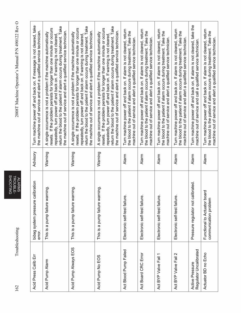
ALA
RM
S
TR
OU
BL
E-
SH
OO
TIN
G
162
Tro
uble
shoo
ting
2008
T M
achi
ne O
pera
tor’
s M
anua
l P/N
490
122
Rev
O
Aci
d P
ress
Cal
ib E
rr
biba
g sy
stem
pre
ssur
e ca
libra
tion
erro
r.
Adv
isor
y T
urn
mac
hine
pow
er o
ff an
d ba
ck o
n. If
mes
sage
is n
ot c
lear
ed, t
ake
the
mac
hine
out
of s
ervi
ce a
nd a
lert
a q
ualif
ied
serv
ice
tech
nici
an.
Aci
d P
ump
Ala
rm
Thi
s is
a p
ump
failu
re w
arni
ng.
War
ning
A
sin
gle
occu
rren
ce is
not
a p
robl
em if
the
mac
hine
aut
omat
ical
ly
rese
ts.
If th
e pr
oble
m p
ersi
sts
for
long
er th
an o
ne m
inut
e or
occ
urs
repe
ated
ly, t
urn
pow
er o
ff an
d ba
ck o
n. If
war
ning
is n
ot c
lear
ed,
retu
rn th
e bl
ood
to th
e pa
tient
if a
larm
occ
urs
durin
g tr
eatm
ent.
Tak
e th
e m
achi
ne o
ut o
f ser
vice
and
ale
rt a
qua
lifie
d se
rvic
e te
chni
cian
.
Aci
d P
ump
Alw
ays
EO
S
Thi
s is
a p
ump
failu
re w
arni
ng.
War
ning
A
sin
gle
occu
rren
ce is
not
a p
robl
em if
the
mac
hine
aut
omat
ical
ly
rese
ts.
If th
e pr
oble
m p
ersi
sts
for
long
er th
an o
ne m
inut
e or
occ
urs
repe
ated
ly, t
urn
pow
er o
ff an
d ba
ck o
n. If
war
ning
is n
ot c
lear
ed,
retu
rn th
e bl
ood
to th
e pa
tient
if a
larm
occ
urs
durin
g tr
eatm
ent.
Tak
e th
e m
achi
ne o
ut o
f ser
vice
and
ale
rt a
qua
lifie
d se
rvic
e te
chni
cian
.
Aci
d P
ump
No
EO
S
Thi
s is
a p
ump
failu
re w
arni
ng.
War
ning
A
sin
gle
occu
rren
ce is
not
a p
robl
em if
the
mac
hine
aut
omat
ical
ly
rese
ts.
If th
e pr
oble
m p
ersi
sts
for
long
er th
an o
ne m
inut
e or
occ
urs
repe
ated
ly, t
urn
pow
er o
ff an
d ba
ck o
n. If
war
ning
is n
ot c
lear
ed,
retu
rn th
e bl
ood
to th
e pa
tient
if a
larm
occ
urs
durin
g tr
eatm
ent.
Tak
e th
e m
achi
ne o
ut o
f ser
vice
and
ale
rt a
qua
lifie
d se
rvic
e te
chni
cian
.
Act
Blo
od P
ump
Fai
led
Ele
ctro
nic
sel
f-te
st fa
ilure
. A
larm
T
urn
mac
hine
pow
er o
ff an
d ba
ck o
n. If
ala
rm is
not
cle
ared
, ret
urn
the
bloo
d to
the
patie
nt if
ala
rm o
ccur
s du
ring
trea
tmen
t. T
ake
the
mac
hine
out
of s
ervi
ce a
nd a
lert
a q
ualif
ied
serv
ice
tech
nici
an.
Act
Boa
rd C
RC
Err
or
Ele
ctro
nic
sel
f-te
st fa
ilure
. A
larm
T
urn
mac
hine
pow
er o
ff an
d ba
ck o
n. If
ala
rm is
not
cle
ared
, ret
urn
the
bloo
d to
the
patie
nt if
ala
rm o
ccur
s du
ring
trea
tmen
t. T
ake
the
mac
hine
out
of s
ervi
ce a
nd a
lert
a q
ualif
ied
serv
ice
tech
nici
an.
Act
BY
P V
alve
Fai
l 1
Ele
ctro
nic
self-
test
failu
re.
Ala
rm
Tur
n m
achi
ne p
ower
off
and
back
on.
If a
larm
is n
ot c
lear
ed, r
etur
n th
e bl
ood
to th
e pa
tient
if a
larm
occ
urs
durin
g tr
eatm
ent.
Tak
e th
e m
achi
ne o
ut o
f ser
vice
and
ale
rt a
qua
lifie
d se
rvic
e te
chni
cian
.
Act
BY
P V
alve
Fai
l 2
Ele
ctro
nic
self-
test
failu
re.
Ala
rm
Tur
n m
achi
ne p
ower
off
and
back
on.
If a
larm
is n
ot c
lear
ed, r
etur
n th
e bl
ood
to th
e pa
tient
if a
larm
occ
urs
durin
g tr
eatm
ent.
Tak
e th
e m
achi
ne o
ut o
f ser
vice
and
ale
rt a
qua
lifie
d se
rvic
e te
chni
cian
.
Act
ive
Pre
ssur
e R
egul
ator
Unc
alib
rate
d P
ress
ure
regu
lato
r no
t cal
ibra
ted.
A
larm
T
urn
mac
hine
pow
er o
ff an
d ba
ck o
n. If
ala
rm is
not
cle
ared
, tak
e th
e m
achi
ne o
ut o
f ser
vice
and
cal
l a q
ualif
ied
serv
ice
tech
nici
an.
Act
uato
r B
D n
o E
cho
Fun
ctio
nal t
o A
ctua
tor
boar
d co
mm
unic
atio
n pr
oble
m
Ala
rm
Tur
n m
achi
ne p
ower
off
and
back
on.
If a
larm
is n
ot c
lear
ed, r
etur
n th
e bl
ood
to th
e pa
tient
if a
larm
occ
urs
durin
g tr
eatm
ent.
Tak
e th
e m
achi
ne o
ut o
f ser
vice
and
ale
rt a
qua
lifie
d se
rvic
e te
chni
cian
.
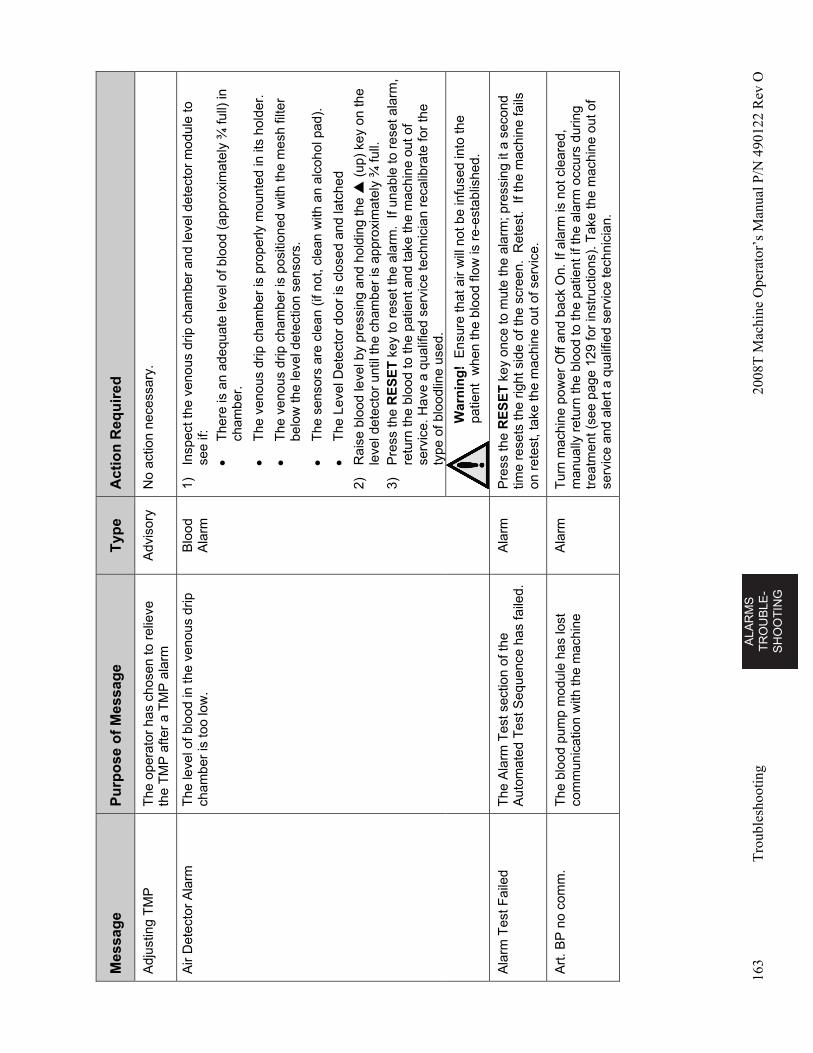
AL
AR
MS
T
RO
UB
LE
-S
HO
OT
ING
163
Tro
uble
shoo
ting
2008
T M
achi
ne O
pera
tor’
s M
anua
l P/N
490
122
Rev
O
Mes
sag
e P
urp
ose
of
Mes
sag
e T
ype
A
ctio
n R
equ
ired
Adj
ustin
g T
MP
T
he o
pera
tor
has
chos
en to
rel
ieve
th
e T
MP
afte
r a
TM
P a
larm
A
dvis
ory
No
actio
n ne
cess
ary.
Air
Det
ecto
r A
larm
T
he le
vel o
f blo
od in
the
veno
us d
rip
cham
ber
is to
o lo
w.
Blo
od
Ala
rm
1)
Insp
ect t
he v
enou
s dr
ip c
ham
ber
and
leve
l det
ecto
r m
odul
e to
se
e if:
T
here
is a
n ad
equa
te le
vel o
f blo
od (
appr
oxim
atel
y ¾
full)
in
cham
ber.
T
he v
enou
s dr
ip c
ham
ber
is p
rope
rly m
ount
ed in
its
hold
er.
T
he v
enou
s dr
ip c
ham
ber
is p
ositi
oned
with
the
mes
h fil
ter
belo
w th
e le
vel d
etec
tion
sens
ors.
T
he s
enso
rs a
re c
lean
(if
not,
clea
n w
ith a
n al
coho
l pad
).
T
he L
evel
Det
ecto
r do
or is
clo
sed
and
latc
hed
2)
Rai
se b
lood
leve
l by
pres
sing
and
hol
ding
the
(up
) ke
y on
the
leve
l det
ecto
r un
til th
e ch
ambe
r is
app
roxi
mat
ely
¾ fu
ll.
3)
Pre
ss th
e R
ES
ET
key
to r
eset
the
alar
m.
If un
able
to r
eset
ala
rm,
retu
rn th
e bl
ood
to th
e pa
tient
and
take
the
mac
hine
out
of
serv
ice.
Hav
e a
qual
ified
ser
vice
tech
nici
an r
ecal
ibra
te fo
r th
e ty
pe o
f blo
odlin
e us
ed.
W
arn
ing
! E
nsur
e th
at a
ir w
ill n
ot b
e in
fuse
d in
to th
e pa
tient
w
hen
the
bloo
d flo
w is
re-
esta
blis
hed.
Ala
rm T
est F
aile
d T
he A
larm
Tes
t sec
tion
of th
e A
utom
ated
Tes
t Seq
uenc
e ha
s fa
iled.
A
larm
P
ress
the
RE
SE
T k
ey o
nce
to m
ute
the
alar
m; p
ress
ing
it a
seco
nd
time
rese
ts th
e rig
ht s
ide
of th
e sc
reen
. R
etes
t. If
the
mac
hine
fails
on
ret
est,
take
the
mac
hine
out
of s
ervi
ce.
Art
. BP
no
com
m.
The
blo
od p
ump
mod
ule
has
lost
co
mm
unic
atio
n w
ith th
e m
achi
ne
Ala
rm
Tur
n m
achi
ne p
ower
Off
and
back
On.
If a
larm
is n
ot c
lear
ed,
man
ually
ret
urn
the
bloo
d to
the
patie
nt if
the
alar
m o
ccur
s du
ring
trea
tmen
t (se
e pa
ge 1
29 fo
r in
stru
ctio
ns).
Tak
e th
e m
achi
ne o
ut o
f se
rvic
e an
d al
ert a
qua
lifie
d se
rvic
e te
chni
cian
.
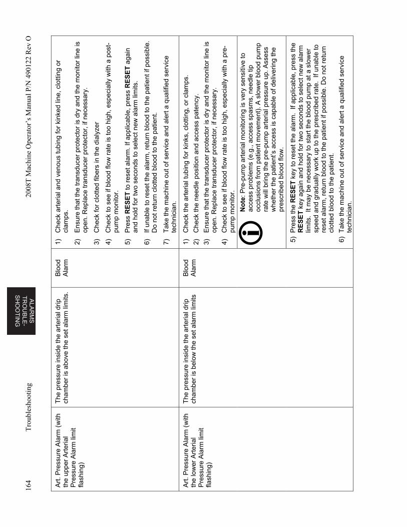
ALA
RM
S
TR
OU
BL
E-
SH
OO
TIN
G
164
Tro
uble
shoo
ting
2008
T M
achi
ne O
pera
tor’
s M
anua
l P/N
490
122
Rev
O
Art
. Pre
ssur
e A
larm
(w
ith
the
uppe
r A
rter
ial
Pre
ssur
e A
larm
lim
it fla
shin
g)
The
pre
ssur
e in
side
the
arte
rial d
rip
cham
ber
is a
bove
the
set a
larm
lim
its.
Blo
od
Ala
rm
1)
Che
ck a
rter
ial a
nd v
enou
s tu
bing
for
kink
ed li
ne, c
lotti
ng o
r cl
amps
.
2)
Ens
ure
that
the
tran
sduc
er p
rote
ctor
is d
ry a
nd th
e m
onito
r lin
e is
op
en. R
epla
ce tr
ansd
ucer
pro
tect
or, i
f nec
essa
ry.
3)
Che
ck fo
r cl
otte
d fib
ers
in th
e di
alyz
er
4)
Che
ck to
see
if b
lood
flow
rat
e is
too
high
, esp
ecia
lly w
ith a
pos
t-pu
mp
mon
itor.
5)
Pre
ss R
ES
ET
to r
eset
ala
rm. I
f app
licab
le, p
ress
RE
SE
T a
gain
an
d ho
ld fo
r tw
o se
cond
s to
sel
ect n
ew a
larm
lim
its.
6)
If un
able
to r
eset
the
alar
m, r
etur
n b
lood
to th
e pa
tient
if p
ossi
ble.
D
o no
t ret
urn
clot
ted
bloo
d to
the
patie
nt.
7)
Tak
e th
e m
achi
ne o
ut o
f ser
vice
and
ale
rt a
qua
lifie
d se
rvic
e te
chni
cian
.
Art
. Pre
ssur
e A
larm
(w
ith
the
low
er A
rter
ial
Pre
ssur
e A
larm
lim
it fla
shin
g)
The
pre
ssur
e in
side
the
arte
rial d
rip
cham
ber
is b
elow
the
set a
larm
lim
its
Blo
od
Ala
rm
1)
Che
ck th
e ar
teria
l tub
ing
for
kink
s, c
lotti
ng, o
r cl
amps
.
2)
Che
ck th
e ne
edle
pos
ition
and
acc
ess
pate
ncy.
3)
Ens
ure
that
the
tran
sduc
er p
rote
ctor
is d
ry a
nd th
e m
onito
r lin
e is
op
en. R
epla
ce tr
ansd
ucer
pro
tect
or, i
f nec
essa
ry.
4)
Che
ck to
see
if b
lood
flow
rat
e is
too
high
, esp
ecia
lly w
ith a
pre
-pu
mp
mon
itor.
N
ote
: Pre
-pum
p ar
teria
l mon
itorin
g is
ver
y se
nsiti
ve to
ac
cess
pro
blem
s (e
.g.,
acce
ss s
pasm
s, n
eedl
e tip
oc
clus
ions
from
pat
ient
mov
emen
t). A
slo
wer
blo
od p
ump
rate
will
brin
g th
e pr
e-pu
mp
arte
rial p
ress
ure
up. A
sses
s w
heth
er th
e pa
tient
’s a
cces
s is
cap
able
of d
eliv
erin
g th
e pr
escr
ibed
blo
od fl
ow.
5) P
ress
the
RE
SE
T k
ey to
res
et th
e al
arm
. If
appl
icab
le, p
ress
the
RE
SE
T k
ey a
gain
and
hol
d fo
r tw
o se
cond
s to
sel
ect n
ew a
larm
lim
its.
It m
ay b
e ne
cess
ary
to s
tart
the
bloo
d pu
mp
at a
slo
wer
sp
eed
and
grad
ually
wor
k up
to th
e pr
escr
ibed
rat
e. I
f una
ble
to
rese
t ala
rm, r
etur
n bl
ood
to th
e pa
tient
if p
ossi
ble.
Do
not r
etur
n cl
otte
d bl
ood
to th
e pa
tient
.
6) T
ake
the
mac
hine
out
of s
ervi
ce a
nd a
lert
a q
ualif
ied
serv
ice
tech
nici
an.
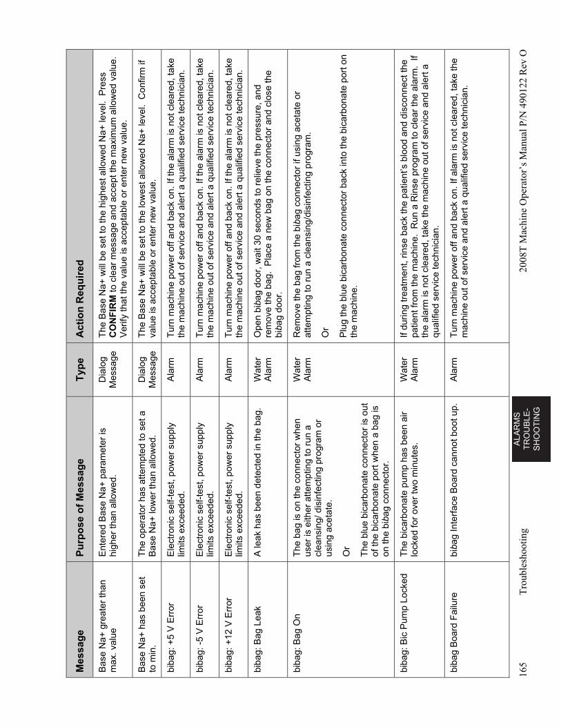
AL
AR
MS
T
RO
UB
LE
-S
HO
OT
ING
165
Tro
uble
shoo
ting
2008
T M
achi
ne O
pera
tor’
s M
anua
l P/N
490
122
Rev
O
Mes
sag
e P
urp
ose
of
Mes
sag
e T
ype
A
ctio
n R
equ
ired
Bas
e N
a+ g
reat
er th
an
max
. val
ue
Ent
ered
Bas
e N
a+ p
aram
eter
is
high
er th
an a
llow
ed.
Dia
log
Mes
sage
T
he B
ase
Na+
will
be
set t
o th
e hi
ghes
t allo
wed
Na+
leve
l. P
ress
C
ON
FIR
M to
cle
ar m
essa
ge a
nd a
ccep
t the
max
imum
allo
wed
val
ue.
Ver
ify th
at th
e va
lue
is a
ccep
tabl
e or
ent
er n
ew v
alue
.
Bas
e N
a+ h
as b
een
set
to m
in.
The
ope
rato
r ha
s at
tem
pted
to s
et a
B
ase
Na+
low
er th
an a
llow
ed.
Dia
log
Mes
sage
T
he B
ase
Na+
will
be
set t
o th
e lo
wes
t allo
wed
Na+
leve
l. C
onfir
m if
va
lue
is a
ccep
tabl
e or
ent
er n
ew v
alue
.
biba
g: +
5 V
Err
or
Ele
ctro
nic
self-
test
, pow
er s
uppl
y lim
its e
xcee
ded.
A
larm
T
urn
mac
hine
pow
er o
ff an
d ba
ck o
n. If
the
alar
m is
not
cle
ared
, tak
e th
e m
achi
ne o
ut o
f ser
vice
and
ale
rt a
qua
lifie
d se
rvic
e te
chni
cian
.
biba
g: -
5 V
Err
or
Ele
ctro
nic
self-
test
, pow
er s
uppl
y lim
its e
xcee
ded.
A
larm
T
urn
mac
hine
pow
er o
ff an
d ba
ck o
n. If
the
alar
m is
not
cle
ared
, tak
e th
e m
achi
ne o
ut o
f ser
vice
and
ale
rt a
qua
lifie
d se
rvic
e te
chni
cian
.
biba
g: +
12 V
Err
or
Ele
ctro
nic
self-
test
, pow
er s
uppl
y lim
its e
xcee
ded.
A
larm
T
urn
mac
hine
pow
er o
ff an
d ba
ck o
n. If
the
alar
m is
not
cle
ared
, tak
e th
e m
achi
ne o
ut o
f ser
vice
and
ale
rt a
qua
lifie
d se
rvic
e te
chni
cian
.
biba
g: B
ag L
eak
A le
ak h
as b
een
dete
cted
in th
e ba
g.
Wat
er
Ala
rm
Ope
n bi
bag
door
, wai
t 30
seco
nds
to r
elie
ve th
e pr
essu
re, a
nd
rem
ove
the
bag.
Pla
ce a
new
bag
on
the
conn
ecto
r an
d cl
ose
the
biba
g do
or.
biba
g: B
ag O
n T
he b
ag is
on
the
conn
ecto
r w
hen
user
is e
ither
atte
mpt
ing
to r
un a
cl
eans
ing/
dis
infe
ctin
g pr
ogra
m o
r us
ing
acet
ate.
Or
The
blu
e bi
carb
onat
e co
nnec
tor
is o
ut
of th
e bi
carb
onat
e po
rt w
hen
a ba
g is
on
the
biba
g co
nnec
tor.
Wat
er
Ala
rm
Rem
ove
the
bag
from
the
biba
g co
nnec
tor
if us
ing
acet
ate
or
atte
mpt
ing
to r
un a
cle
ansi
ng/d
isin
fect
ing
prog
ram
.
Or
Plu
g th
e bl
ue b
icar
bona
te c
onne
ctor
bac
k in
to th
e bi
carb
onat
e po
rt o
n th
e m
achi
ne.
biba
g: B
ic P
ump
Lock
ed
The
bic
arbo
nate
pum
p ha
s be
en a
ir lo
cked
for
over
two
min
utes
. W
ater
A
larm
If
durin
g tr
eatm
ent,
rinse
bac
k th
e pa
tient
’s b
lood
and
dis
conn
ect t
he
patie
nt fr
om th
e m
achi
ne.
Run
a R
inse
pro
gram
to c
lear
the
alar
m.
If th
e al
arm
is n
ot c
lear
ed, t
ake
the
mac
hine
out
of s
ervi
ce a
nd a
lert
a
qual
ified
ser
vice
tech
nici
an.
biba
g B
oard
Fai
lure
bi
bag
Inte
rfac
e B
oard
can
not b
oot u
p.
Ala
rm
Tur
n m
achi
ne p
ower
off
and
back
on.
If a
larm
is n
ot c
lear
ed, t
ake
the
mac
hine
out
of s
ervi
ce a
nd a
lert
a q
ualif
ied
serv
ice
tech
nici
an.
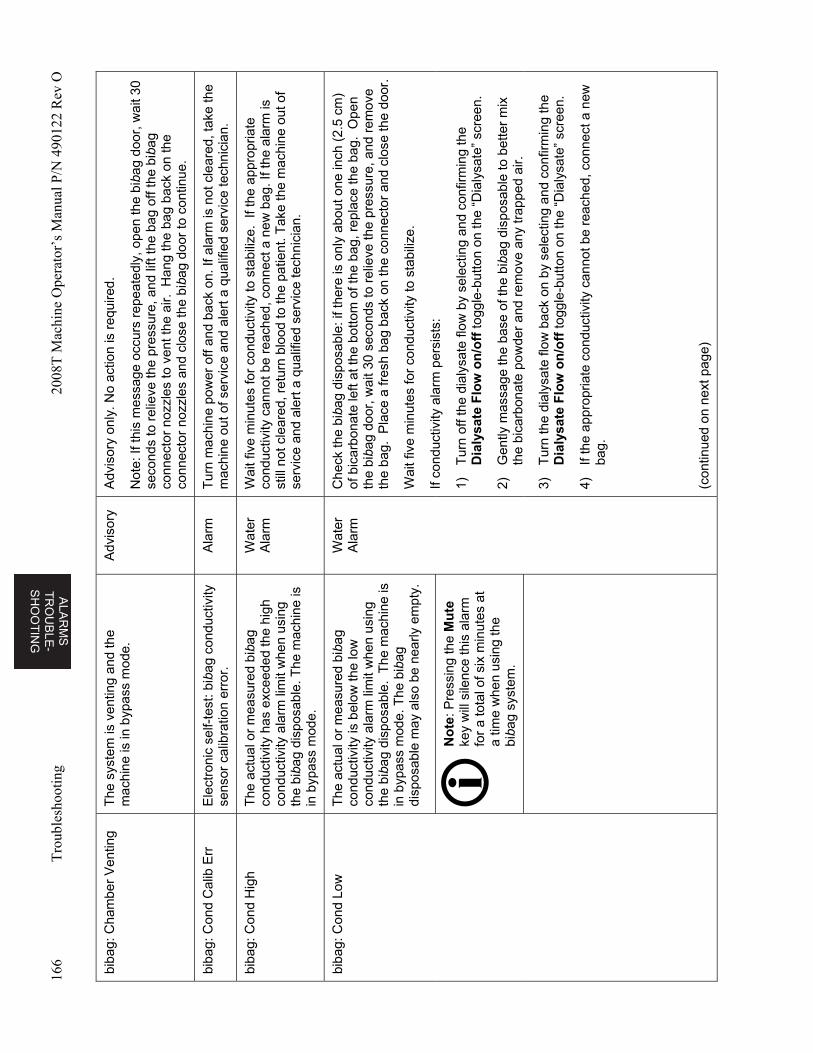
ALA
RM
S
TR
OU
BL
E-
SH
OO
TIN
G
166
Tro
uble
shoo
ting
2008
T M
achi
ne O
pera
tor’
s M
anua
l P/N
490
122
Rev
O
biba
g: C
ham
ber
Ven
ting
The
sys
tem
is v
entin
g an
d th
e m
achi
ne is
in b
ypas
s m
ode.
A
dvis
ory
Adv
isor
y on
ly. N
o ac
tion
is r
equi
red.
Not
e: If
this
mes
sage
occ
urs
repe
ated
ly, o
pen
the
biba
g do
or, w
ait 3
0 se
cond
s to
rel
ieve
the
pres
sure
, and
lift
the
bag
off t
he b
ibag
co
nnec
tor
nozz
les
to v
ent t
he a
ir. H
ang
the
bag
back
on
the
conn
ecto
r no
zzle
s an
d cl
ose
the
biba
g do
or to
con
tinue
.
biba
g: C
ond
Cal
ib E
rr
Ele
ctro
nic
self-
test
: bib
ag c
ondu
ctiv
ity
sens
or c
alib
ratio
n er
ror.
A
larm
T
urn
mac
hine
pow
er o
ff an
d ba
ck o
n. If
ala
rm is
not
cle
ared
, tak
e th
e m
achi
ne o
ut o
f ser
vice
and
ale
rt a
qua
lifie
d se
rvic
e te
chni
cian
.
biba
g: C
ond
Hig
h T
he a
ctua
l or
mea
sure
d bi
bag
cond
uctiv
ity h
as e
xcee
ded
the
high
co
nduc
tivity
ala
rm li
mit
whe
n us
ing
the
biba
g di
spos
able
. The
mac
hine
is
in b
ypas
s m
ode.
Wat
er
Ala
rm
Wai
t fiv
e m
inut
es fo
r co
nduc
tivity
to s
tabi
lize.
If t
he a
ppro
pria
te
cond
uctiv
ity c
anno
t be
reac
hed,
con
nect
a n
ew b
ag. I
f th
e al
arm
is
still
not
cle
ared
, ret
urn
bloo
d to
the
pat
ient
. Tak
e th
e m
achi
ne o
ut o
f se
rvic
e an
d al
ert a
qua
lifie
d se
rvic
e te
chni
cian
.
biba
g: C
ond
Low
T
he a
ctua
l or
mea
sure
d bi
bag
cond
uctiv
ity is
bel
ow th
e lo
w
cond
uctiv
ity a
larm
lim
it w
hen
usin
g th
e bi
bag
disp
osab
le.
The
mac
hine
is
in b
ypas
s m
ode.
The
bib
ag
disp
osab
le m
ay a
lso
be n
early
em
pty.
Wat
er
Ala
rm
Che
ck th
e bi
bag
disp
osab
le: i
f the
re is
onl
y ab
out o
ne in
ch (
2.5
cm)
of b
icar
bona
te le
ft at
the
bot
tom
of t
he b
ag, r
epla
ce th
e ba
g. O
pen
the
biba
g do
or, w
ait 3
0 se
cond
s to
rel
ieve
the
pres
sure
, and
rem
ove
the
bag.
Pla
ce a
fres
h ba
g ba
ck o
n th
e co
nnec
tor
and
clos
e th
e do
or.
Wai
t fiv
e m
inut
es fo
r co
nduc
tivity
to s
tabi
lize.
If co
nduc
tivity
ala
rm p
ersi
sts:
1)
Tur
n of
f the
dia
lysa
te fl
ow b
y se
lect
ing
and
conf
irmin
g th
e D
ialy
sate
Flo
w o
n/o
ff to
ggle
-but
ton
on th
e “D
ialy
sate
” sc
reen
.
2)
Gen
tly m
assa
ge th
e ba
se o
f the
bib
ag d
ispo
sabl
e to
bet
ter
mix
th
e bi
carb
onat
e po
wde
r an
d re
mov
e an
y tr
appe
d ai
r.
3)
Tur
n th
e di
alys
ate
flow
bac
k on
by
sele
ctin
g an
d co
nfirm
ing
the
Dia
lysa
te F
low
on
/off
togg
le-b
utto
n on
the
“Dia
lysa
te”
scre
en.
4)
If th
e ap
prop
riate
con
duct
ivity
can
not b
e re
ache
d, c
onne
ct a
new
ba
g.
(con
tinue
d on
nex
t pag
e)
No
te: P
ress
ing
the
Mu
te
key
will
sile
nce
this
ala
rm
for
a to
tal o
f six
min
utes
at
a tim
e w
hen
usin
g th
e bi
bag
syst
em.
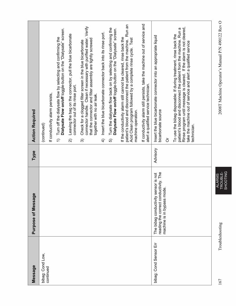
AL
AR
MS
T
RO
UB
LE
-S
HO
OT
ING
167
Tro
uble
shoo
ting
2008
T M
achi
ne O
pera
tor’
s M
anua
l P/N
490
122
Rev
O
Mes
sag
e P
urp
ose
of
Mes
sag
e T
ype
A
ctio
n R
equ
ired
biba
g: C
ond
Low
, co
ntin
ued
(con
tinue
d)
If co
nduc
tivity
ala
rm p
ersi
sts,
1)
Tur
n of
f the
dia
lysa
te fl
ow b
y se
lect
ing
and
conf
irmin
g th
e D
ialy
sate
Flo
w o
n/o
ff to
ggle
-but
ton
on th
e “D
ialy
sate
” sc
reen
.
2)
Leav
ing
the
bag
on th
e co
nnec
tor,
pul
l the
blu
e bi
carb
onat
e co
nnec
tor
out o
f its
rin
se p
ort.
3)
Che
ck fo
r a
clog
ged
filte
r sc
reen
in th
e bl
ue b
icar
bona
te
conn
ecto
r ha
ndle
. C
lean
if n
eces
sary
with
pur
ified
wat
er. V
erify
th
at th
e co
nnec
tor
and
filte
r as
sem
bly
are
tight
ly s
crew
ed
toge
ther
with
no
air
leak
.
4)
Inse
rt th
e bl
ue b
icar
bona
te c
onne
ctor
bac
k in
to it
s rin
se p
ort.
5)
Tur
n th
e di
alys
ate
flow
bac
k on
by
sele
ctin
g an
d co
nfirm
ing
the
Dia
lysa
te F
low
on
/off
togg
le-b
utto
n on
the
“Dia
lysa
te”
scre
en.
If th
e co
nduc
tivity
ala
rm s
till c
anno
t be
clea
red,
rin
se b
ack
the
patie
nt’s
blo
od a
nd d
isco
nnec
t the
pat
ient
from
the
mac
hine
. R
un a
n A
cid
Cle
an p
rogr
am fo
llow
ed b
y a
com
plet
e rin
se c
ycle
. T
est
mac
hine
ope
ratio
n.
If co
nduc
tivity
ala
rm s
till p
ersi
sts,
take
the
mac
hine
out
of s
ervi
ce a
nd
aler
t a q
ualif
ied
serv
ice
tech
nici
an.
biba
g: C
ond
Sen
sor
Err
T
he b
ibag
con
duct
ivity
sen
sor
is n
ot
read
ing
the
corr
ect c
ondu
ctiv
ity. T
he
mac
hine
is in
byp
ass
mod
e.
Adv
isor
y In
sert
the
blue
bic
arbo
nate
con
nect
or in
to a
n ap
prop
riate
liqu
id
bica
rbon
ate
sour
ce
Or
To
use
the
biba
g di
spos
able
: If d
urin
g tr
eatm
ent,
rinse
bac
k th
e pa
tient
’s b
lood
and
dis
conn
ect t
he p
atie
nt fr
om th
e m
achi
ne. R
un a
R
inse
pro
gram
unt
il m
essa
ge is
cle
ared
. If
the
alar
m is
not
cle
ared
, ta
ke th
e m
achi
ne o
ut o
f ser
vice
and
ale
rt a
qua
lifie
d se
rvic
e te
chni
cian
.
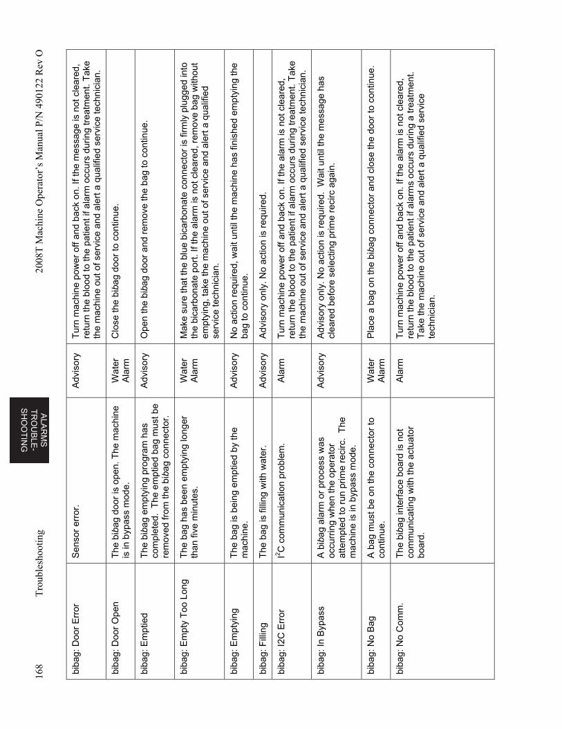
ALA
RM
S
TR
OU
BL
E-
SH
OO
TIN
G
168
Tro
uble
shoo
ting
2008
T M
achi
ne O
pera
tor’
s M
anua
l P/N
490
122
Rev
O
biba
g: D
oor
Err
or
Sen
sor
erro
r.
Adv
isor
y T
urn
mac
hine
pow
er o
ff an
d ba
ck o
n. If
the
mes
sage
is n
ot c
lear
ed,
retu
rn th
e bl
ood
to th
e pa
tient
if a
larm
occ
urs
durin
g tr
eatm
ent.
Tak
e th
e m
achi
ne o
ut o
f ser
vice
and
ale
rt a
qua
lifie
d se
rvic
e te
chni
cian
.
biba
g: D
oor
Ope
n T
he b
ibag
doo
r is
ope
n. T
he m
achi
ne
is in
byp
ass
mod
e.
Wat
er
Ala
rm
Clo
se th
e bi
bag
door
to c
ontin
ue.
biba
g: E
mpt
ied
The
bib
ag e
mpt
ying
pro
gram
has
co
mpl
eted
. T
he e
mpt
ied
bag
mus
t be
rem
oved
from
the
biba
g co
nnec
tor.
Adv
isor
y O
pen
the
biba
g do
or a
nd r
emov
e th
e ba
g to
con
tinue
.
biba
g: E
mpt
y T
oo L
ong
The
bag
has
bee
n em
ptyi
ng lo
nger
th
an fi
ve m
inut
es.
Wat
er
Ala
rm
Mak
e su
re th
at th
e bl
ue b
icar
bona
te c
onne
ctor
is fi
rmly
plu
gged
into
th
e bi
carb
onat
e po
rt. I
f the
ala
rm is
not
cle
ared
, rem
ove
bag
with
out
empt
ying
, tak
e th
e m
achi
ne o
ut o
f ser
vice
and
ale
rt a
qua
lifie
d se
rvic
e te
chni
cian
.
biba
g: E
mpt
ying
T
he b
ag is
bei
ng e
mpt
ied
by th
e m
achi
ne.
Adv
isor
y N
o ac
tion
requ
ired,
wai
t unt
il th
e m
achi
ne h
as fi
nish
ed e
mpt
ying
the
bag
to c
ontin
ue.
biba
g: F
illin
g T
he b
ag is
filli
ng w
ith w
ater
. A
dvis
ory
Adv
isor
y on
ly. N
o ac
tion
is r
equi
red.
biba
g: I2
C E
rror
I2 C
com
mun
icat
ion
prob
lem
. A
larm
T
urn
mac
hine
pow
er o
ff an
d ba
ck o
n. If
the
alar
m is
not
cle
ared
, re
turn
the
bloo
d to
the
patie
nt if
ala
rm o
ccur
s du
ring
trea
tmen
t. T
ake
the
mac
hine
out
of s
ervi
ce a
nd a
lert
a q
ualif
ied
serv
ice
tech
nici
an.
biba
g: In
Byp
ass
A b
ibag
ala
rm o
r pr
oces
s w
as
occu
rrin
g w
hen
the
oper
ator
at
tem
pted
to r
un p
rime
reci
rc.
The
m
achi
ne is
in b
ypas
s m
ode.
Adv
isor
y A
dvis
ory
only
. No
actio
n is
req
uire
d. W
ait u
ntil
the
mes
sage
has
cl
eare
d be
fore
sel
ectin
g pr
ime
reci
rc a
gain
.
biba
g: N
o B
ag
A b
ag m
ust b
e on
the
conn
ecto
r to
co
ntin
ue.
Wat
er
Ala
rm
Pla
ce a
bag
on
the
biba
g co
nnec
tor
and
clos
e th
e do
or to
con
tinue
.
biba
g: N
o C
omm
. T
he b
ibag
inte
rfac
e bo
ard
is n
ot
com
mun
icat
ing
with
the
actu
ator
bo
ard.
Ala
rm
Tur
n m
achi
ne p
ower
off
and
back
on.
If th
e al
arm
is n
ot c
lear
ed,
retu
rn th
e bl
ood
to th
e pa
tient
if a
larm
s oc
curs
dur
ing
a tr
eatm
ent.
Tak
e th
e m
achi
ne o
ut o
f ser
vice
and
ale
rt a
qua
lifie
d se
rvic
e te
chni
cian
.
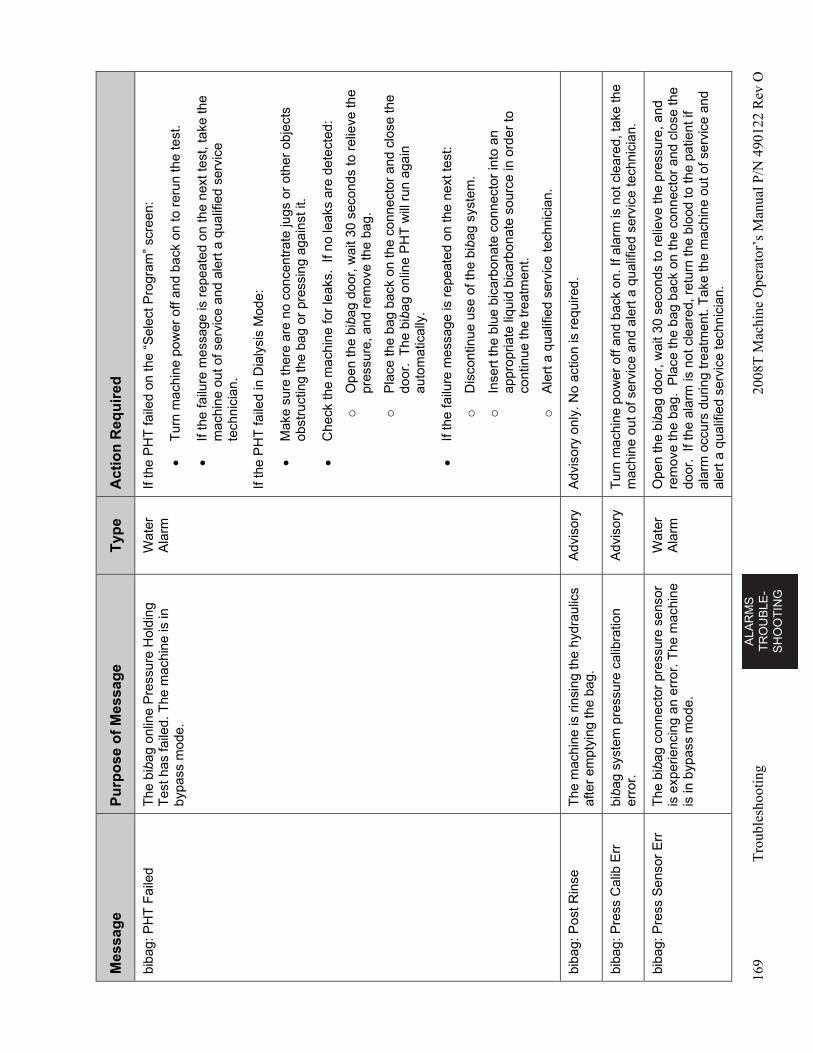
AL
AR
MS
T
RO
UB
LE
-S
HO
OT
ING
169
Tro
uble
shoo
ting
2008
T M
achi
ne O
pera
tor’
s M
anua
l P/N
490
122
Rev
O
Mes
sag
e P
urp
ose
of
Mes
sag
e T
ype
A
ctio
n R
equ
ired
biba
g: P
HT
Fai
led
The
bib
ag o
nlin
e P
ress
ure
Hol
ding
T
est h
as fa
iled.
The
mac
hine
is in
by
pass
mod
e.
Wat
er
Ala
rm
If th
e P
HT
faile
d on
the
“Sel
ect P
rogr
am”
scre
en:
T
urn
mac
hine
pow
er o
ff an
d ba
ck o
n to
rer
un th
e te
st.
If
the
failu
re m
essa
ge is
rep
eate
d on
the
next
test
, ta
ke th
e m
achi
ne o
ut o
f ser
vice
and
ale
rt a
qua
lifie
d se
rvic
e te
chni
cian
.
If th
e P
HT
faile
d in
Dia
lysi
s M
ode:
M
ake
sure
ther
e ar
e no
con
cent
rate
jugs
or
othe
r ob
ject
s ob
stru
ctin
g th
e ba
g or
pre
ssin
g ag
ains
t it.
C
heck
the
mac
hine
for
leak
s. I
f no
leak
s ar
e de
tect
ed:
o
Ope
n th
e bi
bag
door
, wai
t 30
seco
nds
to r
elie
ve th
e pr
essu
re, a
nd r
emov
e th
e ba
g.
o
Pla
ce th
e ba
g ba
ck o
n th
e co
nnec
tor
and
clos
e th
e do
or.
The
bib
ag o
nlin
e P
HT
will
run
aga
in
auto
mat
ical
ly.
If
the
failu
re m
essa
ge is
rep
eate
d on
the
next
test
:
o
Dis
cont
inue
use
of t
he b
ibag
sys
tem
.
o
Inse
rt th
e bl
ue b
icar
bona
te c
onne
ctor
into
an
appr
opria
te li
quid
bic
arbo
nate
sou
rce
in o
rder
to
cont
inue
the
trea
tmen
t.
o
Ale
rt a
qua
lifie
d se
rvic
e te
chni
cian
.
biba
g: P
ost R
inse
T
he m
achi
ne is
rin
sing
the
hydr
aulic
s af
ter
empt
ying
the
bag.
A
dvis
ory
Adv
isor
y on
ly. N
o ac
tion
is r
equi
red.
biba
g: P
ress
Cal
ib E
rr
biba
g sy
stem
pre
ssur
e ca
libra
tion
erro
r.
Adv
isor
y T
urn
mac
hine
pow
er o
ff an
d ba
ck o
n. If
ala
rm is
not
cle
ared
, tak
e th
e m
achi
ne o
ut o
f ser
vice
and
ale
rt a
qua
lifie
d se
rvic
e te
chni
cian
.
biba
g: P
ress
Sen
sor
Err
T
he b
ibag
con
nect
or p
ress
ure
sens
or
is e
xper
ienc
ing
an e
rror
. The
mac
hine
is
in b
ypas
s m
ode.
Wat
er
Ala
rm
Ope
n th
e bi
bag
door
, wai
t 30
seco
nds
to r
elie
ve th
e pr
essu
re, a
nd
rem
ove
the
bag.
Pla
ce th
e ba
g ba
ck o
n th
e co
nnec
tor
and
clos
e th
e do
or.
If th
e al
arm
is n
ot c
lear
ed, r
etur
n th
e bl
ood
to th
e pa
tient
if
alar
m o
ccur
s du
ring
trea
tmen
t. T
ake
the
mac
hine
out
of s
ervi
ce a
nd
aler
t a q
ualif
ied
serv
ice
tech
nici
an.
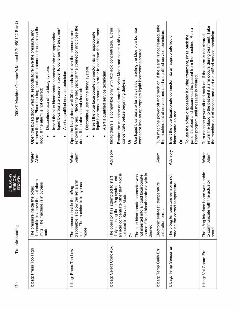
ALA
RM
S
TR
OU
BL
E-
SH
OO
TIN
G
170
Tro
uble
shoo
ting
2008
T M
achi
ne O
pera
tor’
s M
anua
l P/N
490
122
Rev
O
biba
g: P
ress
Too
Hig
h T
he p
ress
ure
insi
de th
e bi
bag
disp
osab
le is
abo
ve th
e se
t ala
rm
limits
. The
mac
hine
is in
byp
ass
mod
e.
Wat
er
Ala
rm
Ope
n th
e bi
bag
door
, wai
t 30
seco
nds
to r
elie
ve th
e pr
essu
re, a
nd
rem
ove
the
bag.
Pla
ce th
e ba
g ba
ck o
n th
e co
nnec
tor
and
clos
e th
e do
or.
If th
e al
arm
is n
ot c
lear
ed:
D
isco
ntin
ue u
se o
f the
bib
ag s
yste
m.
In
sert
the
blue
bic
arbo
nate
con
nect
or in
to a
n ap
prop
riate
liq
uid
bica
rbon
ate
sour
ce in
ord
er to
con
tinue
the
trea
tmen
t.
A
lert
a q
ualif
ied
serv
ice
tech
nici
an.
biba
g: P
ress
Too
Low
T
he p
ress
ure
insi
de th
e bi
bag
disp
osab
le is
bel
ow th
e se
t ala
rm
limits
. The
mac
hine
is in
byp
ass
mod
e.
Wat
er
Ala
rm
Ope
n th
e bi
bag
door
, wai
t 30
seco
nds
to r
elie
ve th
e pr
essu
re, a
nd
rem
ove
the
bag.
Pla
ce th
e ba
g ba
ck o
n th
e co
nnec
tor
and
clos
e th
e do
or.
If th
e al
arm
is n
ot c
lear
ed:
D
isco
ntin
ue u
se o
f the
bib
ag s
yste
m.
In
sert
the
blue
bic
arbo
nate
con
nect
or in
to a
n ap
prop
riate
liq
uid
bica
rbon
ate
sour
ce in
ord
er to
con
tinue
the
trea
tmen
t.
A
lert
a q
ualif
ied
serv
ice
tech
nici
an.
biba
g: S
elec
t Con
c 45
x T
he o
pera
tor
has
atte
mpt
ed to
sta
rt
dial
ysis
usi
ng th
e bi
bag
syst
em a
nd
an a
cid
conc
entr
ate
othe
r th
an 4
5x is
se
lect
ed in
Ser
vice
Mod
e.
Or
The
blu
e bi
carb
onat
e co
nnec
tor
was
no
t ins
erte
d in
to a
liqu
id b
icar
bona
te
sour
ce if
liqu
id b
icar
bona
te d
ialy
sis
is
desi
red.
Adv
isor
y bi
bag
dial
ysis
is c
ompa
tible
onl
y w
ith 4
5x a
cid
conc
entr
ates
. E
ither
,
Res
tart
the
mac
hine
and
ent
er S
ervi
ce M
ode
and
sele
ct a
45x
aci
d co
ncen
trat
e be
fore
beg
inni
ng d
ialy
sis;
Or
Use
liqu
id b
icar
bona
te fo
r di
alys
is b
y in
sert
ing
the
blue
bic
arbo
nate
co
nnec
tor
into
an
appr
opria
te li
quid
bic
arbo
nate
sou
rce.
biba
g: T
emp
Cal
ib E
rr
Ele
ctro
nic
self-
test
: tem
pera
ture
ca
libra
tion
erro
r.
Ala
rm
Tur
n m
achi
ne p
ower
off
and
back
on.
If th
e al
arm
is n
ot c
lear
ed, t
ake
the
mac
hine
out
of s
ervi
ce a
nd a
lert
a q
ualif
ied
serv
ice
tech
nici
an.
biba
g: T
emp
Sen
sor
Err
T
he b
ibag
tem
pera
ture
sen
sor
is n
ot
read
ing
the
corr
ect t
empe
ratu
re.
Adv
isor
y In
sert
the
blue
bic
arbo
nate
con
nect
or in
to a
n ap
prop
riate
liqu
id
bica
rbon
ate
sour
ce
Or
To
use
the
biba
g di
spos
able
: If d
urin
g tr
eatm
ent,
rinse
bac
k th
e pa
tient
’s b
lood
and
dis
conn
ect t
he p
atie
nt fr
om th
e m
achi
ne. R
un a
R
inse
pro
gram
unt
il m
essa
ge is
cle
ared
.
biba
g: V
al C
omm
Err
T
he b
ibag
inte
rfac
e bo
ard
was
una
ble
to c
omm
unic
ate
with
the
actu
ator
bo
ard.
Wat
er
Ala
rm
Tur
n m
achi
ne p
ower
off
and
back
on.
If th
e al
arm
is n
ot c
lear
ed,
retu
rn th
e bl
ood
to th
e pa
tient
if a
larm
occ
urs
durin
g tr
eatm
ent.
Tak
e th
e m
achi
ne o
ut o
f ser
vice
and
ale
rt a
qua
lifie
d se
rvic
e te
chni
cian
.
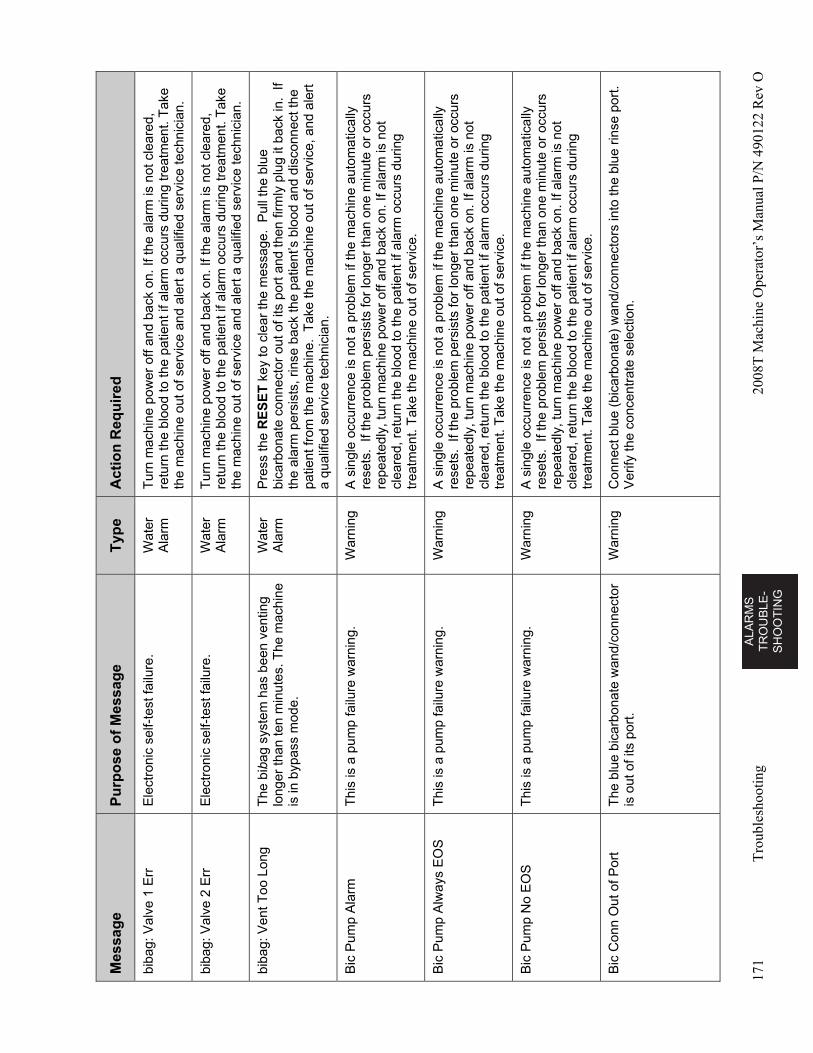
AL
AR
MS
T
RO
UB
LE
-S
HO
OT
ING
171
Tro
uble
shoo
ting
2008
T M
achi
ne O
pera
tor’
s M
anua
l P/N
490
122
Rev
O
Mes
sag
e P
urp
ose
of
Mes
sag
e T
ype
A
ctio
n R
equ
ired
biba
g: V
alve
1 E
rr
Ele
ctro
nic
self-
test
failu
re.
Wat
er
Ala
rm
Tur
n m
achi
ne p
ower
off
and
back
on.
If th
e al
arm
is n
ot c
lear
ed,
retu
rn th
e bl
ood
to th
e pa
tient
if a
larm
occ
urs
durin
g tr
eatm
ent.
Tak
e th
e m
achi
ne o
ut o
f ser
vice
and
ale
rt a
qua
lifie
d se
rvic
e te
chni
cian
.
biba
g: V
alve
2 E
rr
Ele
ctro
nic
self-
test
failu
re.
Wat
er
Ala
rm
Tur
n m
achi
ne p
ower
off
and
back
on.
If th
e al
arm
is n
ot c
lear
ed,
retu
rn th
e bl
ood
to th
e pa
tient
if a
larm
occ
urs
durin
g tr
eatm
ent.
Tak
e th
e m
achi
ne o
ut o
f ser
vice
and
ale
rt a
qua
lifie
d se
rvic
e te
chni
cian
.
biba
g: V
ent T
oo L
ong
The
bib
ag s
yste
m h
as b
een
vent
ing
long
er th
an te
n m
inut
es. T
he m
achi
ne
is in
byp
ass
mod
e.
Wat
er
Ala
rm
Pre
ss th
e R
ES
ET
key
to c
lear
the
mes
sage
. P
ull t
he b
lue
bica
rbon
ate
conn
ecto
r ou
t of i
ts p
ort
and
then
firm
ly p
lug
it ba
ck in
. If
the
alar
m p
ersi
sts,
rin
se b
ack
the
patie
nt’s
blo
od a
nd d
isco
nnec
t the
pa
tient
from
the
mac
hine
. T
ake
the
mac
hine
out
of s
ervi
ce, a
nd a
lert
a
qual
ified
ser
vice
tech
nici
an.
Bic
Pum
p A
larm
T
his
is a
pum
p fa
ilure
war
ning
. W
arni
ng
A s
ingl
e oc
curr
ence
is n
ot a
pro
blem
if th
e m
achi
ne a
utom
atic
ally
re
sets
. If
the
prob
lem
per
sist
s fo
r lo
nger
than
one
min
ute
or o
ccur
s re
peat
edly
, tur
n m
achi
ne p
ower
off
and
back
on.
If a
larm
is n
ot
clea
red,
ret
urn
the
bloo
d to
the
patie
nt if
ala
rm o
ccur
s du
ring
trea
tmen
t. T
ake
the
mac
hine
out
of s
ervi
ce.
Bic
Pum
p A
lway
s E
OS
T
his
is a
pum
p fa
ilure
war
ning
. W
arni
ng
A s
ingl
e oc
curr
ence
is n
ot a
pro
blem
if th
e m
achi
ne a
utom
atic
ally
re
sets
. If
the
prob
lem
per
sist
s fo
r lo
nger
than
one
min
ute
or o
ccur
s re
peat
edly
, tur
n m
achi
ne p
ower
off
and
back
on.
If a
larm
is n
ot
clea
red,
ret
urn
the
bloo
d to
the
patie
nt if
ala
rm o
ccur
s du
ring
trea
tmen
t. T
ake
the
mac
hine
out
of s
ervi
ce.
Bic
Pum
p N
o E
OS
T
his
is a
pum
p fa
ilure
war
ning
. W
arni
ng
A s
ingl
e oc
curr
ence
is n
ot a
pro
blem
if th
e m
achi
ne a
utom
atic
ally
re
sets
. If
the
prob
lem
per
sist
s fo
r lo
nger
than
one
min
ute
or o
ccur
s re
peat
edly
, tur
n m
achi
ne p
ower
off
and
back
on.
If a
larm
is n
ot
clea
red,
ret
urn
the
bloo
d to
the
patie
nt if
ala
rm o
ccur
s du
ring
trea
tmen
t. T
ake
the
mac
hine
out
of s
ervi
ce.
Bic
Con
n O
ut o
f Por
t T
he b
lue
bica
rbon
ate
wan
d/co
nnec
tor
is o
ut o
f its
por
t.
War
ning
C
onne
ct b
lue
(bic
arbo
nate
) w
and/
conn
ecto
rs in
to th
e bl
ue r
inse
por
t. V
erify
the
conc
entr
ate
sele
ctio
n.
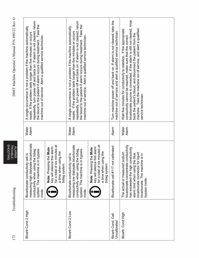
ALA
RM
S
TR
OU
BL
E-
SH
OO
TIN
G
172
Tro
uble
shoo
ting
2008
T M
achi
ne O
pera
tor’
s M
anua
l P/N
490
122
Rev
O
Bic
arb
Con
d 2
Hig
h B
icar
bona
te c
ondu
ctiv
ity c
ell i
s m
easu
ring
high
dia
lysa
te b
icar
bona
te
cond
uctiv
ity w
hen
usin
g th
e bi
bag
syst
em. T
he m
achi
ne is
in b
ypas
s m
ode.
Wat
er
Ala
rm
A s
ingl
e oc
curr
ence
is n
ot a
pro
blem
if th
e m
achi
ne a
utom
atic
ally
re
sets
. If t
he p
robl
em la
sts
long
er t
han
five
min
utes
or
occu
rs
repe
ated
ly, t
urn
pow
er o
ff an
d ba
ck o
n. If
ala
rm is
not
cle
ared
, ret
urn
the
bloo
d to
the
patie
nt if
ala
rm o
ccur
s du
ring
trea
tmen
t. T
ake
the
mac
hine
out
of s
ervi
ce.
Ale
rt a
qua
lifie
d se
rvic
e te
chni
cian
.
No
te: P
ress
ing
the
Mu
te
key
will
sile
nce
this
ala
rm
for
a to
tal o
f six
min
utes
at
a tim
e w
hen
usin
g th
e bi
bag
syst
em.
Bic
arb
Con
d 2
Low
B
icar
bona
te c
ondu
ctiv
ity c
ell i
s m
easu
ring
low
dia
lysa
te b
icar
bona
te
cond
uctiv
ity w
hen
usin
g th
e bi
bag
syst
em. T
he m
achi
ne is
in b
ypas
s m
ode.
Wat
er
Ala
rm
A s
ingl
e oc
curr
ence
is n
ot a
pro
blem
if th
e m
achi
ne a
utom
atic
ally
re
sets
. If
the
prob
lem
last
s lo
nger
than
five
min
utes
or
occu
rs
repe
ated
ly, t
urn
pow
er o
ff an
d ba
ck o
n. If
ala
rm is
not
cle
ared
, ret
urn
the
bloo
d to
the
patie
nt if
ala
rm o
ccur
s du
ring
trea
tmen
t. T
ake
the
mac
hine
out
of s
ervi
ce.
Ale
rt a
qua
lifie
d se
rvic
e te
chni
cian
.
No
te: P
ress
ing
the
Mu
te
key
will
sile
nce
this
ala
rm
for
a to
tal o
f six
min
utes
at
a tim
e w
hen
usin
g th
e bi
bag
syst
em.
Bic
arb
Con
d. C
ell
Unc
alib
rate
d B
icar
bona
te c
ell #
117
not c
alib
rate
d.
Ala
rm
Tur
n m
achi
ne p
ower
off
and
back
on.
If a
larm
is n
ot c
lear
ed, t
ake
the
mac
hine
out
of s
ervi
ce a
nd a
lert
a q
ualif
ied
serv
ice
tech
nici
an.
Bic
arb:
Con
d H
igh
The
act
ual o
r m
easu
red
sodi
um
bica
rbon
ate
conc
entr
ate
cond
uctiv
ity
has
exce
eded
the
high
con
duct
ivity
al
arm
lim
it w
hen
usin
g th
e bl
ue
bica
rbon
ate
conn
ecto
r fo
r liq
uid
bica
rbon
ate.
The
mac
hine
is in
by
pass
mod
e.
Wat
er
Ala
rm
Wai
t fiv
e m
inut
es fo
r co
nduc
tivity
to s
tabi
lize.
If t
he a
ppro
pria
te
cond
uctiv
ity c
anno
t be
reac
hed,
mak
e su
re th
at th
e co
rrec
t bi
carb
onat
e so
urce
is c
onne
cted
. If t
he a
larm
is s
till n
ot c
lear
ed, r
inse
ba
ck th
e pa
tient
’s b
lood
, and
dis
conn
ect t
he p
atie
nt fr
om th
e m
achi
ne.
Tak
e th
e m
achi
ne o
ut o
f ser
vice
, and
ale
rt a
qua
lifie
d se
rvic
e te
chni
cian
.
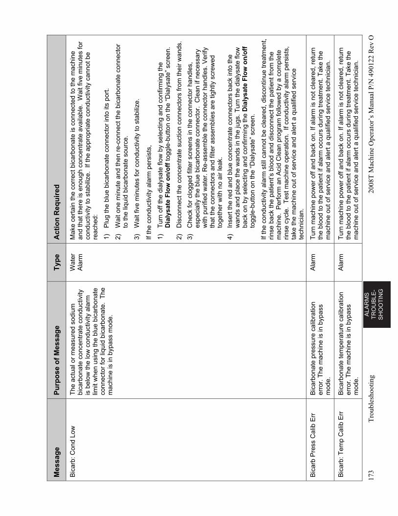
AL
AR
MS
T
RO
UB
LE
-S
HO
OT
ING
173
Tro
uble
shoo
ting
2008
T M
achi
ne O
pera
tor’
s M
anua
l P/N
490
122
Rev
O
Mes
sag
e P
urp
ose
of
Mes
sag
e T
ype
A
ctio
n R
equ
ired
Bic
arb:
Con
d Lo
w
The
act
ual o
r m
easu
red
sodi
um
bica
rbon
ate
conc
entr
ate
cond
uctiv
ity
is b
elow
the
low
con
duct
ivity
ala
rm
limit
whe
n us
ing
the
blue
bic
arbo
nate
co
nnec
tor
for
liqui
d bi
carb
onat
e. T
he
mac
hine
is in
byp
ass
mod
e.
Wat
er
Ala
rm
Mak
e ce
rtai
n th
e co
rrec
t bic
arbo
nate
is c
onne
cted
to th
e m
achi
ne
and
that
ther
e is
eno
ugh
conc
entr
ate
avai
labl
e. W
ait f
ive
min
utes
for
cond
uctiv
ity to
sta
biliz
e. I
f th
e ap
prop
riate
con
duct
ivity
can
not b
e re
ache
d:
1)
Plu
g th
e bl
ue b
icar
bona
te c
onne
ctor
into
its
port
.
2)
Wai
t one
min
ute
and
then
re-
conn
ect t
he b
icar
bona
te c
onne
ctor
to
the
liqui
d bi
carb
onat
e so
urce
.
3)
Wai
t fiv
e m
inut
es fo
r co
nduc
tivity
to s
tabi
lize.
If th
e co
nduc
tivity
ala
rm p
ersi
sts,
1)
Tur
n of
f the
dia
lysa
te fl
ow b
y se
lect
ing
and
conf
irmin
g th
e D
ialy
sate
Flo
w o
n/o
ff to
ggle
-but
ton
on th
e “D
ialy
sate
” sc
reen
.
2)
Dis
conn
ect t
he c
once
ntra
te s
uctio
n co
nnec
tors
from
thei
r w
ands
.
3)
Che
ck fo
r cl
ogge
d fil
ter
scre
ens
in th
e co
nnec
tor
hand
les,
es
peci
ally
the
blue
bic
arbo
nate
con
nect
or.
Cle
an if
nec
essa
ry
with
pur
ified
wat
er. R
e-as
sem
ble
the
conn
ecto
r ha
ndle
s. V
erify
th
at th
e co
nnec
tors
and
filte
r as
sem
blie
s ar
e tig
htly
scr
ewed
to
geth
er w
ith n
o ai
r le
ak.
4)
Inse
rt th
e re
d an
d bl
ue c
once
ntra
te c
onne
ctor
s ba
ck in
to th
e w
ands
and
pla
ce th
e w
ands
in th
e ju
gs. T
urn
the
dial
ysat
e flo
w
back
on
by s
elec
ting
and
conf
irmin
g th
e D
ialy
sate
Flo
w o
n/o
ff
togg
le-b
utto
n on
the
“Dia
lysa
te”
scre
en.
If th
e co
nduc
tivity
ala
rm s
till c
anno
t be
clea
red,
dis
cont
inue
trea
tmen
t, rin
se b
ack
the
patie
nt’s
blo
od a
nd d
isco
nnec
t the
pat
ient
from
the
mac
hine
. P
erfo
rm a
n A
cid
Cle
an p
rogr
am fo
llow
ed b
y a
com
plet
e rin
se c
ycle
. T
est m
achi
ne o
pera
tion.
If
cond
uctiv
ity a
larm
per
sist
s,
take
the
mac
hine
out
of s
ervi
ce a
nd a
lert
a q
ualif
ied
serv
ice
tech
nici
an.
Bic
arb
Pre
ss C
alib
Err
B
icar
bona
te p
ress
ure
calib
ratio
n er
ror.
The
mac
hine
is in
byp
ass
mod
e.
Ala
rm
Tur
n m
achi
ne p
ower
off
and
back
on.
If a
larm
is n
ot c
lear
ed, r
etur
n th
e bl
ood
to th
e pa
tient
if a
larm
occ
urs
durin
g tr
eatm
ent.
Tak
e th
e m
achi
ne o
ut o
f ser
vice
and
ale
rt a
qua
lifie
d se
rvic
e te
chni
cian
.
Bic
arb:
Tem
p C
alib
Err
B
icar
bona
te te
mpe
ratu
re c
alib
ratio
n er
ror.
The
mac
hine
is in
byp
ass
mod
e.
Ala
rm
Tur
n m
achi
ne p
ower
off
and
back
on.
If a
larm
is n
ot c
lear
ed, r
etur
n th
e bl
ood
to th
e pa
tient
if a
larm
occ
urs
durin
g tr
eatm
ent.
Tak
e th
e m
achi
ne o
ut o
f ser
vice
and
ale
rt a
qua
lifie
d se
rvic
e te
chni
cian
.
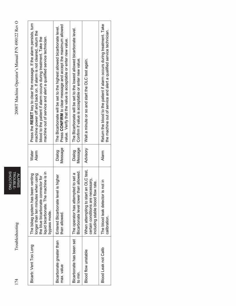
ALA
RM
S
TR
OU
BL
E-
SH
OO
TIN
G
174
Tro
uble
shoo
ting
2008
T M
achi
ne O
pera
tor’
s M
anua
l P/N
490
122
Rev
O
Bic
arb:
Ven
t Too
Lon
g T
he b
ibag
sys
tem
has
bee
n ve
ntin
g lo
nger
than
ten
min
utes
whe
n us
ing
the
blue
bic
arbo
nate
con
nect
or fo
r liq
uid
bica
rbon
ate.
The
mac
hine
is in
by
pass
mod
e.
Wat
er
Ala
rm
Pre
ss th
e R
ES
ET
key
to c
lear
the
mes
sage
. If t
he a
larm
per
sist
s, tu
rn
mac
hine
pow
er o
ff an
d ba
ck o
n. If
ala
rm is
not
cle
ared
, ret
urn
the
bloo
d to
the
patie
nt if
ala
rm o
ccur
s du
ring
trea
tmen
t. T
ake
the
mac
hine
out
of s
ervi
ce a
nd a
lert
a q
ualif
ied
serv
ice
tech
nici
an.
Bic
arbo
nate
gre
ater
than
m
ax. v
alue
E
nter
ed B
icar
bona
te le
vel i
s hi
gher
th
an a
llow
ed.
Dia
log
Mes
sage
T
he B
icar
bona
te w
ill b
e se
t to
the
high
est a
llow
ed b
icar
bona
te le
vel.
P
ress
CO
NF
IRM
to c
lear
mes
sage
and
acc
ept t
he m
axim
um a
llow
ed
valu
e. V
erify
tha
t the
val
ue is
acc
epta
ble
or e
nter
new
val
ue.
Bic
arbo
nate
has
bee
n se
t to
min
. T
he o
pera
tor
has
atte
mpt
ed to
set
a
Bic
arbo
nate
leve
l low
er th
an a
llow
ed.
Dia
log
Mes
sage
T
he B
icar
bona
te w
ill b
e se
t to
the
low
est a
llow
ed b
icar
bona
te le
vel.
C
onfir
m if
val
ue is
acc
epta
ble
or e
nter
new
val
ue.
Blo
od fl
ow u
nsta
ble
Whe
n at
tem
ptin
g to
sta
rt a
n O
LC te
st,
cert
ain
cond
ition
s ar
e ne
cess
ary,
in
clud
ing
stab
le b
lood
flow
rat
e.
Adv
isor
y W
ait a
min
ute
or s
o an
d st
art t
he O
LC te
st a
gain
.
Blo
od L
eak
not C
alib
T
he b
lood
leak
det
ecto
r is
not
in
calib
ratio
n.
Ala
rm
Ret
urn
the
bloo
d to
the
patie
nt if
ala
rm o
ccur
s du
ring
trea
tmen
t. T
ake
the
mac
hine
out
of s
ervi
ce a
nd a
lert
a q
ualif
ied
serv
ice
tech
nici
an.
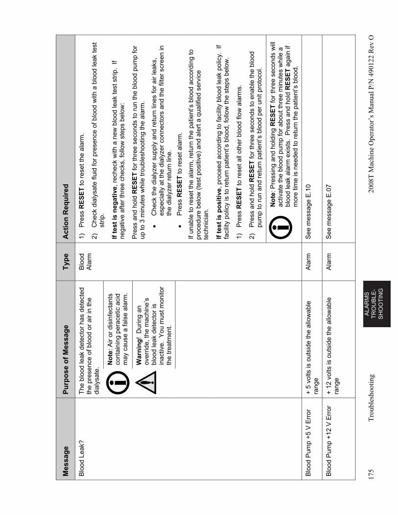
AL
AR
MS
T
RO
UB
LE
-S
HO
OT
ING
175
Tro
uble
shoo
ting
2008
T M
achi
ne O
pera
tor’
s M
anua
l P/N
490
122
Rev
O
Mes
sag
e P
urp
ose
of
Mes
sag
e T
ype
A
ctio
n R
equ
ired
Blo
od L
eak?
T
he b
lood
leak
det
ecto
r ha
s de
tect
ed
the
pres
ence
of b
lood
or
air
in th
e di
alys
ate.
Blo
od
Ala
rm
1)
Pre
ss R
ES
ET
to r
eset
the
alar
m.
2)
Che
ck d
ialy
sate
flui
d fo
r pr
esen
ce o
f blo
od w
ith a
blo
od le
ak te
st
strip
.
If t
est
is n
egat
ive
, rec
heck
with
a n
ew b
lood
leak
test
str
ip.
If ne
gativ
e af
ter
thre
e ch
ecks
, fol
low
ste
ps b
elow
:
Pre
ss a
nd h
old
RE
SE
T fo
r th
ree
seco
nds
to r
un th
e bl
ood
pum
p fo
r up
to 3
min
utes
whi
le tr
oubl
esho
otin
g th
e al
arm
.
C
heck
the
dial
yzer
sup
ply
and
retu
rn li
nes
for
air
leak
s,
espe
cial
ly a
t the
dia
lyze
r co
nnec
tors
and
the
filte
r sc
reen
in
the
dial
yzer
ret
urn
line.
P
ress
RE
SE
T to
res
et a
larm
.
If un
able
to r
eset
the
alar
m, r
etur
n th
e pa
tient
’s b
lood
acc
ordi
ng to
pr
oced
ure
belo
w (
test
pos
itive
) an
d al
ert a
qua
lifie
d se
rvic
e te
chni
cian
.
No
te: A
ir or
dis
infe
ctan
ts
cont
aini
ng p
erac
etic
aci
d m
ay c
ause
a fa
lse
alar
m.
War
nin
g!
Dur
ing
an
over
ride,
the
mac
hine
’s
bloo
d le
ak d
etec
tor
is
inac
tive.
You
mus
t mon
itor
the
trea
tmen
t.
If t
est
is p
osi
tive
, pro
ceed
acc
ordi
ng to
faci
lity
bloo
d le
ak p
olic
y. I
f fa
cilit
y po
licy
is to
ret
urn
patie
nt’s
blo
od, f
ollo
w th
e st
eps
belo
w.
1)
Pre
ss R
ES
ET
to r
eset
all
othe
r bl
ood
flow
ala
rms.
2)
Pre
ss a
nd h
old
RE
SE
T fo
r th
ree
seco
nds
to e
nabl
e th
e bl
ood
pum
p to
run
and
ret
urn
patie
nt’s
blo
od p
er u
nit p
roto
col.
N
ote
: Pre
ssin
g an
d ho
ldin
g R
ES
ET
for
thre
e se
cond
s w
ill
activ
ate
the
bloo
d pu
mp
for
abou
t thr
ee m
inut
es w
hile
a
bloo
d le
ak a
larm
exi
sts.
Pre
ss a
nd h
old
RE
SE
T a
gain
if
mor
e tim
e is
nee
ded
to r
etur
n th
e pa
tient
’s b
lood
.
Blo
od P
ump
+5
V E
rror
+
5 v
olts
is o
utsi
de th
e al
low
able
ra
nge
Ala
rm
See
mes
sage
E.1
0
Blo
od P
ump
+12
V E
rror
+
12
volts
is o
utsi
de th
e al
low
able
ra
nge
Ala
rm
See
mes
sage
E.0
7
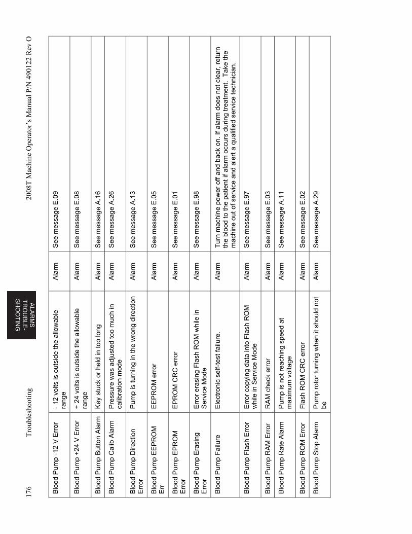
ALA
RM
S
TR
OU
BL
E-
SH
OO
TIN
G
176
Tro
uble
shoo
ting
2008
T M
achi
ne O
pera
tor’
s M
anua
l P/N
490
122
Rev
O
Blo
od P
ump
-12
V E
rror
-
12 v
olts
is o
utsi
de th
e al
low
able
ra
nge
Ala
rm
See
mes
sage
E.0
9
Blo
od P
ump
+24
V E
rror
+
24
volts
is o
utsi
de th
e al
low
able
ra
nge
Ala
rm
See
mes
sage
E.0
8
Blo
od P
ump
But
ton
Ala
rm
Key
stu
ck o
r he
ld in
too
long
A
larm
S
ee m
essa
ge A
.16
Blo
od P
ump
Cal
ib A
larm
P
ress
ure
was
adj
uste
d to
o m
uch
in
calib
ratio
n m
ode
Ala
rm
See
mes
sage
A.2
6
Blo
od P
ump
Dire
ctio
n E
rror
P
ump
is tu
rnin
g in
the
wro
ng d
irect
ion
Ala
rm
See
mes
sage
A.1
3
Blo
od P
ump
EE
PR
OM
E
rr
EE
PR
OM
err
or
Ala
rm
See
mes
sage
E.0
5
Blo
od P
ump
EP
RO
M
Err
or
EP
RO
M C
RC
err
or
Ala
rm
See
mes
sage
E.0
1
Blo
od P
ump
Era
sing
E
rror
E
rror
era
sing
Fla
sh R
OM
whi
le in
S
ervi
ce M
ode
Ala
rm
See
mes
sage
E.9
8
Blo
od P
ump
Fai
lure
E
lect
roni
c se
lf-te
st fa
ilure
. A
larm
T
urn
mac
hine
pow
er o
ff an
d ba
ck o
n. If
ala
rm d
oes
not c
lear
, ret
urn
the
bloo
d to
the
patie
nt if
ala
rm o
ccur
s du
ring
trea
tmen
t. T
ake
the
mac
hine
out
of s
ervi
ce a
nd a
lert
a q
ualif
ied
serv
ice
tech
nici
an.
Blo
od P
ump
Fla
sh E
rror
E
rror
cop
ying
dat
a in
to F
lash
RO
M
whi
le in
Ser
vice
Mod
e A
larm
S
ee m
essa
ge E
.97
Blo
od P
ump
RA
M E
rror
R
AM
che
ck e
rror
A
larm
S
ee m
essa
ge E
.03
Blo
od P
ump
Rat
e A
larm
P
ump
is n
ot r
each
ing
spee
d at
m
axim
um v
olta
ge
Ala
rm
See
mes
sage
A.1
1
Blo
od P
ump
RO
M E
rror
F
lash
RO
M C
RC
err
or
Ala
rm
See
mes
sage
E.0
2
Blo
od P
ump
Sto
p A
larm
P
ump
roto
r tu
rnin
g w
hen
it sh
ould
not
be
A
larm
S
ee m
essa
ge A
.29
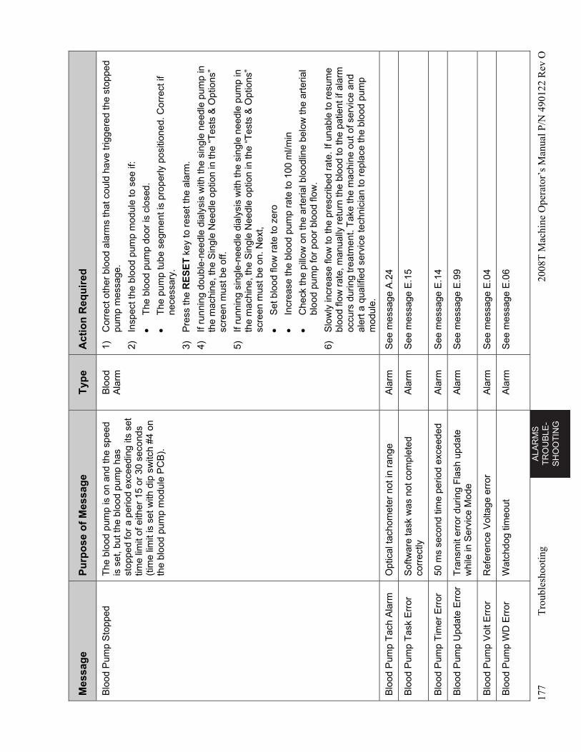
AL
AR
MS
T
RO
UB
LE
-S
HO
OT
ING
177
Tro
uble
shoo
ting
2008
T M
achi
ne O
pera
tor’
s M
anua
l P/N
490
122
Rev
O
Mes
sag
e P
urp
ose
of
Mes
sag
e T
ype
A
ctio
n R
equ
ired
Blo
od P
ump
Sto
pped
T
he b
lood
pum
p is
on
and
the
spee
d is
set
, but
the
bloo
d pu
mp
has
stop
ped
for
a pe
riod
exce
edin
g its
set
tim
e lim
it of
eith
er 1
5 or
30
seco
nds
(tim
e lim
it is
set
with
dip
sw
itch
#4 o
n th
e bl
ood
pum
p m
odul
e P
CB
).
Blo
od
Ala
rm
1)
Cor
rect
oth
er b
lood
ala
rms
that
cou
ld h
ave
trig
gere
d th
e st
oppe
d pu
mp
mes
sage
.
2)
Insp
ect t
he b
lood
pum
p m
odul
e to
see
if:
T
he b
lood
pum
p do
or is
clo
sed.
T
he p
ump
tube
seg
men
t is
prop
erly
pos
ition
ed. C
orre
ct if
ne
cess
ary.
3)
Pre
ss th
e R
ES
ET
key
to r
eset
the
alar
m.
4)
If ru
nnin
g do
uble
-nee
dle
dial
ysis
with
the
sing
le n
eedl
e pu
mp
in
the
mac
hine
, the
Sin
gle
Nee
dle
optio
n in
the
“Tes
ts &
Opt
ions
” sc
reen
mus
t be
off.
5)
If ru
nnin
g si
ngle
-nee
dle
dial
ysis
with
the
sing
le n
eedl
e pu
mp
in
the
mac
hine
, the
Sin
gle
Nee
dle
optio
n in
the
“Tes
ts &
Opt
ions
” sc
reen
mus
t be
on. N
ext,
S
et b
lood
flow
rat
e to
zer
o
In
crea
se th
e bl
ood
pum
p ra
te to
100
ml/m
in
C
heck
the
pillo
w o
n th
e ar
teria
l blo
odlin
e be
low
the
arte
rial
bloo
d pu
mp
for
poor
blo
od fl
ow.
6)
Slo
wly
incr
ease
flow
to th
e pr
escr
ibed
rat
e. If
una
ble
to r
esum
e bl
ood
flow
rat
e, m
anua
lly r
etur
n th
e bl
ood
to th
e pa
tient
if a
larm
oc
curs
dur
ing
trea
tmen
t. T
ake
the
mac
hine
out
of s
ervi
ce a
nd
aler
t a q
ualif
ied
serv
ice
tech
nici
an to
rep
lace
the
bloo
d pu
mp
mod
ule.
Blo
od P
ump
Tac
h A
larm
O
ptic
al ta
chom
eter
not
in r
ange
A
larm
S
ee m
essa
ge A
.24
Blo
od P
ump
Tas
k E
rror
S
oftw
are
task
was
not
com
plet
ed
corr
ectly
A
larm
S
ee m
essa
ge E
.15
Blo
od P
ump
Tim
er E
rror
50
ms
seco
nd ti
me
perio
d ex
ceed
ed
Ala
rm
See
mes
sage
E.1
4
Blo
od P
ump
Upd
ate
Err
or
Tra
nsm
it er
ror
durin
g F
lash
upd
ate
whi
le in
Ser
vice
Mod
e A
larm
S
ee m
essa
ge E
.99
Blo
od P
ump
Vol
t Err
or
Ref
eren
ce V
olta
ge e
rror
A
larm
S
ee m
essa
ge E
.04
Blo
od P
ump
WD
Err
or
Wat
chdo
g tim
eout
A
larm
S
ee m
essa
ge E
.06
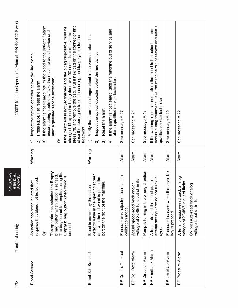
ALA
RM
S
TR
OU
BL
E-
SH
OO
TIN
G
178
Tro
uble
shoo
ting
2008
T M
achi
ne O
pera
tor’
s M
anua
l P/N
490
122
Rev
O
Blo
od S
ense
d A
n ac
tion
has
been
initi
ated
that
re
quire
s th
at b
lood
not
be
sens
ed.
Or
The
ope
rato
r ha
s se
lect
ed th
e E
mp
ty
bib
ag b
utto
n w
hen
bloo
d is
sen
sed.
T
he b
ag c
anno
t be
empt
ied
usin
g th
e E
mp
ty b
ibag
but
ton
whe
n bl
ood
is
sens
ed.
War
ning
1)
In
spec
t the
opt
ical
det
ecto
r be
low
the
line
clam
p.
2)
Pre
ss R
ES
ET
to r
eset
the
alar
m.
3)
If th
e al
arm
is n
ot c
lear
ed, r
etur
n th
e bl
ood
to th
e pa
tient
if a
larm
oc
curs
dur
ing
trea
tmen
t. T
ake
the
mac
hine
out
of s
ervi
ce a
nd
aler
t a q
ualif
ied
serv
ice
tech
nici
an.
Or
If th
e tr
eatm
ent i
s no
t yet
fini
shed
and
the
biba
g di
spos
able
mus
t be
chan
ged,
lift
up o
n th
e bi
bag
door
, wai
t 30
seco
nds
to r
elie
ve th
e pr
essu
re, a
nd r
emov
e th
e ba
g. P
ut a
new
bag
on
the
conn
ecto
r an
d cl
ose
the
door
aga
in to
con
tinue
usi
ng th
e bi
bag
syst
em fo
r th
e tr
eatm
ent.
Blo
od S
till S
ense
d!
Blo
od is
sen
sed
by th
e op
tical
de
tect
or w
hile
in th
e op
enin
g sc
reen
an
d w
ith th
e re
d w
and
is p
ut in
the
port
on
the
fron
t of t
he m
achi
ne.
War
ning
1)
V
erify
that
ther
e is
no
long
er b
lood
in th
e ve
nous
ret
urn
line
2)
Insp
ect t
he o
ptic
al d
etec
tor
belo
w th
e lin
e cl
amp.
3)
Res
et th
e al
arm
.
4)
If th
e al
arm
is n
ot c
lear
ed, t
ake
the
mac
hine
out
of s
ervi
ce a
nd
aler
t a q
ualif
ied
serv
ice
tech
nici
an.
BP
Com
m. T
imeo
ut
Pre
ssur
e w
as a
djus
ted
too
muc
h in
ca
libra
tion
mod
e A
larm
S
ee m
essa
ge A
.27
BP
Del
. Rat
e A
larm
A
ctua
l spe
ed-r
ead
back
ana
log
volta
ge a
t X34
8/10
is o
ut o
f lim
its
Ala
rm
See
mes
sage
A.2
1
BP
Dire
ctio
n A
larm
P
ump
is tu
rnin
g in
the
wro
ng d
irect
ion
Ala
rm
See
mes
sage
A.1
3
BP
Fee
dbac
k A
larm
A
rter
ial r
ate
and
the
bloo
d pu
mp’
s ar
teria
l set
ting
knob
do
not t
rack
in
syn
c.
Ala
rm
If th
e w
arni
ng is
not
cle
ared
, ret
urn
the
bloo
d to
the
patie
nt if
ala
rm
occu
rs d
urin
g tr
eatm
ent.
Tak
e th
e m
achi
ne o
ut o
f ser
vice
and
ale
rt a
qu
alifi
ed s
ervi
ce te
chni
cian
.
BP
Lev
el U
p A
larm
P
ress
ure
incr
ease
whe
n th
e Le
vel U
p ke
y is
pre
ssed
A
larm
S
ee m
essa
ge A
.25
BP
Pre
ssur
e A
larm
A
rter
ial p
ress
ure-
read
bac
k an
alog
vo
ltage
at X
348/
7 is
out
of l
imits
SN
pre
ssur
e-re
ad b
ack
anal
og
volta
ge is
out
of l
imits
Ala
rm
See
mes
sage
A.2
2
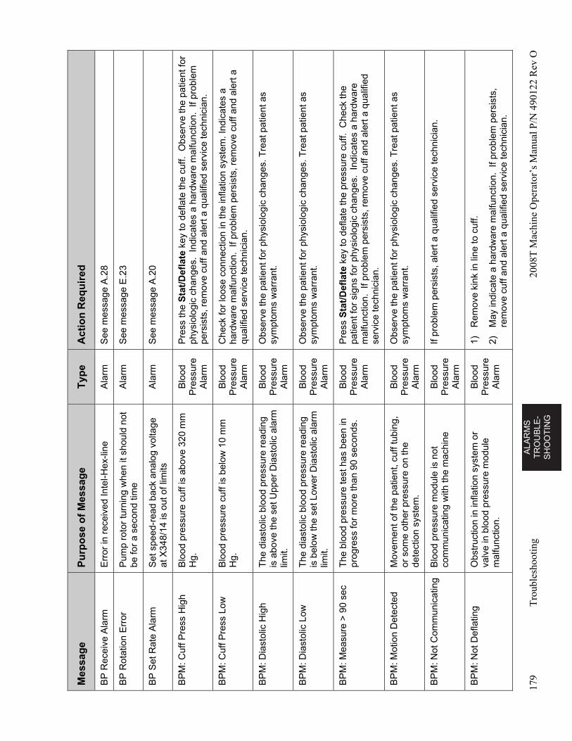
AL
AR
MS
T
RO
UB
LE
-S
HO
OT
ING
179
Tro
uble
shoo
ting
2008
T M
achi
ne O
pera
tor’
s M
anua
l P/N
490
122
Rev
O
Mes
sag
e P
urp
ose
of
Mes
sag
e T
ype
A
ctio
n R
equ
ired
BP
Rec
eive
Ala
rm
Err
or in
rec
eive
d In
tel-H
ex-li
ne
Ala
rm
See
mes
sage
A.2
8
BP
Rot
atio
n E
rror
P
ump
roto
r tu
rnin
g w
hen
it sh
ould
not
be
for
a se
cond
tim
e A
larm
S
ee m
essa
ge E
.23
BP
Set
Rat
e A
larm
S
et s
peed
-rea
d ba
ck a
nalo
g vo
ltage
at
X34
8/14
is o
ut o
f lim
its
Ala
rm
See
mes
sage
A.2
0
BP
M: C
uff P
ress
Hig
h B
lood
pre
ssur
e cu
ff is
abo
ve 3
20 m
m
Hg.
B
lood
P
ress
ure
Ala
rm
Pre
ss th
e S
tat/
Def
late
key
to d
efla
te th
e cu
ff. O
bser
ve th
e pa
tient
for
phys
iolo
gic
chan
ges.
Ind
icat
es a
har
dwar
e m
alfu
nctio
n. I
f pro
blem
pe
rsis
ts, r
emov
e cu
ff an
d al
ert a
qua
lifie
d se
rvic
e te
chni
cian
.
BP
M: C
uff P
ress
Low
B
lood
pre
ssur
e cu
ff is
bel
ow 1
0 m
m
Hg.
B
lood
P
ress
ure
Ala
rm
Che
ck fo
r lo
ose
conn
ectio
n in
the
infla
tion
syst
em. I
ndic
ates
a
hard
war
e m
alfu
nctio
n. I
f pro
blem
per
sist
s, r
emov
e cu
ff an
d al
ert a
qu
alifi
ed s
ervi
ce te
chni
cian
.
BP
M: D
iast
olic
Hig
h T
he d
iast
olic
blo
od p
ress
ure
read
ing
is a
bove
the
set U
pper
Dia
stol
ic a
larm
lim
it.
Blo
od
Pre
ssur
e A
larm
Obs
erve
the
patie
nt fo
r ph
ysio
logi
c ch
ange
s. T
reat
pat
ient
as
sym
ptom
s w
arra
nt.
BP
M: D
iast
olic
Low
T
he d
iast
olic
blo
od p
ress
ure
read
ing
is b
elow
the
set L
ower
Dia
stol
ic a
larm
lim
it.
Blo
od
Pre
ssur
e A
larm
Obs
erve
the
patie
nt fo
r ph
ysio
logi
c ch
ange
s. T
reat
pat
ient
as
sym
ptom
s w
arra
nt.
BP
M: M
easu
re >
90
sec
The
blo
od p
ress
ure
test
has
bee
n in
pr
ogre
ss fo
r m
ore
than
90
seco
nds.
B
lood
P
ress
ure
Ala
rm
Pre
ss S
tat/
Def
late
key
to d
efla
te th
e pr
essu
re c
uff.
Che
ck th
e pa
tient
for
sign
s fo
r ph
ysio
logi
c ch
ange
s. I
ndic
ates
a h
ardw
are
mal
func
tion.
If p
robl
em p
ersi
sts,
rem
ove
cuff
and
aler
t a q
ualif
ied
serv
ice
tech
nici
an.
BP
M: M
otio
n D
etec
ted
Mov
emen
t of t
he p
atie
nt, c
uff t
ubin
g,
or s
ome
othe
r pr
essu
re o
n th
e de
tect
ion
syst
em.
Blo
od
Pre
ssur
e A
larm
Obs
erve
the
patie
nt fo
r ph
ysio
logi
c ch
ange
s. T
reat
pat
ient
as
sym
ptom
s w
arra
nt.
BP
M: N
ot C
omm
unic
atin
g B
lood
pre
ssur
e m
odul
e is
not
co
mm
unic
atin
g w
ith th
e m
achi
ne
Blo
od
Pre
ssur
e A
larm
If pr
oble
m p
ersi
sts,
ale
rt a
qua
lifie
d se
rvic
e te
chni
cian
.
BP
M: N
ot D
efla
ting
Obs
truc
tion
in in
flatio
n sy
stem
or
valv
e in
blo
od p
ress
ure
mod
ule
mal
func
tion.
Blo
od
Pre
ssur
e A
larm
1)
Rem
ove
kink
in li
ne to
cuf
f.
2)
May
indi
cate
a h
ardw
are
mal
func
tion.
If
prob
lem
per
sist
s,
rem
ove
cuff
and
aler
t a q
ualif
ied
serv
ice
tech
nici
an.
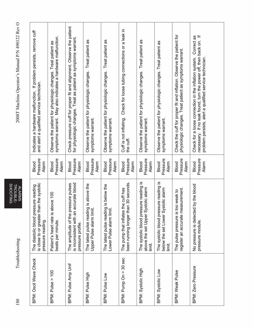
ALA
RM
S
TR
OU
BL
E-
SH
OO
TIN
G
180
Tro
uble
shoo
ting
2008
T M
achi
ne O
pera
tor’
s M
anua
l P/N
490
122
Rev
O
BP
M: O
scil
Wav
e C
heck
T
he d
iast
olic
blo
od p
ress
ure
read
ing
is c
lose
to o
r gr
eate
r th
an th
e sy
stol
ic
pres
sure
rea
ding
.
Blo
od
Pre
ssur
e A
larm
Indi
cate
s a
hard
war
e m
alfu
nctio
n. I
f pro
blem
per
sist
s, r
emov
e cu
ff an
d al
ert a
qua
lifie
d se
rvic
e te
chni
cian
.
BP
M: P
ulse
> 1
00
Pat
ient
’s h
eart
rat
e is
abo
ve 1
00
beat
s pe
r m
inut
e.
Blo
od
Pre
ssur
e A
larm
Obs
erve
the
patie
nt fo
r ph
ysio
logi
c ch
ange
s. T
reat
pat
ient
as
sym
ptom
s w
arra
nt.
May
als
o in
dica
tes
a ha
rdw
are
mal
func
tion.
BP
M: P
ulse
Am
p U
nif
The
am
plitu
de o
f the
pre
ssur
e pu
lses
is
inco
nsis
tent
with
an
accu
rate
blo
od
pres
sure
pro
file.
Blo
od
Pre
ssur
e A
larm
Che
ck p
ress
ure
cuff
for
prop
er fi
t and
alig
nmen
t. O
bser
ve th
e pa
tient
fo
r ph
ysio
logi
c ch
ange
s. T
reat
as
patie
nt a
s sy
mpt
oms
war
rant
.
BP
M: P
ulse
Hig
h T
he la
test
pul
se r
eadi
ng is
abo
ve th
e U
pper
Pul
se a
larm
lim
it.
Blo
od
Pre
ssur
e A
larm
Obs
erve
the
patie
nt fo
r ph
ysio
logi
c ch
ange
s. T
reat
pat
ient
as
sym
ptom
s w
arra
nt.
BP
M: P
ulse
Low
T
he la
test
pul
se r
eadi
ng is
bel
ow th
e Lo
wer
Pul
se a
larm
lim
it.
Blo
od
Pre
ssur
e A
larm
Obs
erve
the
patie
nt fo
r ph
ysio
logi
c ch
ange
s. T
reat
pat
ient
as
sym
ptom
s w
arra
nt.
BP
M: P
ump
On
> 3
0 se
c T
he p
ump
that
infla
tes
the
cuff
has
been
run
ning
long
er th
an 3
0 se
cond
s.
Blo
od
Pre
ssur
e A
larm
Cuf
f is
not i
nfla
ting.
Che
ck fo
r lo
ose
tubi
ng c
onne
ctio
ns o
r a
leak
in
the
cuff.
BP
M: S
ysto
lic H
igh
The
sys
tolic
blo
od p
ress
ure
read
ing
is
abov
e th
e se
t Upp
er S
ysto
lic a
larm
lim
it.
Blo
od
Pre
ssur
e A
larm
Obs
erve
the
patie
nt fo
r ph
ysio
logi
c ch
ange
s. T
reat
pat
ient
as
sym
ptom
s w
arra
nt.
BP
M: S
ysto
lic L
ow
The
sys
tolic
blo
od p
ress
ure
read
ing
is
belo
w th
e se
t Low
er S
ysto
lic a
larm
lim
it.
Blo
od
Pre
ssur
e A
larm
Obs
erve
the
patie
nt fo
r ph
ysio
logi
c ch
ange
s. T
reat
pat
ient
as
sym
ptom
s w
arra
nt.
BP
M: W
eak
Pul
se
The
pul
se p
ress
ure
is to
o w
eak
to
regi
ster
an
accu
rate
mea
sure
men
t. B
lood
P
ress
ure
Ala
rm
Che
ck th
e cu
ff fo
r pr
oper
fit a
nd in
flatio
n. O
bser
ve th
e pa
tient
for
phys
iolo
gic
chan
ges.
Tre
at p
atie
nt a
s sy
mpt
oms
war
rant
.
BP
M: Z
ero
Pre
ssur
e N
o pr
essu
re is
det
ecte
d by
the
bloo
d pr
essu
re m
odul
e.
Blo
od
Pre
ssur
e A
larm
Che
ck fo
r a
loos
e co
nnec
tion
in th
e in
flatio
n sy
stem
. C
orre
ct a
s ne
cess
ary.
If n
o le
ak fo
und,
turn
the
pow
er o
ff, th
en b
ack
on.
If pr
oble
m p
ersi
sts,
ale
rt a
qua
lifie
d se
rvic
e te
chni
cian
.
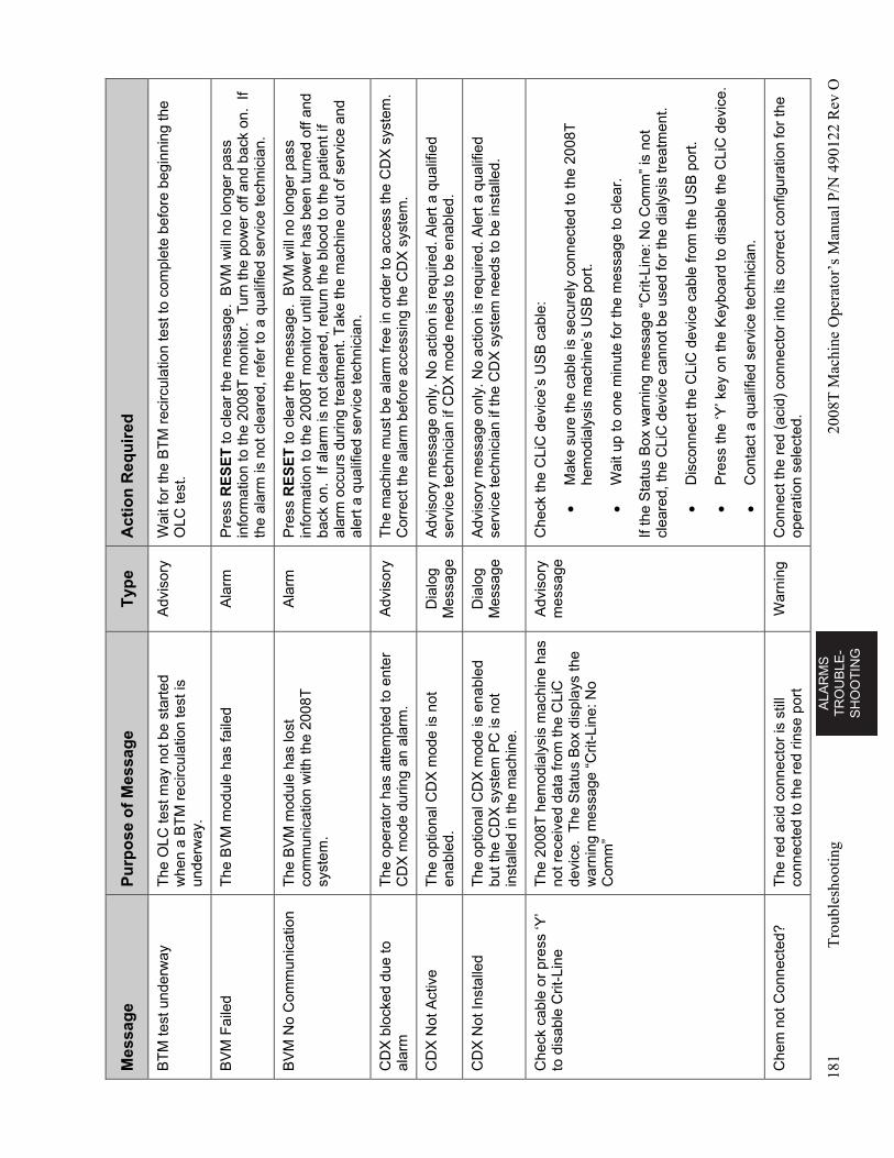
AL
AR
MS
T
RO
UB
LE
-S
HO
OT
ING
181
Tro
uble
shoo
ting
2008
T M
achi
ne O
pera
tor’
s M
anua
l P/N
490
122
Rev
O
Mes
sag
e P
urp
ose
of
Mes
sag
e T
ype
A
ctio
n R
equ
ired
BT
M te
st u
nder
way
T
he O
LC te
st m
ay n
ot b
e st
arte
d w
hen
a B
TM
rec
ircul
atio
n te
st is
un
derw
ay.
Adv
isor
y W
ait f
or th
e B
TM
rec
ircul
atio
n te
st to
com
plet
e be
fore
beg
inni
ng th
e O
LC te
st.
BV
M F
aile
d T
he B
VM
mod
ule
has
faile
d A
larm
P
ress
RE
SE
T to
cle
ar th
e m
essa
ge.
BV
M w
ill n
o lo
nger
pas
s in
form
atio
n to
the
2008
T m
onito
r. T
urn
the
pow
er o
ff an
d ba
ck o
n. I
f th
e al
arm
is n
ot c
lear
ed, r
efer
to a
qua
lifie
d se
rvic
e te
chni
cian
.
BV
M N
o C
omm
unic
atio
n T
he B
VM
mod
ule
has
lost
co
mm
unic
atio
n w
ith th
e 20
08T
sy
stem
.
Ala
rm
Pre
ss R
ES
ET
to c
lear
the
mes
sage
. B
VM
will
no
long
er p
ass
info
rmat
ion
to th
e 20
08T
mon
itor
until
pow
er h
as b
een
turn
ed o
ff an
d ba
ck o
n. I
f ala
rm is
not
cle
ared
, ret
urn
the
bloo
d to
the
patie
nt if
al
arm
occ
urs
durin
g tr
eatm
ent.
Tak
e th
e m
achi
ne o
ut o
f ser
vice
and
al
ert a
qua
lifie
d se
rvic
e te
chni
cian
.
CD
X b
lock
ed d
ue to
al
arm
T
he o
pera
tor
has
atte
mpt
ed to
ent
er
CD
X m
ode
durin
g an
ala
rm.
Adv
isor
y T
he m
achi
ne m
ust b
e al
arm
free
in o
rder
to a
cces
s th
e C
DX
sys
tem
. C
orre
ct th
e al
arm
bef
ore
acce
ssin
g th
e C
DX
sys
tem
.
CD
X N
ot A
ctiv
e T
he o
ptio
nal C
DX
mod
e is
not
en
able
d.
Dia
log
Mes
sage
A
dvis
ory
mes
sage
onl
y. N
o ac
tion
is r
equi
red.
Ale
rt a
qua
lifie
d se
rvic
e te
chni
cian
if C
DX
mod
e ne
eds
to b
e en
able
d.
CD
X N
ot In
stal
led
The
opt
iona
l CD
X m
ode
is e
nabl
ed
but t
he C
DX
sys
tem
PC
is n
ot
inst
alle
d in
the
mac
hine
.
Dia
log
Mes
sage
A
dvis
ory
mes
sage
onl
y. N
o ac
tion
is r
equi
red.
Ale
rt a
qua
lifie
d se
rvic
e te
chni
cian
if th
e C
DX
sys
tem
nee
ds to
be
inst
alle
d.
Che
ck c
able
or
pres
s ‘Y
’ to
dis
able
Crit
-Lin
e T
he 2
008T
hem
odia
lysi
s m
achi
ne h
as
not r
ecei
ved
data
from
the
CLi
C
devi
ce.
The
Sta
tus
Box
dis
play
s th
e w
arni
ng m
essa
ge “
Crit
-Lin
e: N
o C
omm
”
Adv
isor
y m
essa
ge
Che
ck th
e C
LiC
dev
ice’
s U
SB
cab
le:
M
ake
sure
the
cabl
e is
sec
urel
y co
nnec
ted
to th
e 20
08T
he
mod
ialy
sis
mac
hine
’s U
SB
por
t.
W
ait u
p to
one
min
ute
for
the
mes
sage
to c
lear
.
If th
e S
tatu
s B
ox w
arni
ng m
essa
ge “
Crit
-Lin
e: N
o C
omm
” is
not
cl
eare
d, th
e C
LiC
dev
ice
cann
ot b
e us
ed fo
r th
e di
alys
is tr
eatm
ent.
D
isco
nnec
t the
CLi
C d
evic
e ca
ble
from
the
US
B p
ort.
P
ress
the
‘Y’ k
ey o
n th
e K
eybo
ard
to d
isab
le th
e C
LiC
dev
ice.
C
onta
ct a
qua
lifie
d se
rvic
e te
chni
cian
.
Che
m n
ot C
onne
cted
? T
he r
ed a
cid
conn
ecto
r is
stil
l co
nnec
ted
to th
e re
d rin
se p
ort
War
ning
C
onne
ct th
e re
d (a
cid)
con
nect
or in
to it
s co
rrec
t con
figur
atio
n fo
r th
e op
erat
ion
sele
cted
.
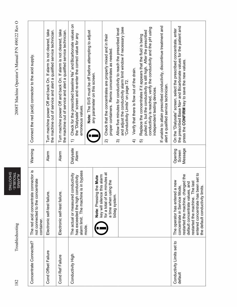
ALA
RM
S
TR
OU
BL
E-
SH
OO
TIN
G
182
Tro
uble
shoo
ting
2008
T M
achi
ne O
pera
tor’
s M
anua
l P/N
490
122
Rev
O
Con
cent
rate
Con
nect
ed?
The
red
aci
d co
ncen
trat
e co
nnec
tor
is
not c
onne
cted
to th
e co
ncen
trat
e co
ntai
ner.
War
ning
C
onne
ct th
e re
d (a
cid)
con
nect
or to
the
acid
sup
ply.
Con
d O
ffset
Fai
lure
E
lect
ron
ic s
elf-
test
failu
re.
Ala
rm
Tur
n m
achi
ne p
ower
Off
and
back
On.
If a
larm
is n
ot c
lear
ed, t
ake
the
mac
hine
out
of s
ervi
ce a
nd a
lert
a q
ualif
ied
serv
ice
tech
nici
an.
Con
d R
ef F
ailu
re
Ele
ctro
nic
self-
test
failu
re.
Ala
rm
Tur
n m
achi
ne p
ower
Off
and
back
On.
If a
larm
is n
ot c
lear
ed, t
ake
the
mac
hine
out
of s
ervi
ce a
nd a
lert
a q
ualif
ied
serv
ice
tech
nici
an.
Con
duct
ivity
Hig
h T
he a
ctua
l or
mea
sure
d co
nduc
tivity
ha
s ex
ceed
ed th
e hi
gh c
ondu
ctiv
ity
alar
m li
mit.
The
mac
hine
is in
byp
ass
mod
e.
Dia
lysa
te
Ala
rm
1)
Che
ck fo
r th
e pr
escr
ibed
bas
elin
e N
a+
and B
icar
bona
te v
alue
s on
th
e “D
ialy
sate
” sc
reen
and
re-
ente
r th
e co
rrec
t val
ue fo
r an
y er
rone
ous
valu
es.
No
te: T
he S
VS
mus
t be
off b
efor
e at
tem
ptin
g to
adj
ust
any
para
met
er o
n th
is s
cree
n.
No
te: P
ress
ing
the
Mu
te
key
will
sile
nce
this
ala
rm
for
a to
tal o
f six
min
utes
at
a tim
e w
hen
usin
g th
e bi
bag
syst
em.
2)
Che
ck th
at th
e co
ncen
trat
es a
re p
rope
rly m
ixed
and
in th
eir
prop
er c
onta
iner
s. R
emix
con
cent
rate
s as
nee
ded.
3)
Allo
w fi
ve m
inut
es fo
r co
nduc
tivity
to r
each
the
pres
crib
ed le
vel
and
adju
st th
e co
nduc
tivity
ala
rm li
mit
win
dow
if n
eces
sary
(se
e “C
ondu
ctiv
ity L
imits
” on
pag
e 72
.
4)
Ver
ify th
at th
ere
is fl
ow o
ut o
f the
dra
in.
5)
Rep
lace
the
conc
entr
ates
if it
app
ears
that
the
fluid
is b
eing
pu
lled
in, b
ut th
e co
nduc
tivity
is s
till h
igh.
Afte
r th
e pr
escr
ibed
co
nduc
tivity
is r
each
ed, v
erify
the
cond
uctiv
ity a
nd th
e pH
usi
ng
inde
pend
ent t
estin
g de
vice
s.
If un
able
to a
ttain
pre
scrib
ed c
ondu
ctiv
ity, d
isco
ntin
ue tr
eatm
ent a
nd
aler
t a q
ualif
ied
serv
ice
tech
nici
an.
Con
duct
ivity
Lim
its s
et to
de
faul
t T
he o
pera
tor
has
ente
red
a ne
w
conc
entr
ate
in S
ervi
ce M
ode,
re
star
ted
the
mac
hine
, cha
nged
the
defa
ult c
once
ntra
te v
alue
s, a
nd
rest
arte
d th
e m
achi
ne.
The
last
en
tere
d co
ncen
trat
e ha
s be
en s
et to
th
e de
faul
t con
duct
ivity
lim
its.
Ope
ning
S
cree
n M
essa
ge
On
the
“Dia
lysa
te”
scre
en, s
elec
t the
pre
scrib
ed c
once
ntra
te, e
nter
th
e pr
escr
ibed
Bas
e N
a+ a
nd B
icar
bona
te v
alue
s fo
r th
e pa
tient
and
pr
ess
the
CO
NF
IRM
key
to s
ave
the
new
val
ues.
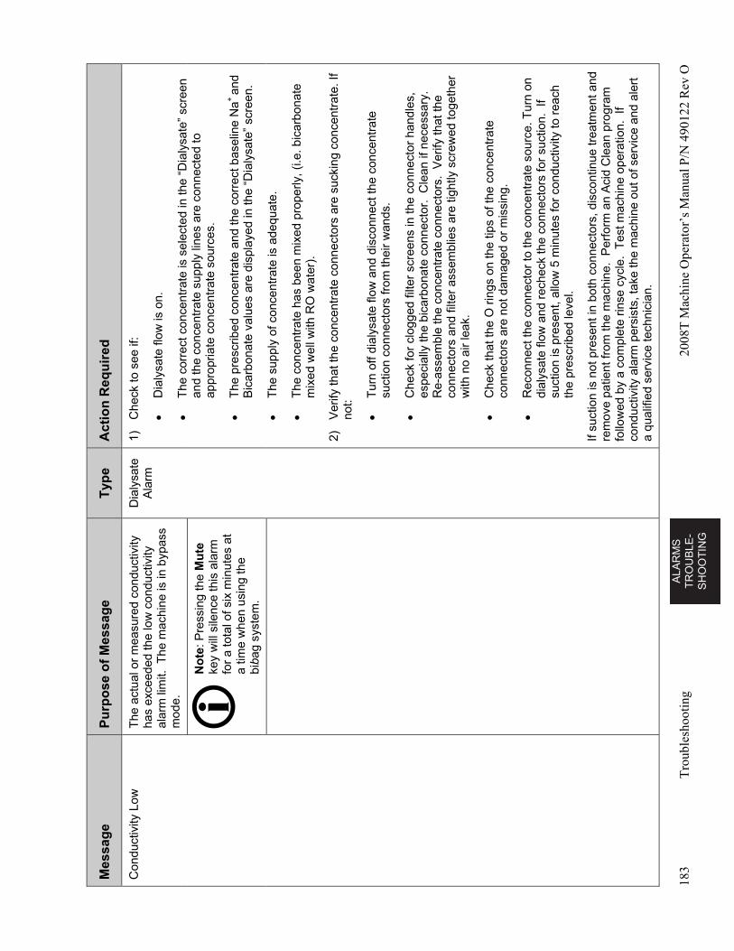
AL
AR
MS
T
RO
UB
LE
-S
HO
OT
ING
183
Tro
uble
shoo
ting
2008
T M
achi
ne O
pera
tor’
s M
anua
l P/N
490
122
Rev
O
Mes
sag
e P
urp
ose
of
Mes
sag
e T
ype
A
ctio
n R
equ
ired
Con
duct
ivity
Low
T
he a
ctua
l or
mea
sure
d co
nduc
tivity
ha
s ex
ceed
ed th
e lo
w c
ondu
ctiv
ity
alar
m li
mit.
The
mac
hine
is in
byp
ass
mod
e.
Dia
lysa
te
Ala
rm
1)
Che
ck to
see
if:
D
ialy
sate
flow
is o
n.
T
he c
orre
ct c
once
ntra
te is
sel
ecte
d in
the
“Dia
lysa
te”
scre
en
and
the
conc
entr
ate
supp
ly li
nes
are
conn
ecte
d to
ap
prop
riate
con
cent
rate
sou
rces
.
T
he p
resc
ribed
con
cent
rate
and
the
corr
ect b
asel
ine
Na
+ an
d B
icar
bona
te v
alue
s ar
e di
spla
yed
in th
e “D
ialy
sate
” sc
reen
.
T
he s
uppl
y of
con
cent
rate
is a
dequ
ate.
T
he c
once
ntra
te h
as b
een
mix
ed p
rope
rly, (
i.e. b
icar
bona
te
mix
ed w
ell w
ith R
O w
ater
).
2)
Ver
ify th
at th
e co
ncen
trat
e co
nnec
tors
are
suc
king
con
cent
rate
. If
not:
T
urn
off d
ialy
sate
flow
and
dis
conn
ect t
he c
once
ntra
te
suct
ion
conn
ecto
rs fr
om th
eir
wan
ds.
C
heck
for
clog
ged
filte
r sc
reen
s in
the
conn
ecto
r ha
ndle
s,
espe
cial
ly th
e bi
carb
onat
e co
nnec
tor.
Cle
an if
nec
essa
ry.
Re-
asse
mbl
e th
e co
ncen
trat
e co
nnec
tors
. V
erify
that
the
co
nnec
tors
and
filte
r as
sem
blie
s ar
e tig
htly
scr
ewed
toge
ther
w
ith n
o ai
r le
ak.
C
heck
that
the
O r
ings
on
the
tips
of th
e co
ncen
trat
e co
nnec
tors
are
not
dam
aged
or
mis
sing
.
R
econ
nect
the
conn
ecto
r to
the
conc
entr
ate
sour
ce. T
urn
on
dial
ysat
e flo
w a
nd r
eche
ck th
e co
nnec
tors
for
suct
ion.
If
suct
ion
is p
rese
nt, a
llow
5 m
inut
es fo
r co
nduc
tivity
to r
each
th
e pr
escr
ibed
leve
l.
If su
ctio
n is
not
pre
sent
in b
oth
conn
ecto
rs, d
isco
ntin
ue tr
eatm
ent a
nd
rem
ove
patie
nt fr
om th
e m
achi
ne.
Per
form
an
Aci
d C
lean
pro
gram
fo
llow
ed b
y a
com
plet
e rin
se c
ycle
. T
est m
achi
ne o
pera
tion.
If
cond
uctiv
ity a
larm
per
sist
s, ta
ke th
e m
achi
ne o
ut o
f ser
vice
and
ale
rt
a qu
alifi
ed s
ervi
ce te
chni
cian
.
No
te: P
ress
ing
the
Mu
te
key
will
sile
nce
this
ala
rm
for
a to
tal o
f six
min
utes
at
a tim
e w
hen
usin
g th
e bi
bag
syst
em.
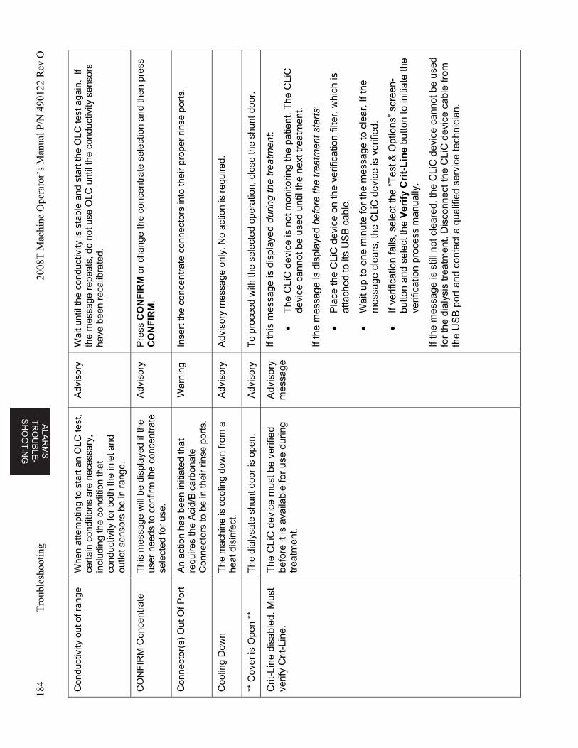
ALA
RM
S
TR
OU
BL
E-
SH
OO
TIN
G
184
Tro
uble
shoo
ting
2008
T M
achi
ne O
pera
tor’
s M
anua
l P/N
490
122
Rev
O
Con
duct
ivity
out
of r
ange
W
hen
atte
mpt
ing
to s
tart
an
OLC
test
, ce
rtai
n co
nditi
ons
are
nece
ssar
y,
incl
udin
g th
e co
nditi
on th
at
cond
uctiv
ity fo
r bo
th th
e in
let a
nd
outle
t sen
sors
be
in r
ange
.
Adv
isor
y W
ait u
ntil
the
cond
uctiv
ity is
sta
ble
and
star
t the
OLC
test
aga
in.
If th
e m
essa
ge r
epea
ts, d
o no
t use
OLC
unt
il th
e co
nduc
tivity
sen
sors
ha
ve b
een
reca
libra
ted.
CO
NF
IRM
Con
cent
rate
T
his
mes
sage
will
be
disp
laye
d if
the
user
nee
ds to
con
firm
the
conc
entr
ate
sele
cted
for
use.
Adv
isor
y P
ress
CO
NF
IRM
or
chan
ge th
e co
ncen
trat
e se
lect
ion
and
then
pre
ss
CO
NF
IRM
.
Con
nect
or(s
) O
ut O
f Por
t A
n ac
tion
has
been
initi
ated
that
re
quire
s th
e A
cid/
Bic
arbo
nate
C
onne
ctor
s to
be
in th
eir
rinse
por
ts.
War
ning
In
sert
the
conc
entr
ate
conn
ecto
rs in
to th
eir
prop
er r
inse
por
ts.
Coo
ling
Dow
n T
he m
achi
ne is
coo
ling
dow
n fr
om a
he
at d
isin
fect
. A
dvis
ory
Adv
isor
y m
essa
ge o
nly.
No
actio
n is
req
uire
d.
** C
over
is O
pen
**
The
dia
lysa
te s
hunt
doo
r is
ope
n.
Adv
isor
y T
o pr
ocee
d w
ith th
e se
lect
ed o
pera
tion,
clo
se th
e sh
unt d
oor.
Crit
-Lin
e di
sabl
ed. M
ust
verif
y C
rit-L
ine.
T
he C
LiC
de
vice
mus
t be
verif
ied
befo
re it
is a
vaila
ble
for
use
dur
ing
trea
tmen
t.
Adv
isor
y m
essa
ge
If th
is m
essa
ge is
dis
play
ed d
urin
g th
e tr
eatm
ent:
T
he C
LiC
de
vice
is n
ot m
onito
ring
the
patie
nt. T
he C
LiC
de
vice
can
not
be
used
unt
il th
e ne
xt tr
eatm
ent.
If th
e m
essa
ge is
dis
play
ed b
efor
e th
e tr
eatm
ent
sta
rts:
P
lace
the
CLi
C d
evic
e on
the
ver
ifica
tion
filte
r, w
hich
is
atta
ched
to
its U
SB
cab
le.
W
ait u
p to
one
min
ute
for
the
mes
sage
to c
lear
. If t
he
mes
sage
cle
ars,
the
CLi
C d
evic
e is
ver
ified
.
If
verif
icat
ion
fails
, sel
ect t
he “
Tes
t & O
ptio
ns”
scre
en-
butto
n an
d se
lect
the
Ver
ify
Cri
t-L
ine
butto
n to
initi
ate
the
verif
icat
ion
proc
ess
man
ually
.
If th
e m
essa
ge is
stil
l not
cle
ared
, the
CLi
C d
evic
e ca
nnot
be
used
fo
r th
e di
alys
is tr
eatm
ent.
Dis
conn
ect t
he C
LiC
de
vice
cab
le fr
om
the
US
B p
ort a
nd c
onta
ct a
qua
lifie
d se
rvic
e te
chni
cian
.
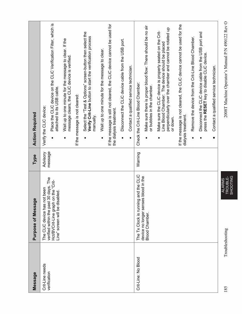
AL
AR
MS
T
RO
UB
LE
-S
HO
OT
ING
185
Tro
uble
shoo
ting
2008
T M
achi
ne O
pera
tor’
s M
anua
l P/N
490
122
Rev
O
Mes
sag
e P
urp
ose
of
Mes
sag
e T
ype
A
ctio
n R
equ
ired
Crit
-Lin
e ne
eds
verif
icat
ion
The
CLi
C d
evic
e ha
s no
t bee
n ve
rifie
d w
ithin
the
past
30
days
. The
H
ct/B
VC
rit-L
ine
grap
h on
the
“Crit
-Li
ne”
scre
en w
ill b
e di
sabl
ed.
Adv
isor
y m
essa
ge
Ver
ify th
e C
LiC
dev
ice:
P
lace
the
CLi
C d
evic
e on
the
CLi
C V
erifi
catio
n F
ilter
, whi
ch is
at
tach
ed to
its
US
B c
able
.
W
ait u
p to
one
min
ute
for
the
mes
sage
to c
lear
. If t
he
mes
sage
cle
ars,
the
CLi
C d
evic
e is
ver
ified
.
If th
e m
essa
ge is
not
cle
ared
:
S
elec
t the
“T
est &
Opt
ions
” sc
reen
-but
ton
then
sel
ect t
he
Ver
ify
Cri
t-L
ine
but
ton
to s
tart
the
verif
icat
ion
proc
ess
man
ually
.
W
ait u
p to
one
min
ute
for
the
mes
sage
to c
lear
.
If th
e m
essa
ge is
stil
l not
cle
ared
, th
e C
LiC
dev
ice
cann
ot b
e us
ed fo
r th
e di
alys
is tr
eatm
ent.
D
isco
nnec
t the
CLi
C d
evic
e ca
ble
from
the
US
B p
ort.
C
onta
ct a
qua
lifie
d se
rvic
e te
chni
cian
.
Crit
-Lin
e: N
o B
lood
T
he T
x C
lock
is r
unni
ng a
nd th
e C
LiC
de
vice
no
long
er s
ense
s bl
ood
in th
e B
lood
Cha
mbe
r.
War
ning
C
heck
the
Crit
-Lin
e B
lood
Cha
mbe
r:
M
ake
sure
ther
e is
pro
per
bloo
d flo
w: T
here
sho
uld
be n
o ai
r or
bub
bles
in th
e ch
ambe
r.
M
ake
sure
the
CLi
C d
evic
e is
pro
perly
sea
ted
on th
e C
rit-
Line
Blo
od C
ham
ber:
The
dev
ice
shou
ld b
e pl
aced
pe
rpen
dicu
larly
ove
r th
e ch
ambe
r an
d ca
nnot
be
rota
ted
up
or d
own.
If th
e m
essa
ge is
not
cle
ared
, the
CLi
C d
evic
e ca
nnot
be
used
for
the
dial
ysis
trea
tmen
t.
R
emov
e th
e de
vice
from
the
Crit
-Lin
e B
lood
Cha
mbe
r.
D
isco
nnec
t the
CLi
C d
evic
e ca
ble
from
the
US
B p
ort a
nd
pres
s th
e R
ES
ET
key
to d
isab
le C
LiC
dev
ice.
C
onta
ct a
qua
lifie
d se
rvic
e te
chni
cian
.
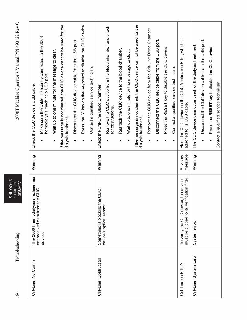
ALA
RM
S
TR
OU
BL
E-
SH
OO
TIN
G
186
Tro
uble
shoo
ting
2008
T M
achi
ne O
pera
tor’
s M
anua
l P/N
490
122
Rev
O
Crit
-Lin
e: N
o C
omm
T
he 2
008T
hem
odia
lysi
s m
achi
ne h
as
not r
ecei
ved
data
from
the
CLi
C
devi
ce.
War
ning
C
heck
the
CLi
C d
evic
e’s
US
B c
able
:
M
ake
sure
the
cabl
e is
sec
urel
y co
nnec
ted
to th
e 20
08T
he
mod
ialy
sis
mac
hine
’s U
SB
por
t.
W
ait u
p to
one
min
ute
for
the
mes
sage
to c
lear
.
If th
e m
essa
ge is
not
cle
ared
, the
CLi
C d
evic
e ca
nnot
be
used
for
the
dial
ysis
trea
tmen
t.
D
isco
nnec
t the
CLi
C d
evic
e ca
ble
from
the
US
B p
ort.
P
ress
the
‘Y’ k
ey o
n th
e K
eybo
ard
to d
isab
le th
e C
LiC
dev
ice.
C
onta
ct a
qua
lifie
d se
rvic
e te
chni
cian
.
Crit
-Lin
e: O
bstr
uctio
n S
omet
hing
is b
lock
ing
the
CLi
C
devi
ce’s
opt
ical
sen
sor.
W
arni
ng
Che
ck th
e C
rit-L
ine
Blo
od C
ham
ber:
R
emov
e th
e C
LiC
dev
ice
from
the
bloo
d ch
ambe
r an
d ch
eck
for
obst
ruct
ions
.
R
eatta
ch th
e C
LiC
dev
ice
to th
e bl
ood
cham
ber.
W
ait u
p to
one
min
ute
for
the
mes
sage
to c
lear
.
If th
e m
essa
ge is
not
cle
ared
, the
CLi
C d
evic
e ca
nnot
be
used
for
the
dial
ysis
trea
tmen
t.
R
emov
e th
e C
LiC
dev
ice
from
the
Crit
-Lin
e B
lood
Cha
mbe
r.
D
isco
nnec
t the
CLi
C d
evic
e ca
ble
from
the
US
B p
ort.
P
ress
the
RE
SE
T k
ey to
dis
able
the
CLi
C d
evic
e.
C
onta
ct a
qua
lifie
d se
rvic
e te
chni
cian
.
Crit
-Lin
e on
Filt
er?
To
verif
y th
e C
LiC
dev
ice,
the
devi
ce
mus
t be
clip
ped
to it
s ve
rific
atio
n fil
ter.
A
dvis
ory
mes
sage
P
lace
the
CLi
C d
evic
e on
the
CLi
C V
erifi
catio
n F
ilter
, whi
ch is
at
tach
ed to
its
US
B c
able
.
Crit
-Lin
e: S
yste
m E
rror
S
yste
m e
rror
. W
arni
ng
The
CL
iC d
evic
e ca
nnot
be
used
for
the
dial
ysis
trea
tmen
t.
D
isco
nnec
t the
CLi
C d
evic
e ca
ble
from
the
US
B p
ort.
P
ress
the
RE
SE
T k
ey to
dis
able
the
CLi
C d
evic
e.
Con
tact
a q
ualif
ied
serv
ice
tech
nici
an.
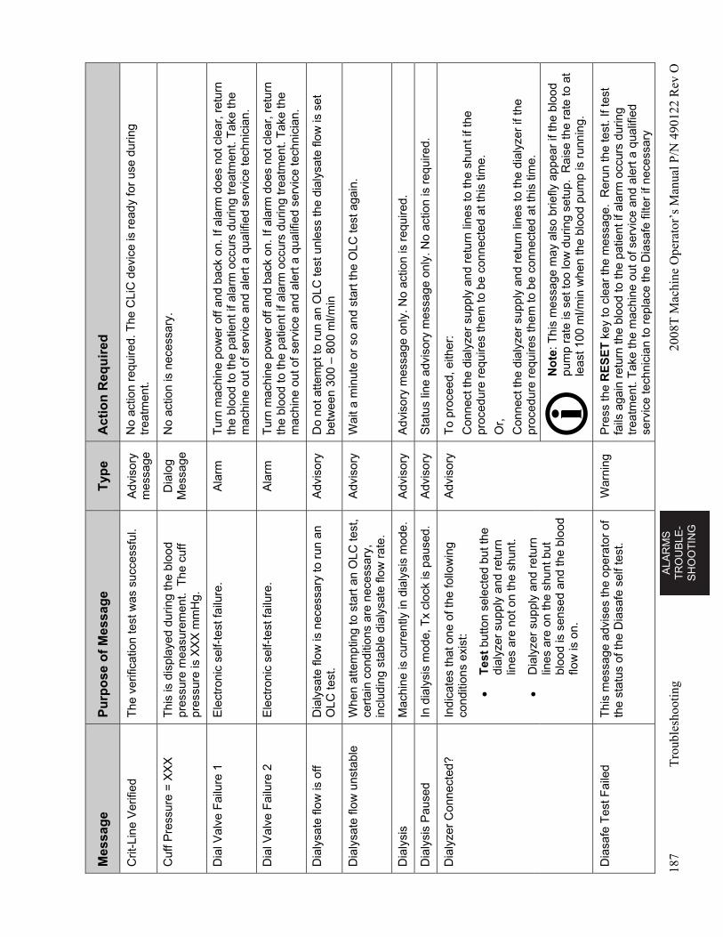
AL
AR
MS
T
RO
UB
LE
-S
HO
OT
ING
187
Tro
uble
shoo
ting
2008
T M
achi
ne O
pera
tor’
s M
anua
l P/N
490
122
Rev
O
Mes
sag
e P
urp
ose
of
Mes
sag
e T
ype
A
ctio
n R
equ
ired
Crit
-Lin
e V
erifi
ed
The
ver
ifica
tion
test
was
suc
cess
ful.
Adv
isor
y m
essa
ge
No
actio
n re
quire
d. T
he C
LiC
dev
ice
is r
eady
for
use
durin
g tr
eatm
ent.
Cuf
f Pre
ssur
e =
XX
X
Thi
s is
dis
play
ed d
urin
g th
e bl
ood
pres
sure
mea
sure
men
t. T
he c
uff
pres
sure
is X
XX
mm
Hg.
Dia
log
Mes
sage
N
o ac
tion
is n
eces
sary
.
Dia
l Val
ve F
ailu
re 1
E
lect
roni
c se
lf-te
st fa
ilure
. A
larm
T
urn
mac
hine
pow
er o
ff an
d ba
ck o
n. If
ala
rm d
oes
not c
lear
, ret
urn
the
bloo
d to
the
patie
nt if
ala
rm o
ccur
s du
ring
trea
tmen
t. T
ake
the
mac
hine
out
of s
ervi
ce a
nd a
lert
a q
ualif
ied
serv
ice
tech
nici
an.
Dia
l Val
ve F
ailu
re 2
E
lect
roni
c se
lf-te
st fa
ilure
. A
larm
T
urn
mac
hine
pow
er o
ff an
d ba
ck o
n. If
ala
rm d
oes
not c
lear
, ret
urn
the
bloo
d to
the
patie
nt if
ala
rm o
ccur
s du
ring
trea
tmen
t. T
ake
the
mac
hine
out
of s
ervi
ce a
nd a
lert
a q
ualif
ied
serv
ice
tech
nici
an.
Dia
lysa
te fl
ow is
off
Dia
lysa
te fl
ow is
nec
essa
ry to
run
an
OLC
test
. A
dvis
ory
Do
not a
ttem
pt to
run
an
OLC
test
unl
ess
the
dial
ysat
e flo
w is
set
be
twee
n 30
0 –
800
ml/m
in
Dia
lysa
te fl
ow u
nsta
ble
Whe
n a
ttem
ptin
g to
sta
rt a
n O
LC te
st,
cert
ain
cond
ition
s ar
e ne
cess
ary,
in
clud
ing
stab
le d
ialy
sate
flow
rat
e.
Adv
isor
y W
ait a
min
ute
or s
o an
d st
art t
he O
LC te
st a
gain
.
Dia
lysi
s M
achi
ne is
cur
rent
ly in
dia
lysi
s m
ode.
A
dvis
ory
Adv
isor
y m
essa
ge o
nly.
No
actio
n is
req
uire
d.
Dia
lysi
s P
ause
d In
dia
lysi
s m
ode,
Tx
cloc
k is
pau
sed.
A
dvis
ory
S
tatu
s lin
e ad
viso
ry m
essa
ge o
nly.
No
actio
n is
req
uire
d.
Dia
lyze
r C
onne
cted
? In
dica
tes
that
one
of t
he fo
llow
ing
cond
ition
s ex
ist:
T
est
butto
n se
lect
ed b
ut th
e di
alyz
er s
uppl
y an
d re
turn
lin
es a
re n
ot o
n th
e sh
unt.
D
ialy
zer
supp
ly a
nd r
etur
n lin
es a
re o
n th
e sh
unt b
ut
bloo
d is
sen
sed
and
the
bloo
d flo
w is
on.
Adv
isor
y T
o pr
ocee
d, e
ither
:
Con
nect
the
dial
yzer
sup
ply
and
retu
rn li
nes
to th
e sh
unt i
f the
pr
oced
ure
requ
ires
them
to b
e co
nnec
ted
at th
is ti
me.
Or,
Con
nect
the
dial
yzer
sup
ply
and
retu
rn li
nes
to th
e di
alyz
er if
the
proc
edur
e re
quire
s th
em to
be
conn
ecte
d at
this
tim
e.
No
te: T
his
mes
sage
may
als
o br
iefly
app
ear
if th
e bl
ood
pum
p ra
te is
set
too
low
dur
ing
setu
p. R
aise
the
rate
to a
t le
ast 1
00 m
l/min
whe
n th
e bl
ood
pum
p is
run
ning
.
Dia
safe
Tes
t Fai
led
Thi
s m
essa
ge a
dvis
es th
e op
erat
or o
f th
e st
atus
of t
he D
iasa
fe s
elf t
est.
War
ning
P
ress
the
RE
SE
T k
ey to
cle
ar th
e m
essa
ge.
Rer
un th
e te
st. I
f tes
t fa
ils a
gain
ret
urn
the
bloo
d to
the
patie
nt if
ala
rm o
ccur
s du
ring
trea
tmen
t. T
ake
the
mac
hine
out
of s
ervi
ce a
nd a
lert
a q
ualif
ied
serv
ice
tech
nici
an to
rep
lace
the
Dia
safe
filte
r if
nece
ssar
y
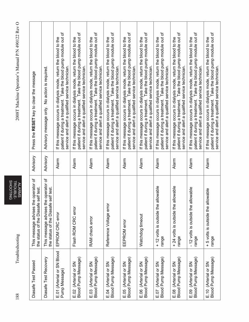
ALA
RM
S
TR
OU
BL
E-
SH
OO
TIN
G
188
Tro
uble
shoo
ting
2008
T M
achi
ne O
pera
tor’
s M
anua
l P/N
490
122
Rev
O
Dia
safe
Tes
t Pas
sed
T
his
mes
sage
adv
ises
the
oper
ator
of
the
stat
us o
f the
Dia
safe
sel
f tes
t. A
dvis
ory
Pre
ss th
e R
ES
ET
key
to c
lear
the
mes
sage
Dia
safe
Tes
t Rec
over
y T
his
mes
sage
adv
ises
the
oper
ator
of
the
stat
us o
f the
Dia
safe
sel
f tes
t. A
dvis
ory
Adv
isor
y m
essa
ge o
nly.
No
actio
n is
req
uire
d.
E.0
1 (A
rter
ial o
r S
N B
lood
P
ump
Mes
sage
) E
PR
OM
CR
C e
rror
A
larm
If
this
mes
sage
occ
urs
in d
ialy
sis
mod
e, r
etur
n th
e bl
ood
to th
e pa
tient
if d
urin
g a
trea
tmen
t. T
ake
the
bloo
d pu
mp
mod
ule
out o
f se
rvic
e an
d al
ert a
qua
lifie
d se
rvic
e te
chni
cian
.
E.0
2 (
Art
eria
l or
SN
B
lood
Pum
p M
essa
ge)
Fla
sh R
OM
CR
C e
rror
A
larm
If
this
mes
sage
occ
urs
in d
ialy
sis
mod
e, r
etur
n th
e bl
ood
to th
e pa
tient
if d
urin
g a
trea
tmen
t. T
ake
the
bloo
d pu
mp
mod
ule
out o
f se
rvic
e an
d al
ert a
qua
lifie
d se
rvic
e te
chni
cian
.
E.0
3 (
Art
eria
l or
SN
B
lood
Pum
p M
essa
ge)
RA
M c
heck
err
or
Ala
rm
If th
is m
essa
ge o
ccur
s in
dia
lysi
s m
ode,
ret
urn
the
bloo
d to
the
patie
nt if
dur
ing
a tr
eatm
ent.
Tak
e th
e bl
ood
pum
p m
odul
e ou
t of
serv
ice
and
aler
t a q
ualif
ied
serv
ice
tech
nici
an.
E.0
4 (
Art
eria
l or
SN
B
lood
Pum
p M
essa
ge)
Ref
eren
ce V
olta
ge e
rror
A
larm
If
this
mes
sage
occ
urs
in d
ialy
sis
mod
e, r
etur
n th
e bl
ood
to th
e pa
tient
if d
urin
g a
trea
tmen
t. T
ake
the
bloo
d pu
mp
mod
ule
out o
f se
rvic
e an
d al
ert a
qua
lifie
d se
rvic
e te
chni
cian
.
E.0
5 (
Art
eria
l or
SN
B
lood
Pum
p M
essa
ge)
EE
PR
OM
err
or
Ala
rm
If th
is m
essa
ge o
ccur
s in
dia
lysi
s m
ode,
ret
urn
the
bloo
d to
the
patie
nt if
dur
ing
a tr
eatm
ent.
Tak
e th
e bl
ood
pum
p m
odul
e ou
t of
serv
ice
and
aler
t a q
ualif
ied
serv
ice
tech
nici
an.
E.0
6 (
Art
eria
l or
SN
B
lood
Pum
p M
essa
ge)
Wat
chdo
g tim
eout
A
larm
If
this
mes
sage
occ
urs
in d
ialy
sis
mod
e, r
etur
n th
e bl
ood
to th
e pa
tient
if d
urin
g a
trea
tmen
t. T
ake
the
bloo
d pu
mp
mod
ule
out o
f se
rvic
e an
d al
ert a
qua
lifie
d se
rvic
e te
chni
cian
.
E.0
7 (
Art
eria
l or
SN
B
lood
Pum
p M
essa
ge)
+ 1
2 vo
lts is
out
side
the
allo
wab
le
rang
e A
larm
If
this
mes
sage
occ
urs
in d
ialy
sis
mod
e, r
etur
n th
e bl
ood
to th
e pa
tient
if d
urin
g a
trea
tmen
t. T
ake
the
bloo
d pu
mp
mod
ule
out o
f se
rvic
e an
d al
ert a
qua
lifie
d se
rvic
e te
chni
cian
.
E.0
8 (
Art
eria
l or
SN
B
lood
Pum
p M
essa
ge)
+ 2
4 vo
lts is
out
side
the
allo
wab
le
rang
e A
larm
If
this
mes
sage
occ
urs
in d
ialy
sis
mod
e, r
etur
n th
e bl
ood
to th
e pa
tient
if d
urin
g a
trea
tmen
t. T
ake
the
bloo
d pu
mp
mod
ule
out o
f se
rvic
e an
d al
ert a
qua
lifie
d se
rvic
e te
chni
cian
.
E.0
9 (
Art
eria
l or
SN
B
lood
Pum
p M
essa
ge)
- 12
vol
ts is
out
side
the
allo
wab
le
rang
e A
larm
If
this
mes
sage
occ
urs
in d
ialy
sis
mod
e, r
etur
n th
e bl
ood
to th
e pa
tient
if d
urin
g a
trea
tmen
t. T
ake
the
bloo
d pu
mp
mod
ule
out o
f se
rvic
e an
d al
ert a
qua
lifie
d se
rvic
e te
chni
cian
.
E.1
0 (
Art
eria
l or
SN
B
lood
Pum
p M
essa
ge)
+ 5
vol
ts is
out
side
the
allo
wab
le
rang
e A
larm
If
this
mes
sage
occ
urs
in d
ialy
sis
mod
e, r
etur
n th
e bl
ood
to th
e pa
tient
if d
urin
g a
trea
tmen
t. T
ake
the
bloo
d pu
mp
mod
ule
out o
f se
rvic
e an
d al
ert a
qua
lifie
d se
rvic
e te
chni
cian
.
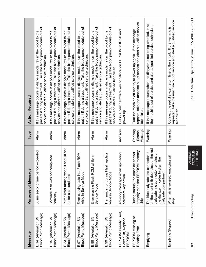
AL
AR
MS
T
RO
UB
LE
-S
HO
OT
ING
189
Tro
uble
shoo
ting
2008
T M
achi
ne O
pera
tor’
s M
anua
l P/N
490
122
Rev
O
Mes
sag
e P
urp
ose
of
Mes
sag
e T
ype
A
ctio
n R
equ
ired
E.1
4 (
Art
eria
l or
SN
B
lood
Pum
p M
essa
ge)
50 m
s se
cond
tim
e pe
riod
exce
eded
A
larm
If
this
mes
sage
occ
urs
in d
ialy
sis
mod
e, r
etur
n th
e bl
ood
to th
e pa
tient
if d
urin
g a
trea
tmen
t. T
ake
the
bloo
d pu
mp
mod
ule
out o
f se
rvic
e an
d al
ert a
qua
lifie
d se
rvic
e te
chni
cian
.
E.1
5 (
Art
eria
l or
SN
B
lood
Pum
p M
essa
ge)
Sof
twar
e ta
sk w
as n
ot c
ompl
eted
co
rrec
tly
Ala
rm
If th
is m
essa
ge o
ccur
s in
dia
lysi
s m
ode,
ret
urn
the
bloo
d to
the
patie
nt if
dur
ing
a tr
eatm
ent.
Tak
e th
e bl
ood
pum
p m
odul
e ou
t of
serv
ice
and
aler
t a q
ualif
ied
serv
ice
tech
nici
an.
E.2
3 (
Art
eria
l or
SN
B
lood
Pum
p M
essa
ge)
Pum
p ro
tor
turn
ing
whe
n it
shou
ld n
ot
be fo
r a
seco
nd ti
me
Ala
rm
If th
is m
essa
ge o
ccur
s in
dia
lysi
s m
ode,
ret
urn
the
bloo
d to
the
patie
nt if
dur
ing
a tr
eatm
ent.
Tak
e th
e bl
ood
pum
p m
odul
e ou
t of
serv
ice
and
aler
t a q
ualif
ied
serv
ice
tech
nici
an.
E.9
7 (
Art
eria
l or
SN
B
lood
Pum
p M
essa
ge)
Err
or c
opyi
ng d
ata
into
Fla
sh R
OM
w
hile
in S
ervi
ce M
ode
Ala
rm
If th
is m
essa
ge o
ccur
s in
dia
lysi
s m
ode,
ret
urn
the
bloo
d to
the
patie
nt if
dur
ing
a tr
eatm
ent.
Tak
e th
e bl
ood
pum
p m
odul
e ou
t of
serv
ice
and
aler
t a q
ualif
ied
serv
ice
tech
nici
an.
E.9
8 (
Art
eria
l or
SN
B
lood
Pum
p M
essa
ge)
Err
or e
rasi
ng F
lash
RO
M w
hile
in
Ser
vice
Mod
e A
larm
If
this
mes
sage
occ
urs
in d
ialy
sis
mod
e, r
etur
n th
e bl
ood
to th
e pa
tient
if d
urin
g a
trea
tmen
t. T
ake
the
bloo
d pu
mp
mod
ule
out o
f se
rvic
e an
d al
ert a
qua
lifie
d se
rvic
e te
chni
cian
.
E.9
9 (
Art
eria
l or
SN
B
lood
Pum
p M
essa
ge)
Tra
nsm
it er
ror
durin
g F
lash
upd
ate
whi
le in
Ser
vice
Mod
e A
larm
If
this
mes
sage
occ
urs
in d
ialy
sis
mod
e, r
etur
n th
e bl
ood
to th
e pa
tient
if d
urin
g a
trea
tmen
t. T
ake
the
bloo
d pu
mp
mod
ule
out o
f se
rvic
e an
d al
ert a
qua
lifie
d te
chni
cian
.
EE
PR
OM
alre
ady
used
, P
ower
Off,
Rep
lace
E
EP
RO
M
Adv
isor
y m
essa
ge w
hen
uplo
adin
g ha
rdw
are
key
optio
n A
dvis
ory
Put
in a
new
har
dwar
e ke
y or
cal
ibra
tion
EE
PR
OM
in IC
20
and
pow
er u
p.
EE
PR
OM
Mis
sing
or
Rea
ding
Err
or
Dur
ing
star
tup,
the
mac
hine
can
not
prop
erly
rea
d th
e E
EP
RO
M m
emor
y ch
ip
Ope
ning
S
cree
n M
essa
ge
Tur
n th
e m
achi
ne o
ff an
d tr
y to
pow
er u
p ag
ain.
If t
he m
essa
ge
repe
ats,
take
the
mac
hine
out
of
serv
ice
and
aler
t a q
ualif
ied
serv
ice
tech
nici
an.
Em
ptyi
ng
The
blu
e di
alys
ate
line
conn
ecto
r is
on
the
shun
t with
doo
r cl
osed
, the
red
di
alys
ate
line
conn
ecto
r re
mai
ns o
n th
e di
alyz
er in
ord
er to
dra
in th
e di
alys
ate
com
part
men
t.
War
ning
If
this
mes
sage
occ
urs
whe
n th
e di
alyz
er is
not
bei
ng e
mpt
ied,
take
th
e m
achi
ne o
ut o
f ser
vice
and
ale
rt a
qua
lifie
d se
rvic
e te
chni
cian
.
Em
ptyi
ng S
topp
ed
Whe
n ai
r is
sen
sed,
em
ptyi
ng w
ill
stop
. W
arni
ng
Con
nect
the
red
dial
yzer
ret
urn
line
to th
e sh
unt.
If th
e w
arni
ng is
re
peat
ed, t
ake
the
mac
hine
out
of
serv
ice
and
aler
t a q
ualif
ied
serv
ice
tech
nici
an.
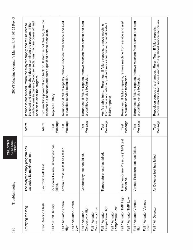
ALA
RM
S
TR
OU
BL
E-
SH
OO
TIN
G
190
Tro
uble
shoo
ting
2008
T M
achi
ne O
pera
tor’
s M
anua
l P/N
490
122
Rev
O
Em
ptyi
ng to
o lo
ng
The
dia
lyze
r em
pty
prog
ram
has
ex
ceed
ed it
s m
axim
um li
mit.
A
larm
If
bloo
d is
not
sen
sed,
ret
urn
the
dial
yzer
sup
ply
and
retu
rn li
nes
to
the
shun
t and
clo
se th
e sh
unt d
oor
to te
rmin
ate
the
prog
ram
. If
the
mac
hine
was
in d
ialy
sis
(blo
od s
ense
d), t
urn
mac
hine
pow
er o
ff an
d ba
ck o
n to
cle
ar th
e pr
ogra
m.
Err
or R
eadi
ng F
lash
E
lect
roni
c S
elf T
est
Ala
rm
Tur
n m
achi
ne p
ower
off
and
back
on.
If a
larm
is n
ot c
lear
ed, t
ake
the
mac
hine
out
of s
ervi
ce a
nd a
lert
a q
ualif
ied
serv
ice
tech
nici
an.
Fai
l * 9
Vol
t Bat
tery
9V
Pow
er F
ailu
re B
atte
ry te
st h
as
faile
d.
Tes
t M
essa
ge
Rep
lace
Bat
tery
Fai
l * A
ctua
tor
Art
eria
l H
igh
Fai
l * A
ctua
tor
Art
eria
l Lo
w
Art
eria
l Pre
ssur
e te
st h
as fa
iled.
T
est
Mes
sage
R
erun
test
, if f
ailu
re r
epea
ts, r
emov
e m
achi
ne fr
om s
ervi
ce a
nd a
lert
a
qual
ified
ser
vice
tech
nici
an.
Fai
l * A
ctua
tor
Con
duct
ivity
Hig
h
Fai
l * A
ctua
tor
Con
duct
ivity
Low
Con
duct
ivity
test
has
faile
d.
Tes
t M
essa
ge
Rer
un te
st, i
f fai
lure
rep
eats
, rem
ove
mac
hine
from
ser
vice
and
ale
rt
a qu
alifi
ed s
ervi
ce te
chni
cian
.
Fai
l * A
ctua
tor
Tem
pera
ture
Hig
h
Fai
l * A
ctua
tor
Tem
pera
ture
Low
Tem
pera
ture
test
has
faile
d.
Tes
t M
essa
ge
Ver
ify s
tabl
e te
mp.
Rer
un te
st. I
f fai
lure
rep
eats
, rem
ove
mac
hine
fr
om s
ervi
ce a
nd a
lert
a q
ualif
ied
serv
ice
tech
nici
an to
rec
alib
rate
if
failu
re r
epea
ts
Fai
l * A
ctua
tor
TM
P H
igh
Fai
l * A
ctua
tor
TM
P L
ow
Tra
nsm
embr
ane
Pre
ssur
e (T
MP
) te
st
has
faile
d.
Tes
t M
essa
ge
Rer
un te
st. I
f fai
lure
rep
eats
, rem
ove
mac
hine
from
ser
vice
and
ale
rt
a qu
alifi
ed s
ervi
ce te
chni
cian
.
Fai
l * A
ctua
tor
Ven
ous
Hig
h
Fai
l * A
ctua
tor
Ven
ous
Low
Ven
ous
Pre
ssur
e te
st h
as fa
iled.
T
est
Mes
sage
R
erun
test
, if f
ailu
re r
epea
ts, r
emov
e m
achi
ne fr
om s
ervi
ce a
nd a
lert
a
qual
ified
ser
vice
tech
nici
an.
Fai
l * A
ir D
etec
tor
Air
Det
ecto
r te
st h
as fa
iled.
T
est
Mes
sage
R
epos
ition
ven
ous
drip
cha
mbe
r. R
erun
Tes
t. If
failu
re r
epea
ts,
rem
ove
mac
hine
from
ser
vice
and
ale
rt a
qua
lifie
d se
rvic
e te
chni
cian
.
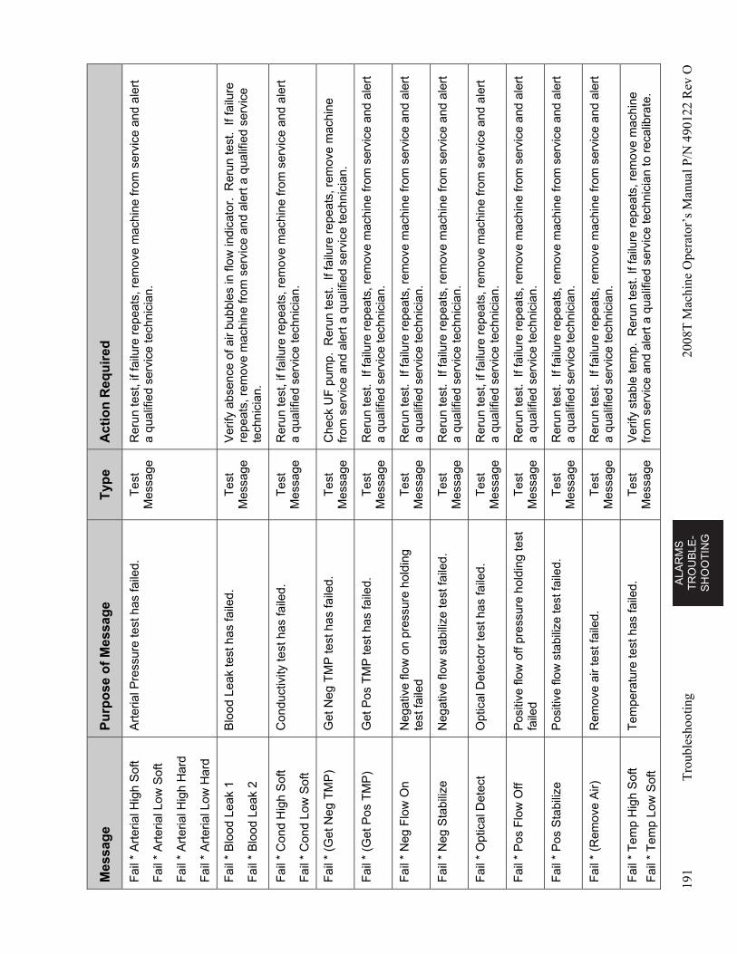
AL
AR
MS
T
RO
UB
LE
-S
HO
OT
ING
191
Tro
uble
shoo
ting
2008
T M
achi
ne O
pera
tor’
s M
anua
l P/N
490
122
Rev
O
Mes
sag
e P
urp
ose
of
Mes
sag
e T
ype
A
ctio
n R
equ
ired
Fai
l * A
rter
ial H
igh
Sof
t
Fai
l * A
rter
ial L
ow S
oft
Fai
l * A
rter
ial H
igh
Har
d
Fai
l * A
rter
ial L
ow H
ard
Art
eria
l Pre
ssur
e te
st h
as fa
iled.
T
est
Mes
sage
R
erun
test
, if f
ailu
re r
epea
ts, r
emov
e m
achi
ne fr
om s
ervi
ce a
nd a
lert
a
qual
ified
ser
vice
tech
nici
an.
Fai
l * B
lood
Lea
k 1
Fai
l * B
lood
Lea
k 2
Blo
od L
eak
test
has
faile
d.
Tes
t M
essa
ge
Ver
ify a
bsen
ce o
f air
bubb
les
in fl
ow in
dica
tor.
Rer
un te
st.
If fa
ilure
re
peat
s, r
emov
e m
achi
ne fr
om s
ervi
ce a
nd a
lert
a q
ualif
ied
serv
ice
tech
nici
an.
Fai
l * C
ond
Hig
h S
oft
Fai
l * C
ond
Low
Sof
t
Con
duct
ivity
test
has
faile
d.
Tes
t M
essa
ge
Rer
un te
st, i
f fai
lure
rep
eats
, rem
ove
mac
hine
from
ser
vice
and
ale
rt
a qu
alifi
ed s
ervi
ce te
chni
cian
.
Fai
l * (
Get
Neg
TM
P)
Get
Neg
TM
P te
st h
as fa
iled.
T
est
Mes
sage
C
heck
UF
pum
p. R
erun
test
. If
failu
re r
epea
ts, r
emov
e m
achi
ne
from
ser
vice
and
ale
rt a
qua
lifie
d se
rvic
e te
chni
cian
.
Fai
l * (
Get
Pos
TM
P)
Get
Pos
TM
P te
st h
as fa
iled.
T
est
Mes
sage
R
erun
test
. If
failu
re r
epea
ts, r
emov
e m
achi
ne fr
om s
ervi
ce a
nd a
lert
a
qual
ified
ser
vice
tech
nici
an.
Fai
l * N
eg F
low
On
Neg
ativ
e flo
w o
n pr
essu
re h
oldi
ng
test
faile
d T
est
Mes
sage
R
erun
test
. If
failu
re r
epea
ts, r
emov
e m
achi
ne fr
om s
ervi
ce a
nd a
lert
a
qual
ified
ser
vice
tech
nici
an.
Fai
l * N
eg S
tabi
lize
N
egat
ive
flow
sta
biliz
e te
st fa
iled.
T
est
Mes
sage
R
erun
test
. If
failu
re r
epea
ts, r
emov
e m
achi
ne fr
om s
ervi
ce a
nd a
lert
a
qual
ified
ser
vice
tech
nici
an.
Fai
l * O
ptic
al D
etec
t O
ptic
al D
etec
tor
test
has
faile
d.
Tes
t M
essa
ge
Rer
un te
st, i
f fai
lure
rep
eats
, rem
ove
mac
hine
from
ser
vice
and
ale
rt
a qu
alifi
ed s
ervi
ce te
chni
cian
.
Fai
l * P
os F
low
Off
Pos
itive
flow
off
pres
sure
hol
ding
test
fa
iled
Tes
t M
essa
ge
Rer
un te
st.
If fa
ilure
rep
eats
, rem
ove
mac
hine
from
ser
vice
and
ale
rt
a qu
alifi
ed s
ervi
ce te
chni
cian
.
Fai
l * P
os S
tabi
lize
P
ositi
ve fl
ow s
tabi
lize
test
faile
d.
Tes
t M
essa
ge
Rer
un te
st.
If fa
ilure
rep
eats
, rem
ove
mac
hine
from
ser
vice
and
ale
rt
a qu
alifi
ed s
ervi
ce te
chni
cian
.
Fai
l * (
Rem
ove
Air)
R
emov
e ai
r te
st fa
iled.
T
est
Mes
sage
R
erun
test
. If
failu
re r
epea
ts, r
emov
e m
achi
ne fr
om s
ervi
ce a
nd a
lert
a
qual
ified
ser
vice
tech
nici
an.
Fai
l * T
emp
Hig
h S
oft
Fai
l * T
emp
Low
Sof
t
Tem
pera
ture
test
has
faile
d.
Tes
t M
essa
ge
Ver
ify s
tabl
e te
mp.
Rer
un te
st. I
f fai
lure
rep
eats
, rem
ove
mac
hine
fr
om s
ervi
ce a
nd a
lert
a q
ualif
ied
serv
ice
tech
nici
an to
rec
alib
rate
.
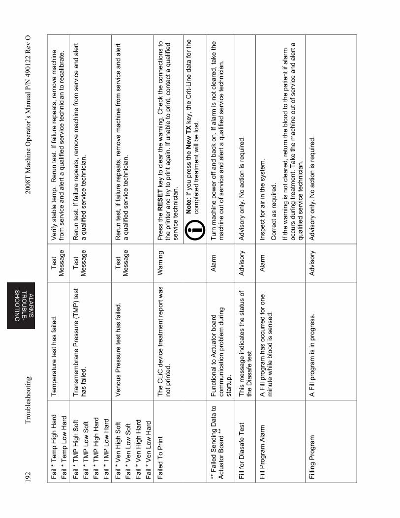
ALA
RM
S
TR
OU
BL
E-
SH
OO
TIN
G
192
Tro
uble
shoo
ting
2008
T M
achi
ne O
pera
tor’
s M
anua
l P/N
490
122
Rev
O
Fai
l * T
emp
Hig
h H
ard
Fai
l * T
emp
Low
Har
d
Tem
pera
ture
test
has
faile
d.
Tes
t M
essa
ge
Ver
ify s
tabl
e te
mp.
Rer
un te
st. I
f fai
lure
rep
eats
, rem
ove
mac
hine
fr
om s
ervi
ce a
nd a
lert
a q
ualif
ied
serv
ice
tech
nici
an to
rec
alib
rate
.
Fai
l * T
MP
Hig
h S
oft
Fai
l * T
MP
Low
Sof
t
Fai
l * T
MP
Hig
h H
ard
Fai
l * T
MP
Low
Har
d
Tra
nsm
embr
ane
Pre
ssur
e (T
MP
) te
st
has
faile
d.
Tes
t M
essa
ge
Rer
un te
st. I
f fai
lure
rep
eats
, rem
ove
mac
hine
from
ser
vice
and
ale
rt
a qu
alifi
ed s
ervi
ce te
chni
cian
.
Fai
l * V
en H
igh
Sof
t
Fai
l * V
en L
ow S
oft
Fai
l * V
en H
igh
Har
d
Fai
l * V
en L
ow H
ard
Ven
ous
Pre
ssur
e te
st h
as fa
iled.
T
est
Mes
sage
R
erun
test
, if f
ailu
re r
epea
ts, r
emov
e m
achi
ne fr
om s
ervi
ce a
nd a
lert
a
qual
ified
ser
vice
tech
nici
an.
Fai
led
To
Prin
t T
he C
LiC
dev
ice
trea
tmen
t rep
ort w
as
not p
rinte
d.
War
ning
P
ress
the
RE
SE
T k
ey to
cle
ar th
e w
arni
ng. C
heck
the
conn
ectio
ns to
th
e pr
inte
r an
d tr
y to
prin
t aga
in. I
f una
ble
to p
rint,
cont
act a
qua
lifie
d se
rvic
e te
chni
cian
.
No
te: I
f you
pre
ss th
e N
ew T
X k
ey, t
he C
rit-L
ine
data
for
the
com
plet
ed tr
eatm
ent w
ill b
e lo
st.
** F
aile
d S
endi
ng D
ata
to
Act
uato
r B
oard
**
Fun
ctio
nal t
o A
ctua
tor
boar
d co
mm
unic
atio
n pr
oble
m d
urin
g st
artu
p.
Ala
rm
Tur
n m
achi
ne p
ower
off
and
back
on.
If a
larm
is n
ot c
lear
ed, t
ake
the
mac
hine
out
of s
ervi
ce a
nd a
lert
a q
ualif
ied
serv
ice
tech
nici
an.
Fill
for
Dia
safe
Tes
t T
his
mes
sage
indi
cate
s th
e st
atus
of
the
Dia
safe
test
A
dvis
ory
Adv
isor
y on
ly. N
o ac
tion
is r
equi
red.
Fill
Pro
gram
Ala
rm
A F
ill p
rogr
am h
as o
ccur
red
for
one
min
ute
whi
le b
lood
is s
ense
d.
Ala
rm
Insp
ect f
or a
ir in
the
syst
em.
Cor
rect
as
requ
ired.
If th
e w
arni
ng is
not
cle
ared
, ret
urn
the
bloo
d to
the
patie
nt if
ala
rm
occu
rs d
urin
g tr
eatm
ent.
Tak
e th
e m
achi
ne o
ut o
f ser
vice
and
ale
rt a
qu
alifi
ed s
ervi
ce te
chni
cian
.
Fill
ing
Pro
gram
A
Fill
pro
gram
is in
pro
gres
s.
Adv
isor
y A
dvis
ory
only
. No
actio
n is
req
uire
d.
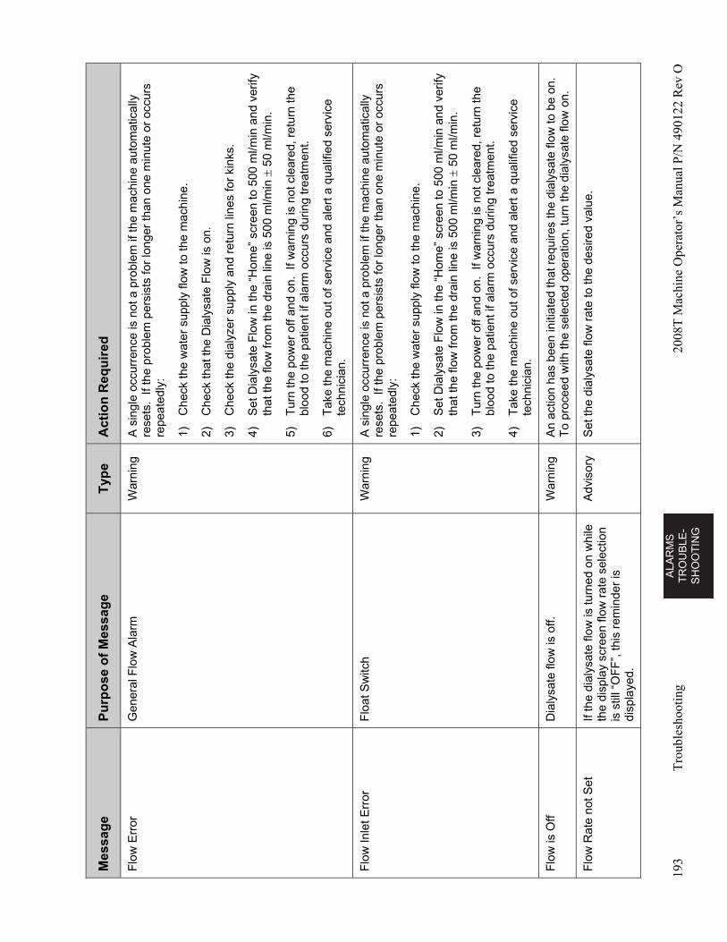
AL
AR
MS
T
RO
UB
LE
-S
HO
OT
ING
193
Tro
uble
shoo
ting
2008
T M
achi
ne O
pera
tor’
s M
anua
l P/N
490
122
Rev
O
Mes
sag
e P
urp
ose
of
Mes
sag
e T
ype
A
ctio
n R
equ
ired
Flo
w E
rror
G
ener
al F
low
Ala
rm
War
ning
A
sin
gle
occu
rren
ce is
not
a p
robl
em if
the
mac
hine
aut
omat
ical
ly
rese
ts.
If th
e pr
oble
m p
ersi
sts
for
long
er th
an o
ne m
inut
e or
occ
urs
repe
ated
ly:
1)
Che
ck th
e w
ater
sup
ply
flow
to th
e m
achi
ne.
2)
Che
ck th
at th
e D
ialy
sate
Flo
w is
on.
3)
Che
ck th
e di
alyz
er s
uppl
y an
d re
turn
line
s fo
r ki
nks.
4)
Set
Dia
lysa
te F
low
in th
e “H
ome”
scr
een
to 5
00 m
l/min
and
ver
ify
that
the
flow
from
the
drai
n lin
e is
500
ml/m
in
50
ml/m
in.
5)
Tur
n th
e po
wer
off
and
on.
If w
arni
ng is
not
cle
ared
, ret
urn
the
bloo
d to
the
patie
nt if
ala
rm o
ccur
s du
ring
trea
tmen
t.
6)
Tak
e th
e m
achi
ne o
ut o
f ser
vice
and
ale
rt a
qua
lifie
d se
rvic
e te
chni
cian
.
Flo
w In
let E
rror
F
loat
Sw
itch
W
arni
ng
A s
ingl
e oc
curr
ence
is n
ot a
pro
blem
if th
e m
achi
ne a
utom
atic
ally
re
sets
. If
the
prob
lem
per
sist
s fo
r lo
nger
than
one
min
ute
or o
ccur
s re
peat
edly
:
1)
Che
ck th
e w
ater
sup
ply
flow
to th
e m
achi
ne.
2)
Set
Dia
lysa
te F
low
in th
e “H
ome”
scr
een
to 5
00 m
l/min
and
ver
ify
that
the
flow
from
the
drai
n lin
e is
500
ml/m
in
50
ml/m
in.
3)
Tur
n th
e po
wer
off
and
on.
If w
arni
ng is
not
cle
ared
, ret
urn
the
bloo
d to
the
patie
nt if
ala
rm o
ccur
s du
ring
trea
tmen
t.
4)
Tak
e th
e m
achi
ne o
ut o
f ser
vice
and
ale
rt a
qua
lifie
d se
rvic
e te
chni
cian
.
Flo
w is
Off
Dia
lysa
te fl
ow is
off.
W
arni
ng
An
actio
n ha
s be
en in
itiat
ed th
at r
equi
res
the
dial
ysat
e flo
w to
be
on.
To
proc
eed
with
the
sele
cted
ope
ratio
n, tu
rn th
e di
alys
ate
flow
on.
Flo
w R
ate
not S
et
If th
e di
alys
ate
flow
is tu
rned
on
whi
le
the
disp
lay
scre
en fl
ow r
ate
sele
ctio
n is
stil
l “O
FF
”, th
is r
emin
der
is
disp
laye
d.
Adv
isor
y S
et th
e di
alys
ate
flow
rat
e to
the
desi
red
valu
e.
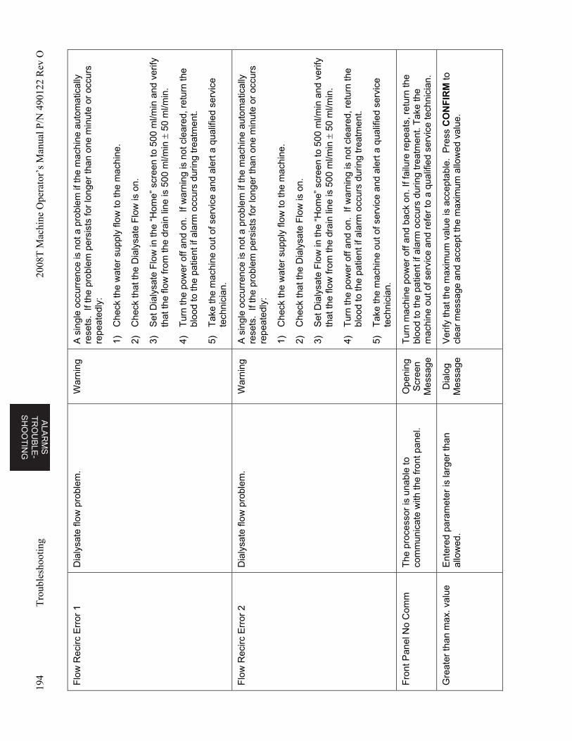
ALA
RM
S
TR
OU
BL
E-
SH
OO
TIN
G
194
Tro
uble
shoo
ting
2008
T M
achi
ne O
pera
tor’
s M
anua
l P/N
490
122
Rev
O
Flo
w R
ecirc
Err
or 1
D
ialy
sate
flow
pro
blem
. W
arni
ng
A s
ingl
e oc
curr
ence
is n
ot a
pro
blem
if th
e m
achi
ne a
utom
atic
ally
re
sets
. If
the
prob
lem
per
sist
s fo
r lo
nger
than
one
min
ute
or o
ccur
s re
peat
edly
:
1)
Che
ck th
e w
ater
sup
ply
flow
to th
e m
achi
ne.
2)
Che
ck th
at th
e D
ialy
sate
Flo
w is
on.
3)
Set
Dia
lysa
te F
low
in th
e “H
ome”
scr
een
to 5
00 m
l/min
and
ver
ify
that
the
flow
from
the
drai
n lin
e is
500
ml/m
in
50
ml/m
in.
4)
Tur
n th
e po
wer
off
and
on.
If w
arni
ng is
not
cle
ared
, ret
urn
the
bloo
d to
the
patie
nt if
ala
rm o
ccur
s du
ring
trea
tmen
t.
5)
Tak
e th
e m
achi
ne o
ut o
f ser
vice
and
ale
rt a
qua
lifie
d se
rvic
e te
chni
cian
.
Flo
w R
ecirc
Err
or 2
D
ialy
sate
flow
pro
blem
. W
arni
ng
A s
ingl
e oc
curr
ence
is n
ot a
pro
blem
if th
e m
achi
ne a
utom
atic
ally
re
sets
. If
the
prob
lem
per
sist
s fo
r lo
nger
than
one
min
ute
or o
ccur
s re
peat
edly
:
1)
Che
ck th
e w
ater
sup
ply
flow
to th
e m
achi
ne.
2)
Che
ck th
at th
e D
ialy
sate
Flo
w is
on.
3)
Set
Dia
lysa
te F
low
in th
e “H
ome”
scr
een
to 5
00 m
l/min
and
ver
ify
that
the
flow
from
the
drai
n lin
e is
500
ml/m
in
50
ml/m
in.
4)
Tur
n th
e po
wer
off
and
on.
If w
arni
ng is
not
cle
ared
, ret
urn
the
bloo
d to
the
patie
nt if
ala
rm o
ccur
s du
ring
trea
tmen
t.
5)
Tak
e th
e m
achi
ne o
ut o
f ser
vice
and
ale
rt a
qua
lifie
d se
rvic
e te
chni
cian
.
Fro
nt P
anel
No
Com
m
The
pro
cess
or is
una
ble
to
com
mun
icat
e w
ith th
e fr
ont p
anel
. O
peni
ng
Scr
een
Mes
sage
Tur
n m
achi
ne p
ower
off
and
back
on.
If fa
ilure
rep
eats
, ret
urn
the
bloo
d to
the
patie
nt if
ala
rm o
ccur
s du
ring
trea
tmen
t. T
ake
the
mac
hine
out
of s
ervi
ce a
nd r
efer
to a
qua
lifie
d se
rvic
e te
chni
cian
.
Gre
ater
than
max
. val
ue
Ent
ered
par
amet
er is
larg
er th
an
allo
wed
. D
ialo
g M
essa
ge
Ver
ify th
at th
e m
axim
um v
alue
is a
ccep
tabl
e. P
ress
CO
NF
IRM
to
clea
r m
essa
ge a
nd a
ccep
t the
max
imum
allo
wed
val
ue.
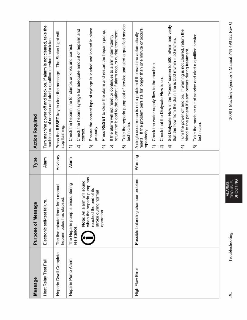
AL
AR
MS
T
RO
UB
LE
-S
HO
OT
ING
195
Tro
uble
shoo
ting
2008
T M
achi
ne O
pera
tor’
s M
anua
l P/N
490
122
Rev
O
Mes
sag
e P
urp
ose
of
Mes
sag
e T
ype
A
ctio
n R
equ
ired
Hea
t Rel
ay T
est F
ail
Ele
ctro
nic
self-
test
failu
re.
Ala
rm
Tur
n m
achi
ne p
ower
off
and
back
on.
If a
larm
is n
ot c
lear
ed, t
ake
the
mac
hine
out
of s
ervi
ce a
nd a
lert
a q
ualif
ied
serv
ice
tech
nici
an.
Hep
arin
Dw
ell C
ompl
ete
The
five
min
ute
timer
for
a m
anua
l he
parin
bol
us h
as e
laps
ed.
Adv
isor
y P
ress
the
RE
SE
T k
ey to
cle
ar th
e m
essa
ge.
The
Sta
tus
Ligh
t will
st
op fl
ashi
ng.
Hep
arin
Pum
p A
larm
T
he H
epar
in p
ump
is e
ncou
nter
ing
resi
stan
ce.
Ala
rm
1)
Che
ck th
e he
parin
line
for
clam
ps o
r ki
nks
and
corr
ect.
2)
Che
ck th
e he
parin
syr
inge
for
adeq
uate
am
ount
of h
epar
in a
nd
corr
ect.
3)
Ens
ure
the
corr
ect t
ype
of s
yrin
ge is
load
ed a
nd lo
cked
in p
lace
pr
oper
ly.
4)
Pre
ss R
ES
ET
to c
lear
the
alar
m a
nd r
esta
rt th
e he
parin
pum
p.
5)
If th
e al
arm
will
not
res
et o
r co
ntin
ues
to a
larm
inte
rmitt
ently
, re
turn
the
bloo
d to
the
patie
nt if
ala
rm o
ccur
s du
ring
trea
tmen
t.
6)
Tak
e th
e he
parin
pum
p ou
t of s
ervi
ce a
nd a
lert
a q
ualif
ied
serv
ice
tech
nici
an.
No
te: A
n al
arm
will
sou
nd
whe
n th
e he
parin
pum
p ha
s re
ache
d th
e en
d of
its
stro
ke d
urin
g no
rmal
op
erat
ion.
Hig
h F
low
Err
or
Pos
sibl
e ba
lanc
ing
cham
ber
prob
lem
. W
arni
ng
A s
ingl
e oc
curr
ence
is n
ot a
pro
blem
if th
e m
achi
ne a
utom
atic
ally
re
sets
. If
the
prob
lem
per
sist
s fo
r lo
nger
than
one
min
ute
or o
ccur
s re
peat
edly
:
1)
Che
ck th
e w
ater
sup
ply
flow
to th
e m
achi
ne.
2)
Che
ck th
at th
e D
ialy
sate
Flo
w is
on.
3)
Set
Dia
lysa
te F
low
in th
e “H
ome”
scr
een
to 5
00 m
l/min
and
ver
ify
that
the
flow
from
the
drai
n lin
e is
500
ml/m
in
50
ml/m
in.
4)
Tur
n th
e po
wer
off
and
on.
If w
arni
ng is
not
cle
ared
, ret
urn
the
bloo
d to
the
patie
nt if
ala
rm o
ccur
s du
ring
trea
tmen
t.
5)
Tak
e th
e m
achi
ne o
ut o
f ser
vice
and
ale
rt a
qua
lifie
d se
rvic
e te
chni
cian
.
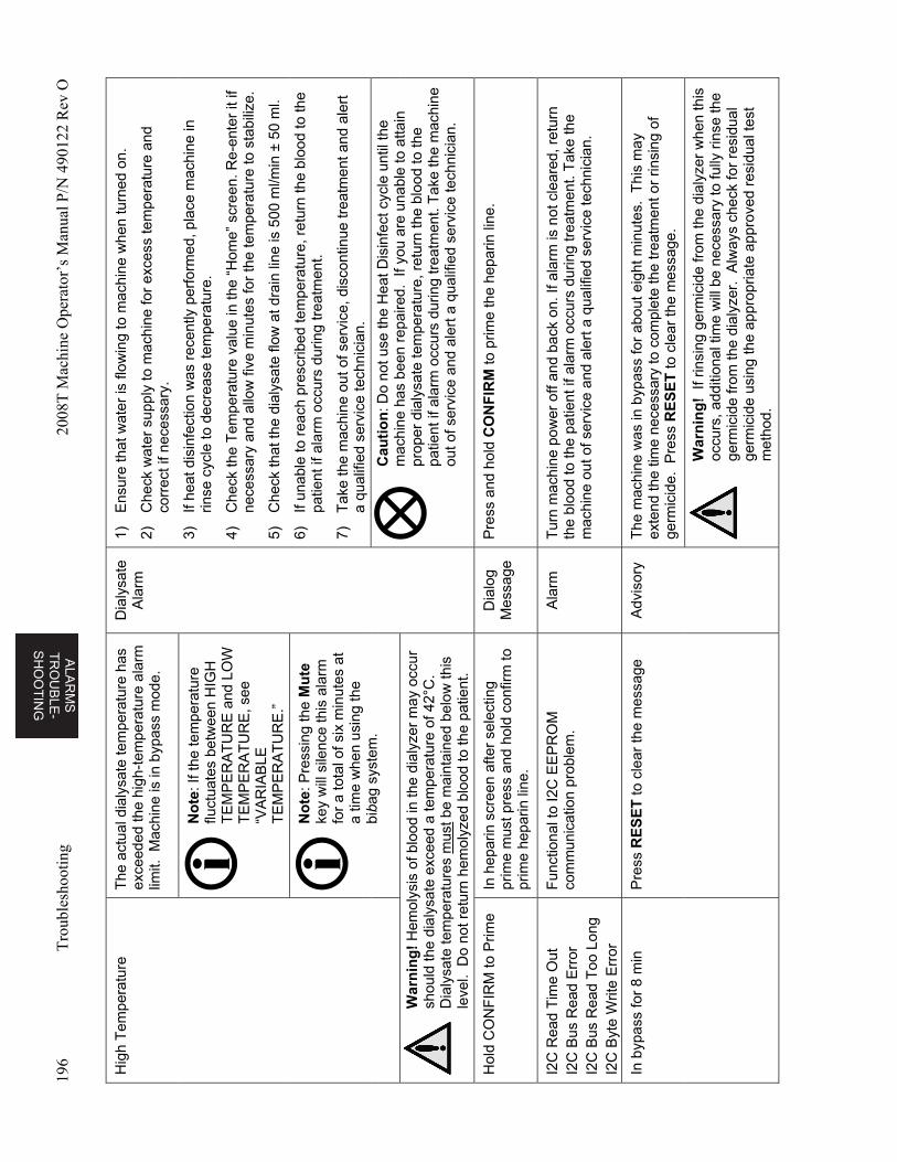
ALA
RM
S
TR
OU
BL
E-
SH
OO
TIN
G
196
Tro
uble
shoo
ting
2008
T M
achi
ne O
pera
tor’
s M
anua
l P/N
490
122
Rev
O
Hig
h T
empe
ratu
re
The
act
ual d
ialy
sate
tem
pera
ture
has
ex
ceed
ed th
e hi
gh-t
empe
ratu
re a
larm
lim
it. M
achi
ne is
in b
ypas
s m
ode.
Dia
lysa
te
Ala
rm
1)
Ens
ure
that
wat
er is
flow
ing
to m
achi
ne w
hen
turn
ed o
n.
2)
Che
ck w
ater
sup
ply
to m
achi
ne fo
r ex
cess
tem
pera
ture
and
co
rrec
t if n
eces
sary
.
3)
If he
at d
isin
fect
ion
was
rec
ently
per
form
ed, p
lace
mac
hine
in
rinse
cyc
le to
dec
reas
e te
mpe
ratu
re.
4)
Che
ck th
e T
empe
ratu
re v
alue
in th
e “H
ome”
scr
een.
Re-
ente
r it
if ne
cess
ary
and
allo
w fi
ve m
inut
es fo
r th
e te
mpe
ratu
re to
sta
biliz
e.
5)
Che
ck th
at th
e di
alys
ate
flow
at d
rain
line
is 5
00 m
l/min
± 5
0 m
l.
6)
If un
able
to r
each
pre
scrib
ed te
mpe
ratu
re, r
etur
n th
e bl
ood
to th
e pa
tient
if a
larm
occ
urs
durin
g tr
eatm
ent.
7)
Tak
e th
e m
achi
ne o
ut o
f ser
vice
, dis
cont
inue
trea
tmen
t and
ale
rt
a qu
alifi
ed s
ervi
ce te
chni
cian
.
No
te: I
f the
tem
pera
ture
flu
ctua
tes
betw
een
HIG
H
TE
MP
ER
AT
UR
E a
nd L
OW
T
EM
PE
RA
TU
RE
, see
“V
AR
IAB
LE
TE
MP
ER
AT
UR
E.”
No
te: P
ress
ing
the
Mu
te
key
will
sile
nce
this
ala
rm
for
a to
tal o
f six
min
utes
at
a tim
e w
hen
usin
g th
e bi
bag
syst
em.
Cau
tio
n: D
o no
t use
the
Hea
t Dis
infe
ct c
ycle
unt
il th
e m
achi
ne h
as b
een
repa
ired.
If y
ou a
re u
nabl
e to
atta
in
prop
er d
ialy
sate
tem
pera
ture
, ret
urn
the
bloo
d to
the
patie
nt if
ala
rm o
ccur
s du
ring
trea
tmen
t. T
ake
the
mac
hine
ou
t of s
ervi
ce a
nd a
lert
a q
ualif
ied
serv
ice
tech
nici
an.
War
nin
g!
Hem
olys
is o
f blo
od in
the
dial
yzer
may
occ
ur
shou
ld th
e di
alys
ate
exce
ed a
tem
pera
ture
of 4
2°C
. D
ialy
sate
tem
pera
ture
s m
ust b
e m
aint
aine
d be
low
this
le
vel.
Do
not r
etur
n he
mol
yzed
blo
od to
the
patie
nt.
Hol
d C
ON
FIR
M to
Prim
e In
hep
arin
scr
een
afte
r se
lect
ing
prim
e m
ust p
ress
and
hol
d co
nfirm
to
prim
e he
parin
line
.
Dia
log
Mes
sage
P
ress
and
hol
d C
ON
FIR
M to
prim
e th
e he
parin
line
.
I2C
Rea
d T
ime
Out
I2
C B
us R
ead
Err
or
I2C
Bus
Rea
d T
oo L
ong
I2C
Byt
e W
rite
Err
or
Fun
ctio
nal t
o I2
C E
EP
RO
M
com
mun
icat
ion
prob
lem
. A
larm
T
urn
mac
hine
pow
er o
ff an
d ba
ck o
n. If
ala
rm is
not
cle
ared
, ret
urn
the
bloo
d to
the
patie
nt if
ala
rm o
ccur
s du
ring
trea
tmen
t. T
ake
the
mac
hine
out
of s
ervi
ce a
nd a
lert
a q
ualif
ied
serv
ice
tech
nici
an.
In b
ypas
s fo
r 8
min
P
ress
RE
SE
T to
cle
ar th
e m
essa
ge
Adv
isor
y T
he m
achi
ne w
as in
byp
ass
for
abou
t eig
ht m
inut
es.
Thi
s m
ay
exte
nd th
e tim
e ne
cess
ary
to c
ompl
ete
the
trea
tmen
t or
rinsi
ng o
f ge
rmic
ide.
Pre
ss R
ES
ET
to c
lear
the
mes
sage
.
W
arn
ing
! If
rin
sing
ger
mic
ide
from
the
dial
yzer
whe
n th
is
occu
rs, a
dditi
onal
tim
e w
ill b
e ne
cess
ary
to fu
lly r
inse
the
germ
icid
e fr
om th
e di
alyz
er.
Alw
ays
chec
k fo
r re
sidu
al
germ
icid
e us
ing
the
appr
opria
te a
ppro
ved
resi
dual
test
m
etho
d.
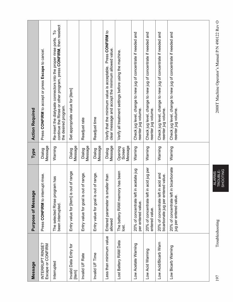
AL
AR
MS
T
RO
UB
LE
-S
HO
OT
ING
197
Tro
uble
shoo
ting
2008
T M
achi
ne O
pera
tor’
s M
anua
l P/N
490
122
Rev
O
Mes
sag
e P
urp
ose
of
Mes
sag
e T
ype
A
ctio
n R
equ
ired
INT
ER
RU
PT
RIN
SE
? E
scap
e or
CO
NF
IRM
P
ress
CO
NF
IRM
to in
terr
upt r
inse
. D
ialo
g M
essa
ge
Pre
ss C
ON
FIR
M to
acc
ept o
r pr
ess
Esc
ape
to c
ance
l.
Inte
rrup
ted
The
sel
ecte
d R
inse
pro
gram
has
be
en in
terr
upte
d.
War
ning
R
e-in
sert
the
dial
ysat
e co
nnec
tors
into
the
prop
er r
inse
por
ts.
To
cont
inue
the
Rin
se o
r ot
her
prog
ram
, pre
ss C
ON
FIR
M, t
hen
rese
lect
th
e de
sire
d pr
ogra
m.
Inva
lid D
ata
Ent
ry fo
r [it
em]
Ent
ry v
alue
for
[item
] is
out o
f ran
ge
Dia
log
Mes
sage
S
et a
ppro
pria
te v
alue
for
[item
]
Inva
lid U
F R
ate
Ent
ry v
alue
for
goal
is o
ut o
f ran
ge.
Dia
log
Mes
sage
R
eadj
ust r
ate
Inva
lid U
F T
ime
Ent
ry v
alue
for
goal
is o
ut o
f ran
ge.
Dia
log
Mes
sage
R
eadj
ust t
ime
Less
than
min
imum
val
ue
Ent
ered
par
amet
er is
sm
alle
r th
an
allo
wed
D
ialo
g M
essa
ge
Ver
ify th
at th
e m
inim
um v
alue
is a
ccep
tabl
e. P
ress
CO
NF
IRM
to
clea
r m
essa
ge a
nd a
ccep
t the
min
imum
allo
wed
val
ue.
Lost
Bat
tery
RA
M D
ata
The
bat
tery
RA
M m
emor
y ha
s be
en
lost
. O
peni
ng
Scr
een
Mes
sage
Ver
ify a
ll tr
eatm
ent s
ettin
gs b
efor
e us
ing
the
mac
hine
.
Low
Ace
tate
War
ning
20
% o
f con
cent
rate
left
in a
ceta
te ju
g pe
r en
tere
d va
lue.
W
arni
ng
Che
ck ju
g le
vel,
chan
ge to
new
jug
of c
once
ntra
te if
nee
ded
and
reen
ter
jug
volu
me.
Low
Aci
d W
arni
ng
20%
of c
once
ntra
te le
ft in
aci
d ju
g pe
r en
tere
d va
lue.
W
arni
ng
Che
ck ju
g le
vel,
chan
ge to
new
jug
of c
once
ntra
te if
nee
ded
and
reen
ter
jug
volu
me.
Low
Aci
d/B
icar
b W
arn
20%
of c
once
ntra
te le
ft in
aci
d an
d bi
carb
onat
e ju
g pe
r en
tere
d va
lue.
W
arni
ng
Che
ck ju
g le
vel,
chan
ge to
new
jug
of c
once
ntra
te if
nee
ded
and
reen
ter
jug
volu
me.
Low
Bic
arb
War
ning
20
% o
f con
cent
rate
left
in b
icar
bona
te
jug
per
ente
red
valu
e.
War
ning
C
heck
jug
leve
l, ch
ange
to n
ew ju
g of
con
cent
rate
if n
eede
d an
d re
ente
r ju
g vo
lum
e.
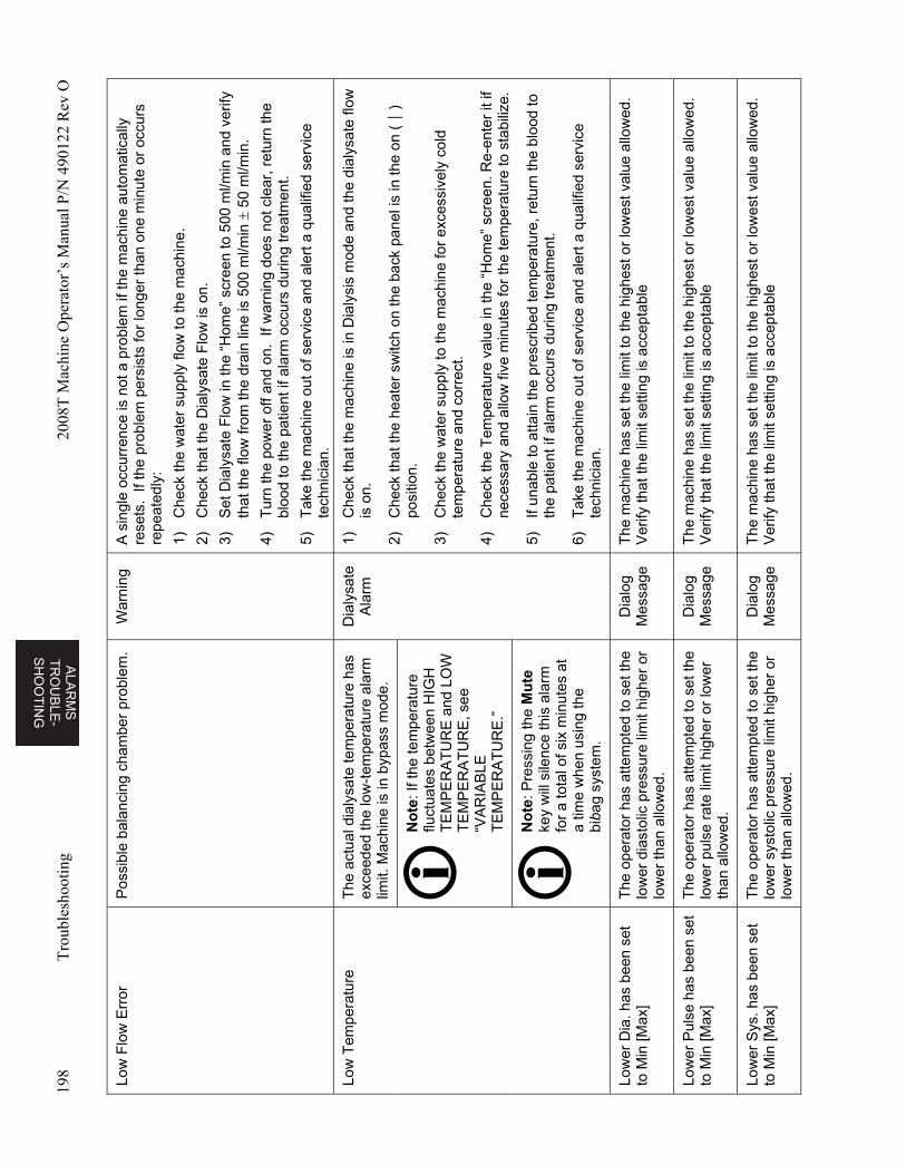
ALA
RM
S
TR
OU
BL
E-
SH
OO
TIN
G
198
Tro
uble
shoo
ting
2008
T M
achi
ne O
pera
tor’
s M
anua
l P/N
490
122
Rev
O
Low
Flo
w E
rror
P
ossi
ble
bala
ncin
g ch
ambe
r pr
oble
m.
War
ning
A
sin
gle
occu
rren
ce is
not
a p
robl
em if
the
mac
hine
aut
omat
ical
ly
rese
ts.
If th
e pr
oble
m p
ersi
sts
for
long
er th
an o
ne m
inut
e or
occ
urs
repe
ated
ly:
1)
Che
ck th
e w
ater
sup
ply
flow
to th
e m
achi
ne.
2)
Che
ck th
at th
e D
ialy
sate
Flo
w is
on.
3)
Set
Dia
lysa
te F
low
in th
e “H
ome”
scr
een
to 5
00 m
l/min
and
ver
ify
that
the
flow
from
the
drai
n lin
e is
500
ml/m
in
50
ml/m
in.
4)
Tur
n th
e po
wer
off
and
on.
If w
arni
ng d
oes
not c
lear
, ret
urn
the
bloo
d to
the
patie
nt if
ala
rm o
ccur
s du
ring
trea
tmen
t.
5)
Tak
e th
e m
achi
ne o
ut o
f ser
vice
and
ale
rt a
qua
lifie
d se
rvic
e te
chni
cian
.
Low
Tem
pera
ture
T
he a
ctua
l dia
lysa
te te
mpe
ratu
re h
as
exce
eded
the
low
-tem
pera
ture
ala
rm
limit.
Mac
hine
is in
byp
ass
mod
e.
Dia
lysa
te
Ala
rm
1)
Che
ck th
at th
e m
achi
ne is
in D
ialy
sis
mod
e an
d th
e di
alys
ate
flow
is
on.
2)
Che
ck th
at th
e he
ater
sw
itch
on th
e ba
ck p
anel
is in
the
on (
) po
sitio
n.
3)
Che
ck th
e w
ater
sup
ply
to th
e m
achi
ne fo
r ex
cess
ivel
y co
ld
tem
pera
ture
and
cor
rect
.
4)
Che
ck th
e T
empe
ratu
re v
alue
in th
e “H
ome”
scr
een.
Re-
ente
r it
if ne
cess
ary
and
allo
w fi
ve m
inut
es fo
r th
e te
mpe
ratu
re to
sta
biliz
e.
5)
If un
able
to a
ttain
the
pres
crib
ed te
mpe
ratu
re, r
etur
n th
e bl
ood
to
the
patie
nt if
ala
rm o
ccur
s du
ring
trea
tmen
t.
6)
Tak
e th
e m
achi
ne o
ut o
f ser
vice
and
ale
rt a
qua
lifie
d se
rvic
e te
chni
cian
.
No
te: I
f the
tem
pera
ture
flu
ctua
tes
betw
een
HIG
H
TE
MP
ER
AT
UR
E a
nd L
OW
T
EM
PE
RA
TU
RE
, see
“V
AR
IAB
LE
TE
MP
ER
AT
UR
E.”
No
te: P
ress
ing
the
Mu
te
key
will
sile
nce
this
ala
rm
for
a to
tal o
f six
min
utes
at
a tim
e w
hen
usin
g th
e bi
bag
syst
em.
Low
er D
ia. h
as b
een
set
to M
in [M
ax]
The
ope
rato
r ha
s at
tem
pted
to s
et th
e lo
wer
dia
stol
ic p
ress
ure
limit
high
er o
r lo
wer
than
allo
wed
.
Dia
log
Mes
sage
T
he m
achi
ne h
as s
et th
e lim
it to
the
high
est o
r lo
wes
t val
ue a
llow
ed.
Ver
ify th
at th
e lim
it se
tting
is a
ccep
tabl
e
Low
er P
ulse
has
bee
n se
t to
Min
[Max
] T
he o
pera
tor
has
atte
mpt
ed to
set
the
low
er p
ulse
rat
e lim
it hi
gher
or
low
er
than
allo
wed
.
Dia
log
Mes
sage
T
he m
achi
ne h
as s
et th
e lim
it to
the
high
est o
r lo
wes
t val
ue a
llow
ed.
Ver
ify th
at th
e lim
it se
tting
is a
ccep
tabl
e
Low
er S
ys. h
as b
een
set
to M
in [M
ax]
The
ope
rato
r ha
s at
tem
pted
to s
et th
e lo
wer
sys
tolic
pre
ssur
e lim
it hi
gher
or
low
er th
an a
llow
ed.
Dia
log
Mes
sage
T
he m
achi
ne h
as s
et th
e lim
it to
the
high
est o
r lo
wes
t val
ue a
llow
ed.
Ver
ify th
at th
e lim
it se
tting
is a
ccep
tabl
e
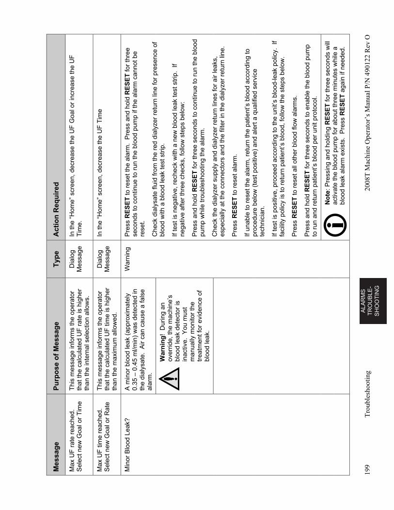
AL
AR
MS
T
RO
UB
LE
-S
HO
OT
ING
199
Tro
uble
shoo
ting
2008
T M
achi
ne O
pera
tor’
s M
anua
l P/N
490
122
Rev
O
Mes
sag
e P
urp
ose
of
Mes
sag
e T
ype
A
ctio
n R
equ
ired
Max
UF
rat
e re
ache
d.
Sel
ect n
ew G
oal o
r T
ime
Thi
s m
essa
ge in
form
s th
e op
erat
or
that
the
calc
ulat
ed U
F r
ate
is h
ighe
r th
an th
e in
tern
al s
elec
tion
allo
ws.
Dia
log
Mes
sage
In
the
“Hom
e” s
cree
n, d
ecre
ase
the
UF
Goa
l or
incr
ease
the
UF
T
ime.
Max
UF
tim
e re
ache
d.
Sel
ect n
ew G
oal o
r R
ate
Thi
s m
essa
ge in
form
s th
e op
erat
or
that
the
calc
ulat
ed U
F ti
me
is h
ighe
r th
an th
e m
axim
um a
llow
ed.
Dia
log
Mes
sage
In
the
“Hom
e” s
cree
n, d
ecre
ase
the
UF
Tim
e
Min
or B
lood
Lea
k?
A m
inor
blo
od le
ak (
appr
oxim
atel
y 0.
35 –
0.4
5 m
l/min
) w
as d
etec
ted
in
the
dial
ysat
e. A
ir ca
n ca
use
a fa
lse
alar
m.
War
ning
P
ress
RE
SE
T to
res
et th
e al
arm
. P
ress
and
hol
d R
ES
ET
for
thre
e se
cond
s to
con
tinue
to r
un th
e bl
ood
pum
p if
the
alar
m c
anno
t be
rese
t.
Che
ck d
ialy
sate
flui
d fr
om th
e re
d di
alyz
er r
etur
n lin
e fo
r pr
esen
ce o
f bl
ood
with
a b
lood
leak
test
str
ip.
If te
st is
neg
ativ
e, r
eche
ck w
ith a
new
blo
od le
ak te
st s
trip
. If
nega
tive
afte
r th
ree
chec
ks, f
ollo
w s
teps
bel
ow:
Pre
ss a
nd h
old
RE
SE
T fo
r th
ree
seco
nds
to c
ontin
ue to
run
the
bloo
d pu
mp
whi
le tr
oubl
esho
otin
g th
e al
arm
.
Che
ck th
e di
alyz
er s
uppl
y an
d di
alyz
er r
etur
n lin
es fo
r ai
r le
aks,
es
peci
ally
at t
he c
onne
ctor
s an
d th
e fil
ter
in th
e di
alyz
er r
etur
n lin
e.
Pre
ss R
ES
ET
to r
eset
ala
rm.
If un
able
to r
eset
the
alar
m, r
etur
n th
e pa
tient
’s b
lood
acc
ordi
ng to
pr
oced
ure
belo
w (
test
pos
itive
) an
d al
ert a
qua
lifie
d se
rvic
e te
chni
cian
.
If te
st is
pos
itive
, pro
ceed
acc
ordi
ng to
the
unit’
s bl
ood-
leak
pol
icy.
If
faci
lity
polic
y is
to r
etur
n pa
tient
’s b
lood
, fol
low
the
step
s be
low
.
Pre
ss R
ES
ET
to r
eset
all
othe
r bl
ood
flow
ala
rms.
Pre
ss a
nd h
old
RE
SE
T fo
r th
ree
seco
nds
to e
nabl
e th
e bl
ood
pum
p to
run
and
ret
urn
patie
nt’s
blo
od p
er u
nit p
roto
col.
War
nin
g!
Dur
ing
an
over
ride,
the
mac
hine
’s
bloo
d le
ak d
etec
tor
is
inac
tive.
You
mus
t m
anua
lly m
onito
r th
e tr
eatm
ent f
or e
vide
nce
of
bloo
d le
ak.
N
ote
: Pre
ssin
g an
d ho
ldin
g R
ES
ET
for
thre
e se
cond
s w
ill
activ
ate
the
bloo
d pu
mp
for
abou
t thr
ee m
inut
es w
hile
a
bloo
d le
ak a
larm
exi
sts.
Pre
ss R
ES
ET
aga
in if
nee
ded.
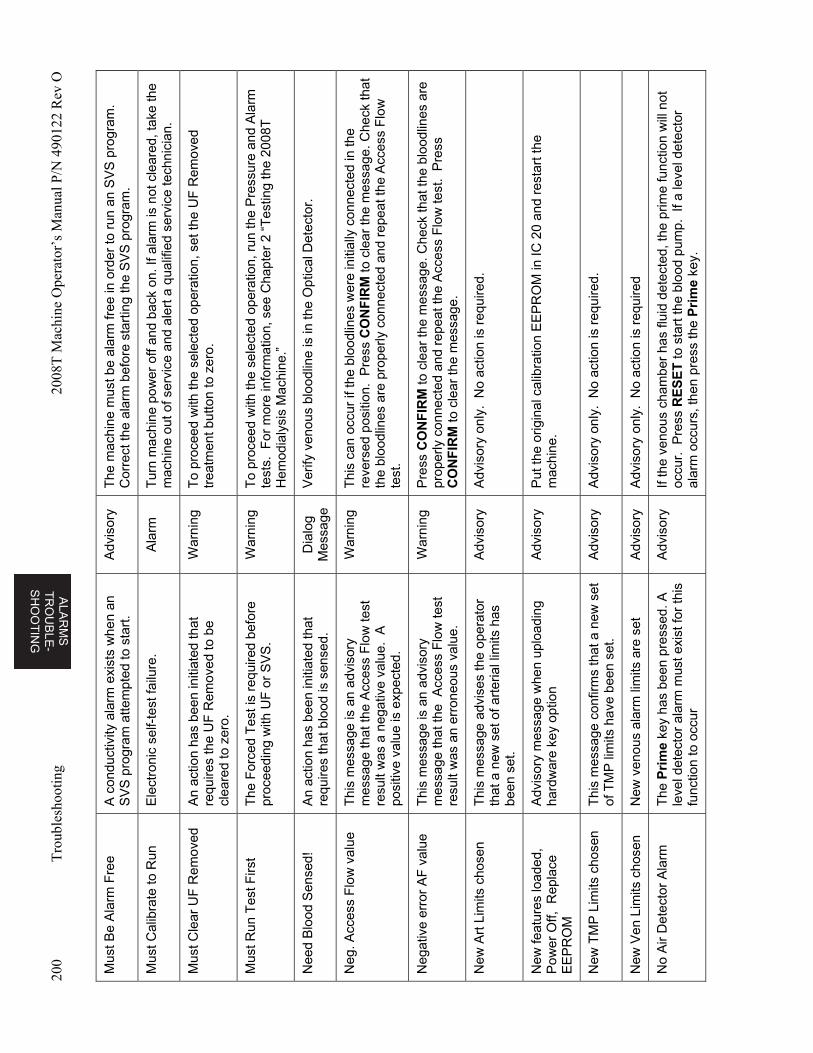
ALA
RM
S
TR
OU
BL
E-
SH
OO
TIN
G
200
Tro
uble
shoo
ting
2008
T M
achi
ne O
pera
tor’
s M
anua
l P/N
490
122
Rev
O
Mus
t Be
Ala
rm F
ree
A c
ondu
ctiv
ity a
larm
exi
sts
whe
n an
S
VS
pro
gram
atte
mpt
ed to
sta
rt.
Adv
isor
y T
he m
achi
ne m
ust b
e al
arm
free
in o
rder
to r
un a
n S
VS
pro
gram
. C
orre
ct th
e al
arm
bef
ore
star
ting
the
SV
S p
rogr
am.
Mus
t Cal
ibra
te to
Run
E
lect
roni
c se
lf-te
st fa
ilure
. A
larm
T
urn
mac
hine
pow
er o
ff an
d ba
ck o
n. If
ala
rm is
not
cle
ared
, tak
e th
e m
achi
ne o
ut o
f ser
vice
and
ale
rt a
qua
lifie
d se
rvic
e te
chni
cian
.
Mus
t Cle
ar U
F R
emov
ed
An
actio
n ha
s be
en in
itiat
ed th
at
requ
ires
the
UF
Rem
oved
to b
e cl
eare
d to
zer
o.
War
ning
T
o pr
ocee
d w
ith th
e se
lect
ed o
pera
tion,
set
the
UF
Rem
oved
tr
eatm
ent b
utto
n to
zer
o.
Mus
t Run
Tes
t Firs
t T
he F
orce
d T
est i
s re
quire
d be
fore
pr
ocee
ding
with
UF
or
SV
S.
War
ning
T
o pr
ocee
d w
ith th
e se
lect
ed o
pera
tion,
run
the
Pre
ssur
e an
d A
larm
te
sts.
For
mor
e in
form
atio
n, s
ee C
hapt
er 2
“T
estin
g th
e 20
08T
H
emod
ialy
sis
Mac
hine
.”
Nee
d B
lood
Sen
sed!
A
n ac
tion
has
been
initi
ated
that
re
quire
s th
at b
lood
is s
ense
d.
Dia
log
Mes
sage
V
erify
ven
ous
bloo
dlin
e is
in th
e O
ptic
al D
etec
tor.
Neg
. Acc
ess
Flo
w v
alue
T
his
mes
sage
is a
n ad
viso
ry
mes
sage
that
the
Acc
ess
Flo
w te
st
resu
lt w
as a
neg
ativ
e va
lue.
A
posi
tive
valu
e is
exp
ecte
d.
War
ning
T
his
can
occu
r if
the
bloo
dlin
es w
ere
initi
ally
con
nect
ed in
the
reve
rsed
pos
ition
. P
ress
CO
NF
IRM
to c
lear
the
mes
sage
. Che
ck th
at
the
bloo
dlin
es a
re p
rope
rly c
onne
cted
and
rep
eat t
he A
cces
s F
low
te
st.
Neg
ativ
e er
ror
AF
val
ue
Thi
s m
essa
ge is
an
advi
sory
m
essa
ge th
at th
e A
cces
s F
low
test
re
sult
was
an
erro
neou
s va
lue.
War
ning
P
ress
CO
NF
IRM
to c
lear
the
mes
sage
. Che
ck th
at th
e bl
oodl
ines
are
pr
oper
ly c
onne
cted
and
rep
eat
the
Acc
ess
Flo
w te
st.
Pre
ss
CO
NF
IRM
to c
lear
the
mes
sage
.
New
Art
Lim
its c
hose
n T
his
mes
sage
adv
ises
the
oper
ator
th
at a
new
set
of a
rter
ial l
imits
has
be
en s
et.
Adv
isor
y A
dvis
ory
only
. N
o ac
tion
is r
equi
red.
New
feat
ures
load
ed,
Pow
er O
ff, R
epla
ce
EE
PR
OM
Adv
isor
y m
essa
ge w
hen
uplo
adin
g ha
rdw
are
key
optio
n A
dvis
ory
Put
the
orig
inal
cal
ibra
tion
EE
PR
OM
in IC
20
and
rest
art t
he
mac
hine
.
New
TM
P L
imits
cho
sen
Thi
s m
essa
ge c
onfir
ms
that
a n
ew s
et
of T
MP
lim
its h
ave
been
set
. A
dvis
ory
Adv
isor
y on
ly.
No
actio
n is
req
uire
d.
New
Ven
Lim
its c
hose
n N
ew v
enou
s al
arm
lim
its a
re s
et
Adv
isor
y A
dvis
ory
only
. N
o ac
tion
is r
equi
red
No
Air
Det
ecto
r A
larm
T
he P
rim
e ke
y ha
s be
en p
ress
ed. A
le
vel d
etec
tor
alar
m m
ust e
xist
for
this
fu
nctio
n to
occ
ur
Adv
isor
y If
the
veno
us c
ham
ber
has
fluid
det
ecte
d, th
e pr
ime
func
tion
will
not
oc
cur.
Pre
ss R
ES
ET
to s
tart
the
bloo
d pu
mp.
If a
leve
l det
ecto
r al
arm
occ
urs,
then
pre
ss th
e P
rim
e ke
y.
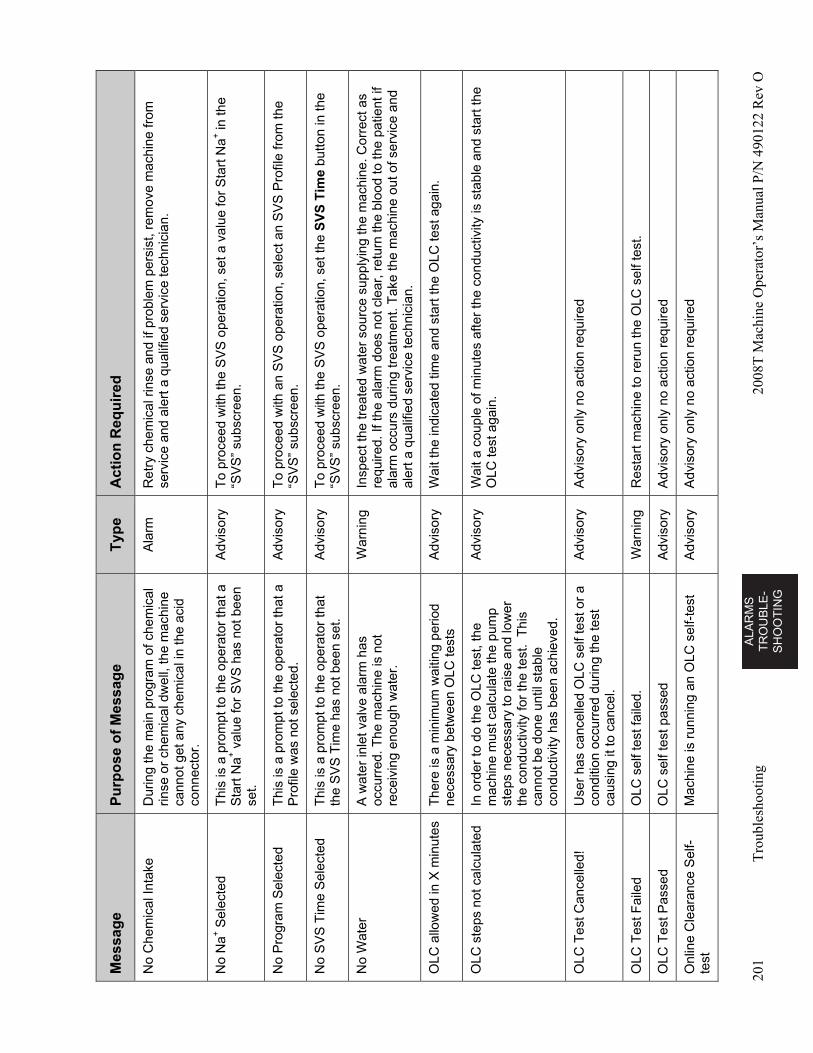
AL
AR
MS
T
RO
UB
LE
-S
HO
OT
ING
201
Tro
uble
shoo
ting
2008
T M
achi
ne O
pera
tor’
s M
anua
l P/N
490
122
Rev
O
Mes
sag
e P
urp
ose
of
Mes
sag
e T
ype
A
ctio
n R
equ
ired
No
Che
mic
al In
take
D
urin
g th
e m
ain
prog
ram
of c
hem
ical
rin
se o
r ch
emic
al d
wel
l, th
e m
achi
ne
cann
ot g
et a
ny c
hem
ical
in th
e ac
id
conn
ecto
r.
Ala
rm
Ret
ry c
hem
ical
rin
se a
nd if
pro
blem
per
sist
, rem
ove
mac
hine
from
se
rvic
e an
d al
ert a
qua
lifie
d se
rvic
e te
chni
cian
.
No
Na
+ S
elec
ted
Thi
s is
a p
rom
pt to
the
oper
ator
that
a
Sta
rt N
a+ v
alue
for
SV
S h
as n
ot b
een
set.
Adv
isor
y T
o pr
ocee
d w
ith th
e S
VS
ope
ratio
n, s
et a
val
ue fo
r S
tart
Na
+ in
the
“SV
S”
subs
cree
n.
No
Pro
gram
Sel
ecte
d T
his
is a
pro
mpt
to th
e op
erat
or th
at a
P
rofil
e w
as n
ot s
elec
ted.
A
dvis
ory
To
proc
eed
with
an
SV
S o
pera
tion,
sel
ect a
n S
VS
Pro
file
from
the
“SV
S”
subs
cree
n.
No
SV
S T
ime
Sel
ecte
d T
his
is a
pro
mpt
to th
e op
erat
or th
at
the
SV
S T
ime
has
not b
een
set.
A
dvis
ory
To
proc
eed
with
the
SV
S o
pera
tion,
set
the
SV
S T
ime
butto
n in
the
“SV
S”
subs
cree
n.
No
Wat
er
A w
ater
inle
t val
ve a
larm
has
oc
curr
ed. T
he m
achi
ne is
not
re
ceiv
ing
enou
gh w
ater
.
War
ning
In
spec
t the
trea
ted
wat
er s
ourc
e su
pply
ing
the
mac
hine
. Cor
rect
as
requ
ired.
If th
e al
arm
doe
s no
t cle
ar, r
etur
n th
e bl
ood
to th
e pa
tient
if
alar
m o
ccur
s du
ring
trea
tmen
t. T
ake
the
mac
hine
out
of s
ervi
ce a
nd
aler
t a q
ualif
ied
serv
ice
tech
nici
an.
OLC
allo
wed
in X
min
utes
T
here
is a
min
imum
wai
ting
perio
d ne
cess
ary
betw
een
OLC
test
s A
dvis
ory
Wai
t the
indi
cate
d tim
e an
d st
art t
he O
LC te
st a
gain
.
OLC
ste
ps n
ot c
alcu
late
d In
ord
er to
do
the
OLC
test
, the
m
achi
ne m
ust c
alcu
late
the
pum
p st
eps
nece
ssar
y to
rai
se a
nd lo
wer
th
e co
nduc
tivity
for
the
test
. T
his
cann
ot b
e do
ne u
ntil
stab
le
cond
uctiv
ity h
as b
een
achi
eved
.
Adv
isor
y W
ait a
cou
ple
of m
inut
es a
fter
the
cond
uctiv
ity is
sta
ble
and
star
t the
O
LC te
st a
gain
.
OLC
Tes
t Can
celle
d!
Use
r ha
s ca
ncel
led
OLC
sel
f tes
t or
a co
nditi
on o
ccur
red
durin
g th
e te
st
caus
ing
it to
can
cel.
Adv
isor
y A
dvis
ory
only
no
actio
n re
quire
d
OLC
Tes
t Fai
led
OLC
sel
f tes
t fai
led.
W
arni
ng
Res
tart
mac
hine
to r
erun
the
OLC
sel
f tes
t.
OLC
Tes
t Pas
sed
OLC
sel
f tes
t pas
sed
Adv
isor
y A
dvis
ory
only
no
actio
n re
quire
d
Onl
ine
Cle
aran
ce S
elf-
te
st
Mac
hine
is r
unni
ng a
n O
LC s
elf-
test
A
dvis
ory
Adv
isor
y on
ly n
o ac
tion
requ
ired
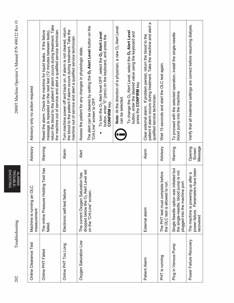
ALA
RM
S
TR
OU
BL
E-
SH
OO
TIN
G
202
Tro
uble
shoo
ting
2008
T M
achi
ne O
pera
tor’
s M
anua
l P/N
490
122
Rev
O
Onl
ine
Cle
aran
ce T
est
Mac
hine
is r
unni
ng a
n O
LC
mea
sure
men
t A
dvis
ory
Adv
isor
y on
ly n
o ac
tion
requ
ired
Onl
ine
PH
T F
aile
d T
he o
nlin
e P
ress
ure
Hol
ding
Tes
t has
fa
iled.
W
arni
ng
Res
et th
e al
arm
. Che
ck th
e m
achi
ne fo
r liq
uid
leak
s. I
f the
failu
re
mes
sage
is r
epea
ted
on th
e ne
xt te
st (
12 m
inut
es b
etw
een
test
s),
retu
rn th
e bl
ood
to th
e pa
tient
if a
larm
occ
urs
durin
g tr
eatm
ent.
Tak
e th
e m
achi
ne o
ut o
f ser
vice
and
ale
rt a
qua
lifie
d se
rvic
e te
chni
cian
.
Onl
ine
PH
T T
oo L
ong
Ele
ctro
nic
self-
test
failu
re.
Ala
rm
Tur
n m
achi
ne p
ower
off
and
back
on.
If a
larm
is n
ot c
lear
ed, r
etur
n th
e bl
ood
to th
e pa
tient
if a
larm
occ
urs
durin
g tr
eatm
ent.
Tak
e th
e m
achi
ne o
ut o
f ser
vice
and
ale
rt a
qua
lifie
d se
rvic
e te
chni
cian
.
Oxy
gen
Sat
urat
ion
Low
T
he c
urre
nt O
xyge
n S
atur
atio
n ha
s dr
oppe
d be
low
the
O2
Ale
rt L
evel
set
on
the
“Crit
-Lin
e” s
cree
n.
Ale
rt
Ass
ess
the
patie
nt fo
r an
y ch
ange
s in
phy
siol
ogic
sta
te.
The
ale
rt c
an b
e cl
eare
d by
set
ting
the
O2
Ale
rt L
evel
but
ton
on th
e “C
rit-L
ine”
scr
een
to O
FF
.
T
o tu
rn th
e O
2 A
lert
leve
l OF
F, s
elec
t the
O2
Ale
rt L
evel
bu
tton,
ent
er “
0” (
zero
) on
the
keyb
oard
, and
pre
ss th
e C
ON
FIR
M k
ey.
No
te: A
t the
dire
ctio
n of
a p
hysi
cian
, a n
ew O
2 A
lert
Lev
el
can
be s
elec
ted.
To
chan
ge th
e O
2 A
lert
Lev
el, s
elec
t the
O2
Ale
rt L
evel
bu
tton,
ent
er th
e de
sire
d va
lue
usin
g th
e ke
yboa
rd a
nd
pres
s th
e C
ON
FIR
M k
ey.
Pat
ient
Ala
rm
Ext
erna
l ala
rm
Ala
rm
Cle
ar e
xter
nal a
larm
. If
prob
lem
per
sist
, ret
urn
the
bloo
d to
the
patie
nt if
ala
rm o
ccur
s du
ring
trea
tmen
t. T
ake
the
mac
hine
and
ale
rt a
qu
alifi
ed s
ervi
ce te
chni
cian
.
PH
T is
run
ning
T
he P
HT
test
mus
t com
plet
e be
fore
th
e O
LC te
st is
allo
wed
to r
un.
Adv
isor
y W
ait 1
5 se
cond
s an
d st
art t
he O
LC te
st a
gain
.
Plu
g in
Ven
ous
Pum
p S
ingl
e N
eedl
e op
tion
was
initi
ated
but
th
e si
ngle
-nee
dle,
blo
od p
ump
is n
ot
plug
ged
into
the
mac
hine
por
t.
War
ning
T
o pr
ocee
d w
ith th
e se
lect
ed o
pera
tion,
inst
all t
he s
ingl
e-ne
edle
bl
ood
pum
p in
to th
e m
achi
ne.
Pow
er F
ailu
re R
ecov
ery
The
mac
hine
is p
ower
ing
up a
fter
a po
wer
failu
re.
Par
amet
ers
have
bee
n re
cove
red
Ope
ning
S
cree
n M
essa
ge
Ver
ify th
at a
ll tr
eatm
ent s
ettin
gs a
re c
orre
ct b
efor
e re
sum
ing
dial
ysis
.
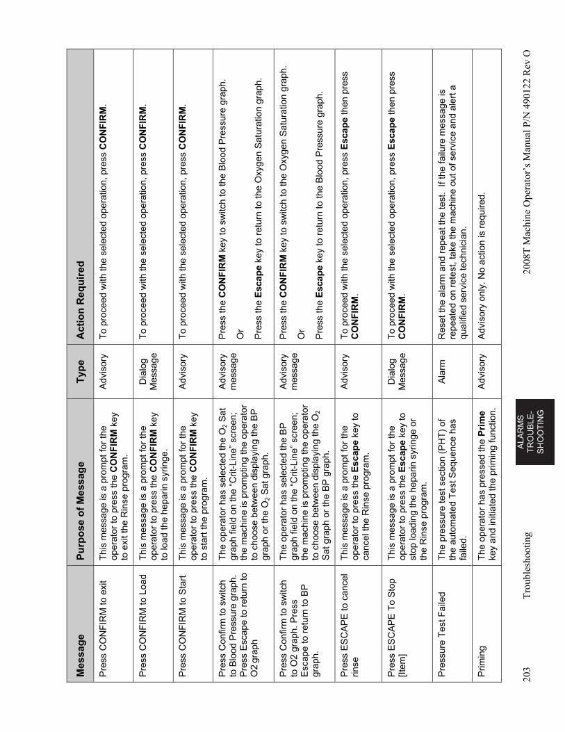
AL
AR
MS
T
RO
UB
LE
-S
HO
OT
ING
203
Tro
uble
shoo
ting
2008
T M
achi
ne O
pera
tor’
s M
anua
l P/N
490
122
Rev
O
Mes
sag
e P
urp
ose
of
Mes
sag
e T
ype
A
ctio
n R
equ
ired
Pre
ss C
ON
FIR
M to
exi
t T
his
mes
sage
is a
pro
mpt
for
the
oper
ator
to p
ress
the
CO
NF
IRM
key
to
exi
t the
Rin
se p
rogr
am.
Adv
isor
y T
o pr
ocee
d w
ith th
e se
lect
ed o
pera
tion,
pre
ss C
ON
FIR
M.
Pre
ss C
ON
FIR
M to
Loa
d T
his
mes
sage
is a
pro
mpt
for
the
oper
ator
to p
ress
the
CO
NF
IRM
key
to
load
the
hepa
rin s
yrin
ge.
Dia
log
Mes
sage
T
o pr
ocee
d w
ith th
e se
lect
ed o
pera
tion,
pre
ss C
ON
FIR
M.
Pre
ss C
ON
FIR
M to
Sta
rt
Thi
s m
essa
ge is
a p
rom
pt fo
r th
e op
erat
or to
pre
ss th
e C
ON
FIR
M k
ey
to s
tart
the
prog
ram
.
Adv
isor
y T
o pr
ocee
d w
ith th
e se
lect
ed o
pera
tion,
pre
ss C
ON
FIR
M.
Pre
ss C
onfir
m to
sw
itch
to B
lood
Pre
ssur
e gr
aph.
P
ress
Esc
ape
to r
etur
n to
O
2 gr
aph
The
ope
rato
r ha
s se
lect
ed th
e O
2 S
at
grap
h fie
ld o
n th
e “C
rit-L
ine”
scr
een;
th
e m
achi
ne is
pro
mpt
ing
the
oper
ator
to
cho
ose
betw
een
disp
layi
ng th
e B
P
grap
h or
the
O2
Sat
gra
ph.
Adv
isor
y m
essa
ge
Pre
ss th
e C
ON
FIR
M k
ey to
sw
itch
to th
e B
lood
Pre
ssur
e gr
aph.
Or
Pre
ss th
e E
scap
e ke
y to
ret
urn
to th
e O
xyge
n S
atur
atio
n gr
aph.
Pre
ss C
onfir
m to
sw
itch
to O
2 gr
aph.
Pre
ss
Esc
ape
to r
etur
n to
BP
gr
aph.
The
ope
rato
r ha
s se
lect
ed th
e B
P
grap
h fie
ld o
n th
e “C
rit-L
ine”
scr
een;
th
e m
achi
ne is
pro
mpt
ing
the
oper
ator
to
cho
ose
betw
een
disp
layi
ng th
e O
2 S
at g
raph
or
the
BP
gra
ph.
Adv
isor
y m
essa
ge
Pre
ss th
e C
ON
FIR
M k
ey to
sw
itch
to th
e O
xyge
n S
atur
atio
n gr
aph.
Or
Pre
ss th
e E
scap
e ke
y to
ret
urn
to th
e B
lood
Pre
ssur
e gr
aph.
Pre
ss E
SC
AP
E to
can
cel
rinse
Thi
s m
essa
ge is
a p
rom
pt fo
r th
e op
erat
or to
pre
ss th
e E
scap
e ke
y to
ca
ncel
the
Rin
se p
rogr
am.
Adv
isor
y T
o pr
ocee
d w
ith th
e se
lect
ed o
pera
tion,
pre
ss E
scap
e th
en p
ress
C
ON
FIR
M.
Pre
ss E
SC
AP
E T
o S
top
[Item
] T
his
mes
sage
is a
pro
mpt
for
the
oper
ator
to p
ress
the
Esc
ape
key
to
stop
load
ing
the
hepa
rin s
yrin
ge o
r th
e R
inse
pro
gram
.
Dia
log
Mes
sage
T
o pr
ocee
d w
ith th
e se
lect
ed o
pera
tion,
pre
ss E
scap
e th
en p
ress
C
ON
FIR
M.
Pre
ssur
e T
est F
aile
d T
he p
ress
ure
test
sec
tion
(PH
T)
of
the
auto
mat
ed T
est S
eque
nce
has
faile
d.
Ala
rm
Res
et th
e al
arm
and
rep
eat t
he te
st.
If th
e fa
ilure
mes
sage
is
repe
ated
on
rete
st, t
ake
the
mac
hine
out
of s
ervi
ce a
nd a
lert
a
qual
ified
ser
vice
tech
nici
an.
Prim
ing
The
ope
rato
r ha
s pr
esse
d th
e P
rim
e ke
y an
d in
itiat
ed th
e pr
imin
g fu
nctio
n.
Adv
isor
y A
dvis
ory
only
. No
actio
n is
req
uire
d.
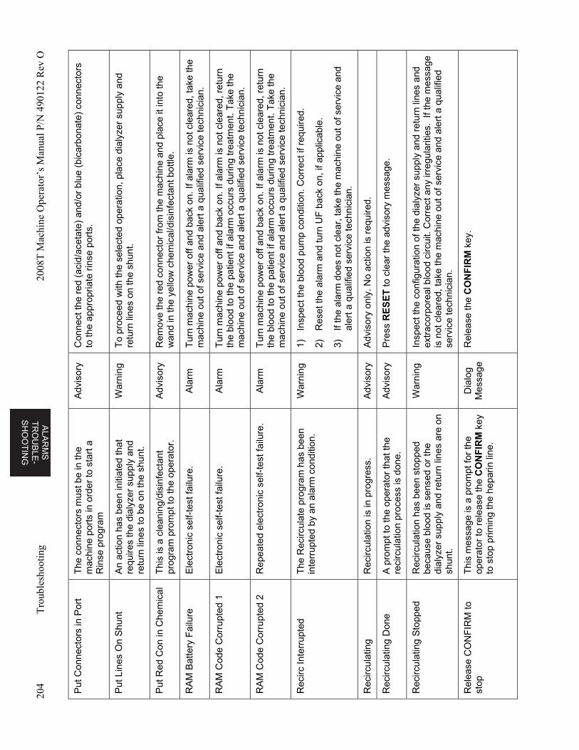
ALA
RM
S
TR
OU
BL
E-
SH
OO
TIN
G
204
Tro
uble
shoo
ting
2008
T M
achi
ne O
pera
tor’
s M
anua
l P/N
490
122
Rev
O
Put
Con
nect
ors
in P
ort
The
con
nect
ors
mus
t be
in th
e m
achi
ne p
orts
in o
rder
to s
tart
a
Rin
se p
rogr
am
Adv
isor
y C
onne
ct th
e re
d (a
cid/
acet
ate)
and
/or
blue
(bi
carb
onat
e) c
onne
ctor
s to
the
appr
opria
te r
inse
por
ts.
Put
Lin
es O
n S
hunt
A
n ac
tion
has
been
initi
ated
that
re
quire
s th
e di
alyz
er s
uppl
y an
d re
turn
line
s to
be
on th
e sh
unt.
War
ning
T
o pr
ocee
d w
ith th
e se
lect
ed o
pera
tion,
pla
ce d
ialy
zer
supp
ly a
nd
retu
rn li
nes
on th
e sh
unt.
Put
Red
Con
in C
hem
ical
T
his
is a
cle
anin
g/di
sinf
ecta
nt
prog
ram
pro
mpt
to th
e op
erat
or.
Adv
isor
y R
emov
e th
e re
d co
nnec
tor
from
the
mac
hine
and
pla
ce it
into
the
wan
d in
the
yello
w c
hem
ical
/dis
infe
ctan
t bot
tle.
RA
M B
atte
ry F
ailu
re
Ele
ctro
nic
self-
test
failu
re.
Ala
rm
Tur
n m
achi
ne p
ower
off
and
back
on.
If a
larm
is n
ot c
lear
ed, t
ake
the
mac
hine
out
of s
ervi
ce a
nd a
lert
a q
ualif
ied
serv
ice
tech
nici
an.
RA
M C
ode
Cor
rupt
ed 1
E
lect
roni
c se
lf-te
st fa
ilure
. A
larm
T
urn
mac
hine
pow
er o
ff an
d ba
ck o
n. If
ala
rm is
not
cle
ared
, ret
urn
the
bloo
d to
the
patie
nt if
ala
rm o
ccur
s du
ring
trea
tmen
t. T
ake
the
mac
hine
out
of s
ervi
ce a
nd a
lert
a q
ualif
ied
serv
ice
tech
nici
an.
RA
M C
ode
Cor
rupt
ed 2
R
epea
ted
elec
tron
ic s
elf-
test
failu
re.
Ala
rm
Tur
n m
achi
ne p
ower
off
and
back
on.
If a
larm
is n
ot c
lear
ed, r
etur
n th
e bl
ood
to th
e pa
tient
if a
larm
occ
urs
durin
g tr
eatm
ent.
Tak
e th
e m
achi
ne o
ut o
f ser
vice
and
ale
rt a
qua
lifie
d se
rvic
e te
chni
cian
.
Rec
irc In
terr
upte
d T
he R
ecirc
ulat
e pr
ogra
m h
as b
een
inte
rrup
ted
by a
n al
arm
con
ditio
n.
War
ning
1)
In
spec
t the
blo
od p
ump
cond
ition
. Cor
rect
if r
equi
red.
2)
Res
et th
e al
arm
and
turn
UF
bac
k on
, if a
pplic
able
.
3)
If th
e al
arm
doe
s no
t cle
ar, t
ake
the
mac
hine
out
of s
ervi
ce a
nd
aler
t a q
ualif
ied
serv
ice
tech
nici
an.
Rec
ircul
atin
g R
ecirc
ulat
ion
is in
pro
gres
s.
Ad
viso
ry
Adv
isor
y on
ly. N
o ac
tion
is r
equi
red.
Rec
ircul
atin
g D
one
A p
rom
pt to
the
oper
ator
that
the
reci
rcul
atio
n pr
oces
s is
don
e.
Adv
isor
y P
ress
RE
SE
T to
cle
ar th
e ad
viso
ry m
essa
ge.
Rec
ircul
atin
g S
topp
ed
Rec
ircul
atio
n ha
s be
en s
topp
ed
beca
use
bloo
d is
sen
sed
or th
e di
alyz
er s
uppl
y an
d re
turn
line
s ar
e on
sh
unt.
War
ning
In
spec
t the
con
figur
atio
n of
the
dial
yzer
sup
ply
and
retu
rn li
nes
and
extr
acor
pore
al b
lood
circ
uit.
Cor
rect
any
irre
gula
ritie
s. I
f the
mes
sage
is
not
cle
ared
, tak
e th
e m
achi
ne o
ut o
f ser
vice
and
ale
rt a
qua
lifie
d se
rvic
e te
chni
cian
.
Rel
ease
CO
NF
IRM
to
stop
T
his
mes
sage
is a
pro
mpt
for
the
oper
ator
to r
elea
se th
e C
ON
FIR
M k
ey
to s
top
prim
ing
the
hepa
rin li
ne.
Dia
log
Mes
sage
R
elea
se th
e C
ON
FIR
M k
ey.
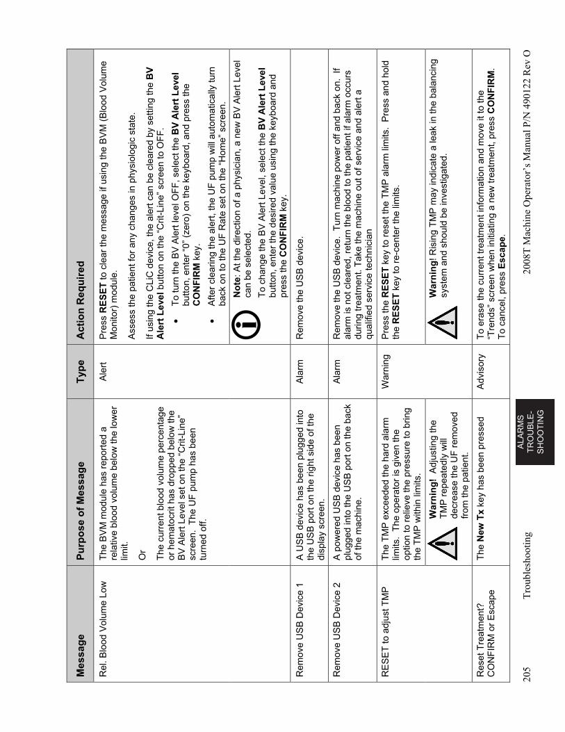
AL
AR
MS
T
RO
UB
LE
-S
HO
OT
ING
205
Tro
uble
shoo
ting
2008
T M
achi
ne O
pera
tor’
s M
anua
l P/N
490
122
Rev
O
Mes
sag
e P
urp
ose
of
Mes
sag
e T
ype
A
ctio
n R
equ
ired
Rel
. Blo
od V
olum
e Lo
w
The
BV
M m
odul
e ha
s re
port
ed a
re
lativ
e bl
ood
volu
me
belo
w th
e lo
wer
lim
it.
Or
The
cur
rent
blo
od v
olum
e pe
rcen
tage
or
hem
atoc
rit h
as d
ropp
ed b
elow
the
BV
Ale
rt L
evel
set
on
the
“Crit
-Lin
e”
scre
en.
The
UF
pum
p ha
s be
en
turn
ed o
ff.
Ale
rt
Pre
ss R
ES
ET
to c
lear
the
mes
sage
if u
sing
the
BV
M (
Blo
od V
olum
e M
onito
r) m
odul
e.
Ass
ess
the
patie
nt fo
r an
y ch
ange
s in
phy
siol
ogic
sta
te.
If us
ing
the
CLi
C d
evic
e, th
e al
ert c
an b
e cl
eare
d by
set
ting
the
BV
A
lert
Lev
el b
utto
n on
the
“Crit
-Lin
e” s
cree
n to
OF
F.
T
o tu
rn th
e B
V A
lert
leve
l OF
F, s
elec
t the
BV
Ale
rt L
evel
bu
tton,
ent
er “
0” (
zero
) on
the
keyb
oard
, and
pre
ss th
e C
ON
FIR
M k
ey.
A
fter
clea
ring
the
aler
t, th
e U
F p
ump
will
aut
omat
ical
ly tu
rn
back
on
to th
e U
F R
ate
set o
n th
e “H
ome”
scr
een.
No
te: A
t the
dire
ctio
n of
a p
hysi
cian
, a n
ew B
V A
lert
Lev
el
can
be s
elec
ted.
To
chan
ge th
e B
V A
lert
Lev
el, s
elec
t the
BV
Ale
rt L
eve
l bu
tton,
ent
er th
e de
sire
d va
lue
usin
g th
e ke
yboa
rd a
nd
pres
s th
e C
ON
FIR
M k
ey.
Rem
ove
US
B D
evic
e 1
A U
SB
dev
ice
has
been
plu
gged
into
th
e U
SB
por
t on
the
right
sid
e of
the
disp
lay
scre
en.
Ala
rm
Rem
ove
the
US
B d
evic
e.
Rem
ove
US
B D
evic
e 2
A p
ower
ed U
SB
dev
ice
has
been
pl
ugge
d in
to th
e U
SB
por
t on
the
back
of
the
mac
hine
.
Ala
rm
Rem
ove
the
US
B d
evic
e. T
urn
mac
hine
pow
er o
ff an
d ba
ck o
n. I
f al
arm
is n
ot c
lear
ed, r
etur
n th
e bl
ood
to th
e pa
tient
if a
larm
occ
urs
durin
g tr
eatm
ent.
Tak
e th
e m
achi
ne o
ut o
f ser
vice
and
ale
rt a
qu
alifi
ed s
ervi
ce te
chni
cian
RE
SE
T to
adj
ust T
MP
T
he T
MP
exc
eede
d th
e ha
rd a
larm
lim
its.
The
ope
rato
r is
giv
en th
e op
tion
to r
elie
ve th
e pr
essu
re to
brin
g th
e T
MP
with
in li
mits
.
War
ning
P
ress
the
RE
SE
T k
ey to
res
et th
e T
MP
ala
rm li
mits
. P
ress
and
hol
d th
e R
ES
ET
key
to r
e-ce
nter
the
limits
.
War
nin
g!
Adj
ustin
g th
e T
MP
rep
eate
dly
will
de
crea
se th
e U
F r
emov
ed
from
the
patie
nt.
War
nin
g! R
isin
g T
MP
may
indi
cate
a le
ak in
the
bala
ncin
g sy
stem
and
sho
uld
be in
vest
igat
ed.
Res
et T
reat
men
t?
CO
NF
IRM
or
Esc
ape
The
New
Tx
key
has
been
pre
ssed
A
dvis
ory
To
eras
e th
e cu
rren
t tre
atm
ent i
nfor
mat
ion
and
mov
e it
to t
he
“Tre
nds”
scr
een
whe
n in
itiat
ing
a ne
w tr
eatm
ent,
pres
s C
ON
FIR
M.
To
canc
el, p
ress
Esc
ape.
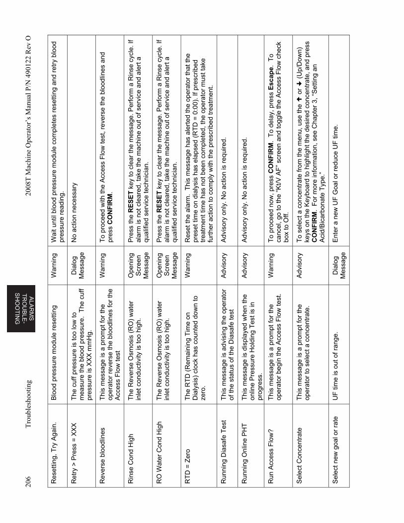
ALA
RM
S
TR
OU
BL
E-
SH
OO
TIN
G
206
Tro
uble
shoo
ting
2008
T M
achi
ne O
pera
tor’
s M
anua
l P/N
490
122
Rev
O
Res
ettin
g, T
ry A
gain
. B
lood
pre
ssur
e m
odul
e re
setti
ng
War
ning
W
ait u
ntil
bloo
d pr
essu
re m
odul
e co
mpl
etes
res
ettin
g an
d re
try
blo
od
pres
sure
rea
ding
.
Ret
ry >
Pre
ss =
XX
X
The
cuf
f pre
ssur
e is
too
low
to
mea
sure
the
bloo
d pr
essu
re.
The
cuf
f pr
essu
re is
XX
X m
mH
g.
Dia
log
Mes
sage
N
o ac
tion
nece
ssar
y
Rev
erse
blo
odlin
es
Thi
s m
essa
ge is
a p
rom
pt fo
r th
e op
erat
or r
ever
se th
e bl
oodl
ines
for
the
Acc
ess
Flo
w te
st
War
ning
T
o pr
ocee
d w
ith th
e A
cces
s F
low
test
, rev
erse
the
bloo
dlin
es a
nd
pre
ss C
ON
FIR
M.
Rin
se C
ond
Hig
h T
he R
ever
se O
smos
is (
RO
) w
ater
in
let c
ondu
ctiv
ity is
too
high
. O
peni
ng
Scr
een
Mes
sage
Pre
ss th
e R
ES
ET
key
to c
lear
the
mes
sage
. Per
form
a R
inse
cyc
le. I
f al
arm
is n
ot c
lear
ed, t
ake
the
mac
hine
out
of s
ervi
ce a
nd a
lert
a
qual
ified
ser
vice
tech
nici
an.
RO
Wat
er C
ond
Hig
h T
he R
ever
se O
smos
is (
RO
) w
ater
in
let c
ondu
ctiv
ity is
too
high
. O
peni
ng
Scr
een
Mes
sage
Pre
ss th
e R
ES
ET
key
to c
lear
the
mes
sage
. Per
form
a R
inse
cyc
le. I
f al
arm
is n
ot c
lear
ed, t
ake
the
mac
hine
out
of s
ervi
ce a
nd a
lert
a
qual
ified
ser
vice
tech
nici
an.
RT
D =
Zer
o T
he R
TD
(R
emai
ning
Tim
e on
D
ialy
sis)
clo
ck h
as c
ount
ed d
own
to
zero
.
War
ning
R
eset
the
alar
m.
Thi
s m
essa
ge h
as a
lert
ed th
e op
erat
or th
at th
e pr
eset
tim
e on
dia
lysi
s ha
s el
apse
d (R
TD
= 0
:00)
. If p
resc
ribed
tr
eatm
ent t
ime
has
not b
een
com
plet
ed, t
he o
pera
tor
mus
t tak
e fu
rthe
r ac
tion
to c
ompl
y w
ith th
e pr
escr
ibed
trea
tmen
t.
Run
ning
Dia
safe
Tes
t T
his
mes
sage
is a
dvis
ing
the
oper
ator
of
the
stat
us o
f the
Dia
safe
test
A
dvis
ory
Adv
isor
y on
ly. N
o ac
tion
is r
equi
red.
Run
ning
Onl
ine
PH
T
Thi
s m
essa
ge is
dis
play
ed w
hen
the
onlin
e P
ress
ure
Hol
ding
Tes
t is
in
prog
ress
.
Adv
isor
y A
dvis
ory
only
. No
actio
n is
req
uire
d.
Run
Acc
ess
Flo
w?
Thi
s m
essa
ge is
a p
rom
pt fo
r th
e op
erat
or b
egin
the
Acc
ess
Flo
w te
st.
War
ning
T
o pr
ocee
d no
w, p
ress
CO
NF
IRM
. T
o de
lay,
pre
ss E
scap
e. T
o ca
ncel
, go
to th
e “K
t/V A
F”
scre
en a
nd to
ggle
the
Acc
ess
Flo
w c
heck
bo
x to
Off.
Sel
ect C
once
ntra
te
Thi
s m
essa
ge is
a p
rom
pt fo
r th
e op
erat
or to
sel
ect a
con
cent
rate
. A
dvis
ory
To
sele
ct a
con
cent
rate
from
the
men
u, u
se th
e
or
(U
p/D
own)
ke
ys o
n th
e K
eybo
ard
to h
ighl
ight
the
desi
red
conc
entr
ate,
and
pre
ss
CO
NF
IRM
. F
or m
ore
info
rmat
ion,
see
Cha
pter
3, “
Set
ting
an
Aci
d/B
icar
bona
te T
ype.
”
Sel
ect n
ew g
oal o
r ra
te
UF
tim
e is
out
of r
ange
. D
ialo
g M
essa
ge
Ent
er a
new
UF
Goa
l or
redu
ce U
F ti
me.
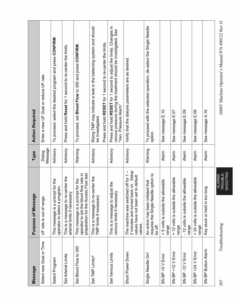
AL
AR
MS
T
RO
UB
LE
-S
HO
OT
ING
207
Tro
uble
shoo
ting
2008
T M
achi
ne O
pera
tor’
s M
anua
l P/N
490
122
Rev
O
Mes
sag
e P
urp
ose
of
Mes
sag
e T
ype
A
ctio
n R
equ
ired
Sel
ect n
ew G
oal o
r T
ime
UF
rat
e is
out
of r
ange
. D
ialo
g M
essa
ge
Ent
er a
new
UF
Goa
l or
redu
ce U
F r
ate.
Sel
ect P
rogr
am
Thi
s m
essa
ge is
a p
rom
pt fo
r th
e op
erat
or to
sel
ect a
pro
gram
. A
dvis
ory
To
proc
eed,
sel
ect t
he d
esire
d pr
ogra
m a
nd p
ress
CO
NF
IRM
.
Set
Art
eria
l Lim
its
Thi
s is
a m
essa
ge to
re-
cent
er th
e ar
teria
l lim
its if
nec
essa
ry
Adv
isor
y P
ress
and
hol
d R
eset
for
1 se
cond
to r
e-ce
nter
the
limits
.
Set
Blo
od F
low
to 3
00
Thi
s m
essa
ge is
a p
rom
pt fo
r th
e op
erat
or to
set
the
bloo
d flo
w r
ate
in
prep
arat
ion
for
the
Acc
ess
Flo
w te
st
War
ning
T
o pr
ocee
d, s
et B
loo
d F
low
to 3
00 a
nd p
ress
CO
NF
IRM
.
Set
TM
P L
imits
? T
his
is a
mes
sage
to r
e-ce
nter
the
TM
P li
mits
if n
eces
sary
A
dvis
ory
Ris
ing
TM
P m
ay in
dica
te a
leak
in th
e ba
lanc
ing
syst
em a
nd s
houl
d be
inve
stig
ated
.
Pre
ss a
nd h
old
RE
SE
T fo
r 1
seco
nd to
re-
cent
er th
e lim
its.
Set
Ven
ous
Lim
its
Thi
s is
a m
essa
ge to
adj
ust t
he
veno
us li
mits
if n
eces
sary
A
dvis
ory
Pre
ss a
nd h
old
RE
SE
T fo
r 1
seco
nd to
adj
ust t
he li
mits
. Cha
nges
in
veno
us p
ress
ure
durin
g th
e tr
eatm
ent s
houl
d be
inve
stig
ated
. See
“V
en. P
ress
ure
Ala
rm”
Sho
rt P
ower
Dow
n T
he m
achi
ne w
as s
witc
hed
off f
or 1
–
2 m
inut
es a
nd tu
rned
bac
k on
. S
etup
va
lues
hav
e no
t bee
n se
t to
defa
ult
valu
es.
Adv
isor
y V
erify
that
the
dial
ysis
par
amet
ers
are
as d
esire
d.
Sin
gle
Nee
dle
On!
A
n ac
tion
has
been
initi
ated
that
re
quire
s th
e S
ingl
e N
eedl
e op
tion
to
be o
ff.
War
ning
T
o pr
ocee
d w
ith th
e se
lect
ed o
pera
tion,
de-
sele
ct th
e S
ingl
e N
eedl
e op
tion.
SN
BP
+5
V E
rror
+
5 v
olts
is o
utsi
de th
e al
low
able
ra
nge
Ala
rm
See
mes
sage
E.1
0
SN
BP
+12
V E
rror
+
12
volts
is o
utsi
de th
e al
low
able
ra
nge
Ala
rm
See
mes
sage
E.0
7
SN
BP
-12
V E
rror
-
12 v
olts
is o
utsi
de th
e al
low
able
ra
nge
Ala
rm
See
mes
sage
E.0
9
SN
BP
+24
V E
rror
+
24
volts
is o
utsi
de th
e al
low
able
ra
nge
Ala
rm
See
mes
sage
E.0
8
SN
BP
But
ton
Ala
rm
Key
stu
ck o
r he
ld in
too
long
A
larm
S
ee m
essa
ge A
.16
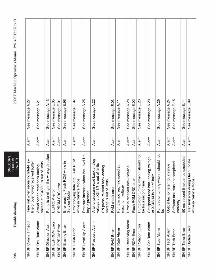
ALA
RM
S
TR
OU
BL
E-
SH
OO
TIN
G
208
Tro
uble
shoo
ting
2008
T M
achi
ne O
pera
tor’
s M
anua
l P/N
490
122
Rev
O
SN
BP
Com
m. T
imeo
ut
Tim
e ou
t whe
n re
ceiv
ing
Inte
l-Hex
-lin
e or
ove
rflo
wed
rec
eive
d bu
ffer
Ala
rm
See
mes
sage
A.2
7
SN
BP
Del
. Rat
e A
larm
A
ctua
l spe
ed-r
ead
back
ana
log
volta
ge a
t X34
8/10
is o
ut o
f lim
its
Ala
rm
See
mes
sage
A.2
1
SN
BP
Dire
ctio
n A
larm
P
ump
is tu
rnin
g in
the
wro
ng d
irect
ion
Ala
rm
See
mes
sage
A.1
3
SN
BP
EE
PR
OM
Err
or
EE
PR
OM
err
or
Ala
rm
See
mes
sage
E.0
5
SN
BP
EP
RO
M E
rror
E
PR
OM
CR
C e
rror
A
larm
S
ee m
essa
ge E
.01
SN
BP
Era
sing
Err
or
Err
or e
rasi
ng F
lash
RO
M w
hile
in
Ser
vice
Mod
e A
larm
S
ee m
essa
ge E
.98
SN
BP
Fla
sh E
rror
E
rror
cop
ying
dat
a in
to F
lash
RO
M
whi
le in
Ser
vice
Mod
e A
larm
S
ee m
essa
ge E
.97
SN
BP
Lev
el U
p A
larm
P
ress
ure
incr
ease
whe
n th
e Le
vel U
p ke
y is
pre
ssed
A
larm
S
ee m
essa
ge A
.25
SN
BP
Pre
ssur
e A
larm
A
rter
ial p
ress
ure-
read
bac
k an
alog
vo
ltage
at X
348/
7 is
out
of l
imits
SN
pre
ssur
e-re
ad b
ack
anal
og
volta
ge is
out
of l
imits
Ala
rm
See
mes
sage
A.2
2
SN
BP
RA
M E
rror
R
AM
che
ck e
rror
A
larm
S
ee m
essa
ge E
.03
SN
BP
Rat
e A
larm
P
ump
is n
ot r
each
ing
spee
d at
m
axim
um v
olta
ge
Ala
rm
See
mes
sage
A.1
1
SN
BP
Rec
eivi
ng A
larm
E
rror
in r
ecei
ved
Inte
l-Hex
-line
A
larm
S
ee m
essa
ge A
.28
SN
BP
RO
M E
rror
F
lash
RO
M C
RC
err
or
Ala
rm
See
mes
sage
E.0
2
SN
BP
Rot
atio
n E
rror
P
ump
roto
r tu
rnin
g w
hen
it sh
ould
not
be
for
a se
cond
tim
e A
larm
S
ee m
essa
ge E
.23
SN
BP
Set
Rat
e A
larm
S
et s
peed
-rea
d ba
ck a
nalo
g vo
ltage
at
X34
8/14
is o
ut o
f lim
its
Ala
rm
See
mes
sage
A.2
0
SN
BP
Sto
p A
larm
P
ump
roto
r tu
rnin
g w
hen
it sh
ould
not
be
A
larm
S
ee m
essa
ge A
.29
SN
BP
Tac
h A
larm
O
ptic
al ta
chom
eter
not
in r
ange
A
larm
S
ee m
essa
ge A
.24
SN
BP
Tas
k E
rror
S
oftw
are
task
was
not
com
plet
ed
corr
ectly
A
larm
S
ee m
essa
ge E
.15
SN
BP
Tim
er E
rror
50
ms
seco
nd ti
me
perio
d ex
ceed
ed
Ala
rm
See
mes
sage
E.1
4
SN
BP
Upd
ate
Err
or
Tra
nsm
it er
ror
durin
g F
lash
upd
ate
whi
le in
Ser
vice
Mod
e A
larm
S
ee m
essa
ge E
.99
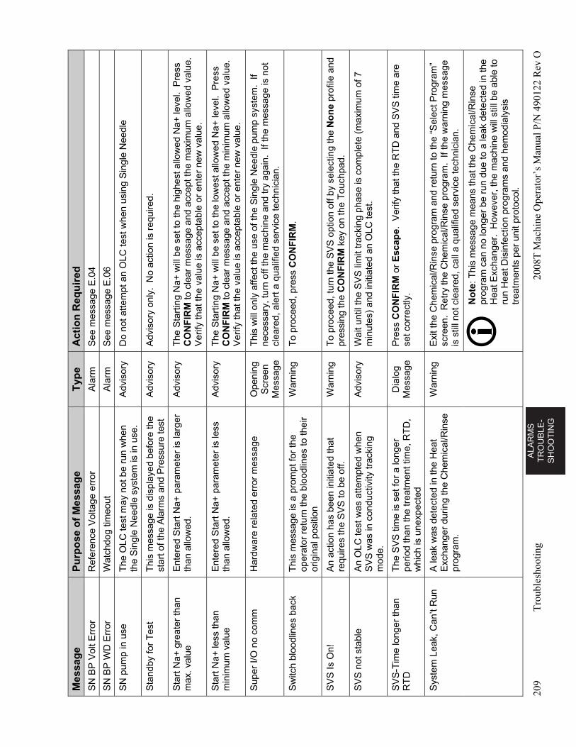
AL
AR
MS
T
RO
UB
LE
-S
HO
OT
ING
209
Tro
uble
shoo
ting
2008
T M
achi
ne O
pera
tor’
s M
anua
l P/N
490
122
Rev
O
Mes
sag
e P
urp
ose
of
Mes
sag
e T
ype
A
ctio
n R
equ
ired
SN
BP
Vol
t Err
or
Ref
eren
ce V
olta
ge e
rror
A
larm
S
ee m
essa
ge E
.04
SN
BP
WD
Err
or
Wat
chdo
g tim
eout
A
larm
S
ee m
essa
ge E
.06
SN
pum
p in
use
T
he O
LC te
st m
ay n
ot b
e ru
n w
hen
the
Sin
gle
Nee
dle
syst
em is
in u
se.
Adv
isor
y D
o no
t atte
mpt
an
OLC
test
whe
n us
ing
Sin
gle
Nee
dle
Sta
ndby
for
Tes
t T
his
mes
sage
is d
ispl
ayed
bef
ore
the
star
t of t
he A
larm
s an
d P
ress
ure
test
A
dvis
ory
Adv
isor
y on
ly.
No
actio
n is
req
uire
d.
Sta
rt N
a+ g
reat
er th
an
max
. val
ue
Ent
ered
Sta
rt N
a+ p
aram
eter
is la
rger
th
an a
llow
ed.
Adv
isor
y T
he S
tart
ing
Na+
will
be
set t
o th
e hi
ghes
t allo
wed
Na+
leve
l. P
ress
C
ON
FIR
M to
cle
ar m
essa
ge a
nd a
ccep
t the
max
imum
allo
wed
val
ue.
Ver
ify th
at th
e va
lue
is a
ccep
tabl
e or
ent
er n
ew v
alue
.
Sta
rt N
a+ le
ss th
an
min
imum
val
ue
Ent
ered
Sta
rt N
a+ p
aram
eter
is le
ss
than
allo
wed
. A
dvis
ory
The
Sta
rtin
g N
a+ w
ill b
e se
t to
the
low
est a
llow
ed N
a+ le
vel.
Pre
ss
CO
NF
IRM
to c
lear
mes
sage
and
acc
ept t
he m
inim
um a
llow
ed v
alue
. V
erify
that
the
valu
e is
acc
epta
ble
or e
nter
new
val
ue.
Sup
er I/
O n
o co
mm
H
ardw
are
rela
ted
erro
r m
essa
ge
Ope
ning
S
cree
n M
essa
ge
Thi
s w
ill o
nly
affe
ct th
e us
e of
the
Sin
gle
Nee
dle
pum
p sy
stem
. If
nece
ssar
y, tu
rn o
ff th
e m
achi
ne a
nd tr
y ag
ain.
If t
he m
essa
ge is
not
cl
eare
d, a
lert
a q
ualif
ied
serv
ice
tech
nici
an.
Sw
itch
bloo
dlin
es b
ack
Thi
s m
essa
ge is
a p
rom
pt fo
r th
e op
erat
or r
etur
n th
e bl
oodl
ines
to th
eir
orig
inal
pos
ition
War
ning
T
o pr
ocee
d, p
ress
CO
NF
IRM
.
SV
S Is
On!
A
n ac
tion
has
been
initi
ated
that
re
quire
s th
e S
VS
to b
e of
f. W
arni
ng
To
proc
eed,
turn
the
SV
S o
ptio
n of
f by
sele
ctin
g th
e N
on
e pr
ofile
and
pr
essi
ng th
e C
ON
FIR
M k
ey o
n th
e T
ouch
pad.
SV
S n
ot s
tabl
e A
n O
LC te
st w
as a
ttem
pted
whe
n S
VS
was
in c
ondu
ctiv
ity tr
acki
ng
mod
e.
Adv
isor
y W
ait u
ntil
the
SV
S li
mit
trac
king
pha
se is
com
plet
e (m
axim
um o
f 7
min
utes
) an
d in
itiat
ed a
n O
LC te
st.
SV
S-T
ime
long
er th
an
RT
D
The
SV
S ti
me
is s
et fo
r a
long
er
perio
d th
an th
e tr
eatm
ent t
ime,
RT
D,
whi
ch is
une
xpec
ted
Dia
log
Mes
sage
P
ress
CO
NF
IRM
or
Esc
ape
. V
erify
that
the
RT
D a
nd S
VS
tim
e ar
e se
t cor
rect
ly.
Sys
tem
Lea
k, C
an’t
Run
A
leak
was
det
ecte
d in
the
Hea
t E
xcha
nger
dur
ing
the
Che
mic
al/R
inse
pr
ogra
m.
War
ning
E
xit t
he C
hem
ical
/Rin
se p
rogr
am
and
ret
urn
to th
e “S
elec
t Pro
gram
” sc
reen
. R
etry
the
Che
mic
al/R
inse
pro
gram
. If
the
war
ning
mes
sage
is
stil
l not
cle
ared
, cal
l a q
ualif
ied
serv
ice
tech
nici
an.
No
te: T
his
mes
sage
mea
ns th
at th
e C
hem
ical
/Rin
se
prog
ram
can
no
long
er b
e ru
n du
e to
a le
ak d
etec
ted
in th
e H
eat E
xcha
nger
. H
owev
er, t
he m
achi
ne w
ill s
till b
e ab
le to
ru
n H
eat D
isin
fect
ion
prog
ram
s an
d he
mod
ialy
sis
trea
tmen
ts p
er u
nit p
roto
col.
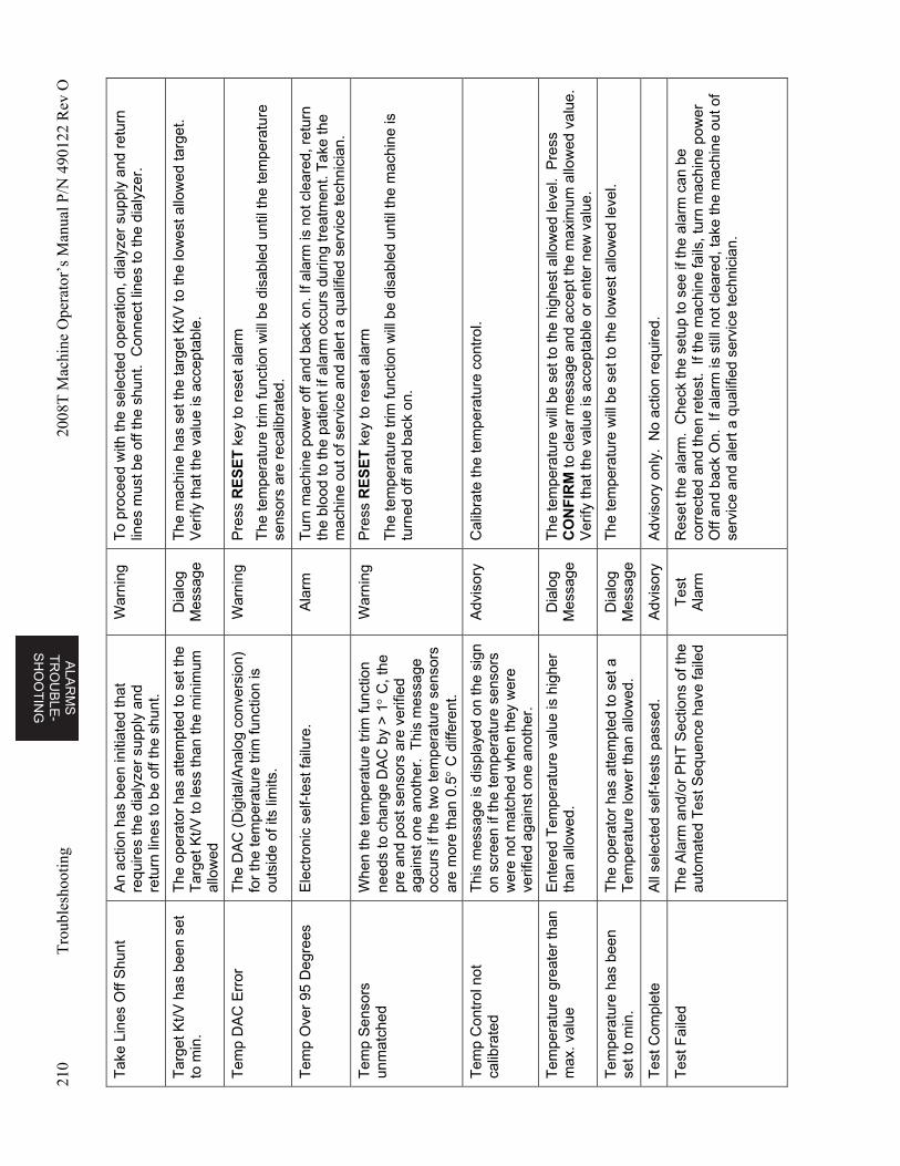
ALA
RM
S
TR
OU
BL
E-
SH
OO
TIN
G
210
Tro
uble
shoo
ting
2008
T M
achi
ne O
pera
tor’
s M
anua
l P/N
490
122
Rev
O
Tak
e Li
nes
Off
Shu
nt
An
actio
n ha
s be
en in
itiat
ed th
at
requ
ires
the
dial
yzer
sup
ply
and
retu
rn li
nes
to b
e of
f the
shu
nt.
War
ning
T
o pr
ocee
d w
ith th
e se
lect
ed o
pera
tion,
dia
lyze
r su
pply
and
ret
urn
lines
mus
t be
off t
he s
hunt
. C
onne
ct li
nes
to th
e di
alyz
er.
Tar
get K
t/V h
as b
een
set
to m
in.
The
ope
rato
r ha
s at
tem
pted
to s
et th
e T
arge
t Kt/V
to
less
than
the
min
imum
al
low
ed
Dia
log
Mes
sage
T
he m
achi
ne h
as s
et th
e ta
rget
Kt/V
to th
e lo
wes
t allo
wed
targ
et.
Ver
ify th
at th
e va
lue
is a
ccep
tabl
e.
Tem
p D
AC
Err
or
The
DA
C (
Dig
ital/A
nalo
g co
nver
sion
) fo
r th
e te
mpe
ratu
re tr
im fu
nctio
n is
ou
tsid
e of
its
limits
.
War
ning
P
ress
RE
SE
T k
ey to
res
et a
larm
The
tem
pera
ture
trim
func
tion
will
be
disa
bled
unt
il th
e te
mpe
ratu
re
sens
ors
are
reca
libra
ted.
Tem
p O
ver
95 D
egre
es
Ele
ctro
nic
self-
test
failu
re.
Ala
rm
Tur
n m
achi
ne p
ower
off
and
back
on.
If a
larm
is n
ot c
lear
ed, r
etur
n th
e bl
ood
to th
e pa
tient
if a
larm
occ
urs
durin
g tr
eatm
ent.
Tak
e th
e m
achi
ne o
ut o
f ser
vice
and
ale
rt a
qua
lifie
d se
rvic
e te
chni
cian
.
Tem
p S
enso
rs
unm
atch
ed
Whe
n th
e te
mpe
ratu
re tr
im fu
nctio
n ne
eds
to c
hang
e D
AC
by
> 1
C, t
he
pre
and
post
sen
sors
are
ver
ified
ag
ains
t one
ano
ther
. T
his
mes
sage
oc
curs
if th
e tw
o te
mpe
ratu
re s
enso
rs
are
mor
e th
an 0
.5
C d
iffer
ent.
War
ning
P
ress
RE
SE
T k
ey to
res
et a
larm
The
tem
pera
ture
trim
func
tion
will
be
disa
bled
unt
il th
e m
achi
ne is
tu
rned
off
and
back
on.
Tem
p C
ontr
ol n
ot
calib
rate
d T
his
mes
sage
is d
ispl
ayed
on
the
sign
on
scr
een
if th
e te
mpe
ratu
re s
enso
rs
wer
e no
t mat
ched
whe
n th
ey w
ere
verif
ied
agai
nst o
ne a
noth
er.
Adv
isor
y C
alib
rate
the
tem
pera
ture
con
trol
.
Tem
pera
ture
gre
ater
than
m
ax. v
alue
E
nter
ed T
empe
ratu
re v
alue
is h
ighe
r th
an a
llow
ed.
Dia
log
Mes
sage
T
he te
mpe
ratu
re w
ill b
e se
t to
the
high
est a
llow
ed le
vel.
Pre
ss
CO
NF
IRM
to c
lear
mes
sage
and
acc
ept t
he m
axim
um a
llow
ed v
alue
. V
erify
that
the
valu
e is
acc
epta
ble
or e
nter
new
val
ue.
Tem
pera
ture
has
bee
n se
t to
min
. T
he o
pera
tor
has
atte
mpt
ed to
set
a
Tem
pera
ture
low
er th
an a
llow
ed.
Dia
log
Mes
sage
T
he te
mpe
ratu
re w
ill b
e se
t to
the
low
est a
llow
ed le
vel.
Tes
t Com
plet
e A
ll se
lect
ed s
elf-
test
s pa
ssed
. A
dvis
ory
Adv
isor
y on
ly.
No
actio
n re
quire
d.
Tes
t Fai
led
The
Ala
rm a
nd/o
r P
HT
Sec
tions
of t
he
auto
mat
ed T
est S
eque
nce
have
faile
d T
est
Ala
rm
Res
et th
e al
arm
. C
heck
the
setu
p to
see
if th
e al
arm
can
be
corr
ecte
d an
d th
en r
etes
t. If
the
mac
hine
fails
, tur
n m
achi
ne p
ower
O
ff an
d ba
ck O
n. I
f ala
rm is
stil
l not
cle
ared
, tak
e th
e m
achi
ne o
ut o
f se
rvic
e an
d al
ert a
qua
lifie
d se
rvic
e te
chni
cian
.
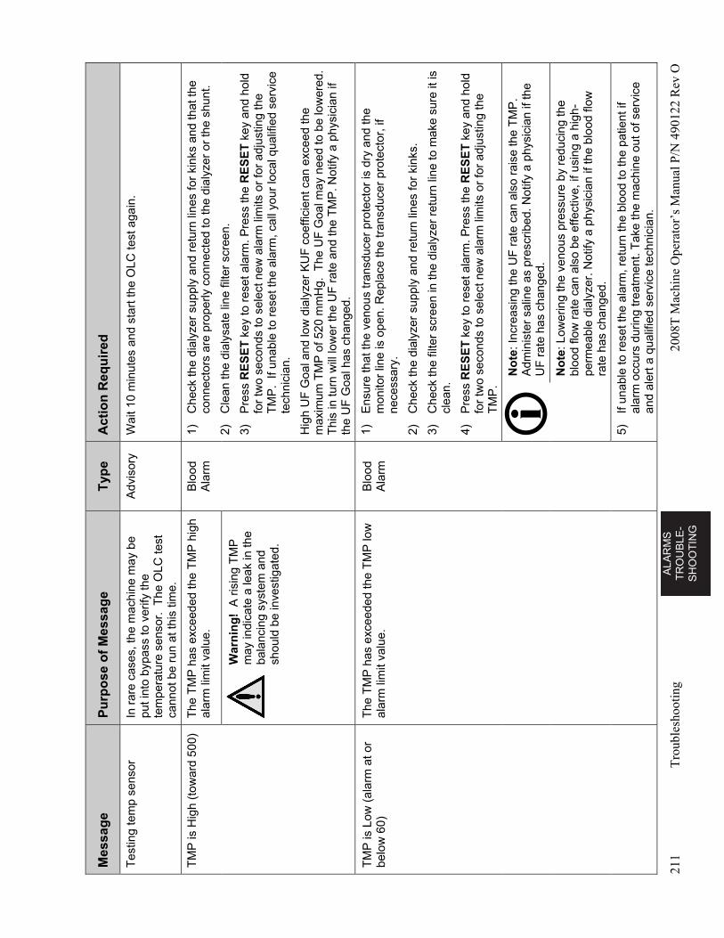
AL
AR
MS
T
RO
UB
LE
-S
HO
OT
ING
211
Tro
uble
shoo
ting
2008
T M
achi
ne O
pera
tor’
s M
anua
l P/N
490
122
Rev
O
Mes
sag
e P
urp
ose
of
Mes
sag
e T
ype
A
ctio
n R
equ
ired
Tes
ting
tem
p se
nsor
In
rar
e ca
ses,
the
mac
hine
may
be
put i
nto
bypa
ss to
ver
ify th
e te
mpe
ratu
re s
enso
r. T
he O
LC te
st
cann
ot b
e ru
n at
this
tim
e.
Adv
isor
y W
ait 1
0 m
inut
es a
nd s
tart
the
OLC
test
aga
in.
TM
P is
Hig
h (t
owar
d 50
0)
The
TM
P h
as e
xcee
ded
the
TM
P h
igh
alar
m li
mit
valu
e.
Blo
od
Ala
rm
1)
Che
ck th
e di
alyz
er s
uppl
y an
d re
turn
line
s fo
r ki
nks
and
that
the
conn
ecto
rs a
re p
rope
rly c
onne
cted
to th
e di
alyz
er o
r th
e sh
unt.
2)
Cle
an th
e di
alys
ate
line
filte
r sc
reen
.
3)
Pre
ss R
ES
ET
key
to r
eset
ala
rm. P
ress
the
RE
SE
T k
ey a
nd h
old
for
two
seco
nds
to s
elec
t new
ala
rm li
mits
or
for
adju
stin
g th
e T
MP
. If
unab
le to
res
et th
e al
arm
, cal
l you
r lo
cal q
ualif
ied
serv
ice
tech
nici
an.
Hig
h U
F G
oal a
nd lo
w d
ialy
zer
KU
F c
oeffi
cien
t can
exc
eed
the
max
imum
TM
P o
f 520
mm
Hg.
The
UF
Goa
l may
nee
d to
be
low
ered
. T
his
in tu
rn w
ill lo
wer
the
UF
rat
e an
d th
e T
MP
. Not
ify a
phy
sici
an if
th
e U
F G
oal h
as c
hang
ed.
War
nin
g!
A r
isin
g T
MP
m
ay in
dica
te a
leak
in th
e ba
lanc
ing
syst
em a
nd
shou
ld b
e in
vest
igat
ed.
TM
P is
Low
(al
arm
at o
r be
low
60)
T
he T
MP
has
exc
eede
d th
e T
MP
low
al
arm
lim
it va
lue.
B
lood
A
larm
1)
E
nsur
e th
at th
e ve
nous
tran
sduc
er p
rote
ctor
is d
ry a
nd th
e m
onito
r lin
e is
ope
n. R
epla
ce t
he tr
ansd
ucer
pro
tect
or, i
f ne
cess
ary.
2)
Che
ck th
e di
alyz
er s
uppl
y an
d re
turn
line
s fo
r ki
nks.
3)
Che
ck th
e fil
ter
scre
en in
the
dial
yzer
ret
urn
line
to m
ake
sure
it is
cl
ean.
4)
Pre
ss R
ES
ET
key
to r
eset
ala
rm. P
ress
the
RE
SE
T k
ey a
nd h
old
for
two
seco
nds
to s
elec
t new
ala
rm li
mits
or
for
adju
stin
g th
e T
MP
.
No
te: I
ncre
asin
g th
e U
F r
ate
can
also
rai
se th
e T
MP
. A
dmin
iste
r sa
line
as p
resc
ribed
. Not
ify a
phy
sici
an if
the
UF
rat
e ha
s ch
ange
d.
N
ote
: Low
erin
g th
e ve
nous
pre
ssur
e by
red
ucin
g th
e bl
ood
flow
rat
e ca
n al
so b
e ef
fect
ive,
if u
sing
a h
igh-
perm
eabl
e di
alyz
er. N
otify
a p
hysi
cian
if th
e bl
ood
flow
ra
te h
as c
hang
ed.
5)
If un
able
to r
eset
the
alar
m, r
etu
rn th
e bl
ood
to th
e pa
tient
if
alar
m o
ccur
s du
ring
trea
tmen
t. T
ake
the
mac
hine
out
of s
ervi
ce
and
aler
t a q
ualif
ied
serv
ice
tech
nici
an.
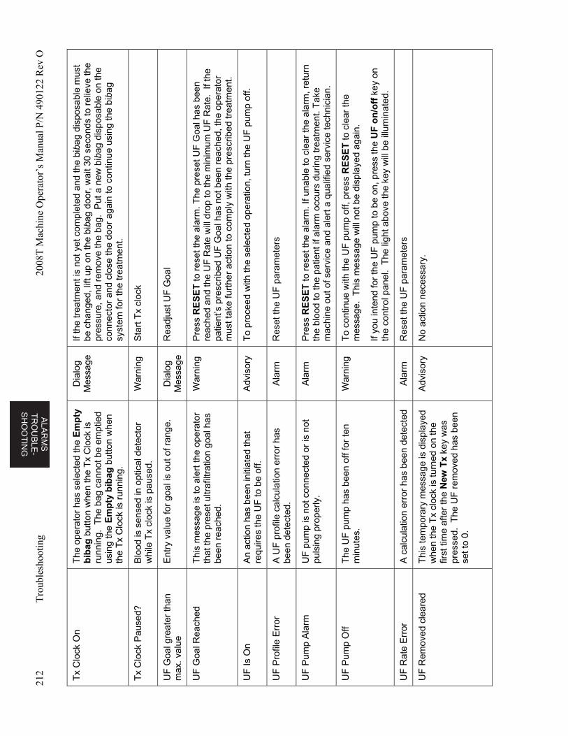
ALA
RM
S
TR
OU
BL
E-
SH
OO
TIN
G
212
Tro
uble
shoo
ting
2008
T M
achi
ne O
pera
tor’
s M
anua
l P/N
490
122
Rev
O
Tx
Clo
ck O
n T
he o
pera
tor
has
sele
cted
the
Em
pty
b
ibag
but
ton
whe
n th
e T
x C
lock
is
runn
ing.
The
bag
can
not b
e em
ptie
d us
ing
the
Em
pty
bib
ag b
utto
n w
hen
the
Tx
Clo
ck is
run
ning
.
Dia
log
Mes
sage
If
the
trea
tmen
t is
not y
et c
ompl
eted
and
the
biba
g di
spos
able
mus
t be
cha
nged
, lift
up
on th
e bi
bag
door
, wai
t 30
seco
nds
to r
elie
ve th
e pr
essu
re, a
nd r
emov
e th
e ba
g. P
ut a
new
bib
ag d
ispo
sabl
e on
the
conn
ecto
r an
d cl
ose
the
door
aga
in to
con
tinue
usi
ng th
e bi
bag
syst
em fo
r th
e tr
eatm
ent.
Tx
Clo
ck P
ause
d?
Blo
od is
sen
sed
in o
ptic
al d
etec
tor
whi
le T
x cl
ock
is p
ause
d.
War
ning
S
tart
Tx
cloc
k
UF
Goa
l gre
ater
than
m
ax. v
alue
E
ntry
val
ue fo
r go
al is
out
of r
ange
. D
ialo
g M
essa
ge
Rea
djus
t UF
Goa
l
UF
Goa
l Rea
ched
T
his
mes
sage
is to
ale
rt th
e op
erat
or
that
the
pres
et u
ltraf
iltra
tion
goal
has
be
en r
each
ed.
War
ning
P
ress
RE
SE
T to
res
et th
e al
arm
. The
pre
set U
F G
oal h
as b
een
reac
hed
and
the
UF
Rat
e w
ill d
rop
to th
e m
inim
um U
F R
ate.
If t
he
patie
nt’s
pre
scrib
ed U
F G
oal h
as n
ot b
een
reac
hed,
the
oper
ator
m
ust t
ake
furt
her
actio
n to
com
ply
with
the
pres
crib
ed tr
eatm
ent.
UF
Is O
n A
n ac
tion
has
been
initi
ated
that
re
quire
s th
e U
F to
be
off.
Adv
isor
y T
o pr
ocee
d w
ith th
e se
lect
ed o
pera
tion,
turn
the
UF
pum
p of
f.
UF
Pro
file
Err
or
A U
F p
rofil
e ca
lcul
atio
n er
ror
has
been
det
ecte
d.
Ala
rm
Res
et th
e U
F p
aram
eter
s
UF
Pum
p A
larm
U
F p
ump
is n
ot c
onne
cted
or
is n
ot
puls
ing
prop
erly
. A
larm
P
ress
RE
SE
T to
res
et th
e al
arm
. If u
nabl
e to
cle
ar th
e al
arm
, ret
urn
the
bloo
d to
the
patie
nt if
ala
rm o
ccur
s du
ring
trea
tmen
t. T
ake
mac
hine
out
of s
ervi
ce a
nd a
lert
a q
ualif
ied
serv
ice
tech
nici
an.
UF
Pum
p O
ff T
he U
F p
ump
has
been
off
for
ten
min
utes
. W
arni
ng
To
cont
inue
with
the
UF
pum
p of
f, pr
ess
RE
SE
T to
cle
ar th
e m
essa
ge.
Thi
s m
essa
ge w
ill n
ot b
e di
spla
yed
agai
n.
If yo
u in
tend
for
the
UF
pum
p to
be
on, p
ress
the
UF
on
/off
key
on
the
cont
rol p
anel
. T
he li
ght a
bove
the
key
will
be
illum
inat
ed.
UF
Rat
e E
rror
A
cal
cula
tion
erro
r ha
s b
een
dete
cted
A
larm
R
eset
the
UF
par
amet
ers
UF
Rem
oved
cle
ared
T
his
tem
pora
ry m
essa
ge is
dis
play
ed
whe
n th
e T
x cl
ock
is tu
rned
on
the
first
tim
e af
ter
the
New
Tx
key
was
pr
esse
d. T
he U
F r
emov
ed h
as b
een
set t
o 0.
Adv
isor
y N
o ac
tion
nece
ssar
y.
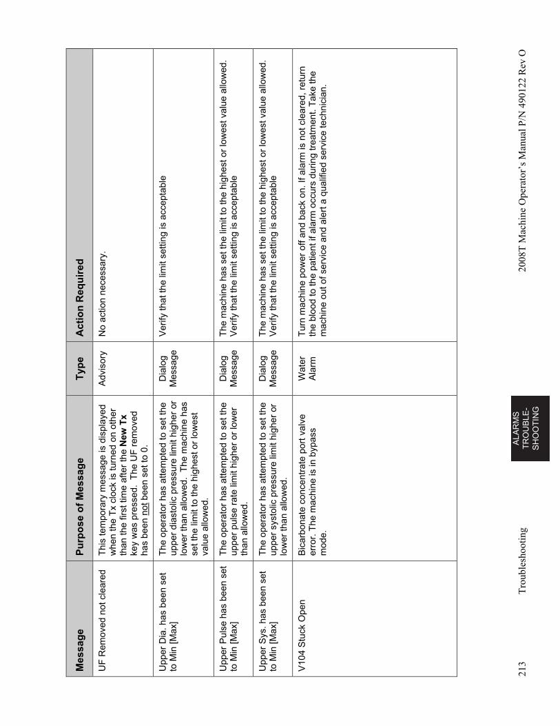
AL
AR
MS
T
RO
UB
LE
-S
HO
OT
ING
213
Tro
uble
shoo
ting
2008
T M
achi
ne O
pera
tor’
s M
anua
l P/N
490
122
Rev
O
Mes
sag
e P
urp
ose
of
Mes
sag
e T
ype
A
ctio
n R
equ
ired
UF
Rem
oved
not
cle
ared
T
his
tem
pora
ry m
essa
ge is
dis
play
ed
whe
n th
e T
x cl
ock
is tu
rned
on
othe
r th
an th
e fir
st ti
me
afte
r th
e N
ew T
x ke
y w
as p
ress
ed.
The
UF
rem
oved
ha
s be
en n
ot b
een
set t
o 0.
Adv
isor
y N
o ac
tion
nece
ssar
y.
Upp
er D
ia. h
as b
een
set
to M
in [M
ax]
The
ope
rato
r ha
s at
tem
pted
to s
et th
e up
per
dias
tolic
pre
ssur
e lim
it hi
gher
or
low
er th
an a
llow
ed.
The
mac
hine
has
se
t the
lim
it to
the
high
est o
r lo
wes
t va
lue
allo
wed
.
Dia
log
Mes
sage
V
erify
that
the
limit
setti
ng is
acc
epta
ble
Upp
er P
ulse
has
bee
n se
t to
Min
[Max
] T
he o
pera
tor
has
atte
mpt
ed to
set
the
uppe
r pu
lse
rate
lim
it hi
gher
or
low
er
than
allo
wed
.
Dia
log
Mes
sage
T
he m
achi
ne h
as s
et th
e lim
it to
the
high
est o
r lo
wes
t val
ue a
llow
ed.
Ver
ify th
at th
e lim
it se
tting
is a
ccep
tabl
e
Upp
er S
ys. h
as b
een
set
to M
in [M
ax]
The
ope
rato
r ha
s at
tem
pted
to s
et th
e up
per
syst
olic
pre
ssur
e lim
it hi
gher
or
low
er th
an a
llow
ed.
Dia
log
Mes
sage
T
he m
achi
ne h
as s
et th
e lim
it to
the
high
est o
r lo
wes
t val
ue a
llow
ed.
Ver
ify th
at th
e lim
it se
tting
is a
ccep
tabl
e
V10
4 S
tuck
Ope
n B
icar
bona
te c
once
ntra
te p
ort v
alve
er
ror.
The
mac
hine
is in
byp
ass
mod
e.
Wat
er
Ala
rm
Tur
n m
achi
ne p
ower
off
and
back
on.
If a
larm
is n
ot c
lear
ed, r
etur
n th
e bl
ood
to th
e pa
tient
if a
larm
occ
urs
durin
g tr
eatm
ent.
Tak
e th
e m
achi
ne o
ut o
f ser
vice
and
ale
rt a
qua
lifie
d se
rvic
e te
chni
cian
.
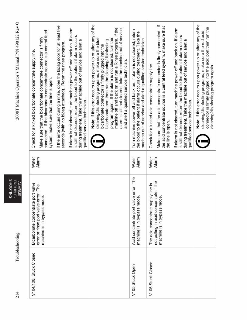
ALA
RM
S
TR
OU
BL
E-
SH
OO
TIN
G
214
Tro
uble
shoo
ting
2008
T M
achi
ne O
pera
tor’
s M
anua
l P/N
490
122
Rev
O
V10
4/10
8 S
tuck
Clo
sed
Bic
arbo
nate
con
cent
rate
por
t val
ve
erro
r or
rin
se p
ort v
alve
err
or. T
he
mac
hine
is in
byp
ass
mod
e.
Wat
er
Ala
rm
Che
ck fo
r a
kink
ed b
icar
bona
te c
once
ntra
te s
uppl
y lin
e.
Mak
e su
re th
at th
e bi
carb
onat
e co
ncen
trat
e co
nnec
tor
is fi
rmly
co
nnec
ted.
If t
he b
icar
bona
te c
once
ntra
te s
ourc
e is
a c
entr
al fe
ed
syst
em, m
ake
sure
that
the
line
is o
pen.
If th
e er
ror
occu
rs d
urin
g a
rinse
, ope
n th
e bi
bag
door
for
at le
ast f
ive
seco
nds
(with
no
biba
g at
tach
ed).
Rer
un th
e rin
se p
rogr
am.
If al
arm
is n
ot c
lear
ed, t
urn
mac
hine
pow
er o
ff an
d ba
ck o
n. If
ala
rm
is s
till n
ot c
lear
ed, r
etur
n th
e bl
ood
to th
e pa
tient
if a
larm
occ
urs
durin
g tr
eatm
ent.
Tak
e th
e m
achi
ne o
ut o
f ser
vice
and
ale
rt a
qu
alifi
ed s
ervi
ce te
chni
cian
.
No
te: I
f thi
s er
ror
occu
rs u
pon
pow
er u
p or
afte
r an
y of
the
clea
ning
/dis
infe
ctin
g pr
ogra
ms,
mak
e su
re th
e bl
ue
bica
rbon
ate
conn
ecto
r is
firm
ly p
lugg
ed in
to th
e bi
carb
onat
e po
rt th
en r
un th
e cl
eani
ng/d
isin
fect
ing
prog
ram
aga
in.
If th
e al
arm
is n
ot c
lear
ed, t
urn
the
mac
hine
off
and
back
on
and
run
a R
inse
pro
gram
. If t
he
alar
m is
stil
l not
cle
ared
, tak
e th
e m
achi
ne o
ut o
f ser
vice
an
d al
ert a
qua
lifie
d se
rvic
e te
chni
cian
.
V10
5 S
tuck
Ope
n A
cid
conc
entr
ate
port
val
ve e
rror
. The
m
achi
ne is
in b
ypas
s m
ode.
W
ater
A
larm
T
urn
mac
hine
pow
er o
ff an
d ba
ck o
n. If
ala
rm is
not
cle
ared
, ret
urn
the
bloo
d to
the
patie
nt if
ala
rm o
ccur
s du
ring
trea
tmen
t. T
ake
the
mac
hine
out
of s
ervi
ce a
nd a
lert
a q
ualif
ied
serv
ice
tech
nici
an.
V10
5 S
tuck
Clo
sed
The
aci
d co
ncen
trat
e su
pply
line
is
not p
ullin
g in
aci
d co
ncen
trat
e. T
he
mac
hine
is in
byp
ass
mod
e.
Wat
er
Ala
rm
Che
ck fo
r a
kink
ed a
cid
conc
entr
ate
supp
ly li
ne.
Mak
e su
re th
at th
e ac
id c
once
ntra
te c
onne
ctor
is fi
rmly
con
nect
ed.
If th
e ac
id c
once
ntra
te s
ourc
e is
a c
entr
al fe
ed s
yste
m, m
ake
sure
that
th
e lin
e is
ope
n.
If al
arm
is n
ot c
lear
ed, t
urn
mac
hine
pow
er o
ff an
d ba
ck o
n. If
ala
rm
is s
till n
ot c
lear
ed, r
etur
n th
e bl
ood
to th
e pa
tient
if a
larm
occ
urs
durin
g tr
eatm
ent.
Tak
e th
e m
achi
ne o
ut o
f ser
vice
and
ale
rt a
qu
alifi
ed s
ervi
ce te
chni
cian
.
No
te: I
f thi
s er
ror
occu
rs u
pon
pow
er u
p or
afte
r an
y of
the
clea
ning
/dis
infe
ctin
g pr
ogra
ms,
mak
e su
re th
e re
d ac
id
conn
ecto
r is
firm
ly p
lugg
ed in
to th
e ac
id p
ort t
hen
run
the
clea
ning
/dis
infe
ctin
g pr
ogra
m a
gain
.
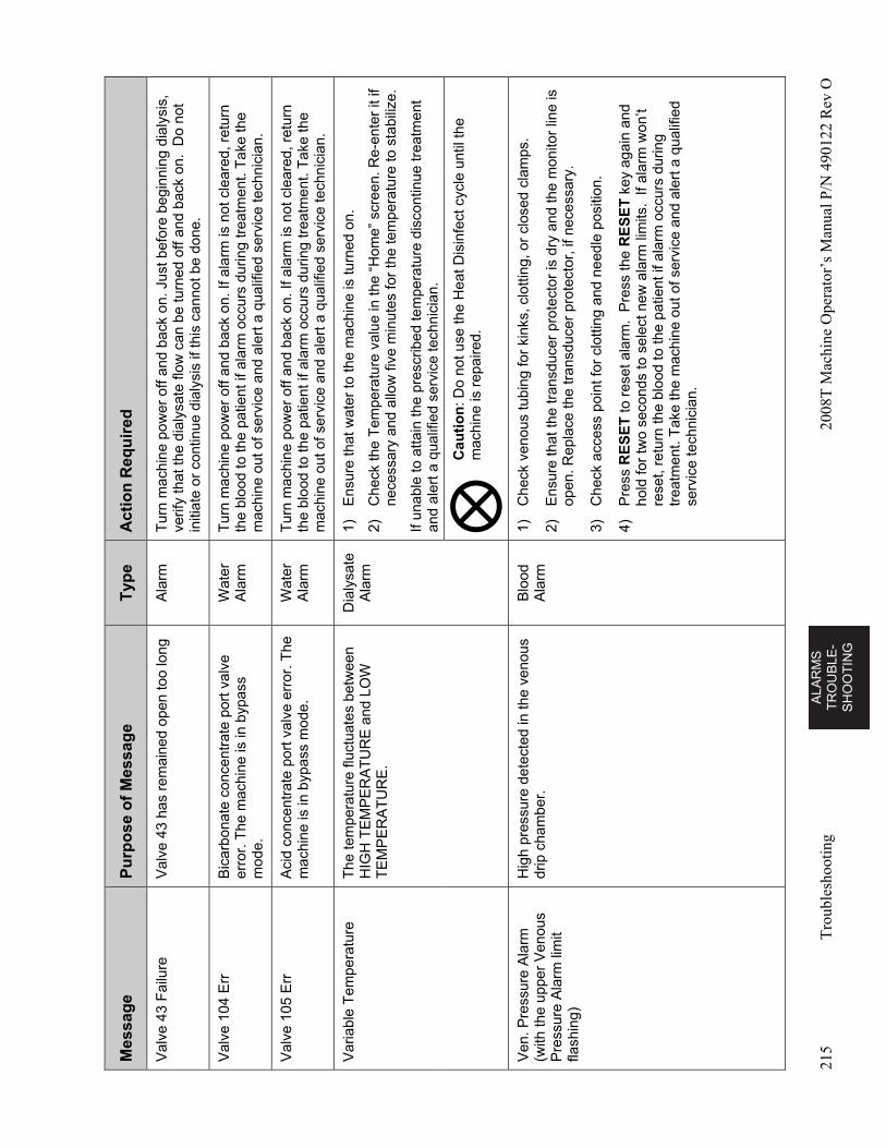
AL
AR
MS
T
RO
UB
LE
-S
HO
OT
ING
215
Tro
uble
shoo
ting
2008
T M
achi
ne O
pera
tor’
s M
anua
l P/N
490
122
Rev
O
Mes
sag
e P
urp
ose
of
Mes
sag
e T
ype
A
ctio
n R
equ
ired
Val
ve 4
3 F
ailu
re
Val
ve 4
3 ha
s re
mai
ned
open
too
long
A
larm
T
urn
mac
hine
pow
er o
ff an
d ba
ck o
n. J
ust b
efor
e be
ginn
ing
dial
ysis
, ve
rify
that
the
dial
ysat
e flo
w c
an b
e tu
rned
off
and
back
on.
Do
not
initi
ate
or c
ontin
ue d
ialy
sis
if th
is c
anno
t be
done
.
Val
ve 1
04 E
rr
Bic
arbo
nate
con
cent
rate
por
t val
ve
erro
r. T
he m
achi
ne is
in b
ypas
s m
ode.
Wat
er
Ala
rm
Tur
n m
achi
ne p
ower
off
and
back
on.
If a
larm
is n
ot c
lear
ed, r
etur
n th
e bl
ood
to th
e pa
tient
if a
larm
occ
urs
durin
g tr
eatm
ent.
Tak
e th
e m
achi
ne o
ut o
f ser
vice
and
ale
rt a
qua
lifie
d se
rvic
e te
chni
cian
.
Val
ve 1
05 E
rr
Aci
d co
ncen
trat
e po
rt v
alve
err
or. T
he
mac
hine
is in
byp
ass
mod
e.
Wat
er
Ala
rm
Tur
n m
achi
ne p
ower
off
and
back
on.
If a
larm
is n
ot c
lear
ed, r
etur
n th
e bl
ood
to th
e pa
tient
if a
larm
occ
urs
durin
g tr
eatm
ent.
Tak
e th
e m
achi
ne o
ut o
f ser
vice
and
ale
rt a
qua
lifie
d se
rvic
e te
chni
cian
.
Var
iabl
e T
empe
ratu
re
The
tem
pera
ture
fluc
tuat
es b
etw
een
HIG
H T
EM
PE
RA
TU
RE
and
LO
W
TE
MP
ER
AT
UR
E.
Dia
lysa
te
Ala
rm
1)
Ens
ure
that
wat
er to
the
mac
hine
is tu
rned
on.
2)
Che
ck th
e T
empe
ratu
re v
alue
in th
e “H
ome”
scr
een.
Re-
ente
r it
if ne
cess
ary
and
allo
w fi
ve m
inut
es fo
r th
e te
mpe
ratu
re to
sta
biliz
e.
If un
able
to a
ttain
the
pres
crib
ed te
mpe
ratu
re d
isco
ntin
ue tr
eatm
ent
and
aler
t a q
ualif
ied
serv
ice
tech
nici
an.
Cau
tio
n: D
o no
t use
the
Hea
t Dis
infe
ct c
ycle
unt
il th
e m
achi
ne is
rep
aire
d.
Ven
. Pre
ssur
e A
larm
(w
ith th
e up
per
Ven
ous
Pre
ssur
e A
larm
lim
it fla
shin
g)
Hig
h pr
essu
re d
etec
ted
in th
e ve
nous
dr
ip c
ham
ber.
B
lood
A
larm
1)
C
heck
ven
ous
tubi
ng fo
r ki
nks,
clo
tting
, or
clos
ed c
lam
ps.
2)
Ens
ure
that
the
tran
sduc
er p
rote
ctor
is d
ry a
nd th
e m
onito
r lin
e is
op
en. R
epla
ce th
e tr
ansd
ucer
pro
tect
or, i
f nec
essa
ry.
3)
Che
ck a
cces
s po
int f
or c
lotti
ng a
nd n
eedl
e po
sitio
n.
4)
Pre
ss R
ES
ET
to r
eset
ala
rm.
Pre
ss th
e R
ES
ET
key
aga
in a
nd
hold
for
two
seco
nds
to s
elec
t new
ala
rm li
mits
. If
alar
m w
on’t
rese
t, re
turn
the
bloo
d to
the
patie
nt if
ala
rm o
ccur
s du
ring
trea
tmen
t. T
ake
the
mac
hine
out
of s
ervi
ce a
nd a
lert
a q
ualif
ied
serv
ice
tech
nici
an.
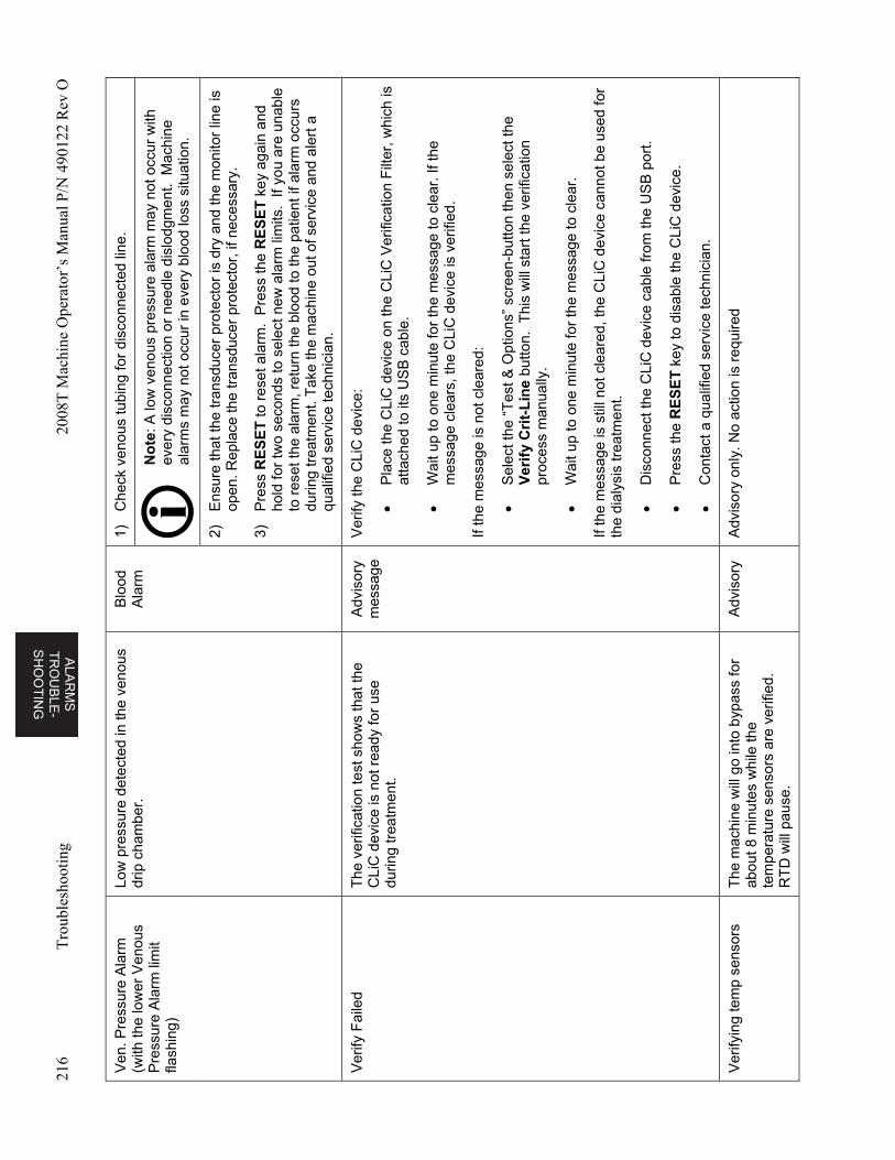
ALA
RM
S
TR
OU
BL
E-
SH
OO
TIN
G
216
Tro
uble
shoo
ting
2008
T M
achi
ne O
pera
tor’
s M
anua
l P/N
490
122
Rev
O
Ven
. Pre
ssur
e A
larm
(w
ith th
e lo
wer
Ven
ous
Pre
ssur
e A
larm
lim
it fla
shin
g)
Low
pre
ssur
e de
tect
ed in
the
veno
us
drip
cha
mbe
r.
Blo
od
Ala
rm
1)
Che
ck v
enou
s tu
bing
for
disc
onne
cted
line
.
No
te: A
low
ven
ous
pres
sure
ala
rm m
ay n
ot o
ccur
with
ev
ery
disc
onne
ctio
n or
nee
dle
disl
odgm
ent.
Mac
hine
al
arm
s m
ay n
ot o
ccur
in e
very
blo
od lo
ss s
ituat
ion.
2)
Ens
ure
that
the
tran
sduc
er p
rote
ctor
is d
ry a
nd th
e m
onito
r lin
e is
op
en. R
epla
ce th
e tr
ansd
ucer
pro
tect
or, i
f nec
essa
ry.
3)
Pre
ss R
ES
ET
to r
eset
ala
rm.
Pre
ss th
e R
ES
ET
key
aga
in a
nd
hold
for
two
seco
nds
to s
elec
t new
ala
rm li
mits
. If
you
are
unab
le
to r
eset
the
alar
m, r
etur
n th
e bl
ood
to th
e pa
tient
if a
larm
occ
urs
durin
g tr
eatm
ent.
Tak
e th
e m
achi
ne o
ut o
f ser
vice
and
ale
rt a
qu
alifi
ed s
ervi
ce te
chni
cian
.
Ver
ify F
aile
d T
he v
erifi
catio
n te
st s
how
s th
at th
e C
LiC
dev
ice
is n
ot r
eady
for
use
durin
g tr
eatm
ent.
Adv
isor
y m
essa
ge
Ver
ify th
e C
LiC
dev
ice:
P
lace
the
CLi
C d
evic
e on
the
CLi
C V
erifi
catio
n F
ilter
, whi
ch is
at
tach
ed to
its
US
B c
able
.
W
ait u
p to
one
min
ute
for
the
mes
sage
to c
lear
. If t
he
mes
sage
cle
ars,
the
CLi
C d
evic
e is
ver
ified
.
If th
e m
essa
ge is
not
cle
ared
:
S
elec
t the
“T
est &
Opt
ions
” sc
reen
-but
ton
then
sel
ect t
he
Ver
ify
Cri
t-L
ine
but
ton.
Thi
s w
ill s
tart
the
verif
icat
ion
proc
ess
man
ually
.
W
ait u
p to
one
min
ute
for
the
mes
sage
to c
lear
.
If th
e m
essa
ge is
stil
l not
cle
ared
, th
e C
LiC
dev
ice
cann
ot b
e us
ed fo
r th
e di
alys
is tr
eatm
ent.
D
isco
nnec
t the
CLi
C d
evic
e ca
ble
from
the
US
B p
ort.
P
ress
the
RE
SE
T k
ey to
dis
able
the
CLi
C d
evic
e.
C
onta
ct a
qua
lifie
d se
rvic
e te
chni
cian
.
Ver
ifyin
g te
mp
sens
ors
The
mac
hine
will
go
into
byp
ass
for
abou
t 8 m
inut
es w
hile
the
tem
pera
ture
sen
sors
are
ver
ified
. R
TD
will
pau
se.
Adv
isor
y A
dvis
ory
only
. No
actio
n is
req
uire
d
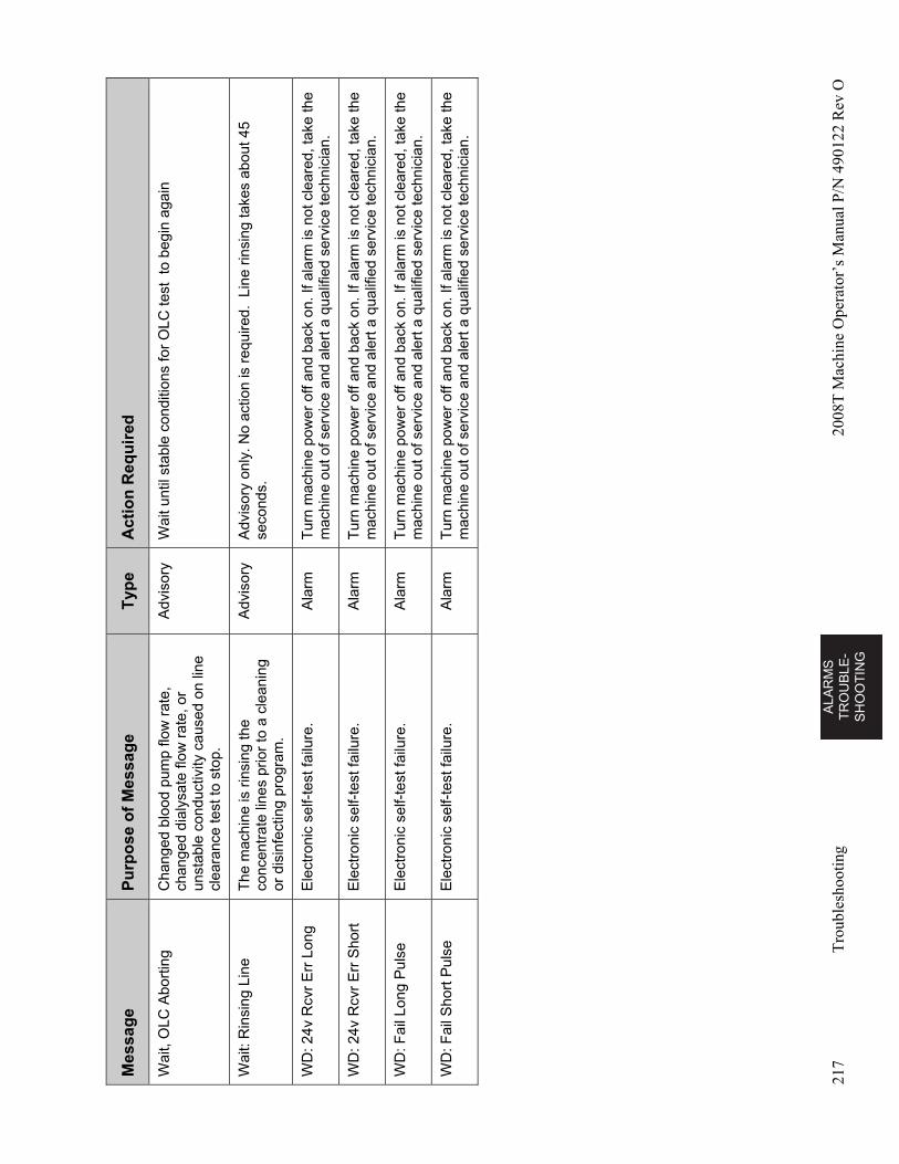
AL
AR
MS
T
RO
UB
LE
-S
HO
OT
ING
217
Tro
uble
shoo
ting
2008
T M
achi
ne O
pera
tor’
s M
anua
l P/N
490
122
Rev
O
Mes
sag
e P
urp
ose
of
Mes
sag
e T
ype
A
ctio
n R
equ
ired
Wai
t, O
LC A
bort
ing
Cha
nged
blo
od p
ump
flow
rat
e,
chan
ged
dial
ysat
e flo
w r
ate,
or
unst
able
con
duct
ivity
cau
sed
on li
ne
clea
ranc
e te
st to
sto
p.
Adv
isor
y W
ait u
ntil
stab
le c
ondi
tions
for
OLC
test
to
begi
n ag
ain
Wai
t: R
insi
ng L
ine
The
mac
hine
is r
insi
ng th
e co
ncen
trat
e lin
es p
rior
to a
cle
anin
g or
dis
infe
ctin
g pr
ogra
m.
Adv
isor
y A
dvis
ory
only
. No
actio
n is
req
uire
d. L
ine
rinsi
ng ta
kes
abou
t 45
seco
nds.
WD
: 24v
Rcv
r E
rr L
ong
Ele
ctro
nic
self-
test
failu
re.
Ala
rm
Tur
n m
achi
ne p
ower
off
and
back
on.
If a
larm
is n
ot c
lear
ed, t
ake
the
mac
hine
out
of s
ervi
ce a
nd a
lert
a q
ualif
ied
serv
ice
tech
nici
an.
WD
: 24v
Rcv
r E
rr S
hort
E
lect
roni
c se
lf-te
st fa
ilure
. A
larm
T
urn
mac
hine
pow
er o
ff an
d ba
ck o
n. If
ala
rm is
not
cle
ared
, tak
e th
e m
achi
ne o
ut o
f ser
vice
and
ale
rt a
qua
lifie
d se
rvic
e te
chni
cian
.
WD
: Fai
l Lon
g P
ulse
E
lect
ron
ic s
elf-
test
failu
re.
Ala
rm
Tur
n m
achi
ne p
ower
off
and
back
on.
If a
larm
is n
ot c
lear
ed, t
ake
the
mac
hine
out
of s
ervi
ce a
nd a
lert
a q
ualif
ied
serv
ice
tech
nici
an.
WD
: Fai
l Sho
rt P
ulse
E
lect
ron
ic s
elf-
test
failu
re.
Ala
rm
Tur
n m
achi
ne p
ower
off
and
back
on.
If a
larm
is n
ot c
lear
ed, t
ake
the
mac
hine
out
of s
ervi
ce a
nd a
lert
a q
ualif
ied
serv
ice
tech
nici
an.
AL
AR
MS
T
RO
UB
LE-
SH
OO
TIN
G
Chapter 6—Alarms and Troubleshooting
218 2008T Machine Operator’s Manual P/N 490122 Rev O
Replacing the Diasafe Plus Filter
The Diasafe Plus filter is intended for the preparation of ultra-pure dialysate. If the machine has a Diasafe Plus filter, it should be replaced at least every 90 days (3 months). You must also replace the filter if the Diasafe test fails or shows an external leak. To replace the Diasafe Plus filter:
Warning! The use of the Diasafe Plus filter does not reduce the need for routine disinfection of your machine and RO system or routine monitoring of the chemical and bacterial water quality. The disinfection procedure is unchanged with the Diasafe Plus filter installed.
Warning! The Diasafe Plus filter can only be used in hemodialysis machines fitted with Diasafe Plus Diafix lock system kits.
Caution: Be sure to remove the plastic tabs on the Diasafe Plus filter inlet and outlet before inserting the new filter in the machine.
1. Lift up the lock levers on the left side of the filter mount and slide used Diasafe Plus filter up and out. Follow your clinic’s instructions for disposal.
2. Fit the fresh Diasafe Plus filter in the groove at the top of the mount and slide it down until it clicks into place. Push the lock levers down again to lock the filter into its mount.
3. Test the new Diasafe Plus filter: From the “Test & Options” screen (see page 92), select the Pressure Test button and press CONFIRM to start the test. When the Pressure Holding test has passed, select the Diasafe Test button and press CONFIRM to start the test.
Warning! If the machine fails any of the tests and the cause cannot be corrected, or if it fails later tests, it should not be used for treatment. Have the machine checked by a qualified technician to correct the problem.
Warning! After replacing the Diasafe Plus filter, run a Heat Disinfect to disinfect the machine.
Replacing the 9-Volt Battery
Replace the machine’s 9-Volt battery if the battery test fails in the Alarm test. Follow the instructions below:
1. Turn the machine OFF. Locate the battery on the back of the machine and push the black battery loading cartridge in and to the left. The battery cartridge will pop forward. Slide the cartridge out.
2. Power the machine ON and run the Alarm test on the “Test & Options” screen (see page 55). The machine should fail the battery test. If it passes the test, call a qualified technician.
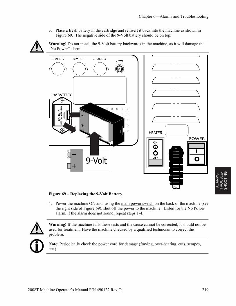
ALA
RM
S
TR
OU
BL
E-
SH
OO
TIN
G
Chapter 6—Alarms and Troubleshooting
2008T Machine Operator’s Manual P/N 490122 Rev O 219
3. Place a fresh battery in the cartridge and reinsert it back into the machine as shown in Figure 69. The negative side of the 9-Volt battery should be on top.
Warning! Do not install the 9-Volt battery backwards in the machine, as it will damage the “No Power” alarm.
Figure 69 – Replacing the 9-Volt Battery
4. Power the machine ON and, using the main power switch on the back of the machine (see the right side of Figure 69), shut off the power to the machine. Listen for the No Power alarm, if the alarm does not sound, repeat steps 1-4.
Warning! If the machine fails these tests and the cause cannot be corrected, it should not be used for treatment. Have the machine checked by a qualified technician to correct the problem.
Note: Periodically check the power cord for damage (fraying, over-heating, cuts, scrapes, etc.)
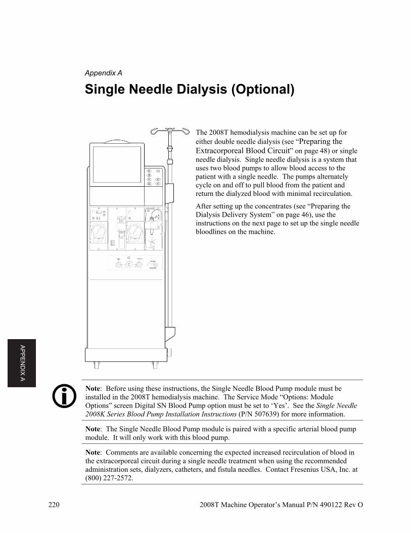
AP
PE
ND
IX A
220 2008T Machine Operator’s Manual P/N 490122 Rev O
Appendix A
Single Needle Dialysis (Optional)
The 2008T hemodialysis machine can be set up for either double needle dialysis (see “Preparing the Extracorporeal Blood Circuit” on page 48) or single needle dialysis. Single needle dialysis is a system that uses two blood pumps to allow blood access to the patient with a single needle. The pumps alternately cycle on and off to pull blood from the patient and return the dialyzed blood with minimal recirculation.
After setting up the concentrates (see “Preparing the Dialysis Delivery System” on page 46), use the instructions on the next page to set up the single needle bloodlines on the machine.
Note: Before using these instructions, the Single Needle Blood Pump module must be installed in the 2008T hemodialysis machine. The Service Mode “Options: Module Options” screen Digital SN Blood Pump option must be set to ‘Yes’. See the Single Needle 2008K Series Blood Pump Installation Instructions (P/N 507639) for more information.
Note: The Single Needle Blood Pump module is paired with a specific arterial blood pump module. It will only work with this blood pump.
Note: Comments are available concerning the expected increased recirculation of blood in the extracorporeal circuit during a single needle treatment when using the recommended administration sets, dialyzers, catheters, and fistula needles. Contact Fresenius USA, Inc. at (800) 227-2572.
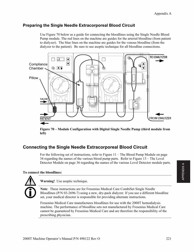
AP
PE
ND
IX A
Appendix A
2008T Machine Operator’s Manual P/N 490122 Rev O 221
Preparing the Single Needle Extracorporeal Blood Circuit
Use Figure 70 below as a guide for connecting the bloodlines using the Single Needle Blood Pump module. The red lines on the machine are guides for the arterial bloodline (from patient to dialyzer). The blue lines on the machine are guides for the venous bloodline (from the dialyzer to the patient). Be sure to use aseptic technique for all bloodline connections.
Figure 70 – Module Configuration with Digital Single Needle Pump (third module from left)
Connecting the Single Needle Extracorporeal Blood Circuit
For the following set of instructions, refer to Figure 11 – The Blood Pump Module on page 34 regarding the names of the various blood pump parts. Refer to Figure 13 – The Level Detector Module on page 36 regarding the names of the various Level Detector module parts.
To connect the bloodlines:
Warning! Use aseptic technique.
Note: These instructions are for Fresenius Medical Care CombiSet Single Needle Bloodlines (P/N 03-2696-7) using a new, dry-pack dialyzer. If you use a different bloodline set, your medical director is responsible for providing alternate instructions.
Fresenius Medical Care manufactures bloodlines for use with the 2008T hemodialysis machine. The performance of bloodline sets not manufactured by Fresenius Medical Care cannot be guaranteed by Fresenius Medical Care and are therefore the responsibility of the prescribing physician.
Pillow
Compliance Chamber
AP
PE
ND
IX A
Appendix A
222 2008T Machine Operator’s Manual P/N 490122 Rev O
Arterial Bloodline Setup
1. Close the medication port clamp located on the short line at the top of the compliance chamber.
2. Snap the compliance chamber into its holder.
3. Connect the arterial monitor line to the pressure port (PSN) on the Single Needle Blood Pump module using a transducer protector. Verify that the monitor line is unclamped.
Warning! Transducer protectors should be used between transducers and each pressure monitor line of the extracorporeal system to prevent the transducers from getting wet. Wet transducer protectors must be replaced, as they will cause inaccurate pressure readings. If the external transducer protector and the internal transducer should become contaminated with blood, the transducer protectors must be replaced, and the transducer must be disinfected or replaced.
4. Locate the “pillow” on the patient end of the arterial bloodline; the pump segment directly above the pillow is the first blood pump segment, this pump segment should be loaded into the arterial blood pump (the first blood pump from the left).
5. Open the arterial blood pump door.
Warning! Inspect the blood pump rotor for proper operation (tubing guide posts not bent, rollers move freely, crank lever moves freely). Bent or loose tubing guide posts can damage bloodlines. Replace rotor if necessary. See page 140 for rotor diagram.
6. If necessary, set the Arterial Blood Pump module for the diameter of the blood pump segment:
Press the Up () and Down () keys on the Arterial Blood Pump module simultaneously. The display will flash.
Press the Up () or Down () key on the Arterial Blood Pump module until the diameter of the pump segment (8.0) being used is displayed.
7. Load the arterial blood pump segment into the arterial blood pump: a. Press and hold the Start/Stop key on the Arterial Blood Pump module to align the
pump rotor for line insertion.
b. Grasp the pump segment and, using thumb pressure, position it behind the left yoke by pressing the tubing retainer inward. Be sure the end of the segment clears the bottom of the yoke.
Warning! Make sure the collar of the pump segment is positioned below the bottom of the yoke. This will minimize the possibility of the segment kinking during pump operation.
c. Press and hold the Start/Stop key. The rotor will rotate to the 5 o’clock position and stop. Relieve pressure on the retainer and release the segment. The beginning of the pump segment should be secured between the left yoke and the tubing retainer.
Warning! Keep fingers free of rotor while it is turning to avoid possible injury.
d. Press and hold the Start/Stop key again and the rotor will rotate one full turn to automatically position the remainder of the segment within the pump housing. After loading, any extra pump segment tubing length should be on the right side of the pump.
AP
PE
ND
IX A
Appendix A
2008T Machine Operator’s Manual P/N 490122 Rev O 223
e. Release the Start/Stop key when the pump segment has been inserted along the track inside the pump housing all the way to the right yoke.
f. Grasp the remaining portion of the segment and, using thumb pressure in a manner similar to step b, position it behind the right yoke.
g. Release the tubing retainer and close the pump door. Be sure the pump segment is free of kinks and both ends of the segment extend below the yoke.
8. Drape the second blood pump segment over the top of the single needle blood pump—do not insert the single needle blood pump segment into the single needle blood pump at this time.
9. Snap remaining arterial tubing in the clips along the red guidelines shown on modules.
10. Aseptically connect the patient end of the arterial line to the priming receptacle. Snap the dialyzer end of the arterial bloodline into the dialyzer holder clip.
Warning! Do not allow the ends to touch the fluid in the bucket to prevent contamination.
Venous Bloodline Setup
1. Close medication port clamp
2. Open the level detector door and roll the venous drip chamber into its holder with the filter below the sensor heads. Close and latch the door.
Warning! The level detector must be calibrated to the venous line model being used.
Warning! If the venous chamber contains a filter, be sure the filter portion of the chamber is positioned below the ultrasonic sensor heads of the drip chamber holder.
3. Connect the venous pressure monitor line to the pressure port. Be sure to insert a transducer protector between the line and the port. Verify that the monitor line is unclamped.
Warning! Transducer protectors should be used between transducers and each pressure monitor line of the extracorporeal system to prevent the transducers from getting wet. Wet transducer protectors must be replaced, as they will cause inaccurate pressure readings. If the external transducer protector and the internal transducer should become contaminated with blood, the transducer protectors must be replaced, and the transducer must be disinfected or replaced.
4. Snap remaining venous tubing in the clips along the blue guidelines shown on modules (do not insert the venous bloodline into the venous clamp yet).
5. Snap the dialyzer end of the venous bloodline into the dialyzer holder clip.
6. Aseptically connect the patient end of the venous line to the priming receptacle.
Warning! Do not allow the ends to touch the fluid in the bucket to prevent contamination.
Dialyzer Setup
1. Mount the dialyzer in its holder, arterial-end up. Screw dialyzer caps onto the dialyzer ports.
AP
PE
ND
IX A
Appendix A
224 2008T Machine Operator’s Manual P/N 490122 Rev O
Priming the Single Needle Blood Circuit
There are two different ways to prime the blood circuit on the 2008T hemodialysis machine:
Standard Prime method: This method allows the operator to prime the blood circuit by controlling the flow of the saline manually.
Prime Amount method: This method limits the amount of saline used in the priming procedure to a preset volume. The preset volume (Prime Amount) is set in Service Mode.
Prime the blood circuit according to how your machine was set up. Follow your unit protocol or dialyzer manufacturer’s instructions for priming and rinsing dialyzers.
Standard Prime Method
1. Connect the dialyzer end of the arterial bloodline to the arterial port of the dialyzer. Rotate the dialyzer to the arterial end down position.
2. Connect the dialyzer end of the venous bloodline to the venous port of the dialyzer.
3. Insert the venous bloodline into the venous line clamp and optical detector on the Level Detector module. Close the optical detector door.
Warning! The tubing beneath the venous drip chamber must be inserted into the venous line clamp and the optical detector.
4. Hang a saline bag and attach an administration line to the saline port on the arterial bloodline below the arterial blood pump. Aseptically spike the saline bag.
5. Gravity prime the patient end of the arterial bloodline below the saline “T” with saline. When primed, clamp the patient end of the arterial bloodline.
6. If the heparin pump is to be used: connect the heparin syringe, prime the heparin line with heparin, and load the heparin syringe into the Heparin Pump module. If the heparin pump is not used, clamp the heparin line.
7. Press the Prime key on the control panel.
8. Press the Start/Stop key on the Arterial Blood Pump module and run the pump at a rate of 150 ml/min. Adjust the flow rate by pressing the (up) or (down) keys. The compliance chamber will automatically fill to an acceptable level.
Warning! The Level Adjust key on the Arterial Blood Pump module can only be used to raise the level in the compliance chamber. Do not press the Level Adjust key so long that the pressure transducer protector becomes wet. Wet transducer protectors must be replaced to avoid erroneous pressure readings.
9. Run the arterial blood pump to flush additional saline through the dialyzer until a fluid level is detected in the venous drip chamber. The blood pump will stop when the level detector detects an acceptable level of fluid.
AP
PE
ND
IX A
Appendix A
2008T Machine Operator’s Manual P/N 490122 Rev O 225
10. Press the RESET key on the control panel to restart the arterial blood pump and continue flushing saline through the blood circuit in accordance with established facility protocol regarding dialyzer rinsing.
11. After the required saline amount has passed through the dialyzer, press the Start/Stop key on the Arterial Blood Pump module to stop the pump.
12. Clamp the patient end of the venous bloodline.
13. Adjust the fluid level in the venous drip chamber by pressing the appropriate or level adjust keys on the Level Detector module. Close the venous pressure monitor line clamp and disconnect the monitor line from the venous pressure port so the port is open to atmosphere.
14. Aseptically connect the patient end of the arterial bloodline to the patient end of the venous bloodline using a sterile recirculation piece. Unclamp both lines.
15. Set the arterial blood pump rate to 350-400 ml/min. Press the Start/Stop key on the Arterial Blood Pump module to start the pump and begin recirculation. Do not insert the single needle blood pump segment into single needle blood pump. If necessary, press the RESET key to clear any alarms.
16. Ensure that the extracorporeal blood circuit is free of air bubbles.
Note: The dialysate lines will have to be attached at the appropriate point during the priming process, depending on facility procedure and manufacturer’s instructions. If 1.5x or 2x dialysate flow (Auto Flow) is selected, be sure that the dialysate flow rate is at least the minimum required rate.
Prime Amount Method
1. Connect the dialyzer end of the arterial bloodline to the arterial port of the dialyzer. Rotate the dialyzer to the arterial end down position.
2. Connect the dialyzer end of the venous bloodline to the venous port of the dialyzer.
3. Hang a saline bag and attach an administration line to the saline port on the arterial bloodline below the arterial blood pump. Aseptically spike the saline bag.
4. Gravity prime the patient end of the arterial bloodline below the saline “T” with saline. When primed, clamp off the patient end of the arterial bloodline.
5. If the heparin pump is to be used: connect the heparin syringe, prime the heparin line with heparin, and load the heparin syringe into the Heparin Pump module. If the heparin pump is not used, clamp the heparin line.
6. Press the Prime key on the control panel.
7. Press the Start/Stop key on the Arterial Blood Pump module and run the pump at a rate of 150 ml/min. Adjust the flow rate by pressing the (up) or (down) keys. The compliance chamber will automatically fill to an acceptable level.
AP
PE
ND
IX A
Appendix A
226 2008T Machine Operator’s Manual P/N 490122 Rev O
Warning! The Level Adjust key on the Arterial Blood Pump module can only be used to raise the level in the compliance chamber. Do not press the Level Adjust key so long that the pressure transducer protector becomes wet. Wet transducer protectors must be replaced to avoid erroneous pressure readings.
8. The arterial blood pump will start and continue to run until the pre-set amount of saline has been flushed through the circuit. When the blood pump stops, clamp the patient end of the venous bloodline.
9. Insert the venous bloodline into the venous line clamp and optical detector on the Level Detector module. Close the optical detector door.
Warning! The tubing beneath the venous drip chamber must be inserted into the venous line clamp and the optical detector.
10. Adjust the fluid level in the venous drip chamber by pressing the appropriate or level adjust keys on the Level Detector module. Close the venous pressure monitor line clamp and disconnect the monitor line from the venous pressure port so the port is open to atmosphere.
11. Aseptically connect the patient end of the arterial bloodline to the patient end of the venous bloodline using a sterile recirculation piece. Unclamp both lines.
12. Set the arterial blood pump rate to 350-400 ml/min. Press the Start/Stop key on the Arterial Blood Pump module to start the pump and begin recirculation. Do not insert the single needle blood pump segment into single needle blood pump. If necessary, press the RESET key to clear any alarms.
13. Ensure that the extracorporeal blood circuit is free of air bubbles.
Note: The dialysate lines will have to be attached at the appropriate point during the priming process, depending on facility procedure and manufacturer’s instructions. If 1.5x or 2x dialysate flow (Auto Flow) is selected, be sure that the dialysate flow rate is at least the minimum required rate.
Testing the 2008T hemodialysis machine with Single Needle blood pump
Follow the instructions in the “Testing the 2008T Hemodialysis Machine” section on page 55.
AP
PE
ND
IX A
Appendix A
2008T Machine Operator’s Manual P/N 490122 Rev O 227
Recirculation and Final Set-Up Procedure with Single Needle Blood Pump
Note: If you are using a reused dialyzer, you cannot run recirculation with the single needle blood pump segment inserted. Recirculation is achieved with the arterial blood pump.
1. Rotate the dialyzer to arterial inlet up.
2. Check the conductivity and pH of the dialysate and test for residual disinfectant before connecting the dialysate lines to the dialyzer. For more information on collecting a dialysate sample for testing, see “Testing the Dialysate” on page 256.
Warning! Always verify the conductivity and approximate pH of the dialysate solution through independent means (e.g. using a conductivity meter or pH paper or meter, as applicable) before initiating each dialysis treatment. Verify that the conductivity is reasonably close to the theoretical conductivity value (TCD) and the pH is between 6.9 and 7.6. If they are not, do not initiate dialysis.
3. Connect the dialysate lines to the dialyzer by matching the color of the dialyzer connector to the color of the blood tube fitting and then close the shunt door. When done correctly, the red arterial blood tubing connector and the red dialyzer connector of the dialysate line should be connected to the corresponding ports at the top of the dialyzer. This is to create a counter-current flow (blood flowing from top to bottom, dialysate flowing from bottom to top) inside the dialyzer to maximize clearance.
4. Pull on the dialyzer connectors to make sure they are firmly connected to the dialyzer.
Note: All dialyzer connectors must be fastened tightly to prevent air from entering the dialysate circuit or to prevent dialysate from leaking from the dialyzer.
5. Reconnect the venous monitor line to the venous pressure port. Unclamp the venous pressure monitor line.
6. When the dialysate compartment is filled, rotate the dialyzer so the arterial inlet is down.
7. After priming the extracorporeal blood circuit, press RESET to clear all alarms. Set the blood pump rate to 350-400 ml/min and start the blood pump to begin recirculating the saline through the circuit.
8. Press the (down) key on the Level Detector module to lower the fluid level in the drip chamber. Verify that the blood pump stops and the venous clamp occludes.
Warning! The test of the level detector system must be run as a precaution and aid to identifying potential failures. Remove the machine from service if it fails this test.
9. Press the (up) key on the Level Detector module to raise the fluid level in the drip chamber to an acceptable level.
10. Check blood tubing to ensure that there are no kinks, especially between the blood pump and the dialyzer.
AP
PE
ND
IX A
Appendix A
228 2008T Machine Operator’s Manual P/N 490122 Rev O
Warning! Kinked lines can cause hemolysis of the blood.
Warning! If using a dialyzer that has been stored in a liquid disinfectant such as formaldehyde or Puristeril 340, test the recirculating saline solution for residual disinfectant according to established facility protocol or the manufacturer’s instructions. Special rinsing techniques must also be employed to assure the concentration of disinfectant is reduced and maintained at an appropriate level. These rinsing procedures are the responsibility of the medical director. The procedure must include a test for residual disinfectant and techniques to avoid rebound of the disinfectant. Turning the dialysate flow off when using a reused dialyzer may allow the chemical disinfectant to rebound (increase) to an unacceptable level.
11. Replace the saline bag with a fresh bag if necessary.
12. Check for a normal dialysate flow by observing the rise and fall of the external flow indicator located on the dialyzer supply line. The float should drop four times in about 15 seconds for a 500 ml/min flow, or four times in 10 seconds for an 800 ml/min flow.
13. Open the shunt door and verify that the machine goes into bypass mode. In bypass mode, the float in the flow indicator of the dialyzer supply line should drop and remain at the bottom of the indicator and an audible alarm may sound.
Note: The 2008T hemodialysis machine can be configured (in Service mode) so that audible alarms occur only when the optical detector senses blood. If this option is not selected, an audible alarm will sound when the shunt interlock door is open.
Setting Single Needle Dialysis Treatment Parameters
Follow the instructions in the “Setting Treatment Parameters” section on page 60. The Single Needle option on the “Test & Options” screen will be set after inserting the single needle blood pump segment in the next section.
Starting Single Needle Dialysis
At this point, all treatment parameters and options should be entered. Dialysate should already be verified for absence of disinfectant, verification of prescription, conductivity, and pH should also be confirmed. It is now time to insert the single needle blood pump segment and connect the patient to the 2008T hemodialysis machine via the blood tubing and begin the dialysis treatment.
1. Press the Start/Stop key on the Arterial Blood Pump module to stop the blood pump.
2. Open the single needle blood pump door to insert the single needle blood pump segment.
Warning! Inspect the blood pump rotor for proper operation (tubing guide posts not bent, rollers move freely, crank lever moves freely). Bent or loose tubing guide posts can damage bloodlines. Replace rotor if necessary. See page 140 for rotor diagram.
AP
PE
ND
IX A
Appendix A
2008T Machine Operator’s Manual P/N 490122 Rev O 229
Caution: If you are using a Single Knob Single Needle Blood Pump module, you must make sure that the pump is set for the diameter of the blood pump segment.
Note: If you are using a Single Knob Single Needle Blood Pump module, you must manually load the single needle blood pump segment: Thread the single needle blood pump segment into the single needle pump using the rotor latch (see Figure 58 #1 on page 130) to rotate the single needle pump rotor clockwise. Make sure the left and right pump segment connectors are positioned below the left and right yokes and the line is free from kinks.
3. Load the single needle blood pump segment:
a. Press and hold the Start/Stop key on the Single Needle Blood Pump module to align rotor for line insertion.
b. Grasp the pump segment and, using thumb pressure, position it behind the left yoke by pressing the tubing retainer inward. Be sure the end of the segment clears the bottom of the yoke.
Warning! Make sure the collar of the pump segment is positioned below the bottom of the yoke. This will minimize the possibility of the segment kinking during pump operation.
c. Press and hold the Start/Stop key. The rotor will rotate to the 5 o’clock position and stop. Relieve pressure on the retainer and release the segment. The beginning of the pump segment should be secured between the left yoke and the tubing retainer.
Warning! Keep fingers free of rotor while it is turning to avoid possible injury.
d. Press and hold the Start/Stop key again and the rotor will rotate one full turn to automatically position the remainder of the segment within the pump housing. After loading, any extra pump segment tubing length should be on the right side of the pump.
e. Release the Start/Stop key when the pump segment has been inserted along the track inside the pump housing all the way to the right yoke.
f. Grasp the remaining portion of the segment and, using thumb pressure in a manner similar to step b, position it behind the right yoke.
g. Release the tubing retainer and close the pump door. Be sure the pump segment is free of kinks and both ends of the segment extend below the yoke.
4. On the “Test & Options” screen, select the Single Needle toggle-button to set it to ‘On’ and press the CONFIRM key to confirm the change.
5. Press the Start/Stop key on the Arterial Blood Pump module to start the blood pump.
Note: If using a Single Knob Single Needle Blood Pump module, set the single needle blood flow rate to approximately 20% higher than the arterial blood pump rate. The blood flow rate displayed on the Arterial Blood Pump module with the Single Needle option set to ‘On’ equals the average blood flow rate for both pumps.
Note: Allow the system to recirculate several times before connecting the patient to assure that the extracorporeal circuit is ready.
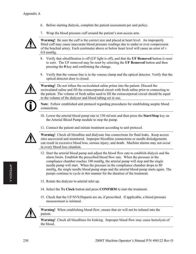
AP
PE
ND
IX A
Appendix A
230 2008T Machine Operator’s Manual P/N 490122 Rev O
6. Before starting dialysis, complete the patient assessment per unit policy.
7. Wrap the blood pressure cuff around the patient’s non-access arm.
Warning! Be sure the cuff is the correct size and placed at heart level. An improperly fitted cuff may cause inaccurate blood pressure readings due to under or over compression of the brachial artery. Each centimeter above or below heart level will cause an error of ± 0.8 mmHg.
8. Verify that ultrafiltration is off (UF light is off), and that the UF Removed button is reset to zero. The UF removed may be reset by selecting the UF Removed button and then pressing the 0 key and confirming the change.
9. Verify that the venous line is in the venous clamp and the optical detector. Verify that the optical detector door is closed.
Warning! Do not infuse the recirculated saline prime into the patient. Discard the recirculated saline and fill the extracorporeal circuit with fresh saline prior to connecting to the patient. The volume of fresh saline used to fill the extracorporeal circuit should be equal to the volume of the dialyzer and blood tubing set in use.
Note: Follow established unit protocol regarding procedures for establishing aseptic blood connections.
10. Lower the arterial blood pump rate to 150 ml/min and then press the Start/Stop key on the Arterial Blood Pump module to stop the pump.
11. Connect the patient and initiate treatment according to unit protocol.
Warning! Check all bloodline and dialysate line connections for fluid leaks. Keep access sites uncovered and monitored. Improper bloodline connections or needle dislodgements can result in excessive blood loss, serious injury, and death. Machine alarms may not occur in every blood loss situation.
12. Start the arterial blood pump and adjust the blood flow rate to establish dialysis and the alarm limits. Establish the prescribed blood flow rate. When the pressure in the compliance chamber reaches 180 mmHg, the arterial pump will stop and the single needle pump will start. When the pressure in the compliance chamber drops to 80 mmHg, the single needle blood pump stops and the arterial blood pump starts again. The pumps continue to cycle in this manner for the duration of the treatment.
13. Rotate the dialyzer to arterial inlet up.
14. Select the Tx Clock button and press CONFIRM to start the treatment.
15. Check that the UF/SVS/Heparin are on, if prescribed. If applicable, a blood pressure measurement is initiated.
Warning! When establishing blood flow, ensure that air will not be infused into the patient.
Warning! Check all bloodlines for kinking. Improper blood flow may cause hemolysis of the blood.
AP
PE
ND
IX A
Appendix A
2008T Machine Operator’s Manual P/N 490122 Rev O 231
Monitoring the Single Needle Dialysis Treatment
Follow the instructions in the “Monitoring the Treatment” section on page 99.
Warning! Administration of intravenous solution during single needle operation requires the use of a sterile one-way valve between the administration set and the infusion site to prevent back up of solution.
Single Needle Alarms and Troubleshooting
Follow the instructions in the “Alarms and Troubleshooting” section on page 153.
Blood Recirculation Procedure during Single Needle Dialysis
Follow the instructions in the “Blood Recirculation Procedure” section on page 128.
Power Failure during Single Needle Dialysis
Follow the instructions in the “Power Failure during Dialysis” section on page 129.
Completion of the Single Needle Dialysis Treatment
At the end of treatment, when the RTD timer has counted down to 0:00, an alarm sounds and the message, RTD = ZERO, appears in the Status Box. An alarm also sounds when the set amount of ultrafiltrate has been removed. When that happens, the Status Box displays the message, UF GOAL REACHED. To reset either alarm, press the RESET key. If the UF GOAL REACHED and RTD = ZERO alarms occur simultaneously, pressing the RESET key will reset both alarms.
Returning Blood to the Patient
1. Select the Tx Clock button and then press the CONFIRM key to stop the treatment
2. Press the Start/Stop key on the Arterial Blood Pump module to stop the pump
3. On the “Test & Options” screen, select the Single Needle toggle-button to set it to ‘Off’ and press the CONFIRM key to confirm the change.
4. Remove the single needle blood pump segment from the single needle blood pump:
a. Open the door and align the rotor by pressing and holding the Start/Stop key until the pump stops.
AP
PE
ND
IX A
Appendix A
232 2008T Machine Operator’s Manual P/N 490122 Rev O
b. Press the latch below the rotor to release the left (incoming) side of the pump segment. Pull the first couple of inches of the pump segment out of the pump.
c. While keeping firm tension outward on the left (incoming) side of the bloodline, press and hold the Start/Stop key a second time and the pump segment will be released from the pump head.
5. Replace saline bag with a fresh bag if necessary
6. Rinse the blood in the bloodline back to the patient:
a. Clamp the arterial bloodline directly below the saline “T”
b. Open the saline line clamps
c. Start the blood pump and set a rate of 150-200 ml/min
d. When the blood has been returned to the patient, turn the blood pump off and close the saline line clamps
7. Rinse the remaining blood in the arterial bloodline back to the patient:
a. Remove the clamp from below the saline “T” and then clamp the arterial bloodline directly above the saline “T”
b. Open the saline line clamps
c. When the blood has been returned to the patient, close the saline line clamps
Warning! Check all bloodlines and dialysate lines for leaks. Keep access sites uncovered and monitored. Improper bloodline connections or needle dislodgements can result in excessive blood loss, serious injury, and death. Machine alarms may not occur in every blood loss situation.
8. Clamp the arterial and venous bloodlines and the patient’s arterial and venous access lines, and aseptically disconnect them.
Note: Depending on how your machine was configured, and audible alarm may sound when the saline solution reaches the optical sensor. Press RESET to silence the alarm.
Continue with the instructions listed in the “Removing the Dialyzer” section on page 133.
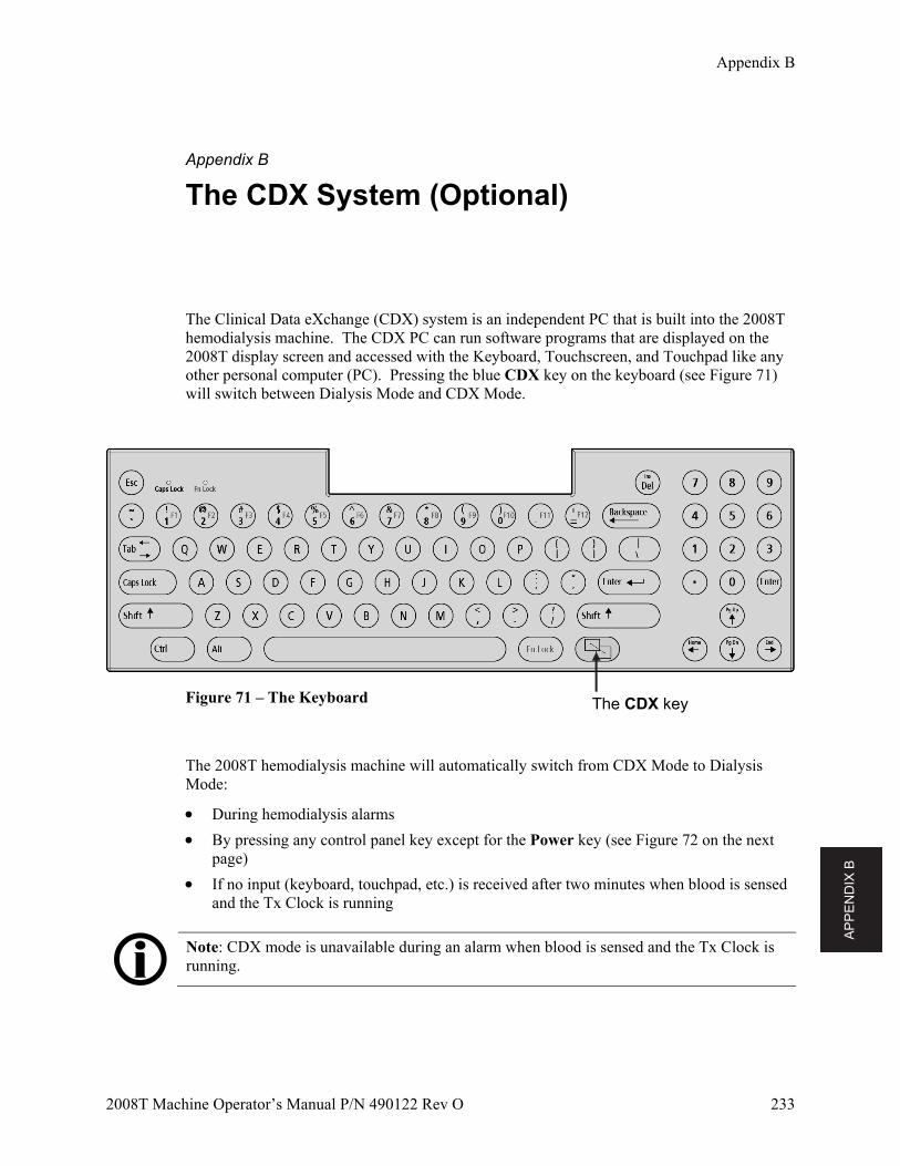
AP
PE
ND
IX B
Appendix B
2008T Machine Operator’s Manual P/N 490122 Rev O 233
Appendix B
The CDX System (Optional)
The Clinical Data eXchange (CDX) system is an independent PC that is built into the 2008T hemodialysis machine. The CDX PC can run software programs that are displayed on the 2008T display screen and accessed with the Keyboard, Touchscreen, and Touchpad like any other personal computer (PC). Pressing the blue CDX key on the keyboard (see Figure 71) will switch between Dialysis Mode and CDX Mode.
Figure 71 – The Keyboard
The 2008T hemodialysis machine will automatically switch from CDX Mode to Dialysis Mode:
During hemodialysis alarms
By pressing any control panel key except for the Power key (see Figure 72 on the next page)
If no input (keyboard, touchpad, etc.) is received after two minutes when blood is sensed and the Tx Clock is running
Note: CDX mode is unavailable during an alarm when blood is sensed and the Tx Clock is running.
The CDX key
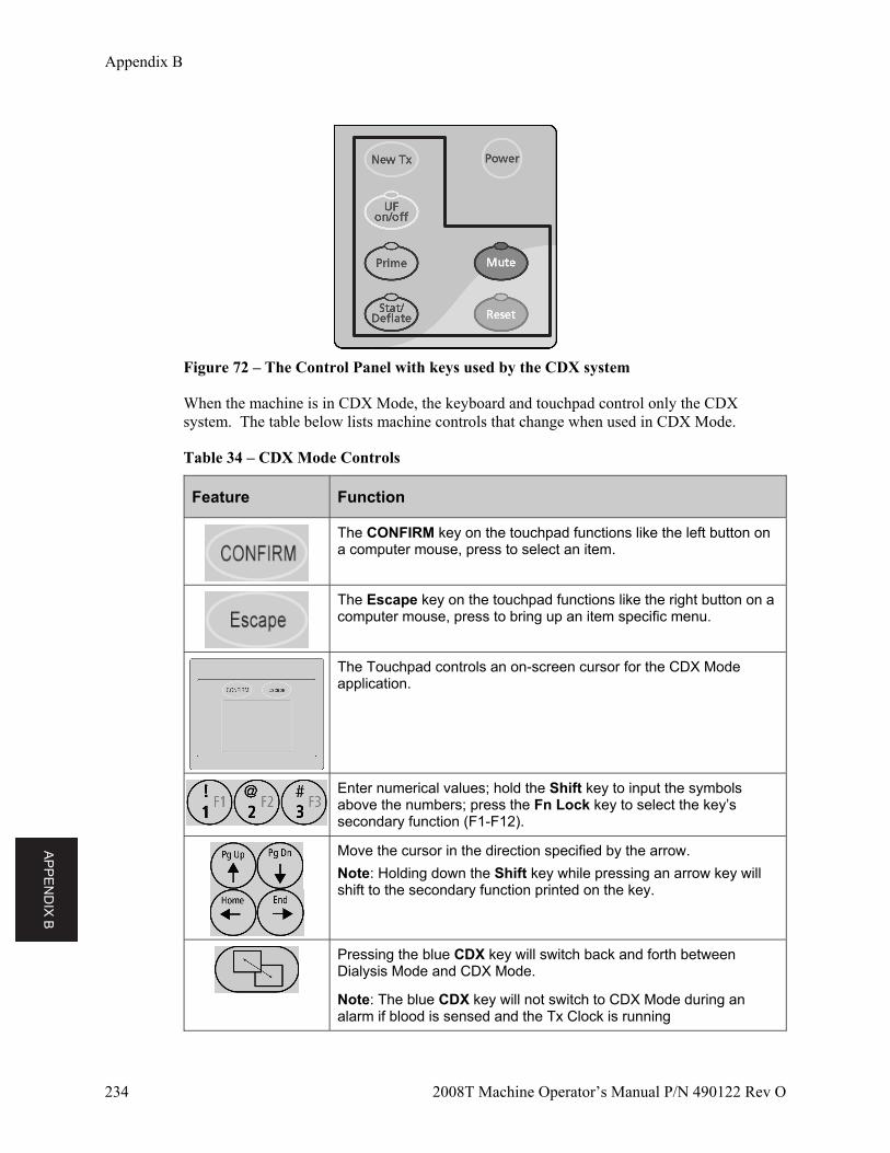
AP
PE
ND
IX B
Appendix B
234 2008T Machine Operator’s Manual P/N 490122 Rev O
Figure 72 – The Control Panel with keys used by the CDX system
When the machine is in CDX Mode, the keyboard and touchpad control only the CDX system. The table below lists machine controls that change when used in CDX Mode.
Table 34 – CDX Mode Controls
Feature Function
The CONFIRM key on the touchpad functions like the left button on a computer mouse, press to select an item.
The Escape key on the touchpad functions like the right button on a computer mouse, press to bring up an item specific menu.
The Touchpad controls an on-screen cursor for the CDX Mode application.
Enter numerical values; hold the Shift key to input the symbols above the numbers; press the Fn Lock key to select the key’s secondary function (F1-F12).
Move the cursor in the direction specified by the arrow.
Note: Holding down the Shift key while pressing an arrow key will shift to the secondary function printed on the key.
Pressing the blue CDX key will switch back and forth between Dialysis Mode and CDX Mode.
Note: The blue CDX key will not switch to CDX Mode during an alarm if blood is sensed and the Tx Clock is running
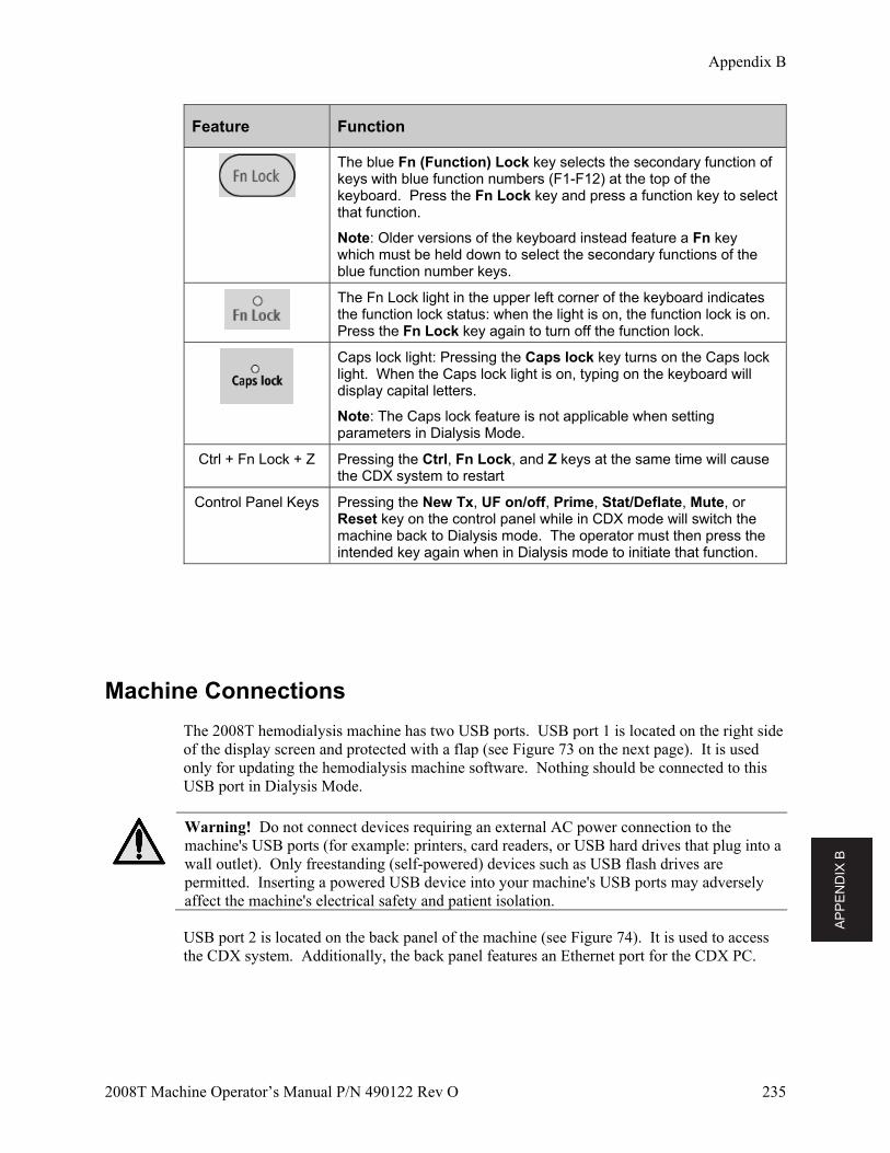
AP
PE
ND
IX B
Appendix B
2008T Machine Operator’s Manual P/N 490122 Rev O 235
Feature Function
The blue Fn (Function) Lock key selects the secondary function of keys with blue function numbers (F1-F12) at the top of the keyboard. Press the Fn Lock key and press a function key to select that function.
Note: Older versions of the keyboard instead feature a Fn key which must be held down to select the secondary functions of the blue function number keys.
The Fn Lock light in the upper left corner of the keyboard indicates the function lock status: when the light is on, the function lock is on. Press the Fn Lock key again to turn off the function lock.
Caps lock light: Pressing the Caps lock key turns on the Caps lock light. When the Caps lock light is on, typing on the keyboard will display capital letters.
Note: The Caps lock feature is not applicable when setting parameters in Dialysis Mode.
Ctrl + Fn Lock + Z Pressing the Ctrl, Fn Lock, and Z keys at the same time will cause the CDX system to restart
Control Panel Keys Pressing the New Tx, UF on/off, Prime, Stat/Deflate, Mute, or Reset key on the control panel while in CDX mode will switch the machine back to Dialysis mode. The operator must then press the intended key again when in Dialysis mode to initiate that function.
Machine Connections
The 2008T hemodialysis machine has two USB ports. USB port 1 is located on the right side of the display screen and protected with a flap (see Figure 73 on the next page). It is used only for updating the hemodialysis machine software. Nothing should be connected to this USB port in Dialysis Mode.
Warning! Do not connect devices requiring an external AC power connection to the machine's USB ports (for example: printers, card readers, or USB hard drives that plug into a wall outlet). Only freestanding (self-powered) devices such as USB flash drives are permitted. Inserting a powered USB device into your machine's USB ports may adversely affect the machine's electrical safety and patient isolation.
USB port 2 is located on the back panel of the machine (see Figure 74). It is used to access the CDX system. Additionally, the back panel features an Ethernet port for the CDX PC.
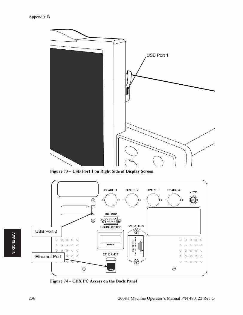
AP
PE
ND
IX B
Appendix B
236 2008T Machine Operator’s Manual P/N 490122 Rev O
Figure 73 – USB Port 1 on Right Side of Display Screen
Figure 74 – CDX PC Access on the Back Panel
USB Port 1
USB Port 2
Ethernet Port
AP
PE
ND
IX B
Appendix B
2008T Machine Operator’s Manual P/N 490122 Rev O 237
Instructions for Clinic Information Systems Personnel
The CDX system may be used to run various Medical Information Systems (MIS) normally housed outside of the 2008T hemodialysis machine and connected through its serial port. The CDX system houses that functionality inside the 2008T hemodialysis machine to reduce cabling and increase user convenience.
Note: The selection, installation, and maintenance of the MIS application is performed by the clinic. No MIS is sold as part of the 2008T hemodialysis machine. The operating system factory-installed on the 2008T hemodialysis machine is for testing purposes only.
Note: The clinic should have a paper patient treatment record or flow sheet available in the event of an MIS application failure.
The 2008T hemodialysis machine runs independent of the CDX system so there is no capacity for the installed MIS to control the 2008T hemodialysis machine.
Operating System and Software Installation
The user of the CDX PC is responsible for installation of the operating system and application for clinical use. This may be installed by either of the following methods:
Caution: Refer to the 2008T Technicians Manual (P/N 490130) when accessing the 2008T hemodialysis machine electronics card cage.
Booting from a USB drive, with the operating system pre-installed, connected to the USB
port on the back panel (see Figure 74). Booting from a USB device to install an operating system image on the existing compact
flash drive.
The BIOS of the CDX PC supports booting from many devices. If booting from anything other than the built-in compact flash device is required, the boot order in the BIOS may need to be updated.
Caution: Incorrectly altering the BIOS could result in the CDX PC not booting up properly. To recall factory BIOS settings, select the “Load Optimized Defaults” in the BIOS.
AP
PE
ND
IX B
Appendix B
238 2008T Machine Operator’s Manual P/N 490122 Rev O
To update the BIOS for operating system installation
1. Press the Power key on the 2008T hemodialysis machine to start the machine. While on the “Select Program” screen, press the blue CDX key on the keyboard (see Figure 71). CDX mode will be displayed.
2. Press the Ctrl + Fn Lock + Z keys simultaneously to restart the CDX system.
3. Press the DEL key when prompted as the CDX system computer boots up.
4. Next, go to the “Advanced BIOS Features” screen.
5. Specify the first boot device to be as required.
6. Once the boot order has been set, save the changes and restart the system to begin the installation process.
Installing MIS software on the CDX PC
After the operating system has been installed, the MIS software may be set up in a manner similar to a PC.
Data Storage
Data storage is on a removable Compact Flash (CF) card holding at least 4GByte of data. The CF card appears as a standard hard drive to the CDX PC.
Note: CF cards are flash based storage and a wear out mechanism exists. CF cards contain internal features to wear level the writing to avoid premature failure. However, it would be advisable to keep writing to a minimum. Writing 5 Gbytes or less per day should not present a problem.
Also note that the 2008T hemodialysis machine may be powered off at any time. There is no requirement that the user do a PC shutdown before power is removed. Because of this, it is recommended that the operating system implemented be tolerant to this situation, or the operator should be instructed to shut down the operating system before shutting off power. The use of a read only operating system is recommended if the user will not shut down the operating system.
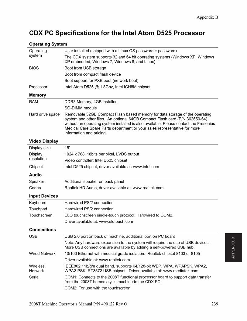
AP
PE
ND
IX B
Appendix B
2008T Machine Operator’s Manual P/N 490122 Rev O 239
CDX PC Specifications for the Intel Atom D525 Processor
Operating System
Operating system
User installed (shipped with a Linux OS password = password)
The CDX system supports 32 and 64 bit operating systems (Windows XP, Windows XP embedded, Windows 7, Windows 8, and Linux)
BIOS Boot from USB storage
Boot from compact flash device
Boot support for PXE boot (network boot)
Processor Intel Atom D525 @ 1.8Ghz, Intel ICH8M chipset
Memory
RAM DDR3 Memory, 4GB installed
SO-DIMM module
Hard drive space Removable 32GB Compact Flash based memory for data storage of the operating system and other files. An optional 64GB Compact Flash card (P/N 362650-64) without an operating system installed is also available. Please contact the Fresenius Medical Care Spare Parts department or your sales representative for more information and pricing.
Video Display
Display size 15”
Display resolution
1024 x 768, 18bits per pixel, LVDS output
Video controller: Intel D525 chipset
Chipset Intel D525 chipset, driver available at: www.intel.com
Audio
Speaker Additional speaker on back panel
Codec Realtek HD Audio, driver available at: www.realtek.com
Input Devices
Keyboard Hardwired PS/2 connection
Touchpad Hardwired PS/2 connection
Touchscreen ELO touchscreen single-touch protocol. Hardwired to COM2.
Driver available at: www.elotouch.com
Connections
USB USB 2.0 port on back of machine, additional port on PC board
Note: Any hardware expansion to the system will require the use of USB devices. More USB connections are available by adding a self-powered USB hub.
Wired Network 10/100 Ethernet with medical grade isolation: Realtek chipset 8103 or 8105
Driver available at: www.realtek.com
Wireless Network
IEEE802.11b/g/n dual band, supports 64/128-bit WEP, WPA, WPAPSK, WPA2, WPA2-PSK. RT3572 USB chipset. Driver available at: www.mediatek.com
Serial COM1: Connects to the 2008T functional processor board to support data transfer from the 2008T hemodialysis machine to the CDX PC.
COM2: For use with the touchscreen
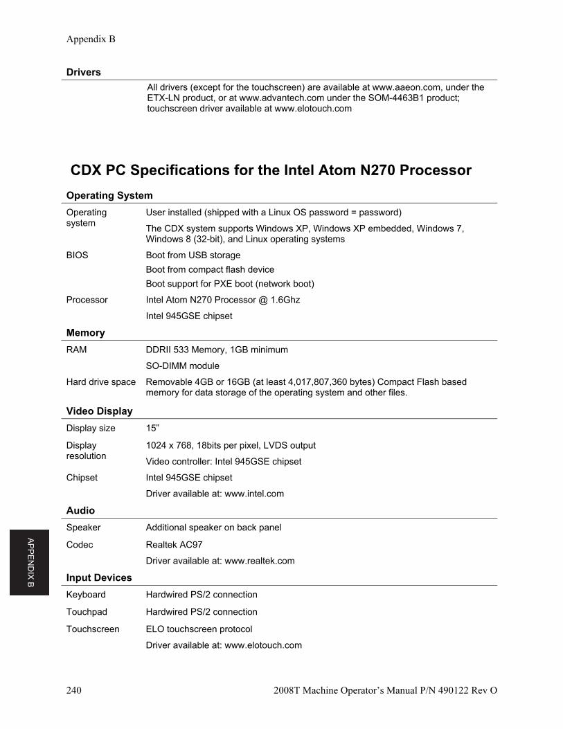
AP
PE
ND
IX B
Appendix B
240 2008T Machine Operator’s Manual P/N 490122 Rev O
Drivers
All drivers (except for the touchscreen) are available at www.aaeon.com, under the ETX-LN product, or at www.advantech.com under the SOM-4463B1 product; touchscreen driver available at www.elotouch.com
CDX PC Specifications for the Intel Atom N270 Processor
Operating System
Operating system
User installed (shipped with a Linux OS password = password)
The CDX system supports Windows XP, Windows XP embedded, Windows 7, Windows 8 (32-bit), and Linux operating systems
BIOS Boot from USB storage
Boot from compact flash device
Boot support for PXE boot (network boot)
Processor Intel Atom N270 Processor @ 1.6Ghz
Intel 945GSE chipset
Memory
RAM DDRII 533 Memory, 1GB minimum
SO-DIMM module
Hard drive space Removable 4GB or 16GB (at least 4,017,807,360 bytes) Compact Flash based memory for data storage of the operating system and other files.
Video Display
Display size 15”
Display resolution
1024 x 768, 18bits per pixel, LVDS output
Video controller: Intel 945GSE chipset
Chipset Intel 945GSE chipset
Driver available at: www.intel.com
Audio
Speaker Additional speaker on back panel
Codec Realtek AC97
Driver available at: www.realtek.com
Input Devices
Keyboard Hardwired PS/2 connection
Touchpad Hardwired PS/2 connection
Touchscreen ELO touchscreen protocol
Driver available at: www.elotouch.com
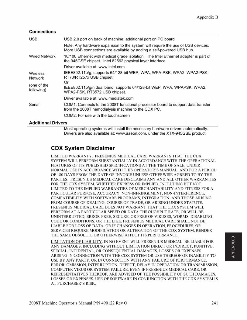
AP
PE
ND
IX B
Appendix B
2008T Machine Operator’s Manual P/N 490122 Rev O 241
Connections
USB USB 2.0 port on back of machine, additional port on PC board
Note: Any hardware expansion to the system will require the use of USB devices. More USB connections are available by adding a self-powered USB hub.
Wired Network 10/100 Ethernet with medical grade isolation: The Intel Ethernet adapter is part of the 945GSE chipset. Intel 82562 physical layer interface
Driver available at: www.intel.com
Wireless Network
(one of the following)
IEEE802.11b/g, supports 64/128-bit WEP, WPA, WPA-PSK, WPA2, WPA2-PSK. RT73/RT257x USB chipset. Or IEEE802.11b/g/n dual band, supports 64/128-bit WEP, WPA, WPAPSK, WPA2, WPA2-PSK. RT3572 USB chipset.
Driver available at: www.mediatek.com
Serial COM1: Connects to the 2008T functional processor board to support data transfer from the 2008T hemodialysis machine to the CDX PC.
COM2: For use with the touchscreen
Additional Drivers
Most operating systems will install the necessary hardware drivers automatically. Drivers are also available at: www.aaeon.com, under the XTX-945GSE product
CDX System Disclaimer LIMITED WARRANTY. FRESENIUS MEDICAL CARE WARRANTS THAT THE CDX SYSTEM WILL PERFORM SUBSTANTIALLY IN ACCORDANCE WITH THE OPERATIONAL FEATURES OF ITS PUBLISHED SPECIFICATIONS AT THE TIME OF SALE, UNDER NORMAL USE IN ACCORDANCE WITH THIS OPERATOR’S MANUAL, AND FOR A PERIOD OF 180 DAYS FROM THE DATE OF INVOICE UNLESS OTHERWISE AGREED TO BY THE PARTIES. FRESENIUS MEDICAL CARE DISCLAIMS ANY AND ALL OTHER WARRANTIES FOR THE CDX SYSTEM, WHETHER EXPRESS OR IMPLIED, INCLUDING BUT NOT LIMITED TO THE IMPLIED WARRANTIES OF MERCHANTABILITY AND FITNESS FOR A PARTICULAR PURPOSE, ACCURACY, NON-INFRINGEMENT, NON-INTERFERENCE, COMPATIBILITY WITH SOFTWARE PROGRAMS, INTEGRATION, AND THOSE ARISING FROM COURSE OF DEALING, COURSE OF TRADE, OR ARISING UNDER STATUTE. FRESENIUS MEDICAL CARE DOES NOT WARRANT THAT THE CDX SYSTEM WILL PERFORM AT A PARTICULAR SPEED OR DATA THROUGHPUT RATE, OR WILL BE UNINTERRUPTED, ERROR-FREE, SECURE, OR FREE OF VIRUSES, WORMS, DISABLING CODE OR CONDITIONS, OR THE LIKE. FRESENIUS MEDICAL CARE SHALL NOT BE LIABLE FOR LOSS OF DATA, OR IF CHANGES IN OPERATION, PROCEDURES, OR SERVICES REQUIRE MODIFICATION OR ALTERATION OF THE CDX SYSTEM, RENDER THE SAME OBSOLETE OR OTHERWISE AFFECT ITS PERFORMANCE.
LIMITATION OF LIABILITY. IN NO EVENT WILL FRESENIUS MEDICAL BE LIABLE FOR ANY DAMAGES, INCLUDING WITHOUT LIMITATION DIRECT OR INDIRECT, PUNITIVE, SPECIAL, INCIDENTAL, OR CONSEQUENTIAL DAMAGES, LOSSES OR EXPENSES ARISING IN CONNECTION WITH THE CDX SYSTEM OR USE THEREOF OR INABILITY TO USE BY ANY PARTY, OR IN CONNECTION WITH ANY FAILURE OF PERFORMANCE, ERROR, OMISSION, INTERRUPTION, DEFECT, DELAY IN OPERATION OR TRANSMISSION, COMPUTER VIRUS OR SYSTEM FAILURE, EVEN IF FRESENIUS MEDICAL CARE, OR REPRESENTATIVES THEREOF, ARE ADVISED OF THE POSSIBILITY OF SUCH DAMAGES, LOSSES OR EXPENSES. USE OF SOFTWARE IN CONJUNCTION WITH THE CDX SYSTEM IS AT PURCHASER’S RISK.

AP
PE
ND
IX C
242 2008T Machine Operator’s Manual P/N 490122 Rev O
Appendix C
Concentrate Types
The 2008T hemodialysis machine can be set up for various concentrate types. If a bicarbonate-type concentrate is to be used, both bicarbonate concentrate and acid concentrate must be connected to the machine. The specific bicarbonate type is selected in Service Mode during calibration. Bicarbonate solution is not stable over time. Make a fresh batch for each treatment according to the manufacturer’s instructions.
Warning! The machine must be labeled to indicate the type of concentrate for which it is configured. Check the composition (i.e., Na, Cl, K, Ca, Mg, HCO3) and pH of the dialysate solution after the machine is installed or after the machine is modified for different concentrate types. Check the conductivity and approximate pH of the dialysate solution with an independent device before initiating dialysis. Improper conductivity or pH could result in patient injury or death.
The table on the following page provides a data reference for ensuring the compatibility of the concentrates selected and instructions on the proper mixtures ratios.
Warning! Acetate concentrates are used individually with the machine. No bicarbonate concentrate is used. The 2008T hemodialysis machine is a standard 1:34 proportioning machine. When it is at a facility that uses 1:44 acid, be sure to use the keys and labeling as indicated. Use of 1:44 acid with a 1:34 acetate machine may cause patient injury or death.
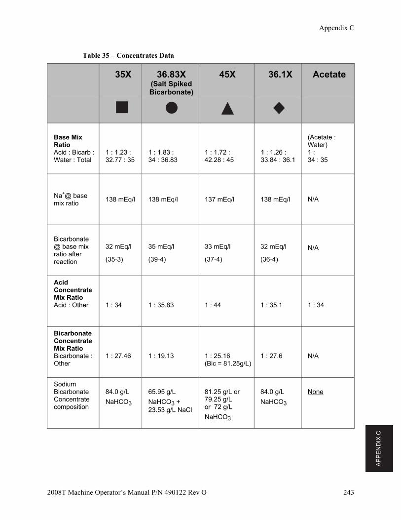
AP
PE
ND
IX C
Appendix C
2008T Machine Operator’s Manual P/N 490122 Rev O 243
Table 35 – Concentrates Data
35X 36.83X (Salt SpikedBicarbonate)
45X 36.1X Acetate
Base Mix Ratio Acid : Bicarb : Water : Total
1 : 1.23 : 32.77 : 35
1 : 1.83 : 34 : 36.83
1 : 1.72 : 42.28 : 45
1 : 1.26 : 33.84 : 36.1
(Acetate : Water) 1 : 34 : 35
Na+@ base mix ratio
138 mEq/l 138 mEq/l 137 mEq/l 138 mEq/l N/A
Bicarbonate @ base mix ratio after reaction
32 mEq/l
(35-3)
35 mEq/l
(39-4)
33 mEq/l
(37-4)
32 mEq/l
(36-4)
N/A
Acid Concentrate Mix Ratio Acid : Other
1 : 34
1 : 35.83
1 : 44
1 : 35.1
1 : 34
Bicarbonate Concentrate Mix Ratio Bicarbonate : Other
1 : 27.46
1 : 19.13
1 : 25.16 (Bic = 81.25g/L)
1 : 27.6
N/A
Sodium Bicarbonate Concentrate composition
84.0 g/L
NaHCO3
65.95 g/L
NaHCO3 + 23.53 g/L NaCl
81.25 g/L or 79.25 g/L or 72 g/L
NaHCO3
84.0 g/L
NaHCO3
None
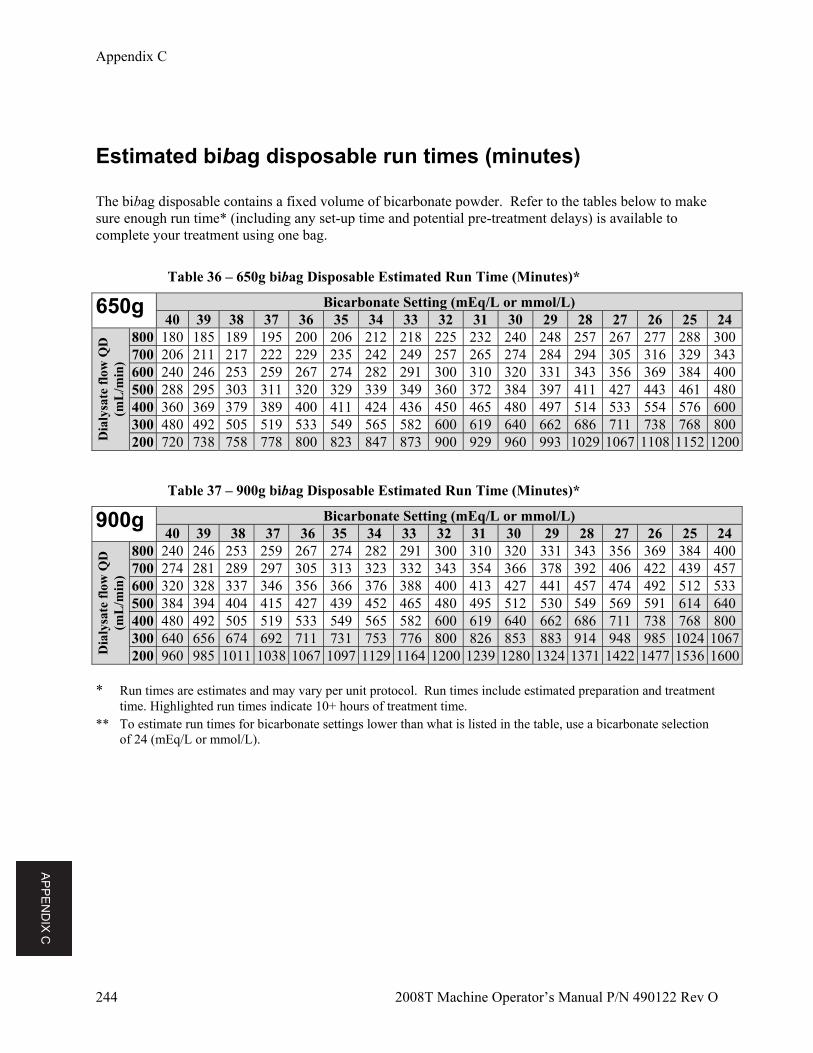
AP
PE
ND
IX C
Appendix C
244 2008T Machine Operator’s Manual P/N 490122 Rev O
Estimated bibag disposable run times (minutes) The bibag disposable contains a fixed volume of bicarbonate powder. Refer to the tables below to make sure enough run time* (including any set-up time and potential pre-treatment delays) is available to complete your treatment using one bag.
Table 36 – 650g bibag Disposable Estimated Run Time (Minutes)*
650g Bicarbonate Setting (mEq/L or mmol/L) 40 39 38 37 36 35 34 33 32 31 30 29 28 27 26 25 24
Dia
lysa
te f
low
QD
(m
L/m
in)
800 180 185 189 195 200 206 212 218 225 232 240 248 257 267 277 288 300700 206 211 217 222 229 235 242 249 257 265 274 284 294 305 316 329 343600 240 246 253 259 267 274 282 291 300 310 320 331 343 356 369 384 400500 288 295 303 311 320 329 339 349 360 372 384 397 411 427 443 461 480400 360 369 379 389 400 411 424 436 450 465 480 497 514 533 554 576 600300 480 492 505 519 533 549 565 582 600 619 640 662 686 711 738 768 800200 720 738 758 778 800 823 847 873 900 929 960 993 1029 1067 1108 1152 1200
Table 37 – 900g bibag Disposable Estimated Run Time (Minutes)*
900g Bicarbonate Setting (mEq/L or mmol/L) 40 39 38 37 36 35 34 33 32 31 30 29 28 27 26 25 24
Dia
lysa
te f
low
QD
(m
L/m
in)
800 240 246 253 259 267 274 282 291 300 310 320 331 343 356 369 384 400700 274 281 289 297 305 313 323 332 343 354 366 378 392 406 422 439 457600 320 328 337 346 356 366 376 388 400 413 427 441 457 474 492 512 533500 384 394 404 415 427 439 452 465 480 495 512 530 549 569 591 614 640400 480 492 505 519 533 549 565 582 600 619 640 662 686 711 738 768 800300 640 656 674 692 711 731 753 776 800 826 853 883 914 948 985 1024 1067200 960 985 1011 1038 1067 1097 1129 1164 1200 1239 1280 1324 1371 1422 1477 1536 1600
* Run times are estimates and may vary per unit protocol. Run times include estimated preparation and treatment
time. Highlighted run times indicate 10+ hours of treatment time. ** To estimate run times for bicarbonate settings lower than what is listed in the table, use a bicarbonate selection
of 24 (mEq/L or mmol/L).
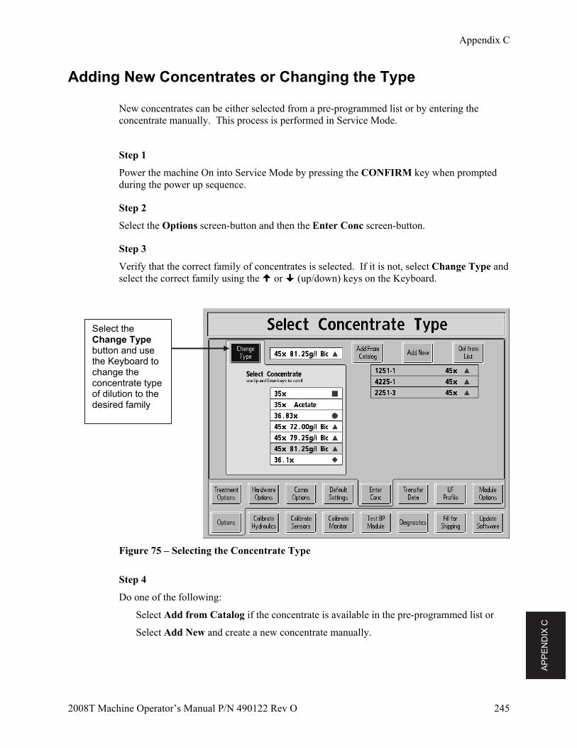
AP
PE
ND
IX C
Appendix C
2008T Machine Operator’s Manual P/N 490122 Rev O 245
Adding New Concentrates or Changing the Type
New concentrates can be either selected from a pre-programmed list or by entering the concentrate manually. This process is performed in Service Mode.
Step 1
Power the machine On into Service Mode by pressing the CONFIRM key when prompted during the power up sequence.
Step 2
Select the Options screen-button and then the Enter Conc screen-button.
Step 3
Verify that the correct family of concentrates is selected. If it is not, select Change Type and select the correct family using the or (up/down) keys on the Keyboard.
Figure 75 – Selecting the Concentrate Type
Step 4
Do one of the following:
Select Add from Catalog if the concentrate is available in the pre-programmed list or
Select Add New and create a new concentrate manually.
Select the Change Type button and use the Keyboard to change the concentrate type of dilution to the desired family
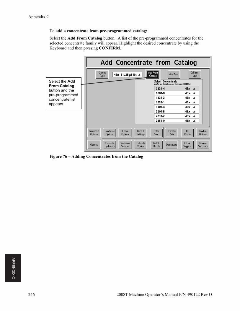
AP
PE
ND
IX C
Appendix C
246 2008T Machine Operator’s Manual P/N 490122 Rev O
To add a concentrate from pre-programmed catalog:
Select the Add From Catalog button. A list of the pre-programmed concentrates for the selected concentrate family will appear. Highlight the desired concentrate by using the Keyboard and then pressing CONFIRM.
Figure 76 – Adding Concentrates from the Catalog
Select the Add From Catalog button and the pre-programmed concentrate list appears.
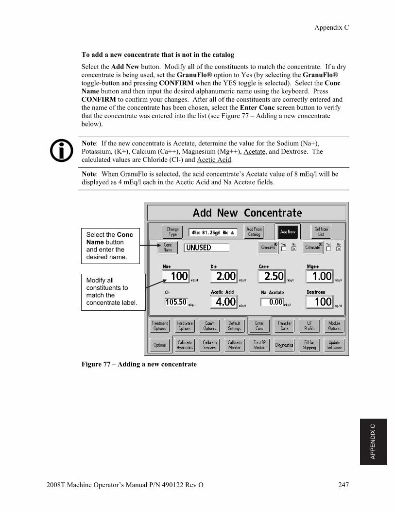
AP
PE
ND
IX C
Appendix C
2008T Machine Operator’s Manual P/N 490122 Rev O 247
To add a new concentrate that is not in the catalog
Select the Add New button. Modify all of the constituents to match the concentrate. If a dry concentrate is being used, set the GranuFlo® option to Yes (by selecting the GranuFlo® toggle-button and pressing CONFIRM when the YES toggle is selected). Select the Conc Name button and then input the desired alphanumeric name using the keyboard. Press CONFIRM to confirm your changes. After all of the constituents are correctly entered and the name of the concentrate has been chosen, select the Enter Conc screen button to verify that the concentrate was entered into the list (see Figure 77 – Adding a new concentrate below).
Note: If the new concentrate is Acetate, determine the value for the Sodium (Na+), Potassium, (K+), Calcium (Ca++), Magnesium (Mg++), Acetate, and Dextrose. The calculated values are Chloride (Cl-) and Acetic Acid.
Note: When GranuFlo is selected, the acid concentrate’s Acetate value of 8 mEq/l will be displayed as 4 mEq/l each in the Acetic Acid and Na Acetate fields.
Figure 77 – Adding a new concentrate
Modify all constituents to match the concentrate label.
Select the Conc Name button and enter the desired name.
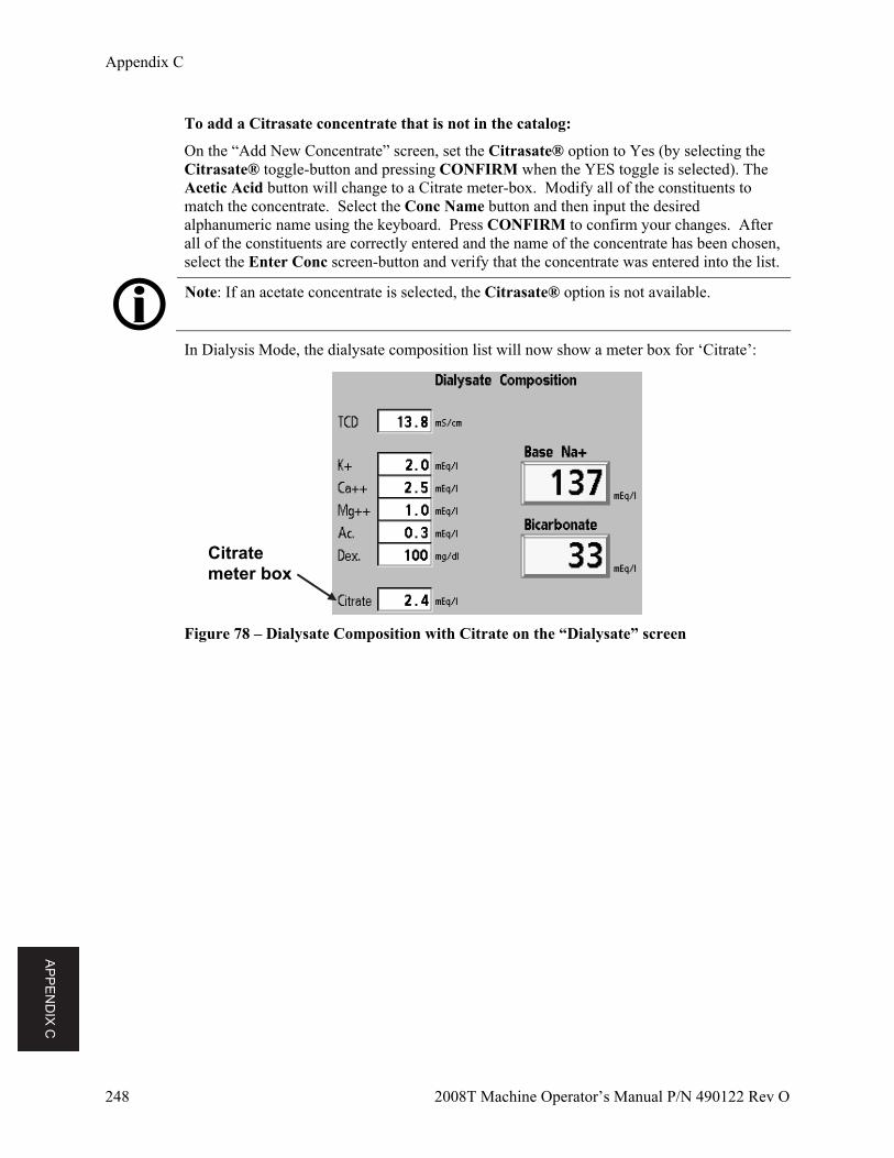
AP
PE
ND
IX C
Appendix C
248 2008T Machine Operator’s Manual P/N 490122 Rev O
To add a Citrasate concentrate that is not in the catalog:
On the “Add New Concentrate” screen, set the Citrasate® option to Yes (by selecting the Citrasate® toggle-button and pressing CONFIRM when the YES toggle is selected). The Acetic Acid button will change to a Citrate meter-box. Modify all of the constituents to match the concentrate. Select the Conc Name button and then input the desired alphanumeric name using the keyboard. Press CONFIRM to confirm your changes. After all of the constituents are correctly entered and the name of the concentrate has been chosen, select the Enter Conc screen-button and verify that the concentrate was entered into the list.
Note: If an acetate concentrate is selected, the Citrasate® option is not available.
In Dialysis Mode, the dialysate composition list will now show a meter box for ‘Citrate’:
Figure 78 – Dialysate Composition with Citrate on the “Dialysate” screen
Citrate meter box
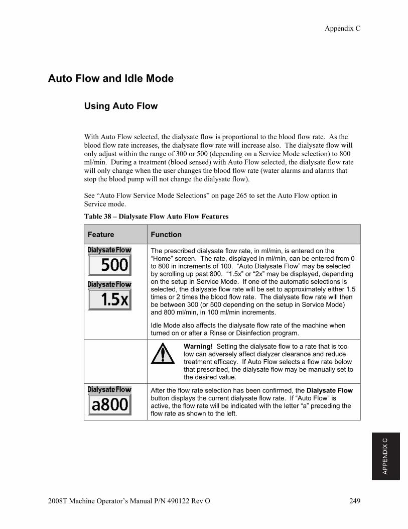
AP
PE
ND
IX C
Appendix C
2008T Machine Operator’s Manual P/N 490122 Rev O 249
Auto Flow and Idle Mode
Using Auto Flow
With Auto Flow selected, the dialysate flow is proportional to the blood flow rate. As the blood flow rate increases, the dialysate flow rate will increase also. The dialysate flow will only adjust within the range of 300 or 500 (depending on a Service Mode selection) to 800 ml/min. During a treatment (blood sensed) with Auto Flow selected, the dialysate flow rate will only change when the user changes the blood flow rate (water alarms and alarms that stop the blood pump will not change the dialysate flow).
See “Auto Flow Service Mode Selections” on page 265 to set the Auto Flow option in Service mode.
Table 38 – Dialysate Flow Auto Flow Features
Feature Function
The prescribed dialysate flow rate, in ml/min, is entered on the “Home” screen. The rate, displayed in ml/min, can be entered from 0 to 800 in increments of 100. “Auto Dialysate Flow” may be selected by scrolling up past 800. “1.5x” or “2x” may be displayed, depending on the setup in Service Mode. If one of the automatic selections is selected, the dialysate flow rate will be set to approximately either 1.5 times or 2 times the blood flow rate. The dialysate flow rate will then be between 300 (or 500 depending on the setup in Service Mode) and 800 ml/min, in 100 ml/min increments.
Idle Mode also affects the dialysate flow rate of the machine when turned on or after a Rinse or Disinfection program.
Warning! Setting the dialysate flow to a rate that is too low can adversely affect dialyzer clearance and reduce treatment efficacy. If Auto Flow selects a flow rate below that prescribed, the dialysate flow may be manually set to the desired value.
After the flow rate selection has been confirmed, the Dialysate Flow button displays the current dialysate flow rate. If “Auto Flow” is active, the flow rate will be indicated with the letter “a” preceding the flow rate as shown to the left.
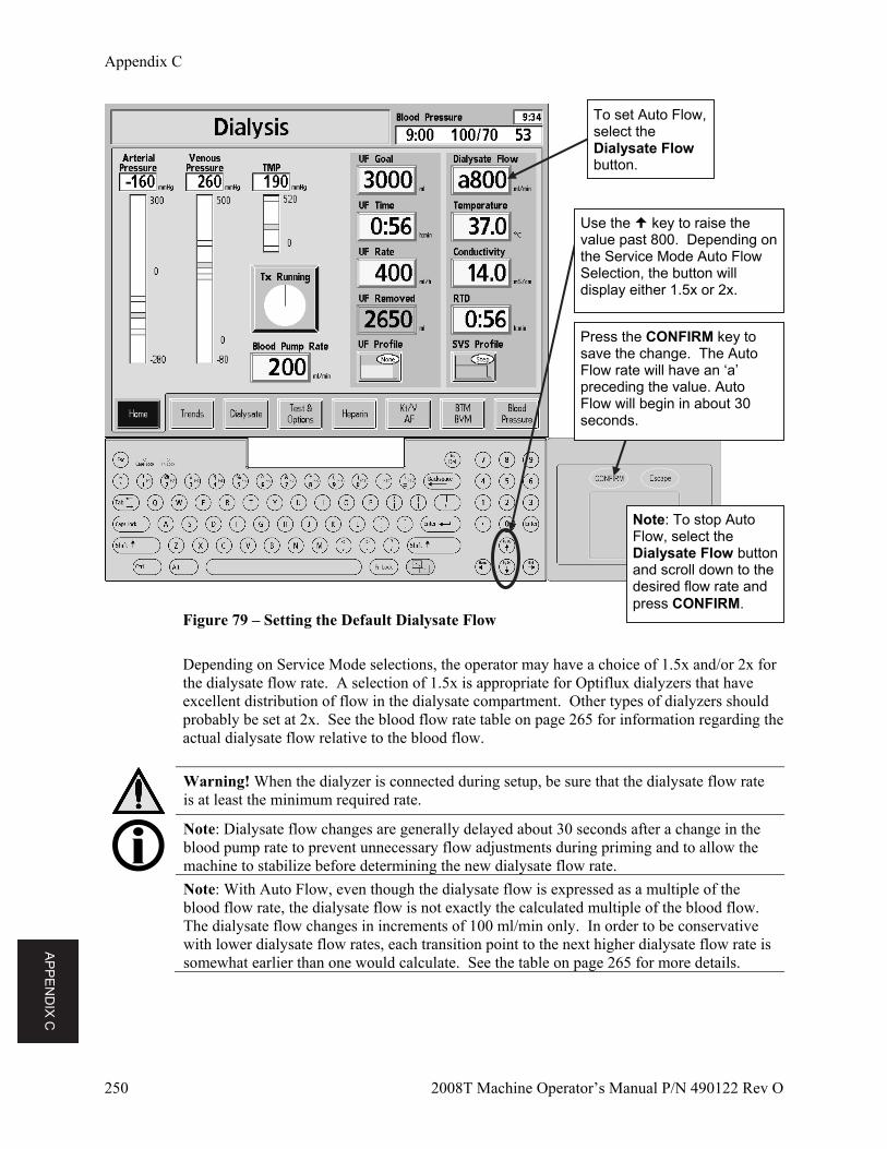
AP
PE
ND
IX C
Appendix C
250 2008T Machine Operator’s Manual P/N 490122 Rev O
Figure 79 – Setting the Default Dialysate Flow
Depending on Service Mode selections, the operator may have a choice of 1.5x and/or 2x for the dialysate flow rate. A selection of 1.5x is appropriate for Optiflux dialyzers that have excellent distribution of flow in the dialysate compartment. Other types of dialyzers should probably be set at 2x. See the blood flow rate table on page 265 for information regarding the actual dialysate flow relative to the blood flow.
Warning! When the dialyzer is connected during setup, be sure that the dialysate flow rate is at least the minimum required rate.
Note: Dialysate flow changes are generally delayed about 30 seconds after a change in the blood pump rate to prevent unnecessary flow adjustments during priming and to allow the machine to stabilize before determining the new dialysate flow rate.
Note: With Auto Flow, even though the dialysate flow is expressed as a multiple of the blood flow rate, the dialysate flow is not exactly the calculated multiple of the blood flow. The dialysate flow changes in increments of 100 ml/min only. In order to be conservative with lower dialysate flow rates, each transition point to the next higher dialysate flow rate is somewhat earlier than one would calculate. See the table on page 265 for more details.
Note: To stop Auto Flow, select the Dialysate Flow button and scroll down to the desired flow rate and press CONFIRM.
Use the key to raise the value past 800. Depending on the Service Mode Auto Flow Selection, the button will display either 1.5x or 2x.
Press the CONFIRM key to save the change. The Auto Flow rate will have an ‘a’ preceding the value. Auto Flow will begin in about 30 seconds.
To set Auto Flow, select the Dialysate Flow button.
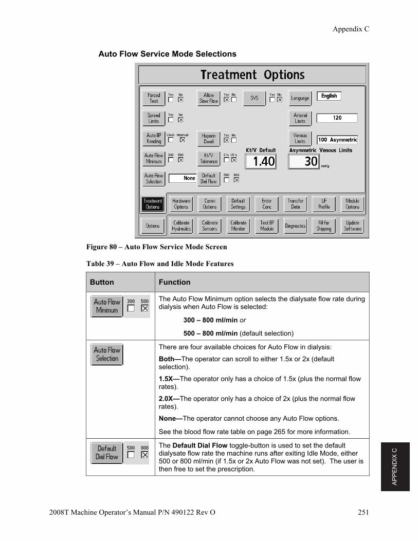
AP
PE
ND
IX C
Appendix C
2008T Machine Operator’s Manual P/N 490122 Rev O 251
Auto Flow Service Mode Selections
Figure 80 – Auto Flow Service Mode Screen
Table 39 – Auto Flow and Idle Mode Features
Button Function
The Auto Flow Minimum option selects the dialysate flow rate during dialysis when Auto Flow is selected:
300 – 800 ml/min or
500 – 800 ml/min (default selection)
There are four available choices for Auto Flow in dialysis:
Both—The operator can scroll to either 1.5x or 2x (default selection).
1.5X—The operator only has a choice of 1.5x (plus the normal flow rates).
2.0X—The operator only has a choice of 2x (plus the normal flow rates).
None—The operator cannot choose any Auto Flow options.
See the blood flow rate table on page 265 for more information.
The Default Dial Flow toggle-button is used to set the default dialysate flow rate the machine runs after exiting Idle Mode, either 500 or 800 ml/min (if 1.5x or 2x Auto Flow was not set). The user is then free to set the prescription.
AP
PE
ND
IX C
Appendix C
252 2008T Machine Operator’s Manual P/N 490122 Rev O
Idle Mode
Regardless of Auto Flow selections, the machine will take control of the dialysate flow during idle periods.
During idle periods, the machine will run dialysate flow at 300 ml/min provided the following conditions are met:
A long power down, rinse, disinfect, or self test has just occurred
No new dialysate flow rate has been set
Conductivity is within limits
The blood pump is off
The Tx Clock has not been started or
Tx has ended (i.e., RTD counted to 0, blood not sensed, and blood pump is off)
Idle Flow is cancelled when the blood pump is turned on, a new dialysate flow rate is selected, or the treatment has started (i.e., RTD > 0 or blood is sensed). The dialysate flow will then be the selected default dialysate flow (see page 251) or what the user has entered on the “Home” screen.
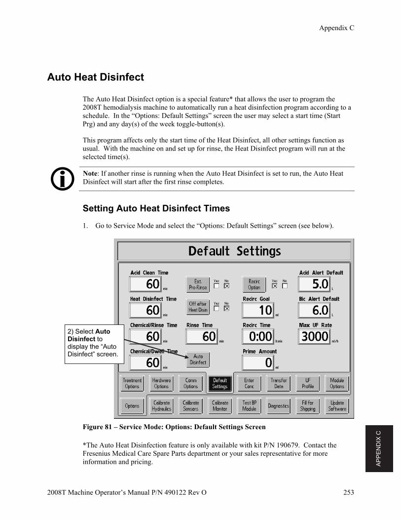
AP
PE
ND
IX C
Appendix C
2008T Machine Operator’s Manual P/N 490122 Rev O 253
Auto Heat Disinfect
The Auto Heat Disinfect option is a special feature* that allows the user to program the 2008T hemodialysis machine to automatically run a heat disinfection program according to a schedule. In the “Options: Default Settings” screen the user may select a start time (Start Prg) and any day(s) of the week toggle-button(s).
This program affects only the start time of the Heat Disinfect, all other settings function as usual. With the machine on and set up for rinse, the Heat Disinfect program will run at the selected time(s).
Note: If another rinse is running when the Auto Heat Disinfect is set to run, the Auto Heat Disinfect will start after the first rinse completes.
Setting Auto Heat Disinfect Times
1. Go to Service Mode and select the “Options: Default Settings” screen (see below).
Figure 81 – Service Mode: Options: Default Settings Screen
*The Auto Heat Disinfection feature is only available with kit P/N 190679. Contact the Fresenius Medical Care Spare Parts department or your sales representative for more information and pricing.
2) Select Auto Disinfect to display the “Auto Disinfect” screen.
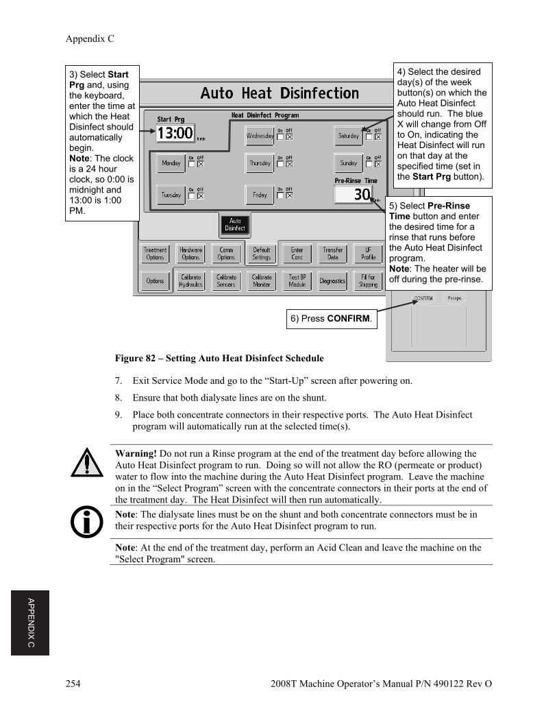
AP
PE
ND
IX C
Appendix C
254 2008T Machine Operator’s Manual P/N 490122 Rev O
Figure 82 – Setting Auto Heat Disinfect Schedule
7. Exit Service Mode and go to the “Start-Up” screen after powering on.
8. Ensure that both dialysate lines are on the shunt.
9. Place both concentrate connectors in their respective ports. The Auto Heat Disinfect program will automatically run at the selected time(s).
Warning! Do not run a Rinse program at the end of the treatment day before allowing the Auto Heat Disinfect program to run. Doing so will not allow the RO (permeate or product) water to flow into the machine during the Auto Heat Disinfect program. Leave the machine on in the “Select Program” screen with the concentrate connectors in their ports at the end of the treatment day. The Heat Disinfect will then run automatically.
Note: The dialysate lines must be on the shunt and both concentrate connectors must be in their respective ports for the Auto Heat Disinfect program to run.
Note: At the end of the treatment day, perform an Acid Clean and leave the machine on the "Select Program" screen.
3) Select Start Prg and, using the keyboard, enter the time at which the Heat Disinfect should automatically begin. Note: The clock is a 24 hour clock, so 0:00 is midnight and 13:00 is 1:00 PM. 5) Select Pre-Rinse
Time button and enter the desired time for a rinse that runs before the Auto Heat Disinfect program. Note: The heater will be off during the pre-rinse.
6) Press CONFIRM.
4) Select the desired day(s) of the week button(s) on which the Auto Heat Disinfect should run. The blue X will change from Off to On, indicating the Heat Disinfect will run on that day at the specified time (set in the Start Prg button).
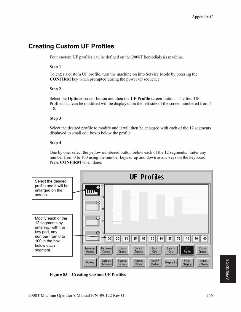
AP
PE
ND
IX C
Appendix C
2008T Machine Operator’s Manual P/N 490122 Rev O 255
Creating Custom UF Profiles
Four custom UF profiles can be defined on the 2008T hemodialysis machine.
Step 1
To enter a custom UF profile, turn the machine on into Service Mode by pressing the CONFIRM key when prompted during the power up sequence.
Step 2
Select the Options screen-button and then the UF Profile screen-button. The four UF Profiles that can be modified will be displayed on the left side of the screen numbered from 5 – 8.
Step 3
Select the desired profile to modify and it will then be enlarged with each of the 12 segments displayed in small edit boxes below the profile.
Step 4
One by one, select the yellow numbered button below each of the 12 segments. Enter any number from 0 to 100 using the number keys or up and down arrow keys on the keyboard. Press CONFIRM when done.
Figure 83 – Creating Custom UF Profiles
Select the desired profile and it will be enlarged on the screen.
Modify each of the 12 segments by entering, with the key pad, any number from 0 to 100 in the box below each segment.
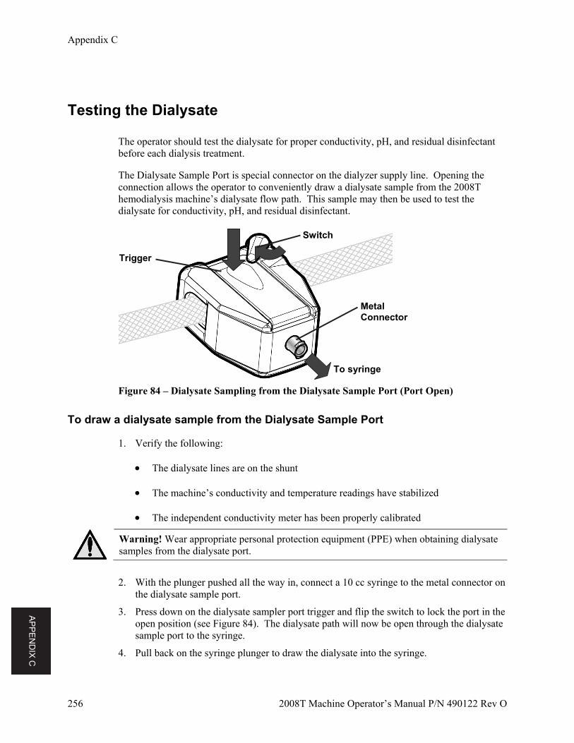
AP
PE
ND
IX C
Appendix C
256 2008T Machine Operator’s Manual P/N 490122 Rev O
Testing the Dialysate
The operator should test the dialysate for proper conductivity, pH, and residual disinfectant before each dialysis treatment.
The Dialysate Sample Port is special connector on the dialyzer supply line. Opening the connection allows the operator to conveniently draw a dialysate sample from the 2008T hemodialysis machine’s dialysate flow path. This sample may then be used to test the dialysate for conductivity, pH, and residual disinfectant.
Figure 84 – Dialysate Sampling from the Dialysate Sample Port (Port Open)
To draw a dialysate sample from the Dialysate Sample Port
1. Verify the following:
The dialysate lines are on the shunt
The machine’s conductivity and temperature readings have stabilized
The independent conductivity meter has been properly calibrated
Warning! Wear appropriate personal protection equipment (PPE) when obtaining dialysate samples from the dialysate port.
2. With the plunger pushed all the way in, connect a 10 cc syringe to the metal connector on
the dialysate sample port.
3. Press down on the dialysate sampler port trigger and flip the switch to lock the port in the open position (see Figure 84). The dialysate path will now be open through the dialysate sample port to the syringe.
4. Pull back on the syringe plunger to draw the dialysate into the syringe.
To syringe
Trigger
Switch
Metal Connector
AP
PE
ND
IX C
Appendix C
2008T Machine Operator’s Manual P/N 490122 Rev O 257
5. Close the dialysate sample port: Flip the switch away from the trigger and release the trigger (see “The Shunt Interlock” on page 34 for picture of dialysate sample port with the switch pushed away from the trigger). The dialysate sample port is now closed again.
6. Disconnect the syringe from the dialysate sample port and discard first sample.
7. Reconnect the syringe to the dialysate sample port, open the dialysate sample port and collect the required amount of dialysate for testing per clinic protocol.
Warning! When connecting a syringe directly to the dialysate sample port, do not inject used dialysate back into the system.
Note: If the testing sample is measured in a container, be sure to rinse the container with dialysate at least three times in order to bring the container up to the temperature of dialysate for proper conductivity.
8. Close the dialysate sample port and disconnect the syringe. Use the facility’s standard measuring devices and follow the device’s instructions to test the dialysate sample per clinic protocol for:
Conductivity - for example, set the meter to read conductivity, connect the syringe, and observe the readings. If the reading is not reasonably close to the theoretical conductivity value (TCD), check the meter’s calibration and retest the dialysate sample. If the reading is still not within limits, take the 2008T hemodialysis machine out of service and contact a qualified technician.
pH - for example, using pH paper, dip the indicator strip in the dialysate for one (1) second and immediately compare it to the manufacturer’s color chart. The color on the indicator strip will indicate the dialysate’s pH. If the reading is not between 6.9 and 7.6, test with another pH indicator strip. If the reading is still not within the specified limits, take the 2008T hemodialysis machine out of service and contact a qualified technician.
Residual disinfectant - see “Testing for Disinfectant” on page 151 for more information
Warning! After testing the dialysate through independent means (e.g., using a conductivity meter and pH paper or meter), verify that the conductivity is reasonably close to the theoretical conductivity value (TCD) and the pH is between 6.9 and 7.6. The machine must also be free of residual disinfectant. If these conditions are not met, do not initiate dialysis.
9. Document the conductivity, pH, or residual disinfectant test readings in the patient treatment record or flow sheet.
Note: Make sure the dialysate sample port switch is locked away from the trigger and the trigger is not pressed down after taking a dialysate sample. Allowing the trigger to stay depressed will cause fluid leaks.
AP
PE
ND
IX C
Appendix C
258 2008T Machine Operator’s Manual P/N 490122 Rev O
Available Software & Hardware Treatment Options and Default Settings
The following options are available on the 2008T hemodialysis machine and selected from the Service Mode in either the “Treatment Options” screen or “Hardware Options” screen.
Forced Test
Upon power up and entering dialysis (except after a power failure or short power down), the machine will be in Standby. In Standby, the blood pump doesn’t run (except for Prime and Level Adjust). The ultrafiltration and Sodium Variation System cannot be turned on. “STANDBY FOR TEST” is displayed as a low priority message.
The test sequence will automatically start 30 seconds after the test criteria have been met. Standby ends with the initiation of the test (whether by the operator or automatically).
Spread Limits
When activated and no blood leak alarm exists, the RESET key can be used to spread the arterial and venous alarm limits by 300 mmHg for 30 seconds. The TMP alarm limits will completely open. After 30 seconds the limits will reset around the current pressure readings.
Auto Blood Pressure Reading
This option can be used to select the method for determining when to take a blood pressure reading. With “Interval” selected, the readings occur at the time interval selected. With “Clock Time” selected, the blood pressure is taken at specified times (e.g. every half hour on the hour and half hour).
Auto Heat Disinfect
In the “Options: Default Settings” screen the user may select a start time (Start Prg), days of the week toggle-buttons, and a pre-rinse time to automatically run a Heat Disinfect program. This program affects only the start time of the Heat Disinfect, all other settings function as usual. With the machine on and set up for rinse, the Heat Disinfect program will run at the selected time(s). Note: Requires special activation for this feature, contact Fresenius Medical Care Spare Parts department or your sales representative for more information and pricing.
Off After Heat Disin
Set in the “Options: Default Settings” screen, the user may choose to automatically power down the machine after an Auto Heat Disinfect program is run.
AP
PE
ND
IX C
Appendix C
2008T Machine Operator’s Manual P/N 490122 Rev O 259
Allow Slow Flow
The Allow Slow Flow option allows the machine to run dialysate flows of 100 or 200 ml/min. This feature is activated in Service Mode and requires a temperature calibration. Please refer to the 2008T Hemodialysis System Calibration Procedures manual (P/N 508032).
SVS
The SVS (Sodium Variation System) feature may be enabled or disabled (software version 2.34 or later).
Heparin Dwell
The Heparin Dwell option displays the Heparin Dwell button on the “Heparin” screen. The button acts as a five minute timer; after a manual heparin bolus is administered and the operator selects and confirms the Heparin Dwell button, causing the yellow Status Light to flash for five minutes while the heparin is dwelling.
Kt/V Graph Tolerance
Either a 0% or a 15% tolerance from the target Kt/V is selectable in Service Mode. If 15% is selected and the projected Kt/V is less than 85% of the target, the operator will be alerted. If 0% is selected and the projected Kt/V is less than 100% of the target, the operator will be alerted.
Kt/V Default
The default Kt/V (target or minimum value) is selectable in the Service Mode.
Language
The operating screens may be setup so that they are in either French (Canada), Spanish (Mexico) or English (USA). Service Mode is always in English.
Arterial and Venous Pressure Limits
The width of the venous and arterial pressure windows are set by these options. The windows may be set to a fixed width for all treatments or the user may be allowed to set the limits for each treatment in the Test & Options screen. The arterial window may be set to a total width of 120, 160, or 200 mmHg. The venous window may be set to for 100 asymmetric, or 120, 160, 200 mmHg width. If 100 asymmetric limits are chosen, the lower venous limit will tighten to the selected value after a short time delay. This value is selected with the “100 Asymmetric Limits” parameter entry button in Service Mode. The choices are 20, 25, 30, 35 mmHg. The lowest value that does not cause frequent nuisance alarms should be chosen.
AP
PE
ND
IX C
Appendix C
260 2008T Machine Operator’s Manual P/N 490122 Rev O
Online PHT
The online pressure holding test (PHT) is enabled or disabled with this button. Normally, the PHT should be set to “Yes”.
Arterial Chamber
This option is used to define whether the arterial chamber is pre-pump or post-pump. The range of the display is different depending on the location of the chamber.
Audible Alarms
This option may be set so that audible alarms do not occur in certain situations. With “Yes” set, audible alarms will occur in any alarm situation when either blood is sensed in the venous bloodline or the lines are off the shunt. If “No” is selected, audible alarms only occur when blood is sensed. Note: Regardless of this setting, the machine responses, such as bypass or blood pump and venous clamp operation are unaffected.
T and C Mode
This is for manufacturing operations only and should never be selected by the facility.
0 Arterial Limit
With this option set to yes, the upper arterial limit cannot be above 0 (with pre-pump arterial monitoring only) when blood is sensed unless the spreading limits function is active.
Beacon (Status Light)
There are four possible selections for this option: Alarm, FDS08, OLC, Status:
With “Alarm” selected, the red light acts the same as the audible alarm. The yellow light illuminates when warnings occur. The green light is illuminated when there are no alarms or warnings.
With “FDS08” selected, the red light acts the same as the audible alarm. The yellow light is based on a flag sent from FDS08 that indicates the machine is set outside of established dialysis order limits. The green light illuminates when the blood volume processed has been achieved as required by the FDS08 dialysis order.
With “OLC” selected, the red light acts the same as the audible alarm. The yellow light is illuminated when the projected Kt/V is less than 100% of the target Kt/V (depending on selected Service Mode option). The Green light is illuminated if there are no alarms, and the necessary OLC parameters have been set (Volume, Target Kt/V, and OLC enabled) and the Kt/V is projected to be at least 100% of target (depending on selected Service Mode option).
With “Status” selected, the lights act the same as the Red/Yellow/Green indicator lights on the machine.
AP
PE
ND
IX C
Appendix C
2008T Machine Operator’s Manual P/N 490122 Rev O 261
DIASAFE Plus Filter
This option defines whether or not a Diasafe Plus filter is present in the machine. As some of the timing of various functions is dependent on the volume in the filter, this option must be set properly.
HE Leak Test
The HE (Heat Exchanger) Leak Test is available in software versions 2.53 and later. Setting this option to ‘Yes’ will run a four minute pressure holding test on the Heat Exchanger after the Chemical/Rinse program’s 45 second pre-rinse.
Clean, Rinse, and Disinfect times
The times for these various programs may be set in the Service Mode.
Extended Pre-Rinse
With this option set to yes, the pre-rinse time for heat disinfect is increased to 20 minutes with reduced flow and higher fluid temperature through the drain line.
Recirculate Option
If active, a RECIRC GOAL and TIME can be selected. When Recirculation is initiated, the preselected goal and time with the calculated rate will automatically display on the “Dialysis” screen and start ultrafiltration.
Prime Amount
A desired prime volume from 100–1000 ml can be selected. This allows Prime to continue until the selected volume has been delivered (measured by the blood pump speed).
Acid and Bic Alert Default
The operator may use the option to sound an alert when the concentrate jugs are low. This is setup in the “Dialysate” screen. These default values are set using these parameter entry buttons.
Max. UF Rate
The maximum UF rate that machine is limited with this selection. The choices are 1000, 2000, 3000, 4000 ml/h.
AP
PE
ND
IX C
Appendix C
262 2008T Machine Operator’s Manual P/N 490122 Rev O
Crit-Line
The Crit-Line option must be set to ‘Yes’ in Service Mode in order to use the Crit-Line in a Clip (CLiC) device during a hemodialysis treatment. Note that the BTM and BVM module options are unavailable if Crit-Line is selected.
Crit-Line Graph
The operator can choose to display either the BV (Blood Volume) or Hct (Hematocrit) graphs on the “Crit-Line” screen. The default Crit-Line graph is the BV graph.
Other Options
There are other options on these screens that may not be specifically described here. Generally, these are setup options that are based upon the presence or absence of other modules or hardware.
Options which require a “key” for activation
Certain options are extra cost or limited in availability and must be activated by use of a special code stored on the functional board. Examples of this sort of feature include OLC. Upon purchase of such a feature, use the following procedure to activate it on the machine.
Caution: This procedure should be performed by a qualified individual. Be sure to follow electrostatic discharge (ESD) procedures when removing the board and replacing the EEPROM chips on the board.
To transfer the option, the EEPROM “hardware key” is placed in IC20 on the functional board in place of the calibration EEPROM. Save the calibration EEPROM as it must be returned to the same machine. Be sure to match the notch on the EEPROM with the socket.
Return the functional board to the machine and turn on the power.
Upon power up the functional board reads the contents of the memory from the EEPROM key.
The message “New feature loaded. Power off. Replace eeprom.” is displayed.
Turn off power, replace the EEPROM “hardware key” with the calibration EEPROM, and turn the power back on.
Note: The key may be used only once. If the key is reused, the machine locks up and displays the message “Eeprom already used. Power off. Replace eeprom”.
AP
PE
ND
IX C
Appendix C
2008T Machine Operator’s Manual P/N 490122 Rev O 263
Equipment Storage and Maintenance
Follow the storage and maintenance procedures for dialysis equipment used for Intermittent Hemodialysis (IHD) in the ICU setting.
Warning! Possible explosion hazard if used in the presence of flammable anesthetics.
Storage Location
If the dialysis unit is incorporated in the hospital, the equipment should be stored so that it will not be damaged. The maintenance of the equipment is normally part of the duty of the dialysis service technician. Depending on the disinfectant and the storage time, frequent flushing of the equipment is necessary.
If it is more convenient to store the equipment close to the ICU, the dedicated storage space should have an access to tap water, power and a drain. The room should be well vented, if disinfectant is used.
Storage Preparation
Before storing the 2008T hemodialysis machine, the hydraulics should be disinfected. It is also necessary to wipe the external parts of the machine with a surface cleaner. Frequency of disinfection and length of the dwell time depend on the disinfectant and shall be determined by acceptable culture result. The following table lists commonly used procedures to store equipment and then return it from storage. Validate your own procedure according to the hospital policy. After prolonged storage, use a bleach disinfectant prior to patient use.
Table 40 – Disinfectant Information
Disinfectant Program Dwell time Retest and Repeat
Formaldehyde Fill Hydraulic (Service Mode)
Unlimited 3 – 4 weeks
Bleach Chemical Disinfection program
Only for time of disinfection program
24 hours
Puristeril 340 Renalin
Chemical Disinfection program
Only for time of disinfection program
24 hours
Heat Heat Disinfection program
Recirculate and shut machine off
24 hours
AP
PE
ND
IX C
Appendix C
264 2008T Machine Operator’s Manual P/N 490122 Rev O
Machine Specifications Dimensions
Floor space Approximately 54 cm wide by 63 cm deep
Height 149 cm
Total weight Approximately 90 kg
Operating conditions 60 – 100 °F (15.5 – 38 °C)
Relative Humidity 10% to 90%, non-condensing
Storage conditions Room temp, 6 months, Do not freeze
Relative Humidity 10% to 90%, non-condensing
Electrical
Power Supply—Main Single phase AC 117 V ±10% 60 Hz ±3 Hz must be connected to a circuit which is equipped with a hospital grade receptacle and is protected by circuit breaker and ground fault interrupter (GFI). Resistance from chassis to ground must be < 0.2 ohm.
Power Consumption Does not exceed 12.5 amps
Fuses 6.3 amp medium blow fuse, 2 each
16 amp double pole rocker switch circuit breaker for heater
External Connections Isolated RS232 and Ethernet ports; leakage current isolation per UL 60601-1 between the machine and external computer
Heat Dissipation to Room 600 to 700 BTU/hr
Electromagnetic compatibility See EMC Declaration on page 271
Electrical safety (UL 60601-1)
Protection against electric shock Type: Safety class I Degree: Type B
Type CF: Only BPM Blood Pressure Cuff
Leakage currents According to UL 60601-1
Water
Ingress Rating IPX1 (Vertical drip-proof protection)
Back Flow Prevention Integral back flow prevention provided by external vent to atmosphere in water inlet circuit.
Water Pressure Min 20 psi; max 105 psi
Water Temperature Min 10 °C; max 25 °C
AP
PE
ND
IX C
Appendix C
2008T Machine Operator’s Manual P/N 490122 Rev O 265
Water Quality Current national (U.S.) Standards for the Quality of Water:
ANSI/AAMI 13959:2014, Water for hemodialysis and related therapies
ANSI/AAMI 26722:2014, Water treatment equipment for hemodialysis applications and related therapies
Other related standards include:
ANSI/AAMI RD62:2006, Water treatment equipment for hemodialysis applications and related therapies
Drain 3 feet maximum height. Must comply with local codes and must maintain a free fall air gap between drain hose and building drain. 3 meters (approximately 10 feet) maximum drain hose length.
Rinsing Temperature 37 °C. Flow rate 620 ml/min. Time between 10 and 60 minutes (internally selectable)
Dialysate
Dialysate Quality Current national (U.S.) Standards for the Quality of Dialysis Fluid:
ANSI/AAMI 11663:2014, Quality of dialysis fluid for hemodialysis and related therapies
ANSI/AAMI 23500:2014, Guidance for the preparation and quality management of fluids for hemodialysis and related therapies
Other related standards include:
ANSI/AAMI RD52:2004, Dialysate for hemodialysis
Dialysate Flow Adjustment Range
Dialysate Flow button
Accuracy: ± 5%
Sequential (0)/100/200/300/400/500/600/700/800ml/min., selectable in the Dialysis screen; Additionally: 1.5X or 2.0X dialysate flow rate based on the Blood Pump rate (Qb):
Qb w/1.5X selected Qb w/2.0X selected Qd
0 – 165† 0 – 150† 300 166 – 215† 151 – 215† 400 216 – 315† 216 – 265† 500 315 and below‡ 265 and below‡ 500 316 – 415 266 – 315 600 416 – 480 316 – 365 700 481 and above 366 and above 800
Note: All flow rates are approximate. Dialysate flow will not adjust unless the blood pump is adjusted at least 15 – 20 ml/min.
† (if Auto Flow Minimum 300 Qd is set in Service Mode)
‡ (if Auto Flow Minimum 500 Qd is set in Service Mode)
Partial Dialysate Collection From Drain line, intermittent collection using a 3 Liter PD drain bag as a collection device with a Safe-Lock connector (optional).
Concentrate Supply
Concentrate Quality Current national (U.S.) Standards for the Quality of Concentrates: ANSI/ AAMI 13958:2014, Concentrates for hemodialysis and related therapies
Concentrate Pressure Max suction height 3 feet; Max supplied pressure 2 psi
Note: Max supplied pressure is 10 psi with bibag kit installed.
AP
PE
ND
IX C
Appendix C
266 2008T Machine Operator’s Manual P/N 490122 Rev O
Proportional Mixing System
Acid Volumetric, selectable:
1:34 1:44 1:35.83 1:35.1
Note: Citrasate is for use with 1:44 concentrates only.
Acetate 1:34
Adjustment Range 130 to 155 mEq/L Na+
Bicarbonate Volumetric, selected with associated acid ratio
1:27.46 1:19.13 1:25.16 1:27.6
Adjustment Range 20 to 40 mEq/L Bicarbonate (post-reaction, after mixing with the acid and purified water).
Monitoring Conductivity Average Accuracy: ± 1.5%
Method: Temperature compensated electronic conductivity meter with adjustable alarm limits.
Temperature compensated conductivity display with automatically set alarm windows ±0.5 mS/cm around calculated conductivity*. User can adjust an additional ±0.5 mS/cm within this range.
Optional bibag Dry Bicarbonate Temperature compensated conductivity display with automatically set alarm windows ±0.5 mS/cm around calculated conductivity*, limited to ±0.4 mEq/L @ 24 mEq/L bicarbonate or less.
With alarm window set at ±0.5 mS/cm: User can move alarm window up or down an additional: ±0.2 mS/cm @ 40 mEq/L ±0.1 mS/cm @ 35 mEq/L no adjustment @ 29 mEq/L
*Conductivity is based on the concentrates’ compositional data entered in the Dialysate screen at the standard temperature of 25 C.
Range of Display 10.0 to 17.0 mS/cm. At 25 °C. Alarm limits will not go below 12.5 or above 16.0 mS/cm.
Dialysate Heating Nominal Value of Temperature
35 to 39 °C Accuracy: ± 0.3 °C (measuring accuracy under calibration conditions for a dialysate flow of 500 ml/min)
(selectable in 0.1 °C steps)
Temperature Display Range 35 to 39 °C with alarm limit window automatically adjusted to 2 °C above and below set point. Alarm window will not go below 30° or above 41 °C. Heater 1.3 kW, electronically controlled.
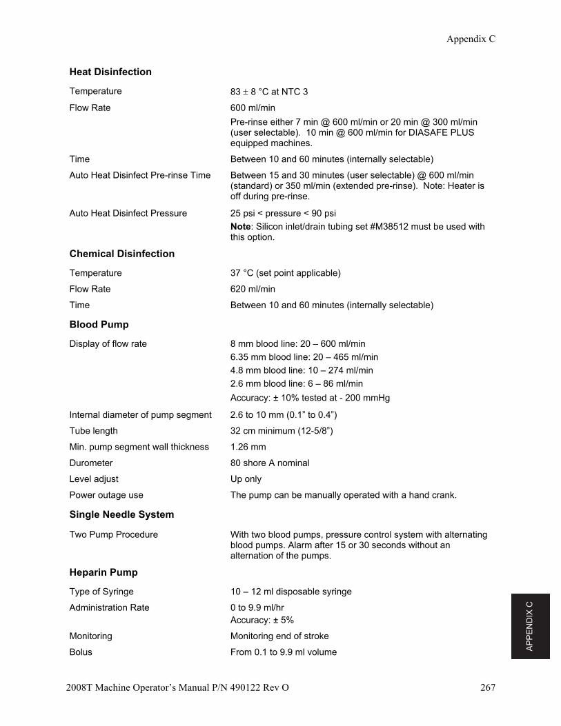
AP
PE
ND
IX C
Appendix C
2008T Machine Operator’s Manual P/N 490122 Rev O 267
Heat Disinfection
Temperature 83 8 °C at NTC 3
Flow Rate 600 ml/min
Pre-rinse either 7 min @ 600 ml/min or 20 min @ 300 ml/min (user selectable). 10 min @ 600 ml/min for DIASAFE PLUS equipped machines.
Time Between 10 and 60 minutes (internally selectable)
Auto Heat Disinfect Pre-rinse Time Between 15 and 30 minutes (user selectable) @ 600 ml/min (standard) or 350 ml/min (extended pre-rinse). Note: Heater is off during pre-rinse.
Auto Heat Disinfect Pressure 25 psi < pressure < 90 psi
Note: Silicon inlet/drain tubing set #M38512 must be used with this option.
Chemical Disinfection
Temperature 37 °C (set point applicable)
Flow Rate 620 ml/min
Time Between 10 and 60 minutes (internally selectable)
Blood Pump
Display of flow rate 8 mm blood line: 20 – 600 ml/min
6.35 mm blood line: 20 – 465 ml/min
4.8 mm blood line: 10 – 274 ml/min
2.6 mm blood line: 6 – 86 ml/min
Accuracy: ± 10% tested at - 200 mmHg
Internal diameter of pump segment 2.6 to 10 mm (0.1” to 0.4”)
Tube length 32 cm minimum (12-5/8”)
Min. pump segment wall thickness 1.26 mm
Durometer 80 shore A nominal
Level adjust Up only
Power outage use The pump can be manually operated with a hand crank.
Single Needle System
Two Pump Procedure With two blood pumps, pressure control system with alternating blood pumps. Alarm after 15 or 30 seconds without an alternation of the pumps.
Heparin Pump
Type of Syringe 10 – 12 ml disposable syringe
Administration Rate 0 to 9.9 ml/hr Accuracy: ± 5%
Monitoring Monitoring end of stroke
Bolus From 0.1 to 9.9 ml volume
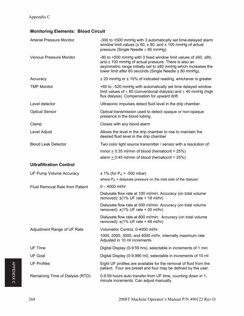
AP
PE
ND
IX C
Appendix C
268 2008T Machine Operator’s Manual P/N 490122 Rev O
Monitoring Elements: Blood Circuit
Arterial Pressure Monitor -300 to +500 mmHg with 3 automatically set time-delayed alarm window limit values (± 60, ± 80, and ± 100 mmHg of actual pressure (Single Needle 80 mmHg).
Venous Pressure Monitor -80 to +500 mmHg with 3 fixed window limit values of ±60, ±80, and ± 100 mmHg of actual pressure. There is also an asymmetric range initially set to ±80 mmHg which increases the lower limit after 60 seconds (Single Needle ± 80 mmHg).
Accuracy ± 20 mmHg or ± 10% of indicated reading, whichever is greater
TMP Monitor +60 to –520 mmHg with automatically set time delayed window limit values of 60 (conventional dialysis) and 40 mmHg (high flux dialysis). Compensation for upward drift.
Level detector Ultrasonic impulses detect fluid level in the drip chamber.
Optical Sensor Optical transmission used to detect opaque or non-opaque presence in the blood tubing.
Clamp Closes with any blood alarm
Level Adjust Allows the level in the drip chamber to rise to maintain the desired fluid level in the drip chamber
Blood Leak Detector Two color light source transmitter / sensor with a resolution of:
minor > 0.35 ml/min of blood (hematocrit = 25%)
alarm > 0.45 ml/min of blood (hematocrit = 25%)
Ultrafiltration Control
UF Pump Volume Accuracy ± 1% (for Pdi > -500 mbar)
where Pdi = dialysate pressure on the inlet side of the dialyzer
Fluid Removal Rate from Patient 0 – 4000 ml/hr
Dialysate flow rate at 100 ml/min: Accuracy (on total volume removed): ±(1% UF rate + 18 ml/hr)
Dialysate flow rate at 500 ml/min: Accuracy (on total volume removed): ±(1% UF rate + 30 ml/hr)
Dialysate flow rate at 800 ml/min: Accuracy (on total volume removed): ±(1% UF rate + 48 ml/hr)
Adjustment Range of UF Rate Volumetric Control, 0-4000 ml/hr
1000, 2000, 3000, and 4000 ml/hr, internally maximum rate Adjusted in 10 ml increments
UF Time Digital Display (0-9:59 hrs), selectable in increments of 1 min
UF Goal Digital Display (0-9,990 ml), selectable in increments of 10 ml
UF Profiles Eight UF profiles are available for the removal of fluid from the patient. Four are preset and four may be defined by the user.
Remaining Time of Dialysis (RTD) 0-9:59 hours auto transfer from UF time, counting down in 1-minute increments. Can adjust manually.
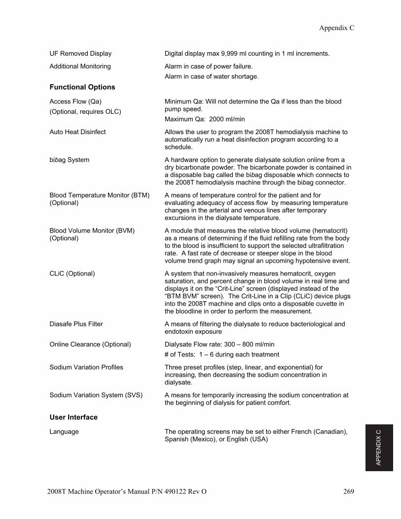
AP
PE
ND
IX C
Appendix C
2008T Machine Operator’s Manual P/N 490122 Rev O 269
UF Removed Display Digital display max 9,999 ml counting in 1 ml increments.
Additional Monitoring Alarm in case of power failure.
Alarm in case of water shortage.
Functional Options
Access Flow (Qa)
(Optional, requires OLC)
Minimum Qa: Will not determine the Qa if less than the blood pump speed.
Maximum Qa: 2000 ml/min
Auto Heat Disinfect Allows the user to program the 2008T hemodialysis machine to automatically run a heat disinfection program according to a schedule.
bibag System A hardware option to generate dialysate solution online from a dry bicarbonate powder. The bicarbonate powder is contained in a disposable bag called the bibag disposable which connects to the 2008T hemodialysis machine through the bibag connector.
Blood Temperature Monitor (BTM) (Optional)
A means of temperature control for the patient and for evaluating adequacy of access flow by measuring temperature changes in the arterial and venous lines after temporary excursions in the dialysate temperature.
Blood Volume Monitor (BVM) (Optional)
A module that measures the relative blood volume (hematocrit) as a means of determining if the fluid refilling rate from the body to the blood is insufficient to support the selected ultrafiltration rate. A fast rate of decrease or steeper slope in the blood volume trend graph may signal an upcoming hypotensive event.
CLiC (Optional) A system that non-invasively measures hematocrit, oxygen saturation, and percent change in blood volume in real time and displays it on the “Crit-Line” screen (displayed instead of the “BTM BVM” screen). The Crit-Line in a Clip (CLiC) device plugs into the 2008T machine and clips onto a disposable cuvette in the bloodline in order to perform the measurement.
Diasafe Plus Filter A means of filtering the dialysate to reduce bacteriological and endotoxin exposure
Online Clearance (Optional) Dialysate Flow rate: 300 – 800 ml/min
# of Tests: 1 – 6 during each treatment
Sodium Variation Profiles Three preset profiles (step, linear, and exponential) for increasing, then decreasing the sodium concentration in dialysate.
Sodium Variation System (SVS) A means for temporarily increasing the sodium concentration at the beginning of dialysis for patient comfort.
User Interface
Language The operating screens may be set to either French (Canadian), Spanish (Mexico), or English (USA)
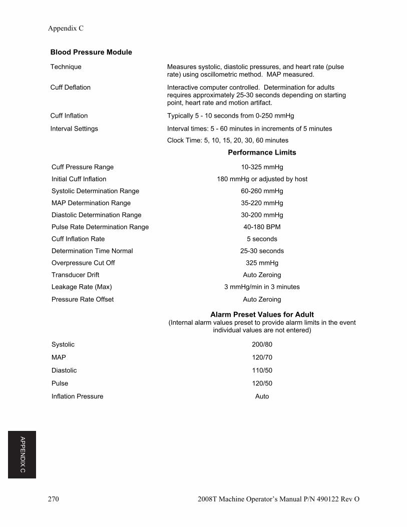
AP
PE
ND
IX C
Appendix C
270 2008T Machine Operator’s Manual P/N 490122 Rev O
Blood Pressure Module
Technique Measures systolic, diastolic pressures, and heart rate (pulse rate) using oscillometric method. MAP measured.
Cuff Deflation Interactive computer controlled. Determination for adults requires approximately 25-30 seconds depending on starting point, heart rate and motion artifact.
Cuff Inflation Typically 5 - 10 seconds from 0-250 mmHg
Interval Settings Interval times: 5 - 60 minutes in increments of 5 minutes
Clock Time: 5, 10, 15, 20, 30, 60 minutes
Performance Limits
Cuff Pressure Range 10-325 mmHg
Initial Cuff Inflation 180 mmHg or adjusted by host
Systolic Determination Range 60-260 mmHg
MAP Determination Range 35-220 mmHg
Diastolic Determination Range 30-200 mmHg
Pulse Rate Determination Range 40-180 BPM
Cuff Inflation Rate 5 seconds
Determination Time Normal 25-30 seconds
Overpressure Cut Off 325 mmHg
Transducer Drift Auto Zeroing
Leakage Rate (Max) 3 mmHg/min in 3 minutes
Pressure Rate Offset Auto Zeroing
Alarm Preset Values for Adult (Internal alarm values preset to provide alarm limits in the event
individual values are not entered)
Systolic 200/80
MAP 120/70
Diastolic 110/50
Pulse 120/50
Inflation Pressure Auto
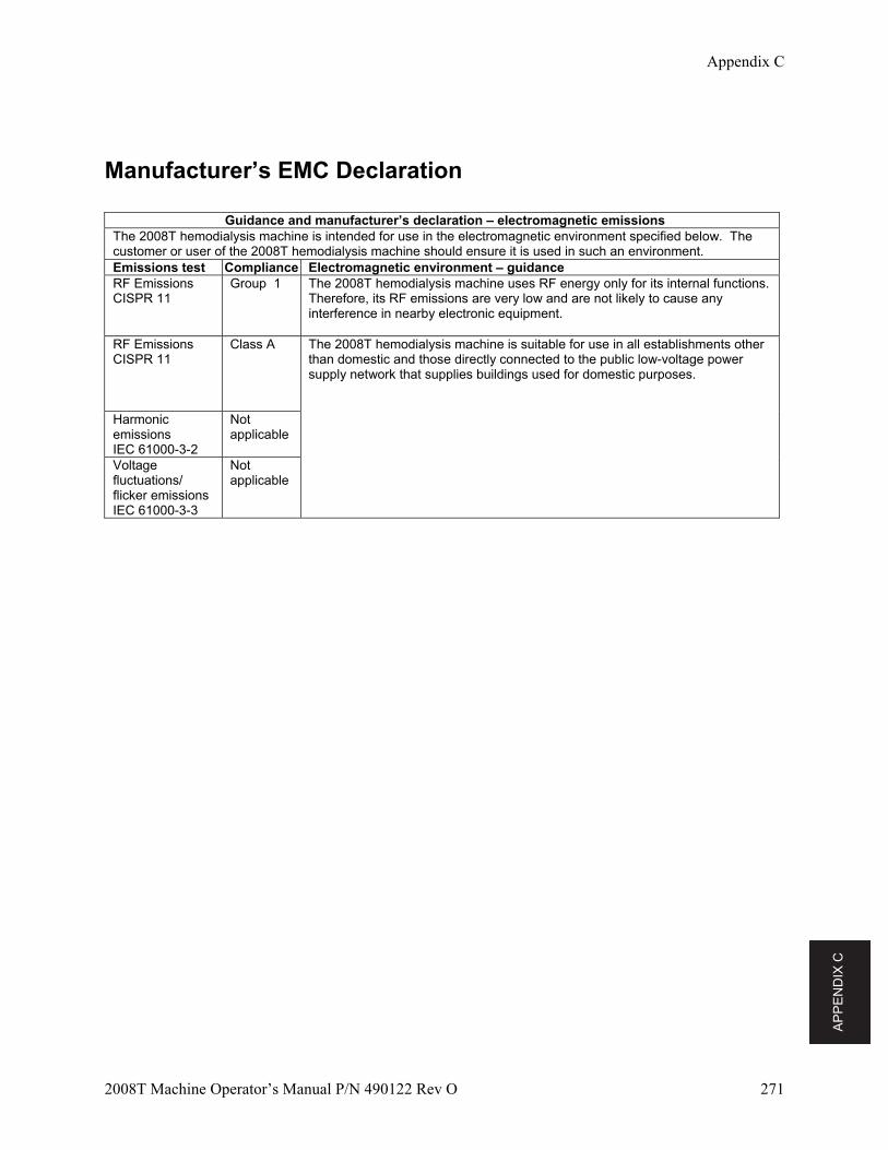
AP
PE
ND
IX C
Appendix C
2008T Machine Operator’s Manual P/N 490122 Rev O 271
Manufacturer’s EMC Declaration
Guidance and manufacturer’s declaration – electromagnetic emissions The 2008T hemodialysis machine is intended for use in the electromagnetic environment specified below. The customer or user of the 2008T hemodialysis machine should ensure it is used in such an environment. Emissions test Compliance Electromagnetic environment – guidanceRF Emissions CISPR 11
Group 1
The 2008T hemodialysis machine uses RF energy only for its internal functions. Therefore, its RF emissions are very low and are not likely to cause any interference in nearby electronic equipment.
RF Emissions CISPR 11
Class A The 2008T hemodialysis machine is suitable for use in all establishments other than domestic and those directly connected to the public low-voltage power supply network that supplies buildings used for domestic purposes.
Harmonic emissions IEC 61000-3-2
Not applicable
Voltage fluctuations/ flicker emissions IEC 61000-3-3
Not applicable
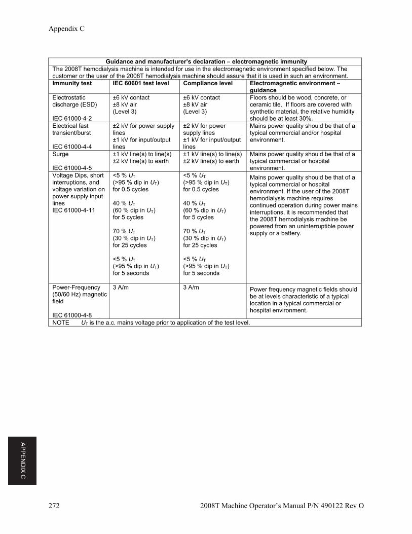
AP
PE
ND
IX C
Appendix C
272 2008T Machine Operator’s Manual P/N 490122 Rev O
Guidance and manufacturer’s declaration – electromagnetic immunity
The 2008T hemodialysis machine is intended for use in the electromagnetic environment specified below. The customer or the user of the 2008T hemodialysis machine should assure that it is used in such an environment. Immunity test IEC 60601 test level Compliance level Electromagnetic environment –
guidance Electrostatic discharge (ESD) IEC 61000-4-2
±6 kV contact ±8 kV air (Level 3)
±6 kV contact ±8 kV air (Level 3)
Floors should be wood, concrete, or ceramic tile. If floors are covered with synthetic material, the relative humidity should be at least 30%.
Electrical fast transient/burst IEC 61000-4-4
±2 kV for power supply lines ±1 kV for input/output lines
±2 kV for power supply lines ±1 kV for input/output lines
Mains power quality should be that of a typical commercial and/or hospital environment.
Surge IEC 61000-4-5
±1 kV line(s) to line(s) ±2 kV line(s) to earth
±1 kV line(s) to line(s) ±2 kV line(s) to earth
Mains power quality should be that of a typical commercial or hospital environment.
Voltage Dips, short interruptions, and voltage variation on power supply input lines IEC 61000-4-11
<5 % UT (>95 % dip in UT) for 0.5 cycles 40 % UT (60 % dip in UT) for 5 cycles 70 % UT (30 % dip in UT) for 25 cycles <5 % UT (>95 % dip in UT) for 5 seconds
<5 % UT (>95 % dip in UT) for 0.5 cycles 40 % UT (60 % dip in UT) for 5 cycles 70 % UT (30 % dip in UT) for 25 cycles <5 % UT (>95 % dip in UT) for 5 seconds
Mains power quality should be that of a typical commercial or hospital environment. If the user of the 2008T hemodialysis machine requires continued operation during power mains interruptions, it is recommended that the 2008T hemodialysis machine be powered from an uninterruptible power supply or a battery.
Power-Frequency (50/60 Hz) magnetic field IEC 61000-4-8
3 A/m 3 A/m Power frequency magnetic fields should be at levels characteristic of a typical location in a typical commercial or hospital environment.
NOTE UT is the a.c. mains voltage prior to application of the test level.
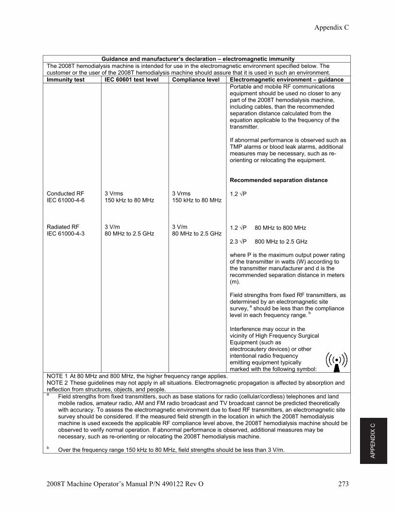
AP
PE
ND
IX C
Appendix C
2008T Machine Operator’s Manual P/N 490122 Rev O 273
Guidance and manufacturer’s declaration – electromagnetic immunity
The 2008T hemodialysis machine is intended for use in the electromagnetic environment specified below. The customer or the user of the 2008T hemodialysis machine should assure that it is used in such an environment. Immunity test IEC 60601 test level Compliance level Electromagnetic environment – guidance Conducted RF IEC 61000-4-6 Radiated RF IEC 61000-4-3
3 Vrms 150 kHz to 80 MHz 3 V/m 80 MHz to 2.5 GHz
3 Vrms 150 kHz to 80 MHz 3 V/m 80 MHz to 2.5 GHz
Portable and mobile RF communications equipment should be used no closer to any part of the 2008T hemodialysis machine, including cables, than the recommended separation distance calculated from the equation applicable to the frequency of the transmitter. If abnormal performance is observed such as TMP alarms or blood leak alarms, additional measures may be necessary, such as re-orienting or relocating the equipment. Recommended separation distance 1.2 P 1.2 P 80 MHz to 800 MHz 2.3 P 800 MHz to 2.5 GHz where P is the maximum output power rating of the transmitter in watts (W) according to the transmitter manufacturer and d is the recommended separation distance in meters (m). Field strengths from fixed RF transmitters, as determined by an electromagnetic site survey, a should be less than the compliance level in each frequency range. b
Interference may occur in the vicinity of High Frequency Surgical Equipment (such as electrocautery devices) or other intentional radio frequency emitting equipment typically marked with the following symbol:
NOTE 1 At 80 MHz and 800 MHz, the higher frequency range applies. NOTE 2 These guidelines may not apply in all situations. Electromagnetic propagation is affected by absorption and reflection from structures, objects, and people. a Field strengths from fixed transmitters, such as base stations for radio (cellular/cordless) telephones and land
mobile radios, amateur radio, AM and FM radio broadcast and TV broadcast cannot be predicted theoretically with accuracy. To assess the electromagnetic environment due to fixed RF transmitters, an electromagnetic site survey should be considered. If the measured field strength in the location in which the 2008T hemodialysis machine is used exceeds the applicable RF compliance level above, the 2008T hemodialysis machine should be observed to verify normal operation. If abnormal performance is observed, additional measures may be necessary, such as re-orienting or relocating the 2008T hemodialysis machine.
b Over the frequency range 150 kHz to 80 MHz, field strengths should be less than 3 V/m.
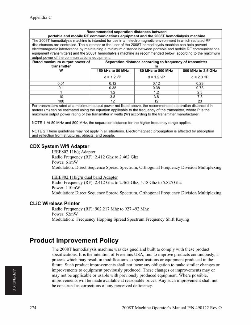
AP
PE
ND
IX C
Appendix C
274 2008T Machine Operator’s Manual P/N 490122 Rev O
Recommended separation distances betweenportable and mobile RF communications equipment and the 2008T hemodialysis machine
The 2008T hemodialysis machine is intended for use in an electromagnetic environment in which radiated RF disturbances are controlled. The customer or the user of the 2008T hemodialysis machine can help prevent electromagnetic interference by maintaining a minimum distance between portable and mobile RF communications equipment (transmitters) and the 2008T hemodialysis machine as recommended below, according to the maximum output power of the communications equipment. Rated maximum output power of
transmitter W
Separation distance according to frequency of transmitterm
150 kHz to 80 MHz
d = 1.2 P
80 MHz to 800 MHz
d = 1.2 P
800 MHz to 2.5 GHz
d = 2.3 P
0.01 0.12 0.12 0.23 0.1 0.38 0.38 0.73 1 1.2 1.2 2.3
10 3.8 3.8 7.3 100 12 12 23
For transmitters rated at a maximum output power not listed above, the recommended separation distance d in meters (m) can be estimated using the equation applicable to the frequency of the transmitter, where P is the maximum output power rating of the transmitter in watts (W) according to the transmitter manufacturer. NOTE 1 At 80 MHz and 800 MHz, the separation distance for the higher frequency range applies. NOTE 2 These guidelines may not apply in all situations. Electromagnetic propagation is affected by absorption and reflection from structures, objects, and people.
CDX System Wifi Adapter
IEEE802.11b/g Adapter Radio Frequency (RF): 2.412 Ghz to 2.462 Ghz Power: 61mW Modulation: Direct Sequence Spread Spectrum, Orthogonal Frequency Division Multiplexing IEEE802.11b/g/n dual band Adapter Radio Frequency (RF): 2.412 Ghz to 2.462 Ghz, 5.18 Ghz to 5.825 Ghz Power: 110mW Modulation: Direct Sequence Spread Spectrum, Orthogonal Frequency Division Multiplexing
CLiC Wireless Printer Radio Frequency (RF): 902.217 Mhz to 927.492 Mhz Power: 52mW Modulation: Frequency Hopping Spread Spectrum Frequency Shift Keying
Product Improvement Policy The 2008T hemodialysis machine was designed and built to comply with these product specifications. It is the intention of Fresenius USA, Inc. to improve products continuously, a process which may result in modifications to specifications or equipment produced in the future. Such product improvements shall not incur any obligation to make similar changes or improvements to equipment previously produced. These changes or improvements may or may not be applicable or usable with previously produced equipment. Where possible, improvements will be made available at reasonable prices. Any such improvement shall not be construed as corrections of any perceived deficiency.
AP
PE
ND
IX C
Appendix C
2008T Machine Operator’s Manual P/N 490122 Rev O 275
Warranty SALE of the machine or parts described or referenced herein is expressly conditioned upon the terms and conditions set forth below. Any additional or different terms or conditions set forth by the Purchaser to Fresenius USA, Inc., (herein called "the Company") shall not be effective or binding, and the terms set forth herein shall not be modified or amended, unless assented to in writing by an authorized official of the Company located in Waltham, Massachusetts.
LIMITED WARRANTY: The Company warrants to the Purchaser that the equipment delivered is free from defects in material or workmanship for the periods specified below, provided the equipment is used and maintained in accordance with the original manufacturer's operating instructions:
A. Mainframe chassis, and electronic components, lamps, etc. shall be warranted for one hundred and eighty (180) days from the date of installation or 2,000 metered hours, whichever occurs first.
B. Consumables are not covered under warranty. Consumables are those parts used in the performance of a Preventive Maintenance procedure as described in the Preventive Maintenance Procedures booklet. This includes routine calibrations, electronic and hydraulic, as outlined in the Preventive Maintenance checklist.
The Company will repair or replace, at its option, using new or reconditioned parts and/or assemblies, any parts subject to this warranty, which are proven defective in materials or workmanship. Such repair and replacement will be made without cost to the Purchaser, and the Company reserves the right to determine the location at which the repair or replacement will be accomplished. The Warranty does not apply to any equipment which is misused, abused, neglected, tampered with, damaged by accident, flood, fire, or other hazard, subjected to abnormal or unusual electrical or fluid stress, improperly installed or operated, or not maintained in accordance with the routine maintenance schedule set forth in the operating manual for the equipment. Routine maintenance is not covered under warranty. Modifications, alterations, installation and service by other than a FRESENIUS USA, Inc. authorized representative may void the warranty.
WARRANTIES APPLICABLE TO EQUIPMENT EXTEND ONLY TO THE PURCHASER, AND ARE NOT ASSIGNABLE OR TRANSFERABLE, AND SHALL NOT APPLY TO AUXILIARY EQUIPMENT, DISPOSABLE ACCESSORIES, OR LIGHT SOURCES. THE FOREGOING WARRANTY SHALL BE IN LIEU OF ANY OTHER WARRANTIES, EXPRESSED IMPLIED OR STATUTORY, RESPECTING THE EQUIPMENT OR ANY PARTS OR COMPONENTS THEREOF, AND THE COMPANY MAKES NO IMPLIED WARRANTY OF MERCHANTABILITY OR FITNESS FOR A PARTICULAR PURPOSE. THE PURCHASER'S SOLE AND EXCLUSIVE REMEDY IN CONTRACT, TORT, OR UNDER ANY OTHER THEORY AGAINST THE COMPANY RESPECTING THE EQUIPMENT AND ITS USE SHALL BE THE REPLACEMENT OR REPAIR OF THE EQUIPMENT AND ITS PARTS AS DESCRIBED ABOVE, AND NO OTHER REMEDY (INCLUDING, WITHOUT LIMITATION, CONSEQUENTIAL DAMAGES) SHALL BE AVAILABLE TO THE PURCHASER. The Company shall have no further obligation or liability with respect to the equipment or its sale, operation and use, and the Company neither assumes, nor authorizes the assumption of, any obligation or liability in connection with such equipment.
REFER ALL SERVICING AND INFORMATION REQUESTS TO:
Fresenius USA, Inc. Attention: Service Department 4040 Nelson Avenue Concord, CA 94520 Telephone: (800) 227-2572
276 2008T Machine Operator’s Manual P/N 490122 Rev O
Glossary
Air Lock—A condition caused by air entering the concentrate supply lines when not enough liquid concentrate is available. Air lock causes dialysate conductivity to be low.
Alarm Window—The allowable range without alarm for the arterial, venous, and transmembrane pressures, and the dialysate temperature and conductivity during treatment. Transition of either value outside the window will trigger an alarm. The conductivity alarm window is graphically represented in the Dialysate screen as the area located between the upper and lower alarm limits of the conductivity bar graph. The alarm window can be widened or narrowed, or shifted up or down within the hard limits. The temperature alarm window is 2 C of the set temperature value within the temperature hard limits (30 C to 41 C). The arterial and venous limit window width is also selectable. The position of the window is set automatically.
Asymmetric Limits—This is an option to select venous limits that are not symmetrical. If asymmetric limits are chosen, the lower venous limit will tighten to the selected value after a short time delay. The lower venous limit choices are 20, 25, 30, 35 mmHg. The lowest value that does not cause frequent nuisance alarms should be chosen.
Auto Flow—A dialysate flow option in which the dialysate flow is proportional and linked to the blood flow rate. Auto Flow may be approximately either 1.5 times or 2 times the blood flow rate between 300 (or 500 depending on the setup in Service Mode) and 800 ml/min, in 100 ml/min increments. The dialysate flow rate on the “Home” screen is preceded by the letter ‘a’ when auto flow has been set.
Back Filtration—The movement of dialysate across the dialyzer membrane and into the patient’s blood. It can be caused by a change in pressure or concentration gradient between the dialysate and the blood.
Balancing Chambers—A hydraulic unit inside the 2008T hemodialysis machine consisting of two chambers that ensure that the amount of fresh dialysate entering the dialysate flow is equal to the amount of used dialysate being drained.
Base Na+—The prescribed base sodium level for the Final Dialysate, viewable in the SVS subscreen. The default Base Na+ value is carried over from the value entered in the Na+ button in the Dialysate screen. Changing the value in either button will change the value of the other.
Bic—Abbreviation for “bicarbonate.”
Biofilm—Biological residue from treatment that collects on machine drain lines.
Blood Sensed—The venous line runs through an optical detector below the venous line clamp. When the line is opaque, the machine uses this “Blood Sensed” information for a number of alarm or informational messages or warnings.
BTM (Blood Temperature Monitor)—This is an optional module that can control or monitor the temperature and energy supply to the patient. It may be used to determine the recirculation of blood within the patient’s access.
Button—An area on the display screen that can be selected and will cause an action by the software.
Glossary
2008T Machine Operator’s Manual P/N 490122 Rev O 277
BVM (Blood Volume Monitor)—This is an optional module that can measure the relative fraction of blood cells within the circulating fluid. It can be used to estimate how the machine’s ultrafiltration rate relates the fluid refilling rate from the extra-cellular compartments. If ultrafiltration rate is excessive compared to the refilling rate, a hypotensive event is more likely.
Bypass Mode—Bypass mode occurs when the dialysate goes outside alarm limits for temperature or conductivity. In bypass mode, valves inside the 2008T hemodialysis machine redirect the flow of dialysate to bypass the dialyzer internally until temperature and conductivity are back within acceptable limits. The 2008T hemodialysis machine can be manually put into bypass mode by lifting the shunt door.
Compliance Chamber—A blood-holding receptacle similar to a drip chamber. Compliance chambers are part of the arterial bloodline used in single-needle dialysis.
Conc—Abbreviation for “concentrate.”
CLiC Device—Abbreviation for “Crit-Line in a Clip.” See Crit-Line in a Clip for more information.
Crit-Line in a Clip—The Crit-Line in a Clip (CLiC) device is used to non-invasively measure a hemodialysis patient’s hematocrit, oxygen saturation and percent change in blood volume. These measurements occur in real time in order to provide a more effective treatment. The measurements are displayed on the 2008T hemodialysis machine’s “Crit-Line” screen. Under the direction of a physician, the clinician/nurse can increase or decrease the ultrafiltration (UF) rate in order to remove the maximum amount of fluid without the patient experiencing the common dialysis related complications which include hypotension, nausea, cramping and vomiting.
The system consists of software for the 2008T hemodialysis machine, a Crit-Line in a Clip (CLiC) device, a CLiC device-specific verification filter which is used to calibrate and verify the CLiC device, and a disposable Crit-Line Blood Chamber.
Dialysate—Aqueous fluid containing electrolytes and usually buffer and glucose, which is intended to exchange solutes with blood during hemodialysis. This is the Final Dialysate, See Final Dialysate for more information.
DIASAFE Plus filter—A filter that is placed in the dialysate fluid path after the addition of the acid and bicarbonate concentrates, shortly before the dialysate is delivered to the dialyzer. It substantially reduces the level of bacteria and endotoxin (pyrogenic material) in the dialysate.
eKt/V—Equilibrated Kt/V or double pool Kt/V. This accounts for rebound of urea after the treatment is stopped. The shorter the treatment time, the greater the percentage difference between spKt/V and eKt/V. We use the Tattersall formula to calculate eKt/V.
Fill Program—Occurs when water level in the air separation chamber gets too low. The air separation chamber is part of the hydraulic system inside the 2008T hemodialysis machine. This program is used to remove excessive air from the hydraulic system. The machine will normally go into a Fill program when the dialyzer is first connected to the dialyzer lines, and the air within the dialyzer is being purged. Repeated Fill programs during operation, however, could indicate a leak in the dialysate delivery system, and should be brought to the attention of a qualified technician.
Final Dialysate—The prescribed dialysate that is delivered to the dialyzer (patient) by the hemodialysis machine after the proportioning (mixing) of the acid concentrate, bicarbonate concentrate, and water. The final dialysate may also be referred to as the post-reaction dialysate (i.e. after proportioning (mixing) of the acid concentrate, bicarbonate concentrate and water by the dialysis machine).
Glossary
278 2008T Machine Operator’s Manual P/N 490122 Rev O
Flow Indicator—A clear, cylindrical section of the dialyzer supply line that allows observation of the dialysate flow. When the dialysate flow is on, a small float inside the cylinder bobs up and down in rhythm to the dialysate pump. When the flow is off, the float sinks to the bottom of the cylinder.
Hard Limits—Unchangeable limits that are hard coded in the software and define the maximum and minimum, alarm-window values for the arterial, venous, and transmembrane pressures, and the dialysate temperature and conductivity. Hard limits are not apparent unless the user attempts to set a value outside the hard limit range.
Hemolysis—Rupture of red blood cells. This may be caused by hyponatremia (low blood sodium), dialysate that is too hot or too dilute (hypotonic), chloramines, copper, or nitrates in dialysate water, bleach in the dialysate, low dialysate conductivity, too-high arterial pressure or kinked blood tubing.
Idle Mode—When dialysis is first entered after a long power down, if a water alarm (temperature or conductivity) exists, the dialysate flow will be 800 ml/min until the machine is up to temperature and conductivity. The dialysate flow then drops to 300 ml/min while the machine is “idle”. The machine will also enter Idle Mode after a treatment is finished (RTD = 0, blood not sensed, and Blood Pump stopped, and the dialysate flow rate > 300 ml/min). This mode is terminated when treatment is started (RTD > 0 or blood sensed by the optical detector) or the dialysate flow rate is changed manually.
Kecn—Effective Clearance as determined with conductivity measurements. The calculated clearance based on the change in conductivity of the pre-dialyzer versus post dialyzer dialysate. Kecn appears in OLC Data subscreen of the “Kt/V AF” screen.
Keys—Are located on the control panel, outside the display screen. Keys are used to enter numbers, confirm selections on the display screen, and activate certain functions.
KoA—Overall mass transfer coefficient multiplied by surface area of a dialyzer.
Kt/V—A measure of therapy delivered to the patient. (K = clearance rate, t = time, V = urea distribution volume). The Kt/V value shown are Single Pool Values (spKt/V). The OLC system is used to determine the effective dialyzer clearance used for this determination.
KUF—An ultrafiltration coefficient that describes how permeable a dialyzer is to water. It is a direct function of surface area and is defined as the number of millimeters of fluid per hour that are transferred across the membrane per mmHg TMP.
Long Power Down—The act of turning off the machine for longer than two minutes. Certain information stored in memory is lost after two minutes, and some treatment parameters are reset to their default settings. Power failures are not the same as long power downs, and treatment data are saved when power to the machine is interrupted in such instances. (See short Power Down and Power Failure recovery)
Numeric KoA—See KoA.
OLC (Online Clearance)—This is an optional system that can determine the effective conductive clearance of a dialyzer up to six times during dialysis.
Override—All protective systems are in operation during treatment. During a blood leak alarm, the user has the option to temporarily suspend (override) a protective system by pressing and holding the RESET key for three seconds. During a blood leak override, the machine’s blood leak monitor is inactive for three minutes. The Status Box will indicate a blood leak override is in effect.
Peracetic acid—A disinfectant used in the Chemical/Rinse program to disinfect the hydraulic system.
Glossary
2008T Machine Operator’s Manual P/N 490122 Rev O 279
Pillow—Small blood reservoir on the Single Needle bloodline. It is located before the first blood pump segment.
Positive Pressure—Condition that exists when air or fluid pressure inside the dialysate lines is greater than outside of the lines. If an opening occurs, air or fluid will flow out of the system.
Post-Reaction Bicarbonate—The prescribed Final Dialysate bicarbonate that will be delivered to the dialyzer in the Final Dialysate after the proportioning (mixing) of the acid concentrate, bicarbonate concentrate, and water. The post-reaction bicarbonate value is entered on the “Dialysate” screen in the Bicarbonate button.
Power Failure Recovery—when power to the machine is lost, many dialysis parameters are stored and recovered when the power is restored to the machine.
Pressure Holding Test (PHT)—There are different Pressure Holding Tests. A PHT verifies the integrity of the hydraulic system, which is necessary for accurate fluid balance and UF control. An extensive Pressure Holding Test is available in Self Test. An Online Pressure Holding Test is done every 12 minutes during treatment. It lasts about seven seconds, depending on the dialysate flow rate (two cycles of the balancing chamber). The online PHT must be selected in Service Mode.
Pure Ultrafiltration—A treatment option in which the ultrafiltration pump draws excess fluid off the patient while the dialysate flow is turned off. See also Sequential Dialysis.
Puristeril 340—A chemical used to clean and disinfect the 2008T hydraulic system.
Reverse Osmosis (RO)—A method for purifying water by forcing it through a semipermeable membrane that prevents the passing of mineral ions.
RTD—Remaining Time on Dialysis. The amount of time remaining until the end of the treatment. RTD is viewable in the Home screen.
Screen Access Button—Any of the eight blue buttons located in the row along the bottom of the display screen. Selecting one of these buttons will bring up the corresponding treatment screen on the display screen.
Sequential Dialysis—A two-stage form of dialysis treatment in which the first stage consists exclusively of ultrafiltration. In the first stage, there is no dialysate flow while the ultrafiltration pump draws excess fluid off the patient. After the determined amount of fluid has been drawn, the second stage, usually a standard dialysis treatment, occurs.
Service Mode—A functional state of the 2008T hemodialysis machine that allows technicians to calibrate the machine or program various software features and options that are only accessible in Service Mode.
Single Needle Dialysis—This is a system with the use of two blood pumps to allow blood access to the patient with a single needle. The pumps alternately turn on and off to pull fluid from the patient and then return the dialyzed blood with minimal recirculation.
Short Power Down—Refers to the act of turning off the power with the Front Panel Power Key to the machine for less than two minutes. Certain information stored in memory is only stored for up to two minutes. After that, it is erased. (See Long Power Down and Power Failure Recovery.)
Sodium Variation System (SVS)—A program that varies the concentration of sodium in the dialysate during treatment. Increased sodium at the onset of treatment is sometimes prescribed to prevent cramping in the patient. Increasing sodium results in increased levels of other electrolytic constituents and a higher level of conductivity.
Glossary
280 2008T Machine Operator’s Manual P/N 490122 Rev O
SVS Profile—A programmable feature for varying the level of sodium in the dialysate throughout the course of treatment.
SVS Time—Time length in hours and minutes prescribed for SVS program.
Theoretical Conductivity (TCD)—The expected conductivity of the dialysate based upon the concentrate type, and sodium and bicarbonate values entered in the Dialysate screen. TCD is measured in milliSiemens per centimeter (mS/cm) and is corrected to 25°C.
Transducer—An electronic device inside the 2008T hemodialysis machine that reads the pressure inside the arterial and venous drip chambers. The drip chamber and transducer are connected via a thin tube that is part of the extracorporeal blood circuit.
Transducer Protector (TP)—a small, disposable, plastic cap containing a hydrophobic, paper filter that fits over each pressure port. It is inserted between the pressure monitor line and the pressure port connection and is used to prevent the transducer from becoming wet or contaminated with blood. There are two transducer protectors for each connection, a disposable external TP that is to be replaced with each treatment. A second internal TP is also installed.
Ultrafiltration (UF)—Ultrafiltration is the process of drawing off excess fluid from the patient during treatment. The 2008T hydraulic system is a closed system that uses a separate UF pump for greater accuracy.
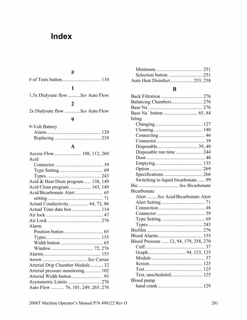
2008T Machine Operator’s Manual P/N 490122 Rev O 281
Index
# # of Tests button................................ 110
1 1.5x Dialysate flow .......... See Auto Flow
2 2x Dialysate flow ............. See Auto Flow
9 9-Volt Battery
Alarm ............................................ 129 Replacing ...................................... 218
A Access Flow ...................... 108, 112, 269 Acid
Connector ........................................ 39 Type Setting .................................... 69 Types ............................................. 243
Acid & Heat Disin program ...... 138, 149 Acid Clean program .................. 143, 149 Acid/Bicarbonate Alert ....................... 65
setting .............................................. 71 Actual Conductivity ................ 64, 72, 86 Actual Time data box ........................ 114 Air lock ............................................... 47 Air Lock ............................................ 276 Alarm
Position button ................................ 65 Types ............................................. 155 Width button ................................... 65 Window ................................... 72, 276
Alarms ............................................... 153 Arrow ..................................... See Cursor Arterial Drip Chamber Module ........... 32 Arterial pressure monitoring ............. 102 Arterial Width button .......................... 93 Asymmetric Limits ........................... 276 Auto Flow ........... 76, 101, 249, 265, 276
Minimum....................................... 251 Selection button ............................ 251
Auto Heat Disinfect .................. 253, 258
B Back Filtration .................................. 276 Balancing Chambers ......................... 276 Base Na+ ............................................ 276 Base Na+ button ............................ 65, 84 bibag
Changing ....................................... 127 Cleaning ........................................ 140 Connecting ...................................... 46 Connector ........................................ 39 Disposable ................................. 39, 40 Disposable run time ...................... 244 Door ................................................ 40 Emptying ....................................... 135 Option ........................................... 269 Specifications ................................ 266 Switching to liquid bicarbonate ...... 99
Bic ................................. See Bicarbonate Bicarbonate
Alert ........ See Acid/Bicarbonate Alert Alert Setting .................................... 71 Connection ...................................... 48 Connector ........................................ 39 Type Setting .................................... 69 Types ............................................. 243
Biofilm .............................................. 276 Blood Alarms .................................... 155 Blood Pressure ...... 12, 94, 179, 258, 270
Cuff ................................................. 37 Graph............................... 94, 123, 125 Module ............................................ 37 Screen ............................................ 125 Test ................................................ 125 Test, unscheduled .......................... 125
Blood pump hand crank ..................................... 129
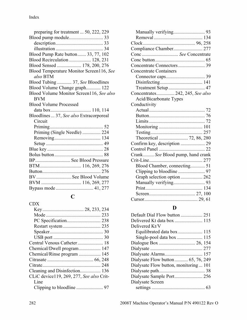
Index
282 2008T Machine Operator’s Manual P/N 490122 Rev O
preparing for treatment ... 50, 222, 229 Blood pump module ............................ 33
description ....................................... 33 illustration ....................................... 34
Blood Pump Rate button ....... 33, 77, 102 Blood Recirculation .................. 128, 231 Blood Sensed .................... 178, 200, 276 Blood Temperature Monitor Screen116, See
also BTM Blood Tubing ............ 37, See Bloodlines Blood Volume Change graph ............ 122 Blood Volume Monitor Screen116, See also
BVM Blood Volume Processed
data box ................................. 110, 114 Bloodlines ... 37, See also Extracorporeal
Circuit Priming ............................................ 52 Priming (Single Needle) ............... 224 Removing ...................................... 134 Setup ............................................... 49
Blue key .............................................. 28 Bolus button ........................................ 88 BP ............................. See Blood Pressure BTM .................................. 116, 269, 276 Button ................................................ 276 BV ............................. See Blood Volume BVM ................................. 116, 269, 277 Bypass mode ............................... 41, 277
C CDX
Key .................................. 28, 233, 234 Mode ............................................. 233 PC Specification............................ 238 Restart system ............................... 235 Speaker ............................................ 30 USB port ......................................... 30
Central Venous Catheter ..................... 18 Chemical/Dwell program .................. 147 Chemical/Rinse program .................. 145 Citrasate ...................................... 66, 248 Citrate ................................................ 248 Cleaning and Disinfection................. 136 CLiC device119, 269, 277, See also Crit-
Line Clipping to bloodline ...................... 97
Manually verifying .......................... 93 Removal ........................................ 134
Clock ........................................... 96, 258 Compliance Chamber ........................ 277 Conc .............................. See Concentrate Conc button ......................................... 65 Concentrate Connectors ...................... 39 Concentrate Containers
Connector caps ................................ 39 Disinfecting ................................... 141 Treatment Setup .............................. 47
Concentrates ............... 242, 245, See also Acid/Bicarbonate Types
Conductivity Actual .............................................. 72 Button .............................................. 76 Limits .............................................. 72 Monitoring .................................... 101 Testing........................................... 257 Theoretical ........................ 72, 86, 280
Confirm key, description .................... 29 Control Panel ...................................... 22 Crank ......... See Blood pump, hand crank Crit-Line ............................................ 277
Blood Chamber, connecting............ 51 Clipping to bloodline ...................... 97 Graph selection option .................. 262 Manually verifying .......................... 93 Print ............................................... 134 Screen ...................................... 27, 100
Cursor ............................................ 29, 61
D Default Dial Flow button .................. 251 Delivered Kt data box ....................... 115 Delivered Kt/V
Equilibrated data box .................... 115 Single-pool data box ..................... 115
Dialogue Box .............................. 26, 154 Dialysate ........................................... 277 Dialysate Alarms ............................... 157 Dialysate Flow button ........... 65, 76, 249 Dialysate Flow button, monitoring ... 101 Dialysate path...................................... 38 Dialysate Sample Port ....................... 256 Dialysate Screen
settings ............................................ 63
Index
2008T Machine Operator’s Manual P/N 490122 Rev O 283
Dialyzer Holder ............................................. 43 Requirements .................................. 40
Diasafe Plus filter .............................. 277 Diasafe Plus Filter
Replacing ...................................... 218 Testing....................... 58, 93, 146, 218
Disinfectant, testing for ............. 151, 257
E eKt/V ................................................. 277 Electrolyte profile ............................... 86 Electromagnetic
Emissions ...................................... 271 Environment .................................. 271 Immunity ....................................... 271
Empty bibag button ........................... 135 Enable OLC button ........................... 109 Escape Key
Keyboard ......................................... 28 Touchpad......................................... 29
Ethernet Port ............................... 30, 235 Exp buttonSee Exponential Profile (SVS)
button Exponential Profile (SVS) button ....... 84 Extracorporeal Circuit .... 19, 49, See also
Bloodlines
F Fill Program ...................................... 277 Final Dialysate ............................ 66, 277 Flow Indicator ................................... 278 Fluid Sample Port ............................... 39 Fn Lock key ........................................ 28
G GranuFlo ..................................... 66, 247 Green button
Heparin ...................................... 91, 99 SVS Profile ............................... 85, 99
H Hard Limits ....................................... 278 Hardware key .................................... 262 Hct ................................... See Hematocrit Heat Disinfect program ..... 144, 149, 253 Heater switch ...................................... 30
Hematocrit graph .............................. 123 Hemolysis ......................................... 278 Heparin Bolus ..................................... 88 Heparin Delivery system, preparing ... 89 Heparin Dwell ............................. 88, 259 Heparin Prime button .......................... 88 Heparin pump...................................... 35 Heparin Rate button ............................ 88 Heparin screen
setting parameters in ....................... 87 High Flux button ................................. 93 Home screen
monitoring the treatment ............... 100 Hour Meter .......................................... 30
I Idle Mode .................................. 252, 278 Inflation Pressure button ..................... 95 Infuse Bolus button ............................. 88 Infusion Time button ........................... 88 Interval button ..................................... 96 IV Pole .......................................... 20, 43
J Jugs ............. See Concentrate Containers
K Kecn .................................................. 278
in OLC table .................................. 115 Keyboard ............................................. 28 Keys .................................................. 278 KoA ................................................... 278 Kt/V................................................... 278 Kt/V Calculator button ...................... 109 Kt/V graph ........................................ 110 Kt/V screen ....................................... 108 KUF........................................... 104, 278
L Level Adjust key ........................... 33, 34 Level Detector Adjust key .................. 37 Level Detector module ........................ 36 Light .............................. See Status Light Lin buttonSee Linear Profile (SVS) button Linear Profile (SVS) button ................ 84 Load Syringe button ............................ 88 Long Power Down ............................ 278
Index
284 2008T Machine Operator’s Manual P/N 490122 Rev O
Lower Dia button ................................ 95 Lower Pulse button ............................. 95 Lower Sys button ................................ 95
M Machine
Lock-up or unresponsive............... 158 Machine Specifications ..................... 264 Mains Power Supply switch ................ 30 Manual OLC Test button .................. 109 Manually turning the blood pump..... 130 MAP ............. See Mean Arterial Pressure Maximum UF Rate ....................... 79, 81 Mean Arterial Pressure ..................... 125 Moving the machine ........................... 43 Mute key ........................................... 156
description ....................................... 23
N NaturaLyte .......................................... 66 New Treatment key ............................. 61 New Tx key ....... See New Treatment key No Power alarm .................................. 31 No-flow dialysis .. See sequential dialysis None (SVS) button .............................. 84 Normal Status.................................... 154
O O2 Sat .................. See Oxygen Saturation OLC....................... See Online Clearance OLC Data button ............................... 109 OLC Data screen ............................... 114 Online Clearance ....................... 108, 278 Online PHT See Online Pressure Holding
Test Online Pressure Holding Test58, 126, 279 Optical Detector .................................. 37 Override ............................................ 278 Oxygen Saturation graph .................. 123
P P art.
See Pressure port, arterial ................ 34 P ven............... See Pressure port, venous Patient ID button ................................. 93 Peracetic acid .................................... 278 pH Testing ......................................... 257
PHT ............... See Pressure Holding Test Pillow ................................................ 279 Plasma Na+ data box ......................... 114 Positive Pressure ............................... 279 Post-Reaction Bicarbonate ................ 279 Power Failure ............................ 129, 231
during chemical disinfection ......... 151 resumption procedure .................... 131
Power Failure Recovery .................... 279 Power key
description ....................................... 23 Pressure and Alarm tests55, 226, 228, 231 Pressure Holding Test ....................... 279 Pressure port
arterial ............................................. 34 venous ............................................. 37
Prime Amount ............................. 53, 225 Prime key
description ....................................... 24 Pump segment ..................................... 37 Pure UltrafiltrationSee Sequential Dialysis Puristeril 340 ..... 143, 145, 149, 263, 279
residual testing .............................. 151
R Rate button ................... See Heparin Rate Recirculation .... See Blood Recirculation Reset key
description ....................................... 24 Reverse Osmosis ............................... 279 Rinse program ................................... 142 RO ......................... See Reverse Osmosis RS 232 Port ......................................... 30 RTD................................................... 279
in Kt/V graph ................................ 110 RTD button ......................................... 76
monitoring ..................................... 101
S Screen Access Button ....................... 279 Select Program screen ................. 46, 136 SEQSee Sequential Dialysis, See Sequential
Dialysis Sequential Dialysis...................... 81, 279 Service mode ..................................... 279 Short Power Down ............................ 279 Shunt Interlock .............................. 21, 41
Index
2008T Machine Operator’s Manual P/N 490122 Rev O 285
Single Needle .............................. 49, 267 Single Needle button ........................... 93 Single Needle Dialysis ...................... 220 Sodium Variation System ........... 83, 279 Speaker
CDX Mode ...................................... 30 Dialysis Mode ................................. 30
Standard Prime ............................ 52, 224 Start Na+ button ................................... 84 Start/Stop key (blood pump) ............... 34 Stat/Deflate key ................................. 126
description ....................................... 24 Status Box ................................... 26, 153 Status Light ................................. 25, 260
Flashing ........................................... 88 Step Profile (SVS) button ................... 84 Storage and maintenance .................. 263 Storage Preparation ........................... 263 SVS ......... See Sodium Variation System SVS Profile ....................................... 280
Button ........................................ 65, 77 setting .............................................. 85
SVS Time .......................................... 280 SVS Time button................................. 84 Switches
Heater .............................................. 30 Power .............................................. 30
Syringe button ..................................... 88
T Target Kt/V ....................... 109, 259, 260
data box ......................................... 115 less than 85 percent ....................... 111
TCD.......... See Conductivity, Theoretical Temperature button ............................. 76 Temperature button, monitoring ....... 101 Test & Options screen
Setting treatment parameters........... 92 TestingSee Pressure and Alarm Tests, See
Pressure and Alarm Tests Theoretical ConductivitySee Conductivity,
Theoretical Timer ......................... See Heparin Dwell TMP ......... See Transmembrane Pressure Total Infused button ............................ 88 Touchpad............................................. 29
Transducer ......................................... 280 Transducer Protector ........... 50, 222, 280 Transmembrane pressure
monitoring ..................................... 104 Treatment Clock button ...................... 77 Treatment Parameters
entering ........................................... 62 Treatment Summary .................... 26, 105 Trends screen .................................... 105 Troubleshooting ................................ 157 Tx Clock button ................................ 101
U UF Goal button ................................... 75 UF on/off key ...................................... 77
description ....................................... 24 UF Profile.................................... 78, 255 UF Profile button ................................ 77 UF Rate button .................................... 75 UF Rate button, monitoring .............. 100 UF Removed button ............................ 76 UF Removed button, monitoring ...... 101 UF Time button ................................... 75 UF Time button, monitoring ............. 100 Ultrafiltration ........................ 38, 78, 280 Ultrafiltration coefficient104, See also KUF Upper Dia button................................. 95 Upper Pulse button .............................. 95 Upper Sys button................................. 95 USB Port ....................... 21, 25, 235, 236
V Venous Line Clamp ...................... 36, 37 Venous pressure
monitoring ..................................... 103 Venous Width button .......................... 93 Verify Crit-Line button ....................... 93 Volume (OLC)
Button ............................................ 109 Data box ........................................ 114
Volume (sound pressure level) ........... 30
W Warning Status .................................. 154 Water Supply maintenance ............... 141 Wheel Lock ......................................... 43