Embed Size (px)
Citation preview
For exploded diagram and part number information, refer to the Spare Parts Catalog available on our website at
www.rockshox.com.
Information contained in this publication is subject to change at anytime without prior notice.
For the latest technical information, visit our website at www.rockshox.com.
Names used in this manual may be trademarks or registered trademarks of others.
© SRAM Corporation • July 2005 PN 95.4310.745.000, Rev. A
20
06
T
OR
AS
ER
VIC
E G
UID
E
2 © SRAM Corporation • 2006 TORA SERVICE GUIDE
2006 Tora Service Guide
G E T T I N G S TA R T E D
T O O L S
L O W E R L E G R E M O VA L ( A I R A N D U - T U R N )
· Perform service every 100 hours of riding (less depending on riding conditions and riding style).· Regular maintenance ensures your RockShox suspension fork performs as it should.· For bushing removal and installation, please reference the Bushing Service Guide.· Right side equals rider’s right; left side equals rider’s left.
1. Remove fork from bicycle.2. Spray entire fork with isopropyl alcohol and wipe all dirt and mud from fork. Clean around dust seals and upper tubes.3. Lay tools out on work bench and create a clean work area for internal’s service.4. Place oil pan under fork on floor.
· Safety Glasses· Clean Rags· Oil Pan or Bucket· Bicycle Stand / Clean Work
Table/Area· 24mm 6-point Socket· Plastic-Faced Mallet· Snap Ring Pliers (internal and external)· Shock Pump
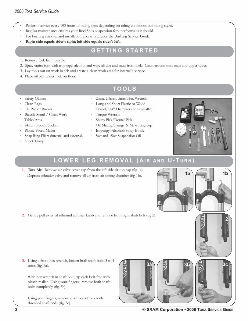
1. Tora Air: Remove air valve cover cap from the left side air top cap (fig 1a).Depress schrader valve and remove all air from air spring chamber (fig 1b).
2. Gently pull external rebound adjuster knob and remove from right shaft bolt (fig 2).
· 2mm, 2.5mm, 5mm Hex Wrench· Long and Short Plastic or Wood
Dowel, 3/4" Diameter (non-metallic)· Torque Wrench· Sharp Pick/Dental Pick· Oil Mixing Syringe & Measuring cup· Isopropyl Alcohol/Spray Bottle· 5wt and 15wt Suspension Oil
1a 1b
2
3. Using a 5mm hex wrench, loosen both shaft bolts 3 to 4turns (fig. 3a).
With hex wrench in shaft bolt, tap each bolt free withplastic mallet. Using your fingers, remove both shaftbolts completely (fig. 3b).
Using your fingers, remove shaft bolts from boththreaded shaft ends (fig. 3c).
3a 3b 3c
PN 95.4310.745.000, REV. A 3
2006 Tora Service Guide
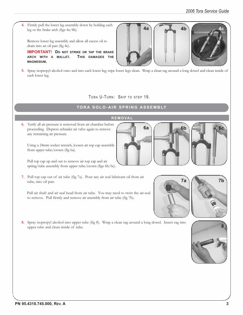
4. Firmly pull the lower leg assembly down by holding eachleg or the brake arch (figs 4a/4b).
Remove lower leg assembly and allow all excess oil todrain into an oil pan (fig 4c).IMPORTANT! DO NOT STRIKE OR TAP THE BRAKE
ARCH WITH A MALLET. THIS DAMAGES THE
MAGNESIUM.
5. Spray isopropyl alcohol onto and into each lower leg; wipe lower legs clean. Wrap a clean rag around a long dowel and clean inside ofeach lower leg.
R E M O VA L
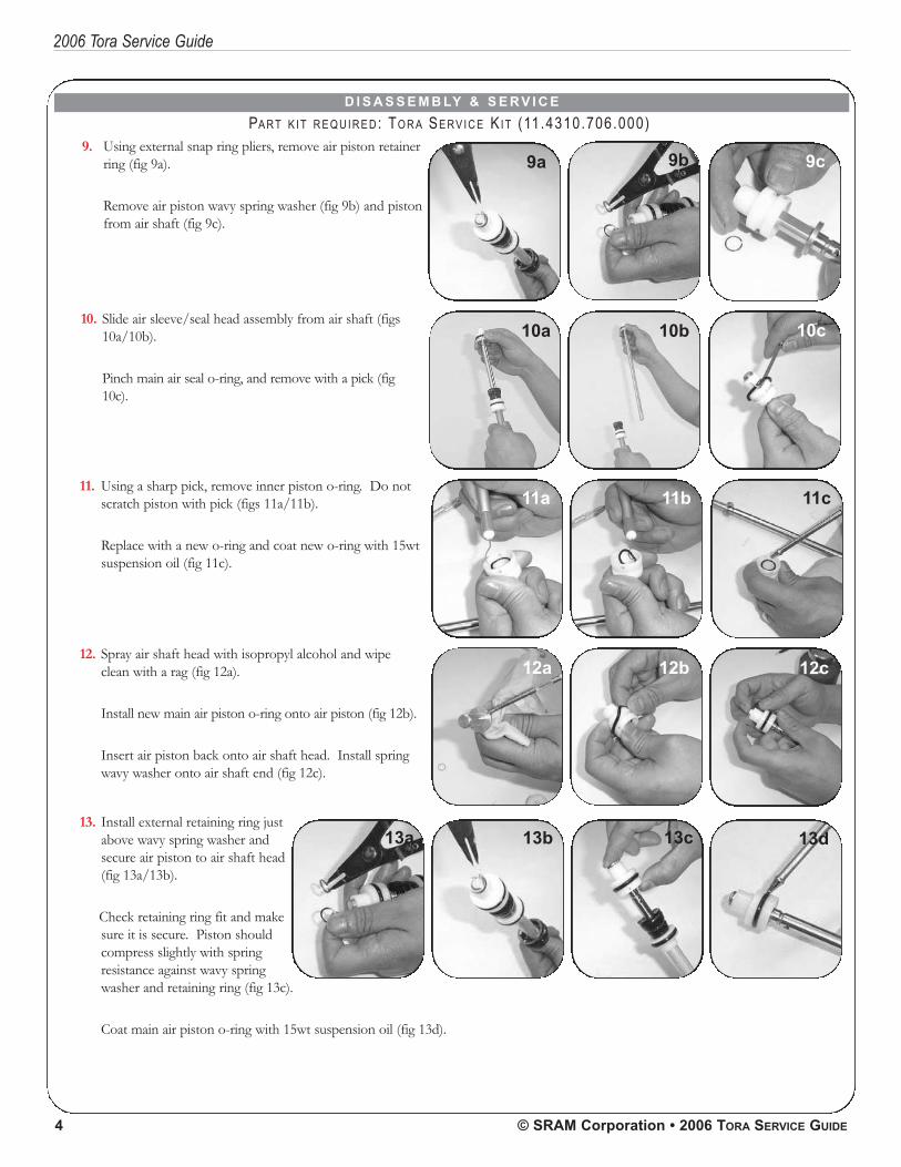
6. Verify all air pressure is removed from air chamber beforeproceeding. Depress schrader air valve again to removeany remaining air pressure.
Using a 24mm socket wrench, loosen air top cap assemblyfrom upper tube/crown (fig 6a).
Pull top cap up and out to remove air top cap and airspring/tube assembly from upper tube/crown (figs 6b/6c).
TO R A U-TU R N: SK I P TO S T E P 19.
T O R A S O L O - A I R S P R I N G A S S E M B LY
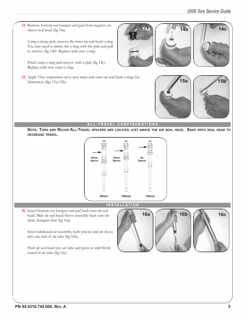
7. Pull top cap out of air tube (fig 7a). Pour any air seal lubricant oil from airtube, into oil pan.
Pull air shaft and air seal head from air tube. You may need to twist the air-sealto remove. Pull firmly and remove air assembly from air tube (fig 7b).
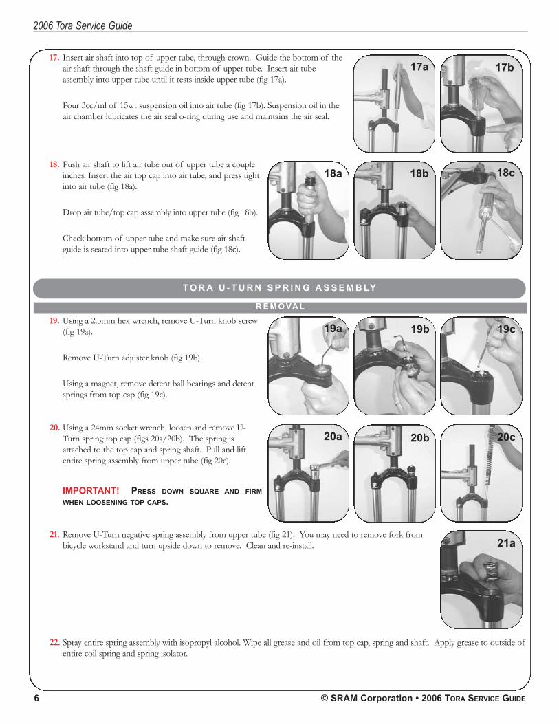
8. Spray isopropyl alcohol into upper tube (fig 8). Wrap a clean rag around a long dowel. Insert rag intoupper tube and clean inside of tube.
4a 4b 4c
6a 6b 6c
7a 7b
8
4 © SRAM Corporation • 2006 TORA SERVICE GUIDE
2006 Tora Service Guide
D I S A S S E M B LY & S E R V I C E
PA RT K I T R E Q U I R E D: TO R A SE RV I C E KI T (11.4310.706.000)
10. Slide air sleeve/seal head assembly from air shaft (figs10a/10b).
Pinch main air seal o-ring, and remove with a pick (fig10c).
9. Using external snap ring pliers, remove air piston retainerring (fig 9a).
Remove air piston wavy spring washer (fig 9b) and pistonfrom air shaft (fig 9c).
11. Using a sharp pick, remove inner piston o-ring. Do notscratch piston with pick (figs 11a/11b).
Replace with a new o-ring and coat new o-ring with 15wtsuspension oil (fig 11c).
12. Spray air shaft head with isopropyl alcohol and wipeclean with a rag (fig 12a).
Install new main air piston o-ring onto air piston (fig 12b).
Insert air piston back onto air shaft head. Install springwavy washer onto air shaft end (fig 12c).
13. Install external retaining ring justabove wavy spring washer andsecure air piston to air shaft head(fig 13a/13b).
Check retaining ring fit and makesure it is secure. Piston shouldcompress slightly with springresistance against wavy springwasher and retaining ring (fig 13c).
Coat main air piston o-ring with 15wt suspension oil (fig 13d).
10a 10b
9b 9c
11a 11b 11c
12a 12b
13d
10c
9a
12c
13c13b13a
PN 95.4310.745.000, REV. A 5
2006 Tora Service Guide
14. Remove bottom-out bumper and pad from negative airsleeve/seal head (fig 14a).
Using a sharp pick, remove the inner air seal head o-ring.You may need to pierce the o-ring with the pick and pullto remove (fig 14b). Replace with new o-ring
Pinch outer o-ring and remove with a pick (fig 14c).Replace with new outer o-ring.
15. Apply 15wt suspension oil to new inner and outer air seal head o-rings forlubrication (figs 15a/15b).
16. Insert bottom-out bumper and pad back onto air sealhead. Slide air seal head/sleeve assembly back onto airshaft, bumpers first (fig 16a).
Insert lubricated air assembly, both pistons and air sleeveinto one end of air tube (fig 16b).
Push air seal head into air tube and press in until firmlyseated in air tube (fig 16c).
NOTE: TORA AND RECON ALL-TRAVEL SPACERS ARE LOCATED JUST ABOVE THE AIR SEAL HEAD. SNAP ONTO SEAL HEAD TO
DECREASE TRAVEL.
A L L - T R AV E L C O N F I G U R AT I O N S
80mm 100mm 130mm
50mm
Spacer
30mm
Spacer
No
Spacer
I N S TA L L AT I O N
14a 14b 14c
15a 15b
16a 16b 16c
6 © SRAM Corporation • 2006 TORA SERVICE GUIDE
2006 Tora Service Guide
17. Insert air shaft into top of upper tube, through crown. Guide the bottom of theair shaft through the shaft guide in bottom of upper tube. Insert air tubeassembly into upper tube until it rests inside upper tube (fig 17a).
Pour 3cc/ml of 15wt suspension oil into air tube (fig 17b). Suspension oil in theair chamber lubricates the air seal o-ring during use and maintains the air seal.
18. Push air shaft to lift air tube out of upper tube a coupleinches. Insert the air top cap into air tube, and press tightinto air tube (fig 18a).
Drop air tube/top cap assembly into upper tube (fig 18b).
Check bottom of upper tube and make sure air shaftguide is seated into upper tube shaft guide (fig 18c).
R E M O VA L
T O R A U - T U R N S P R I N G A S S E M B LY
19. Using a 2.5mm hex wrench, remove U-Turn knob screw(fig 19a).
Remove U-Turn adjuster knob (fig 19b).
Using a magnet, remove detent ball bearings and detentsprings from top cap (fig 19c).
20. Using a 24mm socket wrench, loosen and remove U-Turn spring top cap (figs 20a/20b). The spring isattached to the top cap and spring shaft. Pull and liftentire spring assembly from upper tube (fig 20c).
IMPORTANT! PRESS DOWN SQUARE AND FIRM
WHEN LOOSENING TOP CAPS.
21. Remove U-Turn negative spring assembly from upper tube (fig 21). You may need to remove fork frombicycle workstand and turn upside down to remove. Clean and re-install.
22. Spray entire spring assembly with isopropyl alcohol. Wipe all grease and oil from top cap, spring and shaft. Apply grease to outside ofentire coil spring and spring isolator.
17a 17b
18a 18b 18c
19a 19b 19c
20a 20b 20c
21a
PN 95.4310.745.000, REV. A 7
2006 Tora Service Guide
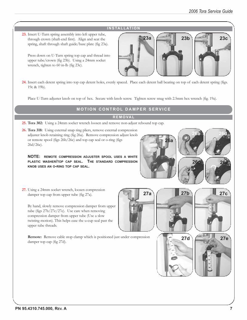
23. Insert U-Turn spring assembly into left upper tube,through crown (shaft-end first). Align and seat thespring, shaft through shaft guide/base plate (fig 23a).
Press down on U-Turn spring top cap and thread intoupper tube/crown (fig 23b). Using a 24mm socketwrench, tighten to 60 in-lb (fig 23c).
I N S TA L L AT I O N
24. Insert each detent spring into top cap detent holes, evenly spaced. Place each detent ball bearing on top of each detent spring (figs.19c & 19b).
Place U-Turn adjuster knob on top of hex. Secure with knob screw. Tighten screw snug with 2.5mm hex wrench (fig. 19a).
M O T I O N C O N T R O L D A M P E R S E R V I C E
R E M O VA L
26. Tora 318: Using external snap ring pliers, remove external compressionadjuster knob retaining ring (fig 26a). Remove compression adjust knobor remote spool (figs 26b/26c) and top cap seal or o-ring (figs26d/26e).
NOTE: REMOTE COMPRESSION ADJUSTER SPOOL USES A WHITE
PLASTIC WASHER/TOP CAP SEAL. THE STANDARD COMPRESSION
KNOB USES AN O-RING TOP CAP SEAL.
27. Using a 24mm socket wrench, loosen compressiondamper top cap from upper tube (fig 27a).
By hand, slowly remove compression damper from uppertube (figs 27b/27c/27e). Use care when removingcompression damper from upper tube (Use a slowtwisting motion). This helps ease the u-cup seal past theupper tube threads.
Remote: Remove cable stop clamp which is positioned just under compressiondamper top cap (fig 27d).
25. Tora 302: Using a 24mm socket wrench loosen and remove non-adjust rebound top cap.
23a 23b 23c
26a
26b 26d
26c 26e
27a 27b 27c
27d 27e
8 © SRAM Corporation • 2006 TORA SERVICE GUIDE
2006 Tora Service Guide
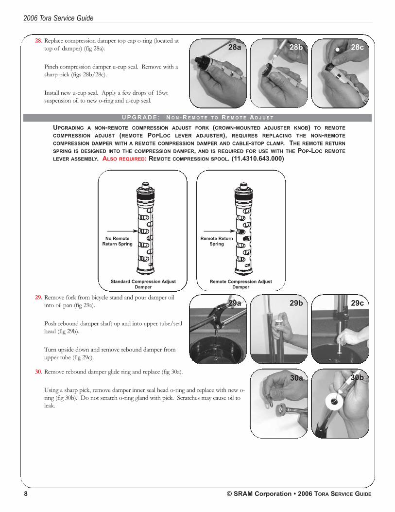
28. Replace compression damper top cap o-ring (located attop of damper) (fig 28a).
Pinch compression damper u-cup seal. Remove with asharp pick (figs 28b/28c).
Install new u-cup seal. Apply a few drops of 15wtsuspension oil to new o-ring and u-cup seal.
U P G R A D E : N O N - R E M O T E T O R E M O T E A D J U S T
UPGRADING A NON-REMOTE COMPRESSION ADJUST FORK (CROWN-MOUNTED ADJUSTER KNOB) TO REMOTE
COMPRESSION ADJUST (REMOTE POPLOC LEVER ADJUSTER), REQUIRES REPLACING THE NON-REMOTE
COMPRESSION DAMPER WITH A REMOTE COMPRESSION DAMPER AND CABLE-STOP CLAMP. THE REMOTE RETURN
SPRING IS DESIGNED INTO THE COMPRESSION DAMPER, AND IS REQUIRED FOR USE WITH THE POP-LOC REMOTE
LEVER ASSEMBLY. ALSO REQUIRED: REMOTE COMPRESSION SPOOL. (11.4310.643.000)
Standard Compression Adjust
Damper
Remote Compression Adjust
Damper
Remote Return
Spring
No Remote
Return Spring
29. Remove fork from bicycle stand and pour damper oilinto oil pan (fig 29a).
Push rebound damper shaft up and into upper tube/sealhead (fig 29b).
Turn upside down and remove rebound damper fromupper tube (fig 29c).
30. Remove rebound damper glide ring and replace (fig 30a).
Using a sharp pick, remove damper inner seal head o-ring and replace with new o-ring (fig 30b). Do not scratch o-ring gland with pick. Scratches may cause oil toleak.
28a 28b 28c
29a 29b 29c
30a 30b
PN 95.4310.745.000, REV. A 9
2006 Tora Service Guide
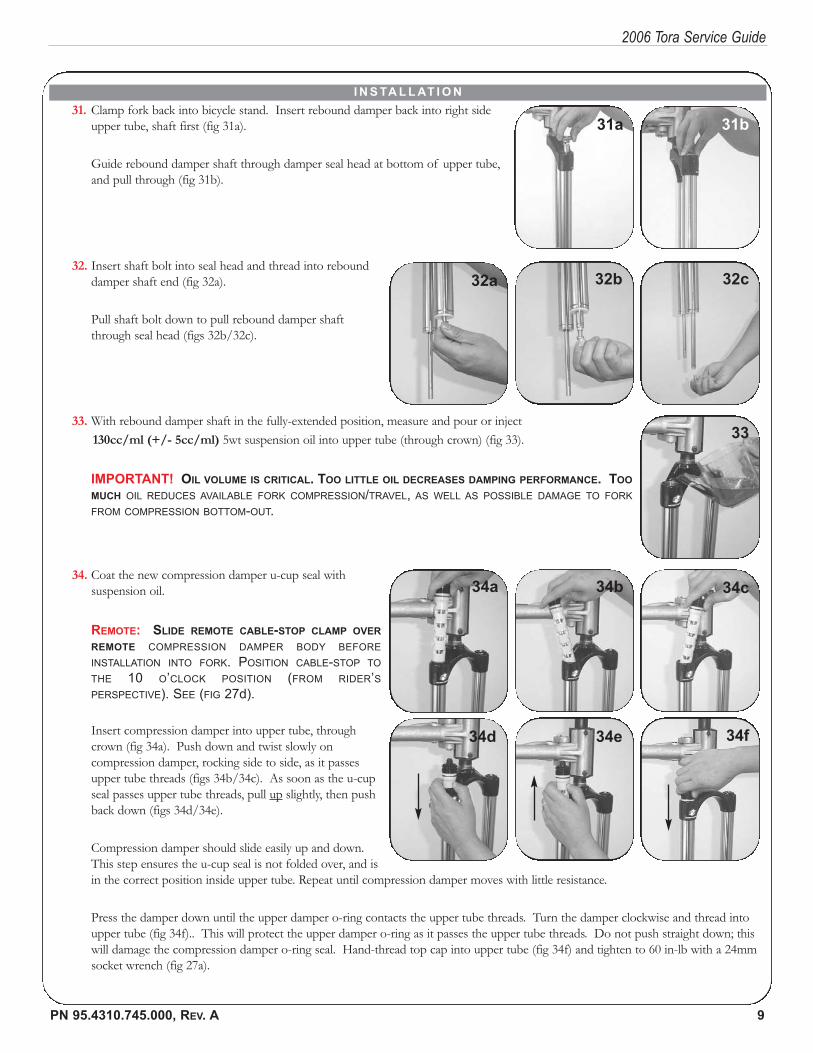
31. Clamp fork back into bicycle stand. Insert rebound damper back into right sideupper tube, shaft first (fig 31a).
Guide rebound damper shaft through damper seal head at bottom of upper tube,and pull through (fig 31b).
32. Insert shaft bolt into seal head and thread into rebounddamper shaft end (fig 32a).
Pull shaft bolt down to pull rebound damper shaftthrough seal head (figs 32b/32c).
I N S TA L L AT I O N
33. With rebound damper shaft in the fully-extended position, measure and pour or inject 130cc/ml (+/- 5cc/ml) 5wt suspension oil into upper tube (through crown) (fig 33).
IMPORTANT! OIL VOLUME IS CRITICAL. TOO LITTLE OIL DECREASES DAMPING PERFORMANCE. TOO
MUCH OIL REDUCES AVAILABLE FORK COMPRESSION/TRAVEL, AS WELL AS POSSIBLE DAMAGE TO FORK
FROM COMPRESSION BOTTOM-OUT.
34. Coat the new compression damper u-cup seal withsuspension oil.
REMOTE: SLIDE REMOTE CABLE-STOP CLAMP OVER
REMOTE COMPRESSION DAMPER BODY BEFORE
INSTALLATION INTO FORK. POSITION CABLE-STOP TO
THE 10 O’CLOCK POSITION (FROM RIDER’S
PERSPECTIVE). SEE (FIG 27d).
Insert compression damper into upper tube, throughcrown (fig 34a). Push down and twist slowly oncompression damper, rocking side to side, as it passesupper tube threads (figs 34b/34c). As soon as the u-cupseal passes upper tube threads, pull up slightly, then pushback down (figs 34d/34e).
Compression damper should slide easily up and down.This step ensures the u-cup seal is not folded over, and isin the correct position inside upper tube. Repeat until compression damper moves with little resistance.
Press the damper down until the upper damper o-ring contacts the upper tube threads. Turn the damper clockwise and thread intoupper tube (fig 34f).. This will protect the upper damper o-ring as it passes the upper tube threads. Do not push straight down; thiswill damage the compression damper o-ring seal. Hand-thread top cap into upper tube (fig 34f) and tighten to 60 in-lb with a 24mmsocket wrench (fig 27a).
31a 31b
32a 32b 32c
33
34a 34b 34c
34d 34e 34f
2006 Tora Service Guide
10 © SRAM Corporation • 2006 TORA SERVICE GUIDE
35. Insert compression damper top cap seal (o-ring or plastic) over top cap (figs 26d/26e).
Place compression knob or remote spool onto compression damper top cap, with knob dial or cable set screw at 3 o'clock position(figs 26b/26c).
Using external snap ring pliers, secure compression knob or remote spool with external retaining ring (fig 26a).36. Motion Control Remote Forks: Cable Installation
1) Thread remote cable through cable-stop clamp on crown.2) Thread cable around compression spool, under cable set-screw, and tighten with 2mm hex wrench. Knob should be positionedin 3 o'clock position in full-open position.3) Test PopLoc remote lever function for proper lockout/compression adjust.4) Adjust cable tension as needed.
L O W E R L E G I N S TA L L AT I O N
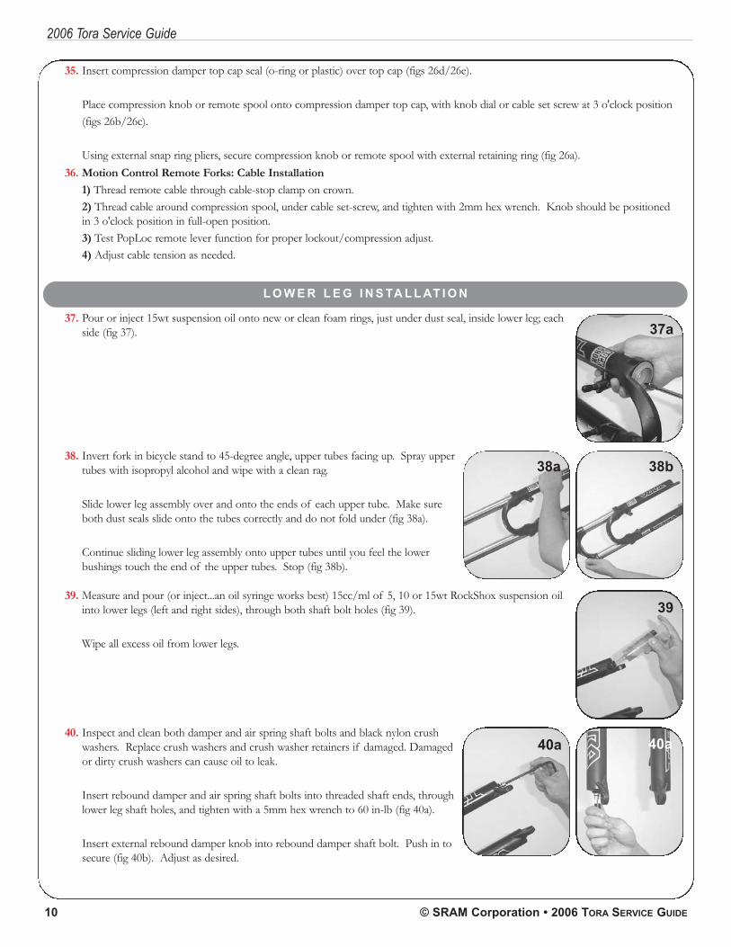
37. Pour or inject 15wt suspension oil onto new or clean foam rings, just under dust seal, inside lower leg; eachside (fig 37).
38. Invert fork in bicycle stand to 45-degree angle, upper tubes facing up. Spray uppertubes with isopropyl alcohol and wipe with a clean rag.
Slide lower leg assembly over and onto the ends of each upper tube. Make sureboth dust seals slide onto the tubes correctly and do not fold under (fig 38a).
Continue sliding lower leg assembly onto upper tubes until you feel the lowerbushings touch the end of the upper tubes. Stop (fig 38b).
39. Measure and pour (or inject...an oil syringe works best) 15cc/ml of 5, 10 or 15wt RockShox suspension oilinto lower legs (left and right sides), through both shaft bolt holes (fig 39).
Wipe all excess oil from lower legs.
40. Inspect and clean both damper and air spring shaft bolts and black nylon crushwashers. Replace crush washers and crush washer retainers if damaged. Damagedor dirty crush washers can cause oil to leak.
Insert rebound damper and air spring shaft bolts into threaded shaft ends, throughlower leg shaft holes, and tighten with a 5mm hex wrench to 60 in-lb (fig 40a).
Insert external rebound damper knob into rebound damper shaft bolt. Push in tosecure (fig 40b). Adjust as desired.
37a
38a 38b
39
40a 40a
2006 Tora Service Guide
PN 95.4310.745.000, REV. A 11
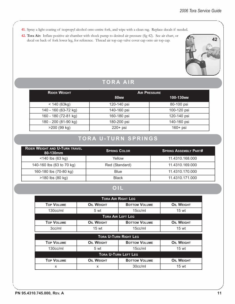
41. Spray a light coating of isopropyl alcohol onto entire fork, and wipe with a clean rag. Replace decals if needed.42. Tora Air: Inflate positive air chamber with shock pump to desired air pressure (fig 42). See air chart, or
decal on back of fork lower leg, for reference. Thread air top cap valve cover cap onto air top cap.
T O R A A I R
RIDER WEIGHT AIR PRESSURE
80MM 100-130MM
< 140 (63kg) 120-140 psi 80-100 psi
140 - 160 (63-72 kg) 140-160 psi 100-120 psi
160 - 180 (72-81 kg) 160-180 psi 120-140 psi
180 - 200 (81-90 kg) 180-200 psi 140-160 psi
>200 (99 kg) 220+ psi 160+ psi
O I L
TORA AIR RIGHT LEG
TOP VOLUME OIL WEIGHT BOTTOM VOLUME OIL WEIGHT
130cc/ml 5 wt 15cc/ml 15 wt
TORA AIR LEFT LEG
TOP VOLUME OIL WEIGHT BOTTOM VOLUME OIL WEIGHT
3cc/ml 15 wt 15cc/ml 15 wt
T O R A U - T U R N S P R I N G S
RIDER WEIGHT AND U-TURN TRAVEL
80-130mmSPRING COLOR SPRING ASSEMBLY PART#
<140 lbs (63 kg) Yellow 11.4310.168.000
140-160 lbs (63 to 70 kg) Red (Standard) 11.4310.169.000
160-180 lbs (70-80 kg) Blue 11.4310.170.000
>180 lbs (80 kg) Black 11.4310.171.000
TORA U-TURN RIGHT LEG
TOP VOLUME OIL WEIGHT BOTTOM VOLUME OIL WEIGHT
130cc/ml 5 wt 15cc/ml 15 wt
TORA U-TURN LEFT LEG
TOP VOLUME OIL WEIGHT BOTTOM VOLUME OIL WEIGHT
x x 30cc/ml 15 wt
42
2006 Tora Service Guide
PN 95.4310.745.000, REV. A 12
T R O U B L E - S H O O T I N G
AIR LOSS• Inspect air piston o-rings. Replace if necessary.• To avoid air loss, remove DualAir top cap and check oil level inside air chamber, every 25 to 50 riding hours. If there is little or
no oil on top of air piston o-ring, pour 3 to 5cc RockShox 15wt suspension oil into air spring chamber. Oil will keep air seallubricated.
• Inspect schrader valve assembly. Replace if damaged or malfunctioning. Clean if clogged.
LOSS OF, OR VARIANCE IN DAMPING• Inspect all damper o-rings. Replace and lubricate.• Inspect damper oil volume. Remove damper top cap/compression damper assembly. Add or remove oil as needed.• Remote: Inspect remote cable tension. Cable may stretch, or become loose. Loosen cable screw, tension cable and tighten.
Test. Adjust as needed.
BUSHING PLAY• Inspect and replace worn bushings. Bushings are a wear and tear item, and need to be replaced after approximately 100 to 200
riding hours, depending your riding style, condition, riding time and body weight. If you ride a lot, check those bushings! • See the 'Bushing Installation' guide at www.rockshox.com for procedures.
OIL LOSS• Inspect the air piston o-ring for air bypass. If there is a repeated loss of air pressure, air may be the cause of oil loss at the left
dust seal.• Inspect your shaft bolt crush washers. Replace if worn or damaged.• Inspect your top cap o-rings. Replace if torn or knicked.