Embed Size (px)
Citation preview

AAAAAAAAnnnnnnnnnnnnnnnnuuuuuuuuaaaaaaaallllllll RRRRRRRReeeeeeeeppppppppoooooooorrrrrrrrtttttttt
TTTTTTTTeeeeeeeecccccccchhhhhhhhnnnnnnnniiiiiiiiccccccccaaaaaaaallllllll RRRRRRRReeeeeeeesssssssseeeeeeeeaaaaaaaarrrrrrrrcccccccchhhhhhhh AAAAAAAAccccccccttttttttiiiiiiiivvvvvvvviiiiiiiittttttttiiiiiiiieeeeeeeessssssss
DDeecceemmbbeerr 22000055
MMeettaall BBuuiillddiinngg MMaannuuffaaccttuurreerrss AAssssoocciiaattiioonn 1300 Sumner Ave.
Cleveland, OH 44115 216-241-7333
Mmax
M r
λp λr
compact noncompact
nonslender
(inelastic buckling)
Mmax
M r
λp λr
compact noncompact
nonslender slender
(inelastic buckling)
(elastic buckling)
Anchor Point 1
Anchor Point 2
KLb or bfc/2t fcLp or λpf Lr or λrf
Fn or Mn
Fmax or Mmax
Fyr or Myr
FLB and LTB resistance
in uniform bending
LTB resistance under
moment gradient
Uniform Bending
Resistance
Cb x Uniform
Bending
Resistance
0
0.5
1
1.5
2
2.5
0 0.5 1 1.5 2 2.5 3 3.5 4
Sidesway displacement, u(in)
Load (kips-in)
Direct Analysis
Effective Length Method
Plastic Zone Analysis

2
Table of Contents
Page
Introduction..............................................................................................................................4
CURRENT PROJECTS
Loading Research
Electromagnetic Uplift.............................................................................................6 Using the NIST Wind Tunnel Database to Update Current Code Models..............8 NIST Virtual Wind Tunnel......................................................................................9
Primary Framing Research
Web Tapered Member Research ...........................................................................11 Evaluation of AISC Stability Analysis and Design Provisions to
Metal Building Systems...................................................................................12 Diaphragm Flexibility............................................................................................13 Seismic Behavior of Metal Buildings....................................................................14
Secondary Framing Research
Analytical Study to Determine Lateral Restraint Forces .......................................16 Insulation Impact on Shear Strength of Screw Connections and Shear
Strength of Diaphragms...................................................................................18 Using the Direct Strength Method to Optimize Purlins.........................................20 Composite Roof Uplift Test...................................................................................21
Energy Research
Thermal Emittance Assessment for the State of California...................................22 Cool Roofs .............................................................................................................23
Design Guide Development
Seismic Design Guide for Metal Building Systems (2006 Update) ......................24 Tapered Member Design Guide.............................................................................25
MBMA RESEARCH REPORTS DISTRIBUTED IN 2005..............................26
OUTREACH PROGRAMS Researcher Symposium – MBMA Meeting, February 9, 2005 .........................................27 ICC Hurricane Symposium – Tampa, FL, February 11-13, 2005, “Performance of
Metal Building Systems in Hurricanes Charley and Ivan,” W. Lee Shoemaker. ..........28 OSHA Advisory Committee on Construction Safety and Health – Chicago, IL, Feb-
ruary 17, 2005, “Voluntary Lubricant Compliance Program for Steel Decking and Roofing,” Patrick Bush and W. Lee Shoemaker ...........................................................29
RICOWI Spring Seminar – Miami, FL, April 1, 2005,“MBMA Team Report – Hur-ricanes Charley and Ivan,” W. Lee Shoemaker..............................................................30
3
California Title 24 Workshops – Sacramento, Fresno, Ontario, CA, April 4, 5, & 7, 2005, “California Title 24 Energy Code – Building Envelope Workshop” ...................31
MBMA Technical Committee Seminar, July 20, 2005, “Designing Metal Buildings with the 2005 AISC Specification,” Don White and Greg Deierlein .............................32
Metalcon, Chicago, IL, October 5, 2005 – “The Performance of Metal Roofing in Hurricanes Charley and Ivan,” W. Lee Shoemaker and Joe Wilson ............................33
Thomas Associates is equipped with the most advanced computational tools.

4
Introduction The Technical Committee and the sponsored research program have accomplished a number of important tasks this year. This Annual Re-port summarizes 12 ongoing technical research projects and two design guides that are fully or partially sponsored by the Metal Building Manufacturers Association. Also contained in this report is a list of final reports for completed projects distributed during the past year, and technical presentations made by and/or to MBMA representatives. It is important to keep in mind the code changes and improvements that have taken place as a result of our research efforts. The following are the most important achievements in the past year:
• Pattern roof live loading was eliminated when not necessary (ASCE 7-05/IBC 2006).
• Eliminated the need to combine pattern snow loading with wind (ASCE 7-05).
• Adopted much less conservative gable-unbalanced snow loading provisions (ASCE 7-05).
• Adopted a lower limit on roof slope for these unbalanced snow-loading provi-sions that made more empirical sense (ASCE 7-05).
• Reduced the wind loading requirements on parapets (ASCE 7-05).
• Relaxed the seismic limitations on sin-gle-story moment frames (ASCE 7-05/IBC 2006).
• Our work with OSHA/SENRAC on the slip hazards of metal roof decking has garnered us an agreement that is not pu-nitive to MBMA while meeting OSHA’s safety goals.
We have many new challenges, some that are being addressed by research summarized in this report and some that will be the focus on new projects in 2006.
• To study and prepare for the huge po-tential impacts coming from the redefi-nition of the specification for the design of structural steel through the creation of our Tapered Member Design Guide and accompanying research.
• To redefine our rigid frames in regards to seismic limitations in order to allow for the inherent empirical advantages they provide that are lost when we must use provisions meant for other types of construction.
• To ensure the adoption of the 50% in-crease in SSR panel wind uplift strength by AISI.
• To closely manage the redefinition of AISI Purlin Anchorage Forces to ensure adoption of reasonable and manageable provisions that make sense.
• To begin working on future ASCE 7 Standards changes, such as the elimina-tion of the 10-psf minimum wind provi-sion.
• To continue the advanced seismic re-search program and recommend changes to both the NEHRP Provisions and ASCE Seismic Provisions with re-gard to metal building systems.
• To study the wind loading on open buildings with sheeted roofs to define
W. Lee Shoemaker, P.E., Ph.D.
MBMA Director of Research & Engineering
Scott Russell, P.E.
Nucor Building Systems MBMA Technical Committee Chairman

5
an approach for the determination of design forces that is far less conserva-tive than existing methods.
• To develop an on-line library for mem-bership-only use of all research com-pleted to date for much-easier review. We can then begin to explore therein for yet-unimplemented benefits of past ex-penditures.
• To help further develop a government (NIST) project for the determination of building wind forces that would more exactly map needed structural design loads than do current provisions that only approximate these based on con-servative generalizations.
• To study the potential benefits to our purlin and girt weights of the new Di-rect Strength Method design approach found in the Appendix of the current AISI Specification.
• To determine if the new AISC flange brace requirements are appropriate for metal building systems.
We encourage anyone who would like more information on any of these projects or other MBMA technical activities to contact us or visit our webpage at www.mbma.com.

6
Electromagnetic Uplift
Principal Investigators
Dr. Ralph Sinno Dr. Burt Nail Mississippi State University Consultants
Dr. David Surry Dr. Eric Ho University of Western Ontario
Sponsor
Metal Building Manufacturers Association American Iron and Steel Institute Metal Construction Association FM Global
Objective The objective of this project is to determine a wind load correlation factor to apply to uniform static air pressure tests to convert the static ca-pacity to the dynamic uplift capacity.
Problem The building codes require that the uplift capacity determined from testing, divided by a factor of safety, exceed the design wind pres-sure. It has been long recognized that the uni-form static air pressure tests do not accurately
represent true wind behavior when evaluating the uplift capacity. It is believed that static pressure tests underestimate the capacity of metal roofing systems and can unnecessarily restrict their use in high wind regions.
Approach A full-scale assembly of a corner of a metal roof was constructed and tested at Mississippi State University using the standard ASTM E-1592 protocol. A dynamic test using a grid of 34 electromag-nets was carried out on the same roof specimen. The electromagnets were programmed to re-produce independent time-history traces ob-tained from a detailed wind tunnel analysis. The simulated wind event was based on Hurri-cane Andrew. Load cells were placed at selected clip loca-tions for both the static ASTM E-1592 test and the dynamic electromagnetic wind simulation. The clip loads in both tests were evaluated to ascertain an appropriate correlation factor re-lated to the true load that is being imparted to the roof system.
Project Status The draft report for this project was submitted in December and it culminates many years of hard work to overcome the difficult technical challenges. Three roof systems were tested, one vertical leg standing seam and two trapezoidal standing seam systems. Dr. David Surry and Dr. Eric Ho of UWO took the lead in combining the results from the MSU project with the results of the UWO Failure Model research into a summary journal article which has been completed and submitted to the ASCE Journal of Structural Engineering.
Electromagnet array

7
This journal article summarized the results which compared the two different approaches to correlating the static uplift test to the dy-namic behavior. The UWO research utilized a model-scale aeroelastic failure model of the same roof system and the results obtained were remarkably consistent. It was found that the E1592 uniform pressure tests contains conservatism of about 50% for the roof system tested by both approaches; and up to about 80% for the other roof systems tested only at MSU. This conservatism arises if the roof system is required to withstand the code recommended pressure applied as uniform pressure in the E1592 test, without accounting for the reality of the dynamic spatially-varying properties of the wind-induced pressures. It is the results of these two research efforts that will be used to support the proposal to adopt a 50% increase in standing seam roof wind uplift strength as part of the AISI Specification.
Diagram of the test setup showing the 34 magnets and the 6 instrumented clips to measure loads.

8
Using the NIST Wind Tunnel Da-
tabase to Update Current Code
Models
MBMA Graduate Fellowship
Mr. Mark Nywening Advisors
Dr. Gregory Kopp Dr. Eric Ho University of Western Ontario Sponsor
Metal Building Manufacturers Association
Objective The objective of this project is to analyze the enormous collection of aerodynamic data for low-rise buildings, which was obtained as part of the National Institute of Standards and Technology (NIST) project to promote data-base assisted design (Virtual Wind Tunnel), to check and improve the code models currently in use that were based on the UWO wind tunnel studies in the late 1970’s.
Problem Currently, the North American provisions, e.g. ASCE 7, for low-rise buildings are based largely on wind tunnel experiments conducted at the University of Western Ontario in the late 1970’s. The data was limited in scope and by the technology of the time. In addition, the primary codification relied on only 9 configura-tions from 3 different gable roof buildings at 3 different heights in open country terrain. The new NIST data set contains information on 7 generic models of 4 to 5 building heights, lead-ing to a total of 64 different building configura-tions. Furthermore, the pressure tap resolution is greatly increased, as is the angular resolution. This database is also being utilized to develop the Virtual Wind Tunnel concept, but this data also gives the opportunity to examine the cur-
rent code requirements in a more comprehen-sive fashion than ever before possible.
Approach Four tasks have been identified in the approach taken:
1. Analysis of structural loads for all 7 mod-els in open country terrain with results pre-sented as modifications to the current code formats.
2. Analysis of local loads, including tributary area effects for all 7 models in open coun-try terrain, with results presented as modi-fications to the current code formats.
3. Analysis of suburban terrain effects on structural loads using selected configura-tions.
4. Analysis of suburban terrain effects on lo-cal loads, including tributary area effects, using selected configurations.
Project Status Task 1 above is well under way and the structural loads have been analyzed for 120 building configurations. Comparison with current code models will be made after the analysis of all the data is complete.
Wind tunnel models used to develop the NIST database.

9
NIST Virtual Wind Tunnel
Principal Investigator
Dr. Emil Simiu National Institute of Standards and Technology Sponsor
Metal Building Manufacturers Association National Institute of Standards and Technology
Objective The objective of this project is to utilize wind tunnel measurements, data storage, and compu-tational capabilities to enable designers to achieve low-rise building designs that are both safer and more economic than using conven-tional wind load standards.
Problem Wind loading provisions of standards such as ASCE 7 were developed to be simple enough for use with the slide rule or pocket calculator. For low-rise frames, wind loads inherent in those provisions are time-invariant, independ-ent of distance between frames, and based on a generic set of the frames’ influence lines, rather than on the actual influence lines. In addition, the ASCE 7 loads model the spatial variation of the actual wind loads in an oversimplified manner. For these reasons, calculations based on the ASCE 7 wind loads can result in large differences between the Standard loads and the actual loads. It is now practical to develop user-friendly methods that incorporate large aerodynamic databases, or virtual wind tunnels (VWT), and allow the calculation for routine designs of considerably more realistic wind load effects than those based on conventional methods. Methods that make full use of aerodynamic data obtained in the wind tunnel are fully con-sistent with the provisions of ASCE 7 insofar as these allow the use of such data for estimat-ing wind load effects.
Codification of wind loads has been carried out by enveloping the most unfavorable situations that can occur for the type of building being examined. NIST has proposed this method that uses present computer storage and processing capabilities in conjunction with up-to-date wind tunnel technologies. A study has shown that this method can result in design moments and shears lower by as much as 50% compared to their counterparts now specified in ASCE 7.
Approach The following steps were outlined and pre-sented to NIST to reflect MBMA’s input on the next steps required to evolve this method into a practical design approach.
1. The database of buildings in the VWT needs to be comprehensive to minimize interpolation between available samples for reliable designs. The interpolation procedures developed by NIST will also need to be finalized and evaluated.
2. The VWT program needs to be made into a subroutine that can be called by a design program, written in a compatible pro-gramming language. Input from the de-sign program to VWT should include in-fluence coefficients and their locations. Output from VWT to the design program

10
should be structural actions represented by the influence coefficients.
3. Checks and reviews should be made to determine the reliability of the VWT.
4. Concurrent with Tasks 1 through 3, write a specification for the program that gen-erates influence coefficients and their lo-cations to be placed in the design pro-gram.
5. The design program will be enhanced to produce influence coefficients and their locations for input to VWT.
6. When Tasks 1 through 5 are complete to a
working degree, some examples should be run to demonstrate that the programs are compatible and wind designs are rea-sonable. Then, experiments should be made to determine the extent to which cycles must be run in order to produce comprehensive designs. That is, deter-mine the number of analysis points, mo-ments, shears and axial forces necessary to cover all cases. It is felt that a rigorous
treatment would require an impracticable amount of computer resources. The task would be to narrow the procedure down to a minimum but sufficient number of investigations.
Project Status MBMA is partnering with NIST to try to bring this concept into a working model, using in-house metal building software and an interface with the NIST database. Much progress has been made, including an interpolation algo-rithm that is needed to evaluate building con-figurations that aren’t defined by the wind tun-nel models used to develop the database. The steps outlined above will be carried out in 2006. Gill Harris has also agreed to act as an advisor with regard to this project, and he has already made significant contributions to this project.
Scaling of pressure tap coordinates to match dimen-sions of structure of interest.

11
Web Tapered Member Research
Principal Investigator
Dr. Donald White Georgia Tech Sponsor
Metal Building Manufacturers Association
Objective The objective of this project is to carry out in-vestigations, as needed, to support the devel-opment of the Tapered Member Design Guide.
Problem It is anticipated that several small research top-ics will need to be conducted as part of the de-velopment of the Tapered Member Design Guide. Dr. White is a co-author of the guide and will be responsible for carrying out these studies, as needed.
Approach Anticipated research topics include:
• Applicability of Direct Analysis to ta-pered members.
• Analysis of modeling de-tails/requirements for tapered members.
• Applicability of AISC Sections E3 (compressive strength for flexural buck-ling of members without slender ele-ments), E4 (compressive strength for torsional and flexural-torsional buckling of members without slender elements) and E7 (members with slender ele-ments) to tapered members.
• Applicability of AISC Sections F2 (doubly symmetric compact I-shaped members and channels bent about their
major axis), F3 (doubly symmetric I-shaped members with compact webs and noncompact or slender flanges bent about their major axis), F4 (other I-shaped members with compact or non-compact webs bent about their major axis) and F5 (doubly symmetric and singly symmetric I-shaped members with slender webs bent about their ma-jor axis) to tapered members.
• Applicability of AISC Sections H1 (doubly and singly symmetric members subject to flexure and axial force) and H2 (unsymmetric and other members subject to flexure and axial force) to ta-pered members.
• Calculation of Fe for lateral torsional buckling and flexural torsional buckling of tapered beams and columns with dif-ferent bracing on each flange using both precise computer methods and conser-vative approximate methods.
Project Status The first task has been accomplished under a separate contract as reported in the next project with Dr. White. The other tasks will be carried out as needed in the first part of 2006.
Mmax
M r
λp λr
compact noncompact
nonslender
(inelastic buckling)
Mmax
M r
λp λr
compact noncompact
nonslender slender
(inelastic buckling)
(elastic buckling)
Anchor Point 1
Anchor Point 2
KL b or bfc/2tfcLp or λpf Lr or λrf
Fn or Mn
Fmax or Mmax
Fyr or M yr
FLB and LTB resistance
in uniform bending
LTB resistance under
moment gradient
Uniform Bending
Resistance
Cb x Uniform
Bending
Resistance

12
Evaluation of AISC Stability
Analysis and Design Provisions to
Metal Building Systems
Principal Investigator
Dr. Donald White Georgia Tech Sponsor
Metal Building Manufacturers Association
Objective The objective of this project is to evaluate the impact of the 2005 AISC Specification re-quirements for analysis and design methods on typical metal building system frames.
Problem The 2005 AISC Combined LRFD/ASD Speci-fication provides new and updated analysis and design methods that should be beneficial to me-tal building structural systems. However, the specifics of how to apply the provisions to metal building structures are not well defined.
Approach This project was divided into three tasks:
1. Provide an overview of the 2005 AISC stability analysis and design provisions and how they can be applied to metal building systems.
2. Provide two example metal building frames (one clear span and one modular frame) designed according to the recom-mendations from Task 1.
3. Provide recommendations for testing, validation and potential refinement of the design procedures presented in Task 1.
The 2005 AISC Specification explicitly re-quires that the analysis must account for the second-order effects in the structure at its strength limit. This study reviews the advan-tages and disadvantages of several ways to carry out these requirements. Specifically, the direct analysis method is scrutinized with re-gard to metal building frames as opposed to the traditional effective length approach.
Project Status The final report is complete and has been dis-tributed to MBMA members. It should be quite helpful in their decisions on implementation strategies for the new 2005 AISC Specification. It will also provide needed input for the devel-opment of the Tapered Member Design Guide.
Comparison of beam-column strength interaction checks for the effective length method and the direct analysis method.

13
Diaphragm Flexibility
Principal Investigator
Dr. Michael Symans Rensselaer Polytechnic Institute Sponsor
Metal Building Manufacturers Association
Objective The objective of this project is to evaluate the conditions under which the assumption of flexi-ble diaphragm behavior for low-rise metal buildings is valid, and to evaluate the effects of making the assumption when it is not strictly valid. Simplified methods of analysis will be proposed for cases in which the flexible dia-phragm assumption is not valid.
Problem All structural systems must provide a continu-ous load path for transferring seismically in-duced inertial forces to the foundation. For sin-gle-story metal buildings, the primary function of the roof system is to support gravity loads and to transfer these loads to other structural members, which, in turn, transfer the loads into the foundation. In addition, the roof system must distribute lateral wind and earthquake loads to the vertical components of the lateral force resisting system (LFRS). Thus, the roof system must be capable of resisting and trans-ferring both out-of-plane and in-plane loads. Accurate determination of the distribution of lateral seismic forces within the horizontal LFRS (i.e., the roof diaphragm) and the vertical LFRS requires a 3-dimensional analysis that accounts for the relative rigidity of the various elements that make up both the horizontal and vertical LFRS. Such analysis is reasonable for certain structures such as major buildings that feature significant irregularities. For general application, however, certain assumptions are often made to simplify the analysis.
For example, assumptions are made regarding the horizontal diaphragm rigidity and simpli-fied analysis is performed to distribute the dia-phragm forces to the vertical LFRS. Clearly, the accuracy of the results depends on the va-lidity of the assumptions made. Furthermore, neglecting the real behavior of the roof dia-phragm can sometimes lead to major errors in assessing the required lateral load capacity of the vertical LFRS components.
Approach A computational study will be performed on a typical metal building subjected to seismic loading. The plans for the building will be util-ized to develop both simplified and complex analytical/computational models that can be modified to investigate the influence of various parameters on diaphragm flexibility. Both static and dynamic analysis will be performed to fully characterize the influence of diaphragm behav-ior on seismic response of the building. Examples of parameters that will be evaluated include plan and elevation geometries of the building, spatial distribution of horizontal brac-ing, roof angle, single vs. multi-span framing (i.e., the absence or presence of interior col-umns), bay spacing, end wall type (e.g. clear span or post and beam), and number of gables.
Project Status Significant progress has been made on this pro-ject. Finite element studies have been carried out that have explored the load distribution into the moment frames. Preliminary results indi-cate that interior frames may not be carrying as much of the lateral load as currently assumed and therefore could be over designed. The con-verse would be true for the end moment frames.

14
Seismic Behavior of Metal Build-
ings
Principal Investigator
Dr. Chia-Ming Uang University of California – San Diego Sponsor
Metal Building Manufacturers Association American Iron and Steel Institute
Objective The objective of this project is to perform ad-vanced analyses of typical metal building sys-tems to better understand their behavior when subject to seismic events, leading to recom-mendations for appropriate code requirements.
Problem The research on steel frames and connection design after the Northridge earthquake was fo-cused on multi-story frames, composed of prismatic, rolled shapes and welded moment connections. In fact, the FEMA 267 Interim Guidelines stated that “light, single-story, frame structures, the design of which is pre-dominated by wind loads, have performed well in past earthquakes and may continue to be de-signed using conventional approaches, regard-less of the seismic zone they are located in.” However, many code revisions were imple-mented as a result of this research that im-pacted these light single-story frames. Testing to demonstrate ductility is now required for the moment connections on intermediate and spe-cial moment frames. Prescriptive requirements are required for ordinary moment frames, based on the aforementioned frame and connection types. The primary steel frames in metal building sys-tems are quite different from the prototype steel frames evaluated in the post-Northridge re-search. Metal building frames are optimized to
match the envelope of maximum moment curves. Therefore, the frames are composed of welded plates that are commonly web tapered and may have unequal flanges. They are pri-marily single story, gable frames and are either clear span or utilize interior columns. In addi-tion, the connections are bolted end-plates. The current requirements for steel frames as-sume that the plastic hinge will form at or near the beam-to-column connections. These re-quirements are also being enforced on metal building frames, in which preliminary analyses have shown that the plastic hinges will form at a considerable distance away from the column, due to the tapered member configuration. If this is the case, a demonstration of inelastic ro-tation capacity at the connection of a metal building frame is probably not the correct ap-proach.
Approach A three phase research plan is being carried out. Phase 1 will involve an analytical study and numerical simulation of typical frames to evaluate seismic demand. Phase 2 deals with
Typical finite element analysis result showing local bucking of web and flange from seismic loads.

15
cyclic testing of metal building components for seismic (deformation) capacity evaluation. Phase 3, which is expected to be submitted for a potential NEES research project, deals with earthquake simulation of metal buildings using the UCSD outdoor shake table to verify the system performance.
Project Status The steering group had a productive kickoff meeting with Dr. Uang in September. It was decided that a full-scale test, subjecting a typi-cal metal building frame to lateral loads, was desirable to be able to have full confidence in the finite element model results. This expansion of the project is going full speed ahead, and it is anticipated that the test will be carried out at the end of January.
Elevation showing full-scale frame to be tested at UCSD to calibrate their finite element models.
16
Analytical Study to Determine
Lateral Restraint Forces
MBMA/AISI Graduate Fellowship
Mr. Michael Seek
Advisor
Dr. Thomas Murray Virginia Tech Sponsor
Metal Building Manufacturers Association American Iron and Steel Institute
Objective The objective of this graduate fellowship study is to carry out additional numerical analyses to develop an improved an accurate method to calculate lateral restraint forces in a metal roof-ing system.
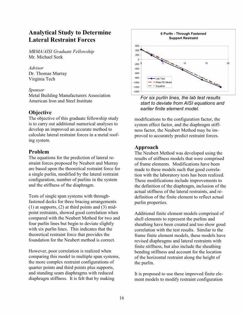
Problem The equations for the prediction of lateral re-straint forces proposed by Neubert and Murray are based upon the theoretical restraint force for a single purlin, modified by the lateral restraint configuration, number of purlins in the system and the stiffness of the diaphragm. Tests of single span systems with through-fastened decks for three bracing arrangements (1) at supports, (2) at third points and (3) mid-point restraints, showed good correlation when compared with the Neubert Method for two and four purlin lines but begin to deviate slightly with six purlin lines. This indicates that the theoretical restraint force that provides the foundation for the Neubert method is correct. However, poor correlation is realized when comparing this model to multiple span systems, the more complex restraint configurations of quarter points and third points plus supports, and standing seam diaphragms with reduced diaphragm stiffness. It is felt that by making
modifications to the configuration factor, the system effect factor, and the diaphragm stiff-ness factor, the Neubert Method may be im-proved to accurately predict restraint forces.
Approach The Neubert Method was developed using the results of stiffness models that were comprised of frame elements. Modifications have been made to these models such that good correla-tion with the laboratory tests has been realized. These modifications include improvements to the definition of the diaphragm, inclusion of the actual stiffness of the lateral restraints, and re-definition of the finite element to reflect actual purlin properties. Additional finite element models comprised of shell elements to represent the purlins and sheathing have been created and too show good correlation with the test results. Similar to the frame finite element models, these models have revised diaphragms and lateral restraints with finite stiffness, but also include the sheathing bending stiffness and account for the location of the horizontal restraint along the height of the purlin. It is proposed to use these improved finite ele-ment models to modify restraint configuration
6 Purlin - Through Fastened
Support Restraint
-1400
-1200
-1000
-800
-600
-400
-200
0
200
400
600
0 5 10 15 20
Lab Test
Plate FE Model
Equation
For six purlin lines, the lab test results start to deviate from AISI equations and earlier finite element model.
17
factors, diaphragm stiffness factors and the sys-tem effect factors of the Neubert Prediction Model. This will require a sizeable test matrix of approximately 2000 tests. The tests will consist of 100 specimens comprised of 10 combinations of purlin type and span length, 2 span types (single span / multiple span), and 5 restraint configurations. Each of the 100 specimens will be subjected to variations of several parameters: roof slope, diaphragm stiffness, number of purlins lines, restraint stiffness values, sheathing bending stiffness values, standing seam clip stiffness, and re-straint height along the purlin depth.
Project Status In addition to the work noted above as part of Mike Seek’s fellowship, the AISI Anchorage Task Force is proceeding to evaluate and possi-bly modify the existing anchorage equations with a term that accounts for the number of an-chorage locations. Mike Seek is continuing his stiffness based ap-proach and should be presenting final recom-mendations based on his work at the Re-searcher Symposium in February 2006. It will be up to the AISI Anchorage Task Force to determine how the specification is modified based on all of the work that is submitted for evaluation and review.
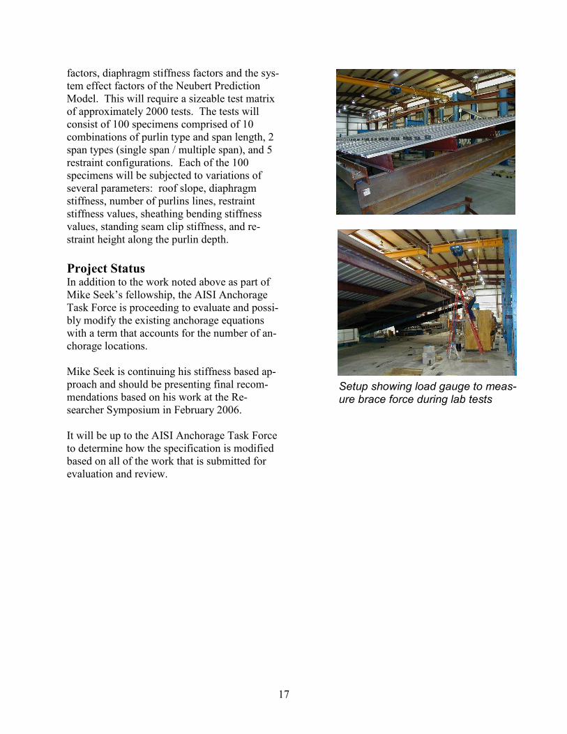
Setup showing load gauge to meas-ure brace force during lab tests

18
Insulation Impact on Shear
Strength of Screw Connections
and Shear Strength of Dia-
phragms
Principal Investigator
Dr. W. Samuel Easterling Virginia Tech Sponsor
Metal Building Manufacturers Association American Iron and Steel Institute
Objective The objective of this project is to establish strength properties for screws used in cold-formed steel connection applications in which a layer of insulation is sandwiched between a steel panel and structural supporting member. Further, the performance of steel deck dia-phragms, in which screws pass through a layer of insulation, will be assessed and design pro-cedures modified or developed to reflect the influence of the insulation on the screws.
Problem Two distinct problems are addressed by this research project (1) the basic shear strength of a screw with insulation sandwiched between the steel deck profile and the supporting structural member and (2) the influence of this fastener configuration on diaphragm strength. Traditionally, individual fastener tests and steel deck diaphragm tests have been conducted without the insulation being present between the sheet and structural material.
Approach Dr. Easterling has identified seven tasks to car-ry out the project objectives:
1. Literature review, existing data collection. 2. Screw component tests – conduct ap-
proximately 250 component screw shear
tests. The specific test matrix will be es-tablished following completion of Task 1 and with input from the advisory commit-tee and industry representatives.
3. Screw Shear Strength Model – Results from Task 2 will be compared to present screw shear strength provisions in the AISI Specification. Based on the com-parisons, a screw shear strength model will be recommended for use.
4. Reliability Analysis of Data – Factors of safety and strength reduction factors will be formulated through reliability based analysis of the data.
5. Diaphragm Analysis – Using results from Tasks 3 and 4, evaluate current analy-sis/design methods to predict diaphragm shear strength. The SDI diaphragm de-sign procedure will be used as the starting point for evaluating various diaphragm configurations.
6. Confirmatory Diaphragm Tests – A set of approximately 6 to 10 confirmatory dia-phragm tests will be conducted. These tests will be used for comparison with the analysis results from Task 5 and as needed to support Task 7.
7. Design Procedures – Develop modifica-tions and/or new procedures for dia-phragm design provisions. Based on re-
Test configuration for shear strength tests.

19
sults from Tasks 6 and 7, recommend de-sign procedures to be used for through fastened steel deck roof diaphragm strength, incorporating the effects of insu-lation placed between the deck and sup-porting members.
Project Status This testing is complete and Dr. Easterling will be submitting a final report in the near future. He indicates that based on his review of the test data to date that the current AISI equations for screw bearing and tilting strength can be used without modification, within the limits of the test results.
Test showing tilting failure.
Test showing screw bearing failure.

20
Using the Direct Strength
Method to Optimize Purlins
Principal Investigator
Dr. Ben Schafer Johns Hopkins University Sponsor
Metal Building Manufacturers Association
Objective The objective of this study is to provide guid-ance to MBMA members on how to utilize the new Direct Strength Method that is available in the AISI specification.
Problem The 2004 Supplement to the AISI Specification added the Direct Strength Method as an option to determine the strength of cold-formed members. This opens up new possibilities by providing a tool that can analyze more complex cross-sections than the specification currently allows.
Approach Two different approaches will be available and will be discussed with the steering group. The first approach would be to actually optimize a purlin for everyone’s use. This would be an “MBMA” series of purlins, so to speak. The second approach would be to provide training and education to MBMA members so that they could all optimize, patent, etc. their own purlins.
Project Status This project was just awarded to Dr. Schafer, in the form of an unrestricted gift to his department so that he has latitude in utilizing the funding for supplementing a student, computers, software, etc.
Examples of shapes currently used that are not fully optimized.
Examples of shapes that can be readily handled with the Direct Strength Method and commonly used in Europe and Australia.

21
Composite Roof Uplift Test
Principal Investigators
Dr. Bas Baskaran National Research Council Ottawa, Canada Dr. David Surry University of Western Ontario Sponsor
Metal Building Manufacturers Association American Iron and Steel Institute Metal Construction Association Copper Development Association
Objective The objective of this project is to determine the proper way to evaluate the uplift capacity of a composite roof system through the load sharing relationship between metal cladding and a solid substrate.
Problem The E1592 uplift test is not applicable to com-posite roofs where the metal covering is sup-ported by a separate substrate. An approach is needed to be able to evaluate this common type of roof system that takes into account the load sharing between the layers and the permeability of the roof covering.
Approach An existing test setup at the National Research Council will be used for this project. A total of 10 systems will be tested for variations in air permeability of the metal cladding with and without rigid insulation. At selected attachment locations, sensors will be installed. Pressure taps to quantify the load sharing between the metal cladding and solid substrate will be used along with force balances to measure the in-duced loads on the metal panel attachments.
Project Status Phase I of this project investigated three differ-ent systems (5 tests). This included 24 gauge steel snap panels as well as copper roofing tiles. Two of the tests with steel snap panels were assembled over a plywood substrate and two were without a substrate. Phase II included 5 tests using the same 24 gauge steel snap panels, but over a steel deck. Various parameters were investigated, includ-ing polyiso board, vapor barrier, and panel sealant. Pressure records revealed the load-sharing pattern among the components. Phase III tests are currently being carried out, which will examine a double lock seam roof that would be less permeable than the others tested and transfer more load to the substrate. When this last phase is completed, the final re-port will be submitted.
P2 Below Organic Felt
D1 D2
D3 L1 L2
P1 Above
Panel
Instrumentation Setup
Dynamic Roofing Facility at National Research
22
Thermal Emittance Assessment
for the State of California
Principal Investigators
Dr. William Miller Mr. Andre Desjarlais Oak Ridge National Laboratory Sponsor
Cool Metal Roofing Coalition
Objective The objective of this project is to investigate the interdependence of thermal emittance, solar reflectance and roof insulation on low-slope roof heat transfer for nonresidential buildings in California.
Problem The thermal emittance of many materials, e.g. wood, paper, plaster, rubber, water, ice, marble, paint, clay or concrete is very high, of the order 0.90. However, shiny bare and acrylic coated metals have a low thermal emittance, and when used as a roof, Galvalume® has an initial measured solar reflectance of 0.67 and an ini-tial measure thermal emittance of only 0.15, and therefore do not comply with the "cool roof" prescriptive requirements specified in California's 2005 building energy efficiency standards for non-residential buildings. The legislation has impacted the economic health building products, with over $103 million sales in 2003 representing 5 to 7% of industry ship-ments. Therefore, the metal industry, being very concerned with the loss of revenue, re-quested Oak Ridge National Laboratory (ORNL) to evaluate the tradeoff between solar reflectance and thermal emittance as applied to the concept of a 2005 Title 24 "cool roof."
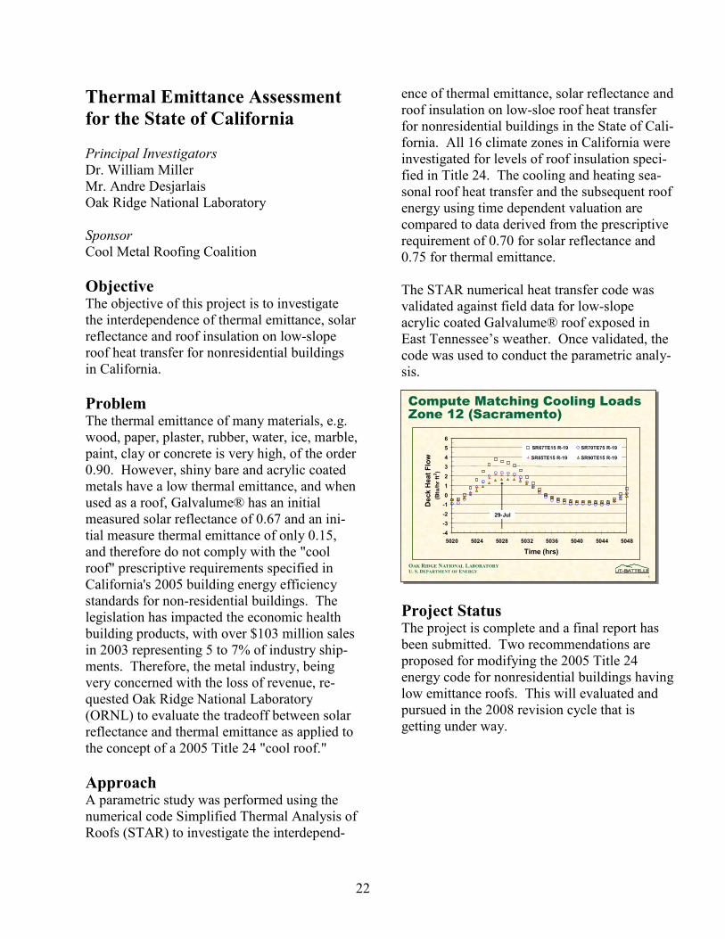
Approach A parametric study was performed using the numerical code Simplified Thermal Analysis of Roofs (STAR) to investigate the interdepend-
ence of thermal emittance, solar reflectance and roof insulation on low-sloe roof heat transfer for nonresidential buildings in the State of Cali-fornia. All 16 climate zones in California were investigated for levels of roof insulation speci-fied in Title 24. The cooling and heating sea-sonal roof heat transfer and the subsequent roof energy using time dependent valuation are compared to data derived from the prescriptive requirement of 0.70 for solar reflectance and 0.75 for thermal emittance. The STAR numerical heat transfer code was validated against field data for low-slope acrylic coated Galvalume® roof exposed in East Tennessee’s weather. Once validated, the code was used to conduct the parametric analy-sis.
Project Status The project is complete and a final report has been submitted. Two recommendations are proposed for modifying the 2005 Title 24 energy code for nonresidential buildings having low emittance roofs. This will evaluated and pursued in the 2008 revision cycle that is getting under way.
1
OAK RIDGE NATIONAL LABORATORYU. S. DEPARTMENT OF ENERGY
Compute Matching Cooling Loads Zone 12 (Sacramento)
-4
-3
-2
-1
0
1
2
3
4
5
6
5020 5024 5028 5032 5036 5040 5044 5048
Time (hrs)
Deck Heat Flow
(Btu/hr ft2)
SR67TE15 R-19 SR70TE75 R-19
SR85TE15 R-19 SR90TE15 R-19
29-Jul
1
OAK RIDGE NATIONAL LABORATORYU. S. DEPARTMENT OF ENERGY
Compute Matching Cooling Loads Zone 12 (Sacramento)
-4
-3
-2
-1
0
1
2
3
4
5
6
5020 5024 5028 5032 5036 5040 5044 5048
Time (hrs)
Deck Heat Flow
(Btu/hr ft2)
SR67TE15 R-19 SR70TE75 R-19
SR85TE15 R-19 SR90TE15 R-19
29-Jul

23
Cool Roofs
Principal Investigators
Mr. Andre DesJarlais Dr. William Miller Oak Ridge National Laboratory Sponsor
Metal Building Manufacturers Association American Iron and Steel Institute Namzac Metal Construction Association National Coil Coaters Association
Objective To evaluate test data from bare and painted metal roofs to formulate and validate design tools for predicting roof energy load during the cooling and heating seasons for buildings with metal roofing. Also, an added benefit is that the data from this project can be used in deter-
mining appropriate ∆T values for thermal ex-pansion/contraction design.
Problem Cool roof surfaces can be a critical component of a proactive roof maintenance program that results in lower lifetime roof surface tempera-tures during sunny periods. The lower surface temperature, in turn, reduces the air condition-ing load of the building and potentially length-ens the service life of the roofing system. If the building is located where cooling loads pre-dominate, peak load reduction and net annual energy savings are also realized. In mixed cli-mates with both significant heating and cooling loads, the wintertime effect may reduce the en-ergy benefit because the desirable roof heat gain in winter is diminished somewhat by the higher solar reflectance of the roof. Field data needs to be collected in order to predict the roof effect on energy load.
Approach Six high slope and six low slope roof configu-rations have been assembled at the Building
Technology Center at Oak Ridge. The various surfaces being tested are shown above. Tem-perature, heat transmission, reflectivity, and emissivity data are being collected. Each of the six high slope roofs has a separate attic cavity and is vented with the exception of one of the painted aluminum specimens. Analytical studies will be carried out to formu-late and validate a computer program using the experimental data. The metal panels will be compared to each other and to the asphalt shin-gle roof for different geographic regions. De-partment of Energy computer models will be used to show annual energy savings.
Project Status Data collection is complete and the final report will be submitted by April 2006.
High-Slope Roof Section (R to L)
1. White PVDF painted galvanized 2. Acrylic coated Galvalume® sheet 3. Bronze PVDF painted aluminum, vented 4. Bronze PVDF painted aluminum, non-vented 5. Black PVDF painted galvanized photovoltaic
6. Slate gray asphalt fiberglass shingle Low-Slope Roof Section (R to L) 7. White PVDF painted galvanized 8. White polyester painted galvanized 9. Acrylic coated Galvalume® sheet 10. Bare Galvanized 11. Bare Galvalume® 12. Black PVDF painted galvanized photovoltaic

24
Seismic Design Guide for Metal
Building Systems (2006 Update)
Consultants
Mr. Robert Bachman Consulting Engineer Mr. Martin Johnson ABS Consulting Mr. Rick Drake J. S. Dyer & Associates Dr. Thomas Murray Virginia Tech Sponsor
Metal Building Manufacturers Association
Objective The objective of this project is to update the Seismic Design Guide for Metal Building Sys-tems to the IBC 2006/ASCE 7-05.
Problem Seismic provisions in recent building codes have become extremely complex. Engineering judgment and interpretations are not clear in many instances when trying to apply the provi-sions to metal buildings. Also, new seismicity maps require higher loads in more parts of the country. The MBMA/ICC Seismic Design Guide was very well received when it was published in 2004. However, it is based on the 2000 IBC, with footnotes and commentary on the impact of the 2003 IBC. An update to the 2006 IBC will make this guide more current and extend its life by at least 4 years.
Approach Under Mr. Bachman’s direction, an MBMA team will update the guide based on the 2006
IBC. The original authors will then review all the material and endorse the guide. All of the examples currently in the guide will be updated, and a new example will be added for a building in Seismic Design Category B, and it will be designed for regular seismic de-tailing assumptions and alternately, with R=3 and no seismic detailing. There are also plans to add an Appendix that explains how to carry-out a pushover analysis.
Project Status The steering group met with Mr. Bachman in July. The first example has been updated be-cause it will also be reproduced in the Metal Building Systems Manual that is being updated concurrently. A meeting is planned for March 2006 to review the status and assignments. The goal is to have the updated guide ready for pub-lication in the summer of 2006.

25
Tapered Member Design Guide
Consultants
Mr. Richard Kaehler CSD Dr. Don White Georgia Tech Sponsor
Metal Building Manufacturers Association
Objective The objective of this project is to develop an AISC/MBMA Design Guide that provides a practical approach to the design of singly and doubly symmetric tapered members that are used in metal building applications.
Problem At MBMA’s request, AISC removed the in-formation on web tapered member design from the 2005 LRFD/ASD Specification because it was not consistent with how the industry was designing tapered members, utilizing more so-phisticated computer methods. It was also agreed that MBMA would take the lead in de-veloping a design guide to fill this void.
Approach It was decided to use an approach similar to the development of the Seismic Design Guide, i.e., to utilize consultants, who will carry out the development with the input and oversight of an industry steering group. Historically, the design of metal building frames has been approached by industry mem-bers pursuing unique methods rather than de-veloping a common design standard. There-fore, this guide must be flexible by providing an accepted consensus approach, and also al-lowing for the adaptation of the guide philoso-phy using appropriate engineering judgment.
A key part of the guide will be to provide guid-ance on the new second order analysis require-ments. Dr. White’s research discussed above (Evaluation of AISC Stability Analysis and De-sign Provisions to Metal Building Systems) has provided insight into this. It has been decided that the Direct Analysis Method will be the emphasized method in the guide, and that the effective length method will be specifically covered, although not to the same extent. Also, other methods will not be precluded, as long as they meet the AISC specification requirements.
Project Status The development of the guide is well under-way, and the target completion date is mid 2006.
26
MBMA RESEARCH REPORTS DISTRIBUTED IN 2005
The following research reports were distributed to MBMA members during 2005. Additional copies may be obtained from the Association office. MBMA Annual Researcher Symposium CD-Rom, Atlanta, GA, February 9, 2005. Murray, Thomas and Seek, Michael, “Testing of Lateral Restraint Force Requirements of Sloped Z-Purlin Supported Standing Seam and Through-Fastened Roof Systems with Two, Four and Six Purlin Lines,” MBMA Report 04-01, December 2004. Murray, Thomas, “Response of Cyclically Loaded Extended End-Plate Moment Connections Used with Welded Built-Up Sections,” MBMA Report 04-02, December 2004. White, Don and Kim, Yoon Duk, “A Prototype Application of the AISC (2005) Stability Analy-sis and Design Provisions to Metal Building Structural Systems, MBMA Report 05-03, Septem-ber 2005.

27
Researcher Symposium
MBMA Meeting
Atlanta, Georgia
February 9, 2005
The annual MBMA Researcher Symposium was held in Atlanta on February 9, 2005. The meeting was well attended with 11 excellent presentations on MBMA sponsored research. MBMA also took the opportunity to present two Graduate Fellowship awards - Michael Seek of Virginia Tech (lower right with Dr. Murray) and Mark Nywening of the University of Western Ontario.
A CD compilation of the presentations was produced and distributed to MBMA members.
Researcher
Symposium

28
ICC Hurricane Symposium
Tampa, Florida
February 11-13, 2005
Performance of Metal Building Systems in Hurricanes Charley and Ivan
Dr. W. Lee Shoemaker made a presentation at the International Code Council sponsored Hurri-cane Symposium. The Symposium was put together to review the 2004 hurricane season and to share observations, lessons learned and to help building safety professionals, legislators, engi-neers, architects, insurance professionals, building owners and the public better prepare for fu-ture hurricanes.
ICC Symposium
Performance of Metal Building Systems Performance of Metal Building Systems
inin
Hurricanes Charley and IvanHurricanes Charley and Ivan
W. Lee Shoemaker, P.E., Ph.D.W. Lee Shoemaker, P.E., Ph.D.
Director of Research & EngineeringDirector of Research & EngineeringMetal Building Manufacturers AssociationMetal Building Manufacturers Association
ICC Hurricane SymposiumICC Hurricane SymposiumTampa, FL Feb 11Tampa, FL Feb 11--13, 200513, 2005

29
OSHA Advisory Committee on Construction Safety and Health
Chicago, IL
February 17, 2005
Voluntary Lubricant Compliance Program for Steel Decking and Roofing
Dr. W. Lee Shoemaker and Pat Bush of US Steel made a presentation to OSHA’s Advisory Committee on Construction Safety and Health for the OSHA/SENRAC Steel Coalition. This was an important step in getting the final approval of the Voluntary Lubricant Compliance Pro-gram for Steel Decking and Roofing.
OSHA ACCSH
30
RICOWI Spring Seminar
Miami, Florida
April 1, 2005
MBMA Team Report – Hurricanes Charley and Ivan Dr. W. Lee Shoemaker reported on the MBMA team’s observations for Hurricanes Charley and Ivan to the Roofing Industry Committee on Weather Issues at their April 1, 2005 meeting in Mi-ami.
RICOWI
MBMA Team ReportMBMA Team Report
Hurricanes Charley and IvanHurricanes Charley and Ivan
April 1, 2005April 1, 2005
Miami, FLMiami, FL
RICOWI Spring SeminarRICOWI Spring Seminar

31
California Title 24 Workshops
Sacramento, Fresno, and Ontario, California
April 4, 5, & 7, 2005
California Title 24 Energy Code – Building Envelope Workshop MBMA sponsored a series of workshops aimed at builders in California, to inform them of the new requirements in the 2005 Title 24. Presenters included Dave Evers of Butler, Jim Robinson of Magnatrax, W. Lee Shoemaker and Charles Praeger of MBMA.
Title 24 Workshop
California Title 24 Energy Code
Building Envelope Workshop
Sacramento April 4, 2005
Fresno April 5, 2005
Ontario April 7, 2005
Metal Building Manufacturers Association
1300 Sumner Ave.
Cleveland, OH 44115
California Title 24 Energy Code
Building Envelope Workshop
Sacramento April 4, 2005
Fresno April 5, 2005
Ontario April 7, 2005
Metal Building Manufacturers Association
1300 Sumner Ave.
Cleveland, OH 44115

32
MBMA Technical Committee Seminar
Designing Metal Buildings with the 2005 AISC Specification
July 20, 2005
MBMA typically sponsors a design seminar in conjunction with the July Technical Committee Meeting. This year, Dr. Don White and Dr. Greg Deierlein presented a seminar on how the new 2005 AISC Specification will impact the design of metal building systems. They focused on the stability design provisions.
Design Seminar

33
The Performance of Metal Roofing in Hurricanes Charley and Ivan
Metalcon, Chicago, Illinois
October 5, 2005
Dr. W. Lee Shoemaker and Joe Wilson of Metro Roof Products gave a presentation at Metalcon entitled, “The Performance of Metal Roofing in Hurricanes Charley and Ivan.” This was a report of the observations during the RICOWI investigations.
Metalcon
Performance of Metal Roofing Performance of Metal Roofing inin
Hurricanes Charley and IvanHurricanes Charley and Ivan
W. Lee ShoemakerW. Lee Shoemaker
Director of Research, MBMADirector of Research, MBMA
Joe WilsonJoe Wilson
Vice President, Metro Roof ProductsVice President, Metro Roof Products