Embed Size (px)
Citation preview

2001 BRAKES
Anti-Lock/TCS - Corvette
DESCRIPTION & OPERATION
ANTI-LOCK BRAKING
The Anti-Lock Brake System (ABS) and Traction Control System (TCS) increases vehicle control during severe deceleration and acceleration on most road surfaces. The ABS/TCS monitors individual wheel speed during a braking event. The Electronic Brake Control Module (EBCM) processes these values and produces commands to prevent braked wheels from locking.
The Brake Pressure Modulator Valve (BPMV) regulates brake fluid pressure based on road condition information from EBCM, regardless of master cylinder output pressure. The BPMV can maintain, reduce or increase brake fluid pressure under ABS conditions; however, BPMV cannot increase brake fluid pressure above master cylinder output. BPMV can apply brake pressure to front brakes when EBCM requires a rear wheel be slowed (regulated) during a Traction Control System (TCS) event.
DYNAMIC REAR PROPORTIONING
The Dynamic Rear Proportioning (DRP) is a control system that replaces the hydraulic proportioning function of the mechanical proportioning valve in the base brake system. DRP control system is part of the operation software in EBCM. DRP uses active control with existing ABS to regulate vehicle's rear brake pressure. The red brake warning indicator is illuminated when the dynamic rear proportioning function is disabled.
TRACTION CONTROL SYSTEM
When drive wheel slip is noted while brake is not applied, EBCM will enter traction control mode.
First, EBCM requests PCM to reduce amount of torque to drive wheels via requested torque signal circuit. PCM reduces torque to drive wheels by retarding spark timing and turning off fuel injectors. PCM reports amount torque delivered to drive wheels via delivered torque signal circuit.
If engine torque reduction does not eliminate drive wheel slip, EBCM will actively apply drive wheel brakes. During traction control braking, hydraulic pressure in each drive wheel circuit is controlled to prevent drive wheels from slipping. Master cylinder isolation valve closes in order to isolate master cylinder from rest of hydraulic system. Prime valve then opens to allow pump to
2001 Chevrolet Corvette
2001 BRAKES Anti-Lock/TCS - Corvette
2001 Chevrolet Corvette
2001 BRAKES Anti-Lock/TCS - Corvette
MY
Monday, April 06, 2009 2:41:18 PM Page 1 © 2005 Mitchell Repair Information Company, LLC.
MY
Monday, April 06, 2009 2:41:24 PM Page 1 © 2005 Mitchell Repair Information Company, LLC.

accumulate brake fluid to build hydraulic pressure for braking. Drive wheel inlet and outlet solenoid valves then open and close in order to perform pressure hold, pressure increase and pressure decrease.
VEHICLE STABILITY ENHANCEMENT SYSTEM
Vehicle Stability Enhancement System (VSES) includes an additional level of vehicle control to EBCM. VSES is activated by EBCM, calculating desired yaw rate and comparing it to actual yaw rate input. Desired yaw rate is calculated from measured steering wheel position, vehicle speed and lateral acceleration. The difference between desired yaw rate and actual yaw rate is yaw rate error, which is a measurement of oversteer or understeer. If yaw rate error becomes too large, EBCM will attempt to correct vehicle's yaw motion by applying differential braking to left or right front wheel.
REAR STABILITY CONTROL
When vehicle performs a high speed turn or curve, EBCM will enter rear stability control mode if vehicle speed is greater than 30 MPH and vehicle lateral acceleration is greater than 0.6 g. Vehicle will exit rear stability control when vehicle speed is less than 25 MPH or vehicle lateral acceleration is less than 0.4 g. During a rear stability control event, EBCM performs a pressure increase on outside rear brake and a pressure hold on inside rear brake. Driver may hear pump motor run and may feel a vibration in brake pedal.
SYSTEM SELF-TEST
The EBCM performs an automatic test once every ignition cycle when ignition switch is turned to RUN position. The self-test cycles each solenoid valve and pump motor (and any necessary relays) in order to check component operation. If a malfunction is detected, EBCM will set a DTC. The self-test may be heard and felt, and is a normal mode of operation.
BRAKE PRESSURE MODULATOR VALVE
Brake Pressure Modulator Valve (BPMV) contains hydraulic valves and pump motor that are controlled electrically by EBCM. BPMV uses a 4 circuit configuration with a front/rear split. BPMV directs fluid from reservoir of master cylinder to left front and right front wheels and fluid from the other reservoir to right rear and left rear wheels. Circuits are hydraulically isolated so that a leak or malfunction in one circuit will allow continued braking ability on the other.
ELECTRONIC BRAKE CONTROL MODULE
Electronic Brake Control Module (EBCM) is mounted directly to BPMV. EBCM receives input from Powertrain Control Module (PCM), wheel speed sensors, steering sensor and brake switch.
2001 Chevrolet Corvette
2001 BRAKES Anti-Lock/TCS - Corvette
MY
Monday, April 06, 2009 2:41:18 PM Page 2 © 2005 Mitchell Repair Information Company, LLC.

EBCM outputs information to PCM and BPMV.
EBCM determines when to activate TCS and how to respond to a particular situation requiring TCS. TCS intervention is achieved using one or more of the following: spark retard (timing), turning off fuel injectors or brake intervention. EBCM also disables TCS when engine is off, with ignition on (when vehicle is being towed).
SYSTEM RELAY
System relay is integral with EBCM and cannot be serviced separately. System relay is energized when ignition is on and no ABS DTCs are present. It supplies battery positive voltage to solenoid valves and pump motor.
SERVICING
TIRES
Tire size is important for proper performance of ABS/TCS. Replace tires in axle sets only. Tires must be same size, load range, and construction as original tires. Using any other tire size or type may affect ABS/TCS operation. Using compact spare supplied with vehicle will not affect ABS/TCS performance.
SERVICE PRECAUTIONS
BLEEDING BRAKE SYSTEM
MANUAL BLEEDING PROCEDURE
1. Deplete vacuum reserve from power brake booster by depressing brake pedal several times with engine off. Fill master cylinder and keep at least half full during bleeding procedure. If master cylinder is not suspected of having air in bore, go to step 4 . If master cylinder is known or is suspected of having air in bore, go to next step.
WARNING: To avoid injury from accidental air bag deployment, read and carefully follow all WARNINGS and SERVICE PRECAUTIONS in appropriate AIR BAG RESTRAINT SYSTEMS article in ACCESSORIES & EQUIPMENT.
CAUTION: Only use DOT 3 brake fluid. DO NOT use DOT 5 silicone brake fluid. DO NOT allow brake fluid to contact skin or painted surfaces.
2001 Chevrolet Corvette
2001 BRAKES Anti-Lock/TCS - Corvette
MY
Monday, April 06, 2009 2:41:19 PM Page 3 © 2005 Mitchell Repair Information Company, LLC.

2. Loosen forward brakeline fitting at master cylinder. Allow fluid to flow from fitting. Tighten fitting to specification. See TORQUE SPECIFICATIONS . Have an assistant depress brake pedal slowly and hold. Loosen forward fitting. Tighten fitting while pedal is still depressed. Release brake pedal slowly. Wait 15 seconds.
3. Repeat step 2 , including 15 second wait, until fluid is clear and free of air bubbles. Repeat procedure at other (rearmost) brakeline fitting on master cylinder. Master cylinder is now bled. If calipers are not suspected to have air in them, it is not necessary to bleed them.
4. If calipers are known or suspected of having air in them, raise and support vehicle. Remove bleeder valve cap from right rear wheel. Place proper size box end wrench over bleeder valve. Attach one end of clear tube over valve and submerge other end in container partially filled with clean brake fluid.
5. Have an assistant depress brake pedal slowly and hold. Loosen bleeder valve to purge air from cylinder. Tighten bleeder valve and slowly release brake pedal. Wait 15 seconds. Repeat sequence, including 15 second wait, until all air is removed.
6. Remove tube and wrench. Proceed to left front, left rear and right front wheels in this order. Fill master cylinder reservoir, and install cover. Ensure there is no sponginess in brake pedal and that BRAKE warning light is off.
PRESSURE BLEEDING PROCEDURE
1. Install Bleeder Adapter (J-35589-A) to brake master cylinder. Pressurize bleeder to 25-30
psi (1.76-2.11 kg/cm2 ). Connect bleeder hose to adapter, and bleed air from adapter.
2. Raise and support vehicle. Starting at right rear wheel, place proper size box end wrench over bleeder valve. Attach one end of clear tube over valve and submerge other end in container partially filled with clean brake fluid.
3. Loosen bleeder valve at least 3/4 turn to purge air from cylinder. Tighten bleeder valve when air is no longer present in tube. Repeat sequence until all air is removed.
4. Remove tube and wrench. Proceed to left front, then left rear and finish at right front wheel. Remove bleeder adapter. Fill master cylinder, and install cover. Ensure there is no sponginess in brake pedal and that BRAKE warning light is off.
AUTO BLEED PROCEDURE
CAUTION: Perform MANUAL BLEEDING PROCEDURE or PRESSURE BLEEDING PROCEDURE before performing auto bleed procedure.
NOTE: Auto bleed procedure is used to provide a complete bleed
2001 Chevrolet Corvette
2001 BRAKES Anti-Lock/TCS - Corvette
MY
Monday, April 06, 2009 2:41:19 PM Page 4 © 2005 Mitchell Repair Information Company, LLC.
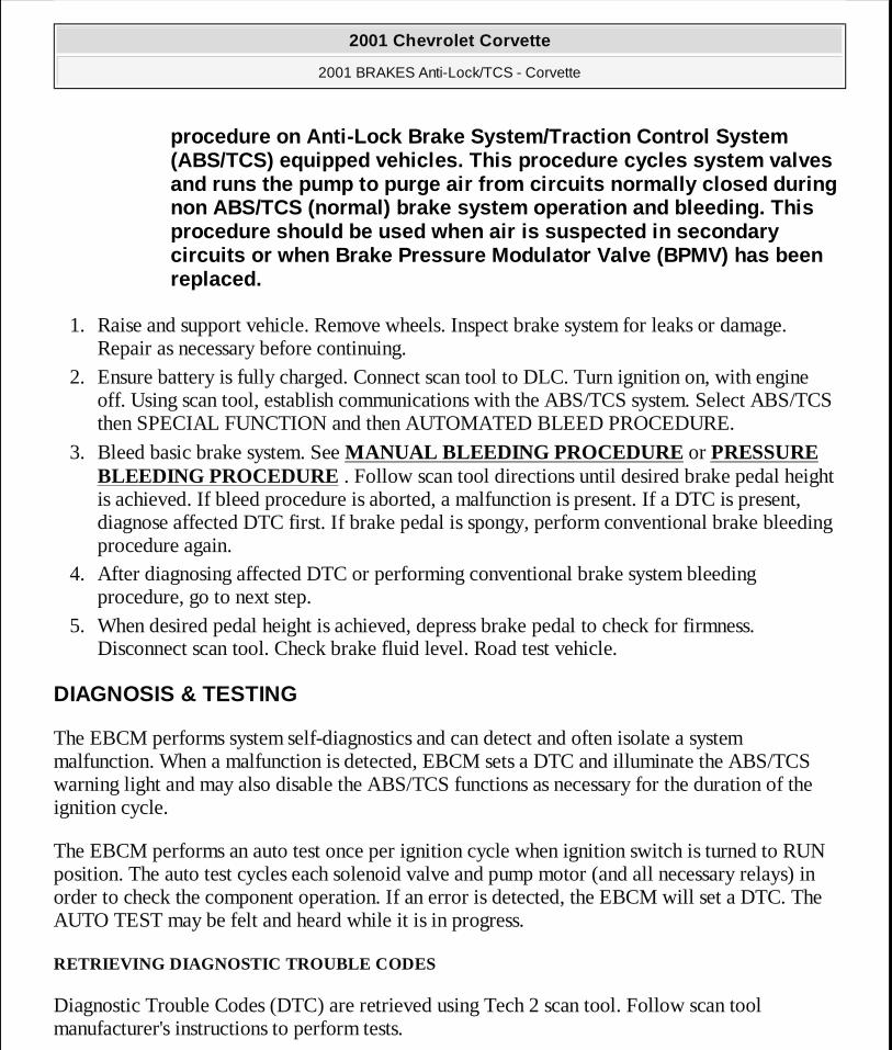
1. Raise and support vehicle. Remove wheels. Inspect brake system for leaks or damage. Repair as necessary before continuing.
2. Ensure battery is fully charged. Connect scan tool to DLC. Turn ignition on, with engine off. Using scan tool, establish communications with the ABS/TCS system. Select ABS/TCS then SPECIAL FUNCTION and then AUTOMATED BLEED PROCEDURE.
3. Bleed basic brake system. See MANUAL BLEEDING PROCEDURE or PRESSURE BLEEDING PROCEDURE . Follow scan tool directions until desired brake pedal height is achieved. If bleed procedure is aborted, a malfunction is present. If a DTC is present, diagnose affected DTC first. If brake pedal is spongy, perform conventional brake bleeding procedure again.
4. After diagnosing affected DTC or performing conventional brake system bleeding procedure, go to next step.
5. When desired pedal height is achieved, depress brake pedal to check for firmness. Disconnect scan tool. Check brake fluid level. Road test vehicle.
DIAGNOSIS & TESTING
The EBCM performs system self-diagnostics and can detect and often isolate a system malfunction. When a malfunction is detected, EBCM sets a DTC and illuminate the ABS/TCS warning light and may also disable the ABS/TCS functions as necessary for the duration of the ignition cycle.
The EBCM performs an auto test once per ignition cycle when ignition switch is turned to RUN position. The auto test cycles each solenoid valve and pump motor (and all necessary relays) in order to check the component operation. If an error is detected, the EBCM will set a DTC. The AUTO TEST may be felt and heard while it is in progress.
RETRIEVING DIAGNOSTIC TROUBLE CODES
Diagnostic Trouble Codes (DTC) are retrieved using Tech 2 scan tool. Follow scan tool manufacturer's instructions to perform tests.
procedure on Anti-Lock Brake System/Traction Control System (ABS/TCS) equipped vehicles. This procedure cycles system valves and runs the pump to purge air from circuits normally closed during non ABS/TCS (normal) brake system operation and bleeding. This procedure should be used when air is suspected in secondary circuits or when Brake Pressure Modulator Valve (BPMV) has been replaced.
2001 Chevrolet Corvette
2001 BRAKES Anti-Lock/TCS - Corvette
MY
Monday, April 06, 2009 2:41:19 PM Page 5 © 2005 Mitchell Repair Information Company, LLC.

Before diagnosing DTC(s), perform DIAGNOSTIC SYSTEM CHECK first. Scan tool is also used to perform test modes for diagnosis and service of the ABS/TCS system.
DIAGNOSTIC SYSTEM CHECK
1. Install scan tool. If scan tool powers up, go to next step. If scan tool does not power up, see SCAN TOOL DOES NOT POWER UP under appropriate BODY CONTROL MODULES article in ACCESSORIES & EQUIPMENT.
2. Turn ignition on, engine off. Try to establish scan tool communication with Body Control Module (BCM), Electronic Brake Control Module (EBCM), Instrument Panel Cluster (IPC) and Powertrain Control Module (PCM). If communication with all modules is established, go to next step. If communication with any module is not established, see SCAN TOOL DOES NOT COMMUNICATE WITH CLASS 2 DEVICE UNDER appropriate BODY CONTROL MODULES article in ACCESSORIES & EQUIPMENT.
3. Select display DTC function for each module. Record all displayed DTCs, status of displayed DTCs and module that set DTC. If DTCs are displayed, go to next step. If no DTCs are displayed, see SYMPTOM DIAGNOSIS .
4. Retrieve codes and perform appropriate test. See DIAGNOSTIC TROUBLE CODE DEFINITIONS table.
DIAGNOSTIC TROUBLE CODE DEFINITIONS DTC DescriptionB2597 Traction Control Switch Signal Grounded
BXXXX (1) C1214 System Relay Contact Or Coil Circuit OpenC1217 BPMV Pump Motor Control Circuit ShortC1218 Pump Motor VoltageC1221 Wheel Speed Sensor Input Signal Is ZeroC1222 Wheel Speed Sensor Input Signal Is ZeroC1223 Wheel Speed Sensor Input Signal Is ZeroC1224 Wheel Speed Sensor Input Signal Is ZeroC1225 Excessive Wheel Speed VariationC1226 Excessive Wheel Speed VariationC1227 Excessive Wheel Speed VariationC1228 Excessive Wheel Speed VariationC1232 Wheel Speed Sensor Circuit Open Or Shorted
Wheel Speed Sensor Circuit Open Or Shorted
2001 Chevrolet Corvette
2001 BRAKES Anti-Lock/TCS - Corvette
MY
Monday, April 06, 2009 2:41:19 PM Page 6 © 2005 Mitchell Repair Information Company, LLC.

C1233 C1234 Wheel Speed Sensor Circuit Open Or ShortedC1235 Wheel Speed Sensor Circuit Open Or ShortedC1236 Low System Supply VoltageC1237 High System Supply VoltageC1242 BPMV Pump Motor Short To GroundC1243 BPMV Pump Motor StalledC1248 Dynamic Rear Proportioning Control SystemC1254 Checksum ErrorC1255 EBTCM Internal Malfunction (ABS/TCS Disabled)C1256 EBTCM Internal MalfunctionC1261 LF Inlet Solenoid Valve MalfunctionC1262 LF Outlet Solenoid Valve MalfunctionC1263 RF Inlet Solenoid Valve MalfunctionC1264 RF Outlet Solenoid Valve MalfunctionC1265 LR Inlet Solenoid Valve MalfunctionC1266 LR Outlet Solenoid Valve MalfunctionC1267 RR Inlet Solenoid Valve MalfunctionC1268 RR Outlet Solenoid Valve MalfunctionC1271 LF TCS Master Cylinder Isolation Valve MalfunctionC1272 LF TCS Prime Valve MalfunctionC1273 RF TCS Master Cylinder Isolation Valve MalfunctionC1274 RF TCS Prime Valve MalfunctionC1276 Delivered Torque Signal Circuit MalfunctionC1277 Requested Torque Signal Circuit MalfunctionC1278 TCS Temporarily Inhibited By PCMC1281 Steering Sensor Uncorrelated MalfunctionC1282 Yaw Rate Sensor Bias Circuit MalfunctionC1283 Excessive Time To Center SteeringC1284 Lateral Accelerometer Self Test MalfunctionC1285 Lateral Accelerometer Circuit MalfunctionC1286 Steering Sensor Bias MalfunctionC1287 Steering Sensor Rate MalfunctionC1288 Steering Sensor Circuit Malfunction
2001 Chevrolet Corvette
2001 BRAKES Anti-Lock/TCS - Corvette
MY
Monday, April 06, 2009 2:41:19 PM Page 7 © 2005 Mitchell Repair Information Company, LLC.

CLEARING DIAGNOSTIC TROUBLE CODES
There are 2 methods to clear DTCs:
� Scan tool method. � Ignition cycle default. On the ignition cycle default method, DTCs will be cleared if
ignition cycles 100 times without a particular malfunction/DTC appearing. EBCM ignition cycle counter will reset to zero.
DTCs cannot be cleared by unplugging EBCM, disconnecting battery or by turning ignition off (except on 50th cycle of ignition cycle default). Whichever method is used, ensure proper system operation and absence of DTCs when clearing procedure is completed.
SCAN TOOL TEST MODES
Data List
Data lists for EBCM include Controller Information 1, Controller Information 2,
C1291 Open Brakelight Switch Contacts During DecelerationC1292 Brake Fluid Pressure LowC1293 Brake Fluid Pressure HighC1294 Brakelight Switch Circuit Always ActiveC1295 Brakelight Switch Circuit OpenC1296 Brake Fluid Pressure Sensor Out Of RangeP1571 Requested Torque Signal Circuit MalfunctionP1644 Delivered Torque Signal Voltage InvalidP1689 Delivered Torque Signal Voltage InvalidPXXXX (2) UXXXX (3) (1) For "B" codes other than B2597, see DIAGNOSTIC TESTS in appropriate BODY
CONTROL MODULES article in ACCESSORIES & EQUIPMENT.(2) For any DTC beginning with the letter "P" except P1571, P1644 or P1689, see
appropriate SELF-DIAGNOSTICS article in ENGINE PERFORMANCE.(3) For any DTC beginning with the letter "U", see SCAN TOOL DOES NOT
COMMUNICATE WITH CLASS 2 DEVICE in appropriate BODY CONTROL MODULES article in ACCESSORIES & EQUIPMENT.
2001 Chevrolet Corvette
2001 BRAKES Anti-Lock/TCS - Corvette
MY
Monday, April 06, 2009 2:41:19 PM Page 8 © 2005 Mitchell Repair Information Company, LLC.

DRP/ABS/TCS/TIM Data, VSES Data, Phase 1-4 and No Phase.
DTC History
Scan tool will display last 3 DTCs to occur, one at a time. DTC with most recent occurrence will be displayed first. Each DTC will indicate number of drive cycles since DTC last occurred, number of occurrences for DTC since scan tool DTC information was last cleared and most recent DTC will also display various data parameters with values from time of DTC occurrence.
DTC(s)
In this mode, DTCs stored in the EBCM memory may be displayed or cleared.
Snapshot
In this mode, scan tool captures data before and after a snapshot-triggering condition which may or may not set a DTC. Refer to scan tool manufacturer's information on the use of this mode.
Special Functions
This mode performs functional tests on ABS/TCS system which help to verify proper operation. In this mode, testing and observing the test results can further identify malfunction conditions. Under this test, the following tests are available:
� Automated Test This test cycles each solenoid valve and pump motor to check component operation. This is identical to self-test that is performed when ignition switch is turned to RUN position. A DTC will set if malfunction is detected.
� Automated Bleed Used to bleed ABS hydraulics.
� Solenoid Test This test activates selected solenoid valves, commanding solenoid on and off.
� Pump Motor Test This test turns pump motor on and off.
2001 Chevrolet Corvette
2001 BRAKES Anti-Lock/TCS - Corvette
MY
Monday, April 06, 2009 2:41:19 PM Page 9 © 2005 Mitchell Repair Information Company, LLC.

� Steering Wheel Position Sensor Test This test monitors the analog and digital steering angle position and can only be run after the Steering Wheel Position Sensor has been centered.
SYMPTOM DIAGNOSIS
If DTCs are not stored, diagnose system by symptom, see SYMPTOM DIAGNOSTIC TESTS table.
SYMPTOM DIAGNOSTIC TESTS
INTERMITTENT OR POOR CONNECTIONS
Most intermittent conditions are caused by faulty electrical connections or wiring. Inspect for the following items:
� Wiring broken inside the insulation � Poor connection between the male and female terminal at a connector. � Poor terminal to wire connection--Some conditions which fall under this description are
poor crimps, poor solder joints, crimping over the wire insulation rather than the wire itself and corrosion in the wire to terminal contact area, etc.
� Wire insulation which is rubbed through--This causes an intermittent short as the bare area touches other wiring or parts of the vehicle.
It is important to test terminal contact at component and any in-line connectors before replacing a suspect component. Mating terminals must be inspected to ensure good terminal contact. A poor connection between male and female terminal at a connector may be the result of contamination or deformation. Contamination may be caused by connector halves being improperly connected. A missing or damaged connector seal, damage to connector itself, or exposing terminals to moisture and dirt can also cause contamination. Contamination, usually in underhood or
Symptom Perform TestABS Indicator Always On A ABS Indicator Inoperative B Traction Control & Active Handling Indicator Always On C Traction Control & Active Handling Indicator Inoperative D VSES Inoperative E VSES Unwanted Activation F VSES Excessive Brake Pulsation G
2001 Chevrolet Corvette
2001 BRAKES Anti-Lock/TCS - Corvette
MY
Monday, April 06, 2009 2:41:19 PM Page 10 © 2005 Mitchell Repair Information Company, LLC.

underbody connectors, leads to terminal corrosion, causing an open circuit or intermittently open circuit. Deformation is caused by probing mating side of a connector terminal without proper adapter, improperly joining connector halves, or repeatedly separating and joining connector halves. Deformation, usually to female terminal contact tang, can result in poor terminal contact causing an open or intermittently open circuit.
SYMPTOM TESTS
TEST A: ABS INDICATOR ALWAYS ON
1. Perform DIAGNOSTIC SYSTEM CHECK . Go to next step. 2. Check EBCM ground, making sure ground is clean and tight. If problem was found, repair
as necessary. After repairs, go to step 9 . If problem was not found, go to next step. 3. Install scan tool. Turn ignition on, engine off. Using scan tool, observe ABS WARNING
INDICATOR parameter in ABS data list. If scan tool displays OFF, go to next step. If scan tool does not display OFF, go to step 5 .
4. Turn ignition off. Turn ignition on, engine off. Observe ABS indicator on instrument cluster during bulb check. If ABS indicator illuminates during bulb check, and then turns off, problem is intermittent. See INTERMITTENT OR POOR CONNECTIONS under DIAGNOSIS & TESTING. If ABS indicator does not illuminate during bulb check, and then turn off, go to step 6 .
5. Check EBCM connector for poor connections. If problem was found, repair as necessary. After repairs, go to step 9 . If problem was not found, go to step 7 .
6. Check instrument cluster connector for poor connections. If problem was found, repair as necessary. After repairs, go to step 9 . If problem was not found, go to step 8 .
7. Replace EBCM. See ELECTRONIC BRAKE CONTROL MODULE under REMOVAL & INSTALLATION. After repairs, go to step 9 .
8. Replace instrument cluster. See appropriate ANALOG INSTRUMENT PANELS article in ACCESSORIES & EQUIPMENT. After repairs, go to next step.
9. Operate system to verify repair.
TEST B: ABS INDICATOR INOPERATIVE
NOTE: To identify circuits and wire colors referenced in testing, see WIRING DIAGRAMS . Testing system requires the use of Pinout Box (J 39700) and Adapter Cable (J 39700-300). After repairs, recheck system operation to verify that problem has been repaired. See DIAGNOSTIC SYSTEM CHECK under DIAGNOSIS & TESTING.
2001 Chevrolet Corvette
2001 BRAKES Anti-Lock/TCS - Corvette
MY
Monday, April 06, 2009 2:41:19 PM Page 11 © 2005 Mitchell Repair Information Company, LLC.

1. Perform DIAGNOSTIC SYSTEM CHECK . Go to next step. 2. Check EBCM ground, making sure ground is clean and tight. If problem was found, repair
as necessary. After repairs, go to step 9 . If problem was not found, go to next step. 3. Install scan tool. Turn ignition on, engine off. Using scan tool, observe ABS WARNING
INDICATOR parameter in ABS data list. If scan tool displays OFF, go to next step. If scan tool does not display OFF, go to step 5 .
4. Turn ignition off. Turn ignition on, engine off. Observe ABS indicator on instrument cluster during bulb check. If ABS indicator illuminates during bulb check, and then turns off, problem is intermittent. See INTERMITTENT OR POOR CONNECTIONS under DIAGNOSIS & TESTING. If ABS indicator does not illuminate during bulb check, and then turn off, go to step 6 .
5. Check EBCM connector for poor connections. If problem was found, repair as necessary. After repairs, go to step 9 . If problem was not found, go to step 7 .
6. Check instrument cluster connector for poor connections. If problem was found, repair as necessary. After repairs, go to step 9 . If problem was not found, go to step 8 .
7. Replace EBCM. See ELECTRONIC BRAKE CONTROL MODULE under REMOVAL & INSTALLATION. After repairs, go to step 9 .
8. Replace instrument cluster. See appropriate ANALOG INSTRUMENT PANELS article in ACCESSORIES & EQUIPMENT. After repairs, go to next step.
9. Operate system to verify repair.
TEST C: TRACTION CONTROL & ACTIVE HANDLING INDICATOR ALWAYS ON
1. Perform DIAGNOSTIC SYSTEM CHECK . Go to next step. 2. Install scan tool. Turn ignition on, engine off. Using scan tool, observe TCS WARNING
INDICATOR/MESSAGE parameter in TCS data list. If scan tool displays OFF, go to next step. If scan tool does not display OFF, go to step 4 .
3. Turn ignition off. Turn ignition on, engine off. Observe TRACTION CONTROL and ACTIVE HANDLING indicator on instrument cluster during bulb check. If TRACTION CONTROL and ACTIVE HANDLING indicator illuminates during bulb check, and then turns off, problem is intermittent. See INTERMITTENT OR POOR CONNECTIONS under DIAGNOSIS & TESTING. If TRACTION CONTROL and ACTIVE HANDLING indicator does not illuminate during bulb check, and then turn off, go to step 5 .
4. Check EBCM connector for poor connections. If problem was found, repair as necessary. After repairs, go to step 8 . If problem was not found, go to step 6 .
5. Check instrument cluster connector for poor connections. If problem was found, repair as necessary. After repairs, go to step 8 . If problem was not found, go to step 7 .
2001 Chevrolet Corvette
2001 BRAKES Anti-Lock/TCS - Corvette
MY
Monday, April 06, 2009 2:41:19 PM Page 12 © 2005 Mitchell Repair Information Company, LLC.

6. Replace EBCM. See ELECTRONIC BRAKE CONTROL MODULE under REMOVAL & INSTALLATION. After repairs, go to step 8 .
7. Replace instrument cluster. See appropriate ANALOG INSTRUMENT PANELS article in ACCESSORIES & EQUIPMENT. After repairs, go to next step.
8. Operate system to verify repair.
TEST D: TRACTION CONTROL & ACTIVE HANDLING INDICATOR INOPERATIVE
1. Perform DIAGNOSTIC SYSTEM CHECK . Go to next step. 2. Install scan tool. Turn ignition on, engine off. Using scan tool, observe TCS WARNING
INDICATOR/MESSAGE parameter in TCS data list. If scan tool displays OFF, go to next step. If scan tool does not display OFF, go to step 10 .
3. Turn ignition off. Turn ignition on, engine off. Observe TRACTION CONTROL and ACTIVE HANDLING indicator on instrument cluster during bulb check. If TRACTION CONTROL and ACTIVE HANDLING indicator illuminates during bulb check, and then turns off, go to next step. If TRACTION CONTROL and ACTIVE HANDLING indicator does not illuminate during bulb check, and then turn off, go to step 11 .
4. Turn ignition off. Install scan tool. Turn ignition on, engine off. Using scan tool, observe TCS SWITCH parameter in BODY CONTROL MODULE data list. Activate traction control switch. If TCS SWITCH parameter changes state, problem is intermittent. See INTERMITTENT OR POOR CONNECTIONS under DIAGNOSIS & TESTING. If TCS SWITCH parameter does not change state, go to next step.
5. Turn ignition off. Disconnect traction control switch connector. Connect fused jumper wire (3 amp) between traction control switch connector terminals No. 5 (Black wire) and No. 6 (Brown/White wire). Turn ignition on, engine off. Using scan tool, observe TCS SWITCH parameter. If scan tool displays ON, go to step 9 . If scan tool does not display ON, go to next step.
6. Check Brown/White wire between traction control switch and BCM open or high resistance. If problem was found, repair as necessary. After repairs, go to step 16 . If problem was not found, go to next step.
7. Check Black wire between traction control switch and ground open or high resistance. If problem was found, repair as necessary. After repairs, go to step 16 . If problem was not found, go to next step.
8. Check BCM connector for poor connections. If problem was found, repair as necessary. After repairs, go to step 16 . If problem was not found, go to step 12 .
9. Check traction control switch connector for poor connections. If problem was found, repair as necessary. After repairs, go to step 16 . If problem was not found, go to step 13 .
2001 Chevrolet Corvette
2001 BRAKES Anti-Lock/TCS - Corvette
MY
Monday, April 06, 2009 2:41:19 PM Page 13 © 2005 Mitchell Repair Information Company, LLC.
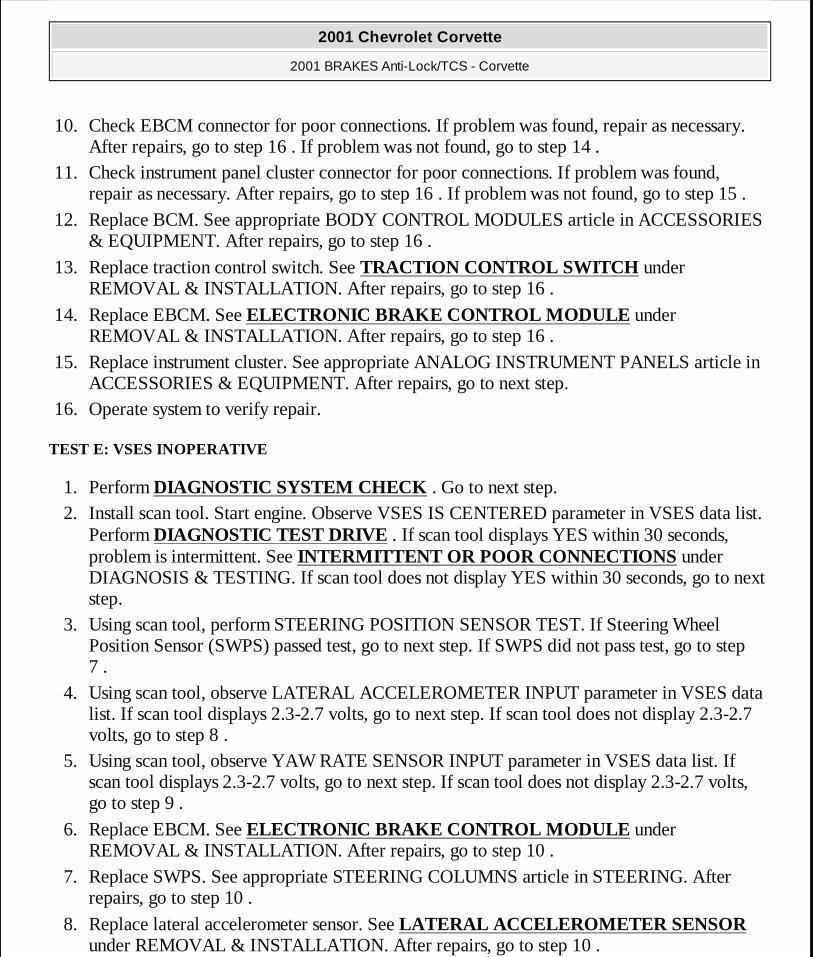
10. Check EBCM connector for poor connections. If problem was found, repair as necessary. After repairs, go to step 16 . If problem was not found, go to step 14 .
11. Check instrument panel cluster connector for poor connections. If problem was found, repair as necessary. After repairs, go to step 16 . If problem was not found, go to step 15 .
12. Replace BCM. See appropriate BODY CONTROL MODULES article in ACCESSORIES & EQUIPMENT. After repairs, go to step 16 .
13. Replace traction control switch. See TRACTION CONTROL SWITCH under REMOVAL & INSTALLATION. After repairs, go to step 16 .
14. Replace EBCM. See ELECTRONIC BRAKE CONTROL MODULE under REMOVAL & INSTALLATION. After repairs, go to step 16 .
15. Replace instrument cluster. See appropriate ANALOG INSTRUMENT PANELS article in ACCESSORIES & EQUIPMENT. After repairs, go to next step.
16. Operate system to verify repair.
TEST E: VSES INOPERATIVE
1. Perform DIAGNOSTIC SYSTEM CHECK . Go to next step. 2. Install scan tool. Start engine. Observe VSES IS CENTERED parameter in VSES data list.
Perform DIAGNOSTIC TEST DRIVE . If scan tool displays YES within 30 seconds, problem is intermittent. See INTERMITTENT OR POOR CONNECTIONS under DIAGNOSIS & TESTING. If scan tool does not display YES within 30 seconds, go to next step.
3. Using scan tool, perform STEERING POSITION SENSOR TEST. If Steering Wheel Position Sensor (SWPS) passed test, go to next step. If SWPS did not pass test, go to step 7 .
4. Using scan tool, observe LATERAL ACCELEROMETER INPUT parameter in VSES data list. If scan tool displays 2.3-2.7 volts, go to next step. If scan tool does not display 2.3-2.7 volts, go to step 8 .
5. Using scan tool, observe YAW RATE SENSOR INPUT parameter in VSES data list. If scan tool displays 2.3-2.7 volts, go to next step. If scan tool does not display 2.3-2.7 volts, go to step 9 .
6. Replace EBCM. See ELECTRONIC BRAKE CONTROL MODULE under REMOVAL & INSTALLATION. After repairs, go to step 10 .
7. Replace SWPS. See appropriate STEERING COLUMNS article in STEERING. After repairs, go to step 10 .
8. Replace lateral accelerometer sensor. See LATERAL ACCELEROMETER SENSOR under REMOVAL & INSTALLATION. After repairs, go to step 10 .
2001 Chevrolet Corvette
2001 BRAKES Anti-Lock/TCS - Corvette
MY
Monday, April 06, 2009 2:41:19 PM Page 14 © 2005 Mitchell Repair Information Company, LLC.
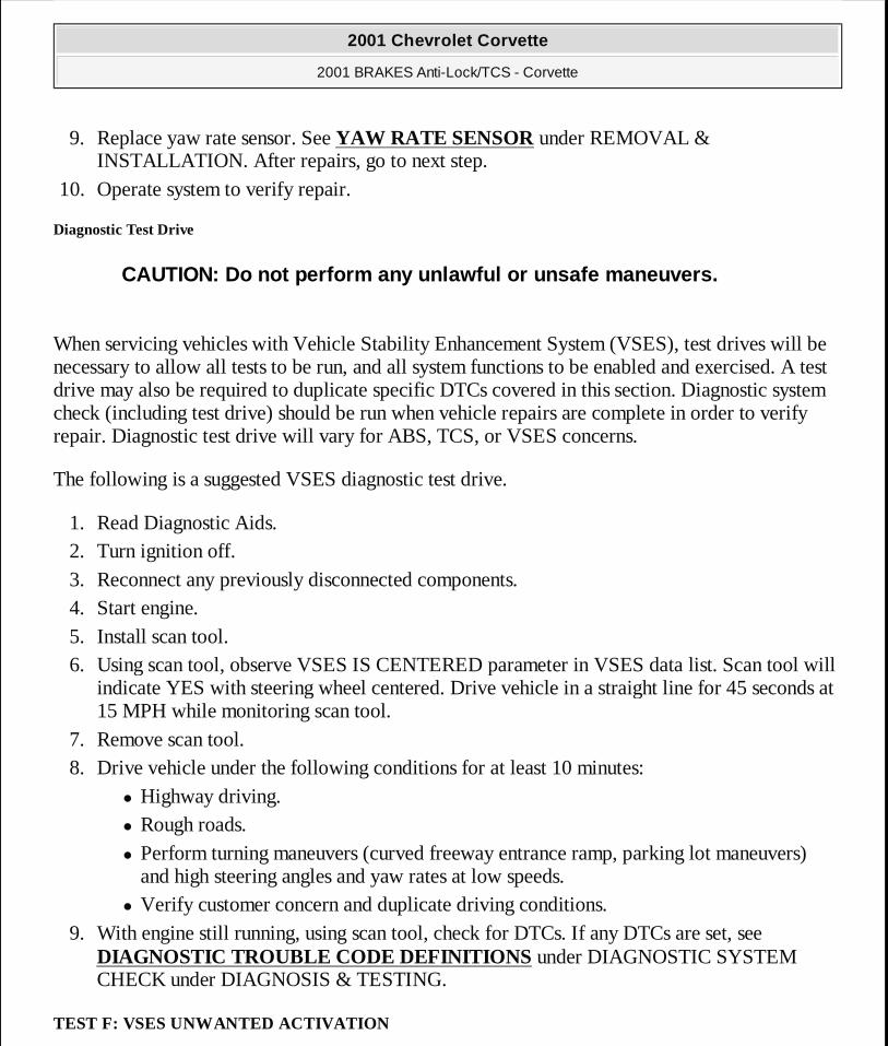
9. Replace yaw rate sensor. See YAW RATE SENSOR under REMOVAL & INSTALLATION. After repairs, go to next step.
10. Operate system to verify repair.
Diagnostic Test Drive
When servicing vehicles with Vehicle Stability Enhancement System (VSES), test drives will be necessary to allow all tests to be run, and all system functions to be enabled and exercised. A test drive may also be required to duplicate specific DTCs covered in this section. Diagnostic system check (including test drive) should be run when vehicle repairs are complete in order to verify repair. Diagnostic test drive will vary for ABS, TCS, or VSES concerns.
The following is a suggested VSES diagnostic test drive.
1. Read Diagnostic Aids. 2. Turn ignition off. 3. Reconnect any previously disconnected components. 4. Start engine. 5. Install scan tool. 6. Using scan tool, observe VSES IS CENTERED parameter in VSES data list. Scan tool will
indicate YES with steering wheel centered. Drive vehicle in a straight line for 45 seconds at 15 MPH while monitoring scan tool.
7. Remove scan tool. 8. Drive vehicle under the following conditions for at least 10 minutes:
� Highway driving. � Rough roads. � Perform turning maneuvers (curved freeway entrance ramp, parking lot maneuvers)
and high steering angles and yaw rates at low speeds. � Verify customer concern and duplicate driving conditions.
9. With engine still running, using scan tool, check for DTCs. If any DTCs are set, see DIAGNOSTIC TROUBLE CODE DEFINITIONS under DIAGNOSTIC SYSTEM CHECK under DIAGNOSIS & TESTING.
TEST F: VSES UNWANTED ACTIVATION
CAUTION: Do not perform any unlawful or unsafe maneuvers.
2001 Chevrolet Corvette
2001 BRAKES Anti-Lock/TCS - Corvette
MY
Monday, April 06, 2009 2:41:19 PM Page 15 © 2005 Mitchell Repair Information Company, LLC.

1. Perform DIAGNOSTIC SYSTEM CHECK . Go to next step.
2. Inspect mounting of yaw rate sensor. See YAW RATE SENSOR under REMOVAL & INSTALLATION. If problem was found, repair as necessary. After repairs, go to step 15 . If problem was not found, go to next step.
3. Install scan tool. Start engine. Using scan tool, observe YAW RATE SENSOR INPUT parameter in VSES data list. Perform DIAGNOSTIC TEST DRIVE under TEST G: VSES INOPERATIVE. If scan tool displays sudden increase or decrease without rapid turning of vehicle, go to next step. If scan tool does not display sudden increase or decrease without rapid turning of vehicle, go to step 5 .
4. Perform diagnosis for DTC C1282. See DTC C1282: YAW RATE SENSOR BIAS CIRCUIT MALFUNCTION under DIAGNOSTIC TESTS. If problem was found, repair as necessary. After repairs, go to step 15 . If problem was not found, go to step 12 .
5. Straighten front wheels. Observe DUAL ANALOG SWPS INPUT A and DUAL ANALOG SWPS INPUT B in VSES data list. Slowly rotate steering wheel in both directions. If scan tool display changes state as steering wheel is rotated, go to next step. If scan tool display does not change state as steering wheel is rotated, go to step 14 .
6. Using scan tool, perform STEERING POSITION SENSOR TEST. If Steering Wheel Position Sensor (SWPS) passed test, go to next step. If SWPS did not pass test, go to step 14 .
7. Place vehicle on a level surface. Using scan tool, observe LATERAL ACCELEROMETER INPUT parameter in VSES data list. If scan tool displays 2.3-2.7 volts, go to step 9 . If scan tool does not display 2.3-2.7 volts, go to next step.
8. Inspect mounting of lateral accelerometer sensor. See LATERAL ACCELEROMETER SENSOR under REMOVAL & INSTALLATION. If problem was found, repair as necessary. After repairs, go to step 15 . If problem was not found, go to next step.
9. Check EBCM for proper part number. If EBCM has correct part number, go to next step. If EBCM does not have correct part number, go to step 12 .
10. Inspect power steering gear for proper part number. If power steering gear has correct part number, go to next step. If power steering gear does not have correct part number, go to step 13 .
11. Inspect alignment of vehicle. If problem was found, repair as necessary. After repair, go to step 15 . If problem was not found, problem is intermittent. See INTERMITTENT OR POOR CONNECTIONS under DIAGNOSIS & TESTING.
12. Replace EBCM. See ELECTRONIC BRAKE CONTROL MODULE under REMOVAL & INSTALLATION. After repair, go to step 15 .
13. Replace power steering gear. See appropriate POWER RACK & PINION article in STEERING. After repair, go to step 15 .
2001 Chevrolet Corvette
2001 BRAKES Anti-Lock/TCS - Corvette
MY
Monday, April 06, 2009 2:41:19 PM Page 16 © 2005 Mitchell Repair Information Company, LLC.
14. Replace SWPS. See appropriate STEERING COLUMNS article in STEERING. After repairs, go to next step.
15. Operate system to verify repair.
TEST G: VSES EXCESSIVE BRAKE PULSATION
1. Perform DIAGNOSTIC SYSTEM CHECK . Go to next step. 2. Install scan tool. Turn ignition on, engine off. Select Powertrain Control Module (PCM)
display DTCs function. If scan tool displays DTC P1575, see appropriate SELF-DIAGNOSTICS article in ENGINE PERFORMANCE. If scan tool does not display DTC P1575, go to next step.
3. Using scan tool, observe EXTENDED TRAVEL BRAKE SWITCH parameter in DRP/ABS/TCS data list. Step on and off brake pedal with enough force to simulate a hard braking condition. As brake pedal is pressed and released, scan tool should read APPLIED and RELEASED. Use a tape measure to measure distance brake pedal travels for scan tool to read APPLIED. If distance is 1.0-1.3 inch (2.5-3.3 cm ), problem is intermittent. See INTERMITTENT OR POOR CONNECTIONS under DIAGNOSIS & TESTING. If distance is not 1.0-1.3" (2.5-3.30 mm), go to next step.
4. Adjust or repair extended travel brake switch as necessary. See STOPLIGHT SWITCH under REMOVAL & INSTALLATION. After repairs, go to next step.
5. Operate system to verify repair.
DIAGNOSTIC TESTS
DTC B2597: TRACTION CONTROL SWITCH SIGNAL GROUNDED
Circuit Description
Traction control and active handling indicator is controlled by instrument cluster via serial data messages from EBCM. When BCM sees traction control switch input grounded through momentary traction control switch, it sends a serial data message to EBCM that tells EBCM that traction control switch has been pressed. EBCM then disables TCS and VSES. EBCM sends a
NOTE: To identify circuits, connectors, terminals and wire colors referenced in testing, see WIRING DIAGRAMS . Testing system requires the use of Pinout Box (J 39700) and Adapter Cable (J 39700-300). After repairs, recheck system operation to verify that problem has been repaired. See DIAGNOSTIC SYSTEM CHECK under DIAGNOSIS & TESTING.
2001 Chevrolet Corvette
2001 BRAKES Anti-Lock/TCS - Corvette
MY
Monday, April 06, 2009 2:41:19 PM Page 17 © 2005 Mitchell Repair Information Company, LLC.

serial data message to instrument cluster to turn Traction Control and Active Handling indicator on and display TRACTION SYSTEM OFF message or TRACTION/ACTIVE HANDLING OFF message (w/VSES) on DIC.
With VSES, when BCM sees traction control switch input grounded for 5 seconds while vehicle is stopped and ignition is on, it sends a serial data message to EBCM that tells EBCM that traction control switch has been pressed for 5 seconds. EBCM then disables TCS, while leaving VSES enabled. EBCM sends a serial data message to instrument cluster to display COMPETITIVE DRIVING message on DIC. TRACTION CONTROL and ACTIVE HANDLING indicator remains off. Each time ignition is cycled from off to on, TCS and VSES are enabled. TRACTION CONTROL and ACTIVE HANDLING indicator to illuminate when EBCM has disabled TCS or VSES due to a DTC, driver manually disables TCS or VSES via traction control switch or during instrument cluster bulb check.
DTC sets when BCM detects a ground on traction control switch signal circuit for longer than 60 seconds.
Diagnosis
1. Perform DIAGNOSTIC SYSTEM CHECK . Go to next step. 2. Install scan tool. Turn ignition on, engine off. Using scan tool, observe TCS SWITCH
parameter in BCM data list. If scan tool displays OFF, go to next step. If scan tool does not display OFF, go to step 4 .
3. Activate TCS switch. Using scan tool, observe TCS SWITCH parameter. If TCS SWITCH parameter changes state, problem is intermittent. See INTERMITTENT OR POOR CONNECTIONS under DIAGNOSIS & TESTING. If TCS SWITCH parameter does not change state, go to next step.
4. Turn ignition off. Disconnect TCS switch. Turn ignition on, engine off. Using scan tool, observe TCS SWITCH parameter. If scan tool displays OFF, go to step 7 . If scan tool does not display OFF, go to next step.
5. Check Brown/White wire between TCS switch and BCM for short to ground. If problem was found, repair as necessary. After repairs, go to step 10 . If problem was not found, go to next step.
6. Check BCM connector for poor connections. If problem was found, repair as necessary. After repairs, go to step 10 . If problem was not found, go to step 8 .
7. Check TCS switch connector for poor connections. If problem was found, repair as necessary. After repairs, go to step 10 . If problem was not found, go to step 9 .
8. Replace BCM. See appropriate BODY CONTROL MODULES article in ACCESSORIES & EQUIPMENT. After repairs, go to step 10 .
2001 Chevrolet Corvette
2001 BRAKES Anti-Lock/TCS - Corvette
MY
Monday, April 06, 2009 2:41:19 PM Page 18 © 2005 Mitchell Repair Information Company, LLC.

9. Replace TCS switch. See TRACTION CONTROL SWITCH under REMOVAL & INSTALLATION. After repairs, go to next step.
10. Using scan tool, clear DTCs. Operate vehicle. If DTC does not reset, system is okay.
DTC C1214: SYSTEM RELAY CONTACT OR COIL CIRCUIT OPEN
Circuit Description
System relay is energized when ignition is on. System relay supplies voltage to solenoid valves and pump motor. This voltage is referred to as system voltage.
DTC sets when system voltage is less than 8 volts for 0.23 second, ignition voltage is greater than 10.5 volts and system relay is commanded on.
Diagnosis
1. Perform DIAGNOSTIC SYSTEM CHECK . Go to next step. 2. Install scan tool. Turn ignition on, engine OFF. Using scan tool, clear DTCs. Using scan
tool, perform AUTOMATED TEST. If DTC resets as a current DTC, go to next step. If DTC does not reset as a current DTC, problem is intermittent. See INTERMITTENT OR POOR CONNECTIONS under DIAGNOSIS & TESTING.
3. Disconnect pump motor harness pigtail connector of Brake Pressure Modulator Valve (BPMV). Measure resistance between each pump motor control circuit and housing of BPMV at pump motor connector of BPMV. If DVOM displays infinite resistance, go to step 5 . If DVOM does not display infinite resistance, go to next step.
4. Replace EBCM and BPMV. See BRAKE PRESSURE MODULATOR VALVE under REMOVAL & INSTALLATION. After repairs, go to step 6 .
5. Replace EBCM. See ELECTRONIC BRAKE CONTROL MODULE under REMOVAL & INSTALLATION. After repairs, go to next step.
6. Using scan tool, clear DTCs. Using scan tool, perform AUTOMATED TEST. If DTC does not reset, system is okay.
Diagnostic Aids
System relay is integral to EBCM. Relay is not serviceable.
DTC C1217: BPMV PUMP MOTOR CONTROL CIRCUIT SHORT
Circuit Description
System relay is energized when ignition is on. System relay supplies voltage to solenoid valves
2001 Chevrolet Corvette
2001 BRAKES Anti-Lock/TCS - Corvette
MY
Monday, April 06, 2009 2:41:19 PM Page 19 © 2005 Mitchell Repair Information Company, LLC.
and pump motor. This voltage is referred to as system voltage. EBCM controls pump motor by grounding control circuit.
DTC sets when pump motor has been commanded off for one second and system voltage is greater than 9 volts. And then, voltage across pump motor is greater than 10.2 volts or pump motor low side voltage is less than 2.7 volts for 0.2 second.
Diagnosis
1. Perform DIAGNOSTIC SYSTEM CHECK . Go to next step. 2. Turn ignition off. Disconnect EBCM harness connector. Connect Universal Pinout Box (J
39700) using Cable Adapter (J 39700-300) to EBCM harness connector only. Test both ground circuits of EBCM including EBCM ground for high resistance or open. If problem was found, repair as necessary. After repairs, go to step 8 . If problem was not found, go to next step.
3. Disconnect pump motor harness pigtail connector of BPMV. Measure resistance between each pump motor control circuit and housing of BPMV at pump motor connector of BPMV. If resistance is less than 5 ohms, go to next step. If resistance is 5 ohms or more, go to step 5 .
4. Check BPMV connector for poor connections. If problem was found, repair as necessary. After repairs, go to step 8 . If problem was not found, go to step 6 .
5. Check EBCM connector for poor connections. If problem was found, repair as necessary. After repairs, go to step 8 . If problem was not found, go to step 7 .
6. Replace BPMV. See BRAKE PRESSURE MODULATOR VALVE under REMOVAL & INSTALLATION. After repairs, go to step 8 .
7. Replace EBCM. See ELECTRONIC BRAKE CONTROL MODULE under REMOVAL & INSTALLATION. After repairs, go to next step.
8. Using scan tool, clear DTCs. Using scan tool, perform AUTOMATED TEST. If DTC does not reset, system is okay.
Diagnostic Aids
DTC determines if there is a short in pump motor control circuit. Pump motor is integral to BPMV. Pump motor is not serviceable.
DTC C1218: PUMP MOTOR VOLTAGE
Circuit Description
System relay is energized when ignition is on. System relay supplies voltage to solenoid valves
2001 Chevrolet Corvette
2001 BRAKES Anti-Lock/TCS - Corvette
MY
Monday, April 06, 2009 2:41:19 PM Page 20 © 2005 Mitchell Repair Information Company, LLC.

and pump motor. This voltage is referred to as system voltage. EBCM controls pump motor by grounding control circuit.
DTC sets when commanded pump motor voltage is less than system voltage, actual pump motor voltage is 3 volts less than commanded voltage, or with commanded pump motor voltage greater than system voltage, actual pump motor voltage is less than 8 volts. Pump motor is commanded on, system voltage is greater than 8 volts, and conditions exists for more than 0.16 second.
Diagnosis
1. Perform DIAGNOSTIC SYSTEM CHECK . Go to next step. 2. Install scan tool. Turn ignition on, engine off. Using scan tool, clear DTCs. Using scan tool,
perform AUTOMATED TEST. If DTC resets, go to next step. If DTC does not reset, problem is intermittent. See INTERMITTENT OR POOR CONNECTIONS under DIAGNOSIS & TESTING.
3. Turn ignition off. Disconnect pump motor connector of BPMV. Connect test light between pump motor circuits at pump motor connector of EBCM.Using scan tool, clear DTCs. Using scan tool, perform PUMP MOTOR TEST. If test light illuminates, go to step 5 . If test light does not illuminate, go to next step.
4. Turn ignition off. Disconnect EBCM harness connector. Connect Universal Pinout Box (J 39700) using Cable Adapter (J 39700-300) to EBCM harness connector only. Check both ground circuits of EBCM including EBCM ground for high resistance or open. If problem was found, repair as necessary. After repairs, go to step 9 . If problem was not found, go to step 6 .
5. Check BPMV connector for poor connections. If problem is found, repair as necessary. After repairs, go to step 9 . If problem is not found, go to step 7 .
6. Check EBCM connector for poor connections. If problem is found, repair as necessary. After repairs, go to step 9 . If problem is not found, go to step 8 .
7. Replace BPMV. See BRAKE PRESSURE MODULATOR VALVE under REMOVAL & INSTALLATION. After repairs, go to step 9 .
8. Replace EBCM. See ELECTRONIC BRAKE CONTROL MODULE under REMOVAL & INSTALLATION. After repairs, go to step 9 .
9. Using scan tool, clear DTCs. Using scan tool, perform AUTOMATED TEST. If DTC does not reset, system is okay.
Diagnostic Aids
Pump motor is integral to BPMV. Pump motor is not serviceable.
2001 Chevrolet Corvette
2001 BRAKES Anti-Lock/TCS - Corvette
MY
Monday, April 06, 2009 2:41:19 PM Page 21 © 2005 Mitchell Repair Information Company, LLC.

DTC C1221, DTC C1222, DTC C1223, DTC C1224, DTC C1225, DTC C1225, DTC C1226, DTC DTC C1228, DTC C1232, DTC C1233, DTC C1234 OR C1235: WHEEL SPEED SENSOR
Circuit Description
Wheel speed sensor input signal is zero:
� DTC C1221 Left front wheel.
� DTC C1222 Right front wheel.
� DTC C1223 Left rear wheel.
� DTC C1224 Right rear wheel.
Excessive wheel speed variation:
� DTC C1225 Left front wheel.
� DTC C1226 Right front wheel.
� DTC C1227 Left rear wheel.
� DTC C1228 Right rear wheel.
Wheel speed sensor circuit open or shorted:
2001 Chevrolet Corvette
2001 BRAKES Anti-Lock/TCS - Corvette
MY
Monday, April 06, 2009 2:41:19 PM Page 22 © 2005 Mitchell Repair Information Company, LLC.

� DTC C1232 Left front wheel.
� DTC C1233 Right front wheel.
� DTC C1234 Left rear wheel.
� DTC C1235 Right rear wheel.
As the toothed ring passes Wheel Speed Sensor (WSS), an AC voltage signal is produced. Signal frequency is proportional to the wheel speed. The magnitude of this signal is directly related to the wheel speed and the proximity of the WSS to the toothed ring (air gap).
DTC C1221-C1224 will set when vehicle in not in an ABS or TCS event and one wheel speed is equal to zero, other wheel speeds are greater than 5 MPH and other wheel speeds are within 7 MPH of each other for 2.5 seconds.
DTC C1225-C1228 will set when EBCM detects a rapid variation in wheel speed. Wheel speed changes by 10 MPH or more in 0.01 second and change must occur 3 times with no more than 0.2 second between occurrences.
DTC C1232-C1235 will set when one of the following conditions exists for 0.02 seconds:
� A short to voltage - wheel speed sensor signal circuit and wheel speed sensor return circuit voltages are both greater than 4.25 volts.
� A short to ground - wheel speed sensor signal circuit and wheel speed sensor return circuit voltages are both less than 0.75 volt.
� An open - wheel speed sensor signal circuit voltage is greater than 4.25 volts and wheel speed sensor return circuit voltage is less than 0.75 volt.
Diagnosis
1. Perform DIAGNOSTIC SYSTEM CHECK . Go to next step.
2001 Chevrolet Corvette
2001 BRAKES Anti-Lock/TCS - Corvette
MY
Monday, April 06, 2009 2:41:19 PM Page 23 © 2005 Mitchell Repair Information Company, LLC.
2. Install scan tool. Turn ignition on. Set up scan tool snap shot feature to trigger for this DTC. Drive vehicle at a speed greater than 5 MPH. If scan tool indicates that DTC set, go to next step. If scan tools does not indicate that DTC set, problem is intermittent. See INTERMITTENT OR POOR CONNECTIONS under DIAGNOSIS & TESTING.
3. Raise and support vehicle. Disconnect wheel speed sensor connector. Measure resistance across wheel speed sensor. If resistance is 850-1350 ohms, go to next step. If resistance is not 850-1350 ohms, go to step 8 .
4. Spin wheel. Measure AC voltage across wheel speed sensor. If AC voltage is greater than 100 millivolts, go to next step. If AC voltage is not greater than 100 millivolts, go to step 8 .
5. Check wheel speed sensor connector for poor connections. If problem was found, repair as necessary. After repairs, go to step 10 . If problem was not found, go to next step.
6. Disconnect EBCM harness connector. Install Universal Pinout Box (J 39700) using Cable Adapter (J 39700-300) to EBCM harness connector only. Check wheel speed sensor circuits for open, short to ground, short to voltage or shorted together. If problem was found, repair as necessary. After repairs, go to step 10 . If problem was not found, go to next step.
7. Check EBCM connector for poor connections. at the harness connector for the EBCM. If problem was found, repair as necessary. After repairs, go to step 10 . If problem was not found, go to step 9 .
8. Replace wheel speed sensor. See WHEEL SPEED SENSORS under REMOVAL & INSTALLATION. After repairs, go to step 10 .
9. Replace EBCM. See ELECTRONIC BRAKE CONTROL MODULE under REMOVAL & INSTALLATION. After repairs, go to next step.
10. Using scan tool, clear DTCs. Operate vehicle. If DTC does not reset, system is okay.
Diagnostic Aids
DTC C1221-C1224: Under the following conditions, 2 DTCs are set: 2 suspect wheel speeds equal zero for 60 seconds, other wheel speeds are greater than 10 MPH and are within 7 MPH of each other. Diagnose each wheel speed sensor individually.
DTC C1225-C1228: Possible cause of this DTC is electrical noise on wheel speed sensor harness wiring. Electrical noise could result from wheel speed sensor wires being routed too close to high energy ignition system components, such as spark plug wires.
DTC C1232-C1235: If customer comments that ABS indicator is ON only during moist environmental conditions (rain, snow, vehicle wash, etc.), inspect wheel speed sensor wiring for signs of water intrusion. If DTC is not current, clear all DTCs and simulate effects of water intrusion by spraying suspected area with a 5 percent saltwater solution. To create a 5 percent saltwater solution, add 2 teaspoons of salt to 12 oz. of water. Test drive vehicle over various road
2001 Chevrolet Corvette
2001 BRAKES Anti-Lock/TCS - Corvette
MY
Monday, April 06, 2009 2:41:19 PM Page 24 © 2005 Mitchell Repair Information Company, LLC.

surfaces (bumps, turns, etc.) above 25 MPH for at least 30 seconds. If DTC returns, replace suspected wheel speed sensor or repair wheel speed sensor wiring. Rinse area thoroughly when completed.
DTC C1236: LOW SYSTEM SUPPLY VOLTAGE
Circuit Description
EBCM monitors voltage level available for system operation. A low voltage condition prevents system from operating properly.
DTC sets when, during initialization or when system is inactive, system voltage is less than 10.5 volts, or, during system operation, system voltage is less than 9.0 volts. Conditions must exist for 0.72 second, vehicle speed must be greater than 5 MPH, ignition voltage must be less than 10.5 volts and system relay must be commanded on.
Diagnosis
1. Perform DIAGNOSTIC SYSTEM CHECK . Go to next step. 2. Install scan tool. Start engine. Using scan tool, observe SWITCHED SYSTEM BATTERY
VOLTAGE parameter in ABS data list. If scan tool indicates voltage is greater than 10.5 volts, see DIAGNOSTIC AIDS . If scan tool indicates voltage is not greater than 10.5 volts, go to next step.
3. Using scan tool, observe BATTERY VOLTAGE parameter in BODY CONTROL MODULE data list. If scan tool indicates voltage is greater than 10.5 volts, go to next step. If scan tool does not indicate voltage is greater than 10.5 volts, see appropriate GENERATORS & REGULATORS article in STARTING & CHARGING SYSTEMS.
4. Turn ignition off. Disconnect EBCM harness connector. Install Universal Pinout Box (J 39700) using Cable Adaptor (J 39700-300) to EBCM harness connector only. Check ground circuits of EBCM including EBCM ground for high resistance or open. If problem was found, repair as necessary. After repairs, go to step 7 . If problem was not found, go to next step.
5. Reconnect EBCM harness connector. Turn ignition on, engine off. Using scan tool, clear DTCs. Operate vehicle. If DTC resets, go to next step. If DTC does not reset, see DIAGNOSTIC AIDS .
6. Replace EBCM. See ELECTRONIC BRAKE CONTROL MODULE under REMOVAL & INSTALLATION. After repairs, go to next step.
7. Using scan tool, clear DTCs. Operate vehicle. If DTC does not reset, system is okay.
Diagnostic Aids
2001 Chevrolet Corvette
2001 BRAKES Anti-Lock/TCS - Corvette
MY
Monday, April 06, 2009 2:41:19 PM Page 25 © 2005 Mitchell Repair Information Company, LLC.

Test charging system. See appropriate GENERATORS & REGULATORS article in STARTING & CHARGING SYSTEMS. Possible causes of DTC are:
� Charging system malfunction. � Excessive battery draw. � Weak battery. � Faulty system ground.
DTC C1237: HIGH SYSTEM SUPPLY VOLTAGE
Circuit Description
EBCM monitors voltage level available for system operation. If voltage level is too high, damage may result in system. When EBCM detects a high voltage condition, EBCM turns off system relay, which removes battery voltage from solenoid valves and pump motor.
DTC sets when system voltage is greater than 16.3 volts for 0.72 second and vehicle speed is greater than 5 MPH.
Diagnosis
1. Perform DIAGNOSTIC SYSTEM CHECK . Go to next step. 2. Turn off all accessories. Install scan tool. Start engine. Run engine at approximately 2000
RPM. Using scan tool, observe SWITCHED SYSTEM BATTERY VOLTAGE parameter in ABS data list. If scan tool indicates voltage is greater than 16.3 volts, go to next step. If scan tool does not indicate voltage is greater than 16.3 volts, see DIAGNOSTIC AIDS .
3. Using scan tool, observe BATTERY VOLTAGE parameter in BODY CONTROL MODULE data list. If scan tool indicates voltage is greater than 16.3 volts, see appropriate GENERATORS & REGULATORS article in STARTING & CHARGING SYSTEMS. If scan tool does not indicate voltage is greater than 16.3 volts, go to next step.
4. Using scan tool, clear DTCs. Operate vehicle. If DTC resets, go to next step. If DTC does not reset, see DIAGNOSTIC AIDS .
5. Replace EBCM. See ELECTRONIC BRAKE CONTROL MODULE under REMOVAL & INSTALLATION. After repairs, go to next step.
6. Using scan tool, clear DTCs. Operate vehicle. If DTC does not reset, system is okay.
Diagnostic Aids
Possible cause of this DTC is overcharging.
2001 Chevrolet Corvette
2001 BRAKES Anti-Lock/TCS - Corvette
MY
Monday, April 06, 2009 2:41:19 PM Page 26 © 2005 Mitchell Repair Information Company, LLC.

DTC C1242 OR DTC C1243: BPMV PUMP MOTOR SHORT TO GROUND OR BPMV PUMP MOTOR STALLED
Circuit Description
System relay is energized when ignition on. System relay supplies voltage to solenoid valves and pump motor. This voltage is referred to as system voltage. EBCM controls pump motor by grounding control circuit.
DTC C1242 sets when voltage across pump motor is 1.7-10.2 volts for 2 seconds, system voltage is greater than 8.0 volts, system relay is on and pump motor is commanded off.
DTC C1243 sets when pump motor is stalled or turning slowly, pump motor is on for at least 0.3 seconds and system relay is on.
Diagnosis
1. Perform DIAGNOSTIC SYSTEM CHECK . Go to next step. 2. Install scan tool. Turn ignition on, engine off. Using scan tool, clear DTCs. Using scan tool,
perform AUTOMATED TEST. If DTC resets, go to next step. If DTC does not reset, problem is intermittent. See INTERMITTENT OR POOR CONNECTIONS under DIAGNOSIS & TESTING.
3. Turn ignition off. Disconnect pump motor harness pigtail connector of BPMV. Connect test light between pump motor circuits at pump motor connector of EBCM using Connector Test Adapter Kit (J 35616-A). Using scan tool, clear DTCs. Using scan tool, perform PUMP MOTOR TEST. If test light illuminates, go to next step. If test light does not illuminate, go to step 5 .
4. Check pump motor connector of BPMV for poor connections. If problem was found, repair as necessary. After repairs, go to step 8 . If problem was not found, go to step 6 .
5. Check EBCM connector for poor connections. If problem was found, repair as necessary. After repairs, go to step 8 . If problem was not found, go to step 7 .
6. Replace BPMV. See BRAKE PRESSURE MODULATOR VALVE under REMOVAL & INSTALLATION. After repairs, go to step 8 .
7. Replace EBCM. See ELECTRONIC BRAKE CONTROL MODULE under REMOVAL & INSTALLATION. After repairs, go to next step.
8. Using scan tool, clear DTCs. Using scan tool, perform AUTOMATED TEST. If DTC does not reset, system is okay.
Diagnostic Aids
2001 Chevrolet Corvette
2001 BRAKES Anti-Lock/TCS - Corvette
MY
Monday, April 06, 2009 2:41:19 PM Page 27 © 2005 Mitchell Repair Information Company, LLC.

Pump motor is integral to BPMV. Pump motor is not serviceable.
DTC C1248: DYNAMIC REAR PROPORTIONING CONTROL SYSTEM
Circuit Description
Dynamic Rear Proportioning (DRP) is a control system that replaces the hydraulic proportioning function of the mechanical proportioning valve in the base brake system. DRP control system is part of operating software in EBCM. DRP uses active control with existing ABS in order to regulate vehicle's rear brake pressure.
DTC sets when DTC C1254, C1255, C1265 or C1267 sets, DTC C1236 sets and system voltage is less than 8.5 volts, or 2 wheel speed sensor DTCs on same axle set.
Diagnosis
1. Perform DIAGNOSTIC SYSTEM CHECK . Go to next step. 2. Install scan tool. Turn ignition on, engine off. Select DISPLAY DTCs function on scan tool
for EBCM. If scan tool displays any ABS/TCS/VSES DTCs, see DIAGNOSTIC TROUBLE CODE DEFINITIONS table. If scan tool does not display any ABS/TCS/VSES DTCs, go to next step.
3. Using scan tool, clear DTCs. Operate vehicle. If DTC does not reset, system is okay.
Diagnostic Aids
Use this DTC in order to differentiate which of the following conditions is present:
� EBCM turned on Red BRAKE warning indicator. � Instrument cluster turned on Red BRAKE warning indicator due to low brake fluid in
master cylinder reservoir. � Instrument cluster turned on Red BRAKE warning indicator due to application of park
brake.
Diagnose any other ABS DTCs that set along with this DTC.
DTC C1254: CHECKSUM ERROR
Circuit Description
The microprocessor contains a data storage area (keep alive memory) which can save pertinent data when ignition is turned off. Keep Alive Memory (KAM) data is lost if battery power or module ground is removed from module. KAM area is an integral part of microprocessor and
2001 Chevrolet Corvette
2001 BRAKES Anti-Lock/TCS - Corvette
MY
Monday, April 06, 2009 2:41:19 PM Page 28 © 2005 Mitchell Repair Information Company, LLC.

cannot be serviced separately.
The microprocessor calculates a checksum on those areas of memory that hold critical operation data. This is done at a regular interval and is called periodic checksum. The microprocessor also calculates a checksum on these memory locations when ever new data is written to them. This is called running checksum. To check KAM, the microprocessor compares periodic checksum to running checksum. If they do not match, the microprocessor sets DTC.
Diagnosis
1. Perform DIAGNOSTIC SYSTEM CHECK . Go to next step. 2. Turn ignition off. Disconnect EBCM harness connector. Install Universal Pinout Box (J
39700) using Cable Adapter (J 39700-300) to EBCM harness connector only. Test both ground circuits of EBCM including EBCM ground for high resistance or open. If problem was found, repair as necessary. After repairs, go to step 8 . If problem was not found, go to next step.
3. If battery been disconnected recently, go to step 8 . If battery has not been disconnected recently, go to next step.
4. Test charging system. See appropriate GENERATORS & REGULATORS article in STARTING & CHARGING SYSTEMS. If problem was found, repair as necessary. After repairs, go to step 8 . If problem was not found, go to next step.
5. Check EBCM connector for poor connections. If problem was found, repair as necessary. After repairs, go to step 8 . If problem was not found, go to next step.
6. Using scan tool, clear DTCs. Using scan tool, perform AUTOMATED TEST. If DTC resets, go to next step. If DTC does not reset, problem is intermittent. See INTERMITTENT OR POOR CONNECTIONS under DIAGNOSIS & TESTING.
7. Replace EBCM. See ELECTRONIC BRAKE CONTROL MODULE under REMOVAL & INSTALLATION. After repairs, go to next step.
8. Using scan tool, clear DTCs. Using scan tool, perform AUTOMATED TEST. If DTC does not reset, system is okay.
Diagnostic Aids
Possible causes of this DTC are:
� Loss of battery ground. � Disconnected battery. � Running reset. (Running reset is detected when KAM check sum is not updated properly.) � Sudden drop in system voltage to less than 5 volts.
2001 Chevrolet Corvette
2001 BRAKES Anti-Lock/TCS - Corvette
MY
Monday, April 06, 2009 2:41:19 PM Page 29 © 2005 Mitchell Repair Information Company, LLC.

� Long extended engine cranks that cause battery voltage to drop. � Poor power or ground connections. � An internal EBCM malfunction.
DTC C1255 OR DTC C1256: EBCM INTERNAL MALFUNCTION (ABS/TCS DISABLED) OR EBCM EBCM INTERNAL MALFUNCTION
Circuit Description
DTCs identify a malfunction within EBCM. DTC is set when an internal EBCM malfunction exists.
Diagnosis
1. Perform DIAGNOSTIC SYSTEM CHECK . Go to next step. 2. Install scan tool. Turn ignition on, engine off. Using scan tool, clear DTCs. Using scan tool,
perform AUTOMATED TEST. If DTC resets as current, go to next step. If DTC does not reset, problem is intermittent. See INTERMITTENT OR POOR CONNECTIONS under DIAGNOSIS & TESTING.
3. Replace EBCM. See ELECTRONIC BRAKE CONTROL MODULE under REMOVAL & INSTALLATION. After repairs, go to next step.
4. Using scan tool, clear DTCs. Using scan tool, perform AUTOMATED TEST. If DTC does not reset, system is okay.
Diagnostic Aids
Scan tool displays 2 additional characters after DTC. Take note of 2 character code and any other DTCs that are set. 2 character code is an engineering aid used in order to determine cause of internal malfunction.
DTC C1261, DTC C1262, DTC C1263, DTC C1264, DTC C1265, DTC C1266, DTC C1267, DTC C1268 & C1271, DTC C1272, DTC C1273, DTC C1274: INLET, ISOLATION , OUTLET OR TCS SOLENSOLENOID VALVE MALFUNCTION.
Circuit Description
DTC definitions:
� DTC C1261 Left front inlet solenoid valve malfunction.
2001 Chevrolet Corvette
2001 BRAKES Anti-Lock/TCS - Corvette
MY
Monday, April 06, 2009 2:41:19 PM Page 30 © 2005 Mitchell Repair Information Company, LLC.
� DTC C1262 Left front outlet solenoid valve malfunction.
� DTC C1263 Right front inlet solenoid valve malfunction.
� DTC C1264 Right front outlet solenoid valve malfunction.
� DTC C1265 Left rear outlet solenoid valve malfunction.
� DTC C1266 Left rear inlet solenoid valve malfunction.
� DTC C1267 Right rear inlet solenoid valve malfunction.
� DTC C1268 Right rear outlet solenoid valve malfunction.
� DTC C1271 Left front TCS master cylinder isolation valve malfunction.
� DTC C1272 Left front TCS prime valve malfunction.
� DTC C1273 Right front TCS master cylinder isolation valve malfunction.
� DTC C1274
2001 Chevrolet Corvette
2001 BRAKES Anti-Lock/TCS - Corvette
MY
Monday, April 06, 2009 2:41:19 PM Page 31 © 2005 Mitchell Repair Information Company, LLC.

Right front TCS prime valve malfunction.
System relay is energized when ignition is on. System relay supplies voltage to valve solenoids and pump motor. This voltage is referred to as system voltage. EBCM microprocessor activates valve solenoids by grounding control circuit.
DCT sets when commanded state of driver and actual state of control circuit do not match for 0.03 second. System voltage must be greater than 8 volts and ignition voltage must be greater than 9 volts.
Diagnosis
1. Perform DIAGNOSTIC SYSTEM CHECK . Go to next step. 2. Install scan tool. Turn ignition on, engine off. Using scan tool, clear DTCs. Using scan tool,
perform AUTOMATED TEST. If DTC resets as current, go to next step. If DTC does not reset, problem is intermittent. See INTERMITTENT OR POOR CONNECTIONS under DIAGNOSIS & TESTING.
3. Replace EBCM. See ELECTRONIC BRAKE CONTROL MODULE under REMOVAL & INSTALLATION. After repairs, go to next step.
4. Using scan tool, clear DTCs. Using scan tool, perform AUTOMATED TEST. If DTC does not reset, system is okay.
Diagnostic Aids
Solenoid valve circuit is internal to EBCM. Solenoid valve circuit is not diagnosable external to EBCM. DTC sets when there is a malfunction in solenoid circuit internal to EBCM.
DTC C1276, DTC P1644 OR DTC P1689: DELIVERED TORQUE SIGNAL CIRCUIT MALFUNCTION OR VOLTAGE INVALID
Circuit Description
EBCM and PCM simultaneously control traction control. PCM reduces amount of torque supplied to drive wheels by retarding spark timing and selectively turning off fuel injectors. EBCM actively applies brakes to front wheels in order to reduce torque. EBCM sends a requested torque message via a Pulse Width Modulated (PWM) signal to PCM. Duty cycle of signal is used to determine how much engine torque EBCM is requesting PCM to deliver. Normal values are 10-90 percent duty cycle. Signal should be at 90 percent when traction control is not active and at lower values during traction control activations. PCM supplies a pull up voltage of 5 volts that EBCM switches to ground to create signal. PCM sends a delivered torque message
2001 Chevrolet Corvette
2001 BRAKES Anti-Lock/TCS - Corvette
MY
Monday, April 06, 2009 2:41:19 PM Page 32 © 2005 Mitchell Repair Information Company, LLC.
via a Pulse Width Modulated (PWM) signal to EBCM. Duty cycle of signal is used to determine how much engine torque PCM is delivering. Normal values are 10-90 percent duty cycle. Signal should be at low values (around 10 percent) at idle and higher values under driving conditions. EBCM supplies a pull up voltage of 12 volts that PCM switches to ground to create signal. When certain PCM DTCs are set, PCM will not be able to perform torque reduction portion of traction control. A serial data message is sent to EBCM indicating that traction control is not allowed.
DTC C1276 sets when EBCM detects that delivered torque signal is out of valid range or EBCM does not receive delivered torque signal.
DTC P1644 or P1689 sets when PCM detects that delivered torque signal voltage is invalid.
Diagnosis
1. Perform DIAGNOSTIC SYSTEM CHECK . Go to next step. 2. Check EBCM ground and PCM ground, making sure each ground is clean and tight. If
problem was found, repair as necessary. After repairs, go to step 11 . If problem was not found, go to next step.
3. Install scan tool. Start engine. Using scan tool, observe DELIVERED TORQUE parameter in TCS data list. If scan tool displays 90 percent, go to next step. If scan tool does not display 90 percent, problem is intermittent. See INTERMITTENT OR POOR CONNECTIONS under DIAGNOSIS & TESTING.
4. Turn ignition off. Disconnect EBCM connector. Install Universal Breakout Box (J 39700) using Cable Adapter (J 39700-300) to EBCM harness connector and EBCM connector. Disconnect Powertrain Control Module (PCM) harness connector. Turn ignition on, engine off. Measure voltage between EBCM connector C2 terminal No. 2 (Tan/Black wire) and ground. If voltage is near battery voltage, go to next step. If voltage is not near battery voltage, go to step 6 .
5. Turn ignition off. Disconnect cable adapter from EBCM connector. Turn ignition on, engine off. Tan/Black wire for short to voltage. If problem was found, repair as necessary. After repairs, go to step 11 . If problem was not found, go to step 7 .
6. Turn ignition off. Disconnect cable adapter from EBCM connector. Test Tan/Black wire for open, short to ground or high resistance. If problem was found, repair as necessary. After repairs, go to step 11 . If problem was not found, go to step 8 .
7. Check PCM connector for poor connections. If problem was found, repair as necessary. After repairs, go to step 11 . If problem was not found, go to step 9 .
8. Check EBCM connector for poor connections. If problem was found, repair as necessary. After repairs, go to step 11 . If problem was not found, go to step 10 .
9. Replace PCM. See appropriate REMOVAL, OVERHAUL & INSTALLATION article in
2001 Chevrolet Corvette
2001 BRAKES Anti-Lock/TCS - Corvette
MY
Monday, April 06, 2009 2:41:19 PM Page 33 © 2005 Mitchell Repair Information Company, LLC.

ENGINE PERFORMANCE. After repairs, go to step 11 .
10. Replace EBCM. See ELECTRONIC BRAKE CONTROL MODULE under REMOVAL & INSTALLATION. After repairs, go to next step.
11. Using scan tool, clear DTCs. Operate vehicle. If DTC does not reset, system is okay.
Diagnostic Aids
These conditions can cause this concern:
� Open in delivered torque circuit. � Short to ground or voltage in delivered torque circuit. � Wiring problem, terminal corrosion, or poor connection in delivered torque circuit. � Communication frequency problem. � Communication duty cycle problem. � EBCM is not receiving information from PCM. � Loose or corroded EBCM ground or PCM ground.
DTC C1277 OR DTC P1571: REQUESTED TORQUE SIGNAL CIRCUIT MALFUNCTION
Circuit Description
EBCM and PCM simultaneously control traction control. PCM reduces amount of torque supplied to drive wheels by retarding spark timing and selectively turning off fuel injectors. EBCM actively applies brakes to front wheels in order to reduce torque. EBCM sends a requested torque message via a Pulse Width Modulated (PWM) signal to PCM. Duty cycle of signal is used to determine how much engine torque EBCM is requesting PCM to deliver. Normal values are 10-90 percent duty cycle. Signal should be at 90 percent when traction control is not active and at lower values during traction control activations. PCM supplies a pull up voltage of 5 volts that EBCM switches to ground to create signal. PCM sends a delivered torque message via a Pulse Width Modulated (PWM) signal to EBCM. Duty cycle of signal is used to determine how much engine torque PCM is delivering. Normal values are between 10 and 90 percent duty cycle. Signal should be at low values (around 10 percent) at idle and higher values under driving conditions. EBCM supplies a pull up voltage of 12 volts that PCM switches to ground to create signal. When certain PCM DTCs are set, PCM will not be able to perform torque reduction portion of traction control. A serial data message is sent to EBCM indicating that traction control is not allowed.
DTC C1277 sets when PCM diagnoses requested torque signal circuit and sends a serial data message to EBCM indicating a fault is present.
2001 Chevrolet Corvette
2001 BRAKES Anti-Lock/TCS - Corvette
MY
Monday, April 06, 2009 2:41:19 PM Page 34 © 2005 Mitchell Repair Information Company, LLC.

DTC P1571 sets when PCM detects that requested torque signal is out of valid range or PCM does not receive requested torque signal.
Diagnosis
1. Perform DIAGNOSTIC SYSTEM CHECK . Go to next step. 2. Check EBCM ground and PCM ground, making sure each ground is clean and tight. If
problem was found, repair as necessary. After repairs, go to step 13 . If problem was not found, go to next step.
3. Install scan tool. Turn ignition on, engine off. Using scan tool, clear DTCs in both EBCM and PCM. Turn ignition off. Start engine. If DTC resets as a current DTC, go to next step. If DTC does not reset as a current DTC, problem is intermittent. See INTERMITTENT OR POOR CONNECTIONS under DIAGNOSIS & TESTING.
4. Turn ignition off. Disconnect EBCM harness connector. Install Universal Breakout Box (J 39700) using Cable Adapter (J 39700-300) to EBCM harness connector and EBCM connector. Start engine. Measure duty cycle between EBCM connector C2 terminal No. 12 (Orange/Black wire) and ground. If duty cycle is 5-95 percent, go to next step. If duty cycle is not 5-95 percent, go to step 6 .
5. Measure frequency between EBCM connector C2 terminal No. 12 (Orange/Black wire) and ground. If frequency is 121-134 hertz, go to step 8 . If frequency is not 121-134 hertz, go to next step.
6. Turn ignition off. Disconnect cable adapter from EBCM connector. Turn ignition on, engine OFF. Measure voltage between EBCM connector C2 terminal No. 12 (Orange/Black wire) and ground. If voltage is 4-6 volts, go to step 10 . If voltage is not 4-6 volts, go to next step.
7. Turn ignition off. Disconnect Powertrain Control Module (PCM) harness connector. Check Orange/Black wire for short to voltage and short to ground. If problem was found, repair as necessary. After repairs, go to step 13 . If problem was not found, go to step 10 .
8. Turn ignition off. Disconnect Powertrain Control Module (PCM) harness connector. Check Orange/Black wire for open and high resistance. If problem was found, repair as necessary. After repairs, go to step 13 . If problem was not found, go to next step.
9. Check PCM connector for poor connections. If problem was found, repair as necessary. After repairs, go to step 13 . If problem was not found, go to step 11 .
NOTE: Disconnecting EBCM connector and turning ignition on could cause other modules to set loss of communication DTCs (Uxxxx). Once EBCM is reconnected, EBCM may set DTC C1245 or DTC C1298.
2001 Chevrolet Corvette
2001 BRAKES Anti-Lock/TCS - Corvette
MY
Monday, April 06, 2009 2:41:19 PM Page 35 © 2005 Mitchell Repair Information Company, LLC.

10. Check EBCM connector for poor connections. If problem was found, repair as necessary. After repairs, go to step 13 . If problem was not found, go to step 12 .
11. Replace PCM. See appropriate REMOVAL, OVERHAUL & INSTALLATION in ENGINE PERFORMANCE. After repairs, go to step 13 .
12. Replace EBCM. See ELECTRONIC BRAKE CONTROL MODULE under REMOVAL & INSTALLATION. After repairs, go to next step.
13. Using scan tool, clear DTCs. Operate vehicle. If DTC does not reset, system is okay.
Diagnostic Aids
These conditions can cause this concern:
� Open in requested torque circuit. � Short to ground or voltage in requested torque circuit. � Wiring problem, terminal corrosion, or poor connection in requested torque circuit. � Communication frequency problem. � Communication duty cycle problem. � PCM is not receiving information from EBCM. � Loose or corroded EBCM ground or PCM ground.
DTC P1571 may set along with several other PCM DTCs if the key is held in CRANK position while engine is running. Starter lockout function of PCM is enabled several seconds after engine is running and prevents starter from engaging while engine is running. This will cause a partial loss of power to some components and systems.
DTC C1278: TCS TEMPORARILY INHIBITED BY PCM
Circuit Description
EBCM and PCM simultaneously control traction control. PCM reduces amount of torque supplied to drive wheels by retarding spark timing and selectively turning off fuel injectors. EBCM actively applies brakes to front wheels in order to reduce torque. EBCM sends a requested torque message via a Pulse Width Modulated (PWM) signal to PCM. Duty cycle of signal is used to determine how much engine torque EBCM is requesting PCM to deliver. Normal values are 10-90 percent duty cycle. Signal should be at 90 percent when traction control is not active and at lower values during traction control activations. PCM supplies a pull up voltage of 5 volts that EBCM switches to ground to create the signal. PCM sends a delivered torque message via a PWM signal to EBCM. Duty cycle of signal is used to determine how much engine torque PCM is delivering. Normal values are 10-90 percent duty cycle. Signal should be at low
2001 Chevrolet Corvette
2001 BRAKES Anti-Lock/TCS - Corvette
MY
Monday, April 06, 2009 2:41:19 PM Page 36 © 2005 Mitchell Repair Information Company, LLC.

values (around 10 percent) at idle and higher values under driving conditions. EBCM supplies a pull up voltage of 12 volts that PCM switches to ground to create the signal. When certain PCM DTCs are set, PCM will not be able to perform torque reduction portion of traction control. A serial data message is sent to EBCM indicating that traction control is not allowed.
DTC sets when PCM diagnoses a condition preventing engine control portion of traction control function and sends a serial data message to EBCM indicating that torque reduction is not allowed. PCM will typically set a DTC and EBCM will set this DTC.
Diagnosis
Perform DIAGNOSTIC SYSTEM CHECK .
Diagnostic Aids
This DTC is for information only. As an aid to technician, this DTC indicates that there are no problems in ABS/TCS system.
DTC C1281, DTC C1283 OR DTC C1286: STEERING SENSOR
Circuit Description
DTC definitions:
� DTC C1281 Steering sensor uncorrelated malfunction.
� DTC C1283 Excessive time to center steering.
� DTC C1286 Steering sensor bias malfunction.
Vehicle Stability Enhancement System (VSES) is activated by EBCM calculating desired yaw rate and comparing it to actual yaw rate input. Desired yaw rate is calculated from measured steering wheel position, vehicle speed, and lateral acceleration. The difference between desired yaw rate and actual yaw rate is yaw rate error, which is a measurement of oversteer or understeer. If yaw rate error becomes too large, EBCM will attempt to correct vehicle's yaw motion by applying differential braking to left or right front wheel. VSES activations generally occur during
2001 Chevrolet Corvette
2001 BRAKES Anti-Lock/TCS - Corvette
MY
Monday, April 06, 2009 2:41:19 PM Page 37 © 2005 Mitchell Repair Information Company, LLC.

aggressive driving, in turns or bumpy roads without much use of accelerator pedal. When braking during VSES activation, brake pedal will feel different than ABS pedal pulsation. Brake pedal pulsates at a higher frequency during VSES activation. Usable output voltage range for lateral accelerometer and yaw rate sensors is 0.25-4.75 volts. Scan tool will report zero lateral acceleration or yaw rate as 2.5 volts with no sensor bias present. Sensor bias compensates for sensor mounting alignment errors, electronic signal errors, temperature changes, and manufacturing differences. Steering wheel position sensor supplies 2 analog inputs, Phase A and Phase B, to EBCM. The 2 input signals are approximately 90 degrees out of phase. By interpreting the relationship between the 2 inputs, EBCM can determine the position of steering wheel and direction of steering wheel rotation. Steer angle centering is the process by which EBCM calibrates steering sensor output so that output reads zero when steering wheel is centered. Using yaw rate input, lateral accelerometer input, and wheel speed sensor inputs, the initial steering center position is calculated after driving greater than 6 MPH for more than 10 seconds in a straight line on a level surface.
DTC C1281 sets when steer angle has been centered, VSES is active and direction (understeer or oversteer) of yaw rate error has not changed, centered lateral acceleration value is less than 0.5 g. and one of the following conditions exists:
� VSES is engaged for 10 seconds with yaw rate error always in either understeer or oversteer. Under this condition, DTC will set by itself.
� Yaw rate error is greater than 10 degrees/second for 5 seconds. Under this condition, DTC will set along with DTC C1282.
� Yaw rate error is greater than 10 degrees/second with vehicle speed less than 37 MPH and accelerator pedal is pressed more than 25 percent of pedal travel range for one second during VSES activation. Under this condition, DTC will set along with DTC C1282.
� With yaw rate less than 8 degrees/second, side slip error is greater than 4.9 meters/second*second for 5 seconds. Under this condition, this DTC will set along with DTC C1284.
� With vehicle speed greater than 6.2 MPH and less than 62 MPH and centered yaw rate has a value that is positive and is greater than 10 degrees/second, oversteer term is negative for 2 seconds. Oversteer term is yaw rate value times lateral acceleration value. Under this condition, this DTC will set along with DTC C1284.
� With steer rate less than 80 degrees/second, difference between the 2 steering sensor signals (phase A and phase B) is greater than 20 degrees for 1 second. Under this condition, DTC will set along with DTC C1287.
DTC C1283 sets when vehicle has driven for 10 minutes without completing steer angle centering and vehicle speed is greater than 25 MPH.
2001 Chevrolet Corvette
2001 BRAKES Anti-Lock/TCS - Corvette
MY
Monday, April 06, 2009 2:41:19 PM Page 38 © 2005 Mitchell Repair Information Company, LLC.
DTC C1286 sets when steering sensor bias moves greater than 40 degrees after steer centering was accomplished and steer angle has been centered.
Diagnosis
1. Perform DIAGNOSTIC SYSTEM CHECK . Go to next step. 2. Install scan tool. Turn ignition on, engine OFF. Using scan tool, perform STEERING
POSITION SENSOR TEST. If Steering Wheel Position Sensor (SWPS) passed test, go to next step. If SWPS did not pass test, go to step 7 .
3. Using scan tool, observe LATERAL ACCELEROMETER INPUT parameter in VSES data list. If scan tool displays 2.3-2.7 volts, go to next step. If scan tool does not display 2.3-2.7 volts, go to step 8 .
4. Using scan tool, observe YAW RATE SENSOR INPUT parameter in VSES data list. If scan tool displays 2.3-2.7 volts, go to next step. If scan tool does not display 2.3-2.7 volts, go to step 9 .
5. Using scan tool, clear DTCs. Perform DIAGNOSTIC TEST DRIVE . If DTC resets, go to next step. If DTC does not reset, see DIAGNOSTIC AIDS .
6. Replace EBCM. See ELECTRONIC BRAKE CONTROL MODULE under REMOVAL & INSTALLATION. After repairs, go to step 10 .
7. Replace Steering Wheel Position Sensor (SWPS). See appropriate STEERING COLUMNS article in STEERING. After repairs, go to step 10 .
8. Replace lateral accelerometer sensor. See LATERAL ACCELEROMETER SENSOR under REMOVAL & INSTALLATION. After repairs, go to step 10 .
9. Replace yaw rate sensor. See YAW RATE SENSOR under REMOVAL & INSTALLATION. After repairs, go to next step.
10. Using scan tool, clear DTCs. Operate vehicle. If DTC does not reset, system is okay.
Diagnostic Aids
During diagnosis, park vehicle on a level surface. Check vehicle for proper alignment. Car should not pull in either direction while driving straight on a level surface. Find out from driver under what conditions DTC was set (when DIC displayed SERVICE STABILITY SYSTEM message). This information will help to duplicate failure. Snapshot function on scan tool can help find an intermittent DTC.
Diagnostic Test Drive
When servicing vehicles with Vehicle Stability Enhancement System (VSES), test drives will be necessary to allow all tests to be run, and all system functions to be enabled and exercised. A test
2001 Chevrolet Corvette
2001 BRAKES Anti-Lock/TCS - Corvette
MY
Monday, April 06, 2009 2:41:19 PM Page 39 © 2005 Mitchell Repair Information Company, LLC.

drive may also be required to duplicate specific DTCs covered in this section. Diagnostic system check (including test drive) should be run when vehicle repairs are complete in order to verify repair. Diagnostic test drive will vary for ABS, TCS, or VSES concerns.
The following is a suggested VSES diagnostic test drive.
1. Read Diagnostic Aids . 2. Turn ignition off. 3. Reconnect any previously disconnected components. 4. Start engine. 5. Install scan tool. 6. Using scan tool, observe VSES IS CENTERED parameter in VSES data list. Scan tool will
indicate YES with steering wheel centered. Drive vehicle in a straight line for 45 seconds at 15 MPH while monitoring scan tool.
7. Remove scan tool. 8. Drive vehicle under the following conditions for at least 10 minutes:
� Highway driving. � Rough roads. � Perform turning maneuvers (curved freeway entrance ramp, parking lot maneuvers)
and high steering angles and yaw rates at low speeds. � Verify customer concern and duplicate driving conditions.
9. With engine still running, using scan tool, check for DTCs. If any DTCs are set, see DIAGNOSTIC TROUBLE CODE DEFINITIONS under DIAGNOSTIC SYSTEM CHECK under DIAGNOSIS & TESTING.
DTC C1282: YAW RATE SENSOR BIAS CIRCUIT MALFUNCTION
Circuit Description
Vehicle Stability Enhancement System (VSES) is activated by EBCM calculating desired yaw rate and comparing it to actual yaw rate input. Desired yaw rate is calculated from measured steering wheel position, vehicle speed, and lateral acceleration. The difference between desired yaw rate and actual yaw rate is yaw rate error, which is a measurement of oversteer or understeer. If yaw rate error becomes too large, EBCM will attempt to correct vehicle's yaw motion by applying differential braking to left or right front wheel. VSES activations generally occur during aggressive driving, in turns or bumpy roads without much use of accelerator pedal. When braking during VSES activation, brake pedal will feel different than ABS pedal pulsation. Brake pedal pulsates at a higher frequency during VSES activation. Usable output voltage range for lateral
2001 Chevrolet Corvette
2001 BRAKES Anti-Lock/TCS - Corvette
MY
Monday, April 06, 2009 2:41:19 PM Page 40 © 2005 Mitchell Repair Information Company, LLC.

accelerometer and yaw rate sensors is 0.25-4.75 volts. Scan tool will report zero lateral acceleration or yaw rate as 2.5 volts with no sensor bias present. Sensor bias compensates for sensor mounting alignment errors, electronic signal errors, temperature changes, and manufacturing differences. Steering wheel position sensor supplies 2 analog inputs, phase A and phase B, to EBCM. The 2 input signals are approximately 90 degrees out of phase. By interpreting relationship between the 2 inputs, EBCM can determine position of steering wheel and direction of steering wheel rotation. Steer angle centering is the process by which EBCM calibrates steering sensor output so that output reads zero when steering wheel is centered. Using yaw rate input, lateral accelerometer input, and wheel speed sensor inputs, initial steering center position is calculated after driving greater than 6 MPH for more than 10 seconds in a straight line on a level surface.
EBCM performs 6 different tests to detect a DTC condition. DTC sets when one of the following conditions exists:
1. Yaw rate bias is greater than 7 degrees/second with ignition on. 2. Yaw rate input change is greater than 390 degrees/second/second with ignition on. 3. Yaw rate input voltage is less than 0.15 volts or greater than 4.85 volts for 1 second with
vehicle stopped or with vehicle speed greater than 28 MPH. 4. Yaw rate error is greater than 10 degrees/second 30 times within a drive cycle with brake
pedal is not pressed, ABS not active and vehicle speed greater than 3 MPH. 5. Yaw rate error is greater than 10 degrees/second for 5 seconds with VSES active. Under
this condition, DTC C1281 will also set. 6. Yaw rate error is greater than 10 degrees/second with vehicle speed less than 37 MPH and
acceleration pedal is pressed more than 25 percent of pedal travel range for 1 second during VSES activation. Under this condition, DTC C1281 will also set.
Diagnosis
1. Perform DIAGNOSTIC SYSTEM CHECK . Go to next step. 2. Install scan tool. Turn ignition on, engine off. Using scan tool, observe YAW RATE
SENSOR INPUT parameter in VSES data list. If scan tool displays YAW RATE SENSOR INPUT parameter as 0.15-4.85 volts, go to step 6 . If scan tool does not display YAW RATE SENSOR INPUT parameter as 0.15-4.85 volts, go to next step.
3. Turn ignition off. Disconnect yaw rate sensor connector. Turn ignition on, engine off. Using scan tool, observe YAW RATE SENSOR INPUT parameter. If scan tool displays YAW RATE SENSOR INPUT parameter as less than 0.15 volts, go to next step. If scan tool does not display YAW RATE SENSOR INPUT parameter as less than 0.15 volts, go to step 10 .
4. Turn ignition off. Disconnect yaw rate sensor connector. Connect fused jumper wire (3
2001 Chevrolet Corvette
2001 BRAKES Anti-Lock/TCS - Corvette
MY
Monday, April 06, 2009 2:41:19 PM Page 41 © 2005 Mitchell Repair Information Company, LLC.
amp) between yaw rate sensor connector terminals "A" (Gray/Black wire) and "C" (Dark Blue wire). Turn ignition on, engine off. Using scan tool, observe YAW RATE SENSOR INPUT parameter. If scan tool displays YAW RATE SENSOR INPUT parameter as greater than 4.85 volts, go to next step. If scan tool does not display YAW RATE SENSOR INPUT parameter as greater than 4.85 volts, go to step 8 .
5. Disconnect fused jumper wire. Measure voltage between yaw rate sensor connector terminals "A" (Gray/Black wire) and "B" (Light Green/Black wire). If voltage is less than 5 volts, go to step 12 . If voltage is not less than 5 volts, go to step 7 .
6. If scan tool displays YAW RATE SENSOR INPUT parameter as 2.3-2.7 volts, see DIAGNOSTIC AIDS . If scan tool does not display YAW RATE SENSOR INPUT parameter as 2.3-2.7 volts, go to step 11 .
7. Check Gray/Black wire between yaw rate sensor and EBCM for short to voltage. If problem was found, repair as necessary. After repairs, go to step 16 . If problem was not found, go to step 13 .
8. Check Gray/Black wire between yaw rate sensor and EBCM for open, short to ground or high resistance. If problem was found, repair as necessary. After repairs, go to step 16 . If problem was not found, go to next step.
9. Check Dark Blue wire between yaw rate sensor and EBCM for open, short to ground or high resistance. If problem was found, repair as necessary. After repairs, go to step 16 . If problem was not found, go to step 13 .
10. Check Dark Blue wire between yaw rate sensor and EBCM for short to voltage. If problem was found, repair as necessary. After repairs, go to step 16 . If problem was not found, go to step 13 .
11. Turn ignition off. Disconnect EBCM harness connector. Install Universal Pinout Box (J 39700) using Cable Adapter (J 39700-300) to EBCM harness connector only. Check Light Green/Black wire between yaw rate sensor and EBCM for high resistance or open. If problem was found, repair as necessary. After repairs, go to step 16 . If problem was not found, go to next step.
12. Check yaw rate sensor connector for poor connections. If problem was found, repair as necessary. After repairs, go to step 16 . If problem was not found, go to step 14 .
13. Check EBCM connector for poor connections. If problem was found, repair as necessary. After repairs, go to step 16 . If problem was not found, go to step 15 .
14. Replace yaw rate sensor. See YAW RATE SENSOR under REMOVAL & INSTALLATION. After repairs, go to step 16 .
15. Replace EBCM. See ELECTRONIC BRAKE CONTROL MODULE under REMOVAL & INSTALLATION. After repairs, go to next step.
16. Using scan tool, clear DTCs. Operate vehicle. If DTC does not reset, system is okay.
2001 Chevrolet Corvette
2001 BRAKES Anti-Lock/TCS - Corvette
MY
Monday, April 06, 2009 2:41:20 PM Page 42 © 2005 Mitchell Repair Information Company, LLC.
Diagnostic Aids
During diagnosis, park vehicle on a level surface. Check vehicle for proper alignment. Car should not pull in either direction while driving straight on a level surface. Find out from driver under what conditions DTC was set (when DIC displayed SERVICE STABILITY SYSTEM message). This information will help to duplicate failure. Snapshot function on scan tool can help find an intermittent DTC.
DTC C1284 OR DTC C1285: LATERAL ACCELEROMETER SELF TEST MALFUNCTION OR LATERAL ACCELEROMETER CIRCUIT MALFUNCTION
Circuit Description
Vehicle Stability Enhancement System (VSES) is activated by EBCM calculating desired yaw rate and comparing it to actual yaw rate input. Desired yaw rate is calculated from measured steering wheel position, vehicle speed, and lateral acceleration. The difference between desired yaw rate and actual yaw rate is yaw rate error, which is a measurement of oversteer or understeer. If yaw rate error becomes too large, EBCM will attempt to correct vehicle's yaw motion by applying differential braking to left or right front wheel. VSES activations generally occur during aggressive driving, in turns or bumpy roads without much use of accelerator pedal. When braking during VSES activation, brake pedal will feel different than ABS pedal pulsation. Brake pedal pulsates at a higher frequency during VSES activation. Usable output voltage range for lateral accelerometer and yaw rate sensors is 0.25-4.75 volts. Scan tool will report zero lateral acceleration or yaw rate as 2.5 volts with no sensor bias present. Sensor bias compensates for sensor mounting alignment errors, electronic signal errors, temperature changes, and manufacturing differences. Steering wheel position sensor supplies 2 analog inputs, phase A and phase B, to EBCM. The 2 input signals are approximately 90 degrees out of phase. By interpreting relationship between the 2 inputs, EBCM can determine position of steering wheel and direction of steering wheel rotation. Steer angle centering is the process by which EBCM calibrates steering sensor output so that output reads zero when steering wheel is centered. Using yaw rate input, lateral accelerometer input, and wheel speed sensor inputs, initial steering center position is calculated after driving greater than 6 MPH for more than 10 seconds in a straight line on a level surface.
EBCM performs 7 different tests to detect a DTC condition. DTC sets when one of the following conditions exists:
� The compensated bias value of the lateral accelerometer sensor is greater than 0.3 g. � Lateral accelerometer sensor performs a self test that results in an offset of 0.5 g. EBCM
compares sensor output during self test with output following test. DTC sets when lateral acceleration immediately following self test is greater than self test output minus 0.4 g.
2001 Chevrolet Corvette
2001 BRAKES Anti-Lock/TCS - Corvette
MY
Monday, April 06, 2009 2:41:20 PM Page 43 © 2005 Mitchell Repair Information Company, LLC.

� Lateral jerk is greater than 16.5 g/second for 0.12 seconds more than 2 times within ignition cycle.
� Lateral acceleration is 0.4 g for 0.25 seconds. � Side slip error is greater than 0.5 g 30 times within a drive cycle. � Side slip error is greater than 0.5 g for 5 seconds. Under this condition, this DTC will set
along with DTC C1281. � Oversteer term is negative for 2 seconds. Oversteer term is yaw rate value times lateral
acceleration value. Under this condition, this DTC will set along with DTC C1281.
DTC C1285 sets when lateral accelerometer input voltage is less than 0.15 volts or greater than 4.85 volts for 1 second.
Diagnosis
1. Perform DIAGNOSTIC SYSTEM CHECK . Go to next step. 2. Install scan tool. Turn ignition on, engine off. Using scan tool, observe LATERAL
ACCELEROMETER INPUT parameter in VSES data list. If scan tool displays LATERAL ACCELEROMETER INPUT parameter as 0.15-4.85 volts, go to step 6 . If scan tool does not display LATERAL ACCELEROMETER INPUT parameter as 0.15-4.85 volts, go to next step.
3. Turn ignition off. Disconnect lateral accelerometer sensor connector. Turn ignition on, engine off. Using scan tool, observe LATERAL ACCELEROMETER INPUT parameter. If scan tool displays LATERAL ACCELEROMETER INPUT parameter as less than 0.15 volts, go to next step. If scan tool does not display LATERAL ACCELEROMETER INPUT parameter as less than 0.15 volts, go to step 10 .
4. Turn ignition off. Connect fused jumper wire (3 amp) between lateral accelerometer sensor connector terminals "A" (Gray/Black wire) and "B" (Light Blue wire). Turn ignition on, engine off. Using scan tool, observe LATERAL ACCELEROMETER INPUT parameter. If scan tool displays LATERAL ACCELEROMETER INPUT parameter as greater than 4.85 volts, go to next step. If scan tool does not display LATERAL ACCELEROMETER INPUT parameter as greater than 4.85 volts, go to step 8 .
5. Disconnect fused jumper wire. Measure voltage between lateral accelerometer sensor connector terminals "A" (Gray/Black wire) and "C" (Light Green wire). If voltage is less than 5 volts, go to step 12 . If voltage is not less than 5 volts, go to step 7 .
6. If scan tool displays LATERAL ACCELEROMETER INPUT parameter as 2.3-2.7 volts, see DIAGNOSTIC AIDS . If scan tool does not display LATERAL ACCELEROMETER INPUT parameter as 2.3-2.7 volts, go to step 11 .
7. Check Gray/Black wire between lateral accelerometer sensor and EBCM for short to
2001 Chevrolet Corvette
2001 BRAKES Anti-Lock/TCS - Corvette
MY
Monday, April 06, 2009 2:41:20 PM Page 44 © 2005 Mitchell Repair Information Company, LLC.
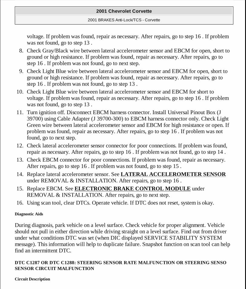
voltage. If problem was found, repair as necessary. After repairs, go to step 16 . If problem was not found, go to step 13 .
8. Check Gray/Black wire between lateral accelerometer sensor and EBCM for open, short to ground or high resistance. If problem was found, repair as necessary. After repairs, go to step 16 . If problem was not found, go to next step.
9. Check Light Blue wire between lateral accelerometer sensor and EBCM for open, short to ground or high resistance. If problem was found, repair as necessary. After repairs, go to step 16 . If problem was not found, go to step 13 .
10. Check Light Blue wire between lateral accelerometer sensor and EBCM for short to voltage. If problem was found, repair as necessary. After repairs, go to step 16 . If problem was not found, go to step 13 .
11. Turn ignition off. Disconnect EBCM harness connector. Install Universal Pinout Box (J 39700) using Cable Adapter (J 39700-300) to EBCM harness connector only. Check Light Green wire between lateral accelerometer sensor and EBCM for high resistance or open. If problem was found, repair as necessary. After repairs, go to step 16 . If problem was not found, go to next step.
12. Check lateral accelerometer sensor connector for poor connections. If problem was found, repair as necessary. After repairs, go to step 16 . If problem was not found, go to step 14 .
13. Check EBCM connector for poor connections. If problem was found, repair as necessary. After repairs, go to step 16 . If problem was not found, go to step 15 .
14. Replace lateral accelerometer sensor. See LATERAL ACCELEROMETER SENSOR under REMOVAL & INSTALLATION. After repairs, go to step 16 .
15. Replace EBCM. See ELECTRONIC BRAKE CONTROL MODULE under REMOVAL & INSTALLATION. After repairs, go to next step.
16. Using scan tool, clear DTCs. Operate vehicle. If DTC does not reset, system is okay.
Diagnostic Aids
During diagnosis, park vehicle on a level surface. Check vehicle for proper alignment. Vehicle should not pull in either direction while driving straight on a level surface. Find out from driver under what conditions DTC was set (when DIC displayed SERVICE STABILITY SYSTEM message). This information will help to duplicate failure. Snapshot function on scan tool can help find an intermittent DTC.
DTC C1287 OR DTC C1288: STEERING SENSOR RATE MALFUNCTION OR STEERING SENSOSENSOR CIRCUIT MALFUNCTION
Circuit Description
2001 Chevrolet Corvette
2001 BRAKES Anti-Lock/TCS - Corvette
MY
Monday, April 06, 2009 2:41:20 PM Page 45 © 2005 Mitchell Repair Information Company, LLC.

Vehicle Stability Enhancement System (VSES) is activated by EBCM calculating desired yaw rate and comparing it to actual yaw rate input. Desired yaw rate is calculated from measured steering wheel position, vehicle speed, and lateral acceleration. The difference between desired yaw rate and actual yaw rate is yaw rate error, which is a measurement of oversteer or understeer. If yaw rate error becomes too large, EBCM will attempt to correct vehicle's yaw motion by applying differential braking to left or right front wheel. VSES activations generally occur during aggressive driving, in turns or bumpy roads without much use of accelerator pedal. When braking during VSES activation, brake pedal will feel different than ABS pedal pulsation. Brake pedal pulsates at a higher frequency during VSES activation. Usable output voltage range for lateral accelerometer and yaw rate sensors is 0.25-4.75 volts. Scan tool will report zero lateral acceleration or yaw rate as 2.5 volts with no sensor bias present. Sensor bias compensates for sensor mounting alignment errors, electronic signal errors, temperature changes, and manufacturing differences. Steering Wheel Position Sensor (SWPS) supplies 2 analog inputs, phase A and phase B, to EBCM. The 2 input signals are approximately 90 degrees out of phase. By interpreting relationship between the 2 inputs, EBCM can determine position of steering wheel and direction of steering wheel rotation. Steer angle centering is the process by which EBCM calibrates steering sensor output so that output reads zero when steering wheel is centered. Using yaw rate input, lateral accelerometer input, and wheel speed sensor inputs, initial steering center position is calculated after driving greater than 6 MPH for more than 10 seconds in a straight line on a level surface.
DTC C1287 sets when steering wheel position sensor is synchronized and steer rate (speed that steering wheel appears to be turning) is greater than 1100 degrees/second, steer rate is less than 80 degrees/second and difference in phase angle between phase A and phase B is greater than 20 degrees, or the 2 steering sensor signals (phase A and phase B) do not agree for one second. Under this condition, DTC C1281 will also set.
DTC C1288 sets when both phase A and phase B are greater than 4.9 volts for 1.6 seconds, both phase A and phase B are less than 0.2 volts for 1.6 seconds, or the difference in changes in phase A and phase B is greater than 35.2 degrees for 9.76 milliseconds.
Diagnosis
1. Perform DIAGNOSTIC SYSTEM CHECK . Go to next step. 2. Install scan tool. Turn ignition on, engine off. Using scan tool, perform STEERING
POSITION SENSOR TEST. If SWPS passed test, see DIAGNOSTIC AIDS . If SWPS did not pass test, go to next step.
3. Turn ignition off. Disconnect SWPS connector. Turn ignition on, engine off. Using scan tool, observe DUAL ANALOG SWPS INPUT A parameter in VSES data list. If scan tool indicates DUAL ANALOG SWPS INPUT A parameter as less than 0.2 volt, go to next step.
2001 Chevrolet Corvette
2001 BRAKES Anti-Lock/TCS - Corvette
MY
Monday, April 06, 2009 2:41:20 PM Page 46 © 2005 Mitchell Repair Information Company, LLC.

If scan tool does not indicate DUAL ANALOG SWPS INPUT A parameter as less than 0.2 volt, go to step 13 .
4. Using scan tool, observe DUAL ANALOG SWPS INPUT B parameter. If scan tool indicates DUAL ANALOG SWPS INPUT B parameter as less than 0.2 volt, go to next step. If scan tool does not indicate DUAL ANALOG SWPS INPUT B parameter as less than 0.2 volt, go to step 14 .
5. Turn ignition off. Disconnect SWPS connector. Connect fused jumper wire (3 amp) between SWPS connector terminals No. 1 (Dark Green wire) and No. 5 (Light Green wire). Turn ignition on, engine off. Using scan tool, observe DUAL ANALOG SWPS INPUT A parameter. If scan tool indicates DUAL ANALOG SWPS INPUT A parameter as greater than 4.9 volts, go to next step. If scan tool does not indicate DUAL ANALOG SWPS INPUT A parameter as greater than 4.9 volts, go to step 10 .
6. Turn ignition off. Disconnect fused jumper wire. Connect fused jumper wire (3 amp) between SWPS connector terminals No. 1 (Dark Green wire) and No. 6 (Light Blue wire). Turn ignition on, engine off. Using scan tool, observe DUAL ANALOG SWPS INPUT B parameter. If scan tool indicates DUAL ANALOG SWPS INPUT B parameter is greater than 4.9 volts, go to next step. If scan tool does not indicate DUAL ANALOG SWPS INPUT B parameter as greater than 4.9 volts, go to step 10 .
7. Disconnect fused jumper wire. Measure voltage between SWPS connector terminals No. 1 (Dark Green wire) and No. 2 (Light Blue wire). If voltage is less than 5 volts, go to next step. If voltage is not less than 5 volts, go to step 9 .
8. Turn ignition off. Disconnect negative battery cable. Measure resistance between SWPS connector terminal No. 2 (Light Blue wire) and ground. If resistance is less than 5 ohms, go to step 16 . If resistance is not less than 5 ohms, go to step 15 .
9. Check Dark Green wire and Gray/Black wire between SWPS and EBCM for short to voltage. If problem was found, repair as necessary. After repairs, go to step 20 . If problem was not found, go to step 17 .
10. Check Dark Green wire and Gray/Black wire between SWPS and EBCM for open, short to ground or high resistance. If problem was found, repair as necessary. After repairs, go to step 20 . If problem was not found, go to next step.
11. Check Light Green wire between SWPS and EBCM for open, short to ground or high resistance. If problem was found, repair as necessary. After repairs, go to step 20 . If problem was not found, go to next step.
12. Check Light Blue wire between SWPS and EBCM for open, short to ground or high resistance. If problem was found, repair as necessary. After repairs, go to step 20 . If problem was not found, go to step 17 .
13. Check Light Green wire between SWPS and EBCM for short to voltage. If problem was found, repair as necessary. After repairs, go to step 20 . If problem was not found, go to step
2001 Chevrolet Corvette
2001 BRAKES Anti-Lock/TCS - Corvette
MY
Monday, April 06, 2009 2:41:20 PM Page 47 © 2005 Mitchell Repair Information Company, LLC.

17 . 14. Check Light Blue wire between SWPS and EBCM for short to voltage. If problem was
found, repair as necessary. After repairs, go to step 20 . If problem was not found, go to step 17 .
15. Disconnect EBCM harness connector. Install Universal Pinout Box (J 39700) using Cable Adapter (J 39700-300) to EBCM harness connector only. Check Light Blue wire and Light Green/Black wire between SWPS and EBCM for high resistance or open. If problem was found, repair as necessary. After repairs, go to step 20 . If problem was not found, go to step 17 .
16. Check SWPS connector for poor connections. If problem was found, repair as necessary. After repairs, go to step 20 . If problem was not found, go to step 18 .
17. Check EBCM connector for poor connections. If problem was found, repair as necessary. After repairs, go to step 20 . If problem was not found, go to step 19 .
18. Replace SWPS. See appropriate POWER RACK & PINION article in STEERING. After repairs, go to step 20 .
19. Replace EBCM. See ELECTRONIC BRAKE CONTROL MODULE under REMOVAL & INSTALLATION. After repairs, go to next step.
20. Using scan tool, clear DTCs. Operate vehicle. If DTC does not reset, system is okay.
Diagnostic Aids
During diagnosis, park vehicle on a level surface. Check vehicle for proper alignment. Car should not pull in either direction while driving straight on a level surface. Find out from driver under what conditions DTC was set (when DIC displayed SERVICE STABILITY SYSTEM message). This information will help to duplicate failure. Snapshot function on scan tool can help find an intermittent DTC.
DTC C1291: OPEN BRAKELIGHT SWITCH CONTACTS DURING DECELERATION
Circuit Description
Stoplamp switch signal informs the EBCM when the brake pedal is pressed.
DTC C1291 sets when stoplight switch remains open for 3 deceleration cycles.
Diagnosis
1. Perform DIAGNOSTIC SYSTEM CHECK . Go to next step. 2. Press brake pedal. If brake lights turn on, go to next step. If brake lights do not turn on, go
to step 7 .
2001 Chevrolet Corvette
2001 BRAKES Anti-Lock/TCS - Corvette
MY
Monday, April 06, 2009 2:41:20 PM Page 48 © 2005 Mitchell Repair Information Company, LLC.

3. Press brake pedal. Using scan tool, observe STOP LAMP SWITCH parameter in TCS data list. If STOP LAMP SWITCH parameter changes state, see DIAGNOSTIC AIDS . If STOP LAMP SWITCH parameter does not change state, go to next step.
4. Turn ignition off. Inspect stoplight switch and adjust and/or calibrate if needed. If problem was found, repair as necessary. After repairs, go to step 14 . If problem was not found, go to next step.
5. Turn ignition off. Disconnect stoplight switch connector. Connect fused jumper wire (3 amp) between stoplight switch connector terminals "A" (Orange wire) and "B" (White wire). Turn ignition on, engine off. Using scan tool, observe STOP LAMP SWITCH parameter. If scan tool displays APPLIED, go to step 11 . If scan tool does not display APPLIED, go to next step.
6. Check White wire between stoplight switch and EBCM for open. If problem was found, repair as necessary. After repairs, go to step 14 . If problem was not found, go to step 10 .
7. Check Orange wire between rear fuse block and stoplight switch for short to ground or open. If problem was found, repair as necessary. After repairs, go to step 14 . If problem was not found, go to next step.
8. Check White wire between stoplight switch and EBCM for open. If problem is found, repair as necessary. After repairs, go to step 14 . If problem is not found, go to next step.
9. Check White wire between stoplight switch and EBCM for short to ground. If problem was found, repair as necessary. After repairs, go to step 14 . If problem was not found, go to next step.
10. Check EBCM connector for poor connections. If problem was found, repair as necessary. After repairs, go to step 14 . If problem was not found, go to step 12 .
11. Check stoplight switch connector for poor connections. If problem was found, repair as necessary. After repairs, go to step 14 . If problem was not found, go to step 13 .
12. Replace EBCM. See ELECTRONIC BRAKE CONTROL MODULE under REMOVAL & INSTALLATION. After repairs, go to step 14 .
13. Replace stoplight switch. See STOPLIGHT SWITCH under REMOVAL & INSTALLATION. After repairs, go to next step.
14. Using scan tool, clear DTCs. Operate vehicle. If DTC does not reset, system is okay.
Diagnostic Aids
Diagnose any wheel speed sensor DTCs before continuing with diagnosis of DTC.
Deceleration cycle consists of the following sequence:
1. Vehicle speed is greater than 15 MPH.
2001 Chevrolet Corvette
2001 BRAKES Anti-Lock/TCS - Corvette
MY
Monday, April 06, 2009 2:41:20 PM Page 49 © 2005 Mitchell Repair Information Company, LLC.

2. Vehicle decelerates more than 5 MPH/second for 2 seconds. 3. Vehicle speed decelerates to less than 10 MPH.
Verify proper stoplight switch operation using data list of scan tool. As brake is applied, data list should display stoplight switch on within 1 inch (2.54 cm) of travel.
Possible causes of this DTC are the following conditions:
� Open stoplight switch. � Stoplight switch is misadjusted. � Open fuse. � Circuit has a wiring problem, terminal corrosion, or poor connections. � Erratic wheel speeds.
DTC C1292, DTC C1293 OR DTC C1296: BRAKE FLUID PRESSURE SENSOR
Circuit Description
DTC definitions:
� DTC C1292 Brake fluid pressure low.
� DTC C1293 Brake fluid pressure high.
� DTC C1296 Brake fluid pressure sensor out of range.
EBCM uses input from brake fluid pressure sensor for more accurate braking control during VSES.
DTC C1292 sets when brake fluid pressure is less than 50 psi (3.5 kg/cm2 ) for 3 deceleration cycles.
DTC C1293 sets when brake fluid pressure is greater than 50 psi (3.5 kg/cm2 ) for 2 consecutive ignition cycles and vehicle speed is above 25 MPH.
2001 Chevrolet Corvette
2001 BRAKES Anti-Lock/TCS - Corvette
MY
Monday, April 06, 2009 2:41:20 PM Page 50 © 2005 Mitchell Repair Information Company, LLC.

DTC C1296 sets when brake fluid pressure sensor signal is greater than 4.9 volts for 2 minutes or brake fluid pressure sensor signal is less than 0.14 volts for 0.1 second.
Diagnosis
1. Perform DIAGNOSTIC SYSTEM CHECK . Go to next step. 2. Install scan tool. Turn ignition on, engine off. Using scan tool, observe BRAKE FLUID
PRESSURE SENSOR INPUT parameter in VSES data list. If scan tool displays BRAKE FLUID PRESSURE SENSOR INPUT parameter as 0.14-4.90 volts, see DIAGNOSTIC AIDS . If scan tool does not display BRAKE FLUID PRESSURE SENSOR INPUT parameter as 0.14-4.90 volts, go to next step.
3. Turn ignition off. Disconnect brake fluid pressure sensor connector. Turn ignition on, engine off. Using scan tool, observe BRAKE FLUID PRESSURE SENSOR INPUT parameter. If scan tool indicates BRAKE FLUID PRESSURE SENSOR INPUT parameter as less than 0.14 volt, go to next step. If scan tool does not indicate BRAKE FLUID PRESSURE SENSOR INPUT parameter as less than 0.14 volt, go to step 10 .
4. Turn ignition. Connect fused jumper wire (3 amp) between brake fluid pressure sensor connector terminals "A" and "B". See Fig. 1 . Turn ignition on, engine off. Using scan tool, observe BRAKE FLUID PRESSURE SENSOR INPUT parameter. If scan tool indicates BRAKE FLUID PRESSURE SENSOR INPUT parameter is greater than 4.9 volts, go to next step. If scan tool does not indicate BRAKE FLUID PRESSURE SENSOR INPUT parameter is greater than 4.9 volts, go to step 8 .
5. Disconnect fused jumper wire. Measure voltage between brake fluid pressure sensor connector terminals "A" and "C". If voltage is less than 5 volts, go to next step. If voltage is not less than 5 volts, go to step 7 .
6. Turn ignition off. Disconnect negative battery cable. Measure resistance between brake fluid pressure sensor connector terminal "C" and ground. If resistance is less than 5 ohms, go to step 12 . If resistance is not less than 5 ohms, go to step 11 .
7. Check Gray wire (5 volt reference voltage) for short to voltage. If problem was found, repair as necessary. After repairs, go to step 16 . If problem was not found, go to step 13 .
8. Check Gray wire (5 volt reference voltage) for open, short to ground or high resistance. If problem was found, repair as necessary. After repairs, go to step 16 . If problem was not found, go to next step.
9. Check Black wire (sensor signal) between brake fluid pressure sensor and EBCM for open, short to ground or high resistance. If problem was found, repair as necessary. After repairs, go to step 16 . If problem was not found, go to step 13 .
10. Check Black wire (sensor signal) between brake fluid pressure sensor and EBCM for short to voltage. If problem was found, repair as necessary. After repairs, go to step 16 . If
2001 Chevrolet Corvette
2001 BRAKES Anti-Lock/TCS - Corvette
MY
Monday, April 06, 2009 2:41:20 PM Page 51 © 2005 Mitchell Repair Information Company, LLC.

problem was not found, go to step 13 . 11. Disconnect EBCM connector. Install Universal Pinout Box (J 39700) using Cable Adapter
(J 39700-300) to EBCM harness connector only. Check Orange/Black wire between brake fluid pressure sensor and EBCM for high resistance or open. If problem was found, repair as necessary. After repairs, go to step 16 . If problem was not found, go to step 13 .
12. Check brake fluid pressure sensor connector for poor connections. If problem was found, repair as necessary. After repairs, go to step 16 . If problem was not found, go to step 14 .
13. Check EBCM connector for poor connections. If problem was found, repair as necessary. After repairs, go to step 16 . If problem was not found, go to step 15 .
14. Replace brake fluid pressure sensor. See BRAKE FLUID PRESSURE SENSOR under REMOVAL & INSTALLATION. After repairs, go to step 16 .
15. Replace EBCM. See ELECTRONIC BRAKE CONTROL MODULE under REMOVAL & INSTALLATION. After repairs, go to next step.
16. Using scan tool, clear DTCs. Operate vehicle. If DTC does not reset, system is okay.
2001 Chevrolet Corvette
2001 BRAKES Anti-Lock/TCS - Corvette
MY
Monday, April 06, 2009 2:41:20 PM Page 52 © 2005 Mitchell Repair Information Company, LLC.

Fig. 1: Identifying Brake Fluid Pressure Sensor Connector Terminals Courtesy of GENERAL MOTORS CORP.
Diagnostic Aids
Find out from driver under what conditions DTC was set (when DIC displayed SERVICE ACTIVE HANDLING message). This information will help to duplicate the failure. Snapshot function on scan tool can help find an intermittent DTC.
Deceleration cycle consists of the following sequence:
1. Vehicle speed is greater than 15 MPH. 2. Vehicle decelerates more than 5 MPH/second for 2 seconds.
2001 Chevrolet Corvette
2001 BRAKES Anti-Lock/TCS - Corvette
MY
Monday, April 06, 2009 2:41:20 PM Page 53 © 2005 Mitchell Repair Information Company, LLC.
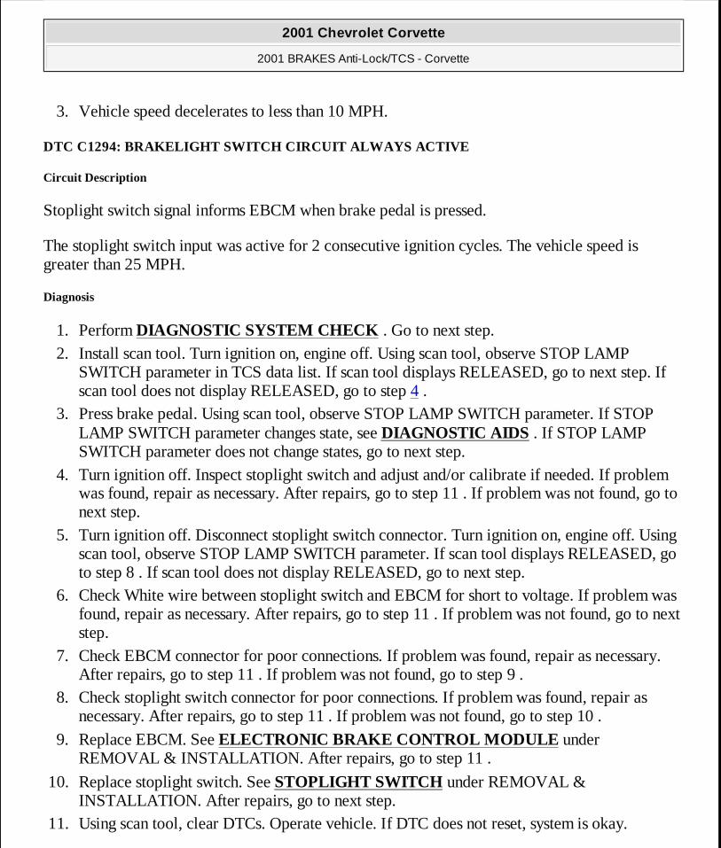
3. Vehicle speed decelerates to less than 10 MPH.
DTC C1294: BRAKELIGHT SWITCH CIRCUIT ALWAYS ACTIVE
Circuit Description
Stoplight switch signal informs EBCM when brake pedal is pressed.
The stoplight switch input was active for 2 consecutive ignition cycles. The vehicle speed is greater than 25 MPH.
Diagnosis
1. Perform DIAGNOSTIC SYSTEM CHECK . Go to next step. 2. Install scan tool. Turn ignition on, engine off. Using scan tool, observe STOP LAMP
SWITCH parameter in TCS data list. If scan tool displays RELEASED, go to next step. If scan tool does not display RELEASED, go to step 4 .
3. Press brake pedal. Using scan tool, observe STOP LAMP SWITCH parameter. If STOP LAMP SWITCH parameter changes state, see DIAGNOSTIC AIDS . If STOP LAMP SWITCH parameter does not change states, go to next step.
4. Turn ignition off. Inspect stoplight switch and adjust and/or calibrate if needed. If problem was found, repair as necessary. After repairs, go to step 11 . If problem was not found, go to next step.
5. Turn ignition off. Disconnect stoplight switch connector. Turn ignition on, engine off. Using scan tool, observe STOP LAMP SWITCH parameter. If scan tool displays RELEASED, go to step 8 . If scan tool does not display RELEASED, go to next step.
6. Check White wire between stoplight switch and EBCM for short to voltage. If problem was found, repair as necessary. After repairs, go to step 11 . If problem was not found, go to next step.
7. Check EBCM connector for poor connections. If problem was found, repair as necessary. After repairs, go to step 11 . If problem was not found, go to step 9 .
8. Check stoplight switch connector for poor connections. If problem was found, repair as necessary. After repairs, go to step 11 . If problem was not found, go to step 10 .
9. Replace EBCM. See ELECTRONIC BRAKE CONTROL MODULE under REMOVAL & INSTALLATION. After repairs, go to step 11 .
10. Replace stoplight switch. See STOPLIGHT SWITCH under REMOVAL & INSTALLATION. After repairs, go to next step.
11. Using scan tool, clear DTCs. Operate vehicle. If DTC does not reset, system is okay.
2001 Chevrolet Corvette
2001 BRAKES Anti-Lock/TCS - Corvette
MY
Monday, April 06, 2009 2:41:20 PM Page 54 © 2005 Mitchell Repair Information Company, LLC.
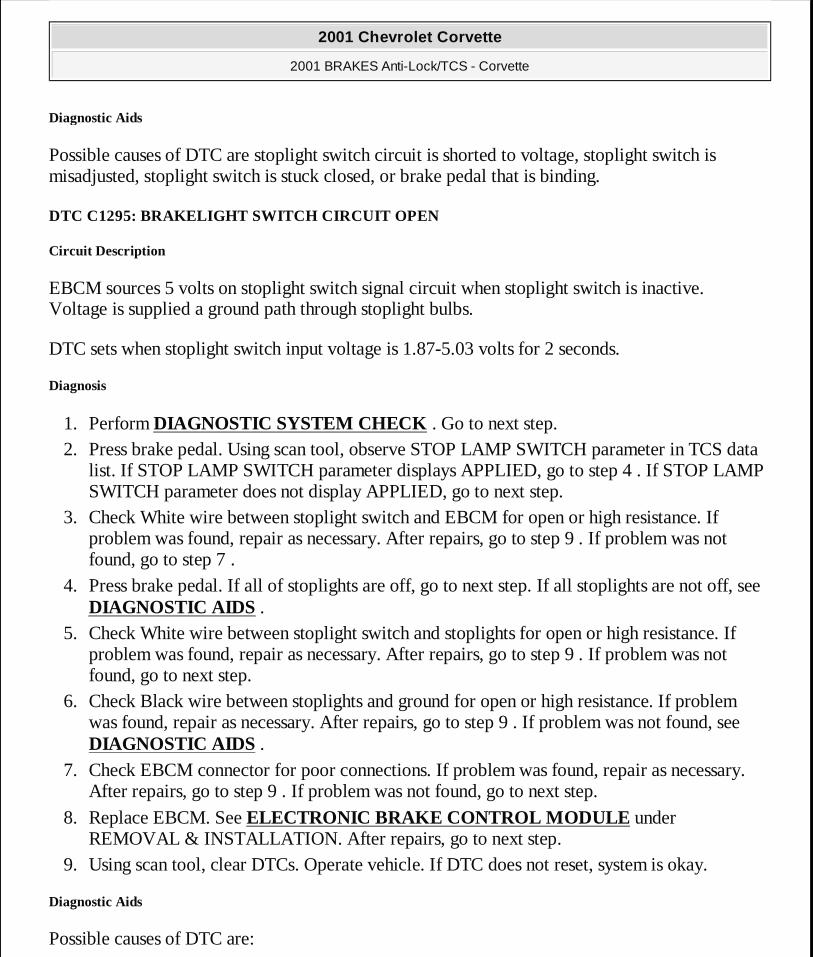
Diagnostic Aids
Possible causes of DTC are stoplight switch circuit is shorted to voltage, stoplight switch is misadjusted, stoplight switch is stuck closed, or brake pedal that is binding.
DTC C1295: BRAKELIGHT SWITCH CIRCUIT OPEN
Circuit Description
EBCM sources 5 volts on stoplight switch signal circuit when stoplight switch is inactive. Voltage is supplied a ground path through stoplight bulbs.
DTC sets when stoplight switch input voltage is 1.87-5.03 volts for 2 seconds.
Diagnosis
1. Perform DIAGNOSTIC SYSTEM CHECK . Go to next step. 2. Press brake pedal. Using scan tool, observe STOP LAMP SWITCH parameter in TCS data
list. If STOP LAMP SWITCH parameter displays APPLIED, go to step 4 . If STOP LAMP SWITCH parameter does not display APPLIED, go to next step.
3. Check White wire between stoplight switch and EBCM for open or high resistance. If problem was found, repair as necessary. After repairs, go to step 9 . If problem was not found, go to step 7 .
4. Press brake pedal. If all of stoplights are off, go to next step. If all stoplights are not off, see DIAGNOSTIC AIDS .
5. Check White wire between stoplight switch and stoplights for open or high resistance. If problem was found, repair as necessary. After repairs, go to step 9 . If problem was not found, go to next step.
6. Check Black wire between stoplights and ground for open or high resistance. If problem was found, repair as necessary. After repairs, go to step 9 . If problem was not found, see DIAGNOSTIC AIDS .
7. Check EBCM connector for poor connections. If problem was found, repair as necessary. After repairs, go to step 9 . If problem was not found, go to next step.
8. Replace EBCM. See ELECTRONIC BRAKE CONTROL MODULE under REMOVAL & INSTALLATION. After repairs, go to next step.
9. Using scan tool, clear DTCs. Operate vehicle. If DTC does not reset, system is okay.
Diagnostic Aids
Possible causes of DTC are:
2001 Chevrolet Corvette
2001 BRAKES Anti-Lock/TCS - Corvette
MY
Monday, April 06, 2009 2:41:20 PM Page 55 © 2005 Mitchell Repair Information Company, LLC.

� A signal circuit of the stoplight switch is open. � Stoplight switch is misadjusted. Verify proper stoplight switch operation using data list of
scan tool. As brake is applied, data list should display stoplight switch on within 1 inch (2.54 cm) of travel.
� All brake lights are open. � All brake light grounds are open. � Circuit has wiring problem, terminal corrosion, or poor connections. � Loose or corroded EBCM ground or PCM ground. � Internal EBCM problem.
REMOVAL & INSTALLATION
BRAKE FLUID PRESSURE SENSOR
Removal & Installation
Drain cooling system. Remove upper radiator hose. Loosen BPMV/EBCM retaining nuts and reposition BPMV/EBCM to access brake fluid pressure sensor. Disconnect brake fluid pressure sensor connector. Remove brake fluid pressure sensor. To install, reverse removal procedure.
BRAKE PRESSURE MODULATOR VALVE
Removal
1. Turn ignition switch to OFF position. Disconnect EBCM connector. Note brakeline location on Brake Pressure Modulator alve (BPMV). Remove brakelines. Remove BPMV pump ground wire. Remove mounting 2 nuts and remove EBCM/BPMV assembly.
CAUTION: When battery is disconnected, vehicle computer and memory systems may lose memory data. Driveability problems may exist until computer systems have completed a relearn cycle. See COMPUTER RELEARN PROCEDURES article in GENERAL INFORMATION before disconnecting battery.
WARNING: Vehicle is equipped with Supplemental Inflatable Restraint (SIR) system. Disable SIR system when working near steering column or instrument panel. See SUPPLEMENTAL INFLATABLE RESTRAINT (SIR) under SERVICE PRECAUTIONS.
2001 Chevrolet Corvette
2001 BRAKES Anti-Lock/TCS - Corvette
MY
Monday, April 06, 2009 2:41:20 PM Page 56 © 2005 Mitchell Repair Information Company, LLC.

2. If EBCM is being replaced, remove ground wire and then remove EBCM. Ensure EBCM seal is not damaged during this step. Remove insulator from EBCM. Remove 4 EBCM to BPMV mounting bolts. Separate EBCM from BPMV carefully. Do not damage seal.
Installation
To install, reverse removal procedure. Clean up any spilled brake fluid in mounting area. Tighten bolts and brakelines to specification. See TORQUE SPECIFICATIONS . After completing installation, bleed brake system. See BLEEDING BRAKE SYSTEM .
ELECTRONIC BRAKE CONTROL MODULE
Removal & Installation
1. Turn ignition switch to Off position. Disconnect EBTCM connector. Remove 3 EBTCM/BPMV mounting nuts. Lift EBTCM/BPMV far enough out of bracket to separate EBTCM from BPMV. Remove insulator from EBTCM. Remove 4 EBTCM to BPMV mounting bolts. Separate EBTCM from BPMV carefully. Do not damage seal.
2. To install, reverse removal procedure. Tighten bolts and brakelines to specification. See TORQUE SPECIFICATIONS .
LATERAL ACCELEROMETER SENSOR
Removal & Installation
Turn ignition switch to OFF position. Remove passenger seat. Disconnect lateral accelerometer connector. Remove 2 mounting nuts and remove lateral accelerometer. To install, reverse removal procedure.
STEERING WHEEL POSITION SENSOR
The steering wheel position sensor is mounted to steering shaft. For removal and installation, see appropriate STEERING COLUMNS article in STEERING.
STOPLIGHT SWITCH
Removal & Installation
Remove left sound insulator. Disconnect electrical connectors from switch. Remove stoplight
CAUTION: Ensure brakelines are correctly connected to BPMV or wheel lock-up will occur.
2001 Chevrolet Corvette
2001 BRAKES Anti-Lock/TCS - Corvette
MY
Monday, April 06, 2009 2:41:20 PM Page 57 © 2005 Mitchell Repair Information Company, LLC.

switch. To install, reverse removal procedure.
TRACTION CONTROL SWITCH
Removal & Installation
Turn ignition switch to OFF position. Open center console door. Pull up on rear of switch assembly to release mounting clips. If clips do not release, carefully insert screwdriver into access hole at rear of switch assembly and gently pull up on switch. Disconnect traction control switch connector and remove traction control switch. To install, reverse removal procedure.
TOOTHED RING
WHEEL SPEED SENSORS
Removal & Installation (Front)
1. Turn ignition off. Raise and support vehicle. Remove wheel. Remove brake caliper and rotor. Remove the stabilizer shaft link from the lower control arm. Disconnect Wheel Speed Sensor (WSS) electrical connector. Support the lower control arm. Separate outer tie rod and lower ball joint from the steering knuckle. Remove wheel hub retaining bolts and remove hub/wheel speed sensor assembly from steering knuckle.
2. To install, reverse removal procedure. Tighten bolts to specification. See TORQUE SPECIFICATIONS .
Removal & Installation (Rear)
1. Turn ignition off. Raise and support vehicle. Remove wheel. Disconnect WSS connector. Disconnect Real Time Dampening (RTD) position sensor link, if equipped. Remove brake caliper and rotor. Remove shock absorber solenoid electrical connector, if equipped.
2. Separate tie rod end from suspension knuckle. Remove spindle nut and washer. Separate upper and lower control arm from suspension knuckle. Remove suspension knuckle from vehicle Remove wheel hub retaining bolts and remove hub/wheel speed sensor assembly from steering knuckle.
NOTE: Toothed ring is not serviceable. Toothed ring is incorporated into hub assemblies. A NEW hub assembly must be installed if toothed ring requires replacement.
NOTE: Wheel speed sensors are incorporated in hub assembly. Entire hub/wheel speed sensor assembly must be replaced.
2001 Chevrolet Corvette
2001 BRAKES Anti-Lock/TCS - Corvette
MY
Monday, April 06, 2009 2:41:20 PM Page 58 © 2005 Mitchell Repair Information Company, LLC.

3. To install, reverse removal procedure. Tighten mounting bolt to specification. See TORQUE SPECIFICATIONS .
YAW RATE SENSOR
Removal & Installation
1. Turn ignition switch to OFF position. Apply parking brake and shift transmission to rear most gearshift position. On convertibles, remove folding top stowage compartment lid extension panel. On all models, remove traction control switch. See TRACTION CONTROL SWITCH .
2. Using flat blade screwdriver, remove console retaining nut covers. Remove retaining nuts for console and instrument panel trim plate. Lift rear of console and pull rearward to release front from under instrument panel trim plate. Disconnect accessory plug and fuel door release connectors. Remove console.
3. With M/T, apply light pressure on shift boot towards shift lever to release shift boot from trim plate. On all models, remove ashtray. Remove trim plate grille by gently prying with flat bladed screwdriver at side edge. Remove accessory trim plate screws next to lighter, behind ashtray and in trim plate grille opening. Pull accessory trim plate rearward to release locking tabs. Disconnect lighter connector. On M/T, rotate shift boot to go through trim panel opening. On all models, remove accessory trim plate.
4. Disconnect yaw rate sensor connector. Remove 2 retaining nuts and remove yaw rate sensor. To install, reverse removal procedure.
ADJUSTMENTS
STOPLIGHT/CRUISE CONTROL SWITCH
With brake pedal depressed, insert stoplight/cruise control switch into retainer until switch body seats in retainer. Note that clicks can be heard as threaded portion of switch is pushed through retainer. Slowly pull brake pedal fully rearward against stop until click sound can no longer be heard. Switch will be moved in retainer providing proper adjustment.
TORQUE SPECIFICATIONS
TORQUE SPECIFICATIONS Application Ft. Lbs. (N.m)Brakeline-To-BPMV 12 (16)EBTCM/BPMV Insulator 10 (14)
2001 Chevrolet Corvette
2001 BRAKES Anti-Lock/TCS - Corvette
MY
Monday, April 06, 2009 2:41:20 PM Page 59 © 2005 Mitchell Repair Information Company, LLC.
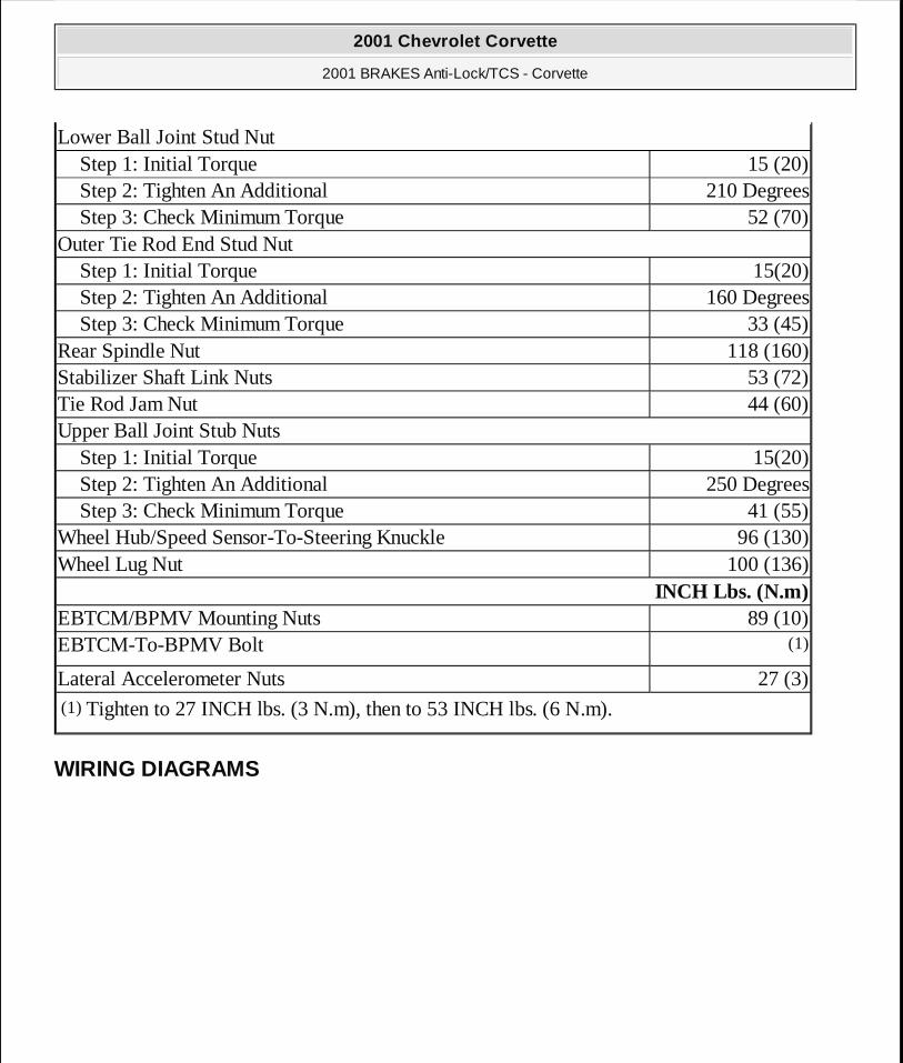
WIRING DIAGRAMS
Lower Ball Joint Stud NutStep 1: Initial Torque 15 (20)Step 2: Tighten An Additional 210 DegreesStep 3: Check Minimum Torque 52 (70)
Outer Tie Rod End Stud NutStep 1: Initial Torque 15(20)Step 2: Tighten An Additional 160 DegreesStep 3: Check Minimum Torque 33 (45)
Rear Spindle Nut 118 (160)Stabilizer Shaft Link Nuts 53 (72)Tie Rod Jam Nut 44 (60)Upper Ball Joint Stub Nuts
Step 1: Initial Torque 15(20)Step 2: Tighten An Additional 250 DegreesStep 3: Check Minimum Torque 41 (55)
Wheel Hub/Speed Sensor-To-Steering Knuckle 96 (130)Wheel Lug Nut 100 (136)
INCH Lbs. (N.m) EBTCM/BPMV Mounting Nuts 89 (10)EBTCM-To-BPMV Bolt (1) Lateral Accelerometer Nuts 27 (3)(1) Tighten to 27 INCH lbs. (3 N.m), then to 53 INCH lbs. (6 N.m).
2001 Chevrolet Corvette
2001 BRAKES Anti-Lock/TCS - Corvette
MY
Monday, April 06, 2009 2:41:20 PM Page 60 © 2005 Mitchell Repair Information Company, LLC.

2001 Chevrolet Corvette
2001 BRAKES Anti-Lock/TCS - Corvette
MY
Monday, April 06, 2009 2:41:20 PM Page 61 © 2005 Mitchell Repair Information Company, LLC.

Fig. 2: Anti-Lock Brake/Traction Control System Wiring Diagram (Corvette - 2001)
2001 Chevrolet Corvette
2001 BRAKES Anti-Lock/TCS - Corvette
MY
Monday, April 06, 2009 2:41:20 PM Page 62 © 2005 Mitchell Repair Information Company, LLC.