Embed Size (px)
Citation preview

Pipeline Materials Selection -An Overview
Prasenjit Kayal

INTRODUCTION TO PIPELINE DESIGN – June 2009 2
Material OverviewMaterial Overview
IndexIndex
1. Linepipe
2. Clad pipe
3. Large Radius Bends
4. Anticorrosion Coatings
5. Concrete Coating
6. Sacrificial Anodes
7. Field Joint Material
8. Flanges, Gaskets and Bolting
9. SSIV (Subsea Safety Insulated Valve) Overview
10. Insulating Joints
11. T & Y tees and Conical Reducer (Buttwelded Fittings)
04/12/23
INTRODUCTION TO PIPELINE DESIGN – June 2009 3
Material OverviewMaterial Overview
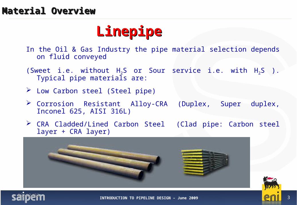
LinepipeLinepipe
04/12/23
In the Oil & Gas Industry the pipe material selection depends on fluid conveyed
(Sweet i.e. without H2S or Sour service i.e. with H2S ). Typical pipe materials are:
Low Carbon steel (Steel pipe)
Corrosion Resistant Alloy-CRA (Duplex, Super duplex, Inconel 625, AISI 316L)
CRA Cladded/Lined Carbon Steel (Clad pipe: Carbon steel layer + CRA layer)
INTRODUCTION TO PIPELINE DESIGN – June 2009 4
Material OverviewMaterial Overview
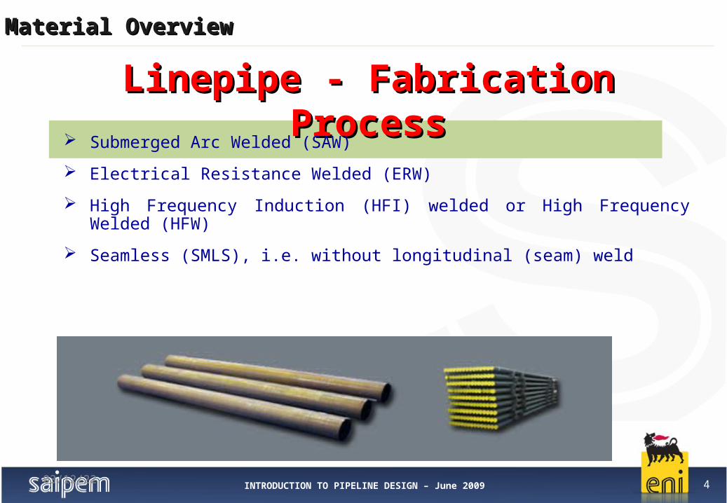
Linepipe - Fabrication ProcessLinepipe - Fabrication Process
04/12/23
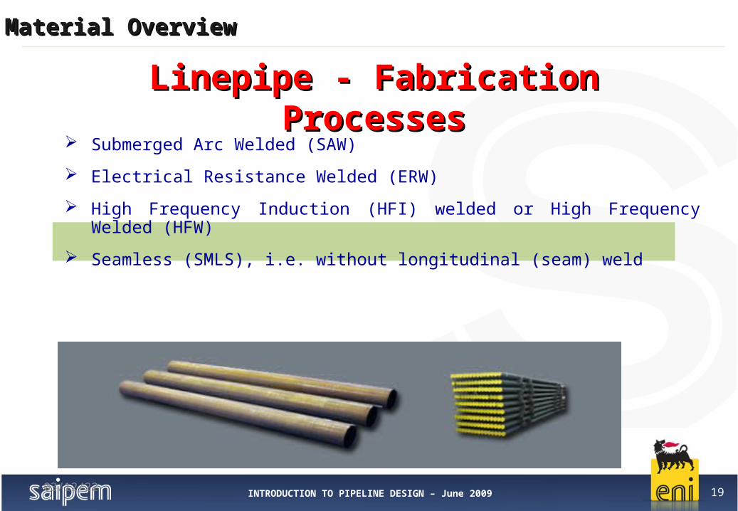
Submerged Arc Welded (SAW)
Electrical Resistance Welded (ERW)
High Frequency Induction (HFI) welded or High Frequency Welded (HFW)
Seamless (SMLS), i.e. without longitudinal (seam) weld
INTRODUCTION TO PIPELINE DESIGN – June 2009 5
Material OverviewMaterial Overview
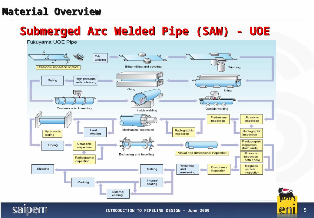
Submerged Arc Welded Pipe (SAW) - UOE Submerged Arc Welded Pipe (SAW) - UOE

INTRODUCTION TO PIPELINE DESIGN – June 2009 6
Material OverviewMaterial Overview
Submerged Arc Welded Pipe (SAW) - UOE Submerged Arc Welded Pipe (SAW) - UOE
04/12/23

INTRODUCTION TO PIPELINE DESIGN – June 2009 7
Material OverviewMaterial Overview
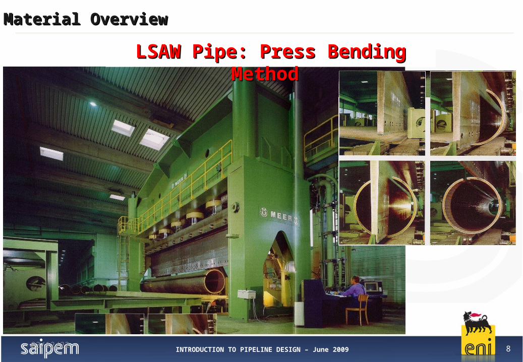
LSAW Pipe: Press Bending Method LSAW Pipe: Press Bending Method
04/12/23
INTRODUCTION TO PIPELINE DESIGN – June 2009 8
Material OverviewMaterial Overview
04/12/23
LSAW Pipe: Press Bending Method LSAW Pipe: Press Bending Method
INTRODUCTION TO PIPELINE DESIGN – June 2009 9
Material OverviewMaterial Overview
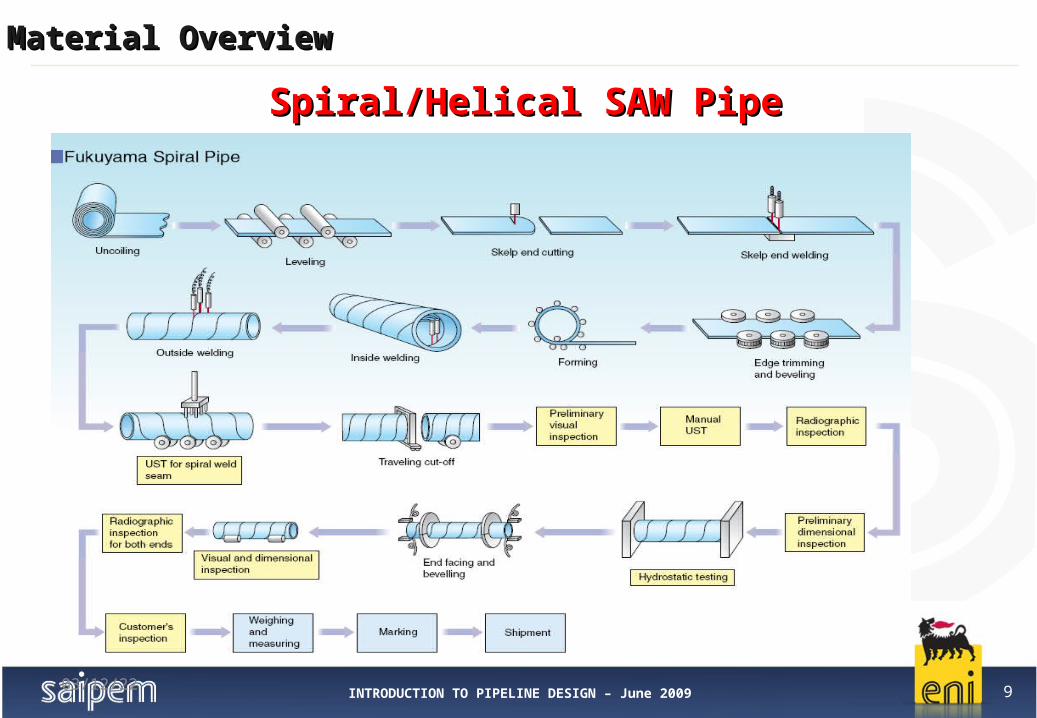
Spiral/Helical SAW Pipe Spiral/Helical SAW Pipe
04/12/23

INTRODUCTION TO PIPELINE DESIGN – June 2009 10
Material OverviewMaterial Overview
Spiral/Helical SAW Pipe Spiral/Helical SAW Pipe
04/12/23

INTRODUCTION TO PIPELINE DESIGN – June 2009 11
Material OverviewMaterial Overview
Linepipe - Fabrication ProcessesLinepipe - Fabrication Processes
04/12/23
Submerged Arc Welded (SAW)
Electrical Resistance Welded (ERW)
High Frequency Induction (HFI) welded or High Frequency Welded (HFW)
Seamless (SMLS), i.e. without longitudinal (seam) weld

INTRODUCTION TO PIPELINE DESIGN – June 2009 12
Material OverviewMaterial Overview
Medium-Diameter (26-in)Medium-Diameter (26-in)
Electrical Resistance Welded Pipe (ERW)Electrical Resistance Welded Pipe (ERW)

INTRODUCTION TO PIPELINE DESIGN – June 2009 13
Material OverviewMaterial Overview
Linepipe - Fabrication ProcessesLinepipe - Fabrication Processes
04/12/23
Submerged Arc Welded (SAW)
Electrical Resistance Welded (ERW)
High Frequency Induction (HFI) welded or High Frequency Welded (HFW)
Seamless (SMLS), i.e. without longitudinal (seam) weld
INTRODUCTION TO PIPELINE DESIGN – June 2009 14
Material OverviewMaterial Overview
Small-Diameter (6-in) HFI PipeSmall-Diameter (6-in) HFI Pipe
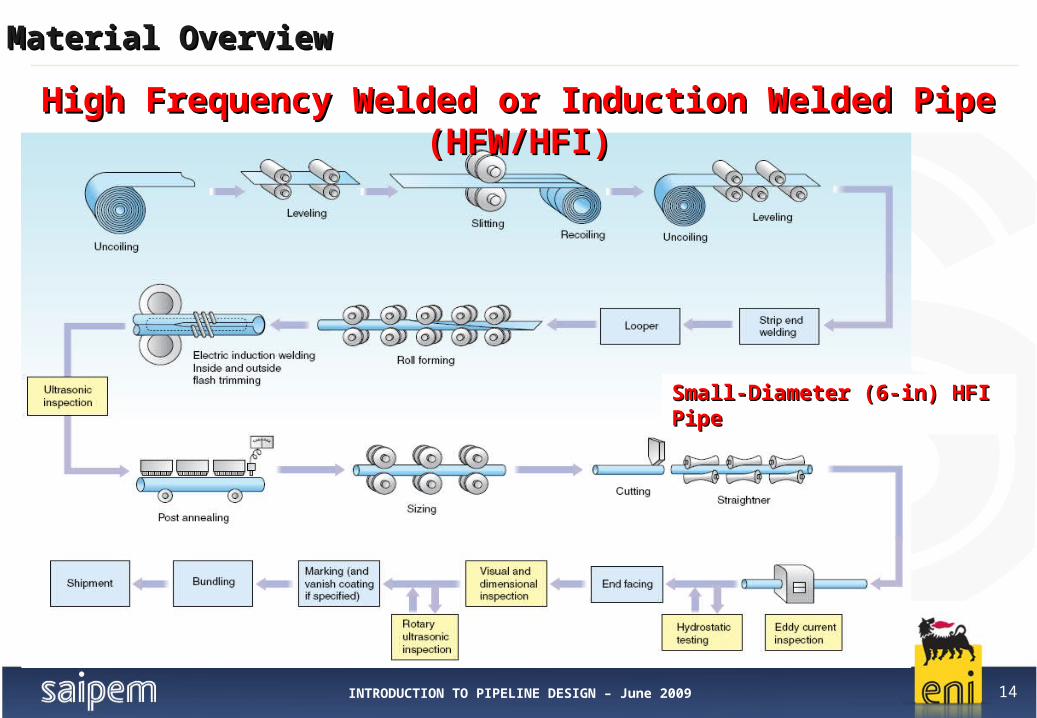
High Frequency Welded or Induction Welded Pipe (HFW/HFI)High Frequency Welded or Induction Welded Pipe (HFW/HFI)

INTRODUCTION TO PIPELINE DESIGN – June 2009 15
Material OverviewMaterial Overview
HFI PIPE – CoilerHFI PIPE – Coiler

INTRODUCTION TO PIPELINE DESIGN – June 2009 16
Material OverviewMaterial Overview
HFI PIPE – WeldingHFI PIPE – Welding

INTRODUCTION TO PIPELINE DESIGN – June 2009 17
Material OverviewMaterial Overview
04/12/23
ERW Pipe vs. HFI PipeERW Pipe vs. HFI Pipe

INTRODUCTION TO PIPELINE DESIGN – June 2009 18
Material OverviewMaterial Overview
04/12/23
TENARISTENARIS
INTRODUCTION TO PIPELINE DESIGN – June 2009 19
Material OverviewMaterial Overview
Linepipe - Fabrication ProcessesLinepipe - Fabrication Processes
04/12/23
Submerged Arc Welded (SAW)
Electrical Resistance Welded (ERW)
High Frequency Induction (HFI) welded or High Frequency Welded (HFW)
Seamless (SMLS), i.e. without longitudinal (seam) weld

INTRODUCTION TO PIPELINE DESIGN – June 2009 20
Material OverviewMaterial Overview
Plug Rolling Mill (Medium Diameter Seamless Pipe) Plug Rolling Mill (Medium Diameter Seamless Pipe)
04/12/23
INTRODUCTION TO PIPELINE DESIGN – June 2009 21
Material OverviewMaterial Overview
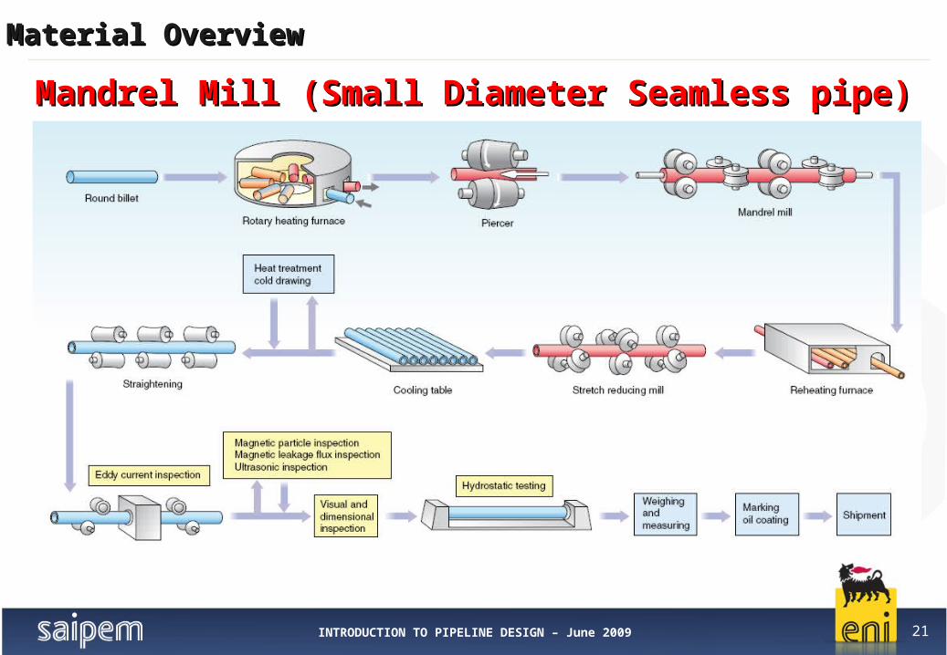
Mandrel Mill (Small Diameter Seamless pipe)Mandrel Mill (Small Diameter Seamless pipe)

INTRODUCTION TO PIPELINE DESIGN – June 2009 22
Material OverviewMaterial Overview
04/12/23
TENARISTENARIS

INTRODUCTION TO PIPELINE DESIGN – June 2009 23
Material OverviewMaterial Overview
Pipe Production RangePipe Production Range

INTRODUCTION TO PIPELINE DESIGN – June 2009 24
Material OverviewMaterial Overview
Pipelines usually have diameters within 10”and 48”. Large diameter linepipes (*) correspond to SAW longitudinal welded pipes that match more requirements for Oil & Gas applications.Generally speaking, ERW and SEAMLESS pipes are respectively less and more expensive than LSAW.
SEAMLESS/ERW
LSAW
SAW Spiral
Quantity of Supplier for Market Segment
10” 20” 48” 56” 64”DIAMETER (inch) 24”
Typical Pipelines Range
Offshore Pipeline Market
LD (*)
Pipe – Market SegmentPipe – Market Segment
04/12/23

INTRODUCTION TO PIPELINE DESIGN – June 2009 25
Material OverviewMaterial Overview
IndexIndex
1. Linepipe
2. Clad pipe
3. Large Radius Bends
4. Anticorrosion Coatings
5. Concrete Coating
6. Sacrificial Anodes
7. Field Joint Material
8. Flanges, Gaskets and Bolting
9. SSIV (Subsea Safety Insulated Valve) Overview
10. Insulating Joints
11. T & Y tees and Conical Reducer (Buttwelded Fittings)
04/12/23

INTRODUCTION TO PIPELINE DESIGN – June 2009 26
Material OverviewMaterial Overview
Offshore Pipeline for corrosive service (sour service i.e. with H2S) are fabricated in: Corrosion Resistant Alloy-CRA (Duplex, Super duplex, Inconel 625, AISI 316L) CRA Cladded/Lined Carbon Steel (Clad pipe: Carbon steel layer + CRA layer)Clad pipelines are formed from a carbon manganese steel outer pipe (base material or backsteel) lined internally with a thin layer (2-3 mm thick) of corrosion resistant material.
Definition: Linepipe is denoted “clad” if the bond between base and cladding material is metallurgical. Linepipe is denoted “lined” if the bond between base and cladding material is mechanical.
Clad PipeCRA PipeLined Pipe
CLAD PipeCLAD Pipe

INTRODUCTION TO PIPELINE DESIGN – June 2009 27
Material OverviewMaterial Overview
04/12/23
CLAD PipeCLAD Pipe
INTRODUCTION TO PIPELINE DESIGN – June 2009 28
Material OverviewMaterial Overview
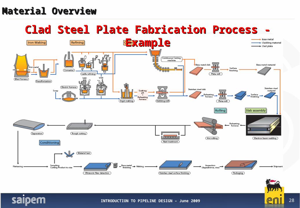
Clad Steel Plate Fabrication Process - ExampleClad Steel Plate Fabrication Process - Example
INTRODUCTION TO PIPELINE DESIGN – June 2009 29
Material OverviewMaterial Overview
04/12/23
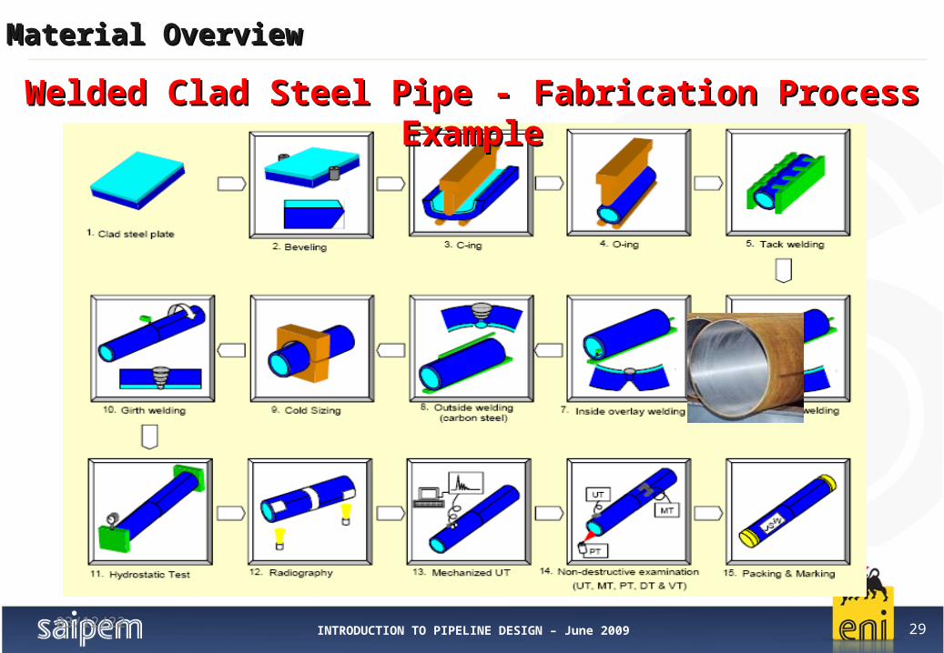
Welded Clad Steel Pipe - Fabrication Process ExampleWelded Clad Steel Pipe - Fabrication Process Example

INTRODUCTION TO PIPELINE DESIGN – June 2009 30
Material OverviewMaterial Overview
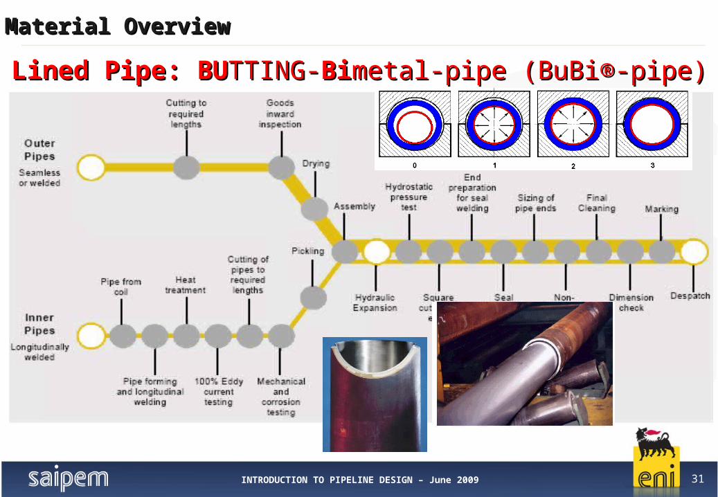
An example of Mechanically Bonded (Lined) pipe:
BUTTING BuBi®In order to increase the advantages of a clad pipe, BUTTING developed a mechanically
bonded BUTTING-Bimetal-pipe ( BuBi®-pipe) at the beginning of the ‘90.
The BuBi®-pipe consists of a CRA pipe which is telescopically aligned inside a pipe in carbon-manganese material (seamless or welded pipe).
The tight bonding between the two pipes is achieved by hydraulic expansion.
The producible size range comprises pipes in OD's from 114.3 mm (4") up to 660 mm (26") and lengths up to 12 m without circumferential weld.
Compared with the metallurgically clad pipe, BuBi®-pipe offers a wide range of material combinations - for both the inner and outer pipe - and price advantages.
Price advantage is due to the use of low cost carbon steels in conjunction with corrosion resisting steels and an economic production process.
04/12/23
Lined PipeLined Pipe
INTRODUCTION TO PIPELINE DESIGN – June 2009 31
Material OverviewMaterial Overview
Lined Pipe: Lined Pipe: BUBUTTING-TTING-BiBimetal-pipe (BuBi®-pipe)metal-pipe (BuBi®-pipe)
INTRODUCTION TO PIPELINE DESIGN – June 2009 32
Material OverviewMaterial Overview
IndexIndex1. Linepipe
2. Clad pipe
3. Large Radius Bends
4. Anticorrosion Coatings
5. Concrete Coating
6. Sacrificial Anodes
7. Field Joint Material
8. Flanges, Gaskets and Bolting
9. SSIV (Subsea Safety Insulated Valve) Overview
10. Insulating Joints
11. T & Y tees and Conical Reducer (Buttwelded Fittings)
04/12/23

INTRODUCTION TO PIPELINE DESIGN – June 2009 33
Material OverviewMaterial Overview
04/12/23
Offshore Application: Expansion loop (Spool) construction (e.g. goose neck, bend part). Riser construction (e.g. bend part). Top side Piping
Main Characteristics: Bend Radius ≥ 5 x OD Pipeline (i.e. piggable) Straight length (e.g. 0.5 -1.0 m) Same Chemical composition of mother pipe of linepipe (e.g. Carbon Equivalent)
Main Fabrication Processes: Hot bending of the original pipe (R≈5-10OD) Cold Bending of the original pipe (R≈0-40OD)
Large Radius BendsLarge Radius Bends

INTRODUCTION TO PIPELINE DESIGN – June 2009 34
Material OverviewMaterial Overview
04/12/23
Bends – Hot Bend ProductionBends – Hot Bend Production

INTRODUCTION TO PIPELINE DESIGN – June 2009 35
Material OverviewMaterial Overview
Bends – Hot induction Bending - ExampleBends – Hot induction Bending - Example

INTRODUCTION TO PIPELINE DESIGN – June 2009 36
Material OverviewMaterial Overview
Bending Machine Heating and Cooling Ring
Bends – Hot induction Bending - ExampleBends – Hot induction Bending - Example

INTRODUCTION TO PIPELINE DESIGN – June 2009 37
Material OverviewMaterial Overview
R
NPS
V
DETAIL"A"
OD
THK ID
SEE DETAIL
"A"
T
T
Note 2
Note 2
ITEM PIPE Wall Mother
Material Grade
Pipe Type
alpha R V T V+2TNAME SIZE Thickness Pipe W.T
(inch) [mm] [mm] (°) (mm) (mm) (mm) (mm)
Expansion Loops 90° Bends
10 20,6 23,8L415 QC
SEAMLESS90 1365,5 2145 500 3145
Goose Neck20° Bends
10 20,6 23,8L415 QC
SEAMLESS20 1365,5 477 500 1477
04/12/23
Typical Bend Dimensions - ExampleTypical Bend Dimensions - Example

INTRODUCTION TO PIPELINE DESIGN – June 2009 38
Material OverviewMaterial Overview
IndexIndex
1. Linepipe
2. Clad pipe
3. Large Radius Bends
4. Anticorrosion Coatings
5. Concrete Coating
6. Sacrificial Anodes
7. Field Joint Material
8. Flanges, Gaskets and Bolting
9. SSIV (Subsea Safety Insulated Valve) Overview
10. Insulating Joints
11. T & Y tees and Conical Reducer (Buttwelded Fittings)
04/12/23

INTRODUCTION TO PIPELINE DESIGN – June 2009 39
Material OverviewMaterial Overview
Coating: The liquid, liquefiable, mastic, powder or any composition and material that
after application to a substrate (e.g. pipes), is converted into a solid anticorrosion protective adherent films.
Offshore Application: Pipeline and Components (Bends, flange, fittings, etc.) External Anticorrosion
Protection System. Riser External Anticorrosion and mechanical Protection System.
Coating System Selection Criteria is based on: Project Requirements Environmental service exposure (seawater, soil, other) Service temperature (depends on max. conveyed fluid temperature)
Anticorrosion CoatingsAnticorrosion Coatings
04/12/23

INTRODUCTION TO PIPELINE DESIGN – June 2009 40
Material OverviewMaterial Overview
Anticorrosion coatings main type: Polyethylene (PE) (e.g. 3.5mm @ 950 kg/m3 – linepipe) Coal tar Enamel (CTE) (e.g. pipeline) Polypropylene (PP) (e.g. 3mm @ 900 kg/m3 linepipe, 3.5mm Flame Spray PP –
Riser and Bends) Fusion Bonded Epoxy (FBE) (e.g. field joint) Polyurethane (PU) (e.g. 15mm@1500kg/m3-Solid PU Risers, 1.5mm @ 1600 kg/m3
PU tar free-Bends) Polychloroprene (PCP) (e.g. 15mm @ 1450 kg/m3 – Risers) High solid Epoxy (e.g. Bends, 1.5mm @ 1600 kg/m3 Flanges)
Main Characteristics to be required: Minimum Thickness; Minimum Density. and Min. and Max. Service Temperature. Cut back length (Depends on Welding System used)
Anticorrosion CoatingsAnticorrosion Coatings
04/12/23

INTRODUCTION TO PIPELINE DESIGN – June 2009 41
Material OverviewMaterial Overview
3LPP
FBE
3LPE
5LPP
PU Mixture (e.g. Marinplast) 15mm@1200kg/m3
PU
Solid
CTE
Anticorrosion Coatings - ExamplesAnticorrosion Coatings - Examples

INTRODUCTION TO PIPELINE DESIGN – June 2009 42
Material OverviewMaterial Overview
The three-layer’s Polyethylene coating (3LPE) is a multilayer coating composed of three functional components: First layer: primer (liquid or powdered fusion bonded epoxy (FBE)). Continuous thin layer
resistant to the corrosive agents. Guarantee a suitable adhesion of the coating to the steel. Second layer: co-polymer or modified polyethylene adhesive. Guarantee a suitable adhesion
between the upper polyethylene layer and the primer. Third layer: polyethylene. It provides good mechanical strength, mechanical protection and
electric insulation.
3LPE Systems provide excellent pipeline protection for small and large diameterpipelines with service temperatures varying from -60° C to +85 °C.According to the maximum service temperatures the polyethylene may be: Low Density Polyethylene (LDPE) (918 - 935 Kg/m3) Medium/High Density Polyethylene (MDPE/HDPE) (940 - 950 kg/m3)Minimum PE Coating Thickness: 3.5 mmCut back length required for pipeline installation: 150 mm +20/-0 mm;
04/12/23
3-Layer Polyethylene (3LPE)3-Layer Polyethylene (3LPE)
INTRODUCTION TO PIPELINE DESIGN – June 2009 43
Material OverviewMaterial Overview
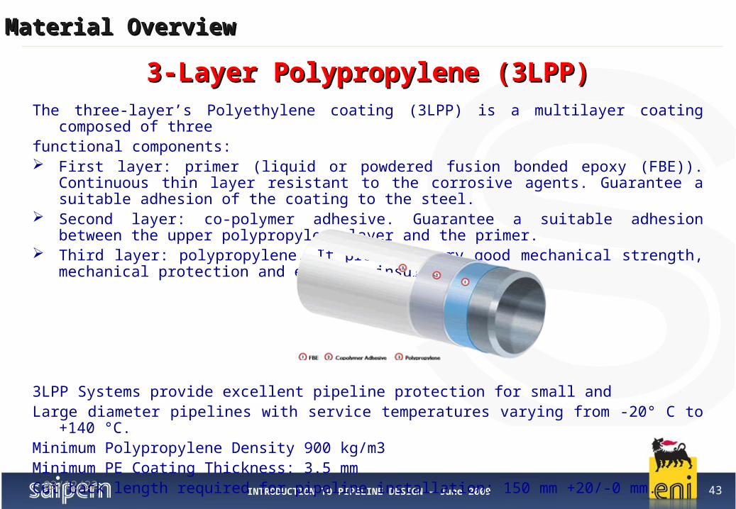
The three-layer’s Polyethylene coating (3LPP) is a multilayer coating composed of threefunctional components: First layer: primer (liquid or powdered fusion bonded epoxy (FBE)). Continuous thin layer
resistant to the corrosive agents. Guarantee a suitable adhesion of the coating to the steel. Second layer: co-polymer adhesive. Guarantee a suitable adhesion between the upper
polypropylene layer and the primer. Third layer: polypropylene. It provides very good mechanical strength, mechanical protection
and electric insulation.
3LPP Systems provide excellent pipeline protection for small and Large diameter pipelines with service temperatures varying from -20° C to +140 °C.Minimum Polypropylene Density 900 kg/m3Minimum PE Coating Thickness: 3.5 mmCut back length required for pipeline installation: 150 mm +20/-0 mm.
04/12/23
3-Layer Polypropylene (3LPP)3-Layer Polypropylene (3LPP)
INTRODUCTION TO PIPELINE DESIGN – June 2009 44
Material OverviewMaterial Overview
3
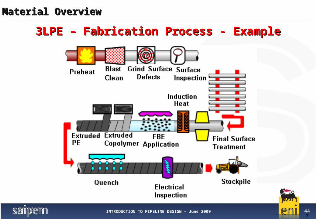
3LPE – Fabrication Process - Example3LPE – Fabrication Process - Example
04/12/23

INTRODUCTION TO PIPELINE DESIGN – June 2009 45
Material OverviewMaterial Overview
3
3LPP – Fabrication Process - Example3LPP – Fabrication Process - Example
04/12/23
INTRODUCTION TO PIPELINE DESIGN – June 2009 46
Material OverviewMaterial Overview
3
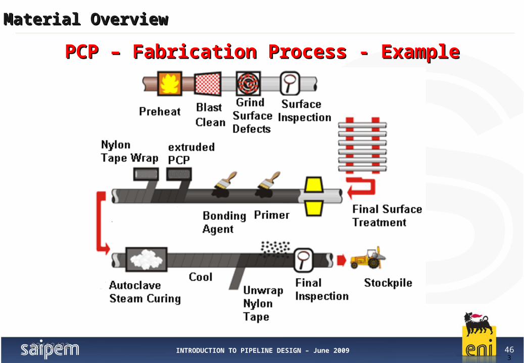
PCP – Fabrication Process - ExamplePCP – Fabrication Process - Example
04/12/23

INTRODUCTION TO PIPELINE DESIGN – June 2009 47
Material OverviewMaterial Overview
3
FBE – Fabrication Process - ExampleFBE – Fabrication Process - Example
04/12/23

INTRODUCTION TO PIPELINE DESIGN – June 2009 48
Material OverviewMaterial Overview
3
Coal Tar Enamel (CTE) – Fabrication Process - ExampleCoal Tar Enamel (CTE) – Fabrication Process - Example
04/12/23

INTRODUCTION TO PIPELINE DESIGN – June 2009 49
Material OverviewMaterial Overview
This lining is applied by layering one or several coats of paint or by spraying epoxy powder.1. The pipe is preheated to eliminate humidity2. The interior surface is shot-blasted to remove mill scale and rust, obtaining a metal surface
which facilitates the adhesion3. When epoxy powder is fused, the pipe is preheated to 238°C, in order to quickly cure the epoxy.4. The pipe is rotated and the lining is sprayed from a set of nozzles which moves inside the pipe.5. When paint is used, it is dried by blowing hot air through the pipe.
Epoxy Resin Lining – Application ExampleEpoxy Resin Lining – Application Example

INTRODUCTION TO PIPELINE DESIGN – June 2009 50
Material OverviewMaterial Overview
IndexIndex
1. Linepipe
2. Clad pipe
3. Large Radius Bends
4. Anticorrosion Coatings
5. Concrete Coating
6. Sacrificial Anodes
7. Field Joint Material
8. Flanges, Gaskets and Bolting
9. SSIV (Subsea Safety Insulated Valve) Overview
10. Insulating Joints
11. T & Y tees and Conical Reducer (Buttwelded Fittings)
04/12/23
INTRODUCTION TO PIPELINE DESIGN – June 2009 51
Material OverviewMaterial Overview
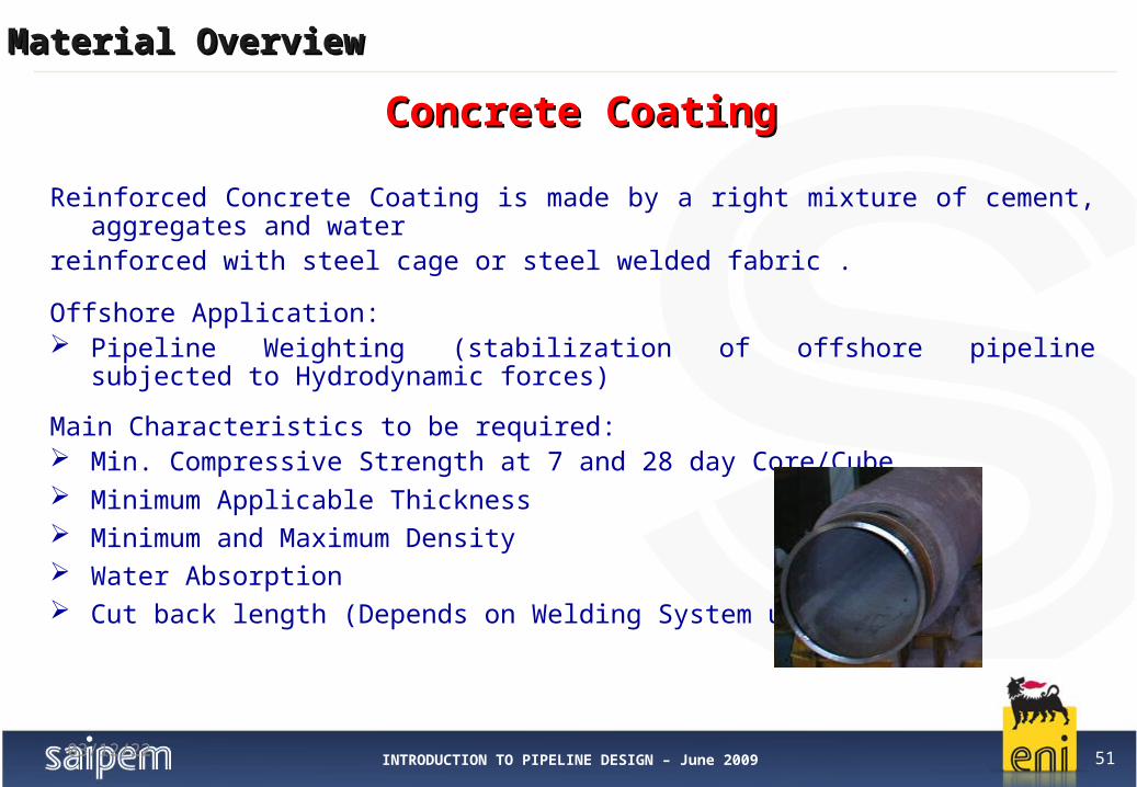
Reinforced Concrete Coating is made by a right mixture of cement, aggregates and waterreinforced with steel cage or steel welded fabric .
Offshore Application: Pipeline Weighting (stabilization of offshore pipeline subjected to Hydrodynamic
forces)
Main Characteristics to be required: Min. Compressive Strength at 7 and 28 day Core/Cube Minimum Applicable Thickness Minimum and Maximum Density Water Absorption Cut back length (Depends on Welding System used)
04/12/23
Concrete CoatingConcrete Coating

INTRODUCTION TO PIPELINE DESIGN – June 2009 52
Material OverviewMaterial Overview
04/12/23
Minimum Recommended Applicable Concrete Thickness: 40 mm;
Maximum Standard Applicable Concrete Thickness: 150 mm;
Maximum Standard concrete coating density (dry): 3.040 t/m3;
Minimum Standard concrete coating density (dry): 2.240 t/m3;
Concrete weight increase in order to take into account water absorption: on bottom stability analysis (minimum) 2% by weight; laying analysis (maximum) 5% by weight.
Cut back length required for pipeline installation: 370 mm +20/-0 mm (Presto & Passo Welding System); 390 mm +20/-0 mm (Wermaat Welding System).
Typical Concrete Data - ExampleTypical Concrete Data - Example

INTRODUCTION TO PIPELINE DESIGN – June 2009 53
Material OverviewMaterial Overview
IndexIndex
1. Linepipe
2. Clad pipe
3. Large Radius Bends
4. Anticorrosion Coatings
5. Concrete Coating
6. Sacrificial Anodes
7. Field Joint Material
8. Flanges, Gaskets and Bolting
9. SSIV (Subsea Safety Insulated Valve) Overview
10. Insulating Joints
11. T & Y tees and Conical Reducer (Buttwelded Fittings)
04/12/23

INTRODUCTION TO PIPELINE DESIGN – June 2009 54
Material OverviewMaterial Overview
Sacrificial Anode (Offshore Pipeline) is made by Indium activated aluminium alloy or Zinc alloy.
Offshore Application: Pipeline Cathodic Protection (External Anticorrosion System)
Anode Type: Bracelet, half-shell (squared and Tapered) Long Slender Stand-off (e.g. Platform Leg, Subsea Structure, etc.) Flush-mounted (e.g. Platform Leg, Subsea Structure, etc.)
Sacrificial AnodesSacrificial Anodes

INTRODUCTION TO PIPELINE DESIGN – June 2009 55
Material OverviewMaterial Overview
Collegamento a Rp32.exe.lnk
Anode Typical Drawing- Concrete Coated PipeAnode Typical Drawing- Concrete Coated Pipe
INTRODUCTION TO PIPELINE DESIGN – June 2009 56
Material OverviewMaterial Overview
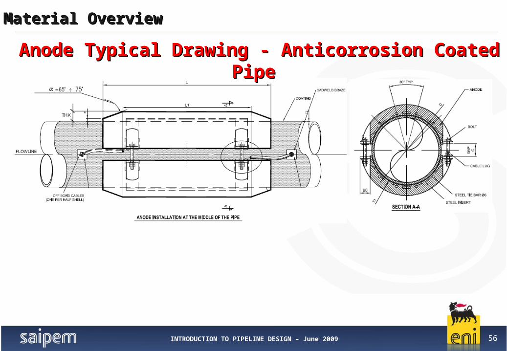
Anode Typical Drawing - Anticorrosion Coated PipeAnode Typical Drawing - Anticorrosion Coated Pipe

INTRODUCTION TO PIPELINE DESIGN – June 2009 57
Material OverviewMaterial Overview
IndexIndex
1. Linepipe
2. Clad pipe
3. Large Radius Bends
4. Anticorrosion Coatings
5. Concrete Coating
6. Sacrificial Anodes
7. Field Joint Material
8. Flanges, Gaskets and Bolting
9. SSIV (Subsea Safety Insulated Valve) Overview
10. Insulating Joints
11. T & Y tees and Conical Reducer (Buttwelded Fittings)
04/12/23

INTRODUCTION TO PIPELINE DESIGN – June 2009 58
Material OverviewMaterial Overview
FJC is the protective coating applied on field weld joints (circumferential weld).The FJC ensure the suitable corrosion protection and coating continuity to the steel pipes surface left bare (uncoated) during coating application on shop.
Field Joint coating System Selection Criteria is based on: Project Requirements Environmental service exposure (seawater, soil, other) Service temperature (depends on max. Fluid conveyed temperature) Compatibility with the pipeline External Anticorrosion Coating
Field Joints CoatingsField Joints Coatings

INTRODUCTION TO PIPELINE DESIGN – June 2009 59
Material OverviewMaterial Overview
Field Joint coatings main type:
Anticorrosion Coated Pipe Heat Shrinkable Sleeve (HSS) Polymer plastic tapes (e.g. Spirally wrapped PP tapes (PIH) & Cigarette wrapped PP tapes (CCSI)) Fusion Bonded Epoxy Powder (FBE) Liquid Epoxy resin (Tar free) Liquid Polyurethane (Tar free) (e.g. Marinblock trademark) Injection Moulded Polypropylene (PP) and Polyurethane (PU)
Concrete Coated Pipe Polyurethane mixture with anticorrosion properties (PU) (e.g. 1500kg/m3) with or w/o Gravel Polyurethane Foam with anticorrosion properties (PU) (e.g. 125kg/m3) with or w/o Gravel Heat Shrinkable Sleeve (HSS) + Polyurethane (PU) mixture Infill material (e.g. 1100 -1150kg/m3) Flame Spray Polypropylene + Polyurethane (PU) mixture Infill material (e.g. 900Kg/m3 PP+1400-
1600kg/m3 PU)
Field Joints CoatingsField Joints Coatings
04/12/23

INTRODUCTION TO PIPELINE DESIGN – June 2009 60
Material OverviewMaterial Overview
3
3LPP
FBE PP
Flame-Spray
PU Foam
PU Mixture (e.g. Marinblock)HSS
Field Joints Coatings - ExamplesField Joints Coatings - Examples
04/12/23

INTRODUCTION TO PIPELINE DESIGN – June 2009 61
Material OverviewMaterial Overview
1. 2. 3.
4. 5. 6.
1. and 2. All weld areas shall be grit or sand blasted to remove all frayed or loosened coating at edges of the mill cutback and slightly abrade the coating sections to be covered by the heat shrinkable sleeve (HSS).
3. and 4. Heating the weld joint up to the specified heating application temperature.
5. Before sleeve application, the primer, when required, shall be applied to bare steel and adjacent abraided mill coating using supplied applicator (i.e. spatula).
Then wrapping the sleeve centrally around the weld joint. Sleeve overlap onto itself should be not less than 150 mm.
6. Installation of the closure patch and pressing in position centering over the exsposed sheet end.
Application Of Heat Shrinkable Sleeve (HSS)Application Of Heat Shrinkable Sleeve (HSS)
04/12/23
INTRODUCTION TO PIPELINE DESIGN – June 2009 62
Material OverviewMaterial Overview
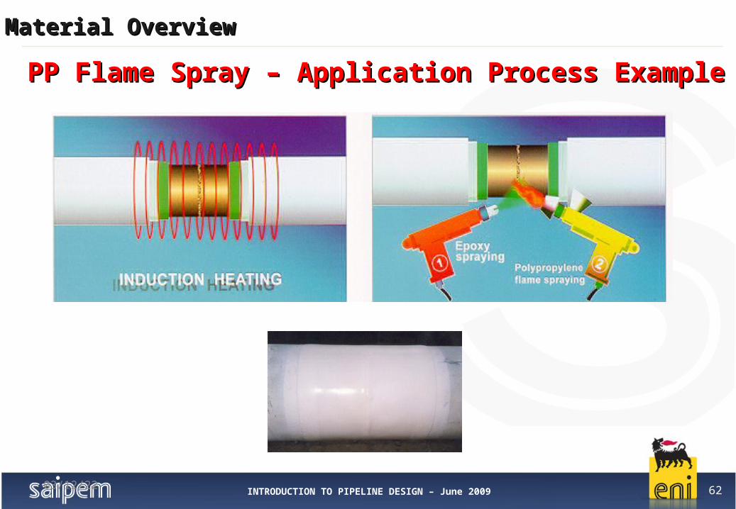
PP Flame Spray – Application Process ExamplePP Flame Spray – Application Process Example
04/12/23

INTRODUCTION TO PIPELINE DESIGN – June 2009 63
Material OverviewMaterial Overview
IndexIndex
1. Linepipe
2. Clad pipe
3. Large Radius Bends
4. Anticorrosion Coatings
5. Concrete Coating
6. Sacrificial Anodes
7. Field Joint Material
8. Flanges, Gaskets and Bolting
9. SSIV (Subsea Safety Insulated Valve) Overview
10. Insulating Joints
11. T & Y tees and Conical Reducer (Buttwelded Fittings)
04/12/23

INTRODUCTION TO PIPELINE DESIGN – June 2009 64
Material OverviewMaterial Overview
Flanges are hot or cold forged fittingsRequired Flange Rating depends on the pipeline design and hydrostatic test pressures
Offshore Application:Coupling flanged (e.g. Pipeline-Spool, Riser-Spool, Valve-piping, etc.)
Typical Flanges Materials:Carbon Steel, Low Alloyed Steel, Stainless Steel.
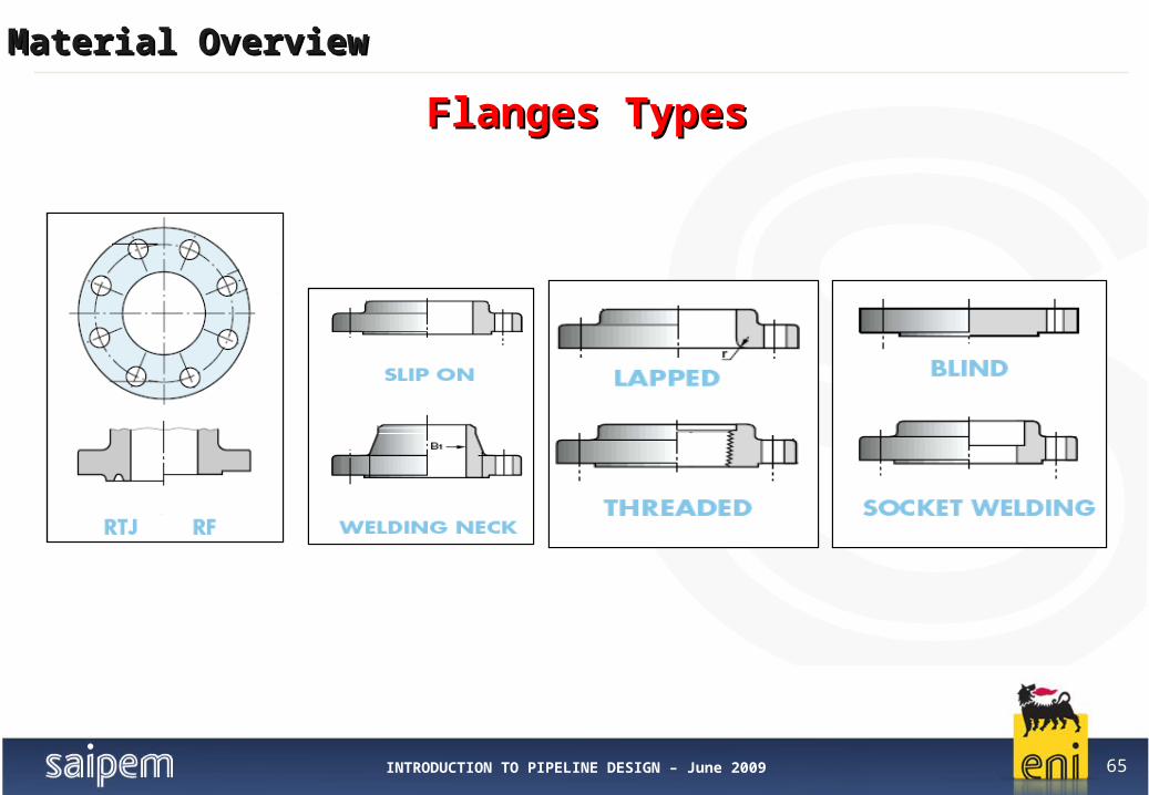
Flange Type:Welding Neck (WN) - Swivel Neck (SW) - Blind (BL) - Flat Face (FF) - Raise Face (RF)
FlangesFlanges
INTRODUCTION TO PIPELINE DESIGN – June 2009 65
Material OverviewMaterial Overview
Flanges TypesFlanges Types
INTRODUCTION TO PIPELINE DESIGN – June 2009 66
Material OverviewMaterial Overview
04/12/23
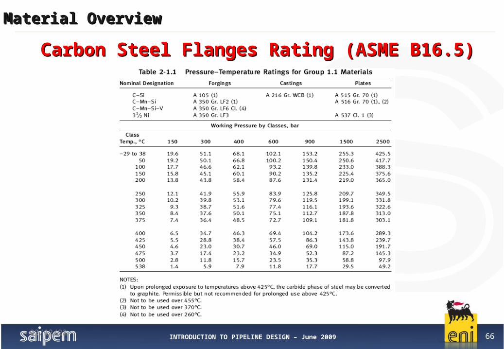
Carbon Steel Flanges Rating (ASME B16.5)Carbon Steel Flanges Rating (ASME B16.5)
INTRODUCTION TO PIPELINE DESIGN – June 2009 67
Material OverviewMaterial Overview
04/12/23
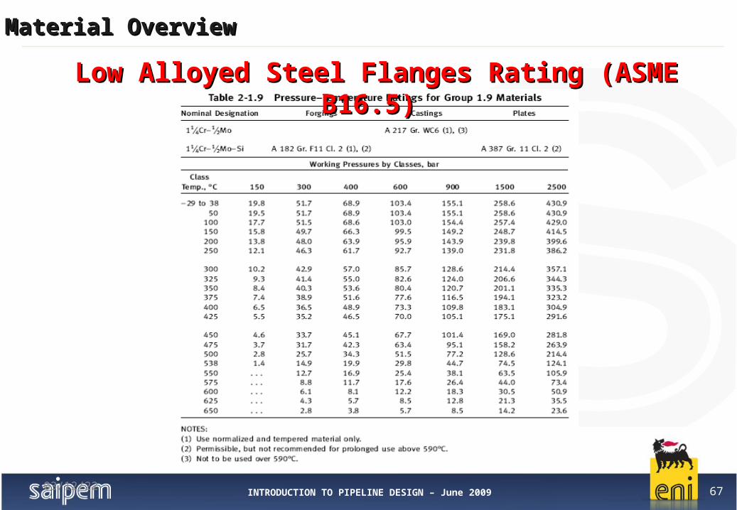
Low Alloyed Steel Flanges Rating (ASME B16.5)Low Alloyed Steel Flanges Rating (ASME B16.5)

INTRODUCTION TO PIPELINE DESIGN – June 2009 68
Material OverviewMaterial Overview
04/12/23
Stainless Steel Flanges Rating (ASME B16.5) Stainless Steel Flanges Rating (ASME B16.5)

INTRODUCTION TO PIPELINE DESIGN – June 2009 69
Material OverviewMaterial Overview
Swivel Flange Typical Drawing- 10” SW RTJ ExampleSwivel Flange Typical Drawing- 10” SW RTJ Example
INTRODUCTION TO PIPELINE DESIGN – June 2009 70
Material OverviewMaterial Overview
04/12/23
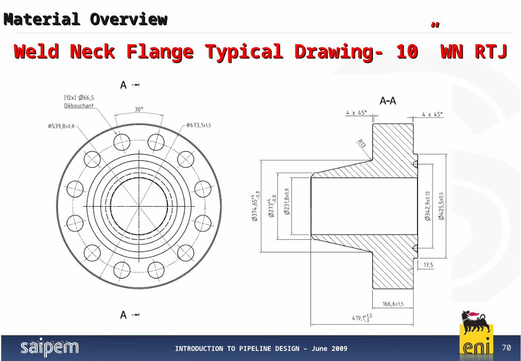
Weld Neck Flange Typical Drawing- 10” WN RTJWeld Neck Flange Typical Drawing- 10” WN RTJ

INTRODUCTION TO PIPELINE DESIGN – June 2009 71
Material OverviewMaterial Overview
04/12/23
Blind Neck Flange Typical Drawing- 10” BL RTJ Blind Neck Flange Typical Drawing- 10” BL RTJ

INTRODUCTION TO PIPELINE DESIGN – June 2009 72
Material OverviewMaterial Overview
Ring Type Joint (RTJ) Gaskets are metallic sealing rings suitable for high pressure and high temperature applications (e.g. coupling flanged).RTJ gaskets are designed to seal by "initial line contact" or wedging action between the mating flange and the gasket. By applying pressure on the seal interface through bolt force, the softer metal of the gasket flows into the micro-fine structure of the harder flange material, creating very tight and efficient seal.
Typical Gaskets Material: Soft iron, SS 316 (and Plastic, Metallic-Plastic)The rings shall have hardness lower than that of the flange in order to assure tight joint.
Ring Gasket Profiles used in offshore pipeline application are: Oval Flat Octagonal.
RTJ gaskets are manufactured in accordance with ASME B16.5,ASME B16.47, ASME B16.20 and MS SP 44 specifications.
Gaskets (Offshore Application)Gaskets (Offshore Application)

INTRODUCTION TO PIPELINE DESIGN – June 2009 73
Material OverviewMaterial Overview
Ring Type Joint (RJT) & FLAT (RF) Gaskets-ExamplesRing Type Joint (RJT) & FLAT (RF) Gaskets-Examples
INTRODUCTION TO PIPELINE DESIGN – June 2009 74
Material OverviewMaterial Overview
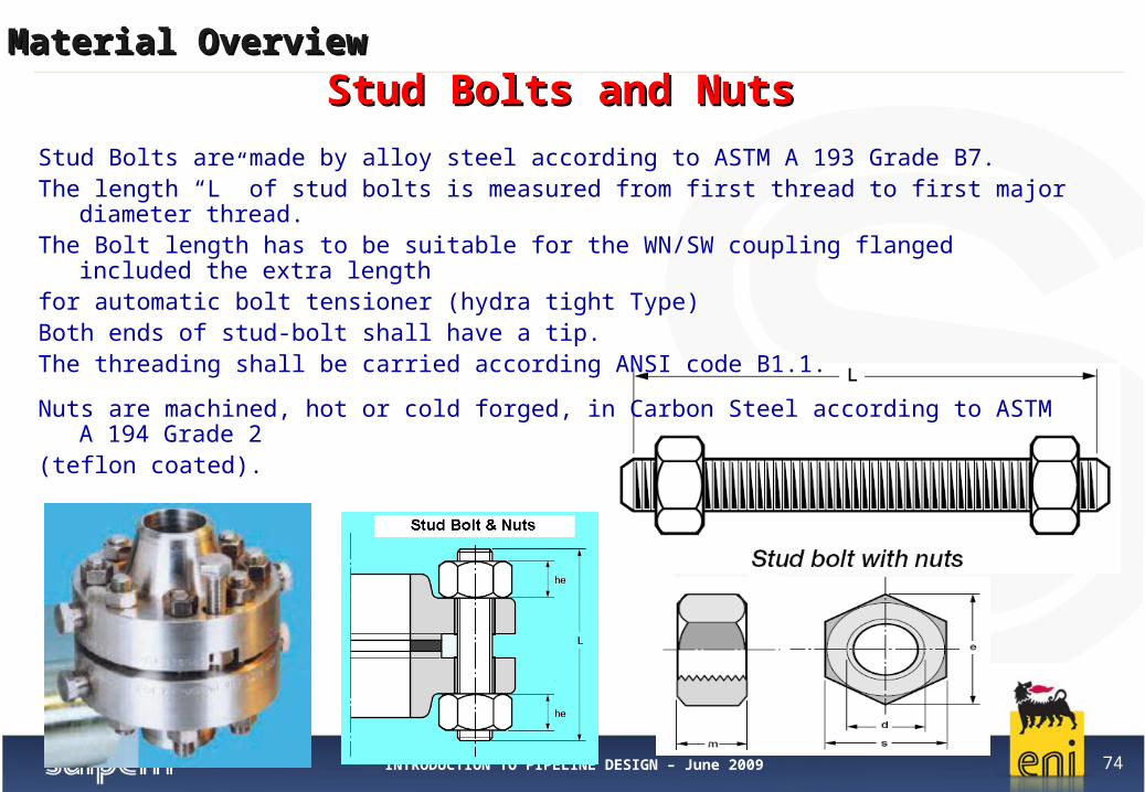
Stud Bolts are made by alloy steel according to ASTM A 193 Grade B7.The length “L” of stud bolts is measured from first thread to first major diameter thread.The Bolt length has to be suitable for the WN/SW coupling flanged included the extra lengthfor automatic bolt tensioner (hydra tight Type) Both ends of stud-bolt shall have a tip. The threading shall be carried according ANSI code B1.1.
Nuts are machined, hot or cold forged, in Carbon Steel according to ASTM A 194 Grade 2(teflon coated).
Stud Bolts and Nuts Stud Bolts and Nuts
INTRODUCTION TO PIPELINE DESIGN – June 2009 75
Material OverviewMaterial Overview
IndexIndex1. Linepipe
2. Clad pipe
3. Large Radius Bends
4. Anticorrosion Coatings
5. Concrete Coating
6. Sacrificial Anodes
7. Field Joint Material
8. Flanges, Gaskets and Bolting
9. SSIV (Subsea Safety Insulated Valve) Overview
10. Insulating Joints
11. T & Y tees and Conical Reducer (Buttwelded Fittings)
04/12/23

INTRODUCTION TO PIPELINE DESIGN – June 2009 76
Material OverviewMaterial Overview
A Subsea Safety Isolation Valve (SSIV) is required in proximity (distance to be defined by dedicated study) of a selected platform to provide the isolation, in case of accident (e.g. fire), of the surface facilities and the riser from the fluid (e.g. Methane) contained inside the sealine coming from another Platform or from onshore Facilities.
SSIV Station Main Components:• On-Off Ball Valve• Actuator• Base support + Protection Cover• Piping (flanges included)• Control Umbilical • Control system • J-tube and its top flange for the umbilical hang-off
SSIV (Subsea Safety Isolation Valve) SSIV (Subsea Safety Isolation Valve)

INTRODUCTION TO PIPELINE DESIGN – June 2009 77
Material OverviewMaterial Overview
SSIV Genaral Arrangement - Example SSIV Genaral Arrangement - Example
Protection Cover
PipingOn-Off Ball Valve
Actuator

INTRODUCTION TO PIPELINE DESIGN – June 2009 78
Material OverviewMaterial Overview
IndexIndex1. Linepipe
2. Clad pipe
3. Large Radius Bends
4. Anticorrosion Coatings
5. Concrete Coating
6. Sacrificial Anodes
7. Field Joint Material
8. Flanges, Gaskets and Bolting
9. SSIV (Subsea Safety Insulated Valve) Overview
10. Insulating Joints
11. T & Y tees and Conical Reducer (Buttwelded Fittings)
04/12/23

INTRODUCTION TO PIPELINE DESIGN – June 2009 79
Material OverviewMaterial Overview
An Isolating Joint (IJ) is a high-resistance fitting used to electrically isolate sections of a pipeline in order to avoid any electrical current to cross from one side of the joint to the other one and consequently to improve the effectiveness of the cathodic protection system.
Welded connection
Flanged connection
Insulation Joint Insulation Joint

INTRODUCTION TO PIPELINE DESIGN – June 2009 80
Material OverviewMaterial Overview
Good insulation level between two sections of a pipeline is granted when the isolating joint is installed above ground or above sea level or in inspection pits.
Ground Level
Sea Level
Sediment Level
Isolating Joints
Inspection Pit
Insulation Joint Insulation Joint

INTRODUCTION TO PIPELINE DESIGN – June 2009 81
Material OverviewMaterial Overview
Insulation Joints are typically made in one piece (Monolithic) or flanged and can be designed and manufactured for any pipeline size and pressure rating.
A Monolithic dielectric Joint (MIJ) are composed of two pieces of metallic pipe, assembled by welding along with interposition of insulating material and sealing gaskets so that the two piece at the same time come out each other mechanically connected and electrically insulated.
MIJ is provided with extension nipples (pup piece) that must match the pipeline wall and grade and are long enough to eliminate any possibility of thermal damage to the MIJ during field welding.
04/12/23
Insulation Joint Insulation Joint

INTRODUCTION TO PIPELINE DESIGN – June 2009 82
Material OverviewMaterial Overview
IndexIndex1. Linepipe
2. Clad pipe
3. Large Radius Bends
4. Anticorrosion Coatings
5. Concrete Coating
6. Sacrificial Anodes
7. Field Joint Material
8. Flanges, Gaskets and Bolting
9. SSIV (Subsea Safety Insulated Valve) Overview
10. Insulating Joints
11. T & Y tees and Conical Reducer (Buttwelded Fittings)
04/12/23

INTRODUCTION TO PIPELINE DESIGN – June 2009 83
Material OverviewMaterial Overview
04/12/23
Buttwelded FittingsButtwelded Fittings

INTRODUCTION TO PIPELINE DESIGN – June 2009 84
Material OverviewMaterial Overview
Tee piece is a special buttwelded fitting used to realize the connection between two pipelines with different headings and same (Straight tee) or different (Reducing Tee) Outsider diameters.
Y-way piece is a special buttwelded fitting used to realize the connection between two pipelines with different headings and same or different Outsider diameters.
Each Tee and y-way can be designed and manufactured for any pipeline size and
Pressure rating.
Straight Tee Reducing Tee
““T” and “Y” TeeT” and “Y” Tee
INTRODUCTION TO PIPELINE DESIGN – June 2009 85
Material OverviewMaterial Overview
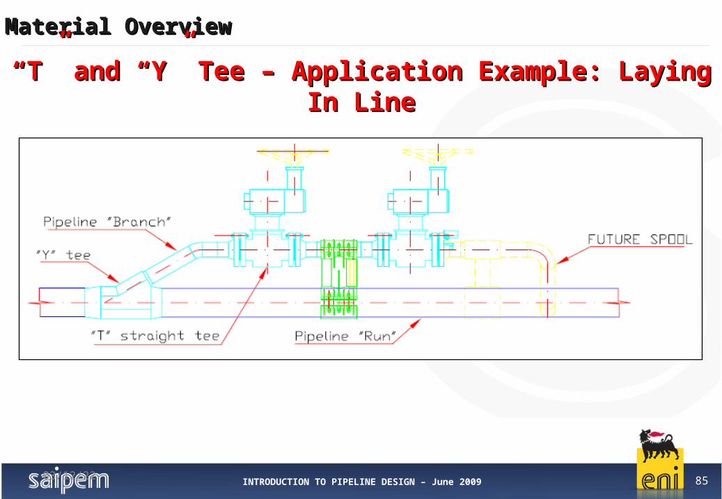
04/12/23
““T” and “Y” Tee – Application Example: Laying In LineT” and “Y” Tee – Application Example: Laying In Line

INTRODUCTION TO PIPELINE DESIGN – June 2009 86
Material OverviewMaterial Overview
““T” and “Y” Tee Welded on Spool - ExampleT” and “Y” Tee Welded on Spool - Example

INTRODUCTION TO PIPELINE DESIGN – June 2009 87
Material OverviewMaterial Overview
A conical reducer is a buttwelded fitting used to connect two pipelines with different Outsider diameter (e.g. 36” OD offshore Pipeline with 34” OD existing onshore pipeline).
Conical Reducer can be made from steel plates and/or pipes and may be manufactured by forging, pressing, rolling, welding or by a combination of these processes.
Conical reducers can be designed and manufactured for any pipeline size and
Pressure rating.
Conical ReducerConical Reducer


