Embed Size (px)
Citation preview
1flowserve.com
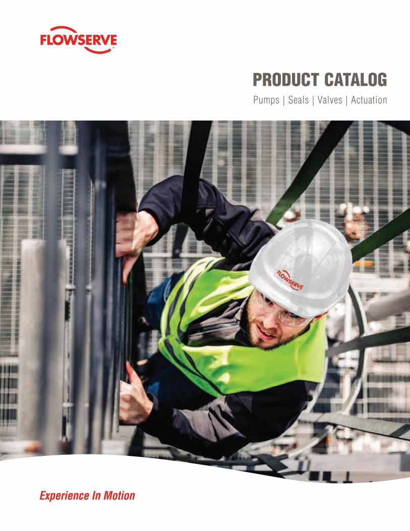
PRODUCT CATALOGPumps | Seals | Valves | Actuation
Experience In Motion
Flowserve Corporation2
TABLE OF CONTENTS
Introduction . . . . . . . . . . . . . . . . . . . . . . . . . 4
Industries . . . . . . . . . . . . . . . . . . . . . . . . . . . 6
Services . . . . . . . . . . . . . . . . . . . . . . . . . . . . 8
Pumps . . . . . . . . . . . . . . . . . . . . . . . . . . . . . 10
Overhung . . . . . . . . . . . . . . . . . . . . . . . . . . . 12
Between Bearings . . . . . . . . . . . . . . . . . . . . 30
Vertical . . . . . . . . . . . . . . . . . . . . . . . . . . . . . 44
Positive Displacement . . . . . . . . . . . . . . . . . 56
Side Channel . . . . . . . . . . . . . . . . . . . . . . . . 60
Vacuum Pumps & Compressors . . . . . . . . . 68
Specialty Products . . . . . . . . . . . . . . . . . . . . 74
Seals . . . . . . . . . . . . . . . . . . . . . . . . . . . . . . 84
Standard Cartridge . . . . . . . . . . . . . . . . . . . 86
Pusher . . . . . . . . . . . . . . . . . . . . . . . . . . . . . 90
Metal Bellows . . . . . . . . . . . . . . . . . . . . . . . 98
Mixer . . . . . . . . . . . . . . . . . . . . . . . . . . . . . 104
Compressor Seals and Systems . . . . . . . . 108
Slurry . . . . . . . . . . . . . . . . . . . . . . . . . . . . . 114
Gas Barrier and Containment . . . . . . . . . . 118
OEM and Special Duty . . . . . . . . . . . . . . . 122
Seal Support Systems . . . . . . . . . . . . . . . . 128
Accessories . . . . . . . . . . . . . . . . . . . . . . . . 134
Valves . . . . . . . . . . . . . . . . . . . . . . . . . . . . 140
Ball . . . . . . . . . . . . . . . . . . . . . . . . . . . . . . . 142
Butterfly . . . . . . . . . . . . . . . . . . . . . . . . . . . 158
Rotary Control . . . . . . . . . . . . . . . . . . . . . . 162
Linear Control . . . . . . . . . . . . . . . . . . . . . . 168
Severe Service Control . . . . . . . . . . . . . . . 174
Gate . . . . . . . . . . . . . . . . . . . . . . . . . . . . . . 180
Globe . . . . . . . . . . . . . . . . . . . . . . . . . . . . . 184
Check . . . . . . . . . . . . . . . . . . . . . . . . . . . . 192
Plug . . . . . . . . . . . . . . . . . . . . . . . . . . . . . . 200
Actuation & Instrumentation . . . . . . . . . 210
Electric Actuation . . . . . . . . . . . . . . . . . . . . 212
Gearboxes . . . . . . . . . . . . . . . . . . . . . . . . . 220
Fluid Power Actuation . . . . . . . . . . . . . . . . 224
Positioners . . . . . . . . . . . . . . . . . . . . . . . . . 236
Switch Boxes . . . . . . . . . . . . . . . . . . . . . . . 244
Software . . . . . . . . . . . . . . . . . . . . . . . . . . . 248
Index . . . . . . . . . . . . . . . . . . . . . . . . . . . . 252
3flowserve.com
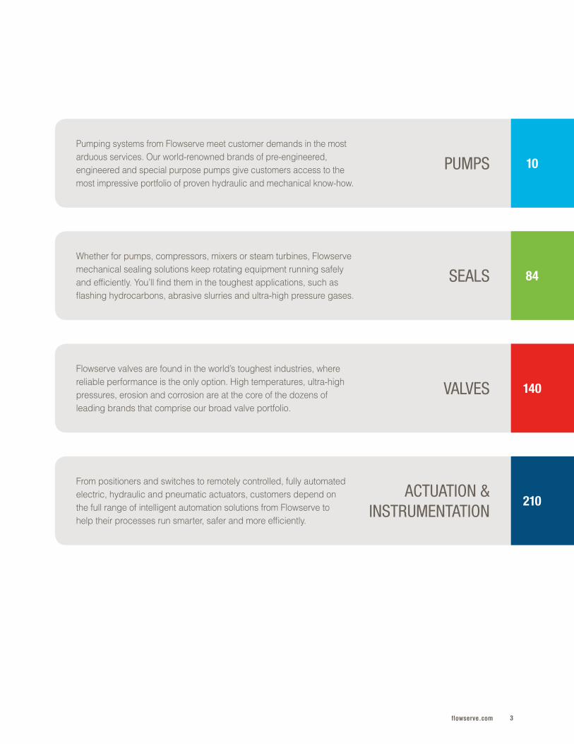
SEALSWhether for pumps, compressors, mixers or steam turbines, Flowserve mechanical sealing solutions keep rotating equipment running safely and efficiently . You’ll find them in the toughest applications, such as flashing hydrocarbons, abrasive slurries and ultra-high pressure gases .
84
VALVESFlowserve valves are found in the world’s toughest industries, where reliable performance is the only option . High temperatures, ultra-high pressures, erosion and corrosion are at the core of the dozens of leading brands that comprise our broad valve portfolio .
140
ACTUATION &INSTRUMENTATION
From positioners and switches to remotely controlled, fully automated electric, hydraulic and pneumatic actuators, customers depend on the full range of intelligent automation solutions from Flowserve to help their processes run smarter, safer and more efficiently .
210
PUMPSPumping systems from Flowserve meet customer demands in the most arduous services . Our world-renowned brands of pre-engineered, engineered and special purpose pumps give customers access to the most impressive portfolio of proven hydraulic and mechanical know-how .
10
Flowserve Corporation4
EXPERIENCE IN MOTION
Every day, our customers are challenged to take their plant operations to the next level . To do that, they need partners who deliver much more than products .
Flowserve is answering that call . We’re working with the world’s most important providers of oil and gas, power, chemicals, water and other essential products to solve the absolute toughest challenges in fluid motion and control .
Our industry-leading portfolio of pumps, seals, valves and actuation is only part of the story . Our customers need answers that demand extensive know-how and experience, and we’ve got it . More than 18 000 committed associates are go-to resources for expert engineering, project management, technical support and service in every corner of the world .
5flowserve.com
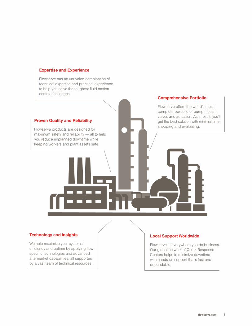
Expertise and Experience
Flowserve has an unrivaled combination of technical expertise and practical experience to help you solve the toughest fluid motion control challenges .
Comprehensive Portfolio
Flowserve offers the world’s most complete portfolio of pumps, seals, valves and actuation . As a result, you’ll get the best solution with minimal time shopping and evaluating .
Proven Quality and Reliability
Flowserve products are designed for maximum safety and reliability — all to help you reduce unplanned downtime while keeping workers and plant assets safe .
Local Support Worldwide
Flowserve is everywhere you do business . Our global network of Quick Response Centers helps to minimize downtime with hands-on support that’s fast and dependable .
Technology and Insights
We help maximize your systems’ efficiency and uptime by applying flow-specific technologies and advanced aftermarket capabilities, all supported by a vast team of technical resources .
Flowserve Corporation6
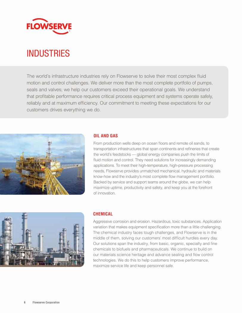
OIL AND GAS
From production wells deep on ocean floors and remote oil sands, to transportation infrastructures that span continents and refineries that create the world’s feedstocks — global energy companies push the limits of fluid motion and control . They need solutions for increasingly demanding applications . To meet their high-temperature, high-pressure processing needs, Flowserve provides unmatched mechanical, hydraulic and materials know-how and the industry’s most complete flow management portfolio . Backed by service and support teams around the globe, we can help maximize uptime, productivity and safety, and keep you at the forefront of innovation .
INDUSTRIES
The world’s infrastructure industries rely on Flowserve to solve their most complex fluid motion and control challenges . We deliver more than the most complete portfolio of pumps, seals and valves; we help our customers exceed their operational goals . We understand that profitable performance requires critical process equipment and systems operate safely, reliably and at maximum efficiency . Our commitment to meeting these expectations for our customers drives everything we do .
CHEMICAL
Aggressive corrosion and erosion . Hazardous, toxic substances . Application variation that makes equipment specification more than a little challenging . The chemical industry faces tough challenges, and Flowserve is in the middle of them, solving our customers’ most difficult hurdles every day . Our solutions span the industry, from basic, organic, specialty and fine chemicals to biofuels and pharmaceuticals . We continue to build on our materials science heritage and advance sealing and flow control technologies . We do this to help customers improve performance, maximize service life and keep personnel safe .
7flowserve.com
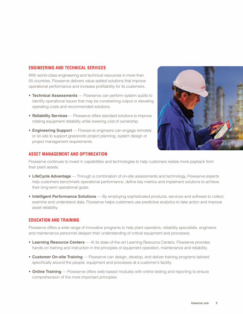
GENERAL INDUSTRY
From paper and metals to sweeteners and electronics, most of the world’s products depend on reliable fluid motion and control solutions . Endless demanding and complicated application parameters are found in industries such as food and beverage, mining, steelmaking, and pulp and paper . Flowserve has a global portfolio of solutions and technical expertise capable of tackling the tough and often unique requirements found in these industries . A global network of Quick Response Centers delivers the timely technical support, parts and service needed to keep operations running dependably and profitably .
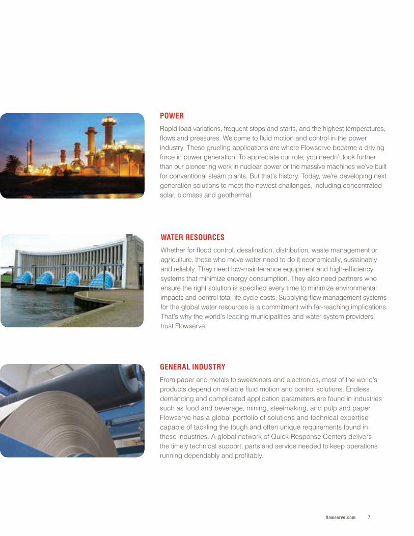
POWER
Rapid load variations, frequent stops and starts, and the highest temperatures, flows and pressures . Welcome to fluid motion and control in the power industry . These grueling applications are where Flowserve became a driving force in power generation . To appreciate our role, you needn’t look further than our pioneering work in nuclear power or the massive machines we’ve built for conventional steam plants . But that’s history . Today, we’re developing next generation solutions to meet the newest challenges, including concentrated solar, biomass and geothermal .
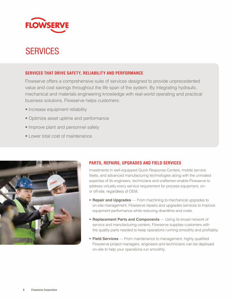
WATER RESOURCES
Whether for flood control, desalination, distribution, waste management or agriculture, those who move water need to do it economically, sustainably and reliably . They need low-maintenance equipment and high-efficiency systems that minimize energy consumption . They also need partners who ensure the right solution is specified every time to minimize environmental impacts and control total life cycle costs . Supplying flow management systems for the global water resources is a commitment with far-reaching implications . That’s why the world’s leading municipalities and water system providers trust Flowserve .
Flowserve Corporation8
SERVICES THAT DRIVE SAFETY, RELIABILITY AND PERFORMANCE
Flowserve offers a comprehensive suite of services designed to provide unprecedented value and cost savings throughout the life span of the system . By integrating hydraulic, mechanical and materials engineering knowledge with real-world operating and practical business solutions, Flowserve helps customers:
• Increase equipment reliability
• Optimize asset uptime and performance
• Improve plant and personnel safety
• Lower total cost of maintenance
PARTS, REPAIRS, UPGRADES AND FIELD SERVICES
Investments in well-equipped Quick Response Centers, mobile service fleets, and advanced manufacturing technologies along with the unrivaled expertise of its engineers, technicians and craftsmen enable Flowserve to address virtually every service requirement for process equipment, on- or off-site, regardless of OEM .
• Repair and Upgrades — From machining to mechanical upgrades to on-site management, Flowserve repairs and upgrades services to improve equipment performance while reducing downtime and costs .
• Replacement Parts and Components — Using its broad network of service and manufacturing centers, Flowserve supplies customers with the quality parts needed to keep operations running smoothly and profitably .
• Field Services — From maintenance to management, highly qualified Flowserve project managers, engineers and technicians can be deployed on-site to help your operations run smoothly .
SERVICES
9flowserve.com
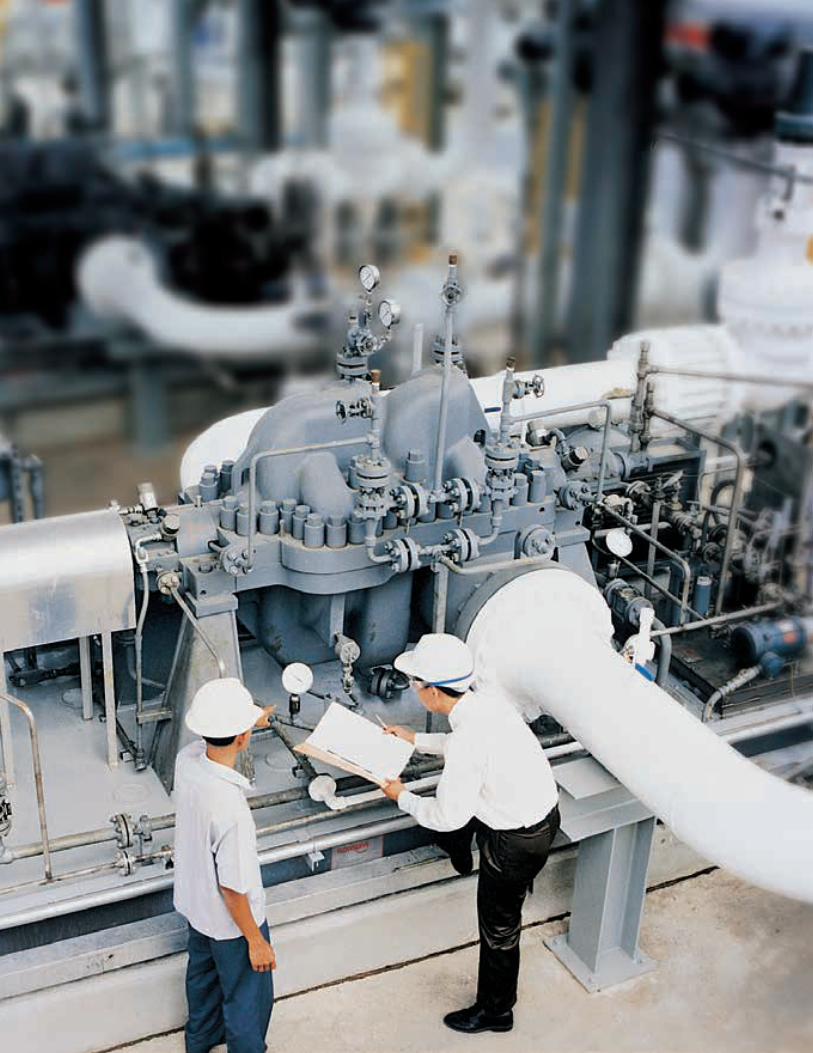
ENGINEERING AND TECHNICAL SERVICES
With world-class engineering and technical resources in more than 55 countries, Flowserve delivers value-added solutions that improve operational performance and increase profitability for its customers .
• Technical Assessments — Flowserve can perform system audits to identify operational issues that may be constraining output or elevating operating costs and recommended solutions .
• Reliability Services — Flowserve offers standard solutions to improve rotating equipment reliability while lowering cost of ownership .
• Engineering Support — Flowserve engineers can engage remotely or on-site to support grassroots project planning, system design or project management requirements .
ASSET MANAGEMENT AND OPTIMIZATION
Flowserve continues to invest in capabilities and technologies to help customers realize more payback from their plant assets .
• LifeCycle Advantage — Through a combination of on-site assessments and technology, Flowserve experts help customers benchmark operational performance, define key metrics and implement solutions to achieve their long-term operational goals .
• Intelligent Performance Solutions — By employing sophisticated products, services and software to collect, examine and understand data, Flowserve helps customers use predictive analytics to take action and improve asset reliability .
EDUCATION AND TRAINING
Flowserve offers a wide range of innovative programs to help plant operators, reliability specialists, engineers and maintenance personnel deepen their understanding of critical equipment and processes .
• Learning Resource Centers — At its state-of-the-art Learning Resource Centers, Flowserve provides hands-on training and instruction in the principles of equipment operation, maintenance and reliability .
• Customer On-site Training — Flowserve can design, develop, and deliver training programs tailored specifically around the people, equipment and processes at a customer’s facility .
• Online Training — Flowserve offers web-based modules with online testing and reporting to ensure comprehension of the most important principles .
Flowserve Corporation1010
11flowserve.com
The most aggressive fluids and slurries on
the planet . High-volume and high-pressure
applications that test the limits of hydraulic
and mechanical design . That’s where you’ll
find Flowserve pumps performing efficiently,
safely and reliably . It’s a legacy that goes
back centuries — one we build upon every
day, outperforming expectations no matter
how great the demands .
Global customers can easily find
configurations to precisely match the
pumping requirements that drive their
operations, even specialty applications
most pump companies have never heard of .
From small pumps that dependably process
thousands of end products day-in and day-
out, to massive machines that efficiently
move the fluids that are the lifeblood of our
industrial infrastructure, Flowserve carefully
engineers the highest degrees of reliability
and performance into every product . It’s a
commitment that ensures maximum uptime
from every pump we deliver .
PUMPS
Overhung . . . . . . . . . . . . . . . . . . . . . . . .12
Between Bearings . . . . . . . . . . . . . . . . .30
Vertical . . . . . . . . . . . . . . . . . . . . . . . . . .44
Positive Displacement . . . . . . . . . . . . . .56
Side Channel . . . . . . . . . . . . . . . . . . . . .60
Vacuum Pumps & Compressors . . . . . .68
Specialty Products . . . . . . . . . . . . . . . .74
PUM
PS
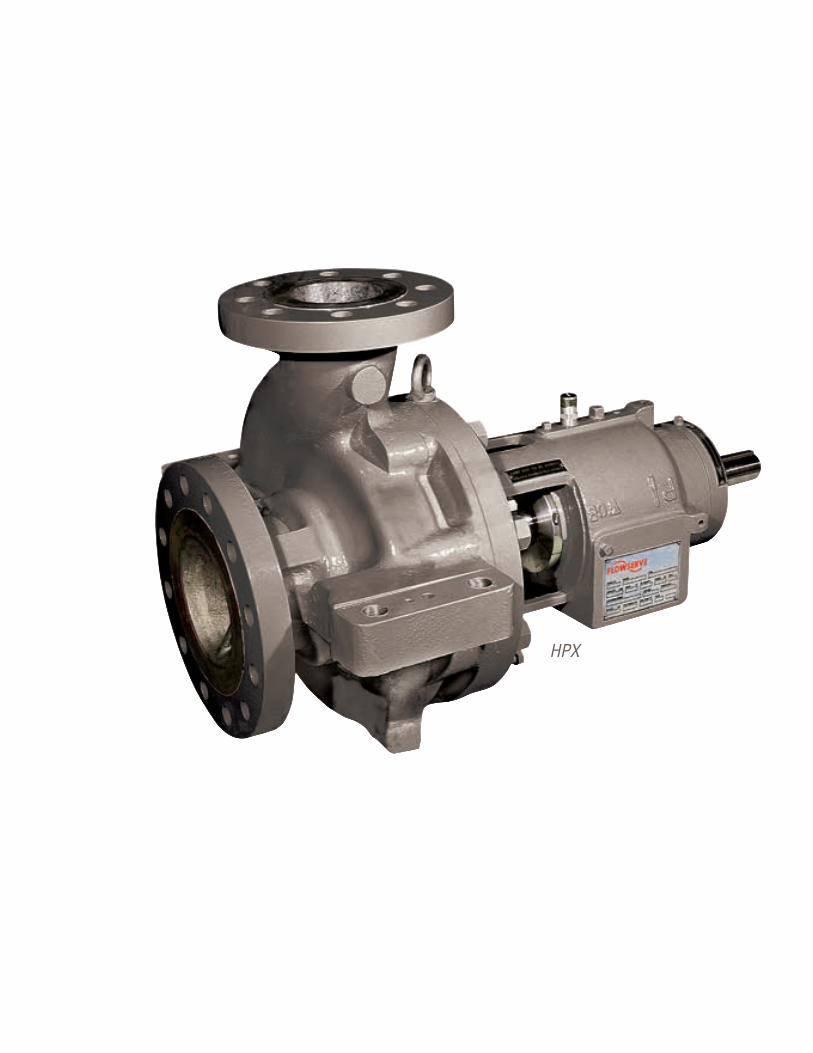
Flowserve Corporation1212
HPX
13flowserve.com
PUM
PS | O
VERHUNG
OVERHUNG
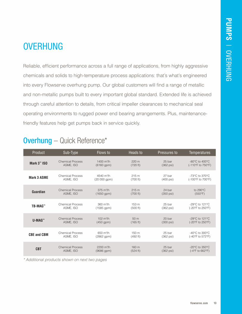
Product Sub-Type Flows to Heads to Pressures to Temperatures
Mark 3™ ISO Chemical ProcessASME, ISO
1400 m3/h(6160 gpm)
220 m (720 ft)
25 bar (362 psi)
-80°C to 400°C(-110°F to 750°F)
Mark 3 ASME Chemical ProcessASME, ISO
4540 m3/h (20 000 gpm)
215 m (700 ft)
27 bar(400 psi)
-73°C to 370°C(-100°F to 700°F)
Guardian Chemical ProcessASME, ISO
375 m3/h(1650 gpm)
215 m(700 ft)
24 bar(350 psi)
to 290°C(550°F)
TB-MAG™ Chemical ProcessASME, ISO
360 m3/h(1585 gpm)
153 m(500 ft)
25 bar(362 psi)
-29°C to 121°C(-20°F to 250°F)
U-MAG™ Chemical ProcessASME, ISO
102 m3/h(450 gpm)
50 m(165 ft)
20 bar(300 psi)
-29°C to 121°C(-20°F to 250°F)
CBE and CBM Chemical ProcessASME, ISO
650 m3/h(2862 gpm)
150 m(492 ft)
25 bar(362 psi)
-40°C to 300°C (-40°F to 572°F)
CBT Chemical ProcessASME, ISO
2200 m3/h (9686 gpm)
160 m(524 ft)
25 bar(362 psi)
-20°C to 350°C(-4°F to 662°F)
Overhung – Quick Reference*
Reliable, efficient performance across a full range of applications, from highly aggressive
chemicals and solids to high-temperature process applications: that’s what’s engineered
into every Flowserve overhung pump . Our global customers will find a range of metallic
and non-metallic pumps built to every important global standard . Extended life is achieved
through careful attention to details, from critical impeller clearances to mechanical seal
operating environments to rugged power end bearing arrangements . Plus, maintenance-
friendly features help get pumps back in service quickly .
* Additional products shown on next two pages
Flowserve Corporation14
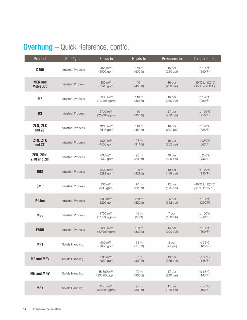
Overhung – Quick Reference, cont'd.Product Sub-Type Flows to Heads to Pressures to Temperatures
D800 Industrial Process 455 m3/h(2000 gpm)
150 m (500 ft)
15 bar (220 psi)
to 120°C(250°F)
MEN and MENBLOC
Industrial Process 800 m3/h(3520 gpm)
140 m (450 ft)
16 bar (230 psi)
-10°C to 120°C(15°F to 250°F)
ME Industrial Process 3000 m3/h(13 208 gpm)
110 m (361 ft)
16 bar (230 psi)
to 120°C(250°F)
DS Industrial Process 5700 m3/h(25 000 gpm)
110 m (350 ft)
27 bar (400 psi)
to 120°C (250°F)
ZLN, ZLKand ZLI
Industrial Process 1800 m3/h (7925 gpm)
140 m (459 ft)
16 bar (232 psi)
to 170°C (338°F)
ZTN, ZTKand ZTI
Industrial Process 1000 m3/h (4403 gpm)
95 m (311 ft)
16 bar (232 psi)
to 350°C (662°F)
ZEN, ZDN,ZHN and ZDI
Industrial Process 600 m3/h (2642 gpm)
90 m (295 ft)
40 bar (580 psi)
to 230°C (446°F)
DBS Industrial Process 1200 m3/h (5283 gpm)
100 m (328 ft)
10 bar (145 psi)
to 110°C (230°F)
SMP Industrial Process 135 m3/h (600 gpm)
70 m (220 ft)
12 bar (175 psi)
-40°C to 120°C (-40°F to 250°F)
F-Line Industrial Process 500 m3/h (2200 gpm)
250 m (820 ft)
25 bar (362 psi)
to 105°C (220°F)
MVE Industrial Process 2700 m3/h (11 890 gpm)
15 m (50 ft)
7 bar (100 psi)
to 100°C (212°F)
FRBH Industrial Process 9085 m3/h (40 000 gpm)
100 m (330 ft)
14 bar (200 psi)
to 150°C (300°F)
MPT Solids Handling 600 m3/h (2650 gpm)
35 m (115 ft)
5 bar (72 psi)
to 75°C (165°F)
MF and MFV Solids Handling 600 m3/h (2650 gpm)
90 m (300 ft)
19 bar(275 psi)
to 63°C (145°F)
MN and MNV Solids Handling 45 500 m3/h (200 000 gpm)
90 m (300 ft)
17 bar(240 psi)
to 63°C (145°F)
MSX Solids Handling 4545 m3/h (20 000 gpm)
90 m (300 ft)
11 bar (160 psi)
to 40°C (104°F)
15flowserve.com
PUM
PS | O
VERHUNG
Product Sub-Type Flows to Heads to Pressures to Temperatures
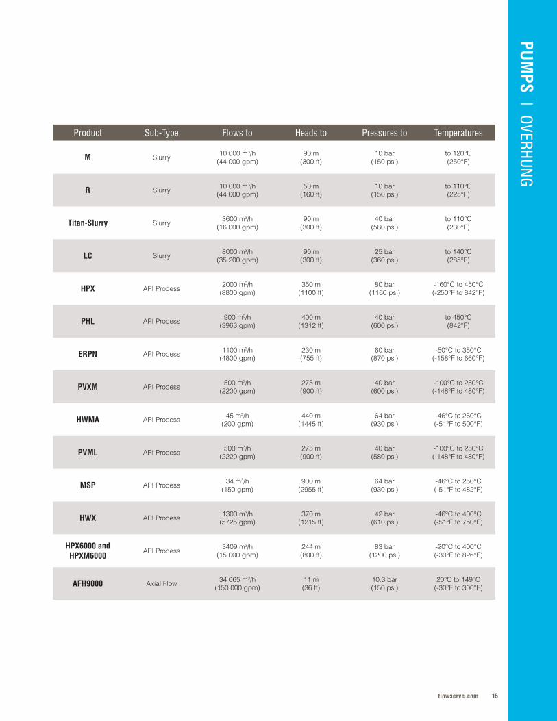
M Slurry 10 000 m3/h (44 000 gpm)
90 m (300 ft)
10 bar (150 psi)
to 120°C (250°F)
R Slurry 10 000 m3/h (44 000 gpm)
50 m (160 ft)
10 bar (150 psi)
to 110°C (225°F)
Titan-Slurry Slurry 3600 m3/h (16 000 gpm)
90 m (300 ft)
40 bar (580 psi)
to 110°C (230°F)
LC Slurry 8000 m3/h (35 200 gpm)
90 m (300 ft)
25 bar (360 psi)
to 140°C (285°F)
HPX API Process 2000 m3/h (8800 gpm)
350 m (1100 ft)
80 bar (1160 psi)
-160°C to 450°C (-250°F to 842°F)
PHL API Process 900 m3/h (3963 gpm)
400 m (1312 ft)
40 bar (600 psi)
to 450°C (842°F)
ERPN API Process 1100 m3/h (4800 gpm)
230 m (755 ft)
60 bar (870 psi)
-50°C to 350°C (-158°F to 660°F)
PVXM API Process 500 m3/h (2200 gpm)
275 m (900 ft)
40 bar (600 psi)
-100°C to 250°C (-148°F to 480°F)
HWMA API Process 45 m3/h (200 gpm)
440 m (1445 ft)
64 bar (930 psi)
-46°C to 260°C (-51°F to 500°F)
PVML API Process 500 m3/h (2220 gpm)
275 m (900 ft)
40 bar (580 psi)
-100°C to 250°C (-148°F to 480°F)
MSP API Process 34 m3/h (150 gpm)
900 m (2955 ft)
64 bar (930 psi)
-46°C to 250°C (-51°F to 482°F)
HWX API Process 1300 m3/h (5725 gpm)
370 m (1215 ft)
42 bar (610 psi)
-46°C to 400°C (-51°F to 750°F)
HPX6000 and HPXM6000
API Process 3409 m3/h(15 000 gpm)
244 m(800 ft)
83 bar(1200 psi)
-20°C to 400°C(-30°F to 826°F)
AFH9000 Axial Flow 34 065 m3/h(150 000 gpm)
11 m(36 ft)
10 .3 bar(150 psi)
20°C to 149°C(-30°F to 300°F)

Flowserve Corporation16
SPECIFICATIONS
Flows to: 4540 m3/h (20 000 gpm)Heads to: 215 m (700 ft)Press. to: 27 bar (400 psi)Temp: -73°C to 370°C (-100°F to 700°F)
Refer to literature PS-10-13 at flowserve.com/library.
SPECIFICATIONS
Flows to: 375 m3/h (1650 gpm)Heads to: 215 m (700 ft)Press. to: 24 bar (350 psi)Temp: to 290°C (550°F)
Refer to literature PS-10-14 at flowserve.com/library.
• Lower total cost of ownership from reverse vane impeller, which eases maintenance and provides renewable, high-efficiency performance over the pumps’ life
• Increased reliability and mechanical seal life due to the ideal seal environment created by the SealSentry seal chamber
• Ease of maintenance resulting from optimal, predictable seal chamber pressures that are re-established after every impeller setting
• Extended mechanical seal and bearing life through robust shaft and bearing designs that also minimize shaft deflection
• Optimal performance through a highly engineered internal lubrication flow paths designed to maximize cooling of the bushings and journals
• Ease of maintenance due to standard and contained back pullout, allowing the casing to stay in-line and piping connections to remain intact
• Higher process temperature range capabilities with the use of strong samarium cobalt rare earth magnets in the couplings
• Longer service life resulting from silicon carbide bushings and journals that resist wear and corrosion
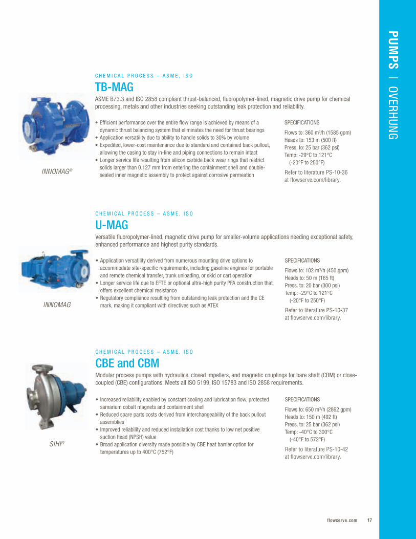
C H E M I C A L P R O C E S S – A S M E , I S O
Mark 3 ASME ASME B73.1 chemical process pump for corrosive applications in chemical, petrochemical, hydrocarbon and pharmaceuticals processing requiring unequaled efficiency, extended life and repeatable pump performance.
C H E M I C A L P R O C E S S – A S M E , I S O
GuardianMetallic sealless magnetic drive pump compliant with ASME B73.1, ASME B73.3 and HI 5.1-5.6 that is designed for applications requiring efficient performance and emissions-free reliability.
SPECIFICATIONS
Flows to: 1400 m3/h (6160 gpm)Heads to: 220 m (720 ft)Press. to: 25 bar (362 psi)Temp: -80°C to 400°C (-110°F to 750°F)
Refer to literature PS-10-31 at flowserve.com/library.
• Lower total cost of pump ownership resulting from simplified maintenance and extended bearing and seal life associated with reverse vane impeller
• Increased reliability and mechanical seal life due to the ideal seal environment created by the SealSentry™ seal chamber
• Simplified maintenance with two-piece power end featuring self-contained bearing housing and external impeller adjustment mechanism
• Optimal, predictable seal chamber pressure that is established after every impeller setting
C H E M I C A L P R O C E S S – A S M E , I S O
Mark 3 ISOISO 2858/5199 compliant pump for corrosive applications in chemical, hydrocarbon and pharmaceutical processing requiring unmatched reliability, outstanding hydraulic performance and increased pump availability.
OVERHUNG
Durco®
Durco
Durco
17flowserve.com
VALVES | LINEAR CO
NTRO
LPU
MPS | O
VERHUNGSPECIFICATIONS
Flows to: 360 m3/h (1585 gpm)Heads to: 153 m (500 ft) Press. to: 25 bar (362 psi)Temp: -29°C to 121°C (-20°F to 250°F)
Refer to literature PS-10-36 at flowserve.com/library.
• Efficient performance over the entire flow range is achieved by means of a dynamic thrust balancing system that eliminates the need for thrust bearings
• Application versatility due to ability to handle solids to 30% by volume• Expedited, lower-cost maintenance due to standard and contained back pullout,
allowing the casing to stay in-line and piping connections to remain intact • Longer service life resulting from silicon carbide back wear rings that restrict
solids larger than 0.127 mm from entering the containment shell and double-sealed inner magnetic assembly to protect against corrosive permeation
C H E M I C A L P R O C E S S – A S M E , I S O
TB-MAGASME B73.3 and ISO 2858 compliant thrust-balanced, fluoropolymer-lined, magnetic drive pump for chemical processing, metals and other industries seeking outstanding leak protection and reliability.
SPECIFICATIONS
Flows to: 102 m3/h (450 gpm)Heads to: 50 m (165 ft)Press. to: 20 bar (300 psi)Temp: -29°C to 121°C (-20°F to 250°F)
Refer to literature PS-10-37 at flowserve.com/library.
SPECIFICATIONS
Flows to: 650 m3/h (2862 gpm)Heads to: 150 m (492 ft)Press. to: 25 bar (362 psi)Temp: -40°C to 300°C (-40°F to 572°F)
Refer to literature PS-10-42 at flowserve.com/library.
• Application versatility derived from numerous mounting drive options to accommodate site-specific requirements, including gasoline engines for portable and remote chemical transfer, trunk unloading, or skid or cart operation
• Longer service life due to EFTE or optional ultra-high purity PFA construction that offers excellent chemical resistance
• Regulatory compliance resulting from outstanding leak protection and the CE mark, making it compliant with directives such as ATEX
• Increased reliability enabled by constant cooling and lubrication flow, protected samarium cobalt magnets and containment shell
• Reduced spare parts costs derived from interchangeability of the back pullout assemblies
• Improved reliability and reduced installation cost thanks to low net positive suction head (NPSH) value
• Broad application diversity made possible by CBE heat barrier option for temperatures up to 400°C (752°F)
C H E M I C A L P R O C E S S – A S M E , I S O
U-MAGVersatile fluoropolymer-lined, magnetic drive pump for smaller-volume applications needing exceptional safety, enhanced performance and highest purity standards.
C H E M I C A L P R O C E S S – A S M E , I S O
CBE and CBMModular process pumps with hydraulics, closed impellers, and magnetic couplings for bare shaft (CBM) or close-coupled (CBE) configurations. Meets all ISO 5199, ISO 15783 and ISO 2858 requirements.
PUM
PS | O
VERHUNG
INNOMAG®
INNOMAG
SIHI®
Flowserve Corporation18
OVERHUNG
• High efficiency through a precision-cast, closed impeller with machine shrouds and balance holes that also minimize axial thrust
• Performance reliability due to an integral, one-piece cast iron bearing frame that provides excellent rigidity and concentricity to minimize vibration
• Optimized hydraulics and components meet European Regulation No. 547/2012• Versatility through a wide hydraulic range, multiple configurations, parts
interchangeability and materials options• Ease of maintenance and inspection resulting from a back pullout design
SPECIFICATIONS
Flows to: 455 m3/h (2000 gpm)Heads to: 150 m (500 ft) Press. to: 15 bar (220 psi)Temp: to 120°C (250°F)
Refer to literature PSS-10-6.1 at flowserve.com/library.
• Increased uptime enabled by a precision dry-rabbet fit with one-piece adapter and seal cover to ensure positive alignment
• Easy maintenance and assembly facilitated by pre-set mechanical seal assembly on the shaft sleeve
• Improved energy efficiency due to a precision-cast, high-efficiency closed impeller that is statically and hydraulically balanced to reduce power consumption
• Low operating costs and extended pump life provided by renewable wear rings and shaft sleeves that restore worn operating clearances
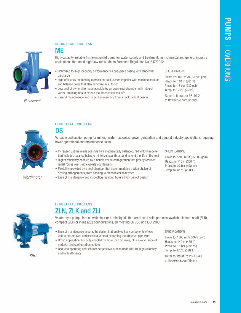
I N D U S T R I A L P R O C E S S
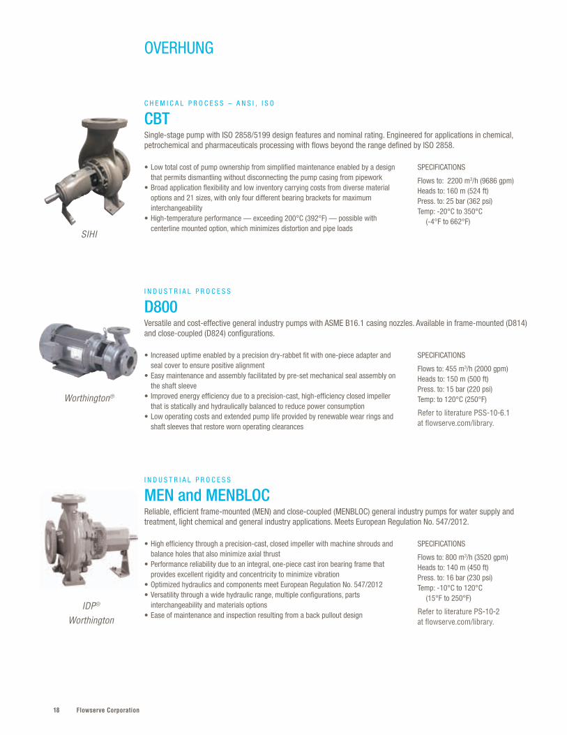
MEN and MENBLOCReliable, efficient frame-mounted (MEN) and close-coupled (MENBLOC) general industry pumps for water supply and treatment, light chemical and general industry applications. Meets European Regulation No. 547/2012.
I N D U S T R I A L P R O C E S S
D800Versatile and cost-effective general industry pumps with ASME B16.1 casing nozzles. Available in frame-mounted (D814) and close-coupled (D824) configurations.
SIHI
Worthington®
IDP®
Worthington
SPECIFICATIONS
Flows to: 2200 m3/h (9686 gpm)Heads to: 160 m (524 ft)Press. to: 25 bar (362 psi)Temp: -20°C to 350°C (-4°F to 662°F)
• Low total cost of pump ownership from simplified maintenance enabled by a design that permits dismantling without disconnecting the pump casing from pipework
• Broad application flexibility and low inventory carrying costs from diverse material options and 21 sizes, with only four different bearing brackets for maximum interchangeability
• High-temperature performance — exceeding 200°C (392°F) — possible with centerline mounted option, which minimizes distortion and pipe loads
SPECIFICATIONS
Flows to: 800 m3/h (3520 gpm)Heads to: 140 m (450 ft)Press. to: 16 bar (230 psi)Temp: -10°C to 120°C (15°F to 250°F)
Refer to literature PS-10-2 at flowserve.com/library.
C H E M I C A L P R O C E S S – A N S I , I S O
CBTSingle-stage pump with ISO 2858/5199 design features and nominal rating. Engineered for applications in chemical, petrochemical and pharmaceuticals processing with flows beyond the range defined by ISO 2858.
19flowserve.com
VALVES | LINEAR CO
NTRO
LPU
MPS | O
VERHUNG
SPECIFICATIONS
Flows to: 1800 m3/h (7925 gpm)Heads to: 140 m (459 ft)Press. to: 16 bar (232 psi)Temp: to 170°C (338°F)
Refer to literature PS-10-40 at flowserve.com/library.
• Ease of maintenance assured by design that enables key components of each unit to be removed and serviced without disturbing the attached pipe work
• Broad application flexibility enabled by more than 50 sizes, plus a wide range of material and configuration options
• Reduced operating cost via low net positive suction head (NPSH), high reliability and high efficiency
• Increased uptime made possible by a mechanically balanced, radial flow impeller that includes balance holes to minimize axial thrust and extend the life of the seal
• Higher efficiency enabled by a double volute configuration that greatly reduces radial forces over single-volute counterparts
• Flexibility provided by a seal chamber that accommodates a wide choice of sealing arrangements, from packing to mechanical seal types
• Ease of maintenance and inspection resulting from a back pullout design
I N D U S T R I A L P R O C E S S
ZLN, ZLK and ZLIVolute-style pumps for use with clear or turbid liquids that are free of solid particles. Available in bare shaft (ZLN), compact (ZLK) or inline (ZLI) configurations, all meeting EN 733 and ISO 9908.
SPECIFICATIONS
Flows to: 5700 m3/h (25 000 gpm)Heads to: 110 m (350 ft)Press. to: 27 bar (400 psi)Temp: to 120°C (250°F)
SPECIFICATIONS
Flows to: 3000 m3/h (13 208 gpm)Heads to: 110 m (361 ft) Press. to: 16 bar (230 psi)Temp: to 120°C (250°F)
Refer to literature PS-10-2 at flowserve.com/library.
• Optimized for high-capacity performance via one-piece casing with tangential discharge
• High efficiency enabled by a precision-cast, closed impeller with machine shrouds and balance holes that also minimize axial thrust
• Low cost of ownership made possible by an open-seal chamber with integral vortex-breaking ribs to extend the mechanical seal life
• Ease of maintenance and inspection resulting from a back pullout design
I N D U S T R I A L P R O C E S S
DSVersatile end suction pump for mining, water resources, power generation and general industry applications requiring lower operational and maintenance costs.
I N D U S T R I A L P R O C E S S
MEHigh-capacity, reliable frame-mounted pump for water supply and treatment, light chemical and general industry applications that need high flow rates. Meets European Regulation No. 547/2012.
Flowserve®
Worthington
SIHI
PUM
PS | O
VERHUNG

Flowserve Corporation20
SPECIFICATIONS
Flows to: 1000 m3/h (4403 gpm)Heads to: 95 m (311 ft)Press. to: 16 bar (232 psi)Temp: to 350°C (662°F)
Refer to literature PS-10-40 at flowserve.com/library.
SPECIFICATIONS
Flows to: 600 m3/h (2642 gpm)Heads to: 90 m (295 ft)Press. to: 40 bar (580 psi)Temp: to 230°C (446°F)
Refer to literature EN 733/EN 22858 at flowserve.com/library.
SPECIFICATIONS
Flows to: 1200 m3/h (5283 gpm)Heads to: 100 m (328 ft)Press. to: 10 bar (145 psi)Temp: to 110°C (230°F)
• Ease of maintenance assured by design that enables key components to be removed and serviced without removing pump casing from attached pipe work
• Broad application versatility via multiple sizes, materials and configurations; ZTN usable in installations with positive or negative suction pressure
• Lower lifetime cost of ownership from space-saving and easy-to-install compact and inline designs
• Improved plant and personnel safety assured by a double heat barrier design • Increased service life enabled by optimization of the high pressures and temperatures
associated with hot water heat carrier systems, as well as the mechanical seal• Ease of maintenance assured by designs that enable each unit type to be serviced
without disturbing attached pipe work
• High performance, with dirty liquids assured by non-clogging design• Ease of maintenance enabled by process design that permits dismantling of complete
bearing unit without disconnecting pump casing from piping• Broad application flexibility made possible by multiple impeller shapes — including
double-channel, triple-channel and free-flow — plus diverse configuration, size and material options
I N D U S T R I A L P R O C E S S
ZTN, ZTK and ZTIVolute pumps developed specifically for handling mineral and synthetic heat transfer oils, compliant with dimensions and nominal rating according to EN 733. Choose from bare shaft (ZTN), compact (ZTK) or inline (ZTI) units.
I N D U S T R I A L P R O C E S S
ZEN, ZDN, ZHN and ZDIVolute casing pumps designed to meet the high demands of pumping hot water. Bare shaft (ZHN, ZDN, ZEN) or inline (ZDI) configurations available. Dimensions and nominal rating according to EN 733/EN 22858.
I N D U S T R I A L P R O C E S S
DBSNon-clogging, volute-casing pumps designed for pumping dirty liquids or liquids with solids, with design features and nominal rating to ISO 2858 enlarged sizes.
OVERHUNG
SIHI
SIHI
SIHI
21flowserve.com
Simple and Accurate Pump SelectionEliminate pump selection and sizing confusion with Affinity™ Portal.
This free web-based tool gives you immediate access to the latest,
most accurate data on Flowserve pumps. Use it to size a pump for
a new application or get performance information for an existing
unit. You can also save selections and generate technical
documents specific for your hydraulic selection. Register
today at www.flowserve.com/affinity.
SPECIFICATIONS
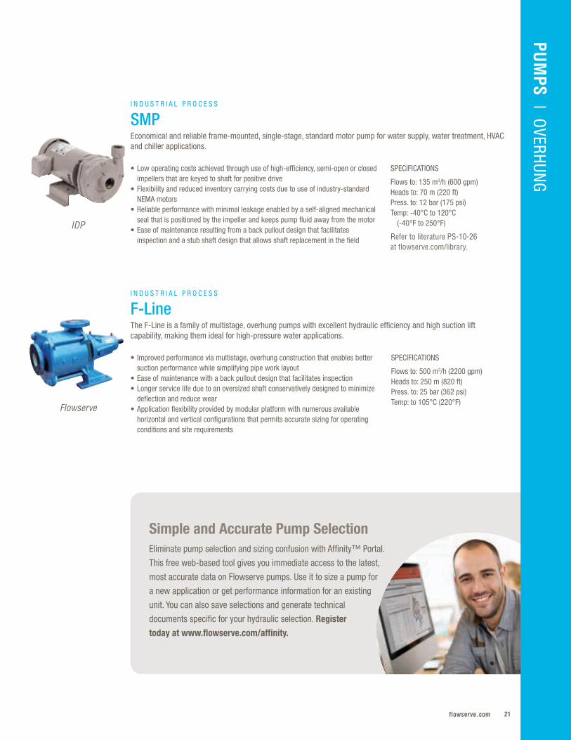
Flows to: 135 m3/h (600 gpm)Heads to: 70 m (220 ft) Press. to: 12 bar (175 psi)Temp: -40°C to 120°C (-40°F to 250°F)
Refer to literature PS-10-26 at flowserve.com/library.
• Low operating costs achieved through use of high-efficiency, semi-open or closed impellers that are keyed to shaft for positive drive
• Flexibility and reduced inventory carrying costs due to use of industry-standard NEMA motors
• Reliable performance with minimal leakage enabled by a self-aligned mechanical seal that is positioned by the impeller and keeps pump fluid away from the motor
• Ease of maintenance resulting from a back pullout design that facilitates inspection and a stub shaft design that allows shaft replacement in the field
I N D U S T R I A L P R O C E S S
SMPEconomical and reliable frame-mounted, single-stage, standard motor pump for water supply, water treatment, HVAC and chiller applications.
SPECIFICATIONS
Flows to: 500 m3/h (2200 gpm)Heads to: 250 m (820 ft) Press. to: 25 bar (362 psi)Temp: to 105°C (220°F)
• Improved performance via multistage, overhung construction that enables better suction performance while simplifying pipe work layout
• Ease of maintenance with a back pullout design that facilitates inspection • Longer service life due to an oversized shaft conservatively designed to minimize
deflection and reduce wear• Application flexibility provided by modular platform with numerous available
horizontal and vertical configurations that permits accurate sizing for operating conditions and site requirements
I N D U S T R I A L P R O C E S S
F-LineThe F-Line is a family of multistage, overhung pumps with excellent hydraulic efficiency and high suction lift capability, making them ideal for high-pressure water applications.
IDP
Flowserve
VALVES | LINEAR CO
NTRO
LPU
MPS | O
VERHUNG
Flowserve Corporation22
OVERHUNG
SPECIFICATIONS
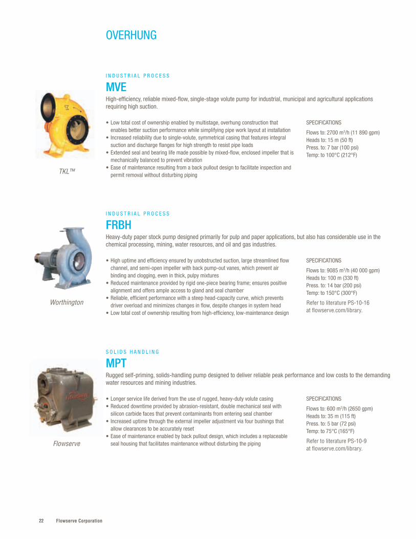
Flows to: 2700 m3/h (11 890 gpm)Heads to: 15 m (50 ft) Press. to: 7 bar (100 psi)Temp: to 100°C (212°F)
SPECIFICATIONS
Flows to: 9085 m3/h (40 000 gpm)Heads to: 100 m (330 ft)Press. to: 14 bar (200 psi)Temp: to 150°C (300°F)
Refer to literature PS-10-16 at flowserve.com/library.
SPECIFICATIONS
Flows to: 600 m3/h (2650 gpm)Heads to: 35 m (115 ft) Press. to: 5 bar (72 psi)Temp: to 75°C (165°F)
Refer to literature PS-10-9 at flowserve.com/library.
• Low total cost of ownership enabled by multistage, overhung construction that enables better suction performance while simplifying pipe work layout at installation
• Increased reliability due to single-volute, symmetrical casing that features integral suction and discharge flanges for high strength to resist pipe loads
• Extended seal and bearing life made possible by mixed-flow, enclosed impeller that is mechanically balanced to prevent vibration
• Ease of maintenance resulting from a back pullout design to facilitate inspection and permit removal without disturbing piping
• High uptime and efficiency ensured by unobstructed suction, large streamlined flow channel, and semi-open impeller with back pump-out vanes, which prevent air binding and clogging, even in thick, pulpy mixtures
• Reduced maintenance provided by rigid one-piece bearing frame; ensures positive alignment and offers ample access to gland and seal chamber
• Reliable, efficient performance with a steep head-capacity curve, which prevents driver overload and minimizes changes in flow, despite changes in system head
• Low total cost of ownership resulting from high-efficiency, low-maintenance design
• Longer service life derived from the use of rugged, heavy-duty volute casing• Reduced downtime provided by abrasion-resistant, double mechanical seal with
silicon carbide faces that prevent contaminants from entering seal chamber• Increased uptime through the external impeller adjustment via four bushings that
allow clearances to be accurately reset• Ease of maintenance enabled by back pullout design, which includes a replaceable
seal housing that facilitates maintenance without disturbing the piping
I N D U S T R I A L P R O C E S S
MVEHigh-efficiency, reliable mixed-flow, single-stage volute pump for industrial, municipal and agricultural applications requiring high suction.
I N D U S T R I A L P R O C E S S
FRBHHeavy-duty paper stock pump designed primarily for pulp and paper applications, but also has considerable use in the chemical processing, mining, water resources, and oil and gas industries.
S O L I D S H A N D L I N G
MPTRugged self-priming, solids-handling pump designed to deliver reliable peak performance and low costs to the demanding water resources and mining industries.
TKL™
Worthington
Flowserve

23flowserve.com
VALVES | LINEAR CO
NTRO
LPU
MPS | O
VERHUNG
SPECIFICATIONS
Flows to: 600 m3/h (2650 gpm)Heads to: 90 m (300 ft)Press. to: 19 bar (275 psi)Temp: to 63°C (145°F)
Refer to literature PS-10-3 at flowserve.com/library.
• Ease of maintenance enabled by the removable gland, which simplifies packing adjustment and replacement, plus readily accessible lubrication points
• Broad application versatility provided by a wide variety of mechanical seal options and design of the stuffing box, which allows for either grease or water seal
• Low maintenance costs due to conservative bearing design that eliminates radial and axial play, as well as supports that minimize vibration and ensure rigidity
S O L I D S H A N D L I N G
MF and MFVRugged and efficient solids-handling pump designed specifically for reliability, low cost and long life in demanding sewage handling services or where suspended solids are of particular concern.
SPECIFICATIONS
Flows to: 45 500 m3/h (200 000 gpm)Heads to: 90 m (300 ft)Press. to: 17 bar (240 psi)Temp: to 63°C (145°F)
Refer to literature PS-10-4 at flowserve.com/library.
SPECIFICATIONS
Flows to: 4545 m3/h (20 000 gpm)Heads to: 90 m (300 ft)Press. to: 11 bar (160 psi)Temp: to 40°C (104°F)
Refer to literature PS-50-2-E at flowserve.com/library.
• Application versatility provided by a design that includes horizontal and vertical models, a variety of nozzle positions, and direct or independent motor mounting
• Increased uptime enabled by oversized shaft and reduced overhang, which minimize shaft deflection and increase packing or seal life
• High-efficiency performance enabled by adjustable, double-chrome steel wear rings
• Reduced maintenance with back pullout design, removable gland, replaceable shaft sleeves, and readily accessible lubrication points in bearing housing
• Low operating costs enabled by EPACT-rated motor and high-efficiency hydraulics that reduce energy consumption while providing predictable pumping performance
• Reliability with spike-resistant windings that provide smooth, consistent motor performance and the ability to handle voltage spikes
• Increased uptime via dynamically balanced shaft and rotor for reduced vibration and smooth operation
• Long service life provided by watertight cable entry that protects motor from moisture and contamination
S O L I D S H A N D L I N G
MN and MNVRugged, large-capacity, mixed-flow, solids-handling pump designed specifically for demanding sewage handling services or where suspended solids are of particular concern.
S O L I D S H A N D L I N G
MSXThe MSX solids-handling submersible pump is engineered to perform efficiently in the most challenging environments, from pumping raw sewage to moving industrial wastewater and solids-laden liquids.
Worthington
Worthington
IDP
Flowserve Corporation24
OVERHUNG
SPECIFICATIONS
Flows to: 10 000 m3/h (44 000 gpm)Heads to: 50 m (160 ft)Press. to: 10 bar (150 psi)Temp: to 110°C (225°F)
Refer to literature PS-10-18 at flowserve.com/library.
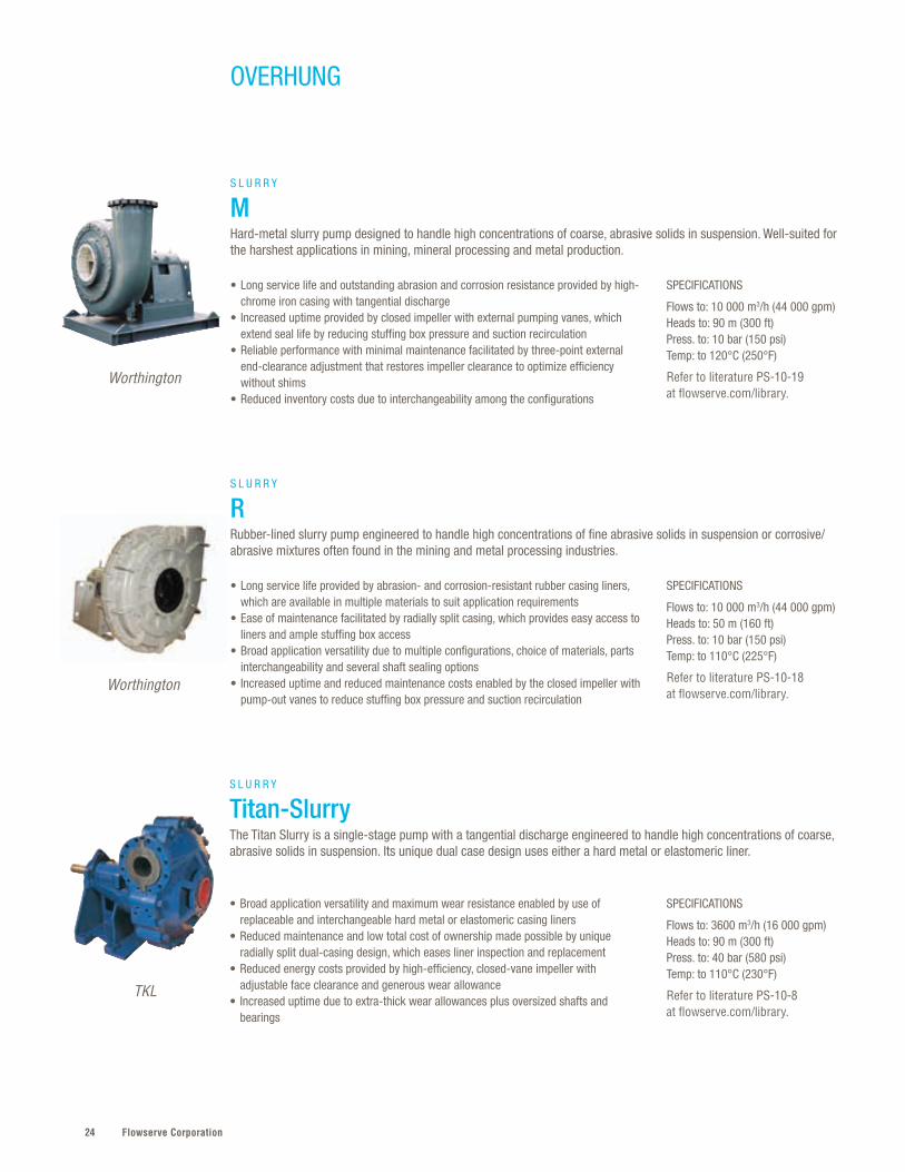
• Long service life provided by abrasion- and corrosion-resistant rubber casing liners, which are available in multiple materials to suit application requirements
• Ease of maintenance facilitated by radially split casing, which provides easy access to liners and ample stuffing box access
• Broad application versatility due to multiple configurations, choice of materials, parts interchangeability and several shaft sealing options
• Increased uptime and reduced maintenance costs enabled by the closed impeller with pump-out vanes to reduce stuffing box pressure and suction recirculation
S L U R R Y
RRubber-lined slurry pump engineered to handle high concentrations of fine abrasive solids in suspension or corrosive/abrasive mixtures often found in the mining and metal processing industries.
Worthington
SPECIFICATIONS
Flows to: 10 000 m3/h (44 000 gpm)Heads to: 90 m (300 ft)Press. to: 10 bar (150 psi)Temp: to 120°C (250°F)
Refer to literature PS-10-19 at flowserve.com/library.
• Long service life and outstanding abrasion and corrosion resistance provided by high-chrome iron casing with tangential discharge
• Increased uptime provided by closed impeller with external pumping vanes, which extend seal life by reducing stuffing box pressure and suction recirculation
• Reliable performance with minimal maintenance facilitated by three-point external end-clearance adjustment that restores impeller clearance to optimize efficiency without shims
• Reduced inventory costs due to interchangeability among the configurations
S L U R R Y
MHard-metal slurry pump designed to handle high concentrations of coarse, abrasive solids in suspension. Well-suited for the harshest applications in mining, mineral processing and metal production.
Worthington
SPECIFICATIONS
Flows to: 3600 m3/h (16 000 gpm)Heads to: 90 m (300 ft)Press. to: 40 bar (580 psi)Temp: to 110°C (230°F)
Refer to literature PS-10-8 at flowserve.com/library.
• Broad application versatility and maximum wear resistance enabled by use of replaceable and interchangeable hard metal or elastomeric casing liners
• Reduced maintenance and low total cost of ownership made possible by unique radially split dual-casing design, which eases liner inspection and replacement
• Reduced energy costs provided by high-efficiency, closed-vane impeller with adjustable face clearance and generous wear allowance
• Increased uptime due to extra-thick wear allowances plus oversized shafts and bearings
S L U R R Y
Titan-SlurryThe Titan Slurry is a single-stage pump with a tangential discharge engineered to handle high concentrations of coarse, abrasive solids in suspension. Its unique dual case design uses either a hard metal or elastomeric liner.
TKL
25flowserve.com
VALVES | LINEAR CO
NTRO
LPU
MPS | O
VERHUNG
SPECIFICATIONS
Flows to: 8000 m3/h (35 200 gpm)Heads to: 90 m (300 ft)Press. to: 25 bar (360 psi)Temp: to 140°C (285°F)
Refer to literature PS-10-11 at flowserve.com/library.
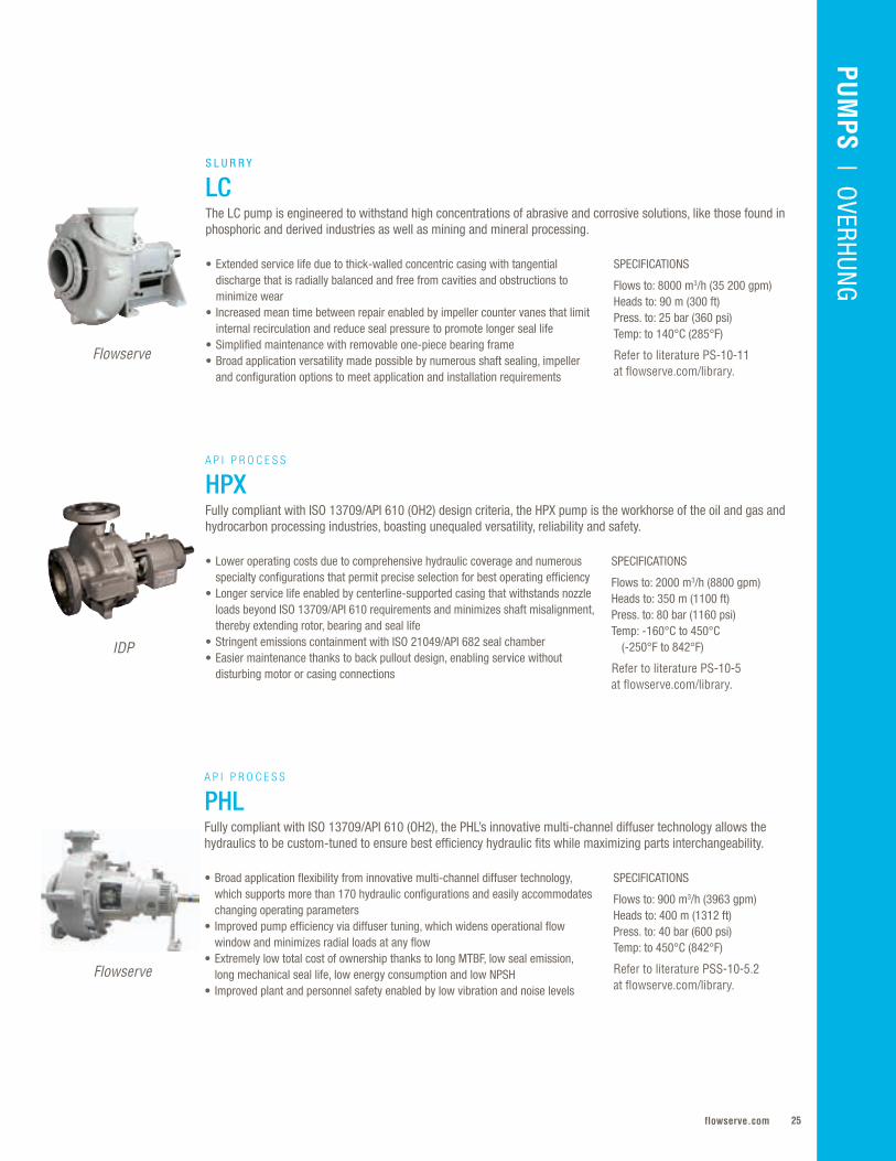
• Extended service life due to thick-walled concentric casing with tangential discharge that is radially balanced and free from cavities and obstructions to minimize wear
• Increased mean time between repair enabled by impeller counter vanes that limit internal recirculation and reduce seal pressure to promote longer seal life
• Simplified maintenance with removable one-piece bearing frame• Broad application versatility made possible by numerous shaft sealing, impeller
and configuration options to meet application and installation requirements
S L U R R Y
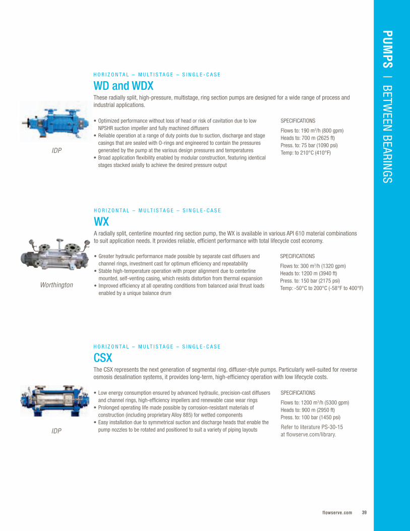
LCThe LC pump is engineered to withstand high concentrations of abrasive and corrosive solutions, like those found in phosphoric and derived industries as well as mining and mineral processing.
Flowserve
SPECIFICATIONS
Flows to: 2000 m3/h (8800 gpm)Heads to: 350 m (1100 ft)Press. to: 80 bar (1160 psi)Temp: -160°C to 450°C (-250°F to 842°F)
Refer to literature PS-10-5 at flowserve.com/library.
• Lower operating costs due to comprehensive hydraulic coverage and numerous specialty configurations that permit precise selection for best operating efficiency
• Longer service life enabled by centerline-supported casing that withstands nozzle loads beyond ISO 13709/API 610 requirements and minimizes shaft misalignment, thereby extending rotor, bearing and seal life
• Stringent emissions containment with ISO 21049/API 682 seal chamber• Easier maintenance thanks to back pullout design, enabling service without
disturbing motor or casing connections
A P I P R O C E S S
HPXFully compliant with ISO 13709/API 610 (OH2) design criteria, the HPX pump is the workhorse of the oil and gas and hydrocarbon processing industries, boasting unequaled versatility, reliability and safety.
IDP
SPECIFICATIONS
Flows to: 900 m3/h (3963 gpm)Heads to: 400 m (1312 ft)Press. to: 40 bar (600 psi)Temp: to 450°C (842°F)
Refer to literature PSS-10-5.2 at flowserve.com/library.
• Broad application flexibility from innovative multi-channel diffuser technology, which supports more than 170 hydraulic configurations and easily accommodates changing operating parameters
• Improved pump efficiency via diffuser tuning, which widens operational flow window and minimizes radial loads at any flow
• Extremely low total cost of ownership thanks to long MTBF, low seal emission, long mechanical seal life, low energy consumption and low NPSH
• Improved plant and personnel safety enabled by low vibration and noise levels
A P I P R O C E S S
PHLFully compliant with ISO 13709/API 610 (OH2), the PHL’s innovative multi-channel diffuser technology allows the hydraulics to be custom-tuned to ensure best efficiency hydraulic fits while maximizing parts interchangeability.
Flowserve
Flowserve Corporation26
OVERHUNG
Worthington
SPECIFICATIONS
Flows to: 1100 m3/h (4800 gpm)Heads to: 230 m (755 ft)Press. to: 60 bar (870 psi)Temp: -50°C to 350°C (-158°F to 660°F)
Refer to literature PS-10-20 at flowserve.com/library.
• Greater service life enabled by centerline-supported pump casing that accommodates nozzle loads in accordance with ISO 13709/API 610 requirements, minimizing shaft misalignment and extending rotor, bearing and seal life
• Emissions containment with ISO 21049/API 682 seal chamber, which accepts all seal types, including dual-pressurized and unpressurized cartridge units
• Simplified maintenance and inspection made possible by back pullout design• Mechanical and hydraulic design flexibility supported by a variety of configurations
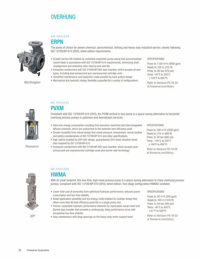
A P I P R O C E S S
ERPNThe pump of choice for severe chemical, petrochemical, refining and heavy-duty industrial service, closely following ISO 13709/API 610 (OH2), latest edition requirements.
SPECIFICATIONS
Flows to: 45 m3/h (200 gpm)Heads to: 440 m (1445 ft)Press. to: 64 bar (930 psi)Temp: -46°C to 260°C (-51°F to 500°F)
Refer to literature PS-10-23 at flowserve.com/library.
• Lower total cost of ownership from optimized hydraulic performance, reduced power consumption and low-flow stability
• Broad application versatility and low energy costs enabled by modular design that offers more than 80 best efficiency point fits in a single pump size
• Precise, repeatable hydraulic performance delivered by replaceable volute insert and Barske-type impeller that provides a continuously rising performance curve with exceptional low-flow stability
• Easy maintenance with large openings on the heavy-duty motor support head
A P I P R O C E S S
HWMAWith its small footprint, this low-flow, high-head process pump is a space-saving alternative to many overhung process pumps. Compliant with ISO 13709/API 610 (OH3), latest edition. Two-stage configuration HWMA2 available.
IDP
SPECIFICATIONS
Flows to: 500 m3/h (2200 gpm)Heads to: 275 m (900 ft)Press. to: 40 bar (600 psi)Temp: -100°C to 250°C (-148°F to 480°F)
Refer to literature PS-10-29 at flowserve.com/library.
• Extra-low energy consumption resulting from precision-machined and interchangeable diffuser channels, which are customized to the hydraulic best efficiency point
• Greater durability from robust design that meets pressure, temperature, nozzle loading and safety considerations of ISO 13709/API 610 and other specifications
• High uptime enabled by stiff rotor design, guaranteeing 20% lower vibration levels than required by ISO 13709/API 610
• Emissions containment with ISO 21049/API 682 seal chamber, which accepts dual-pressurized and unpressurized cartridge seals plus barrier seal technology
A P I P R O C E S S
PVXMCompliant with ISO 13709/API 610 (OH3), the PVXM vertical in-line pump is a space-saving alternative to horizontal overhung process pumps in upstream and downstream services.
Flowserve
27flowserve.com
VALVES | LINEAR CO
NTRO
LPU
MPS | O
VERHUNG
SPECIFICATIONS
Flows to: 500 m3/h (2220 gpm)Heads to: 275 m (900 ft)Press. to: 40 bar (580 psi)Temp: -100°C to 250°C (-148°F to 480°F)
Refer to literature PS-10-28 at flowserve.com/library.
• Lower total cost of ownership from customized hydraulics that generate low vibration levels, high efficiencies and near-zero seal emissions
• Performance flexibility provided by milled and interchangeable diffuser channels, which are customized for specific duty points, enabling customers to address changing operating parameters
• Ease of maintenance enabled by direct-drive design, which does not require alignment, and cartridge seal mounting, which assures precise seal face setting
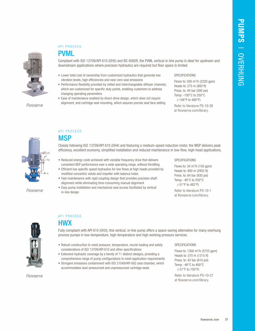
A P I P R O C E S S
PVMLCompliant with ISO 13709/API 610 (OH5) and BS 4082R, the PVML vertical in-line pump is ideal for upstream and downstream applications where precision hydraulics are required but floor space is limited.
Flowserve
SPECIFICATIONS
Flows to: 34 m3/h (150 gpm)Heads to: 900 m (2955 ft) Press. to: 64 bar (930 psi)Temp: -46°C to 250°C (-51°F to 482°F)
Refer to literature PS-10-1 at flowserve.com/library.
• Reduced energy costs achieved with variable frequency drive that delivers consistent BEP performance over a wide operating range, without throttling
• Efficient low specific speed hydraulics for low flows at high heads provided by modified concentric volute and impeller with balance holes
• Fast maintenance with rigid coupling design that provides precision shaft alignment while eliminating time-consuming manual alignment
• Easy pump installation and mechanical seal access facilitated by vertical in-line design
A P I P R O C E S S
MSPClosely following ISO 13709/API 610 (OH4) and featuring a medium-speed induction motor, the MSP delivers peak efficiency, excellent economy, simplified installation and reduced maintenance in low-flow, high-head applications.
Flowserve
SPECIFICATIONS
Flows to: 1300 m3/h (5725 gpm)Heads to: 370 m (1215 ft)Press. to: 42 bar (610 psi)Temp: -46°C to 400°C (-51°F to 750°F)
Refer to literature PS-10-27 at flowserve.com/library.
• Robust construction to meet pressure, temperature, nozzle loading and safety considerations of ISO 13709/API 610 and other specifications
• Extensive hydraulic coverage by a family of 11 distinct designs, providing a comprehensive range of pump configurations to meet application requirements
• Stringent emissions containment with ISO 21049/API 682 seal chamber, which accommodates dual-pressurized and unpressurized cartridge seals
A P I P R O C E S S
HWXFully compliant with API 610 (OH3), this vertical, in-line pump offers a space-saving alternative for many overhung process pumps in low-temperature, high-temperature and high working pressure services.
Flowserve

Flowserve Corporation28
OVERHUNG
SPECIFICATIONS
Flows to: 34 065 m3/h (150 000 gpm)Heads to: 11 m (36 ft)Press. to: 10.3 bar (150 psi)Temp: -20°C to 149°C (-30°F to 300°F)
Refer to literature PS-100-17 at flowserve.com/library.
• Reduced downtime derived from use of large-diameter cantilevered shafts that eliminate need for internal support bearings and minimize deflection at seal chamber
• Ease of maintenance enabled by back pullout design, which simplifies inspection and maintenance of the roter without disturbing piping or motor connections
• Increased uptime derived from one-piece, 360° bearing frame with deep metal-to-metal fit that provides superior alignment compared to 180° designs
A X I A L F L O W
AFH9000Axial flow elbow pump ideal for low-pressure, high-volume transfer applications, such as those frequently found in chemical and hydrocarbon processing. Typical applications include evaporators, crystallizers and heat recovery.
Lawrence Pumps
SPECIFICATIONS
Flows to: 3409 m3/h (15 000 gpm)Heads to: 244 m (800 ft)Press. to: 83 bar (1200 psi)Temp: -20°C to 400°C (-30°F to 826°F)
Refer to literature PS-10-33 at flowserve.com/library.
• Low life cycle cost provided by replaceable mechanically fastened liners that protect the pressure casing from erosion and abrasion
• Process flexibility made possible by interchangeable diffuser, casing liner and impeller, which allow operators to adapt performance to changing process conditions
• Extended operating life ensured by a rigid, oversized bearing frame that maintains shaft deflection below ISO/API requirements
• Casing liners are available in multiple abrasion-resistant materials and surface treatments to meet any process or operational requirement
A P I P R O C E S S
HPX6000 and HPXM6000HPX6000 and HPXM6000 (low-flow) are fully lined slurry pumps built to ISO 13709/API 610 (OH2) and used in heavy oil processing. They reliably handle hot, abrasive solids without the danger of pump casing erosion.
Lawrence Pumps

29flowserve.com
VALVES | LINEAR CO
NTRO
LPU
MPS | O
VERHUNG
Flowserve Corporation3030
WIKO

31flowserve.com
PUM
PS | BETW
EEN BEARIN
GS
BETWEEN BEARINGS
Between Bearings – Quick Reference*
Long life and high efficiency performance in the world’s most critical services characterize
this highly engineered range of pumps . Capable of reaching massive flow rates and
pressures, single- and double-case designs are designed for continuous operation, often
un-spared . Extended uptime is achieved through rugged rotor designs that carefully
account for mechanical and hydraulic balance . Energy savings realized from a huge range
of hydraulic options keep operating costs in check .
* Additional products shown on next two pages
FPO
Product Sub-Type Flows to Heads to Pressures to Temperatures
LR Single-Case –Axially Split
2000 m3/h (8800 gpm)
170 m (560 ft)
21 bar (300 psi)
-20°C to 150°C(-4°F to 300°F)
LNN Single-Case –Axially Split
30 000 m3/h (132 000 gpm)
300 m (985 ft)
40 bar (580 psi)
-20°C to 140°C (-4°F to 285°F)
DVSH Single-Case –Axially Split – API
12 000 m3/h (52 835 gpm)
565 m (1854 ft)
150 bar (2175 psi)
to 200°C (400°F)
LPN Single-Case –Axially Split – API
15 000 m3/h (65 000 gpm)
250 m (820 ft)
50 bar (725 psi)
-80°C to 204°C (-110°F to 400°F)
UZDL Single-Case –Axially Split – API
2950 m3/h (13 000 gpm)
685 m (2250 ft)
64 bar (910 psi)
to 200°C (400°F)
EC Single-Case –Axially Split – Multistage
2340 m3/h(10 300 gpm)
650 m(2130 ft)
88 bar(1300 psi)
-30°C to 150°C(-20°F to 300°F)
Flowserve Corporation32
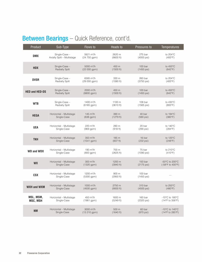
Between Bearings – Quick Reference, cont’d.Product Sub-Type Flows to Heads to Pressures to Temperatures
DMX Single-Case –Axially Split – Multistage
5621 m3/h (24 750 gpm)
2620 m (8600 ft)
275 bar (4000 psi)
to 204°C (400°F)
HDX Single-Case –Radially Split
5000 m3/h (22 000 gpm)
450 m (1500 ft)
100 bar (1450 psi)
to 450°C (842°F)
DVSR Single-Case –Radially Split
6585 m3/h(29 000 gpm)
330 m(1080 ft)
260 bar(3750 psi)
to 204°C(400°F)
HED and HED-DS Single-Case –Radially Split
2000 m3/h(8800 gpm)
450 m(1500 ft)
100 bar(1450 psi)
to 450°C(842°F)
WTB Single-Case –Radially Split
1400 m3/h (6165 gpm)
1100 m (3610 ft)
108 bar (1565 psi)
to 430°C (800°F)
HEGA Horizontal – Multistage Single-Case
145 m3/h (638 gpm)
390 m(1279 ft)
40 bar(580 psi)
to 194°C(380°F)
UEA Horizontal – Multistage Single-Case
220 m3/h (969 gpm)
280 m (918 ft)
20 bar (290 psi)
to 140°C (284°F)
TKH Horizontal – Multistage Single-Case
350 m3/h (1541 gpm)
185 m (607 ft)
16 bar (232 psi)
to 120°C (248°F)
WD and WDX Horizontal – Multistage Single-Case
190 m3/h (800 gpm)
700 m (2625 ft)
75 bar(1090 psi)
to 210°C (410°F)
WX Horizontal – Multistage Single-Case
300 m3/h (1320 gpm)
1200 m (3940 ft)
150 bar (2175 psi)
-50°C to 200°C (-58°F to 400°F)
CSX Horizontal – Multistage Single-Case
1200 m3/h(5300 gpm)
900 m(2950 ft)
100 bar(1450 psi) —
WXH and WXM Horizontal – Multistage Single-Case
1000 m3/h (4500 gpm)
2750 m (9000 ft)
310 bar (4500 psi)
to 250°C(480°F)
MSL, MSM,MSC, MSH
Horizontal – Multistage Single-Case
450 m3/h (1981 gpm)
1600 m (5249 ft)
160 bar (2320 psi)
-10°C to 180°C (14°F to 356°F)
NM Horizontal – Multistage Single-Case
3000 m3/h(13 210 gpm)
500 m(1640 ft)
60 bar(870 psi)
-10°C to 140°C(14°F to 285°F)
33flowserve.com
PUM
PS | BETW
EEN BEARIN
GS
Product Sub-Type Flows to Heads to Pressures to Temperatures
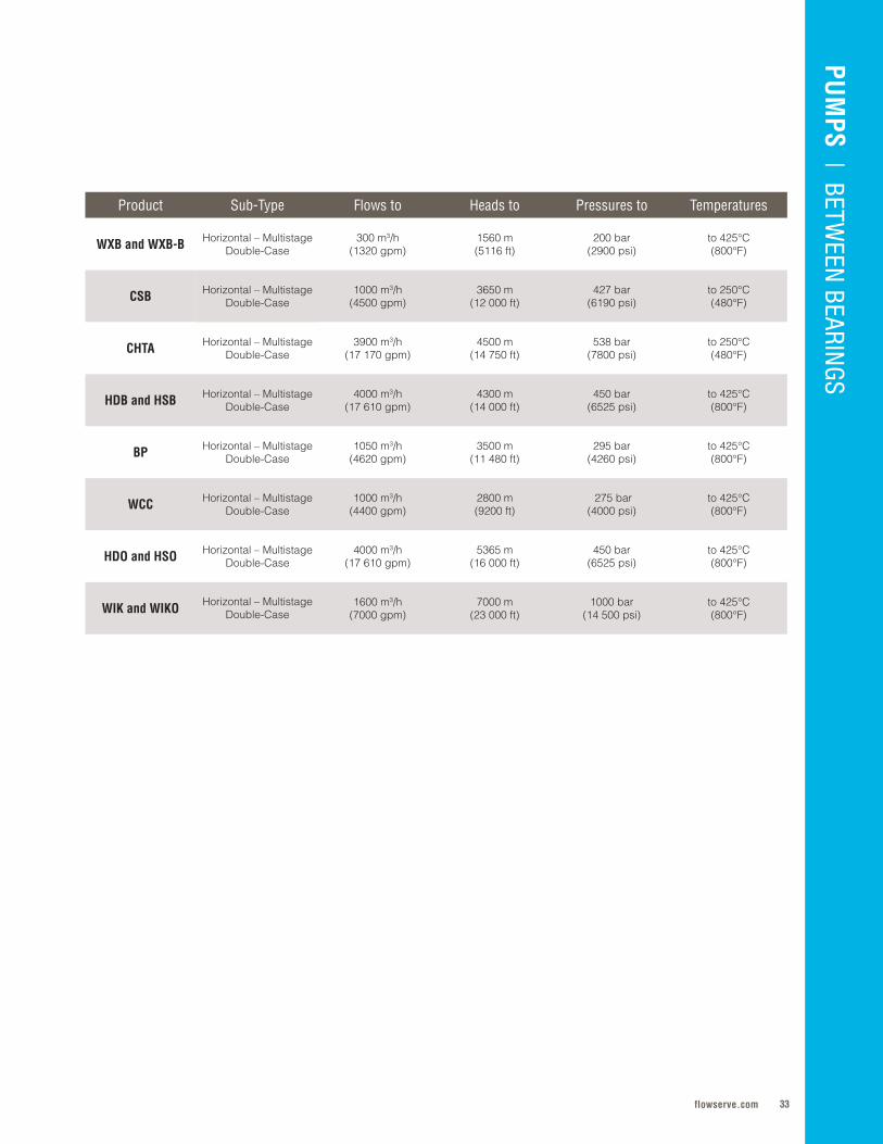
WXB and WXB-B Horizontal – Multistage Double-Case
300 m3/h (1320 gpm)
1560 m (5116 ft)
200 bar (2900 psi)
to 425°C (800°F)
CSB Horizontal – Multistage Double-Case
1000 m3/h (4500 gpm)
3650 m (12 000 ft)
427 bar (6190 psi)
to 250°C (480°F)
CHTA Horizontal – Multistage Double-Case
3900 m3/h (17 170 gpm)
4500 m (14 750 ft)
538 bar (7800 psi)
to 250°C (480°F)
HDB and HSB Horizontal – Multistage Double-Case
4000 m3/h (17 610 gpm)
4300 m (14 000 ft)
450 bar (6525 psi)
to 425°C(800°F)
BP Horizontal – Multistage Double-Case
1050 m3/h (4620 gpm)
3500 m (11 480 ft)
295 bar (4260 psi)
to 425°C(800°F)
WCC Horizontal – Multistage Double-Case
1000 m3/h (4400 gpm)
2800 m (9200 ft)
275 bar (4000 psi)
to 425°C(800°F)
HDO and HSO Horizontal – Multistage Double-Case
4000 m3/h (17 610 gpm)
5365 m (16 000 ft)
450 bar (6525 psi)
to 425°C(800°F)
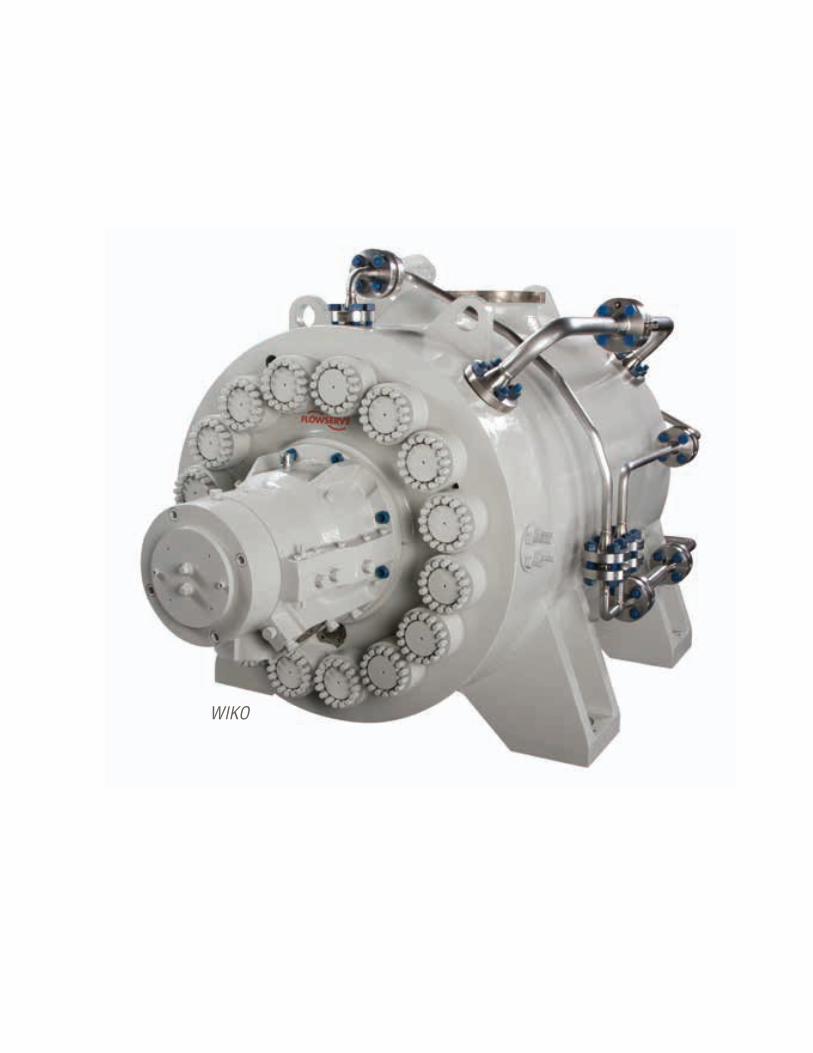
WIK and WIKO Horizontal – Multistage Double-Case
1600 m3/h (7000 gpm)
7000 m (23 000 ft)
1000 bar (14 500 psi)
to 425°C(800°F)
Flowserve Corporation34
BETWEEN BEARINGS
SPECIFICATIONS
Flows to: 12 000 m3/h (52 835 gpm)Heads to: 565 m (1854 ft) Press. to: 150 bar (2175 psi) Temp: to 200°C (400°F)
Refer to literature PS-20-2 at flowserve.com/library.
• Low operating costs derived from comprehensive hydraulic coverage (more than 100 sizes), thereby permitting precise selection for best hydraulic fit and efficiency
• High uptime made possible by double suction impeller and double volute designs, which create optimal axial and radial thrust balance
• Increased reliability provided by the heavy-duty shaft design, which ensures trouble-free operation below the first critical speed
• Ease of maintenance due to suction and discharge nozzles that are integrally cast in lower casing half, permitting disassembly without disturbing piping
S I N G L E - C A S E – A X I A L LY S P L I T – A P I
DVSHFully compliant with ISO 13709/API 610 (BB1), this heavy-duty, single-stage pump with side/side nozzles is well-suited for process charge, transfer and pipeline services where uncompromising reliability over a wide flow range is paramount.
SPECIFICATIONS
Flows to: 2000 m3/h (8800 gpm)Heads to: 170 m (560 ft) Press. to: 21 bar (300 psi)Temp: -20°C to 150°C (-4°F to 300°F)
Refer to literature PS-20-3 at flowserve.com/library.
SPECIFICATIONS
Flows to: 30 000 m3/h (132 000 gpm)Heads to: 300 m (985 ft) Press. to: 40 bar (580 psi) Temp: -20°C to 140°C (-4°F to 285°F)
Refer to literature PS-20-1 at flowserve.com/library.
• High efficiency and optimum performance over a wide flow range due to low-NPSH enclosed impeller and casing wear rings that easily restore operating clearances
• Application versatility provided by numerous options that permit the pump to be precisely configured for service requirements
• Low inventory carrying costs made possible by parts interchangeability among sizes and configurations
• Ease of maintenance resulting from axial split-case design, which allows access to rotating element without disturbing the piping or driver
• Optimal hydraulic balance and efficiency over its full operating range provided by double suction impeller operating in a double volute, axially split casing
• Low inventory carrying cost provided by a high degree of parts interchangeability among sizes and configurations
• Application flexibility enabled by ability to modify pump performance to meet future service conditions by changing impeller designs
• Increased uptime from double-volute design, ample shaft and 360° bearing housings, all of which minimize shaft deflection and vibration to extend bearing and seal life
S I N G L E - C A S E – A X I A L LY S P L I T
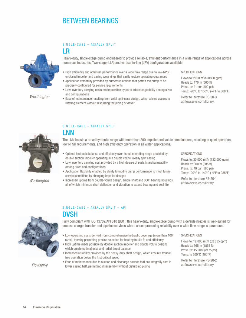
LRHeavy-duty, single-stage pump engineered to provide reliable, efficient performance in a wide range of applications across numerous industries. Two-stage (LLR) and vertical in-line (LRV) configurations available.
S I N G L E - C A S E – A X I A L LY S P L I T
LNNThe LNN boasts a broad hydraulic range with more than 200 impeller and volute combinations, resulting in quiet operation, low NPSH requirements, and high efficiency operation in all water applications.
Flowserve
Worthington
Worthington
35flowserve.com
Partnerships With Long-Term ValueFlowserve enterprise framework agreement (EFA) partners have access
to all facets of our business, from front-end engineering to research
and development to solve real-world problems. It’s a total lifecycle
management approach that applies to day-to-day operational
challenges as well as plant expansions and greenfield
projects — and it pays. One EFA partner has garnered more
than $400 million in value in the first five years.
VALVES | LINEAR CO
NTRO
LPU
MPS | BETW
EEN BEARIN
GS
SPECIFICATIONS
Flows to: 15 000 m3/h (65 000 gpm)Heads to: 250 m (820 ft)Press. to: 50 bar (725 psi)Temp: -80°C to 204°C (-110°F to 400°F)
Refer to literature PS-20-5 at flowserve.com/library.
SPECIFICATIONS
Flows to: 2950 m3/h (13 000 gpm)Heads to: 685 m (2250 ft)Press. to: 64 bar (910 psi)Temp: to 200°C (400°F)
Refer to literature PS-30-2 at flowserve.com/library.
• High uptime made possible by double-suction impeller and double volute designs, which create optimal axial and radial thrust balance
• Increased MTBR resulting from heavy-duty bearings and bearing lubrication system; multiple options available to suit application requirements
• Superior performance at elevated temperatures with near-centerline mounting• Simplified maintenance enabled by the split-casing design, which permits the
rotor, seals and bearings to be serviced without disturbing the piping • Emissions control with ISO 21049/API 682 seal chambers
• Increased uptime made possible by double volute design that minimizes hydraulic radial loads, and virtually eliminates shaft deflection and vibration
• Safety and environmental compliance with ISO 21049/API 682 seal chambers• Increased reliability provided by stiff shaft design, which ensures trouble-free
operation below the first critical speed• Ease of maintenance due to suction and discharge nozzles that are integrally cast
in lower casing half, permitting disassembly without disturbing piping
S I N G L E - C A S E – A X I A L LY S P L I T – A P I
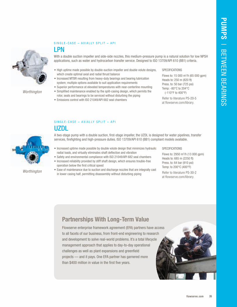
LPNWith a double suction impeller and side-side nozzles, this medium-pressure pump is a natural solution for low NPSH applications, such as water and hydrocarbon transfer service. Designed to ISO 13709/API 610 (BB1) criteria.
S I N G L E - C A S E – A X I A L LY S P L I T – A P I
UZDLA two-stage pump with a double suction, first-stage impeller, the UZDL is designed for water pipelines, transfer services, firefighting and high-pressure duties. ISO 13709/API 610 (BB1) compliant models available.
Worthington
Worthington
Flowserve Corporation36
BETWEEN BEARINGS
SPECIFICATIONS
Flows to: 2340 m3/h (10 300 gpm)Heads to: 650 m (2130 ft)Press. to: 88 bar (1300 psi)Temp: -30°C to 150°C (-20°F to 300°F)
SPECIFICATIONS
Flows to: 5621 m3/h (24 750 gpm)Heads to: 2620 m (8600 ft)Press. to: 275 bar (4000 psi)Temp: to 204°C (400°F)
Refer to literature PS-30-3 at flowserve.com/library.
SPECIFICATIONS
Flows to: 5000 m3/h (22 000 gpm)Heads to: 450 m (1500 ft) Press. to: 100 bar (1450 psi)Temp: to 450°C (842°F)
Refer to literature PS-20-4 at flowserve.com/library.
• Lower maintenance time and costs enabled by horizontally split casing and removable pump rotor, which allow access without disturbing suction and discharge connections or motor alignment
• Installation ease via pump design that can be mounted horizontally or vertically• Longer service life from shaft sleeves that reduce friction wear and graphite-
impregnated packing, which provides easy leakage adjustment
• Increased uptime enabled by opposed mounted impellers operating in a double volute casing, which provide inherent hydraulic balance over the full operating range
• Broad application versatility provided by numerous options that permit the pump to be precisely configured for service requirements
• Superior performance at elevated temperatures with near-centerline mounting• Ease of maintenance facilitated by cap nuts on top half casing parting flange• Emissions control with ISO 21049/API 682 seal chambers
• Increased uptime enabled by double suction impeller that minimizes thrust problems, reduces NPSHR, and allows mechanical seals to operate at equal and low pressure
• Excellent high-temperature performance provided by centerline mounting plus gasketing with metal-to-metal fit to ensure proper sealing and alignment
• Installation ease with top-top, side-top and side-side nozzle configurations available to meet any customer piping layout
• Safety and environmental compliance with ISO 21049/API 682 seal chambers• Power recovery turbine configuration (HDX-TT) available
S I N G L E - C A S E – A X I A L LY S P L I T – M U LT I S T A G E
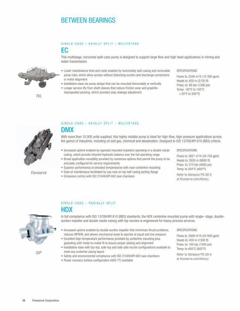
ECThis multistage, horizontal split-case pump is designed to support large flow and high head applications in mining and water transmission.
S I N G L E - C A S E – A X I A L LY S P L I T – M U LT I S T A G E
DMXWith more than 10 000 units supplied, this highly reliable pump is ideal for high-flow, high-pressure applications across the gamut of industries, including oil and gas, chemical and desalination. Designed to ISO 13709/API 610 (BB3) criteria.
S I N G L E - C A S E – R A D I A L LY S P L I T
HDXIn full compliance with ISO 13709/API 610 (BB2) standards, the HDX centerline mounted pump with single- stage, double-suction impeller and double volute casing with top nozzles is engineered for heavy process services.
TKL
Flowserve
IDP
37flowserve.com
VALVES | LINEAR CO
NTRO
LPU
MPS | BETW
EEN BEARIN
GS
SPECIFICATIONS
Flows to: 2000 m3/h (8800 gpm)Heads to: 650 m (2100 ft)Press. to: 120 bar (1750 psi)Temp: to 450°C (842°F)
Refer to literature PS-30-4 at flowserve.com/library.
• Extended reliability and life made possible by heavy-duty, single- or dual-volute casings with a staggered arrangement, which ensures radial balance
• Application versatility provided by numerous options — including 50- or 60-cycle operation and top-top, side-top and side-side nozzle orientations — that permit the pump to be precisely configured for service and site requirements
• Increased reliability provided by stiff shaft design, which ensures trouble-free operation below the first critical speed
• Environmental regulatory compliance with ISO 21049/API 682 seal chambers
S I N G L E - C A S E – R A D I A L LY S P L I T
HED and HED-DSTwo-stage, centerline mounted pump engineered for safe, reliable operation in heavy-duty process services and elevated temperatures. Fully compliant with ISO 13709/API 610 (BB2).
SPECIFICATIONS
Flows to: 6585 m3/h (29 000 gpm)Heads to: 330 m (1080 ft)Press. to: 260 bar (3750 psi)Temp: to 204°C (400°F)
Refer to literature PS-30-17 at flowserve.com/library.
• Maximum efficiency through a double-suction impeller that provides axial hydraulic thrust balance
• Higher uptime due to a double-volute design that minimizes hydraulic loads, even at minimal flow, to prolong the life of bearings, seals and wear rings
• Stringent emissions control with ISO 21049/API 682 seal chambers• Trouble-free operation below the first critical speed ensured by the heavy-duty
shaft design • API performance testing is conducted on each pump prior to shipment
S I N G L E - C A S E – R A D I A L LY S P L I T
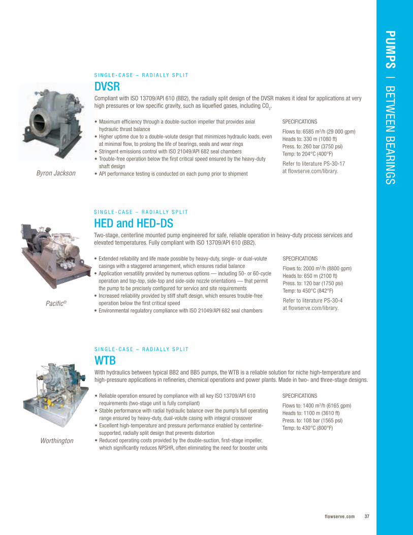
DVSRCompliant with ISO 13709/API 610 (BB2), the radially split design of the DVSR makes it ideal for applications at very high pressures or low specific gravity, such as liquefied gases, including CO2.
Byron Jackson
Pacific®
SPECIFICATIONS
Flows to: 1400 m3/h (6165 gpm)Heads to: 1100 m (3610 ft) Press. to: 108 bar (1565 psi)Temp: to 430°C (800°F)
• Reliable operation ensured by compliance with all key ISO 13709/API 610 requirements (two-stage unit is fully compliant)
• Stable performance with radial hydraulic balance over the pump’s full operating range ensured by heavy-duty, dual-volute casing with integral crossover
• Excellent high-temperature and pressure performance enabled by centerline-supported, radially split design that prevents distortion
• Reduced operating costs provided by the double-suction, first-stage impeller, which significantly reduces NPSHR, often eliminating the need for booster units
S I N G L E - C A S E – R A D I A L LY S P L I T
WTBWith hydraulics between typical BB2 and BB5 pumps, the WTB is a reliable solution for niche high-temperature and high-pressure applications in refineries, chemical operations and power plants. Made in two- and three-stage designs.
Worthington
Flowserve Corporation38
BETWEEN BEARINGS
SPECIFICATIONS
Flows to: 220 m3/h (969 gpm)Heads to: 280 m (918 ft)Press. to: 20 bar (290 psi)Temp: to 140°C (284°F)
Refer to literature PS-120-2 at flowserve.com/library.
• Safe, reliable pumping of boiling liquids ensured by a special priming stage that absorbs vapor from the suction side
• Trouble-free operation under unfavorable suction conditions enabled by axial inlet with NPSH inducer stage
• Wide application range resulting from its ability to handle liquids at their boiling points as well as its low required NPSH
• Shaft sealing by a single- or double-mechanical seal to suit application requirements
H O R I Z O N T A L – M U LT I S T A G E – S I N G L E - C A S E
UEAHorizontal, self-priming multistage ring-section pump designed for pumping liquids at their boiling point. It is particularly well suited for condensates, liquefied gases, refrigerants, LPG and boiler feedwater.
SIHI
SPECIFICATIONS
Flows to: 350 m3/h (1541 gpm)Heads to: 185 m (607 ft)Press. to: 16 bar (232 psi)Temp: to 120°C (248°F)
• Reduced downtime resulting from the separation of gas before entering the first impeller
• Maximum performance via a priming stage that runs in parallel with the first liquid stage and operates according to the mixed media separation principle
• Wide range of applications due to the self-priming capability and multitude of material combinations, including shipbuilding and the construction of cooling and firefighting equipment
H O R I Z O N T A L – M U LT I S T A G E – S I N G L E - C A S E
TKHHorizontal, self-priming and segmental-type centrifugal pumps with shrouded impellers for water and utility water supply, fuel handling, and chemical and petrochemical applications.
SIHI
SPECIFICATIONS
Flows to: 145 m3/h (638 gpm) Heads to: 390 m (1279 ft)Press. to: 40 bar (580 psi)Temp: to 194°C (380°F)
• Reduced energy costs achieved by sizing impellers for best hydraulic fit and operating efficiency
• Low installation costs enabled by movable suction head casing, which easily adapts flange position to site conditions
• Low inventory carrying costs enabled by high degree of parts interchangeability• Reliable bearing performance provided by grease lubricated deep groove and
cylindrical roller bearing, respectively meeting DIN 625 and DIN 5412• Shaft sealing by a stuffing box or mechanical seal to suit application requirements
H O R I Z O N T A L – M U LT I S T A G E – S I N G L E - C A S E
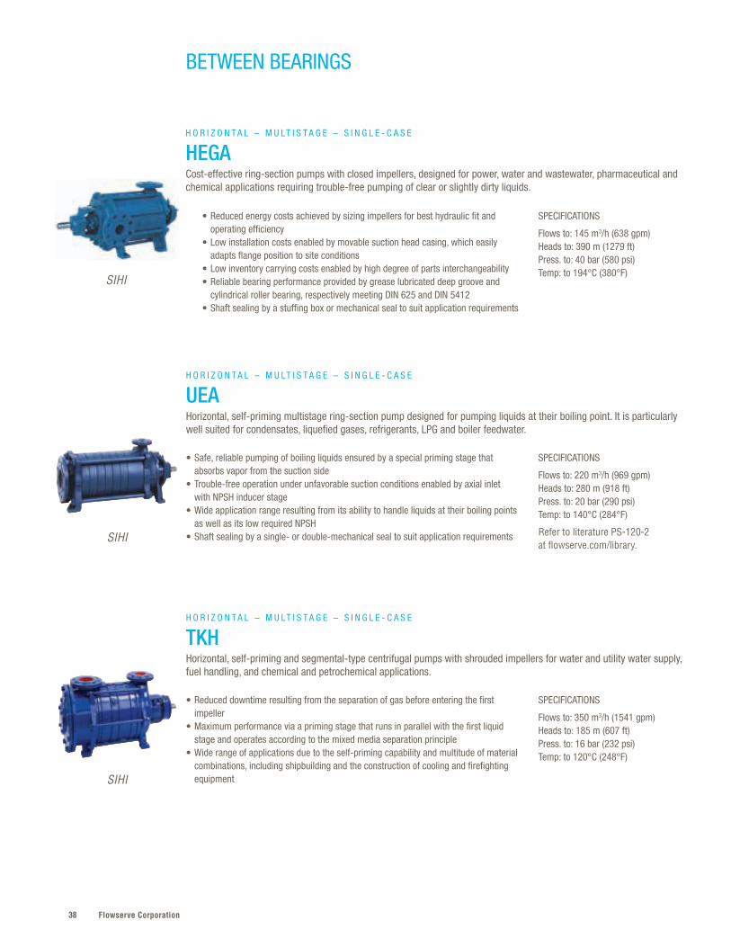
HEGACost-effective ring-section pumps with closed impellers, designed for power, water and wastewater, pharmaceutical and chemical applications requiring trouble-free pumping of clear or slightly dirty liquids.
SIHI
39flowserve.com
SPECIFICATIONS
Flows to: 190 m3/h (800 gpm)Heads to: 700 m (2625 ft) Press. to: 75 bar (1090 psi)Temp: to 210°C (410°F)
• Optimized performance without loss of head or risk of cavitation due to low NPSHR suction impeller and fully machined diffusers
• Reliable operation at a range of duty points due to suction, discharge and stage casings that are sealed with O-rings and engineered to contain the pressures generated by the pump at the various design pressures and temperatures
• Broad application flexibility enabled by modular construction, featuring identical stages stacked axially to achieve the desired pressure output
H O R I Z O N T A L – M U LT I S T A G E – S I N G L E - C A S E
WD and WDXThese radially split, high-pressure, multistage, ring section pumps are designed for a wide range of process and industrial applications.
IDP
VALVES | LINEAR CO
NTRO
LPU
MPS | BETW
EEN BEARIN
GS
IDP
SPECIFICATIONS
Flows to: 1200 m3/h (5300 gpm)Heads to: 900 m (2950 ft)Press. to: 100 bar (1450 psi)
Refer to literature PS-30-15 at flowserve.com/library.
• Low energy consumption ensured by advanced hydraulic, precision-cast diffusers and channel rings, high-efficiency impellers and renewable case wear rings
• Prolonged operating life made possible by corrosion-resistant materials of construction (including proprietary Alloy 885) for wetted components
• Easy installation due to symmetrical suction and discharge heads that enable the pump nozzles to be rotated and positioned to suit a variety of piping layouts
H O R I Z O N T A L – M U LT I S T A G E – S I N G L E - C A S E
CSXThe CSX represents the next generation of segmental ring, diffuser-style pumps. Particularly well-suited for reverse osmosis desalination systems, it provides long-term, high-efficiency operation with low lifecycle costs.
H O R I Z O N T A L – M U LT I S T A G E – S I N G L E - C A S E
WXA radially split, centerline mounted ring section pump, the WX is available in various API 610 material combinations to suit application needs. It provides reliable, efficient performance with total lifecycle cost economy.
SPECIFICATIONS
Flows to: 300 m3/h (1320 gpm)Heads to: 1200 m (3940 ft)Press. to: 150 bar (2175 psi)Temp: -50°C to 200°C (-58°F to 400°F)
• Greater hydraulic performance made possible by separate cast diffusers and channel rings, investment cast for optimum efficiency and repeatability
• Stable high-temperature operation with proper alignment due to centerline mounted, self-venting casing, which resists distortion from thermal expansion
• Improved efficiency at all operating conditions from balanced axial thrust loads enabled by a unique balance drum
Worthington
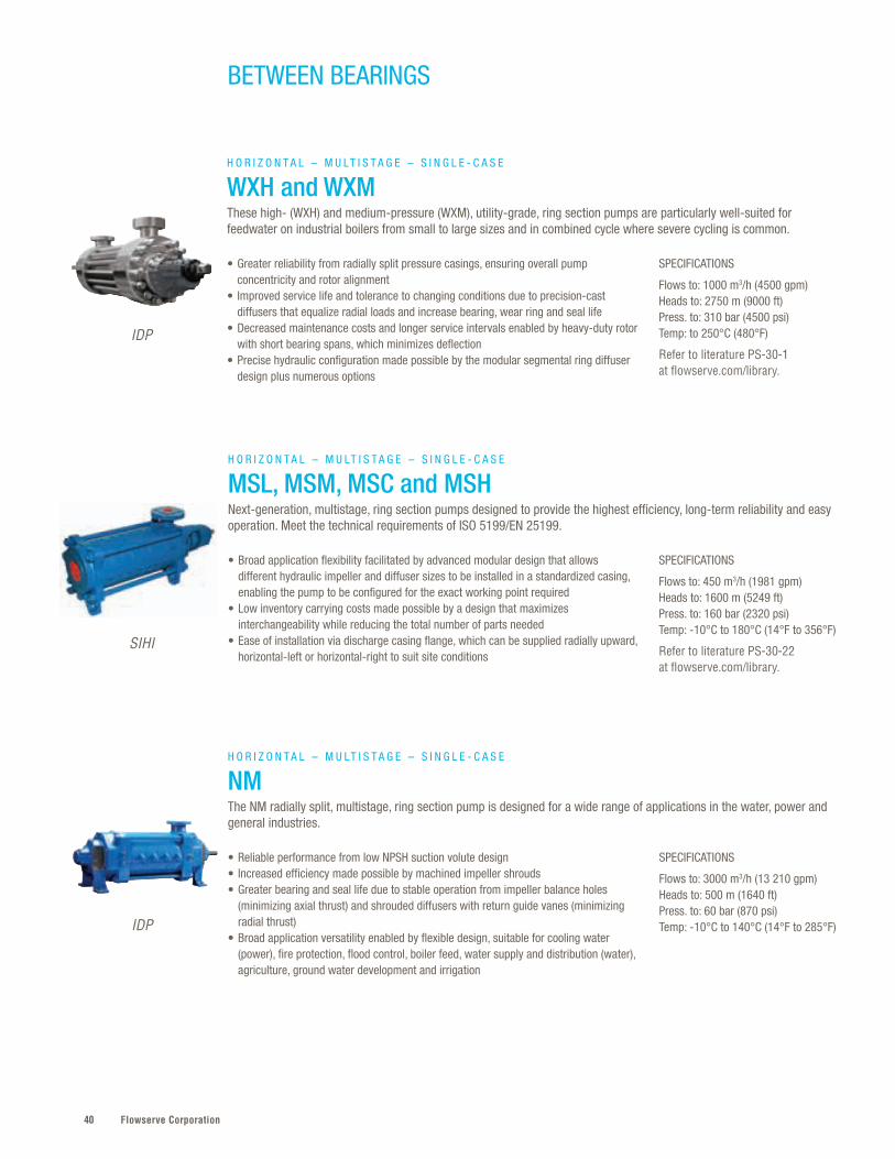
Flowserve Corporation40
BETWEEN BEARINGS
SPECIFICATIONS
Flows to: 3000 m3/h (13 210 gpm)Heads to: 500 m (1640 ft) Press. to: 60 bar (870 psi)Temp: -10°C to 140°C (14°F to 285°F)
• Reliable performance from low NPSH suction volute design• Increased efficiency made possible by machined impeller shrouds• Greater bearing and seal life due to stable operation from impeller balance holes
(minimizing axial thrust) and shrouded diffusers with return guide vanes (minimizing radial thrust)
• Broad application versatility enabled by flexible design, suitable for cooling water (power), fire protection, flood control, boiler feed, water supply and distribution (water), agriculture, ground water development and irrigation
H O R I Z O N T A L – M U LT I S T A G E – S I N G L E - C A S E
NMThe NM radially split, multistage, ring section pump is designed for a wide range of applications in the water, power and general industries.
IDP
SPECIFICATIONS
Flows to: 450 m3/h (1981 gpm)Heads to: 1600 m (5249 ft)Press. to: 160 bar (2320 psi)Temp: -10°C to 180°C (14°F to 356°F)
Refer to literature PS-30-22 at flowserve.com/library.
• Broad application flexibility facilitated by advanced modular design that allows different hydraulic impeller and diffuser sizes to be installed in a standardized casing, enabling the pump to be configured for the exact working point required
• Low inventory carrying costs made possible by a design that maximizes interchangeability while reducing the total number of parts needed
• Ease of installation via discharge casing flange, which can be supplied radially upward, horizontal-left or horizontal-right to suit site conditions
H O R I Z O N T A L – M U LT I S T A G E – S I N G L E - C A S E
MSL, MSM, MSC and MSHNext-generation, multistage, ring section pumps designed to provide the highest efficiency, long-term reliability and easy operation. Meet the technical requirements of ISO 5199/EN 25199.
SIHI
SPECIFICATIONS
Flows to: 1000 m3/h (4500 gpm)Heads to: 2750 m (9000 ft) Press. to: 310 bar (4500 psi)Temp: to 250°C (480°F)
Refer to literature PS-30-1 at flowserve.com/library.
• Greater reliability from radially split pressure casings, ensuring overall pump concentricity and rotor alignment
• Improved service life and tolerance to changing conditions due to precision-cast diffusers that equalize radial loads and increase bearing, wear ring and seal life
• Decreased maintenance costs and longer service intervals enabled by heavy-duty rotor with short bearing spans, which minimizes deflection
• Precise hydraulic configuration made possible by the modular segmental ring diffuser design plus numerous options
H O R I Z O N T A L – M U LT I S T A G E – S I N G L E - C A S E
WXH and WXMThese high- (WXH) and medium-pressure (WXM), utility-grade, ring section pumps are particularly well-suited for feedwater on industrial boilers from small to large sizes and in combined cycle where severe cycling is common.
IDP
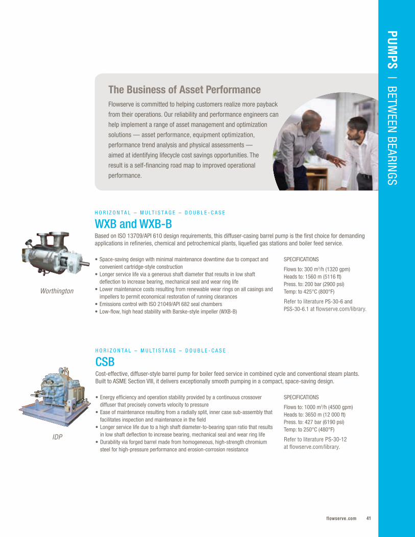
41flowserve.com
The Business of Asset Performance Flowserve is committed to helping customers realize more payback
from their operations. Our reliability and performance engineers can
help implement a range of asset management and optimization
solutions — asset performance, equipment optimization,
performance trend analysis and physical assessments —
aimed at identifying lifecycle cost savings opportunities. The
result is a self-financing road map to improved operational
performance.
SPECIFICATIONS
Flows to: 300 m3/h (1320 gpm)Heads to: 1560 m (5116 ft) Press. to: 200 bar (2900 psi)Temp: to 425°C (800°F)
Refer to literature PS-30-6 and PSS-30-6.1 at flowserve.com/library.
• Space-saving design with minimal maintenance downtime due to compact and convenient cartridge-style construction
• Longer service life via a generous shaft diameter that results in low shaft deflection to increase bearing, mechanical seal and wear ring life
• Lower maintenance costs resulting from renewable wear rings on all casings and impellers to permit economical restoration of running clearances
• Emissions control with ISO 21049/API 682 seal chambers • Low-flow, high head stability with Barske-style impeller (WXB-B)
H O R I Z O N T A L – M U LT I S T A G E – D O U B L E - C A S E
WXB and WXB-BBased on ISO 13709/API 610 design requirements, this diffuser-casing barrel pump is the first choice for demanding applications in refineries, chemical and petrochemical plants, liquefied gas stations and boiler feed service.
Worthington
PUM
PS | BETWEEN
BEARINGS
SPECIFICATIONS
Flows to: 1000 m3/h (4500 gpm)Heads to: 3650 m (12 000 ft)Press. to: 427 bar (6190 psi)Temp: to 250°C (480°F)
Refer to literature PS-30-12 at flowserve.com/library.
• Energy efficiency and operation stability provided by a continuous crossover diffuser that precisely converts velocity to pressure
• Ease of maintenance resulting from a radially split, inner case sub-assembly that facilitates inspection and maintenance in the field
• Longer service life due to a high shaft diameter-to-bearing span ratio that results in low shaft deflection to increase bearing, mechanical seal and wear ring life
• Durability via forged barrel made from homogeneous, high-strength chromium steel for high-pressure performance and erosion-corrosion resistance
H O R I Z O N T A L – M U LT I S T A G E – D O U B L E - C A S E
CSBCost-effective, diffuser-style barrel pump for boiler feed service in combined cycle and conventional steam plants. Built to ASME Section VIII, it delivers exceptionally smooth pumping in a compact, space-saving design.
IDP
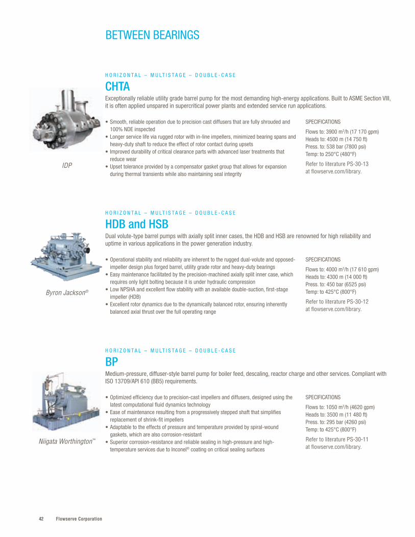
Flowserve Corporation42
BETWEEN BEARINGS
SPECIFICATIONS
Flows to: 1050 m3/h (4620 gpm)Heads to: 3500 m (11 480 ft)Press. to: 295 bar (4260 psi)Temp: to 425°C (800°F)
Refer to literature PS-30-11 at flowserve.com/library.
• Optimized efficiency due to precision-cast impellers and diffusers, designed using the latest computational fluid dynamics technology
• Ease of maintenance resulting from a progressively stepped shaft that simplifies replacement of shrink-fit impellers
• Adaptable to the effects of pressure and temperature provided by spiral-wound gaskets, which are also corrosion-resistant
• Superior corrosion-resistance and reliable sealing in high-pressure and high-temperature services due to Inconel® coating on critical sealing surfaces
H O R I Z O N T A L – M U LT I S T A G E – D O U B L E - C A S E
BPMedium-pressure, diffuser-style barrel pump for boiler feed, descaling, reactor charge and other services. Compliant with ISO 13709/API 610 (BB5) requirements.
Niigata Worthington™
IDP
SPECIFICATIONS
Flows to: 3900 m3/h (17 170 gpm)Heads to: 4500 m (14 750 ft)Press. to: 538 bar (7800 psi)Temp: to 250°C (480°F)
Refer to literature PS-30-13 at flowserve.com/library.
• Smooth, reliable operation due to precision cast diffusers that are fully shrouded and 100% NDE inspected
• Longer service life via rugged rotor with in-line impellers, minimized bearing spans and heavy-duty shaft to reduce the effect of rotor contact during upsets
• Improved durability of critical clearance parts with advanced laser treatments that reduce wear
• Upset tolerance provided by a compensator gasket group that allows for expansion during thermal transients while also maintaining seal integrity
H O R I Z O N T A L – M U LT I S T A G E – D O U B L E - C A S E
CHTAExceptionally reliable utility grade barrel pump for the most demanding high-energy applications. Built to ASME Section VIII, it is often applied unspared in supercritical power plants and extended service run applications.
SPECIFICATIONS
Flows to: 4000 m3/h (17 610 gpm)Heads to: 4300 m (14 000 ft) Press. to: 450 bar (6525 psi)Temp: to 425°C (800°F)
Refer to literature PS-30-12 at flowserve.com/library.
• Operational stability and reliability are inherent to the rugged dual-volute and opposed-impeller design plus forged barrel, utility grade rotor and heavy-duty bearings
• Easy maintenance facilitated by the precision-machined axially split inner case, which requires only light bolting because it is under hydraulic compression
• Low NPSHA and excellent flow stability with an available double-suction, first-stage impeller (HDB)
• Excellent rotor dynamics due to the dynamically balanced rotor, ensuring inherently balanced axial thrust over the full operating range
H O R I Z O N T A L – M U LT I S T A G E – D O U B L E - C A S E
HDB and HSBDual volute-type barrel pumps with axially split inner cases, the HDB and HSB are renowned for high reliability and uptime in various applications in the power generation industry.
Byron Jackson®

43flowserve.com
VALVES | LINEAR CO
NTRO
LPU
MPS | BETW
EEN BEARIN
GS
SPECIFICATIONS
Flows to: 1000 m3/h (4400 gpm)Heads to: 2800 m (9200 ft)Press. to: 275 bar (4000 psi)Temp: to 425°C (800°F)
Refer to literature PS-30-7 at flowserve.com/library.
• Optimized hydraulic efficiency and repeatable performance due to precision-cast tandem impellers, multi-vane diffusers and advanced balance drum design
• Incredible reliability with advanced close clearance technologies, erosion- and abrasion-resistant materials in the running fits, and robust bearing system
• Reduced downtime and maintenance from the standard cartridge type construction that allows major assembly and disassembly in the workshop rather than the field
• Balanced hydraulic loads over the operating range while maximizing efficiency at duty conditions enabled by single diameter balance drum
H O R I Z O N T A L – M U LT I S T A G E – D O U B L E - C A S E
WCCMedium-duty, diffuser-type barrel pump built to ISO 13709/API 610 (BB5) and customer specifications. Typically used in refinery services, pipeline, amine and ethylene feed, water and CO2 injection, plus hydraulic power recovery.
IDP
Flowserve
SPECIFICATIONS
Flows to: 1600 m3/h (7000 gpm)Heads to: 7000 m (23 000 ft)Press. to: 1000 bar (14 500 psi)Temp: to 425°C (800°F)
Refer to literature PS-30-9 at flowserve.com/library.
• Outstanding reliability assured by low static deflection, the result of a large diameter shaft and short bearing spans
• Optimized efficiency due to precision-cast, low specific speed impellers, multi-vane diffuser and milled channel collectors to ensure repeatable performance
• Smooth, stable performance with multi-vane, split diffuser and channel ring collectors that eliminate radial imbalance
• Performance tested in accordance with API and Hydraulic Institute standards• Ease of maintenance with back pullout, cartridge-style construction
H O R I Z O N T A L – M U LT I S T A G E – D O U B L E - C A S E
WIK and WIKOExtra heavy-duty barrel pump intended for special purpose, unspared, high-power density applications. Pumps are custom engineered to customer requirements, often exceeding ISO 13709/API 610 (BB5).
SPECIFICATIONS
Flows to: 4000 m3/h (17 610 gpm)Heads to: 5365 m (16 000 ft)Press. to: 450 bar (6525 psi)Temp: to 425°C (800°F)
Refer to literature PS-30-8 at flowserve.com/library.
• Highest reliability in critical processes assured by the volute design • Improved hydraulic efficiency and performance repeatability provided by the
precision-cast opposed impellers • Nearly balanced axial thrust with volute-type opposed impeller design that breaks
down 50% of the discharge pressure to the intermediate stage before the long crossover
• Excellent rotor dynamics due to the dynamically balanced rotor, ensuring inherently balanced axial thrust over the full operating range
H O R I Z O N T A L – M U LT I S T A G E – D O U B L E - C A S E
HDO and HSOOffered in both general and special purpose configurations, these volute-style barrel pumps are manufactured to customer specifications, often exceeding ISO 13709/API 610 (BB5).
Byron Jackson
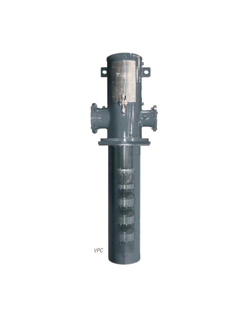
Flowserve Corporation4444
VPC
45flowserve.com
The global requirement for vertical pumps is diverse . The Flowserve portfolio reliably
addresses the vast majority, from general industrial products to massive systems used in
power generation and oil and gas . Designed to critical global standards, these pumps meet
customer energy savings goals with their extensive hydraulic options that precisely meet
operating requirements . Long-life performance in aggressive media is achieved with non-
metallic and erosion-resistant wet ends for many designs .
Vertical – Quick Reference*
VERTICAL
PUM
PS | VERTICAL
* Additional products shown on next page
Product Sub-Type Flows to Heads to Pressures to Temperatures
WUJ Wet-Pit 3000 m3/h (13 200 gpm)
2000 m (6560 ft)
200 bar (2900 psi)
-200°C to 350°C (-328°F to 660°F)
VTP Wet-Pit 13 600 m3/h (60 000 gpm)
700 m (2300 ft)
100 bar (1450 psi)
-73°C to 200°C (-100°F to 400°F)
QL and QLQ Wet-Pit 25 000 m3/h (110 000 gpm)
500 m (1640 ft)
70 bar (1015 psi)
-45°C to 204°C (-50°F to 400°F)
VCT Wet-Pit 181 700 m3/h (800 000 gpm)
110 m (350 ft) — —
AFV Wet-Pit 181 700 m3/h (800 000 gpm)
11 m (35 ft) — —
Barge VTP Wet-Pit 1035 m3/h (5000 gpm)
120 m (400 ft)
8 .6 bar(125 psi)
-18°C to 150°C (0°F to 300°F)
Molten Salt VTP Wet-Pit 13 600 m3/h (60 000 gpm)
530 m (1740 ft)
100 bar (1450 psi)
to 600°C (1100°F)
QLC and QLQC Double-Case 25 000 m3/h (110 000 gpm)
500 m (1640 ft)
70 bar (1015 psi)
-45°C to 204°C (-50°F to 400°F)
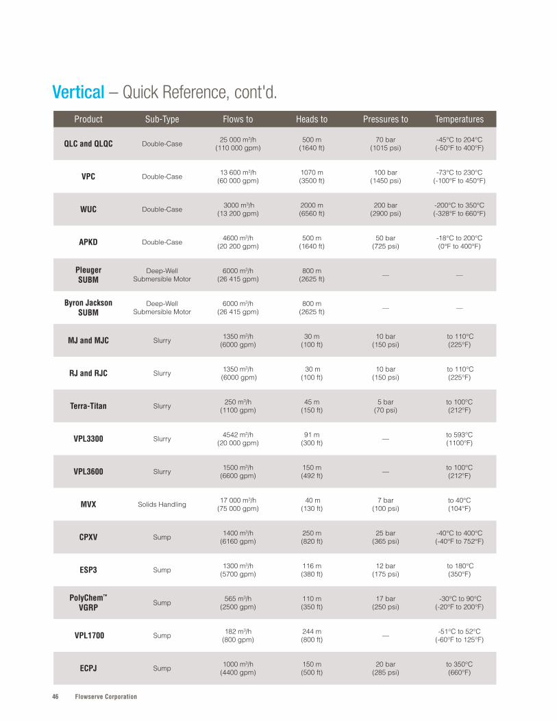
Flowserve Corporation46
Vertical – Quick Reference, cont'd.Product Sub-Type Flows to Heads to Pressures to Temperatures
QLC and QLQC Double-Case 25 000 m3/h (110 000 gpm)
500 m (1640 ft)
70 bar (1015 psi)
-45°C to 204°C (-50°F to 400°F)
VPC Double-Case 13 600 m3/h (60 000 gpm)
1070 m (3500 ft)
100 bar (1450 psi)
-73°C to 230°C (-100°F to 450°F)
WUC Double-Case 3000 m3/h (13 200 gpm)
2000 m (6560 ft)
200 bar (2900 psi)
-200°C to 350°C (-328°F to 660°F)
APKD Double-Case 4600 m3/h (20 200 gpm)
500 m (1640 ft)
50 bar (725 psi)
-18°C to 200°C (0°F to 400°F)
PleugerSUBM
Deep-WellSubmersible Motor
6000 m3/h (26 415 gpm)
800 m (2625 ft) — —
Byron JacksonSUBM
Deep-WellSubmersible Motor
6000 m3/h (26 415 gpm)
800 m (2625 ft) — —
MJ and MJC Slurry 1350 m3/h (6000 gpm)
30 m (100 ft)
10 bar (150 psi)
to 110°C (225°F)
RJ and RJC Slurry 1350 m3/h (6000 gpm)
30 m (100 ft)
10 bar (150 psi)
to 110°C (225°F)
Terra-Titan Slurry 250 m3/h (1100 gpm)
45 m (150 ft)
5 bar (70 psi)
to 100°C (212°F)
VPL3300 Slurry 4542 m3/h (20 000 gpm)
91 m (300 ft) — to 593°C
(1100°F)
VPL3600 Slurry 1500 m3/h (6600 gpm)
150 m (492 ft) — to 100°C
(212°F)
MVX Solids Handling 17 000 m3/h (75 000 gpm)
40 m (130 ft)
7 bar (100 psi)
to 40°C (104°F)
CPXV Sump 1400 m3/h (6160 gpm)
250 m (820 ft)
25 bar (365 psi)
-40°C to 400°C (-40°F to 752°F)
ESP3 Sump 1300 m3/h (5700 gpm)
116 m (380 ft)
12 bar (175 psi)
to 180°C (350°F)
PolyChem™
VGRPSump 565 m3/h
(2500 gpm)110 m (350 ft)
17 bar (250 psi)
-30°C to 90°C (-20°F to 200°F)
VPL1700 Sump 182 m3/h (800 gpm)
244 m (800 ft) — -51°C to 52°C
(-60°F to 125°F)
ECPJ Sump 1000 m3/h (4400 gpm)
150 m (500 ft)
20 bar (285 psi)
to 350°C (660°F)

47flowserve.com
VALVES | LINEAR CO
NTRO
LPU
MPS | O
VERHUNG
PUM
PS | VERTICALSPECIFICATIONS
Flows to: 3000 m3/h (13 200 gpm)Heads to: 2000 m (6560 ft) Press. to: 200 bar (2900 psi)Temp: -200°C to 350°C (-328°F to 660°F)
Refer to literature PS-40-8 at flowserve.com/library.
SPECIFICATIONS
Flows to: 13 600 m3/h (60 000 gpm)Heads to: 700 m (2300 ft) Press. to: 100 bar (1450 psi)Temp: -73°C to 200°C (-100°F to 400°F)
Refer to literature PS-40-4 at flowserve.com/library.
SPECIFICATIONS
Flows to: 25 000 m3/h (110 000 gpm)Heads to: 500 m (1640 ft)Press. to: 70 bar (1015 psi)Temp: -45°C to 204°C (-50°F to 400°F)
Refer to literature PS-40-6 at flowserve.com/library.
• Maximum design and operating flexibility enabled by modular design system along with mixed or radial flow hydraulics, which enable precise configuration
• Unspared reliability owing to under-critical stiff shaft design, separate axial thrust bearing assembly and pressure-containing parts certified to international standards
• Economical retention of operating efficiency and mechanical stability with casing and impeller wear rings
• Reduced maintenance with flanged spacer-type coupling that permits easy access to the thrust bearings and mechanical seals without disturbing the motor
• Unsurpassed hydraulic coverage with more than 300 bowl and impeller designs to ensure optimum pump selection
• Design flexibility arising from a wide variety of configurations, constructions and materials to suit application requirements; standard and ISO 13709/API 610 (VS1) units available
• Lower operating costs from available aftermarket rebowl services that revitalize aged VTPs — including competitor models — to reduce power consumption, downtime and maintenance costs
• Superior performance from innovative, double-suction impeller that produces more flow and higher head at lower NPSHR
• High uptime with sealed-for-life bottom bearing plus heavy-duty discharge head and integral line shaft bracket, which ensure shaft concentricity and alignment
• High operating efficiency promoted by renewable impeller wear rings that restore original clearances
• Reliable performance in applications containing silt or abrasive solids owing to optional enclosed lineshaft construction
W E T - P I T
WUJHighly engineered heavy-duty, multistage vertical pump for wet-pit or deep well applications requiring continuous, unspared duty in a variety of severe services. Meets or exceeds ISO 13709/API 610 (VS1).
W E T - P I T
VTPDiffuser-type, single or multistage vertical turbine pump for use in wet-pit or deep well applications in a variety of industries, including oil and gas, power, water, chemical, mining and metals.
W E T - P I T
QL and QLQDouble-suction, twin-volute vertical turbine pumps in single (QL) or multistage (QLQ) designs. ISO 13709/API 610 (VS2) compliant units available.
Worthington
Flowserve
Worthington

Flowserve Corporation48
VERTICAL
SPECIFICATIONS
Flows to: 181 700 m3/h (800 000 gpm)Heads to: 110 m (350 ft)
Refer to literature PS-40-6 at flowserve.com/library.
• Reliable, efficient performance assured by a five-mitered elbow discharge head designed to reduce friction loss
• Outstanding operating efficiency arising from multiple hydraulic combinations that allow precise configuration
• Longer service life due to an inner column enclosing tube that is internally pressurized to lubricate bearings and prevent shaft and bearing damage during operation
• Design flexibility with above- or below-grade discharge, pullout and non-pullout designs, plus grease, freshwater or self-lubricating column constructions
W E T - P I T
VCTMixed-flow circulating pump designed for continuous duty wet-pit applications requiring large capacities at relatively low heads. Often used in power plants, desalination, cooling water, drainage, flood protection and water supply.
SPECIFICATIONS
Flows to: 181 700 m3/h (800 000 gpm)Heads to: 11 m (35 ft)
Refer to literature PS-40-3 at flowserve.com/library.
SPECIFICATIONS
Flows to: 1035 m3/h (5000 gpm)Heads to: 120 m (400 ft) Press. to: 8.6 bar (125 psi)Temp: -18°C to 150°C (0°F to 300°F)
Refer to literature PSS-40-7.2 at flowserve.com/library.
• Optimal performance from a flared suction bell that provides a smooth entrance to the impeller and has integral splitters to reduce swirl and entrance losses
• Improved reliability resulting from a hydraulically balanced three- or four-vane axial flow propeller and top propeller hub wear ring to reduce axial down thrust
• Installation versatility provided by a discharge elbow that can be located above or below ground at any orientation
• Design flexibility with pullout or non-pullout construction, packing or mechanical seal, drive options, and optional enclosed lineshaft with oil or freshwater lubrication
• Reduced stripping turnaround times assured by a self-priming stripper stage that operates efficiently at extremely low submergence levels
• Fewer costly oil and chemical spills owing to a bleed off stuffing box that diverts product bypass back to the compartment via a sealed return line
• Ease of maintenance resulting from large ports that allow access to the stuffing box without removing the driver
W E T - P I T
AFVThe AFV axial flow suspended shaft vertical pump is a single-stage, propeller-type design. This pump is designed for low head movement of water for municipal, agricultural and industrial services.
W E T - P I T
Barge VTPVertical self-contained, self-priming unit designed for barge unloading and transfer operations. Innovative pollution prevention design inhibits costly oil and chemical spills.
Flowserve
Flowserve
Flowserve
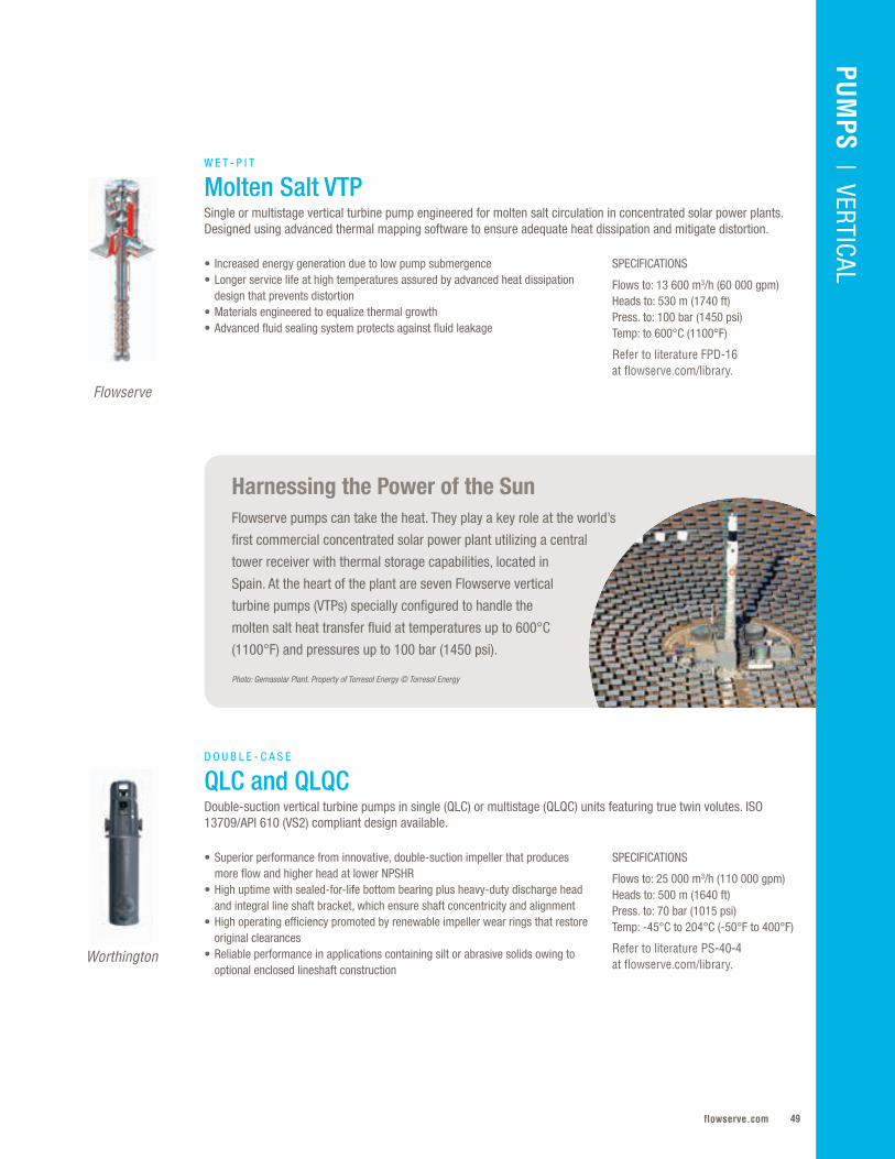
49flowserve.com
Harnessing the Power of the SunFlowserve pumps can take the heat. They play a key role at the world’s
first commercial concentrated solar power plant utilizing a central
tower receiver with thermal storage capabilities, located in
Spain. At the heart of the plant are seven Flowserve vertical
turbine pumps (VTPs) specially configured to handle the
molten salt heat transfer fluid at temperatures up to 600°C
(1100°F) and pressures up to 100 bar (1450 psi).
Photo: Gemasolar Plant. Property of Torresol Energy © Torresol Energy
VALVES | LINEAR CO
NTRO
LPU
MPS
| VERTICAL
SPECIFICATIONS
Flows to: 25 000 m3/h (110 000 gpm)Heads to: 500 m (1640 ft)Press. to: 70 bar (1015 psi)Temp: -45°C to 204°C (-50°F to 400°F)
Refer to literature PS-40-4 at flowserve.com/library.
• Superior performance from innovative, double-suction impeller that produces more flow and higher head at lower NPSHR
• High uptime with sealed-for-life bottom bearing plus heavy-duty discharge head and integral line shaft bracket, which ensure shaft concentricity and alignment
• High operating efficiency promoted by renewable impeller wear rings that restore original clearances
• Reliable performance in applications containing silt or abrasive solids owing to optional enclosed lineshaft construction
D O U B L E - C A S E
QLC and QLQCDouble-suction vertical turbine pumps in single (QLC) or multistage (QLQC) units featuring true twin volutes. ISO 13709/API 610 (VS2) compliant design available.
Worthington
SPECIFICATIONS
Flows to: 13 600 m3/h (60 000 gpm)Heads to: 530 m (1740 ft)Press. to: 100 bar (1450 psi)Temp: to 600°C (1100°F)
Refer to literature FPD-16 at flowserve.com/library.
Flowserve
W E T - P I T
Molten Salt VTPSingle or multistage vertical turbine pump engineered for molten salt circulation in concentrated solar power plants. Designed using advanced thermal mapping software to ensure adequate heat dissipation and mitigate distortion.
• Increased energy generation due to low pump submergence• Longer service life at high temperatures assured by advanced heat dissipation
design that prevents distortion• Materials engineered to equalize thermal growth • Advanced fluid sealing system protects against fluid leakage
Flowserve Corporation50
VERTICAL
SPECIFICATIONS
Flows to: 13 600 m3/h (60 000 gpm)Heads to: 1070 m (3500 ft)Press. to: 100 bar (1450 psi)Temp: -73°C to 230°C (-100°F to 450°F)
Refer to literature PS-40-2 at flowserve.com/library.
• Broad application versatility due to extensive hydraulic coverage plus wide variety of configurations, constructions and materials to suit application requirements
• Lower installation costs with low NPSH first-stage impeller that reduces suction can length
• Lower operating costs from available aftermarket rebowl services that revitalize aged VPCs — including competitor models — to reduce power consumption, downtime and maintenance costs
D O U B L E - C A S E
VPCDiffuser-type, vertical turbine pump well-suited for closed system and low NPSH applications. Available in single or multistage units, as well as standard and ISO 13709/API 610 (VS6) compliant designs.
Flowserve
SPECIFICATIONS
Flows to: 4600 m3/h (20 200 gpm)Heads to: 500 m (1640 ft)Press to: 50 bar (725 psi)Temp: -18°C to 200°C (0°F to 400°F)
Refer to literature PS-40-10 at flowserve.com/library.
• Lower energy consumption and operating costs provided by a versatile series of impeller design options that enable optimum hydraulic fit
• Wide operating range with multiple suction-specific speed options• Reliable operation with balanced hydraulic loads owing to double-suction,
twin-volute design
D O U B L E - C A S E
APKDThe APKD is ideal for critical services with limited NPSHA. An innovative double-suction impeller in a true twin-volute design produces more flow and higher head at lower NPSHR.
Flowserve
SPECIFICATIONS
Flows to: 3000 m3/h (13 200 gpm)Heads to: 2000 m (6560 ft)Press. to: 200 bar (2900 psi)Temp: -200°C to 350°C (-328°F to 660°F)
Refer to literature PS-40-9 at flowserve.com/library.
• Maximum design and operating flexibility enabled by modular design system, along with mixed or radial flow hydraulics that enable precise configuration
• Unspared reliability owing to stiff shaft construction, a self-contained axial thrust bearing housing and pressure-containing parts certified to international standards
• Reduced maintenance with flanged spacer type coupling that permits easy access to the thrust bearings and mechanical seals
• Reliable cryogenic operation made possible by an available coffer dam system, which provides a gas barrier between pumped fluid and mechanical seal
D O U B L E - C A S E
WUCCompliant with ISO 13709/API 610 (VS6), the WUC is a highly engineered heavy-duty, multistage process vertical pump designed for continuous duty in critical applications at high pressures and temperatures.
Worthington
51flowserve.com
VALVES | LINEAR CO
NTRO
L
Life-Giving Water in Thailand Thailand’s Royal Irrigation Department chose Flowserve to help
provide its people with dependable irrigation and flood control.
For years the people living in the 3.65 million acre Pasak
River Basin, north of Bangkok, suffered cycles of drought
and flood. No longer. With the construction of a dam
employing vertical mixed flow pumps from Flowserve,
the people are protected from flooding and have
adequate water to grow crops.
PUM
PS | VERTICAL
SPECIFICATIONS
Flows: to 6000 m3/h (26 415 gpm)Heads: to 800 m (2625 ft)Motor Sizes to: 1650 kW (2200 hp)
Refer to literature PS-50-3 at flowserve.com/library.
• Extended motor service life enabled by induction motor plus Class F insulation system designed with vacuum-pressure impregnated epoxy, re-windable stators and internal circulation system
• Maximum pump efficiency with minimum vibration provided by dynamically balanced heavy-duty impellers and bowl cases
• Ease of installation with sealed power cable plug-in feature, which eliminates field splicing
• Precise configuration for application needs owing to numerous hydraulic, cooling, lubrication, sealing, materials and accessory options
D E E P - W E L L
Byron Jackson SUBMOil-filled submersible motor pump built for the world's most demanding deep-well services. Rugged, reliable and long-lasting, the Byron Jackson SUBM offers significant total lifecycle cost savings.
Byron Jackson
SPECIFICATIONS
Flows to: 6000 m3/h (26 415 gpm)Heads to: 800 m (2625 ft)Motor Sizes to: 5000 kW (6700 hp)
Refer to literature PS-50-3 at flowserve.com/library.
• Exceptional submersible motor value owing to superior thrust bearing design, 100% pressure compensation system, re-windable stators and materials options for both strength and dielectric characteristics
• Precise configuration for application needs with many hydraulic, cooling, lubrication, sealing, materials and accessory options
• Ease of maintenance and extended service life provided by wet-type motor with non-toxic Class Y insulated windings and internal circulation system
• Maximum pump efficiency with minimum vibration due to dynamically balanced heavy-duty impellers and bowl cases
D E E P - W E L L
Pleuger SUBMThe Pleuger SUBM submersible motor pump uses water-filled, wet-wound motors. This design is environmentally friendly, provides high efficiency and offers great reliability.
Pleuger®

Flowserve Corporation52
VERTICAL
SPECIFICATIONS
Flows to: 1350 m3/h (6000 gpm)Heads to: 30 m (100 ft)Press. to: 10 bar (150 psi)Temp: to 110°C (225°F)
Refer to literature PS-10-19 at flowserve.com/library.
• Increased uptime provided by extra-thick wear allowances• Efficient operation and prolonged service life as a result of concentric casing and anti
pre-rotation vanes, which reduce suction pipe swirl and impeller wear• Extended seal and bearing life enabled by closed impeller with pump-out vanes, which
reduces stuffing box pressure and suction recirculation as well as balances axial hydraulic loads
• Reduced inventory costs from parts interchangeability among related horizontal and vertical configurations
S L U R R Y
MJ and MJCVertical lineshaft (MJ) and cantlever (MJC) hard-metal slurry pumps designed for services containing coarse solids in suspension (to 70% by weight). Suitable for a broad range of wet- and dry-pit services.
SPECIFICATIONS
Flows to: 1350 m3/h (6000 gpm)Heads to: 30 m (100 ft)Press. to: 10 bar (150 psi)Temp: to 110°C (225°F)
Refer to literature PS-10-18 at flowserve.com/library.
• Low total cost of ownership provided by replaceable rubber liners • Extended seal and bearing life enabled by rubber-closed impeller with pump-out
vanes, which reduces stuffing box pressure and suction recirculation as well as balances axial hydraulic loads
• Efficient operation and prolonged service life as a result of concentric casing and anti pre-rotation vanes, which reduce suction pipe swirl and impeller wear
• Reduced inventory costs from parts interchangeability among related horizontal and vertical configurations
S L U R R Y
RJ and RJCRubber-lined lineshaft (RJ) and cantilever (RJC) slurry pumps designed to handle services containing fine solids in suspension (to 70% by weight). Suitable for a broad range of wet- and dry-pit applications.
Worthington
Worthington
SPECIFICATIONS
Flows to: 250 m3/h (1100 gpm)Heads to: 45 m (150 ft)Press. to: 5 bar (70 psi)Temp: to 100°C (212°F)
Refer to literature PS-10-7 at flowserve.com/library.
• Reliable, long-lasting performance due to rigid one-piece suspended, oversized cantilever shaft design, which reduces vibration and tolerates run-dry operation
• Reduced maintenance with renewable Terraprene™ shaft sleeve that eliminates shaft wear within the casing
• Ease of maintenance and efficient operation via external impeller adjustment, which provides simple way to adjust clearances for special applications
• Application versatility provided by low-mounted motor, taper lock bushes and V-belt drive, which allow simple adaptation to suitable pump speeds
S L U R R Y
Terra-TitanThis vertical cantilever shaft sump pump is ruggedly built to provide economic reliability demanded by mining, process and general industries.
TKL
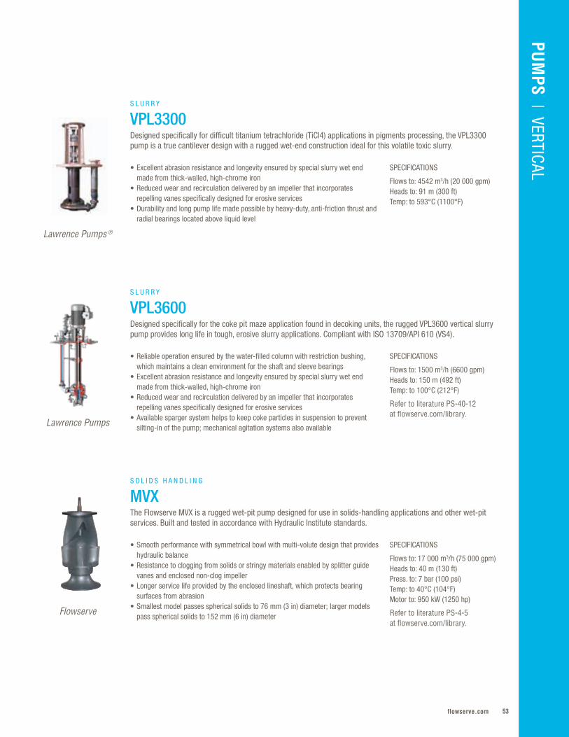
53flowserve.com
VALVES | LINEAR CO
NTRO
LPU
MPS
| VERTICAL
SPECIFICATIONS
Flows to: 1500 m3/h (6600 gpm)Heads to: 150 m (492 ft)Temp: to 100°C (212°F)
Refer to literature PS-40-12 at flowserve.com/library.
SPECIFICATIONS
Flows to: 4542 m3/h (20 000 gpm)Heads to: 91 m (300 ft)Temp: to 593°C (1100°F)
SPECIFICATIONS
Flows to: 17 000 m3/h (75 000 gpm)Heads to: 40 m (130 ft)Press. to: 7 bar (100 psi)Temp: to 40°C (104°F)Motor to: 950 kW (1250 hp)
Refer to literature PS-4-5 at flowserve.com/library.
• Reliable operation ensured by the water-filled column with restriction bushing, which maintains a clean environment for the shaft and sleeve bearings
• Excellent abrasion resistance and longevity ensured by special slurry wet end made from thick-walled, high-chrome iron
• Reduced wear and recirculation delivered by an impeller that incorporates repelling vanes specifically designed for erosive services
• Available sparger system helps to keep coke particles in suspension to prevent silting-in of the pump; mechanical agitation systems also available
• Excellent abrasion resistance and longevity ensured by special slurry wet end made from thick-walled, high-chrome iron
• Reduced wear and recirculation delivered by an impeller that incorporates repelling vanes specifically designed for erosive services
• Durability and long pump life made possible by heavy-duty, anti-friction thrust and radial bearings located above liquid level
• Smooth performance with symmetrical bowl with multi-volute design that provides hydraulic balance
• Resistance to clogging from solids or stringy materials enabled by splitter guide vanes and enclosed non-clog impeller
• Longer service life provided by the enclosed lineshaft, which protects bearing surfaces from abrasion
• Smallest model passes spherical solids to 76 mm (3 in) diameter; larger models pass spherical solids to 152 mm (6 in) diameter
S L U R R Y
VPL3600 Designed specifically for the coke pit maze application found in decoking units, the rugged VPL3600 vertical slurry pump provides long life in tough, erosive slurry applications. Compliant with ISO 13709/API 610 (VS4).
S L U R R Y
VPL3300 Designed specifically for difficult titanium tetrachloride (TiCl4) applications in pigments processing, the VPL3300 pump is a true cantilever design with a rugged wet-end construction ideal for this volatile toxic slurry.
S O L I D S H A N D L I N G
MVXThe Flowserve MVX is a rugged wet-pit pump designed for use in solids-handling applications and other wet-pit services. Built and tested in accordance with Hydraulic Institute standards.
Lawrence Pumps
Lawrence Pumps ®
Flowserve
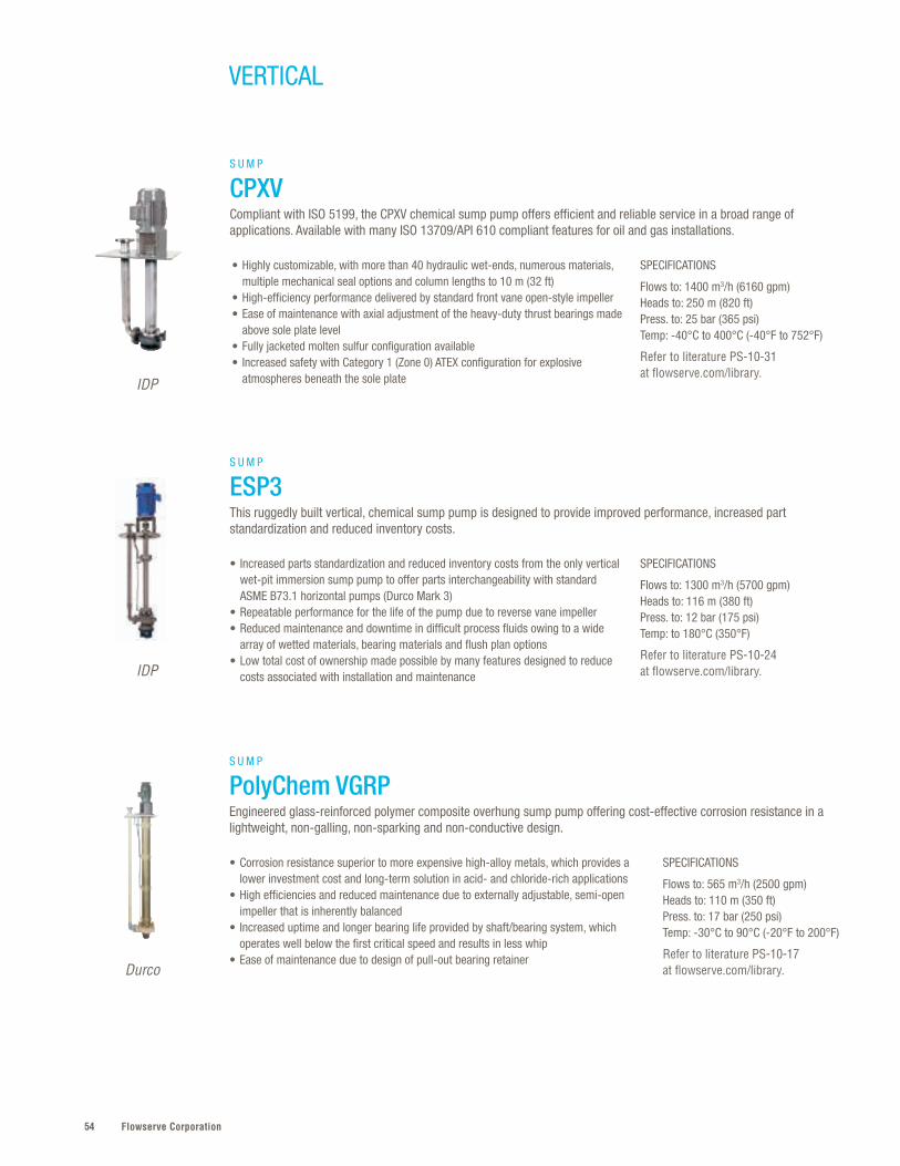
Flowserve Corporation54
SPECIFICATIONS
Flows to: 565 m3/h (2500 gpm)Heads to: 110 m (350 ft)Press. to: 17 bar (250 psi)Temp: -30°C to 90°C (-20°F to 200°F)
Refer to literature PS-10-17 at flowserve.com/library.
• Corrosion resistance superior to more expensive high-alloy metals, which provides a lower investment cost and long-term solution in acid- and chloride-rich applications
• High efficiencies and reduced maintenance due to externally adjustable, semi-open impeller that is inherently balanced
• Increased uptime and longer bearing life provided by shaft/bearing system, which operates well below the first critical speed and results in less whip
• Ease of maintenance due to design of pull-out bearing retainerDurco
S U M P
PolyChem VGRPEngineered glass-reinforced polymer composite overhung sump pump offering cost-effective corrosion resistance in a lightweight, non-galling, non-sparking and non-conductive design.
VERTICAL
SPECIFICATIONS
Flows to: 1400 m3/h (6160 gpm)Heads to: 250 m (820 ft)Press. to: 25 bar (365 psi)Temp: -40°C to 400°C (-40°F to 752°F)
Refer to literature PS-10-31 at flowserve.com/library.
SPECIFICATIONS
Flows to: 1300 m3/h (5700 gpm)Heads to: 116 m (380 ft)Press. to: 12 bar (175 psi)Temp: to 180°C (350°F)
Refer to literature PS-10-24 at flowserve.com/library.
• Highly customizable, with more than 40 hydraulic wet-ends, numerous materials, multiple mechanical seal options and column lengths to 10 m (32 ft)
• High-efficiency performance delivered by standard front vane open-style impeller• Ease of maintenance with axial adjustment of the heavy-duty thrust bearings made
above sole plate level• Fully jacketed molten sulfur configuration available• Increased safety with Category 1 (Zone 0) ATEX configuration for explosive
atmospheres beneath the sole plate
• Increased parts standardization and reduced inventory costs from the only vertical wet-pit immersion sump pump to offer parts interchangeability with standard ASME B73.1 horizontal pumps (Durco Mark 3)
• Repeatable performance for the life of the pump due to reverse vane impeller • Reduced maintenance and downtime in difficult process fluids owing to a wide
array of wetted materials, bearing materials and flush plan options • Low total cost of ownership made possible by many features designed to reduce
costs associated with installation and maintenance
IDP
S U M P
ESP3This ruggedly built vertical, chemical sump pump is designed to provide improved performance, increased part standardization and reduced inventory costs.
S U M P
CPXVCompliant with ISO 5199, the CPXV chemical sump pump offers efficient and reliable service in a broad range of applications. Available with many ISO 13709/API 610 compliant features for oil and gas installations.
IDP
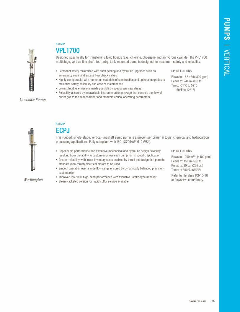
55flowserve.com
VALVES | LINEAR CO
NTRO
L
SPECIFICATIONS
Flows to: 182 m3/h (800 gpm)Heads to: 244 m (800 ft)Temp: -51°C to 52°C (-60°F to 125°F)
SPECIFICATIONS
Flows to: 1000 m3/h (4400 gpm)Heads to: 150 m (500 ft)Press. to: 20 bar (285 psi)Temp: to 350°C (660°F)
Refer to literature PS-10-10 at flowserve.com/library.
• Personnel safety maximized with shaft sealing and hydraulic upgrades such as emergency seals and excess flow check valves
• Highly configurable, with numerous materials of construction and optional upgrades to maximize safety, reliability and ease of maintenance
• Lowest fugitive emissions made possible by special gas seal design • Reliability assured by an available instrumentation package that controls the flow of
buffer gas to the seal chamber and monitors critical operating parameters
• Dependable performance and extensive mechanical and hydraulic design flexibility resulting from the ability to custom engineer each pump for its specific application
• Greater reliability with lower inventory costs enabled by thrust pot design that permits standard (non-thrust) electrical motors to be used
• Smooth operation over a wide flow range ensured by dynamically balanced precision-cast impeller
• Improved low-flow, high-head performance with available Barske-type impeller • Steam-jacketed version for liquid sulfur service available
S U M P
VPL1700Designed specifically for transferring toxic liquids (e.g., chlorine, phosgene and anhydrous cyanide), the VPL1700 multistage, vertical line shaft, top-entry, tank-mounted pump is designed for maximum safety and reliability.
S U M P
ECPJThis rugged, single-stage, vertical-lineshaft sump pump is a proven performer in tough chemical and hydrocarbon processing applications. Fully compliant with ISO 13709/API 610 (VS4).
Lawrence Pumps
Worthington
PUM
PS | VERTICAL
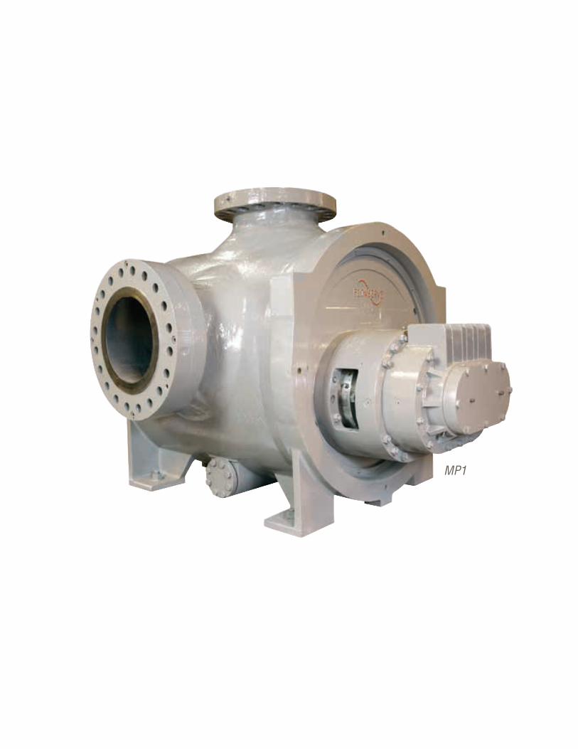
Flowserve Corporation5656
MP1
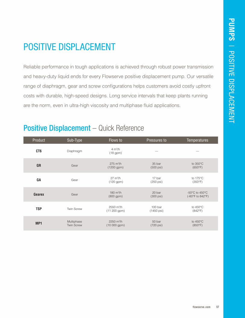
57flowserve.com
Positive Displacement – Quick ReferenceProduct Sub-Type Flows to Pressures to Temperatures
CT6 Diaphragm 4 m3/h(18 gpm) — —
GR Gear 275 m3/h (1200 gpm)
35 bar (500 psi)
to 350°C (650°F)
GA Gear 27 m3/h (120 gpm)
17 bar (250 psi)
to 175°C (350°F)
Gearex Gear 180 m3/h (800 gpm)
20 bar (300 psi)
-50°C to 450°C (-60°F to 842°F)
TSP Twin Screw 2550 m3/h (11 200 gpm)
100 bar (1450 psi)
to 450°C (842°F)
MP1 Multiphase Twin Screw
2250 m3/h (10 000 gpm)
50 bar (720 psi)
to 450°C (850°F)
PUM
PS | PO
SITIVE DISPLACEM
ENT
POSITIVE DISPLACEMENT
Reliable performance in tough applications is achieved through robust power transmission
and heavy-duty liquid ends for every Flowserve positive displacement pump . Our versatile
range of diaphragm, gear and screw configurations helps customers avoid costly upfront
costs with durable, high-speed designs . Long service intervals that keep plants running
are the norm, even in ultra-high viscosity and multiphase fluid applications .
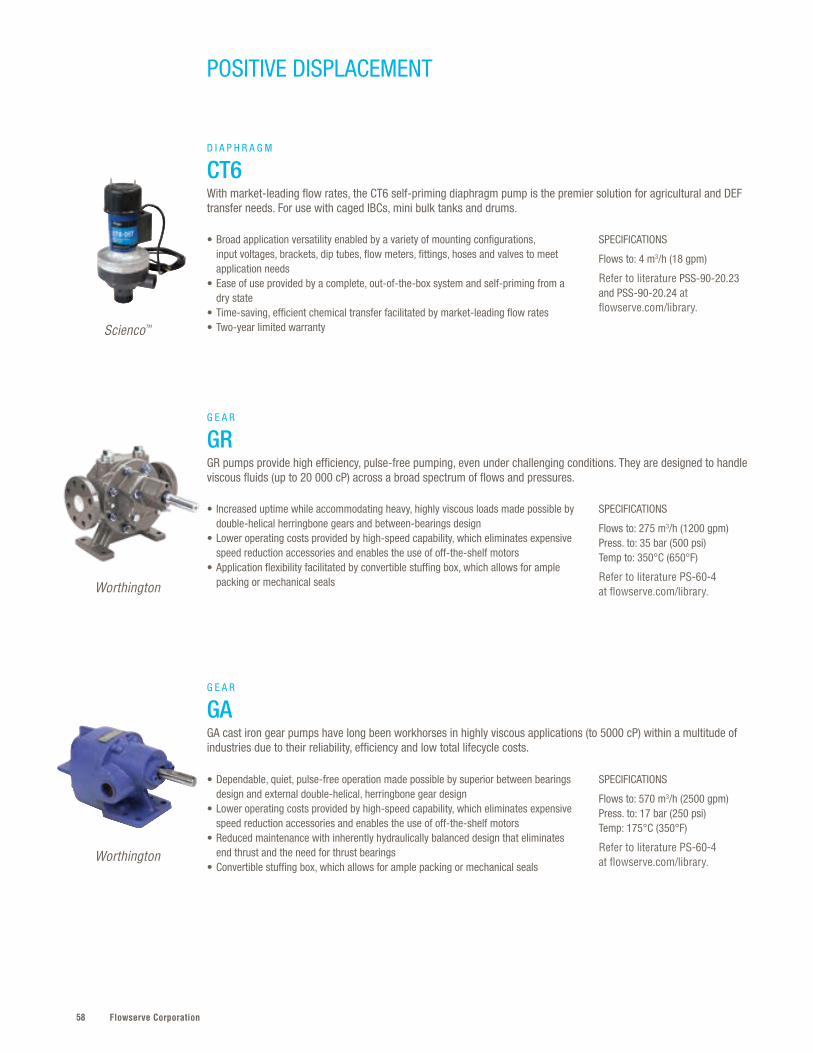
Flowserve Corporation58
SPECIFICATIONS
Flows to: 4 m3/h (18 gpm)
Refer to literature PSS-90-20.23 and PSS-90-20.24 at flowserve.com/library.
SPECIFICATIONS
Flows to: 275 m3/h (1200 gpm)Press. to: 35 bar (500 psi)Temp to: 350°C (650°F)
Refer to literature PS-60-4 at flowserve.com/library.
SPECIFICATIONS
Flows to: 570 m3/h (2500 gpm)Press. to: 17 bar (250 psi)Temp: 175°C (350°F)
Refer to literature PS-60-4 at flowserve.com/library.
• Broad application versatility enabled by a variety of mounting configurations, input voltages, brackets, dip tubes, flow meters, fittings, hoses and valves to meet application needs
• Ease of use provided by a complete, out-of-the-box system and self-priming from a dry state
• Time-saving, efficient chemical transfer facilitated by market-leading flow rates• Two-year limited warranty
• Increased uptime while accommodating heavy, highly viscous loads made possible by double-helical herringbone gears and between-bearings design
• Lower operating costs provided by high-speed capability, which eliminates expensive speed reduction accessories and enables the use of off-the-shelf motors
• Application flexibility facilitated by convertible stuffing box, which allows for ample packing or mechanical seals
• Dependable, quiet, pulse-free operation made possible by superior between bearings design and external double-helical, herringbone gear design
• Lower operating costs provided by high-speed capability, which eliminates expensive speed reduction accessories and enables the use of off-the-shelf motors
• Reduced maintenance with inherently hydraulically balanced design that eliminates end thrust and the need for thrust bearings
• Convertible stuffing box, which allows for ample packing or mechanical seals
D I A P H R A G M
CT6With market-leading flow rates, the CT6 self-priming diaphragm pump is the premier solution for agricultural and DEF transfer needs. For use with caged IBCs, mini bulk tanks and drums.
G E A R
GR GR pumps provide high efficiency, pulse-free pumping, even under challenging conditions. They are designed to handle viscous fluids (up to 20 000 cP) across a broad spectrum of flows and pressures.
G E A R
GAGA cast iron gear pumps have long been workhorses in highly viscous applications (to 5000 cP) within a multitude of industries due to their reliability, efficiency and low total lifecycle costs.
Scienco™
Worthington
Worthington
POSITIVE DISPLACEMENT

59flowserve.com
VALVES | LINEAR CO
NTRO
L
SPECIFICATIONS
Flows to: 180 m3/h (800 gpm)Press. to: 20 bar (300 psi)Temp: -50°C to 450°C (-60°F to 842°F)
Refer to literature PS-60-4 at flowserve.com/library.
• Long, reliable operation due to precision-machined herringbone pumping gears that provide low vibration, pulseless discharge while timing gears transfer power with minimal wear
• Lower total cost of ownership derived from ability to directly connect to motors up to 1800 rpm, eliminating the need for heavy foundation, belts or reduction gears
• Increased uptime via heavy-duty ball and roller bearings, which support the rotating element to prevent contact with the housing
• Reduced downtime with split brackets facilitate seal maintenance
G E A R
GearexExtremely rugged and unusually compact for its high capacity and range, the Gearex rotary pump is generally compliant with API 676, second edition. Handles viscosities to 20 000 cP.
SPECIFICATIONS
Flows to: 2550 m3/h (11 200 gpm)Diff. Press. to: 100 bar (1450 psi)Temp: 450°C (842°F)
Refer to literature PS-60-1 at flowserve.com/library.
SPECIFICATIONS
Flows to: 2250 m3/h (10 000 gpm)Diff. Press. to: 50 bar (720 psi)Temp: to 450°C (850°F)
Refer to literature PS-60-2 at flowserve.com/library.
• Increased availability, especially in fluids that are contaminated or have poor lubricity, assured by external bearings and AGMA 11 timing gears, which are housed in separate oil reservoirs to eliminate exposure to pumped fluid
• Application versatility provided by high volumetric efficiency over a wide range of viscosities (up to 55 million cP), run-dry capability and ISO 21049/API 682 seal chamber that accommodates multiple seal types
• Ease of maintenance with split bearing brackets that provide access to the bearings and seals
• Rugged and versatile operation that readily accommodates rapid changes in viscosities, gas-to-liquid ratios and GVF
• Reliable, efficient performance from one-piece integral rotor and double-suction design, which provides balanced hydraulic loads
• High availability due to external bearings and AGMA 11 timing gears, which are housed in separate oil reservoirs to eliminate exposure to pumped fluid
• Easy access to bearings and seals with split bearing brackets• Safety and environmental compliance with ISO 21049/API 682 seal chamber
T W I N S C R E W
TSPBuilt in accordance with API 676, the TSP double-suction, timed twin-screw pump improves upon traditional rotary pump designs by providing smoother, more constant flow.
M U L T I P H A S E T W I N S C R E W
MP1Compliant with API 676, the MP1 is engineered for reliability in the toughest multiphase upstream oil field applications. Handles viscosities to 8000 cP, slurries to 70% solids by weight and gas volume fractions (GVF) to 100%
Worthington
Sier-Bath®
Flowserve
PUM
PS | PO
SITIVE DISPLACEM
ENT

Flowserve Corporation60
AEH
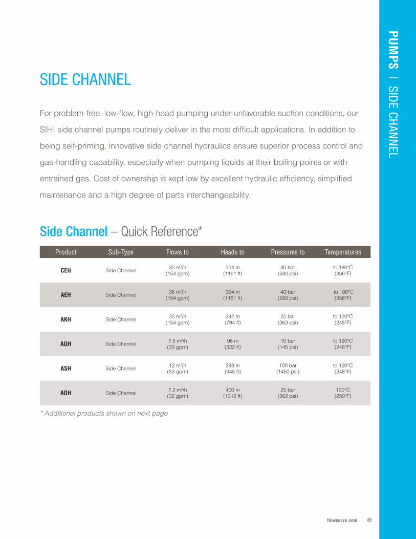
61flowserve.com
Product Sub-Type Flows to Heads to Pressures to Temperatures
CEH Side Channel 35 m3/h (154 gpm)
354 m (1161 ft)
40 bar (580 psi)
to 180°C (356°F)
AEH Side Channel 35 m3/h (154 gpm)
354 m (1161 ft)
40 bar (580 psi)
to 180°C (356°F)
AKH Side Channel 35 m3/h (154 gpm)
242 m (794 ft)
25 bar (363 psi)
to 120°C (248°F)
AOH Side Channel 7 .5 m3/h (33 gpm)
98 m (322 ft)
10 bar (145 psi)
to 120°C (248°F)
ASH Side Channel 12 m3/h (53 gpm)
288 m (945 ft)
100 bar (1450 psi)
to 120°C (248°F)
ADH Side Channel 7 .2 m3/h(32 gpm)
400 m(1312 ft)
25 bar(362 psi)
120°C(250°F)
For problem-free, low-flow, high-head pumping under unfavorable suction conditions, our
SIHI side channel pumps routinely deliver in the most difficult applications . In addition to
being self-priming, innovative side channel hydraulics ensure superior process control and
gas-handling capability, especially when pumping liquids at their boiling points or with
entrained gas . Cost of ownership is kept low by excellent hydraulic efficiency, simplified
maintenance and a high degree of parts interchangeability .
SIDE CHANNEL
PUM
PS | SID
E CHANN
EL
Side Channel – Quick Reference*
* Additional products shown on next page

Flowserve Corporation62
Side Channel – Quick Reference, cont'd.Product Sub-Type Flows to Heads to Pressures to Temperatures
SC Side Channel 65 l/min(17 gpm) — 25 bar
(362 psi)80°C
(to 176°F)
SMX Side Channel 100 l/min(26 gpm) — — -20°C to 40°C
(-4°F to 104°F)
CEB Side Channel 65 l/min(17 gpm) — 40 bar
(580 psi)-40°C to 60°C
(-40°F to 140°F)
DRV Side Channel 2 m3/h(17 gpm)
27 m (88 ft)
6 bar (218 psi)
100°C(212°F)
AKL and AKV Side Channel 12 m3/h(50 gpm)
70 m(230 ft)
16 bar (230 psi)
120°C (250°F)
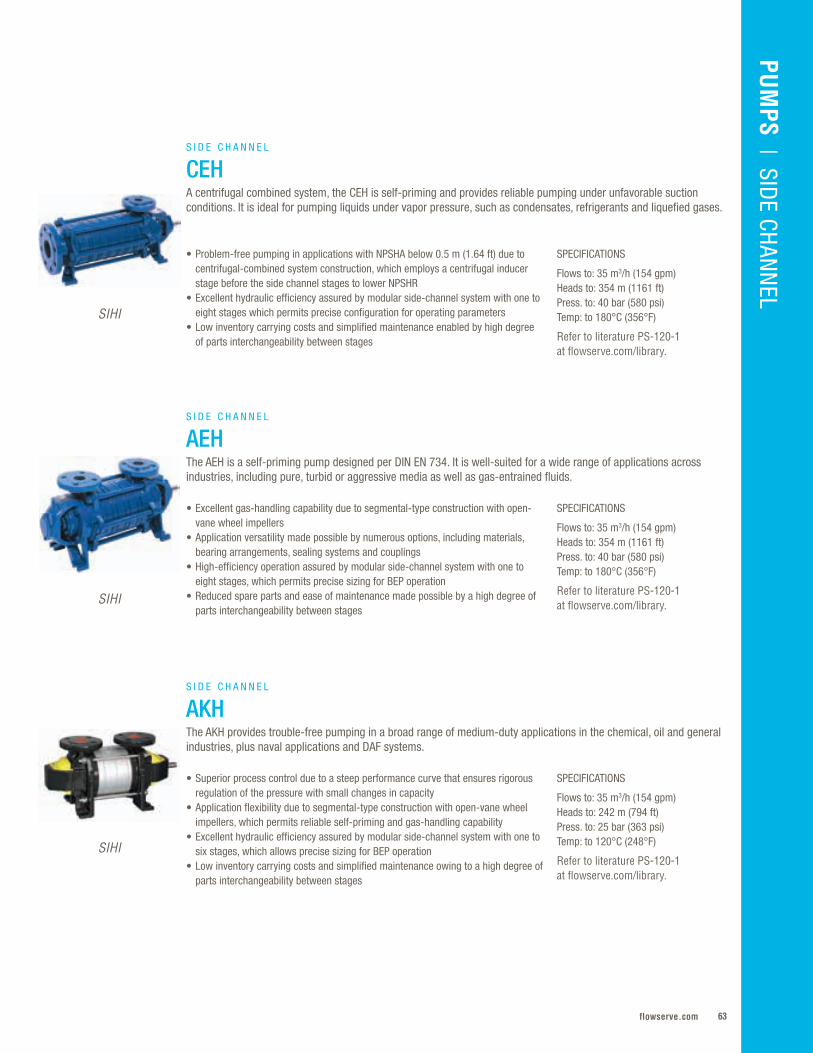
63flowserve.com
VALVES | LINEAR CO
NTRO
LPU
MPS | O
VERHUNG
PUM
PS | SID
E CHANN
EL
SPECIFICATIONS
Flows to: 35 m3/h (154 gpm)Heads to: 354 m (1161 ft)Press. to: 40 bar (580 psi)Temp: to 180°C (356°F)
Refer to literature PS-120-1 at flowserve.com/library.
SPECIFICATIONS
Flows to: 35 m3/h (154 gpm)Heads to: 354 m (1161 ft)Press. to: 40 bar (580 psi)Temp: to 180°C (356°F)
Refer to literature PS-120-1 at flowserve.com/library.
SPECIFICATIONS
Flows to: 35 m3/h (154 gpm)Heads to: 242 m (794 ft)Press. to: 25 bar (363 psi)Temp: to 120°C (248°F)
Refer to literature PS-120-1 at flowserve.com/library.
• Problem-free pumping in applications with NPSHA below 0.5 m (1.64 ft) due to centrifugal-combined system construction, which employs a centrifugal inducer stage before the side channel stages to lower NPSHR
• Excellent hydraulic efficiency assured by modular side-channel system with one to eight stages which permits precise configuration for operating parameters
• Low inventory carrying costs and simplified maintenance enabled by high degree of parts interchangeability between stages
• Excellent gas-handling capability due to segmental-type construction with open-vane wheel impellers
• Application versatility made possible by numerous options, including materials, bearing arrangements, sealing systems and couplings
• High-efficiency operation assured by modular side-channel system with one to eight stages, which permits precise sizing for BEP operation
• Reduced spare parts and ease of maintenance made possible by a high degree of parts interchangeability between stages
• Superior process control due to a steep performance curve that ensures rigorous regulation of the pressure with small changes in capacity
• Application flexibility due to segmental-type construction with open-vane wheel impellers, which permits reliable self-priming and gas-handling capability
• Excellent hydraulic efficiency assured by modular side-channel system with one to six stages, which allows precise sizing for BEP operation
• Low inventory carrying costs and simplified maintenance owing to a high degree of parts interchangeability between stages
S I D E C H A N N E L
AKHThe AKH provides trouble-free pumping in a broad range of medium-duty applications in the chemical, oil and general industries, plus naval applications and DAF systems.
SIHI
SIHI
SIHI
S I D E C H A N N E L
AEHThe AEH is a self-priming pump designed per DIN EN 734. It is well-suited for a wide range of applications across industries, including pure, turbid or aggressive media as well as gas-entrained fluids.
S I D E C H A N N E L
CEHA centrifugal combined system, the CEH is self-priming and provides reliable pumping under unfavorable suction conditions. It is ideal for pumping liquids under vapor pressure, such as condensates, refrigerants and liquefied gases.
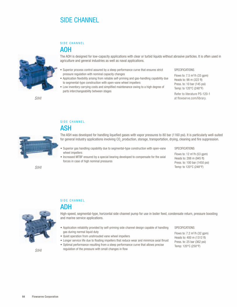
Flowserve Corporation64
SPECIFICATIONS
Flows to: 7.2 m3/h (32 gpm)Heads to: 400 m (1312 ft)Press. to: 25 bar (362 psi)Temp: 120°C (250°F)
SPECIFICATIONS
Flows to: 12 m3/h (53 gpm)Heads to: 288 m (945 ft)Press. to: 100 bar (1450 psi)Temp: to 120°C (248°F)
SPECIFICATIONS
Flows to: 7.5 m3/h (33 gpm)Heads to: 98 m (322 ft)Press. to: 10 bar (145 psi)Temp: to 120°C (248°F)
Refer to literature PS-120-1 at flowserve.com/library.
• Application reliability provided by self-priming side channel design capable of handling gas during normal liquid duty
• Quiet operation from unshrouded vane wheel impellers • Longer service life due to floating impellers that reduce wear and minimize axial thrust• Optimal performance resulting from a steep performance curve that allows precise
regulation of the pressure with small changes in flow
• Superior gas handling capability due to segmental-type construction with open-vane wheel impellers
• Increased MTBF ensured by a special bearing developed to compensate for the axial forces in case of high nominal pressures
• Superior process control assured by a steep performance curve that ensures strict pressure regulation with nominal capacity changes
• Application flexibility arising from reliable self-priming and gas-handling capability due to segmental-type construction with open-vane wheel impellers
• Low inventory carrying costs and simplified maintenance owing to a high degree of parts interchangeability between stages
S I D E C H A N N E L
ADHHigh-speed, segmental-type, horizontal side channel pump for use in boiler feed, condensate return, pressure boosting and marine service applications.
S I D E C H A N N E L
ASHThe ASH was developed for handling liquefied gases with vapor pressures to 80 bar (1160 psi). It is particularly well-suited for general industry applications involving CO2 production, storage, transportation, drying, cleaning and fire suppression.
S I D E C H A N N E L
AOHThe AOH is designed for low-capacity applications with clear or turbid liquids without abrasive particles. It is often used in agriculture and general industries as well as naval applications.
SIHI
SIHI
SIHI
SIDE CHANNEL
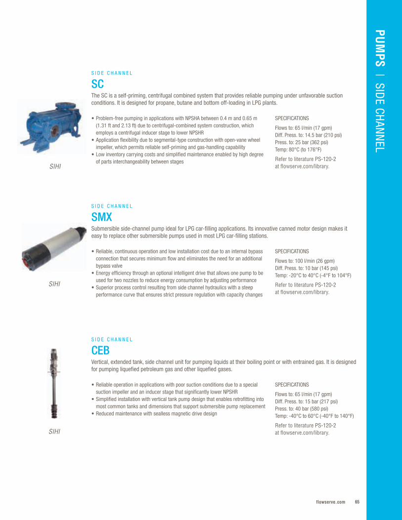
65flowserve.com
VALVES | LINEAR CO
NTRO
LPU
MPS
| SIDE CHAN
NEL
SPECIFICATIONS
Flows to: 65 l/min (17 gpm)Diff. Press. to: 14.5 bar (210 psi) Press. to: 25 bar (362 psi)Temp: 80°C (to 176°F)
Refer to literature PS-120-2 at flowserve.com/library.
SPECIFICATIONS
Flows to: 100 l/min (26 gpm)Diff. Press. to: 10 bar (145 psi)Temp: -20°C to 40°C (-4°F to 104°F)
Refer to literature PS-120-2 at flowserve.com/library.
SPECIFICATIONS
Flows to: 65 l/min (17 gpm)Diff. Press. to: 15 bar (217 psi)Press. to: 40 bar (580 psi)Temp: -40°C to 60°C (-40°F to 140°F)
Refer to literature PS-120-2 at flowserve.com/library.
• Problem-free pumping in applications with NPSHA between 0.4 m and 0.65 m (1.31 ft and 2.13 ft) due to centrifugal-combined system construction, which employs a centrifugal inducer stage to lower NPSHR
• Application flexibility due to segmental-type construction with open-vane wheel impeller, which permits reliable self-priming and gas-handling capability
• Low inventory carrying costs and simplified maintenance enabled by high degree of parts interchangeability between stages
• Reliable, continuous operation and low installation cost due to an internal bypass connection that secures minimum flow and eliminates the need for an additional bypass valve
• Energy efficiency through an optional intelligent drive that allows one pump to be used for two nozzles to reduce energy consumption by adjusting performance
• Superior process control resulting from side channel hydraulics with a steep performance curve that ensures strict pressure regulation with capacity changes
• Reliable operation in applications with poor suction conditions due to a special suction impeller and an inducer stage that significantly lower NPSHR
• Simplified installation with vertical tank pump design that enables retrofitting into most common tanks and dimensions that support submersible pump replacement
• Reduced maintenance with sealless magnetic drive design
S I D E C H A N N E L
SCThe SC is a self-priming, centrifugal combined system that provides reliable pumping under unfavorable suction conditions. It is designed for propane, butane and bottom off-loading in LPG plants.
S I D E C H A N N E L
SMXSubmersible side-channel pump ideal for LPG car-filling applications. Its innovative canned motor design makes it easy to replace other submersible pumps used in most LPG car-filling stations.
S I D E C H A N N E L
CEBVertical, extended tank, side channel unit for pumping liquids at their boiling point or with entrained gas. It is designed for pumping liquefied petroleum gas and other liquefied gases.
SIHI
SIHI
SIHI
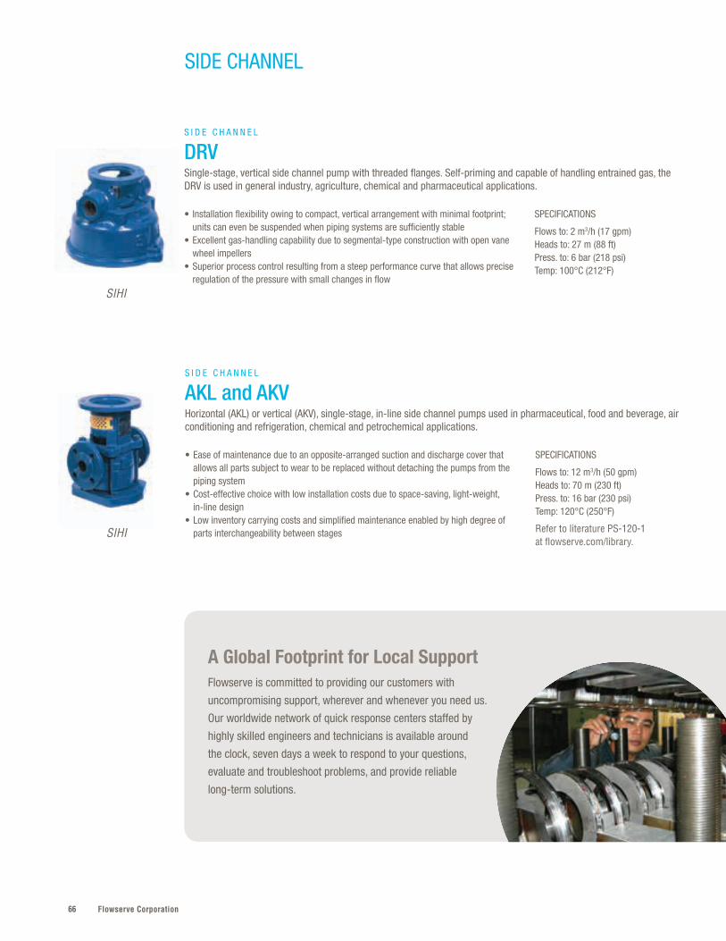
Flowserve Corporation66
A Global Footprint for Local Support Flowserve is committed to providing our customers with
uncompromising support, wherever and whenever you need us.
Our worldwide network of quick response centers staffed by
highly skilled engineers and technicians is available around
the clock, seven days a week to respond to your questions,
evaluate and troubleshoot problems, and provide reliable
long-term solutions.
SPECIFICATIONS
Flows to: 2 m3/h (17 gpm)Heads to: 27 m (88 ft)Press. to: 6 bar (218 psi)Temp: 100°C (212°F)
• Installation flexibility owing to compact, vertical arrangement with minimal footprint; units can even be suspended when piping systems are sufficiently stable
• Excellent gas-handling capability due to segmental-type construction with open vane wheel impellers
• Superior process control resulting from a steep performance curve that allows precise regulation of the pressure with small changes in flow
S I D E C H A N N E L
DRVSingle-stage, vertical side channel pump with threaded flanges. Self-priming and capable of handling entrained gas, the DRV is used in general industry, agriculture, chemical and pharmaceutical applications.
SPECIFICATIONS
Flows to: 12 m3/h (50 gpm)Heads to: 70 m (230 ft)Press. to: 16 bar (230 psi)Temp: 120°C (250°F)
Refer to literature PS-120-1 at flowserve.com/library.
• Ease of maintenance due to an opposite-arranged suction and discharge cover that allows all parts subject to wear to be replaced without detaching the pumps from the piping system
• Cost-effective choice with low installation costs due to space-saving, light-weight, in-line design
• Low inventory carrying costs and simplified maintenance enabled by high degree of parts interchangeability between stages
S I D E C H A N N E L
AKL and AKVHorizontal (AKL) or vertical (AKV), single-stage, in-line side channel pumps used in pharmaceutical, food and beverage, air conditioning and refrigeration, chemical and petrochemical applications.
SIHI
SIHI
SIDE CHANNEL

67flowserve.com
VALVES | LINEAR CO
NTRO
LPU
MPS
| SIDE CHAN
NEL
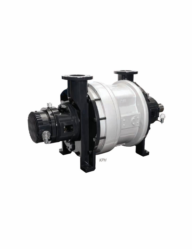
Flowserve Corporation6868
KPH
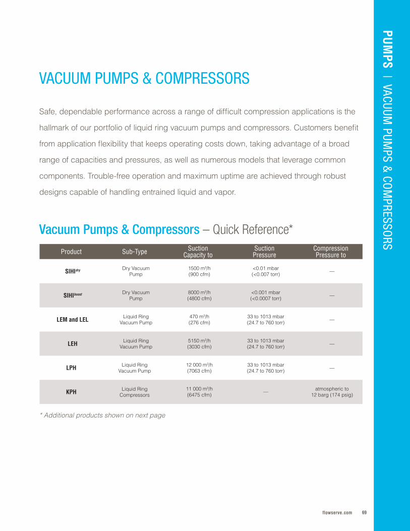
69flowserve.com
Product Sub-Type Suction Capacity to
Suction Pressure
CompressionPressure to
SIHIdry Dry VacuumPump
1500 m3/h (900 cfm)
<0 .01 mbar(<0 .007 torr) —
SIHIboost Dry VacuumPump
8000 m3/h (4800 cfm)
<0 .001 mbar(<0 .0007 torr) —
LEM and LEL Liquid Ring Vacuum Pump
470 m3/h (276 cfm)
33 to 1013 mbar (24 .7 to 760 torr) —
LEH Liquid Ring Vacuum Pump
5150 m3/h (3030 cfm)
33 to 1013 mbar (24 .7 to 760 torr) —
LPH Liquid Ring Vacuum Pump
12 000 m3/h (7063 cfm)
33 to 1013 mbar (24 .7 to 760 torr) —
KPH Liquid Ring Compressors
11 000 m3/h (6475 cfm) — atmospheric to
12 barg (174 psig)
VACUUM PUMPS & COMPRESSORS
Safe, dependable performance across a range of difficult compression applications is the
hallmark of our portfolio of liquid ring vacuum pumps and compressors . Customers benefit
from application flexibility that keeps operating costs down, taking advantage of a broad
range of capacities and pressures, as well as numerous models that leverage common
components . Trouble-free operation and maximum uptime are achieved through robust
designs capable of handling entrained liquid and vapor .
Vacuum Pumps & Compressors – Quick Reference*
PUM
PS | VACUUM
PUMPS &
COM
PRESSORS
* Additional products shown on next page
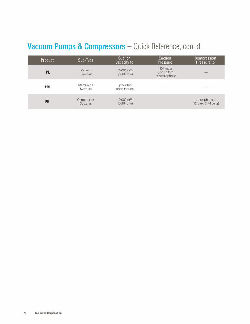
Flowserve Corporation70
Product Sub-Type Suction Capacity to
Suction Pressure
CompressionPressure to
PL VacuumSystems
10 000 m3/h (5886 cfm)
10-3 mbar (7x10⁻⁴ torr)
to atmospheric—
PM MembraneSystems
providedupon request — —
PK CompressorSystems
10 000 m3/h (5886 cfm) — atmospheric to
12 barg (174 psig)
Vacuum Pumps & Compressors – Quick Reference, cont'd.

71flowserve.com
VALVES | LINEAR CO
NTRO
LPU
MPS | O
VERHUNG
SPECIFICATIONS
Suct. Cap. to: 470 m3/h (276 cfm)Suct. Press: 33 to 1013 mbar (24.7 to 760 torr)
SPECIFICATIONS
Suct. Cap. to: 8000 m3/h (4800 cfm)Ult. Press. to: <0.001 mbar (<0.0007 torr)
SPECIFICATIONS
Suct. Cap. to: 1500 m3/h (900 cfm)Ult. Press. to: <0.01 mbar (<0.007 torr)
Refer to literature PS-110-4 and PS-110-5 at flowserve.com/library.
PUM
PS | VACUUM
PUMPS &
COM
PRESSORS
SIHI
SIHI
SIHI
• Lower life cycle cost made possible by dry operation, eliminating service liquids, lubrication and waste disposal costs
• Increased energy efficiency from intelligent drive system that performs ongoing rotor diagnostics while optimizing speed and pressure control
• Increased personnel safety enabled by low-noise, gearbox-free operation (all models), plus explosion-proof design for chemical and pharmaceutical models
• Economical performance enabled by low power consumption and fast pump-down from atmosphere
• Lower maintenance costs and time from oil- and maintenance-free design with no gearbox, mechanical seals or other wearing parts
• Increased personnel safety and comfort due to low-noise operation
• Longer service life enabled by rotating parts with no metallic contact, oil/lubrication-free operation and efficient cavitation protection
• Ease of maintenance and reliable operation from integrated dirt and central drains, enabling reuse of service liquid
• Suitable for use in noise-sensitive environments due to very low noise levels and virtually vibration-free operation
• Environmental regulatory compliance assisted by non-polluting design with near-isothermal compression
D R Y V A C U U M P U M P
SIHIdry
A completely dry running vertical twin-screw machine with no mechanical shaft seals. Designed for chemical, pharmaceutical, and industrial applications requiring uncontaminated vacuum, free from oil or service liquids.
D R Y V A C U U M P U M P
SIHIboost
Dual-stage vacuum systems that deliver deep vacuum with less power. Provides completely dry compression of gases from vacuum up to atmospheric conditions.
L I Q U I D R I N G V A C U U M P U M P
LEM and LELCompact, single-stage liquid ring vacuum pumps featuring simple and robust construction. Typically used for handling and exhausting dry and humid gases as well as vapors and quantities of water carryover.
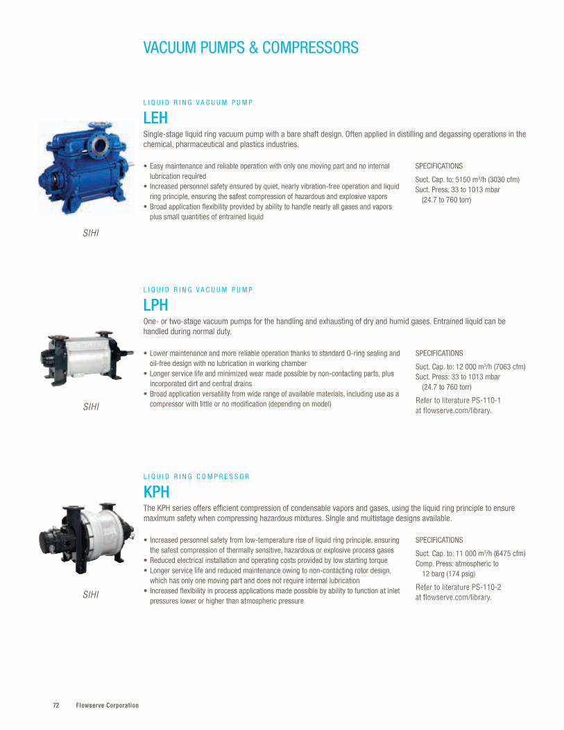
Flowserve Corporation72
SPECIFICATIONS
Suct. Cap. to: 5150 m3/h (3030 cfm)Suct. Press: 33 to 1013 mbar (24.7 to 760 torr)
SPECIFICATIONS
Suct. Cap. to: 12 000 m3/h (7063 cfm)Suct. Press: 33 to 1013 mbar (24.7 to 760 torr)
Refer to literature PS-110-1 at flowserve.com/library.
• Easy maintenance and reliable operation with only one moving part and no internal lubrication required
• Increased personnel safety ensured by quiet, nearly vibration-free operation and liquid ring principle, ensuring the safest compression of hazardous and explosive vapors
• Broad application flexibility provided by ability to handle nearly all gases and vapors plus small quantities of entrained liquid
• Lower maintenance and more reliable operation thanks to standard O-ring sealing and oil-free design with no lubrication in working chamber
• Longer service life and minimized wear made possible by non-contacting parts, plus incorporated dirt and central drains
• Broad application versatility from wide range of available materials, including use as a compressor with little or no modification (depending on model)
L I Q U I D R I N G V A C U U M P U M P
LEHSingle-stage liquid ring vacuum pump with a bare shaft design. Often applied in distilling and degassing operations in the chemical, pharmaceutical and plastics industries.
L I Q U I D R I N G V A C U U M P U M P
LPHOne- or two-stage vacuum pumps for the handling and exhausting of dry and humid gases. Entrained liquid can be handled during normal duty.
SIHI
SIHI
VACUUM PUMPS & COMPRESSORS
SPECIFICATIONS
Suct. Cap. to: 11 000 m3/h (6475 cfm)Comp. Press: atmospheric to 12 barg (174 psig)
Refer to literature PS-110-2 at flowserve.com/library.
• Increased personnel safety from low-temperature rise of liquid ring principle, ensuring the safest compression of thermally sensitive, hazardous or explosive process gases
• Reduced electrical installation and operating costs provided by low starting torque• Longer service life and reduced maintenance owing to non-contacting rotor design,
which has only one moving part and does not require internal lubrication • Increased flexibility in process applications made possible by ability to function at inlet
pressures lower or higher than atmospheric pressure
L I Q U I D R I N G C O M P R E S S O R
KPHThe KPH series offers efficient compression of condensable vapors and gases, using the liquid ring principle to ensure maximum safety when compressing hazardous mixtures. Single and multistage designs available.
SIHI
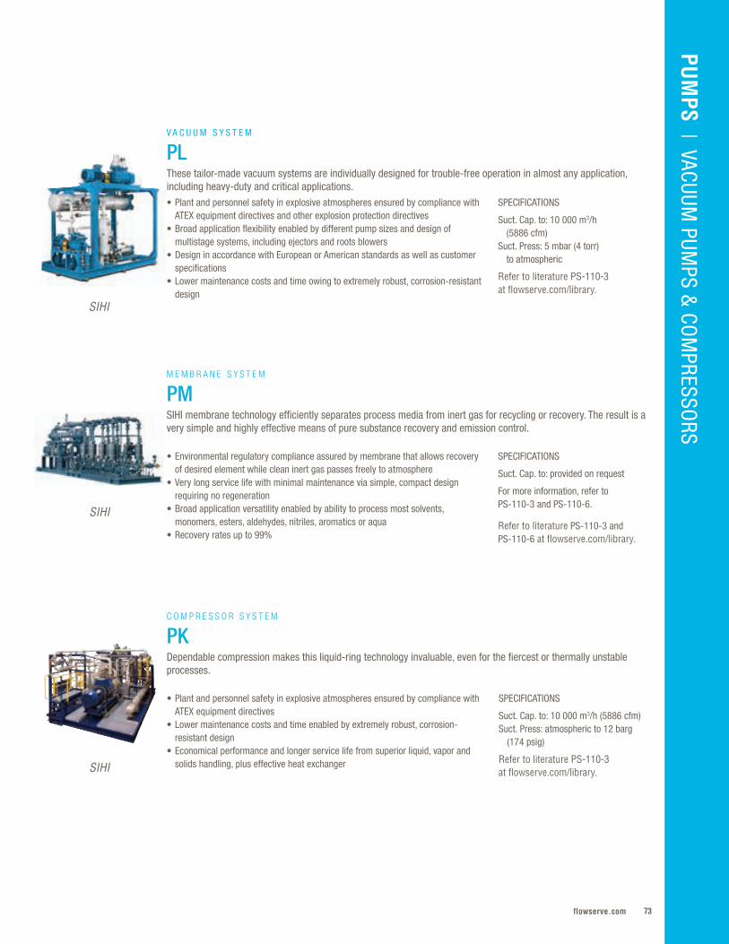
73flowserve.com
VALVES | LINEAR CO
NTRO
LPU
MPS
| VACUUM PUM
PS & CO
MPRESSO
RS
SPECIFICATIONS
Suct. Cap. to: 10 000 m3/h (5886 cfm) Suct. Press: 5 mbar (4 torr) to atmospheric
Refer to literature PS-110-3 at flowserve.com/library.
• Plant and personnel safety in explosive atmospheres ensured by compliance with ATEX equipment directives and other explosion protection directives
• Broad application flexibility enabled by different pump sizes and design of multistage systems, including ejectors and roots blowers
• Design in accordance with European or American standards as well as customer specifications
• Lower maintenance costs and time owing to extremely robust, corrosion-resistant design
V A C U U M S Y S T E M
PLThese tailor-made vacuum systems are individually designed for trouble-free operation in almost any application, including heavy-duty and critical applications.
SPECIFICATIONS
Suct. Cap. to: provided on request
For more information, refer to PS-110-3 and PS-110-6.
Refer to literature PS-110-3 and PS-110-6 at flowserve.com/library.
SPECIFICATIONS
Suct. Cap. to: 10 000 m3/h (5886 cfm) Suct. Press: atmospheric to 12 barg (174 psig)
Refer to literature PS-110-3 at flowserve.com/library.
• Environmental regulatory compliance assured by membrane that allows recovery of desired element while clean inert gas passes freely to atmosphere
• Very long service life with minimal maintenance via simple, compact design requiring no regeneration
• Broad application versatility enabled by ability to process most solvents, monomers, esters, aldehydes, nitriles, aromatics or aqua
• Recovery rates up to 99%
• Plant and personnel safety in explosive atmospheres ensured by compliance with ATEX equipment directives
• Lower maintenance costs and time enabled by extremely robust, corrosion-resistant design
• Economical performance and longer service life from superior liquid, vapor and solids handling, plus effective heat exchanger
M E M B R A N E S Y S T E M
PMSIHI membrane technology efficiently separates process media from inert gas for recycling or recovery. The result is a very simple and highly effective means of pure substance recovery and emission control.
C O M P R E S S O R S Y S T E M
PKDependable compression makes this liquid-ring technology invaluable, even for the fiercest or thermally unstable processes.
SIHI
SIHI
SIHI
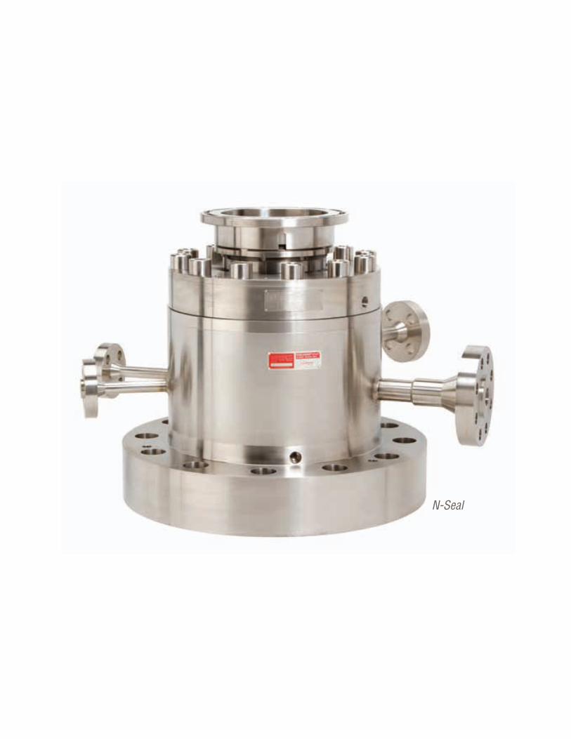
Flowserve Corporation74
N-Seal
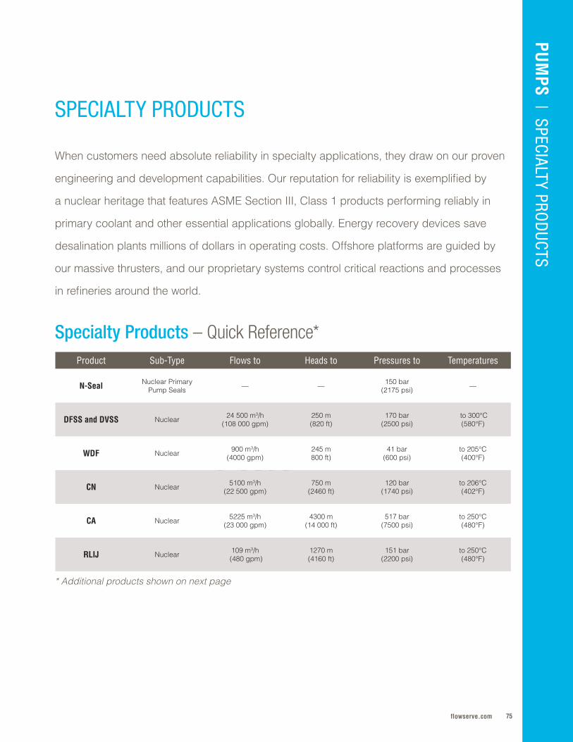
75flowserve.com
When customers need absolute reliability in specialty applications, they draw on our proven
engineering and development capabilities . Our reputation for reliability is exemplified by
a nuclear heritage that features ASME Section III, Class 1 products performing reliably in
primary coolant and other essential applications globally . Energy recovery devices save
desalination plants millions of dollars in operating costs . Offshore platforms are guided by
our massive thrusters, and our proprietary systems control critical reactions and processes
in refineries around the world .
SPECIALTY PRODUCTS
Specialty Products – Quick Reference*
* Additional products shown on next page
FPO
Product Sub-Type Flows to Heads to Pressures to Temperatures
N-Seal Nuclear PrimaryPump Seals — — 150 bar
(2175 psi) —
DFSS and DVSS Nuclear 24 500 m3/h (108 000 gpm)
250 m (820 ft)
170 bar(2500 psi)
to 300°C (580°F)
WDF Nuclear 900 m3/h(4000 gpm)
245 m 800 ft)
41 bar(600 psi)
to 205°C(400°F)
CN Nuclear 5100 m3/h (22 500 gpm)
750 m (2460 ft)
120 bar (1740 psi)
to 206°C (402°F)
CA Nuclear 5225 m3/h (23 000 gpm)
4300 m (14 000 ft)
517 bar (7500 psi)
to 250°C (480°F)
RLIJ Nuclear 109 m3/h (480 gpm)
1270 m (4160 ft)
151 bar (2200 psi)
to 250°C (480°F)
PUM
PS | SPECIALTY PRO
DUCTS
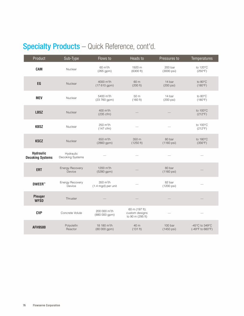
Flowserve Corporation76
Specialty Products – Quick Reference, cont'd.Product Sub-Type Flows to Heads to Pressures to Temperatures
CAM Nuclear 60 m3/h (265 gpm)
1920 m (6300 ft)
200 bar (3000 psi)
to 120°C (250°F)
EG Nuclear 4000 m3/h(17 610 gpm)
60 m (200 ft)
14 bar (200 psi)
to 80°C (180°F)
MEV Nuclear 5400 m3/h (23 760 gpm)
50 m (160 ft)
14 bar (200 psi)
to 80°C (180°F)
LBSZ Nuclear 400 m3/h (235 cfm) — — to 100°C
(212°F)
KBSZ Nuclear 250 m3/h (147 cfm) — — to 100°C
(212°F)
KSCZ Nuclear 650 m3/h (2860 gpm)
350 m (1250 ft)
80 bar (1160 psi)
to 180°C (356°F)
Hydraulic Decoking Systems
HydraulicDecoking Systems — — — —
ERT Energy RecoveryDevice
1200 m3/h(5280 gpm) — 80 bar
(1160 psi) —
DWEER™ Energy RecoveryDevice
350 m3/h(1 .4 mgd) per unit — 82 bar
(1200 psi) —
Pleuger WFSD
Thruster — — — —
CVP Concrete Volute 200 000 m3/h(880 000 gpm)
60 m (197 ft); custom designs to 90 m (295 ft)
— —
AFH9500 Polyolefin Reactor
18 180 m3/h (80 000 gpm)
40 m (131 ft)
100 bar (1450 psi)
-45°C to 349°C (-49°F to 660°F)
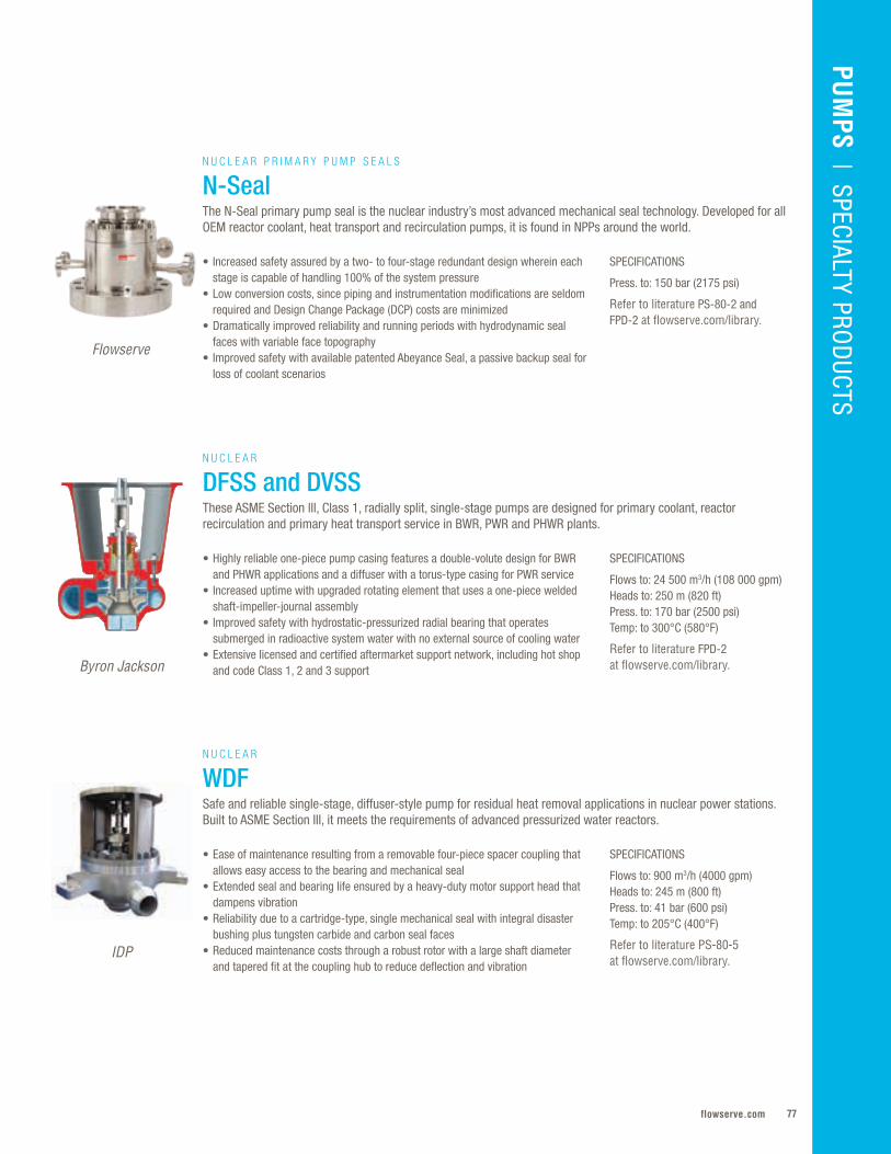
77flowserve.com
VALVES | LINEAR CO
NTRO
LPU
MPS | O
VERHUNG
PUM
PS | SPECIALTY PRO
DUCTS
IDP
SPECIFICATIONS
Flows to: 900 m3/h (4000 gpm)Heads to: 245 m (800 ft) Press. to: 41 bar (600 psi)Temp: to 205°C (400°F)
Refer to literature PS-80-5 at flowserve.com/library.
• Ease of maintenance resulting from a removable four-piece spacer coupling that allows easy access to the bearing and mechanical seal
• Extended seal and bearing life ensured by a heavy-duty motor support head that dampens vibration
• Reliability due to a cartridge-type, single mechanical seal with integral disaster bushing plus tungsten carbide and carbon seal faces
• Reduced maintenance costs through a robust rotor with a large shaft diameter and tapered fit at the coupling hub to reduce deflection and vibration
Byron Jackson
SPECIFICATIONS
Flows to: 24 500 m3/h (108 000 gpm)Heads to: 250 m (820 ft) Press. to: 170 bar (2500 psi) Temp: to 300°C (580°F)
Refer to literature FPD-2 at flowserve.com/library.
• Highly reliable one-piece pump casing features a double-volute design for BWR and PHWR applications and a diffuser with a torus-type casing for PWR service
• Increased uptime with upgraded rotating element that uses a one-piece welded shaft-impeller-journal assembly
• Improved safety with hydrostatic-pressurized radial bearing that operates submerged in radioactive system water with no external source of cooling water
• Extensive licensed and certified aftermarket support network, including hot shop and code Class 1, 2 and 3 support
N U C L E A R
DFSS and DVSSThese ASME Section lll, Class 1, radially split, single-stage pumps are designed for primary coolant, reactor recirculation and primary heat transport service in BWR, PWR and PHWR plants.
Flowserve
SPECIFICATIONS
Press. to: 150 bar (2175 psi)
Refer to literature PS-80-2 and FPD-2 at flowserve.com/library.
• Increased safety assured by a two- to four-stage redundant design wherein each stage is capable of handling 100% of the system pressure
• Low conversion costs, since piping and instrumentation modifications are seldom required and Design Change Package (DCP) costs are minimized
• Dramatically improved reliability and running periods with hydrodynamic seal faces with variable face topography
• Improved safety with available patented Abeyance Seal, a passive backup seal for loss of coolant scenarios
N U C L E A R P R I M A R Y P U M P S E A L S
N-SealThe N-Seal primary pump seal is the nuclear industry’s most advanced mechanical seal technology. Developed for all OEM reactor coolant, heat transport and recirculation pumps, it is found in NPPs around the world.
N U C L E A R
WDFSafe and reliable single-stage, diffuser-style pump for residual heat removal applications in nuclear power stations. Built to ASME Section III, it meets the requirements of advanced pressurized water reactors.

Flowserve Corporation78
SPECIFICATIONS
Flows to: 5100 m3/h (22 500 gpm)Heads to: 750 m (2460 ft)Press. to: 120 bar (1740 psi)Temp: to 206°C (402°F)
Refer to literature PS-80-4 at flowserve.com/library.
• Ease of maintenance facilitated by replaceable casing wear rings that enable running clearances to be renewed easily
• Lower operating costs provided by precision-cast chrome steel impellers, which ensure hydraulic efficiency and performance repeatability
• Reduced downtime facilitated by 416 stainless steel shaft, which is ground in steps to minimize stresses and stress relieved in the vertical position to prevent warping
N U C L E A R
CNRadially split, single-stage, double-suction, high-speed pump that features a rugged diffuser-style barrel design engineered to meet ASME Section IV Division 1 requirements for commercial nuclear power plants.
IDP
SPECIALTY PRODUCTS
IDP
SPECIFICATIONS
Flows to: 5225 m3/h (23 000 gpm)Heads to: 4300 m (14 000 ft)Press. to: 517 bar (7500 psi)Temp: to 250°C (480°F)
Refer to literature PS-30-13 at flowserve.com/library.
• Increased MTBR with precision-cast diffusers, which minimize bearing spans• Increased reliability provided by serrated impeller running fits that reduce effects
of rotor contact during system upsets or turning gear operation• Ease of maintenance provided by casing rings that enable running clearances to
be renewed easily• Installation flexibility owing to suction and discharge connections that can be on
the top or bottom of the barrel with flanged or weld-end designs
N U C L E A R
CARadially split, between-bearing, multistage barrel pump designed to comply with ASME Section III Class 2 and 3 for nuclear safety injection and emergency feedwater service.
Increase Production With the IOTFlowserve is helping clients achieve step-change increases in production
by applying industrial internet principles, technologies and related
reliability services to pumps and rotating equipment. By developing
scalable systems that capture and make sense of equipment
data, Flowserve can offer a practical and economical solution
for predictive versus reactive maintenance.
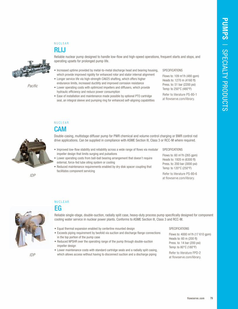
79flowserve.com
VALVES | LINEAR CO
NTRO
LPU
MPS
| SPECIALTY PROD
UCTS
Pacific
IDP
SPECIFICATIONS
Flows to: 109 m3/h (480 gpm)Heads to: 1270 m (4160 ft)Press. to: 51 bar (2200 psi)Temp: to 250°C (480°F)
Refer to literature PS-80-1 at flowserve.com/library.
SPECIFICATIONS
Flows to: 60 m3/h (265 gpm)Heads to: 1920 m (6300 ft)Press. to: 200 bar (3000 psi)Temp: to 120°C (250°F)
Refer to literature PS-80-6 at flowserve.com/library.
• Increased uptime provided by metal-to-metal discharge head and bearing housing, which provide improved rigidity for enhanced rotor and stator internal alignment
• Longer service life via high-strength CA625 shafting, which offers higher endurance limits, increased ductility and improved corrosion resistance
• Lower operating costs with optimized impellers and diffusers, which provide hydraulic efficiency and reduce power consumption
• Ease of installation and maintenance made possible by optional PTO cartridge seal, an integral sleeve and pumping ring for enhanced self-aligning capabilities
• Improved low-flow stability and reliability across a wide range of flows via modular impeller design that limits surging and pulsations
• Lower operating costs from ball-ball bearing arrangement that doesn’t require external, force-fed lube oiling system or cooling
• Reduced maintenance requirements enabled by dry disk spacer coupling that facilitates component servicing
N U C L E A R
RLIJReliable nuclear pump designed to handle low-flow and high-speed operations, frequent starts and stops, and operating upsets for prolonged pump life.
N U C L E A R
CAMDouble-casing, multistage diffuser pump for PWR chemical and volume control charging or BWR control rod drive applications. Can be supplied in compliance with ASME Section lll, Class 3 or RCC-M where required.
SPECIFICATIONS
Flows to: 4000 m3/h (17 610 gpm)Heads to: 60 m (200 ft)Press. to: 14 bar (200 psi)Temp: to 80°C (180°F)
Refer to literature FPD-2 at flowserve.com/library.
• Equal thermal expansion enabled by centerline mounted design• Exceeds piping requirement by twofold via suction and discharge flange connections
in the top portion of the pump case• Reduced NPSHR over the operating range of the pump through double-suction
impeller design• Lower maintenance costs with standard cartridge seals and a radially split casing,
which allows access without having to disconnect suction and a discharge piping
N U C L E A R
EGReliable single-stage, double-suction, radially split case, heavy-duty process pump specifically designed for component cooling water service in nuclear power plants. Conforms to ASME Section lll, Class 3 and RCC-M.
IDP
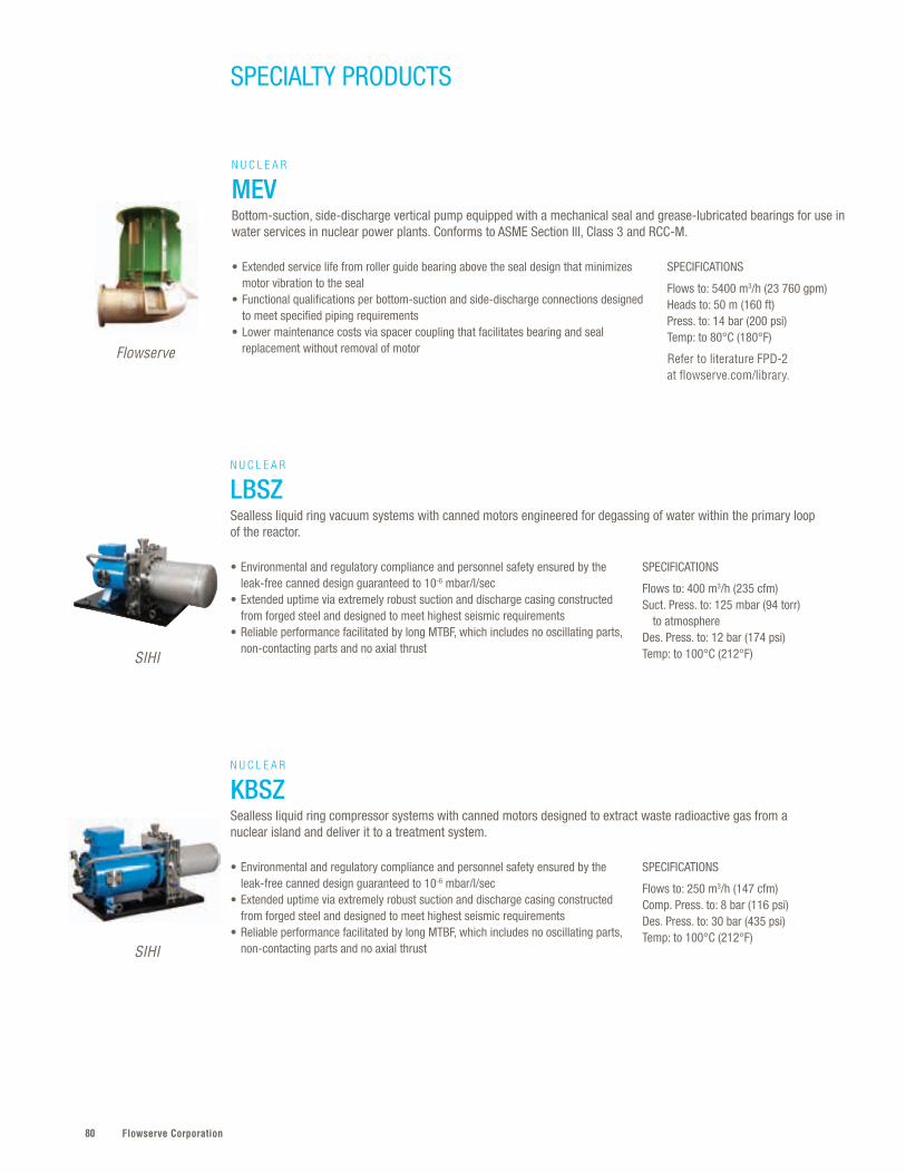
Flowserve Corporation80
SPECIALTY PRODUCTS
SPECIFICATIONS
Flows to: 5400 m3/h (23 760 gpm)Heads to: 50 m (160 ft)Press. to: 14 bar (200 psi)Temp: to 80°C (180°F)
Refer to literature FPD-2 at flowserve.com/library.
• Extended service life from roller guide bearing above the seal design that minimizes motor vibration to the seal
• Functional qualifications per bottom-suction and side-discharge connections designed to meet specified piping requirements
• Lower maintenance costs via spacer coupling that facilitates bearing and seal replacement without removal of motor
N U C L E A R
MEVBottom-suction, side-discharge vertical pump equipped with a mechanical seal and grease-lubricated bearings for use in water services in nuclear power plants. Conforms to ASME Section lll, Class 3 and RCC-M.
Flowserve
SPECIFICATIONS
Flows to: 400 m3/h (235 cfm)Suct. Press. to: 125 mbar (94 torr) to atmosphere Des. Press. to: 12 bar (174 psi) Temp: to 100°C (212°F)
SPECIFICATIONS
Flows to: 250 m3/h (147 cfm)Comp. Press. to: 8 bar (116 psi) Des. Press. to: 30 bar (435 psi) Temp: to 100°C (212°F)
• Environmental and regulatory compliance and personnel safety ensured by the leak-free canned design guaranteed to 10-6 mbar/l/sec
• Extended uptime via extremely robust suction and discharge casing constructed from forged steel and designed to meet highest seismic requirements
• Reliable performance facilitated by long MTBF, which includes no oscillating parts, non-contacting parts and no axial thrust
N U C L E A R
LBSZSealless liquid ring vacuum systems with canned motors engineered for degassing of water within the primary loop of the reactor.
N U C L E A R
KBSZSealless liquid ring compressor systems with canned motors designed to extract waste radioactive gas from a nuclear island and deliver it to a treatment system.
SIHI
SIHI
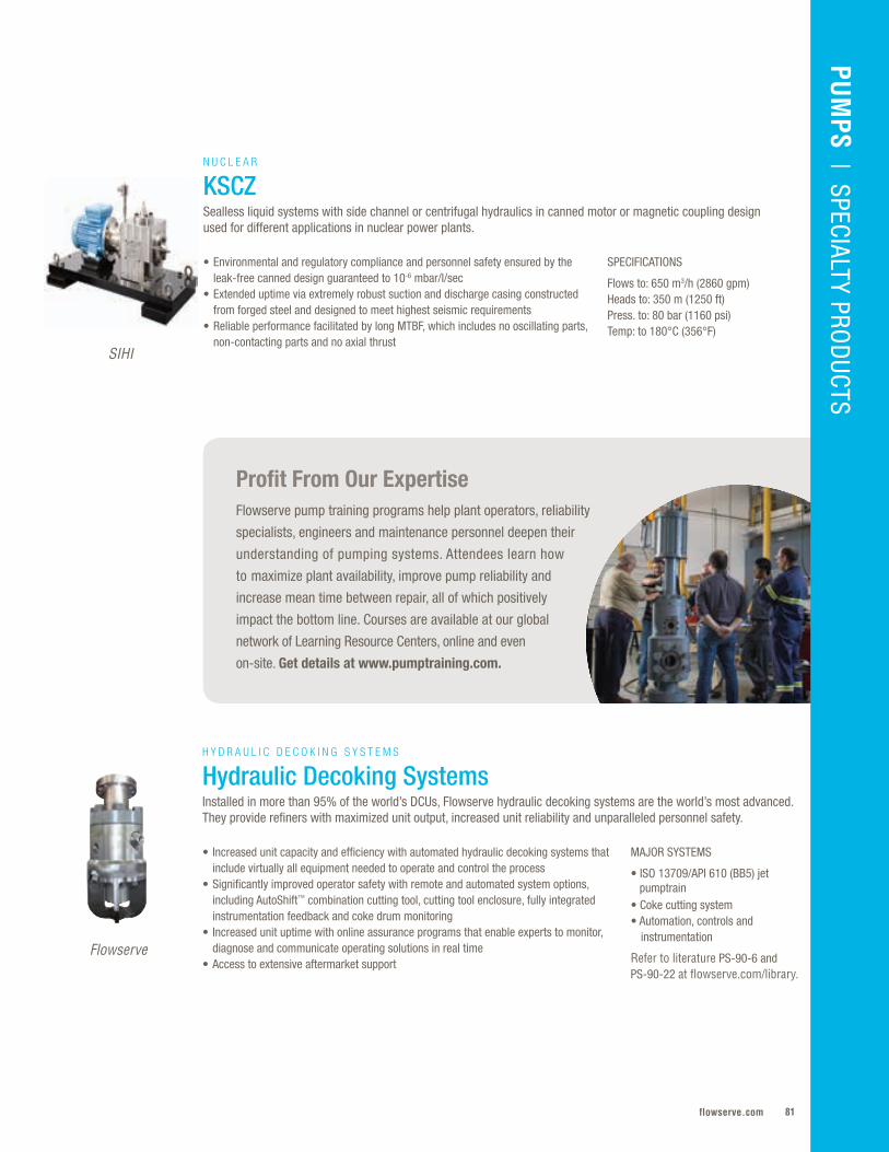
81flowserve.com
VALVES | LINEAR CO
NTRO
L
Profit From Our ExpertiseFlowserve pump training programs help plant operators, reliability
specialists, engineers and maintenance personnel deepen their
understanding of pumping systems. Attendees learn how
to maximize plant availability, improve pump reliability and
increase mean time between repair, all of which positively
impact the bottom line. Courses are available at our global
network of Learning Resource Centers, online and even
on-site. Get details at www.pumptraining.com.
PUM
PS | SPECIALTY PRO
DUCTS
SIHI
SPECIFICATIONS
Flows to: 650 m3/h (2860 gpm)Heads to: 350 m (1250 ft)Press. to: 80 bar (1160 psi)Temp: to 180°C (356°F)
• Environmental and regulatory compliance and personnel safety ensured by the leak-free canned design guaranteed to 10-6 mbar/l/sec
• Extended uptime via extremely robust suction and discharge casing constructed from forged steel and designed to meet highest seismic requirements
• Reliable performance facilitated by long MTBF, which includes no oscillating parts, non-contacting parts and no axial thrust
N U C L E A R
KSCZSealless liquid systems with side channel or centrifugal hydraulics in canned motor or magnetic coupling design used for different applications in nuclear power plants.
MAJOR SYSTEMS
• ISO 13709/API 610 (BB5) jet pumptrain• Coke cutting system• Automation, controls and instrumentation
Refer to literature PS-90-6 and PS-90-22 at flowserve.com/library.
• Increased unit capacity and efficiency with automated hydraulic decoking systems that include virtually all equipment needed to operate and control the process
• Significantly improved operator safety with remote and automated system options, including AutoShift™ combination cutting tool, cutting tool enclosure, fully integrated instrumentation feedback and coke drum monitoring
• Increased unit uptime with online assurance programs that enable experts to monitor, diagnose and communicate operating solutions in real time
• Access to extensive aftermarket support
H Y D R A U L I C D E C O K I N G S Y S T E M S
Hydraulic Decoking SystemsInstalled in more than 95% of the world’s DCUs, Flowserve hydraulic decoking systems are the world’s most advanced. They provide refiners with maximized unit output, increased unit reliability and unparalleled personnel safety.
Flowserve
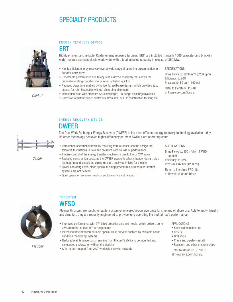
Flowserve Corporation82
SPECIALTY PRODUCTS
E N E R G Y R E C O V E R Y D E V I C E
DWEERThe Dual Work Exchanger Energy Recovery (DWEER) is the most efficient energy recovery technology available today. No other technology achieves higher efficiency or lower SWRO plant operating costs.
SPECIFICATIONS
Brine Flows to: 350 m3/h (1.4 MGD) per unitEfficiency: to 98%Pressures: 82 bar (1200 psi)
Refer to literature FPD-18 at flowserve.com/library.
• Unmatched operational flexibility resulting from a robust isobaric design that tolerates fluctuations in flow and pressure with no loss of performance
• Precise control of the energy transfer mechanism due to the LinX™ valve • Reduced construction costs, as the DWEER uses only a basic header design, plus
its footprint and associated piping runs are easily optimized for the site• Lower operating costs, since special flushing procedures, strainers or filtration
systems are not needed• Quiet operation so noise hoods or enclosures are not needed
Calder
SPECIFICATIONS
Brine Flows to: 1200 m3/h (5280 gpm)Efficiency: to 90%Pressure to: 80 bar (1160 psi)
Refer to literature FPD-18 at flowserve.com/library.
• Highly efficient energy recovery over a wide range of operating pressures due to flat efficiency curve
• Repeatable performance due to adjustable nozzle assembly that allows the original operating conditions to be re-established quickly
• Reduced downtime enabled by horizontal split-case design, which provides easy access for rotor inspection without disturbing alignment
• Installation ease with standard ANSI discharge; DIN flange discharge available• Corrosion-resistant, super duplex stainless steel or FRP construction for long life
E N E R G Y R E C O V E R Y D E V I C E
ERTHighly efficient and reliable, Calder energy recovery turbines (ERT) are installed in nearly 1000 seawater and brackish water reverse osmosis plants worldwide, with a total installed capacity in excess of 350 MW.
Calder™
APPLICATIONS• Semi-submersible rigs• FPSOs• Drill ships• Crane and pipelay vessels• Research and other offshore ships
Refer to literature PS-90-51 at flowserve.com/library.
• Improved performance with 97° tilted propeller axis and nozzle, which delivers up to 25% more thrust than 90° arrangements
• Increased time between periodic special class surveys enabled by available online condition monitoring systems
• Reduced maintenance costs resulting from the unit’s ability to be mounted and dismantled underwater without dry-docking
• Aftermarket support from 24/7 worldwide service network
T H R U S T E R
WFSDPleuger thrusters are tough, versatile, custom-engineered propulsion units for ship and offshore use. Able to apply thrust in any direction, they are robustly engineered to provide long operating life and fail-safe performance.
Pleuger
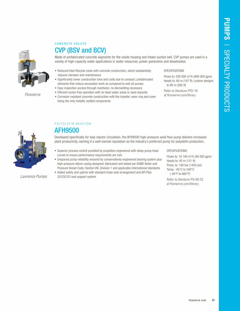
83flowserve.com
VALVES | LINEAR CO
NTRO
LPU
MPS
| SPECIALTY PROD
UCTS
SPECIFICATIONS
Flows to: 200 000 m3/h (880 000 gpm)Heads to: 60 m (197 ft); custom designs to 90 m (295 ft)
Refer to literature FPD-18 at flowserve.com/library.
• Reduced total lifecycle costs with concrete construction, which substantially reduces vibration and maintenance
• Significantly lower construction time and costs due to compact, prefabricated elements that reduce excavation work as compared to wet-pit pumps
• Easy inspection access through manholes; no dismantling necessary• Efficient vortex-free operation with no dead water areas or sand deposits• Corrosion-resistant concrete construction with the impeller, wear ring and cover
being the only metallic wetted components
C O N C R E T E V O L U T E
CVP (BSV and BCV)Made of prefabricated concrete segments for the volute housing and intake suction bell, CVP pumps are used in a variety of high-capacity water applications in water resources, power generation and desalination.
Flowserve
SPECIFICATIONS
Flows to: 18 180 m3/h (80 000 gpm)Heads to: 40 m (131 ft)Press. to: 100 bar (1450 psi)Temp: -45°C to 349°C (-49°F to 660°F)
Refer to literature PS-90-23 at flowserve.com/library.
• Superior process control provided by propellers engineered with steep pump head curves to ensure performance requirements are met
• Unspared pump reliability ensured by conservatively engineered bearing system plus high-pressure elbow casing designed, fabricated and tested per ASME Boiler and Pressure Vessel Code, Section VIII, Division 1 and applicable international standards
• Added safety and uptime with standard triple-seal arrangement and API Plan 32/53C/52 seal support system
P O LY O L E F I N R E A C T O R
AFH9500Developed specifically for loop reactor circulation, the AFH9500 high-pressure axial flow pump delivers increased plant productivity, earning it a well-earned reputation as the industry’s preferred pump for polyolefin production.
Lawrence Pumps
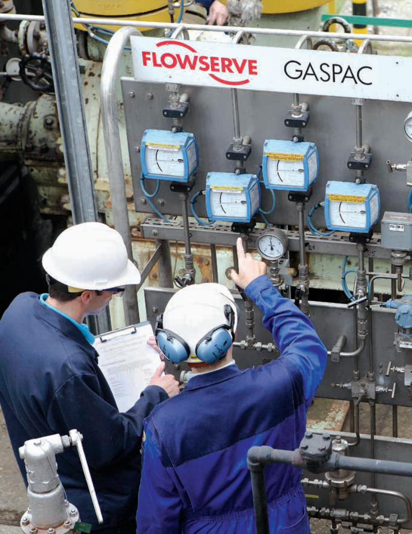
Flowserve Corporation8484

85flowserve.com
The applications just keep getting tougher .
Higher pressures and temperatures . Highly
corrosive and erosive fluids . But Flowserve
continues to redefine the way mechanical
seals operate by developing some of the
most advanced seal modeling, design, and
manufacturing capabilities in the world .
These pioneering techniques have led
to sophisticated seal face topographies
and innovative microfeatures that can be
designed to boost your bottom line by
enhancing fluid film, creating lift, reducing
friction, minimizing emissions, and
reducing wear . All of this makes Flowserve
seals the industry’s top choice for the most
demanding environments . The success
of your application isn’t just about seal
design . It also depends on selecting the
right model, design options, materials,
arrangements, and piping plans . Flowserve
engineers make sure you have the most
appropriate seal and sealing system to
ensure high reliability, long life and low
total cost of ownership .
SEALS
Standard Cartridge . . . . . . . . . . . . . . . .86
Pusher . . . . . . . . . . . . . . . . . . . . . . . . . .90
Metal Bellows . . . . . . . . . . . . . . . . . . . .98
Mixer . . . . . . . . . . . . . . . . . . . . . . . . . . 104
Compressor Seals and Systems . . . . . 108
Slurry . . . . . . . . . . . . . . . . . . . . . . . . . . 114
Gas Barrier and Containment . . . . . . . 118
OEM and Special Duty . . . . . . . . . . . .122
Seal Support Systems . . . . . . . . . . . . .128
Accessories . . . . . . . . . . . . . . . . . . . . .134
SEALS
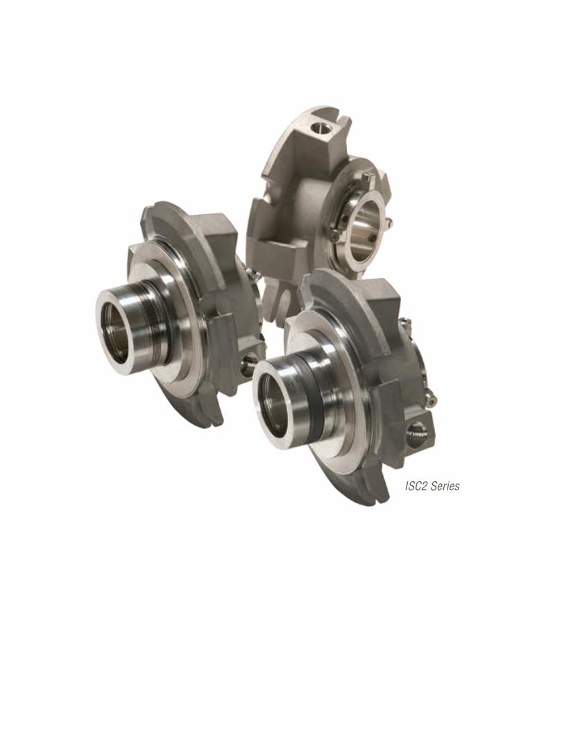
Flowserve Corporation8686
ISC2 Series
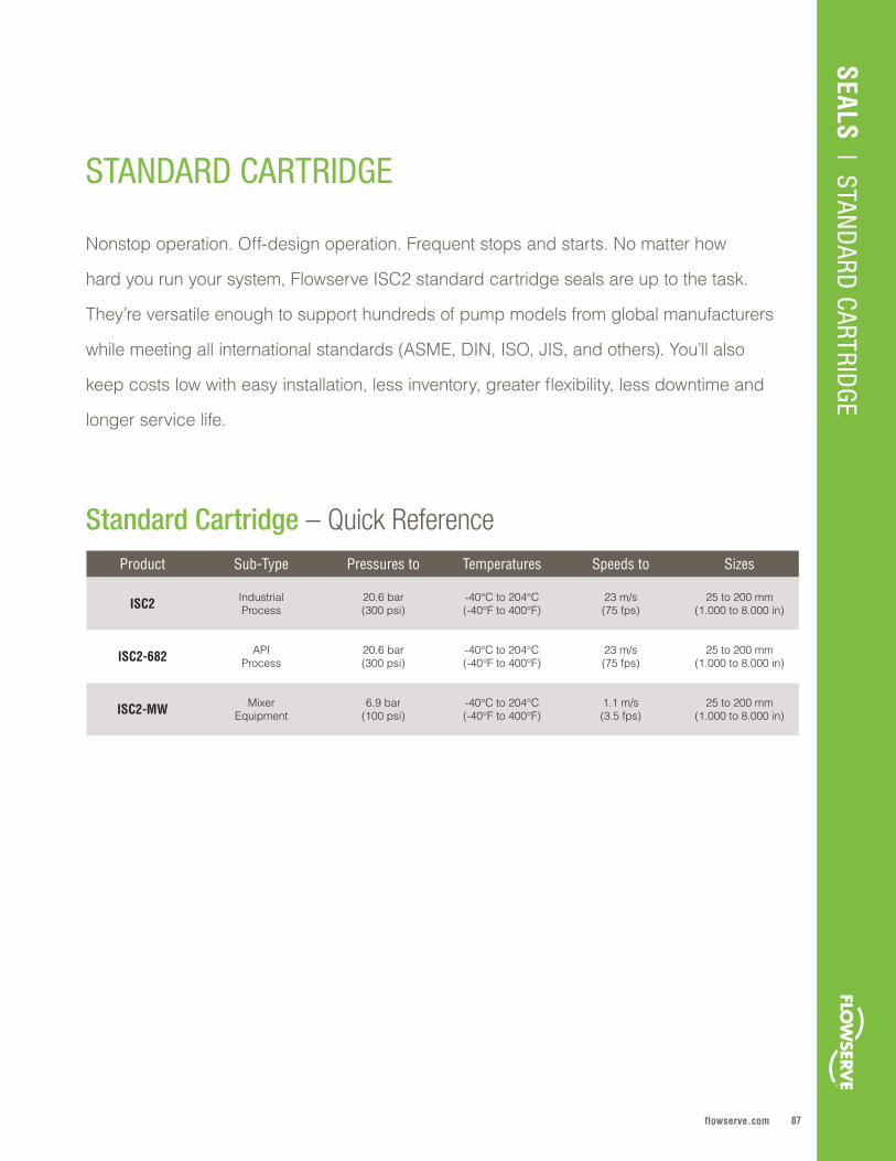
87flowserve.com
Product Sub-Type Pressures to Temperatures Speeds to Sizes
ISC2 IndustrialProcess
20 .6 bar(300 psi)
-40°C to 204°C(-40°F to 400°F)
23 m/s(75 fps)
25 to 200 mm(1 .000 to 8 .000 in)
ISC2-682 APIProcess
20 .6 bar(300 psi)
-40°C to 204°C (-40°F to 400°F)
23 m/s(75 fps)
25 to 200 mm(1 .000 to 8 .000 in)
ISC2-MW MixerEquipment
6 .9 bar(100 psi)
-40°C to 204°C(-40°F to 400°F)
1 .1 m/s(3 .5 fps)
25 to 200 mm(1 .000 to 8 .000 in)
SEALS | STAN
DARD
CARTRIDGE
STANDARD CARTRIDGE
Standard Cartridge – Quick Reference
Nonstop operation . Off-design operation . Frequent stops and starts . No matter how
hard you run your system, Flowserve ISC2 standard cartridge seals are up to the task .
They’re versatile enough to support hundreds of pump models from global manufacturers
while meeting all international standards (ASME, DIN, ISO, JIS, and others) . You’ll also
keep costs low with easy installation, less inventory, greater flexibility, less downtime and
longer service life .
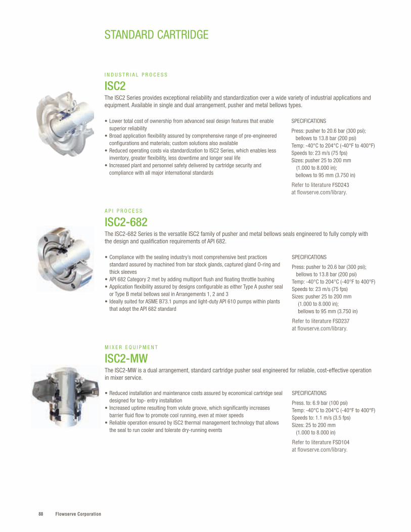
Flowserve Corporation88
SPECIFICATIONS
Press: pusher to 20.6 bar (300 psi); bellows to 13.8 bar (200 psi)Temp: -40°C to 204°C (-40°F to 400°F)Speeds to: 23 m/s (75 fps)Sizes: pusher 25 to 200 mm (1.000 to 8.000 in); bellows to 95 mm (3.750 in)
Refer to literature FSD243 at flowserve.com/library.
• Lower total cost of ownership from advanced seal design features that enable superior reliability
• Broad application flexibility assured by comprehensive range of pre-engineered configurations and materials; custom solutions also available
• Reduced operating costs via standardization to ISC2 Series, which enables less inventory, greater flexibility, less downtime and longer seal life
• Increased plant and personnel safety delivered by cartridge security and compliance with all major international standards
I N D U S T R I A L P R O C E S S
ISC2The ISC2 Series provides exceptional reliability and standardization over a wide variety of industrial applications and equipment. Available in single and dual arrangement, pusher and metal bellows types.
SPECIFICATIONS
Press: pusher to 20.6 bar (300 psi); bellows to 13.8 bar (200 psi)Temp: -40°C to 204°C (-40°F to 400°F)Speeds to: 23 m/s (75 fps)Sizes: pusher 25 to 200 mm (1.000 to 8.000 in); bellows to 95 mm (3.750 in)
Refer to literature FSD237 at flowserve.com/library.
SPECIFICATIONS
Press. to: 6.9 bar (100 psi)Temp: -40°C to 204°C (-40°F to 400°F)Speeds to: 1.1 m/s (3.5 fps)Sizes: 25 to 200 mm (1.000 to 8.000 in)
Refer to literature FSD104 at flowserve.com/library.
• Compliance with the sealing industry’s most comprehensive best practices standard assured by machined from bar stock glands, captured gland O-ring and thick sleeves
• API 682 Category 2 met by adding multiport flush and floating throttle bushing• Application flexibility assured by designs configurable as either Type A pusher seal
or Type B metal bellows seal in Arrangements 1, 2 and 3• Ideally suited for ASME B73.1 pumps and light-duty API 610 pumps within plants
that adopt the API 682 standard
• Reduced installation and maintenance costs assured by economical cartridge seal designed for top- entry installation
• Increased uptime resulting from volute groove, which significantly increases barrier fluid flow to promote cool running, even at mixer speeds
• Reliable operation ensured by ISC2 thermal management technology that allows the seal to run cooler and tolerate dry-running events
A P I P R O C E S S
ISC2-682The ISC2-682 Series is the versatile ISC2 family of pusher and metal bellows seals engineered to fully comply with the design and qualification requirements of API 682.
M I X E R E Q U I P M E N T
ISC2-MWThe ISC2-MW is a dual arrangement, standard cartridge pusher seal engineered for reliable, cost-effective operation in mixer service.
STANDARD CARTRIDGE

89flowserve.com
VALVES | LINEAR CO
NTRO
LSEALS
| STAND
ARD CARTRID
GE
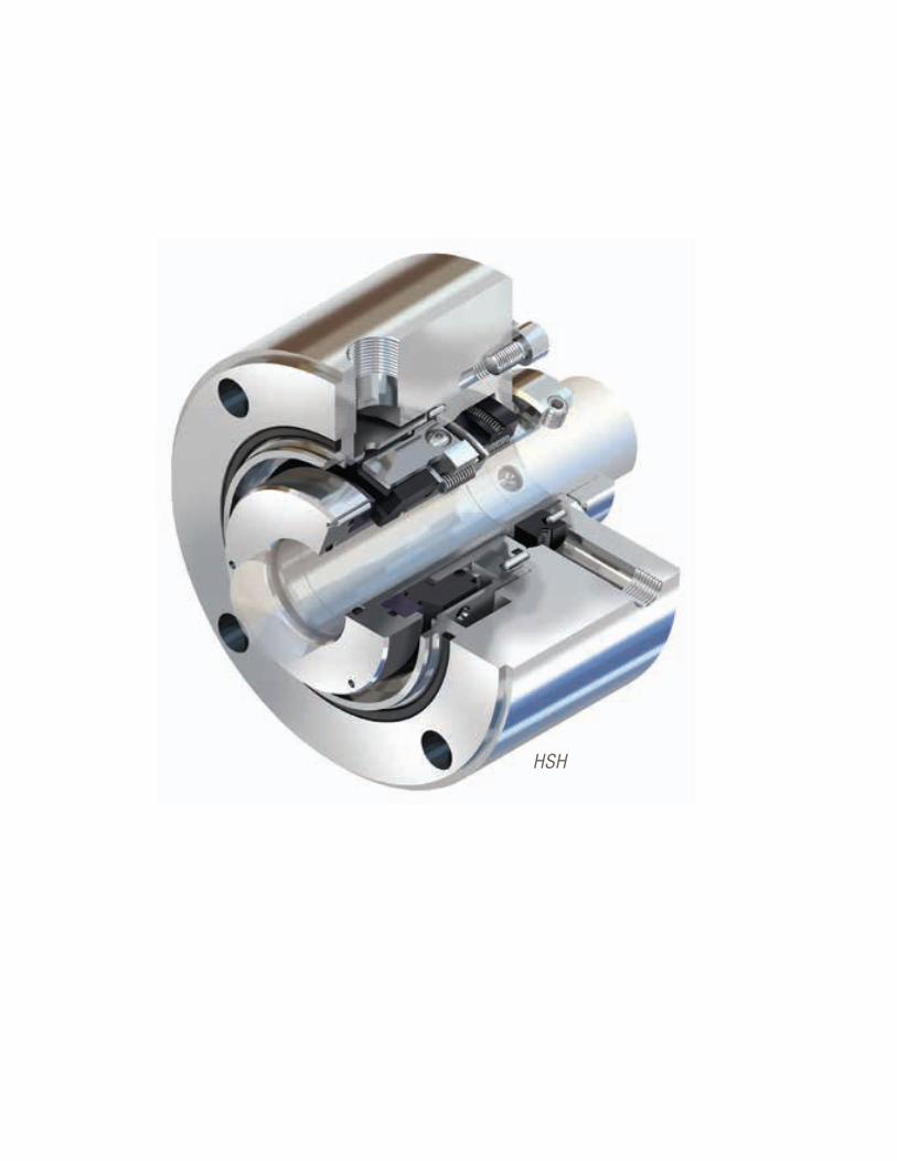
Flowserve Corporation9090
HSH
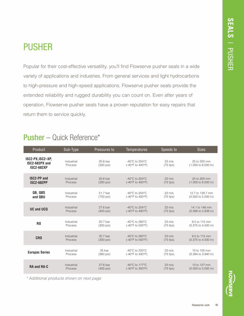
91flowserve.com
Pusher – Quick Reference*
SEALS | PUSHERPopular for their cost-effective versatility, you’ll find Flowserve pusher seals in a wide
variety of applications and industries . From general services and light hydrocarbons
to high-pressure and high-speed applications, Flowserve pusher seals provide the
extended reliability and rugged durability you can count on . Even after years of
operation, Flowserve pusher seals have a proven reputation for easy repairs that
return them to service quickly .
PUSHER
Product Sub-Type Pressures to Temperatures Speeds to Sizes
ISC2-PX,ISC2–XP, ISC2-682PX and
ISC2-682XP
IndustrialProcess
20 .6 bar(300 psi)
-40°C to 204°C(-40°F to 400°F)
23 m/s(75 fps)
25 to 200 mm(1 .000 to 8 .000 in)
ISC2-PP and ISC2-682PP
IndustrialProcess
20 .6 bar(300 psi)
-40°C to 204°C (-40°F to 400°F)
23 m/s(75 fps)
25 to 200 mm(1 .000 to 8 .000 in)
QB, QBSand QBU
IndustrialProcess
51 .7 bar (750 psi)
-40°C to 204°C (-40°F to 400°F)
23 m/s (75 fps)
12 .7 to 139 .7 mm (0 .500 to 5 .500 in)
UC and UCQ IndustrialProcess
27 .6 bar (400 psi)
-40°C to 204°C (-40°F to 400°F)
23 m/s (75 fps)
14 .1 to 148 mm (0 .566 to 5 .838 in)
RO IndustrialProcess
20 .7 bar(300 psi)
-40°C to 260°C (-40°F to 500°F)
23 m/s(75 fps)
9 .5 to 115 mm(0 .375 to 4 .500 in)
CRO IndustrialProcess
20 .7 bar(300 psi)
-40°C to 260°C(-40°F to 500°F)
23 m/s (75 fps)
9 .5 to 115 mm(0 .375 to 4 .500 in)
Europac Series IndustrialProcess
25 bar(360 psi)
-40°C to 220°C(-40°F to 430°F)
23 m/s(75 fps)
10 to 100 mm (0 .394 to 3 .940 in)
RA and RA-C IndustrialProcess
27 .6 bar(400 psi)
-40°C to 177°C (-40°F to 350°F)
23 m/s(75 fps)
13 to 127 mm(0 .500 to 5 .000 in)
* Additional products shown on next page
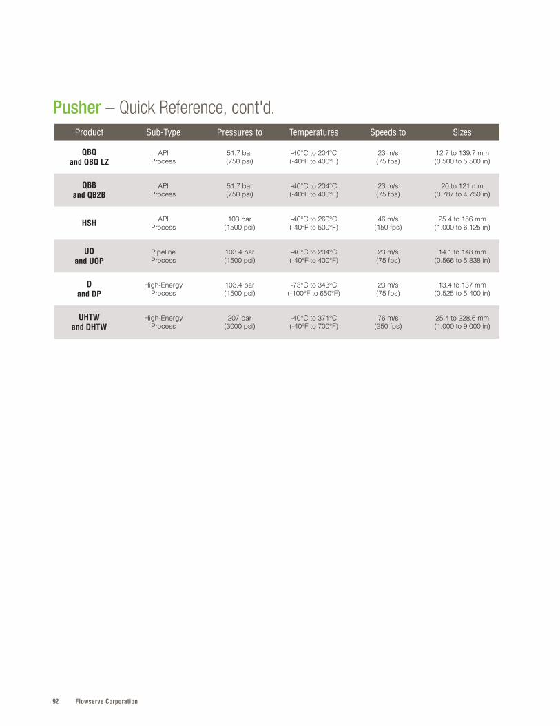
Flowserve Corporation92
Pusher – Quick Reference, cont'd.Product Sub-Type Pressures to Temperatures Speeds to Sizes
QBQand QBQ LZ
APIProcess
51 .7 bar (750 psi)
-40°C to 204°C (-40°F to 400°F)
23 m/s (75 fps)
12 .7 to 139 .7 mm (0 .500 to 5 .500 in)
QBBand QB2B
APIProcess
51 .7 bar (750 psi)
-40°C to 204°C (-40°F to 400°F)
23 m/s (75 fps)
20 to 121 mm(0 .787 to 4 .750 in)
HSH APIProcess
103 bar (1500 psi)
-40°C to 260°C(-40°F to 500°F)
46 m/s(150 fps)
25 .4 to 156 mm (1 .000 to 6 .125 in)
UOand UOP
PipelineProcess
103 .4 bar (1500 psi)
-40°C to 204°C (-40°F to 400°F)
23 m/s (75 fps)
14 .1 to 148 mm (0 .566 to 5 .838 in)
Dand DP
High-Energy Process
103 .4 bar (1500 psi)
-73°C to 343°C (-100°F to 650°F)
23 m/s (75 fps)
13 .4 to 137 mm (0 .525 to 5 .400 in)
UHTW and DHTW
High-EnergyProcess
207 bar (3000 psi)
-40°C to 371°C (-40°F to 700°F)
76 m/s (250 fps)
25 .4 to 228 .6 mm (1 .000 to 9 .000 in)
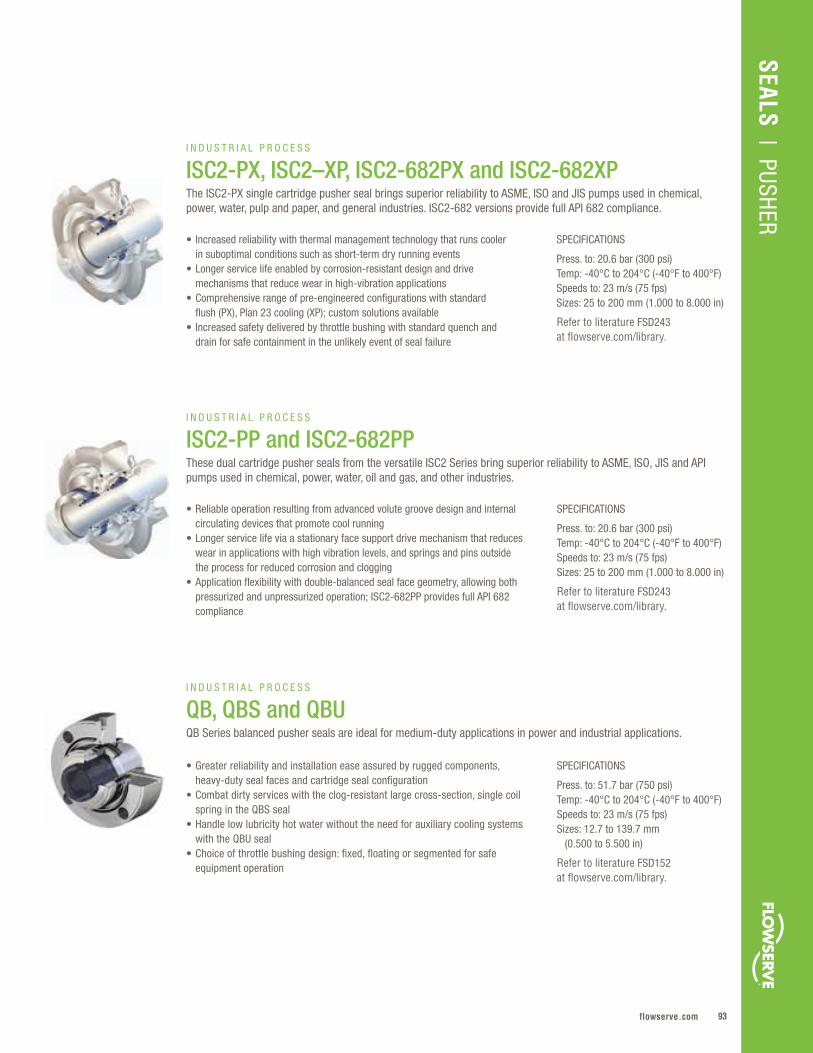
93flowserve.com
VALVES | LINEAR CO
NTRO
LSEALS
| PUSHERSEALS
| PUSHER
SPECIFICATIONS
Press. to: 20.6 bar (300 psi)Temp: -40°C to 204°C (-40°F to 400°F)Speeds to: 23 m/s (75 fps)Sizes: 25 to 200 mm (1.000 to 8.000 in)
Refer to literature FSD243 at flowserve.com/library.
SPECIFICATIONS
Press. to: 20.6 bar (300 psi)Temp: -40°C to 204°C (-40°F to 400°F)Speeds to: 23 m/s (75 fps)Sizes: 25 to 200 mm (1.000 to 8.000 in)
Refer to literature FSD243 at flowserve.com/library.
SPECIFICATIONS
Press. to: 51.7 bar (750 psi)Temp: -40°C to 204°C (-40°F to 400°F)Speeds to: 23 m/s (75 fps)Sizes: 12.7 to 139.7 mm (0.500 to 5.500 in)
Refer to literature FSD152 at flowserve.com/library.
• Increased reliability with thermal management technology that runs cooler in suboptimal conditions such as short-term dry running events
• Longer service life enabled by corrosion-resistant design and drive mechanisms that reduce wear in high-vibration applications
• Comprehensive range of pre-engineered configurations with standard flush (PX), Plan 23 cooling (XP); custom solutions available
• Increased safety delivered by throttle bushing with standard quench and drain for safe containment in the unlikely event of seal failure
• Reliable operation resulting from advanced volute groove design and internal circulating devices that promote cool running
• Longer service life via a stationary face support drive mechanism that reduces wear in applications with high vibration levels, and springs and pins outside the process for reduced corrosion and clogging
• Application flexibility with double-balanced seal face geometry, allowing both pressurized and unpressurized operation; ISC2-682PP provides full API 682 compliance
• Greater reliability and installation ease assured by rugged components, heavy-duty seal faces and cartridge seal configuration
• Combat dirty services with the clog-resistant large cross-section, single coil spring in the QBS seal
• Handle low lubricity hot water without the need for auxiliary cooling systems with the QBU seal
• Choice of throttle bushing design: fixed, floating or segmented for safe equipment operation
I N D U S T R I A L P R O C E S S
ISC2-PX, ISC2–XP, ISC2-682PX and ISC2-682XPThe ISC2-PX single cartridge pusher seal brings superior reliability to ASME, ISO and JIS pumps used in chemical, power, water, pulp and paper, and general industries. ISC2-682 versions provide full API 682 compliance.
I N D U S T R I A L P R O C E S S
ISC2-PP and ISC2-682PPThese dual cartridge pusher seals from the versatile ISC2 Series bring superior reliability to ASME, ISO, JIS and API pumps used in chemical, power, water, oil and gas, and other industries.
I N D U S T R I A L P R O C E S S
QB, QBS and QBUQB Series balanced pusher seals are ideal for medium-duty applications in power and industrial applications.
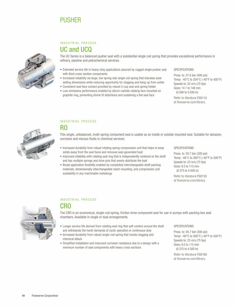
Flowserve Corporation94
SPECIFICATIONS
Press. to: 20.7 bar (300 psi)Temp: -40°C to 260°C (-40°F to 500°F)Speeds to: 23 m/s (75 fps)Sizes: 9.5 to 115 mm (0.375 to 4.500 in)
Refer to literature FSD155 at flowserve.com/library.
SPECIFICATIONS
Press. to: 27.6 bar (400 psi)Temp: -40°C to 204°C (-40°F to 400°F)Speeds to: 23 m/s (75 fps)Sizes: 14.1 to 148 mm (0.566 to 5.838 in)
Refer to literature FSD110 at flowserve.com/library.
SPECIFICATIONS
Press. to: 20.7 bar (300 psi)Temp: -40°C to 260°C (-40°F to 500°F)Speeds to: 23 m/s (75 fps)Sizes: 9.5 to 115 mm (0.375 to 4.500 in)
Refer to literature FSD169 at flowserve.com/library.
• Increased durability from robust rotating spring compression unit that helps to keep solids away from the seal faces and removes seal-generated heat
• Improved reliability with rotating seal ring that is independently centered on the shaft and has multiple springs and drive pins that evenly distribute the load
• Broad application flexibility enabled by completely interchangeable shaft packing materials, dimensionally interchangeable insert mounting, and compression unit availability in any machinable metallurgy
• Extended service life in heavy-duty applications assured by rugged single pusher seal with thick cross-section components
• Increased reliability via large, low spring rate single coil spring that tolerates axial setting dimensions while reducing opportunity for clogging and hang-up from solids
• Consistent seal face contact provided by robust U-cup seal and spring holder• Low-emissions performance enabled by silicon carbide rotating face mounted on
graphite ring, preventing shrink fit distortions and sustaining a flat seal face
• Longer service life derived from rotating seal ring that self-centers around the shaft and withstands the harsh demands of cyclic operation or continuous duty
• Increased durability from robust single-coil spring that resists clogging and chemical attack
• Simplified installation and improved corrosion resistance due to a design with a minimum number of seal components with heavy cross-sections
I N D U S T R I A L P R O C E S S
ROThis single, unbalanced, multi-spring component seal is usable as an inside or outside mounted seal. Suitable for abrasive, corrosive and viscous fluids in chemical services.
I N D U S T R I A L P R O C E S S
UC and UCQThe UC Series is a balanced pusher seal with a substantial single coil spring that provides exceptional performance in refinery, pipeline and petrochemical services.
I N D U S T R I A L P R O C E S S
CROThe CRO is an economical, single-coil spring, friction drive component seal for use in pumps with packing box seal chambers. Available in single or dual arrangements.
PUSHER
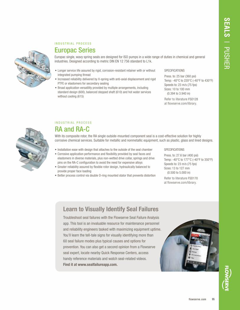
95flowserve.com
VALVES | LINEAR CO
NTRO
L
SPECIFICATIONS
Press. to: 27.6 bar (400 psi)Temp: -40°C to 177°C (-40°F to 350°F)Speeds to: 23 m/s (75 fps)Sizes: 13 to 127 mm (0.500 to 5.000 in)
Refer to literature FSD170 at flowserve.com/library.
• Installation ease with design that attaches to the outside of the seal chamber• Corrosive application performance and flexibility provided by seal faces and
elastomers in diverse materials, plus non-wetted drive collar, springs and drive pins on the RA-C configuration to avoid the need for expensive alloys
• Greater reliability assured by flexible rotor design, hydraulically balanced to provide proper face loading
• Better process control via double O-ring mounted stator that prevents distortion
I N D U S T R I A L P R O C E S S
RA and RA-CWith its composite rotor, the RA single outside-mounted component seal is a cost-effective solution for highly corrosive chemical services. Suitable for metallic and nonmetallic equipment, such as plastic, glass and lined designs.
SPECIFICATIONS
Press. to: 25 bar (360 psi)Temp: -40°C to 220°C (-40°F to 430°F)Speeds to: 23 m/s (75 fps)Sizes: 10 to 100 mm (0.394 to 3.940 in)
Refer to literature FSD128 at flowserve.com/library.
• Longer service life assured by rigid, corrosion-resistant retainer with or without integrated pumping thread
• Increased reliability delivered by X-spring with anti-axial displacement and rigid PTFE or elastomers for secondary sealing
• Broad application versatility provided by multiple arrangements, including standard design (600), balanced stepped shaft (610) and hot water services without cooling (615)
I N D U S T R I A L P R O C E S S
Europac SeriesEuropac single, wavy spring seals are designed for ISO pumps in a wide range of duties in chemical and general industries. Designed according to metric DIN EN 12 756 standard to L1k.
Learn to Visually Identify Seal FailuresTroubleshoot seal failures with the Flowserve Seal Failure Analysis
app. This tool is an invaluable resource for maintenance personnel
and reliability engineers tasked with maximizing equipment uptime.
You’ll learn the tell-tale signs for visually identifying more than
60 seal failure modes plus typical causes and options for
prevention. You can also get a second opinion from a Flowserve
seal expert, locate nearby Quick Response Centers, access
handy reference materials and watch seal-related videos.
Find it at www.sealfailureapp.com.
SEALS | PUSHER
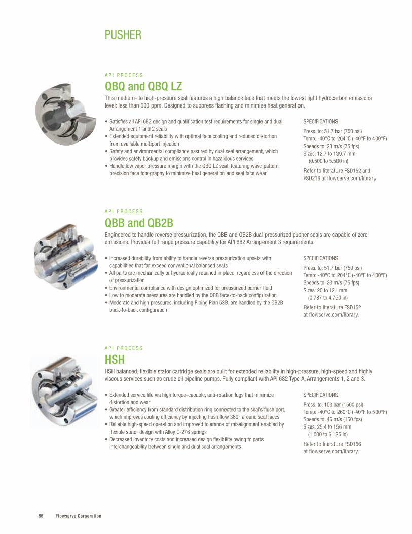
Flowserve Corporation96
SPECIFICATIONS
Press. to: 51.7 bar (750 psi)Temp: -40°C to 204°C (-40°F to 400°F)Speeds to: 23 m/s (75 fps)Sizes: 20 to 121 mm (0.787 to 4.750 in)
Refer to literature FSD152 at flowserve.com/library.
SPECIFICATIONS
Press. to: 103 bar (1500 psi)Temp: -40°C to 260°C (-40°F to 500°F)Speeds to: 46 m/s (150 fps)Sizes: 25.4 to 156 mm (1.000 to 6.125 in)
Refer to literature FSD156 at flowserve.com/library.
• Increased durability from ability to handle reverse pressurization upsets with capabilities that far exceed conventional balanced seals
• All parts are mechanically or hydraulically retained in place, regardless of the direction of pressurization
• Environmental compliance with design optimized for pressurized barrier fluid• Low to moderate pressures are handled by the QBB face-to-back configuration• Moderate and high pressures, including Piping Plan 53B, are handled by the QB2B
back-to-back configuration
• Extended service life via high torque-capable, anti-rotation lugs that minimize distortion and wear
• Greater efficiency from standard distribution ring connected to the seal’s flush port, which improves cooling efficiency by injecting flush flow 360° around seal faces
• Reliable high-speed operation and improved tolerance of misalignment enabled by flexible stator design with Alloy C-276 springs
• Decreased inventory costs and increased design flexibility owing to parts interchangeability between single and dual seal arrangements
A P I P R O C E S S
QBB and QB2BEngineered to handle reverse pressurization, the QBB and QB2B dual pressurized pusher seals are capable of zero emissions. Provides full range pressure capability for API 682 Arrangement 3 requirements.
A P I P R O C E S S
HSHHSH balanced, flexible stator cartridge seals are built for extended reliability in high-pressure, high-speed and highly viscous services such as crude oil pipeline pumps. Fully compliant with API 682 Type A, Arrangements 1, 2 and 3.
PUSHER
SPECIFICATIONS
Press. to: 51.7 bar (750 psi)Temp: -40°C to 204°C (-40°F to 400°F)Speeds to: 23 m/s (75 fps)Sizes: 12.7 to 139.7 mm (0.500 to 5.500 in)
Refer to literature FSD152 and FSD216 at flowserve.com/library.
• Satisfies all API 682 design and qualification test requirements for single and dual Arrangement 1 and 2 seals
• Extended equipment reliability with optimal face cooling and reduced distortion from available multiport injection
• Safety and environmental compliance assured by dual seal arrangement, which provides safety backup and emissions control in hazardous services
• Handle low vapor pressure margin with the QBQ LZ seal, featuring wave pattern precision face topography to minimize heat generation and seal face wear
A P I P R O C E S S
QBQ and QBQ LZThis medium- to high-pressure seal features a high balance face that meets the lowest light hydrocarbon emissions level: less than 500 ppm. Designed to suppress flashing and minimize heat generation.
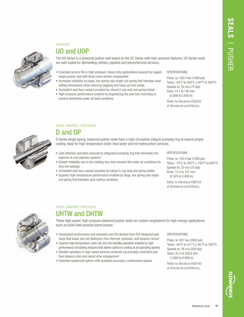
97flowserve.com
VALVES | LINEAR CO
NTRO
L
SPECIFICATIONS
Press. to: 103.4 bar (1500 psi)Temp: -73°C to 343°C (-100°F to 650°F)Speeds to: 23 m/s (75 fps)Sizes: 13.4 to 137 mm (0.525 to 5.400 in)
Refer to literature FSD153 at flowserve.com/library.
• Cost-effective operation ensured by integrated pumping ring that eliminates the expense of cool injection systems
• Greater reliability due to the rotating face that remains flat under all conditions for very low leakage
• Consistent seal face contact provided by robust U-cup seal and spring holder• Superior high-temperature performance enabled by large, low spring rate single
coil spring that tolerates axial setting variations
H I G H - E N E R G Y P R O C E S S
D and DPD Series single spring, balanced pusher seals have a high-circulation integral pumping ring to ensure proper cooling. Ideal for high-temperature boiler feed water and hot hydrocarbon services.
SPECIFICATIONS
Press. to: 207 bar (3000 psi)Temp: -40°C to 371°C (-40°F to 700°F)Speeds to: 76 m/s (250 fps)Sizes: 25.4 to 228.6 mm (1.000 to 9.000 in)
Refer to literature FSD140 at flowserve.com/library.
• Unmatched performance and extended seal life derived from FEA-designed seal faces that boast zero net deflection from thermal, hydraulic, and dynamic forces
• Superior high temperature, slow roll, and hot standby operation enabled by high performance circulating features that deliver optimum cooling at all operating speeds
• Reliable operation in high speed services achieved via precisely controlled seal face balance ratio and robust drive engagement
• Extended equipment uptime with available secondary containment options
H I G H - E N E R G Y P R O C E S S
UHTW and DHTWThese high-speed, high-pressure balanced pusher seals are custom-engineered for high-energy applications such as boiler-feed process barrel pumps.
SPECIFICATIONS
Press. to: 103.4 bar (1500 psi)Temp: -40°C to 204°C (-40°F to 400°F)Speeds to: 23 m/s (75 fps)Sizes: 14.1 to 148 mm (0.566 to 5.838 in)
Refer to literature FSD255 at flowserve.com/library.
• Extended service life in high-pressure, heavy-duty applications assured by rugged single pusher seal with thick cross-section components
• Increased reliability via large, low spring rate single coil spring that tolerates axial setting dimensions while reducing clogging and hang-up from solids
• Consistent seal face contact provided by robust U-cup seal and spring holder• High-pressure performance enabled by engineering the seal face mounting to
prevent distortions under all load conditions
P U S H E R
UO and UOPThe UO Series is a balanced pusher seal based on the UC Series with high-pressure features. UO Series seals are well-suited for demanding refinery, pipeline and petrochemical services.
SEALS | PUSHER
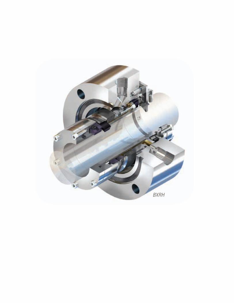
Flowserve Corporation98
BXRH
99flowserve.com
Metal Bellows – Quick Reference
Flowserve metal bellows seals provide proven reliability and long-term performance in
general and critical services, whether you’re dealing with hazardous chemicals or refinery
processing . Edge-welded, high-alloy bellows get the job done where corrosive chemicals
degrade elastomers and other dynamic gaskets . Available with rotating or stationary bellows
and in single, dual unpressurized or dual pressurized configurations, our global customers
will find a variety of arrangements to meet their toughest sealing requirements, including
full API 682 compliance .
SEALS | M
ETAL BELLOW
S
METAL BELLOWS
Product Sub-Type Pressures to Temperatures Speeds to Sizes
ISC2-BX, ISC2-XB, ISC2-682BX and
ISC2-682XB
IndustrialProcess
13 .8 bar(200 psi)
-40°C to 204°C (-40°F to 400°F)
23 m/s(75 fps)
25 to 95 mm (1 .000 to 3 .750 in)
ISC2-BB IndustrialProcess
13 .8 bar(200 psi)
-40°C to 204°C(-40°F to 400°F)
23 m/s(75 fps)
25 to 95 mm(1 .000 to 3 .750 in)
BXLS IndustrialProcess
27 .6 bar (400 psi)
-40°C to 204°C (-40°F to 400°F)
23 m/s(75 fps)
16 to 100 mm(0 .623 to 3 .937 in)
BX, BXQ and BXB
APIProcess
27 .6 bar(400 psi)
40°C to 204°C (-40°F to 400°F)
23 m/s(75 fps)
12 .3 to 127 mm (0 .483 to 5 .000 in)
BXRH APIProcess
20 .7 bar (300 psi)
-73°C to 427°C (-100°F to 800°F)
46 m/s(150 fps)
21 .8 to 127 mm (0 .857 in to 5 .000 in)
BXHHS and BXHHSB
APIProcess
20 .7 bar(300 psi)
-73°C to 427°C (-100°F to 800°F)
23 m/s (75 fps)
28 .2 to 128 .9 mm (1 .110 in to 5 .073 in)
BRC and BRCSH
APIProcess
20 .7 bar(300 psi)
-73°C to 427°C (-100°F to 800°F)
23 m/s (75 fps)
28 .2 to 150 mm (1 .110 to 5 .906 in)
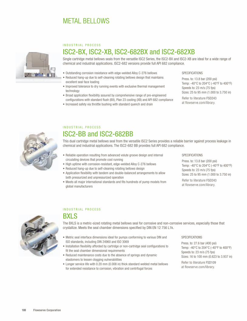
Flowserve Corporation100
SPECIFICATIONS
Press. to: 27.6 bar (400 psi)Temp: -40°C to 204°C (-40°F to 400°F)Speeds to: 23 m/s (75 fps)Sizes: 16 to 100 mm (0.623 to 3.937 in)
Refer to literature FSD109 at flowserve.com/library.
• Metric seal interface dimensions ideal for pumps conforming to various DIN and ISO standards, including DIN 24960 and ISO 3069
• Installation flexibility afforded by cartridge or non-cartridge seal configurations to fit the seal chamber dimensional requirements
• Reduced maintenance costs due to the absence of springs and dynamic elastomers to lessen clogging vulnerabilities
• Longer service life with 0.20 mm (0.008 in) thick standard welded metal bellows for extended resistance to corrosion, vibration and centrifugal forces
I N D U S T R I A L P R O C E S S
BXLSThe BXLS is a metric-sized rotating metal bellows seal for corrosive and non-corrosive services, especially those that crystallize. Meets the seal chamber dimensions specified by DIN EN 12 756 L1k.
SPECIFICATIONS
Press. to: 13.8 bar (200 psi)Temp: -40°C to 204°C (-40°F to 400°F)Speeds to: 23 m/s (75 fps)Sizes: 25 to 95 mm (1.000 to 3.750 in)
Refer to literature FSD243 at flowserve.com/library.
SPECIFICATIONS
Press. to: 13.8 bar (200 psi)Temp: -40°C to 204°C (-40°F to 400°F)Speeds to: 23 m/s (75 fps)Sizes: 25 to 95 mm (1.000 to 3.750 in)
Refer to literature FSD243 at flowserve.com/library.
• Outstanding corrosion resistance with edge-welded Alloy C-276 bellows• Reduced hang-up due to self-cleaning rotating bellows design that maintains
excellent seal face loading • Improved tolerance to dry running events with exclusive thermal management
technology • Broad application flexibility assured by comprehensive range of pre-engineered
configurations with standard flush (BX), Plan 23 cooling (XB) and API 682 compliance• Increased safety via throttle bushing with standard quench and drain
• Reliable operation resulting from advanced volute groove design and internal circulating devices that promote cool running
• High uptime with corrosion-resistant, edge-welded Alloy C-276 bellows • Reduced hang-up due to self-cleaning rotating bellows design• Application flexibility with tandem and double-balanced arrangements to allow
both pressurized and unpressurized operation• Meets all major international standards and fits hundreds of pump models from
global manufacturers
I N D U S T R I A L P R O C E S S
ISC2-BX, ISC2-XB, ISC2-682BX and ISC2-682XBSingle cartridge metal bellows seals from the versatile ISC2 Series, the ISC2-BX and ISC2-XB are ideal for a wide range of chemical and industrial applications. ISC2-682 versions provide full API 682 compliance.
I N D U S T R I A L P R O C E S S
ISC2-BB and ISC2-682BB This dual cartridge metal bellows seal from the versatile ISC2 Series provides a reliable barrier against process leakage in chemical and industrial applications. The ISC2-682 BB provides full API 682 compliance.
METAL BELLOWS
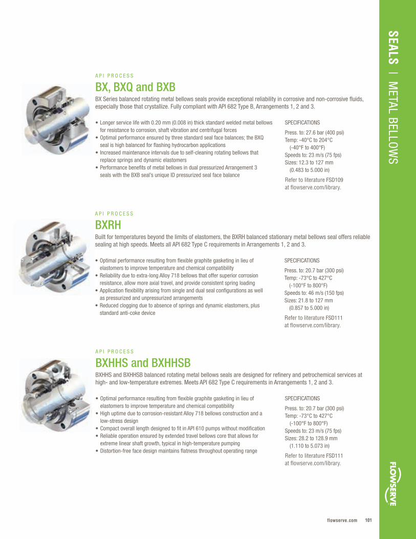
101flowserve.com
SEALS | M
ETAL BELLOW
S
SPECIFICATIONS
Press. to: 20.7 bar (300 psi)Temp: -73°C to 427°C (-100°F to 800°F)Speeds to: 46 m/s (150 fps)Sizes: 21.8 to 127 mm (0.857 to 5.000 in)
Refer to literature FSD111 at flowserve.com/library.
• Optimal performance resulting from flexible graphite gasketing in lieu of elastomers to improve temperature and chemical compatibility
• Reliability due to extra-long Alloy 718 bellows that offer superior corrosion resistance, allow more axial travel, and provide consistent spring loading
• Application flexibility arising from single and dual seal configurations as well as pressurized and unpressurized arrangements
• Reduced clogging due to absence of springs and dynamic elastomers, plus standard anti-coke device
A P I P R O C E S S
BXRH Built for temperatures beyond the limits of elastomers, the BXRH balanced stationary metal bellows seal offers reliable sealing at high speeds. Meets all API 682 Type C requirements in Arrangements 1, 2 and 3.
SPECIFICATIONS
Press. to: 20.7 bar (300 psi)Temp: -73°C to 427°C (-100°F to 800°F)Speeds to: 23 m/s (75 fps)Sizes: 28.2 to 128.9 mm (1.110 to 5.073 in)
Refer to literature FSD111 at flowserve.com/library.
• Optimal performance resulting from flexible graphite gasketing in lieu of elastomers to improve temperature and chemical compatibility
• High uptime due to corrosion-resistant Alloy 718 bellows construction and a low-stress design
• Compact overall length designed to fit in API 610 pumps without modification • Reliable operation ensured by extended travel bellows core that allows for
extreme linear shaft growth, typical in high-temperature pumping• Distortion-free face design maintains flatness throughout operating range
A P I P R O C E S S
BXHHS and BXHHSBBXHHS and BXHHSB balanced rotating metal bellows seals are designed for refinery and petrochemical services at high- and low-temperature extremes. Meets API 682 Type C requirements in Arrangements 1, 2 and 3.
SPECIFICATIONS
Press. to: 27.6 bar (400 psi)Temp: -40°C to 204°C (-40°F to 400°F)Speeds to: 23 m/s (75 fps)Sizes: 12.3 to 127 mm (0.483 to 5.000 in)
Refer to literature FSD109 at flowserve.com/library.
• Longer service life with 0.20 mm (0.008 in) thick standard welded metal bellows for resistance to corrosion, shaft vibration and centrifugal forces
• Optimal performance ensured by three standard seal face balances; the BXQ seal is high balanced for flashing hydrocarbon applications
• Increased maintenance intervals due to self-cleaning rotating bellows that replace springs and dynamic elastomers
• Performance benefits of metal bellows in dual pressurized Arrangement 3 seals with the BXB seal’s unique ID pressurized seal face balance
A P I P R O C E S S
BX, BXQ and BXBBX Series balanced rotating metal bellows seals provide exceptional reliability in corrosive and non-corrosive fluids, especially those that crystallize. Fully compliant with API 682 Type B, Arrangements 1, 2 and 3.

Flowserve Corporation102
METAL BELLOWS
SPECIFICATIONS
Press. to: 20.7 bar (300 psi)Temp: -73°C to 427°C (-100°F to 800°F)Speeds to: 23 m/s (75 fps)Sizes: 28.2 to 150 mm (1.110 to 5.906 in)
Refer to literature FSD142 at flowserve.com/library.
• Longer service life ensured by edge-welded, thick-plate Alloy 718 bellows that comply with NACE MR0103 criteria and withstand long-term chemical exposure
• Reliability resulting from the canned face design that eliminates shrink-fit distortions and allows low-leakage performance
• Prolonged clean operation due to steam purge baffle on stationary configurations that eliminates coking
• Application flexibility accommodates extreme shaft movement in single or dual seal arrangements
A P I P R O C E S S
BRC and BRCSHThese robust balanced metal bellows seals are designed for high-temperature hydrocarbons, heat transfer fluids and other severe services. Meet all API 682 Type C requirements in Arrangements 1, 2 and 3.
The Highest Standards of SafetyOur customers find in Flowserve a partner that is closely aligned
with their standards of a safe operating environment. Our overall,
industry-recognized performance far exceeds our peers, rivaling
that of industry award winners. It’s a continuously improving
part of our business, where where we‘ve established a safety-
first culture with processes that demonstrate reductions in
lost time accidents, lower total recordable rates and
improvements in near-miss reporting.

103flowserve.com
SEALS | M
ETAL BELLOW
S

Flowserve Corporation104
MD-200
105flowserve.com
MIXER
Mixer – Quick Reference
Flowserve mixer seals are designed to handle significant radial and axial shaft run-out
while keeping workers safe and protecting the environment . Cost-effective performance,
safety and reliability are engineered into every seal so total costs stay low . Choose from
a variety of cartridge or split designs for top-, side- or bottom-entry installations or have
seals custom-tailored to your specifications . Plus, every design is backed by our savvy
rotating equipment specialists . They have the industry knowledge and skills to help extend
the reliability of all kinds of agitating, blending, drying, filtering, separating and processing
equipment .
SEALS | M
IXER
Product Valve Type Pressures Temperatures Speeds Sizes
M Series Mixer & Specialty Equipment
vacuum to 35 bar (500 psi)
to 200°C (390°F)
to 10 m/s (33 fps)
40 to 220 mm(1 .575 to 9 .000 in)
Mixerpac Mixer & Specialty Equipment
vacuum to 250 bar (3600 psi)
to 200°C (390°F)
to 10 m/s (33 fps)
25 to 365 mm (1 .000 to 14 .400 in)
VRA Mixer & Specialty Equipment
vacuum to 13 .8 bar (200 psi)
to 121°C (250°F) to 350 rpm 25 to 178 mm
(1 .000 to 7 .000 in)
MSS Mixer & Specialty Equipment
vacuum to 7 bar (100 psi)
to 150°C (300°F) to 1740 rpm 25 to 305 mm
(1 .000 to 12 .000 in)
ST Mixer & Specialty Equipment
vacuum to 3 .4 bar (50 psi)
-40°C to 135°C (-40°F to 275°F) to 4 m/s (13 fps) 25 .4 to 108 mm
(1 .000 to 4 .250 in)
ISC2-MW Mixer Equipment to 6 .9 bar (100 psi)
-40°C to 204°C (-40°F to 400°F)
to 1 .1 m/s (3 .5 fps)
25 to 200 mm (1 .000 to 8 .000 in)
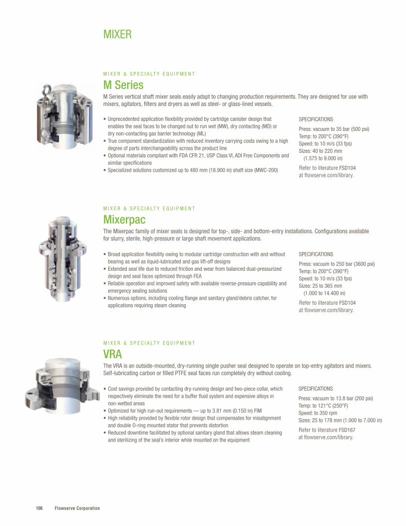
Flowserve Corporation106
SPECIFICATIONS
Press: vacuum to 13.8 bar (200 psi)Temp: to 121°C (250°F)Speed: to 350 rpmSizes: 25 to 178 mm (1.000 to 7.000 in)
Refer to literature FSD167 at flowserve.com/library.
• Cost savings provided by contacting dry-running design and two-piece collar, which respectively eliminate the need for a buffer fluid system and expensive alloys in non-wetted areas
• Optimized for high run-out requirements — up to 3.81 mm (0.150 in) FIM • High reliability provided by flexible rotor design that compensates for misalignment
and double O-ring mounted stator that prevents distortion • Reduced downtime facilitated by optional sanitary gland that allows steam cleaning
and sterilizing of the seal’s interior while mounted on the equipment
M I X E R & S P E C I A LT Y E Q U I P M E N T
VRAThe VRA is an outside-mounted, dry-running single pusher seal designed to operate on top-entry agitators and mixers. Self-lubricating carbon or filled PTFE seal faces run completely dry without cooling.
SPECIFICATIONS
Press: vacuum to 250 bar (3600 psi)Temp: to 200°C (390°F)Speed: to 10 m/s (33 fps) Sizes: 25 to 365 mm (1.000 to 14.400 in)
Refer to literature FSD104 at flowserve.com/library.
• Broad application flexibility owing to modular cartridge construction with and without bearing as well as liquid-lubricated and gas lift-off designs
• Extended seal life due to reduced friction and wear from balanced dual-pressurized design and seal faces optimized through FEA
• Reliable operation and improved safety with available reverse-pressure capability and emergency sealing solutions
• Numerous options, including cooling flange and sanitary gland/debris catcher, for applications requiring steam cleaning
M I X E R & S P E C I A LT Y E Q U I P M E N T
MixerpacThe Mixerpac family of mixer seals is designed for top-, side- and bottom-entry installations. Configurations available for slurry, sterile, high-pressure or large shaft movement applications.
MIXER
SPECIFICATIONS
Press: vacuum to 35 bar (500 psi)Temp: to 200°C (390°F)Speed: to 10 m/s (33 fps) Sizes: 40 to 220 mm (1.575 to 9.000 in)
Refer to literature FSD104 at flowserve.com/library.
• Unprecedented application flexibility provided by cartridge canister design that enables the seal faces to be changed out to run wet (MW), dry contacting (MD) or dry non-contacting gas barrier technology (ML)
• True component standardization with reduced inventory carrying costs owing to a high degree of parts interchangeability across the product line
• Optional materials compliant with FDA CFR 21, USP Class VI, ADI Free Components and similar specifications
• Specialized solutions customized up to 480 mm (18.900 in) shaft size (MWC-200)
M I X E R & S P E C I A LT Y E Q U I P M E N T
M SeriesM Series vertical shaft mixer seals easily adapt to changing production requirements. They are designed for use with mixers, agitators, filters and dryers as well as steel- or glass-lined vessels.

107flowserve.com
VALVES | LINEAR CO
NTRO
LSEALS
| MIXER
SPECIFICATIONS
Press: vacuum to 7 bar (100 psi)Temp: to 150°C (300°F)Speed: to 1740 rpmSizes: 25 to 305 mm (1.000 to 12.000 in)
For more information, refer to FSD162.
SPECIFICATIONS
Press: vacuum to 3.4 bar (50 psi)Temp: -40°C to 135°C (-40°F to 275°F)Speed: to 4 m/s (13 fps)Sizes: 25.4 to 108 mm (1.000 to 4.250 in)
For more information, refer to FSD104 and FSD147.
• Easy installation, inspection and maintenance facilitated by outside seal arrangement and split design
• Fits in tight spaces with no equipment tear down; can be installed in cramped stuffing box areas where the bearing housing, gear box or coupling create obstructions
• Reliable operation owing to self-lubricating faces and design that dissipates heat from seal faces, which allows it to run dry or wet
• Product purity ensured by design that compensates for pressure reversals
• Sterile operation ensured by sloped non-pooling, product-side design that minimizes crevices and is drainable
• Cartridge seal ensures installation ease and can be fitted with a bearing to help steady the shaft
• Highly reliable liquid-lubricated, dual-pressurized design eliminates leakage and protects process integrity
• Materials compliant with FDA CFR 21 and USP Class VI; all components are ADI free
M I X E R & S P E C I A L T Y E Q U I P M E N T
MSSThe MSS is for tough mixer and vessel applications where stuffing box face, bore and OD run-out are extreme. Typically used on older equipment or where compression packing had been used.
M I X E R & S P E C I A L T Y E Q U I P M E N T
ST The ST is a bottom-entry mixer seal designed for the ruggedness and reliability necessary in sterile environments, such as bioreactors. Suitable for CIP and SIP use.
SPECIFICATIONS
Press: to 6.9 bar (100 psi)Temp: -40°C to 204°C (-40°F to 400°F)Speed: to 1.1 m/s (3.5 fps) Sizes: 25 to 200 mm (1.000 to 8.000 in)
For more information, refer to FSD104.
• Reduced installation and maintenance costs assured by economical cartridge seal design for top-entry installation
• Increased uptime resulting from volute groove, which significantly increases barrier fluid flow to promote cool running, even at mixer speeds
• Reliable operation ensured by ISC2 thermal management technology that allows the seal to run cooler and tolerate dry-running events
M I X E R E Q U I P M E N T
ISC2-MWThe ISC2-MW is a dual-arrangement standard cartridge pusher seal engineered for reliable, cost-effective operation in mixer service.
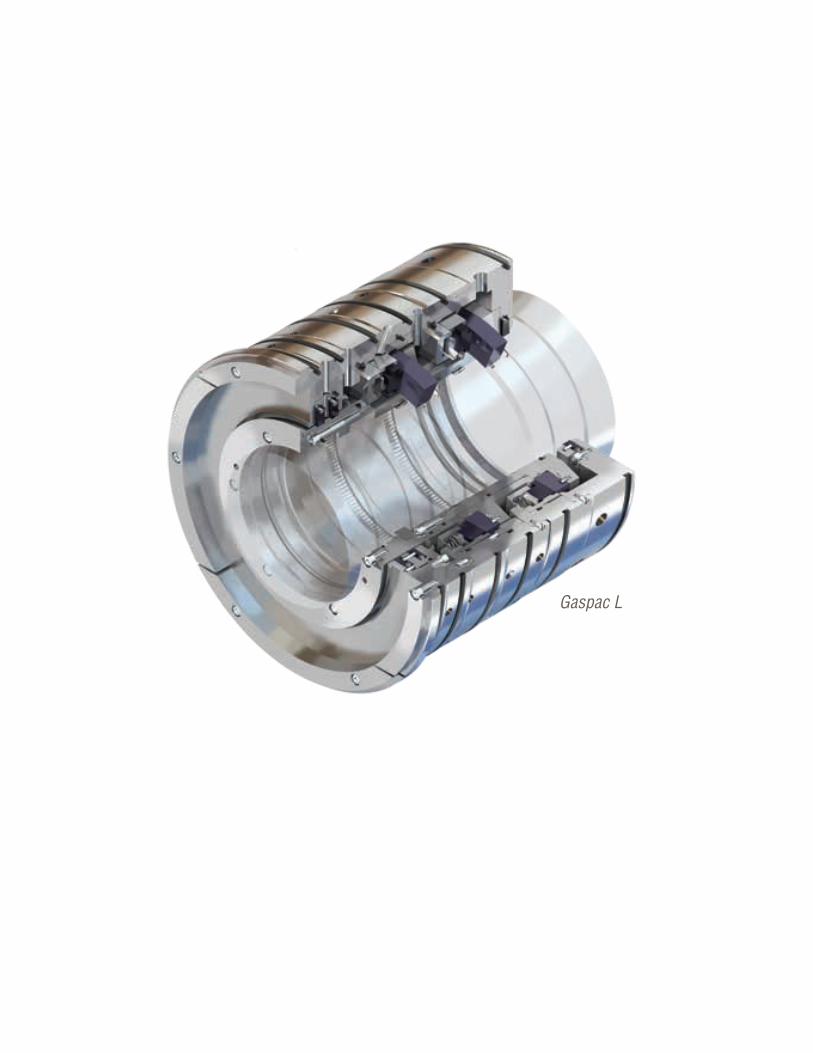
Flowserve Corporation108
Gaspac L
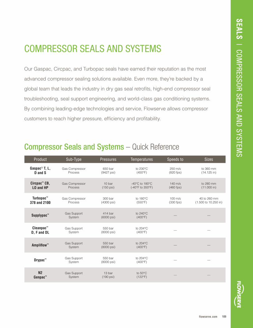
109flowserve.com
SEALS | CO
MPRESSO
R SEALS AND
SYSTEMS
COMPRESSOR SEALS AND SYSTEMS
Compressor Seals and Systems – Quick Reference
Our Gaspac, Circpac, and Turbopac seals have earned their reputation as the most
advanced compressor sealing solutions available . Even more, they’re backed by a
global team that leads the industry in dry gas seal retrofits, high-end compressor seal
troubleshooting, seal support engineering, and world-class gas conditioning systems .
By combining leading-edge technologies and service, Flowserve allows compressor
customers to reach higher pressure, efficiency and profitability .
Product Sub-Type Pressures Temperatures Speeds to Sizes
Gaspac® T, L, D and S
Gas Compressor Process
650 bar(9427 psi)
to 230°C(450°F)
250 m/s(820 fps)
to 360 mm(14 .125 in)
Circpac™ CB, LO and HP
Gas Compressor Process
10 bar(150 psi)
-40°C to 180°C (-40°F to 350°F)
140 m/s(460 fps)
to 280 mm(11 .000 in)
Turbopac™ 378 and 2100
Gas Compressor Process
300 bar(4300 psi)
to 180°C(550°F)
100 m/s(330 fps)
40 to 260 mm(1 .500 to 10 .250 in)
Supplypac™ Gas SupportSystem
414 bar (6000 psi)
to 240°C(400°F) — —
Cleanpac™ D, F and DL
Gas SupportSystem
550 bar(8000 psi)
to 204°C (400°F) — —
Ampliflow™ Gas SupportSystem
550 bar(8000 psi)
to 204°C(400°F) — —
Drypac™ Gas SupportSystem
550 bar(8000 psi)
to 204°C(400°F) — —
N2 Genpac™
Gas SupportSystem
13 bar(190 psi)
to 50°C(122°F) — —
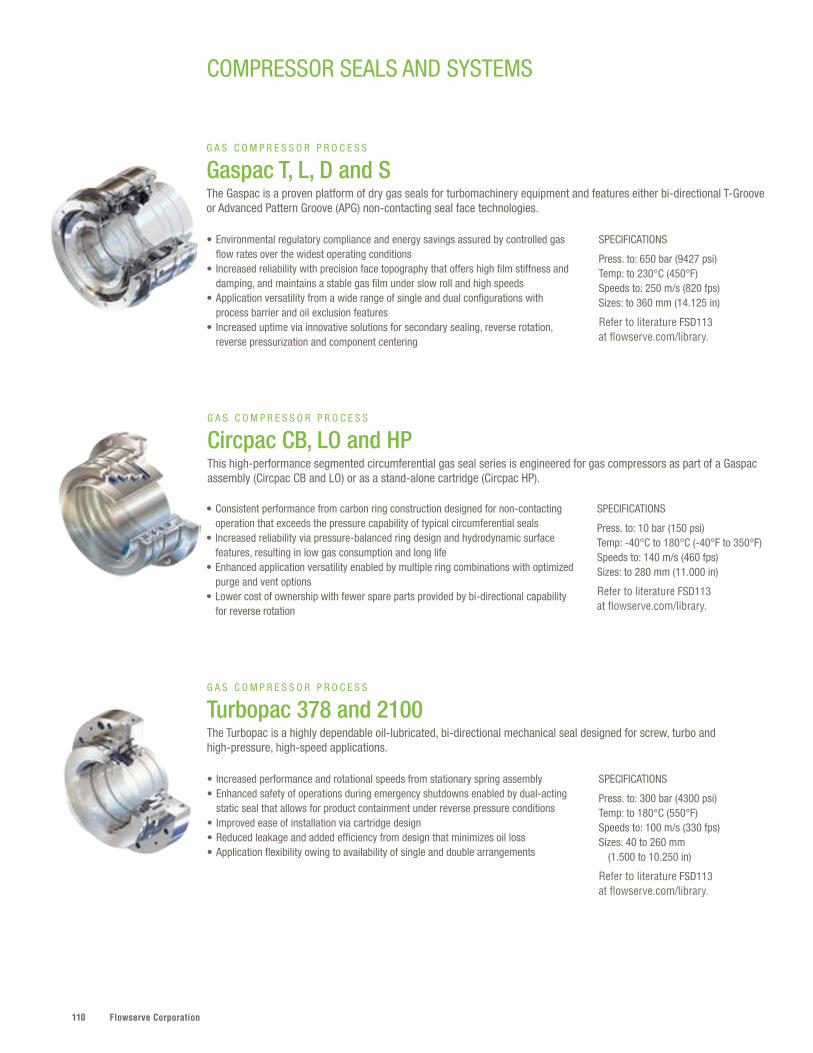
Flowserve Corporation110
SPECIFICATIONS
Press. to: 300 bar (4300 psi)Temp: to 180°C (550°F)Speeds to: 100 m/s (330 fps)Sizes: 40 to 260 mm (1.500 to 10.250 in)
Refer to literature FSD113 at flowserve.com/library.
• Increased performance and rotational speeds from stationary spring assembly• Enhanced safety of operations during emergency shutdowns enabled by dual-acting
static seal that allows for product containment under reverse pressure conditions• Improved ease of installation via cartridge design• Reduced leakage and added efficiency from design that minimizes oil loss• Application flexibility owing to availability of single and double arrangements
G A S C O M P R E S S O R P R O C E S S
Turbopac 378 and 2100The Turbopac is a highly dependable oil-lubricated, bi-directional mechanical seal designed for screw, turbo and high-pressure, high-speed applications.
COMPRESSOR SEALS AND SYSTEMS
SPECIFICATIONS
Press. to: 10 bar (150 psi)Temp: -40°C to 180°C (-40°F to 350°F) Speeds to: 140 m/s (460 fps)Sizes: to 280 mm (11.000 in)
Refer to literature FSD113 at flowserve.com/library.
• Consistent performance from carbon ring construction designed for non-contacting operation that exceeds the pressure capability of typical circumferential seals
• Increased reliability via pressure-balanced ring design and hydrodynamic surface features, resulting in low gas consumption and long life
• Enhanced application versatility enabled by multiple ring combinations with optimized purge and vent options
• Lower cost of ownership with fewer spare parts provided by bi-directional capability for reverse rotation
G A S C O M P R E S S O R P R O C E S S
Circpac CB, LO and HP This high-performance segmented circumferential gas seal series is engineered for gas compressors as part of a Gaspac assembly (Circpac CB and LO) or as a stand-alone cartridge (Circpac HP).
SPECIFICATIONS
Press. to: 650 bar (9427 psi)Temp: to 230°C (450°F) Speeds to: 250 m/s (820 fps)Sizes: to 360 mm (14.125 in)
Refer to literature FSD113 at flowserve.com/library.
• Environmental regulatory compliance and energy savings assured by controlled gas flow rates over the widest operating conditions
• Increased reliability with precision face topography that offers high film stiffness and damping, and maintains a stable gas film under slow roll and high speeds
• Application versatility from a wide range of single and dual configurations with process barrier and oil exclusion features
• Increased uptime via innovative solutions for secondary sealing, reverse rotation, reverse pressurization and component centering
G A S C O M P R E S S O R P R O C E S S
Gaspac T, L, D and SThe Gaspac is a proven platform of dry gas seals for turbomachinery equipment and features either bi-directional T-Groove or Advanced Pattern Groove (APG) non-contacting seal face technologies.
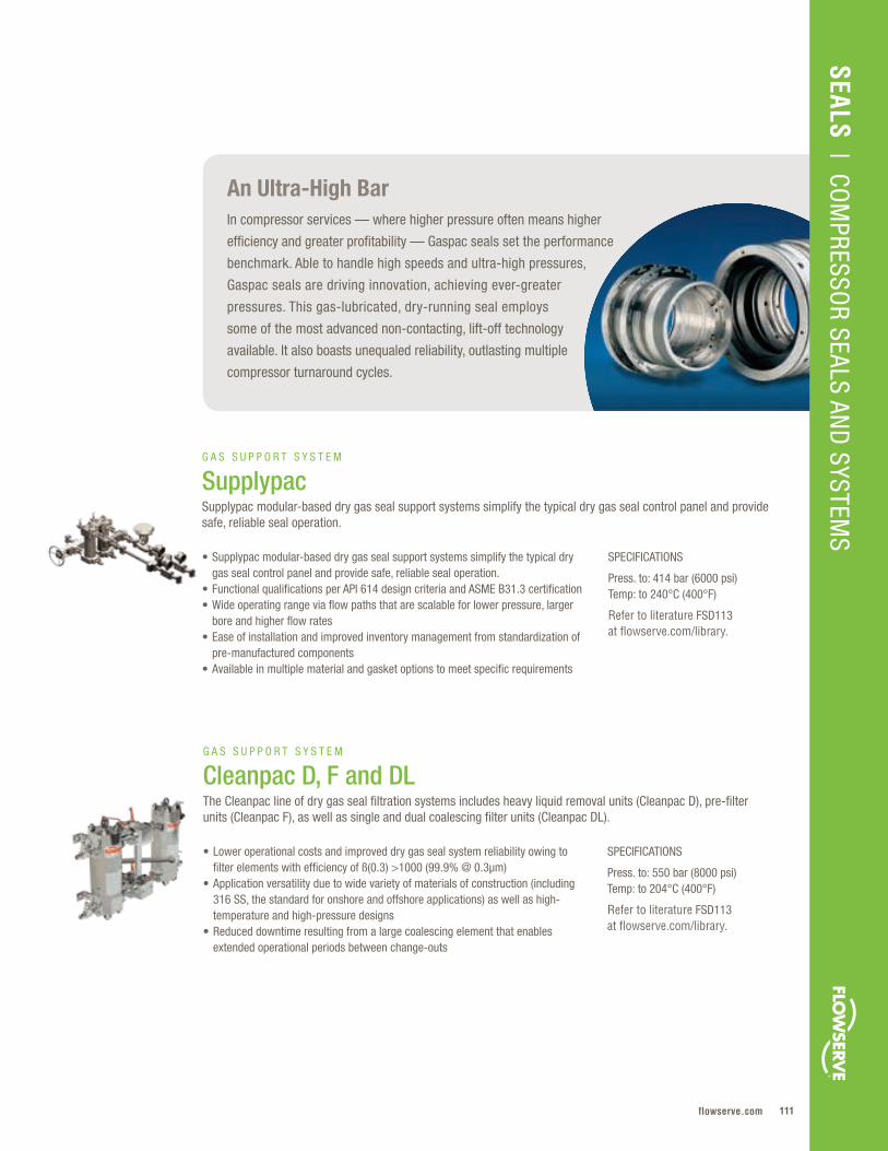
111flowserve.com
VALVES | LINEAR CO
NTRO
L
SPECIFICATIONS
Press. to: 550 bar (8000 psi)Temp: to 204°C (400°F)
Refer to literature FSD113 at flowserve.com/library.
• Lower operational costs and improved dry gas seal system reliability owing to filter elements with efficiency of ß(0.3) >1000 (99.9% @ 0.3µm)
• Application versatility due to wide variety of materials of construction (including 316 SS, the standard for onshore and offshore applications) as well as high-temperature and high-pressure designs
• Reduced downtime resulting from a large coalescing element that enables extended operational periods between change-outs
G A S S U P P O R T S Y S T E M
Cleanpac D, F and DLThe Cleanpac line of dry gas seal filtration systems includes heavy liquid removal units (Cleanpac D), pre-filter units (Cleanpac F), as well as single and dual coalescing filter units (Cleanpac DL).
SPECIFICATIONS
Press. to: 414 bar (6000 psi)Temp: to 240°C (400°F)
Refer to literature FSD113 at flowserve.com/library.
• Supplypac modular-based dry gas seal support systems simplify the typical dry gas seal control panel and provide safe, reliable seal operation.
• Functional qualifications per API 614 design criteria and ASME B31.3 certification• Wide operating range via flow paths that are scalable for lower pressure, larger
bore and higher flow rates• Ease of installation and improved inventory management from standardization of
pre-manufactured components• Available in multiple material and gasket options to meet specific requirements
G A S S U P P O R T S Y S T E M
SupplypacSupplypac modular-based dry gas seal support systems simplify the typical dry gas seal control panel and provide safe, reliable seal operation.
An Ultra-High BarIn compressor services — where higher pressure often means higher
efficiency and greater profitability — Gaspac seals set the performance
benchmark. Able to handle high speeds and ultra-high pressures,
Gaspac seals are driving innovation, achieving ever-greater
pressures. This gas-lubricated, dry-running seal employs
some of the most advanced non-contacting, lift-off technology
available. It also boasts unequaled reliability, outlasting multiple
compressor turnaround cycles.
SEALS | CO
MPRESSO
R SEALS AND
SYSTEMS

Flowserve Corporation112
SPECIFICATIONS
Press. to: 13 bar (190 psi)Temp: to 50°C (122°F)
Refer to literature FSD113 at flowserve.com/library.
• Optimal dry gas seal performance ensured by micron fiber filtration technology that extracts nitrogen gas at purities between 97% and 99%
• Uninterrupted nitrogen flow made possible by dual parallel filtration technology• High uptime provided by monitoring system with differential pressure indicating
transmitters and inlet/outlet pressure gauges• Application flexibility arising from system that can operate independently or
integrate with the Flowserve dry gas seal panel or Cleanpac and Drypac gas conditioning systems
G A S S U P P O R T S Y S T E M
N2 Genpac The N2 Genpac system safely generates nitrogen gas from compressed air in hazardous conditions or remote locations.
SPECIFICATIONS
Press. to: 550 bar (8000 psi)Temp: to 204°C (400°F)
Refer to literature FSD113 at flowserve.com/library.
SPECIFICATIONS
Press. to: 550 bar (8000 psi)Temp: to 204°C (400°F)
Refer to literature FSD113 at flowserve.com/library.
• Optimal dry gas seal performance ensured by the system’s ability to maintain flow through the conditioning system or seal gas panel
• Lower operating costs made possible by eliminating process contamination — the number one cause of dry gas seal failures
• Versatility via configuration options that include a portable unit, standalone panel, or integration with a Flowserve dry gas seal control panel or filter gas conditioning panel
• Decreased liquid formation ensured by system that lowers the dew point of the gas and raises the temperature of the seal supply gas to at least 20°C (36°F) above the dew point
• Increased MTBF of dry gas seals when the dew point of the gas is a potential issue• Low operating costs due to simplified installation, operation and maintenance • Easily integrated within existing gas seal control panels
G A S S U P P O R T S Y S T E M
AmpliflowThe Ampliflow seal supply gas boosting system ensures an adequate supply of clean, filtered gas is provided to the seals during periods of low differential pressure across the compressor.
G A S S U P P O R T S Y S T E M
Drypac The Drypac gas dryer reduces the potential of liquid formation between the seal faces as a best practice reliability improvement measure and recommended by API standards.
COMPRESSOR SEALS AND SYSTEMS

113flowserve.com
VALVES | LINEAR CO
NTRO
LSEALS
| COM
PRESSOR SEALS AN
D SYSTEM
S
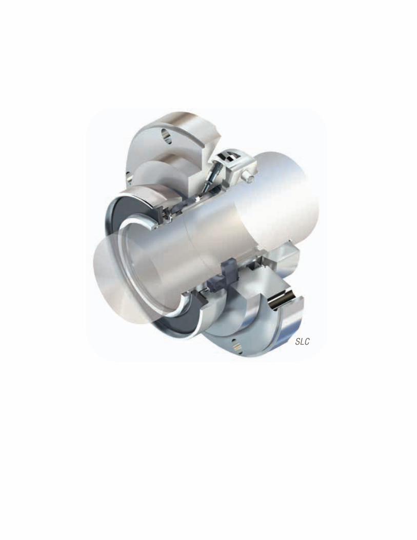
Flowserve Corporation114
SLC

115flowserve.com
SEALS | SLURRY
SLURRY
Slurry – Quick Reference
Abrasive . Erosive . Corrosive . Viscous . Slurry applications can be brutal on equipment,
but Flowserve slurry seals are engineered to last . From economical designs for low-solids
applications to rugged beasts that handle up to 60% solids content by weight, Flowserve
slurry seals resist clogging with smooth geometries and non-wetted springs . Costs
are controlled with engineered assemblies that fit common slurry pumps and modular
components that make field repair easy . What’s more, customers will find unrivaled
support in our knowledgeable and experienced engineering and support teams .
Product Sub-Type Pressures Temperatures Speeds to Sizes
SLC Series Slurry Process 20 .6 bar (300 psi)
-18°C to 110°C (10°F to 230°F)
15 m/s (50 fps)
32 to 220 mm (1 .250 to 8 .661 in)
SLM Series Slurry Process 17 .2 bar (250 psi)
-40°C to 149°C (-40°F to 300°F)
23 m/s (75 fps)
50 to 235 mm (2 .000 to 9 .250 in)
RIS Slurry Process 10 .3 bar (150 psi)
-4°C to 110°C (25°F to 230°F)
11 m/s (36 fps)
32 to 235 mm (1 .250 to 9 .250 in)
Allpac Slurry Process 50 bar (725 psi)
-40°C to 220°C (-40°F to 430°F)
50 m/s (164 fps)
20 to 30 mm (0 .750 to 11 .750 in)

Flowserve Corporation116
SLURRY
SPECIFICATIONS
Press. to: 20.6 bar (300 psi)Temp: -18°C to 110°C (10°F to 230°F)Speeds to: 15 m/s (50 fps)Sizes: 32 to 220 mm (1.250 to 8.661 in)
Refer to literature FSD120 or FSD103 at flowserve.com/library.
• Lower operating costs ensured by unique non-clogging, encapsulated cone spring, which increases reliability and enables flushless operation
• Maximized equipment uptime provided by abrasion-resistant metal components and silicon carbide faces that extend seal life beyond that of slurry pump components
• Economical performance via clean, open design, which operates without flush water to reduce product dilution and eliminate flush water costs
• Ease of installation resulting from cartridge design that requires no special tools or bearing housing adjustments
S L U R R Y P R O C E S S
SLC SeriesSLC seals are heavy-duty, single pusher cartridge seals built for the harshest slurry pump services found in mining, mineral and ore processing, and flue gas desulfurization. Suitable for solids to 60% by weight.
SPECIFICATIONS
Press. to: 17.2 bar (250 psi)Temp: -40°C to 149°C (-40°F to 300°F)Speeds to: 23 m/s (75 fps) Sizes: 50 to 235 mm (2.000 to 9.250 in)
Refer to literature FSD166 or FSD103 at flowserve.com/library.
SPECIFICATIONS
Press. to: 10.3 bar (150 psi)Temp: -4°C to 110°C (25°F to 230°F)Speeds to: 11 m/s (36 fps) Sizes: 32 to 235 mm (1.250 to 9.250 in)
Refer to literature FSD151 or FSD103 at flowserve.com/library.
• Increased reliability and consistent “no visible leakage” operation due to line-on-line, hydraulically balanced faces
• Extended seal life enabled by centroid-loaded monoblock rotor that helps to maintain zero net deflection, reducing leakage and wear
• Reduced maintenance costs provided by large cross-section stator O-ring, which allows maximum shaft movement while reducing the damaging effects of hang-up
• Dependable performance provided by single seals handling solids to 20%, dual seals to 60% solids, and quench options providing complete application flexibility
• Ease of installation provided by innovative adaptive components that allow the seal to be installed from the wet end and adjusted externally
• Longer MTBF from non-clogging elastomer spring design that has no dynamic O-ring to hang up
• Reliable operation ensured by the rubber-energized stationary seal face that holds the seal faces together and absorbs relative shaft movement
• Reduced operating costs and improved control made possible by flushless operation, which is especially beneficial in flue gas desulphurization
S L U R R Y P R O C E S S
SLM Series These balanced single (SLM-6000) or dual (SLM-6200) cartridge pusher seals have a flexible stator and operate without outside flush liquid to eliminate product dilution, increase plant efficiency and reduce costs.
S L U R R Y P R O C E S S
RIS The RIS rubber-energized, component slurry seal features a unique non-clogging design that does not utilize springs or bellows. Handles solids to 50% by weight.
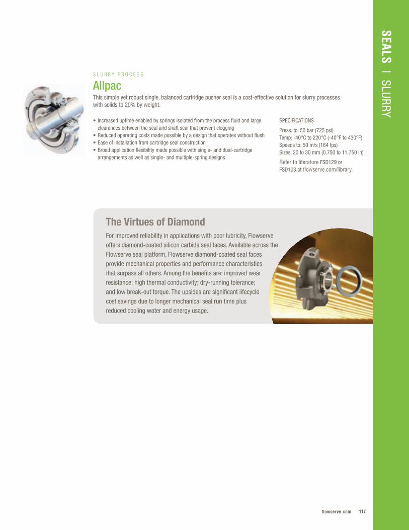
117flowserve.com
VALVES | LINEAR CO
NTRO
L
The Virtues of DiamondFor improved reliability in applications with poor lubricity, Flowserve offers diamond-coated silicon carbide seal faces. Available across the Flowserve seal platform, Flowserve diamond-coated seal faces provide mechanical properties and performance characteristics that surpass all others. Among the benefits are: improved wear resistance; high thermal conductivity; dry-running tolerance; and low break-out torque. The upsides are significant lifecycle cost savings due to longer mechanical seal run time plus reduced cooling water and energy usage.
SPECIFICATIONS
Press. to: 50 bar (725 psi)Temp: -40°C to 220°C (-40°F to 430°F)Speeds to: 50 m/s (164 fps)Sizes: 20 to 30 mm (0.750 to 11.750 in)
Refer to literature FSD129 or FSD103 at flowserve.com/library.
• Increased uptime enabled by springs isolated from the process fluid and large clearances between the seal and shaft seal that prevent clogging
• Reduced operating costs made possible by a design that operates without flush • Ease of installation from cartridge seal construction • Broad application flexibility made possible with single- and dual-cartridge
arrangements as well as single- and multiple-spring designs
S L U R R Y P R O C E S S
AllpacThis simple yet robust single, balanced cartridge pusher seal is a cost-effective solution for slurry processes with solids to 20% by weight.
SEALS | SLURRY
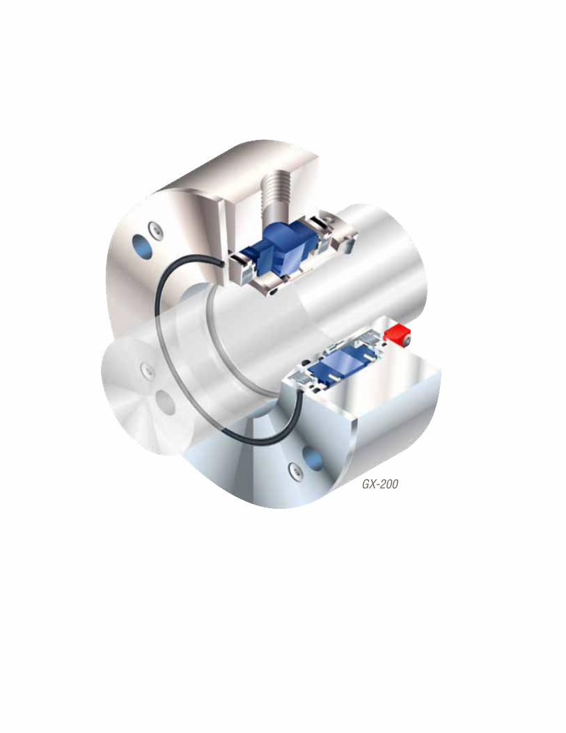
Flowserve Corporation118
GX-200
119flowserve.com
SEALS | GAS BARRIER AN
D CO
NTAIN
MEN
T
GAS BARRIER AND CONTAINMENT
Gas Barrier and Containment – Quick Reference
Running a liquid seal dry almost always means trouble, whether it’s equipment failure,
unwanted downtime or unsafe conditions . Flowserve gas barrier seals have non-contacting
seal faces that lift off during operation, so they run safely and reliably, no matter what’s
happening in the seal chamber . They also use less power and employ simplified support
systems . Flowserve containment seals normally run dry as a ready backup behind a liquid-
lubricated inboard seal . During upset events, the containment seal takes over primary
sealing responsibilities until the equipment can be safely serviced . Both designs offer
significant cost and environmental advantages, either minimizing or eliminating emissions .
Product Sub-Type Pressures to Temperatures Speeds Sizes
GF-200 Industrial Process 34 .5 bar (500 psi)
-40°C to 260°C (-40°F to 500°F)
1 .3 to 25 m/s (4 to 82 fps)
25 .4 to 152 mm (1 .000 to 6 .000 in)
GX-200 Industrial Process 13 .8 bar (200 psi)
-40°C to 260°C (-40°F to 500°F)
2 .5 to 35 m/s (8 to 115 fps)
25 .4 to 76 .2 mm (1 .000 to 3 .000 in)
GSL API Process 41 .4 bar (600 psi)
-40°C to 204°C (-40°F to 400°F)
1 .5 to 30 .5 m/s (5 to 100 fps)
20 .6 to 152 mm (0 .813 to 6 .000 in)
GSDH API Process 20 .7 bar (300 psi)
-73°C to 427°C (-100°F to 800°F)
to 19 .8 m/s (57 fps)
28 .2 to 128 .9 mm (1 .110 to 5 .073 in)
GTSP API Process 17 .2 bar (250 psi)
-73°C to 427°C (-100°F to 800°F)
3 to 46 m/s (10 to 150 fps)
47 .6 to 104 .8 mm (1 .875 to 4 .125 in)

Flowserve Corporation120
GAS BARRIER AND CONTAINMENT
SPECIFICATIONS
Press. to: 34.5 bar (500 psi)Temp: -40°C to 260°C (-40°F to 500°F)Speeds: 1.3 to 25 m/s (4 to 82 fps)Sizes: 25.4 to 152 mm (1.000 to 6.000 in)
Refer to literature FSD137 at flowserve.com/library.
SPECIFICATIONS
Press. to: 13.8 bar (200 psi)Temp: -40°C to 260°C (-40°F to 500°F)Speeds: 2.5 to 35 m/s (8 to 115 fps) Sizes: 25.4 to 76.2 mm (1.000 to 3.000 in)
Refer to literature FSD105 at flowserve.com/library.
SPECIFICATIONS
Press. to: 41.4 bar (600 psi)Temp: -40°C to 204°C (-40°F to 400°F)Speeds: 1.5 to 30.5 m/s (5 to 100 fps) Sizes: 20.6 to 152 mm (0.813 to 6.000 in)
Refer to literature FSD143 at flowserve.com/library.
• Environmental regulatory compliance assured by inert gas barrier that operates with zero process emissions
• Greater reliability enabled by spring energized O-ring technology to maintain proper seal face tracking
• Longer service life from silicon carbide seal faces using APG precision face topography, which creates a stiff, thin gas film that prevents wear
• Economical performance via non-contacting seal faces that require very low power consumption during startup and operation
• Environmental regulatory compliance assured by inert gas barrier that operates with zero process emissions
• Long-term reliability provided by high alloy metal bellows that resist contamination and hang-up while providing pressure reversal product containment during upset events
• Lower operation and maintenance costs provided by unique design that eliminates the costs of maintaining a liquid barrier system and the risks of barrier fluid contamination
• Economical performance enabled by energy-efficient design that delivers the industry’s lowest power consumption for conventional pumps
• Fully compliant with API 682 Type A, Arrangement 2 containment seal requirements • Greater reliability and service life assured by silicon carbide seal face with a bi-
directional wave pattern that provides the lift necessary for non-contacting operation • Improved plant and personnel safety from backup sealing capability to 600 psi
(41.4 bar), allowing safe shutdown if primary seal fails • Faster, trouble-free startup via cartridge assembly that simplifies installation • Meets environmental emission limits with available nitrogen sweep auxiliary system
I N D U S T R I A L P R O C E S S
GF-200This dual pressurized non-contacting, gas barrier pusher seal is used in applications where zero emissions of hazardous pumped products can be tolerated.
I N D U S T R I A L P R O C E S S
GX-200GX-200 dual metal bellows seals utilize APG non-contacting seal face technology for outstanding performance in a variety of applications. Fits standard or small bore seal chambers without modifications.
A P I P R O C E S S
GSLGSL non-contacting gas seals are designed for dry running vapor containment and full pressure wet backup sealing in light hydrocarbon, crude oil and hazardous services.
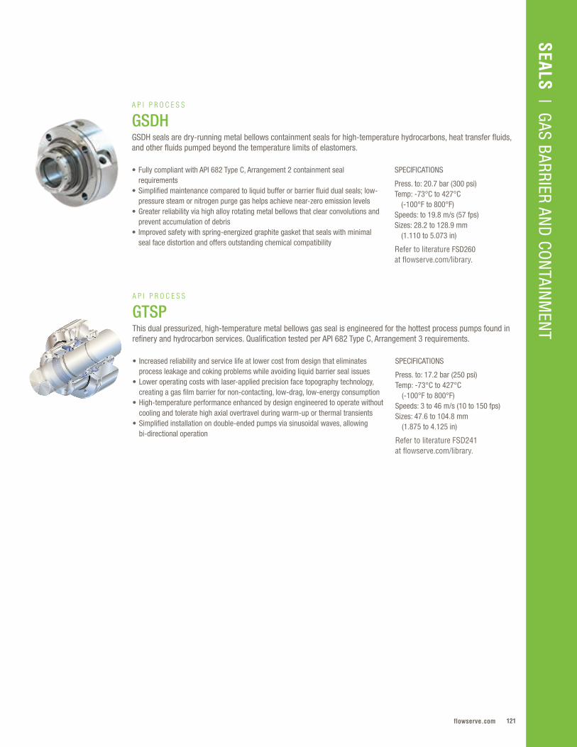
121flowserve.com
SEALS | GAS BARRIER AN
D CO
NTAIN
MEN
T
SPECIFICATIONS
Press. to: 20.7 bar (300 psi)Temp: -73°C to 427°C (-100°F to 800°F)Speeds: to 19.8 m/s (57 fps) Sizes: 28.2 to 128.9 mm (1.110 to 5.073 in)
Refer to literature FSD260 at flowserve.com/library.
• Fully compliant with API 682 Type C, Arrangement 2 containment seal requirements
• Simplified maintenance compared to liquid buffer or barrier fluid dual seals; low- pressure steam or nitrogen purge gas helps achieve near-zero emission levels
• Greater reliability via high alloy rotating metal bellows that clear convolutions and prevent accumulation of debris
• Improved safety with spring-energized graphite gasket that seals with minimal seal face distortion and offers outstanding chemical compatibility
A P I P R O C E S S
GSDHGSDH seals are dry-running metal bellows containment seals for high-temperature hydrocarbons, heat transfer fluids, and other fluids pumped beyond the temperature limits of elastomers.
SPECIFICATIONS
Press. to: 17.2 bar (250 psi)Temp: -73°C to 427°C (-100°F to 800°F) Speeds: 3 to 46 m/s (10 to 150 fps) Sizes: 47.6 to 104.8 mm (1.875 to 4.125 in)
Refer to literature FSD241 at flowserve.com/library.
• Increased reliability and service life at lower cost from design that eliminates process leakage and coking problems while avoiding liquid barrier seal issues
• Lower operating costs with laser-applied precision face topography technology, creating a gas film barrier for non-contacting, low-drag, low-energy consumption
• High-temperature performance enhanced by design engineered to operate without cooling and tolerate high axial overtravel during warm-up or thermal transients
• Simplified installation on double-ended pumps via sinusoidal waves, allowing bi-directional operation
A P I P R O C E S S
GTSPThis dual pressurized, high-temperature metal bellows gas seal is engineered for the hottest process pumps found in refinery and hydrocarbon services. Qualification tested per API 682 Type C, Arrangement 3 requirements.
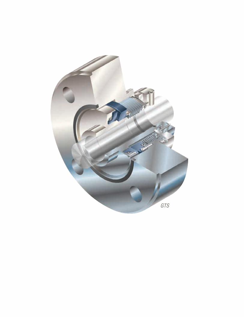
Flowserve Corporation122122
GTS

123flowserve.com
SEALS | O
EM AN
D SPECIAL D
UTY
OEM AND SPECIAL DUTY
Product Sub-Type Pressures Temperatures Speeds Sizes
Pac-Seal® Industrial Process
to 27 bar (400 psi)
-40°C to 204°C (-40°F to 400°F)
to 25 m/s (83 fps)
15 .8 to 150 mm (0 .625 to 6 .000 in)
PL Series Industrial Process
Vacuum to 10 .3 bar (150 psi)
-18°C to 150°C (0°F to 300°F)
to 23 m/s (60 fps)
35 to 53 mm (1 .375 to 2 .750 in)
PSS 4 Industrial Process
Vacuum to 30 bar (450 psi)
-18°C to 121°C (0°F to 250°F)
to 19 .3 m/s (3800 fpm)
38 to 152 mm (1 .500 to 6 .000 in)
LS-300 High-Viscosity Process
to 10 .3 bar (150 psi)
-53°C to 149°C (-65°F to 300°F)
to 3 .5 m/s (12 fps)
19 .1 to 76 .2 mm (0 .750 to 3 .000 in)
GTS Steam Turbines
to 20 .7 bar (300 psi)
100°C to 343°C (212°F to 650°F)
3 to 46 m/s (10 to 150 fps)
54 to 181 mm (2 .125 to 7 .125 in)
GSS Specialty Equipment
to 86 .2 bar (1250 psi)
-62°C to 204°C (-80°F to 400°F)
1500 to 36 000 rpm
25 .4 to 31 .8 mm (1 .000 to 1 .250 in)
GLS Specialty Equipment
to 86 .2 bar (1250 psi)
-62°C to 204°C (-80°F to 400°F)
1500 to 36 000 rpm
25 .4 to 31 .8 mm (1 .000 to 1 .250 in)
GSG Specialty Equipment
to 17 .2 bar (250 psi)
-40°C to 204°C (-40°F to 400°F)
1500 to 36 000 rpm
to 31 .8 mm (1 .250 in)
Circpac MD Specialty Equipment
Vacuum to 6 .9 bar (100 psi)
-40°C to 593°C (-40°F to 1100°F)
to 46 m/s (150 fps)
25 .4 to 457 mm (1 .000 to 18 .000 in)
Bulk-Tite™ Specialty Equipment
Vacuum to 3 .3 bar (50 psi)
0°C to 121°C (32°F to 250°F)
16 .6 m/s (54 fps)
12 to 152 mm (0 .500 to 6 .000 in)
OEM and Special Duty – Quick Reference
Flexibility, reliability and low total cost are fundamental to the general industrial and specialty
equipment requirements of OEMs . And Flowserve delivers . Global OEM customers will find
a variety of mechanical seals developed specifically with OEMs in mind . That means seals
for just about anything: seals for a high-speed, high- pressure integrally geared pump;
special configurations for a low- speed, high- viscosity positive displacement pump; and
much more . We can even help with custom designs . Reach out to our experienced team .

Flowserve Corporation124
OEM AND SPECIAL DUTY
SPECIFICATIONS
Press.: Vacuum to 10.3 bar (150 psi)Temp: -18°C to 150°C (0°F to 300°F)Speeds: to 23 m/s (60 fps) Sizes: 35 to 53 mm (1.375 to 2.750 in)
• Greater reliability from special carbon fiber reinforced PTFE construction that provides excellent corrosion resistance and mechanical properties to maintain seal integrity
• Longer service life and MTBF ensured by springs and pins that are isolated from the product to prevent clogging and chemical attack
• Reduced maintenance costs with replaceable carbon fiber PTFE liner that protects the 316 SS gland
• Affordable alternative to high-alloy single or dual metal seals
I N D U S T R I A L P R O C E S S
PL SeriesPL Series seals are pre-engineered single (PL-100) and dual (PL-200) cartridge seals with non-metallic wetted components. They are a cost-effective alternative to high-alloy seals in ASME and ISO pumps in corrosive services.
SPECIFICATIONS
Press. to: 27 bar (400 psi)Temp: -40°C to 204°C (-40°F to 400°F)Speeds to: 25 m/s (83 fps) Sizes: 15.8 to 150 mm (0.625 to 6.000 in)
Refer to literature FSD258 at flowserve.com/library.
• Low cost of ownership enabled by readily available components with multiple material options
• Excellent reliability ensured by standardized features, including crimped-head rotary units and hex-torque drive
• Easy installation with no set screws or setting clips • Custom designs with flexible inventory, logistics and packaging solutions for high-
volume OEM orders ensure the right supply requirements are fully achieved
I N D U S T R I A L P R O C E S S
Pac-SealThe Pac-Seal family of component seals is available in numerous designs and styles, including diaphragm elastomer bellows to fit a wide range of standard industrial and custom equipment applications.
SPECIFICATIONS
Press.: Vacuum to 30 bar (450 psi)Temp: -18°C to 121°C (0°F to 250°F) Speeds: to 19.3 m/s (3800 fpm) Sizes: 38 to 152 mm (1.500 to 6.000 in); contact Flowserve for larger sizes
Refer to literature FSD272 at flowserve.com/library.
• Exclusive 3D Key technology assures optimum face alignment in both axial and radial direction, reducing leakage and installation time
• Unique setting tabs eliminate all seal positioning, measuring and marking, assuring installation success
• Easily handles mixer equipment runout up to 1.5 mm (0.060 in) TIR radial shaft movement
• Fully split design installs easily around the shaft, outside the seal chamber, eliminating the need to dismantle the equipment
I N D U S T R I A L P R O C E S S
PSS 4The PSS 4 semi-cartridge split seal is ideal for pump and mixer applications. With only two major components, it makes installation quick and easy without requiring equipment teardown.
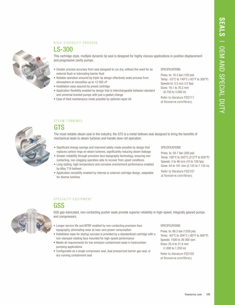
125flowserve.com
SEALS | O
EM AN
D SPECIAL D
UTY
SPECIFICATIONS
Press. to: 10.3 bar (150 psi)Temp: -53°C to 149°C (-65°F to 300°F)Speeds to: 3.5 m/s (12 fps) Sizes: 19.1 to 76.2 mm (0.750 to 3.000 in)
Refer to literature FSD117 at flowserve.com/library.
• Greater process accuracy from seal designed to run dry, without the need for an external flush or lubricating barrier fluid
• Reliable operation ensured by triple-lip design effectively seals process from atmosphere at viscosities up to 12 000 cP
• Installation ease assured by preset cartridge • Application flexibility enabled by design that is interchangeable between standard
and universal bracket pumps with just a gasket change • Ease of field maintenance made possible by optional repair kit
H I G H - V I S C O S I T Y P R O C E S S
LS-300This cartridge-style, multiple dynamic lip seal is designed for highly viscous applications in positive displacement and progressive cavity pumps.
SPECIFICATIONS
Press. to: 20.7 bar (300 psi) Temp: 100°C to 343°C (212°F to 650°F)Speeds: 3 to 46 m/s (10 to 150 fps) Sizes: 54 to 181 mm (2.125 to 7.125 in)
Refer to literature FSD107 at flowserve.com/library.
• Significant energy savings and improved safety made possible by design that replaces carbon rings on steam turbines, significantly reducing steam leakage
• Greater reliability through precision face topography technology, ensuring non-contacting, non-clogging operation able to recover from upset conditions
• Long-lasting, high-temperature and corrosive environment performance enabled by Alloy 718 bellows
• Application versatility enabled by internal or external cartridge design, adaptable for diverse turbines
S T E A M T U R B I N E S
GTSThe most reliable steam seal in the industry, the GTS is a metal bellows seal designed to bring the benefits of mechanical seals to steam turbines and handle slow roll operation.
SPECIFICATIONS
Press. to: 86.2 bar (1250 psi)Temp: -62°C to 204°C (-80°F to 400°F)Speeds: 1500 to 36 000 rpm Sizes: 25.4 to 31.8 mm (1.000 to 1.250 in)
Refer to literature FSD102 at flowserve.com/library.
• Longer service life and MTBF enabled by non-contacting precision face topography, eliminating wear at near-zero power consumption
• Installation ease for startup success is provided by a standardized cartridge with a non-clamped rotating face mounted for high-speed performance
• Meets all requirements for low emission containment seals in hydrocarbon pumping applications
• Configurable as a single compressor seal, dual pressurized barrier gas seal, or dry-running containment seal
S P E C I A L T Y E Q U I P M E N T
GSSGSS gas-lubricated, non-contacting pusher seals provide superior reliability in high-speed, integrally geared pumps and compressors.
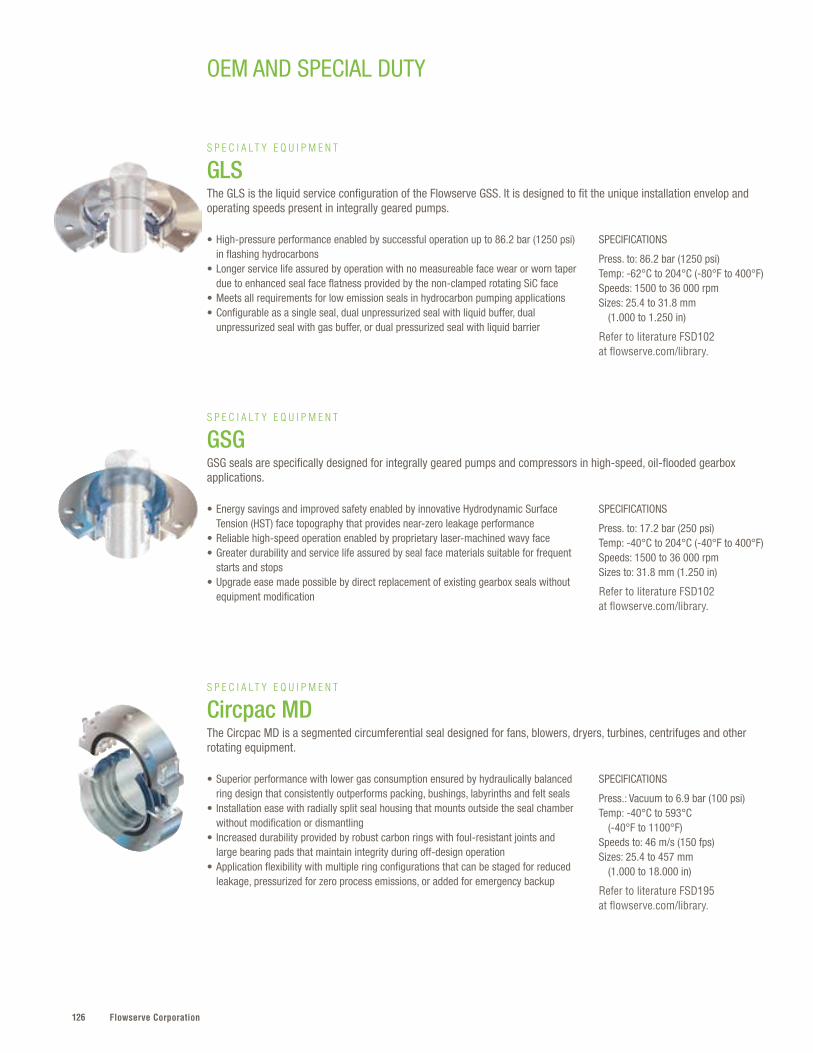
Flowserve Corporation126
OEM AND SPECIAL DUTY
SPECIFICATIONS
Press. to: 86.2 bar (1250 psi)Temp: -62°C to 204°C (-80°F to 400°F)Speeds: 1500 to 36 000 rpm Sizes: 25.4 to 31.8 mm (1.000 to 1.250 in)
Refer to literature FSD102 at flowserve.com/library.
SPECIFICATIONS
Press. to: 17.2 bar (250 psi)Temp: -40°C to 204°C (-40°F to 400°F)Speeds: 1500 to 36 000 rpm Sizes to: 31.8 mm (1.250 in)
Refer to literature FSD102 at flowserve.com/library.
SPECIFICATIONS
Press.: Vacuum to 6.9 bar (100 psi)Temp: -40°C to 593°C (-40°F to 1100°F)Speeds to: 46 m/s (150 fps) Sizes: 25.4 to 457 mm (1.000 to 18.000 in)
Refer to literature FSD195 at flowserve.com/library.
• High-pressure performance enabled by successful operation up to 86.2 bar (1250 psi) in flashing hydrocarbons
• Longer service life assured by operation with no measureable face wear or worn taper due to enhanced seal face flatness provided by the non-clamped rotating SiC face
• Meets all requirements for low emission seals in hydrocarbon pumping applications • Configurable as a single seal, dual unpressurized seal with liquid buffer, dual
unpressurized seal with gas buffer, or dual pressurized seal with liquid barrier
• Energy savings and improved safety enabled by innovative Hydrodynamic Surface Tension (HST) face topography that provides near-zero leakage performance
• Reliable high-speed operation enabled by proprietary laser-machined wavy face • Greater durability and service life assured by seal face materials suitable for frequent
starts and stops • Upgrade ease made possible by direct replacement of existing gearbox seals without
equipment modification
• Superior performance with lower gas consumption ensured by hydraulically balanced ring design that consistently outperforms packing, bushings, labyrinths and felt seals
• Installation ease with radially split seal housing that mounts outside the seal chamber without modification or dismantling
• Increased durability provided by robust carbon rings with foul-resistant joints and large bearing pads that maintain integrity during off-design operation
• Application flexibility with multiple ring configurations that can be staged for reduced leakage, pressurized for zero process emissions, or added for emergency backup
S P E C I A L T Y E Q U I P M E N T
GLSThe GLS is the liquid service configuration of the Flowserve GSS. It is designed to fit the unique installation envelop and operating speeds present in integrally geared pumps.
S P E C I A L T Y E Q U I P M E N T
GSGGSG seals are specifically designed for integrally geared pumps and compressors in high-speed, oil-flooded gearbox applications.
S P E C I A L T Y E Q U I P M E N T
Circpac MDThe Circpac MD is a segmented circumferential seal designed for fans, blowers, dryers, turbines, centrifuges and other rotating equipment.

127flowserve.com
SEALS | O
EM AN
D SPECIAL D
UTY
SPECIFICATIONS
Press. to: Vacuum to 3.3 bar (50 psi)Temp: 0°C to 121°C (32°F to 250°F)Speeds to: 16.6 m/s (54 fps)Sizes: 12 to 152 mm (0.500 to 6.000 in)
Refer to literature FSD267 at flowserve.com/library.
• Easy cartridge seal installation, minimizing downtime• Superior seal life with 3.2 mm (0.125 in) radial shaft movement,
up to 2° angular misalignment and axial shaft movement• Minimal gas consumption for reduced operating costs
S P E C I A L T Y E Q U I P M E N T
BulkTiteDesigned for rotating equipment handling powder and bulk solids, BulkTite seals improve sealing performance with non-wearing, low-maintenance solutions for screw conveyors, rotary airlocks, mixers, de-lumpers and more.
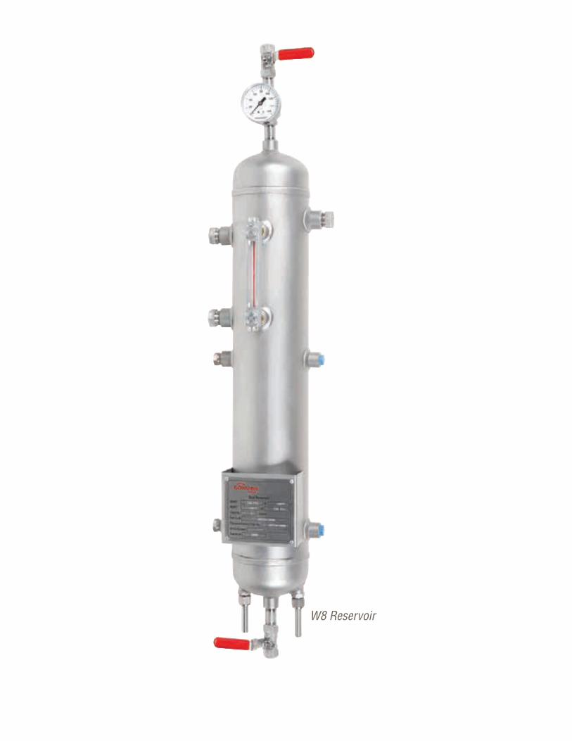
Flowserve Corporation128128
W8 Reservoir
129flowserve.com
SEALS | SEAL SUPPO
RT SYSTEMS
SEAL SUPPORT SYSTEMS
Product Type Sub-Type Flows to Pressures Temperatures Volume
Buffer/Barrier Fluid Reservoirs
Industrial & API Process — to 82 .3 bar
(1200 psi)to 148°C (300°F)
to 20 L (5 gal)
Bladder Accumulators
Industrial & API Process — to 82 .3 bar
(1200 psi)to 148°C (300°F)
20 to 50 L (5 to 13 gal)
PistonAccumulators
Industrial & API Process — to 75 .8 bar
(1100 psi)to 148°C(300°F)
to 11 .4 L(3 gal)
Buffer/Barrier Gas Panels
Industrial & API Process
14 .2 lpm(30 SCFH)
to 34 .4 bar(500 psi)
to 93°C(200°F) —
Circulators Industrial & API Process
15 lpm(4 gpm)
to 27 .6 bar(400 psi)
4 .4°C to 60°C(40°F to 140°F) —
682 Water Seal Coolers
API Process — to 275 bar (4000 psi)to 371°C (700°F) (coil) — —
Water Seal Coolers
Industrial Process — to 183 bar (2650 psi)to 95°C (200°F) — —
Airfin Seal Cooler Industrial Process — to 80 bar(1200 psi)
to 425°C(800°F) —
Seal Support Systems – Quick Reference
Flowserve seal support systems help ensure years of safe, reliable and cost-effective
mechanical seal operation . Flowserve employs a specialized engineering team with years of
experience recommending or designing systems to suit specific applications, specifications
and unique customer requirements . With a full range of products that meet ASME Section
VII Division 1, API, PED, NR13 and numerous other regional and international standards,
Flowserve fulfills the global needs of the oil and gas, chemical, power, water and general
industries .
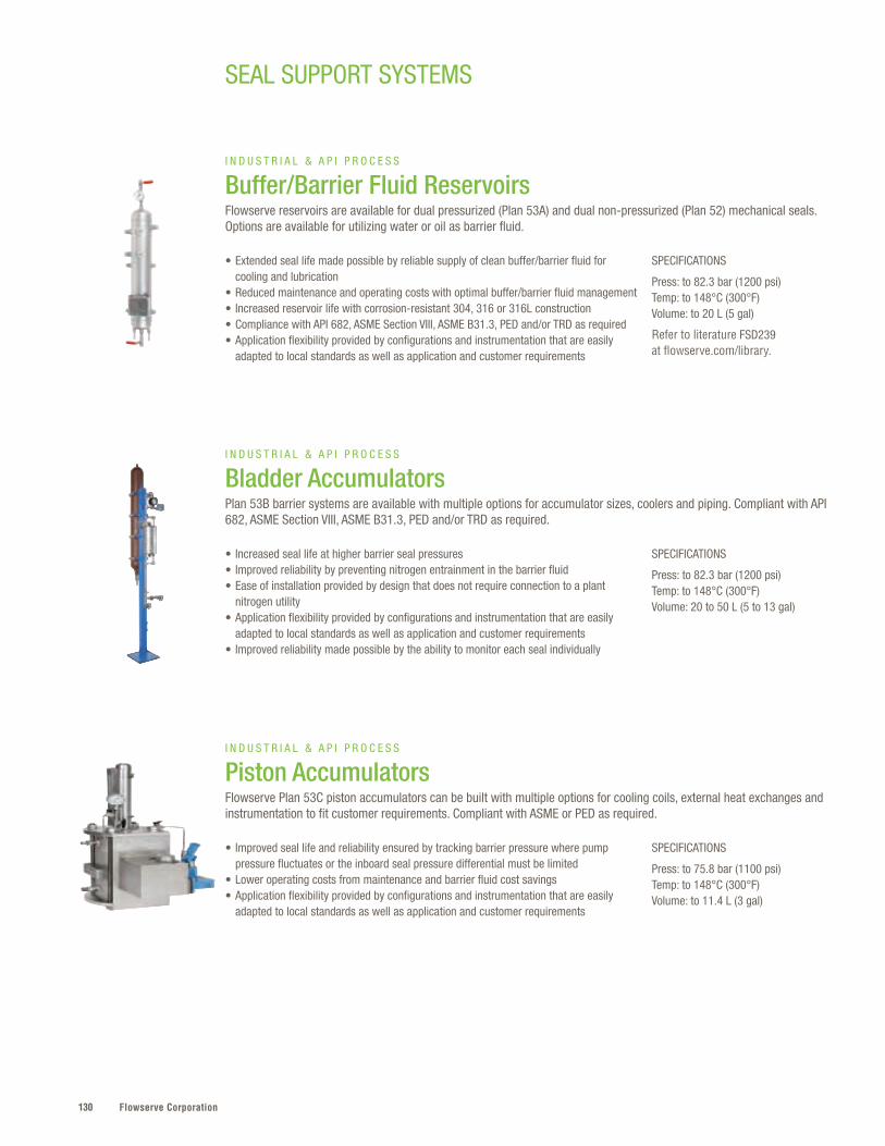
Flowserve Corporation130
SPECIFICATIONS
Press: to 82.3 bar (1200 psi) Temp: to 148°C (300°F)Volume: to 20 L (5 gal)
Refer to literature FSD239 at flowserve.com/library.
SPECIFICATIONS
Press: to 82.3 bar (1200 psi)Temp: to 148°C (300°F)Volume: 20 to 50 L (5 to 13 gal)
SPECIFICATIONS
Press: to 75.8 bar (1100 psi)Temp: to 148°C (300°F)Volume: to 11.4 L (3 gal)
• Extended seal life made possible by reliable supply of clean buffer/barrier fluid for cooling and lubrication
• Reduced maintenance and operating costs with optimal buffer/barrier fluid management• Increased reservoir life with corrosion-resistant 304, 316 or 316L construction• Compliance with API 682, ASME Section VIII, ASME B31.3, PED and/or TRD as required• Application flexibility provided by configurations and instrumentation that are easily
adapted to local standards as well as application and customer requirements
• Increased seal life at higher barrier seal pressures• Improved reliability by preventing nitrogen entrainment in the barrier fluid• Ease of installation provided by design that does not require connection to a plant
nitrogen utility • Application flexibility provided by configurations and instrumentation that are easily
adapted to local standards as well as application and customer requirements• Improved reliability made possible by the ability to monitor each seal individually
• Improved seal life and reliability ensured by tracking barrier pressure where pump pressure fluctuates or the inboard seal pressure differential must be limited
• Lower operating costs from maintenance and barrier fluid cost savings• Application flexibility provided by configurations and instrumentation that are easily
adapted to local standards as well as application and customer requirements
I N D U S T R I A L & A P I P R O C E S S
Buffer/Barrier Fluid ReservoirsFlowserve reservoirs are available for dual pressurized (Plan 53A) and dual non-pressurized (Plan 52) mechanical seals. Options are available for utilizing water or oil as barrier fluid.
I N D U S T R I A L & A P I P R O C E S S
Bladder AccumulatorsPlan 53B barrier systems are available with multiple options for accumulator sizes, coolers and piping. Compliant with API 682, ASME Section VIII, ASME B31.3, PED and/or TRD as required.
I N D U S T R I A L & A P I P R O C E S S
Piston AccumulatorsFlowserve Plan 53C piston accumulators can be built with multiple options for cooling coils, external heat exchanges and instrumentation to fit customer requirements. Compliant with ASME or PED as required.
SEAL SUPPORT SYSTEMS
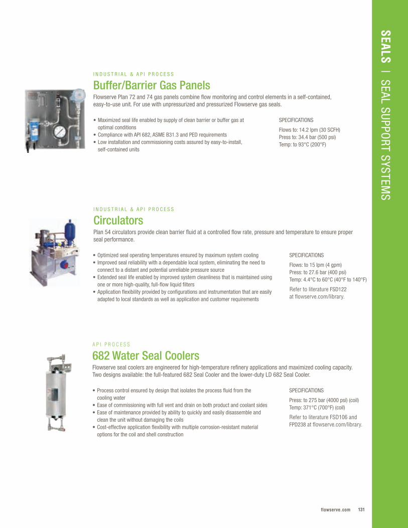
131flowserve.com
VALVES | LINEAR CO
NTRO
L
SPECIFICATIONS
Flows to: 14.2 lpm (30 SCFH) Press to: 34.4 bar (500 psi)Temp: to 93°C (200°F)
• Maximized seal life enabled by supply of clean barrier or buffer gas at optimal conditions
• Compliance with API 682, ASME B31.3 and PED requirements • Low installation and commissioning costs assured by easy-to-install,
self-contained units
I N D U S T R I A L & A P I P R O C E S S
Buffer/Barrier Gas Panels Flowserve Plan 72 and 74 gas panels combine flow monitoring and control elements in a self-contained, easy-to-use unit. For use with unpressurized and pressurized Flowserve gas seals.
SEALS | SEAL SUPPO
RT SYSTEMS
SPECIFICATIONS
Flows: to 15 lpm (4 gpm)Press: to 27.6 bar (400 psi)Temp: 4.4°C to 60°C (40°F to 140°F)
Refer to literature FSD122 at flowserve.com/library.
• Optimized seal operating temperatures ensured by maximum system cooling • Improved seal reliability with a dependable local system, eliminating the need to
connect to a distant and potential unreliable pressure source • Extended seal life enabled by improved system cleanliness that is maintained using
one or more high-quality, full-flow liquid filters• Application flexibility provided by configurations and instrumentation that are easily
adapted to local standards as well as application and customer requirements
I N D U S T R I A L & A P I P R O C E S S
CirculatorsPlan 54 circulators provide clean barrier fluid at a controlled flow rate, pressure and temperature to ensure proper seal performance.
SPECIFICATIONS
Press: to 275 bar (4000 psi) (coil)Temp: 371°C (700°F) (coil)
Refer to literature FSD106 and FPD238 at flowserve.com/library.
• Process control ensured by design that isolates the process fluid from the cooling water
• Ease of commissioning with full vent and drain on both product and coolant sides• Ease of maintenance provided by ability to quickly and easily disassemble and
clean the unit without damaging the coils• Cost-effective application flexibility with multiple corrosion-resistant material
options for the coil and shell construction
A P I P R O C E S S
682 Water Seal CoolersFlowserve seal coolers are engineered for high-temperature refinery applications and maximized cooling capacity. Two designs available: the full-featured 682 Seal Cooler and the lower-duty LD 682 Seal Cooler.
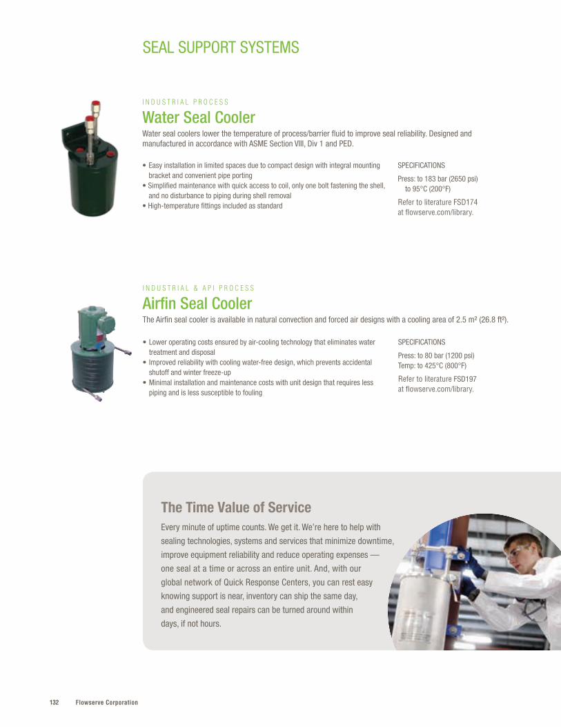
Flowserve Corporation132
SEAL SUPPORT SYSTEMS
The Time Value of ServiceEvery minute of uptime counts. We get it. We’re here to help with
sealing technologies, systems and services that minimize downtime,
improve equipment reliability and reduce operating expenses —
one seal at a time or across an entire unit. And, with our
global network of Quick Response Centers, you can rest easy
knowing support is near, inventory can ship the same day,
and engineered seal repairs can be turned around within
days, if not hours.
SPECIFICATIONS
Press: to 80 bar (1200 psi)Temp: to 425°C (800°F)
Refer to literature FSD197 at flowserve.com/library.
• Lower operating costs ensured by air-cooling technology that eliminates water treatment and disposal
• Improved reliability with cooling water-free design, which prevents accidental shutoff and winter freeze-up
• Minimal installation and maintenance costs with unit design that requires less piping and is less susceptible to fouling
I N D U S T R I A L & A P I P R O C E S S
Airfin Seal CoolerThe Airfin seal cooler is available in natural convection and forced air designs with a cooling area of 2.5 m² (26.8 ft²).
SPECIFICATIONS
Press: to 183 bar (2650 psi) to 95°C (200°F)
Refer to literature FSD174 at flowserve.com/library.
• Easy installation in limited spaces due to compact design with integral mounting bracket and convenient pipe porting
• Simplified maintenance with quick access to coil, only one bolt fastening the shell, and no disturbance to piping during shell removal
• High-temperature fittings included as standard
I N D U S T R I A L P R O C E S S
Water Seal CoolerWater seal coolers lower the temperature of process/barrier fluid to improve seal reliability. Designed and manufactured in accordance with ASME Section VIII, Div 1 and PED.

133flowserve.com
VALVES | LINEAR CO
NTRO
LSEALS
| SEAL SUPPORT SYSTEM
S

Flowserve Corporation134134
Bearing Gard
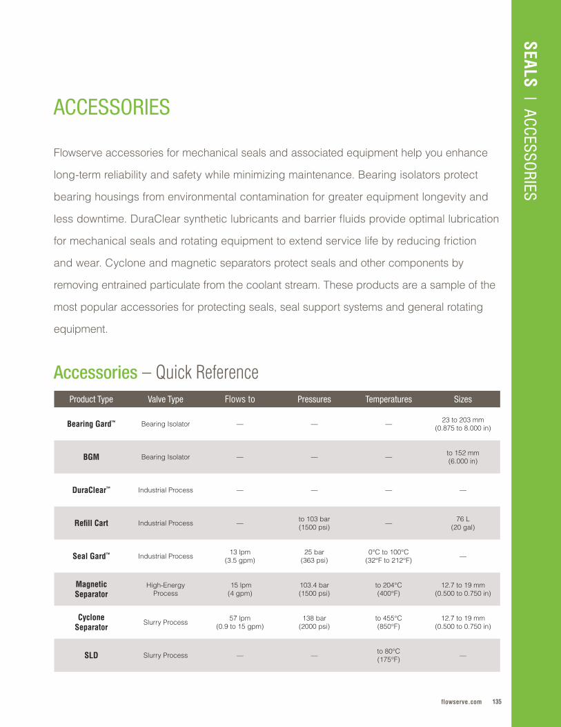
135flowserve.com
SEALS | ACCESSO
RIES
ACCESSORIES
Product Type Valve Type Flows to Pressures Temperatures Sizes
Bearing Gard™ Bearing Isolator — — — 23 to 203 mm (0 .875 to 8 .000 in)
BGM Bearing Isolator — — — to 152 mm (6 .000 in)
DuraClear™ Industrial Process — — — —
Refill Cart Industrial Process — to 103 bar(1500 psi) — 76 L
(20 gal)
Seal Gard™ Industrial Process 13 lpm (3 .5 gpm)
25 bar (363 psi)
0°C to 100°C (32°F to 212°F) —
Magnetic Separator
High-Energy Process
15 lpm (4 gpm)
103 .4 bar (1500 psi)
to 204°C (400°F)
12 .7 to 19 mm (0 .500 to 0 .750 in)
Cyclone Separator
Slurry Process 57 lpm (0 .9 to 15 gpm)
138 bar (2000 psi)
to 455°C (850°F)
12 .7 to 19 mm (0 .500 to 0 .750 in)
SLD Slurry Process — — to 80°C (175°F) —
Accessories – Quick Reference
Flowserve accessories for mechanical seals and associated equipment help you enhance
long-term reliability and safety while minimizing maintenance . Bearing isolators protect
bearing housings from environmental contamination for greater equipment longevity and
less downtime . DuraClear synthetic lubricants and barrier fluids provide optimal lubrication
for mechanical seals and rotating equipment to extend service life by reducing friction
and wear . Cyclone and magnetic separators protect seals and other components by
removing entrained particulate from the coolant stream . These products are a sample of the
most popular accessories for protecting seals, seal support systems and general rotating
equipment .
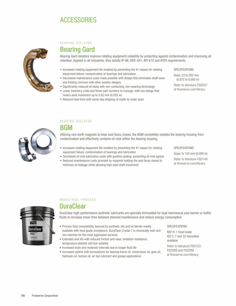
Flowserve Corporation136
ACCESSORIES
SPECIFICATIONS
Sizes: 23 to 203 mm (0.875 to 8.000 in)
Refer to literature FSD257 at flowserve.com/library.
SPECIFICATIONS
Sizes: to 152 mm (6.000 in)
Refer to literature FSD149 at flowserve.com/library.
• Increased rotating equipment life enabled by preventing the #1 reason for rotating equipment failure: contamination of bearings and lubrication
• Decreased maintenance costs made possible with design that eliminates shaft wear and fretting common with other isolator designs
• Significantly reduced oil leaks with non-contacting, non-wearing technology • Lower inventory costs and fewer part numbers to manage, with one design that
covers axial movement up to 0.63 mm (0.025 in) • Reduced lead time with same-day shipping of made-to-order sizes
• Increased rotating equipment life enabled by preventing the #1 reason for rotating equipment failure: contamination of bearings and lubrication
• Decreased oil mist lubrication costs with positive sealing, preventing oil mist egress • Reduced maintenance costs provided by magnets holding the seal faces closed to
minimize oil leakage while allowing high axial shaft movement
B E A R I N G I S O L A T O R
Bearing GardBearing Gard isolators improve rotating equipment reliability by protecting against contamination and improving oil retention. Applied in all industries, they satisfy IP-66, IEEE-841, API 610 and ATEX requirements.
B E A R I N G I S O L A T O R
BGMUtilizing rare earth magnets to keep seal faces closed, the BGM completely isolates the bearing housing from contamination and effectively contains oil mist within the bearing housing.
SPECIFICATIONS
NSF H-1 Food Grade ISO 5, 7 and 32 viscosities available
Refer to literature FSD123, FSD269 and FSD268 at flowserve.com/library.
• Process fluid compatibility assured by synthetic oils and oil blends readily available with food grade compliance; DuraClear Crystal 7 is chemically inert and non-reactive for the most aggressive services
• Extended seal life with reduced friction and wear, oxidation resistance, temperature stability and low volatility
• Increased drain and replenish intervals due to longer fluid life • Increased uptime with formulations for bearing frame oil, compressor oil, gear oil,
hydraulic oil, turbine oil, air tool lubricant and grease applications
I N D U S T R I A L P R O C E S S
DuraClearDuraClear high-performance synthetic lubricants are specially formulated for dual mechanical seal barrier or buffer fluids to increase mean time between planned maintenance and reduce energy consumption.
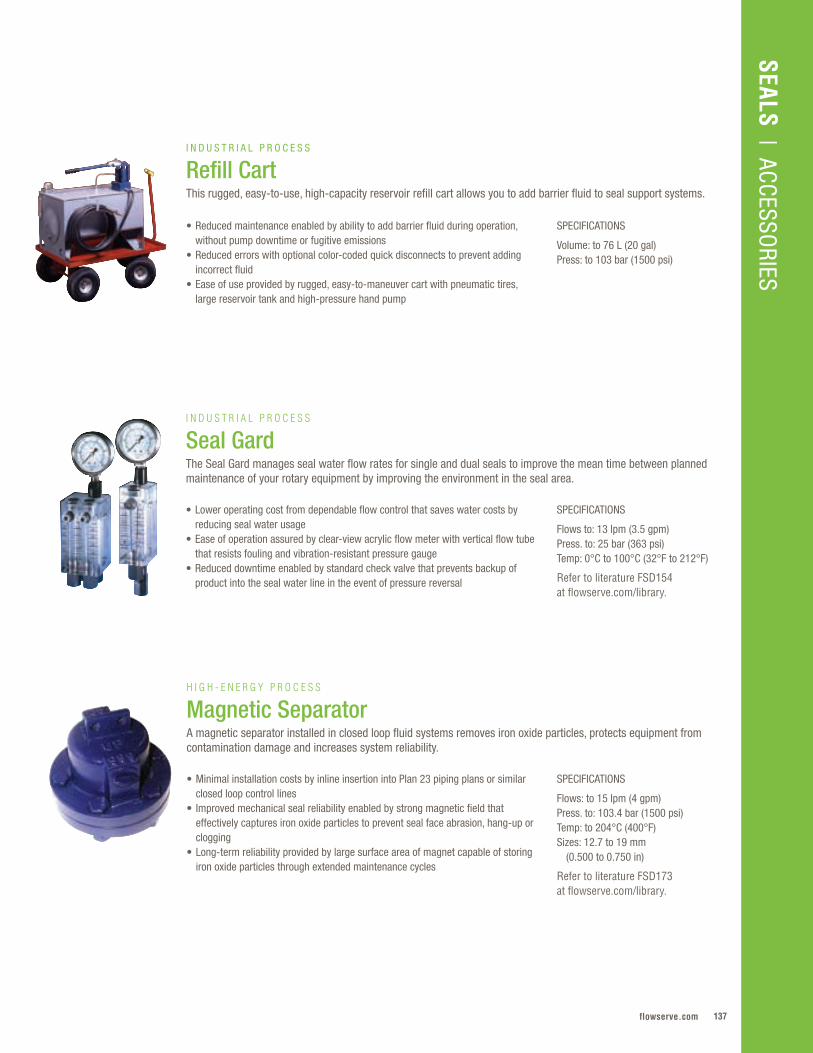
137flowserve.com
VALVES | LINEAR CO
NTRO
LSEALS
| ACCESSORIES
SPECIFICATIONS
Flows: to 15 lpm (4 gpm) Press. to: 103.4 bar (1500 psi) Temp: to 204°C (400°F) Sizes: 12.7 to 19 mm (0.500 to 0.750 in)
Refer to literature FSD173 at flowserve.com/library.
• Minimal installation costs by inline insertion into Plan 23 piping plans or similar closed loop control lines
• Improved mechanical seal reliability enabled by strong magnetic field that effectively captures iron oxide particles to prevent seal face abrasion, hang-up or clogging
• Long-term reliability provided by large surface area of magnet capable of storing iron oxide particles through extended maintenance cycles
H I G H - E N E R G Y P R O C E S S
Magnetic SeparatorA magnetic separator installed in closed loop fluid systems removes iron oxide particles, protects equipment from contamination damage and increases system reliability.
SPECIFICATIONS
Flows to: 13 lpm (3.5 gpm) Press. to: 25 bar (363 psi) Temp: 0°C to 100°C (32°F to 212°F)
Refer to literature FSD154 at flowserve.com/library.
• Lower operating cost from dependable flow control that saves water costs by reducing seal water usage
• Ease of operation assured by clear-view acrylic flow meter with vertical flow tube that resists fouling and vibration-resistant pressure gauge
• Reduced downtime enabled by standard check valve that prevents backup of product into the seal water line in the event of pressure reversal
I N D U S T R I A L P R O C E S S
Seal GardThe Seal Gard manages seal water flow rates for single and dual seals to improve the mean time between planned maintenance of your rotary equipment by improving the environment in the seal area.
SPECIFICATIONS
Volume: to 76 L (20 gal)Press: to 103 bar (1500 psi)
• Reduced maintenance enabled by ability to add barrier fluid during operation, without pump downtime or fugitive emissions
• Reduced errors with optional color-coded quick disconnects to prevent adding incorrect fluid
• Ease of use provided by rugged, easy-to-maneuver cart with pneumatic tires, large reservoir tank and high-pressure hand pump
I N D U S T R I A L P R O C E S S
Refill CartThis rugged, easy-to-use, high-capacity reservoir refill cart allows you to add barrier fluid to seal support systems.
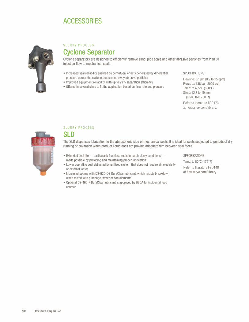
Flowserve Corporation138
ACCESSORIES
SPECIFICATIONS
Temp: to 80°C (175°F)
Refer to literature FSD148 at flowserve.com/library.
• Extended seal life — particularly flushless seals in harsh slurry conditions — made possible by providing and maintaining proper lubrication
• Lower operating cost delivered by unitized system that does not require air, electricity or external water
• Increased uptime with DS-920-OG DuraClear lubricant, which resists breakdown when mixed with pumpage, water or containments
• Optional DS-460-F DuraClear lubricant is approved by USDA for incidental food contact
S L U R R Y P R O C E S S
SLDThe SLD dispenses lubrication to the atmospheric side of mechanical seals. It is ideal for seals subjected to periods of dry running or cavitation when product liquid does not provide adequate film between seal faces.
SPECIFICATIONS
Flows to: 57 lpm (0.9 to 15 gpm) Press. to: 138 bar (2000 psi) Temp: to 455°C (850°F) Sizes: 12.7 to 19 mm (0.500 to 0.750 in)
Refer to literature FSD173 at flowserve.com/library.
• Increased seal reliability ensured by centrifugal effects generated by differential pressure across the cyclone that carries away abrasive particles
• Improved equipment reliability, with up to 99% separation efficiency • Offered in several sizes to fit the application based on flow rate and pressure
S L U R R Y P R O C E S S
Cyclone SeparatorCyclone separators are designed to efficiently remove sand, pipe scale and other abrasive particles from Plan 31 injection flow to mechanical seals.

139flowserve.com
VALVES | LINEAR CO
NTRO
LSEALS
| ACCESSORIES
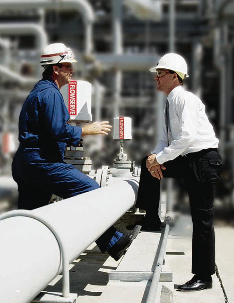
Flowserve Corporation140140140
141flowserve.com
Whether it’s critical, lethal, toxic or
aggressive, you’ll find Flowserve valves
doing the job around the world . That’s
because extended service life, safe
operation and environmental protection are
at the core of every valve we manufacture .
Global customers can easily find the
configurations they require, engineered
to meet requisite performance and safety
standards, whether it’s a standard or
custom-engineered solution .
It’s a portfolio of brands for quarter-
turn, rotary, linear, control and specialty
configurations that covers today’s toughest
demands for valve performance . But
we’re looking ahead to new challenges
that will test the current state of valve
manufacturing . This mindset pushes us
to pursue materials advancements and
severe-duty enhancements as well as the
next levels of precision control, optimized
flow and fail-safe shut-off .
VALVES
VALVES
Ball . . . . . . . . . . . . . . . . . . . . . . . . . . . .142
Butterfly . . . . . . . . . . . . . . . . . . . . . . . .158
Rotary Control . . . . . . . . . . . . . . . . . . .162
Linear Control . . . . . . . . . . . . . . . . . . .168
Severe Service Control . . . . . . . . . . . . 174
Gate . . . . . . . . . . . . . . . . . . . . . . . . . . .180
Globe . . . . . . . . . . . . . . . . . . . . . . . . . .184
Check . . . . . . . . . . . . . . . . . . . . . . . . .192
Plug . . . . . . . . . . . . . . . . . . . . . . . . . . .200
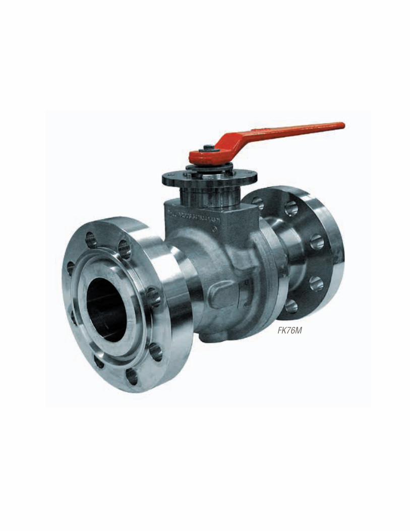
Flowserve Corporation142142
FK76M
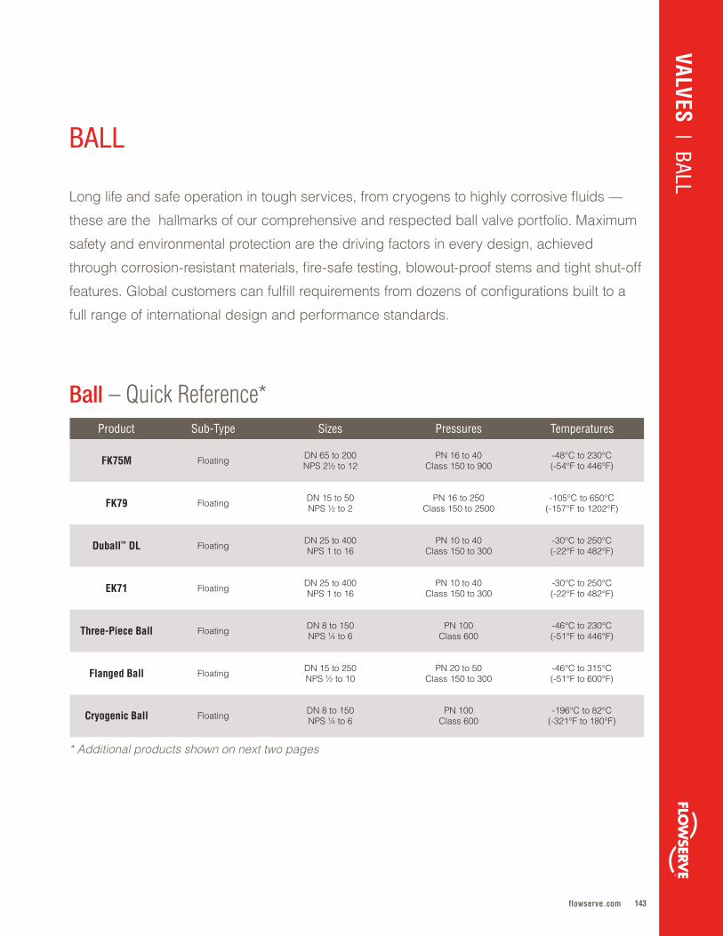
143flowserve.com
Product Sub-Type Sizes Pressures Temperatures
FK75M Floating DN 65 to 200NPS 2½ to 12
PN 16 to 40Class 150 to 900
-48°C to 230°C(-54°F to 446°F)
FK79 Floating DN 15 to 50NPS ½ to 2
PN 16 to 250Class 150 to 2500
-105°C to 650°C(-157°F to 1202°F)
Duball™ DL Floating DN 25 to 400NPS 1 to 16
PN 10 to 40Class 150 to 300
-30°C to 250°C(-22°F to 482°F)
EK71 Floating DN 25 to 400NPS 1 to 16
PN 10 to 40Class 150 to 300
-30°C to 250°C(-22°F to 482°F)
Three-Piece Ball Floating DN 8 to 150NPS ¼ to 6
PN 100Class 600
-46°C to 230°C(-51°F to 446°F)
Flanged Ball Floating DN 15 to 250NPS ½ to 10
PN 20 to 50Class 150 to 300
-46°C to 315°C(-51°F to 600°F)
Cryogenic Ball Floating DN 8 to 150NPS ¼ to 6
PN 100Class 600
-196°C to 82°C(-321°F to 180°F)
Long life and safe operation in tough services, from cryogens to highly corrosive fluids —
these are the hallmarks of our comprehensive and respected ball valve portfolio . Maximum
safety and environmental protection are the driving factors in every design, achieved
through corrosion-resistant materials, fire-safe testing, blowout-proof stems and tight shut-off
features . Global customers can fulfill requirements from dozens of configurations built to a
full range of international design and performance standards .
Ball – Quick Reference*
BALL
VALVES | BALL
* Additional products shown on next two pages
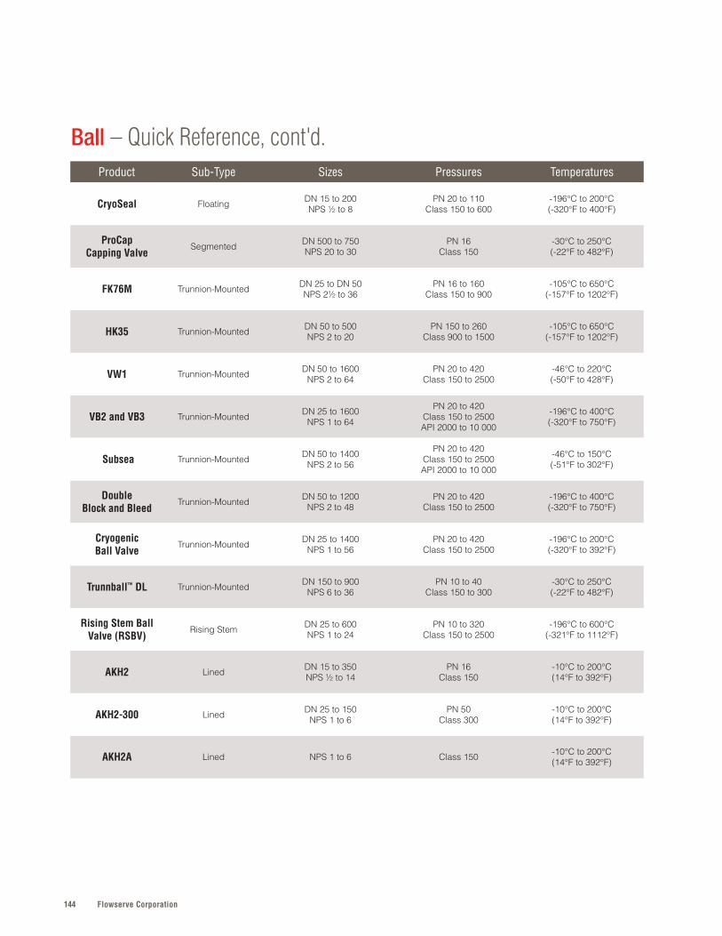
Flowserve Corporation144
Product Sub-Type Sizes Pressures Temperatures
CryoSeal Floating DN 15 to 200NPS ½ to 8
PN 20 to 110Class 150 to 600
-196°C to 200°C(-320°F to 400°F)
ProCap Capping Valve
Segmented DN 500 to 750NPS 20 to 30
PN 16Class 150
-30°C to 250°C(-22°F to 482°F)
FK76M Trunnion-Mounted DN 25 to DN 50NPS 2½ to 36
PN 16 to 160Class 150 to 900
-105°C to 650°C(-157°F to 1202°F)
HK35 Trunnion-Mounted DN 50 to 500NPS 2 to 20
PN 150 to 260Class 900 to 1500
-105°C to 650°C(-157°F to 1202°F)
VW1 Trunnion-Mounted DN 50 to 1600NPS 2 to 64
PN 20 to 420Class 150 to 2500
-46°C to 220°C(-50°F to 428°F)
VB2 and VB3 Trunnion-Mounted DN 25 to 1600NPS 1 to 64
PN 20 to 420Class 150 to 2500API 2000 to 10 000
-196°C to 400°C(-320°F to 750°F)
Subsea Trunnion-Mounted DN 50 to 1400NPS 2 to 56
PN 20 to 420Class 150 to 2500API 2000 to 10 000
-46°C to 150°C(-51°F to 302°F)
Double Block and Bleed
Trunnion-Mounted DN 50 to 1200NPS 2 to 48
PN 20 to 420Class 150 to 2500
-196°C to 400°C(-320°F to 750°F)
Cryogenic Ball Valve
Trunnion-Mounted DN 25 to 1400NPS 1 to 56
PN 20 to 420Class 150 to 2500
-196°C to 200°C(-320°F to 392°F)
Trunnball™ DL Trunnion-Mounted DN 150 to 900NPS 6 to 36
PN 10 to 40Class 150 to 300
-30°C to 250°C(-22°F to 482°F)
Rising Stem Ball Valve (RSBV)
Rising Stem DN 25 to 600NPS 1 to 24
PN 10 to 320Class 150 to 2500
-196°C to 600°C(-321°F to 1112°F)
AKH2 Lined DN 15 to 350NPS ½ to 14
PN 16Class 150
-10°C to 200°C(14°F to 392°F)
AKH2-300 Lined DN 25 to 150NPS 1 to 6
PN 50Class 300
-10°C to 200°C(14°F to 392°F)
AKH2A Lined NPS 1 to 6 Class 150 -10°C to 200°C(14°F to 392°F)
Ball – Quick Reference, cont'd.
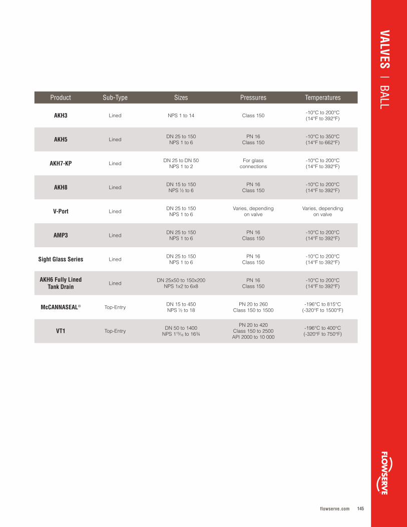
145flowserve.com
VALVES | LINEAR CO
NTRO
LVALVES
| BALLProduct Sub-Type Sizes Pressures Temperatures
AKH3 Lined NPS 1 to 14 Class 150 -10°C to 200°C(14°F to 392°F)
AKH5 Lined DN 25 to 150NPS 1 to 6
PN 16Class 150
-10°C to 350°C(14°F to 662°F)
AKH7-KP Lined DN 25 to DN 50NPS 1 to 2
For glassconnections
-10°C to 200°C(14°F to 392°F)
AKH8 Lined DN 15 to 150NPS ½ to 6
PN 16Class 150
-10°C to 200°C(14°F to 392°F)
V-Port Lined DN 25 to 150NPS 1 to 6
Varies, dependingon valve
Varies, dependingon valve
AMP3 Lined DN 25 to 150NPS 1 to 6
PN 16Class 150
-10°C to 200°C(14°F to 392°F)
Sight Glass Series Lined DN 25 to 150NPS 1 to 6
PN 16Class 150
-10°C to 200°C(14°F to 392°F)
AKH6 Fully Lined Tank Drain
Lined DN 25x50 to 150x200NPS 1x2 to 6x8
PN 16Class 150
-10°C to 200°C(14°F to 392°F)
McCANNASEAL® Top-Entry DN 15 to 450NPS ½ to 18
PN 20 to 260Class 150 to 1500
-196°C to 815°C(-320°F to 1500°F)
VT1 Top-Entry DN 50 to 1400NPS 1¹³∕16 to 16¾
PN 20 to 420Class 150 to 2500API 2000 to 10 000
-196°C to 400°C(-320°F to 750°F)

Flowserve Corporation146
SPECIFICATIONS
Sizes: DN 15 to 50; NPS ½ to 2Press: PN 16 to 250; Class 150 to 2500Temp: -105°C to 650°C (-157°F to 1202°F)
Refer to literature ARAFL0001-W-FK79 at flowserve.com/library.
SPECIFICATIONS
Sizes: DN 25 to 400; NPS 1 to 16Press: PN 10 to 40; Class 150 to 300Temp: -30°C to 250°C (-22°F to 482°F)
Refer to literature NFENTB4167 at flowserve.com/library.
• Increased uptime and durability from robust design with chemical coating and high-performance cladding
• Reliable performance to highest zero-tightness demands enabled by FCI 70-2 Class VI seat design
• Reduced replacement cost via easy upgrades and chemical coating options for diverse applications
• Improved plant and personnel safety assured by valve compliance with fugitive emissions standard ISO 15848
• High performance in severe service conditions and extreme environments ensured by durable design with chemical coating and high-performance cladding
• Reliable performance to highest zero-tightness demands enabled by FCI 70-2 Class VI seat design
• Long service life via double-stem seal system and stem supported in bearings, ensuring seals are free from operating loads
• Reduced environmental impact and improved safety ensured by compliance with TA-Luft, EPA (Method 21) and ISO 15848 fugitive emissions requirements
• Long, maintenance-free, safe operation in automated on-off and control service assured by spring-loaded stem seal packing
• Increased plant and personnel safety via blowout-proof stem and high-torque transmission with minimum mechanical backlash
• Broad application versatility enabled by extensive size range and options, including fire-safe tested versions
F L O A T I N G
Duball DL A high-performance, metal-seated, full-bore ball valve, equally suitable for isolation, on-off and modulating control applications.
SPECIFICATIONS
Sizes: DN 65 to 200; NPS 2½ to 12Press: PN 16 to 40; Class 150 to 900Temp: -48°C to 230°C (-54°F to 446°F)
Refer to literature ARAFL0001-W-FK75M at flowserve.com/library.
F L O A T I N G
FK79With many innovative design features, the FK79 represents the highest standard in valve technology and is designed to meet API-6D, ANSI 16.34 and BS 5351 requirements.
BALL
F L O A T I N G
FK75MA split-body ball valve for the chemical and petrochemical industries with a highly standardized design.
Argus ®
Argus
NAF ®
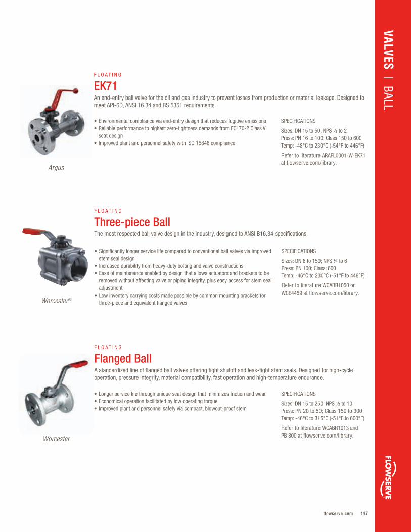
147flowserve.com
SPECIFICATIONS
Sizes: DN 15 to 50; NPS ½ to 2Press: PN 16 to 100; Class 150 to 600Temp: -48°C to 230°C (-54°F to 446°F)
Refer to literature ARAFL0001-W-EK71 at flowserve.com/library.
SPECIFICATIONS
Sizes: DN 8 to 150; NPS ¼ to 6Press: PN 100; Class: 600Temp: -46°C to 230°C (-51°F to 446°F)
Refer to literature WCABR1050 or WCE4459 at flowserve.com/library.
SPECIFICATIONS
Sizes: DN 15 to 250; NPS ½ to 10Press: PN 20 to 50; Class 150 to 300Temp: -46°C to 315°C (-51°F to 600°F)
Refer to literature WCABR1013 and PB 800 at flowserve.com/library.
• Longer service life through unique seat design that minimizes friction and wear • Economical operation facilitated by low operating torque• Improved plant and personnel safety via compact, blowout-proof stem
F L O A T I N G
Three-piece Ball The most respected ball valve design in the industry, designed to ANSI B16.34 specifications.
F L O A T I N G
EK71An end-entry ball valve for the oil and gas industry to prevent losses from production or material leakage. Designed to meet API-6D, ANSI 16.34 and BS 5351 requirements.
• Environmental compliance via end-entry design that reduces fugitive emissions• Reliable performance to highest zero-tightness demands from FCI 70-2 Class VI
seat design• Improved plant and personnel safety with ISO 15848 compliance
• Significantly longer service life compared to conventional ball valves via improved stem seal design
• Increased durability from heavy-duty bolting and valve constructions• Ease of maintenance enabled by design that allows actuators and brackets to be
removed without affecting valve or piping integrity, plus easy access for stem seal adjustment
• Low inventory carrying costs made possible by common mounting brackets for three-piece and equivalent flanged valves
F L O A T I N G
Flanged Ball A standardized line of flanged ball valves offering tight shutoff and leak-tight stem seals. Designed for high-cycle operation, pressure integrity, material compatibility, fast operation and high-temperature endurance.
VALVES | BALL
Argus
Worcester®
Worcester
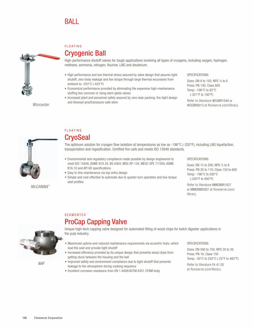
Flowserve Corporation148
SPECIFICATIONS
Sizes: DN 15 to 200; NPS ½ to 8Press: PN 20 to 110; Class 150 to 600Temp: -196°C to 200°C (-320°F to 400°F)
Refer to literature MMENBR1027 or MMENIM2007 at flowserve.com/library.
• Environmental and regulatory compliance made possible by design engineered to meet ISO 15848, ASME B16.34, BS 6364, MSS SP-134, MESC SPE 77/200, ASME B16.10 and API 6D specifications
• Easy in-line maintenance via top-entry design• Simple and cost-effective to automate due to quarter-turn operation and low-torque
seat profiles
SPECIFICATIONS
Sizes: DN 8 to 150; NPS ¼ to 6Press: PN 100; Class 600 Temp: -196°C to 82°C (-321°F to 180°F)
Refer to literature WCABR1040 or WCEBR0013 at flowserve.com/library.
• High performance and low thermal stress assured by valve design that assures tight shutoff, zero-body leakage and low torque through large thermal excursions from ambient to -253°C (-425°F)
• Economical performance provided by eliminating the expensive high-maintenance stuffing box common in rising stem globe valves
• Increased plant and personnel safety assured by zero-leak packing, fire-tight design and blowout-proof/pressure-safe stem
F L O A T I N G
CryoSealThe optimum solution for cryogen flow isolation at temperatures as low as -196°C (-320°F), including LNG liquefaction, transportation and regasification. Certified fire-safe and meets ISO 15848 standards.
F L O A T I N G
Cryogenic Ball High-performance shutoff valves for tough applications involving all types of cryogens, including oxygen, hydrogen, methane, ammonia, nitrogen, flourine, LNG and deuterium.
BALL
SPECIFICATIONS
Sizes: DN 500 to 750; NPS 20 to 30Press: PN 16; Class 150Temp: -30°C to 250°C (-22°F to 482°F)
Refer to literature Fk 41.55 at flowserve.com/library.
• Maximized uptime and reduced maintenance requirements via eccentric hubs, which load the seat and provide tight shutoff
• Increased efficiency provided by its unique design that prevents wood chips from getting stuck between the housing and the ball
• Improved safety and environment compliance due to tight shutoff that prevents leakage to the atmosphere during cooking sequence
• Excellent corrosion resistance from EN 1.4408/ASTM A351 CF8M body
S E G M E N T E D
ProCap Capping ValveUnique high-tech capping valve designed for automated filling of wood chips for batch digester applications in the pulp industry.
NAF
Worcester
McCANNA™

149flowserve.com
VALVES | BALL
SPECIFICATIONS
Sizes: DN 65 to 900; NPS 2½ to 36 Press: PN 16 to 160; Class 150 to 900Temp: -105°C to 650°C (-157°F to 1202°F)
Refer to literature ARENTB0001 at flowserve.com/library.
• Long service life in severe applications owing to chemical coating and high-performance cladding
• Reliability ensured by seat design to FCI 70-2 Class VI, enabling it to meet the highest demands with zero tightness
• Reduced replacement cost, as performance capabilities of valves can be easily upgraded and coatings can be applied to suit different applications
• Improved plant and personnel safety from valve design, which meets fugitive emission standard ISO 15848
T R U N N I O N - M O U N T E D
FK76MDesigned to meet API-6D, ANSI B16.34 and BS 5351 requirements, the FK76M delivers durability and low operating torques with a clear separation of sealing and bearing functions. Fire-safe to BS 6755 and API 607.
Argus
Argus
SPECIFICATIONS
Sizes: DN 50 to 500; NPS 2 to 20 Press: PN 150 to 260; Class 900 to 1500Temp: -105°C to 650°C (-157°F to 1202°F)
Refer to literature ARGBR 1111 at flowserve.com/library.
• Extended service life and low operating torques provided by clear separation of sealing and bearing functions on both ball and stem
• Environmental compliance assured by stem seal design, which meets current TA-Luft and EPA (method 21) standards
• Increased plant and personnel safety via fire-safe design and construction that complies with fugitive emission standard ISO 15848
• Installation ease enhanced by included DIN ISO mounting plate
T R U N N I O N - M O U N T E D
HK35 All the benefits of the FK76M in a high-pressure design. Designed to meet API-6D, ANSI B16.34 and BS 5351 requirements.
SPECIFICATIONS
Sizes: DN 50 to 1600; NPS 2 to 64 Press: PN 20 to 420; Class 150 to 2500Temp: -46°C to 220°C (-50°F to 428°F)
Refer to literature VBEEBR1009 or VBENBR1010 at flowserve.com/library.
• Reduced fugitive emissions made possible by welded-body construction, which eliminates leak paths
• Greater process control and safety assured by dual independent floating seat design, guaranteeing sealing power at any pressure level
• Economical performance due to low torque requirements• Simplified seal verification made possible by double block and bleed feature
T R U N N I O N - M O U N T E D
VW1This API 6D-compliant, welded-body valve seals off both seats at the same time and allows bleeding of the entrapped cavity pressure (double block and bleed) with the ball in the closed position.
Valbart ®

Flowserve Corporation150
BALL
SPECIFICATIONS
Sizes: DN 50 to 1200; NPS 2 to 48 Press: PN 20 to 420; Class 150 to 2500Temp: -196°C to 400°C (-320°F to 750°F)
Refer to literature VBENBR1004 at flowserve.com/library.
• Initial and installation cost savings owing to reduced structural requirements of design that saves both space and weight
• Increased system reliability from single valve with bleed port between two valves• Improved plant and personnel safety due to anti-blowout stem, fire-safe construction
and anti-static design
T R U N N I O N - M O U N T E D
Double Block and BleedSide-entry ball valve, with either a bolted or welded body, designed for use in upstream, midstream and downstream oil and gas applications.
Valbart
SPECIFICATIONS
Sizes: DN 50 to 1400; NPS 2 to 56 Press: PN 20 to 420; Class 150 to 2500; API 2000 to 10 000Temp: -46°C to 150°C (-51°F to 302°F)
Refer to literature VBENBR1005 at flowserve.com/library.
• Application flexibility derived from compatibility with hydraulic actuators, ROV-operated gear boxes, and electrical and hydraulic umbilical systems
• Extended life due to robust design that protects against leaks with metal-to-metal seats, elastomeric and thermoplastic seals, and corrosion-resistant alloy seal housing
• Minimized leak paths made possible by body designs plus corrosion-resistant materials of construction
• Complete safety and functionality compliance ensured by hyperbaric chamber testing (API 6DSS certification/API Spec Q1)
T R U N N I O N - M O U N T E D
SubseaQuarter-turn ball valve designed for total reliability against internal and external leaks in shallow and deep-water applications.
Valbart
SPECIFICATIONS
Sizes: DN 25 to 1600; NPS 1 to 64 Press: PN 20 to 42; Class 150 to 2500; API 2000 to 10 000Temp: -196°C to 400°C (-320°F to 750°F)
Refer to literature VBEEBR1009 or VBENBR1010 at flowserve.com/library.
• Greater efficiency, safety and control enabled by pressure-absorbing bearings, seat-sealing action at any rated pressure and anti-static design
• Plant and personnel protected by anti-blowout design that ensures the stem is retained by the stem cover
• Environmental compliance assured by zero-emission design• Reduced actuation costs, as seat design minimizes the torque required to operate the
valve without losing the sealing power
T R U N N I O N - M O U N T E D
VB2 and VB3The Valbart VB2 and VB3 are repairable, bolted body, side-entry, trunnion-mounted ball valves featuring a fixed ball and floating seat rings. Compliant with API 6D and 6A.
Valbart
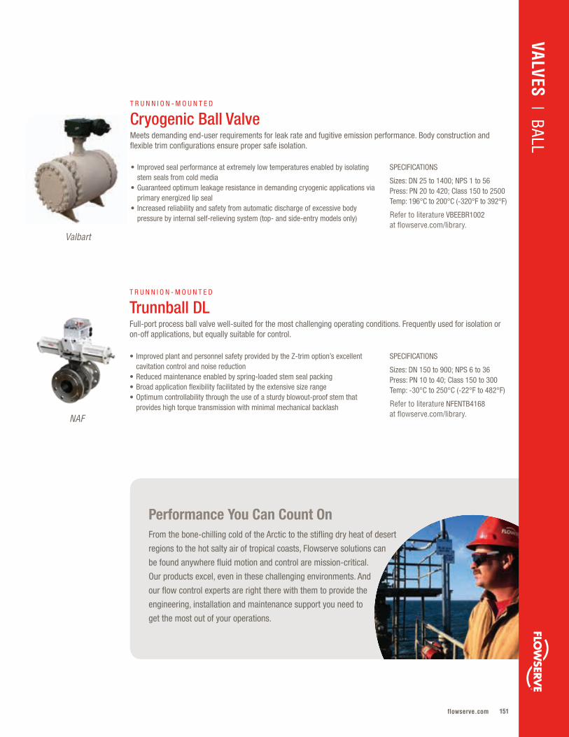
151flowserve.com
Performance You Can Count OnFrom the bone-chilling cold of the Arctic to the stifling dry heat of desert
regions to the hot salty air of tropical coasts, Flowserve solutions can
be found anywhere fluid motion and control are mission-critical.
Our products excel, even in these challenging environments. And
our flow control experts are right there with them to provide the
engineering, installation and maintenance support you need to
get the most out of your operations.
VALVES | BALL
Valbart
SPECIFICATIONS
Sizes: DN 25 to 1400; NPS 1 to 56 Press: PN 20 to 420; Class 150 to 2500Temp: 196°C to 200°C (-320°F to 392°F)
Refer to literature VBEEBR1002 at flowserve.com/library.
• Improved seal performance at extremely low temperatures enabled by isolating stem seals from cold media
• Guaranteed optimum leakage resistance in demanding cryogenic applications via primary energized lip seal
• Increased reliability and safety from automatic discharge of excessive body pressure by internal self-relieving system (top- and side-entry models only)
T R U N N I O N - M O U N T E D
Cryogenic Ball ValveMeets demanding end-user requirements for leak rate and fugitive emission performance. Body construction and flexible trim configurations ensure proper safe isolation.
SPECIFICATIONS
Sizes: DN 150 to 900; NPS 6 to 36Press: PN 10 to 40; Class 150 to 300Temp: -30°C to 250°C (-22°F to 482°F)
Refer to literature NFENTB4168 at flowserve.com/library.
• Improved plant and personnel safety provided by the Z-trim option’s excellent cavitation control and noise reduction
• Reduced maintenance enabled by spring-loaded stem seal packing• Broad application flexibility facilitated by the extensive size range• Optimum controllability through the use of a sturdy blowout-proof stem that
provides high torque transmission with minimal mechanical backlash
T R U N N I O N - M O U N T E D
Trunnball DLFull-port process ball valve well-suited for the most challenging operating conditions. Frequently used for isolation or on-off applications, but equally suitable for control.
NAF
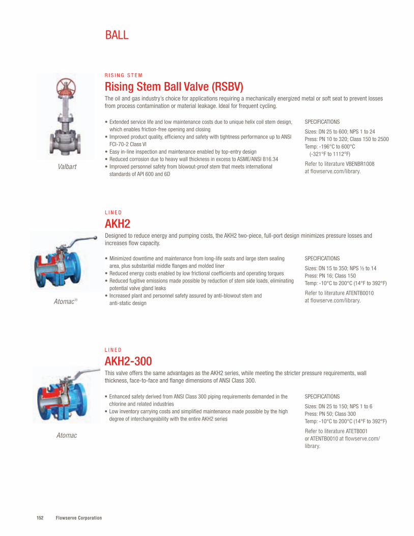
Flowserve Corporation152
SPECIFICATIONS
Sizes: DN 25 to 150; NPS 1 to 6Press: PN 50; Class 300Temp: -10°C to 200°C (14°F to 392°F)
Refer to literature ATETB001 or ATENTB0010 at flowserve.com/library.
• Enhanced safety derived from ANSI Class 300 piping requirements demanded in the chlorine and related industries
• Low inventory carrying costs and simplified maintenance made possible by the high degree of interchangeability with the entire AKH2 series
L I N E D
AKH2-300This valve offers the same advantages as the AKH2 series, while meeting the stricter pressure requirements, wall thickness, face-to-face and flange dimensions of ANSI Class 300.
Atomac
Atomac ®
BALL
SPECIFICATIONS
Sizes: DN 15 to 350; NPS ½ to 14 Press: PN 16; Class 150Temp: -10°C to 200°C (14°F to 392°F)
Refer to literature ATENTB0010 at flowserve.com/library.
• Minimized downtime and maintenance from long-life seats and large stem sealing area, plus substantial middle flanges and molded liner
• Reduced energy costs enabled by low frictional coefficients and operating torques• Reduced fugitive emissions made possible by reduction of stem side loads, eliminating
potential valve gland leaks• Increased plant and personnel safety assured by anti-blowout stem and
anti-static design
L I N E D
AKH2 Designed to reduce energy and pumping costs, the AKH2 two-piece, full-port design minimizes pressure losses and increases flow capacity.
SPECIFICATIONS
Sizes: DN 25 to 600; NPS 1 to 24Press: PN 10 to 320; Class 150 to 2500Temp: -196°C to 600°C (-321°F to 1112°F)
Refer to literature VBENBR1008 at flowserve.com/library.
• Extended service life and low maintenance costs due to unique helix coil stem design, which enables friction-free opening and closing
• Improved product quality, efficiency and safety with tightness performance up to ANSI FCI-70-2 Class VI
• Easy in-line inspection and maintenance enabled by top-entry design• Reduced corrosion due to heavy wall thickness in excess to ASME/ANSI B16.34• Improved personnel safety from blowout-proof stem that meets international
standards of API 600 and 6D
R I S I N G S T E M
Rising Stem Ball Valve (RSBV) The oil and gas industry’s choice for applications requiring a mechanically energized metal or soft seat to prevent losses from process contamination or material leakage. Ideal for frequent cycling.
Valbart
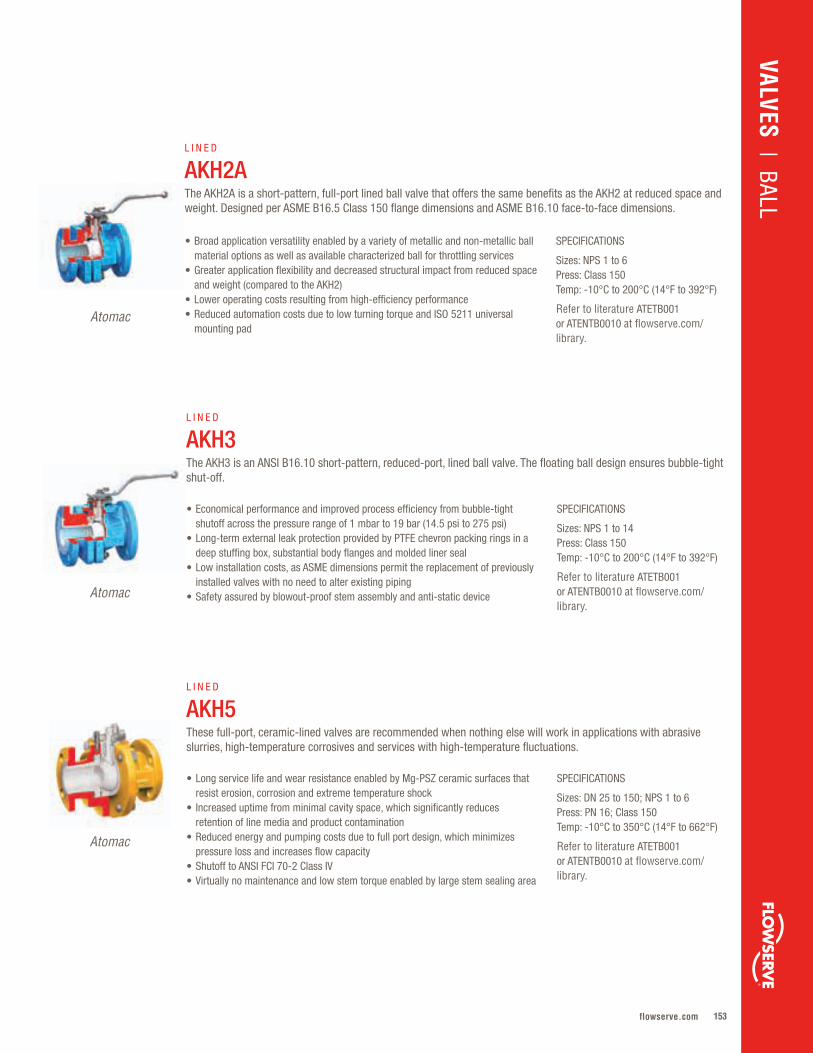
153flowserve.com
VALVES | BALL
SPECIFICATIONS
Sizes: NPS 1 to 6Press: Class 150Temp: -10°C to 200°C (14°F to 392°F)
Refer to literature ATETB001 or ATENTB0010 at flowserve.com/library.
• Broad application versatility enabled by a variety of metallic and non-metallic ball material options as well as available characterized ball for throttling services
• Greater application flexibility and decreased structural impact from reduced space and weight (compared to the AKH2)
• Lower operating costs resulting from high-efficiency performance• Reduced automation costs due to low turning torque and ISO 5211 universal
mounting pad
L I N E D
AKH2A The AKH2A is a short-pattern, full-port lined ball valve that offers the same benefits as the AKH2 at reduced space and weight. Designed per ASME B16.5 Class 150 flange dimensions and ASME B16.10 face-to-face dimensions.
Atomac
SPECIFICATIONS
Sizes: DN 25 to 150; NPS 1 to 6Press: PN 16; Class 150Temp: -10°C to 350°C (14°F to 662°F)
Refer to literature ATETB001 or ATENTB0010 at flowserve.com/library.
• Long service life and wear resistance enabled by Mg-PSZ ceramic surfaces that resist erosion, corrosion and extreme temperature shock
• Increased uptime from minimal cavity space, which significantly reduces retention of line media and product contamination
• Reduced energy and pumping costs due to full port design, which minimizes pressure loss and increases flow capacity
• Shutoff to ANSI FCI 70-2 Class IV• Virtually no maintenance and low stem torque enabled by large stem sealing area
L I N E D
AKH5These full-port, ceramic-lined valves are recommended when nothing else will work in applications with abrasive slurries, high-temperature corrosives and services with high-temperature fluctuations.
Atomac
SPECIFICATIONS
Sizes: NPS 1 to 14Press: Class 150Temp: -10°C to 200°C (14°F to 392°F)
Refer to literature ATETB001 or ATENTB0010 at flowserve.com/library.
• Economical performance and improved process efficiency from bubble-tight shutoff across the pressure range of 1 mbar to 19 bar (14.5 psi to 275 psi)
• Long-term external leak protection provided by PTFE chevron packing rings in a deep stuffing box, substantial body flanges and molded liner seal
• Low installation costs, as ASME dimensions permit the replacement of previously installed valves with no need to alter existing piping
• Safety assured by blowout-proof stem assembly and anti-static device
L I N E D
AKH3The AKH3 is an ANSI B16.10 short-pattern, reduced-port, lined ball valve. The floating ball design ensures bubble-tight shut-off.
Atomac
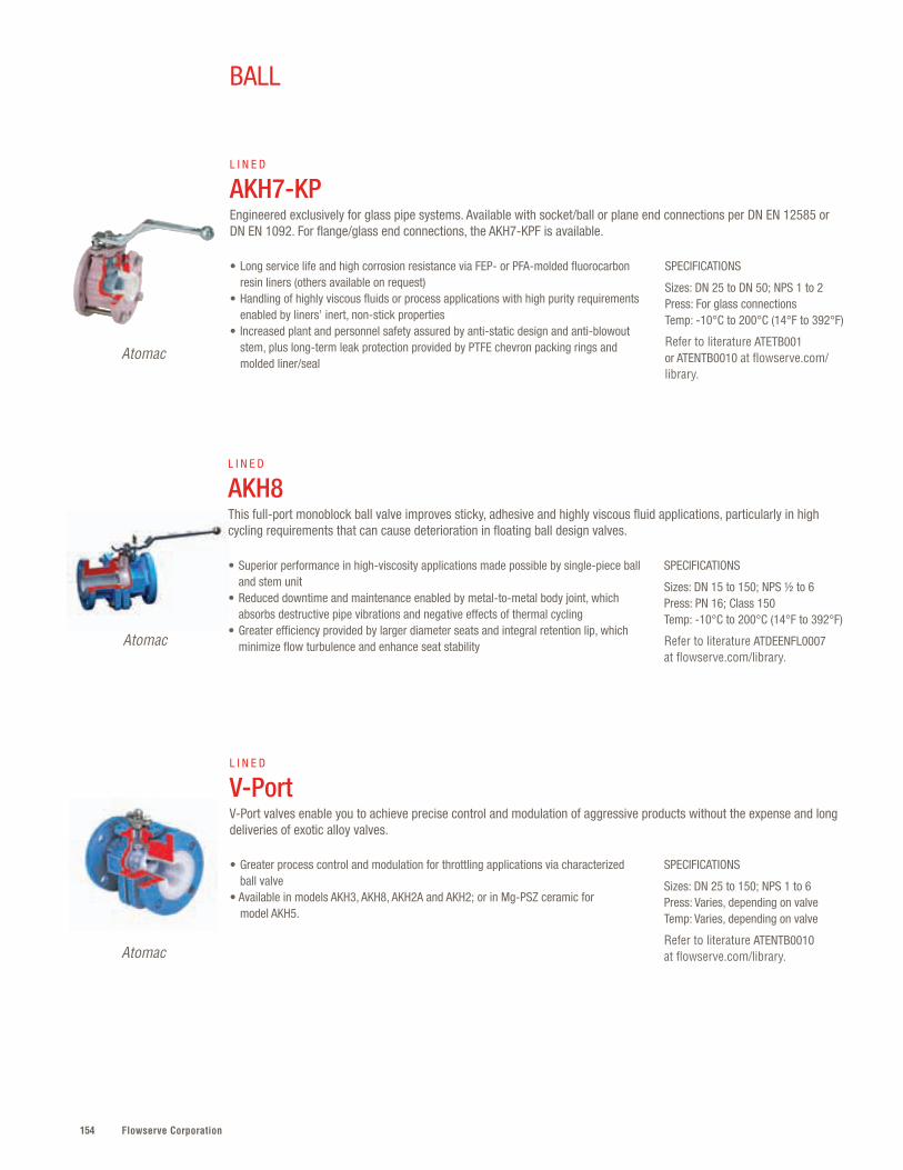
Flowserve Corporation154
SPECIFICATIONS
Sizes: DN 15 to 150; NPS ½ to 6Press: PN 16; Class 150Temp: -10°C to 200°C (14°F to 392°F)
Refer to literature ATDEENFL0007 at flowserve.com/library.
• Superior performance in high-viscosity applications made possible by single-piece ball and stem unit
• Reduced downtime and maintenance enabled by metal-to-metal body joint, which absorbs destructive pipe vibrations and negative effects of thermal cycling
• Greater efficiency provided by larger diameter seats and integral retention lip, which minimize flow turbulence and enhance seat stability
L I N E D
AKH8This full-port monoblock ball valve improves sticky, adhesive and highly viscous fluid applications, particularly in high cycling requirements that can cause deterioration in floating ball design valves.
Atomac
BALL
SPECIFICATIONS
Sizes: DN 25 to 150; NPS 1 to 6Press: Varies, depending on valveTemp: Varies, depending on valve
Refer to literature ATENTB0010 at flowserve.com/library.
• Greater process control and modulation for throttling applications via characterized ball valve
• Available in models AKH3, AKH8, AKH2A and AKH2; or in Mg-PSZ ceramic for model AKH5.
L I N E D
V-PortV-Port valves enable you to achieve precise control and modulation of aggressive products without the expense and long deliveries of exotic alloy valves.
Atomac
SPECIFICATIONS
Sizes: DN 25 to DN 50; NPS 1 to 2Press: For glass connectionsTemp: -10°C to 200°C (14°F to 392°F)
Refer to literature ATETB001 or ATENTB0010 at flowserve.com/library.
• Long service life and high corrosion resistance via FEP- or PFA-molded fluorocarbon resin liners (others available on request)
• Handling of highly viscous fluids or process applications with high purity requirements enabled by liners’ inert, non-stick properties
• Increased plant and personnel safety assured by anti-static design and anti-blowout stem, plus long-term leak protection provided by PTFE chevron packing rings and molded liner/seal
L I N E D
AKH7-KPEngineered exclusively for glass pipe systems. Available with socket/ball or plane end connections per DN EN 12585 or DN EN 1092. For flange/glass end connections, the AKH7-KPF is available.
Atomac

155flowserve.com
SPECIFICATIONS
Sizes: DN 25 to 150; NPS 1 to 6Press: PN 16; Class 150Temp: -10°C to 200°C (14°F to 392°F)
Refer to literature ATETB001 or ATENTB0010 at flowserve.com/library.
• Lower capital cost in difficult services than alloy valves, with equal or superior corrosion resistance
• Reduced plant operating costs made possible by high-flow capacity, which minimizes valve pressure losses
• Broad application versatility for a wide variety of 90° or 180° flow patterns enabled by L- or T-ball configurations
• Improved efficiency due to floating ball seat design which ensures bubble-tight shutoff across the pressure range
L I N E D
AMP3 The compact design of this three-way ball valve permits use in corrosive diverter applications with space constraints.
Atomac
VALVES | BALL
SPECIFICATIONS
Sizes: DN 25 to 150; NPS 1 to 6Press: PN 16; Class 150Temp: -10°C to 200°C (14°F to 392°F)
Refer to literature ATETB001 or ATENTB0010 at flowserve.com/library.
• Convenience, efficiency and ease of visual inspection enabled by sight glass on either side
• High durability of inspection apertures assured by borosilicate glass, utilized to withstand high temperatures, mechanical stress and corrosion per DIN 7080
• Long service life and high corrosion resistance due to thick, uniform, blowhole-free FEP or PFA liners for all non-glass internal components
L I N E D
Sight Glass Series Atomac sight glasses offer clear visual inspection from either side. An integrated drip lip with a cast core provides visual flow indication, even at low velocity. Available in standard, three-way and four-way models.
Atomac
SPECIFICATIONS
Sizes: DN 25x50 to 150x200; NPS 1x2 to 6x8Press: PN 16; Class 150Temp: -10°C to 200°C (14°F to 392°F)
Refer to literature ATETB001 or ATENTB0010 at flowserve.com/library.
• Lower energy and pumping costs facilitated by larger inlet port and full-port design, which minimizes pressure loss and increases flow capacity
• Improved handling of highly viscous or high-purity services assured by inert, non-stick liners
• Reduced downtime and easy maintenance made possible by interchangeability of all internal components and spare parts with entire AKH2 series
L I N E D
AKH6 Fully Lined Tank Drain Primarily used for tank drainage, AKH6 valves are also commonly installed in place of reducing spools to downsize piping dimensions.
Atomac
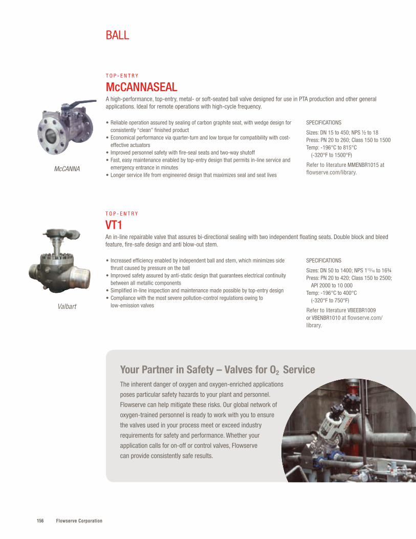
Flowserve Corporation156
Your Partner in Safety – Valves for O2 ServiceThe inherent danger of oxygen and oxygen-enriched applications
poses particular safety hazards to your plant and personnel.
Flowserve can help mitigate these risks. Our global network of
oxygen-trained personnel is ready to work with you to ensure
the valves used in your process meet or exceed industry
requirements for safety and performance. Whether your
application calls for on-off or control valves, Flowserve
can provide consistently safe results.
SPECIFICATIONS
Sizes: DN 50 to 1400; NPS 113∕16 to 16¾ Press: PN 20 to 420; Class 150 to 2500; API 2000 to 10 000Temp: -196°C to 400°C (-320°F to 750°F)
Refer to literature VBEEBR1009 or VBENBR1010 at flowserve.com/library.
• Increased efficiency enabled by independent ball and stem, which minimizes side thrust caused by pressure on the ball
• Improved safety assured by anti-static design that guarantees electrical continuity between all metallic components
• Simplified in-line inspection and maintenance made possible by top-entry design• Compliance with the most severe pollution-control regulations owing to
low-emission valves
T O P - E N T R Y
VT1An in-line repairable valve that assures bi-directional sealing with two independent floating seats. Double block and bleed feature, fire-safe design and anti blow-out stem.
SPECIFICATIONS
Sizes: DN 15 to 450; NPS ½ to 18Press: PN 20 to 260; Class 150 to 1500Temp: -196°C to 815°C (-320°F to 1500°F)
Refer to literature MMENBR1015 at flowserve.com/library.
• Reliable operation assured by sealing of carbon graphite seat, with wedge design for consistently “clean” finished product
• Economical performance via quarter-turn and low torque for compatibility with cost-effective actuators
• Improved personnel safety with fire-seal seats and two-way shutoff• Fast, easy maintenance enabled by top-entry design that permits in-line service and
emergency entrance in minutes• Longer service life from engineered design that maximizes seal and seat lives
T O P - E N T R Y
McCANNASEAL A high-performance, top-entry, metal- or soft-seated ball valve designed for use in PTA production and other general applications. Ideal for remote operations with high-cycle frequency.
McCANNA
Valbart
BALL

157flowserve.com
VALVES | BALL
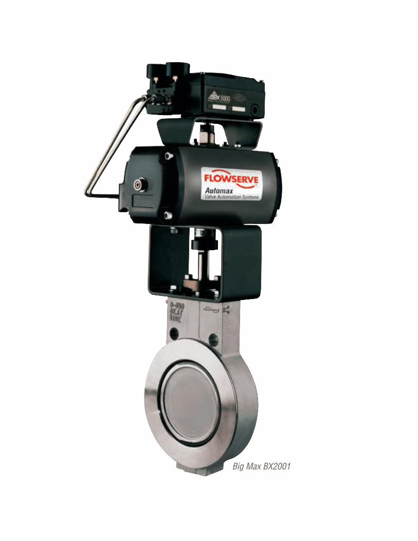
Flowserve Corporation158
Big Max BX2001
159flowserve.com
Ideal for precision throttling and on-off applications, especially in lighter-weight piping
systems, the Flowserve family of butterfly valves is often specified for its versatility .
Outstanding throttling accuracy for process control is achieved through low-friction, erosion-
resistant sealing surfaces with very low operating torques . A broad range of applications
can be met via metal- and soft-seated designs as well as lined versions for corrosive and
hygienic applications .
BUTTERFLY
Product Sub-Type Sizes Pressures Temperatures
Big Max ® BX2001 Double-Offset DN 50 to 900NPS 2 to 36
PN 10 to 40Class 150 and 300
-73°C to 538°C(-100°F to 1000°F)
Valdisk™ Double-Offset DN 50 to 750NPS 2 to 30
PN 10 to 400Class 150 to 2500
-196°C to 649°C(-320°F to 1200°F)
TX3 Triple-Offset DN 80 to 600NPS 3 to 24
PN 20 to 260Class 150 to 1500
-196°C to 820°C(-320°F to 1500°F)
Torex™ Triple-Offset DN 80 to 700NPS 3 to 28
PN 10 to 40Class 150 and 300
-30°C to 350°C(-22°F to 662°F)
BTV Lined DN 50 to 600NPS 2 to 24
PN up to 10Up to 150 psi
177°C(350°F)
Slimseal ® Lined DN 50 to 600NPS 2 to 24
PN 10 to 20Class 125 to 150
-10°C to 140°C(14°F to 284°F)
Butterfly – Quick Reference
VALVES | BUTTERFLY
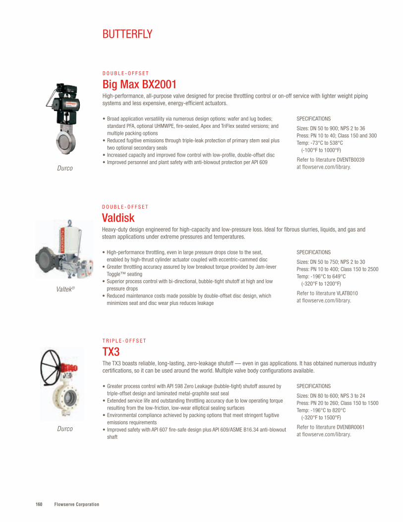
Flowserve Corporation160
SPECIFICATIONS
Sizes: DN 50 to 900; NPS 2 to 36Press: PN 10 to 40; Class 150 and 300Temp: -73°C to 538°C (-100°F to 1000°F)
Refer to literature DVENTB0039 at flowserve.com/library.
SPECIFICATIONS
Sizes: DN 80 to 600; NPS 3 to 24Press: PN 20 to 260; Class 150 to 1500Temp: -196°C to 820°C (-320°F to 1500°F)
Refer to literature DVENBR0061 at flowserve.com/library.
• Broad application versatility via numerous design options: wafer and lug bodies; standard PFA, optional UHMWPE, fire-sealed, Apex and TriFlex seated versions; and multiple packing options
• Reduced fugitive emissions through triple-leak protection of primary stem seal plus two optional secondary seals
• Increased capacity and improved flow control with low-profile, double-offset disc• Improved personnel and plant safety with anti-blowout protection per API 609
• Greater process control with API 598 Zero Leakage (bubble-tight) shutoff assured by triple-offset design and laminated metal-graphite seat seal
• Extended service life and outstanding throttling accuracy due to low operating torque resulting from the low-friction, low-wear elliptical sealing surfaces
• Environmental compliance achieved by packing options that meet stringent fugitive emissions requirements
• Improved safety with API 607 fire-safe design plus API 609/ASME B16.34 anti-blowout shaft
D O U B L E - O F F S E T
Big Max BX2001High-performance, all-purpose valve designed for precise throttling control or on-off service with lighter weight piping systems and less expensive, energy-efficient actuators.
T R I P L E - O F F S E T
TX3The TX3 boasts reliable, long-lasting, zero-leakage shutoff — even in gas applications. It has obtained numerous industry certifications, so it can be used around the world. Multiple valve body configurations available.
Durco
Durco
BUTTERFLY
SPECIFICATIONS
Sizes: DN 50 to 750; NPS 2 to 30Press: PN 10 to 400; Class 150 to 2500Temp: -196°C to 649°C (-320°F to 1200°F)
Refer to literature VLATB010 at flowserve.com/library.
• High-performance throttling, even in large pressure drops close to the seat, enabled by high-thrust cylinder actuator coupled with eccentric-cammed disc
• Greater throttling accuracy assured by low breakout torque provided by Jam-lever Toggle™ seating
• Superior process control with bi-directional, bubble-tight shutoff at high and low pressure drops
• Reduced maintenance costs made possible by double-offset disc design, which minimizes seat and disc wear plus reduces leakage
D O U B L E - O F F S E T
ValdiskHeavy-duty design engineered for high-capacity and low-pressure loss. Ideal for fibrous slurries, liquids, and gas and steam applications under extreme pressures and temperatures.
Valtek®
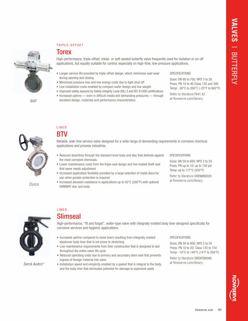
161flowserve.com
VALVES | BUTTERFLY
SPECIFICATIONS
Sizes: DN 50 to 600; NPS 2 to 24Press: PN up to 10; up to 150 psiTemp: up to 177°C (350°F)
Refer to literature DVENBR0020 at flowserve.com/library.
• Reduced downtime through the standard lined body and disc that defends against the most corrosive chemicals
• Lower maintenance costs from the triple-seal design and live-loaded shaft seal that never needs adjustment
• Increased application flexibility provided by a large selection of metal discs for use when greater protection is required
• Increased abrasion resistance in applications up to 93°C (200°F) with optional UHMWPE disc and body
L I N E D
BTVReliable, leak-free service valve designed for a wide range of demanding requirements in corrosive chemical applications and process industries.
Durco
SPECIFICATIONS
Sizes: DN 50 to 600; NPS 2 to 24Press: PN 10 to 20; Class 125 to 150Temp: -10°C to 140°C (14°F to 284°F)
Refer to literature SRENTB0006 at flowserve.com/library.
• Increased uptime compared to loose liners resulting from integrally molded elastomer body liner that is not prone to stretching
• Low maintenance requirements from liner construction that is designed to last throughout the entire valve life cycle
• Reduced operating costs due to primary and secondary stem seal that prevents ingress of foreign material into valve
• Installation speed and simplicity enabled by a gasket that is integral to the body, and the body liner that eliminates potential for damage to expensive seats
L I N E D
SlimsealHigh-performance, “fit and forget”, wafer-type valve with integrally molded body liner designed specifically for corrosive services and hygienic applications.
Serck Audco ®
SPECIFICATIONS
Sizes: DN 80 to 700; NPS 3 to 28Press: PN 10 to 40 Class 150 and 300Temp: -30°C to 350°C (-22°F to 662°F)
Refer to literature Fk41.42 at flowserve.com/library.
• Longer service life provided by triple-offset design, which minimizes seat wear during opening and closing
• Minimized pressure loss and low energy costs due to tight shut-off• Low installation costs enabled by compact wafer design and low weight• Improved safety assured by Safety Integrity Level (SIL) 3 and IEC 61508 certifications• Increased uptime — even in difficult media and demanding pressures — through
excellent design, materials and performance characteristics
T R I P L E - O F F S E T
TorexHigh-performance, triple-offset, metal- or soft-seated butterfly valve frequently used for isolation or on-off applications, but equally suitable for control, especially on high-flow, low-pressure applications.
NAF
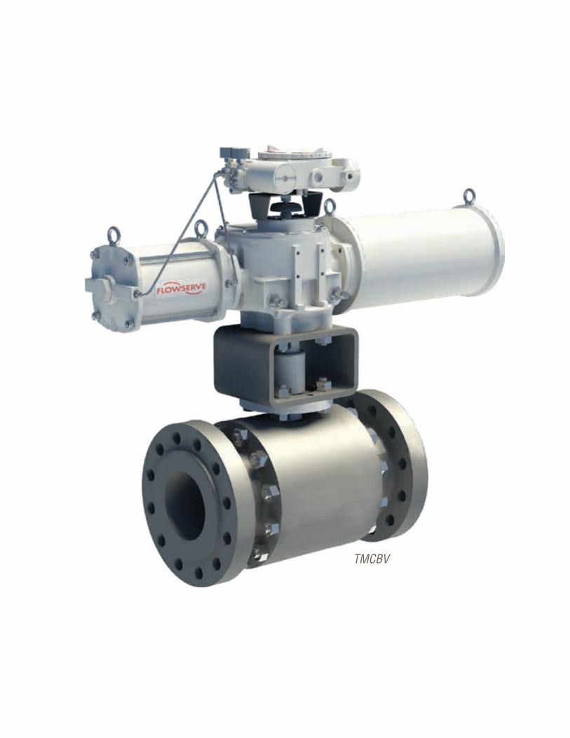
Flowserve Corporation162162
TMCBV
163flowserve.com
Long life in severe conditions characterizes this flexible range of plug, ball and butterfly
control valves . Precision control can be realized across a range of harsh applications,
including fibrous slurries, entrained particles, steam and high-pressure/temperature liquids
and gases . Users find numerous performance advantages, from reduced cavitation and
flashing to low noise levels, as well as safety assurances from tight shut-off features and
designs certified to the latest, global safety standards .
Rotary Control – Quick Reference
ROTARY CONTROL
Product Sub-Type Sizes Pressures Temperatures
MaxFlo® 4 Eccentric Plug DN 25 to 300NPS 1 to 12
PN 10 to 63Class 150 to 600
-100°C to 400°C(-148°F to 750°F)
ShearStream™ HP Segmented Ball DN 25 to 400NPS 1 to 16
PN 10 to 63Class 150 to 600
-46°C to 316°C (-50°F to 600°F)
Setball™ Segmented Ball DN 25 to 700NPS 1 to 28
PN 10 to 40Class 150 to 300
-30°C to 250°C(-22°F to 482°F)
Setball SF Segmented Ball DN 25 to 250NPS 1 to 10
PN 10 to 40Class 150 to 300
-30°C to 250°C(-22°F to 482°F)
Valdisk High-Performance Butterfly
DN 50 to 750NPS 2 to 30
PN 10 to 400Class 150 to 2500
-196°C to 649°C(-320°F to 1200°F)
Torex High-Performance Butterfly
DN 80 to 700NPS 3 to 28
PN 10 to 40Class 150 and 300
-30°C to 350°C(-22°F to 662°F)
TMCBV Trunnion-Mounted Control Ball
DN 75 to 1400NPS 3 to 56
Class 150 to 2500 API 3000, 5000, 10 000
-196°C to 450°C(-320°F to 842°F)
Trunnball DL Trunnion-Mounted Control Ball
DN 150 to 900NPS 6 to 36
PN 10 to 40Class 150 to 300
-30°C to 250°C(-22°F to 482°F)
CPT Floating Control Ball DN 8 to 100NPS ¼ to 4
PN 20 to 110Class 150 to 600
-29°C to 427°C(-20°F to 800°F)
Duball DL Floating Control Ball DN 25 to 400NPS 1 to 16
PN 10 to 40Class 150 to 300
-30°C to 350°C(-22°F to 482°F)
VALVES | RO
TARY CON
TROL
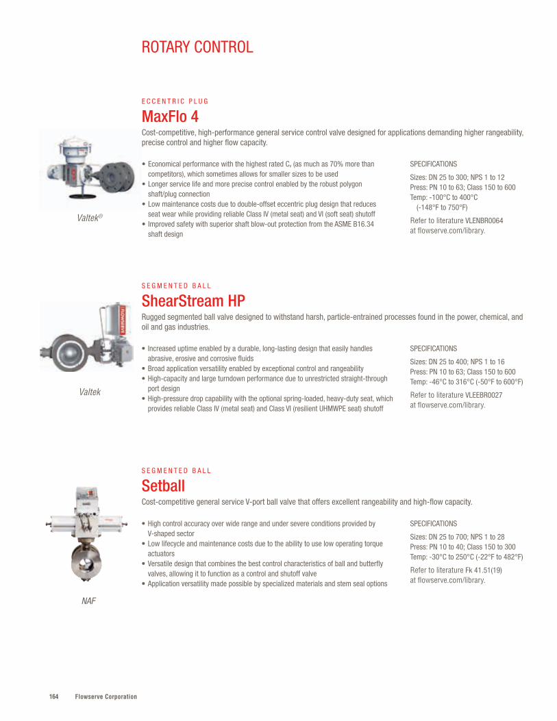
Flowserve Corporation164
SPECIFICATIONS
Sizes: DN 25 to 400; NPS 1 to 16Press: PN 10 to 63; Class 150 to 600Temp: -46°C to 316°C (-50°F to 600°F)
Refer to literature VLEEBR0027 at flowserve.com/library.
• Increased uptime enabled by a durable, long-lasting design that easily handles abrasive, erosive and corrosive fluids
• Broad application versatility enabled by exceptional control and rangeability• High-capacity and large turndown performance due to unrestricted straight-through
port design• High-pressure drop capability with the optional spring-loaded, heavy-duty seat, which
provides reliable Class IV (metal seat) and Class VI (resilient UHMWPE seat) shutoff
S E G M E N T E D B A L L
ShearStream HPRugged segmented ball valve designed to withstand harsh, particle-entrained processes found in the power, chemical, and oil and gas industries.
Valtek
SPECIFICATIONS
Sizes: DN 25 to 700; NPS 1 to 28Press: PN 10 to 40; Class 150 to 300Temp: -30°C to 250°C (-22°F to 482°F)
Refer to literature Fk 41.51(19) at flowserve.com/library.
• High control accuracy over wide range and under severe conditions provided by V-shaped sector
• Low lifecycle and maintenance costs due to the ability to use low operating torque actuators
• Versatile design that combines the best control characteristics of ball and butterfly valves, allowing it to function as a control and shutoff valve
• Application versatility made possible by specialized materials and stem seal options
S E G M E N T E D B A L L
Setball Cost-competitive general service V-port ball valve that offers excellent rangeability and high-flow capacity.
NAF
SPECIFICATIONS
Sizes: DN 25 to 300; NPS 1 to 12Press: PN 10 to 63; Class 150 to 600 Temp: -100°C to 400°C (-148°F to 750°F)
Refer to literature VLENBR0064 at flowserve.com/library.
• Economical performance with the highest rated Cv (as much as 70% more than competitors), which sometimes allows for smaller sizes to be used
• Longer service life and more precise control enabled by the robust polygon shaft/plug connection
• Low maintenance costs due to double-offset eccentric plug design that reduces seat wear while providing reliable Class IV (metal seat) and VI (soft seat) shutoff
• Improved safety with superior shaft blow-out protection from the ASME B16.34 shaft design
E C C E N T R I C P L U G
MaxFlo 4Cost-competitive, high-performance general service control valve designed for applications demanding higher rangeability, precise control and higher flow capacity.
Valtek®
ROTARY CONTROL
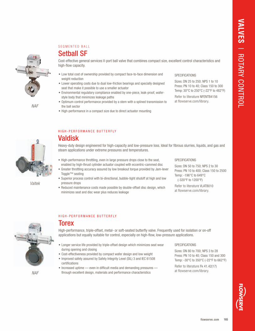
165flowserve.com
NAF
SPECIFICATIONS
Sizes: DN 25 to 250; NPS 1 to 10Press: PN 10 to 40; Class 150 to 300Temp: 30°C to 250°C (-22°F to 482°F)
Refer to literature NFENTB4156 at flowserve.com/library.
• Low total cost of ownership provided by compact face-to-face dimension and weight reduction
• Lower operating costs due to dual low-friction bearings and specially designed seat that make it possible to use a smaller actuator
• Environmental regulatory compliance enabled by one-piece, leak-proof, wafer-style body that minimizes leakage paths
• Optimum control performance provided by a stem with a splined transmission to the ball sector
• High-performance in a compact size due to direct actuator mounting
S E G M E N T E D B A L L
Setball SFCost-effective general services V-port ball valve that combines compact size, excellent control characteristics and high-flow capacity.
VALVES | ROTARY CO
NTRO
L
SPECIFICATIONS
Sizes: DN 80 to 700; NPS 3 to 28Press: PN 10 to 40; Class 150 and 300Temp: -30°C to 350°C (-22°F to 662°F)
Refer to literature Fk 41.42(17) at flowserve.com/library.
• Longer service life provided by triple-offset design which minimizes seat wear during opening and closing
• Cost-effectiveness provided by compact wafer design and low weight• Improved safety assured by Safety Integrity Level (SIL) 3 and IEC 61508
certifications• Increased uptime — even in difficult media and demanding pressures —
through excellent design, materials and performance characteristics
H I G H - P E R F O R M A N C E B U T T E R F LY
Torex High-performance, triple-offset, metal- or soft-seated butterfly valve. Frequently used for isolation or on-off applications but equally suitable for control, especially on high-flow, low-pressure applications.
NAF
SPECIFICATIONS
Sizes: DN 50 to 750; NPS 2 to 30Press: PN 10 to 400; Class 150 to 2500Temp: -196°C to 649°C (-320°F to 1200°F)
Refer to literature VLATB010 at flowserve.com/library.
• High-performance throttling, even in large pressure drops close to the seat, enabled by high-thrust cylinder actuator coupled with eccentric-cammed disc
• Greater throttling accuracy assured by low breakout torque provided by Jam-lever Toggle™ seating
• Superior process control with bi-directional, bubble-tight shutoff at high and low pressure drops
• Reduced maintenance costs made possible by double-offset disc design, which minimizes seat and disc wear plus reduces leakage
H I G H - P E R F O R M A N C E B U T T E R F LY
ValdiskHeavy-duty design engineered for high-capacity and low-pressure loss. Ideal for fibrous slurries, liquids, and gas and steam applications under extreme pressures and temperatures.
Valtek
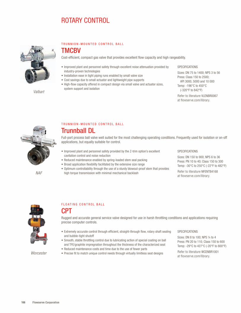
Flowserve Corporation166
SPECIFICATIONS
Sizes: DN 75 to 1400; NPS 3 to 56Press: Class 150 to 2500; API 3000, 5000 and 10 000Temp: -196°C to 450°C (-320°F to 842°F)
Refer to literature VLENBR0067 at flowserve.com/library.
• Improved plant and personnel safety through excellent noise attenuation provided by industry-proven technologies
• Installation ease in tight piping runs enabled by small valve size• Cost savings due to small actuator and lightweight pipe supports• High-flow capacity offered in compact design via small valve and actuator sizes,
system support and isolation
T R U N N I O N - M O U N T E D C O N T R O L B A L L
TMCBV Cost-efficient, compact gas valve that provides excellent flow capacity and high rangeability.
Valbart
ROTARY CONTROL
SPECIFICATIONS
Sizes: DN 150 to 900; NPS 6 to 36Press: PN 10 to 40; Class 150 to 300Temp: -30°C to 250°C (-22°F to 482°F)
Refer to literature NFENTB4168 at flowserve.com/library.
• Improved plant and personnel safety provided by the Z-trim option’s excellent cavitation control and noise reduction
• Reduced maintenance enabled by spring-loaded stem seal packing• Broad application flexibility facilitated by the extensive size range• Optimum controllability through the use of a sturdy blowout-proof stem that provides
high torque transmission with minimal mechanical backlash
T R U N N I O N - M O U N T E D C O N T R O L B A L L
Trunnball DLFull-port process ball valve well suited for the most challenging operating conditions. Frequently used for isolation or on-off applications, but equally suitable for control.
NAF
SPECIFICATIONS
Sizes: DN 8 to 100; NPS ¼ to 4Press: PN 20 to 110; Class 150 to 600Temp: -29°C to 427°C (-20°F to 800°F)
Refer to literature WCENBR1001 at flowserve.com/library.
• Extremely accurate control through efficient, straight-through flow, rotary shaft sealing and bubble-tight shutoff
• Smooth, stable throttling control due to lubricating action of special coating on ball and TFE/graphite impregnation throughout the thickness of the characterized seat
• Reduced maintenance costs and time due to the use of fewer parts• Precise fit to match unique control needs through virtually limitless seat designs
F L O A T I N G C O N T R O L B A L L
CPTRugged and accurate general service valve designed for use in harsh throttling conditions and applications requiring precise computer controls.
Worcester
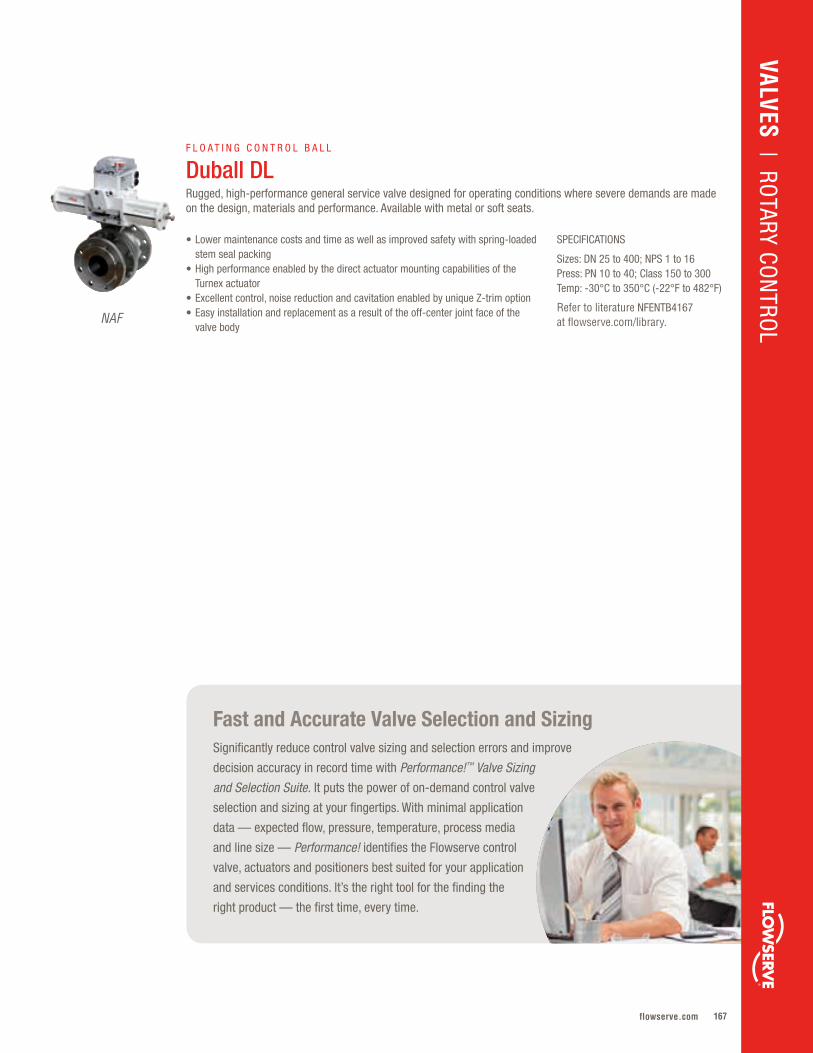
167flowserve.com
Fast and Accurate Valve Selection and Sizing Significantly reduce control valve sizing and selection errors and improve
decision accuracy in record time with Performance!™ Valve Sizing
and Selection Suite. It puts the power of on-demand control valve
selection and sizing at your fingertips. With minimal application
data — expected flow, pressure, temperature, process media
and line size — Performance! identifies the Flowserve control
valve, actuators and positioners best suited for your application
and services conditions. It’s the right tool for the finding the
right product — the first time, every time.
NAF
SPECIFICATIONS
Sizes: DN 25 to 400; NPS 1 to 16Press: PN 10 to 40; Class 150 to 300Temp: -30°C to 350°C (-22°F to 482°F)
Refer to literature NFENTB4167 at flowserve.com/library.
• Lower maintenance costs and time as well as improved safety with spring-loaded stem seal packing
• High performance enabled by the direct actuator mounting capabilities of the Turnex actuator
• Excellent control, noise reduction and cavitation enabled by unique Z-trim option• Easy installation and replacement as a result of the off-center joint face of the
valve body
F L O A T I N G C O N T R O L B A L L
Duball DL Rugged, high-performance general service valve designed for operating conditions where severe demands are made on the design, materials and performance. Available with metal or soft seats.
VALVES | ROTARY CO
NTRO
L
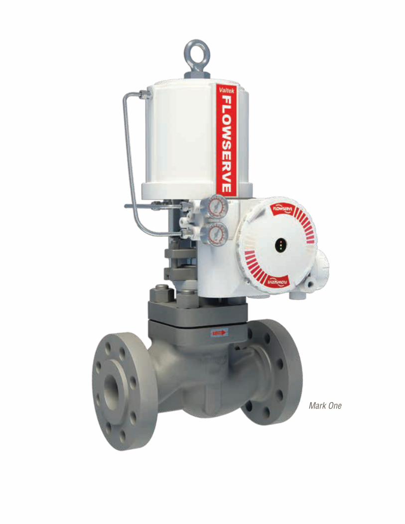
Flowserve Corporation168168
Mark One

169flowserve.com
Ideal for high-accuracy flow control, the Flowserve family of globe/angle linear control valves
can be applied from general service to severe applications for both gas and liquids . They
are ideal for frequent operation due to their excellent position accuracy and repeatability .
Precision control is repeatedly achieved via longer strokes and assured actuator response .
Users can satisfy a range of requirements, with choices ranging from cryogenic designs to
low noise and anti-cavitation trims .
Product Sub-Type Sizes Pressures Temperatures
Mark One™ Linear Globe/Angle DN 15 to 915NPS ½ to 36
PN 10 to 400Class 150 to 2500
-196°C to 815°C(-320°F to 1500°F)
Mark One Three-Way
Linear Globe/Angle DN 15 to 300 NPS ½ to 12
PN 10 to 400 Class 150 to 2500
-196°C to 400°C (-320°F to 1500°F)
Mark One-X Linear Globe/Angle to DN 300to NPS 12
PN 50 to 100 Class 300 to 600
-196°C to 815°C (-320°F to 1500°F)
Mark 100 Linear Globe/Angle DN 150 to 750NPS 6 to 30
PN 10 to 100Class 150 to 600
-196°C to 815°C(-320°F to 1500°F)
Mark 200 Linear Globe/Angle DN 50 to 400NPS 2 to 16
PN 160 to 400Class 900 to 2500
-196°C to 815°C(-320°F to 1500°F)
Mark Two™ Linear Globe/Angle DN 15 to 150 NPS ½ to 6
PN 10 to 400 Class 150 to 2500
-196°C to 815°C (-320°F to 1500°F)
Mark Eight™ Linear Globe/Angle DN 25 to 500 NPS 1 to 20
PN 10 to 400 Class 150 to 2500
-196°C to 815°C (-320°F to 1500°F)
GS Linear Globe/Angle DN 15 to 150NPS ½ to 6
PN 16 to 40Class 150 to 300
-60°C to 400°C(-76°F to 752°F)
Linear Control – Quick Reference
LINEAR CONTROL
VALVES | LIN
EAR CON
TROL
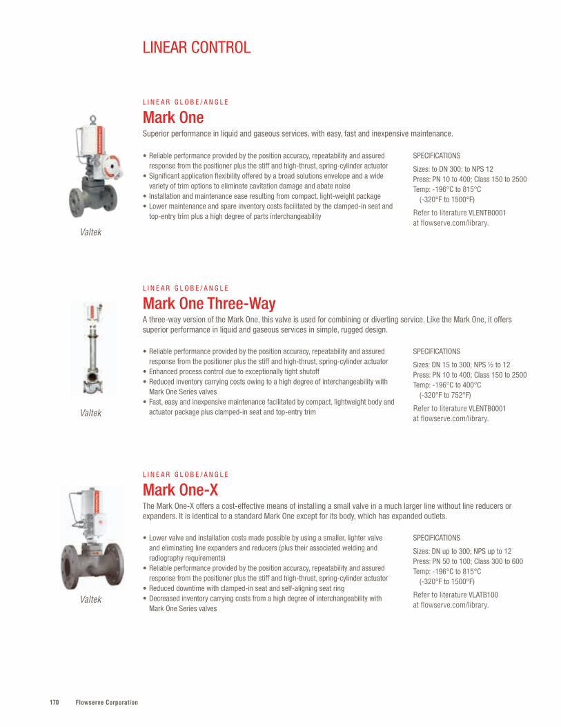
Flowserve Corporation170
SPECIFICATIONS
Sizes: to DN 300; to NPS 12Press: PN 10 to 400; Class 150 to 2500Temp: -196°C to 815°C (-320°F to 1500°F)
Refer to literature VLENTB0001 at flowserve.com/library.
SPECIFICATIONS
Sizes: DN 15 to 300; NPS ½ to 12Press: PN 10 to 400; Class 150 to 2500Temp: -196°C to 400°C (-320°F to 752°F)
Refer to literature VLENTB0001 at flowserve.com/library.
SPECIFICATIONS
Sizes: DN up to 300; NPS up to 12Press: PN 50 to 100; Class 300 to 600 Temp: -196°C to 815°C (-320°F to 1500°F)
Refer to literature VLATB100 at flowserve.com/library.
• Reliable performance provided by the position accuracy, repeatability and assured response from the positioner plus the stiff and high-thrust, spring-cylinder actuator
• Significant application flexibility offered by a broad solutions envelope and a wide variety of trim options to eliminate cavitation damage and abate noise
• Installation and maintenance ease resulting from compact, light-weight package• Lower maintenance and spare inventory costs facilitated by the clamped-in seat and
top-entry trim plus a high degree of parts interchangeability
• Reliable performance provided by the position accuracy, repeatability and assured response from the positioner plus the stiff and high-thrust, spring-cylinder actuator
• Enhanced process control due to exceptionally tight shutoff• Reduced inventory carrying costs owing to a high degree of interchangeability with
Mark One Series valves• Fast, easy and inexpensive maintenance facilitated by compact, lightweight body and
actuator package plus clamped-in seat and top-entry trim
• Lower valve and installation costs made possible by using a smaller, lighter valve and eliminating line expanders and reducers (plus their associated welding and radiography requirements)
• Reliable performance provided by the position accuracy, repeatability and assured response from the positioner plus the stiff and high-thrust, spring-cylinder actuator
• Reduced downtime with clamped-in seat and self-aligning seat ring• Decreased inventory carrying costs from a high degree of interchangeability with
Mark One Series valves
L I N E A R G L O B E / A N G L E
Mark OneSuperior performance in liquid and gaseous services, with easy, fast and inexpensive maintenance.
L I N E A R G L O B E / A N G L E
Mark One Three-Way A three-way version of the Mark One, this valve is used for combining or diverting service. Like the Mark One, it offers superior performance in liquid and gaseous services in simple, rugged design.
L I N E A R G L O B E / A N G L E
Mark One-X The Mark One-X offers a cost-effective means of installing a small valve in a much larger line without line reducers or expanders. It is identical to a standard Mark One except for its body, which has expanded outlets.
Valtek
Valtek
Valtek
LINEAR CONTROL

171flowserve.com
Giants of Offshore Production When building the world’s largest FPSOs, capable of producing
500 000 barrels of oil per day, ExxonMobil chose Flowserve
pump and valve control systems for its Kizomba A and B
floating platforms. Drawing on decades of offshore experience,
Flowserve provided 74 high-performance pump systems
and 360 control valves. Most were custom engineered to
accommodate the weight and space parameters of
the project.
VALVES | LIN
EAR CON
TROL
SPECIFICATIONS
Sizes: DN 150 to 750; NPS 6 to 30Press: PN 10 to 100; Class 150 to 600Temp: -196°C to 815°C (-320°F to 1500°F)
Refer to literature FCATB0100 at flowserve.com/library.
SPECIFICATIONS
Sizes: DN 50 to 400; NPS 2 to 16Press: PN 160 to 400; Class 900 to 2500Temp: -196°C to 815°C (-328°F to 1500°F)
Refer to literature VLENTB0200 at flowserve.com/library.
• Cost-effective performance, as higher Cv capacity allows for smaller valve sizes • Superior process control made possible by long stroke lengths, the position
accuracy, repeatability and assured response from the positioner, and the stiff and high-thrust, spring-cylinder actuator
• Reduced downtime with the clamped-in seat and self-aligning seat ring• Severe service application versatility provided by a wide variety of noise
abatement and anti-cavitation trims
• Cost-effective and significantly smaller and lighter design that outperforms competing brands
• Greater severe service protection with finer control provided by larger galleries and longer strokes
• Improved safety and reduced maintenance costs derived from a broad spectrum of severe service trim solutions for noise abatement and cavitation control
• Easy, low-cost maintenance and extremely tight shutoff made possible by the clamped-in seat and self-aligning seat ring
L I N E A R G L O B E / A N G L E
Mark 100 A large control valve designed for larger size applications. Suited for maximum capacity Cv and severe applications in both gas and liquid services.
L I N E A R G L O B E / A N G L E
Mark 200 Designed for gas and liquid control while significantly reducing noise and cavitation. Ideal for high-flow, high-pressure and extreme temperature applications in the oil and gas and power industries.
Valtek
Valtek
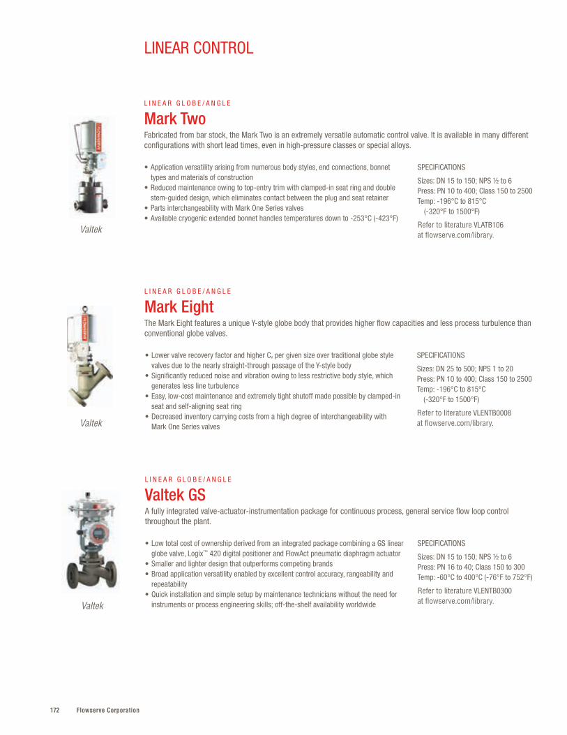
Flowserve Corporation172
LINEAR CONTROL
SPECIFICATIONS
Sizes: DN 25 to 500; NPS 1 to 20Press: PN 10 to 400; Class 150 to 2500Temp: -196°C to 815°C (-320°F to 1500°F)
Refer to literature VLENTB0008 at flowserve.com/library.
• Lower valve recovery factor and higher Cv per given size over traditional globe style valves due to the nearly straight-through passage of the Y-style body
• Significantly reduced noise and vibration owing to less restrictive body style, which generates less line turbulence
• Easy, low-cost maintenance and extremely tight shutoff made possible by clamped-in seat and self-aligning seat ring
• Decreased inventory carrying costs from a high degree of interchangeability with Mark One Series valves
L I N E A R G L O B E / A N G L E
Mark EightThe Mark Eight features a unique Y-style globe body that provides higher flow capacities and less process turbulence than conventional globe valves.
Valtek
SPECIFICATIONS
Sizes: DN 15 to 150; NPS ½ to 6Press: PN 16 to 40; Class 150 to 300Temp: -60°C to 400°C (-76°F to 752°F)
Refer to literature VLENTB0300 at flowserve.com/library.
• Low total cost of ownership derived from an integrated package combining a GS linear globe valve, Logix™ 420 digital positioner and FlowAct pneumatic diaphragm actuator
• Smaller and lighter design that outperforms competing brands • Broad application versatility enabled by excellent control accuracy, rangeability and
repeatability • Quick installation and simple setup by maintenance technicians without the need for
instruments or process engineering skills; off-the-shelf availability worldwide
L I N E A R G L O B E / A N G L E
Valtek GSA fully integrated valve-actuator-instrumentation package for continuous process, general service flow loop control throughout the plant.
Valtek
SPECIFICATIONS
Sizes: DN 15 to 150; NPS ½ to 6Press: PN 10 to 400; Class 150 to 2500Temp: -196°C to 815°C (-320°F to 1500°F)
Refer to literature VLATB106 at flowserve.com/library.
• Application versatility arising from numerous body styles, end connections, bonnet types and materials of construction
• Reduced maintenance owing to top-entry trim with clamped-in seat ring and double stem-guided design, which eliminates contact between the plug and seat retainer
• Parts interchangeability with Mark One Series valves• Available cryogenic extended bonnet handles temperatures down to -253°C (-423°F)
L I N E A R G L O B E / A N G L E
Mark TwoFabricated from bar stock, the Mark Two is an extremely versatile automatic control valve. It is available in many different configurations with short lead times, even in high-pressure classes or special alloys.
Valtek

173flowserve.com
VALVES | LINEAR CO
NTRO
L

Flowserve Corporation174174
Mark 100 with Stealth trim
175flowserve.com
Longer service life and lower maintenance costs are made possible through precision-
engineered valve and trim options — even in corrosive, erosive and high-velocity
applications . A range of advanced anti-erosion, noise reduction and anti-cavitation
selections neutralizes the detrimental wear and tear that too often reduce valve life or lead
to failures . Maximum flexibility is achieved through severe service products that incorporate
a range of material, pressure and temperature options .
Severe Service Control – Quick Reference*
SEVERE SERVICE CONTROL
VALVES | SEVERE SERVICE CO
NTRO
L
Product Sub-Type Sizes Pressures Temperatures
Survivor™ Anti-Erosion DN 25 to 600NPS 1 to 24
PN 20 to 420Class 150 to 2500
-10°C to 400°C(14°F to 752°F)
* Additional products shown on next page
Flowserve Corporation176
Product Sub-Type Base Valve Sizes Kv (Cv) Range
Severe Service Control – Quick Reference, cont’d.
MegaStream™ Noise Reduction Valtek Mark Series DN 25 to 900 NPS 1 to 36
4 to 8737(5 to 10 100)
Stealth™ Noise Reduction Valtek Mark Series DN 80 to 900 NPS 3 to 36
to 3547 (4100)
TMCBV C2, N2 and Z2
Noise Reduction Valbart TMCBV DN 80 to 1400 NPS 3 to 56
117 to 77 850(135 to 90 000)
Z-Trim™ Noise Reduction Setball, Duball DL and Trunnball DL
DN 40 to DN 500; NPS 1 .5 to 20 58 to 25 537
CavControl™ Cavitation Control Valtek Mark Series DN 25 to 600 NPS 1 to 24
1 .3 to 865(1 .5 to 1000)
ChannelStream™ Cavitation Elimination Valtek Mark Series DN 40 to 900NPS 1½ to 36
5 to 623(6 to 720)
DiamondBack™ Cavitation Elimination Valtek Mark Series DN 40 to 400NPS 1½ to 16
2 to 1773(3 to 2050)
SideWinder™ Cavitation Elimination Valtek Mark Series DN 15 to 100 NPS ½ to 4
0 .078 to 8 .425 (0 .09 to 9 .74)
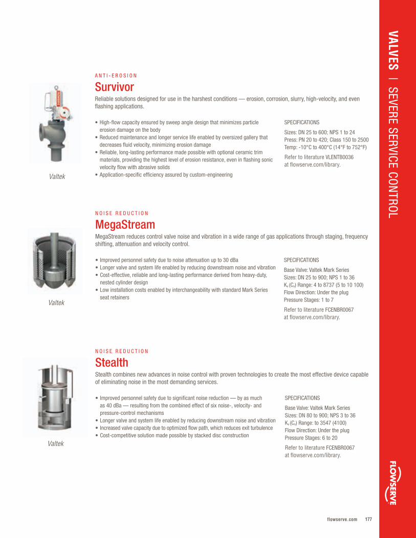
177flowserve.com
Valtek
SPECIFICATIONS
Base Valve: Valtek Mark SeriesSizes: DN 25 to 900; NPS 1 to 36Kv (Cv) Range: 4 to 8737 (5 to 10 100)Flow Direction: Under the plugPressure Stages: 1 to 7
Refer to literature FCENBR0067 at flowserve.com/library.
• Improved personnel safety due to noise attenuation up to 30 dBa • Longer valve and system life enabled by reducing downstream noise and vibration • Cost-effective, reliable and long-lasting performance derived from heavy-duty,
nested cylinder design• Low installation costs enabled by interchangeability with standard Mark Series
seat retainers
N O I S E R E D U C T I O N
MegaStreamMegaStream reduces control valve noise and vibration in a wide range of gas applications through staging, frequency shifting, attenuation and velocity control.
VALVES | SEVERE SERVICE CO
NTRO
L
SPECIFICATIONS
Sizes: DN 25 to 600; NPS 1 to 24Press: PN 20 to 420; Class 150 to 2500Temp: -10°C to 400°C (14°F to 752°F)
Refer to literature VLENTB0036 at flowserve.com/library.
• High-flow capacity ensured by sweep angle design that minimizes particle erosion damage on the body
• Reduced maintenance and longer service life enabled by oversized gallery that decreases fluid velocity, minimizing erosion damage
• Reliable, long-lasting performance made possible with optional ceramic trim materials, providing the highest level of erosion resistance, even in flashing sonic velocity flow with abrasive solids
• Application-specific efficiency assured by custom-engineering
A N T I - E R O S I O N
SurvivorReliable solutions designed for use in the harshest conditions — erosion, corrosion, slurry, high-velocity, and even flashing applications.
Valtek
Valtek
SPECIFICATIONS
Base Valve: Valtek Mark SeriesSizes: DN 80 to 900; NPS 3 to 36Kv (Cv) Range: to 3547 (4100)Flow Direction: Under the plugPressure Stages: 6 to 20
Refer to literature FCENBR0067 at flowserve.com/library.
• Improved personnel safety due to significant noise reduction — by as much as 40 dBa — resulting from the combined effect of six noise-, velocity- and pressure-control mechanisms
• Longer valve and system life enabled by reducing downstream noise and vibration• Increased valve capacity due to optimized flow path, which reduces exit turbulence• Cost-competitive solution made possible by stacked disc construction
N O I S E R E D U C T I O N
StealthStealth combines new advances in noise control with proven technologies to create the most effective device capable of eliminating noise in the most demanding services.
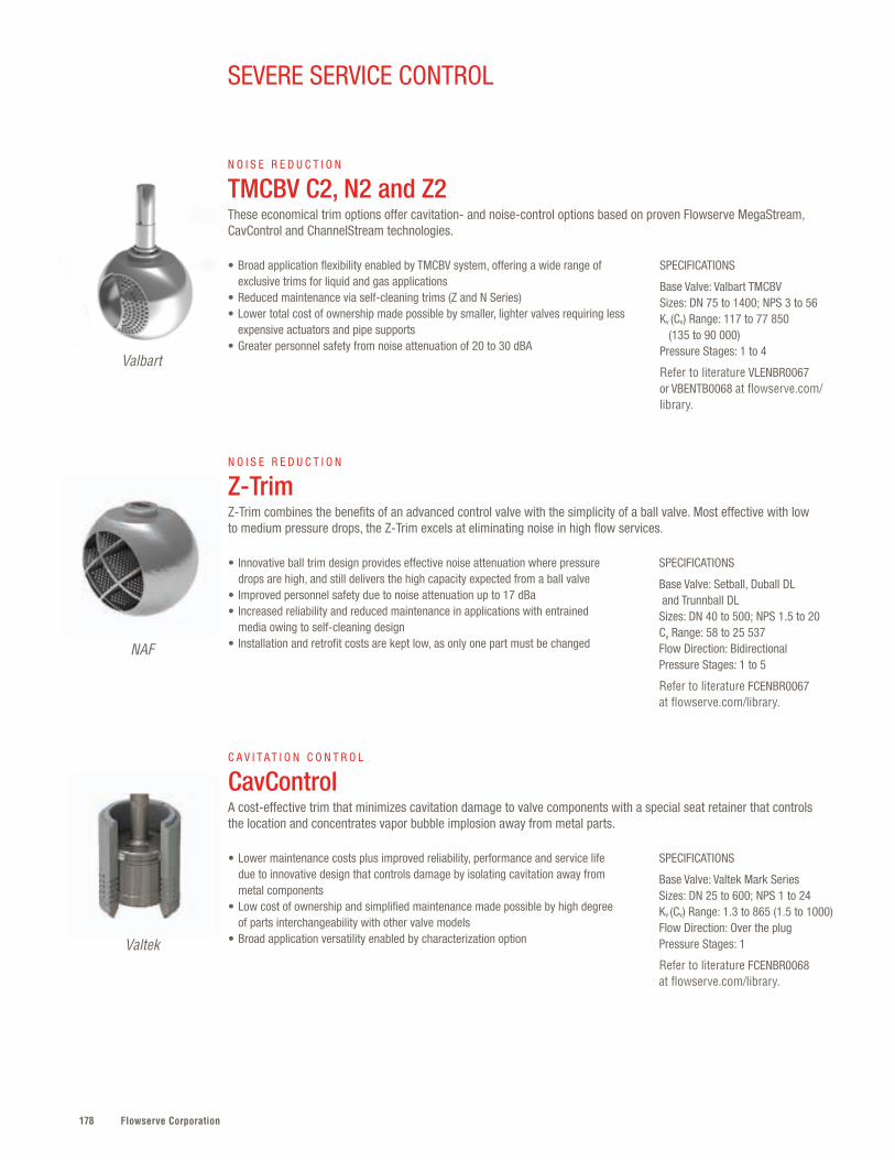
Flowserve Corporation178
SEVERE SERVICE CONTROL
SPECIFICATIONS
Base Valve: Valbart TMCBVSizes: DN 75 to 1400; NPS 3 to 56Kv (Cv) Range: 117 to 77 850 (135 to 90 000)Pressure Stages: 1 to 4
Refer to literature VLENBR0067 or VBENTB0068 at flowserve.com/library.
• Broad application flexibility enabled by TMCBV system, offering a wide range of exclusive trims for liquid and gas applications
• Reduced maintenance via self-cleaning trims (Z and N Series)• Lower total cost of ownership made possible by smaller, lighter valves requiring less
expensive actuators and pipe supports• Greater personnel safety from noise attenuation of 20 to 30 dBA
N O I S E R E D U C T I O N
TMCBV C2, N2 and Z2 These economical trim options offer cavitation- and noise-control options based on proven Flowserve MegaStream, CavControl and ChannelStream technologies.
Valbart
SPECIFICATIONS
Base Valve: Setball, Duball DL and Trunnball DLSizes: DN 40 to 500; NPS 1.5 to 20Cv Range: 58 to 25 537Flow Direction: BidirectionalPressure Stages: 1 to 5
Refer to literature FCENBR0067 at flowserve.com/library.
SPECIFICATIONS
Base Valve: Valtek Mark SeriesSizes: DN 25 to 600; NPS 1 to 24Kv (Cv) Range: 1.3 to 865 (1.5 to 1000)Flow Direction: Over the plugPressure Stages: 1
Refer to literature FCENBR0068 at flowserve.com/library.
• Innovative ball trim design provides effective noise attenuation where pressure drops are high, and still delivers the high capacity expected from a ball valve
• Improved personnel safety due to noise attenuation up to 17 dBa• Increased reliability and reduced maintenance in applications with entrained
media owing to self-cleaning design • Installation and retrofit costs are kept low, as only one part must be changed
• Lower maintenance costs plus improved reliability, performance and service life due to innovative design that controls damage by isolating cavitation away from metal components
• Low cost of ownership and simplified maintenance made possible by high degree of parts interchangeability with other valve models
• Broad application versatility enabled by characterization option
N O I S E R E D U C T I O N
Z-TrimZ-Trim combines the benefits of an advanced control valve with the simplicity of a ball valve. Most effective with low to medium pressure drops, the Z-Trim excels at eliminating noise in high flow services.
C A V I T A T I O N C O N T R O L
CavControlA cost-effective trim that minimizes cavitation damage to valve components with a special seat retainer that controls the location and concentrates vapor bubble implosion away from metal parts.
NAF
Valtek
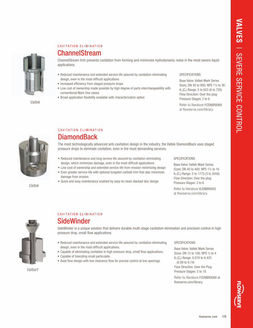
179flowserve.com
VALVES | SEVERE SERVICE CO
NTRO
L
SPECIFICATIONS
Base Valve: Valtek Mark SeriesSizes: DN 15 to 100; NPS ½ to 4Kv (Cv) Range: 0.078 to 8.425 (0.09 to 9.74)Flow Direction: Over the Plug Pressure Stages: 5 to 18
Refer to literature FCENBR0068 at flowserve.com/library.
• Reduced maintenance and extended service life assured by cavitation-eliminating design, even in the most difficult applications.
• Capable of eliminating cavitation in high pressure drop, small flow applications.• Capable of tolerating small particulate.• Axial flow design with low clearance flow for precise control at low openings.
C A V I T A T I O N E L I M I N A T I O N
SideWinder SideWinder is a unique solution that delivers durable multi-stage cavitation elimination and precision control in high pressure drop, small flow applications.
Valbart
Valtek
SPECIFICATIONS
Base Valve: Valtek Mark SeriesSizes: DN 40 to 900; NPS 1½ to 36Kv (Cv) Range: 5 to 623 (6 to 720)Flow Direction: Over the plugPressure Stages: 2 to 6
Refer to literature FCENBR0068 at flowserve.com/library.
• Reduced maintenance and extended service life assured by cavitation-eliminating design, even in the most difficult applications
• Increased efficiency from staged pressure drops• Low cost of ownership made possible by high degree of parts interchangeability with
conventional Mark One valves• Broad application flexibility available with characterization option
C A V I T A T I O N E L I M I N A T I O N
ChannelStreamChannelStream trim prevents cavitation from forming and minimizes hydrodynamic noise in the most severe liquid applications.
Valtek
SPECIFICATIONS
Base Valve: Valtek Mark SeriesSizes: DN 40 to 400; NPS 1½ to 16Kv (Cv) Range: 2 to 1773 (3 to 2050)Flow Direction: Over the plugPressure Stages: 3 to 6
Refer to literature VLENBR0005 at flowserve.com/library.
• Reduced maintenance and long service life assured by cavitation-eliminating design, which minimizes damage, even in the most difficult applications
• Low cost of ownership and extended service life from erosion-minimizing design • Even greater service life with optional tungsten carbide trim that also minimizes
damage from erosion• Quick and easy maintenance enabled by easy-to-clean stacked disc design
C A V I T A T I O N E L I M I N A T I O N
DiamondBackThe most technologically advanced anti-cavitation design in the industry, the Valtek DiamondBack uses staged pressure drops to eliminate cavitation, even in the most demanding services.

Flowserve Corporation180180
Equiwedge MSIV/MFIV
181flowserve.com
Reliable, tight shutoff and low-pressure drop operation characterize the Flowserve range
of gate valves . Flexible wedge, split wedge, slab gate and double-disk configurations cover
a range of requirements to meet any user need, from general service to severe conditions
with gross thermal transients or dual-phase fluids . Plant personnel are kept safe through
the application of fast-acting valves manufactured to ASME B16 .34, ASME Section III
and RCC-M design codes .
Gate – Quick Reference
GATE
VALVES | GATE
Product Sub-Type Sizes Pressures Temperatures
Equiwedge™
MSIV/MFIV Flexible Split Wedge DN 100 to 1050
NPS 4 to 42PN 110 to 420
Class 600 to 2500-29°C to 566°C
(-20°F to 1050°F)
Equiwedge Flexible Split Wedge DN 65 to 900NPS 2½ to 36
PN 110 to 610Class 600 to 3600
-29°C to 650°C(-20°F to 1200°F)
Flex Wedge Flexible Wedge DN 65 to 600NPS 2½ to 24
PN 20 to 260Class 150 to 1500
-29°C to 566°C(-20°F to 1050°F)
Double Disk Parallel Slide DN 15 to 600NPS ½ to 24
PN 20 to 325Class 150 to 1888
-29°C to 566°C(-20°F to 1050°F)
Split Wedge Split Wedge DN 15 to 50NPS ½ to 2
PN 20 to 140Class 150 to 800
-29°C to 566°C(-20°F to 1050°F)
Slab Gate Slab DN 50 to 1600NPS 2 to 64
PN 20 to 420Class 150 to 2500
-100°C to 400°C(-148°F to 750°F)
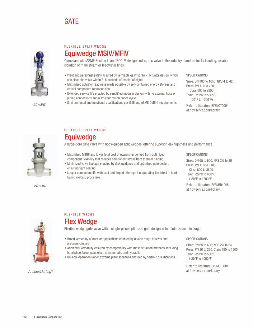
Flowserve Corporation182
SPECIFICATIONS
Sizes: DN 100 to 1050; NPS 4 to 42Press: PN 110 to 420; Class 600 to 2500Temp: -29°C to 566°C (-20°F to 1050°F)
Refer to literature EVENCT0004 at flowserve.com/library.
SPECIFICATIONS
Sizes: DN 65 to 900; NPS 2½ to 36Press: PN 110 to 610; Class 600 to 3600Temp: -29°C to 650°C (-20°F to 1200°F)
Refer to literature EVENBR1005 at flowserve.com/library.
SPECIFICATIONS
Sizes: DN 65 to 600; NPS 2½ to 24Press: PN 20 to 260; Class 150 to 1500Temp: -29°C to 566°C (-20°F to 1050°F)
Refer to literature EVENCT0004 at flowserve.com/library.
• Plant and personnel safety assured by verifiable gas/hydraulic actuator design, which can close the valve within 3–5 seconds of receipt of signal
• Maximized actuator readiness made possible by self-contained energy storage and critical component redundancies
• Extended service life enabled by simplified modular design with no external hose or piping connections and a 12-year maintenance cycle
• Environmental and functional qualifications per IEEE and ASME QME-1 requirements
• Maximized MTBF and lower total cost of ownership derived from optimized component flexibility that reduces component stress from thermal binding
• Minimized valve leakage enabled by disk guidance and optimized gate design, ensuring tight seating
• Longer component life with cast and forged offerings incorporating the latest in hard-facing welding processes
• Broad versatility of nuclear applications enabled by a wide range of sizes and pressure classes
• Additional versatility ensured by compatibility with most actuation methods, including handwheel/bevel gear, electric, pneumatic and hydraulic
• Reliable operation under extreme plant scenarios ensured by seismic qualifications
F L E X I B L E S P L I T W E D G E
Equiwedge MSIV/MFIVCompliant with ASME Section III and RCC-M design codes, this valve is the industry standard for fast-acting, reliable isolation of main steam or feedwater lines.
F L E X I B L E S P L I T W E D G E
Equiwedge A large-bore gate valve with body-guided split wedges, offering superior leak tightness and performance.
F L E X I B L E W E D G E
Flex WedgeFlexible wedge gate valve with a single-piece optimized gate designed to minimize seat leakage.
Edward®
Anchor/Darling®
GATE
Edward
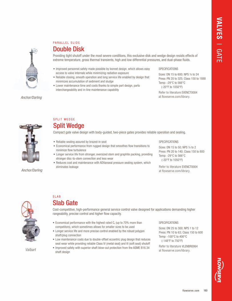
183flowserve.com
S P L I T W E D G E
Split WedgeCompact gate valve design with body-guided, two-piece gates provides reliable operation and sealing.
SPECIFICATIONS
Sizes: DN 15 to 600; NPS ½ to 24Press: PN 20 to 325; Class 150 to 1888Temp: -29°C to 566°C (-20°F to 1050°F)
Refer to literature EVENCT0004 at flowserve.com/library.
• Improved personnel safety made possible by bonnet design, which allows easy access to valve internals while minimizing radiation exposure
• Reliable closing, smooth operation and long service life enabled by design that minimizes accumulation of sediment and sludge
• Lower maintenance time and costs thanks to simple part design, parts interchangeability and in-line maintenance capability
P A R A L L E L S L I D E
Double DiskProviding tight shutoff under the most severe conditions, this exclusive disk and wedge design resists effects of extreme temperature, gross thermal transients, high and low differential pressures, and dual-phase fluids.
Anchor/Darling
SPECIFICATIONS
Sizes: DN 15 to 50; NPS ½ to 2Press: PN 20 to 140; Class 150 to 800Temp: -29°C to 566°C (-20°F to 1050°F)
Refer to literature EVENCT0004 at flowserve.com/library.
• Reliable sealing assured by brazed-in seat• Economical performance from rugged design that smoothes flow transitions to
minimize flow turbulence• Longer service life from stronger, oversized stem and graphite packing, providing
stronger disc-to-stem connection and less wear• Reduces cost and maintenance with ADVanseal pressure sealing system, which
eliminates leakageAnchor/Darling
VALVES | GATE
SPECIFICATIONS
Sizes: DN 25 to 300; NPS 1 to 12Press: PN 10 to 63; Class 150 to 600 Temp: -100°C to 400°C (-148°F to 750°F)
Refer to literature VLENBR0064 at flowserve.com/library.
• Economical performance with the highest rated Cv (up to 70% more than competitors), which sometimes allows for smaller sizes to be used
• Longer service life and more precise control enabled by the robust polygon shaft/plug connection
• Low maintenance costs due to double-offset eccentric plug design that reduces seat wear while providing reliable Class IV (metal seat) and VI (soft seat) shutoff
• Improved safety with superior shaft blow-out protection from the ASME B16.34 shaft design
S L A B
Slab GateCost-competitive, high-performance general service control valve designed for applications demanding higher rangeability, precise control and higher flow capacity.
Valbart

Flowserve Corporation184184
Univalve
185flowserve.com
Maintaining a safe plant environment and extending service life — that’s what’s engineered
into every Flowserve globe valve . Whether it’s fail-safe response in nuclear plants or reliable
performance in high-temperature/pressure boiler plant services, every Flowserve globe
valve incorporates special features to maximize performance . Optimized flow passages and
smooth transitions reduce pressure drop and destructive turbulence .
Product Sub-Type Sizes Pressures Temperatures
Flite-Flow® Main Steam Isolation
Y-Pattern DN 600 to 850NPS 24 to 34
PN 110 to 260Class 600 to 900
-29°C to 565°C(-20°F to 1050°F)
Flite-Flow Y-Pattern DN 65 to 800NPS 2½ to 32
PN 50 to 760Class 300 to 4500
-29°C to 650°C(-20°F to 1200°F)
Univalve® Y-Pattern DN 15 to 100NPS ½ to 4
PN 290, 460 and 760Class 1690, 2680 and 4500
-29°C to 816°C(-20°F to 1500°F)
Edward Bolted Bonnet
Y-Pattern DN 8 to 50NPS ¼ to 2
PN 130 and 260Class 800 and 1500
-29°C to 565°C(-20°F to 1050°F)
Edward Blow-off Y-Pattern DN 25 to 65NPS 1 to 2½
PN 50 to 420Class 300 to 2500
-29°C to 565°C(-20°F to 1050°F)
1878 Y-Pattern Y-Pattern DN 15 to 50NPS ½ to 2
PN 20 to 325Class 150 to 1878
-29°C to 371°C(-20°F to 700°F)
Anchor/Darling Y-Pattern
Y-Pattern DN 15 to 600NPS ½ to 24
PN 20 to 260Class 150 to 1500
-29°C to 565°C(-20°F to 1050°F)
Globe – Quick Reference*
GLOBE
VALVES | GLO
BE
* Additional products shown on next page
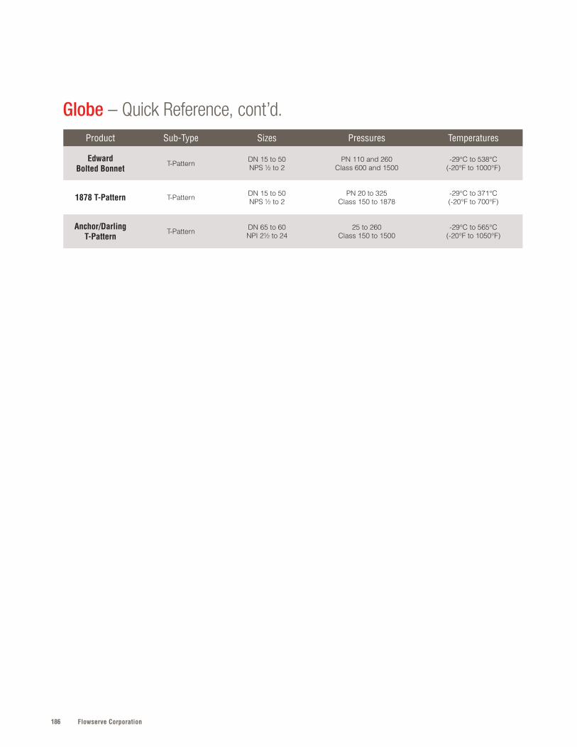
Flowserve Corporation186
Product Sub-Type Sizes Pressures Temperatures
Edward Bolted Bonnet
T-Pattern DN 15 to 50NPS ½ to 2
PN 110 and 260Class 600 and 1500
-29°C to 538°C (-20°F to 1000°F)
1878 T-Pattern T-Pattern DN 15 to 50NPS ½ to 2
PN 20 to 325Class 150 to 1878
-29°C to 371°C(-20°F to 700°F)
Anchor/Darling T-Pattern
T-Pattern DN 65 to 60NPI 2½ to 24
25 to 260Class 150 to 1500
-29°C to 565°C(-20°F to 1050°F)
Globe – Quick Reference, cont’d.
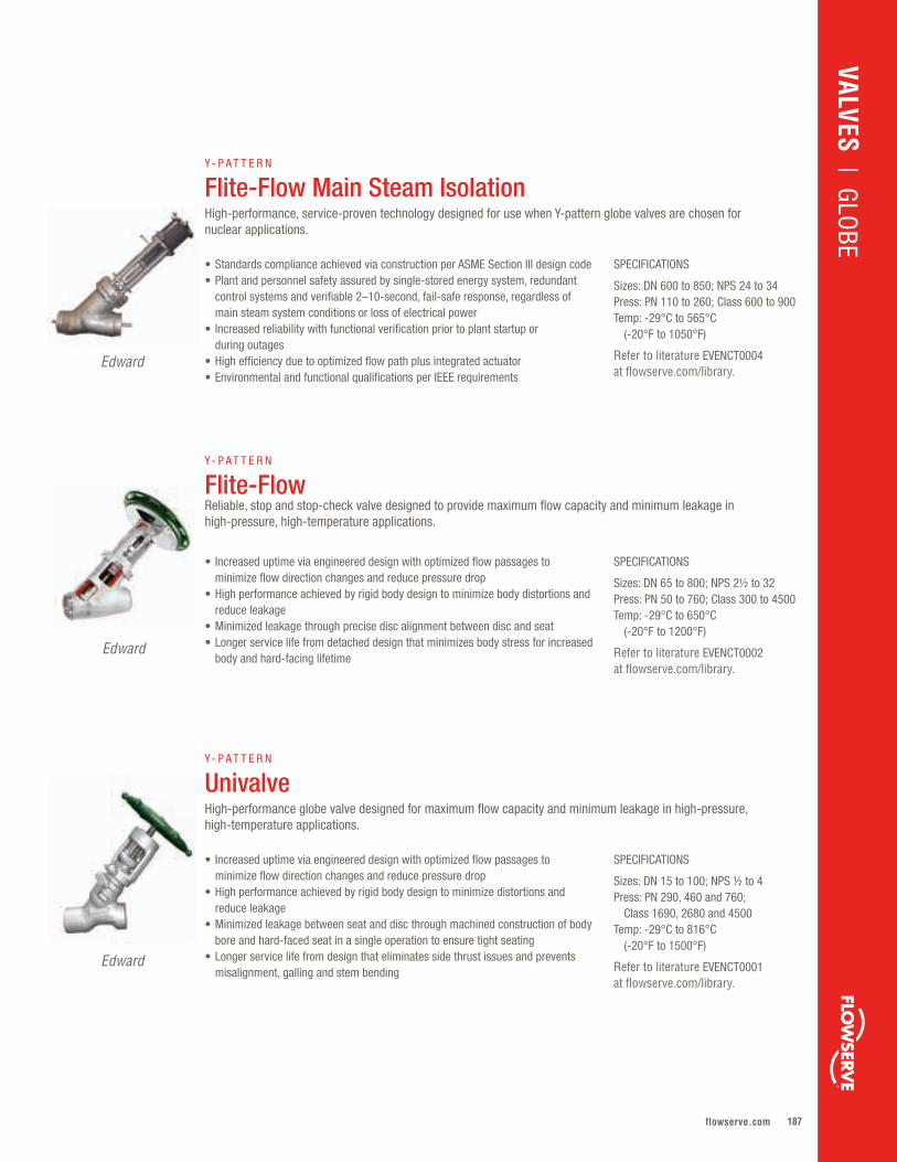
187flowserve.com
VALVES | GLO
BE
SPECIFICATIONS
Sizes: DN 600 to 850; NPS 24 to 34Press: PN 110 to 260; Class 600 to 900Temp: -29°C to 565°C (-20°F to 1050°F)
Refer to literature EVENCT0004 at flowserve.com/library.
SPECIFICATIONS
Sizes: DN 65 to 800; NPS 2½ to 32Press: PN 50 to 760; Class 300 to 4500Temp: -29°C to 650°C (-20°F to 1200°F)
Refer to literature EVENCT0002 at flowserve.com/library.
SPECIFICATIONS
Sizes: DN 15 to 100; NPS ½ to 4Press: PN 290, 460 and 760; Class 1690, 2680 and 4500Temp: -29°C to 816°C (-20°F to 1500°F)
Refer to literature EVENCT0001 at flowserve.com/library.
• Standards compliance achieved via construction per ASME Section III design code• Plant and personnel safety assured by single-stored energy system, redundant
control systems and verifiable 2–10-second, fail-safe response, regardless of main steam system conditions or loss of electrical power
• Increased reliability with functional verification prior to plant startup or during outages
• High efficiency due to optimized flow path plus integrated actuator• Environmental and functional qualifications per IEEE requirements
• Increased uptime via engineered design with optimized flow passages to minimize flow direction changes and reduce pressure drop
• High performance achieved by rigid body design to minimize body distortions and reduce leakage
• Minimized leakage through precise disc alignment between disc and seat • Longer service life from detached design that minimizes body stress for increased
body and hard-facing lifetime
• Increased uptime via engineered design with optimized flow passages to minimize flow direction changes and reduce pressure drop
• High performance achieved by rigid body design to minimize distortions and reduce leakage
• Minimized leakage between seat and disc through machined construction of body bore and hard-faced seat in a single operation to ensure tight seating
• Longer service life from design that eliminates side thrust issues and prevents misalignment, galling and stem bending
Y - P A T T E R N
Flite-Flow Main Steam IsolationHigh-performance, service-proven technology designed for use when Y-pattern globe valves are chosen for nuclear applications.
Y - P A T T E R N
Flite-Flow Reliable, stop and stop-check valve designed to provide maximum flow capacity and minimum leakage in high-pressure, high-temperature applications.
Y - P A T T E R N
Univalve
High-performance globe valve designed for maximum flow capacity and minimum leakage in high-pressure, high-temperature applications.
Edward
Edward
Edward
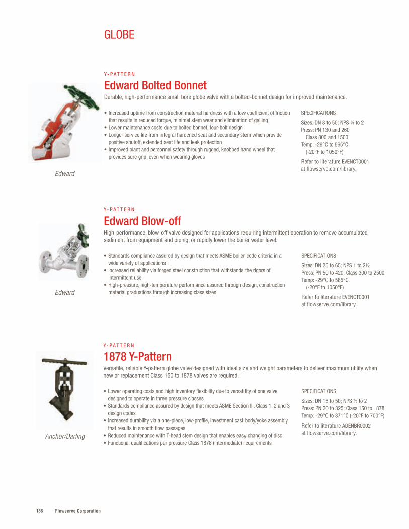
Flowserve Corporation188
SPECIFICATIONS
Sizes: DN 8 to 50; NPS ¼ to 2Press: PN 130 and 260 Class 800 and 1500Temp: -29°C to 565°C (-20°F to 1050°F)
Refer to literature EVENCT0001 at flowserve.com/library.
• Increased uptime from construction material hardness with a low coefficient of friction that results in reduced torque, minimal stem wear and elimination of galling
• Lower maintenance costs due to bolted bonnet, four-bolt design• Longer service life from integral hardened seat and secondary stem which provide
positive shutoff, extended seat life and leak protection• Improved plant and personnel safety through rugged, knobbed hand wheel that
provides sure grip, even when wearing gloves
Y - P A T T E R N
Edward Bolted Bonnet Durable, high-performance small bore globe valve with a bolted-bonnet design for improved maintenance.
Edward
SPECIFICATIONS
Sizes: DN 25 to 65; NPS 1 to 2½Press: PN 50 to 420; Class 300 to 2500Temp: -29°C to 565°C (-20°F to 1050°F)
Refer to literature EVENCT0001 at flowserve.com/library.
SPECIFICATIONS
Sizes: DN 15 to 50; NPS ½ to 2Press: PN 20 to 325; Class 150 to 1878Temp: -29°C to 371°C (-20°F to 700°F)
Refer to literature ADENBR0002 at flowserve.com/library.
• Standards compliance assured by design that meets ASME boiler code criteria in a wide variety of applications
• Increased reliability via forged steel construction that withstands the rigors of intermittent use
• High-pressure, high-temperature performance assured through design, construction material graduations through increasing class sizes
• Lower operating costs and high inventory flexibility due to versatility of one valve designed to operate in three pressure classes
• Standards compliance assured by design that meets ASME Section III, Class 1, 2 and 3 design codes
• Increased durability via a one-piece, low-profile, investment cast body/yoke assembly that results in smooth flow passages
• Reduced maintenance with T-head stem design that enables easy changing of disc• Functional qualifications per pressure Class 1878 (intermediate) requirements
Y - P A T T E R N
Edward Blow-off High-performance, blow-off valve designed for applications requiring intermittent operation to remove accumulated sediment from equipment and piping, or rapidly lower the boiler water level.
Y - P A T T E R N
1878 Y-PatternVersatile, reliable Y-pattern globe valve designed with ideal size and weight parameters to deliver maximum utility when new or replacement Class 150 to 1878 valves are required.
Edward
Anchor/Darling
GLOBE
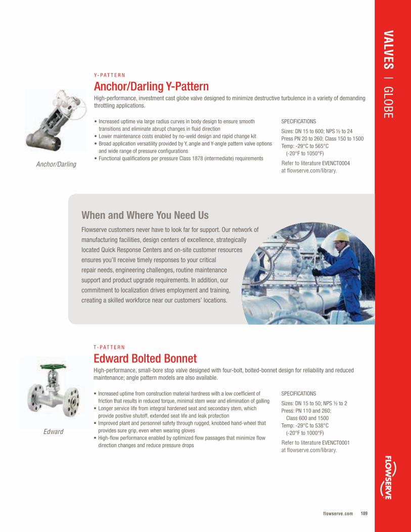
189flowserve.com
VALVES | GLOBE
SPECIFICATIONS
Sizes: DN 15 to 600; NPS ½ to 24Press PN 20 to 260; Class 150 to 1500Temp: -29°C to 565°C (-20°F to 1050°F)
Refer to literature EVENCT0004 at flowserve.com/library.
• Increased uptime via large radius curves in body design to ensure smooth transitions and eliminate abrupt changes in fluid direction
• Lower maintenance costs enabled by no-weld design and rapid change kit• Broad application versatility provided by Y, angle and Y-angle pattern valve options
and wide range of pressure configurations• Functional qualifications per pressure Class 1878 (intermediate) requirements
Y - P A T T E R N
Anchor/Darling Y-PatternHigh-performance, investment cast globe valve designed to minimize destructive turbulence in a variety of demanding throttling applications.
Anchor/Darling
SPECIFICATIONS
Sizes: DN 15 to 50; NPS ½ to 2Press: PN 110 and 260; Class 600 and 1500Temp: -29°C to 538°C (-20°F to 1000°F)
Refer to literature EVENCT0001 at flowserve.com/library.
• Increased uptime from construction material hardness with a low coefficient of friction that results in reduced torque, minimal stem wear and elimination of galling
• Longer service life from integral hardened seat and secondary stem, which provide positive shutoff, extended seat life and leak protection
• Improved plant and personnel safety through rugged, knobbed hand-wheel that provides sure grip, even when wearing gloves
• High-flow performance enabled by optimized flow passages that minimize flow direction changes and reduce pressure drops
T - P A T T E R N
Edward Bolted BonnetHigh-performance, small-bore stop valve designed with four-bolt, bolted-bonnet design for reliability and reduced maintenance; angle pattern models are also available.
Edward
When and Where You Need UsFlowserve customers never have to look far for support. Our network of
manufacturing facilities, design centers of excellence, strategically
located Quick Response Centers and on-site customer resources
ensures you’ll receive timely responses to your critical
repair needs, engineering challenges, routine maintenance
support and product upgrade requirements. In addition, our
commitment to localization drives employment and training,
creating a skilled workforce near our customers’ locations.
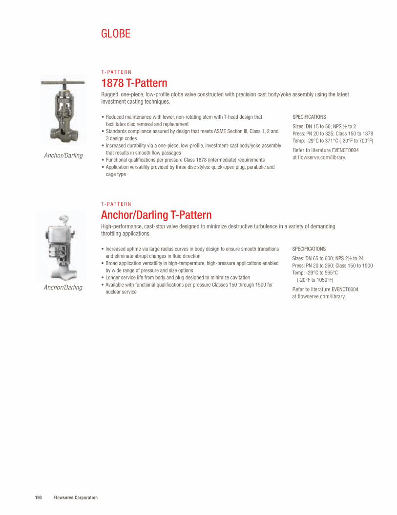
Flowserve Corporation190
GLOBE
SPECIFICATIONS
Sizes: DN 65 to 600; NPS 2½ to 24Press: PN 20 to 260; Class 150 to 1500Temp: -29°C to 565°C (-20°F to 1050°F)
Refer to literature EVENCT0004 at flowserve.com/library.
• Increased uptime via large radius curves in body design to ensure smooth transitions and eliminate abrupt changes in fluid direction
• Broad application versatility in high-temperature, high-pressure applications enabled by wide range of pressure and size options
• Longer service life from body and plug designed to minimize cavitation• Available with functional qualifications per pressure Classes 150 through 1500 for
nuclear service
T - P A T T E R N
Anchor/Darling T-PatternHigh-performance, cast-stop valve designed to minimize destructive turbulence in a variety of demanding throttling applications.
Anchor/Darling
SPECIFICATIONS
Sizes: DN 15 to 50; NPS ½ to 2Press: PN 20 to 325; Class 150 to 1878Temp: -29°C to 371°C (-20°F to 700°F)
Refer to literature EVENCT0004 at flowserve.com/library.
• Reduced maintenance with lower, non-rotating stem with T-head design that facilitates disc removal and replacement
• Standards compliance assured by design that meets ASME Section III, Class 1, 2 and 3 design codes
• Increased durability via a one-piece, low-profile, investment-cast body/yoke assembly that results in smooth flow passages
• Functional qualifications per pressure Class 1878 (intermediate) requirements• Application versatility provided by three disc styles: quick-open plug, parabolic and
cage type
T - P A T T E R N
1878 T-Pattern Rugged, one-piece, low-profile globe valve constructed with precision cast body/yoke assembly using the latest investment casting techniques.
Anchor/Darling

191flowserve.com
VALVES | GLOBE
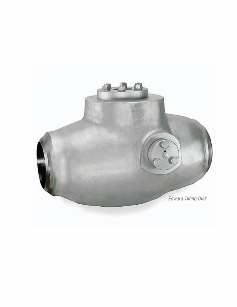
Flowserve Corporation192192
Edward Tilting Disk

193flowserve.com
VALVES | CHECK
Product Sub-Type Sizes Pressures Temperatures
Flite-Flow Piston (Lift) DN 65 to 800NPS 2½ to 32
PN 50 to 760Class 300 to 4500
-29°C to 650°C(-20°F to 1200°F)
Univalve Piston (Lift) DN 15 to 100NPS ½ to 4
PN 290, 460 and 760Class 1690, 2680 and 4500
-29°C to 816°C(-20°F to 1500°F)
EdwardBolted Bonnet
Piston (Lift) DN 15 to 50NPS ½ to 2
PN 110 to 260Class 600 and 1500
-29°C to 538°C(-20°F to 1000°F)
1878 Piston Check
Piston (Lift) DN 15 to 50NPS ½ to 2
PN 110, 150, 260 and 325Class 600, 900, 1500
and 1878
38°C to 371°C(100°F to 700°F)
Anchor/Darling Piston (Lift) Check
Piston (Lift) DN 65 to 600NPI 2½ to 24
PN 20 to 260Class 150 to 1500
-29°C to 565°C(-20°F to 1050°F)
1878 Swing Check
Swing DN 15 to 50NPS ½ to 2
PN 110, 150, 260 and 325 Class 600, 900, 1500 and
1878
-29°C to 371°C(-20°F to 700°F)
Anchor/DarlingSwing Check
Swing DN 65 to 600NPI 2½ to 24
PN 20 to 260Class 150 to 1500
-29°C to 565°C(-20°F to 1050°F)
Check – Quick Reference*
Leak-free, tight sealing, protection against reverse flow and minimal flow direction changes
are at the core of Flowserve check valve designs . A broad range of configurations that
includes piston, tilting disc, spring-loaded disc and dual-plate models meets the critical,
high-temperature/pressure demands of the world’s major industries . Customers can carefully
match application requirements through myriad valve body, seat and disc options .
CHECK
* Additional products shown on next page
Flowserve Corporation194
Product Sub-Type Sizes Pressures Temperatures
EdwardTilting Disk
Tilting Disk DN 65 to 600NPS 2½ to 24
PN 110 to 760Class 600 to 4500
-29°C to 650°C(-20°F to 1200°F)
Anchor/DarlingTilting Disk
Tilting Disk DN 65 to 600NPS 2½ to 24
PN 20 to 260Class 150 to 1500
-29°C to 565°C(-20°F to 1050°F)
NAF Check Tilting Disk DN 40 to 1000NPS 1½ to 24
PN 20 to 40Class 150 to 300
-30°C to 350°C(-22°F to 662°F)
Check – Quick Reference, cont’d.
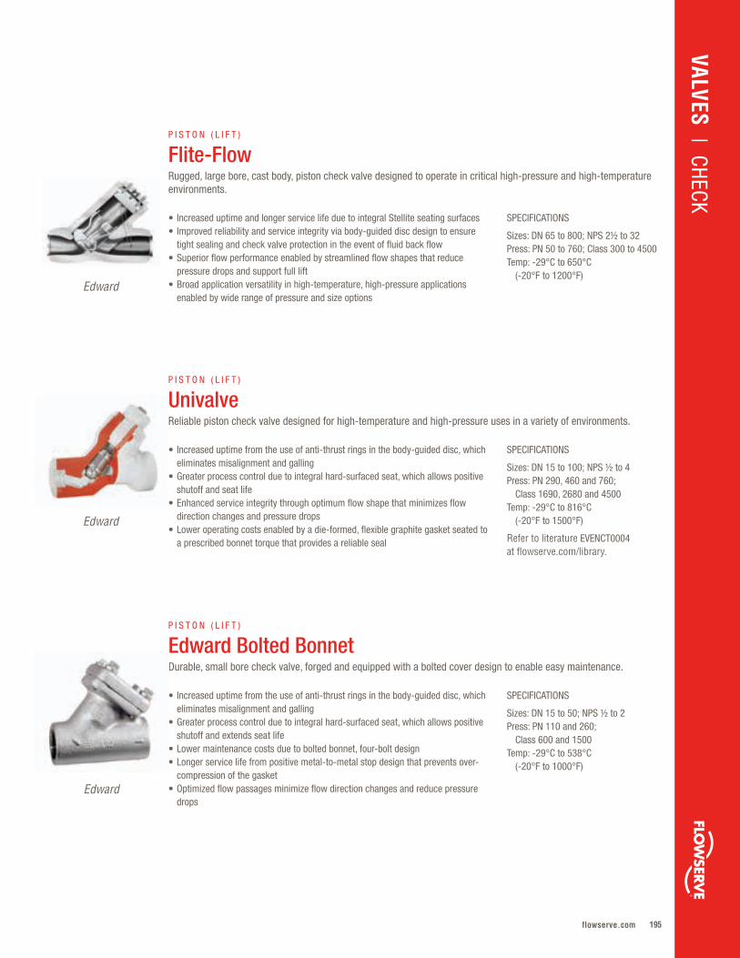
195flowserve.com
VALVES | CHECK
SPECIFICATIONS
Sizes: DN 15 to 50; NPS ½ to 2Press: PN 110 and 260; Class 600 and 1500Temp: -29°C to 538°C (-20°F to 1000°F)
• Increased uptime from the use of anti-thrust rings in the body-guided disc, which eliminates misalignment and galling
• Greater process control due to integral hard-surfaced seat, which allows positive shutoff and extends seat life
• Lower maintenance costs due to bolted bonnet, four-bolt design• Longer service life from positive metal-to-metal stop design that prevents over-
compression of the gasket• Optimized flow passages minimize flow direction changes and reduce pressure
drops
P I S T O N ( L I F T )
Edward Bolted BonnetDurable, small bore check valve, forged and equipped with a bolted cover design to enable easy maintenance.
SPECIFICATIONS
Sizes: DN 65 to 800; NPS 2½ to 32Press: PN 50 to 760; Class 300 to 4500Temp: -29°C to 650°C (-20°F to 1200°F)
• Increased uptime and longer service life due to integral Stellite seating surfaces• Improved reliability and service integrity via body-guided disc design to ensure
tight sealing and check valve protection in the event of fluid back flow• Superior flow performance enabled by streamlined flow shapes that reduce
pressure drops and support full lift• Broad application versatility in high-temperature, high-pressure applications
enabled by wide range of pressure and size options
P I S T O N ( L I F T )
Flite-FlowRugged, large bore, cast body, piston check valve designed to operate in critical high-pressure and high-temperature environments.
Edward
SPECIFICATIONS
Sizes: DN 15 to 100; NPS ½ to 4Press: PN 290, 460 and 760; Class 1690, 2680 and 4500Temp: -29°C to 816°C (-20°F to 1500°F)
Refer to literature EVENCT0004 at flowserve.com/library.
• Increased uptime from the use of anti-thrust rings in the body-guided disc, which eliminates misalignment and galling
• Greater process control due to integral hard-surfaced seat, which allows positive shutoff and seat life
• Enhanced service integrity through optimum flow shape that minimizes flow direction changes and pressure drops
• Lower operating costs enabled by a die-formed, flexible graphite gasket seated to a prescribed bonnet torque that provides a reliable seal
P I S T O N ( L I F T )
UnivalveReliable piston check valve designed for high-temperature and high-pressure uses in a variety of environments.
Edward
Edward
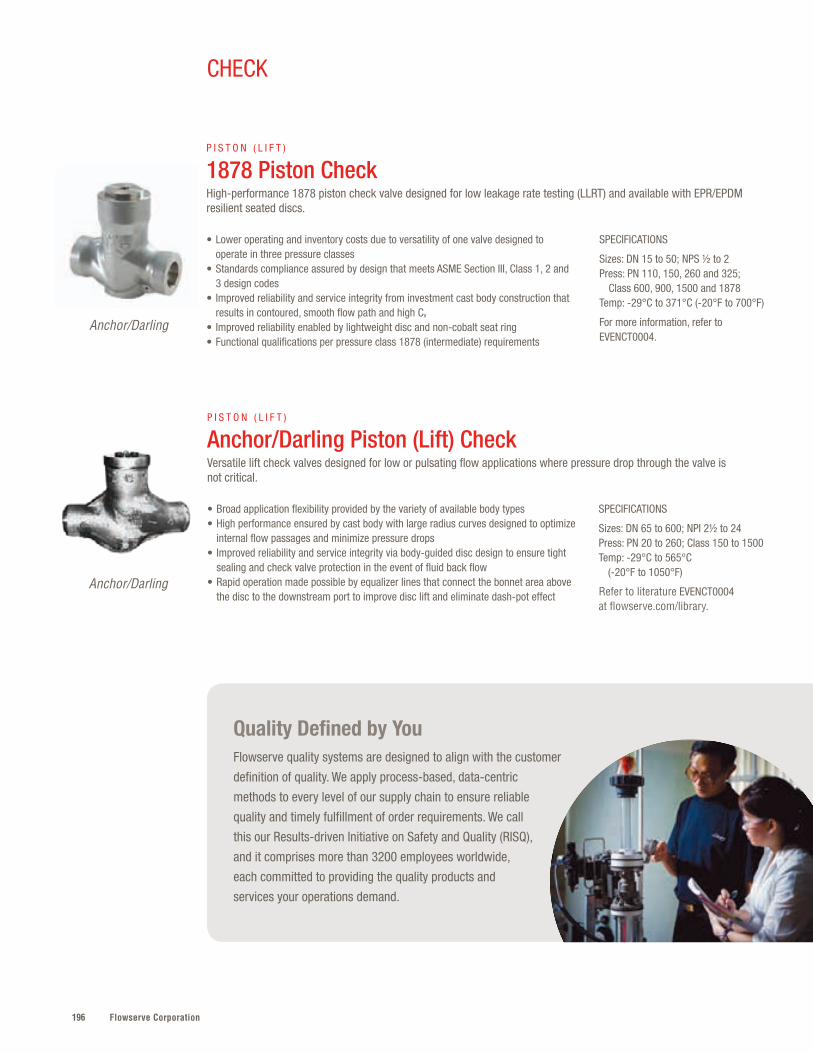
Flowserve Corporation196
CHECK
SPECIFICATIONS
Sizes: DN 15 to 50; NPS ½ to 2Press: PN 110, 150, 260 and 325; Class 600, 900, 1500 and 1878Temp: -29°C to 371°C (-20°F to 700°F)
For more information, refer to EVENCT0004.
• Lower operating and inventory costs due to versatility of one valve designed to operate in three pressure classes
• Standards compliance assured by design that meets ASME Section III, Class 1, 2 and 3 design codes
• Improved reliability and service integrity from investment cast body construction that results in contoured, smooth flow path and high Cv
• Improved reliability enabled by lightweight disc and non-cobalt seat ring• Functional qualifications per pressure class 1878 (intermediate) requirements
P I S T O N ( L I F T )
1878 Piston Check High-performance 1878 piston check valve designed for low leakage rate testing (LLRT) and available with EPR/EPDM resilient seated discs.
Anchor/Darling
SPECIFICATIONS
Sizes: DN 65 to 600; NPI 2½ to 24Press: PN 20 to 260; Class 150 to 1500Temp: -29°C to 565°C (-20°F to 1050°F)
Refer to literature EVENCT0004 at flowserve.com/library.
• Broad application flexibility provided by the variety of available body types• High performance ensured by cast body with large radius curves designed to optimize
internal flow passages and minimize pressure drops• Improved reliability and service integrity via body-guided disc design to ensure tight
sealing and check valve protection in the event of fluid back flow• Rapid operation made possible by equalizer lines that connect the bonnet area above
the disc to the downstream port to improve disc lift and eliminate dash-pot effect
P I S T O N ( L I F T )
Anchor/Darling Piston (Lift) Check Versatile lift check valves designed for low or pulsating flow applications where pressure drop through the valve is not critical.
Anchor/Darling
Quality Defined by YouFlowserve quality systems are designed to align with the customer
definition of quality. We apply process-based, data-centric
methods to every level of our supply chain to ensure reliable
quality and timely fulfillment of order requirements. We call
this our Results-driven Initiative on Safety and Quality (RISQ),
and it comprises more than 3200 employees worldwide,
each committed to providing the quality products and
services your operations demand.

197flowserve.com
VALVES | CHECK
SPECIFICATIONS
Sizes: DN 15 to 50; NPS ½ to 2Press: PN 110, 150, 260 and 325; Class 600, 900, 1500 and 1878Temp: -29°C to 371°C (-20°F to 700°F)
Refer to literature EVENCT0004 at flowserve.com/library.
• Rapid disassembly/reassembly during maintenance and repair that minimizes exposure to radiation
• Environmental/regulatory compliance and improved plant safety due to ALARA-compliant design
• Functional qualifications per ratings in accordance with ASME Section III, Class 1 pressure class 1878 (intermediate) requirements
• Greater process control through available dual-seat disc design for leak-free sealing at both high- and low-pressure differentials
S W I N G
1878 Swing Check Rugged, specialized swing check valve optimally designed for use in reactor penetration and isolation applications.
Anchor/Darling
SPECIFICATIONS
Sizes: DN 65 to 600; NPI 2½ to 24Press: PN 20 to 260; Class 150 to 1500Temp: -29°C to 565°C (-20°F to 1050°F)
Refer to literature EVENCT0004 at flowserve.com/library.
• Broad application and installation versatility via option to install in horizontal or vertical lines (with flow up)
• Low initial cost and low ongoing costs due to ease of maintenance • Functional qualifications per ratings in accordance with ASME Section III• Greater process control through available dual-seat disc design for leak-free
sealing at both high- and low-pressure differentials• Reliable performance enabled by design that ensures tight sealing
S W I N G
Anchor/Darling Swing Check Valve All-purpose swing check valve provides economical reverse-flow protection for piping system applications where flow is relatively constant.
Anchor/Darling
SPECIFICATIONS
Sizes: DN 65 to 600; NPS 2½ to 24Press: PN 110 to 760; Class 600 to 4500Temp: -29°C to 650°C (-20°F to 1200°F)
Refer to literature EVENCT0002 at flowserve.com/library.
• Greater process control assured by precision-machined cover and integral hard-surfaced seats
• Fast shutoff response facilitated by counterweighted dome-shaped disk, low-friction pivots and enclosed torsion springs
• Long, reliable service in high pressures and temperatures due to preloaded pressure-energized flexible graphite composite
• Easy installation and alignment made possible by adjustable hinge pin
T I LT I N G D I S K
Edward Tilting DiskDesigned to close as quickly as possible, this large-bore valve minimizes loud, damaging slamming and vibration noises caused by high-velocity reverse flow in high-pressure and high-temperature applications.
Edward
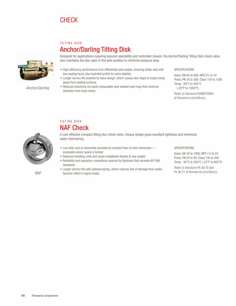
Flowserve Corporation198
CHECK
SPECIFICATIONS
Sizes: DN 65 to 600; NPS 2½ to 24Press: PN 20 to 260; Class 150 to 1500Temp: -29°C to 565°C (-20°F to 1050°F)
Refer to literature EVENCT0004 at flowserve.com/library.
• High-efficiency performance from differential seat angles, ensuring better seal with low seating force, plus hydrofoil profile for extra stability
• Longer service life enabled by valve design, which causes disc stops to impact body away from sealing surfaces
• Reduced downtime via easily replaceable seal-welded seat rings that minimize distortion from body stress
T I LT I N G D I S K
Anchor/Darling Tilting DiskDesigned for applications requiring assured operability and controlled closure, the Anchor/Darling Tilting Disk check valve also maintains the disc open in the best position to minimize pressure drop.
Anchor/Darling
SPECIFICATIONS
Sizes: DN 40 to 1000; NPS 1½ to 24Press: PN 20 to 40; Class 150 to 300Temp: -30°C to 350°C (-22°F to 662°F)
Refer to literature Fk 30.70 and Fk 30.71 at flowserve.com/library.
• Low total cost of ownership provided by compact face-to-face dimension — invaluable where space is limited
• Reduced handling costs and easier installation thanks to low weight• Reliability and regulatory compliance assured by tightness that exceeds API 598
standards• Longer service life with optional spring, which reduces risk of damage from water-
hammer effect in liquid media
T I LT I N G D I S K
NAF CheckA cost-effective compact tilting disc check valve. Unique design gives excellent tightness and minimizes water-hammering.
NAF

199flowserve.com
VALVES | CHECK
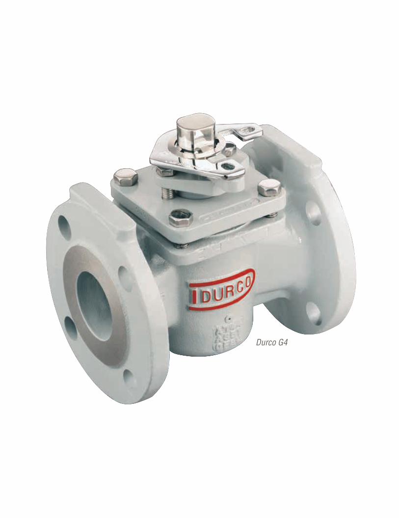
Flowserve Corporation200200
Durco G4
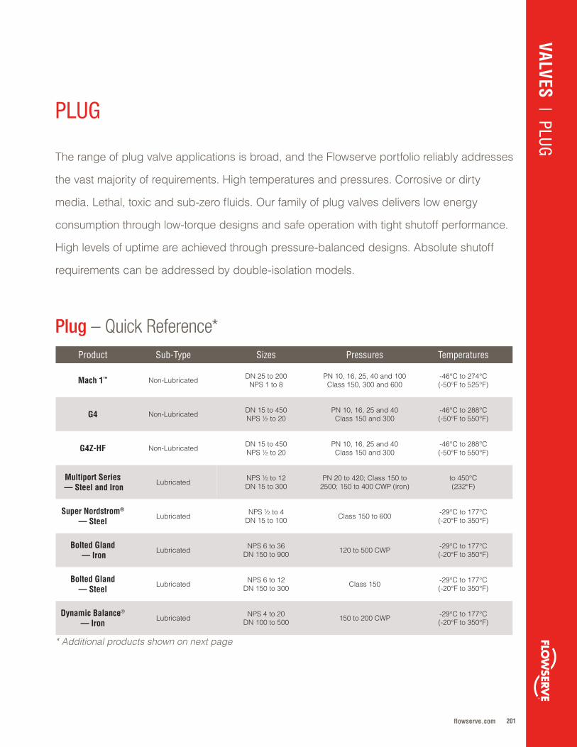
201flowserve.com
The range of plug valve applications is broad, and the Flowserve portfolio reliably addresses
the vast majority of requirements . High temperatures and pressures . Corrosive or dirty
media . Lethal, toxic and sub-zero fluids . Our family of plug valves delivers low energy
consumption through low-torque designs and safe operation with tight shutoff performance .
High levels of uptime are achieved through pressure-balanced designs . Absolute shutoff
requirements can be addressed by double-isolation models .
Product Sub-Type Sizes Pressures Temperatures
Mach 1™ Non-Lubricated DN 25 to 200NPS 1 to 8
PN 10, 16, 25, 40 and 100Class 150, 300 and 600
-46°C to 274°C(-50°F to 525°F)
G4 Non-Lubricated DN 15 to 450NPS ½ to 20
PN 10, 16, 25 and 40Class 150 and 300
-46°C to 288°C(-50°F to 550°F)
G4Z-HF Non-Lubricated DN 15 to 450NPS ½ to 20
PN 10, 16, 25 and 40Class 150 and 300
-46°C to 288°C(-50°F to 550°F)
Multiport Series — Steel and Iron
Lubricated NPS ½ to 12DN 15 to 300
PN 20 to 420; Class 150 to 2500; 150 to 400 CWP (iron)
to 450°C(232°F)
Super Nordstrom® — Steel
Lubricated NPS ½ to 4DN 15 to 100 Class 150 to 600 -29°C to 177°C
(-20°F to 350°F)
Bolted Gland — Iron
Lubricated NPS 6 to 36DN 150 to 900 120 to 500 CWP -29°C to 177°C
(-20°F to 350°F)
Bolted Gland— Steel
Lubricated NPS 6 to 12DN 150 to 300 Class 150 -29°C to 177°C
(-20°F to 350°F)
Dynamic Balance® — Iron
Lubricated NPS 4 to 20DN 100 to 500 150 to 200 CWP -29°C to 177°C
(-20°F to 350°F)
Plug – Quick Reference*
PLUG
VALVES | PLUG
* Additional products shown on next page
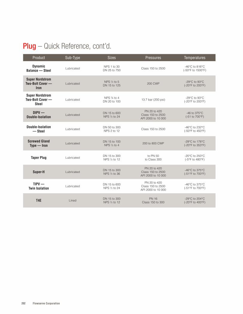
Flowserve Corporation202
Product Sub-Type Sizes Pressures Temperatures
Dynamic Balance — Steel
Lubricated NPS 1 to 30DN 25 to 750 Class 150 to 2500 -46°C to 816°C
(-50°F to 1500°F)
Super Nordstrom Two-Bolt Cover —
Iron Lubricated NPS ½ to 5
DN 15 to 125 200 CWP -29°C to 93°C(-20°F to 200°F)
Super Nordstrom Two-Bolt Cover —
SteelLubricated NPS ¾ to 4
DN 20 to 100 13 .7 bar (200 psi) -29°C to 93°C(-20°F to 200°F)
DIPV —Double-Isolation
Lubricated DN 15 to 600NPS ½ to 24
PN 20 to 420Class 150 to 2500API 2000 to 10 000
-46 to 375°C(-51 to 700°F)
Double-Isolation — Steel
Lubricated DN 50 to 300NPS 2 to 12 Class 150 to 2500 -46°C to 232°C
(-50°F to 450°F)
Screwed Gland Type — Iron
Lubricated DN 15 to 100NPS ½ to 4 200 to 800 CWP -29°C to 178°C
(-20°F to 353°F)
Taper Plug Lubricated DN 15 to 300NPS ½ to 12
to PN 50to Class 300
-20°C to 250°C(-5°F to 480°F)
Super-H Lubricated DN 15 to 300NPS ½ to 36
PN 20 to 420Class 150 to 2500API 2000 to 10 000
-46°C to 375°C(-51°F to 700°F)
TIPV — Twin Isolation
Lubricated DN 15 to 600NPS ½ to 24
PN 20 to 420Class 150 to 2500API 2000 to 10 000
-46°C to 375°C(-51°F to 700°F)
T4E Lined DN 15 to 300NPS ½ to 12
PN 16Class 150 to 300
-29°C to 204°C(-20°F to 400°F)
Plug – Quick Reference, cont’d.

203flowserve.com
VALVES | PLUG
SPECIFICATIONS
Sizes: DN 25 to 200; NPS 1 to 8Press: PN 10, 16, 25, 40 and 100; Class 150, 300 and 600Temp: -46°C to 274°C (-50°F to 525°F)
Refer to literature DVATB0030 at flowserve.com/library.
• Dependable, tight shutoff and in-line seal adjustment from tapered plug design• Reduced actuation costs from lower constant turning torques owing to unique
plug and sleeve design• Lower maintenance costs with in-line seat replacement • High-temperature and high-pressure capabilities to 274°C (525°F) and Class
600 (derated)• Ease of operation enabled by ISO 5211 mounting pad with universal flange and
double-D plug stem that accepts most standard actuation
N O N - L U B R I C A T E D
Mach 1 All-purpose, non-lubricated Sleeveline plug valve designed to provide reliable service with consistent, lower torques for cost-effective actuation.
Durco
Durco
SPECIFICATIONS
Sizes: DN 15 to 450; NPS ½ to 20Press: PN 10, 16, 25 and 40; Class 150 and 300 Temp: -46°C to 288°C (50°F to 550°F)
Refer to literature DVENBR0024 at flowserve.com/library.
• Dependable, tight shutoff and in-line seal adjustment from tapered plug design• Lower maintenance costs due to design that utilizes two adjuster fasteners that
permit in-line seal adjustments under pressure within seconds• Low fugitive emissions through fluoropolymer reverse-lip diaphragm that provides
a pressure-activated, self-energizing dynamic and static stem seal• Compatibility with a range of Automax™ actuators and other instrumentation• Options for lethal, toxic and sub-zero fluid services plus process control and high
flow requirements
N O N - L U B R I C A T E D
G4Reliable, versatile Sleeveline plug valve designed for the most corrosive and difficult chemical services where drop-tight shutoff is an absolute requirement.
Durco
SPECIFICATIONS
Sizes: DN 15 to 450; NPS ½ to 20Press: PN 10, 16, 25 and 40; Class 150 and 300Temp: -46°C to 288°C (-50°F to 550°F)
Refer to literature DVENTB0025 at flowserve.com/library.
• Corrosion-resistant Monel M35-1 and API 607 fire-sealed construction ideal for refinery applications that include HF and H2SO4 alkylation
• Dependable, tight shutoff and in-line seal adjustment from tapered plug design• Low fugitive emissions through fluoropolymer reverse-lip diaphragm that provides
a pressure-activated, self-energizing dynamic and static stem seal• Ease of operation enabled by compatibility with a wide range of Automax
actuators and other instrumentation
N O N - L U B R I C A T E D
G4Z-HF Reliable, HF alkylation plug value preferred at refineries throughout the world when drop-tight shutoff is an absolute requirement.

Flowserve Corporation204
PLUG
SPECIFICATIONS
Sizes: NPS ½ to 4, DN 15 to 100Press: Class 150 to 600Temp: -29°C to 177°C (-20°F to 350°F)
Refer to literature NVENBR1004 at flowserve.com/library.
• Greater process control provided by the bubble-tight shutoff and predictable torque• Increased uptime provided by the precisely controlled vertical lifting of the plug, which
eliminates its wedging without affecting tight shutoff• Durable performance via the specially shaped weather seal that protects the stem,
gland and packing from hostile environments and corrosion• Reliable operation enabled by the Sealdport™ sealant grooving system, designed to
give complete distribution of pressurized sealant to seating surfaces
L U B R I C A T E D
Super Nordstrom – SteelWell-tested, economical line of super-steel plug valves that provides dependable operations and eliminates the need for field readjustments.
Nordstrom
SPECIFICATIONS
Sizes: NPS ½ to 12; DN 15 to 300Press: PN 20 to 420; Class 150 to 2500; 150 to 400 CWP (iron) Temp: to 450°C (232°F)
Refer to literature NVABR0014 at flowserve.com/library.
• Low inventory carrying costs and convenient operations as a result of the simplified piping that eliminates the need for other fittings
• Broad application use via the ports and stops that can be arranged to fit required operating conditions
• Greater process control by eliminating waste, overpressure on equipment or incorrect mixtures due to the convenient design
• Efficient operation facilitated by the sealant grooves, which provide consistent lubrication while protecting against corrosion
L U B R I C A T E D
Multiport Series – Steel and IronDynamic Balance (steel), Super Nordstrom (steel) and Nordstrom Iron multiport plug valves are extremely efficient and designed for applications that ordinarily require two to four straightway valves.
Nordstrom
SPECIFICATIONS
Sizes: NPS 6 to 36; DN 150 to 900Press: 120 to 500 CWPTemp: -29°C to 177°C (-20°F to 350°F)
Refer to literature NVENBR1003 at flowserve.com/library.
• Reduced downtime as a result of sealant channels that provide lubrication and protect the seating surface against corrosion, erosion or accumulation of solids
• Greater process control provided by leak-free, easy turning performance of the gland, which flexes
• High-pressure performance made possible by the heavy-wall body, which can withstand higher-than-line sealant pressure and expected line stresses
• Reliable operation enabled by the Sealdport sealant grooving system, designed to give complete distribution of pressurized sealant to seating surfaces
L U B R I C A T E D
Bolted Gland – IronReliable bolted gland iron valve for applications in high-stress environments, such as gas, HVACI, wastewater, oil, steam and more.
Nordstrom
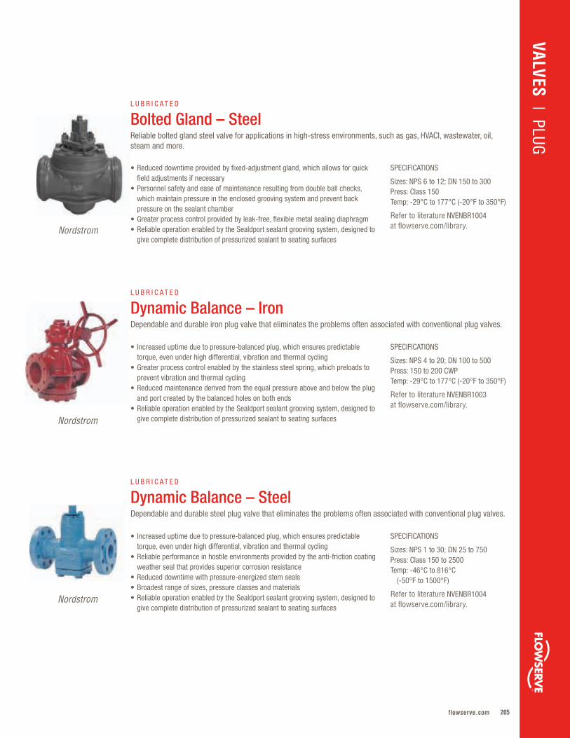
205flowserve.com
VALVES | PLUG
SPECIFICATIONS
Sizes: NPS 4 to 20; DN 100 to 500Press: 150 to 200 CWPTemp: -29°C to 177°C (-20°F to 350°F)
Refer to literature NVENBR1003 at flowserve.com/library.
• Increased uptime due to pressure-balanced plug, which ensures predictable torque, even under high differential, vibration and thermal cycling
• Greater process control enabled by the stainless steel spring, which preloads to prevent vibration and thermal cycling
• Reduced maintenance derived from the equal pressure above and below the plug and port created by the balanced holes on both ends
• Reliable operation enabled by the Sealdport sealant grooving system, designed to give complete distribution of pressurized sealant to seating surfaces
L U B R I C A T E D
Dynamic Balance – IronDependable and durable iron plug valve that eliminates the problems often associated with conventional plug valves.
Nordstrom
Nordstrom
SPECIFICATIONS
Sizes: NPS 6 to 12; DN 150 to 300Press: Class 150Temp: -29°C to 177°C (-20°F to 350°F)
Refer to literature NVENBR1004 at flowserve.com/library.
• Reduced downtime provided by fixed-adjustment gland, which allows for quick field adjustments if necessary
• Personnel safety and ease of maintenance resulting from double ball checks, which maintain pressure in the enclosed grooving system and prevent back pressure on the sealant chamber
• Greater process control provided by leak-free, flexible metal sealing diaphragm• Reliable operation enabled by the Sealdport sealant grooving system, designed to
give complete distribution of pressurized sealant to seating surfaces
L U B R I C A T E D
Bolted Gland – SteelReliable bolted gland steel valve for applications in high-stress environments, such as gas, HVACI, wastewater, oil, steam and more.
SPECIFICATIONS
Sizes: NPS 1 to 30; DN 25 to 750Press: Class 150 to 2500Temp: -46°C to 816°C (-50°F to 1500°F)
Refer to literature NVENBR1004 at flowserve.com/library.
• Increased uptime due to pressure-balanced plug, which ensures predictable torque, even under high differential, vibration and thermal cycling
• Reliable performance in hostile environments provided by the anti-friction coating weather seal that provides superior corrosion resistance
• Reduced downtime with pressure-energized stem seals• Broadest range of sizes, pressure classes and materials• Reliable operation enabled by the Sealdport sealant grooving system, designed to
give complete distribution of pressurized sealant to seating surfaces
L U B R I C A T E D
Dynamic Balance – SteelDependable and durable steel plug valve that eliminates the problems often associated with conventional plug valves.
Nordstrom
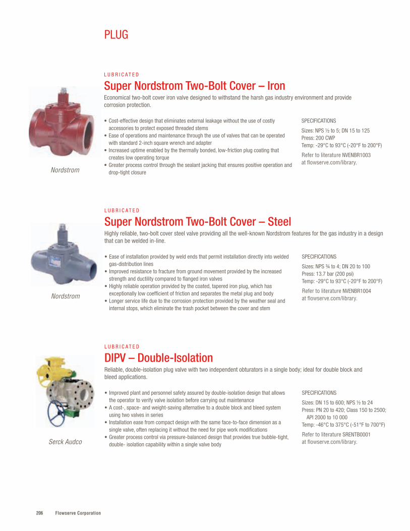
Flowserve Corporation206
PLUG
SPECIFICATIONS
Sizes: NPS ½ to 5; DN 15 to 125Press: 200 CWPTemp: -29°C to 93°C (-20°F to 200°F)
Refer to literature NVENBR1003 at flowserve.com/library.
• Cost-effective design that eliminates external leakage without the use of costly accessories to protect exposed threaded stems
• Ease of operations and maintenance through the use of valves that can be operated with standard 2-inch square wrench and adapter
• Increased uptime enabled by the thermally bonded, low-friction plug coating that creates low operating torque
• Greater process control through the sealant jacking that ensures positive operation and drop-tight closure
L U B R I C A T E D
Super Nordstrom Two-Bolt Cover – IronEconomical two-bolt cover iron valve designed to withstand the harsh gas industry environment and provide corrosion protection.
Nordstrom
SPECIFICATIONS
Sizes: NPS ¾ to 4; DN 20 to 100Press: 13.7 bar (200 psi)Temp: -29°C to 93°C (-20°F to 200°F)
Refer to literature NVENBR1004 at flowserve.com/library.
• Ease of installation provided by weld ends that permit installation directly into welded gas-distribution lines
• Improved resistance to fracture from ground movement provided by the increased strength and ductility compared to flanged iron valves
• Highly reliable operation provided by the coated, tapered iron plug, which has exceptionally low coefficient of friction and separates the metal plug and body
• Longer service life due to the corrosion protection provided by the weather seal and internal stops, which eliminate the trash pocket between the cover and stem
L U B R I C A T E D
Super Nordstrom Two-Bolt Cover – SteelHighly reliable, two-bolt cover steel valve providing all the well-known Nordstrom features for the gas industry in a design that can be welded in-line.
Nordstrom
SPECIFICATIONS
Sizes: DN 15 to 600; NPS ½ to 24Press: PN 20 to 420; Class 150 to 2500; API 2000 to 10 000Temp: -46°C to 375°C (-51°F to 700°F)
Refer to literature SRENTB0001 at flowserve.com/library.
• Improved plant and personnel safety assured by double-isolation design that allows the operator to verify valve isolation before carrying out maintenance
• A cost-, space- and weight-saving alternative to a double block and bleed system using two valves in series
• Installation ease from compact design with the same face-to-face dimension as a single valve, often replacing it without the need for pipe work modifications
• Greater process control via pressure-balanced design that provides true bubble-tight, double- isolation capability within a single valve body
L U B R I C A T E D
DIPV – Double-IsolationReliable, double-isolation plug valve with two independent obturators in a single body; ideal for double block and bleed applications.
Serck Audco
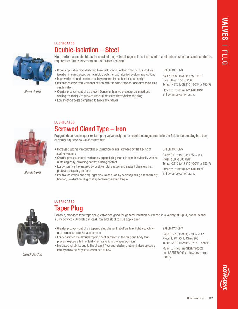
207flowserve.com
VALVES | PLUG
Nordstrom
SPECIFICATIONS
Sizes: DN 15 to 100; NPS ½ to 4Press: 200 to 800 CWPTemp: -29°C to 178°C (-20°F to 353°F)
Refer to literature NVENBR1003 at flowserve.com/library.
• Increased uptime via controlled plug motion design provided by the flexing of spring washers
• Greater process control enabled by tapered plug that is lapped individually with its matching body, providing perfect seating contact
• Longer service life assured by positive rotary action and sealant channels that protect the seating surfaces
• Positive operation and drop-tight closure ensured by sealant jacking and thermally bonded, low-friction plug coating for low operating torque
L U B R I C A T E D
Screwed Gland Type – IronRugged, dependable, quarter-turn plug valve designed to require no adjustments in the field once the plug has been carefully adjusted by valve assembler.
Nordstrom
SPECIFICATIONS
Sizes: DN 50 to 300; NPS 2 to 12Press: Class 150 to 2500Temp: -46°C to 232°C (-50°F to 450°F)
Refer to literature NVENBR1016 at flowserve.com/library.
• Broad application versatility due to robust design, making valve well-suited for isolation in compressor, pump, meter, water or gas injection system applications
• Improved plant and personnel safety assured by double-isolation design• Installation ease from compact design with the same face-to-face dimension as a
single valve• Greater process control via proven Dynamic Balance pressure-balanced and
sealing technology to prevent unequal pressure above/below the plug• Low lifecycle costs compared to two single valves
L U B R I C A T E D
Double-Isolation – SteelHigh-performance, double-isolation steel plug valve designed for critical shutoff applications where absolute shutoff is required for safety, environmental or process reasons.
Serck Audco
SPECIFICATIONS
Sizes: DN 15 to 300; NPS ½ to 12Press: to PN 50; to Class 300Temp: -20°C to 250°C (-5°F to 480°F)
Refer to literature SRENTB0002 and SRENTB0003 at flowserve.com/library.
• Greater process control via tapered plug design that offers leak tightness while maintaining smooth valve operation
• Longer service life through tapered seat surfaces of the plug and body that prevent exposure to line fluid when valve is in the open position
• Increased reliability due to the straight flow path design that minimizes pressure loss by allowing very little resistance to flow
L U B R I C A T E D
Taper PlugReliable, standard type taper plug valve designed for general isolation purposes in a variety of liquid, gaseous and slurry services. Available in cast iron and steel to suit application.
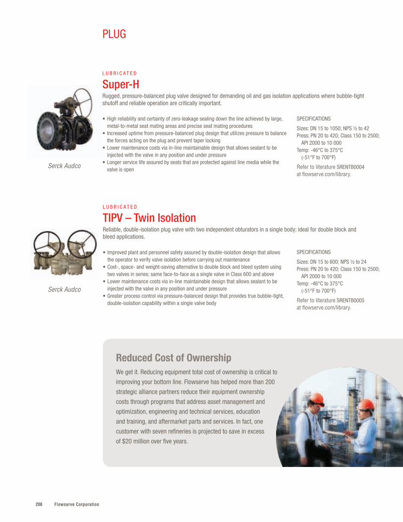
Flowserve Corporation208
PLUG
SPECIFICATIONS
Sizes: DN 15 to 1050; NPS ½ to 42Press: PN 20 to 420; Class 150 to 2500; API 2000 to 10 000Temp: -46°C to 375°C (-51°F to 700°F)
Refer to literature SRENTB0004 at flowserve.com/library.
• High reliability and certainty of zero-leakage sealing down the line achieved by large, metal-to-metal seat mating areas and precise seat mating procedures
• Increased uptime from pressure-balanced plug design that utilizes pressure to balance the forces acting on the plug and prevent taper locking
• Lower maintenance costs via in-line maintainable design that allows sealant to be injected with the valve in any position and under pressure
• Longer service life assured by seats that are protected against line media while the valve is open
L U B R I C A T E D
Super-HRugged, pressure-balanced plug valve designed for demanding oil and gas isolation applications where bubble-tight shutoff and reliable operation are critically important.
SPECIFICATIONS
Sizes: DN 15 to 600; NPS ½ to 24Press: PN 20 to 420; Class 150 to 2500; API 2000 to 10 000Temp: -46°C to 375°C (-51°F to 700°F)
Refer to literature SRENTB0005 at flowserve.com/library.
• Improved plant and personnel safety assured by double-isolation design that allows the operator to verify valve isolation before carrying out maintenance
• Cost-, space- and weight-saving alternative to double block and bleed system using two valves in series; same face-to-face as a single valve in Class 600 and above
• Lower maintenance costs via in-line maintainable design that allows sealant to be injected with the valve in any position and under pressure
• Greater process control via pressure-balanced design that provides true bubble-tight, double-isolation capability within a single valve body
L U B R I C A T E D
TIPV – Twin IsolationReliable, double-isolation plug valve with two independent obturators in a single body; ideal for double block and bleed applications.
Serck Audco
Serck Audco
Reduced Cost of OwnershipWe get it. Reducing equipment total cost of ownership is critical to
improving your bottom line. Flowserve has helped more than 200
strategic alliance partners reduce their equipment ownership
costs through programs that address asset management and
optimization, engineering and technical services, education
and training, and aftermarket parts and services. In fact, one
customer with seven refineries is projected to save in excess
of $20 million over five years.
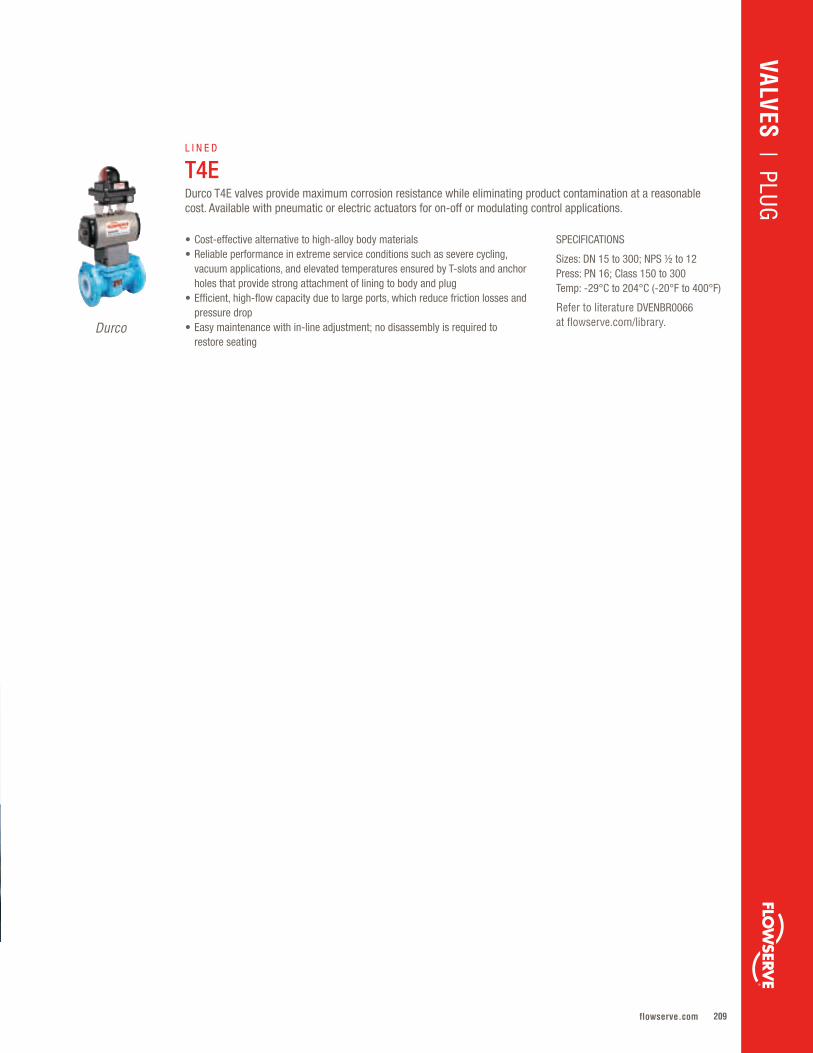
209flowserve.com
SPECIFICATIONS
Sizes: DN 15 to 300; NPS ½ to 12Press: PN 16; Class 150 to 300Temp: -29°C to 204°C (-20°F to 400°F)
Refer to literature DVENBR0066 at flowserve.com/library.
• Cost-effective alternative to high-alloy body materials • Reliable performance in extreme service conditions such as severe cycling,
vacuum applications, and elevated temperatures ensured by T-slots and anchor holes that provide strong attachment of lining to body and plug
• Efficient, high-flow capacity due to large ports, which reduce friction losses and pressure drop
• Easy maintenance with in-line adjustment; no disassembly is required to restore seating
L I N E D
T4EDurco T4E valves provide maximum corrosion resistance while eliminating product contamination at a reasonable cost. Available with pneumatic or electric actuators for on-off or modulating control applications.
Durco
VALVES | PLUG
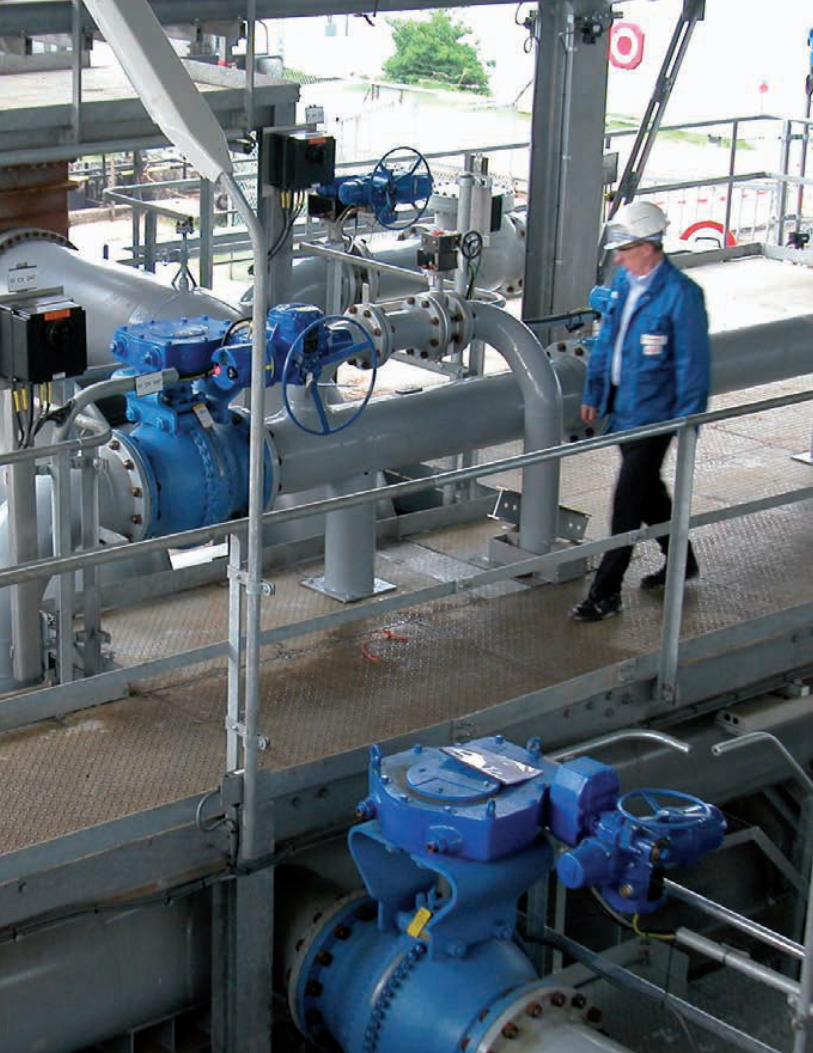
Flowserve Corporation210210
211flowserve.com
While pumps, seals and valves seem to
get most of the attention, it’s often the
actuators and positioning solutions that are
running the show . Fail-safe isolation . On-
off modulation . Precision process control .
These are the must-haves of fluid motion
and control, no matter how difficult or
remote the application .
Our actuator and positioning products are
equal parts durability and sophistication,
an ideal balance that delivers reliable valve
control in tough, hazardous environments .
From small-footprint, compact electric
actuators to high-torque, high-speed, fluid-
powered products, every solution is built
to withstand its environment and deliver
industry-leading service life . Embedded
technologies make them easy to use and
set up . More importantly, operators can
readily identify and expedite solutions to
process and equipment issues through
advanced prognostics, diagnostics and
communications protocols .
ACTUATION & INSTRUMENTATION
Electric Actuation . . . . . . . . . . . . . . . . .212
Gearboxes . . . . . . . . . . . . . . . . . . . . . .220
Fluid Power Actuation . . . . . . . . . . . . .224
Positioners . . . . . . . . . . . . . . . . . . . . . .236
Switch Boxes . . . . . . . . . . . . . . . . . . . .244
Software . . . . . . . . . . . . . . . . . . . . . . .248
ACTUATIO
N &
INSTR
UM
ENTATIO
N
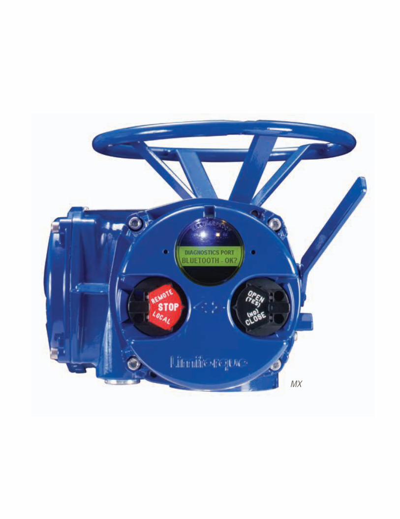
Flowserve Corporation212212
MX

213flowserve.com
ELECTRIC
Delivering unmatched positioning accuracy for control and modulating functions, Flowserve
electric actuators are the world’s first choice for some of the most challenging applications .
Compact, lightweight designs keep footprints small . Cost-effective capital investment is
matched by reduced costs for operation, control functions, maintenance, environmental
compliance and safety . Superior process monitoring, data logging and information feedback
options maximize efficiency and minimize downtime .
Product Sub-Type Torque Thrust Output Speed Temperatures
L120 Intrusive Multi-Turn
136 to 81 600 Nm(100 to 60 000 ft-lb)
4500 to 225 000 kN (10 000 to 500 000 lbf)
750 to 3000 rpm
-50°C to 65°C (-56°F to 150°F)
SMB Intrusive Multi-Turn
20 to 81 349 Nm(15 to 60 000 ft-lb)
36 to 2224 kN (8000 to 500 000 lbf)
1800 to 3600 rpm
-20°F to 150°F (-29°C to 66°C)
SB and SBD Intrusive Multi-Turn
353 to 11 253 Nm(260 to 8300 ft-lb)
62 to 1112 kN (14 000 to 250 000 lbf)
1800 to 3600 rpm
-20°F to 150°F (-29°C to 66°C)
QX Non-Intrusive, Quarter-Turn
54 to 2033 Nm(40 to 1500 ft-lb) — 5 to 120 s -55°C to 70°C
(-67°F to 156°F)
QXM Non-Intrusive, Multi-Turn
24 to 337 Nm(18 to 250 ft-lb)
3 to 40 kN (593 to 9065 lbf)
3 to 24 rpm
-30°C to 70°C (-22°F to 156°F)
MX Non-Intrusive, Multi-Turn
27 to 2307 Nm(20 to 1700 ft-lb)
35 to 333 kN (8000 to 75 000 lbf)
15 to 200 rpm
-60°C to 70°C (-76°F to 158°F)
Electric – Quick Reference*
* Additional products shown on next page
ACTUATIO
N &
INSTR
UM
ENTATIO
N | ELECTRIC
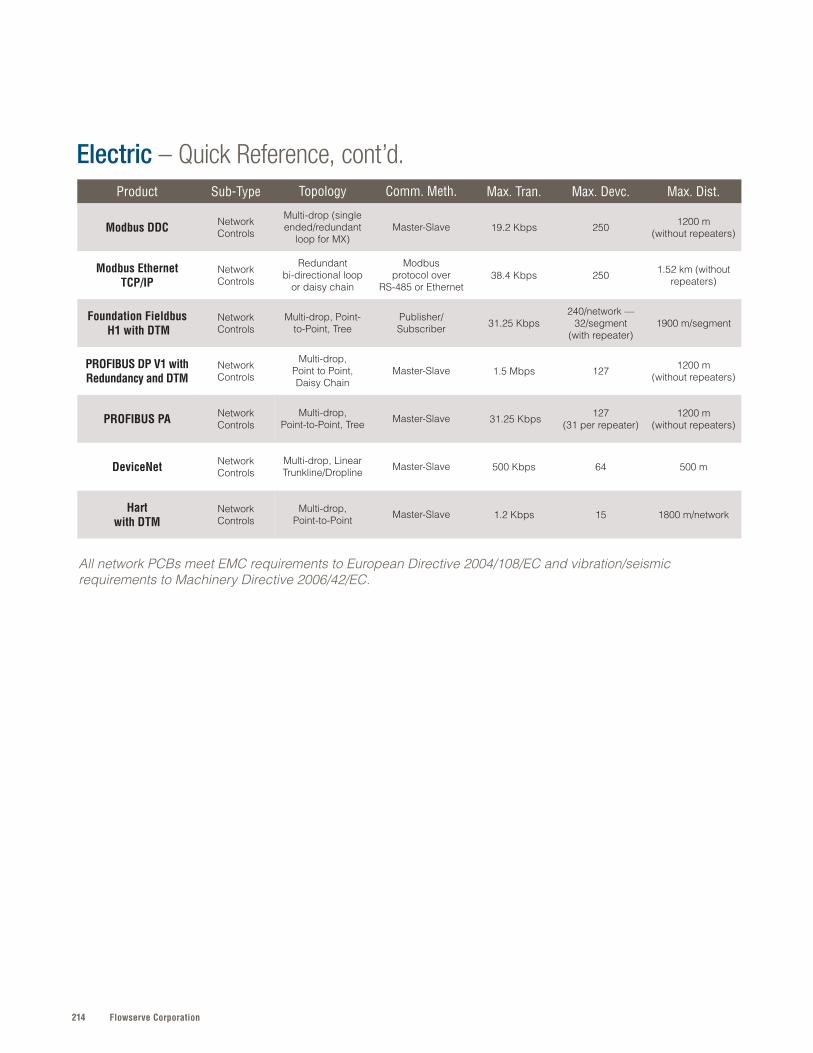
Flowserve Corporation214
Product Sub-Type Topology Comm. Meth. Max. Tran. Max. Devc. Max. Dist.
Modbus DDC Network Controls
Multi-drop (single ended/redundant
loop for MX)Master-Slave 19 .2 Kbps 250 1200 m
(without repeaters)
Modbus Ethernet TCP/IP
Network Controls
Redundant bi-directional loop
or daisy chain
Modbus protocol over
RS-485 or Ethernet38 .4 Kbps 250 1 .52 km (without
repeaters)
Foundation Fieldbus H1 with DTM
Network Controls
Multi-drop, Point-to-Point, Tree
Publisher/ Subscriber 31 .25 Kbps
240/network — 32/segment
(with repeater)1900 m/segment
PROFIBUS DP V1 with Redundancy and DTM
Network Controls
Multi-drop, Point to Point, Daisy Chain
Master-Slave 1 .5 Mbps 127 1200 m (without repeaters)
PROFIBUS PA Network Controls
Multi-drop, Point-to-Point, Tree Master-Slave 31 .25 Kbps 127
(31 per repeater)1200 m
(without repeaters)
DeviceNet Network Controls
Multi-drop, Linear Trunkline/Dropline Master-Slave 500 Kbps 64 500 m
Hart with DTM
Network Controls
Multi-drop, Point-to-Point Master-Slave 1 .2 Kbps 15 1800 m/network
Electric – Quick Reference, cont’d.
All network PCBs meet EMC requirements to European Directive 2004/108/EC and vibration/seismic requirements to Machinery Directive 2006/42/EC.
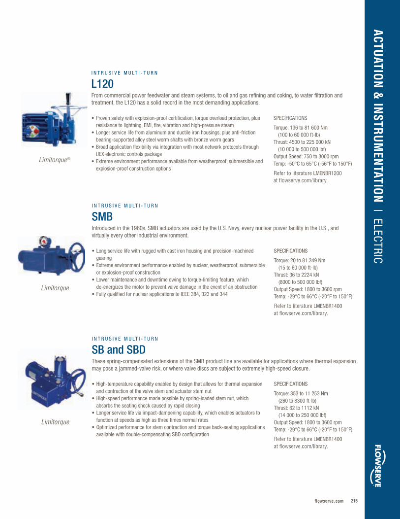
215flowserve.com
VALVES | LINEAR CO
NTRO
L
SPECIFICATIONS
Torque: 136 to 81 600 Nm (100 to 60 000 ft-lb)Thrust: 4500 to 225 000 kN (10 000 to 500 000 lbf)Output Speed: 750 to 3000 rpmTemp: -50°C to 65°C (-56°F to 150°F)
Refer to literature LMENBR1200 at flowserve.com/library.
• Proven safety with explosion-proof certification, torque overload protection, plus resistance to lightning, EMI, fire, vibration and high-pressure steam
• Longer service life from aluminum and ductile iron housings, plus anti-friction bearing-supported alloy steel worm shafts with bronze worm gears
• Broad application flexibility via integration with most network protocols through UEX electronic controls package
• Extreme environment performance available from weatherproof, submersible and explosion-proof construction options
SPECIFICATIONS
Torque: 20 to 81 349 Nm (15 to 60 000 ft-lb) Thrust: 36 to 2224 kN (8000 to 500 000 lbf)Output Speed: 1800 to 3600 rpmTemp: -29°C to 66°C (-20°F to 150°F)
Refer to literature LMENBR1400 at flowserve.com/library.
SPECIFICATIONS
Torque: 353 to 11 253 Nm (260 to 8300 ft-lb)Thrust: 62 to 1112 kN (14 000 to 250 000 lbf)Output Speed: 1800 to 3600 rpmTemp: -29°C to 66°C (-20°F to 150°F)
Refer to literature LMENBR1400 at flowserve.com/library.
• Long service life with rugged with cast iron housing and precision-machined gearing
• Extreme environment performance enabled by nuclear, weatherproof, submersible or explosion-proof construction
• Lower maintenance and downtime owing to torque-limiting feature, which de-energizes the motor to prevent valve damage in the event of an obstruction
• Fully qualified for nuclear applications to IEEE 384, 323 and 344
• High-temperature capability enabled by design that allows for thermal expansion and contraction of the valve stem and actuator stem nut
• High-speed performance made possible by spring-loaded stem nut, which absorbs the seating shock caused by rapid closing
• Longer service life via impact-dampening capability, which enables actuators to function at speeds as high as three times normal rates
• Optimized performance for stem contraction and torque back-seating applications available with double-compensating SBD configuration
I N T R U S I V E M U LT I - T U R N
SMBIntroduced in the 1960s, SMB actuators are used by the U.S. Navy, every nuclear power facility in the U.S., and virtually every other industrial environment.
I N T R U S I V E M U LT I - T U R N
SB and SBDThese spring-compensated extensions of the SMB product line are available for applications where thermal expansion may pose a jammed-valve risk, or where valve discs are subject to extremely high-speed closure.
I N T R U S I V E M U LT I - T U R N
L120From commercial power feedwater and steam systems, to oil and gas refining and coking, to water filtration and treatment, the L120 has a solid record in the most demanding applications.
ACTUATIO
N &
INSTR
UM
ENTATIO
N | ELECTRIC
Limitorque ®
Limitorque
Limitorque
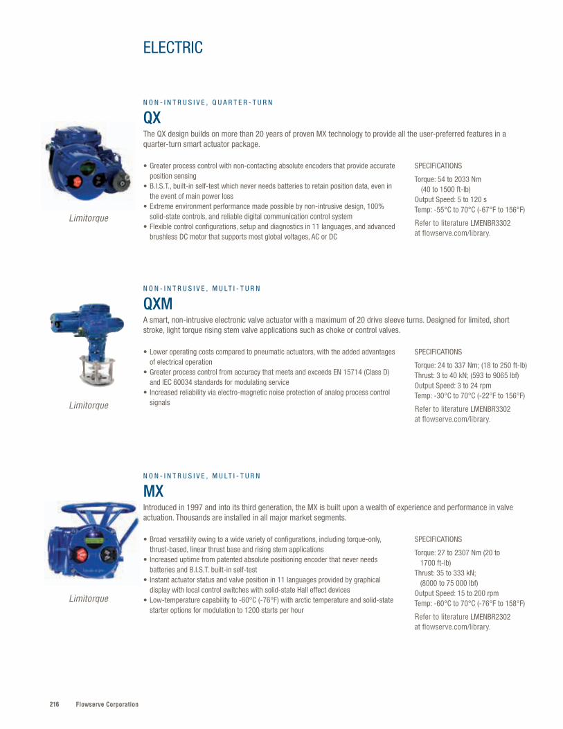
Flowserve Corporation216
SPECIFICATIONS
Torque: 24 to 337 Nm; (18 to 250 ft-lb)Thrust: 3 to 40 kN; (593 to 9065 lbf)Output Speed: 3 to 24 rpmTemp: -30°C to 70°C (-22°F to 156°F)
Refer to literature LMENBR3302 at flowserve.com/library.
• Lower operating costs compared to pneumatic actuators, with the added advantages of electrical operation
• Greater process control from accuracy that meets and exceeds EN 15714 (Class D) and IEC 60034 standards for modulating service
• Increased reliability via electro-magnetic noise protection of analog process control signals
N O N - I N T R U S I V E , M U LT I - T U R N
QXMA smart, non-intrusive electronic valve actuator with a maximum of 20 drive sleeve turns. Designed for limited, short stroke, light torque rising stem valve applications such as choke or control valves.
Limitorque
SPECIFICATIONS
Torque: 54 to 2033 Nm (40 to 1500 ft-lb)Output Speed: 5 to 120 sTemp: -55°C to 70°C (-67°F to 156°F)
Refer to literature LMENBR3302 at flowserve.com/library.
• Greater process control with non-contacting absolute encoders that provide accurate position sensing
• B.I.S.T., built-in self-test which never needs batteries to retain position data, even in the event of main power loss
• Extreme environment performance made possible by non-intrusive design, 100% solid-state controls, and reliable digital communication control system
• Flexible control configurations, setup and diagnostics in 11 languages, and advanced brushless DC motor that supports most global voltages, AC or DC
N O N - I N T R U S I V E , Q U A R T E R - T U R N
QXThe QX design builds on more than 20 years of proven MX technology to provide all the user-preferred features in a quarter-turn smart actuator package.
Limitorque
SPECIFICATIONS
Torque: 27 to 2307 Nm (20 to 1700 ft-lb)Thrust: 35 to 333 kN; (8000 to 75 000 lbf)Output Speed: 15 to 200 rpmTemp: -60°C to 70°C (-76°F to 158°F)
Refer to literature LMENBR2302 at flowserve.com/library.
• Broad versatility owing to a wide variety of configurations, including torque-only, thrust-based, linear thrust base and rising stem applications
• Increased uptime from patented absolute positioning encoder that never needs batteries and B.I.S.T. built-in self-test
• Instant actuator status and valve position in 11 languages provided by graphical display with local control switches with solid-state Hall effect devices
• Low-temperature capability to -60°C (-76°F) with arctic temperature and solid-state starter options for modulation to 1200 starts per hour
N O N - I N T R U S I V E , M U LT I - T U R N
MXIntroduced in 1997 and into its third generation, the MX is built upon a wealth of experience and performance in valve actuation. Thousands are installed in all major market segments.
Limitorque
ELECTRIC
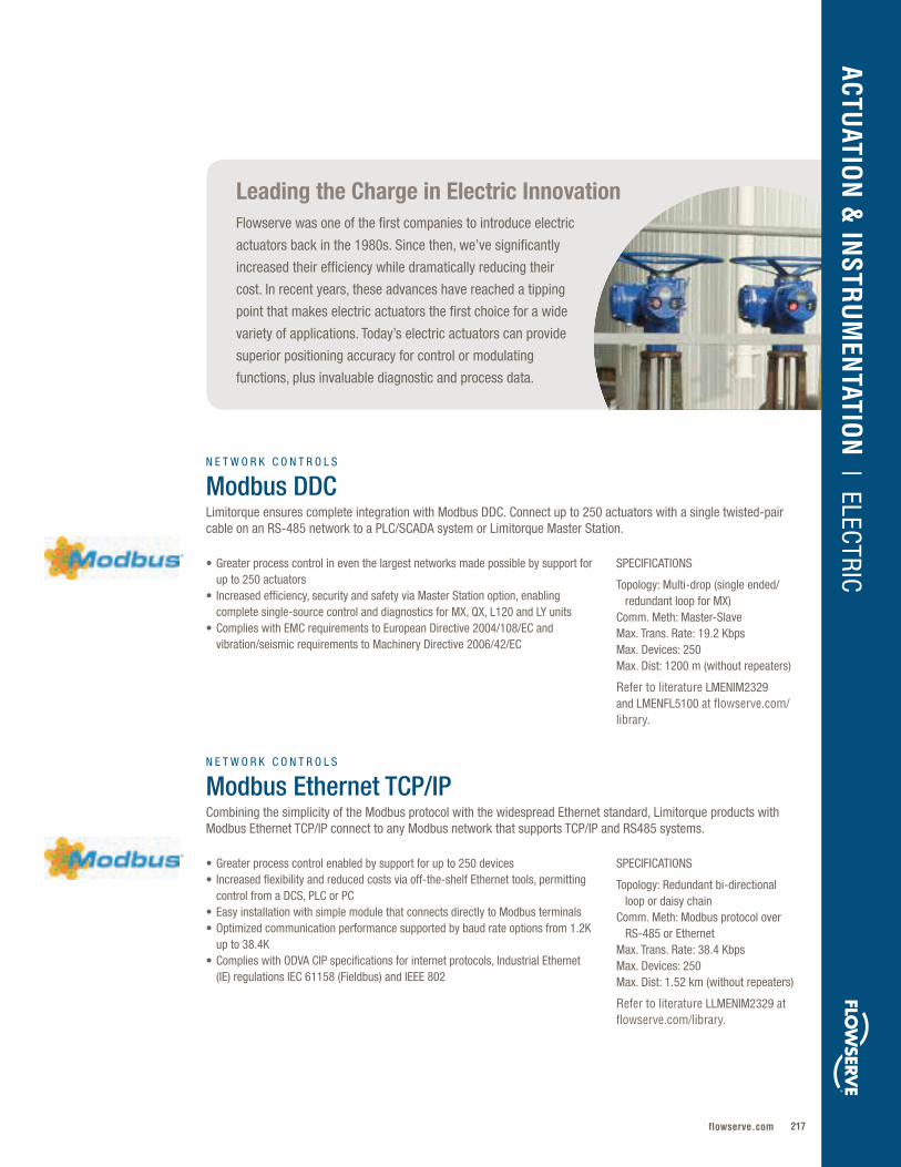
217flowserve.com
VALVES | LINEAR CO
NTRO
L
Leading the Charge in Electric InnovationFlowserve was one of the first companies to introduce electric
actuators back in the 1980s. Since then, we’ve significantly
increased their efficiency while dramatically reducing their
cost. In recent years, these advances have reached a tipping
point that makes electric actuators the first choice for a wide
variety of applications. Today’s electric actuators can provide
superior positioning accuracy for control or modulating
functions, plus invaluable diagnostic and process data.
SPECIFICATIONS
Topology: Multi-drop (single ended/ redundant loop for MX)Comm. Meth: Master-Slave Max. Trans. Rate: 19.2 KbpsMax. Devices: 250Max. Dist: 1200 m (without repeaters)
Refer to literature LMENIM2329 and LMENFL5100 at flowserve.com/library.
SPECIFICATIONS
Topology: Redundant bi-directional loop or daisy chainComm. Meth: Modbus protocol over RS-485 or Ethernet Max. Trans. Rate: 38.4 KbpsMax. Devices: 250Max. Dist: 1.52 km (without repeaters)
Refer to literature LLMENIM2329 at flowserve.com/library.
• Greater process control in even the largest networks made possible by support for up to 250 actuators
• Increased efficiency, security and safety via Master Station option, enabling complete single-source control and diagnostics for MX, QX, L120 and LY units
• Complies with EMC requirements to European Directive 2004/108/EC and vibration/seismic requirements to Machinery Directive 2006/42/EC
• Greater process control enabled by support for up to 250 devices• Increased flexibility and reduced costs via off-the-shelf Ethernet tools, permitting
control from a DCS, PLC or PC• Easy installation with simple module that connects directly to Modbus terminals • Optimized communication performance supported by baud rate options from 1.2K
up to 38.4K • Complies with ODVA CIP specifications for internet protocols, Industrial Ethernet
(IE) regulations IEC 61158 (Fieldbus) and IEEE 802
N E T W O R K C O N T R O L S
Modbus DDCLimitorque ensures complete integration with Modbus DDC. Connect up to 250 actuators with a single twisted-pair cable on an RS-485 network to a PLC/SCADA system or Limitorque Master Station.
N E T W O R K C O N T R O L S
Modbus Ethernet TCP/IPCombining the simplicity of the Modbus protocol with the widespread Ethernet standard, Limitorque products with Modbus Ethernet TCP/IP connect to any Modbus network that supports TCP/IP and RS485 systems.
ACTUATIO
N &
INSTR
UM
ENTATIO
N | ELECTRIC
®
®
Flowserve Corporation218
SPECIFICATIONS
Topology: Multi-drop, Tree, Point-to-PointComm. Meth: Master-Slave Max. Trans. Rate: 31.25 KbpsMax. Devices: 127 (31 per repeater)Max. Dist: 1200 m (without repeaters)
Refer to literature LMENIM2336 at flowserve.com/library.
• Broad application flexibility via analog and digital input/output function blocks• Ease of installation and setup made possible by direct connection to PLC or DCS
systems from major manufacturers, including Emerson, Honeywell, ABB and Yokogawa• Increased performance, safety and environmental compliance from Flowserve
ValveSight support• Complies with EMC requirements to European Directive 2004/108/EC and vibration/
seismic requirements to Machinery Directive 2006/42/EC
N E T W O R K C O N T R O L S
PROFIBUS PALimitorque actuators with PROFIBUS PA are used to monitor and control process automation applications.
ELECTRIC
SPECIFICATIONS
Topology: Multi-drop, Point-to-Point, Daisy Chain Comm. Meth: Master-Slave Max. Trans. Rate: 1.5 MbpsMax. Devices: 127Max. Dist: 1200 m (without repeaters)
Refer to literature LMENIM2339 and LMENFL2336 at flowserve.com/library.
• Reduced maintenance and related operating costs via intuitive software that proactively identifies maintenance needs, preventing unscheduled shutdowns
• Increased efficiency enabled by network that allows users to communicate in real time with every device and monitor diagnostics information, including alarms
• Complies with EMC requirements to European Directive 2004/108/EC• Complies with Profibus specification, Slave-Redundancy_2.212_v12 and transfers
communication for both flying and system redundancy in ≤ 500 ms per specification• Supports NAMUR NE-107
N E T W O R K C O N T R O L S
PROFIBUS DP V1 with Redundancy and DTMLimitorque actuators with PROFIBUS DP are designed to operate sensors and actuators via a centralized controller in production (factory) automation applications.
SPECIFICATIONS
Topology: Multi-drop, Tree, Point-to-PointComm. Meth: Publisher/Subscriber Max. Trans. Rate: 31.25 KbpsMax. Devices: 240/network; 32/segment (with repeater)Max. Dist: 1900 m/segment
Refer to literature LMENIM2330 at flowserve.com/library.
• Broad network versatility from support for multiple topologies, including point-to-point, bus with spurs, daisy chain, tree or combinations of these
• Ease of installation and setup with direct connection to PLC or DCS systems from major manufacturers, including Emerson, Honeywell, ABB, GE and Yokogawa
• Increased performance, safety and environmental compliance from Flowserve ValveSightTM support
• Complies with EMC requirements to European Directive 2004/108/EC and vibration/seismic requirements to Machinery Directive 2006/42/EC
N E T W O R K C O N T R O L S
Foundation Fieldbus H1 with DTMLimitorque actuators with Foundation Fieldbus can act as a link active scheduler and time master for regulating communication on a fieldbus segment.
219flowserve.com
VALVES | LINEAR CO
NTRO
L
SPECIFICATIONS
Topology: Multi-drop, Linear Trunkline/DroplineComm. Meth: Master-Slave Max. Trans. Rate: 500 KbpsMax. Devices: 64Max. Dist: 500 m
Refer to literature LMENIM2328 at flowserve.com/library.
• Broad application flexibility via support for multiple communication hierarchies and message prioritization
• Greater reliability and reduced downtime assured by cyclic redundancy checking (CRC), auto retries, and bus-powered network interface that allows alarm information to be communicated when actuator loses main power
• Complies with EMC requirements to European Directive 2004/108/EC and vibration/seismic requirements to Machinery Directive 2006/42/EC
N E T W O R K C O N T R O L S
DeviceNetLimitorque actuators integrate seamlessly with DeviceNet. DeviceNet is a digital, multi-drop network that connects and serves as a communication network between industrial controllers and field devices.
ACTUATIO
N &
INSTR
UM
ENTATIO
N | ELECTRICSPECIFICATIONS
Topology: Multi-drop, Point-to-Point Comm. Meth: Master-Slave Max. Trans. Rate: 1.2 KbpsMax. Devices: 15Max. Dist: 1800 m/Network
Refer to literature LMENFL2340 or LMENIM2340 at flowserve.com/library.
• Greater process control, asset management efficiency and safety made possible by enabling the use of both centralized control/monitoring and smart field devices
• Faster diagnostic feedback and summaries due to burst mode that enables response of up to three commands continuously
• Complies with EMC requirements to European Directive 2004/108/EC and vibration/seismic requirements to Machinery Directive 2006/42/EC
N E T W O R K C O N T R O L S
Hart with DTMLimitorque actuators with HART (Highway Addressable Remote Transducer) allow secondary masters, such as handheld communicators, to be connected without interfering with the plant control system.
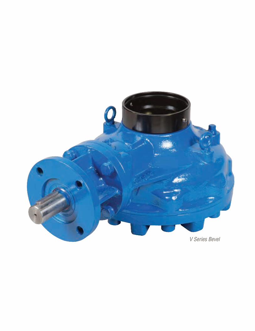
Flowserve Corporation220220
V Series Bevel
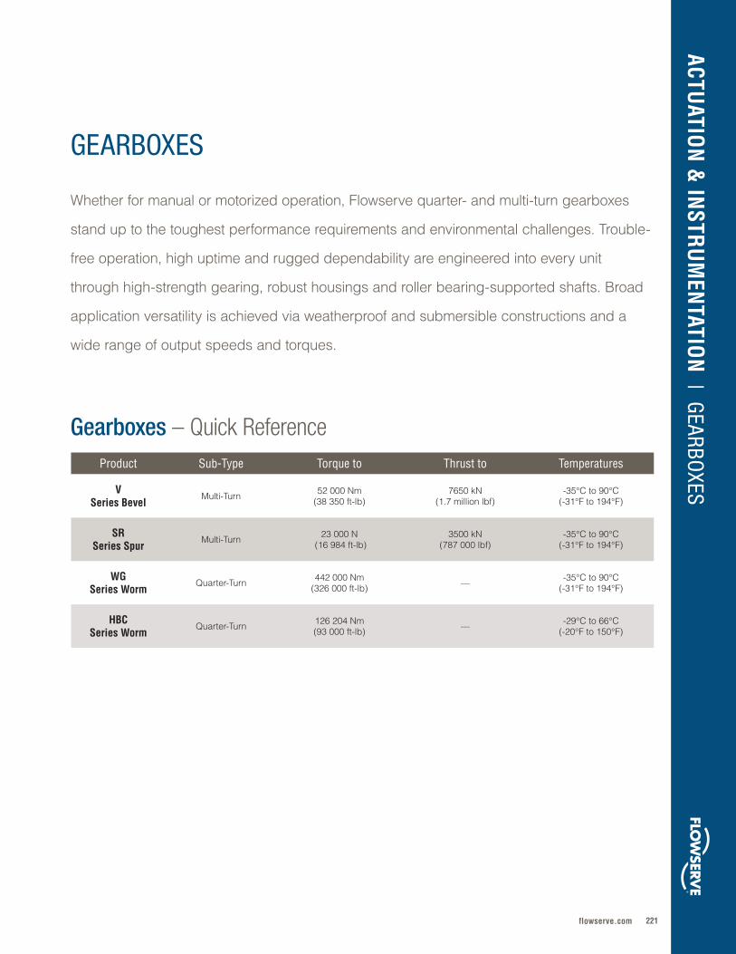
221flowserve.com
Whether for manual or motorized operation, Flowserve quarter- and multi-turn gearboxes
stand up to the toughest performance requirements and environmental challenges . Trouble-
free operation, high uptime and rugged dependability are engineered into every unit
through high-strength gearing, robust housings and roller bearing-supported shafts . Broad
application versatility is achieved via weatherproof and submersible constructions and a
wide range of output speeds and torques .
GEARBOXES
Gearboxes – Quick Reference
ACTUATIO
N &
INSTR
UM
ENTATIO
N | GEARBOXES
Product Sub-Type Torque to Thrust to Temperatures
VSeries Bevel
Multi-Turn 52 000 Nm(38 350 ft-lb)
7650 kN(1 .7 million lbf)
-35°C to 90°C(-31°F to 194°F)
SRSeries Spur
Multi-Turn 23 000 N (16 984 ft-lb)
3500 kN(787 000 lbf)
-35°C to 90°C(-31°F to 194°F)
WGSeries Worm
Quarter-Turn 442 000 Nm(326 000 ft-lb) — -35°C to 90°C
(-31°F to 194°F)
HBCSeries Worm
Quarter-Turn 126 204 Nm(93 000 ft-lb) — -29°C to 66°C
(-20°F to 150°F)
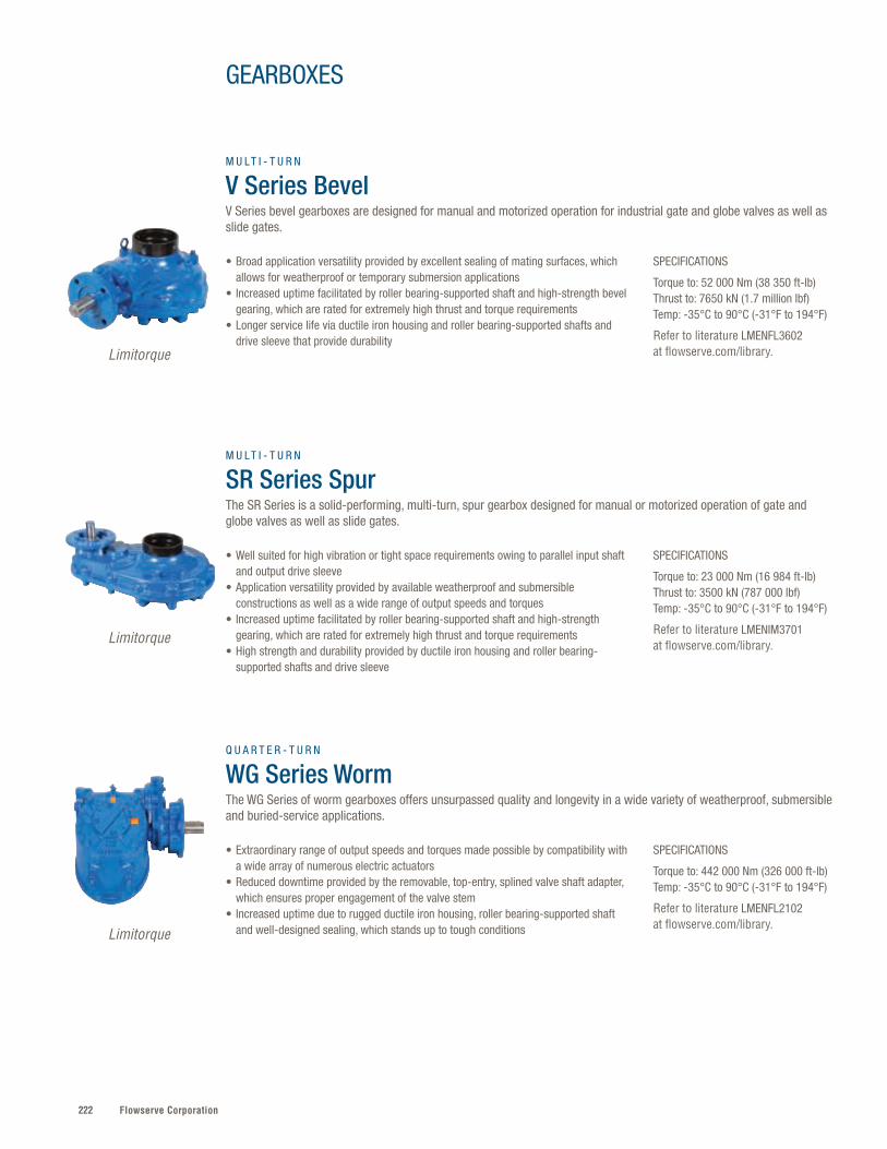
Flowserve Corporation222
• Extraordinary range of output speeds and torques made possible by compatibility with a wide array of numerous electric actuators
• Reduced downtime provided by the removable, top-entry, splined valve shaft adapter, which ensures proper engagement of the valve stem
• Increased uptime due to rugged ductile iron housing, roller bearing-supported shaft and well-designed sealing, which stands up to tough conditions
• Well suited for high vibration or tight space requirements owing to parallel input shaft and output drive sleeve
• Application versatility provided by available weatherproof and submersible constructions as well as a wide range of output speeds and torques
• Increased uptime facilitated by roller bearing-supported shaft and high-strength gearing, which are rated for extremely high thrust and torque requirements
• High strength and durability provided by ductile iron housing and roller bearing-supported shafts and drive sleeve
SPECIFICATIONS
Torque to: 442 000 Nm (326 000 ft-lb)Temp: -35°C to 90°C (-31°F to 194°F)
Refer to literature LMENFL2102 at flowserve.com/library.
SPECIFICATIONS
Torque to: 23 000 Nm (16 984 ft-lb)Thrust to: 3500 kN (787 000 lbf)Temp: -35°C to 90°C (-31°F to 194°F)
Refer to literature LMENIM3701 at flowserve.com/library.
Q U A R T E R - T U R N
WG Series Worm The WG Series of worm gearboxes offers unsurpassed quality and longevity in a wide variety of weatherproof, submersible and buried-service applications.
M U LT I - T U R N
SR Series SpurThe SR Series is a solid-performing, multi-turn, spur gearbox designed for manual or motorized operation of gate and globe valves as well as slide gates.
SPECIFICATIONS
Torque to: 52 000 Nm (38 350 ft-lb)Thrust to: 7650 kN (1.7 million lbf)Temp: -35°C to 90°C (-31°F to 194°F)
Refer to literature LMENFL3602 at flowserve.com/library.
• Broad application versatility provided by excellent sealing of mating surfaces, which allows for weatherproof or temporary submersion applications
• Increased uptime facilitated by roller bearing-supported shaft and high-strength bevel gearing, which are rated for extremely high thrust and torque requirements
• Longer service life via ductile iron housing and roller bearing-supported shafts and drive sleeve that provide durability
M U LT I - T U R N
V Series Bevel V Series bevel gearboxes are designed for manual and motorized operation for industrial gate and globe valves as well as slide gates.
Limitorque
Limitorque
Limitorque
GEARBOXES
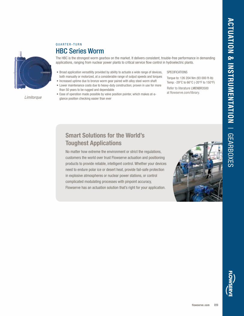
223flowserve.com
Smart Solutions for the World’s Toughest ApplicationsNo matter how extreme the environment or strict the regulations,
customers the world over trust Flowserve actuation and positioning
products to provide reliable, intelligent control. Whether your devices
need to endure polar ice or desert heat, provide fail-safe protection
in explosive atmospheres or nuclear power stations, or control
complicated modulating processes with pinpoint accuracy,
Flowserve has an actuation solution that’s right for your application.
SPECIFICATIONS
Torque to: 126 204 Nm (93 000 ft-lb)Temp: -29°C to 66°C (-20°F to 150°F)
Refer to literature LMENBR3500 at flowserve.com/library.
• Broad application versatility provided by ability to actuate a wide range of devices, both manually or motorized, at a considerable range of output speeds and torques
• Increased uptime due to bronze worm gear paired with alloy steel worm shaft• Lower maintenance costs due to heavy-duty construction; proven in use for more
than 50 years to be rugged and dependable• Ease of operation made possible by valve position pointer, which makes at-a-
glance position checking easier than ever
Q U A R T E R - T U R N
HBC Series WormThe HBC is the strongest worm gearbox on the market. It delivers consistent, trouble-free performance in demanding applications, ranging from nuclear power plants to critical service flow control in hydroelectric plants.
Limitorque
ACTUATIO
N &
INSTR
UM
ENTATIO
N | GEARBOXES

Flowserve Corporation224
40R
225flowserve.com
Whether you need fail-safe action, high-torque power or high-speed functionality, Flowserve
fluid power actuators are built for the world’s toughest jobs . Reliable operation, reduced
maintenance and longer service life are made possible by the simplicity, efficiency and
flexibility built into every design . From nuclear power plants to offshore drilling platforms,
the world’s most critical infrastructures rely on Flowserve for rugged, efficient actuators with
service lifespans of a quarter-century or more .
Product Sub-Type Torque Thrust MAWP Temperatures
LPS Pneumatic — Scotch Yoke
550 kNm (405 659 ft-lb) — 12 barg
(174 psig)-60°C to 160°C (-76°F to 320°F)
LPC Pneumatic — Scotch Yoke
5500 Nm (4057 ft-lb) — 12 barg
(174 psig)-60°C to 160°C (-76°F to 320°F)
RG, ARG and WRG
Pneumatic — Scotch Yoke
248 kNm(2 .2M in-lb) — 10 .3 barg
(150 psig)-55°C to 149°C (-67°F to 300°F)
Turnex™ Pneumatic — Linkage
60 to 20 000 Nm (44 to 1475 ft-lb) — 8 barg
(116 psig)
-30°C to 80°C (-22°F to 176°F); to -40°C
(-40°F) on request
F39 Pneumatic — Rack & Pinion
7100 Nm (62 835 in-lb) — 8 .3 barg
(120 psig)-40°C to 150°C (-40°F to 302°F)
40R Pneumatic — Rack & Pinion
7100 Nm (62 835 in-lb) — 8 .3 barg
(120 psig)-40°C to 150°C (-40°F to 302°F)
33R Pneumatic —Rack & Pinion
2309 Nm (20 436 in-lb) — 5 .5 barg
(80 psig)-40°C to 150°C(-40°F to 302°F)
Fluid Power – Quick Reference*
FLUID POWER
ACTUATIO
N &
INSTR
UM
ENTATIO
N | FLUID
POW
ER
* Additional products shown on next page

Flowserve Corporation226
Fluid Power – Quick Reference, cont’d.Product Sub-Type Torque Thrust MAWP Temperatures
P61 Pneumatic — Rack & Pinion
1063 Nm (9408 in-lb) — 8 .3 barg
(120 psig)-40°C to 150°C (-40°F to 302°F)
Supernova™ Pneumatic — Rack & Pinion
5005 Nm (44 294 in-lb) — 8 barg
(120 psig)-50°C to 150°C (-55°F to 302°F)
SXL Pneumatic — Rack & Pinion
765 Nm (6770 in-lb) — 8 .3 barg
(120 psig)-50°C to 150°C (-55°F to 302°F)
NR Pneumatic — Rotary
5 to 1285 Nm (43 to 11 381 in-lb) — 6 barg
(80 psig)-60°C to 70°C
(-76°F to 158°F)
VR Pneumatic — Rotary
8 to 4160 Nm (72 to 36 820 in-lb) — 10 .3 barg
(150 psig)-60°C to 177°C (-76°F to 350°F)
FlowAct™ Pneumatic — Linear — 0 .25 to 60 kN
(56 .2 to 13 488 .5 lbf)6 barg
(87 psig)-40°C to 80°C
(-40°F to 176°F)
VL Pneumatic — Linear — 15 .85 to 262 .53 kN
(3564 to 59 020 lbf) 10 .3 barg(150 psig)
-40°C to 177°C(-40°F to 350°F)
VL-C Pneumatic — Linear — 15 .85 to 134 .11 kN
(3564 to 30 150 lbf) 10 .3 barg(150 psig)
-40°C to 177°C(-40°F to 350°F)
VL-ES Pneumatic — Linear — 72 .73 to 166 .45 kN
(16 350 to 37 420 lbf)10 .3 barg(150 psig)
-40°C to 177°C(-40°F to 350°F)
VL-UHC Pneumatic — Linear — 15 .85 to 125 .88 kN
(3564 to 28 300 lbf)10 .3 barg(150 psig)
-40°C to 80°C(-40°F to 176°F)
Series 2 Type KP
Pneumatic — Linear — to 35 .0 kN (7868 lbf) 6 barg (87 psig) -40°C to 80°C
(-40°F to 176°F)
Series 4 Type KA
Pneumatic — Linear — to 25 .5 kN (5735 lbf) 1 .4 to 4 .2 barg
(20 to 60 psig)-30°C to 80°C
(-22°F to 176°F)
LHS and LHH Hydraulic 550 kNm (405 659 ft-lb)
345 barg (5000 psig)
-60°C to 160°C (-76°F to 320°F)
LDG Direct Gas 550 kNm (405 659 ft-lb)
105 barg (1500 psig)
-40°C to 160°C (-40°F to 320°F)

227flowserve.com
ACTUATIO
N &
INSTR
UM
ENTATIO
N | FLUID
POW
ER
SPECIFICATIONS
Torque: 550 kNm (405 659 ft-lb)MAWP: 12 barg (174 psig)Temp: -60°C to 160°C (-76°F to 320°F)
For more information, refer to LFENBR0001 or LFENFL0001.
Refer to literature LFENBR0001 or LFENFL0001 at flowserve.com/library.
• Low total cost of ownership provided by 25-year design life and maintenance intervals up to six years
• High-speed performance with reduced size, weight and consumption made possible by highly efficient design
• Modular construction allows easy on site maintenance without special tools and without removal from the valve
• Regulatory compliance with the highest industry standards, including EN 15714 and IEC 61508 (SIL 3 capable)
P N E U M A T I C — S C O T C H Y O K E
LPSIdeal for medium or large valve actuation and any application requiring robust design, long service life and high-speed operation. Meets the most stringent safety and performance standards for oil and gas applications.
SPECIFICATIONS
Torque: 5500 Nm (4057 ft-lb)MAWP: 12 barg (174 psig)Temp: -60°C to 160°C (-76°F to 320°F)
Refer to literature LFENBR0002 or LFENTB0002 at flowserve.com/library.
SPECIFICATIONS
Torque: 248 kNm (2.2M in-lb)MAWP: 10.3 barg (150 psig)Temp: -55°C to 149°C (-67°F to 300°F)
Refer to literature AXEBR1002 at flowserve.com/library.
• Low total cost of ownership provided by proven design with 25-year life cycle and maintenance intervals up to five years (or per EN 15714 endurance testing)
• Application versatility enabled by flexible field conversion from Fail Close CW to Fail Open CCW and easy retrofitting via specially designed coupling interface
• Superior reliability and durability above typical industry standards, thanks to heavy-duty design and excellent corrosion resistance
• Regulatory compliance with the toughest industry standards, including EN 15714 and ISO 9001
• Easier installation in tight spaces via pull-to-compress design and concentric nested spring configuration plus easy on-site field reconfiguration
• Increased efficiency from canted yoke and support system, which delivers approximately 20% higher break torque
• Greater process control via bidirectional travel stops that allow precise adjustment of open and closed positions
• Environmental protection assured by IP67M (temporary submersion) rating and marine-grade epoxy surface treatment
P N E U M A T I C — S C O T C H Y O K E
LPCSuitable for pneumatic on-off, light modulating and control applications of small or medium quarter-turn valves in general and protective services. Also useable in safety services up to SIL 3 in accordance with IEC 61508.
P N E U M A T I C — S C O T C H Y O K E
RG, ARG and WRGA ductile cast iron actuator series, ideal for general process and chemical applications where highly standardized pneumatic actuators are required. It offers more than 250 torque profiles and significantly reduces transverse loads.
Limitorque
Limitorque
AutomaxAccord ™
Worcester
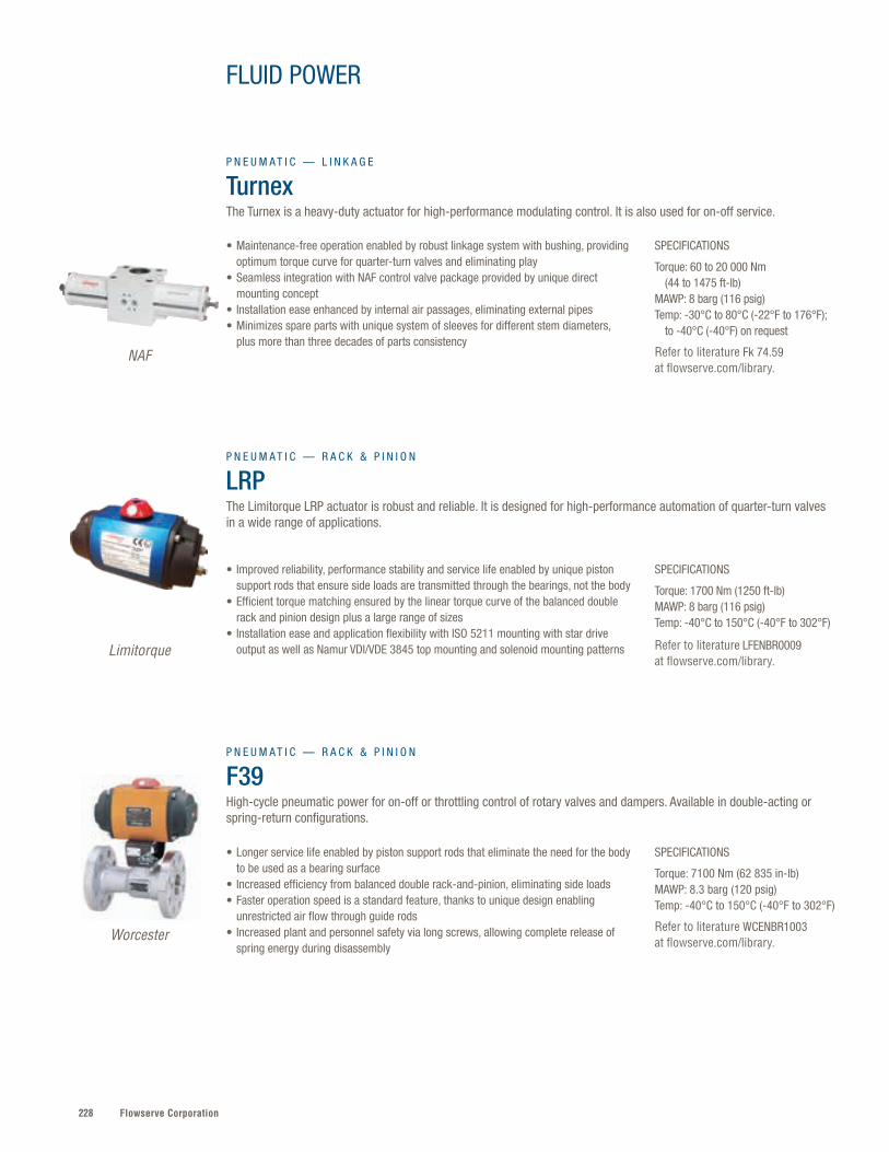
Flowserve Corporation228
SPECIFICATIONS
Torque: 60 to 20 000 Nm (44 to 1475 ft-lb)MAWP: 8 barg (116 psig)Temp: -30°C to 80°C (-22°F to 176°F); to -40°C (-40°F) on request
Refer to literature Fk 74.59 at flowserve.com/library.
SPECIFICATIONS
Torque: 1700 Nm (1250 ft-lb)MAWP: 8 barg (116 psig)Temp: -40°C to 150°C (-40°F to 302°F)
Refer to literature LFENBR0009 at flowserve.com/library.
SPECIFICATIONS
Torque: 7100 Nm (62 835 in-lb)MAWP: 8.3 barg (120 psig) Temp: -40°C to 150°C (-40°F to 302°F)
Refer to literature WCENBR1003 at flowserve.com/library.
• Maintenance-free operation enabled by robust linkage system with bushing, providing optimum torque curve for quarter-turn valves and eliminating play
• Seamless integration with NAF control valve package provided by unique direct mounting concept
• Installation ease enhanced by internal air passages, eliminating external pipes• Minimizes spare parts with unique system of sleeves for different stem diameters,
plus more than three decades of parts consistency
• Improved reliability, performance stability and service life enabled by unique piston support rods that ensure side loads are transmitted through the bearings, not the body
• Efficient torque matching ensured by the linear torque curve of the balanced double rack and pinion design plus a large range of sizes
• Installation ease and application flexibility with ISO 5211 mounting with star drive output as well as Namur VDI/VDE 3845 top mounting and solenoid mounting patterns
• Longer service life enabled by piston support rods that eliminate the need for the body to be used as a bearing surface
• Increased efficiency from balanced double rack-and-pinion, eliminating side loads• Faster operation speed is a standard feature, thanks to unique design enabling
unrestricted air flow through guide rods• Increased plant and personnel safety via long screws, allowing complete release of
spring energy during disassembly
P N E U M A T I C — L I N K A G E
TurnexThe Turnex is a heavy-duty actuator for high-performance modulating control. It is also used for on-off service.
P N E U M A T I C — R A C K & P I N I O N
LRPThe Limitorque LRP actuator is robust and reliable. It is designed for high-performance automation of quarter-turn valves in a wide range of applications.
P N E U M A T I C — R A C K & P I N I O N
F39High-cycle pneumatic power for on-off or throttling control of rotary valves and dampers. Available in double-acting or spring-return configurations.
FLUID POWER
NAF
Limitorque
Worcester
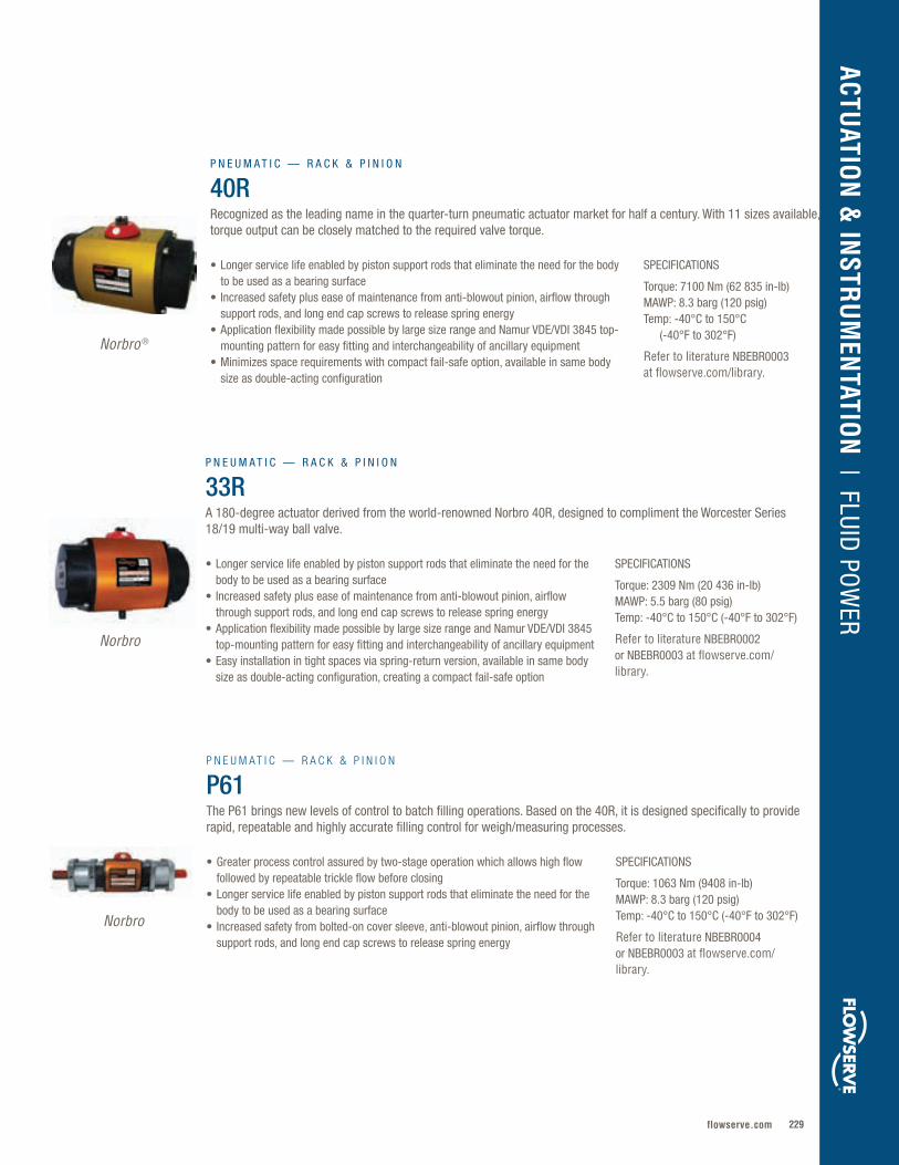
229flowserve.com
VALVES | LINEAR CO
NTRO
L
SPECIFICATIONS
Torque: 7100 Nm (62 835 in-lb)MAWP: 8.3 barg (120 psig) Temp: -40°C to 150°C (-40°F to 302°F)
Refer to literature NBEBR0003 at flowserve.com/library.
• Longer service life enabled by piston support rods that eliminate the need for the body to be used as a bearing surface
• Increased safety plus ease of maintenance from anti-blowout pinion, airflow through support rods, and long end cap screws to release spring energy
• Application flexibility made possible by large size range and Namur VDE/VDI 3845 top-mounting pattern for easy fitting and interchangeability of ancillary equipment
• Minimizes space requirements with compact fail-safe option, available in same body size as double-acting configuration
P N E U M A T I C — R A C K & P I N I O N
40RRecognized as the leading name in the quarter-turn pneumatic actuator market for half a century. With 11 sizes available, torque output can be closely matched to the required valve torque.
Norbro ®
ACTUATIO
N &
INSTR
UM
ENTATIO
N | FLUID
POW
ER
SPECIFICATIONS
Torque: 2309 Nm (20 436 in-lb)MAWP: 5.5 barg (80 psig) Temp: -40°C to 150°C (-40°F to 302°F)
Refer to literature NBEBR0002 or NBEBR0003 at flowserve.com/library.
• Longer service life enabled by piston support rods that eliminate the need for the body to be used as a bearing surface
• Increased safety plus ease of maintenance from anti-blowout pinion, airflow through support rods, and long end cap screws to release spring energy
• Application flexibility made possible by large size range and Namur VDE/VDI 3845 top-mounting pattern for easy fitting and interchangeability of ancillary equipment
• Easy installation in tight spaces via spring-return version, available in same body size as double-acting configuration, creating a compact fail-safe option
P N E U M A T I C — R A C K & P I N I O N
33RA 180-degree actuator derived from the world-renowned Norbro 40R, designed to compliment the Worcester Series 18/19 multi-way ball valve.
SPECIFICATIONS
Torque: 1063 Nm (9408 in-lb)MAWP: 8.3 barg (120 psig) Temp: -40°C to 150°C (-40°F to 302°F)
Refer to literature NBEBR0004 or NBEBR0003 at flowserve.com/library.
• Greater process control assured by two-stage operation which allows high flow followed by repeatable trickle flow before closing
• Longer service life enabled by piston support rods that eliminate the need for the body to be used as a bearing surface
• Increased safety from bolted-on cover sleeve, anti-blowout pinion, airflow through support rods, and long end cap screws to release spring energy
P N E U M A T I C — R A C K & P I N I O N
P61The P61 brings new levels of control to batch filling operations. Based on the 40R, it is designed specifically to provide rapid, repeatable and highly accurate filling control for weigh/measuring processes.
Norbro
Norbro

Flowserve Corporation230
FLUID POWER
SPECIFICATIONS
Torque: 5005 Nm (44 294 in-lb) MAWP: 8 barg (120 psig) Temp: -50°C to 150°C (-55°F to 302°F)
Refer to literature ACENBR0004 or ACENBR0001 at flowserve.com/library.
• Increased efficiency and cycle life from precision die-cast pistons with large cylinder bearings
• Greater precision and reliability assured by integral travel stops in both directions, plus 10 degrees of overtravel for precise adjustment
• Longer, trouble-free service life enabled by precision-extruded hard anodized aluminum body and a one-piece, factory-lubricated, nitride-protected pinion gear
• Ease and flexibility of installation via dual ISO 5211 mounting pattern
P N E U M A T I C — R A C K & P I N I O N
SupernovaSupernova ASAP series rack and pinion actuators are designed for butterfly, plug or ball valves, and offer one compact design for double acting and spring return.
Accord
Automax
Valtek
SPECIFICATIONS
Torque: 765 Nm (6770 in-lb)MAWP: 8.3 barg (120 psig) Temp: -50°C to 150°C (-55°F to 302°F)
Refer to literature LPR0006 at flowserve.com/library.
SPECIFICATIONS
Torque: 5 to 1285 Nm (43 to 11 381 in-lb) MAWP: 6 barg (80 psig)Temp: -60°C to 70°C (-76°F to 158°F)
Refer to literature VLENIM0064 at flowserve.com/library.
• Longer service life and lower maintenance cost from corrosion-resistant materials• Greater process control enabled by bi-directional travel stops, with 5° overtravel and
10° undertravel adjustment in each direction• Installation ease via ISO 5211 mounting with Namur VDE/VDI 3845 top-mounting
pattern for easy fitting and interchangeability of ancillary equipment
• Long operating life enabled by rolling diaphragm that creates minimal wear• Lower maintenance and parts cost assured by simple design• Increased efficiency from ISO 9001-compliant design, allowing direct mounting of
positioners for minimal lost motion
P N E U M A T I C — R A C K & P I N I O N
SXLIdeal for corrosive environments, the SXL Series utilizes a 316 stainless steel body with stainless steel or aluminum pistons and springs. Optional polished finishes for sanitary applications also available.
P N E U M A T I C — R O T A R Y
NRThe Flowserve Valtek NR diaphragm rotary actuator features excellent sensitivity that provides quick, accurate movements for precise control.
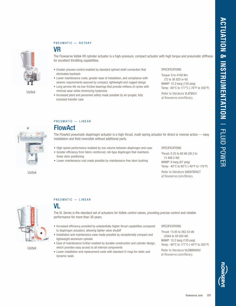
231flowserve.com
VALVES | LINEAR CO
NTRO
LACTU
ATION
& IN
STRU
MEN
TATION
| FLUID PO
WER
SPECIFICATIONS
Thrust: 0.25 to 60 kN (56.2 to 13 488.5 lbf)MAWP: 6 barg (87 psig)Temp: -40°C to 80°C (-40°F to 176°F)
Refer to literature SAENTBFACT at flowserve.com/library.
• High-speed performance enabled by low volume between diaphragm and case• Greater efficiency from fabric-reinforced, roll-type diaphragm that maintains
linear stem positioning• Lower maintenance cost made possible by maintenance-free stem bushing
P N E U M A T I C — L I N E A R
FlowActThe FlowAct pneumatic diaphragm actuator is a high-thrust, multi-spring actuator for direct or reverse action — easy installation and field reversible without additional parts.
SPECIFICATIONS
Thrust: 15.85 to 262.53 kN (3564 to 59 020 lbf) MAWP: 10.3 barg (150 psig)Temp: -40°C to 177°C (-40°F to 350°F)
Refer to literature VLENBR0002 at flowserve.com/library.
• Increased efficiency provided by substantially higher thrust capabilities compared to diaphragm actuators, allowing tighter valve shutoff
• Installation and maintenance ease made possible by exceptionally compact and lightweight aluminum cylinder
• Ease of maintenance further enabled by durable construction and cylinder design, which provides easy access to all internal components
• Lower installation and replacement costs with standard O-rings for static and dynamic seals
P N E U M A T I C — L I N E A R
VLThe VL Series is the standard set of actuators for Valtek control valves, providing precise control and reliable performance for more than 30 years.
Valtek
Valtek
Valtek
SPECIFICATIONS
Torque: 8 to 4160 Nm (72 to 36 820 in-lb) MAWP: 10.3 barg (150 psig) Temp: -60°C to 177°C (-76°F to 350°F)
Refer to literature VLATB031 at flowserve.com/library.
• Greater process control enabled by standard splined shaft connection that eliminates backlash
• Lower maintenance costs, greater ease of installation, and compliance with seismic requirements assured by compact, lightweight and rugged design
• Long service life via low-friction bearings that provide millions of cycles with minimal wear while minimizing hysteresis
• Increased plant and personnel safety made possible by air-purged, fully enclosed transfer case
P N E U M A T I C — R O T A R Y
VRThe Flowserve Valtek VR cylinder actuator is a high-pressure, compact actuator with high torque and pneumatic stiffness for excellent throttling capabilities.

Flowserve Corporation232
FLUID POWER
SPECIFICATIONS
Thrust: 15.85 to 134.11 kN (3564 to 30 150 lbf) MAWP: 10.3 barg (150 psig)Temp: -40°C to 177°C (-40°F to 350°F)
Refer to literature VLENBR0002 at flowserve.com/library.
• High performance enabled by replacing all aluminum parts with carbon steel• Lower maintenance costs and time from simple design• Broad nuclear application flexibility provided by a variety of options and
accessories, allowing the VL cylinder to fit into almost any application requiring high thrust and low maintenance
• Low inventory carrying costs enabled by lower-cost VL soft goods that are easier to find
P N E U M A T I C — L I N E A R
VL-COffering identical springs and all the advantages of Flowserve standard aluminum actuators, the VL-C replaces all aluminum parts with carbon steel.
Valtek
SPECIFICATIONS
Thrust: 72.73 to 166.45 kN (16 350 to 37 420 lbf) MAWP: 10.3 barg (150 psig)Temp: -40°C to 177°C (-40°F to 350°F)
Refer to literature VLENBR0002 at flowserve.com/library.
SPECIFICATIONS
Thrust: 15.85 to 125.88 kN (3564 to 28 300 lbf)MAWP: 10.3 barg (150 psig) Temp: -40°C to 80°C (-40°F to 176°F)
Refer to literature VLENBR0002 at flowserve.com/library.
• Longer service life — up to 2 million cycles — from dynamic quad seal design, stronger springs, plug stem jam nut, and thrust bearings that prevent windup
• Installation and maintenance ease made possible by exceptionally compact and lightweight aluminum cylinder
• Ease of maintenance via spring cylinder actuator design requiring the removal of just two parts to access all internal components
• Lower installation and replacement costs thanks to standard O-rings for static and dynamic seals
• Significantly longer service life provided by dynamic quad seals, plug stem jam nut, recessed O-ring adjusting screw seal, and stronger springs with stress-reducing thrust bearings
• Lower maintenance costs and time from simple design that requires removal of just two parts to access all internal components
• Broad nuclear application flexibility provided by a variety of options and accessories, allowing the VL cylinder to fit into almost any application requiring high thrust and low maintenance
P N E U M A T I C — L I N E A R
VL-UHCFor applications where ultra high cycle (UHC) life is needed, VL-UHC Series actuators offer up to 2 million full stroke cycles with periodic soft goods replacement.
P N E U M A T I C — L I N E A R
VL-ESUsing many of the same design concepts as the VL-C, the VL-ES offers external spring cans for applications where longer strokes or unusually high spring thrust are required.
Valtek
Valtek

233flowserve.com
VALVES | LINEAR CO
NTRO
LACTU
ATION
& IN
STRU
MEN
TATION
| FLUID PO
WER
SPECIFICATIONS
Thrust: to 35.0 kN (7868 lbf)MAWP: 6 barg (87 psig) Temp: -40°C to 80°C (-40°F to 176°F)
Refer to literature KMEEBR0021 at flowserve.com/library.
• Broad application versatility offered by a wide range of sizes, integrated options and accessories
• Increased durability from stainless steel material, which provides superior corrosion resistance, even without a protective coating
• Installation ease and flexibility enabled by compact variations with enclosed accessories
P N E U M A T I C — L I N E A R
Series 2 Type KPStainless steel actuators for standard use. Multi-spring design, fail-open or fail-close position, and various accessories such as handwheels or limit stops make the KP actuator a frequent choice among operators.
SPECIFICATIONS
Torque: to 550 kNm (405 659 ft-lb)MAWP: 345 barg (5000 psig) Temp: -60°C to 160°C (-76°F to 320°F)
Refer to literature LFENBR0003 and LFENFL0003 at flowserve.com/library.
• Longer service life and lower maintenance provided by proven design with 25-year life cycle and maintenance intervals up to six years
• Broad application versatility enabled by true modular design for flexible and easy field conversion
• Regulatory compliance assured by reliable design that meets a wide range of general service, protective service and safety application standards, including ESD / HIPPS and SIL Level 3 in accordance with IEC 61508
• Extreme environment performance available with polar or offshore variants
H Y D R A U L I C
LHS and LHHSuitable for on-off, modulating and control applications of quarter-turn valves in general and protective services. Also useable in safety services up to SIL 3 in accordance with IEC 61508.
Limitorque
SPECIFICATIONS
Thrust: to 25.5 kN (5735 lbf) MAWP: 1.4 to 4.2 barg (20 to 60 psig) Temp: -30°C to 80°C (-22°F to 176°F)
Refer to literature KMEEBR003 at flowserve.com/library.
• Lower maintenance costs made possible by rugged positioner and internal design that protects all moving parts against damage and dirt
• Increased plant and personnel safety enabled by multiple-spring design, improving safety of fail-safe mode
• Broad application versatility enabled by a wide variety of top-mounted options, including handwheels, proximity switches and electric switches
P N E U M A T I C — L I N E A R
Series 4 Type KACompared to other manufacturers’ diaphragm actuator designs, Series 4 offers much higher thrust, compact design and lighter weight. Field-reversible design may require no additional parts.
Kämmer
Kämmer ®
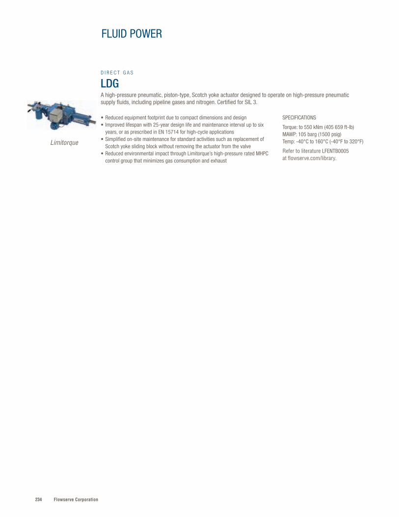
Flowserve Corporation234
FLUID POWER
SPECIFICATIONS
Torque: to 550 kNm (405 659 ft-lb)MAWP: 105 barg (1500 psig) Temp: -40°C to 160°C (-40°F to 320°F)
Refer to literature LFENTB0005 at flowserve.com/library.
• Reduced equipment footprint due to compact dimensions and design • Improved lifespan with 25-year design life and maintenance interval up to six
years, or as prescribed in EN 15714 for high-cycle applications• Simplified on-site maintenance for standard activities such as replacement of
Scotch yoke sliding block without removing the actuator from the valve• Reduced environmental impact through Limitorque’s high-pressure rated MHPC
control group that minimizes gas consumption and exhaust
D I R E C T G A S
LDGA high-pressure pneumatic, piston-type, Scotch yoke actuator designed to operate on high-pressure pneumatic supply fluids, including pipeline gases and nitrogen. Certified for SIL 3.
Limitorque
235flowserve.com
VALVES | LINEAR CO
NTRO
LACTU
ATION
& IN
STRU
MEN
TATION
| FLUID PO
WER
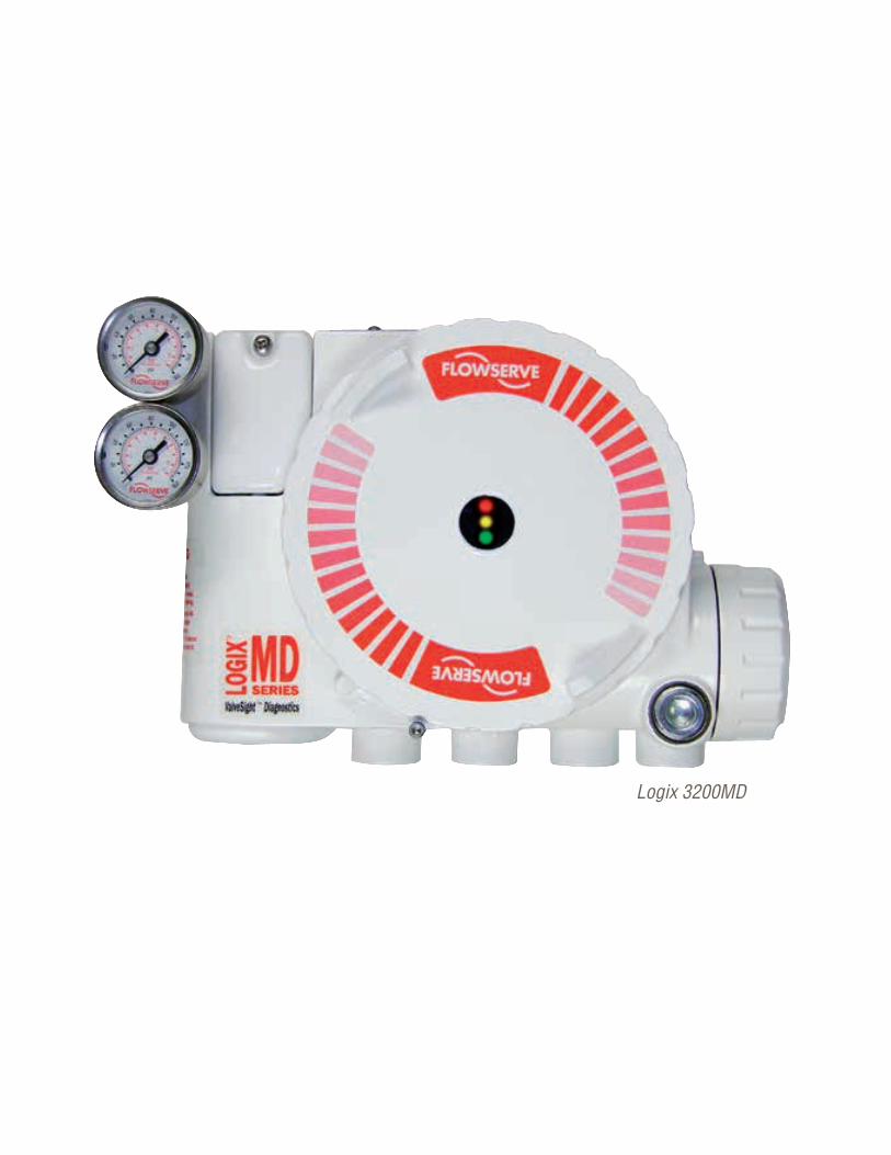
Flowserve Corporation236236
Logix 3200MD
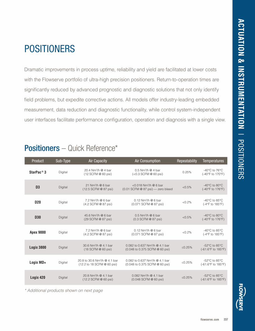
237flowserve.com
Product Sub-Type Air Capacity Air Consumption Repeatability Temperatures
StarPac ® 3 Digital 20 .4 Nm3/h @ 4 bar(12 SCFM @ 60 psi)
0 .5 Nm3/h @ 4 bar(<0 .3 SCFM @ 60 psi) 0 .25% -40°C to 76°C
(-40°F to 170°F)
D3 Digital 21 Nm3/h @ 6 bar (12 .5 SCFM @ 87 psi)
<0 .018 Nm3/h @ 6 bar (0 .01 SCFM @ 87 psi) — zero bleed <0 .5% -40°C to 80°C
(-40°F to 176°F)
D20 Digital 7 .2 Nm3/h @ 6 bar (4 .2 SCFM @ 87 psi)
0 .12 Nm3/h @ 6 bar(0 .071 SCFM @ 87 psi) <0 .2% -40°C to 85°C
(-4°F to 185°F)
D30 Digital 45 .6 Nm3/h @ 6 bar (29 SCFM @ 87 psi)
0 .5 Nm3/h @ 6 bar (0 .3 SCFM @ 87 psi) <0 .5% -40°C to 80°C
(-40°F to 176°F)
Apex 9000 Digital 7 .2 Nm3/h @ 6 bar(4 .2 SCFM @ 87 psi)
0 .12 Nm3/h @ 6 bar (0 .071 SCFM @ 87 psi) <0 .2% -40°C to 85°C
(-4°F to 185°F)
Logix 3800 Digital 30 .6 Nm3/h @ 4 .1 bar (18 SCFM @ 60 psi)
0 .082 to 0 .637 Nm3/h @ 4 .1 bar (0 .048 to 0 .375 SCFM @ 60 psi) ≤0 .25% -52°C to 85°C
(-61 .6°F to 185°F)
Logix MD+ Digital 20 .8 to 30 .6 Nm3/h @ 4 .1 bar(12 .2 to 18 SCFM @ 60 psi)
0 .082 to 0 .637 Nm3/h @ 4 .1 bar(0 .048 to 0 .375 SCFM @ 60 psi) ≤0 .25% -52°C to 85°C
(-61 .6°F to 185°F)
Logix 420 Digital 20 .8 Nm3/h @ 4 .1 bar(12 .2 SCFM @ 60 psi)
0 .082 Nm3/h @ 4 .1 bar (0 .048 SCFM @ 60 psi) ≤0 .25% -52°C to 85°C
(-61 .6°F to 185°F)
ACTUATIO
N &
INSTR
UM
ENTATIO
N | PO
SITION
ERS
POSITIONERS
Positioners – Quick Reference*
Dramatic improvements in process uptime, reliability and yield are facilitated at lower costs
with the Flowserve portfolio of ultra-high precision positioners . Return-to-operation times are
significantly reduced by advanced prognostic and diagnostic solutions that not only identify
field problems, but expedite corrective actions . All models offer industry-leading embedded
measurement, data reduction and diagnostic functionality, while control system-independent
user interfaces facilitate performance configuration, operation and diagnosis with a single view .
* Additional products shown on next page
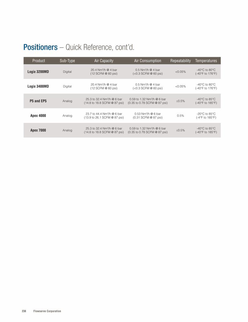
Flowserve Corporation238
Product Sub-Type Air Capacity Air Consumption Repeatability Temperatures
Logix 3200MD Digital 20 .4 Nm3/h @ 4 bar(12 SCFM @ 60 psi)
0 .5 Nm3/h @ 4 bar(<0 .3 SCFM @ 60 psi) <0 .05% -40°C to 80°C
(-40°F to 176°F)
Logix 3400MD Digital 20 .4 Nm3/h @ 4 bar(12 SCFM @ 60 psi)
0 .5 Nm3/h @ 4 bar(<0 .3 SCFM @ 60 psi) <0 .05% -40°C to 80°C
(-40°F to 176°F)
P5 and EP5 Analog 25 .3 to 32 .4 Nm3/h @ 6 bar (14 .8 to 18 .8 SCFM @ 87 psi)
0 .59 to 1 .32 Nm3/h @ 6 bar (0 .35 to 0 .78 SCFM @ 87 psi) ≤0 .5% -40°C to 85°C
(-40°F to 185°F)
Apex 4000 Analog 23 .7 to 44 .4 Nm3/h @ 6 bar (13 .9 to 26 .1 SCFM @ 87 psi)
0 .53 Nm3/h @ 6 bar (0 .31 SCFM @ 87 psi) 0 .5% -20°C to 85°C
(-4°F to 185°F)
Apex 7000 Analog 25 .3 to 32 .4 Nm3/h @ 6 bar (14 .8 to 18 .8 SCFM @ 87 psi)
0 .59 to 1 .32 Nm3/h @ 6 bar (0 .35 to 0 .78 SCFM @ 87 psi) ≤0 .5% -40°C to 85°C
(-40°F to 185°F)
Positioners – Quick Reference, cont’d.

239flowserve.com
SPECIFICATIONS
Air Cap: 21 Nm3/h @ 6 bar (12.5 SCFM @ 87 psi)Air Con: <0.018 Nm3/h @ 6 bar (0.01 SCFM @ 87 psi) – zero bleed Repeatability: <0.5%Temp: -40°C to 80°C (-40°F to 176°F)
Refer to literature PMENBR0001 or PMENBR0021 at flowserve.com/library.
• Lower operational cost made possible by zero-bleed pneumatic relay that enables very low air consumption to minimize electricity costs and meet EPA bleed limits for natural gas applications
• Installation and configuration ease enabled by friction clutch, five simple keys and large graphic LCD display
• Broad application versatility with Hart, PROFIBUS PA, PROFIBUS DP, Foundation Fieldbus and industry-leading IEC ISA100 wireless communication technology
• ATEX, IECEx, CSA, FM and SIL 2 approvals available with some configurations
VALVES | LINEAR CO
NTRO
L
SPECIFICATIONS
Air Cap: 20.4 Nm3/h @ 4 bar (12 SCFM @ 60 psi)Air Con: 0.5 Nm3/h @ 4 bar (<0.3 SCFM @ 60 psi)Repeatability: 0.25%Temp: -40°C to 76°C (-40°F to 170°F)
Refer to literature VLENBR0066 at flowserve.com/library.
• Greater process control with built-in diagnostics compared to traditional control loop technology
• Significantly higher response time via built-in process sensors with a sample rate of 16 times per second and typical loop time of 3 milliseconds
• Greater accuracy from control valve with digital positioner, including valve position sensor and actuator pressure sensors
• Lower installation and operating costs enabled by compact design that eliminates separate line taps and long runs of straight piping
D I G I T A L
StarPac 3The StarPac 3 digital positioner offers repeatability, accuracy and quick system response time with a small footprint and simple installation.
D I G I T A L
D3The D3 is suitable for linear or rotary valves, single- or double-acting actuators, and special applications. Available with general purpose, intrinsically safe and explosion-proof housings, with plug-in modules for limit switches and feedback.
Valtek Kammer
PMV ™
PMV
SPECIFICATIONS
Air Cap: 7.2 Nm3/h @ 6 bar (4.2 SCFM @ 87 psiAir Con: 0.12 Nm3/h @ 6 ba (0.071 SCFM @ 87 psi)Repeatability: <0.2%Temp: -40°C to 85°C (-4°F to 185°F)
Refer to literature PMENBR0015 or PMENBR0021 at flowserve.com/library.
• Greater process control with very high precision, even on the smallest valves, plus add-in switches and 4-20 mA position feedback options
• Installation and operation ease from friction clutch, compact design, and single-button quick auto-calibration feature that tunes the D20 in seconds
• Broad application versatility made possible by flexible design that allows mounting to VDI/VDE 3845 (rotary) and VDI/VDE 3847 (linear with integrated tubing) standards
• ATEX, IECEx, CSA and FM approvals available with some configurations
D I G I T A L
D20This compact digital positioner suits both linear and rotary actuators in single-acting applications. Very high control precision on even the smallest valves. IS, NI and explosion-proof versions.
ACTUATIO
N &
INSTR
UM
ENTATIO
N | PO
SITION
ERS
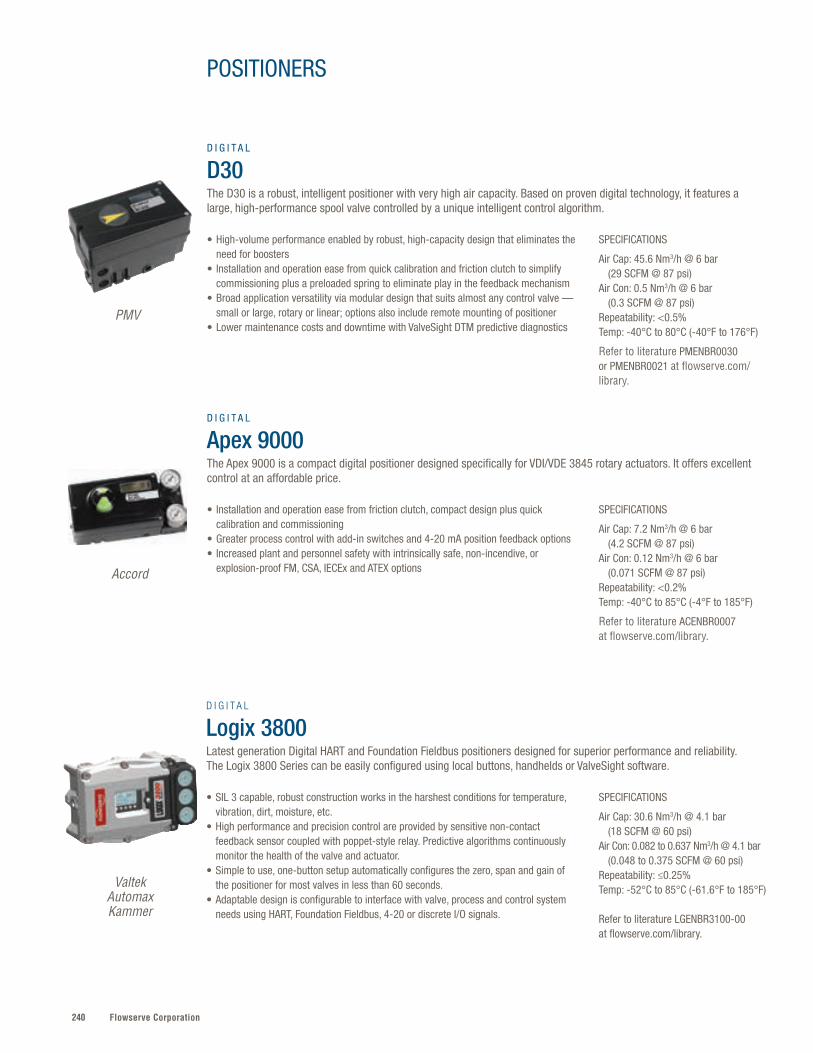
Flowserve Corporation240
SPECIFICATIONS
Air Cap: 30.6 Nm3/h @ 4.1 bar (18 SCFM @ 60 psi) Air Con: 0.082 to 0.637 Nm3/h @ 4.1 bar (0.048 to 0.375 SCFM @ 60 psi) Repeatability: ≤0.25% Temp: -52°C to 85°C (-61.6°F to 185°F)
Refer to literature LGENBR3100-00 at flowserve.com/library.
• SIL 3 capable, robust construction works in the harshest conditions for temperature, vibration, dirt, moisture, etc.
• High performance and precision control are provided by sensitive non-contact feedback sensor coupled with poppet-style relay. Predictive algorithms continuously monitor the health of the valve and actuator.
• Simple to use, one-button setup automatically configures the zero, span and gain of the positioner for most valves in less than 60 seconds.
• Adaptable design is configurable to interface with valve, process and control system needs using HART, Foundation Fieldbus, 4-20 or discrete I/O signals.
D I G I T A L
Logix 3800 Latest generation Digital HART and Foundation Fieldbus positioners designed for superior performance and reliability. The Logix 3800 Series can be easily configured using local buttons, handhelds or ValveSight software.
Valtek Automax Kammer
PMV
Accord
SPECIFICATIONS
Air Cap: 45.6 Nm3/h @ 6 bar (29 SCFM @ 87 psi)Air Con: 0.5 Nm3/h @ 6 bar (0.3 SCFM @ 87 psi)Repeatability: <0.5%Temp: -40°C to 80°C (-40°F to 176°F)
Refer to literature PMENBR0030 or PMENBR0021 at flowserve.com/library.
SPECIFICATIONS
Air Cap: 7.2 Nm3/h @ 6 bar (4.2 SCFM @ 87 psi)Air Con: 0.12 Nm3/h @ 6 bar (0.071 SCFM @ 87 psi)Repeatability: <0.2%Temp: -40°C to 85°C (-4°F to 185°F)
Refer to literature ACENBR0007 at flowserve.com/library.
• High-volume performance enabled by robust, high-capacity design that eliminates the need for boosters
• Installation and operation ease from quick calibration and friction clutch to simplify commissioning plus a preloaded spring to eliminate play in the feedback mechanism
• Broad application versatility via modular design that suits almost any control valve — small or large, rotary or linear; options also include remote mounting of positioner
• Lower maintenance costs and downtime with ValveSight DTM predictive diagnostics
• Installation and operation ease from friction clutch, compact design plus quick calibration and commissioning
• Greater process control with add-in switches and 4-20 mA position feedback options• Increased plant and personnel safety with intrinsically safe, non-incendive, or
explosion-proof FM, CSA, IECEx and ATEX options
D I G I T A L
D30The D30 is a robust, intelligent positioner with very high air capacity. Based on proven digital technology, it features a large, high-performance spool valve controlled by a unique intelligent control algorithm.
D I G I T A L
Apex 9000 The Apex 9000 is a compact digital positioner designed specifically for VDI/VDE 3845 rotary actuators. It offers excellent control at an affordable price.
POSITIONERS
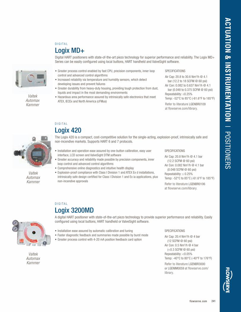
241flowserve.com
VALVES | LINEAR CO
NTRO
L
SPECIFICATIONS
Air Cap: 20.8 to 30.6 Nm3/h @ 4.1 bar (12.2 to 18 SCFM @ 60 psi)Air Con: 0.082 to 0.637 Nm3/h @ 4.1 bar (0.048 to 0.375 SCFM @ 60 psi)Repeatability: ≤0.25%Temp: -52°C to 85°C (-61.6°F to 185°F)
Refer to literature LGENBR0109 at flowserve.com/library.
• Greater process control enabled by fast CPU, precision components, inner loop control and advanced control algorithms
• Increased reliability via temperature and humidity sensors, which detect developing issues and prevent failures
• Greater durability from heavy-duty housing, providing tough protection from dust, liquids and impact in the most demanding environments
• Hazardous area performance assured by intrinsically safe electronics that meet ATEX, IECEx and North America (cFMus)
D I G I T A L
Logix MD+Digital HART positioners with state-of-the-art piezo technology for superior performance and reliability. The Logix MD+ Series can be easily configured using local buttons, HART handheld and ValveSight software.
SPECIFICATIONS
Air Cap: 20.8 Nm3/h @ 4.1 bar (12.2 SCFM @ 60 psi)Air Con: 0.082 Nm3/h @ 4.1 bar (0.048 SCFM @ 60 psi)Repeatability: ≤ 0.25%Temp: -52°C to 85°C (-61.6°F to 185°F)
Refer to literature LGENBR0106 at flowserve.com/library.
SPECIFICATIONS
Air Cap: 20.4 Nm3/h @ 4 bar (12 SCFM @ 60 psi)Air Con: 0.5 Nm3/h @ 4 bar (<0.3 SCFM @ 60 psi)Repeatability: <0.05%Temp: -40°C to 80°C (-40°F to 176°F)
Refer to literature LGENBR3000 or LGENIM0059 at flowserve.com/library.
• Installation and operation ease assured by one-button calibration, easy user interface, LCD screen and ValveSight DTM software
• Greater accuracy and reliability made possible by precision components, inner loop control and advanced control algorithms
• Comprehensive online diagnostics and intuitive health display• Explosion-proof compliance with Class I Division 1 and ATEX Ex d installations,
intrinsically safe design certified for Class I Division 1 and Ex ia applications, plus non-incendive approvals
• Installation ease assured by automatic calibration and tuning• Faster diagnostic feedback and summaries made possible by burst mode • Greater process control with 4-20 mA position feedback card option
D I G I T A L
Logix 420The Logix 420 is a compact, cost-competitive solution for the single-acting, explosion-proof, intrinsically safe and non-incendive markets. Supports HART 6 and 7 protocols.
D I G I T A L
Logix 3200MDA digital HART positioner with state-of-the-art piezo technology to provide superior performance and reliability. Easily configured using local buttons, HART handheld or ValveSight software.
Valtek Automax Kammer
Valtek Automax Kammer
Valtek Automax Kammer
ACTUATIO
N &
INSTR
UM
ENTATIO
N | PO
SITION
ERS
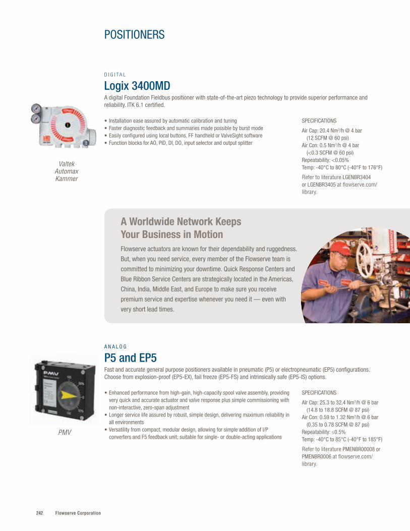
Flowserve Corporation242
A Worldwide Network Keeps Your Business in MotionFlowserve actuators are known for their dependability and ruggedness.
But, when you need service, every member of the Flowserve team is
committed to minimizing your downtime. Quick Response Centers and
Blue Ribbon Service Centers are strategically located in the Americas,
China, India, Middle East, and Europe to make sure you receive
premium service and expertise whenever you need it — even with
very short lead times.
PMV
SPECIFICATIONS
Air Cap: 25.3 to 32.4 Nm3/h @ 6 bar (14.8 to 18.8 SCFM @ 87 psi)Air Con: 0.59 to 1.32 Nm3/h @ 6 bar (0.35 to 0.78 SCFM @ 87 psi)Repeatability: ≤0.5%Temp: -40°C to 85°C (-40°F to 185°F)
Refer to literature PMENBR00008 or PMENBR0006 at flowserve.com/library.
• Enhanced performance from high-gain, high-capacity spool valve assembly, providing very quick and accurate actuator and valve response plus simple commissioning with non-interactive, zero-span adjustment
• Longer service life assured by robust, simple design, delivering maximum reliability in all environments
• Versatility from compact, modular design, allowing for simple addition of I/P converters and F5 feedback unit; suitable for single- or double-acting applications
A N A L O G
P5 and EP5 Fast and accurate general purpose positioners available in pneumatic (P5) or electropneumatic (EP5) configurations. Choose from explosion-proof (EP5-EX), fail freeze (EP5-FS) and intrinsically safe (EP5-IS) options.
POSITIONERS
Valtek Automax Kammer
SPECIFICATIONS
Air Cap: 20.4 Nm3/h @ 4 bar (12 SCFM @ 60 psi)Air Con: 0.5 Nm3/h @ 4 bar (<0.3 SCFM @ 60 psi)Repeatability: <0.05%Temp: -40°C to 80°C (-40°F to 176°F)
Refer to literature LGENBR3404 or LGENBR3405 at flowserve.com/library.
• Installation ease assured by automatic calibration and tuning• Faster diagnostic feedback and summaries made possible by burst mode • Easily configured using local buttons, FF handheld or ValveSight software • Function blocks for AO, PID, DI, DO, input selector and output splitter
D I G I T A L
Logix 3400MDA digital Foundation Fieldbus positioner with state-of-the-art piezo technology to provide superior performance and reliability. ITK 6.1 certified.
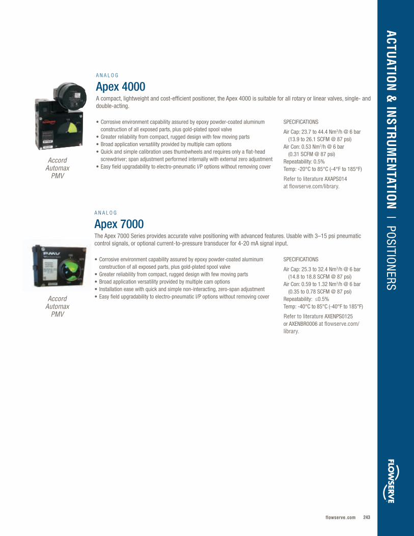
243flowserve.com
SPECIFICATIONS
Air Cap: 23.7 to 44.4 Nm3/h @ 6 bar (13.9 to 26.1 SCFM @ 87 psi)Air Con: 0.53 Nm3/h @ 6 bar (0.31 SCFM @ 87 psi) Repeatability: 0.5%Temp: -20°C to 85°C (-4°F to 185°F)
Refer to literature AXAPS014 at flowserve.com/library.
SPECIFICATIONS
Air Cap: 25.3 to 32.4 Nm3/h @ 6 bar (14.8 to 18.8 SCFM @ 87 psi)Air Con: 0.59 to 1.32 Nm3/h @ 6 bar (0.35 to 0.78 SCFM @ 87 psi) Repeatability: ≤0.5%Temp: -40°C to 85°C (-40°F to 185°F)
Refer to literature AXENPS0125 or AXENBR0006 at flowserve.com/library.
• Corrosive environment capability assured by epoxy powder-coated aluminum construction of all exposed parts, plus gold-plated spool valve
• Greater reliability from compact, rugged design with few moving parts• Broad application versatility provided by multiple cam options• Quick and simple calibration uses thumbwheels and requires only a flat-head
screwdriver; span adjustment performed internally with external zero adjustment• Easy field upgradability to electro-pneumatic I/P options without removing cover
• Corrosive environment capability assured by epoxy powder-coated aluminum construction of all exposed parts, plus gold-plated spool valve
• Greater reliability from compact, rugged design with few moving parts• Broad application versatility provided by multiple cam options• Installation ease with quick and simple non-interacting, zero-span adjustment• Easy field upgradability to electro-pneumatic I/P options without removing cover
A N A L O G
Apex 4000 A compact, lightweight and cost-efficient positioner, the Apex 4000 is suitable for all rotary or linear valves, single- and double-acting.
A N A L O G
Apex 7000 The Apex 7000 Series provides accurate valve positioning with advanced features. Usable with 3–15 psi pneumatic control signals, or optional current-to-pressure transducer for 4-20 mA signal input.
AccordAutomax
PMV
AccordAutomax
PMV
ACTUATIO
N &
INSTR
UM
ENTATIO
N | PO
SITION
ERS
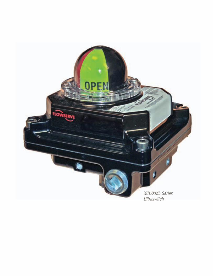
Flowserve Corporation244244
XCL/XML Series Ultraswitch
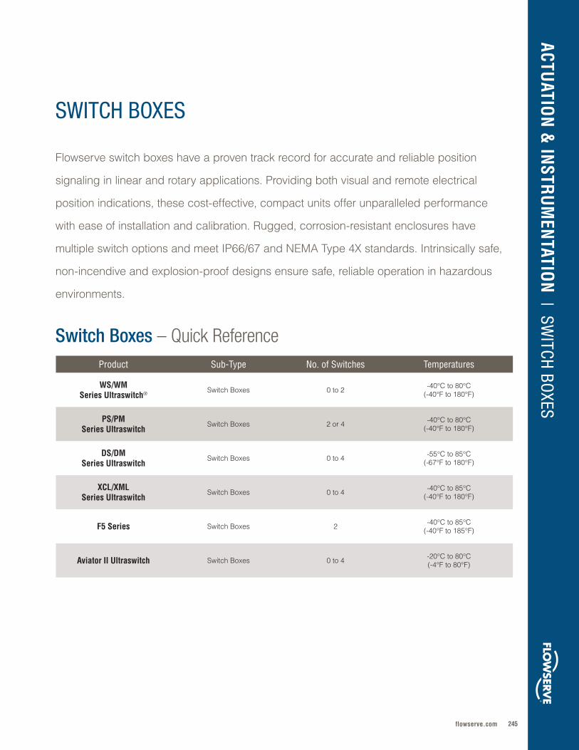
245flowserve.com
Flowserve switch boxes have a proven track record for accurate and reliable position
signaling in linear and rotary applications . Providing both visual and remote electrical
position indications, these cost-effective, compact units offer unparalleled performance
with ease of installation and calibration . Rugged, corrosion-resistant enclosures have
multiple switch options and meet IP66/67 and NEMA Type 4X standards . Intrinsically safe,
non-incendive and explosion-proof designs ensure safe, reliable operation in hazardous
environments .
Product Sub-Type No. of Switches Temperatures
WS/WM Series Ultraswitch® Switch Boxes 0 to 2 -40°C to 80°C
(-40°F to 180°F)
PS/PMSeries Ultraswitch
Switch Boxes 2 or 4 -40°C to 80°C (-40°F to 180°F)
DS/DMSeries Ultraswitch
Switch Boxes 0 to 4 -55°C to 85°C (-67°F to 180°F)
XCL/XMLSeries Ultraswitch
Switch Boxes 0 to 4 -40°C to 85°C (-40°F to 180°F)
F5 Series Switch Boxes 2 -40°C to 85°C(-40°F to 185°F)
Aviator II Ultraswitch Switch Boxes 0 to 4 -20°C to 80°C (-4°F to 80°F)
ACTUATIO
N &
INSTR
UM
ENTATIO
N | SW
ITCH BOXES
Switch Boxes – Quick Reference
SWITCH BOXES
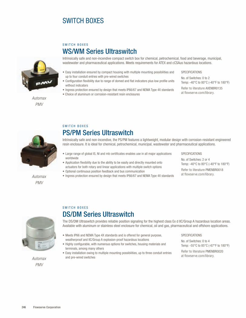
Flowserve Corporation246
SPECIFICATIONS
No. of Switches: 0 to 2 Temp: -40°C to 80°C (-40°F to 180°F)
Refer to literature AXENBR0135 at flowserve.com/library.
SPECIFICATIONS
No. of Switches: 2 or 4 Temp: -40°C to 80°C (-40°F to 180°F)
Refer to literature PMENBR0018 at flowserve.com/library.
SPECIFICATIONS
No. of Switches: 0 to 4 Temp: -55°C to 85°C (-67°F to 180°F)
Refer to literature PMENBR0020 at flowserve.com/library.
• Easy installation ensured by compact housing with multiple mounting possibilities and up to four conduit entries with pre-wired switches
• Configuration flexibility due to range of domed and flat indicators plus low profile units without indicators
• Ingress protection ensured by design that meets IP66/67 and NEMA Type 4X standards • Choice of aluminum or corrosion-resistant resin enclosures
• Large range of global IS, NI and mb certificates enables use in all major applications worldwide
• Application flexibility due to the ability to be easily and directly mounted onto actuators for both rotary and linear applications with multiple switch options
• Optional continuous position feedback and bus communication• Ingress protection ensured by design that meets IP66/67 and NEMA Type 4X standards
• Meets IP66 and NEMA Type 4X standards and is offered for general purpose, weatherproof and IIC/Group A explosion-proof hazardous locations
• Highly configurable, with numerous options for switches, housing materials and terminals, among many others
• Easy installation owing to multiple mounting possibilities, up to three conduit entries and pre-wired switches
S W I T C H B O X E S
PS/PM Series UltraswitchIntrinsically safe and non-incendive, the PS/PM features a lightweight, modular design with corrosion-resistant engineered resin enclosure. It is ideal for chemical, petrochemical, municipal, wastewater and pharmaceutical applications.
S W I T C H B O X E S
DS/DM Series UltraswitchThe DS/DM Ultraswitch provides reliable position signaling for the highest class Ex d IIC/Group A hazardous location areas. Available with aluminum or stainless steel enclosure for chemical, oil and gas, pharmaceutical and offshore applications.
AutomaxPMV
AutomaxPMV
AutomaxPMV
S W I T C H B O X E S
WS/WM Series UltraswitchIntrinsically safe and non-incendive compact switch box for chemical, petrochemical, food and beverage, municipal, wastewater and pharmaceutical applications. Meets requirements for ATEX and cCSAus hazardous locations.
SWITCH BOXES
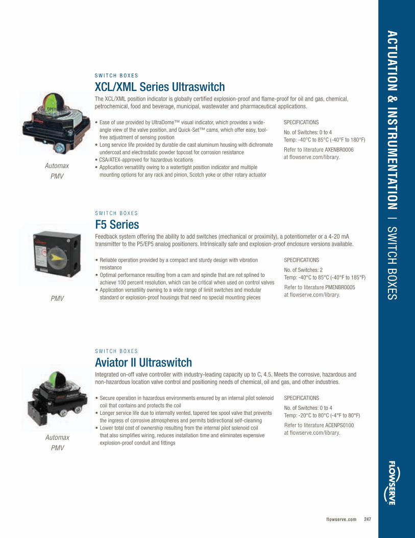
247flowserve.com
VALVES | LINEAR CO
NTRO
L
SPECIFICATIONS
No. of Switches: 0 to 4 Temp: -40°C to 85°C (-40°F to 180°F)
Refer to literature AXENBR0006 at flowserve.com/library.
• Ease of use provided by UltraDome™ visual indicator, which provides a wide-angle view of the valve position, and Quick-Set™ cams, which offer easy, tool-free adjustment of sensing position
• Long service life provided by durable die cast aluminum housing with dichromate undercoat and electrostatic powder topcoat for corrosion resistance
• CSA/ATEX-approved for hazardous locations• Application versatility owing to a watertight position indicator and multiple
mounting options for any rack and pinion, Scotch yoke or other rotary actuator
S W I T C H B O X E S
XCL/XML Series UltraswitchThe XCL/XML position indicator is globally certified explosion-proof and flame-proof for oil and gas, chemical, petrochemical, food and beverage, municipal, wastewater and pharmaceutical applications.
SPECIFICATIONS
No. of Switches: 2 Temp: -40°C to 85°C (-40°F to 185°F)
Refer to literature PMENBR0005 at flowserve.com/library.
SPECIFICATIONS
No. of Switches: 0 to 4Temp: -20°C to 80°C (-4°F to 80°F)
Refer to literature ACENPS0100 at flowserve.com/library.
• Reliable operation provided by a compact and sturdy design with vibration resistance
• Optimal performance resulting from a cam and spindle that are not splined to achieve 100 percent resolution, which can be critical when used on control valves
• Application versatility owning to a wide range of limit switches and modular standard or explosion-proof housings that need no special mounting pieces
• Secure operation in hazardous environments ensured by an internal pilot solenoid coil that contains and protects the coil
• Longer service life due to internally vented, tapered tee spool valve that prevents the ingress of corrosive atmospheres and permits bidirectional self-cleaning
• Lower total cost of ownership resulting from the internal pilot solenoid coil that also simplifies wiring, reduces installation time and eliminates expensive explosion-proof conduit and fittings
S W I T C H B O X E S
F5 SeriesFeedback system offering the ability to add switches (mechanical or proximity), a potentiometer or a 4-20 mA transmitter to the P5/EP5 analog positioners. Intrinsically safe and explosion-proof enclosure versions available.
S W I T C H B O X E S
Aviator II UltraswitchIntegrated on-off valve controller with industry-leading capacity up to Cv 4.5. Meets the corrosive, hazardous and non-hazardous location valve control and positioning needs of chemical, oil and gas, and other industries.
AutomaxPMV
PMV
AutomaxPMV
ACTUATIO
N &
INSTR
UM
ENTATIO
N | SW
ITCH BOXES
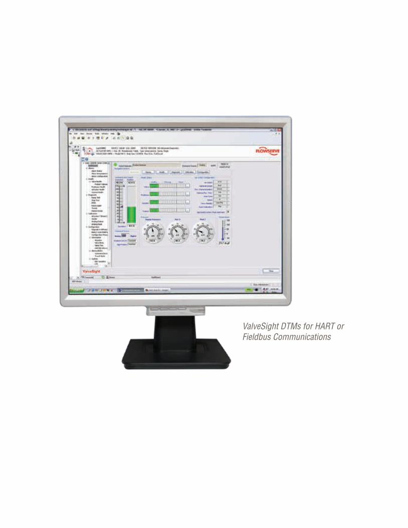
Flowserve Corporation248248
ValveSight DTMs for HART or Fieldbus Communications
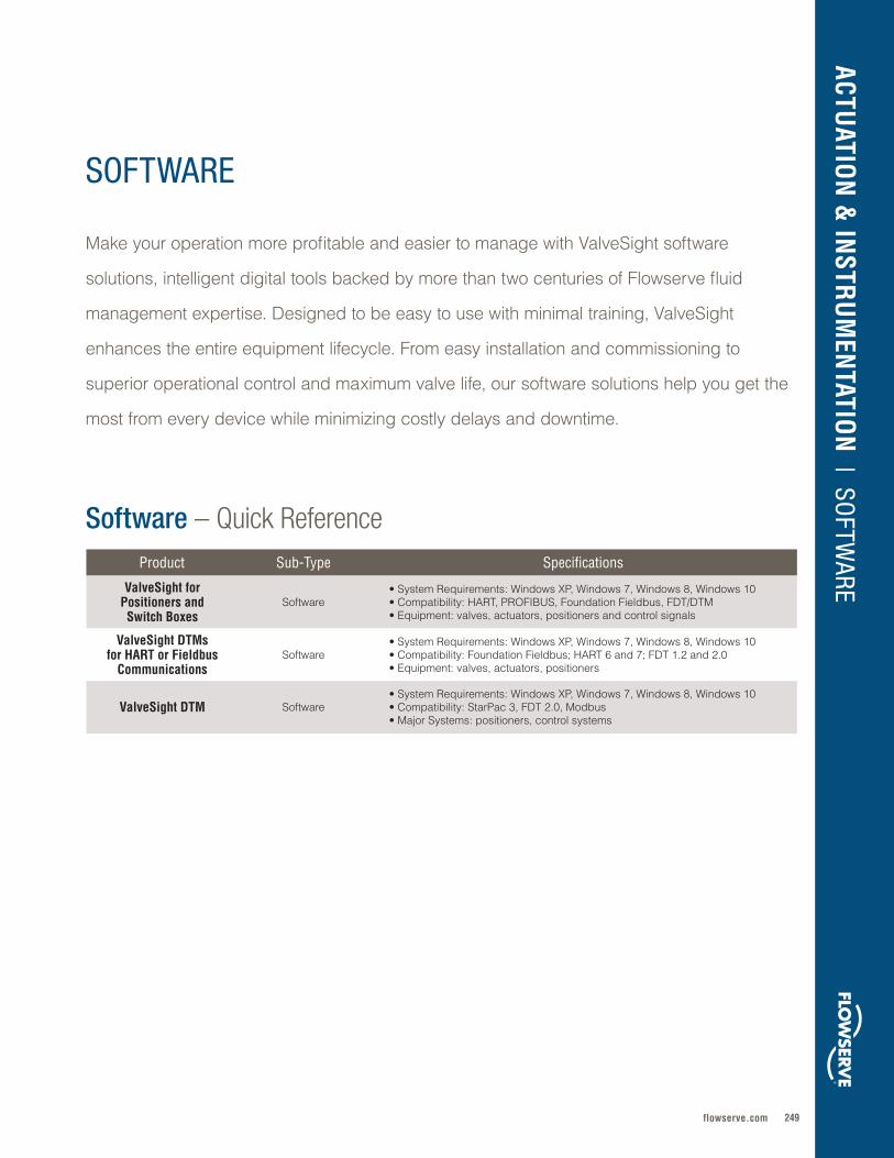
249flowserve.com
ACTUATIO
N &
INSTR
UM
ENTATIO
N | SO
FTWARE
SOFTWARE
Product Sub-Type Specifications
ValveSight for Positioners and Switch Boxes
Software• System Requirements: Windows XP, Windows 7, Windows 8, Windows 10• Compatibility: HART, PROFIBUS, Foundation Fieldbus, FDT/DTM• Equipment: valves, actuators, positioners and control signals
ValveSight DTMs for HART or Fieldbus
CommunicationsSoftware
• System Requirements: Windows XP, Windows 7, Windows 8, Windows 10• Compatibility: Foundation Fieldbus; HART 6 and 7; FDT 1 .2 and 2 .0 • Equipment: valves, actuators, positioners
ValveSight DTM Software• System Requirements: Windows XP, Windows 7, Windows 8, Windows 10• Compatibility: StarPac 3, FDT 2 .0, Modbus• Major Systems: positioners, control systems
Software – Quick Reference
Make your operation more profitable and easier to manage with ValveSight software
solutions, intelligent digital tools backed by more than two centuries of Flowserve fluid
management expertise . Designed to be easy to use with minimal training, ValveSight
enhances the entire equipment lifecycle . From easy installation and commissioning to
superior operational control and maximum valve life, our software solutions help you get the
most from every device while minimizing costly delays and downtime .
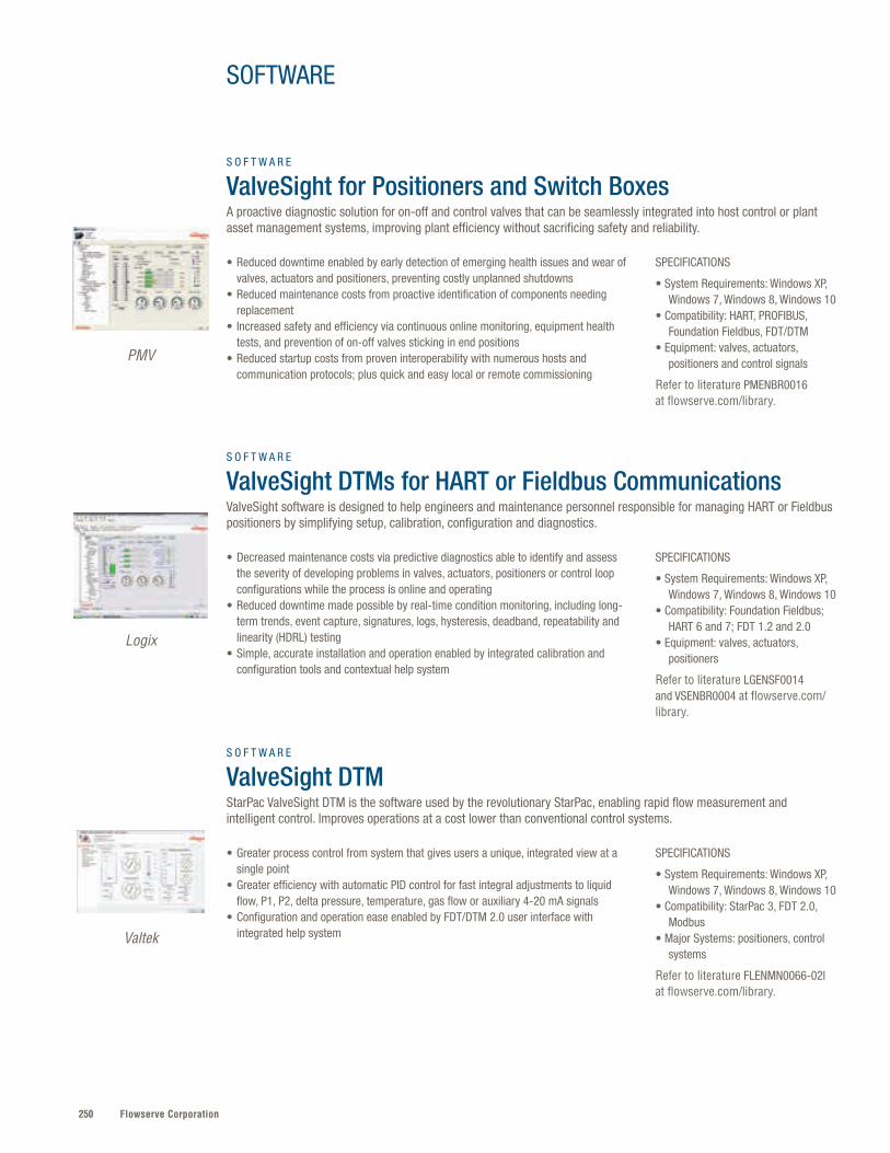
Flowserve Corporation250
SPECIFICATIONS
• System Requirements: Windows XP, Windows 7, Windows 8, Windows 10• Compatibility: HART, PROFIBUS, Foundation Fieldbus, FDT/DTM• Equipment: valves, actuators, positioners and control signals
Refer to literature PMENBR0016 at flowserve.com/library.
SPECIFICATIONS
• System Requirements: Windows XP, Windows 7, Windows 8, Windows 10• Compatibility: Foundation Fieldbus; HART 6 and 7; FDT 1.2 and 2.0 • Equipment: valves, actuators, positioners
Refer to literature LGENSF0014 and VSENBR0004 at flowserve.com/library.
SPECIFICATIONS
• System Requirements: Windows XP, Windows 7, Windows 8, Windows 10• Compatibility: StarPac 3, FDT 2.0, Modbus • Major Systems: positioners, control systems
Refer to literature FLENMN0066-02l at flowserve.com/library.
• Reduced downtime enabled by early detection of emerging health issues and wear of valves, actuators and positioners, preventing costly unplanned shutdowns
• Reduced maintenance costs from proactive identification of components needing replacement
• Increased safety and efficiency via continuous online monitoring, equipment health tests, and prevention of on-off valves sticking in end positions
• Reduced startup costs from proven interoperability with numerous hosts and communication protocols; plus quick and easy local or remote commissioning
• Decreased maintenance costs via predictive diagnostics able to identify and assess the severity of developing problems in valves, actuators, positioners or control loop configurations while the process is online and operating
• Reduced downtime made possible by real-time condition monitoring, including long-term trends, event capture, signatures, logs, hysteresis, deadband, repeatability and linearity (HDRL) testing
• Simple, accurate installation and operation enabled by integrated calibration and configuration tools and contextual help system
• Greater process control from system that gives users a unique, integrated view at a single point
• Greater efficiency with automatic PID control for fast integral adjustments to liquid flow, P1, P2, delta pressure, temperature, gas flow or auxiliary 4-20 mA signals
• Configuration and operation ease enabled by FDT/DTM 2.0 user interface with integrated help system
S O F T W A R E
ValveSight for Positioners and Switch Boxes A proactive diagnostic solution for on-off and control valves that can be seamlessly integrated into host control or plant asset management systems, improving plant efficiency without sacrificing safety and reliability.
S O F T W A R E
ValveSight DTMs for HART or Fieldbus CommunicationsValveSight software is designed to help engineers and maintenance personnel responsible for managing HART or Fieldbus positioners by simplifying setup, calibration, configuration and diagnostics.
S O F T W A R E
ValveSight DTMStarPac ValveSight DTM is the software used by the revolutionary StarPac, enabling rapid flow measurement and intelligent control. Improves operations at a cost lower than conventional control systems.
PMV
Logix
Valtek
SOFTWARE

251flowserve.com
ACTUATIO
N &
INSTR
UM
ENTATIO
N | SO
FTWARE
Flowserve Corporation252
Numbers
33R . . . . . . . . . . . . . . . . . . . . . . . . . . . . . . . . . . . . . . . . . . . . . . . . . . . . . . 229
40R . . . . . . . . . . . . . . . . . . . . . . . . . . . . . . . . . . . . . . . . . . . . . . . . . . . . . . 229
682 Water Seal Coolers . . . . . . . . . . . . . . . . . . . . . . . 131
1878 Piston Check . . . . . . . . . . . . . . . . . . . . . . . . . . . . . . . . 196
1878 Swing Check . . . . . . . . . . . . . . . . . . . . . . . . . . . . . . 197
1878 T-Pattern . . . . . . . . . . . . . . . . . . . . . . . . . . . . . . . . . . . . . 190
1878 Y-Pattern . . . . . . . . . . . . . . . . . . . . . . . . . . . . . . . . . . . . . 188
A
ADH . . . . . . . . . . . . . . . . . . . . . . . . . . . . . . . . . . . . . . . . . . . . . . . . . . . . . . . 64
AEH . . . . . . . . . . . . . . . . . . . . . . . . . . . . . . . . . . . . . . . . . . . . . . . . . . . . . . . 63
AFH9000 . . . . . . . . . . . . . . . . . . . . . . . . . . . . . . . . . . . . . . . . . . . . . . . . 28
AFH9500 . . . . . . . . . . . . . . . . . . . . . . . . . . . . . . . . . . . . . . . . . . . . . . . . 83
AFV . . . . . . . . . . . . . . . . . . . . . . . . . . . . . . . . . . . . . . . . . . . . . . . . . . . . . . . . 48
Airfin Seal Cooler . . . . . . . . . . . . . . . . . . . . . . . . . . . . . . . . . 132
AKH . . . . . . . . . . . . . . . . . . . . . . . . . . . . . . . . . . . . . . . . . . . . . . . . . . . . . . . 63
AKH2 . . . . . . . . . . . . . . . . . . . . . . . . . . . . . . . . . . . . . . . . . . . . . . . . . . . 152
AKH2-300 . . . . . . . . . . . . . . . . . . . . . . . . . . . . . . . . . . . . . . . . . . . . 152
AKH2A . . . . . . . . . . . . . . . . . . . . . . . . . . . . . . . . . . . . . . . . . . . . . . . . . 153
AKH3 . . . . . . . . . . . . . . . . . . . . . . . . . . . . . . . . . . . . . . . . . . . . . . . . . . . 153
AKH5 . . . . . . . . . . . . . . . . . . . . . . . . . . . . . . . . . . . . . . . . . . . . . . . . . . . 153
AKH6 Fully Lined Tank Drain . . . . . . . . . . . . . . . 155
AKH7-KP . . . . . . . . . . . . . . . . . . . . . . . . . . . . . . . . . . . . . . . . . . . . . 154
AKH8 . . . . . . . . . . . . . . . . . . . . . . . . . . . . . . . . . . . . . . . . . . . . . . . . . . . 154
AKL and AKV . . . . . . . . . . . . . . . . . . . . . . . . . . . . . . . . . . . . . . . . . 66
Allpac . . . . . . . . . . . . . . . . . . . . . . . . . . . . . . . . . . . . . . . . . . . . . . . . . . 117
AMP3 . . . . . . . . . . . . . . . . . . . . . . . . . . . . . . . . . . . . . . . . . . . . . . . . . . . 155
Ampliflow . . . . . . . . . . . . . . . . . . . . . . . . . . . . . . . . . . . . . . . . . . . . . 112
Anchor/Darling Piston (Lift) Check . . . . . . 196
Anchor/Darling Swing Check Valve . . . . . 197
Anchor/Darling Tilting Disk . . . . . . . . . . . . . . . . . . 198
Anchor/Darling T-Pattern . . . . . . . . . . . . . . . . . . . . . 190
Anchor/Darling Y-Pattern . . . . . . . . . . . . . . . . . . . . . 189
AOH . . . . . . . . . . . . . . . . . . . . . . . . . . . . . . . . . . . . . . . . . . . . . . . . . . . . . . . 64
Apex 4000 . . . . . . . . . . . . . . . . . . . . . . . . . . . . . . . . . . . . . . . . . . . 243
Apex 7000 . . . . . . . . . . . . . . . . . . . . . . . . . . . . . . . . . . . . . . . . . . . 243
Apex 9000 . . . . . . . . . . . . . . . . . . . . . . . . . . . . . . . . . . . . . . . . . . . 240
APKD . . . . . . . . . . . . . . . . . . . . . . . . . . . . . . . . . . . . . . . . . . . . . . . . . . . . . 50
ASH . . . . . . . . . . . . . . . . . . . . . . . . . . . . . . . . . . . . . . . . . . . . . . . . . . . . . . . 64
Aviator II Ultraswitch . . . . . . . . . . . . . . . . . . . . . . . . . . . . 247
B
Barge VTP . . . . . . . . . . . . . . . . . . . . . . . . . . . . . . . . . . . . . . . . . . . . . 48
Bearing Gard . . . . . . . . . . . . . . . . . . . . . . . . . . . . . . . . . . . . . . . 136
BGM . . . . . . . . . . . . . . . . . . . . . . . . . . . . . . . . . . . . . . . . . . . . . . . . . . . . 136
Big Max BX2001 . . . . . . . . . . . . . . . . . . . . . . . . . . . . . . . . . . 160
Bladder Accumulators . . . . . . . . . . . . . . . . . . . . . . . . . 130
Bolted Gland – Iron . . . . . . . . . . . . . . . . . . . . . . . . . . . . . 204
Bolted Gland – Steel . . . . . . . . . . . . . . . . . . . . . . . . . . . . 205
BP . . . . . . . . . . . . . . . . . . . . . . . . . . . . . . . . . . . . . . . . . . . . . . . . . . . . . . . . . . 42
BRC and BRCSH . . . . . . . . . . . . . . . . . . . . . . . . . . . . . . . . . 102
BTV . . . . . . . . . . . . . . . . . . . . . . . . . . . . . . . . . . . . . . . . . . . . . . . . . . . . . . 161
Buffer/Barrier Fluid Reservoirs . . . . . . . . . . . . 130
Buffer/Barrier Gas Panels . . . . . . . . . . . . . . . . . . . . 131
BulkTite . . . . . . . . . . . . . . . . . . . . . . . . . . . . . . . . . . . . . . . . . . . . . . . . 127
BX, BXQ and BXB . . . . . . . . . . . . . . . . . . . . . . . . . . . . . . . 101
BXHHS and BXHHSB . . . . . . . . . . . . . . . . . . . . . . . . . . 101
BXLS . . . . . . . . . . . . . . . . . . . . . . . . . . . . . . . . . . . . . . . . . . . . . . . . . . . . 100
BXRH . . . . . . . . . . . . . . . . . . . . . . . . . . . . . . . . . . . . . . . . . . . . . . . . . . . 101
Byron Jackson SUBM . . . . . . . . . . . . . . . . . . . . . . . . . . . . 51
INDEX
253flowserve.com
C
CA . . . . . . . . . . . . . . . . . . . . . . . . . . . . . . . . . . . . . . . . . . . . . . . . . . . . . . . . . . 78
CAM . . . . . . . . . . . . . . . . . . . . . . . . . . . . . . . . . . . . . . . . . . . . . . . . . . . . . . . 79
CavControl . . . . . . . . . . . . . . . . . . . . . . . . . . . . . . . . . . . . . . . . . . . 178
CBE and CBM . . . . . . . . . . . . . . . . . . . . . . . . . . . . . . . . . . . . . . . 17
CBT . . . . . . . . . . . . . . . . . . . . . . . . . . . . . . . . . . . . . . . . . . . . . . . . . . . . . . . . 18
CEB . . . . . . . . . . . . . . . . . . . . . . . . . . . . . . . . . . . . . . . . . . . . . . . . . . . . . . . 65
CEH . . . . . . . . . . . . . . . . . . . . . . . . . . . . . . . . . . . . . . . . . . . . . . . . . . . . . . . 63
ChannelStream . . . . . . . . . . . . . . . . . . . . . . . . . . . . . . . . . . . . 179
CHTA . . . . . . . . . . . . . . . . . . . . . . . . . . . . . . . . . . . . . . . . . . . . . . . . . . . . . 42
Circpac CB, LO and HP . . . . . . . . . . . . . . . . . . . . . . 110
Circpac MD . . . . . . . . . . . . . . . . . . . . . . . . . . . . . . . . . . . . . . . . . 126
Circulators . . . . . . . . . . . . . . . . . . . . . . . . . . . . . . . . . . . . . . . . . . . 131
Cleanpac D, F and DL . . . . . . . . . . . . . . . . . . . . . . . . . 111
CN . . . . . . . . . . . . . . . . . . . . . . . . . . . . . . . . . . . . . . . . . . . . . . . . . . . . . . . . . 78
CPT . . . . . . . . . . . . . . . . . . . . . . . . . . . . . . . . . . . . . . . . . . . . . . . . . . . . . . 166
CPXV . . . . . . . . . . . . . . . . . . . . . . . . . . . . . . . . . . . . . . . . . . . . . . . . . . . . . 54
CRO . . . . . . . . . . . . . . . . . . . . . . . . . . . . . . . . . . . . . . . . . . . . . . . . . . . . . . . 94
Cryogenic Ball . . . . . . . . . . . . . . . . . . . . . . . . . . . . . . . . . . . . . 148
Cryogenic Ball Valve . . . . . . . . . . . . . . . . . . . . . . . . . . . 151
CryoSeal . . . . . . . . . . . . . . . . . . . . . . . . . . . . . . . . . . . . . . . . . . . . . . 148
CSB . . . . . . . . . . . . . . . . . . . . . . . . . . . . . . . . . . . . . . . . . . . . . . . . . . . . . . . 41
CSX . . . . . . . . . . . . . . . . . . . . . . . . . . . . . . . . . . . . . . . . . . . . . . . . . . . . . . . . 39
CT6 . . . . . . . . . . . . . . . . . . . . . . . . . . . . . . . . . . . . . . . . . . . . . . . . . . . . . . . . 58
CVP (BSV and BCV) . . . . . . . . . . . . . . . . . . . . . . . . . . . . . . 83
Cyclone Separator . . . . . . . . . . . . . . . . . . . . . . . . . . . . . . . 138
D
D3 . . . . . . . . . . . . . . . . . . . . . . . . . . . . . . . . . . . . . . . . . . . . . . . . . . . . . . . . 239
D20 . . . . . . . . . . . . . . . . . . . . . . . . . . . . . . . . . . . . . . . . . . . . . . . . . . . . . . 239
D30 . . . . . . . . . . . . . . . . . . . . . . . . . . . . . . . . . . . . . . . . . . . . . . . . . . . . . . 240
D800 . . . . . . . . . . . . . . . . . . . . . . . . . . . . . . . . . . . . . . . . . . . . . . . . . . . . . . 18
D and DP . . . . . . . . . . . . . . . . . . . . . . . . . . . . . . . . . . . . . . . . . . . . . . . 97
DBS . . . . . . . . . . . . . . . . . . . . . . . . . . . . . . . . . . . . . . . . . . . . . . . . . . . . . . . 20
DeviceNet . . . . . . . . . . . . . . . . . . . . . . . . . . . . . . . . . . . . . . . . . . . . 219
DFSS and DVSS . . . . . . . . . . . . . . . . . . . . . . . . . . . . . . . . . . . . 77
DiamondBack . . . . . . . . . . . . . . . . . . . . . . . . . . . . . . . . . . . . . . 179
DIPV – Double-Isolation . . . . . . . . . . . . . . . . . . . . . . . 206
DMX . . . . . . . . . . . . . . . . . . . . . . . . . . . . . . . . . . . . . . . . . . . . . . . . . . . . . . . 36
Double Block and Bleed . . . . . . . . . . . . . . . . . . . . . 150
Double Disk . . . . . . . . . . . . . . . . . . . . . . . . . . . . . . . . . . . . . . . . . 183
Double-Isolation – Steel . . . . . . . . . . . . . . . . . . . . . . . 207
DRV . . . . . . . . . . . . . . . . . . . . . . . . . . . . . . . . . . . . . . . . . . . . . . . . . . . . . . . 66
Drypac . . . . . . . . . . . . . . . . . . . . . . . . . . . . . . . . . . . . . . . . . . . . . . . . . 112
DS . . . . . . . . . . . . . . . . . . . . . . . . . . . . . . . . . . . . . . . . . . . . . . . . . . . . . . . . . . 19
DS/DM Series Ultraswitch . . . . . . . . . . . . . . . . . . . 246
Duball DL . . . . . . . . . . . . . . . . . . . . . . . . . . . . . . . . . . . . . .146, 167
DuraClear . . . . . . . . . . . . . . . . . . . . . . . . . . . . . . . . . . . . . . . . . . . . 136
DVSH . . . . . . . . . . . . . . . . . . . . . . . . . . . . . . . . . . . . . . . . . . . . . . . . . . . . . 34
DVSR . . . . . . . . . . . . . . . . . . . . . . . . . . . . . . . . . . . . . . . . . . . . . . . . . . . . . 37
DWEER . . . . . . . . . . . . . . . . . . . . . . . . . . . . . . . . . . . . . . . . . . . . . . . . . . 82
Dynamic Balance – Iron . . . . . . . . . . . . . . . . . . . . . . 205
Dynamic Balance – Steel . . . . . . . . . . . . . . . . . . . . 205
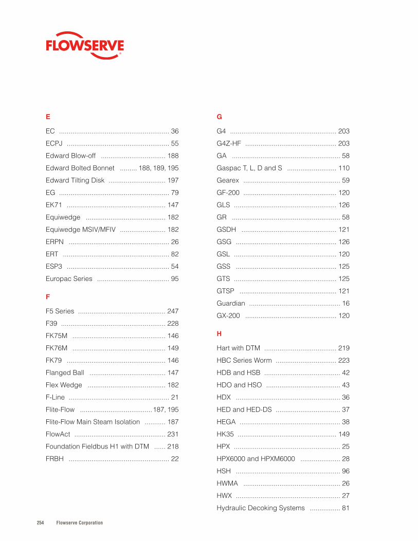
Flowserve Corporation254
E
EC . . . . . . . . . . . . . . . . . . . . . . . . . . . . . . . . . . . . . . . . . . . . . . . . . . . . . . . . . . 36
ECPJ . . . . . . . . . . . . . . . . . . . . . . . . . . . . . . . . . . . . . . . . . . . . . . . . . . . . . . 55
Edward Blow-off . . . . . . . . . . . . . . . . . . . . . . . . . . . . . . . . . . 188
Edward Bolted Bonnet . . . . . . . . . 188, 189, 195
Edward Tilting Disk . . . . . . . . . . . . . . . . . . . . . . . . . . . . . . 197
EG . . . . . . . . . . . . . . . . . . . . . . . . . . . . . . . . . . . . . . . . . . . . . . . . . . . . . . . . . . 79
EK71 . . . . . . . . . . . . . . . . . . . . . . . . . . . . . . . . . . . . . . . . . . . . . . . . . . . . 147
Equiwedge . . . . . . . . . . . . . . . . . . . . . . . . . . . . . . . . . . . . . . . . . . 182
Equiwedge MSIV/MFIV . . . . . . . . . . . . . . . . . . . . . . . . 182
ERPN . . . . . . . . . . . . . . . . . . . . . . . . . . . . . . . . . . . . . . . . . . . . . . . . . . . . . 26
ERT . . . . . . . . . . . . . . . . . . . . . . . . . . . . . . . . . . . . . . . . . . . . . . . . . . . . . . . . 82
ESP3 . . . . . . . . . . . . . . . . . . . . . . . . . . . . . . . . . . . . . . . . . . . . . . . . . . . . . . 54
Europac Series . . . . . . . . . . . . . . . . . . . . . . . . . . . . . . . . . . . . . . 95
F
F5 Series . . . . . . . . . . . . . . . . . . . . . . . . . . . . . . . . . . . . . . . . . . . . . . 247
F39 . . . . . . . . . . . . . . . . . . . . . . . . . . . . . . . . . . . . . . . . . . . . . . . . . . . . . . . 228
FK75M . . . . . . . . . . . . . . . . . . . . . . . . . . . . . . . . . . . . . . . . . . . . . . . . . 146
FK76M . . . . . . . . . . . . . . . . . . . . . . . . . . . . . . . . . . . . . . . . . . . . . . . . . 149
FK79 . . . . . . . . . . . . . . . . . . . . . . . . . . . . . . . . . . . . . . . . . . . . . . . . . . . . 146
Flanged Ball . . . . . . . . . . . . . . . . . . . . . . . . . . . . . . . . . . . . . . . . 147
Flex Wedge . . . . . . . . . . . . . . . . . . . . . . . . . . . . . . . . . . . . . . . . . 182
F-Line . . . . . . . . . . . . . . . . . . . . . . . . . . . . . . . . . . . . . . . . . . . . . . . . . . . . . 21
Flite-Flow . . . . . . . . . . . . . . . . . . . . . . . . . . . . . . . . . . . . . .187, 195
Flite-Flow Main Steam Isolation . . . . . . . . . . . 187
FlowAct . . . . . . . . . . . . . . . . . . . . . . . . . . . . . . . . . . . . . . . . . . . . . . . . 231
Foundation Fieldbus H1 with DTM . . . . . . 218
FRBH . . . . . . . . . . . . . . . . . . . . . . . . . . . . . . . . . . . . . . . . . . . . . . . . . . . . . 22
G
G4 . . . . . . . . . . . . . . . . . . . . . . . . . . . . . . . . . . . . . . . . . . . . . . . . . . . . . . . . 203
G4Z-HF . . . . . . . . . . . . . . . . . . . . . . . . . . . . . . . . . . . . . . . . . . . . . . . . 203
GA . . . . . . . . . . . . . . . . . . . . . . . . . . . . . . . . . . . . . . . . . . . . . . . . . . . . . . . . . 58
Gaspac T, L, D and S . . . . . . . . . . . . . . . . . . . . . . . . . . 110
Gearex . . . . . . . . . . . . . . . . . . . . . . . . . . . . . . . . . . . . . . . . . . . . . . . . . . . 59
GF-200 . . . . . . . . . . . . . . . . . . . . . . . . . . . . . . . . . . . . . . . . . . . . . . . . . 120
GLS . . . . . . . . . . . . . . . . . . . . . . . . . . . . . . . . . . . . . . . . . . . . . . . . . . . . . . 126
GR . . . . . . . . . . . . . . . . . . . . . . . . . . . . . . . . . . . . . . . . . . . . . . . . . . . . . . . . . 58
GSDH . . . . . . . . . . . . . . . . . . . . . . . . . . . . . . . . . . . . . . . . . . . . . . . . . . 121
GSG . . . . . . . . . . . . . . . . . . . . . . . . . . . . . . . . . . . . . . . . . . . . . . . . . . . . . 126
GSL . . . . . . . . . . . . . . . . . . . . . . . . . . . . . . . . . . . . . . . . . . . . . . . . . . . . . . 120
GSS . . . . . . . . . . . . . . . . . . . . . . . . . . . . . . . . . . . . . . . . . . . . . . . . . . . . . 125
GTS . . . . . . . . . . . . . . . . . . . . . . . . . . . . . . . . . . . . . . . . . . . . . . . . . . . . . . 125
GTSP . . . . . . . . . . . . . . . . . . . . . . . . . . . . . . . . . . . . . . . . . . . . . . . . . . . 121
Guardian . . . . . . . . . . . . . . . . . . . . . . . . . . . . . . . . . . . . . . . . . . . . . . . . 16
GX-200 . . . . . . . . . . . . . . . . . . . . . . . . . . . . . . . . . . . . . . . . . . . . . . . . 120
H
Hart with DTM . . . . . . . . . . . . . . . . . . . . . . . . . . . . . . . . . . . . . . 219
HBC Series Worm . . . . . . . . . . . . . . . . . . . . . . . . . . . . . . . . 223
HDB and HSB . . . . . . . . . . . . . . . . . . . . . . . . . . . . . . . . . . . . . . . . 42
HDO and HSO . . . . . . . . . . . . . . . . . . . . . . . . . . . . . . . . . . . . . . . 43
HDX . . . . . . . . . . . . . . . . . . . . . . . . . . . . . . . . . . . . . . . . . . . . . . . . . . . . . . . 36
HED and HED-DS . . . . . . . . . . . . . . . . . . . . . . . . . . . . . . . . . . 37
HEGA . . . . . . . . . . . . . . . . . . . . . . . . . . . . . . . . . . . . . . . . . . . . . . . . . . . . . 38
HK35 . . . . . . . . . . . . . . . . . . . . . . . . . . . . . . . . . . . . . . . . . . . . . . . . . . . . 149
HPX . . . . . . . . . . . . . . . . . . . . . . . . . . . . . . . . . . . . . . . . . . . . . . . . . . . . . . . . 25
HPX6000 and HPXM6000 . . . . . . . . . . . . . . . . . . . . . 28
HSH . . . . . . . . . . . . . . . . . . . . . . . . . . . . . . . . . . . . . . . . . . . . . . . . . . . . . . . 96
HWMA . . . . . . . . . . . . . . . . . . . . . . . . . . . . . . . . . . . . . . . . . . . . . . . . . . . 26
HWX . . . . . . . . . . . . . . . . . . . . . . . . . . . . . . . . . . . . . . . . . . . . . . . . . . . . . . . 27
Hydraulic Decoking Systems . . . . . . . . . . . . . . . . 81
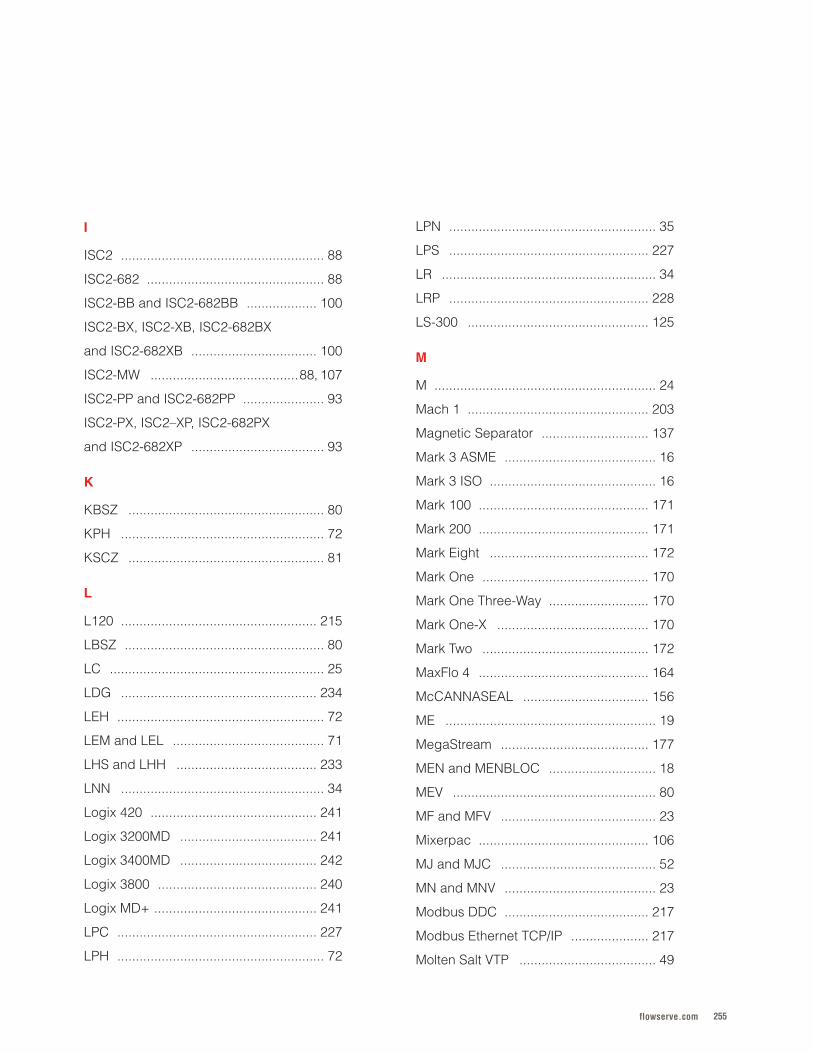
255flowserve.com
I
ISC2 . . . . . . . . . . . . . . . . . . . . . . . . . . . . . . . . . . . . . . . . . . . . . . . . . . . . . . . 88
ISC2-682 . . . . . . . . . . . . . . . . . . . . . . . . . . . . . . . . . . . . . . . . . . . . . . . . 88
ISC2-BB and ISC2-682BB . . . . . . . . . . . . . . . . . . . 100
ISC2-BX, ISC2-XB, ISC2-682BX
and ISC2-682XB . . . . . . . . . . . . . . . . . . . . . . . . . . . . . . . . . . 100
ISC2-MW . . . . . . . . . . . . . . . . . . . . . . . . . . . . . . . . . . . . . . . .88, 107
ISC2-PP and ISC2-682PP . . . . . . . . . . . . . . . . . . . . . . 93
ISC2-PX, ISC2–XP, ISC2-682PX
and ISC2-682XP . . . . . . . . . . . . . . . . . . . . . . . . . . . . . . . . . . . . 93
K
KBSZ . . . . . . . . . . . . . . . . . . . . . . . . . . . . . . . . . . . . . . . . . . . . . . . . . . . . . 80
KPH . . . . . . . . . . . . . . . . . . . . . . . . . . . . . . . . . . . . . . . . . . . . . . . . . . . . . . . 72
KSCZ . . . . . . . . . . . . . . . . . . . . . . . . . . . . . . . . . . . . . . . . . . . . . . . . . . . . . 81
L
L120 . . . . . . . . . . . . . . . . . . . . . . . . . . . . . . . . . . . . . . . . . . . . . . . . . . . . . 215
LBSZ . . . . . . . . . . . . . . . . . . . . . . . . . . . . . . . . . . . . . . . . . . . . . . . . . . . . . . 80
LC . . . . . . . . . . . . . . . . . . . . . . . . . . . . . . . . . . . . . . . . . . . . . . . . . . . . . . . . . . 25
LDG . . . . . . . . . . . . . . . . . . . . . . . . . . . . . . . . . . . . . . . . . . . . . . . . . . . . . 234
LEH . . . . . . . . . . . . . . . . . . . . . . . . . . . . . . . . . . . . . . . . . . . . . . . . . . . . . . . . 72
LEM and LEL . . . . . . . . . . . . . . . . . . . . . . . . . . . . . . . . . . . . . . . . . 71
LHS and LHH . . . . . . . . . . . . . . . . . . . . . . . . . . . . . . . . . . . . . . 233
LNN . . . . . . . . . . . . . . . . . . . . . . . . . . . . . . . . . . . . . . . . . . . . . . . . . . . . . . . 34
Logix 420 . . . . . . . . . . . . . . . . . . . . . . . . . . . . . . . . . . . . . . . . . . . . . 241
Logix 3200MD . . . . . . . . . . . . . . . . . . . . . . . . . . . . . . . . . . . . . 241
Logix 3400MD . . . . . . . . . . . . . . . . . . . . . . . . . . . . . . . . . . . . . 242
Logix 3800 . . . . . . . . . . . . . . . . . . . . . . . . . . . . . . . . . . . . . . . . . . . 240
Logix MD+ . . . . . . . . . . . . . . . . . . . . . . . . . . . . . . . . . . . . . . . . . . . . 241
LPC . . . . . . . . . . . . . . . . . . . . . . . . . . . . . . . . . . . . . . . . . . . . . . . . . . . . . . 227
LPH . . . . . . . . . . . . . . . . . . . . . . . . . . . . . . . . . . . . . . . . . . . . . . . . . . . . . . . . 72
LPN . . . . . . . . . . . . . . . . . . . . . . . . . . . . . . . . . . . . . . . . . . . . . . . . . . . . . . . . 35
LPS . . . . . . . . . . . . . . . . . . . . . . . . . . . . . . . . . . . . . . . . . . . . . . . . . . . . . . 227
LR . . . . . . . . . . . . . . . . . . . . . . . . . . . . . . . . . . . . . . . . . . . . . . . . . . . . . . . . . . 34
LRP . . . . . . . . . . . . . . . . . . . . . . . . . . . . . . . . . . . . . . . . . . . . . . . . . . . . . . 228
LS-300 . . . . . . . . . . . . . . . . . . . . . . . . . . . . . . . . . . . . . . . . . . . . . . . . . 125
M
M . . . . . . . . . . . . . . . . . . . . . . . . . . . . . . . . . . . . . . . . . . . . . . . . . . . . . . . . . . . . 24
Mach 1 . . . . . . . . . . . . . . . . . . . . . . . . . . . . . . . . . . . . . . . . . . . . . . . . . 203
Magnetic Separator . . . . . . . . . . . . . . . . . . . . . . . . . . . . . 137
Mark 3 ASME . . . . . . . . . . . . . . . . . . . . . . . . . . . . . . . . . . . . . . . . . 16
Mark 3 ISO . . . . . . . . . . . . . . . . . . . . . . . . . . . . . . . . . . . . . . . . . . . . . 16
Mark 100 . . . . . . . . . . . . . . . . . . . . . . . . . . . . . . . . . . . . . . . . . . . . . . 171
Mark 200 . . . . . . . . . . . . . . . . . . . . . . . . . . . . . . . . . . . . . . . . . . . . . . 171
Mark Eight . . . . . . . . . . . . . . . . . . . . . . . . . . . . . . . . . . . . . . . . . . . 172
Mark One . . . . . . . . . . . . . . . . . . . . . . . . . . . . . . . . . . . . . . . . . . . . . 170
Mark One Three-Way . . . . . . . . . . . . . . . . . . . . . . . . . . . 170
Mark One-X . . . . . . . . . . . . . . . . . . . . . . . . . . . . . . . . . . . . . . . . . 170
Mark Two . . . . . . . . . . . . . . . . . . . . . . . . . . . . . . . . . . . . . . . . . . . . . 172
MaxFlo 4 . . . . . . . . . . . . . . . . . . . . . . . . . . . . . . . . . . . . . . . . . . . . . . 164
McCANNASEAL . . . . . . . . . . . . . . . . . . . . . . . . . . . . . . . . . . 156
ME . . . . . . . . . . . . . . . . . . . . . . . . . . . . . . . . . . . . . . . . . . . . . . . . . . . . . . . . . 19
MegaStream . . . . . . . . . . . . . . . . . . . . . . . . . . . . . . . . . . . . . . . . 177
MEN and MENBLOC . . . . . . . . . . . . . . . . . . . . . . . . . . . . . 18
MEV . . . . . . . . . . . . . . . . . . . . . . . . . . . . . . . . . . . . . . . . . . . . . . . . . . . . . . . 80
MF and MFV . . . . . . . . . . . . . . . . . . . . . . . . . . . . . . . . . . . . . . . . . . 23
Mixerpac . . . . . . . . . . . . . . . . . . . . . . . . . . . . . . . . . . . . . . . . . . . . . . 106
MJ and MJC . . . . . . . . . . . . . . . . . . . . . . . . . . . . . . . . . . . . . . . . . . 52
MN and MNV . . . . . . . . . . . . . . . . . . . . . . . . . . . . . . . . . . . . . . . . . 23
Modbus DDC . . . . . . . . . . . . . . . . . . . . . . . . . . . . . . . . . . . . . . . 217
Modbus Ethernet TCP/IP . . . . . . . . . . . . . . . . . . . . . 217
Molten Salt VTP . . . . . . . . . . . . . . . . . . . . . . . . . . . . . . . . . . . . . 49
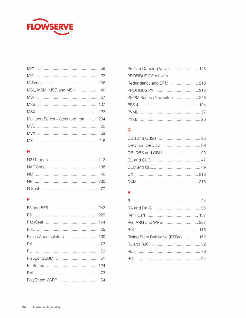
Flowserve Corporation256
MP1 . . . . . . . . . . . . . . . . . . . . . . . . . . . . . . . . . . . . . . . . . . . . . . . . . . . . . . . 59
MPT . . . . . . . . . . . . . . . . . . . . . . . . . . . . . . . . . . . . . . . . . . . . . . . . . . . . . . . 22
M Series . . . . . . . . . . . . . . . . . . . . . . . . . . . . . . . . . . . . . . . . . . . . . . . 106
MSL, MSM, MSC and MSH . . . . . . . . . . . . . . . . . . . 40
MSP . . . . . . . . . . . . . . . . . . . . . . . . . . . . . . . . . . . . . . . . . . . . . . . . . . . . . . . 27
MSS . . . . . . . . . . . . . . . . . . . . . . . . . . . . . . . . . . . . . . . . . . . . . . . . . . . . . 107
MSX . . . . . . . . . . . . . . . . . . . . . . . . . . . . . . . . . . . . . . . . . . . . . . . . . . . . . . . 23
Multiport Series – Steel and Iron . . . . . . . . . 204
MVE . . . . . . . . . . . . . . . . . . . . . . . . . . . . . . . . . . . . . . . . . . . . . . . . . . . . . . . 22
MVX . . . . . . . . . . . . . . . . . . . . . . . . . . . . . . . . . . . . . . . . . . . . . . . . . . . . . . . 53
MX . . . . . . . . . . . . . . . . . . . . . . . . . . . . . . . . . . . . . . . . . . . . . . . . . . . . . . . 216
N
N2 Genpac . . . . . . . . . . . . . . . . . . . . . . . . . . . . . . . . . . . . . . . . . . 112
NAF Check . . . . . . . . . . . . . . . . . . . . . . . . . . . . . . . . . . . . . . . . . . 198
NM . . . . . . . . . . . . . . . . . . . . . . . . . . . . . . . . . . . . . . . . . . . . . . . . . . . . . . . . . 40
NR . . . . . . . . . . . . . . . . . . . . . . . . . . . . . . . . . . . . . . . . . . . . . . . . . . . . . . . . 230
N-Seal . . . . . . . . . . . . . . . . . . . . . . . . . . . . . . . . . . . . . . . . . . . . . . . . . . . . 77
P
P5 and EP5 . . . . . . . . . . . . . . . . . . . . . . . . . . . . . . . . . . . . . . . . . . 242
P61 . . . . . . . . . . . . . . . . . . . . . . . . . . . . . . . . . . . . . . . . . . . . . . . . . . . . . . 229
Pac-Seal . . . . . . . . . . . . . . . . . . . . . . . . . . . . . . . . . . . . . . . . . . . . . . 124
PHL . . . . . . . . . . . . . . . . . . . . . . . . . . . . . . . . . . . . . . . . . . . . . . . . . . . . . . . . 25
Piston Accumulators . . . . . . . . . . . . . . . . . . . . . . . . . . . . 130
PK . . . . . . . . . . . . . . . . . . . . . . . . . . . . . . . . . . . . . . . . . . . . . . . . . . . . . . . . . . 73
PL . . . . . . . . . . . . . . . . . . . . . . . . . . . . . . . . . . . . . . . . . . . . . . . . . . . . . . . . . . 73
Pleuger SUBM . . . . . . . . . . . . . . . . . . . . . . . . . . . . . . . . . . . . . . . 51
PL Series . . . . . . . . . . . . . . . . . . . . . . . . . . . . . . . . . . . . . . . . . . . . . 124
PM . . . . . . . . . . . . . . . . . . . . . . . . . . . . . . . . . . . . . . . . . . . . . . . . . . . . . . . . . 73
PolyChem VGRP . . . . . . . . . . . . . . . . . . . . . . . . . . . . . . . . . . . . 54
ProCap Capping Valve . . . . . . . . . . . . . . . . . . . . . . . . 148
PROFIBUS DP V1 with
Redundancy and DTM . . . . . . . . . . . . . . . . . . . . . . . . 218
PROFIBUS PA . . . . . . . . . . . . . . . . . . . . . . . . . . . . . . . . . . . . . . 218
PS/PM Series Ultraswitch . . . . . . . . . . . . . . . . . . . . 246
PSS 4 . . . . . . . . . . . . . . . . . . . . . . . . . . . . . . . . . . . . . . . . . . . . . . . . . . . 124
PVML . . . . . . . . . . . . . . . . . . . . . . . . . . . . . . . . . . . . . . . . . . . . . . . . . . . . . 27
PVXM . . . . . . . . . . . . . . . . . . . . . . . . . . . . . . . . . . . . . . . . . . . . . . . . . . . . . 26
Q
QBB and QB2B . . . . . . . . . . . . . . . . . . . . . . . . . . . . . . . . . . . . . 96
QBQ and QBQ LZ . . . . . . . . . . . . . . . . . . . . . . . . . . . . . . . . . 96
QB, QBS and QBU . . . . . . . . . . . . . . . . . . . . . . . . . . . . . . . . 93
QL and QLQ . . . . . . . . . . . . . . . . . . . . . . . . . . . . . . . . . . . . . . . . . . 47
QLC and QLQC . . . . . . . . . . . . . . . . . . . . . . . . . . . . . . . . . . . . . 49
QX . . . . . . . . . . . . . . . . . . . . . . . . . . . . . . . . . . . . . . . . . . . . . . . . . . . . . . . . 216
QXM . . . . . . . . . . . . . . . . . . . . . . . . . . . . . . . . . . . . . . . . . . . . . . . . . . . . . 216
R
R . . . . . . . . . . . . . . . . . . . . . . . . . . . . . . . . . . . . . . . . . . . . . . . . . . . . . . . . . . . . 24
RA and RA-C . . . . . . . . . . . . . . . . . . . . . . . . . . . . . . . . . . . . . . . . . 95
Refill Cart . . . . . . . . . . . . . . . . . . . . . . . . . . . . . . . . . . . . . . . . . . . . . 137
RG, ARG and WRG . . . . . . . . . . . . . . . . . . . . . . . . . . . . . 227
RIS . . . . . . . . . . . . . . . . . . . . . . . . . . . . . . . . . . . . . . . . . . . . . . . . . . . . . . . 116
Rising Stem Ball Valve (RSBV) . . . . . . . . . . . . 152
RJ and RJC . . . . . . . . . . . . . . . . . . . . . . . . . . . . . . . . . . . . . . . . . . . 52
RLIJ . . . . . . . . . . . . . . . . . . . . . . . . . . . . . . . . . . . . . . . . . . . . . . . . . . . . . . . 79
RO . . . . . . . . . . . . . . . . . . . . . . . . . . . . . . . . . . . . . . . . . . . . . . . . . . . . . . . . . 94
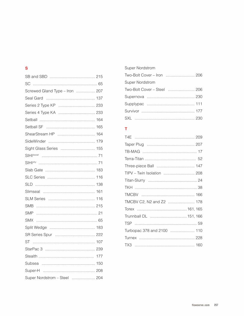
257flowserve.com
S
SB and SBD . . . . . . . . . . . . . . . . . . . . . . . . . . . . . . . . . . . . . . . . . 215
SC . . . . . . . . . . . . . . . . . . . . . . . . . . . . . . . . . . . . . . . . . . . . . . . . . . . . . . . . . . 65
Screwed Gland Type – Iron . . . . . . . . . . . . . . . . . 207
Seal Gard . . . . . . . . . . . . . . . . . . . . . . . . . . . . . . . . . . . . . . . . . . . . 137
Series 2 Type KP . . . . . . . . . . . . . . . . . . . . . . . . . . . . . . . . . 233
Series 4 Type KA . . . . . . . . . . . . . . . . . . . . . . . . . . . . . . . . . 233
Setball . . . . . . . . . . . . . . . . . . . . . . . . . . . . . . . . . . . . . . . . . . . . . . . . . . 164
Setball SF . . . . . . . . . . . . . . . . . . . . . . . . . . . . . . . . . . . . . . . . . . . . 165
ShearStream HP . . . . . . . . . . . . . . . . . . . . . . . . . . . . . . . . . . 164
SideWinder . . . . . . . . . . . . . . . . . . . . . . . . . . . . . . . . . . . . . . . . . . 179
Sight Glass Series . . . . . . . . . . . . . . . . . . . . . . . . . . . . . . . 155
SIHIboost . . . . . . . . . . . . . . . . . . . . . . . . . . . . . . . . . . . . . . . . . . . . . . . . . . 71
SIHIdry . . . . . . . . . . . . . . . . . . . . . . . . . . . . . . . . . . . . . . . . . . . . . . . . . . . . . 71
Slab Gate . . . . . . . . . . . . . . . . . . . . . . . . . . . . . . . . . . . . . . . . . . . . . 183
SLC Series . . . . . . . . . . . . . . . . . . . . . . . . . . . . . . . . . . . . . . . . . . . 116
SLD . . . . . . . . . . . . . . . . . . . . . . . . . . . . . . . . . . . . . . . . . . . . . . . . . . . . . . 138
Slimseal . . . . . . . . . . . . . . . . . . . . . . . . . . . . . . . . . . . . . . . . . . . . . . . 161
SLM Series . . . . . . . . . . . . . . . . . . . . . . . . . . . . . . . . . . . . . . . . . . 116
SMB . . . . . . . . . . . . . . . . . . . . . . . . . . . . . . . . . . . . . . . . . . . . . . . . . . . . . 215
SMP . . . . . . . . . . . . . . . . . . . . . . . . . . . . . . . . . . . . . . . . . . . . . . . . . . . . . . . 21
SMX . . . . . . . . . . . . . . . . . . . . . . . . . . . . . . . . . . . . . . . . . . . . . . . . . . . . . . . 65
Split Wedge . . . . . . . . . . . . . . . . . . . . . . . . . . . . . . . . . . . . . . . . . 183
SR Series Spur . . . . . . . . . . . . . . . . . . . . . . . . . . . . . . . . . . . . 222
ST . . . . . . . . . . . . . . . . . . . . . . . . . . . . . . . . . . . . . . . . . . . . . . . . . . . . . . . . 107
StarPac 3 . . . . . . . . . . . . . . . . . . . . . . . . . . . . . . . . . . . . . . . . . . . . . 239
Stealth . . . . . . . . . . . . . . . . . . . . . . . . . . . . . . . . . . . . . . . . . . . . . . . . . . 177
Subsea . . . . . . . . . . . . . . . . . . . . . . . . . . . . . . . . . . . . . . . . . . . . . . . . 150
Super-H . . . . . . . . . . . . . . . . . . . . . . . . . . . . . . . . . . . . . . . . . . . . . . . 208
Super Nordstrom – Steel . . . . . . . . . . . . . . . . . . . . . 204
Super Nordstrom
Two-Bolt Cover – Iron . . . . . . . . . . . . . . . . . . . . . . . . . . 206
Super Nordstrom
Two-Bolt Cover – Steel . . . . . . . . . . . . . . . . . . . . . . . . 206
Supernova . . . . . . . . . . . . . . . . . . . . . . . . . . . . . . . . . . . . . . . . . . . 230
Supplypac . . . . . . . . . . . . . . . . . . . . . . . . . . . . . . . . . . . . . . . . . . . 111
Survivor . . . . . . . . . . . . . . . . . . . . . . . . . . . . . . . . . . . . . . . . . . . . . . . . 177
SXL . . . . . . . . . . . . . . . . . . . . . . . . . . . . . . . . . . . . . . . . . . . . . . . . . . . . . . 230
T
T4E . . . . . . . . . . . . . . . . . . . . . . . . . . . . . . . . . . . . . . . . . . . . . . . . . . . . . . 209
Taper Plug . . . . . . . . . . . . . . . . . . . . . . . . . . . . . . . . . . . . . . . . . . . 207
TB-MAG . . . . . . . . . . . . . . . . . . . . . . . . . . . . . . . . . . . . . . . . . . . . . . . . . 17
Terra-Titan . . . . . . . . . . . . . . . . . . . . . . . . . . . . . . . . . . . . . . . . . . . . . . 52
Three-piece Ball . . . . . . . . . . . . . . . . . . . . . . . . . . . . . . . . . . 147
TIPV – Twin Isolation . . . . . . . . . . . . . . . . . . . . . . . . . . . . 208
Titan-Slurry . . . . . . . . . . . . . . . . . . . . . . . . . . . . . . . . . . . . . . . . . . . . 24
TKH . . . . . . . . . . . . . . . . . . . . . . . . . . . . . . . . . . . . . . . . . . . . . . . . . . . . . . . . 38
TMCBV . . . . . . . . . . . . . . . . . . . . . . . . . . . . . . . . . . . . . . . . . . . . . . . . 166
TMCBV C2, N2 and Z2 . . . . . . . . . . . . . . . . . . . . . . . . 178
Torex . . . . . . . . . . . . . . . . . . . . . . . . . . . . . . . . . . . . . . . . . . . . .161, 165
Trunnball DL . . . . . . . . . . . . . . . . . . . . . . . . . . . . . . . . .151, 166
TSP . . . . . . . . . . . . . . . . . . . . . . . . . . . . . . . . . . . . . . . . . . . . . . . . . . . . . . . . 59
Turbopac 378 and 2100 . . . . . . . . . . . . . . . . . . . . . . 110
Turnex . . . . . . . . . . . . . . . . . . . . . . . . . . . . . . . . . . . . . . . . . . . . . . . . . . 228
TX3 . . . . . . . . . . . . . . . . . . . . . . . . . . . . . . . . . . . . . . . . . . . . . . . . . . . . . . 160
Flowserve Corporation258
U
UC and UCQ . . . . . . . . . . . . . . . . . . . . . . . . . . . . . . . . . . . . . . . . . 94
UEA . . . . . . . . . . . . . . . . . . . . . . . . . . . . . . . . . . . . . . . . . . . . . . . . . . . . . . . 38
UHTW and DHTW . . . . . . . . . . . . . . . . . . . . . . . . . . . . . . . . . . 97
U-MAG . . . . . . . . . . . . . . . . . . . . . . . . . . . . . . . . . . . . . . . . . . . . . . . . . . . 17
Univalve . . . . . . . . . . . . . . . . . . . . . . . . . . . . . . . . . . . . . . . .187, 195
UO and UOP . . . . . . . . . . . . . . . . . . . . . . . . . . . . . . . . . . . . . . . . . 97
UZDL . . . . . . . . . . . . . . . . . . . . . . . . . . . . . . . . . . . . . . . . . . . . . . . . . . . . . 35
V
Valdisk . . . . . . . . . . . . . . . . . . . . . . . . . . . . . . . . . . . . . . . . . .160, 165
Valtek GS . . . . . . . . . . . . . . . . . . . . . . . . . . . . . . . . . . . . . . . . . . . . . 172
ValveSight DTM . . . . . . . . . . . . . . . . . . . . . . . . . . . . . . . . . . . 250
ValveSight DTMs for HART or
Fieldbus Communications . . . . . . . . . . . . . . . . . . . 250
ValveSight for Positioners
and Switch Boxes . . . . . . . . . . . . . . . . . . . . . . . . . . . . . . . . 250
VB2 and VB3 . . . . . . . . . . . . . . . . . . . . . . . . . . . . . . . . . . . . . . . 150
VCT . . . . . . . . . . . . . . . . . . . . . . . . . . . . . . . . . . . . . . . . . . . . . . . . . . . . . . . . 48
VL . . . . . . . . . . . . . . . . . . . . . . . . . . . . . . . . . . . . . . . . . . . . . . . . . . . . . . . . 231
VL-C . . . . . . . . . . . . . . . . . . . . . . . . . . . . . . . . . . . . . . . . . . . . . . . . . . . . . 232
VL-ES . . . . . . . . . . . . . . . . . . . . . . . . . . . . . . . . . . . . . . . . . . . . . . . . . . . 232
VL-UHC . . . . . . . . . . . . . . . . . . . . . . . . . . . . . . . . . . . . . . . . . . . . . . . 232
VPC . . . . . . . . . . . . . . . . . . . . . . . . . . . . . . . . . . . . . . . . . . . . . . . . . . . . . . . . 50
VPL1700 . . . . . . . . . . . . . . . . . . . . . . . . . . . . . . . . . . . . . . . . . . . . . . . . 55
VPL3300 . . . . . . . . . . . . . . . . . . . . . . . . . . . . . . . . . . . . . . . . . . . . . . . . 53
VPL3600 . . . . . . . . . . . . . . . . . . . . . . . . . . . . . . . . . . . . . . . . . . . . . . . . 53
V-Port . . . . . . . . . . . . . . . . . . . . . . . . . . . . . . . . . . . . . . . . . . . . . . . . . . . 154
VR . . . . . . . . . . . . . . . . . . . . . . . . . . . . . . . . . . . . . . . . . . . . . . . . . . . . . . . . 231
VRA . . . . . . . . . . . . . . . . . . . . . . . . . . . . . . . . . . . . . . . . . . . . . . . . . . . . . . 106
V Series Bevel . . . . . . . . . . . . . . . . . . . . . . . . . . . . . . . . . . . . . 222
VT1 . . . . . . . . . . . . . . . . . . . . . . . . . . . . . . . . . . . . . . . . . . . . . . . . . . . . . . 156
VTP . . . . . . . . . . . . . . . . . . . . . . . . . . . . . . . . . . . . . . . . . . . . . . . . . . . . . . . . 47
VW1 . . . . . . . . . . . . . . . . . . . . . . . . . . . . . . . . . . . . . . . . . . . . . . . . . . . . . 149
W
Water Seal Cooler . . . . . . . . . . . . . . . . . . . . . . . . . . . . . . . . 132
WCC . . . . . . . . . . . . . . . . . . . . . . . . . . . . . . . . . . . . . . . . . . . . . . . . . . . . . . 43
WD and WDX . . . . . . . . . . . . . . . . . . . . . . . . . . . . . . . . . . . . . . . . . 39
WDF . . . . . . . . . . . . . . . . . . . . . . . . . . . . . . . . . . . . . . . . . . . . . . . . . . . . . . . 77
WFSD . . . . . . . . . . . . . . . . . . . . . . . . . . . . . . . . . . . . . . . . . . . . . . . . . . . . . 82
WG Series Worm . . . . . . . . . . . . . . . . . . . . . . . . . . . . . . . . . 222
WIK and WIKO . . . . . . . . . . . . . . . . . . . . . . . . . . . . . . . . . . . . . . 43
WS/WM Series Ultraswitch . . . . . . . . . . . . . . . . . . 246
WTB . . . . . . . . . . . . . . . . . . . . . . . . . . . . . . . . . . . . . . . . . . . . . . . . . . . . . . . 37
WUC . . . . . . . . . . . . . . . . . . . . . . . . . . . . . . . . . . . . . . . . . . . . . . . . . . . . . . 50
WUJ . . . . . . . . . . . . . . . . . . . . . . . . . . . . . . . . . . . . . . . . . . . . . . . . . . . . . . . 47
WX . . . . . . . . . . . . . . . . . . . . . . . . . . . . . . . . . . . . . . . . . . . . . . . . . . . . . . . . . 39
WXB and WXB-B . . . . . . . . . . . . . . . . . . . . . . . . . . . . . . . . . . . 41
WXH and WXM . . . . . . . . . . . . . . . . . . . . . . . . . . . . . . . . . . . . . . 40
X
XCL/XML Series Ultraswitch . . . . . . . . . . . . . . . . 247
Z
ZEN, ZDN, ZHN and ZDI . . . . . . . . . . . . . . . . . . . . . . . 20
ZLN, ZLK and ZLI . . . . . . . . . . . . . . . . . . . . . . . . . . . . . . . . . . 19
ZTN, ZTK and ZTI . . . . . . . . . . . . . . . . . . . . . . . . . . . . . . . . . . 20
Z-Trim . . . . . . . . . . . . . . . . . . . . . . . . . . . . . . . . . . . . . . . . . . . . . . . . . . 178

259flowserve.com
Flowserve Corporation260
flowserve.com
Flowserve Corporation5215 North O’Connor Blvd . Suite 2300Irving, Texas 75039-5421 USATelephone: +1 937 890 5839
FLS-1000 (E) May 2018
Flowserve Corporation has established industry leadership in the design and manufacture of its products . When properly selected, this Flowserve product is designed to perform its intended function safely during its useful life . However, the purchaser or user of Flowserve products should be aware that Flowserve products might be used in numerous applications under a wide variety of industrial service conditions . Although Flowserve can provide general guidelines, it cannot provide specific data and warnings for all possible applications . The purchaser/user must therefore assume the ultimate responsibility for the proper sizing and selection, installation, operation, and maintenance of Flowserve products . The purchaser/user should read and understand the Installation Instructions included with the product, and train its employees and contractors in the safe use of Flowserve products in connection with the specific application .
While the information and specifications contained in this literature are believed to be accurate, they are supplied for informative purposes only and should not be considered certified or as a guarantee of satisfactory results by reliance thereon . Nothing contained herein is to be construed as a warranty or guarantee, express or implied, regarding any matter with respect to this product . Because Flowserve is continually improving and upgrading its product design, the specifications, dimensions and information contained herein are subject to change without notice . Should any question arise concerning these provisions, the purchaser/user should contact Flowserve Corporation at any one of its worldwide operations or offices .
©2018 Flowserve Corporation . All rights reserved . This document contains registered and unregistered trademarks of Flowserve Corporation . Other company, product, or service names may be trademarks or service marks of their respective companies .