Embed Size (px)
Citation preview
1
Last Revision: 03JL2012
1969 THROUGH 1982 CORVETTE TILT & TELESCOPING
STEERING COLUMN DISASSEMBLY & REPAIR INSTRUCTIONS
PAPER #3 Disassembly and Repair Instructions Addressed in this Paper
Degree of Difficulty Page
REPLACE THE WASH/WIPE SWITCH (1977 ONLY) Difficult 2
DIMMER PIVOTS AND TURN SIGNAL LEVERS Difficult 2 & 3
TIGHTEN SUPPORT SCREWS Hardest 4 & 11
BROKEN/FATIGUED MAST JACKET Hardest 4 & 5
REPAIR & REMOVE LOOSE PIVOT PINS Hardest 5 & 6
REPAIR LOOSE LOCK SHOES Hardest 6
REPAIR RACK AND SECTOR Hardest 6
REPAIR THE UPPER BEARINGS Hardest 7
REMOVING STEERING SHAFT FROM STRG COLUMN Hardest 8
ELIMINATE LASH IN THE PLASTIC TILT JOINT Hardest 8
STEERING SHAFT ORIENTATION & LENGTH CHECK Hardest 9
REMOVE SHIFT TUBE FROM BOWL Hardest 9 & 10
INSTALL SHIFT TUBE TO BOWL Hardest 11
How the Paper is Setup This is the third of a series of three papers that address various replacement and
adjustment procedures that can be performed on the Corvette C3 tilt and telescoping
(T&T) steering column.
This paper starts at the point where the steering column has been removed from the car.
Also, the steering wheel, horn parts, shaft lock, ignition lock cylinder, key warning
buzzer, turn signal, ignition, and dimmer switches have been removed from the T&T
steering column. All of these operations were described in detail in Papers #1 & #2.
This paper makes reference to three pages of line drawings. They are entitled Corvette
C3 Tilt & Telescoping Steering Column Disassembly Instruction Pic #1, #2 & #3.
There is a schematic drawing entitled 1969-76 Corvette Tilt & Telescoping Column
Blowup. There is also another schematic entitled Tilt Steering Column w/Key Release &
Dimmer (similar to 77-82) Blowup Pic. This drawing does not show the telescoping
upper shaft but it does show the dimmer and key release parts. For the most part I will
use the callouts from the 1969-76 blowup. The drawings are all available from the author
or from the host website. You will find these pictures and descriptions to be most helpful
when working on your steering column.
The T&T steering columns from 1969 through 1976 are called “round” columns because
the column head is completely circular in shape. Starting in 1977, a characteristic bulge
appeared on the left side of the column head. This bulge housed the headlight dimmer
pivot which actuated a rod which tripped the dimmer switch now mounted on the steering
column jacket down under the dash.
2
Turn Signal Levers The 1969 through 1976 turn signal lever screwed into a metal post inside the steering
column head. The 1977 through 1982 turn signal lever has a metal end that "plugs into"
the plastic (or die cast) dimmer pivot. The lever is held in place with a spring loaded ball
that is part of the pivot. You should be able to push/pull directly on the lever to assemble
or disassemble it from the pivot.
Disassemble the Column Head - Shown On Instruction Pic #1 Remove the tilt and turn signal levers. Remove the three turn signal housing screws #12
located at the 12, 3, and 8 o’clock positions .
On 1977 and later columns the turn signal housing #15 will also contain a dimmer pivot
assembly, a wash/wipe switch (1977 only) and a dimmer rod actuator which will come
with the housing and its end cap. Be careful of the end cap and dimmer switch rod
actuator. Separate the actuator from the cap by simply pulling them apart. They are held
together by grease. Note, the above parts are not shown on the 1969-76 blowup pic.
Guide the (1977) wash/wipe wires out of the column as you remove the cover. It is a
good idea to tie a tracer string to the wiring connector to aid when you reassemble it.
1977 Dimmer Pivot with Wash/Wipe Switch The 1977 steering column had the dimmer, turn signal, and windshield wash/wipe all
integrated into the turn signal lever. This was a one year only system and the dimmer
pivot with integral wash/wipe switch was shared with the Chevette. The pivot/switch is
attached to the inside of the turn signal switch housing by screw. To remove the
pivot/switch you must feed the wash/wipe switch wires back through the housing. Then
remove the pivot screw. The pivot/switch can then be pulled from the housing. The
1977 dimmer pivot/wash/wipe switch is GM #7827252 but it is no longer available
through GM dealers. The turn signal/wash wipe lever is Doc Rebuild 2897112.
1978-82 Dimmer Pivots & Turn Signal Levers For the 1978 model year the C3 wash/wipe switch was returned to the instrument panel.
So the pivot was simplified. However, from 1978 through 1982 there were three
different combinations of dimmer pivots and turn signal levers. For some years
(particularly 1978-79) you are going to need to determine which vintage dimmer pivot
that you have.
1978 SOP had a dimmer pivot (Corvette Central #563002) that was held in place in the
turn signal housing by means of a big screw and the turn signal lever mounting hole in
the pivot was at a shallow 21 degrees.
1978 Late to 1979 - The attachment of the dimmer pivot was changed from a screw to a
pressed-in pin (Corvette Central dimmer pivot #563001). So you will need to know if
your housing is threaded for the screw or does it have a hole for the pressed-in pin. I do
not have any information as to how “early” or “late” in the model year the change
occurred. The turn signal lever hole in the pivot remained at 21 degrees.

3
Dimmer Pivots & Turn Signal Levers (Continued) The 78 to 79 - The turn signal lever w/cruise (GM 25030522, ZIP SC-337 or Doc
Rebuild #2897116) had a 30 degree bend in it because the dimmer pivot had the lever
mounting hole that was at a shallow angle (21 degrees) and the lever needs to bend
toward the steering wheel rim such that the driver can easily reach the cruise button.
The 78-82 T&T turn signal lever w/o cruise was GM 14009242, ZIP SC-333 or Doc
Rebuild #2897118. It was a straight lever.
The next change occurred late in the 1979 model year. The angle of the turn signal lever
mounting hole in the dimmer pivot was changed to 46 degrees. The turn signal lever now
was pointed more directly at the steering wheel and the turn signal lever was straight.
Zip Products lists a 79L-82 Turn Signal Arm Pivot Assembly SC-756. This should be the
pivot that works with straight turn signal levers.
Here are the T&T levers that I think work with the 46 degree pivot. GM 25030492, Zip
Products 79L-80 Turn Signal Lever w/tele & w/o cruise SC-332. 1981-82 Turn Signal
Lever w/cruise (Resume Switch on side of lever) – very rare and hard to find.
Continue Disassembly of T&T Strg Column Head
Remove Tilt Spring - Shown On Instruction Pic #2 Replace the tilt lever and place the column in the full “up” position.
Caution: The spring is quite powerful, without the steering wheel to counterbalance its
force, the column head can spring upward with a lot of energy.
Remove the tilt lever spring retainer #16 using a tool that just fits into the slot opening.
Note, the picture on page #6 shows a screwdriver blade being inserted into the retainer
slot for removal/installation. Early retainers have a slot, later retainers have a square
hole. A medium size Phillips bit will fit the square shape quite well.
Caution: The spring is compressed with a lot of force. Press squarely on the retainer
and press in approximately 3/16 inch, turn 1/8 turn counterclockwise until the ears align
with the grooves in the housing and remove the retainer, spring #17, and guide #18.
Remove Dimmer and/or Ignition Switch – Shown On Instruction Pic #3 The dimmer switch and/or the ignition switch should already have been removed from
the steering column jacket. Reference Paper #2; pages 4, 5, & 6.
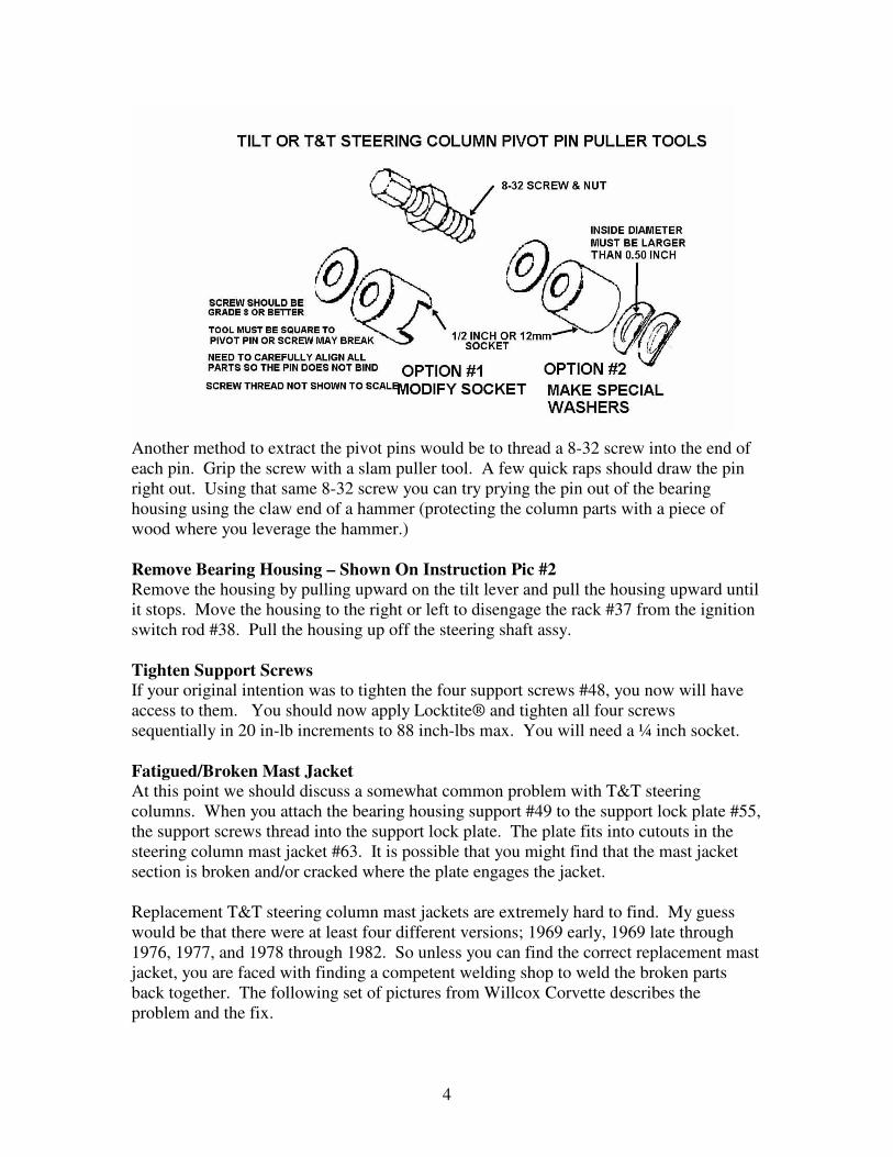
Remove Pivot Pin - Shown On Instruction Pic #2 Remove the two pivot pins #35. Each of the pins has a tapped hole so that you can use
the GM tool or jury rig a puller using an 8-32 screw, nut, washer, and a ½ inch or a
12mm socket. Bridge each pin with the socket and use the screw and nut to pull them
out. You will note that the bowl of the transmission control lock tube housing #58 comes
right up to the edge of each pivot pin. You cannot react against the fragile bowl. But you
also must keep your removal tool square to the pivot pins. Two home made tools that
provide clearance to the bowl and keep things square are shown on the next page.
4
Another method to extract the pivot pins would be to thread a 8-32 screw into the end of
each pin. Grip the screw with a slam puller tool. A few quick raps should draw the pin
right out. Using that same 8-32 screw you can try prying the pin out of the bearing
housing using the claw end of a hammer (protecting the column parts with a piece of
wood where you leverage the hammer.)
Remove Bearing Housing – Shown On Instruction Pic #2 Remove the housing by pulling upward on the tilt lever and pull the housing upward until
it stops. Move the housing to the right or left to disengage the rack #37 from the ignition
switch rod #38. Pull the housing up off the steering shaft assy.
Tighten Support Screws If your original intention was to tighten the four support screws #48, you now will have
access to them. You should now apply Locktite® and tighten all four screws
sequentially in 20 in-lb increments to 88 inch-lbs max. You will need a ¼ inch socket.
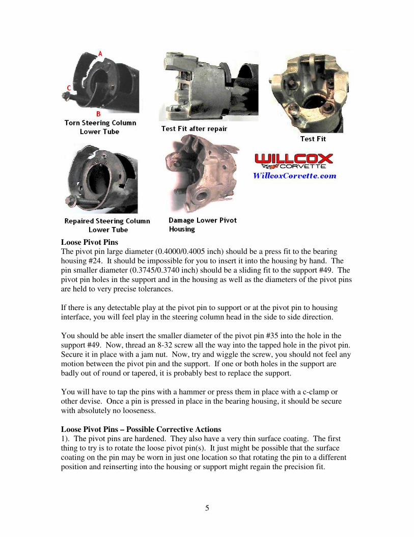
Fatigued/Broken Mast Jacket At this point we should discuss a somewhat common problem with T&T steering
columns. When you attach the bearing housing support #49 to the support lock plate #55,
the support screws thread into the support lock plate. The plate fits into cutouts in the
steering column mast jacket #63. It is possible that you might find that the mast jacket
section is broken and/or cracked where the plate engages the jacket.
Replacement T&T steering column mast jackets are extremely hard to find. My guess
would be that there were at least four different versions; 1969 early, 1969 late through
1976, 1977, and 1978 through 1982. So unless you can find the correct replacement mast
jacket, you are faced with finding a competent welding shop to weld the broken parts
back together. The following set of pictures from Willcox Corvette describes the
problem and the fix.
5
Loose Pivot Pins The pivot pin large diameter (0.4000/0.4005 inch) should be a press fit to the bearing
housing #24. It should be impossible for you to insert it into the housing by hand. The
pin smaller diameter (0.3745/0.3740 inch) should be a sliding fit to the support #49. The
pivot pin holes in the support and in the housing as well as the diameters of the pivot pins
are held to very precise tolerances.
If there is any detectable play at the pivot pin to support or at the pivot pin to housing
interface, you will feel play in the steering column head in the side to side direction.
You should be able insert the smaller diameter of the pivot pin #35 into the hole in the
support #49. Now, thread an 8-32 screw all the way into the tapped hole in the pivot pin.
Secure it in place with a jam nut. Now, try and wiggle the screw, you should not feel any
motion between the pivot pin and the support. If one or both holes in the support are
badly out of round or tapered, it is probably best to replace the support.
You will have to tap the pins with a hammer or press them in place with a c-clamp or
other devise. Once a pin is pressed in place in the bearing housing, it should be secure
with absolutely no looseness.
Loose Pivot Pins – Possible Corrective Actions 1). The pivot pins are hardened. They also have a very thin surface coating. The first
thing to try is to rotate the loose pivot pin(s). It just might be possible that the surface
coating on the pin may be worn in just one location so that rotating the pin to a different
position and reinserting into the housing or support might regain the precision fit.
6
Loose Pivot Pins – Possible Corrective Actions (Continued) 2). The next approach may be to replace the housing or support with one that has pivot
holes of the correct size. The support #49 from any tilt or T&T column from 1969
through at least 1982 should be an acceptable replacement. However, only a T&T
column with a round head can supply the housing #24 for a 1969 through 76 T&T
column. Only a T&T dimmer column (one with the bulge on the left side of the housing)
can supply a replacement housing for a 1977 through 1982 column. T&T columns were
also available in Cadillacs and big Oldsmobiles from 1969 through the 1970s.
3). The other course of action is to make the pivot pins larger. If you have access to a
machine shop, you could fabricate new pivot pins from hardenable steel with a larger
outside diameter to regain the press fit to the housing and/or the precision slip fit to the
support. Another thing you could try is to plate the original pivot pins. After plating you
will probably have to polish the appropriate diameters so as to attain the proper
interference or slip fit. Remember, a press fit is only a few ten thousandths of an inch of
interference between the pins and the housing holes. Any more interference and the pins
will plow metal out of the mating housing holes as they are being inserted rather than just
expanding the hole to lock them in place.
Loose Lock Shoes There are two lock shoes #25 in every tilt or T&T steering column. Both shoes pivot on
a small pin #27 that is part of the housing #24. They engage a pin #50 that is part of the
support #49. They alternate locking the steering column tilt head one at a time. The
Corvette T&T column has one shoe with four engagement slots while the other shoe has
three slots. This results in seven tilt positions in a Saginaw adjustable steering column.
That is why if you have one bad shoe or the pin is worn where only one shoe pivots, it is
possible that your column head may feel loose at every other tilt position.
Look for a worn shoe pivot pin. The shoes should rotate freely on the pin but there
should be no noticeable looseness. Replace the pin and/or the shoes if needed. DO NOT
LUBRICATE THE SLOTS IN THE LOCK SHOES. They should be “dry as a bone”.
It is possible that the column can be made to “ratchet” all the way to the lowest tilt
position if the slots are lubricated.
If you have access to a donor tilt or T&T steering column, you may find that the lock
shoes do not have locking slots in exactly the same location as the shoes from your
Corvette T&T. The Corvette column had the maximum amount of tilt adjustment travel
of any of the GM columns. Tilt shoes from other adjustable columns will still fit your
housing but may slightly restrict your maximum up or down tilt travel.
Remove Rack and Sector – Shown On Instruction Pic #2 Remove the tilt lever opening shield #20 from the housing and also the turn signal lever
opening shield #19 if so equipped. Remove the lock bolt spring #23 by removing the
spring retaining screw #32, and moving the spring clockwise to remove the lock bolt #22.
If there is a snap ring #33, remove it from the sector drive shaft #26. With a small punch
lightly tap the drive shaft from the sector #34. Remove the drive shaft. Remove the rack
#37 and rack spring #36 (also a shim, if there is one). Remove the sector and bolt.
7
Replace the Upper Bearings – Missing Balls/Broken Separator - Instruction Pic #2 There are two identical bearings (#21 & #39) located in the bearing housing #24, they are
seated back to back with one inch between them. They consist of an outer race, a plastic
ball separator, and ball bearings. The bearing outer races are press fit into the housing,
one toward the driver and the other one in the other side of the housing pointed in the
opposite direction. The balls ride on inner races. One is permanently pressed onto the
steering shaft yoke #44. The other inner race #10, the one closest to the driver, is a loose
fit to the shaft. This one is preloaded by upper bearing inner race seat #9 that is pushed
by a 100 lb spring #5, and secured with that shaft lock retainer c-clip #2.
The column upper bearing service kit is GM part number 26001827. It contains one
bearing with an inner and outer race.
However, if you need both bearings, I have found that it is cheaper if you purchase GM
kit #7844651. The kit contains two bearings, along with a rack, sector, lock bolt spring,
and screw. Just save the extra parts or replace your thirty year old rack, sector, and
spring while you have the housing apart. You should be able to purchase either kit from
any GM dealer.
One other suggestion. One enthusiast found very similar bearings at a bicycle shop! I
would guess that they were probably a lot cheaper than going through a dealership.
Now that you have the housing removed from the column, place it on a terry cloth
surface. You now need to take a small screwdriver and pop the individual ball bearings
out of the separator. You will soon understand why I recommended a terry cloth work
surface. With all of the balls removed, it is now possible to inspect the plastic separator.
If it is brittle and broken, replace it by reaching into the housing and popping the
separator out of the outer race. If it is in good condition, leave it alone.
Inspect the outer race. If it is in good condition, leave it alone. Otherwise, you need to
reach through the back side of the housing with a thin punch and using the notches that
are in the housing bore to assist you, work the race out of the housing. Press the new
outer race into place.
Caution: Do not press the race into the housing by pushing on the balls, this will cause
them to damage the race and rotation of the steering shaft will feel rough. Snap the new
separator into the outer race. Individually snap the ball bearings into the separator. Make
sure that you lubricate the bearing with the grease that comes in the service kit.
Caution: When you purchase replacement upper bearings you should receive the balls, a
plastic separator, and the outer race as a set. It has come to my attention that the
replacement bearing separator may rub on the original outer race that is pressed into the
bearing housing. This will cause objectionable friction when turning the steering shaft.
Snap the ball bearings into the new separator and make a trial fit to the outer race in the
bearing housing. Check if the new plastic carrier rubs or not. If it rubs you will need to
replace the outer race with the one supplied in the kit. Follow the earlier instructions to
remove and replace the outer race.
8
Removing Steering Shaft from Steering Column At this point it should be fairly easy to remove the steering shaft from the steering
column. First remove the detachable flange from the lower end of the steering column
shaft. With the bearing housing removed the steering shaft should slide right up and out.
However, corrosion can cause this simple procedure to be quite a bit more difficult. The
lower steering column bearing and the lower steering column shaft can be exposed to
road contamination and moisture. The inner race of the lower bearing assembly is a slip
fit over the lower steering shaft and this race can fuse to the shaft with rust. Therefore,
you may need to soak the bearing race and shaft with a penetrant. In some cases the
corrosion can be so bad as to require that you slit the bearing race with a Dremel tool.
Steering Shaft Tilt Joint Lash Check & Lash Elimination Procedure If you have removed the steering shaft assembly from the column, here is a quick test to
determine if the plastic sphere tilt joint is properly snug. Straighten the shaft assembly at
the pivot ball and hold the lower steering shaft as the upper steering shaft sticks straight
out. There should be sufficient friction in the plastic ball to the shaft yokes so that the
upper shaft will remain straight or will just barely slump downward. If the joint is so
loose that the upper shaft falls to a 90 degree angle, most likely you will have some
looseness in the joint where you might detect some steering wheel play while driving.
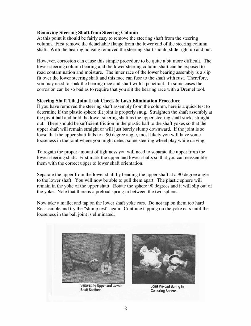
To regain the proper amount of tightness you will need to separate the upper from the
lower steering shaft. First mark the upper and lower shafts so that you can reassemble
them with the correct upper to lower shaft orientation.
Separate the upper from the lower shaft by bending the upper shaft at a 90 degree angle
to the lower shaft. You will now be able to pull them apart. The plastic sphere will
remain in the yoke of the upper shaft. Rotate the sphere 90 degrees and it will slip out of
the yoke. Note that there is a preload spring in between the two spheres.
Now take a mallet and tap on the lower shaft yoke ears. Do not tap on them too hard!
Reassemble and try the “slump test” again. Continue tapping on the yoke ears until the
looseness in the ball joint is eliminated.
9
Reassemble Upper and Lower T&T Steering Shafts at Tilt Joint You can reassemble the shafts by first installing the spring in between the two spheres.
Slide and rotate the spheres into the upper yoke. Position the lower shaft onto the upper
yoke and rotate the lower shaft 90 degrees, making sure that the upper shaft and the lower
shaft are oriented correctly.
Steering Shaft Reassembly Tip - Orientation Upper to Lower Shaft Notice: If for some reason you lose the original orientation of the steering shaft yoke #44
to the lower shaft #47, you will find that you will have two possible ways to reassemble
this connection. If you look closely at the steering shaft yoke, you will note that the end
that points at the steering wheel has two machined flats, one on each side. However, one
flat is longer than the other. This is important because the carrier #4 has a flat that must
mate with the long flat. The carrier also has the turn signal cancelling tabs molded into it.
If you reassemble the shaft yoke to the plastic spheres in the wrong orientation, your turn
signals will not cancel properly. (You probably won’t notice this problem until you have
the column back in the car!)
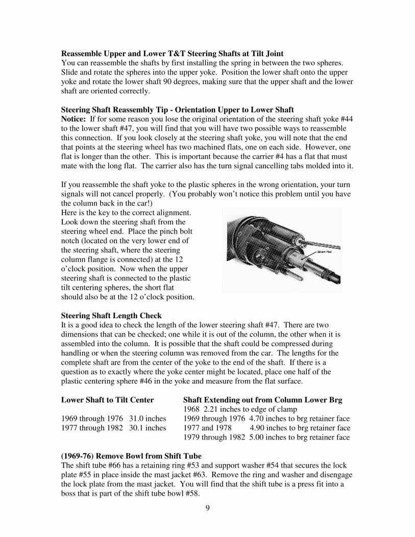
Here is the key to the correct alignment.
Look down the steering shaft from the
steering wheel end. Place the pinch bolt
notch (located on the very lower end of
the steering shaft, where the steering
column flange is connected) at the 12
o’clock position. Now when the upper
steering shaft is connected to the plastic
tilt centering spheres, the short flat
should also be at the 12 o’clock position.
Steering Shaft Length Check It is a good idea to check the length of the lower steering shaft #47. There are two
dimensions that can be checked; one while it is out of the column, the other when it is
assembled into the column. It is possible that the shaft could be compressed during
handling or when the steering column was removed from the car. The lengths for the
complete shaft are from the center of the yoke to the end of the shaft. If there is a
question as to exactly where the yoke center might be located, place one half of the
plastic centering sphere #46 in the yoke and measure from the flat surface.
Lower Shaft to Tilt Center Shaft Extending out from Column Lower Brg 1968 2.21 inches to edge of clamp
1969 through 1976 31.0 inches 1969 through 1976 4.70 inches to brg retainer face
1977 through 1982 30.1 inches 1977 and 1978 4.90 inches to brg retainer face
1979 through 1982 5.00 inches to brg retainer face
(1969-76) Remove Bowl from Shift Tube The shift tube #66 has a retaining ring #53 and support washer #54 that secures the lock
plate #55 in place inside the mast jacket #63. Remove the ring and washer and disengage
the lock plate from the mast jacket. You will find that the shift tube is a press fit into a
boss that is part of the shift tube bowl #58.
10
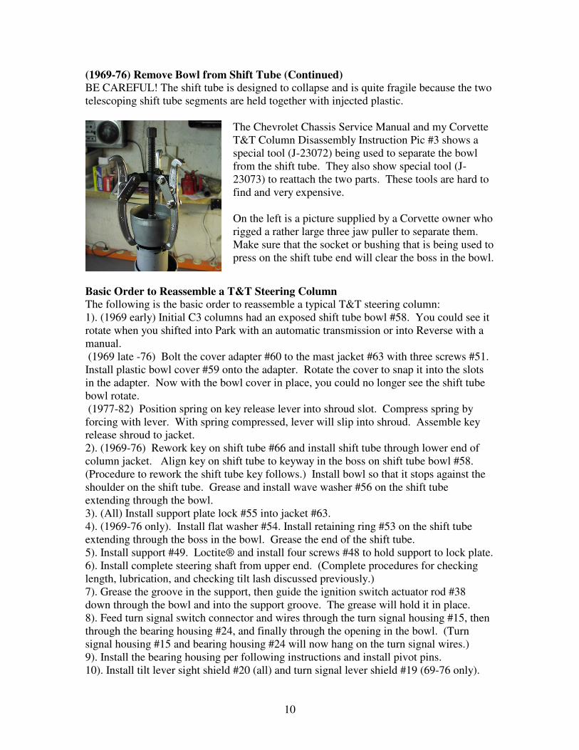
(1969-76) Remove Bowl from Shift Tube (Continued) BE CAREFUL! The shift tube is designed to collapse and is quite fragile because the two
telescoping shift tube segments are held together with injected plastic.
The Chevrolet Chassis Service Manual and my Corvette
T&T Column Disassembly Instruction Pic #3 shows a
special tool (J-23072) being used to separate the bowl
from the shift tube. They also show special tool (J-
23073) to reattach the two parts. These tools are hard to
find and very expensive.
On the left is a picture supplied by a Corvette owner who
rigged a rather large three jaw puller to separate them.
Make sure that the socket or bushing that is being used to
press on the shift tube end will clear the boss in the bowl.
Basic Order to Reassemble a T&T Steering Column The following is the basic order to reassemble a typical T&T steering column:
1). (1969 early) Initial C3 columns had an exposed shift tube bowl #58. You could see it
rotate when you shifted into Park with an automatic transmission or into Reverse with a
manual.
(1969 late -76) Bolt the cover adapter #60 to the mast jacket #63 with three screws #51.
Install plastic bowl cover #59 onto the adapter. Rotate the cover to snap it into the slots
in the adapter. Now with the bowl cover in place, you could no longer see the shift tube
bowl rotate.
(1977-82) Position spring on key release lever into shroud slot. Compress spring by
forcing with lever. With spring compressed, lever will slip into shroud. Assemble key
release shroud to jacket.
2). (1969-76) Rework key on shift tube #66 and install shift tube through lower end of
column jacket. Align key on shift tube to keyway in the boss on shift tube bowl #58.
(Procedure to rework the shift tube key follows.) Install bowl so that it stops against the
shoulder on the shift tube. Grease and install wave washer #56 on the shift tube
extending through the bowl.
3). (All) Install support plate lock #55 into jacket #63.
4). (1969-76 only). Install flat washer #54. Install retaining ring #53 on the shift tube
extending through the boss in the bowl. Grease the end of the shift tube.
5). Install support #49. Loctite® and install four screws #48 to hold support to lock plate.
6). Install complete steering shaft from upper end. (Complete procedures for checking
length, lubrication, and checking tilt lash discussed previously.)
7). Grease the groove in the support, then guide the ignition switch actuator rod #38
down through the bowl and into the support groove. The grease will hold it in place.
8). Feed turn signal switch connector and wires through the turn signal housing #15, then
through the bearing housing #24, and finally through the opening in the bowl. (Turn
signal housing #15 and bearing housing #24 will now hang on the turn signal wires.)
9). Install the bearing housing per following instructions and install pivot pins.
10). Install tilt lever sight shield #20 (all) and turn signal lever shield #19 (69-76 only).
11
Basic Order to Reassemble a T&T Steering Column (continued) 11). Attach the turn signal switch housing to the bearing housing with three screws #12.
12). Attach the spring clip #14 to the key warning buzzer #13 and insert the assembly
into the turn signal housing.
13). Pull the turn signal switch wires and install the switch with three screws #6.
14). Follow instructions in T&T Disassembly & Repair Papers #1 & #2 to complete
assembly of the steering column and steering wheel along with adjustment procedures for
the telescope lock, ignition and dimmer switches.
(1969-76) Reattach Shift Tube to Bowl Once that you have the two apart you now are faced with reattaching them without
damaging the shift tube. Unless you have a special tool to grab the inside of the shift
tube and pull it into the bowl, here is a very good alternate method.
The press fit of the shift tube to the bowl is located on the sides of the raised key (part
of the shift tube neck.) Carefully file the sides of the key so that you eliminate the
interference and convert the attachment to a very close tolerance slip fit. You can
then assemble the tube to the bowl by hand. You want the tube to slide easily through
the bowl until the shoulder on the shift tube stops against the bowl.
Install Support Lock Plate (1969-76) Grease and install wave washer #56 on the end of the shift tube #66. Slide the
support plate lock #55 onto the shift tube.
(All) Work the plate lock into notches in mast jacket #63 by tipping the plate lock toward
12 o’clock position and into the jacket opening. Slide plate lock into notches in the mast
jacket. (It will only lock into place one way.)
(1969-76) Grease and install flat washer #54. Install retaining ring #53 on the shift tube.
Grease the end of the shift tube.
Install Support - Shown On Instruction Pic #3 Align the holes in the support #49 to the tapped holes in the support lock plate. You
should now apply Locktite® and tighten the four screws #48 sequentially in 20 in-lb
increments to 88 inch-lbs max. You will need a ¼ inch socket.
If all you were intending was to tighten the bolts you don’t have to disassemble
everything, apply Locktite® and torque the bolts one at a time.
Reassembly – Sector, Rack, Leaf Spring, & Bolt to Bearing Housing Install the sector shaft #26 into the bearing housing. Lightly tap the sector #34 onto the
shaft far enough to expose the snap ring groove. Replace the snap ring #33 if it was
removed. On later columns, lightly tap the sector onto shaft far enough to snap sector
into drive shaft groove.
Install the lock bolt #22 and engage with the sector. Install the rack #37 and leaf spring
#36. (Replace shim if one was removed.) The big tooth on the sector must engage the
corresponding big space on the rack.
12
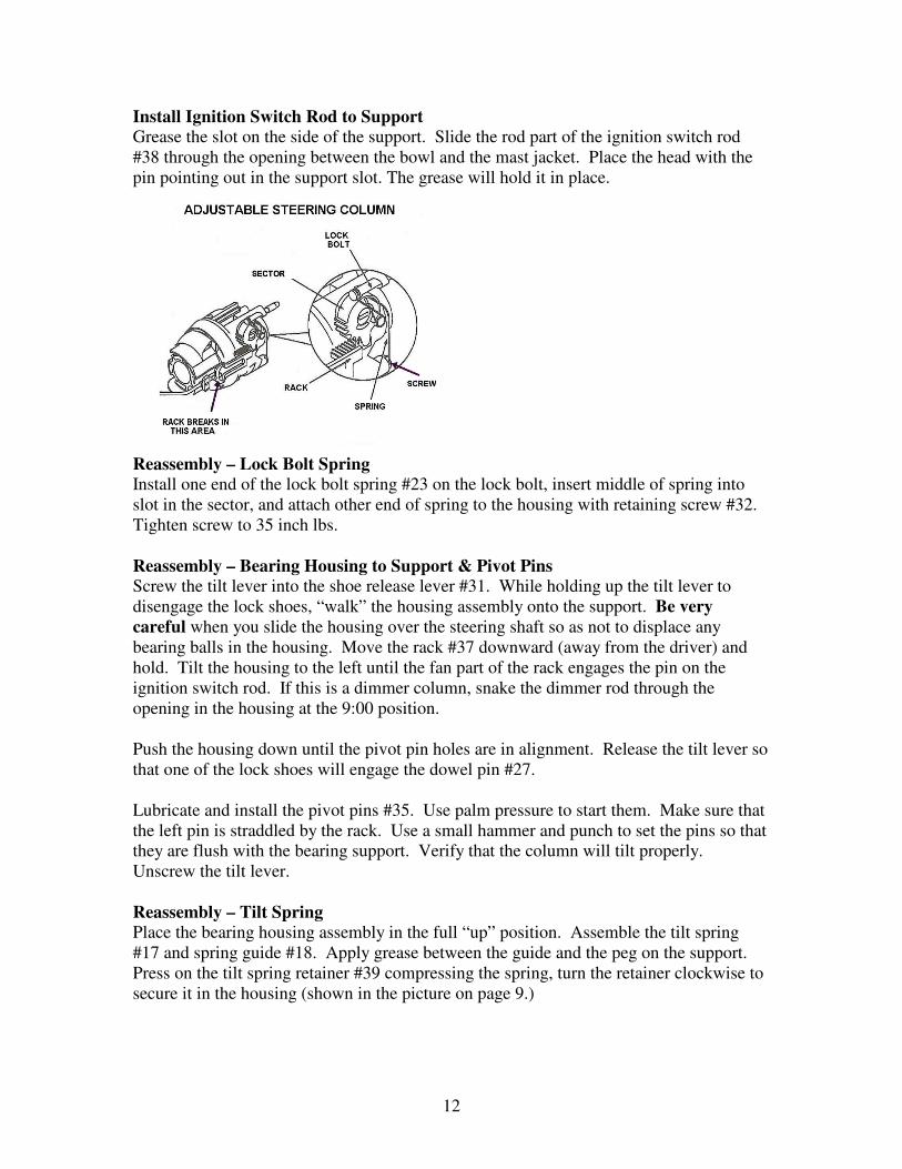
Install Ignition Switch Rod to Support Grease the slot on the side of the support. Slide the rod part of the ignition switch rod
#38 through the opening between the bowl and the mast jacket. Place the head with the
pin pointing out in the support slot. The grease will hold it in place.
Reassembly – Lock Bolt Spring Install one end of the lock bolt spring #23 on the lock bolt, insert middle of spring into
slot in the sector, and attach other end of spring to the housing with retaining screw #32.
Tighten screw to 35 inch lbs.
Reassembly – Bearing Housing to Support & Pivot Pins Screw the tilt lever into the shoe release lever #31. While holding up the tilt lever to
disengage the lock shoes, “walk” the housing assembly onto the support. Be very
careful when you slide the housing over the steering shaft so as not to displace any
bearing balls in the housing. Move the rack #37 downward (away from the driver) and
hold. Tilt the housing to the left until the fan part of the rack engages the pin on the
ignition switch rod. If this is a dimmer column, snake the dimmer rod through the
opening in the housing at the 9:00 position.
Push the housing down until the pivot pin holes are in alignment. Release the tilt lever so
that one of the lock shoes will engage the dowel pin #27.
Lubricate and install the pivot pins #35. Use palm pressure to start them. Make sure that
the left pin is straddled by the rack. Use a small hammer and punch to set the pins so that
they are flush with the bearing support. Verify that the column will tilt properly.
Unscrew the tilt lever.
Reassembly – Tilt Spring Place the bearing housing assembly in the full “up” position. Assemble the tilt spring
#17 and spring guide #18. Apply grease between the guide and the peg on the support.
Press on the tilt spring retainer #39 compressing the spring, turn the retainer clockwise to
secure it in the housing (shown in the picture on page 9.)
13
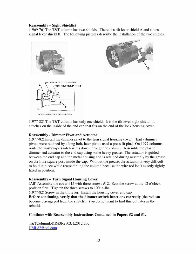
Reassembly – Sight Shield(s) (1969-76) The T&T column has two shields. There is a tilt lever shield A and a turn
signal lever shield B. The following pictures describe the installation of the two shields.
(1977-82) The T&T column has only one shield. It is the tilt lever sight shield. It
attaches on the inside of the end cap that fits on the end of the lock housing cover.
Reassembly - Dimmer Pivot and Actuator (1977-82) Install the dimmer pivot to the turn signal housing cover. (Early dimmer
pivots were retained by a long bolt, later pivots used a press fit pin.) On 1977 columns
route the wash/wipe switch wires down through the column. Assemble the plastic
dimmer rod actuator to the end cap using some heavy grease. The actuator is guided
between the end cap and the metal housing and is retained during assembly by the grease
on the little square post inside the cap. Without the grease, the actuator is very difficult
to hold in place while reassembling the column because the wire rod isn’t exactly tightly
fixed in position.
Reassembly – Turn Signal Housing Cover (All) Assemble the cover #15 with three screws #12. Seat the screw at the 12 o’clock
position first. Tighten the three screws to 100 in-lbs.
(1977-82) Screw in the tilt lever. Install the housing cover end cap.
Before continuing, verify that the dimmer switch functions correctly (the rod can
become disengaged from the switch). You do not want to find this out later in the
rebuild.
Continue with Reassembly Instructions Contained in Papers #2 and #1.
T&TColumnD&R#3Rev03JL2012.doc