Embed Size (px)
DESCRIPTION
18: Ethernet, Hubs, Bridges, Switches. Last Modified: 11/29/2014 6:52:06 AM. Ethernet. “dominant” LAN technology: First widely used LAN technology Kept up with speed race: 10, 100, 1000 Mbps. Metcalfe’s Ethernet sketch. Ethernet Frame Structure. - PowerPoint PPT Presentation
Citation preview

5: DataLink Layer 5a-1
18: Ethernet, Hubs, Bridges, Switches
Last Modified: 04/19/23 04:47 PM

5: DataLink Layer 5a-2
Ethernet“dominant” LAN technology: First widely used LAN technology Kept up with speed race: 10, 100, 1000 Mbps
Metcalfe’s Ethernetsketch

5: DataLink Layer 5a-3
Ethernet Frame Structure
Sending adapter encapsulates IP datagram (or other network layer protocol packet) in Ethernet frame
Preamble: 7 bytes with pattern 10101010 followed by one
byte with pattern 10101011 used to synchronize receiver, sender clock
rates
5: DataLink Layer 5a-4
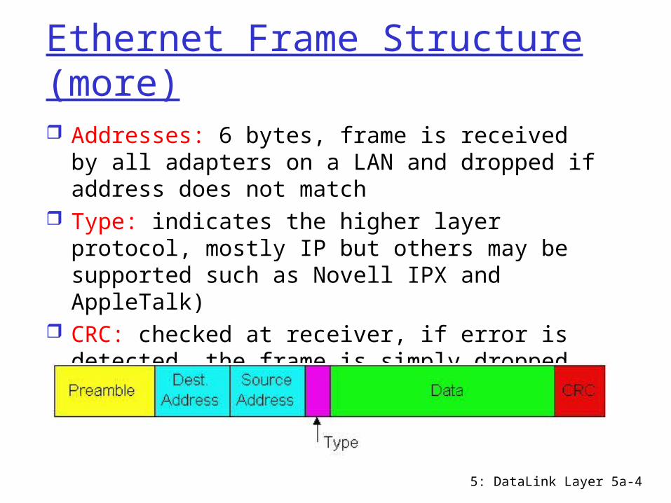
Ethernet Frame Structure (more) Addresses: 6 bytes, frame is received by all
adapters on a LAN and dropped if address does not match
Type: indicates the higher layer protocol, mostly IP but others may be supported such as Novell IPX and AppleTalk)
CRC: checked at receiver, if error is detected, the frame is simply dropped
Data Link Layer 5-5
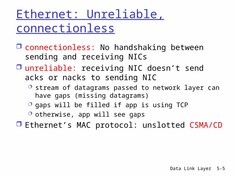
Ethernet: Unreliable, connectionless connectionless: No handshaking between sending
and receiving NICs unreliable: receiving NIC doesn’t send acks or
nacks to sending NIC stream of datagrams passed to network layer can have
gaps (missing datagrams) gaps will be filled if app is using TCP otherwise, app will see gaps
Ethernet’s MAC protocol: unslotted CSMA/CD

5: DataLink Layer 5a-6
Ethernet: uses CSMA/CD
A: sense channel, if idle then {
transmit and monitor the channel; If detect another transmission then { abort and send jam signal;
update # collisions; delay as required by exponential backoff algorithm; goto A}
else {done with the frame; set collisions to zero}}
else {wait until ongoing transmission is over and goto A}

5: DataLink Layer 5a-7
Ethernet’s CSMA/CD (more)
Jam Signal: make sure all other transmitters are aware of collision; 48 bits;
Exponential Backoff: Goal: adapt retransmission attempts to
estimated current load heavy load: random wait will be longer
first collision: choose K from {0,1}; delay is K x 512 bit transmission times
after second collision: choose K from {0,1,2,3}…
after ten or more collisions, choose K from {0,1,2,3,4,…,1023}
Data Link Layer 5-8
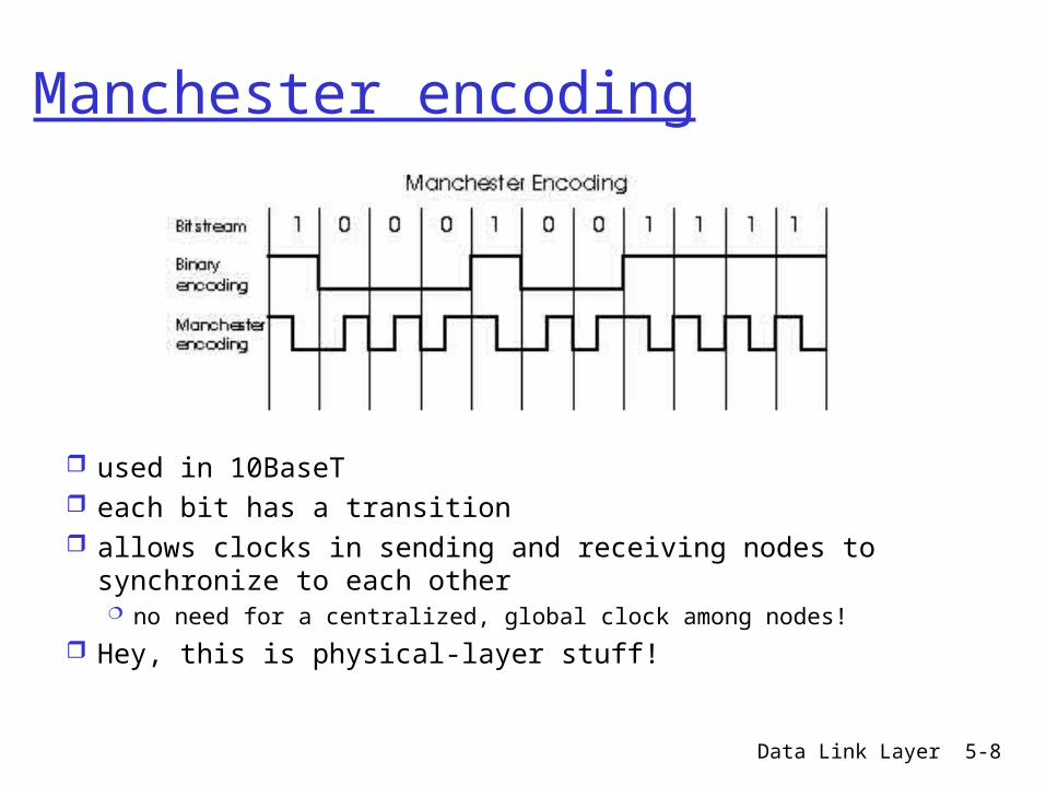
Manchester encoding
used in 10BaseT each bit has a transition allows clocks in sending and receiving nodes to
synchronize to each other no need for a centralized, global clock among nodes!
Hey, this is physical-layer stuff!
5: DataLink Layer 5a-9
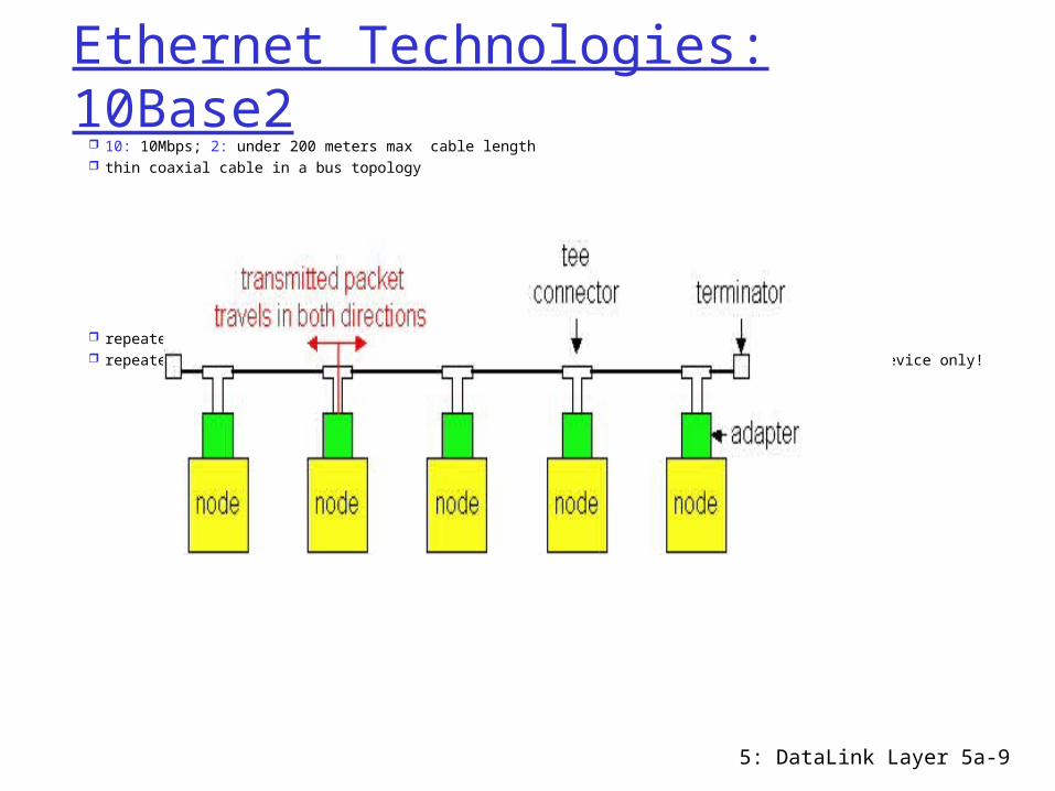
Ethernet Technologies: 10Base2 10: 10Mbps; 2: under 200 meters max cable length thin coaxial cable in a bus topology
repeaters used to connect up to multiple segments repeater repeats bits it hears on one interface to its other interfaces: physical layer device only!
5: DataLink Layer 5a-10
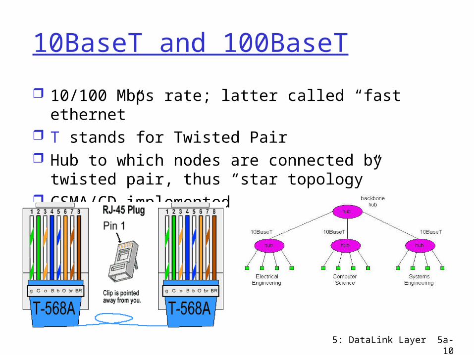
10BaseT and 100BaseT
10/100 Mbps rate; latter called “fast ethernet” T stands for Twisted Pair Hub to which nodes are connected by twisted
pair, thus “star topology” CSMA/CD implemented at hub

5: DataLink Layer 5a-11
10BaseT and 100BaseT (more) Max distance from node to Hub is 100 meters Hub can disconnect “jabbering adapter” Hub can gather monitoring information,
statistics for display to LAN administrators
5: DataLink Layer 5a-12
Gbit Ethernet
use standard Ethernet frame format allows for point-to-point links and shared
broadcast channels in shared mode, CSMA/CD is used; short
distances between nodes to be efficient uses hubs, called here “Buffered Distributors” Full-Duplex at 1 Gbps for point-to-point links
5: DataLink Layer 5a-13
Repeaters Physical Layer devices: operating at bit levels: repeat
received bits on one interface to all other interfaces Extend the range of a signal by amplifying Useful when want to connect devices beyond the IEEE
802.3 specifications for distance limitation of 328 feet or 100 meters
Examples – outdoor installations, mine shafts, remote locations, etc.
5: DataLink Layer 5a-14
Hubs
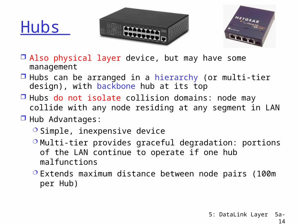
Also physical layer device, but may have some management
Hubs can be arranged in a hierarchy (or multi-tier design), with backbone hub at its top
Hubs do not isolate collision domains: node may collide with any node residing at any segment in LAN
Hub Advantages: Simple, inexpensive device Multi-tier provides graceful degradation: portions of
the LAN continue to operate if one hub malfunctions Extends maximum distance between node pairs
(100m per Hub)
Data Link Layer 5-15
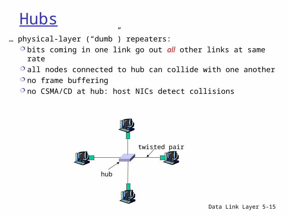
Hubs… physical-layer (“dumb”) repeaters:
bits coming in one link go out all other links at same rate all nodes connected to hub can collide with one another no frame buffering no CSMA/CD at hub: host NICs detect collisions
twisted pair
hub
5: DataLink Layer 5a-16
Hub limitations
Single collision domain results in no increase in max throughput multi-tier throughput same as single segment
throughput Also less secure – hear traffic from/to everyone on
the hub Individual LAN restrictions pose limits on number of
nodes in same collision domain and on total allowed geographical coverage
Difficult to connect different Ethernet types, but can have dual speed hubs (e.g., 10BaseT and 100baseT)
Data Link Layer 5-17
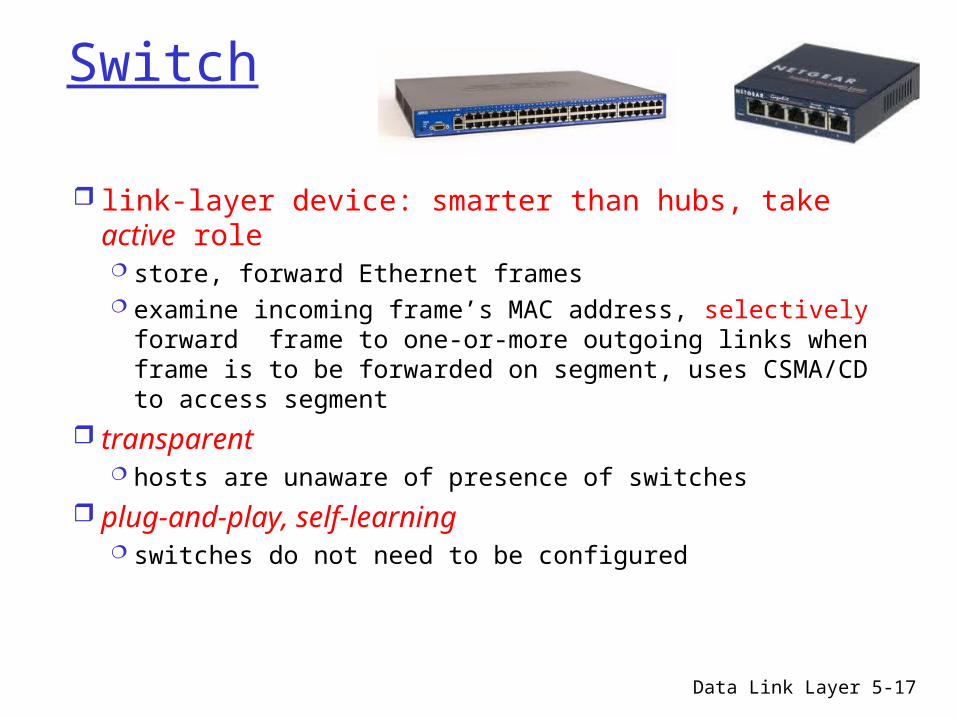
Switch
link-layer device: smarter than hubs, take active role store, forward Ethernet frames examine incoming frame’s MAC address, selectively
forward frame to one-or-more outgoing links when frame is to be forwarded on segment, uses CSMA/CD to access segment
transparent hosts are unaware of presence of switches
plug-and-play, self-learning switches do not need to be configured
Data Link Layer 5-18
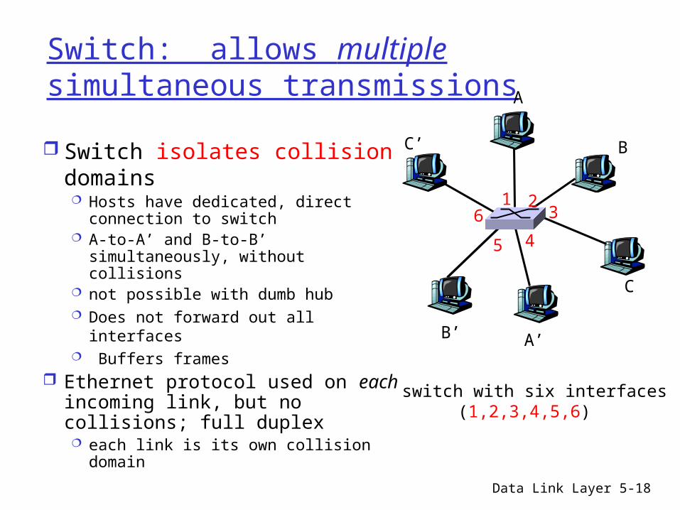
Switch: allows multiple simultaneous transmissions
Switch isolates collision domains Hosts have dedicated, direct
connection to switch A-to-A’ and B-to-B’ simultaneously,
without collisions not possible with dumb hub Does not forward out all interfaces Buffers frames
Ethernet protocol used on each incoming link, but no collisions; full duplex each link is its own collision domain
switch with six interfaces(1,2,3,4,5,6)
A
A’
B
B’
C
C’
1 23
45
6

Collision domain When I speak, who else can I prevent from
speaking at the same time Hub = one collision domain; Switch =
collision domain per port Broadcast domain
When I deliberately send a broadcast address, who all hears it
VLANs separate broadcast domains
5: DataLink Layer 5a-19
Managed vs Unmanaged
Switches more likely than hubs or repeaters to have sophisticated management features
Log in remotely and configure, get reports/statistics etc.
More control over what each port or group of ports can do (e.g. establish groups of ports into virtual LANs or VLANs that further divide the broadcast domain)
5: DataLink Layer 5a-20
5: DataLink Layer 5a-21
Switches (more)
Switch advantages: Isolates collision domains resulting in higher
total max throughput and more security
Can connect different type Ethernet since it is a store and forward device ( dual speed hub is compromise between full switch and hub that does this)
5: DataLink Layer 5a-22
Switch: frame filtering, forwarding
Switches filter packets same-LAN -segment frames not forwarded
onto other LAN segments Forwarding:
how to know which LAN segment on which to forward frame?
looks like a routing problem?
Data Link Layer 5-23
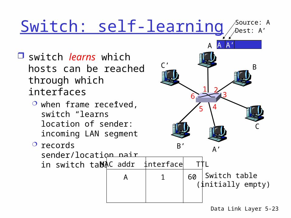
Switch: self-learning
switch learns which hosts can be reached through which interfaces when frame received,
switch “learns” location of sender: incoming LAN segment
records sender/location pair in switch table
A
A’
B
B’
C
C’
1 23
45
6
A A’
Source: ADest: A’
MAC addr interface TTL
Switch table (initially empty)
A 1 60
Data Link Layer 5-24
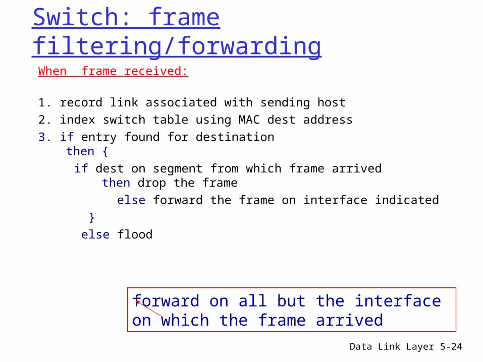
Switch: frame filtering/forwardingWhen frame received:
1. record link associated with sending host2. index switch table using MAC dest address3. if entry found for destination
then { if dest on segment from which frame arrived
then drop the frame else forward the frame on interface indicated } else flood
forward on all but the interface on which the frame arrived
Data Link Layer 5-25
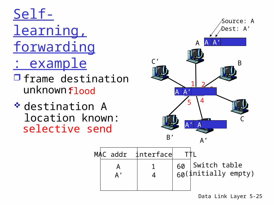
Self-learning, forwarding: example
A
A’
B
B’
C
C’
1 23
45
6
A A’
Source: ADest: A’
MAC addr interface TTL
Switch table (initially empty)
A 1 60
A A’A A’A A’A A’A A’
frame destination unknown:flood
A’ A
destination A location known:
A’ 4 60
selective send
Generally on a switch only see traffic to/from your machine and broadcast traffic
Can attack switch by sending many MACs and overflowing its storage of which MACs on which port => will begin to act like hub ( flooding each packet out every port)
5: DataLink Layer 5a-26
Data Link Layer 5-27
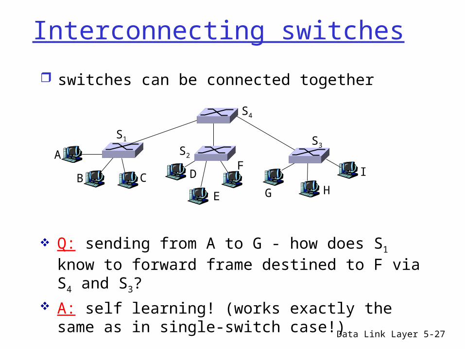
Interconnecting switches
switches can be connected together
A
B
Q: sending from A to G - how does S1 know to forward frame destined to F via S4 and S3?
A: self learning! (works exactly the same as in single-switch case!)
S1
C D
E
FS2
S4
S3
H
I
G
Data Link Layer 5-28
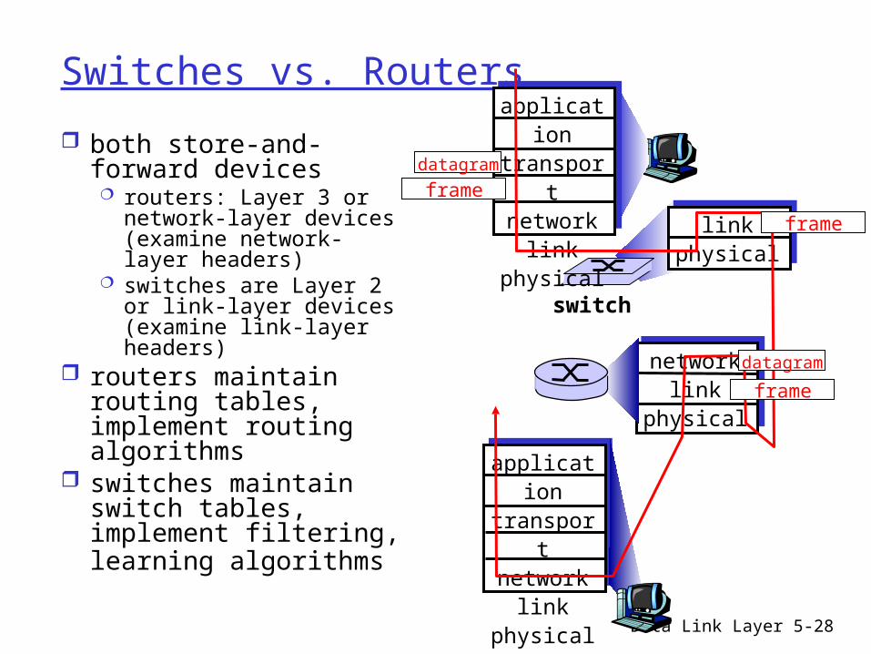
Switches vs. Routers
both store-and-forward devices routers: Layer 3 or
network-layer devices (examine network-layer headers)
switches are Layer 2 or link-layer devices (examine link-layer headers)
routers maintain routing tables, implement routing algorithms
switches maintain switch tables, implement filtering, learning algorithms
application
transportnetwork
linkphysical
networklink
physical
linkphysical
switch
datagram
application
transportnetwork
linkphysical
frame
frame
frame
datagram
5: DataLink Layer 5a-29
Switch Pros and Cons
+ Switch operation is simpler requiring less processing bandwidth
- Topologies are restricted with bridges: a spanning tree must be built to avoid cycles
- Switch do not offer protection from broadcast storms (endless broadcasting by a host will be forwarded by a bridge)
5: DataLink Layer 5a-30
Routers Pros and Cons
+ arbitrary topologies can be supported, cycling is limited by TTL counters (and good routing protocols)
+ provide firewall protection against broadcast storms
- require IP address configuration (not plug and play)
- require higher processing bandwidth
5: DataLink Layer 5a-31
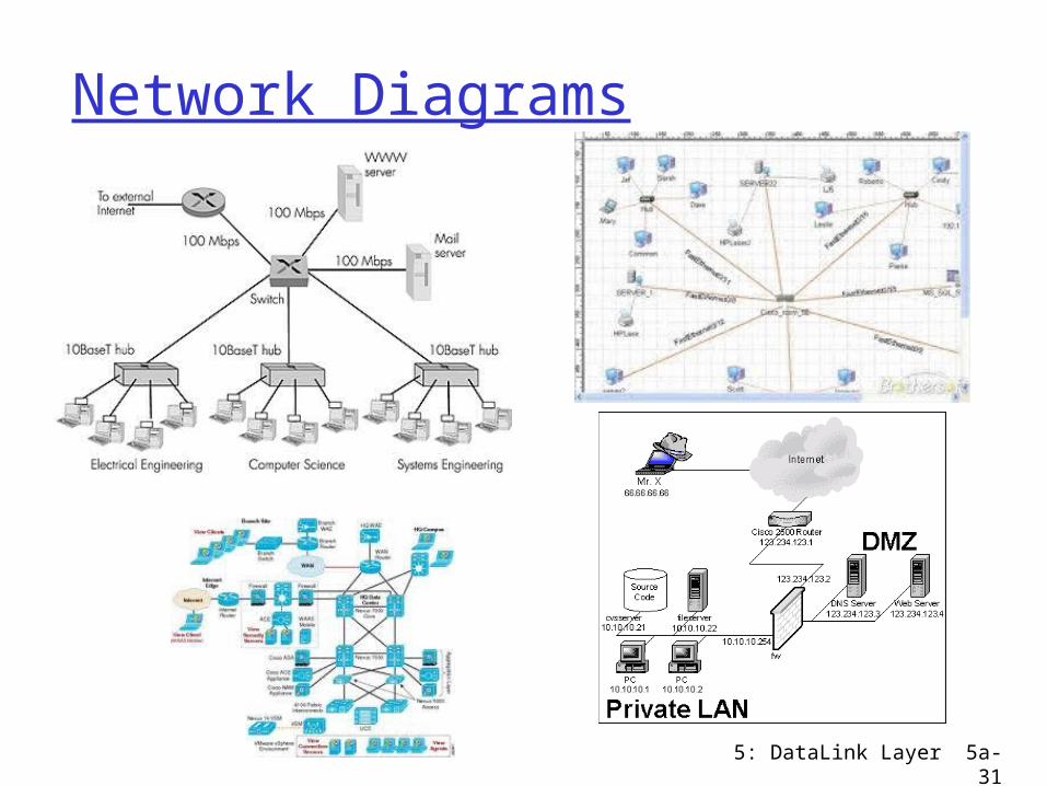
Network Diagrams
Shared
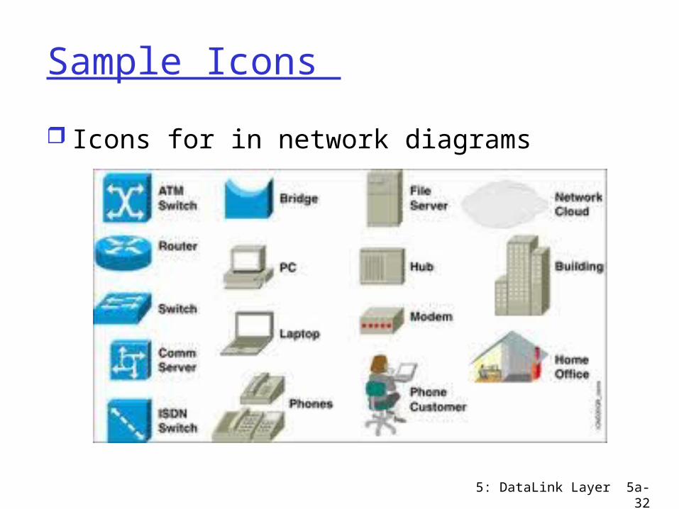
Sample Icons
Icons for in network diagrams
5: DataLink Layer 5a-32
5: DataLink Layer 5a-33
Summary
Layer 3 Devices (Network Layer) Router
Layer 2 Devices (Link Layer) Bridge Switch
Layer 1 Devices (Physical Layer) Repeaters Hubs

5: DataLink Layer 5a-34
Outtakes
Data Link Layer 5-35
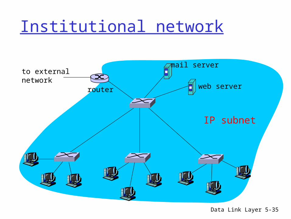
Institutional network
to externalnetwork
router
IP subnet
mail server
web server
5: DataLink Layer 5a-36
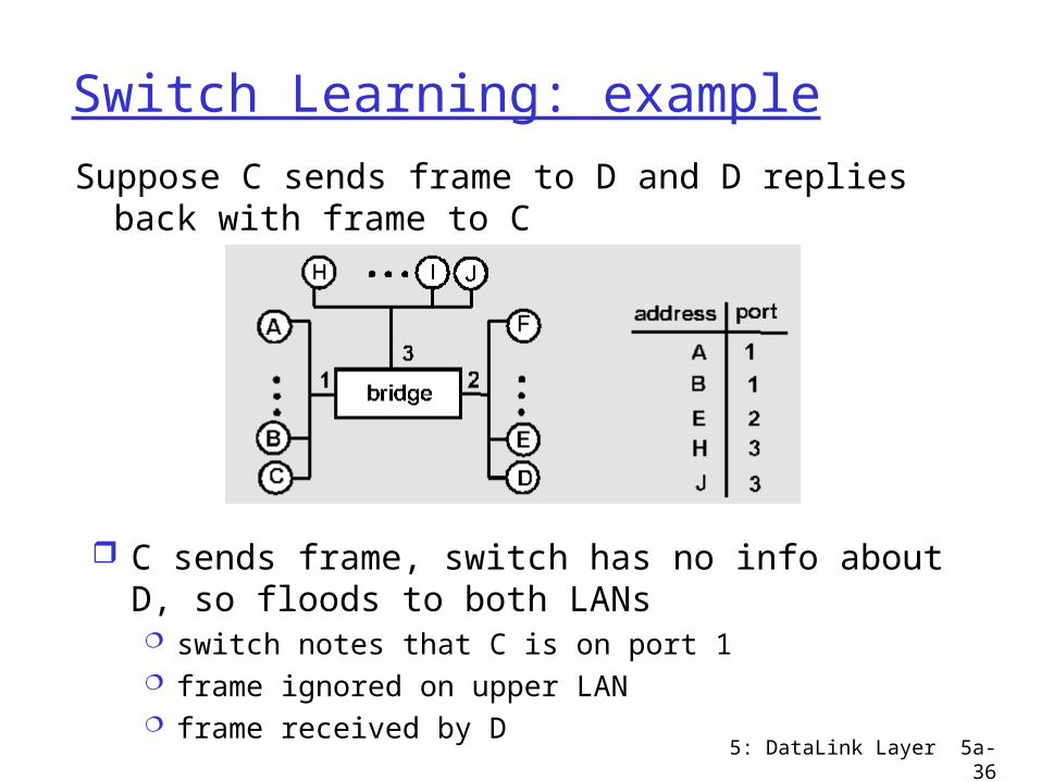
Switch Learning: example
Suppose C sends frame to D and D replies back with frame to C
C sends frame, switch has no info about D, so floods to both LANs switch notes that C is on port 1 frame ignored on upper LAN frame received by D
5: DataLink Layer 5a-37
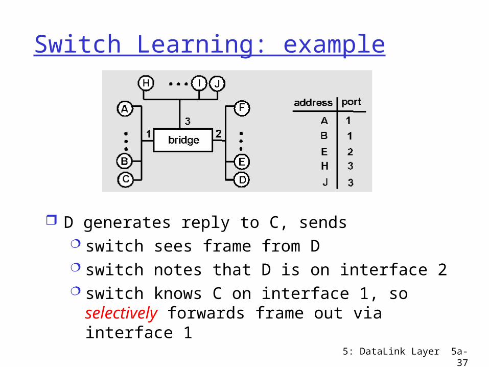
Switch Learning: example
D generates reply to C, sends switch sees frame from D switch notes that D is on interface 2 switch knows C on interface 1, so selectively
forwards frame out via interface 1
5: DataLink Layer 5a-38
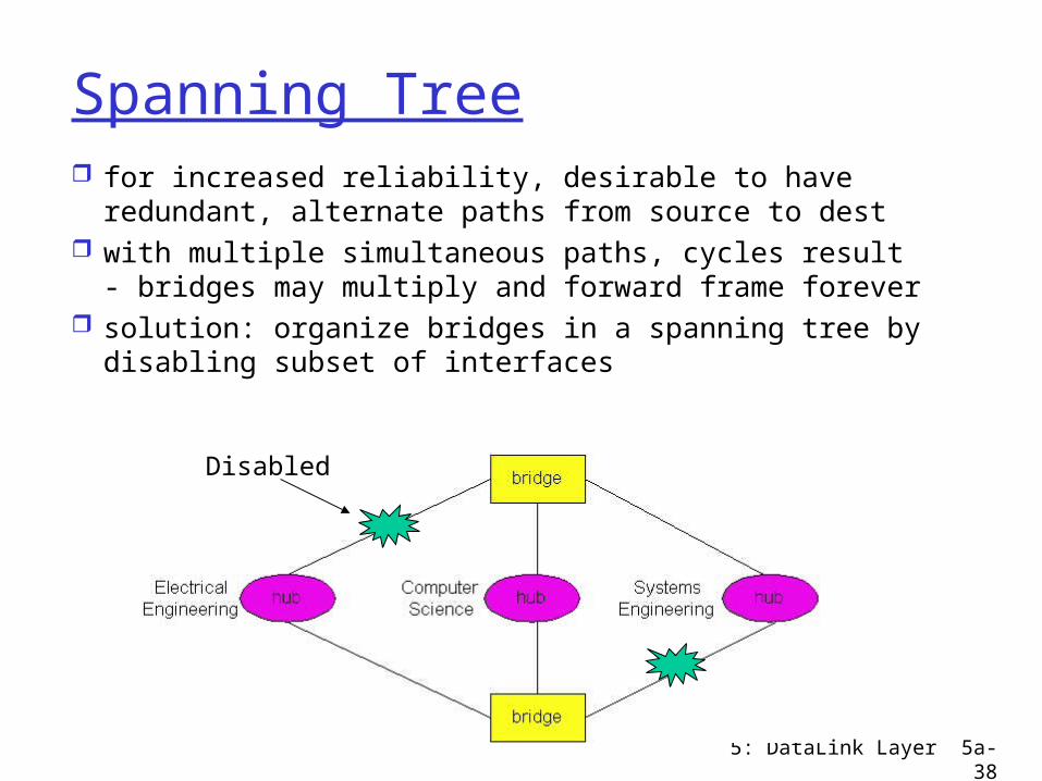
Spanning Tree for increased reliability, desirable to have redundant,
alternate paths from source to dest with multiple simultaneous paths, cycles result -
bridges may multiply and forward frame forever solution: organize bridges in a spanning tree by
disabling subset of interfaces
Disabled
5: DataLink Layer 5a-39
Spanning Tree Algorithm
VLAN tagging
5: DataLink Layer 5a-40
5: DataLink Layer 5a-41
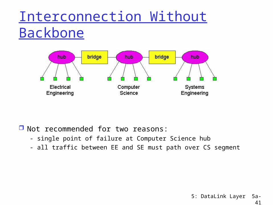
Interconnection Without Backbone
Not recommended for two reasons:- single point of failure at Computer Science hub- all traffic between EE and SE must path over CS segment
5: DataLink Layer 5a-42
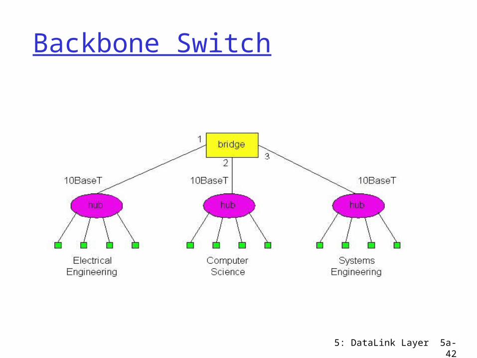
Backbone Switch
5: DataLink Layer 5a-43
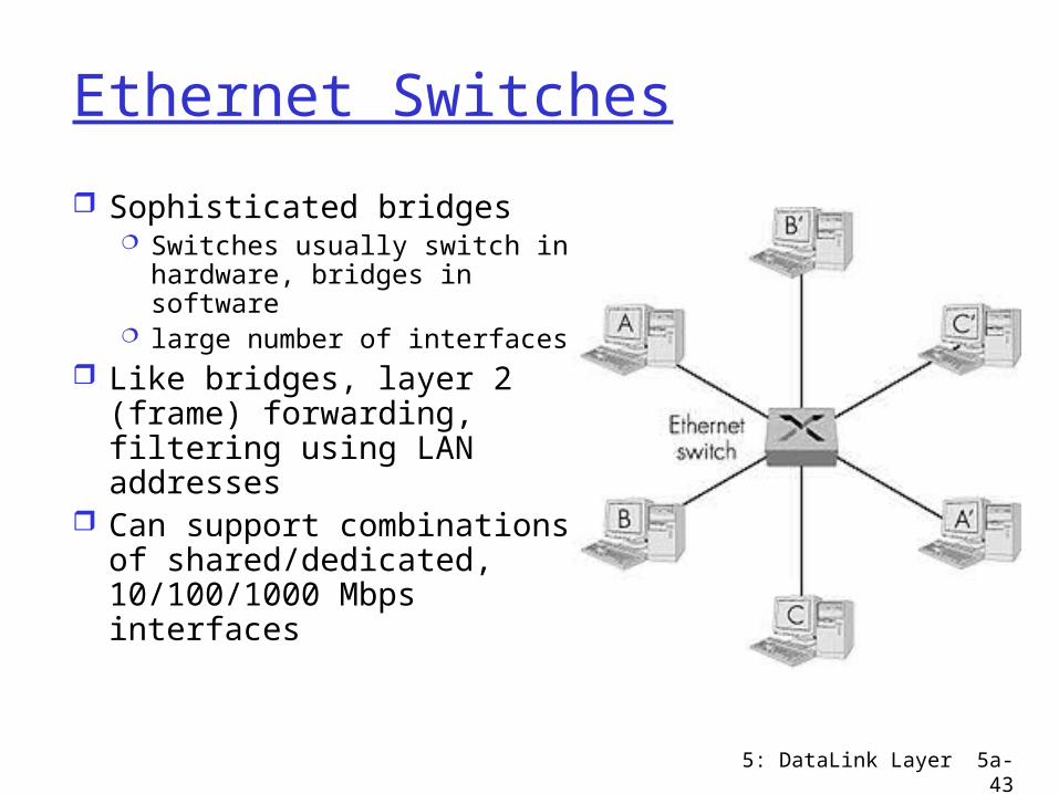
Ethernet Switches
Sophisticated bridges Switches usually switch in
hardware, bridges in software
large number of interfaces Like bridges, layer 2
(frame) forwarding, filtering using LAN addresses
Can support combinations of shared/dedicated, 10/100/1000 Mbps interfaces
5: DataLink Layer 5a-44
Switching
Switching: A-to-B and A’-to-B’ simultaneously, no collisions
cut-through switching: frame forwarded from input to output port without awaiting for assembly of entire frame slight reduction in latency
Store and forward switching: entire frame received before transmission out an output port
Fragment-free switching: compromise, before send out the output port receive enough of the packet to do some error checking (ex. detect and drop partial frames)
5: DataLink Layer 5a-45
Ethernet Limitations
Q: Why not just one big Ethernet? Limited amount of supportable traffic: on
single LAN, all stations must share bandwidth limited length: 802.3 specifies maximum cable
length large “collision domain” (can collide with many
stations)