Embed Size (px)
Citation preview

PREPARED FOR: Shippensburg University 1871 Old Main Dr. Shippensburg, PA 17257 SHIPPENSBURG PROJECT: SU-2017/26 RPA PROJECT: 17117.001 DATE: December 18, 2017
Shippensburg University
Gilbert Hall
HVAC Feasibility Study

Shippensburg University – Gilbert Hall HVAC Feasibility Study
Final Report ǀ December 18, 2017 i
RPA Engineering
TABLE OF CONTENTS
1. EXECUTIVE SUMMARY .......................................................................................... 1
2. INTRODUCTION ............................................................................................ 2
3. EXISTING CONDITIONS ................................................................................ 3
4. METHODOLOGY ............................................................................................ 3
5. DISCUSSION.................................................................................................. 5
6. RECOMMENDATIONS ................................................................................. 11
LIST OF ATTACHMENTS
1. DRAWING M-100: PROPOSED CHILLED WATER ROUTING ..................... 1
2. PRELIMINARY SHAFT LAYOUT .................................................................... 3
3. COST ESTIMATES ......................................................................................... 8
Total

Shippensburg University – Gilbert Hall HVAC Feasibility Study
Final Report ǀ December 18, 2017 1
RPA Engineering
1. EXECUTIVE SUMMARY Shippensburg University retained RPA Engineering to perform a HVAC feasibility study for Gilbert Hall. The intent of the study is to examine three options for a new HVAC system at Gilbert Hall and make a determination of the best match based on first cost, operating cost and the benefits and drawbacks of each system.
Three Mechanical system replacement options were evaluated to provide cooling, heating and ventilation. The systems evaluated are as follows:
1. Option 1: Install a new two pipe fan coil system and connect to the campus central chilled water system and utilize the existing steam radiators for heating. Outdoor air ventilation will be provided through a Dedicated Outdoor Air System (DOAS). The cost of this system is $1,107,000.
2. Option 2A: Install a new four-pipe fan coil system and connect to the campus central chilled water system. Install a steam to hot water converter and utilize hot water heating. Outdoor air ventilation will be provided through a Dedicated Outdoor Air System (DOAS). The cost of this system is $1,345,000.
3. Option 2B: Install a new four-pipe fan coil system and connect to the campus central chilled water system. Install a steam to hot water converter and utilize hot water heating. Outdoor air ventilation will be provided through brick vents. The cost of this system is $1,210,000.
4. Option 3: Install a Variable Refrigerant Flow (VRF) system and utilize the existing steam radiators for supplement heating. Outdoor air ventilation will be provided through a Dedicated Outdoor Air System (DOAS). The cost of this system is $980,000.
RPA recommends Option 2B as it takes full advantage of the central utility plants for heating and cooling, does not require intensive steam trap maintenance, does not require exterior ductwork or a DOAS, and has the ability to heat and cool simultaneously. Additionally, the benefits outweigh the disadvantages at a reasonable cost.

Shippensburg University – Gilbert Hall HVAC Feasibility Study
Final Report ǀ December 18, 2017 2
RPA Engineering
2. INTRODUCTION The scope of this report is to identify the best HVAC system to support Gilbert Hall based on cost, ease of installation and the ability to provide good temperature control and reliable performance.

Shippensburg University – Gilbert Hall HVAC Feasibility Study
Final Report ǀ December 18, 2017 3
RPA Engineering
3. EXISTING CONDITIONS
Chilled water to the Shippensburg Campus is provided by three 1,000 ton VFD centrifugal chillers and one 500 ton air-cooled chiller for a total combined capacity of 3,500 tons of cooling. Heat rejection is via three 1,000 ton cooling towers. Water is circulated by four chilled water pumps. Provisions for the addition of a fourth 1,000 ton chiller and cooling tower (complete with pumps) have been made to account for the addition of future buildings not yet connected to the chilled water system.
Currently, Gilbert Hall is not connected to the central chilled water plant and there is no means of mechanical cooling within the building. Operable windows serve as the primary means of ventilation as well as cooling throughout Gilbert Hall, however there is one split AC system that serves Room 100.
Heating to the Shippensburg Campus is provided through a combination of eleven decentralized heating clusters with hot water condensing boilers and a small, central steam plant with medium-pressure steam service to six buildings. Gilbert Hall is one of the six building which currently uses steam service from the central plant and utilizes a steam pressure reducing station located on the Ground Floor to provide low-pressure steam distribution within the building. Heating is delivered via steam radiators with thermostatic control valves.
Left: Typical Steam Radiator Right: Window Air Conditioner
4. METHODOLOGY
To estimate the heating and cooling requirements of the building the square footage of each space was calculated and assigned a heating and cooling load factor. In addition, occupant

Shippensburg University – Gilbert Hall HVAC Feasibility Study
Final Report ǀ December 18, 2017 4
RPA Engineering
density was determined from the square footage as well as the ventilation requirements from each space. A summary of the loads for each floor were comprised and totaled to represent the complete building heating, cooling and ventilation load.
Building Totals Units Total Ground 1st 2nd
Area SF 11898 3761 4123 4014
Cooling Tons 42 12 19 11 Heating MBH 602 166 272 164
Ventilation CFM 3972 596 2455 921
A dedicated outdoor air system (DOAS) was sized based on the ventilation required, ambient conditions of 95°F summer and 0°F winter and maintaining a 55°F discharge air temperature in the cooling season and an 85°F discharge air temperature in the heating season. For Option 2, a steam to hot water heat exchanger was sized based on 15 psi steam and total heating required for the building. Hot water and chilled water pumps were sized based on the heating and cooling requirements of each building, a temperature differential of 20°F for hot water and a temperature differential of 10°F for chilled water.
For Options 1, 2A and 2B fan coil units were selected to match the heating and cooling requirements for each space to determine a quantity for each size. Piping sizes, lengths and other supporting infrastructure were also developed to provide a complete HVAC system.
Similar methodology was used to develop equipment quantity and size for the VRF system in Option 3.
Once the size and quantity of equipment and infrastructure was determine, costs were determined and organized into three estimates for each option.

Shippensburg University – Gilbert Hall HVAC Feasibility Study
Final Report ǀ December 18, 2017 5
RPA Engineering
Connected Cooling Load, Source Gannett Flemming 2012 Report
The existing chiller plant was designed to accommodate 3,000 tons of cooling and has a connected diversified load of 2,232. Adding Gilbert Hall will result in an additional 50 tons of cooling. However, at 70% diversity, this will equate to 35 tons in addition to the 2,232, resulting in a total new connected load of 2,267. Therefore the chiller plant has adequate capacity to support the additional load as it is currently configured.
Since the overall space use of the building will not change and the building is already connected to the central steam plant, there is a net-zero effect in terms of impact to the central steam plant in terms of the heating with the modifications being considered at Gilbert Hall.
5. DISCUSSION 5.1 – General Construction Considerations The existing building is constructed of stone foundations, brick exterior walls and mostly exposed ceilings. Since there is no ductwork that currently serves the building, new duct shafts will need to be constructed to accommodate each of the three options. Options 1 and 2, which employ hydronic pumping systems, will require additional mechanical space to be allotted to house the pumping equipment. In general, the area used for these new mechanical spaces will need to be

Shippensburg University – Gilbert Hall HVAC Feasibility Study
Final Report ǀ December 18, 2017 6
RPA Engineering
on the ground floor, close to the existing steam pressure reducing station. Option 2 will require both chilled and hot water pumps, as well as a steam to hot water converter and therefore will require the most mechanical space of all options. Consideration should be made during detailed design as to whether the overhead MEP infrastructure should be concealed using an acoustic tile ceiling for aesthetics and noise attenuation. 5.2 –Option 1: Two Pipe Fan Coil Unit System with Dedicated Outdoor Air System This system consists of utilizing two pipe chilled water fan coil units to provide cooling to each zone. The existing steam radiators and distribution piping will remain but will be retrofitted with new space control valves and zone controllers to provide improved heating control in each space. The ventilation air will be sourced from the Dedicated Outdoor Air System (DOAS). Refer to Section 5.5 Dedicated Outdoor Air System for additional information. This option will require ventilation air ductwork, chilled water piping, control upgrades and electrical feeds to be supplied to each fan coil unit. Since the building is not connected to the campus central chilled water system, new piping will follow the same path as the existing steam piping to the building, which is via Old Main and Horton Hall through an existing network of underground tunnels. Refer to Attachment 1 for the new proposed chilled water routing and preliminary sizing. Since the new piping will be routed through Horton Hall, costs for this work was accounted for in the Horton Hall Feasibility Study with breakout costs for routing of the mains.
Old Main Hall: Chilled Water Entry to Existing Tunnel

Shippensburg University – Gilbert Hall HVAC Feasibility Study
Final Report ǀ December 18, 2017 7
RPA Engineering
Tunnel to Horton Hall - Left: Old Main Tunnel Side Right: Tunnel Looking Towards Horton
Since the existing central chilled water system was designed to operate on differential pressure, no new chilled water pumps are required at the building level. New chilled water piping risers will be installed from the Ground Level to the 3rd Floor. New piping chases will be constructed within enclosures spanning each floor or one of the two existing chimneys may be used as a pipe chase. Fan coil units will be controlled via a space temperature sensor and 2-way modulating chilled water control valves. The building control system will require updates to accommodate individual space control while integrating the cooling-only fan coil units and steam radiators such that the systems act in unison. 5.3.1 Option 2A – Four Pipe Fan Coil System with Dedicated Outdoor Air System This system consists of utilizing four pipe hot water/chilled water fan coil units to provide cooling to each zone. The ventilation air will be sourced from a Dedicated Outdoor Air System (DOAS). Refer to Section 5.5 Dedicated Outdoor Air System for additional information. Option 2A will require the same modifications as Option 1 but will utilize four-pipe fan coil units in lieu of 2-pipe fan coil units, a steam to hot water converter, hot water pumps and new hot water piping. The system description remains the same as above with the following additions: hot water supply and return risers, hot water supply and return loops to each floor, two 75 GPM hot water pumps, sized at full load for full redundancy each controlled by a VFD with feedback from a 2/3 differential pressure sensor; two-way modulating control valves to each fan coil unit and one space temperature sensor for each space. Three way control valves will be installed at strategic locations to maintain circulation through the loops and to prevent dead heading of the pumps. Control modifications to the building will be similar to that of Option 1 but with the added points and controllers required for the addition of the hot-water system. A significant benefit of fan coil

Shippensburg University – Gilbert Hall HVAC Feasibility Study
Final Report ǀ December 18, 2017 8
RPA Engineering
units is the simplicity of the units, ease of maintenance and reliability. 5.3.2 Option 2B – Four Pipe Fan Coil System with Brick Vents Option 2B is the same in concept as Option 2A, but utilizes brick vents and small ducts to provide ventilation air, which does not require a DOAS or associated ductwork. This option will require that penetrations be made to the exterior walls and brick vents be installed and takes advantage of the exterior spaces ability to provide ventilation air through the fan coil units. Floor mounted units along exterior walls can reduce cost of this system significantly. Furthermore, the piping can be located in a steel finned tube enclosure along the exterior wall in lieu of locating the piping above the ceiling. 5.4 – Option 3: Variable Refrigerant Flow System with Dedicated Outdoor Air System This system consists of utilizing a variable refrigerant flow low ambient heat recovery system with six outdoor inverter driven condensing units and refrigerant based fan coil units to provide heating, cooling and ventilation to each space. This option will require ventilation air ductwork, refrigerant piping, condensate piping and electrical feeds to be supplied to each fan coil unit and condensing unit. The existing steam radiators can be utilized to supplement the VRF system in heating mode during colder, winter months. The existing steam radiators and distribution piping will remain but will be retrofitted with new space control valves and zone controllers to provide improved heating control in each space. The Automated Logic system would provide overall control of both the VRF and steam systems. This will provide a good level of heating redundancy since the existing steam heat can fully heat the building on its own. Ventilation air will be sourced from the Dedicated Outdoor Air System (DOAS). Refer to Section 5.5 Dedicated Outdoor Air System for additional information. This system will require refrigerant piping and refrigerant circuit controllers to be installed throughout the spaces. The piping for this system will be smaller in size compared to hydronic systems and will require that only a two pipe refrigerant system be installed throughout the building rather than a separate chilled and hot water piping systems. Therefore the VRF system presents a somewhat less-invasive approach to heating and cooling the building. While space would need to be allotted for the outdoor condensing units, it will not require usable square footage within the building to be dedicated for mechanical space. Refrigerant piping risers would be run along the exterior of the building with entry into the building at each floor that it serves. It would also be possible to enter at the first floor and utilize one of the existing chimneys as a piping chase if desired. This system will provide the means for simultaneous heating and cooling, which would provide good temperature control year round. The VRF heat recovery system will
Shippensburg University – Gilbert Hall HVAC Feasibility Study
Final Report ǀ December 18, 2017 9
RPA Engineering
recover heat from zones in the cooling mode and transfer it to zones in the heating mode, which makes this system efficient during transitional months. This system is most efficient where the building has substantial interior spaces that would reject heat during the winter. Gilbert Hall has some interior and mostly exterior spaces; therefore, the overall benefit of utilizing rejected heat from interior spaces to heat the exterior will not provide significant energy savings. This system depends on the reliability of the condensing unit. If the condensing unit fails or there is a refrigerant leak, the entire area served will be without heating or cooling. 5.5 – Dedicated Outdoor Air System This system is used in conjunction with a hydronic or VRF fan coil unit system to provide outdoor air ventilation ducted directly to each unit. The Dedicated Outdoor Air System (DOAS) unit will temper approximately 4,000 cfm (22 tons) of 100% outdoor air to be ducted to each space. . The heating medium may be natural gas or steam which can be modulated for good temperature control. If steam is used, the control valves and traps shall be located indoors in a heated environment where the steam condensate can quickly drain from the coil to prevent freezing. An integral face and bypass steam coil shall be applied. Utilizing a direct expansion refrigeration system with digital scroll or variable speed compressors as the cooling medium will require a 208/230 volt, 3 phase, 90 amp electrical feed, but provides the advantage of utilizing a refrigerant based hot gas reheat coil to dehumidify the incoming air without expending additional reheat energy. Since additional electrical loads that do not currently exist will be placed on the existing electrical infrastructure a load study would need to be performed to determine whether the electrical infrastructure is suitable for additional service or may require modifications to satisfy the increased load. It is likely that since these loads do not exist currently, that additional electrical upgrades will be required. The digital and variable speed compressors provide good capacity control which will minimize cycling of compressors while simultaneously providing good temperature control. The unit will be located outdoors, in the northwest corner of the building on an equipment pad. The ductwork will need to be installed on the exterior of the building and enter the First Floor through the existing window of the storage room. Since a storage room is directly above on the 2nd Floor, this space can be utilized as new shaft to the Second Floor. Since the area below the First Floor Storage Room is currently used as an Elevator Equipment Room, a different path will be needed for the main serving the Ground Floor. Therefore, a bulkhead can be constructed in

Shippensburg University – Gilbert Hall HVAC Feasibility Study
Final Report ǀ December 18, 2017 10
RPA Engineering
Room 100 “The AM” along the southwest corner which will allow the ductwork to be routed to the existing chimney and serve as a pathway to the ground floor. Please refer to Attachment 2 for conceptual drawings of the preliminary duct routing. 5.6 – Fan Coil Unit Locations Location of fan coil units can be in a closet, exposed on the floor within the room it serves or at ceiling level. However, for options where the existing steam radiators are to remain, ceiling or closet installation may be the only option as floor space is already occupied by radiators. The location impacts the design in regards to noise transmission, amount of floor space it occupies and effective condensate drainage from the cooling coil drain pan. Units located above a ceiling will have to be smaller in physical size, which would be applicable to units serving smaller spaces. Units located above a ceiling will require an auxiliary drain pan. There is sufficient space at ceiling level, however most or all of the building has exposed ceilings which may make floor installation more aesthetically pleasing option for installation. Where installing floor mounted units are not possible, consideration must be giving as to install an acoustic tile ceiling to conceal the HVAC infrastructure. While installing a fan coil unit outside of the occupied environment will minimize noise issues is ideal, going to great lengths to do so will complicate the overall installation and increase the overall cost of the project. Therefore, each space will need to be evaluated on a case-by-case basis in terms of placement of the fan coil units so that an optimal balance of practicality and overall system performance are achieved.

Shippensburg University – Gilbert Hall HVAC Feasibility Study
Final Report ǀ December 18, 2017 11
RPA Engineering
6. RECOMMENDATIONS To compare the configurations, installed cost and benefits and disadvantages of each option please refer to Table 2 below.
Option 1 Option 2A Option 2B Option 3
Cooling (57) 2- Pipe Fan Coil Units (57) 4 - Pipe Fan Coil Units (57) 4 - Pipe Fan Coil Units (48) Indoor VRF Units (6) VRF Outdoor Units
Heating Existing Steam Radiators (57) 4 - Pipe Fan Coil Units (57) 4 - Pipe Fan Coil Units
(48) Indoor VRF Units (6) VRF Outdoor Units Existing Steam Heat
Ventilation (1) 22 Ton Dedicated Outdoor Air System
(1) 22 Ton Dedicated Outdoor Air System
Brick Vents and short runs of ductwork
(1) 22 Ton Dedicated Outdoor Air System
Piping Chilled Water Piping Chilled Water Piping Hot Water Piping
Chilled Water Piping Hot Water Piping
Refrigerant Liquid Refrigerant Gas
Steam to Hot Water None (1) Heat Exchanger (1) Heat Exchanger None
Air Distribution
Ventilation Supply/Exhaust Air
Ductwork
Ventilation Supply/Exhaust Air
Ductwork
Brick Vents & Supply/Exhaust Air
Ductwork
Ventilation Supply/Exhaust Air
Ductwork
Pumps None
(2) 75 GPM Hot Water
Pumps
(2) 75 GPM Hot Water
Pumps None
Installed Cost $1,107,000 $1,345,000 $1,210,000 $980,000 Expected Life Cycle 20+ Years 20+ Years 20+ Years 15 Years
Advantages
• Lowest First Cost • Connects Heating and Cooling to Central Plant
• Connects Heating and Cooling to Central Plant
• Ability to Transfer Energy from One Zone to Another (minimal due to building configuration)
• Connects Heating and Cooling to Central Plant
• Minimal Steam Trap Maintenance
• Minimal Steam Trap Maintenance
• Does not Require Additional Interior Mechanical Space
• Utilizes Existing Steam Infrastructure
• Ability to Heat and Cool Simultaneously
• Minimal Ductwork, No Exterior Ductwork
• Provides redundancy during heating season
• Requires Least Amount of New Infrastructure • Easy to Maintain • Does Not Require DOAS
• Easy to Maintain • Ability to Heat and Cool Simultaneously
• Easy to Maintain
Disadvantages
• Requires Steam Trap Maintenance • Highest First Cost • Requires Building
Exterior Penetrations • Complex to Maintain
• Less Accurate Temperature Control
• Requires all new infrastructure
• Requires all new infrastructure • Complexity of Install
• Limited Ability to Heat and Cool Simultaneously
• Requires Exterior Ductwork
• Requires Additional Interior Mechanical Space
• Requires Steam Trap Maintenance
• Requires Exterior Ductwork
• Requires Additional Interior Mechanical Space • Requires Exterior
Ductwork & Piping • Requires Additional Interior Mechanical Space
• Equipment Located on Grade • Lowest Expected Life
Cycle • Equipment Located on Grade • Bigger Impact on
Electrical System
• Equipment Located on Grade
Table 2: Option Comparison

Shippensburg University – Gilbert Hall HVAC Feasibility Study
Final Report ǀ December 18, 2017 12
RPA Engineering
One of the difficulties in executing this project will be to overcome the lack of existing mechanical infrastructure within the building to be repurposed or reused. Coupled with minimal existing mechanical space to house new equipment, it is evident that some trade-offs will need to be accepted to make the project viable. The most minimally evasive and lowest installed cost is presented in Option 1, however this option still requires that a DOAS and ductwork be installed since much of the exterior wall space is currently occupied by steam radiators. This adds cost and complexity to the overall install. While ceiling mounted fan-coil units with exterior brick vents could be considered, this could prove to be a complex option when considering the brick vents would need to be uniformly located on the exterior for aesthetics and may require excessive duct runs from the penetration to the fan coil unit, as the location of the fan coil may not be in proximity to penetration. Option 2A is the most evasive install in that it requires the most new infrastructure to be installed within the building and therefore results in the highest cost of all of the options. While this system may be the most desirable from an ease of maintenance stand-point as well as the added benefit of incorporating hot water heating with minimal trap maintenance, it will require the largest amount of effort and coordination throughout the design and construction period. Option 2B is a marginally evasive install but does reduces overall project complexity by eliminating the DOAS and ductwork. This option provides good balance of cost, performance and maintenance as it achieves the desired result of connecting the building to the central utility system, minimizes steam trap maintenance and ease of maintenance over the equipment life cycle. The compromise with this option is that new mechanical space will need to be created from existing usable space. Option 3 requires a smaller-bore, 2-pipe refrigerant network be installed which will be less evasive than larger bore hydronic systems. However, this does not take advantage of the central utility systems. Benefits of this system are added redundancy during the heating season between the steam radiators and the VRF heating capabilities, however a higher number of outdoor condensing units, complexity of install and complexity of maintenance are of concern. In addition, this system will require a DOAS and ductwork. Between an outdoor DOAS, Outdoor Condensing Units, this system is a high-cost, high-complexity install with complex maintenance over the service life of the equipment. Other notable drawbacks are a limited life expectancy due to a compressor-based system and the possibility that the refrigerant piping network may not be appropriately sized to accommodate refrigerants at the time of future replacement. RPA Engineering recommends Option 2B as it provides the best value in terms of first cost, good temperature control, overall reliability and ease of maintenance. The largest disadvantage of this option is the requirement for additional mechanical space, however this near-term project challenge is outweighed by the future benefits the system will provide to the University.

Shippensburg University – Gilbert Hall HVAC Feasibility Study
Final Report ǀ December 18, 2017
RPA Engineering
ATTACHMENT 1


Shippensburg University – Gilbert Hall HVAC Feasibility Study
Final Report ǀ December 18, 2017
RPA Engineering
ATTACHMENT 2

GILBERT HALLGROUND FLOOR PLAN
UPUP
Regional OfficesWyomissing, PAPhiladelphia, PA
Knoxville, TNVenice, FL
Durham, NC
RPA ENGINEERING, INC.333 Rouser Road
Pittsburgh, PA 15108Phone: 1.888.RPA.6053
www.RPAengr.com
GROUND FLOOR

FIRST FLOOR PLAN GILBERT HALL
Regional OfficesWyomissing, PAPhiladelphia, PA
Knoxville, TNVenice, FL
Durham, NC
RPA ENGINEERING, INC.333 Rouser Road
Pittsburgh, PA 15108Phone: 1.888.RPA.6053
www.RPAengr.com
FIRST FLOOR

GILBERT HALLSECOND FLOOR PLAN
Regional OfficesWyomissing, PAPhiladelphia, PA
Knoxville, TNVenice, FL
Durham, NC
RPA ENGINEERING, INC.333 Rouser Road
Pittsburgh, PA 15108Phone: 1.888.RPA.6053
www.RPAengr.com
SECOND FLOOR

Shippensburg University – Gilbert Hall HVAC Feasibility Study
Final Report ǀ December 18, 2017
RPA Engineering
ATTACHMENT 3

Client Shippensburg University Job # 17117
Project: Date 12/12/2017
Option 1: 2 Pipe Fan Coils w/ Existing Steam Heat
Sub-Total $922,024
Contingency 20% $184,405
$1,106,429
PROJECT ESTIMATE SUMMARY
Total Price
Gilbert Hall Study

Gilbert Hall Study
Option 1 2‐Pipe Fan Coil w/Existing Steam Heat Qty Hours Multiplier Ext Lab Hrs Unit Material Ext Material Lab Rate Ext Lab Total
Mechanical
Fan Coil Units 1 0.0 1 0.0 ls. $107,000.00 $107,000.00 $70 $0 $107,000
Dedicated Outdoor Air System for Ventilation 1 50.0 1 50.0 ea. $30,000.00 $30,000.00 $70 $3,500 $33,500
Ductwork 1 0.0 1 0.0 ls. $60,000.00 $60,000.00 $70 $0 $60,000
*Chilled Water Piping from Old Main to Gilbert 1 0.00 1 0.0 ls. $205,000.00 $205,000.00 $70 $0 $205,000
Chilled Water Piping 1 0.0 1 0.0 ls. $73,600.00 $73,600.00 $70 $0 $73,600
Condensate Piping 1 0.0 1 0.0 ls. $26,200.00 $26,200.00 $70 $0 $26,200
New Duct Shafts & Pipe Chases Chases 1 0.0 1 0.0 ls. $7,000.00 $7,000.00 $70 $0 $7,000
Demolition 1 0.0 1 0.0 ls. $5,300.00 $5,300.00 $70 $0 $5,300
Balancing 1 0.0 1 0.0 ls. $5,000.00 $5,000.00 $70 $0 $5,000
Duct Insulation 1 0.0 1 0.0 ls. $17,000.00 $17,000.00 $70 $0 $17,000
Pipe Insulation 1 0.0 1 0.0 ls. $35,000.00 $35,000.00 $70 $0 $35,000
Automatic Temperature Controls 1 0.0 1 0.0 ls. $80,000.00 $80,000.00 $70 $0 $80,000
Concrete Pad 1 64.0 1 64.0 ls. $4,000.00 $4,000.00 $70 $4,480 $8,480
Steam and Condensate Piping for DOAS 1 0.0 1 0.0 ls. $18,720.00 $18,720.00 $70 $0 $18,720
Replace steam traps and valves 1 0.0 1 0.0 ls. $16,400.00 $16,400.00 $70 $0 $16,400
Miscellaneous 1 0.0 1 0.0 ls. $20,600.00 $20,600.00 $70 $0 $20,600
Electrical 1 0.0 1 0.0 ls. $42,000.00 $42,000.00 $70 $0 $42,000
Total 114.0 $752,820 $7,980 $7,980 $760,800
Rentals (Scaffolding, Manlifts, Safety, Etc) $5,000.00
Small Tools/Consumables 1% $12,608.00
Sales Tax 0% $0.00
Overhead and Profit 15% $116,761.20
Bond/Special Insurance 3% $26,855.08
Permits
Grand Total $922,024.28
* Costs for extending chilled water mains from Old Main to Gilbert Hall may be deleted if Horton Hall is completed prior to Gilbert Hall
Labor Cost

Client Shippensburg University Job # 17117
Project: Date 12/12/2017
Option 2A: 4 Pipe Fan‐Coils
Sub-Total $1,120,223
Contingency 20% $224,045
$1,344,267
PROJECT ESTIMATE SUMMARY
Total Price
Gilbert Hall Study
Gilbert Hall Study
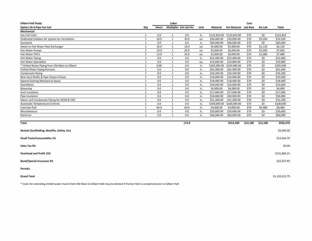
Option 2A 4‐Pipe Fan Coil Qty Hours Multiplier Ext Lab Hrs Unit Material Ext Material Lab Rate Ext Lab Total
Mechanical
Fan Coil Units 1 0.0 1 0.0 ls. $122,810.00 $122,810.00 $70 $0 $122,810
Dedicated Outdoor Air System for Ventilation 1 50.0 1 50.0 ea. $30,000.00 $30,000.00 $70 $3,500 $33,500
Ductwork 1 0.0 1 0.0 ls. $60,000.00 $60,000.00 $70 $0 $60,000
Steam to Hot Water Heat Exchanger 1 16.0 1 16.0 ea. $5,000.00 $5,000.00 $70 $1,120 $6,120
Hot Water Pumps 2 10.0 1 20.0 ea. $3,000.00 $6,000.00 $70 $1,400 $7,400
Hot Water VFD's 2 12.0 1 24.0 ea. $3,000.00 $6,000.00 $70 $1,680 $7,680
Hot Water Piping 1 0.0 1 0.0 ls. $52,400.00 $52,400.00 $70 $0 $52,400
Hot Water Specialties 1 0.0 1 0.0 ea. $10,680.00 $10,680.00 $70 $0 $10,680
* Chilled Water Piping from Old Main to Gilbert 1 0.00 1 0.0 ls. $205,000.00 $205,000.00 $70 $0 $205,000
Chilled Water Piping Runouts 1 0.0 1 0.0 ls. $62,400.00 $62,400.00 $70 $0 $62,400
Condensate Piping 1 0.0 1 0.0 ls. $26,200.00 $26,200.00 $70 $0 $26,200
New Duct Shafts & Pipe Chases Chases 1 0.0 1 0.0 ls. $10,000.00 $10,000.00 $70 $0 $10,000
Expand Existing Mechanical Space 1 0.0 1 0.0 ls. $18,400.00 $18,400.00 $70 $0 $18,400
Demolition 1 0.0 1 0.0 ls. $10,600.00 $10,600.00 $70 $0 $10,600
Balancing 1 0.0 1 0.0 ls. $6,000.00 $6,000.00 $70 $0 $6,000
Duct Insulation 1 0.0 1 0.0 ls. $17,000.00 $17,000.00 $70 $0 $17,000
Pipe Insulation 1 0.0 1 0.0 ls. $50,000.00 $50,000.00 $70 $0 $50,000
Steam and Condensate Piping for DOAS & HEX 1 0.0 1 0.0 ls. $31,200.00 $31,200.00 $70 $0 $31,200
Automatic Temperature Controls 1 0.0 1 0.0 ls. $100,000.00 $100,000.00 $70 $0 $100,000
Concrete Pad 1 64.0 1 64.0 ls. $4,000.00 $4,000.00 $70 $4,480 $8,480
Miscellaneous 1 0.0 1 0.0 ls. $20,600.00 $20,600.00 $70 $0 $20,600
Electrical 1 0.0 1 0.0 ls. $60,000.00 $60,000.00 $70 $0 $60,000
Total 174.0 $914,290 $12,180 $12,180 $926,470
Rentals (Scaffolding, Manlifts, Safety, Etc) $5,000.00
Small Tools/Consumables 1% $14,264.70
Sales Tax 0% $0.00
Overhead and Profit 15% $141,860.21
Bond/Special Insurance 3% $32,627.85
Permits
Grand Total $1,120,222.75
* Costs for extending chilled water mains from Old Main to Gilbert Hall may be deleted if Horton Hall is completed prior to Gilbert Hall
Labor Cost

Client Shippensburg University Job # 17117
Project: Date 12/12/2017
Option 2B: 4 Pipe Fan‐Coils
Sub-Total $1,008,077
Contingency 20% $201,615
$1,209,692
PROJECT ESTIMATE SUMMARY
Total Price
Gilbert Hall Study

Gilbert Hall Study
Option 2B 4‐Pipe Fan Coil Qty Hours Multiplier Ext Lab Hrs Unit Material Ext Material Lab Rate Ext Lab Total
Mechanical
Fan Coil Units 1 0.0 1 0.0 ls. $122,810.00 $122,810.00 $70 $0 $122,810
Brick Vents 1 0.0 1 0.0 ls. $11,500.00 $11,500.00 $70 $0 $11,500
Steam to Hot Water Heat Exchanger 1 16.0 1 16.0 ea. $5,000.00 $5,000.00 $70 $1,120 $6,120
Hot Water Pumps 2 10.0 1 20.0 ea. $3,000.00 $6,000.00 $70 $1,400 $7,400
Hot Water VFD's 2 12.0 1 24.0 ea. $3,000.00 $6,000.00 $70 $1,680 $7,680
Hot Water Piping 1 0.0 1 0.0 ls. $52,400.00 $52,400.00 $70 $0 $52,400
Hot Water Specialties 1 0.0 1 0.0 ea. $10,680.00 $10,680.00 $70 $0 $10,680
* Chilled Water Piping from Old Main to Gilbert 1 0.0 1 0.0 ls. $205,000.00 $205,000.00 $70 $0 $205,000
Chilled Water Piping Mains 1000 0.50 1 500.0 lf $10.00 $10,000.00 $70 $35,000 $45,000
Chilled Water Runouts 1 0.0 1 0.0 l.s. $62,400.00 $62,400.00 $70 $0 $62,400
Condensate Piping 1 0.0 1 0.0 ls. $26,200.00 $26,200.00 $70 $0 $26,200
Pipe Chases 1 0.0 1 0.0 ls. $5,000.00 $5,000.00 $70 $0 $5,000
Expand Existing Mechanical Space 1 0.0 1 0.0 ls. $18,400.00 $18,400.00 $70 $0 $18,400
Demolition 1 0.0 1 0.0 ls. $11,600.00 $11,600.00 $70 $0 $11,600
Balancing 1 0.0 1 0.0 ls. $4,800.00 $4,800.00 $70 $0 $4,800
Pipe Insulation 1 0.0 1 0.0 ls. $50,000.00 $50,000.00 $70 $0 $50,000
Steam and Condensate Piping for HEX 1 0.0 1 0.0 ls. $14,480.00 $14,480.00 $70 $0 $14,480
Automatic Temperature Controls 1 0.0 1 0.0 ls. $90,000.00 $90,000.00 $70 $0 $90,000
Concrete Pad 1 64.0 1 64.0 ls. $4,000.00 $4,000.00 $70 $4,480 $8,480
Miscellaneous 1 0.0 1 0.0 ls. $20,600.00 $20,600.00 $70 $0 $20,600
Electrical 1 0.0 1 0.0 ls. $48,000.00 $48,000.00 $70 $0 $48,000
Total 624.0 $784,870 $43,680 $43,680 $828,550
Rentals (Scaffolding, Manlifts, Safety, Etc) $5,000.00
Small Tools/Consumables 1% $13,285.50
Sales Tax 0% $0.00
Overhead and Profit 15% $127,025.33
Bond/Special Insurance 3% $29,215.82
Permits $5,000.00
Grand Total $1,008,076.65
* Costs for extending chilled water mains from Old Main to Gilbert Hall may be deleted if Horton Hall is completed prior to Gilbert Hall
Labor Cost

Client Shippensburg University Job # 17118
Project: Date 12/12/2017
Option 3: VRF w/ Existing Steam Heat
Sub-Total $2,574,763
Contingency 20% $514,953
$3,089,716
PROJECT ESTIMATE SUMMARY
Total Price
Horton Hall Study

Horton Hall Study
Option 3 VRF w/Existing Steam Heat Qty Hours Multiplier Ext Lab Hrs Unit Material Ext Material Lab Rate Ext Lab Total
Mechanical
VRF System (13 fcus each system) 12 40.00 1 480.0 ls. $50,000.00 $600,000.00 $70 $33,600 $633,600
Dedicated Outdoor Air System for Ventilation 1 80.00 1 80.0 ea. $50,000.00 $50,000.00 $70 $5,600 $55,600
Ductwork DOAS 9000 0.10 1 900.0 lbs $7.00 $63,000.00 $70 $63,000 $126,000
Ductwork FCUs 12000 0.10 1 1200.0 lbs $7.00 $84,000.00 $70 $84,000 $168,000
Refrigerant Piping 12000 0.30 1 3600.0 lf $6.00 $72,000.00 $70 $252,000 $324,000
Refrigerant Piping Specialties 320 1.00 1 320.0 ea. $40.00 $12,800.00 $70 $22,400 $35,200
Condensate Piping 3000 0.20 1 600.0 lf $5.00 $15,000.00 $70 $42,000 $57,000
New Duct Shafts & Pipe Chases Chases 1 320.00 1 320.0 ls. $15,000.00 $15,000.00 $70 $22,400 $37,400
Demolition 1 80.00 1 80.0 ls. $2,000.00 $2,000.00 $70 $5,600 $7,600
Balancing 1 0.00 1 0.0 ls. $12,000.00 $12,000.00 $70 $0 $12,000
Duct Insulation 6000 0.05 1 300.0 sf $2.00 $12,000.00 $70 $21,000 $33,000
Pipe Insulation 7200 0.07 1 504.0 lf $3.50 $25,200.00 $70 $35,280 $60,480
Automatic Temperature Controls 1 0.00 1 0.0 ls. $160,000.00 $160,000.00 $70 $0 $160,000
Concrete Pad 12 40.00 1 480.0 ls. $2,000.00 $24,000.00 $70 $33,600 $57,600
Steam and Condensate Piping for DOAS 400 0.50 1 200.0 lf $6.00 $2,400.00 $70 $14,000 $16,400
Replace steam traps and valves 153 1.00 1 153.0 ea. $100.00 $15,300.00 $70 $10,710 $26,010
Miscellaneous 1 320.00 1 320.0 ls. $50,000.00 $50,000.00 $70 $22,400 $72,400
Electrical 1 0.00 1 0.0 ls. $260,000.00 $260,000.00 $70 $0 $260,000
Total 9537.0 $1,474,700 $667,590 $667,590 $2,142,290
Rentals (Scaffolding, Manlifts, Safety, Etc) $5,000.00
Small Tools/Consumables 1% $26,422.90
Sales Tax 0% $0.00
Overhead and Profit 15% $326,056.94
Bond/Special Insurance 3% $74,993.10
Permits
Grand Total $2,574,762.93
Labor Cost