Embed Size (px)
DESCRIPTION
This is the 1642 D250x550 Lathe operation manual.
Citation preview
© 2
008
GB
Page 122 / 04 / 2008 Version 1.1.2 D210x400; D250x400; D250x550 Lathe
quantumM A S C H I N E N - G E R M A N Y
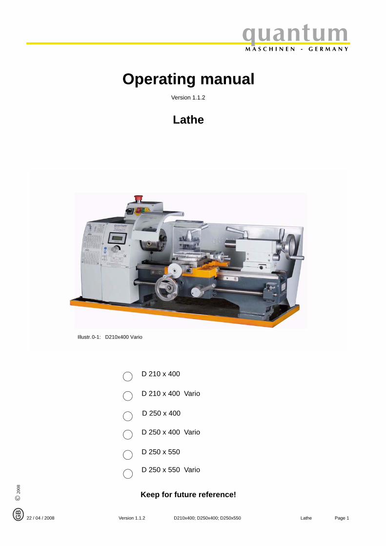
Operating manualVersion 1.1.2
Lathe
Keep for future reference!
Illustr.0-1: D210x400 Vario
D 210 x 400 Vario
D 250 x 400
D 250 x 400 Vario
D 250 x 550
D 250 x 550 Vario
D 210 x 400
© 2008
GB
Page 2 Lathe D210x400; D250x400; D250x550 Version 1.1.2 22 / 04 / 2008
quantumM A S C H I N E N - G E R M A N Y
Table of content
1 Safety1.1 Safety warnings (warning notes).................................................................................. 6
1.1.1 Classification of hazards................................................................................... 61.1.2 Further ideograms ............................................................................................ 7
1.2 Proper use ................................................................................................................... 71.3 Possible dangers caused by the lathe ......................................................................... 81.4 Qualification of employees........................................................................................... 8
1.4.1 Target group ..................................................................................................... 81.4.2 Authorized persons........................................................................................... 91.4.3 Obligations of the operator ............................................................................... 91.4.4 Obligations of the user...................................................................................... 91.4.5 Additional qualification requirements .............................................................. 10
1.5 User’s position............................................................................................................ 101.6 Safety devices............................................................................................................ 10
1.6.1 EMERGENCY-STOP button........................................................................... 101.6.2 Protective cover .............................................................................................. 111.6.3 Lathe chuck key.............................................................................................. 11
1.7 Safety check .............................................................................................................. 111.8 Personal protective equipment................................................................................... 121.9 For your own safety during operation......................................................................... 12
1.9.1 Switching-off and securing the lathe............................................................... 131.10 Use of lifting equipment.............................................................................................. 131.11 Mechanical maintenance work................................................................................... 13
2 Technical dataPower connection....................................................................................................... 14Machine data ............................................................................................................. 14Dimensions ................................................................................................................ 14Environmental conditions........................................................................................... 14Operating material...................................................................................................... 14
2.1 Emissions................................................................................................................... 14
3 Assembly3.1 Delivery volume.......................................................................................................... 153.2 Transport.................................................................................................................... 153.3 Storage ...................................................................................................................... 153.4 Installation and assembly........................................................................................... 16
3.4.1 Requirement to the installation site................................................................. 163.4.2 Load suspension point.................................................................................... 163.4.3 Installation....................................................................................................... 163.4.4 Assembly plan D210 x 400 ............................................................................. 173.4.5 Assembly plan D250 x 400 ............................................................................. 183.4.6 Assembly plan D250 x 550 ............................................................................. 19
3.5 First use ..................................................................................................................... 203.5.1 Cleaning and greasing.................................................................................... 203.5.2 Functional check............................................................................................. 203.5.3 Power connection ........................................................................................... 203.5.4 Functional test ................................................................................................ 21
3.6 Optional accessories D210 ........................................................................................ 223.7 Optional accessories D250 ........................................................................................ 22
3.7.1 Mounting instruction chuck flange .................................................................. 233.7.2 Mounting instruction for collet chuck holder.................................................... 233.7.3 Use of collet chucks........................................................................................ 243.7.4 Mounting of follow rest - D210x400 Vario....................................................... 253.7.5 Mounting of steady rest - D210x400 Vario ..................................................... 253.7.6 Mounting of quick change tool holder SWH 1-A ............................................. 26
4 Operation4.1 Safety......................................................................................................................... 274.2 Control and indicating elements................................................................................. 27
4.2.1 D210x400 / Vario ............................................................................................ 274.2.2 D 250 x 550 .................................................................................................. 28
4.3 Operating signs.......................................................................................................... 284.4 Tool holder ................................................................................................................. 29
© 2
008
GB
Page 322 / 04 / 2008 Version 1.1.2 D210x400; D250x400; D250x550 Lathe
quantumM A S C H I N E N - G E R M A N Y
4.5 Lathe chuck ................................................................................................................294.5.1 Head spindle seat ...........................................................................................29
4.6 Adjusting the speed....................................................................................................304.6.1 Protective cover of the headstock...................................................................304.6.2 Changing the speed range..............................................................................304.6.3 Speed table D 210 x 400 ................................................................................314.6.4 Speed table D 250 x 550 ................................................................................31
4.7 Speed setting "VARIO"...............................................................................................314.7.1 Speed table D 210 x 400 Vario ......................................................................324.7.2 Speed table D 250 Vario.................................................................................324.7.3 Changing the change gears............................................................................324.7.4 Engaging lever ................................................................................................33
4.8 Lathe saddle with cross and top slide ........................................................................334.8.1 Immobilising the lathe saddle..........................................................................334.8.2 Turning short tapers with the top slide ............................................................344.8.3 Turning tapers with the tailstock......................................................................34
4.9 Tailstock sleeve..........................................................................................................354.10 Clamping a workpiece into the three-jaw chuck .........................................................35
4.10.1 Replacing the clamping jaws on the lathe chuck ............................................364.11 General working notes ...............................................................................................36
4.11.1 Fitting a follow rest ..........................................................................................364.11.2 Coolant............................................................................................................36
5 Maintenance5.1 Safety .........................................................................................................................38
5.1.1 Preparation .....................................................................................................385.1.2 Restarting........................................................................................................38
5.2 Inspection and maintenance ......................................................................................395.3 Repair .........................................................................................................................42
6 Appendix turning6.1 ISO-designation system for tool holder, inside machining ........................................446.2 ISO-designation system for tool holder, outside machining .....................................456.3 Cutter with hard metal reversible carbide tip soldered on ..........................................466.4 Cut the first chips........................................................................................................466.5 Outside machining, longitudinal turning and facing....................................................486.6 Inside machining, drilling and longitudinal turning......................................................486.7 Tapping of external and internal threads....................................................................49
6.7.1 Thread types ...................................................................................................506.7.2 Metric thread (60° flank angle)........................................................................526.7.3 British threads (55° flank angle)......................................................................536.7.4 Indexable inserts .............................................................................................546.7.5 Examples for thread cutting ............................................................................55
6.8 Recessing, cutting off and turning off .........................................................................576.9 Turning cones with high precision ..............................................................................596.10 Cutting material ..........................................................................................................62
6.10.1 Cutting materials for chipping..........................................................................626.11 Standard values for cutting data when turning ...........................................................63
6.11.1 Cutting speed table .........................................................................................646.12 Grinding or regrinding of cutting edge geometries of turning tools.............................64
6.12.1 Terms for the turning tool ................................................................................656.12.2 Cutting edge geometry for turning tools ..........................................................666.12.3 Types of cutting form levels ............................................................................66
6.13 Lifetime and wear characteristics ...............................................................................68
7 Annex change gears7.1 Assembly of the change gears ...................................................................................69
7.1.1 The table of the gear wheels on your lathe.....................................................717.2 Determination of modules of toothed wheels .............................................................717.3 Tables of gear wheels inch treads..............................................................................727.4 Change gears metric threads .....................................................................................85
8 Ersatzteile - Spare parts - D210 (Vario), D250 (Vario)8.1 Oberschlitten - Top slide ............................................................................................898.2 Planschlitten - Cross slide ..........................................................................................90
8.2.1 Teileliste Maschinenschlitten- Parts list top and cross slide ...........................91
© 2008
GB
Page 4 Lathe D210x400; D250x400; D250x550 Version 1.1.2 22 / 04 / 2008
quantumM A S C H I N E N - G E R M A N Y
8.2.2 Wechselradschere - Change gear train .......................................................... 928.2.3 Teileliste Wechselradschere - Parts list change gear train............................. 92
8.3 Bettschlitten - Bed slide.............................................................................................. 938.3.1 Teileliste Bettschlitten - Parts list bed slide..................................................... 94
8.4 Reitstock - Tailstock................................................................................................... 958.4.1 Teileliste Reitstock - Parts list tailstock........................................................... 96
8.5 Reitstock ab Baujahr 2008 - Tailstock starting from year of construction 2008 ... 978.5.1 Teileliste Reitstock Baujahr ab 2008 - Parts list tailstock starting from year of
construction 2008988.6 Verkleidung Spindelstock D210x400 Vario - Headstock housing D210x400 Vario 99
8.6.1 Teileliste Verkleidung Spindelstock - Parts list headstock housing .............. 1008.7 Spindelstock - Headstock......................................................................................... 1018.8 Maschinenbett - Lathe bed....................................................................................... 102
8.8.1 Teileliste Spindelstock und Maschinenbett - Parts headstock and lathe bed1038.9 Vario Antrieb D210 - Vario drive D210..................................................................... 104
8.9.1 Teileliste Vario Antrieb D210 - Parts list Vario drive D210 ........................... 1058.10 Antrieb 1-2 - Drive 1-2............................................................................................. 1068.11 Antrieb 2-2 - Drive 2-2............................................................................................ 107
8.11.1 Teileliste Antrieb - Parts list drive ................................................................. 1088.12 Sonstiges Zubehör (ohne Abbildung) - Other accessories (without illustration) ...... 1098.13 Schaltplan - Wiring diagram D210 x 400 Vario ........................................................ 1108.14 Schaltplan - Wiring diagram D210, D250 (230 V) .................................................... 1118.15 Schaltplan - Wiring diagram D250 (400 V)............................................................... 1128.16 Schaltplan - Wiring diagram D250 Vario (230V) ...................................................... 1138.17 Schaltplan - Wiring diagram D250 Vario (400V) ...................................................... 114
9 Malfunction9.1 Malfunction on the lathe........................................................................................... 115
10 Appendix10.1 Copyright..................................................................................................................11610.2 Terminology/glossary ............................................................................................... 11610.3 Product follow-up ..................................................................................................... 11710.4 Warranty...................................................................................................................11810.5 Disposal ...................................................................................................................11810.6 EC - declaration of conformity.................................................................................. 119

© 2
008
GB
Page 522 / 04 / 2008 Version 1.1.2 D210x400; D250x400; D250x550 Lathe
quantumM A S C H I N E N - G E R M A N Y
Safety
1 Safety
Glossary of symbols
This part of the operating manual
does explain the meaning and how to use the warning references contained in this operating manual,does explain how to use the lathe,highlights the dangers that might arise for you and others if these instructions are not fol-lowed thoroughly,informs you on how to prevent dangers.
In addition to this operating manual, please note
applicable laws and regulations,legal regulations for preventing an accident,the prohibition, warning and mandatory signs as well as the warning notes on the lathe.
European standards must be kept during installation, operation, maintenance and repair of thelathe.
If European standards are not applied at the national legislation of the country of destination, thespecific applicable regulations of each country are to be observed.
If necessary, the required measures must be taken to comply with the specific regulations ofeach country before the lathe is used for the first time.
ALWAYS KEEP THIS DOCUMENT CLOSE TO THE LATHE FOR FURTHER REFERENCE.
INFORMATION
If you are not able to solve a problem using this manual, please do not hesitate to contact us forfurther professional advice:
OPTIMUM Maschinen Germany GmbHDr. Robert-Pfleger-Str. 26
D- 96103 Hallstadt
gives further advice
calls on you to get in action
enumeration

© 2008
GB
Page 6 Lathe D210x400; D250x400; D250x550 Version 1.1.2 22 / 04 / 2008
SafetyquantumM A S C H I N E N - G E R M A N Y
1.1 Safety warnings (warning notes)
1.1.1 Classification of hazards
We classify the safety warnings into various levels. The table below gives an overview of theclassification of symbols (ideogram) and the warning signs for each specific danger and its (pos-sible) consequences.
ideogram warning alert definition/consequences
DANGER! Threatening danger that will cause serious injury or death to people.
WARNING! Risk: a danger that might cause serious injury or death to people.
CAUTION! Danger or unsafe procedure that might cause injury to people or damage to property.
ATTENTION!
Situation that could cause damage to the machine and to the product and other types of damages.No risk of injury to people.
INFORMATION
Application advice and other important or useful informa-tion and notes.No dangerous or harmful consequences for people or objects.
In case of certain dangers, we replace the ideogram by
or
general dan-ger
with a warning of
injuries to hands,
hazardous electrical volt-age,
rotating parts.
© 2
008
GB
Page 722 / 04 / 2008 Version 1.1.2 D210x400; D250x400; D250x550 Lathe
quantumM A S C H I N E N - G E R M A N Y
Safety
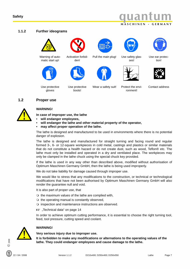
1.1.2 Further ideograms
1.2 Proper use
WARNING!
In case of improper use, the lathe• will endanger employees,• will endanger the lathe and other material property of the operator,• may affect proper operation of the lathe.The lathe is designed and manufactured to be used in environments where there is no potentialdanger of explosion.
The lathe is designed and manufactured for straight turning and facing round and regularformed 3-, 6- or 12-square workpieces in cold metal, castings and plastics or similar materialsthat do not constitute a health hazard or do not create dust, such as wood, Teflon® etc. Thelathe must only be installed and operated in a dry and ventilated place. The workpieces mayonly be clamped in the lathe chuck using the special chuck key provided.
If the lathe is used in any way other than described above, modified without authorisation ofOptimum Maschinen Germany GmbH, then the lathe is being used improperly.
We do not take liability for damage caused through improper use.
We would like to stress that any modifications to the construction, or technical or technologicalmodifications that have not been authorised by Optimum Maschinen Germany GmbH will alsorender the guarantee null and void.
It is also part of proper use, that
the maximum values of the lathe are complied with,the operating manual is constantly observed, inspection and maintenance instructions are observed.
„Technical data“ on page 14
In order to achieve optimum cutting performance, it is essential to choose the right turning tool,feed, tool pressure, cutting speed and coolant.
WARNING!
Very serious injury due to improper use.It is forbidden to make any modifications or alternations to the operating values of the lathe. They could endanger employees and cause damage to the lathe.
Warning of auto-matic start up!
Activation forbid-den!
Pull the main plug! Use safety glas-ses!
Use ear protec-tion!
Use protective gloves
Use protective boots!
Wear a safety suit! Protect the envi-ronment!
Contact address

© 2008
GB
Page 8 Lathe D210x400; D250x400; D250x550 Version 1.1.2 22 / 04 / 2008
SafetyquantumM A S C H I N E N - G E R M A N Y
1.3 Possible dangers caused by the latheThe lathe has undergone a safety inspection. It has been designed and built on the basis of thisanalysis using the latest technological advances.
Nevertheless, there is a residual risk as the lathe operated with
high revolutions,rotating parts,electrical voltage and currents.
We have used construction resources and safety techniques to minimize the health risk to per-sons resulting from these hazards.
If the lathe is used and maintained by employees who are poorly qualified, then there might be arisk resulting from incorrect operation and unsuitable maintenance of the machine.
INFORMATION
Everyone involved in the assembly, commissioning, operation and maintenance must
be duly qualified,strictly follow this operating manual.
Always disconnect the machine if cleaning or maintenance work is being carried out.
WARNING!
THE lathe MAY ONLY BE USED WITH THE SAFETY DEVICES ACTIVATED. Disconnect the lathe immediately whenever you detect a failure in the safety devices or when they are not mounted!All additional installations carried out by the operator must incorporate the safety devices prescribed.This is your responsibility being the operator!
„Safety devices“ on page 10
1.4 Qualification of employees
1.4.1 Target group
This manual applies to
the operators,the users,the maintenance staff.
Therefore, the warning notes refer to both operation and maintenance of the machine.
Always disconnect the main plug of the machine. This will prevent it from being used by unau-thorised persons.

© 2
008
GB
Page 922 / 04 / 2008 Version 1.1.2 D210x400; D250x400; D250x550 Lathe
quantumM A S C H I N E N - G E R M A N Y
Safety
INFORMATIONEveryone involved in the assembly, commissioning, operation and maintenance must
be duly qualified,strictly follow this operating manual.
Due to improper use
there is a risk for the employees,the machine and further property might be endangered,the function of the lathe could be affected.
1.4.2 Authorized persons
WARNING!
Incorrect use and maintenance of the machine constitutes a danger for the staff, objects and the environment.Only authorized persons may operate the machine!Persons authorized to operate and maintain should be trained technical staff and instructed bythe ones who are working for the operator and for the manufacturer.
1.4.3 Obligations of the operator
The operator must instruct the staff at least once a year on
all safety standards that apply to the machine,the operation,accredited technical guidelines.
The operator must also
check the knowledge of the staff,document training/instructions,require the staff to confirm participation in training/instructions by means of a signature,check if the staff is aware of safety rules and dangers in the workplace and that they observe the operating manual.
1.4.4 Obligations of the user
The user must
have read and understood the operating manual,be familiar with all safety devices and regulations,be able to operate the machine.

© 2008
GB
Page 10 Lathe D210x400; D250x400; D250x550 Version 1.1.2 22 / 04 / 2008
SafetyquantumM A S C H I N E N - G E R M A N Y
1.4.5 Additional qualification requirements
For work on electrical components or equipment, there are additional requirements:
This work should only be carried out by qualified electrician or a person working under the instructions and supervision of a qualified electrician.
Before carrying out work on electrical components or operating units, the following measuresmust be taken, in the order given.
disconnect all poles,
ensure that the lathe cannot be turned on again,
check that there is no voltage.
1.5 User’s positionThe user must stand in front of the machine.
1.6 Safety devicesOperate the lathe only with properly functioning safety devices.
Stop the lathe immediately if there is a failure in the safety device or if it is not functioning forsome reason.
It is your responsibility!
If the safety advice has been activated or has failed, the lathe must only be operated againwhen
the cause of the failure has been removed,you have made sure that there is no existing danger for persons or objects.
WARNING!
If you bypass, remove or override a safety device in any other way, you are endangering yourself and other persons working on the machine. The possible consequences are fol-lowing• injuries due to components or parts of components flying off at high speed,• contact with rotating parts,• fatal electrocution.The lathe includes the following safety advices:
self-locking, lockable EMERGENCY-STOP button,screwed-down protective cover on the headstock,special key for the lathe chuck,lathe chuck protection.
1.6.1 EMERGENCY-STOP buttonIllustr.1-1: Illustr.1-2:
Illustr.1-3: EMERGENCY STOP button
© 2
008
GB
Page 1122 / 04 / 2008 Version 1.1.2 D210x400; D250x400; D250x550 Lathe
quantumM A S C H I N E N - G E R M A N Y
Safety
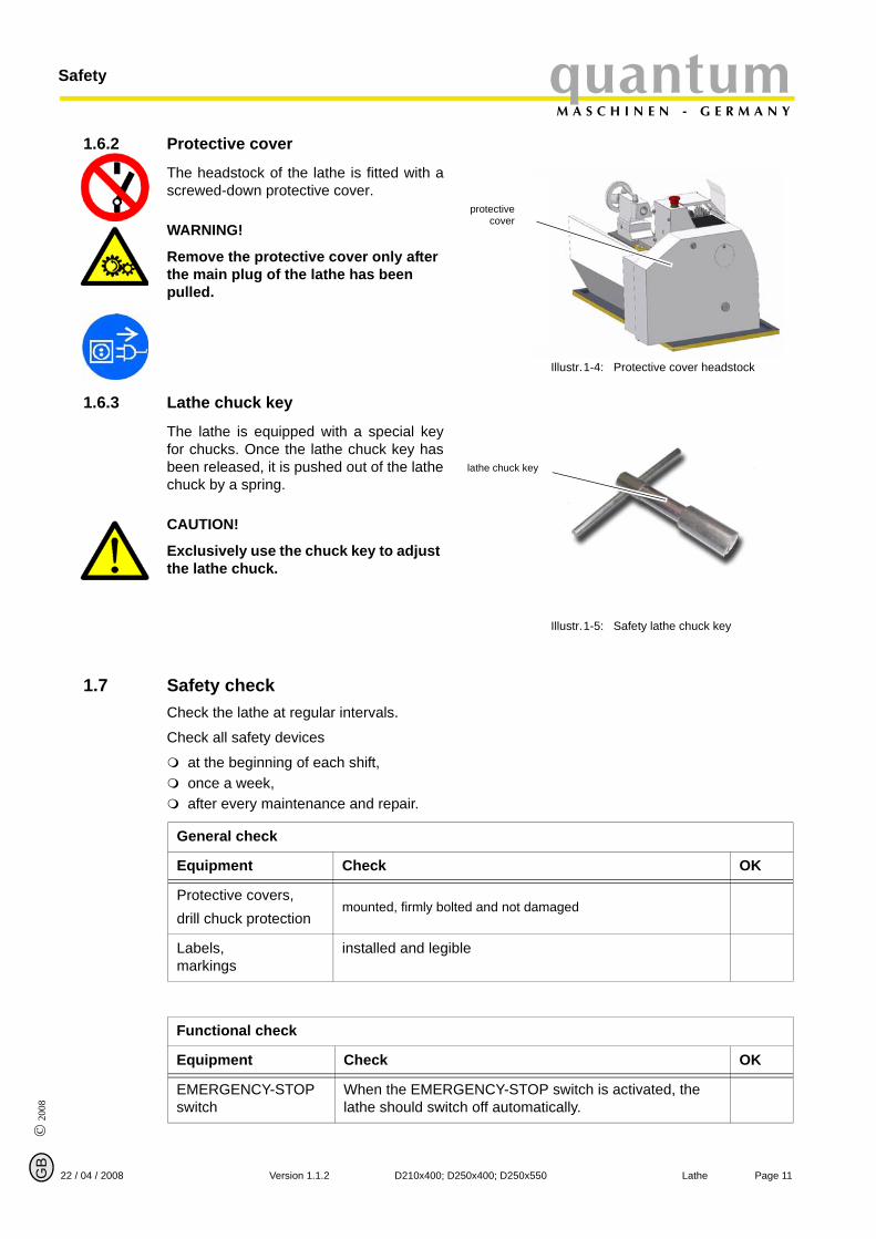
1.6.2 Protective cover
The headstock of the lathe is fitted with ascrewed-down protective cover.
WARNING!
Remove the protective cover only after the main plug of the lathe has been pulled.
Illustr.1-4: Protective cover headstock
1.6.3 Lathe chuck key
The lathe is equipped with a special keyfor chucks. Once the lathe chuck key hasbeen released, it is pushed out of the lathechuck by a spring.
CAUTION!
Exclusively use the chuck key to adjust the lathe chuck.
Illustr.1-5: Safety lathe chuck key
1.7 Safety checkCheck the lathe at regular intervals.
Check all safety devices
at the beginning of each shift,once a week,after every maintenance and repair.
protectivecover
lathe chuck key
General check
Equipment Check OK
Protective covers,drill chuck protection
mounted, firmly bolted and not damaged
Labels,markings
installed and legible
Functional check
Equipment Check OK
EMERGENCY-STOP switch
When the EMERGENCY-STOP switch is activated, the lathe should switch off automatically.

© 2008
GB
Page 12 Lathe D210x400; D250x400; D250x550 Version 1.1.2 22 / 04 / 2008
SafetyquantumM A S C H I N E N - G E R M A N Y
1.8 Personal protective equipmentFor certain work personal protective equipment is required.
Protect your face and your eyes: Wear a safety helmet with a face guard for every work, espe-cially for the kind of work where your face and eyes are exposed to hazards.
Use protective gloves when lifting or handling pieces with sharp edges.
Wear safety shoes when fitting, dismantling or transporting heavy components.
Use ear protection if the noise level (emission) in the workplace exceeds 80 dB (A).
Before starting work, make sure that the prescribed personal protective equipment is availableat the workplace.
CAUTION!
Dirty or eventually contaminated personal protective equipment might cause disease.Clean it after each use and once a week.
1.9 For your own safety during operation
WARNING!
Before activating the machine, make sure that this will not endanger other people or cause damage to equipment.Avoid unsafe working practice:
Make sure, your work does not endanger anyone.Clamp the workpiece tightly before activating the lathe. For clamping workpieces, only use the special chuck key supplied.Mind the maximum chuck opening.Use safety glasses.Do not remove the turning chips by hand. Use a chip hook and / or a hand brush to remove the turning chips.Clamp the turning tool at the correct height and with the least possible overhang. Turn off the lathe before measuring the workpiece.The instructions of this manual have to be observed strictly during assembly, operation, maintenance and repair.Do not work on the lathe, if your concentration is reduced, for example, because you are taken medication.
Lathe chuck key After releasing the lathe chuck key it has to squeeze out of the lathe chuck by itself.
Lathe chuck protection/ Protective cover head-stock
You may only switch on with the button "ON" after closing the lathe chuck protection/ Protective cover headstock
Functional check
Equipment Check OK

© 2
008
GB
Page 1322 / 04 / 2008 Version 1.1.2 D210x400; D250x400; D250x550 Lathe
quantumM A S C H I N E N - G E R M A N Y
Safety
Observe the regulations for the prevention of accidents issued by your association for the prevention of occupational accidents and safety in the workplace or other inspection authori-ties.Stay on the lathe until all rotating parts have come to standstill.Use the prescribed personal protective equipment. Make sure to wear a well-fitting work suit and a hairnet, if necessary.
In the description of work with and on the machine, we highlight the danger specific to that work.
1.9.1 Switching-off and securing the lathe
Turn off the main plug of the lathe before starting any maintenance or repair work. All machinecomponents and hazardous voltages and movements are disconnected.
Place a warning sign at the machine.
1.10 Use of lifting equipment
WARNING!
Use of unstable lifting and load-suspension gear that might break under load can cause very serious injuries or even death.Check that the lifting and load suspension gear is of sufficient load capacity and in per-fect condition.Observe the regulations for the prevention of accidents issued by your association for the prevention of occupational accidents and safety in the workplace or other inspection authorities.Fasten the loads properly.Do not walk under lifted loads!
1.11 Mechanical maintenance workRemove all protection and safety devices before starting maintenance work and re-install themonce the work has been completed, such as:
covers,safety indications and warning signs,earth (ground) cables.
If you remove protection or safety devices, refit them immediately after completing the work.
Check if they are working properly!
© 2008
GB
Page 14 Lathe D210x400; D250x400; D250x550 Version 1.1.2 22 / 04 / 2008
Technical dataquantumM A S C H I N E N - G E R M A N Y
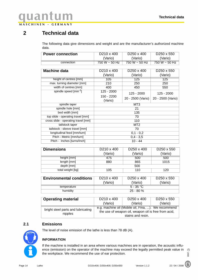
2 Technical data
The following data give dimensions and weight and are the manufacturer’s authorized machinedata.
2.1 EmissionsThe level of noise emission of the lathe is less than 78 dB (A).
INFORMATION
If the machine is installed in an area where various machines are in operation, the acoustic influ-ence (emission) on the operator of the machine may exceed the legally permitted peak value inthe workplace. We recommend the use of ear protection.
Power connection D210 x 400 (Vario)
D250 x 400 (Vario)
D250 x 550 (Vario)
connection 750 W ~ 50 Hz 750 W ~ 50 Hz 750 W ~ 50 Hz
Machine data D210 x 400 (Vario)
D250 x 400 (Vario)
D250 x 550 (Vario)
height of centres [mm] 105 125 125max. turning diameter [mm] 210 250 250
width of centres [mm] 400 450 550spindle speed [min-1] 125 - 2000
150 - 2200 (Vario)
125 - 200020 - 2500 (Vario)
125 - 200020 - 2500 (Vario)
spindle taper MT3spindle hole [mm] 21bed width [mm] 135
top slide - operating travel [mm] 70cross slide - operating travel [mm] 110
tailstock taper MT2tailstock - sleeve travel [mm] 70longitudinal feed [mm/turn] 0,1 - 0,2
Pitch - Metric [mm/turn] 0,4 - 3,5Pitch - Inches [turns/Inch] 10 - 44
Dimensions D210 x 400 (Vario)
D250 x 400 (Vario)
D250 x 550 (Vario)
height [mm] 475 500 500length [mm] 880 865 1015depth [mm] 500
total weight [kg] 105 110 120
Environmental conditions D210 x 400 (Vario)
D250 x 400 (Vario)
D250 x 550 (Vario)
temperature 5 - 35 °Chumidity 25 - 80 %
Operating material D210 x 400 (Vario)
D250 x 400 (Vario)
D250 x 550 (Vario)
bright steel parts and lubricating nipples
e.g. machine oil (Mobile oil, Fina, ...). We recommend the use of weapon oil, weapon oil is free from acid,
stains and resin.

© 2
008
GB
Page 1522 / 04 / 2008 Version 1.1.2 D210x400; D250x400; D250x550 Lathe
quantumM A S C H I N E N - G E R M A N Y
Assembly
3 Assembly
INFORMATION
The lathe is delivered pre-assembled.
3.1 Delivery volumeIf the lathe is being delivered, please check immediately that it has not been damaged duringtransportation and that all components are included. Also check that no fastening screws havecome loose.
Compare the delivery volume with the indications on the packing list.
3.2 Transport
WARNING!
Machine parts falling off forklift trucks or other transport vehicles could cause very seri-ous or even fatal injuries. Follow the instructions and information on the transport case:• centre of gravity• suspension points• weights• means of transport to be used• prescribed shipping position
WARNING!
Use of unstable lifting and load suspension gear that might break under load can cause very serious injuries or even death.Check that the lifting and load suspension gear has sufficient load capacity and that it is in perfect condition. Observe the regulations for the prevention of accidents.Fasten the loads properly. Do not walk under lifted loads!
3.3 Storage
ATTENTION!
Improper storage may damage or destroy important parts.Store packed and unpacked parts only under the intended environmental conditions.
„Environmental conditions“ on page 14Consult Optimum Maschinen Germany GmbH if the lathe and accessories are being stored formore than three months or are stored under different environmental conditions than those givenhere.

© 2008
GB
Page 16 Lathe D210x400; D250x400; D250x550 Version 1.1.2 22 / 04 / 2008
AssemblyquantumM A S C H I N E N - G E R M A N Y
3.4 Installation and assembly
3.4.1 Requirement to the installation site
The main switch of the lathe must be easily accessible.
3.4.2 Load suspension point
Fasten the load suspension gear around the lathe bed.
Make sure that you distribute the loads evenly so, that the lathe cannot turn over while lifting.
Make sure that no add-on pieces or varnished parts are damaged due to the load suspen-sion.
3.4.3 Installation
WARNING!
Danger of crushing and overturning. The lathe must be installed by at least 2 people.Check the horizontal orientation of the base of the lathe with a spirit level.
Check that the foundation has sufficient floor-load capacity and rigidity.
ATTENTION!
Insufficient rigidity of the foundation leads to the superposition of vibrations between the machine and the foundation (natural frequency of components). Insufficient rigidity of the entire lathe assembly also rapidly causes the lathe to reach critical speeds, with unpleasant vibrations, leading to bad turning results.
Position the lathe on the intended foundation.
Secure the lathe to the foundation or substructure of the machine using the through holes (4).If necessary, use anti-vibration elements (model S1) for your machine substructure.The installation drawings described below may differ from the real dimensions (cast parts). The tolerances are in the range of the general tolerances according to DIN 7168 g.
© 2
008
GB
Page 1722 / 04 / 2008 Version 1.1.2 D210x400; D250x400; D250x550 Lathe
quantumM A S C H I N E N - G E R M A N Y
Assembly
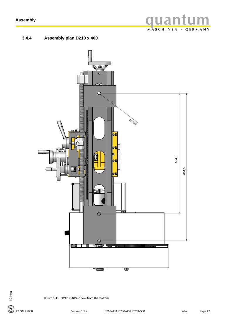
3.4.4 Assembly plan D210 x 400
Illustr.3-1: D210 x 400 - View from the bottom
© 2008
GB
Page 18 Lathe D210x400; D250x400; D250x550 Version 1.1.2 22 / 04 / 2008
AssemblyquantumM A S C H I N E N - G E R M A N Y
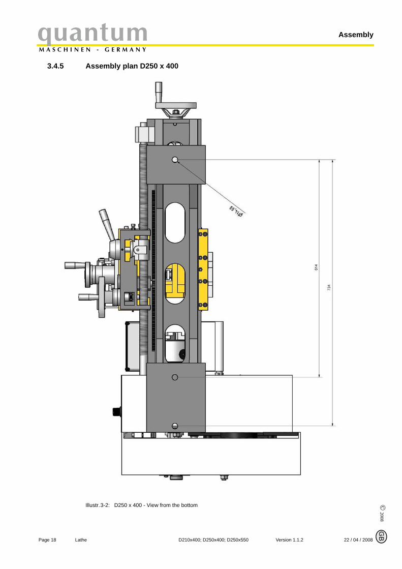
3.4.5 Assembly plan D250 x 400
Illustr.3-2: D250 x 400 - View from the bottom
© 2
008
GB
Page 1922 / 04 / 2008 Version 1.1.2 D210x400; D250x400; D250x550 Lathe
quantumM A S C H I N E N - G E R M A N Y
Assembly
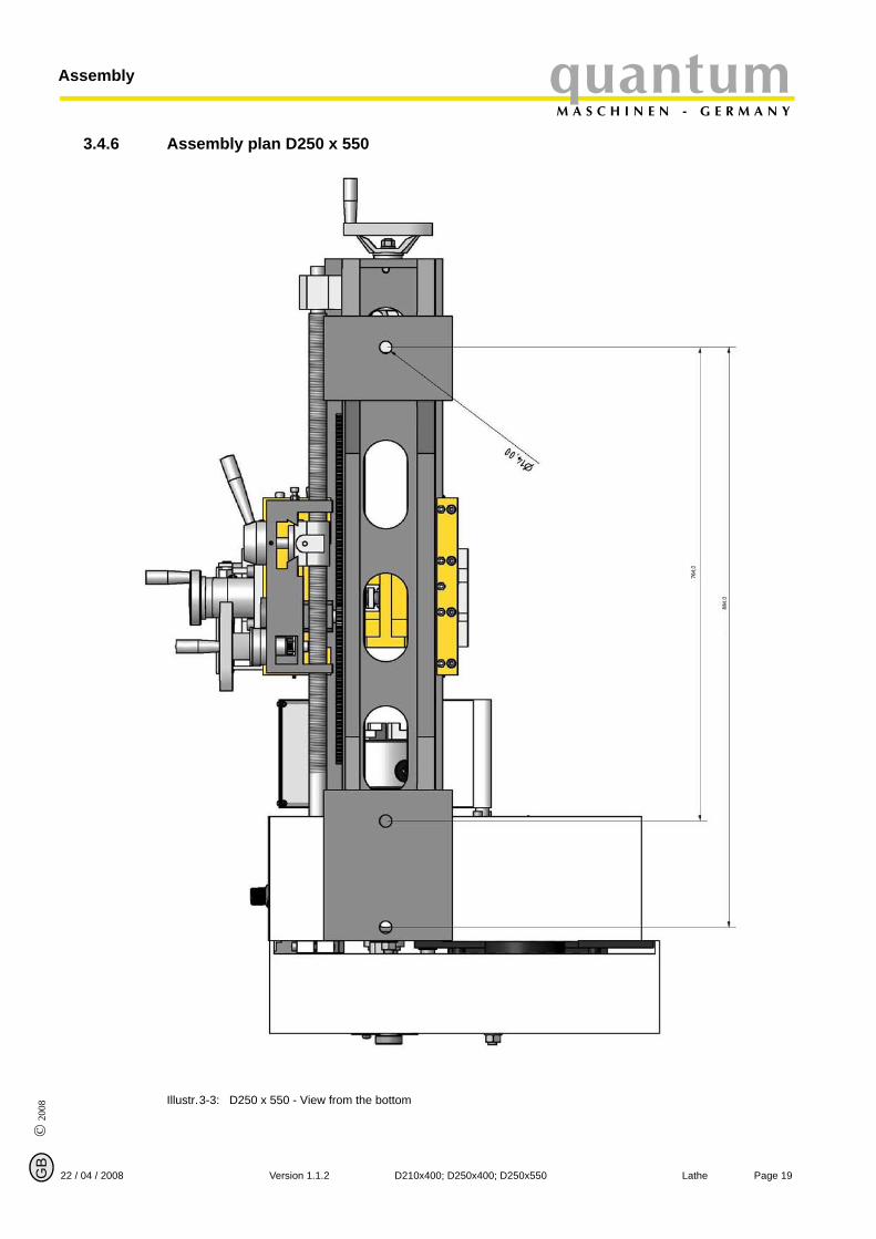
3.4.6 Assembly plan D250 x 550
Illustr.3-3: D250 x 550 - View from the bottom
© 2008
GB
Page 20 Lathe D210x400; D250x400; D250x550 Version 1.1.2 22 / 04 / 2008
AssemblyquantumM A S C H I N E N - G E R M A N Y
3.5 First use
WARNING!
Staff and equipment may be endangered if the lathe is first used by unexperienced staff.We do not take any liability for damages caused by incorrect commissioning.
3.5.1 Cleaning and greasing
Remove the anti-corrosive agent applied to the machine for transport and storage purposes. We recommend the use of kerosene.
Do not use any solvents, thinner or other cleaning agents, which could corrode the varnish on the machine. Follow the specifications and indications of the manufacturer of the cleaning agent.
Lubricate the bright machine parts with acid-free lubricating oil.
Grease the machine according to the lubrication chart. „Inspection and maintenance“ on page 39
3.5.2 Functional check
Check free movement of all spindles.
INFORMATION
For manufacturing engineering reasons and for reasons of precision of fit, there may be occa-sional slight stiffness in the spindles. This will disappear after a short time in use.
Check the state of the lathe chuck and the turning jaws.
3.5.3 Power connection
Connect the electric supply cable.
Check the fuse protection of your power supply to the technical data for the total connection value of the lathe.
ATTENTION!
Please pay attention that all three phases (L1, L2, L3) of 400V machines are connected correctly.Most engine failure result from incorrect connection, for instance the neutral conductor (N) is being connected to a phase.This might lead to the following results:• the engine does get quickly very hot,• the engine noise increases,• the engine has no power.When the phases are connected wrongly, the guarantee is being null and void.
© 2
008
GB
Page 2122 / 04 / 2008 Version 1.1.2 D210x400; D250x400; D250x550 Lathe
quantumM A S C H I N E N - G E R M A N Y
Assembly
ATTENTION!Lathes with frequency converter must not be operated with a CEE plug. Connect the machine permanently to a connection box (see EN 50178 / VDE 5.2.11.1)• D 250 x 400 Vario• D 250 x 550 Vario
INFORMATION
On lathes of the type " VARIO", the frequency converter (driving regulator) might release the FIprotected switch of your electrical supply. In order to avoid malfunction, you either need an FIprotected switch sensitive for pulse current or AC/DC sensitive.
In case of malfunction or release of the FI protected switch, please check the type installed.
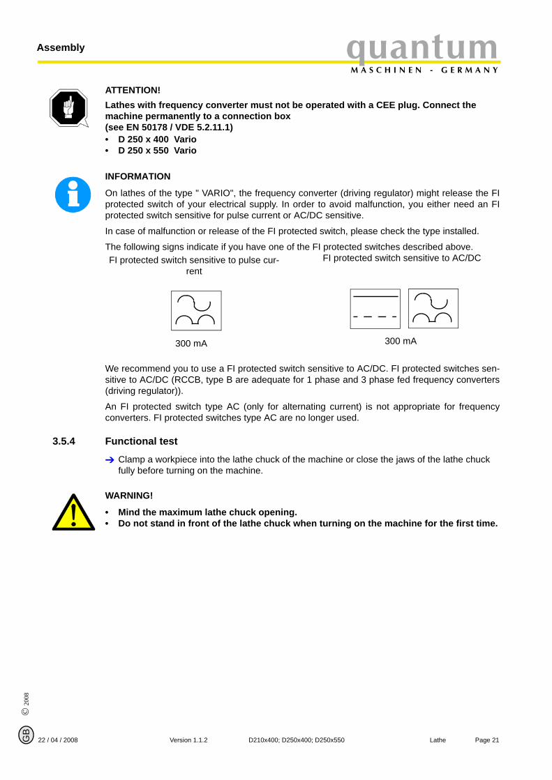
The following signs indicate if you have one of the FI protected switches described above.
We recommend you to use a FI protected switch sensitive to AC/DC. FI protected switches sen-sitive to AC/DC (RCCB, type B are adequate for 1 phase and 3 phase fed frequency converters(driving regulator)).
An FI protected switch type AC (only for alternating current) is not appropriate for frequencyconverters. FI protected switches type AC are no longer used.
3.5.4 Functional test
Clamp a workpiece into the lathe chuck of the machine or close the jaws of the lathe chuck fully before turning on the machine.
WARNING!
• Mind the maximum lathe chuck opening.• Do not stand in front of the lathe chuck when turning on the machine for the first time.
FI protected switch sensitive to pulse cur-rent
FI protected switch sensitive to AC/DC
300 mA 300 mA
© 2008
GB
Page 22 Lathe D210x400; D250x400; D250x550 Version 1.1.2 22 / 04 / 2008
AssemblyquantumM A S C H I N E N - G E R M A N Y
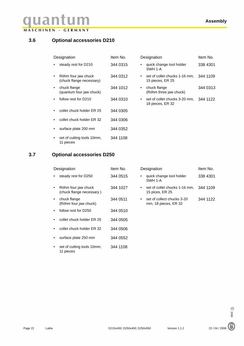
3.6 Optional accessories D210
3.7 Optional accessories D250
Designation Item No. Designation Item No.
• steady rest for D210 344 0315 • quick change tool holderSWH 1-A
338 4301
• Röhm four jaw chuck(chuck flange necessary)
344 0312 • set of collet chucks 1-16 mm, 15 pieces, ER 25
344 1109
• chuck flange(quantum four jaw chuck)
344 1012 • chuck flange(Röhm three jaw chuck)
344 0313
• follow rest for D210 344 0310 • set of collet chucks 3-20 mm, 18 pieces, ER 32
344 1122
• collet chuck holder ER 25 344 0305
• collet chuck holder ER 32 344 0306
• surface plate 200 mm 344 0352
• set of cutting tools 10mm,11 pieces
344 1108
Designation Item No. Designation Item No.
• steady rest for D250 344 0515 • quick change tool holderSWH 1-A
338 4301
• Röhm four jaw chuck(chuck flange necessary )
344 1027 • set of collet chucks 1-16 mm, 15 pices, ER 25
344 1109
• chuck flange(Röhm four jaw chuck)
344 0511 • set of collect chucks 3-20 mm, 18 pieces, ER 32
344 1122
• follow rest for D250 344 0510
• collet chuck holder ER 25 344 0505
• collet chuck holder ER 32 344 0506
• surface plate 250 mm 344 0552
• set of cutting tools 10mm,11 pieces
344 1108
© 2
008
GB
Page 2322 / 04 / 2008 Version 1.1.2 D210x400; D250x400; D250x550 Lathe
quantumM A S C H I N E N - G E R M A N Y
Assembly
3.7.1 Mounting instruction chuck flange
Putting on of jaw chuck onto the chuck flange
Clean the flange and spindle nose, put the flange onto the spindle nose.
Measure the inner hole of the jaw chuck and turn this value of the chuck flange to a diameter asa H7 fit. Turn once easily over the flat surface of the chuck flange until the surface runs true.Place the lathe chuck and tighten it.
Consider: The jaw chuck must let itself manually and put on with the aid of a back-proof plastictip hammer (distribute uniformly easy strokes over the front panel).
Clamp clamping bolts alternating and uniformly.
The screws may perform no compulsion onto the drilling wall since the chuck body bends itselfelse or the jaws are locked in position.
Furthermore, radial run-outs can occur.
Refinishing on the jaw chuck is not admissible!
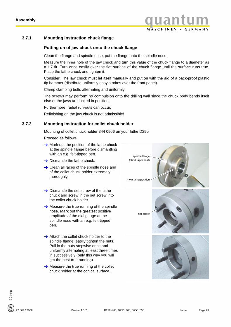
3.7.2 Mounting instruction for collet chuck holder
Mounting of collet chuck holder 344 0506 on your lathe D250
Proceed as follows.
Mark out the position of the lathe chuck at the spindle flange before dismantling with an e.g. felt-tipped pen.
Dismantle the lathe chuck.
Clean all faces of the spindle nose and of the collet chuck holder extremely thoroughly.
Dismantle the set screw of the lathe chuck and screw in the set screw into the collet chuck holder.
Measure the true running of the spindle nose. Mark out the greatest positive amplitude of the dial gauge at the spindle nose with an e.g. felt-tipped pen.
Attach the collet chuck holder to the spindle flange, easily tighten the nuts. Pull in the nuts stepwise once and uniformly alternating at least three times in successively (only this way you will get the best true running).
Measure the true running of the collet chuck holder at the conical surface.
spindle flange(short taper seat)
measuring position
set screw

© 2008
GB
Page 24 Lathe D210x400; D250x400; D250x550 Version 1.1.2 22 / 04 / 2008
AssemblyquantumM A S C H I N E N - G E R M A N Y
Position the collet chuck holder by turning each 120° at the spindle flange to the highest run out precision is achieved.
Mark out the position of the highest circularity accuracy of spindle flange with collet chuck holder and assemble then the collet chuck holder on the highest circularity accuracy position.
Illustr.3-4: 344 1305 Without union nut
3.7.3 Use of collet chucks
When using collet chucks to clamp the workpiece higher machining tolerances are available.The exchange of collet chucks for a smaller or larger diameter is simple and can be easily per-formed.
First, the collect chuck will be pressed into the ring of the union nut and has to rest there byitself. The workpiece will be clamped by fastening the union nut.
Make sure that you are using the correct collet chuck for the corresponding diameter in order tobe able to fix the workpiece safety and firmly.
measuring position
© 2
008
GB
Page 2522 / 04 / 2008 Version 1.1.2 D210x400; D250x400; D250x550 Lathe
quantumM A S C H I N E N - G E R M A N Y
Assembly
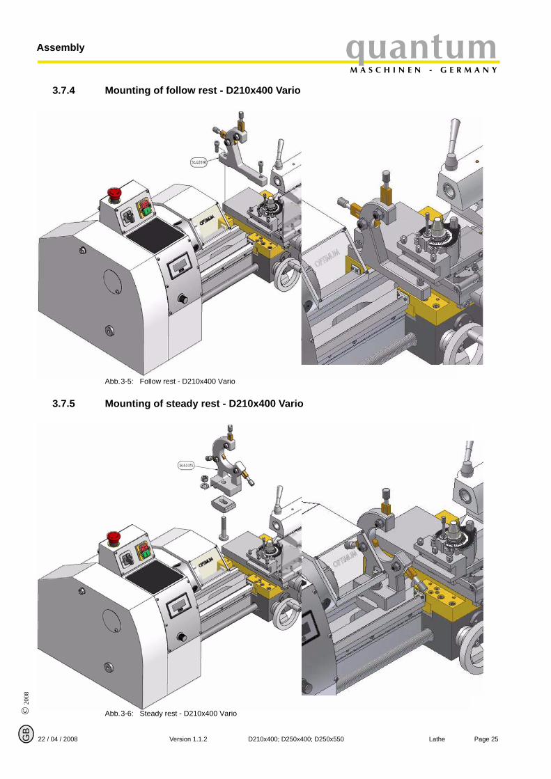
3.7.4 Mounting of follow rest - D210x400 Vario
Abb.3-5: Follow rest - D210x400 Vario
3.7.5 Mounting of steady rest - D210x400 Vario
Abb.3-6: Steady rest - D210x400 Vario
© 2008
GB
Page 26 Lathe D210x400; D250x400; D250x550 Version 1.1.2 22 / 04 / 2008
AssemblyquantumM A S C H I N E N - G E R M A N Y
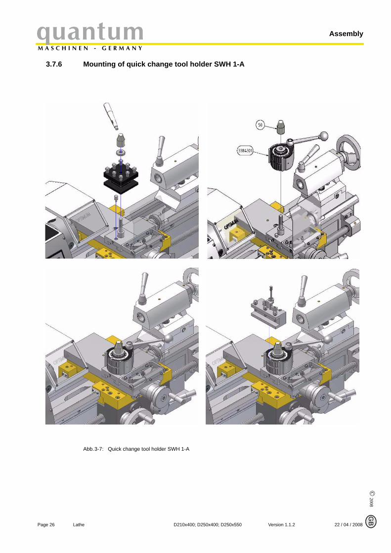
3.7.6 Mounting of quick change tool holder SWH 1-A
Abb.3-7: Quick change tool holder SWH 1-A

© 2
008
GB
Page 2722 / 04 / 2008 Version 1.1.2 D210x400; D250x400; D250x550 Lathe
quantumM A S C H I N E N - G E R M A N Y
Operation
4 Operation
4.1 SafetyThe lathe operates safely only under following conditions:
The lathe is in proper working order.The lathe is used as prescribed.The operating manual is followed.All safety devices are being installed and activated.
Any malfunctions should be eliminated immediately. Stop the machine immediately in the eventof any malfunction during operation and make sure it cannot be started up accidentally or with-out authorization.
Notify the person responsible immediately of any modification.
„For your own safety during operation“ on page 12
4.2 Control and indicating elements
4.2.1 D210x400 / Vario
Illustr.4-1: D210x400 Vario
handwheel lathe saddle
EMERGENCY STOP button
ON/ OFF switchchange-over switch
protective cover of headstock
change wheel and infeed table
rotation speed indicator
speed setting invi-nitely variable
speed table
feed activation lever
lathe chuck protection
lathe chuck
quadruple tool holder
clamping lever tailstock sleeve
tailstock
adjusting screw tailstock
handwheel top slide
lead screwhandwheel cross slide
© 2008
GB
Page 28 Lathe D210x400; D250x400; D250x550 Version 1.1.2 22 / 04 / 2008
OperationquantumM A S C H I N E N - G E R M A N Y
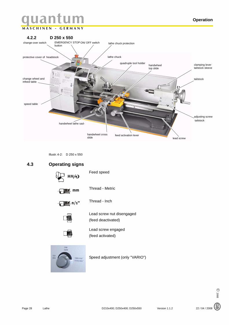
4.2.2 D 250 x 550
Illustr.4-2: D 250 x 550
4.3 Operating signsFeed speed
Thread - Metric
Thread - Inch
Lead screw nut disengaged(feed deactivated)
Lead screw engaged(feed activated)
Speed adjustment (only "VARIO")
change wheel and infeed table
change-over switch EMERGENCY STOP button
quadruple tool holder clamping lever tailstock sleeve
ON/ OFF switch lathe chuck protection
handwheel top slide
handwheel lathe sad-
feed activation lever
adjusting screw tailstock
tailstock
protective cover of headstock lathe chuck
speed table
lead screwhandwheel cross slide
mm
n/1"
© 2
008
GB
Page 2922 / 04 / 2008 Version 1.1.2 D210x400; D250x400; D250x550 Lathe
quantumM A S C H I N E N - G E R M A N Y
Operation
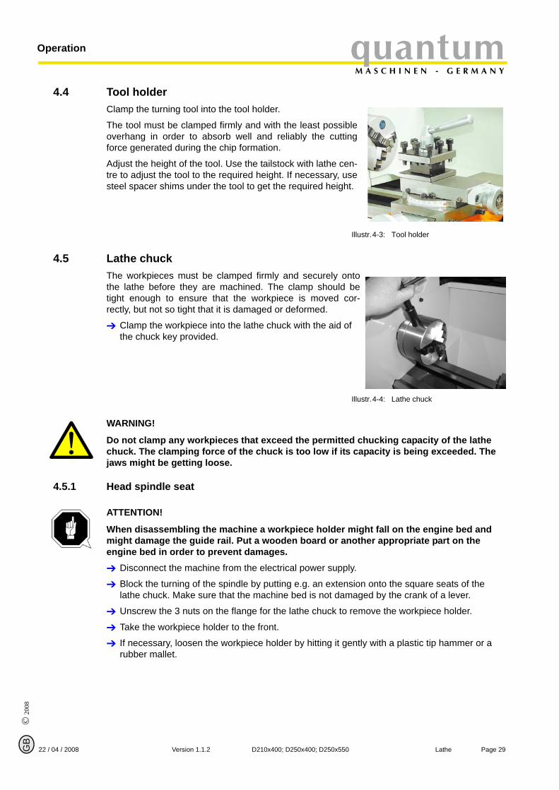
4.4 Tool holderClamp the turning tool into the tool holder.
The tool must be clamped firmly and with the least possibleoverhang in order to absorb well and reliably the cuttingforce generated during the chip formation.
Adjust the height of the tool. Use the tailstock with lathe cen-tre to adjust the tool to the required height. If necessary, usesteel spacer shims under the tool to get the required height.
Illustr.4-3: Tool holder
4.5 Lathe chuckThe workpieces must be clamped firmly and securely ontothe lathe before they are machined. The clamp should betight enough to ensure that the workpiece is moved cor-rectly, but not so tight that it is damaged or deformed.
Clamp the workpiece into the lathe chuck with the aid of the chuck key provided.
Illustr.4-4: Lathe chuck
WARNING!
Do not clamp any workpieces that exceed the permitted chucking capacity of the lathe chuck. The clamping force of the chuck is too low if its capacity is being exceeded. The jaws might be getting loose.
4.5.1 Head spindle seat
ATTENTION!
When disassembling the machine a workpiece holder might fall on the engine bed and might damage the guide rail. Put a wooden board or another appropriate part on the engine bed in order to prevent damages.
Disconnect the machine from the electrical power supply.
Block the turning of the spindle by putting e.g. an extension onto the square seats of the lathe chuck. Make sure that the machine bed is not damaged by the crank of a lever.
Unscrew the 3 nuts on the flange for the lathe chuck to remove the workpiece holder.
Take the workpiece holder to the front.
If necessary, loosen the workpiece holder by hitting it gently with a plastic tip hammer or a rubber mallet.
© 2008
GB
Page 30 Lathe D210x400; D250x400; D250x550 Version 1.1.2 22 / 04 / 2008
OperationquantumM A S C H I N E N - G E R M A N Y
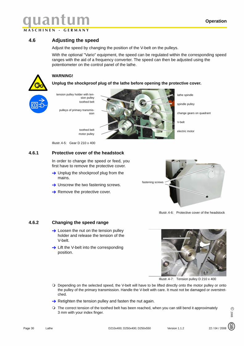
4.6 Adjusting the speedAdjust the speed by changing the position of the V-belt on the pulleys.
With the optional "Vario" equipment, the speed can be regulated within the corresponding speedranges with the aid of a frequency converter. The speed can then be adjusted using the potentiometer on the control panel of the lathe.
WARNING!
Unplug the shockproof plug of the lathe before opening the protective cover.
Illustr.4-5: Gear D 210 x 400
4.6.1 Protective cover of the headstock
In order to change the speed or feed, youfirst have to remove the protective cover.
Unplug the shockproof plug from the mains.
Unscrew the two fastening screws.
Remove the protective cover.
Illustr.4-6: Protective cover of the headstock
4.6.2 Changing the speed range
Loosen the nut on the tension pulley holder and release the tension of the V-belt.
Lift the V-belt into the corresponding position.
Illustr.4-7: Tension pulley D 210 x 400
Depending on the selected speed, the V-belt will have to be lifted directly onto the motor pulley or ontothe pulley of the primary transmission. Handle the V-belt with care. It must not be damaged or overstret-ched.
Retighten the tension pulley and fasten the nut again.The correct tension of the toothed belt has been reached, when you can still bend it approximately 3 mm with your index finger.
tension pulley holder with ten-sion pulley
toothed belt
pulleys of primary transmis-sion
toothed beltmotor pulley
lathe spindle
spindle pulley
change gears on quadrant
V-belt
electric motor
fastening screws
© 2
008
GB
Page 3122 / 04 / 2008 Version 1.1.2 D210x400; D250x400; D250x550 Lathe
quantumM A S C H I N E N - G E R M A N Y
Operation
ATTENTION!
Make sure the tension pulley is in contact with the outside of the V-belt at all times!Make sure the tension of the V-belt is correct. Excessive or insufficient tension can cause damage.
4.6.3 Speed table D 210 x 400
Illustr.4-8: Speed table D 210 x 400
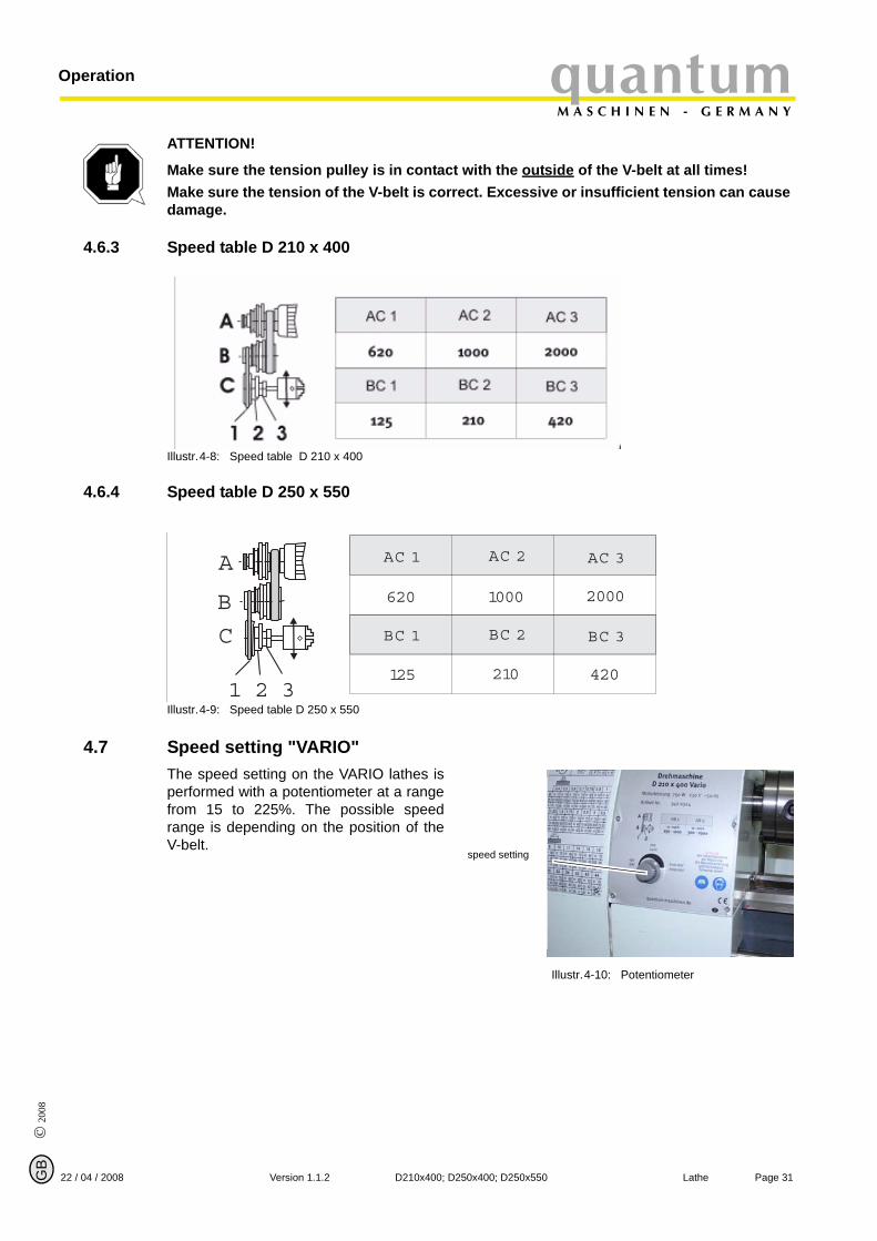
4.6.4 Speed table D 250 x 550
Illustr.4-9: Speed table D 250 x 550
4.7 Speed setting "VARIO"The speed setting on the VARIO lathes isperformed with a potentiometer at a rangefrom 15 to 225%. The possible speedrange is depending on the position of theV-belt.
Illustr.4-10: Potentiometer
D
D
1 2 3
A
B
C
AC 1 AC 2 AC 3
620 1000 2000
BC 1 BC 2 BC 3
125 210 420
D
speed setting

© 2008
GB
Page 32 Lathe D210x400; D250x400; D250x550 Version 1.1.2 22 / 04 / 2008
OperationquantumM A S C H I N E N - G E R M A N Y
4.7.1 Speed table D 210 x 400 Vario
Illustr.4-11: Speed table D 210 x 400 VARIO
4.7.2 Speed table D 250 Vario
Illustr.4-12: Speed table D 250 VARIO
INFORMATION
In the V-belt position AC 3, the physical limits of the drive are being achieved at 2500 min-1 bymechanical frictional resistance. It is impossible to have an effective controlling variable of 225%in the V-belt position AC 3. The full range of controlling variables from 15% to 225% are onlyavailable for the V-belt position AC 1.
This setting is intended to prevent the workpiece from getting loose by too high centrifugal forceof the clamping jaws on the lathe chuck.
4.7.3 Changing the change gears
The change gears for the feed are mounted on a quadrant.
Disconnect the shockproof plug from the mains.
Loosen the locking screw on the quadrant.
Swing the quadrant to the right.
Unscrew the bolt from the lead screw or the nuts from the quadrant bolts in order to remove the change gears to the front.
Install the gear couples using the feed or change gear table and screw the gearwheels onto the quadrant again.
Swing the quadrant to the left until the gearwheels have engaged again.
Re-adjust gear flank clearance by inserting a normal sheet of paper as an adjusting or dis-tance aid between the gearwheels.
Immobilise the quadrant with the locking screw.
Attach the protective cover of the headstock and reconnect the machine to the power supply.
D
D
AC 1 AC 2 AC 3
80 - 1200 160 - 2200 320 - 2500
BC 1 BC 2 BC 3
20 - 330 45 - 660 95 - 1100
15 - 225%15 - 225% 15 - 225%
15 - 225%15 - 225% 15 - 225%
1 2 3
A
B
C
D
© 2
008
GB
Page 3322 / 04 / 2008 Version 1.1.2 D210x400; D250x400; D250x550 Lathe
quantumM A S C H I N E N - G E R M A N Y
Operation
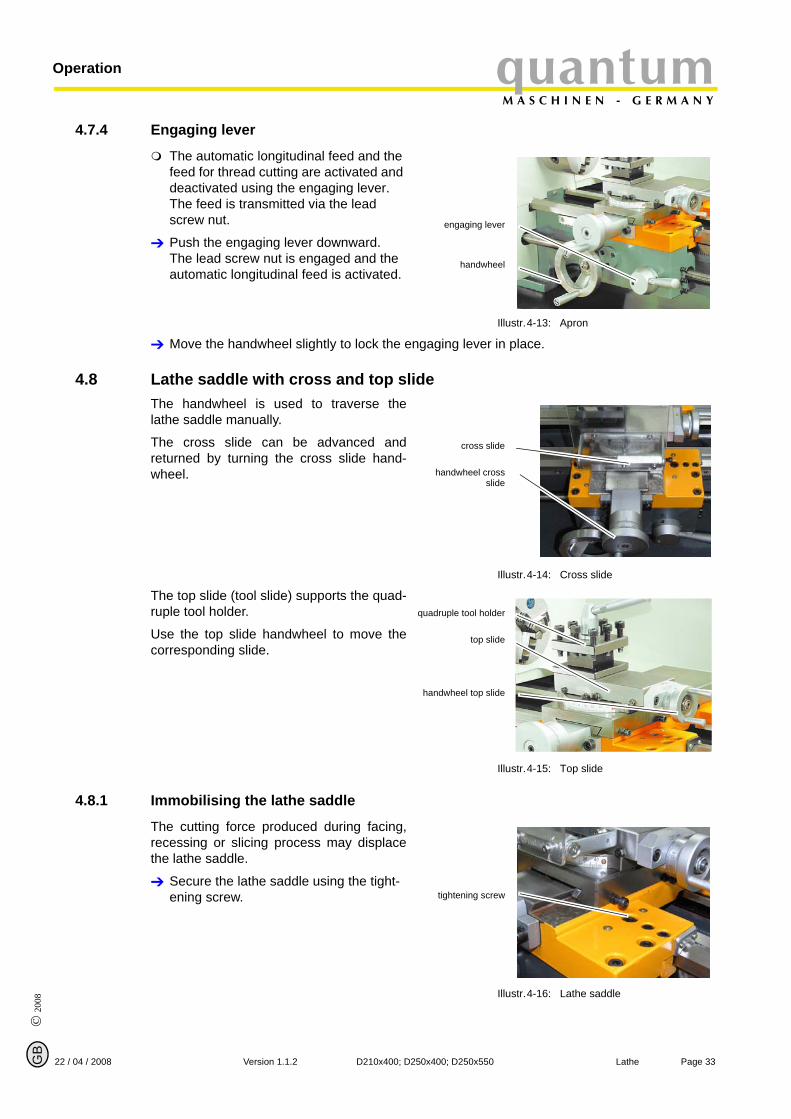
4.7.4 Engaging lever
The automatic longitudinal feed and the feed for thread cutting are activated and deactivated using the engaging lever. The feed is transmitted via the lead screw nut.
Push the engaging lever downward. The lead screw nut is engaged and the automatic longitudinal feed is activated.
Illustr.4-13: Apron
Move the handwheel slightly to lock the engaging lever in place.
4.8 Lathe saddle with cross and top slideThe handwheel is used to traverse thelathe saddle manually.
The cross slide can be advanced andreturned by turning the cross slide hand-wheel.
Illustr.4-14: Cross slide
The top slide (tool slide) supports the quad-ruple tool holder.
Use the top slide handwheel to move thecorresponding slide.
Illustr.4-15: Top slide
4.8.1 Immobilising the lathe saddle
The cutting force produced during facing,recessing or slicing process may displacethe lathe saddle.
Secure the lathe saddle using the tight-ening screw.
Illustr.4-16: Lathe saddle
engaging lever
handwheel
cross slide
handwheel crossslide
quadruple tool holder
top slide
handwheel top slide
tightening screw
© 2008
GB
Page 34 Lathe D210x400; D250x400; D250x550 Version 1.1.2 22 / 04 / 2008
OperationquantumM A S C H I N E N - G E R M A N Y
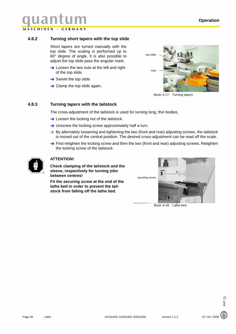
4.8.2 Turning short tapers with the top slide
Short tapers are turned manually with thetop slide. The scaling is performed up to60° degree of angle. It is also possible toadjust the top slide pass the angular mark.
Loosen the two nuts at the left and right of the top slide.
Swivel the top slide.
Clamp the top slide again.
Illustr.4-17: Turning tapers
4.8.3 Turning tapers with the tailstock
The cross-adjustment of the tailstock is used for turning long, thin bodies.
Loosen the locking nut of the tailstock.
Unscrew the locking screw approximately half a turn.By alternately loosening and tightening the two (front and rear) adjusting screws, the tailstock is moved out of the central position. The desired cross-adjustment can be read off the scale.
First retighten the locking screw and then the two (front and rear) adjusting screws. Retighten the locking screw of the tailstock.
ATTENTION!
Check clamping of the tailstock and the sleeve, respectively for turning jobs between centres! Fit the securing screw at the end of the lathe bed in order to prevent the tail-stock from falling off the lathe bed.
Illustr.4-18: Lathe bed
top slide
nuts
securing screw
© 2
008
GB
Page 3522 / 04 / 2008 Version 1.1.2 D210x400; D250x400; D250x550 Lathe
quantumM A S C H I N E N - G E R M A N Y
Operation
4.9 Tailstock sleeve The tailstock sleeve is used to hold the tools (bits, lathe centres, etc.)
Clamp the required tool in the tailstock sleeve.Use the scale [mm] on the sleeve to re-adjust and / or adjust the tool.
Clamp the sleeve with the clamping lever.Use the handwheel to move the sleeve back and forth.
The sleeve of the tailstock can be used to introduce a drill chuck for holding bits and counter-sinks.
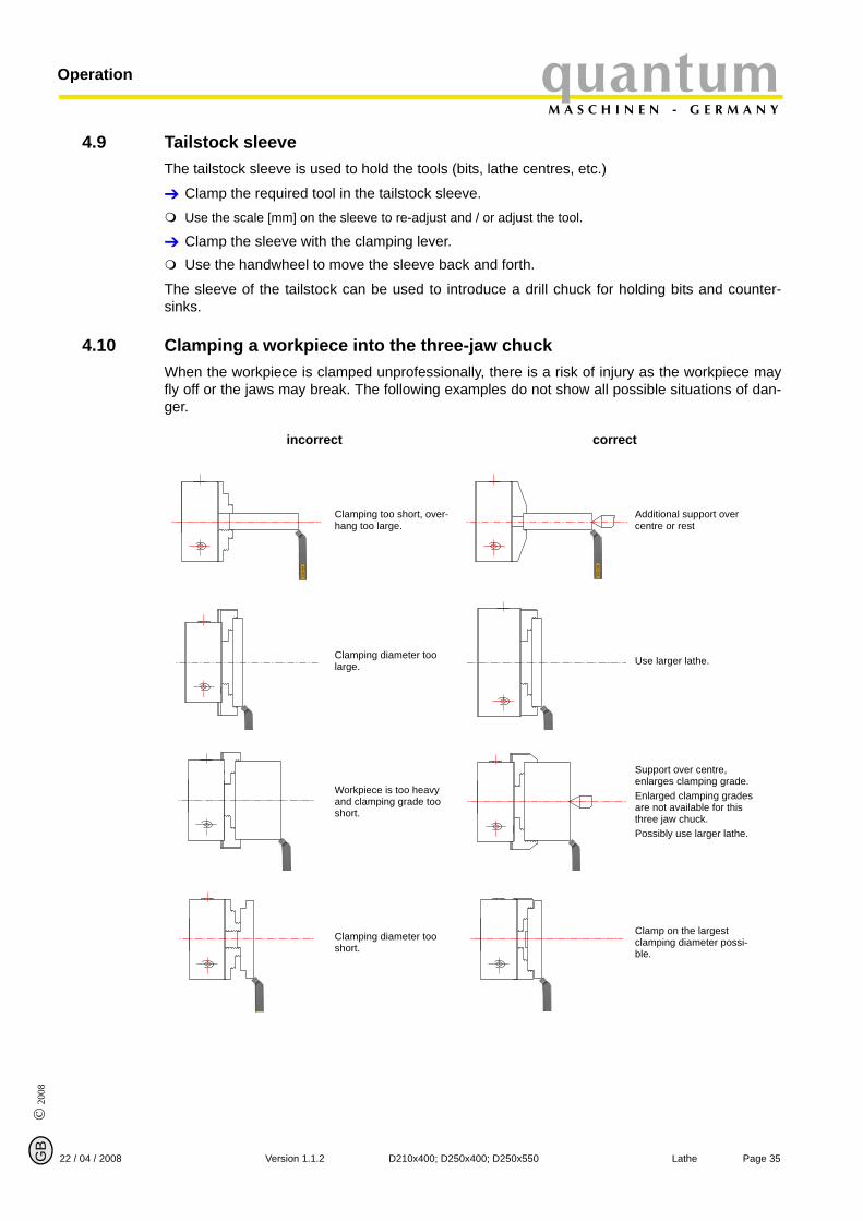
4.10 Clamping a workpiece into the three-jaw chuckWhen the workpiece is clamped unprofessionally, there is a risk of injury as the workpiece mayfly off or the jaws may break. The following examples do not show all possible situations of dan-ger.
incorrect correct
Clamping too short, over-hang too large.
Additional support over centre or rest
Clamping diameter too large. Use larger lathe.
Workpiece is too heavy and clamping grade too short.
Support over centre, enlarges clamping grade.Enlarged clamping grades are not available for this three jaw chuck.Possibly use larger lathe.
Clamping diameter too short.
Clamp on the largest clamping diameter possi-ble.
© 2008
GB
Page 36 Lathe D210x400; D250x400; D250x550 Version 1.1.2 22 / 04 / 2008
OperationquantumM A S C H I N E N - G E R M A N Y
4.10.1 Replacing the clamping jaws on the lathe chuck
The clamping jaws and the three-jaw chuckare provided with numbers. Check before thechange, if the numbers are readable and, ifnecessary, mark the jaws and their primaryposition. Insert the clamping jaws at the cor-rect position and in the right order into thethree-jaw chuck.
After the replacement, bring the jaws com-pletely together in order to control if they areinserted correctly.
Illustr.4-19: Three-jaw chuck / clamping jaws
4.11 General working notes
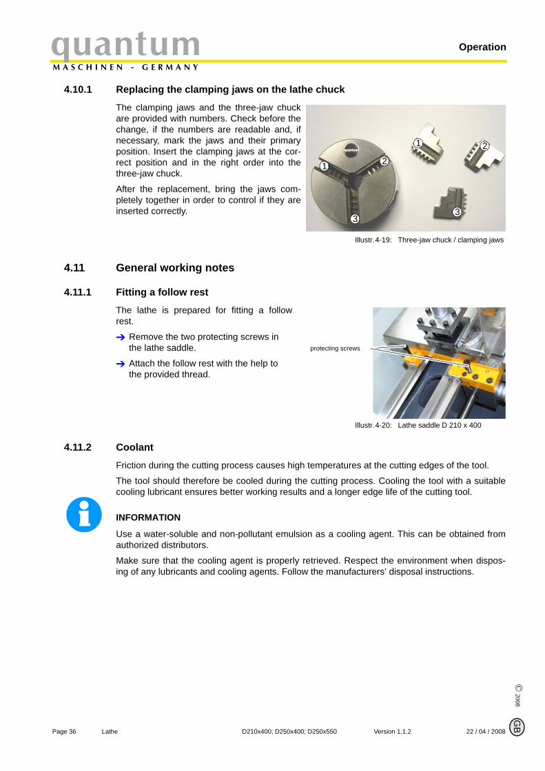
4.11.1 Fitting a follow rest
The lathe is prepared for fitting a followrest.
Remove the two protecting screws in the lathe saddle.
Attach the follow rest with the help to the provided thread.
Illustr.4-20: Lathe saddle D 210 x 400
4.11.2 Coolant
Friction during the cutting process causes high temperatures at the cutting edges of the tool.
The tool should therefore be cooled during the cutting process. Cooling the tool with a suitablecooling lubricant ensures better working results and a longer edge life of the cutting tool.
INFORMATION
Use a water-soluble and non-pollutant emulsion as a cooling agent. This can be obtained fromauthorized distributors.
Make sure that the cooling agent is properly retrieved. Respect the environment when dispos-ing of any lubricants and cooling agents. Follow the manufacturers’ disposal instructions.
1 2
33
21
protecting screws
© 2
008
GB
Page 3722 / 04 / 2008 Version 1.1.2 D210x400; D250x400; D250x550 Lathe
quantumM A S C H I N E N - G E R M A N Y
Maintenance
5 Maintenance
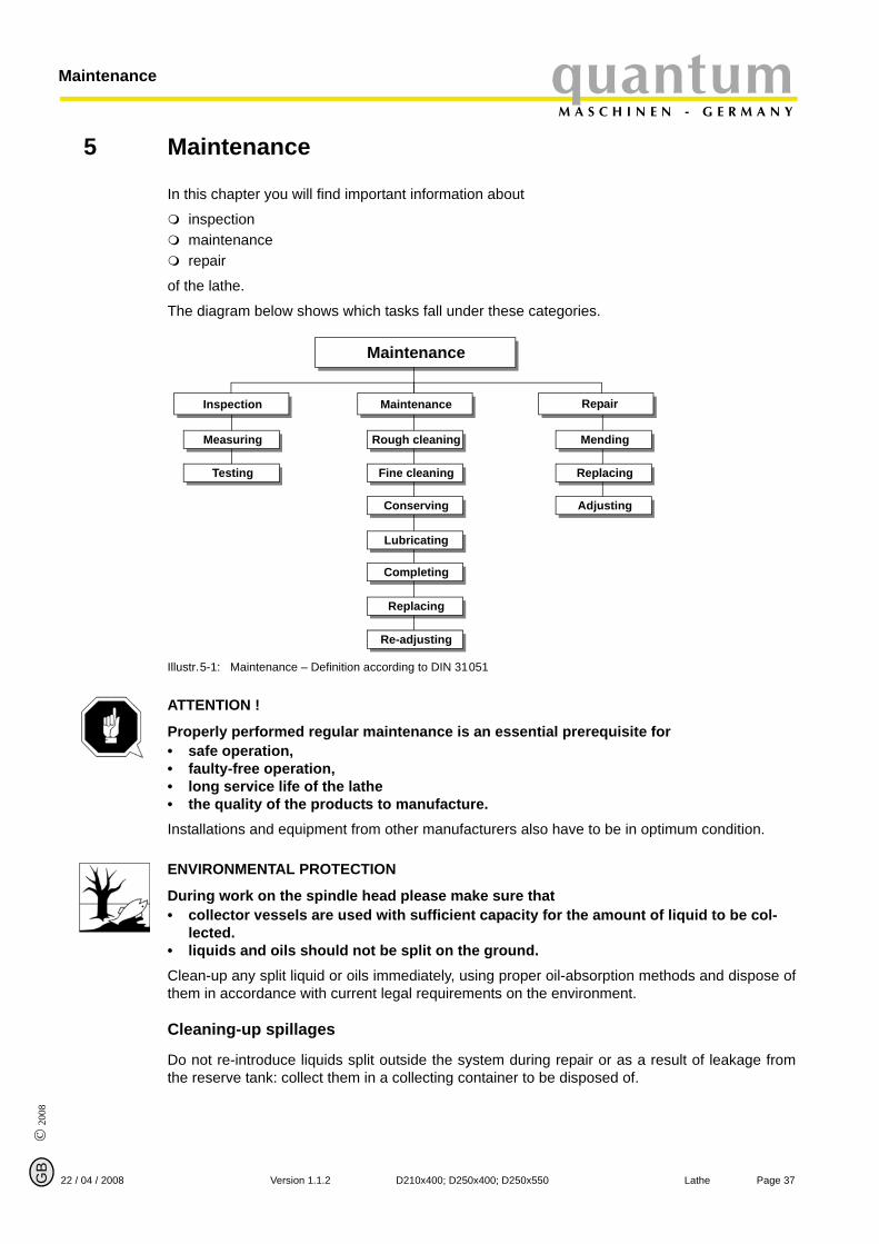
In this chapter you will find important information about
inspectionmaintenancerepair
of the lathe.
The diagram below shows which tasks fall under these categories.
Illustr.5-1: Maintenance – Definition according to DIN 31051
ATTENTION !
Properly performed regular maintenance is an essential prerequisite for• safe operation,• faulty-free operation,• long service life of the lathe • the quality of the products to manufacture.Installations and equipment from other manufacturers also have to be in optimum condition.
ENVIRONMENTAL PROTECTION
During work on the spindle head please make sure that• collector vessels are used with sufficient capacity for the amount of liquid to be col-
lected.• liquids and oils should not be split on the ground.Clean-up any split liquid or oils immediately, using proper oil-absorption methods and dispose ofthem in accordance with current legal requirements on the environment.
Cleaning-up spillages
Do not re-introduce liquids split outside the system during repair or as a result of leakage fromthe reserve tank: collect them in a collecting container to be disposed of.
Maintenance
Inspection Maintenance Repair
Measuring Rough cleaning Mending
Testing Fine cleaning Replacing
Conserving
Lubricating
Completing
Replacing
Re-adjusting
Adjusting

© 2008
GB
Page 38 Lathe D210x400; D250x400; D250x550 Version 1.1.2 22 / 04 / 2008
MaintenancequantumM A S C H I N E N - G E R M A N Y
Disposal
Never dump oil or other pollutant substances in water inlets, rivers or channels.
Used oils have to be delivered to a collection centre. Consult your supervisor if you do not knowwhere the collection centre is.
5.1 Safety
WARNING!
The consequences of incorrect maintenance and repair work may include:• very serious injury to the staff working on the lathe,• damage to the lathe.Only qualified staff should carry out maintenance and repair work on the lathe.
5.1.1 Preparation
WARNING!
Only carry out work on the lathe, if it has been disconnected of the power supply. „Switching-off and securing the lathe“ on page 13
Attach a warning label.
5.1.2 Restarting
Run a safety check before restarting the lathe.
„Safety check“ on page 11
WARNING!
Before connecting the lathe, you must check that there is no danger for persons and that the lathe is not damaged.
© 2
008
GB
Page 3922 / 04 / 2008 Version 1.1.2 D210x400; D250x400; D250x550 Lathe
quantumM A S C H I N E N - G E R M A N Y
Maintenance
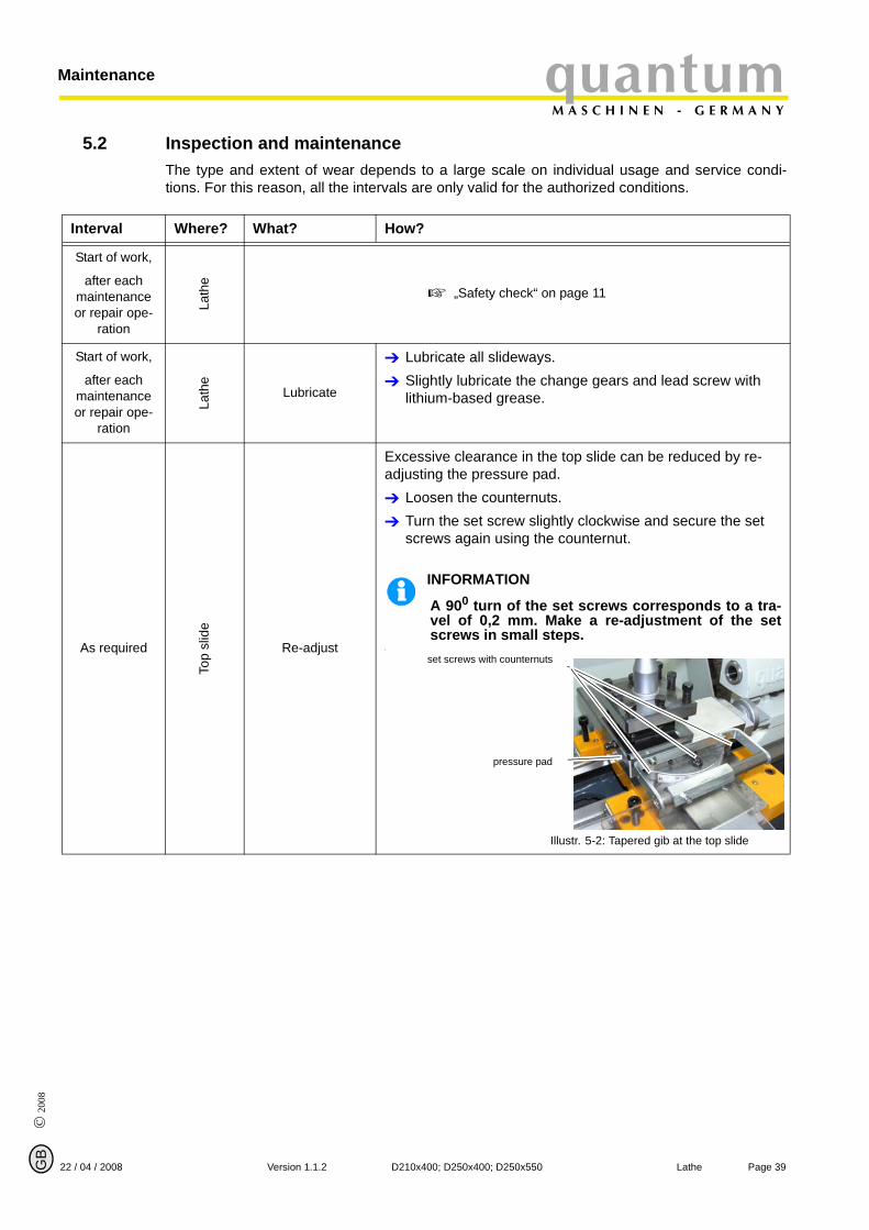
5.2 Inspection and maintenanceThe type and extent of wear depends to a large scale on individual usage and service condi-tions. For this reason, all the intervals are only valid for the authorized conditions.
Interval Where? What? How?
Start of work,
after each maintenance or repair ope-
ration
Lath
e
„Safety check“ on page 11
Start of work,
after each maintenance or repair ope-
ration
Lath
e
Lubricate
Lubricate all slideways.Slightly lubricate the change gears and lead screw with lithium-based grease.
As required
Top
slid
e
Re-adjust
Excessive clearance in the top slide can be reduced by re-adjusting the pressure pad.
Loosen the counternuts.Turn the set screw slightly clockwise and secure the set screws again using the counternut.
INFORMATION
A 900 turn of the set screws corresponds to a tra-vel of 0,2 mm. Make a re-adjustment of the setscrews in small steps.
.
Illustr. 5-2: Tapered gib at the top slide
set screws with counternuts
pressure pad
© 2008
GB
Page 40 Lathe D210x400; D250x400; D250x550 Version 1.1.2 22 / 04 / 2008
MaintenancequantumM A S C H I N E N - G E R M A N Y
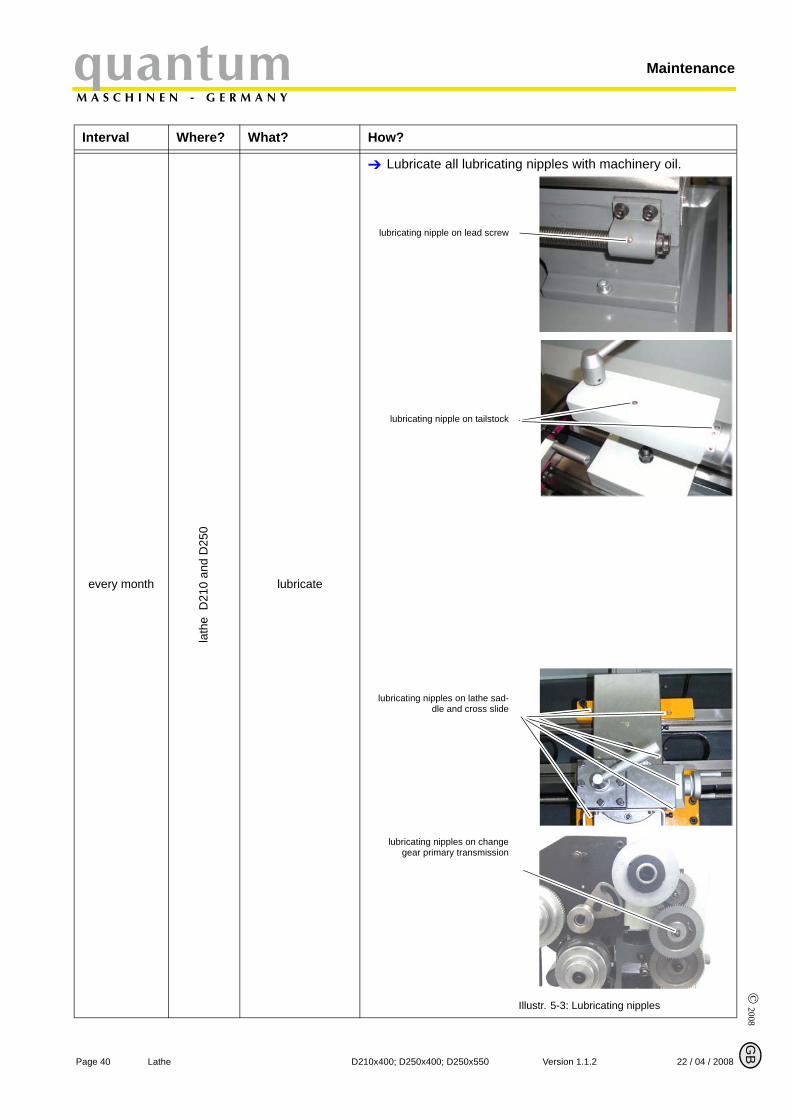
every month
lath
e D
210
and
D25
0
lubricate
Lubricate all lubricating nipples with machinery oil.
Illustr. 5-3: Lubricating nipples
Interval Where? What? How?
lubricating nipple on lead screw
lubricating nipple on tailstock
lubricating nipples on lathe sad-dle and cross slide
lubricating nipples on changegear primary transmission
© 2
008
GB
Page 4122 / 04 / 2008 Version 1.1.2 D210x400; D250x400; D250x550 Lathe
quantumM A S C H I N E N - G E R M A N Y
Maintenance
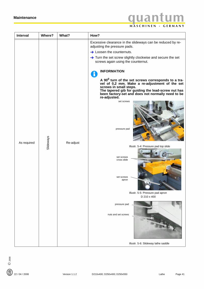
As required
Slid
eway
s
Re-adjust
Excessive clearance in the slideways can be reduced by re-adjusting the pressure pads.
Loosen the counternuts.Turn the set screw slightly clockwise and secure the set screws again using the counternut.
INFORMATION
A 900 turn of the set screws corresponds to a tra-vel of 0,2 mm. Make a re-adjustment of the setscrews in small steps. The tapered gib for guiding the lead-screw nut hasbeen factory-set and does not normally need to bere-adjusted.
Illustr. 5-4: Pressure pad top slide
Illustr. 5-5: Pressure pad apron D 210 x 400
Illustr. 5-6: Slideway lathe saddle
Interval Where? What? How?
set screws
pressure pad
set screwscross slide
set screwsapron
pressure pad
nuts and set screws

© 2008
GB
Page 42 Lathe D210x400; D250x400; D250x550 Version 1.1.2 22 / 04 / 2008
MaintenancequantumM A S C H I N E N - G E R M A N Y
INFORMATION
The spindle bearings are permanently greased. Greasing during the maintenance intervals isnot necessary. Further greasing of the spindle bearings is only necessary in case of de- andremounting of the spindle bearing.
5.3 RepairFor any repair work, request the assistance of an employee of Optimum Maschinen GermanyGmbH’s technical service or send us the lathe.
If the repairs are carried out by qualified technical staff, they must follow the indications given inthis manual.
The company Optimum Maschinen Germany GmbH does not take any responsibility nor does itguarantee against damage and operating malfunctions resulting from failure to observe thisoperating manual.
For repairs only use
faultless and suitable tools,original parts or parts from series expressly authorized by Optimum Maschinen Germany GmbH.
© 2
008
GB
quantumM A S C H I N E N - G E R M A N Y
Appendix turning
6 Appendix turning
22 April 2008
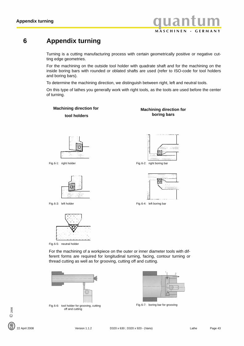
Turning is a cutting manufacturing process with certain geometrically positive or negative cut-ting edge geometries.
For the machining on the outside tool holder with quadrate shaft and for the machining on theinside boring bars with rounded or oblated shafts are used (refer to ISO-code for tool holdersand boring bars).
To determine the machining direction, we distinguish between right, left and neutral tools.
On this type of lathes you generally work with right tools, as the tools are used before the centerof turning.
Machining direction for
tool holdersMachining direction for
boring bars
Fig.6-1: right holder Fig.6-2: right boring bar
Fig.6-3: left holder Fig.6-4: left boring bar
Fig.6-5: neutral holder
For the machining of a workpiece on the outer or inner diameter tools with dif-ferent forms are required for longitudinal turning, facing, contour turning orthread cutting as well as for grooving, cutting off and cutting.
Fig.6-6: tool holder for grooving, cutting off and cutting
Fig.6-7: boring bar for grooving
Page 43Version 1.1.2 D320 x 630 ; D320 x 920 - (Vario) Lathe
Page 44 La
Appendix turningquantumM A S C H I N E N - G E R M A N Y
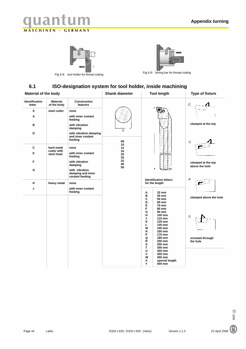
Fig.6-8: tool holder for thread cutting Fig.6-9: boring bar for thread cutting
6.1 ISO-designation system for tool holder, inside machining
clamped at the top
clamped at the topabove the hole
clamped above the hole
screwed throughthe hole
Type of fixtureMaterial of the body Shank diameter Tool length
081012162025324050
Identification letters for the length
ABCDEFGHJKLMNPQRSTUVWXY
32 mm40 mm50 mm60 mm70 mm80 mm90 mm100 mm110 mm125 mm140 mm150 mm160 mm170 mm180 mm200 mm250 mm300 mm350 mm400 mm450 mmspecial length500 mm
Identification Material Construction of the body
S steel cutter none
A with inner coolantfeeding
B with vibrationdamping
D with vibration damping and inner coolant
hard metal none
with inner coolant feeding
with vibrationdamping
with vibrationdamping and inner coolant feeding
cutter withsteel head
C
E
F
G
heavy metal none
with inner coolantfeeding
H
J
letter features
feeding
© 2008
G
Bthe D320 x 630 ; D320 x 920 - (Vario) Version 1.1.2 22 April 2008

© 2
008
GB
quantumM A S C H I N E N - G E R M A N Y
Appendix turning
6.2 ISO-designation system for tool holder, outside machining
clamped at the top
clamped at the topabove the hole
clamped above the hole
screwed through the hole
free angles where specialindications are requiired
Type of fixture Form of the indexable insert Form of the tool holder Free angle of the indexab
Page 4522 April 2008 Version 1.1.2 D320 x 630 ; D320 x 920 - (Vario) Lathe
Appendix turningquantumM A S C H I N E N - G E R M A N Y
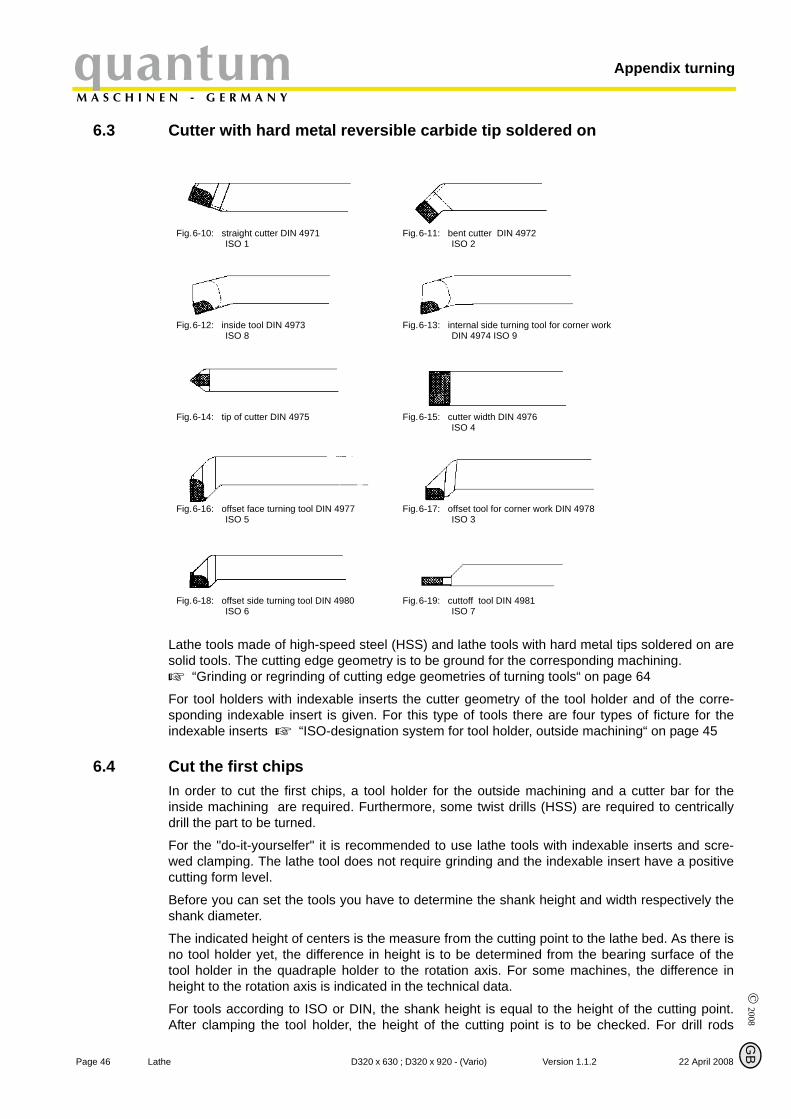
6.3 Cutter with hard metal reversible carbide tip soldered on
Page 46 La
Lathe tools made of high-speed steel (HSS) and lathe tools with hard metal tips soldered on aresolid tools. The cutting edge geometry is to be ground for the corresponding machining.
“Grinding or regrinding of cutting edge geometries of turning tools“ on page 64
For tool holders with indexable inserts the cutter geometry of the tool holder and of the corre-sponding indexable insert is given. For this type of tools there are four types of ficture for theindexable inserts “ISO-designation system for tool holder, outside machining“ on page 45
Fig.6-10: straight cutter DIN 4971ISO 1
Fig.6-11: bent cutter DIN 4972ISO 2
Fig.6-12: inside tool DIN 4973ISO 8
Fig.6-13: internal side turning tool for corner work DIN 4974 ISO 9
Fig.6-14: tip of cutter DIN 4975 Fig.6-15: cutter width DIN 4976ISO 4
Fig.6-16: offset face turning tool DIN 4977ISO 5
Fig.6-17: offset tool for corner work DIN 4978ISO 3
Fig.6-18: offset side turning tool DIN 4980ISO 6
Fig.6-19: cuttoff tool DIN 4981ISO 7
6.4 Cut the first chips
© 2008
G
In order to cut the first chips, a tool holder for the outside machining and a cutter bar for theinside machining are required. Furthermore, some twist drills (HSS) are required to centricallydrill the part to be turned.
For the "do-it-yourselfer" it is recommended to use lathe tools with indexable inserts and scre-wed clamping. The lathe tool does not require grinding and the indexable insert have a positivecutting form level.
Before you can set the tools you have to determine the shank height and width respectively theshank diameter.
The indicated height of centers is the measure from the cutting point to the lathe bed. As there isno tool holder yet, the difference in height is to be determined from the bearing surface of thetool holder in the quadraple holder to the rotation axis. For some machines, the difference inheight to the rotation axis is indicated in the technical data.
For tools according to ISO or DIN, the shank height is equal to the height of the cutting point.After clamping the tool holder, the height of the cutting point is to be checked. For drill rods
B
the D320 x 630 ; D320 x 920 - (Vario) Version 1.1.2 22 April 2008

© 2
008
GB
22 April 2008
quantumM A S C H I N E N - G E R M A N Y
Appendix turning
according to ISO, the height of the cutting point is half the shank diameter and for flattened drillrods half the flattened height. For inside tools according to DIN the height of th cutting point cor-responds to 0,8 x shank diameter respectively shank height.
ATTENTION!
If due to a variation in tolerance there is a slug or cone on the plane face, the exact height ofcenters is to be found by facing trials (put the tool holder higher for slugs and lower for cones).
The height of centers is to be checked each time when the turning tools are changed!
For example, a shaft with a diameter of 30mm is to be machined of C45. The outside diameter isto be turned and faced 20mm and a hole of 16mm is to be drilled.
Selecting the tools
• tool holder for turningand facing with 95° tool cutting edge angle • indexable insert with a point angle of 80°• we select a coated hard metal HC M15/K10 as cutting material. With this tool about 75% of
all lathe work on the outside diameter may be performed.
Selecting the cutting data
• A hard metal with the designation HC M15/K10 is selected as cutting material, cutting speed ϑc = 80 m/min
• ap = 0,4mm for outside machining; ap = 0,2 mm for inside machining • f = 0,05 mm/U (value for automatic feed)
The speed which is to be set is calculated with
the formular
n ϑc 1000×d 3 14,×------------------------- 80 1000×
30 3 14,×------------------------ 849min 1–
===
Page 47Version 1.1.2 D320 x 630 ; D320 x 920 - (Vario) Lathe
Appendix turningquantumM A S C H I N E N - G E R M A N Y
6.5 Outside machining, longitudinal turning and facing
Page 48 La
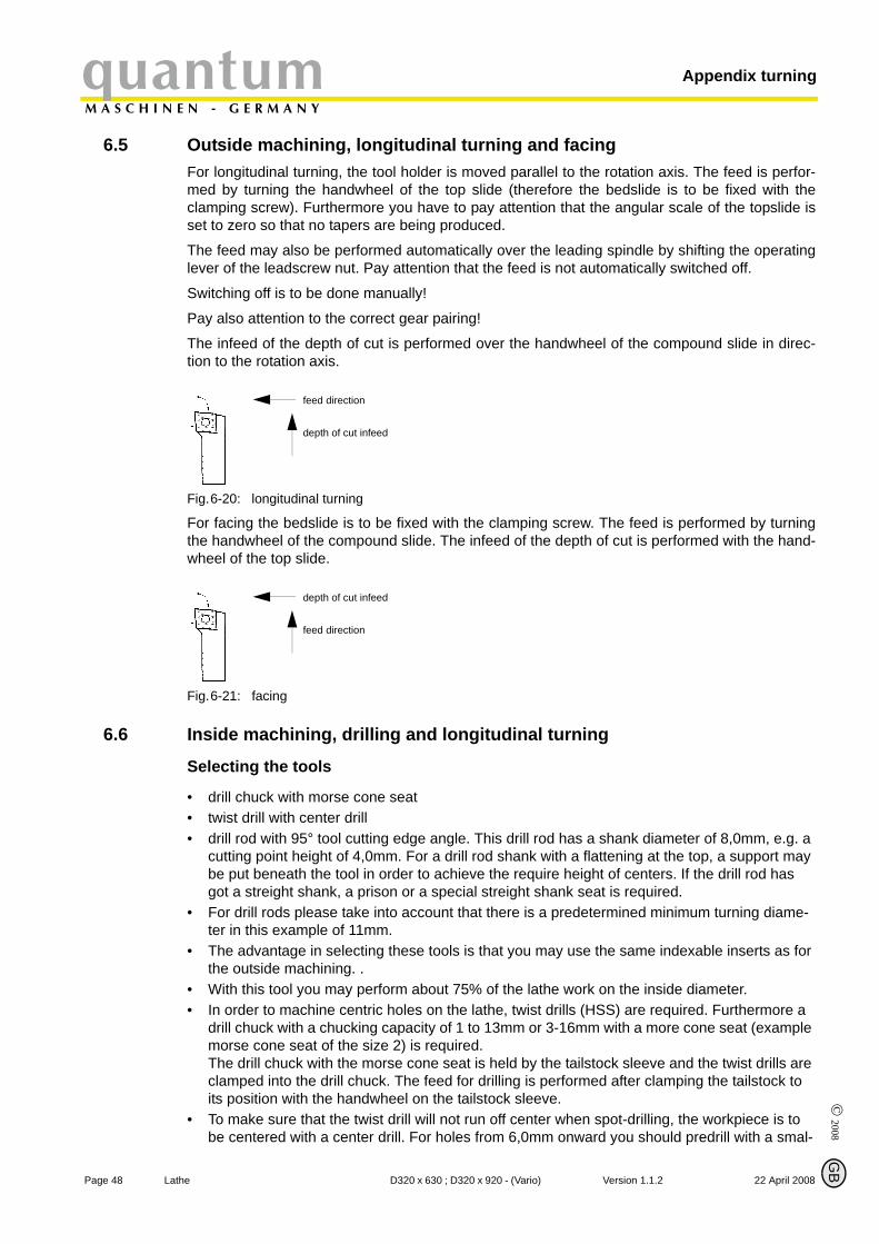
For longitudinal turning, the tool holder is moved parallel to the rotation axis. The feed is perfor-med by turning the handwheel of the top slide (therefore the bedslide is to be fixed with theclamping screw). Furthermore you have to pay attention that the angular scale of the topslide isset to zero so that no tapers are being produced.
The feed may also be performed automatically over the leading spindle by shifting the operatinglever of the leadscrew nut. Pay attention that the feed is not automatically switched off.
Switching off is to be done manually!
Pay also attention to the correct gear pairing!
The infeed of the depth of cut is performed over the handwheel of the compound slide in direc-tion to the rotation axis.
Fig.6-20: longitudinal turning
feed direction
depth of cut infeed
For facing the bedslide is to be fixed with the clamping screw. The feed is performed by turningthe handwheel of the compound slide. The infeed of the depth of cut is performed with the hand-wheel of the top slide.
Fig.6-21: facing
depth of cut infeed
feed direction
6.6 Inside machining, drilling and longitudinal turning
© 2008
G
Selecting the tools
• drill chuck with morse cone seat • twist drill with center drill • drill rod with 95° tool cutting edge angle. This drill rod has a shank diameter of 8,0mm, e.g. a
cutting point height of 4,0mm. For a drill rod shank with a flattening at the top, a support may be put beneath the tool in order to achieve the require height of centers. If the drill rod has got a streight shank, a prison or a special streight shank seat is required.
• For drill rods please take into account that there is a predetermined minimum turning diame-ter in this example of 11mm.
• The advantage in selecting these tools is that you may use the same indexable inserts as for the outside machining. .
• With this tool you may perform about 75% of the lathe work on the inside diameter. • In order to machine centric holes on the lathe, twist drills (HSS) are required. Furthermore a
drill chuck with a chucking capacity of 1 to 13mm or 3-16mm with a more cone seat (example morse cone seat of the size 2) is required. The drill chuck with the morse cone seat is held by the tailstock sleeve and the twist drills are clamped into the drill chuck. The feed for drilling is performed after clamping the tailstock to its position with the handwheel on the tailstock sleeve.
• To make sure that the twist drill will not run off center when spot-drilling, the workpiece is to be centered with a center drill. For holes from 6,0mm onward you should predrill with a smal-
the
B
D320 x 630 ; D320 x 920 - (Vario) Version 1.1.2 22 April 2008
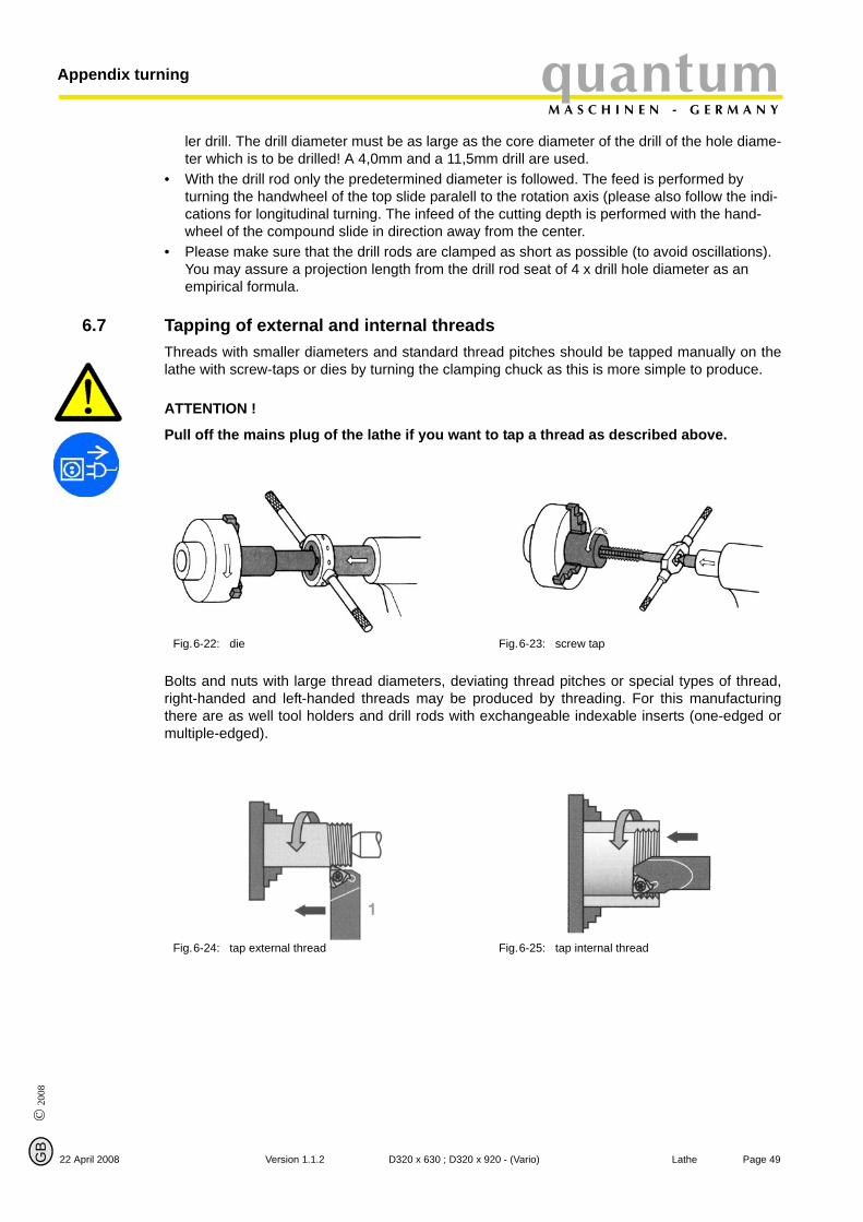
© 2
008
GB
22 April 2008
quantumM A S C H I N E N - G E R M A N Y
Appendix turning
ler drill. The drill diameter must be as large as the core diameter of the drill of the hole diame-ter which is to be drilled! A 4,0mm and a 11,5mm drill are used.
• With the drill rod only the predetermined diameter is followed. The feed is performed by turning the handwheel of the top slide paralell to the rotation axis (please also follow the indi-cations for longitudinal turning. The infeed of the cutting depth is performed with the hand-wheel of the compound slide in direction away from the center.
• Please make sure that the drill rods are clamped as short as possible (to avoid oscillations). You may assure a projection length from the drill rod seat of 4 x drill hole diameter as an empirical formula.
6.7 Tapping of external and internal threads
Threads with smaller diameters and standard thread pitches should be tapped manually on thelathe with screw-taps or dies by turning the clamping chuck as this is more simple to produce.ATTENTION !
Pull off the mains plug of the lathe if you want to tap a thread as described above.
Bolts and nuts with large thread diameters, deviating thread pitches or special types of thread,right-handed and left-handed threads may be produced by threading. For this manufacturingthere are as well tool holders and drill rods with exchangeable indexable inserts (one-edged ormultiple-edged).
Fig.6-22: die Fig.6-23: screw tap
Fig.6-24: tap external thread Fig.6-25: tap internal thread
Page 49Version 1.1.2 D320 x 630 ; D320 x 920 - (Vario) Lathe
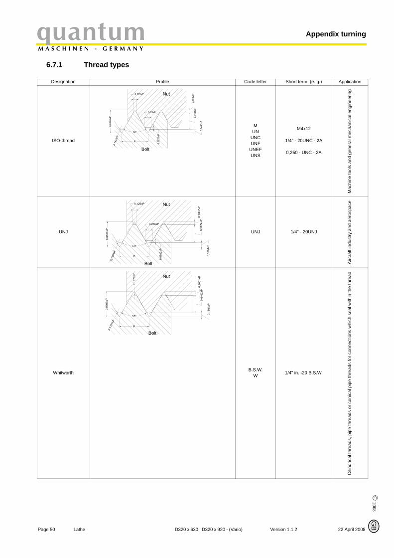
Appendix turningquantumM A S C H I N E N - G E R M A N Y
6.7.1 Thread types
Page 50 La
Profile Code letter Short term (e. g.) Application
© 2008
G
Designation
ISO-thread
MUN
UNC UNF
UNEF UNS
M4x12
1/4" - 20UNC - 2A
0,250 - UNC - 2A
Mac
hine
tool
s an
d ge
nera
l mec
hani
cal e
ngin
eerin
g
UNJ UNJ 1/4" - 20UNJ
Airc
raft
indu
stry
and
aer
ospa
ce
Whitworth B.S.W.W 1/4" in. -20 B.S.W.
Cili
ndric
al th
read
s, p
ipe
thre
ads
or c
onic
al p
ipe
thre
ads
for c
onne
ctio
ns w
hich
sea
l with
in th
e th
read
Nut
Bolt
Nut
Bolt
Nut
Bolt
B
the D320 x 630 ; D320 x 920 - (Vario) Version 1.1.2 22 April 2008
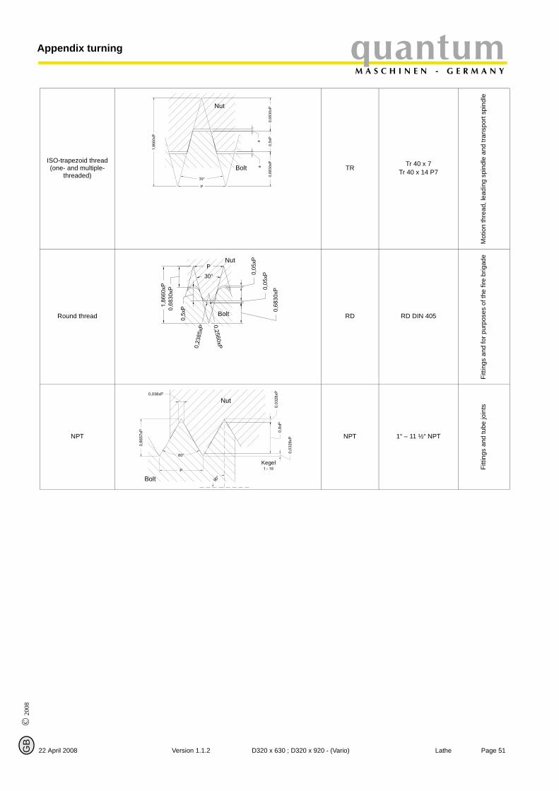
© 2
008
GB
quantumM A S C H I N E N - G E R M A N Y
Appendix turning
ISO-trapezoid thread(one- and multiple-
threaded)TR Tr 40 x 7
Tr 40 x 14 P7
Mot
ion
thre
ad, l
eadi
ng s
pind
le a
nd tr
ansp
ort s
pind
le
Round thread RD RD DIN 405
Fitti
ngs
and
for p
urpo
ses
of th
e fir
e br
igad
e
NPT NPT 1“ – 11 ½“ NPT
Fitti
ngs
and
tube
join
ts
Nut
Bolt
Nut
Bolt
Nut
Bolt
Kegel
Page 5122 April 2008 Version 1.1.2 D320 x 630 ; D320 x 920 - (Vario) Lathe
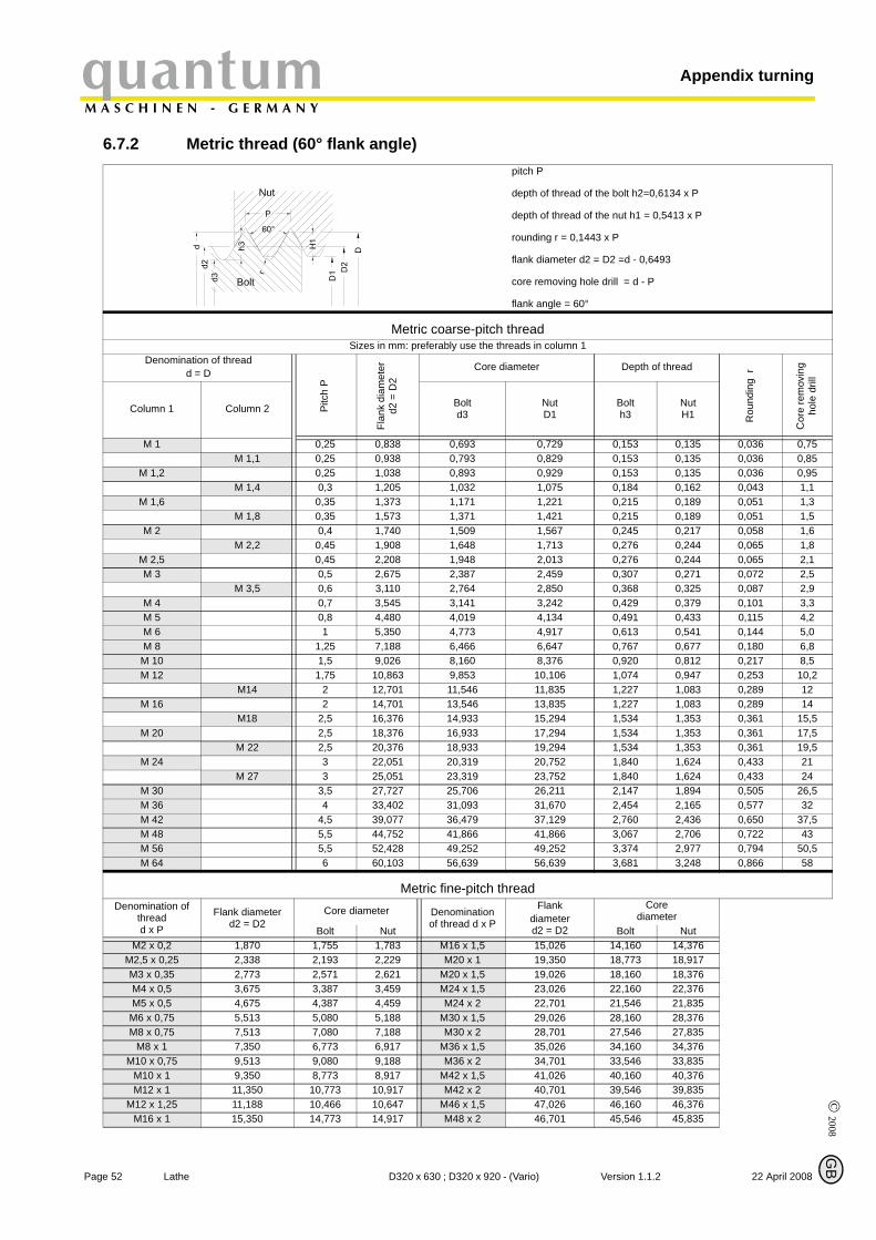
© 2008
Appendix turningquantumM A S C H I N E N - G E R M A N Y
G
6.7.2 Metric thread (60° flank angle) pitch P
depth of thread of the bolt h2=0,6134 x P
depth of thread of the nut h1 = 0,5413 x P
rounding r = 0,1443 x P
flank diameter d2 = D2 =d - 0,6493
core removing hole drill = d - P
flank angle = 60°
Metric coarse-pitch thread Sizes in mm: preferably use the threads in column 1
Denomination of thread d = D
Pitc
h P
Flan
k di
amet
er
d2 =
D2
Core diameter Depth of thread
Rou
ndin
g r
Cor
e re
mov
ing
hole
dril
l
Column 1 Column 2 Boltd3
NutD1
Bolth3
NutH1
M 1 0,25 0,838 0,693 0,729 0,153 0,135 0,036 0,75M 1,1 0,25 0,938 0,793 0,829 0,153 0,135 0,036 0,85
M 1,2 0,25 1,038 0,893 0,929 0,153 0,135 0,036 0,95M 1,4 0,3 1,205 1,032 1,075 0,184 0,162 0,043 1,1
M 1,6 0,35 1,373 1,171 1,221 0,215 0,189 0,051 1,3M 1,8 0,35 1,573 1,371 1,421 0,215 0,189 0,051 1,5
M 2 0,4 1,740 1,509 1,567 0,245 0,217 0,058 1,6M 2,2 0,45 1,908 1,648 1,713 0,276 0,244 0,065 1,8
M 2,5 0,45 2,208 1,948 2,013 0,276 0,244 0,065 2,1M 3 0,5 2,675 2,387 2,459 0,307 0,271 0,072 2,5
M 3,5 0,6 3,110 2,764 2,850 0,368 0,325 0,087 2,9M 4 0,7 3,545 3,141 3,242 0,429 0,379 0,101 3,3M 5 0,8 4,480 4,019 4,134 0,491 0,433 0,115 4,2M 6 1 5,350 4,773 4,917 0,613 0,541 0,144 5,0M 8 1,25 7,188 6,466 6,647 0,767 0,677 0,180 6,8M 10 1,5 9,026 8,160 8,376 0,920 0,812 0,217 8,5M 12 1,75 10,863 9,853 10,106 1,074 0,947 0,253 10,2
M14 2 12,701 11,546 11,835 1,227 1,083 0,289 12M 16 2 14,701 13,546 13,835 1,227 1,083 0,289 14
M18 2,5 16,376 14,933 15,294 1,534 1,353 0,361 15,5M 20 2,5 18,376 16,933 17,294 1,534 1,353 0,361 17,5
M 22 2,5 20,376 18,933 19,294 1,534 1,353 0,361 19,5M 24 3 22,051 20,319 20,752 1,840 1,624 0,433 21
M 27 3 25,051 23,319 23,752 1,840 1,624 0,433 24M 30 3,5 27,727 25,706 26,211 2,147 1,894 0,505 26,5M 36 4 33,402 31,093 31,670 2,454 2,165 0,577 32M 42 4,5 39,077 36,479 37,129 2,760 2,436 0,650 37,5M 48 5,5 44,752 41,866 41,866 3,067 2,706 0,722 43M 56 5,5 52,428 49,252 49,252 3,374 2,977 0,794 50,5M 64 6 60,103 56,639 56,639 3,681 3,248 0,866 58
Metric fine-pitch thread Denomination of
thread d x P
Flank diameter d2 = D2
Core diameter Denomination of thread d x P
Flankdiameter d2 = D2
Corediameter
Bolt Nut Bolt NutM2 x 0,2 1,870 1,755 1,783 M16 x 1,5 15,026 14,160 14,376
M2,5 x 0,25 2,338 2,193 2,229 M20 x 1 19,350 18,773 18,917M3 x 0,35 2,773 2,571 2,621 M20 x 1,5 19,026 18,160 18,376M4 x 0,5 3,675 3,387 3,459 M24 x 1,5 23,026 22,160 22,376M5 x 0,5 4,675 4,387 4,459 M24 x 2 22,701 21,546 21,835
M6 x 0,75 5,513 5,080 5,188 M30 x 1,5 29,026 28,160 28,376M8 x 0,75 7,513 7,080 7,188 M30 x 2 28,701 27,546 27,835
M8 x 1 7,350 6,773 6,917 M36 x 1,5 35,026 34,160 34,376M10 x 0,75 9,513 9,080 9,188 M36 x 2 34,701 33,546 33,835
M10 x 1 9,350 8,773 8,917 M42 x 1,5 41,026 40,160 40,376M12 x 1 11,350 10,773 10,917 M42 x 2 40,701 39,546 39,835
M12 x 1,25 11,188 10,466 10,647 M46 x 1,5 47,026 46,160 46,376M16 x 1 15,350 14,773 14,917 M48 x 2 46,701 45,546 45,835
Nut
Bolt
B
Page 52 Lathe D320 x 630 ; D320 x 920 - (Vario) Version 1.1.2 22 April 2008
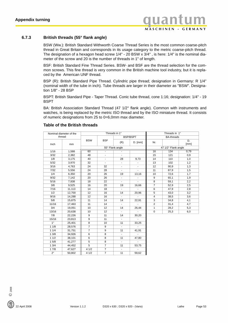
© 2
008
GB
quantumM A S C H I N E N - G E R M A N Y
Appendix turning
6.7.3 British threads (55° flank angle)
22 April 2008
BSW (Ww.): British Standard Withworth Coarse Thread Series is the most common coarse-pitchthread in Great Britain and corresponds in its usage category to the metric coarse-pitch thread.The designation of a hexagon head screw 1/4" - 20 BSW x 3/4" , is here: 1/4" is the nominal dia-meter of the screw and 20 is the number of threads in 1" of length.
BSF: British Standard Fine Thread Series. BSW- and BSF are the thread selection for the com-mon screws. This fine thread is very common in the British machine tool industry, but it is repla-ced by the American UNF thread.
BSP (R): British Standard Pipe Thread. Cylindric pipe thread; designation in Germany: R 1/4"(nominal width of the tube in inch). Tube threads are larger in their diameter as "BSW". Designa-tion 1/8" - 28 BSP
BSPT: British Standard Pipe - Taper Thread. Conic tube thread, cone 1:16; designation: 1/4" - 19BSPT
BA: British Association Standard Thread (47 1/2° flank angle). Common with instruments andwatches, is being replaced by the metric ISO thread and by the ISO miniature thread. It consistsof numeric designations from 25 to 0=6,0mm max diameter.
Table of the British threads
Nominal diameter of the thread
Threads in 1" Threads in 1"
BSW BSFBSP/BSPT BA-threads
Inch mm(R) D. [mm] Nr. D.
[mm]55° Flank angle 47 1/2° Flank angle
1/16 1,588 60 - - 16 134 0,793/32 2,382 48 - - 15 121 0,91/8 3,175 40 - 28 9,73 14 110 1,05/32 3,970 32 - - - 13 102 1,23/16 4,763 24 32 - - 12 90,9 1,37/32 5,556 24 28 - - 11 87,9 1,51/4 6,350 20 26 19 13,16 10 72,6 1,79/32 7,142 20 26 - - 9 65,1 1,95/16 7,938 18 22 - - 8 59,1 2,23/8 9,525 16 20 19 16,66 7 52,9 2,57/16 11,113 14 18 - - 6 47,9 2,81/2 12,700 12 16 14 20,96 5 43,0 3,29/16 14,288 12 16 - - 4 38,5 3,65/8 15,875 11 14 14 22,91 3 34,8 4,1
11/16 17,463 11 14 - - 2 31,4 4,73/4 19,051 10 12 14 26,44 1 28,2 5,3
13/16 20,638 10 12 - - 0 25,3 6,07/8 22,226 9 11 14 30,20
15/16 23,813 9 11 - -1" 25,401 8 10 11 33,25
1 1/8 28,576 7 9 - -1 1/4 31,751 7 9 11 41,911 3/8 34,926 6 8 - -1 1/2 38,101 6 8 11 47,801 5/8 41,277 5 8 - -1 3/4 44,452 5 7 11 53,751 7/8 47,627 4 1/2 7 - -
2" 50,802 4 1/2 7 11 59,62
Page 53Version 1.1.2 D320 x 630 ; D320 x 920 - (Vario) Lathe
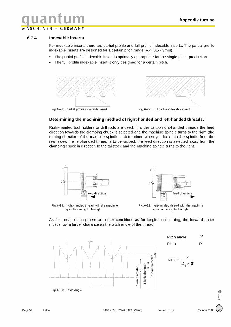
Appendix turningquantumM A S C H I N E N - G E R M A N Y
6.7.4 Indexable inserts
© 2008
Page 54 La
G
For indexable inserts there are partial profile and full profile indexable inserts. The partial profileindexable inserts are designed for a certain pitch range (e.g. 0,5 - 3mm).
• The partial profile indexable insert is optimally appropriate for the single-piece production.• The full profile indexable insert is only designed for a certain pitch.
Determining the machining method of right-handed and left-handed threads:
Right-handed tool holders or drill rods are used. In order to top right-handed threads the feeddirection towards the clamping chuck is selected and the machine spindle turns to the right (theturning direction of the machine spindle is determined when you look into the spindle from therear side). If a left-handed thread is to be tapped, the feed direction is selected away from theclamping chuck in direction to the tailstock and the machine spindle turns to the right.
As for thread cutting there are other conditions as for longitudinal turning, the forward cuttermust show a larger charance as the pitch angle of the thread.
Fig.6-26: partial profile indexable insert Fig.6-27: full profile indexable insert
Fig.6-28: right-handed thread with the machine spindle turning to the right
Fig.6-29: left-handed thread with the machine spindle turning to the right
Fig.6-30: Pitch angle
Pitch angle
Pitch P
feed direction feed direction
Cor
e di
amet
er
Flan
k di
amet
er
Thre
ad d
iam
eter
ϕ
ϕtan PD2 π×-----------------=
B
the D320 x 630 ; D320 x 920 - (Vario) Version 1.1.2 22 April 2008
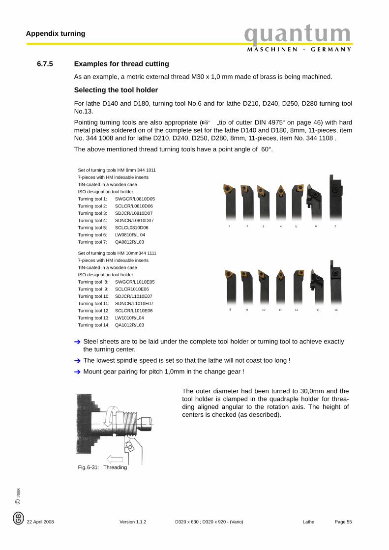
© 2
008
GB
quantumM A S C H I N E N - G E R M A N Y
Appendix turning
6.7.5 Examples for thread cutting
22 April 2008
As an example, a metric external thread M30 x 1,0 mm made of brass is being machined.
Selecting the tool holder
For lathe D140 and D180, turning tool No.6 and for lathe D210, D240, D250, D280 turning toolNo.13.
Pointing turning tools are also appropriate ( „tip of cutter DIN 4975“ on page 46) with hardmetal plates soldered on of the complete set for the lathe D140 and D180, 8mm, 11-pieces, itemNo. 344 1008 and for lathe D210, D240, D250, D280, 8mm, 11-pieces, item No. 344 1108 .
The above mentioned thread turning tools have a point angle of 60°.
Steel sheets are to be laid under the complete tool holder or turning tool to achieve exactly the turning center.
The lowest spindle speed is set so that the lathe will not coast too long !
Mount gear pairing for pitch 1,0mm in the change gear !
Set of turning tools HM 8mm 344 10117-pieces with HM indexable insertsTiN-coated in a wooden case ISO designation tool holder Turning tool 1: SWGCR/L0810D05Turning tool 2: SCLCR/L0810D06Turning tool 3: SDJCR/L0810D07Turning tool 4: SDNCN/L0810D07Turning tool 5: SCLCL0810D06Turning tool 6: LW0810R/L 04Turning tool 7: QA0812R/L03
Set of turning tools HM 10mm344 11117-pieces with HM indexable inserts TiN-coated in a wooden case ISO designation tool holder Turning tool 8: SWGCR/L1010E05Turning tool 9: SCLCR1010E06Turning tool 10: SDJCR/L1010E07Turning tool 11: SDNCN/L1010E07Turning tool 12: SCLCR/L1010E06Turning tool 13: LW1010R/L04Turning tool 14: QA1012R/L03
Fig.6-31: Threading
The outer diameter had been turned to 30,0mm and thetool holder is clamped in the quadraple holder for threa-ding aligned angular to the rotation axis. The height ofcenters is checked (as described).
1 2 3 4 5 6 7
8 9 10 11 12 13 14
Page 55Version 1.1.2 D320 x 630 ; D320 x 920 - (Vario) Lathe
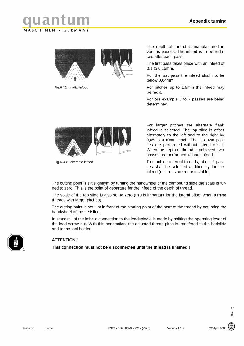
© 2008
Page 56 La
Appendix turningquantumM A S C H I N E N - G E R M A N Y
G
The cutting point is slit slightlym by turning the handwheel of the compound slide the scale is tur-ned to zero. This is the point of departure for the infeed of the depth of thread.
The scale of the top slide is also set to zero (this is important for the lateral offset when turningthreads with larger pitches).
The cutting point is set just in front of the starting point of the start of the thread by actuating thehandwheel of the bedslide.
In standstill of the lathe a connection to the leadspindle is made by shifting the operating lever ofthe lead-screw nut. With this connection, the adjusted thread pitch is transfered to the bedslideand to the tool holder.
ATTENTION !
This connection must not be disconnected until the thread is finished !
Fig.6-32: radial infeed
The depth of thread is manufactured invarious passes. The infeed is to be redu-ced after each pass.
The first pass takes place with an infeed of0,1 to 0,15mm.
For the last pass the infeed shall not bebelow 0,04mm.
For pitches up to 1,5mm the infeed maybe radial.
For our example 5 to 7 passes are beingdetermined.
Fig.6-33: alternate infeed
For larger pitches the alternate flankinfeed is selected. The top slide is offsetalternately to the left and to the right by0,05 to 0.10mm each. The last two pas-ses are performed without lateral offset.When the depth of thread is achieved, twopasses are performed without infeed.
To machine internal threads, about 2 pas-ses shall be selected additionally for theinfeed (drill rods are more instable).
B
the D320 x 630 ; D320 x 920 - (Vario) Version 1.1.2 22 April 2008
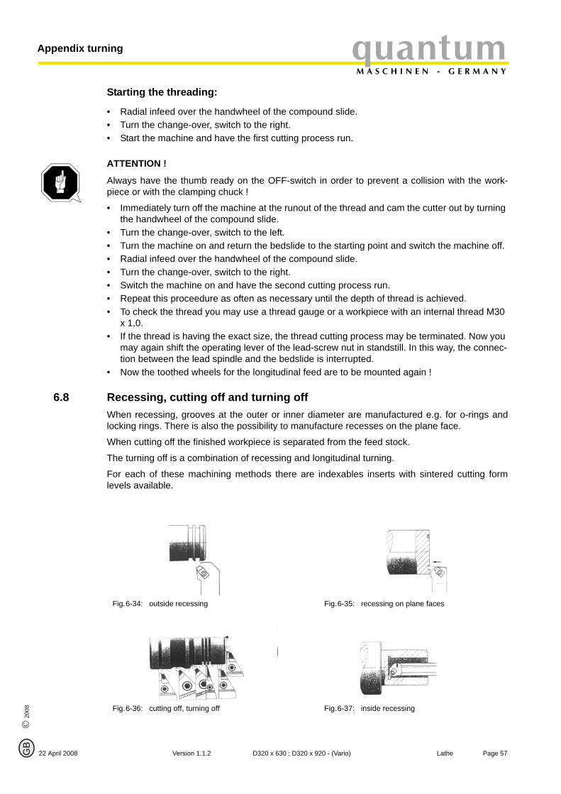
© 2
008
GB
22 April 2008
quantumM A S C H I N E N - G E R M A N Y
Appendix turning
Starting the threading:
• Radial infeed over the handwheel of the compound slide. • Turn the change-over, switch to the right. • Start the machine and have the first cutting process run.
ATTENTION !
Always have the thumb ready on the OFF-switch in order to prevent a collision with the work-piece or with the clamping chuck !
• Immediately turn off the machine at the runout of the thread and cam the cutter out by turning the handwheel of the compound slide.
• Turn the change-over, switch to the left. • Turn the machine on and return the bedslide to the starting point and switch the machine off. • Radial infeed over the handwheel of the compound slide.• Turn the change-over, switch to the right. • Switch the machine on and have the second cutting process run. • Repeat this proceedure as often as necessary until the depth of thread is achieved. • To check the thread you may use a thread gauge or a workpiece with an internal thread M30
x 1,0.• If the thread is having the exact size, the thread cutting process may be terminated. Now you
may again shift the operating lever of the lead-screw nut in standstill. In this way, the connec-tion between the lead spindle and the bedslide is interrupted.
• Now the toothed wheels for the longitudinal feed are to be mounted again !
6.8 Recessing, cutting off and turning off
When recessing, grooves at the outer or inner diameter are manufactured e.g. for o-rings andlocking rings. There is also the possibility to manufacture recesses on the plane face.When cutting off the finished workpiece is separated from the feed stock.
The turning off is a combination of recessing and longitudinal turning.
For each of these machining methods there are indexables inserts with sintered cutting formlevels available.
Fig.6-34: outside recessing Fig.6-35: recessing on plane faces
Fig.6-36: cutting off, turning off Fig.6-37: inside recessing
Page 57Version 1.1.2 D320 x 630 ; D320 x 920 - (Vario) Lathe

© 2008
Page 58 La
Appendix turningquantumM A S C H I N E N - G E R M A N Y
G
On a shaft made of brass, an undercut for a thread M30 is to be machined. Groove with 5,0mmwith a depth of 2,5mm.
Selecting the tool holder: For lathe D140 and D180, turning tool No.7, and for lathe D210,D240, D250, D280 turning tool No. 14
For small lathes the cutting speed for this machining compared to the cutting speed for longitudi-nal turning is reduced by about 60% in order to prevent oscillations.
Cutting speed Vc = 40 m/min, the speed to be set would be 425min-1 .
The tool holder is clamped into the quadraple holder, aligned angular to the rotation axis and theheight of centers is checked.
The tool is positioned and fixed with the bedslide. The exact position is set with the handwheelof the top slide. With the indexable insert the outer diameter is slit slightly (by turning the handw-heel of the compound slide). Set the scale to zero and the first recess of 3,0mm width may bemachined. Apply some machine oil on the cutter to grease it! Another recess of 2,0mm is requi-red to achieve a groove width of 5,0mm.
Fig.6-38: recessing 1 Fig.6-39: recessing 2
B
the D320 x 630 ; D320 x 920 - (Vario) Version 1.1.2 22 April 2008

© 2
008
GB
quantumM A S C H I N E N - G E R M A N Y
Appendix turning
6.9 Turning cones with high precision
22 April 2008
There are different possibilities to machine a cone on a common small lathe:
1. By twisting the top slide and by setting the setting-angle with the angular scale. But there the graduation of the scale is too inaccurate. For chamfers and conic passingsthe graduation of the angular scale is sufficient.
2. By a simple calculation, a stop measure of 100mm length (of your own production)and a gauge with stand.
Calculation
of the offset of the topslide relating to the stop measure with a length of 100mm.
The stop measure (100mm) is to be put between a fixed lunit stop and the bedslide. Put thegauge with stand on the lathe bed and horizontally align the test prod with the testprod with thetopslide (90° to the topslide). The twisting measure is calculated with the above mentioned for-mula. The topslide is twisted by this value (then set the gauge to zero). After removing the stopmeasure, the bedslide will be aligned to the limit stop. The gauge must indicate the calculated
Fig.6-40: designations on the cone
D = large diameter [mm]
d = small diameter [mm]
L = cone length [mm]
Lw = workpiece length [mm]
= cone angle
= setting angle
Kv = cone proportion
Vr = tailstock offset
Vd = measure change [mm]
Vo = twist measure of top slide [mm]
step by step
by one calculation step (summary)
example:
D = 30,0mm ; d = 24,0mm ; L = 22,0mm
α
α 2⁄
D d
Lw
L
α
α 2⁄
Kv LD d–-------------= Vd 100mm
Kv-------------------= Vo Vd
2-------=
Vo 100mm D d–( )×2 L×
-------------------------------------------=
Vo 100mm 30mm 24mm–( )×2 22mm×
-------------------------------------------------------------------- 100mm 6mm×44mm
-------------------------------------- 13= 63mm,==
Version 1
.1.2 Page 59D320 x 630 ; D320 x 920 - (Vario) Lathe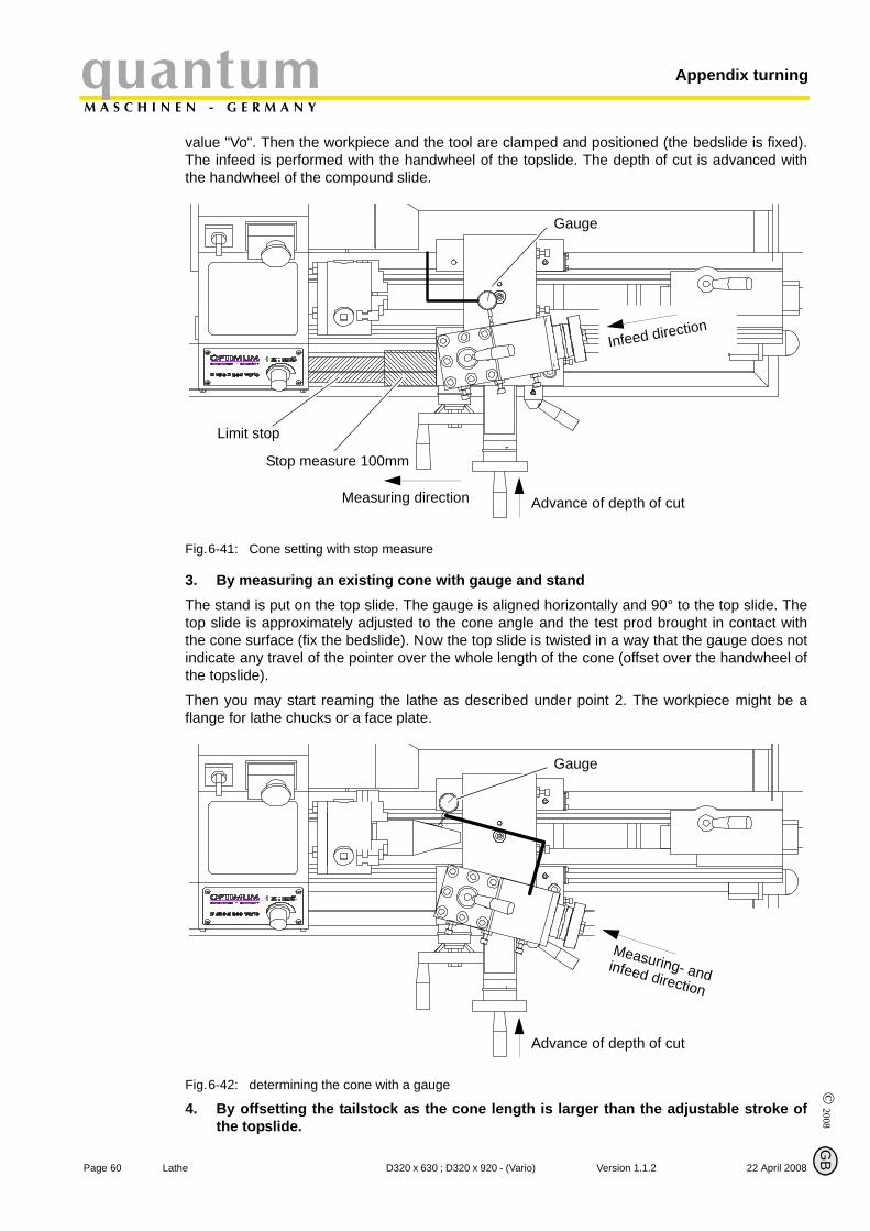
Page 60 La
Appendix turningquantumM A S C H I N E N - G E R M A N Y
value "Vo". Then the workpiece and the tool are clamped and positioned (the bedslide is fixed).The infeed is performed with the handwheel of the topslide. The depth of cut is advanced withthe handwheel of the compound slide.
Fig.6-41: Cone setting with stop measure
Gauge
Stop measure 100mm
Limit stop
Measuring direction Advance of depth of cut
Infeed direction
3. By measuring an existing cone with gauge and stand The stand is put on the top slide. The gauge is aligned horizontally and 90° to the top slide. Thetop slide is approximately adjusted to the cone angle and the test prod brought in contact withthe cone surface (fix the bedslide). Now the top slide is twisted in a way that the gauge does notindicate any travel of the pointer over the whole length of the cone (offset over the handwheel ofthe topslide).
Then you may start reaming the lathe as described under point 2. The workpiece might be aflange for lathe chucks or a face plate.
Fig.6-42: determining the cone with a gauge
Gauge
Advance of depth of cut
Measuring- andinfeed direction
©
2008G
4. By offsetting the tailstock as the cone length is larger than the adjustable stroke ofthe topslide.
B
the D320 x 630 ; D320 x 920 - (Vario) Version 1.1.2 22 April 2008
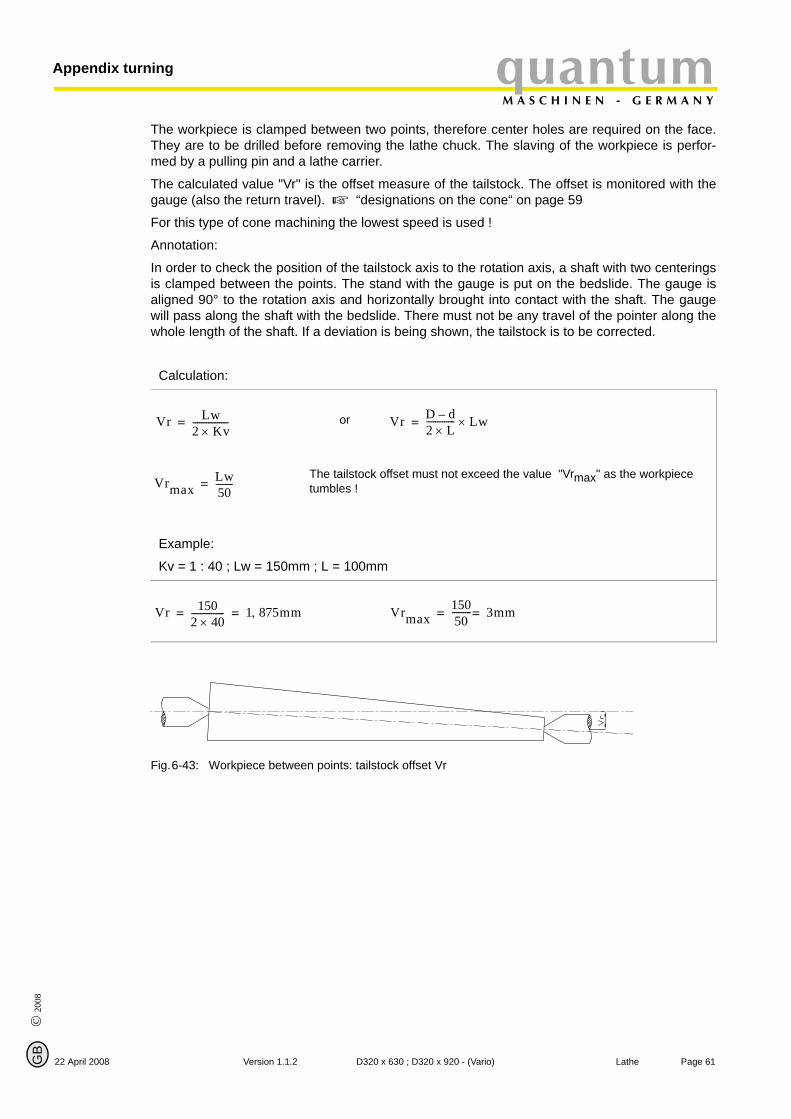
© 2
008
GB
22 April 2008
quantumM A S C H I N E N - G E R M A N Y
Appendix turning
The workpiece is clamped between two points, therefore center holes are required on the face.They are to be drilled before removing the lathe chuck. The slaving of the workpiece is perfor-med by a pulling pin and a lathe carrier.
The calculated value "Vr" is the offset measure of the tailstock. The offset is monitored with thegauge (also the return travel). “designations on the cone“ on page 59
For this type of cone machining the lowest speed is used !
Annotation:
In order to check the position of the tailstock axis to the rotation axis, a shaft with two centeringsis clamped between the points. The stand with the gauge is put on the bedslide. The gauge isaligned 90° to the rotation axis and horizontally brought into contact with the shaft. The gaugewill pass along the shaft with the bedslide. There must not be any travel of the pointer along thewhole length of the shaft. If a deviation is being shown, the tailstock is to be corrected.
Fig.6-43: Workpiece between points: tailstock offset Vr
Calculation:
or
The tailstock offset must not exceed the value "Vrmax" as the workpiece tumbles !
Example:
Kv = 1 : 40 ; Lw = 150mm ; L = 100mm
Vr Lw2 Kv×----------------= Vr D d–
2 L×------------- Lw×=
VrmaxLw50--------=
Vr 1502 40×--------------- 1 875mm,= = Vrmax
15050--------- 3mm==
Page 61Version 1.1.2 D320 x 630 ; D320 x 920 - (Vario) Lathe

Appendix turningquantumM A S C H I N E N - G E R M A N Y
6.10 Cutting material
Page 62 La
The basic requirement for a cutting material is that it is harder than the material which is to beworked. The larger the difference is, the higher the wear resistance of the cutting material.
6.10.1 Cutting materials for chipping
© 2008
G
High-speed steel (HSS)
High-speed steel is a high-alloy tol steel with high tenacy. The cutting edges may be groundsharp-edged and the tools may be used with low cutting speed.
Hard metal (uncoated and coated)
Hard metal is a sintered material on the basis of tungsten carbide which may be applied foralmost all materials which are to be chipped due to the different composition. There are somemore wear-resistant types of hard metal and others with a higher tenacy.
The hard metals are divided into three main groups:
P - for long-chipping materials (steel, meltable cast iron)
M - for long- and short-chipping material (stainless steel, machining steel)
K - for short-chipping materials (castiron, NE metals, hardened steel)
An additional classification is performed with an annexed figure:
The lower the figure (P10), the higher is the wear resistance (planing)
The higher the figure (P40), the higher the tenacy (roughing).
In order to make hard metals more wear resistant, they may be coated with mechanically resi-stant materials. These layers may be applied as single or multiple-layer coatings.
There are two proceedures:
• PVD / Physical Vapor Deposition,• CVD / Chemikal Vapor Deposition.
The most common layers of mechanically resistant materials are:
• TiN / titanium nitride,• TiC / titanium carbide,• TiCN / titanium carbon nitride,• Al2O3 / aluminum oxide,
as well as their combinations
The PVD-coated indexable inserts have sharper cutting edges and thus lower cutting forces.Also well appropriate for small lathes.
Cermet (uncoated and coated)
Cermet (ceramic-metal) is a hard metal on the basis of titanium carbide. The cutting materialhas very good wear resistance and edge strength. Indexable inserts made of Cermet are usedwith high cutting speeds for planing.
Cutting ceramics
Cutting ceramics is composed of non-metalic anorganic material.
Oxide ceramics on the basis of aluminum oxide and an addition of zircon. The main applicationis the machining of cast iron.
Mixed ceramics made of aluminum oxide an addition of titanium carbide has good a wear resi-stance on the edge strength. This cutting material is applied in the machining of chill casting.
B
the D320 x 630 ; D320 x 920 - (Vario) Version 1.1.2 22 April 2008
© 2
008
GB
22 April 2008
quantumM A S C H I N E N - G E R M A N Y
Appendix turning
Non-oxide ceramics on the basis of silicon nitride is insensible against thermal shock (it may beused with coolants). Non-alloy cast iron is chipped.
Cubic boron nitride (CBN)
Cubic boron mitride has a high tenacy and a good high temperature strength. It is appropriatefor the planing of hardened materials.
Polycrystalline diamond (PKD)
Polycrystalline diamond has a good wear resistance. Good surface qualities with stable cuttingconditions are being achieved. Fields of application are nonferrous and non-metallic materials inthe finishing.
For other application references please refer to the documents of the tools’ manufacturer.
6.11 Standard values for cutting data when turning
The better the cutting data are selected, the better the turning result. Some standard values forcutting speeds of different materials are listed on the following pages. “Cutting speed table“on page 64Criteria of the cutting conditions:
Cutting speed: Vc (m/min)
Depth of cut: ap (mm)
Infeed: f (mm/U)
Cutting speed:
In order to get the speed for the machine settings of the selected cutting speeds the followingformula is to be applied:
Speed: n (1/min)
Workpiece diameter: d (mm)
For lathes without continuously adjustable drive (V-belt drive, speed gear) the nearest speed isbeing selected.
Depth of cut:
In order to achieve a good chipping, the results of the depth of cut divided by the infed shallresult in a figure between 4 and 10.
Example: ap = 1,0mm; f = 0,14mm/U ; and this equals to in a value of 7,1 !
Infeed:
The infeed for roughing/turning is to be selected in a way that it does not exceed buff the valueof the corner radius.
Example: r = 0,4mm ; equals to fmax. = 0,2mm/U !
For planing/turning the infeed should be maximum 1/3 of the corner radius.
Example: r = 0,4mm ; equals to fmax. = 0,12mm/U !
n Vc 1000×d 3 14,×-------------------------=
Page 63Version 1.1.2 D320 x 630 ; D320 x 920 - (Vario) Lathe
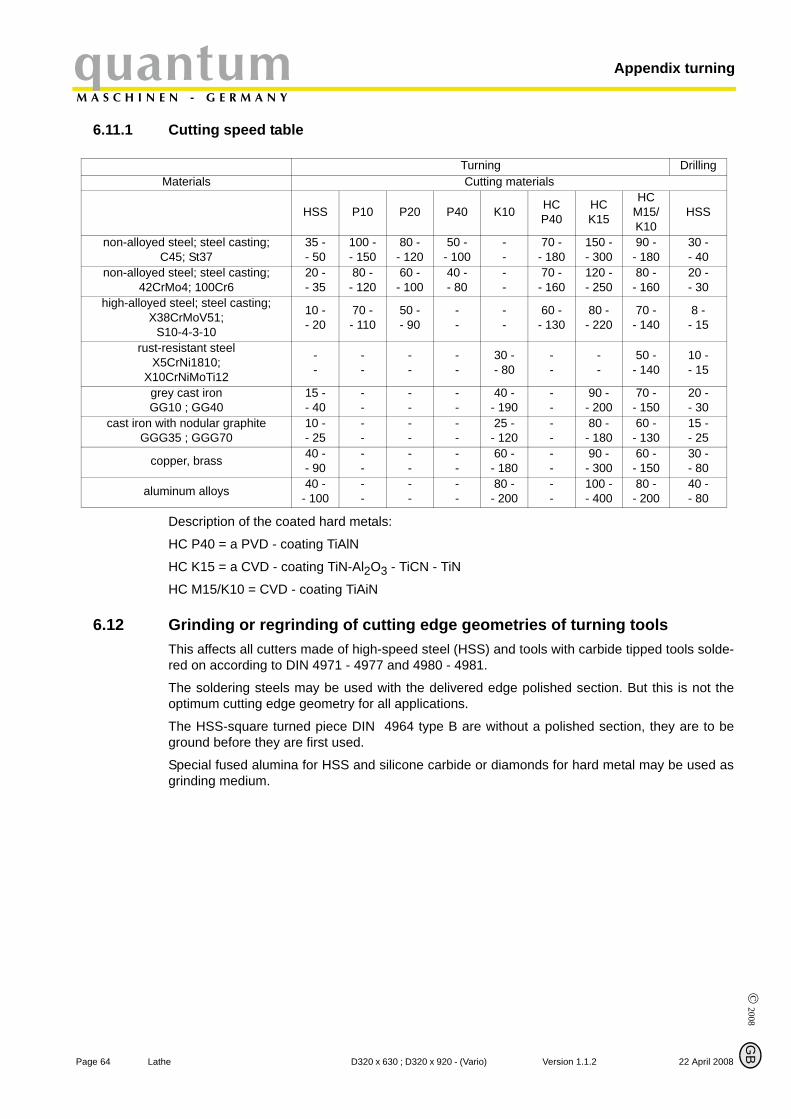
Appendix turningquantumM A S C H I N E N - G E R M A N Y
6.11.1 Cutting speed table
Page 64 La
Turning Drilling
Materials Cutting materialsHSS P10 P20 P40 K10 HC P40
HCK15
HCM15/K10
HSS
non-alloyed steel; steel casting; C45; St37
35 -- 50
100 -- 150
80 -- 120
50 -- 100
--
70 -- 180
150 -- 300
90 -- 180
30 -- 40
non-alloyed steel; steel casting; 42CrMo4; 100Cr6
20 -- 35
80 -- 120
60 -- 100
40 -- 80
--
70 -- 160
120 -- 250
80 -- 160
20 -- 30
high-alloyed steel; steel casting;X38CrMoV51;
S10-4-3-10
10 -- 20
70 -- 110
50 -- 90
--
--
60 -- 130
80 -- 220
70 -- 140
8 - - 15
rust-resistant steel X5CrNi1810;
X10CrNiMoTi12
--
--
--
--
30 -- 80
--
--
50 -- 140
10 -- 15
grey cast ironGG10 ; GG40
15 -- 40
--
--
--
40 -- 190
--
90 -- 200
70 -- 150
20 -- 30
cast iron with nodular graphiteGGG35 ; GGG70
10 -- 25
--
--
--
25 -- 120
--
80 -- 180
60 -- 130
15 -- 25
copper, brass 40 -- 90
--
--
--
60 -- 180
--
90 -- 300
60 -- 150
30 -- 80
aluminum alloys 40 -- 100
--
--
--
80 -- 200
--
100 -- 400
80 -- 200
40 -- 80
Description of the coated hard metals:
HC P40 = a PVD - coating TiAlN
HC K15 = a CVD - coating TiN-Al2O3 - TiCN - TiN
HC M15/K10 = CVD - coating TiAiN
6.12 Grinding or regrinding of cutting edge geometries of turning tools
© 2008
G
This affects all cutters made of high-speed steel (HSS) and tools with carbide tipped tools solde-red on according to DIN 4971 - 4977 and 4980 - 4981.
The soldering steels may be used with the delivered edge polished section. But this is not theoptimum cutting edge geometry for all applications.
The HSS-square turned piece DIN 4964 type B are without a polished section, they are to beground before they are first used.
Special fused alumina for HSS and silicone carbide or diamonds for hard metal may be used asgrinding medium.
B
the D320 x 630 ; D320 x 920 - (Vario) Version 1.1.2 22 April 2008
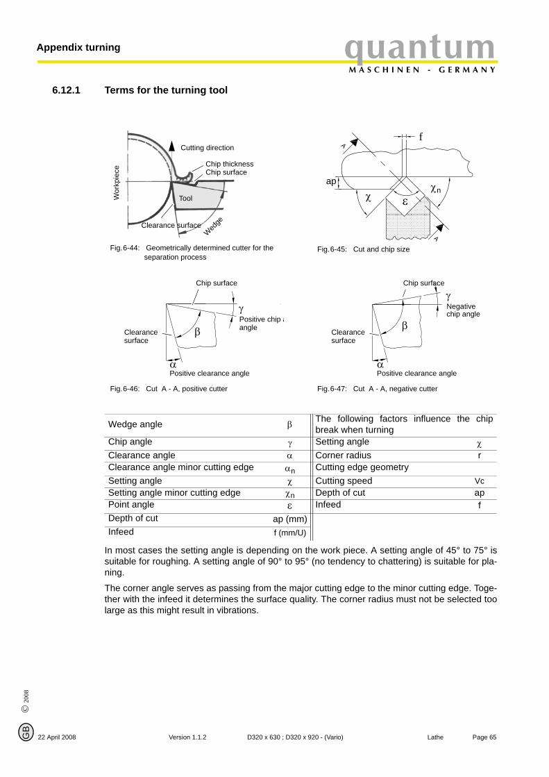
© 2
008
GB
quantumM A S C H I N E N - G E R M A N Y
Appendix turning
6.12.1 Terms for the turning tool
22 April 2008
Fig.6-44: Geometrically determined cutter for the separation process
Fig.6-45: Cut and chip size
Fig.6-46: Cut A - A, positive cutter Fig.6-47: Cut A - A, negative cutter
Tool Wor
kpie
ce
Cutting direction
Wed
ge
Clearance surface
Chip thicknessChip surface
f
ε
ap χnχ
Chip surface
γPositive chip aangle β
αPositive clearance angle
Clearance surface
Chip surface
γNegative chip angle
β
αPositive clearance angle
Clearancesurface
Wedge angle β The following factors influence the chipbreak when turning
Chip angle γ Setting angle χClearance angle α Corner radius rClearance angle minor cutting edge αn Cutting edge geometry Setting angle χ Cutting speed VcSetting angle minor cutting edge χn Depth of cut apPoint angle ε Infeed fDepth of cut ap (mm)Infeed f (mm/U)
In most cases the setting angle is depending on the work piece. A setting angle of 45° to 75° issuitable for roughing. A setting angle of 90° to 95° (no tendency to chattering) is suitable for pla-ning.
The corner angle serves as passing from the major cutting edge to the minor cutting edge. Toge-ther with the infeed it determines the surface quality. The corner radius must not be selected toolarge as this might result in vibrations.
Page 65Version 1.1.2 D320 x 630 ; D320 x 920 - (Vario) Lathe

Appendix turningquantumM A S C H I N E N - G E R M A N Y
6.12.2 Cutting edge geometry for turning tools
Page 66 La
High-speed steel Hard metal
Clearanceangle Chip angle Clearance angle Chip angle
Steel +5° bis +7° +5° bis +6° +5° bis +11° +5° bis +7°Cast non +5° bis +7° +5° bis +6° +5° bis +11° +5° bis +7°
NE - metal +5° bis +7° +6° bis +12° +5° bis +11° +5° bis +12°Aluminum alloys +5° bis +7° +6° bis +24° +5° bis +11° +5° bis +24°
6.12.3 Types of cutting form levels
© 2008
G
They are needed to influence the chip drain and the chip shape in order to achieve optimumchipping conditions.
Examples of types of cutting form levels
Fig.6-48: cutting form level Fig.6-49: cutting form level with fillet
b = 1,0mm to 2,2mmt = 0,4mm to 0,5mm
b = 2,2mm with fillet
For infeeds of 0,05 to 0,5mm/U and depths of cut of 0,2mm to 3,0mm
The different apex angles of the cutting form level need to conduct the chip. ( j ) .
Fig.6-50: Positive apex angle for planing Fig.6-51: Neutral apex angle for planing and roughing
Fig.6-52: Negative apex angle for roughing
btγ γ
b
ϕ ϕ
ϕ
B
the D320 x 630 ; D320 x 920 - (Vario) Version 1.1.2 22 April 2008
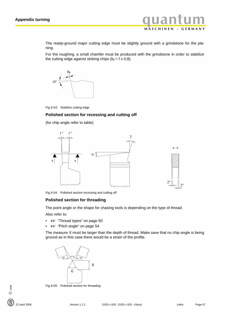
© 2
008
GB
22 April 2008
quantumM A S C H I N E N - G E R M A N Y
Appendix turning
The ready-ground major cutting edge must be slightly ground with a grindstone for the pla-ning.
For the roughing, a small chamfer must be produced with the grindstone in order to stabilizethe cutting edge against striking chips (bf = f x 0,8).
Fig.6-53: Stabilize cutting edge
Polished section for recessing and cutting off
(for chip angle refer to table)
Fig.6-54: Polished section recessing and cutting off
Polished section for threading
The point angle or the shape for chasing tools is depending on the type of thread.
Also refer to:
• “Thread types“ on page 50• “Pitch angle“ on page 54
The measure X must be larger than the depth of thread. Make save that no chip angle is beingground as in this case there would be a strain of the profile.
Fig.6-55: Polished section for threading
bf
10°
α
γ1°1°
2°2°
Xε
Page 67Version 1.1.2 D320 x 630 ; D320 x 920 - (Vario) Lathe
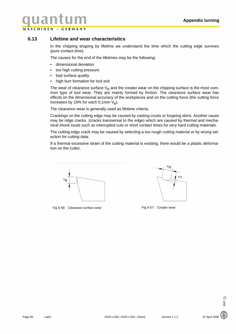
Appendix turningquantumM A S C H I N E N - G E R M A N Y
6.13 Lifetime and wear characteristics
© 2008
Page 68 La
G
In the chipping shaping by lifetime we understand the time which the cutting edge survives(pure contact time).
The causes for the end of the lifetimes may be the following:
• dimensional deviation • too high cutting pressure • bad surface quality • high burr formation for tool exit
The wear of clearance surface VB and the creater wear on the chipping surface is the most com-mon type of tool wear. They are mainly formed by friction. The clearance surface wear haseffects on the dimensional accuracy of the workpieces and on the cutting force (the cutting forceincreases by 10% for each 0,1mm VB).
The clearance wear is generally used as lifetime criteria.
Crackings on the cutting edge may be caused by casting crusts or forgeing skins. Another causemay be ridge cracks (cracks transversal to the edge) which are caused by thermal and mecha-nical shock louds such as interrupted cuts or short contact times for very hard cutting materials.
The cutting edge crack may be caused by selecting a too rough cutting material or by wrong sel-ection for cutting data.
If a thermal excessive strain of the cutting material is existing, there would be a plastic deforma-tion on the cutter.
Fig.6-56: Clearance surface wear Fig.6-57: Creater wear
VB
KB
KT
B
the D320 x 630 ; D320 x 920 - (Vario) Version 1.1.2 22 April 2008
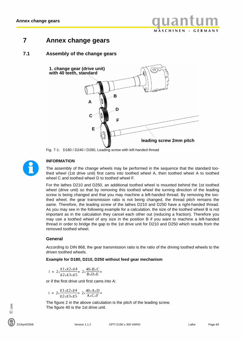
© 2
008
GB
quantumM A S C H I N E N - G E R M A N Y
Annex change gears
7 Annex change gears
7.1 Assembly of the change gears
22/April/2008
Fig. 7-1: D180 / D240 / D280, Leading screw with left-handed thread
1. change gear (drive unit)
leading screw 2mm pitch
AB
CD
E
F
with 40 teeth, standard
INFORMATION
The assembly of the change wheels may be performed in the sequence that the standard too-thed wheel (1st drive unit) first cams into toothed wheel A, then toothed wheel A to toothedwheel C and toothed wheel D to toothed wheel F.
For the lathes D210 and D250, an additional toothed wheel is mounted behind the 1st toothedwheel (drive unit) so that by removing this toothed wheel the turning direction of the leadingscrew is being changed and that you may machine a left-handed thread. By removing the too-thed wheel, the gear transmission ratio is not being changed, the thread pitch remains thesame. Therefore, the leading screw of the lathes D210 and D250 have a right-handed thread.As you may see in the following example for a calculation, the size of the toothed wheel B is notimportant as in the calculation they cancel each other out (reducing a fraction). Therefore youmay use a toothed wheel of any size in the position B if you want to machine a left-handedthread in order to bridge the gap to the 1st drive unit for D210 and D250 which results from theremoved toothed wheel.
General
According to DIN 868, the gear transmission ratio is the ratio of the driving toothed wheels to thedriven toothed wheels.
Example for D180, D210, D250 without feed gear mechanism
or if the first drive unit first cams into A:
The figure 2 in the above calculation is the pitch of the leading screw. The figure 40 is the 1st drive unit.
i 2xz1xz2xz4z2xz3xz5------------------------- 2x
40xBxCBxDxE-------------------===
i 2xz1xz2xz4z2xz3xz5------------------------- 2x
40xAxDAxCxF--------------------===
Page 69Version 1.1.2 OPTI D180 x 300 VARIO Lathe

© 2008
Page 70 La
Annex change gearsquantumM A S C H I N E N - G E R M A N Y
G
Example for D240, D280 with feed gear mechanism
or if the first drive unit first cams into A:
The figure 3 in the above calculation is the pitch of the leading screw. The figure 40 is the 1st drive unit. Vg calls the feed machanism
Feed machanism (Vg) position A = 1
Feed machanism (Vg) position B = 2
Feed machanism (Vg) position C = 0,5
i 3xVgxz1xz2xz4z2xz3xz5------------------------- 3xVgx
40xBxCBxDxE-------------------===
i 3xVgxz1xz2xz4z2xz3xz5------------------------- 3xVgx
40xAxDAxCxF--------------------===
B
the OPTI D180 x 300 VARIO Version 1.1.2 22/April/2008
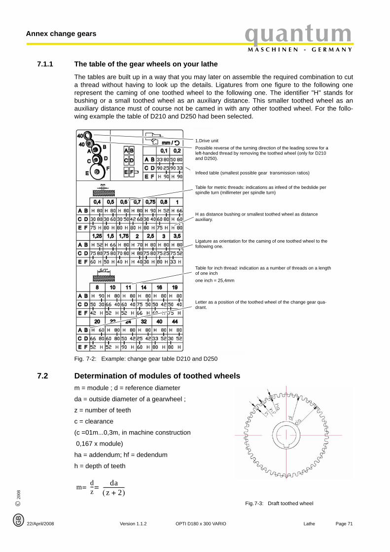
© 2
008
GB
quantumM A S C H I N E N - G E R M A N Y
Annex change gears
7.1.1 The table of the gear wheels on your lathe
22/April/2008
The tables are built up in a way that you may later on assemble the required combination to cuta thread without having to look up the details. Ligatures from one figure to the following onerepresent the caming of one toothed wheel to the following one. The identifier "H" stands forbushing or a small toothed wheel as an auxiliary distance. This smaller toothed wheel as anauxiliary distance must of course not be camed in with any other toothed wheel. For the follo-wing example the table of D210 and D250 had been selected.
Fig. 7-2: Example: change gear table D210 and D250
1.Drive unit Possible reverse of the turning direction of the leading screw for a left-handed thread by removing the toothed wheel (only for D210 and D250).
Infeed table (smallest possible gear transmission ratios)
Table for metric threads: indications as infeed of the bedslide per spindle turn (millimeter per spindle turn)
H as distance bushing or smallest toothed wheel as distance auxiliary.
Ligature as orientation for the caming of one toothed wheel to the following one.
Table for inch thread: indication as a number of threads on a length of one inch one inch = 25,4mm
Letter as a position of the toothed wheel of the change gear qua-drant.
7.2 Determination of modules of toothed wheels
m = module ; d = reference diameterda = outside diameter of a gearwheel ;
z = number of teeth
c = clearance
(c =01m...0,3m, in machine construction
0,167 x module)
ha = addendum; hf = dedendum
h = depth of teeth
Fig.7-3: Draft toothed wheel
m dz--- da
z 2+( )----------------==
Version 1.1.2 OPTI D
Page 71180 x 300 VARIO Lathe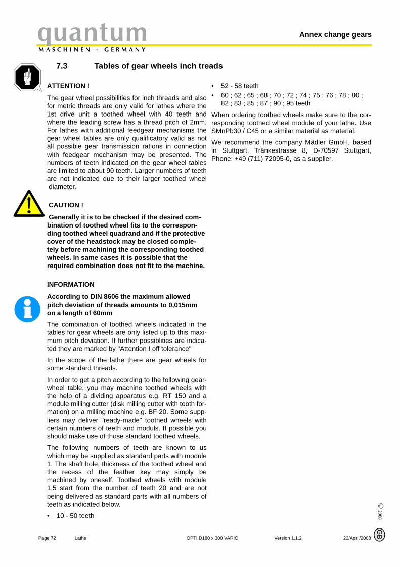
Annex change gearsquantumM A S C H I N E N - G E R M A N Y
7.3 Tables of gear wheels inch treads
© 2008
P
ATTENTION !
The gear wheel possibilities for inch threads and alsofor metric threads are only valid for lathes where the1st drive unit a toothed wheel with 40 teeth andwhere the leading screw has a thread pitch of 2mm.For lathes with additional feedgear mechanisms thegear wheel tables are only qualificatory valid as notall possible gear transmission rations in connectionwith feedgear mechanism may be presented. Thenumbers of teeth indicated on the gear wheel tablesare limited to about 90 teeth. Larger numbers of teethare not indicated due to their larger toothed wheeldiameter.
CAUTION !
Generally it is to be checked if the desired com-bination of toothed wheel fits to the correspon-ding toothed wheel quadrand and if the protective cover of the headstock may be closed comple-tely before machining the corresponding toothed wheels. In same cases it is possible that the required combination does not fit to the machine.
INFORMATION
According to DIN 8606 the maximum allowed pitch deviation of threads amounts to 0,015mm on a length of 60mm The combination of toothed wheels indicated in thetables for gear wheels are only listed up to this maxi-mum pitch deviation. If further possiblities are indica-ted they are marked by "Attention ! off tolerance"
In the scope of the lathe there are gear wheels forsome standard threads.
In order to get a pitch according to the following gear-wheel table, you may machine toothed wheels withthe help of a dividing apparatus e.g. RT 150 and amodule milling cutter (disk milling cutter with tooth for-mation) on a milling machine e.g. BF 20. Some supp-liers may deliver "ready-made" toothed wheels withcertain numbers of teeth and moduls. If possible youshould make use of those standard toothed wheels.
The following numbers of teeth are known to uswhich may be supplied as standard parts with module1. The shaft hole, thickness of the toothed wheel andthe recess of the feather key may simply bemachined by oneself. Toothed wheels with module1,5 start from the number of teeth 20 and are notbeing delivered as standard parts with all numbers ofteeth as indicated below.
• 10 - 50 teeth
••
WrS
WiP
age 72 Lathe OPTI D18
G
52 - 58 teeth 60 ; 62 ; 65 ; 68 ; 70 ; 72 ; 74 ; 75 ; 76 ; 78 ; 80 ; 82 ; 83 ; 85 ; 87 ; 90 ; 95 teeth
hen ordering toothed wheels make sure to the cor-esponding toothed wheel module of your lathe. UseMnPb30 / C45 or a similar material as material.
e recommend the company Mädler GmbH, basedn Stuttgart, Tränkestrasse 8, D-70597 Stuttgart,hone: +49 (711) 72095-0, as a supplier.
B
0 x 300 VARIO Version 1.1.2 22/April/2008
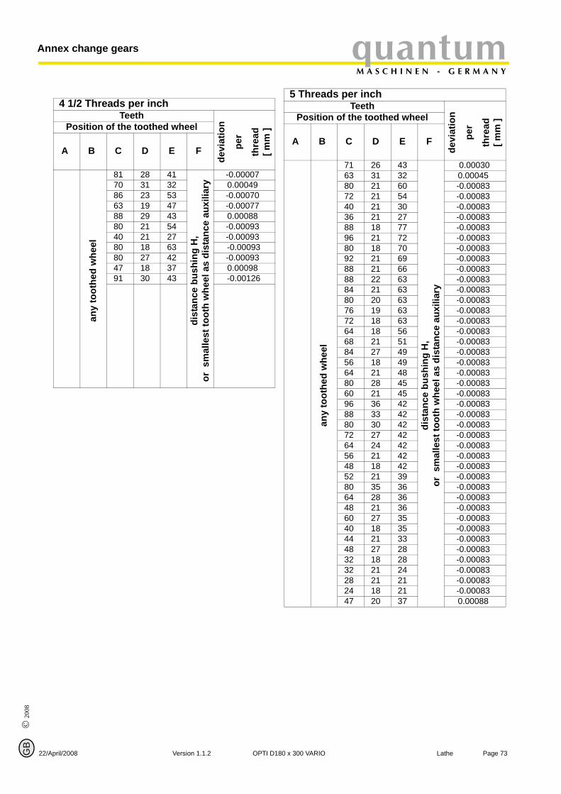
© 2
008
GB
22
quantumM A S C H I N E N - G E R M A N Y
Annex change gears
4 1/2 Threads per inchTeeth
devi
atio
n
per
thre
ad[ m
m ]Position of the toothed wheel
A B C D E F
any
toot
hed
whe
el
81 28 41
dist
ance
bus
hing
H,
or s
mal
lest
toot
h w
heel
as
dist
ance
aux
iliar
y
-0.0000770 31 32 0.0004986 23 53 -0.0007063 19 47 -0.0007788 29 43 0.00088 80 21 54 -0.0009340 21 27 -0.0009380 18 63 -0.0009380 27 42 -0.0009347 18 37 0.0009891 30 43 -0.00126
/April/2008 Version 1.1.2 OPTI D1
5 Threads per inchTeeth
devi
atio
n
per
thre
ad[ m
m ]Position of the toothed wheel
A B C D E F
any
toot
hed
whe
el
71 26 43
dist
ance
bus
hing
H,
or s
mal
lest
toot
h w
heel
as
dist
ance
aux
iliar
y
0.0003063 31 32 0.0004580 21 60 -0.0008372 21 54 -0.0008340 21 30 -0.00083 36 21 27 -0.0008388 18 77 -0.0008396 21 72 -0.0008380 18 70 -0.0008392 21 69 -0.0008388 21 66 -0.0008388 22 63 -0.0008384 21 63 -0.0008380 20 63 -0.0008376 19 63 -0.0008372 18 63 -0.0008364 18 56 -0.0008368 21 51 -0.0008384 27 49 -0.00083 56 18 49 -0.0008364 21 48 -0.0008380 28 45 -0.0008360 21 45 -0.0008396 36 42 -0.0008388 33 42 -0.00083 80 30 42 -0.0008372 27 42 -0.0008364 24 42 -0.0008356 21 42 -0.0008348 18 42 -0.0008352 21 39 -0.0008380 35 36 -0.0008364 28 36 -0.00083 48 21 36 -0.0008360 27 35 -0.0008340 18 35 -0.0008344 21 33 -0.0008348 27 28 -0.0008332 18 28 -0.0008332 21 24 -0.0008328 21 21 -0.0008324 18 21 -0.0008347 20 37 0.00088
Page 7380 x 300 VARIO Lathe
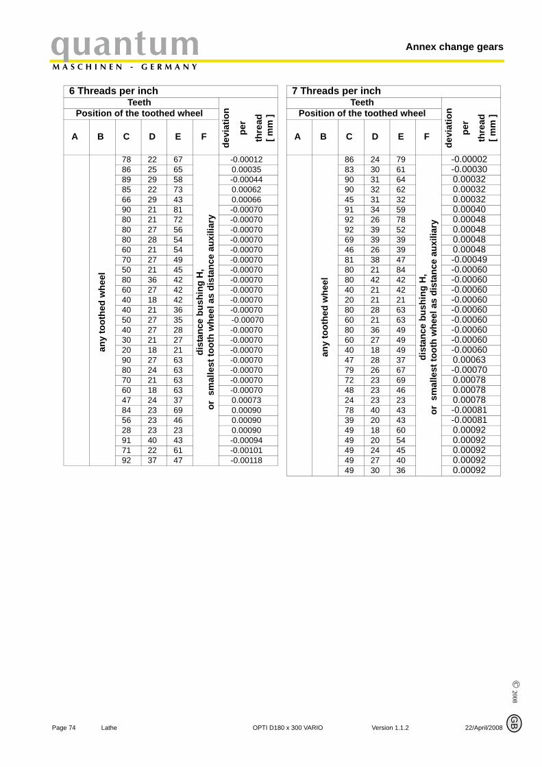
© 2008
P
Annex change gearsquantumM A S C H I N E N - G E R M A N Y
6 Threads per inchTeeth
devi
atio
n
per
thre
ad[ m
m ]Position of the toothed wheel
A B C D E F
any
toot
hed
whe
el
78 22 67
dist
ance
bus
hing
H,
or s
mal
lest
toot
h w
heel
as
dist
ance
aux
iliar
y
-0.00012 86 25 65 0.0003589 29 58 -0.0004485 22 73 0.0006266 29 43 0.0006690 21 81 -0.0007080 21 72 -0.0007080 27 56 -0.0007080 28 54 -0.0007060 21 54 -0.0007070 27 49 -0.0007050 21 45 -0.0007080 36 42 -0.0007060 27 42 -0.0007040 18 42 -0.00070 40 21 36 -0.0007050 27 35 -0.0007040 27 28 -0.00070 30 21 27 -0.0007020 18 21 -0.0007090 27 63 -0.0007080 24 63 -0.00070 70 21 63 -0.0007060 18 63 -0.0007047 24 37 0.0007384 23 69 0.0009056 23 46 0.0009028 23 23 0.0009091 40 43 -0.0009471 22 61 -0.0010192 37 47 -0.00118
age 74 Lathe OPTI D18
G
7 Threads per inchTeeth
devi
atio
n
per
thre
ad[ m
m ]Position of the toothed wheel
A B C D E F
any
toot
hed
whe
el
86 24 79
dist
ance
bus
hing
H,
or s
mal
lest
toot
h w
heel
as
dist
ance
aux
iliar
y
-0.0000283 30 61 -0.0003090 31 64 0.0003290 32 62 0.0003245 31 32 0.0003291 34 59 0.0004092 26 78 0.0004892 39 52 0.0004869 39 39 0.0004846 26 39 0.0004881 38 47 -0.0004980 21 84 -0.0006080 42 42 -0.0006040 21 42 -0.0006020 21 21 -0.0006080 28 63 -0.0006060 21 63 -0.0006080 36 49 -0.0006060 27 49 -0.0006040 18 49 -0.0006047 28 37 0.0006379 26 67 -0.0007072 23 69 0.0007848 23 46 0.0007824 23 23 0.0007878 40 43 -0.0008139 20 43 -0.0008149 18 60 0.0009249 20 54 0.0009249 24 45 0.0009249 27 40 0.0009249 30 36 0.00092
B
0 x 300 VARIO Version 1.1.2 22/April/2008

© 2
008
GB
22
quantumM A S C H I N E N - G E R M A N Y
Annex change gears
8 Threads per inchTeeth
devi
atio
n
per
thre
ad
[ mm
]Position of the toothed wheel
A B C D E F
any
toot
hed
whe
el
61 29 53
dist
ance
bus
hing
H,
or s
mal
lest
toot
h w
heel
as
dist
ance
aux
iliar
y
0.00002 97 47 52 0.0001296 41 59 -0.00013 92 38 61 0.00015 46 19 61 0.00015 55 18 77 -0.0004075 27 70 -0.0004050 18 70 -0.0004090 36 63 -0.0004085 34 63 -0.0004080 32 63 -0.0004075 30 63 -0.0004070 28 63 -0.0004065 26 63 -0.0004060 24 63 -0.0004055 22 63 -0.0004050 20 63 -0.00040 45 18 63 -0.0004050 21 60 -0.0004095 42 57 -0.0004080 36 56 -0.0004060 27 56 -0.0004040 18 56 -0.0004090 42 54 -0.0004075 35 54 -0.00040 60 28 54 -0.0004045 21 54 -0.0004085 42 51 -0.0004080 42 48 -0.0004040 21 48 -0.0004025 18 35 -0.0004025 21 30 -0.0004030 27 28 -0.0004020 18 28 -0.0004020 21 24 -0.00040 75 21 90 -0.0004090 27 84 -0.0004080 24 84 -0.00040 70 21 84 -0.0004060 18 84 -0.0004090 28 81 -0.0004065 21 78 -0.0004080 28 72 -0.00040 60 21 72 -0.0004070 36 49 -0.0004035 18 49 -0.0004075 42 45 -0.0004050 28 45 -0.0004070 42 42 -0.00040 65 39 42 -0.0004060 36 42 -0.00040
/April/2008 Version 1.1.2 OPTI D1
any
toot
hed
whe
el
55 33 42
dist
ance
bus
hing
H,
or s
mal
lest
toot
h w
heel
as
dist
ance
aux
iliar
y
-0.0004050 30 42 -0.00040 45 27 42 -0.00040 40 24 42 -0.0004035 21 42 -0.0004030 18 42 -0.0004050 35 36 -0.0004040 28 36 -0.0004030 21 36 -0.00040 30 21 36 -0.0004093 33 71 0.00042 62 22 71 0.0004283 41 51 0.0005199 43 58 0.0006299 29 86 0.0006294 32 74 0.0006894 37 64 0.00068 47 32 37 0.0006884 29 73 -0.0007089 38 59 0.0007469 37 47 -0.0007663 23 69 0.00080 84 46 46 0.0008042 23 46 0.0008042 23 46 0.0008021 23 23 0.00080
Page 7580 x 300 VARIO Lathe
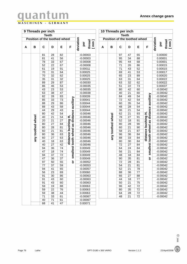
© 2008
P
Annex change gearsquantumM A S C H I N E N - G E R M A N Y
9 Threads per inchTeeth
devi
atio
n
per
thre
ad[ m
m ]Position of the toothed wheel
A B C D E F
any
toot
hed
whe
el
81 28 82
dist
ance
bus
hing
H,
or s
mal
lest
toot
h w
heel
as
dist
ance
aux
iliar
y
-0.0000381 41 56 -0.0000378 33 67 -0.0000852 22 67 -0.0000861 19 91 0.0001170 31 64 0.0002570 32 62 0.0002535 31 32 0.0002589 29 87 -0.0003086 46 53 -0.0003543 23 53 -0.0003563 38 47 -0.0003882 28 83 0.00039 85 33 73 0.0004188 29 86 0.0004488 43 58 0.0004444 29 43 0.0004480 42 54 -0.0004640 21 54 -0.0004620 21 27 -0.0004680 27 84 -0.0004680 28 81 -0.0004660 21 81 -0.0004680 36 63 -0.0004660 27 63 -0.0004640 18 63 -0.0004640 27 42 -0.0004694 36 74 0.0004947 18 74 0.0004994 37 72 0.0004947 36 37 0.0004997 50 55 -0.0005277 37 59 -0.0005394 41 65 -0.0005756 23 69 0.0006091 30 86 -0.0006391 43 60 -0.0006391 43 60 -0.0006359 19 88 0.0006359 22 76 0.0006359 38 44 0.0006371 33 61 -0.0006740 71 61 -0.0006768 41 47 0.00071
age 76 Lathe OPTI D18
G
10 Threads per inchTeeth
devi
atio
n
per
thre
ad[ m
m ]Position of the toothed wheel
A B C D E F
any
toot
hed
whe
el
97 47 65
dist
ance
bus
hing
H,
or s
mal
lest
toot
h w
heel
as
dist
ance
aux
iliar
y
0.0000095 34 88 0.0000195 44 68 0.00001 71 26 86 0.0001571 43 52 0.0001569 41 53 0.0001765 23 89 0.0002063 31 64 0.00022 63 32 62 0.0002251 22 73 0.0003780 42 60 -0.00042 40 21 60 -0.0004284 49 54 -0.0004272 42 54 -0.0004260 35 54 -0.0004248 28 54 -0.0004236 21 54 -0.0004262 21 93 -0.0004278 27 91 -0.0004252 18 91 -0.0004280 28 90 -0.0004260 21 90 -0.0004258 21 87 -0.0004296 36 84 -0.0004288 33 84 -0.0004280 30 84 -0.0004272 27 84 -0.0004264 24 84 -0.00042 56 21 84 -0.0004248 18 84 -0.0004290 35 81 -0.0004272 28 81 -0.0004254 21 81 -0.0004252 21 78 -0.0004288 36 77 -0.0004266 27 88 -0.0004244 18 77 -0.0004250 21 75 -0.00042 96 42 72 -0.0004280 35 72 -0.0004264 28 72 -0.0004248 21 72 -0.00042
B
0 x 300 VARIO Version 1.1.2 22/April/2008
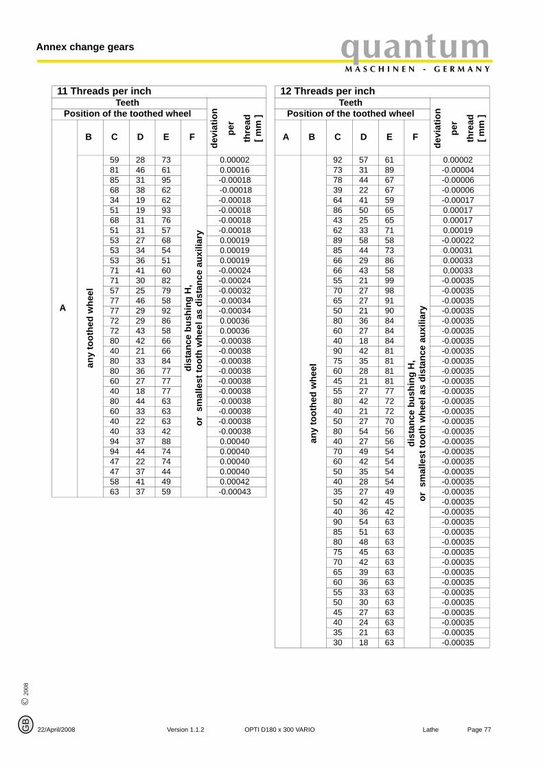
© 2
008
GB
22
quantumM A S C H I N E N - G E R M A N Y
Annex change gears
11 Threads per inchTeeth
devi
atio
n
per
thre
ad[ m
m ]Position of the toothed wheel
A
B C D E F
any
toot
hed
whe
el
59 28 73
dist
ance
bus
hing
H,
or s
mal
lest
toot
h w
heel
as
dist
ance
aux
iliar
y
0.00002 81 46 61 0.0001685 31 95 -0.0001868 38 62 -0.0001834 19 62 -0.0001851 19 93 -0.0001868 31 76 -0.0001851 31 57 -0.0001853 27 68 0.0001953 34 54 0.00019 53 36 51 0.0001971 41 60 -0.0002471 30 82 -0.0002457 25 79 -0.00032 77 46 58 -0.0003477 29 92 -0.0003472 29 86 0.0003672 43 58 0.0003680 42 66 -0.0003840 21 66 -0.0003880 33 84 -0.0003880 36 77 -0.00038 60 27 77 -0.0003840 18 77 -0.0003880 44 63 -0.0003860 33 63 -0.0003840 22 63 -0.0003840 33 42 -0.0003894 37 88 0.0004094 44 74 0.0004047 22 74 0.0004047 37 44 0.0004058 41 49 0.0004263 37 59 -0.00043
/April/2008 Version 1.1.2 OPTI D1
12 Threads per inchTeeth
devi
atio
n
per
thre
ad[ m
m ]Position of the toothed wheel
A B C D E F
any
toot
hed
whe
el
92 57 61
dist
ance
bus
hing
H,
or s
mal
lest
toot
h w
heel
as
dist
ance
aux
iliar
y
0.0000273 31 89 -0.0000478 44 67 -0.0000639 22 67 -0.0000664 41 59 -0.0001786 50 65 0.0001743 25 65 0.0001762 33 71 0.00019 89 58 58 -0.0002285 44 73 0.0003166 29 86 0.0003366 43 58 0.0003355 21 99 -0.0003570 27 98 -0.0003565 27 91 -0.0003550 21 90 -0.0003580 36 84 -0.0003560 27 84 -0.0003540 18 84 -0.0003590 42 81 -0.0003575 35 81 -0.0003560 28 81 -0.0003545 21 81 -0.0003555 27 77 -0.00035 80 42 72 -0.0003540 21 72 -0.00035 50 27 70 -0.0003580 54 56 -0.0003540 27 56 -0.0003570 49 54 -0.0003560 42 54 -0.00035 50 35 54 -0.0003540 28 54 -0.0003535 27 49 -0.0003550 42 45 -0.0003540 36 42 -0.0003590 54 63 -0.0003585 51 63 -0.0003580 48 63 -0.00035 75 45 63 -0.0003570 42 63 -0.0003565 39 63 -0.0003560 36 63 -0.0003555 33 63 -0.0003550 30 63 -0.0003545 27 63 -0.0003540 24 63 -0.0003535 21 63 -0.0003530 18 63 -0.00035
Page 7780 x 300 VARIO Lathe
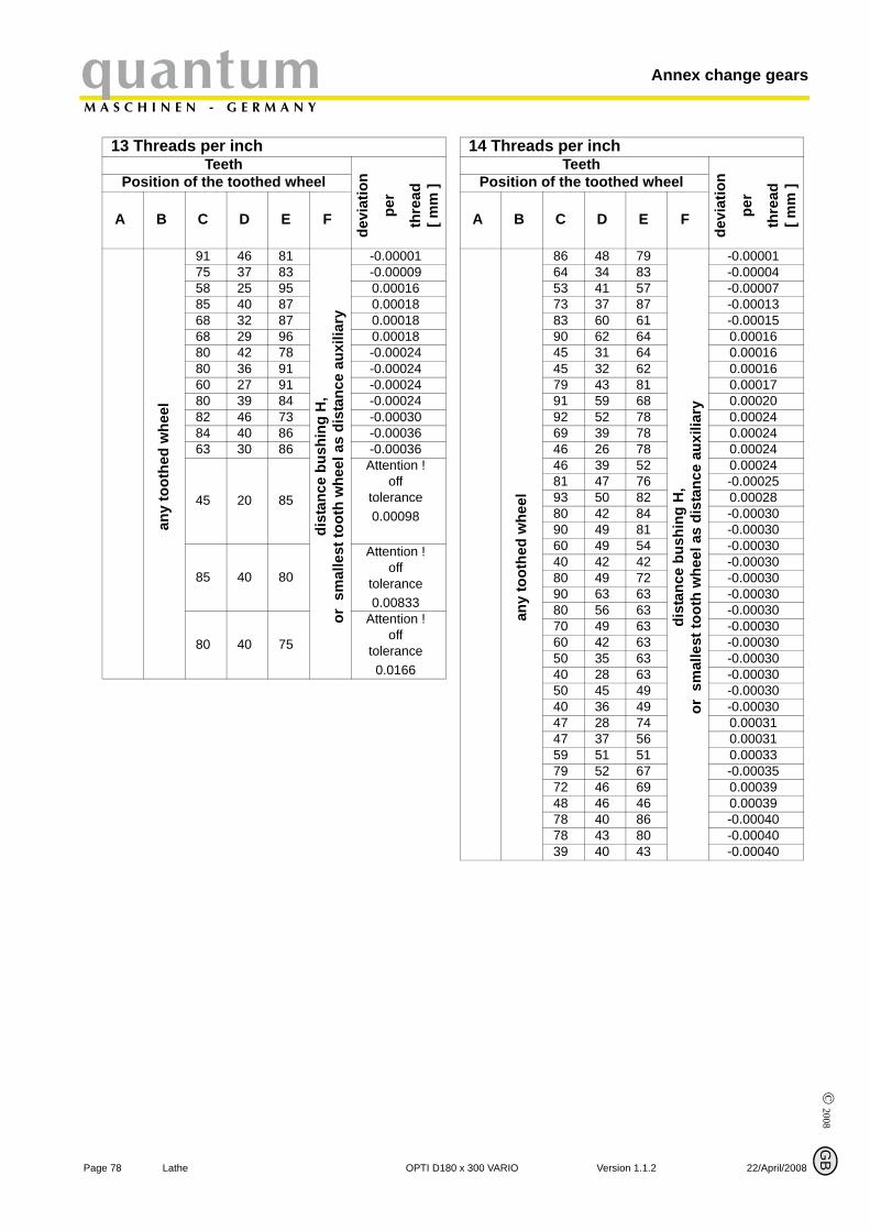
© 2008
P
Annex change gearsquantumM A S C H I N E N - G E R M A N Y
13 Threads per inchTeeth
devi
atio
n
per
thre
ad[ m
m ]Position of the toothed wheel
A B C D E F
any
toot
hed
whe
el
91 46 81
dist
ance
bus
hing
H,
or s
mal
lest
toot
h w
heel
as
dist
ance
aux
iliar
y
-0.0000175 37 83 -0.0000958 25 95 0.0001685 40 87 0.0001868 32 87 0.0001868 29 96 0.0001880 42 78 -0.0002480 36 91 -0.0002460 27 91 -0.0002480 39 84 -0.0002482 46 73 -0.0003084 40 86 -0.0003663 30 86 -0.00036
45 20 85
Attention !off
tolerance0.00098
85 40 80
Attention !off
tolerance0.00833
80 40 75
Attention !off
tolerance0.0166
age 78 Lathe OPTI D18
G
14 Threads per inchTeeth
devi
atio
n
per
thre
ad[ m
m ]Position of the toothed wheel
A B C D E F
any
toot
hed
whe
el
86 48 79
dist
ance
bus
hing
H,
or s
mal
lest
toot
h w
heel
as
dist
ance
aux
iliar
y
-0.0000164 34 83 -0.0000453 41 57 -0.0000773 37 87 -0.0001383 60 61 -0.0001590 62 64 0.00016 45 31 64 0.0001645 32 62 0.0001679 43 81 0.0001791 59 68 0.0002092 52 78 0.0002469 39 78 0.00024 46 26 78 0.0002446 39 52 0.0002481 47 76 -0.0002593 50 82 0.0002880 42 84 -0.0003090 49 81 -0.0003060 49 54 -0.0003040 42 42 -0.0003080 49 72 -0.00030 90 63 63 -0.0003080 56 63 -0.0003070 49 63 -0.0003060 42 63 -0.0003050 35 63 -0.0003040 28 63 -0.0003050 45 49 -0.0003040 36 49 -0.0003047 28 74 0.0003147 37 56 0.0003159 51 51 0.0003379 52 67 -0.0003572 46 69 0.0003948 46 46 0.0003978 40 86 -0.0004078 43 80 -0.0004039 40 43 -0.00040
B
0 x 300 VARIO Version 1.1.2 22/April/2008
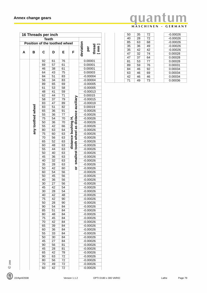
© 2
008
GB
22
quantumM A S C H I N E N - G E R M A N Y
Annex change gears
16 Threads per inchTeeth
devi
atio
n
per
thre
ad[ m
m ]Position of the toothed wheel
A B C D E F
any
toot
hed
whe
el
92 61 76
dist
ance
bus
hing
H,
or s
mal
lest
toot
h w
heel
as
dist
ance
aux
iliar
y
0.0000169 57 61 0.0000146 38 61 0.0000164 43 75 0.0000384 51 83 -0.0000456 34 83 -0.0000489 65 69 -0.0000561 53 58 -0.0000548 41 59 -0.0001362 44 71 0.0001558 37 79 -0.0001583 47 89 -0.0001983 51 82 0.0001965 36 91 -0.0002655 36 77 -0.0002675 54 70 -0.0002650 36 70 -0.0002655 42 66 -0.0002680 63 64 -0.0002675 60 63 -0.0002670 56 63 -0.0002665 52 63 -0.0002660 48 63 -0.0002655 44 63 -0.0002650 40 63 -0.0002645 36 63 -0.0002640 32 63 -0.0002635 28 63 -0.0002650 42 60 -0.0002660 54 56 -0.0002650 45 56 -0.0002640 36 56 -0.0002630 27 56 -0.0002645 42 54 -0.0002630 28 54 -0.0002640 42 48 -0.0002675 42 90 -0.0002650 28 90 -0.0002690 54 84 -0.0002685 51 84 -0.0002680 48 84 -0.0002675 45 84 -0.0002670 42 84 -0.0002665 39 84 -0.0002660 36 84 -0.0002655 33 84 -0.0002650 30 84 -0.0002645 27 84 -0.0002690 56 81 -0.0002645 28 81 -0.0002665 42 78 -0.00026 90 63 72 -0.0002680 56 72 -0.00026 70 49 72 -0.0002660 42 72 -0.00026
/April/2008 Version 1.1.2 OPTI D1
50 35 72 -0.0002640 28 72 -0.0002685 63 68 -0.0002635 36 49 -0.0002635 42 42 -0.0002647 32 74 0.0002847 37 64 0.0002881 53 77 0.0002889 59 76 0.0003184 46 92 0.00034 63 46 69 0.0003442 46 46 0.0003471 49 73 0.00036
Page 7980 x 300 VARIO Lathe
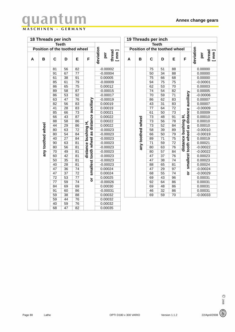
© 2008
P
Annex change gearsquantumM A S C H I N E N - G E R M A N Y
18 Threads per inchTeeth
devi
atio
n
per
thre
ad[ m
m ]Position of the toothed wheel
A B C D E F
any
toot
hed
whe
el
81 56 82
dist
ance
bus
hing
H,
or s
mal
lest
toot
h w
heel
as
dist
ance
aux
iliar
y
-0.0000291 67 77 -0.0000461 38 91 0.0000585 61 79 -0.0000986 65 75 0.0001289 58 87 -0.0001586 53 92 -0.0001763 47 76 -0.00019 82 56 83 0.0001941 28 83 0.0001985 66 73 0.0002166 43 87 0.0002288 58 86 0.00022 44 29 86 0.0002280 63 72 -0.0002380 54 84 -0.0002340 27 84 -0.0002390 63 81 -0.0002380 56 81 -0.0002370 49 81 -0.0002360 42 81 -0.0002350 35 81 -0.0002340 28 81 -0.0002347 36 74 0.0002447 37 72 0.0002472 53 77 0.0002577 59 74 -0.0002684 69 69 0.0003091 60 86 -0.0003159 38 88 0.0003259 44 76 0.0003240 59 76 0.0003268 47 82 0.00035
age 80 Lathe OPTI D18
G
19 Threads per inchTeeth
devi
atio
n
per
thre
ad[ m
m ]Position of the toothed wheel
A B C D E F
any
toot
hed
whe
el
75 51 88
dist
ance
bus
hing
H,
or s
mal
lest
toot
h w
heel
as
dist
ance
aux
iliar
y
0.0000050 34 88 0.0000075 66 68 0.0000094 75 75 -0.0000162 53 70 0.0000374 54 82 0.00005 70 59 71 -0.0000686 62 83 0.0000743 31 83 0.0000777 64 72 -0.0000961 50 73 0.0000973 48 91 0.0001073 56 78 0.0001073 52 84 0.0001058 39 89 -0.0001066 50 79 -0.0001989 71 75 0.0001971 59 72 0.0002180 63 76 -0.0002280 57 84 -0.0002247 37 76 0.0002347 38 74 0.0002388 65 81 0.0002447 29 97 -0.0002468 55 74 -0.0002969 43 96 0.0003192 64 86 0.0003169 48 86 0.0003146 32 86 0.0003169 59 70 -0.00033
B
0 x 300 VARIO Version 1.1.2 22/April/2008
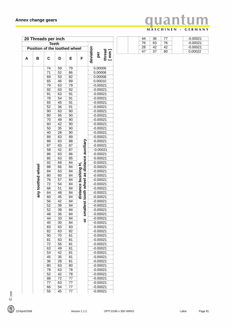
© 2
008
GB
22
quantumM A S C H I N E N - G E R M A N Y
Annex change gears
20 Threads per inchTeeth
devi
atio
n
per
thre
ad[ m
m ]Position of the toothed wheel
A B C D E F
any
toot
hed
whe
el
74 59 79
dist
ance
bus
hing
H,
or s
mal
lest
toot
h w
heel
as
dist
ance
aux
iliar
y
0.00006 71 52 86 0.0000869 53 82 0.0000865 46 89 0.0001079 63 79 -0.0002192 63 92 -0.0002191 63 91 -0.0002178 54 91 -0.0002165 45 91 -0.0002152 36 91 -0.0002190 63 90 -0.0002180 56 90 -0.0002170 49 90 -0.0002160 42 90 -0.0002150 35 90 -0.0002140 28 90 -0.0002189 63 89 -0.0002188 63 88 -0.0002187 63 87 -0.0002158 42 87 -0.0002186 63 86 -0.0002185 63 85 -0.0002192 69 84 -0.0002188 66 84 -0.0002184 63 84 -0.0002180 60 84 -0.0002176 57 84 -0.0002172 54 84 -0.0002168 51 84 -0.0002164 48 84 -0.0002160 45 84 -0.0002156 42 84 -0.0002152 39 84 -0.0002152 39 84 -0.0002148 36 84 -0.0002144 33 84 -0.0002140 30 84 -0.0002183 63 83 -0.0002182 63 82 -0.0002190 70 81 -0.0002181 63 81 -0.0002172 56 81 -0.0002163 49 81 -0.0002154 42 81 -0.0002145 35 81 -0.0002136 28 81 -0.0002180 63 80 -0.0002178 63 78 -0.0002152 42 78 -0.0002188 72 77 -0.0002177 63 77 -0.0002166 54 77 -0.0002155 45 77 -0.00021
/April/2008 Version 1.1.2 OPTI D1
44 36 77 -0.0002176 63 76 -0.0002128 42 42 -0.0002147 37 80 0.00022
Page 8180 x 300 VARIO Lathe
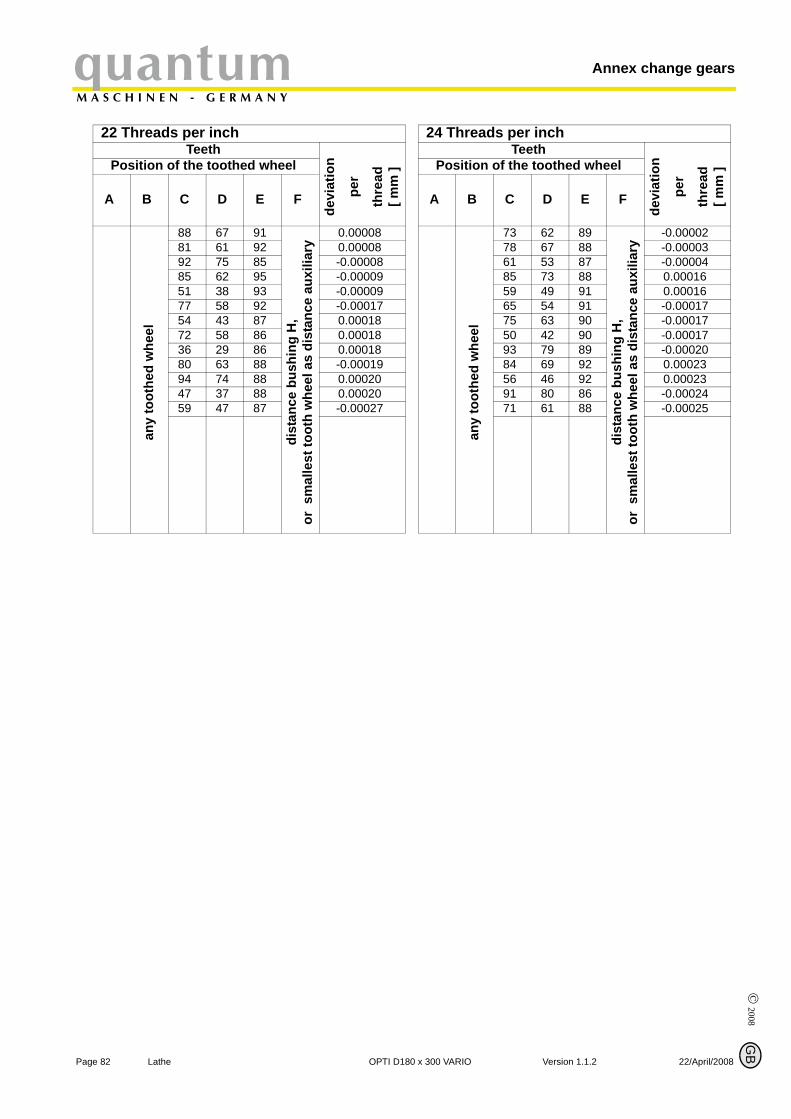
© 2008
P
Annex change gearsquantumM A S C H I N E N - G E R M A N Y
22 Threads per inchTeeth
devi
atio
n
per
thre
ad[ m
m ]Position of the toothed wheel
A B C D E F
any
toot
hed
whe
el
88 67 91
dist
ance
bus
hing
H,
or s
mal
lest
toot
h w
heel
as
dist
ance
aux
iliar
y
0.0000881 61 92 0.0000892 75 85 -0.0000885 62 95 -0.0000951 38 93 -0.0000977 58 92 -0.0001754 43 87 0.0001872 58 86 0.0001836 29 86 0.0001880 63 88 -0.0001994 74 88 0.00020 47 37 88 0.0002059 47 87 -0.00027
age 82 Lathe OPTI D18
G
24 Threads per inchTeeth
devi
atio
n
per
thre
ad[ m
m ]Position of the toothed wheel
A B C D E F
any
toot
hed
whe
el
73 62 89
dist
ance
bus
hing
H,
or s
mal
lest
toot
h w
heel
as
dist
ance
aux
iliar
y
-0.0000278 67 88 -0.0000361 53 87 -0.00004 85 73 88 0.0001659 49 91 0.0001665 54 91 -0.0001775 63 90 -0.0001750 42 90 -0.0001793 79 89 -0.0002084 69 92 0.0002356 46 92 0.0002391 80 86 -0.0002471 61 88 -0.00025
B
0 x 300 VARIO Version 1.1.2 22/April/2008
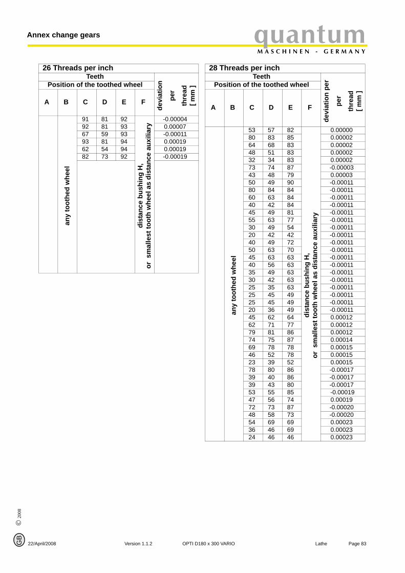
© 2
008
GB
22
quantumM A S C H I N E N - G E R M A N Y
Annex change gears
26 Threads per inchTeeth
devi
atio
n
per
thre
ad[ m
m ]Position of the toothed wheel
A B C D E F
any
toot
hed
whe
el
91 81 92
dist
ance
bus
hing
H,
or s
mal
lest
toot
h w
heel
as
dist
ance
aux
iliar
y
-0.0000492 81 93 0.0000767 59 93 -0.0001193 81 94 0.0001962 54 94 0.0001982 73 92 -0.00019
/April/2008 Version 1.1.2 OPTI D1
28 Threads per inchTeeth
devi
atio
n pe
r
per
thre
ad[ m
m ]
Position of the toothed wheel
A B C D E F
any
toot
hed
whe
el
53 57 82
dist
ance
bus
hing
H,
or s
mal
lest
toot
h w
heel
as
dist
ance
aux
iliar
y
0.0000080 83 85 0.0000264 68 83 0.0000248 51 83 0.0000232 34 83 0.0000273 74 87 -0.0000343 48 79 0.0000350 49 90 -0.0001180 84 84 -0.0001160 63 84 -0.0001140 42 84 -0.0001145 49 81 -0.0001155 63 77 -0.0001130 49 54 -0.0001120 42 42 -0.0001140 49 72 -0.0001150 63 70 -0.0001145 63 63 -0.0001140 56 63 -0.0001135 49 63 -0.0001130 42 63 -0.0001125 35 63 -0.0001125 45 49 -0.0001125 45 49 -0.0001120 36 49 -0.0001145 62 64 0.0001262 71 77 0.0001279 81 86 0.0001274 75 87 0.0001469 78 78 0.0001546 52 78 0.0001523 39 52 0.0001578 80 86 -0.0001739 40 86 -0.0001739 43 80 -0.0001753 55 85 -0.0001947 56 74 0.0001972 73 87 -0.0002048 58 73 -0.0002054 69 69 0.0002336 46 69 0.0002324 46 46 0.00023
Page 8380 x 300 VARIO Lathe

© 2008
P
Annex change gearsquantumM A S C H I N E N - G E R M A N Y
32 Threads per inchTeeth
devi
atio
n
per
thre
ad[ m
m ]Position of the toothed wheel
A B C D E F
any
toot
hed
whe
el
21 46 46
dist
ance
bus
hing
H,
or s
mal
lest
toot
h w
heel
as
dist
ance
aux
iliar
y
0.00017
age 84 Lathe OPTI D18
G
40 ; 48 ; 60 Threads per inchTeeth
devi
atio
n
per
thre
ad[ m
m ]Position of the toothed wheel
A B C D E F
not possible
B
0 x 300 VARIO Version 1.1.2 22/April/2008
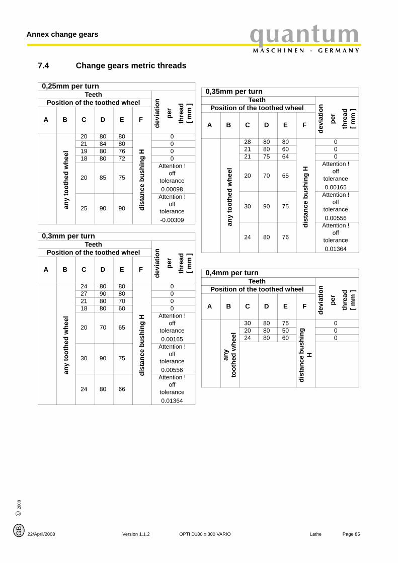
© 2
008
GB
quantumM A S C H I N E N - G E R M A N Y
Annex change gears
7.4 Change gears metric threads
22
0,25mm per turnTeeth
devi
atio
n
per
thre
ad[ m
m ]Position of the toothed wheel
A B C D E F
any
toot
hed
whe
el
20 80 80di
stan
ce b
ushi
ng H
021 84 80 019 80 76 018 80 72 0
20 85 75
Attention !off
tolerance0.00098
25 90 90
Attention !off
tolerance-0.00309
0,3mm per turnTeeth
devi
atio
n
per
thre
ad[ m
m ]Position of the toothed wheel
A B C D E F
any
toot
hed
whe
el
24 80 80
dist
ance
bus
hing
H
027 90 80 021 80 70 018 80 60 0
20 70 65
Attention !off
tolerance0.00165
30 90 75
Attention !off
tolerance0.00556
24 80 66
Attention !off
tolerance0.01364
/April/2008 Version 1.1.2 OPTI D1
0,35mm per turnTeeth
devi
atio
n
per
thre
ad[ m
m ]Position of the toothed wheel
A B C D E F
any
toot
hed
whe
el
28 80 80
dist
ance
bus
hing
H
021 80 60 021 75 64 0
20 70 65
Attention !off
tolerance0.00165
30 90 75
Attention !off
tolerance0.00556
24 80 76
Attention !off
tolerance0.01364
0,4mm per turnTeeth
devi
atio
n
per
thre
ad[ m
m ]Position of the toothed wheel
A B C D E F
any
toot
hed
whe
el
30 80 75
dist
ance
bus
hing
H
020 80 50 024 80 60 0
Page 8580 x 300 VARIO Lathe
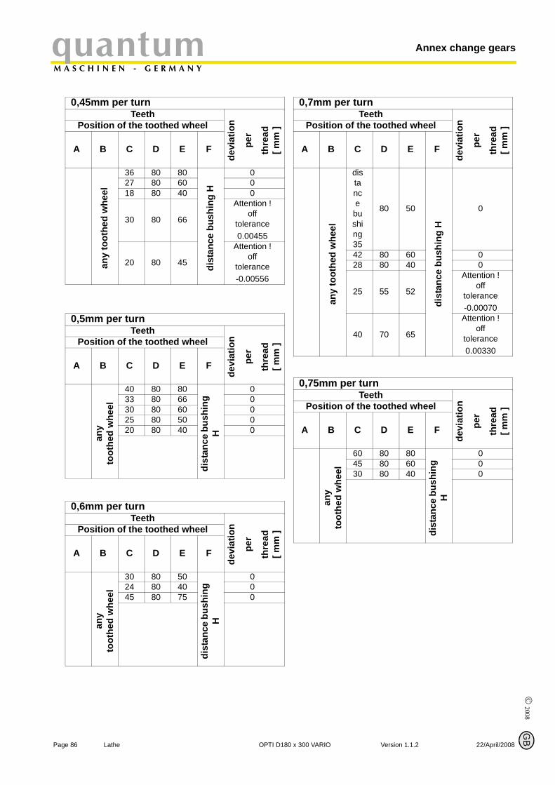
© 2008
P
Annex change gearsquantumM A S C H I N E N - G E R M A N Y
0,45mm per turnTeeth
devi
atio
n
per
thre
ad[ m
m ]Position of the toothed wheel
A B C D E F
any
toot
hed
whe
el
36 80 80
dist
ance
bus
hing
H
027 80 60 018 80 40 0
30 80 66
Attention !off
tolerance0.00455
20 80 45
Attention !off
tolerance-0.00556
0,5mm per turnTeeth
devi
atio
n
per
thre
ad[ m
m ]Position of the toothed wheel
A B C D E F
any
toot
hed
whe
el
40 80 80
dist
ance
bus
hing
H
033 80 66 030 80 60 025 80 50 020 80 40 0
0,6mm per turnTeeth
devi
atio
n
per
thre
ad[ m
m ]Position of the toothed wheel
A B C D E F
any
toot
hed
whe
el
30 80 50
dist
ance
bus
hing
H
024 80 40 045 80 75 0
age 86 Lathe OPTI D18
G
0,7mm per turnTeeth
devi
atio
n
per
thre
ad[ m
m ]Position of the toothed wheel
A B C D E F
any
toot
hed
whe
el
distance
bushing 35
80 50
dist
ance
bus
hing
H
0
42 80 60 028 80 40 0
25 55 52
Attention !off
tolerance-0.00070
40 70 65
Attention !off
tolerance0.00330
0,75mm per turnTeeth
devi
atio
n
per
thre
ad[ m
m ]Position of the toothed wheel
A B C D E F
any
toot
hed
whe
el
60 80 80
dist
ance
bus
hing
H
045 80 60 030 80 40 0
B
0 x 300 VARIO Version 1.1.2 22/April/2008

© 2
008
GB
22
quantumM A S C H I N E N - G E R M A N Y
Annex change gears
0,8mm per turnTeeth
devi
atio
n
per
thre
ad[ m
m ]Position of the toothed wheel
A B C D E F
any
toot
hed
whe
el
40 80 50di
stan
ce b
ushi
ng
H
033 66 50 030 60 50 024 60 40 025 50 50 060 80 75 030 75 40 0
1mm per turnTeeth
devi
atio
n
per
thre
ad[ m
m ]Position of the toothed wheel
A B C D E F
any
toot
hed
whe
el
80 80 80
dist
ance
bus
hing
H
066 80 66 060 80 60 052 80 52 050 80 50 045 80 45 040 80 40 035 80 35 030 60 40 025 50 40 0
1,25mm per turnTeeth
devi
atio
n
per
thre
ad[ m
m ]Position of the toothed wheel
A B C D E F
any
toot
hed
whe
el
50 80 40
dist
ance
bus
hing
H
075 80 60 065 80 52 0
/April/2008 Version 1.1.2 OPTI D1
1,5mm per turnTeeth
devi
atio
n
per
thre
ad[ m
m ]Position of the toothed wheel
A B C D E F
any
toot
hed
whe
el
60 80 40
dist
ance
bus
hing
H
045 80 30 045 60 40 090 80 60 075 80 50 0
60 80 40 0
1,75mm per turnTeeth
devi
atio
n
per
thre
ad[ m
m ]Position of the toothed wheel
A B C D E F
any
toot
hed
whe
el
70 80 40
dist
ance
bus
hing
H
035 40 40 0
2mm per turnTeeth
devi
atio
n
per
thre
ad[ m
m ]Position of the toothed wheel
A B C D E F
any
toot
hed
whe
el
80 80 40
dist
ance
bus
hing
H
066 80 33 060 80 30 050 80 25 045 60 30 0
Page 8780 x 300 VARIO Lathe

© 2008
P
Annex change gearsquantumM A S C H I N E N - G E R M A N Y
2,5mm per turnTeeth
devi
atio
n
per
thre
ad[ m
m ]Position of the toothed wheel
A B C D E F
any
toot
hed
whe
el
75 60 40
dist
ance
bus
hing
H
075 80 30 060 80 24 050 80 20 045 60 24 0
3mm per turnTeeth
devi
atio
n
per
thre
ad[ m
m ]Position of the toothed wheel
A B C D E F
any
toot
hed
whe
el
90 80 30
dist
ance
bus
hing
H
090 60 40 075 80 25 075 50 40 060 80 20 045 60 20 045 50 24 045 40 30 0
3,5mm per turnTeeth
devi
atio
n
per
thre
ad[ m
m ]Position of the toothed wheel
A B C D E F
any
toot
hed
whe
el
70 40 40
dist
ance
bus
hing
H
070 80 20 075 52 33 -0.00350
age 88 Lathe OPTI D18
G
4mm per turnTeeth
devi
atio
n
per
thre
ad[ m
m ]Position of the toothed wheel
A B C D E F
any
toot
hed
whe
el
90 60 30
dist
ance
bus
hing
H
075 60 25 075 50 30 075 60 25 066 40 30 060 40 30 060 50 24 0
50 40 25 0
4,5mm per turnTeeth
devi
atio
n
per
thre
ad[ m
m ]Position of the toothed wheel
A B C D E Fan
y to
othe
d w
heel
90 80 20
dist
ance
bus
hing
H
0
5mm per turnTeeth
devi
atio
n
per
thre
ad[ m
m ]Position of the toothed wheel
A B C D E F
any
toot
hed
whe
el
60 40 24
dist
ance
bus
hing
H
075 40 30 075 60 20 0
65 52 20 0
B
0 x 300 VARIO Version 1.1.2 22/April/2008
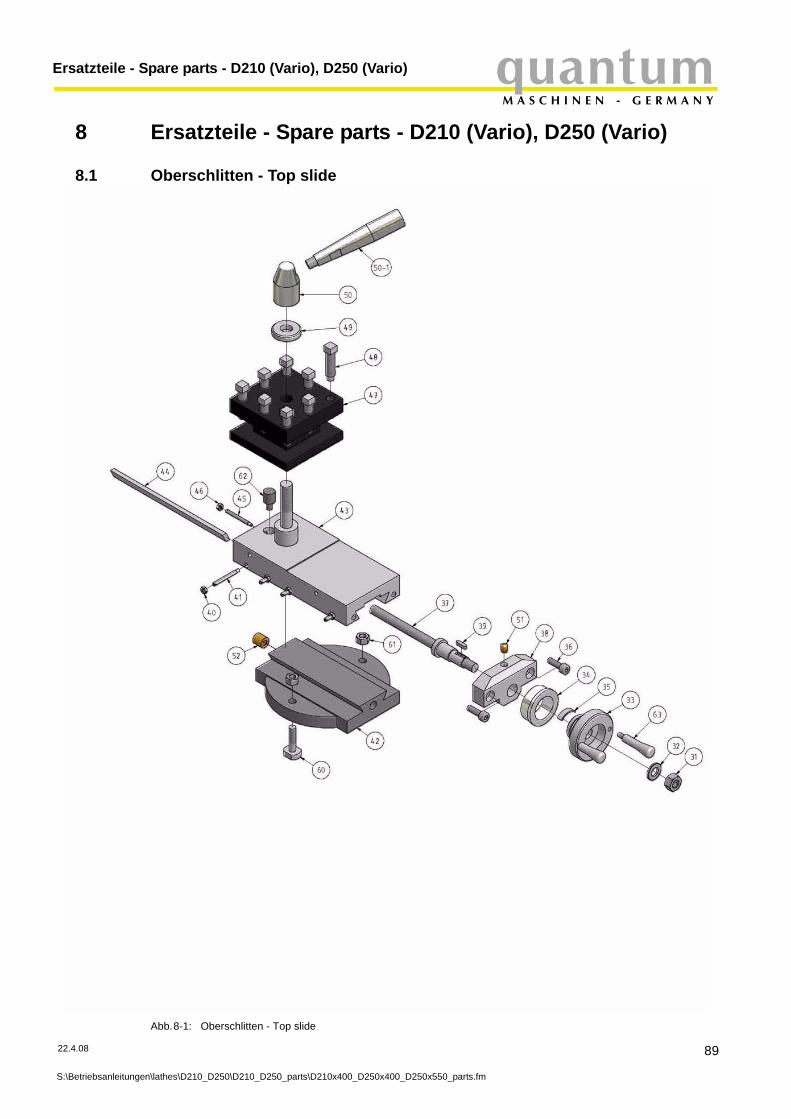
quantumM A S C H I N E N - G E R M A N Y
Ersatzteile - Spare parts - D210 (Vario), D250 (Vario)
8 Ersatzteile - Spare parts - D210 (Vario), D250 (Vario)
8.1 Oberschlitten - Top slide
Abb.8-1: Oberschlitten - Top slide
22.4.08
S:\Betriebsanleitungen\lathes\D210_D250\D210_D250_parts\D210x400_D250x400_D250x550_parts.fm
89
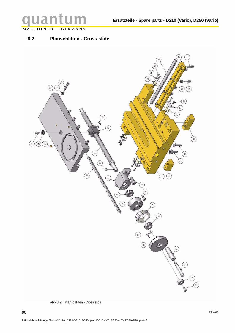
Ersatzteile - Spare parts - D210 (Vario), D250 (Vario)quantumM A S C H I N E N - G E R M A N Y
8.2 Planschlitten - Cross slide
90
S:\Betriebsanleitunge
Abb.8-2: Planschlitten - Cross slide
n\lathes\D210_D250\D210_D250_parts\D210x400_D250x400_D250x550_parts.fm
22.4.08

quantumM A S C H I N E N - G E R M A N Y
Ersatzteile - Spare parts - D210 (Vario), D250 (Vario)
8.2.1 Teileliste Maschinenschlitten- Parts list top and cross slide
22.4.08
S:\Betriebsanleitung
Pos. Bezeichnung Designation Menge Grösse Artikelnummer
Qty. Size Item no.1 Bettschlitten lathe saddle 1 03420321112 Führungslager Planschlitten Guide bearing cross slide 1 034251043 Innensechskantschraube Socket head screw 3 ISO 4762-M8x204 Spindel Planschlitten Spindle cross slide 1 034251055 Axial-Rillenkugellager Deep groove ball thrust bearing 2 51101 03420321156 Abdeckung Lagerbock Planschlitten Cover clevis mounting cross slide 1 0342032116
7 Innensechskantschraube Socket head screw 7ISO 4762- M5 x16
8 Paßfeder Key 1 4x12 03420321189 Skalenring Planschlitten Scale ring cross slide 1 034256310 Federblech Spring plate 1 0342032111011 Handrad Planschlitten Handwheel cross slide 1 0342568
12 Unterlegscheibe für Handrad Plan-schlitten Washer for handwheel cross slide 1 03420321112
13 Innensechskantschraube Socket head screw 1ISO4762-
M5x1014 Handgriff Handle 1 034255015 Schraube für Handgriff Screw for handle 1 034254917 Führungsschiene lang Guide rail long 1 034256718 Keilleiste Bettschlitten Taper gib lathe saddle 1 034256219 Einstellschraube Adjusting screw 5 0342032111920 Sechskantmutter Hexagon nut 5 ISO 4033 - M521 Führungsschiene mittel Guide rail means 1 0342593
22 Innensechskantschraube Socket head screw 4 ISO 4762 - M5x25
23 Führungsschiene kurz Guide rail briefly 1 034259224 Metallverstärkung Abstreifer Metal reinforcement stripper 2 0342032112425 Metallverstärkung Abstreifer Metal reinforcement stripper 2 0342032112526 Filz Abstreifer Felt stripper 2 0342032112627 Filz Abstreifer Felt stripper 2 03420321127
28 Flachkopfschraube mit Kreuzschlitz Cheese head screw 8 ISO 7075 - M3x8 - H
30 Keilleiste Planschlitten Taper gib cross slide 1 034256231 Sechskantmutter Hexagon nut 1 ISO 4032 - M832 Unterlegscheibe Washer 1 B8.433 Handrad für Oberschlitten Handwheel for top slide 1 034256934 Skalenring für Oberschlitten Scale for top slide 1 0342032113435 Federblech Spring plate 1 03420321135
36 Innensechskantschraube Socket head screw 2 ISO 4762 - M5x16
37 Spindel Oberschlitten Spindle top slide 1 0342032113738 Lagerbock für Oberschlitten Clevis mounting for top slides 1 0342032113839 Passfeder Key 1 3x10 0342032113940 Sechskantmutter Hexagon nut 4 ISO 4032 - M3
41 Einstellschraube für Druckleiste Ober-schlitten
Adjusting screw for pressure border top slide 4 03420321141
42 Unterteil Oberschlitten Lower part top slide 1 0342032114243 Oberteil Oberschlitten Upper section top slide 1 0342032114344 Druckleiste Oberschlitten Pressure border top slide 1 0342032114445 Fixierschraube Fixing screw 1 0342032114546 Sechskantmutter Hexagon nut 1 ISO 4033 - M347 Vierfachstahlhalter Quadruple tool holder 1 0342032114748 Vierkantschraube Square headed bolt 8 0342032114849 Unterlegscheibe Washer 1 0342032114950 Klemmstück Shim 1 03420321150
50-1 Griff Handle 1 03420321150151 Schmiernippel 6mm Oiler 6mm 10 0342032115152 Schmiernippel 10mm Oiler 10mm 1 0342032115253 Sechskantmutter Hexagon nut 5 ISO 4032- M554 Einstellschraube Planschlitten Adjusting screw cross slide 5 0342032115455 Spindelmutter Planschlitten spindle nut cross slide 1 0342032115556 Verstellschraube Adjusting bolt 2 0342032115657 Planschlitten Cross slide 1 0342032115758 Unterlegscheibe Washer 1 03420321158
59 Innensechskantschraube Socket head screw 1 ISO 4762 - M5x10
60 Befestigungsschraube für Oberschlit-ten Fixing bolt for top slide 2 03420321160
61 Sechskantmutter Hexagon nut 2 ISO 4032 - M662 Fixierstück für Vierfachhalter Fixing piece for quadruple tool holder 1 0342032116263 Griff für Oberschlitten Handle for top slide 2 03420321163
en\lathes\D210_D250\D210_D250_parts\D210x400_D250x400_D250x550_parts.fm
91
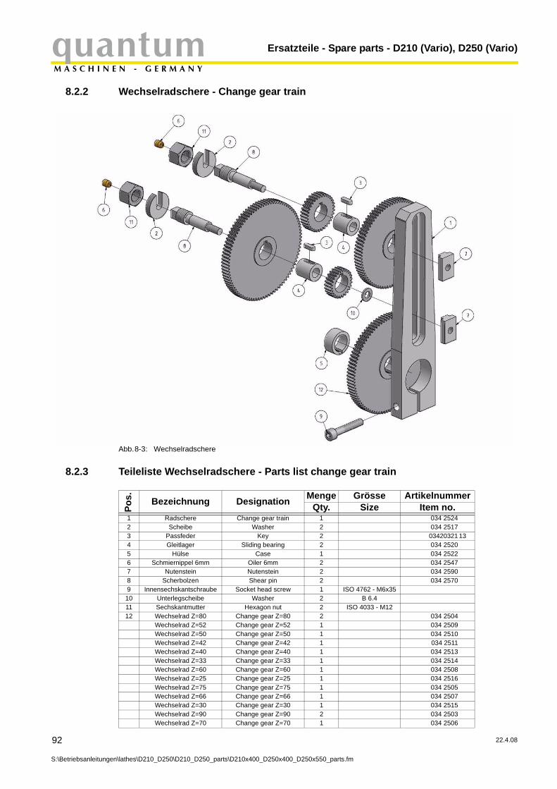
Ersatzteile - Spare parts - D210 (Vario), D250 (Vario)quantumM A S C H I N E N - G E R M A N Y
8.2.2 Wechselradschere - Change gear train
92
S:\Betriebsanleitunge
Abb.8-3: Wechselradschere
8.2.3 Teileliste Wechselradschere - Parts list change gear train
Pos. Bezeichnung Designation Menge Grösse Artikelnummer
Qty. Size Item no.1 Radschere Change gear train 1 034 25242 Scheibe Washer 2 034 25173 Passfeder Key 2 03420321 134 Gleitlager Sliding bearing 2 034 25205 Hülse Case 1 034 25226 Schmiernippel 6mm Oiler 6mm 2 034 25477 Nutenstein Nutenstein 2 034 25908 Scherbolzen Shear pin 2 034 25709 Innensechskantschraube Socket head screw 1 ISO 4762 - M6x3510 Unterlegscheibe Washer 2 B 6.411 Sechskantmutter Hexagon nut 2 ISO 4033 - M1212 Wechselrad Z=80 Change gear Z=80 2 034 2504
Wechselrad Z=52 Change gear Z=52 1 034 2509Wechselrad Z=50 Change gear Z=50 1 034 2510Wechselrad Z=42 Change gear Z=42 1 034 2511Wechselrad Z=40 Change gear Z=40 1 034 2513Wechselrad Z=33 Change gear Z=33 1 034 2514Wechselrad Z=60 Change gear Z=60 1 034 2508Wechselrad Z=25 Change gear Z=25 1 034 2516Wechselrad Z=75 Change gear Z=75 1 034 2505Wechselrad Z=66 Change gear Z=66 1 034 2507Wechselrad Z=30 Change gear Z=30 1 034 2515Wechselrad Z=90 Change gear Z=90 2 034 2503Wechselrad Z=70 Change gear Z=70 1 034 2506
n\lathes\D210_D250\D210_D250_parts\D210x400_D250x400_D250x550_parts.fm
22.4.08

quantumM A S C H I N E N - G E R M A N Y
Ersatzteile - Spare parts - D210 (Vario), D250 (Vario)
8.3 Bettschlitten - Bed slide
22.4.08
S:\Betriebsanleitung
Abb.8-4: Bettschlitten - Bed slide
en\lathes\D210_D250\D210_D250_parts\D210x400_D250x400_D250x550_parts.fm
93

Ersatzteile - Spare parts - D210 (Vario), D250 (Vario)quantumM A S C H I N E N - G E R M A N Y
8.3.1 Teileliste Bettschlitten - Parts list bed slide
94
S:\Betriebsanleitunge
Pos. Bezeichnung Designation Menge Grösse Artikelnummer
Qty. Size Item no.1 Schloßkasten Apron 1 03420321 212 Flanschlagerbock Handrad Flange bearing support handwheel 1 03420321 223 Flanschlagerbock Flange bearing support 1 03420321 234 Verzahnte Welle Toothed shaft 1 03420321 245 Passfeder Key 1 5x10 03420321 256 Skalenring Handrad Scale handwheel 1 03420321 267 Handrad Handwheel 1 03420321 278 Federblech Spring plate 1 03420321 289 Unterlegscheibe Washer 1 B 8.410 Sechskantmutter Hexagon nut 1 ISO 4033 - M811 Handgriff Handle 1 03420321 21112 Schraube Screw 1 03420321 21213 Zahnrad Gear 1 03420321 21314 Verzahnte Welle Toothed shaft 1 03420321 21415 Buchse Socket 1 03420321 21516 Paßfeder Key 1 03420321 21617 Fixierschraube Fixing screw 1 DIN 914 - M4 x1018 Exzenter Eccentric cam 1 03420321 21819 Schloßmutter oben Lock nut above 1 03420321 21920 Schloßmutter unten Lock nut down 1 03420321 22021 Schaltnabe Switching hub 1 03420321 22122 Griff Handle 1 03420321 22223 Verstellschraube Adjusting bolt 3 03420321 22324 Sechskantmutter Hexagon nut 3 ISO 4033 - M525 Innensechskantschraube Socket head screw 1 DIN 914 - M6x826 Druckleiste für Schloßmutter Pressure border for lock nut 1 03420321 22627 Feder Spring 1 03420321 22728 Stahlkugel Steel Ball 1 03420321 22829 Innensechskantschraube Socket head screw 6 GB70-85/4x12
n\lathes\D210_D250\D210_D250_parts\D210x400_D250x400_D250x550_parts.fm
22.4.08
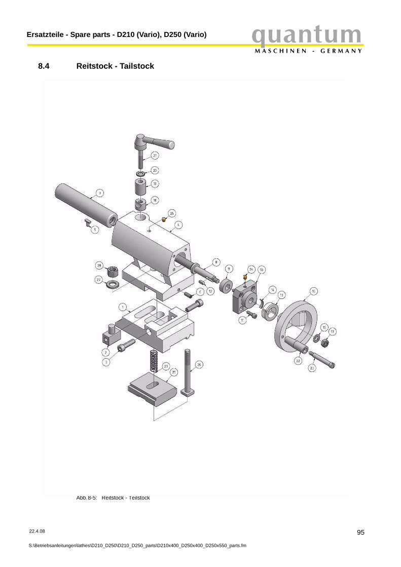
quantumM A S C H I N E N - G E R M A N Y
Ersatzteile - Spare parts - D210 (Vario), D250 (Vario)
8.4 Reitstock - Tailstock
22.4.08
S:\Betriebsanleitung
Abb.8-5: Reitstock - Teilstock
en\lathes\D210_D250\D210_D250_parts\D210x400_D250x400_D250x550_parts.fm
95

Ersatzteile - Spare parts - D210 (Vario), D250 (Vario)quantumM A S C H I N E N - G E R M A N Y
8.4.1 Teileliste Reitstock - Parts list tailstock
96
S:\Betriebsanleitunge
Pos. Bezeichnung Designation Menge Grösse Artikelnummer
Qty. Size Item no.1 Reitstockunterteil Headstock lower part 1 03420321312 Zentrierstück Pinole Piece of centering of spindle sleeve 1 03420321323 Innensechskantschraube Socket head screw 2 ISO 4762 - M8x304 Reitstockoberteil Headstock upper section 1 03420321345 Gleitstein Slide ring 1 03420321356 Gewindestift Headless screw 1 DIN 913 - M6x127 Reitstockpinole Headstock guide 1 03420321378 Spindel Spindle 1 03420321389 Axial-Rillenkugellager Deep groove ball thrust bearing 1 51101 034203213910 Lagerbock für Spindel Clevis mounting for spindle 1 0342032131011 Innensechskantschraube Socket head screw 4 ISO 4762 - M5x1612 Passfeder Key 1 DIN6885/A4x4x14 0342032131213 Skalenring Handrad Scale handwheel 1 0342032131314 Federblech Spring plate 1 0342032131415 Handrad Reitstock Handwheel tailstock 1 0342032131516 Unterlegscheibe Washer 1 B8.417 Sechskantmutter Hexagon nut 1 DIN 6915 - M818 Klemmhülse unten Collet down 1 0342032131819 Klemmhülse oben Collet above 1 0342032131920 Unterlegscheibe Washer 1 B 821 Klemmschraube Clamping screw 1 0342032132122 Griff Handle 1 0342032132223 Schraube für Griff Screw for handle 1 0342032132324 Schmiernippel 6mm Oiler 6mm 2 0342032132425 Klemmplate Clamping plate 1 0342032132526 Spannschraube Tightening screw 1 0342032132627 Scheibe Washer 1 1228 Sechskantmutter Hexagon nut 1 M1229 Feder Spring 1 03420321329
Reitstock D210 komplett 1 0342195Reitstock D250 komplett 1 03425113
n\lathes\D210_D250\D210_D250_parts\D210x400_D250x400_D250x550_parts.fm
22.4.08
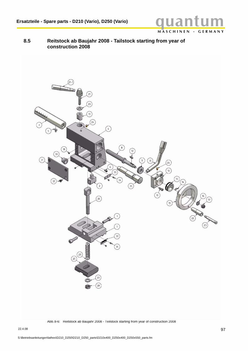
quantumM A S C H I N E N - G E R M A N Y
Ersatzteile - Spare parts - D210 (Vario), D250 (Vario)
8.5 Reitstock ab Baujahr 2008 - Tailstock starting from year of construction 2008
22.4.08
S:\Betriebsanleitung
Abb.8-6: Reitstock ab Baujahr 2008 - Teilstock starting from year of construction 2008
en\lathes\D210_D250\D210_D250_parts\D210x400_D250x400_D250x550_parts.fm
97

Ersatzteile - Spare parts - D210 (Vario), D250 (Vario)quantumM A S C H I N E N - G E R M A N Y
8.5.1 Teileliste Reitstock Baujahr ab 2008 - Parts list tailstock starting from year of construction 2008
98
S:\Betriebsanleitunge
Pos. Bezeichnung Designation Menge Grösse Artikelnummer
Qty. Size Item no.1 Reitstockunterteil Headstock lower part 1 034203218012 Zentrierstück Pinole Piece of centering of spindle sleeve 1 034203218023 Innensechskantschraube Socket head screw 2 ISO 4762 - M8x304 Reitstockoberteil Headstock upper section 1 034203218045 Gleitstein Slide ring 1 034203218056 Gewindestift Headless screw 1 DIN 913 - M6x127 Reitstockpinole Headstock guide 1 034203218078 Spindel Spindle 1 034203218089 Axial-Rillenkugellager Deep groove ball thrust bearing 1 51101 0342032180910 Lagerbock für Spindel Clevis mounting for spindle 1 0342032181011 Innensechskantschraube Socket head screw 4 ISO 4762 - M5x1612 Paßfeder Key 1 DIN6885/A4x4x14 0342032181213 Skalenring Handrad Scale handwheel 1 0342032181314 Federblech Spring plate 1 0342032181415 Handrad Reitstock Handwheel tailstock 1 0342032181516 Unterlegscheibe Washer 1 B8.417 Sechskantmutter Hexagon nut 1 DIN 6915 - M818 Gewindestift Threaded pin 2 ISO4028/M4x519 Klemmhülse oben Collet above 1 0342032181920 Unterlegscheibe Washer 1 B 821 Klemmschraube Clamping screw 1 03420321821
21-1 Griff Handle 03420321821122 Griff Handle 1 0342032182223 Schraube für Griff Screw for handle 1 0342032182324 Schmiernippel 6mm Oiler 6mm 2 0342032182425 Klemmplate Clamping plate 1 0342032182526 Spannschraube Tightening screw 1 0342032182627 Scheibe Washer 1 1228 Sechskantmutter Hexagon nut 1 M1229 Feder Spring 1 0342032182930 Führungsbuchse Guide bush 1 0342032183031 Deckel Cover 1 0342032183132 Senkschraube Countersunk screw 4 ISO2009/M5x1033 Skala Scale 1 0342032183334 Niet Rivet 4 0342032183435 Exzenter Eccentric cam 1 0342032183536 Spannhebel Clamping hebel 1 0342032183637 Skala Scale 1 03420321837
Reitstock D210 komplett 1 03420321838Reitstock D250 komplett 1 03420321839
n\lathes\D210_D250\D210_D250_parts\D210x400_D250x400_D250x550_parts.fm
22.4.08
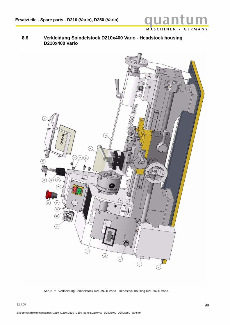
quantumM A S C H I N E N - G E R M A N Y
Ersatzteile - Spare parts - D210 (Vario), D250 (Vario)
8.6 Verkleidung Spindelstock D210x400 Vario - Headstock housing D210x400 Vario
22.4.08
S:\Betriebsanleitung
Abb.8-7: Verkleidung Spindelstock D210x400 Vario - Headstock housing D210x400 Vario
en\lathes\D210_D250\D210_D250_parts\D210x400_D250x400_D250x550_parts.fm
99
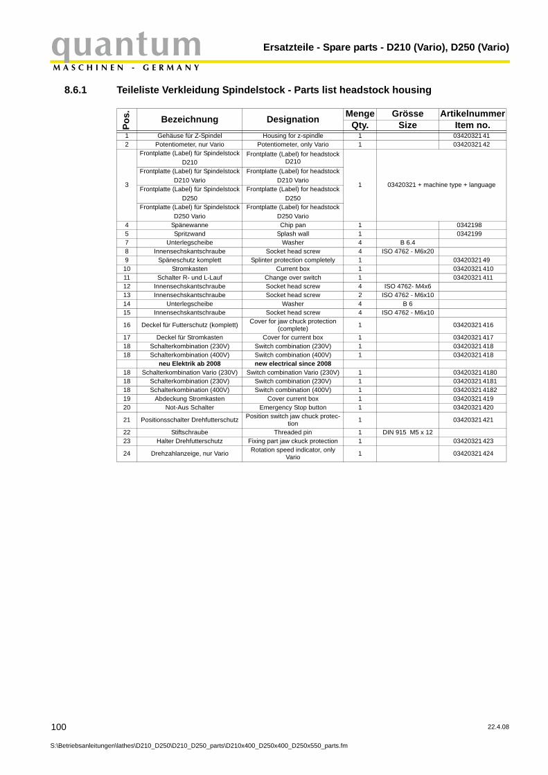
Ersatzteile - Spare parts - D210 (Vario), D250 (Vario)quantumM A S C H I N E N - G E R M A N Y
8.6.1 Teileliste Verkleidung Spindelstock - Parts list headstock housing
100
S:\Betriebsanleitunge
Pos. Bezeichnung Designation Menge Grösse Artikelnummer
Qty. Size Item no.1 Gehäuse für Z-Spindel Housing for z-spindle 1 03420321 412 Potentiometer, nur Vario Potentiometer, only Vario 1 03420321 42
3
Frontplatte (Label) für SpindelstockD210
Frontplatte (Label) for headstock D210
1 03420321 + machine type + language
Frontplatte (Label) für SpindelstockD210 Vario
Frontplatte (Label) for headstockD210 Vario
Frontplatte (Label) für SpindelstockD250
Frontplatte (Label) for headstockD250
Frontplatte (Label) für SpindelstockD250 Vario
Frontplatte (Label) for headstockD250 Vario
4 Spänewanne Chip pan 1 03421985 Spritzwand Splash wall 1 03421997 Unterlegscheibe Washer 4 B 6.48 Innensechskantschraube Socket head screw 4 ISO 4762 - M6x209 Späneschutz komplett Splinter protection completely 1 03420321 4910 Stromkasten Current box 1 03420321 41011 Schalter R- und L-Lauf Change over switch 1 03420321 41112 Innensechskantschraube Socket head screw 4 ISO 4762- M4x613 Innensechskantschraube Socket head screw 2 ISO 4762 - M6x1014 Unterlegscheibe Washer 4 B 615 Innensechskantschraube Socket head screw 4 ISO 4762 - M6x10
16 Deckel für Futterschutz (komplett) Cover for jaw chuck protection (complete) 1 03420321 416
17 Deckel für Stromkasten Cover for current box 1 03420321 41718 Schalterkombination (230V) Switch combination (230V) 1 03420321 41818 Schalterkombination (400V) Switch combination (400V) 1 03420321 418
neu Elektrik ab 2008 new electrical since 200818 Schalterkombination Vario (230V) Switch combination Vario (230V) 1 03420321 418018 Schalterkombination (230V) Switch combination (230V) 1 03420321 418118 Schalterkombination (400V) Switch combination (400V) 1 03420321 418219 Abdeckung Stromkasten Cover current box 1 03420321 41920 Not-Aus Schalter Emergency Stop button 1 03420321 420
21 Positionsschalter Drehfutterschutz Position switch jaw chuck protec-tion 1 03420321 421
22 Stiftschraube Threaded pin 1 DIN 915 M5 x 1223 Halter Drehfutterschutz Fixing part jaw ckuck protection 1 03420321 423
24 Drehzahlanzeige, nur Vario Rotation speed indicator, only Vario 1 03420321 424
n\lathes\D210_D250\D210_D250_parts\D210x400_D250x400_D250x550_parts.fm
22.4.08
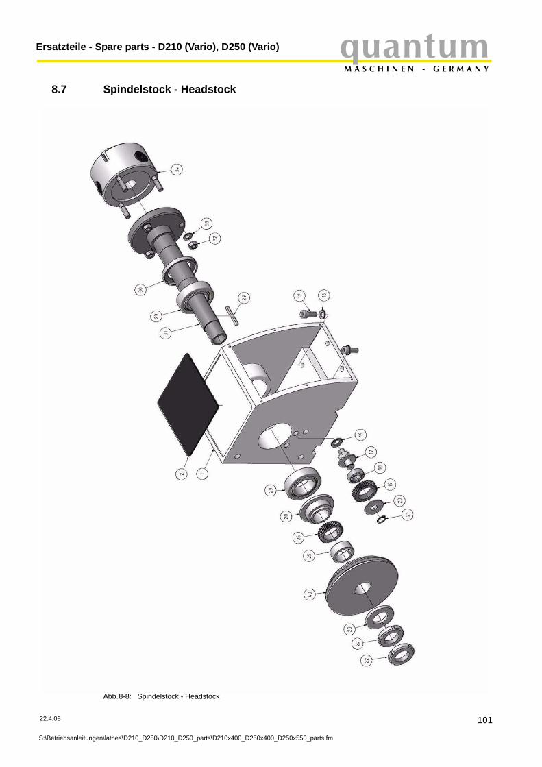
quantumM A S C H I N E N - G E R M A N Y
Ersatzteile - Spare parts - D210 (Vario), D250 (Vario)
8.7 Spindelstock - Headstock
22.4.08
S:\Betriebsanleitung
Abb.8-8: Spindelstock - Headstock
en\lathes\D210_D250\D210_D250_parts\D210x400_D250x400_D250x550_parts.fm
101
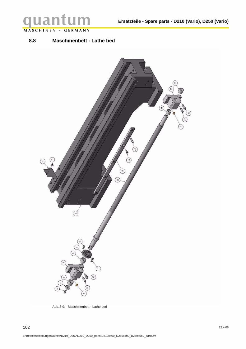
Ersatzteile - Spare parts - D210 (Vario), D250 (Vario)quantumM A S C H I N E N - G E R M A N Y
8.8 Maschinenbett - Lathe bed
102
S:\Betriebsanleitunge
Abb.8-9: Maschinenbett - Lathe bed
n\lathes\D210_D250\D210_D250_parts\D210x400_D250x400_D250x550_parts.fm
22.4.08

quantumM A S C H I N E N - G E R M A N Y
Ersatzteile - Spare parts - D210 (Vario), D250 (Vario)
8.8.1 Teileliste Spindelstock und Maschinenbett - Parts headstock and lathe bed
22.4.08
S:\Betriebsanleitung
Pos. Name Designation Menge Grösse Artikelnummer
Qty. Size Item no.1 Spindelstock Headstock 1 03420321 512 Auflagegummi Edition rubber 1 03420321 52
3 Drehmaschinenbett 1D210 x 400 03420321 5531D250 x 400 03420321 5532D250 x 550 03420321 5533
4 Innensechskantschraube Socket head screw 1 03420321 545 Unterlegscheibe Washer 1 03420321 556 Einstellflansch Adjusting flange 1 03420321 567 Schmiernippel 6mm Oiler 6mm 2 03420321 57
8 Gleitlager für Lagerbock links
Sliding bearing for clevis mounting left 2 03420321 58
9 Lagerbock links Clevis mounting left 1 03420321 5910 Paßfeder Key 1 03420321 51011 Innensechskantschraube Socket head screw 3 ISO 4762 - M4x1612 Innensechskantschraube Socket head screw 4 ISO 4762 - M8x2013 Unterlegscheibe Washer 4 B8.4
14 Abdeckung im Maschinen-bett Cover in the lathe bed 1 03420321 514
15 Flachkopfschraube Cheese head screw 1 ISO 7045- M5x616 Unterlegscheibe Washer 1 B10.517 Welle Shaft 1 03420321 51718 Rillenkugellager Grooved ball bearing 1 03420321 51819 Zahnrad Gear 1 03420321 51920 Abdeckscheibe Cover plate 1 03420321 52021 Sicherungsring Circlip 1 1222 Mutter Nut 2 M27x1.523 Unterlegscheibe Washer 1 03420321 52325 Zwischenhülse Intermediate case 1 03420321 52526 Zahnrad Gear 1 03420321 52627 Passfeder Key 1 4x40 03420321 52728 Druckplatte Lager Pressure plate bearing 1 03420321 52829 Kegelrollenlager Taper roller bearing 2 32007 03420321 52930 Abdeckung Cover 1 03420321 53031 Arbeitsspindel Working-spindle 1 03420321 53132 Sechskantmutter Hexagon nut 3 ISO 4032 - M833 Unterlegscheibe Washer 3 B834 3-Backenfutter D210 3-jaw chuck D210 1 D210, 100mm 344101034 3-Backenfutter D250 3-jaw chuck D250 1 D250, 125mm 344102535 Leitspindel Lead screw 1 03420321 53536 Innensechskantschraube Socket head screw 4 ISO 4762 - M6x16 03420321 53637 Zylinderstift Cylindrical pin 4 6 h8x22
38 Gleitlager Lagerbock rechts Sliding bearing clevis mounting right 2 03420321 538
39 Lagerbock rechts Clevis mounting right 1 03420321 53940 Riemenscheibe Spindel Spindle pulley 1 03420321 62241 Zahnstange Rack 1 03420321 45
42 Senkschraube Countersunk screw 5 ISO 7046 - M5x12-H
43 Zylinderstift Cylindrical pin 2 ISO 2338 - 6h8 x22
en\lathes\D210_D250\D210_D250_parts\D210x400_D250x400_D250x550_parts.fm
103

Ersatzteile - Spare parts - D210 (Vario), D250 (Vario)quantumM A S C H I N E N - G E R M A N Y
8.9 Vario Antrieb D210 - Vario drive D210
104
S:\Betriebsanleitunge
Abb.8-10: Vario Antrieb D210 - Vario drive D210
n\lathes\D210_D250\D210_D250_parts\D210x400_D250x400_D250x550_parts.fm
22.4.08

quantumM A S C H I N E N - G E R M A N Y
Ersatzteile - Spare parts - D210 (Vario), D250 (Vario)
8.9.1 Teileliste Vario Antrieb D210 - Parts list Vario drive D210
22.4.08
S:\Betriebsanleitung
Pos. Bezeichnung Designation Menge Grösse Artikelnummer
Qty. Size Item no.1 Motor D210 Vario Motor D210 Vario 1 03420321 612 Motorabdeckung Motor cover 1 03420321 623 Motorträgerplatte Motor fixing plate 1 03420321 634 Schraube Screw 2 ISO 7045 - M5x65 Winkelblech für Motor Bracket plate for motor 1 03420321 656 Abstandshülse Spacer 4 03420321 667 Unterlegscheibe Washer 4 B 6.48 Innensechskantschraube Socket head screw 4 ISO 4762 M6x109 Riemenscheibe Motor Pulley motor 1 03420321 6910 Spannrolle Riemen Idler belt 1 03420321 61011 Sechskantmutter Hexagon nut 7 EN 24032 - M1012 Sechskantmutter Hexagon nut 1 EN 24032 - M813 Unterlegscheibe Washer 1 B8.414 Fixierstift Fixing pin 1 03420321 61415 Antriebsriemen V-belt 1 03420321 61516 Stehbolzen Thread bolt 2 03420321 616
17 Innensechskantschraube Socket head screw 2 ISO 4762 -M10x20
18 Unterlegscheibe Washer 3 B 10.519 Abdeckung D210 "rund" Cover D210 "round" 1 0342032153519 Abdeckung D210 "eckig" CoverD210 "angularly" 1 034219619 Abdeckung D250 "eckig" Cover D250 "angularly" 1 034259619 Abdeckung D250 "rund" Cover D250 "round" 1 03420321535-120 Rändelmutter Knurled nut 1 03420321 62021 Falldeckel Cover Spindle tube 1 03420321 62122 Riemenscheibe Spindel Spindle pulley 1 03420321 62223 Trafo Transformer 1 03420321 623
24 Positionsschalter Spin-delstockabdeckung
Position switch headstock protec-tion 1 03420321 624
25 Halter Holder, only Vario 1 03420321 62526 Drehzahlsensor Rotation speed sensor, only Vario 1 03420321 62627 Netzteil, nur Vario Power pack, only Vario 1 03420321 62728 Netzfilter Line filter 1 03420321 628
Motorschalzschütz Exchanges contact device 1 03420321 629Steuerplatine Electronic board 1 0320297
en\lathes\D210_D250\D210_D250_parts\D210x400_D250x400_D250x550_parts.fm
105
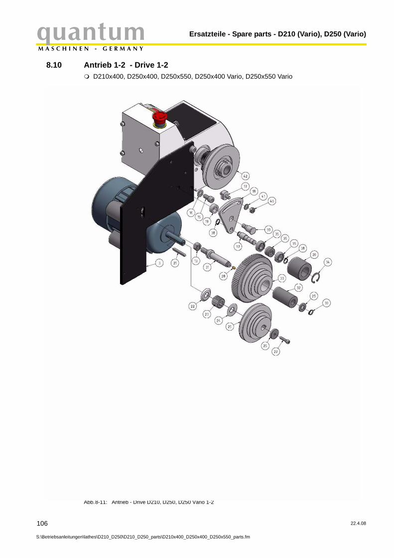
Ersatzteile - Spare parts - D210 (Vario), D250 (Vario)quantumM A S C H I N E N - G E R M A N Y
8.10 Antrieb 1-2 - Drive 1-2
106
S:\Betriebsanleitunge
D210x400, D250x400, D250x550, D250x400 Vario, D250x550 Vario
Abb.8-11: Antrieb - Drive D210, D250, D250 Vario 1-2
n\lathes\D210_D250\D210_D250_parts\D210x400_D250x400_D250x550_parts.fm
22.4.08
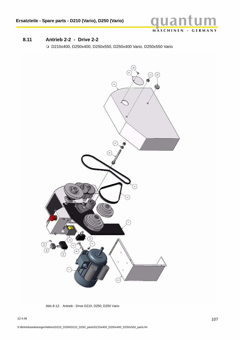
quantumM A S C H I N E N - G E R M A N Y
Ersatzteile - Spare parts - D210 (Vario), D250 (Vario)
8.11 Antrieb 2-2 - Drive 2-2
22.4.08
S:\Betriebsanleitung
D210x400, D250x400, D250x550, D250x400 Vario, D250x550 Vario
Abb.8-12: Antrieb - Drive D210, D250, D250 Vario
en\lathes\D210_D250\D210_D250_parts\D210x400_D250x400_D250x550_parts.fm
107

Ersatzteile - Spare parts - D210 (Vario), D250 (Vario)quantumM A S C H I N E N - G E R M A N Y
8.11.1 Teileliste Antrieb - Parts list drive
108
S:\Betriebsanleitunge
D210x400, D250x400, D250x550, D250x400 Vario, D250x550 Vario
Pos. Bezeichnung Designation Menge Grösse Artikelnummer
Qty. Size Item no.
1Motor Motor
1230V 03420321 711
Motor Motor 400V 03420321 712Motor D250 Motor D250 Vario 03420321 713
2 Abdeckung Motor Cover Motor 1 03420321 723 Motorplatte Motor plate 1 03420321 73
4 Abdeckung D210/D250 Cover D210/D250 Vario Antrieb Position 19
5 Antriebsriemen Drive belt 1 03420321 756 Zahnriemen Toothed belt 1 03420321 767 Sechskantmutter Hexagon nut 4 EN 24032 - M68 Stehbolzen Thread bolt 4 M6 03420321 789 Distanzstück Spacer piece 4 03420321 7910 Rändelmutter Knurled nut 1 03420321 71011 Spindelabdeckung Spindle cover 1 03420321 71112 Schraube Screw 5 ISO 7045 - M5x613 Sechskantmutter Hexagon bolt 7 EN 24032 - M1014 Stehbolzen Thread bolt 2 03420321 714
15 Innensechskantschraube Socket head screw 2 ISO 4762 - M10x20
16 Unterlegscheibe Washer 2 B 10.517 Fixierstift Fixing pin 1 03420321 71718 Trägerplatte für Spannrolle Support for idler 1 03420321 71819 Distanzring Trägerplatte Spacer ring support plate 1 03420321 71920 Rolle für Spannrolle Role for idler 1 03420321 72021 Passfeder für Motor Key for motor 1 5x40 03420321 72122 Bundscheibe innen Flanged washer inside 1 03420321 72223 Zahnriemenscheibe Toothed belt disk 1 18 Zähne (teeths) 03420321 72324 Bundscheibe außen Flanged washer outside 1 03420321 72425 Riemenscheibe Motor V-belt motor 1 03420321 72526 Unterlegscheibe Motor Distance washer motor 1 03420321 72627 Innensechskantschraube Socket head screw 1 DIN 4762 - M6x2528 Schmiernippel 6mm Oiler 6mm 1 03420321 72829 Deckscheibe Cover disk 1 03420321 72930 Sicherungsring Circlip 1 12mm31 Welle für Zwischenscheibe Shaft for intermediate washer 1 03420321 73132 Führunghülse Guidance case 1 03420321 73233 Zahnriemenscheibe Toothed belt disk 1 84 Zähne (teeths) 03420321 73334 Sicherungsring Circlip 1 26mm35 Rillenkugellager Grooved ball bearing 2 6001 03420321 73536 Distanzstück Spacer piece 1 03420321 73637 Welle für Spannrolle Shaft for idler 1 03420321 737
38 Sicherungsring für Spann-rolle Circlip for idler 2 03420321 738
39 Führungsbolzen Guide pin 1 03420321 73940 Sechskantmutter Hexagon nut 1 EN 24032 - M841 Unterlegscheibe Washer 1 B 8.442 Riemenscheibe Spindel Pulley spindle 1 03420321 74243 Stiftschraube Threaded pin 1 DIN 915 M5 x 12
44 Halter Drehfutterschutz Fixing part jaw ckuck protec-tion 1 23 03420321 744
45 Positionsschalter Drehfut-terschutz
Position switch jaw chuck pro-tection 1 03420321 745
46 Trafo Transformer 1 03420321 746
47 Positionsschalter Spin-delstockabdeckung
Position switch headstock pro-tection 1 03420321 747
Kondensator 25 microF Condenser 25 microF 1 0342576Kondensator 150 microF Condenser 150 microF 1 0342579Lenze Frequenzumrichter Lenze Frequency converter 1
Kondensator (230V) Capacitor (230V) 1 25µF 03420321 743Kondensator (230V) Capacitor (230V) 1 150µF 03420321 744
n\lathes\D210_D250\D210_D250_parts\D210x400_D250x400_D250x550_parts.fm
22.4.08

quantumM A S C H I N E N - G E R M A N Y
Ersatzteile - Spare parts - D210 (Vario), D250 (Vario)
8.12 Sonstiges Zubehör (ohne Abbildung) - Other accessories (without illustration)
22.4.08
S:\Betriebsanleitung
Pos. Bezeichnung Designation Menge Grösse Artikelnummer
Qty. Size Item no.Spritzwand D250x400 Splash guard D250x400 1 0342599Spritzwand D250x550 Splash guardD250x550 1 0342600
Spänewanne D250x400 Chip pan D250x400 1 0342598Spänewanne D250x550 Chip pan D250x550 1 0342601
Maschinenunterbau D250x400 Machine stand D250x400 1 3440407Maschinenunterbau D250x550 Machine stand D250x550 1 3440507
Werkzeugbox komplett Tool box complete 1 0342589Feste Spitze MK 2 Fixed center MT 2 1 0342594Feste Spitze MK 3 Fixed center MT 3 1 0342595
3-Backenfutter 3-jaw chuck 1 100 mm 344 10103-Backenfutter 3-jaw chuck 1 125 mm 344 10254-Backenfutter 4-jaw chuck 1 100 mm 344 10124-Backenfutter 4-jaw chuck 1 125 mm 344 1027
en\lathes\D210_D250\D210_D250_parts\D210x400_D250x400_D250x550_parts.fm
109

Ersatzteile - Spare parts - D210 (Vario), D250 (Vario)quantumM A S C H I N E N - G E R M A N Y
8.13 Schaltplan - Wiring diagram D210 x 400 Vario
Abb.8-13: Schaltplan - Wiring diagram D210x400 Vario
110
S:\Betriebsanleitungen\lathes\D210_D250\D210_D250_parts\D210x400_D250x400_D250x550_parts.fm
22.4.08
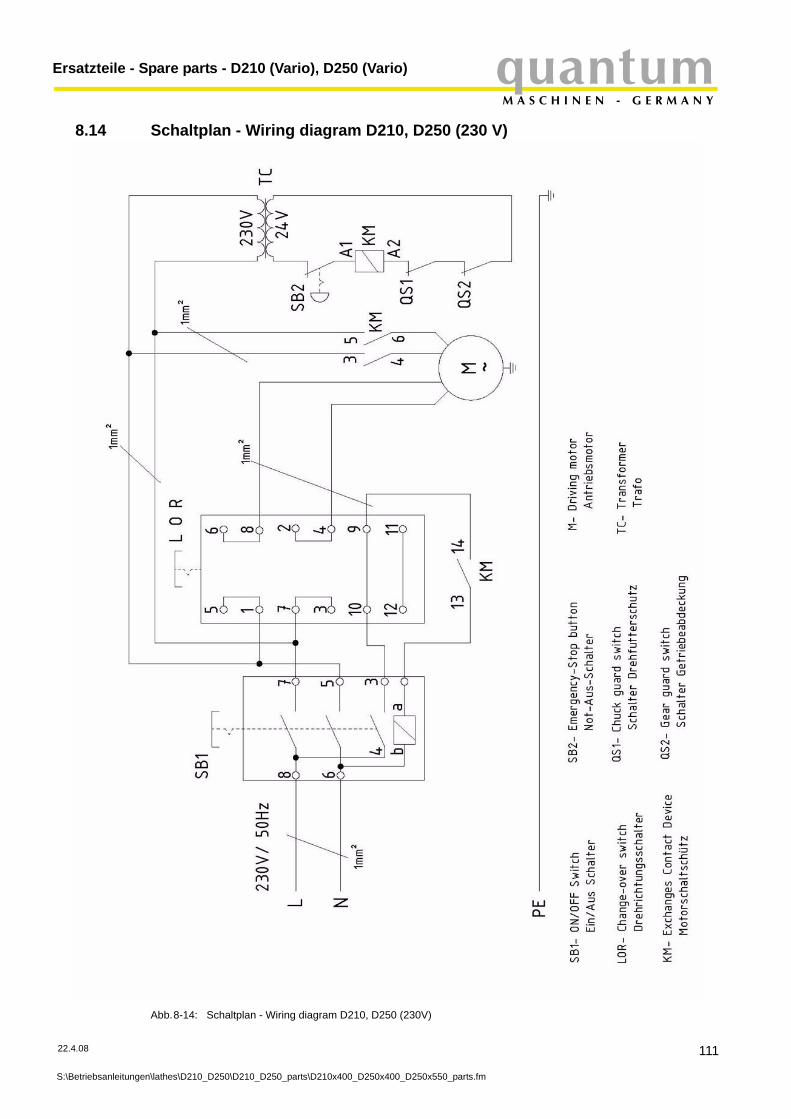
quantumM A S C H I N E N - G E R M A N Y
Ersatzteile - Spare parts - D210 (Vario), D250 (Vario)
8.14 Schaltplan - Wiring diagram D210, D250 (230 V)
Abb.8-14: Schaltplan - Wiring diagram D210, D250 (230V)
22.4.08
S:\Betriebsanleitungen\lathes\D210_D250\D210_D250_parts\D210x400_D250x400_D250x550_parts.fm
111
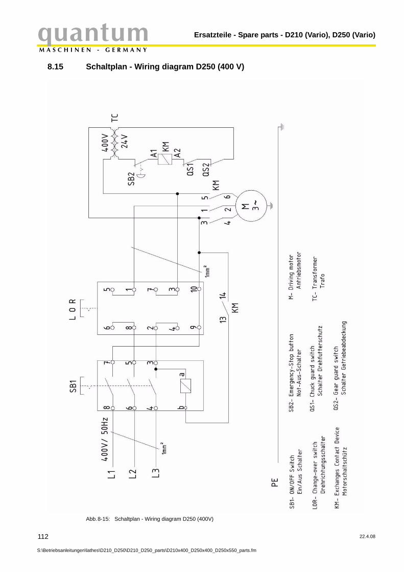
Ersatzteile - Spare parts - D210 (Vario), D250 (Vario)quantumM A S C H I N E N - G E R M A N Y
8.15 Schaltplan - Wiring diagram D250 (400 V)
112
S:\Betriebsanleitunge
Abb.8-15: Schaltplan - Wiring diagram D250 (400V)
n\lathes\D210_D250\D210_D250_parts\D210x400_D250x400_D250x550_parts.fm
22.4.08
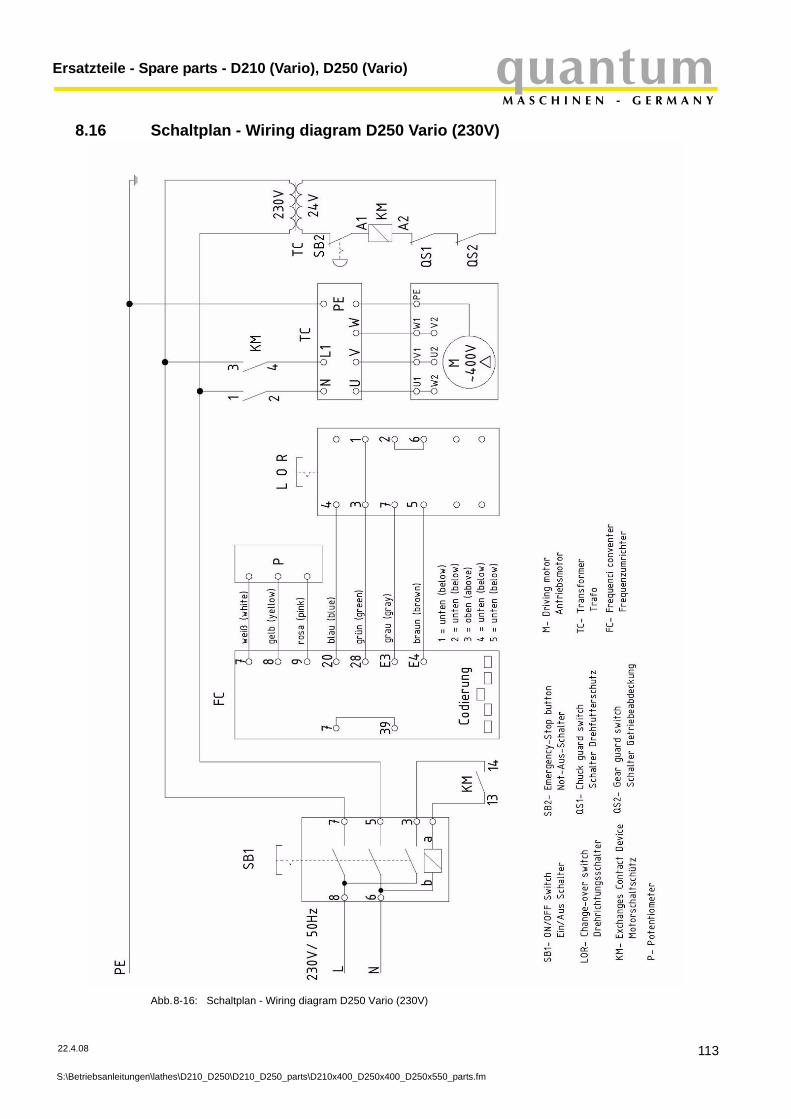
quantumM A S C H I N E N - G E R M A N Y
Ersatzteile - Spare parts - D210 (Vario), D250 (Vario)
8.16 Schaltplan - Wiring diagram D250 Vario (230V)
Abb.8-16: Schaltplan - Wiring diagram D250 Vario (230V)
22.4.08
S:\Betriebsanleitung
en\lathes\D210_D250\D210_D250_parts\D210x400_D250x400_D250x550_parts.fm113
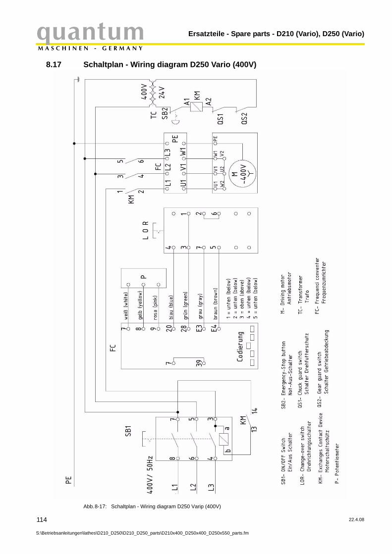
Ersatzteile - Spare parts - D210 (Vario), D250 (Vario)quantumM A S C H I N E N - G E R M A N Y
8.17 Schaltplan - Wiring diagram D250 Vario (400V)
Abb.8-17: Schaltplan - Wiring diagram D250 Varip (400V)
114
S:\Betriebsanleitungen\lathes\D210_D250\D210_D250_parts\D210x400_D250x400_D250x550_parts.fm
22.4.08
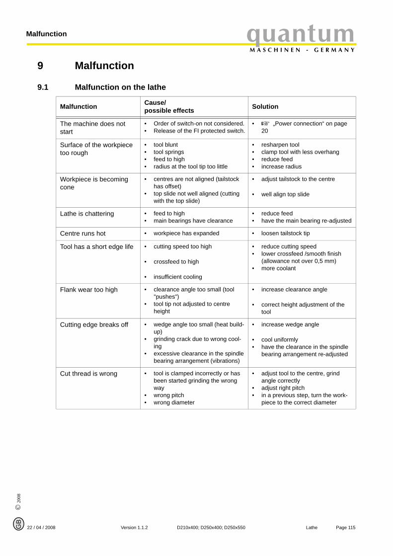
© 2
008
GB
Page 11522 / 04 / 2008 Version 1.1.2 D210x400; D250x400; D250x550 Lathe
quantumM A S C H I N E N - G E R M A N Y
Malfunction
9 Malfunction
9.1 Malfunction on the lathe
Malfunction Cause/possible effects Solution
The machine does not start
• Order of switch-on not considered.• Release of the FI protected switch.
• „Power connection“ on page 20
Surface of the workpiece too rough
• tool blunt• tool springs• feed to high• radius at the tool tip too little
• resharpen tool• clamp tool with less overhang• reduce feed• increase radius
Workpiece is becoming cone
• centres are not aligned (tailstock has offset)
• top slide not well aligned (cutting with the top slide)
• adjust tailstock to the centre
• well align top slide
Lathe is chattering • feed to high• main bearings have clearance
• reduce feed• have the main bearing re-adjusted
Centre runs hot • workpiece has expanded • loosen tailstock tip
Tool has a short edge life • cutting speed too high
• crossfeed to high
• insufficient cooling
• reduce cutting speed• lower crossfeed /smooth finish
(allowance not over 0,5 mm)• more coolant
Flank wear too high • clearance angle too small (tool "pushes")
• tool tip not adjusted to centre height
• increase clearance angle
• correct height adjustment of the tool
Cutting edge breaks off • wedge angle too small (heat build-up)
• grinding crack due to wrong cool-ing
• excessive clearance in the spindle bearing arrangement (vibrations)
• increase wedge angle
• cool uniformly• have the clearance in the spindle
bearing arrangement re-adjusted
Cut thread is wrong • tool is clamped incorrectly or has been started grinding the wrong way
• wrong pitch• wrong diameter
• adjust tool to the centre, grind angle correctly
• adjust right pitch• in a previous step, turn the work-
piece to the correct diameter
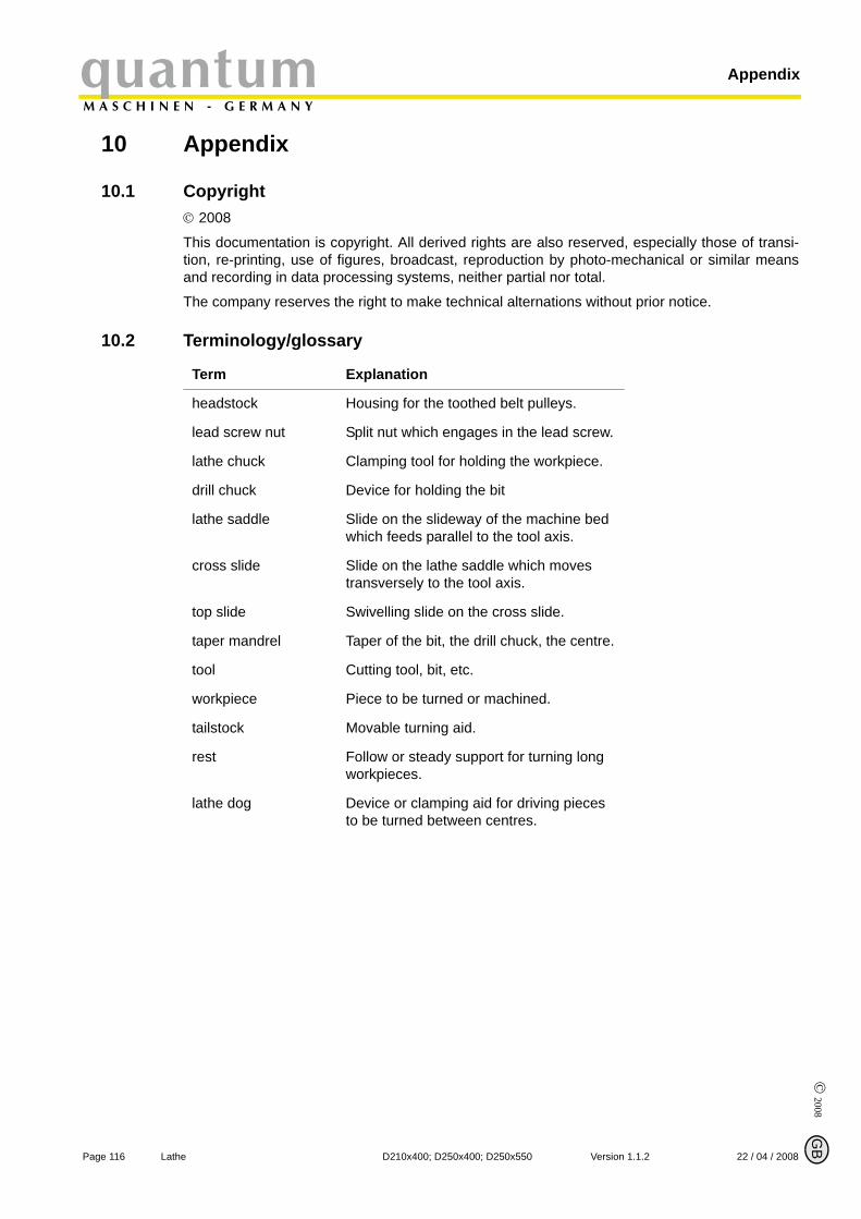
© 2008
GB
Page 116 Lathe D210x400; D250x400; D250x550 Version 1.1.2 22 / 04 / 2008
AppendixquantumM A S C H I N E N - G E R M A N Y
10 Appendix
10.1 Copyright© 2008
This documentation is copyright. All derived rights are also reserved, especially those of transi-tion, re-printing, use of figures, broadcast, reproduction by photo-mechanical or similar meansand recording in data processing systems, neither partial nor total.
The company reserves the right to make technical alternations without prior notice.
10.2 Terminology/glossary
Term Explanation
headstock Housing for the toothed belt pulleys.
lead screw nut Split nut which engages in the lead screw.
lathe chuck Clamping tool for holding the workpiece.
drill chuck Device for holding the bit
lathe saddle Slide on the slideway of the machine bed which feeds parallel to the tool axis.
cross slide Slide on the lathe saddle which moves transversely to the tool axis.
top slide Swivelling slide on the cross slide.
taper mandrel Taper of the bit, the drill chuck, the centre.
tool Cutting tool, bit, etc.
workpiece Piece to be turned or machined.
tailstock Movable turning aid.
rest Follow or steady support for turning long workpieces.
lathe dog Device or clamping aid for driving pieces to be turned between centres.

© 2
008
GB
Page 11722 / 04 / 2008 Version 1.1.2 D210x400; D250x400; D250x550 Lathe
quantumM A S C H I N E N - G E R M A N Y
Appendix
10.3 Product follow-upWe are required to perform a follow-up service for our products which extends beyond shipment.
We would be grateful if you could send us the following information:
modified settingsexperiences with the lathe, which could be important for other usersrecurring failures
Optimum Maschinen Germany GmbHDr.-Robert-Pfleger-Str. 26
D-96103 Hallstadt
Fax: +49 (0) 951 - 96 822 - 22E-Mail: [email protected]

© 2008
GB
Page 118 Lathe D210x400; D250x400; D250x550 Version 1.1.2 22 / 04 / 2008
AppendixquantumM A S C H I N E N - G E R M A N Y
10.4 WarrantyWithin the term of warranty, the company Optimum warrants for a perfect quality of its productsand will reimburse any cost for overhaul or exchange of defective parts in case of constructionerror, fault in material and / or defect fabrication.
The term of warranty for commercial use is 12 months and for use as an amateur it is 24months. Condition for a warranty claim due to construction errors, faults in material and / ordefects of fabrication is:
Proof of purchase and that the instructions for use had been followed.In order to assert the claim of warranty, you have to present a typescript original receipt of purchase. It must comprise the complete address, date of purchase and type designation of the product.The instruction for use for the corresponding device as well as the safety information are to be observed. Damages due to operator’s mistakes may not be accepted as warranty claims.Correct use of the devices.The products of the company Optimum had been designed and built for certain purposes. They are listed in the operation manual.The warranty claim may not be accepted if the operating manual is not being followed prop-erly or if it is used for a purpose which has not been intended or with improper accessory.Maintenance work and cleaning.It is absolutely necessary to maintain and clean the machine in regular intervals according to the prescriptions of the instruction for use.In case of intervention of a third party, any warranty claim will expire. Maintenance work and cleaning are usually not part of the claim of warranty.Original spare partsMake sure to use only original spare parts and original accessory. This can be acquired from authorized distributors of the machine.When other than original parts are being used, consequential damages may occur and dan-ger of accidents will increase. Disassembled or partially disassembled devices and devices which are repaired with foreign parts are excluded from warranty claims.
10.5 DisposalDisposal of used electric and electronic machines(Applicable in the countries of the European Union and other European countries with a sepa-rate collecting system for those devices).
The sign on the product or on its packing indicates that the product must not be handled as common household waist, but that it needs to be delivered to a central collection point for recycling. Your contribution to the correct disposal of this product will protect the environ-ment and the health of your fellow men. The environment and the health are endangered by incorrect disposal. Recycling of material will help to reduce the consumption of raw materials. Your District Office, the municipal waste collection station or the shop where you have bought the product will inform you about the recycling of this product.
© 2
008
GB
Page 11922 / 04 / 2008 Version 1.1.2 D210x400; D250x400; D250x550 Lathe
quantumM A S C H I N E N - G E R M A N Y
Appendix
10.6 EC - declaration of conformitythe manufacturer /retailer:
Optimum Maschinen Germany GmbHDr.-Robert-Pfleger-Str. 26D-96103 Hallstadt
hereby declares that the following product,
type of machine: Lathe
designation of machine: D210x400D210x400 VarioD250x400D250x400 VarioD250x550D250x550 Vario
relevant EU directives:
machine directive: 98/37/EG, appendix II A
EEC directive 89/336/EWG
low voltage directive 73/23/EWG
meets the provisions of the aforementioned directive, including any amendments valid at the time of this statement.
In order to ensure conformity, the following harmonized standards in particular have been applied:
DIN EN 12840: 06/2001 safety of machine tools - manually controlled lathes with or without automatic control.
DIN 45635-1601 09/1978 Noise measurement to machines. Airborne sound measurement, machine tools for metal processing. Special determination for lathes.
DIN EN 62079:2001(VDE 0039)IEC 62079:2001
Setting up instructions - structure, content and presentation
Hallstadt, 22. April 2008
Kilian Stürmer(Manager)
Thomas Collrep(Manager)

© 2008
GB
Seite 120 Lathe D210x400; D250x400; D250x550 Version 1.1.2 Stand 22 / 04 / 2008
quantumM A S C H I N E N - G E R M A N Y
Index
AAdjusting the speed ....................................... 30Assembly change gears ................................ 69Assembly plan
D210 x 400 ............................................. 17D250 x 400 ............................................. 18D250 x 550 ............................................. 19
BBritish threads ............................................... 53CChange gears metric threads ........................ 85Cones ............................................................ 59Cross-adjustment of the tailstock .................. 34Cutter ............................................................ 46Cutting material ............................................. 62Cutting off ...................................................... 57Cutting speed ................................................ 63Cutting speed table ....................................... 64Ddeclaration of conformity ............................. 119Determination of modules of toothed wheels 71EEC - declaration of conformity ..................... 119External threads, Internal threads ................. 49GGrinding of cutting edge geometries ............. 64MMetric thread ................................................. 52OOperating signs ............................................. 28Operation ...................................................... 27Outside machining ........................................ 48PProtective cover ............................................ 11RRecessing ..................................................... 57SSpeed table D 210 x 400 ............................... 31Speed table D 210 x 400 Vario ..................... 32Speed table D 250 Vario ............................... 32Speed table D 250 x 550 ............................... 31TTable of the gear wheels ............................... 71Tables of gear wheels inch treads ................ 72Thread types ................................................. 50Turning .......................................................... 43Turning cones ............................................... 59Turning off ..................................................... 57