Embed Size (px)
Citation preview
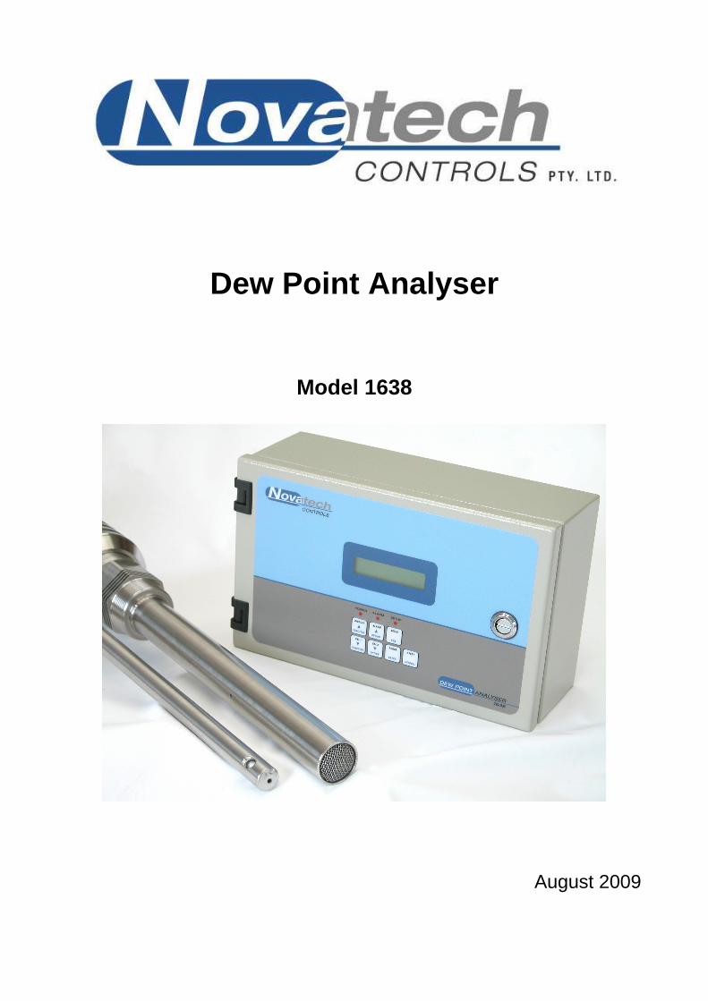
Dew Point Analyser
Model 1638
August 2009

August 2009 1638 Dew Point Analyser 1
CONTENTS 1 SPECIFICATIONS .......................................................................................................................... 3 2 DESCRIPTION .............................................................................................................................. 13 3 INSTALLING & COMMISSIONING .......................................................................................... 19 4 OPERATOR FUNCTIONS ........................................................................................................... 33 5 SETTING UP THE TRANSMITTER ........................................................................................... 39 6 MAINTENANCE ........................................................................................................................... 57 APPENDICES APPENDIX 1 PROBE OR SENSOR EMF TABLES ............................................................................. 62 APPENDIX 2 % OXYGEN SCALE TO LOGARITHMIC .................................................................... 65 APPENDIX 3 SAMPLE LOG PRINT OUT ........................................................................................... 66 APPENDIX 4 CIRCUIT SCHEMATICS ................................................................................................ 67 APPENDIX 5 MODBUS™ REGISTER MAP AND APPLICATION NOTES ..................................... 76 Note: This manual includes software modifications up to Version 8.11, May, 2006
© Copyright NOVATECH CONTROLS PTY. LTD. - 1996 - 2008 This manual is part of the product sold by Novatech Controls Pty. Ltd. ("Novatech Controls") and is provided to the customer subject to Novatech Controls' conditions of sale, a copy of which is set out herein. Novatech Controls' liability for the product including the contents of this manual is as set out in the conditions of sale. All maintenance and service of the product should be carried out by Novatech Controls' authorised dealers. This manual is intended only to assist the reader in the use of the products. This manual is provided in good faith but Novatech Controls does not warrant or represent that the contents of this manual are correct or accurate. It is the responsibility of the owner of the product to ensure users take care in familiarising themselves in the use, operation and performance of the product. The product, including this manual and products for use with it, are subject to continuous developments and improvement by Novatech Controls. All information of a technical nature and particulars of the product and its use (including the information in this manual) may be changed by Novatech Controls at any time without notice and without incurring any obligation. A list of details of any amendments or revisions to this manual can be obtained upon request from Novatech Controls. Novatech Controls welcome comments and suggestions relating to the product including this manual. Neither the whole nor any part of the information contained in, or the product described in, this manual may be adapted or reproduced in any material form except with the prior written approval of Novatech Controls Pty. Ltd. All correspondence should be addressed to: Technical Enquires Novatech Controls Pty Ltd 309 Reserve Road Cheltenham Victoria 3192 Phone: Melbourne +61 3 9585 2833 Australia Fax: Melbourne +61 3 9585 2844 Website: http://www.novatech.com.au/
August 2009 2 1638 Dew Point Analyser
USING THIS MANUAL The Novatech 1638 Oxygen Transmitter has a variety of user-selectable functions. They are simple to use because each selection is menu driven. For options you are not sure about; read the manual on that particular item. Please read the safety information below and the ‘Installation’ section before connecting power to the analyser.
CAUTION 1 The probe or sensor heater is supplied with mains voltage. This supply has electrical shock danger to maintenance personnel. Always isolate the analyser before working with the probe or sensor. The EARTH wire (green) from a heated probe or sensor must ALWAYS be connected to earth.
CAUTION 2 Combustion or atmosphere control systems can be dangerous. Burners must be mechanically set up so that in the worst case of equipment failure, the system cannot generate explosive atmospheres. This danger is normally avoided with flue gas trim systems by adjustment so that in the case of failure the appliance will not generate CO in excess of 400 ppm in the flue. The CO level in the flue should be measured with a separate CO instrument, normally an infrared or cell type.
CAUTION 3 The oxygen sensor which is heated to over 700°C (1300°F) and is a source of ignition. Since raw fuel leaks can occur during burner shutdown, the analyser has an interlocking relay that removes power from the probe or sensor heater when the main fuel shut-off valve power is off. If this configuration does not suit or if it is possible for raw fuel to come into contact with a hot oxygen probe or sensor then the Model 1638 analyser with a heated probe or sensor will not be safe in your application. An unheated probe can be utilised in such applications, however the oxygen readings are valid only above 650°C (1200°F).
August 2009 1638 Dew Point Analyser 3
1 SPECIFICATIONS Section Number 1.1 MODEL 1638 OXYGEN & DEW POINT ANALYSER ................................................................. 4 1.2 SERIES 1230 OXYGEN PROBES & SENSORS ............................................................................ 7 1.3 PURGE & CALIBRATION CHECK ACCESSORIES .................................................................. 11 1.4 FILTER PURGE PRESSURE SWITCH ........................................................................................ 11
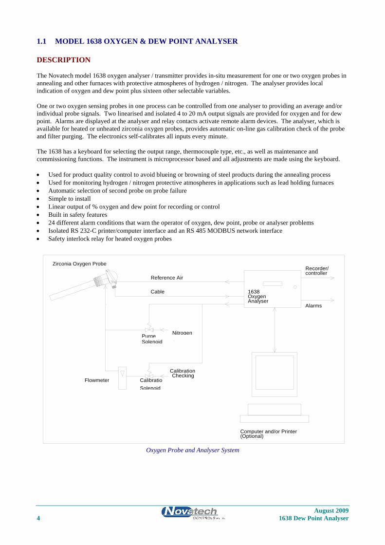
1.1 MODEL 1638 OXYGEN & DEW POINT ANALYSER DESCRIPTION The Novatech model 1638 oxygen analyser / transmitter provides in-situ measurement for one or two oxygen probes in annealing and other furnaces with protective atmospheres of hydrogen / nitrogen. The analyser provides local indication of oxygen and dew point plus sixteen other selectable variables. One or two oxygen sensing probes in one process can be controlled from one analyser to providing an average and/or individual probe signals. Two linearised and isolated 4 to 20 mA output signals are provided for oxygen and for dew point. Alarms are displayed at the analyser and relay contacts activate remote alarm devices. The analyser, which is available for heated or unheated zirconia oxygen probes, provides automatic on-line gas calibration check of the probe and filter purging. The electronics self-calibrates all inputs every minute. The 1638 has a keyboard for selecting the output range, thermocouple type, etc., as well as maintenance and commissioning functions. The instrument is microprocessor based and all adjustments are made using the keyboard. • Used for product quality control to avoid blueing or browning of steel products during the annealing process • Used for monitoring hydrogen / nitrogen protective atmospheres in applications such as lead holding furnaces • Automatic selection of second probe on probe failure • Simple to install • Linear output of % oxygen and dew point for recording or control • Built in safety features • 24 different alarm conditions that warn the operator of oxygen, dew point, probe or analyser problems • Isolated RS 232-C printer/computer interface and an RS 485 MODBUS network interface • Safety interlock relay for heated oxygen probes
REF
1638Oxygen Analyser
Computer and/or Printer (Optional)
Reference Air
Nitrogen
Flowmeter
CalibrationChecking
CalibratioSolenoid
PurgeSolenoid
Zirconia Oxygen Probe Recorder/controller
Alarms
Cable
Oxygen Probe and Analyser System
August 2009 4 1638 Dew Point Analyser
August 2009 1638 Dew Point Analyser 5
SPECIFICATIONS Inputs • Zirconia oxygen probe, heated or unheated • Furnace thermocouple, field selectable as type K or R • Process purge complete / main flame established safety interlock (for heated probes) • Purge pressure switch • Remote alarm accept Outputs • Two linearised 4 to 20 mA DC outputs, max. load 1000Ω • Common alarm relay • Three other alarm relays with selectable functions Computer • RS 232-C or RS 485 for connection of a computer terminal or printer for diagnostics of the analyser, sensing
probe, or process. This connection is suitable for network connection to computers, DCSs or PLCs using MODBUS protocol.
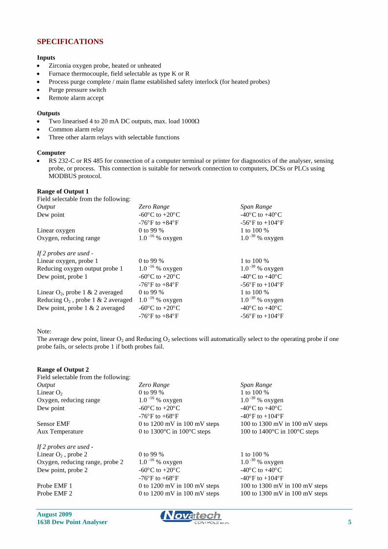
Range of Output 1 Field selectable from the following: Output Zero Range Span Range Dew point -60°C to +20°C -40°C to +40°C -76°F to +84°F -56°F to +104°F Linear oxygen 0 to 99 % 1 to 100 % Oxygen, reducing range 1.0 -16 % oxygen 1.0 -30 % oxygen If 2 probes are used - Linear oxygen, probe 1 0 to 99 % 1 to 100 % Reducing oxygen output probe 1 1.0 -16 % oxygen 1.0 -30 % oxygen Dew point, probe 1 -60°C to +20°C -40°C to +40°C -76°F to +84°F -56°F to +104°F Linear O2, probe 1 & 2 averaged 0 to 99 % 1 to 100 % Reducing O2 , probe 1 & 2 averaged 1.0 -16 % oxygen 1.0 -30 % oxygen Dew point, probe 1 & 2 averaged -60°C to +20°C -40°C to +40°C -76°F to +84°F -56°F to +104°F Note: The average dew point, linear O2 and Reducing O2 selections will automatically select to the operating probe if one probe fails, or selects probe 1 if both probes fail. Range of Output 2 Field selectable from the following: Output Zero Range Span Range Linear O2 0 to 99 % 1 to 100 % Oxygen, reducing range 1.0 -16 % oxygen 1.0 -30 % oxygen Dew point -60°C to +20°C -40°C to +40°C -76°F to +68°F -40°F to +104°F Sensor EMF 0 to 1200 mV in 100 mV steps 100 to 1300 mV in 100 mV steps Aux Temperature 0 to 1300°C in 100°C steps 100 to 1400°C in 100°C steps If 2 probes are used - Linear O2 , probe 2 0 to 99 % 1 to 100 % Oxygen, reducing range, probe 2 1.0 -16 % oxygen 1.0 -30 % oxygen Dew point, probe 2 -60°C to +20°C -40°C to +40°C -76°F to +68°F -40°F to +104°F Probe EMF 1 0 to 1200 mV in 100 mV steps 100 to 1300 mV in 100 mV steps Probe EMF 2 0 to 1200 mV in 100 mV steps 100 to 1300 mV in 100 mV steps
August 2009 6 1638 Dew Point Analyser
Range of Indication, Upper Line • Oxygen auto ranging from 10-30 to 100 % • Dew point -60 °C to +40 °C, -76 °F to +104 °F Indication Choice, Lower Line Any or all of the following can be selected for lower line display: • Dew point probe 1 • Dew point probe 2 ** • Dew point probe 1 and 2 averaged ** • Date - time • Run Hours since last service • Date of last service • Oxygen probe 2 ** • Oxygen probe 1 and 2 averaged ** • Probe EMF 1 • Probe EMF 2 ** • Temperature probe 1 • Auxiliary Temperature * • Temperature probe 2 ** • Impedance probe 1 • Impedance probe 2 ** • Ambient Temperature • Ambient Relative Humidity * If the analyser is enabled for 1 probe ** If the analyser is enabled for 2 probes Accuracy • ±1% of actual measured oxygen value with a repeatability of ±0.5% of measured value. Relay Contacts • 0.5A 24 VAC, 1A 36 VDC Environmental Rating • Operating Temperature: -25 to 55°C • Relative Humidity: 5 to 95% (non-condensing) • Vibration: 10 to 150Hz (2g peak) Power Requirements • 240 or 110V, 50/60 Hz, 105 VA (heated probe) • 240 or 110V, 50/60 Hz, 5 VA (unheated probe) Weight • Analyser, 3.75 kg Degree of Protection • IP65 without reference air pump • IP54 with reference air pump Mounting • Suitable for wall or surface mounting.
1.2 SERIES 1230 OXYGEN PROBES & SENSORS DESCRIPTION Novatech series 1230 oxygen probes and sensors employ state-of-the-art zirconia sensors and advanced materials, which provide the following benefits: • Improved control due to fast response time to typically less than four seconds • Cost-efficient design provides improved reliability • Longer-life probes with greater resistance to corrosion from sulphur and zinc contaminants in flue gas • Low cost allows maintenance by replacement • Reduced probe breakage due to greater resistance to thermal shock and mechanical damage during installation and
start-up • Series 1230 probes are simple to install and maintain. All models provide direct measurement of oxygen level.
On-line automatic calibration check is available if required. Probes may be used with Novatech combustion controllers and some analyser models from other manufacturers.
All Novatech oxygen probes are designed and manufactured to exacting standards of performance and reliability. Series 1230 probes are the result of extensive research and development by Novatech, industry and government agencies. Novatech Controls provides application and after sales support for oxygen probes, sensors and analysers, worldwide.
Model 1231 Heated Oxygen Probe
Model 1232 Unheated Oxygen Probe
August 2009 1638 Dew Point Analyser 7
E X HA U ST
1234 OXYGEN SENSOR
N OV A T EC H C ON T R OL S
CABLE GLAN D
ID LABEL
EXHAUST 1/4" NPT FEMALE
GAS INLET 1/4" TUBE ELBOW
Model 1234 Oxygen Sensor
STANDARD PROBE ‘U’ LENGTHS 1231 1232 250 mm (10”) 500 mm (20”) 350 mm (14”) 750 mm (30”) 500 mm (20”) 1000 mm (40”) 750 mm (30”) 1500 mm (60”) 1000 mm (40”) 1500 mm (60”) 2000 mm (80”)
Ordering Information 1. Probe insertion length (from process end of mounting thread to probe sensing tip). 2. Mounting thread (process connection), BSP or NPT (for size of thread refer to specifications). 3. Lagging extension length, if required. 4. If model 1232 probe, state preferred thermocouple type (refer to specifications).
August 2009 8 1638 Dew Point Analyser
August 2009 1638 Dew Point Analyser 9
OXYGEN PROBE SPECIFICATIONS
MODEL 1231 1232 Application Furnaces operating Furnaces operating below 900°C above 700°C with refer to note 1 no contaminants. Temperature Range 0 to 900°C 700 to 1400°C (0 to 500°C with filter fitted) Length 250 to 2000 mm 500 to 1000 mm Process 1 1/2" BSP 3/4" BSP Connection or NPT or NT Electrical Weather-proof plug-in connector or optional screw terminals. The plug connector is Connection supplied with the cable. Ex(e) heads have screw terminals. Cable Order a specific length with the analyser except for hazardous installations where the cable is supplied by the customer. Heater Yes No Furnace Thermocouple Refer to note 3 R or S, integral Response Time Typically < 4 secs. Typically < 1 sec Head Temperature -25 to 100°C with weatherproof connector -25 to 150°C with screw terminals Reference Gas Ambient air 50 cc/min approx. Pump supplied with analyser Ref Air Connection 1/4" Tube Integral air line in probe cable or external ¼” tube. Optional Filter Sintered titanium alloy particulate filter, replaceable, 30 or 15 micron. Calibration Check Gas 1/8" NPT female 1/8" NPT female Connection Weight 2 kg plus 165 g / 100 mm 1 kg plus 100 g / 100 mm Notes: 1. Care must be taken to avoid contact with explosive or inflammable gases with 1231 heated probes. Novatech
analysers have built in safety protection. 2. Please contact factory for corrosives other than sulphur or zinc. We can provide test materials to try in your
atmosphere.
August 2009 10 1638 Dew Point Analyser
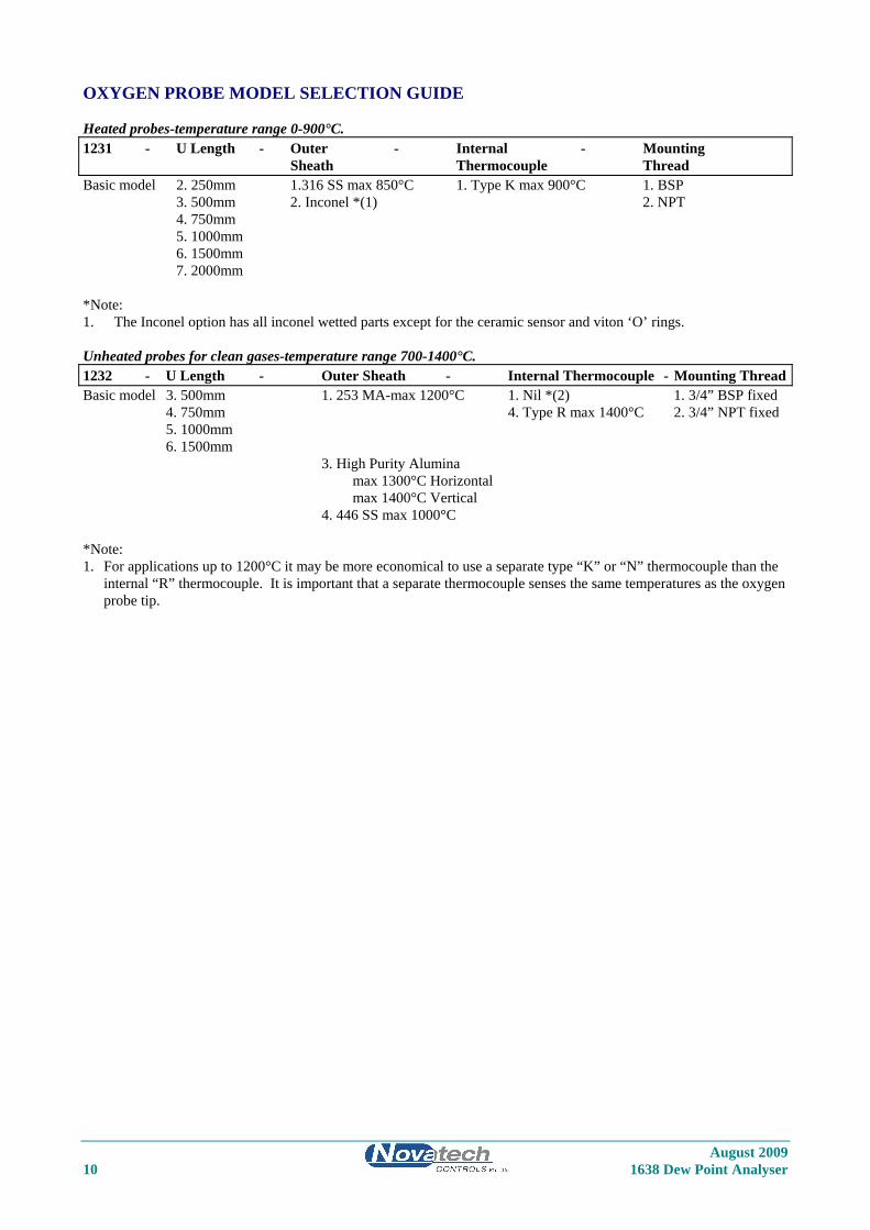
OXYGEN PROBE MODEL SELECTION GUIDE Heated probes-temperature range 0-900°C. 1231 - U Length - Outer - Internal - Mounting Sheath Thermocouple Thread Basic model 2. 250mm 1.316 SS max 850°C 1. Type K max 900°C 1. BSP 3. 500mm 2. Inconel *(1) 2. NPT 4. 750mm 5. 1000mm 6. 1500mm 7. 2000mm *Note: 1. The Inconel option has all inconel wetted parts except for the ceramic sensor and viton ‘O’ rings. Unheated probes for clean gases-temperature range 700-1400°C. 1232 - U Length - Outer Sheath - Internal Thermocouple - Mounting Thread Basic model 3. 500mm 1. 253 MA-max 1200°C 1. Nil *(2) 1. 3/4” BSP fixed 4. 750mm 4. Type R max 1400°C 2. 3/4” NPT fixed 5. 1000mm 6. 1500mm 3. High Purity Alumina max 1300°C Horizontal max 1400°C Vertical 4. 446 SS max 1000°C *Note: 1. For applications up to 1200°C it may be more economical to use a separate type “K” or “N” thermocouple than the
internal “R” thermocouple. It is important that a separate thermocouple senses the same temperatures as the oxygen probe tip.

August 2009 1638 Dew Point Analyser 11
1.3 PURGE & CALIBRATION CHECK ACCESSORIES Due to the absolute measurement characteristics of zirconia sensors and the self calibration features of Novatech analysers, probe calibration checks with calibrated gas are not normally required. In some installations however customers prefer the have a calibration check facility. Novatech probes and analysers provide a ready method of connecting on-line calibration check gases. They provide on-line automatic checking of probe and analyser calibration, as well as a probe purge facility. The absolute characteristics of zirconia sensors require only one calibration check gas to properly check the probe’s performance. Where required however, the dual gas calibration check facility can be utilised. Dirty furnace applications often require the back purge facility to keep a probe filter free from blockage. (In these applications, it is more reliable to install probes pointing vertically downwards with no filter). Purge and calibration check solenoid valves can be operated manually or automatically from a 1638 analyser. The external components required for automatic / manual gas calibration checking are: • A calibration check gas flow meter/regulator • A mains voltage (240 or 110 VAC) solenoid valve for each calibration check gas The external components required for automatic / manual purging are: • A mains voltage (240 or 110 VAC) purge solenoid valve • A purge pressure switch, 0 to 35 kPa (0 to 5 psi), to test for filter blockage. The user should supply: • Span gas cylinder(s), typically 2 % oxygen in nitrogen or a similar percentage of 02 close to the normal level in the
gas stream being measured, to ensure fast recovery. • A 100 kPa (15 psi) clean and dry nitrogen supply when filter purging is required.
1.4 FILTER PURGE PRESSURE SWITCH To automatically sense a blocked probe filter, a pressure sensor should be connected to the ‘purge’ line to the probe ‘cal’ port. It should be adjusted so that it energises just above the purge pressure with a new or clean filter installed. The switch contacts should be connected to terminals 12 & 13 (PURGE FL SWITCH). If the filter is still blocked or partly blocked after an auto purge cycle, the pressure switch will energise and cause a ‘Probe Filter Blocked’ alarm. The contacts must be normally closed. The pressure switch should have an adjustable range of 0 to 35 kPa (0 to 5 psi).

August 2009 12 1638 Dew Point Analyser
August 2009 1638 Dew Point Analyser 13
2 DESCRIPTION Section Number 2.1 THE ANNEALING PROCESS (OR OTHER SIMILAR APPLICATIONS) ................................ 14 2.2 THE OBJECTIVE OF ATMOSPHERE MONITORING............................................................... 14 2.3 WHAT DO WE NEED TO MEASURE? ....................................................................................... 14 2.4 ZIRCONIA OXYGEN PROBE MEASUREMENT ....................................................................... 14 2.5 OTHER TYPES OF OXYGEN MEASUREMENT ....................................................................... 14 2.6 DEW POINT MEASUREMENT .................................................................................................... 14 2.7 IN-SITU OXYGEN PROBES ........................................................................................................ 14 2.8 THE ZIRCONIA SENSOR ............................................................................................................. 15 2.9 THE ANALYSER ........................................................................................................................... 16 2.10 ALARMS ........................................................................................................................................ 16 2.11 HEATER ......................................................................................................................................... 16 2.12 APPLICATIONS WHERE SENSING POINT IS NOT AT ATMOSPHERIC PRESSURE ......... 16 2.13 PROBE IMPEDANCE .................................................................................................................... 16 2.14 AUTO CALIBRATION – ELECTRONICS ................................................................................... 16 2.15 AUTO CALIBRATION CHECKING – PROBES ......................................................................... 17 2.16 AUTO PURGE ................................................................................................................................ 17 2.17 RS 485 AND RS 232C PORT ......................................................................................................... 17 2.18 AUXILIARY TEMPERATURE THERMOCOUPLE ................................................................... 17 2.19 WATCHDOG TIMER .................................................................................................................... 17 2.20 BACK-UP BATTERY .................................................................................................................... 17
August 2009 14 1638 Dew Point Analyser
DESCRIPTION
2.1 THE ANNEALING PROCESS (OR OTHER SIMILAR APPLICATIONS) The annealing process is carried out in an atmosphere of hydrogen and nitrogen to protect the surface of the steel from oxidising and discolouring during the annealing process. There is usually some air leakage in a furnace and the hydrogen serves to “mop up” the oxygen by combining with it to form water vapour.
2.2 THE OBJECTIVE OF ATMOSPHERE MONITORING The primary objective of monitoring the furnace atmosphere is to be able to measure whether the steel product in the furnace will become oxidised during the process and to raise an alarm to warn the operator that there is a problem.
2.3 WHAT DO WE NEED TO MEASURE? The variable that we need to measure to monitor the atmosphere to prevent oxidation of the product is the oxygen partial pressure at the surface of the steel. At any particular furnace temperature, there is a unique oxygen partial pressure, above which the steel will tend to oxidise and below which no oxidation will occur. The steel acts as a catalyst in the hydrogen / nitrogen bringing the gas at the surface close to chemical equilibrium. The composition of the gas at the surface is normally different from that of the gas nearby. For example, trace oxygen is quickly converted to water vapour. In the gas, a reaction to form water vapour requires collisions involving two hydrogen molecules and one oxygen molecule, the probability of which is low. On the surface of the steel, one or the other of the molecules becomes partly immobilised. This increases the probability of successful collisions to form water vapour. Essentially, gas molecules are held on the steel surface, waiting for the complementary molecule(s) to arrive.
2.4 ZIRCONIA OXYGEN PROBE MEASUREMENT The catalytic process which occurs on the surface of the steel also occurs on a zirconia oxygen sensor. This means that the measurement of the oxygen level with a zirconia oxygen sensor exactly duplicates the equilibrium conditions of the gas at the surface of the steel. It measures the oxidation potential of the gas or its potential to damage or discolour the steel.
2.5 OTHER TYPES OF OXYGEN MEASUREMENT Other types of oxygen analysers such as a paramagnetic analyser measure the unreacted molecular level of oxygen in the furnace atmosphere, which has no direct thermodynamic relationship with the effect of the gas on the steel. These analysers are not useful for measuring the oxidation potential in annealing furnace atmospheres.
2.6 DEW POINT MEASUREMENT Dew point measurement was commonly used in the past because dew point analysers were the only technology available at the time. Dew point can be related to the oxidation potential of the furnace atmosphere but the relationship depends on how much hydrogen is available at the surface of the steel. With dew point held constant, if the hydrogen level varies, so will the oxidation potential of the atmosphere. Dew point measurement is not the best method of measurement because of this. Also dew point instruments normally have limited reliability in on-line applications on annealing furnaces. With a known hydrogen level, the dew point in the furnace can be calculated. This is provided as an output on a standard Novatech 1638 analyser but we recommend the use of the oxygen output from the same analyser. Both outputs are available simultaneously for operators who are more used to furnace dew point levels. The dew point output however is only an approximate guide if the hydrogen level in the furnace varies.
2.7 IN-SITU OXYGEN PROBES There are very few oxygen probes on the market, which can operate reliably in an annealing furnace atmosphere at furnace temperatures. Novatech probes have been developed in co-operation with BHP steel for annealing furnace applications to provide a reliable measurement for monitoring both continuous and batch furnaces. BHP now have 60 Novatech probes and analysers installed to protect their products during the annealing process. These sensing probes give long life with no need for calibration. The most important feature however is that Novatech oxygen probes measure the oxygen partial pressure just as it occurs at the surface of the steel.
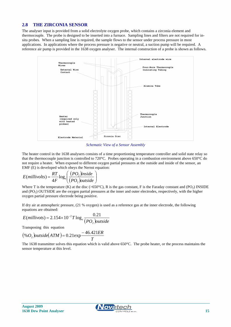
2.8 THE ZIRCONIA SENSOR The analyser input is provided from a solid electrolyte oxygen probe, which contains a zirconia element and thermocouple. The probe is designed to be inserted into a furnace. Sampling lines and filters are not required for in-situ probes. When a sampling line is required, the sample flows to the sensor under process pressure in most applications. In applications where the process pressure is negative or neutral, a suction pump will be required. A reference air pump is provided in the 1638 oxygen analyser. The internal construction of a probe is shown as follows.
Internal electrode wire
Ziconia Disc
ThermocoupleWires
Electrode Material
(required onlyHeater
with heatedprobes)
External Wire Contact
ThermocoupleJunction
Internal Electrode
Four-Bore ThermocoupleInsulating Tubing
Alumina Tube
Schematic View of a Sensor Assembly
The heater control in the 1638 analysers consists of a time proportioning temperature controller and solid state relay so that the thermocouple junction is controlled to 720°C. Probes operating in a combustion environment above 650°C do not require a heater. When exposed to different oxygen partial pressures at the outside and inside of the sensor, an EMF (E) is developed which obeys the Nernst equation:
( )( ) ⎟⎟
⎠
⎞⎜⎜⎝
⎛=
outsidePOinsidePO
FRTmillivoltsE e
2
2log4
)(
Where T is the temperature (K) at the disc (>650°C), R is the gas constant, F is the Faraday constant and (PO2) INSIDE and (PO2) OUTSIDE are the oxygen partial pressures at the inner and outer electrodes, respectively, with the higher oxygen partial pressure electrode being positive. If dry air at atmospheric pressure, (21 % oxygen) is used as a reference gas at the inner electrode, the following equations are obtained:
( )outsidePOTmillivotsE e
2
2 21.0log10154.2)( −×=
Transposing this equation
( ) ( )T
ERATMoutsideO 421.46exp21.0% 2−
=
The 1638 transmitter solves this equation which is valid above 650°C. The probe heater, or the process maintains the sensor temperature at this level.
August 2009 1638 Dew Point Analyser 15
August 2009 16 1638 Dew Point Analyser
2.9 THE ANALYSER The 1638 analyser is a transmitter with two 4 to 20 mA outputs. One output is % oxygen or dew point with selectable zero and span. The second output can be selected as dew point, oxygen, auxiliary temperature or sensor EMF. Four alarm relays are provided. Refer to the sections 4.2 and 4.3 for more details. The 1638 analyser is designed to operate with either one or two heated or unheated, zirconia probes in one process. If two probes are being used, the analyser can average the two oxygen and dew point signals, alarm when there is a high difference, transmit and display the average and/or individual oxygen signals. If heated probes are being used, the analyser will maintain the temperature of the sensor(s) at 720°C. The analyser solves the Nernst equation and will provide accurate oxygen measurements up to 1500°C (2730°F), although most probes are suitable only to 1400°C (2250°F). 1231 heated probes are limited to 900°C (1650°F).
2.10 ALARMS Refer to OPERATOR FUNCTIONS Section 4 for details on alarm functions.
2.11 HEATER CAUTION
The probe heater is supplied with mains voltage. This supply has electrical shock danger to maintenance personnel. Always isolate the analyser before working with the probe.
The EARTH wire (green) from the probe / sensor must always be connected to earth. The heater is supplied from the mains power directly, and the temperature is controlled initially at over 700°C (1300°F) after turn on.
2.12 APPLICATIONS WHERE SENSING POINT IS NOT AT ATMOSPHERIC PRESSURE To apply the 1638 analyser to processes, when the pressure at the point of measurement is significantly above or below atmospheric pressure, then compensation must be applied. (Refer to Set-up Steps 34 and 35 in Section 5.5). If two sensors are being used, they must be close to the same pressure.
2.13 PROBE IMPEDANCE The probe impedance is a basic measurement of the reliability of the oxygen reading. A probe with a high impedance reading will eventually produce erroneous signals. The analyser regularly checks the probe impedance and if the impedance is above the maximum level for a specific temperature then the impedance alarm will be activated. Typical probe impedance is 1 KΩ to 8 KΩ at 720° C.
2.14 AUTO CALIBRATION – ELECTRONICS The analyser input section is self calibrating. There are no adjustments. The analog to digital converter input stages are checked against a precision reference source and calibrated once every minute. Should the input electronics drift slightly then the drift will be automatically compensated for within the microprocessor. If a large error occurs due to an electronic fault then an ‘ADC CAL FAIL’ alarm will occur. A one-off calibration procedure of the precision reference sources should never need to be repeated for the instrument life unless the instrument has been repaired. For a description of the calibration procedure, refer to ‘Setting Up The Analyser’ Section 5.5, items 7, 8 9 and 10. The digital to analog converters or output section of the analyser are tested for accuracy every minute and if they are found to have an error then a ‘ADC CAL FAIL’ alarm will occur. The D/A sections are re-calibrated by pressing the ‘AUTO CAL’ button on the keyboard while in 'SET-UP' mode. All output signals will drop to 0 mA for a one second period. It is suggested that a D/A re-calibration be performed after the instrument has stabilised, approximately 30 minutes after first switching on and after Setting Up The Analyser Section 5.5, items 6, 7, 8 and 9 have been completed, and then annually.
August 2009 1638 Dew Point Analyser 17
2.15 AUTO CALIBRATION CHECKING – PROBES On-line automatic gas calibration check is not normally required. Where it is required however, the probe can be checked for accuracy in-situ and on-line. Solenoid valves can admit up to two calibrated gas mixtures into the probe via solenoid valves under microprocessor control on a timed basis. For details on installation refer Section 3.11. For details on setting up this facility refer to Set-up steps 41 to 53 in Section 5.5. During probe auto calibration checking, the analyser output will freeze and remain frozen for a further adjustable period, allowing the probe time to recover and continue reading the furnace oxygen level. Calibration check gases may be manually admitted by pressing the ‘CAL’ buttons on the keyboard while in ‘RUN’ mode. The analyser output is frozen during the pressing of these buttons and immediately becomes active when the button is released. If calibration gas checking is enabled in the Set-up menu for either gas, an automatic gas cycle can be started by pressing the ‘CAL’ buttons in RUN mode. The cycle can be terminated by pressing any other button.
2.16 AUTO PURGE In steel annealing applications it is expected that the furnace will be gas fired. However, in oil and coal fired plant, it is possible for the probe sensing filter to become blocked. An automatic purge cycle can be set up so that a blast of air or nitrogen, maximum 100 kPa., will automatically back-flush the probe filter on a timed basis. Refer to Set-up steps 36 to 40 in Section 5.5. A purge pressure switch will sense if there is insufficient flow to clear the filter during the purge cycle. In this case a ‘PROBE FILTER’ alarm will occur. The probe can be manually purged from the keyboard while in ‘RUN’ mode. The analyser output is not frozen during or after the pressing of this button. Automatic or manual purge is not available if two probes are being used. However, one of the gas check output could be used to purge the filter.
2.17 RS 485 AND RS 232C PORT The serial port is for connecting a printer, a data logger, or any computer with an RS485 MODBUS or 232-C port. It can be used to monitor the transmitter and process by logging the values of functions selected in step 70 of the Set-up menu in Section 5.5. The log period may be selected in step 71, and the baud rate may be set in set-up step 72. Alarms, including the time they occurred, will be transmitted to the printer and computer whenever they are first initiated, accepted and cleared. The protocol for the serial port is eight data bits, one stop bit, no parity. Please contact the factory for further details on serial communications with external systems such as computers, DCS’s or PLC’s. The MODBUS address is set in step 81 of the set-up menu.
2.18 AUXILIARY TEMPERATURE THERMOCOUPLE A furnace thermocouple should also be connected when an additional temperature display or transmitted signal is required. This input is not available if two probes are being used.
2.19 WATCHDOG TIMER The watchdog timer is started if the microprocessor fails to pulse it within any one second period, (ie. fails to run its normal program). The microprocessor will then be reset up to three times until normal operation is resumed. Reset cycles are displayed by the POWER light on the keyboard. A steady ‘ON’ light indicates normal operation. If the program has not resumed normal operation after three attempts to reset, the common alarm relay will be activated. The reset function will continue repeatedly after the alarm. If a successful reset is achieved, the alarm will be cancelled and the analyser will continue to run normally.
2.20 BACK-UP BATTERY The transmitter’s RAM and real-time clock are backed up by a lithium battery in the event of power failure. All set-up variables are saved and the clock is kept running for approximately ten years with the power off. The battery module should be replaced every 8 years. (It is the battery shaped device clipped in a socket labelled M1 on the 1630-1 PCB)

August 2009 18 1638 Dew Point Analyser
August 2009 1638 Dew Point Analyser 19
3 INSTALLING & COMMISSIONING Section Number INSTALLATION 3.1 MOUNTING THE ANALYSER .................................................................................................... 20 3.2 INSTALLING A 1231 OXYGEN PROBE ..................................................................................... 20 3.3 INSTALLING THE AUXILIARY THERMOCOUPLE ................................................................ 21 3.4 SHIELD CONNECTIONS ............................................................................................................. 21 3.5 ELECTRICAL CONNECTIONS ................................................................................................... 22 3.6 HEATER INTERLOCK RELAYS ................................................................................................. 24 3.7 CONNECTING AN OXYGEN PROBE CABLE .......................................................................... 24 3.8 CONNECTING THE AUXILIARY THERMOCOUPLE (OPTIONAL) ...................................... 26 3.9 CONNECTING THE OUTPUT CHANNELS ............................................................................... 26 3.10 CONNECTING THE ALARMS ..................................................................................................... 26 3.11 CONNECTING THE AUTOMATIC PURGE AND CALIBRATION CHECK SYSTEM .......... 27 3.12 CONNECTING REFERENCE AIR ............................................................................................... 27 3.13 CONNECTING THE DUAL FUEL INPUT .................................................................................. 28 3.14 CONNECTING THE PRINTER ..................................................................................................... 28 3.15 CONNECTING THE ANALYSER TO A MODBUS™ NETWORK ........................................... 29
COMMISSIONING 3.16 CONNECTING POWER ................................................................................................................ 30 3.17 COMMISSIONING – SET-UP MODE .......................................................................................... 30 3.18 COMMISSIONING – RUN MODE ............................................................................................... 30 3.19 BURNER BYPASS SWITCH ........................................................................................................ 30 3.20 CHECKING THE ALARMS .......................................................................................................... 30 3.21 PROBE CALIBRATION ................................................................................................................ 30 3.22 FILTER PURGING ......................................................................................................................... 31 3.23 CALIBRATION GAS CHECK ...................................................................................................... 31 3.24 DUST IN THE FURNACE ............................................................................................................. 31
INSTALLATION
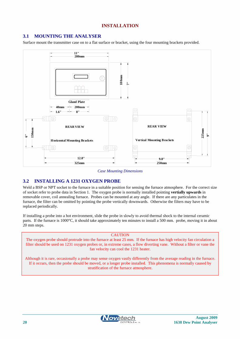
3.1 MOUNTING THE ANALYSER Surface mount the transmitter case on to a flat surface or bracket, using the four mounting brackets provided.
Gland Plate
Vertical Mounting Brackets Horizontal Mounting Brackets
150m
m
280mm
180m
m
225m
m
250mm325mm
11"
7"
6"
12.8" 9.8"
9"
REAR VIEW
200mm 8"
40mm 1.6"
REAR VIEW
Case Mounting Dimensions
3.2 INSTALLING A 1231 OXYGEN PROBE Weld a BSP or NPT socket to the furnace in a suitable position for sensing the furnace atmosphere. For the correct size of socket refer to probe data in Section 1. The oxygen probe is normally installed pointing vertially upwards in removable cover, coil annealing furnace. Probes can be mounted at any angle. If there are any particulates in the furnace, the filter can be omitted by pointing the probe vertically downwards. Otherwise the filters may have to be replaced periodically. If installing a probe into a hot environment, slide the probe in slowly to avoid thermal shock to the internal ceramic parts. If the furnace is 1000°C, it should take approximately ten minutes to install a 500 mm. probe, moving it in about 20 mm steps.
CAUTION The oxygen probe should protrude into the furnace at least 25 mm. If the furnace has high velocity fan circulation a filter should be used on 1231 oxygen probes or, in extreme cases, a flow diverting vane. Without a filter or vane the
fan velocity can cool the 1231 heater.
Although it is rare, occasionally a probe may sense oxygen vastly differently from the average reading in the furnace. If it occurs, then the probe should be moved, or a longer probe installed. This phenomena is normally caused by
stratification of the furnace atmosphere.
August 2009 20 1638 Dew Point Analyser

August 2009 1638 Dew Point Analyser 21
3.3 INSTALLING THE AUXILIARY THERMOCOUPLE Weld a 1/2 inch BSP mounting socket to the furnace within about 300 mm, and upstream of the oxygen probe. The thermocouple should be of similar length to the oxygen probe to prevent furnace temperature distribution errors.
3.4 SHIELD CONNECTIONS All external wiring to the 1638 analyser should be shielded. Do not connect shields at the field end. Simply clip off and insulate. An extra terminal strip may be required to connect all shields together. This should be supplied by the installer.
3.5 ELECTRICAL CONNECTIONS All wiring should comply with local electrical codes. The printed circuit boards are fully floating above earth. All earth and shield connections should be connected to the earth stud on the LHS inside the case. Before connection of mains power check that the 115 / 230 volt power selector switch is set to the correct voltage.
21 RS- 232 Tx22 Network -23242526 Output 1-27 Output 2+28 Output 2-29 Common Alarm30 Common Alarm31 Alarm 232 Alarm 233 Alarm 334 Alarm 335 Alarm 436 Alarm 4
SENSOR #1
SENSOR #2
4- 20mA OutputsSelectableranges
Optional AlarmRelay ContactsNormally Closed
Mains Power240/ 115VAC
414243 Cal 1 Sol44 Cal 1 Sol45 Cal 2 Sol46 Cal 2 Sol
47 Mains E4849 Mains N50 Mains A
Purge SolPurge Sol
51 Heater #152 Heater #1
WhiteWhiteWhiteWhite
53 Heater #254 Heater #2
Network +Serial CommonOutput 1+
Burner safetyor if safetynot requiredterminals 18 &
OrangeBrown
BlackBlueBlackBlue
OrangeBrown
Purge FlowPurge Flow
Remote AlarmRemote AlarmBurner On InputBurner On InputRS- 232 Rx
Fuel 1/ 2
181920
151617
Sens #2+Sens #2-
Fuel 1/ 2
RGCI/ P-
121314
91011
Probe TC+Probe TC-Probe TC2/ Aux+Probe TC2/ Aux-+12VRGCI/ P+
678
345
Probe +Probe -
12
Connection Diagram for 1638 Analyser and one or two 1231 Heated Sensors
August 2009 22 1638 Dew Point Analyser
All wiring should comply with local electrical codes. The printed circuit boards are fully floating above earth. All earth and shield connections should be connected to the earth stud on the LHS inside the case. Before connection of mains power check that the 115 / 230 volt power selector switch is set to the correct voltage.
21 RS- 232 Tx22 Network -23242526 Output 1-27 Output 2+28 Output 2-29 Common Alarm30 Common Alarm31 Alarm 232 Alarm 233 Alarm 334 Alarm 335 Alarm 436 Alarm 4
PROBE #1
PROBE #2
4- 20mA OutputsSelectableranges
Optional AlarmRelay ContactsNormally Closed
Mains Power Supply240/ 115VAC
414243 Cal 1 Sol44 Cal 1 Sol45 Cal 2 Sol46 Cal 2 Sol
47 Mains E4849 Mains N50 Mains A
Purge SolPurge Sol
51 Heater #152 Heater #153 Heater #254 Heater #2
Network +Serial CommonOutput 1+
Burner safety lockor if safety interlocknot required, linkterminals 18 & 19
OrangeBlack
Red
Red
OrangeBlack
Purge Flow SwitchPurge Flow Switch
Remote Alarm ResetRemote Alarm ResetBurner On InputBurner On InputRS- 232 Rx
Fuel 1/ 2
181920
151617
Sens #2+Sens #2-
Fuel 1/ 2
RGCI/ P-
121314
91011
Probe TC+Probe TC-Probe TC2/ Aux+Probe TC2/ Aux-+12VRGCI/ P+
678
345
Probe +Probe -
12
Connection Diagram for 1638 Analyser and one or two 1232 Unheated Sensors
August 2009 1638 Dew Point Analyser 23
3.6 HEATER INTERLOCK RELAYS
CAUTION
Explosion protection for heated probes is achieved by switching the power to the probe heater off whenever the main fuel valve is closed.
The principle of safety is that if the main fuel valve is open then main flame has been established. With this primary source of ignition on, the probe heater can be safely switched on. The most dangerous situation is if fuel or hydrogen
leaks into the furnace when the fuel valve is closed. When power is removed from the main fuel valve the heater should be switched off.
To achieve this protection, connect a main fuel valve voltage free contact to the ‘BURNER ON SWITCH’ terminals 18 & 19. When the main fuel valve is open, the voltage free contact should be closed. For installations where there is no
risk of explosion, connect a link between terminals number 18 & 19.
Burner on Switchwhen main fuel valve is openContact must be closedFor Safety Interlock 18
19
Heater Supply Interlock Connection For Heated Probes
3.7 CONNECTING AN OXYGEN PROBE CABLE Connect the probe lead as shown in the following drawings. Unheated probe leads have integral reference air tube. An adaptor has been supplied to connect this tube to quarter inch flexible PVC tubing, from the air pump or reference air supply.
August 2009 24 1638 Dew Point Analyser
B
Orange
Black1 Probe +
2 Probe -
3 Probe TC +
4 Probe TC -
ShieldCommonTerminal Block
OtherShields
Green &Yellow(Shield)
SensorZirconia
Red
A
ProbeThermocouple
EC
MainsEarth
Probe HeadConnector
Note 1: Jumper terminals 3 & 4to terminals 5 & 6 if
temperature display isrequired. Use copper wire.
efficiency or flue
*Note 1
Ref Air
Reducing Fitting
1/4" PVC tube toreference air supply.
A
B
CD
E
F
G
Plug mountedon head viewedfrom outside ofhead.
(Optional)
Earth Stud
(By Installer)
Connection of Probe Cable for Unheated Probes Model 1232
CBAF
DE
G
Orange
Black
Brown
Blue
White
White
MainsEarth
1 Probe +
2 Probe -
3 Probe TC +
4 Probe TC -
ShieldCommonTerminal
Green
ProbeThermocouple
ProbeHeater
ProbeEarth
OtherShields
ProbeConnector
Green &Yellow(Shield)
SensorZirconia
Earth
(By Installer)
51
52
Connection of Probe Cable for Heated Probes Model 1231
August 2009 1638 Dew Point Analyser 25
August 2009 26 1638 Dew Point Analyser
3.8 CONNECTING THE AUXILIARY THERMOCOUPLE (OPTIONAL) For 1231 heated probes, the auxiliary thermocouple must be a separate TC with the junction isolated from earth, mounted near to and upstream of the oxygen probe. It can be either type K or R. It is optional. If efficiency, oxygen deficiency or auxiliary temperature display or transmitted signals are not required, then an auxiliary TC is not necessary.
3.9 CONNECTING THE OUTPUT CHANNELS The two 4 to 20 mA DC output channels are capable of driving into a 1000Ω load.
3.10 CONNECTING THE ALARMS A common alarm, which should be connected for all installations initiates on alarms functions described below. Three additional alarm relays are available for selectable functions as listed in Section 4.2 and 4.3. Each relay has normally closed contacts. The contacts will open in alarm condition except for the optional horn function which operates with normally open contacts. Relays are connected as follows: Relay Terminal Numbers Common Alarm 29 & 30 Alarm 2 31 & 32 Alarm 3 33 & 34 Alarm 4 35 & 36 Common Alarms All of the following conditions will cause a common alarm - ADC Warning DAC Warning ADC Calibration Fail DAC Calibration Fail Sensor 1 Fail Sensor 2 Fail ** Heater 1 Fail Heater 2 Fail ** Sensor 1 TC Open Sensor 2 TC Open ** Aux. TC Open Reference Air Pump Fail Mains Frequency Check fail Probe Filter Blocked Gas 1 or 2 Calibration Check Error Memory device fail Burner bypass Switch on Watchdog Timer The watchdog timer is a special alarm. It will force the common alarm to activate in the event of a microprocessor failure. There will not be an alarm message displayed, but the analyser will reset. Alarms can be accepted by either pressing the alarm button (viewing the alarm messages), or by temporarily closing a switch connected to terminals 16 & 17, REM ALARM RESET. Alarm relay 2 to 4 Select any one or all of the following for each relay. Refer 5 to Section 5.5, steps 54 to 66 Oxygen Deviation High ** Dew point Deviation High ** High oxygen probe 1 High oxygen probe 2 High dew point probe 1 High dew point probe 2 High oxygen deviation between probes High dew point deviation between probes Probe under temperature Calibration check in progress Probe purge in progress Alarm horn function (Relay 4 only) ** These alarms are only available if two sensors are selected
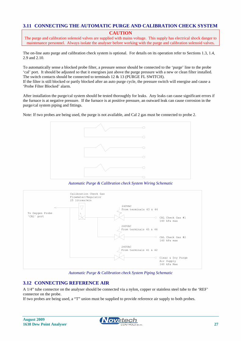
3.11 CONNECTING THE AUTOMATIC PURGE AND CALIBRATION CHECK SYSTEM CAUTION
The purge and calibration solenoid valves are supplied with mains voltage. This supply has electrical shock danger to maintenance personnel. Always isolate the analyser before working with the purge and calibration solenoid valves.
The on-line auto purge and calibration check system is optional. For details on its operation refer to Sections 1.3, 1.4, 2.9 and 2.10. To automatically sense a blocked probe filter, a pressure sensor should be connected to the ‘purge’ line to the probe ‘cal’ port. It should be adjusted so that it energises just above the purge pressure with a new or clean filter installed. The switch contacts should be connected to terminals 12 & 13 (PURGE FL SWITCH). If the filter is still blocked or partly blocked after an auto purge cycle, the pressure switch will energise and cause a ‘Probe Filter Blocked’ alarm. After installation the purge/cal system should be tested thoroughly for leaks. Any leaks can cause significant errors if the furnace is at negative pressure. If the furnace is at positive pressure, an outward leak can cause corrosion in the purge/cal system piping and fittings. Note: If two probes are being used, the purge is not available, and Cal 2 gas must be connected to probe 2.
Automatic Purge & Calibration check System Wiring Schematic
240VACFrom terminals 43 & 44
240VACFrom terminals 45 & 46
240VACFrom terminals 41 & 42
Calibration Check Gas
To Oxygen Probe'CAL' port
Flowmeter/Regulator25 litres/min
Clear & Dry PurgeAir Supply140 kPa Max
CAL Check Gas #1140 kPa max
CAL Check Gas #2140 kPa max
Automatic Purge & Calibration check System Piping Schematic
3.12 CONNECTING REFERENCE AIR A 1/4” tube connector on the analyser should be connected via a nylon, copper or stainless steel tube to the ‘REF’ connector on the probe. If two probes are being used, a “T” union must be supplied to provide reference air supply to both probes.
August 2009 1638 Dew Point Analyser 27
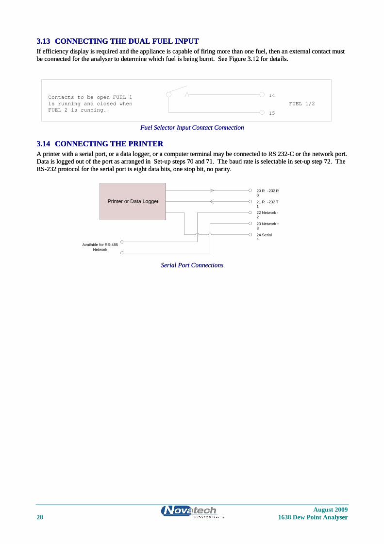
3.13 CONNECTING THE DUAL FUEL INPUT 3.13 CONNECTING THE DUAL FUEL INPUT If efficiency display is required and the appliance is capable of firing more than one fuel, then an external contact must be connected for the analyser to determine which fuel is being burnt. See Figure 3.12 for details. If efficiency display is required and the appliance is capable of firing more than one fuel, then an external contact must be connected for the analyser to determine which fuel is being burnt. See Figure 3.12 for details.
Contacts to be open FUEL 1is running and closed whenFUEL 2 is running.
14
15
FUEL 1/2
Fuel Selector Input Contact Connection Fuel Selector Input Contact Connection
3.14 CONNECTING THE PRINTER 3.14 CONNECTING THE PRINTER A printer with a serial port, or a data logger, or a computer terminal may be connected to RS 232-C or the network port. Data is logged out of the port as arranged in Set-up steps 70 and 71. The baud rate is selectable in set-up step 72. The RS-232 protocol for the serial port is eight data bits, one stop bit, no parity.
A printer with a serial port, or a data logger, or a computer terminal may be connected to RS 232-C or the network port. Data is logged out of the port as arranged in Set-up steps 70 and 71. The baud rate is selectable in set-up step 72. The RS-232 protocol for the serial port is eight data bits, one stop bit, no parity.
August 2009 28 1638 Dew Point Analyser yser
Serial Port Connections Serial Port Connections
Printer or Data Logger
Available for RS-485
Network
200
1
R -232
R
21 R -232
T
- 22 Network
2
233
Network
+
244
Serial
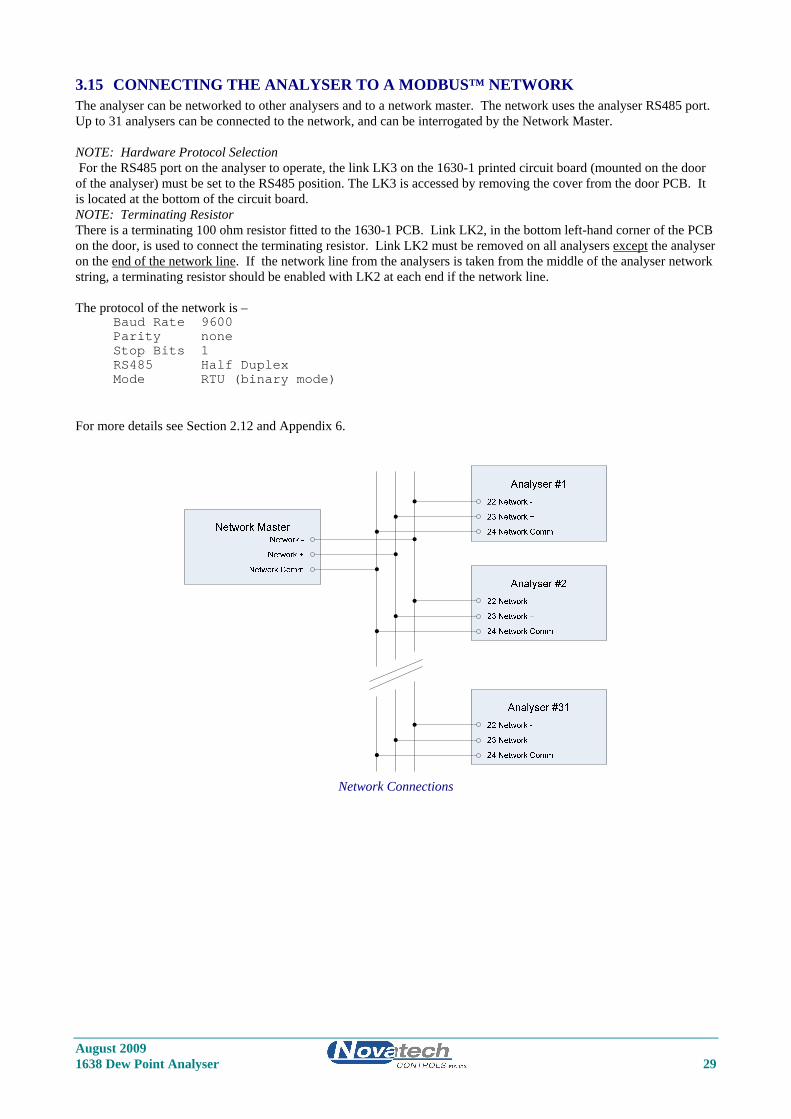
3.15 CONNECTING THE ANALYSER TO A MODBUS™ NETWORK The analyser can be networked to other analysers and to a network master. The network uses the analyser RS485 port. Up to 31 analysers can be connected to the network, and can be interrogated by the Network Master. NOTE: Hardware Protocol Selection For the RS485 port on the analyser to operate, the link LK3 on the 1630-1 printed circuit board (mounted on the door of the analyser) must be set to the RS485 position. The LK3 is accessed by removing the cover from the door PCB. It is located at the bottom of the circuit board. NOTE: Terminating Resistor There is a terminating 100 ohm resistor fitted to the 1630-1 PCB. Link LK2, in the bottom left-hand corner of the PCB on the door, is used to connect the terminating resistor. Link LK2 must be removed on all analysers except the analyser on the end of the network line. If the network line from the analysers is taken from the middle of the analyser network string, a terminating resistor should be enabled with LK2 at each end if the network line. The protocol of the network is –
Baud Rate 9600 Parity none Stop Bits 1 RS485 Half Duplex Mode RTU (binary mode)
For more details see Section 2.12 and Appendix 6.
Network Connections
August 2009 1638 Dew Point Analyser 29
August 2009 30 1638 Dew Point Analyser
COMMISSIONING
3.16 CONNECTING POWER Before commissioning the probe, sensor or transmitter, read the CAUTION paragraphs at the front of this manual. Check that the mains supply voltage switch is set for the correct supply voltage, and that the green / yellow EARTH wire MUST be connected to earth.
3.17 COMMISSIONING – SET-UP MODE Press the SET-UP button to select the ‘SET-UP’ mode. Most of the default settings of the functions will be correct, or will have been pre-set at the factory. Refer to Section 5.5 for more details. Check the following set-up functions - 2 to 6 Date /time 7 to 10 Reference voltages 11 & 12 Probe offset 22 & 23 Sensor type 26 to 28 Output channel #1 29 to 31 Output channel #2 37 Auto purge 41 Auto gas calibration checking 54 to 69 Alarm set-up 80 Hydrogen level
3.18 COMMISSIONING – RUN MODE When the analyser is turned on it will go to RUN mode. The SET-UP/RUN button will toggle between the two modes. The upper line of the display will now read ‘% OXYGEN’. If the probe temperature is not above 650°C, a “Probe Low Temperature” message will be flashed on the lower line. The probe temperature can be checked on the lower line of the display.
3.19 BURNER BYPASS SWITCH Heated probes and sensors should have their heater supply interlocked. If the combustion appliance is not running, then power will not be supplied to the heater. To commission an oxygen probe when the main burner is turned off, switch power off the analyser, remove the probe from the furnace. Re-apply power to the analyser, press the BURNER BY-PASS switch into the ‘DOWN’ or ‘ON’ position. This will apply power to the probe heater even when the plant is not running. The offset can now be set and calibration checked with appropriate calibration check gases (typically 2% oxygen in nitrogen). Ensure that the burner by-pass switch and the power are turned off before the probe is re-installed. An alarm will occur if the BURNER BY-PASS switch is turned on (down) during normal operation.
3.20 CHECKING THE ALARMS If any alarms are present the alarm LED will be lit, either flashing or steady. To interpret the alarms, press the alarm button until all alarm functions have been displayed. Rectify the cause of each alarm until no further alarms appear on the display. For details on the operation of the alarm button and the alarm functions refer to Section 4.
3.21 PROBE CALIBRATION The zirconia sensor provides an absolute measurement of oxygen partial pressure. There are no calibration adjustments, apart from ‘SENSOR OFFSET’, for the probe. The probe EMF is either correct or replacement is required. To check that the probe is functioning correctly, firstly check that the high impedance alarm is not activated causing a ‘SENSOR FAIL’ alarm. The actual impedance can be displayed on the lower line. It should be less than 9 KΩ at 720°C. Once it has been established that the impedance is normal, the offset may be set using the millivolt level marked on the oxygen probe. Refer to Section 5.5.11. The probe offset can be tested on site. A small flow of air must be admitted to both the ‘REF’ and ‘CAL’ ports when testing the probe offset. If the probe is in the process, the air must fully purge the probe sensor without interference from the process gas sample.
August 2009 1638 Dew Point Analyser 31
3.22 FILTER PURGING Purging probe filters is controlled from the ‘PURGE’ button on the analyser when in ‘RUN’ mode. If ‘AUTO PURGE’ has been enabled in set-up 37, pressing the PURGE button will start the automatic cycle. Pressing any other button will cancel the auto purge cycle. If AUTO PURGE was not enabled, the purge solenoid will only stay open for as long as the button is pressed. Gradually adjust the purge gas supply regulator, increasing the pressure until sufficient flow is obtained to clear the filter. This is best checked with a dirty filter after a period of operation, by withdrawing the probe from service and watching any build up on the filter being blown off at the set pressure. Normally 30 kPa (5 psi) is adequate but the air pressure may be set as high as 100 kPa (15 psi).
3.23 CALIBRATION GAS CHECK If the installation has a filter purge facility, set this up first. Refer to the previous paragraph. Press the ‘CAL 1 or ‘CAL 2’ button while in ‘SET UP’ mode to obtain a reasonable flow through the calibration check gas flow meter. If air is being used as a calibration check gas, use the air from the regulator for filter purge. Then, when setting up a gas for calibration checking, set the pressure from the calibration gas cylinder so that it is the same as the pressure set on the air regulator. Then the setting on the rotameter / flow regulator will be the same as that for the air flow. Required flows are about 2 litres per minute. Air is not the best gas for calibration checking on a zirconia sensor. The output of a zirconia sensor with reference air is zero millivolts. It is better to choose a gas value which provides a reasonable output from the sensor and which is near to the process oxygen level. A cylinder with 2% oxygen in nitrogen is a commonly used calibration gas. The maximum pressure on the calibration check gas cylinder regulators is 100 kPa (15 psi). Note: If two probes were selected in set-up 1, ‘Cal Gas 2’ must be connected to probe 2.
3.24 DUST IN THE FURNACE For unheated probes with no filter, entrained solids or dust in the furnace does not present a problem unless the dust, when settled, is not porous. Allow the dust in the process to build up on the probe. It will form a porous layer slowing the response time. To avoid mechanical abrasion of the electrode material in installations with unheated oxygen probes, pack ‘SAFFIL’ or equivalent alumina based ceramic fibre in the sensing holes to protect the electrode. Do not use silica based ceramic fibres such as ‘KAOWOOL’, which can attack the electrode at high temperatures. Once the dust has built up the response time of the probe will be slower. For heated probes the preferred method of mounting for dust laden applications is facing vertically downwards with the filter removed. Probes can also be mounted horizontally with no filter with some dusts. An occasional automatic back purge is helpful in this case. Normally heated probes are supplied with filters for applications with particulate in the furnace. The probe response time should be tested when the probe is first installed, and then regularly until it remains constant for a significant period. Filter purging should be set up on the time periods determined by these tests. To test the probe response time, use a stop watch to obtain the time for a probe to achieve a 63 % change from one reading to another. If a probe filter blocks completely in a short period of time, then there is no option but to use the probe without the filter.

August 2009 32 1638 Dew Point Analyser
August 2009 1638 Dew Point Analyser 33
4 OPERATOR FUNCTIONS Section Number 4.1 DISPLAY BUTTON ....................................................................................................................... 34 4.2 ALARM BUTTON ......................................................................................................................... 35 4.3 ALARM SCHEDULE ..................................................................................................................... 35 4.3.1 SUMMARY OF ALARMS – COMMON ALARM ....................................................................... 35 4.3.2 SUMMARY OF ALARMS – SELECTABLE ALARMS .............................................................. 36 4.3.3 ALARM RELAYS .......................................................................................................................... 37 4.4 POWER LAMP ............................................................................................................................... 37 4.5 BURNER BYPASS SWITCH ........................................................................................................ 37
August 2009 34 1638 Dew Point Analyser
OPERATOR FUNCTIONS (RUN MODE)
4.1 DISPLAY BUTTON The upper line on the display will always read % oxygen for probe 1. The following are available for display on the lower line. 1. DEW POINT MEASURED BY PROBE 1 2. DEW POINT MEASURED BY PROBE 2 ** 3. DEW POINT AVERAGE MEASURED BY PROBES 1 AND 2 ** 4. OXYGEN PROBE 2 ** 5. OXYGEN AVERAGE OF PROBES 1 AND 2 ** 6. SENSOR 1 EMF (millivolts) 7. SENSOR 2 EMF (millivolts) ** 8. SENSOR 1 TEMPERATURE 9. SENSOR 2 TEMPERATURE ** or AUXILIARY TEMPERATURE 10. SENSOR 1 IMPEDANCE 11. SENSOR 2 IMPEDANCE ** 12. AMBIENT TEMPERATURE 13. AMBIENT RELATIVE HUMIDITY 14. DATE / TIME 15. RUN HOURS SINCE LAST SERVICE 16. DATE OF LAST SERVICE ** available when 2 sensors selected in set-up 1 Any number of these variables can be displayed sequentially by pressing the ‘DISPLAY’ button. Items can be selected for display or deleted in Set-up step 33 on the keyboard. In addition to the above lower line displays, the analyser will automatically display: “Sensor 1 Temp Low”, when probe one is below 650°C “Sensor 2 Temp Low”, when probe two is below 650°C “Gas 1 ON”, “Gas 2 ON” for Calibration check Gas 1 or 2 “Purging Probe” “Sensor 1 Thermocouple Wrong Polarity” “Sensor 2 Thermocouple Wrong Polarity” “Aux Thermocouple Wrong Polarity” NOTE: 2. The run time will be the period of time the BURNER ON SWITCH (terminals 18 & 19) contact is closed (ie.
main fuel valve open). If no explosion protection is required, a permanent bridge between the BURNER ON SWITCH terminals will register run time whenever the analyser is powered.
3. This timer can be used as a probe replacement and/or boiler service schedule aid. The start time is reset by
changing the ‘SERVICE DAY’ in set-up mode on the keyboard. 4. If you hold the display button down as you switch on the power, the maximum ambient temperature which the
instrument has been subjected to, will be displayed. This temperature should be less than 50°C.
August 2009 1638 Dew Point Analyser 35
4.2 ALARM BUTTON Repeatedly pressing the ‘ALARM’ button will produce alarm displays in sequence on the lower line of the LCD display. If an alarm has cleared prior to pressing the ‘ALARM’ button, it will not re-appear on a second run through the alarms. Active alarms which have been previously displayed will have ‘acc’ (accepted in lower case), displayed alongside. New alarms will not have ‘ACC’ (in upper case) displayed until a second press of the ‘ALARM’ button. After the last active alarm is indicated, the lower line of the display will return to the last displayed lower line variable. Alarms may also be accepted remotely by a temporary closure of a switch connected to terminal 16 & 17, ‘REMOTE ALARM RESET’. The alarm ‘LED’ will flash when there is an un-accepted alarm. Pressing the ‘ALARM’ button will cause the LED to go steady if any alarms are still active, or extinguish if there are no active alarms. The horn relay will operate when an alarm occurs. Pressing ‘ALARM’ will mute a horn relay (if one of the user configurable relays have been selected as a ‘Horn’ relay) which will re-initiate on any new alarms.
4.3 ALARM SCHEDULE
4.3.1 SUMMARY OF ALARMS – COMMON ALARM 1. ‘Sensor 1 Fail’ 2. ‘Sensor 2 Fail’ Oxygen cell or electrode failure (high impedance), (inhibited under 650°C). 3. ‘Heater 1 Fail’ 4. ‘Heater 2 Fail’ In the first 20 minutes of power being applied to the heater after being switched on, this alarm will not occur, but a ‘Sensor # Lo Temp’ display will occur and common alarm relay will be activated. Refer to Section 6.11. If an ADC alarms occurs, the heaters will automatically be turned off. 5. ‘Sensor 1 TC Open’ 6. ‘Sensor 1 TC Open’ Probe thermocouple is open circuit. The heater in heated probes will switch off. 7. ‘Aux TC Open’ Stack thermocouple is open circuit. If the thermocouple is not needed, select “NO T/C” for “Aux TC Type” or place a short circuit between terminals 5 & 6. 8. ‘Ref Pump Fail’ The reference air pump in the analyser has failed. 9. ‘ADC Cal Fail’ The analog to digital converter has been found to fall outside the normal calibration specifications. In this case the probe heater will automatically be turned off. 10. ‘Mains Freq’ The sample of the mains frequency has failed. 11. ‘DAC Cal Fail’ The digital to analog and voltage isolator circuit has been found to fall outside the normal calibration specifications. This check is only performed when the ‘AUTO CAL’ button is pressed. Refer to Section 6.3. 12. ‘Probe Filter Blocked probe filter. This test is only performed when automatic purging of the probe is requested. Refer to step 36 in the set-up menu Section 5.5. This alarm will not reset until the next purge cycle which can be initiated manually or automatically. 13. ‘Gas 1 Cal Err’ Probe does not correctly calibrate to calibration check gas 1. 14. ‘Gas 2 Cal Err’ Probe does not correctly calibrate to calibration check gas 2.
August 2009 36 1638 Dew Point Analyser
15. ‘Burner bypass’ The safety interlock relay has been bypassed by turning on the ‘BURNER BYPASS’ switch on the terminal printed circuit board. Refer to Section 3.18 16. ‘Watchdog Timer’ Microprocessor error. This alarm will not appear on the display. The common alarm relay will be forced open circuit. If the watchdog timer senses a malfunction in the microprocessor, it will attempt to reset the analyser every 2 seconds. After two resets the alarm relay contacts will go open circuit. 17. ‘BB RAM Fail” The battery backed memory module has failed in service. The device normally lasts 10 years. It is the plug-in battery like module on the 1630 -1 board, labelled M1.
4.3.2 SUMMARY OF ALARMS – SELECTABLE ALARMS NOTE: The process alarms must be enabled in set-up 54 if required. There are three user configurable alarm relays. Any or all of the following functions can be selected for each relay. 18. ‘Dew Point 1 High” The dew point measured by probe 1 (Dew Point 1 High) is above the limit set in set-up 59, and has been there for longer than the time set in set-up 60. 19. ‘Dew Point 2 High” The dew point measured by probe 2 (Dew Point 2 High) is above the limit set in set-up 61, and has been there for longer than the time set in set-up 62. 20. ‘Oxygen % 1 High” The oxygen measured by probe 1 (Oxygen % 1 High) is above the limit set in set-up 55, and has been there for longer than the time set in set-up 56. 21. ‘Oxygen % 2 High” The oxygen measured by probe 2 (Oxygen % 2 High) is above the limit set in set-up 57, and has been there for longer than the time set in set-up 58. 22. ‘Oxygen % deviation High” The oxygen difference measured by probe 1 and 2 is above the limit set in set-up 65, and has been there for longer than the time set in set-up 66. 23. ‘Dew point deviation High” The dew point difference measured by probe 1 and 2 is above the limit set in set-up 63, and has been there for longer than the time set in set-up 64. 24. ‘Probe Temperature’ The probe temperature is under 650°C. The oxygen an dew point readings are therefore invalid. If the sensor heater has been on for more than 20 minutes and the temperature is less than 650°C a ‘heater fail’ alarm will occur. NOTE: The ‘Probe Temp’ relay function is used with unheated probes to indicate oxygen reading is invalid (the probe is below 650°C), in case the process temperature falls below this level. For heated probes this relay will be energised while the probe is heating up from ambient. 25. ‘Cal in Progress’ A calibration check is occurring, either manual ( in RUN mode) or automatic 26. ‘Probe Purge’ A probe purge is occurring, either manual ( in RUN mode) or automatic 27. Alarm Horn This is not an alarm condition. If one of the three user configureable alarm relays have ‘Alarm Horn’ enabled, the relay will have closed contacts only when there is an un-accepted alarm on the analyser. Press the alarm button twice to accept any new alarm and to cancel the horn relay. This is only available on relay 4.

August 2009 1638 Dew Point Analyser 37
4.3.3 ALARM RELAYS The alarm relays are fail safe. That is, the contacts will be closed during normal operation, and will be open circuit if there is an alarm or if the power is removed from the analyser.
4.4 POWER LAMP Illuminates when power is connected to the analyser. If the lamp is flashing, the watchdog timer is attempting to reset the microprocessor. Replace the 1630-1 microprocessor PCB.
4.5 BURNER BYPASS SWITCH This switch is mounted on the terminal PCB near the POWER switch. Before the heater in a heated probe, or the alarms will be enabled, the probes must be enabled. There are two ways of doing this. Use the safety interlock on terminals 18 & 19 (BURNER ON switch), or press the BURNER BYPASS switch to the ON position. While the BURNER BYPASS switch is on there will be an alarm, “Burner Bypass”. If it is not needed to have the analyser interlocked with the combustion appliance terminals 18 & 19 can be connected together.

August 2009 38 1638 Dew Point Analyser
August 2009 1638 Dew Point Analyser 39
5 SETTING UP THE TRANSMITTER Section Number 5.1 SET-UP MODE FUNCTIONS ....................................................................................................... 40 5.2 SET-UP & RUN MODES ............................................................................................................... 42 5.3 FUNCTION SELECT ..................................................................................................................... 42 5.4 ENTER OPTION OR VALUE ....................................................................................................... 42 5.5 SET-UP FUNCTION DETAILS..................................................................................................... 43
August 2009 40 1638 Dew Point Analyser
SET-UP MODE SUMMARY
5.1 SET-UP MODE FUNCTIONS 1 Number of Sensors 2 Calender Year 3 Calender Month 4 Calender Day 5 Real time clock Hour 6 Real time clock Minutes 7 Reference voltage #1 8 Reference voltage #2 9 Reference voltage #3 10 Reference voltage #4 11 Sensor 1 offset 12 Sensor 2 offset 13 Output channel number 1 calibration 14 Output channel number 1 calibration, 4mA trim 15 Output channel number 1 calibration, 20mA trim 16 Output channel number 2 calibration 17 Output channel number 2 calibration, 4mA trim 18 Output channel number 2 calibration, 20mA trim 19 Service record year 20 Service record month 21 Service record day 22 Sensor 1 Type 23 Sensor 2 Type 24 Sensor 1 Thermocouple Type 25 Sensor 2, Auxiliary Thermocouple Type 26 Transmitter Output Channel 1 scale 27 Transmitter Zero Channel 1 28 Transmitter Span Channel 1 29 Transmitter Output Channel 2 scale 30 Transmitter Zero Channel 2 31 Transmitter Span Channel 2 32 Centigrade/Fahrenheit Selection 33 Lower Line Display Functions 34 Flue Pressure mm/inches/kilopascals 35 Flue Pressure Value 36 Purge/Cal Time 37 Automatic Purge Set-up steps 38to 40 will be skipped automatically if ‘No’ is selected in set-up step 37. 38 Time Between Purges 39 Purge Duration 40 Purge Freeze Time
August 2009 1638 Dew Point Analyser 41
41 Number of Cal Gases Set-up steps 42 to 47 may be skipped automatically, depending on the selection in set-up step 41. 42 Oxygen Content of Cal Gas 1 43 Maximum Acceptable Positive Error Gas 1 44 Maximum Acceptable Negative Error Gas 1 45 Period Between Gas 1 Autocals 46 Duration of Autocal Gas 1 47 Freeze Time Gas 1 48 Oxygen Content Of Cal Gas 2 49 Maximum Acceptable Positive Error Gas 2 50 Maximum Acceptable Negative Error Gas 2 51 Period Between Gas 2 Autocals 52 Duration of Autocal Gas 2 53 Freeze Time Gas 2 54 Process alarm enable Set-up steps 55 and 66 may be skipped automatically, depending on the selection in set-up steps 54 and 85. 55 High oxygen alarm sensor #1 level 56 High oxygen alarm sensor #1 delay time 57 High oxygen alarm sensor #2 level 58 High oxygen alarm sensor #2 delay time 59 High dew point sensor #1 level 60 High dew point sensor #1 delay time 61 High dew point sensor #2 level 62 High dew point sensor #2 delay time 63 High dew point deviation level 64 High dew point deviation delay time 65 High oxygen deviation level 66 High oxygen deviation delay time Set-up steps 67 and 70 may be skipped automatically, depending on the selection in set-up steps 54 and 85. 67 High pre-reaction oxygen warning alarm sensor #1 level 68 High pre-reaction oxygen alarm sensor #1 level 69 High pre-reaction oxygen warning alarm sensor #2 level 70 High pre-reaction oxygen alarm sensor #2 level 71 Alarm relay number 2 function select 72 Alarm relay number 3 function select 73 Alarm relay number 4 function select 74 Data to Print 75 Print Log Period 76 Printer Baud Rate 77 Reference air pump mode selection Set-up steps 78 may be skipped automatically, depending on the selection in set-up step 77. 78 Reference air RH 79 Damping factor 80 Digital output filter enable 81 External hydrogen level input enable Set-up steps 82 and 83 may be skipped automatically, depending on the selection in set-up step 81. 82 External hydrogen level input zero level 83 External hydrogen level input span level Set-up step 84 may be skipped automatically, depending on the selection in set-up step 81. 84 Fixed hydrogen level 85 Instrument operating mode. Pre-reaction oxygen or Dew point 86 MODBUS address, 0 for no MODBUS communications
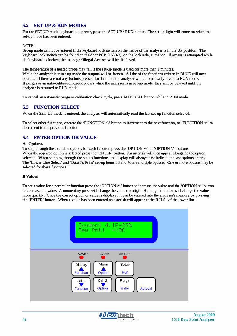
5.2 SET-UP & RUN MODES 5.2 SET-UP & RUN MODES For the SET-UP mode keyboard to operate, press the SET-UP / RUN button. The set-up light will come on when the set-up mode has been entered. For the SET-UP mode keyboard to operate, press the SET-UP / RUN button. The set-up light will come on when the set-up mode has been entered. NOTE: NOTE: Set-up mode cannot be entered if the keyboard lock switch on the inside of the analyser is in the UP position. The keyboard lock switch can be found on the door PCB (1630-2), on the lock side, at the top. If access is attempted while the keyboard is locked, the message ‘Illegal Access’ will be displayed.
Set-up mode cannot be entered if the keyboard lock switch on the inside of the analyser is in the UP position. The keyboard lock switch can be found on the door PCB (1630-2), on the lock side, at the top. If access is attempted while the keyboard is locked, the message ‘Illegal Access’ will be displayed. The temperature of a heated probe may fall if the set-up mode is used for more than 2 minutes. The temperature of a heated probe may fall if the set-up mode is used for more than 2 minutes. While the analyser is in set-up mode the outputs will be frozen. All the of the functions written in BLUE will now operate. If there are not any buttons pressed for 1 minute the analyser will automatically revert to RUN mode. While the analyser is in set-up mode the outputs will be frozen. All the of the functions written in BLUE will now operate. If there are not any buttons pressed for 1 minute the analyser will automatically revert to RUN mode. If purges or an auto-calibration check occurs while the analyser is in set-up mode, they will be delayed until the analyser is returned to RUN mode. If purges or an auto-calibration check occurs while the analyser is in set-up mode, they will be delayed until the analyser is returned to RUN mode. To cancel an automatic purge or calibration check cycle, press AUTO CAL button while in RUN mode. To cancel an automatic purge or calibration check cycle, press AUTO CAL button while in RUN mode.
5.3 FUNCTION SELECT 5.3 FUNCTION SELECT When the SET-UP mode is entered, the analyser will automatically read the last set-up function selected. When the SET-UP mode is entered, the analyser will automatically read the last set-up function selected. To select other functions, operate the ‘FUNCTION ’ button to increment to the next function, or ‘FUNCTION ’ to decrement to the previous function. To select other functions, operate the ‘FUNCTION ’ button to increment to the next function, or ‘FUNCTION ’ to decrement to the previous function.
5.4 ENTER OPTION OR VALUE 5.4 ENTER OPTION OR VALUE A. Options. A. Options. To step through the available options for each function press the ‘OPTION ’ or ‘OPTION ’ buttons. To step through the available options for each function press the ‘OPTION ’ or ‘OPTION ’ buttons. When the required option is selected press the ‘ENTER’ button. An asterisk will then appear alongside the option selected. When stepping through the set-up functions, the display will always first indicate the last options entered. The ‘Lower Line Select’ and ‘Data To Print’ set-up items 33 and 70 are multiple options. One or more options may be selected for these functions.
When the required option is selected press the ‘ENTER’ button. An asterisk will then appear alongside the option selected. When stepping through the set-up functions, the display will always first indicate the last options entered. The ‘Lower Line Select’ and ‘Data To Print’ set-up items 33 and 70 are multiple options. One or more options may be selected for these functions. B Values B Values To set a value for a particular function press the ‘OPTION ’ button to increase the value and the ‘OPTION ’ button to decrease the value. A momentary press will change the value one digit. Holding the button will change the value more quickly. Once the correct option or value is displayed it can be entered into the analyser's memory by pressing the ‘ENTER’ button. When a value has been entered an asterisk will appear at the R.H.S. of the lower line.
To set a value for a particular function press the ‘OPTION ’ button to increase the value and the ‘OPTION ’ button to decrease the value. A momentary press will change the value one digit. Holding the button will change the value more quickly. Once the correct option or value is displayed it can be entered into the analyser's memory by pressing the ‘ENTER’ button. When a value has been entered an asterisk will appear at the R.H.S. of the lower line.
August 2009 42 1638 Dew Point Analyser yser
Oxygen1 4.1E-23% Dew Pnt1 -18C
POWER ALARM SETUP
Cal 1
Function
Cal 2
Option
Purge
Enter
Autocal
Setup
Run
Alarm Display
Function
Option
August 2009 1638 Dew Point Analyser 43
1638 Oxygen Analyser Keyboard
5.5 SET-UP FUNCTION DETAILS Note: The * indicates the default setting after a COLD-START. See Section 6.1
1. Number of Sensors Options Select the number of oxygen probes or sensors being used. 1 Sensor * 2 Sensors
2. Calender Year Options Select the current year for the real time clock/calendar. The cold start default sets the date and time to the software version date.
3. Calender Month Options Select the current month for the real time clock/calendar.
4. Calender Day Options Select the current day for the real time clock/calendar.
5. Real time clock hour Options Select the current hour for the real time clock. (24 hour format)
6. Real time clock minutes Options Select the current minutes for the real time clock.
7. Reference Voltage # 1 ( about 27.5 mV’s ) Options Set the value of the reference voltage as read on a 3 1/2 digit multimeter (See Section 6.2 for further details). 27.55 mV *
8. Reference Voltage # 2 ( about 194 mV’s ) Options Set the value of the reference voltage as read on a 3 1/2 digit multimeter (See Section 6.2 for further details). 193.60 mV *
9. Reference Voltage # 3 ( about 1200 mV’s ) Options Set the value of the reference voltage as read on a 3 1/2 digit multimeter (See Section 6.2 for further details). 1202.00 mV *
10. Reference Voltage # 4 ( about 2500 mV’s ) Options Set the value of the reference voltage as read on a 3 1/2 digit multimeter (See Section 6.2 for further details). 2479.00 mV * Set-up items 7 to 10 are used to calibrate the A/D of the instrument. This should be done 30 minutes or more after the instrument has been on. The calibration constants are retained in battery backed memory unless a ‘COLD START’ is performed. Connect a 3 1/2 digit multimeter negative lead to the test point marked ‘C’ to the right of the PCB on the inside of the door (labelled ‘REF VOLTS’). Measure the four voltages on the test point marked 1 to 4 with the positive lead. Refer to Figure 6.2 in the 1638 manual. Enter the measured values in set-up items 7 to 10. Whenever new values are entered the D/A section should be re-calibrated, Refer to Section 6.3.
August 2009 44 1638 Dew Point Analyser
11. Set Probe or Sensor 1 Offset
12. Set Probe or Sensor 2 Offset (When 2 sensors are selected in set-up 1) A new EMF offset must be entered whenever a new oxygen probe or sensor is installed to calibrate for any offset an individual probe or sensor may have. Each probe or sensor will have an offset value noted on a removable tag. Enter the ‘SENSOR OFFSET’ value with the underline polarity, eg. if offset value is -1.2 mV. enter -1.2 mV. The typical maximum is 2mV. To check a probe or sensor offset on site, the probe or sensor must be sensing air with reference air and allowed to settle at the probe operating temperature for 30 minutes. Read the offset in ‘RUN’ mode in millivolts on the lower line. Offset errors can occur if the sensor does not have some air passing over it. A gentle flow of air in the calibration check port can be provided by a reference air pump or similar. For heated probes or sensors, if the combustion appliance is not operational and the probe or sensor heater is interlocked with the ‘BURNER ON’ signal, the ‘BURNER BYPASS’ switch should be set to ‘ON to power the probe heater after removing the probe from the flue.
CAUTION DANGER
Return the BURNER BYPASS switch to normal (off) before installing the probe in the flue.
For unheated probes, the probe sensing tip must be raised to at least 650°C with a portable furnace. (Available as an accessory). Determine the probe or sensor offset in ‘RUN’ mode. Select ‘Sensor EMF’ on the lower line. With probe in air, stabilised at temperature for 30 minutes, read the ‘Sensor EMF’. Switch back to ‘set-up’ mode and enter ‘Sensor Offset’ of equal value and the same polarity. eg. If the measured ’SENSOR OFFSET’ was -1.2 mV, enter -1.2 mV. When reading the EMF offset, the flue pressure compensation must be set. If the probe has been removed from the flue, set the flue pressure compensation to 0 in set-up step 35.
13. 4-20mA Calibration Options, Channel #1 Select the calibration method for the 4-20mA output channel #1. The output channels can be either calibrated by simply pressing the ‘AUTO CAL’ button, or can be trimmed at both the 4mA and 20mA ends of the scale using an external multimeter. Options: 1. Auto Calibration * 2. Manual Calibration 3. Set 4mA Trim 4. Set 20mA Trim If ‘AUTO CAL’ is selected, the output channel is calibrated when ‘Auto Cal’ is initiated from the keyboard (See section 6.3). If ‘MAN CAL’ is selected, it is necessary to trim both ends of the 4-20mA output range using the 4mA and 20mA options in this menu item. Selecting ‘MAN CAL’ inhibits the ‘Auto Cal’ process of this channel. Always do the 4mA trim first, and then the 20mA trim. After trimming both ends of the scale, return the ‘CALIBRATION OPTIONS’ menu option back to ‘MAN CAL’ (not ‘AUTO CAL’), or the calibration factors will be over written by the next ‘AUTO CAL’. For more details on calibrating the output channels, see section 6.3. NOTE: If the analyser will only stay in either ‘4mA TRIM’ or ‘20mA TRIM’ modes for 30 minutes before it automatically returns to ‘MAN AL’.
14. Calibrate 4mA, Channel #1 This menu item only appears if ‘Set 4mA Trim’ is selected in Set-up 13. Range: 0 to 25mA, Default is 4.00mA For full details on the calibration of the 4-20mA output channels, see section 6.3.
August 2009 1638 Dew Point Analyser 45
15. Calibrate 20mA, Channel #1 This menu item only appears if ‘Set 20mA Trim’ is selected in Set-up 13. Range: 0 to 25mA, Default is 20.00mA
16. 4-20mA Calibration Options, Channel #2 Select the calibration method for the 4-20mA output channel #1. For more details, see Set-up 13 and section 6.3. Options: 1. Auto Calibration * 2. Manual Calibration 3. Set 4mA Trim 4. Set 20mA Trim
17. Calibrate 4mA, Channel #2 This menu item only appears if ‘Set 4mA Trim’ is selected in Set-up 16. Range: 0 to 25mA, Default is 4.00mA For full details on the calibration of the 4-20mA output channels, see section 6.3.
18. Calibrate 20mA, Channel #2 This menu item only appears if ‘Set 20mA Trim’ is selected in Set-up 16. Range: 0 to 25mA, Default is 20.00mA
19. Enter Service Year For a new ‘DATE OF LAST SERVICE’, enter the service ‘YEAR’. This can represent the last time the probe or sensor was serviced or the last time the boiler was serviced. It is recommended that probes and sensors be refurbished every two years
20. Enter Service Month Enter the current ‘MONTH’.
21. Enter Service Day End the current ‘DAY’ of the month. Altering these values will reset the ‘RUN TIME’.
22. Sensor 1 Type
23. Sensor 2 Type Options Model No. Enter the probe or sensor model number in use 1. 1231/1234 Heated * Heated Probe or sensor 2. 1232 Unheated Unheated Probe
24. Probe or Sensor 1 Thermocouple Type
25. Probe or Sensor 2 Thermocouple Type (When 2 sensors are selected in set-up 1) Auxiliary Thermocouple Type (When 1 sensor is selected in set-up 1) The probe can have either a type K, R, or N thermocouple as a sensor temperature detector. A 1231 probe or a 1234 sensor will always have a K thermocouple, and a 1232 will usually have an R thermocouple. Options 1. K * Check in the manual Section 1 2. R for the probe model number. 3. NO T/C If no TC type is to be used for an Auxiliary use.
August 2009 46 1638 Dew Point Analyser
26. Transmitter Output Channel 1 Select the type of output required from Channel 1. All of the outputs from channel #1 are signals generated from probe #1, even if two sensors are selected in set-up 1. Normally dew point would be selected as the prime output signal. The reducing output is fixed at 10 -16 % to 10 -30 % oxygen to cover the range of dew point readings. For the range of the outputs see the table below. Options: 1. Linear oxygen probe 1 2. Reducing oxygen, probe 1 3. Dew point, probe 1 * (only available if Dew point is selected in set-up 85) 4. Pre-reaction oxygen, probe 1 * (only available if Pre-reaction is selected in set-up 85) 5. Linear oxygen probe 1 and 2 averaged (only available if 2 sensors are selected in set-up 1) 6. Reducing oxygen, probe 1 and 2 averaged (only available if 2 sensors are selected in set-up 1) 7. Dew point, probe 1 and 2 averaged (only available if 2 sensors are selected in set-up 1 and if Dew point
is selected in set-up 85) 8. Pre-reaction oxygen, probe 1 and 2 averaged (only available if 2 sensors are selected in set-up 1 and if Pre-reaction
is selected in set-up 85) 9. No Output Note: The average dew point, pre-reaction oxygen, linear O2 and Reducing O2 selections will automatically select the operating probe if one probe fails, or selects probe 1 if both probes fail.
27. Transmitter Zero Channel 1 Select transmitter zero for output Channel 1. See table below.
28. Transmitter Span Channel 1 Select transmitter span for output Channel 1. See table below. Output Zero Range Span Range Default Setting LINEAR OXYGEN #1 0 to 99% oxygen 1 to 100% oxygen 0 to 100% REDUCING OXYGEN #1 10 -16 % fixed 10 -30 10 -16 to 10 -26 DEW POINT #1 -60 to +20 °C -40 to +40 °C -60 to +40 °C -76 to +68 °F -8 to +104 °F 1 ° steps 1 ° steps PRE-REACTION OXYGEN #1 0 oxygen fixed 1 to 10.0% oxygen 0 to 4.0% LINEAR OXYGEN #1 and #2 0 to 99% oxygen 1 to 100% oxygen 0 to 100% REDUCING OXYGEN #1 and #2 10 -16 % 10 -30 10 -16 to 10 -30 DEW POINT #1 and #2 -60 to +20 °C -40 to +40 °C -60 to +40 °C -76 to +68 °F -8 to +104 °F 1 ° steps 1 ° steps PRE-REACTION OXYGEN #1 and #2 0 fixed oxygen 1 to 10.0% oxygen 0 to 4.0% Note: The last four items (average of probe 1 and 2) are only available if two sensors are selected in set-up 1
August 2009 1638 Dew Point Analyser 47
29. Transmitter Output Channel 2 Select transmitter output for output Channel 2. Options: 1. Linear oxygen % probe 2 ( or probe 1, if 1 sensor is selected in set-up 1) 2. Reducing oxygen, probe 2 ( or probe 1, if 1 sensor is selected in set-up 1) 3. Dew point, probe 2 ( or probe 1, if 1 sensor is selected in set-up 1) 4. Pre-reaction oxygen, probe 2 (only available if 2 sensors are selected in set-up 1 and if Pre-reaction
is selected in set-up 85) 5. EMF sensor 1 6. EMF sensor 2 ( not available if 1 sensor is selected in set-up 1) 7. Auxiliary thermocouple ( not available if 2 sensors are selected in set-up 1, or if NO TC is selected in
set-up 25) 8. No Output
30. Transmitter Zero Channel 2 The output zero and span of Channel 2 is set in set-up steps 30 and 31. Range limits are shown below.
31. Transmitter Span Channel 2 Output Zero Range Span Range Default Setting LINEAR OXYGEN #2 0 to 99% oxygen 1 to 100% oxygen 0 to 100% REDUCING OXYGEN #2 10 -1 to 10 -25 % 10 -5 to 10 -30 % 10 -16 to 10 -26 (see Note 1) oxygen in one oxygen in one decade steps, decade steps. Min span five decades. DEW POINT #2 -60 to +20 °C -40 to +40 °C -60 to +40 °C -76 to +68 °F -8 to +104 °F 1 ° steps 1 ° steps PRE-REACTION OXYGEN #2 0 oxygen fixed 1 to 10.0% oxygen 0 to 4.0% SENSOR EMF #1 0 to 1200 mV in 100 to 1300 mV 0 to 1300mV 100 mV steps in 100 mV steps SENSOR EMF #2 0 to 1200 mV in 100 to 1300 mV 0 to 1300mV 100 mV steps in 100 mV steps AUX TEMPERATURE 0 to 100 °C in 100 to 1400 °C in 0 to 1300°C 100 ° C steps 100 ° C steps NOTE 1: Note that the reducing oxygen span is shown on the display as the exponent only. -1 represents 10 -1 % oxygen.
32. Centigrade/Fahrenheit Selection Select whether displays and outputs are to be in ° Celsius or Fahrenheit Options: 1. Celsius (Centigrade) * 2. Fahrenheit
August 2009 48 1638 Dew Point Analyser
33. Lower Line Display Functions In the run mode the upper line on the LCD display will always read % oxygen. The lower line can be set to read one or more of the following. Select as many as are required to be displayed by pressing the ‘ENTER’ button. Those selected will have an asterisk displayed alongside. Options: 1. Probe 2 oxygen ** 2. Probe 1 and 2 oxygen averaged ** 3. Sensor 1 EMF 4. Sensor 2 EMF ** 5. Probe 1 temperature 6. Probe 2 temperature, Auxiliary temperature ( this will depend if one or two sensors are selected in set-up 1 ) 7. Sensor 1 impedance 8. Sensor 2 impedance ** 9. Ambient temperature 10. Relative humidity 11. Dew point probe 1 12. Dew point probe 2 ** 13. Pre-reactive oxygen probe 1 14. Pre-reactive oxygen probe 2 ** 15. Dew point probe 1 and 2 averaged ** 16. Date and time 17. Run hours since last service 18. Date of last service ** This will not appear if only one sensor is selected in set-up 1 If no lower line options are required then do not enter any. If options already selected are required to be deleted, select the required option and press the ‘ENTER’ button. The asterisk will be removed.
34. Flue Pressure Enter flue pressure units, eg. 3 mm W.G. Options: mm W.G. * Kilopascals Inches W.G.
35. Flue Pressure Value Enter flue pressure e.g. 3 mm WG. The default setting is 0 Limits : -200 to +200 mm W.G. -9 to +9 inches W.G. -200 to +200 kpa.
36. Purge / Cal Time Set the first purge to occur at the correct time-of-day. If purging is not required but on-line auto gas calibration check is required, enter a time-of-day value suitable for the auto calibration checks. Cal Gas 1 will be tested ten minutes after the purge/cal time and Cal Gas 2, 20 minutes after. If neither purge nor auto calibration check is required, ignore this time setting. Range: 0 to 23 hours in one hour steps. The default time is 12 noon.
37. Automatic Purge For some oil and coal fired plant, probe filters are necessary and should be back-purged with sufficient frequency to avoid blocked filters. The outputs will be frozen during purging. If no purge is required, set-up steps 38, 39 and 40 will be skipped. Options: Yes No *
August 2009 1638 Dew Point Analyser 49
38. Time Between Purges Set the time between purges eg. a two hourly purge or a 100 hourly purge. Range: 1 to 199 hours. Default setting is 24 hours.
39. Purge Duration Set up purge duration to a number between three and ten seconds. The filter is actually purged in less than one second, but three seconds are required for the purge flow switch to check that the filter is not blocked. Range: 0 to 10 seconds. Default setting is 10 seconds.
40. Purge Freeze Time After the purge period the transmitter output will remain fixed (frozen) for an adjustable period to allow the probe reading to return to the correct process level and avoid output ‘bumps’. The freeze period time required will depend on the probe response time and thus its design, and whether it has a filter or not. To determine the required freeze time, manually perform a purge while the plant is in operation and note the time required for the reading to return to the correct process level within approximately 0.5 % oxygen. Range: 100 to 1000 seconds in ten second steps. Default setting is 60 seconds.
41. Number of Cal Gases Select the number of cal gases 0, 1 or 2. For example, one may be air (20.9 % oxygen) and the other 2 % oxygen Options: No Cal Gases * Single Gas Two Cal Gas During the timed calibration check periods the transmitter outputs will be frozen and the analyser will alarm if readings are not within the accuracy limits sets in set-up steps 43 and 44. If autocal is not required enter ‘NO CAL GAS’ and the transmitter will step to set-up 54.
42. Oxygen Content of Cal Gas 1 Enter value of Cal Gas 1 (to one decimal point). Range: 0.1 to 20.9 % oxygen. Default setting is 8.0 % oxygen.
43. Maximum Acceptable Positive Error Gas 1 Set the maximum positive error above which the ‘Gas 1 Cal Error’ alarm will be initiated after the timed period set in set-up step 47. Range: 0.1 to 3.0 % oxygen. The default setting is 0.5 % oxygen.
44. Maximum Acceptable Negative Error Gas 1 Set the maximum negative error below which the ‘Gas 1 Cal Error’ alarm will be initiated after the timed period set in set-up step 47. Range: 0.1 to 3.0 % oxygen. The default setting is 0.2 % oxygen.
45. Period Between Gas 1 Autocals Set the number of hours between autocal Gas 1. A typical time would be 24 or 168 hours. (Daily or weekly). Range: 1 to 1999 hours. The default setting is 1 hour.
August 2009 50 1638 Dew Point Analyser
46. Duration Of Autocal Gas 1 Set the number of seconds that the autocal gas solenoid will be open. At the end of this period, if the oxygen level measured is not within the limits set for Cal Gas 2, an ‘Gas 2 Cal Error’ will initiate. To determine the minimum time required for a particular length or design of probe to settle, manually admit cal gas while observing the oxygen reading in ‘RUN’ mode. Typical minimum times vary from 15 seconds to 90 seconds, depending on the probe length and gas plumbing arrangement. If there is a filter fitted to the oxygen probe, the calibration check reading will be much closer to the actual gas value. Range: 0 to 90 seconds. The default setting is 10 seconds.
47. Freeze Time Gas 1 After the Cal Gas 1 period, the transmitter output will remain fixed (frozen) for an adjustable period to allow the probe reading to return to the correct process level and avoid output ‘bumps’. The freeze period time required will depend on the probe response time, and whether or not it has a filter fitted. Range: 10 to 100 seconds in ten second steps. The default setting is 30 seconds. To determine the required freeze time, manually perform a calibration check with Gas 1 while the plant is in operation and note the time required for the reading to return to the correct process level within approximately 0.5 % oxygen.
48 to 53. Cal Gas 2 Parameters Enter the same requirements for Cal Gas 2 as per set-up steps 42 to 47 for Cal Gas 1. Cal Gas 2 could typically be 2 % oxygen in nitrogen.
54. Process Alarm Enable If process alarms are not required, ‘NO’ can be selected. There will not be any process related alarms generated, and all process alarms will be cancelled, if ‘NO’ is selected. The process alarms are High dew point, High dew point deviation, High pre-reaction oxygen, High oxygen, Low oxygen, Oxygen deviation, and Very low oxygen. Options: Yes No *
55. High Oxygen Alarm #1 Set the operating point for the high oxygen alarm relay. This alarm monitors the oxygen level from probe 1. The alarm level is set as an exponent value. ie. If the alarm level is set to -18, an alarm will be initiated (after the time set in set-up 56) if the oxygen measured by probe 1 is 1.0-18 %or higher. This menu item will only appear if Dew point is selected in set-up 85. Range: -10 to -25. The default setting is -18.
56. High Oxygen Delay #1 Typically set at 10 seconds. This delay is to avoid nuisance alarms when the furnace is undergoing transitions in firing rate or gas changes which can cause it to deviate from the oxygen set point, but recover quickly. This menu item will only appear if Dew point is selected in set-up 85. Range: 0–999 seconds. The default setting is 10 seconds.
57. High Oxygen Alarm #2 Set the operating point for the high oxygen alarm relay. This alarm monitors the oxygen level from probe 2. The alarm level is set as an exponent value. ie. If the alarm level is set to -18, an alarm will be initiated (after the time set in set-up 58) if the oxygen measured by probe 1 is 1.0-18 %or higher. This menu item will only appear if Dew point is selected in set-up 85. Range: -10 to -25. The default setting is -18.
August 2009 1638 Dew Point Analyser 51
58. High Oxygen Delay #2 Typically set at 10 seconds. This delay is to avoid nuisance alarms when the furnace is undergoing transitions in firing rate or gas changes which can cause it to deviate from the oxygen set point, but recover quickly. This menu item will only appear if Dew point is selected in set-up 85. Range: 0–999 seconds. The default setting is 10 seconds.
59. High Dew Point #1 Set the operating point for the high dew point alarm relay. This alarm monitors the dew point level from probe 1. This menu item will only appear if Dew point is selected in set-up 85. The alarm level is set in degrees Centigrade. Range: -60 to -40. The default setting is -15.
60. High Dew Point Delay #1 Typically set at 10 seconds. This delay is to avoid nuisance alarms when the furnace is undergoing transitions in firing rate or gas changes which can cause it to deviate from the dew point set point, but recover quickly. This menu item will only appear if Dew point is selected in set-up 85. Range: 0–999 seconds. The default setting is 10 seconds.
61. High Dew Point #2 Set the operating point for the high dew point alarm relay. This alarm monitors the dew point level from probe 2. The alarm level is set in degrees Centigrade. This menu item will only appear if Dew point is selected in set-up 85. Range: -60 to -40. The default setting is -15.
62. High Dew Point Delay #2 Typically set at 10 seconds. This delay is to avoid nuisance alarms when the furnace is undergoing transitions in firing rate or gas changes which can cause it to deviate from the dew point set point, but recover quickly. This menu item will only appear if Dew point is selected in set-up 85. Range: 0–999 seconds. The default setting is 10 seconds.
63. High Dew Point Deviation Set the operating point for the high dew point deviation alarm relay. This alarm monitors the dew point difference between probe 1 and probe 2. The alarm level is set in degrees Centigrade. This menu item will only appear if Dew point is selected in set-up 85. Range: -60 to -40. The default setting is 5.
64. High Dew Point Deviation Delay Typically set at 10 seconds. This delay is to avoid nuisance alarms when there are short term deviations in the atmosphere at the two probes. This menu item will only appear if Dew point is selected in set-up 85. Range: 0–999 seconds. The default setting is 10 seconds.
65. High Oxygen Deviation Set the operating point for the high dew point alarm relay. This alarm monitors the dew point level from probe 2. The alarm level is set in decades of oxygen %. ie. If the alarm level is set to 2, the oxygen of one probe would have to be 100 times or 2 decades higher than the other. This menu item will only appear if Dew point is selected in set-up 85. Range: 1-25 % oxygen decades. The default setting is 2.
August 2009 52 1638 Dew Point Analyser
66. High Oxygen Deviation Delay Typically set at 10 seconds. This delay is to avoid nuisance alarms when the furnace is undergoing transitions in firing rate or gas changes which can cause it to deviate from the dew point set point, but recover quickly. This menu item will only appear if Dew point is selected in set-up 85. Range: 0–999 seconds. The default setting is 10 seconds.
67. High Pre-reaction Oxygen #1 Warning Set the operating point for the high pre-reaction oxygen warning alarm relay. This alarm monitors the pre-reaction oxygen level from probe 1. This alarm could be used to give an early warning that the oxygen is rising in the appliance. Perhaps corrective action could be taken when this alarm is activated. If the oxygen continues to rise and reaches the alarm level set in the next menu item a higher level of control should be acted on. ie. The operator should start the shutdown sequence. The alarm level is set in %. This menu item will only appear if Pre-reaction is selected in set-up 85. Range: 0.01 to 5.00. The default setting is 1.00.
68. High Pre-reaction Oxygen #1 Alarm If the pre-reaction reaches this alarm level it is recommended that the shutdown sequence is started for the appliance. The alarm level is set in %. This menu item will only appear if Pre-reaction is selected in set-up 85. Range: 0.01 to 5.00. The default setting is 2.50.
69. High Pre-reaction Oxygen #2 Warning Set the operating point for the high pre-reaction oxygen warning alarm relay. This alarm monitors the pre-reaction oxygen level from probe 2 in the same way that set-up 67 monitors the pre-reaction oxygen level from probe 1. The alarm level is set in %. This menu item will only appear if Pre-reaction is selected in set-up 85. Range: 0.01 to 5.00. The default setting is 1.00.
70. High Pre-reaction Oxygen #2 Alarm This alarm monitors the pre-reaction oxygen level from probe 2 in the same way that set-up 69 monitors the pre-reaction oxygen level from probe 1. The alarm level is set in %. This menu item will only appear if Pre-reaction is selected in set-up 85. Range: 0.01 to 5.00. The default setting is 2.50.
71. Alarm Relay #2 Any or all of the following alarm functions may be used to activate the alarm relay. They may be selected or de-selected using the ‘ENTER’ buttons as in set-up step 33. Options : 1. Dew point 1 high 2. Dew point 2 high 3. Oxygen 1 high 4. Oxygen 2 high 5. Oxygen deviation 6. Heater SSR Fail 7. Dew point deviation 8. Probe temperature 9. Gas calibration in progress 10. Purging probe in progress
72. Alarm Relay #3 Alarm relay #3 has the same functions available as alarm relay #2. See SET-UP 71.
August 2009 1638 Dew Point Analyser 53
73. Alarm Relay #4 Alarm relay #4 has the same functions available as alarm relay #2. See SET-UP 71. In addition an alarm horn function is also available. If ‘Horn’ is selected it will override any other selections. A relay selected as a ‘Horn’ driver will have the relay contacts open circuit if there is an un-accepted alarm, and closed when a new alarm occurs.
74. Data to Print Any or all of the following values may be printed on a printer or computer connected to port 2. They may be selected or de-selected using the ‘ENTER’ buttons as in set-up step 33. The log period follows in set-up step 75. A sample of a print-out is contained in Appendix 3. RS to 232C protocol is : Data word length Eight bits Stop bits One Parity None Oxygen from probe 1 is always printed, plus any of the following Options : 1. Probe 2 oxygen ** 2. Probe 1 and 2 oxygen averaged ** 3. Sensor 1 EMF 4. Sensor 2 EMF ** 5. Sensor 1 temperature 6. Sensor 2 temperature, Auxiliary temperature ( this will depend if one or two sensors are selected in set-up 1 ) 7. Sensor 1 impedance 8. Sensor 2 impedance ** 9. Ambient temperature 10. Relative humidity 11. Dew point probe 1 12. Dew point probe 2 ** 13. Dew point probe 1 and 2 averaged ** 14. Date to time 15. Run hours since last service 16. Date of last service ** This will not appear if only one sensor is selected in set-up 1
75. Print Log Period Select the time interval between data print outs on the printer. Range: 1 to 2000 minutes
76. Printer Baud Rate Select the correct BAUD rate for data to be transmitted out of the port to the printer. Options: 1200 2400 4800 9600 *
77. Reference Air Selection The reference air supply for the oxygen sensor is normally supplied from the analyser. If the internal pump is not being used, ‘External’ must be selected to stop the ‘Ref Pump Fail’ alarm. If an external air supply that has a known relative humidity, select ‘Instrument Air’. This will allow the relative humidity level to be entered in set-up 78. Less than half a litre per minute provides sufficient reference air for any sensor. Note: If ‘Internal’ is selected, and a reference airflow sensor is connected to CN8 on the 1630-2 (terminal) PCB, the pump is cycled on and off within a minute. Options Internal * External Instrument air
August 2009 54 1638 Dew Point Analyser
78. Reference Air Relative Humidity This selection will only appear if ‘Instrument Air’ is selected in set-up 73. If the reference air is being supplied from an instrument air supply, the relative humidity will be different from the ambient air being measured within the analyser. In this case set the set the RH to the RH of the air supply. As a guide, the RH of a compressor driven air supply is up to 10%. Range: 1-100%
79. Damping Factor Each time a new reading is read from the oxygen probe or sensor, the new reading is averaged with the last readings taken, before the new average is either displayed on the LCD, or sent to the 4 to 20 mA output. The smoothing of the oxygen signal is an exponential function. If a factor of 5 is used, a step change of input signal will take about 5 seconds to reach 63% of the change on the output/display. A value of zero entered here will mean that every new reading from the probe or sensor will be sent to the display unaltered. Range 0 to 20. Default setting is 5. Zero will turn the damping off.
80. Digital Output Filter Enable If the dew point reading on the display or on the 4-20 output reads short duration unexpected changes, the digital filter may be enabled to exclude these nuisance diversions. Options Yes No *
81. External Hydrogen Level Input Enable If the hydrogen level in the furnace varies by more than 15% of the hydrogen value, automatic on line compensation can be made by feeding the hydrogen level into the 1638 analyser. The signal must be proportional to hydrogen, but can represent any range (zero and span ) from 0 to 100%. The signal can either be a 0 to 5 volt or a 0 to 20 mA level. Normally the hydrogen in the furnace is constant, and therefore select 'No' in this function, and set a hydrogen level in set-up 84. Options Yes No *
82. External Hydrogen Level Input Zero Level Set the zero level of your hydrogen level signal. If your signal is proportional to hydrogen from 5 to 20 %, set this function to 5 %. Range 0 to 100 Default setting is 0 %
83. External Hydrogen Level Input Span Level Set the span level of your hydrogen level signal. If your signal is proportional to hydrogen from 5 to 20 %, set this function to 20 %. Range 0 to 100 Default setting is 100 %
84. Fixed Hydrogen Level Set the hydrogen of the furnace to be used in the calculation of dew point. This is not required if an external hydrogen input is being used (set-up steps 82 and 83) Range 0.0 to 100.0 Default setting is 6.5 %
August 2009 1638 Dew Point Analyser 55
85. Pre-reaction Oxygen or Dew Point Instrument Mode Selection The 1638 has been designed to measure oxygen in a hydrogen/nitrogen atmosphere. However, to simplify the operation of the instrument, the 4-20mA output ranges, the alarms and the lower line displays will tailored to suit the selected instrument mode. Options Dew Point * Pre-reaction Oxygen Range 0 to 100 Default setting is 100 %
86. MODBUS™ Address This function is used when networking of one or more analyser back to a master computer or data acquisition system is required. For more details on the functions of the MODBUS™ see Section 2.12, and Appendix 6. The valid range of MODBUS™ addresses is from 1 to 31. Any analyser with zero selected as the MODBUS™ address will have the MODBUS™ disabled, and the DATA log function enabled. For the connection details, see Section 3.15. NOTE: If the MODBUS™ address is changed, the analyser must be turned off and back on for the address change to take effect. Range 0-31 Default setting is 0 which disables the MODBUS communications.

August 2009 56 1638 Dew Point Analyser
August 2009 1638 Dew Point Analyser 57
6 MAINTENANCE Section Number TRANSMITTER MAINTENANCE 6.1 COLD START ................................................................................................................................ 58 6.2 A/D CALIBRATION ...................................................................................................................... 58 6.3 D/A (4-20MA OUTPUT CHANNELS) CALIBRATION .............................................................. 59 6.4 PUMP REPLACEMENT ................................................................................................................ 59 6.5 BACK-UP BATTERY REPLACEMENT ...................................................................................... 59 6.6 ELECTRONIC REPAIRS ............................................................................................................... 59
PROBE MAINTENANCE 6.7 INSTALLING A NEW PROBE OR SENSOR .............................................................................. 60 6.8 TEST EQUIPMENT REQUIRED .................................................................................................. 60 6.9 TESTING A PROBE OR SENSOR ................................................................................................ 61 6.10 PROBE OR SENSOR THERMOCOUPLE .................................................................................... 61 6.11 HEATER FAILURE ....................................................................................................................... 61 6.12 FILTER BLOCKAGE ..................................................................................................................... 61
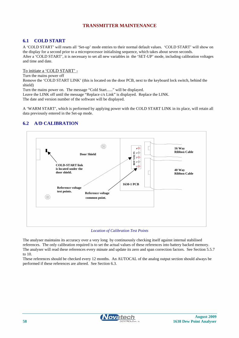
TRANSMITTER MAINTENANCE
6.1 COLD START A ‘COLD START’ will resets all ‘Set-up’ mode entries to their normal default values. ‘COLD START’ will show on the display for a second prior to a microprocessor initialising sequence, which takes about seven seconds. After a ‘COLD START’, it is necessary to set all new variables in the ‘SET-UP’ mode, including calibration voltages and time and date. To initiate a ‘COLD START’ - Turn the mains power off Remove the ‘COLD START LINK’ (this is located on the door PCB, next to the keyboard lock switch, behind the shield) Turn the mains power on. The message “Cold Start......” will be displayed. Leave the LINK off until the message “Replace c/s Link” is displayed. Replace the LINK. The date and version number of the software will be displayed. A ‘WARM START’, which is performed by applying power with the COLD START LINK in its place, will retain all data previously entered in the Set-up mode.
6.2 A/D CALIBRATION
Ribbon Cable
Ribbon Cable
Reference voltage
Reference voltagetest points.
common point.
Door Shield
RE
F V
OL
TS
1630-1 PCB
1
C
4
3
2
40 Way
16 Way
COLD-START linkis located under thedoor shield.
Location of Calibration Test Points The analyser maintains its accuracy over a very long by continuously checking itself against internal stabilised references. The only calibration required is to set the actual values of these references into battery backed memory. The analyser will read these references every minute and update its zero and span correction factors. See Section 5.5.7 to 10. These references should be checked every 12 months. An AUTOCAL of the analog output section should always be performed if these references are altered. See Section 6.3.
August 2009 58 1638 Dew Point Analyser
August 2009 1638 Dew Point Analyser 59
6.3 D/A (4-20MA OUTPUT CHANNELS) CALIBRATION The calibration can either be done using the ‘Auto Cal’ or ‘Manual Cal’. Auto Cal The ‘Auto Cal’ mode is selected in set-up 13 (and 16 for channel 2). The analyser will automatically divert the output back to the input, measure the offset and span, and record the calibration factors for each channel. If either of the channels are selected to be calibrated manually, the factors will not be changed by an ‘Auto Cal’. Manual Cal The ‘Manual Cal’ mode is selected in set-up 13 (and 16). Set the 4mA calibration first and then the 20mA calibration. 1. Select ‘Set 4mA Trim’ in set-up 13 (or 16). 2. Return to RUN mode. 3. Measure the output on the channel to be calibrated with a digital multimeter. If the current is not exactly 4.00mA,
return to set-up mode and change the 4mA calibration factor in set-up 14 (or 17). 4. Re-measure the current while back in RUN mode until the current is within 3.9 to 4.1mA. 5. Return to set-up mode and select ‘Manual Cal’ in set-up 13 (or 16). Set the 20mA calibration factor. 6. Select ‘Set 20mA Trim’ in set-up 13 (or 16). 7. Return to RUN mode. 8. Measure the output on the channel to be calibrated with a digital multimeter. If the current is not exactly 20.00mA,
return to set-up mode and change the 20mA calibration factor in set-up 15 (or 18). 9. Re-measure the current while back in RUN mode until the current is within 19.9 to 20.1mA. 10. Return to set-up mode and select ‘Manual Cal’ in set-up 13 (or 16). This calibration is now saved in battery backed memory until The factors are changed in the manual calibration The analyser is forced into a COLD-START (see section 6.1) The calibration mode in set-up 13 (or 16) is changed to Auto Cal and an Auto Cal is initiated. NOTE: The 4mA or the 20mA trim mode will only be held on the output channels for 30 minutes before automatically returning to ‘Manual Cal’ mode in set-up 13 (or 16).
6.4 PUMP REPLACEMENT The reference air pump is mounted on the 1630-2 PCB in the base of the analyser. The operation of the pump is monitored by the analyser and alarms will be shown if a fault occurs. (“Pump Fail” alarm, “Pump Blocked” alarm ) To replace the pump, unplug all the field wiring terminals. ie. Probe connectors, power connector etc. Unplug the 10 way and the 40 way ribbon connectors. Remove the 5 captive screws that retain the terminal PCB in the base of the case. Remove the PCB from the case. The pump can now be un-screwed, and the wires un-plugged.
6.5 BACK-UP BATTERY REPLACEMENT The back-up battery is contained within the battery-like real time clock/memory module, plugged into socket M2. It is rated for an average service life of greater than ten years. The module is not re-chargeable and should be replaced every three years with a stored transmitters with power off or every eight years with a transmitters which have had the power on. The memory module must be purchased from Novatech Controls or an agent of Novatech Controls. After replacing the battery, re-enter all set-up mode functions.
6.6 ELECTRONIC REPAIRS Electronic schematics are included in Appendix 4. A competent electronic technician could perform troubleshooting with these schematics, aided by the analyser self-diagnostic alarms. It is recommended that service be performed on a change-over circuit board basis. A fast turn-around or replacement service is available from Novatech or accredited service agents. Other service aids, including a test EPROM firmware package and probe input simulator are also available.
August 2009 60 1638 Dew Point Analyser
6.7 INSTALLING A NEW PROBE OR SENSOR Whenever a new oxygen probe or sensor is installed, the millivolt offset value should be entered. To achieve this refer to set-up 11 (and 12 for the second sensor). The probe or sensor offset is noted on a tag or label attached to probe or sensor. To check an offset on site, the probe must be sensing air with reference air connected and allowed to settle at the operating temperature for 10 minutes. Read the offset in ‘RUN’ mode in millivolts on the lower line. Offset errors can occur if the sensor does not have some air passing over it. A gentle flow of air in the calibration check port can be provided by a reference air pump or similar. If a probe is in a process with the process running, the air purge on the sensing side of the sensor will only be successful if the probe has a filter or small sensing hole. Probes with open sensing ends or with large sensing holes allow the process gas to mix with the calibration gas, giving a false reading. For heated probes or sensors, if the combustion appliance is not operational and the probe or sensor heater is interlocked with the ‘FUEL ON’ signal, the ‘BURNER BYPASS’ switch should be set to ‘BYPASS’ to power the probe or sensor heater after removing the probe from the flue. For unheated probes, the sensing tip must be raised to at least 650°C with a portable furnace.
CAUTION DANGER
Return the ‘BURNER BYPASS’ switch to normal (off) before installing the probe in the flue.
6.8 TEST EQUIPMENT REQUIRED All measurements are simplified if an analyser is connected to the probe or sensor. Readings can then be easily taken of sensor impedance, EMF, temperature and percent oxygen. The analyser also provides proper heater control for heated probes or sensors. The following tests are described using readily available workshop equipment where an analyser is not available. If an analyser is available the same test procedures will apply. First check all alarms on the analyser, allowing time for the probe or sensor to heat up after switch on. An instrument to measure sensor EMF and temperature is required. A 3 1/2 or 4 1/2 digit multimeter will perform both measurements. A separate temperature indicator to suit the probe or sensor thermocouple type is also useful, although not necessary. A reference air pump is required and a cylinder of calibration check gas e.g. 2 % oxygen in nitrogen. The cylinder should have a pressure and flow regulator. Both of these are inexpensive devices available from gas supply companies. The calibration check gas should be chromatograph tested to an accuracy of 0.1 % oxygen.
TEST EQUIPMENT FOR UNHEATED PROBES A small test furnace capable of raising the probe tip temperature to 720 °C is required. The furnace should have a uniform temperature for about 50 mm either side of the sensor tip.
TEST EQUIPMENT FOR HEATED PROBES If a 1638 analyser is available at the test location then no other equipment will be required. If not, then a controllable power source for the heater is required. A Variac (variable transformer), set to approximately 100 or 240 volts will regulate the sensor temperature to 720° C.
August 2009 1638 Dew Point Analyser 61
6.9 TESTING A PROBE OR SENSOR With the sensor heated to approximately 720 °C, either from a small test furnace or its own internal heater, connect a digital multimeter to the sensor electrode conductors. Connect the multimeter positive to the internal electrode conductor. Connect reference air to and apply a gentle purge of air to the probe calibration check port. Reference air flow should be the smallest flow available (less than 50 cc per minute). The multimeter should read zero millivolts ± two millivolts. If not, then there is a problem with the probe electrodes and the sensor needs refurbishing. Normally a faulty probe electrode is indicated with a high source impedance. 1234 sensors do not require reference air but a gentle flow of air should be admitted into the sample connection. To test the source impedance, set the multimeter to read ohms and take a measurement within a couple of seconds, of the sensor impendence. Reverse the multimeter and repeat the reading. Take the average of the two readings for an approximate measurement of impedance. If the impedance is above 10kΩ, then the probe or sensor needs to be replaced. The sensor must be 720°C or above for this measurement. The reason that impedance measurements need to be performed quickly, is that the zirconia sensor polarises with the DC voltage from the multimeter across it. If the probe or sensor tests reveal less than 2 mV offset and a good impedance reading, the next step is to apply a calibration check gas. The calibration check gas should be inserted in the calibration check port. With the calibration check gas flowing, the sensor should develop an EMF according to the tables in Appendix 1. If the EMF reading is low then there may be insufficient calibration check gas flow. Increase the calibration check gas until the reading is correct. An excessive calibration check gas flow will cause cooling on one surface of the sensor, giving temperature differential errors on the sensor. As an alternative, using the reference air port, the calibration check gas can be inserted into the inside of a probe sensor. This requires a lower flow rate, and thus lower usage of calibration check gas. The flow rate should be similar to that of the reference air, which should be removed for internal calibration check. The sensor EMF reading will be identical but negative in polarity. A small flow of air should be flowing over the outside of the sensor, when testing in this way. Occasionally, a sensor can develop offset with a polluted electrode caused by contaminants in the flue gas stream. In this case the impedance may be OK but the output incorrect. This phenomena is rare.
6.10 PROBE OR SENSOR THERMOCOUPLE Although some unheated probes are specified without a thermocouple, most probes, both heated and unheated, have an integral thermocouple which is fitted in to the four bore insulator. The analyser has an alarm function which will advise the operator of an open circuit thermocouple, however bench testing can be performed by simply measuring the thermocouple continuity.
6.11 HEATER FAILURE For heated probe or sensors, a heater failure will cause a ‘PROBE TEMPERATE’ or ‘HEATER FAIL’ alarm. Heaters can be tested with a continuity test. The heater impedance should be approximately 100Ω. Should the heater be open or short circuited, replace the probe or sensor.
6.12 FILTER BLOCKAGE For oxygen probes or flow guide tubes with filters in installations with entrained solids in the flue gas, it is sometimes necessary to replace the filter. Filters are normally cleared with back purging. However fine fly-ash, or other particles can ultimately completely block a filter necessitating filter replacement. A new probe filter can be fitted
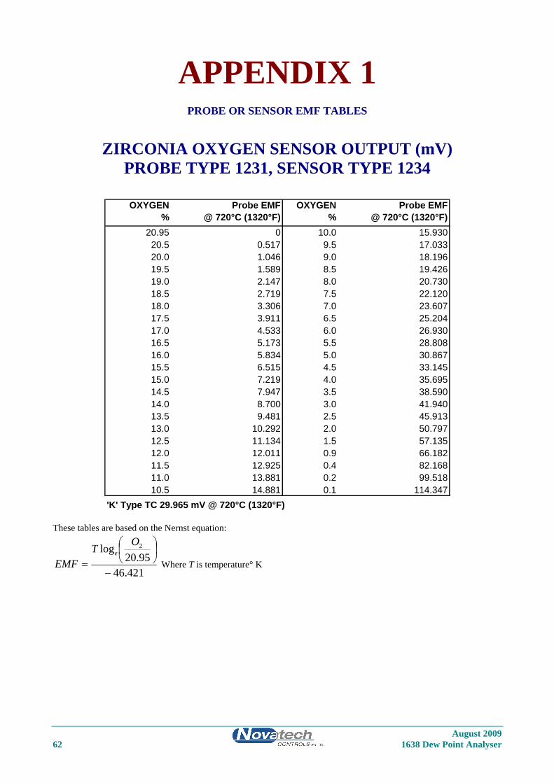
APPENDIX 1
PROBE OR SENSOR EMF TABLES
ZIRCONIA OXYGEN SENSOR OUTPUT (mV) PROBE TYPE 1231, SENSOR TYPE 1234
OXYGEN Probe EMF OXYGEN Probe EMF% @ 720°C (1320°F) % @ 720°C (1320°F)
20.95 0 10.0 15.93020.5 0.517 9.5 17.03320.0 1.046 9.0 18.19619.5 1.589 8.5 19.42619.0 2.147 8.0 20.73018.5 2.719 7.5 22.12018.0 3.306 7.0 23.60717.5 3.911 6.5 25.20417.0 4.533 6.0 26.93016.5 5.173 5.5 28.80816.0 5.834 5.0 30.86715.5 6.515 4.5 33.14515.0 7.219 4.0 35.69514.5 7.947 3.5 38.59014.0 8.700 3.0 41.94013.5 9.481 2.5 45.91313.0 10.292 2.0 50.79712.5 11.134 1.5 57.13512.0 12.011 0.9 66.18211.5 12.925 0.4 82.16811.0 13.881 0.2 99.51810.5 14.881 0.1 114.347
'K' Type TC 29.965 mV @ 720°C (1320°F) These tables are based on the Nernst equation:
421.4695.20
log 2
−
⎟⎠⎞
⎜⎝⎛
=
OTEMF
e
Where T is temperature° K
August 2009 62 1638 Dew Point Analyser
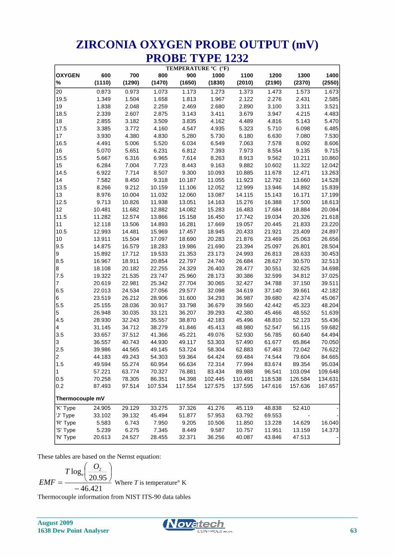
ZIRCONIA OXYGEN PROBE OUTPUT (mV) PROBE TYPE 1232
OXYGEN 600 700 800 900 1000 1100 1200 1300 1400% (1110) (1290) (1470) (1650) (1830) (2010) (2190) (2370) (2550)20 0.873 0.973 1.073 1.173 1.273 1.373 1.473 1.573 1.67319.5 1.349 1.504 1.658 1.813 1.967 2.122 2.276 2.431 2.58519 1.838 2.048 2.259 2.469 2.680 2.890 3.100 3.311 3.52118.5 2.339 2.607 2.875 3.143 3.411 3.679 3.947 4.215 4.48318 2.855 3.182 3.509 3.835 4.162 4.489 4.816 5.143 5.47017.5 3.385 3.772 4.160 4.547 4.935 5.323 5.710 6.098 6.48517 3.930 4.380 4.830 5.280 5.730 6.180 6.630 7.080 7.53016.5 4.491 5.006 5.520 6.034 6.549 7.063 7.578 8.092 8.60616 5.070 5.651 6.231 6.812 7.393 7.973 8.554 9.135 9.71515.5 5.667 6.316 6.965 7.614 8.263 8.913 9.562 10.211 10.86015 6.284 7.004 7.723 8.443 9.163 9.882 10.602 11.322 12.04214.5 6.922 7.714 8.507 9.300 10.093 10.885 11.678 12.471 13.26314 7.582 8.450 9.318 10.187 11.055 11.923 12.792 13.660 14.52813.5 8.266 9.212 10.159 11.106 12.052 12.999 13.946 14.892 15.83913 8.976 10.004 11.032 12.060 13.087 14.115 15.143 16.171 17.19912.5 9.713 10.826 11.938 13.051 14.163 15.276 16.388 17.500 18.61312 10.481 11.682 12.882 14.082 15.283 16.483 17.684 18.884 20.08411.5 11.282 12.574 13.866 15.158 16.450 17.742 19.034 20.326 21.61811 12.118 13.506 14.893 16.281 17.669 19.057 20.445 21.833 23.22010.5 12.993 14.481 15.969 17.457 18.945 20.433 21.921 23.409 24.89710 13.911 15.504 17.097 18.690 20.283 21.876 23.469 25.063 26.6569.5 14.875 16.579 18.283 19.986 21.690 23.394 25.097 26.801 28.5049 15.892 17.712 19.533 21.353 23.173 24.993 26.813 28.633 30.4538.5 16.967 18.911 20.854 22.797 24.740 26.684 28.627 30.570 32.5138 18.108 20.182 22.255 24.329 26.403 28.477 30.551 32.625 34.6987.5 19.322 21.535 23.747 25.960 28.173 30.386 32.599 34.812 37.0257 20.619 22.981 25.342 27.704 30.065 32.427 34.788 37.150 39.5116.5 22.013 24.534 27.056 29.577 32.098 34.619 37.140 39.661 42.1826 23.519 26.212 28.906 31.600 34.293 36.987 39.680 42.374 45.0675.5 25.155 28.036 30.917 33.798 36.679 39.560 42.442 45.323 48.2045 26.948 30.035 33.121 36.207 39.293 42.380 45.466 48.552 51.6394.5 28.930 32.243 35.557 38.870 42.183 45.496 48.810 52.123 55.4364 31.145 34.712 38.279 41.846 45.413 48.980 52.547 56.115 59.6823.5 33.657 37.512 41.366 45.221 49.076 52.930 56.785 60.640 64.4943 36.557 40.743 44.930 49.117 53.303 57.490 61.677 65.864 70.0502.5 39.986 44.565 49.145 53.724 58.304 62.883 67.463 72.042 76.6222 44.183 49.243 54.303 59.364 64.424 69.484 74.544 79.604 84.6651.5 49.594 55.274 60.954 66.634 72.314 77.994 83.674 89.354 95.0341 57.221 63.774 70.327 76.881 83.434 89.988 96.541 103.094 109.6480.5 70.258 78.305 86.351 94.398 102.445 110.491 118.538 126.584 134.6310.2 87.493 97.514 107.534 117.554 127.575 137.595 147.616 157.636 167.657
Thermocouple mV'K' Type 24.905 29.129 33.275 37.326 41.276 45.119 48.838 52.410 -'J' Type 33.102 39.132 45.494 51.877 57.953 63.792 69.553 - -'R' Type 5.583 6.743 7.950 9.205 10.506 11.850 13.228 14.629 16.040'S' Type 5.239 6.275 7.345 8.449 9.587 10.757 11.951 13.159 14.373'N' Type 20.613 24.527 28.455 32.371 36.256 40.087 43.846 47.513 -
TEMPERATURE ºC (°F)
These tables are based on the Nernst equation:
421.4695.20
log 2
−
⎟⎠⎞
⎜⎝⎛
=
OTEMF
e
Where T is temperature° K
Thermocouple information from NIST ITS-90 data tables
August 2009 1638 Dew Point Analyser 63
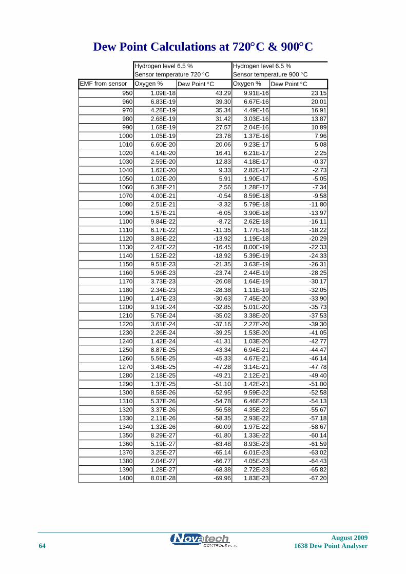
August 2009 64 1638 Dew Point Analyser
Dew Point Calculations at 720°C & 900°C
Hydrogen level 6.5 % Hydrogen level 6.5 % Sensor temperature 720 °C Sensor temperature 900 °C
EMF from sensor Oxygen % Dew Point °C Oxygen % Dew Point °C 950 1.09E-18 43.29 9.91E-16 23.15 960 6.83E-19 39.30 6.67E-16 20.01 970 4.28E-19 35.34 4.49E-16 16.91 980 2.68E-19 31.42 3.03E-16 13.87 990 1.68E-19 27.57 2.04E-16 10.89
1000 1.05E-19 23.78 1.37E-16 7.96 1010 6.60E-20 20.06 9.23E-17 5.08 1020 4.14E-20 16.41 6.21E-17 2.25 1030 2.59E-20 12.83 4.18E-17 -0.37 1040 1.62E-20 9.33 2.82E-17 -2.73 1050 1.02E-20 5.91 1.90E-17 -5.05 1060 6.38E-21 2.56 1.28E-17 -7.34 1070 4.00E-21 -0.54 8.59E-18 -9.58 1080 2.51E-21 -3.32 5.79E-18 -11.80 1090 1.57E-21 -6.05 3.90E-18 -13.97 1100 9.84E-22 -8.72 2.62E-18 -16.11 1110 6.17E-22 -11.35 1.77E-18 -18.22 1120 3.86E-22 -13.92 1.19E-18 -20.29 1130 2.42E-22 -16.45 8.00E-19 -22.33 1140 1.52E-22 -18.92 5.39E-19 -24.33 1150 9.51E-23 -21.35 3.63E-19 -26.31 1160 5.96E-23 -23.74 2.44E-19 -28.25 1170 3.73E-23 -26.08 1.64E-19 -30.17 1180 2.34E-23 -28.38 1.11E-19 -32.05 1190 1.47E-23 -30.63 7.45E-20 -33.90 1200 9.19E-24 -32.85 5.01E-20 -35.73 1210 5.76E-24 -35.02 3.38E-20 -37.53 1220 3.61E-24 -37.16 2.27E-20 -39.30 1230 2.26E-24 -39.25 1.53E-20 -41.05 1240 1.42E-24 -41.31 1.03E-20 -42.77 1250 8.87E-25 -43.34 6.94E-21 -44.47 1260 5.56E-25 -45.33 4.67E-21 -46.14 1270 3.48E-25 -47.28 3.14E-21 -47.78 1280 2.18E-25 -49.21 2.12E-21 -49.40 1290 1.37E-25 -51.10 1.42E-21 -51.00 1300 8.58E-26 -52.95 9.59E-22 -52.58 1310 5.37E-26 -54.78 6.46E-22 -54.13 1320 3.37E-26 -56.58 4.35E-22 -55.67 1330 2.11E-26 -58.35 2.93E-22 -57.18 1340 1.32E-26 -60.09 1.97E-22 -58.67 1350 8.29E-27 -61.80 1.33E-22 -60.14 1360 5.19E-27 -63.48 8.93E-23 -61.59 1370 3.25E-27 -65.14 6.01E-23 -63.02 1380 2.04E-27 -66.77 4.05E-23 -64.43 1390 1.28E-27 -68.38 2.72E-23 -65.82 1400 8.01E-28 -69.96 1.83E-23 -67.20
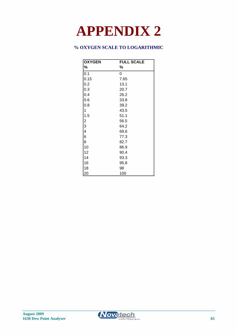
APPENDIX 2
% OXYGEN SCALE TO LOGARITHMIC
OXYGEN FULL SCALE% %0.1 00.15 7.650.2 13.10.3 20.70.4 26.20.6 33.80.8 39.21 43.51.5 51.12 56.53 64.24 69.66 77.38 82.710 86.912 90.414 93.316 95.818 9820 100
August 2009 1638 Dew Point Analyser 65

August 2009 66 1638 Dew Point Analyser
APPENDIX 3
SAMPLE LOG PRINT OUT Novatech Controls 04-07-1995 06:13:59 Oxygen % 1.86 EMF 1 mV 38.0 Probe Temp 458C Ambient T 21.9C Servc'd 03/07/95 Humidity 43% Sensor 1 Imp 5.7K Next Purge at 06:00:00 17-10-1995 Next Print at 06:27:00 17-10-1995 06:00:11 04-07-1995 Heater 1 Fail Is Active 06:00:13 04-07-1995 O2% Low Is Active 02:33:17 04-07-1995 RefPump Fail Accepted

August 2009 1638 Dew Point Analyser 67
APPENDIX 4
CIRCUIT SCHEMATICS
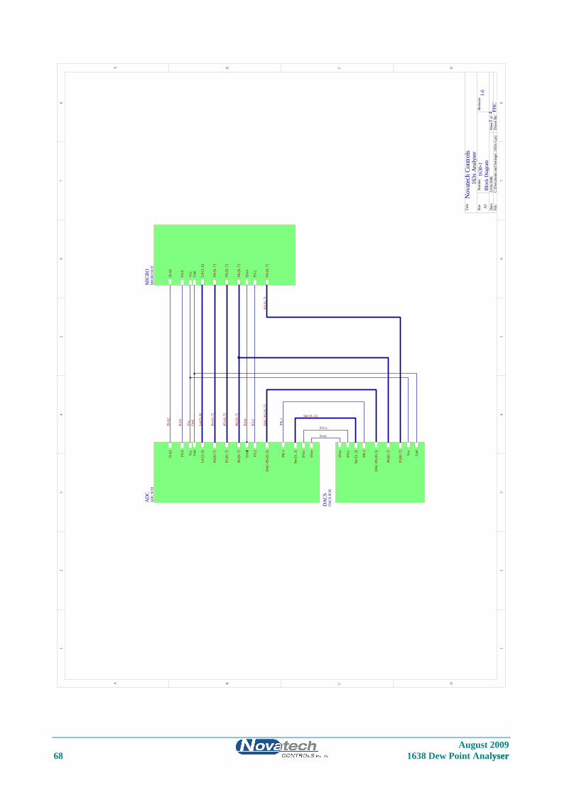
77
88
August 2009 68 1638 Dew Point Analyser yser
11
22
33
44
55
66
DD
BB
AA
CC
Title
Num
ber
Revi
sion
Size A3
Dat
e:22
/04/
2008
Shee
t o
fFi
le:
C:\D
ocum
ents
and
Set
tings
\..\1
63x-
1.pr
jD
raw
n By
:
Nov
atec
h Co
ntro
ls
1630
-1Bl
ock
Dia
gram
1.6
14 FH
C
163x
Ana
lyse
r
P5-[
0..7
]
L4-[
3..6
]
DA
C-PS
-[0.
.5]
P6-[
0..7
]
P4-[
0..7
]
D-A
2
P3-2
/P6-
1
Ser-[
1..5
]
SVcc
P3-0
Vcc
Gnd 01
Erro
r
SVee
AD
CA
DC.
SCH
DA
C-PS
-[0.
.5]
P6-[
0..7
]
P3-[
0..7
]
/P6-
1
Ser-[
1..5
]
SVcc
SVee
Vcc
Gnd
DA
CSD
ACS
.SCH
L4-[
3..6
]
D-A
2
P3-[
0..7
]
P4-[
0..7
]
P6-[
0..7
]
P5-[
0..7
]
P3-2
P3-0
Vcc
Gnd
Erro
r
MIC
ROM
ICRO
.SCH
L4-[
3..6
]
P4-[
0..7
]
P5-[
0..7
]
P6-[
0..7
]
DA
C-PS
-[0.
.5]
P3-[
0..7
]
Ser-[1..5]
SVcc
Vcc
P3-0
D-A
2
P3-2
/P6-
1
Gnd
Erro
r
Svee
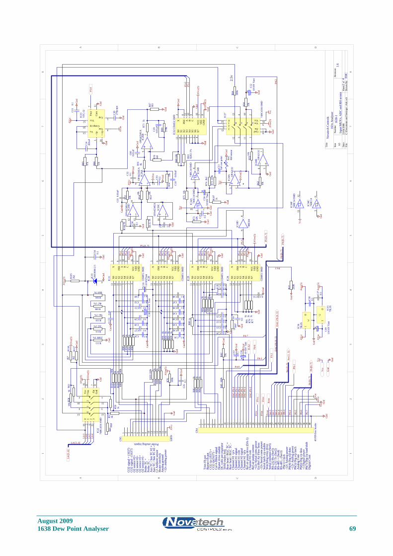
August 2009 1638 Dew Point Analyser 69
11
22
33
44
55
66
77
88
DD
CC
BB
AA
Title
Num
ber
Revi
sion
Size A3
Dat
e:22
/04/
2008
Shee
t o
fFi
le:
C:\D
ocum
ents
and
Set
tings
\..\A
dc.sc
hD
raw
n By
:
R5410
k
R5310
k
R52
10k
R56
10k
R51
1k
R70
1k8
R681
2K R63
82K
5 1%
R69
270k
R71
1k
R67
1k5
AV
cc
Gnd
C18
0.01
uF
C19
0.01
uFA
Vee
Gnd
C15
0.01
uF
X0
13
X1
14
X2
15
X3
12
X4
1
X5
5
X6
2
X7
4
INH
6
A11
B10
C9
VEE
7
X3
VCC
16
GN
D8
IC32
CD40
51 S
MD
X0
13
X1
14
X2
15
X3
12
X4
1
X5
5
X6
2
X7
4
INH
6
A11
B10
C9
VEE
7
X3
VCC
16
GN
D8
IC30
CD40
51 S
MD
Gnd
Gnd
Gnd
X0
13
X1
14
X2
15
X3
12
X4
1
X5
5
X6
2
X7
4
INH
6
A11
B10
C9
VEE
7
X3
VCC
16
GN
D8
IC28
CD40
51 S
MD
X0
13
X1
14
X2
15
X3
12
X4
1
X5
5
X6
2
X7
4
INH
6
A11
B10
C9
VEE
7
X3
VCC
16
GN
D8
IC31
CD40
51 S
MD
X0
13
X1
14
X2
15
X3
12
X4
1
X5
5
X6
2
X7
4
INH
6
A11
B10
C9
VEE
7
X3
VCC
16
GN
D8
IC29
CD40
51 S
MD
AV
ee(5
)
AV
ee(5
)
AV
ee(5
)
AV
ee(5
)
AV
cc(5
)
AV
cc(5
)
AV
cc(5
)
AV
cc(5
)
89
IC18
D
74H
C04
P5-[
0..7
]
014
15
26
12
3
11
1
13
4
10
2
Vcc
16
Gnd
83
15
Vee
90
12
3
/En
7
IC22
74H
C431
6 SM
D
R104
100k
R103
100k
R102
1k
R101
1k
R100
1k
R99
1kR9
710
0k
R98
100k
R96
1k
R95
1kR9
31k
R91
1kR8
91k
C33
1.0/
16V
Tant
C32 0.1
C31 0.1
C30
1.0/
16V
Tan
t
C29 0.1
C28 0.1
C27 0.1
C26 0.1
R94
1kR9
21k
R90
1k
Gnd
R113
250R 1%
R111
1k5 1%
R110
9k1 1%
R108
4k7 1%
R106
6k8 1%
R105
2k2
Gnd
AV
cc(5
)
R60
6k8
R57
1k
R61
1kR5
810
k
AV
cc(5
)
AV
ee(5
)
Gnd
L4-[
3..6
]
Gnd
Gnd
AV
cc
R88
1k
R86
1kR8
51k
R84
1kR8
31k
R82
1kR8
01k
R78
1k
R87
1k
R77
1kR7
91k
R81
1k
C25 0.1
C22 0.1
C21 0.1
C20 0.1 Gnd
Gnd
C24 0.1
Probe analog inputs
R45
100k
R42
10k
Gnd
C10
10/1
6Vt
Tan
Gnd
Gnd
Gnd
Gnd
AV
cc(5
)
AV
ee(5
)
Gnd
Gnd
AV
ee(5
)
R59
1k
R66
12k
R65
47k
C16
270p
npo
Gnd
AV
cc
AV
ee
Gnd
3 21
4 11
IC26
AO
PA42
34U
A
5 67
IC26
BPA
4234
UA
O
10 98
IC26
CO
PA42
34U
A
12 1314
IC26
DO
P4U
AA
423
O2
sens
or #
1+
Prob
e TC
+
Aux
TC
/ Sen
TC
#2 -
CO2
i/p(1
637)
-
Rear
hea
d / R
GC
TC -
Burn
er f/
b po
tTr
im f/
b po
t
Hea
ter i
nter
lock
+12v
ana
log
pow
er
P5-4
P5-3
P5-2
P5-5
P5-4
P5-3
P5-2
P5-4
P5-3
P5-2
P5-4
P5-3
P5-2
DC
volts
pre
-regu
lato
r50
/60
mai
ns fr
eq
Hea
ter d
rive
enab
le
/P6(
1) C
lock
+5 D
igita
l pow
er
Rear
hea
d / R
GC
TC +
Ana
log
grou
nd
CJ A
mbi
ent s
enso
r
R76
100k
AV
ee(5
)
Cal 4
-20m
A si
gnal
Chan
nel #
1 +p
/sCh
anne
l #1
signa
lCh
anne
l #1
com
Chan
nel #
2 sig
nal
Chan
nel #
2 +p
/s
Chan
nel #
2 co
m
-12v
Ana
log
pow
er
Ref a
ir pu
mp
driv
e (D
A-1
)
+12v
Ana
log
pow
er
Ref a
ir pu
mp
curre
nt
P4-7
P4-1
R12
250R
Gnd
P4-3
12
714
IC34
A74
HC1
4 SM
D3
4
IC34
B
74H
C14
SMD
014 15 26
12 3 11 1
13 4 10 2
Vcc 16
Gnd 8
315
Vee 90 1 2 3
/En 7
IC27
74H
C431
6 SM
D
R75
10k
R74
2k2
R73
220k
R5510
k
R62
10k
R50
10k
C23
0.1
C11
1uF
non
pola
r
C12
10/1
6V T
ant
R41
RH se
nsor
3 21
8 4
IC24
A OPA
2132 56
7
IC24
B OPA
2132
Vcc
AV
ee(5
)
Gnd
Gnd
Gnd
AV
ee(5
)V
cc
Gnd
Gnd
P5-0
P5-1
L4-3
L4-4
L4-5
L4-6
P4-2
DA
C-PS
-[0.
.5]
P6(4
) Dig
o/p
dat
a
P6(5
) Dig
o/p
latc
hA
nalo
g Co
mP6
(6) D
ig i/
p da
ta
P6(7
) Dig
i/p
load
/shift
Dig
ital C
om
/P6-
1
P6-4
P6-5
P6-6
P6-7
P4-0
Gnd
Gnd
Vcc
AV
ccAV
ee
Nov
atec
h Co
ntro
ls
1630
-1In
put M
UX
's, A
DC
and
RH se
nsor
1.6
24 FH
C
163x
Ana
lyse
r
L4-[3..6]
P6-[
0..7
]
P4-[
0..7
]
D-A
2
/P6-
1
P6-[
0..7
]
DA
C-PS
-[0.
.5]
DA
C-PS
-0D
AC-
PS-1
DA
C-PS
-2D
AC-
PS-3
DA
C-PS
-4
DA
C-PS
-5
P3-2
P4-[
0..7
]
P5-[0..7]
R107
1k
Gnd
C34
10/1
6V T
ant
1 2 3 4 5 6 7 8 9 10 11 12 13 14 15 16 17 18 19 20 21 22 23 24 25 26 27 28 29 30 31 32 33 34 35 36 37 38 39 40
CN4
40 P
IN b
ox h
eade
r
RS-4
85 +
(Ser
4)RS
-485
- (S
er3)
RS-2
32 T
x (S
er2)
RS-2
32 R
x (S
er1)
Seria
l com
mon
(Ser
5)W
atch
dog
rela
y dr
ive
CO2
i/p (1
637)
+
Ser-
[1..5
]
Ser-1
Ser-2
Ser-4
Ser-3
Ser-5
P4-6
Erro
r
Ser-
[1..5
]
Ext R
ef A
ir Fl
ow S
ens
1213
IC34
F74
HC1
4 SM
D
Vcc
R64
100k
2.5v
SVcc
SVee
SVcc
SVee
I
C
O
IC36
78L0
5
I
C
O IC35
79L0
5
C38
0.1
C37
0.1
C39
1.0/
16V
Tan
t
Gnd
R72
12K
Gnd
+ i/p
14
Vo13
Comp i/p10
Vcc12
- i/p
1
Fout
7
Com
11
Cap 5
Vee 4
IC23
VFC
-32
Gnd
C14
.001
uF
+12v
Ser
ial c
oms p
ower
-12v
Ser
ial c
oms p
ower
O2
sens
or #
1-
Prob
e TC
-A
ux T
C / S
en T
C #2
+
C13
0.1 G
nd
C35
0.1
Gnd
P3-0
Avc
c(5)
Ave
e(5)
AV
cc
AV
ee
GndVcc
GndVcc
56
IC34
C74
HC1
4
Gnd
1 2 3 4 5 6 7 8 9 10 11 12 13 14 15 16
CN5
16PI
N
O2
sens
or #
2+O
2 se
nsor
#2-
CO2
signa
l + (1
637)
CO2
signa
l - (1
637)
Seria
l lat
ch o
/p e
nabl
e
C40 0.1
Erro
r
C41 0.1
C42 0.1
C43 0.1
C44 0.1
C45 0.1
C46 0.1
C47 0.1
C48 0.1
Gnd
Gnd
Gnd
C49
0.1
R115
1k
R116
1k C50
0.1
C51 0.1
Gnd G
nd
C52
0.1
C53
0.1
Gnd
Gnd
C54
0.1
Gnd
C55 0.1G
nd
C56 0.1
C57
0.1
Gnd
C58
0.1
Gnd
C60
0.01
uF
Gnd
C59 0.1
GndVcc
R117
1k2
R118
4k7
Gnd
48
IC33
LM33
6M-2
.5
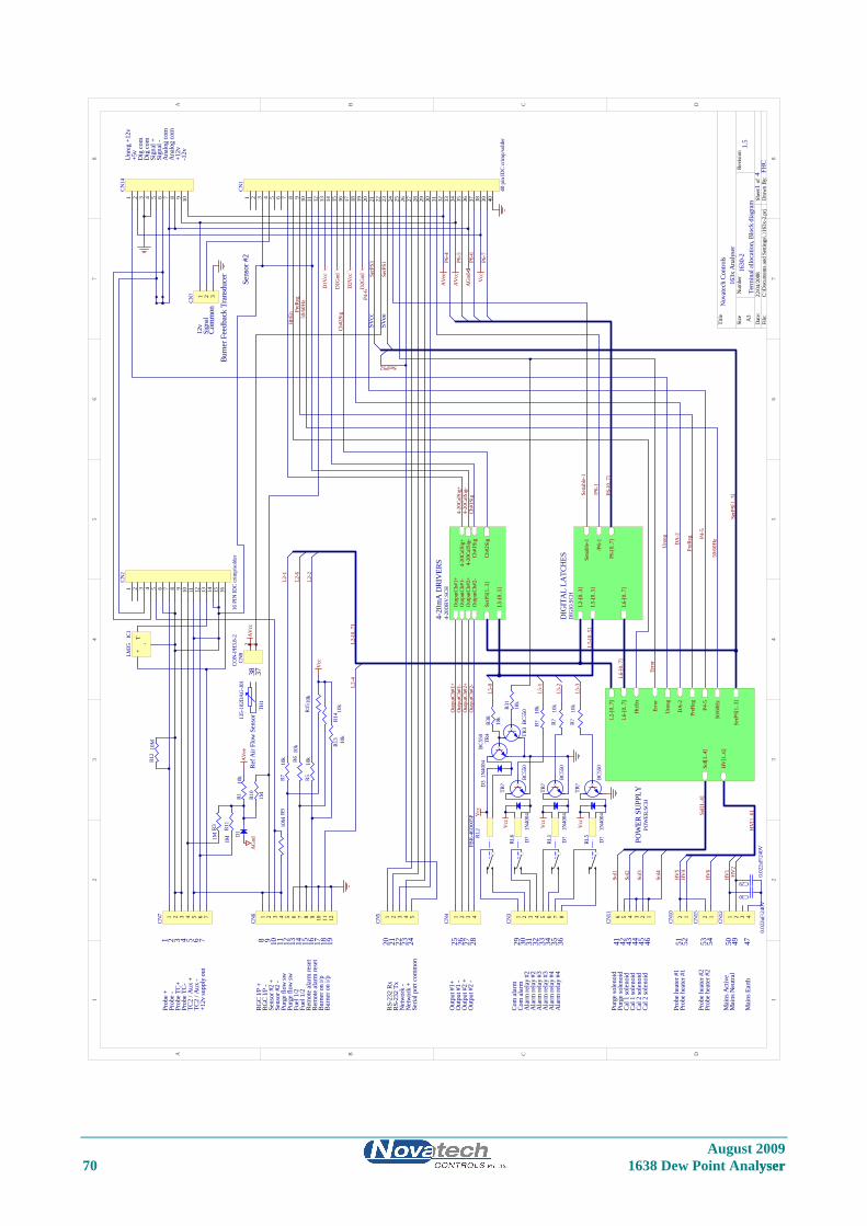
August 2009 70 1638 Dew Point Analyser yser
11
22
33
44
55
66
77
88
DD
CC
BB
AA
Title
Num
ber
Revi
sion
Size A3
Dat
e:22
/04/
2008
Shee
t o
fFi
le:
C:\D
ocum
ents
and
Set
tings
\..\1
63x-
2.pr
jD
raw
n By
:
Nov
atec
h Co
ntro
ls
1630
-2Te
rmin
al a
lloca
tion,
Blo
ck d
iagr
am1.
5
14 FH
C
163x
Ana
lyse
r
Prob
e +
Prob
e -
Prob
e TC
+Pr
obe
TC-
TC2
/ Aux
+TC
2 / A
ux -
Out
put #
1+
Out
put #
2 +
Out
put #
2 -
Out
put #
1 -
Purg
e flo
w sw
Purg
e flo
w sw
Fuel
1/2
Com
ala
rmCo
m a
larm
Ala
rm re
lay
#2A
larm
rela
y #2
Purg
e so
leno
idPu
rge
sole
noid
Cal 1
sole
noid
Cal 2
sole
noid
Prob
e he
ater
#1
Prob
e he
ater
#1
Mai
ns A
ctiv
eM
ains
Neu
tral
Mai
ns E
arth
Fuel
1/2
Cal 1
sole
noid
Cal 2
sole
noid
Burn
er o
n i/p
Burn
er o
n i/p
+12v
supp
ly o
ut
RGC
I/P +
RGC
I/P -
Sens
or #
2 +
Sens
or #
2 -
Rem
ote
alar
m re
set
Rem
ote
alar
m re
set
RS-2
32 R
xRS
-232
Tx
Net
wor
k -
Net
wor
k +
Seria
l por
t com
mon
Ala
rm re
lay
#3A
larm
rela
y #3
Ala
rm re
lay
#4A
larm
rela
y #4
T+
-
IC1
LM35
TR4
BC55
0 TR3
BC55
0
D3
1N40
04V
cc
1 2 3 4 5 6 7 8 9 10 11 12 13 14 15 16 17 18 19 20 21 22 23 24 25 26 27 28 29 30 31 32 33 34 35 36 37 38 39 40
CN1
40 p
in ID
C cr
imp/
sold
erR3
1
10k
R38
10k
R15 1
0k
R710
k
R510
kR610
k
R14 10
kR1
3 10k
Vcc
L5-[
0..5
]
L6-[
0..7
]
L2-[
0..3
]
P6-[
0..7
]
/P6-
1
Sena
ble-
1
DIG
ITA
L LA
TCH
ESD
IGIO
.SCH
Out
putC
h#1+
Out
putC
h#1-
Out
putC
h#2+
Out
putC
h#2-
4-20
CalS
ig+
Ch#1
Sig
Ch#2
Sig
L5-[
0..5
]
SerP
S[1.
.3]
4-20
CalS
ig-
4-20
mA
DRI
VER
S4-
20D
RV.S
CH
4-20
CalS
ig+
PreR
eg
50/6
0Hz
P6-7
P6-6
P6-4
/P6-
1
P6-5
P4-6
Vcc
AG
nd
AV
cc
AV
ee
D1V
cc
D1G
nd
D2V
cc
D2G
nd
50/6
0Hz
HV
[1..6
]
Sol[1
..4]
L2-[
0..7
]
HtrE
n
L6-[
0..7
]
DA
-2
P4-5
PreR
eg
SerP
S[1.
.3]
Unr
eg
Erro
r
L2-1
L2-6
L2-2
L2-[
0..7
]
L5-[
0..5
]
Sol1
Sol2
Sol3
HV
4H
V5
HV
1H
V2
POW
ER S
UPP
LYPO
WER
.SCH
Reow
Sen
sor
f Air
Fl
L2-4
P6-[
0..7
]
L6-[
0..7
]
Sol[1
..4]
HV
[1..6
]
1 2 3 4 5 6 7
CN7 1 2 3 4 5 6 7 8 9 10 11 12CN6 1 2 3 4 5
CN5 1 2 3 4
CN4 1 2 3 4 5 6 7 8
CN3 123456
CN11 12
CN10 1 2 3 4
CN12
TH1
135-
102D
AG
-J01
RL2
FBR-
46D
005P
RL6
RL1
RL5
Out
putC
h#1+
Out
putC
h#1-
Out
putC
h#2+
Out
putC
h#2-
L5-0
L5-1
L5-2
L5-3
HtrE
n
DA
-2
PreR
eg
P4-5
50/6
0Hz
Ch#1
Sig
Ch#2
Sig
R31M
R10
1M
R11
1M
12CN
8CO
N-P
H3.
8-2
3738A
Vcc
Sens
or #
2A
Vee
1 2 3 4 5 6 7 8 9 10 11 12 13 14 15 16 17 18 19 20 21 22 23 24 25 26 27 28 29 30 31 32 33 34 35 36 41 42 43 44 45 46 50 49 4751 52
Sol4
SerP
S[1.
.3]
SerP
S1
SerPS2
SerP
S3SV
cc
SVee
D1
R110
k
AG
nd
R12
10M
4-20
CalS
ig-
R910
M
1 2 3 4 5 6 7 8 9 10 11 12 13 14 15 16
CN2
16 P
IN ID
C cr
imp/
sold
er
1 2 3 4 5 6 7 8 9 10
CN14
Unr
eg +
12v
+5v
Dig
com
Dig
com
Sign
al +
Sign
al -
Ana
log
com
Ana
log
com
+12v
-12v
Unr
eg
Sena
ble-
1
Prob
e he
ater
#2
Prob
e he
ater
#2
12
CN15
53 54H
V6
C29
0.02
2uF/
240V
C30
0.02
2uF/
240V
Erro
r
TR?
BC55
0
TR?
BC55
0
TR?
BC55
0
D?
1N40
04
D?
1N40
04
D?
1N40
04
R?10
k
R?10
k
R?10
k
Vcc
Vcc
Vcc
1 2 3
CN?
12v
Sign
alCo
mm
onBu
rner
Fee
dbac
k Tr
ansd
ucer
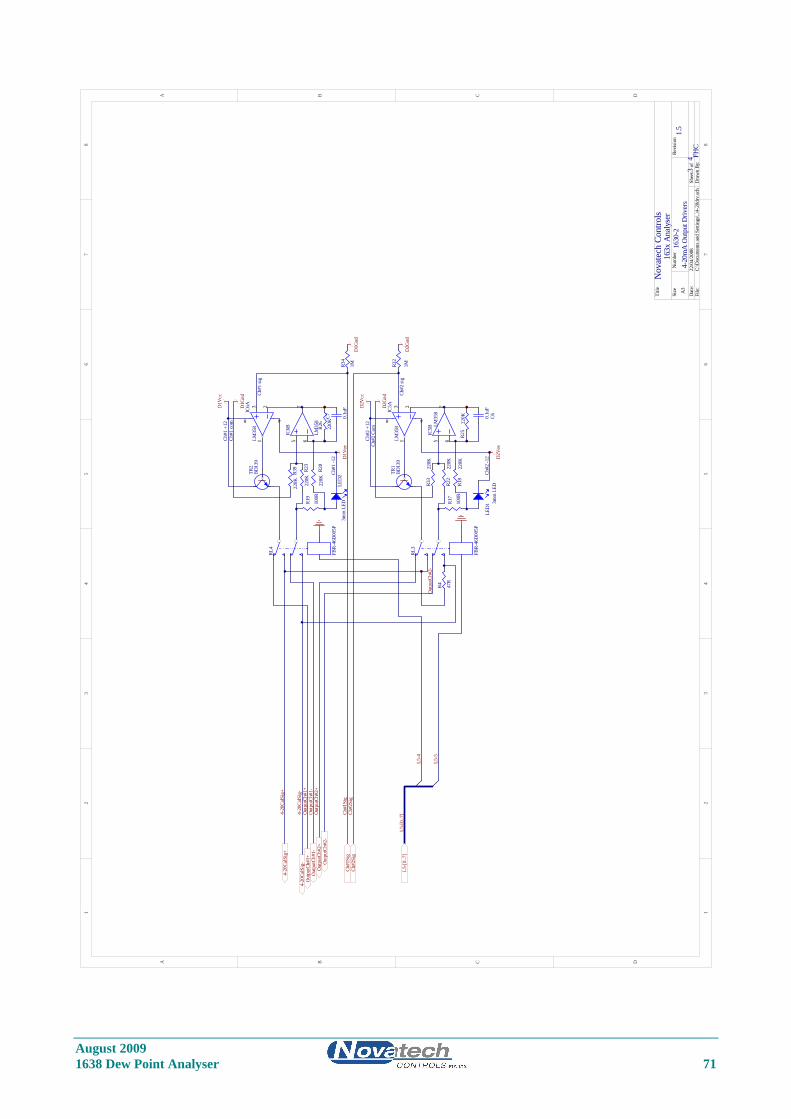
77
88
August 2009 1638 Dew Point Analyser 71
11
22
33
44
55
66
DD
BB
AA
CC
Title
Num
ber
Revi
sion
Size A3
Dat
e:22
/04/
2008
Shee
t o
fFi
le:
C:\D
ocum
ents
and
Set
tings
\..\4
-20d
rv.sc
hD
raw
n By
:
Nov
atec
h Co
ntro
ls
1630
-24-
20m
A O
utpu
t Driv
ers
1.5
34 FH
C
163x
Ana
lyse
r
D1G
nd
D2G
nd
R19
100R
5 67
IC6B
LM35
8
R23
220K
R20
220K
R26
220K
R39
220K LE
D2
3mm
LED R1
7
100R
5 67
IC5B
LM35
8
R22
220K
R18
220K
R25
220K
R32
1M
LED
1 3mm
LED
3 21
8 4
ICLM
358
6A 3 21
8 4
ICLM
358
5A
Ch#1
+12
Ch#1
-12
Ch#1
sig
Ch#1
com
D1V
cc
D1G
nd
D1V
ee
Ch#2
+12
Ch#2
Com
Ch#2
-12
Ch#2
sig
D2V
ee
D2V
cc
D2G
nd
Out
putC
h#1+
Out
putC
h#1-
Out
putC
h#2+
Out
putC
h#2-
4-20
CalS
ig+
Ch#1
Sig
Ch#2
Sig
L5-4
L5-5
L5-[
0..7
]
RL4
FBR-
46D
005P
RL3
FBR-
46D
005P
TR2
BD13
9
TR1
BD13
9L5
-[0.
.7]4-
20Ca
lSig
+
Out
putC
h#1+
Out
putC
h#1-
Out
putC
h#2+
Out
putC
h#2-
Ch#2
Sig
Ch#1
Sig
R34
1M
R33
220K
C7 0.1u
F
C60.1u
F
R4 47R
4-20
CalS
ig-
4-20
CalS
ig-
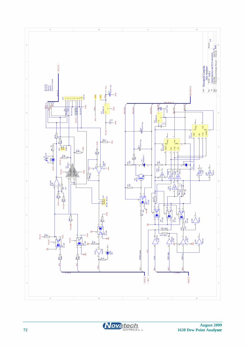
August 2009 72 1638 Dew Point Analyser yser
11
22
33
44
55
66
77
88
DD
CC
BB
AA
Title
Num
ber
Revi
sion
Size A3
Dat
e:22
/04/
2008
Shee
t o
fFi
le:
C:\D
ocum
ents
and
Set
tings
\..\D
acs.s
chD
raw
n By
:
REFi
n6
Agnd 5
Vou
t7
Vdd8
Din
1
CLK
2
/CS
3
Dou
t4
IC1
MA
X53
8
R2 4K7
48
IC2
LM33
6M-2
.5
R111
K
R10
1K
R91K
R29 220R
R24 220R R23
220R
Vcc
DA
C da
ta
DA
C cs
48
IC7
LM33
6M-2
.5
R5 10K
R4 6k8
R30
1K
R3 10K
C3 10/1
6V T
ant
Gnd
PWM
out
put
LED
1
R14
10k
R22
1K
R81k
R27
47k
R32
470R
R21
1k
R13
10k
R19
100k
R25
10k
R7 100R
567
IC8B
LM14
58
3 21
8 4
IC8A
LM14
58
SVcc
(5)
SGnd
SGnd
SGnd
SVee
SVee
SVcc
SGnd
R28
2k2
RX
Tx
I
C
O
IC3
LM34
0L-0
5
C20.1
C410
/25V
Tan
t
R36
470R
R35
1K
Vcc
Gnd
Gnd
SGnd
SGnd
SGnd
LED
2
123
LK3
RS-4
85
RS-2
32
SVcc
(5)
R26
47k
SVcc
(5)
Vcc
SGnd
RS-2
32 R
x
RS-2
32 C
om
RS-2
32 T
xN
et +
Net
-
SVcc
(5)
+12
Isol
ated
1 2 3 4 5 6 7 8 9 10
CN1
CON
-10
RS-2
32 R
xRS
-232
Tx
Net
wor
k -
Net
wor
k +
Seria
l por
t com
mon
RS-4
85 D
ir
DA
C-PS
-[0.
.5]
P6-1
P3-3
P6-2
P6-3
Cloc
k
/P6-
1
P3-5
P3-7
P3-4
P6-[
0..7
]
R18
1kSV
cc(5
)
R1 1k
Nov
atec
h Co
ntro
ls
1630
-1Se
rial i
nter
face
and
D/A
con
verte
rs1.
63
4 FHC
163x
Ana
lyse
r
P3-[
0..7
]
/P6-
1
P3-[0..7] P6-[0..7]
DA
C-PS
-0
DA
C-PS
-1
DA
C-PS
-2
DA
C-PS
-3
DA
C-PS
-4
DA
C-PS
-5
Ser-1
Ser-2
Ser-3 Se
r-4 Ser-5
Ser-
[1..5
]Se
r-[1
..5]
Tx4
TXen
3
/RX
en2
Rx1
NET
-7
NET
+6
Vcc8 Gnd 5
IC5
SP48
5CS
TR1
BC81
7
Vcc
R20
27k
SVcc
12LK
2
LIN
K-2
I
C
O
IC4
LM34
0L-0
5
SGnd
C6 10/1
6V T
ant
C5 10/2
5V T
ant
C1 0.1
SGnd
SGnd
SVcc
SVcc
(5)
REF
6
Gnd 5
Vou
t7
Vcc8
Din
2
CLK
1
/LO
AD
3
Dou
t4
IC37
LTC1
257
DAC-PS-[0..5]SV
cc
SVee
SVee
SVcc
SVee
SGnd
12
714
IC6A
74H
C14
34
IC6B74
HC1
4
56
IC6C
74H
C14
89
IC6D
74H
C14
1011
IC6E
74H
C14
1213
IC6F
74H
C14
GndVcc
12
714
IC10
A74
HC0
4
34
IC10
B
74H
C04
56
IC10
C
74H
C04
89
IC10
D
74H
C04
1011
IC10
E74
HC0
41213
IC10
F74
HC0
4
D1
BAV
99
1 3
4 5
6O
P4PC
-400
1 3
4 5
6
OP7
PC-4
00
1 3
4 5
6
OP6
PC-4
00
1 3
4 5
6
OP5
PC-4
00
SVcc
(5)
SVcc
(5)
Vcc
1 3
4 5
6
OP3
PC-4
00
1 3
4 5
6
OP2
PC-4
00
1 3
4 5
6
OP1
PC-4
00
R119
470
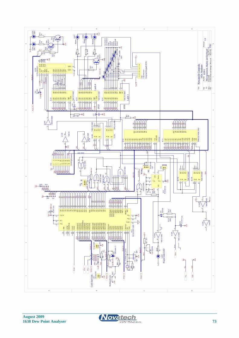
August 2009 1638 Dew Point Analyser 73
11
22
33
44
55
66
77
88
DD
CC
BB
AA
Title
Num
ber
Revi
sion
Size A3
Dat
e:22
/04/
2008
Shee
t o
fFi
le:
C:\D
ocum
ents
and
Set
tings
\..\M
icro
.sch
Dra
wn
By:
1 2 3 4 5 6 11 12
8IC
16
74H
C30
SMD
56
IC18
C
74H
C04
SMD
1213
IC18
F74
HC0
4 SM
D
12
714
IC18
A
74H
C04
SMD
8 910
IC15
C
74H
C02
SMD
12 3
IC15
A
74H
C02
SMD
D0
3Q
02
D1
4Q
15
D2
7Q
26
D3
8Q
39
D4
13Q
412
D5
14Q
515
D6
17Q
616
D7
18Q
719
OE
1
CLK
11
IC20
74H
C374
SM
D
D0
3Q
02
D1
4Q
15
D2
7Q
26
D3
8Q
39
D4
13Q
412
D5
14Q
515
D6
17Q
616
D7
18Q
719
OE
1
CLK
11
IC14
74H
C374
SM
D
D0
3Q
02
D1
4Q
15
D2
7Q
26
D3
8Q
39
D4
13Q
412
D5
14Q
515
D6
17Q
616
D7
18Q
719
OE
1
LE11
IC25
74H
C373
SM
D
LGnd
1
Vcc
2
V1
3
RSel
4
R/W
5
E6
LD0
7
LD1
8
LD2
9
LD3
10
LD4
11
LD5
12
LD6
13
LD7
14
LED+ 16
LED- 15Gnd
30
Gnd
31
Gnd
32
Gnd
33
LCD
1LC
D-L
M16
A21
A0
10
A1
9
A2
8
A3
7
A4
6
A5
5
A6
4
A7
3
A8
25
A9
24
A10
21
A11
23
A12
2
A13
26
A14
27
A15
1
/CS
20
OE/
VPP
22
DO
11
D1
12
D2
13
D3
15
D4
16
D5
17
D6
18
D7
19
IC12
27C5
12
A0
10
A1
9
A2
8
A3
7
A4
6
A5
5
A6
4
A7
3
A8
25
A9
24
A10
21
A11
23
A12
2
A13
26
A14
1
/CS
20
/OE
22
DO
11
DI
12
D2
13
D3
15
D4
16
D5
17
D6
18
D7
19
R/W
27
IC13
HM
6225
6 W
IDE
SMD
D0
D1
D2
D3
D4
D5
D6
D7
A14
B13
E15
Y0
12
Y1
11
Y2
10
Y3
9
IC17
B
74H
C139
SM
D
A2
B3
E1
Y0
4
Y1
5
Y2
6
Y3
7
IC17
A
74H
C139
SM
D
A2
B3
E1
Y0
4
Y1
5
Y2
6
Y3
7
IC19
A74
HC1
39 S
MD
A14
B13
E15
Y0
12
Y1
11
Y2
10
Y3
9
IC19
B74
HC1
39 S
MD
R44
47K
Gnd
Gnd
Vcc
Gnd
SIP410
K 9
PIN
VccTR
2BC
817
R31
1K
D0
D1
D2
D3
D4
D5
D6
D7
A14
A15
A14
A13
A12
A11
A10
A9
A8
A7
A6
A5
A3
A4
AB
Gnd
45 6
IC15
B
74H
C02
SMD
2
Vcc8
3
Vss 4Cl
k7
Sw-in
1o/
p6
IC21
TC12
32CO
A
R49
10k
Vcc
Gnd
Reset
LCD
-R/W
Gnd
Vcc
Latc
h 4
Latc
h 1
A0
LCD
-R/W
D0
D1
D2
D3
D4
D5
D6
D7
D0
D1
D2
D3
D4
D5
D6
D7
D0
D1
D2
D3
D4
D5
D6
D7
D0
D1
D2
D3
D4
D5
D6
D7
A0
A1
A2
A3
A4
A5
A6
A7
A8
A9
A10
A11
A12
A13
A14
A15
R/W
PH
Vcc
Vcc
Gnd
1 3 5 7 9 11 13 15 17 19
2 4 6 8 10 12 14 16 18 20
CN2
20 P
IN (p
in h
eade
r)
D1
D2
D3
D4
D5
D6
D7
A4
A5
A2
A3
A1
A0
/PH
R/W
D0
Vcc
Gnd
SIP1 47k
Vcc
PH/PH
A0
A1
A2
A3
A4
A5
A7
A8
A9
A10
A11
A12
A13
A14
A15
A6
A0
A1
A2
A3
A4
A5
A7
A8
A9
A10
A11
A12
A13
A14
A6
R/W
P3-0
P3-1
P3-2
P3-3
P3-4
P3-5
P3-6
P3-7
P4-1
P4-3
P4-4
P4-5
P4-7
P5-0
P5-1
P5-2
P5-3
P5-4
P5-5
P5-6
P5-7
P6-0
P6-1
P6-2
P6-3
P6-4
P6-5
P6-6
P6-7
48
IC9
LM33
6M-2
.5
R16
2K2
GndVcc
R40
1M
XL1
10.0
Mhz
low
pro
file
C9 6p8
C7 6p8
Gnd
123
LK4
1 2LK5
Cold
star
t Lin
k
1FF0
1FC0
1F80-1FFF
TR4
BC81
7 TR3
BC81
7
R38
4k7
R37
4k7
Gnd
P5-6
L4-[
3..6
]
L4-3
L4-4
L4-5
L4-6
P4-0
P4-2
P4-4
P3-1
P3-2
P3-6
Gnd
Vcc
+
M1
DS1
994
Gnd
Nov
atec
h Co
ntro
ls
1630
-1M
icro
proc
esso
r, di
spla
y an
d ke
yboa
rd1.
64
4 FHC
163x
Ana
lyse
r
/WR
20
SYN
C23
RESE
Tout
24
D-A
167
D-A
266
P3(0
) EV
13
P3(1
) EV
22
P3(2
) EV
379
P3(3
) PW
Mou
t78
P3(4
) RxD
77
P3(5
) TxD
76
P3(6
) Scl
k75
P3(7
) Srd
y74
P4(0
) AN
065
P4(1
) AN
164
P4(2
) AN
263
P4(3
) AN
362
P4(4
) AN
461
P4(5
) AN
560
P4(6
) AN
659
P4(7
) AN
758
DA
-Vre
f68
P5(0
)11
P5(1
)10
P5(2
)9
P5(3
)8
P5(4
)7
P5(5
)6
P5(6
)5
P5(7
)4
AD
-Vre
f69
Xin
28
Xou
t29
/RD
21/R
ESET
26
P6(7
)12
P6(6
)13
P6(5
)14
P6(4
)15
P6(3
)16
INT3
P6(
2)17
D7
33D
634
D5
35D
436
D3
37D
238
D1
39D
040
PH31
R/W
22
A15
42A
1443
A13
44A
1245
A11
46A
1047
A9
48A
849
A7
50A
651
A5
52A
453
Vcc72
CN25
A-Vcc71
AVss 70
Vss 32
Vss 73INT2
P6(
1)18
INT0
P6(
0)19
A3
54A
255
A1
56A
057
IC11
M37
451S
4FP
SMD
L4-[3..6]
D-A
2
P3-[
0..7
]
P4-[
0..7
]
P5-[
0..7
]
P6-[
0..7
]
P3-[
0..7
]
P4-[
0..7
]
P5-[
0..7
]
P6-[
0..7
]
SIP2
1k
12
LK1
2x1
pin
link
P3-0
P6-0
P5-[
0..7
]P5
-[0.
.7]
P3-2
R/W
PH
89
IC34
D
74H
C14
SMD
1011
IC34
E
74H
C14
SMD
R112
2M2
R114
100K
C36
1.0/
16V
Tan
t
Gnd
Erro
r
Pow
er/re
set L
ED
111213
IC15
D
74H
C02
SMD
123
LK6
3x1
pin
link
A0
W/d
og
A0
R109
1k
SW7
SW9
SW3
SW8
SW6
SW4
SW2
Gnd
R39
1kR43
1k R46
1k
LED
7
LED
6
LED
5 Gnd
LED
8
Vcc
A[0
..15]
LED
4LE
D3
R34
1kR3
31k
Vcc
R48 1M
R47
1M
Gnd
Gnd
C8 10/1
6V T
antGnd
Ala
rmA
utoc
al
Dis
play
Purg
e
Setu
p m
ode
Cal c
heck
#2
Neu
tral
Cal c
heck
#1
R6 10k
Vcc
SIP3 47K
Vcc
D0
D1
D2
D3
D4
D5
D6
D7
A6
C17
100p
Gnd
R17
4k7
Vcc
1011
IC18
E
74H
C04
34
IC18
B
74H
C04
SW5
P3-0
INC
DEC
P4-5
SW1
Gnd
Key
boar
d Lo
ck
R15
10k
Vcc
Vcc
Vcc
12345678
CN3
CON
-PH
3.8-
8
Gnd
Vcc
Exte
rnal
Key
pad/
LED
's
Ala
rm
Setu
p
Neu
tral
P4-6
Gnd
Gnd
Gnd
Erro
r
Vcc
Gnd
D3
BAV
99
D2
BAV
99
Gnd
P5-7
Gnd
Vcc
C61
0.1
Gnd
C62
0.1
Vcc
12
LK7
2x1
pin
link
Gnd
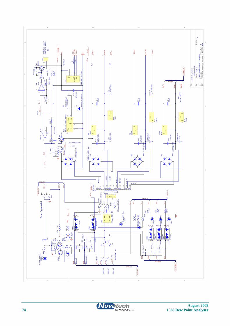
August 2009 74 1638 Dew Point Analyser yser
11
22
33
44
55
66
77
88
DD
CC
BB
AA
Title
Num
ber
Revi
sion
Size A3
Dat
e:22
/04/
2008
Shee
t o
fFi
le:
C:\D
ocum
ents
and
Set
tings
\..\P
ower
.sch
Dra
wn
By:
Nov
atec
h Co
ntro
ls
1630
-2Po
wer
Sup
ply,
Ref
eren
ce a
ir pu
mp
1.6
44 FH
C
BR3
W04
1A
brid
ge re
ct
C14
2200uF/25v RB, 0.3"
C13
470u
F/16
v
/En 5
Gnd 3
Vou
t2
Vin
1
F/B
4
IC12
LM25
75T-
5.0,
smal
l hea
tsin
k
D4
SR10
4 Sc
hotk
y di
ode
L1 PE 9
2114
330
uH
C20
220u
F/35
vC9 1.
0uF
Tant
12v
+5v
330m
A
-12v
C21
220u
F/35
vC1
10.
1uF
BR2
W04
1A
brid
ge re
ct
C26
220u
F/35
vC1
01.
0uF
Tant
C27
220u
F/35
v
C12
0.1u
F
BR4
W04
1A
brid
ge re
ct
C19
220u
F/35
vC1
51.
0uF
Tant
C25
220u
F/35
v
C17
0.1u
F
BR1
W04
1A
brid
ge re
ct
1 2
11
3
87 1210 1618 1315 1417
TF1
SD-9
26c
TR6
BC55
0R4
3
10k
R42
1k50
/60H
z
Out
Out
3
In1
In2
FL1
PLA
M 2
321
R9FS
1
FS2
Vcc
HV
[1..6
] Sol[1
..4]
Sol1
Sol2
Sol3
L2-[
0..7
] L2-3 L2
-4
HtrE
n
L6-[
0..7
]
L6-1
L6-2
L6-3
+in
1
-in2
-out
3
com
-out
4
+out
5
PS1
HPR
-104
(5 to
+/-1
2v)
TR5
BD14
0
R27
1ohm
R24
12k
R16
10k
3 21
8 4
IC4A
LM35
8
5 67
IC4B
LM35
8R2
9
150
DA
-2
40 R
ef a
ir pu
mp
-39
Ref
air
pum
p +
R21
5k6
R28
1k
P4-6
163x
Ana
lyse
r
Mai
ns E
Hea
ter c
om
Hea
ter 1
Mai
ns N
Mai
ns A
L2-0
HV
1
HV
2 HV
3
HV
4
HV
5
Vcc
AV
ee
AG
nd
AV
cc
D1V
cc
D1V
ee
D1G
nd
D2V
ee
D2V
ccD
2Gnd
-12v
+12v
DA
C 2
Com
PreR
eg
12v/
300
15v/
30
15v/
30
15v/
30
15v/30
15v/
50
15v/
50
240v
110v
C810
/35v
Ele
ct
R30
680
C310uF
/16v
RB
L6-0
C1 0.1u
F
1 2
CN9
AA
KK
22
11
SSR4
S202
-S02
AA
KK
22
11
SSR3
S202
-S02
AA
KK
22
11
SSR2
S202
-S02
AA
KK
22
11
SSR1
S202
-S02
I
C
O
IC8
78L1
2
I
C
O
IC10
79L1
2
I
C
O
IC9
78L1
2
I
C
O
IC11
79L1
2
I
C
O
IC13
78L1
2
I
C
O
IC14
79L1
2
SW3
V20
2-12
-MS-
02-Q
RL7
SW1
R40
1kLE
D3
Burn
er o
n LE
DBu
rner
Byp
ass s
witc
h
SW2
POW
ER O
N
LED
4H
eate
r #1
On
C22
0.02
2uF
C18
0.02
2uF
C16
0.02
2uF
HV[1..6]
Sol[1..4]
L6-[0..7]
L2-[0..7]
50/6
0Hz
PreR
eg
P4-6
DA
-2
HtrE
n
R37
220R
R36
220R
R35
220R
R41
220R
LED
7
LED
6
LED
5
C28
0.02
2uF
Sol4
D5
1N40
04
SerP
S1
SerP
S2
SerP
S3
SerPS[1..3]
SerP
S[1.
.3]
C24
0.02
2uF
C23
0.02
2uF
12345
CN13
AA
KK
22
11
SSR5
S202
-S02
HV
6 eate
Hr 2
R44
220R
L6-4
LED
8H
eate
r #2
On
0-2.
5v
0-5v
Unr
eg
FS3
250m
A a
xial
lead
fuse
Unr
eg
TR11
BC56
0
R48 10k
R50
10k
TR10BC560
R49
10k
R51
10k
R47
10k
TR12
BC55
0
Erro
r
L6-5
Erro
r
Vcc
R56
10k
C331
.0uF
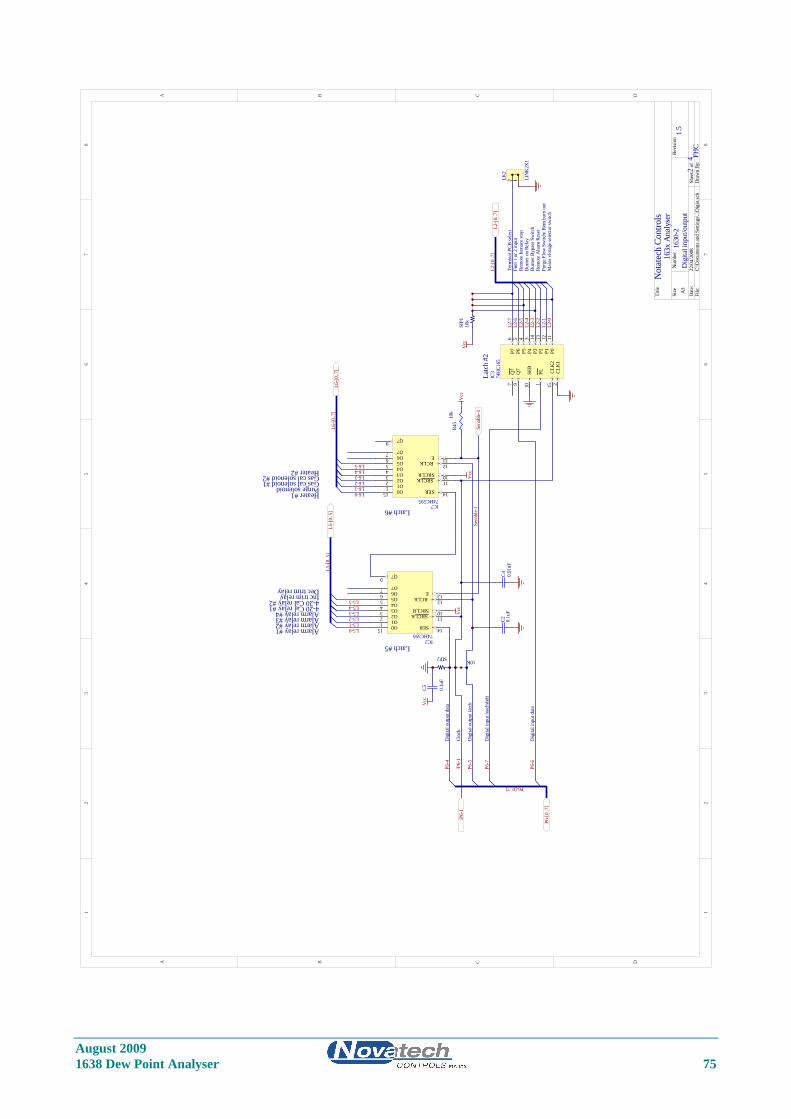
August 2009 1638 Dew Point Analyser 75
11
22
33
44
55
66
77
88
DD
BB
AA
CC
Title
Num
ber
Revi
sion
Size A3
Dat
e:22
/04/
2008
Shee
t o
fFi
le:
C:\D
ocum
ents
and
Set
tings
\..\D
igio
.sch
Dra
wn
By:
Not
atec
h Co
ntro
ls
1630
-2D
igita
l inp
ut/o
utpu
t1.
52
4 FHC
163x
Ana
lyse
r
SER 14
SRCLK 11
SRCLR 10
RCLK 12
E 13
O015
O11
O22
O33
O44
O55
O66
O77
Q79
IC274HC595
SER 14
SRCLK 11
SRCLR 10
RCLK 12
E 13
O015O11
O22
O33
O44
O55
O66
O77
Q79
IC774HC595
Vcc
Vcc
SER
10
P011
P112
P213
P314
P43
P54
P65
P76
CLK
12
CLK
215
PL1
Q7
9Q
77
IC3
74H
C165
Dig
ital o
utpu
t dat
a
Cloc
k
Dig
ital o
utpu
t lat
ch
Dig
ital i
nput
dat
a
Dig
ital i
nput
load
/shi
ftL5-0L5-1L5-2L5-3L5-4L5-5
L6-0L6-1
L5-[
0..5
]L6
-[0.
.7]
L2-0
L2-1
L2-3
L2-4
L2-5
L2-6
L2-7
L2-[
0..7
]
P6-4
P6-5
P6-6
Rem
ote
furn
ace
stop
Purg
e Fl
ow S
witc
h/ R
em b
urn
out
Fuel
1 o
r 2 in
put
Burn
er B
ypas
s Sw
itch
Burn
er o
n Re
lay
Term
inal
PCB
sele
ct
Rem
ote
Ala
rm R
eset
Mai
ns v
lota
ge se
lect
or sw
itch
P6-[
0..7
]
SIP1
10k
Vcc
P6-7
L6-2L6-3
L2-2
/P6-
1
L5-[
0..5
]L6
-[0.
.7]
L2-[
0..7
]
P6-[0..7]
Latc
h #2
12LK2
LIN
K2X
1
/P6-
1
Alarm relay #1Alarm relay #2Alarm relay #3Alarm relay #44-20 Cal relay #14-20 Cal relay #2Inc trim relayDec trim relay
Heater #1Purge solenoidGas cal solenoid #1Gas cal solenoid #2
SIP210K
Vcc
C5 0.1u
F
C2 0.1u
FC4 0.
01uF
Latch #5
Latch #6
Sena
ble-
1
R45
10k
Heater #2 L6-4
Vcc
Sena
ble-
1
L6-5
August 2009 76 1638 Dew Point Analyser
APPENDIX 5
MODBUS™ REGISTER MAP AND APPLICATION NOTES Modbus Functions Supported are:-
ReadHolding Register Function 3 WriteHolding Register Function 6 ( for allowable addresses only )
Introduction. The 1638 Analyser implements the MODBUS™ slave protocol, it is intended to work in conjunction with a MODBUS™ master. This is accomplished by setting the MODBUS™ address to some non-zero value in the range 1-31, setting the jumper positions to select the RS485 half duplex configuration, and re-starting the analyser. The master must be configured as follows:-
Baud Rate 9600 Parity None Stop Bits 1 RS485 Half Duplex Mode RTU ( binary mode)
A typical transaction would be to read the current value of a variable from the analyser.
The master sends a ReadHoldingRegister packet, with the appropriate address and the analyser responds with data at that address.
The Register Addresses are as follows, to convert to Schneider addresses for earlier model PLC's address space, add 40001 to each address. or for later model PLC's with linear address space the address corresponds directly to %MW XXXX address. For Example, to read probe temperature setpoint - Read %MW1436 which is equivalent to holding register 41437 = 40001 + 1436 Some data is 32 bit data (double) which requires some care to ensure that the word order is correctly interpreted. For Example, OXYGEN32, (dual probe) which is at address 2052 is interpreted as follows. 2052 contains the high 16 bits for probe 1 oxygen 2053 contains the low 16 bits for probe 1 oxygen 2054 contains the high 16 bits for probe 2 oxygen 2055 contains the low 16 bits for probe 2 oxygen
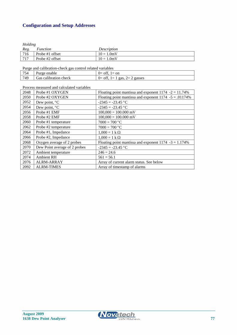
August 2009 1638 Dew Point Analyser 77
Configuration and Setup Addresses Holding Reg. Function Description 716 Probe #1 offset 10 = 1.0mV 717 Probe #2 offset 10 = 1.0mV Purge and calibration-check gas control related variables 754 Purge enable 0= off, 1= on 749 Gas calibration check 0= off, 1= 1 gas, 2= 2 gasses Process measured and calculated variables 2048 Probe #1 OXYGEN Floating point mantissa and exponent 1174 -2 = 11.74% 2050 Probe #2 OXYGEN Floating point mantissa and exponent 1174 -5 = .01174% 2052 Dew point, °C -2345 = -23.45 °C 2054 Dew point, °C -2345 = -23.45 °C 2056 Probe #1 EMF 100,000 = 100.000 mV 2058 Probe #2 EMF 100,000 = 100.000 mV 2060 Probe #1 temperature 7000 = 700 °C 2062 Probe #2 temperature 7000 = 700 °C 2064 Probe #1, Impedance 1,000 = 1 k Ω 2066 Probe #2, Impedance 1,000 = 1 k Ω 2068 Oxygen average of 2 probes Floating point mantissa and exponent 1174 -3 = 1.174% 2070 Dew Point average of 2 probes -2345 = -23.45 °C 2072 Ambient temperature 246 = 24.6 2074 Ambient RH 561 = 56.1 2076 ALRM-ARRAY Array of current alarm status. See below 2092 ALRM-TIMES Array of timestamp of alarms
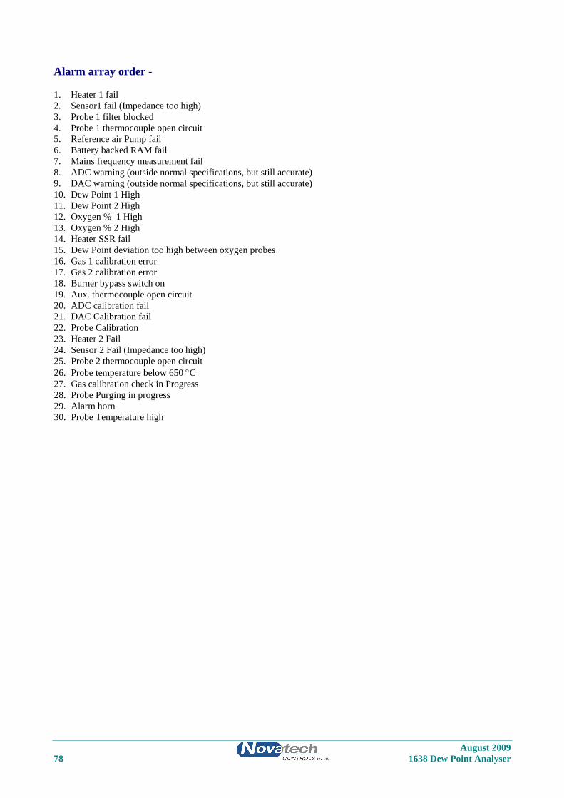
August 2009 78 1638 Dew Point Analyser
Alarm array order - 1. Heater 1 fail 2. Sensor1 fail (Impedance too high) 3. Probe 1 filter blocked 4. Probe 1 thermocouple open circuit 5. Reference air Pump fail 6. Battery backed RAM fail 7. Mains frequency measurement fail 8. ADC warning (outside normal specifications, but still accurate) 9. DAC warning (outside normal specifications, but still accurate) 10. Dew Point 1 High 11. Dew Point 2 High 12. Oxygen % 1 High 13. Oxygen % 2 High 14. Heater SSR fail 15. Dew Point deviation too high between oxygen probes 16. Gas 1 calibration error 17. Gas 2 calibration error 18. Burner bypass switch on 19. Aux. thermocouple open circuit 20. ADC calibration fail 21. DAC Calibration fail 22. Probe Calibration 23. Heater 2 Fail 24. Sensor 2 Fail (Impedance too high) 25. Probe 2 thermocouple open circuit 26. Probe temperature below 650 °C 27. Gas calibration check in Progress 28. Probe Purging in progress 29. Alarm horn 30. Probe Temperature high
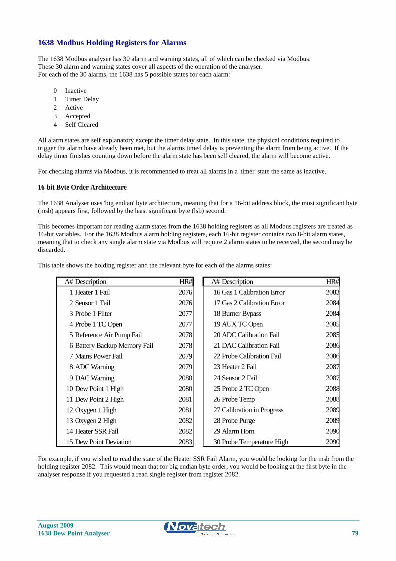
1638 Modbus Holding Registers for Alarms The 1638 Modbus analyser has 30 alarm and warning states, all of which can be checked via Modbus. These 30 alarm and warning states cover all aspects of the operation of the analyser. For each of the 30 alarms, the 1638 has 5 possible states for each alarm:
0 Inactive 1 Timer Delay 2 Active 3 Accepted 4 Self Cleared
All alarm states are self explanatory except the timer delay state. In this state, the physical conditions required to trigger the alarm have already been met, but the alarms timed delay is preventing the alarm from being active. If the delay timer finishes counting down before the alarm state has been self cleared, the alarm will become active. For checking alarms via Modbus, it is recommended to treat all alarms in a 'timer' state the same as inactive. 16-bit Byte Order Architecture The 1638 Analyser uses 'big endian' byte architecture, meaning that for a 16-bit address block, the most significant byte (msb) appears first, followed by the least significant byte (lsb) second. This becomes important for reading alarm states from the 1638 holding registers as all Modbus registers are treated as 16-bit variables. For the 1638 Modbus alarm holding registers, each 16-bit register contains two 8-bit alarm states, meaning that to check any single alarm state via Modbus will require 2 alarm states to be received, the second may be discarded. This table shows the holding register and the relevant byte for each of the alarms states:
A# Description HR# A# Description HR#1 Heater 1 Fail 2076 16 Gas 1 Calibration Error 20832 Sensor 1 Fail 2076 17 Gas 2 Calibration Error 20843 Probe 1 Filter 2077 18 Burner Bypass 20844 Probe 1 TC Open 2077 19 AUX TC Open 20855 Reference Air Pump Fail 2078 20 ADC Calibration Fail 20856 Battery Backup Memory Fail 2078 21 DAC Calibration Fail 20867 Mains Power Fail 2079 22 Probe Calibration Fail 20868 ADC Warning 2079 23 Heater 2 Fail 20879 DAC Warning 2080 24 Sensor 2 Fail 2087
10 Dew Point 1 High 2080 25 Probe 2 TC Open 208811 Dew Point 2 High 2081 26 Probe Temp 208812 Oxygen 1 High 2081 27 Calibration in Progress 208913 Oxygen 2 High 2082 28 Probe Purge 208914 Heater SSR Fail 2082 29 Alarm Horn 209015 Dew Point Deviation 2083 30 Probe Temperature High 2090
For example, if you wished to read the state of the Heater SSR Fail Alarm, you would be looking for the msb from the holding register 2082. This would mean that for big endian byte order, you would be looking at the first byte in the analyser response if you requested a read single register from register 2082.
August 2009 1638 Dew Point Analyser 79
Declaration of Conformity Declaration of Conformity Application of Council Directives: Application of Council Directives: 89/336/EEC (92/31/EEC) 89/336/EEC (92/31/EEC) 72/23/EEC 72/23/EEC Standards to which conformity is declared: Standards to which conformity is declared: EN550011.1:1995 (ISM, Group 1, Class B) EN550011.1:1995 (ISM, Group 1, Class B) EN55014:1995 (Clause 4.2) EN55014:1995 (Clause 4.2) EN50082-2 (Industrial) EN50082-2 (Industrial) EN61010-1 EN61010-1 AS61000.4.5:1999 AS61000.4.5:1999 IEC-68-2-2 IEC-68-2-2 IEC-68-2-3 IEC-68-2-3 AS1099.2.6 AS1099.2.6 Manufacturer’s name: Novatech Controls Pty Ltd Manufacturer’s name: Novatech Controls Pty Ltd Manufacturer’s address: 309 Reserve Road Manufacturer’s address: 309 Reserve Road Cheltenham VIC 3192 Cheltenham VIC 3192 AUSTRALIA AUSTRALIA Type of equipment: Oxygen Transmitter Type of equipment: Oxygen Transmitter
Equipment Class: ISM, Group 1, Class B Equipment Class: ISM, Group 1, Class B
Model Number: 1630 Series Transmitter Model Number: 1630 Series Transmitter 1231 Oxygen Probe 1231 Oxygen Probe 1234 Oxygen Sensor 1234 Oxygen Sensor I hereby declare that the equipment specified herein conforms to the above directive(s) and standards(s). I hereby declare that the equipment specified herein conforms to the above directive(s) and standards(s).
Full Name: Fraser Chapman Position: R & D Manager
August 2009 80 1638 Dew Point Analyser yser
Novatech Controls Pty. Ltd. ABN 57 006 331 700 Conditions of Sale
1. Interpretation In these conditions: (a) `Seller' means Novatech Controls Pty. Ltd.
ABN 57 006 331 700 of 309 Reserve Road, Cheltenham Victoria, 3192 which is the seller of the goods.
(b) `Buyer' means the buyer of the goods specified in the seller's quotation, or in the buyer's order for the goods.
(c) `Goods' means the products and, if any, services specified in Buyer's, orders or Seller's order acknowledgments from time to time.
(d) Nothing in these conditions shall be read or applied so as to exclude, restrict or modify or have the effect of excluding, restricting or modifying any condition, warranty, guarantee, right or remedy implied by law (including the Trade Practices Act 1974) and which by law cannot be excluded, restricted or modified.
2. General These conditions (which shall only be waived in writing signed by the seller) prevail over all conditions of the buyer's order to the extent of any inconsistency. 3. Terms of sale The goods and all other products sold by the seller are sold on these terms and conditions. 4. Seller's quotations Unless previously withdrawn, seller's quotations are open for acceptance within the period stated in them or, when no period is so stated, within 60 days only after its date. The seller reserves the right to refuse any order based on this quotation within 7 days after the receipt of the order. 5. Packing The cost of any special packing and packing materials used in relation to the goods are at the buyer's expense notwithstanding that such cost may have been omitted from any quotation. 6. Shortage The buyer waives any claim for shortage of any goods delivered if a claim in respect for short delivery has not been lodged with seller within seven (7) days from the date of receipt of goods by the buyer. 7. Drawings, etc. (a) All specifications, drawings, and particulars of
weights and dimensions submitted to the buyer are approximate only and any deviation from any of these things does not vitiate any contract with the seller or form grounds for any claim against the seller.
(b) Except as referred to in Clause 13.1 herein, the descriptions, illustrations and performances contained in catalogues, price lists and other advertising matter do not form part of the contract of sale of the goods or of the description applied to the goods.
(c) Where specifications, drawings or other particulars are supplied by the buyer, the seller’s price is made on estimates of quantities required. If there are any adjustments in quantities above or below the quantities estimated by seller and set out in a quotation, then any such increase or decrease are to be adjusted on a unit rate basis according to unit prices set out in the quotation.
8. Performance Any performance figures given by the seller are estimates only. The seller is under no liability for damages for failure of the goods to attain such figures unless specifically guaranteed in writing. Any such written guarantees are subject to the recognised tolerances applicable to such figures.
9. Acknowledgment regarding facilities for repairs or parts
The buyer acknowledges that the seller does not promise or represent that facilities for the repair of the goods, or that parts of the goods are or will be available. The buyer must ensure that each purchaser of the goods from the buyer receives notice that the seller does not promise that facilities for the repair of the goods will be available; or parts for the goods will be available. 10. Delivery (a) The delivery times made known to the buyer
are estimates only and the seller is not be liable for late delivery or non-delivery.
(b) The seller is not be liable for any loss, damage or delay occasioned to the buyer or its customers arising from late or non-delivery or late installation of the goods.
(c) The seller may at its option deliver the goods to the buyer in any number of instalments unless there is an agreement in writing between the parties to the effect that the buyer will not take delivery by instalments.
(d) If the seller delivers any of the goods by instalments, and any one of those instalments is defective for any reason: (i) it is not a repudiation of the contract of
sale formed by these conditions; and (ii) the defective instalment is a severable
breach that gives rise only to a claim for compensation.
11. Passing of risk Risk in the goods passes to the buyer upon the earlier of: (a) actual or constructive delivery of the goods to
the buyer; or (b) collection of the goods from the seller or any
bailee or agent of the seller by the buyer's agent, carrier or courier.
12. Loss or damage in transit (a) The seller is not responsible to the buyer or any
person claiming through the buyer for any loss or damage to goods in transit caused by any event of any kind by any person (whether or not the seller is legally responsible for the person who caused or contributed to that loss or damage).
(b) The seller must provide the buyer with such assistance as may be necessary to press claims on carriers so long as the buyer: (i) has notified the seller and the carriers in
writing immediately after loss or damage is discovered on receipt of goods; and
(ii) lodges a claim for compensation on the carrier within three (3) days of the date of receipt of the goods.
13. Guarantee 13.1 The seller's liability for goods manufactured by
it is limited to making good any defects by repairing the defects or at the seller's option by replacement, within a period as specified in Seller's catalogues or other product literature for specified cases or not exceeding twelve (12) calendar months after the goods have been dispatched (whichever is the lesser period) so long as:
(a) defects have arisen solely from faulty materials or workmanship;
(b) the damage does not arise from: (i) improper adjustment, calibration or
operation by the buyer; (ii) the use of accessories including
consumables, hardware, or software which
were not manufactured by or approved in writing by the seller;
(iii) any contamination or leakages caused or induced by the buyer;
(iv) any modifications of the goods which were not authorised in writing by the seller;
(v) any misuse of the goods by the buyer or anyone for whom the buyer has legal responsibility (including a minor);
(vi) any use or operation of the goods outside of the physical, electrical or environmental specifications of the goods;
(vii) inadequate or incorrect site preparation; and
(viii) inadequate or improper maintenance of the goods.
(ix) fair wear and tear of the product in an environment in respect of which the Seller has informed the Buyer in catalogues or other product literature that the period of usefulness of the product is likely to be shorter that twelve 12 months.
(c) the goods have not received maltreatment, inattention or interference;
(d) accessories of any kind used by the buyer are manufactured by or approved by the seller;
(e) the seals of any kind on the goods remain unbroken; and
(f) the defective parts are promptly returned free of cost to the seller.
13.2 The seller is not liable for and the buyer releases the seller from any claims in respect of faulty or defective design of any goods supplied unless such design has been wholly prepared by the seller and the responsibility for any claim has been specifically accepted by the seller in writing. In any event the seller’s liability under this paragraph is limited strictly to the replacement of defective parts in accordance with para 13.1 of these conditions.
13.3 Except as provided in these conditions, all express and implied warranties, guarantees and conditions under statute or general law as to merchantability, description, quality, suitability or fitness of the goods for any purpose or as to design, assembly, installation, materials or workmanship or otherwise are expressly excluded. The seller is not liable for physical or financial injury, loss or damage or for consequential loss or damage of any kind arising out of the supply, layout, assembly, installation or operation of the goods or arising out of the seller’s negligence or in any way whatsoever.
14. Seller's liability 14.1 The seller's liability for a breach of a condition
or warranty implied by Div 2 of Pt V of the Trade Practices Act 1974 (other than s 69) is limited to:
(a) in the case of goods, any one or more of the following: (i) the replacement of the goods or the supply
of equivalent goods; (ii) the repair of the goods; (iii) the payment of the cost of replacing the
goods or of acquiring equivalent goods; (iv) the payment of the cost of having the
goods repaired; or (b) in the case of services:
(i) the supplying of the services again; or (ii) the payment of the cost of having the
services supplied again.
Novatech Controls Pty. Ltd. ABN 57 006 331 700 Conditions of Sale
14.2 The seller's liability under s 74H of the Trade
Practices Act 1975 is expressly limited to a liability to pay to the purchaser an amount equal to:
(a) the cost of replacing the goods; (b) the cost of obtaining equivalent goods; or (c) the cost of having the goods repaired,
whichever is the lowest amount. 15. Prices (a) Unless otherwise stated all prices quoted by
vendor are net, exclusive of Goods and Services Tax (GST) and the buyer agrees to pay to the seller any GST in addition to the price.
(b) Prices quoted are those ruling at the date of issue of quotation and are based on rates of freight, insurance, customs duties, exchange, shipping expenses, sorting and stacking charges, cartage, the quotation, cost of materials, wages and other charges affecting the cost of production ruling on the date is made.
(c) If the seller makes any alterations to the price of the goods or to any of their inputs either before acceptance of or during the currency of the contract, these alterations are for the buyer’s account.
16. Payment The purchase price in relation to goods is payable net and payment of the price of the goods must be made on or before the thirtieth day from the date of invoice unless other terms of payment are expressly stated in these conditions in writing. 17. Rights in relation to goods (Romalpa clause) The seller reserves the following rights in relation to the goods until all accounts owed by the buyer to the seller are fully paid: (a) ownership of the goods; (b) to enter the buyer's premises (or the premises of
any associated company or agent where the goods are located) without liability for trespass or any resulting damage and retake possession of the goods; and
(c) to keep or resell the goods including any goods repossessed pursuant to 17(b) above;
If the goods are resold, or goods manufactured using the goods are sold, by the buyer, the buyer shall hold
such part of the proceeds of any such sale as represents the invoice price of the goods sold or used in the manufacture of the goods sold in a separate identifiable account as the beneficial property of the seller and shall pay such amount to the seller upon request. Notwithstanding the provisions above the seller shall be entitled to maintain an action against the buyer for the purchase price and the risk of the goods shall pass to the buyer upon delivery. 18. Buyer's property Any property of the buyer under the seller’s possession, custody or control is completely at the buyer’s risk as regards loss or damage caused to the property or by it. 19. Storage The seller reserves the right to make a reasonable charge for storage if delivery instructions are not provided by the buyer within fourteen days of a request by the seller for such instructions. The parties agree that the seller may charge for storage from the first day after the seller requests the buyer to provide delivery instructions. 20. Returned goods (a) The seller will not be under any duty to accept
goods returned by the buyer and will do so only on terms to be agreed in writing in each individual case.
(b) If the seller agrees to accept returned goods from the buyer under para (a) of this clause, the buyer must return the goods to the seller at the seller’s place of business referred to at the head of these conditions.
21. Goods sold All goods to be supplied by the seller to the buyer are as described on the purchase order agreed by the seller and the buyer and the description on such purchase order modified as so agreed prevails over all other descriptions including any specification or enquiry of the buyer. 22. Cancellation No order may be cancelled except with consent in writing and on terms which will indemnify the seller against all losses. 23. Indemnity The buyer indemnifies on a continuing basis on a fully indemnity basis the seller from and against any
liability, loss, expense or demand for or arising from any false, misleading, deceptive or misdescriptive representation or statement made by the buyer in respect of the goods to any person. This indemnity survives termination of this agreement by either part for any reason. 24. Exclusion of representations and
arrangements Except as referred to in Clause 13.1herein, these terms and conditions supersede and exclude all prior and other discussions, representations (contractual or otherwise) and arrangements relating to the supply of the goods or any part of the goods including, but without limiting the generality of the foregoing, those relating to the performance of the goods or any part of the goods or the results that ought to be expected from using the goods. 25. No waiver The failure of any part to enforce the provisions of this agreement or to exercise any rights expressed in this agreement is not to be a waiver of such provisions or rights an does not affect the enforcement of this agreement. 26. Force Majeure If by reason of any fact, circumstance, matter or thing beyond the reasonable control of the seller, the seller is unable to perform in whole or in part any obligation under this agreement the seller is relieved of that obligation under this agreement to the extent and for the period that it is so unable to perform and is not liable to the buyer in respect of such inability. 27. Buyer Acknowledgement The Buyer acknowledges that the above provisions of these Conditions of Sale are reasonable and reflected in the price and the Buyer accepts the risks of the Buyer associated with these Conditions of sale and/or shall issue accordingly. 28. Place of contract (a) The contract for sale of the goods is made in the
state of Victoria Australia. (b) The parties submit all disputes arising between
them to the courts of such state and any court competent to hear appeals from those courts of first instance.


![Sport [broj 1638, 25.10.2011]](https://img.dokumen.tips/doc/110x75/577d24ef1a28ab4e1e9dbd57/sport-broj-1638-25102011.jpg)