Embed Size (px)
Citation preview
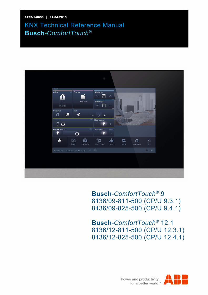
1473-1-8039 21.04.2015
KNX Technical Reference Manual Busch-ComfortTouch®
Pos: 3 /Layout bis 2014-11-11/Online-Dokumentation (+KNX)/Titelblätter/KNX/ComfortPanel 3.0/Titelblatt - KNX-Handbuch - CP 3.0 - ABB @ 36\mod_1364391460577_15.docx @ 293591 @ @ 1
Busch-ComfortTouch® 9 8136/09-811-500 (CP/U 9.3.1) 8136/09-825-500 (CP/U 9.4.1)
Busch-ComfortTouch® 12.1 8136/12-811-500 (CP/U 12.3.1) 8136/12-825-500 (CP/U 12.4.1)
=== Ende der Liste für Textmarke Cover ===
KNX Technical Reference Manual
Busch-ComfortTouch®
KNX Technical Reference Manual | 1473-1-8039 — 2 —
Pos: 5 /Layout bis 2014-11-11/Online-Dokumentation (+KNX)/Inhaltsverzeichnis (--> Für alle Dokumente <--)/Inhaltsverzeichnis @ 19\mod_1320649044386_15.docx @ 109653 @ @ 1
1 Information on the manual ....................................................................................................................................... 5 1.1 General information................................................................................................................................. 5 1.2 Structure of the manual ........................................................................................................................... 5 1.3 Symbols in the manual ............................................................................................................................ 6
2 Safety ....................................................................................................................................................................... 7 2.1 Intended use ........................................................................................................................................... 7 2.2 Improper use ........................................................................................................................................... 7 2.3 Target groups and qualifications ............................................................................................................. 8 2.4 Liability and warranty .............................................................................................................................. 8 2.5 Cyber Security) ....................................................................................................................................... 8
3 Environment ............................................................................................................................................................. 9 4 Product overview ................................................................................................................................................... 10
4.1 Product description ............................................................................................................................... 10 4.2 Function overview ................................................................................................................................. 11 4.3 Device setup ......................................................................................................................................... 13 4.4 Scope of supply .................................................................................................................................... 14 4.5 Additional necessary components ........................................................................................................ 15 4.6 Colour concept ...................................................................................................................................... 15
5 Technical data........................................................................................................................................................ 16 5.1 Overview table ...................................................................................................................................... 16 5.2 Device connection / circuit diagram ...................................................................................................... 16 5.3 Dimensions / dimensional drawing ........................................................................................................ 17
6 Installation .............................................................................................................................................................. 19 6.1 Requirements for the electrician ........................................................................................................... 19 6.2 Installation / mounting ........................................................................................................................... 20 6.2.1 Preparation for installation .................................................................................................................... 20 6.2.2 Installation of the flush-mounted wall box ............................................................................................. 21 6.2.3 Installing the wall alignment parts ......................................................................................................... 22 6.2.4 Attaching the mounting frame ............................................................................................................... 23 6.3 Electrical connection ............................................................................................................................. 24 6.3.1 Inserting the power adapter module ...................................................................................................... 24 6.3.2 Opening out the power adapter module ................................................................................................ 24 6.3.3 Connecting the power adapter module ................................................................................................. 25 6.3.4 Connecting the LAN cable .................................................................................................................... 26 6.3.5 Mounting the display ............................................................................................................................. 27 6.3.6 Dismantling ........................................................................................................................................... 28
7 Start-up .................................................................................................................................................................. 29 8 Preparation for project planning ............................................................................................................................. 31
8.1 Requirements for computer equipment ................................................................................................. 31 8.1.1 Hardware .............................................................................................................................................. 31 8.1.2 Software ................................................................................................................................................ 31 8.2 Installation of IP-Project 3 ..................................................................................................................... 32 8.3 Integration into the KNX system ............................................................................................................ 35 8.3.1 Installation of the Busch-ComfortTouch® ETSx Macro .......................................................................... 35 8.3.2 Installation sequence ............................................................................................................................ 35 8.3.3 Integrating the Busch-ComfortTouch® into the ETSx ............................................................................ 36 8.3.4 Further KNX settings in the Busch-ComfortTouch®............................................................................... 36
KNX Technical Reference Manual
Busch-ComfortTouch®
KNX Technical Reference Manual | 1473-1-8039 — 3 —
9 Overview of IP-Project 3 (IPP) ............................................................................................................................... 37 9.1 Start of IP-Project 3 ............................................................................................................................... 37 9.2 Screen areas in IP-Project 3 ................................................................................................................. 38 9.3 Explanation of the basic structure (Terms) ............................................................................................ 39 9.3.1 Areas ..................................................................................................................................................... 39 9.3.1.1 Library area ........................................................................................................................................... 39 9.3.1.2 Working area ......................................................................................................................................... 40 9.3.1.3 Parameter area ..................................................................................................................................... 41 9.3.1.4 Help area .............................................................................................................................................. 41 9.3.1.5 Levels .................................................................................................................................................... 42 9.4 Basic operation (Copying functions) ..................................................................................................... 44 9.4.1 Copying a project .................................................................................................................................. 44 9.4.2 Moving / copying pages and control elements ...................................................................................... 44 9.4.3 Cross references ................................................................................................................................... 44 9.4.4 Print ....................................................................................................................................................... 44
10 Project planning ..................................................................................................................................................... 45 10.1 Recommended sequence of project planning ....................................................................................... 45 10.2 Consistency check ................................................................................................................................ 45 10.3 Loading the project into the Busch-ComfortTouch® .............................................................................. 46
11 Operation ............................................................................................................................................................... 47 11.1 Basic structure of page types ................................................................................................................ 47 11.2 Status bar .............................................................................................................................................. 48 11.3 Navigation bar ....................................................................................................................................... 48 11.4 Page types of the Busch-ComfortTouch® .............................................................................................. 49 11.4.1 Functional start page............................................................................................................................. 49 11.4.2 Start page with floor plan ...................................................................................................................... 50 11.4.3 Operating page functions ...................................................................................................................... 51 11.4.4 Operating pages with image of room .................................................................................................... 52 11.4.5 Application page ................................................................................................................................... 52
12 Maintenance .......................................................................................................................................................... 53 12.1 Cleaning ................................................................................................................................................ 53
13 Description of functions .......................................................................................................................................... 54 13.1 Device information ................................................................................................................................ 54 13.2 System settings ..................................................................................................................................... 55 13.2.1 Camera adjustment ............................................................................................................................... 56 13.3 Import and export of files ....................................................................................................................... 57 13.4 Operating functions: .............................................................................................................................. 58 13.4.1 Push-button (Switch) ............................................................................................................................. 58 13.4.2 Dimmer ................................................................................................................................................. 58 13.4.3 Roller shutter / Blind .............................................................................................................................. 59 13.4.4 Scenes and sequences ......................................................................................................................... 59 13.4.5 Value and text ....................................................................................................................................... 59 13.4.6 Room temperature controller (RTC) ...................................................................................................... 59 13.4.7 Control element "KNX Audio" ................................................................................................................ 60 13.4.8 RGB control .......................................................................................................................................... 60 13.4.9 Philips Hue control element .................................................................................................................. 61 13.4.10 Step switch ............................................................................................................................................ 61 13.5 Room temperature control .................................................................................................................... 62 13.6 Time and date display ........................................................................................................................... 62 13.7 Image messages ................................................................................................................................... 63 13.8 Voice messages .................................................................................................................................... 64 13.9 Scenes and sequences ......................................................................................................................... 65 13.10 Weekly timers ....................................................................................................................................... 67 13.11 Simpls weekly program ......................................................................................................................... 68 13.12 Presence simulation .............................................................................................................................. 69 13.13 Access control ....................................................................................................................................... 69 13.14 Set mobile control ................................................................................................................................. 70
KNX Technical Reference Manual
Busch-ComfortTouch®
KNX Technical Reference Manual | 1473-1-8039 — 4 —
13.15 Fault and alarm message ...................................................................................................................... 70 13.16 Alarm control unit .................................................................................................................................. 71 13.17 Video surveillance ................................................................................................................................. 73 13.18 Media player ......................................................................................................................................... 74 13.18.1 Playing back audio and video data ....................................................................................................... 74 13.18.2 Use as Internet radio ............................................................................................................................. 75 13.18.3 Use as streaming(web) TV .................................................................................................................... 75 13.19 Electronic image frame: ........................................................................................................................ 76 13.20 E-mails .................................................................................................................................................. 76 13.21 Feed reader .......................................................................................................................................... 77 13.22 Short-time timer .................................................................................................................................... 77 13.23 Alarm clock ........................................................................................................................................... 78 13.24 Remote maintenance / Transmission of data ........................................................................................ 78 13.25 IR remote control .................................................................................................................................. 78 13.26 Web interface: ....................................................................................................................................... 79 13.27 Cleaning blockage ................................................................................................................................ 80 13.28 Data logger ........................................................................................................................................... 81 13.29 Calendar ............................................................................................................................................... 82 13.30 Telephone (VoIP) .................................................................................................................................. 82 13.31 Miele plug-in .......................................................................................................................................... 83 13.32 Internet / Web browser .......................................................................................................................... 84 13.33 Door Communication ............................................................................................................................ 85 13.34 File browser .......................................................................................................................................... 85 13.35 Communication objects ......................................................................................................................... 85 13.36 Logic editor ........................................................................................................................................... 86
=== Ende der Liste für Textmarke TOC ===
KNX Technical Reference Manual
Busch-ComfortTouch® Information on the manual
KNX Technical Reference Manual | 1473-1-8039 — 5 —
Pos: 7.1 /Layout bis 2014-11-11/Online-Dokumentation (+KNX)/Überschriften (--> Für alle Dokumente <--)/1. Ebene/G - L/Hinweise zum KNX Technischen Handbuch @ 30\mod_1348481378060_15.docx @ 238547 @ 2 @ 1
1 Information on the manual Pos: 7.2.1 /Layout bis 2014-11-11/Online-Dokumentation (+KNX)/Überschriften (--> Für alle Dokumente <--)/2. Ebene/A - F/Allgemeine Hinweise @ 30\mod_1348481024126_15.docx @ 238505 @ 1 @ 1
1.1 General information Pos: 7.2.2 /Layout bis 2014-11-11/Online-Dokumentation (+KNX)/Hinweise zum KNX Technischen Handbuch (--> Für alle Dokumente --<)/Allgemeine Hinweise/Allgemeine Hinweise - KNX Technisches Handbuch @ 30\mod_1348479193040_15.docx @ 238433 @ @ 1
Please read this manual through carefully and adhere to the information listed. This will ensure reliable operation and long service life of your product. For reasons of clarity this manual does not contain all the detailed information on all the models of the product, nor can it take into consideration all conceivable circumstances related to installation, operation and maintenance. If additional information is required or problems arise that are not dealt with in this manual, the necessary information can be requested from the manufacturer. The product has been constructed according to the latest valid regulations governing technology and is operationally reliable. It has been tested and left the factory in a technically safe and reliable state. To maintain this state for the period of its operation the specifications of this manual must be observed and adhered to. Modifications and repairs to the product must only be undertaken if the manual expressly permits this. It is only the adherence to the safety instructions and all safety and warning symbols in this manual that will ensure the optimum protection of the user and the environment as well as the safe and trouble-free operation of the product. Pos: 7.3.1 /Layout bis 2014-11-11/Online-Dokumentation (+KNX)/Überschriften (--> Für alle Dokumente <--)/2. Ebene/A - F/Aufbau des Handbuches @ 24\mod_1338552603038_15.docx @ 215245 @ 1 @ 1
1.2 Structure of the manual Pos: 7.3.2 /Layout bis 2014-11-11/Online-Dokumentation (+KNX)/Hinweise zum KNX Technischen Handbuch/KNX/KNX-Aktorik/ComfortPanel 3.0/KNX Technisches Handbuch/Aufbau des Handbuches/Aufbau des Handbuches @ 33\mod_1361360139245_15.docx @ 277899 @ @ 1
• This manual provides you with the detailed technical information on the device, its installation and programming. The use of the device is explained by means of examples.
• The chapters "Information on the manual", "Safety", "Environmental information" and "Product overview" contain general specifications and basic information as well as a description of functions.
• Chapters "Technical data" and "Installation" describe the device technology and installation, mounting and the electrical connections.
• Chapters "Commissioning" and "Operation" contain instructions on commissioning and how to operate the device.
• Chapter "Maintenance" contains information about cleaning, fault condition diagnostics and repairing the device.
• In chapter "Description of functions" describes the individual functions of the device. Pos: 7.4 /Layout bis 2014-11-11/Online-Dokumentation (+KNX)/Steuermodule - Online-Dokumentation (--> Für alle Dokumente <--)/++++++++++++ Seitenumbruch ++++++++++++ @ 9\mod_1268898668093_0.docx @ 52149 @ @ 1
KNX Technical Reference Manual
Busch-ComfortTouch® Information on the manual
KNX Technical Reference Manual | 1473-1-8039 — 6 —
Pos: 7.5.1 /Layout bis 2014-11-11/Online-Dokumentation (+KNX)/Überschriften (--> Für alle Dokumente <--)/2. Ebene/S - T/Symbole des Handbuches @ 30\mod_1348481258296_15.docx @ 238518 @ 2 @ 1
1.3 Symbols in the manual Pos: 7.5.2 /Layout bis 2014-11-11/Online-Dokumentation (+KNX)/Hinweise zum KNX Technischen Handbuch (--> Für alle Dokumente --<)/Symbole des Handbuches (Vollständig - KNX THB)/Symbole des Handbuches (Vollständig - KNX THB) @ 30\mod_1348480199844_15.docx @ 238490 @ @ 1
Danger - danger to life This symbol in connection with the signal word "Danger" indicates dangerous situations which could lead to immediate death or to serious injury.
Warning - danger to life This symbol in connection with the signal word "Warning" indicates a dangerous situation which could lead to immediate death or to serious injury.
Caution - risk of injury This symbol in connection with the signal word "Caution" indicates a possibly dangerous situation which could lead to slight or moderately serious injury.
Attention - damage to property This symbol indicates a possibly harmful situation. Non-observance of the safety instructions can lead to damage or destruction of the product.
Note ... This symbol indicates information or references to additional useful topics. This is not a signal word for a dangerous situation.
This symbol refers to integrated videos with additional information on the respective chapter. An Acrobat Reader from Version 9.0 is required to view the videos.
This symbol indicates information on the protection of the environment.
Examples on application, installation and programming are displayed with a grey background.
Pos: 8 /Layout bis 2014-11-11/Modul-Struktur/Online-Dokumentation/Steuermodule - Online-Dokumentation (--> Für alle Dokumente <--)/++++++++++++ Seitenumbruch ++++++++++++ @ 9\mod_1268898668093_0.docx @ 52149 @ @ 1
KNX Technical Reference Manual
Busch-ComfortTouch® Safety
KNX Technical Reference Manual | 1473-1-8039 — 7 —
Pos: 9.1 /Layout bis 2014-11-11/Online-Dokumentation (+KNX)/Überschriften (--> Für alle Dokumente <--)/1. Ebene/S - T/Sicherheit @ 18\mod_1302612791790_15.docx @ 103357 @ 1 @ 1
2 Safety Pos: 9.2 /Layout bis 2014-11-11/Online-Dokumentation (+KNX)/Sicherheitshinweise und Hinweise (--> Für alle Dokumente <--)/Warnhinweise/Sicherheit - 230 V @ 18\mod_1302606816750_15.docx @ 103308 @ @ 1
Warning Electric voltage! Risk of death and fire due to electrical voltage of 230 V. – Work on the 230V supply system may only be performed by authorised electricians! – Disconnect the mains power supply prior to installation and/or disassembly!
Pos: 9.3 /Layout bis 2014-11-11/Online-Dokumentation (+KNX)/Sicherheitshinweise und Hinweise (--> Für alle Dokumente <--)/Hinweise - Sachschäden/Achtung - Beschädigung durch äußere Einwirkungen @ 26\mod_1343995985123_15.docx @ 226743 @ @ 1
Caution Risk of damaging the device due to external factors! Moisture and contamination can damage the device. That is why the device must be protected against humidity, dirt and damage during transport, storage and operation!
Pos: 9.4 /Layout bis 2014-11-11/Online-Dokumentation (+KNX)/Steuermodule - Online-Dokumentation (--> Für alle Dokumente <--)/++++++++++++ Seitenumbruch ++++++++++++ @ 9\mod_1268898668093_0.docx @ 52149 @ @ 1 Pos: 9.5.1 /Layout bis 2014-11-11/Online-Dokumentation (+KNX)/Überschriften (--> Für alle Dokumente <--)/2. Ebene/A - F/Bestimmungsgemäßer Gebrauch @ 25\mod_1340691838858_15.docx @ 220036 @ 2 @ 1
2.1 Intended use Pos: 9.5.2 /Layout bis 2014-11-11/Online-Dokumentation (+KNX)/Sicherheit/KNX/KNX-Aktorik/ComfortPanel 3.0/KNX Technisches Handbuch/Bestimmungsgemäßer Gebrauch/Bestimmungsgemäßer Gebrauch - KNX ... @ 33\mod_1361372357944_15.docx @ 278688 @ @ 1
The device must only be operated within the specified technical data! The Busch-ComfortTouch® is a central switching and monitoring location for the entire building automation with control, monitoring and visualisation functions for numerous devices and media within a building. The device makes available numerous functions. The range of functions is contained in chapter "Description of Functions". The integrated bus coupler makes possible the connection of a KNX bus line.
Note The device must only be installed in the flush-mounted installation box 8136/01 UP-500 (MD/U 6.1), 8136/UP-500 (MD/U 5.1) or 6136/UP (MD/U 1.1) in dry indoor rooms.
Note Making and saving video recordings can infringe on personal rights! Always observe applicable legal and labeling requirements for placement and operation of video components!
Pos: 9.6.1 /Layout bis 2014-11-11/Online-Dokumentation (+KNX)/Überschriften (--> Für alle Dokumente <--)/2. Ebene/A - F/Bestimmungswidriger Gebrauch @ 30\mod_1348482382253_15.docx @ 238583 @ 2 @ 1
2.2 Improper use Pos: 9.6.2 /Layout bis 2014-11-11/Online-Dokumentation (+KNX)/Sicherheit/KNX/KNX-Aktorik/ComfortPanel 3.0/KNX Technisches Handbuch/Bestimmungswidriger Gebrauch/Bestimmungswidriger Gebrauch - KNX ... @ 33\mod_1361372362056_15.docx @ 278704 @ @ 1
The device is dangerous if used improperly. Any non-intended use is deemed improper use. The manufacturer is not liable for damages resulting from such improper use. The associated risk is borne by the user/operator. The device must never be used outdoors or in bathroom areas. Do not push objects through the openings in the device. Only the available options for connection are to be used in accordance with the technical data. The device has an integrated bus coupler. The use of an additional bus coupler is therefore not admissible. Pos: 9.7.1 /Layout bis 2014-11-11/Online-Dokumentation (+KNX)/Überschriften (--> Für alle Dokumente <--)/2. Ebene/U - Z/Zielgruppen und Qualifikationen @ 30\mod_1348478339232_15.docx @ 238335 @ 2 @ 1
KNX Technical Reference Manual
Busch-ComfortTouch® Safety
KNX Technical Reference Manual | 1473-1-8039 — 8 —
2.3 Target groups and qualifications Pos: 9.7.2 /Layout bis 2014-11-11/Online-Dokumentation (+KNX)/Sicherheit (--> Für alle Dokumente <--)/Zielgruppen und Qualifikationen/Zielgruppen und Aulifikationen @ 30\mod_1348478121448_15.docx @ 238322 @ @ 1
Installation, commissioning and maintenance of the product must only be carried out by trained and properly qualified electrical installers. The electrical installers must have read and understood the manual and follow the instructions provided. The operator must adhere to the valid national regulations in his country governing the installation, functional test, repair and maintenance of electrical products. Pos: 9.8.1 /Layout bis 2014-11-11/Online-Dokumentation (+KNX)/Überschriften (--> Für alle Dokumente <--)/2. Ebene/G - L/Haftung und Gewährleistung @ 30\mod_1348478525228_15.docx @ 238363 @ 2 @ 1
2.4 Liability and warranty Pos: 9.8.2 /Layout bis 2014-11-11/Online-Dokumentation (+KNX)/Sicherheit (--> Für alle Dokumente <--)/Haftung und Gewährleistung/Haftung und Gewährleistung - KNX ... @ 30\mod_1348478419853_15.docx @ 238349 @ @ 1
Improper use, non-observance of this manual, the use of inadequately qualified personnel, as well as unauthorized modification excludes the liability of the manufacturer for the damages caused. It voids the warranty of the manufacturer. Pos: 9.9 /Layout bis 2014-11-11/Online-Dokumentation (+KNX)/Steuermodule - Online-Dokumentation (--> Für alle Dokumente <--)/++++++++++++ Seitenumbruch ++++++++++++ @ 9\mod_1268898668093_0.docx @ 52149 @ @ 1 Pos: 9.10.1 /Layout bis 2014-11-11/Online-Dokumentation (+KNX)/Überschriften (--> Für alle Dokumente <--)/2. Ebene/A - F/Cyber Security (Netzwerksicherheit) @ 40\mod_1418804878733_15.docx @ 310416 @ 2 @ 1
2.5 Cyber Security) Pos: 9.10.2 /Layout bis 2014-11-11/Online-Dokumentation (+KNX)/Sicherheit (--> Für alle Dokumente <--)/Cyber Security (Netzwerksicherheit)/Cyber Security (Netzwerksicherheit) @ 40\mod_1418804500166_15.docx @ 310401 @ @ 1
This product has been developed in connection with a network interface and for communicating information and data via this network interface. It is exclusively your responsibility for establishing a safe connection between the product and your network or (if necessary) a different network and to regularly check this. You must use suitable measures (for example, the installation of firewalls, the use of authentication measures, data encryption, the installation of anti-virus programs, etc.) to protect the product, the network, its system and interface against all kinds of violations of security, unauthorized access, intrusions, information leaks and/or piracy of data and information.ABB and associated companies are not liable for damages and/or losses in connection with the violation of security, unauthorized access, malfunctions, intrusions, information leaks and/or piracy of data or information. Pos: 10 /Layout bis 2014-11-11/Online-Dokumentation (+KNX)/Steuermodule - Online-Dokumentation (--> Für alle Dokumente <--)/++++++++++++ Seitenumbruch ++++++++++++ @ 9\mod_1268898668093_0.docx @ 52149 @ @ 1
KNX Technical Reference Manual
Busch-ComfortTouch® Environment
KNX Technical Reference Manual | 1473-1-8039 — 9 —
Pos: 11.1 /Layout bis 2014-11-11/Modul-Struktur/Online-Dokumentation/Überschriften (--> Für alle Dokumente <--)/1. Ebene/U - Z/Umwelt @ 18\mod_1302614158967_15.docx @ 103383 @ 1 @ 1
3 Environment Pos: 11.2 /Layout bis 2014-11-11/Online-Dokumentation (+KNX)/Sicherheitshinweise und Hinweise (--> Für alle Dokumente <--)/Hinweise/Hinweis - Umwelt - Hinweis Elektrogeräte @ 18\mod_1302763973434_15.docx @ 103500 @ @ 1
Consider the protection of the environment! Used electric and electronic devices must not be disposed of with domestic waste. – The device contains valuable raw materials which can be recycled. Therefore, dispose of the
device at the appropriate collecting depot. Pos: 11.3 /Layout bis 2014-11-11/Online-Dokumentation (+KNX)/Sicherheitshinweise und Hinweise (--> Für alle Dokumente <--)/Hinweise/Hinweis - Umwelt - Entsorgung Elektrogeräte @ 20\mod_1325760695972_15.docx @ 136583 @ @ 1
All packaging materials and devices bear the markings and test seals for proper disposal. Always dispose of the packaging material and electric devices and their components via the authorized collecting depots and disposal companies. The products meet the legal requirements, in particular the laws governing electronic and electrical devices and the REACH ordinance. (EU Directive 2002/96/EC WEEE and 2002/95/EC RoHS) (EU REACH ordinance and law for the implementation of the ordinance (EC) No.1907/2006) Pos: 12 /Layout bis 2014-11-11/Modul-Struktur/Online-Dokumentation/Steuermodule - Online-Dokumentation (--> Für alle Dokumente <--)/++++++++++++ Seitenumbruch ++++++++++++ @ 9\mod_1268898668093_0.docx @ 52149 @ @ 1
KNX Technical Reference Manual
Busch-ComfortTouch® Product overview
KNX Technical Reference Manual | 1473-1-8039 — 10 —
Pos: 14.1 /Layout bis 2014-11-11/Online-Dokumentation (+KNX)/Überschriften (--> Für alle Dokumente <--)/1. Ebene/P - R/Produktübersicht @ 33\mod_1361365511862_15.docx @ 278082 @ 1 @ 1
4 Product overview Pos: 14.2.1 /Layout bis 2014-11-11/Online-Dokumentation (+KNX)/Überschriften (--> Für alle Dokumente <--)/2. Ebene/P - R/Produktbeschreibung @ 33\mod_1361366656992_15.docx @ 278290 @ 2 @ 1
4.1 Product description Pos: 14.2.2 /Layout bis 2014-11-11/Online-Dokumentation (+KNX)/Produktübersicht/KNX/KNX-Aktorik/ComfortPanel 3.0/KNX Technisches Handbuch/ProduktbeschreibungProduktbeschreibung @ 40\mod_1418304922983_15.docx @ 308408 @ @ 1
Busch-ComfortTouch® are high-quality colour touch displays in 16:9 format with a resolution of 800 x 480 pixel for the 23 cm (9“) display and 800 x 1280 pixel for the 31 cm (12.1“) display. The Busch-ComfortTouch® consists of a basic system on a modern computer platform that is also designed for future tasks and is capable of being upgraded. The unit is of fan-free cooling design and does not require a mechanical hard disc to store the platform-independent operating system in the device. The Busch-ComfortTouch® is a central switching and monitoring location for the entire building automation with control, monitoring and visualisation functions for numerous devices and media within a building. It unites the functions of a building control system and an information centre and Media Players on a single monitor. Using the colour display, it is possible to switch on or dim lights in the entire building, control the blinds or regulate the room temperature or scenes using a combination of the functions mentioned above - even via remote control. Please note that additional components of building automation are required for this. The operation and control is carried out via the text-labelled touch surfaces in a clear menu structure and/or via floor plans and room views. It is a labelling code that is understood internationally and does not rely on language.They are supplemented by easily understood function icons. No lettering is needed. You can design the touch surfaces to your individual preferences dependent of the parameter settings. The display has LED backlighting. The integrated speaker can, for example, provide acoustic feedback to operations, be used as an alarm clock or to signal alarms and fault messages and can also be used for playing back stored audio files. The Busch-ComfortTouch® has a USB connection (USB 2.0) and a slot for a 64 GB multimedia / SD card (SD, SDHC and Micro SD (SDHC with the use of a suitable adapter)). Pos: 14.2.3 /Layout bis 2014-11-11/Online-Dokumentation (+KNX)/Produktübersicht/KNX/KNX-Aktorik/ComfortPanel 3.0/KNX Technisches Handbuch/ProduktbeschreibungProduktbeschreibung - ABB - LAN/WLAN/KNX @ 40\mod_1418305527658_15.docx @ 308440 @ @ 1
The design of the Busch-ComfortTouch® allows the connection to networks via LAN or WLAN. Access to KNX is also possible by means of the optional connection of twisted pair power supply modules or via the appropriate IP/KNX router. And the device can additionally serve as gateway between IP networks and KNX networks. Pos: 14.3 /Layout bis 2014-11-11/Online-Dokumentation (+KNX)/Steuermodule - Online-Dokumentation (--> Für alle Dokumente <--)/++++++++++++ Seitenumbruch ++++++++++++ @ 9\mod_1268898668093_0.docx @ 52149 @ @ 1
KNX Technical Reference Manual
Busch-ComfortTouch® Product overview
KNX Technical Reference Manual | 1473-1-8039 — 11 —
Pos: 14.4.1 /Layout bis 2014-11-11/Online-Dokumentation (+KNX)/Überschriften (--> Für alle Dokumente <--)/2. Ebene/A - F/Funktionsübersicht @ 33\mod_1361366367915_15.docx @ 278258 @ 2 @ 1
4.2 Function overview Pos: 14.4.2 /Layout bis 2014-11-11/Online-Dokumentation (+KNX)/Produktübersicht/KNX/KNX-Aktorik/ComfortPanel 3.0/KNX Technisches Handbuch/FunktionsübersichtFunktionsübersicht - KNX ... @ 40\mod_1418305702754_15.docx @ 308456 @ @ 1
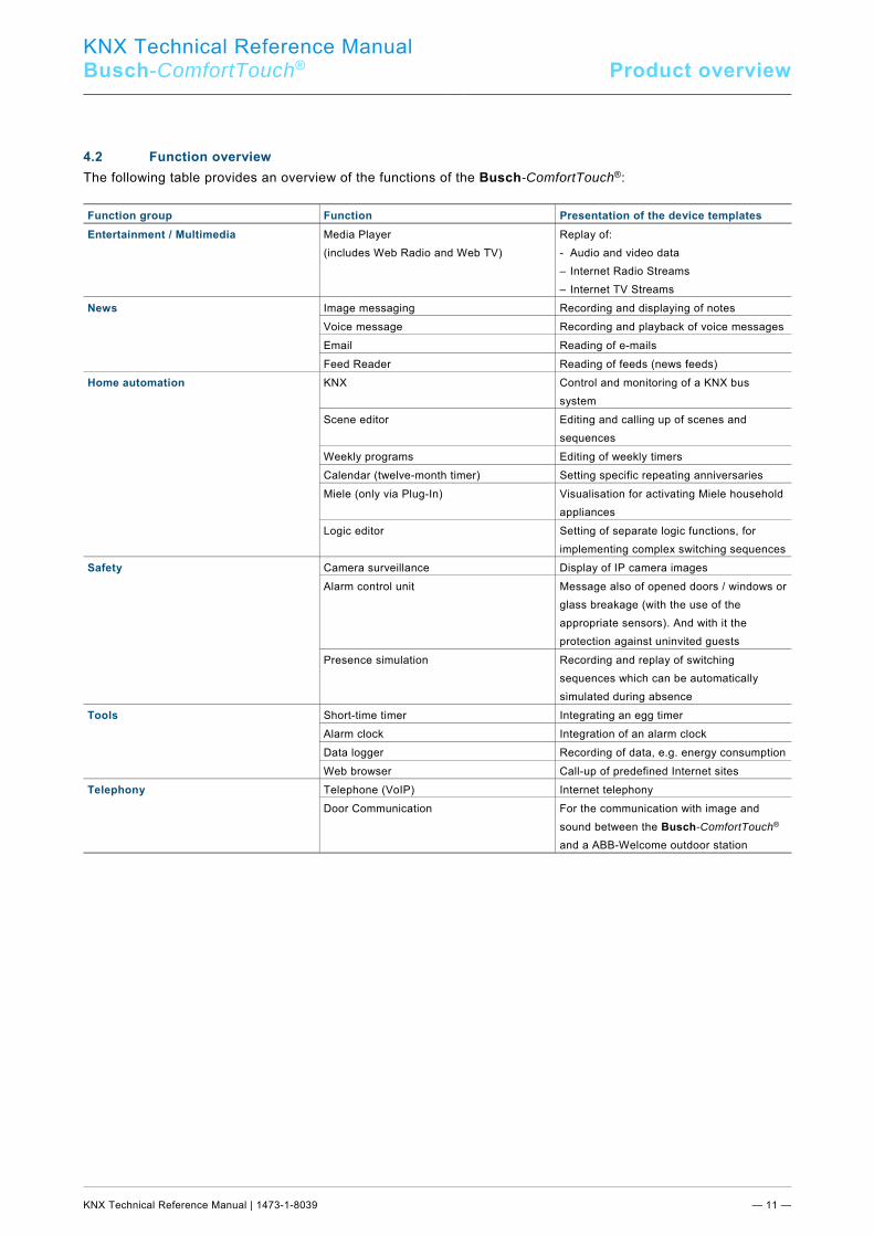
The following table provides an overview of the functions of the Busch-ComfortTouch®: Function group Function Presentation of the device templates Entertainment / Multimedia Media Player
(includes Web Radio and Web TV) Replay of: - Audio and video data – Internet Radio Streams – Internet TV Streams
News Image messaging Recording and displaying of notes Voice message Recording and playback of voice messages Email Reading of e-mails Feed Reader Reading of feeds (news feeds)
Home automation KNX Control and monitoring of a KNX bus system
Scene editor Editing and calling up of scenes and sequences
Weekly programs Editing of weekly timers Calendar (twelve-month timer) Setting specific repeating anniversaries Miele (only via Plug-In) Visualisation for activating Miele household
appliances Logic editor Setting of separate logic functions, for
implementing complex switching sequencesSafety Camera surveillance Display of IP camera images
Alarm control unit Message also of opened doors / windows or glass breakage (with the use of the appropriate sensors). And with it the protection against uninvited guests
Presence simulation Recording and replay of switching sequences which can be automatically simulated during absence
Tools Short-time timer Integrating an egg timer Alarm clock Integration of an alarm clock Data logger Recording of data, e.g. energy consumptionWeb browser Call-up of predefined Internet sites
Telephony Telephone (VoIP) Internet telephony Door Communication For the communication with image and
sound between the Busch-ComfortTouch® and a ABB-Welcome outdoor station
KNX Technical Reference Manual
Busch-ComfortTouch® Product overview
KNX Technical Reference Manual | 1473-1-8039 — 12 —
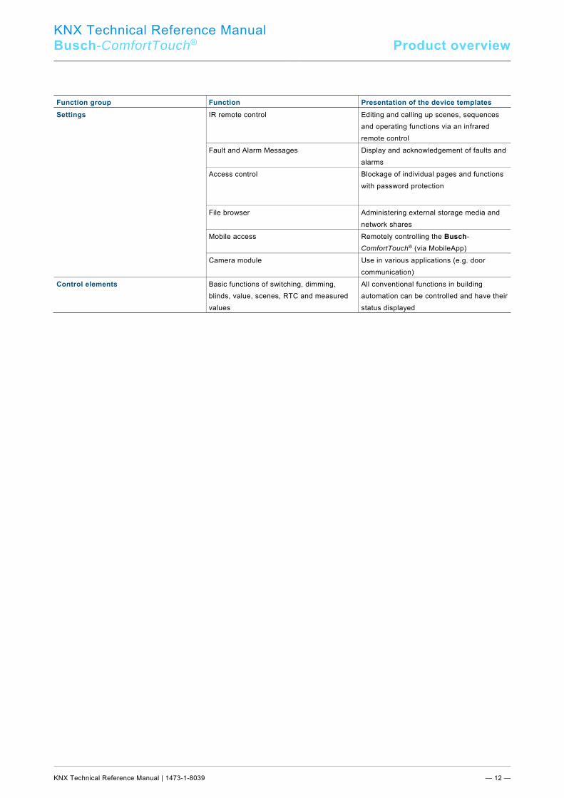
Function group Function Presentation of the device templates Settings IR remote control Editing and calling up scenes, sequences
and operating functions via an infrared remote control
Fault and Alarm Messages Display and acknowledgement of faults and alarms
Access control Blockage of individual pages and functions with password protection
File browser Administering external storage media and network shares
Mobile access Remotely controlling the Busch-
ComfortTouch® (via MobileApp) Camera module Use in various applications (e.g. door
communication) Control elements Basic functions of switching, dimming,
blinds, value, scenes, RTC and measured values
All conventional functions in building automation can be controlled and have their status displayed
Pos: 14.5 /Layout bis 2014-11-11/Online-Dokumentation (+KNX)/Steuermodule - Online-Dokumentation (--> Für alle Dokumente <--)/++++++++++++ Seitenumbruch ++++++++++++ @ 9\mod_1268898668093_0.docx @ 52149 @ @ 1
KNX Technical Reference Manual
Busch-ComfortTouch® Product overview
KNX Technical Reference Manual | 1473-1-8039 — 13 —
Pos: 14.6.1 /Layout bis 2014-11-11/Online-Dokumentation (+KNX)/Überschriften (--> Für alle Dokumente <--)/2. Ebene/A - F/Aufbau Gerät @ 33\mod_1361366224154_15.docx @ 278226 @ 2 @ 1
4.3 Device setup Pos: 14.6.2 /Layout bis 2014-11-11/Online-Dokumentation (+KNX)/Produktübersicht/KNX/KNX-Aktorik/ComfortPanel 3.0/KNX Technisches Handbuch/Aufbau GerätAufbau Gerät - KNX ... @ 40\mod_1418307260736_15.docx @ 308472 @ @ 1
1
2
3
5
6
7
4
8
!
9
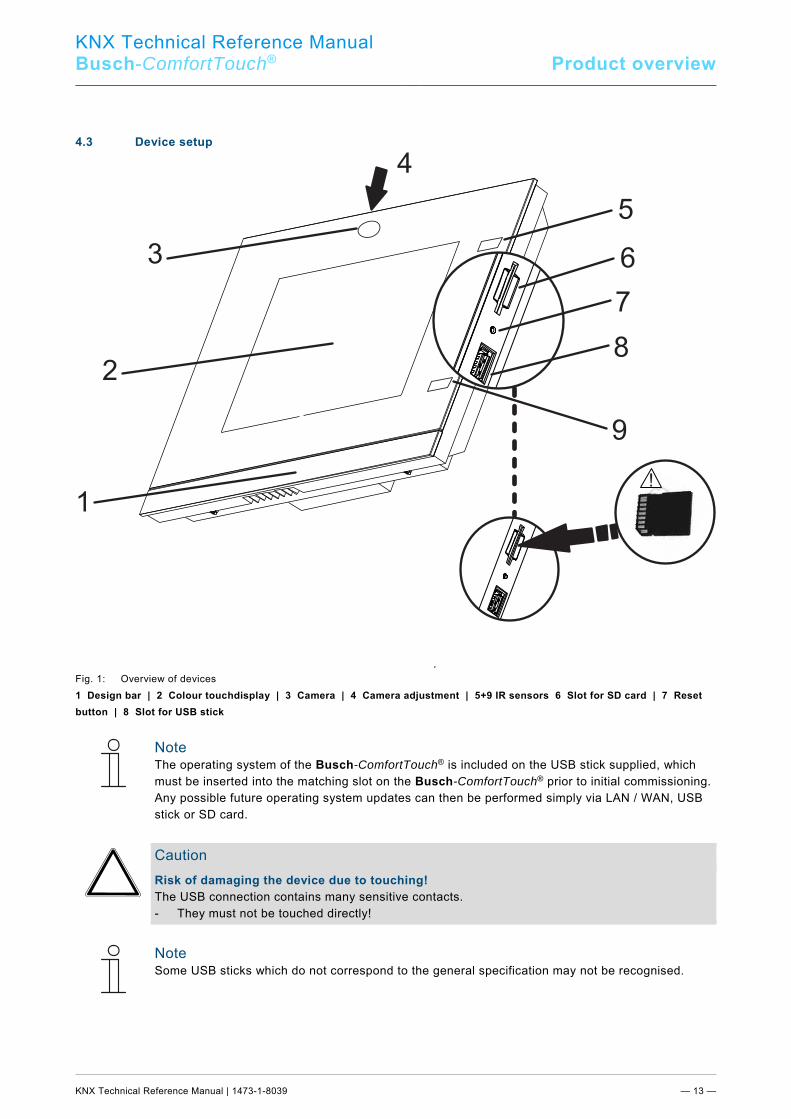
Fig. 1: Overview of devices 1 Design bar | 2 Colour touchdisplay | 3 Camera | 4 Camera adjustment | 5+9 IR sensors 6 Slot for SD card | 7 Reset button | 8 Slot for USB stick
Note The operating system of the Busch-ComfortTouch® is included on the USB stick supplied, which must be inserted into the matching slot on the Busch-ComfortTouch® prior to initial commissioning. Any possible future operating system updates can then be performed simply via LAN / WAN, USB stick or SD card.
Caution Risk of damaging the device due to touching! The USB connection contains many sensitive contacts. - They must not be touched directly!
Note Some USB sticks which do not correspond to the general specification may not be recognised.
Pos: 14.7 /Layout bis 2014-11-11/Online-Dokumentation (+KNX)/Steuermodule - Online-Dokumentation (--> Für alle Dokumente <--)/++++++++++++ Seitenumbruch ++++++++++++ @ 9\mod_1268898668093_0.docx @ 52149 @ @ 1
KNX Technical Reference Manual
Busch-ComfortTouch® Product overview
KNX Technical Reference Manual | 1473-1-8039 — 14 —
Pos: 14.8.1 /Layout bis 2014-11-11/Online-Dokumentation (+KNX)/Überschriften (--> Für alle Dokumente <--)/2. Ebene/G - L/Lieferumfang @ 33\mod_1361366589132_15.docx @ 278274 @ 2 @ 1
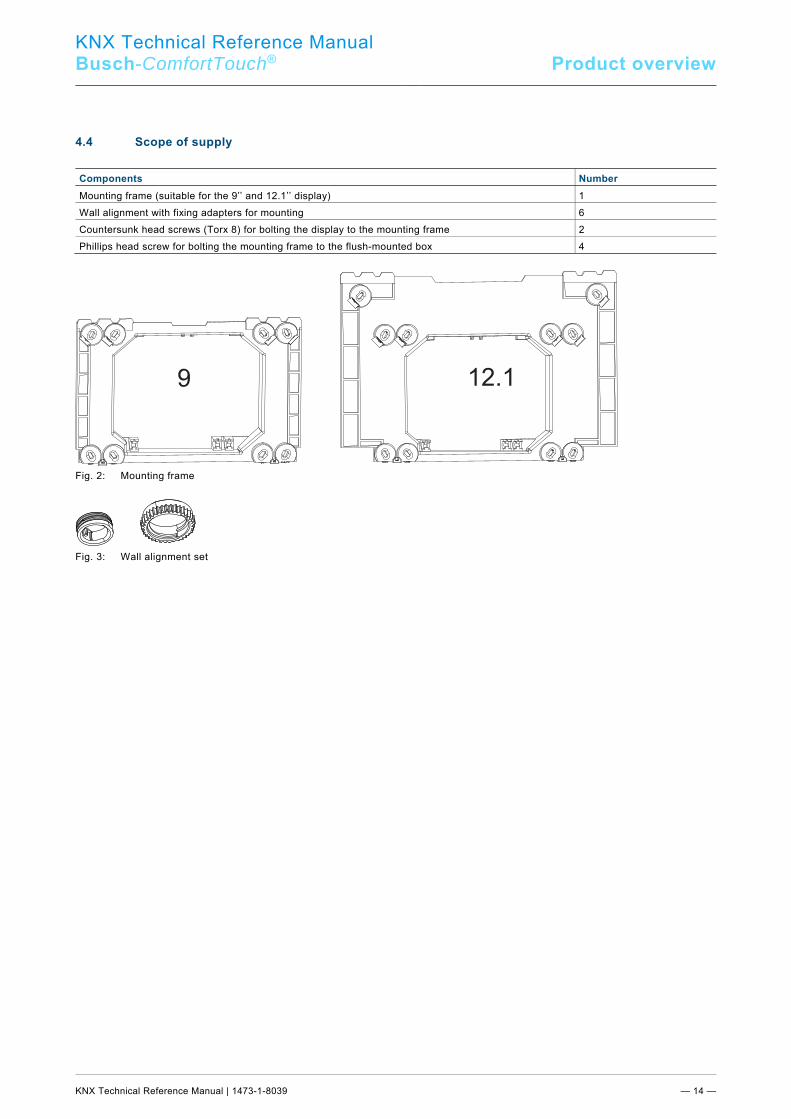
4.4 Scope of supply Pos: 14.8.2 /Layout bis 2014-11-11/Online-Dokumentation (+KNX)/Produktübersicht/KNX/KNX-Aktorik/ComfortPanel 3.0/KNX Technisches Handbuch/Lieferumfang/Lieferumfang @ 33\mod_1361365428309_15.docx @ 278033 @ @ 1
Components Number Mounting frame (suitable for the 9’’ and 12.1’’ display) 1 Wall alignment with fixing adapters for mounting 6 Countersunk head screws (Torx 8) for bolting the display to the mounting frame 2 Phillips head screw for bolting the mounting frame to the flush-mounted box 4
Fig. 2: Mounting frame
Fig. 3: Wall alignment set Pos: 14.9 /Layout bis 2014-11-11/Online-Dokumentation (+KNX)/Steuermodule - Online-Dokumentation (--> Für alle Dokumente <--)/++++++++++++ Seitenumbruch ++++++++++++ @ 9\mod_1268898668093_0.docx @ 52149 @ @ 1
9 12.1
KNX Technical Reference Manual
Busch-ComfortTouch® Product overview
KNX Technical Reference Manual | 1473-1-8039 — 15 —
Pos: 14.10.1 /Layout bis 2014-11-11/Online-Dokumentation (+KNX)/Überschriften (--> Für alle Dokumente <--)/2. Ebene/U - Z/Weitere benötigte Komponenten @ 33\mod_1361366730557_15.docx @ 278306 @ 2 @ 1
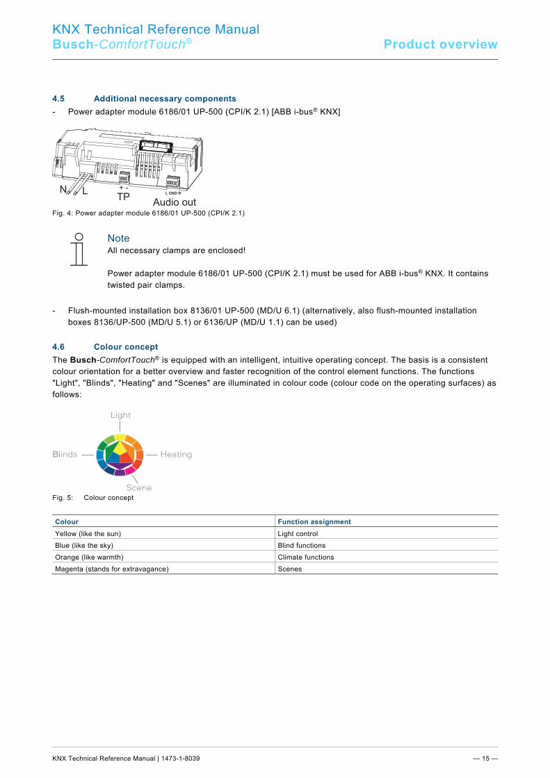
4.5 Additional necessary components Pos: 14.10.2 /Layout bis 2014-11-11/Online-Dokumentation (+KNX)/Produktübersicht/KNX/ComfortPanel 3.0/KNX Technisches Handbuch/Weitere benötigte Komponenten/Weitere benötigte Komponenten - ABB @ 35\mod_1363336229774_15.docx @ 287790 @ @ 1
- Power adapter module 6186/01 UP-500 (CPI/K 2.1) [ABB i-bus® KNX]
Fig. 4: Power adapter module 6186/01 UP-500 (CPI/K 2.1)
Note All necessary clamps are enclosed! Power adapter module 6186/01 UP-500 (CPI/K 2.1) must be used for ABB i-bus® KNX. It contains twisted pair clamps.
- Flush-mounted installation box 8136/01 UP-500 (MD/U 6.1) (alternatively, also flush-mounted installation
boxes 8136/UP-500 (MD/U 5.1) or 6136/UP (MD/U 1.1) can be used) Pos: 14.11 /Layout bis 2014-11-11/Online-Dokumentation (+KNX)/Steuermodule - Online-Dokumentation (--> Für alle Dokumente <--)/++++++++++++ Seitenumbruch ++++++++++++ @ 9\mod_1268898668093_0.docx @ 52149 @ @ 1 Pos: 14.12.1 /Layout bis 2014-11-11/Online-Dokumentation (+KNX)/Überschriften (--> Für alle Dokumente <--)/2. Ebene/A - F/Farbkonzept @ 33\mod_1361366298104_15.docx @ 278242 @ 2 @ 1
4.6 Colour concept Pos: 14.12.2 /Layout bis 2014-11-11/Online-Dokumentation (+KNX)/Produktübersicht/KNX/KNX-Aktorik/ComfortPanel 3.0/KNX Technisches Handbuch/Farbkonzept/Farbkonzept @ 33\mod_1361365475354_15.docx @ 278065 @ @ 1
The Busch-ComfortTouch® is equipped with an intelligent, intuitive operating concept. The basis is a consistent colour orientation for a better overview and faster recognition of the control element functions. The functions "Light", "Blinds", "Heating" and "Scenes" are illuminated in colour code (colour code on the operating surfaces) as follows:
B
Fig. 5: Colour concept
Colour Function assignment Yellow (like the sun) Light control Blue (like the sky) Blind functions Orange (like warmth) Climate functions Magenta (stands for extravagance) Scenes
Pos: 15 /Layout bis 2014-11-11/Modul-Struktur/Online-Dokumentation/Steuermodule - Online-Dokumentation (--> Für alle Dokumente <--)/++++++++++++ Seitenumbruch ++++++++++++ @ 9\mod_1268898668093_0.docx @ 52149 @ @ 1
N LTP
Audio out
L GND R
+ -
KNX Technical Reference Manual
Busch-ComfortTouch® Technical data
KNX Technical Reference Manual | 1473-1-8039 — 16 —
Pos: 17.1 /Layout bis 2014-11-11/Online-Dokumentation (+KNX)/Überschriften (--> Für alle Dokumente <--)/1. Ebene/S - T/Technische Daten @ 11\mod_1279185386320_15.docx @ 83019 @ 2 @ 1
5 Technical data Pos: 17.2.1 /Layout bis 2014-11-11/Online-Dokumentation (+KNX)/Überschriften (--> Für alle Dokumente <--)/2. Ebene/U - Z/Übersichtstabelle @ 33\mod_1361369213708_15.docx @ 278559 @ 1 @ 1
5.1 Overview table Pos: 17.2.2 /Layout bis 2014-11-11/Online-Dokumentation (+KNX)/Technische Daten/KNX/KNX-Aktorik/ComfortPanel 3.0/KNX Technisches Handbuch/Übersichtstabelle/Übersichtstabelle @ 33\mod_1361367419554_15.docx @ 278342 @ @ 1
Note The technical data refer to the Busch-ComfortTouch® including power adapter.
Attribute Value Nominal voltage 110 to 230 V AC, ±10% Rated frequency 50 / 60 Hz, ±2% Power consumption Busch-ComfortTouch® 9 < 15 W Busch-ComfortTouch® 12 < 18 W KNX connection (twisted pair; only 6186/01 UP-500 (CPI/K 2.1))
Bus connection terminal, screw-on
"Audio out" connection (L GND R), plug-in terminal, 1 VRMS, 10 KΩ Multimedia card / SD card (SD, SDHC and Micro SD (SDHC, with the use of an appropriate adapter) USB stick connection USB 2.0, USB socket type A, 5 V/100 mA LAN connection RJ 45 Protection type IP20 according to DIN EN 60529 Ambient temperature range -5 … 45°C Storage temperature range -20 … 70°C
Pos: 17.3 /Layout bis 2014-11-11/Online-Dokumentation (+KNX)/Steuermodule - Online-Dokumentation (--> Für alle Dokumente <--)/++++++++++++ Seitenumbruch ++++++++++++ @ 9\mod_1268898668093_0.docx @ 52149 @ @ 1 Pos: 17.4.1 /Layout bis 2014-11-11/Online-Dokumentation (+KNX)/Überschriften (--> Für alle Dokumente <--)/2. Ebene/G - L/Geräteanschluss / Anschlussbild @ 33\mod_1361369125277_15.docx @ 278543 @ 1 @ 1
5.2 Device connection / circuit diagram Pos: 17.4.2 /Layout bis 2014-11-11/Online-Dokumentation (+KNX)/Technische Daten/KNX/ComfortPanel 3.0/KNX Technisches Handbuch/Geräteanschluss / Anschlussbild/Geräteanschluss /Geräteanschluss / Anschlussbild - ABB @ 35\mod_1363336454376_15.docx @ 287822 @ @ 1
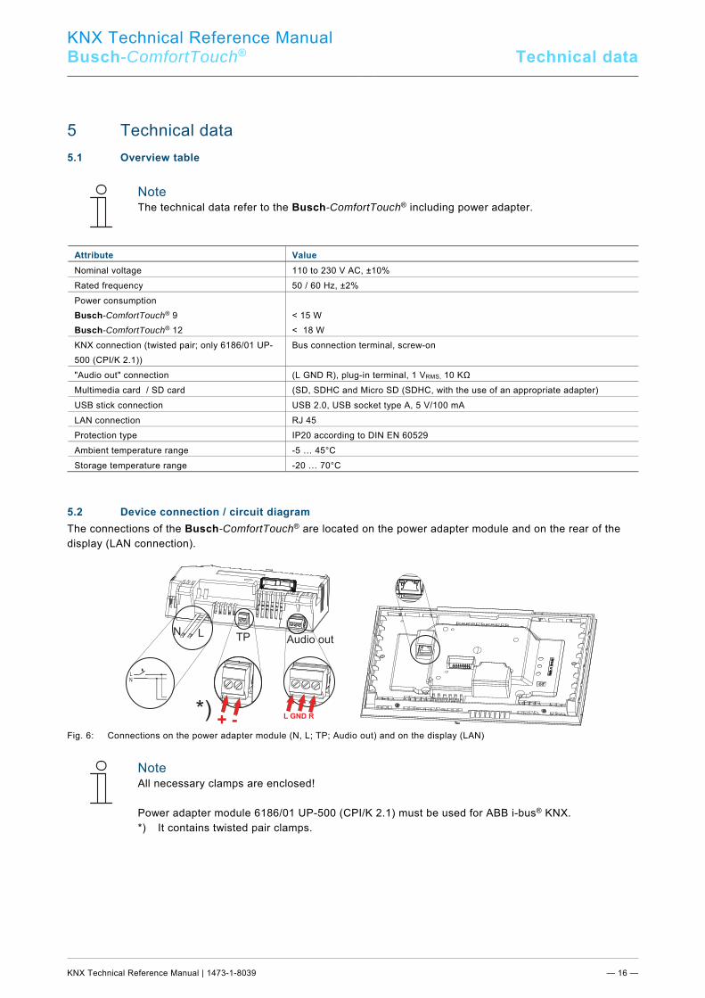
The connections of the Busch-ComfortTouch® are located on the power adapter module and on the rear of the display (LAN connection).
Fig. 6: Connections on the power adapter module (N, L; TP; Audio out) and on the display (LAN)
Note All necessary clamps are enclosed! Power adapter module 6186/01 UP-500 (CPI/K 2.1) must be used for ABB i-bus® KNX. *) It contains twisted pair clamps.
Pos: 17.5 /Layout bis 2014-11-11/Online-Dokumentation (+KNX)/Steuermodule - Online-Dokumentation (--> Für alle Dokumente <--)/++++++++++++ Seitenumbruch ++++++++++++ @ 9\mod_1268898668093_0.docx @ 52149 @ @ 1
N L TP Audio out
+ -L GND R
L
N
*)
KNX Technical Reference Manual
Busch-ComfortTouch® Technical data
KNX Technical Reference Manual | 1473-1-8039 — 17 —
Pos: 17.6.1 /Layout bis 2014-11-11/Online-Dokumentation (+KNX)/Überschriften (--> Für alle Dokumente <--)/2. Ebene/A - F/Abmessungen /Abmessungen / Maßbild @ 33\mod_1361368902556_15.docx @ 278527 @ 1 @ 1
5.3 Dimensions / dimensional drawing Pos: 17.6.2 /Layout bis 2014-11-11/Online-Dokumentation (+KNX)/Technische Daten/KNX/KNX-Aktorik/ComfortPanel 3.0/KNX Technisches Handbuch/Abmessungen / Maßbild/Abmessungen /Abmessungen / Maßbild @ 33\mod_1361367502209_15.docx @ 278438 @ @ 1
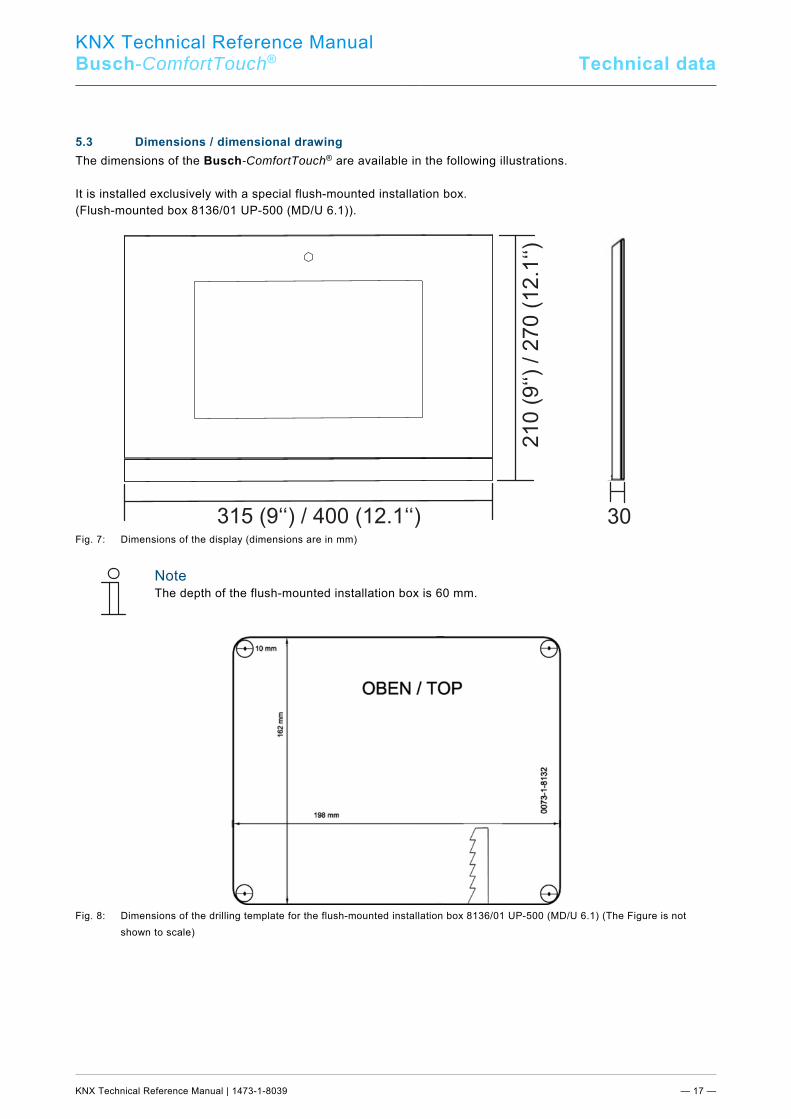
The dimensions of the Busch-ComfortTouch® are available in the following illustrations. It is installed exclusively with a special flush-mounted installation box. (Flush-mounted box 8136/01 UP-500 (MD/U 6.1)).
Fig. 7: Dimensions of the display (dimensions are in mm)
Note The depth of the flush-mounted installation box is 60 mm.
Fig. 8: Dimensions of the drilling template for the flush-mounted installation box 8136/01 UP-500 (MD/U 6.1) (The Figure is not
shown to scale)
315 (9‘‘) / 400 (12.1‘‘) 30
KNX Technical Reference Manual
Busch-ComfortTouch® Technical data
KNX Technical Reference Manual | 1473-1-8039 — 18 —
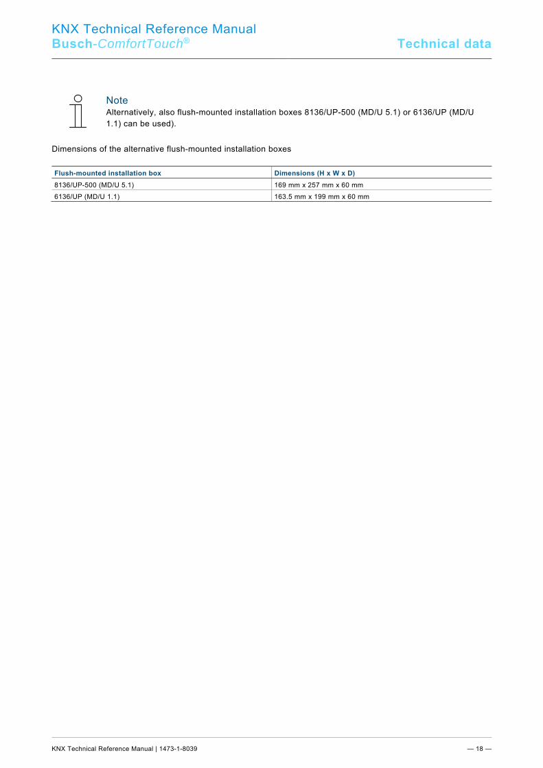
Note Alternatively, also flush-mounted installation boxes 8136/UP-500 (MD/U 5.1) or 6136/UP (MD/U 1.1) can be used).
Dimensions of the alternative flush-mounted installation boxes
Flush-mounted installation box Dimensions (H x W x D) 8136/UP-500 (MD/U 5.1) 169 mm x 257 mm x 60 mm 6136/UP (MD/U 1.1) 163.5 mm x 199 mm x 60 mm
Pos: 18 /Layout bis 2014-11-11/Modul-Struktur/Online-Dokumentation/Steuermodule - Online-Dokumentation (--> Für alle Dokumente <--)/++++++++++++ Seitenumbruch ++++++++++++ @ 9\mod_1268898668093_0.docx @ 52149 @ @ 1
KNX Technical Reference Manual
Busch-ComfortTouch® Installation
KNX Technical Reference Manual | 1473-1-8039 — 19 —
Pos: 20.1 /Layout bis 2014-11-11/Online-Dokumentation (+KNX)/Überschriften (--> Für alle Dokumente <--)/1. Ebene/G - L/Installation @ 17\mod_1297676495008_15.docx @ 100410 @ 2 @ 1
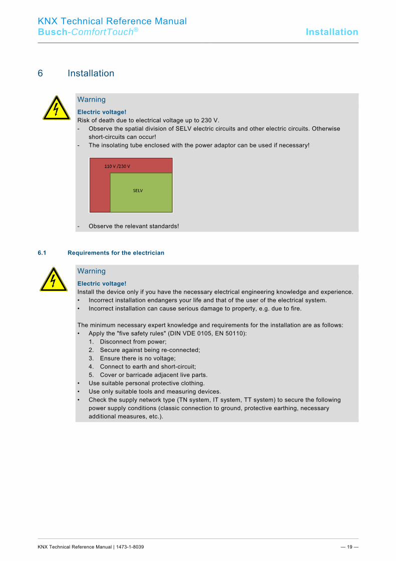
6 Installation Pos: 20.2.1 /Layout bis 2014-11-11/Online-Dokumentation (+KNX)/Sicherheitshinweise und Hinweise (--> Für alle Dokumente <--)/Warnhinweise/Sicherheit - 230 V + SELV @ 35\mod_1362749941351_15.docx @ 285394 @ @ 1
Warning Electric voltage! Risk of death due to electrical voltage up to 230 V. - Observe the spatial division of SELV electric circuits and other electric circuits. Otherwise
short-circuits can occur! - The insolating tube enclosed with the power adaptor can be used if necessary!
- Observe the relevant standards!
Pos: 20.2.2 /Layout bis 2014-11-11/Online-Dokumentation (+KNX)/Sicherheitshinweise und Hinweise (--> Für alle Dokumente <--)/Warnhinweise/Sicherheit - Fachkenntnisse @ 23\mod_1336559183027_15.docx @ 209179 @ 1 @ 1
6.1 Requirements for the electrician
Warning Electric voltage! Install the device only if you have the necessary electrical engineering knowledge and experience. • Incorrect installation endangers your life and that of the user of the electrical system. • Incorrect installation can cause serious damage to property, e.g. due to fire. The minimum necessary expert knowledge and requirements for the installation are as follows: • Apply the "five safety rules" (DIN VDE 0105, EN 50110): 1. Disconnect from power; 2. Secure against being re-connected; 3. Ensure there is no voltage; 4. Connect to earth and short-circuit; 5. Cover or barricade adjacent live parts. • Use suitable personal protective clothing. • Use only suitable tools and measuring devices. • Check the supply network type (TN system, IT system, TT system) to secure the following
power supply conditions (classic connection to ground, protective earthing, necessary additional measures, etc.).
Pos: 20.3 /Layout bis 2014-11-11/Online-Dokumentation (+KNX)/Steuermodule - Online-Dokumentation (--> Für alle Dokumente <--)/++++++++++++ Seitenumbruch ++++++++++++ @ 9\mod_1268898668093_0.docx @ 52149 @ @ 1

KNX Technical Reference Manual
Busch-ComfortTouch® Installation
KNX Technical Reference Manual | 1473-1-8039 — 20 —
Pos: 20.4.1 /Layout bis 2014-11-11/Online-Dokumentation (+KNX)/Überschriften (--> Für alle Dokumente <--)/2. Ebene/A - F/Einbau /Einbau / Montage @ 33\mod_1361372259167_15.docx @ 278673 @ 2 @ 1
6.2 Installation / mounting Pos: 20.4.2 /Layout bis 2014-11-11/Online-Dokumentation (+KNX)/Installation/KNX/KNX-Aktorik/ComfortPanel 3.0/KNX Technisches Handbuch/Einbau / Montage/Einbau /Einbau / Montage @ 33\mod_1361372057729_15.docx @ 278640 @ 2333 @ 1
6.2.1 Preparation for installation
The Busch-ComfortTouch® is installed in flush-mounted installation box 8136/01 UP-500 (MD/U 6.1). For flush-mounted or hollow-wall installation. This applies to the 9" and the 12.1" display.
Note The flush-mounted installation boxes are not included in the scope of supply of the Busch-ComfortTouch®!
Generally the supplied mounting frame (for the 9" or 12.1" display) must be aligned with the wall alignment parts to produce an even surface. The wall alignment parts must be attached from behind on all screw holes according to the following figure (9" = 4, 12.1 = 6). Here it must be observed that the black fixing adapters are coded and can only be attached accordingly. The knurls on the the grey wall alignment parts must sit against the mounting frame.
Fig. 9: Preparing the wall for the installation
KNX Technical Reference Manual
Busch-ComfortTouch® Installation
KNX Technical Reference Manual | 1473-1-8039 — 21 —
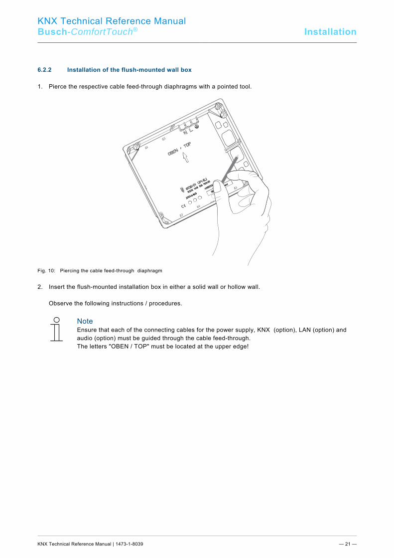
6.2.2 Installation of the flush-mounted wall box
1. Pierce the respective cable feed-through diaphragms with a pointed tool.
Fig. 10: Piercing the cable feed-through diaphragm 2. Insert the flush-mounted installation box in either a solid wall or hollow wall. Observe the following instructions / procedures.
Note Ensure that each of the connecting cables for the power supply, KNX (option), LAN (option) and audio (option) must be guided through the cable feed-through. The letters "OBEN / TOP" must be located at the upper edge!
KNX Technical Reference Manual
Busch-ComfortTouch® Installation
KNX Technical Reference Manual | 1473-1-8039 — 22 —
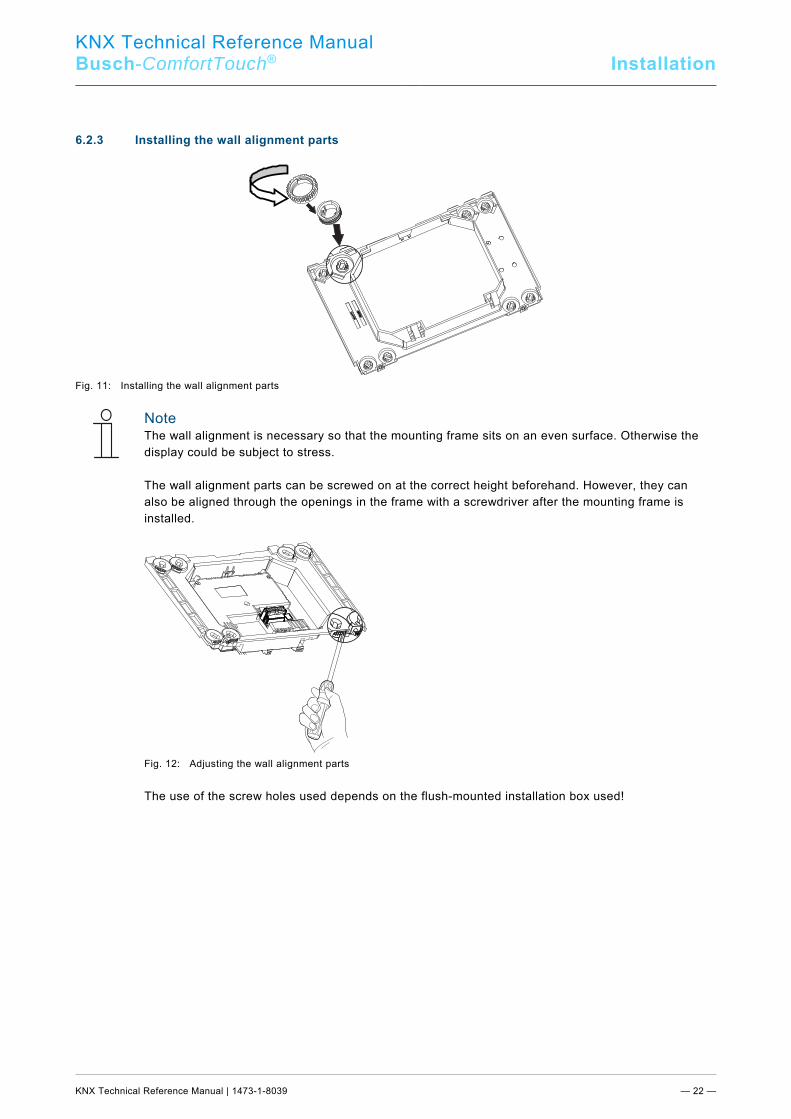
6.2.3 Installing the wall alignment parts
Fig. 11: Installing the wall alignment parts
Note The wall alignment is necessary so that the mounting frame sits on an even surface. Otherwise the display could be subject to stress. The wall alignment parts can be screwed on at the correct height beforehand. However, they can also be aligned through the openings in the frame with a screwdriver after the mounting frame is installed.
Fig. 12: Adjusting the wall alignment parts The use of the screw holes used depends on the flush-mounted installation box used!
KNX Technical Reference Manual
Busch-ComfortTouch® Installation
KNX Technical Reference Manual | 1473-1-8039 — 23 —
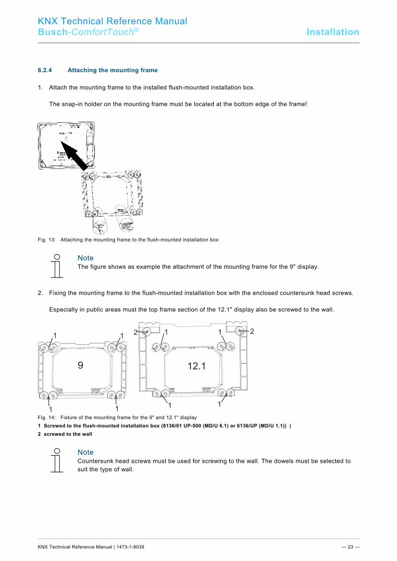
6.2.4 Attaching the mounting frame
1. Attach the mounting frame to the installed flush-mounted installation box. The snap-in holder on the mounting frame must be located at the bottom edge of the frame!
Fig. 13: Attaching the mounting frame to the flush-mounted installation box
Note The figure shows as example the attachment of the mounting frame for the 9" display.
2. Fixing the mounting frame to the flush-mounted installation box with the enclosed countersunk head screws. Especially in public areas must the top frame section of the 12.1" display also be screwed to the wall.
Fig. 14: Fixture of the mounting frame for the 9" and 12.1" display 1 Screwed to the flush-mounted installation box (8136/01 UP-500 (MD/U 6.1) or 6136/UP (MD/U 1.1)) | 2 screwed to the wall
Note Countersunk head screws must be used for screwing to the wall. The dowels must be selected to suit the type of wall.
Pos: 20.5 /Layout bis 2014-11-11/Online-Dokumentation (+KNX)/Steuermodule - Online-Dokumentation (--> Für alle Dokumente <--)/++++++++++++ Seitenumbruch ++++++++++++ @ 9\mod_1268898668093_0.docx @ 52149 @ @ 1
9 12.1
1 1
1 11 1
1 122
KNX Technical Reference Manual
Busch-ComfortTouch® Installation
KNX Technical Reference Manual | 1473-1-8039 — 24 —
Pos: 20.6.1 /Layout bis 2014-11-11/Online-Dokumentation (+KNX)/Überschriften (--> Für alle Dokumente <--)/2. Ebene/A - F/Elektrischer Anschluss @ 21\mod_1328177051724_15.docx @ 138042 @ 3 @ 1
6.3 Electrical connection Pos: 20.6.2 /Layout bis 2014-11-11/Online-Dokumentation (+KNX)/Installation/KNX/ComfortPanel 3.0/KNX Technisches Handbuch/Elektrischer Anschluss/Einlegen des Netzteil-Moduls - ABB @ 36\mod_1363765620823_15.docx @ 289014 @ 2 @ 1
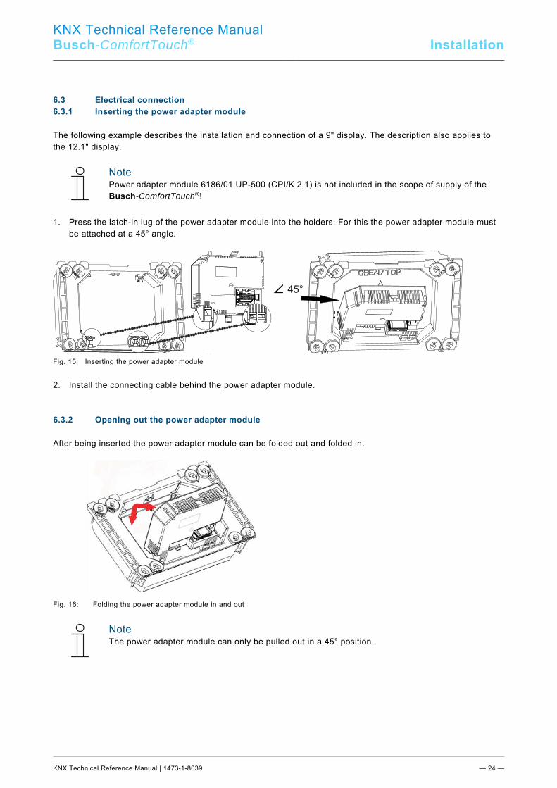
6.3.1 Inserting the power adapter module
The following example describes the installation and connection of a 9" display. The description also applies to the 12.1" display.
Note Power adapter module 6186/01 UP-500 (CPI/K 2.1) is not included in the scope of supply of the Busch-ComfortTouch®!
1. Press the latch-in lug of the power adapter module into the holders. For this the power adapter module must
be attached at a 45° angle.
Fig. 15: Inserting the power adapter module
2. Install the connecting cable behind the power adapter module. Pos: 20.6.3 /Layout bis 2014-11-11/Online-Dokumentation (+KNX)/Installation/KNX/ComfortPanel 3.0/KNX Technisches Handbuch/Elektrischer Anschluss/Aufklappen des Netzteil-Moduls @ 35\mod_1363337473211_15.docx @ 287931 @ 2 @ 1
6.3.2 Opening out the power adapter module
After being inserted the power adapter module can be folded out and folded in.
Fig. 16: Folding the power adapter module in and out
Note The power adapter module can only be pulled out in a 45° position.
Pos: 20.6.4 /Layout bis 2014-11-11/Online-Dokumentation (+KNX)/Steuermodule - Online-Dokumentation (--> Für alle Dokumente <--)/++++++++++++ Seitenumbruch ++++++++++++ @ 9\mod_1268898668093_0.docx @ 52149 @ @ 1
45°
KNX Technical Reference Manual
Busch-ComfortTouch® Installation
KNX Technical Reference Manual | 1473-1-8039 — 25 —
Pos: 20.6.5 /Layout bis 2014-11-11/Online-Dokumentation (+KNX)/Installation/KNX/ComfortPanel 3.0/KNX Technisches Handbuch/Elektrischer Anschluss/Anschließen des Netzteil-Moduls - ABB @ 35\mod_1363337596899_15.docx @ 287946 @ 2 @ 1
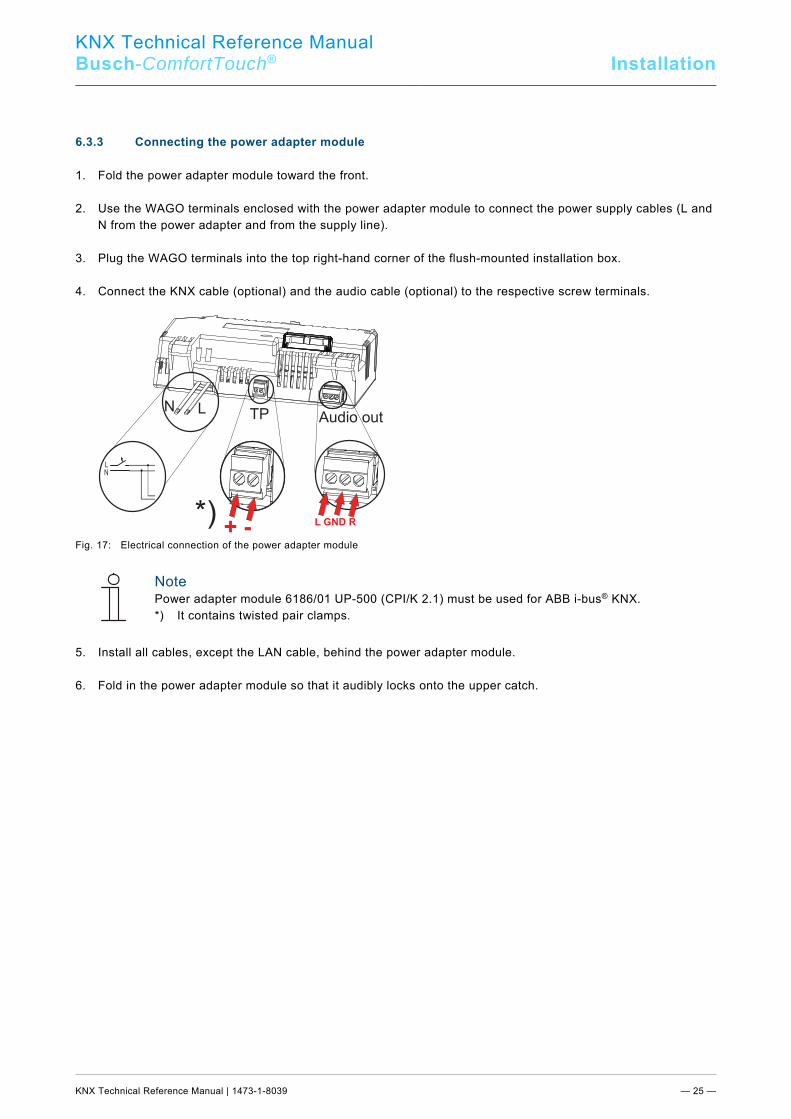
6.3.3 Connecting the power adapter module
1. Fold the power adapter module toward the front. 2. Use the WAGO terminals enclosed with the power adapter module to connect the power supply cables (L and
N from the power adapter and from the supply line). 3. Plug the WAGO terminals into the top right-hand corner of the flush-mounted installation box. 4. Connect the KNX cable (optional) and the audio cable (optional) to the respective screw terminals.
Fig. 17: Electrical connection of the power adapter module
Note Power adapter module 6186/01 UP-500 (CPI/K 2.1) must be used for ABB i-bus® KNX. *) It contains twisted pair clamps.
5. Install all cables, except the LAN cable, behind the power adapter module. 6. Fold in the power adapter module so that it audibly locks onto the upper catch.
N L TP Audio out
+ -L GND R
L
N
*)
KNX Technical Reference Manual
Busch-ComfortTouch® Installation
KNX Technical Reference Manual | 1473-1-8039 — 26 —
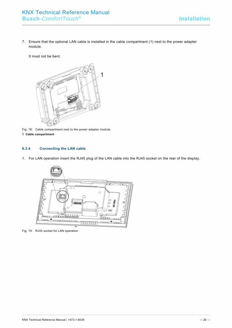
7. Ensure that the optional LAN cable is installed in the cable compartment (1) next to the power adapter module.
It must not be bent.
Fig. 18: Cable compartment next to the power adapter module. 1 Cable compartment Pos: 20.6.6 /Layout bis 2014-11-11/Online-Dokumentation (+KNX)/Installation/KNX/ComfortPanel 3.0/KNX Technisches Handbuch/Elektrischer Anschluss/Anschließen des LAN-Kabels @ 35\mod_1363337113879_15.docx @ 287886 @ 2 @ 1
6.3.4 Connecting the LAN cable
1. For LAN operation insert the RJ45 plug of the LAN cable into the RJ45 socket on the rear of the display.
Fig. 19: RJ45 socket for LAN operation Pos: 20.6.7 /Layout bis 2014-11-11/Online-Dokumentation (+KNX)/Steuermodule - Online-Dokumentation (--> Für alle Dokumente <--)/++++++++++++ Seitenumbruch ++++++++++++ @ 9\mod_1268898668093_0.docx @ 52149 @ @ 1
1
KNX Technical Reference Manual
Busch-ComfortTouch® Installation
KNX Technical Reference Manual | 1473-1-8039 — 27 —
Pos: 20.6.8 /Layout bis 2014-11-11/Online-Dokumentation (+KNX)/Installation/KNX/ComfortPanel 3.0/KNX Technisches Handbuch/Elektrischer Anschluss/Aufsetzen des Displays @ 35\mod_1363337200550_15.docx @ 287901 @ 2 @ 1
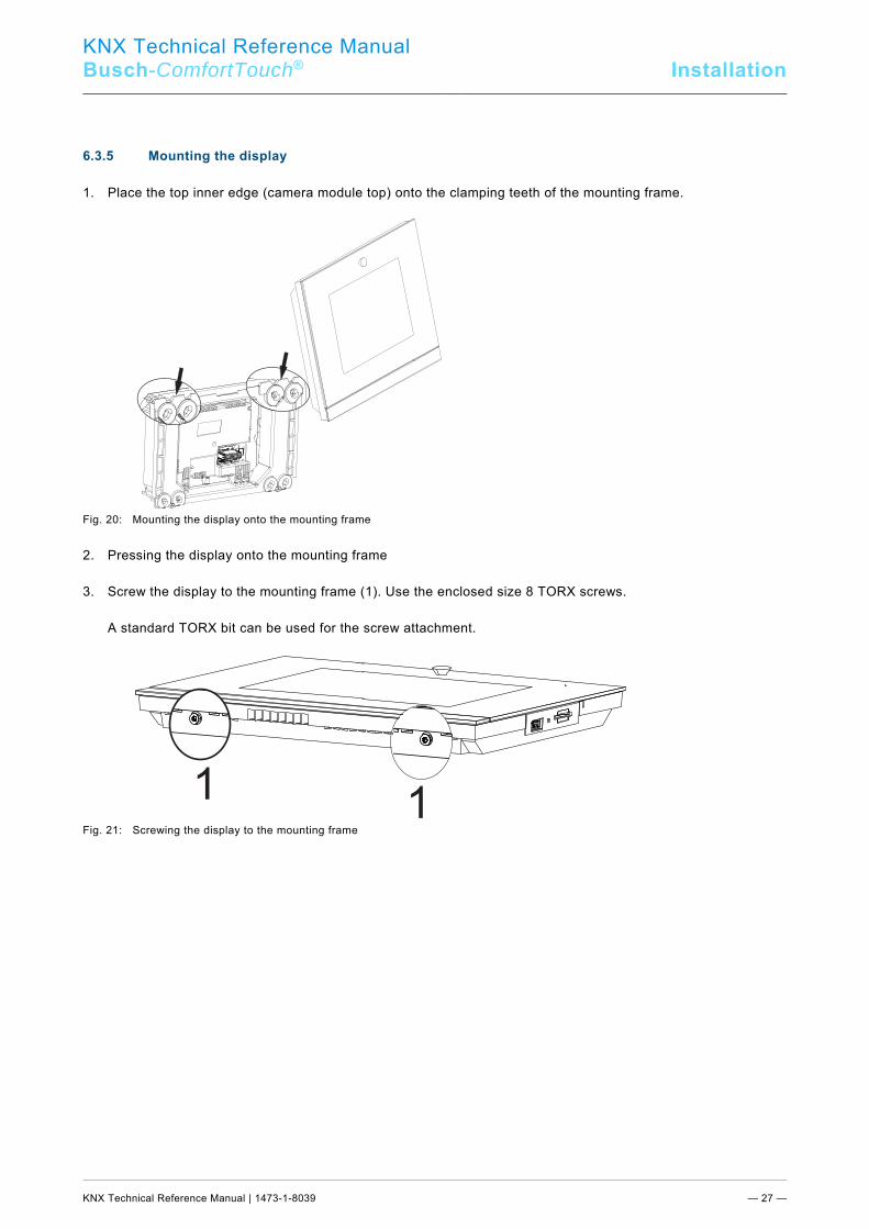
6.3.5 Mounting the display
1. Place the top inner edge (camera module top) onto the clamping teeth of the mounting frame.
Fig. 20: Mounting the display onto the mounting frame 2. Pressing the display onto the mounting frame 3. Screw the display to the mounting frame (1). Use the enclosed size 8 TORX screws. A standard TORX bit can be used for the screw attachment.
Fig. 21: Screwing the display to the mounting frame
11
KNX Technical Reference Manual
Busch-ComfortTouch® Installation
KNX Technical Reference Manual | 1473-1-8039 — 28 —
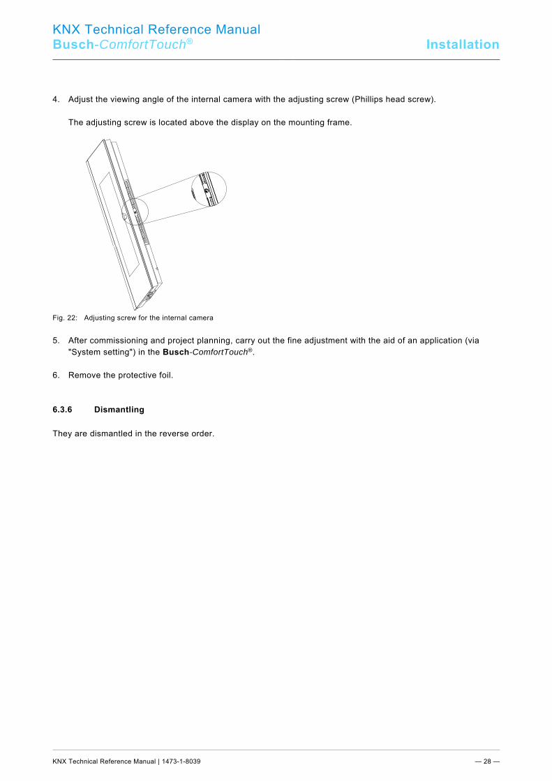
4. Adjust the viewing angle of the internal camera with the adjusting screw (Phillips head screw). The adjusting screw is located above the display on the mounting frame.
Fig. 22: Adjusting screw for the internal camera 5. After commissioning and project planning, carry out the fine adjustment with the aid of an application (via
"System setting") in the Busch-ComfortTouch®. 6. Remove the protective foil. Pos: 20.6.9 /Layout bis 2014-11-11/Online-Dokumentation (+KNX)/Installation/KNX/ComfortPanel 3.0/KNX Technisches Handbuch/Elektrischer Anschluss/Demontage @ 35\mod_1363337257641_15.docx @ 287916 @ 1 @ 1
6.3.6 Dismantling
They are dismantled in the reverse order. Pos: 21 /Layout bis 2014-11-11/Online-Dokumentation (+KNX)/Steuermodule - Online-Dokumentation (--> Für alle Dokumente <--)/++++++++++++ Seitenumbruch ++++++++++++ @ 9\mod_1268898668093_0.docx @ 52149 @ @ 1
KNX Technical Reference Manual
Busch-ComfortTouch® Start-up
KNX Technical Reference Manual | 1473-1-8039 — 29 —
Pos: 22.1 /Layout bis 2014-11-11/Online-Dokumentation (+KNX)/Überschriften (--> Für alle Dokumente <--)/1. Ebene/A - F/Erstinbetriebnahme @ 17\mod_1299234649340_15.docx @ 100978 @ 1 @ 1
7 Start-up Pos: 22.2 /Layout bis 2014-11-11/Online-Dokumentation (+KNX)/Erstinbetriebnahme/KNX/KNX-Aktorik/ComfortPanel 3.0/KNX Technisches Handbuch/Erstinbetriebnahme @ 33\mod_1361430424661_15.docx @ 278774 @ @ 1
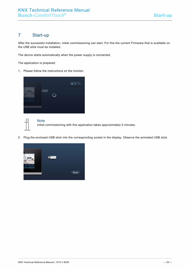
After the successful installation, initial commissioning can start. For this the current Firmware that is available on the USB stick must be installed. The device starts automatically when the power supply is connected. The application is prepared. 1. Please follow the instructions on the monitor.
Note Initial commissioning with this application takes approximately 5 minutes.
2. Plug the enclosed USB stick into the corresponding socket in the display. Observe the animated USB stick.
KNX Technical Reference Manual
Busch-ComfortTouch® Start-up
KNX Technical Reference Manual | 1473-1-8039 — 30 —
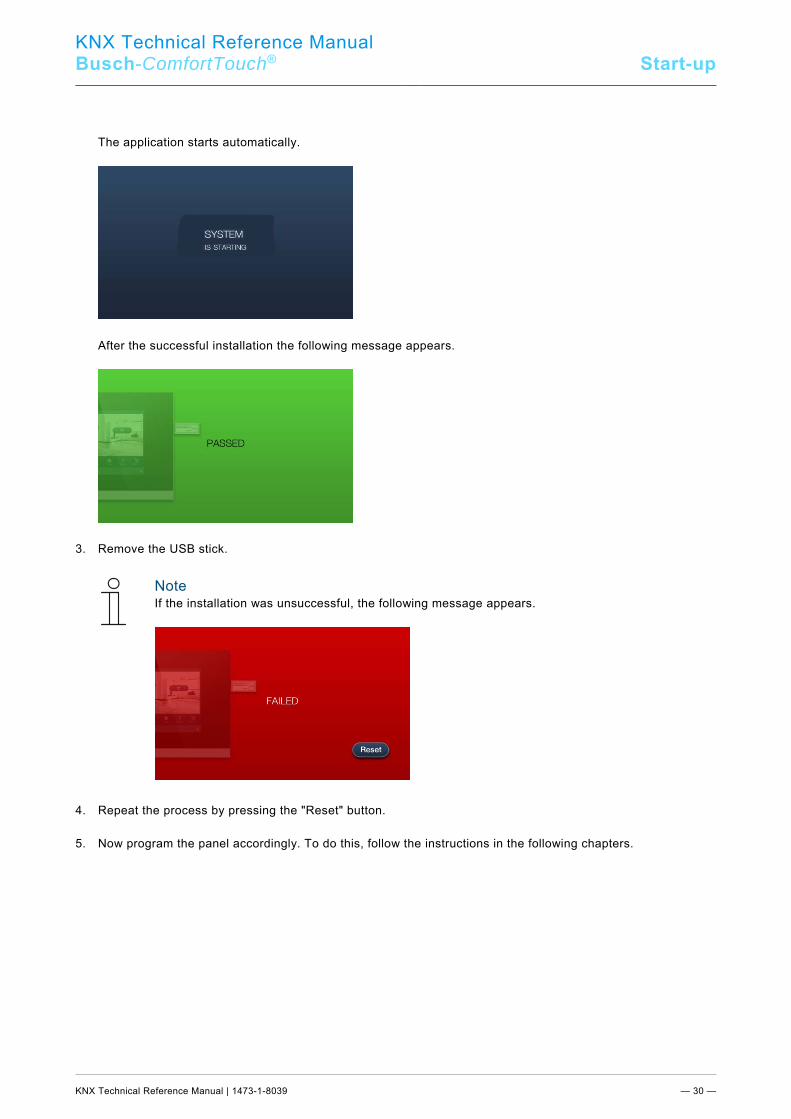
The application starts automatically.
After the successful installation the following message appears.
3. Remove the USB stick.
Note If the installation was unsuccessful, the following message appears.
4. Repeat the process by pressing the "Reset" button. 5. Now program the panel accordingly. To do this, follow the instructions in the following chapters. Pos: 23 /Layout bis 2014-11-11/Modul-Struktur/Online-Dokumentation/Steuermodule - Online-Dokumentation (--> Für alle Dokumente <--)/++++++++++++ Seitenumbruch ++++++++++++ @ 9\mod_1268898668093_0.docx @ 52149 @ @ 1
KNX Technical Reference Manual
Busch-ComfortTouch® Preparation for projectplanning
KNX Technical Reference Manual | 1473-1-8039 — 31 —
Pos: 24.1 /Layout bis 2014-11-11/Online-Dokumentation (+KNX)/Überschriften (--> Für alle Dokumente <--)/1. Ebene/U - ZVorbereitung der Projektierung @ 24\mod_1338554119019_15.docx @ 215329 @ 1 @ 1
8 Preparation for project planning Pos: 24.2 /Layout bis 2014-11-11/Online-Dokumentation (+KNX)/Vorbereitung der Projektierung/KNX/KNX-Aktorik/ComfortPanel 3.0/KNX Technisches Handbuch/Einführung @ 33\mod_1361431077198_15.docx @ 278905 @ @ 1
The individual adaptation of the Busch-ComfortTouch® is carried out with the aid of project planning software "IP-Project 3“. This software is an application especially created for project planning of the Busch-ComfortTouch®. This software must first be installed on a computer (PC). All project planning that has been created can then be simply transferred to each of the Busch-ComfortTouch® units that are connected or linked to the network. Pos: 24.3.1 /Layout bis 2014-11-11/Online-Dokumentation (+KNX)/Überschriften (--> Für alle Dokumente <--)/2. Ebene/A - F/Anforderungen an die Rechnerausstattung @ 33\mod_1361431008937_15.docx @ 278890 @ 2 @ 1
8.1 Requirements for computer equipment Pos: 24.3.2 /Layout bis 2014-11-11/Online-Dokumentation (+KNX)/Vorbereitung der Projektierung/KNX/KNX-Aktorik/ComfortPanel 3.0/KNX Technisches Handbuch/Anforderungen an die Rechnerausstattung/Anforderungen an die Rechnerausstattung @ 33\mod_1361430777852_15.docx @ 278793 @ 33 @ 1
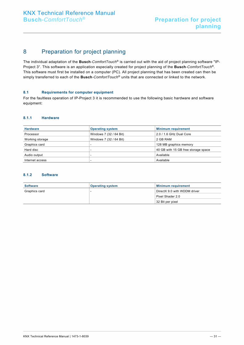
For the faultless operation of IP-Project 3 it is recommended to use the following basic hardware and software equipment: 8.1.1 Hardware
Hardware Operating system Minimum requirement Processor Windows 7 (32 / 64 Bit) 2.0 / 1.6 GHz Dual Core Working storage Windows 7 (32 / 64 Bit) 2 GB RAM Graphics card - 128 MB graphics memory Hard disc - 40 GB with 15 GB free storage space Audio output - Available Internet access - Available
8.1.2 Software
Software Operating system Minimum requirement Graphics card - DirectX 9.0 with WDDM driver
Pixel Shader 2.0
32 Bit per pixel
Pos: 24.4 /Layout bis 2014-11-11/Online-Dokumentation (+KNX)/Steuermodule - Online-Dokumentation (--> Für alle Dokumente <--)/++++++++++++ Seitenumbruch ++++++++++++ @ 9\mod_1268898668093_0.docx @ 52149 @ @ 1
KNX Technical Reference Manual
Busch-ComfortTouch® Preparation for projectplanning
KNX Technical Reference Manual | 1473-1-8039 — 32 —
Pos: 24.5.1 /Layout bis 2014-11-11/Online-Dokumentation (+KNX)/Überschriften (--> Für alle Dokumente <--)/2. Ebene/G - L/Installation von IP-Project 3 @ 33\mod_1361431244448_15.docx @ 278922 @ 2 @ 1
8.2 Installation of IP-Project 3 Pos: 24.5.2 /Layout bis 2014-11-11/Online-Dokumentation (+KNX)/Vorbereitung der Projektierung/KNX/KNX-Aktorik/ComfortPanel 3.0/KNX Technisches Handbuch/Installation von IP-Project 3Installation von IP-Project 3 @ 40\mod_1418379354913_15.docx @ 308669 @ @ 1
In the following the installation of commissioning software IP-Project 3 (IPP) for the Busch-ComfortTouch® is described.
Note Please observe the hardware and software requirements listed above for a proper installation and function of the commissioning software. In particular, you need to have full administrator rights to the operating system.
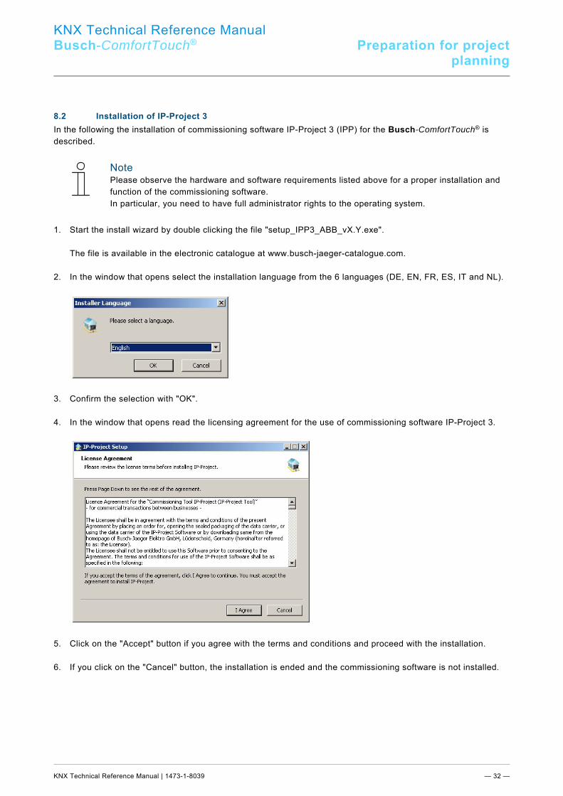
1. Start the install wizard by double clicking the file "setup_IPP3_ABB_vX.Y.exe". The file is available in the electronic catalogue at www.busch-jaeger-catalogue.com. 2. In the window that opens select the installation language from the 6 languages (DE, EN, FR, ES, IT and NL).
3. Confirm the selection with "OK". 4. In the window that opens read the licensing agreement for the use of commissioning software IP-Project 3.
5. Click on the "Accept" button if you agree with the terms and conditions and proceed with the installation. 6. If you click on the "Cancel" button, the installation is ended and the commissioning software is not installed.

KNX Technical Reference Manual
Busch-ComfortTouch® Preparation for projectplanning
KNX Technical Reference Manual | 1473-1-8039 — 33 —
7. If necessary, in the following dialog window select the individual components of the commissioning software. The IP-Project 3 files are absolutely necessary for the commissioning software to function and can therefore
not be de-selected.
8. After clicking button "Continue", create a target directory for the installation program. By default, this is: "C:\Program Files\IPP3\".
KNX Technical Reference Manual
Busch-ComfortTouch® Preparation for projectplanning
KNX Technical Reference Manual | 1473-1-8039 — 34 —
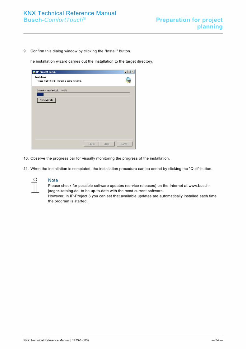
9. Confirm this dialog window by clicking the "Install" button. he installation wizard carries out the installation to the target directory.
10. Observe the progress bar for visually monitoring the progress of the installation. 11. When the installation is completed, the installation procedure can be ended by clicking the "Quit" button.
Note Please check for possible software updates (service releases) on the Internet at www.busch-jaeger-katalog.de, to be up-to-date with the most current software. However, in IP-Project 3 you can set that available updates are automatically installed each time the program is started.
Pos: 24.6 /Layout bis 2014-11-11/Online-Dokumentation (+KNX)/Steuermodule - Online-Dokumentation (--> Für alle Dokumente <--)/++++++++++++ Seitenumbruch ++++++++++++ @ 9\mod_1268898668093_0.docx @ 52149 @ @ 1
KNX Technical Reference Manual
Busch-ComfortTouch® Preparation for projectplanning
KNX Technical Reference Manual | 1473-1-8039 — 35 —
Pos: 24.7.1 /Layout bis 2014-11-11/Online-Dokumentation (+KNX)/Überschriften (--> Für alle Dokumente <--)/2. Ebene/A - F/Einbindung in das KNX-System @ 33\mod_1361431298679_15.docx @ 278938 @ 2 @ 1
8.3 Integration into the KNX system Pos: 24.7.2 /Layout bis 2014-11-11/Online-Dokumentation (+KNX)/Vorbereitung der Projektierung/KNX/KNX-Aktorik/ComfortPanel 3.0/KNX Technisches Handbuch/Einbindung in das KNX-SystemEinbindung in das KNX-System @ 40\mod_1418380509461_15.docx @ 308685 @ 3333 @ 1
Note The device meets KNX guidelines and can be used as a product of the KNX system. Detailed expert knowledge by means of KNX training sessions for a better understanding is assumed.
8.3.1 Installation of the Busch-ComfortTouch® ETSx Macro
For the correct importation and exportation of group addresses a special macro must be installed for the for the Busch-ComfortTouch®. This macro can then be called up in the ETSx via additional buttons. For this, a licensed version of the ETSx Professional software must be installed on the target computer for the installation. The minimum version is the ETS3.
Note The macro for the ETS3 can be downloaded via the electronic catalogue ((www.busch-jaeger-catalogue.com)). From the ETS4, a corresponding app must be downloaded via the electronic catalogue ((www.busch-jaeger-catalogue.com)). Here the following installation procedure is almost identical.
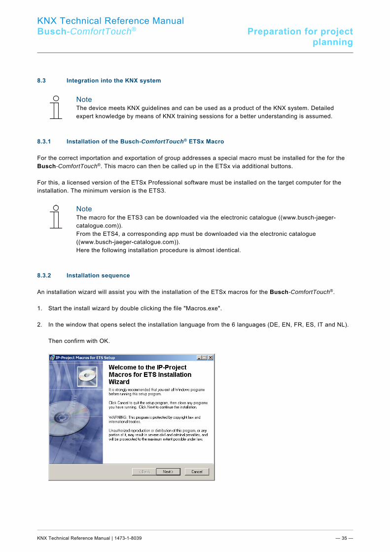
8.3.2 Installation sequence
An installation wizard will assist you with the installation of the ETSx macros for the Busch-ComfortTouch®. 1. Start the install wizard by double clicking the file "Macros.exe". 2. In the window that opens select the installation language from the 6 languages (DE, EN, FR, ES, IT and NL). Then confirm with OK.
KNX Technical Reference Manual
Busch-ComfortTouch® Preparation for projectplanning
KNX Technical Reference Manual | 1473-1-8039 — 36 —
8.3.3 Integrating the Busch-ComfortTouch® into the ETSx
Start the ETSx and import the product data of the Busch-ComfortTouch®(.vd4 file) into the project data base via the import function of the ETSx . 8.3.4 Further KNX settings in the Busch-ComfortTouch®.
For additional information about KNX settings in the Busch-ComfortTouch® use the online Help of IP-Project 3 (IPP). Pos: 25 /Layout bis 2014-11-11/Modul-Struktur/Online-Dokumentation/Steuermodule - Online-Dokumentation (--> Für alle Dokumente <--)/++++++++++++ Seitenumbruch ++++++++++++ @ 9\mod_1268898668093_0.docx @ 52149 @ @ 1
KNX Technical Reference Manual
Busch-ComfortTouch® Overview of IP-Project 3 (IPP)
KNX Technical Reference Manual | 1473-1-8039 — 37 —
Pos: 26.1 /Layout bis 2014-11-11/Online-Dokumentation (+KNX)/Überschriften (--> Für alle Dokumente <--)/1. Ebene/U - Z/Übersicht über IP-Project 3 (IPP) @ 33\mod_1361433797087_15.docx @ 278987 @ 1 @ 1
9 Overview of IP-Project 3 (IPP) Pos: 26.2 /Layout bis 2014-11-11/Online-Dokumentation (+KNX)/Übersicht über IP-Project 3 (IPP)/KNX/KNX-Aktorik/ComfortPanel 3.0/KNX Technisches Handbuch/Einführung @ 33\mod_1361433735606_15.docx @ 278971 @ @ 1
The following chapters contain basic information about project planning software IP-Project 3 (IPP).
Note A detailed description is available in the online Help of IP-Project 3.
IP-Project 3 is project planning software used to configure the Busch-ComfortTouch® for building automation from Busch-Jaeger / ABB. Each Busch-ComfortTouch® can be set up based on the wishes of your customers resulting in completely individual solutions. IP-Project 3 guides you and offers you several version options making project planning simple, efficient and flexible. Important tasks for project planning with IP-Project 3 are: - Defining basic settings such as selecting the colour style or language for a Busch-ComfortTouch® (Basic
settings). - Creating a navigation by putting pages and page groups (containers) in the navigation bar (Create navigation
structure). - Configuring pages, e.g. selecting the page layout. - Configuring control elements, e.g. selecting button icons. - Linking group addresses to establish the connection to actuators and sensors via the bus. Pos: 26.3.1 /Layout bis 2014-11-11/Online-Dokumentation (+KNX)/Überschriften (--> Für alle Dokumente <--)/2. Ebene/S - T/Start von IP-Project 3 @ 33\mod_1361434572882_15.docx @ 279135 @ 2 @ 1
9.1 Start of IP-Project 3 Pos: 26.3.2 /Layout bis 2014-11-11/Online-Dokumentation (+KNX)/Übersicht über IP-Project 3 (IPP)/KNX/KNX-Aktorik/ComfortPanel 3.0/KNX Technisches Handbuch/Start von IP-Project 3/Start von IP-Project 3 @ 33\mod_1361434166794_15.docx @ 279007 @ @ 1
1. Start IP-Project 3 by double clicking the program icon or via the start menu of the operating system (Start -> Programs -> IP-Project 3).
The blank main window of IP-Project 3 opens. The online Help will now guide you through the program. 2. If you are not an experienced user, we recommend that you go through the introductory exercise of the online
Help. Pos: 26.4 /Layout bis 2014-11-11/Online-Dokumentation (+KNX)/Steuermodule - Online-Dokumentation (--> Für alle Dokumente <--)/++++++++++++ Seitenumbruch ++++++++++++ @ 9\mod_1268898668093_0.docx @ 52149 @ @ 1
KNX Technical Reference Manual
Busch-ComfortTouch® Overview of IP-Project 3 (IPP)
KNX Technical Reference Manual | 1473-1-8039 — 38 —
Pos: 26.5.1 /Layout bis 2014-11-11/Online-Dokumentation (+KNX)/Überschriften (--> Für alle Dokumente <--)/2. Ebene/A - F/Bildschirmbereiche in IP-Project 3 @ 33\mod_1361434669489_15.docx @ 279151 @ 2 @ 1
9.2 Screen areas in IP-Project 3 Pos: 26.5.2 /Layout bis 2014-11-11/Online-Dokumentation (+KNX)/Übersicht über IP-Project 3 (IPP)/KNX/KNX-Aktorik/ComfortPanel 3.0/KNX Technisches Handbuch/Bildschirmbereiche in IP-Project 3/Bildschirmbereiche in IP-Project 3 @ 33\mod_1361434169637_15.docx @ 279023 @ @ 1
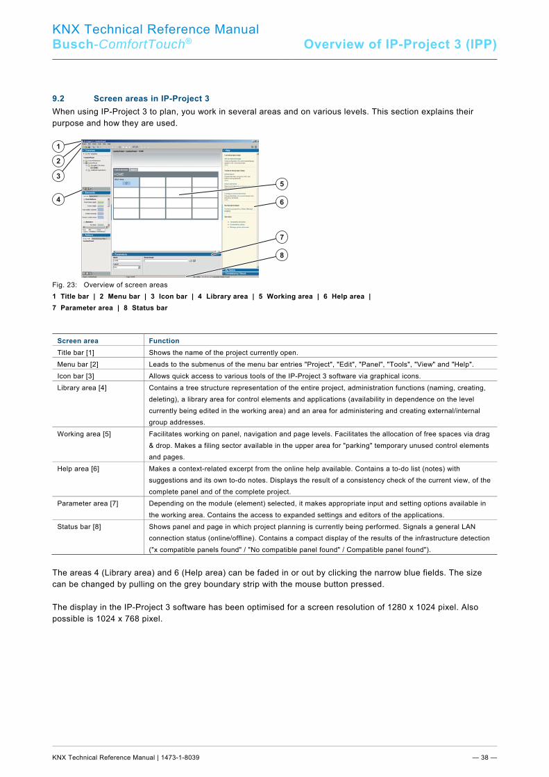
When using IP-Project 3 to plan, you work in several areas and on various levels. This section explains their purpose and how they are used. 1
2
3
4
5
6
7
8
Fig. 23: Overview of screen areas 1 Title bar | 2 Menu bar | 3 Icon bar | 4 Library area | 5 Working area | 6 Help area | 7 Parameter area | 8 Status bar
Screen area Function Title bar [1] Shows the name of the project currently open. Menu bar [2] Leads to the submenus of the menu bar entries "Project", "Edit", "Panel", "Tools", "View" and "Help". Icon bar [3] Allows quick access to various tools of the IP-Project 3 software via graphical icons. Library area [4] Contains a tree structure representation of the entire project, administration functions (naming, creating,
deleting), a library area for control elements and applications (availability in dependence on the level currently being edited in the working area) and an area for administering and creating external/internal group addresses.
Working area [5] Facilitates working on panel, navigation and page levels. Facilitates the allocation of free spaces via drag & drop. Makes a filing sector available in the upper area for "parking" temporary unused control elements and pages.
Help area [6] Makes a context-related excerpt from the online help available. Contains a to-do list (notes) with suggestions and its own to-do notes. Displays the result of a consistency check of the current view, of the complete panel and of the complete project.
Parameter area [7] Depending on the module (element) selected, it makes appropriate input and setting options available in the working area. Contains the access to expanded settings and editors of the applications.
Status bar [8] Shows panel and page in which project planning is currently being performed. Signals a general LAN connection status (online/offline). Contains a compact display of the results of the infrastructure detection ("x compatible panels found" / "No compatible panel found" / Compatible panel found").
The areas 4 (Library area) and 6 (Help area) can be faded in or out by clicking the narrow blue fields. The size can be changed by pulling on the grey boundary strip with the mouse button pressed. The display in the IP-Project 3 software has been optimised for a screen resolution of 1280 x 1024 pixel. Also possible is 1024 x 768 pixel. Pos: 26.6 /Layout bis 2014-11-11/Online-Dokumentation (+KNX)/Steuermodule - Online-Dokumentation (--> Für alle Dokumente <--)/++++++++++++ Seitenumbruch ++++++++++++ @ 9\mod_1268898668093_0.docx @ 52149 @ @ 1
KNX Technical Reference Manual
Busch-ComfortTouch® Overview of IP-Project 3 (IPP)
KNX Technical Reference Manual | 1473-1-8039 — 39 —
Pos: 26.7.1 /Layout bis 2014-11-11/Online-Dokumentation (+KNX)/Überschriften (--> Für alle Dokumente <--)/2. Ebene/A - F/Erläuterung der Grundstruktur (Begriffe) @ 33\mod_1361434727681_15.docx @ 279167 @ 2 @ 1
9.3 Explanation of the basic structure (Terms) Pos: 26.7.2 /Layout bis 2014-11-11/Online-Dokumentation (+KNX)/Übersicht über IP-Project 3 (IPP)/KNX/KNX-Aktorik/ComfortPanel 3.0/KNX Technisches Handbuch/Erläuterung der Grundstruktur (Begriffe)/Erläuterung der Grundstruktur (Begriffe) @ 33\mod_1361434172411_15.docx @ 279039 @ 345554555445554555 @ 1
9.3.1 Areas
Observe also section "Screen areas in IP-Project 3". 9.3.1.1 Library area The left side in IP-Project 3 is called the "Library area" because it includes all elements required for project planning (pages, control elements, etc.). The library area consists of sections "Overview“, "Elements“ and "Actions“. Sub-section "Übersicht“ Sub-section "Overview" shows you all Busch-ComfortTouch® in your project based on the icon. If you see no Busch-ComfortTouch®, you have to first add them. Under "Navigation structure“ you see the pages allocated to a Busch-ComfortTouch®. If you see no pages, you have to first add them. You can save pages and control elements as templates in IP-Project 3 so you can reuse them later. The templates are then found in section "Overview“ under "My Templates“. Also the so-called "Cross References“ are located in the library area in section "Übersicht“. Sub-section "Elements“ The sub-section "Elements“ lists the modules (elements) for compiling a Busch-ComfortTouch®. Depending on whether you are creating the Busch-ComfortTouch® navigation or you want to add control elements to a page, section "Elements“ contains the respective elements. You can save pages and control elements as templates in IP-Project 3 so you can reuse them later. The templates are then found in the bottom My Templates“ tab. Also the so-called "Elements“ are located in the library area in section "Cross References“. Sub-section "Aktionen“ In sub-section "Actions“ you can administer group addresses and from there link them with the communication objects of a control element. If there are no group addresses, you must either import existing group addresses or create new ones yourself.
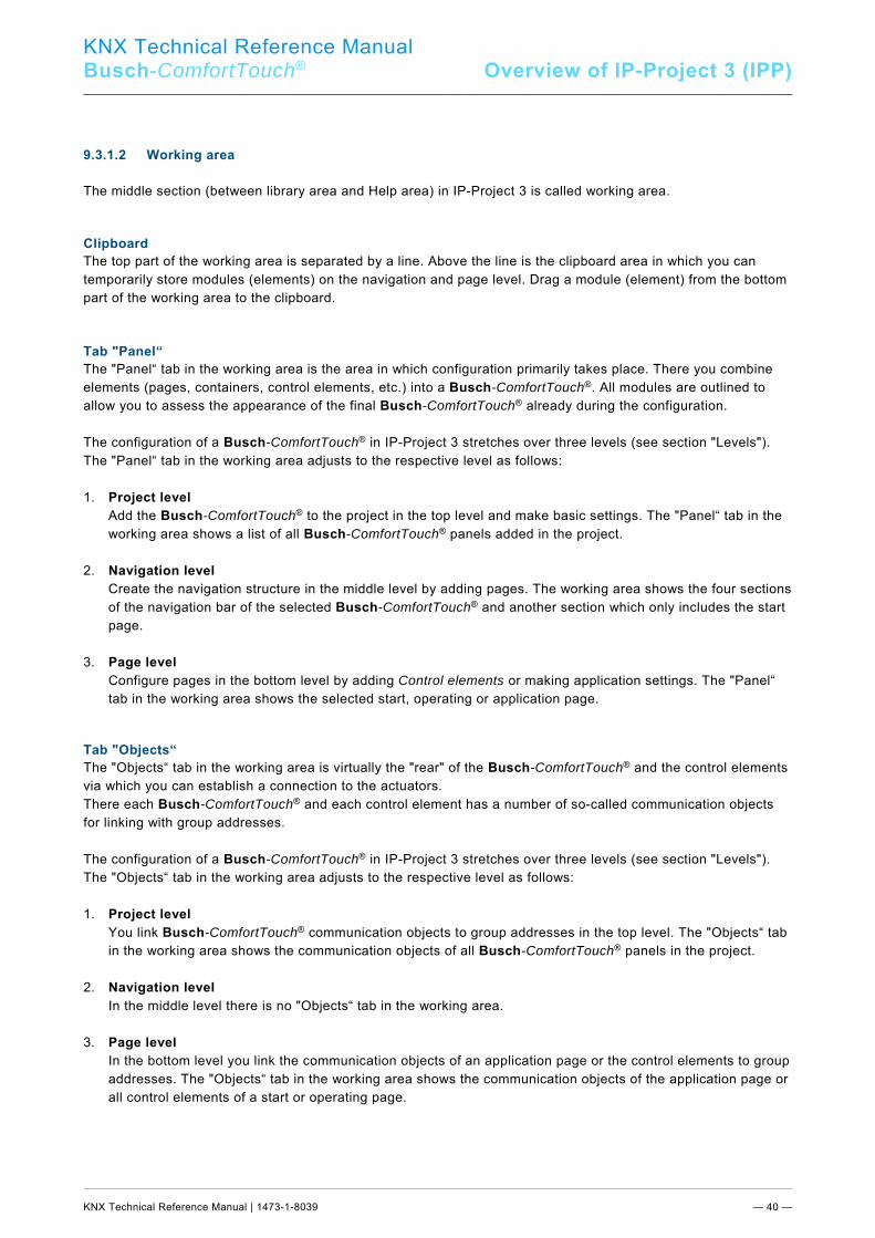
KNX Technical Reference Manual
Busch-ComfortTouch® Overview of IP-Project 3 (IPP)
KNX Technical Reference Manual | 1473-1-8039 — 40 —
9.3.1.2 Working area The middle section (between library area and Help area) in IP-Project 3 is called working area. Clipboard The top part of the working area is separated by a line. Above the line is the clipboard area in which you can temporarily store modules (elements) on the navigation and page level. Drag a module (element) from the bottom part of the working area to the clipboard.
Tab "Panel“ The "Panel“ tab in the working area is the area in which configuration primarily takes place. There you combine elements (pages, containers, control elements, etc.) into a Busch-ComfortTouch®. All modules are outlined to allow you to assess the appearance of the final Busch-ComfortTouch® already during the configuration. The configuration of a Busch-ComfortTouch® in IP-Project 3 stretches over three levels (see section "Levels"). The "Panel“ tab in the working area adjusts to the respective level as follows: 1. Project level Add the Busch-ComfortTouch® to the project in the top level and make basic settings. The "Panel“ tab in the
working area shows a list of all Busch-ComfortTouch® panels added in the project. 2. Navigation level Create the navigation structure in the middle level by adding pages. The working area shows the four sections
of the navigation bar of the selected Busch-ComfortTouch® and another section which only includes the start page.
3. Page level Configure pages in the bottom level by adding Control elements or making application settings. The "Panel“
tab in the working area shows the selected start, operating or application page. Tab "Objects“ The "Objects“ tab in the working area is virtually the "rear" of the Busch-ComfortTouch® and the control elements via which you can establish a connection to the actuators. There each Busch-ComfortTouch® and each control element has a number of so-called communication objects for linking with group addresses. The configuration of a Busch-ComfortTouch® in IP-Project 3 stretches over three levels (see section "Levels"). The "Objects“ tab in the working area adjusts to the respective level as follows: 1. Project level You link Busch-ComfortTouch® communication objects to group addresses in the top level. The "Objects“ tab
in the working area shows the communication objects of all Busch-ComfortTouch® panels in the project. 2. Navigation level In the middle level there is no "Objects“ tab in the working area. 3. Page level In the bottom level you link the communication objects of an application page or the control elements to group
addresses. The "Objects“ tab in the working area shows the communication objects of the application page or all control elements of a start or operating page.
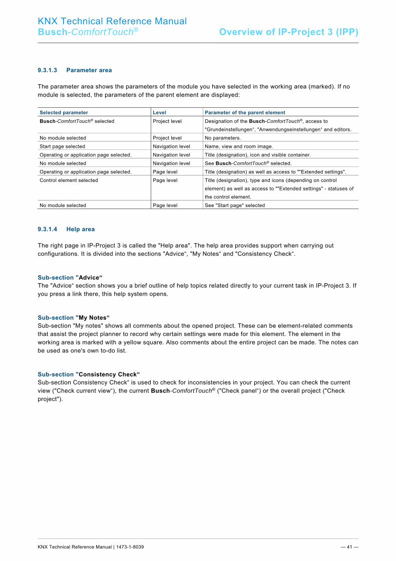
KNX Technical Reference Manual
Busch-ComfortTouch® Overview of IP-Project 3 (IPP)
KNX Technical Reference Manual | 1473-1-8039 — 41 —
9.3.1.3 Parameter area The parameter area shows the parameters of the module you have selected in the working area (marked). If no module is selected, the parameters of the parent element are displayed:
Selected parameter Level Parameter of the parent element Busch-ComfortTouch® selected Project level Designation of the Busch-ComfortTouch®, access to
"Grundeinstellungen“, "Anwendungseinstellungen“ and editors. No module selected Project level No parameters. Start page selected Navigation level Name, view and room image. Operating or application page selected. Navigation level Title (designation), icon and visible container. No module selected Navigation level See Busch-ComfortTouch® selected. Operating or application page selected. Page level Title (designation) as well as access to ""Extended settings". Control element selected Page level Title (designation), type and icons (depending on control
element) as well as access to ""Extended settings" - statuses of the control element.
No module selected Page level See "Start page" selected
9.3.1.4 Help area The right page in IP-Project 3 is called the "Help area". The help area provides support when carrying out configurations. It is divided into the sections "Advice“, "My Notes“ and "Consistency Check“. Sub-section "Advice“ The "Advice“ section shows you a brief outline of help topics related directly to your current task in IP-Project 3. If you press a link there, this help system opens. Sub-section "My Notes“ Sub-section "My notes" shows all comments about the opened project. These can be element-related comments that assist the project planner to record why certain settings were made for this element. The element in the working area is marked with a yellow square. Also comments about the entire project can be made. The notes can be used as one's own to-do list. Sub-section "Consistency Check“ Sub-section Consistency Check“ is used to check for inconsistencies in your project. You can check the current view ("Check current view“), the current Busch-ComfortTouch® ("Check panel“) or the overall project ("Check project").
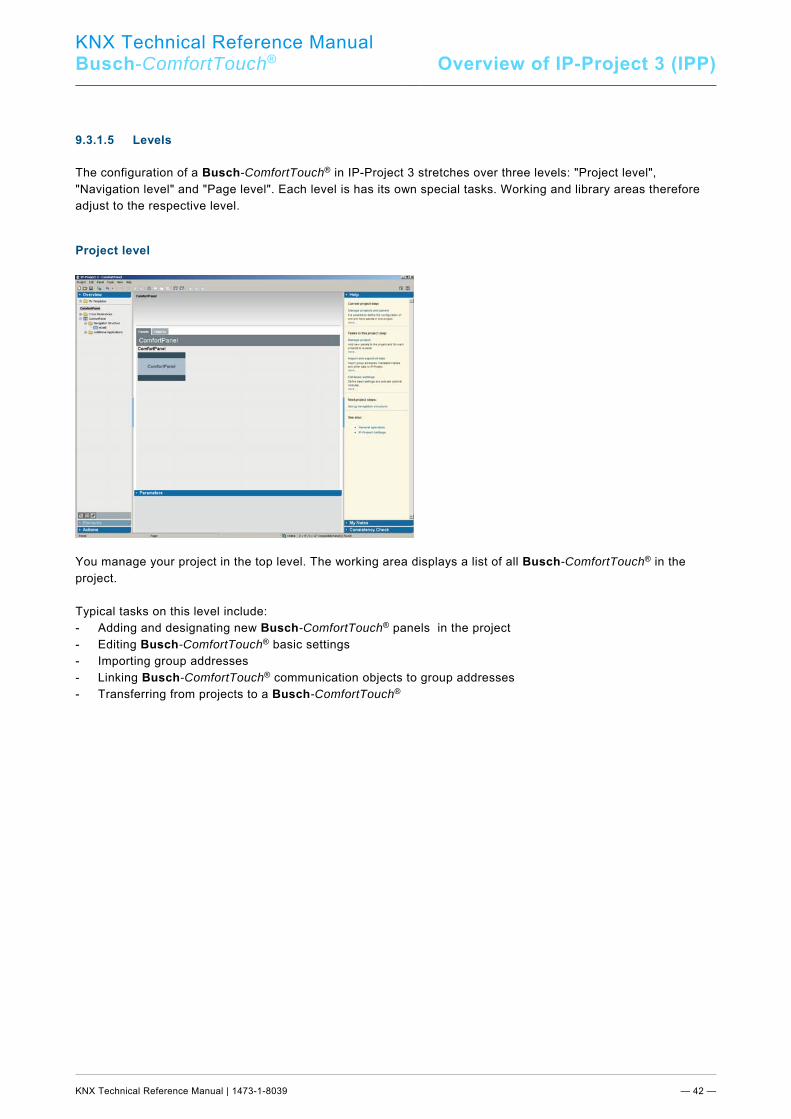
KNX Technical Reference Manual
Busch-ComfortTouch® Overview of IP-Project 3 (IPP)
KNX Technical Reference Manual | 1473-1-8039 — 42 —
9.3.1.5 Levels The configuration of a Busch-ComfortTouch® in IP-Project 3 stretches over three levels: "Project level", "Navigation level" and "Page level". Each level is has its own special tasks. Working and library areas therefore adjust to the respective level. Project level
You manage your project in the top level. The working area displays a list of all Busch-ComfortTouch® in the project. Typical tasks on this level include: - Adding and designating new Busch-ComfortTouch® panels in the project - Editing Busch-ComfortTouch® basic settings - Importing group addresses - Linking Busch-ComfortTouch® communication objects to group addresses - Transferring from projects to a Busch-ComfortTouch®
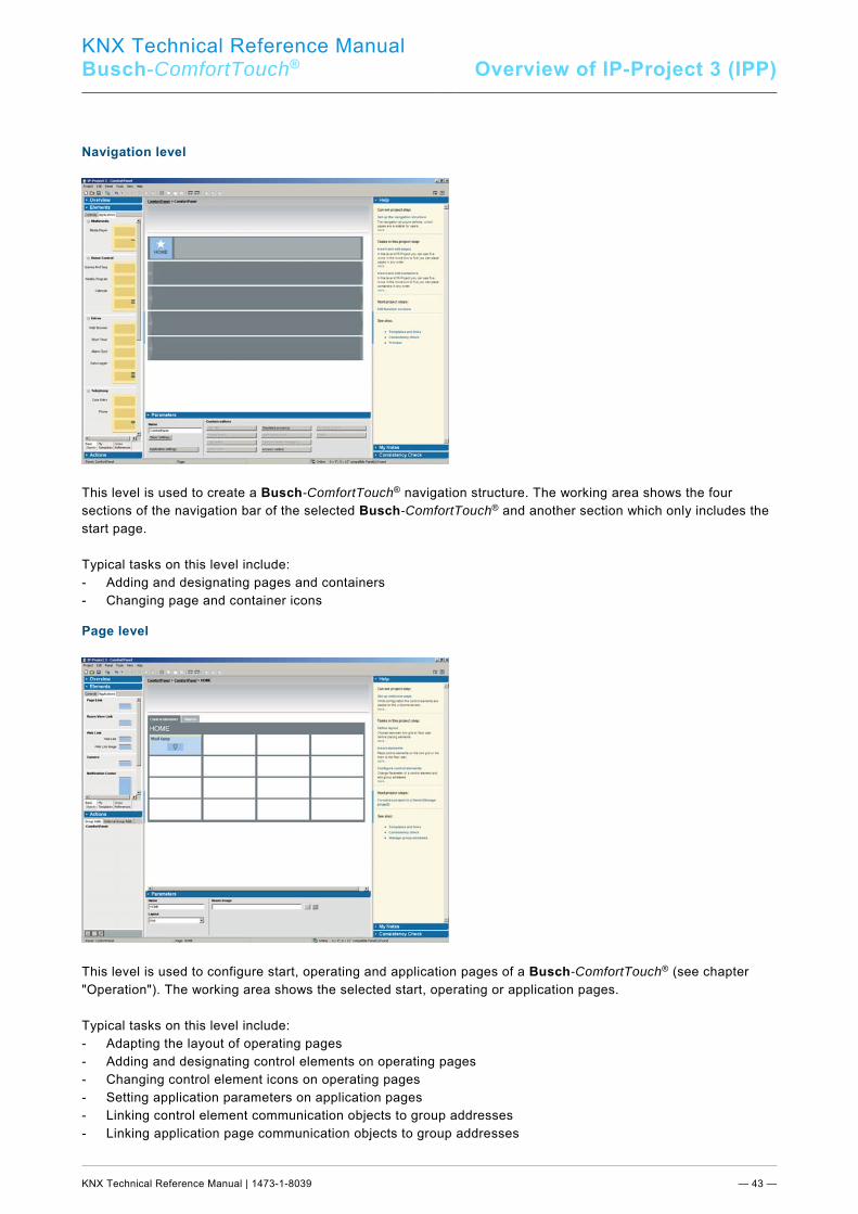
KNX Technical Reference Manual
Busch-ComfortTouch® Overview of IP-Project 3 (IPP)
KNX Technical Reference Manual | 1473-1-8039 — 43 —
Navigation level
This level is used to create a Busch-ComfortTouch® navigation structure. The working area shows the four sections of the navigation bar of the selected Busch-ComfortTouch® and another section which only includes the start page. Typical tasks on this level include: - Adding and designating pages and containers - Changing page and container icons Page level
This level is used to configure start, operating and application pages of a Busch-ComfortTouch® (see chapter "Operation"). The working area shows the selected start, operating or application pages. Typical tasks on this level include: - Adapting the layout of operating pages - Adding and designating control elements on operating pages - Changing control element icons on operating pages - Setting application parameters on application pages - Linking control element communication objects to group addresses - Linking application page communication objects to group addresses Pos: 26.8 /Layout bis 2014-11-11/Online-Dokumentation (+KNX)/Steuermodule - Online-Dokumentation (--> Für alle Dokumente <--)/++++++++++++ Seitenumbruch ++++++++++++ @ 9\mod_1268898668093_0.docx @ 52149 @ @ 1
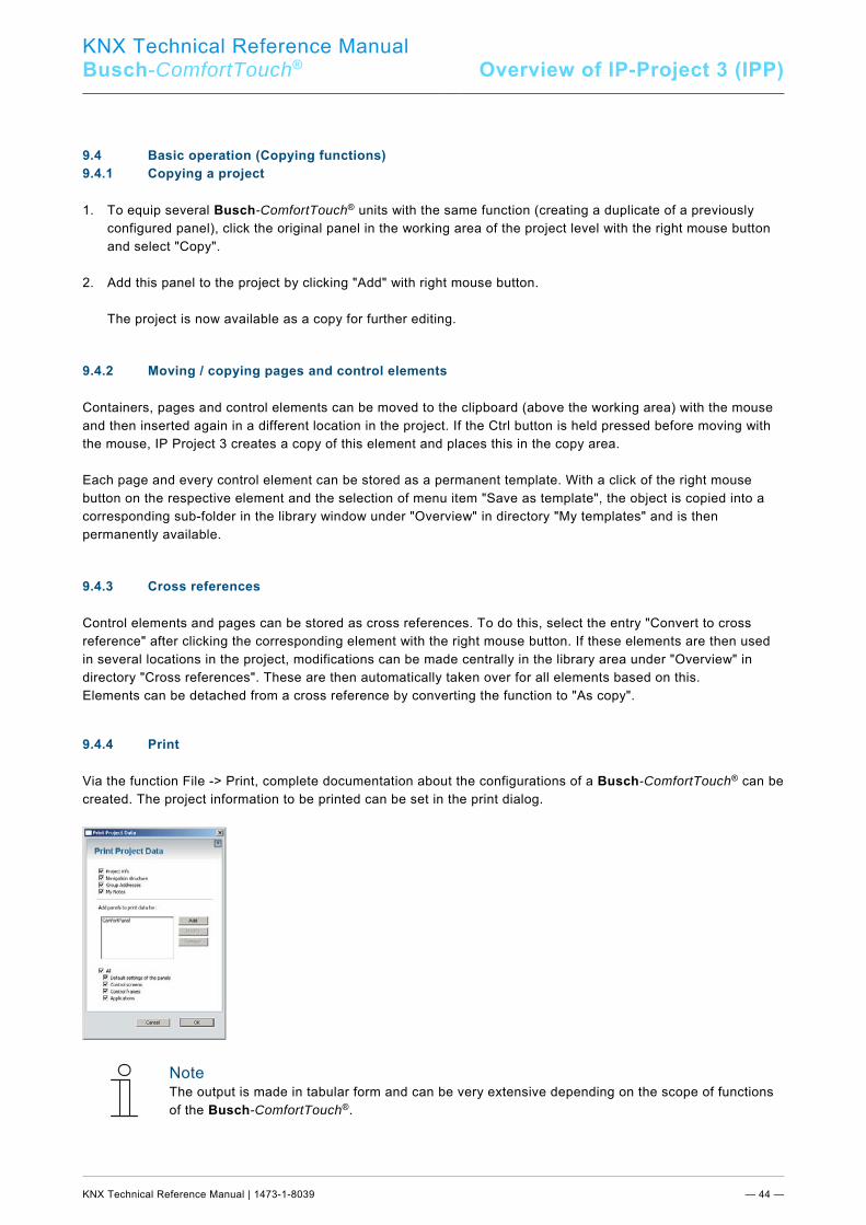
KNX Technical Reference Manual
Busch-ComfortTouch® Overview of IP-Project 3 (IPP)
KNX Technical Reference Manual | 1473-1-8039 — 44 —
Pos: 26.9.1 /Layout bis 2014-11-11/Online-Dokumentation (+KNX)/Überschriften (--> Für alle Dokumente <--)/2. Ebene/G - L/Grundlegende Bedienung (Kopierfunktionen) @ 33\mod_1361434789783_15.docx @ 279183 @ 2 @ 1
9.4 Basic operation (Copying functions) Pos: 26.9.2 /Layout bis 2014-11-11/Online-Dokumentation (+KNX)/Übersicht über IP-Project 3 (IPP)/KNX/KNX-Aktorik/ComfortPanel 3.0/KNX Technisches Handbuch/Grundlegende Bedienung (Kopierfunktionen)Grundlegende Bedienung (Kopierfunktionen) @ 40\mod_1418380851306_15.docx @ 308701 @ 3333 @ 1
9.4.1 Copying a project
1. To equip several Busch-ComfortTouch® units with the same function (creating a duplicate of a previously
configured panel), click the original panel in the working area of the project level with the right mouse button and select "Copy".
2. Add this panel to the project by clicking "Add" with right mouse button. The project is now available as a copy for further editing. 9.4.2 Moving / copying pages and control elements
Containers, pages and control elements can be moved to the clipboard (above the working area) with the mouse and then inserted again in a different location in the project. If the Ctrl button is held pressed before moving with the mouse, IP Project 3 creates a copy of this element and places this in the copy area. Each page and every control element can be stored as a permanent template. With a click of the right mouse button on the respective element and the selection of menu item "Save as template", the object is copied into a corresponding sub-folder in the library window under "Overview" in directory "My templates" and is then permanently available. 9.4.3 Cross references
Control elements and pages can be stored as cross references. To do this, select the entry "Convert to cross reference" after clicking the corresponding element with the right mouse button. If these elements are then used in several locations in the project, modifications can be made centrally in the library area under "Overview" in directory "Cross references". These are then automatically taken over for all elements based on this. Elements can be detached from a cross reference by converting the function to "As copy". 9.4.4 Print
Via the function File -> Print, complete documentation about the configurations of a Busch-ComfortTouch® can be created. The project information to be printed can be set in the print dialog.
Note The output is made in tabular form and can be very extensive depending on the scope of functions of the Busch-ComfortTouch®.
Pos: 27 /Layout bis 2014-11-11/Modul-Struktur/Online-Dokumentation/Steuermodule - Online-Dokumentation (--> Für alle Dokumente <--)/++++++++++++ Seitenumbruch ++++++++++++ @ 9\mod_1268898668093_0.docx @ 52149 @ @ 1
KNX Technical Reference Manual
Busch-ComfortTouch® Project planning
KNX Technical Reference Manual | 1473-1-8039 — 45 —
Pos: 28.1 /Layout bis 2014-11-11/Online-Dokumentation (+KNX)/Überschriften (--> Für alle Dokumente <--)/1. Ebene/P - R/Projektierung @ 33\mod_1361435528871_15.docx @ 279200 @ 2 @ 1
10 Project planning Pos: 28.2.1 /Layout bis 2014-11-11/Online-Dokumentation (+KNX)/Überschriften (--> Für alle Dokumente <--)/2. Ebene/A - F/Empfohlener Ablauf einer Projektierung @ 33\mod_1361435913030_15.docx @ 279320 @ 2 @ 1
10.1 Recommended sequence of project planning Pos: 28.2.2 /Layout bis 2014-11-11/Online-Dokumentation (+KNX)/Projektierung/KNX/KNX-Aktorik/ComfortPanel 3.0/KNX Technisches Handbuch/Empfohlener Ablauf einer Projektierung/Empfohlener Ablauf einer Projektierung @ 33\mod_1361435666094_15.docx @ 279218 @ @ 1
Note Observe the introductory exercise in the online Help of IP-Project 3.
The following working sequence (standard workflow) is recommended for working most effectively with the IP-Project 3 software: 1. Start the software and create a new project (project info, naming the Busch-ComfortTouch®, etc.). 2. If an ETSx project already exists, import group addresses created there into IP-Project 3 and assign the
correct data point type (DPT) to all group addresses used in the Busch-ComfortTouch® (e.g. function: 1.001 switch).
3. Configure the Busch-ComfortTouch® (basic settings, Feed Reader, Web browser, etc.). 4. Specify the navigation structure (insertion of operating and application pages). 5. Configure the operating pages (insert and configure control elements). 6. Configure the application pages (insert and configure applications). 7. Now configure the start page (insert and configure control elements). 8. If additional Busch-ComfortTouch® units are to be installed, start again at point 2 or duplicate the entries of
an already existing Busch-ComfortTouch®. 9. If all entries have been carried out, perform a consistency check (test and possible debugging) see section
"Consistency check"). 10. Transfer the project to the panel and start operating it (see section "Loading the project into the Busch-
ComfortTouch®". Pos: 28.3.1 /Layout bis 2014-11-11/Online-Dokumentation (+KNX)/Überschriften (--> Für alle Dokumente <--)/2. Ebene/G - L/Konsistenzprüfung @ 33\mod_1361435976816_15.docx @ 279336 @ 2 @ 1
10.2 Consistency check Pos: 28.3.2 /Layout bis 2014-11-11/Online-Dokumentation (+KNX)/Projektierung/KNX/KNX-Aktorik/ComfortPanel 3.0/KNX Technisches Handbuch/Konsistenzprüfung/Konsistenzprüfung @ 33\mod_1361435670811_15.docx @ 279234 @ @ 1
There is the option to perform a consistency check after completion of all entries. This function can be called up in the Help area. Optionally only the current view, the currently edited Busch-ComfortTouch® or the entire project can be checked. All entries are tested for plausibility and the result of the test is displayed. By double-clicking the entries shown there, you gain direct access to the associated screen page of the programming. Any inconsistencies found are distinguished as follows: - "Serious inconsistencies" These must be rectified before the project is transferred to the Busch-ComfortTouch®. - "Less serious inconsistencies" These should be rectified, but do not affect functionality. Pos: 28.4 /Layout bis 2014-11-11/Online-Dokumentation (+KNX)/Steuermodule - Online-Dokumentation (--> Für alle Dokumente <--)/++++++++++++ Seitenumbruch ++++++++++++ @ 9\mod_1268898668093_0.docx @ 52149 @ @ 1
KNX Technical Reference Manual
Busch-ComfortTouch® Project planning
KNX Technical Reference Manual | 1473-1-8039 — 46 —
Pos: 28.5.1 /Layout bis 2014-11-11/Online-Dokumentation (+KNX)/Überschriften (--> Für alle Dokumente <--)/2. Ebene/P - R/Projekt in das Busch-ComfortPanel(Touch) laden @ 33\mod_1361436036755_15.docx @ 279352 @ 2 @ 1
10.3 Loading the project into the Busch-ComfortTouch® Pos: 28.5.2 /Layout bis 2014-11-11/Online-Dokumentation (+KNX)/Projektierung/KNX/KNX-Aktorik/ComfortPanel 3.0/KNX Technisches Handbuch/Projekt in das Busch-ComfortPanel laden/Projekt in das Busch-ComfortPanel(Touch) laden @ 33\mod_1361435675099_15.docx @ 279250 @ @ 1
When you have completed the project with the aid of IP-Project 3, you can load it into the Busch-ComfortTouch®. You will find the entry "Send project to" under the "Project" menu item in IP-Project 3. A detailed description is available in the online Help of IP-Project 3. The most important points will be explained in the following. 1. If you have configured several panels in a project file of the IPP software, you can then select under "Select
panel", which Busch-ComfortTouch® you want to start operating. 2. You then provide the installation path. If the Busch-ComfortTouch® is connected with the computer (PC) via LAN or WLAN, the data can be
transferred directly to the Busch-ComfortTouch® after successful identification by the software. For this the UPnP function must be activated in the Busch-ComfortTouch®, otherwise the software cannot locate an available Busch-ComfortTouch®. Devices located in the network via UPnP are listed in the dialog in pull-down menu "To device".
Commissioning is also possible directly via the IP address of the Busch-ComfortTouch® if this is known. The
IP address is entered in the specified fields under "To IP". Alternatively, an installation via storage medium (SD-card or USB stick) is possible. 3. To do this, select the "Save to file system" option and specify the corresponding storage location there. 4. You can then read in the exported project data again after clicking the "System" button and selecting the
"Import" option. Pos: 29 /Layout bis 2014-11-11/Modul-Struktur/Online-Dokumentation/Steuermodule - Online-Dokumentation (--> Für alle Dokumente <--)/++++++++++++ Seitenumbruch ++++++++++++ @ 9\mod_1268898668093_0.docx @ 52149 @ @ 1
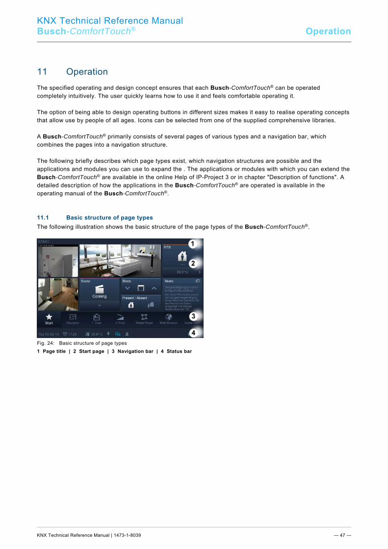
KNX Technical Reference Manual
Busch-ComfortTouch® Operation
KNX Technical Reference Manual | 1473-1-8039 — 47 —
Pos: 30.1 /Layout bis 2014-11-11/Online-Dokumentation (+KNX)/Überschriften (--> Für alle Dokumente <--)/1. Ebene/A - F/Bedienung @ 11\mod_1279185541649_15.docx @ 83043 @ 2 @ 1
11 Operation Pos: 30.2 /Layout bis 2014-11-11/Online-Dokumentation (+KNX)/Bedienung/KNX/KNX-Aktorik/ComfortPanel 3.0/KNX Technisches Handbuch/Einführung @ 33\mod_1361436593717_15.docx @ 279367 @ @ 1
The specified operating and design concept ensures that each Busch-ComfortTouch® can be operated completely intuitively. The user quickly learns how to use it and feels comfortable operating it. The option of being able to design operating buttons in different sizes makes it easy to realise operating concepts that allow use by people of all ages. Icons can be selected from one of the supplied comprehensive libraries. A Busch-ComfortTouch® primarily consists of several pages of various types and a navigation bar, which combines the pages into a navigation structure. The following briefly describes which page types exist, which navigation structures are possible and the applications and modules you can use to expand the . The applications or modules with which you can extend the Busch-ComfortTouch® are available in the online Help of IP-Project 3 or in chapter "Description of functions". A detailed description of how the applications in the Busch-ComfortTouch® are operated is available in the operating manual of the Busch-ComfortTouch®. Pos: 30.3.1 /Layout bis 2014-11-11/Online-Dokumentation (+KNX)/Überschriften (--> Für alle Dokumente <--)/2. Ebene/G - L/Grundstruktur der Seitentypen @ 33\mod_1361437281943_15.docx @ 279512 @ 2 @ 1
11.1 Basic structure of page types Pos: 30.3.2 /Layout bis 2014-11-11/Online-Dokumentation (+KNX)/Bedienung/KNX/KNX-Aktorik/ComfortPanel 3.0/KNX Technisches Handbuch/Grundstruktur der Seitentypen/Grundstruktur der Seitentypen @ 33\mod_1361436929438_15.docx @ 279435 @ @ 1
The following illustration shows the basic structure of the page types of the Busch-ComfortTouch®.
Fig. 24: Basic structure of page types 1 Page title | 2 Start page | 3 Navigation bar | 4 Status bar Pos: 30.4 /Layout bis 2014-11-11/Online-Dokumentation (+KNX)/Steuermodule - Online-Dokumentation (--> Für alle Dokumente <--)/++++++++++++ Seitenumbruch ++++++++++++ @ 9\mod_1268898668093_0.docx @ 52149 @ @ 1
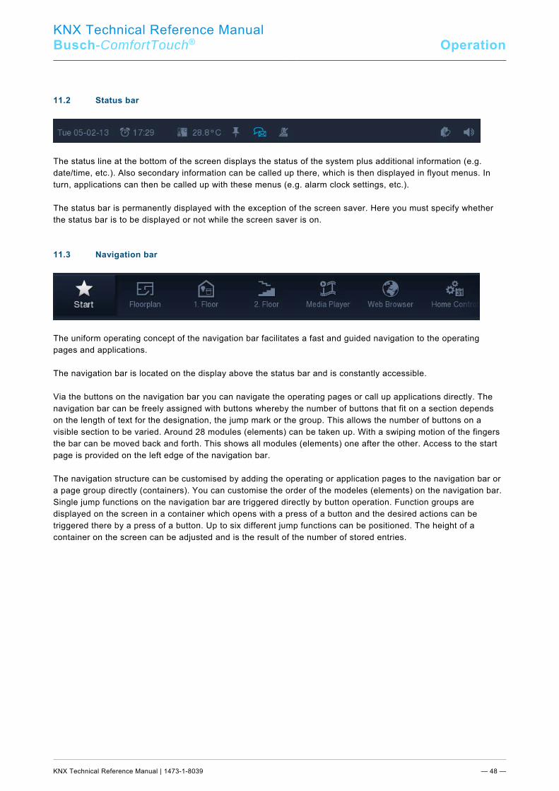
KNX Technical Reference Manual
Busch-ComfortTouch® Operation
KNX Technical Reference Manual | 1473-1-8039 — 48 —
Pos: 30.5.1 /Layout bis 2014-11-11/Online-Dokumentation (+KNX)/Überschriften (--> Für alle Dokumente <--)/2. Ebene/S - T/Statusleiste @ 33\mod_1361437877382_15.docx @ 279528 @ 2 @ 1
11.2 Status bar Pos: 30.5.2 /Layout bis 2014-11-11/Online-Dokumentation (+KNX)/Bedienung/KNX/KNX-Aktorik/ComfortPanel 3.0/KNX Technisches Handbuch/Statusleiste/Statusleiste @ 33\mod_1361436925965_15.docx @ 279419 @ @ 1
The status line at the bottom of the screen displays the status of the system plus additional information (e.g. date/time, etc.). Also secondary information can be called up there, which is then displayed in flyout menus. In turn, applications can then be called up with these menus (e.g. alarm clock settings, etc.). The status bar is permanently displayed with the exception of the screen saver. Here you must specify whether the status bar is to be displayed or not while the screen saver is on. Pos: 30.6.1 /Layout bis 2014-11-11/Online-Dokumentation (+KNX)/Überschriften (--> Für alle Dokumente <--)/2. Ebene/M - O/Navigationsleiste @ 33\mod_1361438865349_15.docx @ 279544 @ 2 @ 1
11.3 Navigation bar Pos: 30.6.2 /Layout bis 2014-11-11/Online-Dokumentation (+KNX)/Bedienung/KNX/KNX-Aktorik/ComfortPanel 3.0/KNX Technisches Handbuch/Navigationsleiste/Navigationsleiste @ 33\mod_1361436921183_15.docx @ 279403 @ @ 1
The uniform operating concept of the navigation bar facilitates a fast and guided navigation to the operating pages and applications. The navigation bar is located on the display above the status bar and is constantly accessible. Via the buttons on the navigation bar you can navigate the operating pages or call up applications directly. The navigation bar can be freely assigned with buttons whereby the number of buttons that fit on a section depends on the length of text for the designation, the jump mark or the group. This allows the number of buttons on a visible section to be varied. Around 28 modules (elements) can be taken up. With a swiping motion of the fingers the bar can be moved back and forth. This shows all modules (elements) one after the other. Access to the start page is provided on the left edge of the navigation bar. The navigation structure can be customised by adding the operating or application pages to the navigation bar or a page group directly (containers). You can customise the order of the modeles (elements) on the navigation bar. Single jump functions on the navigation bar are triggered directly by button operation. Function groups are displayed on the screen in a container which opens with a press of a button and the desired actions can be triggered there by a press of a button. Up to six different jump functions can be positioned. The height of a container on the screen can be adjusted and is the result of the number of stored entries. Pos: 30.7 /Layout bis 2014-11-11/Online-Dokumentation (+KNX)/Steuermodule - Online-Dokumentation (--> Für alle Dokumente <--)/++++++++++++ Seitenumbruch ++++++++++++ @ 9\mod_1268898668093_0.docx @ 52149 @ @ 1
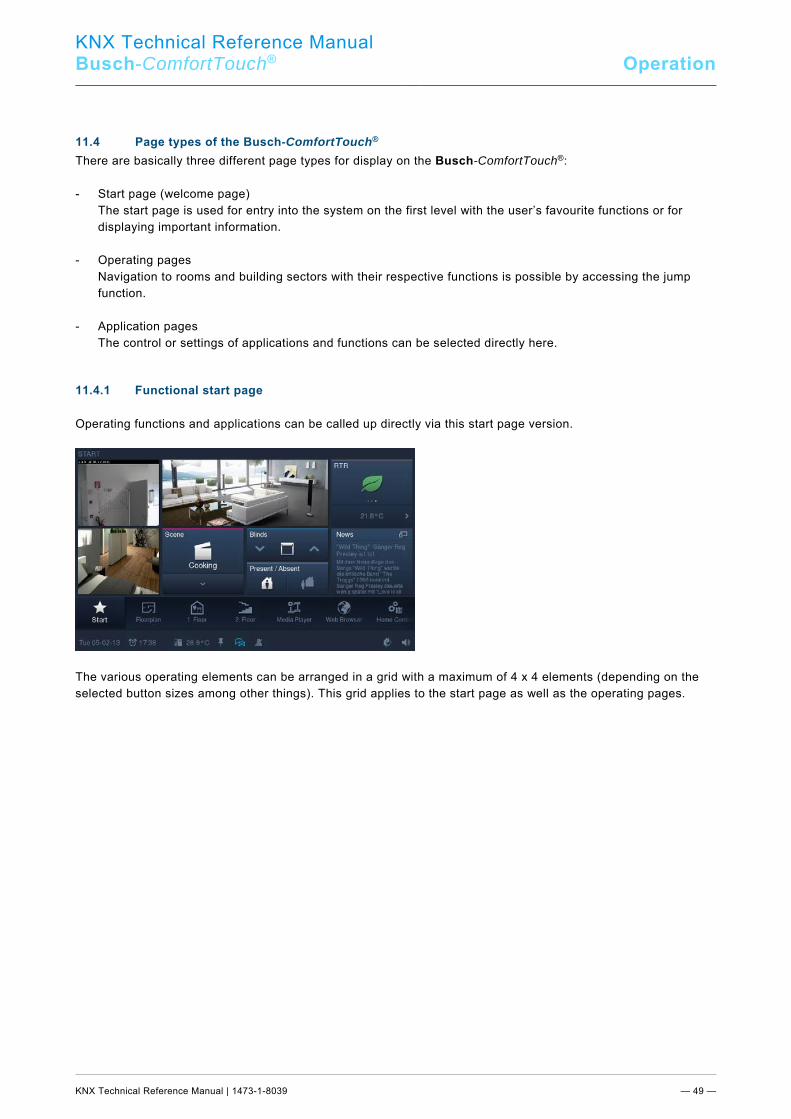
KNX Technical Reference Manual
Busch-ComfortTouch® Operation
KNX Technical Reference Manual | 1473-1-8039 — 49 —
Pos: 30.8.1 /Layout bis 2014-11-11/Online-Dokumentation (+KNX)/Überschriften (--> Für alle Dokumente <--)/2. Ebene/S - T/Seitentypen des Busch-ComfortPanel @ 33\mod_1361438935088_15.docx @ 279560 @ 2 @ 1
11.4 Page types of the Busch-ComfortTouch® Pos: 30.8.2 /Layout bis 2014-11-11/Online-Dokumentation (+KNX)/Bedienung/KNX/KNX-Aktorik/ComfortPanel 3.0/KNX Technisches Handbuch/Seitentypen des Busch-ComfortPanel/Seitentypen des Busch-ComfortPanel @ 33\mod_1361436915222_15.docx @ 279387 @ 23333 @ 1
There are basically three different page types for display on the Busch-ComfortTouch®: - Start page (welcome page) The start page is used for entry into the system on the first level with the user’s favourite functions or for
displaying important information. - Operating pages Navigation to rooms and building sectors with their respective functions is possible by accessing the jump
function. - Application pages The control or settings of applications and functions can be selected directly here. 11.4.1 Functional start page
Operating functions and applications can be called up directly via this start page version.
The various operating elements can be arranged in a grid with a maximum of 4 x 4 elements (depending on the selected button sizes among other things). This grid applies to the start page as well as the operating pages.
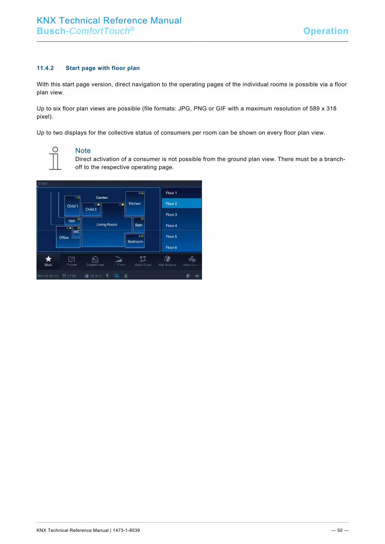
KNX Technical Reference Manual
Busch-ComfortTouch® Operation
KNX Technical Reference Manual | 1473-1-8039 — 50 —
11.4.2 Start page with floor plan
With this start page version, direct navigation to the operating pages of the individual rooms is possible via a floor plan view. Up to six floor plan views are possible (file formats: JPG, PNG or GIF with a maximum resolution of 589 x 318 pixel). Up to two displays for the collective status of consumers per room can be shown on every floor plan view.
Note Direct activation of a consumer is not possible from the ground plan view. There must be a branch-off to the respective operating page.
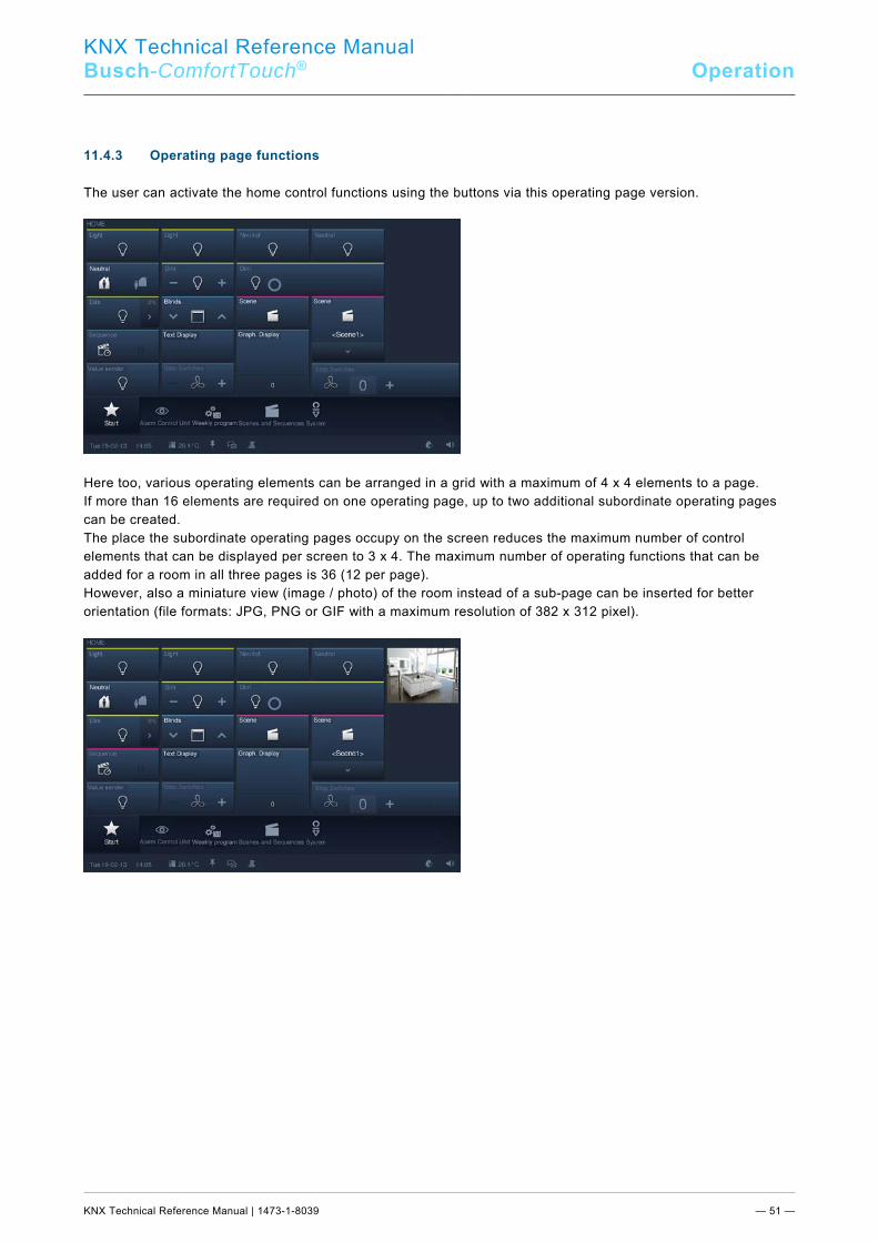
KNX Technical Reference Manual
Busch-ComfortTouch® Operation
KNX Technical Reference Manual | 1473-1-8039 — 51 —
11.4.3 Operating page functions
The user can activate the home control functions using the buttons via this operating page version.
Here too, various operating elements can be arranged in a grid with a maximum of 4 x 4 elements to a page. If more than 16 elements are required on one operating page, up to two additional subordinate operating pages can be created. The place the subordinate operating pages occupy on the screen reduces the maximum number of control elements that can be displayed per screen to 3 x 4. The maximum number of operating functions that can be added for a room in all three pages is 36 (12 per page). However, also a miniature view (image / photo) of the room instead of a sub-page can be inserted for better orientation (file formats: JPG, PNG or GIF with a maximum resolution of 382 x 312 pixel).
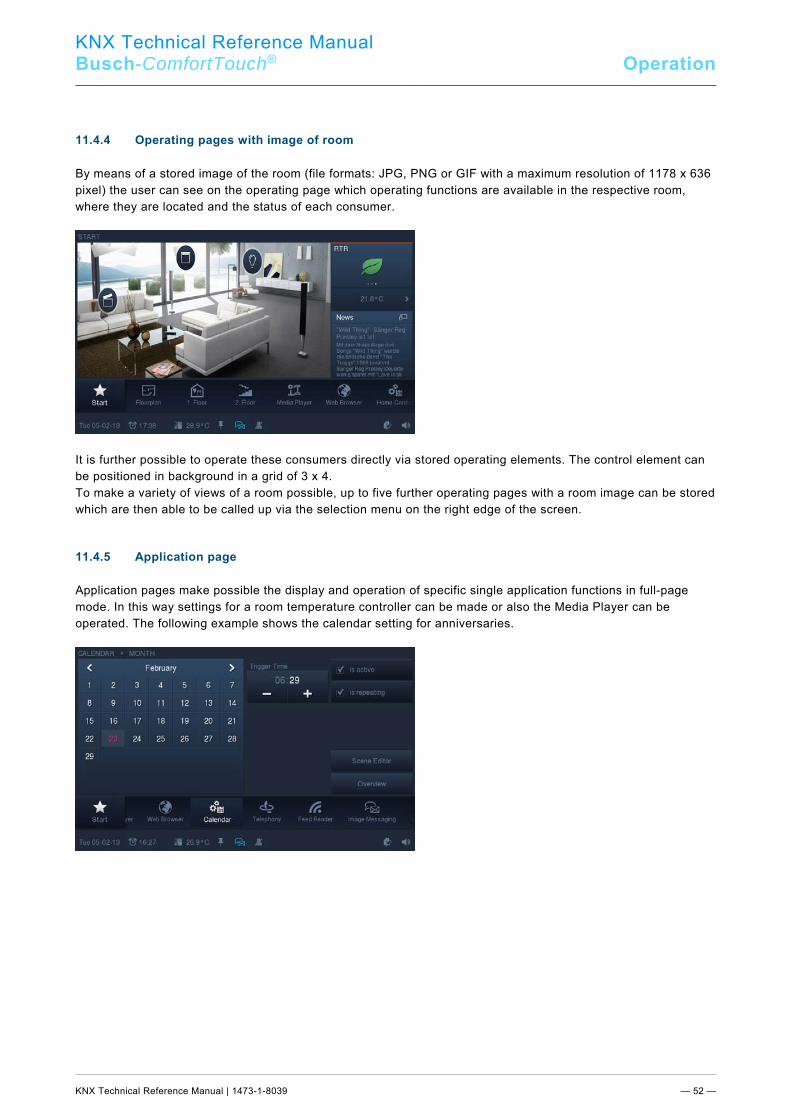
KNX Technical Reference Manual
Busch-ComfortTouch® Operation
KNX Technical Reference Manual | 1473-1-8039 — 52 —
11.4.4 Operating pages with image of room
By means of a stored image of the room (file formats: JPG, PNG or GIF with a maximum resolution of 1178 x 636 pixel) the user can see on the operating page which operating functions are available in the respective room, where they are located and the status of each consumer.
It is further possible to operate these consumers directly via stored operating elements. The control element can be positioned in background in a grid of 3 x 4. To make a variety of views of a room possible, up to five further operating pages with a room image can be stored which are then able to be called up via the selection menu on the right edge of the screen. 11.4.5 Application page
Application pages make possible the display and operation of specific single application functions in full-page mode. In this way settings for a room temperature controller can be made or also the Media Player can be operated. The following example shows the calendar setting for anniversaries.
Pos: 31 /Layout bis 2014-11-11/Modul-Struktur/Online-Dokumentation/Steuermodule - Online-Dokumentation (--> Für alle Dokumente <--)/++++++++++++ Seitenumbruch ++++++++++++ @ 9\mod_1268898668093_0.docx @ 52149 @ @ 1
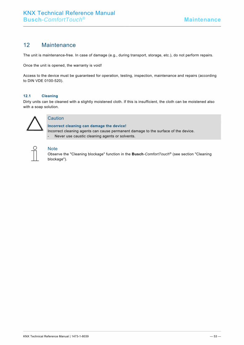
KNX Technical Reference Manual
Busch-ComfortTouch® Maintenance
KNX Technical Reference Manual | 1473-1-8039 — 53 —
Pos: 32.1 /Layout bis 2014-11-11/Modul-Struktur/Online-Dokumentation/Überschriften (--> Für alle Dokumente <--)/1. Ebene/U - Z/Wartung @ 21\mod_1328188606500_15.docx @ 138248 @ 1 @ 1
12 Maintenance Pos: 32.2 /Layout bis 2014-11-11/Online-Dokumentation (+KNX)/Wartung/KNX/KNX-Aktorik/ComfortPanel 3.0/KNX Technisches Handbuch/Wartung @ 33\mod_1361439442867_15.docx @ 279575 @ @ 1
The unit is maintenance-free. In case of damage (e.g., during transport, storage, etc.), do not perform repairs. Once the unit is opened, the warranty is void! Access to the device must be guaranteed for operation, testing, inspection, maintenance and repairs (according to DIN VDE 0100-520). Pos: 32.3.1 /Layout bis 2014-11-11/Online-Dokumentation (+KNX)/Überschriften (--> Für alle Dokumente <--)/2. Ebene/P - R/Reinigung @ 19\mod_1310733980533_15.docx @ 107853 @ 2 @ 1
12.1 Cleaning Pos: 32.3.2 /Layout bis 2014-11-11/Online-Dokumentation (+KNX)/Wartung/KNX/KNX-Aktorik/ComfortPanel 3.0/KNX Technisches Handbuch/Reinigung/Reinigung @ 33\mod_1361439502154_15.docx @ 279607 @ @ 1
Dirty units can be cleaned with a slightly moistened cloth. If this is insufficient, the cloth can be moistened also with a soap solution.
Caution Incorrect cleaning can damage the device! Incorrect cleaning agents can cause permanent damage to the surface of the device. - Never use caustic cleaning agents or solvents.
Note Observe the "Cleaning blockage" function in the Busch-ComfortTouch® (see section "Cleaning blockage").
Pos: 33 /Layout bis 2014-11-11/Modul-Struktur/Online-Dokumentation/Steuermodule - Online-Dokumentation (--> Für alle Dokumente <--)/++++++++++++ Seitenumbruch ++++++++++++ @ 9\mod_1268898668093_0.docx @ 52149 @ @ 1
KNX Technical Reference Manual
Busch-ComfortTouch® Description of functions
KNX Technical Reference Manual | 1473-1-8039 — 54 —
Pos: 34.1 /Layout bis 2014-11-11/Online-Dokumentation (+KNX)/Überschriften (--> Für alle Dokumente <--)/1. Ebene/A - F/Funktionsbeschreibungen @ 24\mod_1338554389814_15.docx @ 215359 @ 1 @ 1
13 Description of functions Pos: 34.2 /Layout bis 2014-11-11/Online-Dokumentation (+KNX)/Funktionsbeschreibungen/KNX/KNX-Aktorik/ComfortPanel 3.0/KNX Technisches HandbuchEinführung @ 40\mod_1418381323771_15.docx @ 308717 @ @ 1
In this chapter the function of the Busch-ComfortTouch® are explained. It involves the pre-configured applications and the operating functions as well as the displays.
Note A detailed description of the parameter settings is available in the online Help of IP-Project 3, since project planning is carried out via this software. The operation of the individual applications and operating functions is described in the manual of the device. The manual can be downloaded via the electronic catalogue at www.busch-jaeger-catalogue.com. However, it is also contained on the USB stick enclosed with the device. With some functions / applications it is necessary to activate other functions / applications before they will function correctly: – Internet access (is required, among other, for streaming (Web)-TV, Internet radio, Feed
Reader) – Access control (required to assign access restrictions to applications) – Presence simulation (required for recording events) – Logic editor – Mobile access
Pos: 34.3.1 /Layout bis 2014-11-11/Online-Dokumentation (+KNX)/Überschriften (--> Für alle Dokumente <--)/2. Ebene/G - L/Geräteinformationen @ 33\mod_1361440289468_15.docx @ 279677 @ 2 @ 1
13.1 Device information Pos: 34.3.2 /Layout bis 2014-11-11/Online-Dokumentation (+KNX)/Funktionsbeschreibungen/KNX/KNX-Aktorik/ComfortPanel 3.0/KNX Technisches Handbuch/GeräteinformationenGeräteinformationen @ 40\mod_1418381514076_15.docx @ 308733 @ @ 1
Important information about the device is available in the Busch-ComfortTouch® via System -> Device information. This includes the IP address, the MAC address and the contact details of the fitter. Pos: 34.4 /Layout bis 2014-11-11/Online-Dokumentation (+KNX)/Steuermodule - Online-Dokumentation (--> Für alle Dokumente <--)/++++++++++++ Seitenumbruch ++++++++++++ @ 9\mod_1268898668093_0.docx @ 52149 @ @ 1
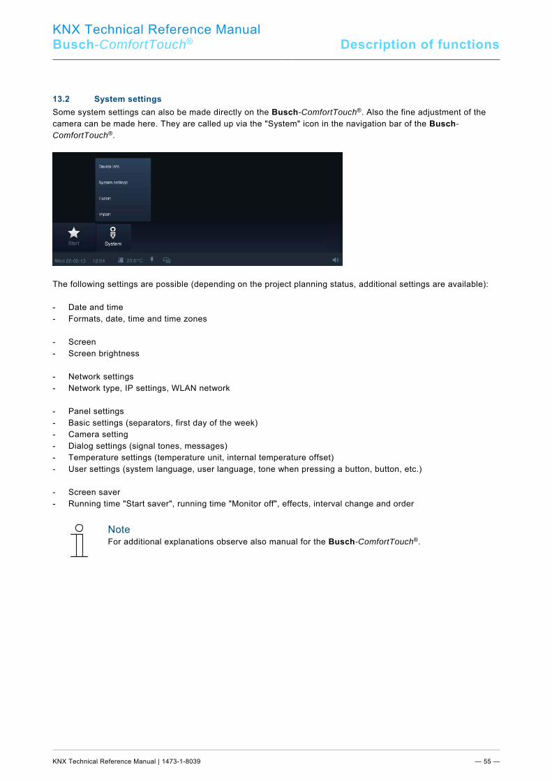
KNX Technical Reference Manual
Busch-ComfortTouch® Description of functions
KNX Technical Reference Manual | 1473-1-8039 — 55 —
Pos: 34.5.1 /Layout bis 2014-11-11/Online-Dokumentation (+KNX)/Überschriften (--> Für alle Dokumente <--)/2. Ebene/S - T/Systemeinstellungen @ 11\mod_1279186386776_15.docx @ 83117 @ 2 @ 1
13.2 System settings Pos: 34.5.2 /Layout bis 2014-11-11/Online-Dokumentation (+KNX)/Funktionsbeschreibungen/KNX/KNX-Aktorik/ComfortPanel 3.0/KNX Technisches Handbuch/Systemeinstellungen/Systemeinstellungen @ 33\mod_1361441532002_15.docx @ 279731 @ 3 @ 1
Some system settings can also be made directly on the Busch-ComfortTouch®. Also the fine adjustment of the camera can be made here. They are called up via the "System" icon in the navigation bar of the Busch-ComfortTouch®.
The following settings are possible (depending on the project planning status, additional settings are available): - Date and time - Formats, date, time and time zones - Screen - Screen brightness - Network settings - Network type, IP settings, WLAN network - Panel settings - Basic settings (separators, first day of the week) - Camera setting - Dialog settings (signal tones, messages) - Temperature settings (temperature unit, internal temperature offset) - User settings (system language, user language, tone when pressing a button, button, etc.) - Screen saver - Running time "Start saver", running time "Monitor off", effects, interval change and order
Note For additional explanations observe also manual for the Busch-ComfortTouch®.
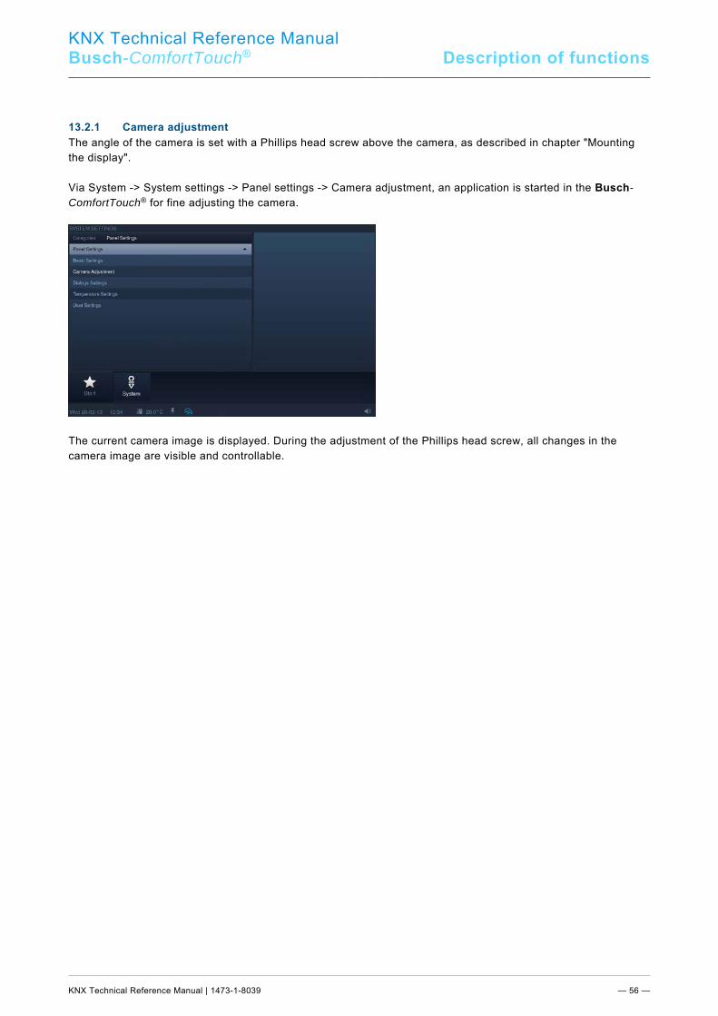
KNX Technical Reference Manual
Busch-ComfortTouch® Description of functions
KNX Technical Reference Manual | 1473-1-8039 — 56 —
13.2.1 Camera adjustment
The angle of the camera is set with a Phillips head screw above the camera, as described in chapter "Mounting the display". Via System -> System settings -> Panel settings -> Camera adjustment, an application is started in the Busch-ComfortTouch® for fine adjusting the camera.
The current camera image is displayed. During the adjustment of the Phillips head screw, all changes in the camera image are visible and controllable. Pos: 34.6 /Layout bis 2014-11-11/Online-Dokumentation (+KNX)/Steuermodule - Online-Dokumentation (--> Für alle Dokumente <--)/++++++++++++ Seitenumbruch ++++++++++++ @ 9\mod_1268898668093_0.docx @ 52149 @ @ 1
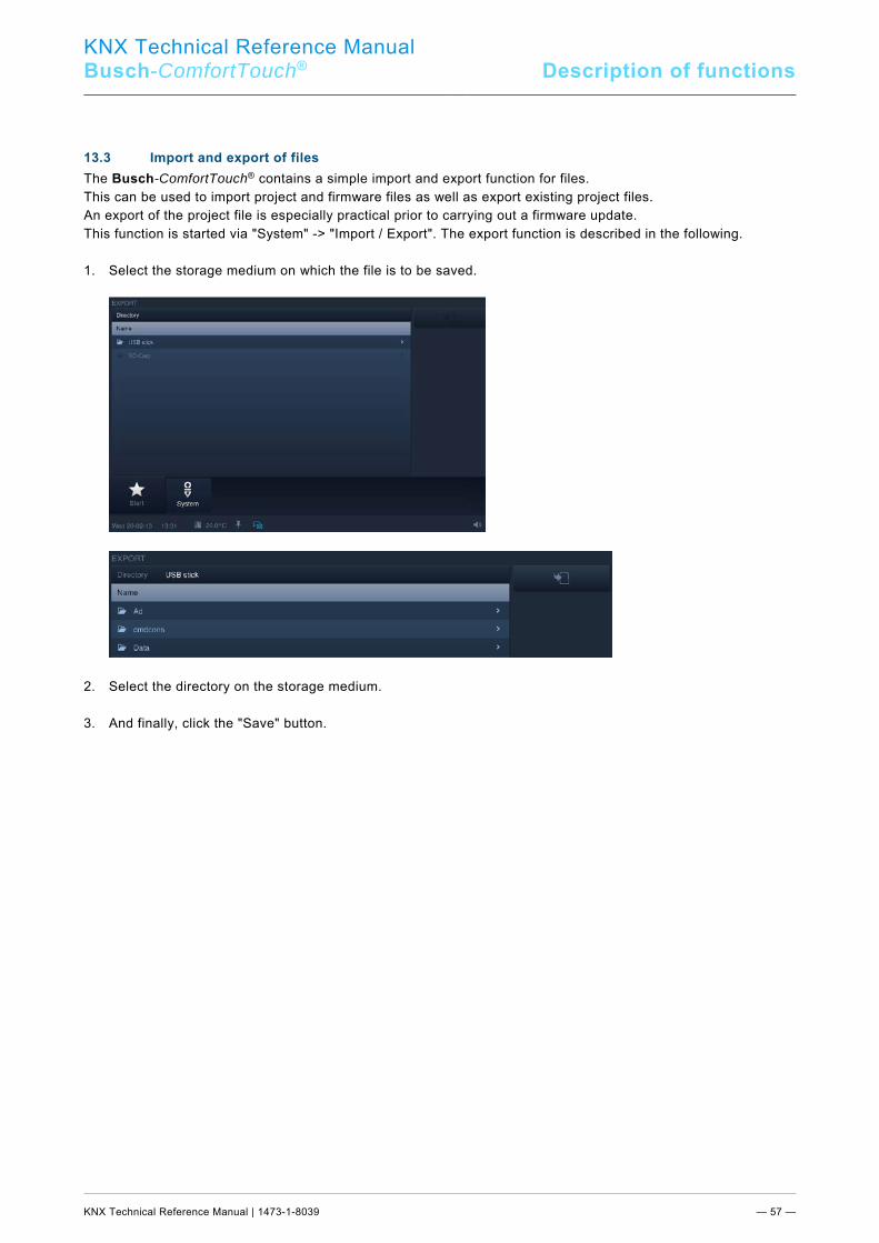
KNX Technical Reference Manual
Busch-ComfortTouch® Description of functions
KNX Technical Reference Manual | 1473-1-8039 — 57 —
Pos: 34.7.1 /Layout bis 2014-11-11/Online-Dokumentation (+KNX)/Überschriften (--> Für alle Dokumente <--)/2. Ebene/G - L/Import und Export von Dateien @ 33\mod_1361443104334_15.docx @ 280790 @ 2 @ 1
13.3 Import and export of files Pos: 34.7.2 /Layout bis 2014-11-11/Online-Dokumentation (+KNX)/Funktionsbeschreibungen/KNX/KNX-Aktorik/ComfortPanel 3.0/KNX Technisches Handbuch/Import und Export von DateienImport und Export von Dateien @ 40\mod_1418382177003_15.docx @ 308749 @ @ 1
The Busch-ComfortTouch® contains a simple import and export function for files. This can be used to import project and firmware files as well as export existing project files. An export of the project file is especially practical prior to carrying out a firmware update. This function is started via "System" -> "Import / Export". The export function is described in the following. 1. Select the storage medium on which the file is to be saved.
2. Select the directory on the storage medium. 3. And finally, click the "Save" button. Pos: 34.8 /Layout bis 2014-11-11/Online-Dokumentation (+KNX)/Steuermodule - Online-Dokumentation (--> Für alle Dokumente <--)/++++++++++++ Seitenumbruch ++++++++++++ @ 9\mod_1268898668093_0.docx @ 52149 @ @ 1
KNX Technical Reference Manual
Busch-ComfortTouch® Description of functions
KNX Technical Reference Manual | 1473-1-8039 — 58 —
Pos: 34.9.1 /Layout bis 2014-11-11/Online-Dokumentation (+KNX)/Überschriften (--> Für alle Dokumente <--)/2. Ebene/A - F/Bedienfunktionen @ 33\mod_1361443179379_15.docx @ 280806 @ 2 @ 1
13.4 Operating functions: Pos: 34.9.2 /Layout bis 2014-11-11/Online-Dokumentation (+KNX)/Funktionsbeschreibungen/KNX/KNX-Aktorik/ComfortPanel 3.0/KNX Technisches Handbuch/BedienfunktionenBedienfunktionen @ 40\mod_1418382402767_15.docx @ 308765 @ 3333333333 @ 1
All conventional functions in building automation can be controlled and have their status displayed. This enables the basic functions "Switching", "Dimming" "Blind", "Value", "Room temperature controller", "Scenes" and "Measured values" to be displayed and operated. The following control elements are available for this: 13.4.1 Push-button (Switch)
With the push-buttons you can integrate simple switches in the panel. Light switches or switches for simple switching processes can be realised based on pushbuttons. The push-button sends out a value during operation. Also reversing functions can be made possible via switches: - Push-button (light) - Switch (Light) - Push-button (Neutral) - Switch (Neutral) - Rocker switch (Neutral) 13.4.2 Dimmer
Dimmers can be used to integrate convenient light switches with dimming function in the Busch-ComfortTouch®. The dimmer sends values from an adjustable span between extreme values to the dimming actuator. - Dimmer without slider The "Without slider" version has a push-button for switching on/off in the centre and two buttons left and right
for stepwise dimming (brighter/darker). - Dimmers with popup slider The "Pop-up slider" version has a push-button for switching on/off on the left side and another button on the
right side. The latter opens a slider for dimming. - Dimmer with slider The "Slider" version has a push-button for switching on/off on the left side and a slider for dimming.
KNX Technical Reference Manual
Busch-ComfortTouch® Description of functions
KNX Technical Reference Manual | 1473-1-8039 — 59 —
13.4.3 Roller shutter / Blind
The blind control element has push-buttons on the left and right to open or close a blind and, if necessary, an additional button to stop in the middle (depending on the operating mode selected. 13.4.4 Scenes and sequences
With the "Scenes and sequences" control element the user can call up so-called scenes or sequences. This enables you to combine several actions into one, so that you can create, for instance, certain lighting scenes with just one press of the button (corresponds to several dimming actions). - Scene The "Scene" control element has only one button and is used to call up simple scenes. - Scene (List) Via the "Scene (List)" control element a list can be called up from which various scenes can be selected. - Sequences • The "Sequences" control element contains, among other things, a pause and stop function for controlling
sequences. 13.4.5 Value and text
With value display elements you can integrate values as text or graphic information in a Busch-ComfortTouch® page. They are not operable, but are used to display values only (exception: Slider value). Control elements "Text" and "Graphics" are available. 13.4.6 Room temperature controller (RTC)
Climate control units can be controlled with the control element for room temperature controllers.
Note The internal room temperature controller of the Busch-ComfortTouch® is not opened via this control element.
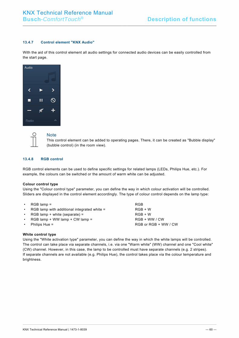
KNX Technical Reference Manual
Busch-ComfortTouch® Description of functions
KNX Technical Reference Manual | 1473-1-8039 — 60 —
13.4.7 Control element "KNX Audio"
With the aid of this control element all audio settings for connected audio devices can be easily controlled from the start page.
Note This control element can be added to operating pages. There, it can be created as "Bubble display" (bubble control) (in the room view).
13.4.8 RGB control
RGB control elements can be used to define specific settings for related lamps (LEDs, Philips Hue, etc.). For example, the colours can be switched or the amount of warm white can be adjusted. Colour control type Using the "Colour control type" parameter, you can define the way in which colour activation will be controlled. Sliders are displayed in the control element accordingly. The type of colour control depends on the lamp type:
• RGB lamp = RGB • RGB lamp with additional integrated white = RGB + W • RGB lamp + white (separate) = RGB + W • RGB lamp + WW lamp + CW lamp = RGB + WW / CW • Philips Hue = RGB or RGB + WW / CW
White control type Using the "White activation type" parameter, you can define the way in which the white lamps will be controlled. The control can take place via separate channels, i.e. via one "Warm white" (WW) channel and one "Cool white" (CW) channel. However, in this case, the lamp to be controlled must have separate channels (e.g. 2 stripes). If separate channels are not available (e.g. Philips Hue), the control takes place via the colour temperature and brightness.
KNX Technical Reference Manual
Busch-ComfortTouch® Description of functions
KNX Technical Reference Manual | 1473-1-8039 — 61 —
13.4.9 Philips Hue control element
Philips Hue control elements can be used to define specific settings for Philips Hue lamps. For example, the colours can be switched or the amount of warm white can be adjusted. Control normally takes place using an RGB control element.
Note This function is an option and only available with a corresponding plug-in. More detailed information about the commissioning process is available in commissioning software IP-Project 3 (IPP) for the Busch-ComfortTouch®.
Note In contrast to normal KNX actuators, the response of Philips Hue lamps is slightly delayed. They react generally a little later than the KNX dimming actuator, for example. This is system-dependent and normal. Since it is a Philips product we have no influence over the matter.
Note Adjustments to the commissioning of Philips Hue lamps can also be made via the system settings (see also chapter 13.2 "System settings"). The settings can be made under "Philips Hue Bridge Settings".
13.4.10 Step switch
You can integrate switch sequences in a Busch-ComfortTouch® with step switches. A step switch effectively combines several push-buttons into one control element. - Step switch without step display The "Without slider" version has two buttons left and right for calling up the next or previous step and a button
in the centre. The button in the centre returns the step switch to the bottom step (= off). - Step switch with step display The "Slider" version has a button to reset the step switch (corresponds to off) and buttons to call up the next
or previous step. In addition, it uses a slider to show which step is currently on. The slider cannot be operated.
Pos: 34.10 /Layout bis 2014-11-11/Online-Dokumentation (+KNX)/Steuermodule - Online-Dokumentation (--> Für alle Dokumente <--)/++++++++++++ Seitenumbruch ++++++++++++ @ 9\mod_1268898668093_0.docx @ 52149 @ @ 1
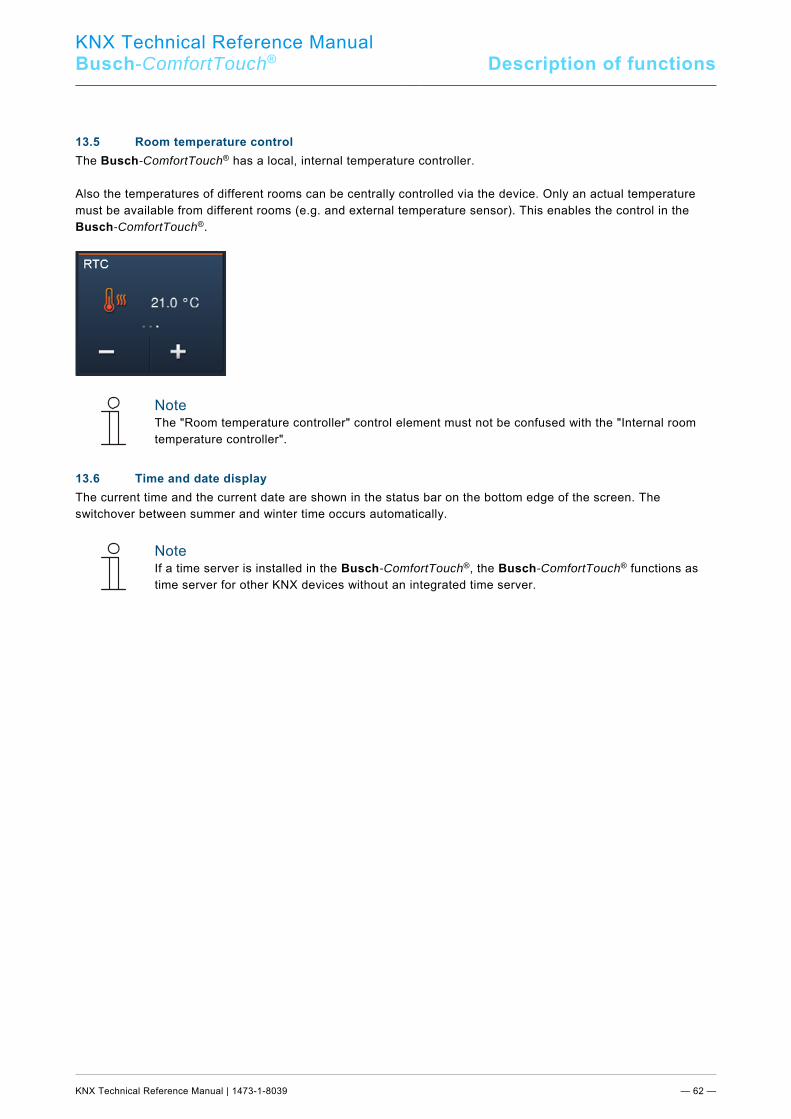
KNX Technical Reference Manual
Busch-ComfortTouch® Description of functions
KNX Technical Reference Manual | 1473-1-8039 — 62 —
Pos: 34.11.1 /Layout bis 2014-11-11/Online-Dokumentation (+KNX)/Überschriften (--> Für alle Dokumente <--)/2. Ebene/P - R/Raumtemperatursteuerung @ 33\mod_1361443250797_15.docx @ 280822 @ 2 @ 1
13.5 Room temperature control Pos: 34.11.2 /Layout bis 2014-11-11/Online-Dokumentation (+KNX)/Funktionsbeschreibungen/KNX/KNX-Aktorik/ComfortPanel 3.0/KNX Technisches Handbuch/RaumtemperatursteuerungRaumtemperatursteuerung @ 40\mod_1418383057285_15.docx @ 308781 @ @ 1
The Busch-ComfortTouch® has a local, internal temperature controller. Also the temperatures of different rooms can be centrally controlled via the device. Only an actual temperature must be available from different rooms (e.g. and external temperature sensor). This enables the control in the Busch-ComfortTouch®.
Note The "Room temperature controller" control element must not be confused with the "Internal room temperature controller".
Pos: 34.12 /Layout bis 2014-11-11/Online-Dokumentation (+KNX)/Steuermodule - Online-Dokumentation (--> Für alle Dokumente <--)/++++++++++++ Seitenumbruch ++++++++++++ @ 9\mod_1268898668093_0.docx @ 52149 @ @ 1 Pos: 34.13.1 /Layout bis 2014-11-11/Online-Dokumentation (+KNX)/Überschriften (--> Für alle Dokumente <--)/2. Ebene/U - Z/Uhrzeit- /Uhrzeit- / Datumsanzeige @ 33\mod_1361443391437_15.docx @ 280838 @ 2 @ 1
13.6 Time and date display Pos: 34.13.2 /Layout bis 2014-11-11/Online-Dokumentation (+KNX)/Funktionsbeschreibungen/KNX/KNX-Aktorik/ComfortPanel 3.0/KNX Technisches Handbuch/Uhrzeit- / Datumsanzeige/Uhrzeit- /Uhrzeit- / Datumsanzeige @ 33\mod_1361441542034_15.docx @ 279795 @ @ 1
The current time and the current date are shown in the status bar on the bottom edge of the screen. The switchover between summer and winter time occurs automatically.
Note If a time server is installed in the Busch-ComfortTouch®, the Busch-ComfortTouch® functions as time server for other KNX devices without an integrated time server.
Pos: 34.14.1 /Layout bis 2014-11-11/Online-Dokumentation (+KNX)/Überschriften (--> Für alle Dokumente <--)/2. Ebene/A - F/Bildnachrichten @ 33\mod_1361443467310_15.docx @ 280854 @ 2 @ 1

KNX Technical Reference Manual
Busch-ComfortTouch® Description of functions
KNX Technical Reference Manual | 1473-1-8039 — 63 —
13.7 Image messages Pos: 34.14.2 /Layout bis 2014-11-11/Online-Dokumentation (+KNX)/Funktionsbeschreibungen/KNX/KNX-Aktorik/ComfortPanel 3.0/KNX Technisches Handbuch/BildnachrichtenBildnachrichten @ 40\mod_1418383412952_15.docx @ 308797 @ @ 1
This enables users to leave image messages for other users on the Busch-ComfortTouch®. An image message is a handwritten text message or drawing created with the finger on the display.
If the "Image message" application is called up, the screen displays an overview of all addressees in the system. The user can then specifically select an addressee for the message.
If image messages are available that have not been viewed since their creation, it will be indicated to the user by an appropriate icon which is displayed in the status bar. This happens independent of the currently active application. Pos: 34.15 /Layout bis 2014-11-11/Online-Dokumentation (+KNX)/Steuermodule - Online-Dokumentation (--> Für alle Dokumente <--)/++++++++++++ Seitenumbruch ++++++++++++ @ 9\mod_1268898668093_0.docx @ 52149 @ @ 1
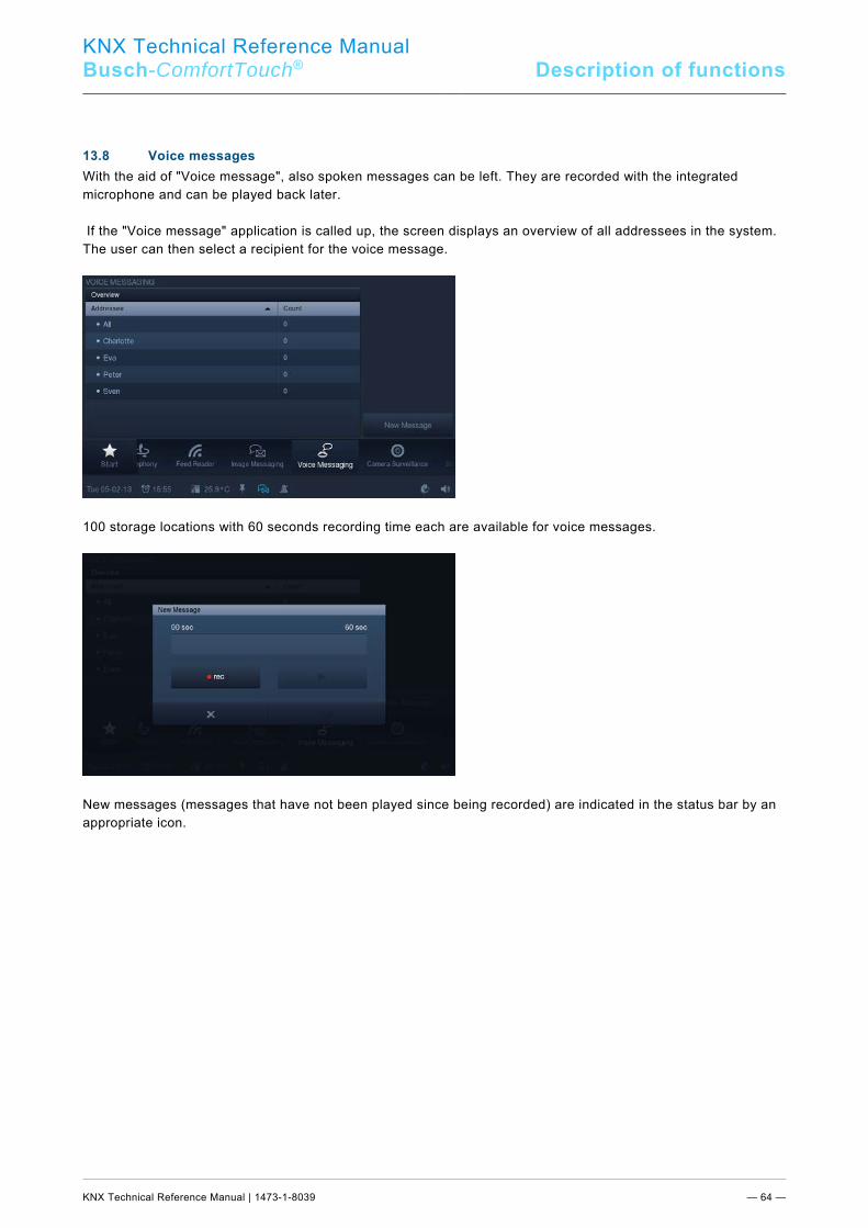
KNX Technical Reference Manual
Busch-ComfortTouch® Description of functions
KNX Technical Reference Manual | 1473-1-8039 — 64 —
Pos: 34.16.1 /Layout bis 2014-11-11/Online-Dokumentation (+KNX)/Überschriften (--> Für alle Dokumente <--)/2. Ebene/S - T/Sprachnachrichten @ 33\mod_1361443533826_15.docx @ 280870 @ 2 @ 1
13.8 Voice messages Pos: 34.16.2 /Layout bis 2014-11-11/Online-Dokumentation (+KNX)/Funktionsbeschreibungen/KNX/KNX-Aktorik/ComfortPanel 3.0/KNX Technisches Handbuch/Sprachnachrichten/Sprachnachrichten @ 33\mod_1361441545965_15.docx @ 279827 @ @ 1
With the aid of "Voice message", also spoken messages can be left. They are recorded with the integrated microphone and can be played back later. If the "Voice message" application is called up, the screen displays an overview of all addressees in the system. The user can then select a recipient for the voice message.
100 storage locations with 60 seconds recording time each are available for voice messages.
New messages (messages that have not been played since being recorded) are indicated in the status bar by an appropriate icon. Pos: 34.17 /Layout bis 2014-11-11/Online-Dokumentation (+KNX)/Steuermodule - Online-Dokumentation (--> Für alle Dokumente <--)/++++++++++++ Seitenumbruch ++++++++++++ @ 9\mod_1268898668093_0.docx @ 52149 @ @ 1
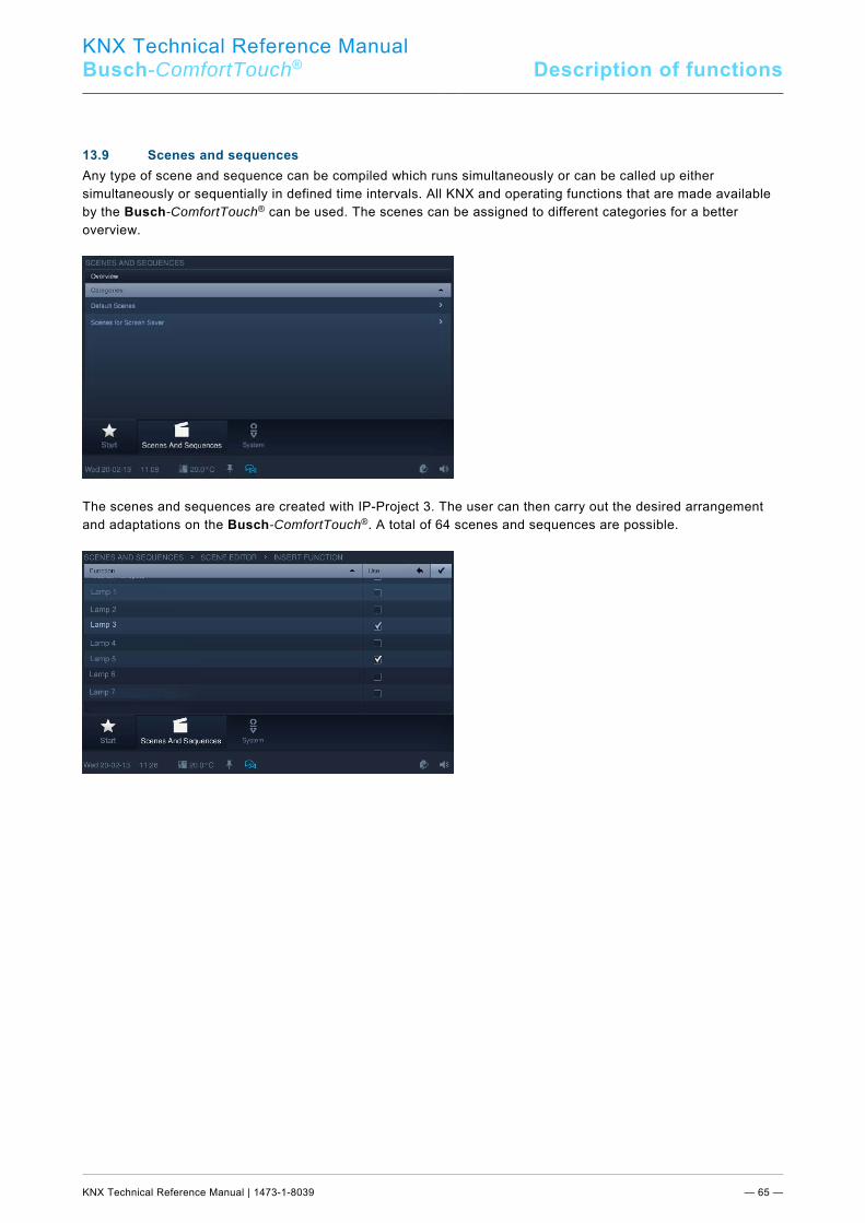
KNX Technical Reference Manual
Busch-ComfortTouch® Description of functions
KNX Technical Reference Manual | 1473-1-8039 — 65 —
Pos: 34.18.1 /Layout bis 2014-11-11/Online-Dokumentation (+KNX)/Überschriften (--> Für alle Dokumente <--)/2. Ebene/S - T/Szenen und Sequenzen @ 33\mod_1361443653855_15.docx @ 280886 @ 2 @ 1
13.9 Scenes and sequences Pos: 34.18.2 /Layout bis 2014-11-11/Online-Dokumentation (+KNX)/Funktionsbeschreibungen/KNX/KNX-Aktorik/ComfortPanel 3.0/KNX Technisches Handbuch/Szenen und Sequenzen/Szenen und Sequenzen @ 33\mod_1361441548050_15.docx @ 279843 @ @ 1
Any type of scene and sequence can be compiled which runs simultaneously or can be called up either simultaneously or sequentially in defined time intervals. All KNX and operating functions that are made available by the Busch-ComfortTouch® can be used. The scenes can be assigned to different categories for a better overview.
The scenes and sequences are created with IP-Project 3. The user can then carry out the desired arrangement and adaptations on the Busch-ComfortTouch®. A total of 64 scenes and sequences are possible.
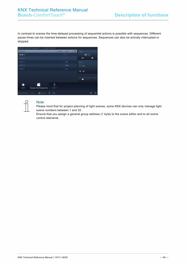
KNX Technical Reference Manual
Busch-ComfortTouch® Description of functions
KNX Technical Reference Manual | 1473-1-8039 — 66 —
In contrast to scenes the time-delayed processing of sequential actions is possible with sequences. Different pause times can be inserted between actions for sequences. Sequences can also be actively interrupted or stopped.
Note Please mind that for project planning of light scenes, some KNX devices can only manage light scene numbers between 1 and 32. Ensure that you assign a general group address (1 byte) to the scene editor and to all scene control elements.
Pos: 34.19 /Layout bis 2014-11-11/Online-Dokumentation (+KNX)/Steuermodule - Online-Dokumentation (--> Für alle Dokumente <--)/++++++++++++ Seitenumbruch ++++++++++++ @ 9\mod_1268898668093_0.docx @ 52149 @ @ 1
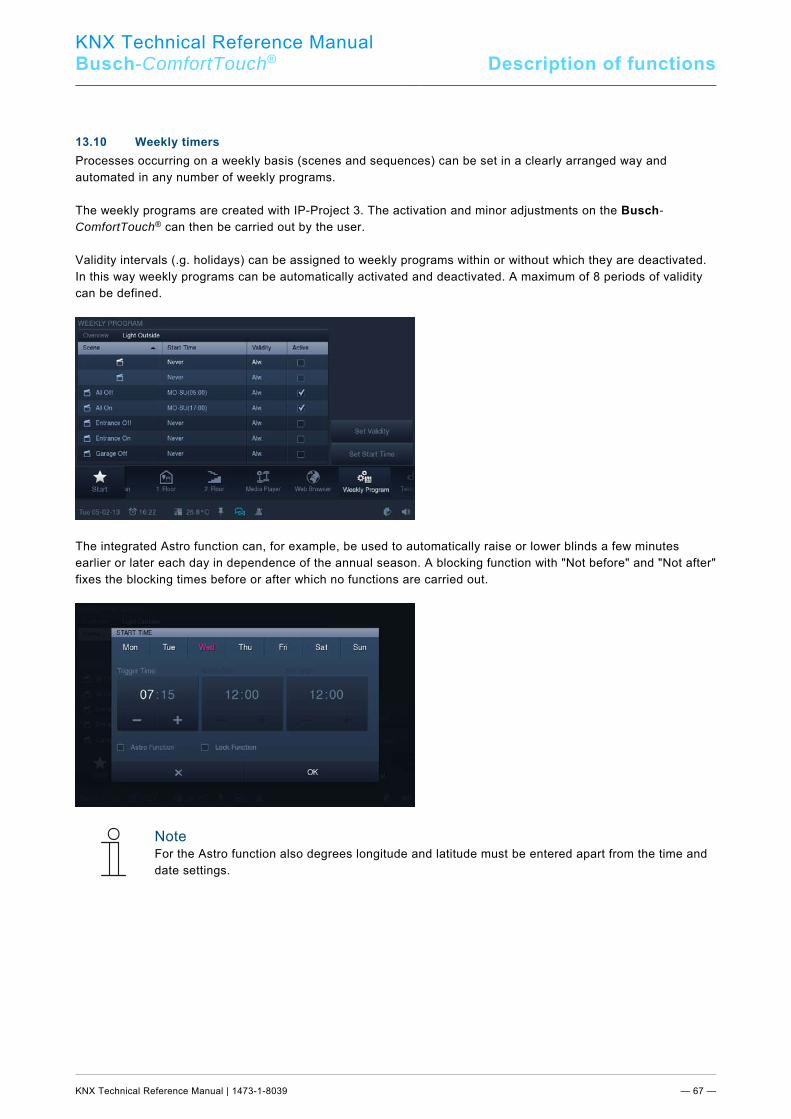
KNX Technical Reference Manual
Busch-ComfortTouch® Description of functions
KNX Technical Reference Manual | 1473-1-8039 — 67 —
Pos: 34.20.1 /Layout bis 2014-11-11/Online-Dokumentation (+KNX)/Überschriften (--> Für alle Dokumente <--)/2. Ebene/U - Z/Wochenprogramme @ 33\mod_1361443728100_15.docx @ 280902 @ 2 @ 1
13.10 Weekly timers Pos: 34.20.2 /Layout bis 2014-11-11/Online-Dokumentation (+KNX)/Funktionsbeschreibungen/KNX/KNX-Aktorik/ComfortPanel 3.0/KNX Technisches Handbuch/WochenprogrammeWochenprogramme @ 40\mod_1418383607594_15.docx @ 308813 @ @ 1
Processes occurring on a weekly basis (scenes and sequences) can be set in a clearly arranged way and automated in any number of weekly programs. The weekly programs are created with IP-Project 3. The activation and minor adjustments on the Busch-ComfortTouch® can then be carried out by the user. Validity intervals (.g. holidays) can be assigned to weekly programs within or without which they are deactivated. In this way weekly programs can be automatically activated and deactivated. A maximum of 8 periods of validity can be defined.
The integrated Astro function can, for example, be used to automatically raise or lower blinds a few minutes earlier or later each day in dependence of the annual season. A blocking function with "Not before" and "Not after" fixes the blocking times before or after which no functions are carried out.
Note For the Astro function also degrees longitude and latitude must be entered apart from the time and date settings.
Pos: 34.21 /Layout bis 2014-11-11/Online-Dokumentation (+KNX)/Steuermodule - Online-Dokumentation (--> Für alle Dokumente <--)/++++++++++++ Seitenumbruch ++++++++++++ @ 9\mod_1268898668093_0.docx @ 52149 @ @ 1
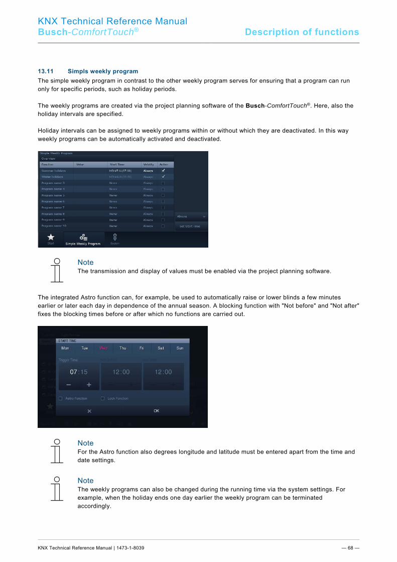
KNX Technical Reference Manual
Busch-ComfortTouch® Description of functions
KNX Technical Reference Manual | 1473-1-8039 — 68 —
Pos: 34.22.1 /Layout bis 2014-11-11/Online-Dokumentation (+KNX)/Überschriften (--> Für alle Dokumente <--)/2. Ebene/U - Z/Wochenprogramme -- einfache @ 40\mod_1418822358921_15.docx @ 310561 @ 2 @ 1
13.11 Simpls weekly program Pos: 34.22.2 /Layout bis 2014-11-11/Online-Dokumentation (+KNX)/Funktionsbeschreibungen/KNX/KNX-Aktorik/ComfortPanel 3.0/KNX Technisches Handbuch/Wochenprogramme -- einfache/Wochenprogramme -- einfache -- THB @ 40\mod_1418822269766_15.docx @ 310546 @ @ 1
The simple weekly program in contrast to the other weekly program serves for ensuring that a program can run only for specific periods, such as holiday periods. The weekly programs are created via the project planning software of the Busch-ComfortTouch®. Here, also the holiday intervals are specified. Holiday intervals can be assigned to weekly programs within or without which they are deactivated. In this way weekly programs can be automatically activated and deactivated.
Note The transmission and display of values must be enabled via the project planning software.
The integrated Astro function can, for example, be used to automatically raise or lower blinds a few minutes earlier or later each day in dependence of the annual season. A blocking function with "Not before" and "Not after" fixes the blocking times before or after which no functions are carried out.
Note For the Astro function also degrees longitude and latitude must be entered apart from the time and date settings.
Note The weekly programs can also be changed during the running time via the system settings. For example, when the holiday ends one day earlier the weekly program can be terminated accordingly.
Pos: 34.23 /Layout bis 2014-11-11/Online-Dokumentation (+KNX)/Steuermodule - Online-Dokumentation (--> Für alle Dokumente <--)/++++++++++++ Seitenumbruch ++++++++++++ @ 9\mod_1268898668093_0.docx @ 52149 @ @ 1
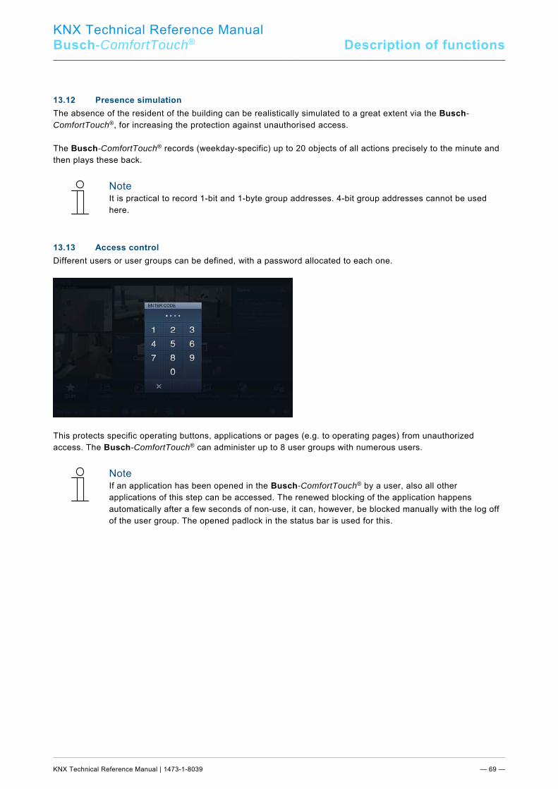
KNX Technical Reference Manual
Busch-ComfortTouch® Description of functions
KNX Technical Reference Manual | 1473-1-8039 — 69 —
Pos: 34.24.1 /Layout bis 2014-11-11/Online-Dokumentation (+KNX)/Überschriften (--> Für alle Dokumente <--)/2. Ebene/A - F/Anwesenheitssimulation @ 33\mod_1361443830911_15.docx @ 280918 @ 2 @ 1
13.12 Presence simulation Pos: 34.24.2 /Layout bis 2014-11-11/Online-Dokumentation (+KNX)/Funktionsbeschreibungen/KNX/KNX-Aktorik/ComfortPanel 3.0/KNX Technisches Handbuch/Anwesenheitssimulation/Anwesenheitssimulation @ 33\mod_1361441551832_15.docx @ 279875 @ @ 1
The absence of the resident of the building can be realistically simulated to a great extent via the Busch-ComfortTouch®, for increasing the protection against unauthorised access. The Busch-ComfortTouch® records (weekday-specific) up to 20 objects of all actions precisely to the minute and then plays these back.
Note It is practical to record 1-bit and 1-byte group addresses. 4-bit group addresses cannot be used here.
Pos: 34.25.1 /Layout bis 2014-11-11/Online-Dokumentation (+KNX)/Überschriften (--> Für alle Dokumente <--)/2. Ebene/U - Z/Zugriffssteuerung @ 33\mod_1361443897667_15.docx @ 280934 @ 2 @ 1
13.13 Access control Pos: 34.25.2 /Layout bis 2014-11-11/Online-Dokumentation (+KNX)/Funktionsbeschreibungen/KNX/KNX-Aktorik/ComfortPanel 3.0/KNX Technisches Handbuch/Zugriffssteuerung/Zugriffssteuerung @ 33\mod_1361441553605_15.docx @ 279891 @ @ 1
Different users or user groups can be defined, with a password allocated to each one.
This protects specific operating buttons, applications or pages (e.g. to operating pages) from unauthorized access. The Busch-ComfortTouch® can administer up to 8 user groups with numerous users.
Note If an application has been opened in the Busch-ComfortTouch® by a user, also all other applications of this step can be accessed. The renewed blocking of the application happens automatically after a few seconds of non-use, it can, however, be blocked manually with the log off of the user group. The opened padlock in the status bar is used for this.
Pos: 34.26 /Layout bis 2014-11-11/Online-Dokumentation (+KNX)/Steuermodule - Online-Dokumentation (--> Für alle Dokumente <--)/++++++++++++ Seitenumbruch ++++++++++++ @ 9\mod_1268898668093_0.docx @ 52149 @ @ 1
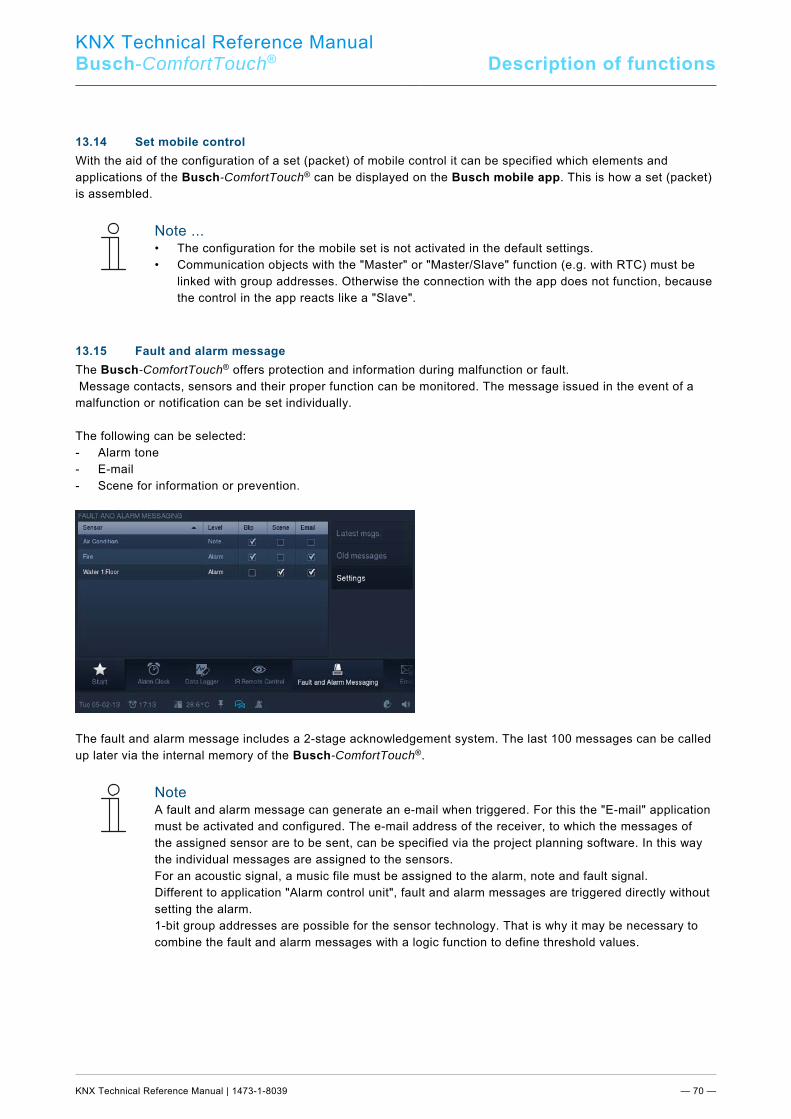
KNX Technical Reference Manual
Busch-ComfortTouch® Description of functions
KNX Technical Reference Manual | 1473-1-8039 — 70 —
Pos: 34.27.1 /Layout bis 2014-11-11/Online-Dokumentation (+KNX)/Überschriften (--> Für alle Dokumente <--)/2. Ebene/S - T/Set Mobile Steuerung @ 33\mod_1361443956549_15.docx @ 280950 @ 2 @ 1
13.14 Set mobile control Pos: 34.27.2 /Layout bis 2014-11-11/Online-Dokumentation (+KNX)/Funktionsbeschreibungen/KNX/KNX-Aktorik/ComfortPanel 3.0/KNX Technisches Handbuch/Set Mobile SteuerungSet Mobile Steuerung @ 40\mod_1418637744684_15.docx @ 308879 @ @ 1
With the aid of the configuration of a set (packet) of mobile control it can be specified which elements and applications of the Busch-ComfortTouch® can be displayed on the Busch mobile app. This is how a set (packet) is assembled.
Note ... • The configuration for the mobile set is not activated in the default settings. • Communication objects with the "Master" or "Master/Slave" function (e.g. with RTC) must be
linked with group addresses. Otherwise the connection with the app does not function, because the control in the app reacts like a "Slave".
Pos: 34.28.1 /Layout bis 2014-11-11/Online-Dokumentation (+KNX)/Überschriften (--> Für alle Dokumente <--)/2. Ebene/S - T/Stör- und Alarmmeldung @ 33\mod_1361444017728_15.docx @ 280966 @ 2 @ 1
13.15 Fault and alarm message Pos: 34.28.2 /Layout bis 2014-11-11/Online-Dokumentation (+KNX)/Funktionsbeschreibungen/KNX/KNX-Aktorik/ComfortPanel 3.0/KNX Technisches Handbuch/Stör- und AlarmmeldungStör- und Alarmmeldung @ 40\mod_1418638409248_15.docx @ 308895 @ @ 1
The Busch-ComfortTouch® offers protection and information during malfunction or fault. Message contacts, sensors and their proper function can be monitored. The message issued in the event of a malfunction or notification can be set individually. The following can be selected: - Alarm tone - E-mail - Scene for information or prevention.
The fault and alarm message includes a 2-stage acknowledgement system. The last 100 messages can be called up later via the internal memory of the Busch-ComfortTouch®.
Note A fault and alarm message can generate an e-mail when triggered. For this the "E-mail" application must be activated and configured. The e-mail address of the receiver, to which the messages of the assigned sensor are to be sent, can be specified via the project planning software. In this way the individual messages are assigned to the sensors. For an acoustic signal, a music file must be assigned to the alarm, note and fault signal. Different to application "Alarm control unit", fault and alarm messages are triggered directly without setting the alarm. 1-bit group addresses are possible for the sensor technology. That is why it may be necessary to combine the fault and alarm messages with a logic function to define threshold values.
Pos: 34.29 /Layout bis 2014-11-11/Online-Dokumentation (+KNX)/Steuermodule - Online-Dokumentation (--> Für alle Dokumente <--)/++++++++++++ Seitenumbruch ++++++++++++ @ 9\mod_1268898668093_0.docx @ 52149 @ @ 1
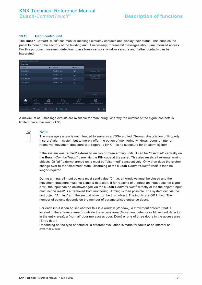
KNX Technical Reference Manual
Busch-ComfortTouch® Description of functions
KNX Technical Reference Manual | 1473-1-8039 — 71 —
Pos: 34.30.1 /Layout bis 2014-11-11/Online-Dokumentation (+KNX)/Überschriften (--> Für alle Dokumente <--)/2. Ebene/M - O/Meldeanlage @ 33\mod_1361444094164_15.docx @ 280982 @ 2 @ 1
13.16 Alarm control unit Pos: 34.30.2 /Layout bis 2014-11-11/Online-Dokumentation (+KNX)/Funktionsbeschreibungen/KNX/KNX-Aktorik/ComfortPanel 3.0/KNX Technisches Handbuch/Meldeanlage/Meldeanlage @ 33\mod_1361441559450_15.docx @ 279939 @ @ 1
The Busch-ComfortTouch® can monitor message circuits / contacts and display their status. This enables the panel to monitor the security of the building and, if necessary, to transmit messages about unauthorized access. For this purpose, movement detectors, glass break sensors, window sensors and further contacts can be integrated.
A maximum of 8 message circuits are available for monitoring, whereby the number of the signal contacts is limited tom a maximum of 30.
Note The message system is not intended to serve as a VDS-certified (German Association of Property Insurers) alarm system but to merely offer the option of monitoring windows, doors or interior rooms via movement detectors with regard to KNX. It is no substitute for an alarm system. If the system was "armed" externally via two or three arming units, it can be "disarmed" centrally on the Busch-ComfortTouch® panel via the PIN code at the panel. This also resets all external arming objects. Or "all" external armed units must be "disarmed" consecutively. Only then does the system change over to the "disarmed" state. Disarming at the Busch-ComfortTouch® itself is then no longer required. During arming, all input objects must send value "0", i.e. all windows must be closed and the movement detectors must not signal a detection. If for reasons of a defect an input does not signal a "0", the input can be acknowledged via the Busch-ComfortTouch® directly or via the object "Input malfunction reset", i.e. removed from monitoring. Arming is then possible. The system can via the first object "Arming" arm the second object or the third object. The inputs are OR linked. The number of objects depends on the number of parameterised entrance doors. For each input it can be set whether this is a window (Window), a movement detector that is located in the entrance area or outside the access area (Movement detector or Movement detector in the entry area), a "normal“ door (no access door, Door) or one of three doors in the access area (Entry door). Depending on the type of detector, a different evaluation is made for faults or an internal or external alarm.
KNX Technical Reference Manual
Busch-ComfortTouch® Description of functions
KNX Technical Reference Manual | 1473-1-8039 — 72 —
Note When setting an alarm, all inputs except the "Entry door" and the movement detector in the entry area are treated the same. This means that arming is also possible when the detector in the access area has been switched on. Set practical values for the cycle times of the sensors (binary inputs or movement detectors). Example: - Monitoring time of inputs: 10 minutes - Cycle time of sensors: 4.5 minutes This ensures that at least two telegrams are received within the monitoring time.
Pos: 34.31 /Layout bis 2014-11-11/Online-Dokumentation (+KNX)/Steuermodule - Online-Dokumentation (--> Für alle Dokumente <--)/++++++++++++ Seitenumbruch ++++++++++++ @ 9\mod_1268898668093_0.docx @ 52149 @ @ 1
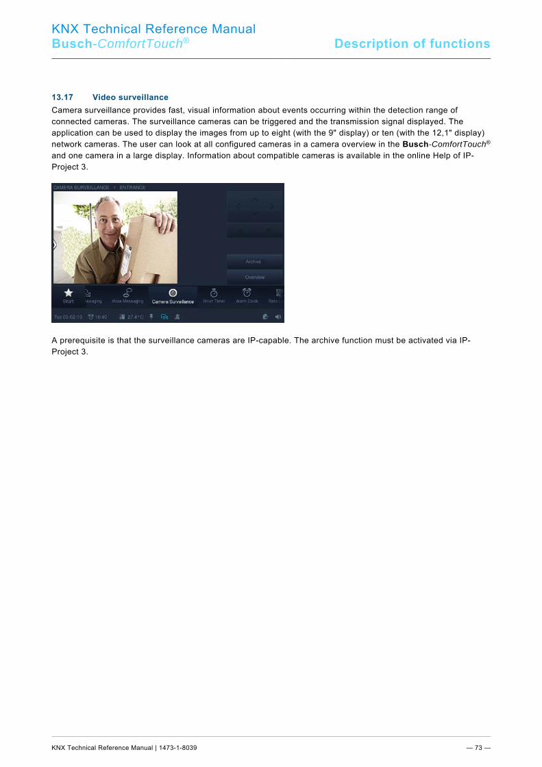
KNX Technical Reference Manual
Busch-ComfortTouch® Description of functions
KNX Technical Reference Manual | 1473-1-8039 — 73 —
Pos: 34.32.1 /Layout bis 2014-11-11/Online-Dokumentation (+KNX)/Überschriften (--> Für alle Dokumente <--)/2. Ebene/G - L/Kameraüberwachung @ 33\mod_1361444157283_15.docx @ 280998 @ 2 @ 1
13.17 Video surveillance Pos: 34.32.2 /Layout bis 2014-11-11/Online-Dokumentation (+KNX)/Funktionsbeschreibungen/KNX/KNX-Aktorik/ComfortPanel 3.0/KNX Technisches Handbuch/Kameraüberwachung/Kameraüberwachung @ 33\mod_1361441561372_15.docx @ 279955 @ @ 1
Camera surveillance provides fast, visual information about events occurring within the detection range of connected cameras. The surveillance cameras can be triggered and the transmission signal displayed. The application can be used to display the images from up to eight (with the 9" display) or ten (with the 12,1" display) network cameras. The user can look at all configured cameras in a camera overview in the Busch-ComfortTouch® and one camera in a large display. Information about compatible cameras is available in the online Help of IP-Project 3.
A prerequisite is that the surveillance cameras are IP-capable. The archive function must be activated via IP-Project 3. Pos: 34.33 /Layout bis 2014-11-11/Online-Dokumentation (+KNX)/Steuermodule - Online-Dokumentation (--> Für alle Dokumente <--)/++++++++++++ Seitenumbruch ++++++++++++ @ 9\mod_1268898668093_0.docx @ 52149 @ @ 1
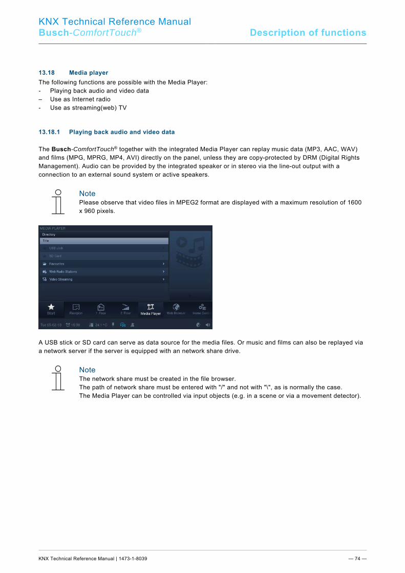
KNX Technical Reference Manual
Busch-ComfortTouch® Description of functions
KNX Technical Reference Manual | 1473-1-8039 — 74 —
Pos: 34.34.1 /Layout bis 2014-11-11/Online-Dokumentation (+KNX)/Überschriften (--> Für alle Dokumente <--)/2. Ebene/M - O/Media-Player @ 33\mod_1361444220764_15.docx @ 281014 @ 2 @ 1
13.18 Media player Pos: 34.34.2 /Layout bis 2014-11-11/Online-Dokumentation (+KNX)/Funktionsbeschreibungen/KNX/KNX-Aktorik/ComfortPanel 3.0/KNX Technisches Handbuch/Media-PlayerMedia-Player @ 40\mod_1418639388669_15.docx @ 308911 @ 333 @ 1
The following functions are possible with the Media Player: - Playing back audio and video data – Use as Internet radio - Use as streaming(web) TV 13.18.1 Playing back audio and video data
The Busch-ComfortTouch® together with the integrated Media Player can replay music data (MP3, AAC, WAV) and films (MPG, MPRG, MP4, AVI) directly on the panel, unless they are copy-protected by DRM (Digital Rights Management). Audio can be provided by the integrated speaker or in stereo via the line-out output with a connection to an external sound system or active speakers.
Note Please observe that video files in MPEG2 format are displayed with a maximum resolution of 1600 x 960 pixels.
A USB stick or SD card can serve as data source for the media files. Or music and films can also be replayed via a network server if the server is equipped with an network share drive.
Note The network share must be created in the file browser. The path of network share must be entered with "/" and not with "\", as is normally the case. The Media Player can be controlled via input objects (e.g. in a scene or via a movement detector).
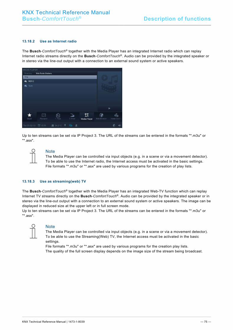
KNX Technical Reference Manual
Busch-ComfortTouch® Description of functions
KNX Technical Reference Manual | 1473-1-8039 — 75 —
13.18.2 Use as Internet radio
The Busch-ComfortTouch® together with the Media Player has an integrated Internet radio which can replay Internet radio streams directly on the Busch-ComfortTouch®. Audio can be provided by the integrated speaker or in stereo via the line-out output with a connection to an external sound system or active speakers.
Up to ten streams can be set via IP Project 3. The URL of the streams can be entered in the formats "*.m3u" or "*.asx".
Note The Media Player can be controlled via input objects (e.g. in a scene or via a movement detector). To be able to use the Internet radio, the Internet access must be activated in the basic settings. File formats "*.m3u" or "*.asx" are used by various programs for the creation of play lists.
13.18.3 Use as streaming(web) TV
The Busch-ComfortTouch® together with the Media Player has an integrated Web-TV function which can replay Internet TV streams directly on the Busch-ComfortTouch®. Audio can be provided by the integrated speaker or in stereo via the line-out output with a connection to an external sound system or active speakers. The image can be displayed in reduced size at the upper left or in full screen mode. Up to ten streams can be set via IP Project 3. The URL of the streams can be entered in the formats "*.m3u" or "*.asx".
Note The Media Player can be controlled via input objects (e.g. in a scene or via a movement detector). To be able to use the Streaming(Web) TV, the Internet access must be activated in the basic settings. File formats "*.m3u" or "*.asx" are used by various programs for the creation play lists. The quality of the full screen display depends on the image size of the stream being broadcast.
Pos: 34.35 /Layout bis 2014-11-11/Online-Dokumentation (+KNX)/Steuermodule - Online-Dokumentation (--> Für alle Dokumente <--)/++++++++++++ Seitenumbruch ++++++++++++ @ 9\mod_1268898668093_0.docx @ 52149 @ @ 1
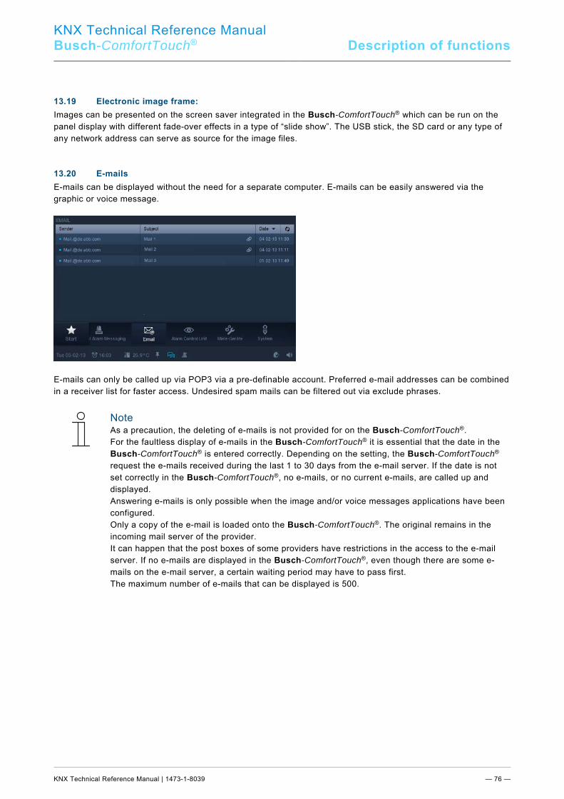
KNX Technical Reference Manual
Busch-ComfortTouch® Description of functions
KNX Technical Reference Manual | 1473-1-8039 — 76 —
Pos: 34.36.1 /Layout bis 2014-11-11/Online-Dokumentation (+KNX)/Überschriften (--> Für alle Dokumente <--)/2. Ebene/A - F/Elektronischer Bilderrahmen @ 33\mod_1361444283131_15.docx @ 281030 @ 2 @ 1
13.19 Electronic image frame: Pos: 34.36.2 /Layout bis 2014-11-11/Online-Dokumentation (+KNX)/Funktionsbeschreibungen/KNX/KNX-Aktorik/ComfortPanel 3.0/KNX Technisches Handbuch/Elektronischer Bilderrahmen/Elektronischer Bilderrahmen @ 33\mod_1361441565125_15.docx @ 279987 @ @ 1
Images can be presented on the screen saver integrated in the Busch-ComfortTouch® which can be run on the panel display with different fade-over effects in a type of “slide show”. The USB stick, the SD card or any type of any network address can serve as source for the image files. Pos: 34.37.1 /Layout bis 2014-11-11/Online-Dokumentation (+KNX)/Überschriften (--> Für alle Dokumente <--)/2. Ebene/A - F/E-Mails @ 34\mod_1361444371212_15.docx @ 281046 @ 2 @ 1
13.20 E-mails Pos: 34.37.2 /Layout bis 2014-11-11/Online-Dokumentation (+KNX)/Funktionsbeschreibungen/KNX/KNX-Aktorik/ComfortPanel 3.0/KNX Technisches Handbuch/E-Mails/E-Mails @ 33\mod_1361441567372_15.docx @ 280003 @ @ 1
E-mails can be displayed without the need for a separate computer. E-mails can be easily answered via the graphic or voice message.
E-mails can only be called up via POP3 via a pre-definable account. Preferred e-mail addresses can be combined in a receiver list for faster access. Undesired spam mails can be filtered out via exclude phrases.
Note As a precaution, the deleting of e-mails is not provided for on the Busch-ComfortTouch®. For the faultless display of e-mails in the Busch-ComfortTouch® it is essential that the date in the Busch-ComfortTouch® is entered correctly. Depending on the setting, the Busch-ComfortTouch® request the e-mails received during the last 1 to 30 days from the e-mail server. If the date is not set correctly in the Busch-ComfortTouch®, no e-mails, or no current e-mails, are called up and displayed. Answering e-mails is only possible when the image and/or voice messages applications have been configured. Only a copy of the e-mail is loaded onto the Busch-ComfortTouch®. The original remains in the incoming mail server of the provider. It can happen that the post boxes of some providers have restrictions in the access to the e-mail server. If no e-mails are displayed in the Busch-ComfortTouch®, even though there are some e-mails on the e-mail server, a certain waiting period may have to pass first. The maximum number of e-mails that can be displayed is 500.
Pos: 34.38 /Layout bis 2014-11-11/Online-Dokumentation (+KNX)/Steuermodule - Online-Dokumentation (--> Für alle Dokumente <--)/++++++++++++ Seitenumbruch ++++++++++++ @ 9\mod_1268898668093_0.docx @ 52149 @ @ 1
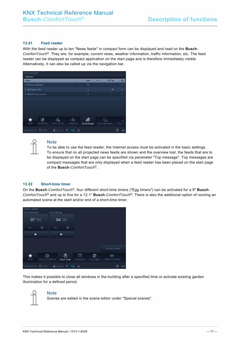
KNX Technical Reference Manual
Busch-ComfortTouch® Description of functions
KNX Technical Reference Manual | 1473-1-8039 — 77 —
Pos: 34.39.1 /Layout bis 2014-11-11/Online-Dokumentation (+KNX)/Überschriften (--> Für alle Dokumente <--)/2. Ebene/A - F/Feed-Reader @ 34\mod_1361444568448_15.docx @ 281062 @ 2 @ 1
13.21 Feed reader Pos: 34.39.2 /Layout bis 2014-11-11/Online-Dokumentation (+KNX)/Funktionsbeschreibungen/KNX/KNX-Aktorik/ComfortPanel 3.0/KNX Technisches Handbuch/Feed-Reader/Feed-Reader @ 33\mod_1361441569294_15.docx @ 280019 @ @ 1
With the feed reader up to ten "News feeds" in compact form can be displayed and read on the Busch-ComfortTouch®. They are, for example, current news, weather information, traffic information, etc. The feed reader can be displayed as compact application on the start page and is therefore immediately visible. Alternatively, it can also be called up via the navigation bar.
Note To be able to use the feed reader, the Internet access must be activated in the basic settings. To ensure that no all projected news feeds are shown and the overview lost, the feeds that are to be displayed on the start page can be specified via parameter "Top message". Top messages are compact messages that are only displayed when a feed reader has been placed on the start page of the Busch-ComfortTouch®.
Pos: 34.40 /Layout bis 2014-11-11/Online-Dokumentation (+KNX)/Steuermodule - Online-Dokumentation (--> Für alle Dokumente <--)/++++++++++++ Seitenumbruch ++++++++++++ @ 9\mod_1268898668093_0.docx @ 52149 @ @ 1 Pos: 34.41.1 /Layout bis 2014-11-11/Online-Dokumentation (+KNX)/Überschriften (--> Für alle Dokumente <--)/2. Ebene/G - L/Kurzzeittimer @ 9\mod_1269501915203_15.docx @ 52882 @ 2 @ 1
13.22 Short-time timer Pos: 34.41.2 /Layout bis 2014-11-11/Online-Dokumentation (+KNX)/Funktionsbeschreibungen/KNX/KNX-Aktorik/ComfortPanel 3.0/KNX Technisches Handbuch/KurzzeittimerKurzzeittimer @ 40\mod_1418639716240_15.docx @ 308927 @ @ 1
On the Busch-ComfortTouch®, four different short-time timers ("Egg timers") can be activated for a 9" Busch-ComfortTouch® and up to five for a 12.1" Busch-ComfortTouch®. There is also the additional option of running an automated scene at the start and/or end of a short-time timer.
This makes it possible to close all windows in the building after a specified time or activate existing garden illumination for a defined period.
Note Scenes are edited in the scene editor under "Special scenes".
Pos: 34.42 /Layout bis 2014-11-11/Online-Dokumentation (+KNX)/Steuermodule - Online-Dokumentation (--> Für alle Dokumente <--)/++++++++++++ Seitenumbruch ++++++++++++ @ 9\mod_1268898668093_0.docx @ 52149 @ @ 1

KNX Technical Reference Manual
Busch-ComfortTouch® Description of functions
KNX Technical Reference Manual | 1473-1-8039 — 78 —
Pos: 34.43.1 /Layout bis 2014-11-11/Online-Dokumentation (+KNX)/Überschriften (--> Für alle Dokumente <--)/2. Ebene/U - Z/Wecker @ 9\mod_1269505094679_15.docx @ 52904 @ 2 @ 1
13.23 Alarm clock Pos: 34.43.2 /Layout bis 2014-11-11/Online-Dokumentation (+KNX)/Funktionsbeschreibungen/KNX/KNX-Aktorik/ComfortPanel 3.0/KNX Technisches Handbuch/Wecker/Wecker @ 33\mod_1361441573382_15.docx @ 280051 @ @ 1
Specific weekday times can be set for activating a specific scene for waking up (e.g. starting the Media Player with one’s favourite music). It is also possible to set a scene to precede the alarm, to prepare the home environment for its occupants prior to rising (the heating is switched on already one hour before to the alarm clock). This allows a scene or a sequence to be started for the lead-in time (specific time set before alarm time), for alarm time, at activation of "Snooze" and switching off the alarm clock.
Various melodies that have been specially developed for this device are available for the wake-up calls of the Busch-ComfortTouch®.
Note Scenes are edited in the scene editor under "Special scenes".
Pos: 34.44 /Layout bis 2014-11-11/Online-Dokumentation (+KNX)/Steuermodule - Online-Dokumentation (--> Für alle Dokumente <--)/++++++++++++ Seitenumbruch ++++++++++++ @ 9\mod_1268898668093_0.docx @ 52149 @ @ 1 Pos: 34.45.1 /Layout bis 2014-11-11/Online-Dokumentation (+KNX)/Überschriften (--> Für alle Dokumente <--)/2. Ebene/A - F/Fernwartbarkeit /Fernwartbarkeit / Übertragung von Daten @ 34\mod_1361444804869_15.docx @ 281094 @ 2 @ 1
13.24 Remote maintenance / Transmission of data Pos: 34.45.2 /Layout bis 2014-11-11/Online-Dokumentation (+KNX)/Funktionsbeschreibungen/KNX/KNX-Aktorik/ComfortPanel 3.0/KNX Technisches Handbuch/Fernwartbarkeit / Übertragung von Daten/Fernwartbarkeit /Fernwartbarkeit / Übertragung von Daten @ 33\mod_1361441575691_15.docx @ 280067 @ @ 1
Remote maintenance and care of the system software of the Busch-ComfortTouch® is also possible. Also project data from IP-Project 3 or changes to individual basic settings can be loaded via the web interface (see section "Web interface"). The access can be made via LAN / Internet, or WLAN. Prerequisite for the use of the Internet is a VPN (Virtual Private Network). This is technology that tunnels the network connection of a remote computer (e.g. the Busch-ComfortTouch®) to the network of a local computer. This allows working on the remote computer as if one is located in the same network. Since IP-Project 3 "locates" the panel via UPnP, it is possible to program the Busch-ComfortTouch® through this tunnel via the Internet. Pos: 34.46.1 /Layout bis 2014-11-11/Online-Dokumentation (+KNX)/Überschriften (--> Für alle Dokumente <--)/2. Ebene/G - L/IR-Fernbedienung @ 34\mod_1361444899085_15.docx @ 281110 @ 2 @ 1
13.25 IR remote control Pos: 34.46.2 /Layout bis 2014-11-11/Online-Dokumentation (+KNX)/Funktionsbeschreibungen/KNX/KNX-Aktorik/ComfortPanel 3.0/KNX Technisches Handbuch/IR-FernbedienungIR-Fernbedienung @ 40\mod_1418643417489_15.docx @ 308943 @ @ 1
The Busch-ComfortTouch® can be controlled via an RC5 or B&O capable remote control. To do this, the functions of the panel are assigned to the buttons of the IR remote control. The available IR functions are defined in advance in the Busch-ComfortTouch® by the electrician. Programming of a new IR remote control is also possible on the device later. Pos: 34.47 /Layout bis 2014-11-11/Online-Dokumentation (+KNX)/Steuermodule - Online-Dokumentation (--> Für alle Dokumente <--)/++++++++++++ Seitenumbruch ++++++++++++ @ 9\mod_1268898668093_0.docx @ 52149 @ @ 1
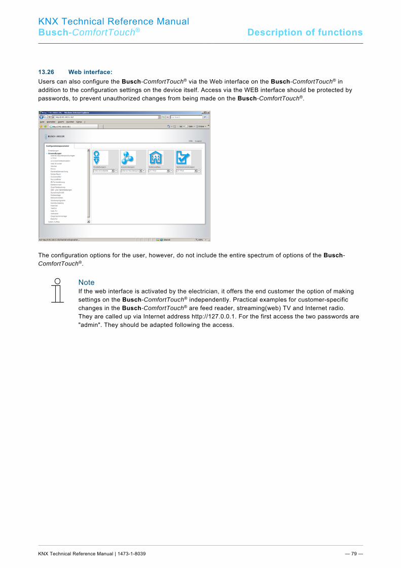
KNX Technical Reference Manual
Busch-ComfortTouch® Description of functions
KNX Technical Reference Manual | 1473-1-8039 — 79 —
Pos: 34.48.1 /Layout bis 2014-11-11/Online-Dokumentation (+KNX)/Überschriften (--> Für alle Dokumente <--)/2. Ebene/U - Z/Web-Interface @ 34\mod_1361445158114_15.docx @ 281126 @ 2 @ 1
13.26 Web interface: Pos: 34.48.2 /Layout bis 2014-11-11/Online-Dokumentation (+KNX)/Funktionsbeschreibungen/KNX/KNX-Aktorik/ComfortPanel 3.0/KNX Technisches Handbuch/Web-Interface/Web-Interface @ 33\mod_1361441579970_15.docx @ 280099 @ @ 1
Users can also configure the Busch-ComfortTouch® via the Web interface on the Busch-ComfortTouch® in addition to the configuration settings on the device itself. Access via the WEB interface should be protected by passwords, to prevent unauthorized changes from being made on the Busch-ComfortTouch®.
The configuration options for the user, however, do not include the entire spectrum of options of the Busch-ComfortTouch®.
Note If the web interface is activated by the electrician, it offers the end customer the option of making settings on the Busch-ComfortTouch® independently. Practical examples for customer-specific changes in the Busch-ComfortTouch® are feed reader, streaming(web) TV and Internet radio. They are called up via Internet address http://127.0.0.1. For the first access the two passwords are "admin". They should be adapted following the access.
Pos: 34.49 /Layout bis 2014-11-11/Online-Dokumentation (+KNX)/Steuermodule - Online-Dokumentation (--> Für alle Dokumente <--)/++++++++++++ Seitenumbruch ++++++++++++ @ 9\mod_1268898668093_0.docx @ 52149 @ @ 1
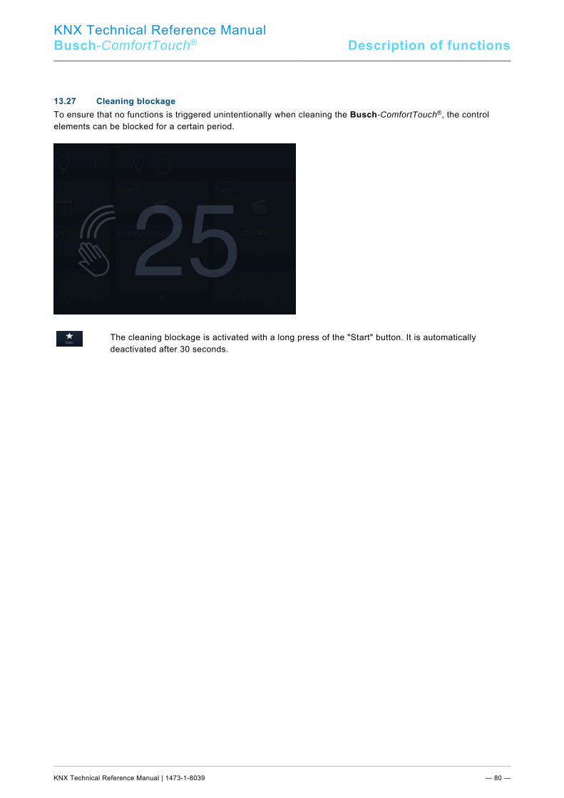
KNX Technical Reference Manual
Busch-ComfortTouch® Description of functions
KNX Technical Reference Manual | 1473-1-8039 — 80 —
Pos: 34.50.1 /Layout bis 2014-11-11/Online-Dokumentation (+KNX)/Überschriften (--> Für alle Dokumente <--)/2. Ebene/P - R/Putzsperre @ 34\mod_1361445562301_15.docx @ 281162 @ 2 @ 1
13.27 Cleaning blockage Pos: 34.50.2 /Layout bis 2014-11-11/Online-Dokumentation (+KNX)/Funktionsbeschreibungen/KNX/KNX-Aktorik/ComfortPanel 3.0/KNX Technisches Handbuch/PutzsperrePutzsperre @ 40\mod_1418644398360_15.docx @ 308978 @ @ 1
To ensure that no functions is triggered unintentionally when cleaning the Busch-ComfortTouch®, the control elements can be blocked for a certain period.
The cleaning blockage is activated with a long press of the "Start" button. It is automatically deactivated after 30 seconds.
Pos: 34.51 /Layout bis 2014-11-11/Online-Dokumentation (+KNX)/Steuermodule - Online-Dokumentation (--> Für alle Dokumente <--)/++++++++++++ Seitenumbruch ++++++++++++ @ 9\mod_1268898668093_0.docx @ 52149 @ @ 1

KNX Technical Reference Manual
Busch-ComfortTouch® Description of functions
KNX Technical Reference Manual | 1473-1-8039 — 81 —
Pos: 34.52.1 /Layout bis 2014-11-11/Online-Dokumentation (+KNX)/Überschriften (--> Für alle Dokumente <--)/2. Ebene/A - F/Datenlogger @ 34\mod_1361445705916_15.docx @ 281178 @ 2 @ 1
13.28 Data logger Pos: 34.52.2 /Layout bis 2014-11-11/Online-Dokumentation (+KNX)/Funktionsbeschreibungen/KNX/KNX-Aktorik/ComfortPanel 3.0/KNX Technisches Handbuch/DatenloggerDatenlogger @ 40\mod_1418821877689_15.docx @ 310498 @ @ 1
The data logger integrated in the Busch-ComfortTouch® can graphically display data for up to eight communication objects. If these communication objects with sensors are linked via group addresses, then the energy consumption of a house, the power of a photovoltaic system or the fill level of an oil tank can be visualised, for example.
Note The data logger can display up to 4 graphs (data points) in one view. The individual graphs can be named and colour coded. For this the legend is displayed.
The Busch-ComfortTouch® can store the values as file in a specified directory to allow the determined values to be further processed. The following storage media can be used: - SD Card - USB stick - Network
Note An SD card is recommended as a durable, non-visible storage medium in the Busch-ComfortTouch®. An automatic data export starts after 5000 events.
Pos: 34.53 /Layout bis 2014-11-11/Online-Dokumentation (+KNX)/Steuermodule - Online-Dokumentation (--> Für alle Dokumente <--)/++++++++++++ Seitenumbruch ++++++++++++ @ 9\mod_1268898668093_0.docx @ 52149 @ @ 1
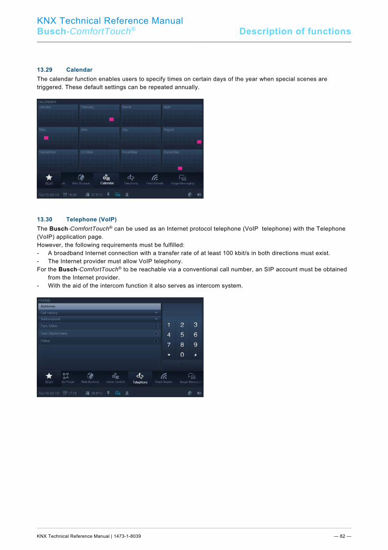
KNX Technical Reference Manual
Busch-ComfortTouch® Description of functions
KNX Technical Reference Manual | 1473-1-8039 — 82 —
Pos: 34.54.1 /Layout bis 2014-11-11/Online-Dokumentation (+KNX)/Überschriften (--> Für alle Dokumente <--)/2. Ebene/G - L/Kalender @ 34\mod_1361445798424_15.docx @ 281194 @ 2 @ 1
13.29 Calendar Pos: 34.54.2 /Layout bis 2014-11-11/Online-Dokumentation (+KNX)/Funktionsbeschreibungen/KNX/KNX-Aktorik/ComfortPanel 3.0/KNX Technisches Handbuch/Kalender/Kalender @ 33\mod_1361441586128_15.docx @ 280147 @ @ 1
The calendar function enables users to specify times on certain days of the year when special scenes are triggered. These default settings can be repeated annually.
Pos: 34.55.1 /Layout bis 2014-11-11/Online-Dokumentation (+KNX)/Überschriften (--> Für alle Dokumente <--)/2. Ebene/S - T/Telefon (VoIP) @ 34\mod_1361445872803_15.docx @ 281210 @ 2 @ 1
13.30 Telephone (VoIP) Pos: 34.55.2 /Layout bis 2014-11-11/Online-Dokumentation (+KNX)/Funktionsbeschreibungen/KNX/KNX-Aktorik/ComfortPanel 3.0/KNX Technisches Handbuch/Telefon (VoIP)/Telefon (VoIP) @ 33\mod_1361441588489_15.docx @ 280163 @ @ 1
The Busch-ComfortTouch® can be used as an Internet protocol telephone (VoIP telephone) with the Telephone (VoIP) application page. However, the following requirements must be fulfilled: - A broadband Internet connection with a transfer rate of at least 100 kbit/s in both directions must exist. - The Internet provider must allow VoIP telephony. For the Busch-ComfortTouch® to be reachable via a conventional call number, an SIP account must be obtained
from the Internet provider. - With the aid of the intercom function it also serves as intercom system.
Pos: 34.56 /Layout bis 2014-11-11/Online-Dokumentation (+KNX)/Steuermodule - Online-Dokumentation (--> Für alle Dokumente <--)/++++++++++++ Seitenumbruch ++++++++++++ @ 9\mod_1268898668093_0.docx @ 52149 @ @ 1
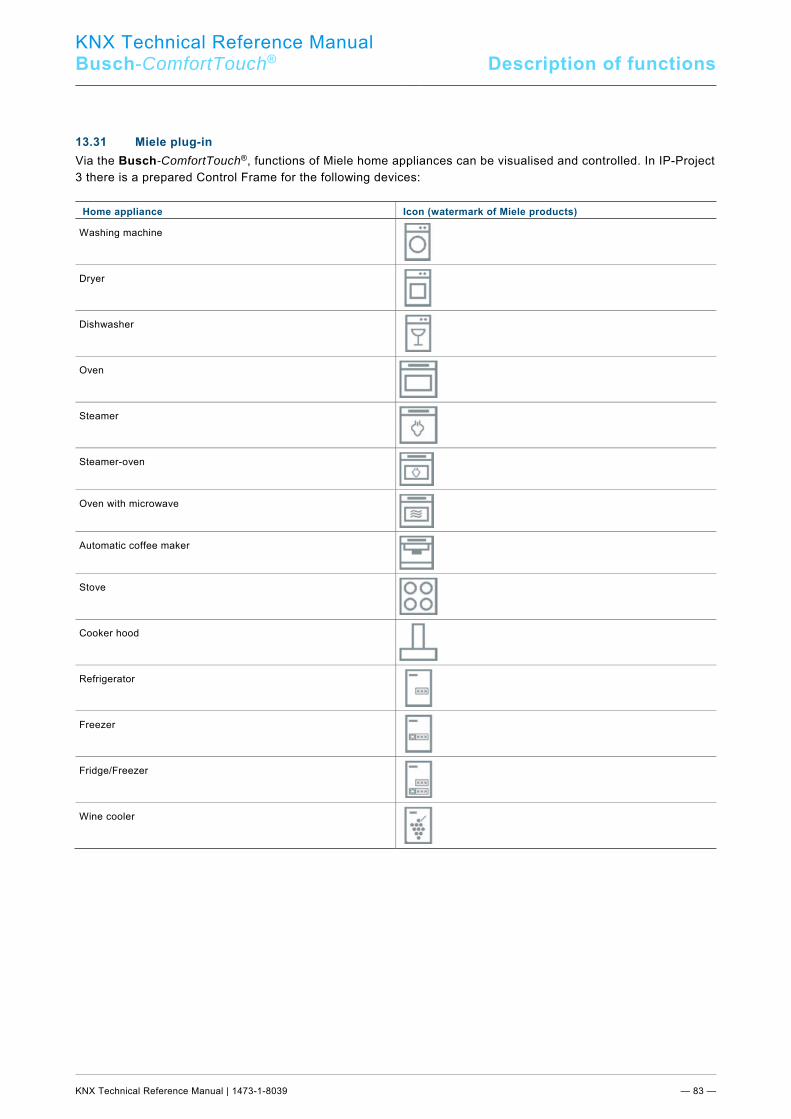
KNX Technical Reference Manual
Busch-ComfortTouch® Description of functions
KNX Technical Reference Manual | 1473-1-8039 — 83 —
Pos: 34.57.1 /Layout bis 2014-11-11/Online-Dokumentation (+KNX)/Überschriften (--> Für alle Dokumente <--)/2. Ebene/M - O/Miele Plug-In @ 34\mod_1361445952341_15.docx @ 281226 @ 2 @ 1
13.31 Miele plug-in Pos: 34.57.2 /Layout bis 2014-11-11/Online-Dokumentation (+KNX)/Funktionsbeschreibungen/KNX/KNX-Aktorik/ComfortPanel 3.0/KNX Technisches Handbuch/Miele Plug-In/Miele Plug-In @ 33\mod_1361441590475_15.docx @ 280179 @ @ 1
Via the Busch-ComfortTouch®, functions of Miele home appliances can be visualised and controlled. In IP-Project 3 there is a prepared Control Frame for the following devices:
Home appliance Icon (watermark of Miele products)
Washing machine
Dryer
Dishwasher
Oven
Steamer
Steamer-oven
Oven with microwave
Automatic coffee maker
Stove
Cooker hood
Refrigerator
Freezer
Fridge/Freezer
Wine cooler
Pos: 34.58 /Layout bis 2014-11-11/Online-Dokumentation (+KNX)/Steuermodule - Online-Dokumentation (--> Für alle Dokumente <--)/++++++++++++ Seitenumbruch ++++++++++++ @ 9\mod_1268898668093_0.docx @ 52149 @ @ 1
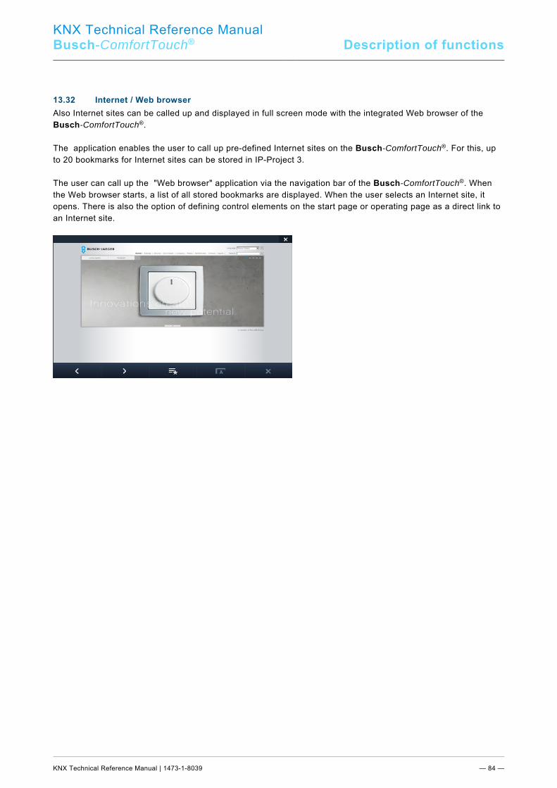
KNX Technical Reference Manual
Busch-ComfortTouch® Description of functions
KNX Technical Reference Manual | 1473-1-8039 — 84 —
Pos: 34.59.1 /Layout bis 2014-11-11/Online-Dokumentation (+KNX)/Überschriften (--> Für alle Dokumente <--)/2. Ebene/G - L/Internet- /Internet- / Web-Browser @ 34\mod_1361446144582_15.docx @ 281242 @ 2 @ 1
13.32 Internet / Web browser Pos: 34.59.2 /Layout bis 2014-11-11/Online-Dokumentation (+KNX)/Funktionsbeschreibungen/KNX/KNX-Aktorik/ComfortPanel 3.0/KNX Technisches Handbuch/Internet- / Web-Browser/Internet- /Internet- / Web-Browser @ 33\mod_1361441592908_15.docx @ 280195 @ @ 1
Also Internet sites can be called up and displayed in full screen mode with the integrated Web browser of the Busch-ComfortTouch®. The application enables the user to call up pre-defined Internet sites on the Busch-ComfortTouch®. For this, up to 20 bookmarks for Internet sites can be stored in IP-Project 3. The user can call up the "Web browser" application via the navigation bar of the Busch-ComfortTouch®. When the Web browser starts, a list of all stored bookmarks are displayed. When the user selects an Internet site, it opens. There is also the option of defining control elements on the start page or operating page as a direct link to an Internet site.
Pos: 34.60 /Layout bis 2014-11-11/Online-Dokumentation (+KNX)/Steuermodule - Online-Dokumentation (--> Für alle Dokumente <--)/++++++++++++ Seitenumbruch ++++++++++++ @ 9\mod_1268898668093_0.docx @ 52149 @ @ 1
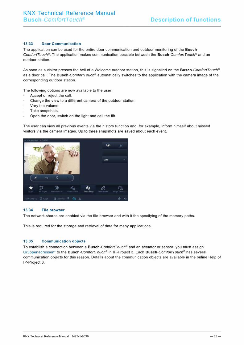
KNX Technical Reference Manual
Busch-ComfortTouch® Description of functions
KNX Technical Reference Manual | 1473-1-8039 — 85 —
Pos: 34.61.1 /Layout bis 2014-11-11/Online-Dokumentation (+KNX)/Überschriften (--> Für alle Dokumente <--)/2. Ebene/S - T/Türkommunikation @ 34\mod_1361446245132_15.docx @ 281258 @ 2 @ 1
13.33 Door Communication Pos: 34.61.2 /Layout bis 2014-11-11/Online-Dokumentation (+KNX)/Funktionsbeschreibungen/KNX/KNX-Aktorik/ComfortPanel 3.0/KNX Technisches Handbuch/TürkommunikationTürkommunikation @ 40\mod_1418645952786_15.docx @ 309012 @ @ 1
The application can be used for the entire door communication and outdoor monitoring of the Busch-ComfortTouch®. The application makes communication possible between the Busch-ComfortTouch® and an outdoor station. As soon as a visitor presses the bell of a Welcome outdoor station, this is signalled on the Busch-ComfortTouch® as a door call. The Busch-ComfortTouch® automatically switches to the application with the camera image of the corresponding outdoor station. The following options are now available to the user: - Accept or reject the call. - Change the view to a different camera of the outdoor station. - Vary the volume. - Take snapshots. - Open the door, switch on the light and call the lift. The user can view all previous events via the history function and, for example, inform himself about missed visitors via the camera images. Up to three snapshots are saved about each event.
Pos: 34.62 /Layout bis 2014-11-11/Online-Dokumentation (+KNX)/Steuermodule - Online-Dokumentation (--> Für alle Dokumente <--)/++++++++++++ Seitenumbruch ++++++++++++ @ 9\mod_1268898668093_0.docx @ 52149 @ @ 1 Pos: 34.63.1 /Layout bis 2014-11-11/Online-Dokumentation (+KNX)/Überschriften (--> Für alle Dokumente <--)/2. Ebene/A - F/Dateibrowser @ 34\mod_1361449192883_15.docx @ 281274 @ 2 @ 1
13.34 File browser Pos: 34.63.2 /Layout bis 2014-11-11/Online-Dokumentation (+KNX)/Funktionsbeschreibungen/KNX/KNX-Aktorik/ComfortPanel 3.0/KNX Technisches Handbuch/Dateibrowser/Dateibrowser @ 33\mod_1361441597381_15.docx @ 280227 @ @ 1
The network shares are enabled via the file browser and with it the specifying of the memory paths. This is required for the storage and retrieval of data for many applications. Pos: 34.64.1 /Layout bis 2014-11-11/Online-Dokumentation (+KNX)/Überschriften (--> Für alle Dokumente <--)/2. Ebene/G - L/Kommunikationsobjekte @ 19\mod_1321367301583_15.docx @ 109938 @ 2 @ 1
13.35 Communication objects Pos: 34.64.2 /Layout bis 2014-11-11/Online-Dokumentation (+KNX)/Funktionsbeschreibungen/KNX/KNX-Aktorik/ComfortPanel 3.0/KNX Technisches Handbuch/Kommunikationsobjekte/Kommunikationsobjekte @ 33\mod_1361441599480_15.docx @ 280243 @ @ 1
To establish a connection between a Busch-ComfortTouch® and an actuator or sensor, you must assign Gruppenadressen“ to the Busch-ComfortTouch® in IP-Project 3. Each Busch-ComfortTouch® has several communication objects for this reason. Details about the communication objects are available in the online Help of IP-Project 3. Pos: 34.65 /Layout bis 2014-11-11/Online-Dokumentation (+KNX)/Steuermodule - Online-Dokumentation (--> Für alle Dokumente <--)/++++++++++++ Seitenumbruch ++++++++++++ @ 9\mod_1268898668093_0.docx @ 52149 @ @ 1
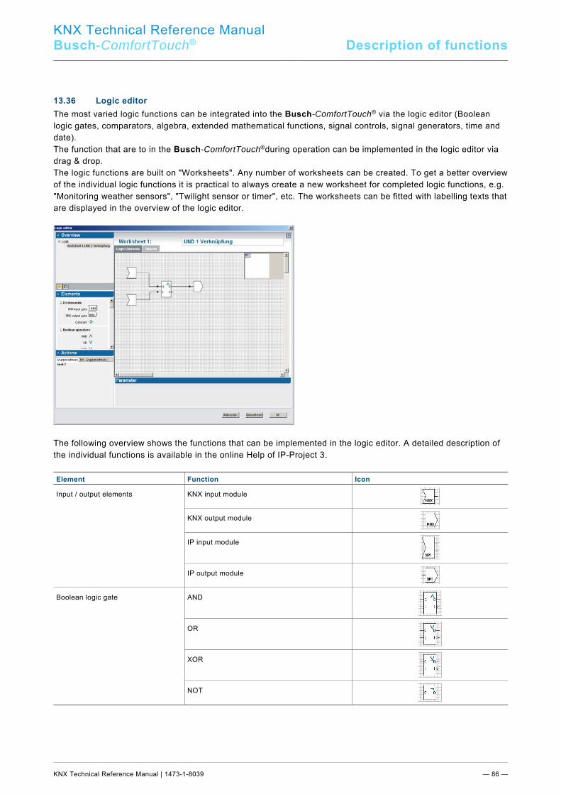
KNX Technical Reference Manual
Busch-ComfortTouch® Description of functions
KNX Technical Reference Manual | 1473-1-8039 — 86 —
Pos: 34.66.1 /Layout bis 2014-11-11/Online-Dokumentation (+KNX)/Überschriften (--> Für alle Dokumente <--)/2. Ebene/G - L/Logikeditor @ 34\mod_1361451088841_15.docx @ 281306 @ 2 @ 1
13.36 Logic editor Pos: 34.66.2 /Layout bis 2014-11-11/Online-Dokumentation (+KNX)/Funktionsbeschreibungen/KNX/KNX-Aktorik/ComfortPanel 3.0/KNX Technisches Handbuch/Logikeditor/Logikeditor @ 33\mod_1361441602520_15.docx @ 280259 @ @ 1
The most varied logic functions can be integrated into the Busch-ComfortTouch® via the logic editor (Boolean logic gates, comparators, algebra, extended mathematical functions, signal controls, signal generators, time and date). The function that are to in the Busch-ComfortTouch®during operation can be implemented in the logic editor via drag & drop. The logic functions are built on "Worksheets". Any number of worksheets can be created. To get a better overview of the individual logic functions it is practical to always create a new worksheet for completed logic functions, e.g. "Monitoring weather sensors", "Twilight sensor or timer", etc. The worksheets can be fitted with labelling texts that are displayed in the overview of the logic editor.
The following overview shows the functions that can be implemented in the logic editor. A detailed description of the individual functions is available in the online Help of IP-Project 3. Element Function Icon
Input / output elements KNX input module
KNX output module
IP input module
IP output module
Boolean logic gate AND
OR
XOR
NOT
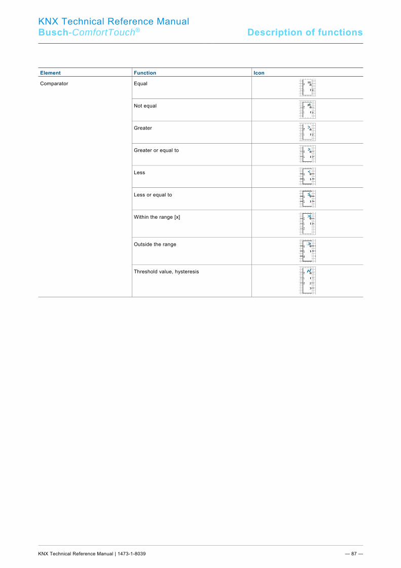
KNX Technical Reference Manual
Busch-ComfortTouch® Description of functions
KNX Technical Reference Manual | 1473-1-8039 — 87 —
Element Function Icon
Comparator Equal
Not equal
Greater
Greater or equal to
Less
Less or equal to
Within the range [x]
Outside the range
Threshold value, hysteresis
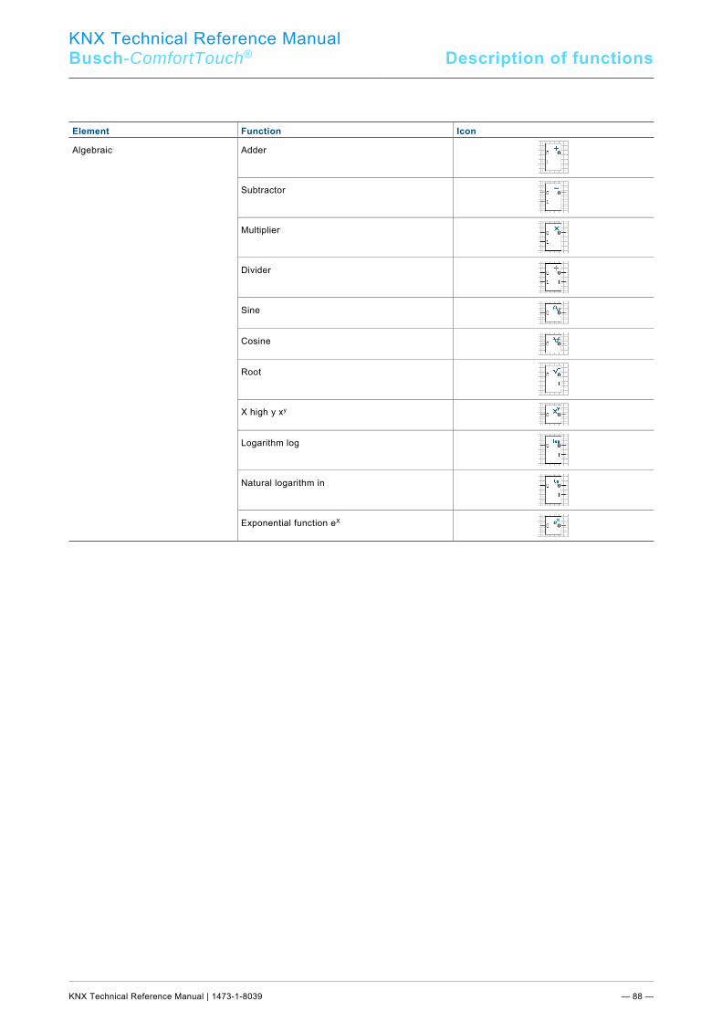
KNX Technical Reference Manual
Busch-ComfortTouch® Description of functions
KNX Technical Reference Manual | 1473-1-8039 — 88 —
Element Function Icon
Algebraic Adder
Subtractor
Multiplier
Divider
Sine
Cosine
Root
X high y xy
Logarithm log
Natural logarithm in
Exponential function eX
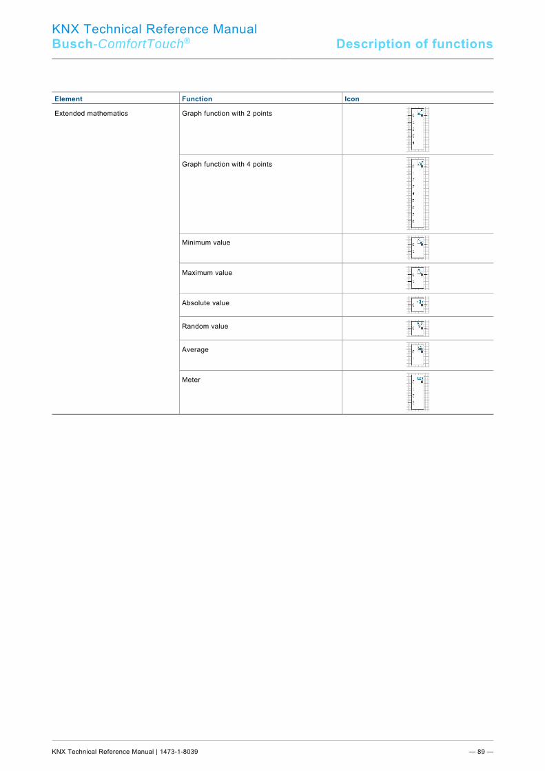
KNX Technical Reference Manual
Busch-ComfortTouch® Description of functions
KNX Technical Reference Manual | 1473-1-8039 — 89 —
Element Function Icon
Extended mathematics Graph function with 2 points
Graph function with 4 points
Minimum value
Maximum value
Absolute value
Random value
Average
Meter
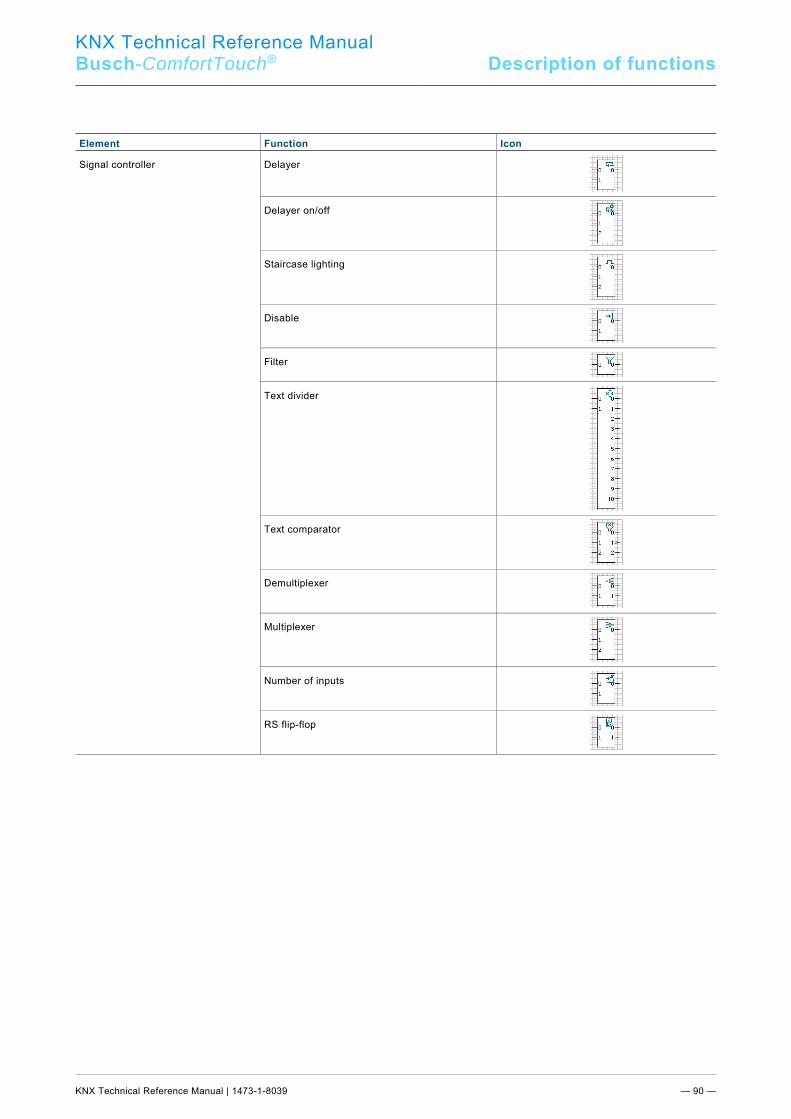
KNX Technical Reference Manual Busch-ComfortTouch® Description of functions
KNX Technical Reference Manual | 1473-1-8039 — 90 —
Element Function Icon
Signal controller Delayer
Delayer on/off
Staircase lighting
Disable
Filter
Text divider
Text comparator
Demultiplexer
Multiplexer
Number of inputs
RS flip-flop
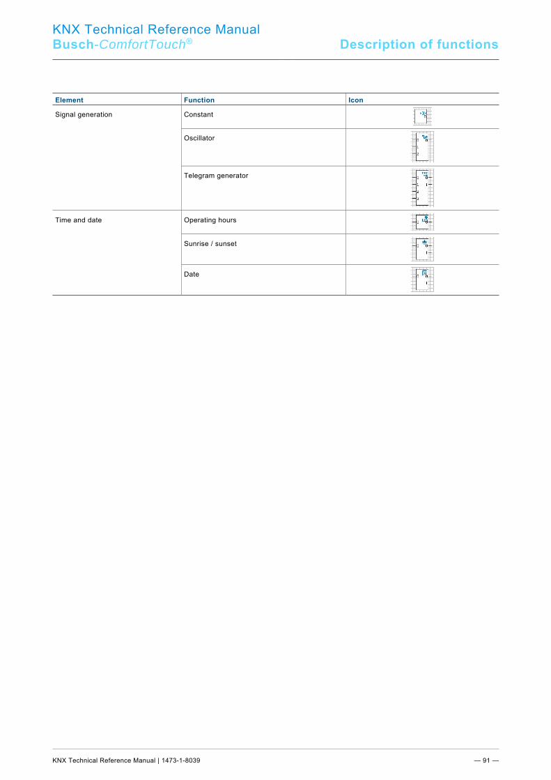
KNX Technical Reference Manual
Busch-ComfortTouch® Description of functions
KNX Technical Reference Manual | 1473-1-8039 — 91 —
Element Function Icon
Signal generation Constant
Oscillator
Telegram generator
Time and date Operating hours
Sunrise / sunset
Date
=== Ende der Liste für Textmarke Content ===
KNX Technical Reference Manual Busch-ComfortTouch®
1473
-1-8
039
| 21.
04.2
015
Pos: 36 /Layout bis 2014-11-11/Online-Dokumentation (+KNX)/Rückseiten (--> Für alle Dokumente <--)/Rückseite - BJE-Variante @ 32\mod_1357201421897_15.docx @ 262132 @ @ 1
A member of the ABB Group
Busch-Jaeger Elektro GmbH PO box 58505 Lüdenscheid
Freisenbergstraße 2 58513 Lüdenscheid Germany
www.BUSCH-JAEGER.de [email protected]
Central sales service: Phone: +49 (0) 2351 956-1600 Fax: +49 (0) 2351 956-1700
Notice
We reserve the right to at all times make
technical changes as well as changes to the
contents of this document without prior notice.
The detailed specifications agreed to at the time
of ordering apply to all orders. ABB accepts no
responsibility for possible errors or
incompleteness in this document.
We reserve all rights to this document and the
topics and illustrations contained therein. The
document and its contents, or extracts thereof,
must not be reproduced, transmitted or reused by
third parties without prior written consent by ABB.
Copyright© 2015 Busch-Jaeger Elektro GmbH
All rights reserved
=== Ende der Liste für Textmarke Backcover ===