Embed Size (px)
Citation preview

1
1/4 scale “Aeronca Champ” ARF
Wingspan: 105 in. (2667mm) Length: 65 in. (1651mm) Wing Area: 1542 in². (995dm²) Weight RTF (electric): 15.5 lbs. (7kg)

2

3
Introduction & History
The full-scale Aeronca Champion, or “Champ,” was manufactured by the Aeronca Aircraft Corporation, in Middletown, Ohio between 1944 and 1951. Over 10,000 were built. In 1946, it was marketed as “the newest in aerodynamic design! . . . It’s the easiest plane you’ve ever flown. ” Like the Piper Cub with which it competed, the Champ also featured tandem seating. While the Piper Cub is soloed from the rear seat, the Champ can be soloed from the front seat, giving improved forward visibility on the ground, and during takeoffs, climbs, landings. Although the Aeronca Champ has a wider cabin than the Piper Cub, the Champ’s cruise speed was about 15mph faster. Its Continental 65hp engine powered it to a top speed of 100 mph.
Pilot-1 is pleased to announce the 1/4 scale Aeronca Champ as part of the Golden Age Civilian Series. The Pilot-1 “Champ” encompasses the same attributes in quality construction and handling that made the original Aeronca Champ a favorite for over 50 years. Our engineers have spent countless hours developing a true-to-scale ARF that looks and flies like the full-scale Champ. We know you will be pleased with its scale looks and balanced maneuverability. In fact, our local model airplane pilots formed a line so they each could get a chance to fly the prototype. All agree, for scale aircraft, it may very well be the “easiest plane you’ve ever flown!”
Hobby Lobby International, Inc. 5614 Franklin Pike Circle
Brentwood, TN 37027 1-866-WE-FLY-RC (1-866-933-5972)
www.hobby-lobby.com

4
Before starting, use the Contents list to take an inventory and make sure it is complete.
If any parts are missing or are not of acceptable quality, contact Hobby-Lobby.com
Support at 1-866-WE-FLY-RC (1-866-933-5972)
Contents List
Fuselage Battery Hatch Engine Cowl Landing Gear Wheels, Velcro, Misc Hardware packages Wings Wing Center Section Tube Wing Joiners Wing Struts and Wing Jury Struts Horizontal Tail Vertical Tail Pushrods
Additional Items Required (electric version)
4-channel Aircraft Radio w/ Receiver (minimum) (2) 6000mah, 4-cell, 14.8v LiPo batteries (4) Hitec HS-635HB servos (or equivalent) Duralite 6v Voltage Regulator and LiPo Receiver Battery 77 amp Jeti SPIN Brushless ESC Jeti SPIN Box Programmer AXI 5320/28 Brushless Motor AMM111 Aluminum Motor Mount Kit APC 20x12W “E” Propeller 5-minute Epoxy Glue Thin CA Glue Small Phillips screwdriver Needle Nose Pliers Hobby Knife Soldering Iron and Electrical Solder

5
1. Locate the aileron assembly bag for the next few steps.
2. Use your radio or our Manual Servo Adjuster (p/n MSA725) to make sure the aileron servo is centered. Install the servo arm 90º to the servo and in the center of the slot as shown.
3. Prepare servo attachment blocks for gluing. Some trimming may be necessary.
4. While holding servo on plate, use 5min Epoxy to glue blocks in place. Once dry, drill (4) pilot holes in the wood blocks, then use servo screws and rubber grommets to secure servo in place.
6
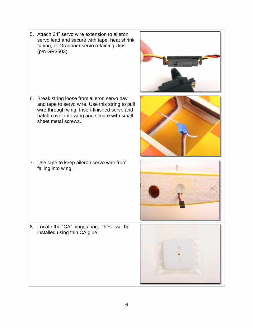
5. Attach 24” servo wire extension to aileron servo lead and secure with tape, heat shrink tubing, or Graupner servo retaining clips (p/n GR3503).
6. Break string loose from aileron servo bay and tape to servo wire. Use this string to pull wire through wing. Insert finished servo and hatch cover into wing and secure with small sheet metal screws.
7. Use tape to keep aileron servo wire from falling into wing.
8. Locate the “CA” hinges bag. These will be installed using thin CA glue.

7
9. Prepare the CA hinges by folding in half as shown. This technique helps keep the hinges centered during installation.
10. Trial fit aileron in place before gluing. Careful attention should be placed on gaps at ends of aileron.
11. With the aileron tight and deflected downward, use 2 to 3 drops per hinge of thin CA to assure strong bonds. Use paper towel to remove any excess CA before it dries. Then flip wing over and repeat for opposite side of hinge, again 2-3 drops of thin CA per hinge.
12. The Aileron Horn needs a hole to be drilled through the aileron. Use a pen and straight edge to mark aileron parallel to the hatch cover slot.

8
13. Use aileron horn washer as a guide to how far back on aileron to drill. Mark center on washer with pen.
14. Drill a 1/8” hole through wing. Take special care to keep drill straight.
15. Install washer on screw, then insert through aileron. Then insert another washer, tapered nut, and nylon horn as shown. Tighten snug but do not crush wood.
16. Install aileron pushrod, nut, clevis, and clevis safety tubing as shown. With servo centered, adjust pushrod length to level aileron.

9
17. Repeat for opposite wing panel.
18. Install the Elevator servo. The servo is centered and control horn should be installed as shown.
19. Prepare the Elevator pushrod for installation.
20. Insert elevator pushrod through front of plane making sure to position it below bulkhead horizontal braces.

10
21. Insert pushrod into hole at rear of fuselage. This photo is looking aft inside fuselage.
22. Install aluminum cross piece and sight through hole for alignment.
23. Use masking tape to hold cap screw on ball driver. Insert screw through hole in bottom of fuselage.
24. Apply a small drop of CA or blue locktite to hold screw in place.

11
25. Locate the Rudder pull-pull and control horn bag.
26. Cut the rudder pull-pull cable into two (2) pieces. Then install rudder pull-pull cable as shown and crimp with pliers.
27. Install the rudder servo and pull leads thru fuselage with small piece of music wire or straightened coat hanger wire. Use tape to hold cables at aft end of fuselage.
28. Install Elevator CA hinges using the same technique as the ailerons. Trial fit then use 2-3 drops thin CA per hinge per side.
12
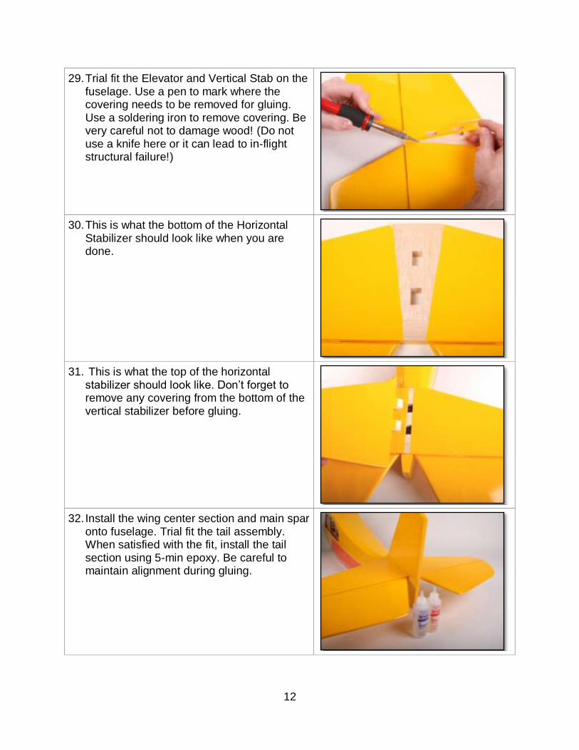
29. Trial fit the Elevator and Vertical Stab on the fuselage. Use a pen to mark where the covering needs to be removed for gluing. Use a soldering iron to remove covering. Be very careful not to damage wood! (Do not use a knife here or it can lead to in-flight structural failure!)
30. This is what the bottom of the Horizontal Stabilizer should look like when you are done.
31. This is what the top of the horizontal stabilizer should look like. Don’t forget to remove any covering from the bottom of the vertical stabilizer before gluing.
32. Install the wing center section and main spar onto fuselage. Trial fit the tail assembly. When satisfied with the fit, install the tail section using 5-min epoxy. Be careful to maintain alignment during gluing.

13
33. Keep the horizontal stabilizer and wing spar parallel. Also keep the vertical stabilizer 90 degrees to the horizontal stabilizer. Hold in place until glue sets (about 5min). Slight misalignment can be corrected with the tail brace wires.
34. Locate the tailwheel assembly bag.
35. Assemble tailwheel as shown. Add a drop of light oil to aluminum bracket and wire. Then use 5min Epoxy to glue tailwheel post into rudder. Make sure it is completely flush with leading edge of rudder.
36. Test fit the Rudder to the vertical stabilizer. Move rudder up or down to adjust gap as shown, approximately 1/16” (2mm).

14
37. Move rudder to full deflection and use 2-3 drops of thin CA per hinge. Then repeat for opposite side of hinge.
38. Drill small pilot holes in tailwheel bracket and install three (3) sheet metal screws. Test rudder to make sure it moves easily.
39. Use masking tape to hold rudder in center for installing pull-pull cable. Also, the radio should also be on or use a servo position adjuster to hold the rudder servo straight.
40. Install control horn and assemble as shown on both sides of rudder. Make sure rudder and servo are centered. Lightly pull slack from cable. Then crimp aluminum tubes as shown. .Remove tape from rudder. Cables should be tightened enough to remove any slop in the rudder system. Do not over tighten!

15
41. Locate the Elevator control system bag.
42. Install control horns and pushrods as shown. Make sure to use locknuts on pushrods.
43. Center the elevator servo. Adjust pushrods so that each elevator half is level.
44. Locate the tail brace assembly pack for the next few steps.

16
45. Start by cutting the cable into four equal lengths. Then assemble as shown on one (1) end of each cable. Position clevis about half way out on threaded coupler. Note how the wire is looped twice through the crimp for safety. Use needle nose pliers to crimp the aluminum tube.
46. Install the brackets with machine screws and nuts. Install clevis with wire as shown.
47. Install the brackets with machine screws and nuts. Assemble unfinished wire end as shown, pull slack out of wire, and crimp aluminum tube with pliers.
48. The finished tail brace wires should look like this.

17
49. Another photo of the completed lower tail brace wire and bracket.
50. Locate the landing gear assembly bag.
51. Use aluminum brackets as a guide and drill 1/16” (1.5mm) pilot holes as shown.
52. Install screws for landing gear straps. Do not install wheels until later to keep plane more stable during building.

18
53. Assemble your power system per manufacturer’s instructions. This is the recommended setup below. Install a 6” servo extension to the throttle control lead of the ESC (black connector for Jeti SPIN) and wrap connector with tape or heat shrink tubing.
54. Solder a Deans Series connector onto speed control and cover exposed solder joints with PFM or Clear Silicon.
55. Connect the wires as shown for the stock setup. This allows motor to turn correct direction.
56. Prepare to install the motor, ESC, and aluminum standoffs. For the standard setup, use the 1” (25mm) spacers and the 1-1/2” (40mm) Cap head screws, lock washers, and large washers as shown.

19
57. Use small drop of blue locktite on each bolt and tighten. Make sure the bolts do not extend too far into motor case. See motor installation manual for more information.
58. Drill pilot holes and install the ESC with small sheet metal screws on the bottom of the motor mount.
59. Install the motor mount with the open side facing up. Route ESC wires through the firewall.
60. Locate the two pieces of Velcro and trial fit them like this. These will be used to hold batteries in place. You may also want to add a second strap of your own.

20
61. Install battery hold down Velcro through precut holes in battery tray.
62. Install LiPo flight batteries and secure with Velcro strap. Also attach Deans Series Plug on the back of the firewall as shown using PFM glue or similar.
63. Assemble your receiver power system as needed. Here we used a 2000mah Duralite LiPo battery and Duralite Regulator with switch. Install in plane and secure components with Velcro or Velcro straps.
64. Notice how the receiver battery lead is constructed using a spare 6” heavy duty servo extension and Deans Ultra plug soldered together. Use extra long heat shrink tubing to support the solder joint. You will charge through the Deans Ultra plug. The servo lead goes to our regulator/switch which then powers the receiver.

21
65. Install electronics. Note the Velcro strap holding the LiPo receiver battery in place. It also has foam and Velcro under it for vibration damping. .
66. Trial fit each window. It may be necessary to
trim the edges slightly for better fit. Use Canopy Glue (p/n DMSP2) to install all windows. Clean up with water and paper towel before it dries.
67. Install the rear windows by starting in large hole above rudder servo and working it aft. You will have to bow the window slightly to fit.
68. Using the same technique, install front side windows as shown.

22
69. Use blue masking tape to hold windows in place while glue dries overnight.
70. Use clear tape to secure aileron servo wire extensions as shown. (leading edge is up) This will help keep wires from showing through side windows.
71. Plug aileron servo extensions into receiver and install wing center section with nylon wing bolts.
72. Use template from this manual to cut out instrument panel and dash cover from standard sandpaper sheet. We used black but original Champ would have been dark brown. Attach with contact cement or UHUpor (p/n GR959).

23
73. Install windshield with canopy glue and use blue painters tape to hold in position overnight while glue dries. You may want to paint edge of canopy for more scale effect.
74. Locate the cowling attachment blocks and sheet metal screws.
75. Install three (3) wood cowling attachment blocks with 5min Epoxy as shown on top and each side of cowl. Note the tapered side faces toward the motor mount.
76. Cut strips of paper and tape in place as shown on each of the cowling attachment blocks. Mark the center of the blocks.

24
77. Slide the cowl in place with paper guide strips on the outside of cowl. Adjust the cowl so there is about 1/4” (6mm) clearance behind the prop flange. Center the cowl as shown and temporarily tape in place. Recheck alignment.
78. Paper alignment tool should now help you drill the cowling attachment screw holes perfectly.
79. Drill three (3) small pilot holes through cowl and cowl attachment blocks.
80. Use reaming tool (p/n MT3417) or slightly larger drill bit to enlarge the hole in the cowling only! This helps the cowl from splitting when the screw goes through it.

25
81. Repeat for the side cowling mount holes and install small sheet metal screws.
82. You may need to trim the bottom of the cowl and install an air outlet depending on the motor used. We trimmed ours with a Dremel tool with a 1/2” sanding drum. Air outlet area should be about 150% of inlet area.
83. Install APC 20x12W propeller for standard electric setup. Tighten nut with 3/4” wrench to secure prop tightly.
84. You may also elect to run a wood prop for scale effect. Again, tighten really tight.

26
85. Locate the Wing attachment assembly bag.
86. And the bag that has the large area washers.
87. Install the long wing attachment screws with large area washers. The wing has internal blind nuts. (Note: The aluminum brackets on the center section do not have threads).
88. Locate the wing jury strut parts as shown and the short aluminum tubes as well.
WWiinngg SSccrreewwss

27
89. Trial fit all the jury strut parts as shown here.
90. Install the main wing struts with the longer screws. Also install the jury struts as shown. Note that the jury strut top “L” bracket points toward the wing tip.
91. Install the Wing strut countersunk screws in the end of the struts.
92. Here is another photo of the completed jury strut assembly.
Install Screws

28
93. Use a 90 degree square to adjust vertical alignment of jury struts..
94. With the radio on and all trims centered, adjust pushrods to make elevator level with the horizontal stabilizer. (*Safety Note: Do not plug in motor flight packs while adjusting radio programming to prevent injury in case the throttle is moved by accident.)
95. Apply full UP elevator and adjust either mechanically or in radio programming to get 1-3/4” (45mm) travel measured at the trailing edge. Also use 35% exponential to soften the center travel (consult your radio manual for how to do this). We recommend a “low rate” setting of 1” (25mm) travel and 20% exponential.
96. Apply full down elevator and adjust for 1-3/4” (45mm) travel down and 35% Expo. “Low rate” is 1” (25mm) and 20% expo.

29
97. With the radio on and all trims centered, adjust pull-pull cable to center Rudder.
98. Apply full RIGHT rudder and adjust either mechanically or in radio programming to get 2” (50mm) travel measured at the trailing edge. Also use 35% exponential to soften the center travel (consult your radio manual for how to do this). We recommend a “low rate” setting of 3/4” (20mm) travel and 20% exponential.
99. Apply full LEFT rudder and adjust for 2” (50mm) travel and 35% expo. “Low rate” is 3/4” (20mm) and 20% expo.
100. With the radio on and all trims centered, adjust pushrods to make ailerons level with the fixed inboard trailing edge of the wing.

30
101. (For this right aileron photo only!) Apply full RIGHT aileron stick and adjust either mechanically or in radio programming to get 1-3/4” (45mm) travel measured at the trailing edge. Also use 35% exponential to soften the center travel (consult your radio manual for how to do this). We recommend a “low rate” setting of 1” (25mm) travel and 20% exponential
102. (For this right aileron photo only!) Apply full LEFT aileron stick and adjust for 1/2" (12mm) travel down and 35% Expo. “Low rate” is 1/4” (6mm) and 20% expo. Repeat for opposite wing.
103. Adjust Flight Batteries and/or Equipment so that plane balances on Center of Gravity. The CG is located at 4” (100mm) aft of the Wing leading edge.
CG = 4” (100mm)

31
Use this pattern to cut out instrument panel background from standard sandpaper sheet.
The original Champ panel was dark brown.

32
Use this pattern to cut out dash cover from standard sandpaper for increased scale effect. The original Champ dash was dark
brown.

33
Preflight If you are new to flying R/C aircraft, or a seasoned modeler, we recommend you have a fellow R/C modeler help you with the first flight. Some items you will need to complete on your first preflight are:
1. Aircraft assembled correctly and ready for flight. 2. All control throws and expos are set per this manual. 3. Transmitter fully charged and on correct model. 4. Aircraft balances at the recommended location. (4” aft of wing Leading Edge) 5. Flight Battery is fully charged and secure. 6. All electronics are operating correctly, proper direction, and secure. 7. Complete a radio Range Check per your radio manual. 8. Balance propeller and make sure it is secure. 9. Wait for a calm or light wind day for first flights. 10. If you are new to R/C flying, consider having an accomplished flyer make the first
flight and trim the aircraft. A buddy-box training system is also very helpful.
Flying You will soon find out the Pilot-1 Champ is a real pleasure to fly. Takeoffs, landings, and scale aerobatics are easy and well behaved. Even if you have never flown a tailwheel airplane before, the Pilot-1 Champ should be an easy transition. Landings are best accomplished by “three-pointing.” This means that all three wheels should touch at the same time and a little up-elevator is held until the aircraft comes to a complete stop. Except for takeoff and climb, you will only use about 1/2 throttle to maintain a scale flying speed. You can expect flight times of 15+ minutes depending on battery used and throttle management. We hope you enjoy your Pilot-1 Champ as much as we do! Happy Landings!
WARNING – THIS IS NOT A TOY!
Radio controlled model aircraft are capable of inflicting serious injury and/or property damage if not assembled, operated, and maintained in a competent and safe manner. If you are not already experienced with radio controlled models, we strongly suggest
that you find an experienced modeler to assist you.
Warranty
Hobby-Lobby guarantees this kit to be free from defects in both material and workmanship at the date of purchase. This warranty does not cover any component parts damaged by use or modification. In no event shall Hobby-Lobby’s liability exceed the original
cost of the purchased kit.
Completely read through this manual before starting construction.

34
2008 Official Academy of Model Aeronautics National Model Aircraft Safety Code
GENERAL
1. A model aircraft shall be defined as a non-human-carrying device capable of sustained flight in the atmosphere. It shall not exceed limitations established in this code and is intended to be used exclusively for recreational or competition activity.
2. The maximum takeoff weight of a model aircraft, including fuel, is 55 pounds, except for those flown under the AMA Experimental Aircraft Rules.
3. I will abide by this Safety Code and all rules established for the flying site I use. I will not willfully fly my model aircraft in a reckless and/or dangerous manner.
4. I will not fly my model aircraft in sanctioned events, air shows, or model demonstrations until it has been proven airworthy.
5. I will not fly my model aircraft higher than approximately 400 feet above ground level, when within three (3) miles of an airport without notifying the airport operator. I will yield the right-of-way and avoid flying in the proximity of full-scale aircraft, utilizing a spotter when appropriate.
6. I will not fly my model aircraft unless it is identified with my name and address, or AMA number, inside or affixed to the outside of the model aircraft. This does not apply to model aircraft flown indoors.
7. I will not operate model aircraft with metal-blade propellers or with gaseous boosts (other than air), nor will I operate model aircraft with fuels containing tetranitromethane or hydrazine.
8. I will not operate model aircraft carrying pyrotechnic devices which explode burn, or propel a projectile of any kind. Exceptions include Free Flight fuses or devices that burn producing smoke and are securely attached to the model aircraft during flight. Rocket motors up to a G-series size may be used, provided they remain firmly attached to the model aircraft during flight. Model rockets may be flown in accordance with the National Model Rocketry Safety Code; however, they may not be launched from model aircraft. Officially designated AMA Air Show Teams (AST) are authorized to use devices and practices as defined within the Air Show Advisory Committee Document.
9. I will not operate my model aircraft while under the influence of alcohol or within eight (8) hours of having consumed alcohol.
10. I will not operate my model aircraft while using any drug which could adversely affect my ability to safely control my model aircraft.
11. Children under six (6) years old are only allowed on a flightline or in a flight area as a pilot or while under flight instruction.
12. When and where required by rule, helmets must be properly worn and fastened. They must be OSHA, DOT, ANSI, SNELL or NOCSAE approved or comply with comparable standards.
RADIO CONTROL
1. All model flying shall be conducted in a manner to avoid over flight of unprotected people. 2. I will have completed a successful radio equipment ground-range check before the first flight of a
new or repaired model aircraft. 3. I will not fly my model aircraft in the presence of spectators until I become a proficient flier, unless
I am assisted by an experienced pilot. 4. At all flying sites a line must be established, in front of which all flying takes place. Only personnel
associated with flying the model aircraft are allowed at or in front of the line. In the case of airshows demonstrations straight line must be established. An area away from the line must be maintained for spectators. Intentional flying behind the line is prohibited.
5. I will operate my model aircraft using only radio-control frequencies currently allowed by the Federal Communications Commission (FCC). Only individuals properly licensed by the FCC are authorized to operate equipment on Amateur Band frequencies.
6. I will not knowingly operate my model aircraft within three (3) miles of any preexisting flying site without a frequency-management agreement. A frequency management agreement may be an
(continued)

35
allocation of frequencies for each site, a day-use agreement between sites, or testing which determines that no interference exists. A frequency-management agreement may exist between two or more AMA chartered clubs, AMA clubs and individual AMA members, or individual AMA members. Frequency-management agreements, including an interference test report if the agreement indicates no interference exists, will be signed by all parties and copies provided to AMA Headquarters.
7. With the exception of events flown under official AMA rules, no powered model may be flown outdoors closer than 25 feet to any individual, except for the pilot and located at the flightline.
8. Under no circumstances may a pilot or other person touch a model aircraft in flight while it is still under power, except to divert it from striking an individual.
9. Radio-controlled night flying is limited to low-performance model aircraft (less than 100 mph). The model aircraft must be equipped with a lighting system which clearly defines the aircraft's attitude and direction at all times.
10. The operator of a radio-controlled model aircraft shall control it during the entire flight, maintaining visual contact without enhancement other than by corrective lenses that are prescribed for the pilot. No model aircraft shall be equipped with devices which allow it to be flown to a selected location which is beyond the visual range of the pilot.
PARK FLYER SAFE OPERATING RECOMMENDATIONS
Inspect your model before every flight to make certain it is airworthy.
Be aware of any other radio frequency user who may present an interference problem.
Always be courteous and respectful of other users of your selected flight area.
Choose an area clear of obstacles and large enough to safely accommodate your flying activity.
Make certain this area is clear of friends and spectators prior to launching your aircraft.
Be aware of other activities in the vicinity of your flight path that could cause potential conflict.
Carefully plan your flight path prior to launch.
Abide by any and all established AMA National Model Aircraft Safety Code.

36
Hobby Lobby International, Inc. 5614 Franklin Pike Circle
Brentwood, TN 37027
1-866-WE-FLY-RC (1-866-933-5972)
www.hobby-lobby.com