Embed Size (px)
Citation preview

1324/1624/1824 owners manual.doc 6/4/08 Page 1 of 64
THE
MODELS 1324 & 1624 & 1824 HYDRAULIC TRENCHERS
CONGRATULATIONS!
You are now the proud owner of a BARRETO trencher. Please take a moment of your time to
look over the following information. Familiarize yourself with the trencher, its characteristics,
and method of operation. Pay particular attention to the safety and operating instructions.
If you have any questions or need any replacement parts in the future, please contact us at your
convenience. Our toll-free phone number, fax and email are listed below.
THANK YOU for your patronage and confidence in BARRETO equipment.
Barreto Manufacturing, Inc.
Innovative Equipment Engineered to Last
66498 Hwy 203, La Grande, OR 97850
(800) 525-7348 (541) 963-7348
FAX (541) 963-6755
E-Mail: [email protected]
Web Site: http://www.barretomfg.com
Page 2 of 64 6/4/08 1324/1624/1824 owners manual.doc
ASSEMBLY INSTRUCTIONS
1. Remove trencher from shipping crate.
2. Install boom onto boom pivot/mount with the 7/8" wide wear strip on bottom side of
boom. Push boom on as far as it will go. Be sure adjuster screw is backed out.
SERVICE INFORMATION
1. Check reservoir level using sight glass on the left side of the tank. If required, add to
reservoir with tractor transmission hydraulic oil. (Shell DONAX TD FLUID or
comparable). The tank holds approximately 15 gallons of hydraulic oil. Recheck oil
level after the trencher has been run and oil has been circulated through the wheel and
chain motors. Routinely check level thereafter. DO NOT OVERFILL THE TANK.
2. Change hydraulic oil filter after the first 50 hours of use. Change it every 200 hours
thereafter.
3. Add 1 quart of hydraulic oil to reservoir with each filter change.
4. Check all hydraulic fittings for leaks and tighten if necessary.
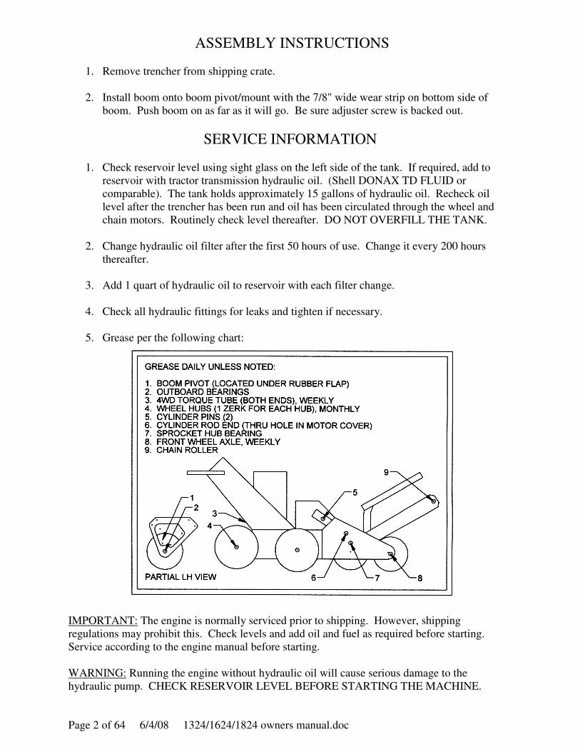
5. Grease per the following chart:
IMPORTANT: The engine is normally serviced prior to shipping. However, shipping
regulations may prohibit this. Check levels and add oil and fuel as required before starting.
Service according to the engine manual before starting.
WARNING: Running the engine without hydraulic oil will cause serious damage to the
hydraulic pump. CHECK RESERVOIR LEVEL BEFORE STARTING THE MACHINE.

1324/1624/1824 owners manual.doc 6/4/08 Page 3 of 64
DIGGING CHAIN INSTALLATION
1. Slide digging chain under sprocket, with teeth in the correct cutting direction. Properly
installed, the cutting edges of the chain will face forward on the top of the boom and
rearward on the bottom of the boom (see diagram below).
2. Start engine. Push digging boom control lever forward to lower boom onto the chain.
Shut off engine.
3. Wrap chain around boom and sprocket. Install chain master link or link pin.
4. Use boom adjuster screw to tighten chain. Chain should have enough slack to allow
approximately 2" of space between middle of boom and chain when boom and chain are
straight out in a horizontal position.
5. Tighten adjuster screw locknut and 4 boom mounting bolts.
Forward Cutting edge
Cutting edge Rearward
Page 4 of 64 6/4/08 1324/1624/1824 owners manual.doc
BARRETO TRENCHER OPERATING INSTRUCTIONS
READ SAFETY INSTRUCTIONS BEFORE OPERATING!
Be sure that the engine oil, fuel and hydraulic oil are at proper levels before starting the engine.
STUDY AND UNDERSTAND CONTROLS BEFORE BEGINNING
OPERATION.
1. IGNITION: Must be in “ON” position to start. “OFF” to stop.
2. ENGINE: This is the throttle. It controls engine speed. Operate at full throttle (all the way
forward).
3. CLUTCH LEVER: (At left handle grip). Activates GROUND SPEED and DIGGING
CHAIN controls when pulled up. Stops all motion when released. DIGGING CHAIN
control must be HELD in “ON” position as clutch lever is depressed in order to start chain in
motion.
4. AXLE: “UNLOCK” position (down) is for maneuvering. “LOCK” position (up) is for
digging. UNLOCK allows left wheel to freewheel while right wheel drives.
5. DIGGING BOOM: Raises and lowers the digging boom.
6. DIGGING CHAIN: Starts chain in forward rotation after clutch lever is engaged.
7. CHAIN: Allows manual operation of chain in forward or reverse rotation to dislodge objects
or dig difficult terrain. (This control can be used with the Clutch Lever released.) To reverse
chain, DIGGING CHAIN control must be in “OFF” position.
8. GROUND SPEED: Controls wheel speed forward or reverse after clutch lever is engaged.
9. GETTING STARTED: Start and warm up engine. Drive trencher to starting location with
AXLE in “UNLOCK” position.
LOCK AXLE. Hold DIGGING CHAIN control in “ON” position. With GROUND SPEED
control in neutral, pull up CLUTCH LEVER and slowly lower DIGGING BOOM to desired
depth. Slowly move GROUND SPEED control in REVERSE direction until desired speed is
reached. (Varying soil conditions may require adjustments to ground speed to avoid wheel
spin or engine overload.)
10. FOR HARD TO DIG AREAS or if object (rock or root) gets lodged in chain, release
CLUTCH LEVER. This will lock wheels in position. Manually reverse chain with the CHAIN
control to dislodge object. Manually run chain forward with CHAIN control to dig through roots
or rocky areas. Intermittently activate CLUTCH LEVER to move trencher back a few inches
and repeat until hard area is passed. Resume normal operation.
ALWAYS THOROUGHLY CLEAN AND SERVICE TRENCHER AFTER EACH USE.
1324/1624/1824 owners manual.doc 6/4/08 Page 5 of 64
BARRETO HYDRAULIC TRENCHER
SAFETY INSTRUCTIONS
• READ SAFETY AND OPERATING INSTRUCTIONS BEFORE
OPERATING!
• Do not leave trencher unattended with the engine running.
• No parking brake. Always leave trencher parked on a level surface.
• The SAFETY CLUTCH lever on the left handlebar is for operator
protection. DO NOT TAPE DOWN OR OTHERWISE BY-PASS THIS
CLUTCH.
• Objects may become airborne while operating trencher. Wear safety
goggles and hard hat while operating or observing!
• Digging chain, auger and other moving parts can cut off arms, legs, or
fingers. STAY CLEAR!
• Buried cables or gas lines can cause serious injury or death. Contact local
agencies for location.
• Exhaust and fuel fumes can cause illness or death. Operate outdoors and
avoid breathing exhaust and fumes.
• Fuel fumes can catch fire or explode. Do not smoke or operate near flames
or sparks.
• Hydraulic oil is under extreme pressure and can get under skin and burn or
poison. Check for leaks with cardboard.
• Muffler and engine get hot enough to cause serious burns. Do not touch
until cool.

Page 6 of 64 6/4/08 1324/1624/1824 owners manual.doc
BARRETO MANUFACTURING, INC.
EQUIPMENT WARRANTY
Barreto Manufacturing, Inc. warrants all BARRETO equipment to free of defects
in material and workmanship for a period of one (1) year, dating from the delivery
to the original user.
This warranty is in lieu of all other warranties, whether written or implied, and is
limited to:
1. Replacement of parts returned to the dealer and/or factory and
determined defective upon inspection. (Replacement for parts to dealers
shall be at dealer cost plus shipping charges.)
2. Time for pick-up and/or delivery, transportation of service calls by
dealers is excluded. Manufacturer reserves the right to determine
reasonable time required for repair.
Warranty does not apply to damage caused by abuse or neglect. Time and
materials required for normal maintenance and service are also excluded from
warranty coverage.
Engines, engine accessories and tires are warranted by the original manufactures
and are not covered by the Barreto Equipment Warranty.
1324/1624/1824 owners manual.doc 6/4/08 Page 7 of 64
THE
MODELS 1324 & 1624 & 1824
HYDRAULIC TRENCHER
CONTROL ADJUSTMENT INSTRUCTIONS
The following pages contain instructions for:
• WHEEL DRIVE CLUTCH CABLE ADJUSTMENT (Illustration A)
• DIGGING CHAIN VALVE LEVER ADJUSTMENT (Illustration B)
• AXLE LOCK ADJUSTMENT (Illustration C)
• SPEED CABLE ADJUSTMENT (Illustration D)
• SPEED LINKAGE ADJUSTMENT (Illustration E)
• SPEED CONTROL LINKAGE DIG SPEED ADJUSTMENT (Illustration F)
Page 8 of 64 6/4/08 1324/1624/1824 owners manual.doc
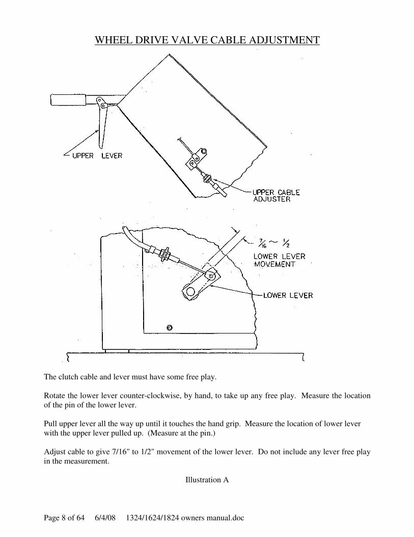
WHEEL DRIVE VALVE CABLE ADJUSTMENT
The clutch cable and lever must have some free play.
Rotate the lower lever counter-clockwise, by hand, to take up any free play. Measure the location
of the pin of the lower lever.
Pull upper lever all the way up until it touches the hand grip. Measure the location of lower lever
with the upper lever pulled up. (Measure at the pin.)
Adjust cable to give 7/16" to 1/2" movement of the lower lever. Do not include any lever free play
in the measurement.
Illustration A
1324/1624/1824 owners manual.doc 6/4/08 Page 9 of 64
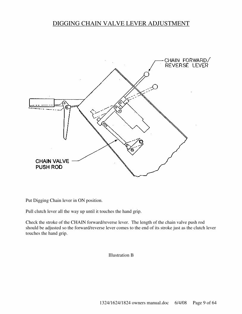
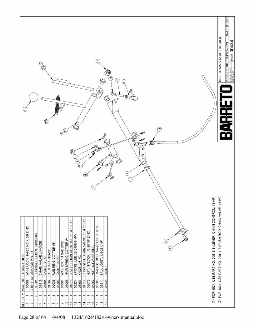
DIGGING CHAIN VALVE LEVER ADJUSTMENT
Put Digging Chain lever in ON position.
Pull clutch lever all the way up until it touches the hand grip.
Check the stroke of the CHAIN forward/reverse lever. The length of the chain valve push rod
should be adjusted so the forward/reverse lever comes to the end of its stroke just as the clutch lever
touches the hand grip.
Illustration B
Page 10 of 64 6/4/08 1324/1624/1824 owners manual.doc
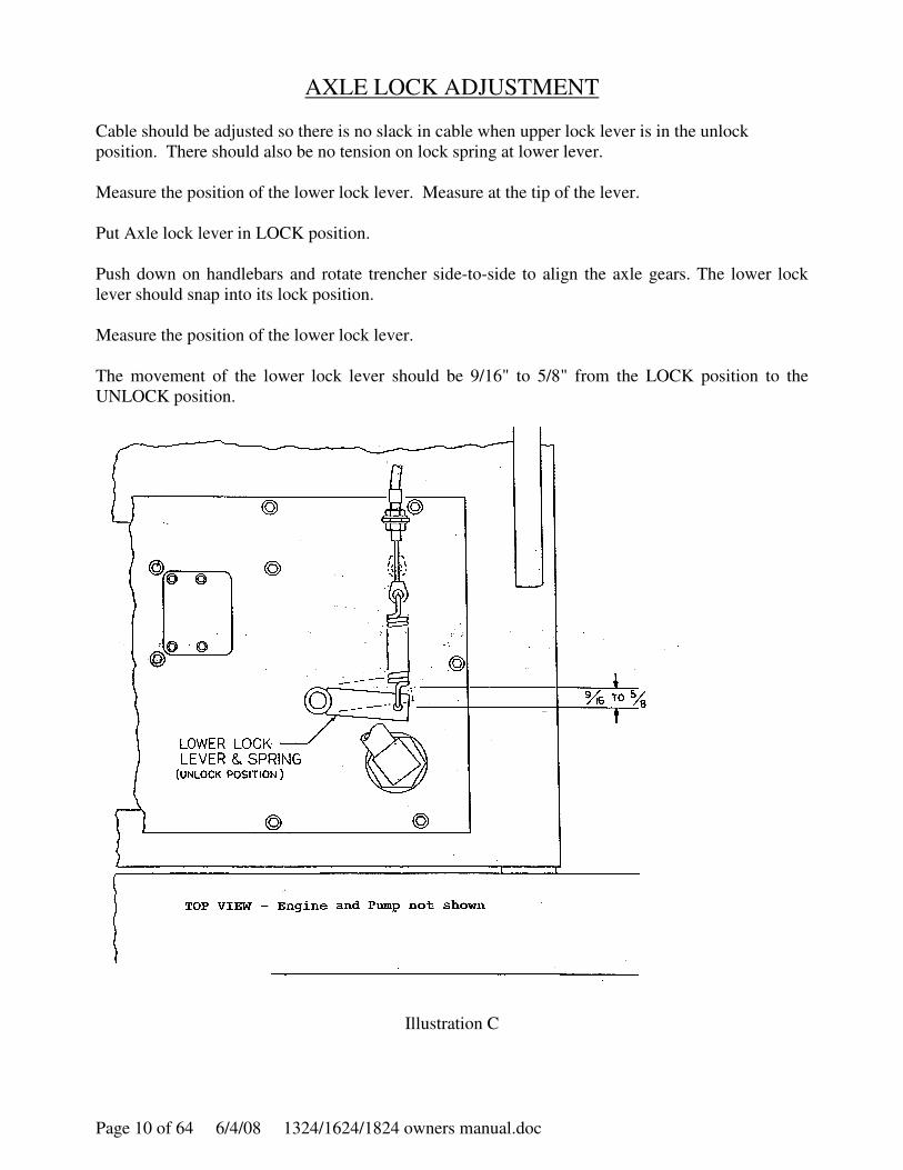
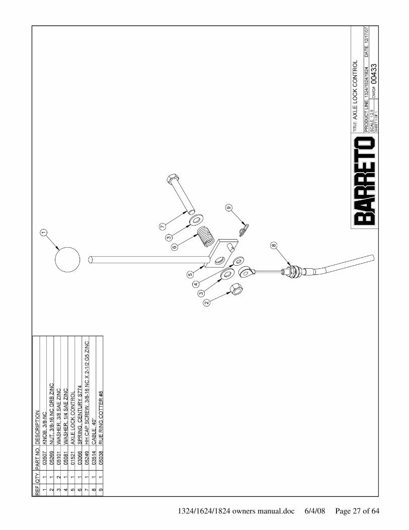
AXLE LOCK ADJUSTMENT
Cable should be adjusted so there is no slack in cable when upper lock lever is in the unlock
position. There should also be no tension on lock spring at lower lever.
Measure the position of the lower lock lever. Measure at the tip of the lever.
Put Axle lock lever in LOCK position.
Push down on handlebars and rotate trencher side-to-side to align the axle gears. The lower lock
lever should snap into its lock position.
Measure the position of the lower lock lever.
The movement of the lower lock lever should be 9/16" to 5/8" from the LOCK position to the
UNLOCK position.
Illustration C
1324/1624/1824 owners manual.doc 6/4/08 Page 11 of 64
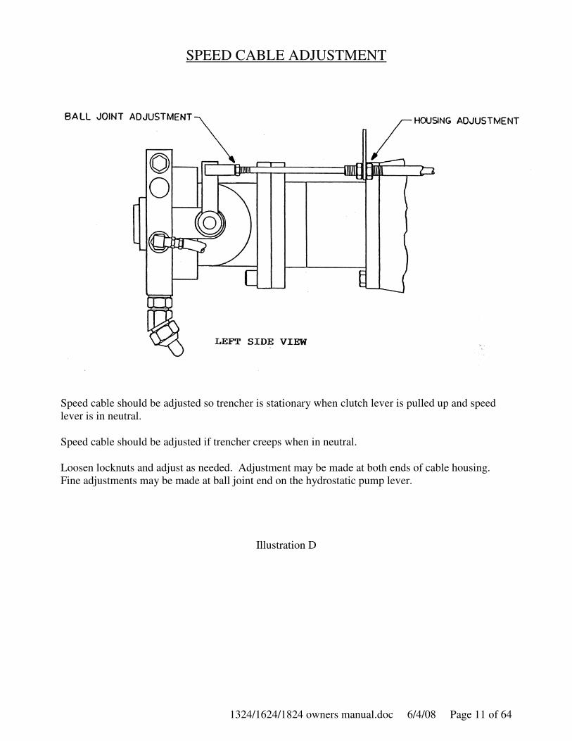
SPEED CABLE ADJUSTMENT
Speed cable should be adjusted so trencher is stationary when clutch lever is pulled up and speed
lever is in neutral.
Speed cable should be adjusted if trencher creeps when in neutral.
Loosen locknuts and adjust as needed. Adjustment may be made at both ends of cable housing.
Fine adjustments may be made at ball joint end on the hydrostatic pump lever.
Illustration D

Page 12 of 64 6/4/08 1324/1624/1824 owners manual.doc
SPEED LINKAGE ADJUSTMENT
TOP VIEW
LEFT SIDE RIGHT SIDE
Proper alignment of the shift forks will allow the ground speed lever to move smoothly from the
forward position to neutral; from neutral to reverse; and back to the forward position.
If the ground speed lever does not move left and right freely, the shift forks may be out of
alignment. Adjust the length of the left or right ball linkage to bring both shift forks into alignment
when the ground speed lever is in the neutral position.
Illustration E
1324/1624/1824 owners manual.doc 6/4/08 Page 13 of 64
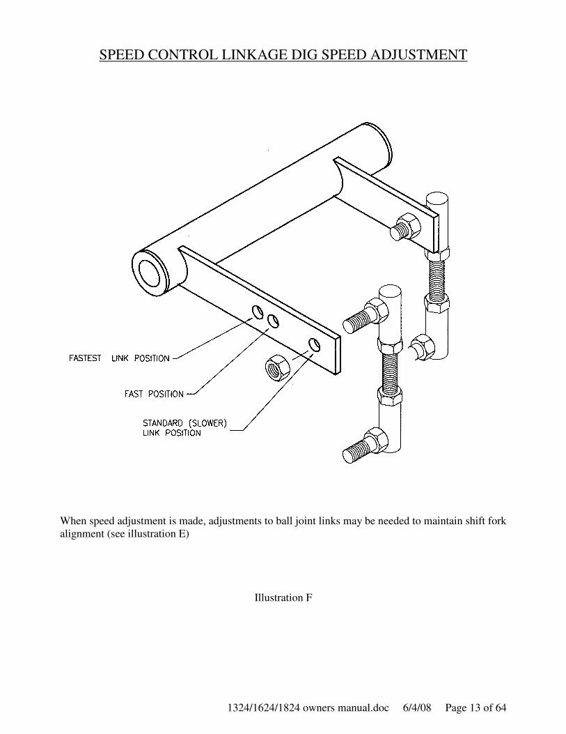
SPEED CONTROL LINKAGE DIG SPEED ADJUSTMENT
When speed adjustment is made, adjustments to ball joint links may be needed to maintain shift fork
alignment (see illustration E)
Illustration F
Page 14 of 64 6/4/08 1324/1624/1824 owners manual.doc
1324/1624/1824 owners manual.doc 6/4/08 Page 15 of 64
Page 16 of 64 6/4/08 1324/1624/1824 owners manual.doc
1324/1624/1824 owners manual.doc 6/4/08 Page 17 of 64

Page 18 of 64 6/4/08 1324/1624/1824 owners manual.doc
1324/1624/1824 owners manual.doc 6/4/08 Page 19 of 64
Page 20 of 64 6/4/08 1324/1624/1824 owners manual.doc
1324/1624/1824 owners manual.doc 6/4/08 Page 21 of 64
Page 22 of 64 6/4/08 1324/1624/1824 owners manual.doc
1324/1624/1824 owners manual.doc 6/4/08 Page 23 of 64

Page 24 of 64 6/4/08 1324/1624/1824 owners manual.doc
1324/1624/1824 owners manual.doc 6/4/08 Page 25 of 64
Page 26 of 64 6/4/08 1324/1624/1824 owners manual.doc
1324/1624/1824 owners manual.doc 6/4/08 Page 27 of 64
Page 28 of 64 6/4/08 1324/1624/1824 owners manual.doc

1324/1624/1824 owners manual.doc 6/4/08 Page 29 of 64

Page 30 of 64 6/4/08 1324/1624/1824 owners manual.doc
1324/1624/1824 owners manual.doc 6/4/08 Page 31 of 64
Page 32 of 64 6/4/08 1324/1624/1824 owners manual.doc
1324/1624/1824 owners manual.doc 6/4/08 Page 33 of 64
Page 34 of 64 6/4/08 1324/1624/1824 owners manual.doc

1324/1624/1824 owners manual.doc 6/4/08 Page 35 of 64
Page 36 of 64 6/4/08 1324/1624/1824 owners manual.doc
1324/1624/1824 owners manual.doc 6/4/08 Page 37 of 64
Page 38 of 64 6/4/08 1324/1624/1824 owners manual.doc
1324/1624/1824 owners manual.doc 6/4/08 Page 39 of 64
Page 40 of 64 6/4/08 1324/1624/1824 owners manual.doc
1324/1624/1824 owners manual.doc 6/4/08 Page 41 of 64
Page 42 of 64 6/4/08 1324/1624/1824 owners manual.doc
1324/1624/1824 owners manual.doc 6/4/08 Page 43 of 64

Page 44 of 64 6/4/08 1324/1624/1824 owners manual.doc
1324/1624/1824 owners manual.doc 6/4/08 Page 45 of 64
Page 46 of 64 6/4/08 1324/1624/1824 owners manual.doc
1324/1624/1824 owners manual.doc 6/4/08 Page 47 of 64
Page 48 of 64 6/4/08 1324/1624/1824 owners manual.doc
1324/1624/1824 owners manual.doc 6/4/08 Page 49 of 64
Page 50 of 64 6/4/08 1324/1624/1824 owners manual.doc
1324/1624/1824 owners manual.doc 6/4/08 Page 51 of 64
Page 52 of 64 6/4/08 1324/1624/1824 owners manual.doc
1324/1624/1824 owners manual.doc 6/4/08 Page 53 of 64
Page 54 of 64 6/4/08 1324/1624/1824 owners manual.doc
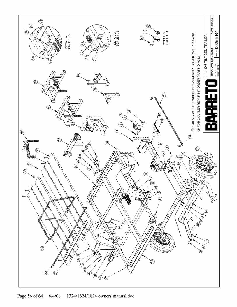
BARRETO E4X6TBT TILT BED TRAILER
The Barreto Tilt Bed Trailer, Model Number E4X6TBT, has three receivers to attach any of the following
options, to be used one at a time:
• 00287 WHEEL LOCK (to transport the Barreto Model 912 trencher)
• 00288 WHEEL LOCK (to transport a Barreto Model 1318 or 1324 or 1624 or 1824 trencher)
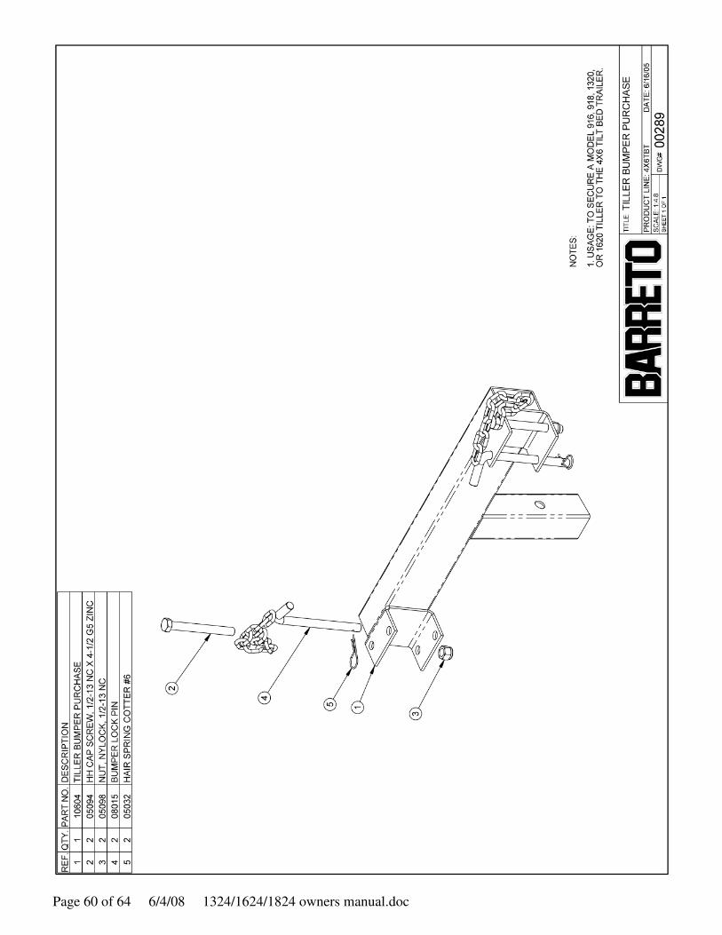
• 00289 TILLER BUMPER PURCHASE (to transport a Barreto Model 916 or 918 or 1320 or 1620
tiller)
Each of the above is designed to aid in holding a single piece of Barreto equipment in place while in
transit.
Although the trailer is versatile, Barreto Manufacturing, Inc. accepts no liability for injury or damage of
any kind related to use of the Barreto Tilt Bed Trailer.
Be sure to read and observe the safety instructions for proper use of the Barreto Tilt Bed Trailer. If there
are any questions regarding proper use, please contact Barreto Manufacturing, Inc. or an authorized
Barreto Dealer.
The VIN is located on the upper bed frame, on the left side and near the front.
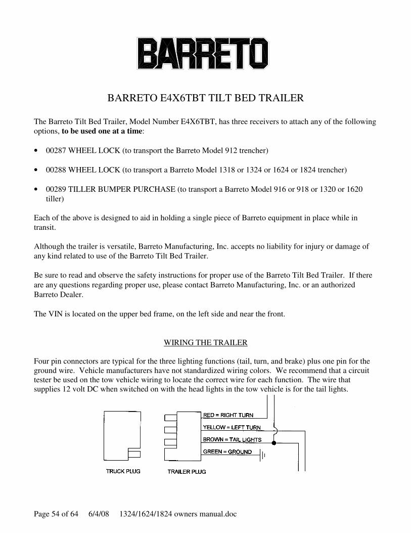
WIRING THE TRAILER
Four pin connectors are typical for the three lighting functions (tail, turn, and brake) plus one pin for the
ground wire. Vehicle manufacturers have not standardized wiring colors. We recommend that a circuit
tester be used on the tow vehicle wiring to locate the correct wire for each function. The wire that
supplies 12 volt DC when switched on with the head lights in the tow vehicle is for the tail lights.

1324/1624/1824 owners manual.doc 6/4/08 Page 55 of 64
SAFETY INSTRUCTIONS / CHECK LIST
BARRETO E4X6TBT TILT BED TRAILER
Be sure to obey all traffic laws and rules of the road while towing the Barreto Tilt Bed Trailer. Never
exceed 45 miles per hour while towing the trailer. The towing vehicle should be in legal operating
condition. If local law requires trailer lights, be sure they are in good repair and are in proper working
condition.
Refer to the following check list before towing:
• Towing vehicle should have a 2" ball. Be sure it is in good repair and securely fastened to the vehicle.
• Securely fasten the hitch to the ball by tightening the hitch nut.
• Thread the safety chain through the loop in the hitch nut handle to prevent it from vibrating loose
while towing.
• Attach the safety chain to the towing vehicle in such a way that it cannot come off accidentally.
• Check the hitch-to-ball connection after driving a few blocks and re-tighten if necessary.
• When using the 00287 WHEEL LOCK to transport the Barreto Model 912 trencher, insure that the
spring-loaded pin is holding the trencher front wheel securely.
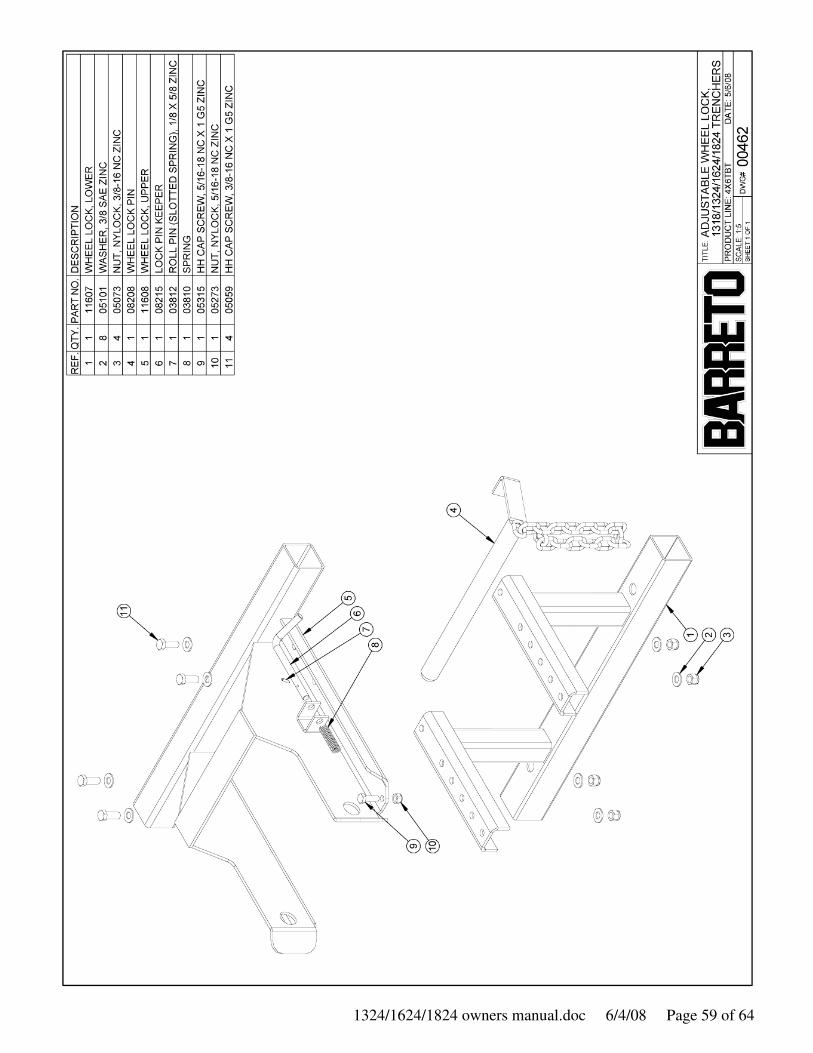
• When using the 00288 WHEEL LOCK to transport a Barreto Model 1318 or 1324 or 1624 or 1824
trencher insure that the wheel lock pin is in place behind the trencher front wheel. The wheel lock pin
handle should be behind the lip on the side plate (near where the chain is fastened) and under the lock
pin keeper.
• When using the 00289 TILLER BUMPER PURCHASE to transport a Barreto Model 916 or 918 or
1320 or 1620 tiller, both bumper lock pins must be placed behind the tiller bumper with a hair spring
cotter through each pin. The two bolts that fasten the bumper lock pin chains prevent the Barreto
tillers from shifting from side to side, and should be in good condition.
• Strap Barreto equipment to the trailer D-rings for highway, long distance, or rough road towing.
Always exercise extreme caution and allow extra clearance while towing a trailer.
DRIVE SAFELY!
Page 56 of 64 6/4/08 1324/1624/1824 owners manual.doc

1324/1624/1824 owners manual.doc 6/4/08 Page 57 of 64

Page 58 of 64 6/4/08 1324/1624/1824 owners manual.doc
1324/1624/1824 owners manual.doc 6/4/08 Page 59 of 64
Page 60 of 64 6/4/08 1324/1624/1824 owners manual.doc
1324/1624/1824 owners manual.doc 6/4/08 Page 61 of 64
Page 62 of 64 6/4/08 1324/1624/1824 owners manual.doc

1324/1624/1824 owners manual.doc 6/4/08 Page 63 of 64
Page 64 of 64 6/4/08 1324/1624/1824 owners manual.doc