Embed Size (px)
Citation preview

13131313 HP Tow Behind Shredder Chipper HP Tow Behind Shredder Chipper HP Tow Behind Shredder Chipper HP Tow Behind Shredder Chipper
OPERATOR’S MANUAL
READ CAREFULLY BEFORE USE AND KEEP THIS INSTRUCTION
MANUAL FOR FUTURE REFERENCE
Page 2 of 28
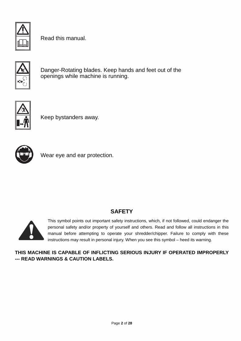
Danger-Rotating blades. Keep hands and feet out of the openings while machine is running.
Keep bystanders away.
Wear eye and ear protection.
SAFETY
This symbol points out important safety instructions, which, if not followed, could endanger the
personal safety and/or property of yourself and others. Read and follow all instructions in this
manual before attempting to operate your shredder/chipper. Failure to comply with these
instructions may result in personal injury. When you see this symbol – heed its warning.
THIS MACHINE IS CAPABLE OF INFLICTING SERIOUS INJUR Y IF OPERATED IMPROPERLY --- READ WARNINGS & CAUTION LABELS.
Read this manual.

Page 3 of 28
INTENDED USE Never use your shredder/chipper for any other purpose than shredding and chipping limbs or other lawn and
garden debris. It is designed for this use and any other use many cause serious injury.
DANGER: Rotating cutting blade.
Keep hands and feet out of inlet and discharge opening while machine is running
DANGER: This machine can CRUSH, GRIND, CUT, and SEVER parts if your body if they
enter the inlet or discharge area of your shredder/chipper.
DANGER: Your shredder/chipper was built to be operated according to the rules for safe
operation in this manual. As with any type of power equipment, carelessness or error on the part of the operator can result in ser ious injury. If you violate any of
these rules, you may cause serious injury to yourself or others.
Page 4 of 28
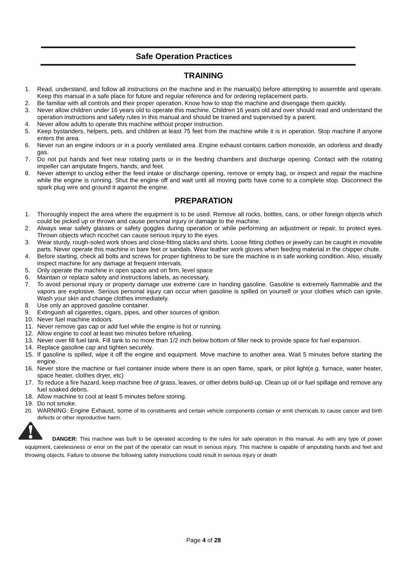
Safe Operation Practices
TRAINING
1. Read, understand, and follow all instructions on the machine and in the manual(s) before attempting to assemble and operate. Keep this manual in a safe place for future and regular reference and for ordering replacement parts.
2. Be familiar with all controls and their proper operation. Know how to stop the machine and disengage them quickly. 3. Never allow children under 16 years old to operate this machine. Children 16 years old and over should read and understand the
operation instructions and safety rules in this manual and should be trained and supervised by a parent. 4. Never allow adults to operate this machine without proper instruction. 5. Keep bystanders, helpers, pets, and children at least 75 feet from the machine while it is in operation. Stop machine if anyone
enters the area. 6. Never run an engine indoors or in a poorly ventilated area .Engine exhaust contains carbon monoxide, an odorless and deadly
gas. 7. Do not put hands and feet near rotating parts or in the feeding chambers and discharge opening. Contact with the rotating
impeller can amputate fingers, hands, and feet. 8. Never attempt to unclog either the feed intake or discharge opening, remove or empty bag, or inspect and repair the machine
while the engine is running. Shut the engine off and wait until all moving parts have come to a complete stop. Disconnect the spark plug wire and ground it against the engine.
PREPARATION
1. Thoroughly inspect the area where the equipment is to be used. Remove all rocks, bottles, cans, or other foreign objects which could be picked up or thrown and cause personal injury or damage to the machine.
2. Always wear safety glasses or safety goggles during operation or while performing an adjustment or repair, to protect eyes. Thrown objects which ricochet can cause serious injury to the eyes.
3. Wear sturdy, rough-soled work shoes and close-fitting slacks and shirts. Loose fitting clothes or jewelry can be caught in movable parts. Never operate this machine in bare feet or sandals. Wear leather work gloves when feeding material in the chipper chute.
4. Before starting, check all bolts and screws for proper tightness to be sure the machine is in safe working condition. Also, visually inspect machine for any damage at frequent intervals.
5. Only operate the machine in open space and on firm, level space 6. Maintain or replace safety and instructions labels, as necessary. 7. To avoid personal injury or property damage use extreme care in handing gasoline. Gasoline is extremely flammable and the
vapors are explosive. Serious personal injury can occur when gasoline is spilled on yourself or your clothes which can ignite. Wash your skin and change clothes immediately.
8. Use only an approved gasoline container. 9. Extinguish all cigarettes, cigars, pipes, and other sources of ignition. 10. Never fuel machine indoors. 11. Never remove gas cap or add fuel while the engine is hot or running. 12. Allow engine to cool at least two minutes before refueling. 13. Never over fill fuel tank. Fill tank to no more than 1/2 inch below bottom of filler neck to provide space for fuel expansion. 14. Replace gasoline cap and tighten securely. 15. If gasoline is spilled, wipe it off the engine and equipment. Move machine to another area. Wait 5 minutes before starting the
engine. 16. Never store the machine or fuel container inside where there is an open flame, spark, or pilot light(e.g. furnace, water heater,
space heater, clothes dryer, etc) 17. To reduce a fire hazard, keep machine free of grass, leaves, or other debris build-up. Clean up oil or fuel spillage and remove any
fuel soaked debris. 18. Allow machine to cool at least 5 minutes before storing. 19. Do not smoke. 20. WARNING: Engine Exhaust, some of its constituents and certain vehicle components contain or emit chemicals to cause cancer and birth
defects or other reproductive harm. DANGER: This machine was built to be operated according to the rules for safe operation in this manual. As with any type of power
equipment, carelessness or error on the part of the operator can result in serious injury. This machine is capable of amputating hands and feet and
throwing objects. Failure to observe the following safety instructions could result in serious injury or death

Page 5 of 28
OPERATION
1. Do not put hands and feet near rotating parts or in the feeding chambers and discharge opening. Contact with the rotating impeller can amputate fingers, hands, and feet.
2. Always stand clear of the discharge zone when operating this machine. 3. Keep proper balance and footing at all times. Do not overreach. Never stand at a higher level than the base of the machine when
feeding material into it. 4. Before starting the machine, make sure the chipper chute, feed intake, and cutting chamber are empty and free of all debris. 5. Thoroughly inspect all material to be shredded and remove any metal, rocks, bottles, cans, or other foreign objects which could
cause personal injury or damage to the machine. 6. If it becomes necessary to push material through the shredder hopper, use a small diameter stick. Do not use your hands or feet. 7. Do not allow processed material to build up in the discharge zone; this may prevent proper discharge and can result in kickback
of material through the feed intake opening. 8. If it impeller strikes a foreign object or if your machine should start making an unusual noise or vibration, immediately shut the
engine off. Allow the impeller to come to a complete stop. Disconnect the spark plug wire, ground it against the engine and perform the following steps:
a. Inspect for damage. b. Repair or replace any damaged parts. c. Check for any loose parts and tighten to assure continued safe operation. 9. Do not allow an accumulation of processed material to build up in the discharge area. This can prevent proper discharge and
result in kickback of material through the feed opening. 10. Do not attempt to shred or chip material larger than specified on the machine or in this manual. Personal injury or machine
damage could result. 11. Never attempt to unclog either the feed intake or discharge opening while the engine is running. Shut the engine off, wait until all
moving parts have stopped, disconnect the spark plug wire and ground it against the engine before clearing debris. 12. Never operate without the shredder hopper, chipper chute, or chute deflector properly attached to the machine .Never empty or
change discharge bag while the engine is running. 13. Keep all guards, deflectors and safety devices in place and operating properly. 14. Keep your face and body back and to the side of the chipper chute while feeding material into the machine to avoid accidental
kickback injuries. 15. Never operate this machine without good visibility or light. 16. Do not operate this machine on a paved, gravel or non-level surface. 17. Do not operate this machine while under the influence of alcohol or drugs. 18. Muffler and engine become hot and can cause a burn. Do not touch. 19. Never pick up or carry machine while the engine is running. 20. Do not tilt the machine while the power source is running.
MAINTENANCE & STORAGE
1. Never tamper with safety devices. Check their proper operation regularly. 2. Check bolts and screws for proper tightness at frequent intervals to keep the machine in safe working condition. Also, visually
inspect machine for any damage and repair, if needed. 3. Before cleaning, repairing, or inspecting, stop the engine and make certain the impeller and all moving parts have stopped.
Disconnect the spark plug wire and ground it against the engine to prevent unintended starting. 4. Do not change the engine governor settings or over speed the engine. The governor controls the maximum safe operating speed
of the engine. 5. Maintain or replace safety and instruction labels, as necessary. 6. Follow this manual for safe loading, unloading, transporting, and storage of this machine. 7. Never store the machine or fuel container inside where there is an open flame, spark or pilot light such as a water heater, furnace,
clothes dryer, etc. 8. Always refer to the operator’s manual for proper instructions on off- season storage. 9. If the fuel tank has to be drained, do this outdoor. 10. Observe proper disposal laws and regulations for gas, oil, etc. to protect the environment. 11. When servicing the cutting means be aware that, even though the power source will not start due to the interlock feature of the
guard, the cutting means can still be moved by a manual starting mechanism.
Do not modify engine To avoid serious injury or death, do not modify engine in any way. Tampering with governor setting can lead to a runaway engine and cause it to operate at unsafe speeds. Never tamper with factory setting of engine governor.
Your Responsibility Restrict the use of this power machine to persons who read, understand and follow the warnings and instructions in this manual and on the machine.
Page 6 of 28
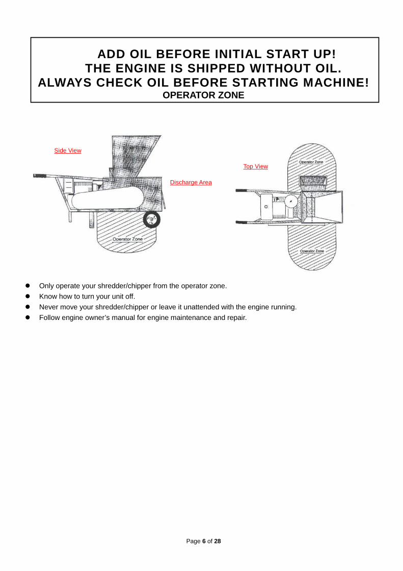
ADD OIL BEFORE INITIAL START UP! THE ENGINE IS SHIPPED WITHOUT OIL.
ALWAYS CHECK OIL BEFORE STARTING MACHINE! OPERATOR ZONE
� Only operate your shredder/chipper from the operator zone.
� Know how to turn your unit off.
� Never move your shredder/chipper or leave it unattended with the engine running.
� Follow engine owner’s manual for engine maintenance and repair.
Side View
Discharge Area
Top View
Page 7 of 28
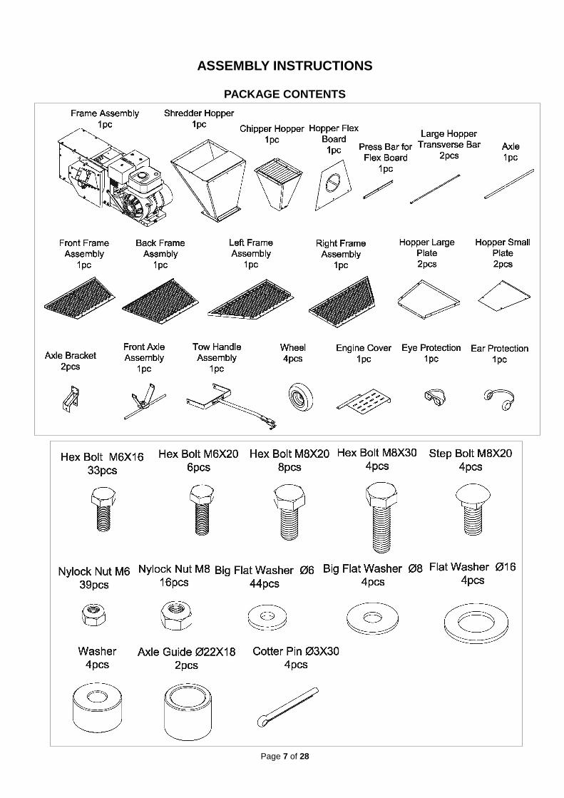
ASSEMBLY INSTRUCTIONS
PACKAGE CONTENTS
Page 8 of 28
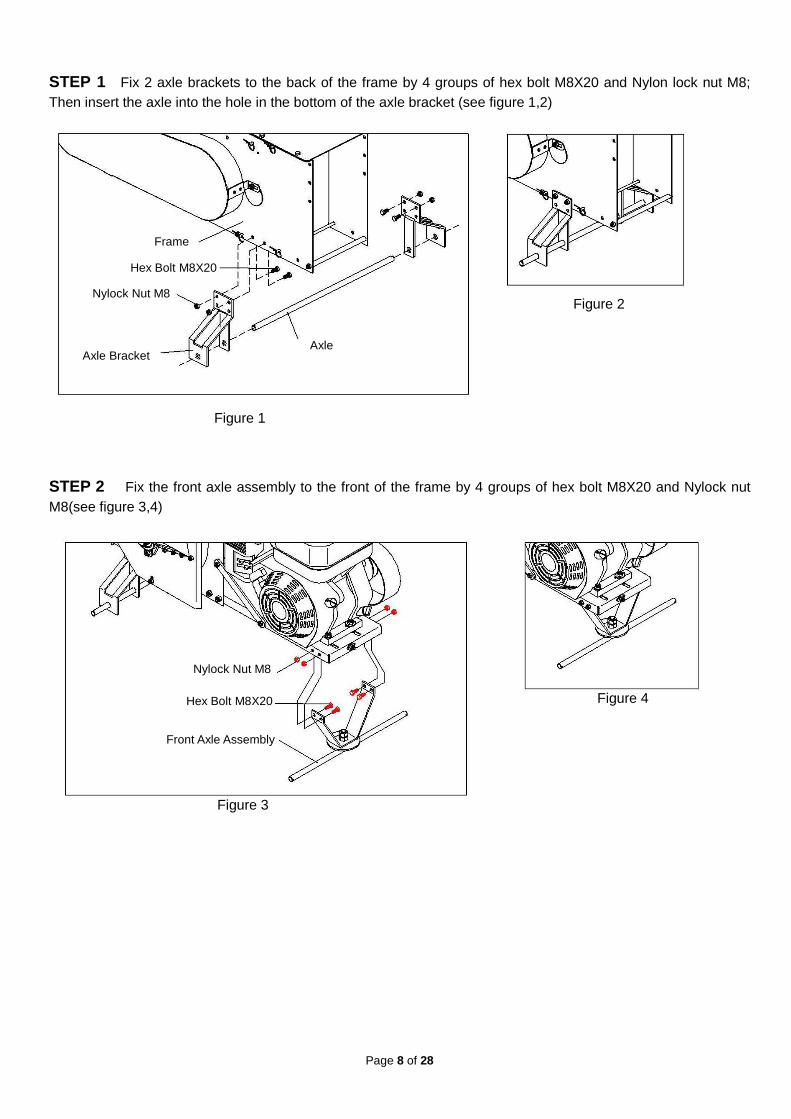
STEP 1 Fix 2 axle brackets to the back of the frame by 4 groups of hex bolt M8X20 and Nylon lock nut M8; Then insert the axle into the hole in the bottom of the axle bracket (see figure 1,2)
STEP 2 Fix the front axle assembly to the front of the frame by 4 groups of hex bolt M8X20 and Nylock nut M8(see figure 3,4)
Frame
Hex Bolt M8X20
Nylock Nut M8
Axle Bracket Axle
Figure 1
Figure 2
Nylock Nut M8
Hex Bolt M8X20
Front Axle Assembly
Figure 3
Figure 4

Page 9 of 28
STEP 3 Attach the tow handle to the front axle.(see figure 5,6)
STEP 4 Attach back wheel to the axle with flat washerØ16 and cotter pin Ø3X30.(see figure 7,8)
STEP 5 Attach the front wheel to the front axle assembly with axle guide Ø22X18 and flat washerØ16 then lock the cotter pin Ø3X30.(see figure 9,10)
Tow Handle
Figure 5
Figure 6
Wheel
Flat Washer Ø16
Cotter Pin Ø3X30
Figure 7 Figure 8
Wheel
Flat Washer Ø16
Cotter Pin Ø3X30
Axle GuideØ22X18
Figure 9 Figure 10
Page 10 of 28
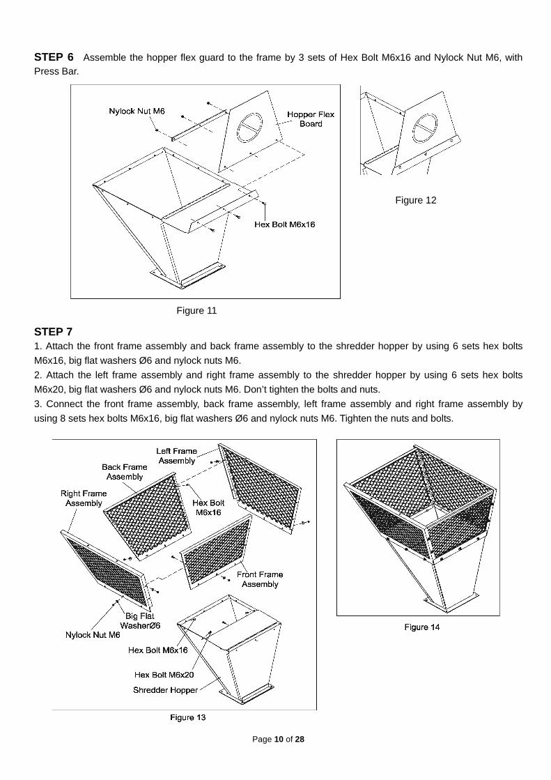
STEP 6 Assemble the hopper flex guard to the frame by 3 sets of Hex Bolt M6x16 and Nylock Nut M6, with Press Bar.
STEP 7 1. Attach the front frame assembly and back frame assembly to the shredder hopper by using 6 sets hex bolts
M6x16, big flat washers Ø6 and nylock nuts M6.
2. Attach the left frame assembly and right frame assembly to the shredder hopper by using 6 sets hex bolts
M6x20, big flat washers Ø6 and nylock nuts M6. Don’t tighten the bolts and nuts.
3. Connect the front frame assembly, back frame assembly, left frame assembly and right frame assembly by
using 8 sets hex bolts M6x16, big flat washers Ø6 and nylock nuts M6. Tighten the nuts and bolts.
Figure 12
Figure 11
Page 11 of 28
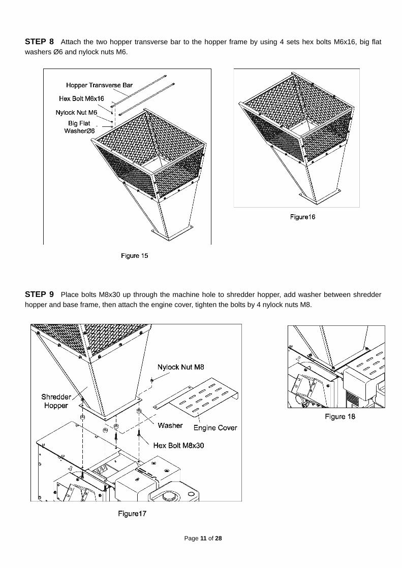
STEP 8 Attach the two hopper transverse bar to the hopper frame by using 4 sets hex bolts M6x16, big flat washers Ø6 and nylock nuts M6. STEP 9 Place bolts M8x30 up through the machine hole to shredder hopper, add washer between shredder hopper and base frame, then attach the engine cover, tighten the bolts by 4 nylock nuts M8.

Page 12 of 28
STEP10 1. Find and remove the four step bolts M8x20 from the bolt bag. Hold the chipper hopper in place and then bolt in
place using the four step bolts M8x20 thru the square holes in the bottom of the hopper going from inside-out. 2. Place four big flat washers Ø8 and four Nylock nuts M8 on the end of each bolt. Secure tightly.
STEP 11 Attach the two hopper small plates and two hopper large plates by using 8 pcs hex bolts M6x16, 16pcs of big flat washers Ø6 and 8pcs of nylon lock nuts M6. Don’t tighten the bolts and nuts.
Page 13 of 28
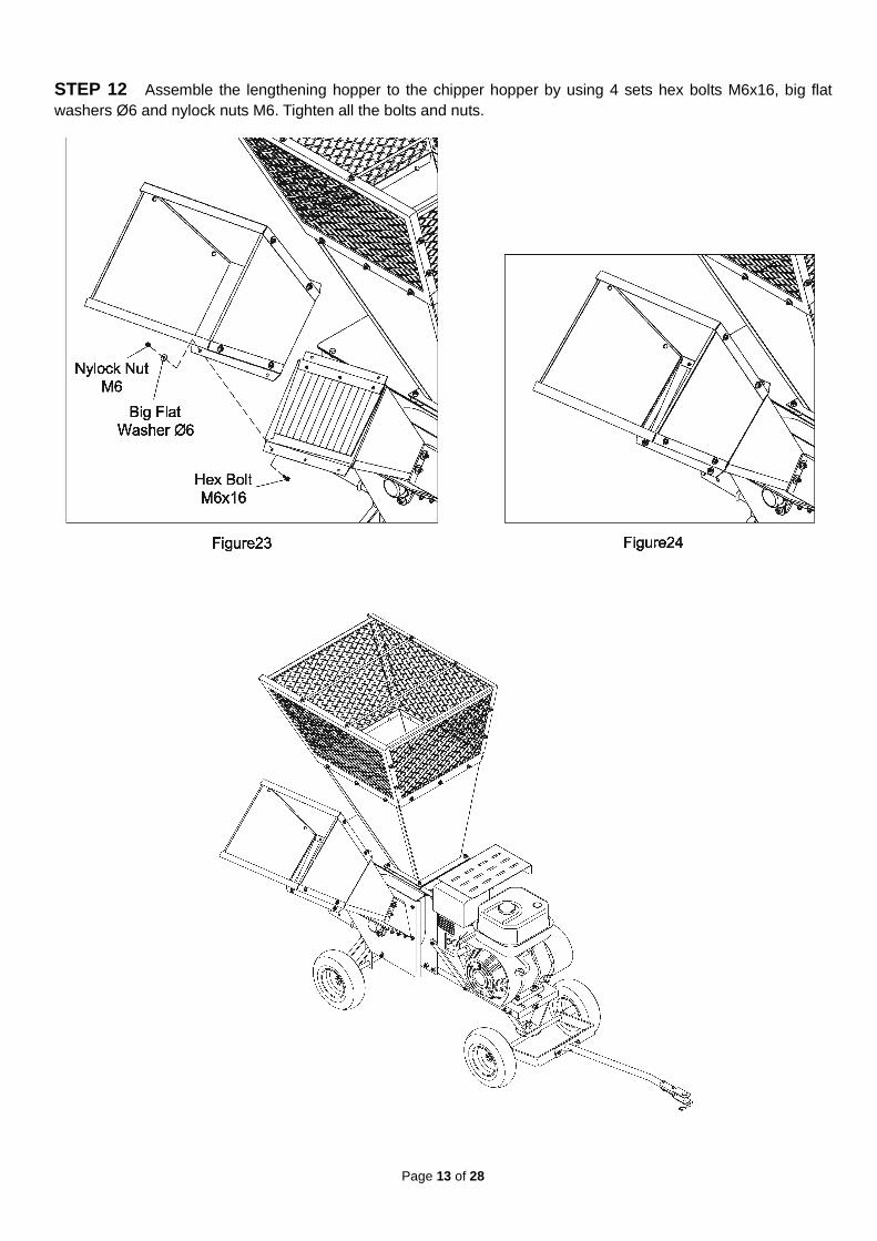
STEP 12 Assemble the lengthening hopper to the chipper hopper by using 4 sets hex bolts M6x16, big flat washers Ø6 and nylock nuts M6. Tighten all the bolts and nuts.

Page 14 of 28
NOW THAT YOU HAVE SET UP YOUR LEAF SHREDDER FOR OPE RATION
See below pictures to know the engine
. Gas and Oil Fill-Up Open the fuel cap and oil cap separately and add gasoline and oil to the relevant tank.
WARNING: Never fill fuel tank indoors with engine r unning or until the engine has been a lowed to cool for at
least two minutes after running.
Starting Engine
Engine Starting Procedure: 1. Move the fuel valve lever to the ON position. The fuel valve opens and closes the passage between the fuel tank and the carburetor. The fuel valve must be in the ON position for the engine to run. 2. To start a cold engine, move the choke lever to the CLOSED position. To restart a warm engine, leave the choke lever in the OPEN position. The choke lever opens and closes the choke valve in the carburetor. The CLOSED position enriches the fuel mixture for starting a cold engine. The OPEN position provides the correct fuel mixture for operation after starting, and for restarting a warm engine. 3. Move the throttle lever away from the SLOW position, about 1/3 of the way toward the FAST position. The throttle lever controls engine speed. Moving the throttle lever in one direction or the other, makes the engine run faster or slower. 4. Turn the engine switch to the ON position. The engine switch enables and disables the ignition system. The engine switch must be in the ON position for the engine to run. Turning the engine switch to the OFF position stops the engine. 5. Operate the RECOIL STARTER: Pull the starter grip lightly until you feel resistance, then pull briskly. Return the starter grip gently. Pulling the starter grip operates the recoil starter to crank the engine. 6. If the choke lever has been moved to the CLOSED position to start the engine, gradually move it to the OPEN position as the engine warms up.
Engine switch Oil cap Choke lever Fuel valve lever
Throttle lever
Fuel cap
Recoil starter
Page 15 of 28
WARNING: Never run the engine indoors or in a poorl y ventilated area. Engine exhaust contains carbon monoxide, an odorless and deadly gas. WARNING: ALWAYS CHECK OIL LEVEL BEFORE STARTING MACHINE
Stopping Engine To stop the engine in an emergency, simply turn the engine switch to the OFF position. Under normal conditions, use the following procedure. 1.Move the throttle lever to the SLOW position. 2.Turn the engine switch to the OFF position. 3.Turn the fuel vale lever to the OFF position. When the engine is not in use, leave the fuel valve lever in the OFF position to prevent carburetor flooding and to reduce the possibility of fuel leakage.
SREDDING & CHIPPING
THIS SHREDDER/CHIPPER WAS DESIGNED FOR SHREDDING LEAFY GARDEN OR ORGANIC MATERIAL AND CHIPPING LIMBS OR BRANCHES. NE VER USE THIS MACHINE
FOR ANY OTHER PURPOSE AS IT COULD CAUSE SERIOUS INJ URY.
CONTACT WITH INTERNAL ROTATING HAMMERS WILL CAUSE S ERIOUS PERSONAL INJURY. DO NOT PUT HANDS, FACE, FEET OR CLOTHING IN TO THE SHREDDER HOPPER, CHIPPER CHUTE, DISCHARGE OPENING OR NEAR THE DISCHA RGE AREA AT ANY TIME.
MAINTENANCE AND SERVICE SHOULD ONLY BE PERFORMED AF TER THE ENGIEN IS OFF AND ALL MOVING PARTS HAVE COME TO A COMPLETE STOP. USE ONLY A WOODEN
STICK TO CLEAR JAMMEN MATERIAL AFTER ALL MOVING PAR TS HAVE STOPPED COMPLETELY.
SAFETY FIRST
� Always wear protective gloves and safety glasses during operation of the shredder/chipper. � Never allow your hands or any part of your body or clothing inside the feed hoppers or discharge area of
the shredder. � Keep all protective guards and warning labels on the machine and in good working condition. � Always stand clear of the discharge area when the shredder/chipper is running. � Keep your face and body back from the feed hoppers to avoid being struck by any material that may
bounce back. � Keep proper balance and footing while operating the shredder/chipper. � If it becomes necessary to push material into the feed hoppers, only use a wood stick, never your hands or
anything steel. � Never assume you know where the chipper knife is. You do not know where it is, � Keep area of discharge clear of people, animals, building, glass or anything else that will obstruct clear
discharge, cause injury or damage. Wind can also change discharge direction, so be aware. � Always keep hands out of the feed hoppers. � Never operate the shredder/chipper without the hoppers in place. � Do not transport the shredder/chipper with the engine running.

Page 16 of 28
PROCESSING MATERIAL
� Your shredder/chipper can process dry or green material. � Green material will process quicker and easier than dry material. � Soft wood processes easier the hard wood. � Your operator experience will teach you how different shred and chip. � Your operator experience will teach how fast you can process different materials � Most materials process well with the standard screen provided with the unit. � When chipping branches, sometimes a tail will be left at the end of a branch. To avoid this, rotate the
branch as it is fed into the chute. � Rotating the branch as you feed it into the machine will improve chipping performance. � An optional screen is available for greater reduction of the material being processed through the shredder
hopper. USING THE SHREDDER HOPPER
� The shredder hopper is located on the top of the unit and is the opening into which all materials to be
shredded should be fed. Most organic materials can be shredded.
� Due to the wide variety of materials that can be shredded, and their very different physical characteristic, only
feed limited quantities of any material into the hopper at first. The amount and length of material can be
increased if you find that the material being processed without any difficulty. Your judgment and operator
experience is very important. Be sure not to overload the machine by feeding too much material into the
hopper at one time. If you hear the RPM’s of the engine decreasing, stop feeding material into the machine at
once. Do not resume feeding the machine until it has returned to full speed.
� The maximum diameter of material that can be shredded is 1”. Any large material should be fed through the
chipper-hopper. Material larger than 1” can cause serious damage to any of the internal parts of the stressing
chamber. The unit should be inspected after every use for bent hammers, missing spacers, damage to the
screen or any other obvious problem. If damage occurs, the rotor assembly can become unbalance causing
excessive vibration. If used in this state, damage can occur. Do not use the machine if vibration is present.
Vibration id generally a warning sign of trouble.
� Several small branches can be fed into the shredder-hopper at once providing their combined diameter is less
than 1”. Branches longer than three feet should be cut to make them more manageable. Green materials
should be allowed to dry, or processed in small batches with dry material to avoid winding around the rotor
assembly.
� Wet materials will clog the machine easily. They are best processed with optional bar screen.
MATERIALS BEST SUITED FOR SHREDDING
� Leaves
� Roots
� Grass clippings
� Straw
� Hay
� Small branches
� Flowers
� Soil
� Garden debris
� Hedge clippings
� Kitchen Waste
� Manure
� Corn Stalks
� Palm frond tops
� Potato vines
� Tomato vines
� Paper
USING THE CHIPPER HOPPER � This chipper-hopper is mounted on the side of the machine and designed to chip the larger, heavier materials
that the shredder-hopper isn’t designed to handle. Branches fed into the chute are turned into “chips” by the revolving chipper knife mounted on a flywheel. The chipper-hopper can chip branches and vines ranging in size from 1” to 3” in diameter. Cut your materials into manageable lengths before feeding them into the chipper.
� Note: The chipper hopper must be securely to the si de of your equipment before using the machine!
Page 17 of 28
� Do not force material into the chipper. If the machine does not chip well, the chipper knives need replace or sharpened or the gap between the knife and the wear plate needs adjusting.
� Extremely hard knots will not process very well. Short stubs that have not self-fed the chipper can be pushed through with the next branch to be chipped. DO NOT THROW REMAININGS STUBS OR UNCHIPPABLE KNOTS INTO THE SHREDDER-HOPPER. DAMAGE WILL RESULT.
� Cut chipping material into manageable length if no more than five or six feet long before chipping them. � If branches are larger than 1” diameter, feed only one branch at a time through the chipper hopper. � Branches smaller than 1”diameter can be bundled together and fed through the chipper hopper at one time. � Overloading the shredder/chipper will cause the rotor speed to decrease. If you hear the RPM’s decreasing,
stop feeding material into the machine until the machine has returned to full speed. Pay attention to operate in safety environment
Never operate your leaf shredder on slippery, wet, muddy, or icy surfaces. Safe footing is essential in preventing
accidents.
Only operate on level ground. If level ground is impossible to find, be
sure the leaf tray is “up hill” to assure proper engine lubrication as shown.
Keep operator zone clean and clear of debris so that you don’t stumble over it. MATERIALS BEST SUITED FOR CHIPPING
� Branches, vines or stalks from 1” to 3” in diameter.
USE COMMON SENSE WHEN USING YOUR SHREDDER/CHIPPER
� LEARN TO RECOGNIZE THE CHANGE IN THE SOUND OF YOUR MACHINE WHEN IT IS OVERLOADED.
� BECOME FAMILIAR WITH SUCCESSFUL OPERATING CONDITION S AND AVOID THOSE THAT CAN OVERLOAD AND DAMAGE THE MACHINE.
� IF THE MACHINE BECOMES JAMMED BY OVERLOADING OR ANY OTHER CAUSE, STOP THE MACHINE IMMEDIATELY.
� IF YOU JAM THE MACHINE AND DO NOT STOP THE ENGINE, IT CAN DAMAGE THE MACHINE. THIS DAMAGE CAN BE COSTLY AND IT MAY NOT BE COVERED UNDER WARRANTY. FOR THIS REASON, IT IS IMPORTANT THAT YOU IMMEDIATELY STOP T HE ENGINE IF THE MACHINE BECOMES JAMMED.
� ONLY YOUR OPERATOR EXPERIENCE WILL TELLYOU HOW FAST TO FEED MATERIAL TO BE PROCESSES.
� CHECK TO SEE THAT THE FLYWHEEL WILL TURN FREELY BEF ORE YOU START THE SHREDDER/CHIPPER.
� CHECK KNIFE CONDITION, WEAR PLATE CONDITION, GAP SE TTING AND THE NUTS AND BOLTS THAT HOLD THE KNIFE IN PLACE FOR TIGHTNESS EVERY 8- 10 HOURS OF OPERATION.
� DO NOT ALLOW PROCESSED MATERIAL TO BUILD UP WITHIN 3” OF DISCHARGE CHUTE OPENING. MOVE SHREDDER/CHIPPER OR PILE AS NEEDED. FAILURE TO DO THIS COULD RESULT IN UNNECESSARY JAMMING OF THE MACHINE.
� TO MOVE PILE OF PROCESSED MATERIAL, USE SPADE, RAKE , OR LONG HANDLE TOOL. NEVER USE YOUR HANDS OR FEET!
Page 18 of 28
MAINTENANCE & STORAGE
IMPORTANT: The knife should be checked for sharpnes s and the bolts attaching them to the flywheel for tightness every 8-10 hours of operatio n.
IMPORTANT: Every time you perform maintenance or an y kind of service or check on the knife, be sure to check the gap between the knife a nd wear plate for proper setting.
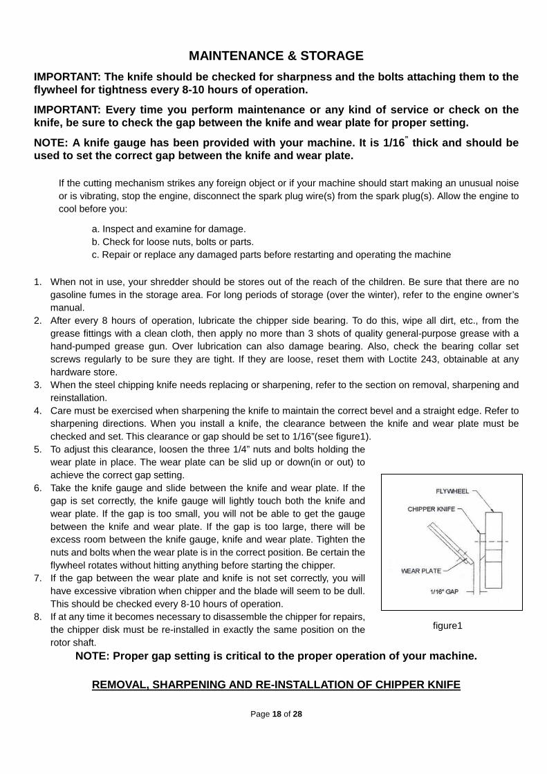
NOTE: A knife gauge has been provided with your mac hine. It is 1/16 ” thick and should be used to set the correct gap between the knife and w ear plate.
If the cutting mechanism strikes any foreign object or if your machine should start making an unusual noise or is vibrating, stop the engine, disconnect the spark plug wire(s) from the spark plug(s). Allow the engine to cool before you:
a. Inspect and examine for damage. b. Check for loose nuts, bolts or parts. c. Repair or replace any damaged parts before restarting and operating the machine
1. When not in use, your shredder should be stores out of the reach of the children. Be sure that there are no gasoline fumes in the storage area. For long periods of storage (over the winter), refer to the engine owner’s manual.
2. After every 8 hours of operation, lubricate the chipper side bearing. To do this, wipe all dirt, etc., from the grease fittings with a clean cloth, then apply no more than 3 shots of quality general-purpose grease with a hand-pumped grease gun. Over lubrication can also damage bearing. Also, check the bearing collar set screws regularly to be sure they are tight. If they are loose, reset them with Loctite 243, obtainable at any hardware store.
3. When the steel chipping knife needs replacing or sharpening, refer to the section on removal, sharpening and reinstallation.
4. Care must be exercised when sharpening the knife to maintain the correct bevel and a straight edge. Refer to sharpening directions. When you install a knife, the clearance between the knife and wear plate must be checked and set. This clearance or gap should be set to 1/16”(see figure1).
5. To adjust this clearance, loosen the three 1/4” nuts and bolts holding the wear plate in place. The wear plate can be slid up or down(in or out) to achieve the correct gap setting.
6. Take the knife gauge and slide between the knife and wear plate. If the gap is set correctly, the knife gauge will lightly touch both the knife and wear plate. If the gap is too small, you will not be able to get the gauge between the knife and wear plate. If the gap is too large, there will be excess room between the knife gauge, knife and wear plate. Tighten the nuts and bolts when the wear plate is in the correct position. Be certain the flywheel rotates without hitting anything before starting the chipper.
7. If the gap between the wear plate and knife is not set correctly, you will have excessive vibration when chipper and the blade will seem to be dull. This should be checked every 8-10 hours of operation.
8. If at any time it becomes necessary to disassemble the chipper for repairs, the chipper disk must be re-installed in exactly the same position on the rotor shaft.
NOTE: Proper gap setting is critical to the proper operation of your machine.
REMOVAL, SHARPENING AND RE-INSTALLATION OF CHIPPER KNIFE
figure1

Page 19 of 28
HOW TO REMOVE THE KNIFE � Stop the engine. � Remove spark plug wire(s) and keep away from spark plug(s). � Open the access cover on the chipper basic machine. � Rotate the chipper disk until the three countersunk screws attaching the knife to the flywheel are visible
through the access door. � Clean out the heads of the allen screws with an awl or sharp tool. � Insert a 3/16” allen wrench into the heads of the screws. � While applying pressure with the allen wrench, apply heat from a propane torch to the screws to break
loose the Loctite on the screws. � Remove the heat once the screws have loosened. � Remove all three allen screws in this manner.
KNIFE SHARPENING � You should never attempt to sharpen the chipper knife (or knives) freehand. � It is extremely important that the 45 degree angle be maintained consistently for proper performance. � The chipper knife(or knife) should be taken to a machine shop for proper sharpening. � Excessive heat generated during the sharpening process will damage knives and weaken the metal. Be
sure the knife is not overheated.
KNIFE INFORMATION � The chipper knife should be checked routinely for sharpness. � Using a dull knife will decrease performance and cause excessive vibration that will cause damage to the
shredder. � How many times a knife can be sharpened is determined by how much material needs to be taken off to
sharpen or to compensate for dents or gouges. � A new chipper knife has 5/16” measurement between the short side bevel edge and the knife mounting
holes. See figure 2.
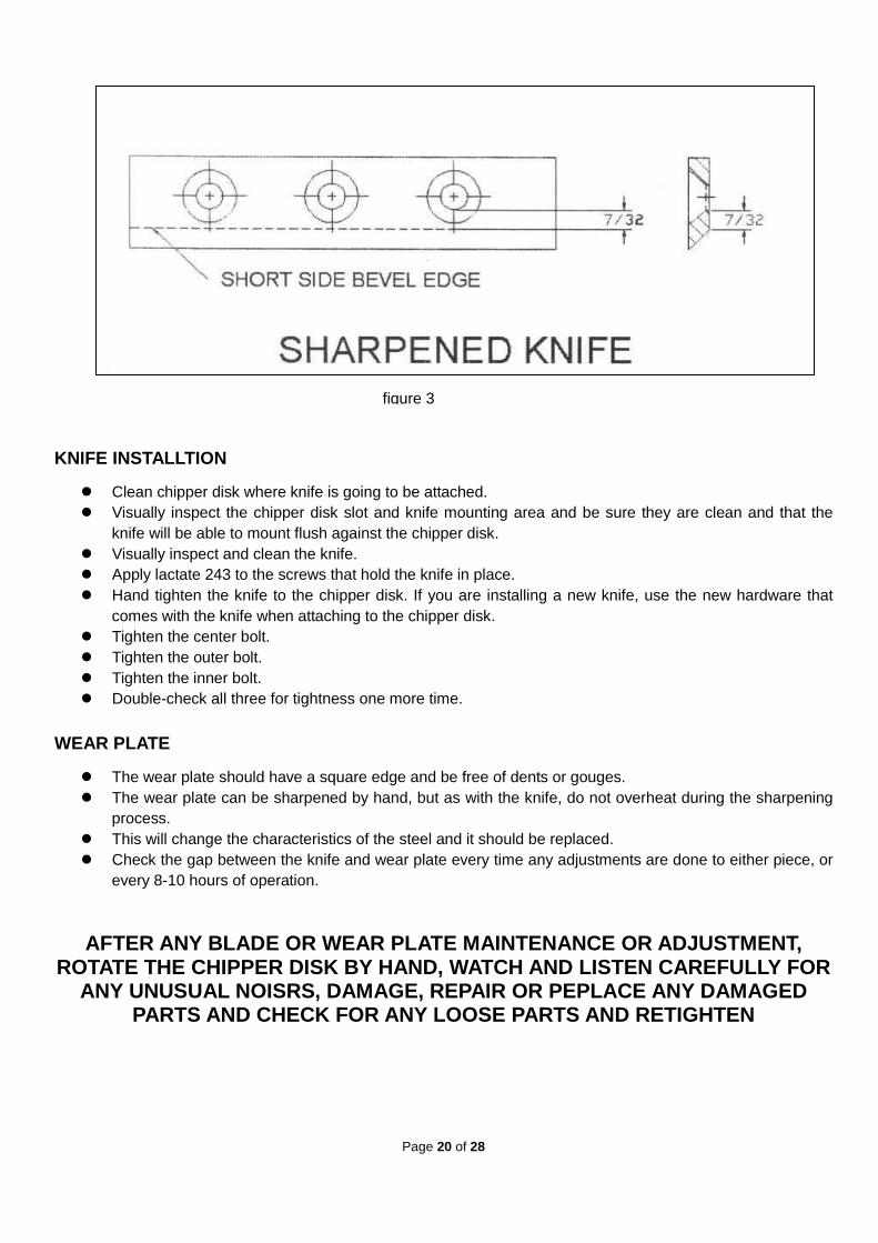
� The knife should never be sharpened to the extent that more than 3/32” is taken off this measurement. � Once this measurement is below 7/32”(see figure 3) the knife should be replaced. � If you are unable to remove dents or gouges with these guideline, replace the knife.
figure 2
Page 20 of 28
KNIFE INSTALLTION
� Clean chipper disk where knife is going to be attached. � Visually inspect the chipper disk slot and knife mounting area and be sure they are clean and that the
knife will be able to mount flush against the chipper disk. � Visually inspect and clean the knife. � Apply lactate 243 to the screws that hold the knife in place. � Hand tighten the knife to the chipper disk. If you are installing a new knife, use the new hardware that
comes with the knife when attaching to the chipper disk. � Tighten the center bolt. � Tighten the outer bolt. � Tighten the inner bolt. � Double-check all three for tightness one more time.
WEAR PLATE
� The wear plate should have a square edge and be free of dents or gouges. � The wear plate can be sharpened by hand, but as with the knife, do not overheat during the sharpening
process. � This will change the characteristics of the steel and it should be replaced. � Check the gap between the knife and wear plate every time any adjustments are done to either piece, or
every 8-10 hours of operation.
AFTER ANY BLADE OR WEAR PLATE MAINTENANCE OR ADJUST MENT, ROTATE THE CHIPPER DISK BY HAND, WATCH AND LISTEN C AREFULLY FOR
ANY UNUSUAL NOISRS, DAMAGE, REPAIR OR PEPLACE ANY D AMAGED PARTS AND CHECK FOR ANY LOOSE PARTS AND RETIGHTEN
figure 3

Page 21 of 28
THE KNIFE MUST BE CHECKED AND MAINTAINED!
KNIVES MUST BE SHARP!
BE SURE TO REINSTALL THE KNIFE CORRECTLY AND DOUBLE CHECK FOR TIGHTNESS
HAMMERS When the hard steel hammers of the rotor assembly become dull or round on the cutting edge, they may be rotated or reversed. These hammers have four cutting edge that may be us ed before replacement is necessary. To reverse the hammers proceed as follows.
� Remove belt guard. � Remove round cover plate from behind belt guard. � Remove the top plate. � Remove shredder hopper. � Turn rotor assembly until hammer rod is facing up. � Turn hammer rod until small end of groove pin is facing up. � Drive the groove pin from the hammer rod with a punch. � Reverse hammers and reinstall with spacers on hammer rod. � Replace old groove pin with new groove pin.
NOTE: Be sure the hammers and spacers are reinstall ed in exactly the order in which they were removed. Refer to the rotor assembly drawing f or the correct order.
INSTRUCTIONS FOR ADJUSTING OR REPLACING BELT
BELT ADJUSTMENT The belt on your chipper should deflect 3/8” under three pounds of pressure as shown in figure 1 below. If it doesn’t, adjust per the following directions.
� Remove belt guard. � Loosen engine bolts. � Tighten or loosen the nut on the belt tension until you have the correct tension as shown in figure 1. � Retighten engine bolts. � Check alignment of the clutch with the drive pulley by placing a straightedge across both faces as shown in
figure 2. If adjustment is necessary, correct alignment by moving rotor pulley in or out on the rotor shaft. Do not make adjustment by moving the clutch on the eng ine shaft.
� Replace belt guard.
figure 1

Page 22 of 28
BELT REPLACEMENT � To replace the belt, follow the above belt adjustment directions. � After you have loosened the engine bolts, remove the old belt and replace it with a new one. � Set belt tension and alignment per above directions.
NOTE: Check and re-tighten belts after initial brea k-in period, one hour of use. CENTRIFUGAL CLUTCH TECH TIPS
CLUTCH PART #62
THE SHOES AND SPRINGS ON THE CLUTCH ARE NORMAL WEAR ITEMS. IF YOU NOTICE DECREASED PERFORMANCE OF THE CLUTCH THEY SHOULD BE CHECKED AND
PERLACED IF NECESSARY.
The clutch on your machine is designed for rugged, dependable service, however, it is important to understand the limitations of a clutch. A clutch is designed to provide load free starting of the engine, and slippage under excessive overloading of the driven application. These features help protect the engine from damages such as broken crankshafts and starters.
The clutch obtain its power from engine RPM’s. The lower the engagement speed, and the higher the maintained engine speed, the more torque the clutch can transfer to the driven unit. Do not operate at less than full RPM’s
� At engine start-up, the engine of your chipper operates under no load until approximately 1000-1200 RPM’s at which speed the centrifugal clutch engages and begins driving the rotor.
� Proper rotor speed is 2400 RPM +/- 200 RPM. � Do not tamper with the engine’s governor setting. The governor controls the maximum safe
operation speed and protects the engine. Over-speeding the engine is dangerous and will cause damage to the engine and to the other moving parts of the machine. See your authorized dealer for engine governor adjustments.
� Become familiar with successful operating conditions and avoid those that can overload and damage the machine.
� Do not overload or attempt to chip material beyond manufacturers recommendation. Personal injury or damage to the machine could result.
figure 2.

Page 23 of 28
� Learn to recognize the sound of the machine when it is overloaded. � If the machine becomes jammed by overloading or any other cause, stop the machine
immediately. � If you jam the machine and do not stop the engine, it can:
� Burn the belt. � Ruin the clutch.
� Only your operator experience will tell you how fast you can successfully feed limbs into the machine.
� Clutch damage can be costly and it may not be cover ed under warranty. For this reason. It is important that you immediately shut off the m achine if it become jammed
CLUTCH MAINTENANCE The centrifugal clutch on this machine is permanently lubricated and does not require oil or grease. If, after long periods of use, the drum wobbles excessively, replace the drum assembly. Always replace shoes and springs in sets. Whenever shoes are changed, replace all springs. CLUTCH REMOVAL 1. Remove clutch from shaft by removing bolt and washers. 2. Slide clutch off shaft. 3. Remove key from keyway. INSTALLATION OF A NEW CLUTCH 1. Clean shaft and remove any burrs. 2. Apply anti-seize compound to the shaft. 3. Place key in keyway on shaft. 4. Slide clutch onto shaft, secure with bolt, lock washer and flat washer(items #29,64 & 63). 5. Tighten bolt

Page 24 of 28
TROUBLESHOOTING
SYMPTOM PROBLEM CORRECTION Clutch overheats. Belt burns Flywheel won’t turn.
Clutch is slipping or flywheel is Jammed or stopped.
Immediately stop engine. Remove spark plug wires. Turn flywheel by hand to Be sure it turns freely. Check belt tension.
Chipping action seems too Slow or flywheel stalling.
Engine speed is too slow. Belts are slipping.
Run engine at full throttle. Check for loose or missing Belt & tighten.
When chipping, log seems to Vibrate excessively & “hammers” hands.
Knife is dull. Gap between knife & wear Plate is too great.
Remove knife & sharpen – Be sure to maintain same Bevel of 45 degrees. Adjust gap as per Instructions.
Chipper knife is hitting wear Plate.
The gap between the knife and wear plate is set incorrectly.
Adjust gap per directions In the front of this section.
Engine runs but flywheel Doesn’t rotate.
Inner shoes of clutch worn. Retaining springs weak or Broken. Loose drive belt.
Replace worn or broken Clutch parts. Check belt tension. Clear chipper chamber.

Page 25 of 28
LUBRICATION AND MAINTENANCE
OPERATION
TIME PROCEDURE COMMENTS
BREAK IN
Change engine oil and Filter after first five Hours. Check belt tension. Check all nuts and Bolts for tightness.
Follow oil Recommendations per The engine & owner’s Manual. Adjust per directions. Tighten if necessary.
8 HOURS
Check engine oil. Check chipper knife For sharpness. Check knife and wear Plate gap. Clean air filter. Grease bearings on Basic chipper.*
Per recommendations, Do not overfill. See knife information. See gap setting Information. Per engine Recommendations. Use quality general- Purpose grease.
40 HOURS
Change engine oil.** Check tire pressure. Remove and sharpen Or replace chipper Knife. Sharpen wear plate.
Per recommendations. Do not overfill. Add or adjust as Required. See knife information. See wear plate Information.
100 HOURS
Replace belt. Change engine oil.
Order replacement belts. Per recommendations. Do not overfill.
200 HOURS
Change engine oil Filter. Clean and adjust, or Replace spark plugs.
Per recommendations in engine manual. Per recommendations In engine manual.
* No more than three pumps of a hand-pumped grease gun. Do not over-grease as this may damage the bearing seal. ** Lubrication schedule may vary depending on working environment. Overly dirty and dusty situations will require more frequent oil changes to protect the engine

Page 26 of 28
DRAWING & PARTS LIST

Page 27 of 28
ITEM DESCRIPTION QTY ITEM DESCRIPTION QTY
1 Pin 4 30 Hex Bolt M10X30 2
2 R Pin Ø3 4 31 Screw M10X16 2
3 Guide Board 1 32 Blade Location Cap 1
4 Sieve 1 33 Blade Assembly 1
5 Pan head screws M5X16 3 34 Front Plate Assembly 1
6 Chipper Hopper 1 35 Outrigger 2
7 Step Bolt M8X20 4 36 Hex Bolt M8X20 11
8 Big Washer Ø8 5 37 Back Axle 1
9 Nylock Nut M8 40 38 Back Axle Bracket 2
10 Rubber Press Plate 1 39 Wheel 4
11 Rubber protective Plate 1 40 Flat Washer Ø16 4
12 Nylock Nut M5 3 41 Cotter Pin Ø3x30 4
13 Screw M8X20 3 42 Axle Bushing 2
14 Blade 1 43 Front Axle 1
15 Hex Bolt M8X245 1 44 Tow Handle 1
16 Step Bolt M6X25 3 45 Front Axle Bracket 1
17 Steel Mat 1 46 Hex Nut M16 1
18 Blade Basic Assembly 1 47 Nylock Nut M16 1
19 Cover Plate 1 48 Bottom Plate 1
20 Hex Bolt M5X8 4 49 Hex Bolt M8X60 4
21 Washer Ø30 6 50 Engine Bottom Assembly 1
22 Axle Insert Retainer Ø30 3 51 Hex Bolt M10X20 4
23 Nylock Nut M10 12 52 Handle Assembly 1
24 Big Washer Ø10 6 53 Hex Bolt M6X40 2
25 Axle Assemble Cap 4 54 Hex Bolt M10X40 2
26 Axle UCL206 2 55 Round Pin Ø12X65 1
27 Nylock Nut M6 44 56 Handle Coupler 2
28 Big Flat Washer Ø6 47 57 R Pin Ø3X75 1
29 Hex Bolt M8X35 6 58 Hex Bolt M10X45 2

Page 28 of 28
ITEM DESCRIPTION QTY ITEM DESCRIPTION QTY
59 Flat Washer Ø10 6 82 Stay Tube 1
60 Belt Tighten Assembly 1 83 Plastic Board 1
61 Engine 1 84 Hex Bolt M6x16 33
62 Clutch 1 85 Shredder Hopper 1
63 Big Washer Ø8 1 86 Washer 4
64 Lock Washer Ø8 1 87 Hex Bolt M8X30 4
65 Triangle Adhesive Tape 1 88 Hex Bolt M8X16 4
66 Belt Cap 1 89 Cover Board 1
67 Flat Washer Ø8 5 90 Inside Hex Screw M10x35 2
68 Belt Pulley 1 91 Press bar for Flex Board 1
69 Screw M8X10 2 92 Hex Bolt M8x255 2
70 Dome 1 93 Engine Cover 1
71 Back Wallboard 1 94 Screw M4x8 3
72 Hex Bolt M8×25 4 95 Axle End Cap 1
73 Pin Axle 4 96 Hex Bolt M6x20 6
74 Spring Pin 4 97 Hopper Transverse Bar 2
75 Sinker Sleeve 2 4 98 Front Frame Assembly 1
76 Revolving Hammer 24 99 Left Frame Assembly 1
77 Sinker Sleeve 1 20 100 Right Frame Assembly 1
78 Sinker Sleeve 3 4 101 Back Frame Assembly 1
79 Principal Axle 1 102 Hopper Large Plate 2
80 Flat Key 1 1 103 Hopper Small Plate 2
81 Flat Key 2 1