Embed Size (px)
Citation preview
8/3/2019 12.15 Transformer Redesign
http://slidepdf.com/reader/full/1215-transformer-redesign 1/14
Transformer ReTransformer Re--DesignDesignDavid Hayes
Rotek Engineering
8/3/2019 12.15 Transformer Redesign
http://slidepdf.com/reader/full/1215-transformer-redesign 2/14
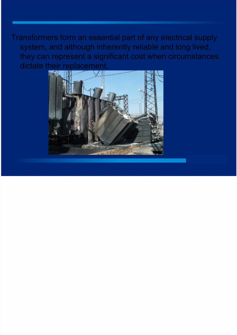
Transformers form an essential part of any electrical supplysystem, and although inherently reliable and long lived,
they can represent a significant cost when circumstances
dictate their replacement.
8/3/2019 12.15 Transformer Redesign
http://slidepdf.com/reader/full/1215-transformer-redesign 3/14
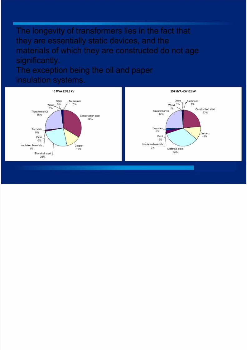
The longevity of transformers lies in the fact that
they are essentially static devices, and thematerials of which they are constructed do not age
significantly.
The exception being the oil and paper
insulation systems.
10 MVA 22/6.6 kV
Construction steel
34%
Copper
13%
Electrical steel
26%
Insulation Materials
1%
Paint
0%
Porcelain0%
Transformer Oil
25%
Wood
1%
Aluminium
0%
Other
0%
250 MVA 400/132 kV
Construction steel
23%
Copper
12%
Electrical steel
34%
Insulation Materials
3%
Paint
0%
Porcelain1%
Transformer Oil
24%
Other
1%
Aluminium
1%Wood
1%
8/3/2019 12.15 Transformer Redesign
http://slidepdf.com/reader/full/1215-transformer-redesign 4/14
Transformer oil, tap changers and bushings can be replaced
onsite as part of a normal maintenance program however paper degradation is non recoverable and is generally
used as the primary indicator of an end of life condition.
Ultimate end of life is considered to be when the paper has
lost its tensile strength (DP of 200)
Typical reasons for transformer replacement:
1. Premature failure
2. End of life3. The requirements of the electrical system have changed.
4. Safety concerns
5. Consequential damage concerns
8/3/2019 12.15 Transformer Redesign
http://slidepdf.com/reader/full/1215-transformer-redesign 5/14
Repairing or remanufacturing the transformers can have asignificant cost benefit especially when multiple units are
involved.
Typically a transformer which is completely re-fitted with
new windings and insulation can cost as little as 60 – 70%
of the price of a new unit and may be considered to be the
equivalent of a new unit in terms of its expected lifespan.
This option can also be beneficial since it utilises a basicdesign which has already proven itself suitable for a
particular application.
8/3/2019 12.15 Transformer Redesign
http://slidepdf.com/reader/full/1215-transformer-redesign 6/14
Repair
•Lowest cost•Perpetuates existing design flaws
Re-Design
•Basic cost not significantly higher
•Corrects design shortcomings
•Can change or improve operational parameters
•Can utilise latest materials and technology
To achieve the best solution the Client must be fully awareof his actual requirements and not create an unrealistic
“wish list”
8/3/2019 12.15 Transformer Redesign
http://slidepdf.com/reader/full/1215-transformer-redesign 7/14
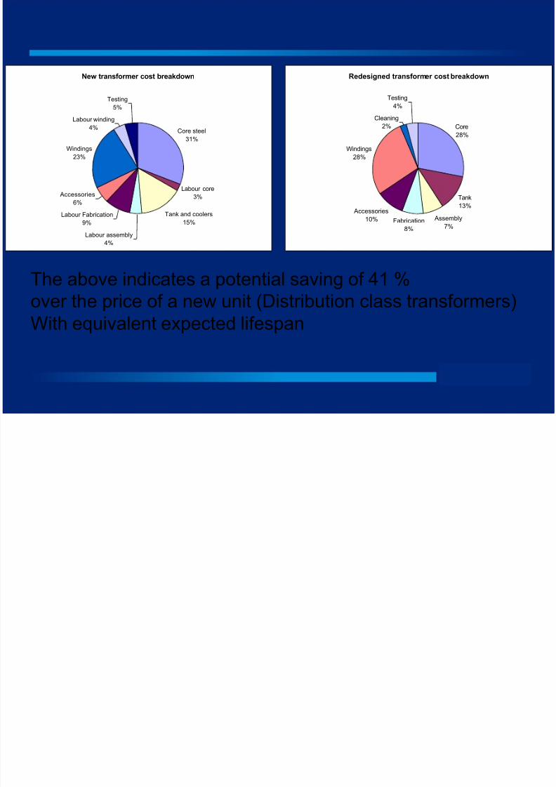
New transformer cost breakdown
Core steel
31%
Labour core
3%
Tank and coolers
15%
Labour assembly
4%
Labour Fabrication
9%
Accessories6%
Windings
23%
Labour winding
4%
Testing
5%
Redesigned transformer cost breakdown
Core
28%
Tank
13%
Assembly
7%Fabrication
8%
Windings
28%
Cleaning
2%
Testing4%
Accessories
10%
The above indicates a potential saving of 41 %
over the price of a new unit (Distribution class transformers)
With equivalent expected lifespan
8/3/2019 12.15 Transformer Redesign
http://slidepdf.com/reader/full/1215-transformer-redesign 8/14
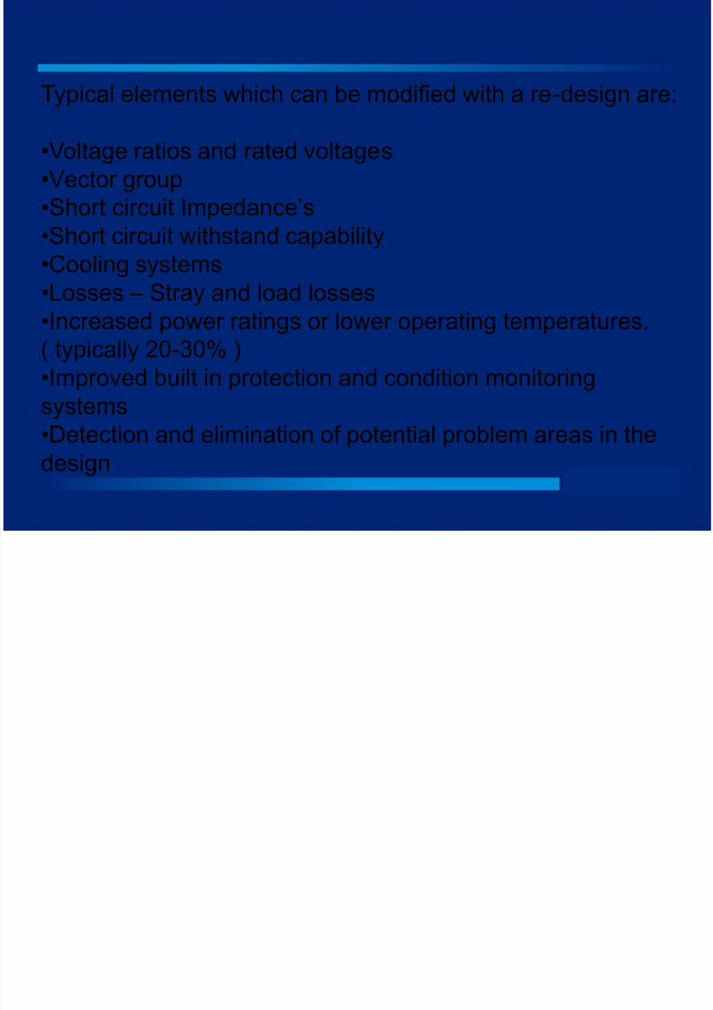
Typical elements which can be modified with a re-design are:
•Voltage ratios and rated voltages
•Vector group
•Short circuit Impedance’s
•Short circuit withstand capability
•Cooling systems
•Losses – Stray and load losses
•Increased power ratings or lower operating temperatures.
( typically 20-30% )
•Improved built in protection and condition monitoringsystems
•Detection and elimination of potential problem areas in the
design
8/3/2019 12.15 Transformer Redesign
http://slidepdf.com/reader/full/1215-transformer-redesign 9/14
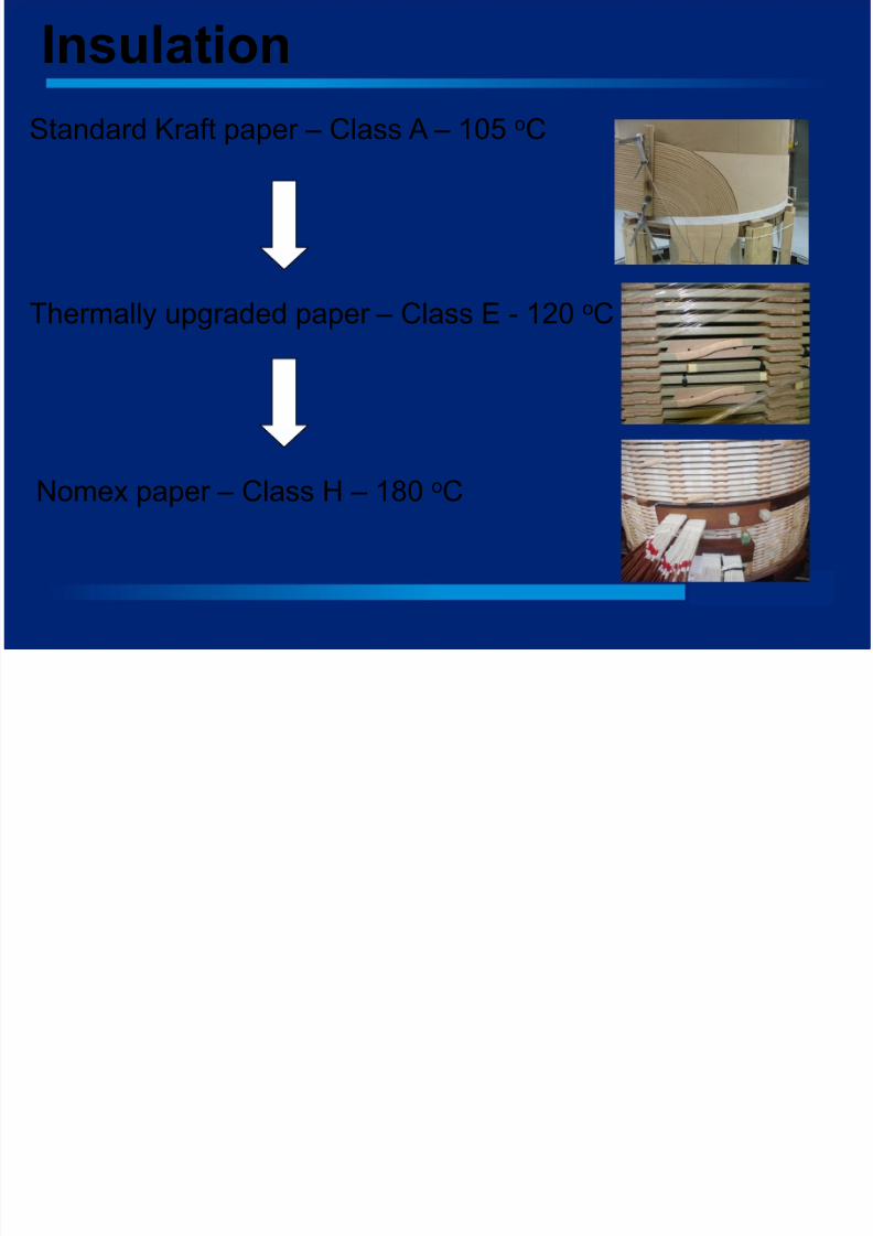
Insulation
Standard Kraft paper – Class A – 105 oC
Thermally upgraded paper – Class E - 120 oC
Nomex paper – Class H – 180 oC
8/3/2019 12.15 Transformer Redesign
http://slidepdf.com/reader/full/1215-transformer-redesign 10/14
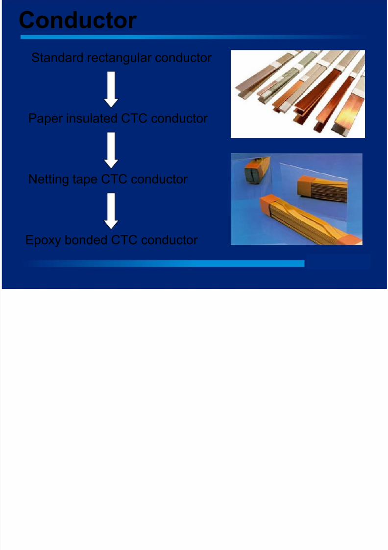
Conductor
Standard rectangular conductor
Paper insulated CTC conductor
Netting tape CTC conductor
Epoxy bonded CTC conductor
8/3/2019 12.15 Transformer Redesign
http://slidepdf.com/reader/full/1215-transformer-redesign 11/14
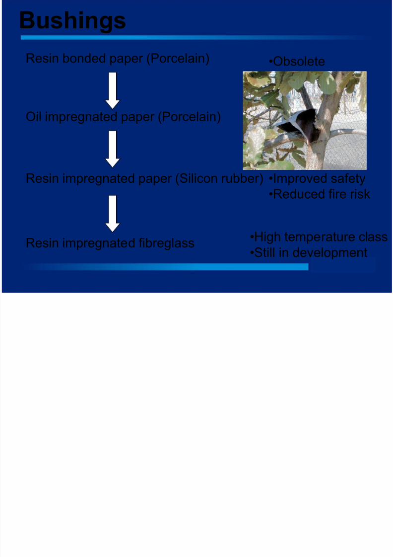
Bushings
Resin bonded paper (Porcelain)
Oil impregnated paper (Porcelain)
Resin impregnated paper (Silicon rubber)
Resin impregnated fibreglass
•Improved safety
•Reduced fire risk
•High temperature class
•Still in development
•Obsolete
8/3/2019 12.15 Transformer Redesign
http://slidepdf.com/reader/full/1215-transformer-redesign 12/14
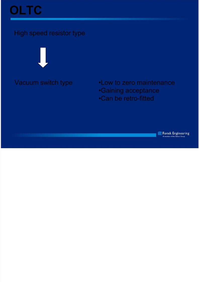
OLTC
High speed resistor type
Vacuum switch type •Low to zero maintenance
•Gaining acceptance
•Can be retro-fitted
8/3/2019 12.15 Transformer Redesign
http://slidepdf.com/reader/full/1215-transformer-redesign 13/14
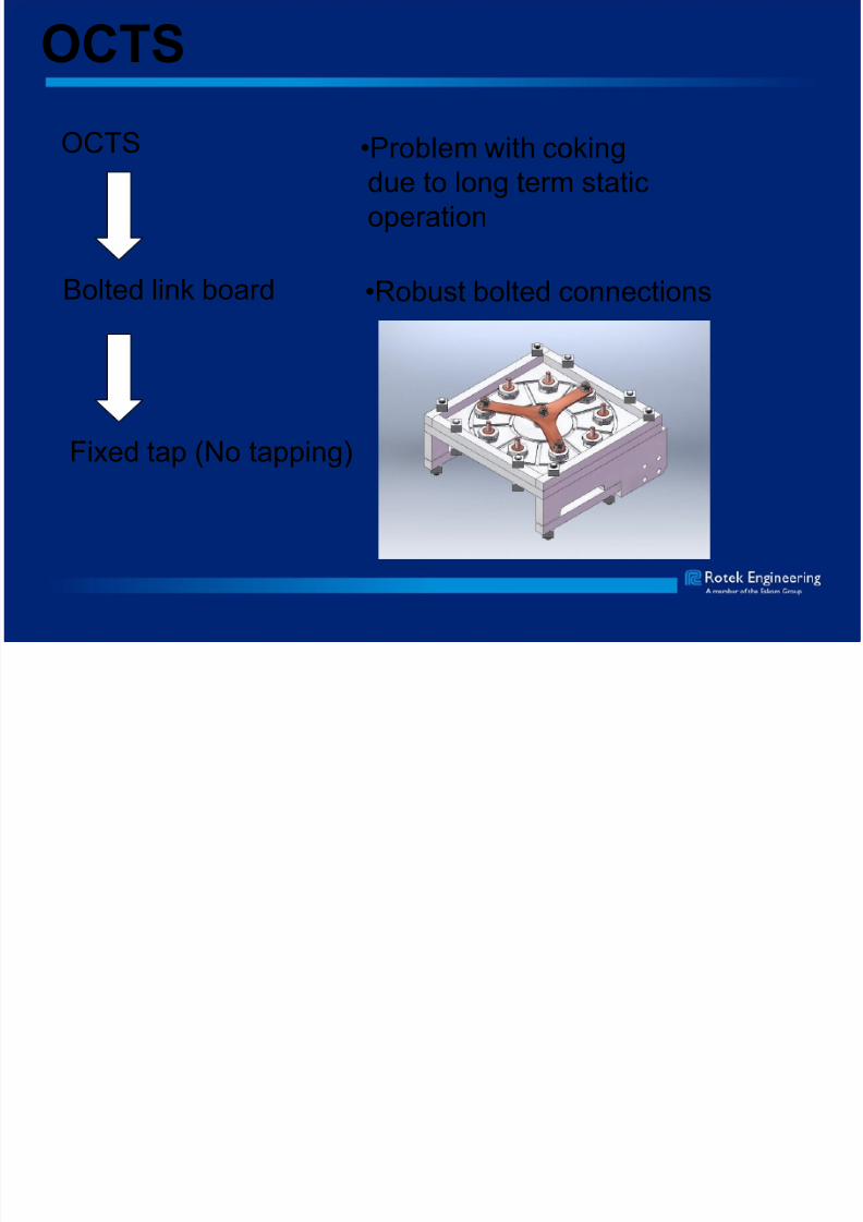
OCTS
OCTS
Bolted link board
Fixed tap (No tapping)
•Problem with cokingdue to long term static
operation
•Robust bolted connections
8/3/2019 12.15 Transformer Redesign
http://slidepdf.com/reader/full/1215-transformer-redesign 14/14
Conclusion
Transformer design is basically a trade off of desired
performance criteria, and can be approached in anumber of ways depending on the relative importance of
the various requirements.
In re-designing a transformer utilising the existing coreand structural elements, it is possible to enhance critical
performance criteria to achieve an optimal design which
is equivalent to a new unit at a reduced cost.