Embed Size (px)
Citation preview
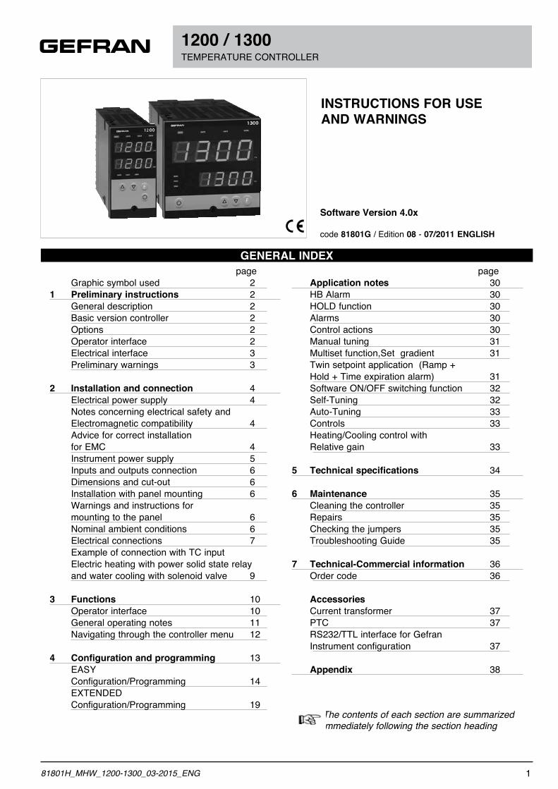
1200 / 1300 TEMPERATURE CONTROLLER
Software Version 4.0x
code 81801G / Edition 08 - 07/2011 ENGLISH
INSTRUCTIONS FOR USE AND WARNINGS
GENERAL INDEX page Graphic symbol used 21 Preliminary instructions 2 General description 2 Basic version controller 2 Options 2 Operator interface 2 Electrical interface 3 Preliminary warnings 3
2 Installation and connection 4 Electrical power supply 4 Notes concerning electrical safety and Electromagnetic compatibility 4 Advice for correct installation for EMC 4 Instrument power supply 5 Inputs and outputs connection 6 Dimensions and cut-out 6 Installation with panel mounting 6 Warnings and instructions for mounting to the panel 6 Nominal ambient conditions 6 Electrical connections 7 Example of connection with TC input Electric heating with power solid state relay and water cooling with solenoid valve 9
3 Functions 10 Operator interface 10 General operating notes 11 Navigating through the controller menu 12
4 Configuration and programming 13 EASY Configuration/Programming 14 EXTENDED Configuration/Programming 19
page Application notes 30 HB Alarm 30 HOLD function 30 Alarms 30 Control actions 30 Manual tuning 31 Multiset function,Set gradient 31 Twin setpoint application (Ramp + Hold + Time expiration alarm) 31 Software ON/OFF switching function 32 Self-Tuning 32 Auto-Tuning 33 Controls 33 Heating/Cooling control with Relative gain 33
5 Technical specifications 34
6 Maintenance 35 Cleaning the controller 35 Repairs 35 Checking the jumpers 35 Troubleshooting Guide 35
7 Technical-Commercial information 36 Order code 36
Accessories Current transformer 37 PTC 37 RS232/TTL interface for Gefran Instrument configuration 37
Appendix 38
The contents of each section are summarized immediately following the section heading
181801H_MHW_1200-1300_03-2015_ENG
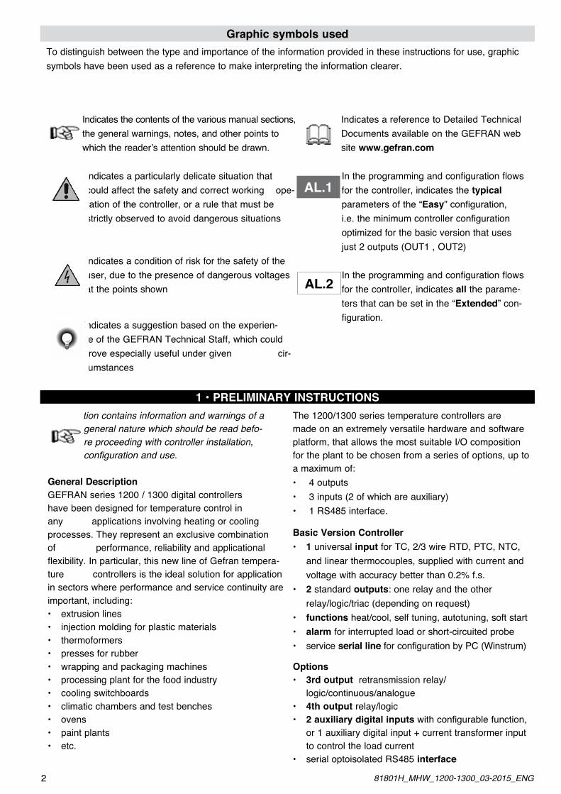
Graphic symbols usedTo distinguish between the type and importance of the information provided in these instructions for use, graphic symbols have been used as a reference to make interpreting the information clearer.
Indicates the contents of the various manual sections, the general warnings, notes, and other points to which the reader’s attention should be drawn.
Indicates a particularly delicate situation that could affect the safety and correct working ope-ration of the controller, or a rule that must be strictly observed to avoid dangerous situations
Indicates a condition of risk for the safety of the user, due to the presence of dangerous voltages at the points shown
Indicates a suggestion based on the experien-ce of the GEFRAN Technical Staff, which could prove especially useful under given cir-cumstances
Indicates a reference to Detailed Technical Documents available on the GEFRAN web site www.gefran.com
In the programming and configuration flows for the controller, indicates the typical parameters of the “Easy” configuration, i.e. the minimum controller configuration optimized for the basic version that uses just 2 outputs (OUT1 , OUT2)
In the programming and configuration flows for the controller, indicates all the parame-ters that can be set in the “Extended” con-figuration.
AL.1
AL.2
1 • PRELIMINARY INSTRUCTIONSThis section contains information and warnings of a
general nature which should be read befo-re proceeding with controller installation, configuration and use.
General DescriptionGEFRAN series 1200 / 1300 digital controllers have been designed for temperature control in any applications involving heating or cooling processes. They represent an exclusive combination of performance, reliability and applicational flexibility. In particular, this new line of Gefran tempera-ture controllers is the ideal solution for application in sectors where performance and service continuity are important, including:• extrusionlines• injectionmoldingforplasticmaterials• thermoformers• pressesforrubber• wrappingandpackagingmachines• processingplantforthefoodindustry• coolingswitchboards• climaticchambersandtestbenches• ovens• paintplants• etc.
The 1200/1300 series temperature controllers are made on an extremely versatile hardware and software platform, that allows the most suitable I/O composition for the plant to be chosen from a series of options, up to a maximum of:• 4outputs• 3inputs(2ofwhichareauxiliary)• 1RS485interface.
Basic Version Controller• 1 universal input for TC, 2/3 wire RTD, PTC, NTC, and linear thermocouples, supplied with current and voltage with accuracy better than 0.2% f.s.• 2 standard outputs: one relay and the other relay/logic/triac (depending on request)• functions heat/cool, self tuning, autotuning, soft start• alarm for interrupted load or short-circuited probe• serviceserial line for configuration by PC (Winstrum)
Options• 3rd output retransmission relay/ logic/continuous/analogue• 4th output relay/logic • 2 auxiliary digital inputs with configurable function, or 1 auxiliary digital input + current transformer input to control the load current• serialoptoisolatedRS485interface
2 81801H_MHW_1200-1300_03-2015_ENG
Operator InterfaceAll the operator interface devices are concentrated on the controller faceplate, suitably protected by a mem-brane in Lexan that guarantees IP65 level protection.• 4buttonstobeusedformanualregulation/ configuration/selection • 2greenfour-digitdisplays (Process Variable and Set point Variable)• 4redLEDsforstatusindicationofsamenumberof relay/logic outputs• 3LEDswithprogramfunctiontoindicatecontroller operating mode.
Electrical InterfaceAll connection terminals (power supply, inputs, outputs, options) are grouped together on the back of the controller.For technical specifications and performance details refer to Section 5 “Technical Specifications”.
Preliminary Warnings
The following preliminary warnings should be read before installing and using the series 1200/1300 controller . This will allow the control- ler to be put into service more quickly and will
avoid certain problems which may mistakenly be interpreted as malfunctions or limitations of the controller.• Immediatelyafterunpackingthecontroller,makea note of the order code and the other identification data given on the label affixed to the outside of the container and copy them to the table below. These details must always be kept close at hand and referred to the personnel involved in the event of help from Gefran Customer Service Assistance.
• Checkalsothatthecontrolleriscompleteandhas not been damaged at all during transit, and that the package contains not only the controller and these Instructions for Use, but also the two brackets for fixing to the panel and the dust protection seal - see: Installation with Panel Fixing in Section 2. Any inconsistencies, omissions or evident signs of damage should be reported immediately to your Gefran sales agent.• Checkthattheordercodecorrespondswiththe configuration requested for the application the controller is needed for, referring to Section 7:
“Technical - Commercial Information”. • No.andTypeofInputs/Outputsavailable • Presenceofthenecessaryoptionsand accessories • Mainsvoltagesupply Example: 1200 – RT – RR – 00 – 0 – 1 Model 1200 controller Output 1 - Relay; Output 2 - Triac (1A) Output 3 - Relay; Output 4 - Relay No Digital Input No Digital Communication Mains Voltage 100...240Vac/dc
• Beforeinstallingtheseries1200/1300controlleron the control panel of the machine or host system, refer to the paragraph “Dimensions and Cut-out” in Section 2 “Installation and Connection”.• WhereconfigurationbyPCisprovidedfor,make sure the interface RS232 cable is available and the CD- ROM containing the WINSTRUM software. For the order code refer to Section 7 “Technical - Commercial Information”.
Users and/or system integrators who wish to know more about the concepts of serial com- munication between standard PC and/or Gefran Industrial PC and Gefran Programmable
Instruments (including the series 1200/1300 controller), can access the various technical reference Documents in Adobe Acrobat format available in the Download section of the Gefran Web Site www.gefran.com including:
•SerialCommunication •MODBusProtocol
In the same Download section of the Gefran Web Site www.gefran.com the 1200/1300 Temperature Controller reference manual is available in Adobe Acrobat format, containing a detailed description of all the adjustable parameters and procedures for the Controller. In the event of presumed instrument malfunction, before contacting Gefran Technical Service Assistance, refer to the Troubleshooting Guide given in Section 6 “Maintenance”, and if necessary refer to the F.A.Q. Section (Frequently Asked Questions) on the Gefran Web Site www.gefran.com
SN: ......................... (Serial no.)CODE: ......................... (Finished product code)TYPE: ......................... (Order Code)SUPPLY: ......................... (Type of electrical power supply)VERS: ......................... (Software version)
381801H_MHW_1200-1300_03-2015_ENG
2 • INSTALLATION AND CONNECTIONThis section contains the instructions necessary for correct installation of the 1200/1300 controllers into the machine control panel or the
host system and for correct connection of the controller power supply, inputs, outputs and interfaces.
Before proceeding with installation read the following warnings carefully! Remember that lack of observation of these warnings could lead to problems of electrical
safety and electromagnetic compatibility, as well as invalidating the warranty.
Electrical power supply
• thecontrollerisNOTequippedwithanOn/Offswitch: the user must provide a two-phase disconnecting switch that conforms to the required safety standards (CE marking), to cut off the power supply upstream of the controller. The switch must be located in the immediate vicinity of the controller and must be within easy reach of the operator. One switch may control more than one controller.• ifthecontrollerisconnectedtoNOTisolatedelectri-cal equipment (e.g. thermocouples), the earth connection must be made with a specific conductor to prevent the connection itself from coming directly through the machine structure.• ifthecontrollerisusedinapplicationswithriskof
damage to persons, machinery or materials, it is essential to connect it up to auxiliary alarm equipment. It is advisable to make sure that alarm signals are also triggered during normal operation. The controller must NOT be installed in flammable or explosive environments; it may be connected to equipment operating in such atmospheres only by means of appropriate and adequate types of interface, conforming to the applicable safety standards.
Notes Concerning Electrical Safety and Electromagnetic Compatibility:
CE MARKING: The instrument conforms to the European Directives 2004/108/CE and 2006/95/CE with reference to the generic standards: EN 61000-6-2 (immunity in industrial environment) EN 61000-6-3 (emission in residential envi-ronment) EN 61010-1 (safety).Series 1200/1300 temperature controllers are mainly designed to operate in industrial environments, installed on the switchboards or control panels of productive process machines or plants.As regards electromagnetic compatibility, the strictest generic standards have been adopted, as indicated in the table below.
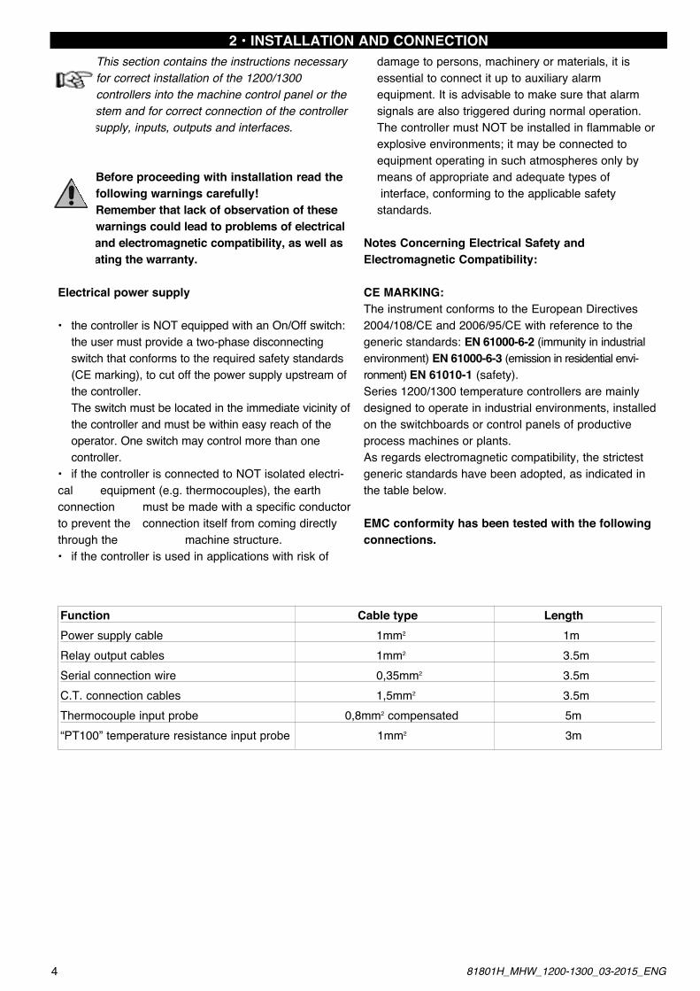
EMC conformity has been tested with the following connections.
Function Cable type LengthPower supply cable 1mm2 1mRelay output cables 1mm2 3.5mSerial connection wire 0,35mm2 3.5mC.T. connection cables 1,5mm2 3.5mThermocouple input probe 0,8mm2 compensated 5m“PT100” temperature resistance input probe 1mm2 3m
4 81801H_MHW_1200-1300_03-2015_ENG
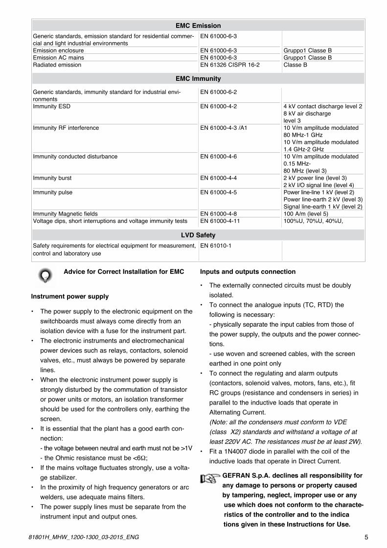
Generic standards, emission standard for residential commer-cial and light industrial environmentsEmission enclosureEmission AC mainsRadiated emission
EN 61000-6-3
EN 61000-6-3 EN 61000-6-3EN 61326 CISPR 16-2
Gruppo1 Classe BGruppo1 Classe BClasse B
EMC Emission
EMC Immunity
Generic standards, immunity standard for industrial envi-ronmentsImmunity ESD
Immunity RF interference
Immunity conducted disturbance
Immunity burst
Immunity pulse
Immunity Magnetic fieldsVoltage dips, short interruptions and voltage immunity tests
EN 61000-6-2
EN 61000-4-2
EN 61000-4-3 /A1
EN 61000-4-6
EN 61000-4-4
EN 61000-4-5
EN 61000-4-8EN 61000-4-11
4 kV contact discharge level 28 kV air discharge level 310 V/m amplitude modulated 80 MHz-1 GHz10 V/m amplitude modulated 1.4 GHz-2 GHz10 V/m amplitude modulated 0.15 MHz-80 MHz (level 3)2 kV power line (level 3)2 kV I/O signal line (level 4)Power line-line 1 kV (level 2)Power line-earth 2 kV (level 3)Signal line-earth 1 kV (level 2)100 A/m (level 5)100%U, 70%U, 40%U,
LVD SafetySafety requirements for electrical equipment for measurement, control and laboratory use
EN 61010-1
Advice for Correct Installation for EMC
Instrument power supply
• Thepowersupplytotheelectronicequipmentonthe switchboards must always come directly from an isolation device with a fuse for the instrument part.• Theelectronicinstrumentsandelectromechanical power devices such as relays, contactors, solenoid valves, etc., must always be powered by separate lines.• Whentheelectronicinstrumentpowersupplyis strongly disturbed by the commutation of transistor or power units or motors, an isolation transformer should be used for the controllers only, earthing the screen.• Itisessentialthattheplanthasagoodearthcon- nection: - the voltage between neutral and earth must not be >1V - the Ohmic resistance must be <6W;• Ifthemainsvoltagefluctuatesstrongly,useavolta- ge stabilizer.• Intheproximityofhighfrequencygeneratorsorarc welders, use adequate mains filters.• Thepowersupplylinesmustbeseparatefromthe instrument input and output ones.
Inputs and outputs connection
• Theexternallyconnectedcircuitsmustbedoubly isolated.• Toconnecttheanalogueinputs(TC,RTD)the following is necessary: - physically separate the input cables from those of the power supply, the outputs and the power connec- tions. - use woven and screened cables, with the screen earthed in one point only• Toconnecttheregulatingandalarmoutputs (contactors, solenoid valves, motors, fans, etc.), fit RC groups (resistance and condensers in series) in parallel to the inductive loads that operate in Alternating Current. (Note: all the condensers must conform to VDE (class X2) standards and withstand a voltage of at least 220V AC. The resistances must be at least 2W).• Fita1N4007diodeinparallelwiththecoilofthe inductive loads that operate in Direct Current.
GEFRAN S.p.A. declines all responsibility forany damage to persons or property caused by tampering, neglect, improper use or any
use which does not conform to the characte- ristics of the controller and to the indica tions given in these Instructions for Use.
581801H_MHW_1200-1300_03-2015_ENG
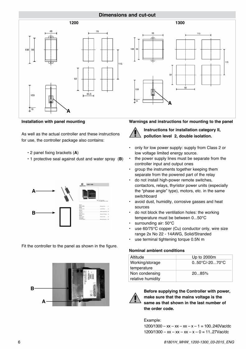
Dimensions and cut-out1200 1300
AA
Installation with panel mounting
As well as the actual controller and these instructions for use, the controller package also contains:
•2panelfixingbrackets(A) •1protectivesealagainstdustandwaterspray(B)
Fit the controller to the panel as shown in the figure.
Warnings and instructions for mounting to the panel
Instructions for installation category II, pollution level 2, double isolation.
• onlyforlowpowersupply:supplyfromClass2or low voltage limited energy source.• thepowersupplylinesmustbeseparatefromthe controller input and output ones• grouptheinstrumentstogetherkeepingthem separate from the powered part of the relay• donotinstallhigh-powerremoteswitches, contactors, relays, thyristor power units (especially the “phase angle” type), motors, etc. in the same switchboard• avoiddust,humidity,corrosivegassesandheat sources• donotblocktheventilationholes:theworking temperature must be between 0...50°C• surroundingair:50°C• use60/75°Ccopper(Cu)conductoronly,wiresize range 2x No 22 - 14AWG, Solid/Stranded• useterminaltighteningtorque0.5Nm
Nominal ambient conditions
Before supplying the Controller with power, make sure that the mains voltage is the same as that shown in the last number of the order code.
Example: 1200/1300 – xx – xx – xx – x – 1 = 100..240Vac/dc 1200/1300 – xx – xx – xx – x – 0 = 11..27Vac/dc
A
B
A
B
Altitude Up to 2000mWorking/storage 0..50°C/-20...70°CtemperatureNon condensing 20...85%relative humidity
6 81801H_MHW_1200-1300_03-2015_ENG
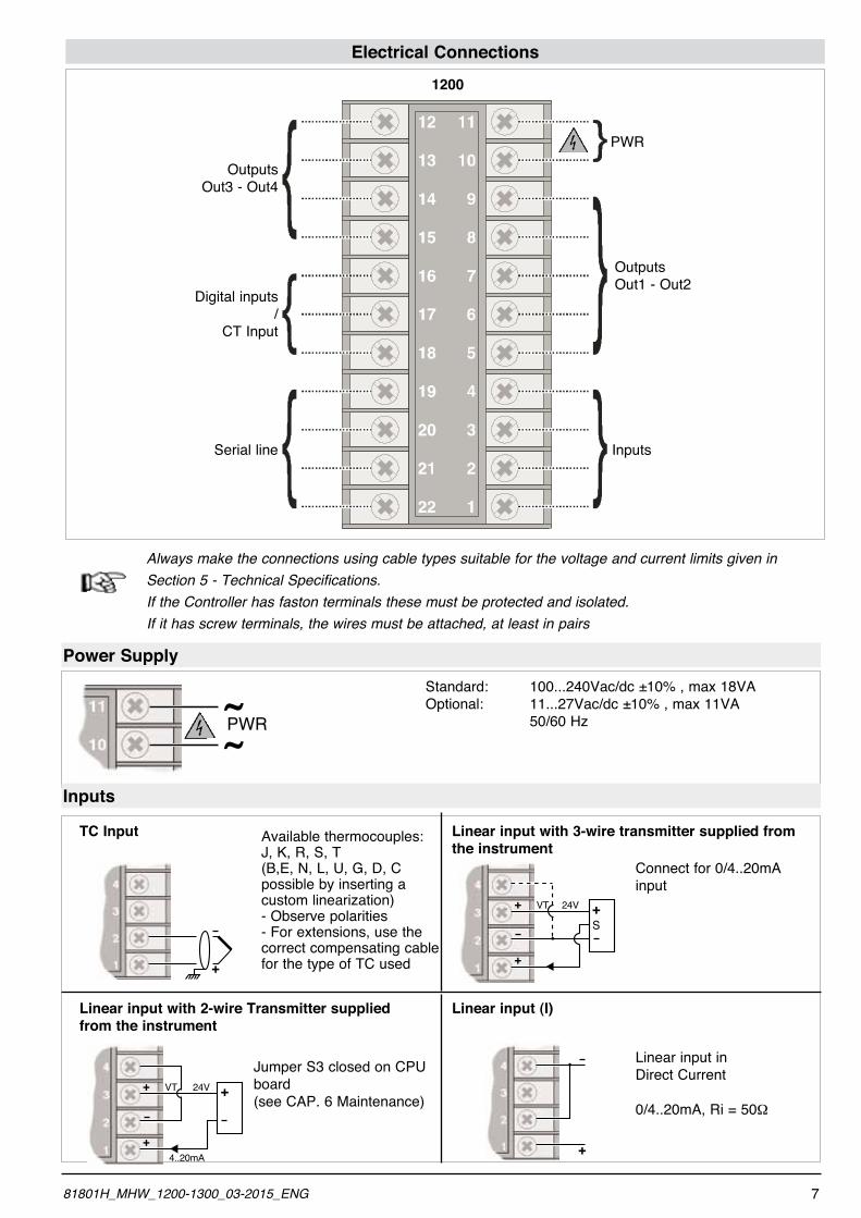
Electrical Connections
PWR
OutputsOut1 - Out2
InputsSerial line
Digital inputs /
CT Input
OutputsOut3 - Out4
1200
Always make the connections using cable types suitable for the voltage and current limits given in Section 5 - Technical Specifications. If the Controller has faston terminals these must be protected and isolated.
If it has screw terminals, the wires must be attached, at least in pairs
Power Supply
Inputs
+
24V
4..20mA
VT ++
+
S
24VVT ++
+
+
Standard: 100...240Vac/dc ±10% , max 18VAOptional: 11...27Vac/dc ±10% , max 11VA 50/60 Hz
Available thermocouples: J, K, R, S, T (B,E, N, L, U, G, D, C possible by inserting a custom linearization) - Observe polarities- For extensions, use the correct compensating cable for the type of TC used
Connect for 0/4..20mA input
Jumper S3 closed on CPU board(see CAP. 6 Maintenance)
Linear input in Direct Current
0/4..20mA, Ri = 50W
TC Input Linear input with 3-wire transmitter supplied from the instrument
Linear input with 2-wire Transmitter supplied from the instrument
Linear input (I)
~~PWR
781801H_MHW_1200-1300_03-2015_ENG
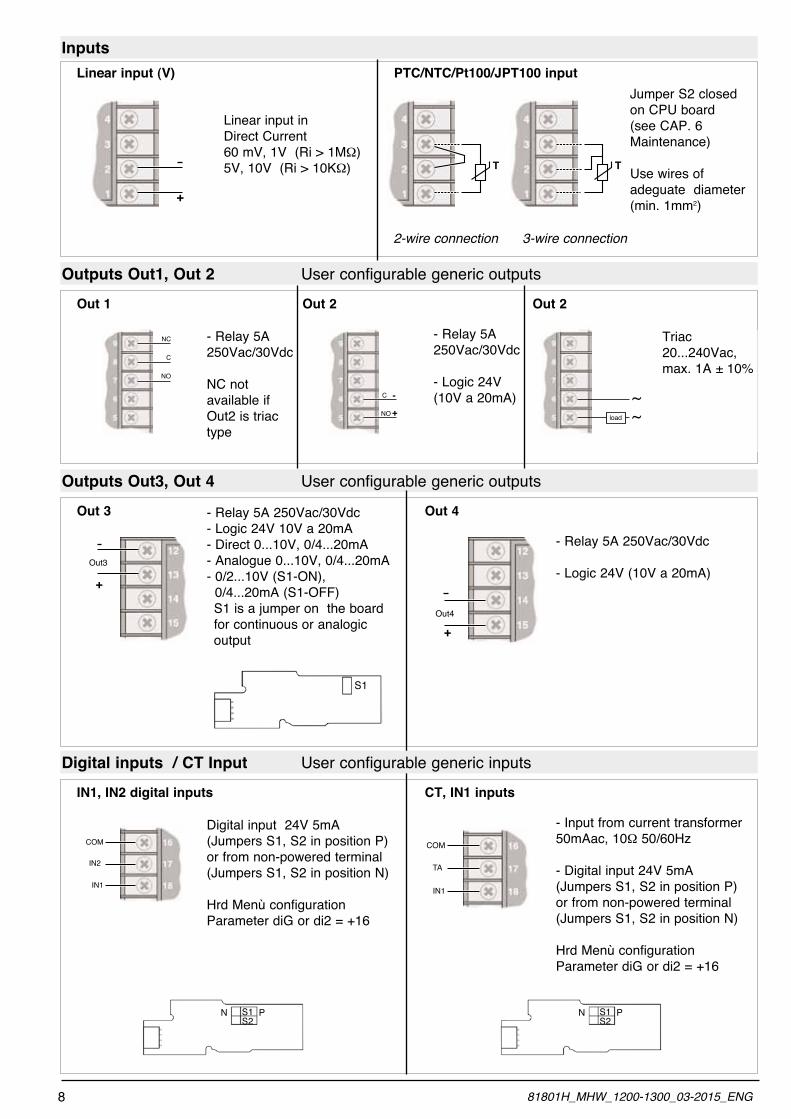
Inputs
+
Linear input in Direct Current 60 mV, 1V (Ri > 1MW)5V, 10V (Ri > 10KW)
Linear input (V) PTC/NTC/Pt100/JPT100 input
T
Jumper S2 closed on CPU board(see CAP. 6 Maintenance)
Use wires of adeguate diameter (min. 1mm2)
2-wire connection 3-wire connection
Outputs Out1, Out 2 User configurable generic outputs
C
NO
NC - Relay 5A 250Vac/30Vdc
NC not available if Out2 is triac type
Out 1
-
+
C
NO
- Relay 5A 250Vac/30Vdc
- Logic 24V (10V a 20mA)
Out 2
~~load
Triac 20...240Vac, max. 1A ± 10%
Out 2
Outputs Out3, Out 4 User configurable generic outputs
- Relay 5A 250Vac/30Vdc - Logic 24V 10V a 20mA - Direct 0...10V, 0/4...20mA - Analogue 0...10V, 0/4...20mA- 0/2...10V (S1-ON), 0/4...20mA (S1-OFF) S1 is a jumper on the board for continuous or analogic output
Out 3
- Relay 5A 250Vac/30Vdc
- Logic 24V (10V a 20mA)
Out 4
Digital input 24V 5mA (Jumpers S1, S2 in position P) or from non-powered terminal (Jumpers S1, S2 in position N)
Hrd Menù configurationParameter diG or di2 = +16
IN1, IN2 digital inputs
- Input from current transformer 50mAac, 10W 50/60Hz
- Digital input 24V 5mA (Jumpers S1, S2 in position P) or from non-powered terminal (Jumpers S1, S2 in position N)
Hrd Menù configurationParameter diG or di2 = +16
CT, IN1 inputs
T
S1
Out3
+
Out4
+
IN2
IN1
COM
TA
IN1
COM
S1S2
N P S1S2
N P
Digital inputs / CT Input User configurable generic inputs
8 81801H_MHW_1200-1300_03-2015_ENG
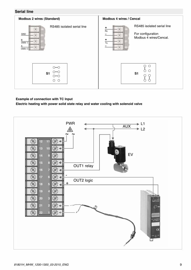
Example of connection with TC InputElectric heating with power solid state relay and water cooling with solenoid valve
EV
L1L2
OUT2 logic
OUT1 relay
AUXPWR
-+
Serial line
(data +)
(data -)
GND
B
A
RS485 isolated serial line
Modbus 2 wires (Standard)
Tx+
Rx+ RS485 isolated serial line
For configurationModbus 4 wires/Cencal.
Modbus 4 wires / Cencal
S1 S1
981801H_MHW_1200-1300_03-2015_ENG
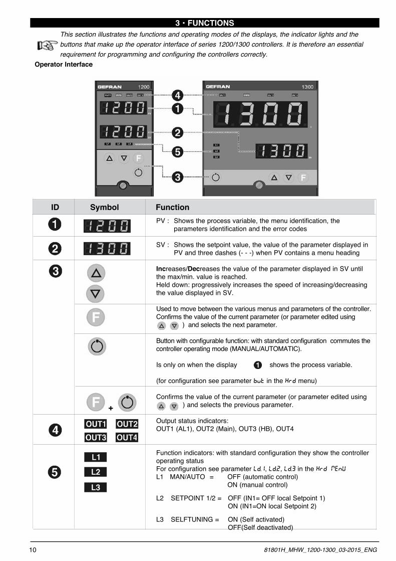
PV : Shows the process variable, the menu identification, the parameters identification and the error codes
SV : Shows the setpoint value, the value of the parameter displayed in PV and three dashes (- - -) when PV contains a menu heading
Increases/Decreases the value of the parameter displayed in SV until the max/min. value is reached.Held down: progressively increases the speed of increasing/decreasing the value displayed in SV.
Used to move between the various menus and parameters of the controller. Confirms the value of the current parameter (or parameter edited using ) and selects the next parameter.
Button with configurable function: with standard configuration commutes the controller operating mode (MANUAL/AUTOMATIC).
Is only on when the display shows the process variable.
(for configuration see parameter BVT in the KRD menu)
Confirms the value of the current parameter (or parameter edited using ) and selects the previous parameter.
Output status indicators:OUT1 (AL1), OUT2 (Main), OUT3 (HB), OUT4
Function indicators: with standard configuration they show the controller operating statusFor configuration see parameter LD.1, LD.2, LD.3 in the KRD menuL1 MAN/AUTO = OFF (automatic control) ON (manual control)
L2 SETPOINT 1/2 = OFF (IN1= OFF local Setpoint 1) ON (IN1=ON local Setpoint 2)
L3 SELFTUNING = ON (Self activated) OFF(Self deactivated)
3 • FUNCTIONSThis section illustrates the functions and operating modes of the displays, the indicator lights and the buttons that make up the operator interface of series 1200/1300 controllers. It is therefore an essential requirement for programming and configuring the controllers correctly.
Operator Interface
ID Symbol Function
+
10 81801H_MHW_1200-1300_03-2015_ENG
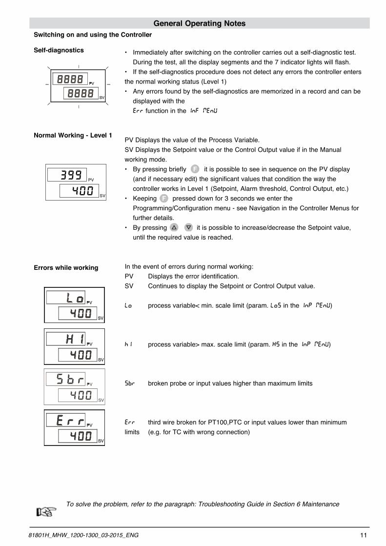
General Operating Notes
• Immediatelyafterswitchingonthecontrollercarriesoutaself-diagnostictest. During the test, all the display segments and the 7 indicator lights will flash.• Iftheself-diagnosticsproceduredoesnotdetectanyerrorsthecontrollerentersthe normal working status (Level 1)• Anyerrorsfoundbytheself-diagnosticsarememorizedinarecordandcanbe displayed with the ERR function in the INF menu
PV Displays the value of the Process Variable.SV Displays the Setpoint value or the Control Output value if in the Manual working mode.• BypressingbrieflyitispossibletoseeinsequenceonthePVdisplay (and if necessary edit) the significant values that condition the way the controller works in Level 1 (Setpoint, Alarm threshold, Control Output, etc.)• Keepingpresseddownfor3secondsweenterthe Programming/Configuration menu - see Navigation in the Controller Menus for further details.• Bypressingitispossibletoincrease/decreasetheSetpointvalue, until the required value is reached.
In the event of errors during normal working:PV Displays the error identification.SV Continues to display the Setpoint or Control Output value.
LO process variable< min. scale limit (param. LOS in the INP menu)
HI process variable> max. scale limit (param. K’S in the INP menu)
SBR broken probe or input values higher than maximum limits
ERR third wire broken for PT100,PTC or input values lower than minimum limits (e.g. for TC with wrong connection)
To solve the problem, refer to the paragraph: Troubleshooting Guide in Section 6 Maintenance
Switching on and using the Controller
Self-diagnostics
Normal Working - Level 1
Errors while working
399 PV
SV400
1181801H_MHW_1200-1300_03-2015_ENG
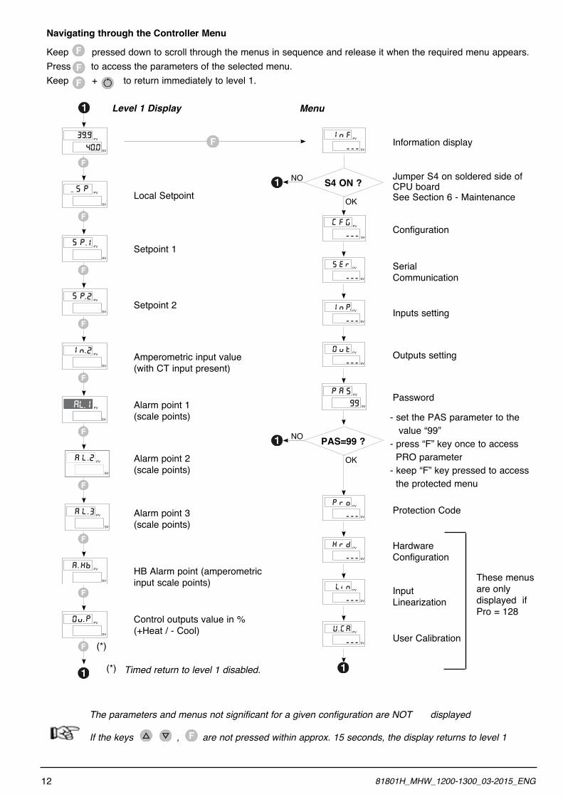
Navigating through the Controller Menu
Keep pressed down to scroll through the menus in sequence and release it when the required menu appears.Press to access the parameters of the selected menu.Keep + to return immediately to level 1.
Level 1 Display Menu
PV
SV
39.9
40.0
PV
SV
nI F
---
PV
SV
PS
PV
SV
PS .I
PV
SV
PS . 2
PV
SV
nI . 2
AL.I PV
SV
PV
SV
KA . b
PV
SV
v0 . P
Local Setpoint
Setpoint 1
Setpoint 2
Amperometric input value (with CT input present)
Alarm point 1(scale points)
Alarm point 2(scale points)
Alarm point 3(scale points)
HB Alarm point (amperometric input scale points)
Control outputs value in % (+Heat / - Cool)
Timed return to level 1 disabled.
(*)
(*)
Information display
Jumper S4 on soldered side of CPU boardSee Section 6 - Maintenance
PV
SV
FG G
---
OK
S4 ON ?NO
PV
SV
ES R
---
PV
SV
nI P.
---
PV
SV
v0 t
---
PV
SV
AP S
99
OK
PAS=99 ?NO
PV
SV
rP o
---
PV
SV
rK d
---
PV
SV
iL n
---
PV
SV
U GA
---
.
Configuration
Serial Communication
Inputs setting
Outputs setting
Password
Protection Code
Hardware Configuration
InputLinearization
User Calibration
The parameters and menus not significant for a given configuration are NOT displayed
If the keys , are not pressed within approx. 15 seconds, the display returns to level 1
- set the PAS parameter to the value “99”- press “F” key once to access PRO parameter- keep “F” key pressed to access the protected menu
These menus are only displayed ifPro = 128
12 81801H_MHW_1200-1300_03-2015_ENG
PV
SV
LA . 2
PV
SV
LA . 3
4 • CONFIGURATION / PROGRAMMINGThis section contains the instructions necessary to configure the 1200/1300 Controller according to the needs of the application..
Optimal working operation of the 1200/1300 Controller in the field of application it is intended for depends largely on correct configuration and programming of the relevant control parameters.The flexibility and high performance level of these instruments is in fact based on the numerous parameters that can be programmed directly by the user with the buttons on the con-trol panel, or transferred from a PC, in the form of configu-ration files, by means of the RS485 interface available as an option on 1200/1300 Controllers.
Easy configurationTo simplify the Controller configuration and programming pro-cess in the most common temperature control applications, that do not require very complex controls, there is a simplified level of configuration (“Easy”) suitable for the basic instrument versions, with just two outputs (Out1 - Out2).
The Easy configuration essentially has three menus:(FG : general Controller configurationINP : input functioning mode0VT : output functioning mode
which involve setting a limited number of parameters (maximum 13), as well as setting the AL.1 alarm point that can be done directly in level 1.
Extended ConfigurationAccess to all the configuration / programming menus and to all the parameters available for the 1200/1300 controllers in extended configuration, allows every detail of the Controller to be configured, to satisfy all application requirements.
Correct setting of the parameters involved in the extended configuration presumes a high level of knowledge regarding temperature control problems and techniques, and so it is recommended that these
parameters are not changed unless the user is fully aware of the consequences, that could arise form incorrect settings.
It is the user’s responsibility to check that the parameters are set correctly before putting the Controller into service, in order to avoid damage to persons or property.
For any doubts or clarification needed, please visit the Web Site www.gefran.com and if necessary contact the Gefran Customer Care service..
To select the Extended configuration mode, 128 must be added to the value of the PRO parameter that appears when scrolling through the Controller menu - see Navigating through the Controller Menus.The following pages describe one by one the various Controller menus and show for each parameter the concise description of the function performed, any default values and the range of values that can be set.
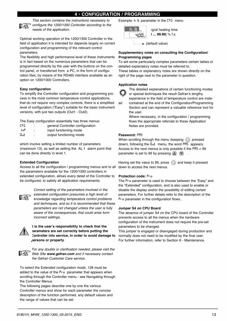
Example: H.IT parameter in the (FG menu
Integral heating time [0.0 ... 99.99] % f.s.
(default value)
Supplementary notes on consulting the Configuration/ Programming pagesTo set some particularly complex parameters certain tables or detailed explanatory notes must be referred to.These tables or explanatory notes are shown directly on the right of the page next to the parameter in question.
Application notes The detailed explanations of certain functioning modes or special techniques the result Gefran’s lengthy experience in the field of temperature control are inste-
ad contained at the end of the Configuration/Programming Section and can represent a valuable reference tool for the user. Where necessary, in the configuration / programming flows the appropriate referrals to these Application Notes are provided.
Password: PASWhen scrolling through the menu (keeping pressed down), following the 0VT menu, the word PAS appears.Access to the next menus is only possible if the PAS = 99 parameter is set to 99 by pressing .
Having set the value to 99, press and keep it pressed down to access the next menus.
Protection code: PROThe PRO parameter is used to choose between the “Easy” and the “Extended” configuration, and is also used to enable or disable the display and/or the possibility of editing certain parameters. For further details refer to the description of the PRO parameter in the configuration flows..
Jumper S4 on CPU BoardThe absence of jumper S4 on the CPU board of the Controller prevents access to all the menus when the hardware configuration of the instrument does not require the pre-set parameters to be changed.This jumper is engaged or disengaged during production and normally does not need to be modified by the final user.For further information, refer to Section 6 - Maintenance.
4.00
h.It PV
SV
1381801H_MHW_1200-1300_03-2015_ENG
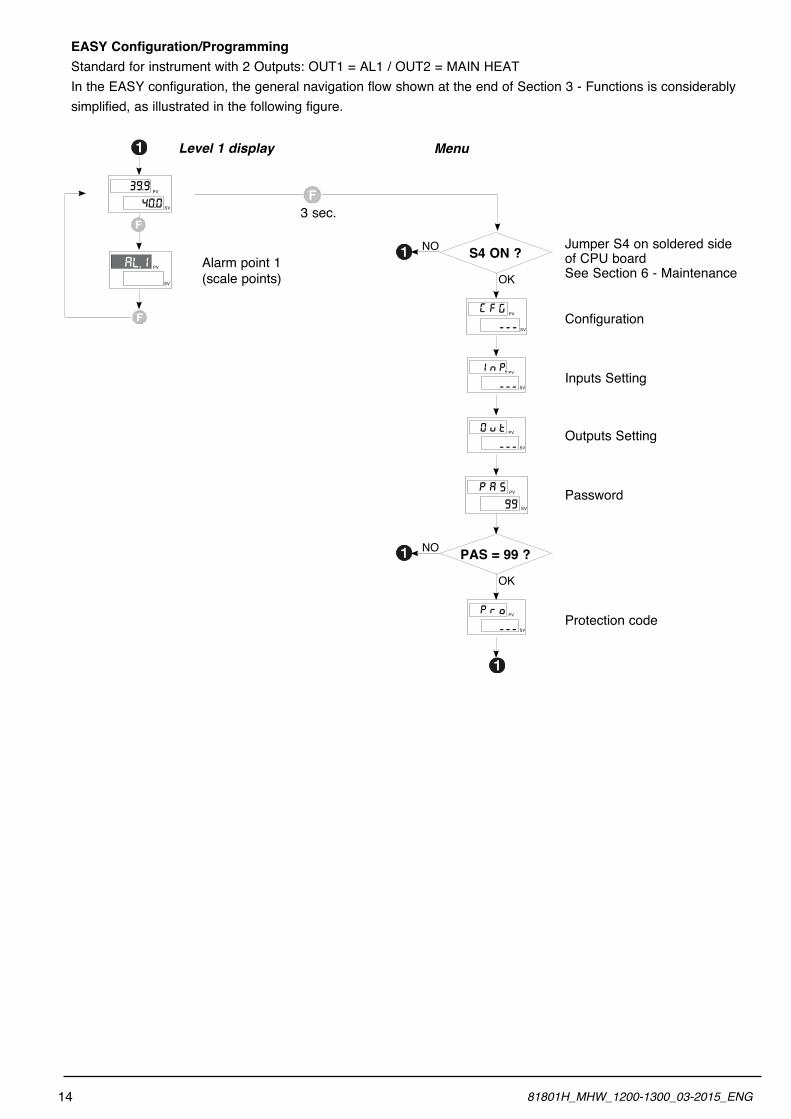
EASY Configuration/Programming Standard for instrument with 2 Outputs: OUT1 = AL1 / OUT2 = MAIN HEATIn the EASY configuration, the general navigation flow shown at the end of Section 3 - Functions is considerably simplified, as illustrated in the following figure.
Level 1 display Menu
PV
SV
39.9
40.0 3 sec.
Jumper S4 on soldered side of CPU boardSee Section 6 - Maintenance
PV
SV
FG G
---
OK
S4 ON ?NO
PV
SV
nI P.
---
PV
SV
v0 t
---
PV
SV
AP S
99
Configuration
Inputs Setting
Outputs Setting
Password
AL.I PV
SV
Alarm point 1 (scale points)
PV
SV
rP o
---
OK
PAS = 99 ?NO
Protection code
14 81801H_MHW_1200-1300_03-2015_ENG
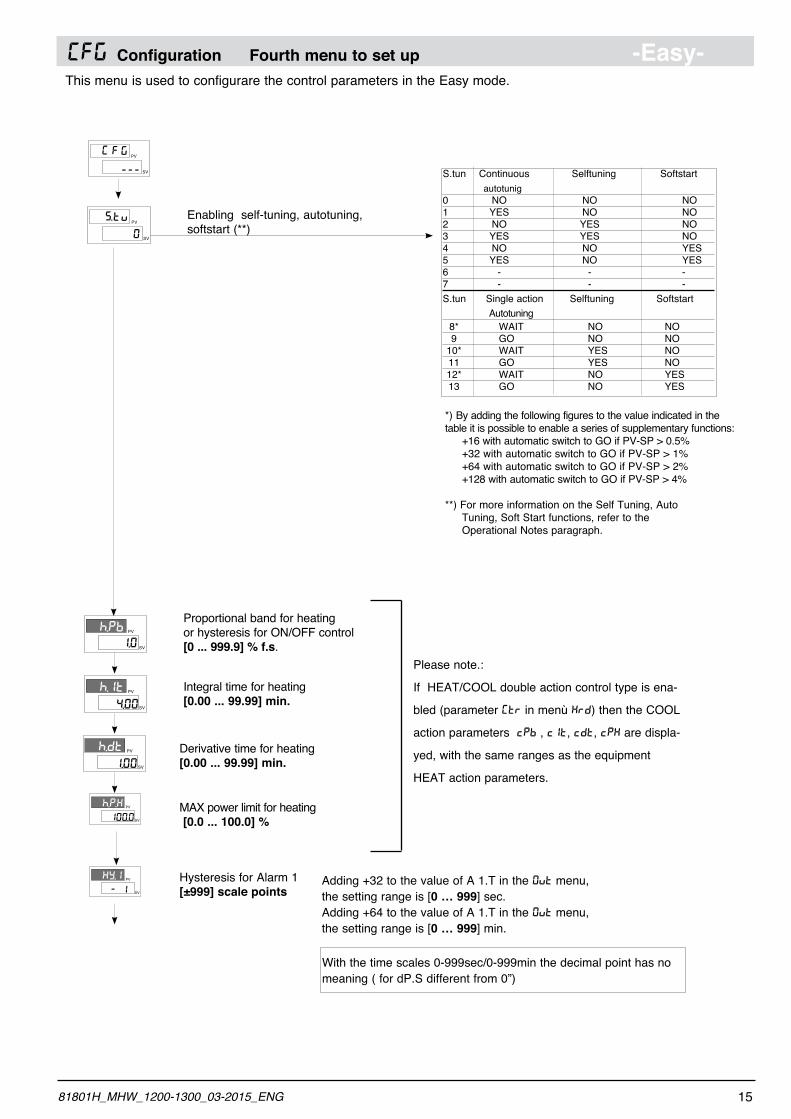
(FG Configuration Fourth menu to set up -Easy-This menu is used to configurare the control parameters in the Easy mode.
PV
SV
FG G
---
1.0
h.Pb PV
SV
4.00
h.It PV
SV
Proportional band for heatingor hysteresis for ON/OFF control[0 ... 999.9] % f.s.
Integral time for heating[0.00 ... 99.99] min.
1.00
h.dt PV
SV
100.0
h.P.K PV
SV
- 1
KY.i PV
SV
MAX power limit for heating [0.0 ... 100.0] %
Hysteresis for Alarm 1[±999] scale points
Derivative time for heating [0.00 ... 99.99] min.
Adding +32 to the value of A 1.T in the 0VT menu,the setting range is [0 … 999] sec.Adding +64 to the value of A 1.T in the 0VT menu,the setting range is [0 … 999] min.
Please note.:
If HEAT/COOL double action control type is ena-
bled (parameter [TR in menù KRD) then the COOL
action parameters cPb , cIt, cdt, cPK are displa-
yed, with the same ranges as the equipment
HEAT action parameters.
PV
SV
tS. v
0
Enabling self-tuning, autotuning, softstart (**)
S.tun Continuous Selftuning Softstart autotunig0 NO NO NO1 YES NO NO2 NO YES NO3 YES YES NO4 NO NO YES5 YES NO YES6 - - -7 - - - S.tun Single action Selftuning Softstart Autotuning 8* WAIT NO NO 9 GO NO NO 10* WAIT YES NO 11 GO YES NO 12* WAIT NO YES 13 GO NO YES
*) By adding the following figures to the value indicated in the table it is possible to enable a series of supplementary functions: +16 with automatic switch to GO if PV-SP > 0.5% +32 with automatic switch to GO if PV-SP > 1% +64 with automatic switch to GO if PV-SP > 2% +128 with automatic switch to GO if PV-SP > 4%
**) For more information on the Self Tuning, Auto Tuning, Soft Start functions, refer to the Operational Notes paragraph.
1581801H_MHW_1200-1300_03-2015_ENG
With the time scales 0-999sec/0-999min the decimal point has no meaning ( for dP.S different from 0”)
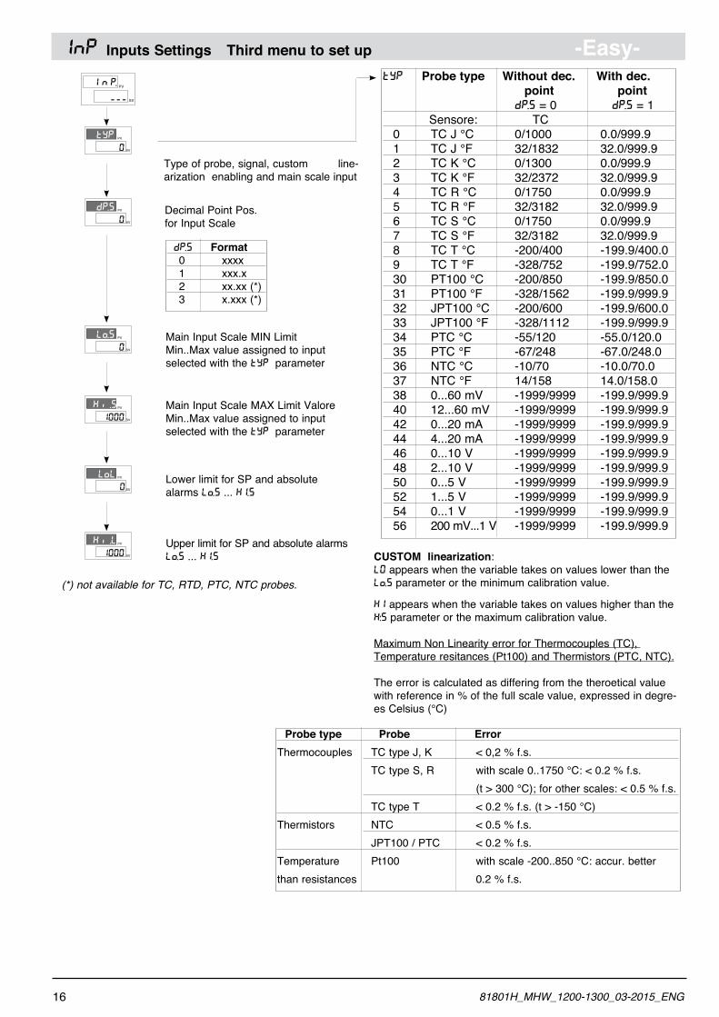
INP Inputs Settings Third menu to set up -Easy-PV
SV
nI P.
---
0
tYP PV
SV
Type of probe, signal, custom line-arization enabling and main scale input
TYP Probe type Without dec. With dec. point point DP.S = 0 DP.S = 1 Sensore: TC 0 TC J °C 0/1000 0.0/999.9 1 TC J °F 32/1832 32.0/999.9 2 TC K °C 0/1300 0.0/999.9 3 TC K °F 32/2372 32.0/999.9 4 TC R °C 0/1750 0.0/999.9 5 TC R °F 32/3182 32.0/999.9 6 TC S °C 0/1750 0.0/999.9 7 TC S °F 32/3182 32.0/999.9 8 TC T °C -200/400 -199.9/400.0 9 TC T °F -328/752 -199.9/752.0 30 PT100 °C -200/850 -199.9/850.0 31 PT100 °F -328/1562 -199.9/999.9 32 JPT100 °C -200/600 -199.9/600.0 33 JPT100 °F -328/1112 -199.9/999.9 34 PTC °C -55/120 -55.0/120.0 35 PTC °F -67/248 -67.0/248.0 36 NTC °C -10/70 -10.0/70.0 37 NTC °F 14/158 14.0/158.0 38 0...60 mV -1999/9999 -199.9/999.9 40 12...60 mV -1999/9999 -199.9/999.9 42 0...20 mA -1999/9999 -199.9/999.9 44 4...20 mA -1999/9999 -199.9/999.9 46 0...10 V -1999/9999 -199.9/999.9 48 2...10 V -1999/9999 -199.9/999.9 50 0...5 V -1999/9999 -199.9/999.9 52 1...5 V -1999/9999 -199.9/999.9 54 0...1 V -1999/9999 -199.9/999.9 56 200 mV...1 V -1999/9999 -199.9/999.9
CUSTOM linearization:L0 appears when the variable takes on values lower than the LO.S parameter or the minimum calibration value.
KI appears when the variable takes on values higher than the K’.S parameter or the maximum calibration value.
Maximum Non Linearity error for Thermocouples (TC), Temperature resitances (Pt100) and Thermistors (PTC, NTC).
The error is calculated as differing from the theroetical value with reference in % of the full scale value, expressed in degre-es Celsius (°C)
Decimal Point Pos.for Input Scale
Probe type Probe ErrorThermocouples TC type J, K < 0,2 % f.s. TC type S, R with scale 0..1750 °C: < 0.2 % f.s. (t > 300 °C); for other scales: < 0.5 % f.s. TC type T < 0.2 % f.s. (t > -150 °C)Thermistors NTC < 0.5 % f.s. JPT100 / PTC < 0.2 % f.s.Temperature Pt100 with scale -200..850 °C: accur. better than resistances 0.2 % f.s.
DP.S Format 0 xxxx 1 xxx.x 2 xx.xx (*) 3 x.xxx (*)
Main Input Scale MAX Limit Valore Min..Max value assigned to input selected with the TYP parameter
Lower limit for SP and absolute alarms LO.S ... KI.S
Upper limit for SP and absolute alarms LO.S ... KI.S
Main Input Scale MIN LimitMin..Max value assigned to input selected with the TYP parameter
(*) not available for TC, RTD, PTC, NTC probes.
0
dP.S PV
SV
0
Lo.S PV
SV
1000
Ki .S PV
SV
0
LoL PV
SV
1000
Ki .L PV
SV
16 81801H_MHW_1200-1300_03-2015_ENG
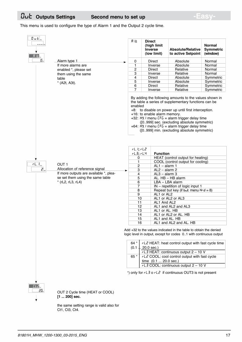
0VT Outputs Settings Second menu to set up -Easy-This menu is used to configure the type of Alarm 1 and the Output 2 cycle time.
PV
SV
v0 t
---
0
AI.t PV
SV Alarm type 1If more alarms are enabled *, please set them using the same table* (A2t, A3t).
A1.T Direct (high limit Normal Inverse Absolute/Relative Symmetric (low limit) to active Setpoint (window)
0 Direct Absolute Normal 1 Inverse Absolute Normal 2 Direct Relative Normal 3 Inverse Relative Normal 4 Direct Absolute Symmetric 5 Inverse Absolute Symmetric 6 Direct Relative Symmetric 7 Inverse Relative Symmetric
By adding the following amounts to the values shown in the table a series of supplementary functions can be enabled +8: to disable on power up until first interception. +16: to enable alarm memory. +32: KY.1 menu [FG = alarm trigger delay time ([0..999] sec. (excluding absolute symmetric) +64: KY.1 menu [FG = alarm trigger delay time ([0..999] min. (excluding absolute symmetric)
20
Gt.2 PV
SV OUT 2 Cycle time (HEAT or COOL)[1 ... 200] sec.
the same setting range is valid also for Ct1, Ct3, Ct4.
PV
SV
L.r
2
1 OUT 1Allocation of reference signalIf more outputs are available *, plea-se set them using the same table* (rL2, rL3, rL4)
RL.1; RL.2 RL.3; RL.4 Function 0 HEAT (control output for heating) 1 COOL (control output for cooling) 2 AL1 – alarm 1 3 AL2 – alarm 2 4 AL3 – alarm 3 5 AL. HB – HB alarm 6 LBA – LBA alarm 7 IN – repetition of logic input 1 8 Repeat but key (if BVT menu KRD = 8) 9 AL1 or AL2 10 AL1 or AL2 or AL3 11 AL1 And AL2 12 AL1 and AL2 and AL3 13 AL1 or AL. HB 14 AL1 or AL2 or AL. HB 15 AL1 and AL. HB 16 AL1 and AL2 and AL. HB
Add +32 to the values indicated in the table to obtain the denied logic level in output, except for codes 0..1 with continuous output
64 * RL.2 HEAT: heat control output with fast cycle time (0.1 ... 20.0 sec.) RL.3 HEAT: continuous output 2 – 10 V 65 * RL.2 COOL: cool control output with fast cycle time (0.1 ... 20.0 sec.) RL.3 COOL: continuous output 2 – 10 V
*) only for RL.3 o RL.2 if continuous OUT3 is not present
1781801H_MHW_1200-1300_03-2015_ENG
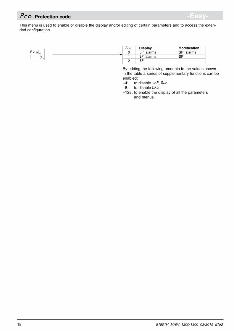
PRO Protection code -Easy-This menu is used to enable or disable the display and/or editing of certain parameters and to access the exten-ded configuration.
PV
SV
rP o
0
PRO Display Modification 0 SP, alarms SP, alarms 1 SP, alarms SP 2 SP
By adding the following amounts to the values shown in the table a series of supplementary functions can be enabled:+4: to disable INP, 0VT+8: to disable [FG+128: to enable the display of all the parameters and menus.
18 81801H_MHW_1200-1300_03-2015_ENG
1981801H_MHW_1200-1300_03-2015_ENG
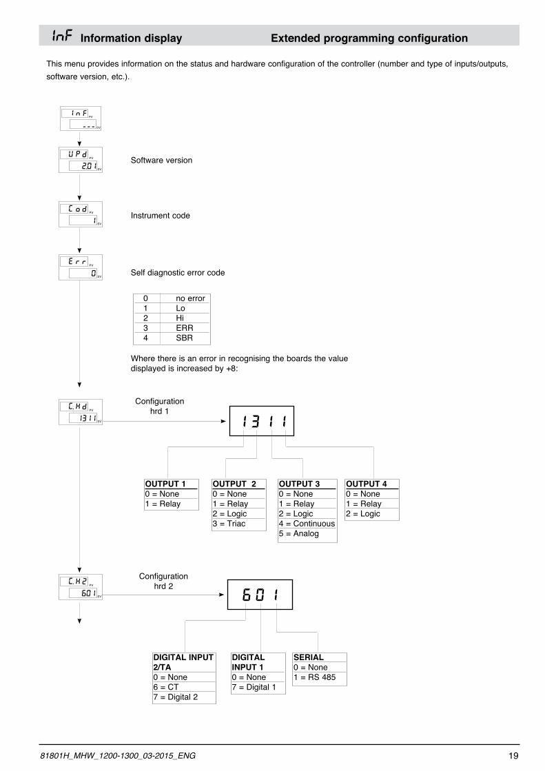
INF Information display Extended programming configuration
PV
SV
nI F
---
PV
SV
PU d
2.0iSoftware version
This menu provides information on the status and hardware configuration of the controller (number and type of inputs/outputs, software version, etc.).
Instrument code
0 no error 1 Lo 2 Hi 3 ERR 4 SBR
Configuration hrd 1
Configurationhrd 2
Where there is an error in recognising the boards the value displayed is increased by +8:
PV
SV
oG d
1
PV
SV
rE r
0
PV
SV
KG. d
1311
PV
SV
KG. 2
601
Self diagnostic error code
1 3 1 1
OUTPUT 10 = None1 = Relay
OUTPUT 20 = None1 = Relay2 = Logic3 = Triac
OUTPUT 30 = None1 = Relay2 = Logic4 = Continuous5 = Analog
OUTPUT 40 = None1 = Relay2 = Logic
6 0 1
DIGITAL INPUT 2/TA0 = None6 = CT7 = Digital 2
DIGITAL INPUT 10 = None7 = Digital 1
SERIAL0 = None1 = RS 485
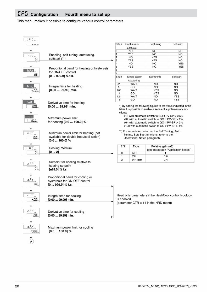
(FG Configuration Fourth menu to set upThis menu makes it possible to configure various control parameters.
PV
SV
FG G
---
1.0
h.Pb PV
SV
4.00
h.It PV
SV
Proportional band for heating or hysteresis for ON/OFF control[0 ... 999.9] % f.s.
Integral time for heating [0.00 ... 99.99] min.
PV
SV
tS. v
0
1.00
h.dt PV
SV
100.0
h.P.K PV
SV
Maximum power limitfor heating [0.0 ... 100.0] %
Derivative time for heating [0.00 ... 99.99] min.
Enabling self-tuning, autotuning, softstart (**)
PV
SV
U
G. E
0
PV
SV
Sc. P
0
Cooling medium[0 ... 2]
Setpoint for cooling relative to heating setpoint[±25.0] % f.s.
PV
SV
P.h. L
0.0
Integral time for cooling[0.00 ... 99.99] min.
Proportional band for cooling or hysteresis for ON-OFF control[0 ... 999.9] % f.s.
Minimum power limit for heating (not available for double heat/cool action)[0.0 ... 100.0] %
Derivative time for cooling[0.00 ... 99.99] min.
Maximum power limit for cooling [0.0 ... 100.0] %
S.tun Continuous Selftuning Softstart autotunig0 NO NO NO1 YES NO NO2 NO YES NO3 YES YES NO4 NO NO YES5 YES NO YES6 - - -7 - - - S.tun Single action Selftuning Softstart Autotuning 8* WAIT NO NO 9 GO NO NO 10* WAIT YES NO 11 GO YES NO 12* WAIT NO YES 13 GO NO YES
*) By adding the following figures to the value indicated in the table it is possible to enable a series of supplementary fun-ctions: +16 with automatic switch to GO if PV-SP > 0.5% +32 with automatic switch to GO if PV-SP > 1% +64 with automatic switch to GO if PV-SP > 2% +128 with automatic switch to GO if PV-SP > 4%
**) For more information on the Self Tuning, Auto Tuning, Soft Start functions, refer to the Operational Notes paragraph.
[ME Type Relative gain (rG) (see paragraph “Application Notes”) 0 AIR 1 1 OIL 0,8 2 WATER 0,4
Read only parameters if the Heat/Cool control typology is enabled (parameter CTR = 14 in the HRD menu)
A
PV
SV
Pc. b
1.0
PV
SV
Ic. t
4.00
PV
SV
dc. t
1.00
PV
SV
P.c. K
100,0
20 81801H_MHW_1200-1300_03-2015_ENG
PV
SV
P.c. L
0.0
PV
SV
rP. S
0.0
PV
SV
rA. S
0
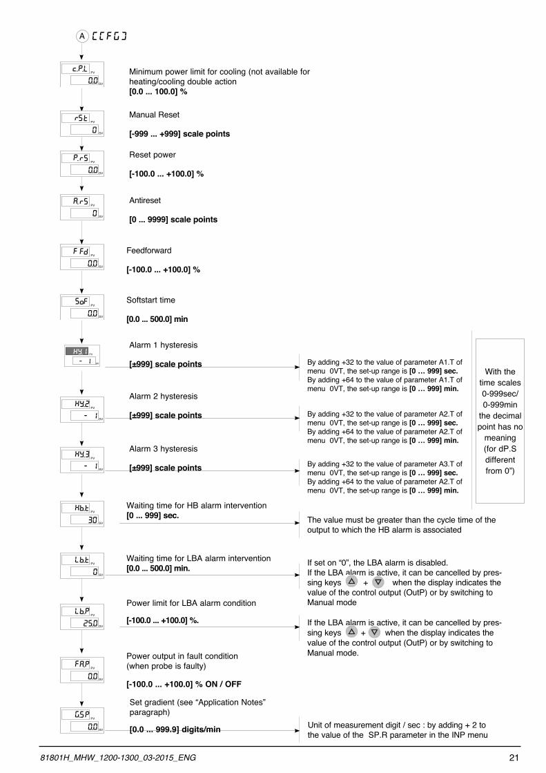
Reset power
[-100.0 ... +100.0] %
Antireset
[0 ... 9999] scale points
PV
SV
Sr t
0
PV
SV
FF d
0.0
PV
SV
oS F
0.0
Softstart time
[0.0 ... 500.0] min
Feedforward
[-100.0 ... +100.0] %
Manual Reset
[-999 ... +999] scale points
PV
SV
Y.K 2
- 1
PV
SV
Y.K 3
- 1
Alarm 2 hysteresis
[±999] scale points
Alarm 3 hysteresis
[±999] scale points
- 1
KY.i PV
SV
PV
SV
b.L t
0
Waiting time for LBA alarm intervention [0.0 ... 500.0] min.
Waiting time for HB alarm intervention [0 ... 999] sec.
Alarm 1 hysteresis
[±999] scale points
Power limit for LBA alarm condition
[-100.0 ... +100.0] %.
PV
SV
A.F P
0.0
Power output in fault condition(when probe is faulty)
[-100.0 ... +100.0] % ON / OFF
A
Minimum power limit for cooling (not available for heating/cooling double action[0.0 ... 100.0] %
[gfg]
PV
SV
SG. P
0.0
Set gradient (see “Application Notes” paragraph)
[0.0 ... 999.9] digits/min
By adding +32 to the value of parameter A1.T of menu 0VT, the set-up range is [0 … 999] sec.By adding +64 to the value of parameter A1.T of menu 0VT, the set-up range is [0 … 999] min.
By adding +32 to the value of parameter A2.T of menu 0VT, the set-up range is [0 … 999] sec.By adding +64 to the value of parameter A2.T of menu 0VT, the set-up range is [0 … 999] min.
By adding +32 to the value of parameter A3.T of menu 0VT, the set-up range is [0 … 999] sec.By adding +64 to the value of parameter A2.T of menu 0VT, the set-up range is [0 … 999] min.
The value must be greater than the cycle time of the output to which the HB alarm is associated
If set on “0”, the LBA alarm is disabled.If the LBA alarm is active, it can be cancelled by pres-sing keys + when the display indicates the value of the control output (OutP) or by switching to Manual mode
If the LBA alarm is active, it can be cancelled by pres-sing keys + when the display indicates the value of the control output (OutP) or by switching to Manual mode.
Unit of measurement digit / sec : by adding + 2 to the value of the SP.R parameter in the INP menu
PV
SV
b.K t
30
PV
SV
b.L P
25.0
2181801H_MHW_1200-1300_03-2015_ENG
With the time scales 0-999sec/0-999min
the decimal point has no
meaning (for dP.S different from 0”)
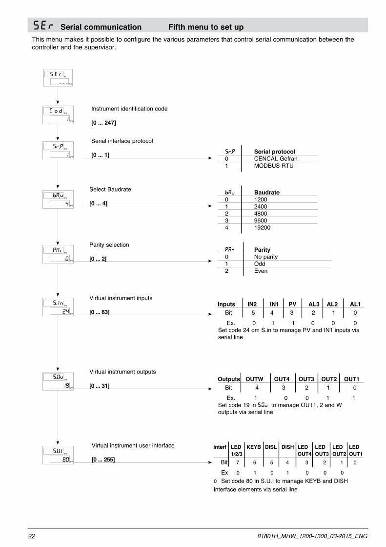
SEr Serial communication Fifth menu to set upThis menu makes it possible to configure the various parameters that control serial communication between the controller and the supervisor.
Instrument identification code
[0 ... 247]
Serial interface protocol
[0 ... 1]
PV
SV
ES R
---
PV
SV
AP
0
rParity selection
[0 ... 2]
Select Baudrate
[0 ... 4]
PV
SV
IS.
24
nVirtual instrument inputs
[0 ... 63]
PV
SV
0S.
19
n Virtual instrument outputs
[0 ... 31]
PV
SV
U.S.
80
IVirtual instrument user interface
[0 ... 255]
Interf LED KEYB DISL DISH LED LED LED LED 1/2/3 OUT4 OUT3 OUT2 OUT1 Bit 7 6 5 4 3 2 1 0
Ex 0 1 0 1 0 0 0 0 Set code 80 in S.U.I to manage KEYB and DISH interface elements via serial line
Outputs OUTW OUT4 OUT3 OUT2 OUT1 Bit 4 3 2 1 0 Ex. 1 0 0 1 1Set code 19 in S.0V to manage OUT1, 2 and W outputs via serial line
Inputs IN2 IN1 PV AL3 AL2 AL1 Bit 5 4 3 2 1 0 Ex. 0 1 1 0 0 0Set code 24 om S.in to manage PV and IN1 inputs via serial line
PAR Parity 0 No parity 1 Odd 2 Even
BAV Baudrate 0 1200 1 2400 2 4800 3 9600 4 19200
SR.P Serial protocol 0 CENCAL Gefran 1 MODBUS RTU
PV
SV
oG d
1
PV
SV
r.S P
1
PV
SV
A.b
n
4
22 81801H_MHW_1200-1300_03-2015_ENG
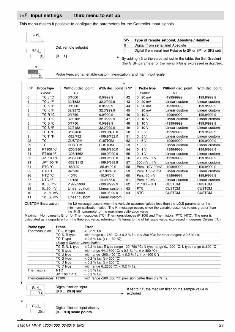
InP Input settings third menu to set upThis menu makes it possible to configure the parameters for the Controller input signals.
PV
SV
P.S
0
r
0
tYP PV
SV
PV
SV
nI P.
---
Def. remote setpoint
[0 ... 1]
SP.R Type of remote setpoint, Absolute / Relative0 Digital (from serial line) Absolute1 Digital (from serial line) Relative to SP or SP1 or SP2 sets
By adding +2 to the value set out in the table, the Set Gradient (the G.SP parameter of the menu [FG) is expressed in digit/sec.
Probe type, signal, enable custom linearization, and main input scale
TYP Probe type Without dec. point With dec. point Probe: TC 0 TC J °C 0/1000 0.0/999.91 TC J °F 32/1832 32.0/999.92 TC K °C 0/1300 0.0/999.93 TC K °F 32/2372 32.0/999.94 TC R °C 0/1750 0.0/999.95 TC R °F 32/3182 32.0/999.96 TC S °C 0/1750 0.0/999.97 TC S °F 32/3182 32.0/999.98 TC T °C -200/400 -199.9/400.09 TC T °F -328/752 -199.9/752.028 TC CUSTOM CUSTOM29 TC CUSTOM CUSTOM30 PT100 °C -200/850 -199.9/850.031 PT100 °F -328/1562 -199.9/999.932 JPT100 °C -200/600 -199.9/600.033 JPT100 °F -328/1112 -199.9/999.934 PTC °C -55/120 -55.0/120.035 PTC °F -67/248 -67.0/248.036 NTC °C -10/70 -10.0/70.037 NTC °F 14/158 14.0/158.038 0...60 mV -1999/9999 -199.9/999.939 0...60 mV Linear custom Linear custom40 12...60 mV -1999/9999 -199.9/999.941 12...60 mV Linear custom Linear custom
TYP Probe type Without dec. point With dec. point Probe: TC42 0...20 mA -1999/9999 -199.9/999.943 0...20 mA Linear custom Linear custom44 4...20 mA -1999/9999 -199.9/999.945 4...20 mA Linear custom Linear custom46 0...10 V -1999/9999 -199.9/999.947 0...10 V Linear custom Linear custom48 2...10 V -1999/9999 -199.9/999.949 2...10 V Linear custom Linear custom50 0...5 V -1999/9999 -199.9/999.951 0...5 V Linear custom Linear custom52 1...5 V -1999/9999 -199.9/999.953 1...5 V Linear custom Linear custom54 0...1 V -1999/9999 -199.9/999.955 0...1 V Linear custom Linear custom56 200 mV...1 V -1999/9999 -199.9/999.957 200 mV...1 V Linear custom Linear custom58 Pers.. 10V-20mA -1999/9999 -199.9/999.959 Pers. 10V-20mA Linear custom Linear custom60 Pers. 60 mV -1999/9999 -199.9/999.961 Pers. 60 mV Linear custom Linear custom62 PT100 – JPT CUSTOM CUSTOM63 PTC CUSTOM CUSTOM64 NTC CUSTOM CUSTOM
CUSTOM linearization: the L0 message occurs when the variable assumes values less than the LO.S parameter or the minimum calibration value. The KI message occurs when the variable assumes values greater than the K’.S parameter of the maximum calibration valueMaximum Non Linearity Error for Thermocouples (TC), Thermoresistances (Pt100) and Thermistors (PTC, NTC). The error is calculated as a departure from the theoretic value, referring in % terms to the of full scale value, expressed in degrees Celsius (°C)
PV
SV
LF
0.1
t
PV
SV
LF
0.5
d
Probe type Probe Error Thermocouples TC J, K type < 0,2 % f.s. TC S, R type with range 0..1750 °C: < 0,2 % f.s. (t > 300 °C); for other ranges: < 0,5 % f.s. TC T type < 0,2 % f.s. (t > -150 °C) Using a Custom Linearization: TC E, N, L type < 0,2 % f.s.; E type range 100..750 °C; N type range 0..1300 °C; L type range 0..600 °C TC B type with range 44..1800 °C: < 0,5 % f.s. (t > 300 °C) TC U type with range -200..400 °C: < 0,2 % f.s. (t > -100 C°) TC G type < 0,2 % f.s. (t > 300 °C) TC D type < 0,2 % f.s. (t > 200 °C TC C type with range 0..2300 °C: < 0,2 % f.s.Thermistors NTC < 0,5 % f.s. JPT100 / PTC < 0,2 % f.s.Thermoresistances Pt100 with range -200..850 °C: precision better than 0.2 % f.s.
Digital filter on input [0.0 ... 20.0] sec If set to “0”, the medium filter on the sample value is
excluded
Digital filter on input display[0 ... 9.9] scale points
2381801H_MHW_1200-1300_03-2015_ENG
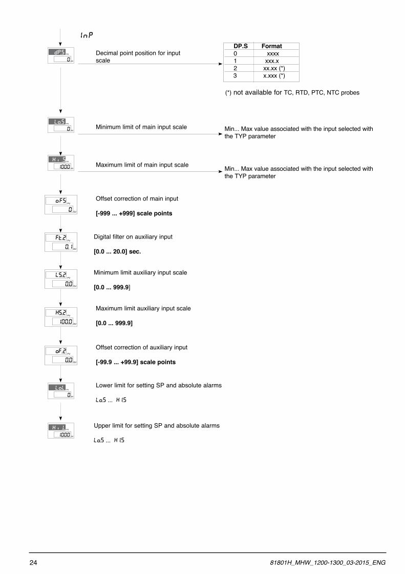
0
dP.S PV
SV
1000
Ki .S PV
SV
PV
SV
Fo
0
S
Maximum limit of main input scale
Offset correction of main input
[-999 ... +999] scale points
0
Lo.S PV
SV
PV
SV
S.L
0.0
2 Minimum limit auxiliary input scale
[0.0 ... 999.9]
Digital filter on auxiliary input
[0.0 ... 20.0] sec.
Minimum limit of main input scale
PV
SV
F.o
0.0
2
0
LoL PV
SV
Offset correction of auxiliary input
[-99.9 ... +99.9] scale points
Lower limit for setting SP and absolute alarms
LO.S ... KI.S
1000
Ki .L PV
SV
Upper limit for setting SP and absolute alarms
LO.S ... KI.S
Maximum limit auxiliary input scale
[0.0 ... 999.9]
Decimal point position for input scale
InP DP.S Format 0 xxxx 1 xxx.x 2 xx.xx (*) 3 x.xxx (*)
(*) not available for TC, RTD, PTC, NTC probes
Min... Max value associated with the input selected with the TYP parameter
Min... Max value associated with the input selected with the TYP parameter
PV
SV
t.F
0.1
2
PV
SV
S.K
100.0
2
24 81801H_MHW_1200-1300_03-2015_ENG
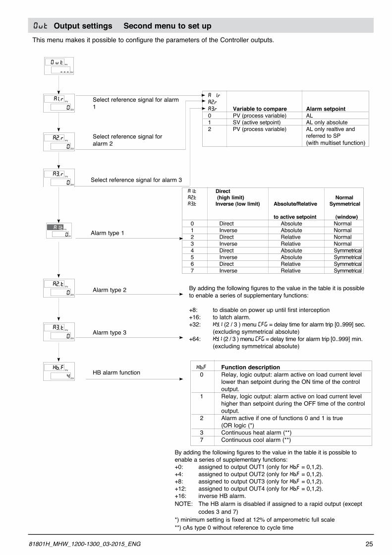
0VT Output settings Second menu to set upThis menu makes it possible to configure the parameters of the Controller outputs.
PV
SV
i.A
0
r
PV
SV
2.A
0
r
Select reference signal for alarm 1
Select reference signal for alarm 2
PV
SV
v0 t
---
PV
SV
3.A
0
r
0
AI.t PV
SVAlarm type 1
Select reference signal for alarm 3
PV
SV
3.A
0
tAlarm type 3
HB alarm function
PV
SV
2.A
0
tAlarm type 2
A 1.R
A2.R
A3.R Variable to compare Alarm setpoint 0 PV (process variable) AL 1 SV (active setpoint) AL only absolute 2 PV (process variable) AL only realtive and referred to SP (with multiset function)
A1.T Direct A2.T (high limit) Normal A3.T Inverse (low limit) Absolute/Relative Symmetrical
to active setpoint (window) 0 Direct Absolute Normal 1 Inverse Absolute Normal 2 Direct Relative Normal 3 Inverse Relative Normal 4 Direct Absolute Symmetrical 5 Inverse Absolute Symmetrical 6 Direct Relative Symmetrical 7 Inverse Relative Symmetrical
By adding the following figures to the value in the table it is possible to enable a series of supplementary functions:
+8: to disable on power up until first interception+16: to latch alarm.+32: KY.1 (2 / 3 ) menu [FG = delay time for alarm trip [0..999] sec. (excluding symmetrical absolute)+64: KY.1 (2 / 3 ) menu [FG = delay time for alarm trip [0..999] min. (excluding symmetrical absolute)
KB.F Function description 0 Relay, logic output: alarm active on load current level lower than setpoint during the ON time of the control output. 1 Relay, logic output: alarm active on load current level higher than setpoint during the OFF time of the control output. 2 Alarm active if one of functions 0 and 1 is true (OR logic (*) 3 Continuous heat alarm (**) 7 Continuous cool alarm (**)
By adding the following figures to the value in the table it is possible to enable a series of supplementary functions:+0: assigned to output OUT1 (only for KB.F = 0,1,2).+4: assigned to output OUT2 (only for KB.F = 0,1,2).+8: assigned to output OUT3 (only for KB.F = 0,1,2).+12: assigned to output OUT4 (only for KB.F = 0,1,2).+16: inverse HB alarm.NOTE: The HB alarm is disabled if assigned to a rapid output (except codes 3 and 7)*) minimum setting is fixed at 12% of amperometric full scale**) cAs type 0 without reference to cycle time
PV
SV
b.K
4
F
2581801H_MHW_1200-1300_03-2015_ENG
PV
SV
L.r
2
1
PV
SV
L.r
3
3
PV
SV
L.r
4
4
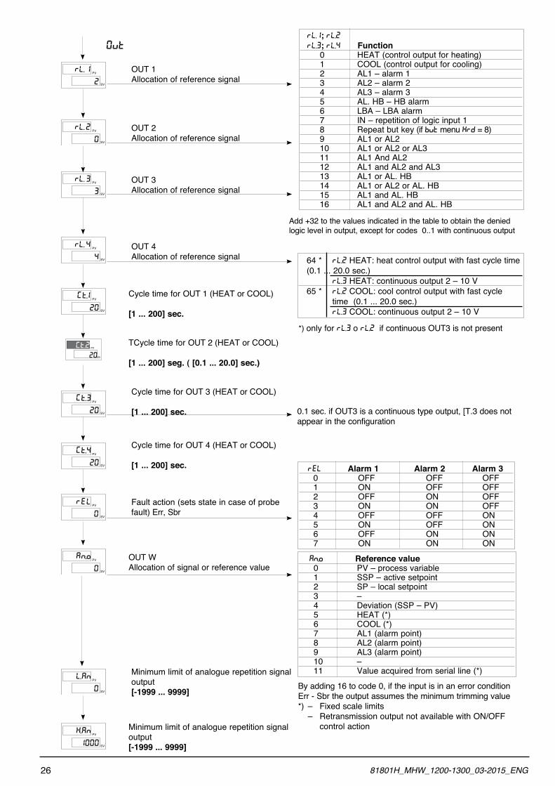
OUT 3Allocation of reference signal
OUT 4Allocation of reference signal
PV
SV
L.r
0
2
PV
SV
t.G
20
1
20
Gt.2 PV
SV
TCycle time for OUT 2 (HEAT or COOL)
[1 ... 200] seg. ( [0.1 ... 20.0] sec.)
Cycle time for OUT 1 (HEAT or COOL)
[1 ... 200] sec.
OUT 2Allocation of reference signal
PV
SV
t.G
20
4
PV
SV
Er
0
l
Cycle time for OUT 4 (HEAT or COOL)
[1 ... 200] sec.
Fault action (sets state in case of probe fault) Err, Sbr
PV
SV
t.G
20
3
PV
SV
n.A
0
o OUT WAllocation of signal or reference value
Cycle time for OUT 3 (HEAT or COOL)
[1 ... 200] sec.
OUT 1Allocation of reference signal
0VT
PV
SV
AL.
0
nMinimum limit of analogue repetition signal output [-1999 ... 9999]
Minimum limit of analogue repetition signal output [-1999 ... 9999]
RL.1; RL.2 RL.3; RL.4 Function 0 HEAT (control output for heating) 1 COOL (control output for cooling) 2 AL1 – alarm 1 3 AL2 – alarm 2 4 AL3 – alarm 3 5 AL. HB – HB alarm 6 LBA – LBA alarm 7 IN – repetition of logic input 1 8 Repeat but key (if BVT menu KRD = 8) 9 AL1 or AL2 10 AL1 or AL2 or AL3 11 AL1 And AL2 12 AL1 and AL2 and AL3 13 AL1 or AL. HB 14 AL1 or AL2 or AL. HB 15 AL1 and AL. HB 16 AL1 and AL2 and AL. HB
Add +32 to the values indicated in the table to obtain the denied logic level in output, except for codes 0..1 with continuous output
64 * RL.2 HEAT: heat control output with fast cycle time (0.1 ... 20.0 sec.) RL.3 HEAT: continuous output 2 – 10 V 65 * RL.2 COOL: cool control output with fast cycle time (0.1 ... 20.0 sec.) RL.3 COOL: continuous output 2 – 10 V
*) only for RL.3 o RL.2 if continuous OUT3 is not present
0.1 sec. if OUT3 is a continuous type output, [T.3 does not appear in the configuration
REL Alarm 1 Alarm 2 Alarm 3 0 OFF OFF OFF 1 ON OFF OFF 2 OFF ON OFF 3 ON ON OFF 4 OFF OFF ON 5 ON OFF ON 6 OFF ON ON 7 ON ON ON
AN.O Reference value 0 PV – process variable 1 SSP – active setpoint 2 SP – local setpoint 3 – 4 Deviation (SSP – PV) 5 HEAT (*) 6 COOL (*) 7 AL1 (alarm point) 8 AL2 (alarm point) 9 AL3 (alarm point) 10 – 11 Value acquired from serial line (*)
By adding 16 to code 0, if the input is in an error condition Err - Sbr the output assumes the minimum trimming value*) – Fixed scale limits – Retransmission output not available with ON/OFF control action
PV
SV
AK.
1000
n
26 81801H_MHW_1200-1300_03-2015_ENG
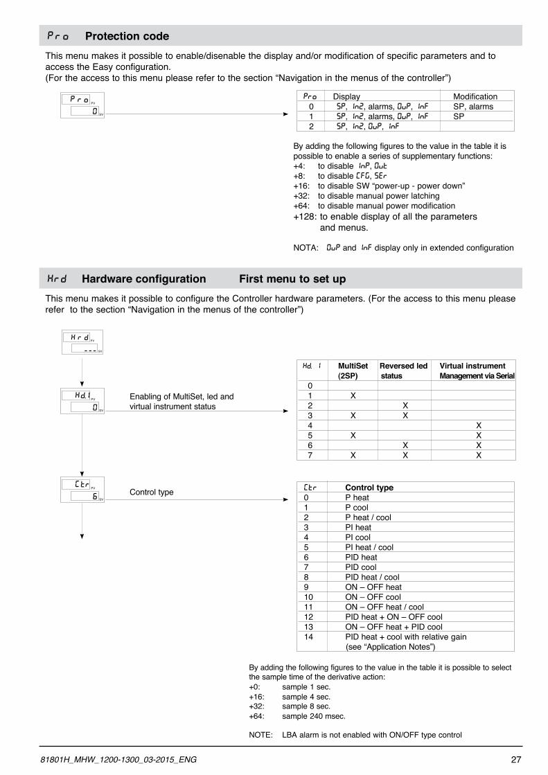
PRO Protection codeThis menu makes it possible to enable/disenable the display and/or modification of specific parameters and to access the Easy configuration.(For the access to this menu please refer to the section “Navigation in the menus of the controller”)
PV
SV
rP o
0
PRO Display Modification 0 SP, IN2, alarms, 0VP, INF SP, alarms 1 SP, IN2, alarms, 0VP, INF SP 2 SP, IN2, 0VP, INF
By adding the following figures to the value in the table it is possible to enable a series of supplementary functions:+4: to disable INP, 0VT+8: to disable [FG, SER+16: to disable SW “power-up - power down”+32: to disable manual power latching+64: to disable manual power modification+128: to enable display of all the parameters and menus.
NOTA: 0VP and INF display only in extended configuration
KRD Hardware configuration First menu to set upThis menu makes it possible to configure the Controller hardware parameters. (For the access to this menu please refer to the section “Navigation in the menus of the controller”)
PV
SV
rK d
---
PV
SV
tG
6
rControl type
PV
SV
d.K
0
1 Enabling of MultiSet, led and virtual instrument status
KD. 1 MultiSet Reversed led Virtual instrument (2SP) status Management via Serial 0 1 X 2 X 3 X X 4 X 5 X X 6 X X 7 X X X
[TR Control type 0 P heat 1 P cool 2 P heat / cool 3 PI heat 4 PI cool 5 PI heat / cool 6 PID heat 7 PID cool 8 PID heat / cool 9 ON – OFF heat 10 ON – OFF cool 11 ON – OFF heat / cool 12 PID heat + ON – OFF cool 13 ON – OFF heat + PID cool 14 PID heat + cool with relative gain (see “Application Notes”)
By adding the following figures to the value in the table it is possible to select the sample time of the derivative action:+0: sample 1 sec.+16: sample 4 sec.+32: sample 8 sec.+64: sample 240 msec.
NOTE: LBA alarm is not enabled with ON/OFF type control
2781801H_MHW_1200-1300_03-2015_ENG
PV
SV
L.A
i
n
PV
SV
i
d
0
G
PV
SV
i
d
0
2
Function of digital input 1 (0 ... 53)
Function of digital input 2 (0 ... 53)
PV
SV
n
b
0
t
PV
SV
S
d
0
P
PV
SV
L
1
d.1Function of led 1
Defining SV display function
Function of M/A key
PV
SV
L
20
d.3Function of led 3
PV
SV
L
10
d.2
Function of led 2
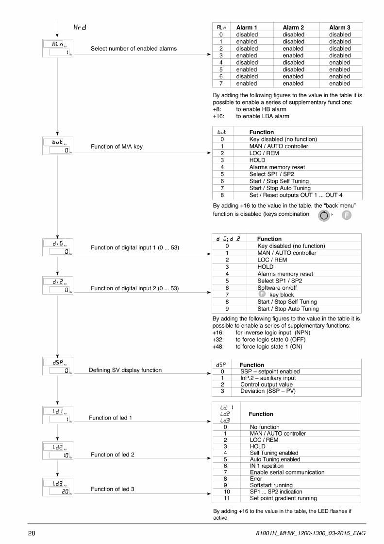
Select number of enabled alarms
KRD AL.N Alarm 1 Alarm 2 Alarm 3 0 disabled disabled disabled 1 enabled disabled disabled 2 disabled enabled disabled 3 enabled enabled disabled 4 disabled disabled enabled 5 enabled disabled enabled 6 disabled enabled enabled 7 enabled enabled enabled
By adding the following figures to the value in the table it is possible to enable a series of supplementary functions:+8: to enable HB alarm+16: to enable LBA alarm
BVT Function 0 Key disabled (no function) 1 MAN / AUTO controller 2 LOC / REM 3 HOLD 4 Alarms memory reset 5 Select SP1 / SP2 6 Start / Stop Self Tuning 7 Start / Stop Auto Tuning 8 Set / Reset outputs OUT 1 ... OUT 4
By adding +16 to the value in the table, the “back menu” function is disabled (keys combination + )
D ,G; D ,2 Function 0 Key disabled (no function) 1 MAN / AUTO controller 2 LOC / REM 3 HOLD 4 Alarms memory reset 5 Select SP1 / SP2 6 Software on/off 7 key block 8 Start / Stop Self Tuning 9 Start / Stop Auto TuningBy adding the following figures to the value in the table it is possible to enable a series of supplementary functions:+16: for inverse logic input (NPN)+32: to force logic state 0 (OFF)+48: to force logic state 1 (ON)
DSP Function 0 SSP – setpoint enabled 1 InP.2 – auxiliary input 2 Control output value 3 Deviation (SSP – PV)
LD. 1 LD.2 Function LD.3 0 No function 1 MAN / AUTO controller 2 LOC / REM 3 HOLD 4 Self Tuning enabled 5 Auto Tuning enabled 6 IN 1 repetition 7 Enable serial communication 8 Error 9 Softstart running 10 SP1 ... SP2 indication 11 Set point gradient running
By adding +16 to the value in the table, the LED flashes if active
28 81801H_MHW_1200-1300_03-2015_ENG
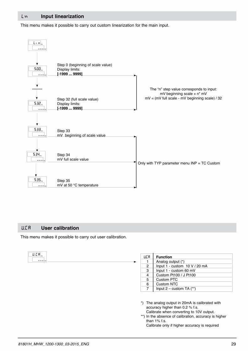
L’N Input linearizationThis menu makes it possible to carry out custom linearization for the main input.
PV
SV
iL n
---
PV
SV
5.
---
00
PV
SV
5.
---
32
PV
SV
5.
---
33
PV
SV
5.
---
34
PV
SV
5.
---
35
Step 0 (beginning of scale value)Display limits: [-1999 ... 9999]
Step 32 (full scale value)Display limits: [-1999 ... 9999]
Step 33mV beginning of scale value
Step 34mV full scale value
Step 35mV at 50 °C temperature
.......... The “n” step value corresponds to input:mV beginning scale + n* mV
mV = (mV full scale - mV beginning scale) / 32
Only with TYP parameter menu INP = TC Custom
U.[A User calibrationThis menu makes it possible to carry out user calibration.
PV
SV
U GA
---
. U.[A Function 1 Analog output (*) 2 Input 1 - custom 10 V / 20 mA 3 Input 1 - custom 60 mV 4 Custom Pt100 / J Pt100 5 Custom PTC 6 Custom NTC 7 Input 2 – custom TA (**)
*) The analog output in 20mA is calibrated with accuracy higher than 0.2 % f.s. Calibrate when converting to 10V output.**) In the absence of calibration, accuracy is higher than 1% f.s. Calibrate only if higher accuracy is required
2981801H_MHW_1200-1300_03-2015_ENG
Application NotesHB AlarmThis type of alarm depends on use of the current transformer (C.T.) input.It can signal variations in load input by identifying the current value in ammeter input in the range (0 ... HS.2). It is enabled by means of configuration code (AL.n); in this case, the alarm trip value is expressed in HB scale points.By means of code Hb.F (“Out” phase), select the type of functioning and the assigned control output.The alarm limit setting is A.Hb.The direct HB alarm trips when the ammeter input value is below the limit set for Hb.t seconds of the “ON” time for the selected output.The HB alarm can be activated only with ON times greater than 0.4 seconds (excludes continuous output).The HB alarm also checks load current during the OFF interval of the cycle time for the selected output. The HB alarm trips if the measured current exceeds approximately 12.5% of the full scale set for HB.t seconds of OFF status of the output (parameter HS.2 in InP).The alarm is reset automatically if its cause is eliminated.Setting limit A.Hb = 0 disables both types of HB alarms, with de-energizing of the assigned relay.You can display the load current by selecting the item In.2. (level 1).NOTE: ON/OFF times refer to the cycle time set for the selected output.Continuous alarm Hb_F = 3 (7) is active for a load current value below the set limit. It is disabled if the heating (cool-ing) output value is below 3%.
HOLD FunctionThe input value and alarms are frozen while the logic input is closed.With logic input closed, a reset turns OFF both the relay outputs and the alarms latch.
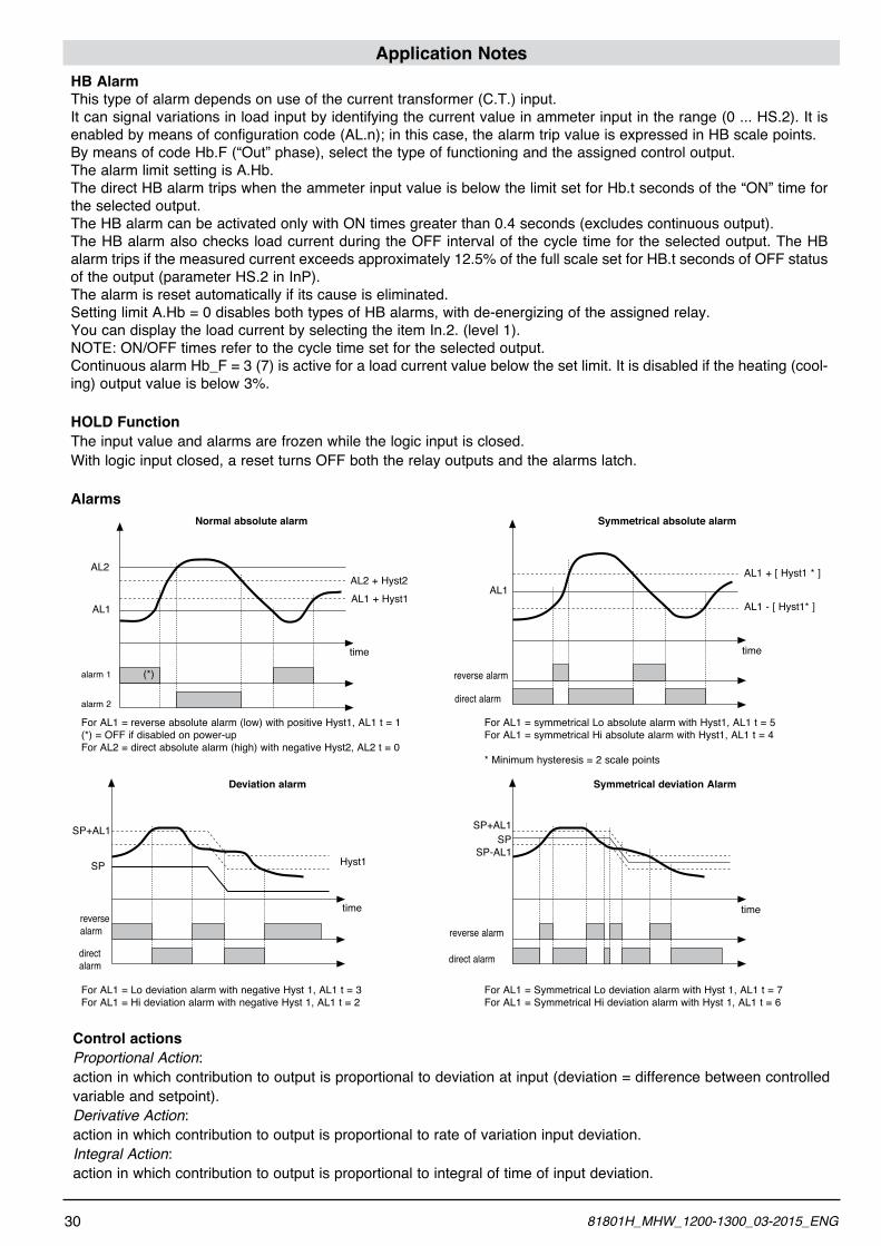
Alarms
For AL1 = reverse absolute alarm (low) with positive Hyst1, AL1 t = 1(*) = OFF if disabled on power-upFor AL2 = direct absolute alarm (high) with negative Hyst2, AL2 t = 0
For AL1 = symmetrical Lo absolute alarm with Hyst1, AL1 t = 5For AL1 = symmetrical Hi absolute alarm with Hyst1, AL1 t = 4
* Minimum hysteresis = 2 scale points
Normal absolute alarm Symmetrical absolute alarm
reverse alarm
direct alarm
AL1AL1 + [ Hyst1 * ]
AL1 - [ Hyst1* ]
time
For AL1 = Lo deviation alarm with negative Hyst 1, AL1 t = 3For AL1 = Hi deviation alarm with negative Hyst 1, AL1 t = 2
For AL1 = Symmetrical Lo deviation alarm with Hyst 1, AL1 t = 7For AL1 = Symmetrical Hi deviation alarm with Hyst 1, AL1 t = 6
time
SP+AL1SP
reverse alarm
direct alarm
SP+AL1
SP
reverse alarm
direct alarm
time
Hyst1
Deviation alarm Symmetrical deviation Alarm
SP-AL1
Control actionsProportional Action:action in which contribution to output is proportional to deviation at input (deviation = difference between controlled variable and setpoint).Derivative Action:action in which contribution to output is proportional to rate of variation input deviation.Integral Action:action in which contribution to output is proportional to integral of time of input deviation.
30 81801H_MHW_1200-1300_03-2015_ENG
time
AL1 + Hyst1
AL2 + Hyst2AL2
AL1
alarm 1
alarm 2
(*)
Influence of Proportional, Derivative and Integral actions on response of process under control* An increase in P.B. reduces oscillations but increases deviation.* A reduction in P.B. reduces the deviation but provokes oscillations of the controlled variable (the system tends to be unstable if P.B. value is too low).* An increase in Derivative Action corresponds to an increase in Derivative Time, reduces deviation and prevents oscillation up to a critical value of Derivative Time, beyond which deviation increases and prolonged oscillations occur.* An increase in Integral Action corresponds to a reduction in Integral Time, and tends to eliminate deviation between the controlled variable and the setpoint when the system is running at rated speed.If the Integral Time value is too long (Weak integral action), deviation between the controlled variable and the set-point may persist.Contact GEFRAN for more information on control actions.
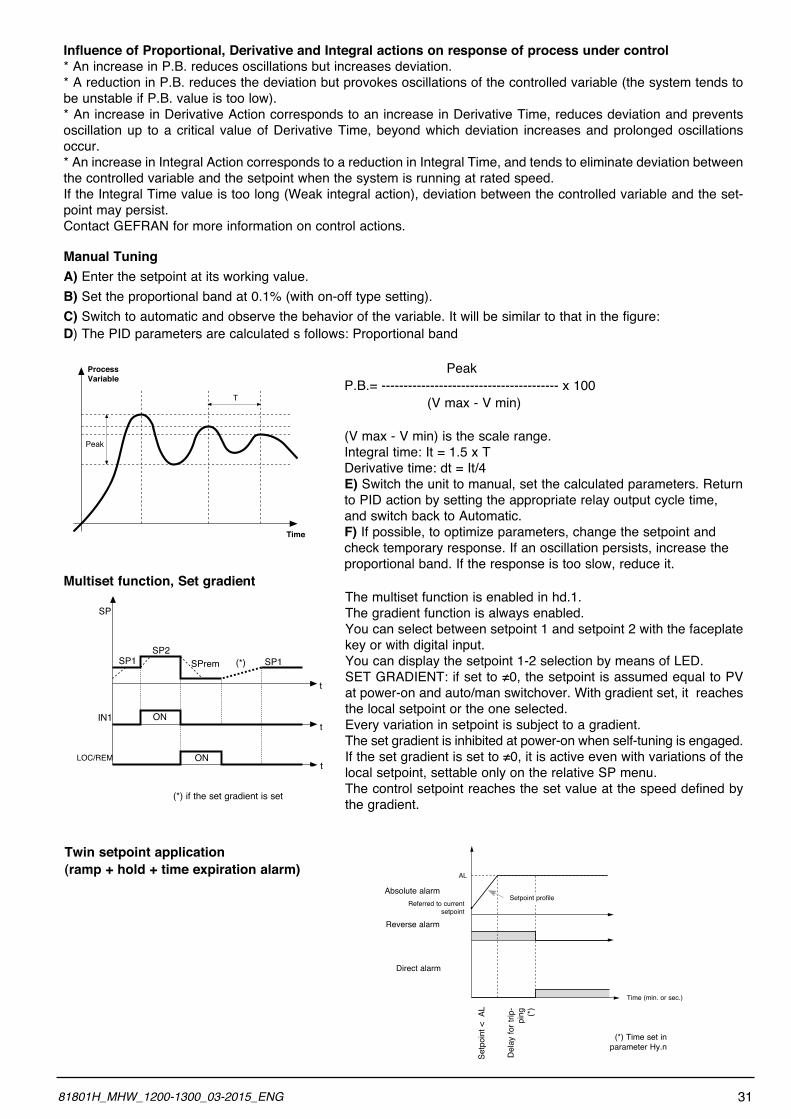
Manual TuningA) Enter the setpoint at its working value.B) Set the proportional band at 0.1% (with on-off type setting).C) Switch to automatic and observe the behavior of the variable. It will be similar to that in the figure:D) The PID parameters are calculated s follows: Proportional band
PeakP.B.= ---------------------------------------- x 100 (V max - V min)
(V max - V min) is the scale range.Integral time: It = 1.5 x TDerivative time: dt = It/4E) Switch the unit to manual, set the calculated parameters. Return to PID action by setting the appropriate relay output cycle time, and switch back to Automatic.F) If possible, to optimize parameters, change the setpoint and check temporary response. If an oscillation persists, increase the proportional band. If the response is too slow, reduce it.
Multiset function, Set gradientThe multiset function is enabled in hd.1.The gradient function is always enabled.You can select between setpoint 1 and setpoint 2 with the faceplate key or with digital input.You can display the setpoint 1-2 selection by means of LED.SETGRADIENT:ifsetto≠0,thesetpointisassumedequaltoPVat power-on and auto/man switchover. With gradient set, it reaches the local setpoint or the one selected.Every variation in setpoint is subject to a gradient.The set gradient is inhibited at power-on when self-tuning is engaged.Ifthesetgradientissetto≠0,itisactiveevenwithvariationsofthelocal setpoint, settable only on the relative SP menu.The control setpoint reaches the set value at the speed defined by the gradient.
Process Variable
Time
T
Peak
SP1SP2
SPrem SP1(*)
ON
ON
SP
IN1
LOC/REM
t
t
t
(*) if the set gradient is set
Twin setpoint application(ramp + hold + time expiration alarm) AL
Referred to current setpoint
Setpoint profile
Setp
oint
< A
L
Del
ay fo
r trip
-pi
ng (*)
Absolute alarm
Reverse alarm
(*) Time set inparameter Hy.n
Direct alarm
Time (min. or sec.)
3181801H_MHW_1200-1300_03-2015_ENG
Software ON/OFF switching function
How to switch the unit OFF: hold down the “F” and “Raise” keys simultaneously for 5 seconds to deactivate the unit, which will go to the OFF state while keeping the line supply connected and keeping the process value displayed. The SV display is OFF.All outputs (alarms and controls) are OFF (logic level 0, relays de-energized) and all unit functions are disabled except the switch-on function and digital communication.How to switch the unit ON: hold down the “F” key for 5 seconds and the unit will switch OFF to ON. If there is a power failure during the OFF state, the unit will remain in OFF state at the next power-up (ON/OFF state is memorized).The function is normally enabled, but can be disabled by setting the parameter Prot = Prot +16. This function can be assigned to a digital input (d.i.G), not é subject to the disabilitazione from parameter “Prot” and excludes deactiva-tion from the keyboard.
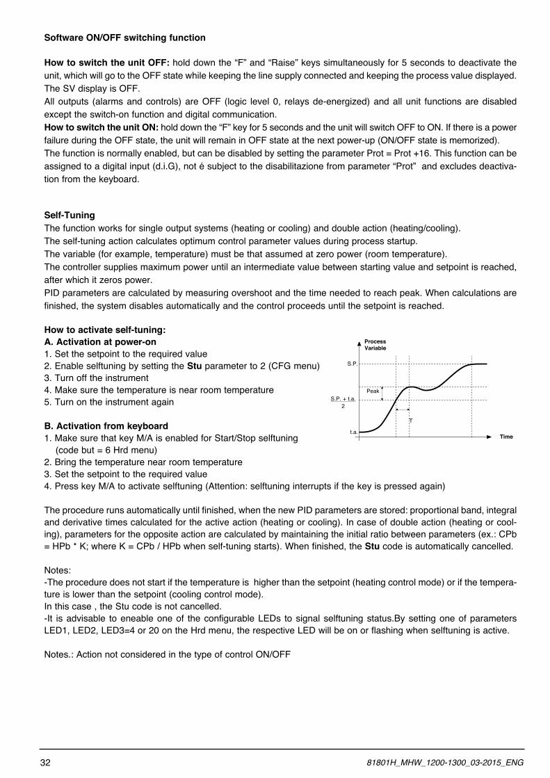
Self-TuningThe function works for single output systems (heating or cooling) and double action (heating/cooling).The self-tuning action calculates optimum control parameter values during process startup.The variable (for example, temperature) must be that assumed at zero power (room temperature).The controller supplies maximum power until an intermediate value between starting value and setpoint is reached, after which it zeros power.PID parameters are calculated by measuring overshoot and the time needed to reach peak. When calculations are finished, the system disables automatically and the control proceeds until the setpoint is reached.
How to activate self-tuning:A. Activation at power-on1. Set the setpoint to the required value 2. Enable selftuning by setting the Stu parameter to 2 (CFG menu)3. Turn off the instrument4. Make sure the temperature is near room temperature5. Turn on the instrument again
B. Activation from keyboard1. Make sure that key M/A is enabled for Start/Stop selftuning (code but = 6 Hrd menu)2. Bring the temperature near room temperature3. Set the setpoint to the required value4. Press key M/A to activate selftuning (Attention: selftuning interrupts if the key is pressed again)
The procedure runs automatically until finished, when the new PID parameters are stored: proportional band, integral and derivative times calculated for the active action (heating or cooling). In case of double action (heating or cool-ing), parameters for the opposite action are calculated by maintaining the initial ratio between parameters (ex.: CPb = HPb * K; where K = CPb / HPb when self-tuning starts). When finished, the Stu code is automatically cancelled.
Notes:-The procedure does not start if the temperature is higher than the setpoint (heating control mode) or if the tempera-ture is lower than the setpoint (cooling control mode). In this case , the Stu code is not cancelled.-It is advisable to eneable one of the configurable LEDs to signal selftuning status.By setting one of parameters LED1, LED2, LED3=4 or 20 on the Hrd menu, the respective LED will be on or flashing when selftuning is active.
Notes.: Action not considered in the type of control ON/OFF
Peak
T
S.P.
t.a.Time
ProcessVariable
S.P. + t.a.2
32 81801H_MHW_1200-1300_03-2015_ENG
Auto-Tuning
Enabling the auto-tuning function blocks the PID parameter settings. It can be one of two types: permanent (continuous) or single-action (one-shot).* Continuous auto-tuning is activated via the Stu parameter (values 1, 3, 5). It continuously reads system oscillations, immediately seeking the PID parameter values that reduce the current oscillation. It does not engage if the oscillations drop below 1.0% of the proportional band. It is interrupted if the set-point is changed, and automatically resumes with a constant set-point. The calculated parameters are not saved if the instrument is switched off, if the instrument is switched to manual, or if the configuration code is disabled. The controller resumes with the parameters programmed before auto-tuning was enabled. The calculated parameters are saved when the function is enabled from the digital input or from the A/M (start/stop) key if the procedure is interrupted.
* One-shot auto-tuning can be enabled manually or automatically. It is activated via the Stu parameter (as can be seen on the table, the values to be set depend on whether Self-tuning or Soft-start is enabled.). It is useful for calculation of PID parameters when the system is around the set-point. It produces a variation on the control output at a maximum of ± 100% of the current control power limited by h.PH - h.PL (hot), c.PH - c.PL (cold), and assesses the effects in timed overshoot. The calculated parameters are saved. Manual activation (Stu code = 8, 10, 12) via direct setting of the parameter or via digital input or via key. Automatic activation (Stu code = 24, 26, 28 with error band of 0.5%) when the PV-SP error exceeds the preset band (programmable to 0.5%, 1%, 2%, 4% of full scale).
NB: at power-up, or after a change of set-point, automatic activation is inhibited for a time equal to five times the integral time, with a minimum of 5 minutes.The same time has to run after one-shot.
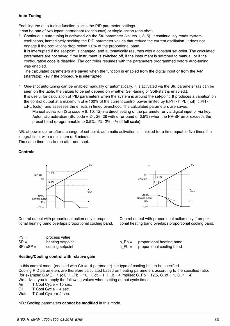
Controls
Control output with proportional action only if propor-tional heating band overlaps proportional cooling band.
PV = process valueSP = heating setpointSP+cSP = cooling setpoint
Control output with proportional action only if propor-tional heating band overlaps proportional cooling band.
h_Pb = proportional heating bandc_Pb = proportional cooling band
Heating/Cooling control with relative gain
In this control mode (enabled with Ctr = 14 parameter) the type of cooling has to be specified.Cooling PID parameters are therefore calculated based on heating parameters according to the specified ratio.(for example: C.ME = 1 (oil), H_Pb = 10, H_dt = 1, H_It = 4 implies: C_Pb = 12,5, C_dt = 1, C_It = 4) We advise you to apply the following values when setting output cycle times:Air T Cool Cycle = 10 sec.Oil T Cool Cycle = 4 sec.Water T Cool Cycle = 2 sec.
NB.: Cooling parameters cannot be modified in this mode.
3381801H_MHW_1200-1300_03-2015_ENG
time
PV
c_Pb
h_Pb
SP+cSP
SP
+100%Control output
0%
-100%
time
PV
c_Pb
h_PbSP+cSP
SP
+100%Control output
0%
-100%
5 • TECHNICAL SPECIFICATIONS
This section contains a list of the Technical Specifications for the 1200/1300 Controller.
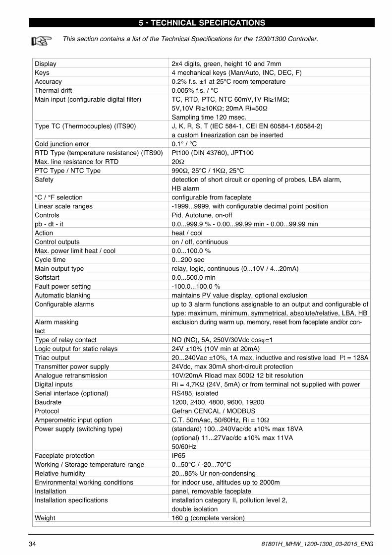
Display 2x4 digits, green, height 10 and 7mmKeys 4 mechanical keys (Man/Auto, INC, DEC, F)Accuracy 0.2% f.s. ±1 at 25°C room temperature Thermal drift 0.005% f.s. / °CMaininput(configurabledigitalfilter) TC,RTD,PTC,NTC60mV,1VRi≥1MW; 5V,10VRi≥10KW; 20mA Ri=50W Sampling time 120 msec.Type TC (Thermocouples) (ITS90) J, K, R, S, T (IEC 584-1, CEI EN 60584-1,60584-2) a custom linearization can be insertedCold junction error 0.1° / °CRTD Type (temperature resistance) (ITS90) Pt100 (DIN 43760), JPT100Max. line resistance for RTD 20WPTC Type / NTC Type 990W, 25°C / 1KW, 25°CSafety detection of short circuit or opening of probes, LBA alarm, HB alarm°C / °F selection configurable from faceplateLinear scale ranges -1999...9999, with configurable decimal point positionControls Pid, Autotune, on-offpb - dt - it 0.0...999.9 % - 0.00...99.99 min - 0.00...99.99 minAction heat / coolControl outputs on / off, continuousMax. power limit heat / cool 0.0...100.0 %Cycle time 0...200 secMain output type relay, logic, continuous (0...10V / 4...20mA)Softstart 0.0...500.0 minFault power setting -100.0...100.0 %Automatic blanking maintains PV value display, optional exclusionConfigurable alarms up to 3 alarm functions assignable to an output and configurable of type: maximum, minimum, symmetrical, absolute/relative, LBA, HBAlarm masking exclusion during warm up, memory, reset from faceplate and/or con-tactType of relay contact NO (NC), 5A, 250V/30Vdc cosj=1Logic output for static relays 24V ±10% (10V min at 20mA)Triac output 20...240Vac ±10%, 1A max, inductive and resistive load I2t = 128ATransmitter power supply 24Vdc, max 30mA short-circuit protectionAnalogue retransmission 10V/20mA Rload max 500W 12 bit resolutionDigital inputs Ri = 4,7KW (24V, 5mA) or from terminal not supplied with powerSerial interface (optional) RS485, isolatedBaudrate 1200, 2400, 4800, 9600, 19200Protocol Gefran CENCAL / MODBUSAmperometric input option C.T. 50mAac, 50/60Hz, Ri = 10WPower supply (switching type) (standard) 100...240Vac/dc ±10% max 18VA (optional) 11...27Vac/dc ±10% max 11VA 50/60HzFaceplate protection IP65Working / Storage temperature range 0...50°C / -20...70°CRelative humidity 20...85% Ur non-condensingEnvironmental working conditions for indoor use, altitudes up to 2000mInstallation panel, removable faceplateInstallation specifications installation category II, pollution level 2, double isolationWeight 160 g (complete version)
34 81801H_MHW_1200-1300_03-2015_ENG
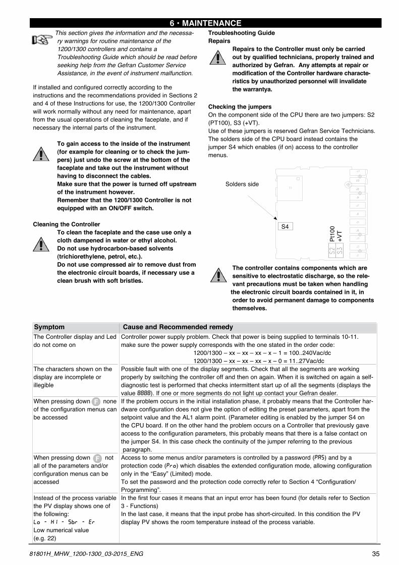
6 • MAINTENANCEThis section gives the information and the necessa- ry warnings for routine maintenance of the 1200/1300 controllers and contains a
Troubleshooting Guide which should be read before seeking help from the Gefran Customer Service Assistance, in the event of instrument malfunction.
If installed and configured correctly according to the instructions and the recommendations provided in Sections 2 and 4 of these Instructions for use, the 1200/1300 Controller will work normally without any need for maintenance, apart from the usual operations of cleaning the faceplate, and if necessary the internal parts of the instrument.
To gain access to the inside of the instrument (for example for cleaning or to check the jum- pers) just undo the screw at the bottom of the faceplate and take out the instrument without
having to disconnect the cables. Make sure that the power is turned off upstream of the instrument however. Remember that the 1200/1300 Controller is not equipped with an ON/OFF switch.
Cleaning the Controller To clean the faceplate and the case use only a cloth dampened in water or ethyl alcohol. Do not use hydrocarbon-based solvents (trichiorethylene, petrol, etc.).
Do not use compressed air to remove dust from the electronic circuit boards, if necessary use a clean brush with soft bristles.
Troubleshooting GuideRepairs
Repairs to the Controller must only be carried out by qualified technicians, properly trained and authorized by Gefran. Any attempts at repair or modification of the Controller hardware characte-
ristics by unauthorized personnel will invalidate the warrantya.
Checking the jumpersOn the component side of the CPU there are two jumpers: S2 (PT100), S3 (+VT). Use of these jumpers is reserved Gefran Service Technicians. The solders side of the CPU board instead contains the jumper S4 which enables (if on) access to the controller menus.
The controller contains components which are sensitive to electrostatic discharge, so the rele- vant precautions must be taken when handling the electronic circuit boards contained in it, in
order to avoid permanent damage to components themselves.
The Controller display and Led do not come on
The characters shown on the display are incomplete or illegible
When pressing down none of the configuration menus can be accessed
When pressing down not all of the parameters and/or configuration menus can be accessed
Instead of the process variable the PV display shows one of the following:LO - KI - SBR - ER
Low numerical value (e.g. 22)
Controller power supply problem. Check that power is being supplied to terminals 10-11.make sure the power supply corresponds with the one stated in the order code: 1200/1300 – xx – xx – xx – x – 1 = 100..240Vac/dc 1200/1300 – xx – xx – xx – x – 0 = 11..27Vac/dcPossible fault with one of the display segments. Check that all the segments are working properly by switching the controller off and then on again. When it is switched on again a self-diagnostic test is performed that checks intermittent start up of all the segments (displays the value 8888). If one or more segments do not light up contact your Gefran dealer.If the problem occurs in the initial installation phase, it probably means that the Controller har-dware configuration does not give the option of editing the preset parameters, apart from the setpoint value and the AL1 alarm point. (Parameter editing is enabled by the jumper S4 on the CPU board. If on the other hand the problem occurs on a Controller that previously gave access to the configuration parameters, this probably means that there is a false contact on the jumper S4. In this case check the continuity of the jumper referring to the previous paragraph.Access to some menus and/or parameters is controlled by a password (PAS) and by a protection code (PRO) which disables the extended configuration mode, allowing configuration only in the “Easy” (Limited) mode.To set the password and the protection code correctly refer to Section 4 “Configuration/Programming”.In the first four cases it means that an input error has been found (for details refer to Section 3 - Functions)In the last case, it means that the input probe has short-circuited. In this condition the PV display PV shows the room temperature instead of the process variable.
Symptom Cause and Recommended remedy
Solders side
S4
Pt10
0+V
T
3581801H_MHW_1200-1300_03-2015_ENG
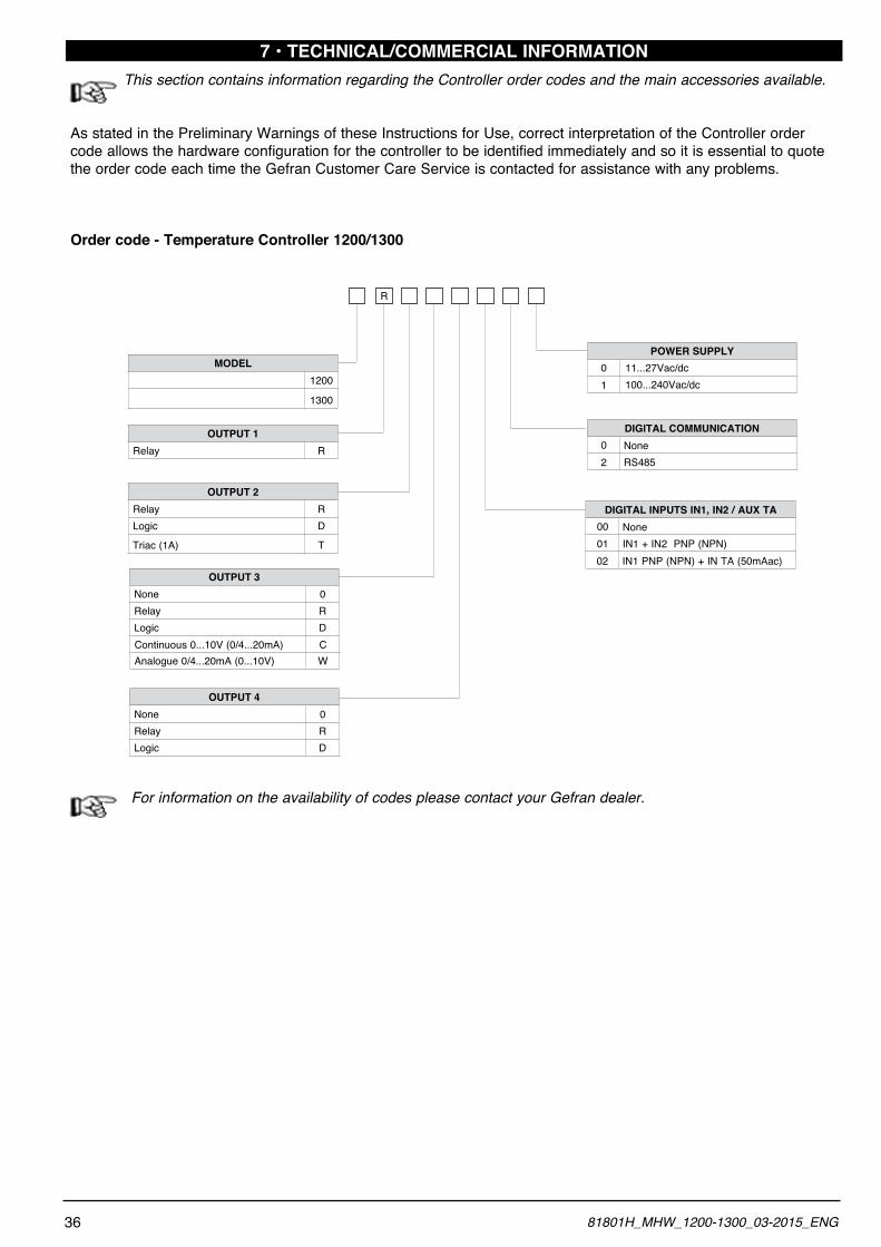
7 • TECHNICAL/COMMERCIAL INFORMATION This section contains information regarding the Controller order codes and the main accessories available.
As stated in the Preliminary Warnings of these Instructions for Use, correct interpretation of the Controller order code allows the hardware configuration for the controller to be identified immediately and so it is essential to quote the order code each time the Gefran Customer Care Service is contacted for assistance with any problems.
Order code - Temperature Controller 1200/1300
For information on the availability of codes please contact your Gefran dealer.
100...240Vac/dc 11...27Vac/dc
10
20 None
RS485
POWER SUPPLY
DIGITAL COMMUNICATION
0100 None
IN1 + IN2 PNP (NPN)02 IN1 PNP (NPN) + IN TA (50mAac)
DIGITAL INPUTS IN1, IN2 / AUX TA
R
OUTPUT 1 Relay R
Analogue 0/4...20mA (0...10V) W
OUTPUT 3 None 0 Relay R Logic D Continuous 0...10V (0/4...20mA) C
OUTPUT 2 Relay R Logic D
Triac (1A) T
OUTPUT 4 None 0 Relay R Logic D
MODEL1200
1300
36 81801H_MHW_1200-1300_03-2015_ENG
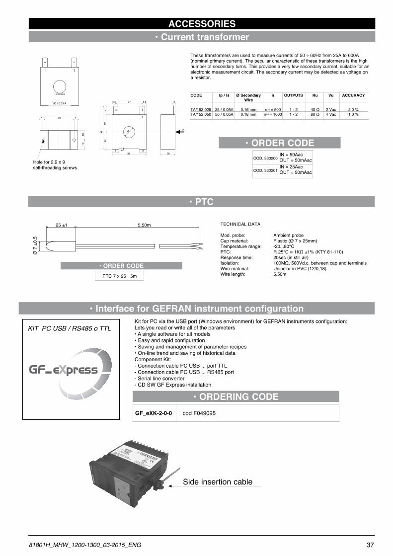
25 ±1
Ø 7
±0,
5
5,50m
PTC 7 x 25 5m
• ORDER CODE
TECHNICAL DATA
Mod. probe: Ambient probeCap material: Plastic (Ø 7 x 25mm)Temperature range: -20...80°CPTC: R25°C=1KΩ±1%(KTY81-110)Response time: 20sec (in still air)Isolation: 100MΩ,500Vd.c.between cap and terminalsWire material: Unipolar in PVC (12/0,18)Wire length: 5,50m
• Current transformerACCESSORIES
50 / 0.05 A
152050 9640
1 2
1 2
5,5 27 5,59
2019
48
8 838
1
13
20
2
In
44 30
1010
Hole for 2.9 x 9self-threading screws
These transformers are used to measure currents of 50 ÷ 60Hz from 25A to 600A(nominal primary current). The peculiar characteristic of these transformers is the high number of secondary turns. This provides a very low secondary current, suitable for an electronic measurement circuit. The secondary current may be detected as voltage on a resistor.
CODE Ip / Is Ø Secondary n OUTPUTS Ru Vu ACCURACY Wire
TA/152 025 25 / 0.05A 0.16 mm n1-2 =500 1-2 40Ω 2Vac 2.0%TA/152 050 50 / 0.05A 0.18 mm n1-2 =1000 1-2 80Ω 4Vac 1.0%
IN = 25AacOUT = 50mAac
COD. 330200IN = 50AacOUT = 50mAac
COD. 330201
• ORDER CODE
• PTC
Side insertion cable
3781801H_MHW_1200-1300_03-2015_ENG
• Interface for GEFRAN instrument configuration
KIT PC USB / RS485 o TTL
• ORDERING CODE
KitforPCviatheUSBport(Windowsenvironment)forGEFRANinstrumentsconfiguration:Lets you read or write all of the parameters•Asinglesoftwareforallmodels•Easyandrapidconfiguration•Savingandmanagementofparameterrecipes•On-linetrendandsavingofhistoricaldataComponent Kit:- Connection cable PC USB ... port TTL- Connection cable PC USB ... RS485 port- Serial line converter- CD SW GF Express installation
GF_eXK-2-0-0 cod F049095
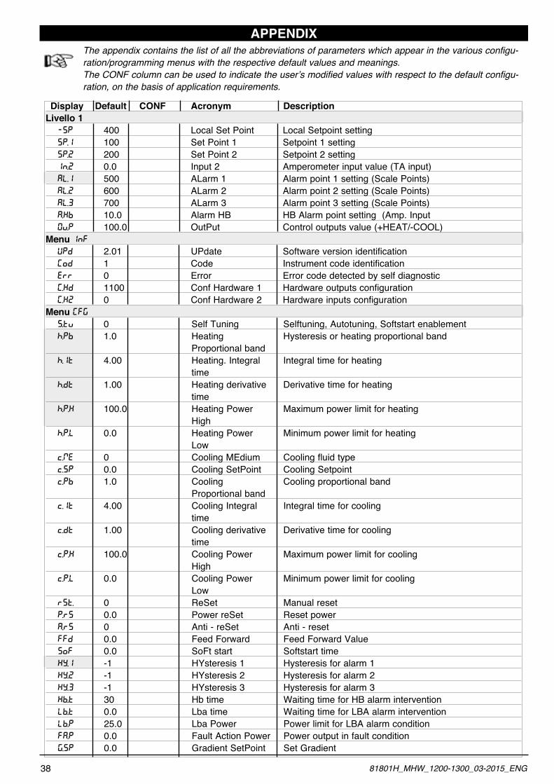
APPENDIXThe appendix contains the list of all the abbreviations of parameters which appear in the various configu-ration/programming menus with the respective default values and meanings.The CONF column can be used to indicate the user’s modified values with respect to the default configu-ration, on the basis of application requirements.
Display Default CONF Acronym DescriptionLivello 1 -SP 400 Local Set Point Local Setpoint setting SP.1 100 Set Point 1 Setpoint 1 setting SP.2 200 Set Point 2 Setpoint 2 setting IN.2 0.0 Input 2 Amperometer input value (TA input) AL.1 500 ALarm 1 Alarm point 1 setting (Scale Points) AL.2 600 ALarm 2 Alarm point 2 setting (Scale Points) AL.3 700 ALarm 3 Alarm point 3 setting (Scale Points) A.KB 10.0 Alarm HB HB Alarm point setting (Amp. Input 0V.P 100.0 OutPut Control outputs value (+HEAT/-COOL)Menu INF UPD 2.01 UPdate Software version identification (OD 1 Code Instrument code identification ERR 0 Error Error code detected by self diagnostic (.KD 1100 Conf Hardware 1 Hardware outputs configuration (.K2 0 Conf Hardware 2 Hardware inputs configurationMenu (FG S.TV 0 Self Tuning Selftuning, Autotuning, Softstart enablement H.PB 1.0 Heating Hysteresis or heating proportional band Proportional band H.IT 4.00 Heating. Integral Integral time for heating time H.DT 1.00 Heating derivative Derivative time for heating time H.P.K 100.0 Heating Power Maximum power limit for heating High H.P.L 0.0 Heating Power Minimum power limit for heating Low C.ME 0 Cooling MEdium Cooling fluid type C.SP 0.0 Cooling SetPoint Cooling Setpoint C.PB 1.0 Cooling Cooling proportional band Proportional band C.IT 4.00 Cooling Integral Integral time for cooling time C.DT 1.00 Cooling derivative Derivative time for cooling time C.P.K 100.0 Cooling Power Maximum power limit for cooling High C.P.L 0.0 Cooling Power Minimum power limit for cooling Low RST. 0 ReSet Manual reset P.RS 0.0 Power reSet Reset power A.RS 0 Anti - reSet Anti - reset FFD 0.0 Feed Forward Feed Forward Value SOF 0.0 SoFt start Softstart time KY.I -1 HYsteresis 1 Hysteresis for alarm 1 KY.2 -1 HYsteresis 2 Hysteresis for alarm 2 KY.3 -1 HYsteresis 3 Hysteresis for alarm 3 KB.T 30 Hb time Waiting time for HB alarm intervention LB.T 0.0 Lba time Waiting time for LBA alarm intervention LB.P 25.0 Lba Power Power limit for LBA alarm condition FA.P 0.0 Fault Action Power Power output in fault condition G.SP 0.0 Gradient SetPoint Set Gradient
38 81801H_MHW_1200-1300_03-2015_ENG
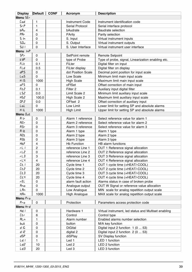
Display Default CONF Acronym DescriptionMenu SER (OD 1 Instrument Code Instrument identification code SR.P 1 Serial Protocol Serial interface protocol BAV 4 bAudrate Baudrate selection PAR 0 PArity Parity selection S.IN 0 S. Input Virtual instrument inputs S.0V 0 S. Output Virtual instrument outputs S.UI 0 S. User Interface Virtual instrument user interfaceMenu INP SP.R 0 SetPoint remote Remote Setpoint TYP 0 type of Probe Type of probe, signal, Linearization enabling etc. FLT 0.1 FiLter Digital filter on input FLD 0.5 FiLter display Digital filter on display DP.S 0 dot Position Scale Decimal point position for input scale LO.S 0 Low Scale Minimum limit main input scale Ki.S 1000 High Scale Maximum limit main input scale OFS 0 oFfSet Offset correction of main input FT.2 0.1 Filter 2 Auxiliary input digital filter LS.2 0.0 Limit Scale 2 Minimum limit auxiliary input scale KS.2 100.0 High Scale 2 Maximum limit auxiliary input scale 0F.2 0.0 OFfset 2 Offset correction of auxiliary input LO.L 0 Low Limit Lower limit for setting SP and absolute alarms Ki.L 1000 High Limit Upper limit for setting SP and absolute alarmsMenu 0VT A1.R 0 Alarm 1 reference Select reference value for alarm 1 A2.R 0 Alarm 2 reference Select reference value for alarm 2 A3.R 0 Alarm 3 reference Select reference value for alarm 3 A1.T 0 Alarm 1 type Alarm 1 type A2.T 0 Alarm 2 type Alarm 2 type A3.T 0 Alarm 3 type Alarm 3 type KB.F 4 Hb Function HB alarm functions RL.1 2 reference Line 1 OUT 1 Reference signal allocation RL.2 0 reference Line 2 OUT 2 Reference signal allocation RL.3 3 reference Line 3 OUT 3 Reference signal allocation RL.4 4 reference Line 4 OUT 4 Reference signal allocation (T.1 20 Cycle time 1 OUT 1 cycle time (+HEAT/-COOL) (T.2 20 Cycle time 2 OUT 2 cycle time (+HEAT/-COOL) (T.3 20 Cycle time 3 OUT 3 cycle time (+HEAT/-COOL) (T.4 20 Cycle time 4 OUT 4 cycle time (+HEAT/-COOL) REL 0 alarm fault action Alarms status in case of broken probe AN.O 0 Analogue output OUT W Signal or reference value allocation L.AN 0 Low Analogue MIN scale for analog repetition output scale K.AN 1000 High Analogue MAX scale for analog repetition output scaleMenu PRO PRO 0 Protection Parameters access protection code Menu KRD KD.1 0 Hardware 1 Virtual instrument, led status and Multiset enabling [TR 6 Control Control type AL.N 1 Alarm number Enabled alarms number selection BVT 0 button M/A key function DiG 0 DiGital Digital input 2 function 1 (0 ... 53) Di2 0 digital 2 Digital input 2 function 2 (0 ... 53) DSP 0 diSPlay SV Display function LD.1 1 Led 1 LED 1 function LD.2 10 Led 2 LED 2 function LD.3 20 Led 3 LED 3 function
3981801H_MHW_1200-1300_03-2015_ENG
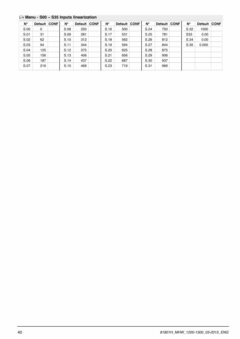
N° Default CONF S.00 0 S.01 31 S.02 62 S.03 94 S.04 125 S.05 156 S.06 187 S.07 219
N° Default CONF S.08 250 S.09 281 S.10 312 S.11 344 S.12 375 S.13 406 S.14 437 S.15 469
N° Default CONF S.16 500 S.17 531 S.18 562 S.19 594 S.20 625 S.21 656 S.22 687 S.23 719
N° Default CONF S.24 750 S.25 781 S.26 812 S.27 844 S.28 875 S.29 906 S.30 937 S.31 969
N° Default CONF S.32 1000 S33 0.00 S.34 0.00 S.35 0.000
L’N Menu - S00 – S35 Inputs linearization
40 81801H_MHW_1200-1300_03-2015_ENG