Embed Size (px)
Citation preview
12 GeV
Cryogenic System Planning
Dana Arenius
Cryogenic Systems Group
This work is supported by the United States Department of Energy (DOE) contract #DE-AC05-060R-23177
Pr~ 3.5
Pr~ 3.5
12 TO 16/21 ATM
3.5 - 6 ATM
1 ATM
C1
T
TURBINE
RECYCLE
FLOW
Pressure
Ratio
C2
Pressure
Ratio
T
COMPRESSORS
Pr~ 3.5-6
Pressure
Ratio
1- 1.75 ATM
SMALLER
2ND STAGE
COMPRESSORS
REFRIGERATION
LOAD
SMALL LOAD
COMPRESSOR
GANNI CYCLE (FLOATING PRESSURE)
HELIUM REFRIGERATION SYSTEM
T
COLD BOX
T
C0
FROM
REFRIGERATED
LOAD
TO
REFRIGERATED
LOAD
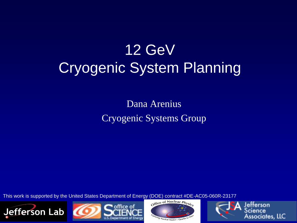
What is an “Optimal” System
Maximum
Efficiency, Reliability,
Low Maintenance
(Operations)
Sys. Capacity/
Loads
(Experimenter) Minimum
Capital
Cost
(Construction)
• One’s viewpoint can be based only on their role and focus within a project
• Easy to believe that one’s goals are mutually exclusive of others
• Many believe that maximum system efficiency occurs only at one set of
fixed operating conditions
Optimize
Compressor
System
(Vendor)
Optimize
Cold Box
Design
(Vendor)
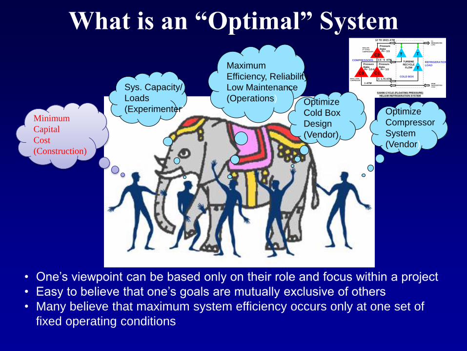
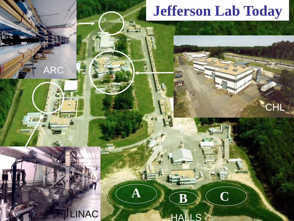
Jefferson Lab Today 2000 member international user community engaged in exploring quark-gluon structure of matter
A C
Superconducting accelerator provides 100% duty factor beams of unprecedented quality, with energies up to 6 GeV
CEBAF’s innovative design
allows delivery of beam with unique properties
to three experimental halls simultaneously
Each of the three halls offers complementary
experimental capabilities and allows for large equipment
installations to extend scientific reach
B
CHL
A B C
Jefferson Lab Today
HALLS
ARC
CHL
LINAC
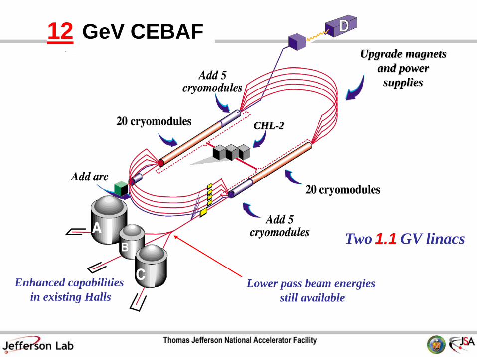
6 GeV CEBAF 11 12
Two 0.6 GV linacs 1.1
CHL-2
Upgrade magnets
and power
supplies
Enhanced capabilities
in existing Halls
Lower pass beam energies
still available
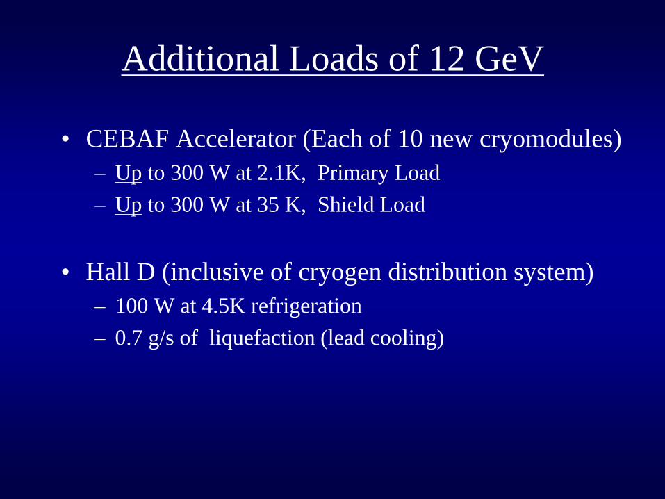
Additional Loads of 12 GeV
• CEBAF Accelerator (Each of 10 new cryomodules)
– Up to 300 W at 2.1K, Primary Load
– Up to 300 W at 35 K, Shield Load
• Hall D (inclusive of cryogen distribution system)
– 100 W at 4.5K refrigeration
– 0.7 g/s of liquefaction (lead cooling)
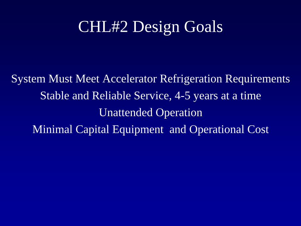
CHL#2 Design Goals
System Must Meet Accelerator Refrigeration Requirements
Stable and Reliable Service, 4-5 years at a time
Unattended Operation
Minimal Capital Equipment and Operational Cost
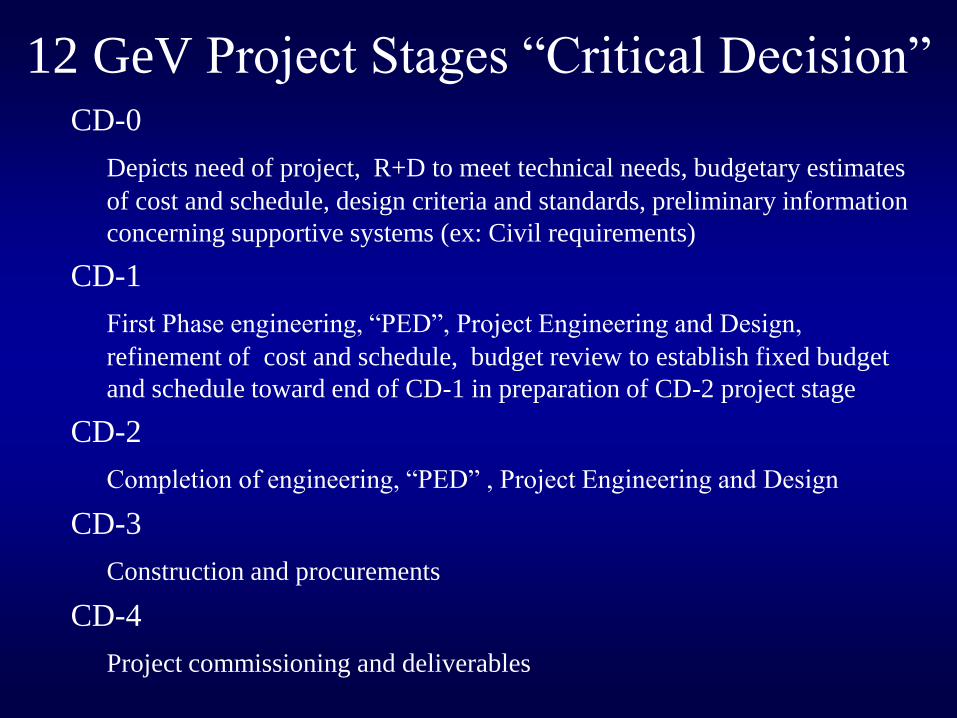
12 GeV Project Stages “Critical Decision” CD-0
Depicts need of project, R+D to meet technical needs, budgetary estimates
of cost and schedule, design criteria and standards, preliminary information
concerning supportive systems (ex: Civil requirements)
CD-1
First Phase engineering, “PED”, Project Engineering and Design,
refinement of cost and schedule, budget review to establish fixed budget
and schedule toward end of CD-1 in preparation of CD-2 project stage
CD-2
Completion of engineering, “PED” , Project Engineering and Design
CD-3
Construction and procurements
CD-4
Project commissioning and deliverables
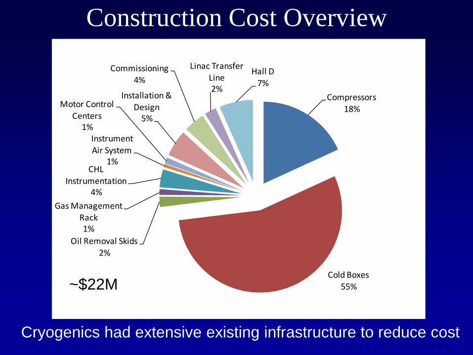
Construction Cost Overview
Compressors18%
Cold Boxes55%
Oil Removal Skids
2%
Gas Management Rack1%
CHL
Instrumentation4%
InstrumentAir System
1%
Motor Control
Centers1%
Installation &
Design5%
Commissioning
4%
Linac Transfer Line2%
Hall D7%
~$22M
Cryogenics had extensive existing infrastructure to reduce cost
Cryo SRD
Costing info &
backup
Drawings
Cryogenics detailed
req & spec doc’s
Cryo DSD
Accelerator DSD
WBS
dictionary
Cryomodules
DSD ICD’s
P3
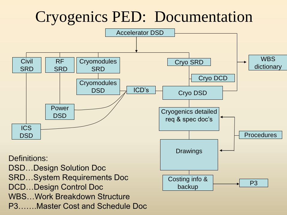
Cryogenics PED: Documentation
Definitions:
DSD…Design Solution Doc
SRD…System Requirements Doc
DCD…Design Control Doc
WBS…Work Breakdown Structure
P3…….Master Cost and Schedule Doc
:
Cryo DCD
Procedures
Power
DSD
ICS
DSD
Cryomodules
SRD
RF
SRD
Civil
SRD

Looking at the CHL
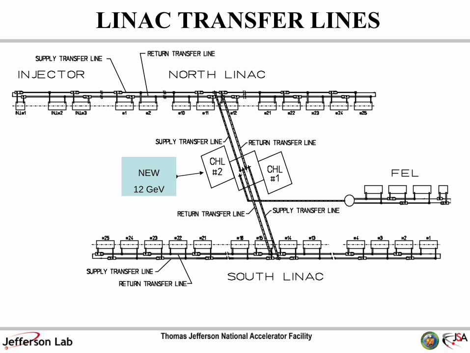
LINAC TRANSFER LINES
NEW FOR
12 GeV
NEW
12 GeV
600W @2.1K on SL
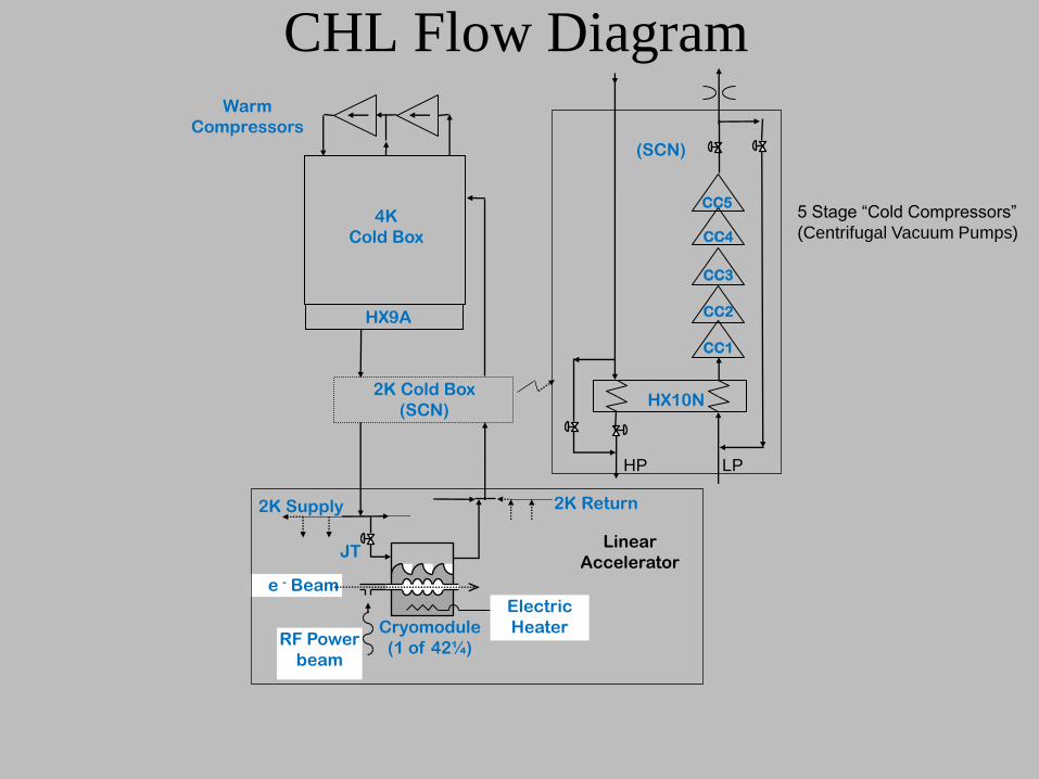
CHL Flow Diagram
2K Cold Box
(SCN)
CC1
CC2
CC3
CC4
Cryomodule
(1 of 42¼)
e - Beam
RF Power
beam
4K
Cold Box
JT
Warm
Compressors
Electric
Heater
Linear
Accelerator
CC5
HX9A
HX10N
2K Supply
2K Return
(SCN)
LP HP
5 Stage “Cold Compressors”
(Centrifugal Vacuum Pumps)
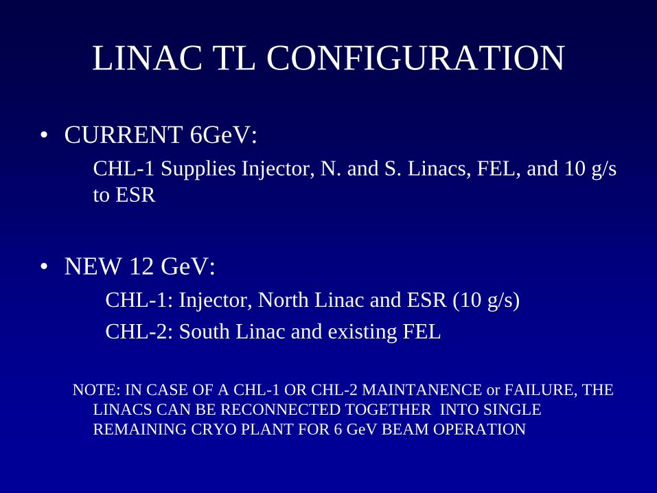
LINAC TL CONFIGURATION
• CURRENT 6GeV:
CHL-1 Supplies Injector, N. and S. Linacs, FEL, and 10 g/s
to ESR
• NEW 12 GeV:
CHL-1: Injector, North Linac and ESR (10 g/s)
CHL-2: South Linac and existing FEL
NOTE: IN CASE OF A CHL-1 OR CHL-2 MAINTANENCE or FAILURE, THE
LINACS CAN BE RECONNECTED TOGETHER INTO SINGLE
REMAINING CRYO PLANT FOR 6 GeV BEAM OPERATION
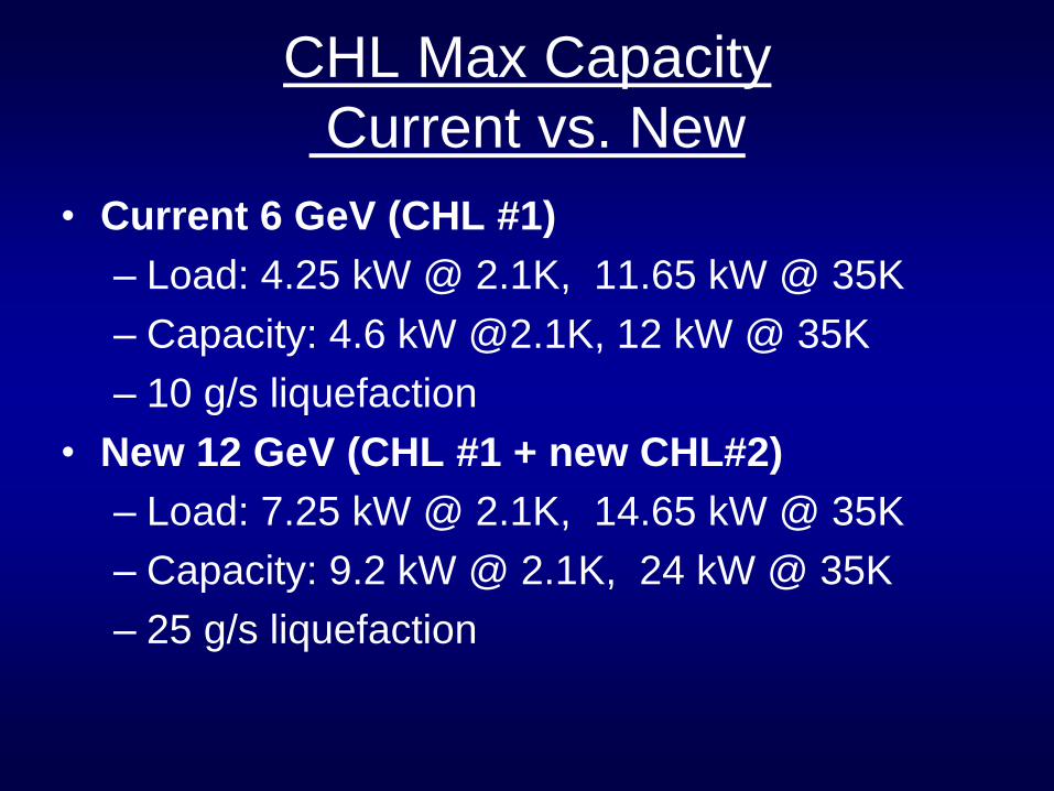
CHL Max Capacity
Current vs. New
• Current 6 GeV (CHL #1)
– Load: 4.25 kW @ 2.1K, 11.65 kW @ 35K
– Capacity: 4.6 kW @2.1K, 12 kW @ 35K
– 10 g/s liquefaction
• New 12 GeV (CHL #1 + new CHL#2)
– Load: 7.25 kW @ 2.1K, 14.65 kW @ 35K
– Capacity: 9.2 kW @ 2.1K, 24 kW @ 35K
– 25 g/s liquefaction
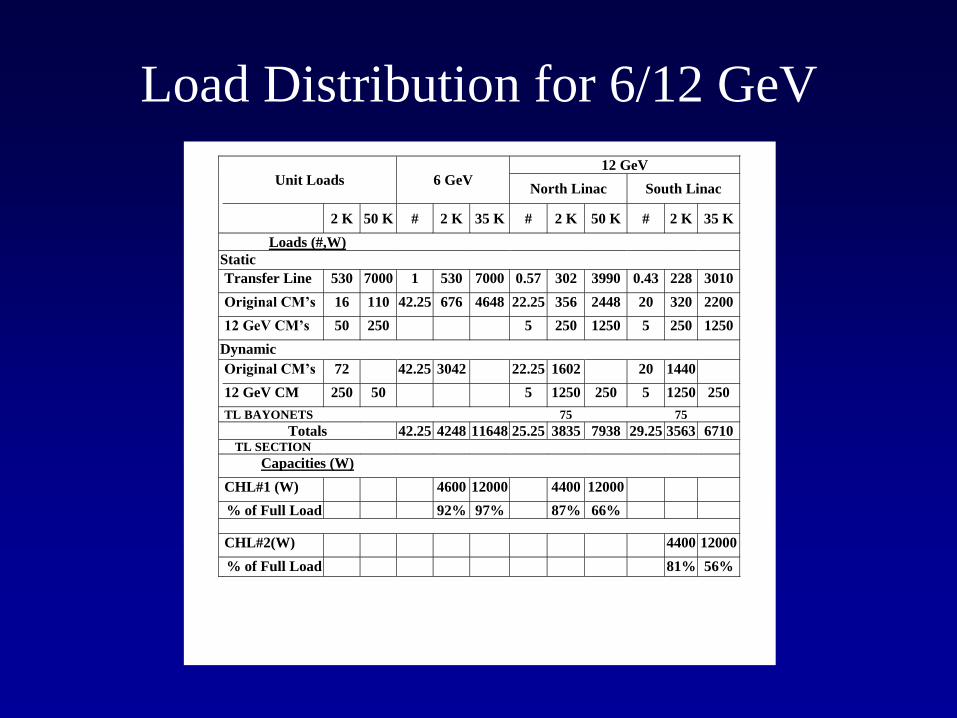
Load Distribution for 6/12 GeV
Unit Loads 6 GeV 12 GeV
North Linac South Linac
2 K 50 K # 2 K 35 K # 2 K 50 K # 2 K 35 K
Loads (#,W)
Static
Transfer Line 530 7000 1 530 7000 0.57 302 3990 0.43 228 3010
Original CM’s 16 110 42.25 676 4648 22.25 356 2448 20 320 2200
12 GeV CM’s 50 250 5 250 1250 5 250 1250
Dynamic
Original CM’s 72 42.25 3042 22.25 1602 20 1440
12 GeV CM 250 50 5 1250 250 5 1250 250
TL BAYONETS 75 75
Totals 42.25 4248 11648 25.25 3835 7938 29.25 3563 6710 TL SECTION
Capacities (W)
CHL#1 (W) 4600 12000 4400 12000
% of Full Load 92% 97% 87% 66%
CHL#2(W) 4400 12000
% of Full Load 81% 56%
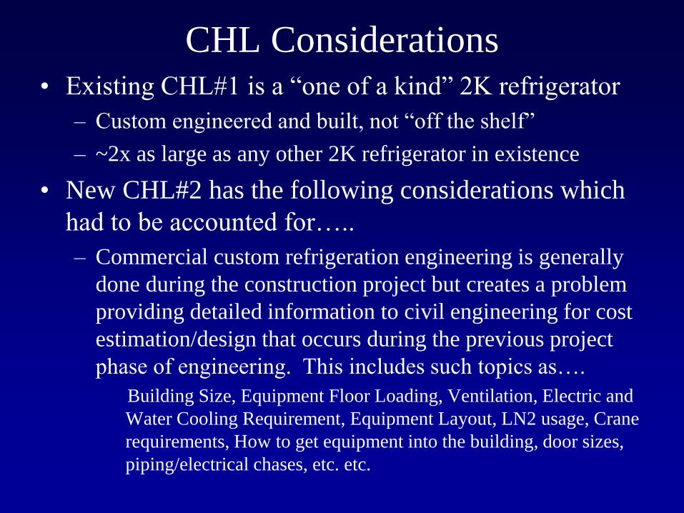
CHL Considerations • Existing CHL#1 is a “one of a kind” 2K refrigerator
– Custom engineered and built, not “off the shelf”
– ~2x as large as any other 2K refrigerator in existence
• New CHL#2 has the following considerations which
had to be accounted for…..
– Commercial custom refrigeration engineering is generally
done during the construction project but creates a problem
providing detailed information to civil engineering for cost
estimation/design that occurs during the previous project
phase of engineering. This includes such topics as….
Building Size, Equipment Floor Loading, Ventilation, Electric and
Water Cooling Requirement, Equipment Layout, LN2 usage, Crane
requirements, How to get equipment into the building, door sizes,
piping/electrical chases, etc. etc.
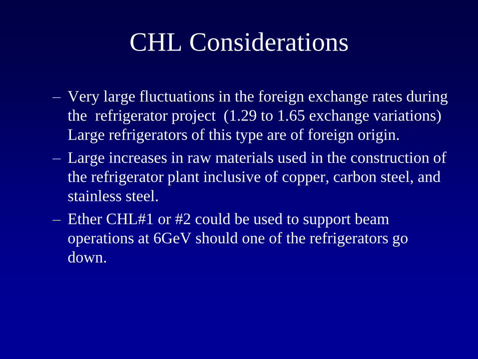
CHL Considerations
– Very large fluctuations in the foreign exchange rates during
the refrigerator project (1.29 to 1.65 exchange variations)
Large refrigerators of this type are of foreign origin.
– Large increases in raw materials used in the construction of
the refrigerator plant inclusive of copper, carbon steel, and
stainless steel.
– Ether CHL#1 or #2 could be used to support beam
operations at 6GeV should one of the refrigerators go
down.
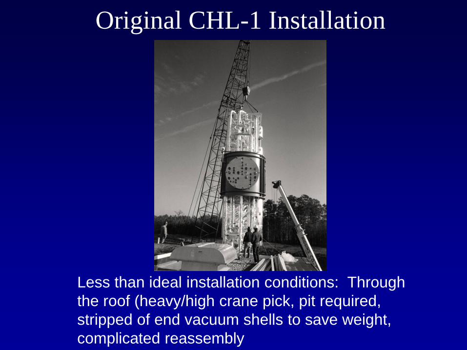
Original CHL-1 Installation
Less than ideal installation conditions: Through
the roof (heavy/high crane pick, pit required,
stripped of end vacuum shells to save weight,
complicated reassembly
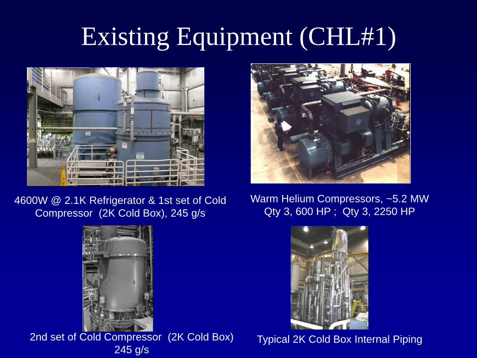
Existing Equipment (CHL#1)
4600W @ 2.1K Refrigerator & 1st set of Cold
Compressor (2K Cold Box), 245 g/s
Warm Helium Compressors, ~5.2 MW
Qty 3, 600 HP ; Qty 3, 2250 HP
2nd set of Cold Compressor (2K Cold Box)
245 g/s Typical 2K Cold Box Internal Piping
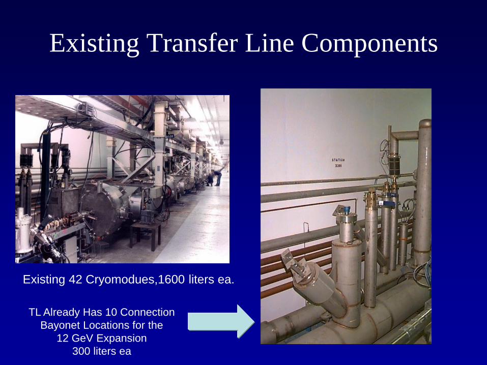
Existing Transfer Line Components
Existing 42 Cryomodues,1600 liters ea.
TL Already Has 10 Connection
Bayonet Locations for the
12 GeV Expansion
300 liters ea
Other CHL Operational Modes
• Although meeting the “steady state” operational
mode is important…there are many other modes
which the refrigerator must practically meet
Examples….
• Filling the cryomodules with liquid (liquefaction rate)
• Maintaining the cryomodules at 4.5K instead of 2K
• Translating from 4.5 to 2.1K operations (very low refrigeration
requirement)
• So these “other” modes must be mapped out to make
sure that the refrigerator can cover them…(part of the
procurement specification)
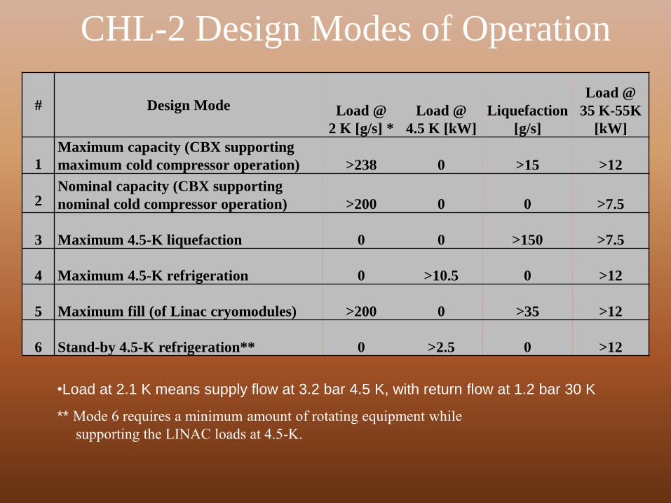
CHL-2 Design Modes of Operation
# Design Mode Load @
2 K [g/s] *
Load @
4.5 K [kW]
Liquefaction
[g/s]
Load @
35 K-55K
[kW]
1
Maximum capacity (CBX supporting
maximum cold compressor operation) >238 0 >15 >12
2 Nominal capacity (CBX supporting
nominal cold compressor operation) >200 0 0 >7.5
3 Maximum 4.5-K liquefaction 0 0 >150 >7.5
4 Maximum 4.5-K refrigeration 0 >10.5 0 >12
5 Maximum fill (of Linac cryomodules) >200 0 >35 >12
6 Stand-by 4.5-K refrigeration** 0 >2.5 0 >12
•Load at 2.1 K means supply flow at 3.2 bar 4.5 K, with return flow at 1.2 bar 30 K
** Mode 6 requires a minimum amount of rotating equipment while
supporting the LINAC loads at 4.5-K.
0
200
400
600
800
1000
1200
1400
1600
1 5 3 2 4 6
Design Mode
Exerg
y [
kW
]
0
10
20
30
40
50
60
70
80
90
100
Exerg
eti
c e
ffic
ien
cy [
%]
Ė @ 2.1 K Ė @ Liq Ė @ 4.5 K
Ė @ 35 K η_total [%] η_CBX [%]
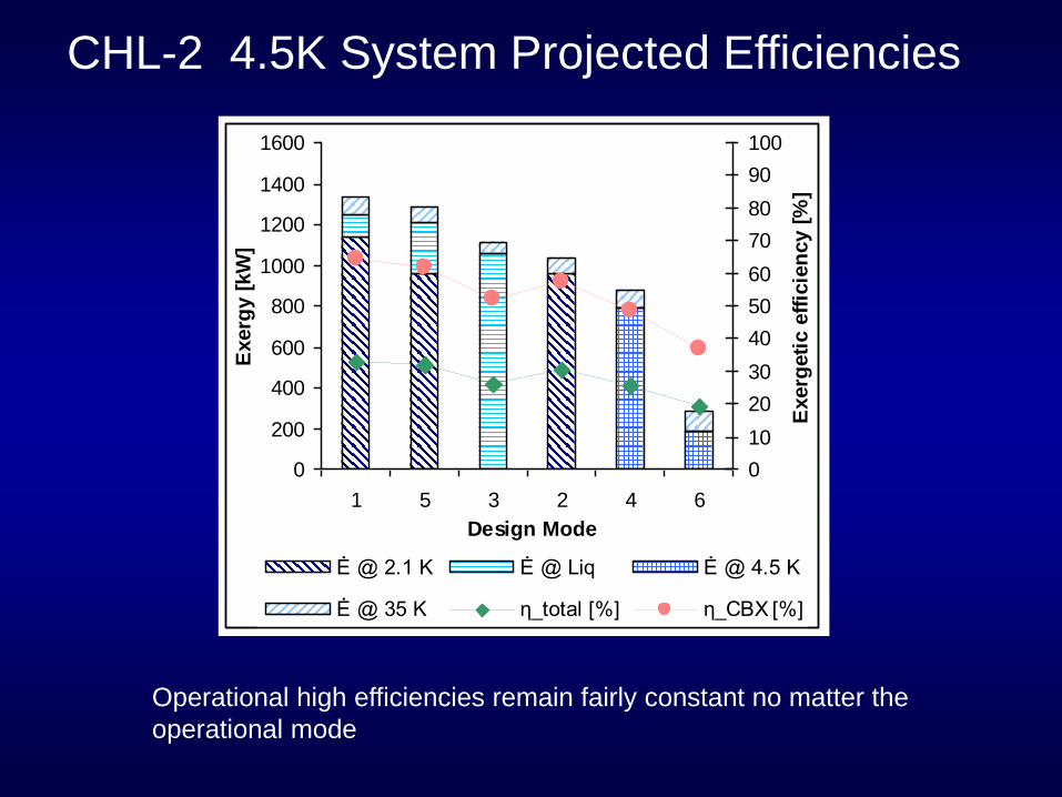
CHL-2 4.5K System Projected Efficiencies
Operational high efficiencies remain fairly constant no matter the
operational mode
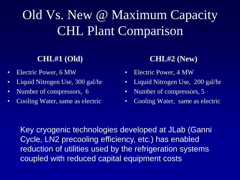
Old Vs. New @ Maximum Capacity
CHL Plant Comparison
CHL#1 (Old)
• Electric Power, 6 MW
• Liquid Nitrogen Use, 300 gal/hr
• Number of compressors, 6
• Cooling Water, same as electric
CHL#2 (New)
• Electric Power, 4 MW
• Liquid Nitrogen Use, 200 gal/hr
• Number of compressors, 5
• Cooling Water, same as electric
Key cryogenic technologies developed at JLab (Ganni
Cycle, LN2 precooling efficiency, etc.) has enabled
reduction of utilities used by the refrigeration systems
coupled with reduced capital equipment costs
JLab CHL#1 facility
had many supportive subsystems
already in place needed by CHL#2
which reduced system cost
substantially
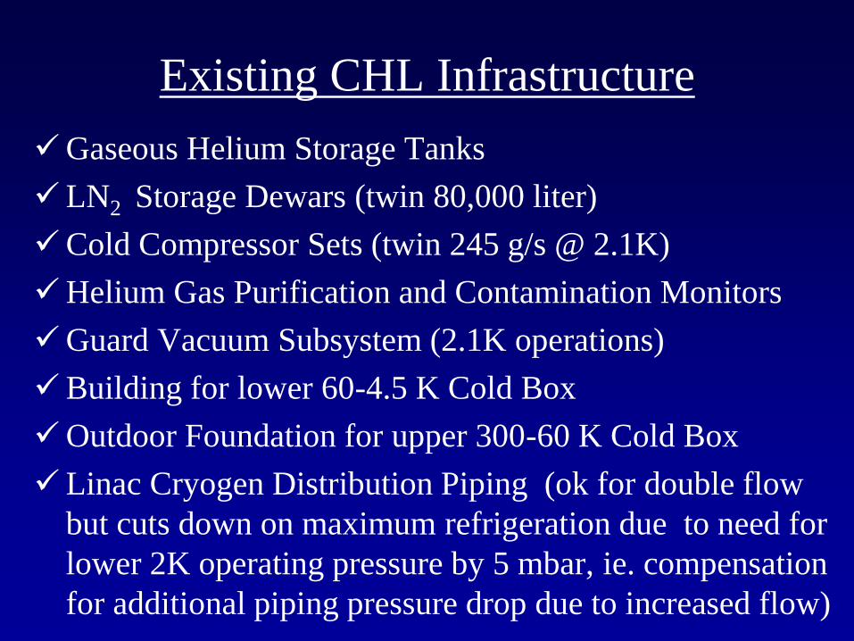
Existing CHL Infrastructure
Gaseous Helium Storage Tanks
LN2 Storage Dewars (twin 80,000 liter)
Cold Compressor Sets (twin 245 g/s @ 2.1K)
Helium Gas Purification and Contamination Monitors
Guard Vacuum Subsystem (2.1K operations)
Building for lower 60-4.5 K Cold Box
Outdoor Foundation for upper 300-60 K Cold Box
Linac Cryogen Distribution Piping (ok for double flow
but cuts down on maximum refrigeration due to need for
lower 2K operating pressure by 5 mbar, ie. compensation
for additional piping pressure drop due to increased flow)
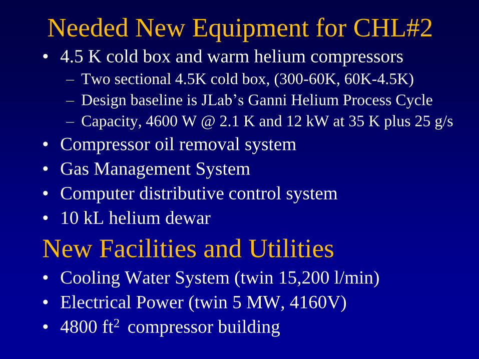
Needed New Equipment for CHL#2 • 4.5 K cold box and warm helium compressors
– Two sectional 4.5K cold box, (300-60K, 60K-4.5K)
– Design baseline is JLab’s Ganni Helium Process Cycle
– Capacity, 4600 W @ 2.1 K and 12 kW at 35 K plus 25 g/s
• Compressor oil removal system
• Gas Management System
• Computer distributive control system
• 10 kL helium dewar
New Facilities and Utilities • Cooling Water System (twin 15,200 l/min)
• Electrical Power (twin 5 MW, 4160V)
• 4800 ft2 compressor building
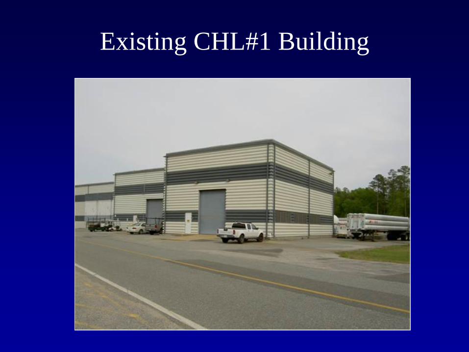
Existing CHL#1 Building
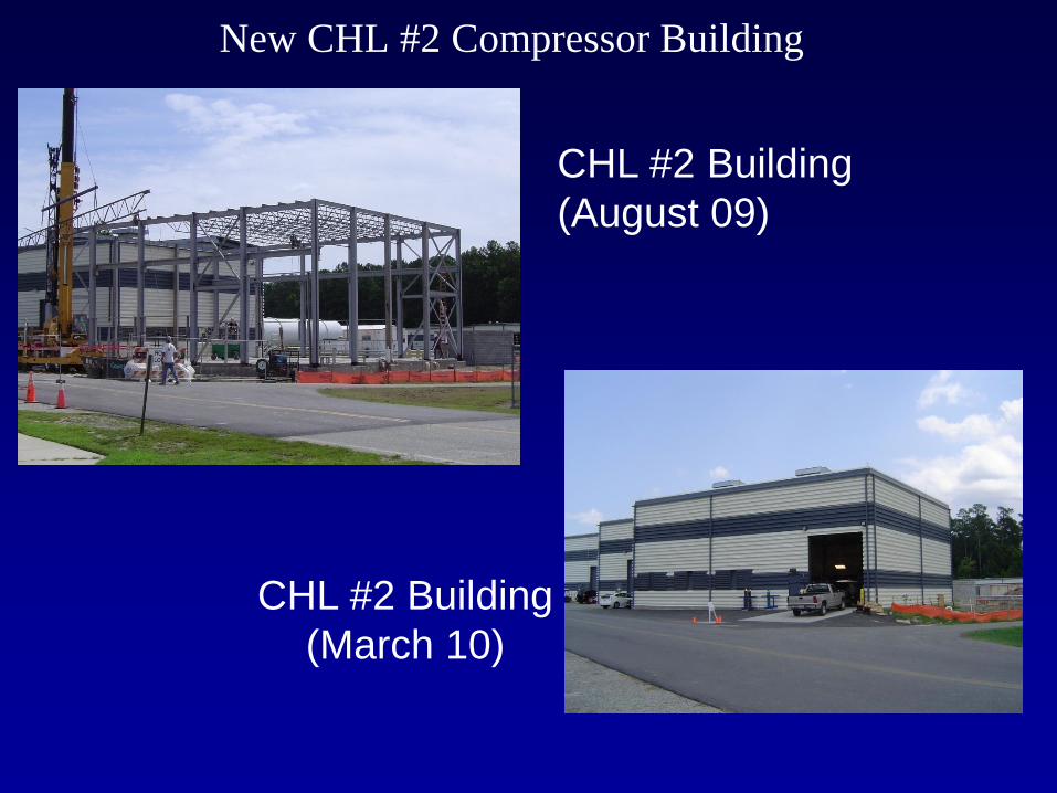
New CHL #2 Compressor Building
CHL #2 Building
(August 09)
CHL #2 Building
(March 10)
New Photo Needed
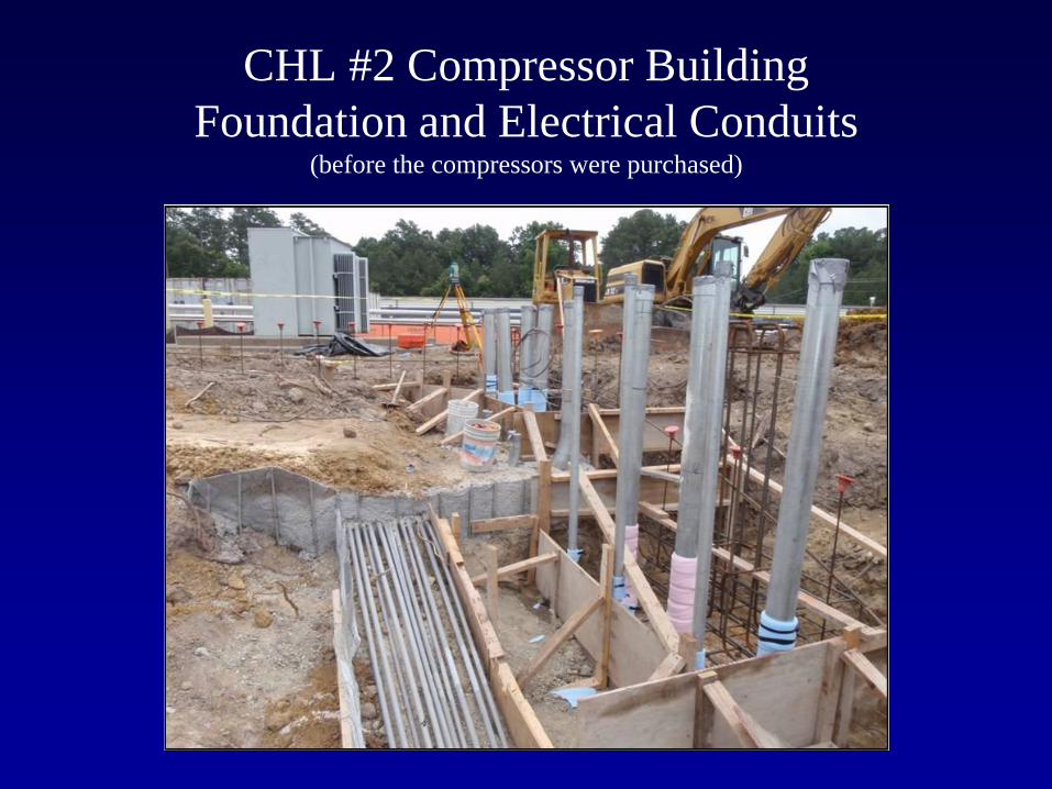
CHL #2 Compressor Building
Foundation and Electrical Conduits (before the compressors were purchased)
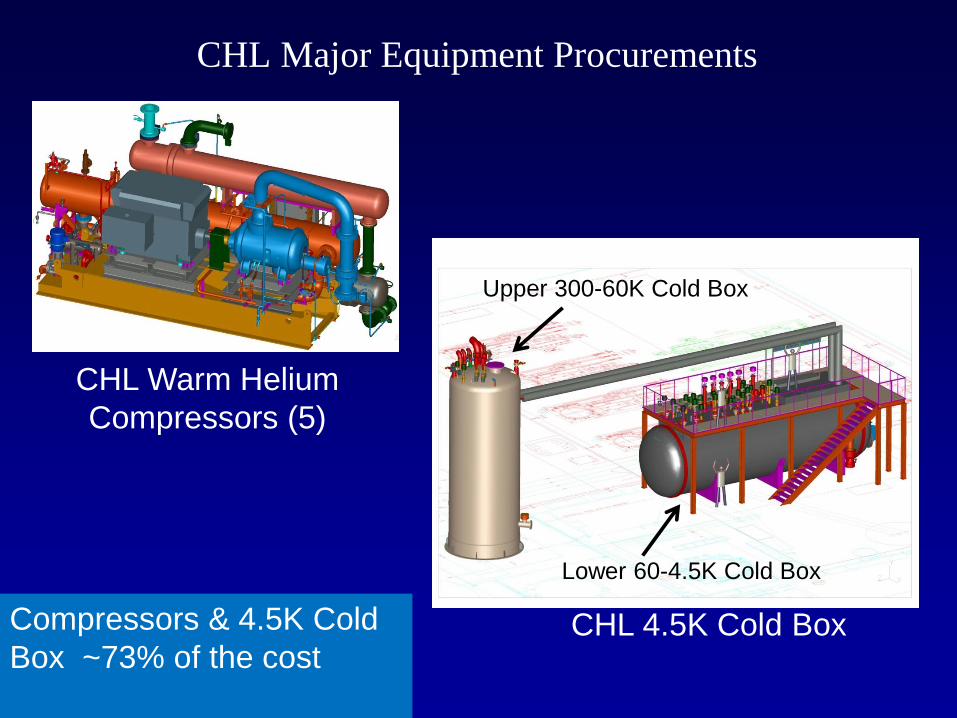
CHL Major Equipment Procurements
CHL Warm Helium
Compressors (5)
CHL 4.5K Cold Box Compressors & 4.5K Cold
Box ~73% of the cost
Upper 300-60K Cold Box
Lower 60-4.5K Cold Box
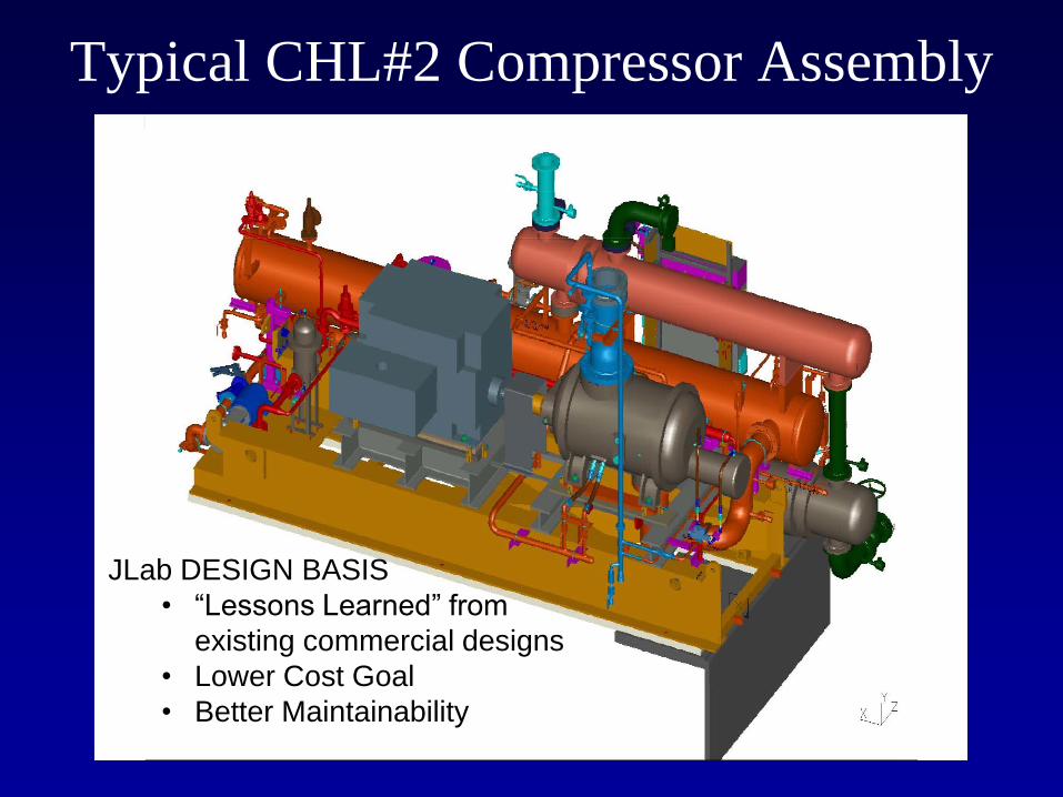
Typical CHL#2 Compressor Assembly
JLab DESIGN BASIS
• “Lessons Learned” from
existing commercial designs
• Lower Cost Goal
• Better Maintainability
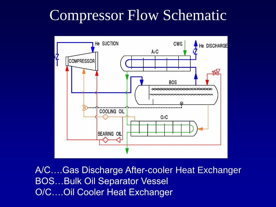
Compressor Flow Schematic
A/C….Gas Discharge After-cooler Heat Exchanger
BOS…Bulk Oil Separator Vessel
O/C….Oil Cooler Heat Exchanger
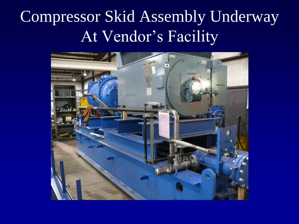
Compressor Skid Assembly Underway
At Vendor’s Facility
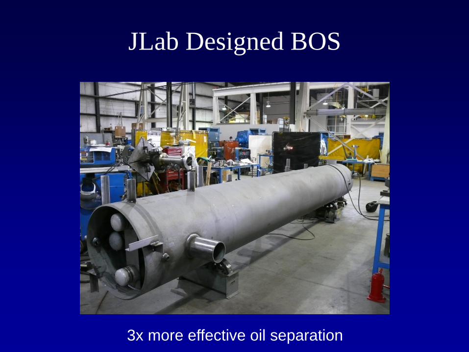
JLab Designed BOS
3x more effective oil separation
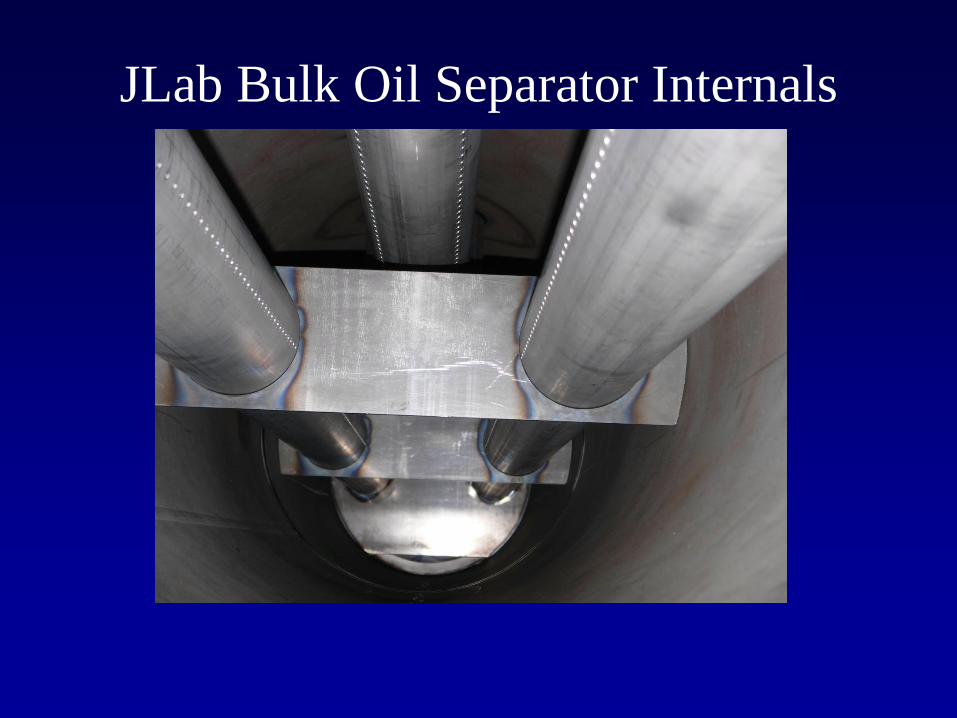
JLab Bulk Oil Separator Internals
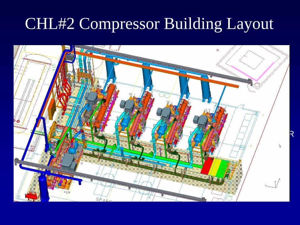
CHL#2 Compressor Building Layout
COMPRESSORS
4 800 HP
1 2500 HP
TRENCH PIPING
COOLING WATER
HELIUM GAS
ELECTRICAL/CONTROL
UNDER SLAB
~4 MW USAGE
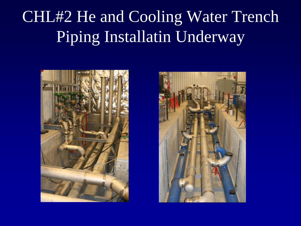
CHL#2 He and Cooling Water Trench
Piping Installatin Underway
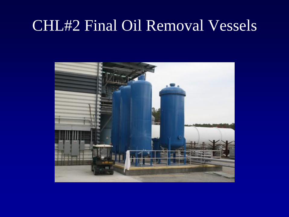
CHL#2 Final Oil Removal Vessels
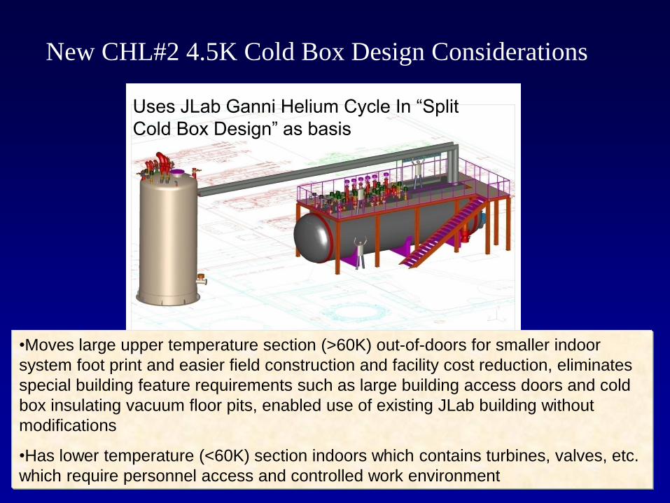
New CHL#2 4.5K Cold Box Design Considerations
Uses JLab Ganni Helium Cycle In “Split
Cold Box Design” as basis
•Moves large upper temperature section (>60K) out-of-doors for smaller indoor
system foot print and easier field construction and facility cost reduction, eliminates
special building feature requirements such as large building access doors and cold
box insulating vacuum floor pits, enabled use of existing JLab building without
modifications
•Has lower temperature (<60K) section indoors which contains turbines, valves, etc.
which require personnel access and controlled work environment
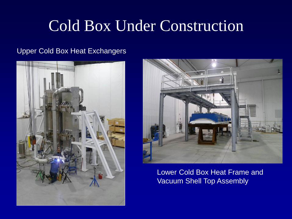
Cold Box Under Construction
Upper Cold Box Heat Exchangers
Lower Cold Box Heat Frame and
Vacuum Shell Top Assembly
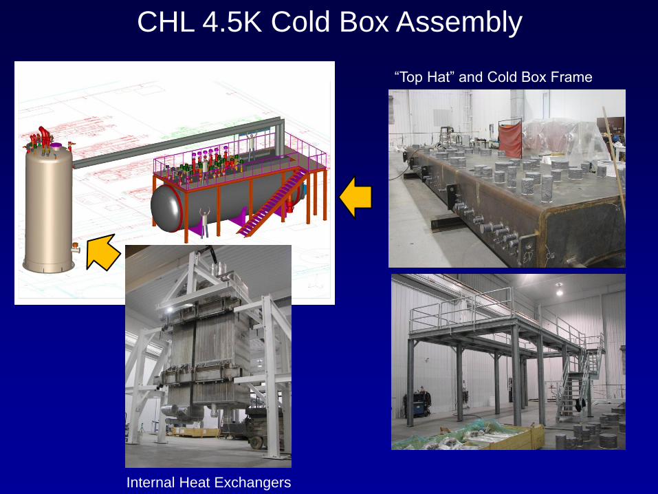
CHL 4.5K Cold Box Assembly
“Top Hat” and Cold Box Frame
Internal Heat Exchangers
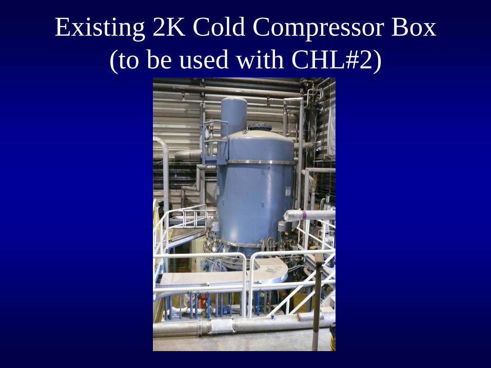
Existing 2K Cold Compressor Box
(to be used with CHL#2)
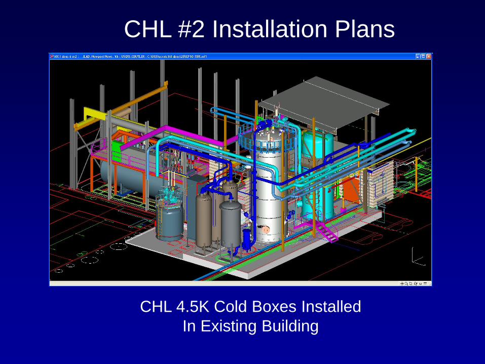
CHL #2 Installation Plans
CHL 4.5K Cold Boxes Installed
In Existing Building
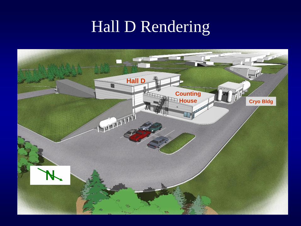
Hall D Rendering
Counting
House Cryo Bldg
Hall D
A Look at the Hall D Refrigerator
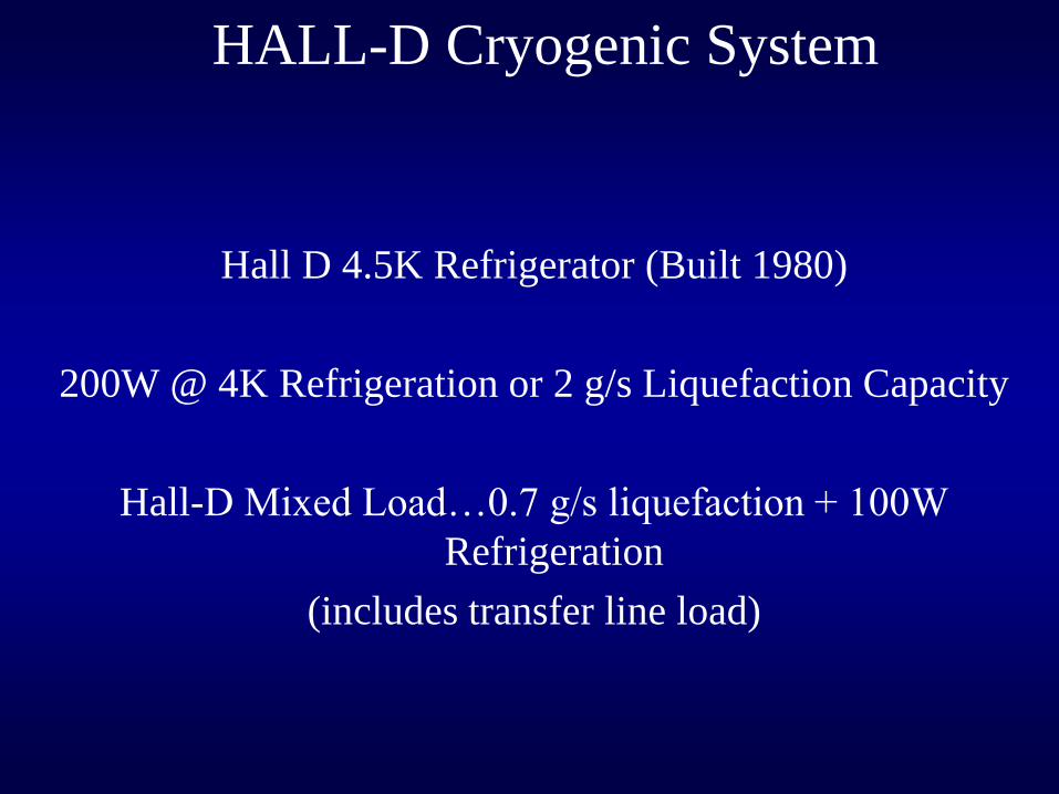
HALL-D Cryogenic System
Hall D 4.5K Refrigerator (Built 1980)
200W @ 4K Refrigeration or 2 g/s Liquefaction Capacity
Hall-D Mixed Load…0.7 g/s liquefaction + 100W
Refrigeration
(includes transfer line load)
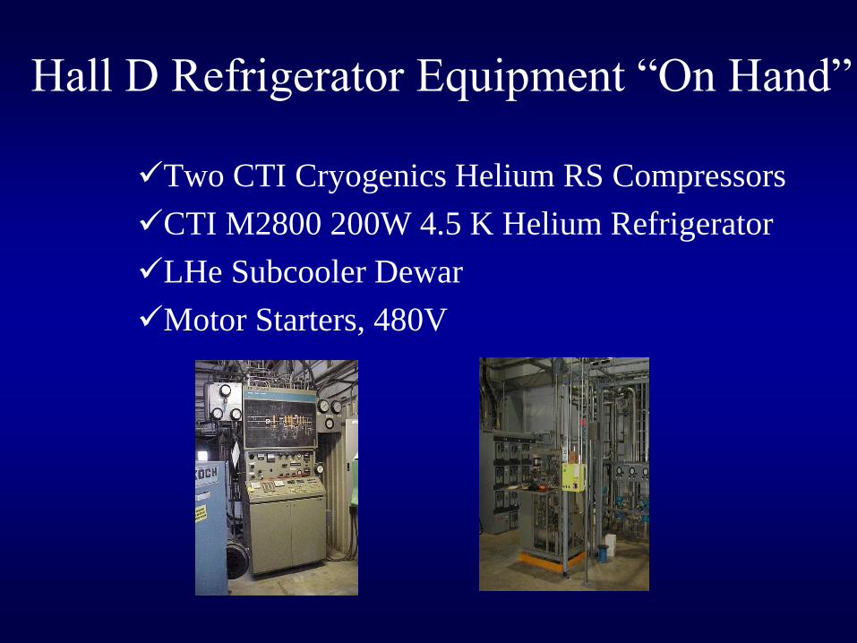
Hall D Refrigerator Equipment “On Hand”
Two CTI Cryogenics Helium RS Compressors
CTI M2800 200W 4.5 K Helium Refrigerator
LHe Subcooler Dewar
Motor Starters, 480V
Other Hall D Cryogenic Equipment
Requirements
• Gas Management Valve Control Rack
• LN2 storage, 10,000 liter dewar
• One 4000 cf Helium Gas Storage Vessel
• Integrated Refrigerator Computer Controls
• Instrument Air System, 15 scfm
• Purification Loop Piping to the CHL via N. Linac
• 640 ft2 building
• Compressor/Turbine Cooling Water
• 480V, 300 kW compressor power
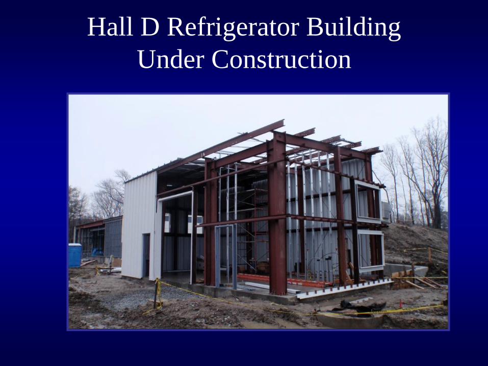
Hall D Refrigerator Building
Under Construction
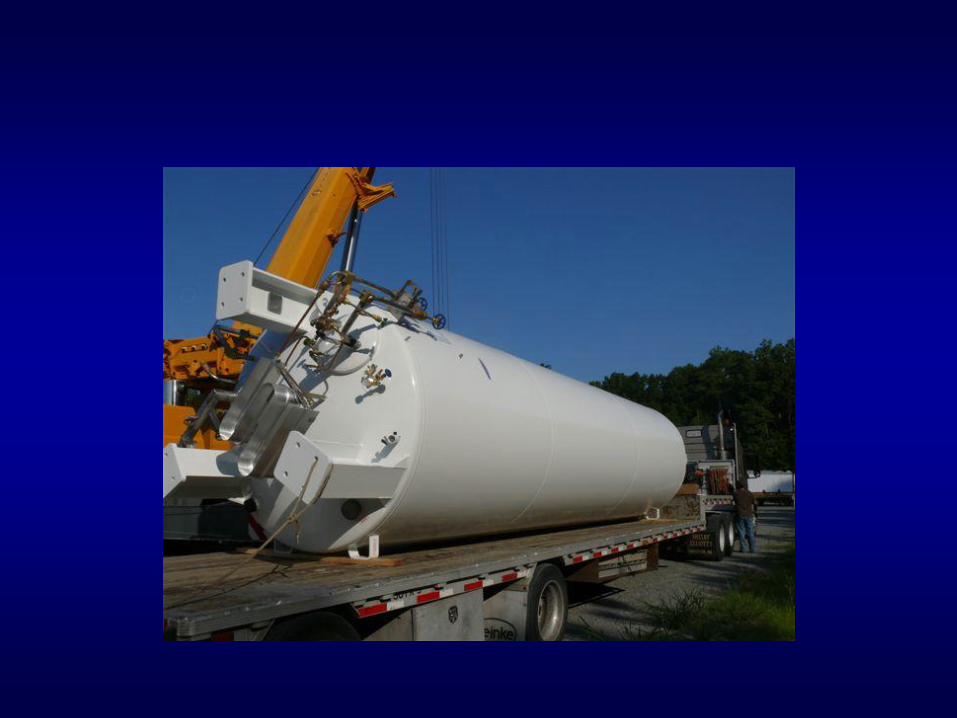
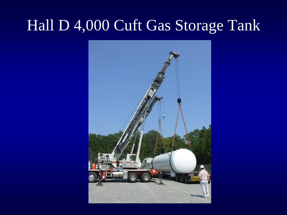
Hall D 4,000 Cuft Gas Storage Tank
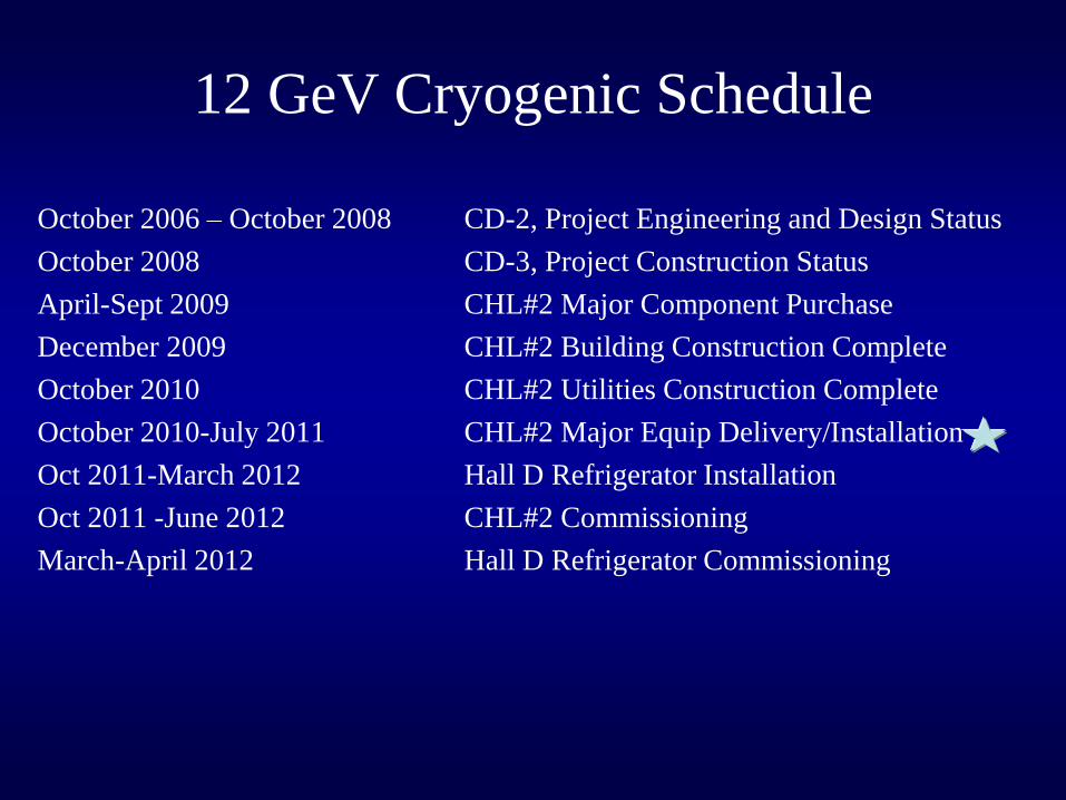
12 GeV Cryogenic Schedule
October 2006 – October 2008 CD-2, Project Engineering and Design Status
October 2008 CD-3, Project Construction Status
April-Sept 2009 CHL#2 Major Component Purchase
December 2009 CHL#2 Building Construction Complete
October 2010 CHL#2 Utilities Construction Complete
October 2010-July 2011 CHL#2 Major Equip Delivery/Installation
Oct 2011-March 2012 Hall D Refrigerator Installation
Oct 2011 -June 2012 CHL#2 Commissioning
March-April 2012 Hall D Refrigerator Commissioning
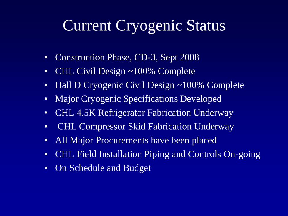
Current Cryogenic Status
• Construction Phase, CD-3, Sept 2008
• CHL Civil Design ~100% Complete
• Hall D Cryogenic Civil Design ~100% Complete
• Major Cryogenic Specifications Developed
• CHL 4.5K Refrigerator Fabrication Underway
• CHL Compressor Skid Fabrication Underway
• All Major Procurements have been placed
• CHL Field Installation Piping and Controls On-going
• On Schedule and Budget
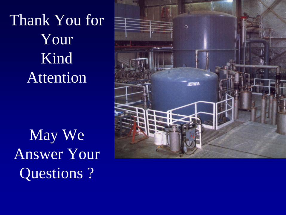
Thank You for
Your
Kind
Attention
May We
Answer Your
Questions ?
Backup Slides of Ganni Cycle Description
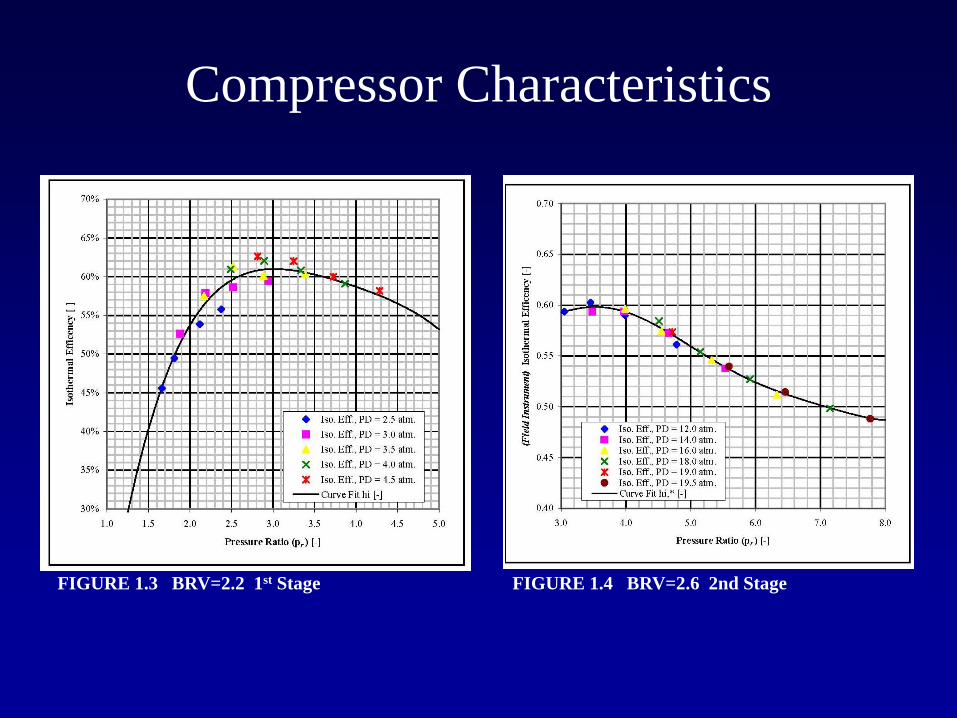
Compressor Characteristics
FIGURE 1.3 BRV=2.2 1st Stage FIGURE 1.4 BRV=2.6 2nd Stage
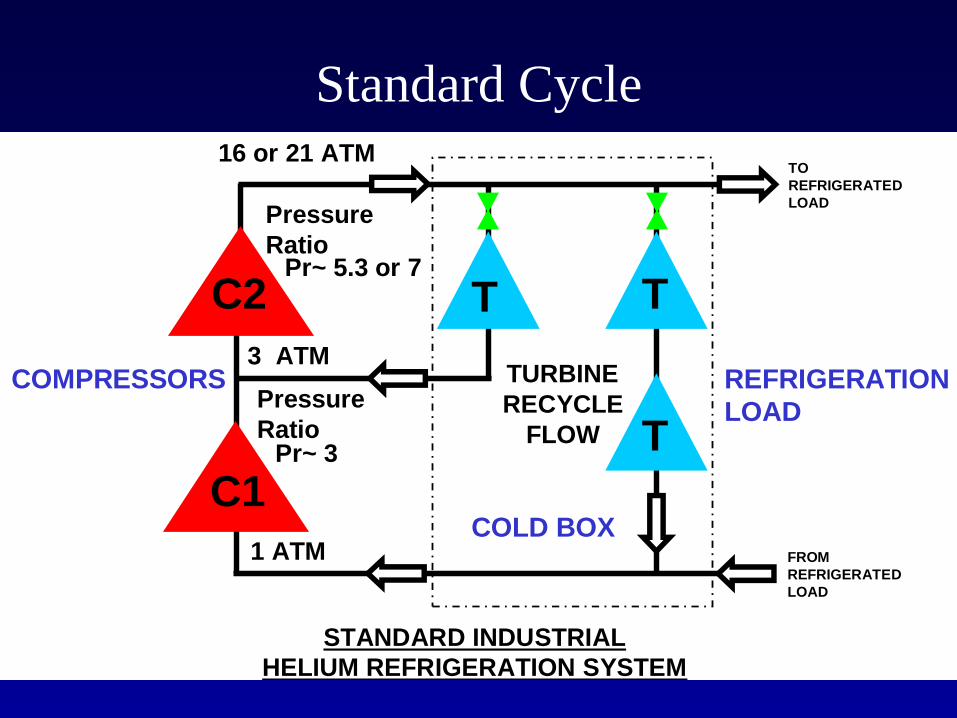
Standard Cycle
Pr~ 5.3 or 7
Pr~ 3
16 or 21 ATM
3 ATM
1 ATM
C1
T
TURBINE
RECYCLE
FLOW
Pressure
Ratio
C2
Pressure
Ratio
T
COMPRESSORS REFRIGERATION
LOAD
STANDARD INDUSTRIAL
HELIUM REFRIGERATION SYSTEM
COLD BOX
T
TO
REFRIGERATED
LOAD
FROM
REFRIGERATED
LOAD
T
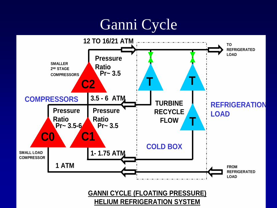
Ganni Cycle
Pr~ 3.5
Pr~ 3.5
12 TO 16/21 ATM
3.5 - 6 ATM
1 ATM
C1
T
TURBINE
RECYCLE
FLOW
Pressure
Ratio
C2
Pressure
Ratio
T
COMPRESSORS
Pr~ 3.5-6
Pressure
Ratio
1- 1.75 ATM
SMALLER
2ND STAGE
COMPRESSORS
REFRIGERATION
LOAD
SMALL LOAD
COMPRESSOR
GANNI CYCLE (FLOATING PRESSURE)
HELIUM REFRIGERATION SYSTEM
T
COLD BOX
T
C0
FROM
REFRIGERATED
LOAD
TO
REFRIGERATED
LOAD

![epub.ub.uni-muenchen.de · JHEP01(2014)109 [GeV] 0 m 1000 2000 3000 4000 5000 6000 [GeV] 1/2 m 800 700 600 500 400 300 q~ (2400 GeV) q~ (1600 GeV) (1000 GeV) ~ g (1400 GeV) ~ g >0](https://img.dokumen.tips/doc/110x75/5f5af63e9c508c0a904d8c92/epububuni-jhep012014109-gev-0-m-1000-2000-3000-4000-5000-6000-gev-12-m.jpg)