Embed Size (px)
DESCRIPTION
Agusta, Maintenance, Manual
Citation preview
A B
C
D
A
B
C
DC
A109E-MPM
A109EHELICOPTERMODEL
Third Issue: 15th May 2011Revision 5: 06th June 2013
THIS PUBLICATION IS ISSUED BY AGUSTAWESTLAND S.p.A.
This document contains proprietary data and information and shall not be disclosed, reproduced in whole or in part for any purpose, other than helicopter operation or maintenance, without prior written authorization from AgustaWestland S.p.A.
PUBLICATION CODE 502100664A
A B
C
D
A
B
C
DC
A109E-MPM
A
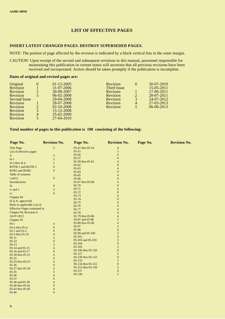
LIST OF EFFECTIVE PAGES
INSERT LATEST CHANGED PAGES. DESTROY SUPERSEDED PAGES.
NOTE: The portion of page affected by the revision is indicated by a black vertical line in the outer margin.
CAUTION: Upon receipt of the second and subsequent revisions to this manual, personnel responsible for maintaining this publication in current status will ascertain that all previous revisions have been received and incorporated. Action should be taken promptly if the publication is incomplete.
Dates of original and revised pages are:
Original 0 01-12-2005 Revision 6 30-07-2010Revision 1 31-07-2006 Third Issue 15-05-2011Revision 2 30-09-2007 Revision 1 17-06-2011Revision 3 06-02-2008 Revision 2 28-07-2011Second Issue 29-04-2008 Revision 3 24-07-2012Revision 1 28-07-2008 Revision 4 27-03-2013Revision 2 02-10-2008 Revision 5 06-06-2013Revision 3 15-12-2008Revision 4 25-02-2009Revision 5 27-04-2010
Total number of pages in this publication is 190 consisting of the following:
Title Page 5List of effective pagesA 5H-1 3H-2 thru H-4 5ROTR-1 and ROTR-2 0ROR1 and ROR2 0Table of contentsi and ii 0Introductionsiii 0iv and v 3vi 0Chapter 04(F.A.A. approved)Refer to applicable List of Effective Pages contained inChapter 04, Revision 424-07-2012.Chapter 0505-i 405-ii thru 05-iv 005-1 and 05-2 005-3 thru 05-10 405-11 305-12 005-13 305-14 and 05-15 405-16 and 05-17 005-18 thru 05-21 405-22 005-23 thru 05-25 405-26 005-27 thru 05-34 405-35 505-36 405-37 005-38 and 05-39 405-40 thru 05-42 005-43 thru 05-45 405-46 0
05-47 thru 05-54 405-55 505-56 405-57 005-58 thru 05-61 405-62 005-63 405-64 005-65 405-66 005-67 thru 05-69 405-70 005-71 405-72 005-73 405-74 005-75 405-76 005-77 405-78 005-79 thru 05-86 405-87 and 05-88 505-89 thru 05-96 405-97 305-98 005-99 and 05-100 305-101 005-102 and 05-103 305-104 005-105 205-106 thru 05-126 005-127 505-128 thru 05-132 005-133 305-134 thru 05-152 005-153 thru 05-156 205-157 405-158 2
Page No. Revision No. Page No. Revision No. Page No. Revision No.

A B
C
D
A
B
C
DC
A109E-MPM
Rev. 3 H-1
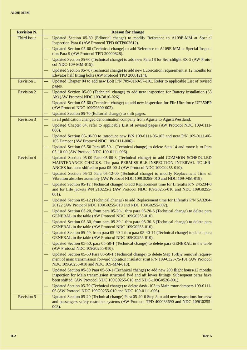
HIGHLIGHTS
The reason for update is given for the revision below listed.
Revision N. Reason for change
Third Issue — Updated Introduction (Technical change) to modify reference to Bollettini Tecnici (AW ProtocolTPD 20005733).
— Updated Section 05-00 (Technical change) to modify para GENERAL.Removed Miscellaneous Requirements reported in the para GENERAL of each scheduled main-tenance inspection (AW Protocol TPD 20005598).
— Updated Section 05-12 (Technical change) to add Searchlight SX-5 Gimbal Arm to ComponentOverhaul Schedule (AW Protocol NDC-109-MM-015)
— Updated Section 05-12 (Technical change) to modify replacement time for External Hoist cablecutter cartridge (AW Protocol TPD 20005906).
— Updated Section 05-12 (Technical change) to modify P/N of External hoist (600 lb) cable (AWProtocol TPD 00TP002766).
— Updated Section 05-12 (Technical change) to add AT42510H battery pack (AW Protocol TPD20000107).
— Updated Section 05-12 (Technical change) to add Hoist operator harness P/N A114A01 and rel-evant Note 13 (AW Protocol TPD 00TP004675).
— Updated Section 05-12 Note 3 and 8 (Technical change) to delete hydrostatic test becausealready required in the related equipment 05-60 para 7 and para 10 (AW Protocol TPD00TP002107).
— Updated Section 05-20-2 Para 2 (Technical change) to add new Step f. (AW Protocol TPD00TP002361).
— Updated Section 05-30-2 Para 2 (Technical change) to add new Step f. (AW Protocol TPD00TP002361).
— Updated Section 05-30-6 Para 4 (Editorial change) (AW Protocol TPD 20000132).
— Updated Section 05-30-6 Para 9 (Editorial change) to modify referenced Para to A109E-MM(AW Protocol TPD 00TP004726).
— Updated Section 05-40-2 Para 2 (Technical change) to add new Step f. (AW Protocol TPD00TP002361).
— Updated Section 05-50-1 (Technical change) to correct Step 12.b.2. (AW Protocol TPD20000384).
— Updated Section 05-50-1 (Technical change) to add new P/N 109-0162-01 at Para 10 (AW Pro-tocol TPD 20003559).
— Updated Section 05-50-1 Para 16 (Technical change) to modify referenced Para to A109E MM(AW Protocol TPD 00TP002144).
— Updated Section 05-50-1 Para 16 (Editorial change) to modify referenced Para to A109E MM(AW Protocol TPD 20000424).
— Updated Section 05-50-1 Para 17 (Technical change) to modify references to A109E MM forthe 2400 Hours Main Rotor Special Inspections (AW Protocol TPD 00TP002322).
— Updated Section 05-50-1 Para 15 (Technical change) to add new Step d. DOORS (AW ProtocolTPD 20001944).
— Updated Section 05-60 (Technical change) to add new 400 Hour/12 months inspection of Hoistoperator harness (AW Protocol TPD 00TP004675).
— Updated Section 05-60 (Technical change) to add Reference to A109E-MM at Special Inspec-tion Para 5 (AW Protocol TPD 00TP001874).
A B
C
D
A
B
C
DC
A109E-MPM
H-2 Rev. 5
Third Issue — Updated Section 05-60 (Editorial change) to modify Reference to A109E-MM at SpecialInspection Para 6 (AW Protocol TPD 00TP002612).
— Updated Section 05-60 (Technical change) to add Reference to A109E-MM at Special Inspec-tion Para 9 (AW Protocol TPD 20000828).
— Updated Section 05-60 (Technical change) to add new Para 18 for Searchlight SX-5 (AW Proto-col NDC-109-MM-015).
— Updated Section 05-70 (Technical change) to add new Lubrication requirement at 12 months forElevator half fitting bolts (AW Protocol TPD 20001214).
Revision 1 — Updated Chapter 04 to add new Bolt P/N 709-0160-57-101. Refer to applicable List of revisedpages.
Revision 2 — Updated Section 05-60 (Technical change) to add new inspection for Battery installation (33Ah) (AW Protocol NDC 109-B810-026).
— Updated Section 05-60 (Technical change) to add new inspection for Flir Ultraforce UF350EP(AW Protocol NDC 109G9300-002).
— Updated Section 05-70 (Editorial change) to shift pages.
Revision 3 — In all publication changed denomination company from Agusta to AgustaWestland.
— Updated Chapter 04, refer to applicable List of revised pages (AW Protocol NDC 109-0111-006).
— Updated Section 05-10-00 to introduce new P/N 109-0111-06-103 and new P/N 109-0111-06-105 Damper (AW Protocol NDC 109-0111-006).
— Updated Section 05-50 Para 05-50-1 (Technical change) to delete Step 14 and move it to Para05-10-00 (AW Protocol NDC 109-0111-006).
Revision 4 — Updated Section 05-00 Para 05-00-3 (Technical change) to add COMMON SCHEDULEDMAINTENANCE CHECKS. The para PERMISSIBLE INSPECTION INTERVAL TOLER-ANCES has been shifted to para 05-00-4 (AW Protocol NDC 109G0255-010).
— Updated Section 05-12 Para 05-12-00 (Technical change) to modify Replacement Time ofVibration absorber assembly (AW Protocol NDC 109G0255-010 and NDC 109-MM-019).
— Updated Section 05-12 (Technical change) to add Replacement time for Liferafts P/N 245234-0and for Life jackets P/N 210225-2 (AW Protocol NDC 109G0255-010 and NDC 109G0255-001).
— Updated Section 05-12 (Technical change) to add Replacement time for Liferafts P/N 5A3204-20122 (AW Protocol NDC 109G0255-010 and NDC 109G0255-002).
— Updated Section 05-20, from para 05-20-1 thru para 05-20-6 (Technical change) to delete paraGENERAL in the table (AW Protocol NDC 109G0255-010).
— Updated Section 05-30, from para 05-30-1 thru para 05-30-6 (Technical change) to delete paraGENERAL in the table (AW Protocol NDC 109G0255-010).
— Updated Section 05-40, from para 05-40-1 thru para 05-40-14 (Technical change) to delete paraGENERAL in the table (AW Protocol NDC 109G0255-010).
— Updated Section 05-50, para 05-50-1 (Technical change) to delete para GENERAL in the table(AW Protocol NDC 109G0255-010).
— Updated Section 05-50 Para 05-50-1 (Technical change) to delete Step 15(b)2 removal require-ment of main transmission forward vibration insulator strut P/N 109-0325-75-101 (AW ProtocolNDC 109G0255-010 and NDC 109-MM-018).
— Updated Section 05-50 Para 05-50-1 (Technical change) to add new 200 flight hours/12 monthsinspection for Main transmission structural fwd and aft lower fittings. Subsequent paras havebeen shifted. (AW Protocol NDC 109G0255-010 and NDC-109G0520-001).
— Updated Section 05-70 (Technical change) to delete dash -103 to Main rotor dampers 109-0111-06 (AW Protocol NDC 109G0255-010 and NDC 109-0111-006).
Revision 5 — Updated Section 05-20 (Technical change) Para 05-20-6 Step 8 to add new inspections for crewand passengers safety restraints systems (AW Protocol TPD 400038690 and NDC 109G0255-003).
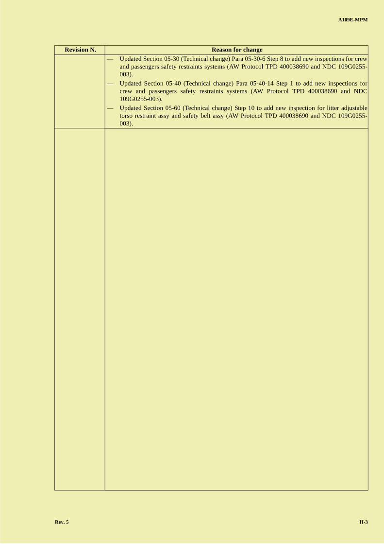
Revision N. Reason for change
A B
C
D
A
B
C
DC
A109E-MPM
Rev. 5 H-3
— Updated Section 05-30 (Technical change) Para 05-30-6 Step 8 to add new inspections for crewand passengers safety restraints systems (AW Protocol TPD 400038690 and NDC 109G0255-003).
— Updated Section 05-40 (Technical change) Para 05-40-14 Step 1 to add new inspections forcrew and passengers safety restraints systems (AW Protocol TPD 400038690 and NDC109G0255-003).
— Updated Section 05-60 (Technical change) Step 10 to add new inspection for litter adjustabletorso restraint assy and safety belt assy (AW Protocol TPD 400038690 and NDC 109G0255-003).
Revision N. Reason for change

A B
C
D
A
B
C
DC
A109E-MPM
H-4 Rev. 5
PAGE INTENTIONALLY LEFT BLANK
A B
C
D
A
B
C
DC
A109E-MPM
ROTR-1
RECORD OF TEMPORARY REVISIONS
INSTRUCTIONS: 1. FILE THIS RECORD OF TEMPORARY REVISIONS IN THE FRONT OF THEMANUAL.
2. ONLY ACTIVE TEMPORARY REVISIONS APPEAR IN THIS LIST. ALL OTHERTEMPORARY REVISIONS SHOULD BE REMOVED FROM THE MANUAL.
3. THIS LIST WILL BE REVISED EACH TIME THAT TEMPORARY REVISIONS AREISSUED, REVISED, OR INCORPORATED BY A NORMAL REVISION, ANASTERISK (*) WILL IDENTIFY TEMPORARY REVISION PAGES PROVIDED WITHTHIS LIST: DESTROY SUPERSEDED, INCORPORATED, OR CANCELEDTEMPORARY REVISION PAGES.
Temporary Revision Interested PagesDate Inserted
Incorporated
No. Date Chapter/Section Page Rev. No. Date

A B
C
D
A
B
C
DC
A109E-MPM
ROTR-2
PAGE INTENTIONALLY LEFT BLANK
A B
C
D
A
B
C
DC
A109E-MPM
ROR-1
RECORD OF REVISIONS
REVI-SION
NUMBER
ISSUE DATE
DATE INSERTED
BY REVI-SION
NUMBER
ISSUE DATE
DATE INSERTED
BY

A B
C
D
A
B
C
DC
A109E-MPM
ROR-2
PAGE INTENTIONALLY LEFT BLANK

A B
C
D
A
B
C
DC
A109E-MPM
i
TABLE OF CONTENTS
Chapter Title
Introduction 04 AIRWORTHINESS LIMITATIONS05 SCHEDULED/UNSCHEDULED MAINTENANCE

A B
C
D
A
B
C
DC
A109E-MPM
ii
PAGE INTENTIONALLY LEFT BLANK
A B
C
D
A
B
C
DC
A109E-MPM
iii
INTRODUCTION
PURPOSE
This A109E-MPM “Maintenance Planning Manual” is part of a set of maintenance publications which comprises 3 man-uals:
— A109E-MPM “Maintenance Planning Manual”
— A109E-MM “Maintenance Manual”
— A109E-WDM “Wiring Diagram Manual”
ARRANGEMENT
This A109E-MPM contains:
APPLICABILITY
This manual applies to all A109E series helicopters powered by Pratt & Whitney Canada 206C or Turbomeca Arrius 2K1engines.
UP-DATING
The content of this manual is subject to updating.Variations and modifications will be introduced as the result of increase of information available, modification of aircraftand progressive extension of the maintenance operations.Every effort is made to keep this manual current, review conferences with maintenance personnel and a constant reviewof maintenance and discrepancy reports assure inclusion of the latest data in the manual. However, we cannot correct anerror unless we know of its existence. In this regard it is essential that you do your part by forwarding the attached “Tech-nical Publications Discrepancy Form” giving detail of the discrepancy.
Chapter 04 : “Airworthiness Limitations”Chapter 05 : “Inspection Requirements and Component Overhaul Schedule”
A B
C
D
A
B
C
DC
A109E-MPM
iv Rev. 3
PURCHASE OF TECHNICAL PUBLICATIONS
The present manual forms part of a set of publications applicable to the A109E helicopter model. This set comprises:
AgustaWestland S.p.a.CUSTOMER SUPPORT & SERVICES - Italy
Product Support Engineering Department Via del Gregge, 100
21015 Lonate Pozzolo (VA) - ItalyTel.: +39-0331664845 - Fax: +39-0331664684
e-mail: [email protected].
Operators of the A109E helicopter model may obtain copies of the above publications by writing to the above statedaddress.
BOLLETTINI TECNICI
For the list of Bollettini Tecnici refer to the AgustaWestland website:
http://www.agustawestland.com/technical-bullettins.
NOTE: It is the operator’s responsibility to check the BT status with continuity.
Rotorcraft Flight Manual A109E-RFM P&W206C
Rotorcraft Flight Manual A109E-RFM TM2K1
Maintenance Planning Manual A109E-MPM
Maintenance Manual A109E-MM
Wiring Diagram Manual A109E-WDM
Overhaul Manual A119/A109 SERIES-OM
Illustrated Parts Catalog A109E-IPC (S/N up to 11600)
Illustrated Parts Catalogue A109E-IPC (S/N 11601 and subs.)
Structural Repair Manual A119/A109 SERIES-SRM
Pictorial Tools Usage Manual A119/A109 SERIES-PTUM
Bollettini Tecnici A109EP
Information Letters —
A B
C
D
A
B
C
DC
A109E-MPM
Rev. 3 v
TECHNICAL PUBLICATION DISCREPANCY FORM
SUBMITTED TO:
AgustaWestland S.p.A.Customer Support & Services - ItalyProduct Support EngineeringVia del Gregge, 10021015 Lonate Pozzolo (VA) ItalyFax: +39-0331664680E-mail:[email protected]
SUBMITTED BY:
Customer name and address:____________________________________________________________
____________________________________________________________
____________________________________________________________
____________________________________________________________
Phone ___________________________________________________
Fax _______________________________________________________
E-mail ___________________________________________________
IF YOU BELIEVE THAT YOU HAVE DISCOVERED A DISCREPANCY IN THE TECHNICALPUBLICATION, PLEASE IDENTIFY THE PUBLICATION, DESCRIBE THE DISCREPANCY ORDEFICIENCY IN DETAIL AND FORWARD TO AGUSTAWESTLAND AT THE ABOVE ADDRESS.
NUMBER: DATE:
PUBLICATION AFFECTED: PUBLICATION TITLE:
ISSUE DATE: CHANGE/REVISION DATE:
AFFECTED PAGE N.: AFFECTED FIGURE:
DISCREPANCY OR DEFICIENCY (DESCRIBE DISCREPANCY WITH TEXT AND/OR SKETCH).

A B
C
D
A
B
C
DC
A109E-MPM
vi
PAGE INTENTIONALLY LEFT BLANK
A B
C
D
A
B
C
DC
A109E-MPM
CHAPTER 04
AIRWORTHINESS LIMITATIONS
F.A.A. APPROVED

A B
C
D
A
B
C
DC
A109E-MPM
PAGE INTENTIONALLY LEFT BLANK
A B
C
D
A
B
C
DC
A109E-MPM
F.A.A. Approved Issue 5 Revision 3 A
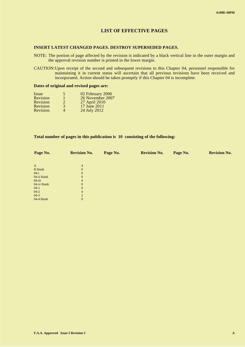
LIST OF EFFECTIVE PAGES
INSERT LATEST CHANGED PAGES. DESTROY SUPERSEDED PAGES.
NOTE: The portion of page affected by the revision is indicated by a black vertical line in the outer margin andthe approval revision number is printed in the lower margin.
CAUTION:Upon receipt of the second and subsequent revisions to this Chapter 04, personnel responsible formaintaining it in current status will ascertain that all previous revisions have been received andincorporated. Action should be taken promptly if this Chapter 04 is incomplete.
Dates of original and revised pages are:
Issue 5 02 February 2006Revision 1 26 November 2007Revision 2 27 April 2010Revision 3 17 June 2011Revision 4 24 July 2012
Total number of pages in this publication is 10 consisting of the following:
A 4B blank 004-i 004-ii blank 004-iii 404-iv blank 004-1 004-2 404-3 204-4 blank 0
Page No. Revision No. Page No. Revision No. Page No. Revision No.
A B
C
D
A
B
C
DC
A109E-MPM
B F.A.A. Approved Issue 5 Revision 0
PAGE INTENTIONALLY LEFT BLANK
A B
C
D
A
B
C
DC
A109E-MPM
F.A.A. Approved Issue 5 Revision 0 04-i
CHAPTER 04 - AIRWORTHINESS LIMITATIONS
TABLE OF CONTENTS
Sect/Para Page
LIST OF REVISED PAGES.................................................................................................................................. 04-iii
04-00 AIRWORTHINESS LIMITATIONS SECTION ............................................................................... 04-1
A B
C
D
A
B
C
DC
A109E-MPM
04-ii F.A.A. Approved Issue 5 Revision 0
PAGE INTENTIONALLY LEFT BLANK
A B
C
D
A
B
C
DC
A109E-MPM
F.A.A. Approved Issue 5 Revision 4 04-iii
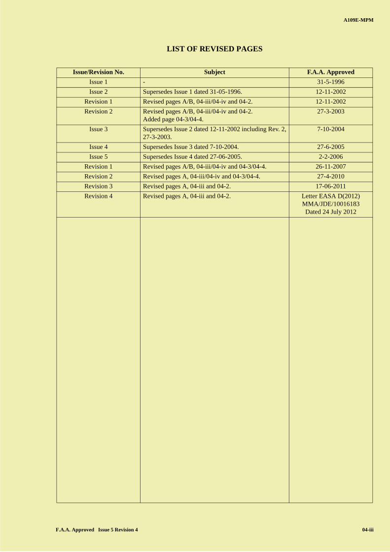
LIST OF REVISED PAGES
Issue/Revision No. Subject F.A.A. Approved
Issue 1 - 31-5-1996
Issue 2 Supersedes Issue 1 dated 31-05-1996. 12-11-2002
Revision 1 Revised pages A/B, 04-iii/04-iv and 04-2. 12-11-2002
Revision 2 Revised pages A/B, 04-iii/04-iv and 04-2.Added page 04-3/04-4.
27-3-2003
Issue 3 Supersedes Issue 2 dated 12-11-2002 including Rev. 2,27-3-2003.
7-10-2004
Issue 4 Supersedes Issue 3 dated 7-10-2004. 27-6-2005
Issue 5 Supersedes Issue 4 dated 27-06-2005. 2-2-2006
Revision 1 Revised pages A/B, 04-iii/04-iv and 04-3/04-4. 26-11-2007
Revision 2 Revised pages A, 04-iii/04-iv and 04-3/04-4. 27-4-2010
Revision 3 Revised pages A, 04-iii and 04-2. 17-06-2011
Revision 4 Revised pages A, 04-iii and 04-2. Letter EASA D(2012)MMA/JDE/10016183Dated 24 July 2012
A B
C
D
A
B
C
DC
A109E-MPM
04-iv F.A.A. Approved Issue 5 Revision 0
PAGE INTENTIONALLY LEFT BLANK
A B
C
D
A
B
C
DC
A109E-MPM
04-00-00
F.A.A. Approved Issue 5 Revision 0 04-1
SECTION 04-00
AIRWORTHINESS LIMITATIONS SECTION
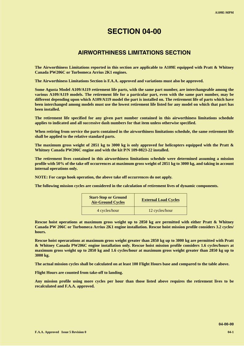
The Airworthiness Limitations reported in this section are applicable to A109E equipped with Pratt & WhitneyCanada PW206C or Turbomeca Arrius 2K1 engines.
The Airworthiness Limitations Section is F.A.A. approved and variations must also be approved.
Some Agusta Model A109/A119 retirement life parts, with the same part number, are interchangeable among thevarious A109/A119 models. The retirement life for a particular part, even with the same part number, may bedifferent depending upon which A109/A119 model the part is installed on. The retirement life of parts which havebeen interchanged among models must use the lowest retirement life listed for any model on which that part hasbeen installed.
The retirement life specified for any given part number contained in this airworthiness limitations scheduleapplies to indicated and all successive dash numbers for that item unless otherwise specified.
When retiring from service the parts contained in the airworthiness limitations schedule, the same retirement lifeshall be applied to the relative standard parts.
The maximum gross weight of 2851 kg to 3000 kg is only approved for helicopters equipped with the Pratt &Whitney Canada PW206C engine and with the kit P/N 109-0823-22 installed.
The retirement lives contained in this airworthiness limitations schedule were determined assuming a missionprofile with 50% of the take off occurrences at maximum gross weight of 2851 kg to 3000 kg, and taking in accountinternal operations only.
NOTE: For cargo hook operation, the above take off occurrences do not apply.
The following mission cycles are considered in the calculation of retirement lives of dynamic components.
Rescue hoist operations at maximum gross weight up to 2850 kg are permitted with either Pratt & WhitneyCanada PW 206C or Turbomeca Arrius 2K1 engine installation. Rescue hoist mission profile considers 3.2 cycles/hours.
Rescue hoist operarations at maximum gross weight greater than 2850 kg up to 3000 kg are permitted with Pratt& Whitney Canada PW206C engine installation only. Rescue hoist mission profile considers 1.6 cycles/hours atmaximum gross weight up to 2850 kg and 1.6 cycles/hour at maximum gross weight greater than 2850 kg up to3000 kg.
The actual mission cycles shall be calculated on at least 100 Flight Hours base and compared to the table above.
Flight Hours are counted from take-off to landing.
Any mission profile using more cycles per hour than those listed above requires the retirement lives to berecalculated and F.A.A. approved.
Start-Stop or GroundAir-Ground Cycles
External Load Cycles
4 cycles/hour 12 cycles/hour
A B
C
D
A
B
C
DC
A109E-MPM
04-00-00
04-2 F.A.A. Approved Issue 5 Revision 4
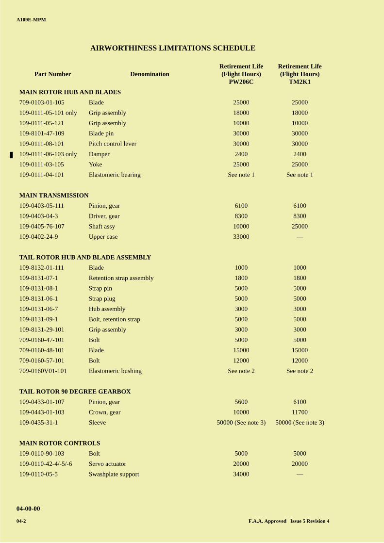
AIRWORTHINESS LIMITATIONS SCHEDULE
Part Number DenominationRetirement Life(Flight Hours)
PW206C
Retirement Life(Flight Hours)
TM2K1
MAIN ROTOR HUB AND BLADES
709-0103-01-105 Blade 25000 25000
109-0111-05-101 only Grip assembly 18000 18000
109-0111-05-121 Grip assembly 10000 10000
109-8101-47-109 Blade pin 30000 30000
109-0111-08-101 Pitch control lever 30000 30000
109-0111-06-103 only Damper 2400 2400
109-0111-03-105 Yoke 25000 25000
109-0111-04-101 Elastomeric bearing See note 1 See note 1
MAIN TRANSMISSION
109-0403-05-111 Pinion, gear 6100 6100
109-0403-04-3 Driver, gear 8300 8300
109-0405-76-107 Shaft assy 10000 25000
109-0402-24-9 Upper case 33000 —
TAIL ROTOR HUB AND BLADE ASSEMBLY
109-8132-01-111 Blade 1000 1000
109-8131-07-1 Retention strap assembly 1800 1800
109-8131-08-1 Strap pin 5000 5000
109-8131-06-1 Strap plug 5000 5000
109-0131-06-7 Hub assembly 3000 3000
109-8131-09-1 Bolt, retention strap 5000 5000
109-8131-29-101 Grip assembly 3000 3000
709-0160-47-101 Bolt 5000 5000
709-0160-48-101 Blade 15000 15000
709-0160-57-101 Bolt 12000 12000
709-0160V01-101 Elastomeric bushing See note 2 See note 2
TAIL ROTOR 90 DEGREE GEARBOX
109-0433-01-107 Pinion, gear 5600 6100
109-0443-01-103 Crown, gear 10000 11700
109-0435-31-1 Sleeve 50000 (See note 3) 50000 (See note 3)
MAIN ROTOR CONTROLS
109-0110-90-103 Bolt 5000 5000
109-0110-42-4/-5/-6 Servo actuator 20000 20000
109-0110-05-5 Swashplate support 34000 —
A B
C
D
A
B
C
DC
A109E-MPM
04-00-00
F.A.A. Approved Issue 5 Revision 2 04-3
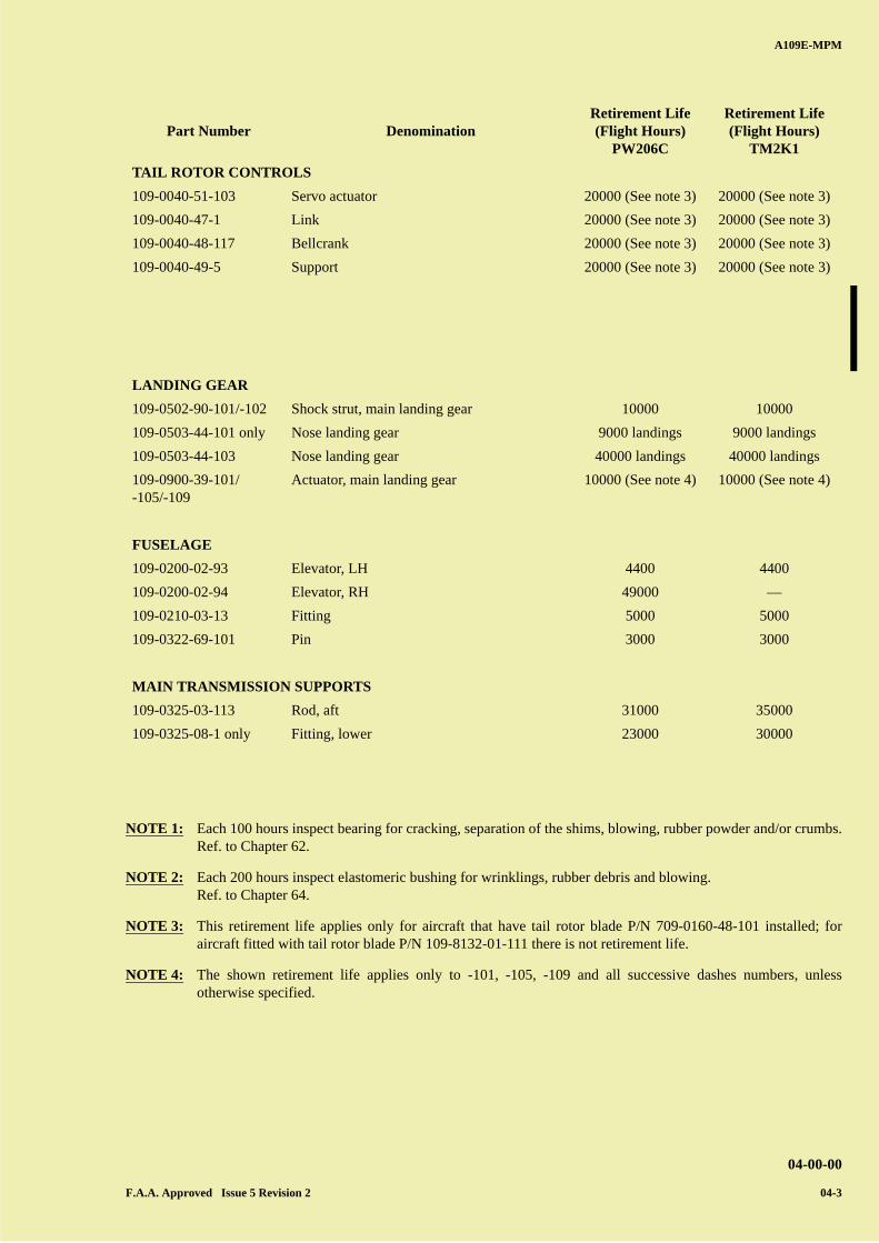
NOTE 1: Each 100 hours inspect bearing for cracking, separation of the shims, blowing, rubber powder and/or crumbs.Ref. to Chapter 62.
NOTE 2: Each 200 hours inspect elastomeric bushing for wrinklings, rubber debris and blowing.Ref. to Chapter 64.
NOTE 3: This retirement life applies only for aircraft that have tail rotor blade P/N 709-0160-48-101 installed; foraircraft fitted with tail rotor blade P/N 109-8132-01-111 there is not retirement life.
NOTE 4: The shown retirement life applies only to -101, -105, -109 and all successive dashes numbers, unlessotherwise specified.
TAIL ROTOR CONTROLS
109-0040-51-103 Servo actuator 20000 (See note 3) 20000 (See note 3)
109-0040-47-1 Link 20000 (See note 3) 20000 (See note 3)
109-0040-48-117 Bellcrank 20000 (See note 3) 20000 (See note 3)
109-0040-49-5 Support 20000 (See note 3) 20000 (See note 3)
LANDING GEAR
109-0502-90-101/-102 Shock strut, main landing gear 10000 10000
109-0503-44-101 only Nose landing gear 9000 landings 9000 landings
109-0503-44-103 Nose landing gear 40000 landings 40000 landings
109-0900-39-101/-105/-109
Actuator, main landing gear 10000 (See note 4) 10000 (See note 4)
FUSELAGE
109-0200-02-93 Elevator, LH 4400 4400
109-0200-02-94 Elevator, RH 49000 —
109-0210-03-13 Fitting 5000 5000
109-0322-69-101 Pin 3000 3000
MAIN TRANSMISSION SUPPORTS
109-0325-03-113 Rod, aft 31000 35000
109-0325-08-1 only Fitting, lower 23000 30000
Part Number DenominationRetirement Life(Flight Hours)
PW206C
Retirement Life(Flight Hours)
TM2K1
A B
C
D
A
B
C
DC
A109E-MPM
04-00-00
04-4 F.A.A. Approved Issue 5 Revision 0
PAGE INTENTIONALLY LEFT BLANK
A B
C
D
A
B
C
DC
A109E-MPM
Rev. 4 05-i
CHAPTER 05 - INSPECTION REQUIREMENTS AND COMPONENT
OVERHAUL SCHEDULE
TABLE OF CONTENTS
Sect/Para Page
05-00 GENERAL ................................................................................................................................................... 05-1
05-00-1. Description ................................................................................................................................................ 05-1
05-00-2. Inspection programs .................................................................................................................................. 05-2
05-00-3. Common scheduled maintenance checks.................................................................................................. 05-3
05-00-4. Permissible inspection interval tolerances ................................................................................................ 05-7
05-00-5. Glossary..................................................................................................................................................... 05-9
05-00-6. Abbreviations ............................................................................................................................................ 05-9
05-00-7. Division of the text.................................................................................................................................... 05-9
05-10 COMPONENT OVERHAUL SCHEDULE.............................................................................................. 05-11
05-12 MISCELLANEOUS REPLACEMENT SCHEDULE............................................................................. 05-13
05-20 SCHEDULED MAINTENANCE CHECKS - STANDARD INSPECTION PROGRAM ................... 05-17
05-20-1. Airworthiness check.................................................................................................................................. 05-17
05-20-2. 100 hours inspection ................................................................................................................................. 05-23
05-20-3. 400 hours inspection ................................................................................................................................. 05-27
05-20-4. 800 hours inspection ................................................................................................................................. 05-29
05-20-5. 3200 hours inspection ............................................................................................................................... 05-31
05-20-6. 12 months inspection................................................................................................................................. 05-33
05-30 SCHEDULED MAINTENANCE CHECKS - EXTENDED INSPECTION PROGRAM ................... 05-37
05-30-1. Basic 50 hours/30 days inspection ............................................................................................................ 05-37
05-30-2. 200 hours inspection ................................................................................................................................. 05-43
05-30-3. 400 hours inspection ................................................................................................................................. 05-47
05-30-4. 800 hours inspection ................................................................................................................................. 05-49
05-30-5. 3200 hours inspection ............................................................................................................................... 05-51
05-30-6. 12 months inspection................................................................................................................................. 05-53
05-40 SCHEDULED MAINTENANCE CHECKS - PROGRESSIVE INSPECTION PROGRAM............. 05-57
05-40-1. Basic 50 hours/30 days inspection ............................................................................................................ 05-57
05-40-2. 200 hours inspection phase A ................................................................................................................... 05-63
05-40-3. 200 hours inspection phase B.................................................................................................................... 05-65
05-40-4. 200 hours inspection phase C.................................................................................................................... 05-67
05-40-5. 200 hours inspection phase D ................................................................................................................... 05-69
05-40-6. 400 hours inspection phase 1 .................................................................................................................... 05-71
05-40-7. 400 hours inspection phase 2 .................................................................................................................... 05-73
05-40-8. 400 hours inspection phase 3 .................................................................................................................... 05-75
05-40-9. 400 hours inspection phase 4 .................................................................................................................... 05-77
05-40-10. 800 hours inspection .............................................................................................................................. 05-79
05-40-11. 3200 hours inspection ............................................................................................................................ 05-81
05-40-12. 12 months inspection - phase I............................................................................................................... 05-83
05-40-13. 12 months inspection - phase II ............................................................................................................. 05-85
05-40-14. 12 months inspection - phase III ............................................................................................................ 05-87
A B
C
D
A
B
C
DC
A109E-MPM
05-ii
Table of Contents — Continued
Sect/Para Page
05-50 UNSCHEDULED MAINTENANCE CHECKS....................................................................................... 05-89
05-50-1. Special inspections.................................................................................................................................... 05-89
05-50-2. Conditional inspections............................................................................................................................. 05-97
05-60 OPTIONAL EQUIPMENT........................................................................................................................ 05-105
05-70 SERVICING ................................................................................................................................................ 05-153
A B
C
D
A
B
C
DC
A109E-MPM
05-iii
LIST OF ILLUSTRATIONS
Figure Title Page
Figure 05-1 (sheet 1 of 2). Inspection scheduling programs ................................................................................... 05-4
Figure 05-1 (sheet 2 of 2). Inspection scheduling programs ................................................................................... 05-5

A B
C
D
A
B
C
DC
A109E-MPM
05-iv
PAGE INTENTIONALLY LEFT BLANK
A B
C
D
A
B
C
DC
A109E-MPM
05-00-00
05-1
SECTION 05-00
GENERAL
05-00-1. DESCRIPTION
This Chapter contains the inspection requirements concerning the A109E helicopters equipped with PRATT &WHITNEY 206C engines or TURBOMECA ARRIUS 2K1 engines, but does not contain inspection procedures. Suchprocedures will be found in the A109E-MM.The inspections are presented in typographic form suitable for the local reproduction in such a way as to be used bypersonnel to perform helicopter inspections and to constitute, if desired, a data collection.The inspections must be accomplished by qualified personnel to ascertain the airworthiness of the helicopter. Eventualdiscrepancies must be eliminated before flight.Prior to inspection, open or remove as necessary, fairings, cowlings panels and inspection doors.Flight airworthiness must be determined by inspection of all parts to check the general condition, security of attachment,cleanliness, freedom of movement and security, in accordance with the operational inspection rules and instructionscontained in the A109E-MM.The airworthiness of the helicopter is determined by acceptance of all parts with quality standard aircraft practice andspecified instructions contained in the pertinent Chapters of this manual. Each inspected component must meet pertinentand applicable Airworthiness Directives requirements.For acceptance requirements and limits refer to A109E-MM or to A109E SERIES-OM.
NOTE: The inspection and maintenance of the engine, electronic equipment, instruments, etc. must be performed inaccordance with the instructions and procedures required by relevant manufacturers and in accordance withapproved maintenance schedule.
NOTE: The inspection and overhaul schedule requirements contained in this Chapter must not be exceeded withoutexplicit approval.
NOTE: When operating under particular environmental conditions (contaminated ambient, near the sea or specialmissions) it is prerogative and responsibility of the operator to increase or intensify the prescribed inspections asnecessary to assure safe operation.
A B
C
D
A
B
C
DC
A109E-MPM
05-00-00
05-2
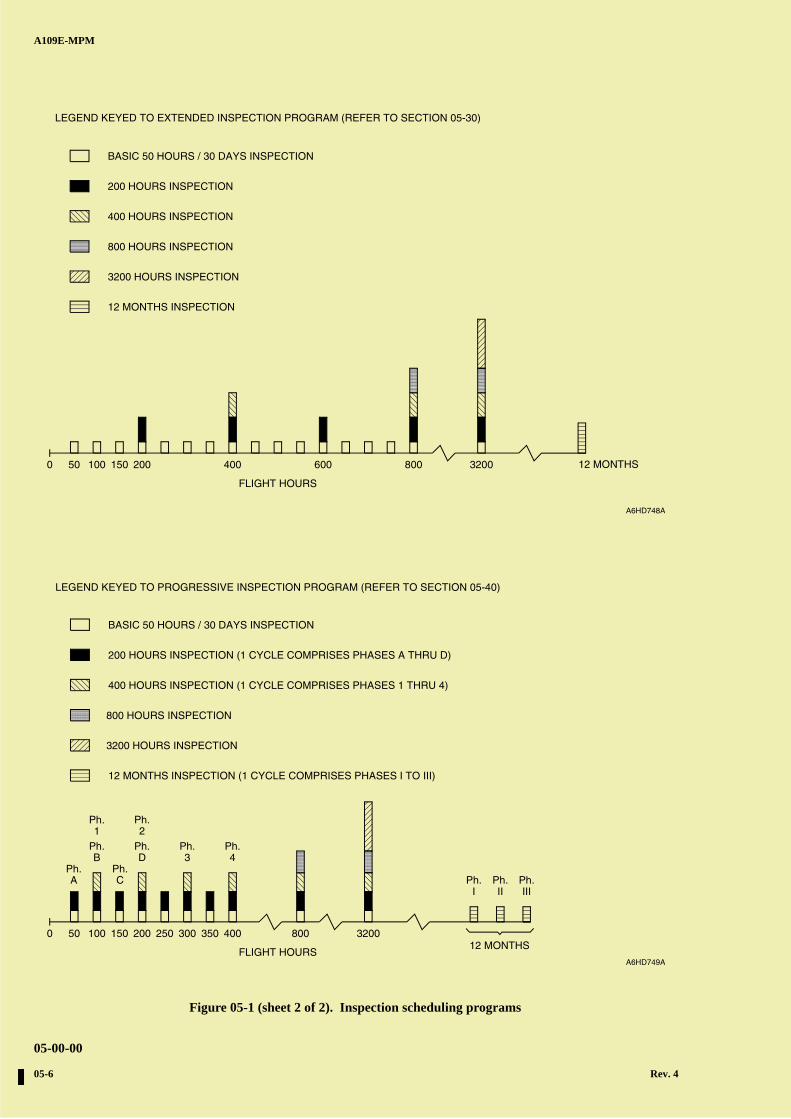
05-00-2. INSPECTION PROGRAMS(Fig 05-1)
The operator may choose from three inspection programs, as indicated in figure, designed to provide flexibility formaximum utilization of the helicopter and to most suit the operator's needs. The inspection programs are identified asfollows:
NOTE: For the inspection requirements concerning the optional equipment refer to Section 05-60.
A. Standard Inspection Program (refer to Section 05-20). The scheduled inspections consist of airworthiness check, 100hours inspection, 400 hours inspection, 800 hours inspection, 3200 hours inspection and 12 months inspection.
B. Extended Inspection Program (refer to Section 05-30). The scheduled inspections consist of a basic 50 hours/30 daysinspection, 200 hours inspection, 400 hours inspection, 800 hours inspection, 3200 hours inspection and 12 monthsinspection.
C. Progressive Inspection Program (refer to Section 05-40). The scheduled inspections consist of a basic 50 hours/30days inspection, progressive 200 hours inspection (divided into four phases), progressive 400 hours inspection(divided into four phases), 800 hours inspection, 3200 hours inspection and 12 months inspection (divided into threephases).
The Operator may decide to interrupt one program and revert to the other provided the following is accomplished:
— Changing from standard to extended inspection program:
— Perform basic 50 hours/30 days and 200 hours inspections of the extended inspection program and continuewith the new program.
— Changing from standard to progressive inspection program:
— Perform basic 50 hours/30 days of the progressive program, the preceding cycle phases of the progressive 200hours inspection, the preceding cycle phases of the progressive 400 hours inspection (if applicable) and thepreceding cycle phases of the progressive 12 months inspection.
— Changing from extended to standard inspection program:
— Perform 100 hours inspection of the standard inspection program and continue with the new program.
— Changing from extended to progressive inspection program:
— Perform basic 50 hours/30 days of the progressive program, the preceding cycle phases of the progressive 200hours inspection, the preceding cycle phases of the progressive 400 hours inspections (if applicable) and thepreceding cycle phases of the progressive 12 months inspection.Example: changing from extended to progressive after 580 flight hours and 9 months after last 12 monthsinspection: perform basic 50 hours/30 days inspection, phases A, B and C of progressive 200 hours inspection,phase 1 of progressive 400 hours inspection and phases I and II of the progressive 12 months inspection.
— Changing from progressive to standard inspection program:
— (Helicopters with less than 400 hours) Perform 100 hours inspection and 12 months inspection and continuewith the new program.
— (Helicopters above 400 hours) Perform 100 hours inspection, 400 hours inspection and the 12 monthsinspection and continue with the new program.
A B
C
D
A
B
C
DC
A109E-MPM
05-00-00
Rev. 4 05-3
— Changing from progressive to extended inspection program:
— (Helicopters with less than 400 hours) Perform 200 hours inspection and the 12 months inspection and continuewith the new program.
— (Helicopters above 400 hours) Perform 200 hours inspection, 400 hours inspection and the 12 monthsinspection and continue with the new program.
This chapter includes:
A. Time Limits:
Permissible inspection interval tolerances.
Component overhaul schedule.
Miscellaneous replacement Schedule.
B. Scheduled Maintenance Inspection:
Standard Inspection program.
Extended inspection program.
Progressive inspection program.
C. Unschedule Maintenance Checks:
Special inspection
Conditional inspection.
D. Optional equipment scheduled / unscheduled inspections:
Special inspection.
Conditional inspection.
05-00-3. COMMON SCHEDULED MAINTENANCE CHECKS
This Section gives the date necessary to do the common scheduled maintenance checks on the helicopter. The common-scheduled maintenance checks are applicable to:
— Standard Inspection Program (Airworthiness Checks) - Section 05-20
— Extended Inspection Program - Section 05-30
— Progressive Inspection Program - Section 05-40
— Unscheduled Maintenance Checks - Section 05-50
The common scheduled maintenance checks includes:
— Expiry of components' retirement life and inspection in accordance with Chapter 04
— Components' overhaul interval in accordance with Section 05-10.
— Non flight critical parts replacement time in accordance with Section 05-12.
— Servicing in accordance with Section 05-70.
— Perform applicable optional equipment inspections in accordance with Section 05-60.
A B
C
D
A
B
C
DC
A109E-MPM
05-00-00
05-4 Rev. 4
— Other inspection requirements.
— Check log book for recorded discrepancies. Correct any fault that could affect safety of operations.
Refer to the latest issue of Engine Maintenance Manual for the scheduled and unscheduled maintenance requirementsapplicable to the Pratt & Whitney Canada 206C or Turbomeca Arrius 2K1 engines.
NOTE 1: With respect to the Rescue Hoist Assembly, there is a set of tasks for which Operators shall obtain the OfficialComponent Maintenance Publication from the OEM (BREEZE EASTERN) and must be certified to asuitable level. For reference of the Operator, a copy of the Component Maintenance Publication is included inthe A109/A119-CMP (CD-ROM only), for information only.
NOTE 2: With respect to the Cargo Hooks, there is a set of tasks for which Operators shall obtain the OfficialComponent Maintenance Publication from the OEM (Onboard System) and must be certified to a suitablelevel. For reference of the Operator, a copy of the Component Maintenance Publication is included in theA109/A119-CMP (CD-ROM only), for information only.
A B
C
D
A
B
C
DC
A109E-MPM
05-00-00
Rev. 4 05-5
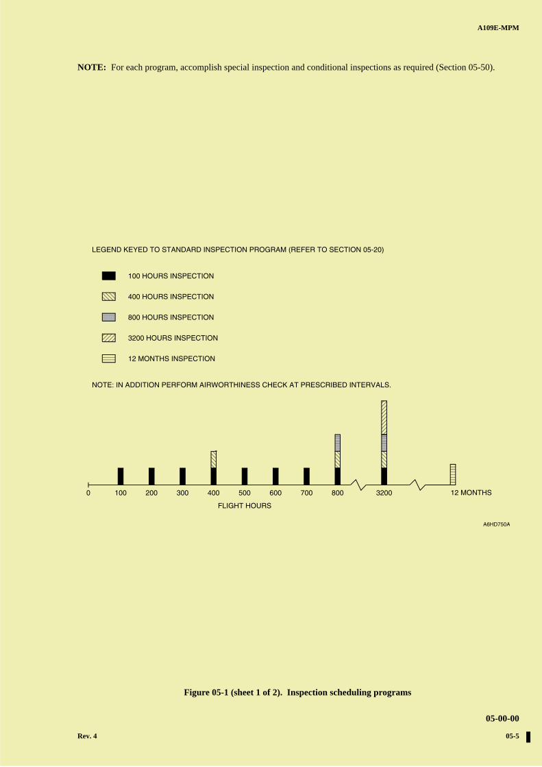
NOTE: For each program, accomplish special inspection and conditional inspections as required (Section 05-50).
0
FLIGHT HOURS
100 200 400 600 800 3200 12 MONTHS
12 MONTHS INSPECTION
3200 HOURS INSPECTION
400 HOURS INSPECTION
800 HOURS INSPECTION
A6HD750A
LEGEND KEYED TO STANDARD INSPECTION PROGRAM (REFER TO SECTION 05-20)
100 HOURS INSPECTION
300 500 700
NOTE: IN ADDITION PERFORM AIRWORTHINESS CHECK AT PRESCRIBED INTERVALS.
Figure 05-1 (sheet 1 of 2). Inspection scheduling programs
A B
C
D
A
B
C
DC
A109E-MPM
05-00-00
05-6 Rev. 4
0
FLIGHT HOURS
50 100 150 200 400 600 800 3200 12 MONTHS
12 MONTHS INSPECTION
BASIC 50 HOURS / 30 DAYS INSPECTION
200 HOURS INSPECTION
3200 HOURS INSPECTION
400 HOURS INSPECTION
800 HOURS INSPECTION
A6HD748A
LEGEND KEYED TO EXTENDED INSPECTION PROGRAM (REFER TO SECTION 05-30)
0
FLIGHT HOURS
Ph.
Ph.Ph.A C
50 100 150 200 400
A6HD749A
BASIC 50 HOURS / 30 DAYS INSPECTION
800 HOURS INSPECTION
3200 HOURS INSPECTION
Ph.
B
1
250 300 350
Ph. Ph.
Ph.2
D 3Ph.4
800 3200
Ph. Ph. Ph.I II III
12 MONTHS
200 HOURS INSPECTION (1 CYCLE COMPRISES PHASES A THRU D)
400 HOURS INSPECTION (1 CYCLE COMPRISES PHASES 1 THRU 4)
12 MONTHS INSPECTION (1 CYCLE COMPRISES PHASES I TO III)
LEGEND KEYED TO PROGRESSIVE INSPECTION PROGRAM (REFER TO SECTION 05-40)
Figure 05-1 (sheet 2 of 2). Inspection scheduling programs
A B
C
D
A
B
C
DC
A109E-MPM
05-00-00
Rev. 4 05-7
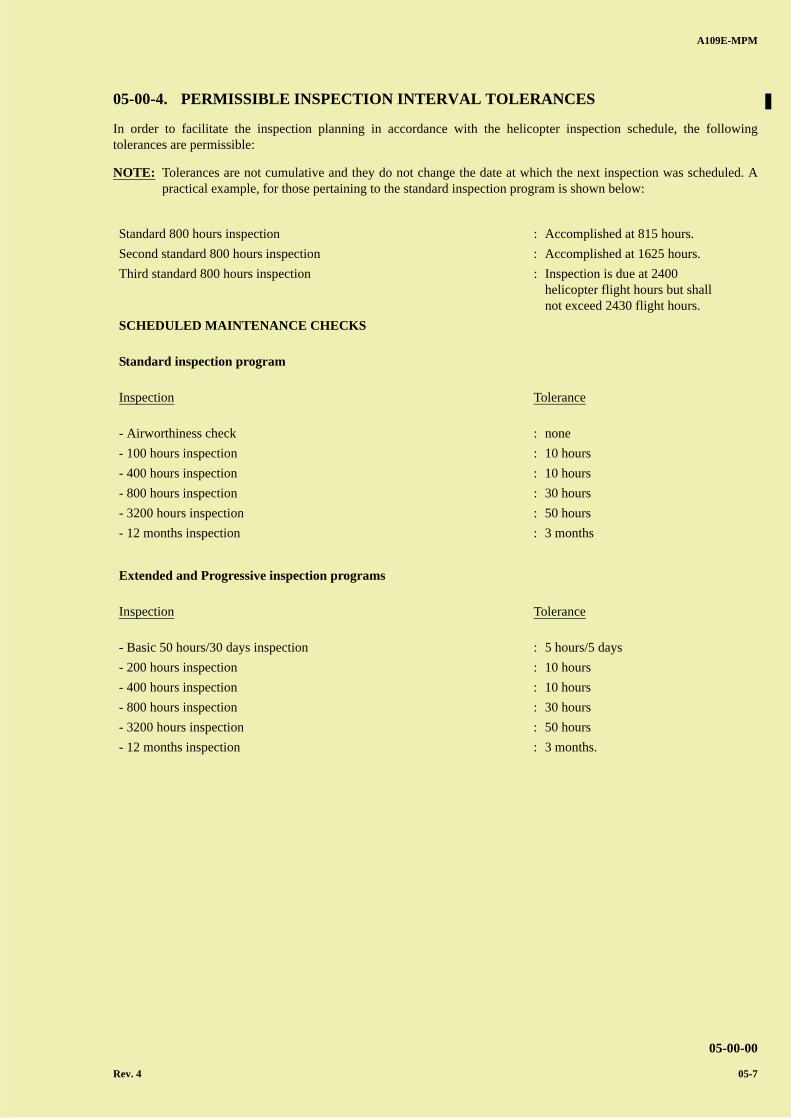
05-00-4. PERMISSIBLE INSPECTION INTERVAL TOLERANCES
In order to facilitate the inspection planning in accordance with the helicopter inspection schedule, the followingtolerances are permissible:
NOTE: Tolerances are not cumulative and they do not change the date at which the next inspection was scheduled. Apractical example, for those pertaining to the standard inspection program is shown below:
Standard 800 hours inspection : Accomplished at 815 hours.
Second standard 800 hours inspection : Accomplished at 1625 hours.
Third standard 800 hours inspection : Inspection is due at 2400helicopter flight hours but shallnot exceed 2430 flight hours.
SCHEDULED MAINTENANCE CHECKS
Standard inspection program
Inspection Tolerance
- Airworthiness check : none
- 100 hours inspection : 10 hours
- 400 hours inspection : 10 hours
- 800 hours inspection : 30 hours
- 3200 hours inspection : 50 hours
- 12 months inspection : 3 months
Extended and Progressive inspection programs
Inspection Tolerance
- Basic 50 hours/30 days inspection : 5 hours/5 days
- 200 hours inspection : 10 hours
- 400 hours inspection : 10 hours
- 800 hours inspection : 30 hours
- 3200 hours inspection : 50 hours
- 12 months inspection : 3 months.
A B
C
D
A
B
C
DC
A109E-MPM
05-00-00
05-8 Rev. 4
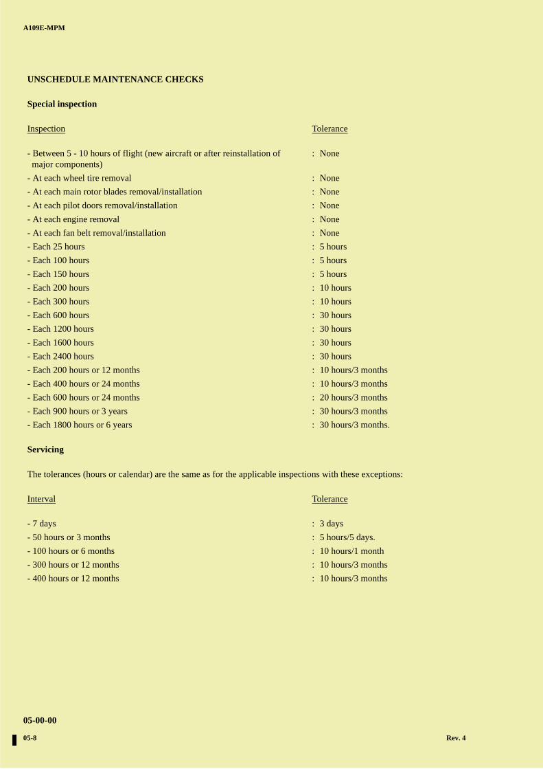
UNSCHEDULE MAINTENANCE CHECKS
Special inspection
Inspection Tolerance
- Between 5 - 10 hours of flight (new aircraft or after reinstallation ofmajor components)
: None
- At each wheel tire removal : None
- At each main rotor blades removal/installation : None
- At each pilot doors removal/installation : None
- At each engine removal : None
- At each fan belt removal/installation : None
- Each 25 hours : 5 hours
- Each 100 hours : 5 hours
- Each 150 hours : 5 hours
- Each 200 hours : 10 hours
- Each 300 hours : 10 hours
- Each 600 hours : 30 hours
- Each 1200 hours : 30 hours
- Each 1600 hours : 30 hours
- Each 2400 hours : 30 hours
- Each 200 hours or 12 months : 10 hours/3 months
- Each 400 hours or 24 months : 10 hours/3 months
- Each 600 hours or 24 months : 20 hours/3 months
- Each 900 hours or 3 years : 30 hours/3 months
- Each 1800 hours or 6 years : 30 hours/3 months.
Servicing
The tolerances (hours or calendar) are the same as for the applicable inspections with these exceptions:
Interval Tolerance
- 7 days : 3 days
- 50 hours or 3 months : 5 hours/5 days.
- 100 hours or 6 months : 10 hours/1 month
- 300 hours or 12 months : 10 hours/3 months
- 400 hours or 12 months : 10 hours/3 months
A B
C
D
A
B
C
DC
A109E-MPM
05-00-00
Rev. 4 05-9
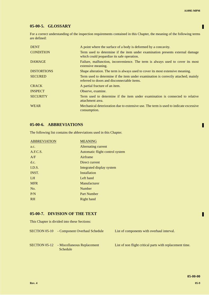
05-00-5. GLOSSARY
For a correct understanding of the inspection requirements contained in this Chapter, the meaning of the following termsare defined:
05-00-6. ABBREVIATIONS
The following list contains the abbreviations used in this Chapter.
05-00-7. DIVISION OF THE TEXT
This Chapter is divided into these Sections:
DENT A point where the surface of a body is deformed by a concavity.
CONDITION Term used to determine if the item under examination presents external damagewhich could jeopardize its safe operation.
DAMAGE Failure, malfunction, inconvenience. The term is always used to cover its mostextensive meaning.
DISTORTIONS Shape alteration. The term is always used to cover its most extensive meaning.
SECURED Term used to determine if the item under examination is correctly attached; mainlyreferred to doors and disconnectable items.
CRACK A partial fracture of an item.
INSPECT Observe, examine.
SECURITY Term used to determine if the item under examination is connected to relativeattachment area.
WEAR Mechanical deterioration due to extensive use. The term is used to indicate excessiveconsumption.
ABBREVIATION MEANING
a.c. Alternating current
A.F.C.S. Automatic flight control system
A/F Airframe
d.c. Direct current
I.D.S. Integrated display system
INST. Installation
LH Left hand
MFR Manufacturer
No. Number
P/N Part Number
RH Right hand
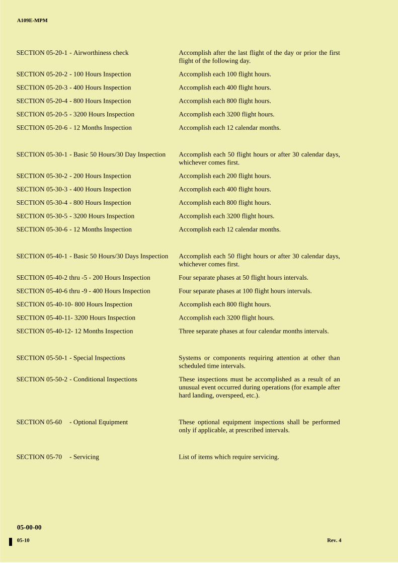
SECTION 05-10 - Component Overhaul Schedule List of components with overhaul interval.
SECTION 05-12 - Miscellaneous Replacement Schedule
List of non flight critical parts with replacement time.
A B
C
D
A
B
C
DC
A109E-MPM
05-00-00
05-10 Rev. 4
SECTION 05-20-1 - Airworthiness check Accomplish after the last flight of the day or prior the firstflight of the following day.
SECTION 05-20-2 - 100 Hours Inspection Accomplish each 100 flight hours.
SECTION 05-20-3 - 400 Hours Inspection Accomplish each 400 flight hours.
SECTION 05-20-4 - 800 Hours Inspection Accomplish each 800 flight hours.
SECTION 05-20-5 - 3200 Hours Inspection Accomplish each 3200 flight hours.
SECTION 05-20-6 - 12 Months Inspection Accomplish each 12 calendar months.
SECTION 05-30-1 - Basic 50 Hours/30 Day Inspection Accomplish each 50 flight hours or after 30 calendar days,whichever comes first.
SECTION 05-30-2 - 200 Hours Inspection Accomplish each 200 flight hours.
SECTION 05-30-3 - 400 Hours Inspection Accomplish each 400 flight hours.
SECTION 05-30-4 - 800 Hours Inspection Accomplish each 800 flight hours.
SECTION 05-30-5 - 3200 Hours Inspection Accomplish each 3200 flight hours.
SECTION 05-30-6 - 12 Months Inspection Accomplish each 12 calendar months.
SECTION 05-40-1 - Basic 50 Hours/30 Days Inspection Accomplish each 50 flight hours or after 30 calendar days,whichever comes first.
SECTION 05-40-2 thru -5 - 200 Hours Inspection Four separate phases at 50 flight hours intervals.
SECTION 05-40-6 thru -9 - 400 Hours Inspection Four separate phases at 100 flight hours intervals.
SECTION 05-40-10- 800 Hours Inspection Accomplish each 800 flight hours.
SECTION 05-40-11- 3200 Hours Inspection Accomplish each 3200 flight hours.
SECTION 05-40-12- 12 Months Inspection Three separate phases at four calendar months intervals.
SECTION 05-50-1 - Special Inspections Systems or components requiring attention at other thanscheduled time intervals.
SECTION 05-50-2 - Conditional Inspections These inspections must be accomplished as a result of anunusual event occurred during operations (for example afterhard landing, overspeed, etc.).
SECTION 05-60 - Optional Equipment These optional equipment inspections shall be performedonly if applicable, at prescribed intervals.
SECTION 05-70 - Servicing List of items which require servicing.
A B
C
D
A
B
C
DC
A109E-MPM
05-10-00
Rev. 3 05-11
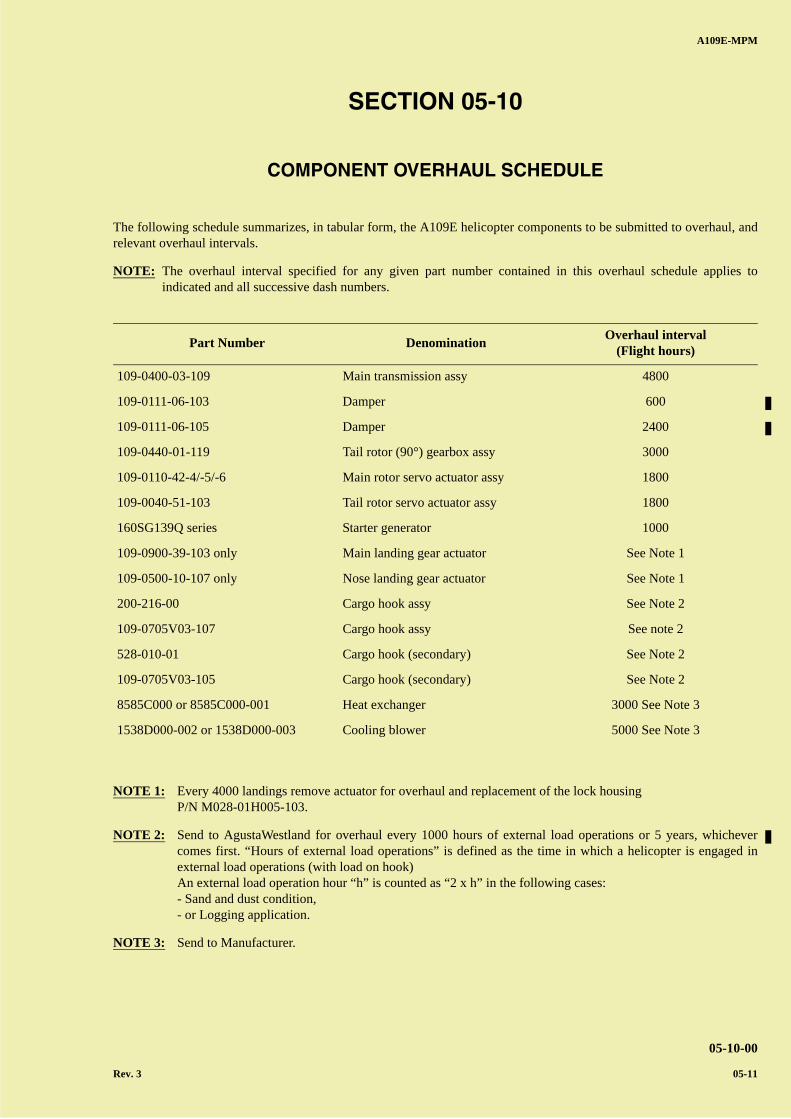
SECTION 05-10
COMPONENT OVERHAUL SCHEDULE
The following schedule summarizes, in tabular form, the A109E helicopter components to be submitted to overhaul, andrelevant overhaul intervals.
NOTE: The overhaul interval specified for any given part number contained in this overhaul schedule applies toindicated and all successive dash numbers.
NOTE 1: Every 4000 landings remove actuator for overhaul and replacement of the lock housingP/N M028-01H005-103.
NOTE 2: Send to AgustaWestland for overhaul every 1000 hours of external load operations or 5 years, whichevercomes first. “Hours of external load operations” is defined as the time in which a helicopter is engaged inexternal load operations (with load on hook)An external load operation hour “h” is counted as “2 x h” in the following cases:- Sand and dust condition,- or Logging application.
NOTE 3: Send to Manufacturer.
Part Number DenominationOverhaul interval
(Flight hours)
109-0400-03-109 Main transmission assy 4800
109-0111-06-103 Damper 600
109-0111-06-105 Damper 2400
109-0440-01-119 Tail rotor (90°) gearbox assy 3000
109-0110-42-4/-5/-6 Main rotor servo actuator assy 1800
109-0040-51-103 Tail rotor servo actuator assy 1800
160SG139Q series Starter generator 1000
109-0900-39-103 only Main landing gear actuator See Note 1
109-0500-10-107 only Nose landing gear actuator See Note 1
200-216-00 Cargo hook assy See Note 2
109-0705V03-107 Cargo hook assy See note 2
528-010-01 Cargo hook (secondary) See Note 2
109-0705V03-105 Cargo hook (secondary) See Note 2
8585C000 or 8585C000-001 Heat exchanger 3000 See Note 3
1538D000-002 or 1538D000-003 Cooling blower 5000 See Note 3

A B
C
D
A
B
C
DC
A109E-MPM
05-10-00
05-12
PAGE INTENTIONALLY LEFT BLANK
A B
C
D
A
B
C
DC
A109E-MPM
05-12-00
Rev. 3 05-13
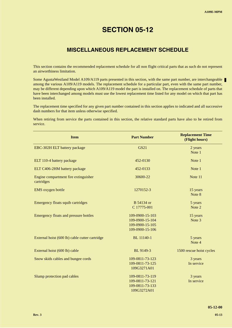
SECTION 05-12
MISCELLANEOUS REPLACEMENT SCHEDULE
This section contains the recommended replacement schedule for all non flight critical parts that as such do not representan airworthiness limitation.
Some AgustaWestland Model A109/A119 parts presented in this section, with the same part number, are interchangeableamong the various A109/A119 models. The replacement schedule for a particular part, even with the same part number,may be different depending upon which A109/A119 model the part is installed on. The replacement schedule of parts thathave been interchanged among models must use the lowest replacement time listed for any model on which that part hasbeen installed.
The replacement time specified for any given part number contained in this section applies to indicated and all successivedash numbers for that item unless otherwise specified.
When retiring from service the parts contained in this section, the relative standard parts have also to be retired fromservice.
Item Part NumberReplacement Time
(Flight hours)
EBC-302H ELT battery package GS21 2 yearsNote 1
ELT 110-4 battery package 452-0130 Note 1
ELT C406-2HM battery package 452-0133 Note 1
Engine compartment fire extinguishercartridges
30600-22 Note 11
EMS oxygen bottle 1270152-3 15 yearsNote 8
Emergency floats squib cartridges B 54134 orC 17775-001
5 yearsNote 2
Emergency floats and pressure bottles 109-0900-15-103109-0900-15-104109-0900-15-105109-0900-15-106
15 yearsNote 3
External hoist (600 lb) cable cutter cartridge BL 11140-1 5 yearsNote 4
External hoist (600 lb) cable BL 9149-3 1500 rescue hoist cycles
Snow skids cables and bungee cords 109-0811-73-123109-0811-73-125
109G3271A01
3 yearsIn service
Slump protection pad cables 109-0811-73-119109-0811-73-121109-0811-73-133
109G3272A01
3 yearsIn service
A B
C
D
A
B
C
DC
A109E-MPM
05-12-00
05-14 Rev. 4
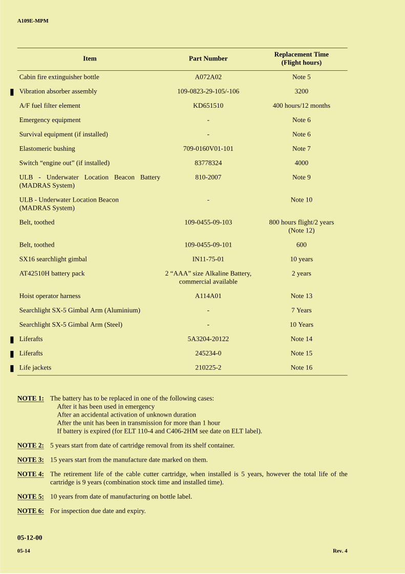
NOTE 1: The battery has to be replaced in one of the following cases: After it has been used in emergency After an accidental activation of unknown duration After the unit has been in transmission for more than 1 hour If battery is expired (for ELT 110-4 and C406-2HM see date on ELT label).
NOTE 2: 5 years start from date of cartridge removal from its shelf container.
NOTE 3: 15 years start from the manufacture date marked on them.
NOTE 4: The retirement life of the cable cutter cartridge, when installed is 5 years, however the total life of thecartridge is 9 years (combination stock time and installed time).
NOTE 5: 10 years from date of manufacturing on bottle label.
NOTE 6: For inspection due date and expiry.
Cabin fire extinguisher bottle A072A02 Note 5
Vibration absorber assembly 109-0823-29-105/-106 3200
A/F fuel filter element KD651510 400 hours/12 months
Emergency equipment - Note 6
Survival equipment (if installed) - Note 6
Elastomeric bushing 709-0160V01-101 Note 7
Switch “engine out” (if installed) 83778324 4000
ULB - Underwater Location Beacon Battery(MADRAS System)
810-2007 Note 9
ULB - Underwater Location Beacon(MADRAS System)
- Note 10
Belt, toothed 109-0455-09-103 800 hours flight/2 years(Note 12)
Belt, toothed 109-0455-09-101 600
SX16 searchlight gimbal IN11-75-01 10 years
AT42510H battery pack 2 “AAA” size Alkaline Battery, commercial available
2 years
Hoist operator harness A114A01 Note 13
Searchlight SX-5 Gimbal Arm (Aluminium) - 7 Years
Searchlight SX-5 Gimbal Arm (Steel) - 10 Years
Liferafts 5A3204-20122 Note 14
Liferafts 245234-0 Note 15
Life jackets 210225-2 Note 16
Item Part NumberReplacement Time
(Flight hours)
A B
C
D
A
B
C
DC
A109E-MPM
05-12-00
Rev. 4 05-15
NOTE 7: Shelf life is 5 years from manufacture. This shelf life is applicable also to a bushing already installed on ablade.
NOTE 8: 15 years start from the manufacture date marked on the bottle.
NOTE 9: 6 years maximum life. See Battery expiration date on ULB label.
NOTE 10: Every 1200 hours or 24 calendars months perform the following:
- Functional testing using Dukane Ultrasonic Test Set model 42A12 or equivalent.- Clean the switch end of the beacon with a soft cloth and mild detergent, then dry thoroughly with a clean
cloth. Clean the switch end insulator to prevent leakage currents from occurring across the switch. Thiswill affect battery life.
NOTE 11: The retirement life of the Engine compartment fire extinguisher cartridge when installed is 12 years, howeverthe total life of the cartridge is 15 years (combination stock time and installed time).
NOTE 12: A tolerance of 30 FH is permitted.
NOTE 13: 3 years of use or 10 years from the date of manufacture.
NOTE 14: Every 1 year from manufacturing date from last overhaul date remove and send the component to theManufacturer or its authorized Repair Center to perform maintenance. First inspection may be deferred up to24 months from manufacturing date.
NOTE 15: Within 1 year from component installation verify the airworthiness documentation provided with thecomponents in order to identify and set the schedule for the check of expired survival bag/components.Every 30 months of storage from manufacturing date or from the last overhaul date, check and inspect statusof vacuum-packed life rafts; do this task before installation on the aircraft; from there on the standardmaintenance schedule will apply in accordance with CMM.
Every 5 years from manufacturing date or from last overhaul date remove and send the component to theManufacturer or its authorized Repair Center to perform overpressure test of life rafts and hydrostatic test ofthe inflation cylinder (disassembly and test equipment required). The inspections must be accomplished byqualified personnel to ascertain the airworthiness of the helicopter.
NOTE 16: Every 5 years from manufacturing date or from the last overhaul date, send the component to theManufacturer or its authorized Repair Center to inspect the buoyancy chambers and components, to performthe overpressure test and the air tightness test (disassembly and test equipment required).

A B
C
D
A
B
C
DC
A109E-MPM
05-12-00
05-16
PAGE INTENTIONALLY LEFT BLANK
A B
C
D
A
B
C
DC
A109E-MPM
05-20-00
05-17
Date .......................................................
Signature ................................................
Helicopter Registration No. ...................
Helicopter Hours ...................................
INITIAL EACH ITEM AFTER ACCOMPLISHMENT INITIAL
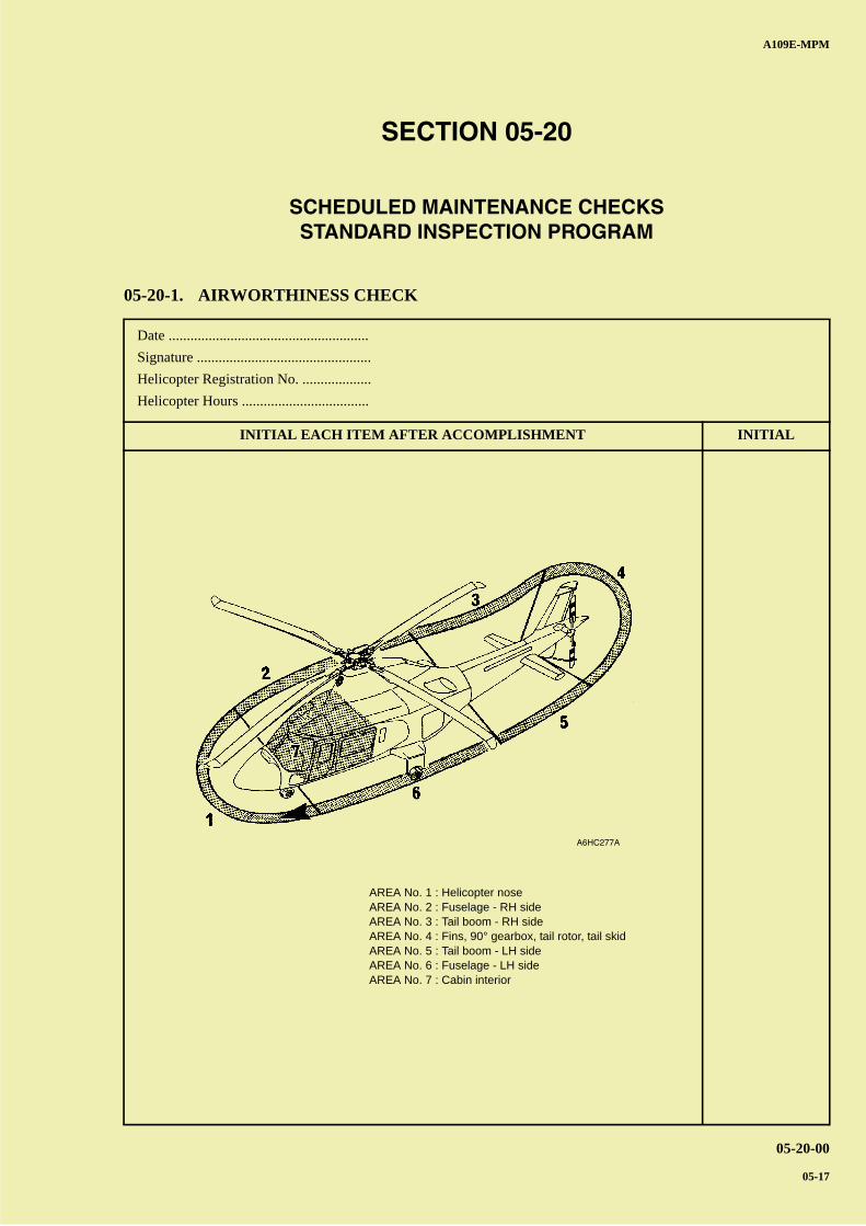
SECTION 05-20
SCHEDULED MAINTENANCE CHECKSSTANDARD INSPECTION PROGRAM
05-20-1. AIRWORTHINESS CHECK
A6HC277A
AREA No. 1 : Helicopter noseAREA No. 2 : Fuselage - RH sideAREA No. 3 : Tail boom - RH sideAREA No. 4 : Fins, 90° gearbox, tail rotor, tail skidAREA No. 5 : Tail boom - LH sideAREA No. 6 : Fuselage - LH sideAREA No. 7 : Cabin interior
A B
C
D
A
B
C
DC
INITIAL EACH ITEM AFTER ACCOMPLISHMENT INITIAL
A109E-MPM
05-20-00
05-18 Rev. 4
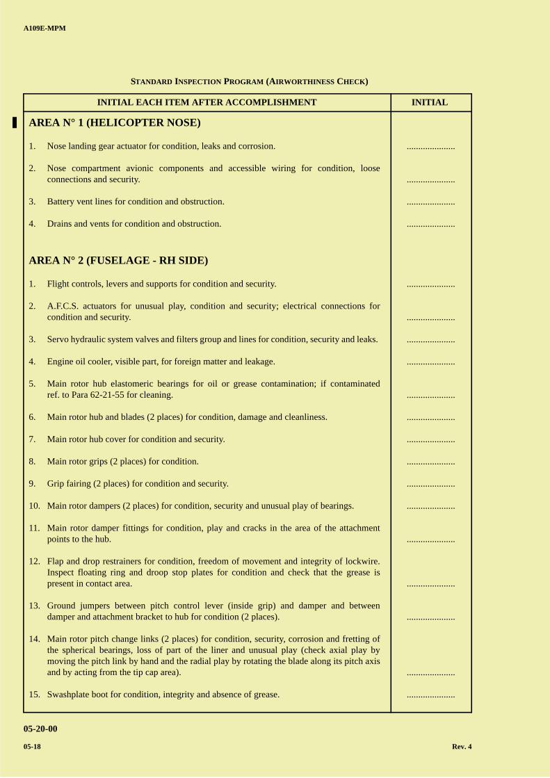
AREA N° 1 (HELICOPTER NOSE)
1. Nose landing gear actuator for condition, leaks and corrosion.
2. Nose compartment avionic components and accessible wiring for condition, looseconnections and security.
3. Battery vent lines for condition and obstruction.
4. Drains and vents for condition and obstruction.
AREA N° 2 (FUSELAGE - RH SIDE)
1. Flight controls, levers and supports for condition and security.
2. A.F.C.S. actuators for unusual play, condition and security; electrical connections forcondition and security.
3. Servo hydraulic system valves and filters group and lines for condition, security and leaks.
4. Engine oil cooler, visible part, for foreign matter and leakage.
5. Main rotor hub elastomeric bearings for oil or grease contamination; if contaminatedref. to Para 62-21-55 for cleaning.
6. Main rotor hub and blades (2 places) for condition, damage and cleanliness.
7. Main rotor hub cover for condition and security.
8. Main rotor grips (2 places) for condition.
9. Grip fairing (2 places) for condition and security.
10. Main rotor dampers (2 places) for condition, security and unusual play of bearings.
11. Main rotor damper fittings for condition, play and cracks in the area of the attachmentpoints to the hub.
12. Flap and drop restrainers for condition, freedom of movement and integrity of lockwire.Inspect floating ring and droop stop plates for condition and check that the grease ispresent in contact area.
13. Ground jumpers between pitch control lever (inside grip) and damper and betweendamper and attachment bracket to hub for condition (2 places).
14. Main rotor pitch change links (2 places) for condition, security, corrosion and fretting ofthe spherical bearings, loss of part of the liner and unusual play (check axial play bymoving the pitch link by hand and the radial play by rotating the blade along its pitch axisand by acting from the tip cap area).
15. Swashplate boot for condition, integrity and absence of grease.
.....................
.....................
.....................
.....................
.....................
.....................
.....................
.....................
.....................
.....................
.....................
.....................
.....................
.....................
.....................
.....................
.....................
.....................
.....................
STANDARD INSPECTION PROGRAM (AIRWORTHINESS CHECK)
A B
C
D
A
B
C
DC
INITIAL EACH ITEM AFTER ACCOMPLISHMENT INITIAL
A109E-MPM
05-20-00
Rev. 4 05-19
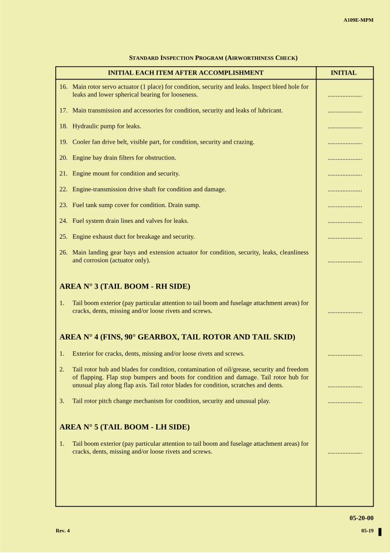
16. Main rotor servo actuator (1 place) for condition, security and leaks. Inspect bleed hole forleaks and lower spherical bearing for looseness.
17. Main transmission and accessories for condition, security and leaks of lubricant.
18. Hydraulic pump for leaks.
19. Cooler fan drive belt, visible part, for condition, security and crazing.
20. Engine bay drain filters for obstruction.
21. Engine mount for condition and security.
22. Engine-transmission drive shaft for condition and damage.
23. Fuel tank sump cover for condition. Drain sump.
24. Fuel system drain lines and valves for leaks.
25. Engine exhaust duct for breakage and security.
26. Main landing gear bays and extension actuator for condition, security, leaks, cleanlinessand corrosion (actuator only).
AREA N° 3 (TAIL BOOM - RH SIDE)
1. Tail boom exterior (pay particular attention to tail boom and fuselage attachment areas) forcracks, dents, missing and/or loose rivets and screws.
AREA N° 4 (FINS, 90° GEARBOX, TAIL ROTOR AND TAIL SKID)
1. Exterior for cracks, dents, missing and/or loose rivets and screws.
2. Tail rotor hub and blades for condition, contamination of oil/grease, security and freedomof flapping. Flap stop bumpers and boots for condition and damage. Tail rotor hub forunusual play along flap axis. Tail rotor blades for condition, scratches and dents.
3. Tail rotor pitch change mechanism for condition, security and unusual play.
AREA N° 5 (TAIL BOOM - LH SIDE)
1. Tail boom exterior (pay particular attention to tail boom and fuselage attachment areas) forcracks, dents, missing and/or loose rivets and screws.
.....................
.....................
.....................
.....................
.....................
.....................
.....................
.....................
.....................
.....................
.....................
.....................
.....................
.....................
.....................
.....................
STANDARD INSPECTION PROGRAM (AIRWORTHINESS CHECK)
A B
C
D
A
B
C
DC
INITIAL EACH ITEM AFTER ACCOMPLISHMENT INITIAL
A109E-MPM
05-20-00
05-20 Rev. 4
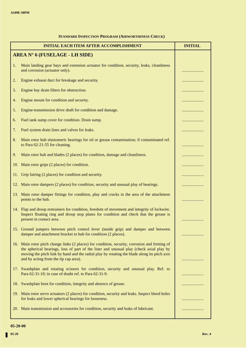
AREA N° 6 (FUSELAGE - LH SIDE)
1. Main landing gear bays and extension actuator for condition, security, leaks, cleanlinessand corrosion (actuator only).
2. Engine exhaust duct for breakage and security.
3. Engine bay drain filters for obstruction.
4. Engine mount for condition and security.
5. Engine-transmission drive shaft for condition and damage.
6. Fuel tank sump cover for condition. Drain sump.
7. Fuel system drain lines and valves for leaks.
8. Main rotor hub elastomeric bearings for oil or grease contamination; if contaminated ref.to Para 62-21-55 for cleaning.
9. Main rotor hub and blades (2 places) for condition, damage and cleanliness.
10. Main rotor grips (2 places) for condition.
11. Grip fairing (2 places) for condition and security.
12. Main rotor dampers (2 places) for condition, security and unusual play of bearings.
13. Main rotor damper fittings for condition, play and cracks in the area of the attachmentpoints to the hub.
14. Flap and droop restrainers for condition, freedom of movement and integrity of lockwire.Inspect floating ring and droop stop plates for condition and check that the grease ispresent in contact area.
15. Ground jumpers between pitch control lever (inside grip) and damper and betweendamper and attachment bracket to hub for condition (2 places).
16. Main rotor pitch change links (2 places) for condition, security, corrosion and fretting ofthe spherical bearings, loss of part of the liner and unusual play (check axial play bymoving the pitch link by hand and the radial play by rotating the blade along its pitch axisand by acting from the tip cap area).
17. Swashplate and rotating scissors for condition, security and unusual play. Ref. toPara 62-31-10; in case of doubt ref. to Para 62-31-9.
18. Swashplate boot for condition, integrity and absence of grease.
19. Main rotor servo actuators (2 places) for condition, security and leaks. Inspect bleed holesfor leaks and lower spherical bearings for looseness.
20. Main transmission and accessories for condition, security and leaks of lubricant.
.....................
.....................
.....................
.....................
.....................
.....................
.....................
.....................
.....................
.....................
.....................
.....................
.....................
.....................
.....................
.....................
.....................
.....................
.....................
.....................
STANDARD INSPECTION PROGRAM (AIRWORTHINESS CHECK)
A B
C
D
A
B
C
DC
INITIAL EACH ITEM AFTER ACCOMPLISHMENT INITIAL
A109E-MPM
05-20-00
Rev. 4 05-21
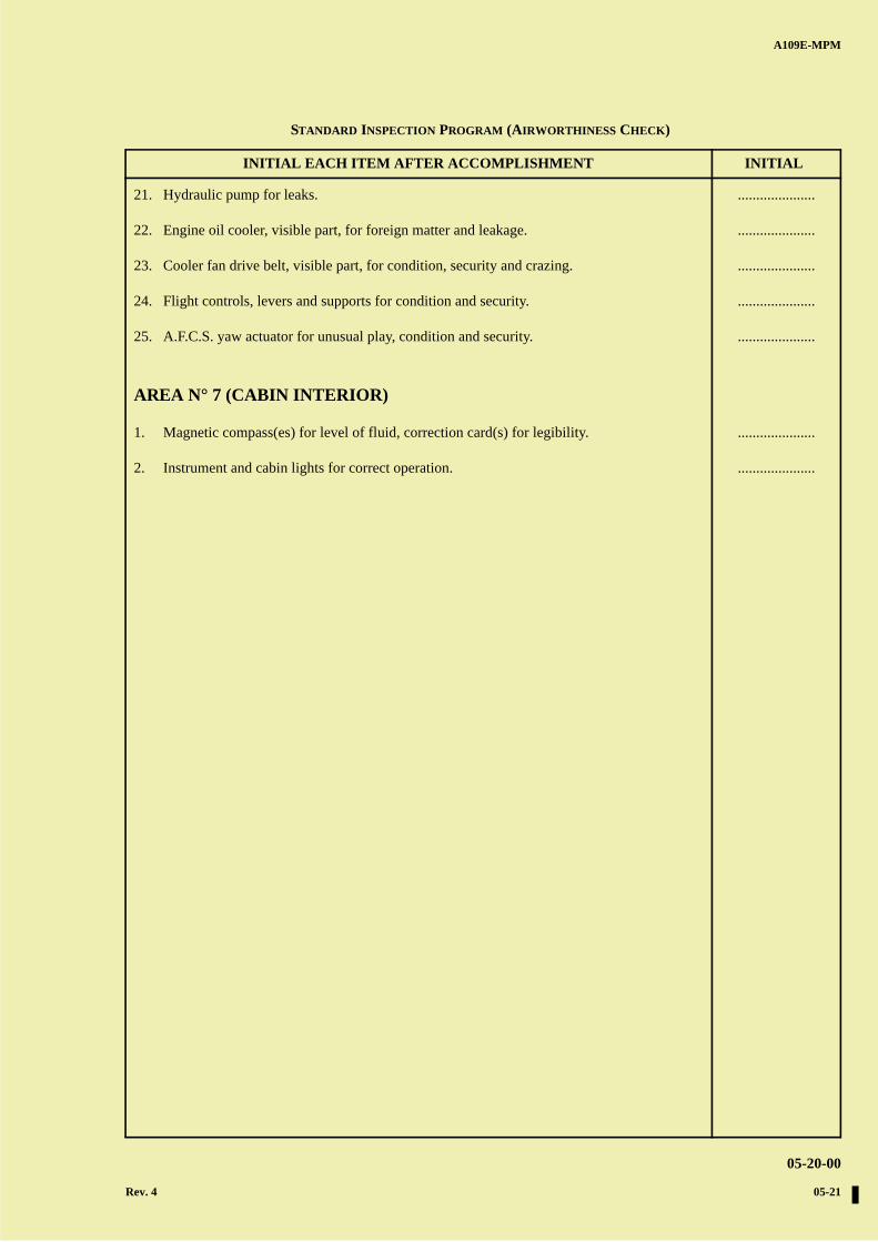
21. Hydraulic pump for leaks.
22. Engine oil cooler, visible part, for foreign matter and leakage.
23. Cooler fan drive belt, visible part, for condition, security and crazing.
24. Flight controls, levers and supports for condition and security.
25. A.F.C.S. yaw actuator for unusual play, condition and security.
AREA N° 7 (CABIN INTERIOR)
1. Magnetic compass(es) for level of fluid, correction card(s) for legibility.
2. Instrument and cabin lights for correct operation.
.....................
.....................
.....................
.....................
.....................
.....................
.....................
STANDARD INSPECTION PROGRAM (AIRWORTHINESS CHECK)

A B
C
D
A
B
C
DC
A109E-MPM
05-20-00
05-22
PAGE INTENTIONALLY LEFT BLANK
A B
C
D
A
B
C
DC
A109E-MPM
05-20-00
Rev. 4 05-23
Date .......................................................
Signature ................................................
Helicopter Registration No. ...................
Helicopter Hours ...................................
INITIAL EACH ITEM AFTER ACCOMPLISHMENT INITIAL
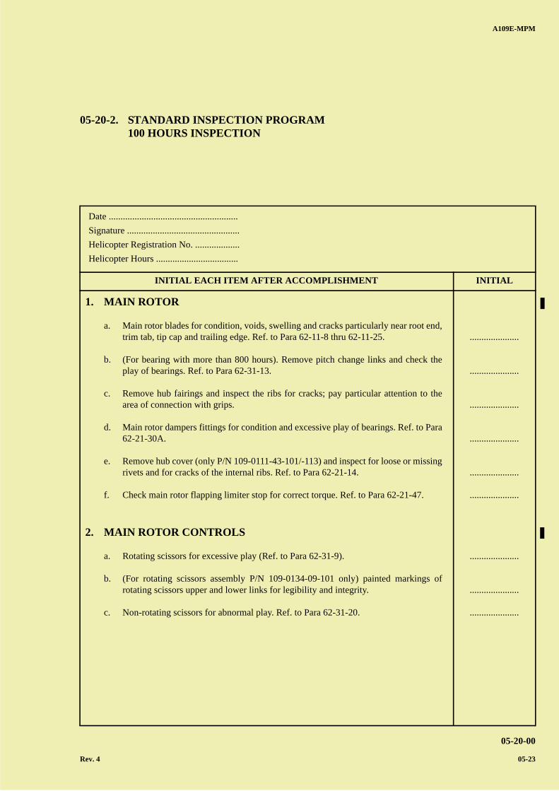
05-20-2. STANDARD INSPECTION PROGRAM100 HOURS INSPECTION
1. MAIN ROTOR
a. Main rotor blades for condition, voids, swelling and cracks particularly near root end,trim tab, tip cap and trailing edge. Ref. to Para 62-11-8 thru 62-11-25.
b. (For bearing with more than 800 hours). Remove pitch change links and check theplay of bearings. Ref. to Para 62-31-13.
c. Remove hub fairings and inspect the ribs for cracks; pay particular attention to thearea of connection with grips.
d. Main rotor dampers fittings for condition and excessive play of bearings. Ref. to Para62-21-30A.
e. Remove hub cover (only P/N 109-0111-43-101/-113) and inspect for loose or missingrivets and for cracks of the internal ribs. Ref. to Para 62-21-14.
f. Check main rotor flapping limiter stop for correct torque. Ref. to Para 62-21-47.
2. MAIN ROTOR CONTROLS
a. Rotating scissors for excessive play (Ref. to Para 62-31-9).
b. (For rotating scissors assembly P/N 109-0134-09-101 only) painted markings ofrotating scissors upper and lower links for legibility and integrity.
c. Non-rotating scissors for abnormal play. Ref. to Para 62-31-20.
.....................
.....................
.....................
.....................
.....................
.....................
.....................
.....................
.....................

A B
C
D
A
B
C
DC
INITIAL EACH ITEM AFTER ACCOMPLISHMENT INITIAL
A109E-MPM
05-20-00
05-24 Rev. 4
3. MAIN TRANSMISSION
a. Upper case to main case attachment nuts for correct torque. Ref. to Para 63-21-20.
4. FLIGHT CONTROLS
a. Check the following components (only visible part on transmission deck, internal oftail boom, two pedals and 90° gearbox areas) for condition, clearances, security andbearings for abnormal play.
1) Control tube.
2) Bellcranks.
3) Supports.
b. A.F.C.S. pitch and roll actuators, on roof deck, and yaw actuator, on rear fuselage;check slippage marks between body and shaft.
c. Tail rotor servo actuator for condition, security and leaks.
d. Main rotor servo actuators upper rod-end bearing for excessive play and lowerspherical bearing for looseness (removal of servo actuators is not requested). Ref. toPara 67-31-9.
5. POWER PLANT AND TAIL ROTOR DRIVE SHAFTS
a. Tail rotor drive shaft bearings for grease leakage. Rubber collars for condition andintegrity. Slippage marks between shaft-collar-bearing and between bearing hangerfor integrity. Inspect bearings on both sides and seals for damage and crazing.
b. Tail rotor drive shaft fittings safety pins for freedom of rotation. If shaft pin is tightrefer to Para 65-11-11.
c. Engine mounts for corrosion, condition and security especially in structureattachment area for cracks and distortion. Verify mounts solidity and absence ofmovement. Verify mounts bolts zone for fretting evidence (black metallic powderand bright halo in the area).
d. Engine oil cooler for leaks, condition and security.
e. Fuel and oil flexible tubes for condition and chafing.
f. Tubes and electrical wiring for condition, chafing, leaks and security of connections.
.....................
.....................
.....................
.....................
.....................
.....................
.....................
.....................
.....................
.....................
.....................
.....................
.....................
STANDARD INSPECTION PROGRAM (100 HOURS INSPECTION)
A B
C
D
A
B
C
DC
INITIAL EACH ITEM AFTER ACCOMPLISHMENT INITIAL
A109E-MPM
05-20-00
Rev. 4 05-25
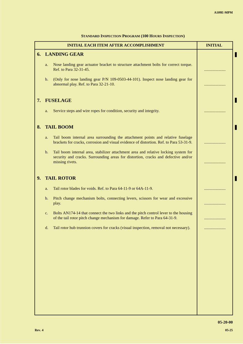
6. LANDING GEAR
a. Nose landing gear actuator bracket to structure attachment bolts for correct torque.Ref. to Para 32-31-45.
b. (Only for nose landing gear P/N 109-0503-44-101). Inspect nose landing gear forabnormal play. Ref. to Para 32-21-10.
7. FUSELAGE
a. Service steps and wire ropes for condition, security and integrity.
8. TAIL BOOM
a. Tail boom internal area surrounding the attachment points and relative fuselagebrackets for cracks, corrosion and visual evidence of distortion. Ref. to Para 53-31-9.
b. Tail boom internal area, stabilizer attachment area and relative locking system forsecurity and cracks. Surrounding areas for distortion, cracks and defective and/ormissing rivets.
9. TAIL ROTOR
a. Tail rotor blades for voids. Ref. to Para 64-11-9 or 64A-11-9.
b. Pitch change mechanism bolts, connecting levers, scissors for wear and excessiveplay.
c. Bolts AN174-14 that connect the two links and the pitch control lever to the housingof the tail rotor pitch change mechanism for damage. Refer to Para 64-31-9.
d. Tail rotor hub trunnion covers for cracks (visual inspection, removal not necessary).
.....................
.....................
.....................
.....................
.....................
.....................
.....................
.....................
.....................
STANDARD INSPECTION PROGRAM (100 HOURS INSPECTION)

A B
C
D
A
B
C
DC
A109E-MPM
05-20-00
05-26
PAGE INTENTIONALLY LEFT BLANK
A B
C
D
A
B
C
DC
A109E-MPM
05-20-00
Rev. 4 05-27
Date .......................................................
Signature ................................................
Helicopter Registration No. ...................
Helicopter Hours ...................................
INITIAL EACH ITEM AFTER ACCOMPLISHMENT INITIAL
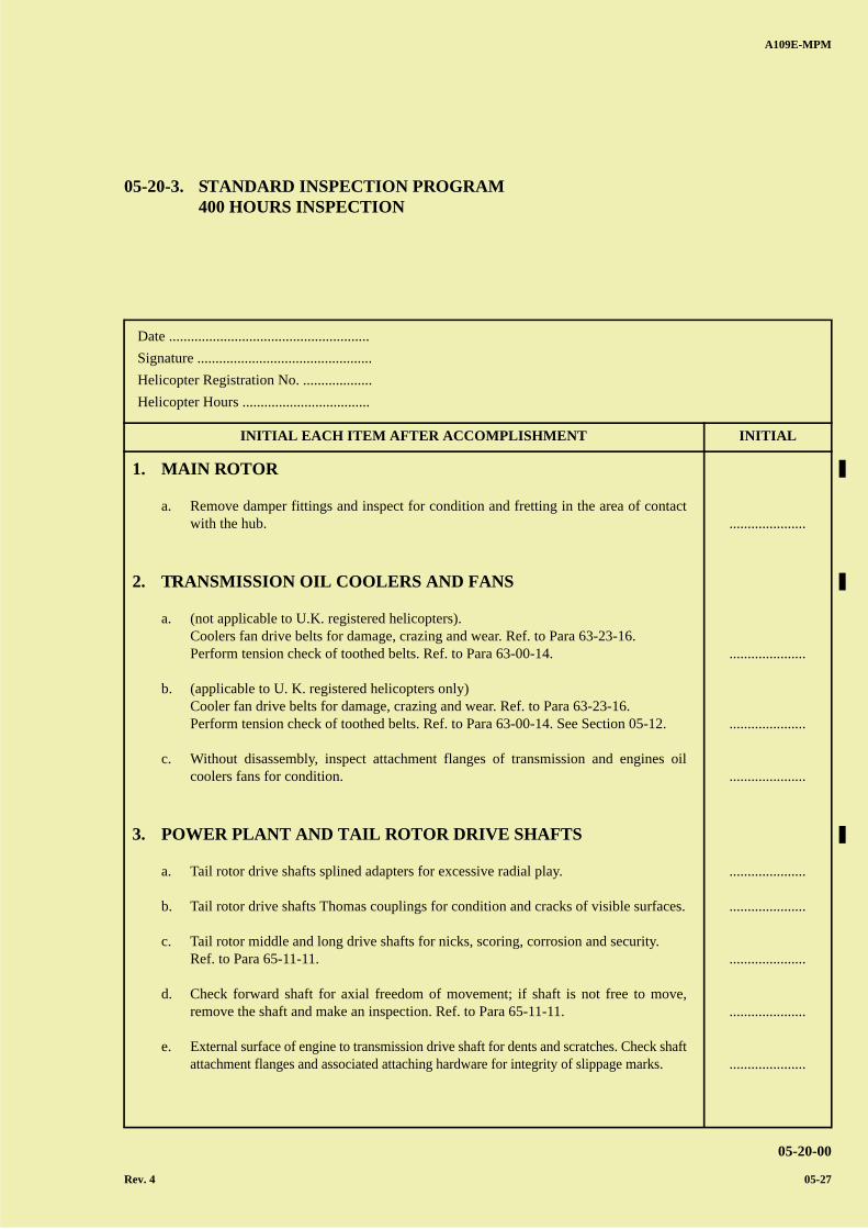
05-20-3. STANDARD INSPECTION PROGRAM400 HOURS INSPECTION
1. MAIN ROTOR
a. Remove damper fittings and inspect for condition and fretting in the area of contactwith the hub.
2. TRANSMISSION OIL COOLERS AND FANS
a. (not applicable to U.K. registered helicopters).Coolers fan drive belts for damage, crazing and wear. Ref. to Para 63-23-16.Perform tension check of toothed belts. Ref. to Para 63-00-14.
b. (applicable to U. K. registered helicopters only)Cooler fan drive belts for damage, crazing and wear. Ref. to Para 63-23-16.Perform tension check of toothed belts. Ref. to Para 63-00-14. See Section 05-12.
c. Without disassembly, inspect attachment flanges of transmission and engines oilcoolers fans for condition.
3. POWER PLANT AND TAIL ROTOR DRIVE SHAFTS
a. Tail rotor drive shafts splined adapters for excessive radial play.
b. Tail rotor drive shafts Thomas couplings for condition and cracks of visible surfaces.
c. Tail rotor middle and long drive shafts for nicks, scoring, corrosion and security.Ref. to Para 65-11-11.
d. Check forward shaft for axial freedom of movement; if shaft is not free to move,remove the shaft and make an inspection. Ref. to Para 65-11-11.
e. External surface of engine to transmission drive shaft for dents and scratches. Check shaftattachment flanges and associated attaching hardware for integrity of slippage marks.
.....................
.....................
.....................
.....................
.....................
.....................
.....................
.....................
.....................
A B
C
D
A
B
C
DC
INITIAL EACH ITEM AFTER ACCOMPLISHMENT INITIAL
A109E-MPM
05-20-00
05-28 Rev. 4
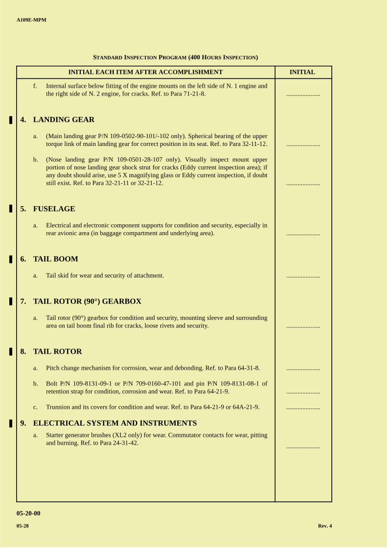
f. Internal surface below fitting of the engine mounts on the left side of N. 1 engine andthe right side of N. 2 engine, for cracks. Ref. to Para 71-21-8.
4. LANDING GEAR
a. (Main landing gear P/N 109-0502-90-101/-102 only). Spherical bearing of the uppertorque link of main landing gear for correct position in its seat. Ref. to Para 32-11-12.
b. (Nose landing gear P/N 109-0501-28-107 only). Visually inspect mount upperportion of nose landing gear shock strut for cracks (Eddy current inspection area); ifany doubt should arise, use 5 X magnifying glass or Eddy current inspection, if doubtstill exist. Ref. to Para 32-21-11 or 32-21-12.
5. FUSELAGE
a. Electrical and electronic component supports for condition and security, especially inrear avionic area (in baggage compartment and underlying area).
6. TAIL BOOM
a. Tail skid for wear and security of attachment.
7. TAIL ROTOR (90°) GEARBOX
a. Tail rotor (90°) gearbox for condition and security, mounting sleeve and surroundingarea on tail boom final rib for cracks, loose rivets and security.
8. TAIL ROTOR
a. Pitch change mechanism for corrosion, wear and debonding. Ref. to Para 64-31-8.
b. Bolt P/N 109-8131-09-1 or P/N 709-0160-47-101 and pin P/N 109-8131-08-1 ofretention strap for condition, corrosion and wear. Ref. to Para 64-21-9.
c. Trunnion and its covers for condition and wear. Ref. to Para 64-21-9 or 64A-21-9.
9. ELECTRICAL SYSTEM AND INSTRUMENTS
a. Starter generator brushes (XL2 only) for wear. Commutator contacts for wear, pittingand burning. Ref. to Para 24-31-42.
.....................
.....................
.....................
.....................
.....................
.....................
.....................
.....................
.....................
.....................
STANDARD INSPECTION PROGRAM (400 HOURS INSPECTION)
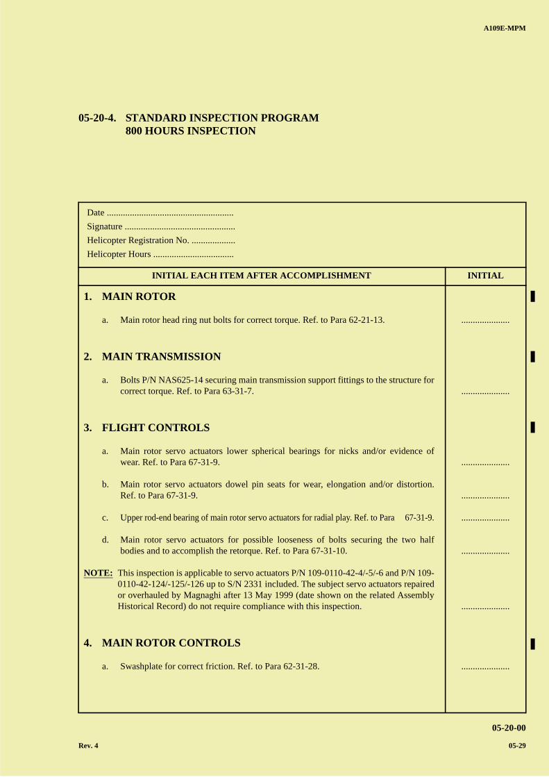
A B
C
D
A
B
C
DC
A109E-MPM
05-20-00
Rev. 4 05-29
Date .......................................................
Signature ................................................
Helicopter Registration No. ...................
Helicopter Hours ...................................
INITIAL EACH ITEM AFTER ACCOMPLISHMENT INITIAL
05-20-4. STANDARD INSPECTION PROGRAM800 HOURS INSPECTION
1. MAIN ROTOR
a. Main rotor head ring nut bolts for correct torque. Ref. to Para 62-21-13.
2. MAIN TRANSMISSION
a. Bolts P/N NAS625-14 securing main transmission support fittings to the structure forcorrect torque. Ref. to Para 63-31-7.
3. FLIGHT CONTROLS
a. Main rotor servo actuators lower spherical bearings for nicks and/or evidence ofwear. Ref. to Para 67-31-9.
b. Main rotor servo actuators dowel pin seats for wear, elongation and/or distortion.Ref. to Para 67-31-9.
c. Upper rod-end bearing of main rotor servo actuators for radial play. Ref. to Para 67-31-9.
d. Main rotor servo actuators for possible looseness of bolts securing the two halfbodies and to accomplish the retorque. Ref. to Para 67-31-10.
NOTE: This inspection is applicable to servo actuators P/N 109-0110-42-4/-5/-6 and P/N 109-0110-42-124/-125/-126 up to S/N 2331 included. The subject servo actuators repairedor overhauled by Magnaghi after 13 May 1999 (date shown on the related AssemblyHistorical Record) do not require compliance with this inspection.
4. MAIN ROTOR CONTROLS
a. Swashplate for correct friction. Ref. to Para 62-31-28.
.....................
.....................
.....................
.....................
.....................
.....................
.....................
.....................
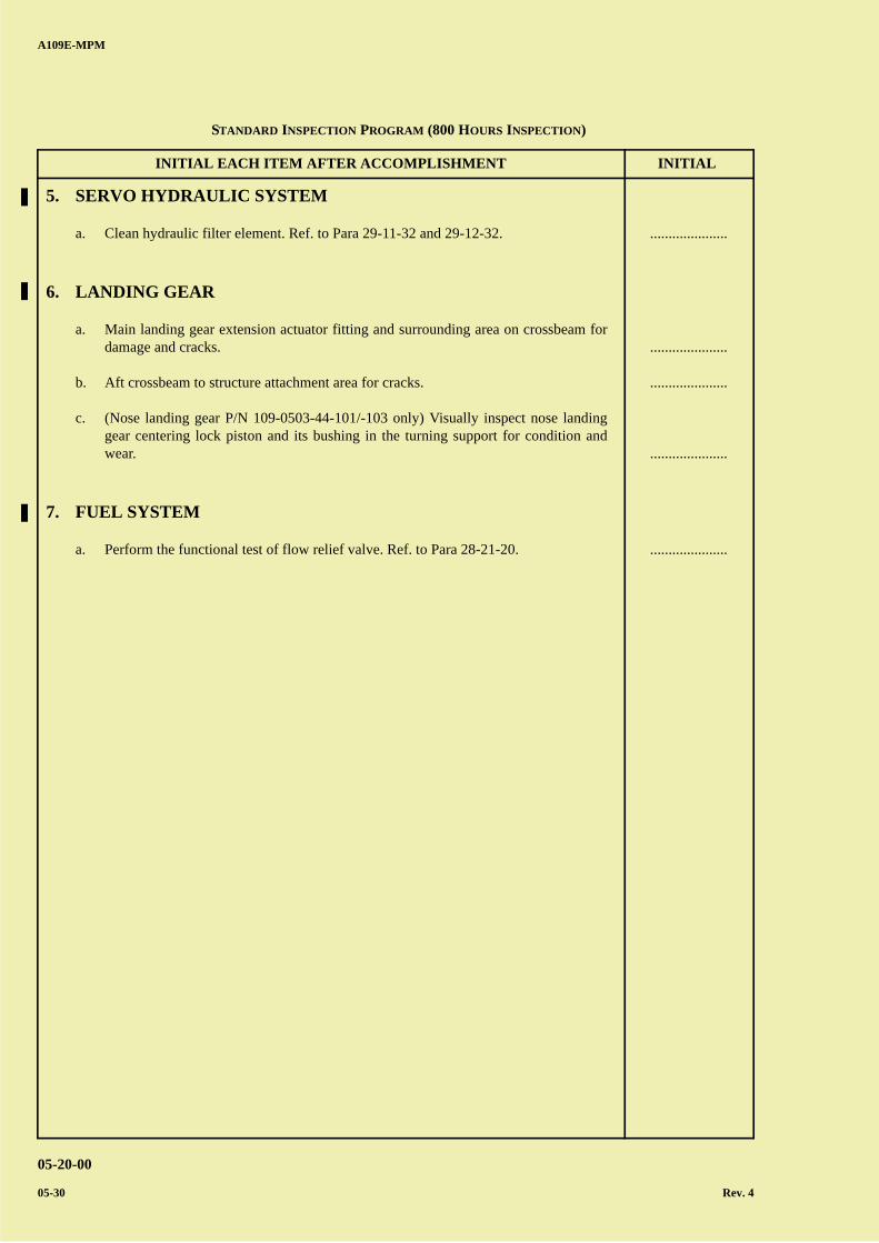
A B
C
D
A
B
C
DC
INITIAL EACH ITEM AFTER ACCOMPLISHMENT INITIAL
A109E-MPM
05-20-00
05-30 Rev. 4
5. SERVO HYDRAULIC SYSTEM
a. Clean hydraulic filter element. Ref. to Para 29-11-32 and 29-12-32.
6. LANDING GEAR
a. Main landing gear extension actuator fitting and surrounding area on crossbeam fordamage and cracks.
b. Aft crossbeam to structure attachment area for cracks.
c. (Nose landing gear P/N 109-0503-44-101/-103 only) Visually inspect nose landinggear centering lock piston and its bushing in the turning support for condition andwear.
7. FUEL SYSTEM
a. Perform the functional test of flow relief valve. Ref. to Para 28-21-20.
.....................
.....................
.....................
.....................
.....................
STANDARD INSPECTION PROGRAM (800 HOURS INSPECTION)
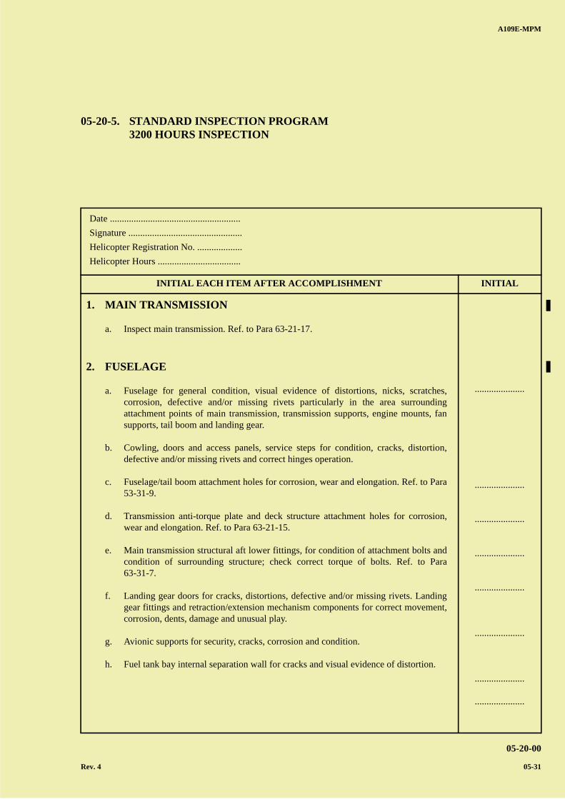
A B
C
D
A
B
C
DC
A109E-MPM
05-20-00
Rev. 4 05-31
Date .......................................................
Signature ................................................
Helicopter Registration No. ...................
Helicopter Hours ...................................
INITIAL EACH ITEM AFTER ACCOMPLISHMENT INITIAL
05-20-5. STANDARD INSPECTION PROGRAM3200 HOURS INSPECTION
1. MAIN TRANSMISSION
a. Inspect main transmission. Ref. to Para 63-21-17.
2. FUSELAGE
a. Fuselage for general condition, visual evidence of distortions, nicks, scratches,corrosion, defective and/or missing rivets particularly in the area surroundingattachment points of main transmission, transmission supports, engine mounts, fansupports, tail boom and landing gear.
b. Cowling, doors and access panels, service steps for condition, cracks, distortion,defective and/or missing rivets and correct hinges operation.
c. Fuselage/tail boom attachment holes for corrosion, wear and elongation. Ref. to Para53-31-9.
d. Transmission anti-torque plate and deck structure attachment holes for corrosion,wear and elongation. Ref. to Para 63-21-15.
e. Main transmission structural aft lower fittings, for condition of attachment bolts andcondition of surrounding structure; check correct torque of bolts. Ref. to Para63-31-7.
f. Landing gear doors for cracks, distortions, defective and/or missing rivets. Landinggear fittings and retraction/extension mechanism components for correct movement,corrosion, dents, damage and unusual play.
g. Avionic supports for security, cracks, corrosion and condition.
h. Fuel tank bay internal separation wall for cracks and visual evidence of distortion.
.....................
.....................
.....................
.....................
.....................
.....................
.....................
.....................
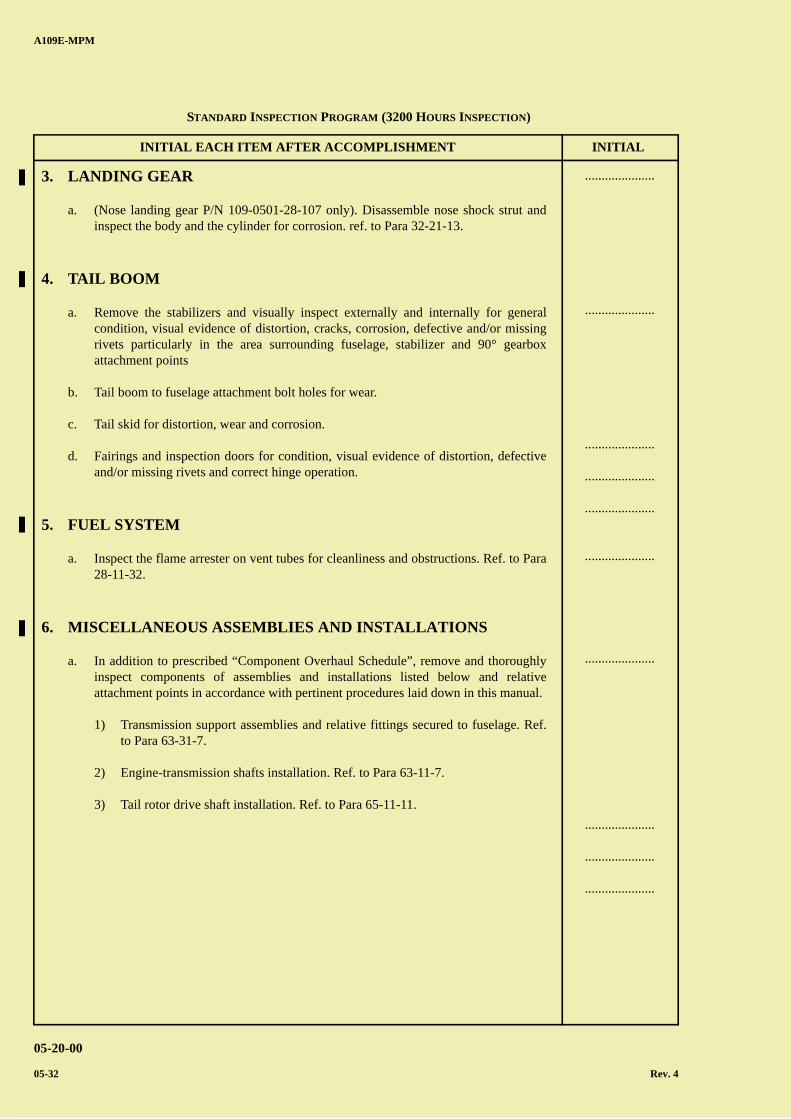
A B
C
D
A
B
C
DC
INITIAL EACH ITEM AFTER ACCOMPLISHMENT INITIAL
A109E-MPM
05-20-00
05-32 Rev. 4
3. LANDING GEAR
a. (Nose landing gear P/N 109-0501-28-107 only). Disassemble nose shock strut andinspect the body and the cylinder for corrosion. ref. to Para 32-21-13.
4. TAIL BOOM
a. Remove the stabilizers and visually inspect externally and internally for generalcondition, visual evidence of distortion, cracks, corrosion, defective and/or missingrivets particularly in the area surrounding fuselage, stabilizer and 90° gearboxattachment points
b. Tail boom to fuselage attachment bolt holes for wear.
c. Tail skid for distortion, wear and corrosion.
d. Fairings and inspection doors for condition, visual evidence of distortion, defectiveand/or missing rivets and correct hinge operation.
5. FUEL SYSTEM
a. Inspect the flame arrester on vent tubes for cleanliness and obstructions. Ref. to Para28-11-32.
6. MISCELLANEOUS ASSEMBLIES AND INSTALLATIONS
a. In addition to prescribed “Component Overhaul Schedule”, remove and thoroughlyinspect components of assemblies and installations listed below and relativeattachment points in accordance with pertinent procedures laid down in this manual.
1) Transmission support assemblies and relative fittings secured to fuselage. Ref.to Para 63-31-7.
2) Engine-transmission shafts installation. Ref. to Para 63-11-7.
3) Tail rotor drive shaft installation. Ref. to Para 65-11-11.
.....................
.....................
.....................
.....................
.....................
.....................
.....................
.....................
.....................
.....................
STANDARD INSPECTION PROGRAM (3200 HOURS INSPECTION)
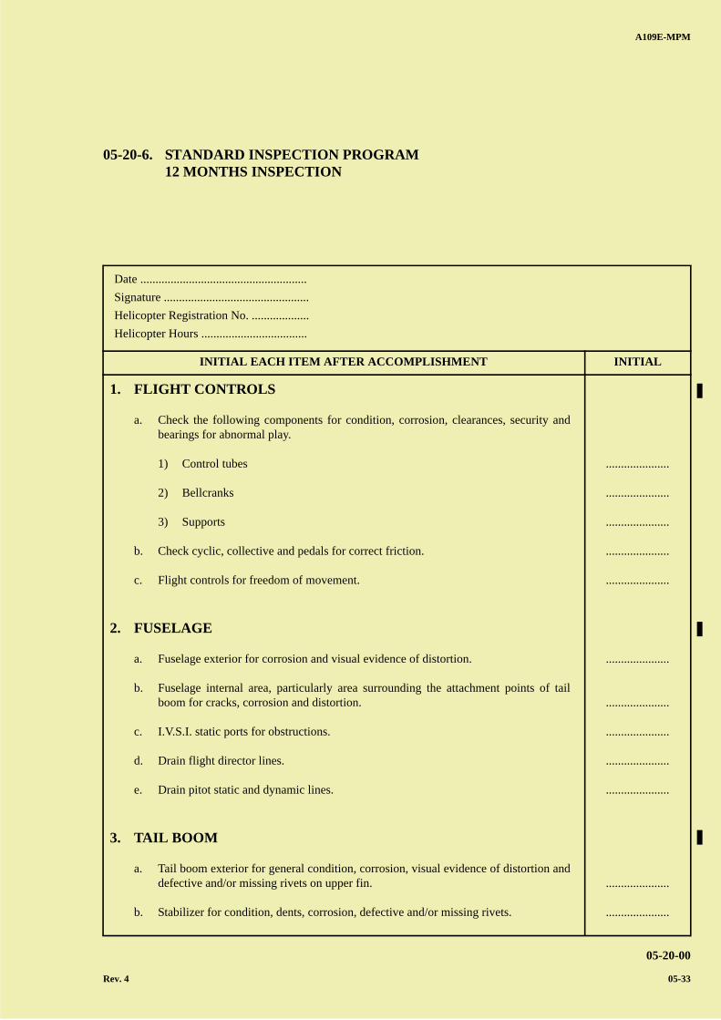
A B
C
D
A
B
C
DC
A109E-MPM
05-20-00
Rev. 4 05-33
Date .......................................................
Signature ................................................
Helicopter Registration No. ...................
Helicopter Hours ...................................
INITIAL EACH ITEM AFTER ACCOMPLISHMENT INITIAL
05-20-6. STANDARD INSPECTION PROGRAM12 MONTHS INSPECTION
1. FLIGHT CONTROLS
a. Check the following components for condition, corrosion, clearances, security andbearings for abnormal play.
1) Control tubes
2) Bellcranks
3) Supports
b. Check cyclic, collective and pedals for correct friction.
c. Flight controls for freedom of movement.
2. FUSELAGE
a. Fuselage exterior for corrosion and visual evidence of distortion.
b. Fuselage internal area, particularly area surrounding the attachment points of tailboom for cracks, corrosion and distortion.
c. I.V.S.I. static ports for obstructions.
d. Drain flight director lines.
e. Drain pitot static and dynamic lines.
3. TAIL BOOM
a. Tail boom exterior for general condition, corrosion, visual evidence of distortion anddefective and/or missing rivets on upper fin.
b. Stabilizer for condition, dents, corrosion, defective and/or missing rivets.
.....................
.....................
.....................
.....................
.....................
.....................
.....................
.....................
.....................
.....................
.....................
.....................
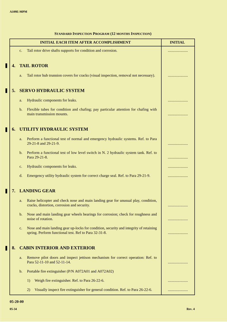
A B
C
D
A
B
C
DC
INITIAL EACH ITEM AFTER ACCOMPLISHMENT INITIAL
A109E-MPM
05-20-00
05-34 Rev. 4
c. Tail rotor drive shafts supports for condition and corrosion.
4. TAIL ROTOR
a. Tail rotor hub trunnion covers for cracks (visual inspection, removal not necessary).
5. SERVO HYDRAULIC SYSTEM
a. Hydraulic components for leaks.
b. Flexible tubes for condition and chafing; pay particular attention for chafing withmain transmission mounts.
6. UTILITY HYDRAULIC SYSTEM
a. Perform a functional test of normal and emergency hydraulic systems. Ref. to Para29-21-8 and 29-21-9.
b. Perform a functional test of low level switch in N. 2 hydraulic system tank. Ref. toPara 29-21-8.
c. Hydraulic components for leaks.
d. Emergency utility hydraulic system for correct charge seal. Ref. to Para 29-21-9.
7. LANDING GEAR
a. Raise helicopter and check nose and main landing gear for unusual play, condition,cracks, distortion, corrosion and security.
b. Nose and main landing gear wheels bearings for corrosion; check for roughness andnoise of rotation.
c. Nose and main landing gear up-locks for condition, security and integrity of retainingspring. Perform functional test. Ref to Para 32-31-8.
8. CABIN INTERIOR AND EXTERIOR
a. Remove pilot doors and inspect jettison mechanism for correct operation: Ref. toPara 52-11-10 and 52-11-14.
b. Portable fire extinguisher (P/N A072A01 and A072A02)
1) Weigh fire extinguisher. Ref. to Para 26-22-6.
2) Visually inspect fire extinguisher for general condition. Ref. to Para 26-22-6.
.....................
.....................
.....................
.....................
.....................
.....................
.....................
.....................
.....................
.....................
.....................
.....................
.....................
.....................
STANDARD INSPECTION PROGRAM (12 MONTHS INSPECTION)
A B
C
D
A
B
C
DC
INITIAL EACH ITEM AFTER ACCOMPLISHMENT INITIAL
A109E-MPM
05-20-00
Rev. 5 05-35
c. Examine crew safety restraint system. Ref. to Para 25-11-13.
d. Examine passengers safety restraint system. Ref. to Para 25-21-32.
9. COWLINGS
a. Engine-transmission cowlings for cracks and defective and/or missing rivets.
10. ELECTRICAL SYSTEM AND INSTRUMENTS
a. Inverters for security and connections.
b. Generator control boxes and terminals for damage and security.
c. Relays and busses for security and connections.
d. Busses insulation for condition.
e. Remove and recondition the battery. Ref. to Para 24-31-26.
f. Perform operational test of the battery temperature detector. Ref. to Para 24-31-17.
g. External power receptacle for condition and arcing.
h. Starter generators for condition and security. Electrical connections for arcing and/orshort-circuit evidence.
i. Connectors and cables on transmission deck, engines bays and landing gear bays forcondition and corrosion.
j. Overhead panel internal wirings, breakers and connectors for condition, chafing andarcing.
k. Perform operational test of d.c. electrical system. Ref. to Para 24-31-14.
l. Perform electrical test of a.c. electrical system. Ref. to Para 24-21-10.
m. Perform functional test of engine out system microswitch (if installed). Refer to para24-31-49.
.....................
.....................
.....................
.....................
.....................
.....................
.....................
.....................
.....................
.....................
.....................
.....................
.....................
.....................
.....................
.....................
STANDARD INSPECTION PROGRAM (12 MONTHS INSPECTION)

A B
C
D
A
B
C
DC
A109E-MPM
05-20-00
05-36 Rev. 4
PAGE INTENTIONALLY LEFT BLANK
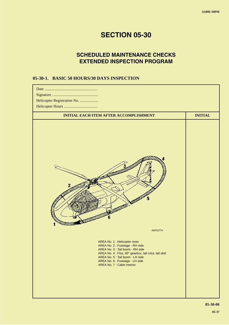
A B
C
D
A
B
C
DC
A109E-MPM
05-30-00
05-37
Date .......................................................
Signature ................................................
Helicopter Registration No. ...................
Helicopter Hours ...................................
INITIAL EACH ITEM AFTER ACCOMPLISHMENT INITIAL
SECTION 05-30
SCHEDULED MAINTENANCE CHECKSEXTENDED INSPECTION PROGRAM
05-30-1. BASIC 50 HOURS/30 DAYS INSPECTION
A6HC277A
AREA No. 1 : Helicopter noseAREA No. 2 : Fuselage - RH sideAREA No. 3 : Tail boom - RH sideAREA No. 4 : Fins, 90° gearbox, tail rotor, tail skidAREA No. 5 : Tail boom - LH sideAREA No. 6 : Fuselage - LH sideAREA No. 7 : Cabin interior
A B
C
D
A
B
C
DC
INITIAL EACH ITEM AFTER ACCOMPLISHMENT INITIAL
A109E-MPM
05-30-00
05-38 Rev. 4
AREA N° 1 (HELICOPTER NOSE)
1. Nose landing gear actuator for condition, leaks and corrosion.
2. Nose compartment avionic components and accessible wiring for condition, looseconnections and security.
3. Battery vent lines for condition and obstruction.
4. Drains and vents for condition and obstruction.
AREA N° 2 (FUSELAGE - RH SIDE)
1. Flight controls, levers and supports for condition and security.
2. A.F.C.S. actuators for unusual play, condition and security; electrical connections forcondition and security.
3. Servo hydraulic system valves and filters group and lines for condition, security and leaks.
4. Engine oil cooler, visible part, for foreign matter and leakage.
5. Main rotor hub elastomeric bearings for oil or grease contamination; if contaminated ref.to Para 62-21-55 for cleaning.
6. Main rotor hub and blades (2 places) for condition, damage and cleanliness.
7. Main rotor hub cover for condition and security.
8. Main rotor grips (2 places) for condition.
9. Grip fairing (2 places) for condition and security.
10. Main rotor damper fittings for condition, play and cracks in the area of the attachmentpoints to the hub.
11. Flap and drop restrainers for condition, freedom of movement and integrity of lockwire.Inspect floating ring and droop stop plates for condition and check that the grease ispresent in contact area.
12. Ground jumpers between pitch control lever (inside grip) and damper and betweendamper and attachment bracket to hub for condition (2 places).
13. Main rotor pitch change links (2 places) for condition, security, corrosion and fretting ofthe spherical bearings, loss of part of the liner and unusual play (check axial play bymoving the pitch link by hand and the radial play by rotating the blade along its pitch axisand by acting from the tip cap area).
14. Swashplate boot for condition, integrity and absence of grease.
.....................
.....................
.....................
.....................
.....................
.....................
.....................
.....................
.....................
.....................
.....................
.....................
.....................
.....................
.....................
.....................
.....................
.....................
EXTENDED INSPECTION PROGRAM (50 HOURS/30 DAYS INSPECTION)
A B
C
D
A
B
C
DC
INITIAL EACH ITEM AFTER ACCOMPLISHMENT INITIAL
A109E-MPM
05-30-00
Rev. 4 05-39
15. Main rotor servo actuator (1 place) for condition, security and leaks. Inspect bleed hole forleaks and lower spherical bearing for looseness.
16. Main transmission and accessories for condition, security and leaks of lubricant.
17. Hydraulic pump for leaks.
18. Cooler fan drive belt, visible part, for condition, security and crazing.
19. Engine bay drain filters for obstruction
20. Engine mount for condition and security.
21. Engine-transmission drive shaft for condition and damage.
22. Fuel tank sump cover for condition. Drain sump.
23. Fuel system drain lines and valves for leaks.
24. Engine exhaust duct for breakage and security.
25. Main landing gear bays and extension actuator for condition, security, leaks, cleanlinessand corrosion (actuator only).
AREA N° 3 (TAIL BOOM - RH SIDE)
1. Tail boom exterior (pay particular attention to tail boom and fuselage attachment areas) forcracks, dents, missing and/or loose rivets and screws.
.....................
.....................
.....................
.....................
.....................
.....................
.....................
.....................
.....................
.....................
.....................
.....................
EXTENDED INSPECTION PROGRAM (50 HOURS/30 DAYS INSPECTION)
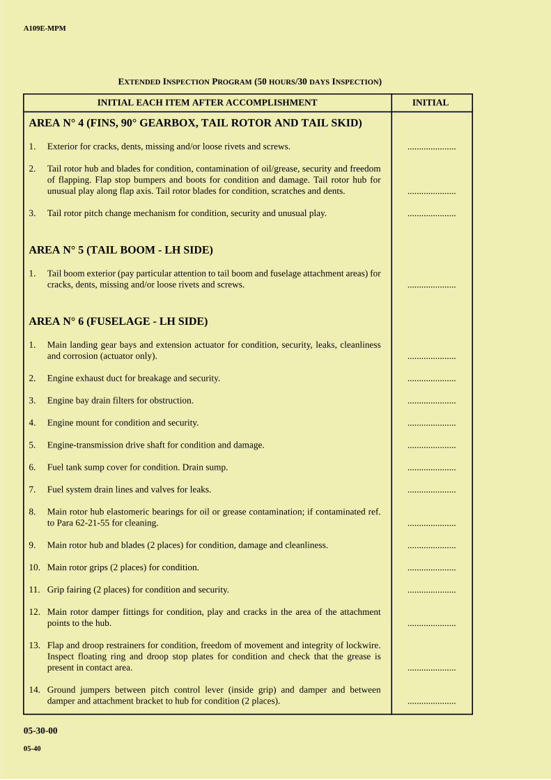
A B
C
D
A
B
C
DC
INITIAL EACH ITEM AFTER ACCOMPLISHMENT INITIAL
A109E-MPM
05-30-00
05-40
AREA N° 4 (FINS, 90° GEARBOX, TAIL ROTOR AND TAIL SKID)
1. Exterior for cracks, dents, missing and/or loose rivets and screws.
2. Tail rotor hub and blades for condition, contamination of oil/grease, security and freedomof flapping. Flap stop bumpers and boots for condition and damage. Tail rotor hub forunusual play along flap axis. Tail rotor blades for condition, scratches and dents.
3. Tail rotor pitch change mechanism for condition, security and unusual play.
AREA N° 5 (TAIL BOOM - LH SIDE)
1. Tail boom exterior (pay particular attention to tail boom and fuselage attachment areas) forcracks, dents, missing and/or loose rivets and screws.
AREA N° 6 (FUSELAGE - LH SIDE)
1. Main landing gear bays and extension actuator for condition, security, leaks, cleanlinessand corrosion (actuator only).
2. Engine exhaust duct for breakage and security.
3. Engine bay drain filters for obstruction.
4. Engine mount for condition and security.
5. Engine-transmission drive shaft for condition and damage.
6. Fuel tank sump cover for condition. Drain sump.
7. Fuel system drain lines and valves for leaks.
8. Main rotor hub elastomeric bearings for oil or grease contamination; if contaminated ref.to Para 62-21-55 for cleaning.
9. Main rotor hub and blades (2 places) for condition, damage and cleanliness.
10. Main rotor grips (2 places) for condition.
11. Grip fairing (2 places) for condition and security.
12. Main rotor damper fittings for condition, play and cracks in the area of the attachmentpoints to the hub.
13. Flap and droop restrainers for condition, freedom of movement and integrity of lockwire.Inspect floating ring and droop stop plates for condition and check that the grease ispresent in contact area.
14. Ground jumpers between pitch control lever (inside grip) and damper and betweendamper and attachment bracket to hub for condition (2 places).
.....................
.....................
.....................
.....................
.....................
.....................
.....................
.....................
.....................
.....................
.....................
.....................
.....................
.....................
.....................
.....................
.....................
.....................
EXTENDED INSPECTION PROGRAM (50 HOURS/30 DAYS INSPECTION)
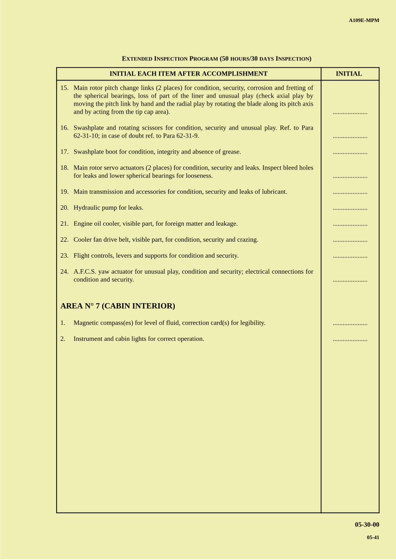
A B
C
D
A
B
C
DC
INITIAL EACH ITEM AFTER ACCOMPLISHMENT INITIAL
A109E-MPM
05-30-00
05-41
15. Main rotor pitch change links (2 places) for condition, security, corrosion and fretting ofthe spherical bearings, loss of part of the liner and unusual play (check axial play bymoving the pitch link by hand and the radial play by rotating the blade along its pitch axisand by acting from the tip cap area).
16. Swashplate and rotating scissors for condition, security and unusual play. Ref. to Para62-31-10; in case of doubt ref. to Para 62-31-9.
17. Swashplate boot for condition, integrity and absence of grease.
18. Main rotor servo actuators (2 places) for condition, security and leaks. Inspect bleed holesfor leaks and lower spherical bearings for looseness.
19. Main transmission and accessories for condition, security and leaks of lubricant.
20. Hydraulic pump for leaks.
21. Engine oil cooler, visible part, for foreign matter and leakage.
22. Cooler fan drive belt, visible part, for condition, security and crazing.
23. Flight controls, levers and supports for condition and security.
24. A.F.C.S. yaw actuator for unusual play, condition and security; electrical connections forcondition and security.
AREA N° 7 (CABIN INTERIOR)
1. Magnetic compass(es) for level of fluid, correction card(s) for legibility.
2. Instrument and cabin lights for correct operation.
.....................
.....................
.....................
.....................
.....................
.....................
.....................
.....................
.....................
.....................
.....................
.....................
EXTENDED INSPECTION PROGRAM (50 HOURS/30 DAYS INSPECTION)

A B
C
D
A
B
C
DC
A109E-MPM
05-30-00
05-42
PAGE INTENTIONALLY LEFT BLANK
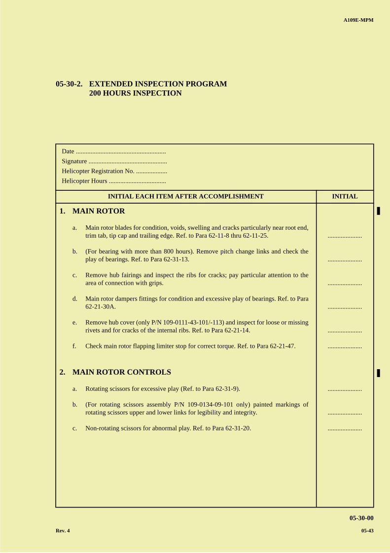
A B
C
D
A
B
C
DC
A109E-MPM
05-30-00
Rev. 4 05-43
Date .......................................................
Signature ................................................
Helicopter Registration No. ...................
Helicopter Hours ...................................
INITIAL EACH ITEM AFTER ACCOMPLISHMENT INITIAL
05-30-2. EXTENDED INSPECTION PROGRAM200 HOURS INSPECTION
1. MAIN ROTOR
a. Main rotor blades for condition, voids, swelling and cracks particularly near root end,trim tab, tip cap and trailing edge. Ref. to Para 62-11-8 thru 62-11-25.
b. (For bearing with more than 800 hours). Remove pitch change links and check theplay of bearings. Ref. to Para 62-31-13.
c. Remove hub fairings and inspect the ribs for cracks; pay particular attention to thearea of connection with grips.
d. Main rotor dampers fittings for condition and excessive play of bearings. Ref. to Para62-21-30A.
e. Remove hub cover (only P/N 109-0111-43-101/-113) and inspect for loose or missingrivets and for cracks of the internal ribs. Ref. to Para 62-21-14.
f. Check main rotor flapping limiter stop for correct torque. Ref. to Para 62-21-47.
2. MAIN ROTOR CONTROLS
a. Rotating scissors for excessive play (Ref. to Para 62-31-9).
b. (For rotating scissors assembly P/N 109-0134-09-101 only) painted markings ofrotating scissors upper and lower links for legibility and integrity.
c. Non-rotating scissors for abnormal play. Ref. to Para 62-31-20.
.....................
.....................
.....................
.....................
.....................
.....................
.....................
.....................
.....................
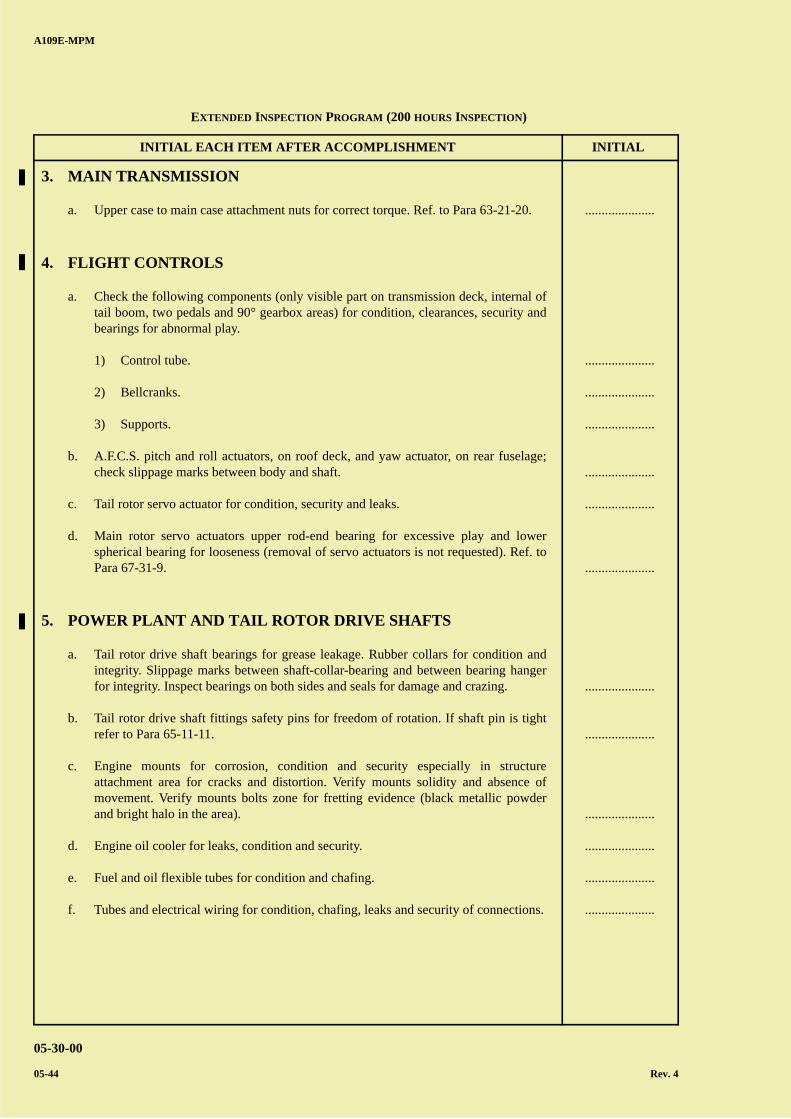
A B
C
D
A
B
C
DC
INITIAL EACH ITEM AFTER ACCOMPLISHMENT INITIAL
A109E-MPM
05-30-00
05-44 Rev. 4
3. MAIN TRANSMISSION
a. Upper case to main case attachment nuts for correct torque. Ref. to Para 63-21-20.
4. FLIGHT CONTROLS
a. Check the following components (only visible part on transmission deck, internal oftail boom, two pedals and 90° gearbox areas) for condition, clearances, security andbearings for abnormal play.
1) Control tube.
2) Bellcranks.
3) Supports.
b. A.F.C.S. pitch and roll actuators, on roof deck, and yaw actuator, on rear fuselage;check slippage marks between body and shaft.
c. Tail rotor servo actuator for condition, security and leaks.
d. Main rotor servo actuators upper rod-end bearing for excessive play and lowerspherical bearing for looseness (removal of servo actuators is not requested). Ref. toPara 67-31-9.
5. POWER PLANT AND TAIL ROTOR DRIVE SHAFTS
a. Tail rotor drive shaft bearings for grease leakage. Rubber collars for condition andintegrity. Slippage marks between shaft-collar-bearing and between bearing hangerfor integrity. Inspect bearings on both sides and seals for damage and crazing.
b. Tail rotor drive shaft fittings safety pins for freedom of rotation. If shaft pin is tightrefer to Para 65-11-11.
c. Engine mounts for corrosion, condition and security especially in structureattachment area for cracks and distortion. Verify mounts solidity and absence ofmovement. Verify mounts bolts zone for fretting evidence (black metallic powderand bright halo in the area).
d. Engine oil cooler for leaks, condition and security.
e. Fuel and oil flexible tubes for condition and chafing.
f. Tubes and electrical wiring for condition, chafing, leaks and security of connections.
.....................
.....................
.....................
.....................
.....................
.....................
.....................
.....................
.....................
.....................
.....................
.....................
.....................
EXTENDED INSPECTION PROGRAM (200 HOURS INSPECTION)
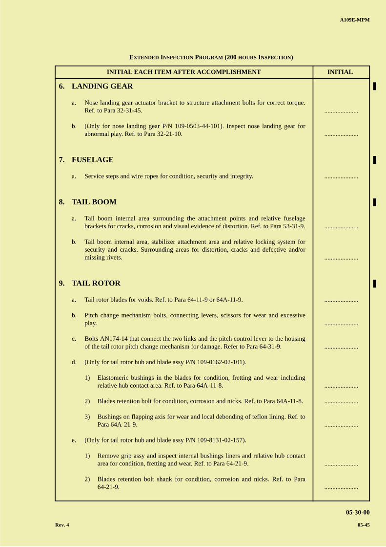
A B
C
D
A
B
C
DC
INITIAL EACH ITEM AFTER ACCOMPLISHMENT INITIAL
A109E-MPM
05-30-00
Rev. 4 05-45
6. LANDING GEAR
a. Nose landing gear actuator bracket to structure attachment bolts for correct torque.Ref. to Para 32-31-45.
b. (Only for nose landing gear P/N 109-0503-44-101). Inspect nose landing gear forabnormal play. Ref. to Para 32-21-10.
7. FUSELAGE
a. Service steps and wire ropes for condition, security and integrity.
8. TAIL BOOM
a. Tail boom internal area surrounding the attachment points and relative fuselagebrackets for cracks, corrosion and visual evidence of distortion. Ref. to Para 53-31-9.
b. Tail boom internal area, stabilizer attachment area and relative locking system forsecurity and cracks. Surrounding areas for distortion, cracks and defective and/ormissing rivets.
9. TAIL ROTOR
a. Tail rotor blades for voids. Ref. to Para 64-11-9 or 64A-11-9.
b. Pitch change mechanism bolts, connecting levers, scissors for wear and excessiveplay.
c. Bolts AN174-14 that connect the two links and the pitch control lever to the housingof the tail rotor pitch change mechanism for damage. Refer to Para 64-31-9.
d. (Only for tail rotor hub and blade assy P/N 109-0162-02-101).
1) Elastomeric bushings in the blades for condition, fretting and wear includingrelative hub contact area. Ref. to Para 64A-11-8.
2) Blades retention bolt for condition, corrosion and nicks. Ref. to Para 64A-11-8.
3) Bushings on flapping axis for wear and local debonding of teflon lining. Ref. toPara 64A-21-9.
e. (Only for tail rotor hub and blade assy P/N 109-8131-02-157).
1) Remove grip assy and inspect internal bushings liners and relative hub contactarea for condition, fretting and wear. Ref. to Para 64-21-9.
2) Blades retention bolt shank for condition, corrosion and nicks. Ref. to Para64-21-9.
.....................
.....................
.....................
.....................
.....................
.....................
.....................
.....................
.....................
.....................
.....................
.....................
.....................
EXTENDED INSPECTION PROGRAM (200 HOURS INSPECTION)
A B
C
D
A
B
C
DC
INITIAL EACH ITEM AFTER ACCOMPLISHMENT INITIAL
A109E-MPM
05-30-00
05-46
3) Bushings on flapping axis for wear and local debonding of teflon lining. Ref. toPara 64-21-9.
f. Tail rotor hub trunnion covers for cracks (visual inspection, removal not necessary).
.....................
.....................
EXTENDED INSPECTION PROGRAM (200 HOURS INSPECTION)
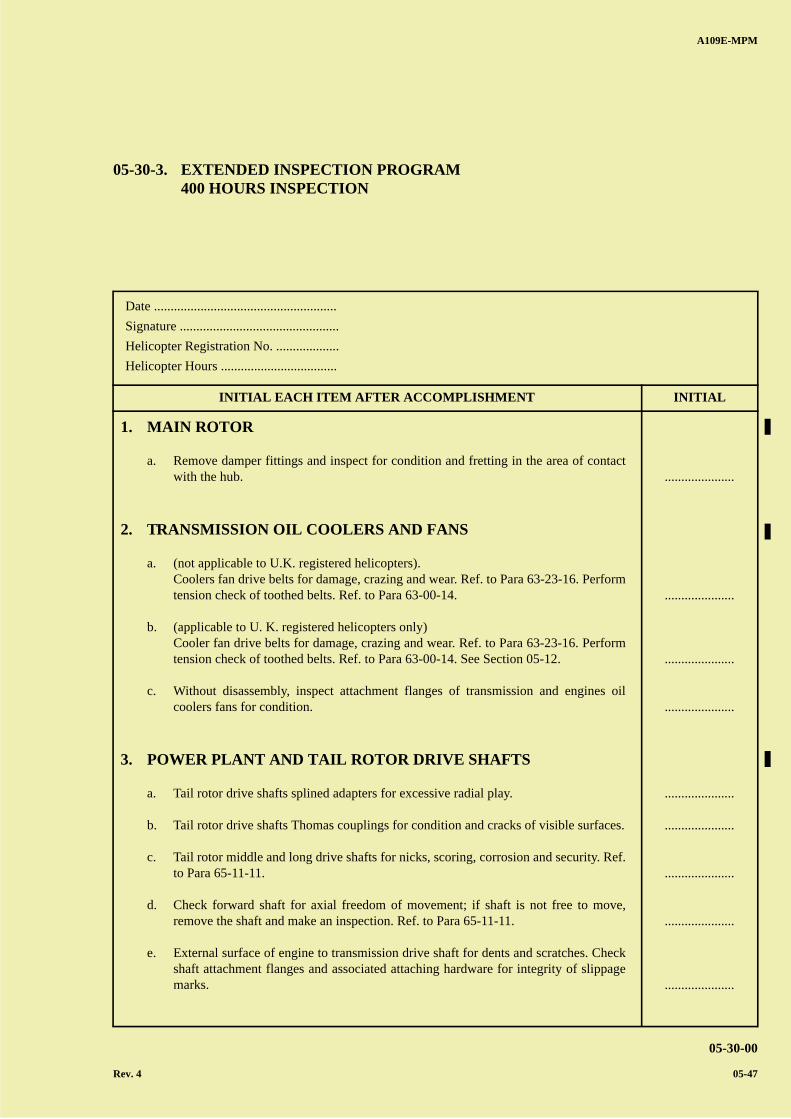
A B
C
D
A
B
C
DC
A109E-MPM
05-30-00
Rev. 4 05-47
Date .......................................................
Signature ................................................
Helicopter Registration No. ...................
Helicopter Hours ...................................
INITIAL EACH ITEM AFTER ACCOMPLISHMENT INITIAL
05-30-3. EXTENDED INSPECTION PROGRAM400 HOURS INSPECTION
1. MAIN ROTOR
a. Remove damper fittings and inspect for condition and fretting in the area of contactwith the hub.
2. TRANSMISSION OIL COOLERS AND FANS
a. (not applicable to U.K. registered helicopters).Coolers fan drive belts for damage, crazing and wear. Ref. to Para 63-23-16. Performtension check of toothed belts. Ref. to Para 63-00-14.
b. (applicable to U. K. registered helicopters only)Cooler fan drive belts for damage, crazing and wear. Ref. to Para 63-23-16. Performtension check of toothed belts. Ref. to Para 63-00-14. See Section 05-12.
c. Without disassembly, inspect attachment flanges of transmission and engines oilcoolers fans for condition.
3. POWER PLANT AND TAIL ROTOR DRIVE SHAFTS
a. Tail rotor drive shafts splined adapters for excessive radial play.
b. Tail rotor drive shafts Thomas couplings for condition and cracks of visible surfaces.
c. Tail rotor middle and long drive shafts for nicks, scoring, corrosion and security. Ref.to Para 65-11-11.
d. Check forward shaft for axial freedom of movement; if shaft is not free to move,remove the shaft and make an inspection. Ref. to Para 65-11-11.
e. External surface of engine to transmission drive shaft for dents and scratches. Checkshaft attachment flanges and associated attaching hardware for integrity of slippagemarks.
.....................
.....................
.....................
.....................
.....................
.....................
.....................
.....................
.....................
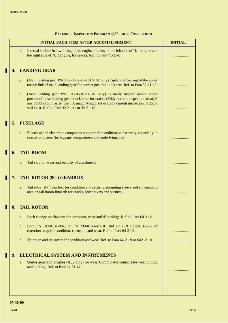
A B
C
D
A
B
C
DC
INITIAL EACH ITEM AFTER ACCOMPLISHMENT INITIAL
A109E-MPM
05-30-00
05-48 Rev. 4
f. Internal surface below fitting of the engine mounts on the left side of N. 1 engine andthe right side of N. 2 engine, for cracks. Ref. to Para 71-21-8.
4. LANDING GEAR
a. (Main landing gear P/N 109-0502-90-101/-102 only). Spherical bearing of the uppertorque link of main landing gear for correct position in its seat. Ref. to Para 32-11-12.
b. (Nose landing gear P/N 109-0501-28-107 only). Visually inspect mount upperportion of nose landing gear shock strut for cracks (Eddy current inspection area); ifany doubt should arise, use 5 X magnifying glass or Eddy current inspection, if doubtstill exist. Ref. to Para 32-21-11 or 32-21-12.
5. FUSELAGE
a. Electrical and electronic component supports for condition and security, especially inrear avionic area (in baggage compartment and underlying area).
6. TAIL BOOM
a. Tail skid for wear and security of attachment.
7. TAIL ROTOR (90°) GEARBOX
a. Tail rotor (90°) gearbox for condition and security, mounting sleeve and surroundingarea on tail boom final rib for cracks, loose rivets and security.
8. TAIL ROTOR
a. Pitch change mechanism for corrosion, wear and debonding. Ref. to Para 64-31-8.
b. Bolt P/N 109-8131-09-1 or P/N 709-0160-47-101 and pin P/N 109-8131-08-1 ofretention strap for condition, corrosion and wear. Ref. to Para 64-21-9.
c. Trunnion and its covers for condition and wear. Ref. to Para 64-21-9 or 64A-21-9.
9. ELECTRICAL SYSTEM AND INSTRUMENTS
a. Starter generator brushes (XL2 only) for wear. Commutator contacts for wear, pittingand burning. Ref. to Para 24-31-42.
.....................
.....................
.....................
.....................
.....................
.....................
.....................
.....................
.....................
.....................
EXTENDED INSPECTION PROGRAM (400 HOURS INSPECTION)
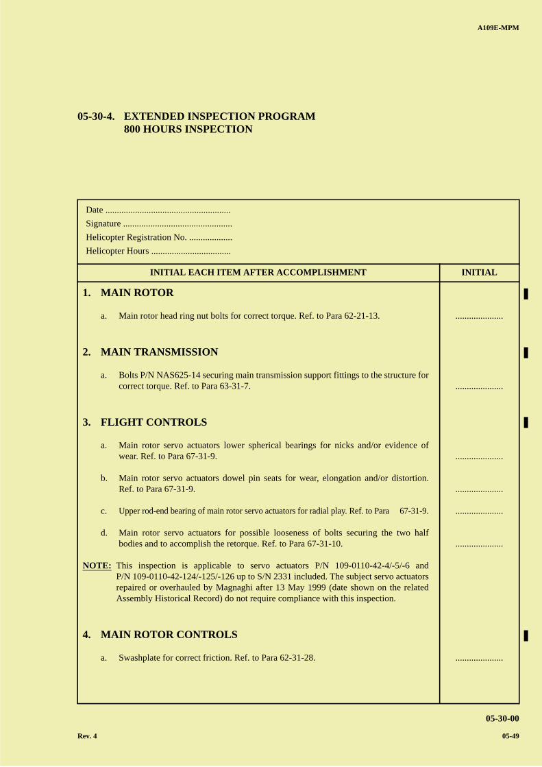
A B
C
D
A
B
C
DC
A109E-MPM
05-30-00
Rev. 4 05-49
Date .......................................................
Signature ................................................
Helicopter Registration No. ...................
Helicopter Hours ...................................
INITIAL EACH ITEM AFTER ACCOMPLISHMENT INITIAL
05-30-4. EXTENDED INSPECTION PROGRAM800 HOURS INSPECTION
1. MAIN ROTOR
a. Main rotor head ring nut bolts for correct torque. Ref. to Para 62-21-13.
2. MAIN TRANSMISSION
a. Bolts P/N NAS625-14 securing main transmission support fittings to the structure forcorrect torque. Ref. to Para 63-31-7.
3. FLIGHT CONTROLS
a. Main rotor servo actuators lower spherical bearings for nicks and/or evidence ofwear. Ref. to Para 67-31-9.
b. Main rotor servo actuators dowel pin seats for wear, elongation and/or distortion.Ref. to Para 67-31-9.
c. Upper rod-end bearing of main rotor servo actuators for radial play. Ref. to Para 67-31-9.
d. Main rotor servo actuators for possible looseness of bolts securing the two halfbodies and to accomplish the retorque. Ref. to Para 67-31-10.
NOTE: This inspection is applicable to servo actuators P/N 109-0110-42-4/-5/-6 andP/N 109-0110-42-124/-125/-126 up to S/N 2331 included. The subject servo actuatorsrepaired or overhauled by Magnaghi after 13 May 1999 (date shown on the relatedAssembly Historical Record) do not require compliance with this inspection.
4. MAIN ROTOR CONTROLS
a. Swashplate for correct friction. Ref. to Para 62-31-28.
.....................
.....................
.....................
.....................
.....................
.....................
.....................
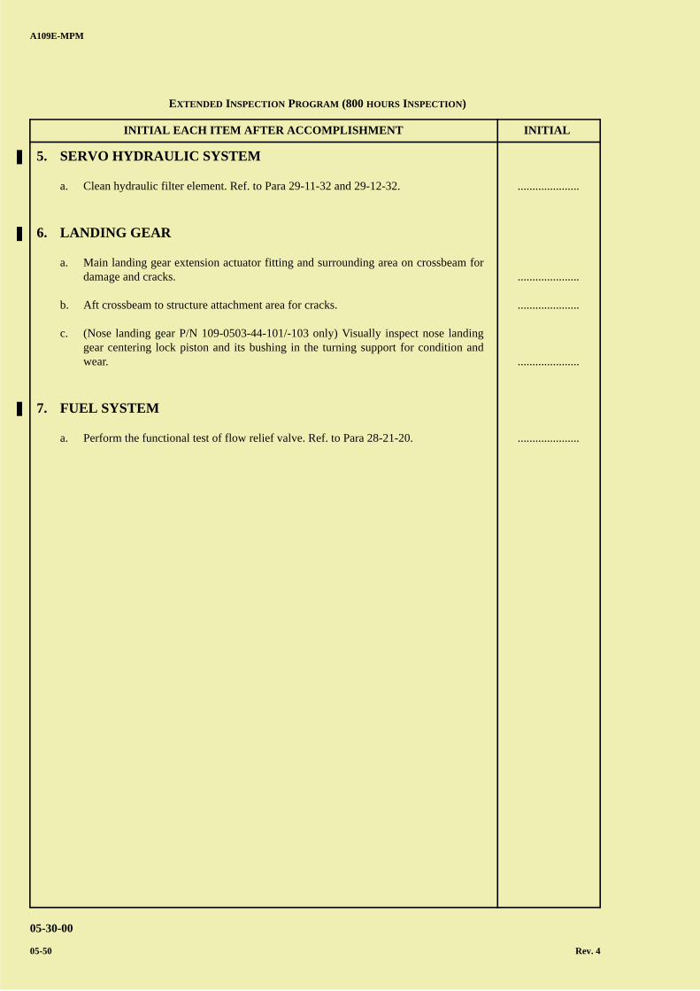
A B
C
D
A
B
C
DC
INITIAL EACH ITEM AFTER ACCOMPLISHMENT INITIAL
A109E-MPM
05-30-00
05-50 Rev. 4
5. SERVO HYDRAULIC SYSTEM
a. Clean hydraulic filter element. Ref. to Para 29-11-32 and 29-12-32.
6. LANDING GEAR
a. Main landing gear extension actuator fitting and surrounding area on crossbeam fordamage and cracks.
b. Aft crossbeam to structure attachment area for cracks.
c. (Nose landing gear P/N 109-0503-44-101/-103 only) Visually inspect nose landinggear centering lock piston and its bushing in the turning support for condition andwear.
7. FUEL SYSTEM
a. Perform the functional test of flow relief valve. Ref. to Para 28-21-20.
.....................
.....................
.....................
.....................
.....................
EXTENDED INSPECTION PROGRAM (800 HOURS INSPECTION)
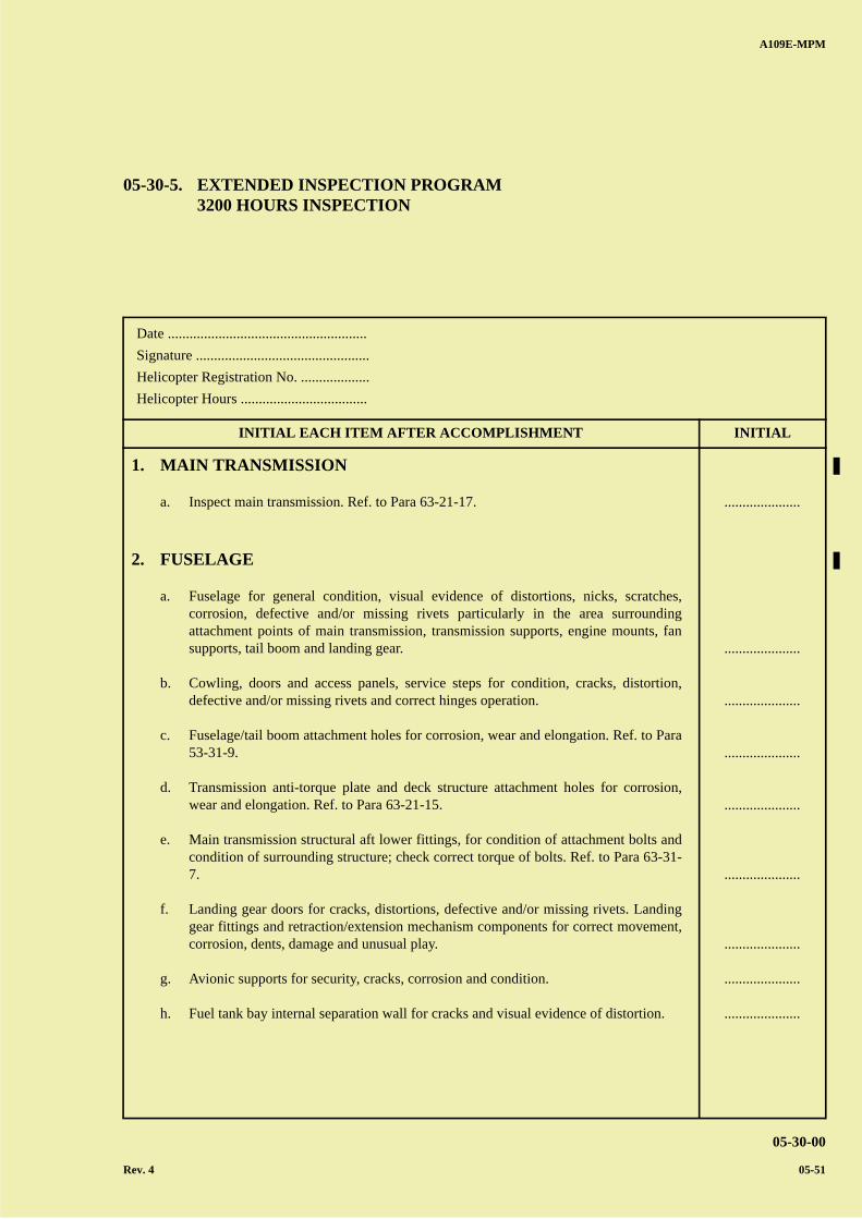
A B
C
D
A
B
C
DC
A109E-MPM
05-30-00
Rev. 4 05-51
Date .......................................................
Signature ................................................
Helicopter Registration No. ...................
Helicopter Hours ...................................
INITIAL EACH ITEM AFTER ACCOMPLISHMENT INITIAL
05-30-5. EXTENDED INSPECTION PROGRAM3200 HOURS INSPECTION
1. MAIN TRANSMISSION
a. Inspect main transmission. Ref. to Para 63-21-17.
2. FUSELAGE
a. Fuselage for general condition, visual evidence of distortions, nicks, scratches,corrosion, defective and/or missing rivets particularly in the area surroundingattachment points of main transmission, transmission supports, engine mounts, fansupports, tail boom and landing gear.
b. Cowling, doors and access panels, service steps for condition, cracks, distortion,defective and/or missing rivets and correct hinges operation.
c. Fuselage/tail boom attachment holes for corrosion, wear and elongation. Ref. to Para53-31-9.
d. Transmission anti-torque plate and deck structure attachment holes for corrosion,wear and elongation. Ref. to Para 63-21-15.
e. Main transmission structural aft lower fittings, for condition of attachment bolts andcondition of surrounding structure; check correct torque of bolts. Ref. to Para 63-31-7.
f. Landing gear doors for cracks, distortions, defective and/or missing rivets. Landinggear fittings and retraction/extension mechanism components for correct movement,corrosion, dents, damage and unusual play.
g. Avionic supports for security, cracks, corrosion and condition.
h. Fuel tank bay internal separation wall for cracks and visual evidence of distortion.
.....................
.....................
.....................
.....................
.....................
.....................
.....................
.....................
.....................
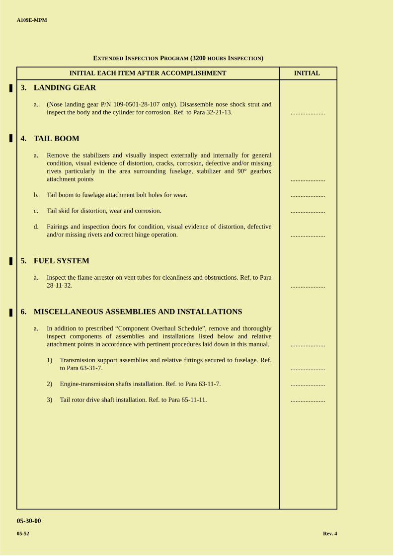
A B
C
D
A
B
C
DC
INITIAL EACH ITEM AFTER ACCOMPLISHMENT INITIAL
A109E-MPM
05-30-00
05-52 Rev. 4
3. LANDING GEAR
a. (Nose landing gear P/N 109-0501-28-107 only). Disassemble nose shock strut andinspect the body and the cylinder for corrosion. Ref. to Para 32-21-13.
4. TAIL BOOM
a. Remove the stabilizers and visually inspect externally and internally for generalcondition, visual evidence of distortion, cracks, corrosion, defective and/or missingrivets particularly in the area surrounding fuselage, stabilizer and 90° gearboxattachment points
b. Tail boom to fuselage attachment bolt holes for wear.
c. Tail skid for distortion, wear and corrosion.
d. Fairings and inspection doors for condition, visual evidence of distortion, defectiveand/or missing rivets and correct hinge operation.
5. FUEL SYSTEM
a. Inspect the flame arrester on vent tubes for cleanliness and obstructions. Ref. to Para28-11-32.
6. MISCELLANEOUS ASSEMBLIES AND INSTALLATIONS
a. In addition to prescribed “Component Overhaul Schedule”, remove and thoroughlyinspect components of assemblies and installations listed below and relativeattachment points in accordance with pertinent procedures laid down in this manual.
1) Transmission support assemblies and relative fittings secured to fuselage. Ref.to Para 63-31-7.
2) Engine-transmission shafts installation. Ref. to Para 63-11-7.
3) Tail rotor drive shaft installation. Ref. to Para 65-11-11.
.....................
.....................
.....................
.....................
.....................
.....................
.....................
.....................
.....................
.....................
EXTENDED INSPECTION PROGRAM (3200 HOURS INSPECTION)

A B
C
D
A
B
C
DC
A109E-MPM
05-30-00
Rev. 4 05-53
Date .......................................................
Signature ................................................
Helicopter Registration No. ...................
Helicopter Hours ...................................
INITIAL EACH ITEM AFTER ACCOMPLISHMENT INITIAL
05-30-6. EXTENDED INSPECTION PROGRAM12 MONTHS INSPECTION
1. FLIGHT CONTROLS
a. Check the following components for condition, corrosion, clearances, security andbearings for abnormal play.
1) Control tubes
2) Bellcranks
3) Supports
b. Check cyclic, collective and pedals for correct friction.
c. Flight controls for freedom of movement.
2. FUSELAGE
a. Fuselage exterior for corrosion and visual evidence of distortion.
b. Fuselage internal area, particularly area surrounding the attachment points of tailboom for cracks, corrosion and distortion.
c. I.V.S.I. static ports for obstructions.
d. Drain flight director lines.
e. Drain pitot static and dynamic lines.
.....................
.....................
.....................
.....................
.....................
.....................
.....................
.....................
.....................
.....................
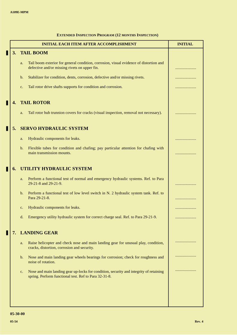
A B
C
D
A
B
C
DC
INITIAL EACH ITEM AFTER ACCOMPLISHMENT INITIAL
A109E-MPM
05-30-00
05-54 Rev. 4
3. TAIL BOOM
a. Tail boom exterior for general condition, corrosion, visual evidence of distortion anddefective and/or missing rivets on upper fin.
b. Stabilizer for condition, dents, corrosion, defective and/or missing rivets.
c. Tail rotor drive shafts supports for condition and corrosion.
4. TAIL ROTOR
a. Tail rotor hub trunnion covers for cracks (visual inspection, removal not necessary).
5. SERVO HYDRAULIC SYSTEM
a. Hydraulic components for leaks.
b. Flexible tubes for condition and chafing; pay particular attention for chafing withmain transmission mounts.
6. UTILITY HYDRAULIC SYSTEM
a. Perform a functional test of normal and emergency hydraulic systems. Ref. to Para29-21-8 and 29-21-9.
b. Perform a functional test of low level switch in N. 2 hydraulic system tank. Ref. toPara 29-21-8.
c. Hydraulic components for leaks.
d. Emergency utility hydraulic system for correct charge seal. Ref. to Para 29-21-9.
7. LANDING GEAR
a. Raise helicopter and check nose and main landing gear for unusual play, condition,cracks, distortion, corrosion and security.
b. Nose and main landing gear wheels bearings for corrosion; check for roughness andnoise of rotation.
c. Nose and main landing gear up-locks for condition, security and integrity of retainingspring. Perform functional test. Ref to Para 32-31-8.
.....................
.....................
.....................
.....................
.....................
.....................
.....................
.....................
.....................
.....................
.....................
.....................
.....................
EXTENDED INSPECTION PROGRAM (12 MONTHS INSPECTION)
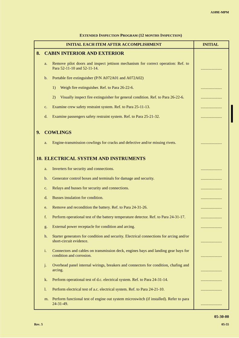
A B
C
D
A
B
C
DC
INITIAL EACH ITEM AFTER ACCOMPLISHMENT INITIAL
A109E-MPM
05-30-00
Rev. 5 05-55
8. CABIN INTERIOR AND EXTERIOR
a. Remove pilot doors and inspect jettison mechanism for correct operation: Ref. toPara 52-11-10 and 52-11-14.
b. Portable fire extinguisher (P/N A072A01 and A072A02)
1) Weigh fire extinguisher. Ref. to Para 26-22-6.
2) Visually inspect fire extinguisher for general condition. Ref. to Para 26-22-6.
c. Examine crew safety restraint system. Ref. to Para 25-11-13.
d. Examine passengers safety restraint system. Ref. to Para 25-21-32.
9. COWLINGS
a. Engine-transmission cowlings for cracks and defective and/or missing rivets.
10. ELECTRICAL SYSTEM AND INSTRUMENTS
a. Inverters for security and connections.
b. Generator control boxes and terminals for damage and security.
c. Relays and busses for security and connections.
d. Busses insulation for condition.
e. Remove and recondition the battery. Ref. to Para 24-31-26.
f. Perform operational test of the battery temperature detector. Ref. to Para 24-31-17.
g. External power receptacle for condition and arcing.
h. Starter generators for condition and security. Electrical connections for arcing and/orshort-circuit evidence.
i. Connectors and cables on transmission deck, engines bays and landing gear bays forcondition and corrosion.
j. Overhead panel internal wirings, breakers and connectors for condition, chafing andarcing.
k. Perform operational test of d.c. electrical system. Ref. to Para 24-31-14.
l. Perform electrical test of a.c. electrical system. Ref. to Para 24-21-10.
m. Perform functional test of engine out system microswitch (if installed). Refer to para24-31-49.
.....................
.....................
.....................
.....................
.....................
.....................
.....................
.....................
.....................
.....................
.....................
.....................
.....................
.....................
.....................
.....................
.....................
.....................
.....................
EXTENDED INSPECTION PROGRAM (12 MONTHS INSPECTION)

A B
C
D
A
B
C
DC
A109E-MPM
05-30-00
05-56 Rev. 4
PAGE INTENTIONALLY LEFT BLANK

A B
C
D
A
B
C
DC
A109E-MPM
05-40-00
05-57
Date .......................................................
Signature ................................................
Helicopter Registration No. ...................
Helicopter Hours ...................................
INITIAL EACH ITEM AFTER ACCOMPLISHMENT INITIAL
SECTION 05-40
SCHEDULED MAINTENANCE CHECKSPROGRESSIVE INSPECTION PROGRAM
05-40-1. BASIC 50 HOURS/30 DAYS INSPECTION
A6HC277A
AREA No. 1 : Helicopter noseAREA No. 2 : Fuselage - RH sideAREA No. 3 : Tail boom - RH sideAREA No. 4 : Fins, 90° gearbox, tail rotor, tail skidAREA No. 5 : Tail boom - LH sideAREA No. 6 : Fuselage - LH sideAREA No. 7 : Cabin interior
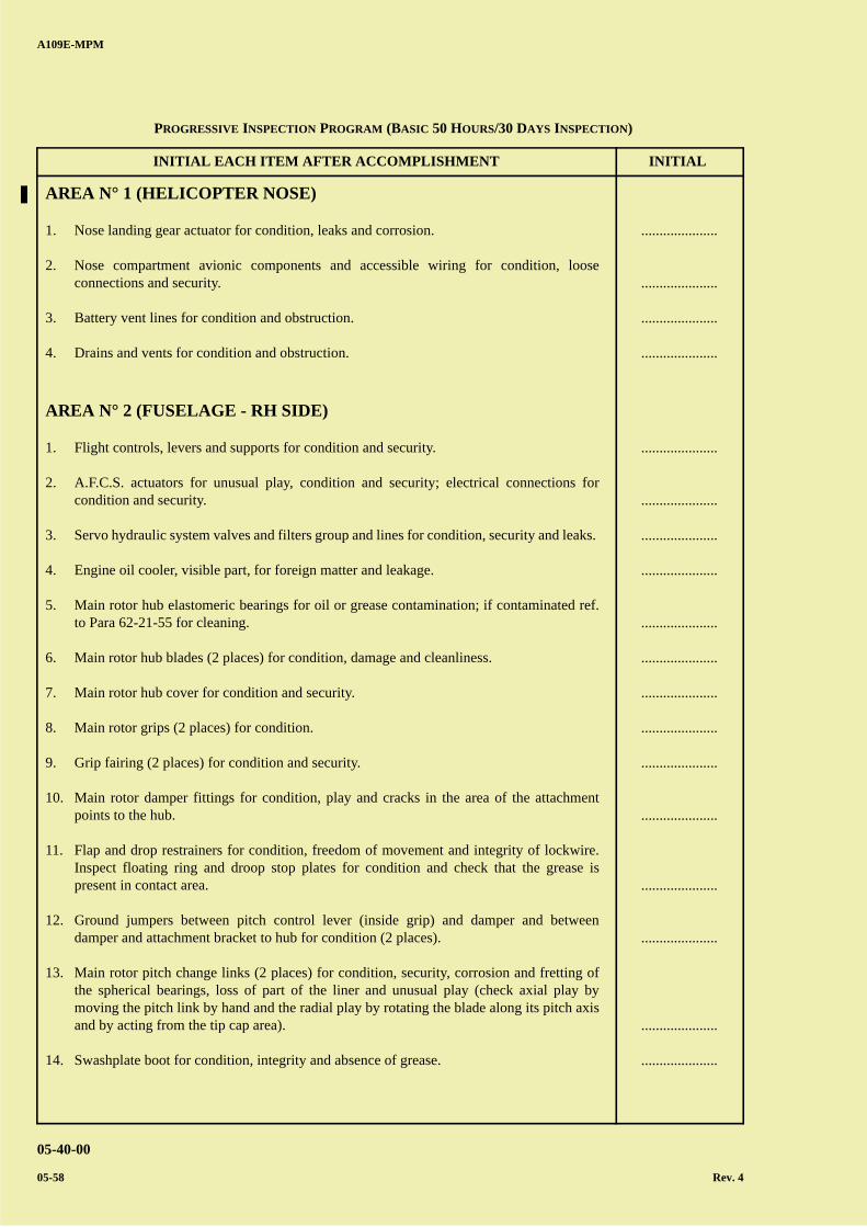
A B
C
D
A
B
C
DC
INITIAL EACH ITEM AFTER ACCOMPLISHMENT INITIAL
A109E-MPM
05-40-00
05-58 Rev. 4
AREA N° 1 (HELICOPTER NOSE)
1. Nose landing gear actuator for condition, leaks and corrosion.
2. Nose compartment avionic components and accessible wiring for condition, looseconnections and security.
3. Battery vent lines for condition and obstruction.
4. Drains and vents for condition and obstruction.
AREA N° 2 (FUSELAGE - RH SIDE)
1. Flight controls, levers and supports for condition and security.
2. A.F.C.S. actuators for unusual play, condition and security; electrical connections forcondition and security.
3. Servo hydraulic system valves and filters group and lines for condition, security and leaks.
4. Engine oil cooler, visible part, for foreign matter and leakage.
5. Main rotor hub elastomeric bearings for oil or grease contamination; if contaminated ref.to Para 62-21-55 for cleaning.
6. Main rotor hub blades (2 places) for condition, damage and cleanliness.
7. Main rotor hub cover for condition and security.
8. Main rotor grips (2 places) for condition.
9. Grip fairing (2 places) for condition and security.
10. Main rotor damper fittings for condition, play and cracks in the area of the attachmentpoints to the hub.
11. Flap and drop restrainers for condition, freedom of movement and integrity of lockwire.Inspect floating ring and droop stop plates for condition and check that the grease ispresent in contact area.
12. Ground jumpers between pitch control lever (inside grip) and damper and betweendamper and attachment bracket to hub for condition (2 places).
13. Main rotor pitch change links (2 places) for condition, security, corrosion and fretting ofthe spherical bearings, loss of part of the liner and unusual play (check axial play bymoving the pitch link by hand and the radial play by rotating the blade along its pitch axisand by acting from the tip cap area).
14. Swashplate boot for condition, integrity and absence of grease.
.....................
.....................
.....................
.....................
.....................
.....................
.....................
.....................
.....................
.....................
.....................
.....................
.....................
.....................
.....................
.....................
.....................
.....................
PROGRESSIVE INSPECTION PROGRAM (BASIC 50 HOURS/30 DAYS INSPECTION)
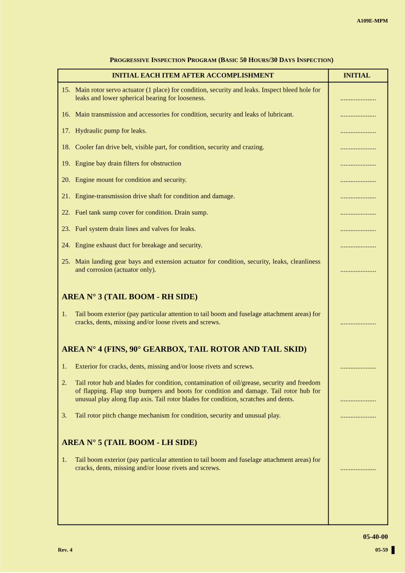
A B
C
D
A
B
C
DC
INITIAL EACH ITEM AFTER ACCOMPLISHMENT INITIAL
A109E-MPM
05-40-00
Rev. 4 05-59
15. Main rotor servo actuator (1 place) for condition, security and leaks. Inspect bleed hole forleaks and lower spherical bearing for looseness.
16. Main transmission and accessories for condition, security and leaks of lubricant.
17. Hydraulic pump for leaks.
18. Cooler fan drive belt, visible part, for condition, security and crazing.
19. Engine bay drain filters for obstruction
20. Engine mount for condition and security.
21. Engine-transmission drive shaft for condition and damage.
22. Fuel tank sump cover for condition. Drain sump.
23. Fuel system drain lines and valves for leaks.
24. Engine exhaust duct for breakage and security.
25. Main landing gear bays and extension actuator for condition, security, leaks, cleanlinessand corrosion (actuator only).
AREA N° 3 (TAIL BOOM - RH SIDE)
1. Tail boom exterior (pay particular attention to tail boom and fuselage attachment areas) forcracks, dents, missing and/or loose rivets and screws.
AREA N° 4 (FINS, 90° GEARBOX, TAIL ROTOR AND TAIL SKID)
1. Exterior for cracks, dents, missing and/or loose rivets and screws.
2. Tail rotor hub and blades for condition, contamination of oil/grease, security and freedomof flapping. Flap stop bumpers and boots for condition and damage. Tail rotor hub forunusual play along flap axis. Tail rotor blades for condition, scratches and dents.
3. Tail rotor pitch change mechanism for condition, security and unusual play.
AREA N° 5 (TAIL BOOM - LH SIDE)
1. Tail boom exterior (pay particular attention to tail boom and fuselage attachment areas) forcracks, dents, missing and/or loose rivets and screws.
.....................
.....................
.....................
.....................
.....................
.....................
.....................
.....................
.....................
.....................
.....................
.....................
.....................
.....................
.....................
.....................
PROGRESSIVE INSPECTION PROGRAM (BASIC 50 HOURS/30 DAYS INSPECTION)
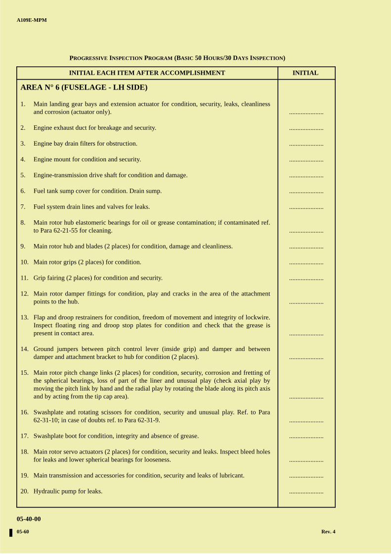
A B
C
D
A
B
C
DC
INITIAL EACH ITEM AFTER ACCOMPLISHMENT INITIAL
A109E-MPM
05-40-00
05-60 Rev. 4
AREA N° 6 (FUSELAGE - LH SIDE)
1. Main landing gear bays and extension actuator for condition, security, leaks, cleanlinessand corrosion (actuator only).
2. Engine exhaust duct for breakage and security.
3. Engine bay drain filters for obstruction.
4. Engine mount for condition and security.
5. Engine-transmission drive shaft for condition and damage.
6. Fuel tank sump cover for condition. Drain sump.
7. Fuel system drain lines and valves for leaks.
8. Main rotor hub elastomeric bearings for oil or grease contamination; if contaminated ref.to Para 62-21-55 for cleaning.
9. Main rotor hub and blades (2 places) for condition, damage and cleanliness.
10. Main rotor grips (2 places) for condition.
11. Grip fairing (2 places) for condition and security.
12. Main rotor damper fittings for condition, play and cracks in the area of the attachmentpoints to the hub.
13. Flap and droop restrainers for condition, freedom of movement and integrity of lockwire.Inspect floating ring and droop stop plates for condition and check that the grease ispresent in contact area.
14. Ground jumpers between pitch control lever (inside grip) and damper and betweendamper and attachment bracket to hub for condition (2 places).
15. Main rotor pitch change links (2 places) for condition, security, corrosion and fretting ofthe spherical bearings, loss of part of the liner and unusual play (check axial play bymoving the pitch link by hand and the radial play by rotating the blade along its pitch axisand by acting from the tip cap area).
16. Swashplate and rotating scissors for condition, security and unusual play. Ref. to Para62-31-10; in case of doubts ref. to Para 62-31-9.
17. Swashplate boot for condition, integrity and absence of grease.
18. Main rotor servo actuators (2 places) for condition, security and leaks. Inspect bleed holesfor leaks and lower spherical bearings for looseness.
19. Main transmission and accessories for condition, security and leaks of lubricant.
20. Hydraulic pump for leaks.
.....................
.....................
.....................
.....................
.....................
.....................
.....................
.....................
.....................
.....................
.....................
.....................
.....................
.....................
.....................
.....................
.....................
.....................
.....................
.....................
PROGRESSIVE INSPECTION PROGRAM (BASIC 50 HOURS/30 DAYS INSPECTION)
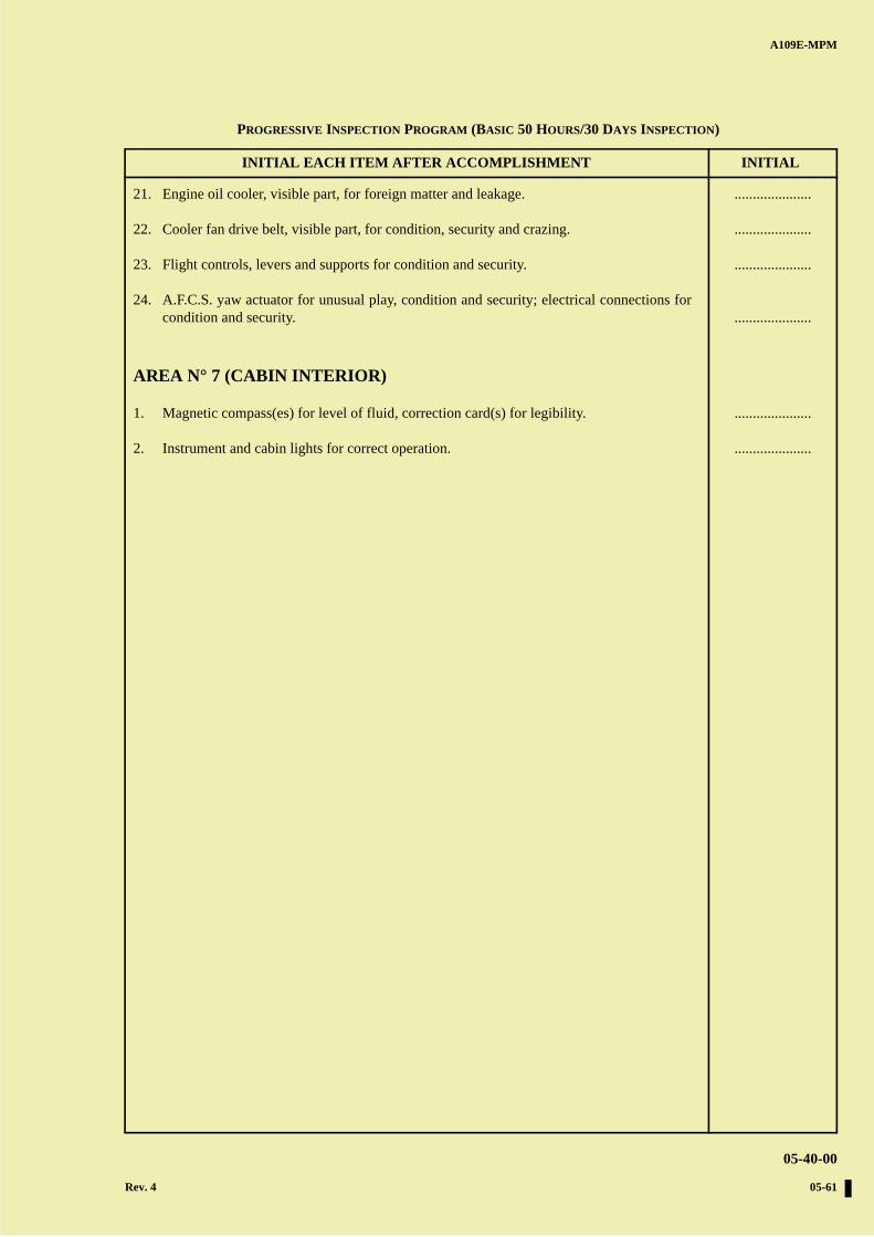
A B
C
D
A
B
C
DC
INITIAL EACH ITEM AFTER ACCOMPLISHMENT INITIAL
A109E-MPM
05-40-00
Rev. 4 05-61
21. Engine oil cooler, visible part, for foreign matter and leakage.
22. Cooler fan drive belt, visible part, for condition, security and crazing.
23. Flight controls, levers and supports for condition and security.
24. A.F.C.S. yaw actuator for unusual play, condition and security; electrical connections forcondition and security.
AREA N° 7 (CABIN INTERIOR)
1. Magnetic compass(es) for level of fluid, correction card(s) for legibility.
2. Instrument and cabin lights for correct operation.
.....................
.....................
.....................
.....................
.....................
.....................
PROGRESSIVE INSPECTION PROGRAM (BASIC 50 HOURS/30 DAYS INSPECTION)

A B
C
D
A
B
C
DC
A109E-MPM
05-40-00
05-62
PAGE INTENTIONALLY LEFT BLANK
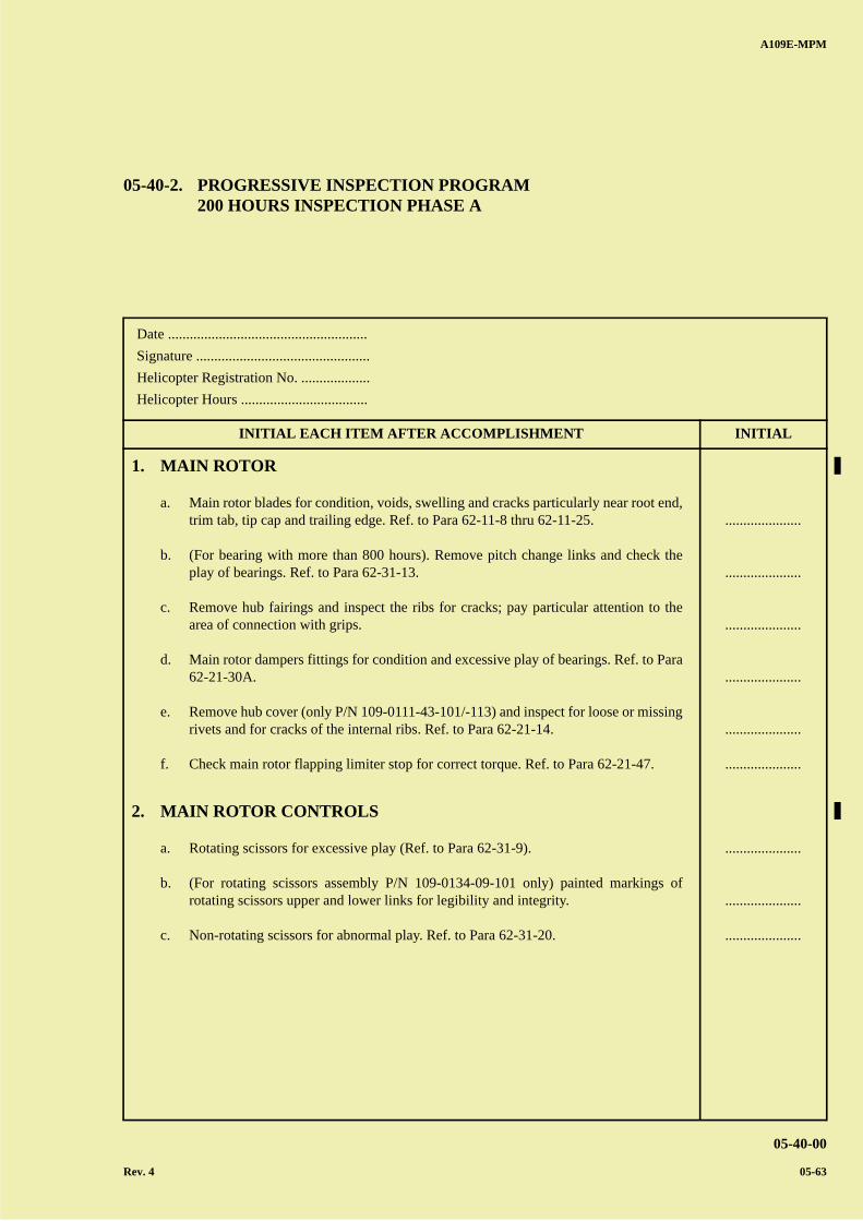
A B
C
D
A
B
C
DC
A109E-MPM
05-40-00
Rev. 4 05-63
Date .......................................................
Signature ................................................
Helicopter Registration No. ...................
Helicopter Hours ...................................
INITIAL EACH ITEM AFTER ACCOMPLISHMENT INITIAL
05-40-2. PROGRESSIVE INSPECTION PROGRAM200 HOURS INSPECTION PHASE A
1. MAIN ROTOR
a. Main rotor blades for condition, voids, swelling and cracks particularly near root end,trim tab, tip cap and trailing edge. Ref. to Para 62-11-8 thru 62-11-25.
b. (For bearing with more than 800 hours). Remove pitch change links and check theplay of bearings. Ref. to Para 62-31-13.
c. Remove hub fairings and inspect the ribs for cracks; pay particular attention to thearea of connection with grips.
d. Main rotor dampers fittings for condition and excessive play of bearings. Ref. to Para62-21-30A.
e. Remove hub cover (only P/N 109-0111-43-101/-113) and inspect for loose or missingrivets and for cracks of the internal ribs. Ref. to Para 62-21-14.
f. Check main rotor flapping limiter stop for correct torque. Ref. to Para 62-21-47.
2. MAIN ROTOR CONTROLS
a. Rotating scissors for excessive play (Ref. to Para 62-31-9).
b. (For rotating scissors assembly P/N 109-0134-09-101 only) painted markings ofrotating scissors upper and lower links for legibility and integrity.
c. Non-rotating scissors for abnormal play. Ref. to Para 62-31-20.
.....................
.....................
.....................
.....................
.....................
.....................
.....................
.....................
.....................

A B
C
D
A
B
C
DC
A109E-MPM
05-40-00
05-64
PAGE INTENTIONALLY LEFT BLANK
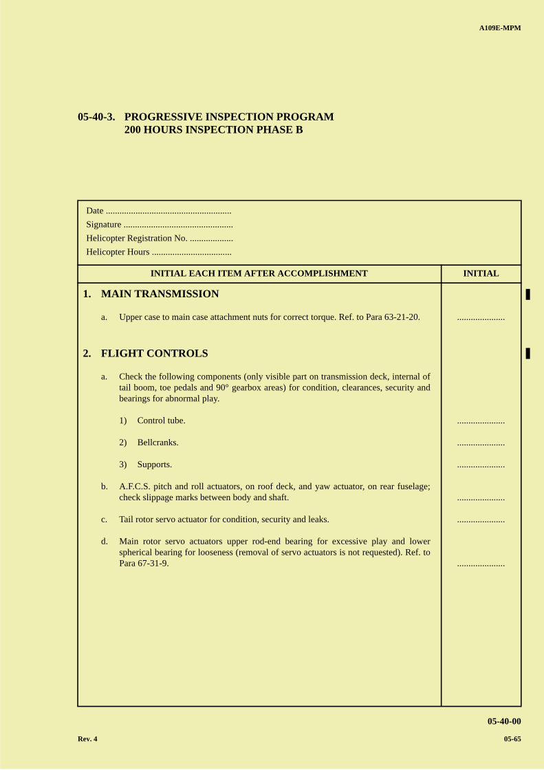
A B
C
D
A
B
C
DC
A109E-MPM
05-40-00
Rev. 4 05-65
Date .......................................................
Signature ................................................
Helicopter Registration No. ...................
Helicopter Hours ...................................
INITIAL EACH ITEM AFTER ACCOMPLISHMENT INITIAL
05-40-3. PROGRESSIVE INSPECTION PROGRAM200 HOURS INSPECTION PHASE B
1. MAIN TRANSMISSION
a. Upper case to main case attachment nuts for correct torque. Ref. to Para 63-21-20.
2. FLIGHT CONTROLS
a. Check the following components (only visible part on transmission deck, internal oftail boom, toe pedals and 90° gearbox areas) for condition, clearances, security andbearings for abnormal play.
1) Control tube.
2) Bellcranks.
3) Supports.
b. A.F.C.S. pitch and roll actuators, on roof deck, and yaw actuator, on rear fuselage;check slippage marks between body and shaft.
c. Tail rotor servo actuator for condition, security and leaks.
d. Main rotor servo actuators upper rod-end bearing for excessive play and lowerspherical bearing for looseness (removal of servo actuators is not requested). Ref. toPara 67-31-9.
.....................
.....................
.....................
.....................
.....................
.....................
.....................

A B
C
D
A
B
C
DC
A109E-MPM
05-40-00
05-66
PAGE INTENTIONALLY LEFT BLANK
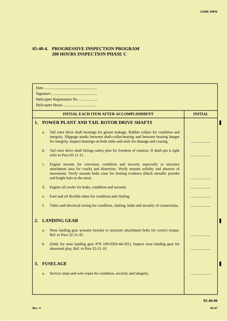
A B
C
D
A
B
C
DC
A109E-MPM
05-40-00
Rev. 4 05-67
Date .......................................................
Signature ................................................
Helicopter Registration No. ...................
Helicopter Hours ...................................
INITIAL EACH ITEM AFTER ACCOMPLISHMENT INITIAL
05-40-4. PROGRESSIVE INSPECTION PROGRAM200 HOURS INSPECTION PHASE C
1. POWER PLANT AND TAIL ROTOR DRIVE SHAFTS
a. Tail rotor drive shaft bearings for grease leakage. Rubber collars for condition andintegrity. Slippage marks between shaft-collar-bearing and between bearing hangerfor integrity. Inspect bearings on both sides and seals for damage and crazing.
b. Tail rotor drive shaft fittings safety pins for freedom of rotation. If shaft pin is tightrefer to Para 65-11-11.
c. Engine mounts for corrosion, condition and security especially in structureattachment area for cracks and distortion. Verify mounts solidity and absence ofmovement. Verify mounts bolts zone for fretting evidence (black metallic powderand bright halo in the area).
d. Engine oil cooler for leaks, condition and security.
e. Fuel and oil flexible tubes for condition and chafing.
f. Tubes and electrical wiring for condition, chafing, leaks and security of connections.
2. LANDING GEAR
a. Nose landing gear actuator bracket to structure attachment bolts for correct torque.Ref. to Para 32-31-45.
b. (Only for nose landing gear P/N 109-0503-44-101). Inspect nose landing gear forabnormal play. Ref. to Para 32-21-10.
3. FUSELAGE
a. Service steps and wire ropes for condition, security and integrity.
.....................
.....................
.....................
.....................
.....................
.....................
.....................
.....................
.....................
A B
C
D
A
B
C
DC
INITIAL EACH ITEM AFTER ACCOMPLISHMENT INITIAL
A109E-MPM
05-40-00
05-68 Rev. 4
4. TAIL BOOM
a. Tail boom internal area surrounding the attachment points and relative fuselagebrackets for cracks, corrosion and visual evidence of distortion. Ref. to Para 53-31-9.
b. Tail boom internal area, stabilizer attachment area and relative locking system forsecurity and cracks. Surrounding areas for distortion, cracks and defective and/ormissing rivets.
.....................
.....................
PROGRESSIVE INSPECTION PROGRAM (PROGRESSIVE 200 HOURS INSPECTION - PHASE C)
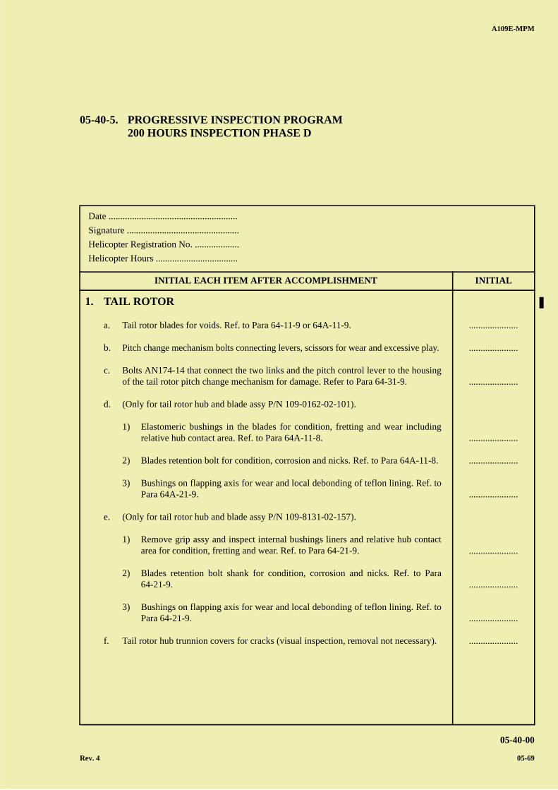
A B
C
D
A
B
C
DC
A109E-MPM
05-40-00
Rev. 4 05-69
Date .......................................................
Signature ................................................
Helicopter Registration No. ...................
Helicopter Hours ...................................
INITIAL EACH ITEM AFTER ACCOMPLISHMENT INITIAL
05-40-5. PROGRESSIVE INSPECTION PROGRAM200 HOURS INSPECTION PHASE D
1. TAIL ROTOR
a. Tail rotor blades for voids. Ref. to Para 64-11-9 or 64A-11-9.
b. Pitch change mechanism bolts connecting levers, scissors for wear and excessive play.
c. Bolts AN174-14 that connect the two links and the pitch control lever to the housingof the tail rotor pitch change mechanism for damage. Refer to Para 64-31-9.
d. (Only for tail rotor hub and blade assy P/N 109-0162-02-101).
1) Elastomeric bushings in the blades for condition, fretting and wear includingrelative hub contact area. Ref. to Para 64A-11-8.
2) Blades retention bolt for condition, corrosion and nicks. Ref. to Para 64A-11-8.
3) Bushings on flapping axis for wear and local debonding of teflon lining. Ref. toPara 64A-21-9.
e. (Only for tail rotor hub and blade assy P/N 109-8131-02-157).
1) Remove grip assy and inspect internal bushings liners and relative hub contactarea for condition, fretting and wear. Ref. to Para 64-21-9.
2) Blades retention bolt shank for condition, corrosion and nicks. Ref. to Para64-21-9.
3) Bushings on flapping axis for wear and local debonding of teflon lining. Ref. toPara 64-21-9.
f. Tail rotor hub trunnion covers for cracks (visual inspection, removal not necessary).
.....................
.....................
.....................
.....................
.....................
.....................
.....................
.....................
.....................
.....................

A B
C
D
A
B
C
DC
A109E-MPM
05-40-00
05-70
PAGE INTENTIONALLY LEFT BLANK
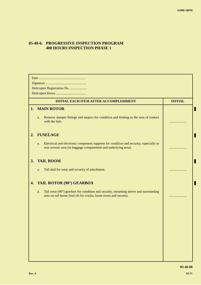
A B
C
D
A
B
C
DC
A109E-MPM
05-40-00
Rev. 4 05-71
Date .......................................................
Signature ................................................
Helicopter Registration No. ...................
Helicopter Hours ...................................
INITIAL EACH ITEM AFTER ACCOMPLISHMENT INITIAL
05-40-6. PROGRESSIVE INSPECTION PROGRAM400 HOURS INSPECTION PHASE 1
1. MAIN ROTOR
a. Remove damper fittings and inspect for condition and fretting in the area of contactwith the hub.
2. FUSELAGE
a. Electrical and electronic component supports for condition and security, especially inrear avionic area (in baggage compartment and underlying area).
3. TAIL BOOM
a. Tail skid for wear and security of attachment.
4. TAIL ROTOR (90°) GEARBOX
a. Tail rotor (90°) gearbox for condition and security, mounting sleeve and surroundingarea on tail boom final rib for cracks, loose rivets and security.
.....................
.....................
.....................
.....................

A B
C
D
A
B
C
DC
A109E-MPM
05-40-00
05-72
PAGE INTENTIONALLY LEFT BLANK
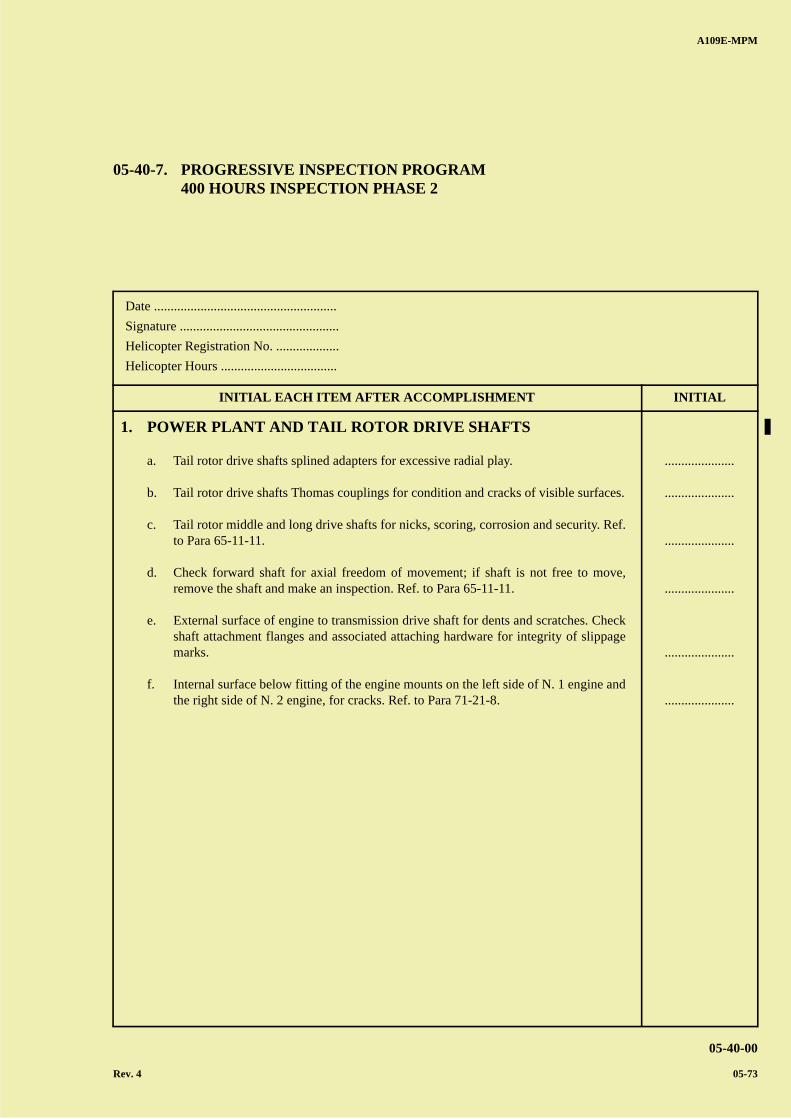
A B
C
D
A
B
C
DC
A109E-MPM
05-40-00
Rev. 4 05-73
Date .......................................................
Signature ................................................
Helicopter Registration No. ...................
Helicopter Hours ...................................
INITIAL EACH ITEM AFTER ACCOMPLISHMENT INITIAL
05-40-7. PROGRESSIVE INSPECTION PROGRAM400 HOURS INSPECTION PHASE 2
1. POWER PLANT AND TAIL ROTOR DRIVE SHAFTS
a. Tail rotor drive shafts splined adapters for excessive radial play.
b. Tail rotor drive shafts Thomas couplings for condition and cracks of visible surfaces.
c. Tail rotor middle and long drive shafts for nicks, scoring, corrosion and security. Ref.to Para 65-11-11.
d. Check forward shaft for axial freedom of movement; if shaft is not free to move,remove the shaft and make an inspection. Ref. to Para 65-11-11.
e. External surface of engine to transmission drive shaft for dents and scratches. Checkshaft attachment flanges and associated attaching hardware for integrity of slippagemarks.
f. Internal surface below fitting of the engine mounts on the left side of N. 1 engine andthe right side of N. 2 engine, for cracks. Ref. to Para 71-21-8.
.....................
.....................
.....................
.....................
.....................
.....................

A B
C
D
A
B
C
DC
A109E-MPM
05-40-00
05-74
PAGE INTENTIONALLY LEFT BLANK
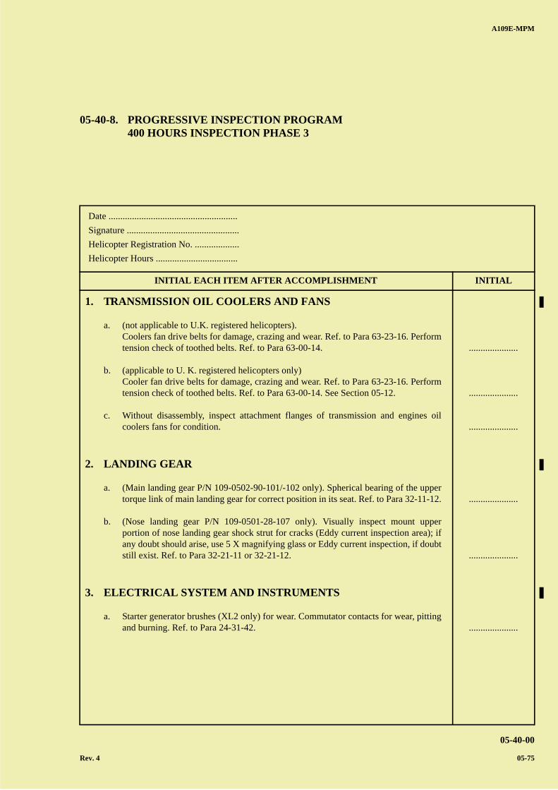
A B
C
D
A
B
C
DC
A109E-MPM
05-40-00
Rev. 4 05-75
Date .......................................................
Signature ................................................
Helicopter Registration No. ...................
Helicopter Hours ...................................
INITIAL EACH ITEM AFTER ACCOMPLISHMENT INITIAL
05-40-8. PROGRESSIVE INSPECTION PROGRAM400 HOURS INSPECTION PHASE 3
1. TRANSMISSION OIL COOLERS AND FANS
a. (not applicable to U.K. registered helicopters).Coolers fan drive belts for damage, crazing and wear. Ref. to Para 63-23-16. Performtension check of toothed belts. Ref. to Para 63-00-14.
b. (applicable to U. K. registered helicopters only)Cooler fan drive belts for damage, crazing and wear. Ref. to Para 63-23-16. Performtension check of toothed belts. Ref. to Para 63-00-14. See Section 05-12.
c. Without disassembly, inspect attachment flanges of transmission and engines oilcoolers fans for condition.
2. LANDING GEAR
a. (Main landing gear P/N 109-0502-90-101/-102 only). Spherical bearing of the uppertorque link of main landing gear for correct position in its seat. Ref. to Para 32-11-12.
b. (Nose landing gear P/N 109-0501-28-107 only). Visually inspect mount upperportion of nose landing gear shock strut for cracks (Eddy current inspection area); ifany doubt should arise, use 5 X magnifying glass or Eddy current inspection, if doubtstill exist. Ref. to Para 32-21-11 or 32-21-12.
3. ELECTRICAL SYSTEM AND INSTRUMENTS
a. Starter generator brushes (XL2 only) for wear. Commutator contacts for wear, pittingand burning. Ref. to Para 24-31-42.
.....................
.....................
.....................
.....................
.....................
.....................

A B
C
D
A
B
C
DC
A109E-MPM
05-40-00
05-76
PAGE INTENTIONALLY LEFT BLANK
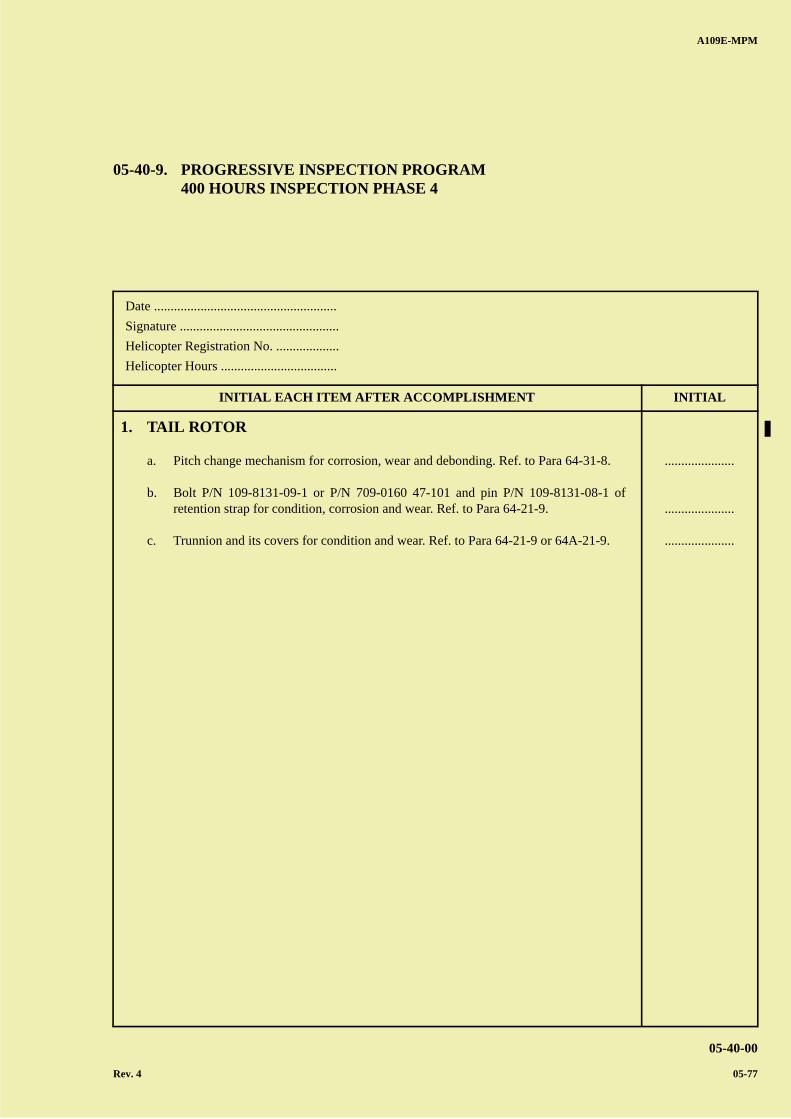
A B
C
D
A
B
C
DC
A109E-MPM
05-40-00
Rev. 4 05-77
Date .......................................................
Signature ................................................
Helicopter Registration No. ...................
Helicopter Hours ...................................
INITIAL EACH ITEM AFTER ACCOMPLISHMENT INITIAL
05-40-9. PROGRESSIVE INSPECTION PROGRAM400 HOURS INSPECTION PHASE 4
1. TAIL ROTOR
a. Pitch change mechanism for corrosion, wear and debonding. Ref. to Para 64-31-8.
b. Bolt P/N 109-8131-09-1 or P/N 709-0160 47-101 and pin P/N 109-8131-08-1 ofretention strap for condition, corrosion and wear. Ref. to Para 64-21-9.
c. Trunnion and its covers for condition and wear. Ref. to Para 64-21-9 or 64A-21-9.
.....................
.....................
.....................

A B
C
D
A
B
C
DC
A109E-MPM
05-40-00
05-78
PAGE INTENTIONALLY LEFT BLANK
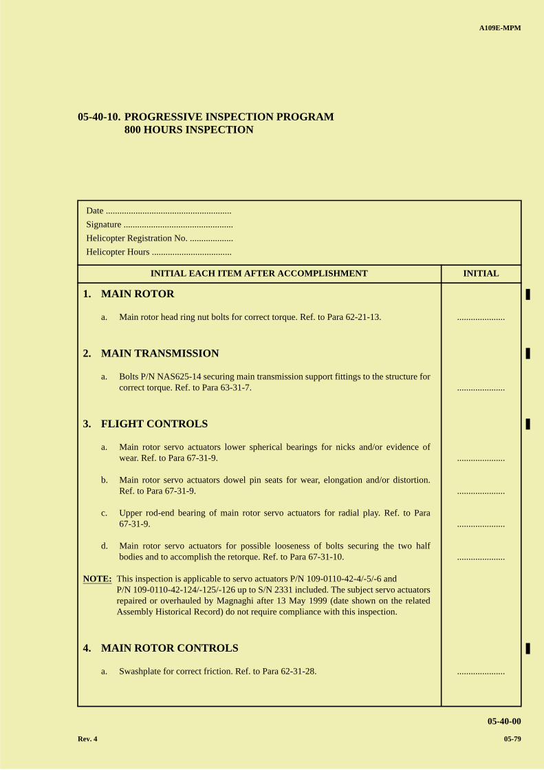
A B
C
D
A
B
C
DC
A109E-MPM
05-40-00
Rev. 4 05-79
Date .......................................................
Signature ................................................
Helicopter Registration No. ...................
Helicopter Hours ...................................
INITIAL EACH ITEM AFTER ACCOMPLISHMENT INITIAL
05-40-10. PROGRESSIVE INSPECTION PROGRAM800 HOURS INSPECTION
1. MAIN ROTOR
a. Main rotor head ring nut bolts for correct torque. Ref. to Para 62-21-13.
2. MAIN TRANSMISSION
a. Bolts P/N NAS625-14 securing main transmission support fittings to the structure forcorrect torque. Ref. to Para 63-31-7.
3. FLIGHT CONTROLS
a. Main rotor servo actuators lower spherical bearings for nicks and/or evidence ofwear. Ref. to Para 67-31-9.
b. Main rotor servo actuators dowel pin seats for wear, elongation and/or distortion.Ref. to Para 67-31-9.
c. Upper rod-end bearing of main rotor servo actuators for radial play. Ref. to Para67-31-9.
d. Main rotor servo actuators for possible looseness of bolts securing the two halfbodies and to accomplish the retorque. Ref. to Para 67-31-10.
NOTE: This inspection is applicable to servo actuators P/N 109-0110-42-4/-5/-6 andP/N 109-0110-42-124/-125/-126 up to S/N 2331 included. The subject servo actuatorsrepaired or overhauled by Magnaghi after 13 May 1999 (date shown on the relatedAssembly Historical Record) do not require compliance with this inspection.
4. MAIN ROTOR CONTROLS
a. Swashplate for correct friction. Ref. to Para 62-31-28.
.....................
.....................
.....................
.....................
.....................
.....................
.....................
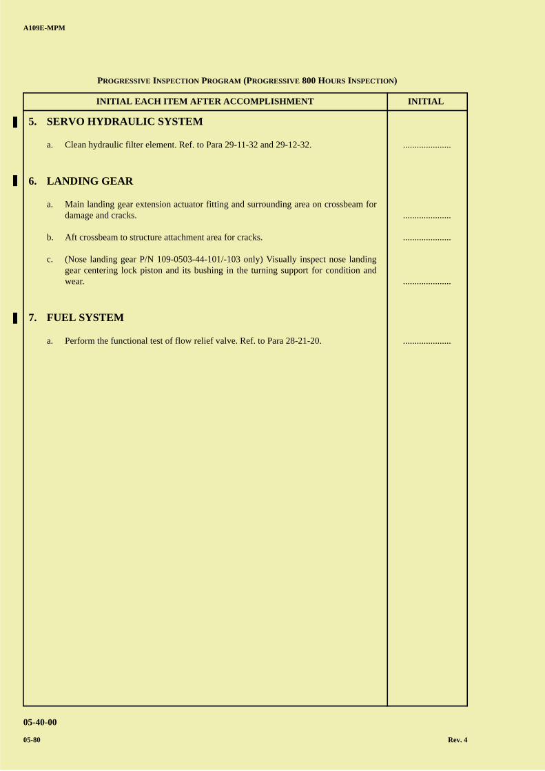
A B
C
D
A
B
C
DC
INITIAL EACH ITEM AFTER ACCOMPLISHMENT INITIAL
A109E-MPM
05-40-00
05-80 Rev. 4
5. SERVO HYDRAULIC SYSTEM
a. Clean hydraulic filter element. Ref. to Para 29-11-32 and 29-12-32.
6. LANDING GEAR
a. Main landing gear extension actuator fitting and surrounding area on crossbeam fordamage and cracks.
b. Aft crossbeam to structure attachment area for cracks.
c. (Nose landing gear P/N 109-0503-44-101/-103 only) Visually inspect nose landinggear centering lock piston and its bushing in the turning support for condition andwear.
7. FUEL SYSTEM
a. Perform the functional test of flow relief valve. Ref. to Para 28-21-20.
.....................
.....................
.....................
.....................
.....................
PROGRESSIVE INSPECTION PROGRAM (PROGRESSIVE 800 HOURS INSPECTION)
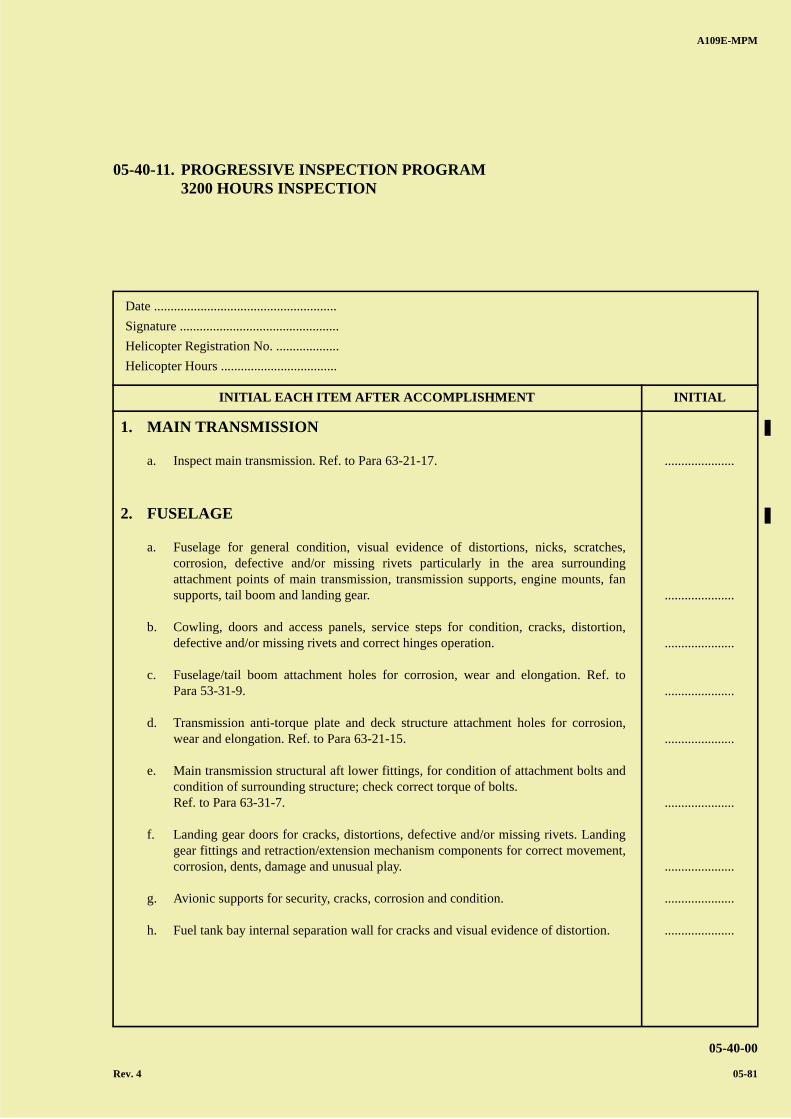
A B
C
D
A
B
C
DC
A109E-MPM
05-40-00
Rev. 4 05-81
Date .......................................................
Signature ................................................
Helicopter Registration No. ...................
Helicopter Hours ...................................
INITIAL EACH ITEM AFTER ACCOMPLISHMENT INITIAL
05-40-11. PROGRESSIVE INSPECTION PROGRAM3200 HOURS INSPECTION
1. MAIN TRANSMISSION
a. Inspect main transmission. Ref. to Para 63-21-17.
2. FUSELAGE
a. Fuselage for general condition, visual evidence of distortions, nicks, scratches,corrosion, defective and/or missing rivets particularly in the area surroundingattachment points of main transmission, transmission supports, engine mounts, fansupports, tail boom and landing gear.
b. Cowling, doors and access panels, service steps for condition, cracks, distortion,defective and/or missing rivets and correct hinges operation.
c. Fuselage/tail boom attachment holes for corrosion, wear and elongation. Ref. toPara 53-31-9.
d. Transmission anti-torque plate and deck structure attachment holes for corrosion,wear and elongation. Ref. to Para 63-21-15.
e. Main transmission structural aft lower fittings, for condition of attachment bolts andcondition of surrounding structure; check correct torque of bolts.Ref. to Para 63-31-7.
f. Landing gear doors for cracks, distortions, defective and/or missing rivets. Landinggear fittings and retraction/extension mechanism components for correct movement,corrosion, dents, damage and unusual play.
g. Avionic supports for security, cracks, corrosion and condition.
h. Fuel tank bay internal separation wall for cracks and visual evidence of distortion.
.....................
.....................
.....................
.....................
.....................
.....................
.....................
.....................
.....................

A B
C
D
A
B
C
DC
INITIAL EACH ITEM AFTER ACCOMPLISHMENT INITIAL
A109E-MPM
05-40-00
05-82 Rev. 4
3. LANDING GEAR
a. (Nose landing gear P/N 109-0501-28-107 only). Disassemble nose shock strut andinspect the body and the cylinder for corrosion. Ref. to Para 32-21-13.
4. TAIL BOOM
a. Remove the stabilizers and visually inspect externally and internally for generalcondition, visual evidence of distortion, cracks, corrosion, defective and/or missingrivets particularly in the area surrounding fuselage, stabilizer and 90° gearboxattachment points
b. Tail boom to fuselage attachment bolt holes for wear.
c. Tail skid for distortion, wear and corrosion.
d. Fairings and inspection doors for condition, visual evidence of distortion, defectiveand/or missing rivets and correct hinge operation.
5. FUEL SYSTEM
e. Inspect the flame arrester on vent tubes for cleanliness and obstructions. Ref. toPara 28-11-32.
6. MISCELLANEOUS ASSEMBLIES AND INSTALLATIONS
a. In addition to prescribed “Component Overhaul Schedule”, remove and thoroughlyinspect components of assemblies and installations listed below and relativeattachment points in accordance with pertinent procedures laid down in this manual.
1) Transmission support assemblies and relative fittings secured to fuselage. Ref.to Para 63-31-7.
2) Engine-transmission shafts installation. Ref. to Para 63-11-7.
3) Tail rotor drive shaft installation. Ref. to Para 65-11-11.
.....................
.....................
.....................
.....................
.....................
.....................
.....................
.....................
.....................
PROGRESSIVE INSPECTION PROGRAM (PROGRESSIVE 3200 HOURS INSPECTION)
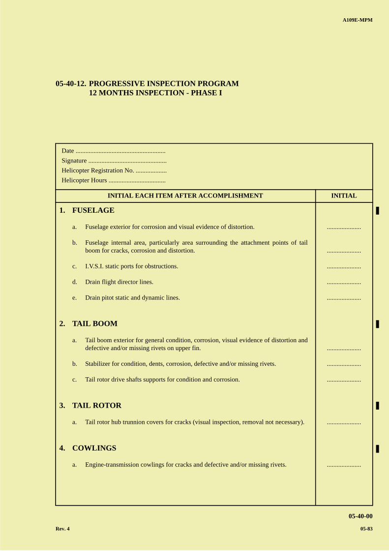
A B
C
D
A
B
C
DC
A109E-MPM
05-40-00
Rev. 4 05-83
Date .......................................................
Signature ................................................
Helicopter Registration No. ...................
Helicopter Hours ...................................
INITIAL EACH ITEM AFTER ACCOMPLISHMENT INITIAL
05-40-12. PROGRESSIVE INSPECTION PROGRAM12 MONTHS INSPECTION - PHASE I
1. FUSELAGE
a. Fuselage exterior for corrosion and visual evidence of distortion.
b. Fuselage internal area, particularly area surrounding the attachment points of tailboom for cracks, corrosion and distortion.
c. I.V.S.I. static ports for obstructions.
d. Drain flight director lines.
e. Drain pitot static and dynamic lines.
2. TAIL BOOM
a. Tail boom exterior for general condition, corrosion, visual evidence of distortion anddefective and/or missing rivets on upper fin.
b. Stabilizer for condition, dents, corrosion, defective and/or missing rivets.
c. Tail rotor drive shafts supports for condition and corrosion.
3. TAIL ROTOR
a. Tail rotor hub trunnion covers for cracks (visual inspection, removal not necessary).
4. COWLINGS
a. Engine-transmission cowlings for cracks and defective and/or missing rivets.
.....................
.....................
.....................
.....................
.....................
.....................
.....................
.....................
.....................
.....................

A B
C
D
A
B
C
DC
A109E-MPM
05-40-00
05-84 Rev. 4
PAGE INTENTIONALLY LEFT BLANK
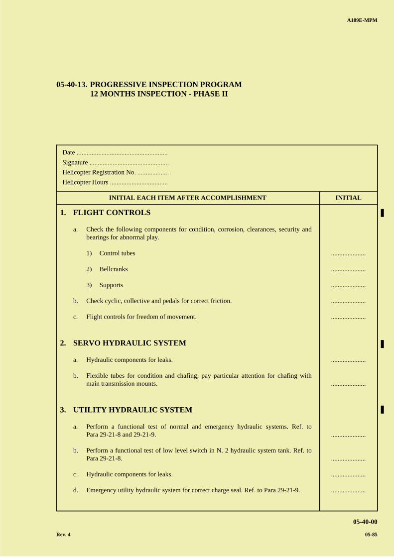
A B
C
D
A
B
C
DC
A109E-MPM
05-40-00
Rev. 4 05-85
Date .......................................................
Signature ................................................
Helicopter Registration No. ...................
Helicopter Hours ...................................
INITIAL EACH ITEM AFTER ACCOMPLISHMENT INITIAL
05-40-13. PROGRESSIVE INSPECTION PROGRAM12 MONTHS INSPECTION - PHASE II
1. FLIGHT CONTROLS
a. Check the following components for condition, corrosion, clearances, security andbearings for abnormal play.
1) Control tubes
2) Bellcranks
3) Supports
b. Check cyclic, collective and pedals for correct friction.
c. Flight controls for freedom of movement.
2. SERVO HYDRAULIC SYSTEM
a. Hydraulic components for leaks.
b. Flexible tubes for condition and chafing; pay particular attention for chafing withmain transmission mounts.
3. UTILITY HYDRAULIC SYSTEM
a. Perform a functional test of normal and emergency hydraulic systems. Ref. toPara 29-21-8 and 29-21-9.
b. Perform a functional test of low level switch in N. 2 hydraulic system tank. Ref. toPara 29-21-8.
c. Hydraulic components for leaks.
d. Emergency utility hydraulic system for correct charge seal. Ref. to Para 29-21-9.
.....................
.....................
.....................
.....................
.....................
.....................
.....................
.....................
.....................
.....................
.....................
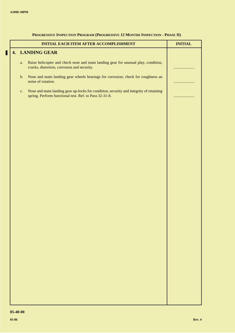
A B
C
D
A
B
C
DC
INITIAL EACH ITEM AFTER ACCOMPLISHMENT INITIAL
A109E-MPM
05-40-00
05-86 Rev. 4
4. LANDING GEAR
a. Raise helicopter and check nose and main landing gear for unusual play, condition,cracks, distortion, corrosion and security.
b. Nose and main landing gear wheels bearings for corrosion; check for roughness annoise of rotation.
c. Nose and main landing gear up-locks for condition, security and integrity of retainingspring. Perform functional test. Ref. to Para 32-31-8.
.....................
.....................
.....................
PROGRESSIVE INSPECTION PROGRAM (PROGRESSIVE 12 MONTHS INSPECTION - PHASE II)
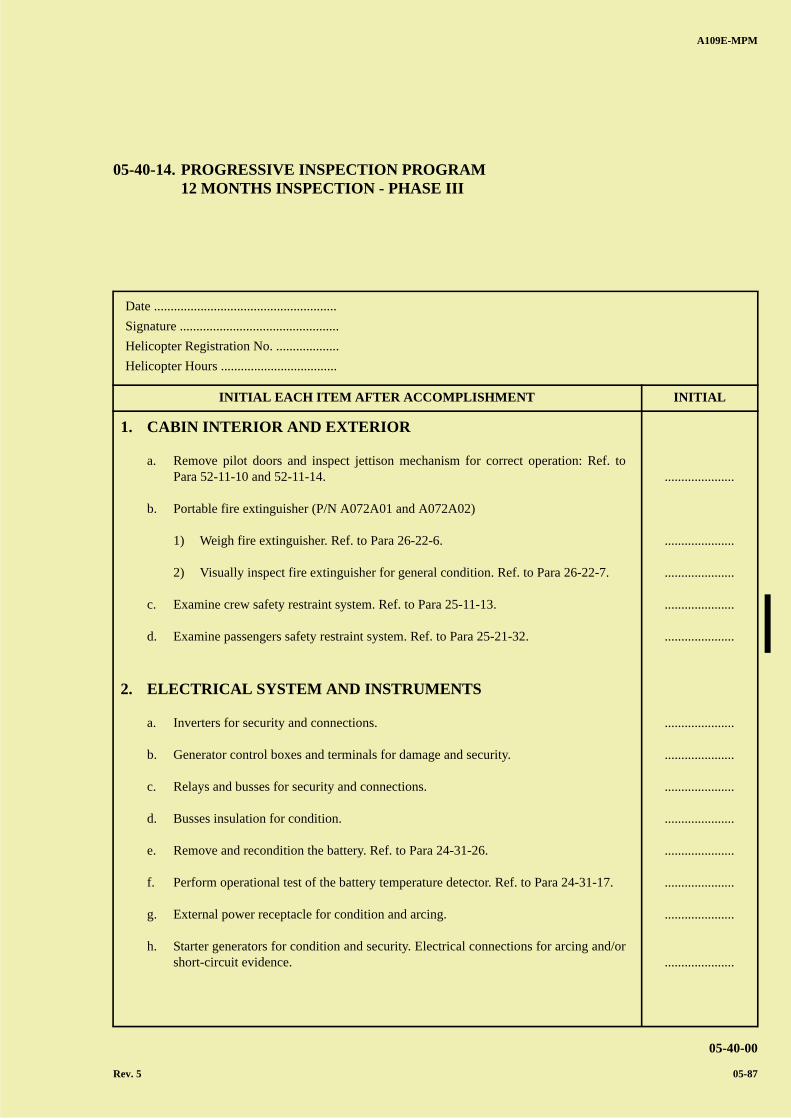
A B
C
D
A
B
C
DC
A109E-MPM
05-40-00
Rev. 5 05-87
Date .......................................................
Signature ................................................
Helicopter Registration No. ...................
Helicopter Hours ...................................
INITIAL EACH ITEM AFTER ACCOMPLISHMENT INITIAL
05-40-14. PROGRESSIVE INSPECTION PROGRAM12 MONTHS INSPECTION - PHASE III
1. CABIN INTERIOR AND EXTERIOR
a. Remove pilot doors and inspect jettison mechanism for correct operation: Ref. toPara 52-11-10 and 52-11-14.
b. Portable fire extinguisher (P/N A072A01 and A072A02)
1) Weigh fire extinguisher. Ref. to Para 26-22-6.
2) Visually inspect fire extinguisher for general condition. Ref. to Para 26-22-7.
c. Examine crew safety restraint system. Ref. to Para 25-11-13.
d. Examine passengers safety restraint system. Ref. to Para 25-21-32.
2. ELECTRICAL SYSTEM AND INSTRUMENTS
a. Inverters for security and connections.
b. Generator control boxes and terminals for damage and security.
c. Relays and busses for security and connections.
d. Busses insulation for condition.
e. Remove and recondition the battery. Ref. to Para 24-31-26.
f. Perform operational test of the battery temperature detector. Ref. to Para 24-31-17.
g. External power receptacle for condition and arcing.
h. Starter generators for condition and security. Electrical connections for arcing and/orshort-circuit evidence.
.....................
.....................
.....................
.....................
.....................
.....................
.....................
.....................
.....................
.....................
.....................
.....................
.....................

A B
C
D
A
B
C
DC
INITIAL EACH ITEM AFTER ACCOMPLISHMENT INITIAL
A109E-MPM
05-40-00
05-88 Rev. 5
i. Connectors and cables on transmission deck, engines bays and landing gear bays forcondition and corrosion.
j. Overhead panel internal wirings, breakers and connectors for condition, chafing andarcing.
k. Perform operational test of d.c. electrical system. Ref. to Para 24-31-14.
l. Perform electrical test of a.c. electrical system. Ref. to Para 24-21-10.
m. Perform functional test of engine out system microswitch (if installed). Refer topara 24-31-49.
.....................
.....................
.....................
.....................
.....................
PROGRESSIVE INSPECTION PROGRAM (PROGRESSIVE 12 MONTHS INSPECTION - PHASE III)
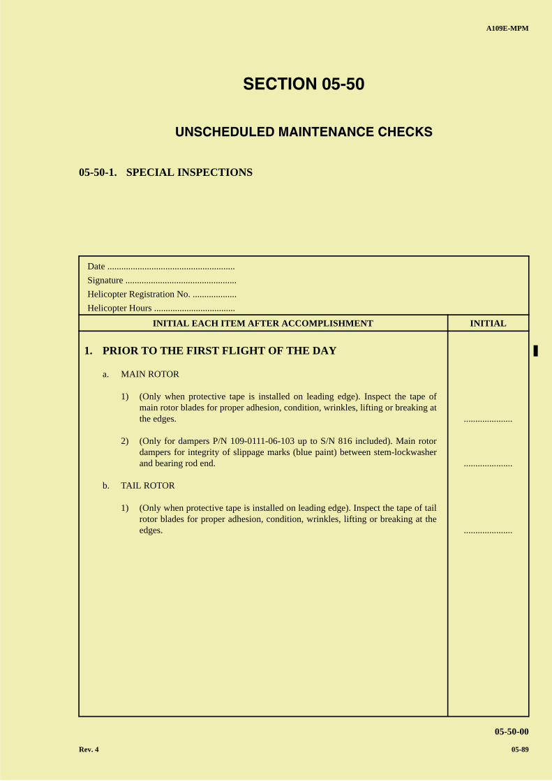
A B
C
D
A
B
C
DC
A109E-MPM
05-50-00
Rev. 4 05-89
Date .......................................................
Signature ................................................
Helicopter Registration No. ...................
Helicopter Hours ...................................
INITIAL EACH ITEM AFTER ACCOMPLISHMENT INITIAL
SECTION 05-50
UNSCHEDULED MAINTENANCE CHECKS
05-50-1. SPECIAL INSPECTIONS
1. PRIOR TO THE FIRST FLIGHT OF THE DAY
a. MAIN ROTOR
1) (Only when protective tape is installed on leading edge). Inspect the tape ofmain rotor blades for proper adhesion, condition, wrinkles, lifting or breaking atthe edges.
2) (Only for dampers P/N 109-0111-06-103 up to S/N 816 included). Main rotordampers for integrity of slippage marks (blue paint) between stem-lockwasherand bearing rod end.
b. TAIL ROTOR
1) (Only when protective tape is installed on leading edge). Inspect the tape of tailrotor blades for proper adhesion, condition, wrinkles, lifting or breaking at theedges.
.....................
.....................
.....................
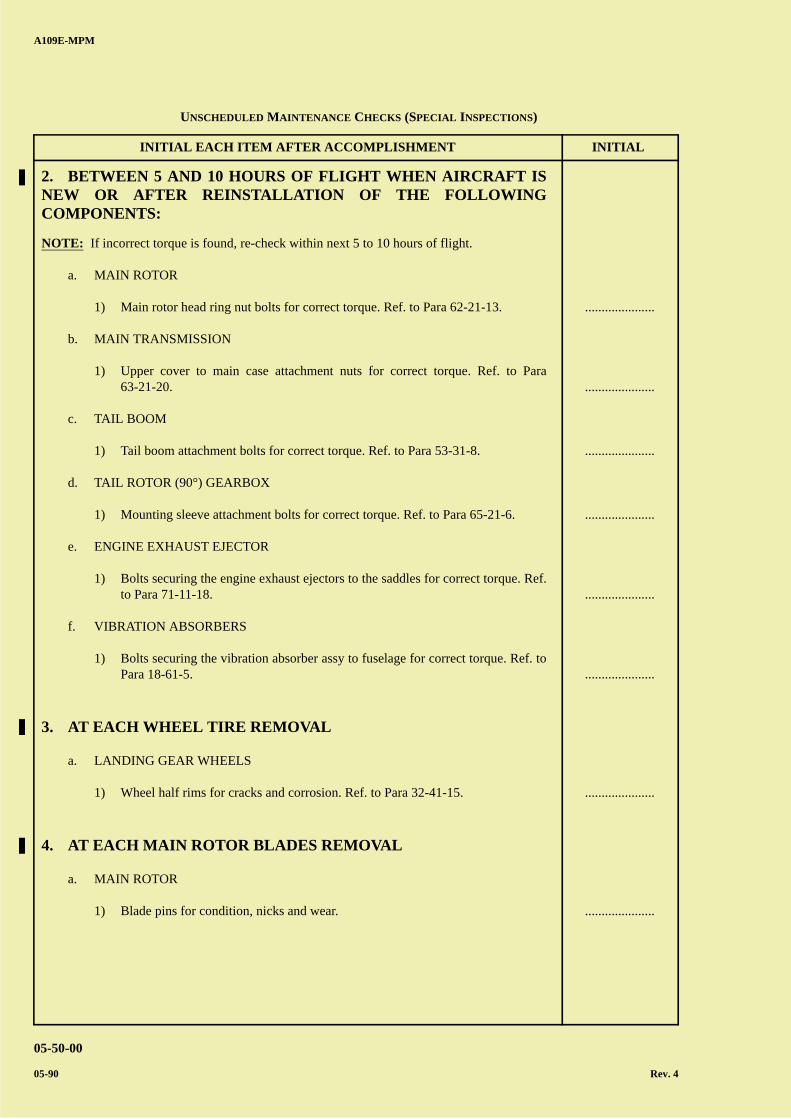
A B
C
D
A
B
C
DC
INITIAL EACH ITEM AFTER ACCOMPLISHMENT INITIAL
A109E-MPM
05-50-00
05-90 Rev. 4
2. BETWEEN 5 AND 10 HOURS OF FLIGHT WHEN AIRCRAFT ISNEW OR AFTER REINSTALLATION OF THE FOLLOWINGCOMPONENTS:
NOTE: If incorrect torque is found, re-check within next 5 to 10 hours of flight.
a. MAIN ROTOR
1) Main rotor head ring nut bolts for correct torque. Ref. to Para 62-21-13.
b. MAIN TRANSMISSION
1) Upper cover to main case attachment nuts for correct torque. Ref. to Para63-21-20.
c. TAIL BOOM
1) Tail boom attachment bolts for correct torque. Ref. to Para 53-31-8.
d. TAIL ROTOR (90°) GEARBOX
1) Mounting sleeve attachment bolts for correct torque. Ref. to Para 65-21-6.
e. ENGINE EXHAUST EJECTOR
1) Bolts securing the engine exhaust ejectors to the saddles for correct torque. Ref.to Para 71-11-18.
f. VIBRATION ABSORBERS
1) Bolts securing the vibration absorber assy to fuselage for correct torque. Ref. toPara 18-61-5.
3. AT EACH WHEEL TIRE REMOVAL
a. LANDING GEAR WHEELS
1) Wheel half rims for cracks and corrosion. Ref. to Para 32-41-15.
4. AT EACH MAIN ROTOR BLADES REMOVAL
a. MAIN ROTOR
1) Blade pins for condition, nicks and wear.
.....................
.....................
.....................
.....................
.....................
.....................
.....................
.....................
UNSCHEDULED MAINTENANCE CHECKS (SPECIAL INSPECTIONS)
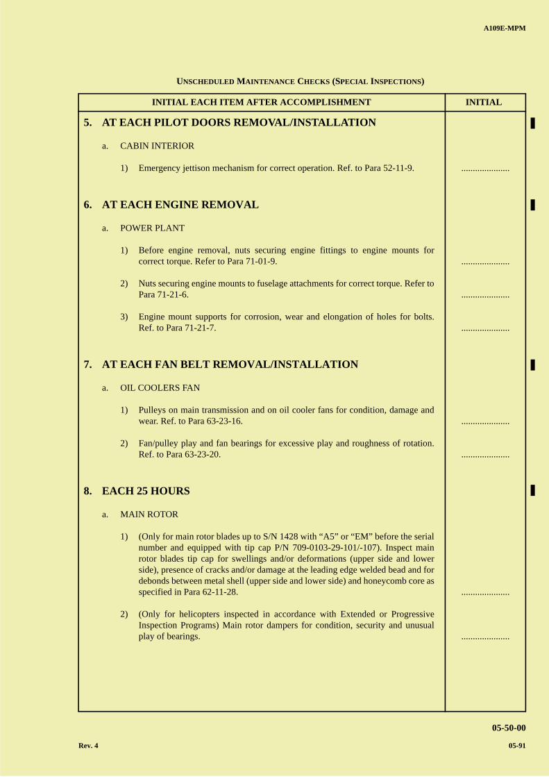
A B
C
D
A
B
C
DC
INITIAL EACH ITEM AFTER ACCOMPLISHMENT INITIAL
A109E-MPM
05-50-00
Rev. 4 05-91
5. AT EACH PILOT DOORS REMOVAL/INSTALLATION
a. CABIN INTERIOR
1) Emergency jettison mechanism for correct operation. Ref. to Para 52-11-9.
6. AT EACH ENGINE REMOVAL
a. POWER PLANT
1) Before engine removal, nuts securing engine fittings to engine mounts forcorrect torque. Refer to Para 71-01-9.
2) Nuts securing engine mounts to fuselage attachments for correct torque. Refer toPara 71-21-6.
3) Engine mount supports for corrosion, wear and elongation of holes for bolts.Ref. to Para 71-21-7.
7. AT EACH FAN BELT REMOVAL/INSTALLATION
a. OIL COOLERS FAN
1) Pulleys on main transmission and on oil cooler fans for condition, damage andwear. Ref. to Para 63-23-16.
2) Fan/pulley play and fan bearings for excessive play and roughness of rotation.Ref. to Para 63-23-20.
8. EACH 25 HOURS
a. MAIN ROTOR
1) (Only for main rotor blades up to S/N 1428 with “A5” or “EM” before the serialnumber and equipped with tip cap P/N 709-0103-29-101/-107). Inspect mainrotor blades tip cap for swellings and/or deformations (upper side and lowerside), presence of cracks and/or damage at the leading edge welded bead and fordebonds between metal shell (upper side and lower side) and honeycomb core asspecified in Para 62-11-28.
2) (Only for helicopters inspected in accordance with Extended or ProgressiveInspection Programs) Main rotor dampers for condition, security and unusualplay of bearings.
.....................
.....................
.....................
.....................
.....................
.....................
.....................
.....................
UNSCHEDULED MAINTENANCE CHECKS (SPECIAL INSPECTIONS)
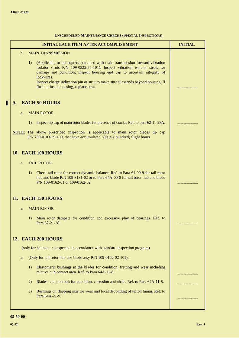
A B
C
D
A
B
C
DC
INITIAL EACH ITEM AFTER ACCOMPLISHMENT INITIAL
A109E-MPM
05-50-00
05-92 Rev. 4
b. MAIN TRANSMISSION
1) (Applicable to helicopters equipped with main transmission forward vibrationisolator struts P/N 109-0325-75-101). Inspect vibration isolator struts fordamage and condition; inspect housing end cap to ascertain integrity oflockwires.Inspect charge indication pin of strut to make sure it extends beyond housing. Ifflush or inside housing, replace strut.
9. EACH 50 HOURS
a. MAIN ROTOR
1) Inspect tip cap of main rotor blades for presence of cracks. Ref. to para 62-11-28A.
NOTE: The above prescribed inspection is applicable to main rotor blades tip capP/N 709-0103-29-109, that have accumulated 600 (six hundred) flight hours.
10. EACH 100 HOURS
a. TAIL ROTOR
1) Check tail rotor for correct dynamic balance. Ref. to Para 64-00-9 for tail rotorhub and blade P/N 109-8131-02 or to Para 64A-00-8 for tail rotor hub and bladeP/N 109-0162-01 or 109-0162-02.
11. EACH 150 HOURS
a. MAIN ROTOR
1) Main rotor dampers for condition and excessive play of bearings. Ref. toPara 62-21-28.
12. EACH 200 HOURS
(only for helicopters inspected in accordance with standard inspection program)
a. (Only for tail rotor hub and blade assy P/N 109-0162-02-101).
1) Elastomeric bushings in the blades for condition, fretting and wear includingrelative hub contact area. Ref. to Para 64A-11-8.
2) Blades retention bolt for condition, corrosion and nicks. Ref. to Para 64A-11-8.
3) Bushings on flapping axis for wear and local debonding of teflon lining. Ref. toPara 64A-21-9.
.....................
.....................
.....................
.....................
.....................
.....................
.....................
UNSCHEDULED MAINTENANCE CHECKS (SPECIAL INSPECTIONS)
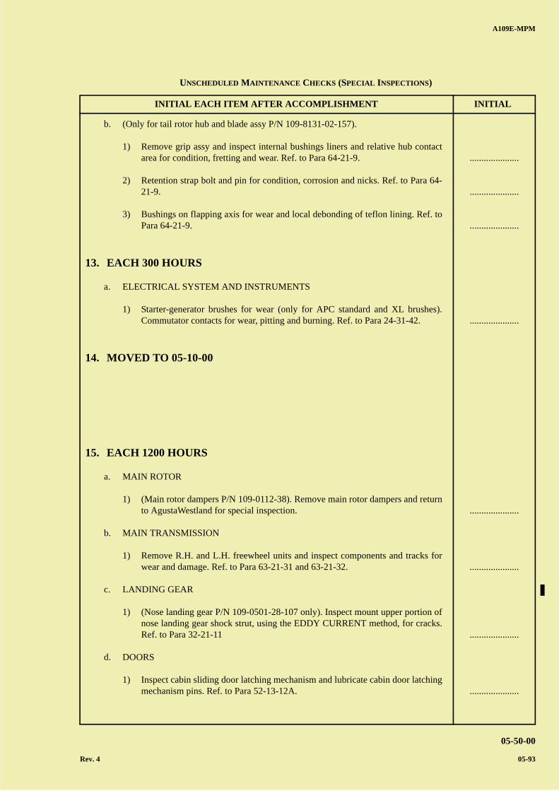
A B
C
D
A
B
C
DC
INITIAL EACH ITEM AFTER ACCOMPLISHMENT INITIAL
A109E-MPM
05-50-00
Rev. 4 05-93
b. (Only for tail rotor hub and blade assy P/N 109-8131-02-157).
1) Remove grip assy and inspect internal bushings liners and relative hub contactarea for condition, fretting and wear. Ref. to Para 64-21-9.
2) Retention strap bolt and pin for condition, corrosion and nicks. Ref. to Para 64-21-9.
3) Bushings on flapping axis for wear and local debonding of teflon lining. Ref. toPara 64-21-9.
13. EACH 300 HOURS
a. ELECTRICAL SYSTEM AND INSTRUMENTS
1) Starter-generator brushes for wear (only for APC standard and XL brushes).Commutator contacts for wear, pitting and burning. Ref. to Para 24-31-42.
14. MOVED TO 05-10-00
15. EACH 1200 HOURS
a. MAIN ROTOR
1) (Main rotor dampers P/N 109-0112-38). Remove main rotor dampers and returnto AgustaWestland for special inspection.
b. MAIN TRANSMISSION
1) Remove R.H. and L.H. freewheel units and inspect components and tracks forwear and damage. Ref. to Para 63-21-31 and 63-21-32.
c. LANDING GEAR
1) (Nose landing gear P/N 109-0501-28-107 only). Inspect mount upper portion ofnose landing gear shock strut, using the EDDY CURRENT method, for cracks.Ref. to Para 32-21-11
d. DOORS
1) Inspect cabin sliding door latching mechanism and lubricate cabin door latchingmechanism pins. Ref. to Para 52-13-12A.
.....................
.....................
.....................
.....................
.....................
.....................
.....................
.....................
UNSCHEDULED MAINTENANCE CHECKS (SPECIAL INSPECTIONS)

A B
C
D
A
B
C
DC
INITIAL EACH ITEM AFTER ACCOMPLISHMENT INITIAL
A109E-MPM
05-50-00
05-94 Rev. 4
16. EACH 1600 HOURS
a. SERVO HYDRAULIC SYSTEM
1) Splined shaft and relevant seating on hydraulic pumps and on main transmissionfor wear. Ref. to Para 29-11-28A, 29-12-28A and 63-21-36.
b. TAIL ROTOR (90°) GEARBOX
1) Inspect gearing teeth for unusual prints, pitting, scoring, damage and bearingsfor freedom of rotation and roughness. Ref. to Para 65-21-9A.
17. EACH 2400 HOURS
a. MAIN ROTOR
1) Grips, pitch control levers, flap and droop restrainers for condition, damage andwear. Inspect blades and blades grips bushings (blade retention pin seat) forwear, nicks and condition. Inspect contact area between blade and grip forcondition and washers bondage. Ref. to Para 62-21-23, 62-21-18, 62-21-40, 62-11-27 and 62-11-26.
2) Main rotor head installation. Ref. to Para 62-21-14.
3) Hub floating ring for wear and DU washers and internal teflon shim fordebonds. Ref. to Para 62-21-51.
b. MAIN ROTOR CONTROLS
1) Remove and inspect swashplate duplex bearing for damage and corrosion. Ref.to Para 62-31-26.
2) Swashplate teflon rings (pivot sleeve and swashplate) for wear. Ref. toPara 62-31-26.
3) Swashplate guides and pivot sleeve slots for damage and wear. Ref. toPara 62-31-26.
c. MAIN TRANSMISSION
1) Upper case for corrosion and wear in the areas in contact with transmissionfitting plates and with servo actuators mounting pads. Ref. to Para 63-21-21.
.....................
.....................
.....................
.....................
.....................
.....................
.....................
.....................
.....................
UNSCHEDULED MAINTENANCE CHECKS (SPECIAL INSPECTIONS)
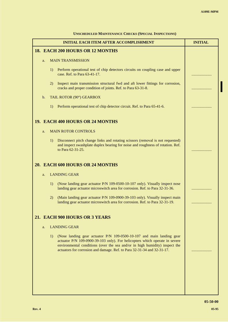
A B
C
D
A
B
C
DC
INITIAL EACH ITEM AFTER ACCOMPLISHMENT INITIAL
A109E-MPM
05-50-00
Rev. 4 05-95
18. EACH 200 HOURS OR 12 MONTHS
a. MAIN TRANSMISSION
1) Perform operational test of chip detectors circuits on coupling case and uppercase. Ref. to Para 63-41-17.
2) Inspect main transmission structural fwd and aft lower fittings for corrosion,cracks and proper condition of joints. Ref. to Para 63-31-8.
b. TAIL ROTOR (90°) GEARBOX
1) Perform operational test of chip detector circuit. Ref. to Para 65-41-6.
19. EACH 400 HOURS OR 24 MONTHS
a. MAIN ROTOR CONTROLS
1) Disconnect pitch change links and rotating scissors (removal is not requested)and inspect swashplate duplex bearing for noise and roughness of rotation. Ref.to Para 62-31-25.
20. EACH 600 HOURS OR 24 MONTHS
a. LANDING GEAR
1) (Nose landing gear actuator P/N 109-0500-10-107 only). Visually inspect noselanding gear actuator microswitch area for corrosion. Ref. to Para 32-31-36.
2) (Main landing gear actuator P/N 109-0900-39-103 only). Visually inspect mainlanding gear actuator microswitch area for corrosion. Ref. to Para 32-31-19.
21. EACH 900 HOURS OR 3 YEARS
a. LANDING GEAR
1) (Nose landing gear actuator P/N 109-0500-10-107 and main landing gearactuator P/N 109-0900-39-103 only). For helicopters which operate in severeenvironmental conditions (over the sea and/or in high humidity) inspect theactuators for corrosion and damage. Ref. to Para 32-31-34 and 32-31-17.
.....................
.....................
.....................
.....................
.....................
.....................
.....................
UNSCHEDULED MAINTENANCE CHECKS (SPECIAL INSPECTIONS)
A B
C
D
A
B
C
DC
INITIAL EACH ITEM AFTER ACCOMPLISHMENT INITIAL
A109E-MPM
05-50-00
05-96 Rev. 4
22. EACH 1800 HOURS OR 6 YEARS
a. LANDING GEAR
1) (Nose landing gear actuator P/N 109-0500-10-107 and main landing gearactuator P/N 109-0900-39-103 only). For helicopters which do not operate insevere environmental conditions (over the sea and/or in high humidity) inspectthe actuators for corrosion and damage. Ref. to Para 32-31-34 and 32-31-17. .....................
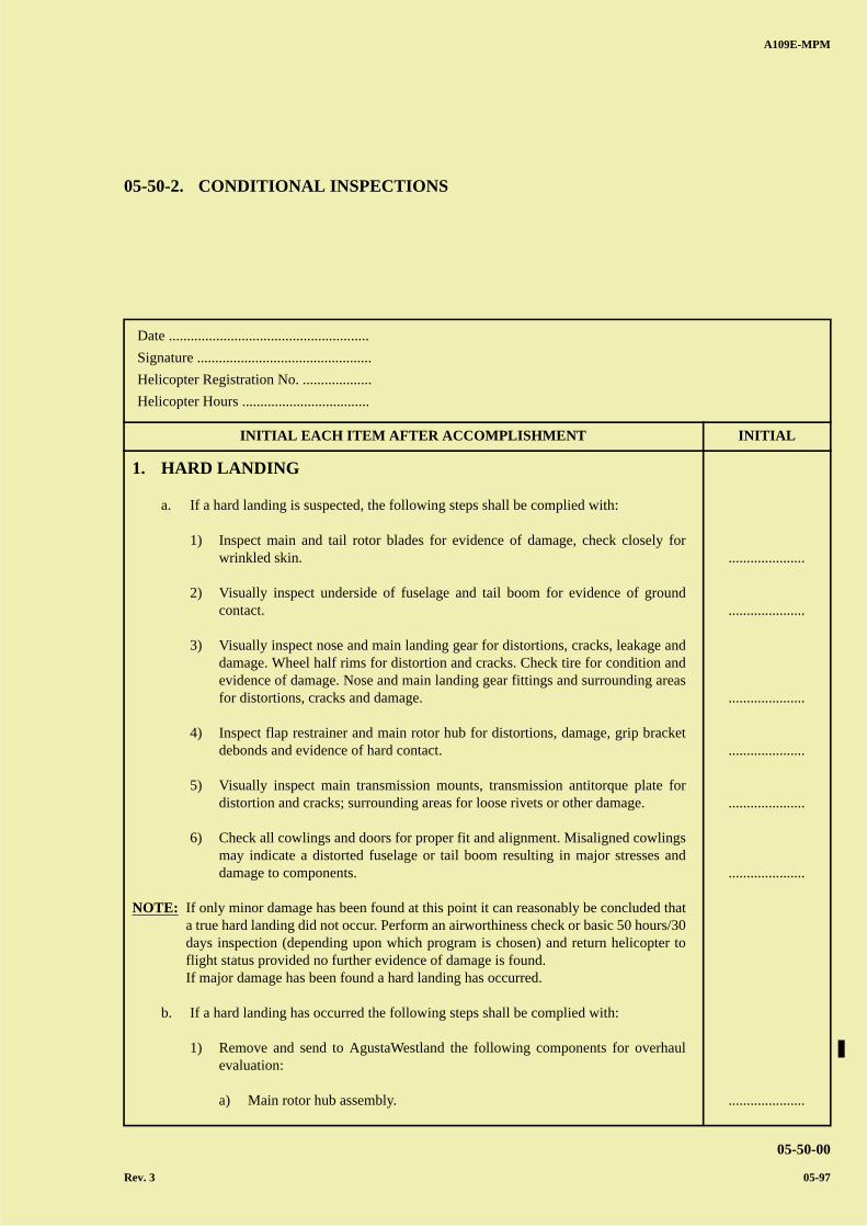
A B
C
D
A
B
C
DC
A109E-MPM
05-50-00
Rev. 3 05-97
Date .......................................................
Signature ................................................
Helicopter Registration No. ...................
Helicopter Hours ...................................
INITIAL EACH ITEM AFTER ACCOMPLISHMENT INITIAL
05-50-2. CONDITIONAL INSPECTIONS
1. HARD LANDING
a. If a hard landing is suspected, the following steps shall be complied with:
1) Inspect main and tail rotor blades for evidence of damage, check closely forwrinkled skin.
2) Visually inspect underside of fuselage and tail boom for evidence of groundcontact.
3) Visually inspect nose and main landing gear for distortions, cracks, leakage anddamage. Wheel half rims for distortion and cracks. Check tire for condition andevidence of damage. Nose and main landing gear fittings and surrounding areasfor distortions, cracks and damage.
4) Inspect flap restrainer and main rotor hub for distortions, damage, grip bracketdebonds and evidence of hard contact.
5) Visually inspect main transmission mounts, transmission antitorque plate fordistortion and cracks; surrounding areas for loose rivets or other damage.
6) Check all cowlings and doors for proper fit and alignment. Misaligned cowlingsmay indicate a distorted fuselage or tail boom resulting in major stresses anddamage to components.
NOTE: If only minor damage has been found at this point it can reasonably be concluded thata true hard landing did not occur. Perform an airworthiness check or basic 50 hours/30days inspection (depending upon which program is chosen) and return helicopter toflight status provided no further evidence of damage is found.If major damage has been found a hard landing has occurred.
b. If a hard landing has occurred the following steps shall be complied with:
1) Remove and send to AgustaWestland the following components for overhaulevaluation:
a) Main rotor hub assembly.
.....................
.....................
.....................
.....................
.....................
.....................
.....................
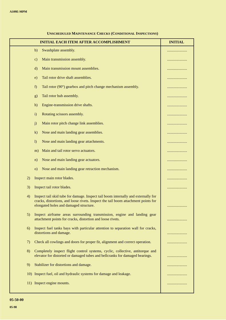
A B
C
D
A
B
C
DC
INITIAL EACH ITEM AFTER ACCOMPLISHMENT INITIAL
A109E-MPM
05-50-00
05-98
b) Swashplate assembly.
c) Main transmission assembly.
d) Main transmission mount assemblies.
e) Tail rotor drive shaft assemblies.
f) Tail rotor (90°) gearbox and pitch change mechanism assembly.
g) Tail rotor hub assembly.
h) Engine-transmission drive shafts.
i) Rotating scissors assembly.
j) Main rotor pitch change link assemblies.
k) Nose and main landing gear assemblies.
l) Nose and main landing gear attachments.
m) Main and tail rotor servo actuators.
n) Nose and main landing gear actuators.
o) Nose and main landing gear retraction mechanism.
2) Inspect main rotor blades.
3) Inspect tail rotor blades.
4) Inspect tail skid tube for damage. Inspect tail boom internally and externally forcracks, distortions, and loose rivets. Inspect the tail boom attachment points forelongated holes and damaged structure.
5) Inspect airframe areas surrounding transmission, engine and landing gearattachment points for cracks, distortion and loose rivets.
6) Inspect fuel tanks bays with particular attention to separation wall for cracks,distortions and damage.
7) Check all cowlings and doors for proper fit, alignment and correct operation.
8) Completely inspect flight control systems, cyclic, collective, antitorque andelevator for distorted or damaged tubes and bellcranks for damaged bearings.
9) Stabilizer for distortions and damage.
10) Inspect fuel, oil and hydraulic systems for damage and leakage.
11) Inspect engine mounts.
.....................
.....................
.....................
.....................
.....................
.....................
.....................
.....................
.....................
.....................
.....................
.....................
.....................
.....................
.....................
.....................
.....................
.....................
.....................
.....................
.....................
.....................
.....................
.....................
UNSCHEDULED MAINTENANCE CHECKS (CONDITIONAL INSPECTIONS)
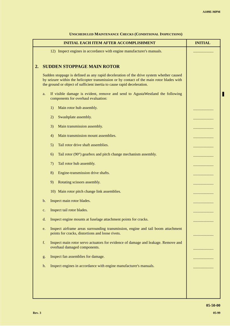
A B
C
D
A
B
C
DC
INITIAL EACH ITEM AFTER ACCOMPLISHMENT INITIAL
A109E-MPM
05-50-00
Rev. 3 05-99
12) Inspect engines in accordance with engine manufacturer's manuals.
2. SUDDEN STOPPAGE MAIN ROTOR
Sudden stoppage is defined as any rapid deceleration of the drive system whether causedby seizure within the helicopter transmission or by contact of the main rotor blades withthe ground or object of sufficient inertia to cause rapid deceleration.
a. If visible damage is evident, remove and send to AgustaWestland the followingcomponents for overhaul evaluation:
1) Main rotor hub assembly.
2) Swashplate assembly.
3) Main transmission assembly.
4) Main transmission mount assemblies.
5) Tail rotor drive shaft assemblies.
6) Tail rotor (90°) gearbox and pitch change mechanism assembly.
7) Tail rotor hub assembly.
8) Engine-transmission drive shafts.
9) Rotating scissors assembly.
10) Main rotor pitch change link assemblies.
b. Inspect main rotor blades.
c. Inspect tail rotor blades.
d. Inspect engine mounts at fuselage attachment points for cracks.
e. Inspect airframe areas surrounding transmission, engine and tail boom attachmentpoints for cracks, distortions and loose rivets.
f. Inspect main rotor servo actuators for evidence of damage and leakage. Remove andoverhaul damaged components.
g. Inspect fan assemblies for damage.
h. Inspect engines in accordance with engine manufacturer's manuals.
.....................
.....................
.....................
.....................
.....................
.....................
.....................
.....................
.....................
.....................
.....................
.....................
.....................
.....................
.....................
.....................
.....................
.....................
UNSCHEDULED MAINTENANCE CHECKS (CONDITIONAL INSPECTIONS)
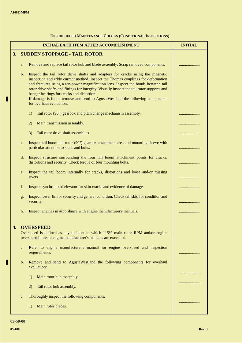
A B
C
D
A
B
C
DC
INITIAL EACH ITEM AFTER ACCOMPLISHMENT INITIAL
A109E-MPM
05-50-00
05-100 Rev. 3
3. SUDDEN STOPPAGE - TAIL ROTOR
a. Remove and replace tail rotor hub and blade assembly. Scrap removed components.
b. Inspect the tail rotor drive shafts and adapters for cracks using the magneticinspection and eddy current method. Inspect the Thomas couplings for deformationand fractures using a ten-power magnification lens. Inspect the bonds between tailrotor drive shafts and fittings for integrity. Visually inspect the tail rotor supports andhanger bearings for cracks and distortion.If damage is found remove and send to AgustaWestland the following componentsfor overhaul evaluation:
1) Tail rotor (90°) gearbox and pitch change mechanism assembly.
2) Main transmission assembly.
3) Tail rotor drive shaft assemblies.
c. Inspect tail boom tail rotor (90°) gearbox attachment area and mounting sleeve withparticular attention to studs and bolts.
d. Inspect structure surrounding the four tail boom attachment points for cracks,distortions and security. Check torque of four mounting bolts.
e. Inspect the tail boom internally for cracks, distortions and loose and/or missingrivets.
f. Inspect synchronized elevator for skin cracks and evidence of damage.
g. Inspect lower fin for security and general condition. Check tail skid for condition andsecurity.
h. Inspect engines in accordance with engine manufacturer's manuals.
4. OVERSPEEDOverspeed is defined as any incident in which 115% main rotor RPM and/or engineoverspeed limits in engine manufacturer's manuals are exceeded.
a. Refer to engine manufacturer's manual for engine overspeed and inspectionrequirements.
b. Remove and send to AgustaWestland the following components for overhaulevaluation:
1) Main rotor hub assembly.
2) Tail rotor hub assembly.
c. Thoroughly inspect the following components:
1) Main rotor blades.
.....................
.....................
.....................
.....................
.....................
.....................
.....................
.....................
.....................
.....................
.....................
.....................
.....................
.....................
UNSCHEDULED MAINTENANCE CHECKS (CONDITIONAL INSPECTIONS)
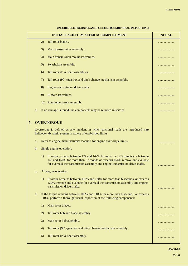
A B
C
D
A
B
C
DC
INITIAL EACH ITEM AFTER ACCOMPLISHMENT INITIAL
A109E-MPM
05-50-00
05-101
2) Tail rotor blades.
3) Main transmission assembly.
4) Main transmission mount assemblies.
5) Swashplate assembly.
6) Tail rotor drive shaft assemblies.
7) Tail rotor (90°) gearbox and pitch change mechanism assembly.
8) Engine-transmission drive shafts.
9) Blower assemblies.
10) Rotating scissors assembly.
d. If no damage is found, the components may be retained in service.
5. OVERTORQUE
Overtorque is defined as any incident in which torsional loads are introduced intohelicopter dynamic system in excess of established limits.
a. Refer to engine manufacturer's manuals for engine overtorque limits.
b. Single engine operation.
1) If torque remains between 124 and 142% for more than 2,5 minutes or between142 and 156% for more than 6 seconds or exceeds 156% remove and evaluatefor overhaul the transmission assembly and engine-transmission drive shafts.
c. All engine operation.
1) If torque remains between 110% and 120% for more than 6 seconds, or exceeds120%, remove and evaluate for overhaul the transmission assembly and engine-transmission drive shafts.
d. If the torque remains between 100% and 110% for more than 6 seconds, or exceeds110%, perform a thorough visual inspection of the following components:
1) Main rotor blades.
2) Tail rotor hub and blade assembly.
3) Main rotor hub assembly.
4) Tail rotor (90°) gearbox and pitch change mechanism assembly.
5) Tail rotor drive shaft assembly.
.....................
.....................
.....................
.....................
.....................
.....................
.....................
.....................
.....................
.....................
.....................
.....................
.....................
.....................
.....................
.....................
.....................
.....................
UNSCHEDULED MAINTENANCE CHECKS (CONDITIONAL INSPECTIONS)
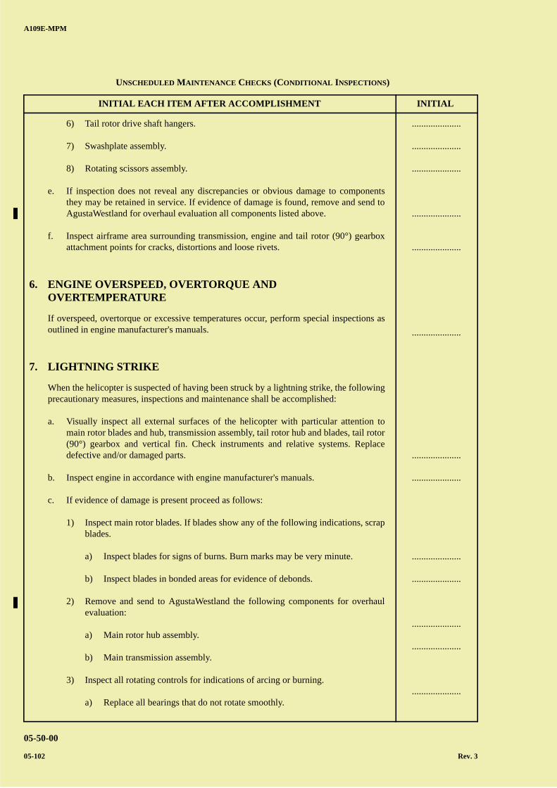
A B
C
D
A
B
C
DC
INITIAL EACH ITEM AFTER ACCOMPLISHMENT INITIAL
A109E-MPM
05-50-00
05-102 Rev. 3
6) Tail rotor drive shaft hangers.
7) Swashplate assembly.
8) Rotating scissors assembly.
e. If inspection does not reveal any discrepancies or obvious damage to componentsthey may be retained in service. If evidence of damage is found, remove and send toAgustaWestland for overhaul evaluation all components listed above.
f. Inspect airframe area surrounding transmission, engine and tail rotor (90°) gearboxattachment points for cracks, distortions and loose rivets.
6. ENGINE OVERSPEED, OVERTORQUE ANDOVERTEMPERATURE
If overspeed, overtorque or excessive temperatures occur, perform special inspections asoutlined in engine manufacturer's manuals.
7. LIGHTNING STRIKE
When the helicopter is suspected of having been struck by a lightning strike, the followingprecautionary measures, inspections and maintenance shall be accomplished:
a. Visually inspect all external surfaces of the helicopter with particular attention tomain rotor blades and hub, transmission assembly, tail rotor hub and blades, tail rotor(90°) gearbox and vertical fin. Check instruments and relative systems. Replacedefective and/or damaged parts.
b. Inspect engine in accordance with engine manufacturer's manuals.
c. If evidence of damage is present proceed as follows:
1) Inspect main rotor blades. If blades show any of the following indications, scrapblades.
a) Inspect blades for signs of burns. Burn marks may be very minute.
b) Inspect blades in bonded areas for evidence of debonds.
2) Remove and send to AgustaWestland the following components for overhaulevaluation:
a) Main rotor hub assembly.
b) Main transmission assembly.
3) Inspect all rotating controls for indications of arcing or burning.
a) Replace all bearings that do not rotate smoothly.
.....................
.....................
.....................
.....................
.....................
.....................
.....................
.....................
.....................
.....................
.....................
.....................
.....................
UNSCHEDULED MAINTENANCE CHECKS (CONDITIONAL INSPECTIONS)
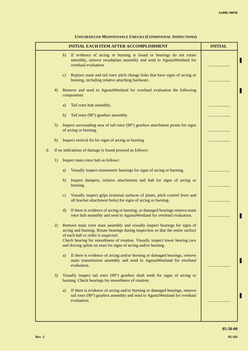
A B
C
D
A
B
C
DC
INITIAL EACH ITEM AFTER ACCOMPLISHMENT INITIAL
A109E-MPM
05-50-00
Rev. 3 05-103
b) If evidence of arcing or burning is found or bearings do not rotatesmoothly, remove swashplate assembly and send to AgustaWestland foroverhaul evaluation.
c) Replace main and tail rotor pitch change links that have signs of arcing orburning, including relative attaching hardware.
4) Remove and send to AgustaWestland for overhaul evaluation the followingcomponents:
a) Tail rotor hub assembly.
b) Tail rotor (90°) gearbox assembly.
5) Inspect surrounding area of tail rotor (90°) gearbox attachment points for signsof arcing or burning.
6) Inspect vertical fin for signs of arcing or burning.
d. If no indications of damage is found proceed as follows:
1) Inspect main rotor hub as follows:
a) Visually inspect elastomeric bearings for signs of arcing or burning.
b) Inspect dampers, relative attachments and hub for signs of arcing orburning.
c) Visually inspect grips (external surfaces of plates, pitch control lever andaft bracket attachment bolts) for signs of arcing or burning.
d) If there is evidence of arcing or burning, or damaged bearings remove mainrotor hub assembly and send to AgustaWestland for overhaul evaluation.
2) Remove main rotor mast assembly and visually inspect bearings for signs ofarcing and burning. Rotate bearings during inspection so that the entire surfaceof each ball or roller is inspected.Check bearing for smoothness of rotation. Visually inspect lower bearing raceand driving spline on mast for signs of arcing and/or burning.
a) If there is evidence of arcing and/or burning or damaged bearings, removemain transmission assembly and send to AgustaWestland for overhaulevaluation.
3) Visually inspect tail rotor (90°) gearbox shaft teeth for signs of arcing orburning. Check bearings for smoothness of rotation.
a) If there is evidence of arcing and/or burning or damaged bearings, removetail rotor (90°) gearbox assembly and send to AgustaWestland for overhaulevaluation.
.....................
.....................
.....................
.....................
.....................
.....................
.....................
.....................
.....................
.....................
.....................
.....................
UNSCHEDULED MAINTENANCE CHECKS (CONDITIONAL INSPECTIONS)
A B
C
D
A
B
C
DC
INITIAL EACH ITEM AFTER ACCOMPLISHMENT INITIAL
A109E-MPM
05-50-00
05-104
8. OPERATIONS IN HIGH CORROSIVE ENVIRONMENTS
If the helicopter operates in high corrosive environments such as marine atmospheres,industrial pollution, agricultural sprays, corrosion soils, abrasive dust and extremetemperatures refer to Section 20-30 of A109E-MM.
.....................
UNSCHEDULED MAINTENANCE CHECKS (CONDITIONAL INSPECTIONS)
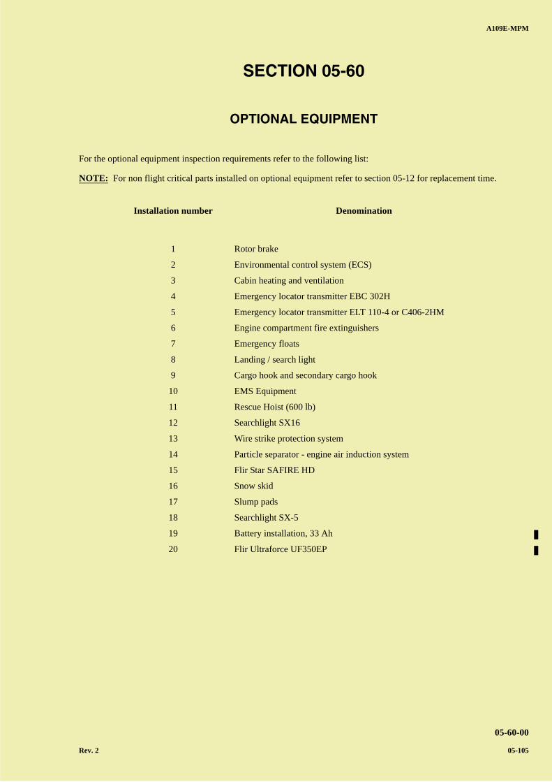
A B
C
D
A
B
C
DC
A109E-MPM
05-60-00
Rev. 2 05-105
SECTION 05-60
OPTIONAL EQUIPMENT
For the optional equipment inspection requirements refer to the following list:
NOTE: For non flight critical parts installed on optional equipment refer to section 05-12 for replacement time.
Installation number Denomination
1 Rotor brake
2 Environmental control system (ECS)
3 Cabin heating and ventilation
4 Emergency locator transmitter EBC 302H
5 Emergency locator transmitter ELT 110-4 or C406-2HM
6 Engine compartment fire extinguishers
7 Emergency floats
8 Landing / search light
9 Cargo hook and secondary cargo hook
10 EMS Equipment
11 Rescue Hoist (600 lb)
12 Searchlight SX16
13 Wire strike protection system
14 Particle separator - engine air induction system
15 Flir Star SAFIRE HD
16 Snow skid
17 Slump pads
18 Searchlight SX-5
19 Battery installation, 33 Ah
20 Flir Ultraforce UF350EP

A B
C
D
A
B
C
DC
A109E-MPM
05-60-00
05-106
PAGE INTENTIONALLY LEFT BLANK
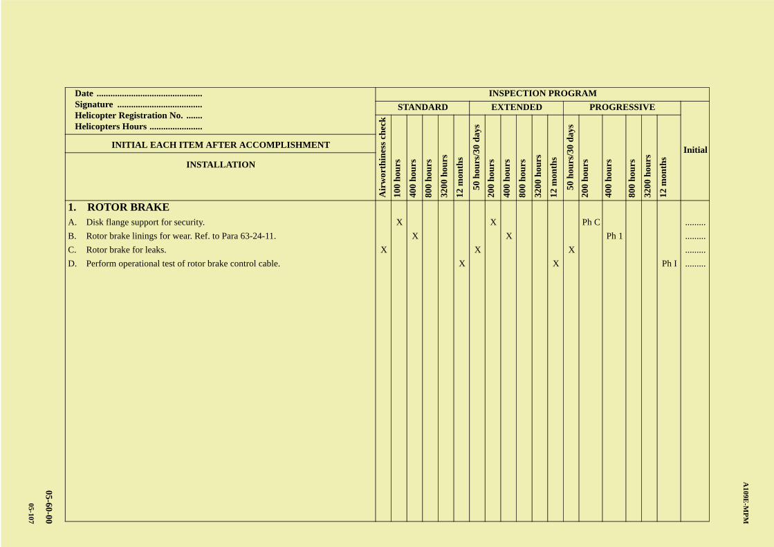
AB
CD
ABCDC
A109E
-MP
M
05-60-00
05-107
Date .............................................. Signature ..................................... Helicopter Registration No. ....... Helicopters Hours .......................
INSPECTION PROGRAM
STANDARD EXTENDED PROGRESSIVE
Initial
Air
wor
thin
ess
chec
k
100
hou
rs
400
hou
rs
800
hou
rs
3200
hou
rs
12 m
onth
s
50 h
ours
/30
day
s
200
hou
rs
400
hou
rs
800
hou
rs
3200
hou
rs
12 m
onth
s
50 h
ours
/30
day
s
200
hou
rs
400
hou
rs
800
hou
rs
3200
hou
rs
12 m
onth
s
INITIAL EACH ITEM AFTER ACCOMPLISHMENT
INSTALLATION
1. ROTOR BRAKEA. Disk flange support for security. X X Ph C .........
B. Rotor brake linings for wear. Ref. to Para 63-24-11. X X Ph 1 .........
C. Rotor brake for leaks. X X X .........
D. Perform operational test of rotor brake control cable. X X Ph I .........

A B
C
D
A
B
C
DC
A109E-MPM
05-60-00
05-108
PAGE INTENTIONALLY LEFT BLANK
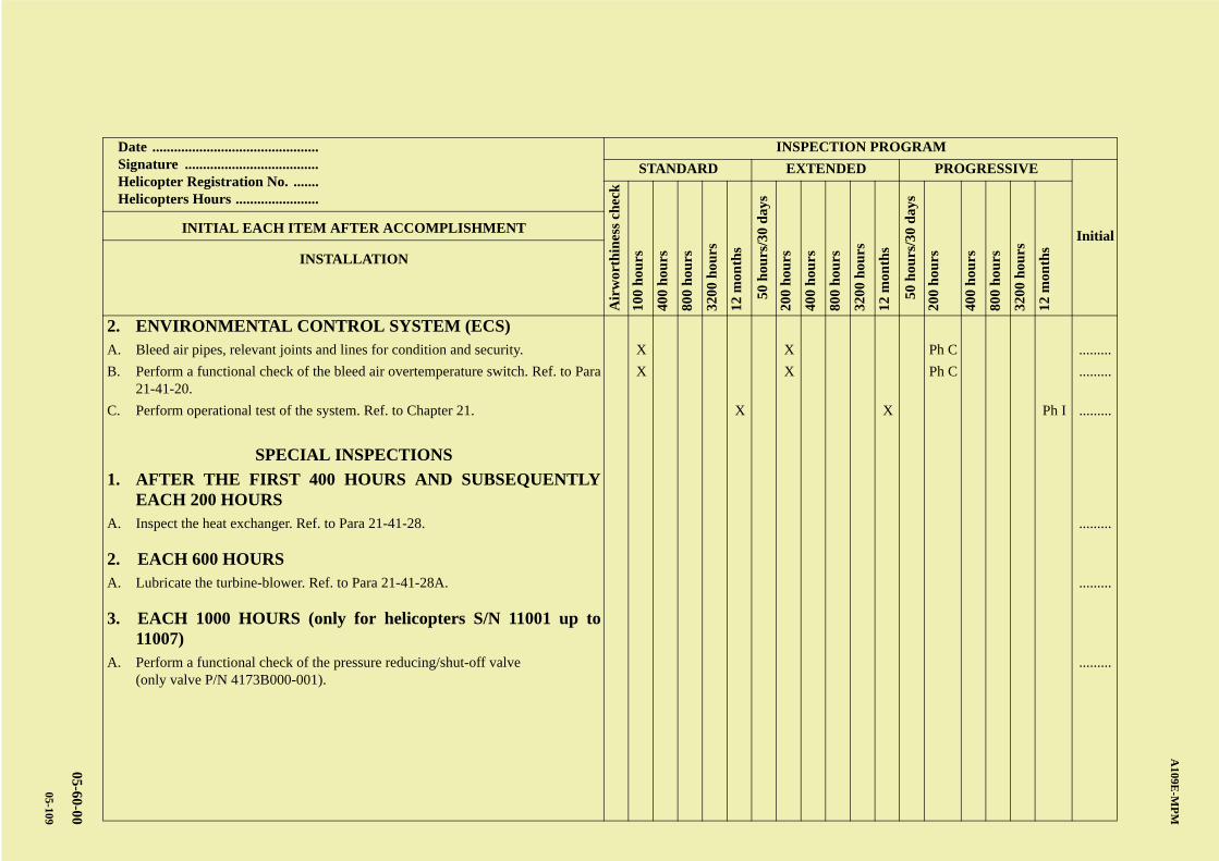
AB
CD
ABCDC
A109E
-MP
M
05-60-00
05-109
Date .............................................. Signature ..................................... Helicopter Registration No. ....... Helicopters Hours .......................
INSPECTION PROGRAM
STANDARD EXTENDED PROGRESSIVE
Initial
Air
wor
thin
ess
chec
k
100
hou
rs
400
hou
rs
800
hou
rs
3200
hou
rs
12 m
onth
s
50 h
ours
/30
day
s
200
hou
rs
400
hou
rs
800
hou
rs
3200
hou
rs
12 m
onth
s
50 h
ours
/30
day
s
200
hou
rs
400
hou
rs
800
hou
rs
3200
hou
rs
12 m
onth
s
INITIAL EACH ITEM AFTER ACCOMPLISHMENT
INSTALLATION
2. ENVIRONMENTAL CONTROL SYSTEM (ECS)A. Bleed air pipes, relevant joints and lines for condition and security. X X Ph C .........
B. Perform a functional check of the bleed air overtemperature switch. Ref. to Para21-41-20.
X X Ph C .........
C. Perform operational test of the system. Ref. to Chapter 21. X X Ph I .........
SPECIAL INSPECTIONS
1. AFTER THE FIRST 400 HOURS AND SUBSEQUENTLYEACH 200 HOURS
A. Inspect the heat exchanger. Ref. to Para 21-41-28. .........
2. EACH 600 HOURSA. Lubricate the turbine-blower. Ref. to Para 21-41-28A. .........
3. EACH 1000 HOURS (only for helicopters S/N 11001 up to11007)
A. Perform a functional check of the pressure reducing/shut-off valve(only valve P/N 4173B000-001).
.........

A B
C
D
A
B
C
DC
A109E-MPM
05-60-00
05-110
PAGE INTENTIONALLY LEFT BLANK
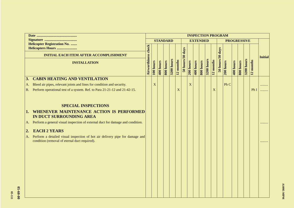
AB
CD
ABCDC
A109E
-MP
M
05-60-00
05-111
Date .............................................. Signature ..................................... Helicopter Registration No. ....... Helicopters Hours .......................
INSPECTION PROGRAM
STANDARD EXTENDED PROGRESSIVE
Initial
Air
wor
thin
ess
chec
k
100
hou
rs
400
hou
rs
800
hou
rs
3200
hou
rs
12 m
onth
s
50 h
ours
/30
day
s
200
hou
rs
400
hou
rs
800
hou
rs
3200
hou
rs
12 m
onth
s
50 h
ours
/30
day
s
200
hou
rs
400
hou
rs
800
hou
rs
3200
hou
rs
12 m
onth
s
INITIAL EACH ITEM AFTER ACCOMPLISHMENT
INSTALLATION
3. CABIN HEATING AND VENTILATIONA. Bleed air pipes, relevant joints and lines for condition and security. X X Ph C .........
B. Perform operational test of a system. Ref. to Para 21-21-12 and 21-42-15. X X Ph I .........
SPECIAL INSPECTIONS
1. WHENEVER MAINTENANCE ACTION IS PERFORMEDIN DUCT SURROUNDING AREA
A. Perform a general visual inspection of external duct for damage and condition. .........
2. EACH 2 YEARSA. Perform a detailed visual inspection of hot air delivery pipe for damage and
condition (removal of eternal duct required). .........

A B
C
D
A
B
C
DC
A109E-MPM
05-60-00
05-112
PAGE INTENTIONALLY LEFT BLANK
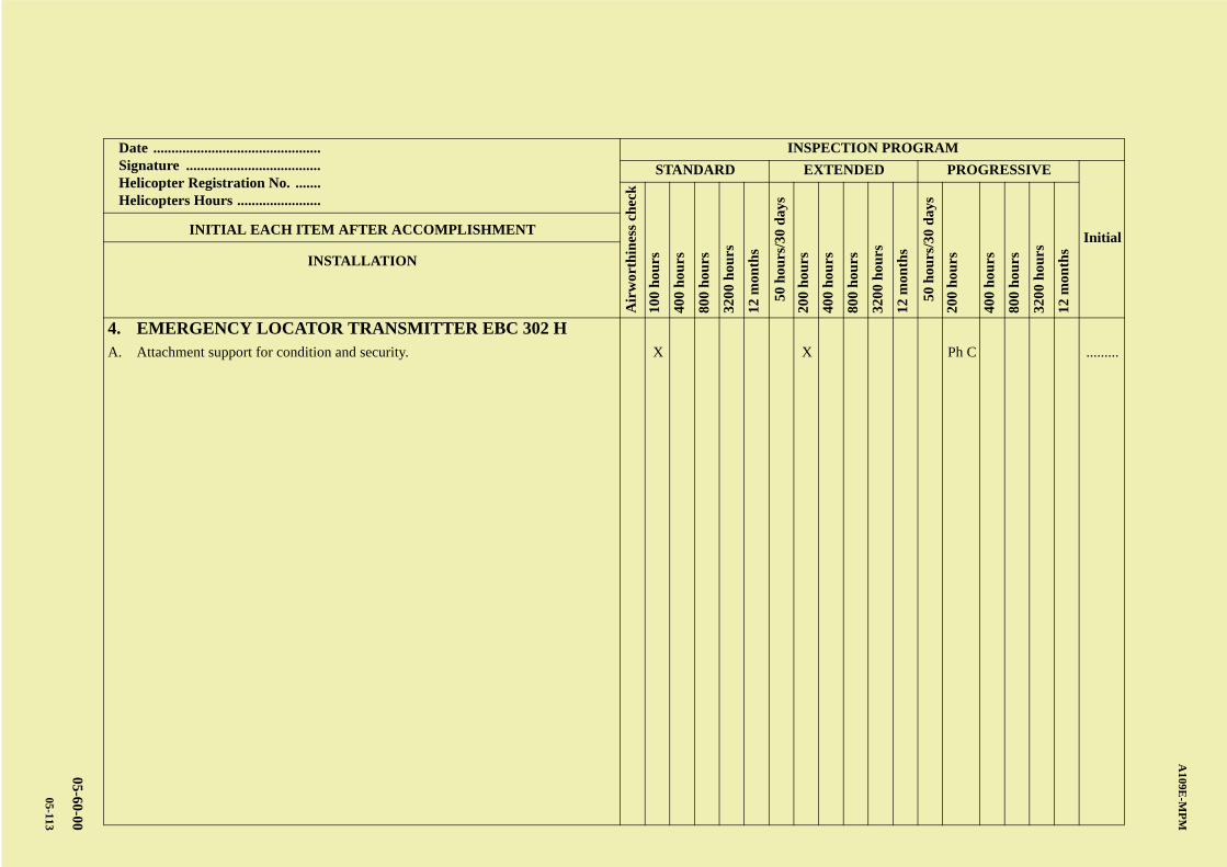
AB
CD
ABCDC
A109E
-MP
M
05-60-00
05-113
Date .............................................. Signature ..................................... Helicopter Registration No. ....... Helicopters Hours .......................
INSPECTION PROGRAM
STANDARD EXTENDED PROGRESSIVE
Initial
Air
wor
thin
ess
chec
k
100
hou
rs
400
hou
rs
800
hou
rs
3200
hou
rs
12 m
onth
s
50 h
ours
/30
day
s
200
hou
rs
400
hou
rs
800
hou
rs
3200
hou
rs
12 m
onth
s
50 h
ours
/30
day
s
200
hou
rs
400
hou
rs
800
hou
rs
3200
hou
rs
12 m
onth
s
INITIAL EACH ITEM AFTER ACCOMPLISHMENT
INSTALLATION
4. EMERGENCY LOCATOR TRANSMITTER EBC 302 HA. Attachment support for condition and security. X X Ph C .........

A B
C
D
A
B
C
DC
A109E-MPM
05-60-00
05-114
PAGE INTENTIONALLY LEFT BLANK
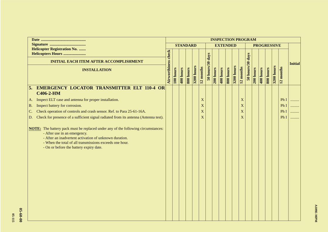
AB
CD
ABCDC
A109E
-MP
M
05-60-00
05-115
Date .............................................. Signature ..................................... Helicopter Registration No. ....... Helicopters Hours .......................
INSPECTION PROGRAM
STANDARD EXTENDED PROGRESSIVE
Initial
Air
wor
thin
ess
chec
k
100
hou
rs
400
hou
rs
800
hou
rs
3200
hou
rs
12 m
onth
s
50 h
ours
/30
day
s
200
hou
rs
400
hou
rs
800
hou
rs
3200
hou
rs
12 m
onth
s
50 h
ours
/30
day
s
200
hou
rs
400
hou
rs
800
hou
rs
3200
hou
rs
12 m
onth
s
INITIAL EACH ITEM AFTER ACCOMPLISHMENT
INSTALLATION
5. EMERGENCY LOCATOR TRANSMITTER ELT 110-4 ORC406-2-HM
A. Inspect ELT case and antenna for proper installation. X X Ph I .........
B. Inspect battery for corrosion. X X Ph I .........
C. Check operation of controls and crash sensor. Ref. to Para 25-61-16A. X X Ph I .........
D. Check for presence of a sufficient signal radiated from its antenna (Antenna test). X X Ph I .........
NOTE: The battery pack must be replaced under any of the following circumstances:- After use in an emergency.- After an inadvertent activation of unknown duration.- When the total of all transmissions exceeds one hour.- On or before the battery expiry date.

A B
C
D
A
B
C
DC
A109E-MPM
05-60-00
05-116
PAGE INTENTIONALLY LEFT BLANK
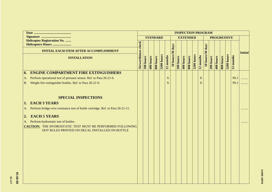
AB
CD
ABCDC
A109E
-MP
M
05-60-00
05-117
Date .............................................. Signature ..................................... Helicopter Registration No. ....... Helicopters Hours .......................
INSPECTION PROGRAM
STANDARD EXTENDED PROGRESSIVE
Initial
Air
wor
thin
ess
chec
k
100
hou
rs
400
hou
rs
800
hou
rs
3200
hou
rs
12 m
onth
s
50 h
ours
/30
day
s
200
hou
rs
400
hou
rs
800
hou
rs
3200
hou
rs
12 m
onth
s
50 h
ours
/30
day
s
200
hou
rs
400
hou
rs
800
hou
rs
3200
hou
rs
12 m
onth
s
INITIAL EACH ITEM AFTER ACCOMPLISHMENT
INSTALLATION
6. ENGINE COMPARTMENT FIRE EXTINGUISHERSA. Perform operational test of pressure sensor. Ref. to Para 26-21-6. X X Ph I .........
B. Weight fire extinguisher bottles. Ref. to Para 26-21-9. X X Ph I .........
SPECIAL INSPECTIONS
1. EACH 3 YEARSA. Perform bridge-wire resistance test of bottle cartridge. Ref. to Para 26-21-11. .........
2. EACH 5 YEARSA. Perform hydrostatic test of bottles. .........
CAUTION: THE HYDROSTATIC TEST MUST BE PERFORMED FOLLOWINGDOT RULES PRINTED ON DECAL INSTALLED ON BOTTLE

A B
C
D
A
B
C
DC
A109E-MPM
05-60-00
05-118
PAGE INTENTIONALLY LEFT BLANK
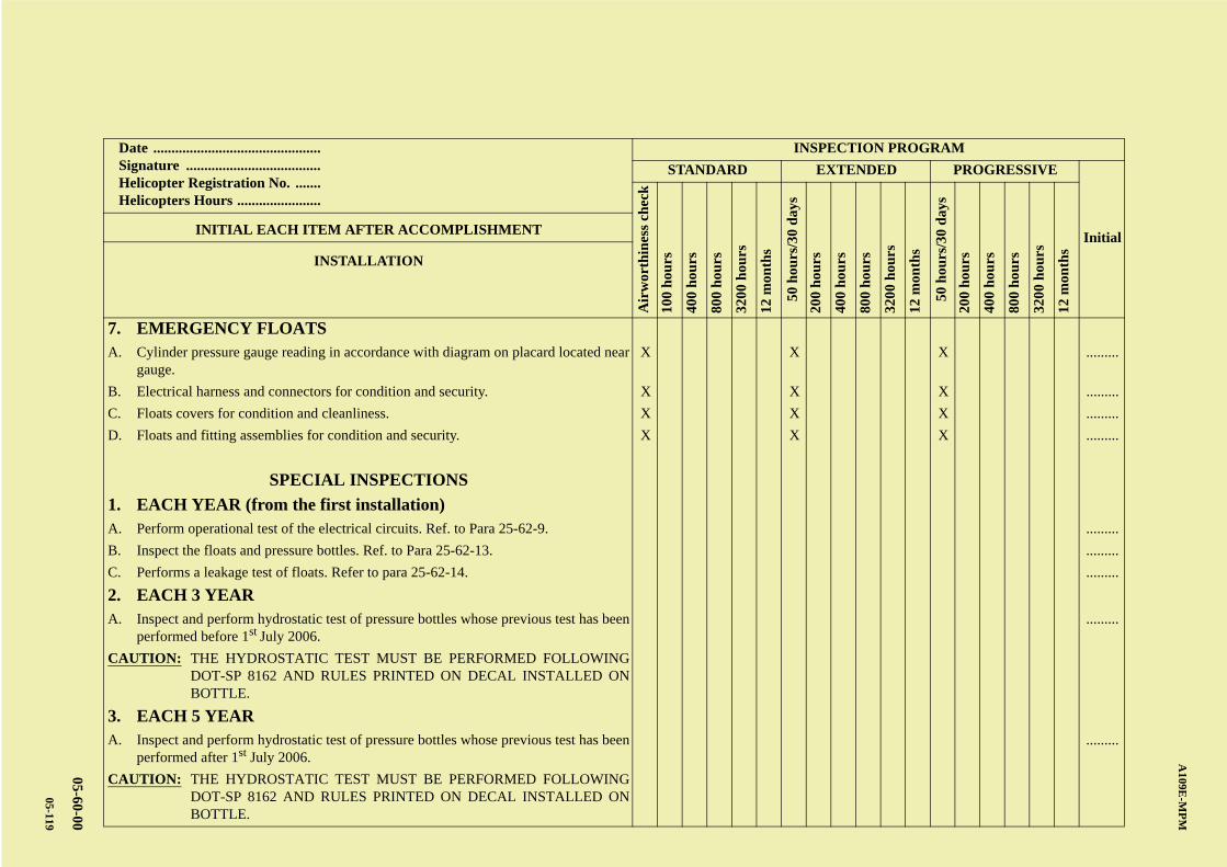
AB
CD
ABCDC
A109E
-MP
M
05-60-00
05-119
Date .............................................. Signature ..................................... Helicopter Registration No. ....... Helicopters Hours .......................
INSPECTION PROGRAM
STANDARD EXTENDED PROGRESSIVE
Initial
Air
wor
thin
ess
chec
k
100
hou
rs
400
hou
rs
800
hou
rs
3200
hou
rs
12 m
onth
s
50 h
ours
/30
day
s
200
hou
rs
400
hou
rs
800
hou
rs
3200
hou
rs
12 m
onth
s
50 h
ours
/30
day
s
200
hou
rs
400
hou
rs
800
hou
rs
3200
hou
rs
12 m
onth
s
INITIAL EACH ITEM AFTER ACCOMPLISHMENT
INSTALLATION
7. EMERGENCY FLOATSA. Cylinder pressure gauge reading in accordance with diagram on placard located near
gauge.X X X .........
B. Electrical harness and connectors for condition and security. X X X .........
C. Floats covers for condition and cleanliness. X X X .........
D. Floats and fitting assemblies for condition and security. X X X .........
SPECIAL INSPECTIONS
1. EACH YEAR (from the first installation) A. Perform operational test of the electrical circuits. Ref. to Para 25-62-9. .........
B. Inspect the floats and pressure bottles. Ref. to Para 25-62-13. .........
C. Performs a leakage test of floats. Refer to para 25-62-14. .........
2. EACH 3 YEARA. Inspect and perform hydrostatic test of pressure bottles whose previous test has been
performed before 1st July 2006..........
CAUTION: THE HYDROSTATIC TEST MUST BE PERFORMED FOLLOWINGDOT-SP 8162 AND RULES PRINTED ON DECAL INSTALLED ONBOTTLE.
3. EACH 5 YEARA. Inspect and perform hydrostatic test of pressure bottles whose previous test has been
performed after 1st July 2006..........
CAUTION: THE HYDROSTATIC TEST MUST BE PERFORMED FOLLOWINGDOT-SP 8162 AND RULES PRINTED ON DECAL INSTALLED ONBOTTLE.

A B
C
D
A
B
C
DC
A109E-MPM
05-60-00
05-120
PAGE INTENTIONALLY LEFT BLANK
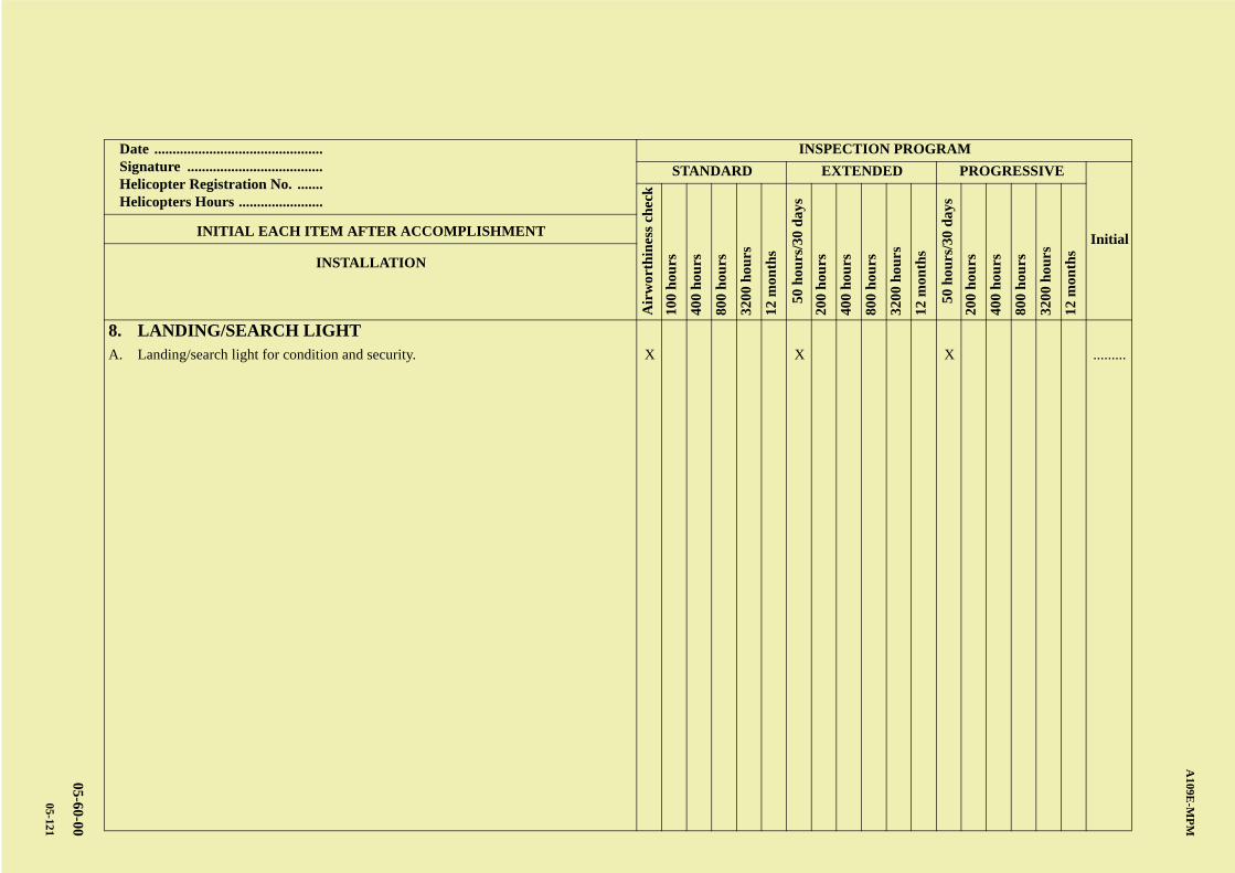
AB
CD
ABCDC
A109E
-MP
M
05-60-00
05-121
Date .............................................. Signature ..................................... Helicopter Registration No. ....... Helicopters Hours .......................
INSPECTION PROGRAM
STANDARD EXTENDED PROGRESSIVE
Initial
Air
wor
thin
ess
chec
k
100
hou
rs
400
hou
rs
800
hou
rs
3200
hou
rs
12 m
onth
s
50 h
ours
/30
day
s
200
hou
rs
400
hou
rs
800
hou
rs
3200
hou
rs
12 m
onth
s
50 h
ours
/30
day
s
200
hou
rs
400
hou
rs
800
hou
rs
3200
hou
rs
12 m
onth
s
INITIAL EACH ITEM AFTER ACCOMPLISHMENT
INSTALLATION
8. LANDING/SEARCH LIGHTA. Landing/search light for condition and security. X X X .........

A B
C
D
A
B
C
DC
A109E-MPM
05-60-00
05-122
PAGE INTENTIONALLY LEFT BLANK
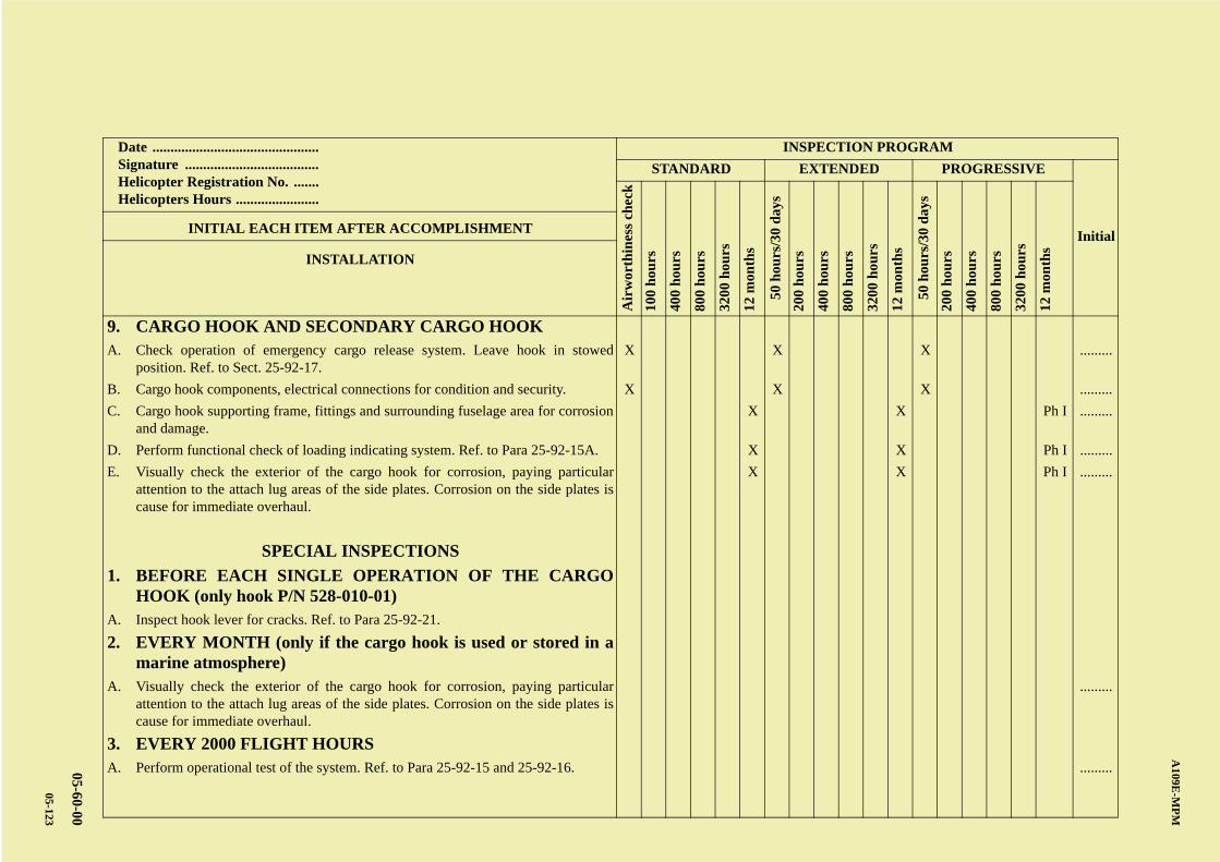
AB
CD
ABCDC
A109E
-MP
M
05-60-00
05-123
Date .............................................. Signature ..................................... Helicopter Registration No. ....... Helicopters Hours .......................
INSPECTION PROGRAM
STANDARD EXTENDED PROGRESSIVE
Initial
Air
wor
thin
ess
chec
k
100
hou
rs
400
hou
rs
800
hou
rs
3200
hou
rs
12 m
onth
s
50 h
ours
/30
day
s
200
hou
rs
400
hou
rs
800
hou
rs
3200
hou
rs
12 m
onth
s
50 h
ours
/30
day
s
200
hou
rs
400
hou
rs
800
hou
rs
3200
hou
rs
12 m
onth
s
INITIAL EACH ITEM AFTER ACCOMPLISHMENT
INSTALLATION
9. CARGO HOOK AND SECONDARY CARGO HOOKA. Check operation of emergency cargo release system. Leave hook in stowed
position. Ref. to Sect. 25-92-17.X X X .........
B. Cargo hook components, electrical connections for condition and security. X X X .........
C. Cargo hook supporting frame, fittings and surrounding fuselage area for corrosionand damage.
X X Ph I .........
D. Perform functional check of loading indicating system. Ref. to Para 25-92-15A. X X Ph I .........
E. Visually check the exterior of the cargo hook for corrosion, paying particularattention to the attach lug areas of the side plates. Corrosion on the side plates iscause for immediate overhaul.
X X Ph I .........
SPECIAL INSPECTIONS
1. BEFORE EACH SINGLE OPERATION OF THE CARGOHOOK (only hook P/N 528-010-01)
A. Inspect hook lever for cracks. Ref. to Para 25-92-21.
2. EVERY MONTH (only if the cargo hook is used or stored in amarine atmosphere)
A. Visually check the exterior of the cargo hook for corrosion, paying particularattention to the attach lug areas of the side plates. Corrosion on the side plates iscause for immediate overhaul.
.........
3. EVERY 2000 FLIGHT HOURSA. Perform operational test of the system. Ref. to Para 25-92-15 and 25-92-16. .........

A B
C
D
A
B
C
DC
A109E-MPM
05-60-00
05-124
PAGE INTENTIONALLY LEFT BLANK
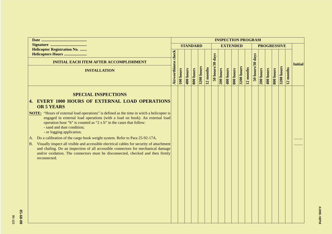
AB
CD
ABCDC
A109E
-MP
M
05-60-00
05-125
Date .............................................. Signature ..................................... Helicopter Registration No. ....... Helicopters Hours .......................
INSPECTION PROGRAM
STANDARD EXTENDED PROGRESSIVE
Initial
Air
wor
thin
ess
chec
k
100
hou
rs
400
hou
rs
800
hou
rs
3200
hou
rs
12 m
onth
s
50 h
ours
/30
day
s
200
hou
rs
400
hou
rs
800
hou
rs
3200
hou
rs
12 m
onth
s
50 h
ours
/30
day
s
200
hou
rs
400
hou
rs
800
hou
rs
3200
hou
rs
12 m
onth
s
INITIAL EACH ITEM AFTER ACCOMPLISHMENT
INSTALLATION
SPECIAL INSPECTIONS
4. EVERY 1000 HOURS OF EXTERNAL LOAD OPERATIONSOR 5 YEARS
NOTE: “Hours of external load operations” is defined as the time in witch a helicopter isengaged in external load operations (with a load on hook). An external loadoperation hour “h” is counted as “2 x h” in the cases that follow:- sand and dust condition;- or logging application.
A. Do a calibration of the cargo hook weight system. Refer to Para 25-92-17A. .........
B. Visually inspect all visible and accessible electrical cables for security of attachmentand chafing. Do an inspection of all accessible connectors for mechanical damageand/or oxidation. The connectors must be disconnected, checked and then firmlyreconnected.
.........

A B
C
D
A
B
C
DC
A109E-MPM
05-60-00
05-126
PAGE INTENTIONALLY LEFT BLANK
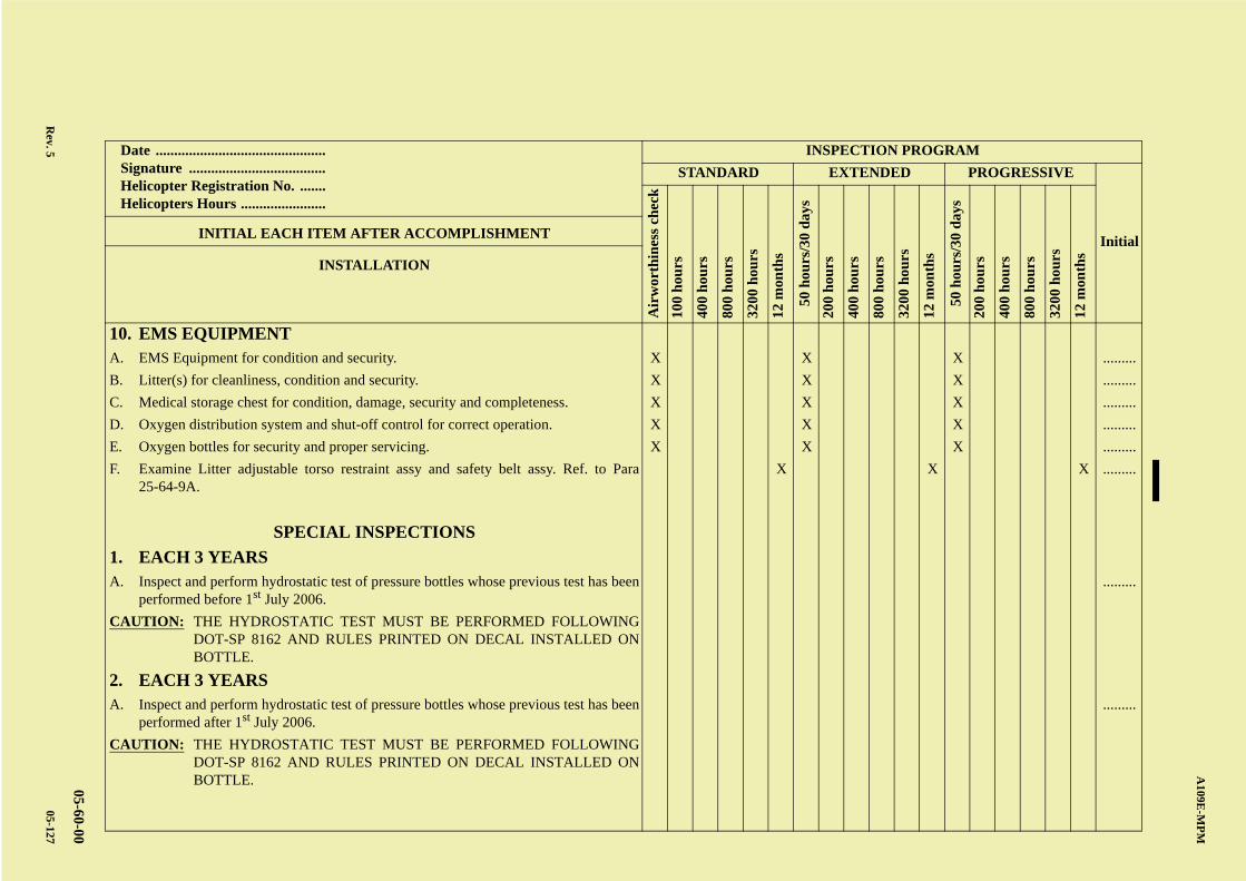
AB
CD
ABCDC
A109E
-MP
M
05-60-00
Rev. 5
05-127
Date .............................................. Signature ..................................... Helicopter Registration No. ....... Helicopters Hours .......................
INSPECTION PROGRAM
STANDARD EXTENDED PROGRESSIVE
Initial
Air
wor
thin
ess
chec
k
100
hou
rs
400
hou
rs
800
hou
rs
3200
hou
rs
12 m
onth
s
50 h
ours
/30
day
s
200
hou
rs
400
hou
rs
800
hou
rs
3200
hou
rs
12 m
onth
s
50 h
ours
/30
day
s
200
hou
rs
400
hou
rs
800
hou
rs
3200
hou
rs
12 m
onth
s
INITIAL EACH ITEM AFTER ACCOMPLISHMENT
INSTALLATION
10. EMS EQUIPMENTA. EMS Equipment for condition and security. X X X .........
B. Litter(s) for cleanliness, condition and security. X X X .........
C. Medical storage chest for condition, damage, security and completeness. X X X .........
D. Oxygen distribution system and shut-off control for correct operation. X X X .........
E. Oxygen bottles for security and proper servicing. X X X .........
F. Examine Litter adjustable torso restraint assy and safety belt assy. Ref. to Para25-64-9A.
X X X .........
SPECIAL INSPECTIONS
1. EACH 3 YEARSA. Inspect and perform hydrostatic test of pressure bottles whose previous test has been
performed before 1st July 2006..........
CAUTION: THE HYDROSTATIC TEST MUST BE PERFORMED FOLLOWINGDOT-SP 8162 AND RULES PRINTED ON DECAL INSTALLED ONBOTTLE.
2. EACH 3 YEARSA. Inspect and perform hydrostatic test of pressure bottles whose previous test has been
performed after 1st July 2006..........
CAUTION: THE HYDROSTATIC TEST MUST BE PERFORMED FOLLOWINGDOT-SP 8162 AND RULES PRINTED ON DECAL INSTALLED ONBOTTLE.

A B
C
D
A
B
C
DC
A109E-MPM
05-60-00
05-128
PAGE INTENTIONALLY LEFT BLANK
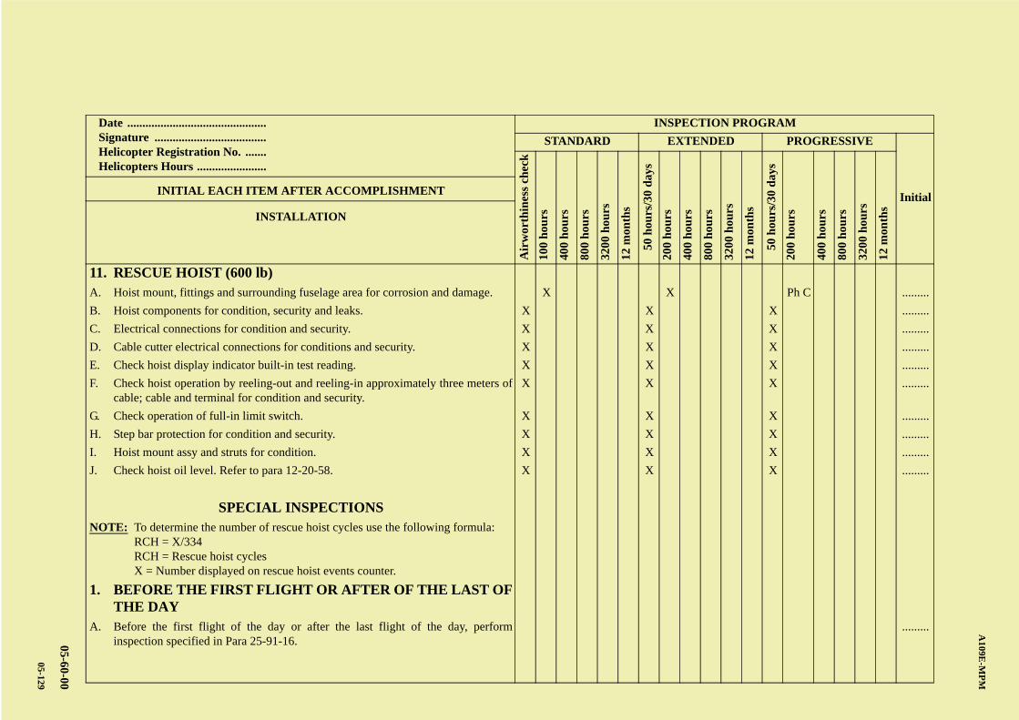
AB
CD
ABCDC
A109E
-MP
M
05-60-00
05-129
Date .............................................. Signature ..................................... Helicopter Registration No. ....... Helicopters Hours .......................
INSPECTION PROGRAM
STANDARD EXTENDED PROGRESSIVE
Initial
Air
wor
thin
ess
chec
k
100
hou
rs
400
hou
rs
800
hou
rs
3200
hou
rs
12 m
onth
s
50 h
ours
/30
day
s
200
hou
rs
400
hou
rs
800
hou
rs
3200
hou
rs
12 m
onth
s
50 h
ours
/30
day
s
200
hou
rs
400
hou
rs
800
hou
rs
3200
hou
rs
12 m
onth
s
INITIAL EACH ITEM AFTER ACCOMPLISHMENT
INSTALLATION
11. RESCUE HOIST (600 lb)A. Hoist mount, fittings and surrounding fuselage area for corrosion and damage. X X Ph C .........
B. Hoist components for condition, security and leaks. X X X .........
C. Electrical connections for condition and security. X X X .........
D. Cable cutter electrical connections for conditions and security. X X X .........
E. Check hoist display indicator built-in test reading. X X X .........
F. Check hoist operation by reeling-out and reeling-in approximately three meters ofcable; cable and terminal for condition and security.
X X X .........
G. Check operation of full-in limit switch. X X X .........
H. Step bar protection for condition and security. X X X .........
I. Hoist mount assy and struts for condition. X X X .........
J. Check hoist oil level. Refer to para 12-20-58. X X X .........
SPECIAL INSPECTIONSNOTE: To determine the number of rescue hoist cycles use the following formula:
RCH = X/334RCH = Rescue hoist cyclesX = Number displayed on rescue hoist events counter.
1. BEFORE THE FIRST FLIGHT OR AFTER OF THE LAST OFTHE DAY
A. Before the first flight of the day or after the last flight of the day, performinspection specified in Para 25-91-16.
.........

A B
C
D
A
B
C
DC
A109E-MPM
05-60-00
05-130
PAGE INTENTIONALLY LEFT BLANK
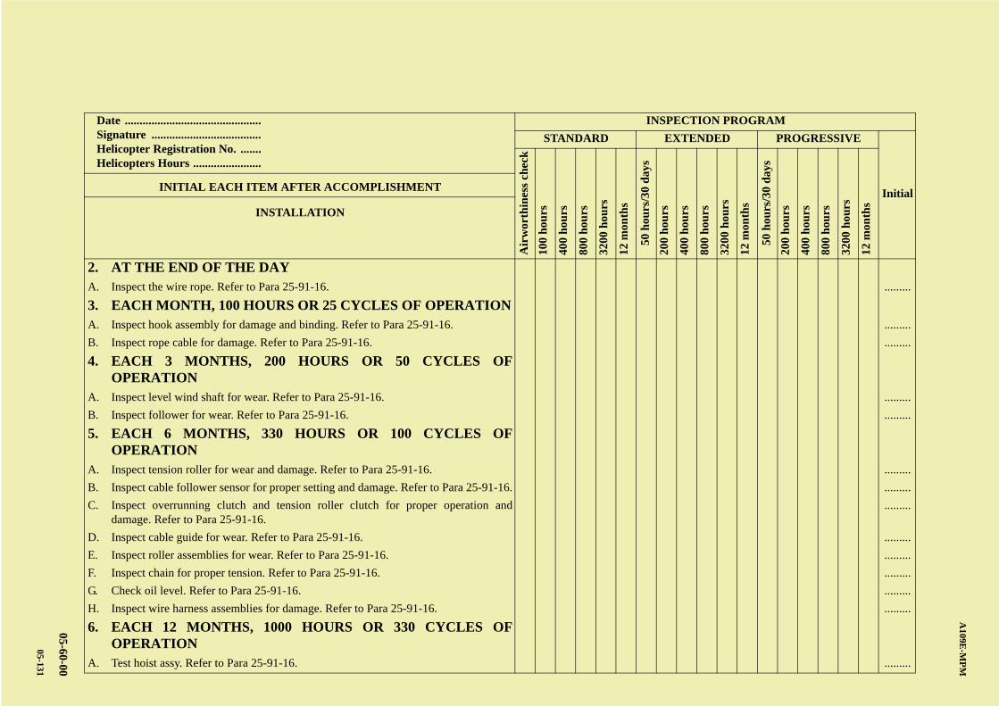
AB
CD
ABCDC
A109E
-MP
M
05-60-00
05-131
Date .............................................. Signature ..................................... Helicopter Registration No. ....... Helicopters Hours .......................
INSPECTION PROGRAM
STANDARD EXTENDED PROGRESSIVE
Initial
Air
wor
thin
ess
chec
k
100
hou
rs
400
hou
rs
800
hou
rs
3200
hou
rs
12 m
onth
s
50 h
ours
/30
day
s
200
hou
rs
400
hou
rs
800
hou
rs
3200
hou
rs
12 m
onth
s
50 h
ours
/30
day
s
200
hou
rs
400
hou
rs
800
hou
rs
3200
hou
rs
12 m
onth
s
INITIAL EACH ITEM AFTER ACCOMPLISHMENT
INSTALLATION
2. AT THE END OF THE DAYA. Inspect the wire rope. Refer to Para 25-91-16. .........
3. EACH MONTH, 100 HOURS OR 25 CYCLES OF OPERATIONA. Inspect hook assembly for damage and binding. Refer to Para 25-91-16. .........
B. Inspect rope cable for damage. Refer to Para 25-91-16. .........
4. EACH 3 MONTHS, 200 HOURS OR 50 CYCLES OFOPERATION
A. Inspect level wind shaft for wear. Refer to Para 25-91-16. .........
B. Inspect follower for wear. Refer to Para 25-91-16. .........
5. EACH 6 MONTHS, 330 HOURS OR 100 CYCLES OFOPERATION
A. Inspect tension roller for wear and damage. Refer to Para 25-91-16. .........
B. Inspect cable follower sensor for proper setting and damage. Refer to Para 25-91-16. .........
C. Inspect overrunning clutch and tension roller clutch for proper operation anddamage. Refer to Para 25-91-16.
.........
D. Inspect cable guide for wear. Refer to Para 25-91-16. .........
E. Inspect roller assemblies for wear. Refer to Para 25-91-16. .........
F. Inspect chain for proper tension. Refer to Para 25-91-16. .........
G. Check oil level. Refer to Para 25-91-16. .........
H. Inspect wire harness assemblies for damage. Refer to Para 25-91-16. .........
6. EACH 12 MONTHS, 1000 HOURS OR 330 CYCLES OFOPERATION
A. Test hoist assy. Refer to Para 25-91-16. .........

A B
C
D
A
B
C
DC
A109E-MPM
05-60-00
05-132
PAGE INTENTIONALLY LEFT BLANK
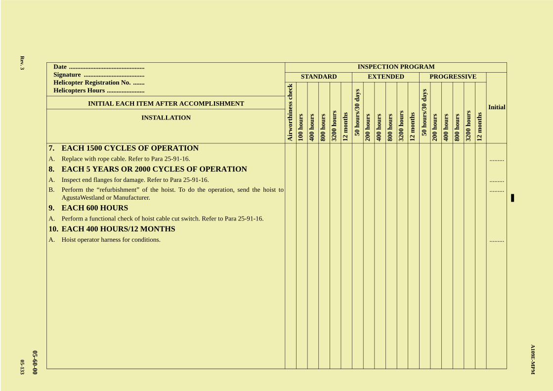
AB
CD
ABCDC
A109E
-MP
M
05-60-00
Rev. 3
05-133
Date .............................................. Signature ..................................... Helicopter Registration No. ....... Helicopters Hours .......................
INSPECTION PROGRAM
STANDARD EXTENDED PROGRESSIVE
Initial
Air
wor
thin
ess
chec
k
100
hou
rs
400
hou
rs
800
hou
rs
3200
hou
rs
12 m
onth
s
50 h
ours
/30
day
s
200
hou
rs
400
hou
rs
800
hou
rs
3200
hou
rs
12 m
onth
s
50 h
ours
/30
day
s
200
hou
rs
400
hou
rs
800
hou
rs
3200
hou
rs
12 m
onth
s
INITIAL EACH ITEM AFTER ACCOMPLISHMENT
INSTALLATION
7. EACH 1500 CYCLES OF OPERATIONA. Replace with rope cable. Refer to Para 25-91-16. .........
8. EACH 5 YEARS OR 2000 CYCLES OF OPERATIONA. Inspect end flanges for damage. Refer to Para 25-91-16. .........
B. Perform the “refurbishment” of the hoist. To do the operation, send the hoist toAgustaWestland or Manufacturer.
.........
9. EACH 600 HOURSA. Perform a functional check of hoist cable cut switch. Refer to Para 25-91-16.
10. EACH 400 HOURS/12 MONTHSA. Hoist operator harness for conditions. .........

A B
C
D
A
B
C
DC
A109E-MPM
05-60-00
05-134
PAGE INTENTIONALLY LEFT BLANK
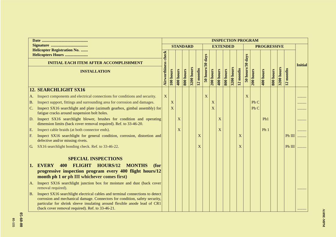
AB
CD
ABCDC
A109E
-MP
M
05-60-00
05-135
Date .............................................. Signature ..................................... Helicopter Registration No. ....... Helicopters Hours .......................
INSPECTION PROGRAM
STANDARD EXTENDED PROGRESSIVE
Initial
Air
wor
thin
ess
chec
k
100
hou
rs
400
hou
rs
800
hou
rs
3200
hou
rs
12 m
onth
s
50 h
ours
/30
day
s
200
hou
rs
400
hou
rs
800
hou
rs
3200
hou
rs
12 m
onth
s
50 h
ours
/30
day
s
200
hou
rs
400
hou
rs
800
hou
rs
3200
hou
rs
12 m
onth
s
INITIAL EACH ITEM AFTER ACCOMPLISHMENT
INSTALLATION
12. SEARCHLIGHT SX16A. Inspect components and electrical connections for conditions and security. X X X .........
B. Inspect support, fittings and surrounding area for corrosion and damages. X X Ph C .........
C. Inspect SX16 searchlight and plate (azimuth gearbox, gimbal assembly) forfatigue cracks around suspension bolt holes.
X X Ph C .........
D. Inspect SX16 searchlight blower, brushes for condition and operatingdimension limits (back cover removal required). Ref. to 33-46-20.
X X Ph1 .........
E. Inspect cable braids (at both connector ends). X X Ph 1 .........
F. Inspect SX16 searchlight for general condition, corrosion, distortion anddefective and/or missing rivets.
X X Ph III .........
G. SX16 searchlight bonding check. Ref. to 33-46-22. X X Ph III .........
SPECIAL INSPECTIONS
1. EVERY 400 FLIGHT HOURS/12 MONTHS (forprogressive inspection program every 400 flight hours/12month ph 1 or ph III whichever comes first)
A. Inspect SX16 searchlight junction box for moisture and dust (back coverremoval required). .........
B. Inspect SX16 searchlight electrical cables and terminal connections to detectcorrosion and mechanical damage. Connectors for condition, safety security,particular for shrink sleeve insulating around flexible anode lead of CR1(back cover removal required). Ref. to 33-46-21. .........

A B
C
D
A
B
C
DC
A109E-MPM
05-60-00
05-136
PAGE INTENTIONALLY LEFT BLANK
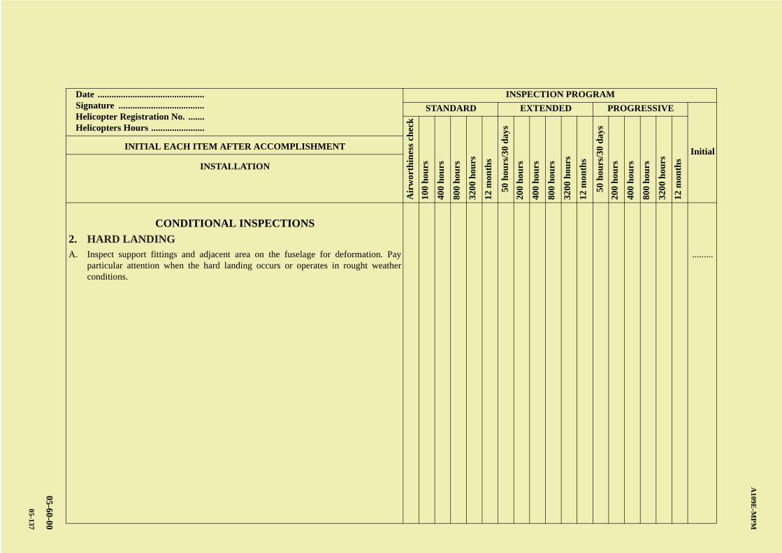
AB
CD
ABCDC
A109E
-MP
M
05-60-00
05-137
Date .............................................. Signature ..................................... Helicopter Registration No. ....... Helicopters Hours .......................
INSPECTION PROGRAM
STANDARD EXTENDED PROGRESSIVE
Initial
Air
wor
thin
ess
chec
k
100
hou
rs
400
hou
rs
800
hou
rs
3200
hou
rs
12 m
onth
s
50 h
ours
/30
day
s
200
hou
rs
400
hou
rs
800
hou
rs
3200
hou
rs
12 m
onth
s
50 h
ours
/30
day
s
200
hou
rs
400
hou
rs
800
hou
rs
3200
hou
rs
12 m
onth
s
INITIAL EACH ITEM AFTER ACCOMPLISHMENT
INSTALLATION
CONDITIONAL INSPECTIONS
2. HARD LANDINGA. Inspect support fittings and adjacent area on the fuselage for deformation. Pay
particular attention when the hard landing occurs or operates in rought weatherconditions.
.........

A B
C
D
A
B
C
DC
A109E-MPM
05-60-00
05-138
PAGE INTENTIONALLY LEFT BLANK

AB
CD
ABCDC
A109E
-MP
M
05-60-00
05-139
Date .............................................. Signature ..................................... Helicopter Registration No. ....... Helicopters Hours .......................
INSPECTION PROGRAM
STANDARD EXTENDED PROGRESSIVE
Initial
Air
wor
thin
ess
chec
k
100
hou
rs
400
hou
rs
800
hou
rs
3200
hou
rs
12 m
onth
s
50 h
ours
/30
day
s
200
hou
rs
400
hou
rs
800
hou
rs
3200
hou
rs
12 m
onth
s
50 h
ours
/30
day
s
200
hou
rs
400
hou
rs
800
hou
rs
3200
hou
rs
12 m
onth
s
INITIAL EACH ITEM AFTER ACCOMPLISHMENT
INSTALLATION
13. WIRE STRIKE PROTECTION SYSTEMA. Inspection wire strike protection system. Ref. to Para 53-21-17. X X X .........

A B
C
D
A
B
C
DC
A109E-MPM
05-60-00
05-140
PAGE INTENTIONALLY LEFT BLANK
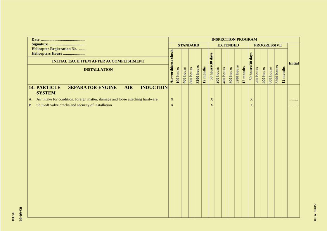
AB
CD
ABCDC
A109E
-MP
M
05-60-00
05-141
Date .............................................. Signature ..................................... Helicopter Registration No. ....... Helicopters Hours .......................
INSPECTION PROGRAM
STANDARD EXTENDED PROGRESSIVE
Initial
Air
wor
thin
ess
chec
k
100
hou
rs
400
hou
rs
800
hou
rs
3200
hou
rs
12 m
onth
s
50 h
ours
/30
day
s
200
hou
rs
400
hou
rs
800
hou
rs
3200
hou
rs
12 m
onth
s
50 h
ours
/30
day
s
200
hou
rs
400
hou
rs
800
hou
rs
3200
hou
rs
12 m
onth
s
INITIAL EACH ITEM AFTER ACCOMPLISHMENT
INSTALLATION
14. PARTICLE SEPARATOR-ENGINE AIR INDUCTIONSYSTEM
A. Air intake for condition, foreign matter, damage and loose attaching hardware. X X X .........
B. Shut-off valve cracks and security of installation. X X X .........

A B
C
D
A
B
C
DC
A109E-MPM
05-60-00
05-142
PAGE INTENTIONALLY LEFT BLANK
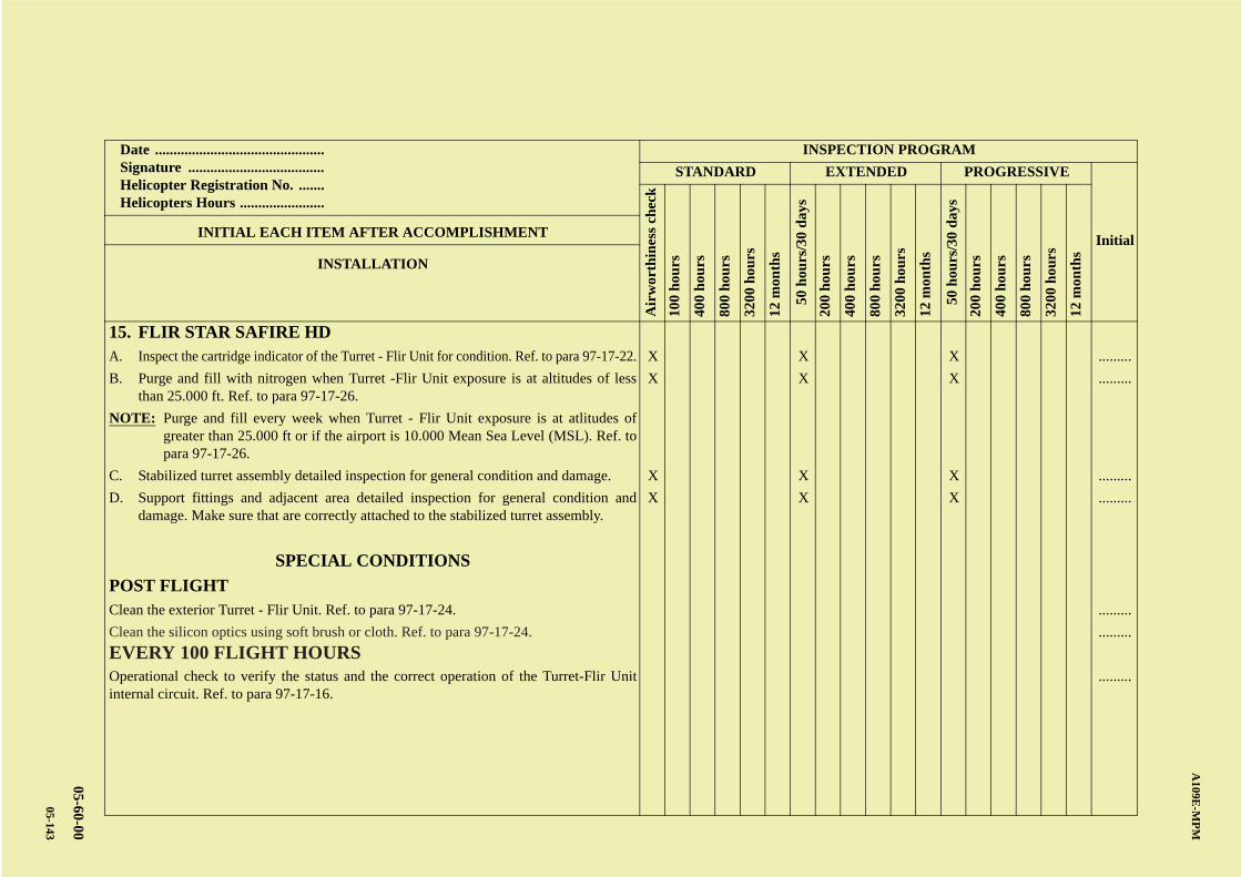
AB
CD
ABCDC
A109E
-MP
M
05-60-00
05-143
Date .............................................. Signature ..................................... Helicopter Registration No. ....... Helicopters Hours .......................
INSPECTION PROGRAM
STANDARD EXTENDED PROGRESSIVE
Initial
Air
wor
thin
ess
chec
k
100
hou
rs
400
hou
rs
800
hou
rs
3200
hou
rs
12 m
onth
s
50 h
ours
/30
day
s
200
hou
rs
400
hou
rs
800
hou
rs
3200
hou
rs
12 m
onth
s
50 h
ours
/30
day
s
200
hou
rs
400
hou
rs
800
hou
rs
3200
hou
rs
12 m
onth
s
INITIAL EACH ITEM AFTER ACCOMPLISHMENT
INSTALLATION
15. FLIR STAR SAFIRE HDA. Inspect the cartridge indicator of the Turret - Flir Unit for condition. Ref. to para 97-17-22. X X X .........
B. Purge and fill with nitrogen when Turret -Flir Unit exposure is at altitudes of lessthan 25.000 ft. Ref. to para 97-17-26.
X X X .........
NOTE: Purge and fill every week when Turret - Flir Unit exposure is at atlitudes ofgreater than 25.000 ft or if the airport is 10.000 Mean Sea Level (MSL). Ref. topara 97-17-26.
C. Stabilized turret assembly detailed inspection for general condition and damage. X X X .........
D. Support fittings and adjacent area detailed inspection for general condition anddamage. Make sure that are correctly attached to the stabilized turret assembly.
X X X .........
SPECIAL CONDITIONS
POST FLIGHTClean the exterior Turret - Flir Unit. Ref. to para 97-17-24. .........
Clean the silicon optics using soft brush or cloth. Ref. to para 97-17-24. .........
EVERY 100 FLIGHT HOURSOperational check to verify the status and the correct operation of the Turret-Flir Unitinternal circuit. Ref. to para 97-17-16.
.........

A B
C
D
A
B
C
DC
A109E-MPM
05-60-00
05-144
PAGE INTENTIONALLY LEFT BLANK
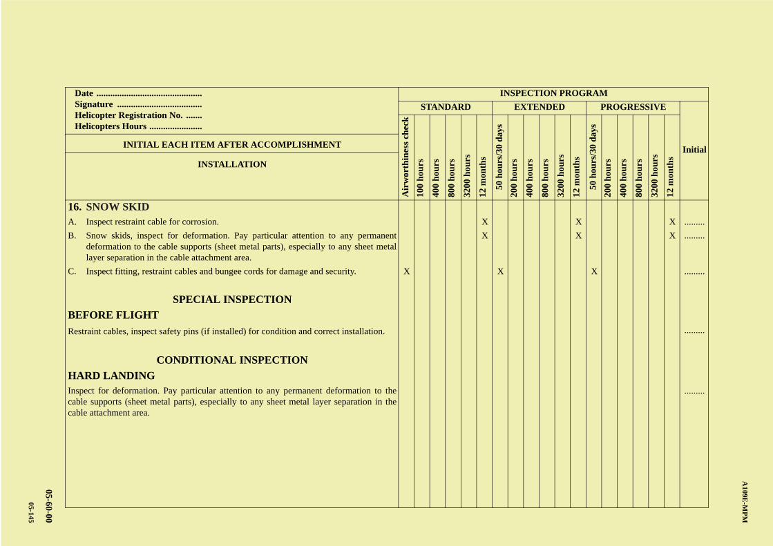
AB
CD
ABCDC
A109E
-MP
M
05-60-00
05-145
Date .............................................. Signature ..................................... Helicopter Registration No. ....... Helicopters Hours .......................
INSPECTION PROGRAM
STANDARD EXTENDED PROGRESSIVE
Initial
Air
wor
thin
ess
chec
k
100
hou
rs
400
hou
rs
800
hou
rs
3200
hou
rs
12 m
onth
s
50 h
ours
/30
day
s
200
hou
rs
400
hou
rs
800
hou
rs
3200
hou
rs
12 m
onth
s
50 h
ours
/30
day
s
200
hou
rs
400
hou
rs
800
hou
rs
3200
hou
rs
12 m
onth
s
INITIAL EACH ITEM AFTER ACCOMPLISHMENT
INSTALLATION
16. SNOW SKIDA. Inspect restraint cable for corrosion. X X X .........
B. Snow skids, inspect for deformation. Pay particular attention to any permanentdeformation to the cable supports (sheet metal parts), especially to any sheet metallayer separation in the cable attachment area.
X X X .........
C. Inspect fitting, restraint cables and bungee cords for damage and security. X X X .........
SPECIAL INSPECTION
BEFORE FLIGHT
Restraint cables, inspect safety pins (if installed) for condition and correct installation. .........
CONDITIONAL INSPECTION
HARD LANDINGInspect for deformation. Pay particular attention to any permanent deformation to thecable supports (sheet metal parts), especially to any sheet metal layer separation in thecable attachment area.
.........

A B
C
D
A
B
C
DC
A109E-MPM
05-60-00
05-146
PAGE INTENTIONALLY LEFT BLANK
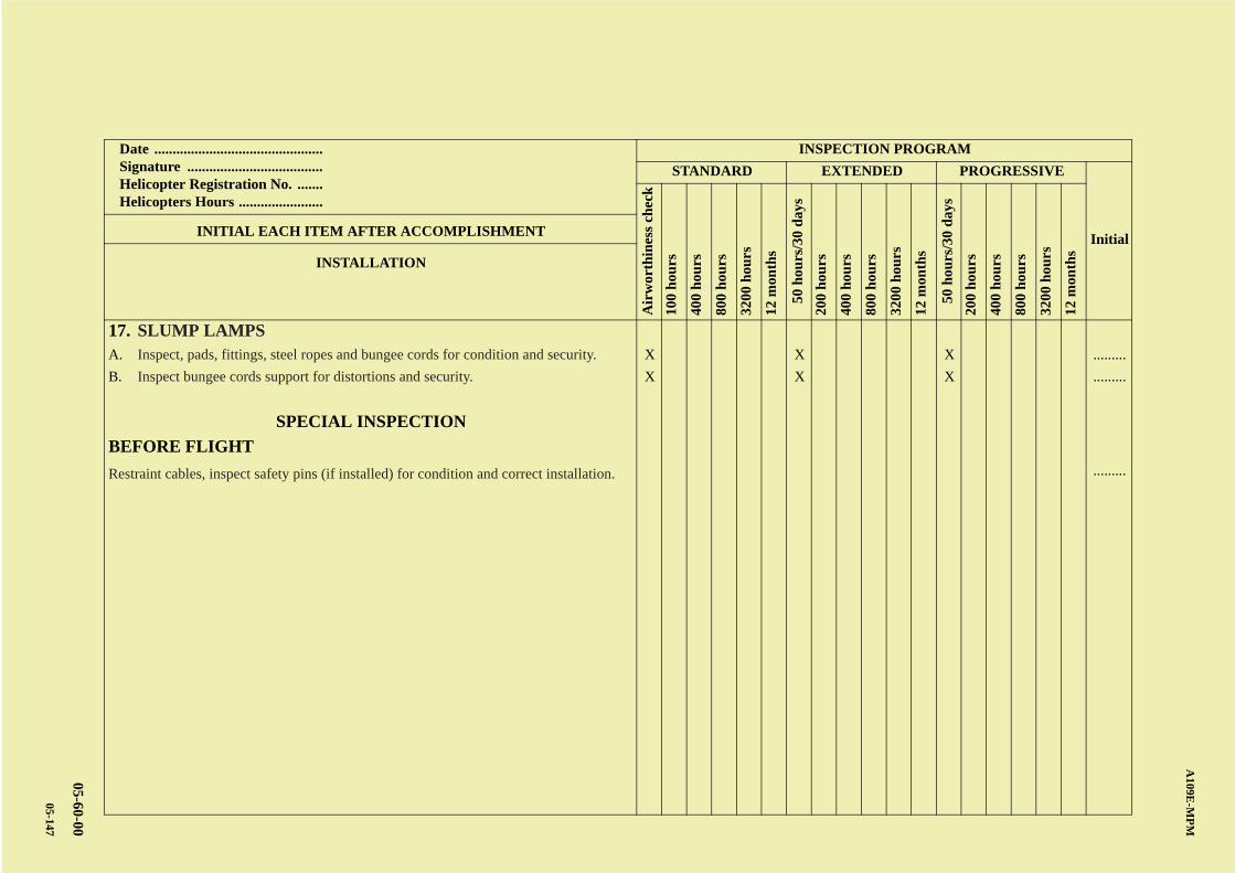
AB
CD
ABCDC
A109E
-MP
M
05-60-00
05-147
Date .............................................. Signature ..................................... Helicopter Registration No. ....... Helicopters Hours .......................
INSPECTION PROGRAM
STANDARD EXTENDED PROGRESSIVE
Initial
Air
wor
thin
ess
chec
k
100
hou
rs
400
hou
rs
800
hou
rs
3200
hou
rs
12 m
onth
s
50 h
ours
/30
day
s
200
hou
rs
400
hou
rs
800
hou
rs
3200
hou
rs
12 m
onth
s
50 h
ours
/30
day
s
200
hou
rs
400
hou
rs
800
hou
rs
3200
hou
rs
12 m
onth
s
INITIAL EACH ITEM AFTER ACCOMPLISHMENT
INSTALLATION
17. SLUMP LAMPSA. Inspect, pads, fittings, steel ropes and bungee cords for condition and security. X X X .........
B. Inspect bungee cords support for distortions and security. X X X .........
SPECIAL INSPECTION
BEFORE FLIGHT
Restraint cables, inspect safety pins (if installed) for condition and correct installation. .........

A B
C
D
A
B
C
DC
A109E-MPM
05-60-00
05-148
PAGE INTENTIONALLY LEFT BLANK
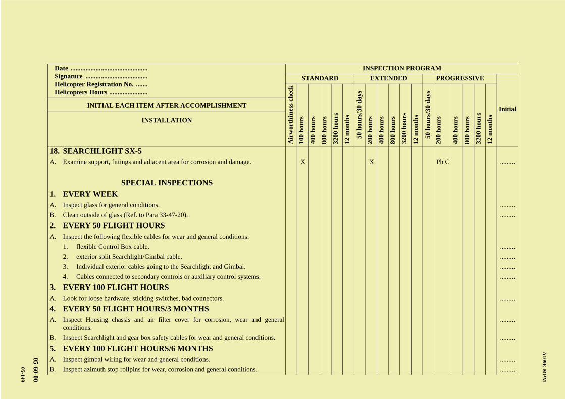
AB
CD
ABCDC
A109E
-MP
M
05-60-00
05-149
Date .............................................. Signature ..................................... Helicopter Registration No. ....... Helicopters Hours .......................
INSPECTION PROGRAM
STANDARD EXTENDED PROGRESSIVE
Initial
Air
wor
thin
ess
chec
k
100
hou
rs
400
hou
rs
800
hou
rs
3200
hou
rs
12 m
onth
s
50 h
ours
/30
day
s
200
hou
rs
400
hou
rs
800
hou
rs
3200
hou
rs
12 m
onth
s
50 h
ours
/30
day
s
200
hou
rs
400
hou
rs
800
hou
rs
3200
hou
rs
12 m
onth
s
INITIAL EACH ITEM AFTER ACCOMPLISHMENT
INSTALLATION
18. SEARCHLIGHT SX-5A. Examine support, fittings and adiacent area for corrosion and damage. X X Ph C .........
SPECIAL INSPECTIONS
1. EVERY WEEKA. Inspect glass for general conditions. .........
B. Clean outside of glass (Ref. to Para 33-47-20). .........
2. EVERY 50 FLIGHT HOURSA. Inspect the following flexible cables for wear and general conditions:
1. flexible Control Box cable. .........
2. exterior split Searchlight/Gimbal cable. .........
3. Individual exterior cables going to the Searchlight and Gimbal. .........
4. Cables connected to secondary controls or auxiliary control systems. .........
3. EVERY 100 FLIGHT HOURSA. Look for loose hardware, sticking switches, bad connectors. .........
4. EVERY 50 FLIGHT HOURS/3 MONTHSA. Inspect Housing chassis and air filter cover for corrosion, wear and general
conditions..........
B. Inspect Searchlight and gear box safety cables for wear and general conditions. .........
5. EVERY 100 FLIGHT HOURS/6 MONTHSA. Inspect gimbal wiring for wear and general conditions. .........
B. Inspect azimuth stop rollpins for wear, corrosion and general conditions. .........

A B
C
D
A
B
C
DC
A109E-MPM
05-60-00
05-150
PAGE INTENTIONALLY LEFT BLANK
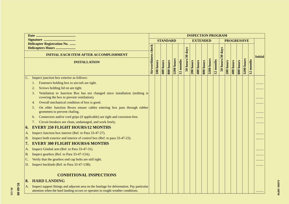
AB
CD
ABCDC
A109E
-MP
M
05-60-00
05-151
Date .............................................. Signature ..................................... Helicopter Registration No. ....... Helicopters Hours .......................
INSPECTION PROGRAM
STANDARD EXTENDED PROGRESSIVE
Initial
Air
wor
thin
ess
chec
k
100
hou
rs
400
hou
rs
800
hou
rs
3200
hou
rs
12 m
onth
s
50 h
ours
/30
day
s
200
hou
rs
400
hou
rs
800
hou
rs
3200
hou
rs
12 m
onth
s
50 h
ours
/30
day
s
200
hou
rs
400
hou
rs
800
hou
rs
3200
hou
rs
12 m
onth
s
INITIAL EACH ITEM AFTER ACCOMPLISHMENT
INSTALLATION
C. Inspect junction box exterior as follows:
1. Fasteners holding box to aircraft are tight. .........
2. Screws holding lid on are tight. .........
3. Ventilation to Junction Box has not changed since installation (nothing iscovering the box to prevent ventilation). .........
4. Overall mechanical condition of box is good. .........
5. On older Junction Boxes ensure cables entering box pass through rubbergrommets to prevent chafing. .........
6. Connectors and/or cord grips (if applicable) are tight and corrosion-free. .........
7. Circuit breakers are clean, undamaged, and work freely. .........
6. EVERY 250 FLIGHT HOURS/12 MONTHSA. Inspect Junction box interior (Ref. to Para 33-47-27). .........
B. Inspect both exterior and interior of control box (Ref. to para 33-47-23). .........
7. EVERY 300 FLIGHT HOURS/6 MONTHSA. Inspect Gimbal arm (Ref. to Para 33-47-31). .........
B. Inspect gearbox (Ref. to Para 33-47-13A). .........
C. Verify that the gearbox end cap bolts are still tight. .........
D. Inspect backlash (Ref. to Para 33-47-13B). .........
CONDITIONAL INSPECTIONS
8. HARD LANDINGA. Inspect support fittings and adjacent area on the fuselage for deformation. Pay particular
attention when the hard landing occurs or operates in rought weather conditions. .........

A B
C
D
A
B
C
DC
A109E-MPM
05-60-00
05-152
PAGE INTENTIONALLY LEFT BLANK
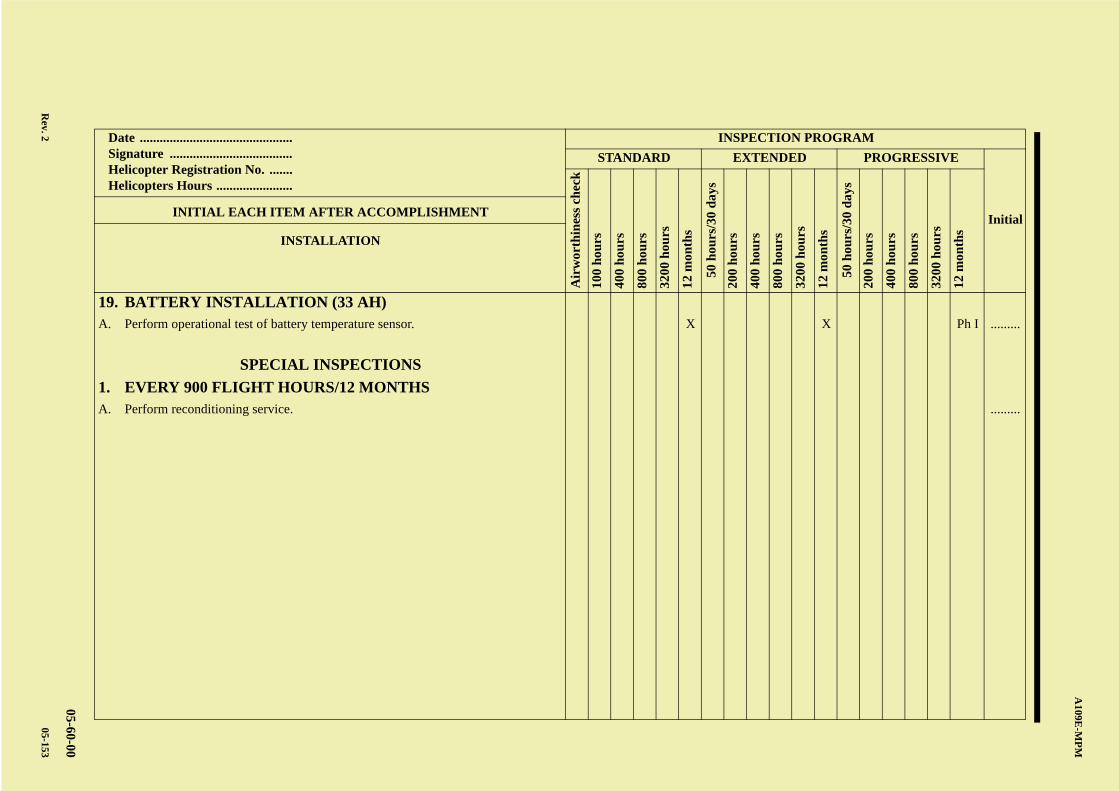
AB
CD
ABCDC
A109E
-MP
M
05-60-00
Rev. 2
05-153
Date .............................................. Signature ..................................... Helicopter Registration No. ....... Helicopters Hours .......................
INSPECTION PROGRAM
STANDARD EXTENDED PROGRESSIVE
Initial
Air
wor
thin
ess
chec
k
100
hou
rs
400
hou
rs
800
hou
rs
3200
hou
rs
12 m
onth
s
50 h
ours
/30
day
s
200
hou
rs
400
hou
rs
800
hou
rs
3200
hou
rs
12 m
onth
s
50 h
ours
/30
day
s
200
hou
rs
400
hou
rs
800
hou
rs
3200
hou
rs
12 m
onth
s
INITIAL EACH ITEM AFTER ACCOMPLISHMENT
INSTALLATION
19. BATTERY INSTALLATION (33 AH)A. Perform operational test of battery temperature sensor. X X Ph I .........
SPECIAL INSPECTIONS
1. EVERY 900 FLIGHT HOURS/12 MONTHSA. Perform reconditioning service. .........

A B
C
D
A
B
C
DC
A109E-MPM
05-60-00
05-154 Rev. 2
PAGE INTENTIONALLY LEFT BLANK
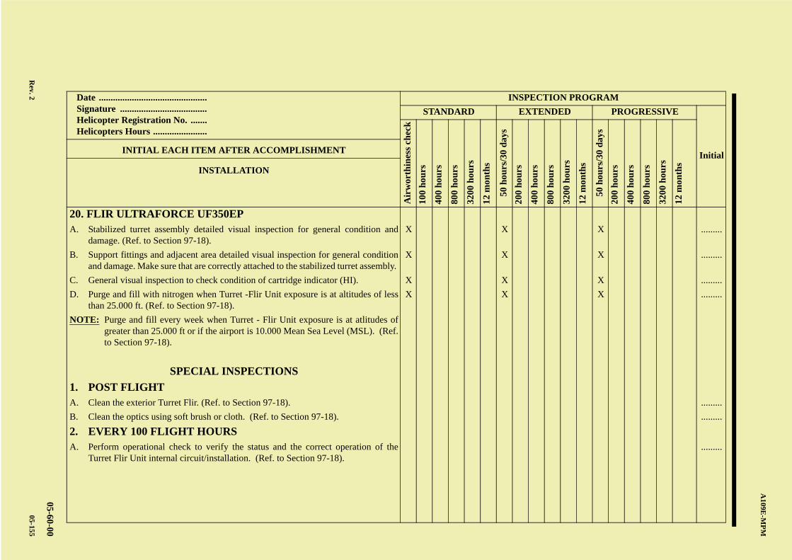
AB
CD
ABCDC
A109E
-MP
M
05-60-00
Rev. 2
05-155
Date .............................................. Signature ..................................... Helicopter Registration No. ....... Helicopters Hours .......................
INSPECTION PROGRAM
STANDARD EXTENDED PROGRESSIVE
Initial
Air
wor
thin
ess
chec
k
100
hou
rs
400
hou
rs
800
hou
rs
3200
hou
rs
12 m
onth
s
50 h
ours
/30
day
s
200
hou
rs
400
hou
rs
800
hou
rs
3200
hou
rs
12 m
onth
s
50 h
ours
/30
day
s
200
hou
rs
400
hou
rs
800
hou
rs
3200
hou
rs
12 m
onth
s
INITIAL EACH ITEM AFTER ACCOMPLISHMENT
INSTALLATION
20. FLIR ULTRAFORCE UF350EPA. Stabilized turret assembly detailed visual inspection for general condition and
damage. (Ref. to Section 97-18).X X X .........
B. Support fittings and adjacent area detailed visual inspection for general conditionand damage. Make sure that are correctly attached to the stabilized turret assembly.
X X X .........
C. General visual inspection to check condition of cartridge indicator (HI). X X X .........
D. Purge and fill with nitrogen when Turret -Flir Unit exposure is at altitudes of lessthan 25.000 ft. (Ref. to Section 97-18).
X X X .........
NOTE: Purge and fill every week when Turret - Flir Unit exposure is at atlitudes ofgreater than 25.000 ft or if the airport is 10.000 Mean Sea Level (MSL). (Ref.to Section 97-18).
SPECIAL INSPECTIONS
1. POST FLIGHTA. Clean the exterior Turret Flir. (Ref. to Section 97-18). .........
B. Clean the optics using soft brush or cloth. (Ref. to Section 97-18). .........
2. EVERY 100 FLIGHT HOURSA. Perform operational check to verify the status and the correct operation of the
Turret Flir Unit internal circuit/installation. (Ref. to Section 97-18)..........
A B
C
D
A
B
C
DC
A109E-MPM
05-60-00
05-156 Rev. 2
PAGE INTENTIONALLY LEFT BLANK
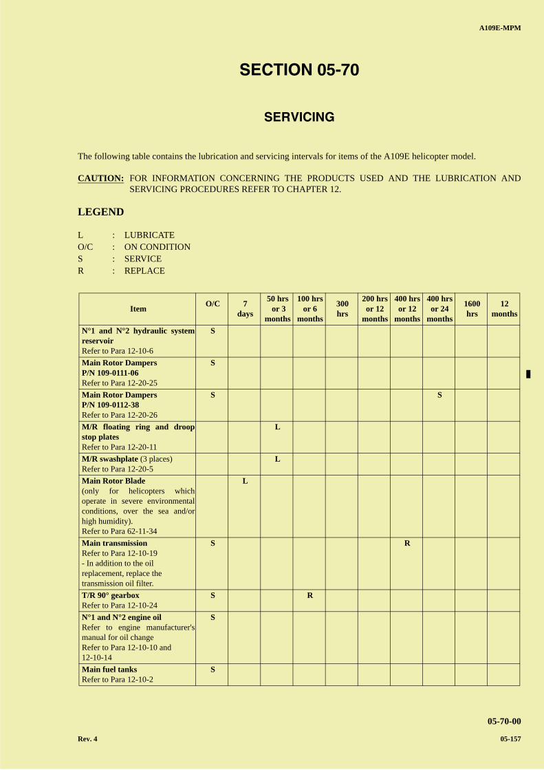
A B
C
D
A
B
C
DC
A109E-MPM
05-70-00
Rev. 4 05-157
SECTION 05-70
SERVICING
The following table contains the lubrication and servicing intervals for items of the A109E helicopter model.
CAUTION: FOR INFORMATION CONCERNING THE PRODUCTS USED AND THE LUBRICATION ANDSERVICING PROCEDURES REFER TO CHAPTER 12.
LEGEND
L : LUBRICATEO/C : ON CONDITIONS : SERVICER : REPLACE
ItemO/C
7
days
50 hrs or 3
months
100 hrsor 6
months
300hrs
200 hrsor 12
months
400 hrsor 12
months
400 hrsor 24
months
1600hrs
12months
N°1 and N°2 hydraulic systemreservoir Refer to Para 12-10-6
S
Main Rotor Dampers P/N 109-0111-06Refer to Para 12-20-25
S
Main Rotor Dampers P/N 109-0112-38 Refer to Para 12-20-26
S S
M/R floating ring and droopstop plates Refer to Para 12-20-11
L
M/R swashplate (3 places)Refer to Para 12-20-5
L
Main Rotor Blade (only for helicopters whichoperate in severe environmentalconditions, over the sea and/orhigh humidity).Refer to Para 62-11-34
L
Main transmission Refer to Para 12-10-19- In addition to the oil replacement, replace the transmission oil filter.
S R
T/R 90° gearbox Refer to Para 12-10-24
S R
N°1 and N°2 engine oil Refer to engine manufacturer'smanual for oil changeRefer to Para 12-10-10 and12-10-14
S
Main fuel tanks Refer to Para 12-10-2
S
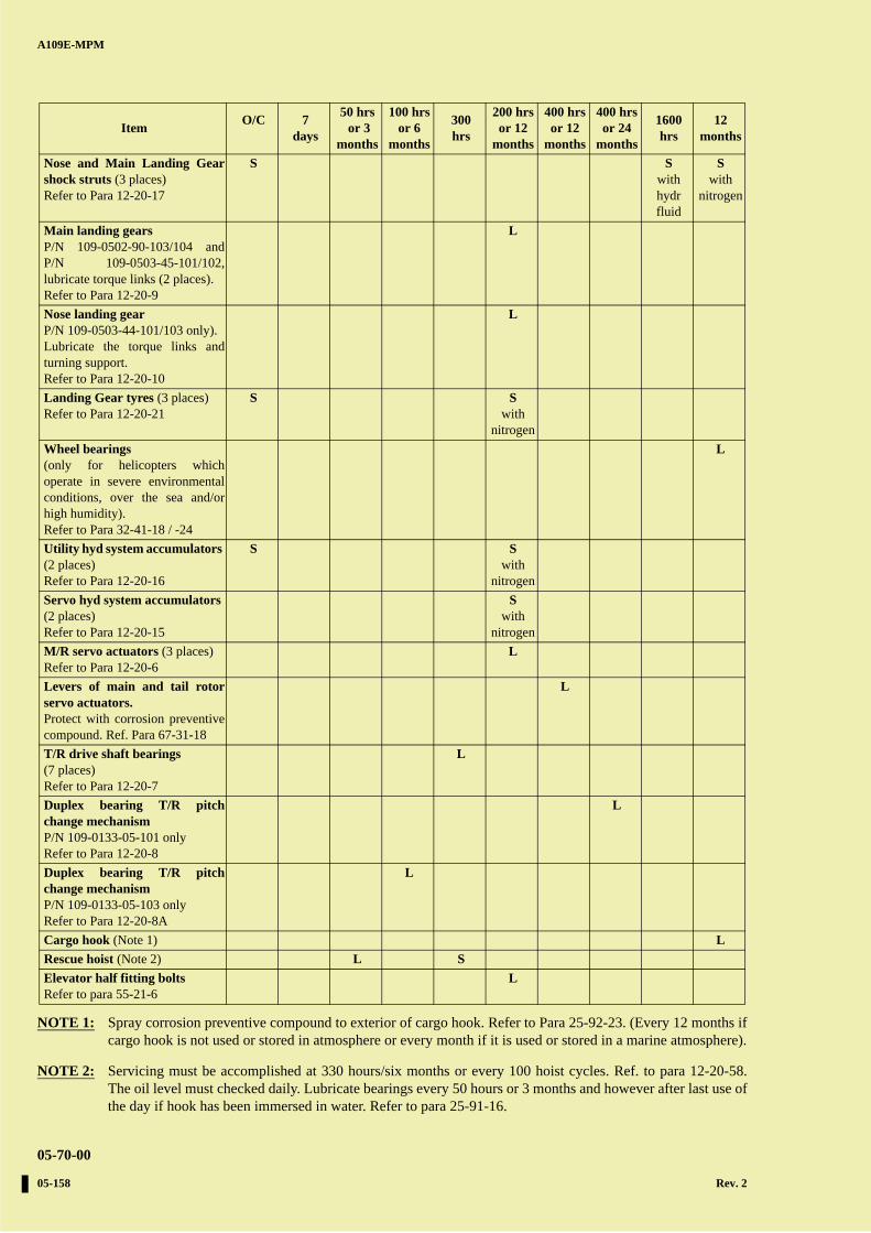
A B
C
D
A
B
C
DC
A109E-MPM
05-70-00
05-158 Rev. 2
NOTE 1: Spray corrosion preventive compound to exterior of cargo hook. Refer to Para 25-92-23. (Every 12 months ifcargo hook is not used or stored in atmosphere or every month if it is used or stored in a marine atmosphere).
NOTE 2: Servicing must be accomplished at 330 hours/six months or every 100 hoist cycles. Ref. to para 12-20-58.The oil level must checked daily. Lubricate bearings every 50 hours or 3 months and however after last use ofthe day if hook has been immersed in water. Refer to para 25-91-16.
Nose and Main Landing Gearshock struts (3 places)Refer to Para 12-20-17
S S withhydr fluid
S with
nitrogen
Main landing gears P/N 109-0502-90-103/104 andP/N 109-0503-45-101/102,lubricate torque links (2 places).Refer to Para 12-20-9
L
Nose landing gear P/N 109-0503-44-101/103 only).Lubricate the torque links andturning support.Refer to Para 12-20-10
L
Landing Gear tyres (3 places)Refer to Para 12-20-21
S Swith
nitrogen
Wheel bearings (only for helicopters whichoperate in severe environmentalconditions, over the sea and/orhigh humidity).Refer to Para 32-41-18 / -24
L
Utility hyd system accumulators (2 places)Refer to Para 12-20-16
S S with
nitrogen
Servo hyd system accumulators (2 places)Refer to Para 12-20-15
S with
nitrogen
M/R servo actuators (3 places)Refer to Para 12-20-6
L
Levers of main and tail rotorservo actuators. Protect with corrosion preventivecompound. Ref. Para 67-31-18
L
T/R drive shaft bearings (7 places)Refer to Para 12-20-7
L
Duplex bearing T/R pitchchange mechanism P/N 109-0133-05-101 onlyRefer to Para 12-20-8
L
Duplex bearing T/R pitchchange mechanism P/N 109-0133-05-103 onlyRefer to Para 12-20-8A
L
Cargo hook (Note 1) L
Rescue hoist (Note 2) L S
Elevator half fitting bolts Refer to para 55-21-6
L
ItemO/C
7
days
50 hrs or 3
months
100 hrsor 6
months
300hrs
200 hrsor 12
months
400 hrsor 12
months
400 hrsor 24
months
1600hrs
12months


![007[Papermodels@Emule] [GPM 007] - Me 109E-4 Tropical](https://img.dokumen.tips/doc/110x75/577cc6811a28aba7119e6fc0/007papermodelsemule-gpm-007-me-109e-4-tropical.jpg)