Embed Size (px)
Citation preview

10.5.1 Ethylene
Properties
Ethylene (H2C�CH2) is the largest volumebuilding block for many petrochemicals and endproducts such as plastics, resins, fibres, etc. TheIUPAC (International Union of Pure and AppliedChemistry) name is ethene.
Physical propertiesEthylene is a colourless, flammable gas with a
slight odour. Table 1 summarizes its physical,thermodynamic and transport properties; additionalvalues are available in many references (Harrison andDouslin, 1971; Starling, 1973; Bonscher et al., 1974;Vargaftik, 1975; Douslin and Harrison, 1976; TRC,Thermodynamics Research Center, 1986; Jacobsen,1988).
Chemical propertiesEthylene is a very reactive intermediate and,
therefore, is involved in many chemical reactions. Thechemistry of ethylene is based mainly around itsdouble bond, which reacts readily to form saturatedhydrocarbons, their derivatives and polymers. It is aplanar molecule with a carbon-carbon bond distanceof 1.34 Å, which is shorter than the C�C bond (s bond) length of 1.53 Å found in ethane, a saturatedmolecule.
In ethylene, the carbon is in its sp2-hybridizedstate. Each carbon uses two of its sp2-hybridizedorbitals to form s bonds with two hydrogen atoms. Theremaining sp2 orbitals – one on each carbon – overlap
to form a s bond connecting the two carbons. The twounhybridized 2p orbitals – one from each carbon –overlap to give a p molecular orbital. Therefore, thedouble bond in ethylene is composed of a scomponent and a p component.
Based on the orbital theory of molecules, 2porbitals overlap to give p and p* orbitals; in ethylene,however, only the p orbital is occupied at normalconditions. Electrons in the p bond are held lesstightly and more easily polarized than electrons in a sbond. The carbon-carbon double bond (s�p) energyis 611 kJ/mol, which is less than twice the C�C bond(s) dissociation energy of 736 kJ/mol found in ethane.The C�H bond dissociation energy is 451 kJ/moland the approximate acidity as measured by thedissociation constant Ka is 10�45. Ethylene reacts withelectrophilic reagents like strong acids (H�), halogens,and oxidizing agents, but not with nucleophilicreagents such as Grignard reagents and bases. For thefundamental mechanisms of these reactions, consultthe following references (Sykes, 1975; Carey, 1987).Some important reactions are discussed below. Otherreactions not included in the following overview areprimarily of academic interest and comprehensivediscussions are provided in various references (Miller,1969; Kniel et al., 1980).
PolymerizationPolymerization is one of the main reactions of
ethylene, and polyethylene ranks as its majorpolymer: nCH2�CH2�
� (�CH2CH2�)n. Veryhigh-purity ethylene (�99.9%) is polymerized underspecific conditions of temperature and pressure inthe presence of an initiator or catalyst. This is anexothermic reaction, and both homogeneous (radicalor cationic) and heterogeneous (solid catalyst)initiators are used (Miller, 1969; Reichert andGeiseler, 1983; Ulrich, 1988). The products range
551VOLUME II / REFINING AND PETROCHEMICALS
10.5
Ethylene and propylene
H
H
H
HC C

from a few hundred to a few million atomic massunit in molecular weight.
Four types of basic reaction systems are ofcommercial importance in the production of polyethylene: • High-pressure (60-350 MPa) free radical
polymerization using oxygen, peroxide or otherstrong oxidizers as initiators at temperatures of up
to 350°C. These produce Low-Density PolyEthylene (LDPE), a highly branched polymerwith densities from 0.91 to 0.94 g/cm3.
• Low-pressure (0.1-20 MPa) polymerization attemperatures of 50 to 300°C using heterogeneouscatalysts such as molybdenum oxide or chromiumoxide supported on inorganic carriers. These areused to produce High-Density PolyEthylene
552 ENCYCLOPAEDIA OF HYDROCARBONS
BULK PRODUCTS AND PRODUCTION LINES IN THE PETROCHEMICAL INDUSTRY
Property Value
Molecular weight, u 28.0536
Triple point Temperature, °C –169.164Pressure, kPa 0.12252Latent heat of fusion, kJ/mol 3.353
Normal freezing pointTemperature, °C –169.15Latent heat of fusion, kJ/mol 3.353
Normal boiling point Temperature, °C –103.71Latent heat of vaporization, kJ/mol 13.548
Density of liquidmol/l 20.27d4
�104 0.566
Specific heat of liquid, J/mol·K 67.4
Viscosity of the liquid, mPa·s (=cP) 0.161
Surface tension of the liquid, mN/m (=dyn/cm) 16.4
Specific heat of ideal gas at 25°C, J/mol·K 42.84
Critical point Temperature, °C 9.194Pressure, kPa 5,040.8Density, mol/l 7.635Compressibility factor 0.2812
Gross heat of combustion at 25°C, MJ/mol 1.411
Limits of flammability at atmospheric pressure and 25°CLower limit in air, mol% 2.7Upper limit in air, mol% 36.0Auto ignition temperature in air at atmospheric pressure, °C 490
Pitzer’s acentric factor 0.278
Dipole moment, D 0.0
Standard enthalpy of formation at 25°C, kJ/mol 52.3
Standard Gibbs energy of formation at 25°C for ideal gas at atmospheric pressure, kJ/mol 68.26
Solubility in water at 0°C and 101 kPa, ml/ml H2O 0.226
Speed of sound at 0°C and 409.681 kPa, m/s 224.979
Standard entropy of formation, J/mol·K 219.28
Standard heat capacity, J/mol·K 42.86
Table 1. Physical properties of ethylene

(HDPE), which is more linear in nature, withdensities of 0.94 to 0.97 g/cm3.
• Low-pressure polymerization via ionic catalysts,using Ziegler catalysts (aluminum alkyls andtitanium halides).
• Low-pressure polymerization with Ziegler catalystssupported on inorganic carriers. A notable development in ethylene polymerization
is the simplified low-pressure LDPE process. Thepressure range is 0.7-2.1 MPa with temperatures lessthan 100°C. The reaction takes place in the gas phaseinstead of the liquid phase as in the conventionalLDPE technology. These new technologies requireultra-high-purity ethylene and many can usemetallocene catalysts (Bennett, 1999). The physicalproperties of the polymers can be modified bycopolymerizing ethylene with other chemicals likehigher olefins, maleic anhydride, etc. Generally,linearity provides strength, and branching providestoughness to the polymer.
OxidationOxidizing ethylene produces ethylene oxide:
CH2�CH2�0.5O2��
The reaction is carried out over a supportedmetallic silver catalyst at 250-300°C and 1-2 MPa.
To produce ethylene glycol, ethylene oxide isfurther reacted with ethylene in the presence of excesswater and an acidic catalyst at low temperatures(50-70°C), followed by hydrolysis at relatively hightemperatures (140-230°C) and moderate pressures(2-4 MPa). At low water concentration, polyethyleneglycol is obtained.
Acetaldehyde can be obtained by the Wackerprocess in which a homogeneous CuCl2/PdCl2 systemis used for the oxidation:
CH2�CH2�0.5O2�� CH3CHO
The reaction is carried out in a bubble column at120-130°C and 0.3 MPa. Palladium chloride isreduced to palladium during the reaction and then isreoxidized by cupric chloride. Oxygen converts thereduced cuprous chloride to cupric chloride.
Vinyl acetate is obtained by the vapour phaseoxidation of ethylene with acetic acid, which isobtained by oxidation of acetaldehyde:
CH2�CH2�CH3COOH�0.5O2��
�� CH2�CHOCOCH3�H2O
This process employs a palladium on carbon,alumina or silica-alumina catalyst at 175-200°C and0.4 to 1.0 MPa.
AdditionMany addition reactions with ethylene are
important in the chemical industry. Halogenation-hydrohalogenation is used to producevarious halides of ethylene, such as ethylenedichloride, which is further cracked to produce vinyl chloride, the monomer required for theproduction of polyvinyl chloride (PVC):
CH2�CH2�Cl2�� ClCH2CH2Cl
Vinyl chloride is obtained by thedehydrochlorination of 1,2-dichloroethane in the gasphase (500-600°C and 2.5-3.5 MPa):
ClCH2CH2Cl��CH2�CHCl�HCl
Oxychlorination of ethylene is carried out in afixed or fluidized bed at 220°C, with a suitable solidchloride catalyst:
2CH2�CH2�O2�4HCl��2ClCH2CH2Cl�2H2O
Trichloroethylene and tetrachloroethylene areimportant organic solvents that are produced by thefurther chlorination of 1,2-dichloroethylene in the gasphase, with the simultaneous dehydrochlorination inthe presence of a suitable chloride catalyst.
Oligomerization is used to produce a-olefins andlinear primary alcohols. Hydration of ethyleneproduces ethanol.
Ethylbenzene, the precursor of styrene, is producedfrom benzene and ethylene. The ethylation of benzeneis carried out in several different ways. In the oldertechnologies, the reaction is conducted in the liquidphase in the presence of a Friedel-Crafts catalyst(AlCl3, BF3, FeCl3). The new processes all use zeolitecatalysts. ABB Lummus Global and UOP (UniversalOil Products) commercialized a process for liquidphase alkylation based on a zeolite catalyst (Horigomeet al., 1991). Badger and Mobil offer a similar processand also have a vapour phase alkylation process usingzeolite catalysts (Lewis and Dwyer, 1977). A processbased on a catalytic distillation reactor also has beencommercialized using zeolites (Ercan et al., 1998).Almost all ethylbenzene produced is used for themanufacture of styrene, which is obtained bydehydrogenation in the presence of a suitable catalystat 550-640°C and relatively low pressures (Lummus Crest, 1988).
Ethanol is manufactured from ethylene by directcatalytic hydration over a H3PO4/SiO2 catalyst atprocess conditions of 300°C and 7.0 MPa (diethylether is formed as a by-product):
CH2�CH2�H2O�� C2H5OH
Ethylene can also be reacted to form propylene viathe metathesis of butene and ethylene (see below). The
553VOLUME II / REFINING AND PETROCHEMICALS
ETHYLENE AND PROPYLENE
O
CH2 CH2

butenes can be taken from steam cracker effluent or arefinery Fluid Catalytic Cracking (FCC) unit. Ethylenedimerization to butene can also be utilized, giving adirect conversion route of ethylene to propylene. Thisroute is expected to become more prevalent as thepropylene demand grows and ethylene productionfrom ethane pyrolysis becomes more common.
Biological propertiesEthylene is slightly more potent as an anesthetic
than nitrous oxide, but the smell of ethylene causeschoking; therefore, it is no longer used as an anestheticagent. Diffusion through the alveolar membrane issufficiently rapid for equilibrium to be establishedbetween the alveolar and the pulmonary capillaryblood with a single exposure. Ethylene is held in bothcells and plasma, in simple physical solution. Thelipoid stroma of the red blood cells absorbs ethylene,but it does not combine with hemoglobin. It iseliminated from the body unchanged – primarily bythe lungs – and most elimination is complete withinthree minutes of administration.
Ethylene has been used in the controlled ripeningof various fruits and vegetables since the 1930s. Itcauses the bleaching of green tissue, gives rise to foliarabscission, suppresses certain types of dormancy, andpromotes cellular swelling. For further information onthis subject, consult references (Miller, 1969).
Manufacture via thermal cracking
Thermal cracking of hydrocarbons is the majorroute for the industrial production of ethylene. Thechemistry and engineering of thermal cracking hasbeen reviewed by Kniel et al. (1980), Froment (1981),Albright et al. (1983), Raseev (2003), and also in anearlier review by Sundaram et al. (1994). In thermalcracking, valuable by-products including propylene,butadiene, and benzene are produced. Less valuablemethane and fuel oil are also produced in significantquantities. An important parameter in the design ofcommercial thermal cracking furnaces is theselectivity to produce the desired products.
Mechanism, kinetics, conversionThe thermal cracking of hydrocarbons proceeds via
a free-radical mechanism as proposed by Rice (1931).Since that discovery, many reaction schemes have beenproposed for various hydrocarbon feeds (Allara andEdelson, 1975; Sundaram and Froment, 1978b; Allaraand Shaw, 1980; Dente and Ranzi, 1983; Willems andFroment, 1988a, 1988b; Depeyre et al., 1989). Sinceradicals are neutral species with a short life, theirconcentrations under reaction conditions are extremelysmall. Therefore, the integration of continuity equations
involving radical and molecular species requires specialintegration algorithms (Gear, 1971). To overcome thesenumerical difficulties, various approximate methodshave been introduced in the past, such as pseudosteady-state approximation for radicals (Semenov, 1959;Boudart, 1968), and the errors associated with suchtechniques have been discussed by Sundaram andFroment (1978a). With modern computing power, suchapproximate methods are no longer required.
Thermal cracking is a complex reaction andinvolves many thousands of chain reactions even forsimple ethane cracking (Sundaram and Froment,1978b; Dente and Ranzi, 1983); however, the reactionscan be classified into several known groups (Table 2).
During initiation, two radicals are produced foreach paraffin molecule. For example:
C2H6��2�CH3
Only a small fraction of reactant is involved in thisstep. When naphthenes are involved, diradicals are produced. For aromatics with side chains, ·H radicals are produced. Typically, this is the rate-controlling stepunder normal commercial operating conditions.
In propagation, many types of reactions areinvolved, including hydrogen abstraction, methylabstraction, radical addition, radical decompositionand radical isomerization.
In hydrogen abstraction, a hydrogen radical reactswith a molecule (primarily a paraffin) and produces ahydrogen molecule and a radical. In methylabstraction, a methyl radical reacts to produce aradical and methane. Similar reactions with otherradicals (ethyl and propyl) can also occur.
In radical addition, some radicals like �H, �CH3,etc., are added to olefins (or diolefins) to form heavierradicals. Radical decomposition is one of the mostimportant types of reactions. In this case, a largerradical decomposes to an olefin and a smaller radical.Radicals usually decompose at the beta-position of theradical centre where the C�C bond is the weakest. Inthe case of naphthenes and aromatics, this may not bethe case and a C�H bond may be the weakest.Finally, radical isomerization frequently occurs forlarge radicals and explains to a large extent theobserved product distribution (i.e. many isomers).
Radical termination is the reverse of initiation. In addition to radical reactions, molecular and
surface reactions also occur. According to Laidler (1965), radicals are classified
as b and m radicals. b radicals (e.g. �H, �CH3) undergoonly addition reactions and do not decompose. m radicals(e.g. �C4H9) undergo mainly decomposition. Someradicals, such as �C2H5, can act as both b and m radicals.
The kinetics of thermal cracking is not simple andinvolves a series of elementary reactions. The order of
554 ENCYCLOPAEDIA OF HYDROCARBONS
BULK PRODUCTS AND PRODUCTION LINES IN THE PETROCHEMICAL INDUSTRY

the elementary reactions almost follows molecularity.Energetically active small radicals, like �H and �C2H3,may involve a third body collision. Based on the maininitiation, propagation, and termination reactions, onecan deduce the overall order of the reaction for thedecomposition of simple molecules like ethane(Laidler, 1965).
Most paraffin decomposition follows a first orderrate-of-reaction, while olefin decomposition follows ahigher order rate-of-reaction. With the advent ofmodern computers, kinetic models for thermalcracking of hydrocarbons involving a few hundred toa few thousand reactions and their mass and energybalance equations can be solved in a few minutes. Thefollowing references provide a detailed review on thistopic (Allara and Edelson, 1975; Sundaram andFroment, 1978b; Dente et al., 1979; Allara and Shaw,1980; Dente and Ranzi, 1983; Willems and Froment,1988a, 1988b; Depeyre et al., 1989; Froment, 1992).The kinetic parameters of typical reactions occurringin thermal cracking are given in Table 2.
The terms conversion or severity are used tomeasure the extent of cracking. Conversion (X) can beeasily measured for a single component feed:
component inlet�component outletX�11111212111111111
component inlet
where inlet and outlet quantities are measured inweight units.
When a mixture is cracked, one or morecomponents in the feed may also be formed asproducts. For example, in the co-cracking of ethaneand propane, ethane is formed as a product ofpropane cracking and propane is formed as aproduct of ethane cracking. Therefore, the outletterm in the above equation contains the contributionof formation from other feed components and thusdoes not represent a true conversion. For simplemixtures, the product formation can be accountedfor and approximate true conversions can becalculated (Sundaram and Fernandez-Baujin, 1988).For liquid feeds like naphtha, it is impractical, if notimpossible, to calculate the true conversion. Basedon measured feed components, one can calculate aweighted average conversion (
–X ) as proposed by van
Camp et al. (1985): –X ��Wi Xi
where Xi is the conversion for the ith feed component
555VOLUME II / REFINING AND PETROCHEMICALS
ETHYLENE AND PROPYLENE
Frequency factor* Activation energy(thousands of t) (kJ/mol)
A) InitiationC2H6�
� 2�CH3 4.0�1016 366.1
B) PropagationH-abstractionC2H6��H�� �C2H5�H2 1.0·1011 40.6
Methyl abstractionC2H6��CH3�
� �C2H5�CH4
Radical additionC2H4��H�� �C2H5 1.0·1010 6.3
Radical decomposition�C2H5�
� C2H4��H 3.2·1013 167.4
Radical isomerization1-�C4H9�
� 2-�C4H9 5.2·1014 171.5
C) Termination2�C2H5�
� n-C4H10 4.0·108 0
D) Molecular reactionsC2H4�C4H6�
� cyC6H10 3.0·107 125.5
E) Surface reactions�C2H3�T�� C2H2��H�T 2.0·109 131.8
Table 2. Examples of reactions occurring in thermal cracking
T= third body collision molecule* For first order reactions the unit is s�1 and for second order reactions l·mol�1s�1. These are typical values

and Wi is the weighting factor (weight or mol fractionusually).
Designers have employed other practical methodssuch as a key component conversion (e.g. n-pentane),kinetic severity factor (Zdonik and Green, 1970), ormolecular collision parameter (Lohr and Schwab,1979) to represent severity. Alternatively, molecularweight of the complete product distribution has beenused to define conversion for liquid feeds:
Mf23223�1MeX�1111Mf23223�124.5
In the equation, Mf and Me are the molecularweight of the feed and of the dry (steam-free) effluentrespectively. Instead of molecular weight, hydrogencontent in the C5� product is also used:
Y�1X�1111
CY�1
In the equation, Y=(H�6)/(HF�6), where HF isfeed hydrogen content in wt%, H is hydrogen contentin the C5� product in wt%, and C is a constant for anygiven feed.
Instead of conversion, some producers prefer to useother identifications of severity, including coil outlettemperature, propylene-to-methane ratio, propylene-to-ethylene ratio, or cracking severity index (Ross andShu, 1979). Of course, all these definitions aresomewhat dependent on feed properties and most arealso dependent on the operating conditions.
When simple liquids like naphtha are cracked,it may be possible to determine the feedcomponents by Gas Chromatography combinedwith Mass Spectrometry (GC-MS; van Camp etal., 1985); however, when gas oil is cracked,complete analysis of the feed may not be possible.Therefore, some simple definitions are used tocharacterize the feed. When available, paraffins,olefins, naphthenes, and aromatics (PONA)content serves as a key property. When PONA isnot available, the Bureau of Mines CorrelationIndex (BMCI) is used:
48,640BMCI�1111�473.7g�456.8
MABP
where MABP is the Molal Average Boiling Point(expressed in K) and g is the specific gravity of thefeed.
Other properties like specific gravity, ASTMdistillation, viscosity, refractive index, Conradsoncarbon, and bromine number are also used tocharacterize the feed. Even nuclear magnetic
resonance spectroscopy has been used to characterizeheavy feedstocks.
Commercial furnacesThermal cracking of hydrocarbons is
accomplished in tubular reactors commonly knownas cracking furnaces, crackers, cracking heaters,etc. Several engineering contractors, includingABB Lummus Global, KBR, Linde, Stone andWebster (a Shaw Group Company), and Technipoffer cracking furnace technology. Two crackingfurnaces may share a common stack, and theheight of the heater may vary from 30 to 50 m.Before the 1960s, cracking tubes were arranged inhorizontal rows in a radiant chamber, leading tolow ethylene capacity (�20,000 mta, metric tonnesper annum). Modern designs use tubes arranged invertical rows, providing superior mechanicalperformance and higher capacity. Today, thecapacity of a single cell furnace is well over150,000 mta. Fig. 1 provides a sketch of a typicalfurnace.
Reaction The reaction proceeds in the pyrolysis coils of
the radiant section of the furnace. Since coke isalso formed during pyrolysis, steam is added asdiluent to the feed. The steam minimizes the sidereaction forming coke and also improves theselectivity to olefins by lowering the hydrocarbonpartial pressure. The temperature of thehydrocarbon and steam mixture entering theradiant chamber (known as the crossovertemperature) is 500 to 700°C. Lower temperaturesare used for heavy feeds like Atmospheric Gas Oil(AGO) and Vacuum Gas Oils (VGOs) to minimizecoking in the convection section, and highertemperatures are used for light gases like ethaneand propane, which are more refractory. Someincipient cracking can start as low as 400°C.However, for light gases incipient conversion isquite low. Depending upon the residence time inthe radiant coil and the required feed severity, thecoil outlet temperature is typically maintainedbetween 775 and 950°C.
The combination of low residence time and lowhydrocarbon partial pressure produces highselectivity to olefins at a constant feed conversion.In the 1960s, the residence time was 0.5 to 0.8 s;by the 1990s, the residence time was typically 0.1to 0.2 s. Typical pyrolysis heater radiant coilcharacteristics are given in Table 3. The typicaltemperature, pressure, conversion, and residencetime profiles across the reactor for naphthacracking are illustrated in Fig. 2.
556 ENCYCLOPAEDIA OF HYDROCARBONS
BULK PRODUCTS AND PRODUCTION LINES IN THE PETROCHEMICAL INDUSTRY

Cracking reactions are endothermic (1,800 to2,800 kJ/kg of ethylene produced) with heatsupplied by firing fuel gas and/or fuel oil insidewall or floor burners. Sidewall burners usuallygive uniform heat distribution, but the capacity ofeach burner is limited (0.1-1 MW) and hence 40 to200 burners are required in a single furnace. Withmodern floor burners, also called hearth burners,uniform heat flux distribution can be obtained forcoils as high as 13.1 m, which are used extensivelyin newer designs. The capacity of these burners isconsiderably large (1-4 MW) and thus only a fewburners are required. The selection of burnersdepends on the type of fuel (gas and/or liquid), thesource of combustion air (ambient, preheated orgas turbine exhaust), and the required NOx levels.
The reaction mixture exiting the furnace isquickly cooled in quench coolers called TransferLine Exchangers (TLEs). In earlier designs, directquenching (spraying water or oil) was used formost liquid feeds. Today, almost all designs employindirect quenching, which generates valuablehigh-pressure steam. Direct quenching is usedonly, in some designs, for very heavy feeds.
Single-stage or two-stage cooling is used toachieve the desired degree of cooling in the TLE.In the first stage, the process gas is cooled in adouble pipe exchanger or in a shell and tubeexchanger. In the second stage, a shell and tube
exchanger is used to generate additional steam andsometimes to preheat the feed and dilution steammixture. The outlet gas temperature from the TLEvaries from 350 to 650°C, depending upon thefeedstock and the design. If the reaction mixture isnot cooled quickly, olefin selectivity is reduced dueto the many side reactions taking place in this
557VOLUME II / REFINING AND PETROCHEMICALS
ETHYLENE AND PROPYLENE
12
3
4
5
7
8
9
10
116
14
13
12 16
15
17
18
19
1- stack 2- induced draft fan 3- upper preheat coil 4- BFW preheat 5- SHP steam superheat coil 6- desuperheater BFW injection 7- lower mixed preheat coil 8- radiant coil 9- floor burner10- wall burner11- crossover manifold12- primary TLE13- SHP saturated steam line14- steam drum15- transfer line valve16- secondary TLE17- decoke valve18- decoke bypass valve19- decoke pot
BFW
convectionsection
radiantsection
hydrocarbon feed � dilutionsteam
SHPsteam
gaseousfuel
BFW: Boiler Feed Water
SHP: Super High Pressure
Fig. 1. Typical heater configuration.
Number of coils 2-176
Coil length, m 9-80
Inside coil diameter, mm 30-200
Process gas outlet temperature, °C 750-950
Clean coil metal temperature, °C 900-1,080
Maximum metal temperature, °C 1,040-1,150
Average heat absorption, kW/m2
external area 50-120
Bulk residence time, s 0.1-0.6
Coil outlet pressure, kPa 150-275
Clean coil pressure drop, kPa 10-200
Ethylene capacity, mta 20,000-250,000
Table 3. Pyrolysis heater radiant coil characteristics(single heater range)

zone. After the TLE, further cooling is achieved bydirectly quenching the furnace effluent withquench oil. The cooled furnace effluent thenproceeds to the recovery section for furtherseparation.
Thermal efficiency Since only a percentage between 35 and 50% of
fired duty is absorbed in the radiant section, theflue gas leaving the radiant chamber containsconsiderable energy, which can be extractedefficiently in the convection section of the furnace.In the convection section, the feed is preheatedalong with dilution steam to the desired crossovertemperature. Residual heat is recovered bygenerating steam. The overall thermal efficiency ofmodern furnaces exceeds 93%, and a value of 95%is not uncommon. Modern heaters generatesuper-high pressure steam (�11 MPa) compared toold generation heaters, which produced 4-6 MPa ofsteam. Since the steam produced in the heaters isused to drive turbines in the recovery section,super-high pressure steam is preferred due tohigher efficiency.
The convection section is a series of cross flowexchangers with flue gas on one side and processfluids on the tube side. Since mainly gas-to-gas heattransfer is involved, fin tubes are employed wherepractical to improve the heat transfer rate. Themetallurgy of the tubes varies from carbon steel tohigh temperature alloy depending on the service.When high overall efficiency is desired, condensationof acidic flue gases must be taken into account in theselection of materials. Fouling of heat transfer surfacesboth inside and outside is unavoidable. Outside foulingis cleaned by steam lancing and inside fouling isusually cleaned by burning with air (and steam) or bymechanical methods.
In new plant designs, cogeneration of electricityand steam is economically attractive. Depending
upon the plant capacity, gas turbines (15 to 70MW) are used to generate electric power. Theseturbines usually burn fuel gas with over 200%excess air. Therefore, the exhaust gas is not onlyhot, but also rich in oxygen. Instead of directlygenerating steam from the exhaust gas by usingwaste heat boilers, the gas is fed to the crackingheaters as a source of combustion oxygen.Typically, the exhaust gas temperature is 400 to590°C with an oxygen content of 14 mol% ormore. Typical energy savings of 10 to 30% arereported (Albano et al., 1991; Cooke and Parizot,1991). Using hot combustion air requires specialducting and hence the investment cost of the heateris slightly higher.
To reduce fuel consumption, air preheat hasbeen used in some plants. Flue gas leaving thefurnace stack passes through an air preheater andthe preheated air is supplied to the burners. Byusing mostly hearth burners, the ductwork and theinvestment cost can be minimized with air preheatand gas turbine exhaust. It is also possible tooperate with 100% wall fired furnaces, which hasbeen proven in commercial operation (Albanoet al., 1991). Economizers also have been used toincrease the thermal efficiency.
EnvironmentStringent environmental laws require that the
emission of nitrogen oxides (NOx) and sulphuroxides from furnaces be drastically reduced. Inmany parts of the world, regulations require NOxlevels of 70 vol ppm or lower on a wet basis.Conventional burners usually produce 100 to 150vol ppm of NOx. Many burner vendors now supplylow NOx and ultra-low NOx burners (�40 ppm).
Since NOx production depends upon the flametemperature and quantity of excess air, meeting therequired limits may not be possible through burnerdesign alone. Many new designs incorporate
558 ENCYCLOPAEDIA OF HYDROCARBONS
BULK PRODUCTS AND PRODUCTION LINES IN THE PETROCHEMICAL INDUSTRY
conv
ersi
on (
%)
conversion
tem
pera
ture
(°C
)
resi
denc
e ti
me
(s)
residence time
max wall T
pressuregas T
0
20
40
60
80
100
600
700
800
900
1,000
1,100
pres
sure
(kP
a)
150
170
190
210
230
250
0
0.20
0.15
0.10
0.05
coil length (%)0 20 40 60 80 100
Fig. 2. Conversion, pressure,temperature and residencetime along the reactorlength for naphthacracking.

DeNOx units that employ catalytic methods toreduce the NOx level. Platinum-containingmonolithic catalysts are used (Boer et al., 1990).Each catalyst performs optimally for a specifictemperature range and most of them work properlyat around 400°C. Both the American Institute ofChemical Engineers (AIChE) and the EuropeanEthylene Producers Association hold regularmeetings and the proceedings contain the currentstatus of ethylene production and governmentregulations. A recent handbook published by JohnZink Company (Baukal Jr., 2001) provides thefundamentals of burner design and controllingemissions in a fired heater.
Product distribution In addition to ethylene, many by-products are
also formed. Typical product distributions forvarious feeds from a typical short-residence-timefurnace are shown in Table 4. The productdistribution is strongly influenced by the residencetime, the hydrocarbon partial pressure, thesteam/oil ratio, and the coil outlet pressure.Generally, the higher the hydrogen content of feed,the higher the ethylene yield. Normal paraffinsproduce more ethylene and propylene thanisoparaffins. Aromatics produce very little ethyleneand propylene. Hydrocracked Vacuum Gas Oil(HVGO) behaves like naphtha in terms of olefinproduction and behaves like vacuum gas oil interms of fouling characteristics. This feed is theunconverted oil from a hydrocracker, rich inhydrogen but containing polynuclear aromatics.Natural Gas Liquids (NGLs), also known as fieldcondensates, are cracked in many plants andbehave almost like a mixture of naphtha and gasoil. The product distribution is similar to that offull range naphtha feed except for coking. Sincethe end point of NGL is not well defined, thefouling (or coking) in the convection section and inthe TLE is of concern.
Table 4 (in the eighth and ninth columns) showsthe effect on product distribution of varyingsteam/oil ratio for a typical naphtha feed. Althoughthis table shows the severity as maximum, it istheoretically possible to further increase theseverity and thus increase the ethylene yield.Increasing the severity above these practical valuesproduces significantly more fuel oil and methanewith a severe reduction in propylene yield. The runlength of the heater is also significantly reduced.Beyond a certain severity level, the ethylene yielddrops (after attaining a maximum); operating nearor beyond this point results in extremely severecoking.
Kinetic models used for designs Due to many free radical and molecular
reactions, simplified kinetics was used in the past.This is no longer necessary with moderncomputing power. Laidler (1965) has generalizedthe reaction order for overall feed decompositionbased on simple reactions for alkanes. Manyresearchers have correlated the overalldecomposition as an nth order reaction with mostparaffin molecules following the first order andmost olefin molecules following a higher order.Fig. 3 shows the first-order rate constant forparaffins as a function of carbon number. Ingeneral, isoparaffin rate constants are lower thannormal paraffin rate constants. Note that the rateconstants are somewhat dependent uponconversion due to inhibition effects. That is, therate constant often decreases with increasingconversion and the reaction order is not affectedsignificantly. This has been explained byconsidering the formation of allyl radicals(Buekens and Froment, 1968). To predict theproduct distribution, yields are often correlated asa function of conversion or other severityparameters (Fernandez-Baujin and Solomon,1975). Detailed kinetic models have also been used(Ranzi et al., 1994; Tomlin et al., 1995).
Instead of radical reactions, models based onmolecular reactions have been proposed for thecracking of simple alkanes and liquid feeds likenaphtha and gas oil (Hirato and Yosida, 1973;Sundaram and Froment, 1977a, 1977b; Kumar andKunzru, 1985; Zou et al., 1993). However, thevalidity of these models is limited and cannot beextrapolated outside the range with confidence.
559VOLUME II / REFINING AND PETROCHEMICALS
ETHYLENE AND PROPYLENE
rate
con
stan
t (s�
1 ) a
t 800
°C
0
10
20
30
carbon number2 4 6 8 10
ZD
Fig. 3. Overall first order reaction rate constants for paraffincracking. Z, Zdonik; D, Davis(adapted from Froment, 1981).

560 ENCYCLOPAEDIA OF HYDROCARBONS
BULK PRODUCTS AND PRODUCTION LINES IN THE PETROCHEMICAL INDUSTRY
Table 4. Product distribution obtained in a short residence time coil at 172 kPa
FEED C2H6 C3H8 n-C4H10 i-C4H10
Light Full Full Full Light Hydrocracked
naphtha range range range atmospheric vacuum naphtha naphtha naphtha gas oil gas oil
Specific gravity 0.662 0.726 0.726 0.726 0.8191 0.852
ASTM, °C
IBP(Initial Boiling Point) 35.1 37.8 37.8 37.8 185.0 360.0
10 vol% 43.5 76.7 76.7 76.7 215.0 382.230 vol% 47.3 105.0 105.0 105.0 241.7 417.250 vol% 53.2 133.0 133.0 133.0 266.1 443.970 vol% 65.8 157.0 157.0 157.0 290.0 472.290 vol% 99.2 180.0 180.0 180.0 316.0 508.9
EBP (End Boiling Point) 148.9 199.0 199.0 199.0 335.0 536.1
BMCI 3.5 12.0 12.0 12.0 23.3 15.6
Paraffins, wt% 100.00 100.00 100.00 100.00 89.60 73.80 73.80 73.80 – –
Naphthenes, wt% 7.70 18.00 18.00 18.00 – –
Aromatics, wt% 2.70 8.20 8.20 8.20 – –
Iso/normal ratio 0.80 1.00 1.00 1.00 – –
Molecular weight, u 30.0 44.0 58.0 58.0 81.0 108.0 108.0 108.0 205.0 425.0
Feed H2 20.10 18.29 17.34 17.34 16.00 15.25 15.25 15.25 13.93 14.20
Steam/HC,wt/wt 0.30 0.30 0.40 0.40 0.50 0.50 0.50 0.75 0.75 0.75
Conversion 65% 95% 96% 95% Max Max Max Max Max Maxethylene ethylene propylene ethylene ethylene ethylene
Yields, wt%
H2 3.93 1.56 1.17 1.31 1.00 0.91 0.75 0.91 0.63 0.65
CH4 3.82 25.30 21.70 23.80 18.00 15.70 12.60 15.30 11.20 12.60
C2H2 0.43 0.64 0.78 0.90 0.95 0.78 0.43 0.95 0.47 0.33
C2H4 53.00 39.04 39.20 15.50 34.30 30.80 25.50 32.20 26.50 29.00
C2H6 35.00 3.94 3.02 0.55 3.80 3.30 4.30 2.80 3.40 3.70
C3H4 0.06 0.53 1.15 3.55 1.02 1.00 0.56 1.15 0.80 0.95
C3H6 0.89 11.34 15.34 19.30 14.10 14.00 17.00 14.40 13.40 13.10
C3H8 0.17 5.00 0.16 0.33 0.35 0.28 0.45 0.22 0.25 0.24
C4H6 1.19 4.50 4.08 2.70 4.45 4.70 4.50 4.90 5.00 5.00
C4H8 0.18 0.80 1.69 16.15 3.70 3.80 6.50 3.81 3.70 3.40
C4H10 0.22 0.09 4.00 5.00 0.20 0.20 0.80 0.20 0.10 0.07
C5 0.27 1.61 1.38 1.40 2.10 2.93 4.95 3.10 2.75 1.90
C6-C8 non aromatics 0.39 0.31 1.45 0.35 0.80 1.80 6.40 2.20 1.20 1.40
Benzene 0.37 2.74 2.48 4.03 6.40 6.70 4.00 5.95 6.90 7.30
Toluene 0.08 0.67 0.52 1.63 2.30 4.00 3.80 3.90 3.20 3.65
Xylene + ethylbenzene 0.00 0.09 0.20 0.41 0.21 1.30 2.20 1.24 1.30 1.10
Styrene 0.00 0.51 0.23 0.42 0.75 0.82 0.65 0.75 0.79 0.65
C9-205°C 0.00 0.93 0.87 0.86 1.40 1.82 2.16 1.72 2.96 2.90
Fuel oil 0.00 0.40 0.58 1.81 4.17 5.16 2.45 4.30 15.45 12.06
Total 100.00 100.00 100.00 100.00 100.00 100.00 100.00 100.00 100.00 100.00

With the introduction of Gear’s algorithm forintegration of stiff differential equations, thecomplete set of continuity equations describing theevolution of radical and molecular species can besolved even with a personal computer. There aremany articles dealing with kinetic models based onfree radical reactions (Rice 1931, 1933;Trotman-Dickenson, 1965; Benson, 1968; Allaraand Edelson, 1975; Sundaram and Froment, 1978b;Dente and Ranzi, 1983; Dean, 1985; Weast, 1987;Hillewaert et al., 1988; Ranzi et al., 1994; Pant andKunzru, 1996). Some of them even used a pseudo-steady state approximation for radicalconcentrations that is not required. In fact, someradicals will never reach steady state (Sundaramand Froment, 1978b).
Run length Coke is produced as a side product, which
deposits on the radiant coil walls. This limits theheat transfer to the coils and increases the pressuredrop across the coil. The coke deposition not onlylimits the heat transfer, but also reduces the olefinselectivity. Periodically, the heater must bedecoked. Typical run lengths are 15 to 100 daysbetween decokings. Prediction of run length of acommercial furnace is still an art, and variousmechanisms are postulated in literature(Proceedings [...], 1991-2004). Often heatermaintenance and operation have a more significantinfluence on the run length than any other singlevariable in the unit. Coke also deposits in the TLE.The mechanisms for coking in radiant coils andTLEs appear to be different for different feeds.
From the beginning of 1960s, Lichtenstein(1964) empirically correlated the coking factor ofthe radiant coil to operating conditions.Fernandez-Baujin and Solomon (1975) assumedthe mass transfer of coke precursors from the bulkof the gas to the walls was controlling the rate ofdeposition. Goossens et al. (1980), Dente andRanzi (1983), Plehiers et al. (1990), Kopinke et al.(1993a, 1993b), and Wauters and Marin (2002)developed kinetic models based on the chemicalreaction at the wall as a controlling step. Benchscale data of Sundaram et al. (1981) and others(Newsome and Leftin, 1980; Trimm and Turner,1981; Lee et al., 2004) appear to indicate that achemical reaction controls. However, flow regimesof bench scale reactors are so different from thecommercial furnaces that the scale-up of benchscale results cannot be applied confidently tocommercial furnaces. For example, the cokedeposited on a controlled cylindrical specimen in aContinuous Stirred Tank Reactor (CSTR) shows
that the deposition rate decreases with time andattains a pseudo-steady state value (Sundaram etal., 1981). Though this is achieved in a matter ofminutes in bench scale reactors, it takes a few daysin a commercial furnace.
Initial coke deposition is affected by surfaceconditions and is commonly known as catalyticcoke. The steady rate of coking following theinitial catalytic coking is known as thermal coking.However, the influence of surface conditions onthermal coking is not yet clear.
Many inhibitors and additives tend to reducethe coking rate in bench scale units, but nosignificant influence has been found incommercial units. In order to take advantage ofany small benefits, many producers use some sortof inhibitors – mostly sulphur compounds – tosuppress coking. Dimethyl disulphide (DMDS) orother refinery gas containing H2S in the range oftypically 50 to 300 ppm is used. Thesecompounds are used to crack gaseous feedstocksand sulphur-deficient liquid feedstocks. Usually,naphtha and gas oil contain more than 100 ppmsulphur, so sulphur is rarely added for these feeds.Sulphur addition, at least in ethane cracking,reduces CO formation and therefore reduces theload on methanators in the recovery section.Sulphur is often injected continuously withhydrocarbon feed, although some producers preferto pretreat the reactor with sulphur (usuallyhigher than 300 ppm) for a few hours beforeinjecting hydrocarbon feed, and do not usesulphur during operation. The beneficial effect ofsulphur pretreatment is still subjective. Thoughsteam acts as a diluent, it also suppresses cokeformation (Lee et al., 2004).
In many instances, the tube metal temperaturecontrols the run length, although it is notuncommon that the pressure drop across the coil – which is equally important for gas cracking –limits the run length. Two-pass and single-passcoils are very sensitive to fireside control (excessair) and run length can be limited by the pressuredrop across the coil (or critical flow Venturipressure ratio used for distributing the flow),instead of the tube metal temperature limit.
TLE coking is different from radiant coilcracking. Fernandez-Baujin and Solomon (1975)claim that condensation of coke precursorscontained in the fuel oil accounts for TLE fouling.Mass transfer of precursors to the film is assumedto be the controlling factor. In contrast, Chen andVogel (1973) and Dente et al. (1983, 1990) assumethat the chemical reaction is the controllingmechanism and have proposed a polymerization
561VOLUME II / REFINING AND PETROCHEMICALS
ETHYLENE AND PROPYLENE

mechanism similar to the Ziegler-Nattamechanism. Both models work well within the datarange. Based on commercial experience forhydrocracked vacuum gas-oil feed (Sundaram andFernandez-Baujin, 1990), it appears that more thanpolymerization, condensation occurs in a TLE. Byway of example, the typical TLE outlet gastemperatures as a function of time on-stream areshown in Fig. 4 for various feeds.
TLE fouling for gaseous feedstocks is differentfrom that for liquid feedstocks. With gas cracking(especially with ethane), coke deposits on the TLEinlet tubesheet, but does not significantly build upinside the tubes. With time, enough coke builds upthat the tubes are partially or fully blocked,reducing the heat transfer surface and giving rise tohigher outlet temperatures and high-pressure drop.This can be minimized with large diameter tubes – an advantage with double pipe exchangers, linearexchangers, and quick quench exchangers.Generally, only a small temperature rise isobserved from start- to end-of-run.
During the radiant coil decoking, the TLE isalso partially decoked (at least for ethane cracking,where most of the coke is deposited on the inlettubesheet). For complete decoking, the furnace isusually cooled down and the TLEs are opened andhydrojetted with high-pressure water. In somecases, the coke in the TLEs can also be burned offand hence no mechanical cleaning is required(BASF, 1980; Sliwka, 1981). The radiant coil isalways cleaned by burning off the coke with steamand air. Usually, all coils in a given heater aredecoked simultaneously and the effluent duringdecoking is sent to a decoking pot or to a fireboxfor burning.
The inside of the convection tubes rarely foul,but occasionally the unsaturated molecules in theliquid feeds will polymerize and stick to the walls,thus reducing the heat transfer. This soft coke isnormally removed by mechanical means. In somecases, the coke can also be burned off with air andsteam. Normally, the outside surface of theconvection section fouls due to dust and particlesin the flue gas. Periodically (6 to 36 months), theoutside surface is cleaned by steam or air lancing.With liquid fuel firing, the surface may requiremore frequent cleaning.
Coke suppression technologiesSeveral companies are engaged in finding an
additive or modifying the radiant coil surface tosuppress coke deposition (Tong et al., 1994;Brown et al., 1997; Redmond and Bergeron,1999; Magnan et al., 2002). In place of sulphur,or sometimes in addition to sulphur, cokesuppressing additives are added to thehydrocarbon/dilution steam mixture beforeentering the coil. It is claimed that theseadditives reduce the CO formation and prolongthe run length by a factor of two to four. Someadditives have been used successfully incommercial gas cracking furnaces. Theeffectiveness of these additives in liquid crackinghas yet to be proven. The cost of these chemicalsneeds to be evaluated considering the benefits oflonger run lengths. Instead of adding a chemical,some vendors have modified the radiant coilsurface by a suitable coating. This reduces thecatalytic coking, which is predominant atstart-of-run, and also reduces the adherence ofgas phase coke, a dominant factor after a few
562 ENCYCLOPAEDIA OF HYDROCARBONS
BULK PRODUCTS AND PRODUCTION LINES IN THE PETROCHEMICAL INDUSTRY
300
350
400
450
500
550
600
650
0 5040302010 60
TL
E o
utle
t tem
pera
ture
(°C
)
time on-stream (days)
HVGO, high severity
full range naphtha, high severity
naphtha, moderate severity
n-butane
ethane
steam
Fig. 4. Typical TLE (Transfer Line Exchanger) outlettemperatures as a functionof time on-stream forvarious feedstocks.

days of operation. Bench scale experiments showas high as a ten-fold reduction in coking rate;however, commercial tests show only a two-foldincrease in run length for shorter residence timegas cracking heaters. Currently, the coating isexpensive and the life of the coating is not yetfully established. Often these coatings or surfacetreatments can enhance the tube life. This topichas been discussed at many ethylene producers’conferences (Proceedings [...], 1991-2004;Health [...], 2001-2004).
Metallurgy and mechanical engineering issuesThermal cracking is a matured technology
and hence recent improvements often come in theway of improved coil metallurgy. This subjectcannot be addressed completely in this review.However, this is a significant discussion item inmost conferences (Proceedings [...], 1991-2004;Health [...], 2001-2004). The producers expect along tube life. The radiant coils are usually madeof high strength materials withstandingtemperatures up to 1,150°C for several years ofoperation. Often the failure mode is carburizationof the radiant coils. In some cases, creep andbulging also contribute. Modern furnaces use theso-called micro alloys with nickel (�30 wt%),chromium (�25 wt%) and the balance iron and afew additives (Si, C, W, Mn). These areproprietary alloys. Both wrought alloys and castalloys with smooth surfaces have been used incommercial operation. For a detailed discussionon related items, one should consult theproceedings published annually in theProceedings [...], 1991-2004 and Health [...],2001-2004 cited earlier. To improve the heattransfer characteristics, fin tubes (Albano et al.,1988; Barker and Jones, 2000) and ellipticaltubes (Heynderickx and Froment, 1996) havebeen used and some are in the commercialoperation for more than 15 years.
Feed impuritiesWhile industrial furnaces can accept a wide
range of feedstocks, the feedstocks are rarely freeof contaminants. Some contaminants present intrace quantities (ppb to ppm range) can damage thefurnace, resulting in plant shutdown. Thecontaminants impact the pyrolysis heater or therecovery section, or both. Most of the impuritiesreduce run length; some to an extent that the runlength is reduced from days to hours. Again, theseare discussed in the various conferenceproceedings cited earlier (Proceedings [...],1991-2004; Health [...], 2001-2004). Mercury in
the feed notably affects the brazed aluminumexchangers in the recovery section, and arsenic andmercury affect the hydrogenation reactors(McPhaul and Reid, 1995). Sodium often reducesthe radiant coil run length and increases CO andCO2 formation. Chlorides cause corrosion of thetubes. Some heavy molecules, which are present inthe feed in ppm range, can cause severe coking inthe convection section and in the TLE. Somecontaminants (oxygenates) affect only theachievable olefin purity (ethylene or propylene).Nitrogen oxides in cracked gas effluents or feedscan produce explosive mixtures in the chilling train(Halle, 1994).
Decoking The heater requires periodic decoking to
remove the coke laydown in the radiant coils, TLE,and/or convection section. This is normallyaccomplished in 12 to 48 hours by controlledburning of the coke with a steam/air mixture indifferent proportions from start to end. The initialconcentration of oxygen is kept low to control cokeburn and avoid temperature overshoot, as steam/airdecoking is an exothermic reaction. In other cases,only steam is used for decoke, which gasifies thecoke. This reaction is endothermic and slowcompared to steam/air decoke. Some proprietaryprocedures use an air only step for decoking theTLE; when decoking cannot burn off the cokelayer, it must be mechanically cleaned.
In order to avoid contact between decoking airand hydrocarbons, all designers and producersadopt rigorous safety standards. These includeusing interlocks to prevent unintended operations.For example, when the heater is on decoke mode,the interlock prevents the feed hydrocarbon valvesfrom opening to eliminate the contact ofhydrocarbons with air.
Recovery and purificationFor gaseous and light naphtha feeds, the
pyrolysis gas leaves the TLE at 300 to 400°C andfor heavy liquid feeds (i.e. gas oil), at 550 to650°C. The lowest temperature is at the beginningof an operating cycle, when the exchangers areclean. In order to minimize any further crackingfor liquid feeds, the temperature must be reducedquickly. This is achieved by direct quench usingquench oil. For naphtha-based plants, quenching istypically performed before reaching the oil quenchtower. In gas-oil plants, quenching is doneimmediately after the TLE, resulting in two-phaseflow in the transferline. For gaseous feeds,pyrolysis gas from the TLE is cooled by direct
563VOLUME II / REFINING AND PETROCHEMICALS
ETHYLENE AND PROPYLENE

quench in the water column before being routed tothe compressor. Pyrolysis gas from liquid feeds iscooled first by direct quench in an oil quenchcolumn followed by a water quench column.
For all feeds, the effluent is separated intodesired products by compression in conjunctionwith condensation and fractionation at lowertemperatures.
Fig. 5 represents a typical flow diagram of anethylene plant for a naphtha feedstock. Thequenched effluent enters the gasolinefractionator, where the pyrolysis gas and heavyfuel oil cuts are separated. The function of thefractionator is to separate the pyrolysis gasolineand pyrolysis fuel oil components and to cool thecracked gas. The circulating quench oil is cooledto 185°C by generating dilution or low-pressuresteam. The bottom temperature of thefractionator must be carefully controlled, sincethe quench oil is unstable at high temperatures.High residence time in combination with hightemperature results in polymerization that can
deposit in the system and also cause higherviscosity. When light feeds are cracked, the fueloil content is low and therefore highconcentrations of unstable material are present.When gas oil is cracked, though the fuel oilcontent is high, it is mainly unconverted feed.Hence the concentration of unstable material islow and a higher bottom temperature can betolerated.
Due to the small temperature differencebetween the hot quench oil and the steamgenerators, and the large amount of heat to beremoved from the pyrolysis gas, the quench oilflow has to be large and is typically in the rangeof 15 to 25 times the flow of feedstock to theheaters. Due to the presence of coke particles inthe quench oil, specially designed pumps areused. The dilution steam generator is one of thelargest multiple-shell exchangers in the plant. Inaddition, spare pumps and exchangers areneeded due to severe fouling (Picciotti, 1977a,1977b, 1977c).
564 ENCYCLOPAEDIA OF HYDROCARBONS
BULK PRODUCTS AND PRODUCTION LINES IN THE PETROCHEMICAL INDUSTRY
gaso
line
fra
ctio
nato
r
ethylenefractionator
propylenefractionator
deet
hani
zer
depr
opan
izer
debu
tani
zer
dem
etha
nize
r
dryer
acet
ylen
eco
nver
ter
met
hyl a
cety
lene
and
prop
adie
neco
nver
ter
fuel
oil
str
ippe
r
proc
ess
wat
er s
trip
per
caus
tic
and
wat
erw
ash
tow
er
cond
ensa
te s
trip
per
water
steam
charge gascompressor
1st - 3rd stages
charge gascompressor
4th and 5th stages
quen
ch to
wer
pyro
lysi
s he
ater
fresh feed
fuel gas hydrogen methane ethane ethylene C3 LPGpropylene
gasoline
C4product
fuel oil
Fig. 5. Schematic flow diagram of an ethylene plant using naphtha feedstock.

The quench tower in essence operates as apartial condenser for the gasoline fractionator,condensing practically all of the steam and theheavy pyrolysis gasoline components. Separationof the water phase from the gasoline phase occursin a quench water drum. Hot quench water is usedas a process heat source for the recovery section. A portion of the gasoline phase is refluxed for thegasoline fractionator, while the remainder is sent tothe gasoline stripper for stabilization. This gasolinehas a Research Octane Number (RON) of 95 to 99,and is usually blended with other gasolineproducts.
The pyrolysis gas leaving the quench tower iscompressed to 3.5 MPa in a four- or five-stagecentrifugal compressor. The number of stages isdetermined by the maximum temperaturepermissible for the fouling tendency of thepyrolysis gas. The compressor typically consists ofthree compressor casings driven by a singleextraction/condensing turbine. For large plants, twoturbines can be used. Water and hydrocarbons areseparated from the pyrolysis gas between stages,and recycled.
Acid gases (CO2 and H2S) are removed afterthe third or fourth compression stage. This is anoptimum location since the gas volume has beenreduced significantly and the acid gases have notcontaminated any final products. When thesulphur content of the feed is low, as in somenaphtha feeds, scrubbing with a dilute causticsoda solution (typically 4 to 12% free caustic) iscost-effective. Relatively weak solutions arepreferred to avoid the precipitation of sodiumsalts and to minimize the formation of sodiumcomplexes and ‘yellow oil’. The pyrolysis gasleaving the scrubber contains less than 1 ppmacid gases and is further treated by a water washto remove any caustic carryover. A detailedanalysis is given by Raab (1976). Plants designedto process high sulphur content feeds (i.e. higherthan 500 ppm) may contain a regenerative acidgas removal system upstream of the causticscrubber. These systems employmonoethanolamine, diethanolamine, or Alkazidas solvents with a standard absorber-desorberdesign. Depending upon the plant location, acidgases are either sent to a fired heater or treated ina Claus unit for conversion of hydrogen sulphideto elemental sulphur. Coke suppression additives,discussed earlier, somewhat decrease the CO2formation and can be economically attractive.
After acid gas removal, the pyrolysis gas fromthe last stage of compression is cooled bypropylene refrigerant and sent to the charge gas
dryers. Molecular sieve dryers completelyremove water from the pyrolysis gas. Typically,there are two dryers with one in normaloperation, while the other is being regenerated.The dryers are designed for 24 to 48 hoursbetween successive regenerations. High-pressuremethane, heated with steam at 225°C, is thepreferred regeneration medium. The pyrolysisgas is partially condensed at essentially constantpressure over the stages of the cascaderefrigeration system to about �165°C, whereonly the hydrogen remains in the vapour state.The stage condensates (only one is shown in Fig. 5) are fed to the appropriate trays of thedemethanizer. Hydrogen (95 mol%) is withdrawnfrom the lowest temperature stage separator. Thedemethanizer is designed for complete separationof methane from ethylene and heaviercomponents, and operates at nearly 0.7 MPa forABB Lummus Global’s low-pressuredemethanizer scheme. Condensing propylenerefrigerant supplies heat to the reboilers andvaporizing refrigerant condenses the reflux. The demethanizer overhead consists of methane(95 mol%) with some minor impuritiesof hydrogen, carbon monoxide, and tracesof ethylene. Brazed aluminum plate-fin exchangersare used for the multi-pass cryogenic heat transferservices and are installed in a cylindrical orrectangular carbon steel container, commonlyknown as a cold box. This unit is filled withperlite or rockwool for insulation.
The demethanizer bottoms, consisting ofethylene and heavier components, are sent to thedeethanizer – a conventional tray-type fractionatoroperating at a pressure of 2.4 to 2.8 MPa. Anoverhead stream containing C2 hydrocarbons and abottoms product of C3 and heavier hydrocarbonsare produced. Since acetylene is not usuallyrecovered, the deethanizer overhead is heated to20-100°C and hydrogen is added. The mixture ispassed over a fixed bed of palladium catalyst foracetylene hydrogenation. Due to the exothermicityof acetylene hydrogenation, multiple beds withintermediate cooling are preferred. The acetylenehydrogenation reactor effluent contains less than 1 ppm of acetylene, but does contain traces ofmethane and hydrogen. This is known as back-endacetylene hydrogenation and is preferred to front-end hydrogenation – particularly in the caseof older catalysts with higher carbon-monoxide(CO) sensitivity – due to higher selectivity andprecise control as hydrogen is varied withacetylene concentration; temperature is varieddepending on catalyst activity.
565VOLUME II / REFINING AND PETROCHEMICALS
ETHYLENE AND PROPYLENE

Front-end acetylene hydrogenation is alsoutilized in the ethylene flow scheme. This approachrequires a catalyst less sensitive to CO, and thereactor is located upstream of the demethanizer.For this design, typically a deethanizer ordepropanizer tower is located upstream of thedemethanizer to remove heavy fractions beforeacetylene hydrogenation. The hydrogenationcatalyst is usually more sensitive to significantvariation in CO concentration, which isexperienced when cracking heaters are brought on-line after decoke operation.
During acetylene hydrogenation, there is a netgain of ethylene since, under normal conditions,more acetylene is hydrogenated to ethylene thanethylene is hydrogenated to ethane. The catalyst isdeactivated over time due to coke and green oil (a polymer formed due to side reactions)production and is therefore regenerated periodically(six to twelve months). The kinetics of this reactionhas been discussed by Lam (1988) and Cider andSchoon (1991). For some catalysts, a trace amountof CO is used to control the selectivity ofhydrogenation; however, the new generation ofcatalysts does not require CO addition.
Acetylene can be recovered by using anabsorption process with multiple towers. In thefirst tower, acetylene is absorbed in acetone,dimethyl formamide or methyl pyrrolidone (Lorberet al., 1971; Stork et al., 1974). In the secondtower, absorbed ethylene and ethane are rejected.In the third tower, acetylene is desorbed. Sinceacetylene decomposition can result at certainconditions of temperature, pressure andcomposition, the design of this unit is critical forsafety reasons.
After acetylene hydrogenation/removal, thedried gas enters an ethylene-ethane separator (i.e.ethylene fractionator). This column contains 80 to150 trays, and a reflux ratio of 2.5 to 4.0 is typicaldepending upon feed composition. A pasteurizingsection is usually provided at the top of thefractionator for removal of residual hydrogen,carbon monoxide, and methane to achieve veryhigh purity ethylene (�99.95%). Propylenerefrigerant is typically used as condensing andreboiling medium. Condensing refrigerant vapoursupplies heat to the reboiler, while the refrigerantboiling under low-pressure generates the coolingrequired in the overhead condenser. An open heatpump can be used with the integration of theethylene-ethane fractionator into the ethylenerefrigeration system. The ethane withdrawn fromthe tower bottom is recycled to the heaters andcracked to extinction.
The condensate stripper bottoms and thedeethanizer bottoms are processed in thedepropanizer for a sharp separation of C3hydrocarbons and C4 and heavier hydrocarbons.The reboiler may be fouled by rubber-likepolymers and require periodic mechanicalcleaning. To minimize this problem, two types ofdesigns are used. In the first design, the bottomstemperature is set low, which results in anoperating pressure requiring propylenerefrigerant instead of cooling water for thecondensation of the overhead product. In the twotower system design, cooling water is used as thecondensing medium for the high pressure towerand propylene refrigerant for the low pressuretower. This concept results in better overallenergy efficiency, but involves higher capitalinvestment.
The depropanizer bottoms are furtherprocessed in the debutanizer for separation of C4product from light pyrolysis gasoline. Thedebutanizer operates at a moderate pressure of0.4 to 0.5 MPa and is a conventional fractionatorwith steam-heated reboilers and water-cooledcondensers.
The overhead of the depropanizer is sent to thepropylene fractionator. The methyl acetylene (MA)and propadiene (PD) are usually hydrogenatedbefore entering the tower. A MAPD converter issimilar to an acetylene converter, but operates at alower temperature and in the liquid phase. Due torecent advances in catalysis, the hydrogenation isperformed at low temperatures (50-90°C) in tricklebed reactors (Stanley and Venner, 1991). Methylacetylene and propadiene are only rarely recovered.Catalytic distillation technology has been used tosaturate MAPD in recent designs (Gildert et al.,1995).
Due to the low relative volatility, fractionationof propylene and propane is even more difficultthan the fractionation of ethylene and ethane. Thepropylene fractionator operates at a pressure of1.8 to 2.0 MPa, with nearly 160 trays required for ahigh purity propylene product. Often a two-towerdesign is employed when polymer grade (highpurity �99.9%) is required. A pasteurizationsection may also be used when high purity isrequired. The bottoms product contains mainlypropane, which can be recycled to the crackingheaters or used as fuel.
A typical specific energy consumption curvefor various feedstocks processed at high severity isshown in Fig. 6. The energy consumption for anaphtha-based plant has been reduced from 8,100kcal/kg C2H4 in the 1960s to nearly 5,000 kcal/kg
566 ENCYCLOPAEDIA OF HYDROCARBONS
BULK PRODUCTS AND PRODUCTION LINES IN THE PETROCHEMICAL INDUSTRY

in 2003. This reduction was made possible byimprovements in cracking coil technology andrecovery section design.
The energy consumption values do not includethe Olefins Conversion Technology (OCT) unit.When OCT is integrated with an ethylene plant,the specific energy drops by up to 10% withsimilar investment cost.
Recent improvementsSome recent improvements not only reduce the
energy consumption, but also increase the capacityof an existing plant. These approaches arediscussed below.
Large capacity cracking heaters. With largecapacity ethylene plants, it is possible to considerhigh capacity heaters and still keep economicalspare heater capacity. All technology suppliersare currently proposing large capacity heaters, inthe range of 150,000-250,000 mta of ethyleneproduction. New computer tools, utilizingComputational Fluid Dynamics (CFD)techniques, have allowed designers anddevelopers to better understand the aerodynamicsof the firebox side of large capacity heaters(Platvoet et al., 2003).
Quench oil viscosity control. Increasing thebottoms temperature of the gasoline fractionatorincreases the bottoms liquid’s viscosity;therefore, flux oil is often added to reduce theviscosity. Effluents from ethane cracking can beused as a viscosity control stripping medium,allowing a temperature of 195-230°C in thegasoline fractionator bottom (depending on typeof feed mix). This reduces the quench oilpumping power, eliminates the flux oil addition(Stanley and Venner, 1991), and improves energyefficiency.
Feed saturation. When gas feeds like ethaneand propane are cracked, dilution steam can beadded via direct humidification in towers known asfeed saturators. This design reduces the load on thedilution steam system and/or the medium pressuresteam level.
Predemethanization. The conventional designemploys a single step, multiple-feed tower.Utilization of a second tower upstream of theexisting primary tower reduces the load on theprimary tower, which reduces the propylenerefrigeration power requirement as well as thepropylene chilling loads. This approach typicallyis not economical with low-pressuredemethanizers.
Demethanizer overhead expander.Incorporation of an expander into the conventionalhigh-pressure demethanizer system will eliminatebottlenecks in the refrigeration system, thedemethanizer condenser, and the charge gascompressor. It reduces the operating cost bylowering the refrigeration power requirement.
Multiple-feed deethanization and ethylenefractionation. This approach debottlenecks thedeethanizer, ethylene fractionator, and therefrigeration systems, thereby reducing powerconsumption.
Tower internals and equipment modification.Tower capacity expansion can be achieved throughthe use of random or structured packing or throughthe use of higher capacity trays, such as the UOPmultiple downcomer tray. Packing, which reducespressure drop and increases capacity, has been usedin the gasoline fractionator, water quench tower,caustic and amine towers, demethanizer, the upperzone of the deethanizer, debutanizer andcondensate strippers. Improved and redesignedrotors of modern compressors save considerablepower. The conventional tube bundles in theethylene fractionator and the propylenerefrigeration condensers can be replaced withextended surface tube bundles.
Dephlegmators. These apparatuses accomplishfeed gas separation (i.e. fractionation) in a coldbox, in combination with heat transfer. Cryogenicdephlegmators are brazed aluminum (plate-fin orcore) heat exchangers that are specially designed tooperate as mass transfer devices. Depending uponthe feed composition, 5 to 15 theoretical stages canbe obtained with one dephlegmator. Application ofdephlegmators to ethylene plants is discussed byBowen (1991) and Nachenberg (1991).Dephlegmators are relatively more capital intensiveas compared to conventional plate-finexchangers.
567VOLUME II / REFINING AND PETROCHEMICALS
ETHYLENE AND PROPYLENE
spec
ific
ene
rgy
(kca
l/kg
C2H
4)
2,500
6,500
6,000
5,500
5,000
4,500
4,000
3,500
3,000
ethanepropane
butanenaphtha
gas oilHVGO
Fig. 6. Specific energy consumption for a plantbuilt in 2003.

Pinch technology. This technology has beenapplied to optimize various designs (Greene et al.,1994). Ethylene production by thermal cracking isan energy intensive process. Hence various optimalarrangements of towers and refrigeration levelshave been proposed (Manley, 1996).
Membrane technology. This technology hasbeen used to partially separate hydrogen from otherproducts to improve plant efficiency. Though theeconomics of this approach is questionable, it maybe attractive for ethane cracking where hydrogenconcentration is the highest in the effluent mixture.
Catalytic distillation. Combining thehydrogenation and fractionation steps involved inthe purification of olefins is a cost-effectiveinnovation. In an ethylene plant, catalyticdistillation can be applied to MAPDhydrogenation, selective hydrogenation of C4 andC5 acetylenes and dienes, and to totalhydrogenation of C3/C4/C5 olefins and dienes(Stanley and Weidert, 2002). It can also be usedto selectively hydrogenate the C2 through C5acetylenes and diolefins in a front-enddepentanizer tower. This processing step removes35 to 40% of the hydrogen contained in theheater effluent by chemical reaction rather thanby cryogenic separation, significantly reducingcompressor power and energy consumption.Catalytic distillation combines hydrogenation andseparation in one reactor, resulting in capitalsavings. A catalyst bed replaces a portion of thetrays in the distillation tower. Since the refluxrequired for the distillation passes through thecatalyst bed, oligomers formed in the bed arecontinuously washed, which increases thecatalyst life and the selectivity to olefins. Thehydrocarbon and the hydrogen enter the reactionzone as a two-phase mixture. Since the reactiontakes place in the liquid phase, the potential forrunaway associated with the highly exothermichydrogenation reaction is also reduced. Theproper selection of the catalyst is crucial since ahighly active catalyst will also saturate thevaluable propylene.
Multi-component refrigeration. Thelow-pressure demethanizer uses a methanerefrigeration system to provide the lowest levelcooling to the cracked gas and the reflux to thedemethanizer. This system results in investmentand operating cost advantages, compared to ahigh-pressure demethanizer system utilizing lowestlevel ethylene refrigeration. The latestdevelopments further simplify this system bycombining the ethylene and methane refrigerationinto a binary refrigeration system. This is a closed
loop, constant composition, mixed refrigerationsystem and provides refrigeration typically at fourtemperature levels ranging from �40°C to�140°C. This concept has been commerciallyproven and has been extended to a tertiaryrefrigeration system that leads to even furthercapital cost savings. A tertiary refrigeration systemcombines all refrigeration systems (methane,ethylene and propylene) into one system, providingrefrigeration from �40 to �140°C. This systemreduces capital cost significantly, improvesoperation reliability, and lowers maintenance costs.
Advanced computer control systems andtraining simulators. An ethylene plant containsmore than 300 equipment items. With the adventof modern computers, the plant operation can besimulated on a real-time basis and the resultsdisplayed on monitors. Sophisticatedmathematical models and control panels are usedto artificially simulate emergencies and train theoperators to respond correctly when suchsituations arise. In a similar way, computers areused in a modern plant to control the entireoperation. For the heaters, a model-based controlsystem is gaining importance (Advanced ProcessControl Handbook, 1991). Instead of simplycontrolling the Coil Outlet Temperature (COT),severity is actually controlled. The measurementof severity (either C3H6/C2H4 or C3H6/CH4 ratio),however, requires on-line effluent analysis usingchromatographs, which have significant lag time.To overcome this lag time, sophisticated kineticmodels are used to predict the severity for agiven COT and compare it against the actualmeasurement as it becomes available. AlthoughCOT is used as the set point, severity is thecontrol variable (Stancato et al., 1991). This alsoprovides a means to optimally adjust severity asfouling in the radiant coil and in the TLE occurs.
Safety and environmental factorsCare must be exercised in the design and
operation of equipment in an ethylene plant. Whileethylene is a colourless gas with a mild odour thatis not irritating to the eyes or respiratory system, itis a hydrocarbon and, therefore, a flammable gas.All vessels must be designed for handling theliquids and gases during operation at thetemperatures and pressures that will exist, andsafety and depressuring valves must be provided torelieve excessive pressure. The releasing ofhydrocarbons into the air in large amounts must beavoided due to health and fire hazards. To protectthe plant and personnel in case of fire, a completefire fighting system is provided. Tanks are grouped
568 ENCYCLOPAEDIA OF HYDROCARBONS
BULK PRODUCTS AND PRODUCTION LINES IN THE PETROCHEMICAL INDUSTRY

to minimize fire and provided with foam makersand deluge systems.
Reviews at various stages of a project assuresafety, which is given constant attention in theplant design. Checklist and Hazard and Operability(HAZOP) reviews are standard practice industry-wide. Failure Modes and Effects Analysis (FMEA),What-If, and Qualitative Fault Tree Analysismethods have also been used when required.
Stringent environmental laws exist in almostevery country in the world. An ethylene plant willproduce liquid, gaseous and solid wastes, which aredisposed of in an environmentally safe manner, asdictated by local regulations.
Liquid wastes generated within the complexconsist of wastewater streams of relatively loworganic content and process wastes of high organiccontent. Wastewater from various units andoperations are segregated according to thewastewater characteristics, such as type ofcontaminants, concentration, and special treatmentor pretreatment requirements. A segregated sewersystem allows for the most efficient treatment ofthe wastewaters.
Atmospheric emissions from the facility areeither controlled or fugitive in nature. Controlledemissions, resulting from process venting, wasteincineration, decoking operations, and heaterfiring, are released from stacks. Fugitive emissionsoccur from product loading and storage andequipment leaks. Most modern plants use low NOxburners and/or SCR (Selective CatalyticReduction) technology and send the decokingeffluents to the firebox. In general, all continuousprocess vents are flared or combusted in thefurnaces. If required, the process vents arescrubbed prior to flaring to minimize acid gasemissions. Flow monitors are installed in majorbranches in the flare collection header to monitorprocess venting. A smokeless flare has a normaldestruction efficiency of over 98%.
During normal plant operation, certain solidwastes are generated. These wastes are treated in asolid waste disposal area to reduce their volumeand or toxicity prior to final disposal in a securedlandfill. Combustible wastes are incinerated in aslagging rotary kiln to reduce volume and toxicity.
Other routes to ethylene manufacture
In addition to conventional thermal cracking intubular furnaces, other thermal methods andcatalytic methods to produce ethylene have beendeveloped. None of these are commercialized as ofpresent.
Advanced cracking reactorAn Advanced Cracking Reactor (ACR) was
developed jointly by Union Carbide with KurehaChemical Industry and Chiyoda ChemicalConstruction (Wett, 1972). The key to this processis high temperature, short residence time, and lowhydrocarbon partial pressure, which improve theselectivity to ethylene significantly. Superheatedsteam is used as the heat carrier to provide the heatof reaction. The burning of fuel (H2 and CH4) withpure oxygen generates temperatures of 2,000°Cand the cracking reaction is carried out at 950 to1,050°C (Hosoi and Keister, 1975; Kearns et al.,1979; Baldwin and Kamm, 1982) with a residencetime of less than 10 ms. Since the residence time inthe reactor is so low, a specially designed Ozakiquench cooler for rapid quenching is required. A prototype was in operation for over 18 monthsduring the 1980s. Unfortunately, all very hightemperature processes produce high amounts ofacetylene (�2 wt%). Acetylene hydrogenation willbe a significant cost factor if there is no market for acetylene.
Adiabatic cracking reactorThis principle is based on the injection of
hydrocarbon feedstock into the flue gas at elevatedtemperatures. Due to the high initial temperature(1,200°C), the feed is instantaneously vaporizedand a very high rate of decomposition is obtained.The temperature of the flue gas is controlled byvarying the oxygen/fuel ratio at the combustionchamber and by the injection of steam in thecombustion chamber. Due to the endothermicnature of the cracking process, the temperaturedrops rapidly after the injection of the feed. Asubstantial increase (over 10 wt%) in olefin yieldcan be expected, but quenching the reaction todesired conditions is still a problem. Theeconomics of the process are still not profitable.This route to ethylene production has beenanalyzed by Dente et al. (1981, 1985) usingmathematical models. Instead of hydrocarbon,hydrogen has also been used as fuel, whichgenerates in situ dilution steam.
Fluidized bed cracking Lurgi developed the sand cracker (Schmalfeld,
1963) using sand as the heat carrier while BASFused coke particles as the fluidizing medium(Steinhofer et al., 1963). Ube (Matsunami et al.,1970) used inorganic oxide as the heat carrier, andthe Kunugi and Kunii process (Kunugi, 1980) useda fluidized bed with coke as the heat carrier.Thermal regenerative cracking, jointly developed
569VOLUME II / REFINING AND PETROCHEMICALS
ETHYLENE AND PROPYLENE

by Gulf Chemical (currently Chevron Phillips) andStone & Webster (Ellis et al., 1981) uses solid heatcarriers in the fluid bed. Other thermal processesare discussed by Hu (1982).
Catalytic pyrolysisIn recent years, there have been many articles
on catalytic pyrolysis. This should not be confusedwith fluid catalytic cracking, which is used in oilrefining to produce gasoline. Catalytic pyrolysis isaimed at producing primarily ethylene. There aremany patents and research articles on this topiccovering the last twenty years (Kikuchi et al.,1985; Kolts and Delzer, 1986; Lemonidou et al.,1987; Lemonidou et al., 1989; Lemonidou andVasalos, 1989; Chernykh, 1991; Basu and Kunzru,1992; DeHertog et al., 1998; Picciotti, 2000; Jeonget al., 2001).
Almost all catalysts produce higher amounts ofCO and CO2 than normally obtained withconventional pyrolysis. This indicates that thewater-gas shift reaction is very active with thesecatalysts and this usually leads to somedeterioration of the olefin yield. Significantamounts of coke have been found in these catalystsand thus there is a further reduction in olefin yieldwith on-stream time. Most of these catalysts arebased on low surface area alumina catalysts(Lemonidou et al., 1989). A notable exception isthe catalyst developed in the former USSR(Chernykh, 1991). This catalyst primarily containsvanadium as the active material on pumice and isclaimed to produce low levels of carbon oxides.LG Petrochemicals, Korea, recently developed asimilar catalytic process (Jeong et al., 2001).DeHertog et al. (1998) and MITI (a Japaneseresearch consortium; Picciotti, 2000) have alsoannounced relatively low temperature catalystsprimarily for naphtha cracking.
In China, fluid catalytic cracking (also knownas deep catalytic cracking) has been used in semi-commercial units to crack gas oils and heavyfeedstocks to produce olefins (Chapin and Letzsch,1996). Mainly zeolites and zeolite type catalystshave been used. Cracking temperatures are stillhigh and the product distribution is almostidentical to that obtained in a pyrolysis unit.However, these catalysts produce higher propyleneyields and slightly lower ethylene yields than thoseachieved in thermal cracking, yielding a higherpropylene/ethylene ratio than possible with thermalcracking alone. Reportedly, this process has beenapplied in one commercial unit outside China. Theeconomics or the suitability to other lightfeedstocks is not reported.
Cracking temperatures in catalytic pyrolysis aresomewhat lower than those observed with thermalpyrolysis. Catalytic pyrolysis is still dominated byfree-radical reactions. As stated by Lemonidou andVasalos (1989), most of these catalysts affect theinitiation of pyrolysis reactions and increase theoverall reaction rate of feed decomposition. Theapplicability of this process to ethane cracking isquestionable, since the equilibrium of ethane toethylene and hydrogen is not altered by a catalyst;therefore, the selectivity to olefins at lower catalysttemperatures may be inferior to that ofconventional thermal cracking. The suitability ofthis process for heavy feeds, like condensates andgas oils, has yet to be demonstrated. Often thesecatalytic processes do not improve the selectivity toolefins significantly, but only reduce the energyconsumption in the hot section. Even after manyyears of research, there is limited commercialinterest for these technologies in the petrochemicalindustry.
Membrane reactorAnother area of current activity uses
membranes in ethane dehydrogenation to shift theethane to ethylene equilibrium. Technology hasimproved to produce ceramic and other inorganicmembranes (Champagnie et al., 1990) that can beused at high temperatures (600°C and above). Inaddition, they can be coated with suitable catalystswithout blocking the pores of the membrane.Therefore, catalyst coated membranes can be usedfor reaction and separation.
As an example, Champagnie et al. (1990) havediscussed the use of ceramic membranes for ethanedehydrogenation. The construction of acommercial reactor, however, is difficult and asweep gas is required to shift the productcomposition away from equilibrium values. The achievable conversion also depends on thepermeability of the membrane.
Another way to use membranes is forseparation only and not for reaction. In thismethod, a conventional, multiple, fixed-bedcatalytic reactor is used for the dehydrogenation.After each bed, the hydrogen is partially separatedusing membranes to shift the equilibrium. Sinceseparation is independent of reaction, reactiontemperature can be optimized for superiorperformance.
Both concepts have been proven in bench scaleunits, but are yet to be demonstrated in commercialreactors. To improve the energy efficiency, anendothermic reaction (pyrolysis) on one side of themembrane and an exothermic reaction
570 ENCYCLOPAEDIA OF HYDROCARBONS
BULK PRODUCTS AND PRODUCTION LINES IN THE PETROCHEMICAL INDUSTRY

(combustion) on the other side has been proposed(Choudhary et al., 2000). There are no commercialreactors yet.
Dehydrogenation of ethaneThe dehydrogenation of paraffins is
equilibrium limited and hence requires hightemperatures. Using this approach andconventional separation methods, ABB LummusGlobal and UOP offer commercialized processesfor the dehydrogenation of propane to propylene(Vora et al., 1986). This technology has beenapplied commercially and has drawn significantinterest in the Middle East with low-cost propanefeed. A similar concept is possible for ethanedehydrogenation, but an economically attractivecommercial reactor has not been built.
Oxydehydrogenation of ethane Due to the limitations of ethane
dehydrogenation equilibrium, research has focusedon ways to remove one of the products – namelyhydrogen – by chemical methods. Hydrogen isoxidized to water and there is no equilibriumlimitation:
C2H6�O2�� C2H4�H2O
However, the same oxygen also oxidizes ethaneand ethylene to CO2 and other oxygenatedproducts. Therefore, the selectivity to olefins is aserious consideration. Recent literature citationsclaim the development of low temperature, highlyselective oxydehydrogenation catalysts (Conwayand Lunsford, 1991; Laegreid, 1991). While thisprocess has not yet been commercialized, it seemspromising.
Recently, Schmidt et al. (2000) developed anovel concept for ethane oxydehydrogenation.Burning hydrogen with oxygen at catalytic sites(platinum gauze) results in very high temperature.The reaction is very selective to hydrogen, whichproduces water. Water (steam) acts as a diluentand also a heating medium. The exothermicity isused to heat the feed (ethane), which isadiabatically cracked with the in situ steamproduced. This is a thermal process. The feed isconverted to products in less than 10 ms andhence the selectivity to ethylene is high. Sinceethane cracking produces more hydrogen thanrequired for oxidation to maintain the energybalance, there is no need to import hydrogen. Forother feeds, however, it is less likely to beeconomically attractive. The interesting feature ofthis process is that it significantly reduces theproduction of greenhouse gases and pollutants,
which are deterrents with conventional thermalcracking furnaces.
Oxidative coupling of methaneThe most stable paraffin is methane, which
has a difficult C–H bond to break. During the1980s, new catalysts were developed to activatemethane, producing methyl radicals. Thesemethyl radicals combine to give ethane, whichfurther undergoes pyrolysis reactions. Thisprocess and its economics have been discussed indetail (Preuss and Baerns, 1987; Baerns, 1991).According to these sources, this process is noteconomical when conventional feedstocks(naphtha, LPG, etc.) are inexpensive. The processcould be economical when methane is availablein abundance at extremely low cost, such as inSaudi Arabia and other geographic locations.Since this process does not depend upon crudeoil for raw feed, research has continued in manycountries, and it is possible that it may soon becommercialized. Instead of direct coupling,oxidation of methane to methanol and then to olefins has also been proposed (Nexant, 2002), but the process is noteconomically attractive.
Methanol to ethylene Methanol to ethylene economics tracks the
economics of methane to ethylene. Methanol togasoline has been fully developed and, during thisdevelopment, specific catalysts to produce ethylenewere discovered. Inui e Takegami (1982) and Inuiet al. (1991) have discussed the economics of thisprocess and recently claimed to have a catalyst(Ni/SAPO 34) with almost 95% selectivity toethylene. According to the authors, methanol isconverted to dimethyl ether, which decomposes toethylene and water. The method of preparation ofthe catalyst, rather than the active ingredient of thecatalyst, has made the significant improvement inyield. By optimizing the catalyst and processconditions, the authors claim to maximize yields ofethylene, propylene, or both. This is still in thebench/pilot scale stage and has yet to be applied ona commercial scale.
Dehydration of ethanolThe economics of this process depends upon
the availability and price of ethanol. High volumeproduction of ethylene from ethanol, which isderived from fermentable raw materials, cannotnormally compete with ethylene produced in large,hydrocarbon-based olefin units. This process,however, offers several advantages to a country
571VOLUME II / REFINING AND PETROCHEMICALS
ETHYLENE AND PROPYLENE

with abundant fermentation materials, but limitedhydrocarbon resources (Winfield, 1960).
Activated alumina and phosphoric acid on asuitable support became the choices for anindustrial process. Zinc oxide with alumina hasalso been claimed to be a good catalyst. The actualmechanism of dehydration is not known, but aplausible mechanism is given below:
In industrial production, the ethylene yield is 94to 99% of the theoretical value depending on theprocessing scheme. Traces of aldehyde, acids,higher hydrocarbons and carbon oxides as well aswater must be removed. Fixed-bed processesdeveloped at the beginning of the last century havebeen commercialized in some countries, and small-scale industries are still in operation in Brazil and India. New fluid-bed processes havebeen developed to reduce the plant investment and operating costs (Winter, 1976; Taso and Reilly,1978).
Ethylene from coalThere are several possible routes to ethylene
from coal based on both conventional andemerging technologies. Synthesis gas derived fromcoal gasification can be converted to hydrocarbonsby the Fischer-Tropsch (FT) process. Theconventional FT process produces high molecularweight saturated and olefinic hydrocarbons andoxygenated compounds. Ethylene can be recovereddirectly or after pyrolyzing the ethane and naphthaproduced. In general, this is not an economicalprocess; however, there is a plant based on thisroute in South Africa (Dry, 1981). Some of the FTcatalysts developed during the last decademaximize ethylene and propylene yields. However,in Mobil’s MTG (Methanol To Gasoline) or MTO(Methanol To Olefins) processes, zeolite catalystsare used and high olefin yields are reported (Inui,1990).
Propylene disproportionation A commercial plant utilizing the
disproportionation of propylene to ethylene andbutene was built in 1966 by Gulf Oil of Canada,utilizing technology developed by Phillips:
2C3H6����C2H4�C4H8
Since the above reaction is reversible, it can beused to produce either propylene or ethylene andbutenes depending on relative prices. Commercialplants based on the reverse reaction have been built
on the Gulf Coast and other locations. This isdiscussed in more detail in Section 10.5.2.
Ethylene as a by-productIn refinery FCC units, a small amount of
ethylene is produced, but rarely recovered. Manynew FCC catalysts (generally ZSM 5) withadditives have improved the olefin production. Asa result, some producers have integrated theirrefinery operation with an ethylene plant. Thoughpropylene is produced in significant amounts andis mostly recovered, ethylene, ethane and butenesare formed in sufficient quantities to beeconomically attractive for integration with anethylene plant.
Shipment and storage
The supply and demand patterns for ethyleneand its derivatives have changed significantly inthe last 15 years. New ethylene projects are beingbuilt in regions with cheaper feedstock with theprimary objective of meeting demand in highgrowth regions. The trade of ethylene and itsderivatives grew from nearly 4.5 million mta of netequivalent ethylene in 1990 to nearly 9 million mtain 2003. Of this, nearly one million mta is traded asethylene. The major exporting countries are in theMiddle East and the major importing countries arein Western Europe and Asia/Pacific. The ethyleneis mostly transported in refrigerated tanks withcapacities ranging from 2,000-10,000 metrictonnes. These tankers are of the semi-refrigeratedtype and transport liquid ethylene at atmosphericpressure and �104°C. The tankers includereliquefaction plants on board, since it is tooexpensive to vent ethylene.
While the quantity of ethylene transported byinternational tankers is large, it accounts for only1% of production. The majority of ethyleneproduced in the United States and WesternEurope is moved by integrated pipeline systems.
In the US, the Gulf Coast produces andconsumes the majority of the US ethyleneproduction. The plants are located along thesoutheast coast of Texas extending into Louisiana(CMAI, 1989). The plants are served by a systemof pipelines connecting the producing andconsuming plants. The ethylene is transported as agas at very high pressures (5-5.7 MPa; Burdick andLeffer, 1983). Since the critical temperature forethylene is 9.2°C, the ethylene remains as a gas atthe elevated pressures. The pipelines are buriedapproximately 3 to 5 meters below the ground, so
572 ENCYCLOPAEDIA OF HYDROCARBONS
BULK PRODUCTS AND PRODUCTION LINES IN THE PETROCHEMICAL INDUSTRY
ethylene ether ethanol ethylene230°C 300-400°C

the surrounding ground temperature rarelyapproaches the critical temperature.
Western Europe also operates an integratedpipeline system. The system links the largeproducers and consumers in Germany, TheNetherlands, France and Belgium. The pipelinesystem is being expanded both in terms of ethyleneand the addition of propylene. Expansion of thepipeline is being instituted to phase-out the use ofrail tankers to transport ethylene. Producers feelthat pipeline transport offers superior specificationguarantees, which rail or barge tankers cannot offersince the operation is not directly under the user’scontrol (Olefins [...], 1990).
A certain amount of storage is provided insideoperating plants to smooth out operational upsets.The capacity stored can range from a few hours toa few days of production, depending on the owner’soperating philosophy. Small amounts of ethyleneare stored as a liquid in pressure tanks and held atthe required temperature by refrigeration availablefrom the operating unit. This method of storage isonly appropriate for a few hours of productionsince the tanks must be expensive, heavy, thickwalled vessels. Cryogenic storage is used for largeramounts of ethylene, which allows for the use of
less expensive, thinner-walled tanks. The ethyleneis kept below its critical temperature and thereforelower pressure can be used. To keep the ethylenebelow its boiling point (�103.7°C), some ethyleneis vaporized and then passed to a refrigerationplant for recovery (Burdick and Leffer, 1983).Cryogenic storage tanks employ an outer and aninner tank with the interspaces filled with aninsulating material (Perry and Chilton, 1973).
For storage of very large quantities,underground caverns or salt domes are used. Thecavern is created by dissolving the salt andpumping out the brine (Perry and Chilton, 1973).As the ethylene is pumped into the cavern, itdisplaces the brine, which creates a pool that exertspressure on the ethylene. The ethylene is removedby returning brine from the pool. Since the cavernsare located a few hundred meters below groundlevel, temperatures are fairly constant and alwaysabove the critical temperature of ethylene (Burdickand Leffer, 1983).
Uses
Almost all ethylene produced is consumed asfeedstock for manufacturing other petrochemicals.
573VOLUME II / REFINING AND PETROCHEMICALS
ETHYLENE AND PROPYLENE
1991 1996 2000**
Polyethylene***
LDPE/LLDPE 19,250 24,516 29,024
HDPE 12,618 17,604 23,582
Ethylene dichloride 8,766 10,560 12,698
Ethylbenzene/styrene 4,213 5,163 6,349
Ethylene oxide 6,952 8,424 10,884
Ethanol 729 685
EPDM rubber**** 347 475
Oligomers 1,406 1,959
Vinyl acetate 925 1,113
Acetaldehyde 997 1,005
Others 1,872 1,143 8,163
Total 58,075 72,647 90,700
Table 5. Ethylene derivatives and world consumption*
* Worldwide consumption as ethylene equivalent in 103 t/yr (SRI Consulting, 1997)** Estimate from information supplied by CMAI (Chemical Market Association)
*** LDPE, Low-Density PolyEthylene; LLDPE, Linear Low-Density PolyEthylene; HDPE, High-Density PolyEthylene**** EPDM, Ethylene Propylene Diene Monomer

Only a very small amount has been used in theagricultural industry for ripening fruits. Table 5 listsmajor ethylene derivatives and the world consumption.
Although some ethylene is shipped across theoceans in large quantities, the preference is to shipfirst generation end-products, such as polyethylene,ethylbenzene, etc.
Specification and analysisPolyethylene is the predominant derivative of
ethylene and requires very high purity (�99.9%)monomer. A typical polymer grade specification ofethylene is given in Table 6. Almost all ethyleneplants use gas chromatography or gaschromatography combined with mass spectrometryfor analysis. For specific impurities like sulphur,water and other hydrocarbons and elements, ASTM standard tests are recommended (D2504-67, D2505-67 2785-70, E203-75). The new generation of polyethylene catalysts requires greater than99.95% purity.
Economic aspects
In 2003, world capacity for the production ofethylene was approximately 110.8 million metrictonnes. The US production capacity accounted foralmost 25% of the world capacity, or approximately27.7 million metric tons, followed by Western Europewith almost 22% or 24 million metric tonnes(Nakamura, 2004).
While the US and Western Europe account for halfof the world’s production capacity, the most rapidgrowth in capacity has been occurring in thedeveloping areas of the world. Table 7 shows theincrease in capacity from 1996 through 2003 for themajor regions of the world. As can be seen from thistable, capacity growth in the developing countries willbe almost twice that of North America and WesternEurope.
Ethylene is the first chemical in total market valueamong petrochemicals. Based on 2003 productioncapacity of 110.8 million metric tonnes, the totalpotential production value is approximately 83 billion
574 ENCYCLOPAEDIA OF HYDROCARBONS
BULK PRODUCTS AND PRODUCTION LINES IN THE PETROCHEMICAL INDUSTRY
Ethylene, mol% 99.95 minMethane + ethane, mol% Balance
Other impurities, mol ppm
Hydrogen 5.0 max
Acetylene 1.0 max
Oxygen 1.0 max
Carbon monoxide 1.0 max
Carbon dioxide 1.0 max
Propylene 10.0 max
C4+s 10.0 max
Water 2.0 max
Total sulphur 2.0 max
Methanol 5.0 max
Total chlorine 2.0 max
Dimethyl formamide (DMF) 1.0 max
Other compounds 5.0 max
Table 6. Specification for polymergrade ethylene
Region 1996 2003Growth rate,
%/year 1996-2003
North America 28.7 34.41 2.8
Western Europe 20.13 24.07 2.8
Asia + Oceania 19.80 29.35 6.9
Middle East and Africa 5.94 11.01 12.2
South and Central America 3.29 4.36 4.6
Eastern Europe 6.20 7.58 3.2
Total 84.06 110.78 4.5
Table 7. Ethylene capacity and growth rate*
* Capacity in 106 t/yr. Projected average growth rate is 3.2%/yr for the next five years.World-operating rate is 90% in 2003.

dollars based on an ethylene price of 750 dollars permetric tonne.
The economics for the production of ethylenedepends to a large extent on the prices for feedstocksand coproducts. In the US, the feedstocks of choicehave been the lighter feeds like ethane, propane, andbutanes, as opposed to Western Europe and the FarEast, which have favoured naphtha (DeWitt andCompany, 1989-1990). Table 8 shows the percentageof ethylene produced from the various feedstocks inthe US since 1987.
The hydrocarbon feedstock used for theproduction of ethylene is shown in Fig. 7. Naphthacracking represents about 45% of productioncapacity, while nearly 35% of capacity is producedfrom ethane cracking. Most of the capacity addition
in the Middle East will be based on ethane crackingand, therefore, the feedstock mix will change in thecoming years. This change will also impactproduction of coproducts like propylene, butadiene,and benzene. As can be seen from Table 8,approximately 70% of US ethylene production isfrom ethane, propane, and butane. This percentagehas remained fairly constant throughout the 1980sand 1990s, and it is assumed that it will remain atthis level. During the same time frame, the use ofnaphtha as a feedstock has nearly doubled,supplanting the use of gas oil as a feedstock.
As an example, Table 9 provides the cost ofproduction of ethylene for ethane feedstock based on2003 prices for the feedstocks and coproducts. Thiscost of production is based on US Gulf Coast energycosts around the hot section. Investment cost andlabour costs are not included. The plant capacity is800,000 mta of ethylene, which is an average 2003size for a new plant. Energy costs are often expressedas the specific energy consumption, which is definedas the fuel equivalent value of all utility imports andexports around the ethylene unit. The specific energyconsumption includes the fuel fired in the furnaces,the electric power required, and the export of steam.Unconverted ethane and propane (formed as product)are recycled to extinction. Acetylene and MAPD are hydrogenated to ethylene/ethane andpropylene/propane respectively. Similar tables can be constructed for other feedstocks. A detailed utility balance for the recovery section canbe constructed on a similar manner. Typically, more than 80% of the cost of production is associated with feed cost. Hence the gross margin
575VOLUME II / REFINING AND PETROCHEMICALS
ETHYLENE AND PROPYLENE
Year Ethane/propane/ Naphtha (%) Gas oil (%)butane (%)
1987 74 15 11
1988 70 25 5
1989 69 26 5
1990 68 27 5
1991 71 24 5
1992 71 24 5
1996 76 20 4
2000 70 25 5
2003 70 27 3
Table 8. US ethylene produced from various feedstocks (Nakamura, 2004; Olefins [...], 1990; SRI Consulting, 1997)
ethane35%
propane9%
naphtha45%
gas oil5%
other3%
C43%
Fig. 7. Distribution of the different feed for ethyleneproduction types in the world.

analysis shown above is sufficient for illustrativepurpose.
Ethane feed gives the lowest cost of productionand the highest return on investment. As the feedsbecome successively heavier, the cost of productionincreases marginally, but the return on investmentdecreases due to the increasingly higher capitalinvestment required. Table 10 shows the effect onrelative capital investment for various feedstocks aswell as for a range of capacities. However,
site-specific feedstock availability determines thetype of plant.
Another significant factor affecting capitalinvestment is plant capacity. Prior to 1970, ethyleneplant capacity was rarely greater than 300,000 mta.Since the late 1990s, 1,000,000 mta plants havebecome common. The incentive to build these largerplants is the economic advantages of scale, resultingfrom the reduction in capital requirements per tonne of ethylene.
576 ENCYCLOPAEDIA OF HYDROCARBONS
BULK PRODUCTS AND PRODUCTION LINES IN THE PETROCHEMICAL INDUSTRY
* Decoking is included. Calculations are done on 8,000 h/yr of operation to account for unscheduled plant shutdown andmaintenance
** Rate is in MW
Unit cost Rate Revenue Cost(dollars/t) (mta) (dollars) (dollars)
Feed
HC feed 169 985,416 166,535,304
Reacted steam 2,526
Total 987,942
Products
Hydrogen 578 87,181 50,390,618
Methane off gas 155 40,282 6,243,710
Ethylene (polymer grade) 500 800,000 400,000,000
Propylene 430 12,477 5,365,110
C4s 205 25,738 5,276,290
C5-gasoline 124 20,613 2,556,012
Fuel oil 155 529 81,995
Acid gases 1,122
Total 987,942
Utilities*
Super high-pressure steam 9 1,700,000 15,300,000
Fuel 110 36,000 3,960,000
Dilution steam 6 380,500 2,283,000
Boiler feed water 2 1,780,000 3,560,000
Electricity (dollars/MW)** 3 5,120 15,360
Miscellaneous (dollars/h) 10 87,600
Total revenue/cost 485,213,735 176,441,264
Net income before tax (dollars) 308,772,471
Table 9. Economic analysis around the ‘hot section’. 800,000 mta ethylene capacitybased on ethane cracking

By 2000, it was possible to build a singletrain (no duplication of compressors or otherequipment, except for cracking heaters) ethyleneplant with a capacity of 1,300,000 mta. Thelimitation above 1,300,000 mta became thesuction volume to the charge gas compressorand/or refrigeration machine. There are ethyleneplants currently under development with ethylenecapacity close to 2,000,000 mta based on ethanecracking and 1,500,000 mta based on liquidfeedstock. Other factors limiting the size ofethylene plants are: larger equipment itemsrequire more costly field fabrication – as opposed to shop fabrication – limitingpotential savings in investment; and increasedrisk due to large initial capital outlay and changing market conditions.
10.5.2 Propylene
Properties
Propylene (CH3CH�CH2) is a colourless,practically odourless, flammable gas and is thebuilding block for many petrochemicals and endproducts, mostly driven by growth in demand forengineered plastics. The IUPAC name is propene.Table 11 summarizes its physical, thermodynamic,and transport properties.
Propylene is a very reactive intermediate and,therefore, is involved in many chemical reactions.The chemistry of propylene is based mainly aroundits double bond that reacts readily to form saturatedhydrocarbons, their derivatives or polymers. Itsstructural formula is:
The carbon-carbon bond distance for thedouble bond is 1.341 Å.
Manufacture
Most propylene is produced as a by-product ofethylene plants based on the thermal cracking ofhydrocarbons and from refinery Fluid CatalyticCracking (FCC) units based on vacuum gasoil/residue feeds. Other processes for on-purposepropylene production include: metathesistechnology, propane dehydrogenation, natural gasor methanol to olefins, and olefins interconversionprocesses using fluidized or fixed bed reactors.
Metathesis technologyMetathesis technology is becoming one of the
major routes for on-purpose production of
577VOLUME II / REFINING AND PETROCHEMICALS
ETHYLENE AND PROPYLENE
Plant capacity (mta) Ethane Propane Butane Naphtha Gas oil
Relative plant investment
300,000 1.17 1.35 1.40 1.70 1.93
500,000 1.00 1.15 1.20 1.45 1.55
600,000 0.96 1.10 1.15 1.39 1.58
800,000 0.84 0.97 1.01 1.22 1.39
1,000,000 0.76 0.89 0.92 1.12 1.30
Relative cost of production
300,000 1.05 1.15 1.16 1.15 1.48
500,000 1.00 1.09 1.11 1.08 1.40
600,000 0.99 1.08 1.09 1.06 1.38
800,000 0.96 1.06 1.07 1.04 1.35
1,000,000 0.93 1.03 1.04 1.01 1.33
Table 10. Relative ethylene plant investment and cost of production as a functionof feedstock and plant capacity
H
H
CC
H
H
H
H
C

propylene. The word metathesis (from the Greekmet©qesij) is derived from the words meta- (after,between) and t…qhmi (to place), and in chemistryrefers to the interchange of atoms between two
molecules. The chemistry of this process is basedon the straight swapping of groups between twoacyclic olefins in the presence of transition-metalcompounds, which is also called cross-metathesis.
578 ENCYCLOPAEDIA OF HYDROCARBONS
BULK PRODUCTS AND PRODUCTION LINES IN THE PETROCHEMICAL INDUSTRY
Property Value
Molecular weight 42.078
Triple pointTemperature, °C �185.3Pressure, kPa 9.5·107
Latent heat of fusion, kJ/mol 3.004
Normal freezing pointTemperature, °C �185.3Latent heat of fusion, kJ/mol 3.004
Normal boiling pointTemperature, °C �47.7Latent heat of vaporization, kJ/mol 18.42
Density of liquidg/ml 0.5139d�47
4 0.609
Specific heat of liquid, J/mol·K 92.1
Viscosity of the liquid, mPa·s (=cP) 0.187
Surface tension of the liquid, mN/m (=dyn/cm) 16.51
Specific heat of ideal gas at 25°C, J/mol·K 71.21
Critical pointTemperature, °C 91.85Pressure, kPa 4620.4Volume, cm3/mol 181Compressibility factor 0.278
Gross heat of combustion of gas at 25°C, MJ/mol 2.058
Limits of flammability at atmospheric pressure and 25°CLower limit in air, mol% 2.0Upper limit in air, mol% 11.1Auto ignition temperature in air at atmospheric pressure, °C 460
Pitzer’s acentric factor 0.148
Dipole moment, D 0.366
Standard enthalpy of formation at 25°C, kJ/molGas 20.0Liquid 1.7
Standard Gibbs energy of formation at 25°C For ideal gas at atmospheric pressure, kJ/mol 62.72
Solubility in water at 0°C and 101 kPa, ml/ml H2O 0.446
Ionization energy, eV 9.730.02
Heat of ionization, kJ/mol 959
Standard entropy of formation, J/mol·K 266.61
Standard heat capacity, J/mol·K 64.31
Table 11. Physical properties of propylene

This chemistry, based on heterogeneous catalysts,was first used in industrial production in a plant(Shawinigan Chemicals) started up in 1966 basedon the Phillips Triolefin Process (now owned andlicensed by ABB Lummus Global as OlefinsConversion Technology or OCT). This plantproduced ethylene and 2-butene from themetathesis of propylene. As this is a reversiblereaction, if ethylene and 2-butene are used asreactants (feeds), then propylene is produced. Themetathesis of olefins was first observed in the1950s by many researchers working withheterogeneous catalysts. Herbert S. Eleuterio ofDuPont first observed in 1956 that a mixture ofpropylene, ethylene and 1-butene was producedwhen propylene was passed over a molybdenum onaluminum catalyst. Peters and Evering (1960) ofStandard Oil also recorded formation of ethyleneand butenes when propylene was passed overmolybdenum oxide on aluminum treated withtriisobutyl aluminum. In the late 1950s, researchersat Phillips observed the formation of propylene and2-pentene when they passed n-butenes overmolybdenum hexacarbonyl supported onhigh-surface-area g-alumina (Banks and Bailey,1964; Banks, 1986). Based on various observations,Banks and Bailey (1964) discovered a reactioninvolving olefinic bonds being catalytically cleavedand recombined to form new olefinic products.They also found that supported molybdenum andtungsten oxides were more active thancorresponding carbonyls.
Similar unexpected reaction products wereobserved due to the cleavage and reformation ofthe double bonds of olefins. Calderon et al.(1967, 1968) at Goodyear Tire & Rubber namedthe reaction Olefin Metathesis. Mol et al. (1968)of the University of Amsterdam, also observedsimilar reactions in the presence of heterogeneouscatalyst.
Mechanism, kinetics and conversionResearchers proposed various reaction
mechanisms to explain the olefin metathesis (Molet al., 1968; Pettit, 1971; Grubbs and Brunck,1972; Biefeld et. al., 1973). In 1971, Yves Chauvinand Jean-Louis Herisson of Institut Français duPétrole suggested that olefin metathesis is initiatedby metal carbene (Chauvin and Herisson, 1971;Chauvin, 1973). This work led to the 2005Chemistry Nobel Prize for Yves Chauvin alongwith the work of Robert H. Grubbs and Richard R.Schrock. In this mechanism, they proposed that themetal carbene reacts with an olefin to form ametallacyclobutane intermediate, which breaks to
form a new olefin and a new metal carbene thatpropagates reaction (Fig. 8). Metal carbenes play akey role in the exchange of groups around thecarbon-carbon double bonds.
Katz and McGinnis (1975) analyzed thekinetics of olefin metathesis. This paper explainedthat if groups around the double bond aresufficiently different, one metal carbene productwill be favoured over the other. In this case, onlyone product will be formed as predicted by theconventional mechanism. However, if groups arenot sufficiently different, three products can form:two cross-products and one predicted by theconventional mechanism.
Heckelsberg et al. (1969) and Banks (1979)searched a number of heterogeneous catalysts formetathesis reactions and found that molybdenumand tungsten oxides supported on high-surface-areasilica were active for olefin metathesis attemperatures several hundred degrees higher thanoptimum for the alumina based catalysts. Whilemost transition metal catalysts were active formetathesis, carbon-monoxide-treated magnesiumoxide catalyzed the propylene reaction without apromoter (Katz and McGinnis, 1975). These newcatalysts broadened the reaction temperature
579VOLUME II / REFINING AND PETROCHEMICALS
ETHYLENE AND PROPYLENE
R1 R1
MX
� C � C �
� �
R1 R1
MXR1 R2
R3
R1
R3R4
R1
R4
M M MX XX
� �M M
� � �
R2
R3
R2
R4
�
cross metathesis
mechanism
overall reaction
Fig. 8. Proposed mechanism of the olefin metathesisreaction.

range, favouring the desired metathesis reactionover competing side reactions. This resulted inhigher equilibrium conversions (reducing reactorsize) and the catalysts were more resistant topoisons.
Experimental studies showed that the primaryproducts of propylene metathesis were ethyleneand cis-/trans-2-butene (Heckelsberg et al.,1968). It was also observed that 1-butenefavoured production of ethylene and hexene,while 2-butene favoured propylene and pentenes.The conversion of mixed n-butenes was higherthan either 1-butene or 2-butene metathesis byitself, indicating significant reaction betweenthese butenes. The earlier, four-centred reactionmechanism scheme helped in understanding thedouble-bond isomerization activity. In someapplications, eliminating isomerization activityprevented secondary metathesis reactions, whichresulted in high selectivity for the desiredproducts. In other applications, the mechanisticscheme indicated the need for higherisomerization activity.
The term conversion is used to measure theextent of conversion of the reactant. Conversion(X) can easily be measured for a single component:
component inlet�componente outletX�11111212111111111
component inlet
Inlet and outlet quantities are measured inweight units.
The yield data for metathesis process can bemeasured by three criteria:• Ethylene selectivity (mol%):
1 propylene1 11111222
2 ethylene reacted
• Butene selectivity (mol%):
1 propylene1 1111122
2 butene reacted
• Propylene selectivity (wt%):
propylene11111111111
propylene�C5 and heavier
Commercial reactorIn ABB Lummus Global’s OCT, the metathesis
of olefins is accomplished in a fixed bed, adiabaticreactor. The reaction is slightly exothermic. Thecatalyst is a mixture of magnesium and tungstenoxides. The vapour phase reaction occurs in anethylene-rich environment and proceeds toequilibrium conditions. Fresh C4s plus unconvertedC4 recycle are mixed with ethylene feed plus
unconverted recycle ethylene. This mixed feed isheated prior to entering the metathesis reactorwhere isomerization and equilibrium reactions takeplace. The catalyst promotes the reaction ofethylene and 2-butene to form propylene andsimultaneously isomerizes 1-butene to 2-butene.The per-pass conversion of 2-butene is greater than60%, with overall selectivity to propyleneexceeding 90%. The reactions occurring areessentially isothermal. The OCT reactor effluentcontains mainly propylene and unreacted feed. It iscooled and chilled prior to entering the productrecovery section.
Reaction. OCT converts 2-butene and ethyleneto propylene via metathesis. Two main equilibriumreactions take place: metathesis and isomerization.Propylene is formed by the metathesis of ethyleneand 2-butene, and 1-butene is isomerized to 2-butene, as 2-butene is consumed in themetathesis reaction. In addition to the mainreaction, side reactions between olefins also occur(Fig. 9). Based on the reaction stoichiometry, 3 tonnes of propylene are produced from 2 tonnesof butene and 1 tonne of ethylene.
Run length. Coke is produced as a side product,which deposits on the catalyst and limits theactivity and, therefore, the conversion. Some feedimpurities can also deposit on the catalyst, limitingactivity. The catalyst requires periodic regeneration
580 ENCYCLOPAEDIA OF HYDROCARBONS
BULK PRODUCTS AND PRODUCTION LINES IN THE PETROCHEMICAL INDUSTRY
C2H4 � 2-C4H8 2C3H6 metathesis
1-C4H8 2-C4H8 isomerization
main reactions
C3H6 � 1-C4H8 C2H4 � 2-C5H10
typical side reactions
2-C4H8 � 1-C4H8 C3H6 � 2-C5H10
1-C4H8 C2H4 � 3-C6H12
ethylene 2-butene propylene
1-butene 2-butene
propylene 1-butene ethylene 2-pentene
2-butene 1-butene propylene 2-pentene
1-butene ethylene 3-hexene
Fig. 9. Scheme of the reactions involved in the synthesisof propylene by metathesis route.

to restore activity. For regeneration, the coke isburned off in a controlled nitrogen-air atmosphere.
Feed impurities. The metathesis catalyst issensitive to poisons in the feed such as arsine,mercury, oxygenates, mercaptans, nitriles, etc.Therefore, the feed must be treated prior toentering the reactor.
The metathesis process can be designed toaccept butene feed from various sources. Ethylenefeed can be polymer grade ethylene or a diluteethylene stream. Any saturated hydrocarbons, suchas ethane and methane, do not react. Possible C4streams sources include: a) FCC mixed C4s; b)steam cracking mixed C4s; c) butadiene extractionC4 raffinate; d) MTBE (or other isobutene removalprocess) C4 raffinate; e) butene from ethylenedimerization process.
Any acetylenes or dienes, if present in the feed,promote coking reactions. If butadiene is present, itcan be selectively hydrogenated to butenes toprovide additional butenes feed for the metathesisreactor. The Selective Hydrogenation Unit (SHU)offers a highly selective catalyst for thehydrogenation of butadiene to butenes withminimal saturation losses.
If isobutene is present in large concentration,it promotes coking reactions and has low per passconversion. Depending on the quantity ofisobutane and isobutene in the C4 feed, the unitdesign may include a deisobutenizer to extendthe reactor run length between regenerations andreduce the required OCT unit throughput,resulting in an overall lower capital cost plant.The deisobutenizer is a catalytic distillationtower that isomerizes 1-butene to 2-butene (i.e. CDIsom technology) to maximize recoveryof OCT feed.
Recovery and purificationFig. 10 is a schematic flow diagram of the OCT
process. The OCT reactor effluent contains amixture of propylene, unconverted ethylene andbutenes, and some C5 plus components from by-product reactions. After cooling, the reactoreffluent is sent to the recovery section. This sectionconsists primarily of two towers. The first towerseparates unreacted ethylene from C3, and heaviesand it is recycled to the metathesis reactor. Thesecond tower processes bottoms from the ethylenerecovery tower to produce a polymer gradepropylene overhead product and a C4 recyclestream. Purge streams containing non-reactive lightmaterial and C4s and heavier are removed and sentto OSBL (OutSide Battery Limit).
Safety and environmental factorsThe safety and environmental considerations
are similar to the ones discussed for ethylene plantsin par. 10.5.1.
Other routes to propylene productionOther processes are available for the production
of propylene. Some have been appliedcommercially, while others are available forcommercialization.
Catalytic cracking processesFCC processes are the second largest source of
propylene as a by-product, supplying nearly 30%of total worldwide demand. FCC units aredesigned primarily to produce motor gasoline anddistillates, and yield of these products typicallyvaries from 60-80 wt% on feed. Propylene isproduced as a by-product and the amount ofpropylene (and light olefins) can be varied by
581VOLUME II / REFINING AND PETROCHEMICALS
ETHYLENE AND PROPYLENE
C4 feed C4 recycle C4�
propyleneproduct
lights purgerecycle ethyleneethylene feed
met
athe
sis
reac
tor
ethy
lene
col
umn
prop
ylen
e co
lum
n
guar
d be
d
Fig. 10. Schematic flowdiagram of an olefinsconversion unit (ABBLummus Global OCTProcess).
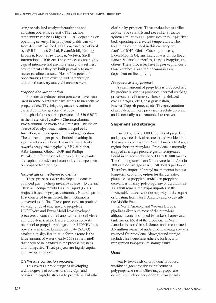
using specialized catalyst formulations andadjusting operating severity. The reactiontemperature can be as high as 700°C, depending onoperating severity. The propylene yields can varyfrom 4-22 wt% of feed. FCC processes are offeredby ABB Lummus Global, ExxonMobil, KelloggBrown & Root, Shaw Stone & Webster, ShellInternational, UOP, etc. These processes are highlycapital intensive and are more suited to a refineryenvironment as they are built primarily to meetmotor gasoline demand. Most of the potentialopportunities from existing units are throughadditional recovery and yield enhancement.
Propane dehydrogenationPropane dehydrogenation processes have been
used in some plants that have access to inexpensivepropane feed. The dehydrogenation reaction iscarried out in the gas phase at sub-atmospheric/atmospheric pressure and 550-650°Cin the presence of catalyst (Chromia-alumina, Pt-on-alumina or Pt-on-Zn-aluminate). The majorsource of catalyst deactivation is rapid cokeformation, which requires frequent regeneration.The conversion per pass is limited, resulting insignificant recycle flow. The overall selectivitytowards propylene is typically 85% or higher. ABB Lummus Global, UOP, and PhillipsPetroleum offer these technologies. These plantsare capital intensive and economics are dependenton propane feed pricing.
Natural gas or methanol to olefinsThese processes were developed to convert
stranded gas – a cheap methane source – to olefins.They will compete with Gas To Liquid (GTL)projects based on project economics. Natural gas isfirst converted to methanol, then methanol isconverted to olefins. These processes can producevarying ratios of ethylene and propylene.UOP/Hydro and ExxonMobil have developedprocesses to convert methanol to olefins (ethyleneand propylene), while Lurgi’s process convertsmethanol to propylene and gasoline. UOP/Hydro’sprocess uses silicoaluminophosphate (SAPO)catalysts. A significant issue for this route is thelarge amount of water (nearly 56% in methanol)that needs to be handled in the processing stepsand transported. These projects are highly capitaland energy intensive.
Olefins interconversion processesThis covers a broad range of developing
technologies that convert olefinic C4s (andheavier) in naphtha streams to propylene and other
olefinic by-products. These technologies utilizezeolite type catalysts and use either a reactorsystem similar to FCC processes or multiple fixedbeds operating at elevated temperatures. Thetechnologies included in this category areAtofina/UOP’s Olefin Cracking process,ExxonMobil’s Olefins Interconversion, KelloggBrown & Root’s Superflex, Lurgi’s Propylur, andothers. These processes have higher capital coststhan metathesis, and their economics aredependent on feed pricing.
Propylene as a by-productA small amount of propylene is produced as a
by-product in various processes: thermal crackingprocesses in refineries (visbreaking, delayedcoking off-gas, etc.), coal gasification, Fischer-Tropsch process, etc. The concentration of propylene in these processes is relatively smalland is normally not economical to recover.
Shipment and storage
Currently, nearly 3,000,000 mta of propyleneand propylene derivatives are traded worldwide.The major export is from North America to Asia, aregion short on propylene. Propylene is normallyshipped as a high-pressure gas or refrigeratedliquid in cargoes between 5,000 to 10,000 tonnes.The shipping rates from North America to Asia in2003 are on average nearly 150 dollars per tonne.Therefore, import of propylene monomer is not along-term economic option for the derivativeplants. Most propylene trade is in propylenederivatives, mainly polypropylene or acrylonitrile.Asia will remain the major importer in theforeseeable future, with the majority of the exportoriginating from North America and, eventually,the Middle East.
In North America and Western Europe,pipelines distribute most of the propylene,although some is shipped by tankers, barges andtank trucks. Most of the propylene in NorthAmerica is stored in salt domes and an estimated3.5 million tonnes of underground storage space isreserved for propylene. Aboveground storageincludes high-pressure spheres, bullets, andrefrigerated low-pressure storage tanks.
Uses
Nearly two-thirds of propylene producedworldwide goes into the manufacture ofpolypropylene resin. Other major propylenederivatives include acrylonitrile, oxoalcohols,
582 ENCYCLOPAEDIA OF HYDROCARBONS
BULK PRODUCTS AND PRODUCTION LINES IN THE PETROCHEMICAL INDUSTRY

propylene oxide, and cumene. Some importantchemical uses are discussed below.
PolypropylenePolypropylene is the largest end user of propylene
and is the fastest growing of all propylene derivativesdue to its versatility. It is used in injection moldingapplications (automobile parts, household appliances,bottle caps, containers, etc.), blow moldingapplications (bottles, containers, etc.), fibres (carpets,sportswear, etc.), and films/sheets (packaging,laminates, liners, etc.). Polypropylene has a very lowspecific gravity (0.90-0.91 g/cm3) with relatively highstiffness, tensile strength, heat deflection temperatures,and good clarity and stress crack resistance. Theseproperties, together with lower cost, makepolypropylene a favourable choice compared to metalsor other polymers where its properties suffice for theintended application.
The polypropylene resins are produced eitherby gas or slurry-phase polymerization using mostlyZiegler-Natta-type catalysts, althoughmetallocene-catalyzed polypropylene production isgaining ground because the resins have betterphysical and mechanical properties. Most of theproduction processes require high purity propylene(99.5%).
Propylene oxidePropylene oxide is used to make propylene
glycols and urethane polyether polyols. It can beproduced by either hydroperoxidation orchlorohydrin processes. In the hydroperoxidationprocess, a hydrocarbon is first converted withoxygen or air to a hydroperoxide, which then reactswith propylene to produce propylene oxide and asignificant amount of coproducts. In thechlorohydrin process, propylene first reacts withhypochlorous acid to produce propyleneclorohydrin, which is then dehydrochlorinated(using caustic soda or slaked lime) to propyleneoxide.
AcrylonitrileAcrylonitrile is a commodity chemical used in
various applications including polyacrylonitrilefibres, plastics (acrylonitrile-butadiene-styreneresins), adiponitrile, etc. It is produced by thecatalytic ammoxidation of propylene, a vapourphase reaction at low pressure (50-200 kPa) andmoderate temperatures (400-500°C) in thepresence of catalysts (Bi2O3/MoO3 with iron andadditives). Chemical grade propylene is typicallyused as feed. One kilogram of acrylonitrilerequires 1.10 to 1.20 kilograms of propylene.
Oxo chemicalsThe addition of synthesis gas to the double
bond of propylene produces butyraldehydes orbutanols. These reactions are carried out atelevated temperatures and pressures in thepresence of catalysts (cobalt or rhodium). n-Butanol is used as a solvent for lacquers andcoatings and is an intermediate for severalchemicals. n-Butyraldehyde is converted to 2-ethylhexanol, which is commonly used as aplasticizer alcohol. Isobutyraldehyde is convertedto isobutanol, which is a solvent for surfacecoatings.
CumeneCumene is produced by the alkylation of
benzene with propylene. This reaction takes placeat elevated temperature and pressure in thepresence of a catalyst (zeolite or phosphoric acid).The earlier Hock process is a vapour phasealkylation reaction. The new processes are mostlyliquid-phase (or two-phase alkylation) processes.All cumene is consumed in phenol production,which is used to manufacture phenolic resins,caprolactam, and bisphenol.
583VOLUME II / REFINING AND PETROCHEMICALS
ETHYLENE AND PROPYLENE
Propylene, mol% 99.95 minPropane + ethane, mol% Balance
Other impurities, mol ppm
Hydrogen 10 max
Acetylene 1 max
Methyl acetylene (MA) 1 max
Propadiene (PD) 1 max
Oxygen 2 max
Carbon monoxide 0.1 max
Carbon dioxide 2 max
Butenes 10 max
C4+s (saturates) 50 max
Water 2 max
Total sulphur 2 max
Methanol 5 max
Butadiene 1 max
Ammonia 5 max
Table 12. Typical specification for polymergrade propylene
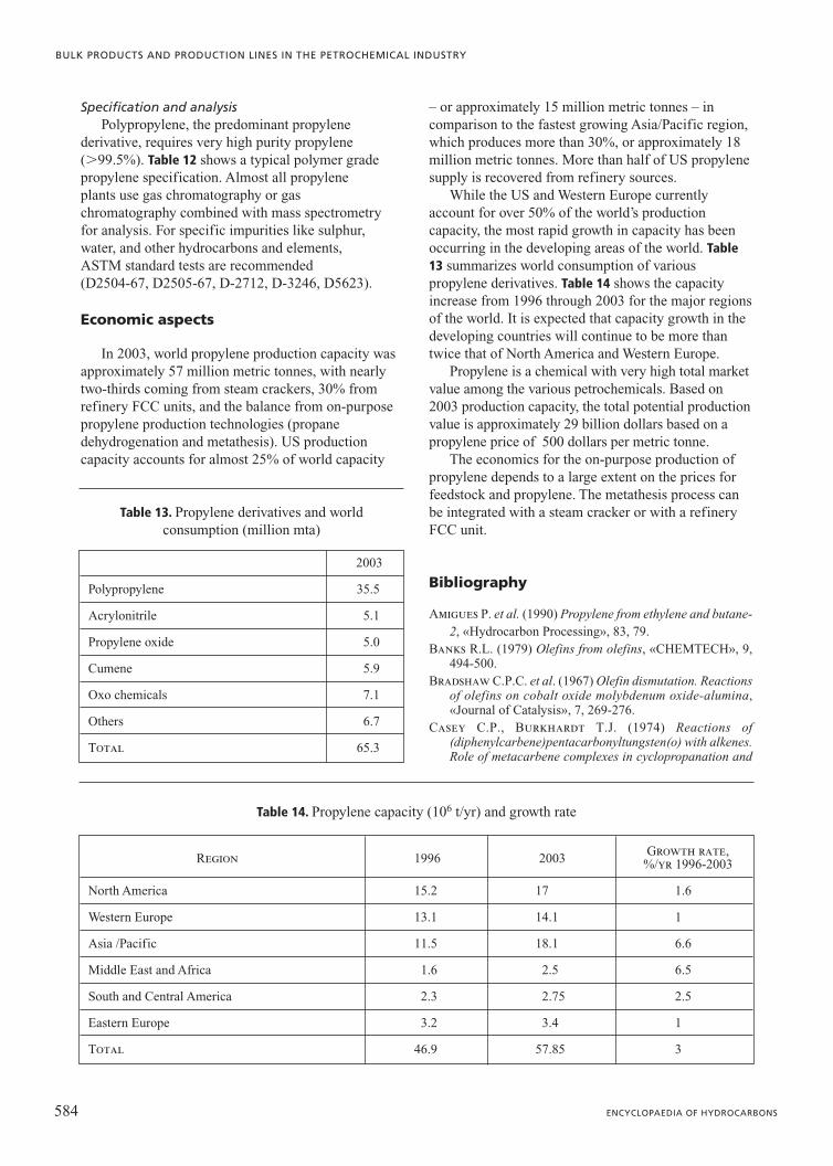
Specification and analysisPolypropylene, the predominant propylene
derivative, requires very high purity propylene(�99.5%). Table 12 shows a typical polymer gradepropylene specification. Almost all propyleneplants use gas chromatography or gaschromatography combined with mass spectrometryfor analysis. For specific impurities like sulphur,water, and other hydrocarbons and elements,ASTM standard tests are recommended(D2504-67, D2505-67, D-2712, D-3246, D5623).
Economic aspects
In 2003, world propylene production capacity wasapproximately 57 million metric tonnes, with nearlytwo-thirds coming from steam crackers, 30% fromrefinery FCC units, and the balance from on-purposepropylene production technologies (propanedehydrogenation and metathesis). US productioncapacity accounts for almost 25% of world capacity
– or approximately 15 million metric tonnes – incomparison to the fastest growing Asia/Pacific region,which produces more than 30%, or approximately 18million metric tonnes. More than half of US propylenesupply is recovered from refinery sources.
While the US and Western Europe currentlyaccount for over 50% of the world’s productioncapacity, the most rapid growth in capacity has beenoccurring in the developing areas of the world. Table13 summarizes world consumption of variouspropylene derivatives. Table 14 shows the capacityincrease from 1996 through 2003 for the major regionsof the world. It is expected that capacity growth in thedeveloping countries will continue to be more thantwice that of North America and Western Europe.
Propylene is a chemical with very high total marketvalue among the various petrochemicals. Based on2003 production capacity, the total potential productionvalue is approximately 29 billion dollars based on apropylene price of 500 dollars per metric tonne.
The economics for the on-purpose production ofpropylene depends to a large extent on the prices forfeedstock and propylene. The metathesis process canbe integrated with a steam cracker or with a refineryFCC unit.
Bibliography
Amigues P. et al. (1990) Propylene from ethylene and butane-2, «Hydrocarbon Processing», 83, 79.
Banks R.L. (1979) Olefins from olefins, «CHEMTECH», 9,494-500.
Bradshaw C.P.C. et al. (1967) Olefin dismutation. Reactionsof olefins on cobalt oxide molybdenum oxide-alumina,«Journal of Catalysis», 7, 269-276.
Casey C.P., Burkhardt T.J. (1974) Reactions of(diphenylcarbene)pentacarbonyltungsten(o) with alkenes.Role of metacarbene complexes in cyclopropanation and
584 ENCYCLOPAEDIA OF HYDROCARBONS
BULK PRODUCTS AND PRODUCTION LINES IN THE PETROCHEMICAL INDUSTRY
2003
Polypropylene 35.5
Acrylonitrile 5.1
Propylene oxide 5.0
Cumene 5.9
Oxo chemicals 7.1
Others 6.7
Total 65.3
Table 13. Propylene derivatives and world consumption (million mta)
Region 1996 2003Growth rate,
%/yr 1996-2003
North America 15.2 17 1.6
Western Europe 13.1 14.1 1
Asia /Pacific 11.5 18.1 6.6
Middle East and Africa 1.6 2.5 6.5
South and Central America 2.3 2.75 2.5
Eastern Europe 3.2 3.4 1
Total 46.9 57.85 3
Table 14. Propylene capacity (106 t/yr) and growth rate

olefin metathesis reactions, «Journal of the AmericanChemical Society», 96, 7808-7809.
CMAI (Chemical Market Associated Inc.) (1988) CMAIPetrochemical handbook.
CMAI (Chemical Market Associated Inc.) (1989-August 1991)CMAI Monomers market report.
Farrauto R.J., Bartholomew C.H. (1997) Fundamentalsof industrial catalytic processes, London, Blackie Academic& Professional.
Ivin K.J., Mol J.C. (1997) Olefin metathesis and metathesispolymerization, San Diego (CA), Academic Press.
Kapur S. (2004) Metathesis. Low cost propylene route, CMR,in: Proceedings of the Global business forum,Houston/Galveston (TX), 12-14 May.
Kapur S. et al. (2001) Olefins metathesis technology, in:Proceedings of the Annual DeWitt petrochemical review,Houston (TX), 28-29 March, G 1-12.
Lide D.R. (editor in chief) (1994) CRC handbook of chemistryand physics. A ready-reference book of chemical andphysical data, Boca Raton (FL)-London, CRC.
Manley D.B. (1997) Multilevel mixed refrigeration for ethylenerecovery, in: Proceedings of the annual American Instituteof Chemical Engineers-Ethylene Producers’ Conference,Houston (TX), 9-13 March.
Moulijn J.A. et al. (2001) Chemical process technology,Chichester, John Wiley.
Rase H.F. (2000) Handbook of commercial catalysts.Heterogeneous catalysts, Boca Raton (FL)-London, CRC.
SRI Consulting (1996) Chemical economics handbook, SRIConsulting.
Stanley S.J., Kapur S. (2002) Recent advances in olefinsproduction, in: Proceedings of the Annual DeWittpetrochemical review, Houston (TX), 19-21 March, B 1-10.
Yaws C.L. (1977) Physical properties. A guide to the physical,thermodynamic and transport property data of industriallyimportant chemical compounds, New York, McGraw-Hill.
Zinger S. (2004) Where can I find propylene?, in: Proceedingsof the Chemical Market Associated Inc. World petrochemicalconference, Houston (TX), 24-25 March, 185-200.
References
Advanced process control handbook (1991), «HydrocarbonProcessing», September.
Albano J.V. (1988) Applications of extended surfaces inpyrolysis coils, «Energy Progress», 8, 160-168.
Albano J.V. et al. (1991) Gas turbine integration in ethyleneplants, in: ACHEMA 91. Proceedings of the Internationalmeeting on chemical engineering and biotechnology,Frankfurt am Main, 9-15 June.
Albright A.L. et al. (1983) Pyrolysis. Theory and industrialpractice, New York-London, Academic Press.
Allara D.L., Edelson D.A. (1975) A computational modelingstudy of the low-temperature pyrolysis of n-alkanes.Mechanisms of propane, n-butane, and n-pentane pyrolyses,«International Journal of Chemical Kinetics», 7, 479-507.
Allara D.L., Shaw R.A. (1980) A compilation of kineticparameters for the thermal degradation of n-alkanemolecules, «Journal of Physical and Chemical ReferencesData», 9, 523-559.
Baerns M. (1991) Progress in methane conversion science-technology-economics, in: Proceedings of the SPUNGseminar, Trondheim (Norway), 24-25 September.
Baldwin R.L., Kamm G.R. (1982) Make ethylene by ACRprocess, «Hydrocarbon Processing. International Edition»,61, 127-130.
Banks R.L. (1979) Olefin from olefins, «CHEMTECH», 9,494-500.
Banks R.L. (1986) Discovery and development of olefindisproportionation, «CHEMTECH», 16, 112-117.
Banks R.L., Bailey G.C. (1964) Olefin metathesis announced,«Industrial & Engineering Chemistry Product Researchand Development», 3, 170.
Barker T., Jones J. (2000) Internally finned ethylene coils,«Hydrocarbon Engineering», 5, 77-78; 80-81.
Basu B., Kunzru D. (1992) Catalytic pyrolysis of naphtha,«Industrial & Engineering Chemistry Resources», 31, 146-155.
Baukal C.E. (editor) (2001) The John Zink combustionhandbook, Boca Raton (FL), CRC.
Bennett A.M.A. (1999) Novel, highly active iron and cobaltcatalysts for olefin polymerization, «CHEMTECH», 24.
Benson S.W. (1968) Thermochemical kinetics. Methods forthe extimation of thermochemical data and rate parameters,New York, John Wiley.
Biefeld C.G. et al. (1973) Crystal structure of bis(triphenylphosphine)tetramethyleneplatinum (II), «InorganicChemistry», 12, 2166-2170.
Boer F.P. et al. (1990) Controlling power plant nox emissions,«CHEMTECH», 20, 312-319.
Bonscher F.S. et al. (1974) Viscosity and conductivity data.1, «Hydrocarbon Processing», 53, 145.
Boudart M. (1968) Kinetics of chemical processes, EnglewoodCliffs (NJ), Prentice-Hall.
Bowen C.P. (1991) Olefin expansion strategies, in: Proceedingsof the Advanced petrochemical technologies and high techproducts symposium, Nijing, Interpec China.
Brown R.E. et al. (1997) Ethane pyrolysis with Phillipsantifoulant in full scale plant operations, in: Proceedingsof the American Institute of Chemical Engineers annualmeeting, Houston (TX), 9 March.
Buekens A.G., Froment G.F. (1968) Thermal cracking ofpropane. Kinetics and product distribution, «Industrial &Engineering Chemistry Process Design and Development»,7, 435-447.
Burdick D.L., Leffer L. (1983) Petrochemicals for the non-technical person, Tulsa (OK), Pennwell, 53-56.
Calderon N. et al. (1967) Olefin metathesis. A novel reactionfor skeletal transformation of unsaturated hydrocarbons,«Tetrahedron Letters», 34, 3327-3329.
Calderon N. et al. (1968) Olefin metathesis. I: Acyclic vinylenichydrocarbons, «Journal of the American Chemical Society»,90, 4133-4140.
Camp C.E. van et al. (1985) Severity in the pyrolysis ofpetroleum fractions. Fundamentals and industrialapplication, «Industrial & Engineering Chemistry ProcessDesign and Development», 24, 561-570.
Carey F.A. (1987) Organic chemistry, New York, McGraw-Hill.Champagnie A.M. et al. (1990) A high temperature catalytic
membrane reactor for ethane dehydrogenation, «ChemicalEngineering Science», 45, 2423-2429.
585VOLUME II / REFINING AND PETROCHEMICALS
ETHYLENE AND PROPYLENE

Chapin L.E., Letzsch W.S. (1997) Deep catalytic cracking,«Petroleum Technology Quarterly», 1, 57.
Chauvin Y. (1973) Catalyse de transformation des oléfins parles complexes du tungstène. Forme possible desintermediaires, «Comtes Rendus. Académie des Sciences»,276, 169-171.
Chauvin Y., Herisson J.-L. (1971) Mechanism of rutheniumcarbene mediated olefin metathesis, «MakromolekulareChemie», 141, 161.
Chen J., Vogel W. (1973) Fouling of transferline exchangersin ethylene services, in: Proceedings of the AmericanInstitute of Chemical Engineers national meeting, NewOrleans (LA), March.
Chernykh S.P. (edited by) (1991) New organic synthesisprocesses, Moskow, Mir.
Choudhary V.R. et al. (2000) High-temperature catalyticoxidative conversion of propane to propylene and ethyleneinvolving coupling of exothermic and endothermic reactions,«Industrial & Engineering Chemistry Resources», 39, 904-908.
Cider L., Schoon N.H. (1991) Hydrogenation of acetylene attransient conditions in the presence of olefins and carbonmonoxide over palladium/alumina, «Industrial & EngineeringChemistry Resources», 30,1437.
CMAI (Chemical Market Associates Inc.) (1989) World lightolefins analysis, August, 1.
Conway S.J., Lunsford J.H. (1991) The oxidativedehydrogenation of ethane over chlorine-promoted lithium-magnesium oxide catalysts, «Journal of Catalysis», 131,513-522.
Cooke D.H., Parizot W.D. (1991) Cogenerative, direct exhaustintegration of gas turbines in ethylene production,«Transactions of American Society of MechanicalEngineers», 113, 212-220.
Dean J.A. (editor) (1985) Lange’s handbook of chemistry, NewYork, McGraw-Hill.
De Hertog W. et al. (1998) A catalytic process for olefinsproduction, in: American Institute of Chemical EngineersConference, Houston (TX), 15-18 March.
Dente M., Ranzi E. (1983) Mathematical modeling ofhydrocarbon pyrolysis reactions, in: Albright L.F. et al.(editors) Pyrolysis theory and industrial practice, NewYork, Academic Press, 133-175.
Dente M. et al. (1979) Detailed prediction of olefin yieldsfrom hydrocarbon pyrolysis through a fundamentalsimulation model (SPYRO), «Computers and ChemicalEngineering», 3, 61-75.
Dente M. et al. (1981) Adiabatic cracking yields theoreticallypredicted, in: Proceedings of the American Institute ofChemical Engineers Spring national meeting, New Orleans(LA), July.
Dente M. et al. (1983) Ethylene cracker transferline exchangerfouling, in: Proceedings of the American Institute ofChemical Engineers annual meeting, Houston (TX), March.
Dente M. et al. (1985) Steam cracking of heavy liquidfeedstocks. Cracking yields rigorously predicted, in:Proceedings of the American Institute of ChemicalEngineers Spring national meeting, New Orleans (LA),4-10 April.
Dente M. et al. (1990), in: Proceedings of the American Instituteof Chemical Engineers Spring meeting, Orlando (FL), 18-22 March.
Depeyre D. et al. (1989) Modeling of thermal steam crackingof an atmospheric gas oil, «Industrial & EngineeringChemistry Research», 28, 967-976.
DeWitt and Company (1989-1990) Ethylene annual, Houston(TX), DeWitt and Company.
Douslin D.R., Harrison R.H. (1976) Pressure, volume,temperature relations of ethylene, «Journal of ChemicalThermodynamics», 8, 301-330.
Dry M.E. (1981) The Fischer Tropsch synthesis, in: AndersonJ.R., Boudart M. (editors) Catalysis science and technology,Berlin-New York, Springer, 1981-1996, 11v.; v.I, 159-255.
Ellis A.F. et al. (1981) TRC. A new olefins technology, in:Proceedings of the American Institute of Chemical Engineersnational meeting, Houston (TX), 5-9 April.
Ercan C. et al. (1998) Mass-transfer effects in liquid-phasealkylation of benzene with zeolite catalysts, «Industrial &Engineering Chemistry Research», 37,1724-1728.
Fernandez-Baujin J.M., Solomon S.M. (1975) An industrialapplication of pyrolysis technology. Lummus SRT-III module,in: Proceedings of the 1st Chemical congress of the NorthAmerican continent, Mexico City, 30 November-5December.
Froment G.F. (1981) Thermal cracking for olefins production.Fundamentals and their application to industrial problems,«Chemical Engineering Science», 36, 1271-1282.
Froment G.F. (1992) Kinetics and reactor designed in thethermal cracking for olefins production, «ChemicalEngineering Science», 47, 2163-2177.
Gear C.W. (1971) Numerical initial value problems in ordinarydifferential equations, Englewood Cliffs (NJ), Prentice Hall.
Gildert G. et al. (1995) Combining hydrogenation withdistillation in ethylene plants, in: Proceedings of the annualAmerican Institute of Chemical Engineers-EthyleneProducers’ Conference, Houston (TX), 19-23 March.
Goossens A.G. et al. (1980) Improve steam cracker operation,in: Kane Les A. (compiled by) Process control andoptimization handbook for hydrocarbon processingindustries, Houston (TX)-London, Gulf, 30.
Greene D.G. et al. (1994) Thermomechanically integrateddistillation of ethylene from ethane, in: Proceedings of thethe annual American Institute of Chemical Engineers-EthyleneProducers’Conference, Atlanta (GA), 17-21 April, 703-714.
Grubbs R.H., Brunck T.K. (1972) Possible intermediate inthe tungsten-catalyzed olefin metathesis reaction, «Journalof the American Chemical Society», 94, 2538-2540.
Halle R.T. (1994) Potential hazards of nitrogen oxidecompound accumulations in cryogenic ethylene recoveryfacilities, in: Oballa M.C., Shih S.S. (edited by) Catalytichydroprocessing of petroleum and distillates. Based on theproceedings of the AIChE Spring national meeting, Houston(TX), March 1993, New York, Marcel Dekker.
Harrison R.H., Douslin D.R. (1971) Derived thermodynamicproperties of ethylene, «Journal of Chemical andEngineering Data», 22, 24-30.
Health, safety and environment conference. Proceedings of theEuropean ethylene producer’s committee (2001-2004).
Heckelsberg L.F. et al. (1968) Tungsten oxide on silica catalystfor Phillips’ triolefin process, «Industrial & EngineeringChemistry Product Research and Development», 7, 29-31.
Heckelsberg L.F. et al. (1969) Olefin disproportionationcatalysts, «Industrial & Engineering Chemistry ProductResearch and Development», 8, 259-261.
586 ENCYCLOPAEDIA OF HYDROCARBONS
BULK PRODUCTS AND PRODUCTION LINES IN THE PETROCHEMICAL INDUSTRY

Heynderickx G.J., Froment G. (1996) A pyrolysis furnacewith reactor tubes of elliptical cross section, «Industrial &Engineering Chemistry Research», 35, 2183-2189.
Hillewaert L.P. et al. (1988) Computer generation of reactionschemes and rate equations for thermal cracking, «AmericanInstitute of Chemical Engineers Journal», 34, 17.
Hirato M., Yosida S. (1973) Simulation of the pyrolysis ofnaphtha, kerosene and gasoil with a tubular reactor,«International Chemical Engineering», 13, 347.
Horigome T. et al. (1991) The first world scale plant usingthe Lummus/Unocal/UOP process for ethylbenzene is ahuge success, in: Proceedings of the Catalyst conference,München, 4 July.
Hosoi T., Keister R.G. (1975) Ethylene from crude oil,«Chemical Engineering Progress», 71, 63-67.
Hu Y.C. (1982) Unconventional olefin processes. Part I:Crude/residual oil cracking, «Hydrocarbon Processing.International Edition», 61, 109-116.
Inui T. (1990) Structure-reactivity relationship in methanol toolefin conversion on various microporous crystallinecatalysts, in: Proceedings of the American Chemical Societynational meeting, Boston (MA), 22-27 April.
Inui T., Takegami T. (1982) Olefins from methanol by modifiedzeolites, «Hydrocarbon Processing. International Edition»,61, 117-120.
Inui T. et al. (1991) Highly selective synthesis of light olefinsfrom methanol on the novel nickel-silicoaluminophosphate,in: Catalytic science and technology. Proceedings of the1st Tokyo Conference on advanced catalytic science andtechnology, Tokyo, 1-5 July 1990, 85.
Jacobsen R.T. (written and compiled by) (1988) Ethylene(Ethene), Oxford, Blackwell.
Jeong S.M. et al. (2001) Study on catalytic pyrolysis of naphthaover a KvO3 /a-Al2O3 catalyst for production of light olefins,«Industrial & Engineering Chemistry Resources», 40, 6081-6086.
Katz T.J., McGinnis J. (1975) Mechanism of the olefinmetathesis reaction, «Journal of the American ChemicalSociety», 97, 1592-1594.
Kearns J.D. et al. (1979) Development of scaling methodsfor a crude oil cracking reactor by using short durationtest techniques, «Advances in Chemistry Series», 183,107-128.
Kikuchi K. et al. (1985) New catalytic cracking process,«Chemical Engineering Progress», June, 54-58.
Kniel L. et al. (1980) Ethylene-Keystone to the petrochemicalindustry, New York, Marcel Dekker.
Kolts J.H., Delzer G.A. (1986) Enhanced ethylene and ethaneproduction with free-radical cracking catalysts, «Science»,232, 744-746.
Kopinke F.D. et al. (1993a) Relative rates of coke formationfrom hydrocarbons in steam cracking of naphtha. 2:Paraffins, naphthenes, mono-, di-, and cycloolefins, andacetylenes, «Industrial & Engineering Chemistry Research»,32, 56-61.
Kopinke F.D. et al. (1993b) Relative rates of coke formationfrom hydrocarbons in steam cracking of naphtha. 3:Aromatic hydrocarbons, «Industrial & EngineeringChemistry Research», 32, 2620-2625.
Kumar P., Kunzru D. (1985) Modeling of naphtha pyrolysis,«Industrial & Engineering Chemistry Process Design andDevelopment», 24, 774-782.
Kunugi D. (1980) Chemical reaction engineering and researchand development of gas solid systems, «ChemicalEngineering Science», 35, 1887-1911.
Laegreid T. (1991) ADH. The dehydrogenation process, status,and possibilities, in: Proceedings of the SPUNG seminar,Trondheim (Norway), 24-25 September.
Laidler K.J. (1965) Chemical kinetics, New York, McGraw-Hill.
Lam W.K. (1988), in: Proceedings of the 4th Pacific AreaChemical Engineering Congress, Acapulco, 19-22 October.
Lee J.H. et al. (2004) Effect of steam on coking in the non-catalytic pyrolysis of naphtha components, «Korean Journalof Chemical Engineering», 21, 252-256.
Lemonidou A.A., Vasalos I.A. (1989) Preparation andevaluation of catalysts for the production of ethylene viasteam cracking. Effect of operating conditions on theperformance of 12 CaO-7 Al2O3 catalyst, «AppliedCatalysis», 54, 119-138.
Lemonidou A.A. et al. (1987) Catalyst evaluation and kineticstudy for ethylene production, in: Proceedings of theAmerican Institute of Chemical Engineers Spring nationalmeeting, Houston (TX), 29 March-2 April.
Lemonidou A.A. et al. (1989) Catalyst evaluation and kineticstudy for ethylene production, «Industrial & EngineeringChemistry Resources», 28, 524-530.
Lewis P.J., Dwyer F.G. (1977) Ethylbenzene unit operateswell on dilute ethylene, «Oil & Gas Journal», 75, 55-58.
Lichtenstein I. (1964) Design cracking furnaces by computer,«Chemical Engeneering Progress», 60, 64.
Lohr B., Schwab W. (1979) Advances in cracking technologyand cracking furnace design, «Linde Reports on Scienceand Technology», 30, 18-27.
Lorber U. et al. (1971) Acetylene recovered from ethylenefeedstock, «Chemical Engineering», 78, 83-85.
Lummus Crest (1988) New styrene plant optimizer, in: Resourcerecovery of municipal solid wastes. Proceedings of theAmerican Institute of Chemical Engineers Spring nationalmeeting, New Orleans (LA), 8-12 March, Paper 65B.
McPhaul D.R., Reid J.A. (1995) Ethylene plant feedstockcontaminants and treatment, in: Proceedings of the annualAmerican Institute of Chemical Engineers-EthyleneProducers’ Conference, Houston (TX), 19-23 March.
Magnan J. et al. (2002) Improved steam cracker furnaceefficiency, «Petroleum Technology Quarterly», Summer, 125.
Manley D.B. (1996) Process design for ethylene recovery, in:Proceedings of the annual American Institute of ChemicalEngineers-Ethylene Producers’Conference, New Orleans(LA), 601-606.
Matsunami T. et al. (1970), «Hydrocarbon Processing»,November, 121.
Miller S.A. (editor) (1969) Ethylene and its industrialderivatives, London, Benn.
Mol J.C. et al. (1968) Carbon-14 studies on the mechanismof the disproportionation of propene, «ChemicalCommunications», 11, 633.
Nachenberg J.A. (1991) ARS update/revamp concepts, in:Proceedings of the 8th Ethylene forum, The Woodlands(TX), 15-17 May.
Nakamura D.N. (2004) Global ethylene capacity growth slowsto lowest level since mid-1980s, «Oil & Gas Journal», 102,48-57.
587VOLUME II / REFINING AND PETROCHEMICALS
ETHYLENE AND PROPYLENE

Newsome D.S., Leftin H.P. (1980) Coking rates in a laboratorypyrolysis furnace, «Chemical Engineering Progress», May, 76.
NEXANT (2002) Methanol to olefins, Nexant Chemical SystemReport, 1 January.
Olefins pipelines set to reshape new logistics (1990), «EuropeanChemistry News», 55, 13.
Pant K.K., Kunzru D. (1996) Pyrolysis of n-heptane. Kineticsand modeling, «Journal of Analytical and Applied Pyrolysis»,36, 103-120.
Perry R.H. (editorial direction), Chilton C.H. (senior adviser)(1973) Chemical engineers handbook, London-Tokyo,McGraw-Hill, 6-89.
Peters E.F., Evering B.L. (1960) US Patent 2963447 toStandard oil.
Pettit R. (1971) Mechanism of the metal-catalyzeddisproportionation of olefins, «Journal of the AmericanChemical Society», 93, 7087-7088.
Picciotti M. (1977a) Optimize quench oil systems,«Hydrocarbon Processing», 56, 183.
Picciotti M. (1977b) Design quench water tower,«Hydrocarbon Processing», 56, 163.
Picciotti M. (1977c) Optimize quench water systems,«Hydrocarbon Processing», 56, 179.
Picciotti M. (2000) Advances in ethylene technology. Anupdate, in: Proceedings of the 2nd Iran Petrochemical Forum,Teheran, 6-8 May.
Platvoet E. et al. (2003) Ethylene furnace modelling. Anintegrated approach, in: Proceedings of the annual AmericanInstitute of Chemical Engineers-Ethylene Producers’Conference, New Orleans (LA), 30 March-3 April.
Plehiers P.M. et al. (1990) Simulation of the run length of anethane cracking furnace, «Industrial & EngineeringChemistry Research», 29, 637-641.
Preuss U., Baerns M. (1987) Chemical technology of naturalgas. Its present state and prospects, «Chemical Engineeringand Technology», 10, 297-305.
Proceedings of the annual American Insitute of ChemicalEngineers/Ethylene Producer’s Conference (1991-2004).
Raab M. (1976) Sodium hydroxide washes in petrochemicalproduction, ethylene production for example. Effect ofmethods and plant conditions on the dimension (ofproduction), «Linde Reports on Science and Technology»,23, 23.
Ranzi E. et al. (1994) Prediction of kinetic parameters forhydrogen astraction reactions, «Combustion Science andTechnology», 95, 1-50.
Raseev S. (2003) Thermal and catalytic processes in petroleumrefining, New York, Marcel Dekker.
Redmond T., Bergeron M.P. (1999) Tests demonstrateanticoking capability of new coating, «Oil & Gas Journal»,May.
Reichert K.H., Geiseler W. (editors) (1983) Polymer reactionengineering. Influence of reaction engineering on polymerproperties, München, Hanser.
Rice F.O. (1931) The thermal decomposition of organiccompounds from the standpoint of free radicals. I: Saturatedhydrocarbons, «Journal of the American Chemical Society»,53, 1959-1972.
Rice F.O. (1933) The thermal decomposition of organiccompounds from the standpoint of free radicals. III: Thecalculation of the products formed from paraffin hydrocarbons,«Journal of the American Chemical Society», 55, 3035-3040.
Ross L.L., Shu W.R. (1979) Computer modeling ofhydrocarbon pyrolysis for olefins production, «Advancesin Chemistry Series», 183, 129-152.
Schmalfeld P. (1963) How Lurgi improved sand crackers,«Hydrocarbon Processing and Petroleum Refiner», 42,145-148.
Schmidt L.D. et al. (2000) New ways to make old chemicals,«American Institute of Chemical Engineers Journal», 46,1492-1495.
Semenov N.N. (1959) Some problems in chemical kinetics andreactivity, Princeton (NJ), University Press, 1958-1959,2v.; v.II.
Sliwka A.D. (1981) European Patent 0036151 to BASF AG.SRI Consulting (1997) World petrochemicals, SRI Consulting,
v.I, May. Stancato B. et al. (1991) Advanced control/optimization for
Mitsubishi Kashima ethylene plant, in: Proceedings of theAmerican Institute of Chemical Engineers Spring nationalmeeting, Houston (TX), 7-11 April.
Stanley S.J., Venner R.M. (1991) Revamp of world scaleethylene unit, in: Proceedings of the 4th World congress ofchemical engineers, Karlsruhe (Germany), 16-20 June.
Stanley S.J., Weidert D. (2002) Advances in CDHydroapplications in olefin production, in: Proceedings of the6th International conference on microreaction technology,New Orleans (LA), 10-14 March.
Starling K.E. (1973) Fluid thermodynamic properties forlight petroleum systems, Houston (TX), Gulf.
Steinhofer A. et al. (1963) Production of ethylene from crudeoil, «Hydrocarbon Processing and Petroleum Refiner», 42,119-124.
Stork K. et al. (1974) US Patent 3816976 to Lummus.Sundaram K.M., Fernandez-Baujin J.M. (1988) Effect of
methane and hydrogen during thermal cracking of lighthydrocarbons, «American Institute of Chemical EngineersJournal», 34, 321-325.
Sundaram K.M., Fernandez-Baujin J.M. (1990) Anexperience on HVGO, in: Proceedings of the AmericanInstitute of Chemical Engineers Spring national meeting,Orlando (FL), March 18-22.
Sundaram K.M., Froment G.F. (1977a) Modeling of thermalcracking kinetics. I: Thermal cracking of ethane, propaneand their mixture, «Chemical Engineering Science», 32,601-608.
Sundaram K.M., Froment G.F. (1977b) Modeling of thermalcracking kinetics. II: Cracking of iso-butane, of n-butaneand of mixture ethane-propane-n-butane, «ChemicalEngineering Science», 32, 609-617.
Sundaram K.M., Froment G.F. (1978a) The accuracy of thepseudo-steady-state approximation for radicals in thermalcracking, «International Journal of Chemical Kinetics»,10, 1189-1193.
Sundaram K.M., G.F. Froment (1978b) Modeling of thermalcracking kinetics. III: Radical mechanisms for the pyrolysisof simple paraffins, olefins and their mixture, «Industrial& Engineering Chemistry Fundamentals», 17, 174-182.
Sundaram K.M. et al. (1981) Coke deposition in the thermalcracking of ethane, «American Institute of ChemicalEngineers Journal», 27, 946-951.
Sundaram K. M. et al. (1994) Ethylene, in: Kirk-OthmerEncyclopedia of chemical technology, New York, JohnWiley, 1991-1998, 27v.; v. IX.
588 ENCYCLOPAEDIA OF HYDROCARBONS
BULK PRODUCTS AND PRODUCTION LINES IN THE PETROCHEMICAL INDUSTRY

Sykes P. (1975) A guidebook to mechanism in organicchemistry, London, Longman.
Taso U., Reilly J.W. (1978), «Hydrocarbon Processing»,February.
Tomlin A.S. et al. (1995) Reduced mechanism for propanepyrolysis, «Industrial & Engineering Chemistry Research»,34, 3749-3760.
Tong Y. et al. (1994) Development of a new coke inhibitor forethylene unit cracking furnaces, in: Proceedings of theAmerican Institute of Chemical Engineers annual meeting,Atlanta (GA), 17-21 April.
TRC (Thermodynamics Research Center) (1986) TRCThermodynamic tables. Hydrocarbons, The Texas UniversitySystem, College Station (TX).
Trimm D.L., Turner C.J. (1981) The pyrolysis of propane. I:Production of gases, liquids and carbon, «Journal ofChemical Technology and Biotechnology», 31, 195-204.
Trotman-Dickenson A.F. (1965) The abstraction of hydrogenatoms by free radicals, «Advances in Free-RadicalChemistry», 1, 1-38.
Ulrich H. (1988) Raw materials for industrial polymers,München, Hanser.
Vargaftik N.B. (1975) Tables on the thermophysical propertiesof liquids and gases in normal and dissociated states,Washington (D.C.), Hemisphere.
Vora B.V. et al. (1986) Oleflex – C2-C5 dehydrogenationupdated, in: Proceedings of the American Institute ofChemical Engineers meeting on new developments in olefintechnology, New Orleans (LA), 6-10 April.
Wauters S., Marin G.B. (2002) Kinetic modeling of the coke
formation during steam cracking, «Industrial & EngineeringChemistry Research», 41, 2379-2391.
Weast R.C. (editor in chief) (1987) CRC Handbook of chemistryand physics, Boca Raton (FL), CRC.
Wett T. (1972) Kureha cracks crude oils for olefins, «Oil &Gas Journal», 70, 76.
Willems P.A., Froment G.F. (1988a) Kinetic modeling of thethermal cracking of hydrocarbons. I: Calculation offrequency factors, «Industrial & Engineering ChemistryResearch», 27, 1959-1966.
Willems P.A., Froment G.F. (1988b) Kinetic modeling ofthe thermal cracking of hydrocarbons. II: Calculation ofactivation energies, «Industrial & Engineering ChemistryResearch», 27, 1966-1971.
Winfield M.E. (1960) Catalytic dehydration and hydration,in: Emmett P.H. (edited by) Catalysis, New York, VanNostrand Reinhold, 1954-1960, 7v.; v.VII, 93-182.
Winter O. (1976) Ethylene from ethanol, in: Proceedings ofthe 1st Brazilian petrochemical congress, Rio de Janeiro,7-12 November.
Zdonik S.B. et al. (1970) Manufacturing ethylene, Tulsa (OK),Petroleum Publishing.
Zou R. et al. (1993) Study on a kinetic model of atmosphericgas oil pyrolysis and coke deposition, «Industrial &Engineering Chemistry Research», 32, 843-847.
Sanjeev Kapur
ABB Lummus GlobalHouston, Texas, USA
589VOLUME II / REFINING AND PETROCHEMICALS
ETHYLENE AND PROPYLENE


![Maximizing propylene production via FCC technology · Maximizing propylene production via FCC technology ... metathesis or propane dehydrogenation [57, 76]. With the ethylene and](https://img.dokumen.tips/doc/110x75/6079e7d4f3a826341a66a1dd/maximizing-propylene-production-via-fcc-technology-maximizing-propylene-production.jpg)