Embed Size (px)
Citation preview
1
TYPICAL ELEMENTS
Triangular shell element6 D.O.F. per node
Tetrahedral solid element3 D.O.F. per node
First order elements
Linear displacement distributionConstant stress distribution
Second order elements
Second order displacement distributionLinear stress distribution
2
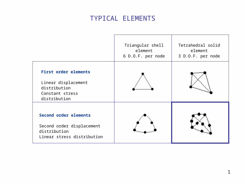
TWO POSSIBLE REPRESENTATIONS OF A PLATE
3
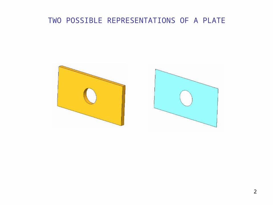
CAN YOU IDENTIFY THESE ELEMENTS?
Note: all these elements would be way too large for analysis
4
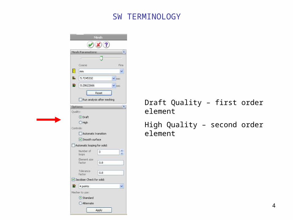
Draft Quality – first order element
High Quality – second order element
SW TERMINOLOGY
5
FINITE ELEMENT MESH
Mesh compatibility
Mesh quality
Mesh adequacy
6
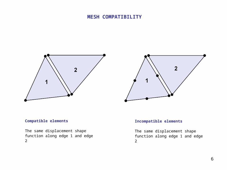
MESH COMPATIBILITY
Compatible elements
The same displacement shape function along edge 1 and edge 2
Incompatible elements
The same displacement shape function along edge 1 and edge 2
7
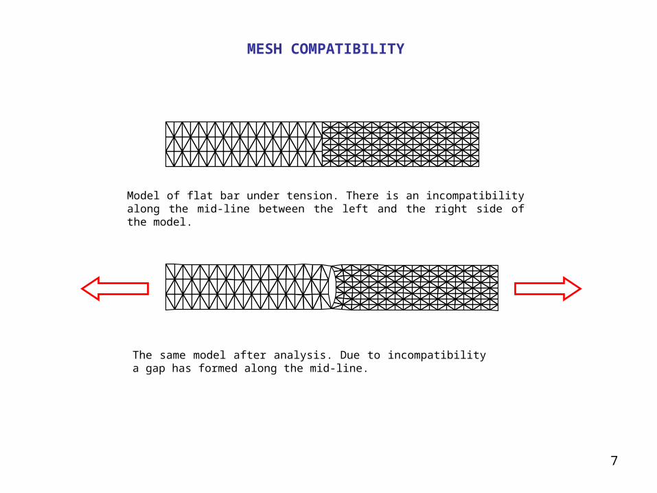
Model of flat bar under tension. There is an incompatibility along the mid-line between the left and the right side of the model.
The same model after analysis. Due to incompatibility a gap has formed along the mid-line.
MESH COMPATIBILITY

8
Tetrahedral solid elements and hexahedral solid elements combined in one model.
Hexahedral solid elements
Tetrahedral solid elements
MESH COMPATIBILITY
9
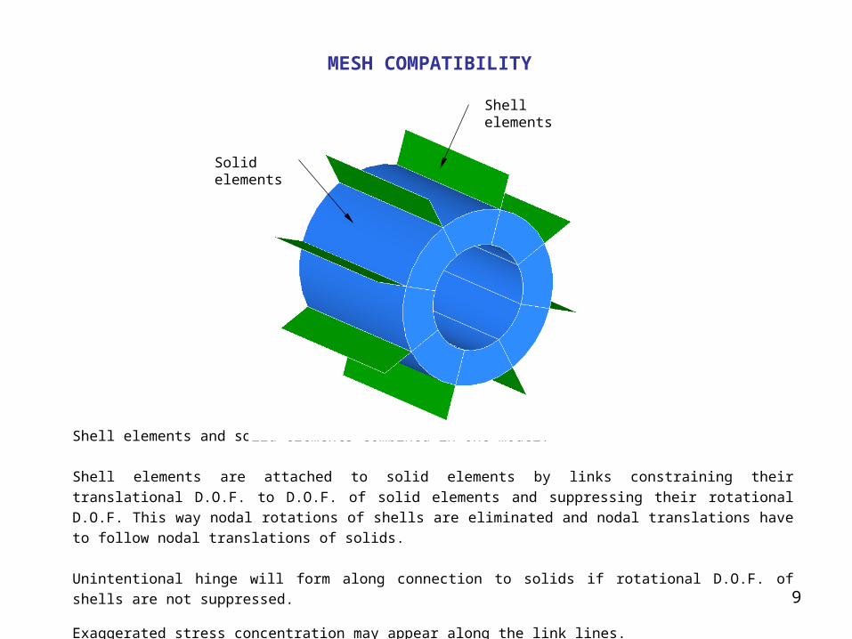
Shell elements and solid elements combined in one model.
Shell elements are attached to solid elements by links constraining their translational D.O.F. to D.O.F. of solid
elements and suppressing their rotational D.O.F. This way nodal rotations of shells are eliminated and nodal
translations have to follow nodal translations of solids.
Unintentional hinge will form along connection to solids if rotational D.O.F. of shells are not suppressed.
Exaggerated stress concentration may appear along the link lines.
MESH COMPATIBILITY
Shell elements
Solidelements
10
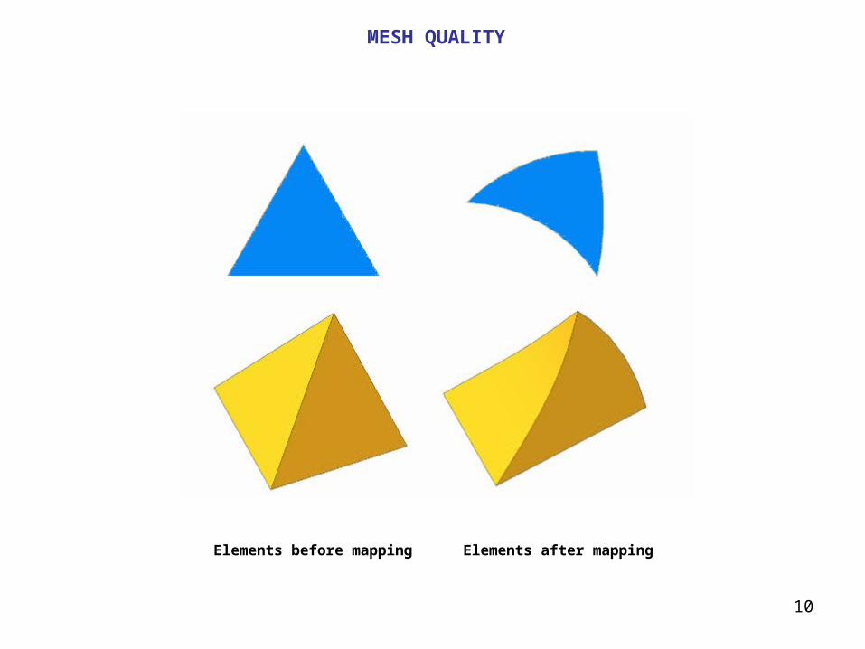
Elements before mapping Elements after mapping
MESH QUALITY
11
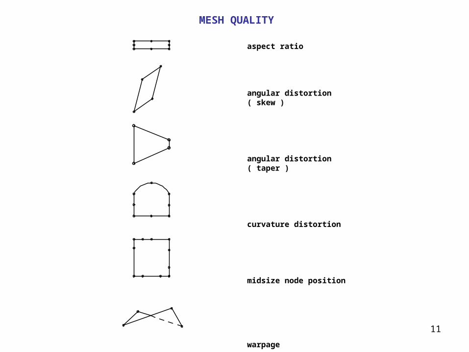
MESH QUALITY
aspect ratio
angular distortion ( skew )
angular distortion ( taper )
curvature distortion
midsize node position
warpage
12
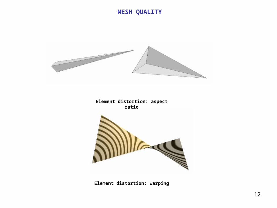
Element distortion: aspect ratio
Element distortion: warping
MESH QUALITY
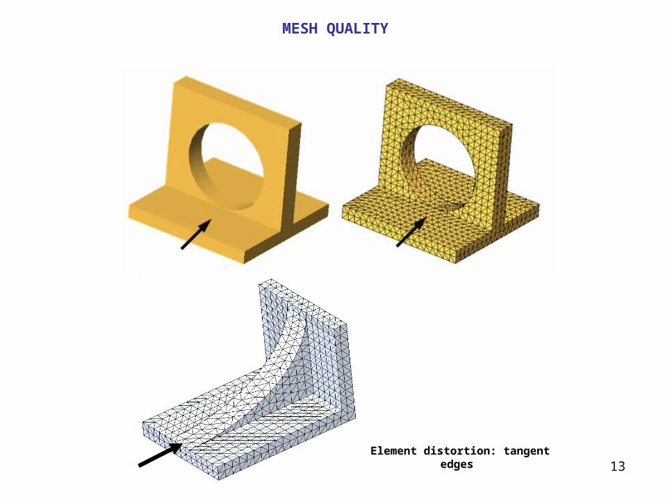
13Element distortion: tangent edges
MESH QUALITY
14
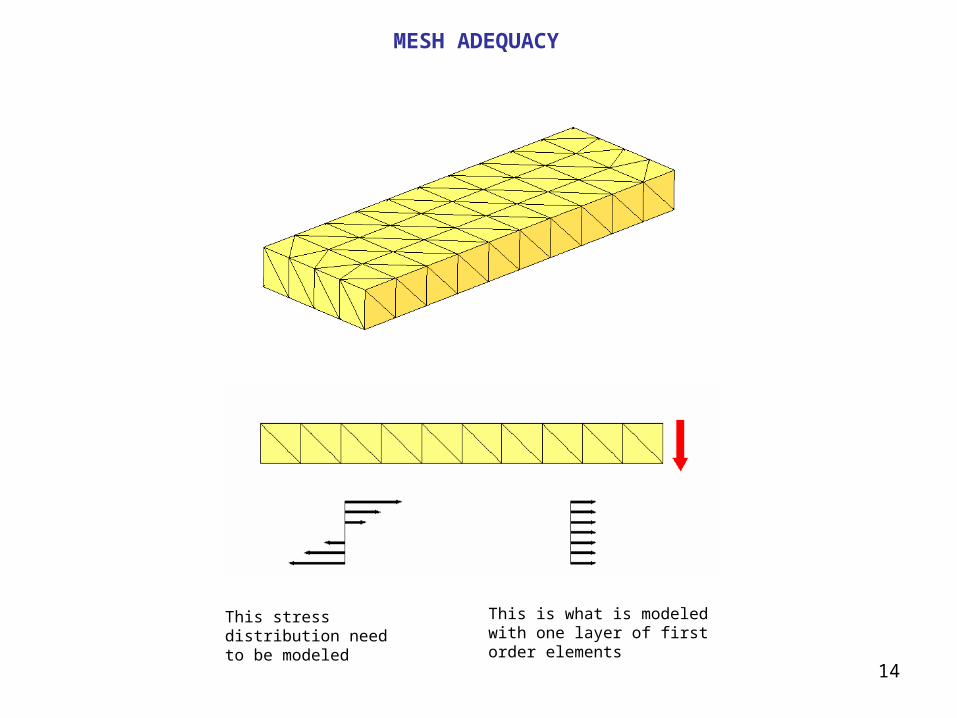
MESH ADEQUACY
This stress distribution need to be modeled
This is what is modeled with one layer of first order elements

15
c a n t i l e v e r b e a m , m o d e l 1t e r r i b l y b a d
c a n t i l e v e r b e a m , m o d e l 2a l s o t e r r i b l y b a d
c a n t i l e v e r b e a m m o d e l 3a g o o d b e g i n n i n g !
c a n t i l e v e r b e a m , m o d e l 4a n a c c e p t a b l e m o d e l
cantilever beam size: 10" x 1" x 0.1"modulus of elasticity: 30,000,000 PSIload: 150 lb.beam theory maximal deflection: f = 0.2"beam theory maximal stress: = 90,000 PSI
our definition of the discretization error : ( beam theory result - FEA result ) / beam theory result
model #
FEA deflection
[in]
deflection error [%]
FEA stress [ PSI ]
stress error [%]
1 0.1358 32 1,500 98
2 0.1791 10 39,713 56
3 0.1950 2.5 65,275 27
4 0.1996 0.2 80,687 10
MESH ADEQUACY
16
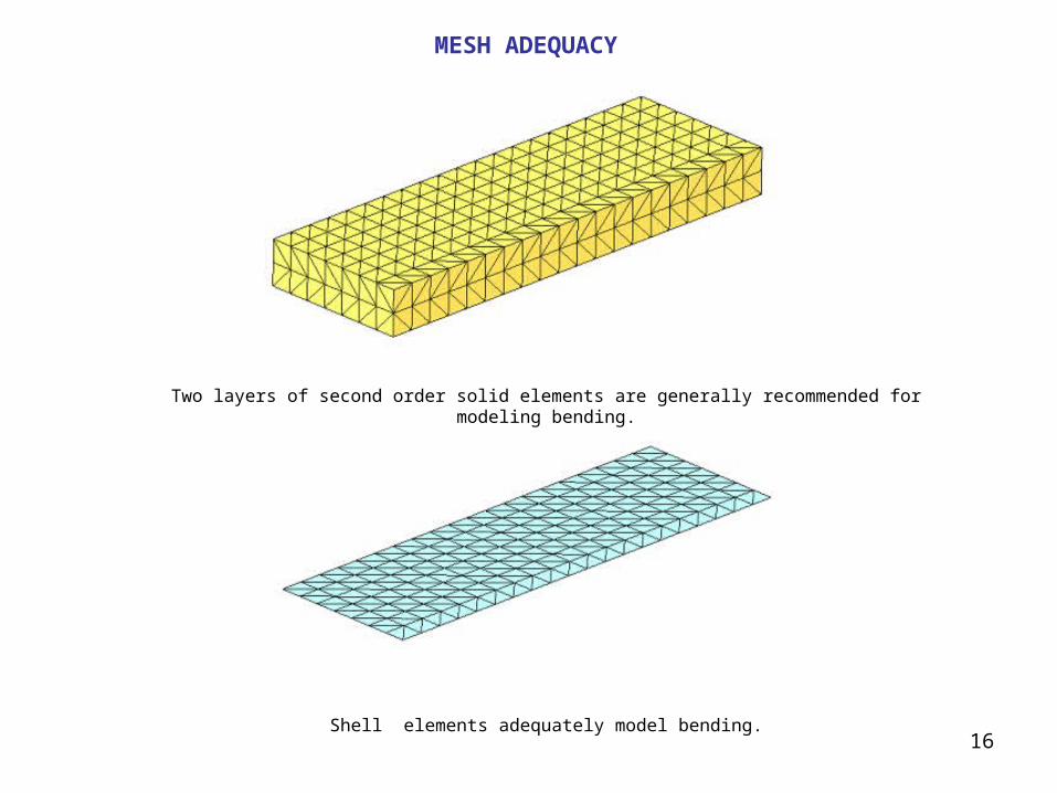
MESH ADEQUACY
Two layers of second order solid elements are generally recommended for modeling bending.
Shell elements adequately model bending.
17
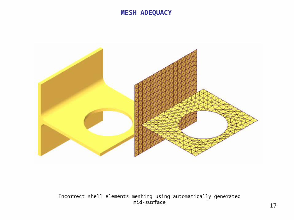
MESH ADEQUACY
Incorrect shell elements meshing using automatically generated mid-surface


![[Doi 10.1016%2Fj.finel.2004.11.007] C.S. Jog -- A 27-Node Hybrid Brick and a 21-Node Hybrid Wedge Element for Structural Analysis](https://img.dokumen.tips/doc/110x75/577cc5bf1a28aba7119d1bfd/doi-1010162fjfinel200411007-cs-jog-a-27-node-hybrid-brick-and.jpg)