Embed Size (px)
Citation preview
1
Copyright © 2007 Fluor Corporation
PUMPS
PUMPS
Lesson Objective
Become familiar with the most common types of pumps, how the different types
of pumps operate, and how the different types of pumps are used
Learn the different types of pump drivers used
Learn how to determine where pumps are located within a process unit
2
Definition:
What is a pump?
Pumps are a device which moves a liquid by means of suction or pressure from
one location to another.
3
Types of Pumps
Types of Pumps
There are three basic types of
pumps
Centrifugal
Rotary
Reciprocrating
4
Copyright © 2007 Fluor Corporation
Centrifugal Pumps
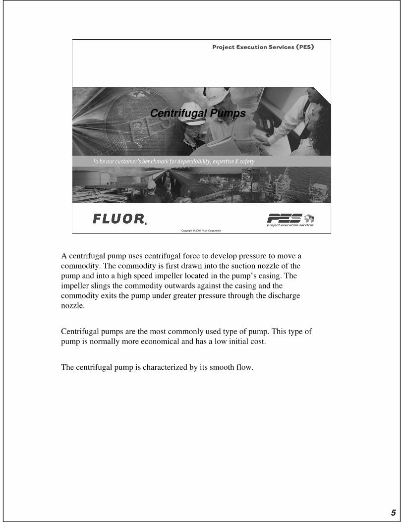
A centrifugal pump uses centrifugal force to develop pressure to move a
commodity. The commodity is first drawn into the suction nozzle of the
pump and into a high speed impeller located in the pump’s casing. The
impeller slings the commodity outwards against the casing and the
commodity exits the pump under greater pressure through the discharge
nozzle.
Centrifugal pumps are the most commonly used type of pump. This type of
pump is normally more economical and has a low initial cost.
The centrifugal pump is characterized by its smooth flow.
5
Centrifugal Pumps
6
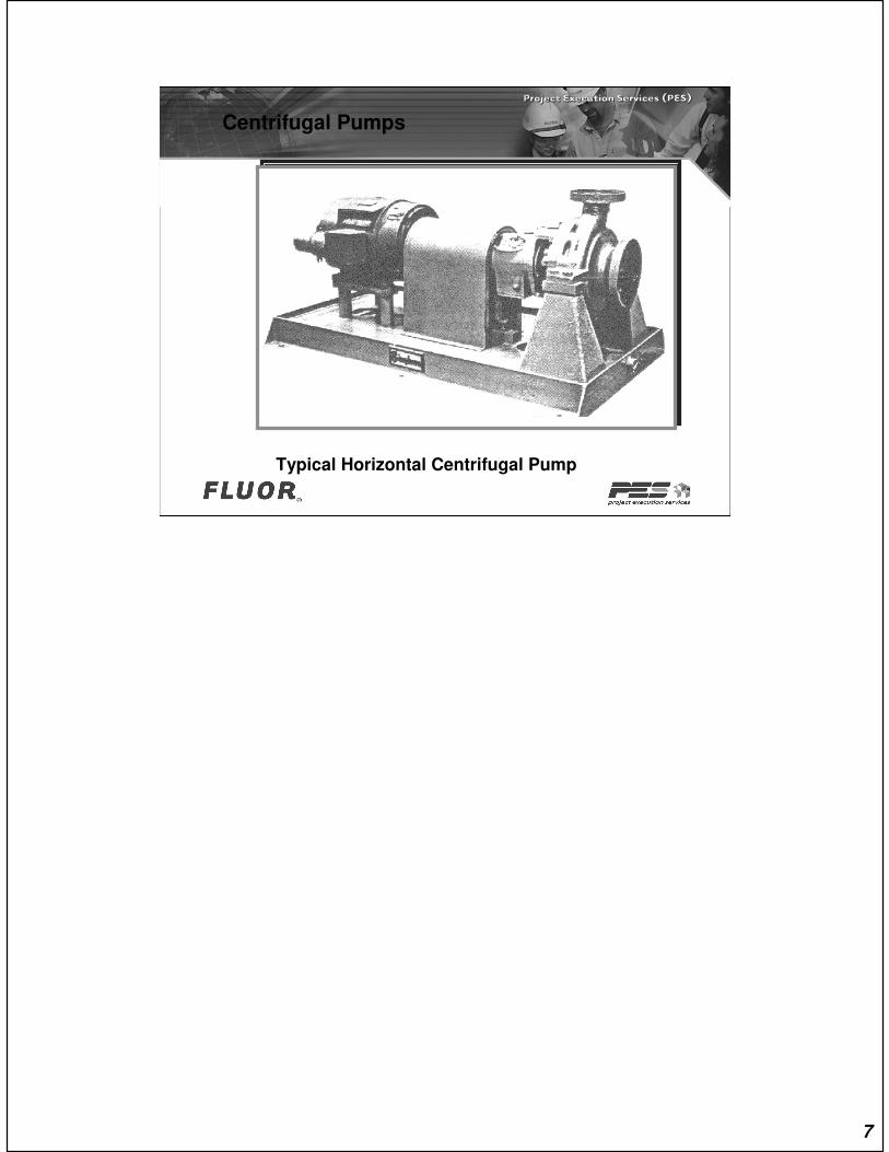
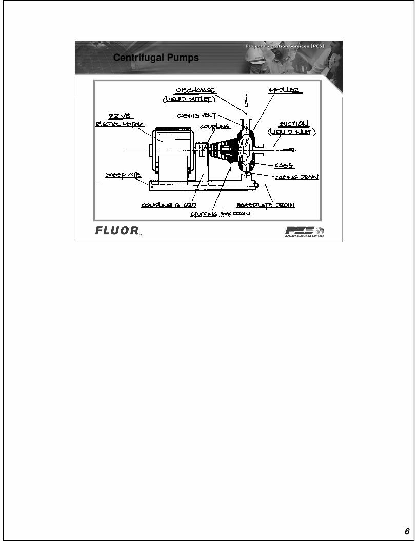
Centrifugal Pumps
Typical Horizontal Centrifugal Pump
7

Centrifugal Pumps
Typical In-line Vertical Pump
8
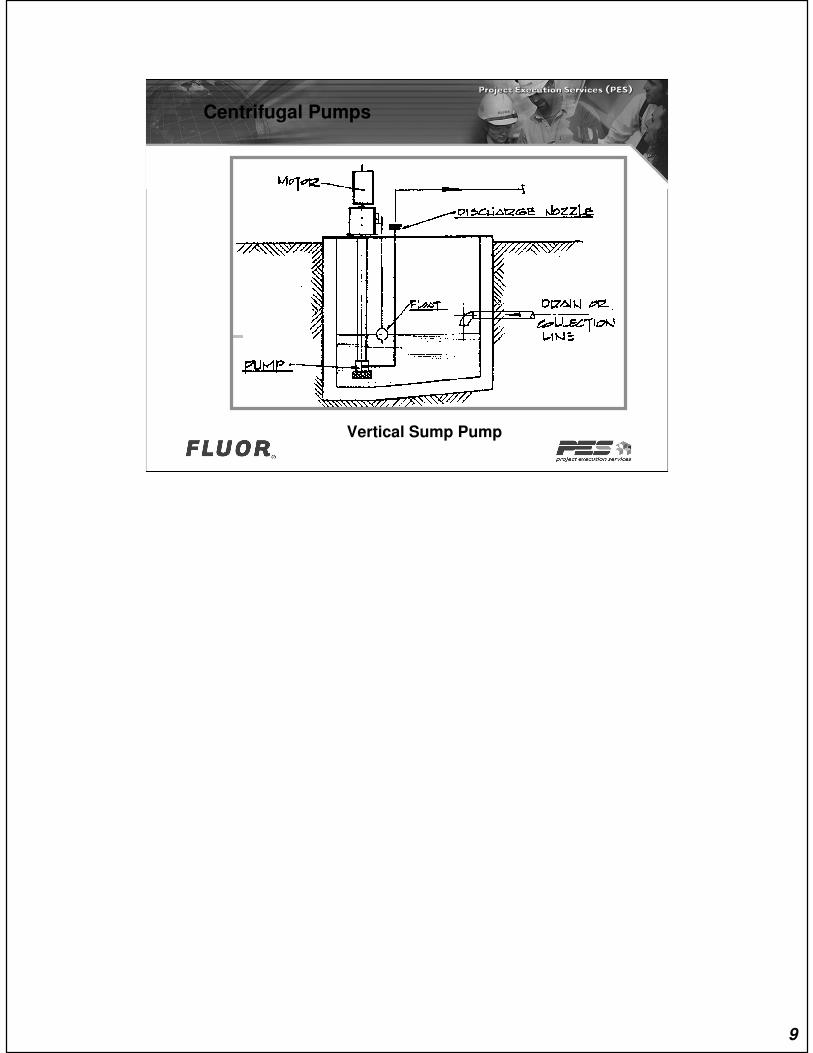
Centrifugal Pumps
Vertical Sump Pump
9

Copyright © 2007 Fluor Corporation
Rotary Pumps
A rotary pump uses gears and screws to develop positive pressure to move a
commodity viscous in nature such as grease, asphalt, and heavy fuel oils. The
commodity is first drawn into the suction nozzle of the pump using a set of
gears or screws located in the pump’s casing. As the set of gears or screws
rotate the commodity fills the space between the gear teeth or screws on the
suction side. As the gears or screws rotate the commodity is pushed out the
pump’s discharge nozzle much like a nut on a bolt.
The rotary pump is characterized by its smooth flow and is considered to be a
positive displacement pump. Positive displacement means that a set volume of
liquid is discharged for each complete rotation of the shaft.
10

Rotary Pumps
Gear Pumps
11
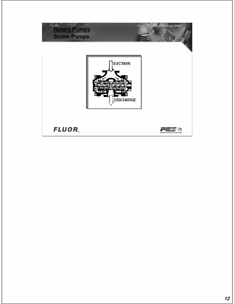
Rotary Pumps
Screw Pumps
12
Copyright © 2007 Fluor Corporation
Reciprocating Pumps
The reciprocating pump is characterized by its pulsating flow and is considered
to be a positive displacement pump. Positive displacement means that a set
volume of liquid is discharged for each complete rotation of the shaft.
Reciprocating pumps are normally used to inject small amounts of additives in
high pressure systems.
A reciprocating pump uses a plunger or piston within a chamber to develop
positive pressure to move a commodity from one location to another. The
commodity is first drawn into the suction nozzle of the pump when the plunger or
piston is drawn back within the suction chamber. As the commodity fills the
suction chamber a baffle opens in the discharge chamber and. As the plunger or
piston is pushed forward in the suction chamber the commodity fills the
discharge chamber through the baffle. As the suction chamber is re-filled by the
suction cycle being repeated the commodity is pushed out the pump’s discharge
nozzle by the plunger or piston in the discharge chamber.
13
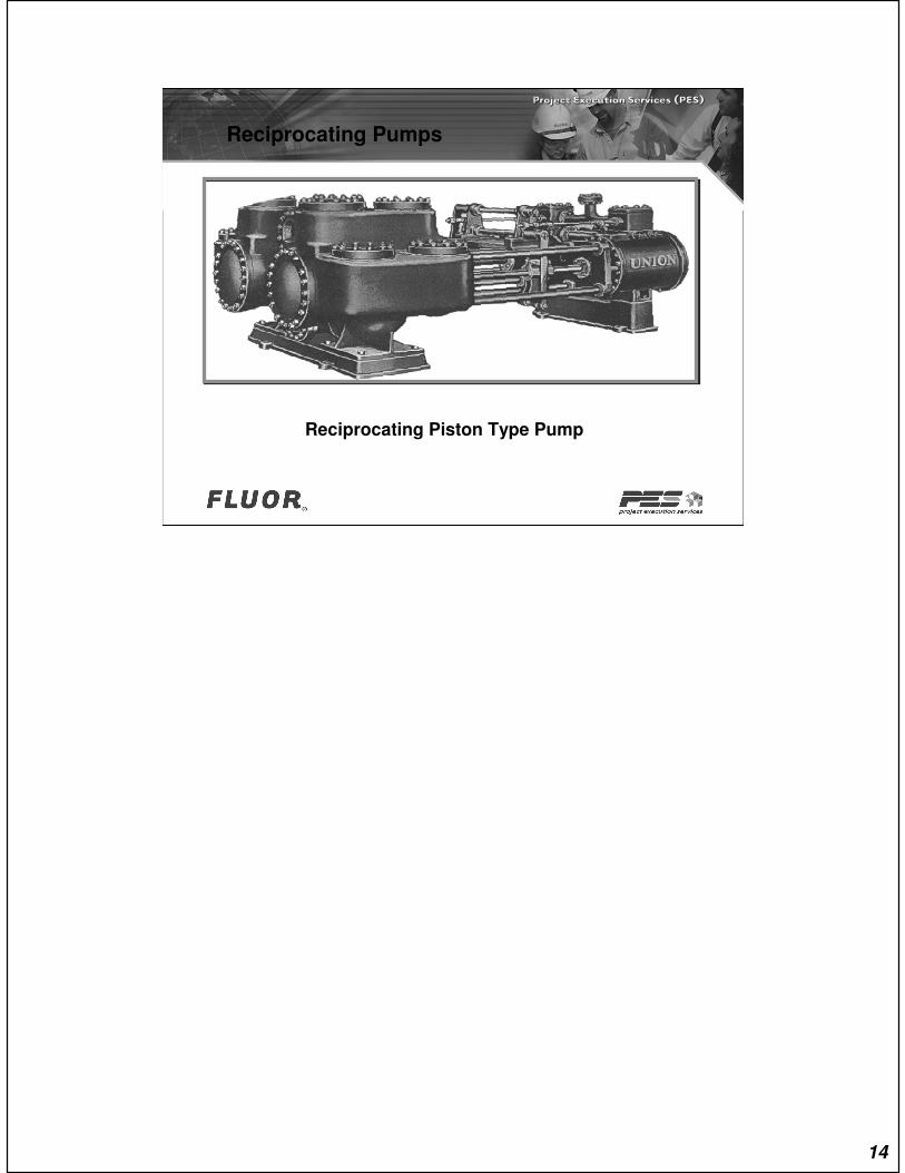
Reciprocating Pumps
Reciprocating Piston Type Pump
14
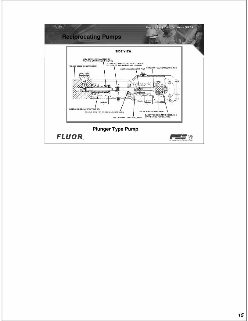
Reciprocating Pumps
Plunger Type Pump
15
Copyright © 2007 Fluor Corporation
Pump Drivers
There are two different types of pump
drivers
Electric motor
Steam Turbine
16
Pump Drivers
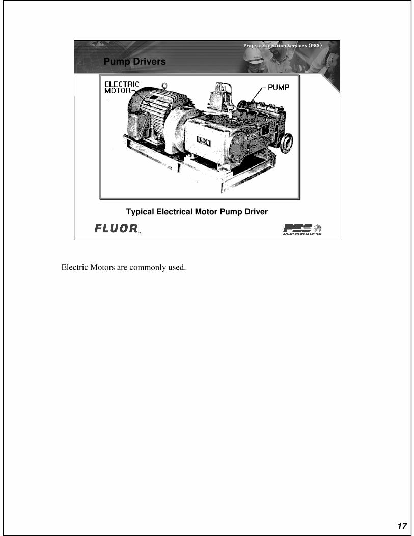
Typical Electrical Motor Pump Driver
Electric Motors are commonly used.
17
Pump Drivers
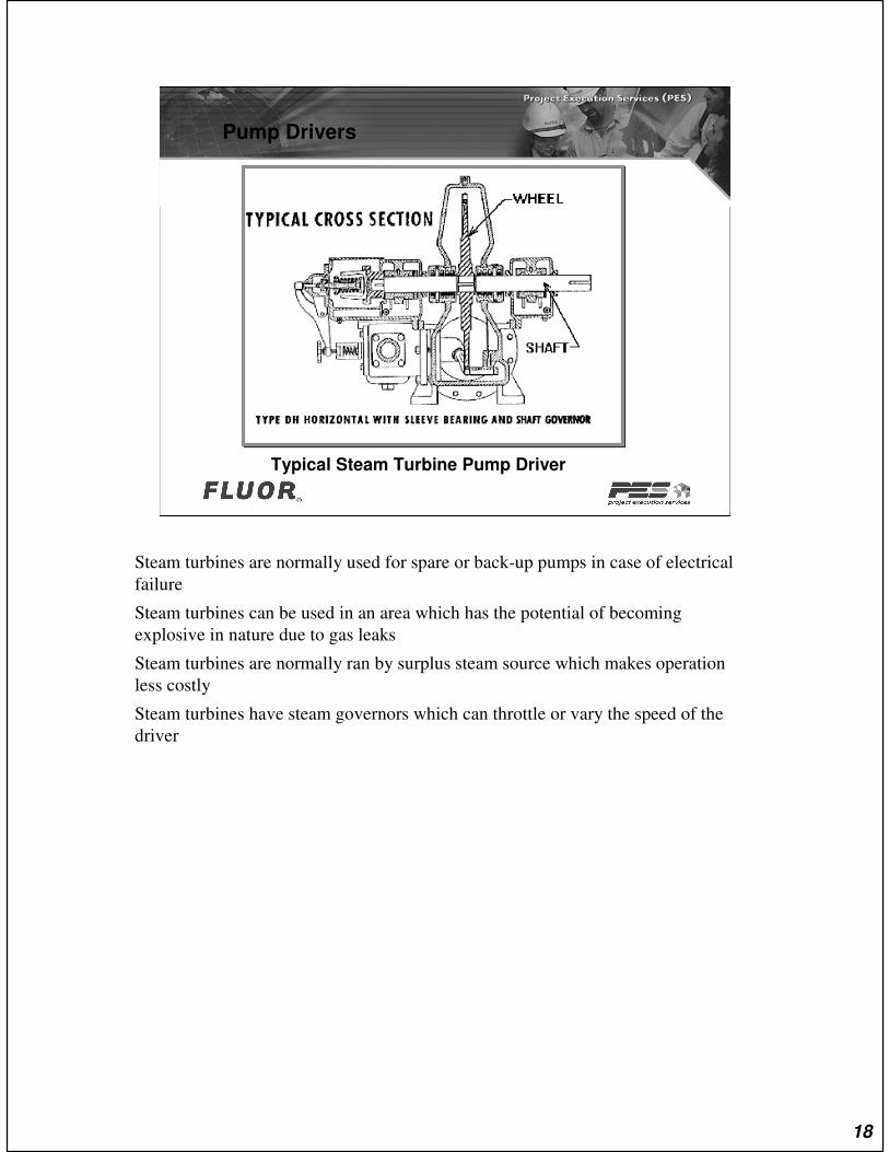
Typical Steam Turbine Pump Driver
Steam turbines are normally used for spare or back-up pumps in case of electrical
failure
Steam turbines can be used in an area which has the potential of becoming
explosive in nature due to gas leaks
Steam turbines are normally ran by surplus steam source which makes operation
less costly
Steam turbines have steam governors which can throttle or vary the speed of the
driver
18

Copyright © 2007 Fluor Corporation
Pumps & Nozzles Locations
19

Nozzle Locations
TOP - TOP
This is a typical top suction – top discharge pump arrangement
20

Nozzle Locations
TOP - TOP
For the aboveground piping symbol all we show is a simple outline of the pump
foundation along with the suction and discharge nozzles
Plan view:
Do not show any detail of the pump and/or driver on the piping plans
21
Nozzle Locations
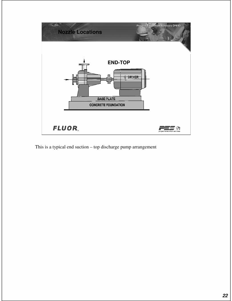
END-TOP
This is a typical end suction – top discharge pump arrangement
22

Nozzle Locations
END-TOP
For the aboveground piping symbol all we show is a simple outline of the pump
foundation along with the suction and discharge nozzles
Plan view:
Do not show any detail of the pump and/or driver on the piping plans
23
Nozzle Locations
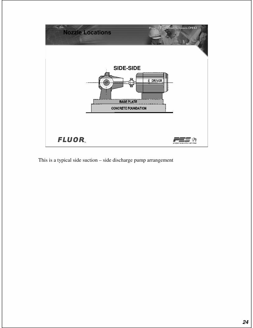
SIDE-SIDE
This is a typical side suction – side discharge pump arrangement
24
Nozzle Locations
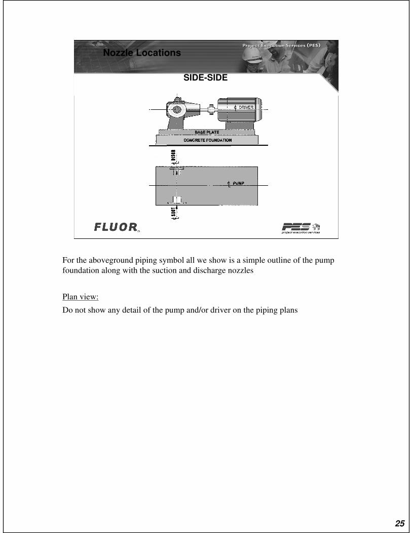
SIDE-SIDE
For the aboveground piping symbol all we show is a simple outline of the pump
foundation along with the suction and discharge nozzles
Plan view:
Do not show any detail of the pump and/or driver on the piping plans
25
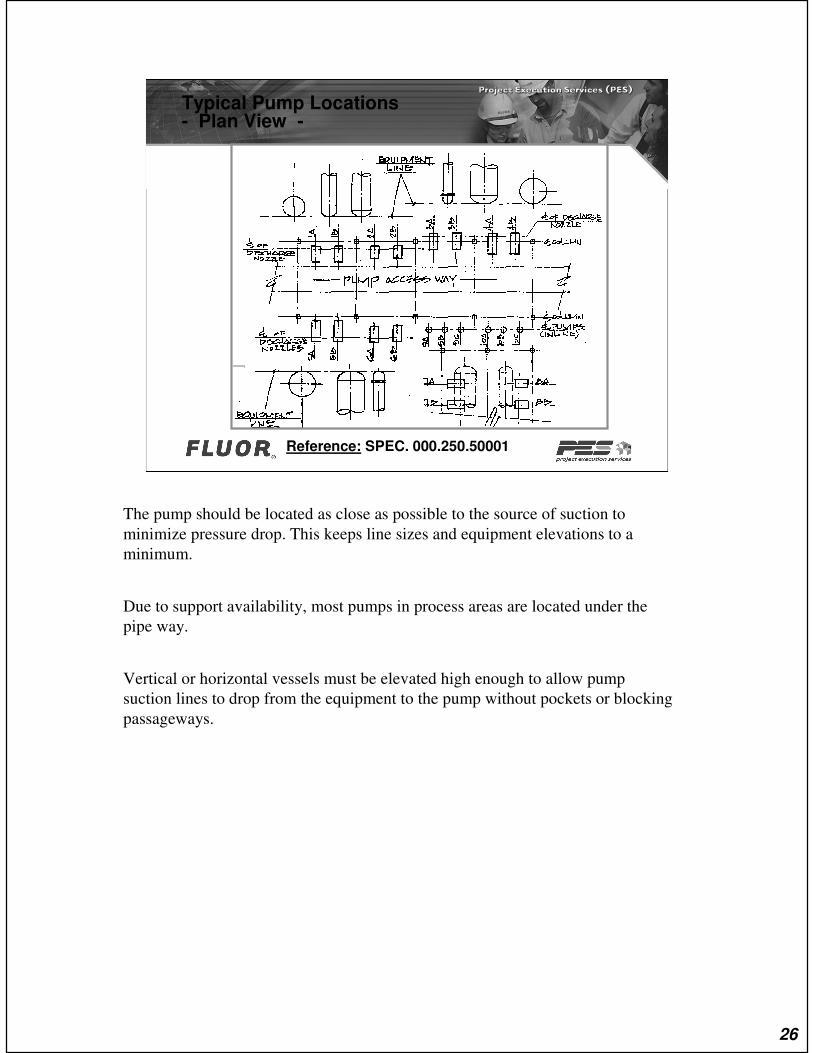
Typical Pump Locations- Plan View -
Reference: SPEC. 000.250.50001
The pump should be located as close as possible to the source of suction to
minimize pressure drop. This keeps line sizes and equipment elevations to a
minimum.
Due to support availability, most pumps in process areas are located under the
pipe way.
Vertical or horizontal vessels must be elevated high enough to allow pump
suction lines to drop from the equipment to the pump without pockets or blocking
passageways.
26
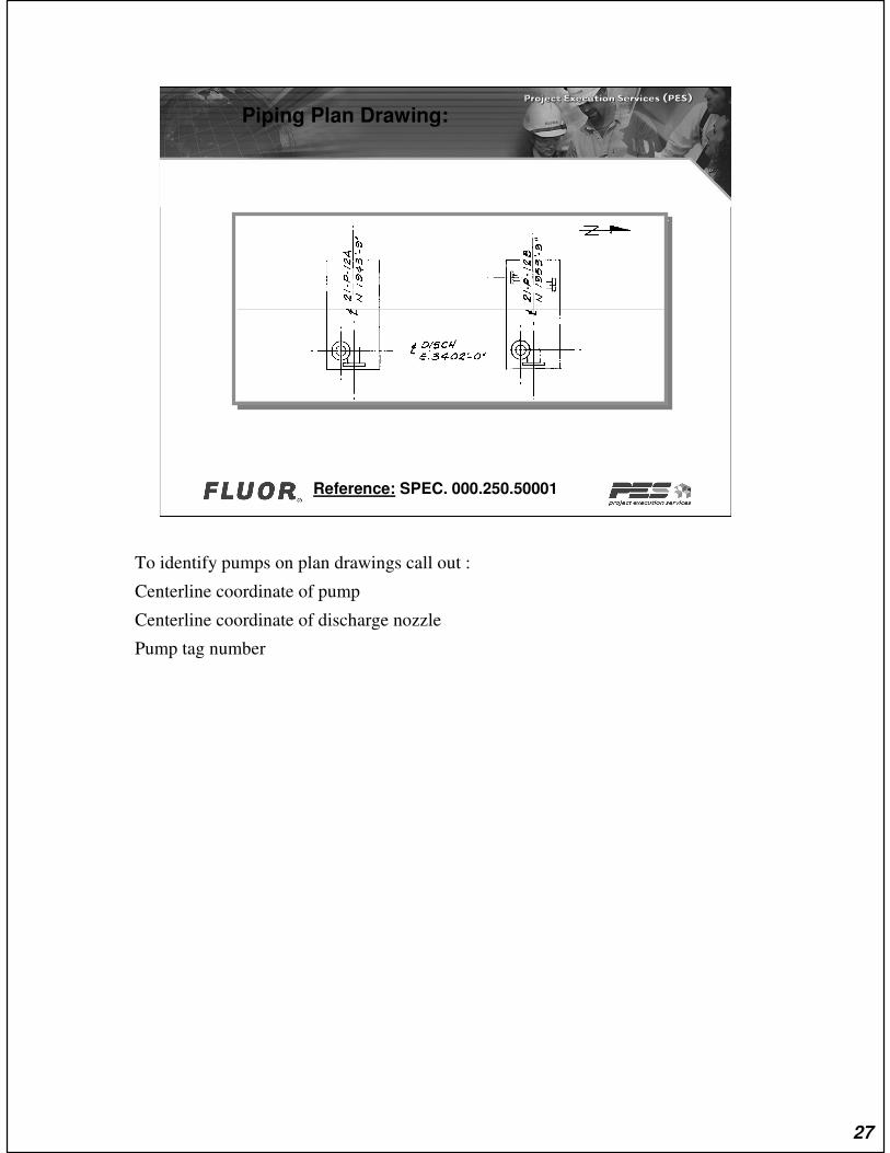
Piping Plan Drawing:
Reference: SPEC. 000.250.50001
To identify pumps on plan drawings call out :
Centerline coordinate of pump
Centerline coordinate of discharge nozzle
Pump tag number
27
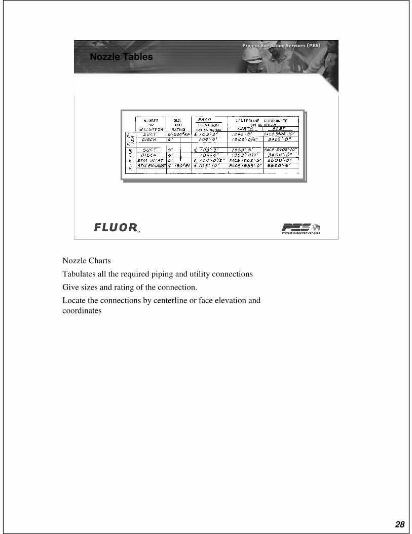
Nozzle Tables
Nozzle Charts
Tabulates all the required piping and utility connections
Give sizes and rating of the connection.
Locate the connections by centerline or face elevation and
coordinates
28

Pump Identification
The Nozzle Chart is found on the Aboveground Piping Plan
29

Components of a Typical Pump Suction And Discharge Piping System
30

Typical Piping Arrangement For Centrifugal Pumps
End Suction - Top Discharge
Reference:
Practice # 000.250.2350
31
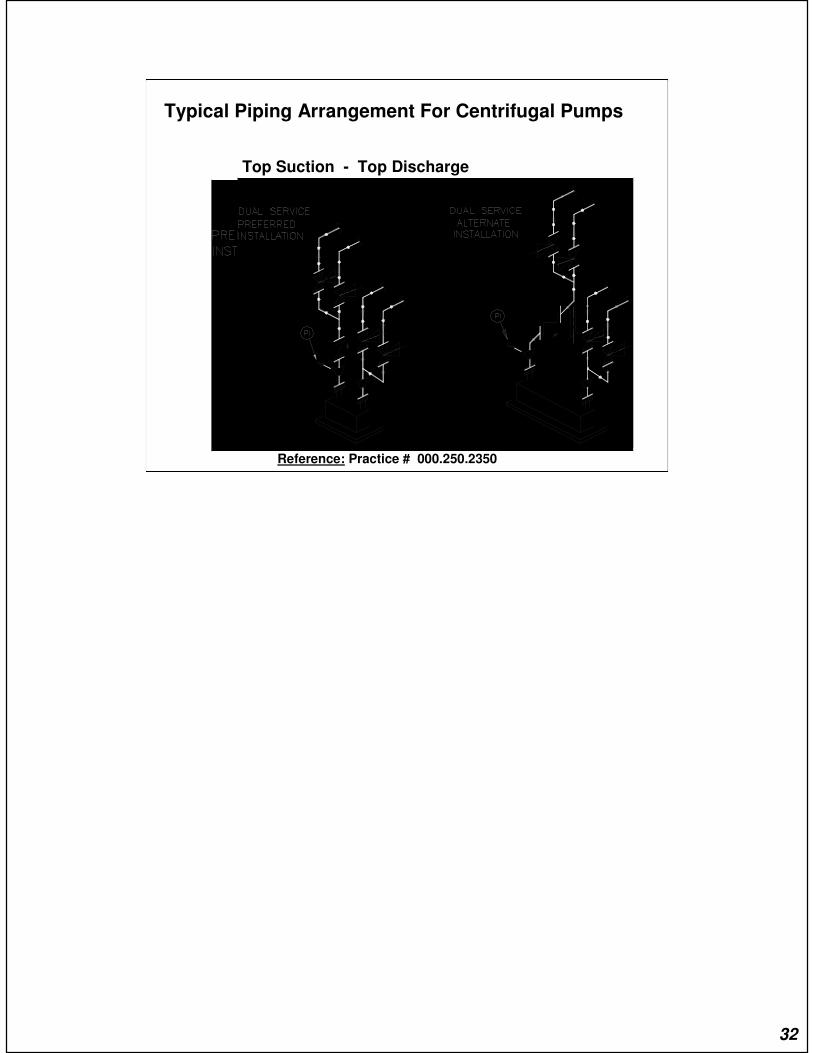
Typical Piping Arrangement For Centrifugal Pumps
Top Suction - Top Discharge
Reference: Practice # 000.250.2350
32
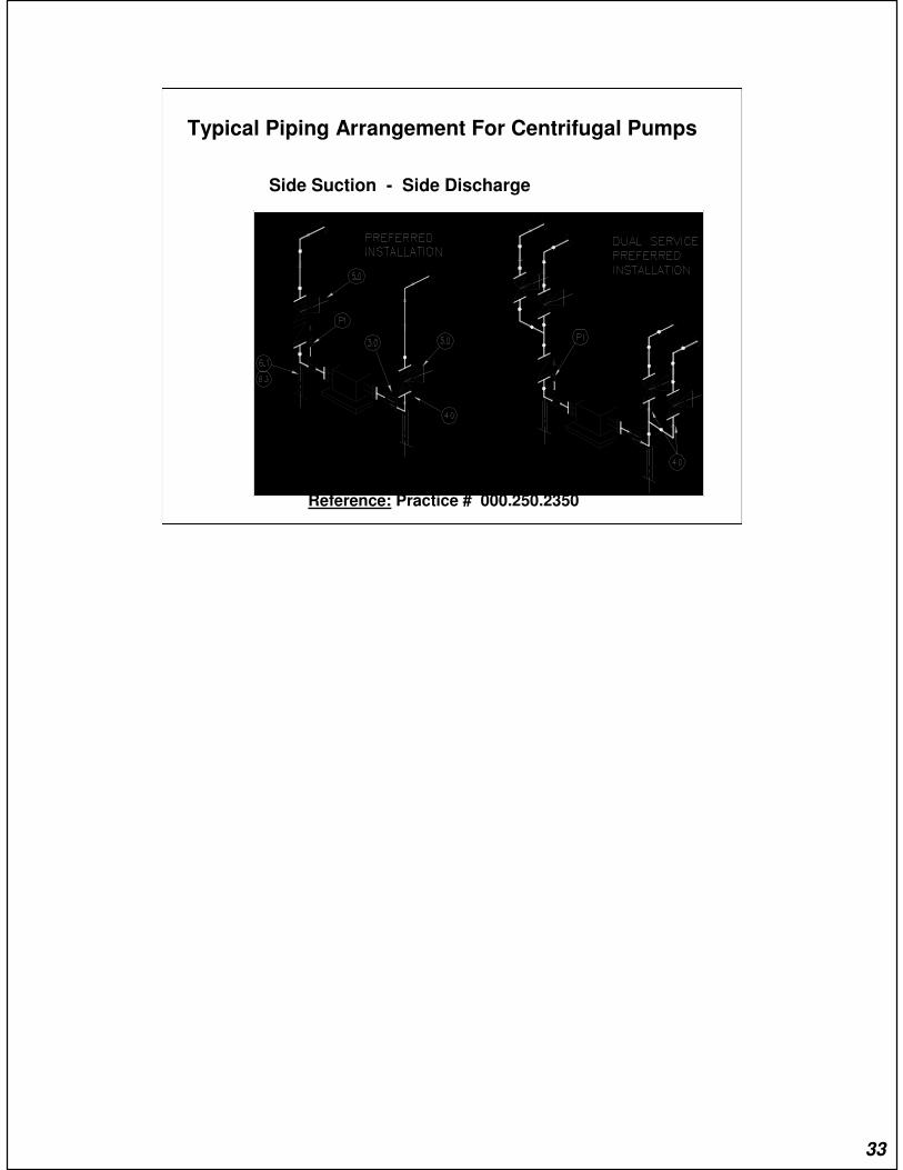
Typical Piping Arrangement For Centrifugal Pumps
Side Suction - Side Discharge
Reference: Practice # 000.250.2350
33
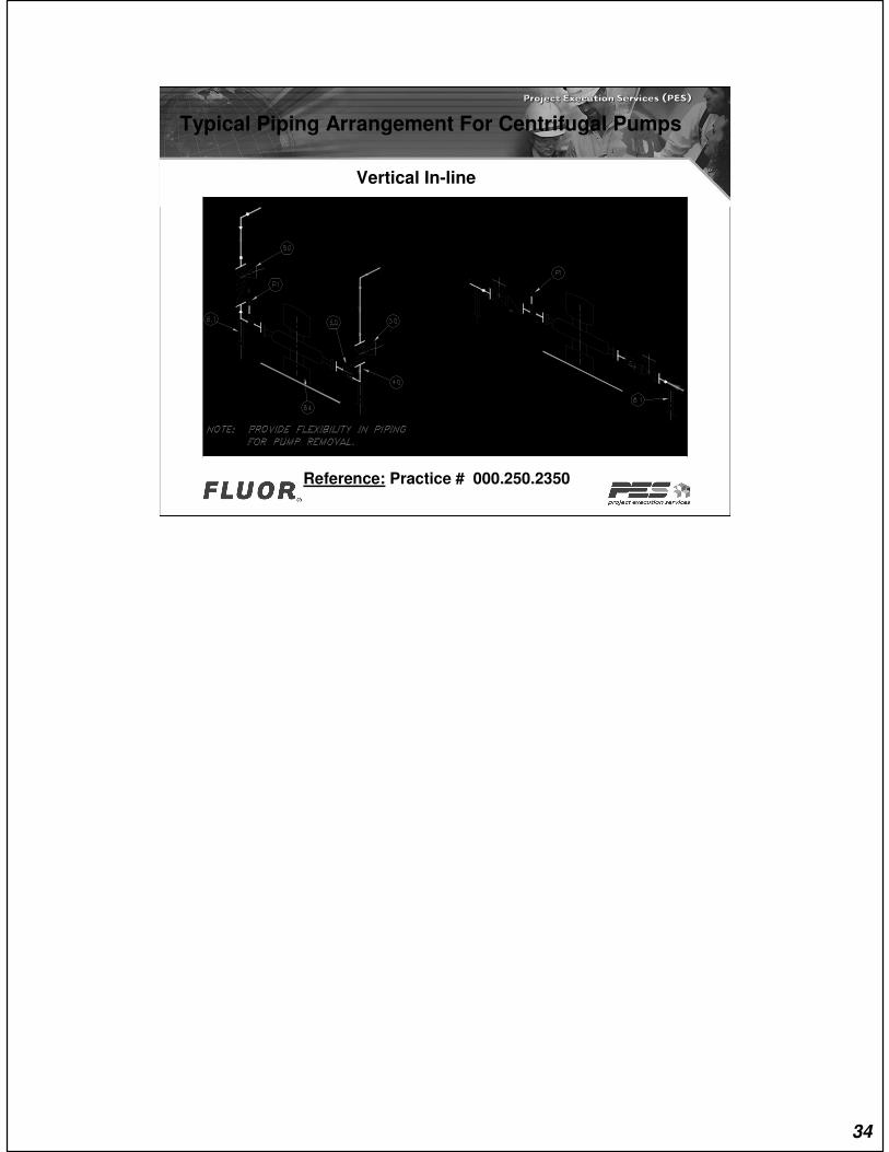
Typical Piping Arrangement For Centrifugal Pumps
Vertical In-line
Reference: Practice # 000.250.2350
34

Handwheel Orientation
Preferred Installation
Note: Alternate installation may be required. depending upon job criteria
35
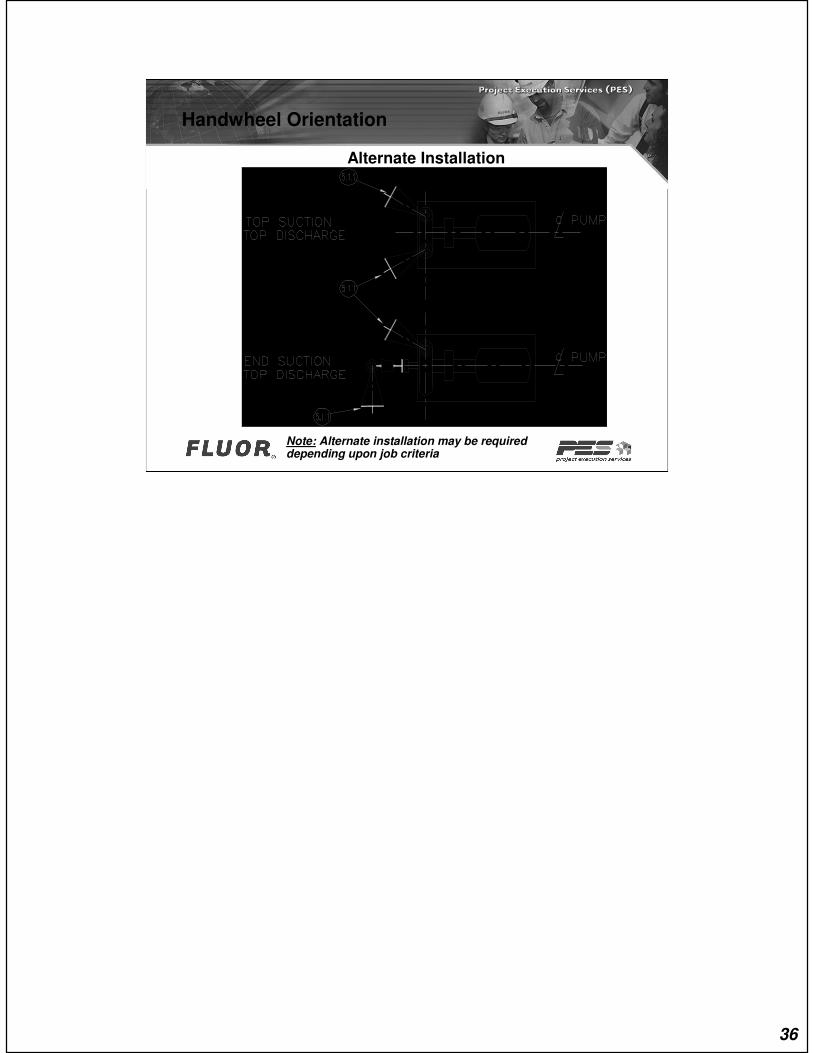
Handwheel Orientation
Alternate Installation
Note: Alternate installation may be required depending upon job criteria
36

Reduction At Pump Suction
Reference: Practice # 000.250.2351
37
Copyright © 2007 Fluor Corporation
STRAINERS
38

Strainers:
39
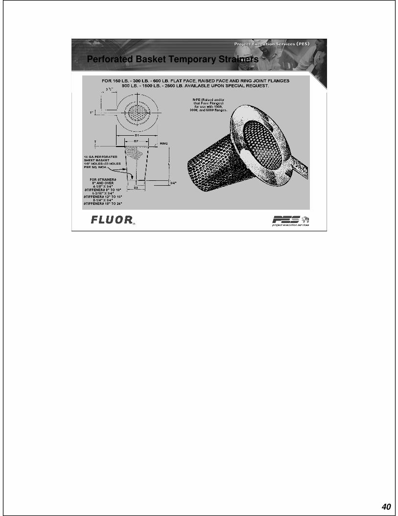
Perforated Basket Temporary Strainers
40
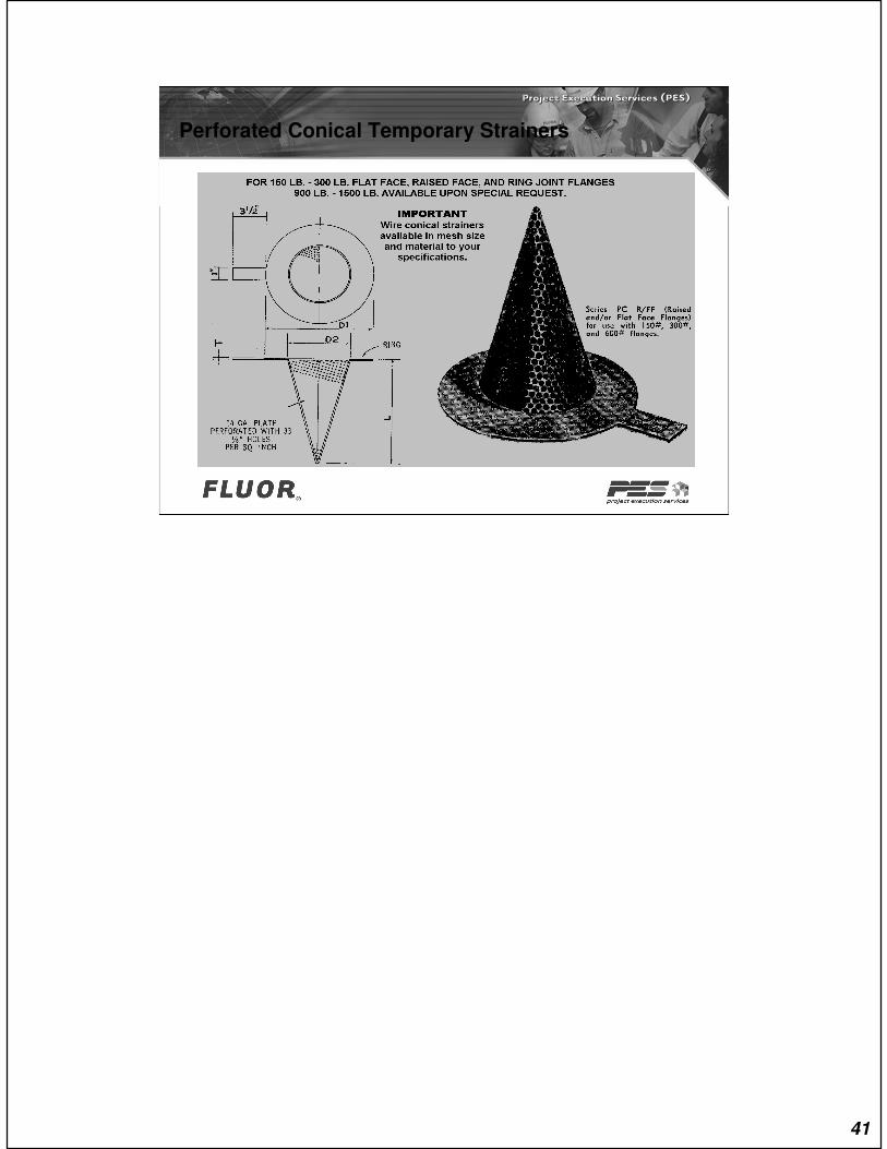
Perforated Conical Temporary Strainers
41
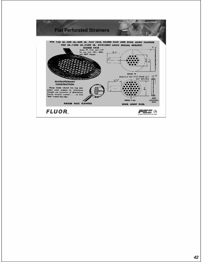
Flat Perforated Strainers
42

Bathtub Unit Temporary Strainers
43
Copyright © 2007 Fluor Corporation
Views & Photos
44
45
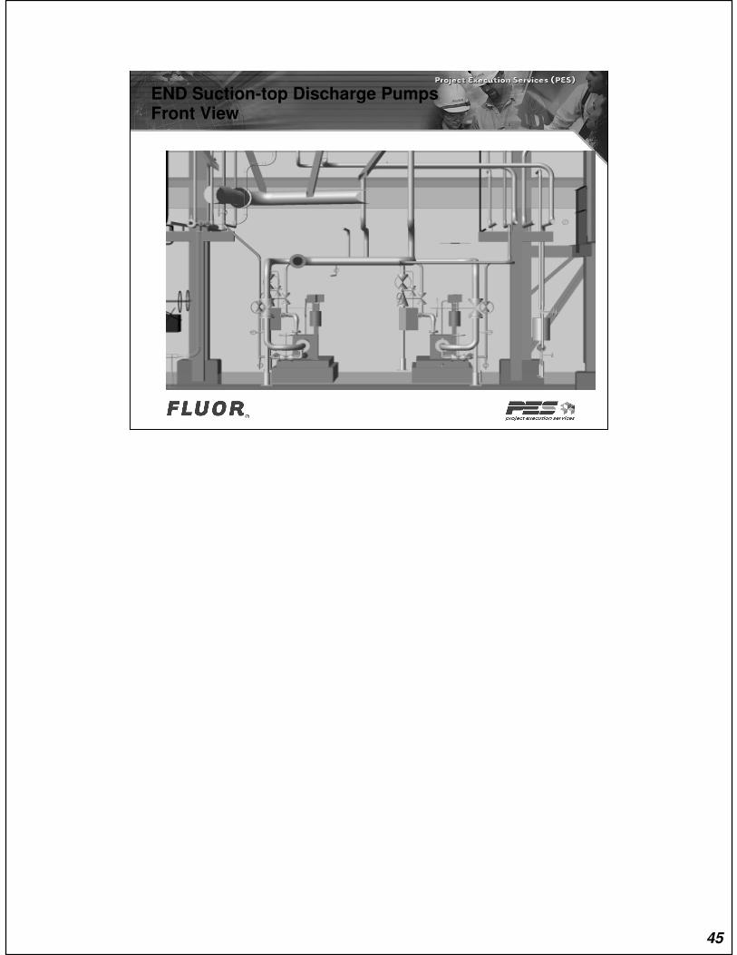
END Suction-top Discharge PumpsFront View
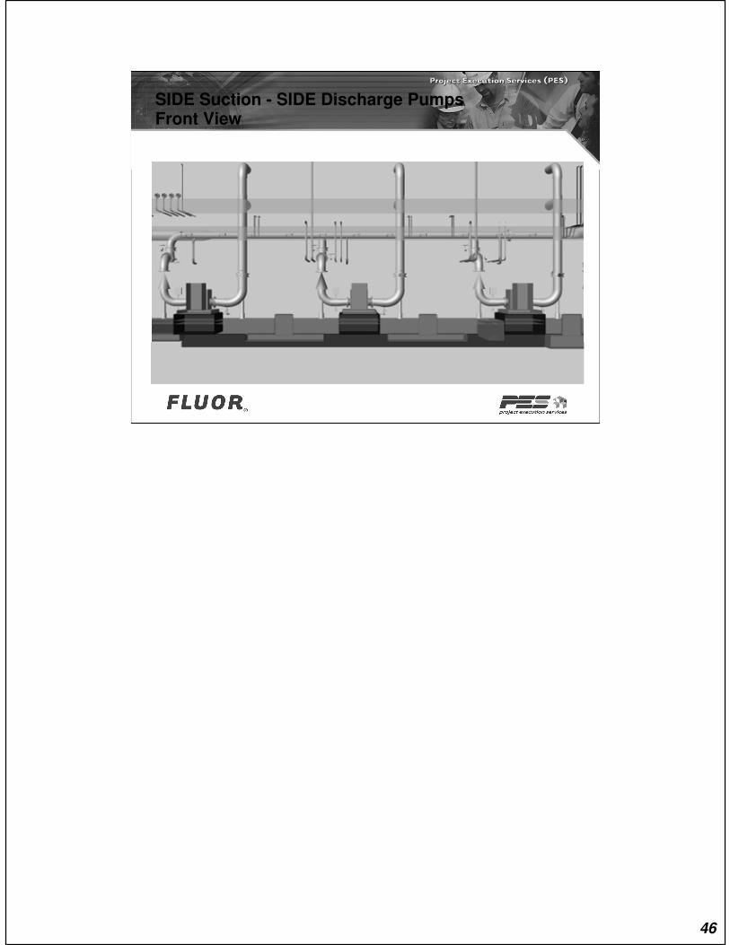
SIDE Suction - SIDE Discharge PumpsFront View
46
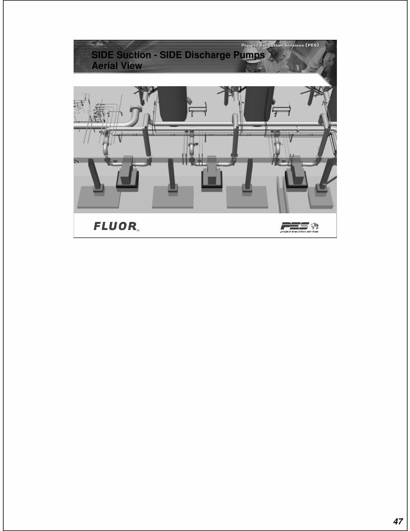
SIDE Suction - SIDE Discharge PumpsAerial View
47
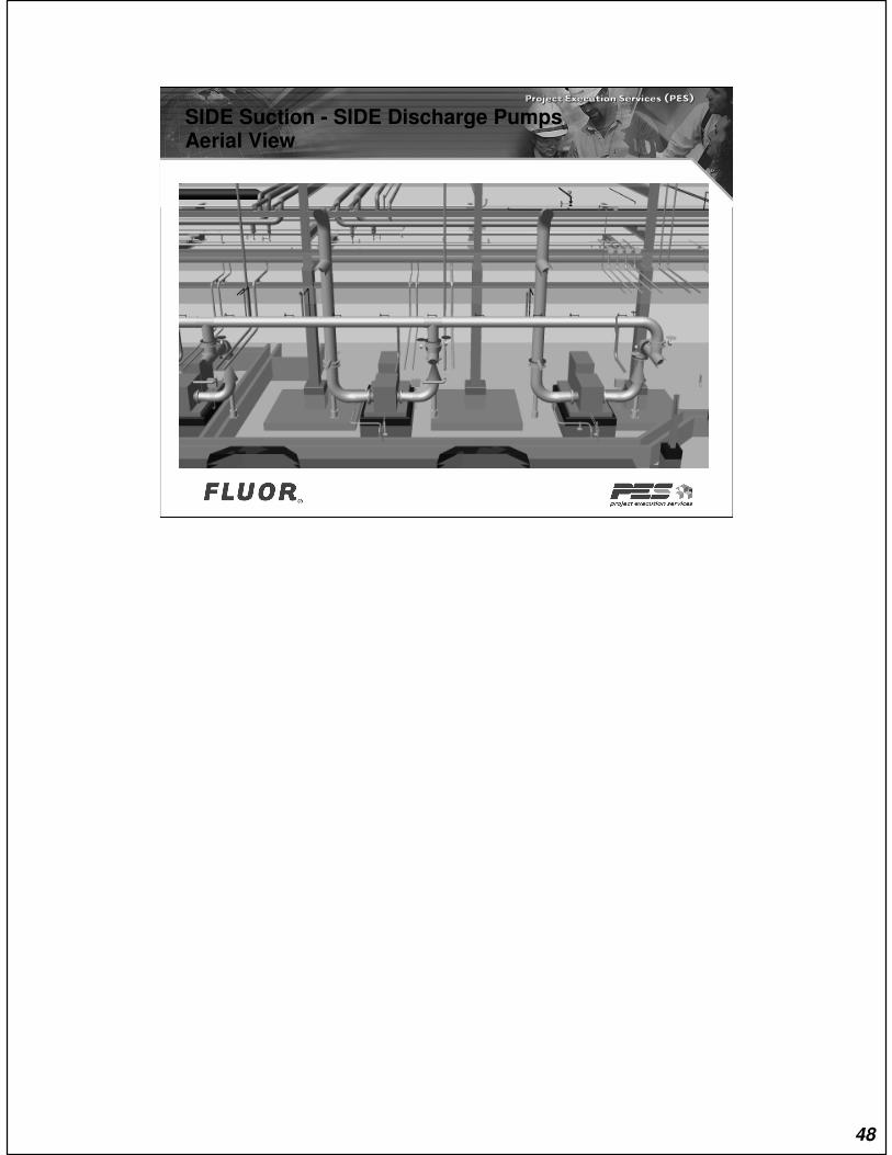
SIDE Suction - SIDE Discharge PumpsAerial View
48
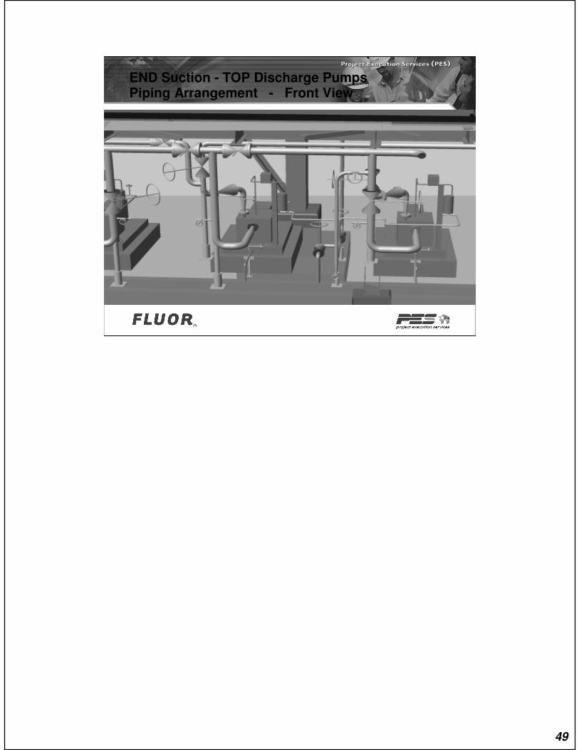
END Suction - TOP Discharge PumpsPiping Arrangement - Front View
49

Vertical And Side-top PumpsPiping Arrangement - Side View
50
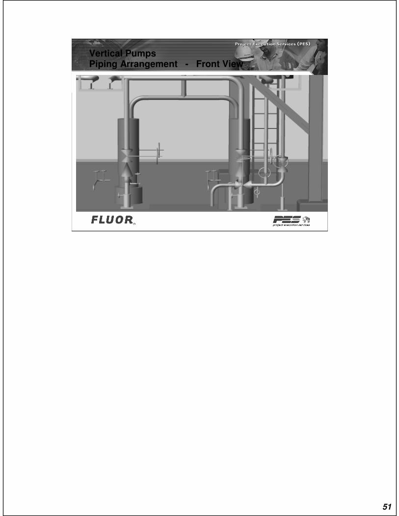
Vertical PumpsPiping Arrangement - Front View
51

Vertical PumpsPiping Arrangement - ISO View
52
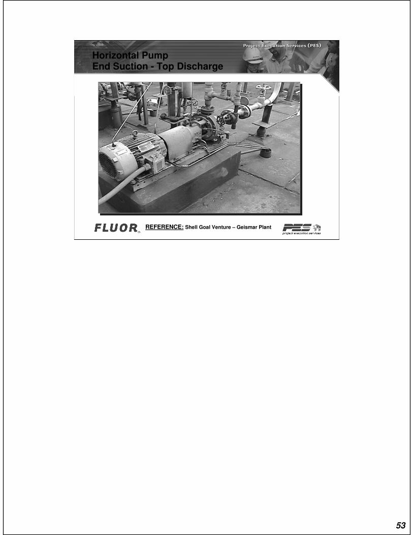
REFERENCE: Shell Goal Venture – Geismar Plant
Horizontal PumpEnd Suction - Top Discharge
53
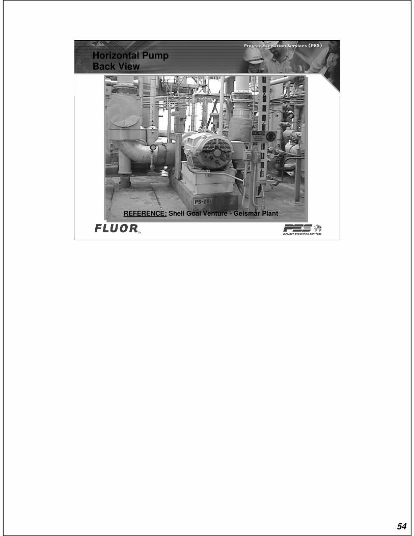
REFERENCE: Shell Goal Venture - Geismar Plant
Horizontal PumpBack View
54

References:Practices #
000.250.2040 - Typical Unit Plot Arrangement
000.250.2350 - Typical arrangement for Centrifugal Pumps
000.250.2351 - Reduction at Pump Suction
000.250.2352 - Pump Piping (Steam) Turbines and
Reciprocating Pumps
000.250.2353 - Miscellaneous Pump Piping
000.250.2360 - Strainers, Pump Suction, Conical
55
Questions??
56
Exercise PI-E11A
57