Embed Size (px)
Citation preview
1 Doppelständerfuss I Support double I Double support2 Säulen 45 I Colonnes 45 I Columns 453 Modulträger doppel I Support module double I Double mounting plate4 LE-50-3005 SA-3-506 EG-20/K7 RE-508 SG-50

ELECTROGREIFER UND SERVOGREIFER
PINCE ÉLECTRIQUE ET PINCE SERVOÉLECTRIQUE
ELECTRIC GRIPPER AND SERVOGRIPPER
EU-20 398
EG-20 402
SG-50 406
10
398 | www.afag.com 2014
EU-20
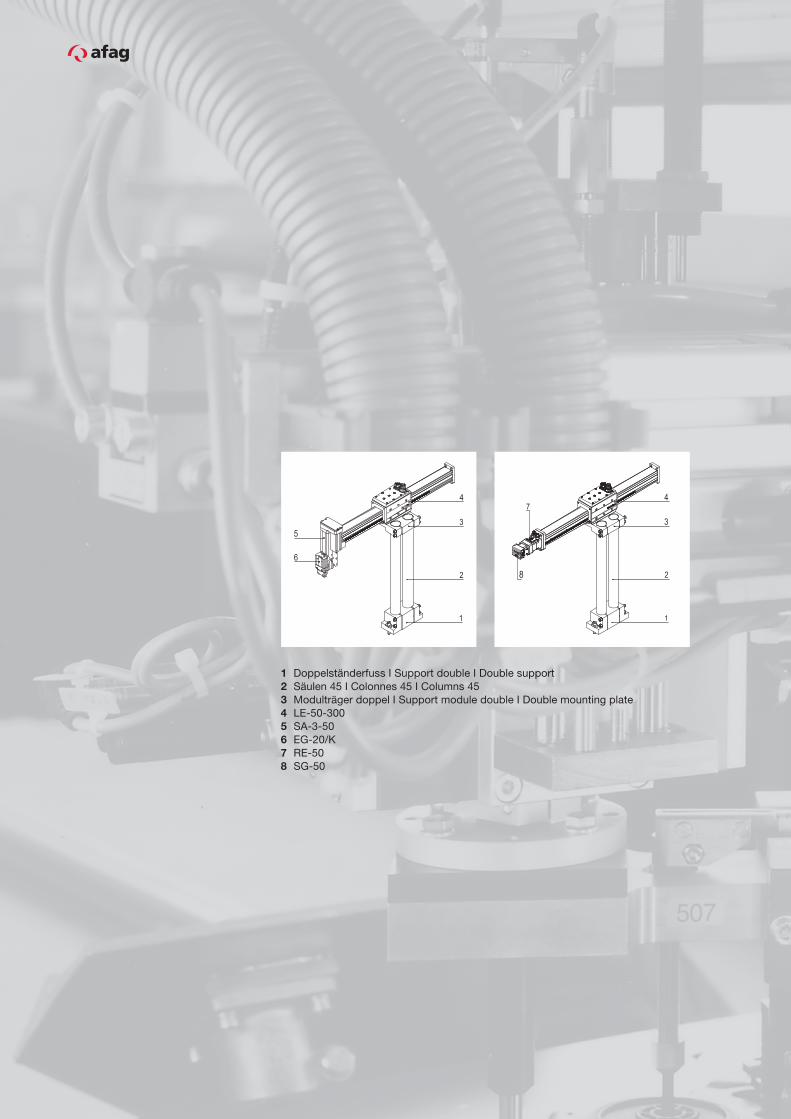
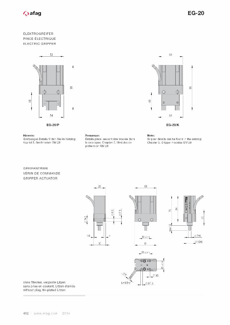
ELEKTROGREIFER
PINCE ELECTRIQUE
ELECTRIC GRIPPER
ohne Stecker, verzinnte Litzensans prise en courant, Litzen étaméswithout plug, tin-plated Litzen

2014 www.afag.com | 399
10
EU-20
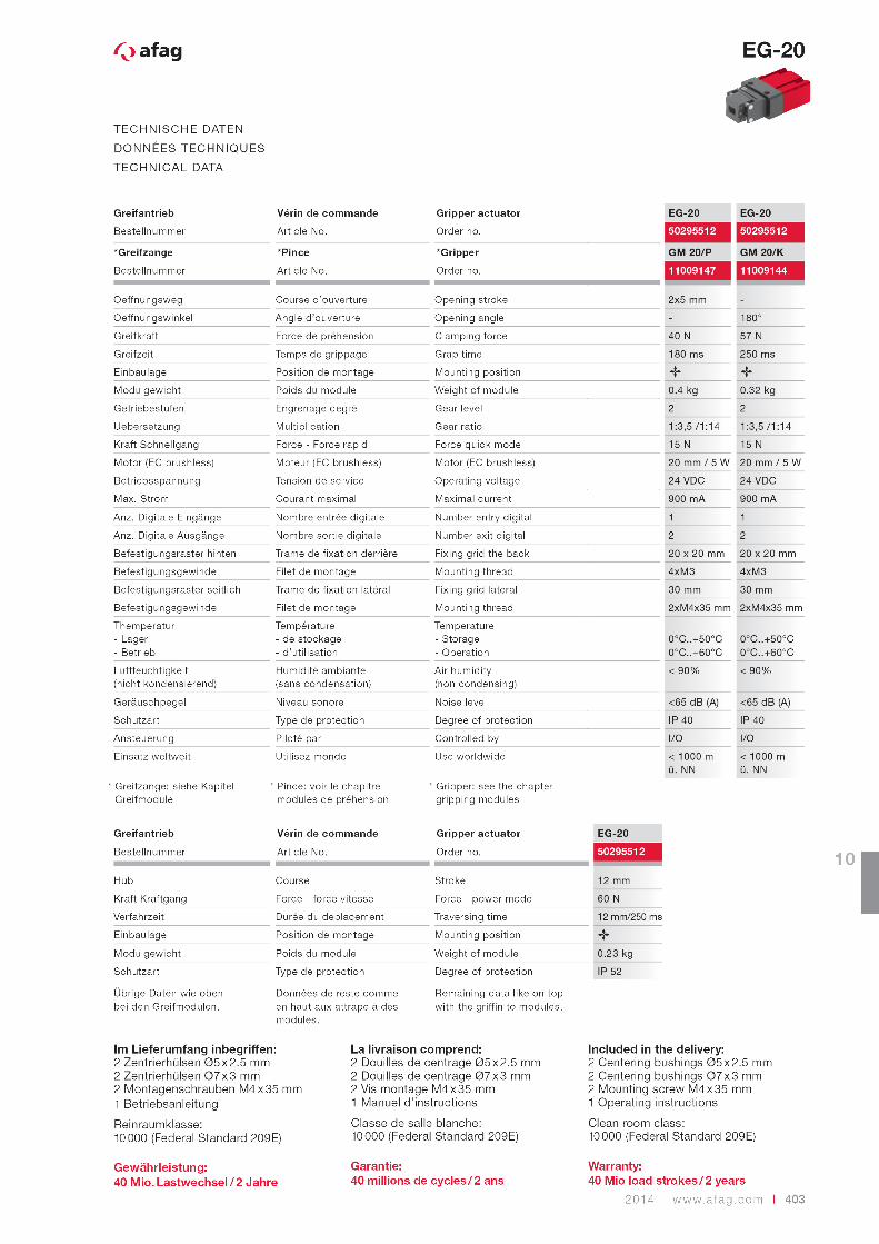
TECHNISCHE DATEN
DONNÉES TECHNIQUES
TECHNICAL DATA
Elektrogreifer Pince électrique Electric gripper EU-20
Bestellnummer Article No. Order no. 50346017
Oeffnungsweg Course d’ouverture Opening stroke 2x4 mm
Greifkraft Force de préhension Clamping force 40 N
Greifzeit Temps de grippage Grap time 180 ms
Einbaulage Position de montage Mounting position
Modulgewicht Poids du module Weight of module 0.280 kg
Kraft Schnellgang Force - Force rapid Force quick mode ~15 N
Motor (EC brushless) Moteur (EC brushless) Motor (EC brushless) 20 mm / 5 W
Betriebsspannung Tension de service Operating voltage 24 VDC
Max. Strom Courant maximal Maximal current 900 mA
Stand by Strom Stand by courant Stand by current 40 mA
Anz. Digitale Eingänge Nombre entrée digitale Number entry digital 1
Anz. Digitale Ausgänge Nombre sortie digitale Number exit digital 2
Befestigungsraster hinten Trame de fixation derrière Fixing grid the back 20 x 20 mm
Befestigungsgewinde Filet de montage Mounting thread 4 x M3
Befestigungsraster seitlich Trame de fixation latéral Fixing grid lateral 30 mm
Befestigungsgewinde Filet de montage Mounting thread 2xM4x35 mm
Themperatur- Lager- Betrieb
Température- de stockage- d’utilisation
Temperature- Storage- Operation
0°C..+50°C10°C..+40°C
Luftfeuchtigkeit (nicht kondensierend)
Humidité ambiante(sans condensation)
Air humidity(non condensing)
< 90%
Geräuschpegel Niveau sonore Noise level <65 dB (A)
Schutzart Type de protection Degree of protection IP 40
Ansteuerung Piloté par Controlled by I/O
Einsatz weltweit Utilisez monde Use worldwide < 1000 m ü. NN
Im Lieferumfang inbegriffen:2 Zentrierhülsen Ø5 x 2.5 mm2 Zentrierhülsen Ø7 x 3 mm2 Montagenschrauben M4 x 35 mm1 Betriebsanleitung
Reinraumklasse:10 000 (Federal Standard 209E)
Gewährleistung: 40 Mio. Lastwechsel / 2 Jahre
La livraison comprend:2 Douilles de centrage Ø5 x 2.5 mm2 Douilles de centrage Ø7 x 3 mm2 Vis montage M4 x 35 mm1 Manuel d’instructions
Classe de salle blanche:10 000 (Federal Standard 209E)
Garantie: 40 millions de cycles / 2 ans
Included in the delivery:2 Centering bushings Ø5 x 2.5 mm2 Centering bushings Ø7 x 3 mm2 Mounting screw M4 x 35 mm1 Operating instructions
Clean room class:10 000 (Federal Standard 209E)
Warranty: 40 Mio load strokes / 2 years
400 | www.afag.com 2014
EU-20
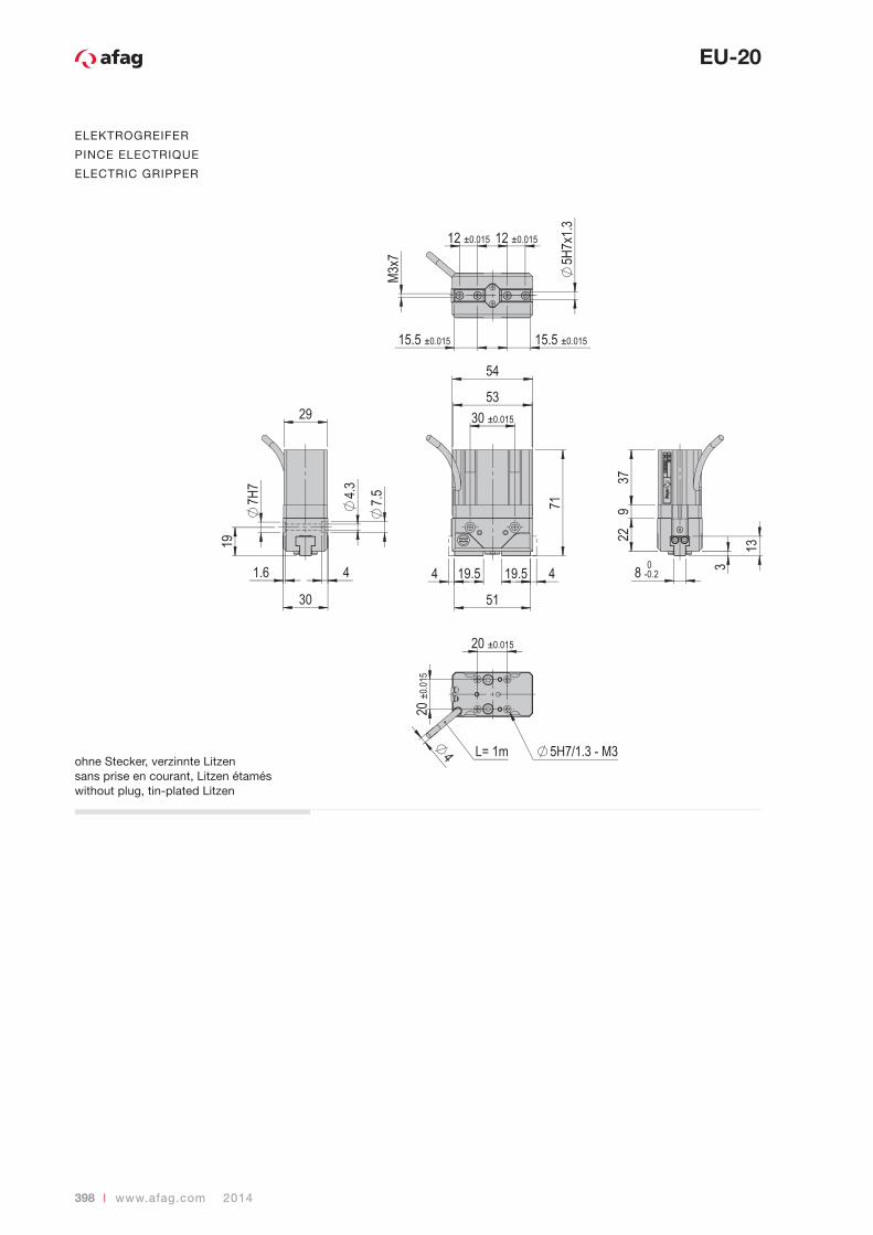
VORZUGSKOMBINATIONEN
COMBINAISONS FAVORITES
PREFERRED COMBINATIONS
Beachten Sie die möglichen Anbaulagen der Module zueinander.Erforderliche Verbindungselemente und das Ständerprogramm finden Sie im Register: «Verbindungselemente und Ständerprogramm.»
Noter que les situations de montage peuvent varier d’un module à l’autre.Vous trouverez dans le registre «Eléments de jonction et supports/colonnes» les éléments de jonction nécessaires ainsi que notre gamme de montants.
Note that there might be different mounting positions from one module to another one.The connection elements required and the range of pedestals are depicted in the «Connection elements and supports/columns» register.
EU-20
SA-312
1,2
direct direct VP 149
112
SA-612
1,2
direct direct VP 149
112
PEZ-6533
direct VP 149
12
LE-5011
direct VP 149
12
CS 121,33
direct VP 149
12
CS 161,33
direct VP 149
12
CS 20133
direct VP 120
VP 120+VP 149
112
LM 16 1,3 VP 115 1
LM 20 1,3 VP 115 1
LM 25 1,3 VP 115 1
PS 161,2,31,2,3
direct VP 149
12
PS 25
12,31
2,3
direct VP 120VP 149
VP 120+VP 149
1122
HM 1011
direct VP 149
12
HM 1611
direct VP 149
12
CR 1633
direct VP 149
12
CR 2033
direct VP 149
12
RM 1633
VF 404VF 404+VP 149
12
RM 2533
VF 404VF 404+VP 149
12
2
31
3
12
13
2
12
1 1 3 1
1
3
2
41
23 2
1 1
22
2
3
1
3
3
HM
UG / GM / EG / EU / SG / DG / PG / EG/GM RE
CR / RM32 / RELM / LECS PS
PMP / PMP-c SA
RM / RE
OZ PEZ / PDZ
3
3
4
Die Steuerungen und die Kabel finden Sie im Kapitel 11.
Vous trouvez les commandes et les câbles dans le chapitre 11.
You find the controls and the cables in the chapter 11.
2014 www.afag.com | 401
10
EU-20
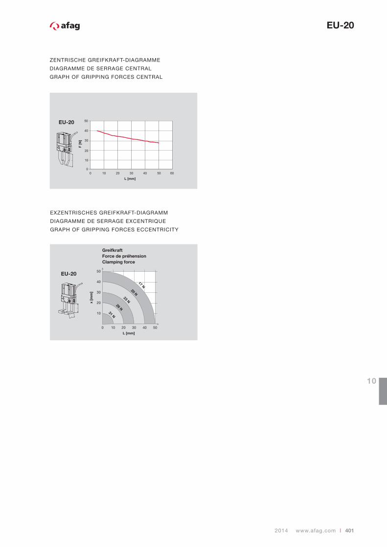
EXZENTRISCHES GREIFKRAFT-DIAGRAMM
DIAGRAMME DE SERRAGE EXCENTRIQUE
GRAPH OF GRIPPING FORCES ECCENTRICITY
GreifkraftForce de préhensionClamping force
EU-20 50
40
30
20
10
0 10 20 30 40 50
x [m
m]
L [mm]
17 N20 N
23 N26 N
31 N
EU-20
L
L
X
ZENTRISCHE GREIFKRAFT-DIAGRAMME
DIAGRAMME DE SERRAGE CENTRAL
GRAPH OF GRIPPING FORCES CENTRAL
404 | www.afag.com 2014
EG-20
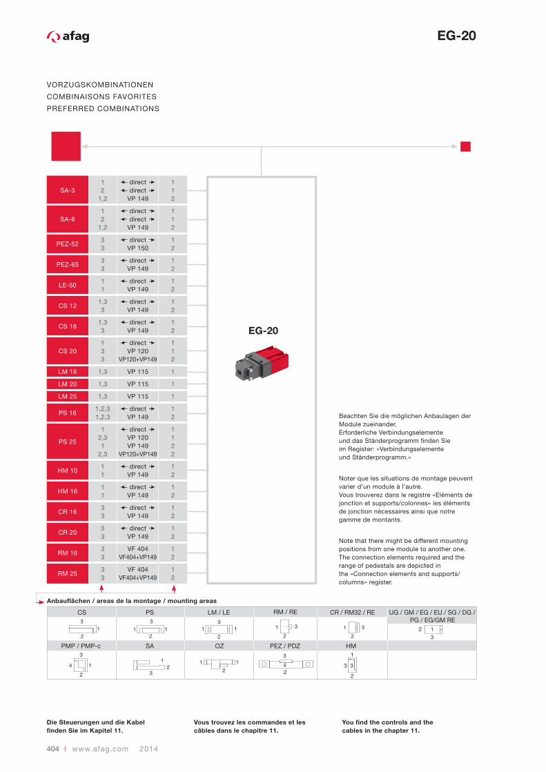
VORZUGSKOMBINATIONEN
COMBINAISONS FAVORITES
PREFERRED COMBINATIONS
Beachten Sie die möglichen Anbaulagen der Module zueinander.Erforderliche Verbindungselemente und das Ständerprogramm finden Sie im Register: «Verbindungselemente und Ständerprogramm.»
Noter que les situations de montage peuvent varier d’un module à l’autre.Vous trouverez dans le registre «Eléments de jonction et supports/colonnes» les éléments de jonction nécessaires ainsi que notre gamme de montants.
Note that there might be different mounting positions from one module to another one.The connection elements required and the range of pedestals are depicted in the «Connection elements and supports/columns» register.
EG-20
SA-312
1,2
direct direct VP 149
112
SA-612
1,2
direct direct VP 149
112
PEZ-5233
direct VP 150
12
PEZ-6533
direct VP 149
12
LE-5011
direct VP 149
12
CS 121,33
direct VP 149
12
CS 161,33
direct VP 149
12
CS 20133
direct VP 120
VP 120+VP 149
112
LM 16 1,3 VP 115 1
LM 20 1,3 VP 115 1
LM 25 1,3 VP 115 1
PS 161,2,31,2,3
direct VP 149
12
PS 25
12,31
2,3
direct VP 120VP 149
VP 120+VP 149
1122
HM 1011
direct VP 149
12
HM 1611
direct VP 149
12
CR 1633
direct VP 149
12
CR 2033
direct VP 149
12
RM 1633
VF 404VF 404+VP 149
12
RM 2533
VF 404VF 404+VP 149
12
2
31
3
12
13
2
12
1 1 3 1
1
3
2
41
23 2
1 1
22
2
3
1
3
3
HM
UG / GM / EG / EU / SG / DG / PG / EG/GM RE
CR / RM32 / RELM / LECS PS
PMP / PMP-c SA
RM / RE
OZ PEZ / PDZ
3
3
4
Die Steuerungen und die Kabel finden Sie im Kapitel 11.
Vous trouvez les commandes et les câbles dans le chapitre 11.
You find the controls and the cables in the chapter 11.
2014 www.afag.com | 405
10
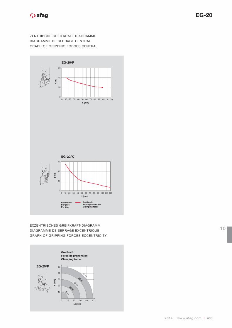
ZENTRISCHE GREIFKRAFT-DIAGRAMME
DIAGRAMME DE SERRAGE CENTRAL
GRAPH OF GRIPPING FORCES CENTRAL
GreifkraftForce préhensionClamping force
EG-20/P
EG-20/K
Pro BackePar jouePer jaw
EXZENTRISCHES GREIFKRAFT-DIAGRAMM
DIAGRAMME DE SERRAGE EXCENTRIQUE
GRAPH OF GRIPPING FORCES ECCENTRICITY
GreifkraftForce de préhensionClamping force
EG-20/P 50
40
30
20
10
0 10 20 30 40 50
x [m
m]
L [mm]
17 N20 N
23 N26 N
31 N
EG-20
406 | www.afag.com 2014
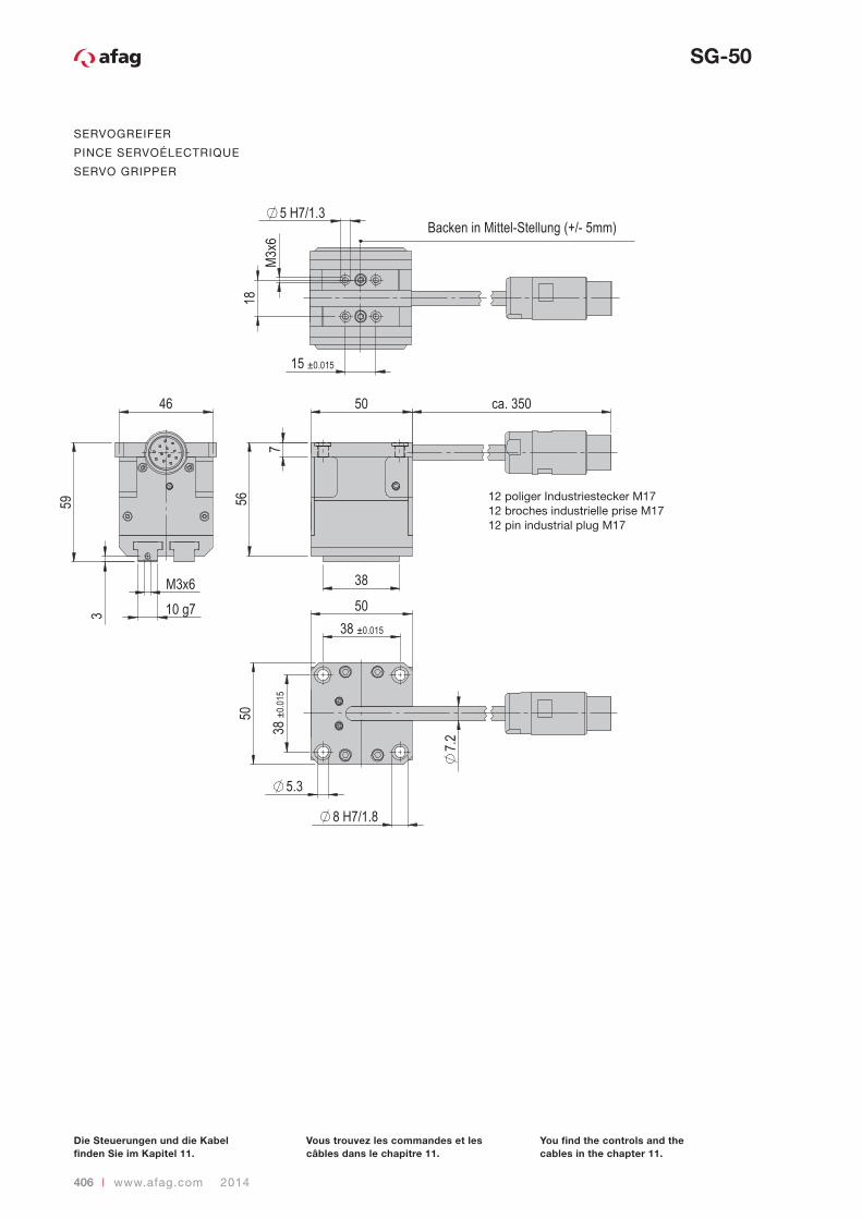
SERVOGREIFER
PINCE SERVOÉLECTRIQUE
SERVO GRIPPER
SG-50
12 poliger Industriestecker M1712 broches industrielle prise M1712 pin industrial plug M17
Die Steuerungen und die Kabel finden Sie im Kapitel 11.
Vous trouvez les commandes et les câbles dans le chapitre 11.
You find the controls and the cables in the chapter 11.
2014 www.afag.com | 407
10
SG-50
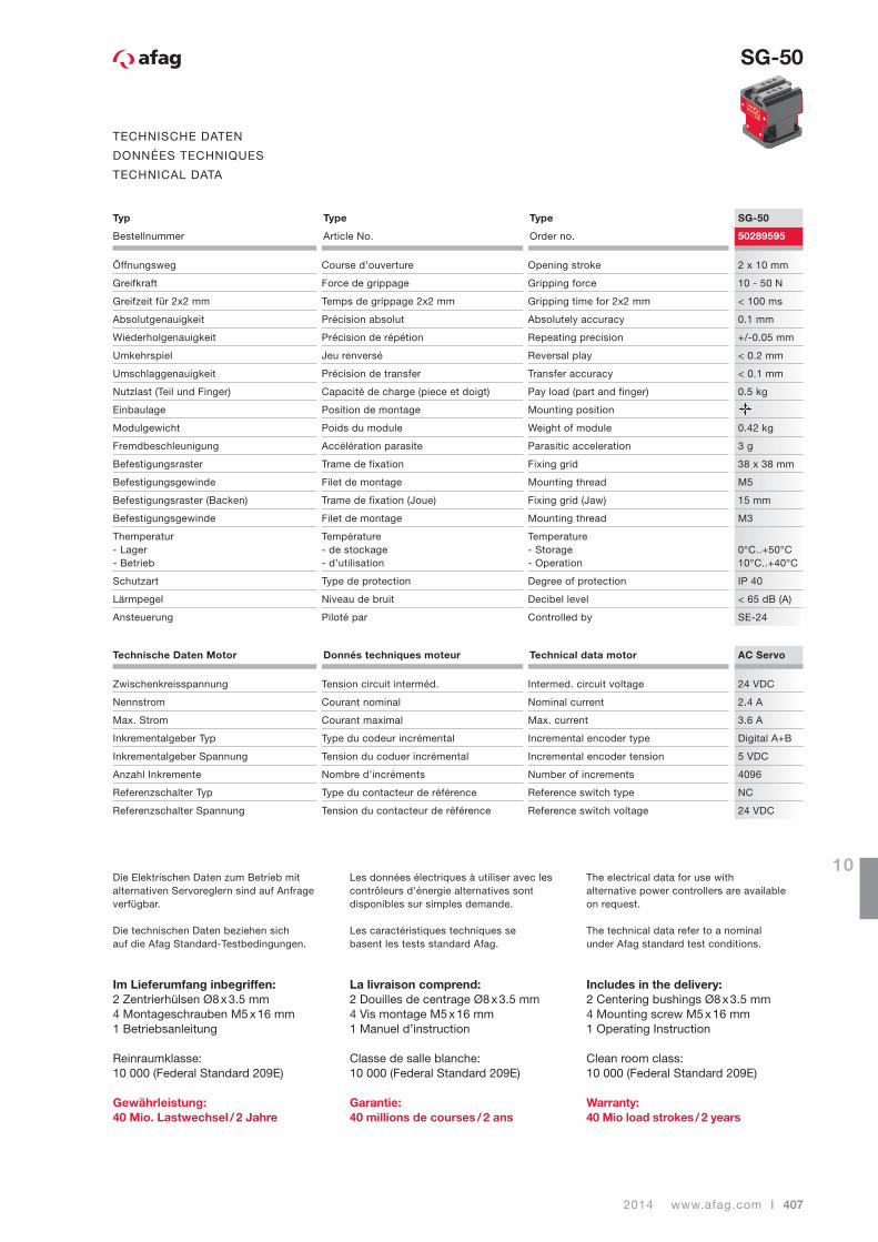
TECHNISCHE DATEN
DONNÉES TECHNIQUES
TECHNICAL DATA
Typ Type Type SG-50
Bestellnummer Article No. Order no. 50289595
Öffnungsweg Course d’ouverture Opening stroke 2 x 10 mm
Greifkraft Force de grippage Gripping force 10 - 50 N
Greifzeit für 2x2 mm Temps de grippage 2x2 mm Gripping time for 2x2 mm < 100 ms
Absolutgenauigkeit Précision absolut Absolutely accuracy 0.1 mm
Wiederholgenauigkeit Précision de répétion Repeating precision +/-0.05 mm
Umkehrspiel Jeu renversé Reversal play < 0.2 mm
Umschlaggenauigkeit Précision de transfer Transfer accuracy < 0.1 mm
Nutzlast (Teil und Finger) Capacité de charge (piece et doigt) Pay load (part and finger) 0.5 kg
Einbaulage Position de montage Mounting position
Modulgewicht Poids du module Weight of module 0.42 kg
Fremdbeschleunigung Accélération parasite Parasitic acceleration 3 g
Befestigungsraster Trame de fixation Fixing grid 38 x 38 mm
Befestigungsgewinde Filet de montage Mounting thread M5
Befestigungsraster (Backen) Trame de fixation (Joue) Fixing grid (Jaw) 15 mm
Befestigungsgewinde Filet de montage Mounting thread M3
Themperatur- Lager- Betrieb
Température- de stockage- d’utilisation
Temperature- Storage- Operation
0°C..+50°C10°C..+40°C
Schutzart Type de protection Degree of protection IP 40
Lärmpegel Niveau de bruit Decibel level < 65 dB (A)
Ansteuerung Piloté par Controlled by SE-24
Technische Daten Motor Donnés techniques moteur Technical data motor AC Servo
Zwischenkreisspannung Tension circuit interméd. Intermed. circuit voltage 24 VDC
Nennstrom Courant nominal Nominal current 2.4 A
Max. Strom Courant maximal Max. current 3.6 A
Inkrementalgeber Typ Type du codeur incrémental Incremental encoder type Digital A+B
Inkrementalgeber Spannung Tension du coduer incrémental Incremental encoder tension 5 VDC
Anzahl Inkremente Nombre d’incréments Number of increments 4096
Referenzschalter Typ Type du contacteur de référence Reference switch type NC
Referenzschalter Spannung Tension du contacteur de référence Reference switch voltage 24 VDC
Die Elektrischen Daten zum Betrieb mit alternativen Servoreglern sind auf Anfrage verfügbar.
Die technischen Daten beziehen sichauf die Afag Standard-Testbedingungen.
Im Lieferumfang inbegriffen:2 Zentrierhülsen Ø8 x 3.5 mm4 Montageschrauben M5 x 16 mm1 Betriebsanleitung
Reinraumklasse:10 000 (Federal Standard 209E)
Gewährleistung: 40 Mio. Lastwechsel / 2 Jahre
Les données électriques à utiliser avec les contrôleurs d'énergie alternatives sont disponibles sur simples demande.
Les caractéristiques techniques sebasent les tests standard Afag.
La livraison comprend:2 Douilles de centrage Ø8 x 3.5 mm4 Vis montage M5 x 16 mm1 Manuel d’instruction
Classe de salle blanche:10 000 (Federal Standard 209E)
Garantie: 40 millions de courses / 2 ans
The electrical data for use with alternative power controllers are available on request.
The technical data refer to a nominalunder Afag standard test conditions.
Includes in the delivery:2 Centering bushings Ø8 x 3.5 mm4 Mounting screw M5 x 16 mm1 Operating Instruction
Clean room class:10 000 (Federal Standard 209E)
Warranty: 40 Mio load strokes / 2 years
408 | www.afag.com 2014
SG-50
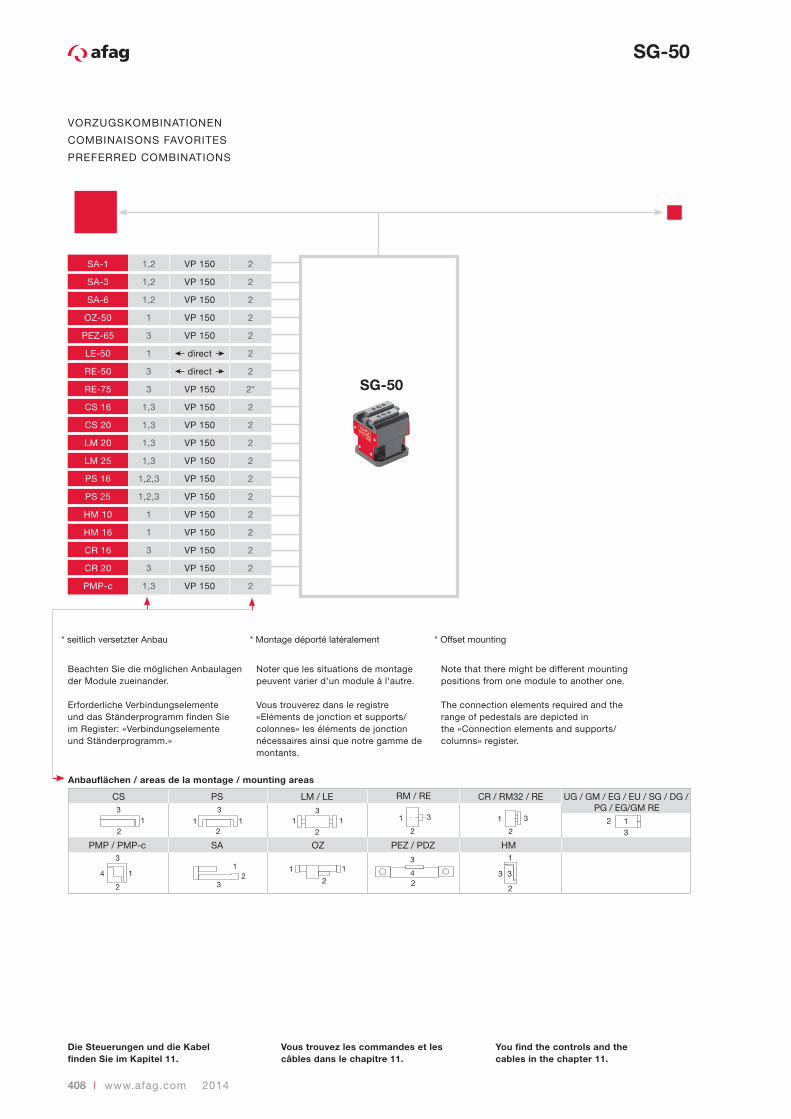
VORZUGSKOMBINATIONEN
COMBINAISONS FAVORITES
PREFERRED COMBINATIONS
Beachten Sie die möglichen Anbaulagen der Module zueinander.
Erforderliche Verbindungselemente und das Ständerprogramm finden Sie im Register: «Verbindungselemente und Ständerprogramm.»
Noter que les situations de montage peuvent varier d’un module à l’autre.
Vous trouverez dans le registre «Eléments de jonction et supports/colonnes» les éléments de jonction nécessaires ainsi que notre gamme de montants.
Note that there might be different mounting positions from one module to another one.
The connection elements required and the range of pedestals are depicted in the «Connection elements and supports/columns» register.
SG-50
SA-1 1,2 VP 150 2
SA-3 1,2 VP 150 2
SA-6 1,2 VP 150 2
OZ-50 1 VP 150 2
PEZ-65 3 VP 150 2
LE-50 1 direct 2
RE-50 3 direct 2
RE-75 3 VP 150 2*
CS 16 1,3 VP 150 2
CS 20 1,3 VP 150 2
LM 20 1,3 VP 150 2
LM 25 1,3 VP 150 2
PS 16 1,2,3 VP 150 2
PS 25 1,2,3 VP 150 2
HM 10 1 VP 150 2
HM 16 1 VP 150 2
CR 16 3 VP 150 2
CR 20 3 VP 150 2
PMP-c 1,3 VP 150 2
2
31
3
12
13
2
12
1 1 3 1
1
3
2
41
23 2
1 1
22
2
3
1
3
3
HM
UG / GM / EG / EU / SG / DG / PG / EG/GM RE
CR / RM32 / RELM / LECS PS
PMP / PMP-c SA
RM / RE
OZ PEZ / PDZ
3
3
4
* seitlich versetzter Anbau * Montage déporté latéralement * Offset mounting
Die Steuerungen und die Kabel finden Sie im Kapitel 11.
Vous trouvez les commandes et les câbles dans le chapitre 11.
You find the controls and the cables in the chapter 11.
2014 www.afag.com | 409
10
SG-50
MODUL BELASTUNGEN
CHARGES MAX. DE MODULE
UNITLOAD FACTORS MODULE
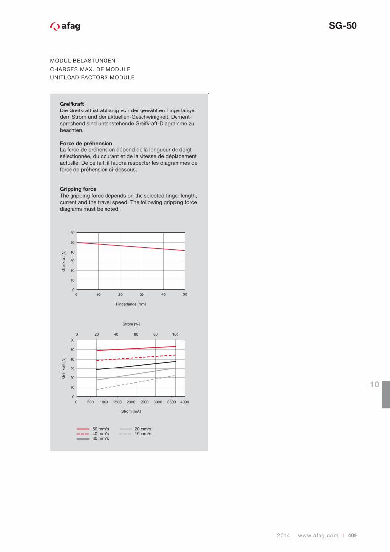
GreifkraftDie Greifkraft ist abhänig von der gewählten Fingerlänge, dem Strom und der aktuellen-Geschwinigkeit. Dement-sprechend sind untenstehende Greifkraft-Diagramme zu beachten.
Force de préhensionLa force de préhension dépend de la longueur de doigt sélectionnée, du courant et de la vitesse de déplacement actuelle. De ce fait, il faudra respecter les diagrammes de force de préhension ci-dessous.
Gripping forceThe gripping force depends on the selected fi nger length, current and the travel speed. The following gripping force diagrams must be noted.
50 mm/s40 mm/s30 mm/s
20 mm/s10 mm/s


![>REPLACETHISLINEWITHYOURPAPERIDENTIFICATIONNUMBER(DOUBLE ... · >REPLACETHISLINEWITHYOURPAPERIDENTIFICATIONNUMBER(DOUBLE-CLICKHERETOEDIT)< 3 where i [ai1,ai2, ,aiN],1 i H](https://img.dokumen.tips/doc/110x75/6078d75b9cffda0d2d7056bf/replacethislinewithyourpaperidentificationnumberdouble-replacethislinewithyourpaperidentificationnumberdouble-clickheretoedit.jpg)


![Troubleshooting19-2 Weather Indicators 19-13 Key ...mb.softbank.jp/mb/support/3g/product/931sh/pdf/931sh_en...Kanji (Hiragana) [Double-byte] Katakana [Double & Single-byte] Alphanumerics](https://img.dokumen.tips/doc/110x75/5fa32d3c813fd46afe087da1/troubleshooting19-2-weather-indicators-19-13-key-mb-kanji-hiragana-double-byte.jpg)