Embed Size (px)
Citation preview

Reg. No. 98/07367/07 • VAT Reg. No. 4490189489
PostNet Suite #251, Private Bag X1015, Lyttelton, 0140 Tel +27 (12) 664-7604 Fax +27 (86) 535-1379 [email protected]
DIRECTORS: M Heyns Pr.Eng., Ph.D., (Managing); CJ Botha, B.Eng.(Hons): Industrial
1. ASSIGNMENT GUIDELINE
The following points are important to remember:
1. You must complete the assignment in this MS Word document, and rename the file as: Assignment by Student Name (Student Number).doc. The Excel file shall be saved as Assignment by Student Name (Student Number).xls
2. Submit the assignment and Excel file by e-mail to: [email protected]. No faxed assignments will be evaluated. Please submit the documents to allow me to make changes and mark it directly in the document. This will also allow detail feedback on your assignment.
3. Copy and paste all diagrams, tables, figures, etc. Into this document.
4. Include proper referencing to detail according to the Harvard Method.
5. Hand sketches may be scanned and copied into the document.
6. Delivery date: As arranged with the class controller.
7. Please contact me at the following should you require assistance:
a. 082 445-0510
b. 012 664-7604
8. The following documents make part of this assignment:
a. This document.
b. Excel file: Assignment1.xls.

2
3
2. GENERAL USE OF THE IDEAS [20 MARKS – 40 MINUTES]
2.1. Problem Statement
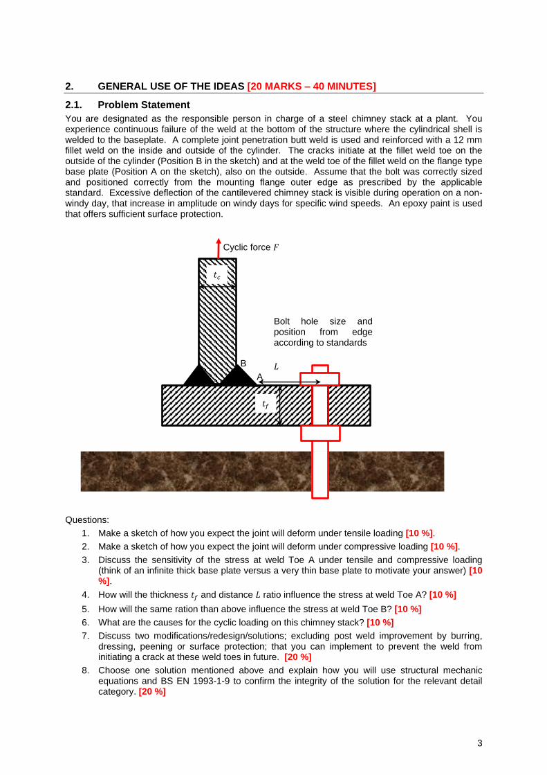
You are designated as the responsible person in charge of a steel chimney stack at a plant. You experience continuous failure of the weld at the bottom of the structure where the cylindrical shell is welded to the baseplate. A complete joint penetration butt weld is used and reinforced with a 12 mm fillet weld on the inside and outside of the cylinder. The cracks initiate at the fillet weld toe on the outside of the cylinder (Position B in the sketch) and at the weld toe of the fillet weld on the flange type base plate (Position A on the sketch), also on the outside. Assume that the bolt was correctly sized and positioned correctly from the mounting flange outer edge as prescribed by the applicable standard. Excessive deflection of the cantilevered chimney stack is visible during operation on a non-windy day, that increase in amplitude on windy days for specific wind speeds. An epoxy paint is used that offers sufficient surface protection.
Questions:
1. Make a sketch of how you expect the joint will deform under tensile loading [10 %].
2. Make a sketch of how you expect the joint will deform under compressive loading [10 %].
3. Discuss the sensitivity of the stress at weld Toe A under tensile and compressive loading (think of an infinite thick base plate versus a very thin base plate to motivate your answer) [10 %].
4. How will the thickness 𝑡𝑓 and distance 𝐿 ratio influence the stress at weld Toe A? [10 %]
5. How will the same ration than above influence the stress at weld Toe B? [10 %]
6. What are the causes for the cyclic loading on this chimney stack? [10 %]
7. Discuss two modifications/redesign/solutions; excluding post weld improvement by burring, dressing, peening or surface protection; that you can implement to prevent the weld from initiating a crack at these weld toes in future. [20 %]
8. Choose one solution mentioned above and explain how you will use structural mechanic equations and BS EN 1993-1-9 to confirm the integrity of the solution for the relevant detail category. [20 %]
Cyclic force 𝐹
𝑡𝑐
𝑡𝑓
𝐿
Bolt hole size and position from edge according to standards
A
B
4
[2 Marks = 1 for the correct equation + 1 for the correct answer]
2.2. Solution
The answer should be typically as follows:
1. Under tensile loading, the bolt will not keep the section from the outside to just to the left of the bolt flat with the foundation as is the case in a bolted flange. This is because the nuts on the anchor studs are used to locate the hole at a specific position. If the bending stiffness of the bolt is ignored, the parts will deflect as shown below:
a. If the joint was grouted, the bolt will pull the outer section to approximately the side of the bolt against the grouting. That is, this section will remain flat. This will increase the strength of the joint because of the additional constraint against rotation at the bolt.
[10 %]
2. Under compressive loading, the flange tip will bend upwards resulting in a deflection shown below:
a. If the joint was grouted, no deformation under compressive loading is expected.
[10 %]
3. The stress at weld Toes A and B will be more than that of the weld toes on the inside because of the bending moment by the bolt reaction. If the baseplate thickness was infinite, no prying effect would result and the weld detail would have been subjected to. [10 %]
4. The thickness of the flange will prevent the magnitude of the deflection (prying action). A thicker section will also result in lower stress at the weld toe due to the bending moment as a
result of the “prying”. The higher the distance, 𝐿, the higher the bending moment at the weld toe due to the bolt reaction force. Bending moment due to the anchor bolt will result in a bending stress that is indirectly proportional to the third power of flange thickness. The bending moment, and the bending stress is proportional to the distance, 𝐿. Therefore, an increase in flange thickness will result in a significant reduction in bending stress at weld Toe
A. A reduction in the 𝐿/𝑡𝑓 ratio will result in a reduction in stress at the weld toes. [10 %]
5. It will have the same effect that at Position A, just slightly smaller because of the deeper section and the deformation of the shell. [10 %]
6. Cyclic loading on a chimney stack can be due to the following:
a. Vortex shedding that is magnified when the vortex shedding frequency is equal to the natural frequency of the stack.
b. Earth movement.
c. Wind pressure loading.
d. Thermal stress.
e. Turbulence of the gasses flowing in the stack exciting natural modes.
f. Etc.
[10 %]
7. The following can be done:
a. Insert grouting. This will limit the deflection and subsequent stress at the weld toes during both tensile and compressive loading.
b. Thicken the flange.
c. Reduce the distance 𝐿 by placing the bolts closer to the cylindrical section.
d. Increase the bolt size. This will result in higher resistance against bending of the bolt that will reduce the deformed curvature of the flange and reduce stress range at the weld Toes A and B.
[10 % x 2 = 20 %]
8. The process will be as follows:
a. Calculate stress range.
b. Find joint detail category dependent fatigue curve.

5
c. Do fatigue calculation and ensure a sufficient design life.
d. Do surface protection.
[20 %]
[2 Marks = 1 for the correct equation + 1 for the correct answer]
6
3. NOTCH DEPENDENT DETAIL CATEGORY
3.1. Question
Explain how the detail category tables in BS EN 1993-1-9 make provision for the notches at weld detail and give an example. For the example, copy and paste the relevant detail categories from the tables into your assignment, reference and discuss.
4. OVERLOADING AND FATIGUE
4.1. Problem statement
You designed new weld detail for a machine subject to constant amplitude stresses. A consultant recommends a few overload cycles to improve the fatigue strength of the load-carrying as-welded fillet welds. The consultant claims that this will result in local yielding that will reduce the mean tensile stress at the weld root and toe. In the design, and from measured strains on previous versions of the machine, you ensured a cyclic stress range below the constant amplitude fatigue limit of the relevant detail category for a damage tolerant assessment method with low consequence of failure. That is, the partial factor for fatigue is 𝛾𝑀𝑓 = 1.0.
Question:
Explain in full how you will evaluate the advantages/disadvantages of the consultant’s recommendation for the as-welded fillet welds.
4.2. Solution
With the new design, the stress ranges are already below the constant amplitude fatigue limit and there is no evidence that the joint will be subjected to stress ranges exceeding the constant amplitude fatigue limit. This will result in infinite life for the detail category.
However, if a few cycles during the overloading are applied that exceed the constant amplitude fatigue limit, micro-cracks can be caused that will result in crack propagation to detectable crack size during the stress cycles with range below the constant amplitude fatigue limit. Therefore, the overloading applied resulted in the joint which was designed for infinite life to have a finite life. Based on this, overloading at stress ranges above the constant amplitude fatigue limit will result in finite fatigue life by stress ranges below the constant amplitude fatigue limit. This has a disadvantage.
Because crack initiation at the notches of weld roots and toes is not sensitive to mean stress, overloading to reduce mean tensile stress does not have any advantage based on the information supplied by BS EN 1993-1-9.
5. SUMMARY FROM PAPER
Planar defects that are potential failure sites.
Surface laser repaired specimens
7
7. WELD FATIGUE LIFE IMPROVEMENT TECHNIQUES [WEIGHT=5/10]
Discuss and compare, including relevant graphs and sketches, the improvement of weld detail by means of:
1. Weld toe treatment (burring).
2. Hammer peening.
Discuss how it is modelled by Bulletin 520 of the International Institute of Welding.
7.1. Answer
Please type your answer here.
Question1: Weld toe treatment (burring) [5 Marks] The aim of burring/grinding the weld toe:
1. To remove imperfections which are an inherent feature of most arc welds like [1 Mark]:
a. Undercut.
b. Cold laps.
c. Sharp crack-like imperfections.
2. Create a smooth transition between the weld an plate – reduce the stress concentration [1 Mark].
The benefit of weld toe treatment:
A factor is calculated that is applied to the fatigue class of the non-improved joint [1 Mark]. The classes applicable are [1 Mark]:
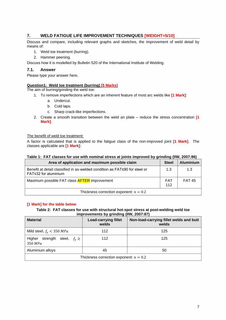
Table 1: FAT classes for use with nominal stress at joints improved by grinding (IIW, 2007:86)
Area of application and maximum possible claim Steel Aluminium
Benefit at detail classified in as-welded condition as FAT≤90 for steel or FAT≤32 for aluminium
1.3 1.3
Maximum possible FAT class AFTER improvement FAT 112
FAT 45
Thickness correction exponent: 𝑛 = 0.2
[1 Mark] for the table below
Table 2: FAT classes for use with structural hot-spot stress at post-welding weld toe improvements by grinding (IIW, 2007:87)
Material Load-carrying fillet welds
Non-load-carrying fillet welds and butt welds
Mild steel, 𝑓𝑦 < 350 𝑀𝑃𝑎 112 125
Higher strength steel, 𝑓𝑦 ≥
350 𝑀𝑃𝑎
112 125
Aluminium alloys 45 50
Thickness correction exponent: 𝑛 = 0.2
8
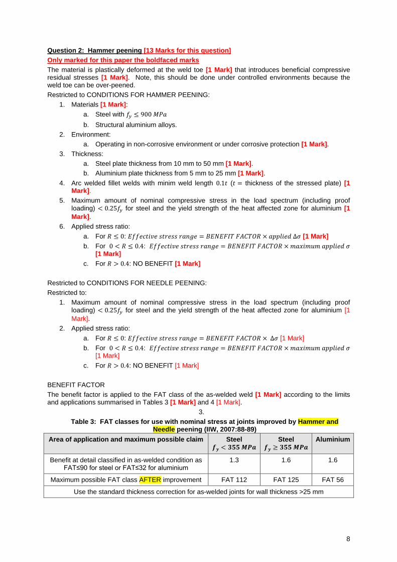
Question 2: Hammer peening [13 Marks for this question]
Only marked for this paper the boldfaced marks
The material is plastically deformed at the weld toe [1 Mark] that introduces beneficial compressive residual stresses [1 Mark]. Note, this should be done under controlled environments because the weld toe can be over-peened.
Restricted to CONDITIONS FOR HAMMER PEENING:
1. Materials [1 Mark]:
a. Steel with 𝑓𝑦 ≤ 900 𝑀𝑃𝑎
b. Structural aluminium alloys.
2. Environment:
a. Operating in non-corrosive environment or under corrosive protection [1 Mark].
3. Thickness:
a. Steel plate thickness from 10 mm to 50 mm [1 Mark].
b. Aluminium plate thickness from 5 mm to 25 mm [1 Mark].
4. Arc welded fillet welds with minim weld length 0.1𝑡 (𝑡 = thickness of the stressed plate) [1 Mark].
5. Maximum amount of nominal compressive stress in the load spectrum (including proof loading) < 0.25𝑓𝑦 for steel and the yield strength of the heat affected zone for aluminium [1
Mark].
6. Applied stress ratio:
a. For 𝑅 ≤ 0: 𝐸𝑓𝑓𝑒𝑐𝑡𝑖𝑣𝑒 𝑠𝑡𝑟𝑒𝑠𝑠 𝑟𝑎𝑛𝑔𝑒 = 𝐵𝐸𝑁𝐸𝐹𝐼𝑇 𝐹𝐴𝐶𝑇𝑂𝑅 × 𝑎𝑝𝑝𝑙𝑖𝑒𝑑 Δ𝜎 [1 Mark]
b. For 0 < 𝑅 ≤ 0.4: 𝐸𝑓𝑓𝑒𝑐𝑡𝑖𝑣𝑒 𝑠𝑡𝑟𝑒𝑠𝑠 𝑟𝑎𝑛𝑔𝑒 = 𝐵𝐸𝑁𝐸𝐹𝐼𝑇 𝐹𝐴𝐶𝑇𝑂𝑅 ×𝑚𝑎𝑥𝑖𝑚𝑢𝑚 𝑎𝑝𝑝𝑙𝑖𝑒𝑑 𝜎 [1 Mark]
c. For 𝑅 > 0.4: NO BENEFIT [1 Mark]
Restricted to CONDITIONS FOR NEEDLE PEENING:
Restricted to:
1. Maximum amount of nominal compressive stress in the load spectrum (including proof loading) < 0.25𝑓𝑦 for steel and the yield strength of the heat affected zone for aluminium [1
Mark].
2. Applied stress ratio:
a. For 𝑅 ≤ 0: 𝐸𝑓𝑓𝑒𝑐𝑡𝑖𝑣𝑒 𝑠𝑡𝑟𝑒𝑠𝑠 𝑟𝑎𝑛𝑔𝑒 = 𝐵𝐸𝑁𝐸𝐹𝐼𝑇 𝐹𝐴𝐶𝑇𝑂𝑅 × Δ𝜎 [1 Mark]
b. For 0 < 𝑅 ≤ 0.4: 𝐸𝑓𝑓𝑒𝑐𝑡𝑖𝑣𝑒 𝑠𝑡𝑟𝑒𝑠𝑠 𝑟𝑎𝑛𝑔𝑒 = 𝐵𝐸𝑁𝐸𝐹𝐼𝑇 𝐹𝐴𝐶𝑇𝑂𝑅 ×𝑚𝑎𝑥𝑖𝑚𝑢𝑚 𝑎𝑝𝑝𝑙𝑖𝑒𝑑 𝜎 [1 Mark]
c. For 𝑅 > 0.4: NO BENEFIT [1 Mark]
BENEFIT FACTOR
The benefit factor is applied to the FAT class of the as-welded weld [1 Mark] according to the limits and applications summarised in Tables 3 [1 Mark] and 4 [1 Mark].
3.
Table 3: FAT classes for use with nominal stress at joints improved by Hammer and Needle peening (IIW, 2007:88-89)
Area of application and maximum possible claim Steel 𝒇𝒚 < 𝟑𝟓𝟓 𝑴𝑷𝒂
Steel 𝒇𝒚 ≥ 𝟑𝟓𝟓 𝑴𝑷𝒂
Aluminium
Benefit at detail classified in as-welded condition as FAT≤90 for steel or FAT≤32 for aluminium
1.3 1.6 1.6
Maximum possible FAT class AFTER improvement FAT 112 FAT 125 FAT 56
Use the standard thickness correction for as-welded joints for wall thickness >25 mm
9
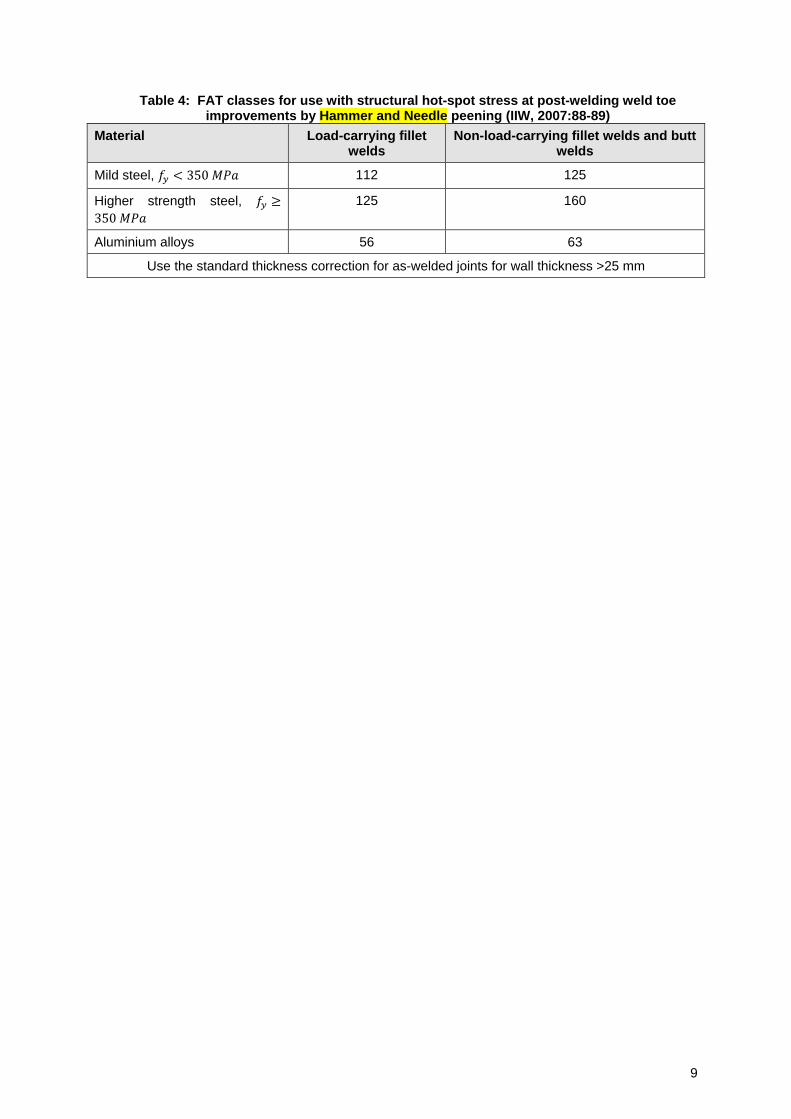
Table 4: FAT classes for use with structural hot-spot stress at post-welding weld toe improvements by Hammer and Needle peening (IIW, 2007:88-89)
Material Load-carrying fillet welds
Non-load-carrying fillet welds and butt welds
Mild steel, 𝑓𝑦 < 350 𝑀𝑃𝑎 112 125
Higher strength steel, 𝑓𝑦 ≥
350 𝑀𝑃𝑎
125 160
Aluminium alloys 56 63
Use the standard thickness correction for as-welded joints for wall thickness >25 mm
10
8. WELD FATIGUE DESIGN ACCORDING TO BS EN 1993-1-9 [WEIGHT = 15/10]
8.1. Background
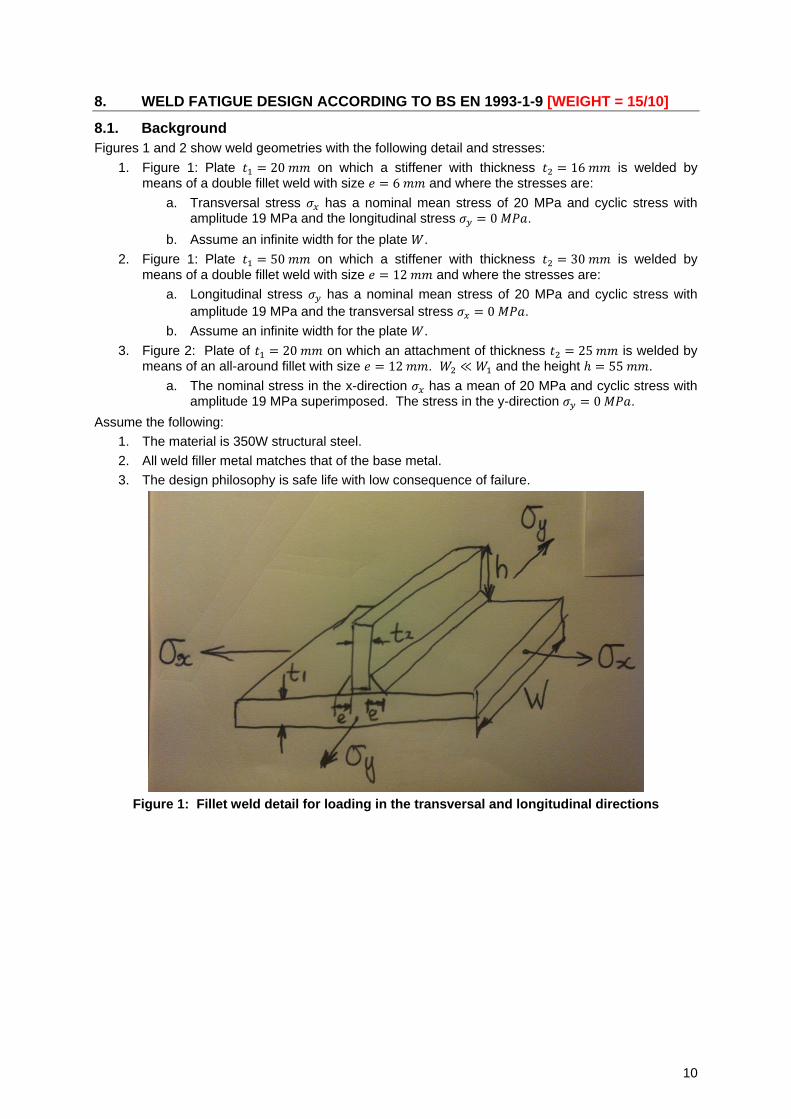
Figures 1 and 2 show weld geometries with the following detail and stresses:
1. Figure 1: Plate 𝑡1 = 20 𝑚𝑚 on which a stiffener with thickness 𝑡2 = 16 𝑚𝑚 is welded by means of a double fillet weld with size 𝑒 = 6 𝑚𝑚 and where the stresses are:
a. Transversal stress 𝜎𝑥 has a nominal mean stress of 20 MPa and cyclic stress with amplitude 19 MPa and the longitudinal stress 𝜎𝑦 = 0 𝑀𝑃𝑎.
b. Assume an infinite width for the plate 𝑊.
2. Figure 1: Plate 𝑡1 = 50 𝑚𝑚 on which a stiffener with thickness 𝑡2 = 30 𝑚𝑚 is welded by
means of a double fillet weld with size 𝑒 = 12 𝑚𝑚 and where the stresses are:
a. Longitudinal stress 𝜎𝑦 has a nominal mean stress of 20 MPa and cyclic stress with
amplitude 19 MPa and the transversal stress 𝜎𝑥 = 0 𝑀𝑃𝑎.
b. Assume an infinite width for the plate 𝑊.
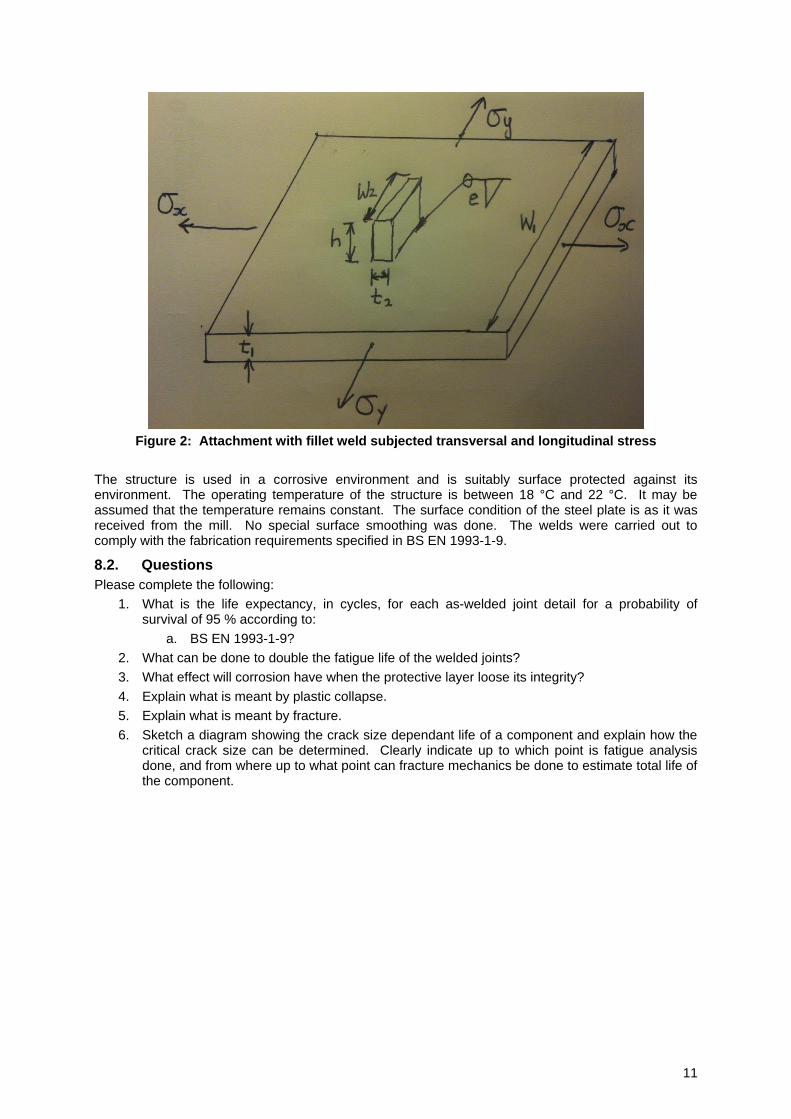
3. Figure 2: Plate of 𝑡1 = 20 𝑚𝑚 on which an attachment of thickness 𝑡2 = 25 𝑚𝑚 is welded by means of an all-around fillet with size 𝑒 = 12 𝑚𝑚. 𝑊2 ≪ 𝑊1 and the height ℎ = 55 𝑚𝑚.
a. The nominal stress in the x-direction 𝜎𝑥 has a mean of 20 MPa and cyclic stress with amplitude 19 MPa superimposed. The stress in the y-direction 𝜎𝑦 = 0 𝑀𝑃𝑎.
Assume the following:
1. The material is 350W structural steel.
2. All weld filler metal matches that of the base metal.
3. The design philosophy is safe life with low consequence of failure.
Figure 1: Fillet weld detail for loading in the transversal and longitudinal directions
11
Figure 2: Attachment with fillet weld subjected transversal and longitudinal stress
The structure is used in a corrosive environment and is suitably surface protected against its environment. The operating temperature of the structure is between 18 °C and 22 °C. It may be assumed that the temperature remains constant. The surface condition of the steel plate is as it was received from the mill. No special surface smoothing was done. The welds were carried out to comply with the fabrication requirements specified in BS EN 1993-1-9.
8.2. Questions
Please complete the following:
1. What is the life expectancy, in cycles, for each as-welded joint detail for a probability of survival of 95 % according to:
a. BS EN 1993-1-9?
2. What can be done to double the fatigue life of the welded joints?
3. What effect will corrosion have when the protective layer loose its integrity?
4. Explain what is meant by plastic collapse.
5. Explain what is meant by fracture.
6. Sketch a diagram showing the crack size dependant life of a component and explain how the critical crack size can be determined. Clearly indicate up to which point is fatigue analysis done, and from where up to what point can fracture mechanics be done to estimate total life of the component.
12
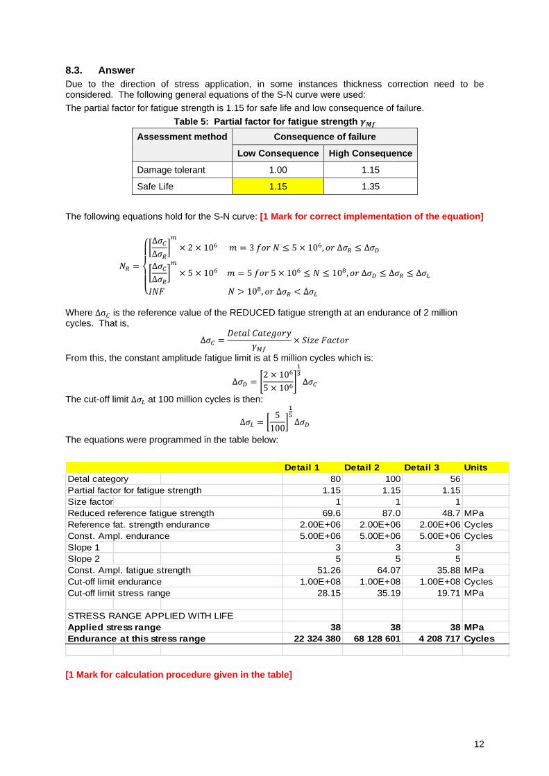
8.3. Answer
Due to the direction of stress application, in some instances thickness correction need to be considered. The following general equations of the S-N curve were used:
The partial factor for fatigue strength is 1.15 for safe life and low consequence of failure.
Table 5: Partial factor for fatigue strength 𝜸𝑴𝒇
Assessment method Consequence of failure
Low Consequence High Consequence
Damage tolerant 1.00 1.15
Safe Life 1.15 1.35
The following equations hold for the S-N curve: [1 Mark for correct implementation of the equation]
𝑁𝑅 =
{
[Δ𝜎𝐶Δ𝜎𝑅
]𝑚
× 2 × 10⁶ 𝑚 = 3 𝑓𝑜𝑟 𝑁 ≤ 5 × 10⁶, 𝑜𝑟 Δ𝜎𝑅 ≤ Δ𝜎𝐷
[Δ𝜎𝐶Δ𝜎𝑅
]𝑚
× 5 × 10⁶ 𝑚 = 5 𝑓𝑜𝑟 5 × 10⁶ ≤ 𝑁 ≤ 108, 𝑜𝑟 Δ𝜎𝐷 ≤ Δ𝜎𝑅 ≤ Δ𝜎𝐿
𝐼𝑁𝐹 𝑁 > 108, 𝑜𝑟 Δ𝜎𝑅 < Δ𝜎𝐿
Where Δσ𝐶 is the reference value of the REDUCED fatigue strength at an endurance of 2 million cycles. That is,
Δ𝜎𝐶 =𝐷𝑒𝑡𝑎𝑙 𝐶𝑎𝑡𝑒𝑔𝑜𝑟𝑦
𝛾𝑀𝑓× 𝑆𝑖𝑧𝑒 𝐹𝑎𝑐𝑡𝑜𝑟
From this, the constant amplitude fatigue limit is at 5 million cycles which is:
Δ𝜎𝐷 = [2 × 10⁶
5 × 10⁶]
13
Δ𝜎𝐶
The cut-off limit Δ𝜎𝐿 at 100 million cycles is then:
Δ𝜎𝐿 = [5
100]
15Δ𝜎𝐷
The equations were programmed in the table below:
Detail 1 Detail 2 Detail 3 Units
Detal category 80 100 56
Partial factor for fatigue strength 1.15 1.15 1.15
Size factor 1 1 1
Reduced reference fatigue strength 69.6 87.0 48.7 MPa
Reference fat. strength endurance 2.00E+06 2.00E+06 2.00E+06 Cycles
Const. Ampl. endurance 5.00E+06 5.00E+06 5.00E+06 Cycles
Slope 1 3 3 3
Slope 2 5 5 5
Const. Ampl. fatigue strength 51.26 64.07 35.88 MPa
Cut-off limit endurance 1.00E+08 1.00E+08 1.00E+08 Cycles
Cut-off limit stress range 28.15 35.19 19.71 MPa
STRESS RANGE APPLIED WITH LIFE
Applied stress range 38 38 38 MPa
Endurance at this stress range 22 324 380 68 128 601 4 208 717 Cycles
[1 Mark for calculation procedure given in the table]

13
14
9. WELD GEOMETRY CHANGE [10 MARKS – 10 MINUTES]
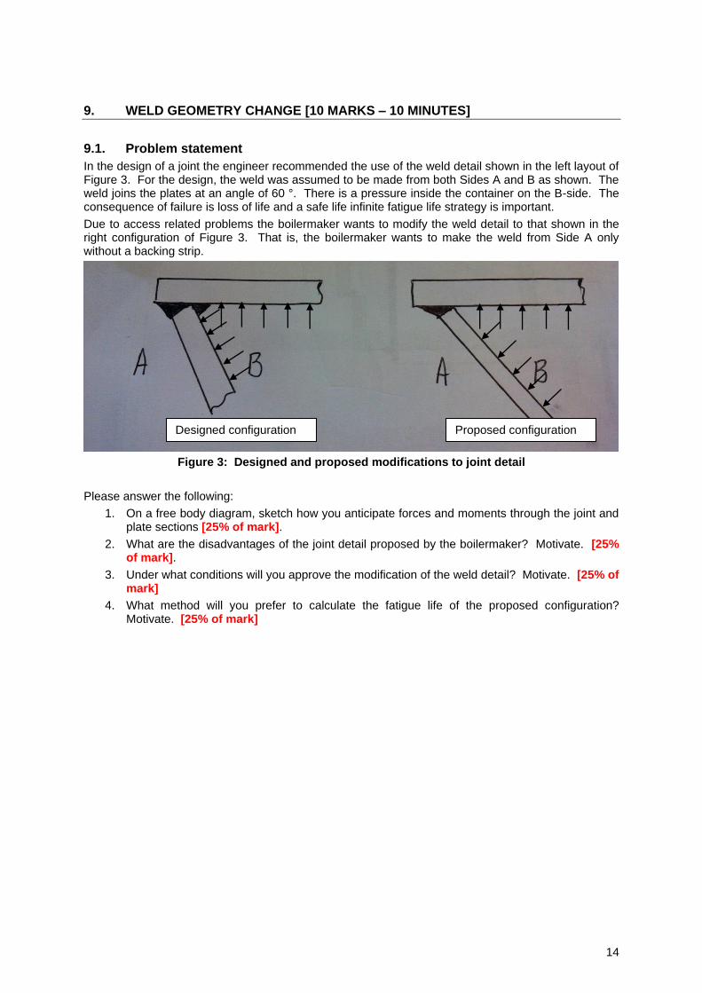
9.1. Problem statement
In the design of a joint the engineer recommended the use of the weld detail shown in the left layout of Figure 3. For the design, the weld was assumed to be made from both Sides A and B as shown. The weld joins the plates at an angle of 60 °. There is a pressure inside the container on the B-side. The consequence of failure is loss of life and a safe life infinite fatigue life strategy is important.
Due to access related problems the boilermaker wants to modify the weld detail to that shown in the right configuration of Figure 3. That is, the boilermaker wants to make the weld from Side A only without a backing strip.
Figure 3: Designed and proposed modifications to joint detail
Please answer the following:
1. On a free body diagram, sketch how you anticipate forces and moments through the joint and plate sections [25% of mark].
2. What are the disadvantages of the joint detail proposed by the boilermaker? Motivate. [25% of mark].
3. Under what conditions will you approve the modification of the weld detail? Motivate. [25% of mark]
4. What method will you prefer to calculate the fatigue life of the proposed configuration? Motivate. [25% of mark]
Designed configuration Proposed configuration
15
9.2. Answer [8 Marks]
Answers as follows:
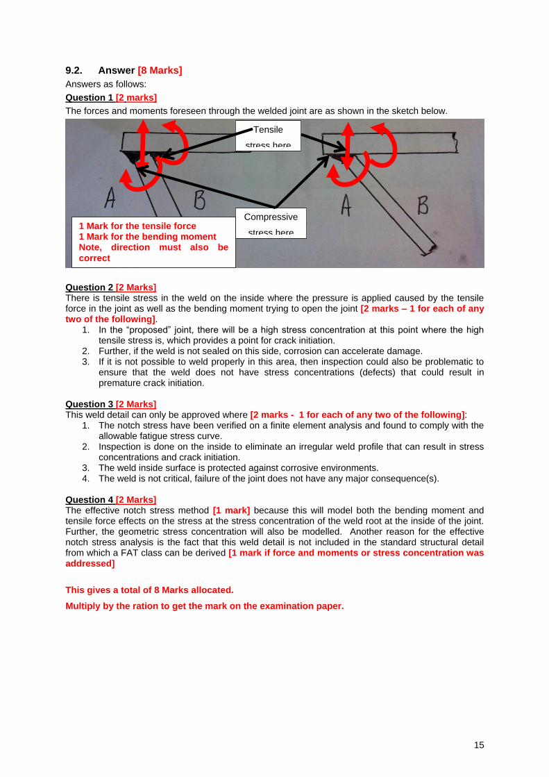
Question 1 [2 marks]
The forces and moments foreseen through the welded joint are as shown in the sketch below.
Question 2 [2 Marks] There is tensile stress in the weld on the inside where the pressure is applied caused by the tensile force in the joint as well as the bending moment trying to open the joint [2 marks – 1 for each of any two of the following].
1. In the “proposed” joint, there will be a high stress concentration at this point where the high tensile stress is, which provides a point for crack initiation.
2. Further, if the weld is not sealed on this side, corrosion can accelerate damage. 3. If it is not possible to weld properly in this area, then inspection could also be problematic to
ensure that the weld does not have stress concentrations (defects) that could result in premature crack initiation.
Question 3 [2 Marks] This weld detail can only be approved where [2 marks - 1 for each of any two of the following]:
1. The notch stress have been verified on a finite element analysis and found to comply with the allowable fatigue stress curve.
2. Inspection is done on the inside to eliminate an irregular weld profile that can result in stress concentrations and crack initiation.
3. The weld inside surface is protected against corrosive environments. 4. The weld is not critical, failure of the joint does not have any major consequence(s).
Question 4 [2 Marks] The effective notch stress method [1 mark] because this will model both the bending moment and tensile force effects on the stress at the stress concentration of the weld root at the inside of the joint. Further, the geometric stress concentration will also be modelled. Another reason for the effective notch stress analysis is the fact that this weld detail is not included in the standard structural detail from which a FAT class can be derived [1 mark if force and moments or stress concentration was addressed]
This gives a total of 8 Marks allocated.
Multiply by the ration to get the mark on the examination paper.
Tensile
stress here
Compressive
stress here 1 Mark for the tensile force 1 Mark for the bending moment Note, direction must also be
correct
16
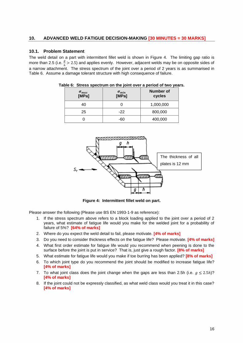
10. ADVANCED WELD FATIGUE DECISION-MAKING [30 MINUTES = 30 MARKS]
10.1. Problem Statement
The weld detail on a part with intermittent fillet weld is shown in Figure 4. The limiting gap ratio is
more than 2.5 (i.e. 𝑔
ℎ> 2.5) and applies evenly. However, adjacent welds may be on opposite sides of
a narrow attachment. The stress spectrum of the joint over a period of 2 years is as summarised in Table 6. Assume a damage tolerant structure with high consequence of failure.
Table 6: Stress spectrum on the joint over a period of two years.
𝝈𝒎𝒂𝒙 [MPa]
𝝈𝒎𝒊𝒏 [MPa]
Number of cycles
40 0 1,000,000
25 -22 800,000
0 -60 400,000
Figure 4: Intermittent fillet weld on part.
Please answer the following (Please use BS EN 1993-1-9 as reference):
1. If the stress spectrum above refers to a block loading applied to the joint over a period of 2 years, what estimate of fatigue life would you make for the welded joint for a probability of failure of 5%? [64% of marks]
2. Where do you expect the weld detail to fail, please motivate. [4% of marks]
3. Do you need to consider thickness effects on the fatigue life? Please motivate. [4% of marks]
4. What first order estimate for fatigue life would you recommend when peening is done to the surface before the joint is put in service? That is, just give a rough factor. [8% of marks]
5. What estimate for fatigue life would you make if toe burring has been applied? [8% of marks]
6. To which joint type do you recommend the joint should be modified to increase fatigue life? [4% of marks]
7. To what joint class does the joint change when the gaps are less than 2.5h (i.e. 𝑔 ≤ 2.5ℎ)? [4% of marks]
8. If the joint could not be expressly classified, as what weld class would you treat it in this case? [4% of marks]
The thickness of all
plates is 12 mm
17
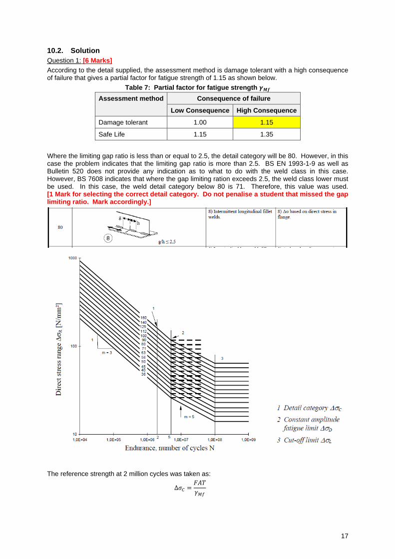
10.2. Solution
Question 1: [6 Marks]
According to the detail supplied, the assessment method is damage tolerant with a high consequence of failure that gives a partial factor for fatigue strength of 1.15 as shown below.
Table 7: Partial factor for fatigue strength 𝜸𝑴𝒇
Assessment method Consequence of failure
Low Consequence High Consequence
Damage tolerant 1.00 1.15
Safe Life 1.15 1.35
Where the limiting gap ratio is less than or equal to 2.5, the detail category will be 80. However, in this case the problem indicates that the limiting gap ratio is more than 2.5. BS EN 1993-1-9 as well as Bulletin 520 does not provide any indication as to what to do with the weld class in this case. However, BS 7608 indicates that where the gap limiting ration exceeds 2.5, the weld class lower must be used. In this case, the weld detail category below 80 is 71. Therefore, this value was used. [1 Mark for selecting the correct detail category. Do not penalise a student that missed the gap limiting ratio. Mark accordingly.]
The reference strength at 2 million cycles was taken as:
Δ𝜎𝐶 =𝐹𝐴𝑇
𝛾𝑀𝑓
18
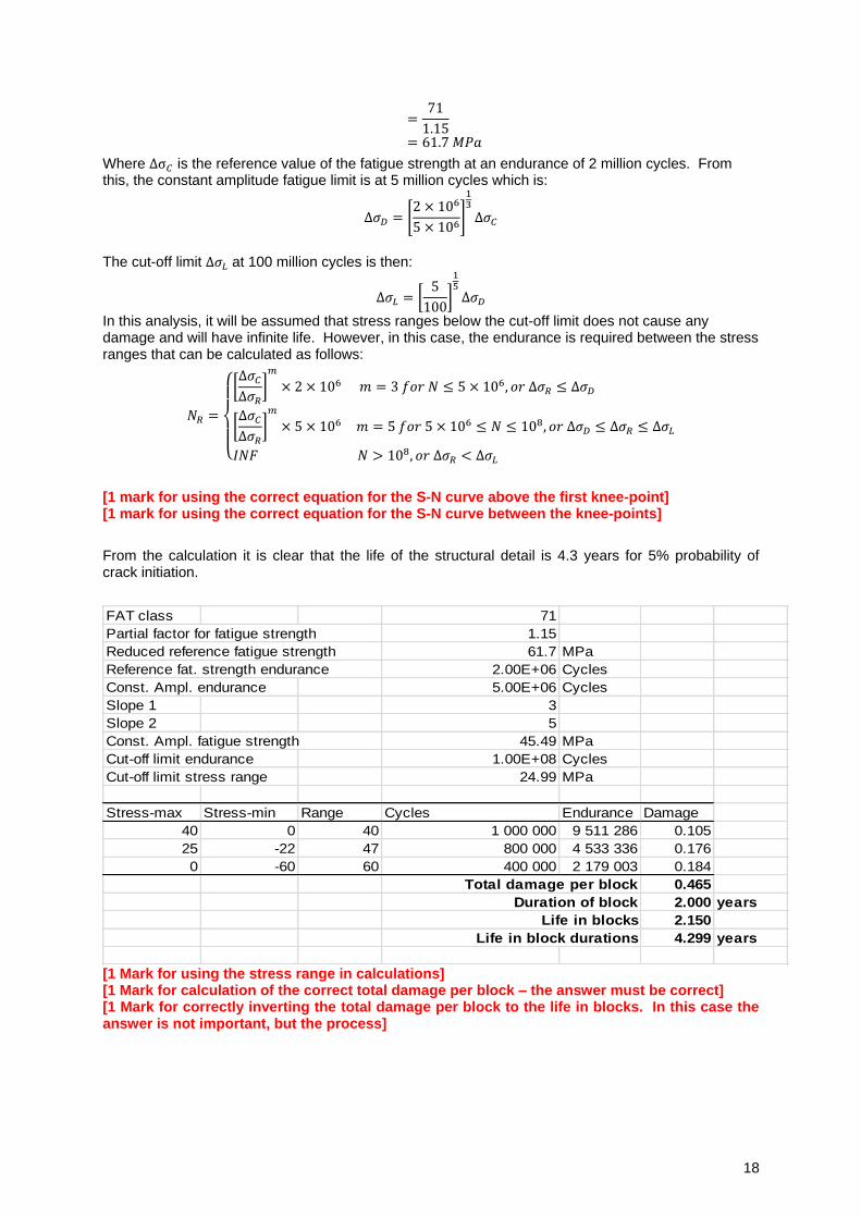
=71
1.15
= 61.7 𝑀𝑃𝑎
Where Δσ𝐶 is the reference value of the fatigue strength at an endurance of 2 million cycles. From this, the constant amplitude fatigue limit is at 5 million cycles which is:
Δ𝜎𝐷 = [2 × 10⁶
5 × 10⁶]
13
Δ𝜎𝐶
The cut-off limit Δ𝜎𝐿 at 100 million cycles is then:
Δ𝜎𝐿 = [5
100]
15Δ𝜎𝐷
In this analysis, it will be assumed that stress ranges below the cut-off limit does not cause any damage and will have infinite life. However, in this case, the endurance is required between the stress ranges that can be calculated as follows:
𝑁𝑅 =
{
[Δ𝜎𝐶Δ𝜎𝑅
]𝑚
× 2 × 10⁶ 𝑚 = 3 𝑓𝑜𝑟 𝑁 ≤ 5 × 10⁶, 𝑜𝑟 Δ𝜎𝑅 ≤ Δ𝜎𝐷
[Δ𝜎𝐶Δ𝜎𝑅
]𝑚
× 5 × 10⁶ 𝑚 = 5 𝑓𝑜𝑟 5 × 10⁶ ≤ 𝑁 ≤ 108, 𝑜𝑟 Δ𝜎𝐷 ≤ Δ𝜎𝑅 ≤ Δ𝜎𝐿
𝐼𝑁𝐹 𝑁 > 108, 𝑜𝑟 Δ𝜎𝑅 < Δ𝜎𝐿
[1 mark for using the correct equation for the S-N curve above the first knee-point] [1 mark for using the correct equation for the S-N curve between the knee-points]
From the calculation it is clear that the life of the structural detail is 4.3 years for 5% probability of crack initiation.
FAT class 71
Partial factor for fatigue strength 1.15
Reduced reference fatigue strength 61.7 MPa
Reference fat. strength endurance 2.00E+06 Cycles
Const. Ampl. endurance 5.00E+06 Cycles
Slope 1 3
Slope 2 5
Const. Ampl. fatigue strength 45.49 MPa
Cut-off limit endurance 1.00E+08 Cycles
Cut-off limit stress range 24.99 MPa
Stress-max Stress-min Range Cycles Endurance Damage
40 0 40 1 000 000 9 511 286 0.105
25 -22 47 800 000 4 533 336 0.176
0 -60 60 400 000 2 179 003 0.184
Total damage per block 0.465
Duration of block 2.000 years
Life in blocks 2.150
Life in block durations 4.299 years
[1 Mark for using the stress range in calculations] [1 Mark for calculation of the correct total damage per block – the answer must be correct] [1 Mark for correctly inverting the total damage per block to the life in blocks. In this case the answer is not important, but the process]
19
Question 2 [1 Mark] The crack is expected to initiate at the toe of the weld at an intermittent weld because of the stress concentration caused by the weld notch at that point. [1 Mark] Question 3 [1 Mark] BS EN 1993-1-9 does not require thickness correction in this case because crack initiation will be at the weld toe where thickness has negligible effect. No thickness correction is required. [1 Mark]
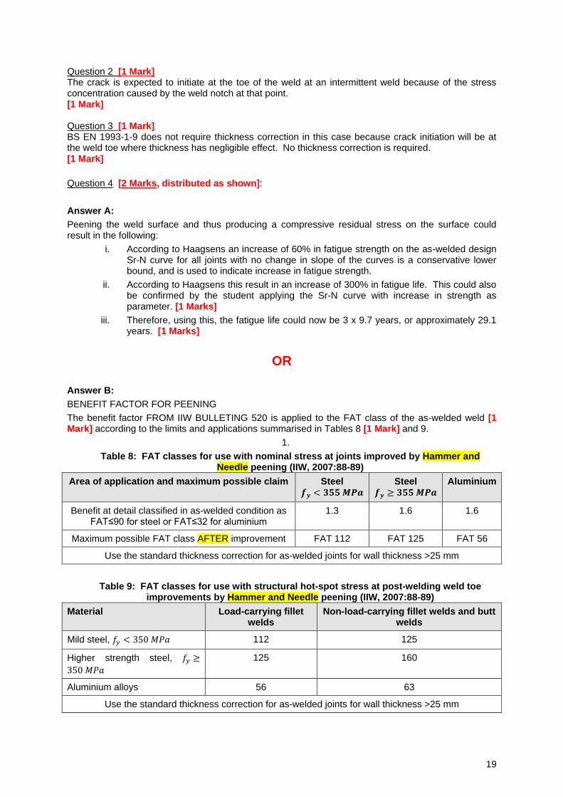
Question 4 [2 Marks, distributed as shown]:
Answer A:
Peening the weld surface and thus producing a compressive residual stress on the surface could result in the following:
i. According to Haagsens an increase of 60% in fatigue strength on the as-welded design Sr-N curve for all joints with no change in slope of the curves is a conservative lower bound, and is used to indicate increase in fatigue strength.
ii. According to Haagsens this result in an increase of 300% in fatigue life. This could also be confirmed by the student applying the Sr-N curve with increase in strength as parameter. [1 Marks]
iii. Therefore, using this, the fatigue life could now be 3 x 9.7 years, or approximately 29.1 years. [1 Marks]
OR
Answer B:
BENEFIT FACTOR FOR PEENING
The benefit factor FROM IIW BULLETING 520 is applied to the FAT class of the as-welded weld [1 Mark] according to the limits and applications summarised in Tables 8 [1 Mark] and 9.
1.
Table 8: FAT classes for use with nominal stress at joints improved by Hammer and Needle peening (IIW, 2007:88-89)
Area of application and maximum possible claim Steel 𝒇𝒚 < 𝟑𝟓𝟓 𝑴𝑷𝒂
Steel 𝒇𝒚 ≥ 𝟑𝟓𝟓 𝑴𝑷𝒂
Aluminium
Benefit at detail classified in as-welded condition as FAT≤90 for steel or FAT≤32 for aluminium
1.3 1.6 1.6
Maximum possible FAT class AFTER improvement FAT 112 FAT 125 FAT 56
Use the standard thickness correction for as-welded joints for wall thickness >25 mm
Table 9: FAT classes for use with structural hot-spot stress at post-welding weld toe improvements by Hammer and Needle peening (IIW, 2007:88-89)
Material Load-carrying fillet welds
Non-load-carrying fillet welds and butt welds
Mild steel, 𝑓𝑦 < 350 𝑀𝑃𝑎 112 125
Higher strength steel, 𝑓𝑦 ≥
350 𝑀𝑃𝑎
125 160
Aluminium alloys 56 63
Use the standard thickness correction for as-welded joints for wall thickness >25 mm
20
Question 5 [2 Marks, distributed as shown]:
a. Tow burring can have the following benefits according to the UK Health and Safety Executive:
a. Factor 1.3 on fatigue strength.
b. Factor 2.2 on life.
b. For design the following conservative lower bounds can be taken:
a. Increase of 30% in fatigue strength, the slope m = 3.
b. This corresponds to a 120% increase in fatigue life provided that the life of the as welded joint is >106 cycles. [1 Marks]
c. As shown, this technique is a high stress life improvement technique and is not efficient for high stresses and a low stress life.
d. Based on this information, the fatigue life is expected to increase only for the low stress high cycle fatigue. In this case, the stresses are all low enough to have a fatigue life in excess of 1 million cycles. Therefore, the life is expected to be 2.2 times the life of 9.7 years or approximately 21 years. [1 Marks]
OR
The benefit of weld toe treatment according to Int. Inst. Welding Bulletin 520:
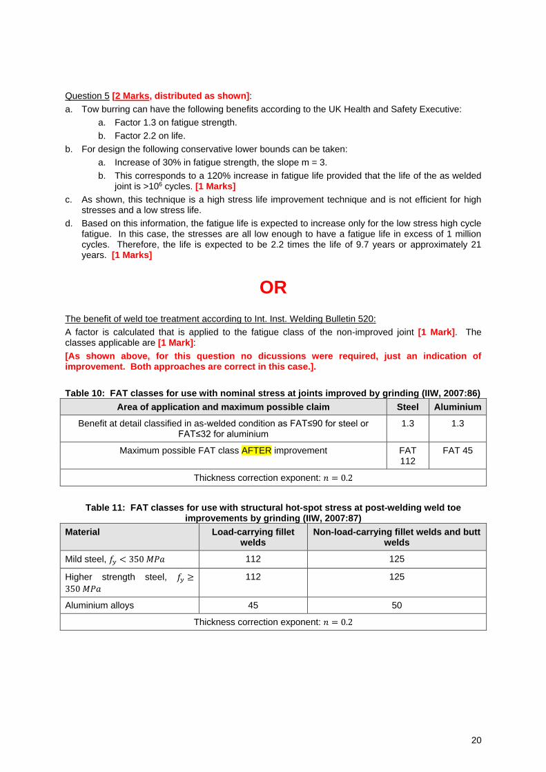
A factor is calculated that is applied to the fatigue class of the non-improved joint [1 Mark]. The classes applicable are [1 Mark]:
[As shown above, for this question no dicussions were required, just an indication of improvement. Both approaches are correct in this case.].
Table 10: FAT classes for use with nominal stress at joints improved by grinding (IIW, 2007:86)
Area of application and maximum possible claim Steel Aluminium
Benefit at detail classified in as-welded condition as FAT≤90 for steel or FAT≤32 for aluminium
1.3 1.3
Maximum possible FAT class AFTER improvement FAT 112
FAT 45
Thickness correction exponent: 𝑛 = 0.2
Table 11: FAT classes for use with structural hot-spot stress at post-welding weld toe improvements by grinding (IIW, 2007:87)
Material Load-carrying fillet welds
Non-load-carrying fillet welds and butt welds
Mild steel, 𝑓𝑦 < 350 𝑀𝑃𝑎 112 125
Higher strength steel, 𝑓𝑦 ≥
350 𝑀𝑃𝑎
112 125
Aluminium alloys 45 50
Thickness correction exponent: 𝑛 = 0.2
21
Question 6 [1 Mark]
BS 7608 Answer
The intermittent weld can be modified to a continuous weld that would improve the weld detail to Class D. [1 Mark]
or BS EN 1993-1-9 Answer:
The weld category will improve by one interval to 100 when the intermittent weld detail is modified to a continuous weld as shown in detail category 100. [1 Mark]
Question 7 [1 Mark]
BS 7608 Answer
If the gap is less than 2.5h the weld detail change to Class E. [1 Mark]
OR BS EN 1993-1-9 Answer:
If the gap is less than 2.5h (gap limiting ration g/h<2.5) the weld improve to detail category 80. [1 Mark]
Question 8 [1 Mark]
BS 7608 Answer:
The weld is non-load carrying welds in this case. For unclassified details similar to that shown in the problem, use Class G weld detail parameters or find applicable fatigue curves in published literature. Special tests can also be carried out on the unclassified joint detail to obtain applicable fatigue curves. [1 Marks]
IIW Bulletin 520 Answer [1 Mark]
For unclassified weld detail, apply the effective notch stress method.
BS EN 1993-1-9 Answer [1 Mark]
According to BS EN 1993-1-9 (2005:16):
1. When test data were used to determine the appropriate detail category for a particular constructional detail, the value of the stress range Δ𝜎𝐶 corresponding to a value of 𝑁𝐶 = 2 ×10⁶ cycles were calculated for a 75% confidence level of 95% probability of survival for 𝑙𝑜𝑔𝑁, taking into account the standard deviation and the sample size and residual stress effects. The number of data points (≥10) was considered in the statistical analysis (see Annex D of EN 1990).
2. The National Annex may permit the verification of a fatigue strength category for a particular application provided that it is evaluated in accordance with the Note above.
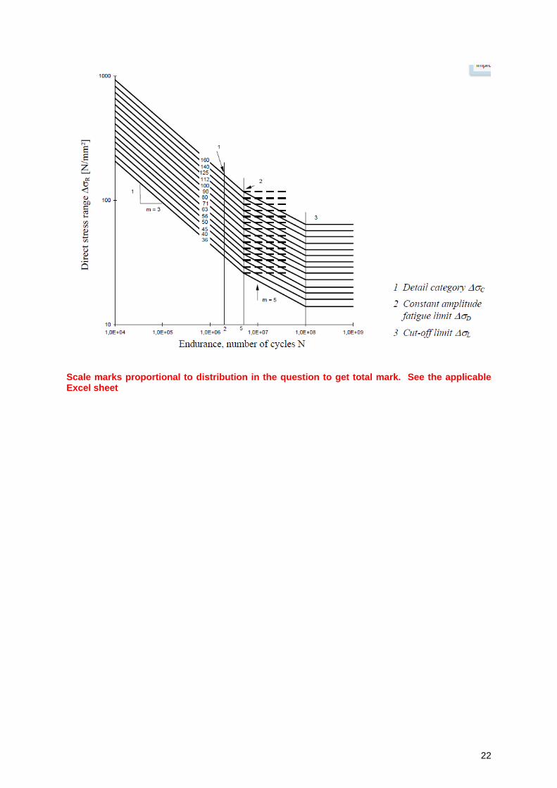
3. Test data for some details do not exactly fit the fatigue strength curves in the figure below. In order to ensure that non-conservative conditions are avoided, such details, marked with an *, are located one detail category lower than their fatigue strength at 2× 10⁶ cycles would require. An alternative assessment may increase the classification of such details be one
detail category provided that the constant amplitude fatigue limit Δ𝜎𝐷 is defined as the fatigue strength at 107 cycles for 𝑚 = 3.
22
Scale marks proportional to distribution in the question to get total mark. See the applicable Excel sheet
23
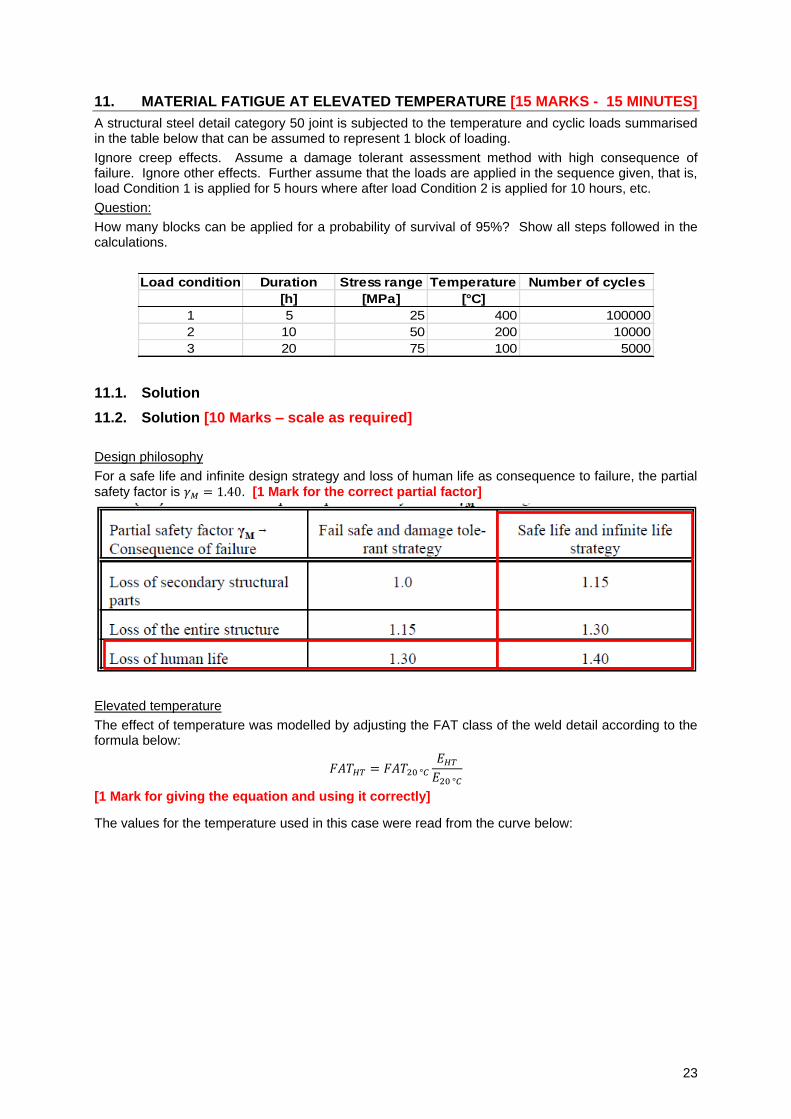
11. MATERIAL FATIGUE AT ELEVATED TEMPERATURE [15 MARKS - 15 MINUTES]
A structural steel detail category 50 joint is subjected to the temperature and cyclic loads summarised in the table below that can be assumed to represent 1 block of loading.
Ignore creep effects. Assume a damage tolerant assessment method with high consequence of failure. Ignore other effects. Further assume that the loads are applied in the sequence given, that is, load Condition 1 is applied for 5 hours where after load Condition 2 is applied for 10 hours, etc.
Question:
How many blocks can be applied for a probability of survival of 95%? Show all steps followed in the calculations.
Load condition Duration Stress range Temperature Number of cycles
[h] [MPa] [°C]
1 5 25 400 100000
2 10 50 200 10000
3 20 75 100 5000
11.1. Solution
11.2. Solution [10 Marks – scale as required]
Design philosophy
For a safe life and infinite design strategy and loss of human life as consequence to failure, the partial
safety factor is 𝛾𝑀 = 1.40. [1 Mark for the correct partial factor]
Elevated temperature
The effect of temperature was modelled by adjusting the FAT class of the weld detail according to the formula below:
𝐹𝐴𝑇𝐻𝑇 = 𝐹𝐴𝑇20 °𝐶𝐸𝐻𝑇𝐸20 °𝐶
[1 Mark for giving the equation and using it correctly]
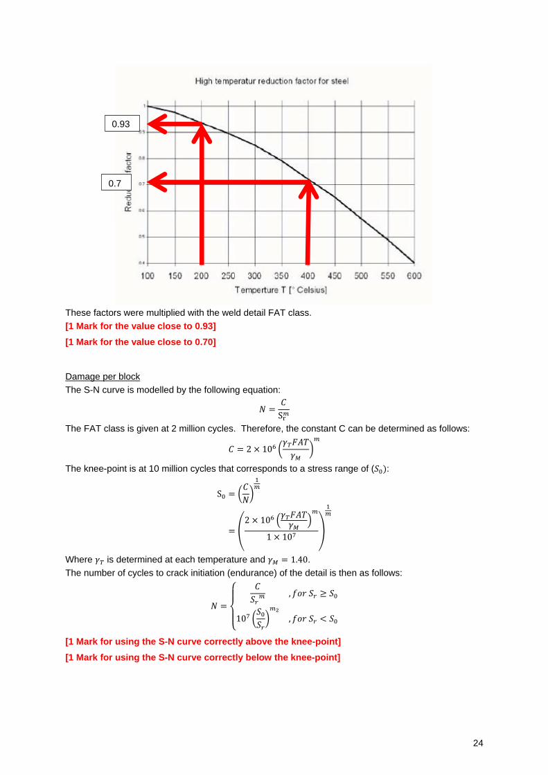
The values for the temperature used in this case were read from the curve below:
24
These factors were multiplied with the weld detail FAT class.
[1 Mark for the value close to 0.93]
[1 Mark for the value close to 0.70]
Damage per block
The S-N curve is modelled by the following equation:
𝑁 =𝐶
Sr𝑚
The FAT class is given at 2 million cycles. Therefore, the constant C can be determined as follows:
𝐶 = 2 × 10⁶ (𝛾𝑇𝐹𝐴𝑇
𝛾𝑀)𝑚
The knee-point is at 10 million cycles that corresponds to a stress range of (𝑆0):
S0 = (𝐶
𝑁)
1𝑚
= (2 × 10⁶ (
𝛾𝑇𝐹𝐴𝑇𝛾𝑀
)𝑚
1 × 10⁷)
1𝑚
Where 𝛾𝑇 is determined at each temperature and 𝛾𝑀 = 1.40.
The number of cycles to crack initiation (endurance) of the detail is then as follows:
𝑁 =
{
𝐶
𝑆𝑟𝑚 , 𝑓𝑜𝑟 𝑆𝑟 ≥ 𝑆0
107 (𝑆0𝑆𝑟)𝑚2
, 𝑓𝑜𝑟 𝑆𝑟 < 𝑆0
[1 Mark for using the S-N curve correctly above the knee-point]
[1 Mark for using the S-N curve correctly below the knee-point]
0.7
0.93
25
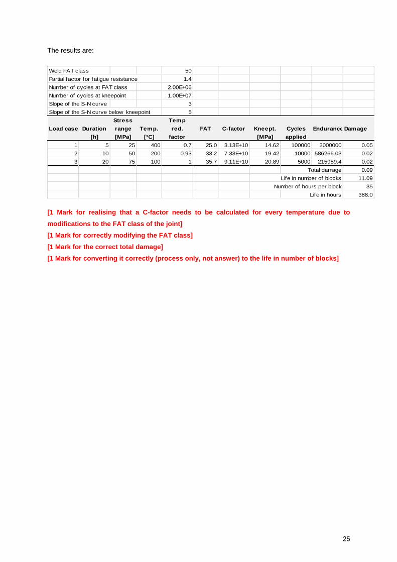
The results are:
Weld FAT class 50
Partial factor for fatigue resistance 1.4
Number of cycles at FAT class 2.00E+06
Number of cycles at kneepoint 1.00E+07
Slope of the S-N curve 3
Slope of the S-N curve below kneepoint 5
Stress Temp
Load case Duration range Temp. red. FAT C-factor Kneept. Cycles Endurance Damage
[h] [MPa] [°C] factor [MPa] applied
1 5 25 400 0.7 25.0 3.13E+10 14.62 100000 2000000 0.05
2 10 50 200 0.93 33.2 7.33E+10 19.42 10000 586266.03 0.02
3 20 75 100 1 35.7 9.11E+10 20.89 5000 215959.4 0.02
Total damage 0.09
Life in number of blocks 11.09
Number of hours per block 35
Life in hours 388.0
[1 Mark for realising that a C-factor needs to be calculated for every temperature due to
modifications to the FAT class of the joint]
[1 Mark for correctly modifying the FAT class]
[1 Mark for the correct total damage]
[1 Mark for converting it correctly (process only, not answer) to the life in number of blocks]