Embed Size (px)
Citation preview

Huawei Confidential. All Rights Reserved
WCDMA Handover Principle and Analysis
ISSUE 1.0
2Internal Use
Why mobile systems need handover?
It is decided by the characters of mobile system:
The mobility of UE The mobile system is composed by c
ells which the coverage ability is limited.
Providing the continuous service in mobile system is the basic element in QoS.
3Internal Use
ObjectObject
Upon completion this course, you will be able to:
The basic definitions of Handover The algorithms of handover
decision The handover flow The parameters of handover
4Internal Use
Chapter 1 Chapter 1 Introduction of HandoverIntroduction of Handover
Chapter 2 Measurement of Handover
Chapter 3 The Basic Handovers
Chapter 4 Blind Handover and
Direct Retry Algorithm
5Internal Use
The Purpose of HandoverThe Purpose of Handover
Providing the continuous service in mobile system is the basic element in QoS.
The load balance: sharing the resource
The hierarchy divided by speed and service: high efficiency of using resource
6Internal Use
The Basic Concepts of HandoverThe Basic Concepts of Handover
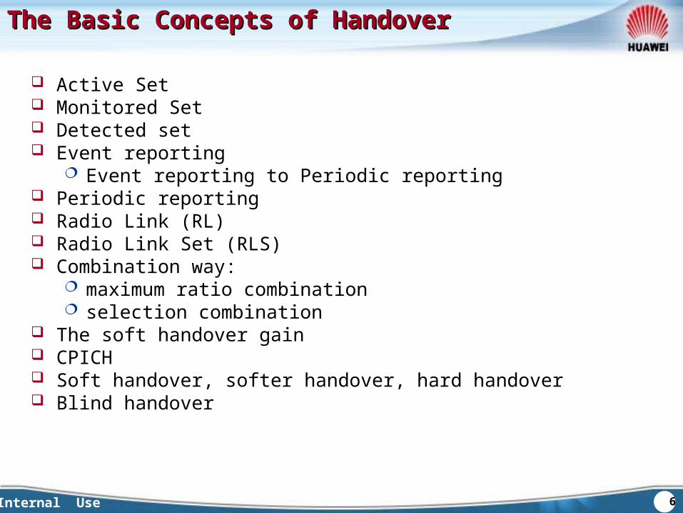
Active Set Monitored Set Detected set Event reporting
Event reporting to Periodic reporting Periodic reporting Radio Link (RL) Radio Link Set (RLS) Combination way:
maximum ratio combination selection combination
The soft handover gain CPICH Soft handover, softer handover, hard handover Blind handover
7Internal Use
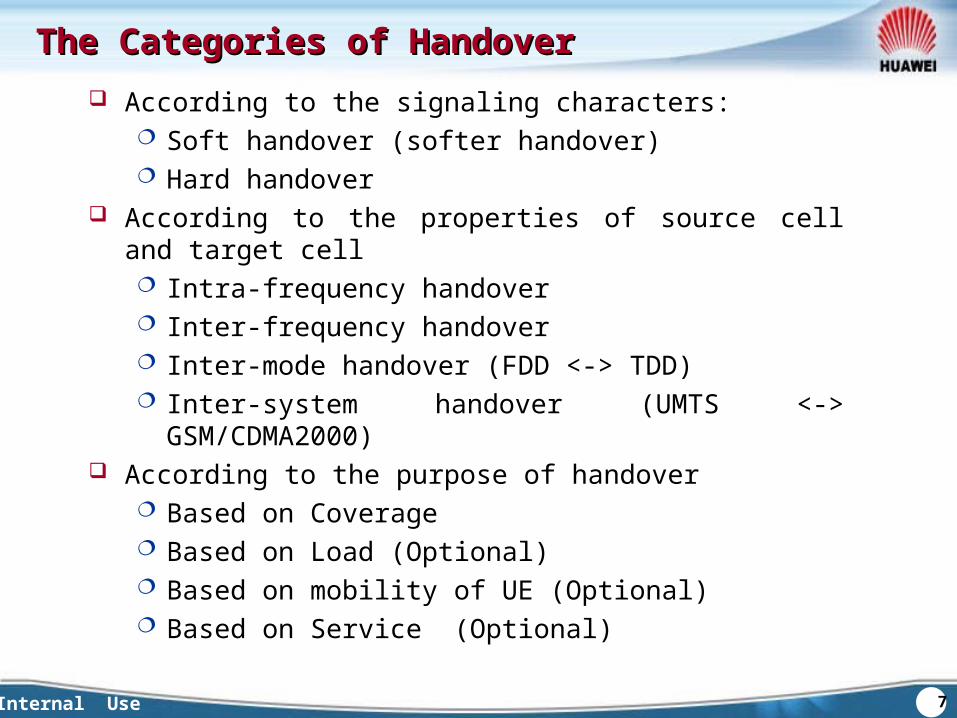
The Categories of HandoverThe Categories of Handover According to the signaling characters:
Soft handover (softer handover) Hard handover
According to the properties of source cell and target cell Intra-frequency handover Inter-frequency handover Inter-mode handover (FDD <-> TDD) Inter-system handover (UMTS <-> GSM/CDMA2000)
According to the purpose of handover Based on Coverage Based on Load (Optional) Based on mobility of UE (Optional) Based on Service (Optional)
8Internal Use
The Characters of Different HandoversThe Characters of Different Handovers
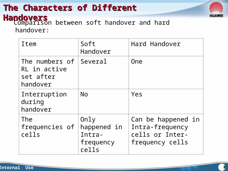
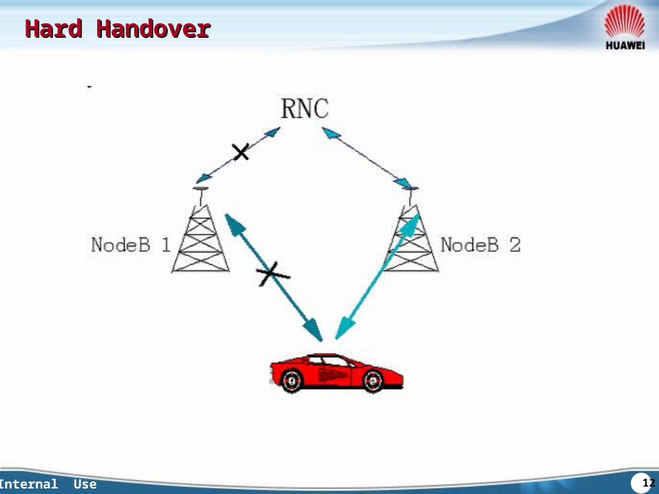
Item Soft Handover Hard HandoverThe numbers of RL in active set after handover
Several One
Interruption during handover
No Yes
The frequencies of cells
Only happened in Intra-frequency cells
Can be happened in Intra-frequency cells or Inter-frequency cells
Comparison between soft handover and hard handover:
9Internal Use
The Characters of Different HandoversThe Characters of Different Handovers
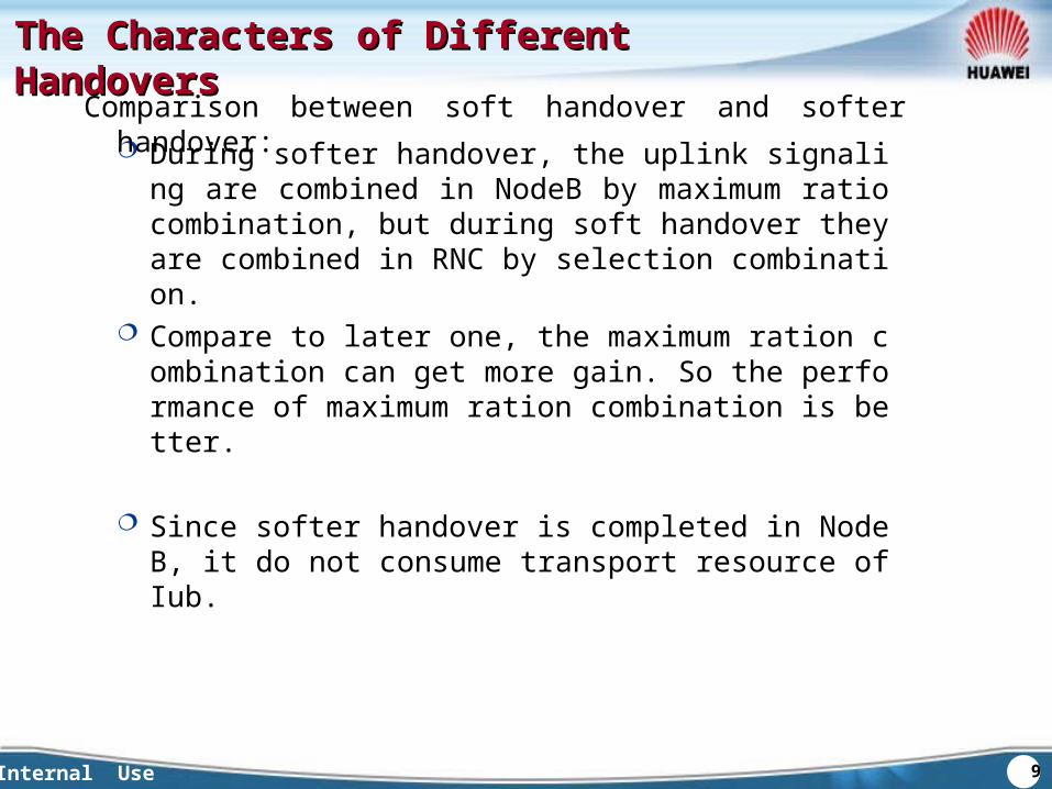
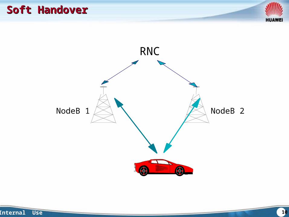
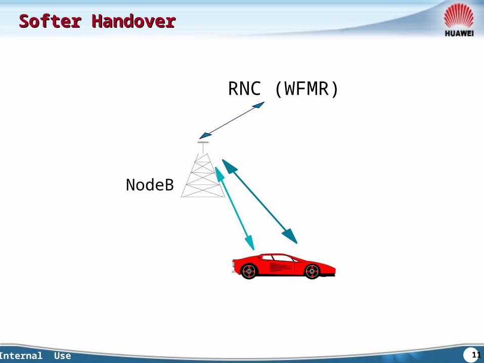
During softer handover, the uplink signaling are combined in NodeB by maximum ratio combination, but during soft handover they are combined in RNC by selection combination.
Compare to later one, the maximum ration combination can get more gain. So the performance of maximum ration combination is better.
Since softer handover is completed in NodeB, it do not consume transport resource of Iub.
Comparison between soft handover and softer handover:
10Internal Use
RNC
NodeB 2NodeB 1
Soft HandoverSoft Handover
11Internal Use
RNC (WFMR)
NodeB
Softer HandoverSofter Handover
12Internal Use
Hard HandoverHard Handover
13Internal Use
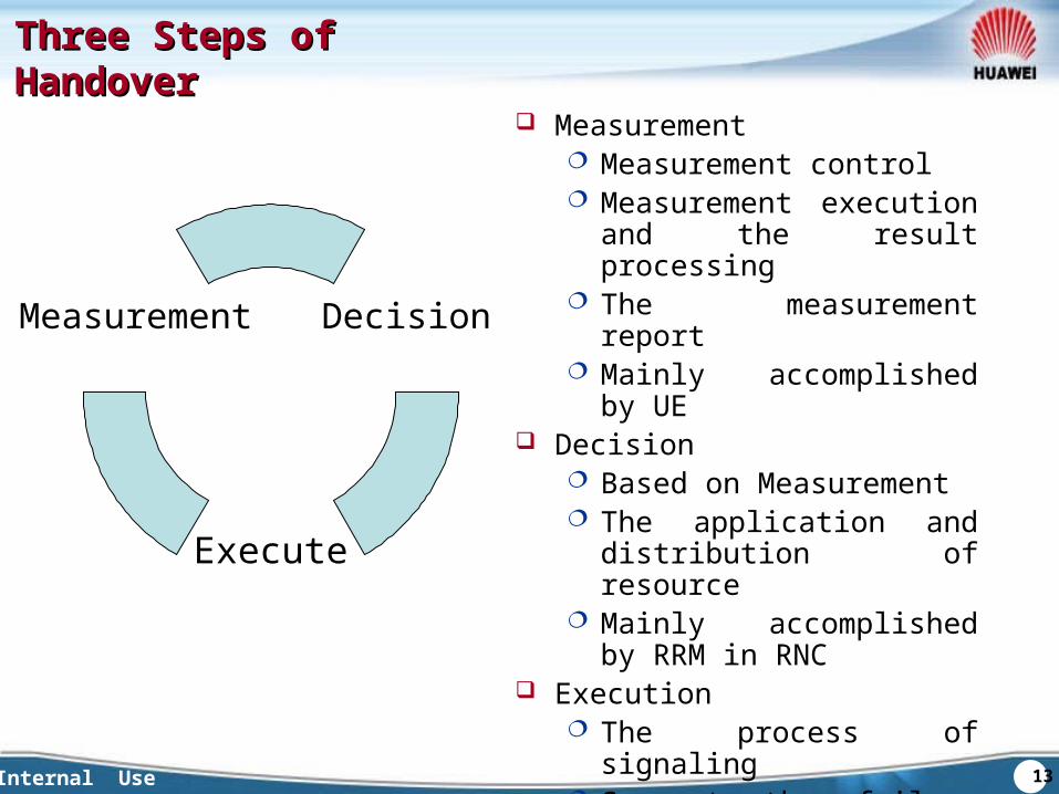
Three Steps of HandoverThree Steps of Handover
Decision
Execute
Measurement
Measurement Measurement control Measurement execution and
the result processing The measurement report Mainly accomplished by UE
Decision Based on Measurement The application and
distribution of resource Mainly accomplished by
RRM in RNC Execution
The process of signaling Support the failure drawback Measurement control refresh
14Internal Use
QuestionsQuestions
The differences among Soft handover, softer handover and hard handover
Typical application scenarios
15Internal Use
SummarySummary
This chapter focus on the purpose of handovers and the categories of handover in WCDMA.

16Internal Use
Chapter 1 Introduction of Handover
Chapter 2Chapter 2 Measurement of HandoverMeasurement of Handover
Chapter 3 The Basic Handovers
Chapter 4 Blind Handover and
Direct Retry Algorithm
17Internal Use
Chapter 2 Chapter 2 Measurement of HandoverMeasurement of Handover
Section 1 Measurement control and
measurement report
Section 2 The basic definitions of measurement
Section 3 Intra-frequency measurement event
Section 4 Inter-frequency and
inter-system measurement event
Section 5 UE internal measurement
18Internal Use
Measurement Control and Measurement Measurement Control and Measurement ReportReport
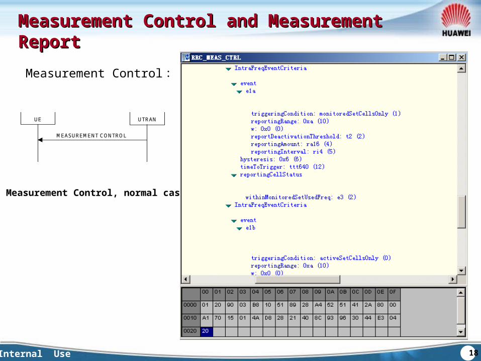
Measurement Control :
UE UTRAN
MEASUREMENT CONTROL
Measurement Control, normal case
19Internal Use
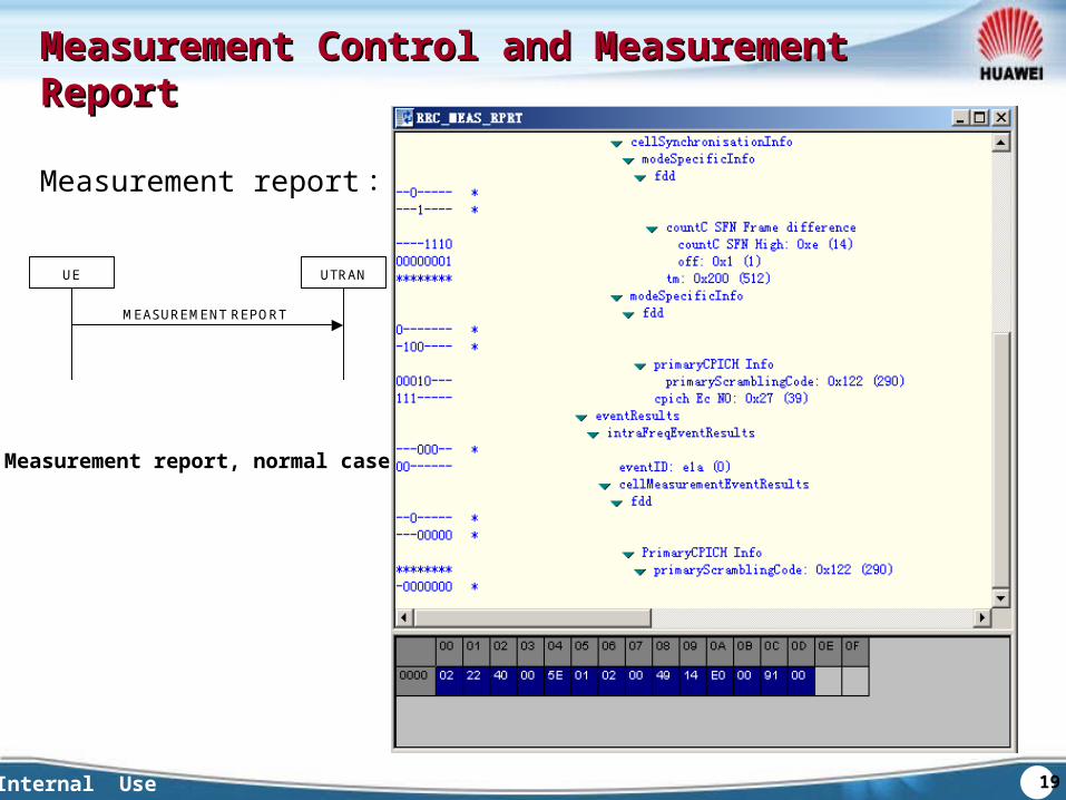
Measurement Control and Measurement Measurement Control and Measurement ReportReport
Measurement report :UE UTRAN
MEASUREMENT REPORT
Measurement report, normal case
20Internal Use
Chapter 2 Chapter 2 Measurement of HandoverMeasurement of Handover
Section 1 Measurement control and
measurement report
Section 2 The basic concepts of measurement
Section 3 Intra-frequency measurement event
Section 4 Inter-frequency and
inter-system measurement event
Section 5 UE Internal Measurement
21Internal Use
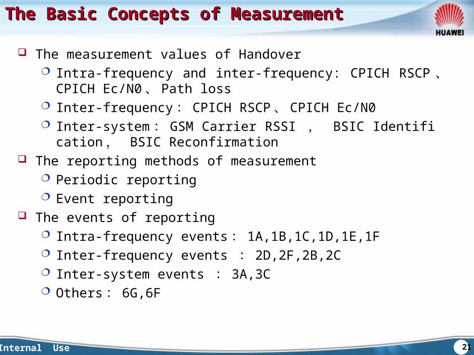
The Basic Concepts of MeasurementThe Basic Concepts of Measurement
The measurement values of Handover Intra-frequency and inter-frequency: CPICH RSCP 、 CPICH Ec/
N0 、 Path loss Inter-frequency : CPICH RSCP 、 CPICH Ec/N0 Inter-system : GSM Carrier RSSI , BSIC Identification , BSI
C Reconfirmation The reporting methods of measurement
Periodic reporting Event reporting
The events of reporting Intra-frequency events : 1A,1B,1C,1D,1E,1F Inter-frequency events : 2D,2F,2B,2C Inter-system events : 3A,3C Others : 6G,6F
22Internal Use
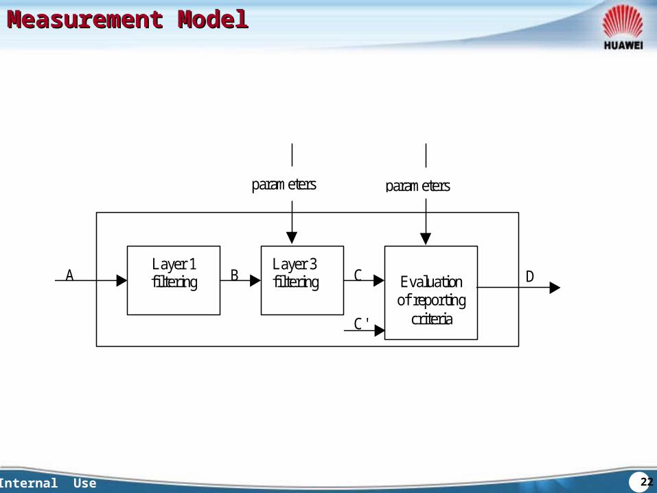
Measurement ModelMeasurement Model
Layer 1filtering
Layer 3filtering Evaluation
of reportingcriteria
A DB C
C'
parameters parameters
23Internal Use
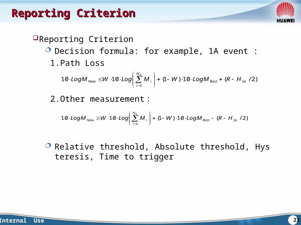
Reporting CriterionReporting Criterion
Reporting Criterion Decision formula: for example, 1A event : 1.Path Loss
2.Other measurement :
Relative threshold, Absolute threshold, Hysteresis, Time to trigger
),2/(10)1(1010 11
aBest
N
iiNew HRLogMWMLogWLogM
A
),2/(10)1(1010 11
aBest
N
iiNew HRLogMWMLogWLogM
A
24Internal Use
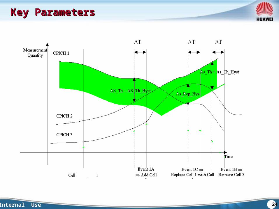
Key ParametersKey Parameters
25Internal Use
Chapter 2 Chapter 2 Measurement of HandoverMeasurement of Handover
Section 1 Measurement control and
measurement report
Section 2 The basic definitions of measurement
Section 3 Intra-frequency measurement events
Section 4 Inter-frequency and
inter-system measurement events
Section 5 UE Internal Measurement
26Internal Use
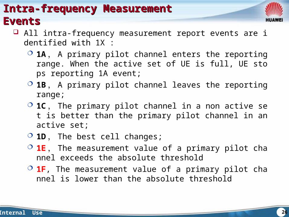
Intra-frequency Measurement EventsIntra-frequency Measurement Events
All intra-frequency measurement report events are identified with 1X : 1A , A primary pilot channel enters the reporting range. When th
e active set of UE is full, UE stops reporting 1A event; 1B , A primary pilot channel leaves the reporting range; 1C , The primary pilot channel in a non active set is better than t
he primary pilot channel in an active set; 1D , The best cell changes; 1E , The measurement value of a primary pilot channel exceeds
the absolute threshold 1F, The measurement value of a primary pilot channel is lower th
an the absolute threshold
27Internal Use
Chapter 2 Chapter 2 Measurement of HandoverMeasurement of Handover
Section 1 Measurement control and
measurement report
Section 2 The basic definitions of measurement
Section 3 Intra-frequency measurement events
Section 4 Inter-frequency and
inter-system measurement events
Section 5 UE Internal Measurement
28Internal Use
Inter-frequency Measurement EventsInter-frequency Measurement Events
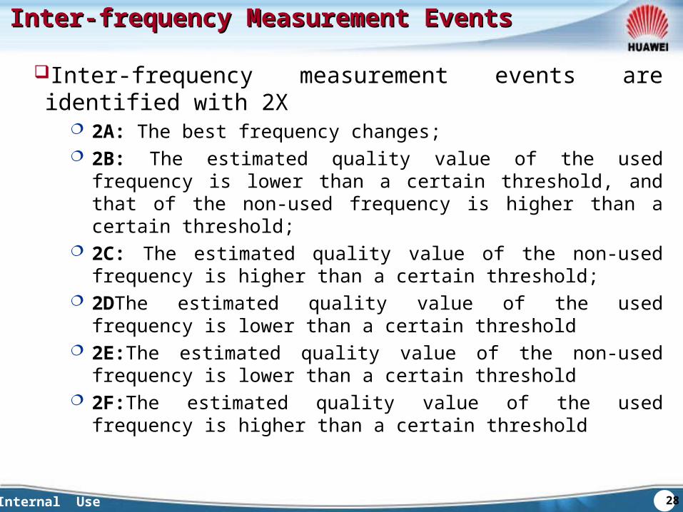
Inter-frequency measurement events are identified with 2X 2A: The best frequency changes; 2B: The estimated quality value of the used frequency is lower than
a certain threshold, and that of the non-used frequency is higher than a certain threshold;
2C: The estimated quality value of the non-used frequency is higher than a certain threshold;
2DThe estimated quality value of the used frequency is lower than a certain threshold
2E:The estimated quality value of the non-used frequency is lower than a certain threshold
2F:The estimated quality value of the used frequency is higher than a certain threshold
29Internal Use
Inter-system Measurement EventsInter-system Measurement Events
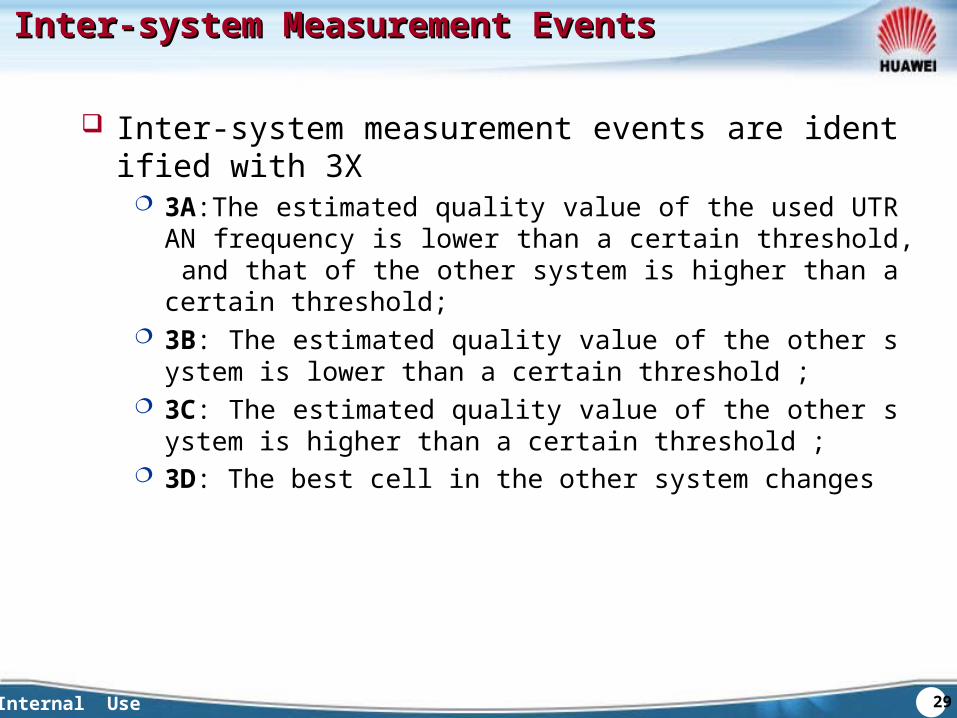
Inter-system measurement events are identified with 3X 3A:The estimated quality value of the used UTRAN frequency
is lower than a certain threshold, and that of the other system is higher than a certain threshold;
3B: The estimated quality value of the other system is lower than a certain threshold ;
3C: The estimated quality value of the other system is higher than a certain threshold ;
3D: The best cell in the other system changes
30Internal Use
Chapter 2 Chapter 2 Measurement of HandoverMeasurement of Handover
Section 1 Measurement control and
measurement report
Section 2 The basic definitions of measurement
Section 3 Intra-frequency measurement events
Section 4 Inter-frequency and
inter-system measurement events
Section 5 UE Internal Measurement
31Internal Use
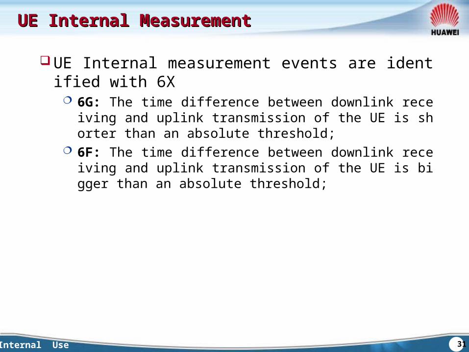
UE Internal MeasurementUE Internal Measurement
UE Internal measurement events are identified with 6X 6G: The time difference between downlink receiving and upli
nk transmission of the UE is shorter than an absolute threshold;
6F: The time difference between downlink receiving and uplink transmission of the UE is bigger than an absolute threshold;
32Internal Use
QuestionsQuestions
How many events are there in intra-frequency measurement? What are they?
How many events are there in UE internal measurement? How many events are there in inter-frequency measurement?
What are they?
33Internal Use
SummarySummary
This chapter covers intra-frequency measurement, inter-frequency measurement, inter-system measurement and UE internal measurement from their definitions and application scenarios.
SummarySummary
34Internal Use
Chapter 1 Introduction of Handover
Chapter 2 Measurement of Handover
Chapter 3Chapter 3 The Basic HandoversThe Basic Handovers
Chapter 4 Blind Handover and
Direct Retry Algorithm
35Internal Use
Chapter 3 The Basic HandoversChapter 3 The Basic HandoversSection 1 Soft HandoverSection 2 Intra-frequency Hard HandoverSection 3 Inter-frequency Hard HandoverSection 4 Inter-system Hard HandoverSection 5 HSDPA HandoverSection 6 Compressed Mode
36Internal Use
Brief Introduction of Soft HandoverBrief Introduction of Soft Handover
Characters of Soft Handover During handover, UE has several RLs with different cells----activ
e set. The handover among different cells which are in same RLS can
be softer handover. Soft handover:
– Selection combination in uplink– Maximum combination in downlink
Softer handover– Maximum combination in uplink and downlink

37Internal Use
Brief Introduction of Soft HandoverBrief Introduction of Soft Handover Advantages
Soft handover gain: Multi-Cell gain: Multiple irrelated soft handover branches low the required
margin for fading Macro Diversity Combining gain: Gain for the link demodulation of the
soft handover: Load balance: Different cells receive the signals from UE in uplink, which
can decrease the transmission power of UE. And UE receive signal from different cells, which also can decrease the transmission power of base station.
Decrease the possibility of call drop caused by ping-pong handover. Disadvantages
More resource needed in downlink, especially for the code resource of BE service.
Usually, the gain of downlink power is negative. When the downlink power from different cells is not balanced, it will bring
side-effect.
38Internal Use
Measurement of Soft Handover Measurement of Soft Handover The measurement of soft handover/softer handover
Measurement value : CPICH RSCP 、 CPICH Ec/No 、 Pathloss
Process of Measurement : Layer 1 filter, Layer 2 filter Reporting way
Periodic reporting Event reporting
– Event type : 1A 、 1B 、 1C 、 1D 、 1F– UE measures the time difference between CFN and SFN– Reporting rules: trigger condition, Relative threshold, Abs
olute threshold, Hysteresis, Time to trigger– Event reporting to periodic reporting
39Internal Use
The Events of Soft Handover MeasurementThe Events of Soft Handover Measurement Soft/softer handover measurement events
Intra-frequency events reporting: 1A , A primary pilot channel enters the reporting range. Whe
n the active set of UE is full, UE stops reporting 1A event; 1B , A primary pilot channel leaves the reporting range; 1C , The primary pilot channel in a non active set is better th
an the primary pilot channel in an active set; 1D , The best cell changes; 1E , The measurement value of a primary pilot channel exce
eds the absolute threshold 1F, The measurement value of a primary pilot channel is lowe
r than the absolute threshold
40Internal Use
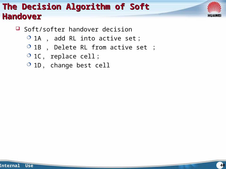
The Decision Algorithm of Soft HandoverThe Decision Algorithm of Soft Handover
Soft/softer handover decision 1A , add RL into active set ; 1B , Delete RL from active set ; 1C , replace cell ; 1D , change best cell
41Internal Use
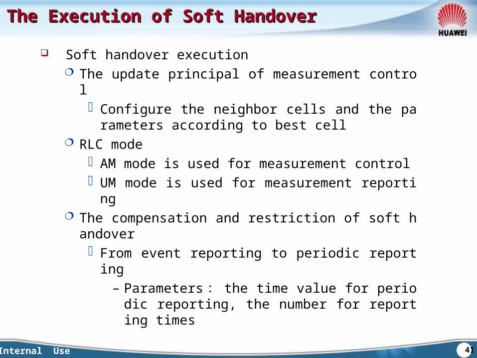
The Execution of Soft HandoverThe Execution of Soft Handover
Soft handover execution The update principal of measurement control
Configure the neighbor cells and the parameters according to best cell
RLC mode AM mode is used for measurement control UM mode is used for measurement reporting
The compensation and restriction of soft handover From event reporting to periodic reporting
– Parameters : the time value for periodic reporting, the number for reporting times
42Internal Use
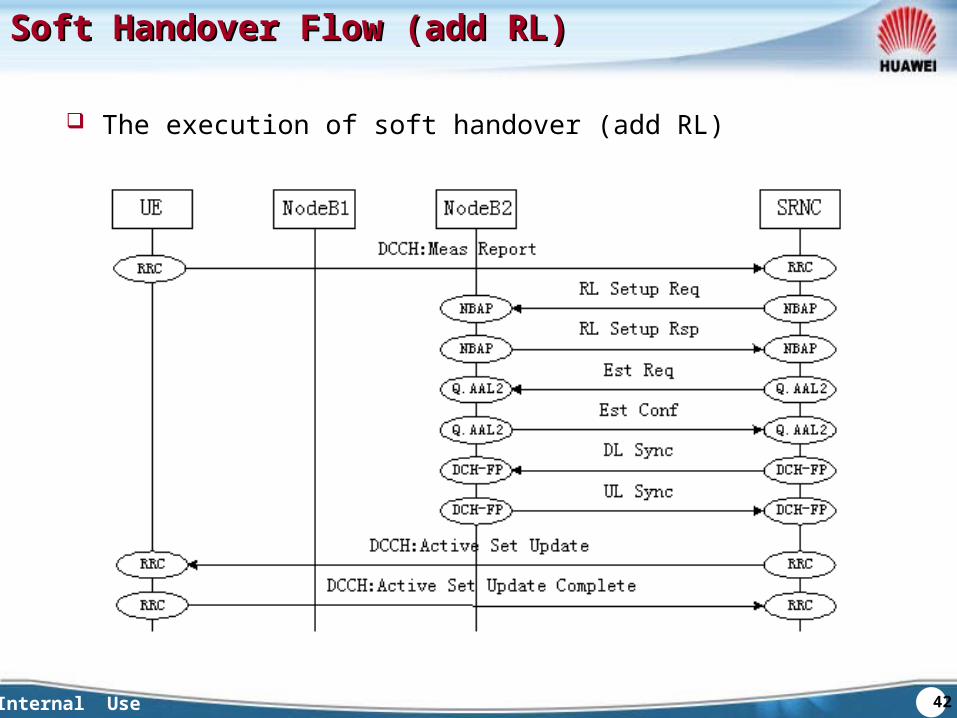
Soft Handover Flow (add RL)Soft Handover Flow (add RL)
The execution of soft handover (add RL)
43Internal Use
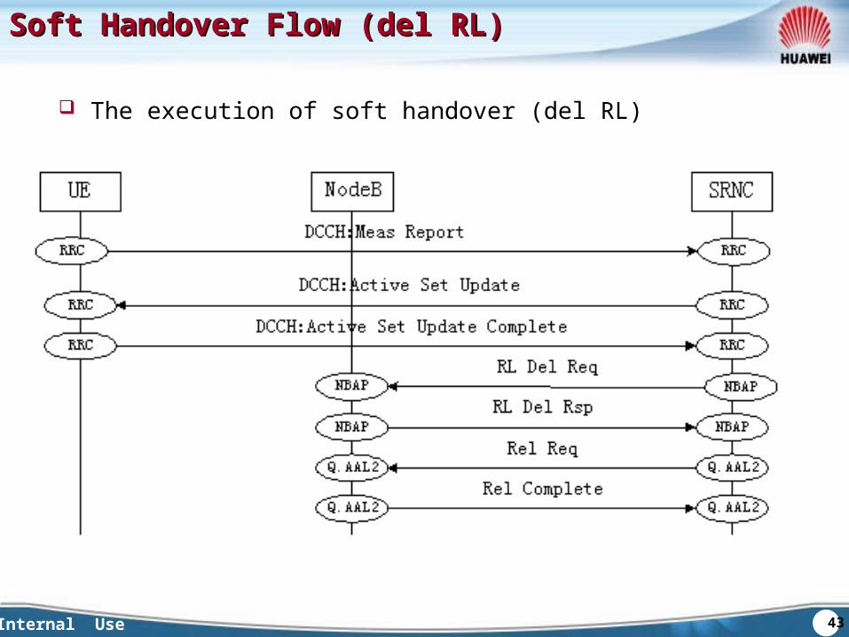
Soft Handover Flow (del RL)Soft Handover Flow (del RL)
The execution of soft handover (del RL)
44Internal Use
Key ParametersKey Parameters
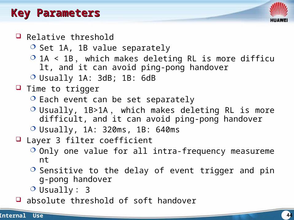
Relative threshold Set 1A, 1B value separately 1A < 1B , which makes deleting RL is more difficult, and it can a
void ping-pong handover Usually 1A: 3dB; 1B: 6dB
Time to trigger Each event can be set separately Usually, 1B>1A , which makes deleting RL is more difficult, and
it can avoid ping-pong handover Usually, 1A: 320ms, 1B: 640ms
Layer 3 filter coefficient Only one value for all intra-frequency measurement Sensitive to the delay of event trigger and ping-pong handover Usually : 3
absolute threshold of soft handover
45Internal Use
Chapter 3 The Basic HandoversChapter 3 The Basic HandoversSection 1 Soft HandoverSection 2 Intra-frequency Hard HandoverSection 3 Inter-frequency Hard HandoverSection 4 Inter-system Hard HandoverSection 5 HSDPA HandoverSection 6 Compressed Mode
46Internal Use
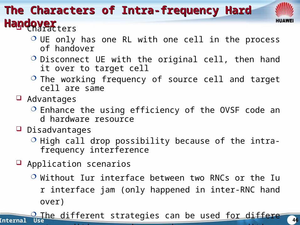
The Characters of Intra-frequency Hard HandoverThe Characters of Intra-frequency Hard Handover Characters
UE only has one RL with one cell in the process of handover Disconnect UE with the original cell, then hand it over to target ce
ll The working frequency of source cell and target cell are same
Advantages Enhance the using efficiency of the OVSF code and hardware re
source Disadvantages
High call drop possibility because of the intra-frequency interference
Application scenarios Without Iur interface between two RNCs or the Iur interface jam
(only happened in inter-RNC handover) The different strategies can be used for different conditions, such
as code resource condition, the QoS condition and so no.
47Internal Use
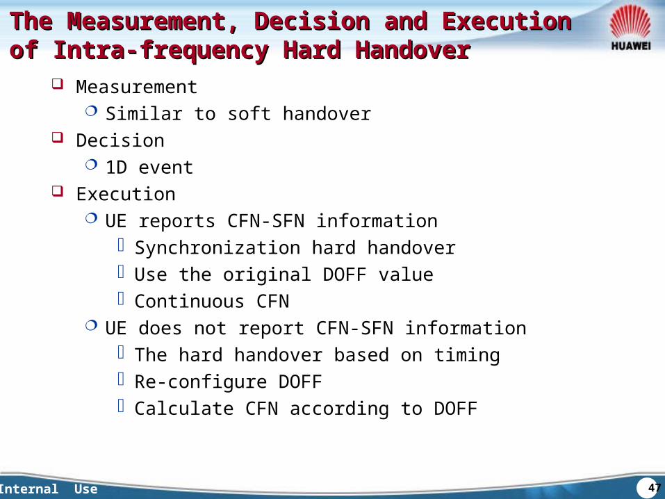
The Measurement, Decision and Execution of The Measurement, Decision and Execution of Intra-frequency Hard HandoverIntra-frequency Hard Handover
Measurement Similar to soft handover
Decision 1D event
Execution UE reports CFN-SFN information
Synchronization hard handover Use the original DOFF value Continuous CFN
UE does not report CFN-SFN information The hard handover based on timing Re-configure DOFF Calculate CFN according to DOFF
48Internal Use
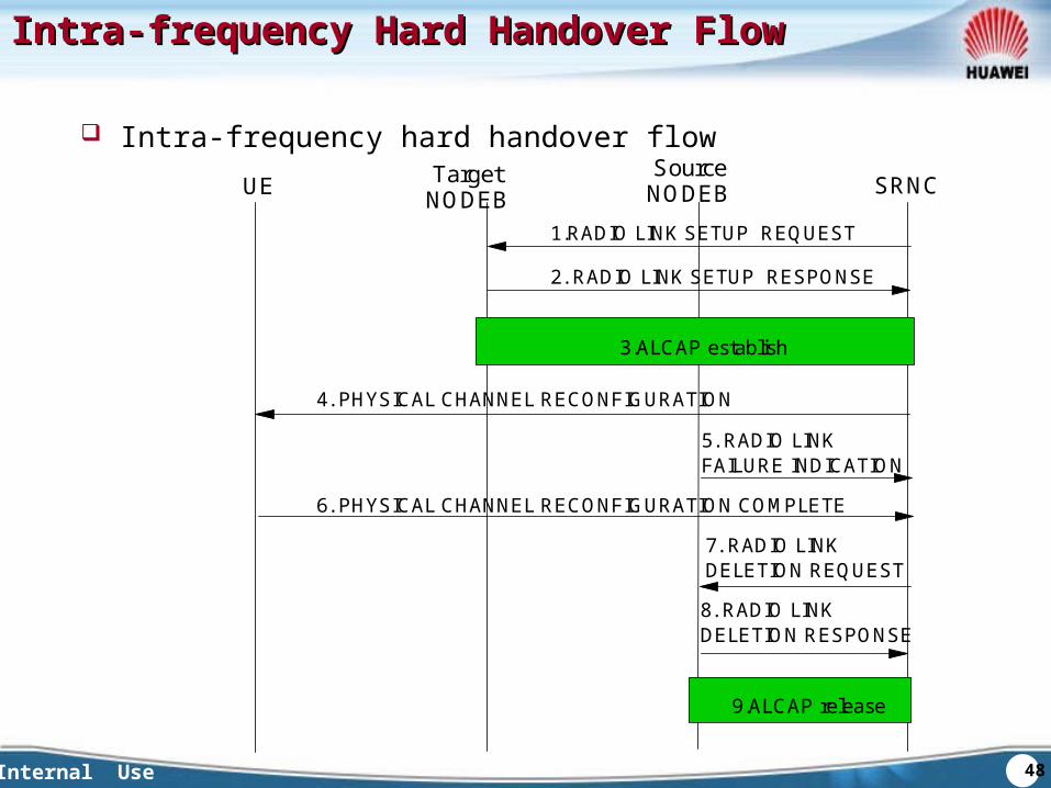
Intra-frequency Hard Handover FlowIntra-frequency Hard Handover Flow
Intra-frequency hard handover flowUE
1.RADIO LINK SETUP REQUEST
Target NODEB
Source NODEB SRNC
2. RADIO LINK SETUP RESPONSE
3.ALCAP establish
4. PHYSICAL CHANNEL RECONFIGURATION
5. RADIO LINK FAILURE INDICATION
6. PHYSICAL CHANNEL RECONFIGURATION COMPLETE
7. RADIO LINK DELETION REQUEST
8. RADIO LINK DELETION RESPONSE
9.ALCAP release
49Internal Use
Key ParametersKey Parameters
Handover decision threshold based on BE speed UE should do soft handover when the speed of BE service is less
than the threshold. UE should do intra-frequency hard handover when the speed of
BE service is greater than the threshold. The parameters about 1D event:
time to trigger , hysteresis The parameters should be set accord with the Qos

50Internal Use
Chapter 3 The Basic HandoversChapter 3 The Basic HandoversSection 1 Soft HandoverSection 2 Intra-frequency Hard HandoverSection 3 Inter-frequency Hard HandoverSection 4 Inter-system Hard HandoverSection 5 HSDPA HandoverSection 6 Compressed Mode
51Internal Use
The Brief Introduction of Inter-frequency The Brief Introduction of Inter-frequency Hard HandoverHard Handover
Characters The working frequency is different after handover The compressed mode needed if the UE only has one receiver Usually, the timing re-initiation hard handover is used for hard
handover Advantages
Compare to intra-frequency hard handover, the success possibility is higher
The load balance among cells with different frequencies Can realize the reasonable configuration for hierarchy cells
Disadvantages Compressed mode results in extra radio resource occupied The timing re-initiation hard handover increase the time of
handover and the risk of call drop Application scenarios
Disconnected coverage Handover based on load Hierarchy cells
52Internal Use
The Inter-frequency Hard Handover Measurement The Inter-frequency Hard Handover Measurement Values and EventsValues and Events
The Inter-frequency hard handover measurement values Measurement values:
CPICH RSCP 、 CPICH Ec/N0 Different handover purpose for different measurement type:
In the edge of carrier coverage: CPICH RSCP In the center of carrier coverage: CPICH Ec/No
53Internal Use
The Measurement Values and Events of Inter-The Measurement Values and Events of Inter-frequency Hard Handover frequency Hard Handover
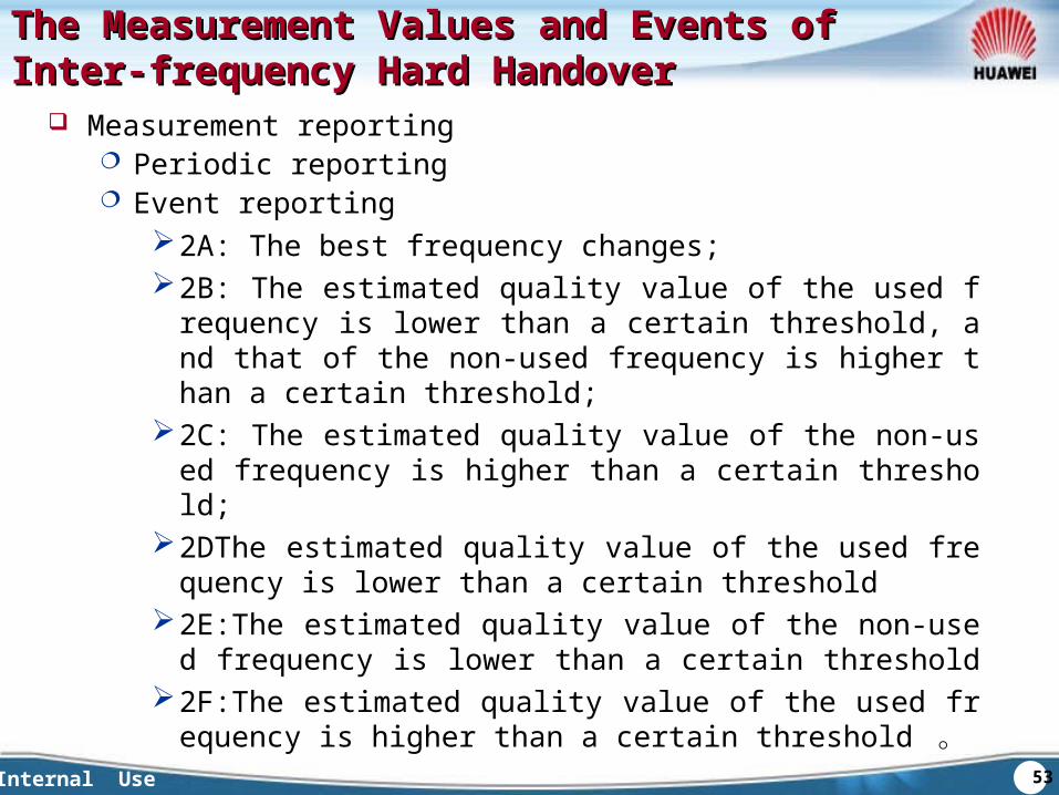
Measurement reporting Periodic reporting Event reporting
2A: The best frequency changes;2B: The estimated quality value of the used frequency is lowe
r than a certain threshold, and that of the non-used frequency is higher than a certain threshold;
2C: The estimated quality value of the non-used frequency is higher than a certain threshold;
2DThe estimated quality value of the used frequency is lower than a certain threshold
2E:The estimated quality value of the non-used frequency is lower than a certain threshold
2F:The estimated quality value of the used frequency is higher than a certain threshold 。
54Internal Use
Compressed Mode ICompressed Mode Initiatnitiation in Inter-frequency ion in Inter-frequency Hard HandoverHard Handover
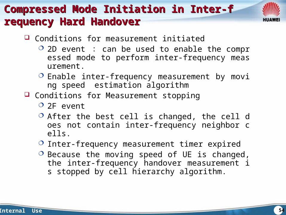
Conditions for measurement initiated 2D event : can be used to enable the compressed mod
e to perform inter-frequency measurement. Enable inter-frequency measurement by moving speed e
stimation algorithm Conditions for Measurement stopping
2F event After the best cell is changed, the cell does not contain int
er-frequency neighbor cells. Inter-frequency measurement timer expired Because the moving speed of UE is changed, the inter-fre
quency handover measurement is stopped by cell hierarchy algorithm.

55Internal Use
Cells Hierarchy Algorithm Based on UE Cells Hierarchy Algorithm Based on UE Moving SpeedMoving Speed
When UE is in one of the hierarchy cells, the moving speed estimation algorithm is initiated Handover events in a while decides whether the speed of UE sati
sfies the current cell hierarchy condition UE is remained in the current cell if the speed is medium. If the speed is very high, it will be handed over to higher hiera
rchy cell. And if not, hand it over to lower hierarchy cell. UE’s moving speed decided the result.
If the hierarchy is configured by different frequencies, the inter-frequency blind handover or inter-frequency measurement handover can be initiated.
If the hierarchy is configured by one frequency, the intra-frequency handover can be initiated.
56Internal Use
Inter-frequency Hard Handover Decision Inter-frequency Hard Handover Decision AlgorithmAlgorithm
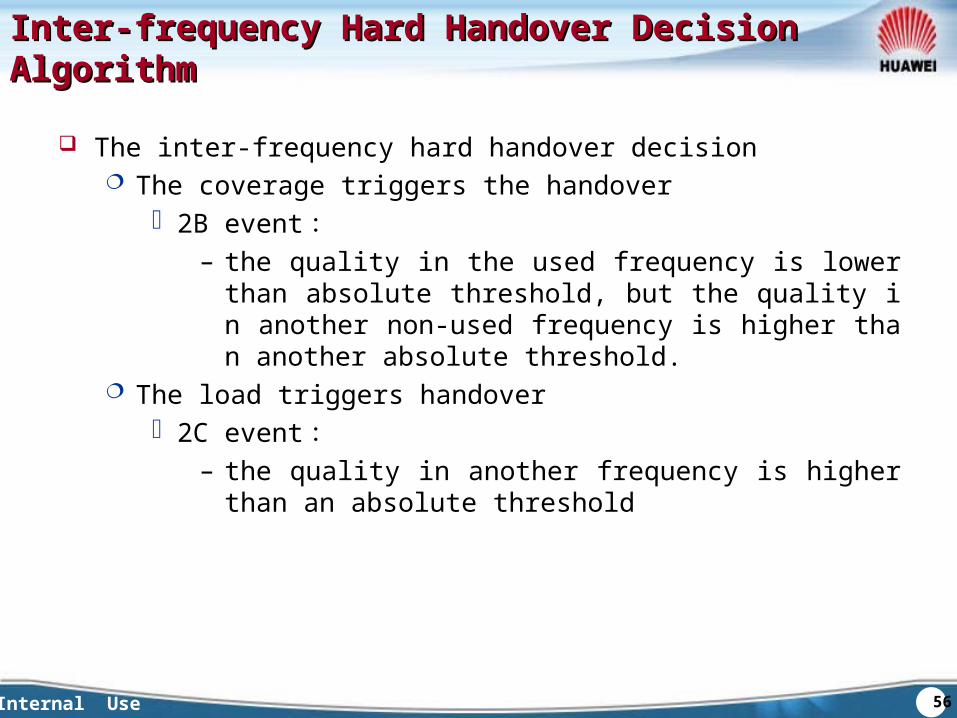
The inter-frequency hard handover decision The coverage triggers the handover
2B event :– the quality in the used frequency is lower than absolute th
reshold, but the quality in another non-used frequency is higher than another absolute threshold.
The load triggers handover 2C event :
– the quality in another frequency is higher than an absolute threshold
57Internal Use
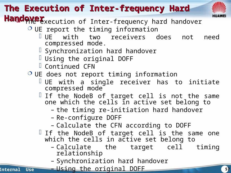
The Execution of Inter-frequency Hard HandoverThe Execution of Inter-frequency Hard Handover The execution of Inter-frequency hard handover
UE report the timing information UE with two receivers does not need compressed mode. Synchronization hard handover Using the original DOFF Continued CFN
UE does not report timing information UE with a single receiver has to initiate compressed mode If the NodeB of target cell is not the same one which the cells
in active set belong to– the timing re-initiation hard handover– Re-configure DOFF– Calculate the CFN according to DOFF
If the NodeB of target cell is the same one which the cells in active set belong to
– Calculate the target cell timing relationship– Synchronization hard handover– Using the original DOFF– Continued CFN
58Internal Use
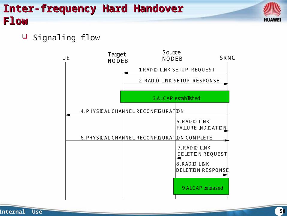
Inter-frequency Hard Handover FlowInter-frequency Hard Handover Flow
Signaling flow
UE
1.RADIO LINK SETUP REQUEST
Target NODEB
Source NODEB SRNC
2. RADIO LINK SETUP RESPONSE
3.ALCAP established
4. PHYSICAL CHANNEL RECONFIGURATION
5. RADIO LINK FAILURE INDICATION
6. PHYSICAL CHANNEL RECONFIGURATION COMPLETE
7. RADIO LINK DELETION REQUEST
8. RADIO LINK DELETION RESPONSE
9.ALCAP released
59Internal Use
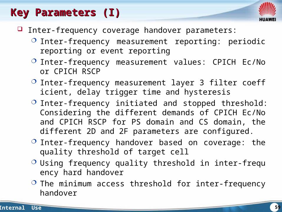
Key Parameters (I)Key Parameters (I) Inter-frequency coverage handover parameters:
Inter-frequency measurement reporting: periodic reporting or event reporting
Inter-frequency measurement values: CPICH Ec/No or CPICH RSCP
Inter-frequency measurement layer 3 filter coefficient, delay trigger time and hysteresis
Inter-frequency initiated and stopped threshold: Considering the different demands of CPICH Ec/No and CPICH RSCP for PS domain and CS domain, the different 2D and 2F parameters are configured.
Inter-frequency handover based on coverage: the quality threshold of target cell
Using frequency quality threshold in inter-frequency hard handover
The minimum access threshold for inter-frequency handover
60Internal Use
Key Parameters (II)Key Parameters (II)
Inter-frequency handover parameters caused by non-coverage ability Inter-frequency measurement layer 3 filter coefficient, delay trigger
time and hysteresis Inter-frequency handover based on non-coverage ability
61Internal Use
Chapter 3 The Basic HandoversChapter 3 The Basic HandoversSection 1 Soft HandoverSection 2 Intra-frequency Hard HandoverSection 3 Inter-frequency Hard HandoverSection 4 Inter-system Hard HandoverSection 5 HSDPA HandoverSection 6 Compressed Mode
62Internal Use
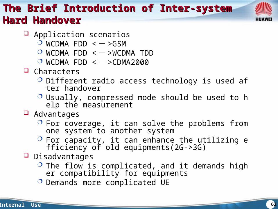
The Brief Introduction of Inter-system Hard The Brief Introduction of Inter-system Hard HandoverHandover
Application scenarios WCDMA FDD < - >GSM WCDMA FDD < - >WCDMA TDD WCDMA FDD < - >CDMA2000
Characters Different radio access technology is used after handover Usually, compressed mode should be used to help the mea
surement Advantages
For coverage, it can solve the problems from one system to another system
For capacity, it can enhance the utilizing efficiency of old equipments(2G->3G)
Disadvantages The flow is complicated, and it demands higher compatibilit
y for equipments Demands more complicated UE
63Internal Use
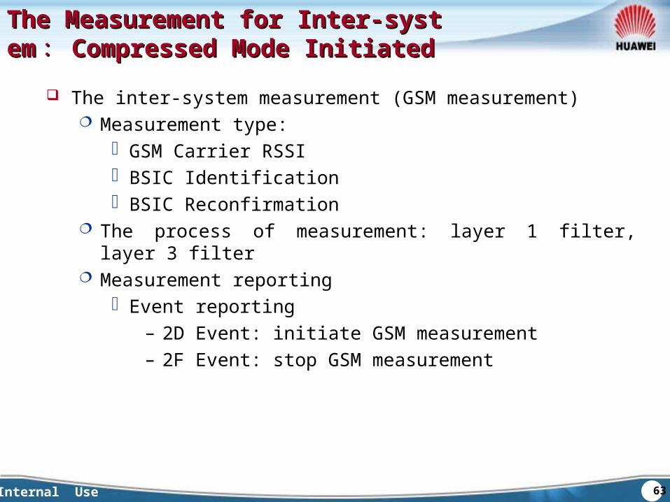
The Measurement for Inter-systemThe Measurement for Inter-system ::Compressed Mode InitiatedCompressed Mode Initiated
The inter-system measurement (GSM measurement) Measurement type:
GSM Carrier RSSI BSIC Identification BSIC Reconfirmation
The process of measurement: layer 1 filter, layer 3 filter Measurement reporting
Event reporting– 2D Event: initiate GSM measurement– 2F Event: stop GSM measurement
64Internal Use
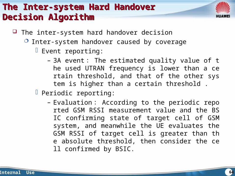
The Inter-system Hard Handover The Inter-system Hard Handover Decision AlgorithmDecision Algorithm
The inter-system hard handover decision Inter-system handover caused by coverage
Event reporting:– 3A event : The estimated quality value of the used UTR
AN frequency is lower than a certain threshold, and that of the other system is higher than a certain threshold .
Periodic reporting:– Evaluation : According to the periodic reported GSM R
SSI measurement value and the BSIC confirming state of target cell of GSM system, and meanwhile the UE evaluates the GSM RSSI of target cell is greater than the absolute threshold, then consider the cell confirmed by BSIC.
65Internal Use
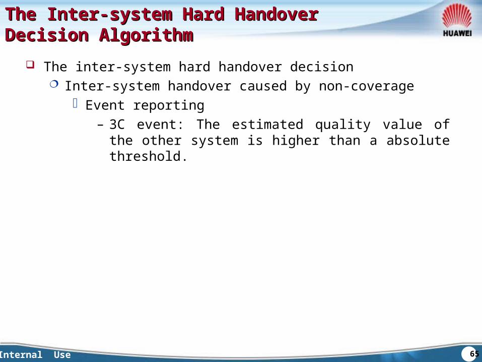
The Inter-system Hard Handover The Inter-system Hard Handover Decision AlgorithmDecision Algorithm
The inter-system hard handover decision Inter-system handover caused by non-coverage
Event reporting– 3C event: The estimated quality value of the other system
is higher than a absolute threshold.
66Internal Use
Inter-system Handover FlowInter-system Handover Flow
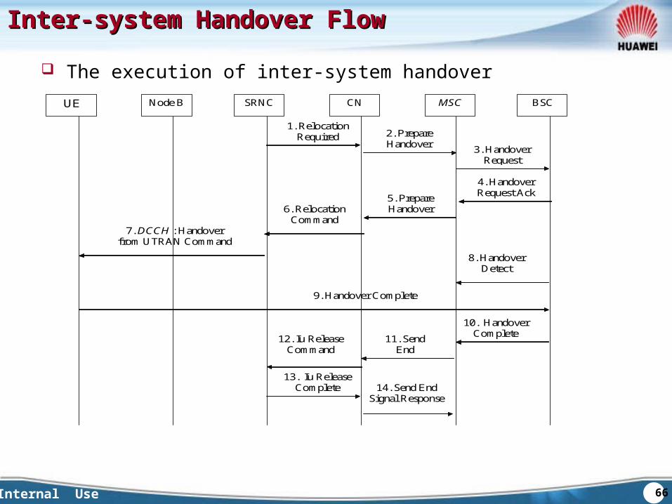
The execution of inter-system handover
1. Relocation Required 2. Prepare
Handover 3. Handover Request
4. Handover Request Ack
12. Iu Release Command
13. Iu Release Complete 14. Send End
Signal Response
5. Prepare Handover Response
6. Relocation Command
7. DCCH : Handover from UTRAN Command
8. Handover Detect
9. Handover Complete
10. Handover Complete 11. Send
End Signal
Request
UE Node B SRNC CN MSC BSC
67Internal Use
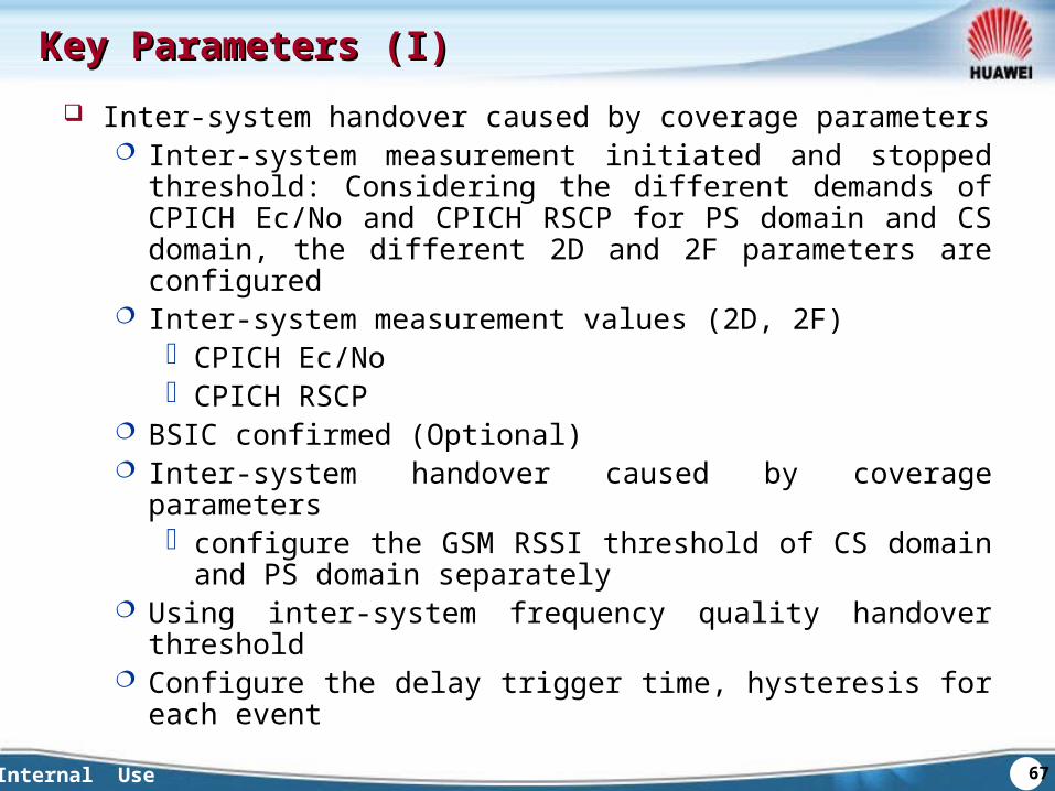
Key Parameters (I)Key Parameters (I) Inter-system handover caused by coverage parameters
Inter-system measurement initiated and stopped threshold: Considering the different demands of CPICH Ec/No and CPICH RSCP for PS domain and CS domain, the different 2D and 2F parameters are configured
Inter-system measurement values (2D, 2F) CPICH Ec/No CPICH RSCP
BSIC confirmed (Optional) Inter-system handover caused by coverage parameters
configure the GSM RSSI threshold of CS domain and PS domain separately
Using inter-system frequency quality handover threshold Configure the delay trigger time, hysteresis for each event
68Internal Use
Key parameters (II)Key parameters (II)
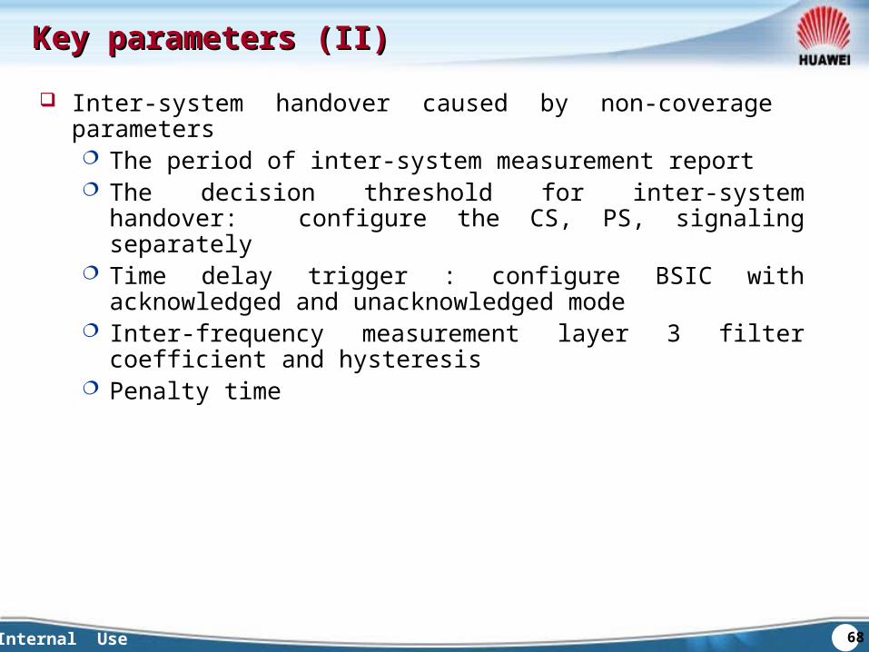
Inter-system handover caused by non-coverage parameters The period of inter-system measurement report The decision threshold for inter-system handover: configure the
CS, PS, signaling separately Time delay trigger : configure BSIC with acknowledged and
unacknowledged mode Inter-frequency measurement layer 3 filter coefficient and
hysteresis Penalty time
69Internal Use
Chapter 3 The Basic HandoversChapter 3 The Basic HandoversSection 1 Soft HandoverSection 2 Intra-frequency Hard HandoverSection 3 Inter-frequency Hard HandoverSection 4 Inter-system Hard HandoverSection 5 HSDPA HandoverSection 6 Compressed Mode
70Internal Use
The Brief Introduction HSDPA HandoverThe Brief Introduction HSDPA Handover
Application Scope Related to the handover between the HS-DSCH channel
of HSDPA The service cell update of HSDPA HSDPA< - >DCH
Purpose the service which data rate satisfied the threshold of HS
DPA should use the HSDPA resource. To realize the maximum traffic volume, the service cell with HS-DSCH should be the best cell in the active set.
71Internal Use
HSDPA MeasurementHSDPA Measurement
HSDPA handover measurement Measurement type: CPICH RSCP 、 CPICH Ec/N0 、 Pat
h loss The process of measurement: layer 1 filter coefficient and
layer 3 filter coefficient Measurement reporting
Periodic reporting Event reporting
– Reporting type: 1A, 1B, 1C, 1D– The event reporting converted to periodic reportin
g
72Internal Use
Service Cell Change AlgorithmService Cell Change Algorithm
Change the service cell for HS-PDSCH in active set According to 1D event to decide the best cell, and hand it over
to the cell. After handover, initiate the timer to forbid the ping-pong
handover Change the service cell for HS-PDSCH after hard handover
Establish the HSDPA channel in target cell with hard handover Establish DCH channel if the target cell can not support HSDPA
Change the service cell for HS-PDSCH during soft handover The service should be handed over to the cell which support
HSDPA when the best cell does not support HSDPA and the original service cell for HSDPA already deleted from active set.
73Internal Use
Direct Retry for HSDPADirect Retry for HSDPA
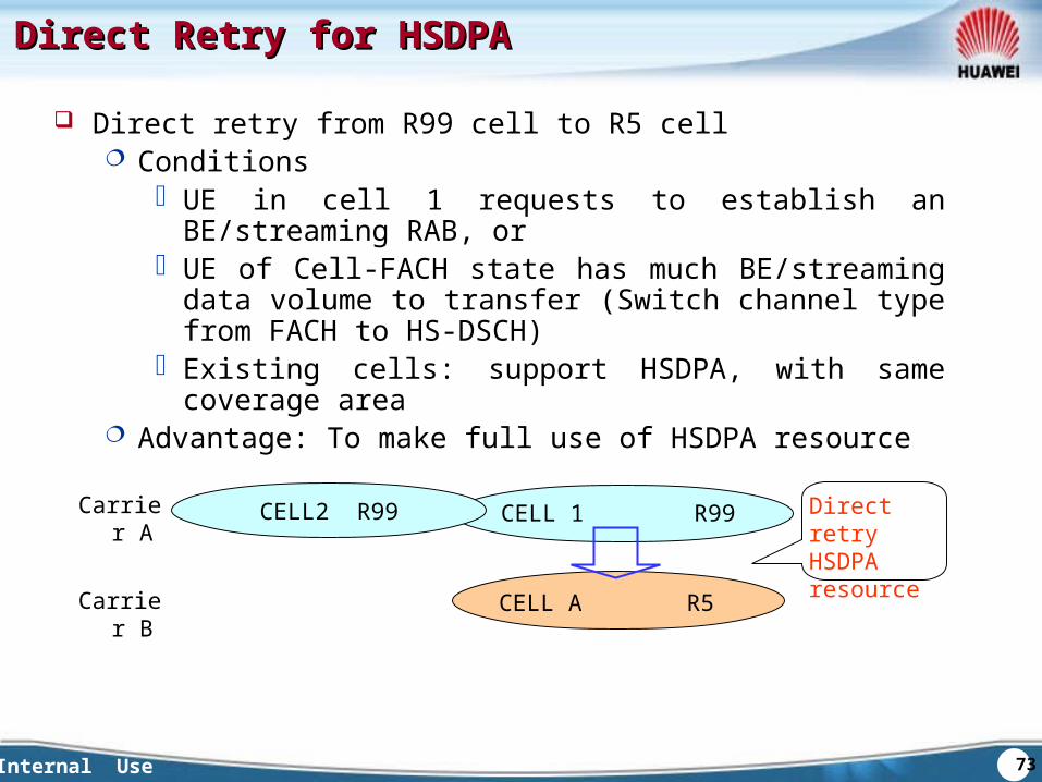
Direct retry from R99 cell to R5 cell Conditions
UE in cell 1 requests to establish an BE/streaming RAB, or UE of Cell-FACH state has much BE/streaming data
volume to transfer (Switch channel type from FACH to HS-DSCH)
Existing cells: support HSDPA, with same coverage area Advantage: To make full use of HSDPA resource
Direct retry HSDPA resource
R5CELL ACarrier B
R99CELL2 R99 CELL 1Carrier A
74Internal Use
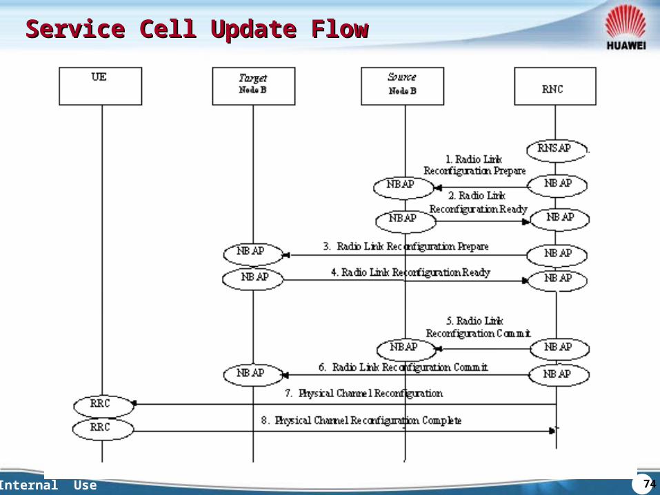
Service Cell Update FlowService Cell Update Flow
75Internal Use
Key ParametersKey Parameters
HSDPA handover protecting timer Configure the T-HSDPA to avoid the influence for the data servic
e caused by the ping-pong handover. During this period, the service cell for HSDPA can not be changed.
The value scope ( 0… 1024) seconds
76Internal Use
Chapter 3 The Basic HandoversChapter 3 The Basic HandoversSection 1 Soft HandoverSection 2 Intra-frequency Hard HandoverSection 3 Inter-frequency Hard HandoverSection 4 Inter-system Hard HandoverSection 5 HSDPA HandoverSection 6 Compressed Mode
77Internal Use
The Purpose of Compressed modeThe Purpose of Compressed mode
Purpose : Measure the inter-frequency cell or inter-system cell under
FDD mode Cause:
Downlink compressed: Since one receiver only can work in one frequency, the U
E has to stop working if it is going to measure the signal from another frequency cell. To ensure the downlink service unaffected, the remained data should be sent in the limited time.
Uplink compressed UE should stop the uplink transmission when the uplink w
orking frequency is very close to the measured frequency, for example GSM 1800/1900 is very close to the UMTS FDD uplink working frequency.
78Internal Use
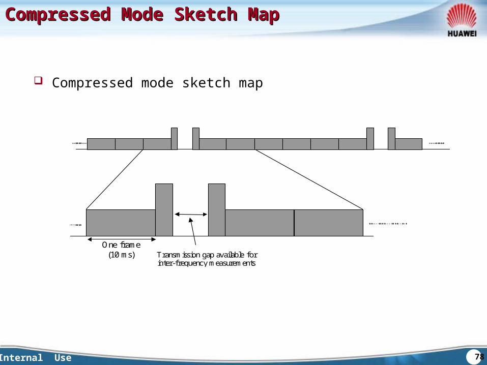
Compressed Mode Sketch MapCompressed Mode Sketch Map
Compressed mode sketch map
One frame(10 ms) Transmission gap available for
inter-frequency measurements
79Internal Use
The realization Methods of Compressed modeThe realization Methods of Compressed mode Realization Methods
SF/2 Should use the replace scrambling code Advantage: easy to handle for RNC Disadvantage: occupied the resource of NodeB, decrease the
utilizing efficiency of OVSF, influenced the coverage and increased interference caused by the replace scrambling code.
rate matching/puncturing Decrease the coding redundancy Advantage: easy to handle for RNC; the SF 4 can be used; no
influence to utilizing efficiency of OVSF Disadvantage: limited to the property of channel coding;
decreased the coding gain higher layer scheduling
MAC can restrict TFCS to change the downlink data rate. Advantage: the interference is lower Disadvantage: complicated for higher layer, only fit for non-
timing data service.
80Internal Use
QuestionsQuestions
What are the differences between soft handover and softer handover?
What is compressed mode? Draw out the hard handover signaling flow.
81Internal Use
SummarySummary
This chapter focus on the basic handovers in WCDMA: soft handover, softer handover, intra-frequency hard handover, inter-frequency hard handover and inter-system hard handover. It also introduced the application scenarios for these different handovers
Meanwhile, compressed mode is introduced in this chapter
82Internal Use
Chapter 1 Introduction of Handover
Chapter 2 Measurement of Handover
Chapter 3 The Basic Handovers
Chapter 4Chapter 4 Blind Handover andBlind Handover and
Direct Retry AlgorithmDirect Retry Algorithm
83Internal Use
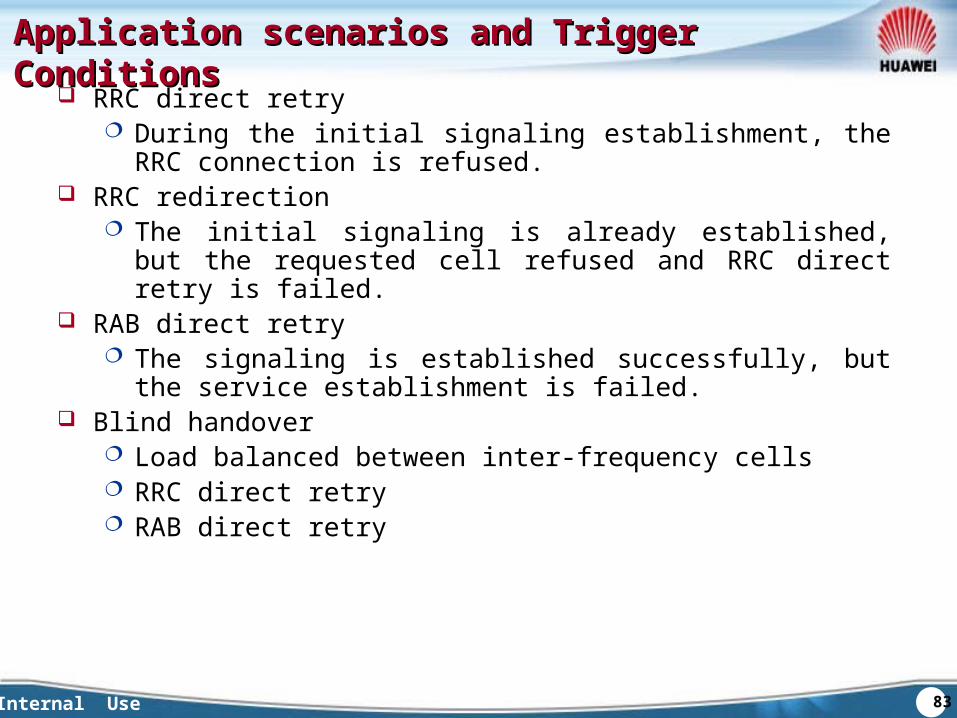
Application scenarios and Trigger ConditionsApplication scenarios and Trigger Conditions RRC direct retry
During the initial signaling establishment, the RRC connection is refused.
RRC redirection The initial signaling is already established, but the requested cell
refused and RRC direct retry is failed. RAB direct retry
The signaling is established successfully, but the service establishment is failed.
Blind handover Load balanced between inter-frequency cells RRC direct retry RAB direct retry
84Internal Use
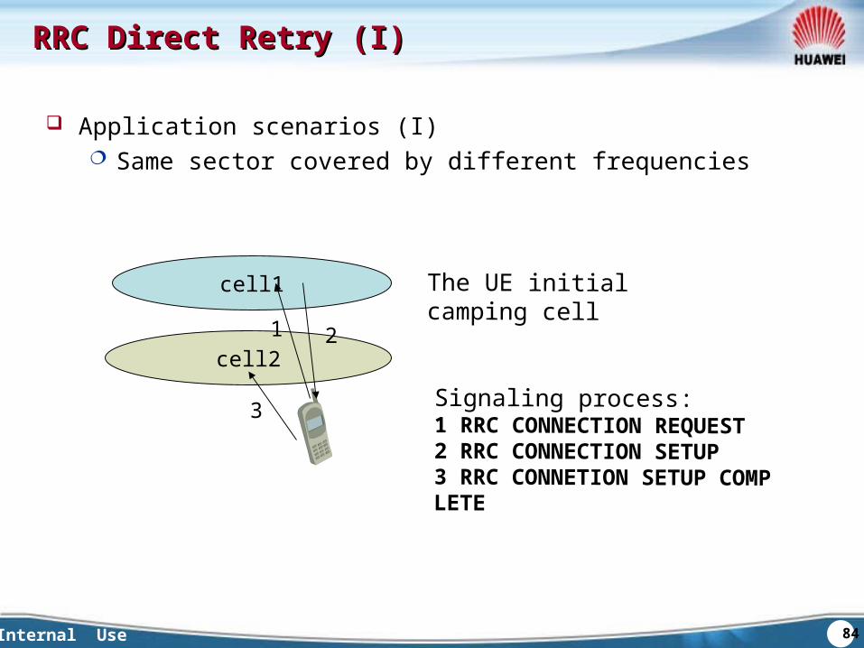
RRC Direct Retry (I)RRC Direct Retry (I)
Application scenarios (I) Same sector covered by different frequencies
cell1
cell21 2
3
The UE initial camping cell
Signaling process:1 RRC CONNECTION REQUEST2 RRC CONNECTION SETUP3 RRC CONNETION SETUP COMPLETE
85Internal Use
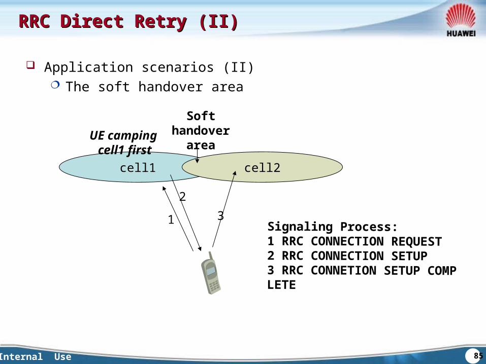
RRC Direct Retry (II)RRC Direct Retry (II)
Application scenarios (II) The soft handover area
cell1 cell2
1
23
UE camping cell1 first
Soft handover area
Signaling Process:1 RRC CONNECTION REQUEST2 RRC CONNECTION SETUP3 RRC CONNETION SETUP COMPLETE
86Internal Use
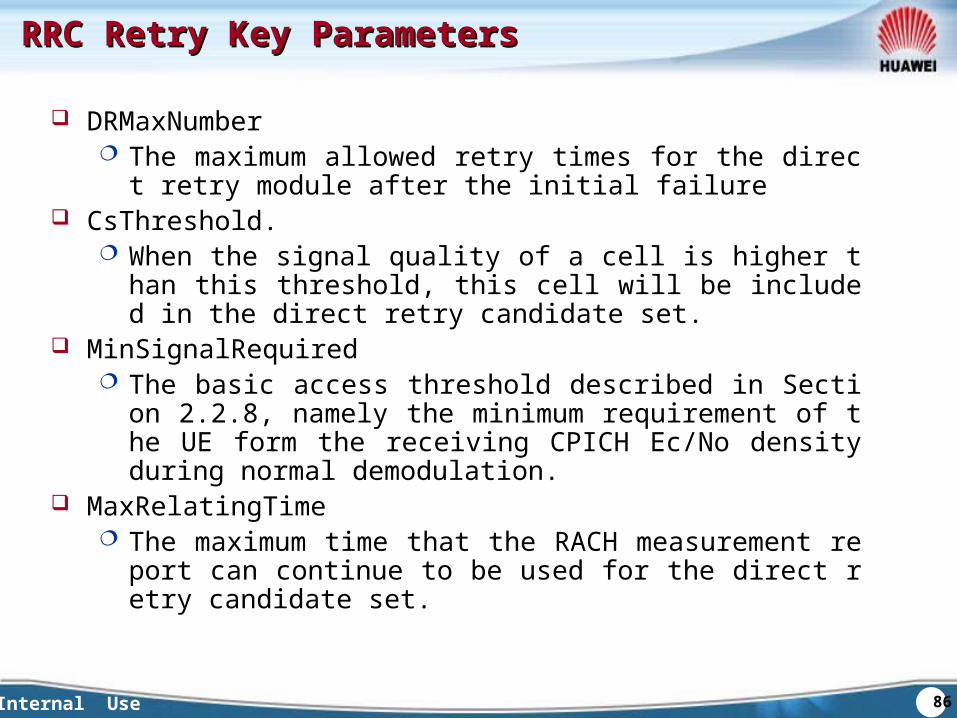
RRC Retry Key ParametersRRC Retry Key Parameters
DRMaxNumber The maximum allowed retry times for the direct retry module a
fter the initial failure CsThreshold.
When the signal quality of a cell is higher than this threshold, this cell will be included in the direct retry candidate set.
MinSignalRequired The basic access threshold described in Section 2.2.8, namel
y the minimum requirement of the UE form the receiving CPICH Ec/No density during normal demodulation.
MaxRelatingTime The maximum time that the RACH measurement report can c
ontinue to be used for the direct retry candidate set.
87Internal Use
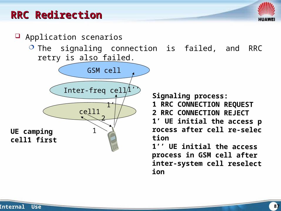
RRC RedirectionRRC Redirection
Application scenarios The signaling connection is failed, and RRC retry is also failed.
Inter-freq cell
cell1
1
2
1’
UE camping cell1 first
GSM cell
1’’Signaling process:1 RRC CONNECTION REQUEST2 RRC CONNECTION REJECT1’ UE initial the access process after cell re-selection1’’ UE initial the access process in GSM cell after inter-system cell reselection
88Internal Use
RRC Direct Retry and Direction RRC Direct Retry and Direction
The trigger condition should be the signaling permitting failure if congestion happed, the RRC connection signaling is refused.
Advantages and disadvantages: RRC direct retry can ensure the time delay. RRC direction is more flexible, and can select to GSM cell. But
the time delay is longer.
89Internal Use
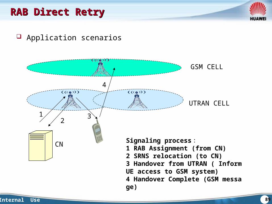
RAB Direct RetryRAB Direct Retry
Application scenarios
UTRAN CELL
GSM CELL
1 3
4
Signaling process:1 RAB Assignment (from CN)2 SRNS relocation (to CN)3 Handover from UTRAN ( Inform UE access to GSM system)4 Handover Complete (GSM message)
2
CN
90Internal Use
QuestionsQuestions
What is the difference of RRC direct retry and RRC redirection?
What are the trigger conditions for RRC direct retry and RRC direction?
91Internal Use
SummarySummary
This chapter focus on RRC direct retry, RRC redirection, the application scenarios of RAB direct retry and blind handover.

Huawei Confidential. All Rights Reserved


![W(Level3)-WCDMA RNO Handover in WCDMA-20041217-A-1[1].0](https://img.dokumen.tips/doc/110x75/577d20161a28ab4e1e91f4a2/wlevel3-wcdma-rno-handover-in-wcdma-20041217-a-110.jpg)