Embed Size (px)
DESCRIPTION
s
Citation preview

506 IEEE TRANSACTIONS ON AUDIO AND ELECTROACOUSTICS, VOL. AU-21, NO. 6, DECEMBER 1973
A Computer Program for Designing Optimum FIR Linear Phase Digital Filters JAMES H. MCCLELLAN, Student Member, IEEE, THOMAS W. PARKS, Member, IEEE, and LAWRENCE R. RABINER, Member, IEEE
Abstract-This paper presents a general-purpose computer program which is capable of designing a large class of optimum (in the minimax sense) FIR linear phase digital filters. The program has options for designing such standard filters as low- pass, high-pass, bandpass, and bandstop filters, as well as multipassband-stopband filters, differentiators, and Hilbert transformers. The program can also be used to design filters which approximate arbitrary frequency specifications which are provided by the user. The program is written in Fortran, and is carefully documented both by comments and by de- tailed flowcharts. The filter design algorithm is shown to be exceedingly efficient, e.g., it is capable of designing a filter with a 100-point impulse response in about 20 s .
I . Introduction
This paper presents a general algorithm for the de- sign of a large class of finite impulse response (FIR) linear phase digital filters. Emphasis is placed on a description of how the algorithm works, and several examples are included which illustrate specific ap- plications. A unified treatment of the theory behind this approach is available in [ 11.
The algorithm uses the Remez exchange method [2] , [3] to design filters with minimum weighted Chebyshev error in approximating a desired ideal fre- quency response D( f ) . Several authors have studied the FIR design problem for special filter types using several different algorithms [4] -[ 131. The advantage of the present approach is that it combines the speed of the Remez procedure with a capability for design- ing a large class of general filter types. While the algo- rithm to be described has a special section for the more common filter types (e.g., bandpass filters with multiple bands, Hilbert transform filters, and differ- entiators), an arbitrary frequency response can also be approximated.
McClellan and T. W. Parks was supported by NSF Grant Manuscript received August 6, 1973. The work of J. H.
J. H. McClellan and T. W. Parks are with Rice University,
L. R. Rabiner is with Bell Laboratories, Murray Hill, N.J.
GK-23697.
Houston, Tex.
07974.
II. Formulation of the Approximation Problem
The frequency response of an FIR digital filter with an N-point impulse response { h ( h ) } is the z-transform of the sequence evaluated on the unit circle, Le.,
The frequency response of a linear phase filter can be written as
where G ( f ) is a real valued function and L = 0 or 1. It is possible to show that there are exactly four cases of linear phase FIR filters to consider [l] . These four cases differ in the length of the impulse response (even or odd) and the symmetry of the impulse re- sponse [positive ( L = 0) or negative (L = l)] . By positive symmetry we mean h ( k ) = h(N - 1 - h) , and by negative symmetry h(h) = - h(N - 1 - h) .
In all cases, the real function G ( f ) will be used to approximate the desired ideal magnitude specifica- tions since the linear phase term in (2) has no effect on the magnitude response of the filter. The form of G ( f ) depends on which of the four cases is being used. Using the appropriate symmetry relations, G( f ) can be expressed as follows.
Case 1 : Positive symmetry, odd length:
G( f ) = 2 a ( k ) cos (27rhf) (3)
where n = (N - 1)/2, a(0) = h(rz), and a(h) = 2h(n - k ) for h = 1, 2,. . . , n.
k = O
Case 2: Positive symmetry, even length:
G ( f ) = 5 b(h) COS [27r(h - $ ) f ] (4)
where n = N / 2 and b ( k ) = 2h(n - h ) for h = 1, * * . , n. k = l
Case 3: Negative symmetry, odd length: n
G ( f ) = c(h) sin (27rkf) (5)
where n = (N - 1)/2 and c(h) = 2h(n - h ) for 12 = 1, 2, . . . , rz and h(n) = 0.
k = l
Case 4: Negative symmetry, even length:
n ~ ( f ) = d ( h ) sin [271(12 - + ) f ] (6)
where n = N / 2 and d ( h ) = 2h(n - h ) for 12 = 1, - . , n. Earlier efforts at designing FIR filters concentrated
on Case 1 designs, but it is now possible to combine
k = l
For convenience, throughout this paper the notation H( f ) rather than H ( e j z n f ) is used to denote the frequency response of the digital filter.

McCLELLAN et al.: LINEAR PHASE DIGITAL FILTERS
all four cases into one algorithm. This is accom- plished by noting that G( f ) can be rewritten as G( f ) = &( f ) P ( f ) where P( f ) is a linear combination of cosine functions. Thus, results that have been worked out for ,Case 1 can be applied to the other three cases as well. For these purposes, it is convenient to express the summations in (4)-(6) as a sum of cosines di- rectly. Simple manipulations of (4)-(6) yield the expressions.
Case 2:
n
b(h) cos [2n(h - + ) f ] k = l
= cos ( n f ) b(h) cos ( 2 n k f ) . (7) n-1 ~
k = O
Case 3:
Case 4:
i d ( h ) = +[; i (k - 1) - &.)I, Case 4:
h = 2 , 3 , . . . , n - 1
The motivation for rewriting the four cases in a common form is that a single central computation routine (based on the Remez exchange method) can be used to calculate the best approximation in each of the four cases. This is accomplished by modifying
507
ing function to formulate a new equivalent approxi- mation problem.
The original approximation problem can be stated as follows: given a desired magnitude response D ( f ) and a positive weight function W( f ) , both continuous on a compact subset F C [0, + ] (note that the sam- pling rate is 1.0) and one of the four cases of linear phase filters [i.e., the forms of G( f ) ] , then one wishes to minimize the maximum absolute weighted error, defined as
IIE(f)ll= max W ( f ) l D ( f ) - G( f ) l (13) f EF
over the set of coefficients of G ( f ) .
form The error function E ( f ) can be rewritten in the
E ( f ) = W f ) CD(f) - G ( f ) l = W ( f ) & ( f ) [ = - Wf) P(fi]
(14)
if one is careful to 2mit those endpoint(s) *where Q ( f ) = 0. Letting D ( f ) = D ( f ) / & ( f ) and W ( f ) = W( f ) &( f ) , then an equivalent approximation problem would be to minimize the quantity
I IE(~)I I = max * ( f ) ~ f i ~ ) - P ( ~ ) I (15) f EF'
by choice of the coefficients of P( f ) . The set F is re- placed by F' = F - { endpoints where &( f ) = o}.
The net effect of this reformulation of the problem is a unification of the four cases of linear phase FIR filters from the point of view of the approximation problem. Furthermore, (15) provides a simplified viewpoint from which it is easy to see the necessary and sufficient conditions which are satisfied by the best approximation. Finally, (15) shows how to calculate this best approximation using an algorithm which can do only cosine approximations. The set of necessary and sufficient conditions for this best approximation is given in the following alternation theorem [ 21 .
Alternation theorem: If P ( f ) is a linear combi- nation of r cosine functions i.e.,
P ( f ) = a(k) cos Znhf, r - 1
k = O
then a necessary and sufficient condition that P ( f ) be the unique best weighted Cheby%hev ap- proximation to a continuous function D ( f ) on F' is tkat the weighted error function E( f ) = W(f ) [ D ( f ) - P ( f ) ] exhibit at least r- + 1 extre- mal frequencies in F' .
These extremal frequencies are a set of points { F j } , i = 1, 2, * . . , r + 1 such that F 1 < F2 < . . < F, < F,+l , with E(F,) = -E(F,+, ), i = 1, 2, . . . , r- and lE(FAl= mmFcw8 E ( f ) .
both the desired magnitude function and the weight- An' algorithm c&- now be designed to make the

508 IEEE TRANSACTIONS ON AUDIO AND ELECTROACOUSTICS, DECEMBER 1973
INPUT FILTER
TRANSFORM
DENSE GRID FOR
DESIRED MAGNITUDE
I APPROXIMATION PROBLEM I FORMULATE EQUIVALENT
EXTREMAL FREQUENCIES
SOLVE THE
CALCULATE IMPULSE RESPONSE x PRINT OUT THE 1 OPTIMAL ERROR-& I
IMPULSE RESPONSE
Fig. 1. Overall flowchart of filter design algorithm.
error function of the filter satisfy the set of necessary and sufficient conditions for optimality as stated in the alternation theorem. The next section describes such an algorithm along with details as to its imple- mentation.
111. Description of the Design Algorithm
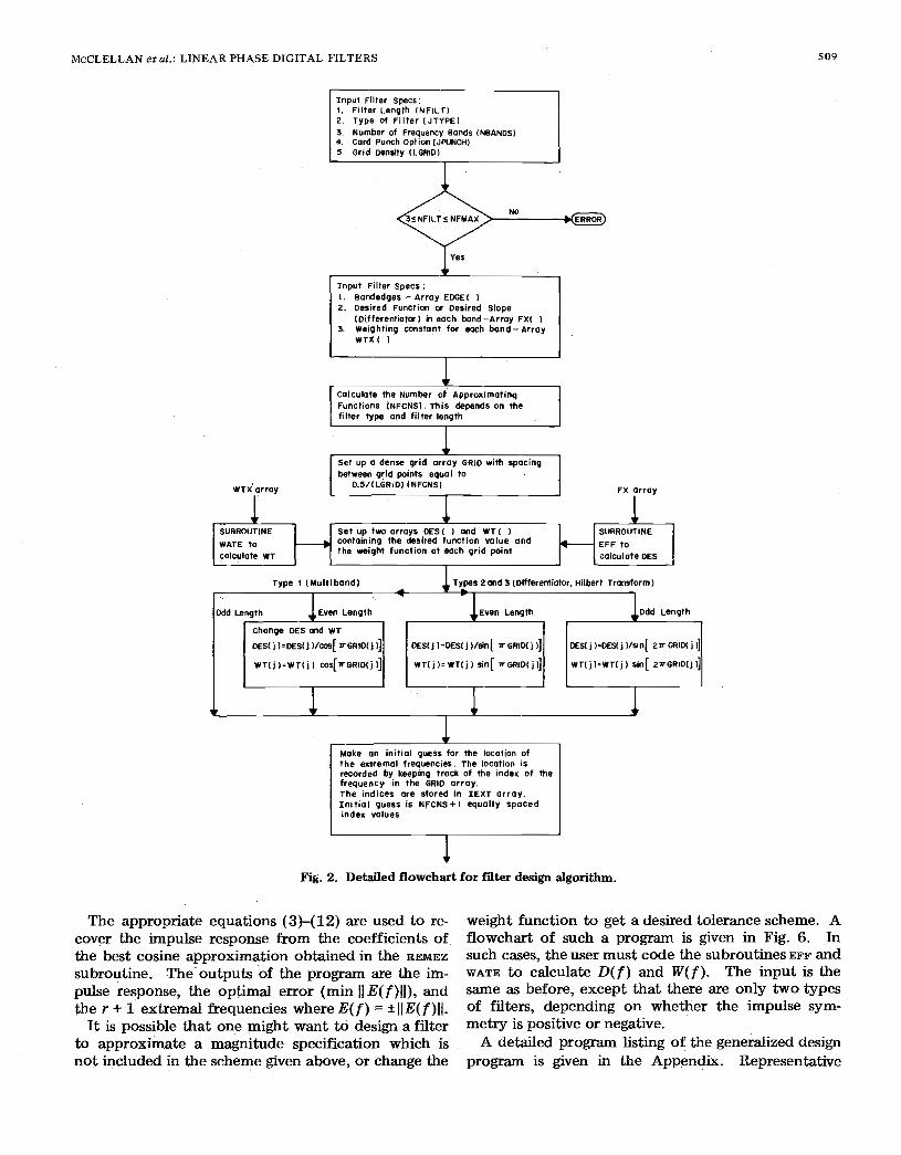
As seen in Fig. 1, the design algorithm consists of an input section, formulation of the appropriate equivalent approximation problem, solution of the approximation problem using the Remez exchange method, and calculation of the filter impulse re- sponse. The flowcharts of Figs. 2-5 give details of the exact structure of the computer program.
The input which describes the filter specifications consists of the following.
1) The filter length, 3 < NFILT < NFMAX (the upper limit set by the programmer).
2) The type of filter (JTYPE):
a) Multiple passband/stopband ( J T Y P E = ~ )
b) Differentiator ( J T Y P E = ~ )
C) Hilbert transformer ( J T Y P E = ~ ) .
3) The frequency bands, specified by upper and lower cutoff frequencies (EDGE array) up to a maxi- mum of 10 bands.
4) The desired frequency response (FX array) in each band.
5) A positive weight function (WTX array) in each band.
6) The grid density (LGRID), assumed to be 16 unless
7) Impulse response punch option (JPUNCH).
Part 3) specifies the set F to be of the form F = U B i where each frequency band Bi is a closed subinterval of [ 0, 1. The inputs 4) and 5) are interpreted differ- ently by the program for a differentiator than for the other two types of filters (see the EFF and WATE sub- routines in Figs. 3 and 4). The weight specification in the case of a differentiator results in a relative error tolerance as is used in all other cases.
The set F must be replaced by a finite set of points for implementation on a computer. A dense grid of points is used with the spacing between points being O . ~ / ( L G R I D X r ) where r is the number of cosine basis functions. Both D( f ) and W ( f ) are evaluated on this grid by the subroutines EFF and WATE, respectively. Then the auxjliary app5oximation problem is set up by forming D ( f ) and W( f ) as above, and an initial guess of the extrema1 frequencies is made by taking r + 1 equally spaced frequency values. The subrou- tine REMEZ (Fig. 5) is called to perform the calcula- tion of the best approximation for the equivalent problem. The mechanics of the Remez algorithm will not be discussed here since they are treated elsewhere for the particular case of low-pass filters [9] . (The flowchart of Fig. 5 gives details about the mechanics of the Remez algorithm as implemented in this design
specified otherwise.
Program.)
509 McCLELLAN et al.: LINEAR PHASE DIGITAL FILTERS
Input Filter specs:
2. Type of F i l t e r ( JTYPEI 1. F i l ter Length (NFILT)
4. Card Punch Option (JPUNCH) 3. Number of Frequency Bands (NBANDS)
5. Grid Density (LGRID)
Input Fi l ter specs :
2. Desired Function or Desired Slope 1. Bandedges - Array EDGE( )
3. weighting m s t a n t for each b a n d - A r r a y (Differentiatar) in each band-Array FX( )
WTX( 1
I
Functions (NFCNS). This depends on the
between grld paints equal to set up a dense grid ar ray GRID with spacing
WTXarray
I + SUBROUTINE - containing the desired function value and + WATE t o
Set up two arrays DES( 1 and WT (
calculate WT the weight function at each grid paint
I -
FX orray
calculote DES
+ + I
Make an initial guess for the locotion of the extremal frequencies. The location is recorded by keeping track of the index of the f requency in the GRID a r ray . The ind ices are s tored in IEXT ar ray. In i t ia l guess i s NFCNS+i equa l ly spaced index values
1 Fig. 2. Detailed flowchart for fiiter design algorithm.
The appropriate equations (3)-(12) are used to re- cover the impulse response from the coefficients of the best cosine approximation obtained in the REMEZ
subroutine. The'outputs of the program are the im- pulse response, the optimal error (min 11 E(f) l l ) , and the r f 1 extremal frequencies where E( f ) = k llE( f ) l l .
It is possible that one might want to design a filter to approximate a magnitude specification which is not included in the scheme given above, or change the
weight function to get a desired tolerance scheme. A flowchart of such a program is given in Fig. 6. In such cases, the user must code the subroutines EFF and WATE to calculate D ( f ) and W( f ) . The input is the same as before, except that there are only two types of filters, depending on whether the impulse syrn- metry is positive or negative.
A detailed program listing of the generalized design program is given in the Appendix. Representative

5 10 IEEE TRANSACTIONS ON AUDIO AND ELECTROACOUSTICS, DECEMBER 1973
C a l l REMEZ e x c h a n g e a l g o r i t h m
O d d L e n g t h
H ( j ) = 1/2 a ( N F C N S + l - j
H I N F C N S ) = a ( l )
Where a o r r a y c o n t a i n s
c o e f f i c i e n t s of b e s t
c o s i n e a p p r o x ~ m a t i o n
Even Leng th
H ( j ) = 1 / 4 [ a ( N F C N S + l - j 1 4
a ( N F C N S + Z - j i ]
H ( 1 I = 1 / 4 a ( N F C N S )
HINFCNS)=I /Z~I I I+
1 / 4 Q ( 2 )
H ( j 1 = 1 / 4 [ a ( N F C N S + l - j ) -
o d d L e n g t h
H ( j ) = 1 / 4 [ a l N F C N S + l - j ) -
Q ( NFCNS + 3 - j I] H ( 1 ) = 1 / 4 a ( N F C N S )
H (2) 114 OL I N F C N S - I
H l N F C N S l = 1 / 2 a ( O -
1 / 4 a ( 3 1 H ( NFCNS +i I = O
P r o g r a m O u t p u t I . T i t l e 2 . T y p e o f F i i t e r 3. F i l t e r L e n g t h 4. I m p u l s e R e s p o n s e 5. s o n d e d g e s 6. D e s i r e d v a l u e / s i o p e i n e a c h b a n d 7. W e i g h t i n g i n e a c h b a n d 8. D e v i a t i o n i n e a c h b a n d 9. D e v i a t i o n i n d B f o r T y p e 1 10. E x t r e m a 1 F r e q u e n c i e s
P u n c h i m p u l s e r e s p o n s e i f desired, JPUNCH = !
Fig. 2. (Continued.)
SUBROUTINE EFF
E F F ( F l = F X l j )
f a r F E j - t h b o n d 0 0.5
E F F ( F 1 = F X ( j l . F
T E v o l u O t e S d e s i r e d f u n c t i o n a t 0 g r i d p o i n t
Fig. 3. Flowchart for subroutine EFF.

McCLELLAN et al.: LINEAR PHASE DIGITAL FILTERS
SUBROUTINE WATE
1
5 1 1
WATE (F) = W t X ( j ) f o r F E j t h band WATE (F) = W t X ( j ) f o r F E j t h band
W T X ( j ) i f F X ( j ) = O WATE ( F ) =
W T X ( j ) l F i f F X ( j ) # O
E v a l u a t e s w e i g h t f u n c t i o n a t a g r i d p o i n t
Fig. 4. Flowchart for subroutine WATE.
REMEZ
Init ialize iteration count ITRMAX * 25
NITERDO
@ Main Iteratian Loop-statement IOO * NITER=NITER t I
Ga to 400
coeff icientsof best approximation
lNO Calculate the abscissae for the Lagrange interpalat ion
x ( j ) = c a s [ Z a F ( j ) ] Where F( j ) are the extrema1 frequencies
1 coefficients using subroutine D calculate Lagrange interpoiat ian
A D ( j ) * G [ X ( i ) - X ( j ) ] ( i # j l i = l
+ Calculate the current value of the deviat ion (DEV) and "print OEV.
A O ( j 1 D E S [ I E X T ( j l ] DEv= i = *
f (-llj-'AO( j )/WT[IEXT( j I] 1'1
1 1 1
I Record sgn (DEW a set DEV= IDEVJ J
Calculate ordinates for Lagrange interpolation Y ~ j l ~ D E S I I E X T ( j ) ] + ( - l l i M V / W T [ I E X T ( j ) ]
GO to calculot ion of coeff icients
approximat ion
error message of best
1"" Fig. 5 . Detailed flowchart for subroutine REMEZ.

512 IEEE TRANSACTIONS ON AUDIO AND ELECTROACOUSTICS, DECEMBER 1973
FOT the 1st extrema1 frequency se1 upper KUP ond lower KLOW I tmi ls On the G ( l 0 Dolnts lo be searched
KUP = IEXT(21 KLOW = 0
Furthermwe, le1 the sign of the error 01 each exfrernol frequency be denoted by v(i I
Yes Go to endpoml search Istolemen1 3001
K = I E x T ~ j I I (.e. the grid polnt @djjacent S u b r w l l n e GEE at GRID ( K t 1 1 where
to the i th exlremal frequencyl. Then COlCulote the welqhled error
E R R = W T ( K + I I [ G E E ( K t I I - D E S ( K t l ) ] i SUBROUTINE GEE
Where X = C O S [ Z r T G R I D ( K I ]
NO yes
1 calculate frequency response a n d weighted error at index K-1
1 I
There 1s a locol maximum of the error Curve where lhe stgned error IS greater than me present deviollon. continue the seorch at KtP, K+3, , . K V P until this locol mox error curve. search K - 2 , 1s found.
yes
There is a locol mox of 2w
max is found K - 3 .... KLOW Ynlii this IOCOI
i( 1. Change lhisexlremal frequency 2. update KLOW and KUP for
KL0W=mox{~1EXT~j l ) -1 .1EXT~i~- I ) * KUP=min{IEXTlJtZl.NGRID}
where signed error I S ~
next iterotlon Find such a locol mor:
Continue searching K-2.K-3. ... KLOW for 0 IOCOI mOK
2 DEV
3. Note that one exlremal hos Don't find
+ I JCHNGE =JCHNGE+I A I
GO to beginnlog I (Statement 2001
of the Imp Find such 0
a tocol max where rlgned locol max Search K t 2 , K t 3 : - . K U P for
error ? D E V
Fig. 5. (Continued.)

MCCLELLAN et al.: LINEAR PHASE DIGITAL FILTERS
Statement 300-Endpoints search I
5 1 3
f ind such 0 search those indices less than min { IEXT ( I ), new IEXT ( 1 ) } locol mox for error with sign - u ( l ) and greater than the error
ot new I E X T ( n 1
Find such a local max
Store the index and error value I 1
for local max of the error curve with sign - u l n l local max and error I error 01 new I E X T ( 1 ) and error fwnd above
locol max
yes
1 IEXT for next i terat ion IEXT ( 1 ) = index f w n d above NO I E X T ( 2 ) =new IEXT ( 1 1
IEXT (1) = n e * I E X T t i l
I
I E X T ( 1 1 = new I E X T ( 2 1
I E x T ( n - O = n e w I E X T ( n ) I E X T ( ~ ) = index just found
t I I I
Evoluate GEE bt NFCNS equOllY spoced points in the interval [ O,l/P]
c Inverse OFT to obtain coeff ic ients of the best cosine approximation
Fig. 5. (Continued.)
I n p u t F i l t e r s p e c s : NFILT, JTYPE, NBANDS, JPUNCH, LGRID, EDGE ( 1 , F X ( ) I W T X (
1 c o l c u l o t e n u m b e r of a p p r o x i m a t i n g f u n c t i o n s
a n d s e t up t he dense grid F X o r r o y W T X a r r a y
1 - 1 1 -
SUBROUTINE WATE se i up the a r r a y s DES and WT EFF SUBROUTINE
s u p p l i e d b y u s e r u s e r S u p p l i e d by - -
P o s i t i v e s y m m e t r y N e g o t i v e S y m m e t r y ( T y p e ! I 1 ( T y p e 2 )
,i Odd Length 1 1 1; Even Length Odd Length ' Even Length
c o n t i n u e d a s in t h e m a i n f l o w c h a r t
Fig. 6. Flowchart for arbitrary magnitude filter design algo- rithm.

5 14 IEEE TRANSACTIONS ON AUDIO AND ELECTROACOUSTICS, DECEMBER 1973
dANtJ
LOWPASS FILTER N.24
1.1, 1
FREQUENCY
Fig. 8. Magnitude responses, on linear and log scales, for an N = 24 low-pass filter.
input card sequences are given for the design of a bandpass filter and a differentiator. To approximate an arbitrary magnitude response and/or an arbitrary weighting function, all the user has to do is change the subroutines EFF and WATE and use the program in the Appendix. In the next section, representative filters designed using these algorithms are presented.
IV. Design Examples
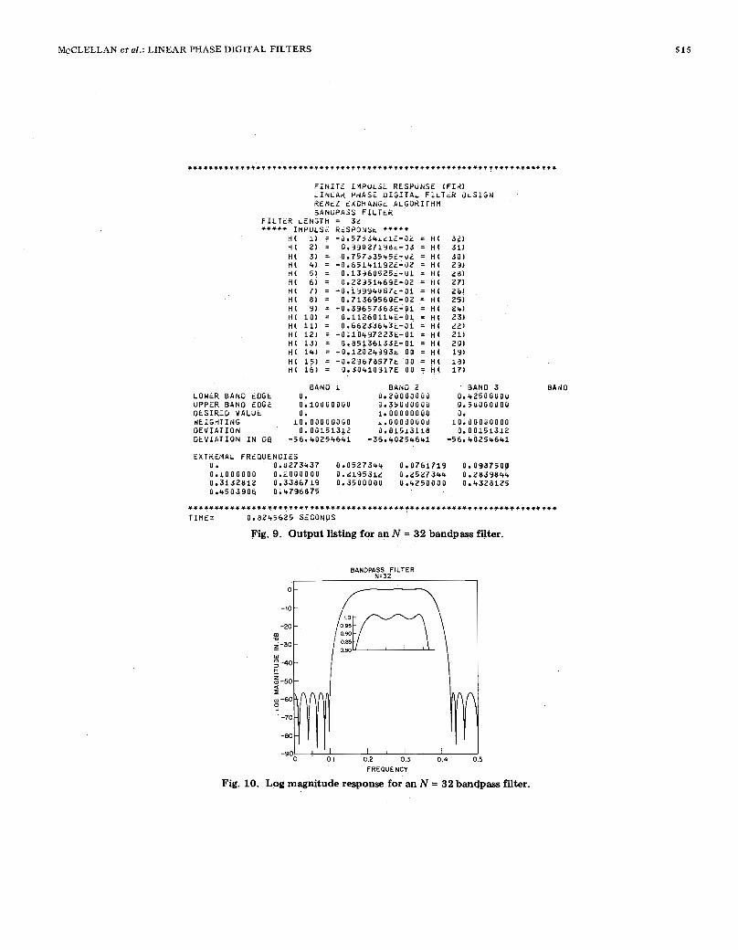
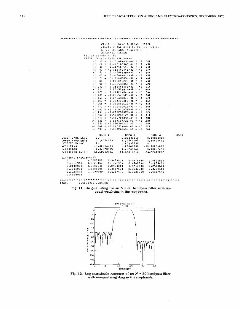
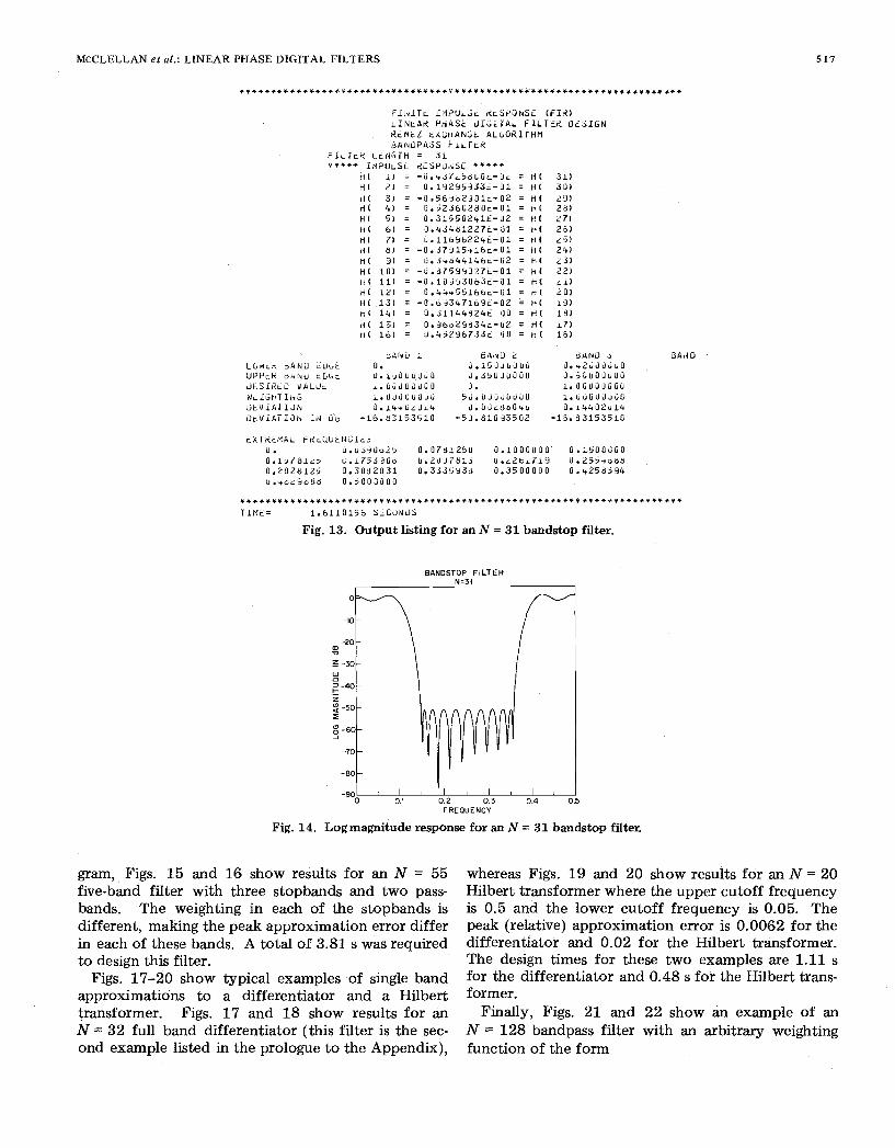
Figs. 7-22 show specific examples of use of the de- sign program for several typical filters of interest. For each of these filters, one figure shows the computer output listing (including the run time on a Honeywell 6000 computer), and the other figure shows a plot of the filter frequency response on either a linear or a log magnitude scale (or sometimes both). Figs. 7 and 8 are for an N = 24 low-pass filter. For this example, the run time was 0.77 s. Figs. 9 and 10 are for an N = 32 bandpass filter. This example is the first ex- ample listed in the prologue to the program in the Appendix. The run time for this example was 0.82 s. Figs. 11 and 12 are for an N = 50 bandpass filter in which unequal weighting was used in the two stop- bands. Thus the peak error in the upper stopband is ten times smaller than the peak error in the lower stopband. A total of 2.96 s was required to design this filter. Figs. 13 and 14 are for an N = 31 bandstop filter with equal weighting in both passbands. For the design of this filter 1.61 s were required.
To illustrate the multiband capability of the pro-
McCLELLAN et al.: LINEAR PHASE DIGITAL FILTERS
B A d O
EXTKEHAL FREQUENCIES 0. 0.1000000 0.2000000 0.L19531L 0.2527344 0.2839844
0.0273437 0.052734~ 0.0761719 0.0937500
0.3132812 0.3386719 0.3500000 0.4250000 0.4328125 U.4503906 0.4796875
. . . . . . . . . . . . . . . . . . . . . . . . . . . . . . . . . . . . . . . . . . . . . . . . . . . . . . . . . . . . . . . . . . . . . . T I M E = 0.8245625 S i G D N D S
Fig. 9. Output listing for an N = 32 bandpws filter.
BANOPASS FILTER N=32
I I 0
-io
-20 rn 2-30 -
2 -40 5
w
-50 I w -60 s -70
-80
-90 0. I 0.2 0.3 0.4 0.5
515
FREOUENCY
Fig. 10. Log magnitude response for an N = 32 badpass filter.
516 IEEE TRANSACTIONS ON AUDIO AND ELECTROACOUSTICS, DECEMBER 1973
BANDPASS FILTER N=50
I 5 -50
-60 w
t i -70 a I -80 0 9 -90
-100
-110
-120
-
~
I I I I 0.1 0.2 0.3 0.4
FREOUENCY
5
Fig. 12. Log magnitude response of an N = 50 bandpass filter with unequal weighting in the stopbands.
MCCLELLAN et al.: LINEAR PHASE DIGITAL FILTERS 5 17
l * + + + + + l + + * + + * * , + * * + * + * ~ l * + + + * + ~ * * + + * + l l + * ~ * * * * + + + + ~ ~ + ~ ~ + + ~ l + + * + ~ + + + + +
T l M t = 1.6110156 S ~ c 3 1 i i ) S
Fig. 13. Output listing for an N = 31 bandstop filter.
BANDSTOP FILTER N-31
Fig. 14. Logmagnitude response for an N = 31 bandstop filter.
gram, Figs. 15 and 16 show results for an N = 55 five-band filter with three stopbands and two pass- bands. The weighting in each of the stopbands is different, making the peak approximation error differ in each of these bands. A total of 3.81 s was required to design this filter.
Figs. 17-20 show typical examples of single band approximations to a differentiator and a Hilbert transformer. Figs. 17 and 18 show results for an N = 32 full band differentiator (this filter is the sec- ond example listed in the prologue to the Appendix),
whereas Figs. 19 and 20 show results for an N = 20 Hilbert transformer where the upper cutoff frequency is 0.5 and the lower cutoff frequency is 0.05. The peak (relative) approximation error is 0.0062 for the differentiator and 0.02 for the Hilbert transformer. The design times for these two examples are 1.11 s for the differentiator and 0.48 s for the Hilbert trans- former.
Finally, Figs. 21 and 22 show an example of an N = 128 bandpass filter with an arbitrary weighting function of the form

5 18
MULTIBAND FILTER
1 ° B
-901 1 I 0.1 0.2 0.3 0.4 (
FREQUENCY
Fig. 16. Log magnitude response for an N = 55 filter.
5
multiband

McCLELLAN et al.: LINEAR PHASE DIGITAL FILTERS 519
DIFFERENTIATOR N = 32
: 'Z(.) z c1 a I
0 0 0.5
0.0062
0 Q
Q Q W
-0.0062
0.0062
W
5: > m
i i W ( C 1
Q
-0.0062 v v v \I \I V I 0.5 . -
FREOUENCY
Fig. 18. Magnitude and error responses for an N = 32 dif- ferentiatw.

520 IEEE TRANSACTIONS ON AUDIO AND ELECTROACOUSTICS, DECEMBER 1973
OY I 0.5
OY I 0.5
0.05 0.5
Fig. 20. Magnitude and error responses for an N = 20 Hilbert transformer.

McCLELLAN et al.: LINEAR PHASE DIGITAL FILTERS 521

522 IEEE TRANSACTIONS ON AUDIO AND ELECTROACOUSTICS, DECEMBER 1973
LOWEQ BPNO EDGE 0. PANO 3
0 . 1 2 0 0 0 0 0 0 RAND 4
0 ~ 1 5 0 0 0 0 0 0 UPPER 91NP F O G € 0.10000000 0.13000000 0.25000000 0.50000000
0.25000000 BAND 1 PANO 7
DESIRED VALUE WEIGHTING
0. 1 . 0 0 0 0 0 0 0 0 0.
D E V I A T I C N 0 . 0 0 5 0 0 1 7 4 0.05001741 0.00500134 10.00000000 1.00000000 1 0 . 0 0 0 0 0 0 0 0 1 0 . 0 0 0 0 0 0 0 0
0.
EXTREHAL FPEn
0.0454102 0.
0.0834961 0.1200000
0.1880859 0 .1548828
0.2271494
0.3461914 0.3066406
0.3857422 0.4252930 0.4647555
0.267089n
UEYCTES 0.0102579
0.0898477 0.0532227
0 . 1 2 4 8 8 7 8 0.1602539 0. 1958984 0.2349609 0.2749023
0.3540039 0.3144531
0.393551r7 0.4331055 0.4771680
0.0200195 0.0610352 0.0952148 0.1300000 0.1666016 0.20?7109 0,2427734
0.3615164 0.3222656
0.4013672
0.4804h87 0.4409190
0.2a27148
0.0288066
0.1500000 0.0996328
0.1734375
0.2509766 0.2115234
0.2910156 0 -3305664 0.?696289 0.4091797 0.4407305
0. 06118477
o ,4887812
0.0371094 0.0761719 0.1000000 0.151464R 0.1807617 0.2193359 0.2592773 o.?9a8?81 0 . 3 3 ~ 3 7 ~ 9 0.3779297 0.4169922
0.4960 937 0.4565430
ARBITRARY WEIGHTING BANDPASS FILTER
N = i 2 8
‘1 A I
z -50
w -60
-70
-eo
s
-901 I I , \ ‘ I 1 I , Ir I 1 0.1 0.2 0.3 0.4 0.5
FREOUENCY
Fig. 22. Log magnitude response for an N = 128 bandpass filter with arbitrary weighting characteristics.
[* Od f < 0.1
I 1 0.12 < f < 0.13
9f - 1.25 0.15 < f < 0.25
10 0.25 < f < 0.5.
Thus the tolerance scheme is linear in the intervals 0 < f d 0.1 and 0.15 < f d 0.25. The error at the stopband edges is 0.0005 (-66 dB), and the peak error increases linearly to 0.005 (-46 dB). The time required to design this filter was 23.8 s.
Summary
A general-purpose linear phase FIR filter design program is presented which is capable of designing a wide variety of standard filters as well as any desired magnitude response which can be specified by the
user. The speed of the algorithm, as well as its gen- erality, make this program an attractive one for a wide variety of design applications.
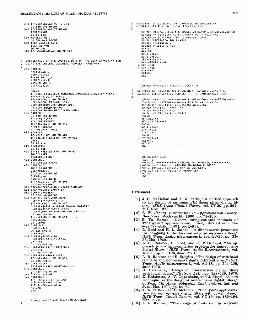
Appendix
C C C C C C C C C L C C C C C C C C C C C C C C C C C C C C c C C C C C C C C C C C C C C C
PROGRAM FOH 1 H t UESIGN OF L INEAH PHASt F IN ITE IMPULSt
J I M MCCLELLAFV. RICE UNIVLKSITY, APRIL 139 1976 RESPONSL (F IR1 F ILTEKS USING THE HCMtL EXCHANtiL ALGOHITHM
TtiHEE TYPES OF F I L T t H S AHL INCLUOED--bANOPUSS F l L l L R S DIFFEREM1 IATORS, ANU H I L B t H T THAkSFORtY F l L l t R b
THt INPUT DAIA CUNSISTS OF 5 CARUS
CAHD l - - F l L T t K L t N G l H v 1 Y P t Ob F I L T t k . 1 - M U L l I P L t PASSBAND/bTUPBANUq 2-UIFFtHENl IATOH* 3-HILdE1RI TRANSFURM FILTER. NUMBER OF BANOSt LAHU PUNCH UtSIRtUq ANU G H l O Ot81SITY.
CAKO 2--Ul iNDtUGtb1 LOirEH AlUU UPPtH LUGES FOR LYCH BANU W l l H A MAXIMUM 01- 1 U BANUS.
CAHU ~ - - U E S I R ~ L . FUNCTIO lv ( O R U t S i H t U SLUPt I F A OIFFEHENl1ATUK) F O R tYCH BANU.
CARD L)--WiIGHT kLINCIIORI I N LAcH BAhU. F O K A DIFFEKEN11UTOR+ THE WLILhT +UNCTION 15 I iUVLHStL I PRUPOHTiUwAL TU F.
THE FULLORINL I w u r LIATA SP~CIFIES A LENGTH 32 BANUPYSS FILTER WlrH STUPBANUS u T U 0.1 A ~ U 0.423 T O O.S, AIW PASSBANU C R O M 0.2 T U 0.3’3 k I T H WLI IHTI I IG UF 1 U I I U Ih t STOPBAINDS ANU 1 I N T H t PAbbBAluU. THL IMPULSE HESPOlUbE WILL B t PUNCHED ANU THE t i H l U I ILNSITY IS 32. I H l S IS T H C F I L T E H I N F I L U K L S 9 A M I 1 U IN I H L T t X l . SAtYPLE I N P U T O A l A S t T U P 3 2 9 1 r S r l r 3 2 0 ~ ~ . 1 ~ 0 . 2 ~ 0 . 3 5 ~ 0 . Y 2 3 ~ 0 . 5 011.0 l t i 1 1 , l U
Tnt FDLLt iwINb I lUPUI OATA SPEClFIES A LENblH 32 WIDrBANU DIFFEHENTIATOH W I T H SLOPE A ANU u i t l L H l I N I OF 111. T H t Io9PJLSt HtbPONbt WlLL h O 1 a t PUNCHtU &NU I h t bK1U DE,USITY I & A S S U M t t i T O b t lo. T H I S IS 1 H t F l L l t H IIU F I G U K t S 1 7 AhU 15 I h I H t T t X I . 32r21110.U O . d . 5 1.U l . u
COMMDiu P I ~ ~ A ~ ~ U E V ~ X , ~ ~ ~ K I U , U ~ ~ . W T I U L P H U I I E X I ~ N F C N S I N G R ~ U 3IMENSIOk I t X T ~ b b l ~ A O ~ 6 b l r A L P n ~ l 6 b ~ ~ X ( 6 b ) . ~ ~ b b l u I M t l U b l U N t i ( b b )
OIPIEI\ ISI~N E ~ I t ~ 2 O l r ~ X ~ i 0 ~ ~ W I X ~ l O l ~ U t ~ l ~ T i l U l DIMEbSlUN D t b ~ 1 0 4 5 1 ~ b H I U ~ l ~ 4 5 1 ~ ~ 1 ~ ~ ~ ~ ’ 3 ~
Ui rUBL t PH iC lb lO iu P12rV1 OOUbLt P f l tC Ia lUN Ab*UtVvX.Y P12=D.ZBj185S0717Y’38b PI:5.1415Y2b53589793

McCLELLAN et al.: LINEAR PHASE DIGITAL FILTERS 5 2 3
C C THE PROGRAM IS SET UP FOR A MAXIMUM LLNGTH OF 1 2 8 1 BUT C T H I S UPPER L I M I T CAN BE CHANGED BY REUIMLNSIONING THL C ARRAYS I E X T t AD, ALPHA1 X+ Yo H TO BE NFHAX/2 + 2.
C C C4LL THC HLMEZ LXCHANbE ALCORIIHM T O UO THL APPhOXIPIATION C PROIjLLM C
c THE A R R ~ Y S DES, GRID, ANO WT MUST OIMLNSIONED
C C l 6 (NFNAX/2 + 2).
1 0 0 CONTINUE NFMAX.128
JTYPE=O C C PROGRAM INPUT SECTION C
READ * ,NF ILT~JTYPE~NBANDSIJPUNCH.LGRIO IF(NFILT.GT.NFMAX.OR.NFILT.LT.3) CALL ERROR IF(NBANOS.LE.01 NBANDS.1
C
C OTHERWISE C GRI0,DENSfTY IS ASSUMED T O BE 16 UNLESS SPECIFIED
C IF(LGRID.LE.0) LGRID:16 JB%?*NBANOS READ * r ( E D G E ( J ) v J = l r J B ) READ * t ( F X ( J ) r J = l r N B A N O S ) READ *r(WTX(J).J:l.NBANUS) fF(JTYPE.EQ.0) C A L L ERROR NEG-1
NODO=NFILT/2 IF(JTYPE.EQ.1) NEG-0
NODD:NFILT-2*NODO NFCNS=NFILT/P IF(NOOD.EQ.l.ANO.NEG.E0.0) NFCNS:NFCNS+l
C
c IS (F ILTER LENGTH + l ) *GRID OENSITY/P C SET UP THE. DENSE GRID. THE NUMBER OF POINTS I N THE GRIO
C GRIO( l ) :EOGE( l )
DELF:0.5/DELF OELF:LGRID*NFCNS
IF(NEti.EQ.0) GO T O 1 3 5 IF (EOGE( l ) .LT .DELF) GRID(1l:OELF
L-1 J-1
LBAND-1
1 3 5 CONTINUE
140 FUP=EOGE(L+l) 145 TEMP=ti f l IO(J)
C
C FUNCTION ON THE G R I O c CALCULATE THE D ~ S I R E D MA~NITUDE RESPONSE AND TnL LUEI~~HT
C U ~ S ( J ) : E F F ( T ~ M P , F X , W T X , L ~ A N O , J T Y P E ) W T ( J ) : ~ A T E I T E M P ~ F X ~ W T X 1 L B A W O I J T I P E l J:J+~ GRIO(J):TEMP+OE.LF
GO T O 145 I F ( G R i V ( J ) . t i r . F U l ' ) 6 0 TU 150
L:L+2
GRIO(J): iDGE(Ll IF(LBANO.GT.NBANOS1 GO T O 160
GO T O 140 160 NGRID=J-1
IF(NEG.NE.NODD) GO TO 165 IF(GRID(NGRIU).GT.(O.5-U~LF)l NGR1O:NGRID-I
1 6 5 CONTINUE C
C T O THE ORIGINAL PROBLEM C SET UP A NEW APPROXIMATION PROBLEM WHICH IS EQUIVALLNT
C I F ( N E G 1 1 7 0 ~ 1 7 0 * 1 8 0
1 7 0 IF(NOOO.EQ.1) GO TO 200 DO 1 7 5 J:lvNGRID CHANGE=UCOS(PI*GRID(J)) DES(Jl:OES(J)/ChANGE
GO TO 200
DO 1 8 5 J = l t N G R I O
175 WT(J l :hT(J l *CHANGE
180 TFlNOOD.EO.1) GO T O 1 9 0
CHANGE.:DSIN(PI*GHID(J)) OES(Jl:DES(J)/CHANGE
GV TO 200
DES(J)-OESIJ) /CHANGE C H A N t i E : O S I N ~ ~ I Z ~ G R I D l J ~ ~
185 WT(J):kT(J)*CHANCE
1 9 0 UO 1 9 5 J:l*NGRID
1 9 5 WT(J):WTIJ)*CHANGE C C I N I T I A L GUESS FOR THE EXTRtMAL FREQUENCILS--EWUALLY C SPACED ALONG THE GRID C
200 T E M P : F L O A T ( N G H I U - l ) / F L U A T ~ N ~ C N S ~ U O 2 1 0 J I l t N F C N S
2 1 0 IEXT(J ) : ( J - l ) *TEMP+ l
NM1;NFLNS-1 ILXT(NFCNS+l)=NGHIO
NZ=NFCNS+l
CALL HEMEZ(LUGEdf3ANUS) L C CALCULATt THt IMPULSE H L S P U N S t . C
300 IF(NODU.Lb.0) ti0 TO 51U I F I N L G ) 3 0 0 ~ 5 0 0 ~ 5 2 0
$05 u(J)=O.S*ALPHA(NL-J) 00 5 0 5 J:l*NPIl
H ( N F L h b I = U L P V A ( l ) 6 0 I U 5 5 0
UO 315 J = 2 d i l d l
l I ~ N ~ C h S ~ : ~ ~ 5 * 4 L P h A ( 1 ~ + 0 ~ 2 5 * U L l " H A ( ~ . ) 60 T U 550
323 IFIl4UtlU.Eb.U) bU IL, 33u
W ( L l = 0 , 2 5 * A L r 1 ~ A ( l v M l ) H~l~=LI.25*ALPtiAIIufL~ub~
00 525 J=J,lUkl
H ( N F C N s ) = 0 . S * A L P H A ( 1 ) - 0 . 2 5 ~ A L ~ H A ( 3 ) H(NLI:U.O GO TO 3 5 0
330 H(1):0,25*ALPHA(NFCNS) 00 535 J-ZvNVI l
3 3 5 H(J):0.25*(ALPHAlNZ-Jl-ALPHA(NFCNS+Z-J)) H I N F C N S ) E O . ~ * A L P H A ( ~ ) - O . ~ ~ * A L P H A ( ~ )
310 1111):11.PS+ALl'hII(i\lFChb)
212 H(JI=U.~S*(ALPH4(i~L-~)+ALPtiA(~~FLN~+2-JII
3 2 5 H ( J ) : 0 . 2 5 * ( A L P H A ( N L - J ) - ~ L P H A ( I ~ F C N ~ + 3 - J ) )
C C PROGRAM OUTPUT SECTION. C
350 PRINT 360 360 FORMAT(lH1, ~ O ( ~ H * I / / ~ ~ X I ' F I N I T E IMPULSE RESPONSE ( F I R ) V /
~ L ~ X I ' L L N E A R PHASE DIGITAL F ILTER OLSIGN' / 225Xt'REMEZ EXCHANGE ALGORITHM'/)
3 6 5 FORMAT(ZSXI'BANUPASS F I L T E R ' / ) IF(JTYPE.EQ.1) PRINT 365
3 7 0 F O R M A T ( ~ ~ X I ' D I F F E R E N T ~ A T O R ' / ) IF(JTYPE.EQ.21 PHINT 370
375 FORMAT(E~XI 'HILBEHT TRANSFORMER'/) IF(JTYPE.EQ.3) PRINT 375
378 FORMAT(15X* 'F ILTLR LLluGTH = '*13/) PRINT 3781NFILT
380 FORMAT(~~XI ' * * * * * IMPULSE RESPONSE *****'I PRINT 300
K = N F I L T + l - J IF( f iEG.EO.0) PRINT 382.J~H(J l .K IF(NEG.EQ.1) PRIhlT 383*JvH(J).K
DO 3 8 1 J=I,NFCNS.
3 8 1 CONTINUE 3 8 2 F O R M A T ( 2 0 X ~ ' H ( ' . I 3 ~ ' ) = ' . E 1 5 . 6 ~ ' = H ( ' 3 1 4 * ' 1 ' 1 3 8 3 F O R M A T ( ~ O X I ' H ( ' ~ I ~ O ' ) = ' r E 1 5 . 8 ~ ' * H ( ' v 1 4 * ' ) ' )
3 8 4 F O R M A T ( ~ O X I ' H ( ' ~ I ~ ~ ' I = IF(NEG.EQ.1~ANO.NODD.EQ~ll PRINT 3849NZ
0.0') 00 450 K=lvNBANOS,4 KUP=K+3
P R I N T 5 8 5 r ( J * J = K v K U P I IF(KUP.GT.NBANOS) KUP-NBANDS
3 8 5 FORMAT(/24X~Y('BAND'rIlt8X))
390 FORMAT(2X~'LOWER BAN0 EOGE'r5F15.91 PRINT ~ ~ O ~ ( E D G E ( ~ * J - ~ I ~ J = K I K U P )
395 FORHAT(~XI'UPPER BAND.EDGE'r5F15.9) P R I N T 3 9 5 r ( E D G E ( Z * J ) r J = K l K U P )
400. FORMAT(2Xv'DESIRED VALUE'r2Xv5F15.9J I F I J T Y P E . N E . 2 1 P R I N T 4 0 0 * ( F X ( J ) * J = K ~ K U P l
405 FORMATIZXI'DLSIRLD SLOPE'g2X15F15r9) I F ( J T Y P E . E Q . 2 ) P R I N T ~ O ~ V ( F X ( J ) ~ J = K I K U P I
410 F O R M A T ( ~ X V ' W E I G H T I N G ' ~ ~ X ~ ~ F ~ ~ . ~ ) P R I N T 4 1 0 v ! W T X ( J ) ~ J s K e K U P )
DO 420 J=K*KUP
4 2 5 F O R M A T ( ~ X I ' D E V I A T I O N ' . ~ X ~ ~ F ~ ~ . ~ ) P R I N T ~ P S , ( D L V I A T ( J ) ~ J = K I K U P )
UI) q30 J:K*Kl.JP IF(JTYPE.NE.11 GO TO 450
433 U ~ V I ~ l ( J ) : 2 0 . 0 * A L 0 6 1 0 1 U L V ~ A l ( J l ) PHINT ~ ~ ~ ~ I ~ L V I A T ( J ) I J = K , K U ~ )
1(3> F O R k ~ T ( 2 X ~ ' ~ L V I A T I O N IIU OB'v5F15.5)
420 OEVIAT(J l=DEV/WTX(J)
45U C O N l l k u E
455 FOHMAT(/2kv0lXTHLMAL FHL~UEI~CILS'/12X~5F12.7)1
4 6 0 F O H M A T I / l X ~ 7 0 1 1 H * ) / 1 H 1 )
PHINT 455.(GKl~(ltXT(J))~J=l~NL)
PRINT 460
IF(JPUidCH.NL.0) PUNCH * t (H(J ) r J : l vNFCNS) IF (NF ILT .kE .01 GO T O 100 RETURN ENU
FUNCTION E F F ( T E M P I F X ~ W T X ~ L B A N U , J T Y P E ~ C C FUIJCTION TO CALCULATL THL ULSIHEU MAGNlTUDE RESPONSE C AS A FUNCTION OF FREQUENCY. C
DIMENSION FX(51rWTX(51 IF(JTYPE.EQ.2) GO T O 1
HETURN EFF:FX(LBANO)

524 IEEE TRANSACTIONS ON AUDIO AND ELECTROACOUSTICS, DECEMBER 1973
C C C C
C C C C C C C C C C C C
C C C
1 EFF=FXILEANO)*TEMP HETUHN ENU
FUNCTION M A T E ( T E M P ~ F X I W T X V L ~ ~ A N O ~ J T Y P E )
FUNCTION T O CALCULATL THL WEIGHT FUNCTION AS A FUNCTION OF FREQUENCY.
OIMENSION FX(5) rWTX(S) IF (JTYPE.EQ.2) GO T O 1 WAtE:klX(LBANDI RETUHN
1 I F ~ F X ( L B A N D ) . L T ~ U . O O O l J GO T O 2 WATE:WTX(LBANO)/TEMP
2 WATE:WTX(LBANG) RETUKN
RETURN END
SUBROUTINE EHHOR PRINT 1
END STOP
1 FORMAT(' ************ ERROR I N INPUT D A T A * * * * * * * * * * * I
SUBROUTINE REMEZIEOGE~NBANDS)
THIS SUBROUTINE IMPLEMEklS THE REMEZ LXCHANGE ALGORIIHM FOR THE WEIGHTED CHEBYCHEV APPROXIMATION OF A CONTINUOUS FUNCTION WITH A SUM OF COSINES. INPUTS T O THE SUBROUTINE
DESIRE0 FUNCTION ON THIS GRID* THE WEIGHT FUNCTION ON THE GRID, THE NUMBER OF COSINES, AND AN I N I T I A L GUESS OF THE EXTREMAL FREQUENCIES. THE PROGRAM M I N I M I Z E S T H t CHEBYCHEV ERROR BY OETERMKNING THE BEST LOCATION OF THE LXTREHAL FREQUENCIES (POINTS OF MAXIMUM ERROR) ANO THEN CALCULATES THE COEFFICIENTS OF THE BEST APPROXIMATION.
ARE A DENSE GRID WHICH RLPLACES THE FHEQUENCY AXIS, THE
COMMON P I ~ ~ A D I O E V I X ~ Y I G R I O I U E S ~ W T ~ A L P H A ~ I E X T ~ N F C N S ~ N G R I D
OIMENSION IEXTi66)~AD(66).ALPHA(66).X(66)~Yi66) OIMENSION EDGE(2O)
DIMENSION DES(1045).GHIU(10459rWT(l0~5) DIMENSION A(66l .P(65) .Q(65) DOUBLE PRECISION P I ~ Q O N U M I O D E N I O T E M P I A I P ~ ~ DOUBLE PRECISION A D ~ D E V ~ X ~ Y
THE PROGRAM ALLOWS A HAXlMUM NUMBER OF ITERATIONS OF 25
ITRMAX=25
N2:NFCNStl DEVL:-1 0
NZZ=NFCNS+Z N1TER:O
1 0 0 CONTINUE IEXT(NZZ)=NGKID+l N1TER:NITERtl IF(NlTER.GT.ITRMAX1 63 T O 4 0 0 DO 1 1 0 J:l,NL OTEMP=GRID( IEXT(J) ) OTEMP=DCOS(UTEMP*PI2)
1 1 0 X(J):DlEMP JET=(NFCNS-1)/15+1
1 2 0 A O ( J ) = O ( J I N Z * J E T ) DO 120 J : l tkZ
0NUM:O.O OOEN-0.0 K:l 00 1 3 0 J:l.hL
OTENP:AD(J)*bES(L) L-IEXT (J )
ONUM:ONUM+DTEMP OTEKP=K*AOiJ)/WT(L)
1 3 0 K=-K OOEN=ODEN+UTLMP
UEV:DNUM/ODEh N u = l IF(OLV.GT.0.U) NU=- l
1
ULV=-NU+OLV K=NU 00 1 9 0 J=ltrUL L = I t X I L Jl UTEMP:K*OLV/WT(L) Y ( J l = D L S ( L ) + b T E W
CALL OUCH 1FiDEV.GE.OEVL) GO TO 1 5 0
9 U K=-K
1 5 0 OEVLEOEV Go TO 4 0 0
JCHNGE:O K l : IEXT( lJ KNZ=IEXTiNZ) KL0W:O NUT:-NU J:l
C C SEARCH FOR THE LXTRtMAL FRLQUENCLES OF IHE BES l C APPROXIMATION C
200 IF(J.EQ.NZZ) YNZ:COMP
2 1 0
2 1 5
2 2 0 22 5
4 3 3 235
L 4 U
250
255
2 6 0
300
3 1 0
315
3 2 0
325
3 3 0
K U P = I E X T ( J t l ) IF(J.GE,.NZZ) 60 TO 300
L = I E X T L J ) + l kUT=-NUT
C0MP:DEV IF(J .EG.2) Y1:COMP
ERR=bEE(L,NZ) IF(L. t iL.KUP) GO T O 2 2 0
ERH=(EHR-DES(L))*WT(L) OT€MP:WUT*ERR-COMP IF(DTEMP.LE.O.0) GO T O 2 2 0 COMP=NUT*ERR L=L t1
ERR=GEE(L*NZ) IF(L.GE.KUP) GO T O 2 1 5
ERR=(EHR-DESLL))*WT(L) 0TEMP:NUTtERk-COMP IF(OTEMP.LE.O.0) 60 TO 2 1 s COMP=NUT*ERR GO T O 2 1 0 I E X T ( J ) = L - 1 J = J + l KLOW-L-1 JCHNbtsJCHNGt+ l G O T O 200 L-L-1 L=L- l
LRR=GELIL*NZ) 1FiL.Lt.KLOW) GO T O 250
ERH=iERR-OES(L) ) *Wl (L) OTEMP=NUT*ERK-COHP IF(OTEMP.GT*O.O) GO TU 430 1FIJCHNtiE.LL.U) 6 0 TO 2 2 5 GO TI) 260 COMP=NUT*ERk L=L-1 IF(L.LL.KLOL1 G O 1U 290 EHR:GLLIL.NLI
UTtMP=f~Ul:LhK-COMP E h h : ( E k h - ~ E S ( L ) ) * Y T I L )
IF(OTLMF.LL.u.U) 66 l(r 11(0 CtiCc-shUT*LHh 60 10 2 3 5 K L O h = l k X T ( J I I r X T I J ) = L + l J=J*1 JCHhbE=JCtiNGL+l
L=L*1 IF(JCHNGE.GT.0) 60 T O 215
t R R = G L L i L t N Z ) IF(L.GL.KUP) 6 0 T U 260
ERR=(EHR-OESIL) ) *Wl IL ) OTEMP=bUT*E&h-COMP
COMP:NUT*ERR IF(OTEMP.LE.O.0) GO 1 0 255
GO T O 2 1 0 KLOW=IEXTIJ) J:J+1 GO TO 200 IF(J.GT.NZZ) GO 10 3 2 0 IF IK l .GT . IEXT(1 ) ) K l : IEXT( l )
NUT1:NUT IF(KNZ.LT.ILXT(N2)) KNZ:IEXl(NZl
NUT:-NU L:O KUP:Kl C O M P = Y N Z + ( ~ . O O O O ~ ) LUCK=l L=L+1
ERR:GEE(L,NZ) IF(L.GE.KUP) GO TO 3 1 5
ERR=iEHR-OES(Ll)*WT(L) DTEMP:NUT*ERR-COMP
COMP:NUT*ERR IFiDTEMP.LE.O.01 GO TO 3 1 0
GO T O 2 1 0 J:NZZ
LUCK:6 GO T O 325 IFiLUCK.GT.91 GO TO 3 5 0
K1:IEXTiNZZ) IF(COMP.GTsY1) YI=COMP
L - N G R I D t l KL0W:KNZ NUT=-NUTl
LZL-1 COMP=Yl*i1.000011
ERR=GEE(LINZ> IF(L.LE.KLOW) GO TO 3 4 0
ERR:(ERR-OES(L))*YT(LI DTEMP=NUT*ERK-COWP
J:WZ IFiOTEMP.LE.O.0) GO T O 3 3 0
COMP=NUT*ERR LUCK:LUCKtlO GO TO 2 3 5
McCLELLAN et QZ.: LINEAR PHASE DIGITAL FILTERS 525
340 IF(LUCK.EQ.6) GO TO 3 7 0
3 4 5 I E X T ( N Z Z - J ) = I E X T ( N Z - J ) DO 345 JZ l rNFCNS
GO TO 1 0 0 IEXTI1) :K l
DO 360 4:ltNFCNS
IEXT(NZ)=KN GO TO 1 0 0
3 5 0 K N = I t X T ( N Z Z )
3 6 0 I L X T ( u ) = I E X T ( J + l )
5 7 0 IF(JCHNGE.GT.0) GO T O 1 0 0
C CALCULATION OF THE COEFFIClLkTS OF THL BEST APPROXIMATION C USING THE INVERbE DISCRETE FOURIER TRANSFORM C
400
4 0 5
410
4 1 5
4 2 0
4 2 5
430
5 0 0
5 1 0 5 0 5
55u
5 1 5
52 0
5 2 3
530
535
54 0
5 4 3 545
C
CONTINUC NM1:NFCNS-1 FSH:l.OE-06
X(NZZl:-2.0 GTEMP=GRIO(l l
CN=2*NFLNS-l DELF=l.O/CN L:l KKK:O I F ~ E D G L ~ l ) . E O . O . O ~ A N D . E D G L ( 2 * N B A N D S ~ ~ E 0 . 0 ~ 5 ~ KKK=1
IF(KKK.EB.1) GO TO 4 0 5 IF(kFCNS.LE.3) KKK=l
tiTEMP=DCOS(PI2*GRID(l)l D N U M = O C O S ( P I 2 * G H I O ( ~ G R I D ) ~ AA:2.O/(DThP-UNUW) BE=-(DTEHPtDNUH)/ (DT~MP-DNUH) CONTiNUE ti0 430 J= lvNFCNS F T = ( J - l ) * D E L F XT:UCOStPI2*FT)
XT:(XT-BB)/AA IF(KKK.EP.11 GO T O 410
FT:ARCOS(XTI/PI2 XE:X ( L ) IFIXT.GT.XE) GO TO 4 2 0 IF l (XE-XT) .LT.FSHl GO T O 4 1 5 L = L t 1 GO TO 6 1 0
C FillvCTlUPv TO CALLULATL T H t LACiKAIUbL INILRPULUTIUN C C J E F F I C I t N T S FOH U S t I N l t i t FUNCTION b t t .
References
121
[31
[4 1
[51
[91
DOUt)LL PRLCII ION FUNLTION t i ( K * N * M )
J. H. McClellan and T. W. Parks, “A unified approach
ters,’ ZEEE Trans. Circuit Theory, vol. CT-20, pp. 697- to t$e design of optimum FIR linear phase digital fil-
701, Nov. 1973. E. W: Cheney, Introduction to Approximation Theory. New York: McGraw-Hill, 1966, pp. 72-100. E. Ya. Remez, “General computational methods of Tchebycheff approximation,” Kiev, 1957 (Atomic En- ergy Translation 4491, pp. 1-85). B. Gold, and K. L. Jordan, “A direct search procedure for designing finite duration impulse response filters,” IEEE Trans. Audio Electroacoust., vol. AU-17, pp. 33- 36, Mar. 1969. L. R. Rabiner, B. Gold, and C. McGonegal, “An ap- proach to the approximation problem for nonrecursive digital filters,” IEEE Trans. Audio Electroacoust., vol. AU-18, pp. 83-106, June 1970.
recursive and nonrecursive digital differentiators,” ZEEE L. R. Rabiner and K. Steiglitz, “The design of wideband
June 1970. Trans. Audio Electroacoust., vol. AU-18, pp. 204-209,
0. Herrmann, “Design of nonrecursive digital filters with linear phase,” Electron. Lett., pp. 328-329, 1970. E. Hofstetter, A. V. Oppenheim, and J. Siegel, “A ne:
in Proc. 5th Annu. Princeton Con$ Inform. Sci. and technique for the design of nonrecursive digital filters,
T. W. Parks and J. H. McClellan, “Chebyshev approxima- tion for nonrecursive digital filters with linear phase,” ZEEE Trans. Circuit Theory, vol. CT-19, pp. 189-194, Mar. 1972. L. R. Rabiner, “The design of finite impulse response
Syst. , Mak. 1971, pp. 64-72.
526 IEEE TRANSACTIONS ON AUDIO AND ELECTROACOUSTICS, VOL. AU-21, NO. 6, DECEMBER 1973
digital filters using linear programming techniques,” Bell [ 121 0. Herrmann, “Transversal filters for the Hilbert Trans- Syst. Tech. J., vol. 51, pp. 1177-1198, July-Aug. 1972. formation,” Arch. Elek. Ubertragung., vol. 23, pp. 581-
sign of linear phase finite impulse response digital fil- [ 131 J. H. McClellan, “On the design of one-dimensional and ters,” IEEE Trans. Audio Electroacoust., vol. AU-20, pp. two-dimensional FIR digital filters,” Ph.D. dissertation,
Rice Univ., Houston, Tex., Apr. 1973.
[ l l ] T. W. Parks and J. H. McClellan, “A program for the de- 587,1969.
195-199, Aug. 1972.
RUSSELL J. NIEDERJOHN, Member, IEEE, and IAN B. THOMAS, Member, IEEE
Abstract-A method of phoneme recognition of connected speech is described. Input to the system is assumed to consist of the 24 continuant phonemes in connected English speech. The system first categorizes each successive 20-ms segment of the input speech utterance as either voiced fricative, voiced nonfricative, unvoiced fricative or no-speech, utilizing a mea- sure of the relative energy balance between low and high fre- quencies. Next, the recognition of each 20-ms segment is per- formed from a distribution of axis-crossing intervals of speech prefiltered to emphasize each formant freauency range. Seg- mentation is performed from the results of the recognition of each 20-ms segment and from changes in Categorization. Finally, the results of the recognition of each 20-ms segment between each pair of segmentation boundaries are combined and the phonemic sound occurring most frequently is printed out. The system has been trained for a single male speaker. Preliminary results for this speaker and for four 3-4s sentences indicate: a correct categorization decision for about 97 per- cent of the input 20-ms segments, a correct recognition for about 78 percent of the input 20-ms segments, and an overall correct phoneme recognition for about 87 percent of the input phonemes.
I. introduction
Phoneme recognition of speech by machine has been a subject of increasing interest in recent years.
This paper was partially presented at the 1972 Internatlonal Manuscript received March 3, 1973; revised June 20, 1.973.
Conference on Speech Communication and Processing, Bos- ton, Mass.
neering, Marquette University, Milwaukee, Wis. 53233. R. J. Niederjohn is with the Department of Electical Engi-
neering, University of Massachusetts, Amherst, Mass. 01002. I. B. Thomas is with the Department of Electrical Engi-
As a result, numerous techniques have been devel- oped and applied [ 11 -[ 141. In these techniques, the difficulties associated with achieving phoneme recog- nition in total generality have forced the employment of constraints on the input speech utterance accept- able by recognition systems. Such constraints include a limitation on the size of the vocabulary (number of phonemes), a limitation on the “naturalness” of the utterance .and a limitation on the number of speakers acceptable by the system. The employment of these three constraints, with varying degrees of restriction, has been universal in phoneme recognition systems.
In the system described in this paper, the input speech utterance is constrained to consist of the con- tinuant phonemes in connected Engiish speech. Hence, 24 of the possible 40 or so phonemes of En- glish are acceptable to the recognizer. The system recognizes: the eleven vowels, /i, I, E , ae, A , a, 3 , u, U, 0, a /; the four voiced fricatives, /v, a , z, j/; the four unvoiced fricatives, /f, 0 , s, I/; the three nasals /m, n, q / ; the two semivowels, /1, r/, and the null phoneme (no speech). It does not presently recognize: the vowel glides, /e, aU, aI, 3 I, iU/; the consonant glides, /j, o/; the affricatives, /tJ, d3/; the stop consonants, /b, d, g, p, t, k/; or the glottal fricative /h/. The group of phonemes to be recognized was chosen pri- marily as a result of the high accuracy achieved in an initial study when recognizing these same phonemes uttered in isolation [ 141. It was of interest to deter- mine if this high accuracy of recognition could be ac- complished for this same group of phonemes in con- tinuous speech. The resulting recognition system is one that vocabulary restrictions can be lessened as methods of recognizing the remaining phonemes are developed and applied. The constraint on the “natu- ralness” of the spoken utterance acceptable to the system is not made. It is assumed that no attempt is made to enhance recognition by other than “normal” enunciation or ideal noise conditions. Finally, the system as implemented is “trained” to accept speech from one talker. A suitable training procedure is therefore required prior to recognition.
Four sentences containing 107 phonemes were used as a test of the recognition system. The system re- sponded correctly for about 87 percent of the pho- nemes. It responded incorrectly for about 4.5 per- cent and failed to respond for about 8.5 percent of the phonemes.