Embed Size (px)
Citation preview

Issue Date:
Revision:
APNIC eLearning:Introduction to MPLS
01 NOVEMBER 2017
01:00 PM AEST Brisbane (UTC+10)
20 May 2016
3.0

Introduction
• Presenter/s
• Reminder: please take time to fill-up the survey
Jessica Bei WeiTraining [email protected]
Specialties: Routing & SwitchingMPLS, IPv6QoS
2
Overview
• Definition of MPLS• Advantages of MPLS
• MPLS Application• MPLS Architecture
• MPLS Labels• LSP Setup• Forwarding Operations
3

Definition of MPLS• Multi Protocol Label Switching
– Multiprotocol, it supports ANY network layer protocol, i.e. IPv4, IPv6, IPX, CLNP, etc.
– A short label of fixed length is used to encapsulate packets
– Packets are forwarded by label switching instead of by IP switching
4

…
128.89/16
171.69/16
AddressPrefix I/F
1
0
IP Forwarding Table
…
128.89/16
171.69/16
AddressPrefix I/F
0
1
IP Forwarding Table
Initial Motivation of MPLS
5
A label-swapping protocol was the need for speed.
• In mid 1990s, IP address lookup was considered more complex and take longer time.– Longest matching
01
128.89
0128.89.25.4 Data 128.89.25.4 Data128.89.25.4 Data
…
128.89/16
171.69/16
AddressPrefix I/F
0
1
IP Forwarding Table
128.89.25.4 Data
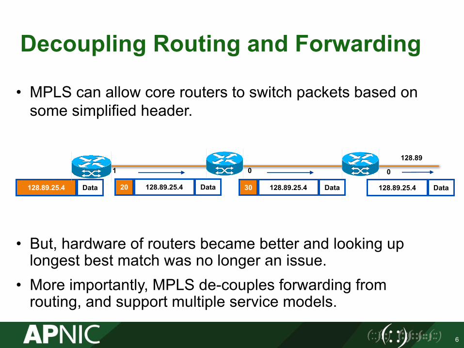
Decoupling Routing and Forwarding
6
• MPLS can allow core routers to switch packets based on some simplified header.
• But, hardware of routers became better and looking up longest best match was no longer an issue.
• More importantly, MPLS de-couples forwarding from routing, and support multiple service models.
1
0
1
128.89.25.4 Data 128.89.25.4 Data20 128.89.25.4 Data30 128.89.25.4 Data
128.89
01 0
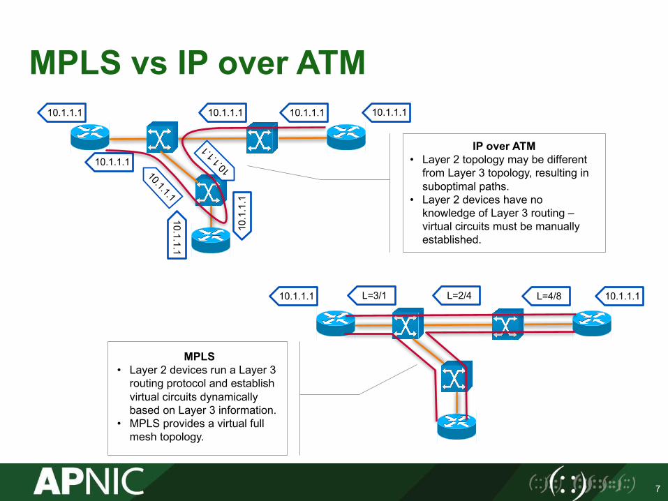
MPLS vs IP over ATM
7
10.1.1.1
MPLS• Layer 2 devices run a Layer 3
routing protocol and establish virtual circuits dynamically based on Layer 3 information.
• MPLS provides a virtual full mesh topology.
10.1.1.110.1.1.1
10.1
.1.1
10.1.1.1
10.1.1.1
L=4/8L=2/4L=3/110.1.1.1
10.1.1.1 10.1.1.1
IP over ATM• Layer 2 topology may be different
from Layer 3 topology, resulting in suboptimal paths.
• Layer 2 devices have no knowledge of Layer 3 routing –virtual circuits must be manually established.

VPN B Site 1
VPN B Site 3
VPN B Site 2
VPNA Site 2
MPLS VPN
8
• MPLS Layer 3/ Layer 2 VPN
MPLS Core
CE
CE
CE
CE
CE
PE
PE
PE
PE
PP
P
VPNA Site 1

Optimal Traffic Engineering
9
IP TE MPLS TEShortest path Determines the path at the source based on additional
parameters (available resources and constraints, etc.)Equal cost load balancing Load sharing across unequal paths can be achieved.
Tunnel 1
Tunnel 2
R1 R2
R3
R4 R5
R6
VPN Site
IP Domain
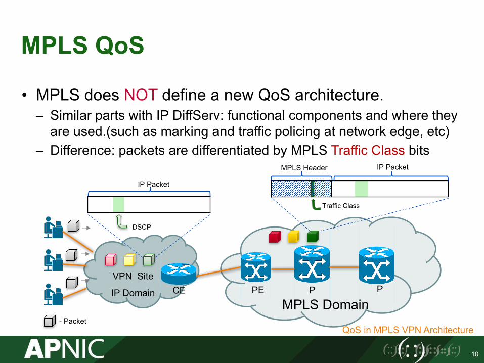
MPLS QoS
• MPLS does NOT define a new QoS architecture. – Similar parts with IP DiffServ: functional components and where they
are used.(such as marking and traffic policing at network edge, etc)– Difference: packets are differentiated by MPLS Traffic Class bits
10
MPLS DomainCE PE PP
QoS in MPLS VPN Architecture
DSCP
MPLS Header
Traffic Class
IP Packet
IP Packet
- Packet

Technology Comparison
IP Native Ethernet MPLS
Forwarding
• Destination address based
• Forwarding table learnedfrom control plane
• TTL support
• Destination address based
• Forwarding table learned from data plane
• No TTL support
• Label based• Forwarding table
learned from control plane
• TTL support
Control Plane Routing protocols Ethernet loop avoidance and signaling protocols
Routing protocolsLabel distribution protocols
Packet Encapsulation IP header 802.3 header MPLS Header
QoS 8 bit TOS in IP header 3 bit 802.1p in VLAN tag 3 bit TC in label
OAM IP Ping, traceroute E-OAM MPLS Ping, traceroute
11

Evolution of MPLS
• Technology Evolution and Main Growth Areas
12
1997 1998 1999 2000 2001 2002 2003 2004 2005 2006 2007 2008 2009 2010 2011 2012 2013 2014 2015
Complete base MPLS portfolio
Optimize MPLS for video
Optimize MPLS for packet transport
Optimize MPLS for Cloud
Today
Formation of the IETF MPLS working group
First MPLS L3VPN &TE
Deployed
First MPLS RFCs
Released
First L2VPNDeployments
Large Scale L3VPN
Deployments
Large Scale
MPLS TEDeployed
Large Scale L2VPN
Deployments
First LSMDeployme
nts
First MPLS TP
Deployments
1996, Ipsilon, Cisco and IBM announced label switching plans, till now, there are over 280 RFCs of MPLS tech.
Bring MPLS to Market

MPLS Application Scenario
13
MPLS CORE
Enterprise
Enterprise
Enterprise
L3VPN
L2VPN L2VPN
EnterpriseTE Main Path for PE1-PE3
TE Backup Path for PE1-PE3
PE1 P
PE2
PE3
PE4
P
P P
QoS Operations:Congestion management, congestion avoidance
QoS Operations:Traffic marking, police, shaping
QoS Operations :Traffic marking, police, shaping
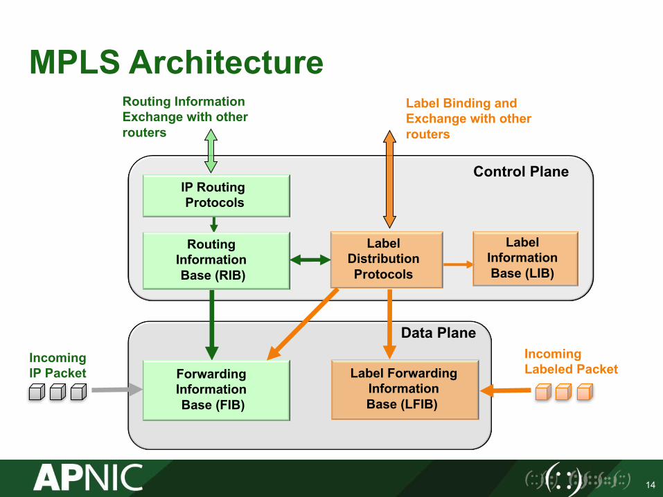
MPLS Architecture
14
IP RoutingProtocols
Label DistributionProtocols
Control Plane
Routing Information Exchange with other routers
Data Plane
Label Binding and Exchange with other routers
Incoming IP Packet
Incoming Labeled Packet
Routing Information Base (RIB)
Forwarding Information Base (FIB)
Label Information Base (LIB)
Label ForwardingInformation Base (LFIB)

IP Domain
MPLS Topology
15
• LSR (Label Switch Router) is a router that supports MPLS.• LER (Label Edge Router), also called edge LSR, is an LSR that operates at
the edge of an MPLS network.• LSP (Label Switched Path) is the path through the MPLS network or a part
of it that packets take.
MPLS Domain
EdgeLSR
LSR LSR EdgeLSR
IP PacketLabel IP PacketLabel IP PacketLabel IP PacketIP Packet
IP Domain

MPLS Label
16
TC = Traffic Class: 3 Bits; S = Bottom of Stack: 1 Bit; TTL = Time to Live
0 1 2 30 1 2 3 4 5 6 7 8 9 0 1 2 3 4 5 6 7 8 9 0 1 2 3 4 5 6 7 8 9 0 1
Label - 20bits TC S TTL-8bits
MPLS LabelDatalink Layer Header Layer 2/ Layer 3 Packet
MPLS Label Encapsulation

MPLS Label Stacking
17
• Multiple labels can be used for MPLS packet encapsulation.network. This is done by packing the labels into a stack.
• Some MPLS applications (VPN, etc.) actually need more than one labels in the label stack to forward the labeled packets.
MPLS Label Stack
LAN MAC Label Header
S=1Bottom of Stack Bit Set
S=0
MAC Header Label S Label S Layer 3 Packet
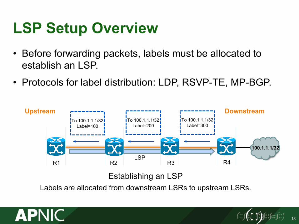
LSP Setup Overview• Before forwarding packets, labels must be allocated to
establish an LSP.
• Protocols for label distribution: LDP, RSVP-TE, MP-BGP.
18
Establishing an LSPLabels are allocated from downstream LSRs to upstream LSRs.
R2
To 100.1.1.1/32Label=100
To 100.1.1.1/32Label=200
To 100.1.1.1/32Label=300
R1 R3 R4LSP
DownstreamUpstream
100.1.1.1/32
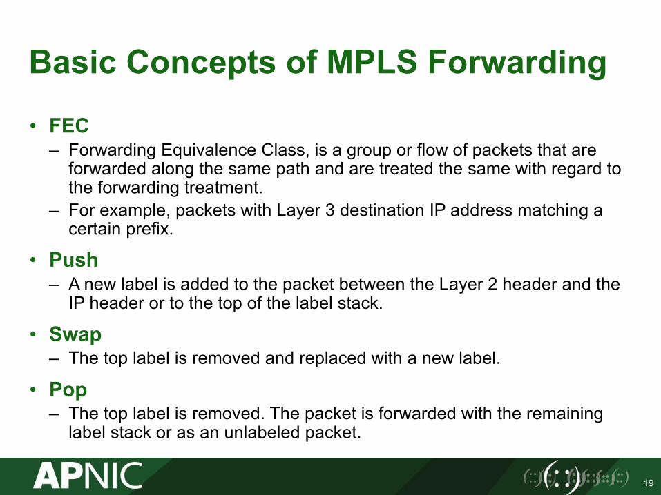
Basic Concepts of MPLS Forwarding
• FEC– Forwarding Equivalence Class, is a group or flow of packets that are
forwarded along the same path and are treated the same with regard to the forwarding treatment.
– For example, packets with Layer 3 destination IP address matching a certain prefix.
• Push– A new label is added to the packet between the Layer 2 header and the
IP header or to the top of the label stack.
• Swap– The top label is removed and replaced with a new label.
• Pop– The top label is removed. The packet is forwarded with the remaining
label stack or as an unlabeled packet.
19

MPLS Forwarding Operations
Prefix: 100.1.1.1/32
Local Label Null
Out Interface E1
Out Label 100
Operation Push
20
R2 R3 R4
IP:100.1.1.1100
100.1.1.1/32
IP:100.1.1.1200 IP:100.1.1.1300
R1
E1 E1 E1E0 E0 E0
Prefix: 100.1.1.1/32
Local Label 100
Out Interface E1
Out Label 200
Operation Swap
Prefix: 100.1.1.1/32
Local Label 200
Out Interface E1
Out Label 300
Operation Swap
Prefix: 100.1.1.1/32
Local Label 300
Out Interface --
Out Label --
Operation POP
Push Swap Swap Pop
Loopback0

Why PHP?
Prefix: 100.1.1.1/32
Local Label Null
Out Interface E1
Out Label 100
Operation Push
21
R2 R3 R4
IP:100.1.1.1100
100.1.1.1/32
IP:100.1.1.1200 IP:100.1.1.1300
R1
E1 E1 E1E0 E0 E0
Prefix: 100.1.1.1/32
Local Label 100
Out Interface E1
Out Label 200
Operation Swap
Prefix: 100.1.1.1/32
Local Label 200
Out Interface E1
Out Label 300
Operation Swap
Prefix: 100.1.1.1/32
Local Label 300
Out Interface --
Out Label --
Operation POP
Push Swap Swap Pop
Review what R4 has done:1. First, lookup the label in the LFIB;
Remove the label2. Then, IP lookup and forward IP packet.
Is the first lookup necessary?
Can we simplify it?
Loopback0
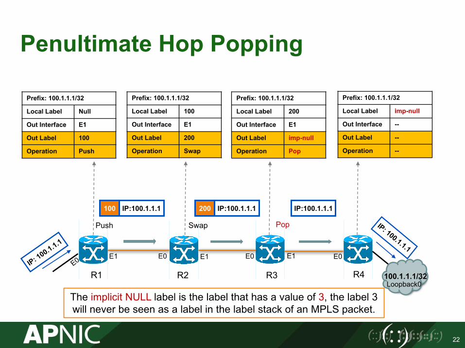
Penultimate Hop Popping
Prefix: 100.1.1.1/32
Local Label Null
Out Interface E1
Out Label 100
Operation Push
22
R2 R3 R4
IP:100.1.1.1100
100.1.1.1/32
IP:100.1.1.1200 IP:100.1.1.1
R1
E1 E1 E1E0 E0 E0
Prefix: 100.1.1.1/32
Local Label 100
Out Interface E1
Out Label 200
Operation Swap
Prefix: 100.1.1.1/32
Local Label 200
Out Interface E1
Out Label imp-null
Operation Pop
Prefix: 100.1.1.1/32
Local Label imp-null
Out Interface --
Out Label --
Operation --
Push Swap Pop
The implicit NULL label is the label that has a value of 3, the label 3 will never be seen as a label in the label stack of an MPLS packet.
Loopback0

MPLS TTL Processing (1)
• MPLS processes the TTL to prevent loops and implement traceroute.
• By default, TTL propagation is enabled as above.
23
IP Domain
MPLS Domain
EdgeLSR
LSR LSR EdgeLSR
TTL=250TTL=251
IP Domain
TTL=250 TTL=249 TTL=250 TTL=248 TTL=247
Decreased & CopiedDecreased & Copied
Only the TTL in the top level decreased

MPLS TTL Processing (2)
• TTL propagation can be disabled to hide the MPLS network topology.
• Disabling TTL propagation makes routers set the value 255 into the TTL field of the label when an IP packet is labeled.
24
IP Domain
MPLS Domain
EdgeLSR
LSR LSR EdgeLSR
TTL=255TTL=251
IP Domain
TTL=250 TTL=254 TTL=250 TTL=249 TTL=248
DecreasedSet 255
Only the TTL in the top level decreased
Decreased
After disabled TTL propagation

MPLS LSP Ping
25
MPLS Domain
R2 R3 R4R1
4.4.4.4/32
R1#ping mpls ipv4 4.4.4.4/32Sending 5, 100-byte MPLS Echos to 4.4.4.4/32,
timeout is 2 seconds, send interval is 0 msec:Codes: '!' - success, 'Q' - request not sent, '.' - timeout,'L' - labeled output interface, 'B' - unlabeled output interface,'D' - DS Map mismatch, 'F' - no FEC mapping, 'f' - FEC mismatch,'M' - malformed request, 'm' - unsupported tlvs, 'N' - no label entry,'P' - no rx intf label prot, 'p' - premature termination of LSP,'R' - transit router, 'I' - unknown upstream index,'l' - Label switched with FEC change, 'd' - see DDMAP for return code,'X' - unknown return code, 'x' - return code 0
Type escape sequence to abort.!!!!!Success rate is 100 percent (5/5), round-trip min/avg/max = 12/14/16 msTotal Time Elapsed 128 ms
MPLS EchoRequest
MPLS EchoReply
Cisco IOS
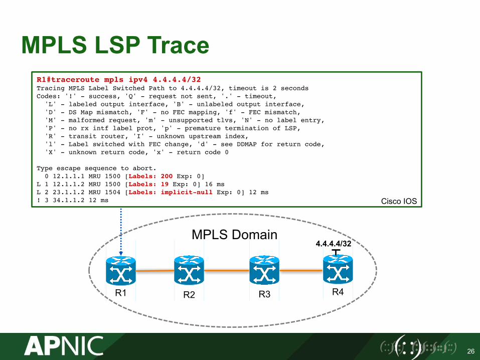
MPLS LSP Trace
26
MPLS Domain
R2 R3 R4R1
4.4.4.4/32
R1#traceroute mpls ipv4 4.4.4.4/32Tracing MPLS Label Switched Path to 4.4.4.4/32, timeout is 2 secondsCodes: '!' - success, 'Q' - request not sent, '.' - timeout,'L' - labeled output interface, 'B' - unlabeled output interface,'D' - DS Map mismatch, 'F' - no FEC mapping, 'f' - FEC mismatch,'M' - malformed request, 'm' - unsupported tlvs, 'N' - no label entry,'P' - no rx intf label prot, 'p' - premature termination of LSP,'R' - transit router, 'I' - unknown upstream index,'l' - Label switched with FEC change, 'd' - see DDMAP for return code,'X' - unknown return code, 'x' - return code 0
Type escape sequence to abort.0 12.1.1.1 MRU 1500 [Labels: 200 Exp: 0]
L 1 12.1.1.2 MRU 1500 [Labels: 19 Exp: 0] 16 msL 2 23.1.1.2 MRU 1504 [Labels: implicit-null Exp: 0] 12 ms! 3 34.1.1.2 12 ms Cisco IOS
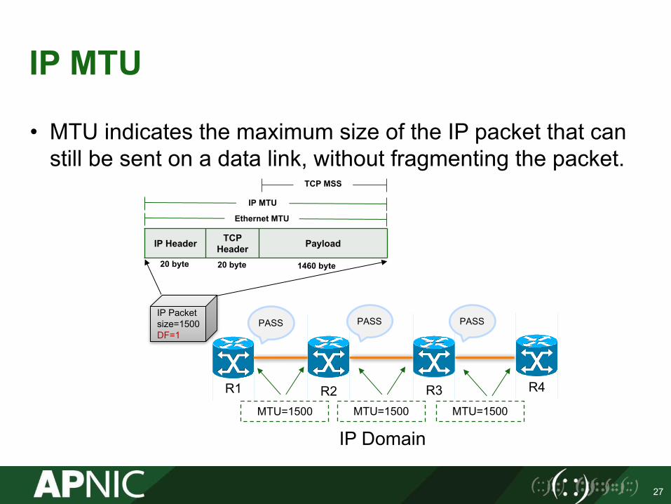
IP MTU
• MTU indicates the maximum size of the IP packet that can still be sent on a data link, without fragmenting the packet.
27
IP Domain
R2 R3 R4R1
MTU=1500 MTU=1500 MTU=1500
IP Packet size=1500DF=1
PASS PASS PASS
IP Header TCPHeader Payload
Ethernet MTU
IP MTU
TCP MSS
20 byte 20 byte 1460 byte
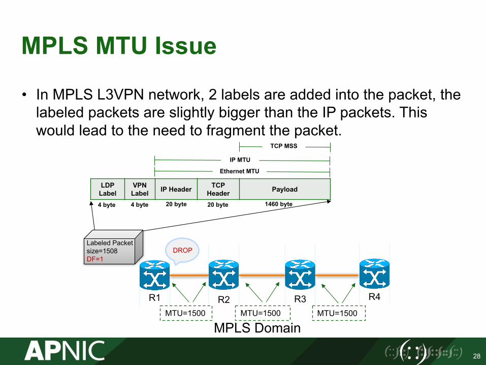
MPLS MTU Issue
28
MPLS Domain
R2 R3 R4R1MTU=1500 MTU=1500 MTU=1500
Labeled Packet size=1508DF=1
DROP
LDPLabel
VPNLabel IP Header TCP
Header Payload
Ethernet MTU
IP MTU
TCP MSS
20 byte 20 byte 1460 byte4 byte 4 byte
• In MPLS L3VPN network, 2 labels are added into the packet, the labeled packets are slightly bigger than the IP packets. This would lead to the need to fragment the packet.

How to Optimize Fragmentation?
• Solution 1. Change MPLS MTU: Make sure that you configure this value on all the links in the path so that the packets are not dropped.
• Solution 2. Change the TCP MSS to be smaller:
29
R1(config)#interface ethernet1/0 R1(config-if)#mpls mtu 1508R1#show mpls interfaces Ethernet 1/0 detail Interface Ethernet1/0:IP labeling enabledLSP Tunnel labeling not enabledBGP labeling not enabledMPLS not operationalMTU = 1508
R1(config)#interface ethernet 1/0R1(config-if)#ip tcp adjust-mss 1452
For detailed, please refer to: https://blog.apnic.net/2014/12/15/ip-mtu-and-tcp-mss-missmatch-an-evil-for-network-performance/
Questions
• Please remember to fill out the feedback form– https://www.surveymonkey.com/r/a
pnic-20171101-eL2
• Slides are available for download from APNIC FTP.
• Acknowledgement to Cisco System.
30

APNIC Helpdesk Chat

32
Thank You!END OF SESSION