Embed Size (px)
Citation preview
00809-0300-4001English
Rev. AA
LCD Meterfor Model 3051 Pressure Transmitters

CONTENTSBefore you Install the Meter Kit . . . . . . . . . . . . . . . . . . . . . . 3
Overview . . . . . . . . . . . . . . . . . . . . . . . . . . . . . . . . . . . . . . . 5
Safety Messages . . . . . . . . . . . . . . . . . . . . . . . . . . . . . . . . . 6
Installation Procedures . . . . . . . . . . . . . . . . . . . . . . . . . . . . 7
Part Numbers 03031-0193-0101 and 03031-0193-0111 7
Part Number 03031-0193-0103 . . . . . . . . . . . . . . . . . . . . 11
Part Numbers 03031-0193-1101 and 03031-0193-1111 . . . 14
Part Number 03031-0193-1103 . . . . . . . . . . . . . . . . . . . . 18
Clone the Transmitter Configuration Parameters . . . . . . . . 22
Configure the Meter for Custom Output . . . . . . . . . . . . . . . . 23
FIGURE 1. Model 3051C with the Optional LCD Meter.
2
BEFORE YOU INSTALL THE METER KIT
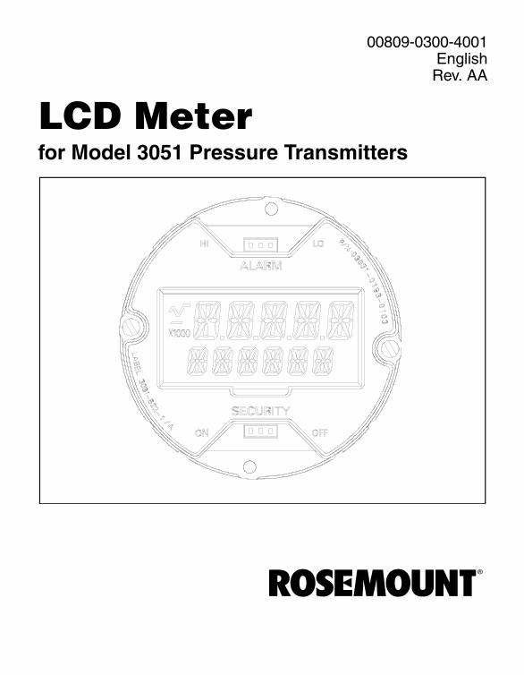
This document contains installation and operation information for six different meter kits. Review Table 1 and Figure 2 carefully to ensure that you are installing the appropriate meter kit.
TABLE 1. Descriptions of the Meter Kits.
Part Number Description
03031-0193-0101 Meter kit – for use with improved style aluminum housing
03031-0193-0111 Meter kit – for use with improved style stainless steel housing
03031-0193-1101 Meter kit – for use with previous style aluminum housing
03031-0193-1111 Meter kit – for use with previous style stainless steel housing
03031-0193-0103 Meter only – for use with improved style aluminum or stainless steel housings
03031-0193-1103 Meter only – for use with previous style aluminum or stainless steel housings
3
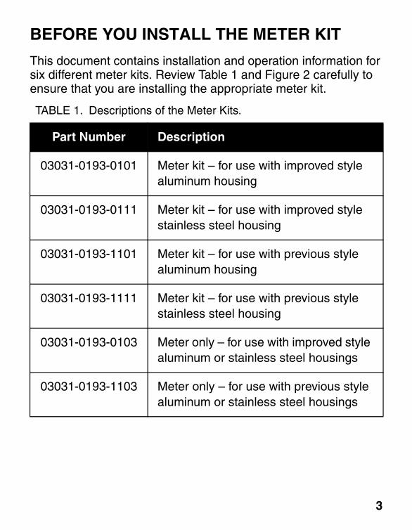
FIGURE 2. Improved and Previous Styles of the Model 3051 Transmitter Housing.
4.0 in.(105 mm)
3.2 in.(80 mm)
IMPROVED HOUSING PREVIOUS HOUSING
4

OVERVIEW
The LCD meter provides local indication of the output, and abbreviated diagnostic messages governing transmitter operation. The meter is located on the electronics board side of the transmitter, and receives its output information directly from the electronics board microprocessor. An extended cover is required to accommodate the meter.
The meter features a two-line display that accommodates five digits for reporting the process variable on the top line, and six characters for displaying engineering units on the bottom line. And in addition to units of pressure, the new LCD meter is capable of displaying flow and level units. The meter uses both lines to display diagnostic messages. You can configure the meter to display the following information:
� Engineering Units� Percent of Range� User-Configurable LCD Scale � Alternating between any two of the above
The user-configurable scale is a new feature that enables you to configure the LCD meter to a custom scale for flow or level. You can configure the meter using a Model 275 HART Communicator or AMS. With the user configurable scale feature, you can define the decimal point position, the upper range value, the lower range value, the engineering units, and the transfer function.
The user-configurable meter scale transfer function is independent of the transmitter analog output transfer function, which allows the meter to display square root flow output while the analog output remains linear with the pressure input.
5

SAFETY MESSAGES
Procedures and instructions in this manual may require special precautions to ensure the safety of the personnel performing the operations. Information that raises potential safety issues is indicated by a warning symbol ( ). Refer to the following safety messages before performing an operation preceded by this symbol.
Explosions can result in death or serious injury.• Do not remove the transmitter covers in explosive
atmospheres when the circuit is alive.
• Both transmitter covers must be fully engaged to meet explosionproof requirements.
• Before connecting a communicator in an explosive atmosphere, make sure the instruments in the loop are installed in accordance with intrinsically safe or nonincendive field wiring practices.
6

INSTALLATION PROCEDURES
The installation procedures vary depending on the style of housing and the meter kit. Examine your meter part numbers closely to ensure that you perform the appropriate procedure.
Part Numbers 03031-0193-0101and 03031-0193-0111
The meter kit includes:� one LCD meter display� one extended cover with O-ring� two captive screws� one ten-pin interconnection header
Use the following procedure and Figure 3 to install the LCD meter.
NOTEThe LCD meter and the electronics board areelectrostatically sensitive; observe handling precautions for static-sensitive components.
7
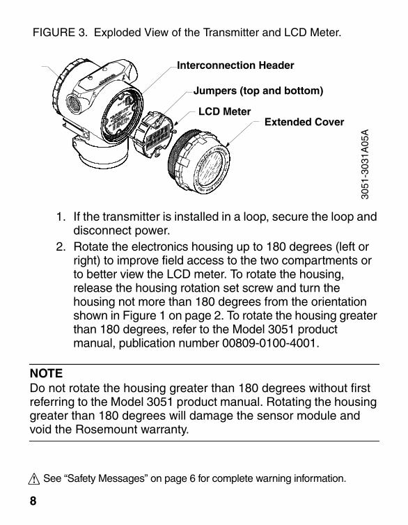
FIGURE 3. Exploded View of the Transmitter and LCD Meter.
1. If the transmitter is installed in a loop, secure the loop and disconnect power.
2. Rotate the electronics housing up to 180 degrees (left or right) to improve field access to the two compartments or to better view the LCD meter. To rotate the housing, release the housing rotation set screw and turn the housing not more than 180 degrees from the orientation shown in Figure 1 on page 2. To rotate the housing greater than 180 degrees, refer to the Model 3051 product manual, publication number 00809-0100-4001.
NOTEDo not rotate the housing greater than 180 degrees without first referring to the Model 3051 product manual. Rotating the housing greater than 180 degrees will damage the sensor module and void the Rosemount warranty.
Interconnection Header
Jumpers (top and bottom)
LCD MeterExtended Cover
3051
-303
1A05
A
8
See “Safety Messages” on page 6 for complete warning information.

3. Remove the transmitter cover opposite the field terminal side. Do not remove the instrument covers in explosive environments when the circuit is alive.
4. Remove the alarm and security jumpers from the electronics board, and insert them in their new positions above and below the meter readout on the meter assembly.
NOTEPlace the security jumper in the OFF position to enable meter configuration changes.
5. Insert the interconnection header in the ten-pin socket exposed by removal of the jumpers.
6. Remove and discard the two captive screws from the electronics board. To do so, loosen the screws to release the module, and pull out the screws until they are stopped by the captive thread inside of the circuit board standoffs. Then continue to loosen the screws until you are able to remove them.
7. Gently pull the electronics board out of the housing. Do not detach the ribbon cable from the back of the electronics board.
8. Decide which direction to orient the meter, and position one of the four connectors on the back of the meter assembly to accept the interconnection header.
9
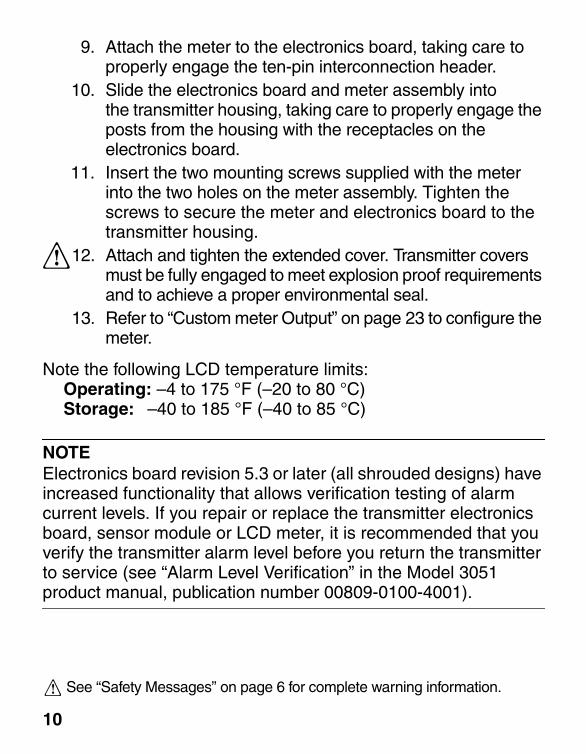
9. Attach the meter to the electronics board, taking care to properly engage the ten-pin interconnection header.
10. Slide the electronics board and meter assembly intothe transmitter housing, taking care to properly engage the posts from the housing with the receptacles on the electronics board.
11. Insert the two mounting screws supplied with the meter into the two holes on the meter assembly. Tighten the screws to secure the meter and electronics board to the transmitter housing.
12. Attach and tighten the extended cover. Transmitter covers must be fully engaged to meet explosion proof requirements and to achieve a proper environmental seal.
13. Refer to “Custom meter Output” on page 23 to configure the meter.
Note the following LCD temperature limits:Operating: –4 to 175 °F (–20 to 80 °C)Storage: –40 to 185 °F (–40 to 85 °C)
NOTEElectronics board revision 5.3 or later (all shrouded designs) have increased functionality that allows verification testing of alarm current levels. If you repair or replace the transmitter electronics board, sensor module or LCD meter, it is recommended that you verify the transmitter alarm level before you return the transmitter to service (see “Alarm Level Verification” in the Model 3051 product manual, publication number 00809-0100-4001).
10
See “Safety Messages” on page 6 for complete warning information.
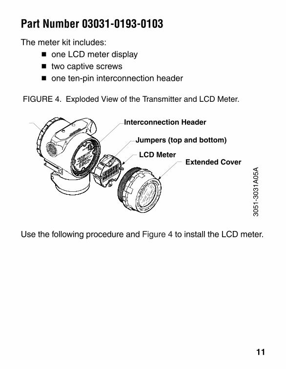
Part Number 03031-0193-0103The meter kit includes:
� one LCD meter display� two captive screws� one ten-pin interconnection header
FIGURE 4. Exploded View of the Transmitter and LCD Meter.
Use the following procedure and Figure 4 to install the LCD meter.
Interconnection Header
Jumpers (top and bottom)
LCD MeterExtended Cover
3051
-303
1A05
A
11

NOTEThe LCD meter and the electronics board are electrostatically sensitive; observe handling precautions for static-sensitive components.
1. If the transmitter is installed in a loop, secure the loop and disconnect power.
2. Remove the LCD meter cover. Do not remove the instrument covers in explosive environments when the circuit is alive.
3. Transfer the alarm and security jumpers from the existing to the new LCD meter.
NOTEPlace the security jumper in the OFF position to enable meter configuration changes.
4. Remove and discard the two captive screws from the existing meter/electronics board assembly. To do so, loosen the screws to release the assembly, and pull out the screws until they are stopped by the captive thread inside of the electronics board standoffs. Then continue to loosen the screws until you are able to remove them.
5. Gently pull the electronics board out of the housing. Do not detach the ribbon cable from the back of the electronics board.
6. Separate the existing LCD meter from the electronics board. Discard the meter.
12
See “Safety Messages” on page 6 for complete warning information.
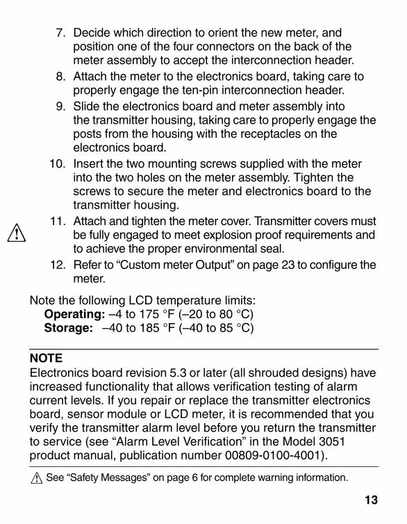
7. Decide which direction to orient the new meter, and position one of the four connectors on the back of the meter assembly to accept the interconnection header.
8. Attach the meter to the electronics board, taking care to properly engage the ten-pin interconnection header.
9. Slide the electronics board and meter assembly intothe transmitter housing, taking care to properly engage the posts from the housing with the receptacles on the electronics board.
10. Insert the two mounting screws supplied with the meter into the two holes on the meter assembly. Tighten the screws to secure the meter and electronics board to the transmitter housing.
11. Attach and tighten the meter cover. Transmitter covers must be fully engaged to meet explosion proof requirements and to achieve the proper environmental seal.
12. Refer to “Custom meter Output” on page 23 to configure the meter.
Note the following LCD temperature limits:Operating: –4 to 175 °F (–20 to 80 °C)Storage: –40 to 185 °F (–40 to 85 °C)
NOTEElectronics board revision 5.3 or later (all shrouded designs) have increased functionality that allows verification testing of alarm current levels. If you repair or replace the transmitter electronics board, sensor module or LCD meter, it is recommended that you verify the transmitter alarm level before you return the transmitter to service (see “Alarm Level Verification” in the Model 3051 product manual, publication number 00809-0100-4001).
See “Safety Messages” on page 6 for complete warning information.
13
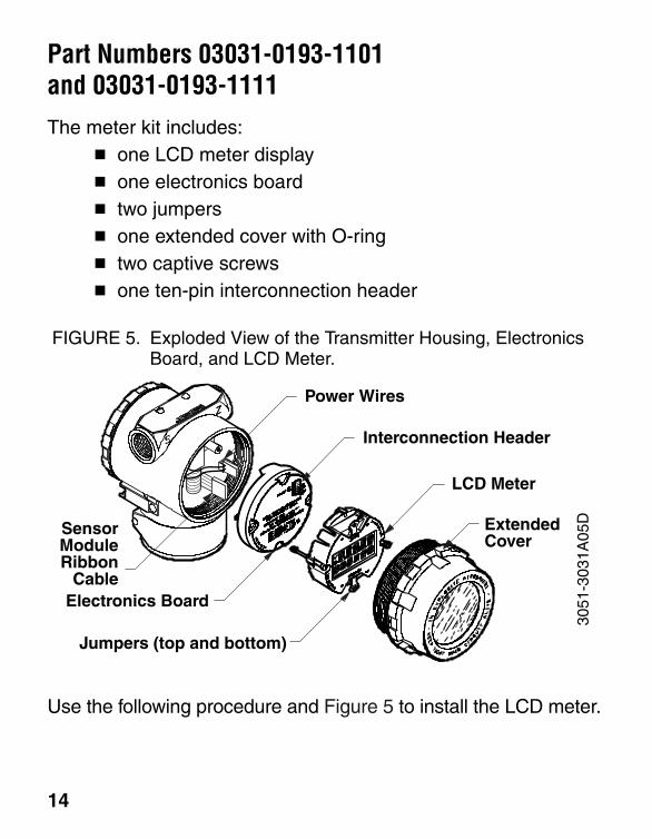
Part Numbers 03031-0193-1101 and 03031-0193-1111The meter kit includes:
� one LCD meter display� one electronics board� two jumpers� one extended cover with O-ring� two captive screws� one ten-pin interconnection header
FIGURE 5. Exploded View of the Transmitter Housing, Electronics Board, and LCD Meter.
Use the following procedure and Figure 5 to install the LCD meter.
Interconnection Header
Jumpers (top and bottom)
LCD Meter
ExtendedCover
3051
-303
1A05
DElectronics Board
Power Wires
SensorModuleRibbon
Cable
14
NOTEThe LCD meter, electronics board, and sensor module are electrostatically sensitive; observe handling precautions for static-sensitive components.
1. Save a copy of the current transmitter configuration data to download to the transmitter after you replace the electronics board and meter (see “Clone the Transmitter Configuration Parameters” on page 22).
2. If the transmitter is installed in a loop, secure the loop and disconnect power.
3. Rotate the electronics housing up to 180 degrees (left or right) to improve field access to the two compartments or to better view the LCD meter. To rotate the housing, release the housing rotation set screw and turn the housing not more than 180 degrees from the orientation shown in Figure 1 on page 2. To rotate the housing greater than 180 degrees, refer to the Model 3051 product manual, publication number 00809-0100-4001.
NOTEDo not rotate the housing greater than 180 degrees without first referring to the Model 3051 product manual. Rotating the housing greater than 180 degrees will damage the sensor module and void the Rosemount warranty.
15
See “Safety Messages” on page 6 for complete warning information.

4. Remove the transmitter cover opposite the field terminal side. Do not remove the instrument covers in explosive environments when the circuit is alive.
5. Loosen the two captive screws that anchor the electronics board in place.
6. Gently pull the electronics board out of the housing, and detach the sensor module ribbon cable and the power wires from the back side.
7. Install the alarm and security jumpers supplied with the new meter kit on the face of the meter.
NOTEPlace the security jumper in the OFF position to enable meter configuration changes.
8. Install the ten-pin interconnection header supplied with the new meter kit in the socket in the upper right corner of the electronics board.
9. Decide which direction to orient the meter, and position one of the four connectors on the back of the meter assembly to accept the interconnection header.
10. Attach the meter to the electronics board, taking care to properly engage the ten-pin interconnection header.
11. Install the two mounting screws included with the meter kit in the mounting holes on both sides of the meter.
12. Attach the sensor module ribbon cable and the power wires to the back side of the electronics board. If properly connected, the power wires should trail toward the center of the board.
16

13. Slide the electronics board and meter assembly into the transmitter housing, and tighten the mounting screws to secure the assembly. Take care not to pinch the power wires behind the white standoff on the back side of the electronics board.
14. Attach and tighten the extended cover provided with the new meter kit. Transmitter covers must be fully engaged to meet explosion proof requirements and to achieve the proper environmental seal.
15. Refer to “Custom meter Output” on page 23 to configure the meter.
Note the following LCD temperature limits:Operating: –4 to 175 °F (–20 to 80 °C)Storage: –40 to 185 °F (–40 to 85 °C)
NOTEElectronics board revision 5.3 or later (all shrouded designs) have increased functionality that allows verification testing of alarm current levels. If you repair or replace the transmitter electronics board, sensor module or LCD meter, it is recommended that you verify the transmitter alarm level before you return the transmitter to service (see “Alarm Level Verification” in the Model 3051 product manual, publication number 00809-0100-4001).
17
See “Safety Messages” on page 6 for complete warning information.

Part Number 03031-0193-1103The meter kit includes:
� one LCD meter display� one electronics board� two jumpers� two captive screws� one ten-pin interconnection header
FIGURE 6. Exploded View of the Transmitter Housing, Electronics Board, and LCD Meter.
Use the following procedure and Figure 6 to install the LCD meter.
Interconnection Header
Jumpers (top and bottom)
LCD Meter
3051
-303
1A05
D
Power Wires
SensorModuleRibbon
CableElectronics Board
ExtendedCover
18
NOTEThe LCD meter and the electronics board are electrostatically sensitive; observe handling precautions for static-sensitive components.
1. Save a copy of the current transmitter configuration data to download to the transmitter after you replace the electronics board and meter (see “Clone the Transmitter Configuration Parameters” on page 22).
2. If the transmitter is installed in a loop, secure the loop and disconnect power.
3. Rotate the electronics housing up to 180 degrees (left or right) to improve field access to the two compartments or to better view the LCD meter. To rotate the housing, release the housing rotation set screw and turn the housing not more than 180 degrees from the orientation shown in Figure 1 on page 2. To rotate the housing greater than 180 degrees, refer to the Model 3051 product manual, publication number 00809-0100-4001.
NOTEDo not rotate the housing greater than 180 degrees without first referring to the Model 3051 product manual. Rotating the housing greater than 180 degrees will damage the sensor module and void the Rosemount warranty.
19
See “Safety Messages” on page 6 for complete warning information.
4. Remove the existing LCD meter cover. Do not remove the instrument covers in explosive environments when the circuit is alive.
5. Loosen the two captive screws that anchor the existing electronics board and LCD meter in place.
6. Gently pull the electronics board and LCD meter out of the housing, and detach the sensor module ribbon cable and the power wires from the back side.
7. Install the alarm and security jumpers supplied with the new meter kit on the face of the new meter.
NOTEPlace the security jumper in the OFF position to enable meter configuration changes.
8. Install the ten-pin interconnection header supplied with the new meter kit in the socket in the upper right corner of the new electronics board.
9. Decide which direction to orient the meter, and position one of the four connectors on the back of the meter assembly to accept the interconnection header.
10. Attach the meter to the electronics board, taking care to properly engage the ten-pin interconnection header.
11. Install the two mounting screws included with the meter kit in the mounting holes on both sides of the meter.
12. Attach the sensor module ribbon cable and the power wires to the back side of the electronics board. If properly connected, the power wires should trail toward the center of the board.
20

13. Slide the electronics board and meter assembly into the transmitter housing, and tighten the mounting screws to secure the assembly. Take care not to pinch the power wires behind the white standoff on the back side of the electronics board.
14. Attach and tighten the extended cover. Transmitter covers must be fully engaged to meet explosion proof requirements and to achieve the proper environmental seal.
15. Refer to “Custom meter Output” on page 23 to configure the meter.
Note the following LCD temperature limits:Operating: –4 to 175 °F (–20 to 80 °C)Storage: –40 to 185 °F (–40 to 85 °C)
NOTEElectronics board revision 5.3 or later (all shrouded designs) have increased functionality that allows verification testing of alarm current levels. If you repair or replace the transmitter electronics board, sensor module or LCD meter, it is recommended that you verify the transmitter alarm level before you return the transmitter to service (see “Alarm Level Verification” in the Model 3051 product manual, publication number 00809-0100-4001).
21See “Safety Messages” on page 6 for complete warning information.
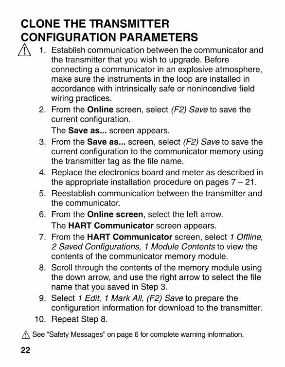
CLONE THE TRANSMITTER CONFIGURATION PARAMETERS
1. Establish communication between the communicator and the transmitter that you wish to upgrade. Before connecting a communicator in an explosive atmosphere, make sure the instruments in the loop are installed in accordance with intrinsically safe or nonincendive field wiring practices.
2. From the Online screen, select (F2) Save to save the current configuration.The Save as... screen appears.
3. From the Save as... screen, select (F2) Save to save the current configuration to the communicator memory using the transmitter tag as the file name.
4. Replace the electronics board and meter as described in the appropriate installation procedure on pages 7 – 21.
5. Reestablish communication between the transmitter and the communicator.
6. From the Online screen, select the left arrow.The HART Communicator screen appears.
7. From the HART Communicator screen, select 1 Offline, 2 Saved Configurations, 1 Module Contents to view the contents of the communicator memory module.
8. Scroll through the contents of the memory module using the down arrow, and use the right arrow to select the file name that you saved in Step 3.
9. Select 1 Edit, 1 Mark All, (F2) Save to prepare the configuration information for download to the transmitter.
10. Repeat Step 8.
See “Safety Messages” on page 6 for complete warning information.
22
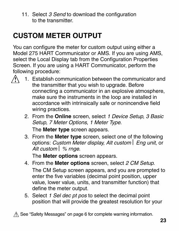
11. Select 3 Send to download the configuration to the transmitter.
CUSTOM METER OUTPUT
You can configure the meter for custom output using either a Model 275 HART Communicator or AMS. If you are using AMS, select the Local Display tab from the Configuration Properties Screen. If you are using a HART Communicator, perform the following procedure:
1. Establish communication between the communicator and the transmitter that you wish to upgrade. Before connecting a communicator in an explosive atmosphere, make sure the instruments in the loop are installed in accordance with intrinsically safe or nonincendive field wiring practices.
2. From the Online screen, select 1 Device Setup, 3 Basic Setup, 7 Meter Options, 1 Meter Type.The Meter type screen appears.
3. From the Meter type screen, select one of the following options: Custom Meter display, Alt custom Eng unit, or Alt custom % rnge.The Meter options screen appears.
4. From the Meter options screen, select 2 CM Setup.The CM Setup screen appears, and you are prompted to enter the five variables (decimal point position, upper value, lower value, units, and transmitter function) that define the meter output.
5. Select 1 Sel dec pt pos to select the decimal point position that will provide the greatest resolution for your
See “Safety Messages” on page 6 for complete warning information.
23
Rosemount Inc. Fisher-Rosemount Limited Fisher-Rosemount
desired output. For example, for an output of 0 to 75 GPM, select 4 XX.XXX.
6. Select F2 Send to send this information to the transmitter.
7. Select 2 CM Upper Value, and enter the value that you wish the transmitter to read at the 20 mA point.
8. Select 3 CM Lower Value, and enter the value that you wish the transmitter to read at the 4 mA point.
9. Select 4 CM Units, and enter the custom units (five characters maximum) that you wish the meter to display.
10. Select 5 CM xf fnct, and enter the transmitter transfer function for the meter. Select Sq root for displaying flow units.
NOTEThe custom meter transfer function is independent of the analog output transfer function.
11. Select (F2) Send to send the configuration information to the transmitter.
8200 Market BoulevardChanhassen, MN 55317 USATel 1-800-999-9307Telex 4310012Fax (612) 949-7001 PR
INTED
INU.S. A.
© Rosemount Inc. 1998.http://www.rosemount.com
¢00809-0300-4001e¤00809-0300-4001, Rev. AA
Heath Place Bognor RegisWest Sussex PO22 9SHEnglandTel 44 (1243) 863 121Fax 44 (1243) 867 5541
Singapore Pte Ltd.1 Pandan CrescentSingapore 128461Tel (65) 777-8211Fax (65) 770-8007Tlx RS 61117 FRSPL


![Untitled-1 [] · YT.. 0300 YT.. 0300 YT.. 0300 YT.. 0300. Title: Untitled-1 Author: Eyup Created Date: 4/4/2016 11:28:30 AM](https://img.dokumen.tips/doc/110x75/5f24e2450a7e2c6cc2663645/untitled-1-yt-0300-yt-0300-yt-0300-yt-0300-title-untitled-1-author.jpg)


![D1 4001 E D1 4001 EI - Bekodownload.beko.com/.../26911_92492-Beko-D1-4001-E_TR.pdfD1 4001 E - D1 4001 EI 0DNLQHQL]LQoDOÕúWÕUÕOPDVÕ 3URJUDPYHW NHWLPWDEORVX 7DEORGDYHULOHQGH÷HUOHUVWDQGDUWNRúXOODUGDKHVDSODQPÕúWÕU](https://img.dokumen.tips/doc/110x75/60d6c0e9677a4e73db624be3/d1-4001-e-d1-4001-ei-d1-4001-e-d1-4001-ei-0dnlqhqllqodowuopdv-3urjudpyhw.jpg)