Embed Size (px)
Citation preview
67
Inp
uts
LCN Inputs
Perfection.ISSENDORFF KG Magdeburger Str.3 30880 Rethen/Germany Tel: +49 (0)5066 99 80 www.LCN.eu
High-End Building Management
1992 2017YEARS
LCN

68
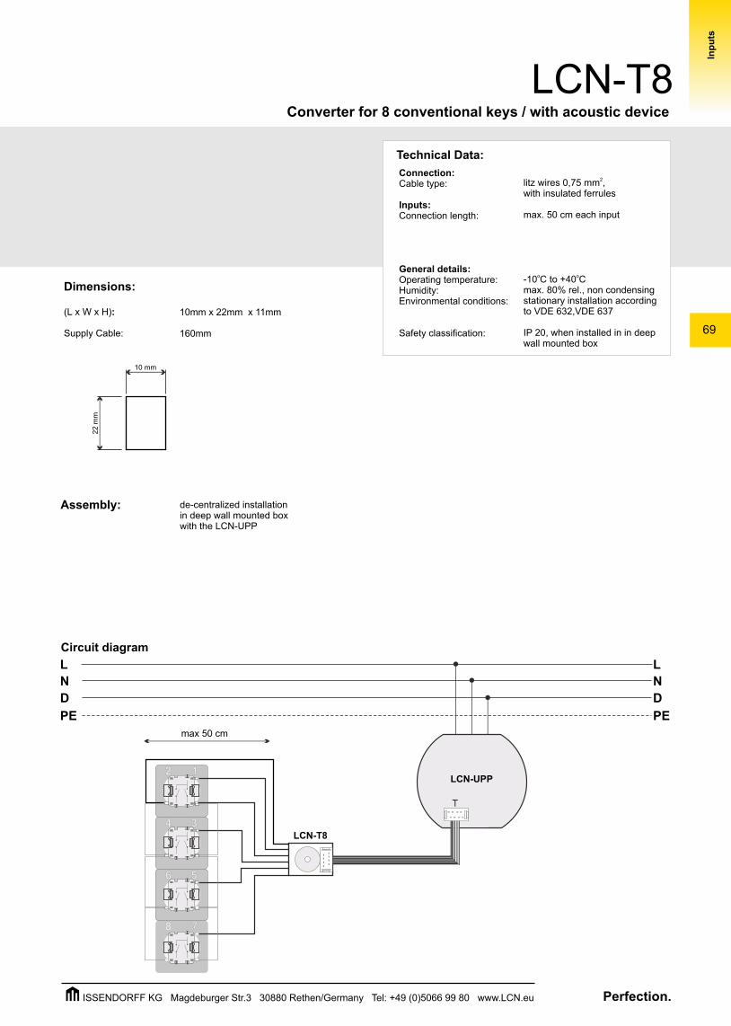
The LCN-T8 is an LCN connection set of cables with an acoustic signal device for conventional potential-free sensors.It is suited for use with the LCN-UPP, LCN-UPS or LCN-UP24 module; it can however be used with the LCN-HU, LCN-SH and LCN-LD.
Each key connection distinguishes between the 'Hit, Hold and Release' functions.
Description:
The LCN-T8 is a connection cable for a max. of 8 UP key converters for simple wiring in a flush mounted wall box.
It can also be used for two 'multi-switches' (with 4 single contacts).
Hardware equipment:
Cable with plug for T-Port connection
Litz wire connection with insulated ferrules for the key sensors
Acoustic signal device
Note:
The connecting cables between key sensor and the LCN-T8 must not exceed the maximum length of 0.5m. For longer connections the LCN-BT4R is available. Not suitable for permanent contacts (switches, binary sensors,...)
Inp
uts
Bus Module
Converter for 8 conventional keys / with acoustic device
LCN-T8
Perfection.ISSENDORFF KG Magdeburger Str.3 30880 Rethen/Germany Tel: +49 (0)5066 99 80 www.LCN.eu
69
Converter for 8 conventional keys / with acoustic device
LCN-T8
D
L
N
PE
D
L
N
PEIn
pu
ts
TT
TT
TT
TT
TT
TT
TT
TT
TT
2 1
34
5
7
6
8
TT
TT
TT
LCN-UPP
T
LCN-T8
Dimensions:
(L x W x H):
Supply Cable:
Assembly: de-centralized installation in deep wall mounted boxwith the LCN-UPP
Technical Data:
Connection:Cable type:
Inputs:Connection length:
General details:Operating temperature:Humidity:Environmental conditions:
Safety classification:
2litz wires 0,75 mm ,with insulated ferrules
max. 50 cm each input
o o-10 C to +40 Cmax. 80% rel., non condensingstationary installation according to VDE 632,VDE 637
IP 20, when installed in in deep wall mounted box
10mm x 22mm x 11mm
160mm
10 mm
22 m
m
Circuit diagram
max 50 cm
Perfection.ISSENDORFF KG Magdeburger Str.3 30880 Rethen/Germany Tel: +49 (0)5066 99 80 www.LCN.eu
70
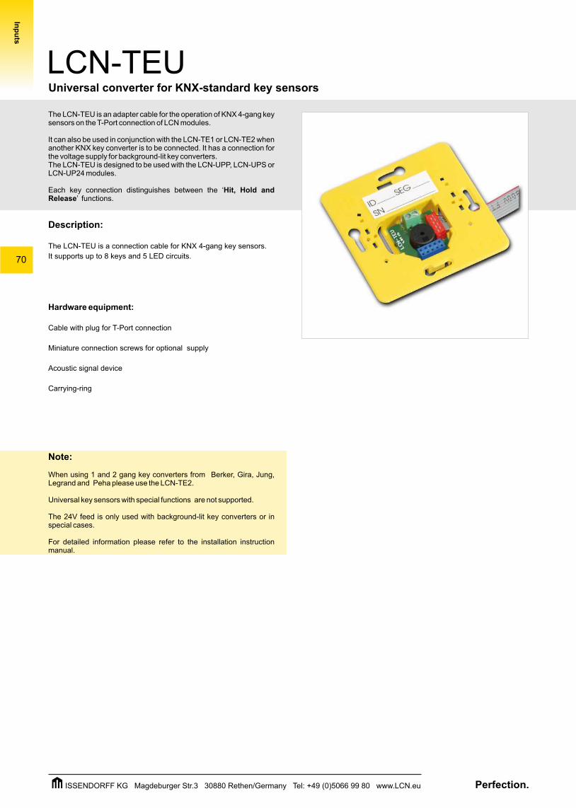
The LCN-TEU is an adapter cable for the operation of KNX 4-gang key sensors on the T-Port connection of LCN modules.
It can also be used in conjunction with the LCN-TE1 or LCN-TE2 when another KNX key converter is to be connected. It has a connection for the voltage supply for background-lit key converters. The LCN-TEU is designed to be used with the LCN-UPP, LCN-UPS or LCN-UP24 modules.
Each key connection distinguishes between the ‘Hit, Hold and Release’ functions.
Description:
The LCN-TEU is a connection cable for KNX 4-gang key sensors.
It supports up to 8 keys and 5 LED circuits.
Hardware equipment:
Cable with plug for T-Port connection
Miniature connection screws for optional supply
Acoustic signal device
Carrying-ring
Note:
When using 1 and 2 gang key converters from Berker, Gira, Jung, Legrand and Peha please use the LCN-TE2.
Universal key sensors with special functions are not supported.
The 24V feed is only used with background-lit key converters or in special cases.
For detailed information please refer to the installation instruction manual.
Bus Module
Universal converter for KNX-standard key sensors
LCN-TEU
Inp
uts
Perfection.ISSENDORFF KG Magdeburger Str.3 30880 Rethen/Germany Tel: +49 (0)5066 99 80 www.LCN.eu
71
Universal converter for KNX-standard key sensors
LCN-TEU
Inp
uts
70mm
70m
m
D
L
N
PE
D
L
N
PE
LCN-UPP
T
option
LCN-NU16
LCN-TEU
Perfection.ISSENDORFF KG Magdeburger Str.3 30880 Rethen/Germany Tel: +49 (0)5066 99 80 www.LCN.eu
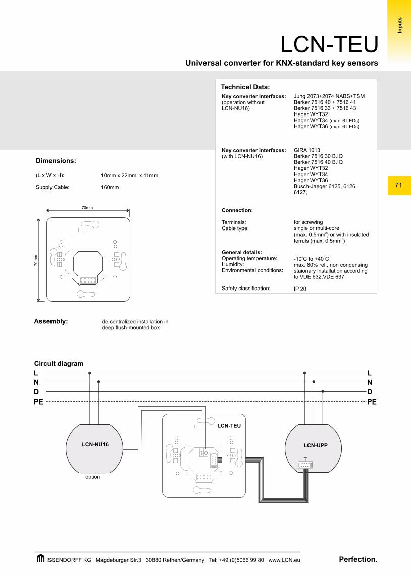
Dimensions:
(L x W x H):
Supply Cable:
Assembly:
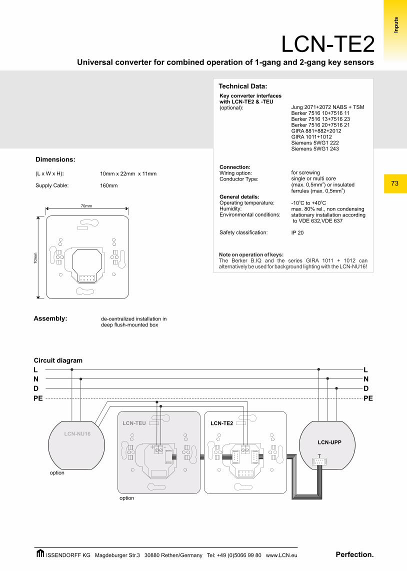
10mm x 22mm x 11mm
160mm
de-centralized installation in deep flush-mounted box
Circuit diagram
Technical Data:
Key converter interfaces(operation without LCN-NU16)
Key converter interfaces:(with LCN-NU16)
Connection:
Terminals:Cable type:
General details:Operating temperature:Humidity:Environmental conditions:
Safety classification:
: Jung 2073+2074 NABS+TSMBerker 7516 40 + 7516 41Berker 7516 33 + 7516 43Hager WYT32Hager WYT34 (max. 6 LEDs)
Hager WYT36 (max. 6 LEDs)
GIRA 1013 Berker 7516 30 B.IQBerker 7516 40 B.IQHager WYT32Hager WYT34 Hager WYT36 Busch-Jaeger 6125, 6126, 6127,
for screwingsingle or multi-core
2(max. 0,5mm ) or with insulated 2ferruls (max. 0,5mm )
o o-10 C to +40 Cmax. 80% rel., non condensingstaionary installation according to VDE 632,VDE 637
IP 20
72
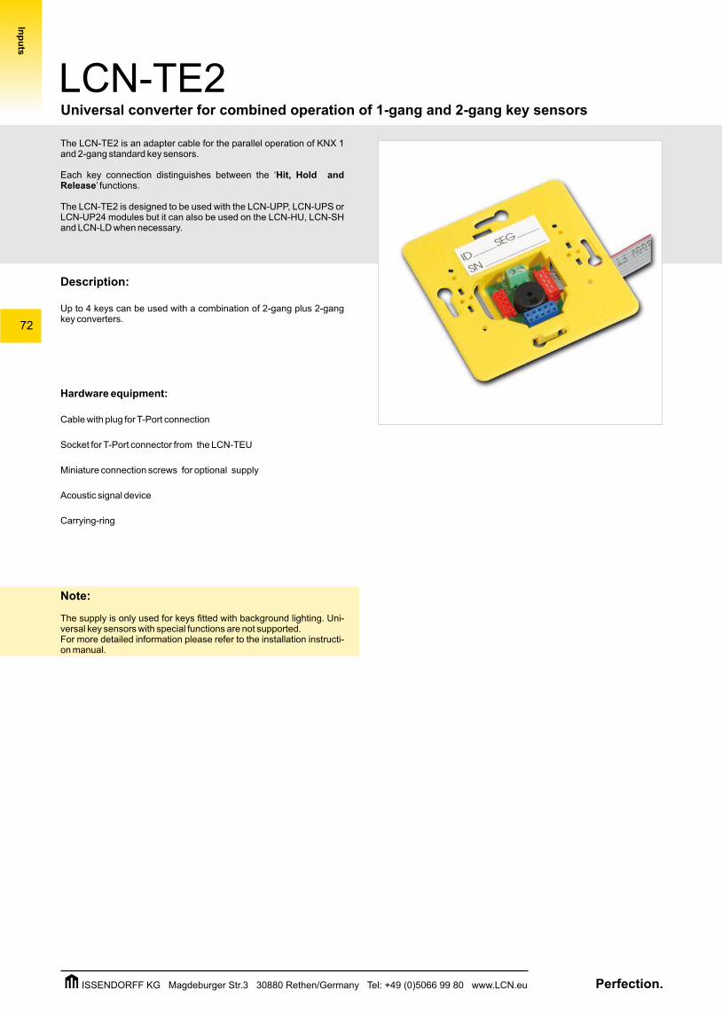
The LCN-TE2 is an adapter cable for the parallel operation of KNX 1 and 2-gang standard key sensors.
Each key connection distinguishes between the ‘Hit, Hold and Release’ functions.
The LCN-TE2 is designed to be used with the LCN-UPP, LCN-UPS or LCN-UP24 modules but it can also be used on the LCN-HU, LCN-SH and LCN-LD when necessary.
Description:
Up to 4 keys can be used with a combination of 2-gang plus 2-gang key converters.
Hardware equipment:
Cable with plug for T-Port connection
Socket for T-Port connector from the LCN-TEU
Miniature connection screws for optional supply
Acoustic signal device
Carrying-ring
Note:
The supply is only used for keys fitted with background lighting. Uni-versal key sensors with special functions are not supported.For more detailed information please refer to the installation instructi-on manual.
Bus Module
Universal converter for combined operation of 1-gang and 2-gang key sensors
LCN-TE2
Inp
uts
Perfection.ISSENDORFF KG Magdeburger Str.3 30880 Rethen/Germany Tel: +49 (0)5066 99 80 www.LCN.eu
73
Universal converter for combined operation of 1-gang and 2-gang key sensors
LCN-TE2
Inp
uts
D
L
N
PE
D
L
N
PE
-+
LCN-TEU
optional
LCN-TE2
LCN-UPP
T
option
option
LCN-NU16
70mm
70m
m
Dimensions:
(L x W x H):
Supply Cable:
Assembly:
10mm x 22mm x 11mm
160mm
de-centralized installation in deep flush-mounted box
Technical Data:
Jung 2071+2072 NABS + TSMBerker 7516 10+7516 11Berker 7516 13+7516 23Berker 7516 20+7516 21GIRA 881+882+2012GIRA 1011+1012 Siemens 5WG1 222Siemens 5WG1 243
for screwingsingle or multi core
2(max. 0,5mm ) or insulated 2ferrules (max. 0,5mm )
o o-10 C to +40 Cmax. 80% rel., non condensing stationary installation according to VDE 632,VDE 637
IP 20
Note on operation of keys:The Berker B.IQ and the series GIRA 1011 + 1012 can alternatively be used for background lighting with the LCN-NU16!
Key converter interfaceswith LCN-TE2 & -TEU (optional):
Connection:Wiring option:Conductor Type:
General details:Operating temperature:Humidity:Environmental conditions:
Safety classification:
Circuit diagram
Perfection.ISSENDORFF KG Magdeburger Str.3 30880 Rethen/Germany Tel: +49 (0)5066 99 80 www.LCN.eu
74
Bus Module
LCN-TE1Universal converter for combined operation of 1-gang and 3/4-gang key sensors
Inp
uts
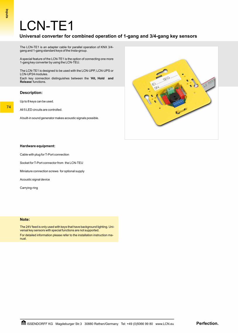
The LCN-TE1 is an adapter cable for parallel operation of KNX 3/4-gang and 1-gang standard keys of the Insta-group.
A special feature of the LCN-TE1 is the option of connecting one more 1-gang key converter by using the LCN-TEU.
The LCN-TE1 is designed to be used with the LCN-UPP, LCN-UPS or LCN-UP24 modules.
Each key connection distinguishes between the ‘Hit, Hold and Release’ functions.
Description:
Up to 8 keys can be used.
All 5 LED circuits are controlled.
A built-in sound generator makes acoustic signals possible.
Hardware equipment:
Cable with plug for T-Port connection
Socket for T-Port connector from the LCN-TEU
Miniature connection screws for optional supply
Acoustic signal device
Carrying-ring
Note:
The 24V feed is only used with keys that have background lighting. Uni-versal key sensors with special functions are not supported.
For detailed information please refer to the installation instruction ma-nual.
Perfection.ISSENDORFF KG Magdeburger Str.3 30880 Rethen/Germany Tel: +49 (0)5066 99 80 www.LCN.eu
75
Inp
uts
Universal converter for combined operation of 1-gang and 3/4-gang key sensors
LCN-TE1
D
L
N
PE
D
L
N
PE
-+
LCN-TEU
optional
LCN-TE1
LCN-UPP
T
option
option
LCN-NU16
Technical Data:
70mm
70m
m
Dimensions:
(L x W x H):
Supply Cable:
Assembly:
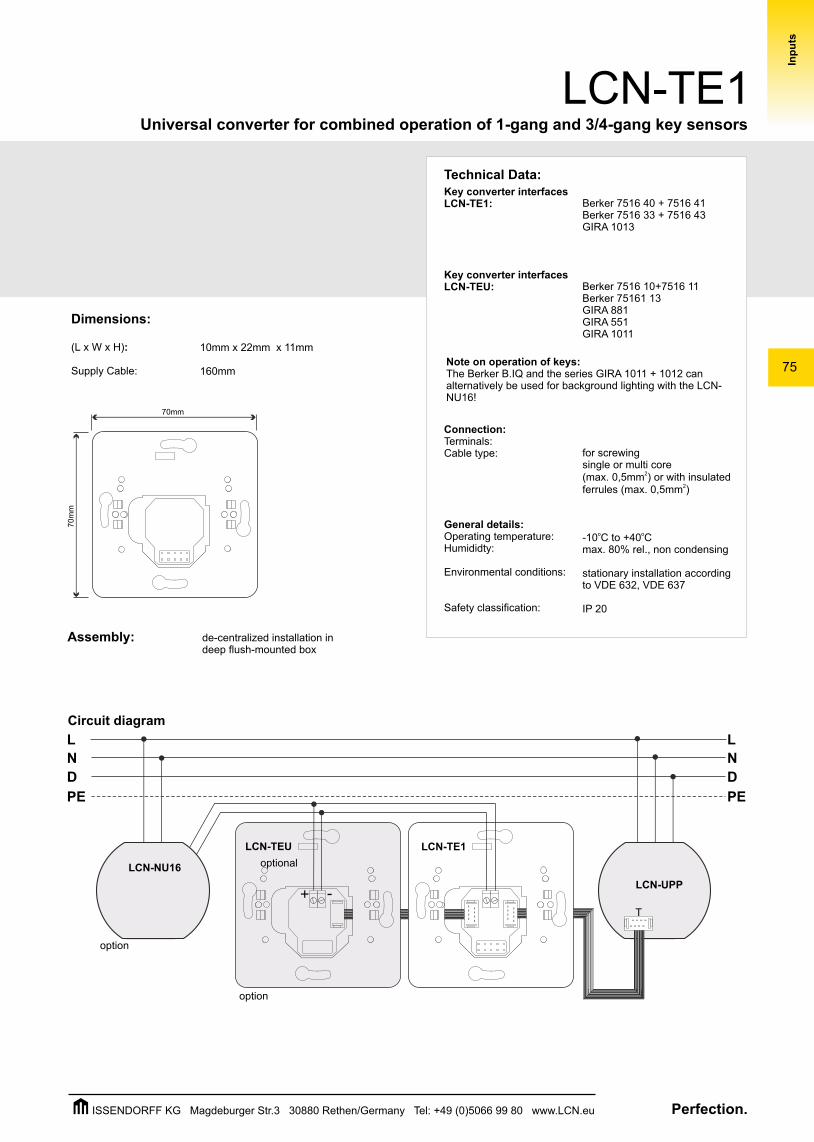
10mm x 22mm x 11mm
160mm
de-centralized installation in deep flush-mounted box
Circuit diagram
Key converter interfaces LCN-TE1:
Key converter interfaces LCN-TEU:
Connection:Terminals:Cable type:
General details:Operating temperature:Humididty:
Environmental conditions:
Safety classification:
Berker 7516 40 + 7516 41Berker 7516 33 + 7516 43GIRA 1013
Berker 7516 10+7516 11Berker 75161 13GIRA 881GIRA 551GIRA 1011
for screwingsingle or multi core
2(max. 0,5mm ) or with insulated 2ferrules (max. 0,5mm )
o o-10 C to +40 Cmax. 80% rel., non condensing
stationary installation according to VDE 632, VDE 637
IP 20
Note on operation of keys:The Berker B.IQ and the series GIRA 1011 + 1012 can alternatively be used for background lighting with the LCN-NU16!
Perfection.ISSENDORFF KG Magdeburger Str.3 30880 Rethen/Germany Tel: +49 (0)5066 99 80 www.LCN.eu
76
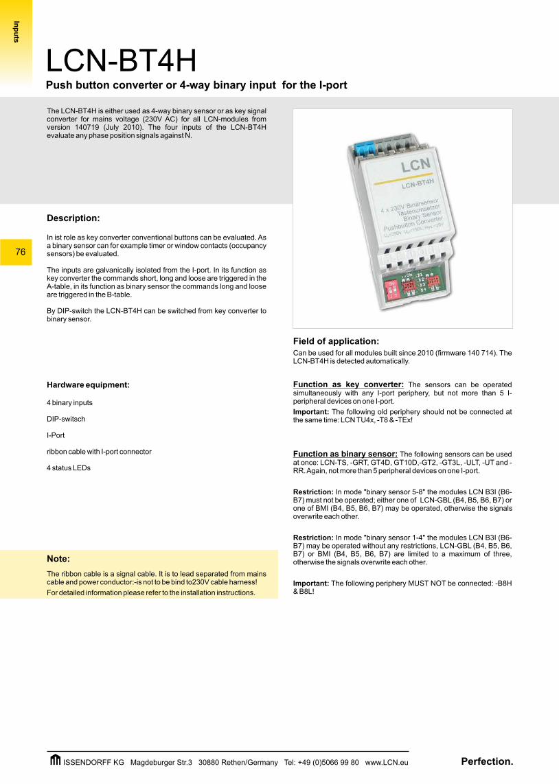
The LCN-BT4H is either used as 4-way binary sensor or as key signal converter for mains voltage (230V AC) for all LCN-modules from version 140719 (July 2010). The four inputs of the LCN-BT4H evaluate any phase position signals against N.
Description:
In ist role as key converter conventional buttons can be evaluated. As a binary sensor can for example timer or window contacts (occupancy sensors) be evaluated.
The inputs are galvanically isolated from the I-port. In its function as key converter the commands short, long and loose are triggered in the A-table, in its function as binary sensor the commands long and loose are triggered in the B-table.
By DIP-switch the LCN-BT4H can be switched from key converter to binary sensor.
Hardware equipment:
4 binary inputs
DIP-switsch
I-Port
ribbon cable with I-port connector
4 status LEDs
Note:
The ribbon cable is a signal cable. It is to lead separated from mains cable and power conductor:-is not to be bind to230V cable harness!
For detailed information please refer to the installation instructions.
Field of application:Can be used for all modules built since 2010 (firmware 140 714). The LCN-BT4H is detected automatically.
Function as key converter: The sensors can be operated simultaneously with any I-port periphery, but not more than 5 I-peripheral devices on one I-port.
Important: The following old periphery should not be connected at the same time: LCN TU4x, -T8 & -TEx!
Function as binary sensor: The following sensors can be used at once: LCN-TS, -GRT, GT4D, GT10D,-GT2, -GT3L, -ULT, -UT and -RR. Again, not more than 5 peripheral devices on one I-port.
Restriction: In mode "binary sensor 5-8" the modules LCN B3I (B6-B7) must not be operated; either one of LCN-GBL (B4, B5, B6, B7) or one of BMI (B4, B5, B6, B7) may be operated, otherwise the signals overwrite each other.
Restriction: In mode "binary sensor 1-4" the modules LCN B3I (B6-B7) may be operated without any restrictions, LCN-GBL (B4, B5, B6, B7) or BMI (B4, B5, B6, B7) are limited to a maximum of three, otherwise the signals overwrite each other.
Important: The following periphery MUST NOT be connected: -B8H & B8L!
LCN-BT4HPush button converter or 4-way binary input for the I-port
Inp
uts
Perfection.ISSENDORFF KG Magdeburger Str.3 30880 Rethen/Germany Tel: +49 (0)5066 99 80 www.LCN.eu
77
LCN-BT4H
Technical data
Push button converter or 4-way binary input for the I-port
D
L
N
PE
D
L
N
PE
Inp
uts
N N
4 3 2 1
On
1 2
1234
On
1 2
LCN
4 x 230VBinärsensor
TastenumsetzerBinary Sensor
Pushbutton ConverterU =230V, U =150V, Hys.=20VN DT
LCN-BT4H
N N
4 3 2 1
On
1 2
1234
On
1 2
LCN
4 x 230VBinärsensor
TastenumsetzerBinary Sensor
Pushbutton ConverterU =230V, U =150V, Hys.=20VN DT
LCN-BT4H
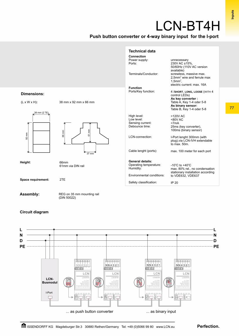
... as push button converter ... as binary input
N N
4 3 2 1
On
1 2
1234
On
1 2
LCN
4 x 230VBinärsensor
TastenumsetzerBinary Sensor
Pushbutton ConverterU =230V, U =150V, Hys.=20VN DT
LCN-BT4H
LCN-Busmodul
N N
4 3 2 1
LCN
4 x 230VBinärsensor
TastenumsetzerBinary Sensor
Pushbutton ConverterU =230V, U =150V, Hys.=20VN DT
LCN-BT4H
On
1 2
1234
On
1 2
I-Port
Dimensions:
(L x W x H): 38 mm x 92 mm x 66 mm
Space requirement:
Assembly:
2TE
Height: 66mm 61mm via DIN rail
REG on 35 mm mounting rail(DIN 50022)
66
mm
37 mm
61 m
m
38 mm (2 TE)
92 m
m
unnecessary230V AC ±15%, 50/60Hz (110V AC version available)screwless, massive max.
22,5mm wire and ferrule max 21,5mm ,
electric current: max. 16A
4 /SHORT, LONG, LOOSE (WITH 4 control LEDs)As key converter :Table A, Key 1-4 oder 5-8As binary sensor: Table B, Key 1-4 oder 5-8
>120V AC<80V AC<7mA 25ms (key converter), 100ms (binary sensor)
I-Port lenght 300mm (with plug),via LCN-IVH extendable to max. 50m.
max. 100 meter for each port
o o-10 C to +40 Cmax. 80% rel., no condensationstationary installation according to VDE632, VDE637
IP 20
ConnectionPower supply:Ports:
Terminals/Conductor:
FunctionPorts/Key function:
High level:Low level:Sensing current:Debounce time:
LCN-connection:
Cable lenght (ports):
General details:Operating temperature:Humidity:
Environmental conditions:
Safety classification:
Circuit diagram
Perfection.ISSENDORFF KG Magdeburger Str.3 30880 Rethen/Germany Tel: +49 (0)5066 99 80 www.LCN.eu
78
LCN-BT4RPush button converter or binary input 4x230V for flush-mounting
Inp
uts
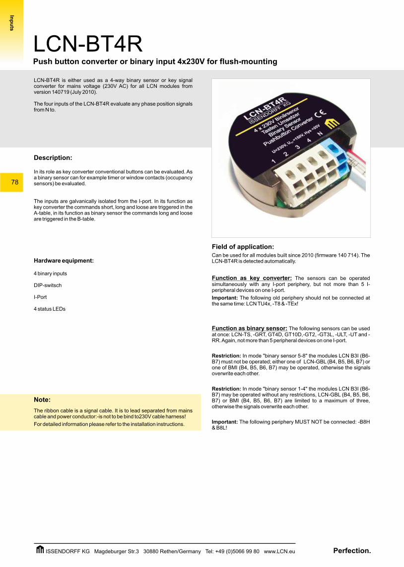
LCN-BT4R is either used as a 4-way binary sensor or key signal converter for mains voltage (230V AC) for all LCN modules from version 140719 (July 2010).
The four inputs of the LCN-BT4R evaluate any phase position signals from N to.
Description:
In its role as key converter conventional buttons can be evaluated. As a binary sensor can for example timer or window contacts (occupancy sensors) be evaluated.
The inputs are galvanically isolated from the I-port. In its function as key converter the commands short, long and loose are triggered in the A-table, in its function as binary sensor the commands long and loose are triggered in the B-table.
Hardware equipment:
4 binary inputs
DIP-switsch
I-Port
4 status LEDs
Note:
The ribbon cable is a signal cable. It is to lead separated from mains cable and power conductor:-is not to be bind to230V cable harness!
For detailed information please refer to the installation instructions.
Field of application:Can be used for all modules built since 2010 (firmware 140 714). The LCN-BT4R is detected automatically.
Function as key converter: The sensors can be operated simultaneously with any I-port periphery, but not more than 5 I-peripheral devices on one I-port.
Important: The following old periphery should not be connected at the same time: LCN TU4x, -T8 & -TEx!
Function as binary sensor: The following sensors can be used at once: LCN-TS, -GRT, GT4D, GT10D,-GT2, -GT3L, -ULT, -UT and -RR. Again, not more than 5 peripheral devices on one I-port.
Restriction: In mode "binary sensor 5-8" the modules LCN B3I (B6-B7) must not be operated; either one of LCN-GBL (B4, B5, B6, B7) or one of BMI (B4, B5, B6, B7) may be operated, otherwise the signals overwrite each other.
Restriction: In mode "binary sensor 1-4" the modules LCN B3I (B6-B7) may be operated without any restrictions, LCN-GBL (B4, B5, B6, B7) or BMI (B4, B5, B6, B7) are limited to a maximum of three, otherwise the signals overwrite each other.
Important: The following periphery MUST NOT be connected: -B8H & B8L!
Perfection.ISSENDORFF KG Magdeburger Str.3 30880 Rethen/Germany Tel: +49 (0)5066 99 80 www.LCN.eu
79
LCN-BT4RPush button converter or binary input 4x230V for wall mounting
Inp
uts
D
L
N
PE
D
L
N
PE
ON
1 2
U=230V, U =150V, Hys=20V MIN
LCN-BT4RISSENDORFF KG
1 2 3 4 N
4 x 230V BinärsensorTasten Umsetzer
Binary SensorPushbutton Converter
BT
5-81-4
ON
1 2
U=230V, U =150V, Hys=20V MIN
LCN-BT4RISSENDORFF KG
1 2 3 4 N
4 x 230V BinärsensorTasten Umsetzer
Binary SensorPushbutton Converter
BT
5-81-4
ON
1 2
U=230V, U =150V, Hys=20V MIN
LCN-BT4RISSENDORFF KG
1 2 3 4 N
4 x 230V BinärsensorTasten Umsetzer
Binary SensorPushbutton Converter
BT
5-81-4
ON
1 2
U=230V, U =150V, Hys=20V MIN
LCN-BT4RISSENDORFF KG
1 2 3 4 N
4 x 230V BinärsensorTasten Umsetzer
Binary SensorPushbutton Converter
BT
5-81-4
LCN-UPSISSENDORFF KG
Schwarz/black
Blau/blue
Weiß/white
L
N
Daten
230VAC 15%50/60 Hz, P <0,5WV
Technical data
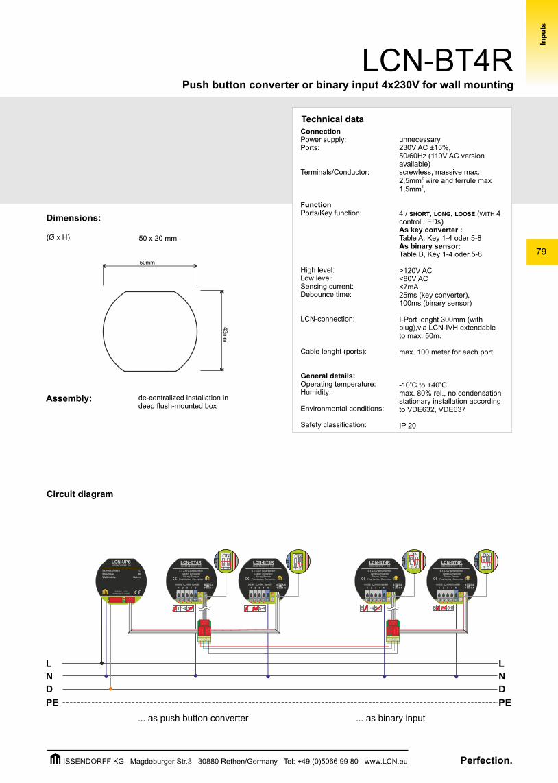
... as binary input... as push button converter
Dimensions:
(Ø x H): 50 x 20 mm
50mm
43m
m
de-centralized installation in deep flush-mounted box
Assembly:
Circuit diagram
unnecessary230V AC ±15%, 50/60Hz (110V AC version available)screwless, massive max.
22,5mm wire and ferrule max 21,5mm ,
4 / SHORT, LONG, LOOSE (WITH 4 control LEDs)As key converter :Table A, Key 1-4 oder 5-8As binary sensor: Table B, Key 1-4 oder 5-8
>120V AC<80V AC<7mA 25ms (key converter), 100ms (binary sensor)
I-Port lenght 300mm (with plug),via LCN-IVH extendable to max. 50m.
max. 100 meter for each port
o o-10 C to +40 Cmax. 80% rel., no condensationstationary installation according to VDE632, VDE637
IP 20
ConnectionPower supply:Ports:
Terminals/Conductor:
FunctionPorts/Key function:
High level:Low level:Sensing current:Debounce time:
LCN-connection:
Cable lenght (ports):
General details:Operating temperature:Humidity:
Environmental conditions:
Safety classification:
Perfection.ISSENDORFF KG Magdeburger Str.3 30880 Rethen/Germany Tel: +49 (0)5066 99 80 www.LCN.eu
80
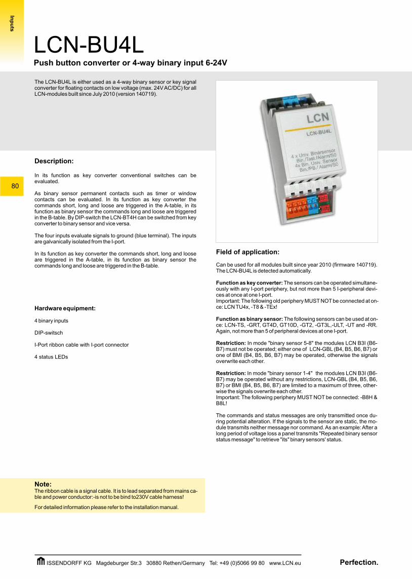
The LCN-BU4L is either used as a 4-way binary sensor or key signal converter for floating contacts on low voltage (max. 24V AC/DC) for all LCN-modules built since July 2010 (version 140719).
Description:
In its function as key converter conventional switches can be evaluated.
As binary sensor permanent contacts such as timer or window contacts can be evaluated. In its function as key converter the commands short, long and loose are triggered in the A-table, in its function as binary sensor the commands long and loose are triggered in the B-table. By DIP-switch the LCN-BT4H can be switched from key converter to binary sensor and vice versa.
The four inputs evaluate signals to ground (blue terminal). The inputs are galvanically isolated from the I-port.
In its function as key converter the commands short, long and loose are triggered in the A-table, in its function as binary sensor the commands long and loose are triggered in the B-table.
Hardware equipment:
4 binary inputs
DIP-switsch
I-Port ribbon cable with I-port connector
4 status LEDs
Note:The ribbon cable is a signal cable. It is to lead separated from mains ca-ble and power conductor:-is not to be bind to230V cable harness!
For detailed information please refer to the installation manual.
Field of application:
Can be used for all modules built since year 2010 (firmware 140719). The LCN-BU4L is detected automatically.
Function as key converter: The sensors can be operated simultane-ously with any I-port periphery, but not more than 5 I-peripheral devi-ces at once at one I-port.Important: The following old periphery MUST NOT be connected at on-ce: LCN TU4x, -T8 & -TEx!
Function as binary sensor: The following sensors can be used at on-ce: LCN-TS, -GRT, GT4D, GT10D, -GT2, -GT3L,-ULT, -UT and -RR. Again, not more than 5 of peripheral devices at one I-port.
Restriction: In mode "binary sensor 5-8" the modules LCN B3I (B6-B7) must not be operated; either one of LCN-GBL (B4, B5, B6, B7) or one of BMI (B4, B5, B6, B7) may be operated, otherwise the signals overwrite each other.
Restriction: In mode "binary sensor 1-4" the modules LCN B3I (B6-B7) may be operated without any restrictions, LCN-GBL (B4, B5, B6, B7) or BMI (B4, B5, B6, B7) are limited to a maximum of three, other-wise the signals overwrite each other.Important: The following periphery MUST NOT be connected: -B8H & B8L!
The commands and status messages are only transmitted once du-ring potential alteration. If the signals to the sensor are static, the mo-dule transmits neither message nor command. As an example: After a long period of voltage loss a panel transmits "Repeated binary sensor status message" to retrieve "its" binary sensors' status.
LCN-BU4LPush button converter or 4-way binary input 6-24V
Inp
uts
Perfection.ISSENDORFF KG Magdeburger Str.3 30880 Rethen/Germany Tel: +49 (0)5066 99 80 www.LCN.eu
81
LCN-BU4LPush button converter or 4-way binary input 6-24V
D
L
N
PE
D
L
N
PE
Inp
uts
o o-10 C to +40 Cmax. 80% rel., no condensationstationary installation according to VDE632, VDE637
IP 20
General details:Operating temperature:Humidity:
Environmental conditions:
Safety classification:
2
L L
N N
LCN
4 x potenzialfreierBinärsensor
Tastenumsetzer4x Bin. Univ. Sensor
Pushbutton Converter
LCN-BU4L
2
L L
N N
LCN
4 x potenzialfreierBinärsensor
Tastenumsetzer4x Bin. Univ. Sensor
Pushbutton Converter
LCN-BU4L
2
On
1 2
On
1 2
L L
N N
LCN
4 x potenzialfreierBinärsensor
Tastenumsetzer4x Bin. Univ. Sensor
Pushbutton Converter
LCN-BU4L
On
1 2
On
1 2
On
1 2
On
1 2
2
L L
N N
LCN
4 x potenzialfreierBinärsensor
Tastenumsetzer4x Bin. Univ. Sensor
Pushbutton Converter
LCN-BU4L
On
1 2
On
1 2
LCN-Busmodul
I-Port
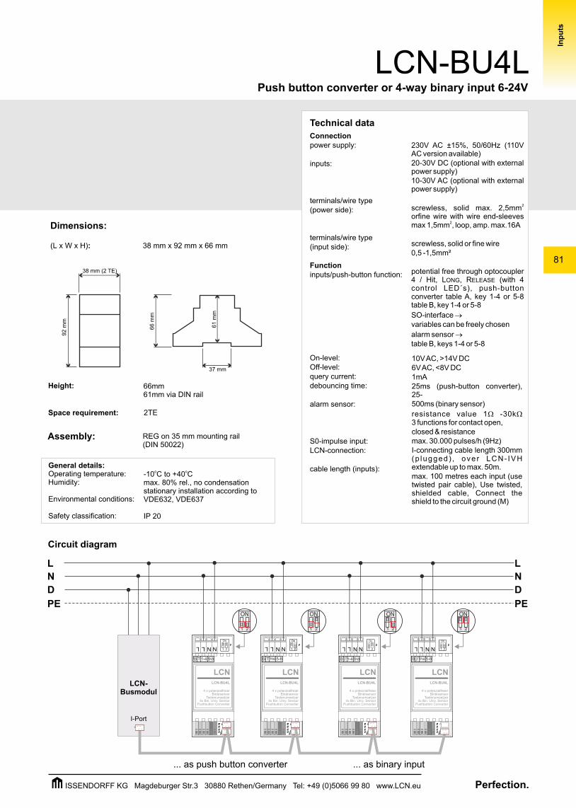
Dimensions:
(L x W x H): 38 mm x 92 mm x 66 mm
Space requirement:
Assembly:
2TE
Height: 66mm 61mm via DIN rail
REG on 35 mm mounting rail(DIN 50022)
66
mm
37 mm
61 m
m
38 mm (2 TE)
92 m
m
... as binary input... as push button converter
Connectionpower supply:
inputs:
terminals/wire type(power side):
terminals/wire type(input side):
Functioninputs/push-button function:
On-level:Off-level:query current:debouncing time:
alarm sensor:
S0-impulse input:LCN-connection:
cable length (inputs):
230V AC ±15%, 50/60Hz (110V AC version available)20-30V DC (optional with external power supply)10-30V AC (optional with external power supply)
2screwless, solid max. 2,5mm orfine wire with wire end-sleeves
2max 1,5mm , loop, amp. max.16A
screwless, solid or fine wire 0,5 -1,5mm²
potential free through optocoupler 4 / Hit, LONG, RELEASE (with 4 control LED´s), push-button converter table A, key 1-4 or 5-8 table B, key 1-4 or 5-8
SO-interface variables can be freely chosen
alarm sensor ® table B, keys 1-4 or 5-8
®
10V AC, >14V DC6V AC, <8V DC1mA 25ms (push-button converter), 25-500ms (binary sensor)
resistance value 1W -30kW3 functions for contact open,closed & resistancemax. 30.000 pulses/h (9Hz)I-connecting cable length 300mm (p lugged) , ove r LCN- IVH extendable up to max. 50m. max. 100 metres each input (use twisted pair cable), Use twisted, shielded cable, Connect the shield to the circuit ground (M)
Technical data
Circuit diagram
Perfection.ISSENDORFF KG Magdeburger Str.3 30880 Rethen/Germany Tel: +49 (0)5066 99 80 www.LCN.eu
82
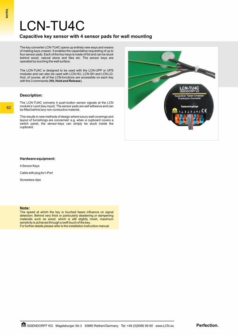
The key converter LCN-TU4C opens up entirely new ways and means of making keys unseen. It enables the capacitative requesting of up to four sensor pads. Each of the four keys is made of foil and can be stuck behind wood, natural stone and tiles etc. The sensor keys are operated by touching the wall surface.
The LCN-TU4C is designed to be used with the LCN-UPP or UPS modules and can also be used with LCN-HU, LCN-SH and LCN-LD. And, of course, all of the LCN-functions are accessible on each key with the 3 commands (Hit, Hold and Release).
Description:
The LCN-TU4C converts 4 push-button sensor signals at the LCN module's I-port (key input). The sensor pads are self adhesive and can be fitted behind any non-conductive material.
This results in new methods of design where luxury wall coverings and layout of furnishings are concerned: e.g. when a cupboard covers a switch panel, the sensor-keys can simply be stuck inside the cupboard.
Hardware equipment:
4 Sensor Keys
Cable with plug for I-Port
Screwless clips
Note:The speed at which the key is touched bears influence on signal detection. Behind very thick or particularly deadening or dampening materials such as wood, which is still slightly moist, maximum sensitvity is achieved through a swift touch of the key.For further details please refer to the installation instruction manual.
LCN-TU4CCapacitive key sensor with 4 sensor pads for wall mounting
Inp
uts
Perfection.ISSENDORFF KG Magdeburger Str.3 30880 Rethen/Germany Tel: +49 (0)5066 99 80 www.LCN.eu
83
LCN-TU4C
Technical Data:
Circuit diagram
D
L
N
PE
D
L
N
PE
Inp
uts
I
Tasteneingänge
LCN-TU4C
Kapazitiver Tasten-UmsetzerPushbutton Converter
1 2 3 4
ISSENDORFF KG
LCN-bus module
Capacitive key sensor with 4 sensor pads for wall mounting
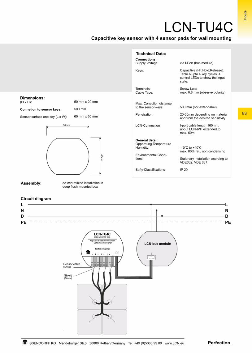
Sensor cable(white)
Shield(Black)
50mm
43m
m
de-centralized installation in deep flush-mounted box
Assembly:
Dimensions:(Ø x H):
Connetion to sensor keys:
Sensor surface one key (L x W):
50 mm x 20 mm
500 mm
60 mm x 60 mm
via I-Port (bus module)
Capazitive (Hit,Hold;Release).Table A upto 4 key cycles. 4 control LEDs to show the input state.
Screw Lessmax. 0,8 mm (observe polarity)
500 mm (not extendabel)
20-30mm depending on material and from the desired sensitivity
I-port cable length 160mm, about LCN-IVH extended to max. 50m
o o-10 C to +40 Cmax. 80% rel., non condensing
Staionary installation acording to VDE632, VDE 637
IP 20,
Connections:Supply Voltage:
Keys:
Terminals:Cable Type:
Max. Conection distance to the sensor-keys:
Penetration:
LCN-Connection
General detail:Opperating TemperatureHumidity:
Environmental Condi-tions:
Safty Classifications
Perfection.ISSENDORFF KG Magdeburger Str.3 30880 Rethen/Germany Tel: +49 (0)5066 99 80 www.LCN.eu
84
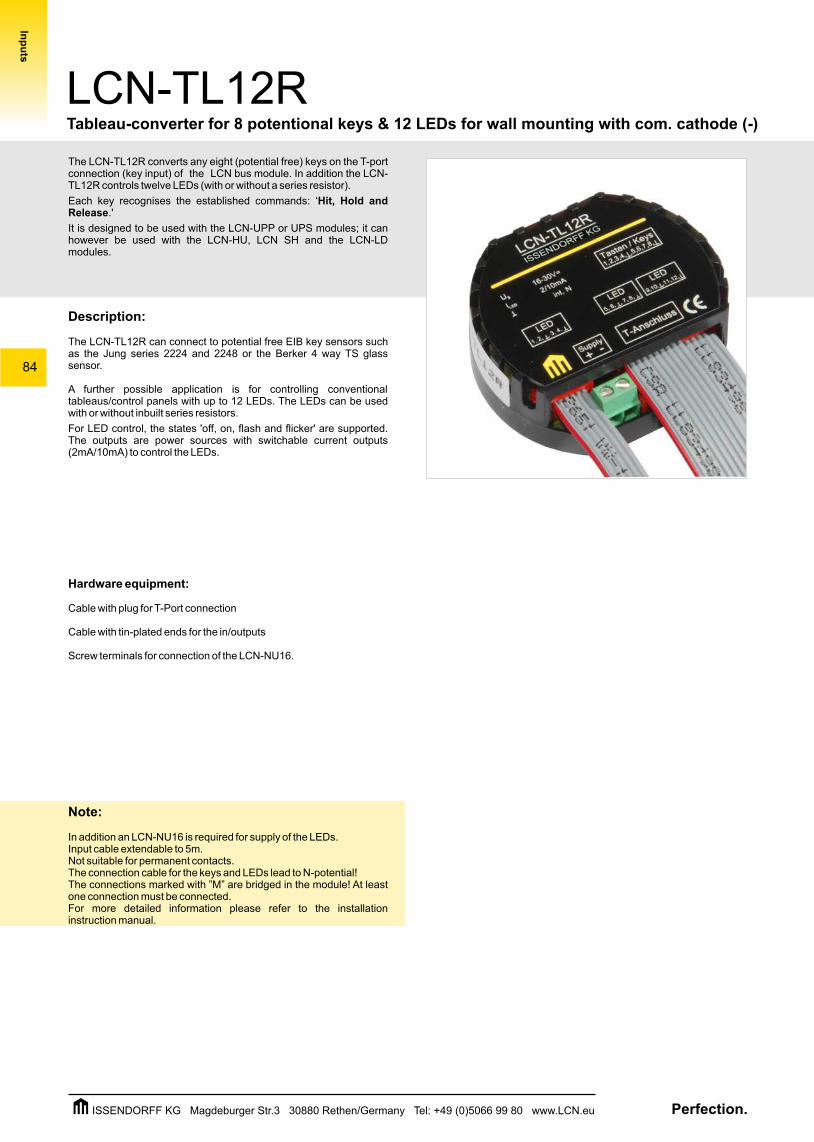
The LCN-TL12R converts any eight (potential free) keys on the T-port connection (key input) of the LCN bus module. In addition the LCN-TL12R controls twelve LEDs (with or without a series resistor).
Each key recognises the established commands: ‘Hit, Hold and Release.'
It is designed to be used with the LCN-UPP or UPS modules; it can however be used with the LCN-HU, LCN SH and the LCN-LD modules.
Description:
The LCN-TL12R can connect to potential free EIB key sensors such as the Jung series 2224 and 2248 or the Berker 4 way TS glass sensor.
A further possible application is for controlling conventional tableaus/control panels with up to 12 LEDs. The LEDs can be used with or without inbuilt series resistors.
For LED control, the states 'off, on, flash and flicker' are supported. The outputs are power sources with switchable current outputs (2mA/10mA) to control the LEDs.
Hardware equipment:
Cable with plug for T-Port connection
Cable with tin-plated ends for the in/outputs
Screw terminals for connection of the LCN-NU16.
Note:
In addition an LCN-NU16 is required for supply of the LEDs.Input cable extendable to 5m.Not suitable for permanent contacts.The connection cable for the keys and LEDs lead to N-potential! The connections marked with ”M” are bridged in the module! At least one connection must be connected.For more detailed information please refer to the installation instruction manual.
LCN-TL12RTableau-converter for 8 potentional keys & 12 LEDs for wall mounting with com. cathode (-)
Inp
uts
Perfection.ISSENDORFF KG Magdeburger Str.3 30880 Rethen/Germany Tel: +49 (0)5066 99 80 www.LCN.eu
85
LCN-TL12R
Technical Data:
Tableau-converter for 8 potentional keys & 12 LEDs for wall mounting with com. cathode (-)
Inp
uts
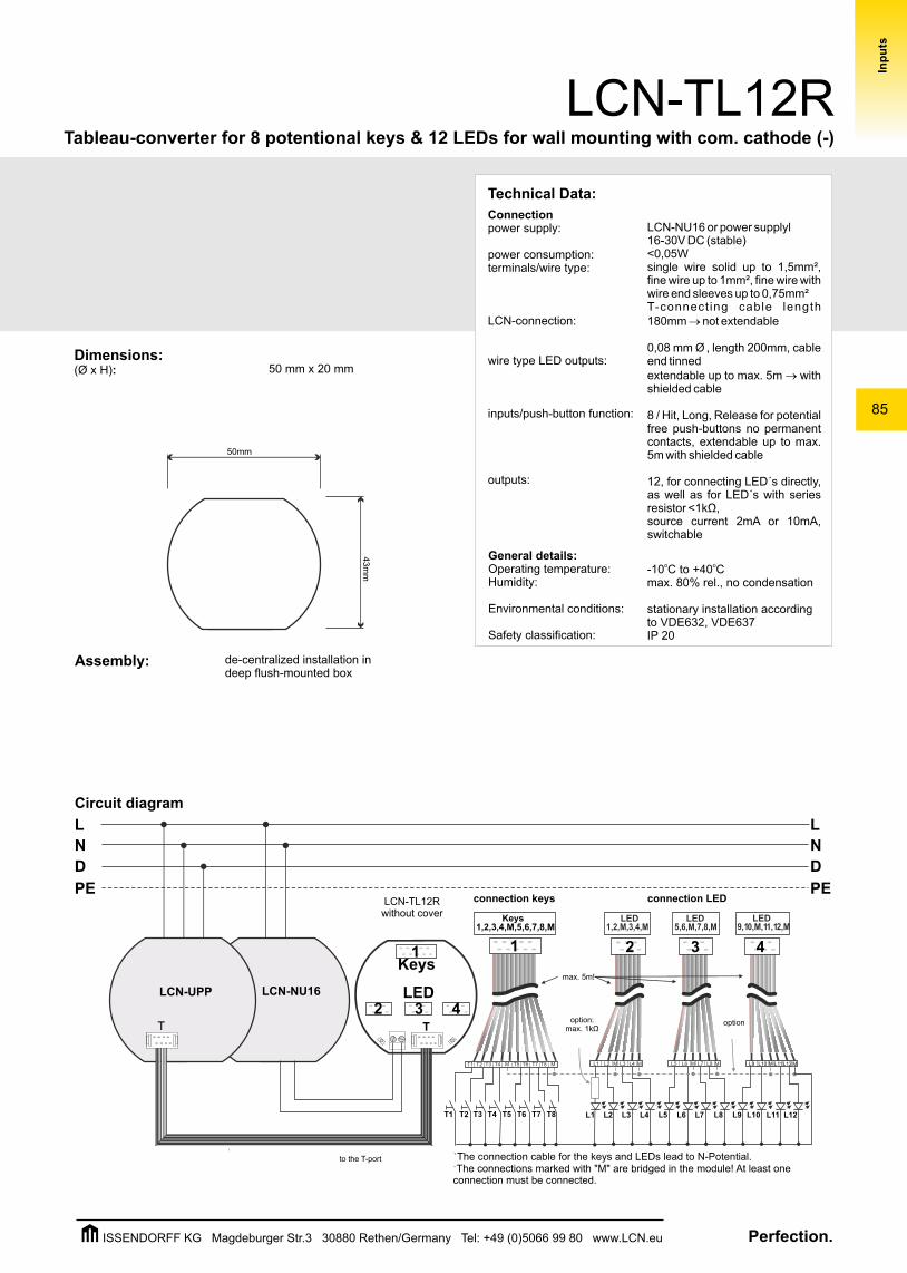
Circuit diagram
D
L
N
PE
D
L
N
PE
1 2 3 4
Keys1,2,3,4,M,5,6,7,8,M
LED1,2,M,3,4,M
LED5,6,M,7,8,M
LED9,10,M,11,12,M
max. 5m!
T1 L2L1T2
LED
Keys1
L4L3 L6L5 L8L7 L10L9 L12L11T3 T4 T5 T6 T7 T8
L9 L10 L11L12 MML1 L2 L3 L4 MM L5 L6 L7 L8 MMT1 T2 T3 T4 M MT5 T6 T7 T8
LCN-NU16LCN-UPP
T T
2 3 4
50mm
43m
m
de-centralized installation in deep flush-mounted box
Assembly:
Dimensions:(Ø x H): 50 mm x 20 mm
LCN-TL12Rwithout cover
connection keys connection LED
to the T-port !The connection cable for the keys and LEDs lead to N-Potential. !The connections marked with "M" are bridged in the module! At least one connection must be connected.
option:max. 1kΩ
option
LCN-NU16 or power supplyl 16-30V DC (stable)<0,05Wsingle wire solid up to 1,5mm², fine wire up to 1mm², fine wire with wire end sleeves up to 0,75mm²T-connect ing cable length 180mm ® not extendable
0,08 mm Ø , length 200mm, cable end tinned extendable up to max. 5m ® with shielded cable
8 / Hit, Long, Release for potential free push-buttons no permanent contacts, extendable up to max. 5m with shielded cable
12, for connecting LED´s directly, as well as for LED´s with series resistor <1kΩ, source current 2mA or 10mA, switchable
Connectionpower supply:
power consumption:terminals/wire type:
LCN-connection:
wire type LED outputs:
inputs/push-button function:
outputs:
o o-10 C to +40 Cmax. 80% rel., no condensation
stationary installation according to VDE632, VDE637IP 20
General details:Operating temperature:Humidity:
Environmental conditions:
Safety classification:
Perfection.ISSENDORFF KG Magdeburger Str.3 30880 Rethen/Germany Tel: +49 (0)5066 99 80 www.LCN.eu
86
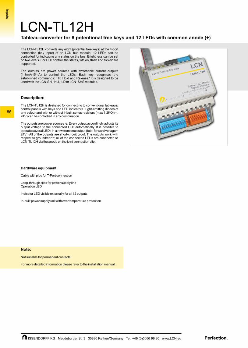
The LCN-TL12H converts any eight (potential free keys) at the T-port connection (key input) of an LCN bus module. 12 LEDs can be controlled for indicating any status on the bus. Brightness can be set on two levels. For LED control, the states, 'off, on, flash and flicker' are supported.
The outputs are power sources with switchable current outputs (1.8mA/15mA) to control the LEDs. Each key recognises the established commands: ‘Hit, Hold and Release.' It is designed to be used with the LCN-SH, -HU, -LD or LCN- SHS modules.
Description:
The LCN-TL12H is designed for connecting to conventional tableaus/ control panels with keys and LED indicators. Light-emitting diodes of any colour and with or without inbuilt series resistors (max 1.2KOhm, 24V) can be controlled in any combination.
The outputs are power sources ie. Every output accordingly adjusts its output voltage to the connected LED automatically. It is possible to operate several LEDs in a row from one output (total forward voltage < 24V!) All of the outputs are short-circuit proof. The outputs work with respect to ground/earth; all of the connected LEDs are connected to LCN-TL12H via the anode on the joint connection clip.
Hardware equipment:
Cable with plug for T-Port connection
Loop-through clips for power supply lineOperation LED
Indicator LED visible externally for all 12 outputs
In-built power supply unit with overtemperature protection
Note:
Not suitable for permanent contacts!
For more detailed information please refer to the installation manual.
LCN-TL12H
Inp
uts
Tableau-converter for 8 potentional free keys and 12 LEDs with common anode (+)
Perfection.ISSENDORFF KG Magdeburger Str.3 30880 Rethen/Germany Tel: +49 (0)5066 99 80 www.LCN.eu
87
LCN-TL12HTableau-converter for 8 potentional free keys and 12 LEDs with common anode (+)
Inp
uts
D
L
N
PE
D
L
N
PE
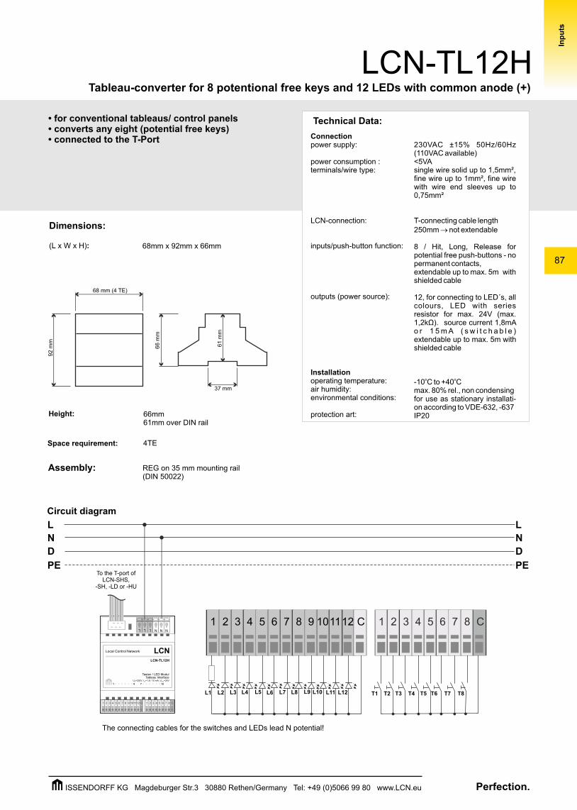
T1L2L1 T2L4L3 L6L5 L8L7 L10L9 L12L11 T3 T4 T5 T6 T7 T8
L L N N
LCNLocal Control Network
Tasten / LED ModulTableau Interface
U =230V, I =1,8 / 15 mA, U =24VN out max
LCN-TL12H
1 6 7 12
1 3 4 5 6 7 8 9 1011122 C 1 3 4 5 6 7 82 C
NL
1 3 4 5 6 7 8 9 1011122 C 1 3 4 5 6 7 82 C
Connectionpower supply:
power consumption :terminals/wire type:
LCN-connection:
inputs/push-button function:
outputs (power source):
Installationoperating temperature:air humidity:environmental conditions:
protection art:
230VAC ±15% 50Hz/60Hz (110VAC available)<5VAsingle wire solid up to 1,5mm², fine wire up to 1mm², fine wire with wire end sleeves up to 0,75mm²
T-connecting cable length250mm ® not extendable
8 / Hit, Long, Release for potential free push-buttons - no permanent contacts,extendable up to max. 5m with shielded cable
12, for connecting to LED´s, all colours, LED with series resistor for max. 24V (max. 1,2kΩ). source current 1,8mA o r 1 5 m A ( s w i t c h a b l e ) extendable up to max. 5m with shielded cable
o o-10 C to +40 Cmax. 80% rel., non condensingfor use as stationary installati-on according to VDE-632, -637 IP20
Dimensions:
(L x W x H):
Assembly:
Space requirement: 4TE
68mm x 92mm x 66mm
68 mm (4 TE)
92 m
m
66 m
m
37 mm
61 m
m
Height: 66mm 61mm over DIN rail
REG on 35 mm mounting rail(DIN 50022)
Circuit diagram
Technical Data:
The connecting cables for the switches and LEDs lead N potential!
To the T-port ofLCN-SHS,
-SH, -LD or -HU
• for conventional tableaus/ control panels • converts any eight (potential free keys) • connected to the T-Port
Perfection.ISSENDORFF KG Magdeburger Str.3 30880 Rethen/Germany Tel: +49 (0)5066 99 80 www.LCN.eu
88
LCN-TLK12H
Inp
uts
Tableau-converter for 8 potentional free keys and 12 LEDs with common cathode (-)
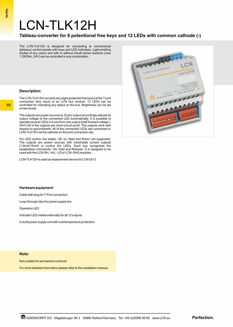
The LCN-TLK12H is designed for connecting to conventional tableaus/ control panels with keys and LED indicators. Light-emitting diodes of any colour and with or without inbuilt series resistors (max 1.2KOhm, 24V) can be controlled in any combination.
Description:
The LCN-TLK12H converts any eight (potential free keys) at the T-port connection (key input) of an LCN bus module. 12 LEDs can be controlled for indicating any status on the bus. Brightness can be set on two levels.
The outputs are power sources ie. Every output accordingly adjusts its output voltage to the connected LED automatically. It is possible to operate several LEDs in a row from one output (total forward voltage < 24V!) All of the outputs are short-circuit proof. The outputs work with respect to ground/earth; all of the connected LEDs are connected to LCN-TLK12H via the cathode on the joint connection clip.
For LED control, the states, 'off, on, flash and flicker' are supported. The outputs are power sources with switchable current outputs (1.8mA/15mA) to control the LEDs. Each key recognises the established commands: ‘Hit, Hold and Release.' It is designed to be used with the LCN-SH, -HU, -LD or LCN- SHS modules.
LCN-TLK12H is used as replacement device for LCN-DI12.
Hardware equipment:
Cable with plug for T-Port connection
Loop-through clips for power supply line
Operation LED
Indicator LED visible externally for all 12 outputs
In-built power supply unit with overtemperature protection
Note:
Not suitable for permanent contacts!
For more detailed information please refer to the installation manual.
Perfection.ISSENDORFF KG Magdeburger Str.3 30880 Rethen/Germany Tel: +49 (0)5066 99 80 www.LCN.eu
LCN-TLK12H
Inp
uts
89
Tableau-converter for 8 potentional free keys and 12 LEDs with common cathode (-)
• for conventional control panels • converts any potential free keys • connected to the T-Port
D
L
N
PE
D
L
N
PE
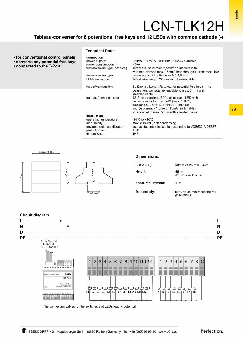
The connecting cables for the switches and LEDs lead N potential!
T1L2L1 T2L4L3 L6L5 L8L7 L10L9 L12L11 T3 T4 T5 T6 T7 T8
To the T-port ofLCN-SHS,
-SH, -LD or -HU
L L N N
LCNLocal Control Network
Tasten / LED ModulTableau Interface
U =230V, I =1,8 / 15 mA, U =24VN out max
LCN-TL12H
1 6 7 12
1 3 4 5 6 7 8 9 1011122 C 1 3 4 5 6 7 82 C
NL
1 3 4 5 6 7 8 9 1011122 C 1 3 4 5 6 7 82 C
Dimensions:
(L x W x H):
Assembly:
Space requirement: 4TE
68mm x 92mm x 66mm
68 mm (4 TE)
92 m
m
66 m
m
37 mm
61 m
m
Height: 66mm 61mm over DIN rail
REG on 35 mm mounting rail(DIN 50022)
Circuit diagram
Technical Data:
connectionpower supply: power consumption : <5VA
2terminals/wire type (net side): screwless, solid max. 2,5mm or fine wire with 2wire end-sleeves max 1,5mm , loop through current max. 16A
terminals/wire type: screwless, solid or fine wire 0,5-1,5mm² LCN-connection: T-Port wire length 250mm ® not extendable
inputs/key function: 8 / SHORT-, LONG-, RELEASE for potential free keys ® no permanent contacts, extendable to max. 5m ® withshielded cable
outputs (power source): 12, for connecting LED´s, all colours, LED with series resistor for max. 24V (max. 1,2kΩ),functions ON, OFF, BLINKING, FLICKERING source currency 1,8mA or 15mA (switchable)extendablet to max. 5m ® with shielded cable
installationo ooperating temperature: -10 C to +40 C
air humidity: max. 80% rel., non condensingenvironmental conditions: use as stationary instalation according to VDE632, VDE637 protection art: IP20dimensions: 4HP
230VAC ±15% 50Hz/60Hz (110VAC avaliable)
Perfection.ISSENDORFF KG Magdeburger Str.3 30880 Rethen/Germany Tel: +49 (0)5066 99 80 www.LCN.eu
90
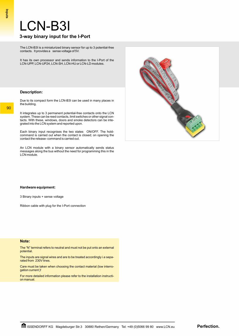
The LCN-B3I is a miniaturized binary sensor for up to 3 potential-free contacts. It provides a sense voltage of 5V.
It has its own processor and sends information to the I-Port of the LCN-UPP, LCN-UP24, LCN-SH, LCN-HU or LCN-LD modules.
Description:
Due to its compact form the LCN-B3I can be used in many places in the building.
It integrates up to 3 permanent potential-free contacts onto the LCN system. These can be reed contacts, limit switches or other signal con-tacts. With these, windows, doors and smoke detectors can be inte-grated into the LCN system and reported upon.
Each binary input recognises the two states ON/OFF. The hold- command is carried out when the contact is closed; on opening the contact the release- command is carried out.
An LCN module with a binary sensor automatically sends status messages along the bus without the need for programming this in the LCN module.
Hardware equipment:
3 Binary inputs + sense voltage
Ribbon cable with plug for the I-Port connection
Note:
The “N” terminal refers to neutral and must not be put onto an external potential.
The inputs are signal wires and are to be treated accordingly i.e sepa-rated from 230V lines.
Care must be taken when choosing the contact material (low interro-gation current )!
For more detailed information please refer to the installation instructi-on manual.
LCN-B3I3-way binary input for the I-Port
Inp
uts
Perfection.ISSENDORFF KG Magdeburger Str.3 30880 Rethen/Germany Tel: +49 (0)5066 99 80 www.LCN.eu
91
LCN-B3I3-way binary input for the I-Port
Inp
uts
D
L
N
PE
D
L
N
PE
25m
m
11mm
I
N 1 2 3
LCN-B3I
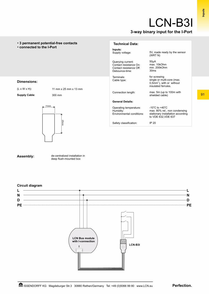
Technical Data:
Inputs:Supply voltage:
Querying current:Contact resistance On:Contact resistance Off:Debounce-time:
Terminals:Cable type:
Connection length:
General Details:
Operating temperature:Humidity:Environmental conditions:
Safety classification:
5V, made ready by the sensor (WRT N)
50µAmax. 10kOhmmin. 200kOhm30ms
for screwingsingle or multi-core (max.
2 0,5mm ), with or without insulated ferrules.
max. 5m (up to 100m with shielded cable)
o o-10 C to +40 Cmax. 80% rel., non condensingstationary installation according to VDE 632,VDE 637
IP 20
Assembly:
Circuit diagram
de-centralized installation in deep flush-mounted box
Dimensions:
(L x W x H):
Supply Cable:
11 mm x 25 mm x 13 mm
300 mm
LCN Bus modulewith I-connection
•• connected to the I-Port 3 permanent potential-free contacts
Perfection.ISSENDORFF KG Magdeburger Str.3 30880 Rethen/Germany Tel: +49 (0)5066 99 80 www.LCN.eu
92
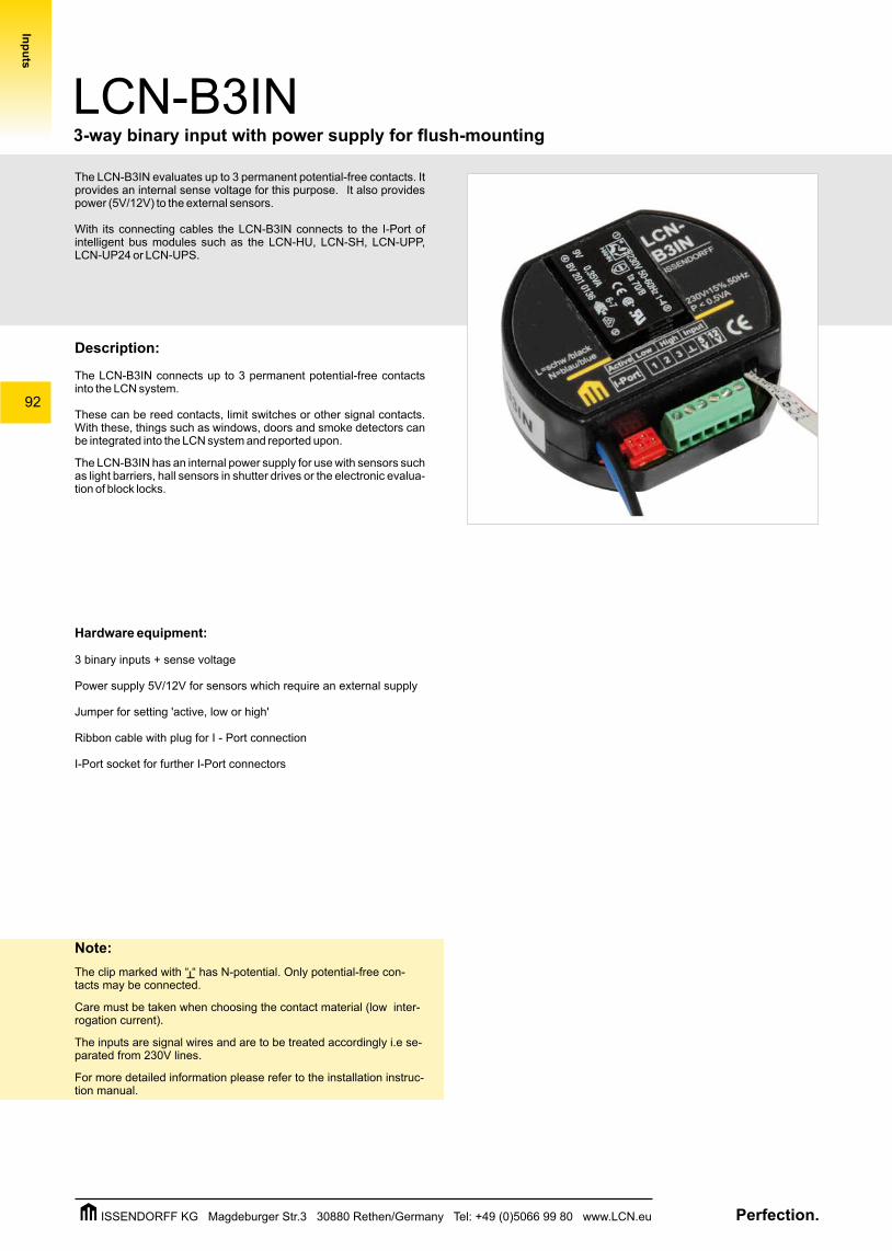
The LCN-B3IN evaluates up to 3 permanent potential-free contacts. It provides an internal sense voltage for this purpose. It also provides power (5V/12V) to the external sensors.
With its connecting cables the LCN-B3IN connects to the I-Port of intelligent bus modules such as the LCN-HU, LCN-SH, LCN-UPP, LCN-UP24 or LCN-UPS.
Description:
The LCN-B3IN connects up to 3 permanent potential-free contacts into the LCN system.
These can be reed contacts, limit switches or other signal contacts. With these, things such as windows, doors and smoke detectors can be integrated into the LCN system and reported upon.
The LCN-B3IN has an internal power supply for use with sensors such as light barriers, hall sensors in shutter drives or the electronic evalua-tion of block locks.
Hardware equipment:
3 binary inputs + sense voltage
Power supply 5V/12V for sensors which require an external supply
Jumper for setting 'active, low or high'
Ribbon cable with plug for I - Port connection
I-Port socket for further I-Port connectors
Note:
The clip marked with “ “ has N-potential. Only potential-free con-tacts may be connected.
Care must be taken when choosing the contact material (low inter-rogation current).
The inputs are signal wires and are to be treated accordingly i.e se-parated from 230V lines.
For more detailed information please refer to the installation instruc-tion manual.
LCN-B3IN
Inp
uts
3-way binary input with power supply for flush-mounting
Perfection.ISSENDORFF KG Magdeburger Str.3 30880 Rethen/Germany Tel: +49 (0)5066 99 80 www.LCN.eu
93
LCN-B3IN3-way binary input with power supply for flush-mounting
Inp
uts
D
L
N
PE
D
L
N
PE
•• internal sense voltage• provides power (5V/12V) to the external sensors• connected to the I-Port
3 permanent potential-free contacts
+12V
T
Sensor
I
ISSENDORFFKG
Technical Data:
Connection:Supply voltage:
Input power:Connection power side:
Inputs:Input voltage:
Querying current:Contact resistance ON:Contact resistance OFF:Debounce time:Cable length:
Sensor supply:Sensor voltage:Sensor current:
Terminals:Cable type:
General Details:Operating temperature:Humidity:
Environmental conditions:
Safety classification:
230V AC ±20%, 50Hz(110V AC ±15% type available)<1W
22 litz wires 0,75 mm (with insulated ferrules)
5V, made available by the sensor (WRT N)50µAmax. 10kOhmmin. 200kOhm 30msmax. 5m / 100m with shielded cable
5V / 12V=max. 25mA (permanently short-circuit safe)
for screwing2single or multi-core max. 0,5mm
or with insulated ferrules
o o-10 C to +40 Cmax. 80% rel., non condensing
stationary installation according to VDE 632,VDE 637
IP 20
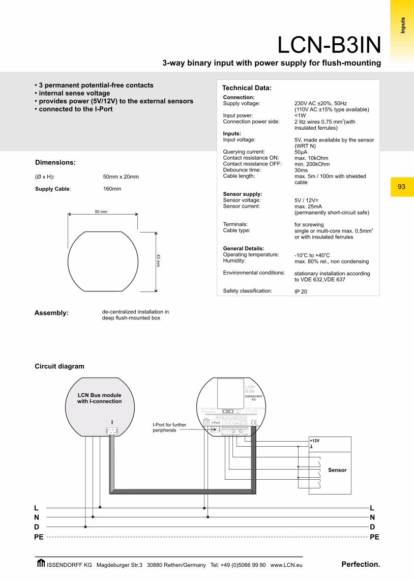
Dimensions:
(Ø x H):
Supply Cable:
Assembly:
50mm x 20mm
160mm
50 mm
43 m
m
de-centralized installation in deep flush-mounted box
Circuit diagram
LCN Bus modulewith I-connection
I-Port for furtherperipherals
Perfection.ISSENDORFF KG Magdeburger Str.3 30880 Rethen/Germany Tel: +49 (0)5066 99 80 www.LCN.eu
94
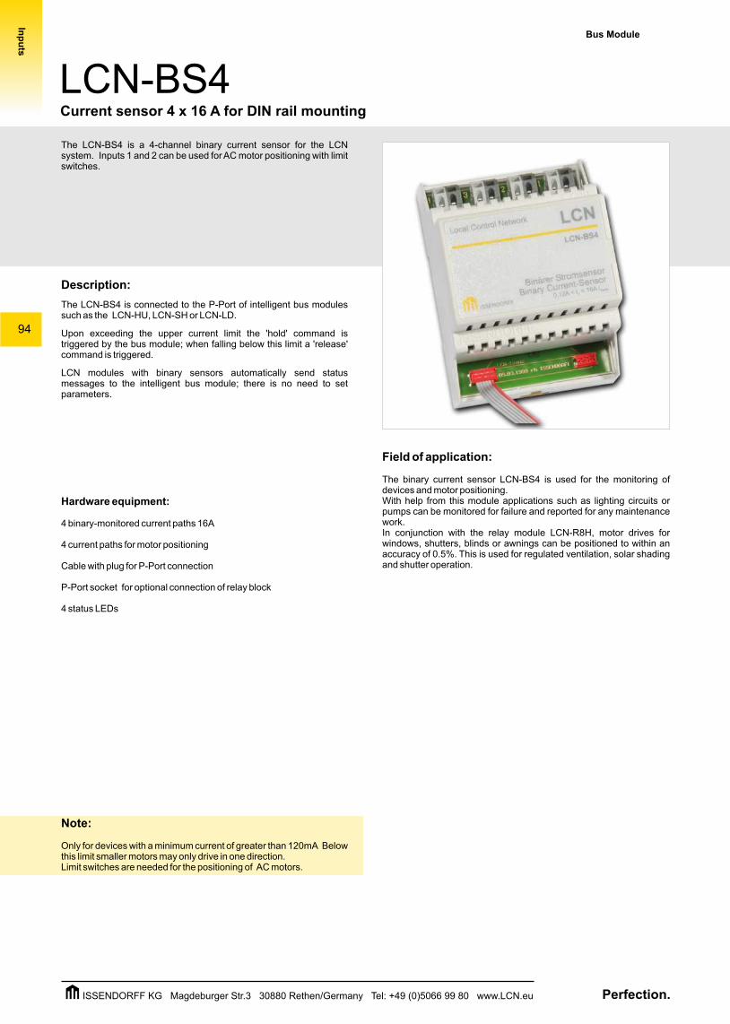
The LCN-BS4 is a 4-channel binary current sensor for the LCN system. Inputs 1 and 2 can be used for AC motor positioning with limit switches.
Description:
The LCN-BS4 is connected to the P-Port of intelligent bus modules such as the LCN-HU, LCN-SH or LCN-LD.
Upon exceeding the upper current limit the 'hold' command is triggered by the bus module; when falling below this limit a 'release' command is triggered.
LCN modules with binary sensors automatically send status messages to the intelligent bus module; there is no need to set parameters.
Hardware equipment:
4 binary-monitored current paths 16A
4 current paths for motor positioning
Cable with plug for P-Port connection
P-Port socket for optional connection of relay block
4 status LEDs
Note:
Only for devices with a minimum current of greater than 120mA Below this limit smaller motors may only drive in one direction. Limit switches are needed for the positioning of AC motors.
Bus Module
LCN-BS4Current sensor 4 x 16 A for DIN rail mounting
Inp
uts
Field of application:
The binary current sensor LCN-BS4 is used for the monitoring of devices and motor positioning. With help from this module applications such as lighting circuits or pumps can be monitored for failure and reported for any maintenance work.In conjunction with the relay module LCN-R8H, motor drives for windows, shutters, blinds or awnings can be positioned to within an accuracy of 0.5%. This is used for regulated ventilation, solar shading and shutter operation.
Perfection.ISSENDORFF KG Magdeburger Str.3 30880 Rethen/Germany Tel: +49 (0)5066 99 80 www.LCN.eu
95
LCN-BS4
•for AC motor positioning •connected to the P-Port•
4-channel binary current sensor
Inp
uts
D
L
N
PE
D
L
N
PE
LCNLocal Control Network
Binärer Stromsensor Binary Current-Sensor
0,1 < I < 16A /d Kanal
LCN-BS4
1 2 3 4
ISSENDORFF
M
Relais1 + 2
P P P P
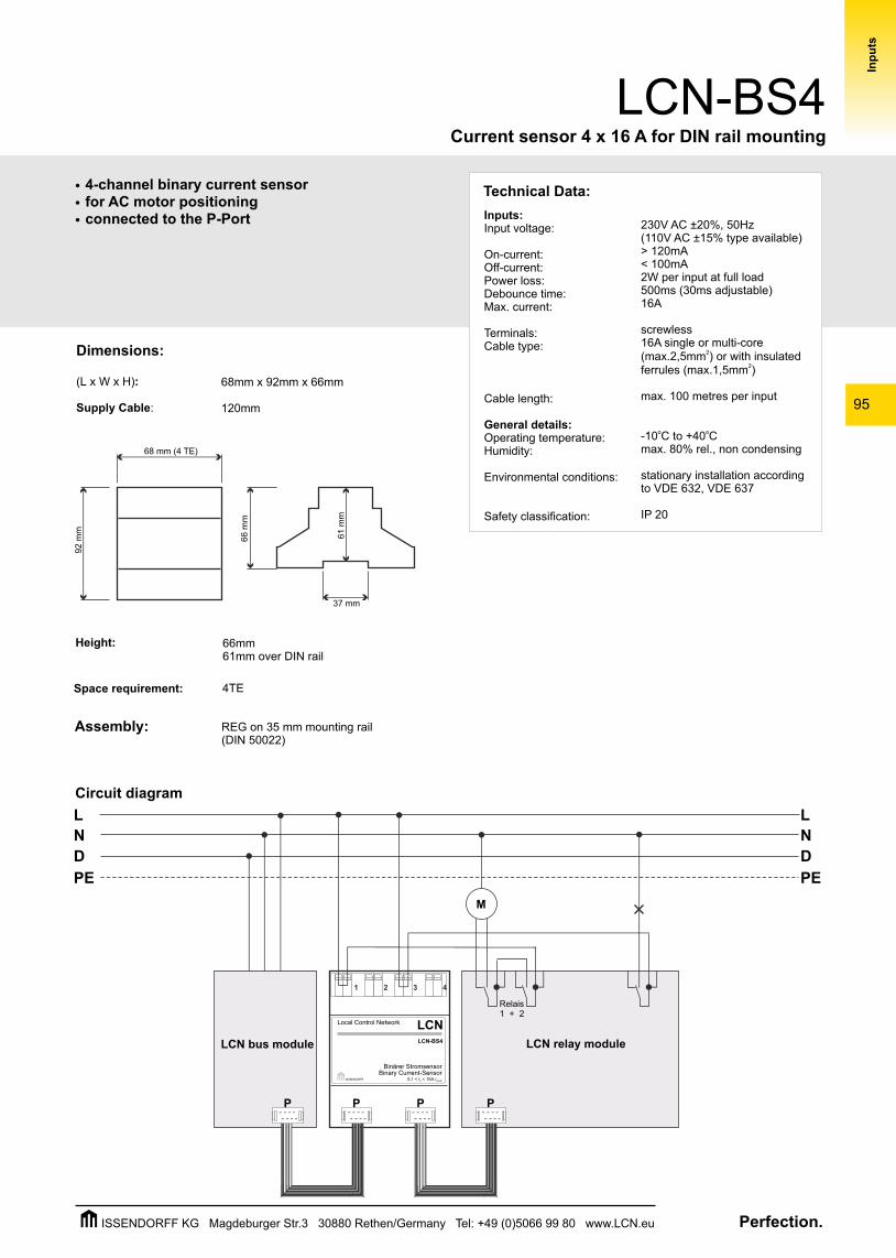
Dimensions:
(L x W x H):
Supply Cable:
Assembly:
Space requirement: 4TE
68mm x 92mm x 66mm
120mm
68 mm (4 TE)
92 m
m
66 m
m
37 mm
61 m
m
Height: 66mm 61mm over DIN rail
REG on 35 mm mounting rail(DIN 50022)
Current sensor 4 x 16 A for DIN rail mounting
Technical Data:
Inputs:Input voltage:
On-current:Off-current:Power loss:Debounce time:Max. current:
Terminals:Cable type:
Cable length:
General details:Operating temperature:Humidity:
Environmental conditions:
Safety classification:
230V AC ±20%, 50Hz(110V AC ±15% type available)> 120mA< 100mA2W per input at full load500ms (30ms adjustable)16A
screwless 16A single or multi-core
2(max.2,5mm ) or with insulated 2ferrules (max.1,5mm )
max. 100 metres per input
o o-10 C to +40 Cmax. 80% rel., non condensing
stationary installation according to VDE 632, VDE 637
IP 20
LCN bus module LCN relay module
Circuit diagram
Perfection.ISSENDORFF KG Magdeburger Str.3 30880 Rethen/Germany Tel: +49 (0)5066 99 80 www.LCN.eu

96
Inp
uts
Perfection.ISSENDORFF KG Magdeburger Str.3 30880 Rethen/Germany Tel: +49 (0)5066 99 80 www.LCN.eu


![C [TE2] Hw_1](https://img.dokumen.tips/doc/110x75/577cd97e1a28ab9e78a3a461/c-te2-hw1.jpg)


