Embed Size (px)
Citation preview
00
00 NAVAL POSTGRADUATE SCHOOLMonterey, California
THSI
AN EVALUATION OF THE EFFECTIVENESS OF SNTI,
AN INTEGRATED SHIPBOARD COMMUNICATIONS SYSTEM,
FOR USE ABOARD U.S. NAVY SURFACE COIMBATANTS
by
George Bartlett Farrell
March 1986
Tihesis Advisor: J. W. L1aPatra
LLU ____ _ _ __ _ _ _
Approvedl for public release;distribution is unlimited.
Sig 8 30 058

SEC.,R~ty CASS.FfCArION 377T5PAGE PREPORT DOCUMENTATION PAGE
1.a REPORT SECURITY CLASS-FICATION lb RESTRICTIVE MARKINGS
UNCLASSIFIED ._.2a SEC R'TY CLASSIFICATION AUTHORITY 3 DISTRIBUTION /AVAILABILITY OF REPORT
Approved for public release; distributionDEC-ASSFICATION;DWNGRADiNG SCHEDULEisulmtd is unlimited..,
4 ERFOQMNc ORGAN'ZATION REPORT NUMBER(S) S MONITORING ORGANIZATION REPORT NUMBER(S)
6a NAME OF PERFORMING ORGANIZATION 6b OFFICE SYMBOL 7a NAME OF MONITORING ORGANIZATION(If applicable)
Naval Postaraduate School Code 54 Naval Postaraduate School6< ADDRESS City State. and ZIPCode) 7b ADDRESS (City, State, and ZIP Code)
Monterey, California 93943-5000 Monterey, California 93943-5000
Sa A AE ,0; F.NDING, SPONSORING 8b OFFICE SYMBOL 9 PROCUREMENT INSTRUMENT IDENrIFiCArION NUMBER2RC(,A% AT ON (If applicable)
AD-D-E5S 1C,, State. and ZIP Code) 10 SOUJRCE OF FUNDING NUMBERS
PROGRAM PROJECT TASK WORK JNITELEMENT NO NO NO ACCESS'ON NO
.. . E inciude Security Classitication)
AN EVALUATION OF THE EFFECTIVENESS OF SNTI, AN INTEGRATED SHIPBOARD COMMUNICATIONSSYSTEM, FOR USE ABOARD U.S. NAVY SURFACE COMBATANTS
Farrell, 3. Bartlett
, " ME CO ERED '4 DATE OF REPORT (Year, Month, Day) 15 PAGE CONr.Master's Thesis FoOM T O _Q/6 1986 March 20 149
* .C'S4 COUiES 18 SuBAECT TERMS iContinue on reverse if necessary and identify by block number):ZOUP 5,S-GPOLP Interior Communications, Integrated Shipboard Communication
Systems, Shipboard Communication Requirements,
Communication Terminals, Communication Interface.* , C'ntmue on revee if necessary and identify by block number) Shipboard Interior Communication (IC)
systems, a critical part of command and control, have not kept pace with the technologicaladvances occurring in other areas of Naval warfare. As a result, the requirements and de-mands claced on an IC system in a warfare scenario are not likely to be met with much suc-
cess. This thesis takes the first steps towards rectifying this unsatisfactory situation.The )eneral weaknesses and problems with present IC systems are identified. Then, paying
close attention to the needs of surface combatants, particularly DDG-51 and FFG-7 classsnips, the requirements and functions needed to improve shipboard IC are presented. These
are incorporated into the requirements and functions needed to develop an ideal IntegratedShipboard Communication System (ISCS). A French designed and built ISCS is then comparedto this ideal system in order to evaluate its potential for implementation aboard U.S. Nav!
surface combatants.
, A,'.,.AB L.T' OF ABSTRACT 21 ABSTRACT SECURITY CLASSIFICATIONC . D Ar E.%. M'rED 0 SA'.E AS qPr 0 DTC ,SEQS Unclassified
3 .' ;;0O ,8LE '.D,o D.AL 22b TElEPHONE (Include Area Code) 22c C;'(.E NIMBOX
J. W. LaPatra (408) 646-2249 54LP
DD FORM 1473,84 'vAR 83 AP ed-t ni -ay be ued in. I exI'austed SECLJRITY CLASSIC.CA % ,) -. ,S P A,'FAll otmer edt,ons are obiolete
- . C . -,_*

Approved for public release; distribution is unlimited.
An Evaluation of the Effectiveness of SNTI,an Integrated Shipboard Communications System,for Use Aboard U.S. Navy Surface Combatants
by
G. Bartlett FarrellLieutenant, United States Navy
B.A., College of the Holy Cross, 1978
Submitted in partial fulfillment of the
requirements for the degree of
MASTER OF SeIENCE IN TELECOMMUNICATIONS SYSTEMS MANAGEMENT
from the
NAVAL POSTGRADUATE SCHOOLMarch 1986
Author: ( t/ 1r / . . ,G. Bartlett Farrell
Approved by:J.W. LaPatra, Thesis Advisor
M.P. Spencer, Second Reader
W.R. Greer, Jr. , Chairman,Department of Administrative Scie hces
Kneale T. Nars alcDean of Information and Policy : eces
2
.9
.-. . .
¢-Z
ABSTRACT
Shipboard Interior Communication (IC) systems, a crit-
ical part of command and control, have not kept pace with
the technological advances occurring in other areas of Naval
warfare. As a result, the requirements and demands placed
on an IC system in a warfare scenario are not likely to be
met with much success. This thesis to takes the first steps
towards rectifying this unsatisfactory situation. The
general weaknesses and problems with present IC systems are
identified. Then, paying close attention to the needs of
surface combatants, particularly DDG-51 and FFG-7 class
" ships, the requirements and functions needed to improve
shipbo.rd IC are presented. These are incorporated into the
requirements and functions needed to develop an ideal
"; Integrated Shipboard Communication System (ISCS). A French
designed and built ISCS is then compared to this ideal
- system in order to evaluate its potential for implementation
aboard U. S. Navy surface combatants.
3
.33
. 3
R'- "
. . . . . . . . . . .
TABLE OF CONTENTS
I. INTRODUCTION ...... .. ..... ... . .......... . ... .10
A. PURPOSE/OBJECTIVES .. .. . . . . .:..... ... 10
B. BACKGROUND....................11
C. METHODOLOGY...................12
II. U.S. NAVY SURFACE COMBATANTS.............14
A. CLASSES AND THEIR CAPABILITIES............14
B. THE ROLE OF SURFACE COMBATANTS............16
C. THE ARLEIGH BURKE CLASS, DDG-51...........18
1. Warfare Areas and Command and ControlrSpaces...................20
2.v Personnel Duties and Responsibilities 23
3. Subscriber Requirements of an ISCS . ... 28
D. THE OLIVER HAZARD PERRY CLASS, FFG-7 .. .... 29
1. Warfare Areas and Command and ControlSpaces...................30
2. Personnel Duties and Responsibilities 33
3. Subscriber Requirements on an ISCS . ... 37
III. INTEGRATED SHIPBOARD COMMUNICATION SYSTEMREQUJIREM]ENTS.......................38
A. PRESENT SYSTEMS.................38
B. £ STEM/DESIGN CONSIDERATIONS.............41
1. Console Design..................42
2. Human Factor Considerations...........44
*.C. DESIRED FUNCTIONS AND CAPABILITIES ........ 47
IV. SYSTEME NUMERISE DE TRANSMISSIONS INTERIEURESOR SNTI.......................56
A. SNTI GENERALITIES..................57
B. SNTI SYSTEM DESCRIPTION/SPECIFICATIONS . . .. 60
C. MULTIPLEXING.....................79
4
H
1. Principles of TDM . . . . . .. . . .. . 80
2. The Multiplex Structure Used in SNTI . . 82
V. ANALYSIS OF SNTI ....... ................. 89
A. VULNERABILITY COSTS ............. 89
B. SYSTEM EFFECTIVENESS ..... ......... 97
VI. THE EVALUATION OF SNTI ...... ............. 110
* . A. SUMMARY ......... .................. 110
B. CONCLUSION ...... ................. 115
APPENDIX A: SUBSCRIBER REQUIREMENTS FOR A DDG-51
ISCS ....... ................... 118
APPENDIX B: SUBSCRIBER REQUIREMENTS FOR A FFG-7 ISCS 137
LIST OF REFERENCES ....... .................. 147
INITIAL DISTRIBUTION LIST ..... ............... . 148
"1 F5
. - 7o- * -
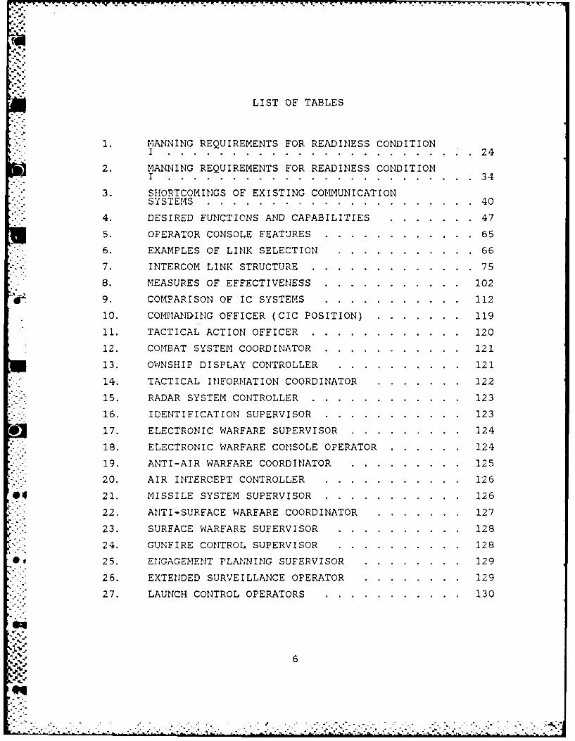
LIST OF TABLES
1. MANNING REQUIREMENTS FOR READINESS CONDITIONI.........................24
2. MANNING REQUIREMENTS FOR READINESS CONDITIONI..........................34
*.3. SHORTCOMINGS OF EXISTING COMMUNICATION* . SYSTE1S......................40
-4. DESIRED FUNCTIONS AND CAPABILITIES........47
5. OPERATOR CONSOLE FEATURES.............65
-6. EXAMPLES OF LINK SELECTION............66
7. INTERCOM LINK STRUCTURE...............75
8. MEASURES OF EFFECTIVENESS..............102
9. COMPARISON OF IC SYSTEMS.............112
10. COMMANDING OFFICER (CIC POSITION).........119
11. TACTICAL ACTION OFFICER..............120
12. COMBAT SYSTEM COORDINATOR..............121
13. OWNSHIP DISPLAY CONTROLLER............121
14. TACTICAL INFORMATION COORDINATOR.........122
-15. RADAR SYSTEM CONTROLLER..............123
16. IDENTIFICATION SUPERVISOR..............123
*17. ELECTRONIC WARFARE SUPERVISOR............124
18. ELECTRONIC WARFARE CONSOLE OPERATOR........124
19. ANTI-AIR WARFARE COORDINATOR...........125
20. AIR INTERCEPT CONTROLLER.............12 6
21. MISSILE SYSTEM SUPERVISOR..............126
22. ANTI-SURFACE WARFARE COORDINATOR.........127
*23. SURFACE WARFARE SUPERVISOR............128
24. GUNFIRE CONTROL SUPERVISOR............128
0*25. ENGAGEMENT PLANNING SUPERVISOR..........129
- -26. EXTENDED SURVEILLANCE OPERATOR..........129
27. LAUNCH CON4TROL OPERATORS.............130
6
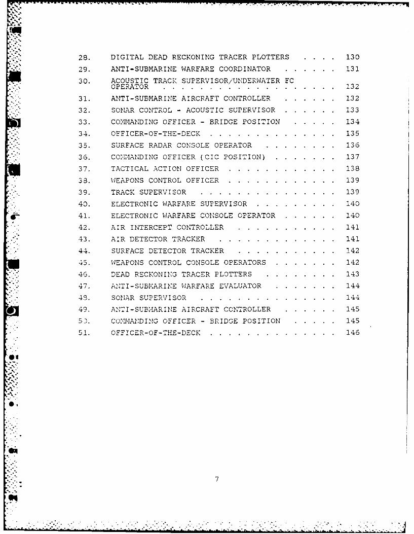
28. DIGITAL DEAD RECKONING TRACER PLOTTERS . . . 130
29. ANTI-SUBMARINE WARFARE COORDINATOR ...... 131
30. ACOUSTIC TRACK SUPERVISOR/UNDERWATER FCOPERATOR ........ ................... 132
31. ANTI-SUBMARINE AIRCRAFT CONTROLLER ...... 132
32. SONAR CONTROL - ACOUSTIC SUPERVISOR . ...... 133
33. COMMANDING OFFICER - BRIDGE POSITION ..... 134
* 34. OFFICER-OF-THE-DECK ..... .............. 135
* - 35. SURFACE RADAR CONSOLE OPERATOR ........ 136
36. CONMANDING OFFICER (CIC POSITION) . ....... 137
37. TACTICAL ACTION OFFICER .... ............ 138
38. WEAPONS CONTROL OFFICER .... ............ 139
39. TRACK SUPERVISOR ..... ............... 139
40. ELECTRONIC WARFARE SUPERVISOR .. ......... 140
41. ELECTRONIC WARFARE CONSOLE OPERATOR . ...... 140
42. AIR INTERCEPT CONTROLLER ........... 141
43. AIR DETECTOR TRACKER .... ............. 141
44. SURFACE DETECTOR TRACKER ... ........... 142
45. WEAPONS CONTROL CONSOLE OPERATORS . ....... 142
4 6. DEAD RECKONING TRACER PLOTTERS ........ 143
47. ANT I-SUBMARINE WARFARE EVALUATOR ....... 144
43. SONAR SUPERVISOR ..... ............... 144"9 . .., . . . 4
49. ANTI-SUB4ARINE AIRCRAFT CONTROLLER.......145
53. CONA 1DING OFFICER - BRIDGE POSITION ..... 145
51. OFFICER-OF-THE-DECK ..... .............. 146
7
.3.
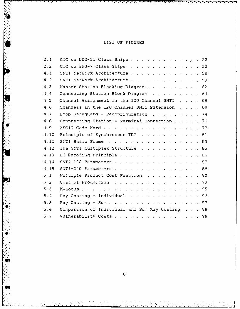
LIST OF FIGURES
2.1 CIC on DDG-51 Class Ships .......... .... 22
2.2 CIC on FFG-7 Class Ships ..... ............. 324. 1 SNTI Network Architecture ..... ............. 58
4.2 SNTI Network Architecture ..... ............. 59
4.3 Master Station Blocking Diagram ... .......... .62
4. 4 Connecting Station Block Diagram ... ......... 64
4.5 Channel Assignment in the 120 Channel SNTI . ... 68
4. 6 Channels in the 120 Channel SNTI Extension . ... 69
4.7 Loop Safeguard - Reconfiguration ... ......... 74
4.8 Connnecting Station - Terminal Connection ..... ... 76
4.9 ASCII Code Word ....... .................. 78
4. 10 Principle of Synchronous TDM ... ........... 814. 11 SNTI Basic Frame ...... ................. 83
4. 12 The SNTI Multiplex Structure ... ........... 85
4. 13 Dr-1 Encoding Principle ........ ............... 86
4. 14 SNTI-120 Parameters ...... ................ 87
4. 15 SNTI-240 Parameters ...... ................ 88
5. 1 Multiple Product Cost Function ..... .......... 92
5.2 Cost of Production ................ 93
5.3 M-Locus ...................... 95
5.4 Ray Costing - Individual ..... ............. 96
5.5 Ray Costing - Sum ....... ................. 97
5. 6 Comparison of Individual and Sum Ray Costing . 98
* . 5. 7 Vulnerability Costs ...... ................ 99
0,
8
.. . ...

ACKNOWLEDGEMENTS
I w,ould like to express my most sincere appreciation to
Mr. Joseph Oleska of Naval Ocean Systems Command, San
Diego, Ca. and to Mr. Gail Borden of Human Performance
Research of Goleta, Ca. The assistance so graciously
provided by both gentlemen, in the form of their expert
advice as well as via the reports, publications and docu-
ments they supplied, was invaluable.
In addition, a special thanks to Professor Jack LaPatra,
who as my advisor, devoted a great deal of time and effort
in assisting me with the completion of my thesis.
4
9
.. . ~ .. .. ' ' .. " .. < • .. ~ ' • • ...
I . INTRODUCTION
~. PURPOSE/OBJECTIVES
In the everchanging, highly volatile, intense tempo of
today's naval warfare scenarios, the ability to communicate
successfully and efficiently is more critical than ever
before. The failure of a ship to communicate, either inter
nally or externally, would probably result in a mission
failure at the very least and quite possibly the_destruction
of tha~ ship in a hostile situation.
Therefore, this thesis will attempt to look at where we
stand with today's Integrated Shipboard Communication
Systems ( ISCS) and what can be done to improve upon our
present condition. The area of research will be to analyze
the ISCS capabilities of present U.S. Navy surface comba
tants, placing special emphasis on the Oliver Hazard Perry,
FFG-7, class and on the Arleigh Burke, DDG-51, class ships.
A majority of the research will be an analysis of the
Systeme Numerise de Transmissions Interieures (SNTI) ability
to match or exceed these capabilities. The SNTI is an inte
grated shipboard communications system developed by the
French for use aboard their Naval surface combatants. As a
result, the thrust of this study will be aimed at deter
mining the ISCS requirements on FFG-7 and DDG-51 ships and
the capabilities of the SNTI with respect to these require
ments. This thesis will examine the weaknesses of present
ISCS and look at how well the SNTI eliminates them.
The result of this research and the goal of this thesis
is to provide the answers to the following two questions:
l. vlhat are the requirements for an ISCS aboard U.S. Navy surface combatants?
2. How effective is SNTI in meeting these requirem0nts?
10

.. ~ .
In answering these questions it was determined that an
in-depth analysis of the external communication requirements
and capabilities of these ships was beyond the scope of this
thesis. To attempt to include them would be detrimental to
providing accurate and viable answers to the research ques
tions posed. Therefore, the assumption is made that the
external communication capabilities of these ships are
considered adequate for -the purp0se of this--thesis. This
assumes that the necessary frequencies, channels, transmit
ters and receivers are available to the shipboard users or
operators. t\s a result, the rscs being evaluated will be
critiqued on its ability to interface with these available
circuits.
B. Bl\CI(GROU!'!D
It has been consistently observed that major Command,
Control and Communication (C 3 ) problems aboard ship today
revolve around the inadequacies of installed ISCS. Poor
response time i~1 defending the ship, delays in establishing
communications (both internal and external) and the inade
quate dissemination of critical information are just a few
of the resulting problems. These problems and others occur
due to t 11e inability of most systems to adapt to changing
scenarios and to respond to increases in demand in a timely
and efficient manner.
New technological advances have resulted in a number of
new weapon systems and an increased offensive capability
that have drastically reduced a ship's defensive response
time down to a matter of seconds in some instances. These
technological improvements .combined with the continued
increase in the volume and complexity of ocean surveillance,
as well as the tactical information associated with these
ne'l'l ,..,•eapons and sensors places an increasing-ly heavy burden
on shipboard C3 systems, including information transfer
rates. The primary data stress points fall on interior
11
voice communications (IC) between watch and battle stations.
This problem is further complicated by the increasing
technical sophistication of own force weapon and sensor
"V .systems and the associated communications necessary to
' - employ these systems in a timely manner.
C. METHODOLOGY
This thesis will attempt to uncover the weaknesses of
today's systems that cause these problems and what capabili-
ties are required of a new system to eliminate such diffi-
culties. The overall approach will consist of the following
general steps:
1. Identify the missions of U. S Naval surface combatantswith special emphasis on FFG-7 and DDG-51 class ships.
2. Briefly describe the impact of new, technologicallyadvanced weapon and detection systems on present ISCS.
3. Identify the shortcomings of the ISCS installed aboardFFG-7 and DDG-51 class ships.
4. Describe the features of an ISCS that would help elim-inate the inadequacies present in current systems.
5. Describe the capabilities and features of SNTI.Evaluate the abi ity of STI to eliminate the weak-nesses identified earlier.
6. Provide conclusions a:.- recommendations with respectto the effectiveness of SNTI for use by the U.S. Navy.
The analysis of the research questions will be based on
a thorough review and examination of the information gath-
- .ered from appropriate articles and references used in
conducting the research. The analysis will also include
judgements and critiques based on personal experiences as04 well as from informal conversations with other Naval offi-
- cers and experts in this field. Thus, using the knowledge
gained, the requirements of and demands on an ISCS will be
presented. The strengths and weaknesses of present systems
will then be identif _-ed. Then, based on the information
gathered, assumptions made and evaluations rendered a hypo-
thetical, ideal system will be defined. The effectiveness
of S.1 in meeting the capabilities of this ideal system
will then be examined.
12
.9 . ..', . ., , - . . , . - - -... -i ,- ,_ . . " ., ' ". ..- .- '
This evaluation will include an analysis of SNTI's func-
tional capabilities, design criterion and its ability to
meet pre-determined human factors considerations. Also
included will be an examination of system effectiveness
regarding vulnerability costs and cost performance analysis.
Then, based on the results of this study a recommendation
for or against the adoption of SNTI by the U.S. Navy will be
* made.
13I
4 v
II. U.S. NAVY SURFACE COM'BATANTS
A. CLASSES AND THEIR CAPABILITIES
As stated in the previous chapter, the primary emphasis
of this thesis in evaluating ISCS is being given to FFG-7
and DDG-5l class ships. However, it is important to note
that most of the capabilities desired in an ISCS for these
two classes of ships are remarkably similar to the capabili-
ties required on all U. S. Navy surface combatants. Any
differences would be due to specific weapon or detection
systems that are unique to that individual class or ship.
Such differences would more than likely result in hardware
or installation changes rather than changes in the desired
requirements of an ISCS.
So, before getting into the specifics of FFG-7 and
DDG-51 platforms it would be beneficial to come to an under-
standing of the differences in design and capabilities of
other classes of surface combatants. In order to achieve an
understanding of the complexities involved in fighting a
ship today, this will include a brief review of the weapon
arjd sensor capabilities of some of the Navy's newest classes
of ships [Ref. 1]. This will also provide a clearer view ofthe thread of commonality that holds for ISCS capabilities
and requirements for these ships.
The first of the three types of combatant to be looked
*.at is the cruiser or CG. Today's cruisers have developed
from the world's first nuclear powered cruiser, the Long
Zleach, and her steam powered sister ships of the Leahy
class, the first class to be designed as cruisers. The
newer classes, using the same basic layout, have developed
via the California class to the Virginia class. These two
classes are very similar in design. Therefore only a
description of the Virginia class will be provided.
14
For weapons this class has two quad surface-to-surface
missile (SSM) launchers, two twin surface-to-air (SAM)/ASW
launchers, two five inch guns, two close-in weapons systems
(CIWS) and torpedo tubes. It has one missile control
director, one ASW FCS and one missile fire control system
(NFCS). Its sensors include a 3-D search radar, surface
search and air search radars, three FC radars, one naviga-
tion radar, a sonar and an EW system. Her basic communica-
tions suite includes satellite communication antennas, one
SSR-l receiver and 4 WSC-3 transceivers.
The follow-on to the Virginia was the Ticonderoga class
cruiser, the first to be fitted with the Aegis system. The
Aegis system provides new levels of anti-air defense of a
carrier battle group (CVBG) using the most advanced tech-
nology. This system has an electronic scanning radar with a
fixed antenna which is capable of aiding in controlling
* aircraft as well as with surveillance, detection and
tracking. It can process its information almost instantane-
ously to identify friend from foe, assess each threat and
via the Navy Tactical Data System (NTDS) control and allo-
cate the fire power of the CVBG's defenses, including
friendly aircraft.
The armament for this class is composed of two quad SSM
launchers, two twin SAM/ASW launchers (newer ships in theclass have two vertical launch systems, VLS, instead), two
five inch guns, two CIWS and torpedo tubes. It has the
'Aegis weapon control system, one gun fire control system
(CFCS), four missile guidance illuminators and one ASW FCS.
This class has the SPY-I phased array, 3-D radar for its
Aegis system, air search and surface search radars, a
weapons FC radar, a navigational radar, a sonar and an EW
system. For communications it has satellite communication
* antennas, four SSR-I receivers, two WSC-3 transceivers plus
the Aegis - NTDS interface capability.
15
.-..
-~~~~ V .. r v v~ 4J '. 4 ' V 4 - - .
The next type of combatant to be examined will be the
- destroyer, both the DD and DDG. Starting with the former,
we will look briefly at the Spruance class. This class is
outfitted with an eight tube SAM launcher plus two quad SSM
launchers. The entire class is to be retro-fitted with VLS
for the Tomahawk missile. Othei weapons include two five
inch guns, two CIWS, torpedo tubes and an anti-submarine
rocket (ASROC) launcher. For fire control there is one
.- FCS, one ASW FCS and one GFCS with two associated fire
control radars. It also has a 3-D search radar, a surface
search radar, a sonar, a towed array and an EW system. The
basic communications suite includes satellite communication
./ antennas, an SSR-1 receiver and three WSC-3 transceivers.
* -The DDG to be looked at is the Arleigh Burke class,
DDG-51, and this will be examined in more detail later in
S"-this chapter.
". The final group to be covered are the frigates, both FF
and FFG. IThe Bronstein class, the first of this type of
surface combatant, introduced the slim, high freeboard hull
and the ASROC stand-off missile. This missile was matched
in range by a large hull mounted sonar; a successful combi-
nation. This ASW potency was improved upon with the Garcia
* class by providing her with organic helicopter assets.
Also, half the class was provided with an area defense SAM
system. At the time the largest class of frigates, the Knox
class, was also dedicated to an ASW escort role. This
changed with the development of the Oliver Hazard Perry
class, FFG-7. This class, like DDG-51, will be looked atlater in the chapter.
-" B. THE ROLE OF SURFACE COMBATANTS
The role of the U.S. Naval surface combatant is to pros-
ecute enemy forces and/or protect what the U. S. Navy refers
to as a high value unit (HVU). This HVU could range from a
troop transport to a supply ship to a battleship to the
-'._ 16"eq.
** - -- *. . * - . -- , * . . .
heart of the U.S. fleet, the aircraft carrier. With the
possible exception of the heavily armed battleship, these
HVUs rely on surface combatants, or escort ships as they are
often called, for firepower and protection. For example, a
CVBG will often have a carrier in the center of the force
with an inner ring of four cruisers and an outer ring of
eight to ten destroyers and frigates. The former is geared
primarily for AAW and the latter to a mix of AAW and ASVI.The positions ships are assigned in a CVBG is usually based
on their missile capability (range) and ASW capability
(sonar range).
Next, a brief description of a warfare scenario is
offered to provide some groundwork for a better under-
standing of the myriad of communication requirements
demanded today. Even before hostilities are initiated,
enormous amounts of intelligence data on force disposition,
the threat situation, etc. is available and needs to be
disseminated. This information needs to get out not only to
the ships in the task force (TF), but internally as well
between vital operational stations and key personnel on
board ship.
When hostilities do erupt, the U.S. Navy employs the
concept of defense-in-depth [Ref. 21. It works as follows.
Airborne early warning (AEW) aircraft from the carrier
detect enemy aircraft and by directing combat air patrol
(CAP), the AEW enable the CAP to intercept the enemy air
strike at extreme ranges before the enemy aircraft can
launch their stand-off weapons. Similarly, the airborne
radar detects enemy surface forces before they can move
against the TF, leaving them vulnerable to counter-attack by
long range air-to-surface missiles (ASM) and SSMs. Widely
spread enemy air strikes may be beyond the capacity of the
CAP and will come into the scope of Aegis platforms. 4edium
V" and long range SA4s will be employed first by the outer
1
..... 17
screen. Surviving attackers, either aircraft or missiles,
which cross the TF's outer boundaries are then challenged by
the outer ring's point defense systems and at the same time
are coming into range of the inner circle's SAM systems.
Point defense systems, which effectively handle crossing
targets, then come into play from the inner ring against any
hostile aircraft or missiles having penetrated this far. A
last ditch defense is provided by the CIWS.
Other defenses, such as the use of EW to provide commu-
nication, detection and tracking difficulties for enemy
forces, are incorporated into this defense-in-depth concept.
Also, each CVBG has at least one friendly submarine assigned
to counter enemy submarines and their missile capability.
With the realization th-at such a scenario could occur
within a span of two or three minutes, the stress placed on
shipboard communications is enormous. The impact on an ISCS
b-ecomes even more apparent when one considers the need for
the numerous weapon and sensor stations aboard each ship to
be able to interface quickly and efficiently. This is in
* addition to the information and data exchange between the
various warfare commanders and the ships and aircraft in the
task force. Therefore, th.' ability of an ISOS to respond
rapidly and accurately is obviously a critical factor in
determining the potential survivability of the task force.
C. THE ARLEIGH BURKE CLASS, DDG-51
*4 This section contains descriptions of the DDG-51 outfit-
ting, mission, combat system and personnel who participate
in the command and control (CI) of shipboard operations.
The descriptions are intended to aid the reader who is unfa-
miliar with this class in understanding the communication
requirements described in the following chapters. See
[Ref. 3].
The DDG-51. class ship is a guided missile destroyer
designed to operate as a component of a surface action group
18
m- k
(SAG) or a CVBG, providing defensive protection against air,
missile, surface and subsurface hostile forces. These ships
S. emphasize AAW capabilities and as such, will work well in
S--supporting Aegis cruisers, (CG-47), in the air and missile
. defense of the SAG and CVBG. The DDG-51 can also operate
extremely well as an independent unit or in coordination
with other ships. As mentioned, her primary emphasis is on
AAW with secondary emphasis placed on anti-surface warfare
(.ASUW), ASW and strike warfare (STW).
T' ship's immense capability lies with her Aegis
system which employs an electronic scanning radar with fixed
antenna. All four SPY-I radar "faces" are located on the
single forward deck house. Control of the Aegis combat
system is distributed. It originates with command and is
distributed to the various coordinators in response to the
threat environment. The warfare coordinators control and
direct engagements within their respective areas. As the
threat changes the flexibility of the Aegis combat system
comes into play. It can be quickly configured to respond to
changes in the threat environment, both within and between
the various warfare areas. It can respond in seconds to
threats that develop with little or no warning.
This combat system is comprised of sensor, weapon,
- control and support elements. Major system elements are the
AN,/SPY-l radar system, the command and decision complex and
the weapons control system. Other weapon, sensor, coordina-
tion and control elements interact with the weapon control
system to form the remainder of the Aegis combat system.
!.:ore specifically, her armament consists of two VLS/VLA for
Tomahawk and ASROC missiles, two quad SSM launchers, one
five inch gun, two CIWS and torpedo tubes. For fire control
there is one GFCS, one ASW FCS and one MFCS with three asso-
ciated FC radars. In addition to the SPY-i multi-purpose
phased array radar, there is one surface search radar, a
19
| % •-. _. , . ... . .. . . .. . .. . - .. - .-.. . . . • . -•
sonar, a towed array and an EW system. It is also capable
of performing on all three of the U.S. Navy's tactical data
links; links 4, 11 and 16. The standard DDG-51 communica-
tions suite is made up of satellite communication antennas,SSR-l receivers and WSC-3 transceivers.
1. Warfare Areas and Command and Control Spaces
The combat system can be divided into four areas:anti-air, anti-submarine, anti-surface and strike.
Following is a brief description of these areas.
Anti-Air Warfare (AAW). The combat system provides
an all-weather AAW capability that includes standard
missiles, CIWS control of carrier based aircraft and the
use of EW.
Anti-Surface Warfare (ASUW). Surface warfare can be
conducted with guns and anti-surface missiles, either inde-
pendently or in coordination with a surface action group.
Anti-Submarine Warfare (ASW). These operations can
be conducted independently or as part of a coordinated ASW
search and attack unit (SAU). The system provides for posi-
tive control of ASW aircraft and weapons.
Strike Warfare (ST). The combat system provides
the capability to conduct pre-assigned strike warfare either
independently or in conjunction with other forces.
Command and control spaces are comprised of the
Combat Information Center (CIC), the sonar control area and
the pilot house and its ancillary spaces. Following is a
description of these spaces and the personnel who man them
during Readiness Condition I. This is to provide an under-
standing of the number of personnel involved in fighting a
s.-ip and the potential for communication difficulties to
arise.
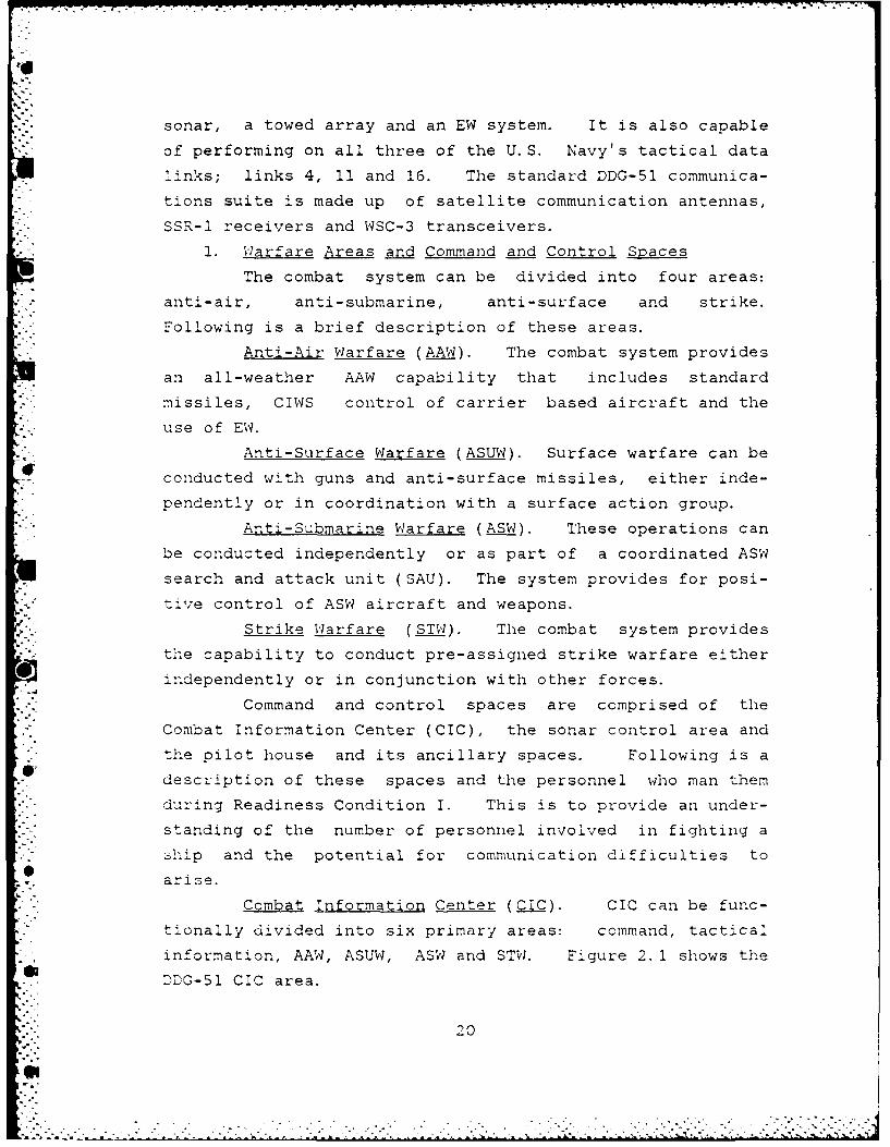
Combat Information Center (CIC). CIC can be func-
tionally divided into six primary areas: command, tactical
information, AAW, ASUW, ASW and STW. Figure 2. 1 shows the
DDG-51 CIC area.
20

Command Area. It provides command, i.e., the
Commanding Officer (CO) and the Tactical Action Officer
(TAO), with the necessary facilities to monitor the tactical
situation and make decisions.
Tactical Information Area. It contains displays and
facilities for sensor and surveillance system management for
air targets and EW and provides the capability for detec-
tion, identification and tracking of targets.
AAW Area. It provides displays and facilities for
coordinating and controlling engagements with air targets by
ship's missiles, guns and CIWS as well as for the close
control of aircraft.
ASW'' Area. It provides displays and facilities for
tracking sub-surface targets, coordinating and controlling
target engagements and the close control of ASW aircraft.
ASUW Area. It provides displays and facilities for
surface tracking, coordinating and controlling engagements
with missiles and guns (including over-the- horizon, OTH,
and strike warfare), controlling shore bombardment when
firing by navigational plot and radar navigation.
STW Area. The STW area is a specialized subarea of
ASUW. It becomes a separate warfare area when conducting
missile launchings against land targets. At that time it
provides displays and facilities for preparation and control
oz omahawk land attack missiles (TLAMS).
;'
21
L "

3
5,
z~WLzr~ -~ -~
J Ii ii
I , :1-
a .~.-1:A
I, .. ~J __~~~~~~'1~ -w ', -w -,
__ to-. -~ - U,
1.-. -1'
- } u-. , r-I
---1- -~ U)
~
* - _____ -* - -*, - ~i~ 0* -~ ~-- ~ c, ~'~Th U
J -~ U
-n* -~ 2111
Li C4
.r-1
fl~ ~ ~AIw ~ -t~~ ~
*
22
- .~j.pjc,~c V *~ >~ ~ ~ . - *
In addition to the personnel in each of the warfare
a~ens, ere is also manned by two radio monitors (RM-1 and
Rr.I-2), the ere Supervi sol', a damage control phone talker and
n Captain's battle talker. These personnel are located
immediately behind the command area.
Sonnr .Q.Qn.!;;.t:.Q.l .lll.:.stil. This area is located in a sepa-
rate space. It provides active and passive sonar surveil-
lance in support of ASW and ASUW operations.
Pilot House and Ancillary Spaces. These areas
provide facilities for conning, maneuvering and navigating
the ship. They can be divided into four areas: C2 , naviga
tion and piloting, quartermaster and visual communications.
The C2 area provides facilities for the Commanding
Officer, the Officer-of-the-Deck and other personnel who
support the CO and OOD in accomplishing ship control opera-
tions. Included in these facilities is a console for main-
taining a surface detection and tracking function, normally
a responsibility of CIC. The console is operated by the
Surface Radar Controller ( SRC). Command also exercises
con~rol over the signal shelter and directs visual communi
cations transmitted and received by the signalmen.
2. Personnel Duties and Responsibilities
This section describes the duties and responsibili
ties of the personnel who participate in command and control
operations during Readiness Condition I. Table 1 shows the
manning requirements for ere, l1 o u s e [ Ref. 3 ] .
sonar control and the pilot
Readiness Condition I, or General Quarters as it is
better known, requires a fully manned C3 organization along
with a fully functioning combat system and weapon system.
This condition places the greatest demand _on an ISCS and
therefore provides us with a worst case scenario. Table 1
is provided to give the reader a better grasp of the number
of people and the complexities involved in fighting a ship.
23
...........
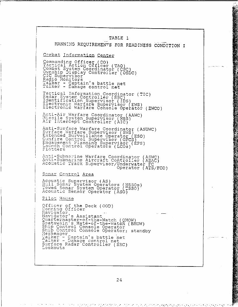
TABLE 1
MANNING REQUIREMENTS FOR READINESS CONDITION I
Combat Information Center
Commanding Officer (CO) Tactical Action Offlcer (TAO) Combat Svstem Coordinator (CSC) Ownship Display Controller (OSDC) CIC Supervisor Radio ~loni tors Talker- Captain's battle net Talker - Damage control net
Tactical Information Coordinator (TIC) Radar System Controller (RSC) Identif1cation Supervisor (IDS) Electronic Warfare Supervisor (EWS) Electronic Warfare Console Operator (EWCO)
Anti-Air Warfare Coordinator (AAWC) Missile System Supervisor (MSS) Alr Intercept Controller (AIC)
Anti-Surface Warfare Coordinator (ASUWC) Surface Warfare Supervisor (SWS~ Extended Surveillance Operator ESO) Gunfire Control Supervisor (GFC ) Engagement Planning Supervisor (8PS) Launch Control Operators (LCOs) Plotters
Anti-Subma~ine Warfare Coordinator (ASWC) Anti-Subma~ine Aircraft Controller (ASAC) Acoustic Track Supervisor/Underwater FC
Operator (ATS/FCO) Sonar ContrQl Area
Acoustic Suoervisor (AS) Hull Sonar Bxstem Operators ~HSSOs) Towed Sonar ~ystem Operator TSSO) Acoustic Sensor Operator (AS )
Pilo.t House
Officer of the Deck (OOD) Conning Officer Navigator --Navigator's Assistant Ouarterma~ter-of-the-Watch (OMOW) Boatswain s Mate-of-the-Watcfi (BMOW) Ship Control Console Operator Ship Control Console Operator; standby Messenger . Talker- Captain's battle net Talker - Damage control net Surface Radar Controller (SRC) Lookouts
24
'•' .
i f'. V,
Commandin Officer. The CO is responsible for
overall command of the ship. He also acts as strike warfare
Ucoordinator.Tactical Action Officer. The TAO is the principal
command decision maker under the direction of the CO.
Authority is delegated to the TAO for control of the Combat
System in all matters relating to tactical employment and
defense. If the TAO console fails he will monitor the CO or
OSDC cnnsole or relocate with the AAWC. In all cases of
console failure the relocation to another console is
dictated by the present tactical situation.
Combat System Coordinator. The CSC is responsible
for controlling the configuration of the combat system. He
monitors system status and operatio and allocates system
resources to the warfare coordinators. If the CSC console
fails, he will relocate to the alternate Radar System
Controller (RSC) console in the Combat System Equipment Room
(cSER).
Ownship Display Controller. The OSDC is responsible
for maintaining the command displays, specifically the large
screen display (LSD), Aegis display system (ADS) and the
automatic status boards.
CIC Supervisor. The CIC supervisor positions
himself in proximity to the TAO, but is free to supervise
where needed or to substitute at any console operator's
position. He acts as the primary enlisted assistant to the
T.O and as the tactical communicator.
Radio Monitors. The two radio monitors are located
at the communication table in the command area. They are
responsible for transmitting, receiving and logging exterior
h c munications.
Tal ' Ikers. Two S/P phone talkers are located in the
command area to monitor the Captain's battle net and Damage
control net.
25
• U
- ' :'ffo:r 'at i on Coordinator. The TIC is
:ns:,ze :r en.suring that the information displays of
ihe ta:-::a! da:a base are accurate and sufficient to
o:'rt t-e warfare coordinators in performing their tasks.
- ..fe fails, he will relocate to the EWS
co:sole :n C:C or to the alternate RSC console in the CSER.•?adar System Controller. The RSC, under direction
of the T:C, is responsible for operation and performance of
the SPY-I radar. if the RSC console fails, he relocates to
the alternate console in the CSER.
Identification Supervisor. The IDS is responsible
for establishing the identity, category and classification
of assigned surveillance targets. If the IDS console fails,
he would relocate to the EWS console.
4Electronic Warfare Supervisor. The EWS is respon-
sible for monitoring and controlling electronic support
measures. If the EWS console fails, he coordinates data
entry with the TIC via interior communications.
Electronic Warfare Console Operator. The EWCO
reports EW information and target correlation data to the
EWS. He is responsible for the configuration, control and
monitoring of the EW system.
d AAW Coordinator. The AAWC is responsible for coor-
dination and direction of all own-ship AAW assets, including
assigned aircraft. If his console fails, he relocates to
the CO console or to the alternate AAWC console in the CSER.
MNissile System Supervisor. The MSS initializes and
controls the FCS and VLS for engagement of assigned air
targets and for the launch of ASROC when assigned. If the
MSS console fails, he will relocate to the AAWC console and
the AAWC will relocate to his alternate console in the CSER.
Air Intercept Controller. The AIC is responsiblefor controlling assigned aircraft. If his console fails, he
relocates to either the ASAC or alternate AAWC console.
26
2.%
ASUW Coordinator. The ASUWC is responsible for the
coordination and direction of all own-ship anti-surface
assets, including assigned aircraft. If the ASUW console
fails, he relocates to the SWS or to the CO console.
Surface Warfare Supervisor. The SWS, under the
direction of the ASUWC, controls surface warfare sensors,
evaluates the surface situation and monitors weapon engage-
ments. If the SWS console fails, he relocates to the alter-
nate AAWC console in the CSER.
Extended Surveillance 0oerator. The ESO is respon-
sible for maintaining extended surveillance (OTH) data. If
the ESO console fails, he relocates to the LCO console or to
the alternate LCO console in the CSER.
Gunfire Control Supervisor. The GFCS is responsible
for the performance of the gun weapon system. If his
console fails, he can relocate to any other CIC console.
Enqaqement Planning Supervisor. The EPS is respon-
sible for planning Tomahawk anti-ship missile (TASM)
land attack missile (TLAIM) engagements for ASUW and
operations. If the EPS console fails, he relocates to the
LCO or ESO console in CIC or to the LCO alternate console in
*-"- the CSER.
Launch Control Operators. Two LCOs, under the
direction of the EPS, are responsible for launching Tomahawk
missiles. If an LCO console fails, they can shift to the
other LCO console in CIC or to the alternate LCO in the
CSER.
Plotters. The plotters are responsible for oper-
ating the Digital Dead Reckoning Tracer (DDRT) and main-
taining a surface and subsurface plot. There is only one,< • D.RT.
"AW4 Coordinator. The ASWC is responsible for the
coordination and direction of all own-ship ASW assets,
including assigned aircraft. If the ASWC console fails, he
reLocates to the 3W3 console.
27
'I
" " ' " ' . . ' ' - " I '• - i " 1 " l" " -" " " - . .. . '+• , " 4_ " . " _ . "= " I ,
Anti-Submarine Aircraft Controller. The ASAC is
responsible for controlling assigned ASW aircraft. If the
ASAC console fails, he relocates to the ATS/FCO console or
to the alternate RCS console in the CSER.
Acoustic Track Supervisor/Underwater Fire Control
Ooerator. The ATS/FCO is responsible for subsurface tracks
and controls all ASW weapons with the exception of aircraft.
If his console fails, he relocates to the acoustic supervi-
sor's console in sonar control.
*Acoustic Supervisor. The AS, under the direction of
the ASWC, is responsible for the supervision of the sonar
control area. If the AS console fails, he will relocate to
an alternate console in the sonar control area.
Sonar Operators. The sonar operators are comprised
l- of two HSSOs, the TSSO and the ASO. They are responsible
for operation of the sonar systems and the detection and
classification of underwater targets. In the event of
console failure, they relocate to other console positions in
sonar control.
Officer-of-the-Deck. The OOD, under direction of
the TAO (acting for the CO), is responsible for all ship* control functions. He has no console per se.
Surface Radar Controller. The SRC, under the super-
vision of the SWS, is responsible for detection and classi-fication of surface targets, low-flying aircraft and
submarine snorkels/periscopes. There is not an alternative
@4 console for the SRC.
* * 3. Subscriber Requirements of an ISCS
As mentioned previously, Readiness Condition I
places the greatest demand on an ISCS, due primarily to the
O" increase in the number of subscribers (the users of an
:SCS - :AO, EWS, AIC, etc. ) and their associated communica-
tion requirements. The tables in Appendix "A" are provided
to assist the reader in grasping the enormous communication
28
2-'. -. 2.
tasking and system coordination that fighting a ship
requires. The listings are not intended to provide a
comprehensive account of subscriber requirements. They are
intended to provide a basis for a general understanding of
the scope of subscriber requirements; keeping in mind the
tremendous demand this can place on an ISCS.
D. THE OLIVER HAZARD PERRY CLASS, FFG-7
This section will emphasize the other class of ships
- that will be emphasized, the Oliver Hazard Perry (FFG-7)
class. It will provide a review of FFG-7 mission, combat
system and personnel who participate in the command and
control of shipboard operations.The FFG-7 class is a guided missile frigate whose
general mission is to operate offensively with ASW forces,
with SAGs, in the protection of underway replenishment
groups, in support of amphibious assaults and to protect
military and commercial shipping against attack.
Control of the FFG-7 combat system is distributed. It
Soriginates with the Commanding Officer and is distributedthrough the chain of command. Combat system control,
consisting of sensors, display and decision, weapons control
* and weapons system is directed by command (via the TAO as-? authorized by the CO) and controlled by the Weapons Control
Officer, ASW Evaluator and EW Supervisor.
The combat system provides the capability to detect,
evaluate, acquire, engage and deceive enemy air, surface and
subsurface threats. The system is comprised of sensor,
control, weapon and support elements. For armament, this
class is fitted with one Guided Missile Launching System
* (GMLS) for both SSMs and SAMs, one 7614 gun and one CIS.
The ship's fire control system consists of one MFCS, one
GFCS and two FC radars. It is equipped with two other
radars, a 2-D air search radar and a surface search radar.
Additional sensors include a hull mounted sonar, a towed
29
p --
array system and an EW system. The basic communications
suite includes satellite communication antennas, one SSR-l
receiver and two WSC-3 transceivers. The remainder of this
section provides a description of the Ca spaces and the
personnel who man them on during Readiness Condition I on
FFG-7 ships. But, before continuing it's important to note
the basic differences and functions between this class and* . DDG-51.
The Aegis system, particularly the phased array radar,
allows DDG-51 to play a more complex, multi-faceted role in
a combat scenario. A much larger crew complement also
allows for more well defined and specific tasking of
personnel. With FFG-7 class, the role the ship plays is
much more limited and restricted. In addition, the concept
of minimum manning on this class requires a much more
general and flexible tasking with respect to personnel.
1. Warfare Areas and Command and Control Spaces
The combat system can be divided into three areas:
anti-air, anti-submarine and anti-surface. Following is a
brief description of these areas.
Anti-Air Warfare (AAW). The combat system provides
an all-weather AAW capability that includes standard
s ms issiles, CIWS, control of carrier based aircraft (though
not regularly assigned) and the use of EW.
Anti-Surface Warfare (ASUW). Surface warfare can be
conducted with guns and anti-surface missiles, either inde-
pendently or in coordination with a surface action group.
Anti-Submarine Warfare. ASW operations can be
cnducted independently or as part of a coordinated AS;
search and attack unit (SAU). The system provides for posi-
-- ,. control of ASW aircraft and weapons that can be
launched either over the side or from ASW aircraft.
Command and control spaces are comprised of the
Combat Infor:nation Center (CIC), the sonar control area and
o3
• ." , . " - -. -,- .- -- - . -' ", ' ' . ... ' -'. . . . . . - - - , -" . ' ' . '"'- ' ', ''-
the pilot house 1'\nd its ancillary spaces. Following is a description of these spaces and the pet·eonnel who man them
during Readiness Condition I. This is to provide an under
standing of the number of personnel involved in fighting a
::;hip and the potential for communication difficulties to arise.
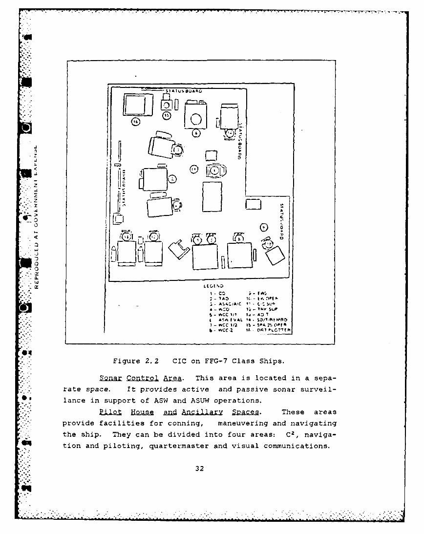
C0mbi'lt Informa·tion Center ( CIC). CIC can be func-
tiollally divided into four primary areas: display and deci
sion, detection and tracking, weapons control and ASW.
Fig~re 2.2 shows the FGG-7 ere area.
Display and Decision Area. It provides command,
i.e. , the Commanding Officer (CO) and the Tactical Action
Officer (TAO), with the necessary facilities to monitor the
tactical situation and make decisions.
Detection and Trar~ing Area. It contains displays
and facilities for senso~ ~nd surveillance system management
of all surface, subsurface and air targets and EW and
provides the capability for detection,
tracking of targets. identification and
It provides displays and facilities for
tracking sub-surface targets, coordinating and controlling
target engagements and the close control of ASW aircraft.
\~eapons Control Area. It provides displays and
facilities for surface and air tracking, ~oordinating and
controlling engagements with missiles, guns and CIWS
(including over-the- horizon, OTH, targeting), as well as
close control of aircraft, controlling shore bombardment
when firing by navigational plot and radar navigation.
In addition to the personnel in each of the warfare
areas, CIC is also manned ~y two radio monitors (RM-1 and
RM-2), the CIC Supervisor, a damage control phone talker and
a Captain's battle talker. These ~ersonnel are located
immediately behind the command area.
31
SI ItJ~ IBs UAJ4L
Ll .
lj L,
.~~ E) C. E % Z)*0O
I ( -( twV)PE p
~ % . -', I t T dV S.I., UP,
b - OCC 1/ lj- ADA ASA IVAL 14. $ D/'.PtMAO
-" .".1 l ol.7, p
b -WCC -2 it. c1 Pl C
- Figure 2.2 CIC on FFG-7 Class Ships.*Zonar C.ontro Area. This area is located in a sepa-
* ."rate space. It provides active and passive sonar surveil-
*, lance in support of ASW and ASUW operations.
jil" House an c illar S • These areasprovide facilities for conning, maneuvering and navigating
the ship. They can be divided into four areas: C2 , naviga-
tion and piloting, quartermaster and visual communications.
32
The Cz area provides facilities for the Commanding
,a Officer, the Officer-of-the-Deck and other personnel who
support the CO and OOD in accomplishing ship control opera-
tions. Included in these facilities are two radar repeaters
(instead of a Surface Radar Console) for maintaining a
surface detection and tracking function, normally a respon-
sibility of CIC. Command also exercises control over the
signal shelter and directs visual communications transmitted
and received by the signalmen.
2. Personnel Duties and Responsibilities
This section describes the duties and responsibili-
ties of the personnel who participate in command and control
operations during Readiness Condition I. Table 2 shows the
manning requirements for CIC, sonar control and the pilot
house.
Commanding Officer. The CO is responsible for
overall command of the ship.
Tactical Action Officer. The TAO is the principal
command decision maker under the direction of the CO.
Authority is delegated to the TAO for- control of the Combat
System in all matters relating to tactical employment and
defense. He has no warfare coordinators (as does the DDG-51
TAO) to delegate his authority to. If the TAO console fails
he will relocate to the ASW Officer Console (ASWOC) and the
ASW Eval moves to the DRT. In all cases of console failure
the relocation to another console is dictated by the present
tactical situation.
CIC Supervisor. The CIC supervisor positions
himself in proximity to the TAO, but is free to supervise
where needed or to substitute at any console operator's
position. He acts as the primary enlisted assistant to the
TAO and as the tactical communicator.
Padio monitors. The two radio monitors are located
at the communication table in the command area. They are
33
_ _ . ... .- . ., ,. ... -. _ . . . . . ., .. - ', - : - ". . .. ., . " , . ' . r. " ., . *._, ', ./. .'. ., ._ - .. . -!
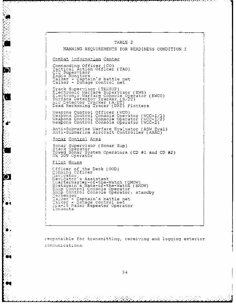
TABLE 2
MANNING REQUIREMENTS FOR READINESS CONDITION I
Combat Information Center
Commanding Officer (CO)Tactical Action Officer (TAO)CIC SupervisorRadio MonitorsTalker - Captain's battle netTalker - Damage control net
Track Supervisor (TRKSUP)Electronic Warfare Supervisor (EWS)Electronic Warfare Console Operator (EWCO)Surface Detector Tracker (S/DT)Air Detector Tracker (A.'DT)Dead Reckoning Tracer (DRT) Plotters
"WeaPons Control Officer (WCO)Weapons Control Console Operator (CC-IWeapons Control Console Operator IWCC-1 2 )
Weapons Control Console Operator (WCC-2)
Anti-Submarine Warfare Evaluator (ASW Eval)Anti-Submarine Aircraft Controller (ASAC)
Sonar Control Area
I Sonar Supervisor (Sonar Sup)Stack Operator-Lowed Sonar System Operators (CD #1 and CD #2)-k 309 Operator
Filot House
Cfficer of the Deck (OOD)C3nning Officer,avga t or
Navigator' s Assistant,uartermaster-of-the-Watch (QMOW).oatswain's mate-of-the-Watch (BOW)Sip Control Console Operator-Sp Control Console Operator; standby.* . 'essenger
- ?'a~:'er - Captain's battle net-alke- - Damage control net-ra-5 Padar Repeater Operator
, . Lcokouts
rezponsible for transmitting, receiving and logging exterior
C omunications.
34
q
Talkers. Two S/P phone talkers are located in the
command area to monitor the Captain's battle net and Damage
control net.
Track Supervisor. The TRKSUP monitors and super-vises the detection, entry, classification and tracking
oerations. If his console should fail, he would move to
either the A/DT or S/DT console.
Electronic Warfare Sunervisor. The EWS is respon-
sible for monitoring and controlling electronic support
measures. If the EWS console fails, he coordinates data
entry with the TRKSU? via interior communications.
Electronic Warfare Console Operator. The EWCO
reports EW information and target correlation data to the
. EWS. He is responsible for the configuration, control and
monitoring of the EW system. There is only one EW console.
Weapons Control Officer. The WCO, under the direc-
tion of the TAO, selects targets for engagements and assigns
appropriate FC channels and weapons for acquisition,
. tracking and FC solutions. In case the WCO console fails.he relocates to the ASAC/AIC console.
Air Intercept Controller. The AIC is responsible
for controlling assigned aircraft. If his console fails, he
relocates to either the WCO or ASWO consoles.
Air Detector Tracker. The A/DT provides new track
entry on all video, enters identity and composition of all
tracks within the surveillance area and correlates EW datawth radar tracks. If his console should fail, he relocates
to either the S/DT or TRKSUP console.
Surface Detector Tracker. The S/DT searches for and
initiates new tracks for detected surface and low flying
" aircraft, updates tracks, enters identification on new
tracks an provides track data for radar navigation. In case
of console failure, he would move to either the A/DT or
TRKSUP console.
35

Weapons Control Console Operators. The WCC opera-
tors are responsible for the efficient use of the guided
missile launching system (WCC-I/1 and WCC-2), the Harpoon
control panel and the CIWS remote panel (WWC-l/2) and the
gun (all three WCCs).
Plotters. The plotters are responsible for oper-
ating the Dead Reckoning Tracer (DRT) and maintaining a
surface and subsurface plot. There is only one DRT.
ASW Evaluator. The ASW Eval is responsible for the
coordination and direction of all own-ship ASW assets,
including assigned aircraft. If the ASWOC fails, he relo-
cates to the DRT plot.
Anti-Submarine Aircraft Controller. The ASAC is
responsible for controlling assigned ASW aircraft. If the0 ASAC console fails, he relocates to the WCO console.
Sonar Sunervisor. The Sonar Sup, inder the direc-
tion of the ASW Eval, is responsible for supervision of the
sonar control area.
Sonar Operators. The sonar operators are comprised
of the Stack Operator, Mk 309 Operator, and the two Towed
Sonar System Operators. They are responsible for operation
of the sonar systems and the detection and classification of
underwater targets. In the event of console failure, they
relocate to other console positions in sonar control.
Officer-of-the-Deck. The OOD, under direction of
the TAO (acting for the CO), is responsible for all ship
control functions. He has no console per se.
Spa-25 Radar Repeater Operator. This operator isresponsible for detection and classification of surface
targets, low-flying aircraft and submarine snorkels/
er, scopes. There is not an SRC console located on the
- bricde as on the DDG-51 class.
36
3. S11bscriber ReQuirements .QD M ~
Appendix "B" contains descriptions of the subscriber
(user) requirements of individual console operators and C2
personnel. The listings are not intended to provide a
comprehensive account of subscriber requirements. They are
intended to provide a basis for a general understanding of
the scope of subscriber requirements; keeping in mind the
tremendous demand this can place on an ISCS.
The material covered so far (including the tables in
the appendix) has been presented to provide the reader witll
a framework from which to understand the workings of an
ISCS. The brief introduction to surface combatants along
with descriptions of the part they play in a warfare scen
ario should help illuminate the important role an ISCS has
in contributing to the success a ship has in meeting its
mission requirements. The identification of the players
(users) in shipboard C3 along with their communication needs
is provided to highLight the heavy demand placed on an IC
system as well as the complex operations necessary for such
a system to function properly. With this background, the
next chapter will show some of the problems inherent in
designing a viable ISCS, as well as, the requirements a
successful ISCS must meet.
37
T I:I INTEGRATED SHIPBOARD COMYUN:CATON SYSTEM PEOUIREMENTS
-his chapter will examine some of the C 3 problems caused
by either the absence of an ISCS or the design flaws on
installed systems. It will then provide a description of
design and system features and capabilities that are desir-
able in the ISCS of the future. See [Ref. 4] and [Ref. 51
.. RESENT SYSTEMS
The source of many of todays C' problems are a direct
result of unsatisfactory interior communications. Some of
the systems and their design features (sound powered tele-
phones fnr example) date back to WWII with little or :-,
. change in operation or capabilities. This, despite -,.e
obvious technological advances in all other areas of nava'
warfare. Sut before going any further, a brief description
of the various types of IC systems will be given.
Sound-Powered (S,) Telephones. Though somewhat anti-
quated and not easily adaptable to changing scenarios, S/P
.. phones are still considered to be the most reliable and
survivable means of communication aboard ship. This is
because they are independent of external electrical power.
.hey require no outside power supply for operation since the
,und waves produced by the speaker's voice provide thenecessary energy to reproduce the voice at a remote loca-
@4 tion. A hand cranked magneto generator or an external
."uzzer provide the audible alert or ringing power.
lti Channel Circuit (MMC). Shipboard one-way
an-nouncing systems serve the general purpose of transmitting
.r.ers and information between station= 1y amplified voice
communications. MCCs are a iicrcphone speaker system
c'esicned, to provide rapid voice communications between twoor more stations, During normal cruising, MCCs can be
38
o.,
considered an auxiliary to S/P phone circuits and should
only be used when necessary. Indiscriminate use of MCCs
lowers its value for emergency communication and raises the
noise level above acceptable limits in C2 spaces.
intercom Systems. Intercom or interphone systems
provide selected communication between selected watch
stations. These calls or messages can be transmitted and
received over console speakers, handsets or headsets.
Normally a channel or station selection switch must be
invoked to establish communications. Due to its simplicity
of operation and ease of access to different watch stations
this is the preferred method of communication between watch
stations.
Ship Service Telephone System. This system is very
similar in principle to a home phone system. That is, to
the user the basic function is the same - selectable calling
of another telephone terminal. The selection of a station
can be via dial-up, selectable switch or push button. An
audible signal is provided at the called terminal to notify
the user at that station.
Radio Telephone (R/T) System. This is the system used
to provide external communication between a user aboard ship
and a user at a location external to the ship.
Communication is via a handset or a headset and can be
either secure or non-secure in nature.
During normal operations or peacetime cruising the
performance of each of these systems is satisfactory.
However, with an increase in the operating tempo comes a
corresponding increase in the demand placed on these systems
with an alarming drop in their performance level. TheIdecrease in the ability of these communication systems to
meet the ever increasing demand placed on them by a techno-
logically advancing navy can be traced to the general
problem or deficiency areas found in Table 3 [Ref. 6: p. 1].
39
41,
"' < " """ ' - ' ' "" "' "" " " '.-i"i" " '" " . - " ' " ,. " ... ' -. .-. . -'... -.
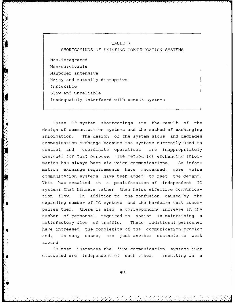
4 TABLE 3
SHORTCOMINGS OF EXISTING COMMUNICATION SYSTEMS
Non- integrated
Nion- survivable
M*anpower intensive
Noisy and mutually disruptive
Inflexible
Slow and unreliable
4 Inadequately interfaced with combat systems
* These C3 system shortcomings are the result of the
* design of communication systems and the method of exchanging
in-formation. The design of the system slows and degrades
communication exchange because the systems currently used to
control and coordinate operations are inappropriately
designed for that purpose. The method for exchanging infor-
mation has always been via voice communications. As infor-
mation exchange requirements have increased, more voice
communication systems have been added to meet the demand.
This has resulted in a proliferation of independent IC
systems that hinders rather than helps effective communica-
tion flow. In addition to the confusion caused by the
* expanding number of IC systems and the hardware that accom-
panies them, there is also a corresponding increase in the
number of personnel required to assist in maintaining a
satisfactory flow of traffic. These additional personnel
6 have increased the complexity of the communication problem
and, in many cases, are just another obstacle to work
around.
In most instances the five communication systems just
discussed are independent of each other, resulting in a
40
ship's interior communication system that has the following
characteristics [Ref. 4]:
1. Individual systems using different technologiesrequiring i specialized raining of maintenancepersonnel in any different types of equipment.
2. Systems are hardwired with no provisions for adding ordeleting stations or reconfiguration in the event ofbattle damage to a portion of the ship.
3. Vulnerability of electrically powered systems tointerruption of the normal power supply i.e., noprovision for uninterrupted power supply (UPS).
4. Reliance on telephone talker personnel to accuratelyrelay information between watch station decisionmakers, which reduces the speed of informationtransfer and has significant potential for errorintroduction.
5. Increased watch station personnel requirements.
6. Inadequate interfaces with combat systems and no inte-gration with external communication systems.
7. Watch stations that are physically cluttered with anassortment of radio and /'P phone handsets, internaland external communications loudspeakers, microphones,two-way internal communication terminals, statusboards and ship's telephones. This requires keyersonnel to be knowledgeable in the operating charac-eristics of each system, determine which systems to
use for communications with specific watch stationsand repeat information as necessary to relayersonnel4 all of which results in dis ractions forhe decision maker.
8. Restricted access and movement on/to watch stationsdue to space requirements of systems.
9. Excessive noise at the watch stations with potentialfor missed information due to simultaneoustransmission.
B. SYSTEM/DESIGN CONSIDERATIONS.
An obvious way to eliminate many of the faults given in
the prior section is to combine the different systems into
one IC system. The U.S. Navy has begun to do this with what
is frequently called the Integrated Shipboard Communication
System (ISCS) and is also referred to as a multi-capability
voice communication system. There are numerous advantages
to such a system. An ISCS offers the opportunity to:
1. Combine traditional voice IC functions.
2. Improve information transfer capacity.
3. Reduce shipboard maintenance action.
41- C
.
4. Reduce the clutter of communication system terminalsat watch stations.
5. Substitute digital data display for much of the statusinformation that is currently transferred by voicecommunications.
Current efforts seek to improve operation of different
IC systems through the application of today's technology
which is aimed at increased speed, reliability, intelligi-
bility, simplified terminal operation and efficiency of
maintenance actions. Introduction of the Integrated Voice
Communication System (IVCS) in both the LHA class and the
CG-47 class ships has provided the first serious attempt at
elimination of overlapping IC functions by providing multi-
capability systems [Ref. 4: p.2-3]. These systems have the
following characteristics:S 1. Fewer total terminals resulting in reduced overall
cabling requirements.
2. Improved intelligibility and voice quality.
3. Access to radio, one-way announcing systems S/Pphones, and ship's service telephone from tfie same.erminal.
4. Four digit pushbutton dialing, with single buttonabbreviated addressing for frequently called subscri-bers and nets.
5. Dial-up and command net conferencing.
6. Alternate power source in the event of a loss ofprimary electrical power.
* 7. RFeduction in range of maintenance training require-ments due to reduce numbers of different equipment andcommonality of terminals throughout the ship.
8. Addition/deletion of terminals through the use ofmodular equipment and software changes.
4 1. Console Design
No discussion of ISCS requirements can be considered
complete with out some mention of console (terminal)
requirements. While any attempt at presenting in-depth
console design requirements and hardware specifications is
beyond the scope of this thesis, a brief summation linking
console specifications to a few of the major fundamental
requirements of a successful IC system will be provided.
42
6!!i
- .''- .-. . -- t -< [ < <.' .6 " - 1- . ." - . " " ." " .. ' ... -- ' - -< - .. - . "'"-*2 .< . "" . -

. .- . .. - - . . . . - -_-. . *.,- . . . .* * 3 , . . - ... ... .. .. .... . . . ..
".
In order to meet the ISCS requirements there are
some general desired features that should be incorporated
into console design. These communication attributes are
given from the point of view of the console operator who
must interface directly with the hardware devices. These
characteristics, found in [Ref. 7: p. 2-51 are:
I. Multiple communications media access must be by asingle communications terminal due to limited operatorfreedom of movement.
2. Manual control actions must be minimized to preventinterference with console manual interface and facili-tate operator concentration on visual informationdisplays.
3. The changing tactical situation may require the oper-ator to instantaneously shift to alternate circuitswithout disrupting control actions associated with theongoing action.
4. incoming call and console alerts must be distinctiveand gain operator attention without becoming an anno-
* yance if the operator is otherwise engaged in higherpriority tasks.
5. Urgent IC calls must have non-blocking access to theoperator, but must have lower priority than externalcommunications in progress.
6. Interconsole net communication capability should allowpreselection of net participants to fit the tacticalsituation.
7. Secure and non-secure communications should be avail-able at key console stations.
8. Emergency (S/P) IC should be instantaneously availablein tne event of total system failure.
The major fundamental requirements of an ISCS that
should be incorporated into console design are speed and
simplicity of operation, integration and flexibility (these
will Le discussed in more detail later). Speed and
6Q simplicity can be satisfied by consolidating all IC subscri-
bers at a single terminal location. This allows for easier
access to the various circuits that an operator may need to
communicate with other subscribers. Labelling of buttons
and switches by title would eliminate the need for an oper-
ator to memorize numbers or to activate a number of controls
to initiate a call and thus help simplify and speed up
c c:-munications.4
[" 43
-
. . .
Integration can be met by incorporating the various
*IC systems into one terminal. This provides the user with
aqzick and easy access to the type of transmission medium
needed in performing his assigned tasks.
Finally, the requirement for flexibility can be
satisfiLed by allowing pre-programming of the terminals,
enabling them to be configured for the specific communica-
tion requirements of individual operators and easily recon-
figured when changes occur in their communication needs.
This also allows operators the flexibility to switch
consoles in case of a malfunction or failure to their
primary console.
2. Human Factor Considerations
Another important area that cannot be overlooked is
4that of human factor considerations and along with them the
concepts of form, fit and function. The pressures placed on
an operator during high tempo operations, plus the potential
for long periods of time on watch at a console without
relief, demand that the operator be able to maintain his
highest performance level, both physically and mentally.
Human factor considerations play a major role in assisting
operator performance. The following paragraphs, taken from
[Ref. 8: p. 3-1] emphasize the importance of this point.
Console operators have severe demands placed on
sensory capacity, vigilance, perception and decision making
*ability in relation to display indications. The primary
sense used by the cperator is visual perception, which
provides for target detection, symbol recognition, alphanu-
* mneric readout and indicators linked to the execution of a
control action. During periods of low operational activity,
such as peacetime transit in open ocean areas, the opera-
tor' s visual sense is used only moderately and console
control actions are few. During these times, operation of
the separate system element controls do not tax the operator
44
and there is little distraction due to other activity in the
immediate vicinity. However, as the tempo of operations
ncreases, the operator's visual and aural senses become
quickly overloaded and mental stress increases to an
extremely high level. At this point, any incompatibility of
system components will become apparent through increased
operator errors or inability to execute control actions fast
enough to effectively support the C2 node (e. g. , continuity
of command, maintaining the common tactical picture). To
solve this problem, it would seem that each of the system
elements should be separately re-evaluated to optimize its
capability and permit easier operation. However, care must
be taken in this approach to ensure that the improved system
element (or subsystem of the overall system) is able to work
in harmony with the total system. In the specific case of a
console mounted terminal, it would seem that optimum design
should, therefore, consider the following:
- 1. Minimize visual reference requirements in order tomaintain operator concentration on tactical displays.
2. Eliminate error provocative features (such as multi-function buttons or lengthy button sequences) toreduce the chance of operator error during high tempooperations.
3. Decrease the amount of effort required by consideringeconomy of motion and compatibility of psychomotorskills with other console sub systems.
4. Choose the proper control devices that contribute tospeed and accuracy of operator movements.
5. Consider the overall ensemble of displays and controldevices to ensure that information presentation isconsistent with other displays, so the operator can
ol easily and correctly identify a particular systemoutput when needed.
. Cutaneous sensitivity follows vision and auditory
sensitivity in relative importance to a console operator.
Touch is particularly good for spatial orientation if
controls are simple to use, require minimum visual reference
and are within the physical reach limits of the operator.'his would seem to indicate that the communication front
panel should be primarily a touch-oriented system, with a
45eq. t
:{:- !"
minimum number of controls/indicators. However, the obvious
use of multi-function controls to achieve an uncluttered
front panel also requires increased visual reference, which
reduces the importance of spatial orientation by touch. The
basic design questions to be addressed then are: 1) What is
the proper allocation of operator sensory channels?; and 2)
I] What are the proper controls/indicators to use with each
sensory channel?
Communication terminal placement is critical to
operator effectiveness. While terminal locations supporting
non-console C2 personnel are generally less sensitive to
size and exact placement of installation, the physical space
limitations and restrictions available in a console impose
design constraints that may limit hardware options. The
'- most restrictive dimensions are those of the front panel.
Since only a finite number of switches/indicators of useable
size can fit into this area, a trade-off between capability
* versus human factors results early-on in system design. The
following are some of the placement factors that must be
analyzed to permit the most effective integration of the
communication terminal with the combat systems console.
1. What is the operator's radius of movement?
* 2. What non-communication control functions are alreadyallocated to the right and left hands?
3. What is the effective viewing distance of various sizelabels and indicators?
What are the environmental conditions (noise, heat,illumination, etc. ) at the watch station.
5. ";hat is the character of the operator population(skill level, training, span of concentration, speedof perception, visual acuity, general intelligence?
With these factors now taken into consideration, we
will move on to the following section. This next section
* -will expand upon the fundamental requirements presented
earlier, in addition to identifying more specific opera-tional capabilities needed to meet the growing demand placed
qrj on today's ISCS.
46
. . . .... .... . .. - 7. ; *.' " '* . - - .- . .i . -• . - "" "" " "- -. ".
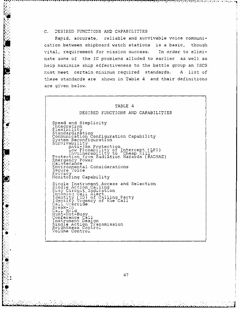
'
C. DESIRED FUNCTIONS AND CAPABILITIES
-"*" Rapid, accurate, reliable and survivable voice communi-
cation between shipboard watch stations is a basic, though
vital, requirement for mission success. In order to elimi-
nate some of the IC problems alluded to earlier as well as
help maximize ship effectiveness to the battle group an ISCS
must meet certain minimum required standards. A list of
these standards are shown in Table 4 and their definitions
. are given below.
TABLE 4
DESIRED FUNCTIONS AND CAPABILITIES
Speed and Simplicity_ IncegrationFlexibilityStandardizationCommunication Configuration CapabilitySystem ReconfigurationSurvivability
Anti-jam ProtectionLow Probability of Intercept( (PI)Invulnerability to Cheap kill
Protection from Radiation Hazards (RADHAZ)Emergency Power!,aintenanceEnvironmental ConsiderationsSecure VoicePrivracy.onitorng Capability
Single Instrument Access and SelectionSingle Action Calling.usy Circuit Indication-ncoming Call AlertIdentity S ID) of Calling PartyIdentify Jrgency of the CallCall O'erride*: Break- inCail HoldHunt-Not-BusyConference CallInstrument DesignSingle Action TransmissionBrightness ControlVolume Control
47
.. .- ..

7 K
The first portion of the list consists of fundamental
• requirements that should form the framework for the design
of an ideal ISCS. The second half of the list contains a
more definitive listing of required operational capabilities
that an ISCS should incorporate in order to satisfy the
fundamental design requirements.
Speed and Simplicity. The system must provide for fast
operation and response with a minimum number of control
actions required to operate individual communication termi-
S- nals. This helps speed information and data exchange and
assists in maintaining operator concentration on tactical
displays. Therefore, complexity of operation, even if it
results in useful system features, is undesirable if it
compromises the fundamental requirement of speed and
simplicity of operation [Ref. 3: p. 201.
Intearation. Communication terminals must have the
capability to integrate all of the communication media
required by a console operator. This will help eliminate
the proliferation of terminals, handsets, microphones, etc.,
" that is presently slowing and degrading shipboard
communications.
Flexibility. The system must provide flexibility to
enable it to be configured for the communication require-
ments of each class of surface combatant. It is also
required in terminal design to enable the terminals of indi-
-',*. vidual users to be configured to their specific needs. The
04- system must also be flexible enough to ensure that shipboard
personnel are capable of making rapid changes in communica-
tion configurations when changes occur in requirements.
Standardization. Maximum standardization of hardware
components and ship communication architecture is desired to
minimize and simplify the number of interfaces and their
costs. Commonality with current telecommunication commer-
cial technology to reduce development, acquisition and life
dycle support costs is a desirable goal [Ref. 7: p. 2-21.
48
o~i L'

Communication Configuration Capability. This capability
is required to configure console communications for the
specific exterior and interior communication needs of each
user and to quickly reconfigure communications in the event
*: that an operator must change console positions because of
- console failure or malfunction. This is analogous to the
flexibility requirement but on a smaller scale.
" System Reconfiguration. This is the capability to add
or delete stations from the system in order to support
changing C' requirements. Further, system configuration and
hardware components/circuit accesses must be such that
changes in system configuration can by made by shipboard
personnel in a timely manner and without the need for
outside assistance.
Survivability. This capability provides communication
to surviving system hardware components within the surviving
sections of the ship (after battle damage) with minimum
reconfiguration actions. An ability to display the
surviving capabilities of a terminal to its user is also
required. Anti-jam protection, LPI and invulnerability to
"cheap kill" are part of this.
Anti-lam Protection. The system must not be vulnerable
to hostile EW or degradation due to own ships
Electromagnetic Interference (EMI).
Low Probability of Intercept (LPI). The system must not
radiate detectable signals external to the ship. Plus, when
*interfaced with an external communication system (an R/T
net), the system must not transmit a unique identifying
signature.
Vulnerability to "Cheap Kill. " The system must ensure
*} that vital stations will not lose communications due to
"cheap kill" hits such as weapon air bursts within 100 feet
of the ship, small arms fire, etc.
49
- -- -! L
6-'. - : " - : : o .:- " :-" : ::::. -:-::: ". ::
. . . = { " m ; " m " ' l i u - '- i " = ".. . . " " "-t - .t . . . . . .j
.rotection from Radiation Hazards (RADHAZ). This capa-
bility is required to protect the ship from (nuclear) radia-
tion hazards and Electromagnetic Pulse (EMP). In addition
: preventing system degradations, exposed terminals must be
easily decontaminated to protect personnel during continued
system use after a nuclear attack.
E:ercency Power. An emergency source of electrical
power is required to enable personnel to communicate when a
ship's primary source of electrical power fails or
m a!functions.
M aintenance. The capability is required to provide
automatic system performance monitoring of hardware compo-
nents and circuit connectivities of IC circuits communica-
-: on system termination paths. Additionally, visual readout
Ei. of hardware component casualties should be provided down to
the lowest replaceable unit level to assist rapid corrective
maintenance action.
* Environmental Considerations. The components of the
system must be capable of operating in environments
containing potentially explosive mixtures of fuel and air
*" and in proximity to ordnance without any possibility of
initiun. The components must also be capable of operating
under conditions ranging from extreme heat to extreme cold
. -as well as in environments containing salt air and water.
" Secure Voice. The capability must be provided to
satisfy secure voice communication requirements, relating to
R/T nets. Consideration should be given to integrating* . secure and non-secure nets if it can be accomplished without
compromising either method of communication.
Privacy. This is required in conversations dealing withO, C2 matters. The system should be capable of allowing users
to communicate without having other IC subscribers eaves-
dropping on sensitive conversation. Privacy is also
required on conference calls, but the need for a break-in
capability overrides the privacy consideration.
50
-9
= .. ."
9."
.onitoring Capability. The capability is required to
monitor all communications being transmitted or received by
a console operator for three reasons: 1) to facilitate
information exchange and minimize disruption; 2) it is
" " required by supervisory personnel and key console operators
* whose duties require them to coordinate the operations of a
uumber of system users; and 3) to allow observation of
console operators for training and supervisory purposes.
IM;ow we start defining the operational requirements
listed in the second half of the list given in Table 4
These are the features and capabilities that should be
incorporated into system and terminal design to satisfy the
fundamental requirements just covered.
SincTle Instrument Access and Selection. The system must
provide the capability to communicate on all communication
media via either a handset, headset or speaker/microphone
and be selectable by console operators based on their commu-
* nication tasking. This includes the necessity for single
microphone access to all communication media.
Single Action Calling. This is required to initiate andreceive IC calls by a single control action. This require-
ment holds for RiT transmissions and announcing systems as
* well. This capability helps satisfy the requirement for
speed and simplicity. Activation of a single push button or
switch labelled by subscriber title of work station to
initiate a call eliminates the need for a user to recall or
look up a subscriber's number or code prior to initiating
the call.
us Circuit 7ndication. This capability allows the
user to identify or indicate busy IC circuits prior to the
call being initiated. This will eliminate the disruptive
and distracting effects of signalling subscribers when they
are engaged in another call. This also minimizes delay time
resulting in operator distraction from tactical displays.
51
e. %. 2. 2
w7
Some IC experts, [Ref. 5: p. 151, feel that both a visual
and audible indication are required. This author feels that
"S only one indication is necessary and that it should bevisual only, in order to reduce noise levels. With the
caller taki.ng positive action to initiate a transmission, lie
_s already looking for a busy signal indication (flashingSighz). Therefore, he does not need an audible indication
:o alert him to the situation; as is the case when he is
receiv.ing a call.
Incomina Call Alert. This capability alerts users to
nccming 1C calls through a brief audible alert to prevent
their distraction from potentially more critical taskings.
An audible vice visual alert does not require the operators
to constantly visually monitor their console. When a
headset is being used at a console the audible alert should
emanate from the earpiece(s) in the headset rather than
through a console speaker in order to reduce noise levels.
!D of Calling Part and Urgency of the Call. These two
requirements go hand-in-hand. The system must be able to !D
the party or the watch station initiating the call in order
to screen incoming calls during high tempo operations and
also indicate the urgency of the call to enable the user to
* determine the priori of calls when two or more are
received simultaneously. These are two essential require-
ments for C personnel. They do not have time to respond to
calls that are not relevant or time critical during periods
10 fof high demand. An additional feature that would be useful,
would be the capability to indicate to the calling party
S,. what his status is. If, for example, he receives indication
-"- that his call is considered a low priority he may terminate
-'s call, thus not only lessening the system load but also
freeing himself to do other things. Another use would be ifhe received a low priority and he felt that was a serious
mistake based on the tactical situation he could then invoke
call b.-eak-in.
52

Call Override. A call (or ring) override capability is
required to alert personnel to an urgent incoming call when
they are engaged with another IC call. This function should
have priority over all but radio communications in progress
at athe called station. This capability can be provided by
the same capabilities described in the previous requirement.
Shipboard personnel prefer call override to the break-in
method for the majority of urgent communication exchanges
[Ref. 5: p. 15]. The break-in method is disruptive and
lacks privacy. Plus, the calling party may disrupt a call
that is more urgent.
Break-in. This capability is required to deliver
messages of extreme emergency. Although call override may
be the preferred method, emergency situations do arise that
Urequire immediate access to other users. In such a situ-
ation the calling party must be able to gain immediate
access to the called party or station by activating a single
control and the called party must be able to receive and
respond to the call without activating any control or
functi ons.
Call Hold. This is required at the console or terminal
to enable IC calls to be temporarily terminated when a more
urgent call is to be received or transmitted. This also
speeds up the communication exchange by keeping the tempo-
rarily terminated console on-line while the urgent call is
in process, eliminating the need to re-initiate the call.
* This is what would occur when the break-in capability is
invoked.
Hunt-Not-Busy. This capability is required at vital C'
nodes, but not necessarily at each individual console, to
* route incoming IC calls to an idle terminal in watch
stations where more that one terminal is implemented for
decision making person-nel. Implementation of this capa-
bility at C2 consoles is desirable, but only if it can be
53
selected during initial console set-up and can be easily
cancelled at any time [Ref. 8: p.2-12]. One other point, is
that this may be desirable for routine calls but not neces-
sarily for urgent or high priority calls. The caller may
prefer a busy signal indication prior to initiating his call
to allow him to chose call override or break-in capability
depending on the situation rather than possibly wasting
valuable time being routed to another terminal.
Conference Call. This is required to enable subscribers
to communicate simultaneously with two or more other users.
Conference calls are necessary for planning and decision
making purposes and for coordinating various aspects of C2.
Instrument Design. This refers to headset design. it
should be constructed of light-weight materials to prevent
user discomfort during prolonged periods of use. It must
* also have non-occluding earpieces to prevent masking of
* face-to-face communications and communications that are
M:onitored over speakers. However, this requirement might
necessitate a reduction in background noise that could be
interfering with a user's ability to hear properly over theheadset. Inadto, a split headset capability (a
different circuit to each earpiece) must be provided to
*allow for the monitoring of two circuits simultaneously.
Singvle Action Transmission. Push-to-talk (PTT) actions
are not required for IC calls. Single action calling opens
a circuit and no further action is required. Access to
announcing circuits should provide the option of spring
loaded PTT buttons to provide channel selection or alternate
action (non-PTT) buttons. R/T transmissions also require a
single action PTT button. Additionally, in order to allow
as much freedom of moDvement to a user as possible, he should
have available both foot-operated and hand-operated PTT
bDutt-ons. The foot pedal would also free the user's hands
f*o r other tasks.
54

Brilhtniess Controls. These controls are required for
adjusting the intensity of light used to illuminate terminal
displays and control labels. Separate controls are required
for displays and labels that vary in design, size, intensity
-. etc.
- Vol,.zme Controls. These controls are required to adjust
. the volume of the communications received over the various
terminal instruments. Separate controls are needed for
adjusting the volume of the headset(s), handset(s) and
-speaker(s) at each console. A volume control switch is also
required for each earpiece of a split headset.
The next chapter contains the description of SNTI.
Before going on the reader should ensure the he or she has a
firm grasp of, not only the fundamental requirements and
operational capabilities of an ideal ISCS, but the reasons
why these requirements exist. That is, what is it about
today's warfare scenario and the current IC systems
installed on U. S Navy surface combatants that lead to poten-
t ial problems and require a redefining of ISCS needs and
-.standards.
To have such an understanding is important because SNTI
is going to be presented from a point of view that attempts
*to show how well it matches up against the concepts and
requirements presented in the first three chapters.
"t
55
e,
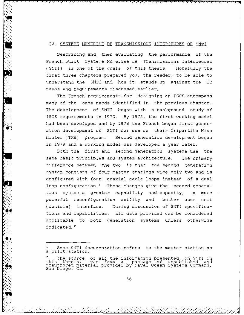
IV. SYSTEME NUMERISE D TRANSMISSIONS INTERIEURES OR SNTI
Describing and then evaluating the performance of the
French built Systeme Numerise de Transmissions Interieures
(SNTI) is one of the goals of this thesis. Hopefully the
first three chapters prepared you, the reader, to be able to
iunderstand the SNTI and how it stands up against the ICneeds and requirements discussed earlier.
The French requirements for designing an ISCS encompass
many of the same needs identified in the previous chapter.
ie development of SNTI began with a background study of
.SCS requirements in 1970. By 1972, the first working model
*2. had been developed and by 1978 the French began first gener-
ation development of SNTI for use on their Tripartite Mine
Hunter (TMH) program. Second generation development began
in 1979 and a working model was developed a year later.
Both the first and second generation systems use the
same basic principles and system architecture. The primary
difference between the two is that the second generation
;... system consists of four master stations vice only two and is
configured with four coaxial cable loops instead of a dual
loop configuration. 1 These changes give the second genera-
*.- tion system a greater capability and capacity, a more
powerful reconfiguration ability and better user unit
(console) interface. During discussion of SNTI specifica-
tions and capabilities, all data provided can be considered
- -applicable to both generation systems unless otherwi.se
indicated.2
1 Some SNTI documentation refers to the master station asa pilot station.2 The source of all the information presented on SNTI in---is thesis, was from a package of unpublishiJ arniunauthored material provided by Naval Ocean Systems Co:mmand,San Diego, Ca.
56
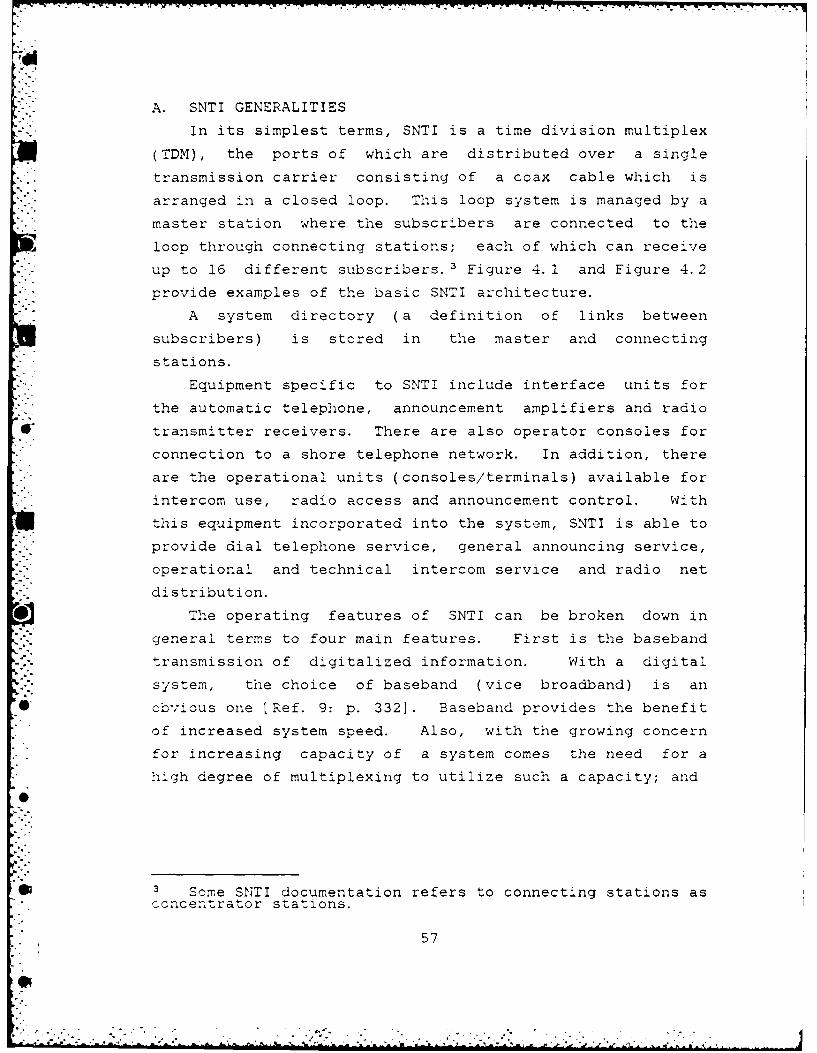
A. SNTI GENERALITIES
In its simplest terms, SNTI is a time division multiplex
(TDM), the ports of which are distributed over a single
transmission carrier consisting of a coax cable which is
arranged in a closed loop. This loop system is managed by a
master station where the subscribers are connected to the
loop through connecting stations; each of which can receive
up to 16 different subscribers.' Figure 4.1 and Figure 4.2
provide examples of the basic SNTI architecture.
A system directory (a definition of links between
subscribers) is stored in the master and connecting
" .stations.
* .- Equipment specific to SNTI include interface units for
the automatic telephone, announcement amplifiers and radio
transmitter receivers. There are also operator consoles for
connection to a shore telephone network. In addition, there
are the operational units (consoles/terminals) available for
intercom use, radio access and announcement control. With
this equipment incorporated into the system, SNTI is able to
S... provide dial telephone service, general announcing service,
o. operational and technical intercom service and radio net
distribution.
The operating features of SNTI can be broken down in
general terms to four main features. First is the baseband
transmission of digitalized information. With a digital
system, the choice of baseband (vice broadband) is an
* obvious one [Ref. 9: p. 3321. Baseband provides the benefit
of increased system speed. Also, with the growing concern
for increasing capacity of a system comes the need for a
high degree of multiplexing to utilize such a capacity; and
* .Some SNTI documentation refers to connecting stations asconcertrator stations.
57
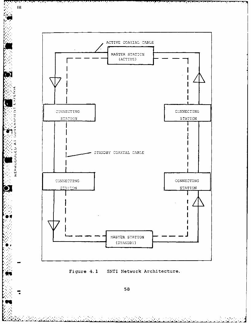
ACTIVE COAXIAL CABLE
I CONNECIN CONNECT ING
S TAT ION STATION
STANDBY COAXIAL CABLE
-~N . CNETNG CONNECTING
* STAT:EN STATION
Figure 4. 1 SNTI Network Architecture.
58
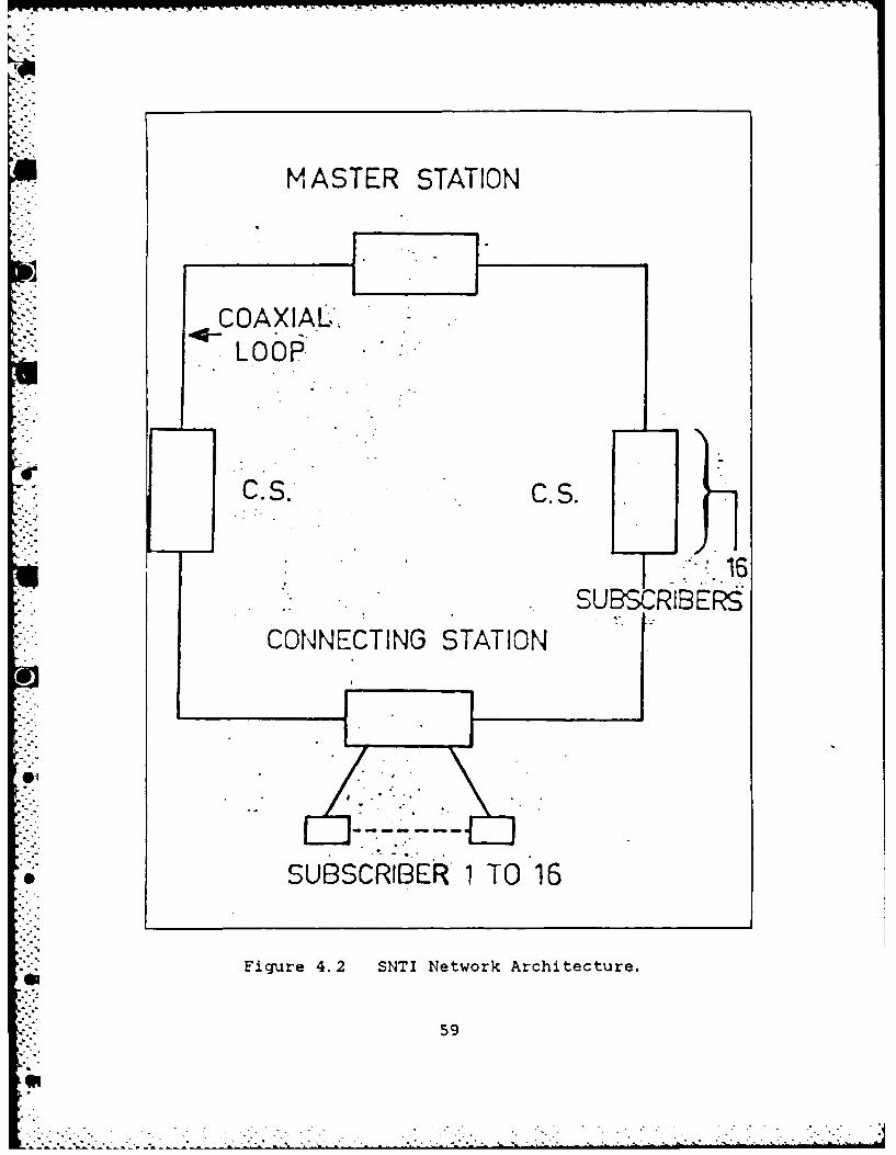
M ASTER STATION
COAXIAL.-LOOP.
SUBKRIBERS
SUBSCRIBER' 1 TO 16
Figure 4. 2 SNTI Network Architecture.
59
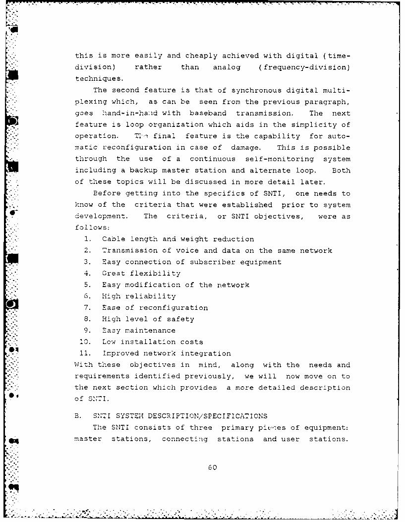
this is more easily and cheaply achieved with digital (time-
division) rather than analog (frequency-division)
techniques.
. The second feature is that of synchronous digital multi--"- plexing which, as can be seen from the previous paragraph,
goes hand-in-hand with baseband transmission. The next
feature is loop organization which aids in the simplicity of
operation. T . final feature is the capability for auto-
matic reconfiguration in case of damage. This is possible
through the use of a continuous self-monitoring system
including a backup master station and alternate loop. Both
of these topics will be discussed in more detail later.
Before getting into the specifics of SNTI, one needs to
know of the criteria that were established prior to system
development. The criteria, or SNTI objectives, were as
follows:
1. Cable length and weight reduction
2. Transmission of voice and data on the same network
3. Easy connection of subscriber equipment
4. Great flexibility
5. Easy modification of the network
6. High reliability
7. Ease of reconfiguration
8. High level of safety
9. Easy maintenance
10. Low installation costs
11. Improved network integrationWith these objectives in mind, along with the needs and
requirements identified previously, we will now move on to
the next section which provides a more detailed description
of SINTI.
B. SNTI SYSTEM DESCRIPTION/SPECIFICATIONS
The SNTI consists of three primary pic,, es of equipment:
master stations, connecting stations and user stations.
60
9'"
-- -- ..

This section will start with definitions of each and then
attempt to show how they interface with the system as a
whole. This will entail a description of other SNTI compo-
nents as well as specifics on system operating characteris-
tics and parameters. A description of a master station
comes first.
Waster Stations. The primary purpose of the master
station is management of the system or, more specifically,
the loop. To do this it generates and inserts into the
multiplex the frame alignment codes from which the digital
multiplex can be extracted. In conjunction with this, it
must also generate a clock frequency that provides transmis-
sion delay compensation (i.e., phase control) in order to
obtain a one-way closed loop transmission system. This
ensures correct phasing of the loop regardless of length.
See Figure 4.3
Additional function performed by the master stations are:
1.. Providing access to the directory required forcreating subsyszems which conform to the inter-connectivity matrix (or grid) laid down in the systemsp eci f ication s.
2. In conjunction with a teleprinter it offers a facilityfor feeding in data (network changes, special mainte-nance and testing programs, etc).
3. Exercising. continuous supervisory control of allsystem devices ensuring fault detection and locationand indicates fault reports or displays to the telep-rinter.
4. Upon a loop interruption it emits signals to triggeran automatic loop reconfiguration.
In normal operation one master station is active and the
other(s) are in a standby mode. In a system with more than
two master stations, the standby one designated as the
primary backup monitors the system in a similar fashion to
the on-line station. Each station is backed up by a buffer
battery system. This means that in the event of a failure
in the main network, it's necessary to switch over to the
protected network to maintain operation. The minimum time
required to make the switch is 200ms in order to allow forproper re-initialization of the system.
61
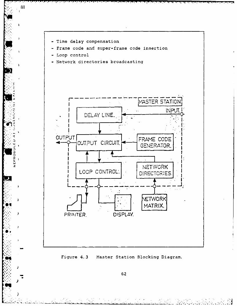
7- V-,%
Time delay compensation
-Frame code and super-frame code insertion
* - Loop control
-Network directories broadcasting
JATER STATIONI~ INPJtL
*I DELAY LINE.. .
OLTTRUT CIRCUIT EEAO~
GNE"NOR.
I LOP CNTROL. DIRECOl
PRlkjTER. DISPLAY.
Figure 4.3 Master Station Blocking Diagram.
62
)4
Connectinq Stations. These stations allow for connec-
tion of up to 16 subscribers to the loop. It provides these
subscribers, or users, with an information input and output
facility, allowing signalling and information to be intro-
duced into and taken out of the multiplex. For each user,
one or two listening channels and one transmitting channel
are available. See Figure 4.4
The connecting stations are divided into two parts:
common circuits and user terminal interface circuits. The
former are the essential part of the station and ensure the
following functions:
1. Incoming signal regeneration.
2. Extraction of the time clock signal from the multi-plex.
3. Frame and multi-frame synchronization.
4. Real time processing of signalling messages.
The second part, the terminal interface units, are stan-
dardized throughout the system and are designed to provide:
1. Two 32 Kbps receiving channel.
2. One 32 Kbps transmitting channel.
3. One incoming signalling channel.
4. One outgoing signalling channel.
5. One 32 KHz clock.
6. The power supply for specific subscriber functions.
As with the master stations, each connecting station is
backed up by a buffer battery supply and the same 200ms time
period is required for system re-initialization. The
connecting stations are also the power supply to the
subscribers and their associated functions that are assigned
* to each station. For example: the subscriber station
itself, radio interface, service operator telephone board,
etc. The power consumption of each subscriber is included
in the power consumption of each station.
User Stations. The purpose of the user stations (or
operator console/terminal or subscriber station) is the
63
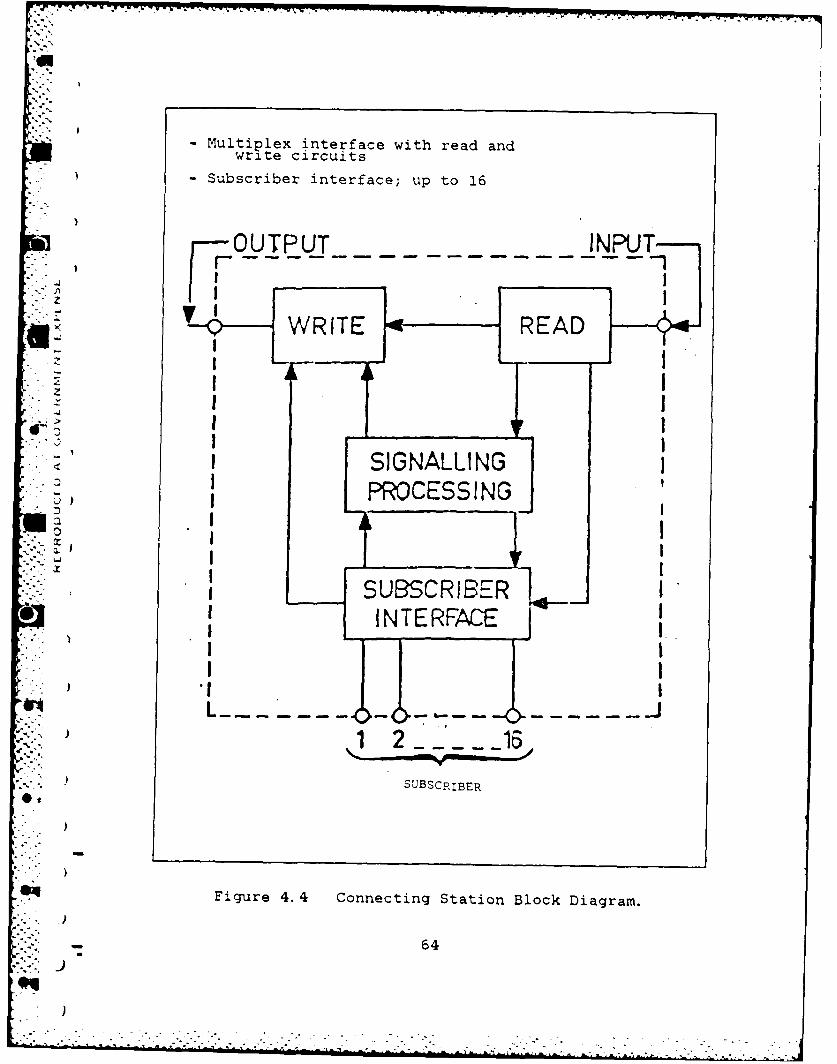
- Multiplex interface with read andwrite circuits
- Subscriber interface; up to 16
fOUTPUT IP
z _ _
I SIGNALLINGPROCESSING
I SUBSCRIBER14INTERFACE
1 2
SUBSCRIB3ER
Figure 4. 4 Connecting Station Block Diagram.
- 64
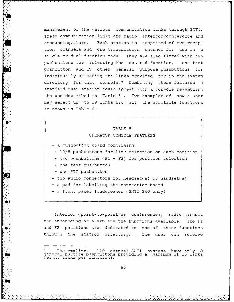
-- v- "
management of the various communication links through SNTI.
.- These communication links are radio, intercom/conference and
announcing/alarm. Each station is comprised of two recep-tion channels and one transmission channel for use :n a
single or dual function mode. They are also fitted with two-pushbuttons for selecting the desired function, one test
pushbutton and 19 other general purpose pushbuttons for
individually selecting the links provided for in the system
directory for that console. 4 Combining these features a
standard user station could appear with a console resembling
the one described in Table 5 Two examples of how a user
may select up to 19 links from all the available functions
is shown in Table 6
TABLE 5
OPERATOR CONSOLE FEATURES
- a pushbutton board comprising:
- 9/'8 pushbuttons for link selection on each position
- two pushbuttons (Fl - F2) for position selection
- one test pushbutton
- one PTT pushbutton
0- - two audio connectors for headset(s) or handset(s)
-a pad for labelling the connection board
- a front panel loudspeaker (SNTI 240 only)
*.-" Intercom (point-to-point or conference), radio circuit
and announcing or alarm are the functions available. The Fl
and F2 positions are dedicated to one of these functions
through the station directory. The user can receive
The smaller, 120 channel SNTI systems have only 8eneral purpose pushbuttons providing a maximum of 16 links
e1 inks per function).
65
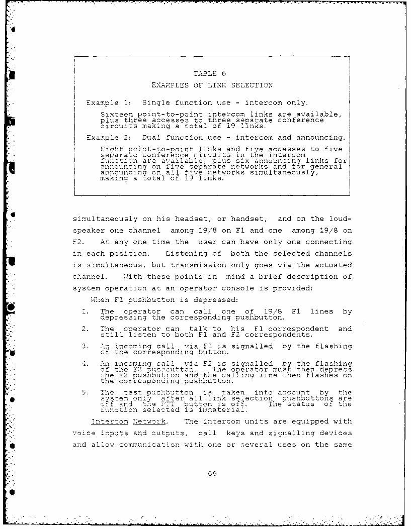
7
TABLE 6
A.PLES OF LINK SELECTION
Example 1: Single function use - intercom only.
Sixteen point-to-point intercom links are available,plus three accesses to three separate conferencecircuits making a total of 19 links.
Example 2: Dual function use - intercom and announcing.
Eight Foint-to-point links and five accesses to fiveseoarate conference circuits in the intercomfuhction are available, plus six announcing links forannouncing on five separate networks and for generalannouncing on all five networks simultaneously,making a total of 19 links.
simultaneously on his headset, or handset, and on the loud-
speaker one channel among 19/'8 on Fl and one among 19/8 on
-2. At any one time the user can have only one connecting
in each position. Listening of both the selected channels
is simultaneous, but transmission only goes via the actuated
channel. With these points in mind a brief description of
system operation at an operator console is provided:
W2hen Fl pushbutton is depressed:
1. The operator can call one of 19/8 Fl lines bydepressing the corresponding pushbutton.
2. The operator can talk to his El correspondent andstill listen to both F1 and F2 correspondents.
3. ?.n incoming call via Fl is signalled by the flashingof the corresponding button.
4. An incoming call via F2 is signalled by the flashingof the F2 pus-hbutton. The operator must then depressthe F2 pusnbutron and the calling line then flashes onthe corresponding pushbutton.
5 5. The test pushbutton is taken into account by theS.-jstem only after all link selection pushbuttons are
o-f and tne C T button is off. The status of thefunction selected is immaterial.
nterom network. The intercom units are equipped with
voice inputs and outputs, call keys and signalling devices
* and allow communication with one or several uses on the same
66
90 ... ,
" network. The intercom (or interphone) provides point-to-
.point connections and conference lines for operational and
technical department communications. The capacity for the
intercom network allows for 30 users to operate as part of
this function, each having up to 19 links to be selected
among the other possible 29 parties and five conference
lines. Refer to Figure 4.5 and Figure 4.6
S 'P Phone Lines Interface. The purpose of this inter-
face is to connect a S/P phone line to the loop. Each
interface is compatible with the use of up to eight S/P
headsets connected in parallel. The S/P phone network
allows for connections to operational systems and to tech-
nical and maintenance systems.
Announcement Interface. The announcing function, via. multiple access terminals, provides for either command
transmission (general and specific broadcasting of voice
orders) or alarm tone transmission (Audio alarms) to one or
more loudspeaker networks, each of which is interfaced with
the system by means of an announcing interface. The purpose
. of this interface is to connect announcement low frequency
amplifiers to the loop.
Two types of links are part of this function: 1)
partial announcing, which is a one-way link between a user
and the announcing interface; and 2) general announcing
(speech or alarm tone) which is acceptable to a multi-
directional link between a user or an alarm channel and all
announcing interfaces concerned. In the case of several
" . simultaneous announcing requests, transmission priority is
in the following descending order:
1. Alarm announcing
0, 2. General speech announcing
3. Partial announcing
Priority is also assigned to each console with an
announcing function. The priority is indicated on the
67
•7 - .
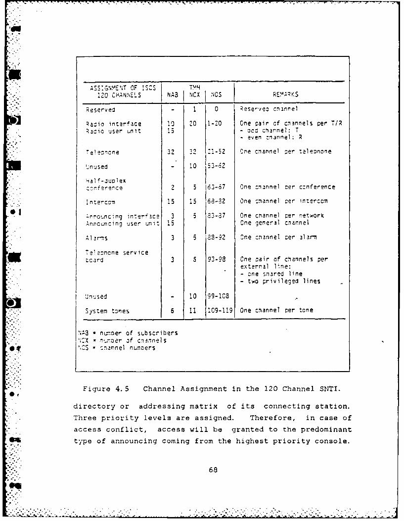
. . .. .
ASSIGN.E!T OF !SCS TMH
120 CHANNELS NAB CX 1 NOS REUKS
Reserved - 0 ;ese-vej ch arnel
R adio interface 10 20 1-20 One pair of cnannels er T/RRaio user unit 15 - oco channel: T
- even :nannel: R
7 e1e cne 32 12 ZI-52 One cnannel )er taleonone
Unused - 10 53-62
'Hal f-,uDl ex: rnference 2 5 63-67 One channel cer conference
Intercom 15 15 68- 2 One :nannel -er interccm
..nr.ounc.n. er,_aC2 3 5 23-87 One cnannel er network
Anncuncing user unit 15 One general cnarnel
sAl' 3 5 2-92 One :hannel cer al am
Telecnone serviceScard 3 5 93-93 Cne oair of channels per
external line:Scne snared line- two privileged lines
Unused - 10 99-108.
System tones 6 11 109-119 One channel per tcne
NAB u number of subscribers'IX - nu,-..er of cn nnelsICS - :nannel numoers
Figure 4.5 Channel Assignment in the 120 Channel SNTI.
directory or addressing matrix of its connecting station.
Three priority levels are assigned. Therefore, in case of
access conflict, access will be granted to the predominant
type of announcing coming from the highest priority console.
68

a&
ASSIGNMENT CF ISCS120 CHANNELS [NABJ NCX] NOS REMARKS
Reserved i 2 Reserved channel
Radio interface 20 40 1-40 One pair of channels per T/RRaiio user unit 30 - - odd charnel: T
- even cnannel: R
Intercom 30 30 41-70Conference user unitHalf-luolex 5 71-75 One channel per conference
Announcing interface .G 6 76-2i One channel per announcingnetwork
Announcing user unit 30 One general announcingcnannel
Tele-none 90 20 E2-101 Pcoled channels: 10 simul-taneous lin<s
Tele~none servicecard 3 6 102-107 - One cair of channels for
the inczrming snared line- T.wo pairs of channels for
two privileged lines
.ele.-rone (extensiOn- snore lines) 2 4 108-11 One oair of c'annels per
additional privileged sub-scriber
Speech tests - 2 112-113 Speech test on user unitswith radio or announcingfunction only
System tones - 6 114 Dial tone115 Silence
116 Ring-back tone117 Busy118 Unavailable1!9 Illegal
NAB a number of sLbscribers"CX - numoer of channels
0 S cnannel numbers
* Figure 4.6 Channels in the 120 Channel SNTI Extension.
69
.. .. . ....... - . ' .-.. L . .-. -,:.- I. . . .
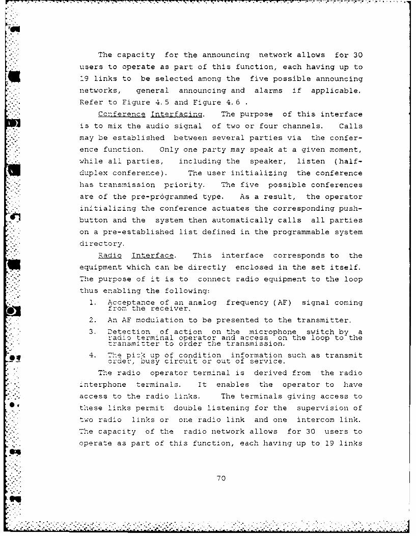
The capacity for the announcing network allows for 30
users to operate as part of this function, each having up to
19 links to be selected among the five possible announcing
networks, general announcing and alarms if applicable.
Refer to Figure 4. 5 and Figure 4. 6
Conference Interfacing. The purpose of this interface
is to mix the audio signal of two or four channels. Calls
may be established between several parties via the confer-
ence function. Only one party may speak at a given moment,
while all parties, including the speaker, listen (half-
duplex conference). The user initializing the conference
has transmission priority. The five possible conferences
are of the pre-pr6grammed type. As a result, the operator
initializing the conference actuates the corresponding push-
button and the system then automatically calls all parties
on a pre-established list defined in the programmable system
directory.
Radio Interface. This interface corresponds to the
equipment which can be directly enclosed in the set itself.
The purpose of it is to connect radio equipment to the loop
thus enabling the following:
I. Acceptance of an analog frequency (AF) signal comingfrom the receiver.
2. An AF modulation to be presented to the transmitter.
3. Detection of action on the microphone switch by aradio terminal operator and access on the loop to thetransmitter to order the transmission.
4. The pick up of condition information such as transmitorder, busy circuit or out of service.
" "The radio operator terminal is derived from the radio
" interphone terminals. It enables the operator to have
access to the radio links. The terminals giving access to
these links permit double listening for the supervision of
two radio links or one radio link and one intercom link.
The capacity of the radio network allows for 30 users to
operate as part of this function, each having up to 19 links
70
. .
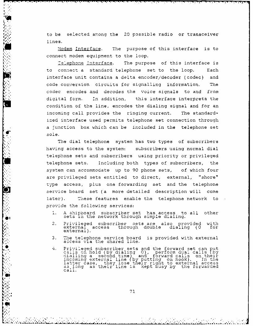
to be selected among the 20 possible radio or transceiver
alines.
lineModem Interface. The purpose of this interface is to
connect modem equipment to the loop.
-. :elephone Interface. The purpose of this interface is
to connect a standard telephone set to the loop. Each
interface unit contains a delta encoder/decoder (codec) and
code conversion circuits for signalling information. The
codec encodes and decodes the voice signals to and from
digital form. In addition, this interface interprets the
condition of the line, encodes the dialing signal and for an
incoming call provides the ringing current. The standard-
ized interface used permits telephone set connection through
a junction box which can be included in the telephone set
sole.
The dial telephone system has two types of subscribers
having access to the system: subscribers using normal dial
telephone sets and subscribers using priority or privileged
telephone sets. Including both types of subscribers, the*'. system can accommodate up to 90 phone sets, of which four
- are privileged sets entitled to direct, external, "shore"
type access, plus one forwarding set and the telephone
* service board set (a more detailed description will come
later). These features enable the telephone network to
provide the following services:
1. A shipboard subscriber set has access to all othersets in the network through simple dialing.
2. Privileged subscriber sets are also provided with
external access through double dialing( 0 forexternal).
3. The telephone service board is provided with externalaccess via the shared line.
0 4. Privileged subscriber sets and the forward set can putcalls on hold (by dialing 0), perform dual calls (bydialling a second time) and forward calls on theirincoming external line (by putting on hook). In thelatter case, they lose theLir right to external accessas long as their line is kept busy by the forwardedcall.
71
I -%
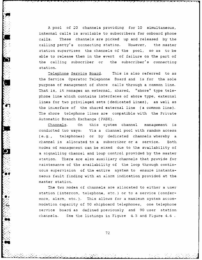
A pool of 20 channels providing for 10 simultaneous,
internal calls is available to subscribers for onboard phone
calls. These channels are picked up and released by the
calling party's connecting station. However, the master
station supervises the channels of the pool, so as to be
able to release them in the event of failure on the part of
the calling subscriber or the subscriber's connecting
station.
Telephone Service Board. This is also referred to as
the Service Operator Telephone Board and is for the sole
.* purpose of management of shore calls through a common line.
That is, it manages an external, shared, "shore" type tele-
phone line which contains interfaces of shore type, external
lines for two privileged sets (dedicated lines), as well as
the interface of the shared external line (a common line).
The shore telephone lines are compatible with the Private
Automatic Branch Exchange (PABX).
Channels. On this system channel management is
conducted two ways: Via a channel pool with random access
(e.g., telephones) or by dedicated channels whereby a
channel is allocated to a subscriber or a service. Both
modes of management can be mixed due to the availability of
a signalling channel and loop control provided by the master
station. There are also auxiliary channels that provide for
maintenance of the availability of the loop through contin-
uous supervision of the entire system to ensure instanta-
neous fault finding with an alarm indication provided at the
master station.
The two modes of channels are allocated to either a user
station (intercom, telephone, etc.) or to a service (confer-
ence, alarm, etc. ). This allows for a maximum system accom-
modation capacity of 90 shipboard telephones, one telephone
service board as defined previously and 90 user station
channels. See the listings in Figure 4.5 and Figure 4.6
.7
",'-'."72

The maximum of a 90 user station channels is assuming the
station is in single vice dual function mode providing for
up to 30 intercom sets, 30 radio links and 30 announcing/
alarm networks.
Time. This system operates with one master clock along
with the necessary number of slave clocks (which varies
according to system size).
Communications Loop. SNTI attempts to reduce cabling
and provide flexibility for IC by combining into one unique
digitalized network the independent IC functions required
aboard ship. A 50 Ohm coaxial cable is used to connect the
system stations. The benefit of that is in its suitability
S. to baseband signalling. More specifically, for digital
signals the 50 Ohm cable suffers less intense reflection
from the insertion of taps on the line and provides better
immunity against low frequency electromagnetic noise,
thereby providing greater system reliability. A minimum of
* two cables per system are used to provide redundancy. When
the active cable between two stations is damaged an auto-
matic reconfiguration occurs via implementation of the.
- second cable (or loop). See Figure 4.7
The main principles of the communication loop are: 1)
use of time division multiplex (covered in the next
section); 2) transmission of the muL:iplex in baseband; and
3) one-way closed loop transmission. In addition, the loop
contains a built-in-test (bit) system for detecting system
faults and for identifying faulty stations. Loop failure
can be replaced down to the line replaceable unit level.
Lin Structure. The coax links are run between the
stations to transmit a well defined message - radio link,
interphone link, announcing link, etc. Table 7 provides a
'list of basic structures necessary for a system of intercom
1.lnk s.
73
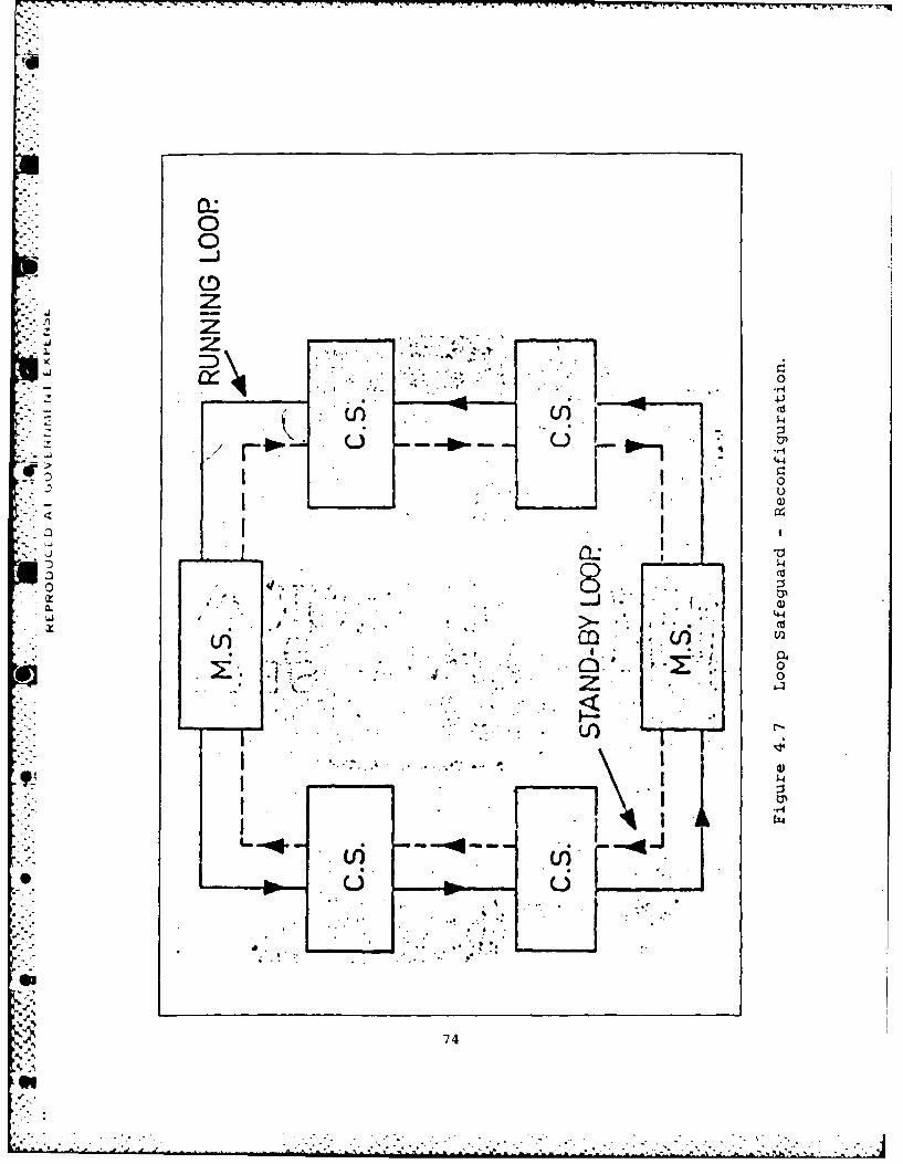
-4-
7DD
z4z .
-Ji
740
k'1)

TABLE 7
INTERCOM LINK STRUCTURE
Structure StructUre Analogy with sepa-diagram race n.e'-orks
push to talk bidirectional Interphone between twopoint to point ,correspcnda.nts, special
L=---J radiose rvices wdulationreception in telephony
Simultaneous point to point Auto.atic telephonebidirectional
lranseit unridirectional [jInterphone broadcast=ultipoint Ln cn
General broaocast overA loudspeaker
Receive unidirectional Reception of one ormul tipoint more radio links
Bidirectional multipoint Conferenceco-nectedg ri dinte rph ons
Autogenerarer telephLnes
Termnal. (User)/ConeZin Station Interface. The
terminal, or user, interface is designed to satisfy all
operational voice terminal constraints. These operational
terminals perform the following functions: intercom, radio
access, general announcing or any combination of two of
them. The interface itself consists of the following wires:
1. Receiver channel one
2. Receiver channel two
3. Transmit channel
4. Clock
5. Terminal input signalling
75

6. Terminal output signalling
7. Common channel
8. 12 volt DC power
9. Ring voltage
10. Terminal recognition
11. Reset
The connecting station - terminal interconnection is
. obtained by seven wires , the purpose of which are given in
Figure 4.8, with the arrows indicating the direction of
information flow.
Connecting TerminalStation
- Transmitted data <
S- Received data one >
. - Received data two >
- Received signalling >
- Transmitted signalling <-
Time base (clock) >
- 12 volt DC power supply >
Figure 4. 8 Connnecting Station - Terminal Connection.
This type of connection enables any terminal to receive
two simultaneous calls and leads to maximum simplification
of circuits available in the terminal and in the connecting
s tation. The following points deal with this interface/
connection:
1. The interface supposes that all data exchanged betweenthe connecting station and the user station has beendigitalized.
2. The time base (clock) which times the data exchange isat a 32 KHz frequency.
3. The connecting station regularly interrogates the user"-stations to which it is connected. it initiates allsignalling exchanges.
76
" !
4. The exchange procedure is a start/stop procedure forthe signalling of words. The words belong to an ASCIIalphabet of seven bits to which one parity bit isadded thus giving an eight bit code.
5. The signalling messages are normally exchanged at a 32Kbps modulation rate, however< the terminal (userstation) is designed so that it is always the clocksignal sent by the connecting station which is used toset the signalling rate.
6. The signal digitalization process is the 32 Kbps modu-lation rate however, the terminal is designed toreceive a clock signal which can attain 128 KHz. Thishas the effect o enabling a digitalization by aprocess which has a maximum binary rate of 132 bpsvice 32 Kbps.
Sianalling Exchanges. The signalling exchanges between
user and connecting stations are performed in an asynchro-
nous mode requiring each ASCII code word to be preceded by a
single start bit and followed by two stop bits. Figure 4.9
shows the basic structure of the exchanged word.The exchanges are based on the acknowledgement/no
acknowledgement (ACK/NACK) procedure. With initialization
of signalling exchanges assigned to it, the connecting
station interrogates its connected user stations one by one
within a given period of time that is compatible with the
reaction time of the station operator. In order to guar-
antee exchanges of limited duration, the number of words
exchanged in a sequence during an interrogation remains
4 limited and is defined for each procedure.
Directory Specifications. Data used to describe the
SN'I system directory are divided into three groups: 1)
data contained in the diode matrix board of the master
. stations; 2) data contained in the diode matrix board of
each connecting station; and 3) common data contained in the
directory memory (2K REPROM) common to all connecting and
master stations. The data contained at the master stations
* consists of station addresses and system parameters required
for reconfiguration, remote zupervision and operation. The
I77'"" 77
i . .- I .

v 1
>4
.78

data at the connecting stations consists of the addresses
and parameters of the subscribers connected to that station.
The third part of the directory defines links and facilities
authorized for all system connected subscribers. Unlike the
S- data at the master and connecting stations which is user
programmable at each station via built-in diode matrices,
the final part of the directory is common to all stations
and is stored in specific re-programmable memory.
The way this system is established, in a very basic
sense, is as follows. First of all, addresses must be allo-
cated to each subscriber. This is done in the connecting
S"printed circuit board of the connecting station by setting
call numbers on a diode matrix. Then the inter-connecticn
grids laid down in the SNTI specifications are reproduced on
one or more matrices, which can be located inside the _-aster
* .station (usually smaller systems) or outside the master
station (larger systems).
Teleprinter. The teleprinter(s) is connected to the
master station to assist in management of the loop. It
provides readouts on control status, tests and alarms and
indicates fault location. Usually one teleprinter is
- - connected to two master stations.
C. mULTIPLEXING
The operation of SNTI is based on the principle of Time
Division ','ultiplexing (TDM). This procedure, simply put,
allows for the division of a transmission medium into two or
more channels by allotting the medium to several different
information channels, one at a time. Though some comments
concerning TDM were made earlier, before getting into the
,oecifics of multiplexing a brief review of general multi-
.- plexing techniques is offered. See Ref 9
@7
"':" 79
eq
....................-

I.Principles of TDM
Time division multiplexing requires that every
signal be in a digital form prior to transmission. The
digital signal is then inserted into the multiplex circu-
lating on the medium (the coax loop in SNTI). A TDM can
consist of: 1) a bit organization - one bit per time slot;
2) a block organization - one block per time slot; or 3) a
mixed organization -a combination of the two.
Here is how TDM works. There are a given number of
digital signals to be transmitted. They are identical in
bit rate but, need not be synchronized. These signals are
sampled by rotation.
The sampling rate is determined by a common clock
whose frequency is a multiple of the bit rate of any mndi-
vidual channel. A sample is then removed from each offered
signal in sequence and the process repeats. Figure 4. 10
providus an example of this process.
The sampled signals are then placed end-to-end to
form an aggregate signal or multiplex. Each slot of the
multiplex contains information (the sample) from a channel.
'lie system needs to know what channel that information is
from. This is accomplished by counting the sample's posi-
tion relative to a synchronization (sync) signal, also
'l~ed an alignment code.
One alignment code and one sample from all the chan-
nels together form a frame. Therefore, the frame alignment
6 code equates to the sync code.
To extract a particular channel, a clock signal is
synchronized with the multiplex frame and a counter, using
the frame sync code, counts off th-e required slot. The
0 signal is then extracted from the slot. The sequence is
08
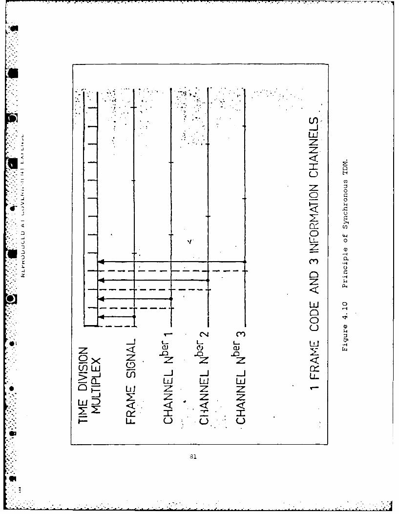
t.D
cfr)
- - 4 0
I-4--,4
U) 1U)
z z zLL-J
LL 0
repeated and the extracts are place end-to-end as they are
removed. This reproduces the original signal. Now this
technique will be applied to SNTI.
2. The Multiolex Structure Used in SNTI
:he multiplex for this system (120 channel -stem)
is required to carry two kinds of information. The _rst is
made up of digitalized voice signals and other data between
system subscribers. Voice signals are digitalized by use of
Delta Modulation (DM) at a bit rate of 32 Kbps. At this bit
rate, DM provides a very good quality voice transmission
(i.e., bandwidth from 300 - 3400 Hz). The transmission code
of the multiplex is baseband in a split-phase code which
eliminates the DC component and contains the information to
extract the clock signal.
The other kind of information carried consists of
signalling data. This includes: 1) data to establish and
terminate connection between subscribers; 2) supervisory,
monitoring and reconfiguration messages; 3) data to estab-
lish messages; and 4) frame codes to recognize and separate
information. The bit rate of the signalling channel is 875
.! bps; as compared to the basic common channel bit rate of 32
O0 The multiplex used by SNTI is based on a frame of
128 slots (or bits) on a bit-by-bit basis (one bit per
slot). See figure 4.11
The first 120 bits of each frame are used to
transmit the proper information. These 120 time slots
correspond to the 120 channels (again, the smaller SNTI
system) and the remaining eight bits form a frame block for
.82
"-"" 82
. * •- .
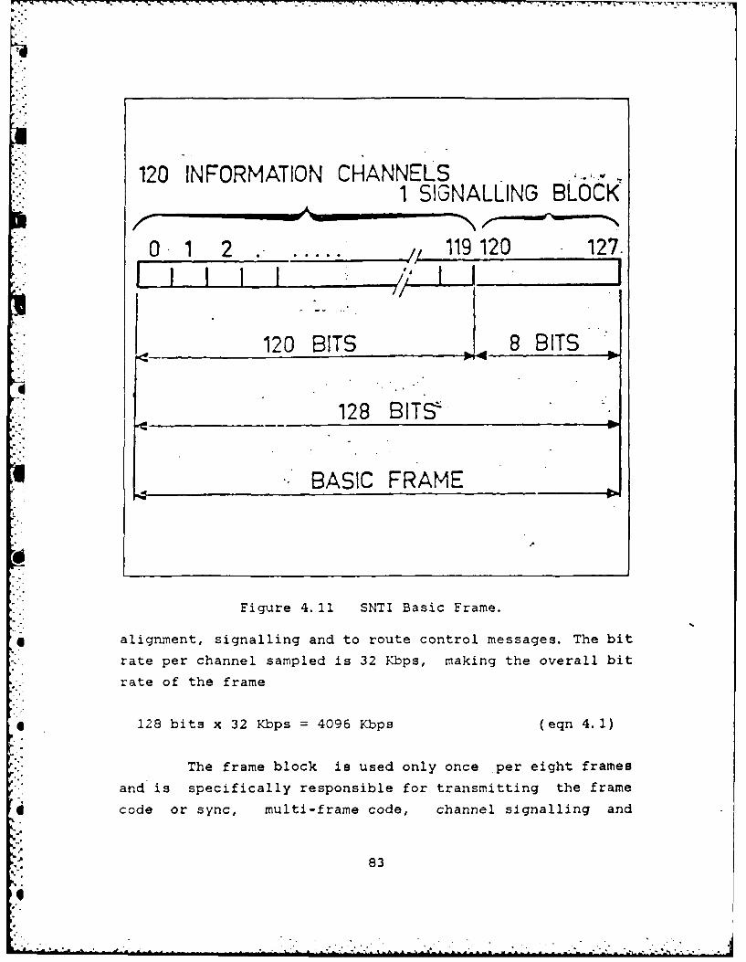
120 INFORMATION CHANNELS1 SIG"NALLING BLOCK
0, 1 2 * .. , 119 120 127.
120 BITS 8 BITS
______128 BITS
BASIC FRAME 0
Figure 4. 11 SNTI Basic Frame.
4 alignment, signalling and to route control messages. The bit
rate per channel sampled is 32 Kbps, making the overall bit
rate of the frame
1 28 bits x 32 Kbps =4096 Kbps (eqn 4.1)
The frame block is used only once per eight frames
and is specifically responsible for transmitting the frame
code or sync, multi-frame code, channel signalling and
83
II
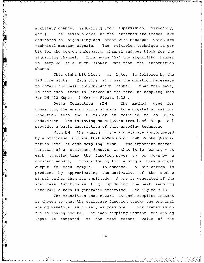
auxiliary channel signalling (for supervision, directory,
etc. ). The seven blocks of the intermediate frames are
dedicated to signalling and order-wire messages which are
technical message signals. The multiplex technique is per
bit for the common information channel and per block for the
signalling channel. This means that the signalling channel
is sampled at a much slower rate than the information
channel.
This eight bit block, or byte, is followed by the
120 time slots. Each time slot has the duration necessary
to obtain the basic communication channel. What this says,
is that each frame in renewed at the rate of sampling used
for DM (32 Kbps). Refer to Figure 4.12
Delta Modulation (DM). The method used for
converting the analog voice signals to a digital signal for
insertion into the multiplex is referred to as Delta
Modulation. The following description from [Ref. 9: p. 841
provides a basic description of this encoding technique.
With DM, the analog voice signals are approximated
by a staircase function that moves up or down by one quanti-
zation level at each sampling time. The important charac-
teristic of a staircase function is that it is binary - at
each sampling time the function moves up or down by a
constant amount, thus allowing for a single binary digit
output for each sample. In essence, a bit stream is
produced by approximating the derivative of the analog
signal rather than its amplitude. A one is generated if the
staircase function is to go up during the next sampling
interval; a zero is generated otherwise. See Figure 4. 13
The transition that occurs at each sampling instant
is chosen so t-hat the staircase function tracks the original
analog waveform as closely as possible. For transmission
t'he following occurs. At each sampling instant, the analog
4nOut .scompared to the most recent value of the
84

9**:V -r.* *.P.--"
" .'<' SIGNANG ORGANIZATIONCN I:iW SITS FRAME BLOCK
SIGNALLING BLOCKSDIANNELR*I
°40
,Il n1 fi 1l 1 0 i l
SYPC. CO(D i SIGNALUNG BLOCKS CHANE. SYNC C ELI
MULTIFRAME ORGANIZATIONFRAME r 120 INFORMATION BITS FRAME
.< ----------- B........................................,CBLOCK
1 I;.- ~SYNC CODE
2
3 CHANNEL ISIGNALLING
-- -- -- -- -- -- -- -- -- -- -- -
91 SYNC. CODE
10
CHANNEL2SIGNALLING
u15
952 I 1 1 SYNC CODE
CKANNEL 120SIGNALLING
* 960 L ,
9b1| SYNC. CODE962 -
12 OW MESSAGES,,~ ~ ~~ .6 -. '.- .. '.., ... , ....-.. i
: ,, ,., 1,. * .,, -
, - .,-- - -.. - , - ,. .
$' - '"'-~
::::.- ',-' " " 4 ." " ';...." ,,.. .. .... : . -. "°" MULTIFRAME "
ivCODE' .
Figure 4. 12 The SNTI Multiplex Structure.
85S!
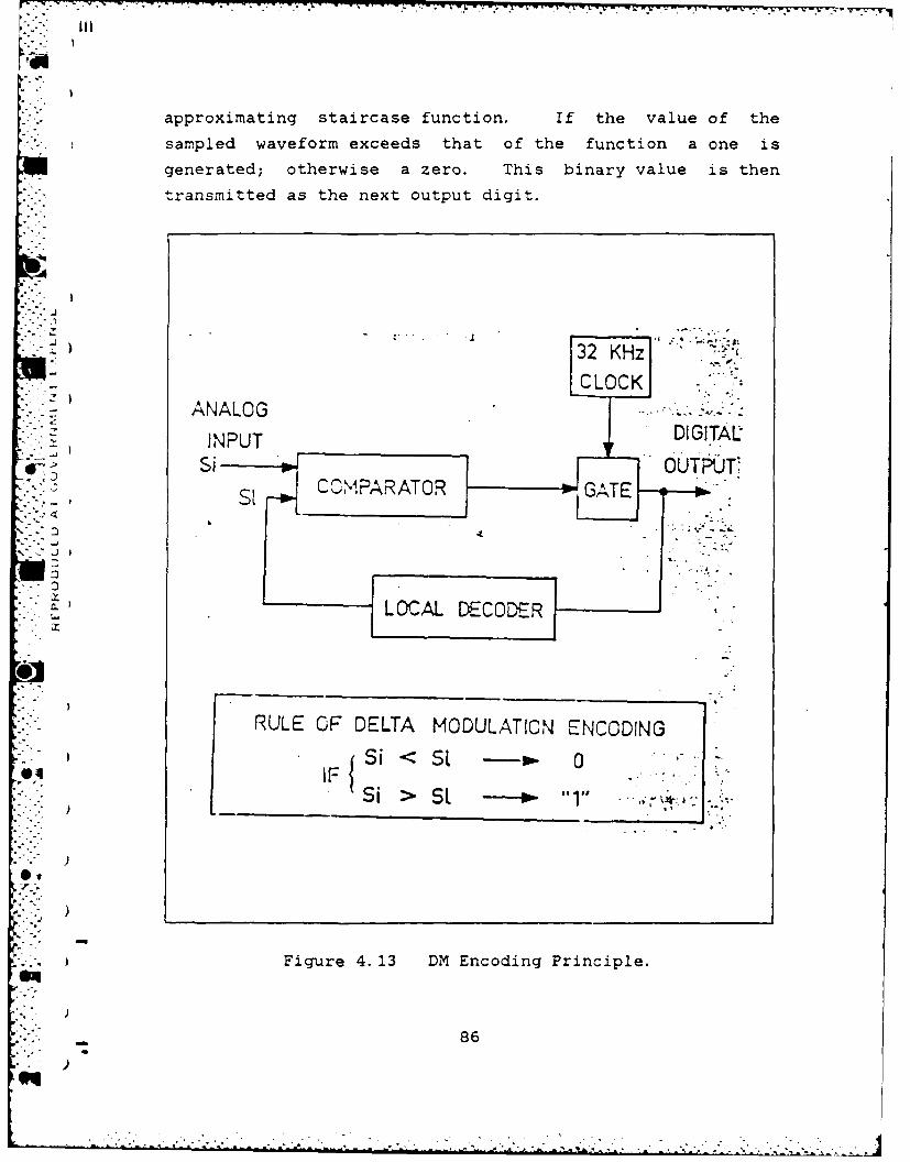
approximating staircase function. If the value of the
sampled waveform exceeds that of the function a one is
generated; otherwise a zero. This binary value is then
transmitted as the next output digit.
32, KHzCLOCK
ANALOGINPUT DIGITALSi-
1 RULE OF DELTA MODULATION ENCODING
@4= ,{ i I - -- 0 ..Si > SE " .- -,
- )
Figure 4. 13 DM Encoding Principle.
86, .)
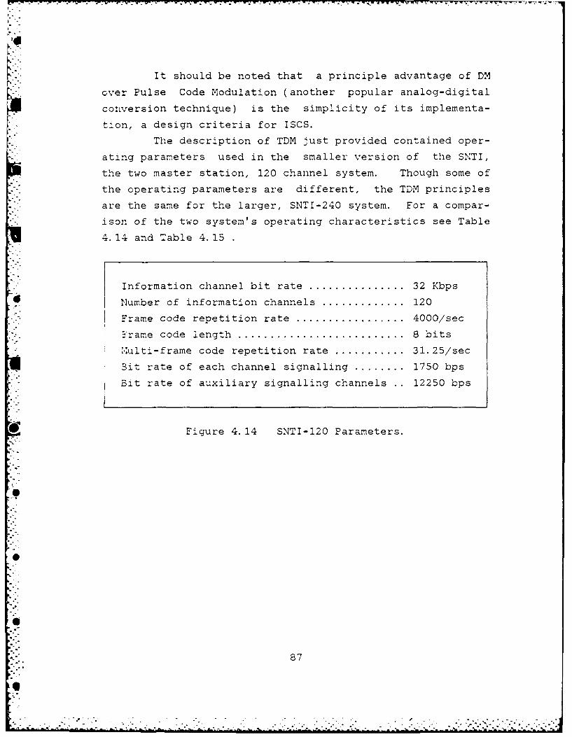
It should be noted that a principle advantage of DM
over Pulse Code Modulation (another popular analog-digital
conversion technique) is the simplicity of its implementa-
tion, a design criteria for ISCS.
The description of TDM just provided contained oper-
ating parameters used in the smaller version of the SNTI,
the two master station, 120 channel system. Though some of
the operating parameters are different, the TDM principles
are the same for the larger, SNTI-240 system. For a compar-
ison of the two system's operating characteristics see Table
4.14 and Table 4.15
Information channel bit rate ................ 32 Kbps
0 Number of information channels .............. 120
Frame code repetition rate .................. 4000/sec
*rame code length ............................ 8 bitsm.uiti-frame code repetition rate ........... 31.25/sec
Bit rate of each channel signalling ........ 1750 bps
Bit rate of auxiliary signalling channels .. 12250 bps
Figure 4.14 SNTI-120 Parameters.
.0
71.. 87
• .- .° ° . .- - .. . . °. , . . " . . - b . ' ° , °

Information channel bi.t rate ................ 32 Kbps
Number of information channels .............. 240
Frame code repetition rate .................. 4000/sec
Frame code length ............................ 8 bits
Multi-frame repetition rate ................. 15. 625/sec
Bit rate of each channel signalling ........ 1792 bps
Bit rate of auxiliary signalling channels .. 26880 bps
Figure 4. 15 SNTI-240 Parameters.
E88
bo°
U;-.. .
L8
V. ANALYSIS OF SNTI
Besides being capable of meeting the design requirements
specified for the system, SNTI must be able to satisfy
design analysts and cost analysts with respect to the ques-
tion of vulnerability. This vulnerability concept relates
to system design, cost and performance.
For example, the more stations in SNTI the less vulner-
able it is to being destroyed by a single missile hit.
However, more stations probably results in an increase in
system costs and it may or may not have a positive effect on
system performance.
Therefore, an analysis of vulnerability costs weighs the
pros and cons of these three factors against one another.
Does the addition of more stations justify an increase in
cost? Does this cost result in improved performance? Do
production costs drop with more stations and, if so, what is
-.. the optimal number of stations to be included in the system?
These are just a few of the types of questions that need to
be answered.
A. VULNERABILITY COSTS
In determining how to measure the cost of vulnerability
with respect to a two (or more) output cost function, it is
necessary to understand the relationships between single
output functions and multiple output functions. This
" - requires a knowledge of the characteristics of an output
"- - function, such as economies of scope, ray cost behavior and
the scale effect [Ref. 10]. Before analyzing these factors
@1 some important assumptions need to be stated and the input
and output variables defined.
What is the cost of vulnerability? It can be equated to
:he cost of consolidation. That is, the more consolidated
89
.4
T . -.4
the SNTI is (fewer master stations and connecting stations)
* the greater is its vulnerability. And obviously, the
greater the number and the greater the dispersal of these
- stations the less the vulnerability of the SNTI. As will be
P shown, the difference between the cost of consolidating
communication requirements (or joint production) and the
- cost of dispersing these requirements (or separate single
*' production) is the cost of vulnerability.
In this model there are two outputs, labeled I, and 12.
The amount or degree of connectivity between the mastersta-
tions and connecting stations (1 i) can be defined as their
ability to communicate with each other or, put another way,
SI| their interoperability. The other output (12) is made up of
all the other reasonable outputs of these stations.
The input variables for a SNTI (or any ISCS for that
matter) are numerous, but a short definition of a few of the
more vital ones that could be used in this model are listed
below:
1 CHANNEL CAPACITY: the number of channels available andtheir transmit/receive capability.
2 FREQUENCY ASSIGNMENT: bandwidth, usage and capacity.
3 TRANSMISSION RATE: from the start of send to thecompletion of receive.
4 TRANSMISSION MEDIUMS: telephone, intercom orannouncing and radio transmissions.
5 ECCM CAPABILITY: ability to avoid a "softkill."
6 USER LOCATIONS: geographic position of user stationsS. with respect to each other.
-" 7 NODAL LOCATIONS: locations of master(s) and connectingstations.
8 USER - USER NEEDLINES: communication requirementsbetween users.
9 NODE - NODE NEEDLINES: communication requirementsbetween master station(s) and connecting stations.
10 COMSEC: communications security requirements.
Values are assigned to these variables either arbi-
trarily (though seldom), based on historical data, statisti-
.• cally or based on relative importance. The cost to achieve
"90
~90
.. °
U! the desired level of each variable is then inputed into the
cost function.-< With respect to vulnerability, it's obvious that the
S- greater the number and the greater the dispersal of
master(s) and connecting stations, the less vulnerable is
.the SNTI. For this to be economically prudent, the cost of
joint production (all communications through one connecting
station with only one master station) must be greater than
the cost of separate single product production (two or more
connecting stations plus a backup mas-er station). This
situation is categorized by diseconomies of scope. However,
by their nature, ISCS exhibit just the opposite economies
of scope; where joint production costs less. The heavy
emphasis on the use of shared resources (CPU's) and collec-
.* - tive resources (multi-channel connecting stations) tends to
* generate economies of scale. Figures 5.1 and 5.2 provide
graphical representation of economies of scope.
The funnel shaped design in Figure 5.1, widens as the
output product levels (I11,2) increase. A given product mix
slices across the funnel and is shown by the curve AGFB.
*Since this funnel opens upward, the middle of the slice (pt.
G) is lower than the ends (points A and B) which indicates
it cost less to produce the two outputs jointly, C(II,I2 )
than separately, C(I1 ) C(12 ). Therefore, exhibits econo-
1 mies of scope. If the funnel were to be flipped over, then
pt. G would be higher than the ends of the slice, points A
and B, indicating joint production (a single connecting
station) is more costly and exhibiting diseconomies of
* scope.
Concurrent with this is the concept of "the index for
the degree of economies/diseconomies of scope," SC(lI,1 2 ).
This is the relative decrease/increase that results from*joint vice separate production.
91
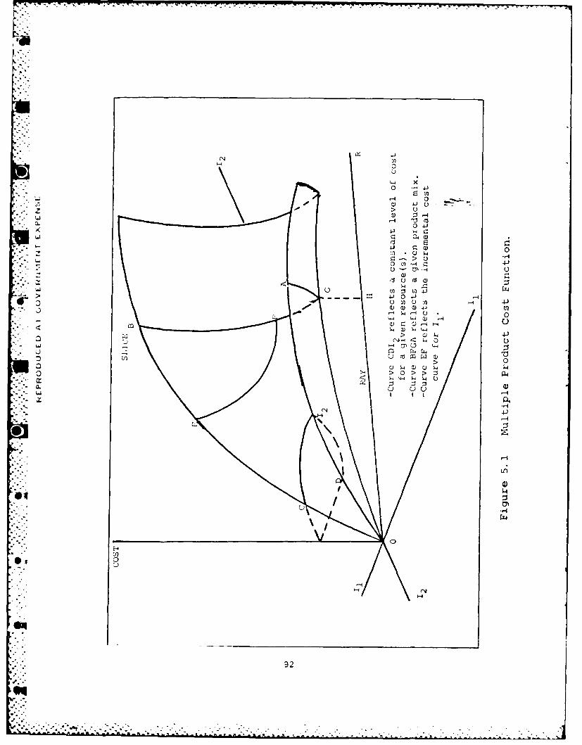
F--
0 4
041 .- L)
L-4 a4(
040
of) 03 U - 7
0 j0
w u-w4-)
~) UU
44U 44
0 0
92
eqL
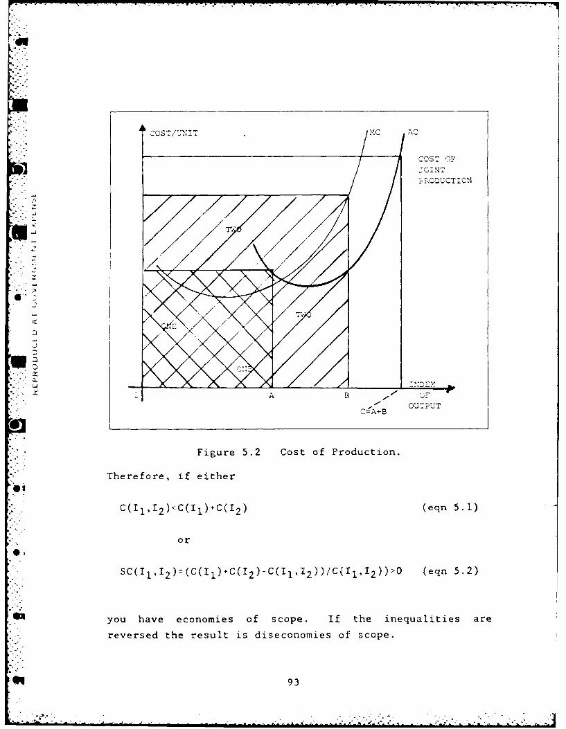
COST OF'
I J;OINT
B 0
C~A+B OUTPUT
Figure 5.2 Cost of Production.
Therefore, if either
C(11 ,12 )<C(Il)+C(12 )(en51
or
SC(11 , 12)=(C(I 1 )+C(I9)C(Il'I2 ) )/C(1 1 ,,2 ) )>O (eqn 5.2)
you have economies of scope. if the inequalities are
reversed the result is diseconomies of scope.
93
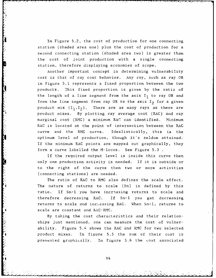
¢.7
In Figure 5.2, the cost of production for one connecting
station (shaded area one) plus the cost of production for a
second connecting station (shaded area two) is greater than
the cost of joint production with a single connecting
station, therefore displaying economies of scope.
Another important concept in determining vulnerability
cost is that of ray cost behavior. Any ray, such as ray OR
in Figure 5.1 represents a fixed proportion between the two
products. This fixed proportion is given by the ratio of
the length of a line segment from the axis I, to ray OR and
from the line segment from ray OR to the axis 12 for a given
product mix (I,I2). There are as many rays as there are
product mixes. By plotting ray average cost (RAC) and ray
marginal cost (RMC) a minimum RAC can identified. Minimum
RAC is located at the point of intersection between the RAC
curve and the RMC curve. Idealistically, this is the
optimum level of production, though it's seldom attained.
If the minimum RAC points are mapped out graphically, they
form a curve labelled the M-locus. See Figure 5.3
If the required output level is inside this curve then
*only one production activity is needed. If it is outside or
to the right of the curve then two or more activities
(connecting stations) are needed.
The ratio of RAC to RMC also defines the scale effect.
The nature of returns to scale (Sn) is defined by this
ratio. If Sn>1 you have incre asing returns to scale and
therefore decreasing RAC. If Sn<l you get decreasing
returns to scale and incieasing RAC. When Snzl, returns to
scale are constant and RAC=PRMC.
By taking the cost characteristics and their relation-
ships just mentioned, one can measure the cost of vulner-
ability. Figure 5.4 shows the RAC and RMC for two selected
* product mixes. In figure 5.5 the sum of their cost is
presented graphically. In Figure 5.6 the cost associated
_4 94
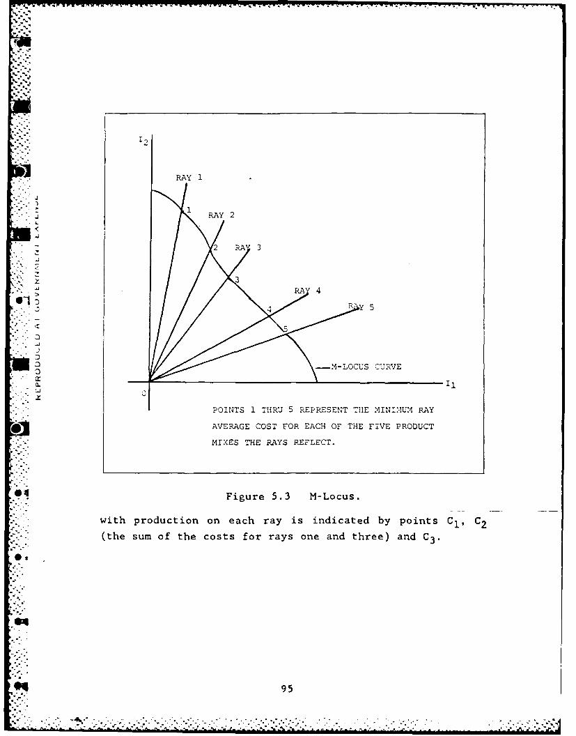
2l
RAyI
RAY 2
* .
.i
-- LOCUS CURVE0
POINTS 1 THRU 5 REPRESENT THE INUMRAY
*AVERAGE COST FOR EACH OF THE FIVE PRODUCT
MIXES THE RAYS REFLECT.
Figure 5.3 M-Locus.
with production on each ray is indicated by points Cl, C2
(the sum of the costs for rays one and three) and C3 .
eq 95
. . .-. .,
*.!* ... :,.<.. * -- .*. .

Wy .~ ..-. - v .iw w v jm
Lii
4. 04
J9
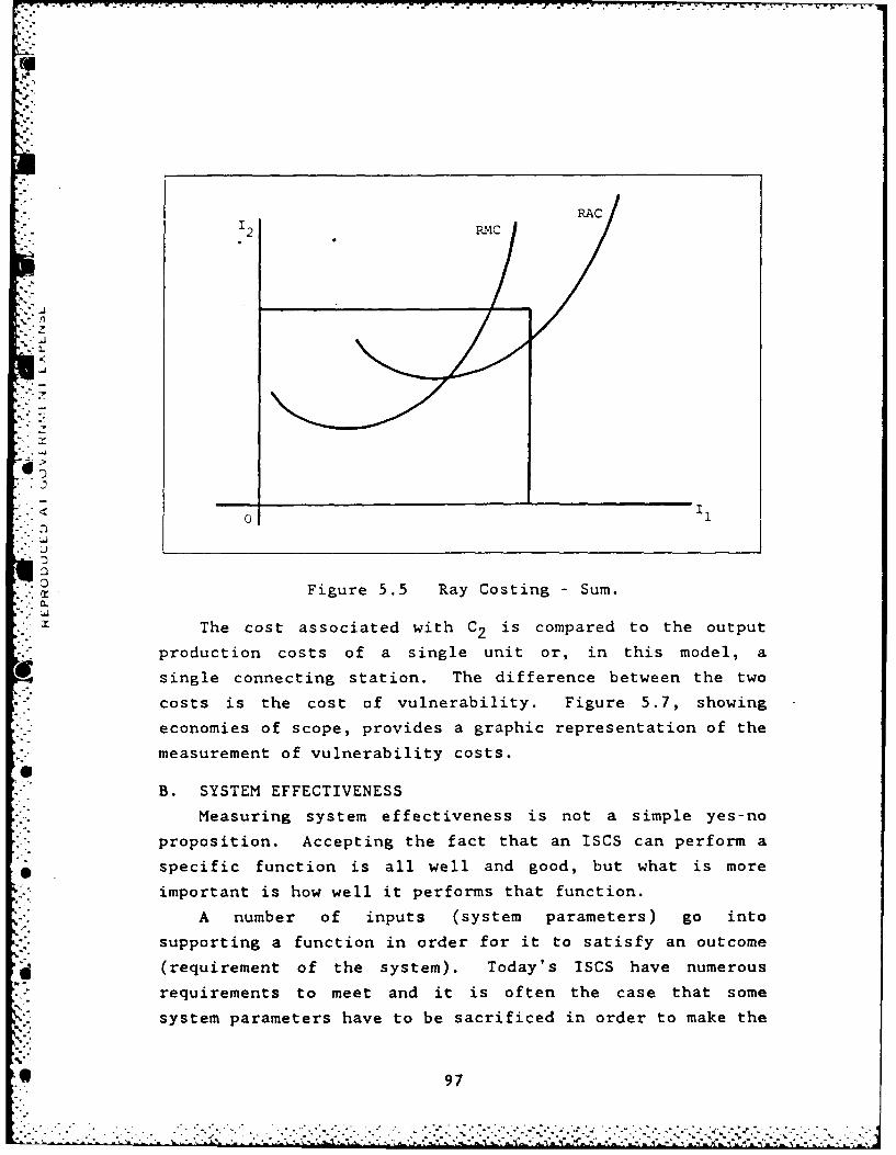
RAC
C Ii
0-Figure 5.5 Ray Costing Sum.
12 MC
-- "
• X The cost associated with C2 is compared to the output
production costs of a single unit or, in this model, a
single connecting station. The difference between the two
costs is the cost of vulnerability. Figure 5.7, showing
economies of scope, provides a graphic representation of the
measurement of vulnerability costs.
B. SYSTEM EFFECTIVENESS
Measuring system effectiveness is not a simple yes-no
proposition. Accepting the fact that an ISCS can perform a
specific function is all well and good, but what is more
important is how well it performs that function.
A number of inputs (system parameters) go into
supporting a function in order for it to satisfy an outcome
(requirement of the system). Today's ISCS have numerous
requirements to meet and it is often the case that some
system parameters have to be sacrificed in order to make the
. 97
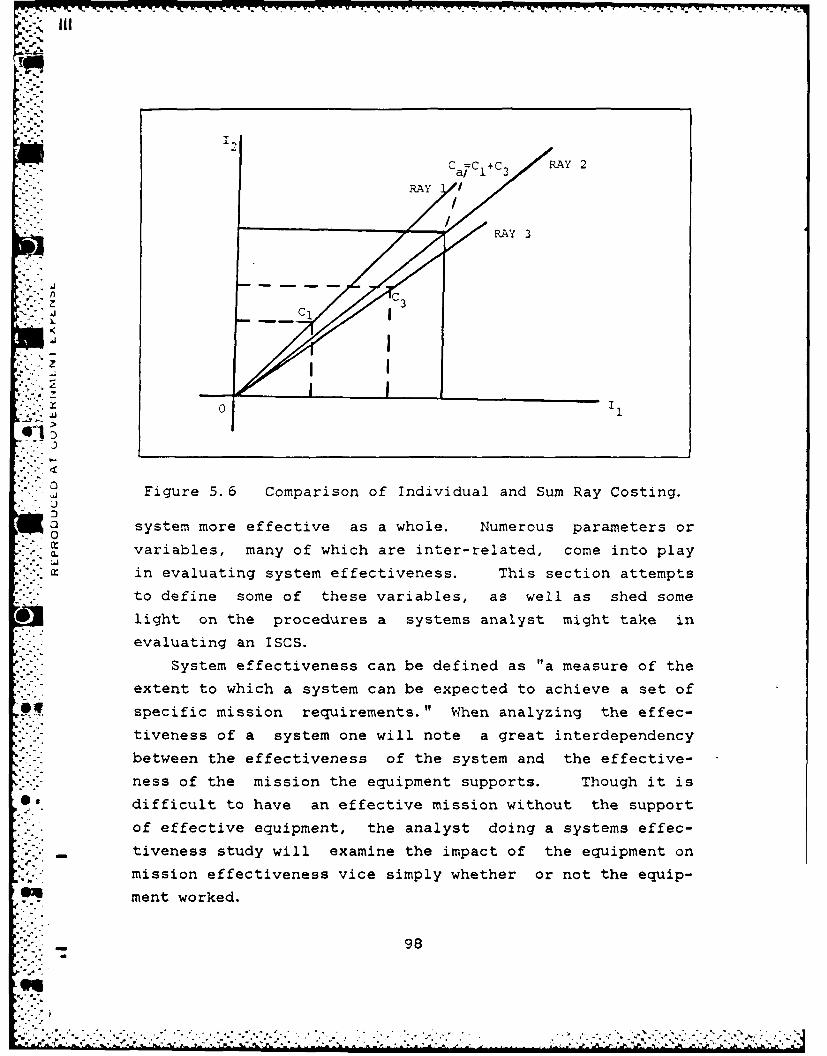
RAY c AY
RAY 3
33
Figure 5. 6 Comparison of Individual and Sum Ray Costing.
0 system more effective as a whole. Numerous parameters or0
in evaluating system effectiveness. This section attempts
to define some of these variables, as well as shed some
* light on the procedures a systems analyst might take in* evaluating an ISCS.
System effectiveness can be defined as "a measure of the
extent to which a system can be expected to achieve a set of
specific mission requirements." When analyzing the effec-
tiveniess of a system one will note a great interdependency
* between the effectiveness of the system and the effective-
ness of the mission the equipment supports. Though it is
difficult to have an effective mission without the support
of effective equipment, the analyst doing a systems effec-
- tiveness study will examine the impact of the equipment on
mission effectiveness vice simply whether or not the equip-
@4 ment worked.
98
-7...
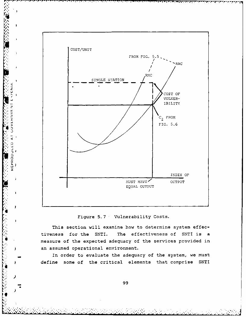
rf.
COST/UNIT
FROM FIG. 5.5,
I'RAC
RMC
SINGLE STATION
zICOST OFI VULNER-
IBILITY
C FROM
S>, FIG. 5.6
0
0
"°Li
INDEX oF
MUST HAVES OUTPUT
EQUAL OUTPUT
-. ,
Figure 5.7 Vulnerability Costs.
This section will examine how to determine system effec-
tiveness for the SNTI. The effectiveness of SNTI is a
measure of the expected adequacy of the services provided in
. }an assumed operational environment.
"- In order to evaluate the adequacy of the system, we must
define some of the critical elements that comprise SNTI
99
V
given the requirements on the system, along with some of
* SNTI's basic operating characteristics that are needed to
judge the system's effectiveness.
SNTI is a single loop transmission system that employs
digital voice encoding and Time Division Multiplexing (TDM)
of data. The system is distributed over a single transmis-
sion carrier, a coaxial cable. With this system a distinc-
tion is usually made between three user categories. First
is the telephone network. Standard telephone sets are used
and are connected to stations via interface units. Each
interface unit contains an encoder/decoder and code conver-
sion circuits for signalling information. Users on board
ship can also communicate with subscribers of the shore
network. Next is the intercom network. These intercom
units are equipped with voice inputs and outputs, call keys
and signalling devices. These units allow communications
with one or several users of the same network. Finally is
what is termed a special interface. Interface boxes are
used to allow interfacing with radio transmitters and
receivers as well as allowing announcement amplifiers to be
connected up to the system.
Generally speaking the system consists of two main
parts: 1) the transmission, multiplexing and demultiplexing
subsystems which includes the connecting stations and the
master stations; and 2) the user stations, each having its
own interface for connection to SNTI.
The two independent master stations (at a minimum)
provide supervisory control for all system terminals that
*.are interfaced through connecting stations. They also
gen~erate the signals essential for TDM. operation. The
master station's continuous supervisory control ensures
fault detection and location and provides for fault display
-i an associated teleprinter or CRT. They also initiate
* automatic reconfiguration in event of loop interruption.
100
- 0
Each connecting station can accept up to 16 user termi-
nals, however, there is no user terminal that combines all
functions. Therefore, watch stations requiring access to
multiple IC systems and external radio will have a number of
terminal devices. The purpose of these stations is to
" . provide the users with an information input/output facility,
allowing signalling and information to be introduced into
and taken out of the multiplex.
At present, SNTI uses a 50-ohm coaxial cable that is
duplicated to ensure that in the event of cable breakage the
coax loop can be restored via reconfiguration. The second
cable is for this purpose. Larger ships may have more than
two cables.
Given this quick review of SNTI, we now look at the
E[ system with respect to the requirements of an integrated
shipboard communications system. Systems effectiveness
-- analysts, after careful review of previous studies and plan-
ning efforts by the Services/Agencies and the TRI-TAC
Office, have identified 16 general elements for use in eval-
uating system effectiveness. See [Ref. 11]. These elements
- "- are intended to be reasonably exhaustive and independent of
each other. These elements or Measures of Effectiveness
(MOEs) can be divided into four groups and a hierarchal
structure can be formed as shown in Table 8
This thesis will now examine the effectiveness of SNTI
with respect to the MOEs provided. The U.S. Navy's interest
* in SNTI is based on the systems ability to perform in a
worst case scenario. This means performance in a wartime
--.- scenario or hostile environment and how well can a ship
perform its mission under such conditions. It's against
*this background that SNTI effectiveness will be evaluated.
The ability of SNTI to meet each MOE will be examined on a
one to one basis starting with Communications Measures.
.
"','" 01
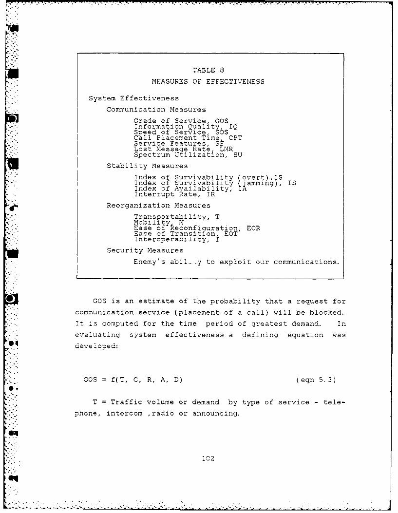
TABLE 8
MEASURES OF EFFECTIVENESS
System Effectiveness
Communication Measures
Grade of Service, GOSInformation Ouality, IQSpeed of Service, SOSCall Placement Time, CPTService Features, SFLost Message Rate, LMRSpectrum Utilization, SU
Stability Measures
Index of Survivability (overt),ISIndex of Survivability (amming), ISIndex of Availability,Interrupt Rate, IR
Reorganization Measures
Transportability, TMobility1 MEase of Reconfiguration, EOREase of Transition EOTInteroperability, I
Security Measures
Enemy's abil_-y to exploit our communications.
*GOS is an estimate of the probability that a request for
communication service (placement of a call) will be blocked.
- It is computed for the time period of greatest demand. In
*-"< evaluating system effectiveness a defining equation was
developed:
GOS = f(T, C, R, A, D) (eqn 5.3)
-. T = Traffic volume or demand by type of service - tele--. , phone, intercom ,radio or announcing.
i02

C = Channel capacity; SNTI offers either 120 or 240
channels.
R = Alternative routing capability; with SNTI this
depends on system configuration.
- A = Call arrival probability distribution. For SNTI
telephones this means a group of channels with random access
(Poisson distribution) are allocated and a caller finds a
free channel. If all channels are busy he receives a busy
signal. For all other services the connection facilities
are defined by a matrix representing the interconnecting
grid(s) as laid down in the system specifications. The
master station allows for connection to the matrices by
creating the subnetworks conforming to the grid(s).
D = Call or message duration; the value will probably
result from a review of historical data.
The second MOE is IQ which represents the degree of
accuracy with which the received signal compares to the
original transmitted signal. It may be defined as:
IQ = f(S,W,K,D,P,M) (eqn 5.4)
. - S = Signal to noise ratio; a function of P, W and the
chosen transmission medium.
P = Power level; as required or selected for the
evaluation.
W = Bandwidth; as required or selected for the
* evaluation.
K = Crosstalk (dB); varies with transmission medium and
the environment.
D = % of distortion; based on transmission medium and
* environment.
M = ,odulation scheme and coding; SNTI is a digital
. system using TDM with frames with 128 time slots on a bit by
bit basis. 120 slots equate to 120 channels and the
103
remaining eight bits form a frame block for frame alignment
and signalling.
i The weight given IQ can vary depending on the transmis-
sion service selected. Also the values assigned to the
variables can differ greatly based on the service involved
and the parameters selected. Therefore it is important to
distinguish which service for information transfer is being
utilized.
Next is SOS, the expected time that a message requires
to move through the network from the last bit out of the
sending terminal to the last bit in to the receiving
terminal. This can be defined as:
SOS = f(S, R, D, P1, P) (eqn 5.5)
S = Sampling rate; determined by a common clock whose
frequency is a multiple of the bit rate of a given channel.
R = Routing plan; varies with system design as it
3I depends on the size of the loop, number of stations, etc.
D = Dialing method; which varies with type of service
selected.
PI = Precedence level; relates to urgency of call,
priority assigned to announcing channels etc.
P = Processor speed; SNTI has durations of 244 nanosec
for bit rate, 31.2 usec for frame repetition rate, 250 usecfor frame alignment repetition rate and 32 millisec for
multi- frame repetition rate.
CET follows. Simply put this is the time required to
establish a connection or complete a circuit between
callers. This can be defined as:
O,
CPT f(A, P, H) (eqn 5.6)
104
" .. " ' ." "" ' ...- - " "
,.- • ........ ....... W - -. .-
A Access time; which for telephone service depends on
the availability of a free channel. For the other services
access is a function of the matrix capability. The matrix
May employ manual access (diode matrix) or it may be imple-
mented by means of software.
- P = Processor speed; defined for SOS.
H = Human factor; how well does the operator perform at
his console.
Service features are a qualitative assessment of the
services available. These features are usually a function
Sof the console that interfaces with a system rather than the
system hardware itself. Some features falling under
Communications Measures are: single instrument access and
selection, single access calling, busy circuit identifica-
tion, incoming call alert, identification of calling party,
urgency of call indicator, call override, call hold,
break-in, conference calling and volume/brightness control.
An equation defining SF would be a function of those
features considered essential for system effectiveness.
.he LMR pertains more to hardcopy message traffic viceS." voice transmissions. Its impact on system effectiveness
with regards to S.NTI would be negligible so it can be
*] excluded as an MOE.
.' . Another element, SU, can also be excluded. Though vital
to the analysis of communications system effectiveness it is
not really a valid MOE for SNTI, which only has an interface
capability with a ships radio transmitters and receivers.
. s::Tr itself does not contain the hardware that this MIOE
. .evaluates.
The next area to review under the MOE hierarchy is that
of Stability Measures. The IS, for both overt attack and
" for jamming, basically re-evaluates the GOS sustained by the
" * system after being subjected to an attack or to jamming. It
compares the average number of calls completed after the
1 105
'
attack or jamming to the average number of calls prior to
either incident.
In order to maintain a high level of GOS the design of
the system includes redundancy. SNTI is designed to incor-
porate two or more master stations, up to 240 connecting
stations each allowing for up to 16 users to be connected to
the system and two coxial cables as alluded to earlier. The
flexible design of the system allows for maximum separation
between the stations and between the cables to minimize the
damage to the system from a single hit. Also, because the
transmission circuit operates on a digital basis, the
"- signals are immune to electromagnetic interference; besides
-.. presenting no source of interference to the other shipboard
*-.. radio equipment.
The next MOE to be examined is the IA, which can be
simply expressed as the ratio of the up-time of a system to
the total time required of the system. Part of evaluating
IA includes a determination of the Mean Time Between
Failures (NTBF). To help ensure a high MTBF a solid state
design is used in designing SNTI. The system is constantly
tested and any fault detected is immediately printed on the
teleprinter or displayed on the CRT that is associated with
a master station. When a fault is detected in the loop
(interrupt or cutoff) the master station emits a signal to
trigger an automatic reconfiguration procedure, restoring
the transmission.
When a fault occurs in the active master station the
standby one takes over immediately. Also, the continuous
* monitoring system displays failures at the circuit board
module level thus allowing for quick repairs of the faulty
part. Plus, additional programs can be implemented for
bringing fault finding down to a component level. All these
features help maximize system up-time thereby increasing the
system IA. One other point worthy of note, is that SNTI
106

meets naval environmental specifications with respect to
temperature, humidity, salt spray, shock and corrosion.
Next, the IR measures the percentage of calls that are
interrupted inadvertently by the system for reasons other
than pre-emption. This is a measurement of either the prob-
ability of losing bit synchronization, system timing and
crypto synchronization or signal fading. The value of the
former would be based on a statistical analysis of the bit
error rate, clock failures, TDM weaknesses, etc. The latter
would entail a more subjective analysis based on selected
parameters such as frequency, power and bandwidth as well as
environmental conditions. Most of the analysis concerning
signal fading would deal with the radio transmitters and
receivers that SNTI interfaces with rather than the system
itself.
A third group of MOEs to examine come under
Reorganization Measures. The first MOE in this group is
Transportability, which is the ease with which the network
or parts thereof can be moved. With respect to SNTI this
MOE is negligible. Since SNTI is designed to be a permanent
installation aboard ship the significance of this MOE is
severely diminished.
*The same can be said of the next MOE, Mobility. Its
impact is also negligible. It's worth noting however, that
SNTI's design is characterized by the use of interface
circuits common to all types of users and the use of micro-
p rocessors in all stations. These two factors combine to
give optimum flexibility and permit the system to be adapted
to a large extent to the specifications and installation
limitations of various ship types. Its flexibility also
4 makes it easy to install and it's designed to provide a
major savings on cable.
Ease of Reconfiguration is one of the most important
:.CEs and it is concerned with measuring the ability of a
107
Z. *-.
system to expand, contract and reorganize to meet subscriberdemands. The impact of adding or deleting another station
q..
to the system has little or no impact on system performance.
Another distinct assest of this type of network is its
isolation from the user devices except for interface compat-
ibility. This allows for user devices to evolve with
concern only for interface compatibility and not for the
hardware (and to some extent the software) in the network
itself.
'Next is Ease of Transition which measures the inherent
ability of a system's design that allows for major modifica-
tion without system degradation. The amount of down-time
and/or system degradation resulting from a major modifica-
tion would require an in-depth analysis of the impact of
c each modification to SNTI. However, SNTI easily lends
itself to all types of connections that may be required
onboard ship as a result of a modification; point-to-point,
conference or multi-point, announcement and information
collection. The system is adaptable, so it can be altered
as well as expanded with a minimum of cost and its flexi-
bility allows for many modifications without any changes in
the hardware.
O* The last MOE in this group, Interoperability, measures
the degree to which a system can interface with external
systems. Since SNTI can interface with radio transmitters
and receivers in can therefore interface with external
systems. However, its ability to do so effectively is only
as good as the radio equipment it interfaces with. As such
the effect of this MOE on evaluating SNTI is not truly
reflective of the system itself.
0, The last group is under the heading of Security Measures
which is beyond the scope of this paper. But it is worth
mentioning that SNTI does have a secure voice capability and
.. -as stated before, it has the advantage of being a digital
system with respect to electromagnetic interference.
108

In conclusion, it should be noted that the effectiveness
* of each MOE is based on the accuracy of the values assigned
to the variables that make up the function defining each
NOE. These values are often subjective and can vary
- "greatly, not only from system to system but within a single
"*.* system, such as when the MOE can be used to measure speci ic
features of that system.
.44.
109
. .- ."].! . .. . . . . .. . . . . .
. . . . . . . . . . . . . . ..-,- .. . . . .
VI. THE EVALUATION OF SNTI
Now that the capabilities and operating characteristics
of SNTI have been presented, it's time to evaluate its
performance against the requirements, functions and perform-
ance standards that defined an ideal ISCS.
A. SUMMARY*The previous chapter defined the models, equations and
techniques that design analysts and systems analysts might
use in evaluating certain aspects of SNTI. The methods
-:[ necessary for analyzing vulnerability costs and system
effectiveness extend well beyond the scope of this thesis.
Though obviously lacking the necessary data to form a
quantitative evaluation and precise solution with respect to
vulnerability costs, it is this author's observation that
the cost of vulnerability would tend to support separate
single production, rather than joint production (all commu-
nication through one connecting station with only one
master station). When defined in terms of an ISCS this
indicates it is more beneficial to have dispersed communica-
tion requirements. With respect to SNTI, this means a
.< system designed with multiple connecting stations and at- .} least on back-up master station.
The preceding statement tends to support the design
features of SNTI. With its numerous stations, redundant
* . cabling and integrated terminals, no communication require-
ment is limited to a single route or source. Though system,
or production, costs will increase with the addition of more
stations, (though only to a certain point, before beginning*- to decrease) the standardization of SNTI components helps to
reduce costs.
110.. .. ... . . . . . . . . . . . . . . . . . . . . . . . .
. . . . .. . . . . . . . . . . . . . . . .
While lacking the required data needed for a concise
solution to the question of system effectiveness, it is
still possible to predict a likely outcome. This can be
accomplished by comparing SNTI against the requirements of
an ideal system.
The reason SNTI is not matched against an ideal system
with respect to the MOEs presented is that SNTI would always
lose. The MOEs are used to provide an indication of a
specific systems level of output. In this case, the measure
of performance for SNTI would be matched against the output
of an ideal system. For SNTI to have a higher level of
performance or output than the ideal system is obviously an
impossible task.In order to gain a better perspective on how well SNTI
matches up against other IC systems see Table 9
*l ;We begin with examining how well SNTI did in eliminating
known IC problems. For a review of these problems refer to
Table 3 As the capabilities of SNTI are matched against
the desired functions and capabilities of the ideal system,
see Table 4, it is clear that SNTI has eliminated these IC
problems. Though, to what degree they have been eliminated
would be a goal of an in-depth analysis of system effective-
*] ness using the MOEs presented earlier.
Speed and Simplicity. This is an advantage of SNTI dueto the design of the system. A digital multiplex (TDM) is
more easily implemented than analog (FDM). In conjunction
with this, Delta Modulation is simpler to implement than the
other probable choice - Pulse Code Modulation.
Additionally, the selection of baseband coax cable allows
for greater transmission speed than the other alternative,
* broadband. Finally, the console face is designed with a
minimum number of buttons and switches.
"S
-"'" 111
9.•

0 C31ON
.dbi.NI SOUd MOI U .A
W 1--a
2 NOILVUO3NI IL x
Ai1dflIMS/033dS K K K K x z-z~~-u~ Yr - a
%L o
N0IIWZIGUVONV±S K K K K X
)- 1-- 4( cU)3310A 3ufl33s K x x .0C ~0
L WA:)VAltd KKKK xx IK UJ Y z
>4 U ~ 3iJ0 KKKKKb
) :3 NI )EV3Ui9 KKK K
o(nU ASnoIoN LNAn KKK X = =
1 4 clmiv k x f
3 rX43O~V K KK
0 .
X oAIIIN301 U31Iy3 IL K K
~4 W IM31V1 IWO NIlODNI K x K x K K0z
ONIIIV3 NOB±3V 310NIS XxX0
0~ a .xxww
> . 71
U' c
-I., &U
- :*
a..
C4
04 I.. M
112 0
An obvious way to speed up transmissions, reduce the
actions required to complete the call, provide more freedom
of movement and lessen the number of buttons and switches
required is use speech recognition. The possibility of
using a voice activated terminal access has been reviewed
recently. It was concluded that the fluctuation in an oper-
ator's voice due to increased stress and tension, along with
possible programming difficulties arising from the need for
an operator to change consoles quickly made the concept
infeasible at the present time. s
Integration. Though not in agreement with Table 9, the
conclusion is that SNTI's design helps meet this require-
ment. The system is capable of multi-media access. The
console operator has access to an intercom network,
announcing/alarm network, telephone system and radio net.
Plus communication can be conducted on all circuits via a
single microphone.
Flexibility. Since SNTI uses standard hardware and
programable software (diode matrix circuit boards and direc-
tory memory) it can be adapted easily to meet the IC needs
of different classes of ships. This also allows for ship-
board personnel to make configuration changes when communi-
cation requirements change. Again, this is in disagreement
with Table 9
Standardization. SNTI uses the same basic hardware and
design characteristics for each installation. There is no
requirement for special equipment due to differences in
system size and capacity. SNTI's phone network is compat-
ible with the PABX.
Communications Configuration Capability. Again, this issimilar to the flexibility requirement. The system is
programmable, so each console can be tailored to the
s This opinion was provided in a phone conversation betweenI'r. Gail Borden of Human Performance Research, Inc. and thisauthor in January 1986.
113
q.
!k . , - . ' ,_ , , , ' L ' ' % ' "
° "A " • " 7 " " : .' ''" = ,
operator's needs. It is also makes it quite simple for
operators to switch consoles.
System Reconfiauration. The system's loop configuration
makes it easy to add/delete stations. Connecting station
design makes it easy to add/delete users; up to 16 per
station.
Survivability. SNTI's design incorporates two or mire
master stations (at least one in standby) and, at a minimum,
at least a dual loop configuration for redundancy. Improved
ship design and installation features, such as a Kevlar
superstructure and shock mounting of equipment, also
enhances survivability.
Protection from Radiation Hazards (RADHAZ). The 50 Ohm
coaxial cable provides for improved immunity against low
4frequency electromagnetic interference. The loop configura-
tion also reduces cabling requirements which further
decrease insulation and ducting needs.
7 mercency Power. SNTI is provided with a back-up
battery system for both its master and connecting
station(s).
Maintenance. SNTI has a continuous, self-monitoring
capability. It has a built-in-test system and a
teleprinter(s) that provides system status reports, fault
indicators and station malfunction alerts. The system is
designed for ease of maintenance down to the line replace-
ment level and can be programmed for repair down to the
component level.
Environmental Considerations. SNTI meets the U.S.
Navy's environmental specifications with respect to tempera-
ture, humidity, salt spray and, shock and corrosion.
6g Secure Voice. SNTI is secure voice capable. This is in
disagreement with Table 9
Privacy. SNTI does provide for privacy on its IC
c rircuits.
114
Monitorin Capability. SNTI -Des provide a monitoring
capability.
With respect to the operational capabilities of SNTI,
the determination as to whether or not the requirement has
been met is fairly straightforward. The following opera-
tional requirements (functions) have been satisfied:
1. Single Access
2. Single Action Calling
3. Incoming Call Alert
4. Single Action Transmission
5. Conference Call
6. Instrument Design
7. Brightness Control
8. Volume Control
At the present time the following capabilities
(features) have not been met by SNTI:
1. Busy Circuit Indication
2. Identity of Calling Party
3. Identify Urgency of Call
4. Call Override
5. Break-in
6. Call Hold
7. Hunt-not-Busy
B. CONCLUSION
In satisfying the fundamental design requirements of an
d ideal communication system, SNTI performs well. The three
primary requirements are speed and simplicity, integration
and flexibility. Though, in disagreement with the view
expressed in Table 9, SNTI appears to match up well in these
areas. It is easy to design a system to satisfy the speed,
integration and flexibility requirements, but it is more
difficult to do while simultaneously keeping the design and
operation simple as well. Through the use of such operating
115
I
parameters and characteristics as baseband coaxial cable,
delta modulation, etc. , SNTI has achieved an excellent
balance.
When compared to the operational requirements of the
ideal system SNTI does not fair as well. This is especially
true from the user's point of view. While SNTI did
extremely well meeting the functional requirements, to the
. . user, these are transparent. For instance, the effect of
• Sthe multiplex or the use of DM cannot be seen. However, the
*" inability to identify the source of a call and determine
it's urgency is a serious limitation.
When examining this system from the point of view of a
system designer, and even a systems analyst, SNTI appears to
be more than adequate. In addition, SNTI has an excellent
01 potential for growth and improvement.
The user, however, sees problems. Though the lack of
such a simple item as a break-in capability may appear
" insignificant to the system designer, to the user it can
present a major difficulty. Without this capability, the
user could experience a serious delay in attempting to get a
- -call through. In a hostile situation, where time is of the
essence, this could have disastrous effects.
* While the use of baseband coaxal cable may increase
speed (compared to broadband), communication delays will
occur because of the lack of a few features that are not
.ncorporated into console capabilities.
04 Therefore, more work is required on this system. Having
satisfied the fundamental requirements of an ISCS, the most
-[ difficult and demanding tasks are passed. More of the oper-
ational requirements given earlier need to be satisfied.
•0 The console operator needs as many of these features as
. possible at his fingertips, without being overwhelmed with
buttons, switches and dials. Incorporating these additional
features into SNTI would make it a complete, if not ideal,
zyste:-,.
116
...'

I
Installing SNTI aboard a 7FG-7 or DDG-51 as a test plat-
form would be extremely beneficial. Everyday use of the
system would enable the operators to not only identify the
features they need, but prioritize them as well. Then,
these additional features can be integrated into SNTI, hope-
fully, without degrading system performance in other areas.
4
4
-..
4
"-6 . . - -- i "-" - - , - - - . : " -. " ; ;- . . i .... . . . . . _ - _ :.:

U APPENDIX ASUBSCRIBER REQUIREMENTS FOR A DDG-51 ISOS
*This appendix contains descriptions of the subscriber
(user) requirements of individual console operators and C2
*personnel [Ref. 31. The listings are not intended to
provide a comprehensive account of subscriber requirements.
* .'ley are intended to provide a basis for a general under-
standing of the scope of subscriber requirements; keeping in
mind the tremendous demand this can place on an ISCS.
As mentioned previously, Readiness Condition I places
the grteatest demand on an ISCS due primarily to the increase
in the number of subscribers and their associated communica-
tion requirements. These tables are provided to assist the
reader in grasping the enormous communication tasking and
- system coordination that fighting a ship requires.
@1
i- •8
,e-.
* * .°
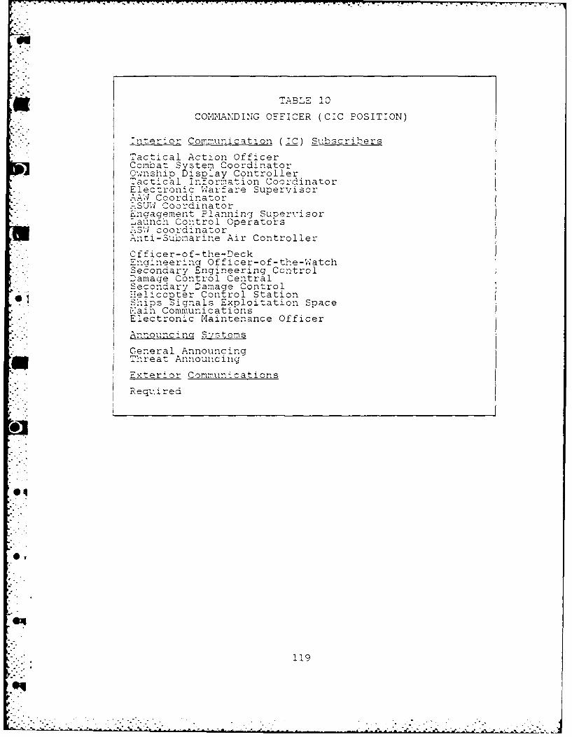
M TA BLE 10COMMAINDING OFFICER (CIC POSITION)
:nt erj or Communication (.IC) Sbscribers
- Tactical Action OfficerCombat System CoordinatorOwanshiro Di splay Controller: actic Ll Inflormation Coordinator
*Elec.ronic W arfare Supervisor.-.AW Coordinator:.SU*- CoordinatorEngagement Planning Supervisor
* Launch Control Operators.7S' - coor:dinator-liti-submarine Air Controller
Officer-of-the-DeckEngineering Officer-of-the-WatchSecondary Engineering ControlDamage Control CentralSecondary Darna e Control"eliccpter Con ~ol StationShips Signals Expiloitation SpaceE~ain CommunicatibnsE;'ectronic maintenance Officer
Announcinc S-istems
Ceneral AnnouncingjThreat Announcin-g
Exterior Commun ations
Requ, ,ired
04
119
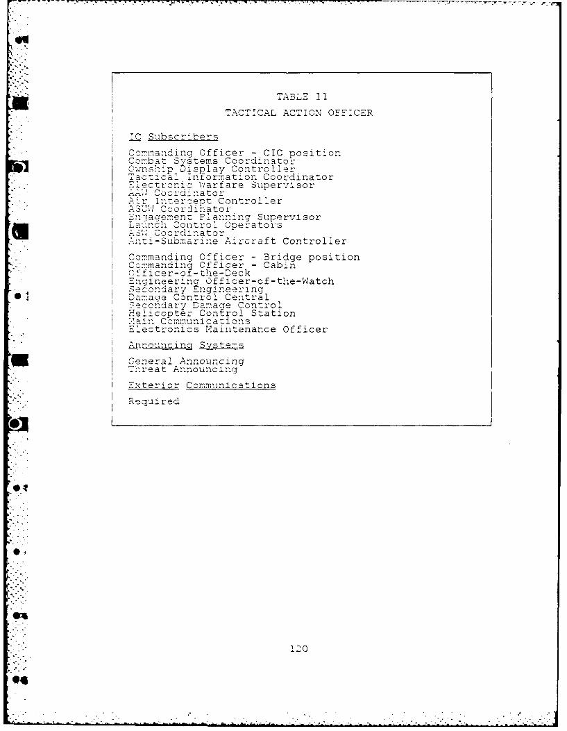
TABLE 11
TA'CTICA'L ACTION OFFICER
:0Subscrib'ers
Cc,-andng Officer - CIC p~ositionCota Systems CoordinatorCwnsr-pDisplay ControllerTacti cal Intormation CoordinatortE,,ct iz Wc',arfare Supervisor
I 'oordinator4 I'-ercept Controller
SIT'- --)o r:inato r:- -aag-'enz Planning Supervi sor
La".c Control operatorsS, oordiinator1ti-Sbmarine Aircraft Controller
'Commanding Officer - Bridge positionConmandiny Off'icer - CabinOfficer-of -the-Deck,ngi neering Officer-of-the-WatchSecondoary ng-ineering
@1 iDamacie Control CentralISecondary Dama ge Control
Helic ooter Con trol StationI rain Cbmmunicazions
*:.lectronics Maintenance OfficerI i-o,,mcing Svstems
IGeneral Announcing-reat Announcing
Exterior Communications
* Re-quired
01
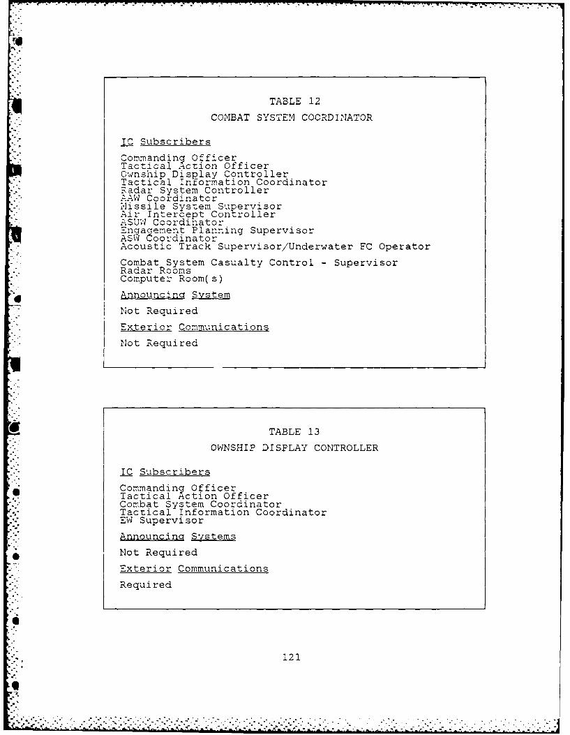
U.
TABLE 12
COMBAT SYSTEM COORDINATOR
!C Subscribers
Commanding OfficerTactical Action OfficerOwnship Display ControllerTactical Information CoordinatorRadar System ControllerAAW CoordinatorMissile System SupervisorAir Intercept ControllerASUW CoordinatorEngagement Planning SupervisorASW CoordinatorAcoustic Track Supervisor/Underwater FC Operator
Combat System Casualty Control - SupervisorRadar RoomsComputer Room(s)
Announcing System
Not Required
Exterior Communications
Not Required
TABLE 13
OWNSHIP DISPLAY CONTROLLER
IC Subscribers
Commanding OfficerTactical Action OfficerCombat System CoordinatorTactical Information CoordinatorEW Supervisor
AnnouncinQ Systems
Not Required
Exterior Communications
Required
121
0. . . . .
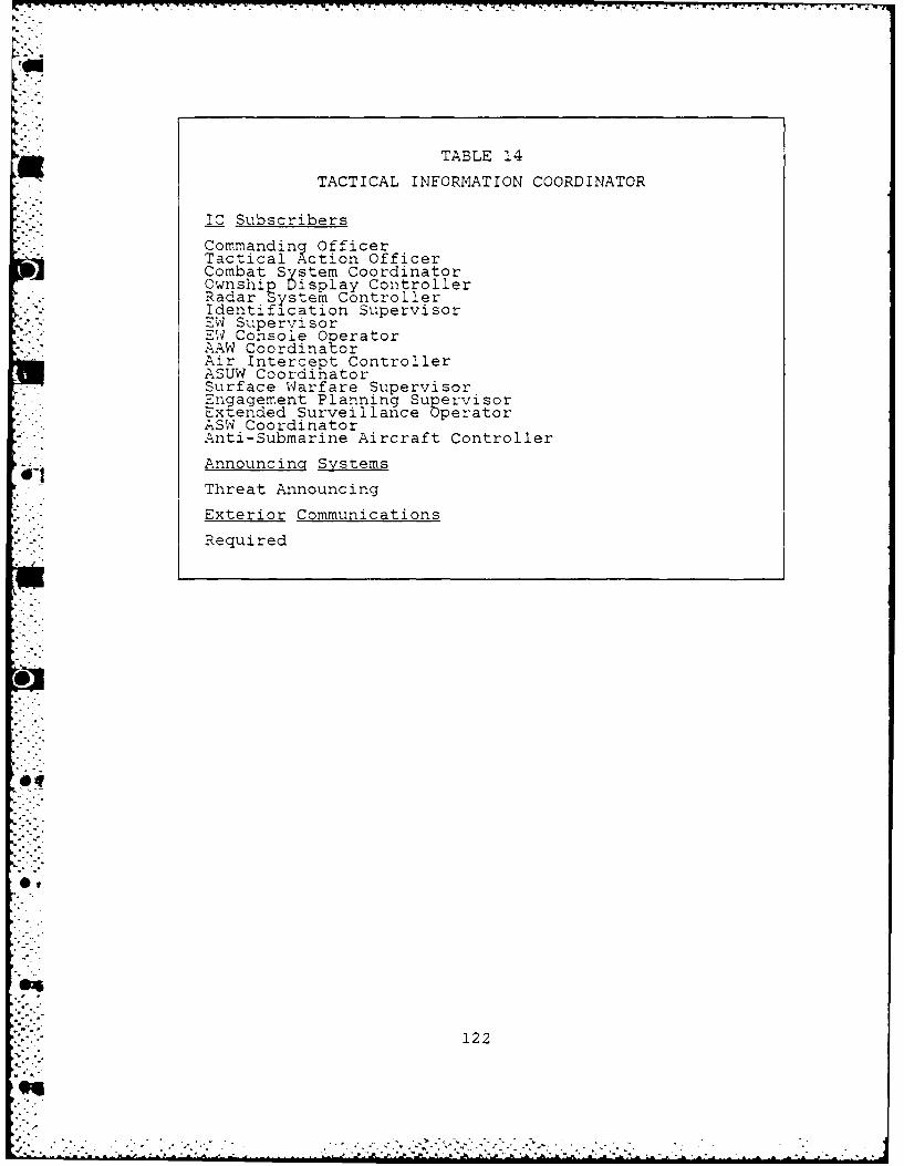
TABLE 14
TACTICAL INFORMATION COORDINATOR
IC Subscribers
Commanding OfficerTactical Action OfficerCombat System CoordinatorOwnshi Display ControllerRadar stem ControllerIdentification SupervisorEW SupervisorEI Console OperatorAAW CoordinatorAir Intercept ControllerASUW CoordinatorSurface Warfare SupervisorEngagement Planning SupervisorExtended Surveillance OperatorASW CoordinatorAnti-Submarine Aircraft Controller
Announcing Systems
Threat Announcing
Exterior Communications
.- "Required
122
.9_,'
o.9
- . .
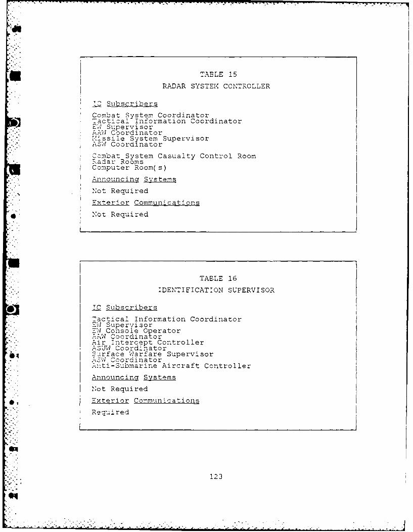
my 7,
TABLE 15
RADAR SYSTEM4 CONTROLLER
TC Subscribers
Combat System CoordinatorTactical information CoordinatorE'; Supervisor'.AW Coordinator'I-issile System SupervisorASW Coordinator
Combat System Casualty Control Room:Radar RoomsComputer Room(s)
Announcing Systems
Not Required
Exterior Communications
*' Not Required
TABLE 16
IDENTIFICATION SUPERVISOR
O* TC Subscribers
Tactical Information Coordinator--4 Supervisor7--l Console Operator.AW CoordinatorAir intercept ControllerASUW CoordinatorSurface Warfare SupervisorASW Coordinator.nti-Submarine Aircraft Controller
Announcin Systems
'Not Required
.xterior Communications
Required
123*4 :
- -- -.1
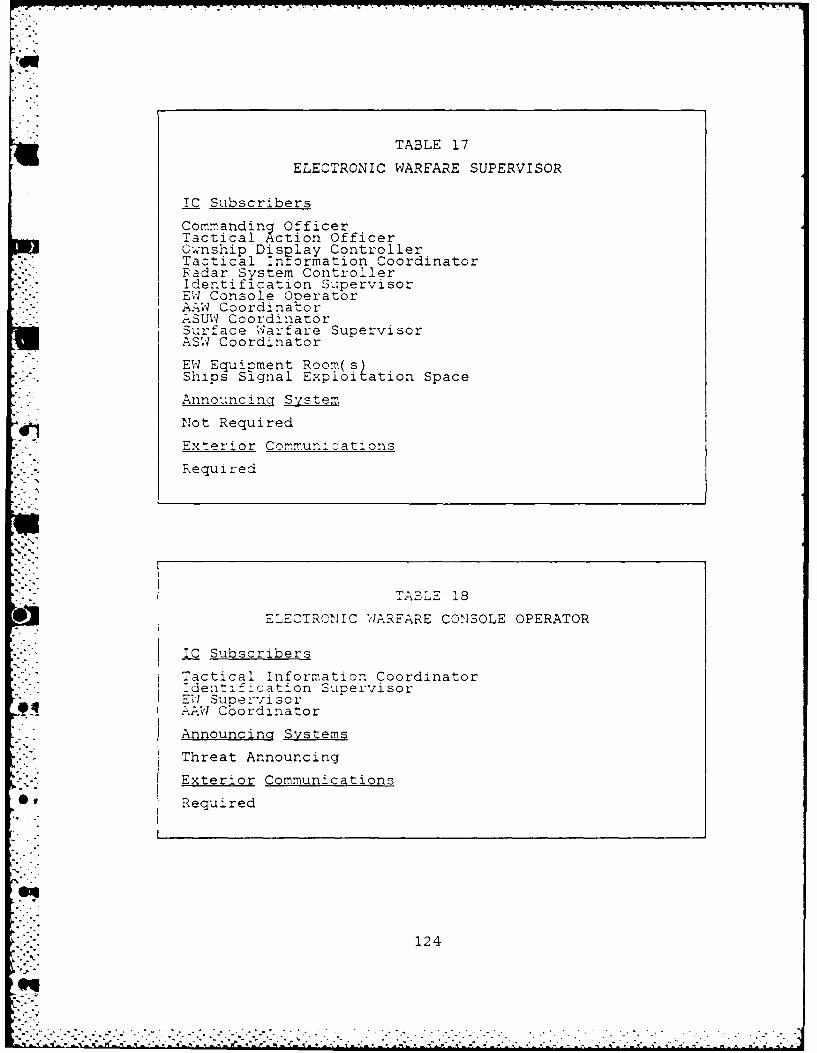
TABLE 17
ELECTRONIC WARFARE SUPERVISOR
IC Subscribers
Commanding OfficerTactical Acti on Office rOwnship DIs~ ControllerRadar System ControllerIdentification SupervisorEW Console &OeratorAA"W CoordinatorA-SUW CoordinatorSurface W arfare SupervisorASW Coordinator
EW Equipment Room(s)Ships Si.gnal Exploitation Space
Announcinc System
Not Required
Exterior Commun-.ations
Rxequi red
TAL 139
ELECTRCNIC W4ARFARE CONSOLE OPERATOR
IC Subscribers
Tactical Information Coordinator:dent: f:cation 'SupervisorE'V sunervisor
9tI.AW Cbordinator
Announcin Systems
Threat Announcing
Exterior Communications
Required
124

TABLE 19
ANTI-AIR WARFARE COORDINATOR
IC Subscribers
Commanding Officer - CIC positionTactical Action OfficerCombat System CoordinatorTactical Information CoordinatorRadar System ControllerIdentification SupervisorEW Supervisor_E Console Operator.Missile System SupervisorAir Intercept ControllerASUW CoordinatorGunfire Control SupervisorASW Coordinator
Commandinq Officer - Bridge positionOfficer-oL-the-DeckHelicopter Control Station,.ain CommunicationsVLS ControlCIWS Control
Announcing Systems
Threat Announcing
Ex erior Communications
Required
125
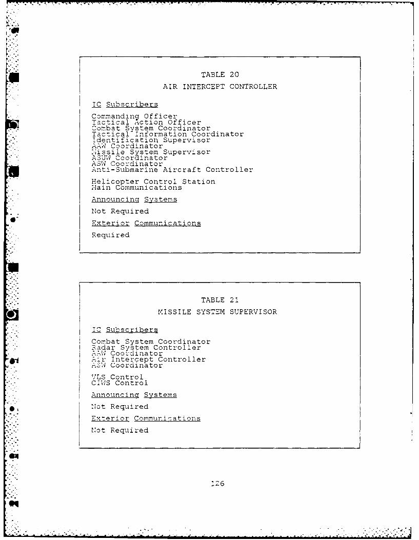
pop
TABLE 20
AIR INTERCEPT CONTROLLER
IC Subscribers
CommandinV OfficerTactical Action OfficerCombat System CoordinatorTactical Information Coordinatoridentification SupervisorAAW Coordinator'.'issile System SupervisorASUW CoordinatorASW CoordinatorAnti-Submarine Aircraft ControllerHelicopter Control StationNain Communications
Announcing Systems
Not Required
" Exterior Communications
Requi red
TABLE 21
MISSILE SYSTEM SUPERVISOR
IC Subscribers
Combat System CoordinatorRadar System ControllerAAW Coordinator:. Ar Intercept Controller
IS4 Coorcinator
-LS ControlCIWS Control
Announcing Systems
Not Required
.Exterior Communications
I Not Required
126
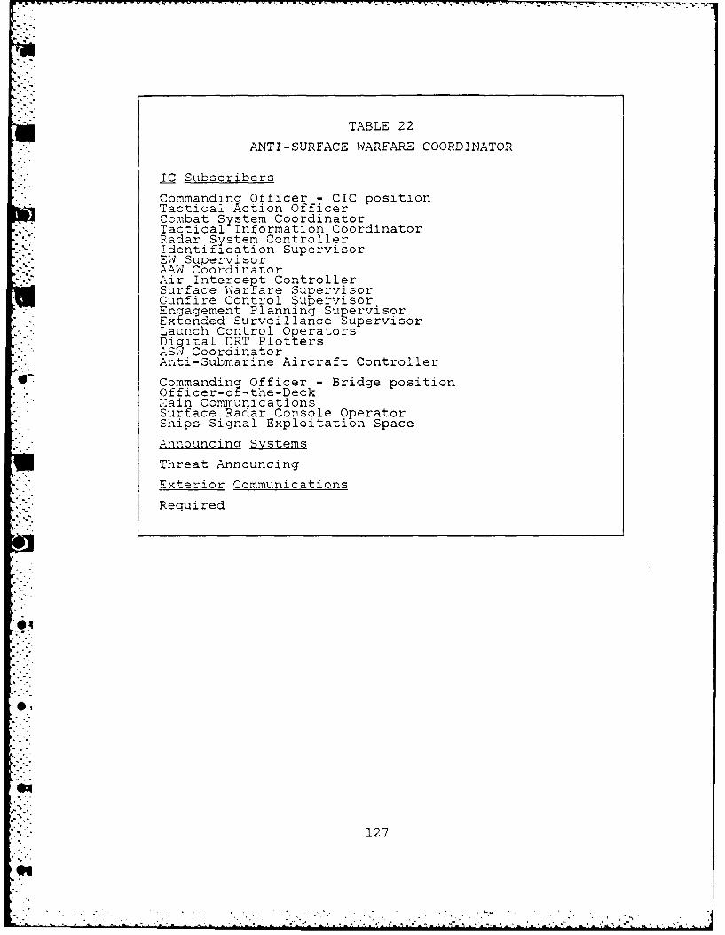
TABLE 22
ANTI-SURFACE WARFARE COORDINATOR
IC Subscribers
Commanding Officer - CIC positionTactical Action OfficerCombat System CoordinatorTactical Information CoordinatorRadar System ControllerIdentification SupervisorEW SupervisorAAW CoordinatorAir Intercet ControllerSurface War are SupervisorGunfire Control SupervisorEngagement Planning SupervisorExtended Surveillance SupervisorLaunch Control OperatorsDigital DRT PlottersAS.I CoordinatorAnti-Submarine Aircraft Controller
Commanding Officer - Bridge positionOfficer-of -the-Deck',:ain CommunicationsSurface Radar Console OperatorShips Signal Exploitation Space
Announcing Systems
Threat Announcing
Exterior CommunicationsRequired
127
eq

TABLE 23
SURFACE WARFARE SUPERVISOR
IC Subscribers
Tactical Information Coordinatoridentification Supervisor
4 Ed Supervisor.SUW CoordinatorExtended Surveillance OperatorDigital DRT OperatorsSurface Radar Console OperatorLookouts
Announcinq Systems
Not Required
.xterior Communications
Requi red
, le
TABLE 24
GUNFIRE CONTROL SUPERVISOR
IC Subscribers* iAW Coordinator
ASUv Coordinator
Gun Mount Control
Announcinq System1 01Not Required
Exterior Communications
Not Required
04
128
' "e qii
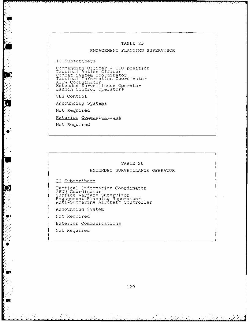
TABLE 25
ENGAGEMENT PLANNING SUPERVISOR
-C Subscribers
Commanding Officer - CIC positionTactical Action OfficerCombat System CoordinatorTactical Information Coordinator..-.ASU'VI CoordinatorExtended Surveillance OperatorLaunch Control Operators
VLS Control
Announcin Systems
Not Required
Exterior Communications
Not Required
TABLE 26
EXTENDED SURVEILLANCE OPERATOR
IC Subscribers
Tactical Information CoordinatorASUW CoordinatorSurface Warfare SupervisorEngagement Planning Supervisor; nt-Submarine Aircraft Controller
Announcinq System
0_, Not Required
Exterior Communications
Not Required
129
*1

TABLE 27
LAUNCH CONTROL OPERATORS
TC Subscribers
CommandinV Officer 7 CIC positionThctical A-ction Officer..:su' CoordinatorEngagement Plarning Supervisor
VLS Control
Announcin Systems
N;ot Required
7mterior Communications
Not Required
TABLE 28
DIGITAL DEAD RECKZONING TRACER BLOTTERS
CSubscribers
ASUW CoordinatorSurface W,-arfare SupervisorA-SW Coordinator
* Acoustic Track Supervisor/Underwater EC Operator
Lookouts
2.nnouncincT Systems
Not Required
@4 I xvrio;r C-mmunications
:;o ot Required
130
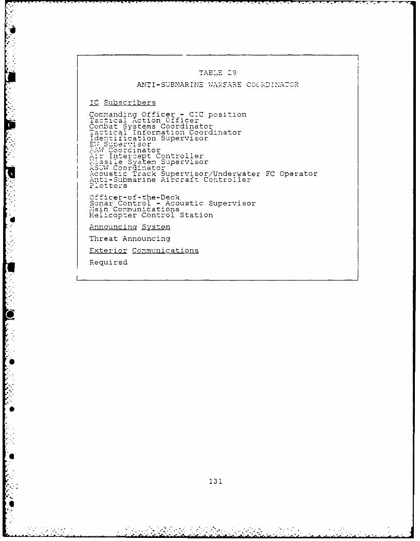
TABLE 29
ANTI -SUBMARINE WARFARE CO.RD NAOR
IC Subscribers
Commanding Officer - CIC positionTactical Action OfficerCombat Systems CoordinatorTactical Information CoordinatorIdentification Supervisor
SupervisorW Cbordinatorr Intercept Controller
issile Syst em SupervisorUW Coordinator
Acoustic Track Supervisor/Underwater EC OperatorAnti-Submarine Aircraft Controller[. Plotters
"Officer-of-the-DeckSonar Control - Acoustic SupervisorNiain Communications
*d Helicopter Control Station
Announcing System
Threat Announcing
Exterior Communications
Required
1
• . ,131
I<
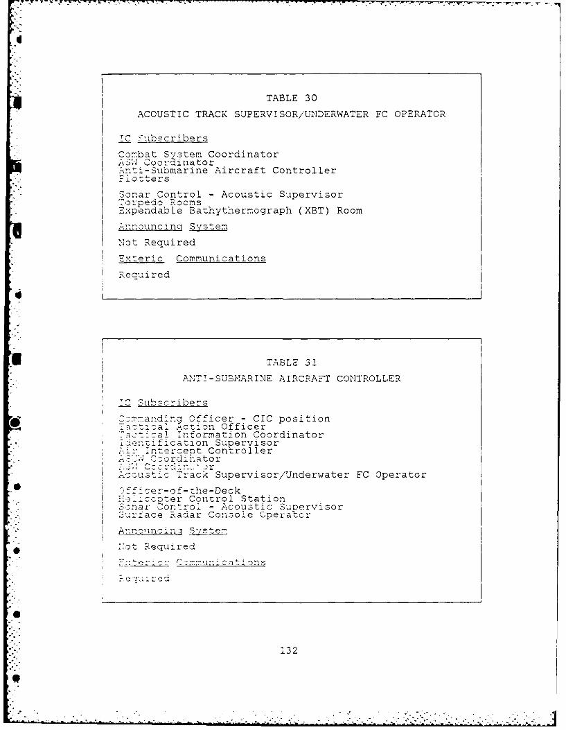
TABLE 30
ACOUSTIC TRACK SUPERVISOR/UNDERWATER FC OPERATOR
C >'ubs-ribers
Combat System Coordinator\S;I CoordinatorA:-i-Submarine Aircraft Controller-. Plotters
Sonar Control - Acoustic Supervisor~Torpedo Rooms
Expendable Bathythermograph (XBT) Room
.-Anouncinq System
Not Required
Exteric Communications
Required
TABLE 32
ANT I - SUBMAR I NE AI RCRAFT CONTROLLER
1C Subscribers
Commanding Officer - CIC positionac-ial Action Officer-_ac-ical Information Coordinator
Slnzification Suoervisorrntercept Controller
CoordihatorC:. Cc r in."
Track Supervisor/Underwater FC Operator-fficer-of-the-Deck::e cccter Control StationSonar -ontrol - Acoustic Supervisor
-u Surface Radar Console Operator
Arnnouncinjt System
lot RequiredE::teriov~~ C ::,n t ion s
132
-----
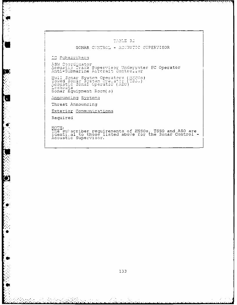
U SONAR C"::: z . .. - ::c EUPER'VISOR
ASW 3z rdi" oAcous:'c Track Supervi sor Underwater FC Operator. ] Anti-Submarne k rcraf- 2ontroi'r
ul' Sonar Svste:n C-eratoys 7 .TSOs)T owed Sonar sstem _4e a : s- J)
' "co s S a r Cpera or' -J "o - . u -s
SSonar Equipment Room(s)Annoulnc ing Systems
Threat Announcing
Exterior Communications
Required
NOTE:T-nesuscriber requirements of HSSOs TSSO and ASO areidenti-al to those listed above for he sonar Control -
"* Acoustic Supervisor.
0
133
..4

TABLE 33
COMMANDING OFFICER - BRIDGE POSITION
Tactical Action Officero Corin ato r
.SWCoordin-atorSurface/Subsurface Warfare Coordinator
Engi:-eerincj Offi4cer-of-the-Watchamacage Contro 7 Cetia
Helicopter Control StationSecondary Engineering ControlSecondary Damage Control
A nnouncina, Systems
General Announcing
ExteiorCommunications
Required
Of
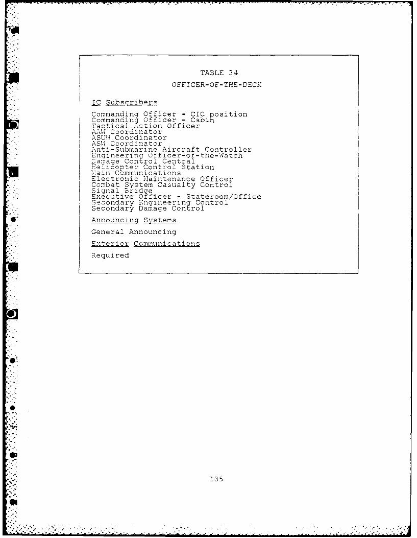
TABLE 34
OFFICER-OF-THE-DECK
IC Subscribers
Commanding Officer - CIC positionCommanding Officer - CabinTactical .-.ction Officer
" AAW CoordinatorASUW CoordinatorASW Coordinator. nti-Submarine Aircraft ControllerEngineering 0fficer-o f- the-Watch--Damage Control CentralHelicopte: -ontrol Station1ain CommunicationsElectronic Naintenance OfficerCombat System Casualty ControlSignal BridceExecutive Officer - Stateroom/OfficeSecondary Engineering ControlSecondary Damage Control
*" Announcing Systems
General Announcing
Exterior Communications
Required
i3° . .
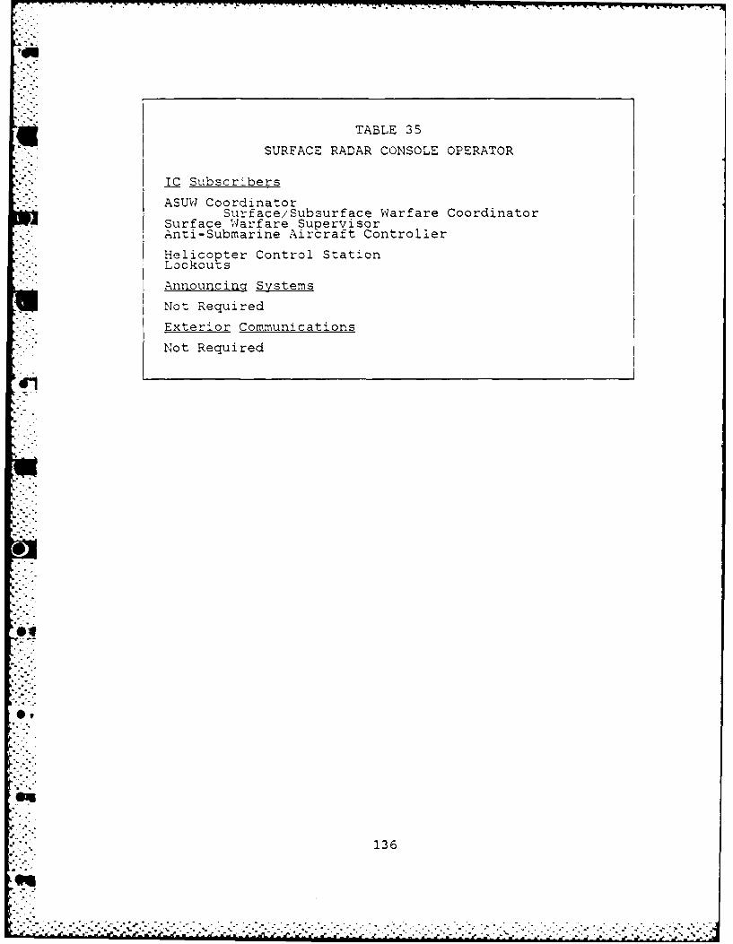
TABLE 35
SURFACE RADAR CONSOLE OPERATOR
IC Subscri'bers
ASUW CoordinatorSurface/Subsurface Warfare Coordinator
Surface vqarfare SupervisorAnti-Submarine Aircraft Controller
Helicopter Control Station
Announcina Systems
Not Required
Exterior Communications
Not Required
136
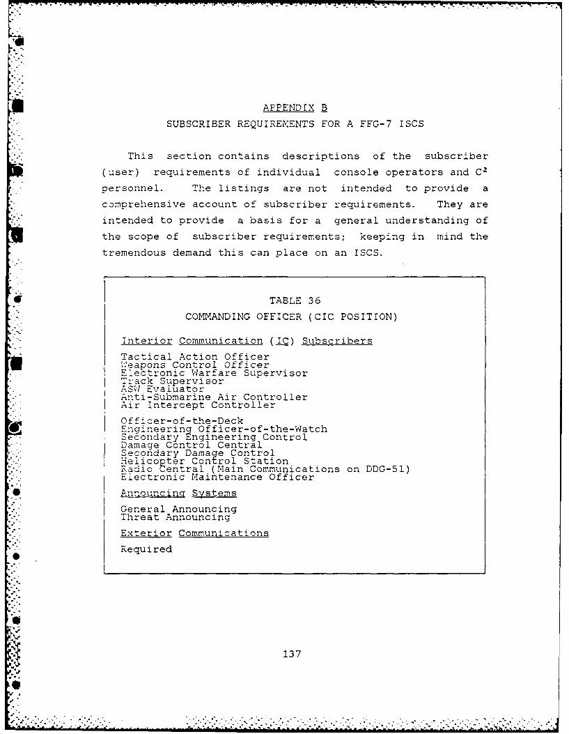
APPENDIX B
SUBSCRIBER REQUIREMENTS FOR A FFG-7 ISCS
This section contains descriptions of the subscriber
(user) requirements of individual console operators and C2
personnel. The listings are not intended to provide a
comprehensive account of subscriber requirements. They are
intended to provide a basis for a general understanding of
the scope of subscriber requirements; keeping in mind the
tremendous demand this can place on an ISCS.
E TABLE 36
COMMANDING OFFICER (CIC POSITION)
Interior Communication (I__) Subscribers
Tactical Action Officerw.eapons Control Officer
.. ELectronic Warfare SupervisorTrack SupervisorASW EvaluatorAnti-Submarine Air ControllerAir Intercept Controller
Officer-of-the-DeckEngineering Officer-of-the-WatchSecondary Engineering ControlDamage Control CentralSecondary Damage ControlHelico pter Control StationRadio Central (Main Communications on DDG-51)Electronic Maintenance Officer
Announcing Systems
General AnnouncingThreat Announcing
Exterior Communications
Required
137
--
* . * * . .* ..'... . . * ***.. * .
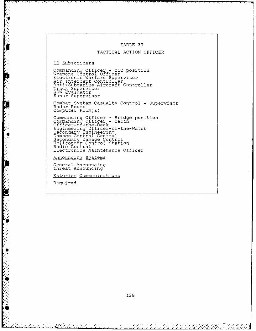
TABLE 37
TACTICAL ACTION OFFICER
IC Subscribers
Commanding Officer - CIC positionSWeapons Control OfficerElectronic Warfare SupervisorAir Intercept ControllerAnti-Submarine Aircraft ControllerTrack Supervisor
-_ ASW EvalUatorSonar Supervisor
Combat System Casualty Control - SupervisorRadar RoomsComputer Room(s)
Commanding Officer - Bridge positionCommandinq Officer - CabinOfficer-o-the-DeckEngineering Officer-of-the-WatchSecondary EngineeringDamage Control CentralSecondary Damaqe ControlHelicop ter Control StationRadio CentralElectronics Maintenance Officer
Announcing Systems
General AnnouncingThreat Announcing
Exterior Communications
Required
138
,L l..m..£ *-
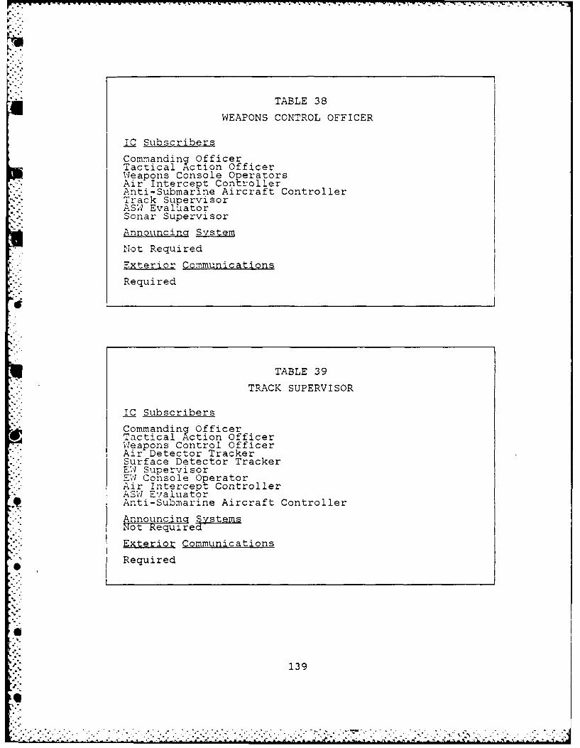
I,.
TABLE 38
WEAPONS CONTROL OFFICER
IC Subscribers
Commanding OfficerTactical Action OfficerWeapons Console OperatorsAir Intercept Con roller
•- Anti-Submarine Aircraft ControllerTrack SupervisorASW EvaluatorSonar Supervisor
Announcincr System
Not Required
Exterior Communications
Required
TABLE 39
TRACK SUPERVISOR
IC Subscribers
Commanding OfficerTactical Action OfficerWeapons Control OfficerAir Detector TrackerSurface Detector TrackerEW SupervisorEW Console OperatorAir Intercept ControllerASW Evaluator
9 Anti-Submarine Aircraft ControllerAnnouncinq SystemsNot Required
Exterior Communications
Required
139
0Q
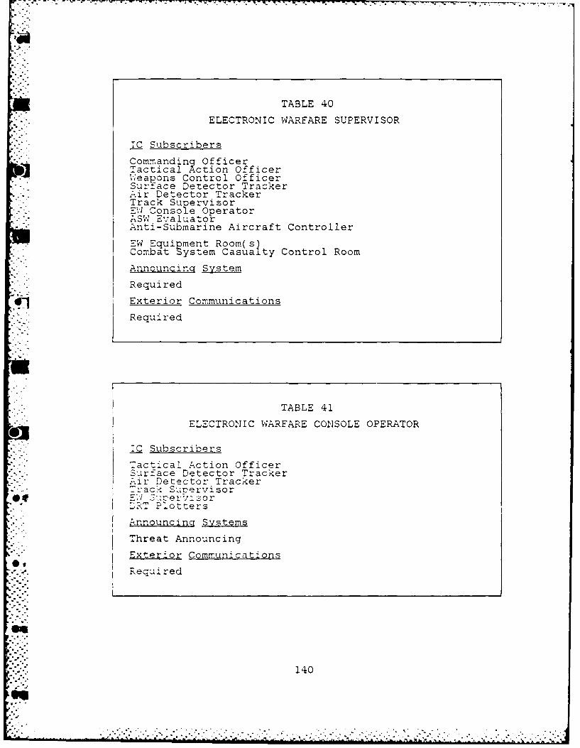
TABLE 40
ELECTRONIC WARFARE SUPERVISOR
IC Subscribers
Commanding OfficerTactical Action Officer'ieapons Control OfficerSurface Detector TrackerAir Detector TrackerTrack SupervisorEI Console OperatorASW EvaluatorAnti-Submarine Aircraft Controller
EW Equipment Room(s)Combat System Casualty Control Room
Announcing System
Required
'1. Exterior Communications
Required
TABLE 41
ELECTRONIC WARFARE CONSOLE OPERATOR
IC Subscribers
Tactical Action Officer"urface Detector Tracker-.ir Detector Tracker
4' • rack SupervisorQI 7, E:; .cerv-- sorT Plotters
Announcinq Systems
Threat Announcing
Exterior Communications
N. equi red
140
d-7
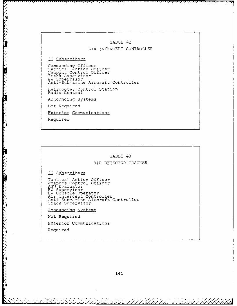
TABLE 42
AIR INTERCEPT CONTROLLER
I Subscribers
Commanding OfficerTactical Action OfficerWeapons Control OfficerTrack SuCervisor-. ~EW' Supe rviso rSnt-Submarine Aircraft ControllerHelicooter Control StationRadio Central
A.nnouncincq Systems
Not Required
Exterior Communications
Required
TABLE 43
AIR DETECTOR TRACKER
IC Subscribers
Tactical Action Officer.. 7eapons Control OfficerASW EvaluatorEW SupervisorEW Console OperatorAir Intercept ControllerAnti-Submarine Aircraft ControllerTrack Supervisor
Announcing Systems
Not Required
Exterior Communications
Required
141
S"
* . . . . . . . . . . .

TABLE 44
SURFACE DETECTOR TRACKER
IC Subscribers
Tactical Action OfficerWeapons Control OfficerASW EvaluatorEW SurpervisorEW Cohsole OperatorAnti-Submarine Aircraft ControllerDRT PlottersTrack Supervisor
Announcin Systems
Not Required
Exterior Communications
Required
TABLE 45
WEAPONS CONTROL CONSOLE OPERATORS
IC Subscribers
Tactical Action OfficerWeapons Control Officerother Weaoons Control Console OperatorsAir Detector TrackerSurface Detector TrackerTrack Supervisor
Launcher Control* Gun Mount
Announcing Systems
Not Required
Exterior Communications
* Not Required
142
. * . . .j
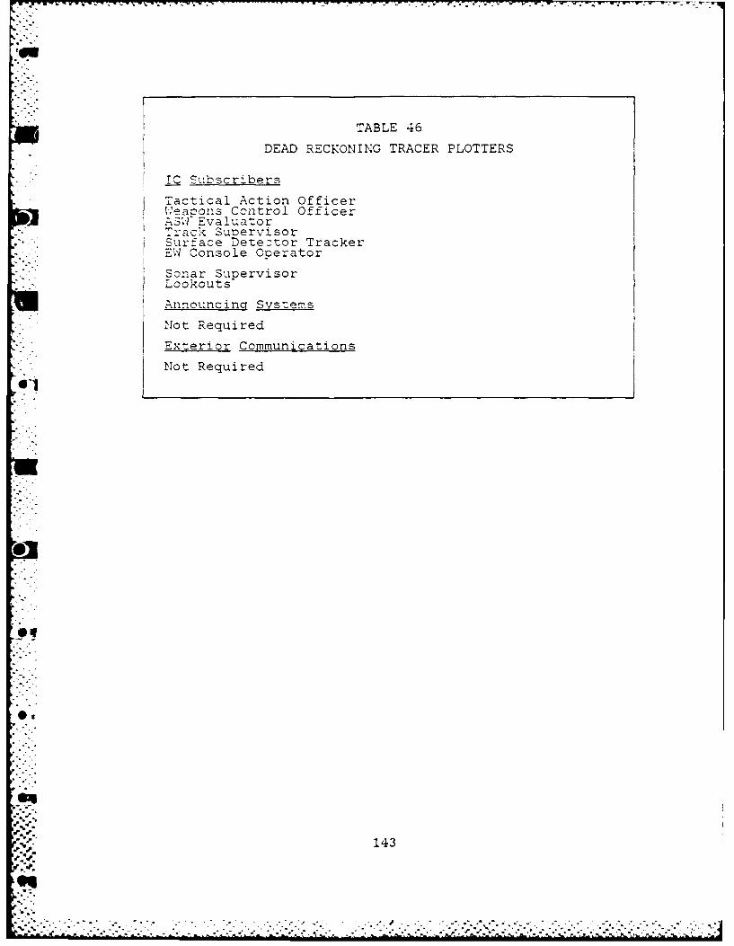
TABLE 46
DEAD RECKONING TRACER PLOTTERS
ICSuscribers
Tactical Action Officer;t.'eacons Cz'ntrol Officer.. ~siEvaluatorTrack SunervisorSurface Teteztor TrackerE,, Console Operator
Sonar SupervisorLookouts
Announcing Systems
Not Required
Exterior Communications
Not Required
0A
V 143
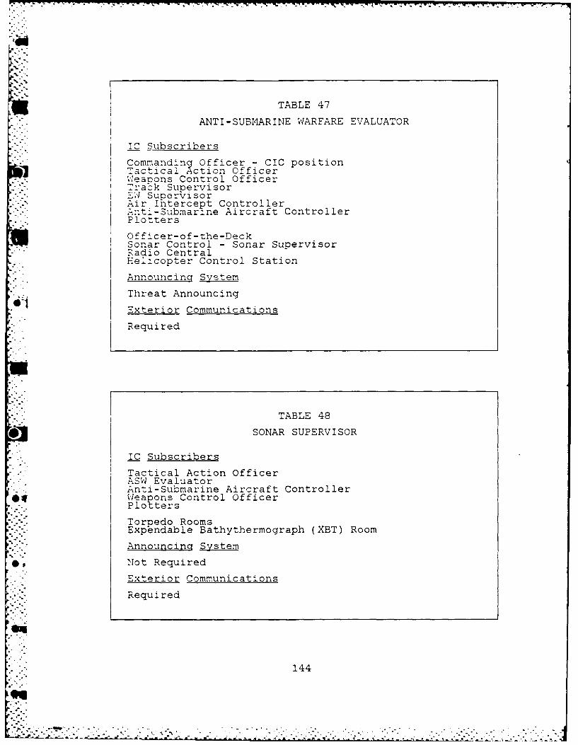
TABLE 47
ANTI-SUBMARINE WARFARE EVALUATOR
IC Subscribers
Commanding Officer - CIC positionTactical Action Officer.eanons Control Officer
-. SupervisorAir Intercept ControllerAnti-Submarine Aircraft ControllerPlotters
Officer-of-the-DeckSonar Control - Sonar Supervisor'-' Radio CentralHelicopter Control Station
Announcing System
Threat Announcing
'Exterior Communications
Required
TABLE 48
SONAR SUPERVISOR
* "IC SubscribersTactical Action Officer
ASW EvaluatorAnti-Submarine Aircraft Controller0eapons Control Officerr<.. PlotersTorpedo Rooms
Expbndable Bathythermograph (XBT) Room
Announcing System
Not Required
Exterior Communications
Required
144
' . °
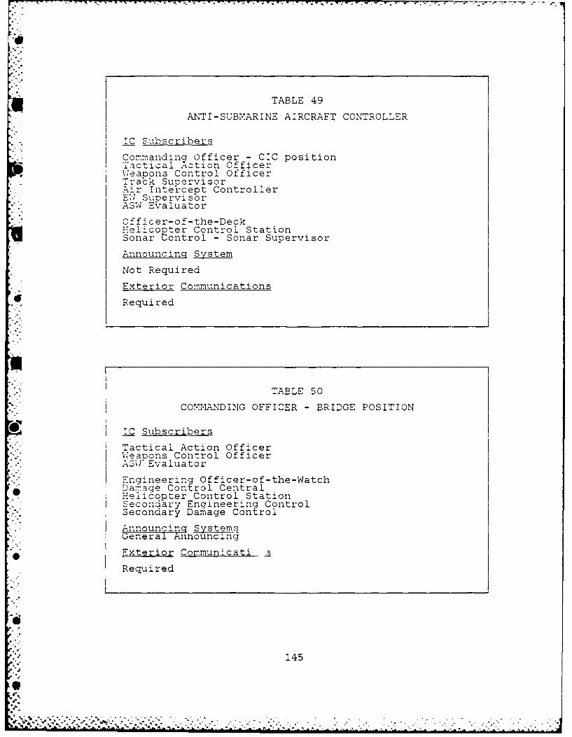
TABLE 49
ANTI-SUBMARINE AIRCRAFT CONTROLLER
T- Subscribers
Commanding Officer - CIC positionTactical Action OfficerWeapons Control OfficerTrack SupervisorAir Inte'rcept Controller-E, SupervisorASW Evaluator
S""Officer-of-the-Deck;-:elico pter Control StationSonar ontrol - Sonar Supervisor
Announcing System
Not Required
Exterior Communications
Required
TABLE 50
COMMANDING OFFICER - BRIDGE POSITION
SIC Subscribers
Tactical Action OfficerWeaoons Control OfficerASX Evaluator
Engineering Officer-of-the-WatchDamage Control CentralWeliconter Control StationSecondary Engineering ControlSecondary Damage Control
Announcing SystemsGeneral Announcing
Exterior Communicati s
Required
145
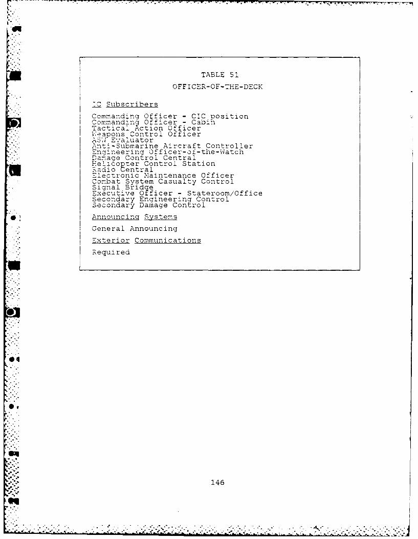
TABLE 52.
OFFICER-OF-THE-DECK
.'C Subscribers
Commanding Officer - CI positionCommancdin ; Officer - C abiiiTactical .,ction Officer;W-?aoons Control OfficerA-I Evaluator'nti-Submarine Aircraft Controller
IEngineering Officer-o-teWacIDamage Control CentralHelicopter Control Station%adio Central' l-ectronic Maintenance OfficerCom.Tbat System Casualty ControlSignal* BridgleExecutive Officer - Stateroom/OfficeSecondary Engineering ControlSecondary Damage Control
0 Announcing Systems
General Announcing
Exterior Communications
IRequired
@4
146
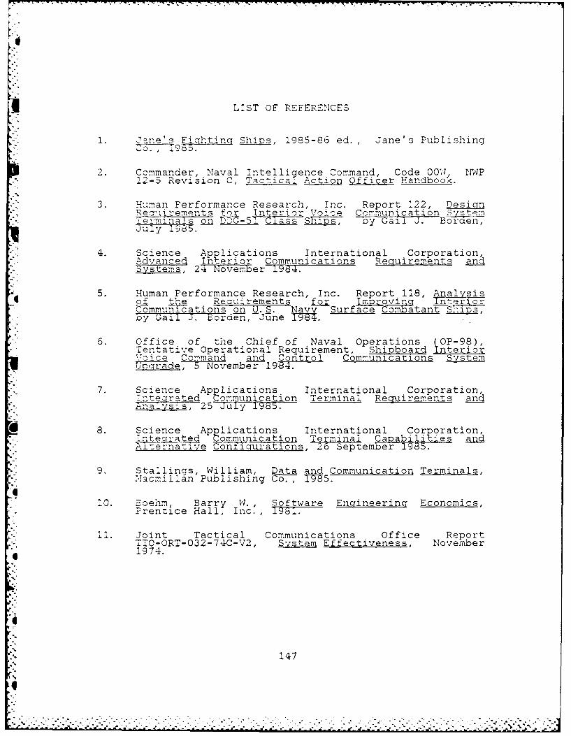
LIST OF REFERENCES
1. Jane's Fiqhtin Ships, 1985-86 ed., Jane's PublishingCO. , 1985b.
2. Commander, Naval Intelligence Command, Code 00W NWP
12-5 Revision C, Tactica Action Officer Handbook.
3. Human Performance Research, Inc. Report 122, DesicinRea-irements for Interior Voice Communication-erminals on D5G-51 Class ShTTs, byGall J. Borden,July 1! .
4. Science Applications International Corporation,Advanced Interior Communications Requirements andSystems, 24 November 1984.
5. Human Performance Research, Inc. Report 118, Analysisof the Reauirements for Improving Interior7-ommu-cations on U.S. a Surface Combatant Ship_ p,by Gail J. Borden, June i
0. Office of the Chief of Naval Operations (OP-98),Tentative Operational Requirement, Shipboard InteriorVoice Command and Control Communications System,g Ucqrade, 5 November--19T:.
7. Science Applications International Corporation,integrated Communication Terminal Requirements andAnalysis, 25 July 1985.
8. Science Applications International Corporation,!ntecrrated Communication Terminal Capabilities andAicernative Conqicuratons, 6 September1985.
9. Stallings, William, Data and Communication Terminals,
Macmillan Publishing Co. , -75.
10. Eoehm, Barry W. , Software Engineering Economics,Prentice Hall, Inc., 1981.
11. Joint Tactical Communications Office ReportTTO-ORT-032-74C-V2, System Effectiveness, November
f 1974.
147
.i

INITIAL DISTRIBUTION LIST
No. Copies
1. Defense Technical Information Center 2Cameron StationAlexandria, Va. 22304-6145
2. Library, Code 0142 2Naval Postgraduate School..nterey, Ca. 93943- 5000
3. Ccmmander 2Naval Ocean Systems Command (code 821)ATT: o'r. Joseph J. OleskaSan Diego, Ca. 92152-5000
4. Lt. G. Bartlett Farrell 2Deoartment Head School Class 93Sul-face Warfare Officer School CommandNewport, R.I. 02841
. .. . .