Embed Size (px)
Citation preview
Prod
uct B
roch
ure
| Ver
sion
02.
01
R&S®NRQ6 Frequency Selective Power SensorA milestone in power measurements
year
NRQ6_bro_en_3607-1888-12_v0201.indd 1 08.05.2018 13:41:43
2
The R&S®NRQ6 combines the accuracy of a power meter with the dynamic range of a spectrum analyzer. It performs extremely precise and fast power measurements down to –130 dBm.
R&S®NRQ6Frequency Selective Power SensorAt a glance
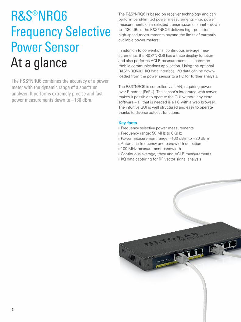
The R&S®NRQ6 is based on receiver technology and can perform band-limited power measurements – i.e. power measurements on a selected transmission channel – down to –130 dBm. The R&S®NRQ6 delivers high-precision, high-speed measurements beyond the limits of currently available power meters.
In addition to conventional continuous average mea-surements, the R&S®NRQ6 has a trace display function and also performs ACLR measurements – a common mobile communications application. Using the optional R&S®NRQ6-K1 I/Q data interface, I/Q data can be down-loaded from the power sensor to a PC for further analysis.
The R&S®NRQ6 is controlled via LAN, requiring power over Ethernet (PoE+). The sensor’s integrated web server makes it possible to operate the GUI without any extra software – all that is needed is a PC with a web browser. The intuitive GUI is well structured and easy to operate thanks to diverse autoset functions.
Key facts Frequency selective power measurements Frequency range: 50 MHz to 6 GHz Power measurement range: –130 dBm to +20 dBm Automatic frequency and bandwidth detection 100 MHz measurement bandwidth Continuous average, trace and ACLR measurements I/Q data capturing for RF vector signal analysis
NRQ6_bro_en_3607-1888-12_v0201.indd 2 08.05.2018 13:41:44
Rohde & Schwarz R&S®NRQ6 Frequency Selective Power Sensor 3
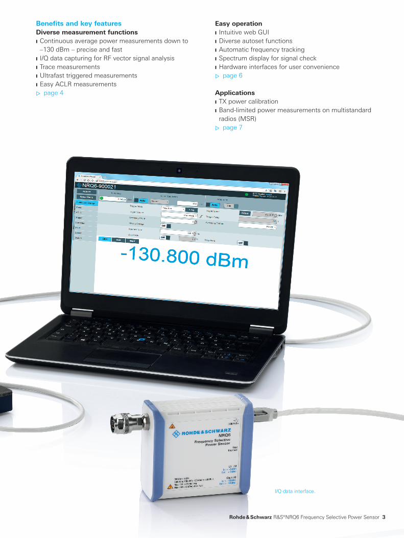
Benefits and key featuresDiverse measurement functions Continuous average power measurements down to –130 dBm – precise and fast
I/Q data capturing for RF vector signal analysis Trace measurements Ultrafast triggered measurements Easy ACLR measurements ▷ page 4
I/Q data interface.
Easy operation Intuitive web GUI Diverse autoset functions Automatic frequency tracking Spectrum display for signal check Hardware interfaces for user convenience ▷ page 6
Applications TX power calibration Band-limited power measurements on multistandard radios (MSR) ▷ page 7
NRQ6_bro_en_3607-1888-12_v0201.indd 3 08.05.2018 13:41:45
4
Continuous average power measurements down to –130 dBm – precise and fastConventional diode power sensors reach their physical limits at approx. –70 dBm. Fast measurements degrade accuracy especially at low power levels, since the noise content measured by these sensors is relatively high. As a result, either speed or accuracy has to be sacrificed.
The receiver based architecture of the R&S®NRQ6 elimi-nates this problem. This concept provides lower measure-ment noise. In addition, the sensor’s ability to perform band-limited measurements reduces the noise floor. These characteristics enable high-precision, high-speed measure-ments down to –130 dBm.
I/Q data capturing for RF vector signal analysisThe R&S®NRQ6 can be used as a standalone RF frontend to capture vector-modulated I/Q signals.
With the optional R&S®NRQ6-K1 I/Q data interface, cap-tured I/Q data can be read out using SCPI commands. The data is demodulated and analyzed using external software.
Automated, cloud-based data processing and analysis is also possible using the R&S®Quickstep test executive soft-ware to control any analysis tool in order to measure error vector magnitude (EVM), adjacent channel leakage ratio (ACLR) and other TX performance parameters.
Diverse measurement functions
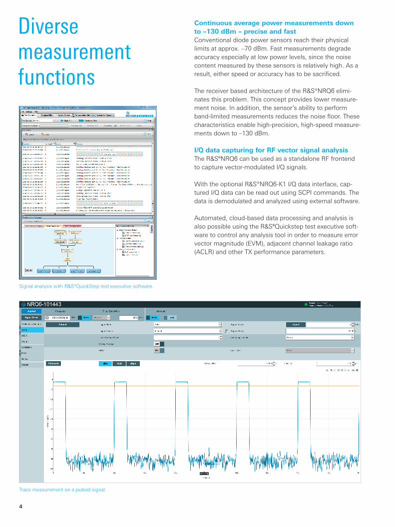
Trace measurement on a pulsed signal.
Signal analysis with R&S®QuickStep test executive software.
NRQ6_bro_en_3607-1888-12_v0201.indd 4 08.05.2018 13:41:46
Rohde & Schwarz R&S®NRQ6 Frequency Selective Power Sensor 5
Trace measurementsA detailed trace display is necessary for a precise analy-sis of short pulses. With an inherent rise/fall time of 13 ns at a resolution bandwidth of 50 MHz, for example, the R&S®NRQ6 can easily measure steep-edged pulses.
Ultrafast triggered measurementsTriggered measurements in particular call for ever higher measurement speeds over an extended period of time. The R&S®NRQ6 contains a powerful FPGA and a large memory to meet these requirements. More than 100 000 triggered readings can be stored in a buffer in 200 ms – correspond-ing to a measurement speed of 500 000 readings/s – and transferred to a control PC.
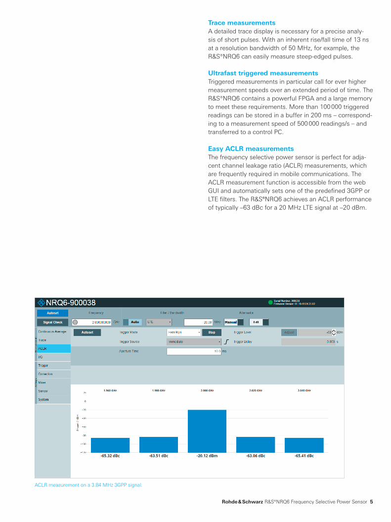
Easy ACLR measurementsThe frequency selective power sensor is perfect for adja-cent channel leakage ratio (ACLR) measurements, which are frequently required in mobile communications. The ACLR measurement function is accessible from the web GUI and automatically sets one of the predefined 3GPP or LTE filters. The R&S®NRQ6 achieves an ACLR performance of typically –63 dBc for a 20 MHz LTE signal at –20 dBm.
ACLR measurement on a 3.84 MHz 3GPP signal.
NRQ6_bro_en_3607-1888-12_v0201.indd 5 08.05.2018 13:41:46
6
Automatic frequency trackingA frequency tracker automatically sets the center fre-quency to facilitate measurements on narrowband signals with varying center frequency. This ensures that the mea-sured signal is always within the selected measurement bandwidth.
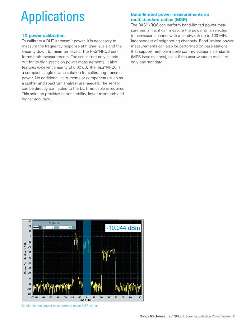
Spectrum display for signal checkSince power measurements are performed only in the set frequency range (defined by center frequency and band-width), the settings must be checked to make sure they are correct. The signal check function provides a graphi-cal display of the measured signal’s spectrum and the set bandwidth. Users can see at a glance if the measured sig-nal is within the set frequency range.
Hardware interfaces for user convenienceThe R&S®NRQ6 can be easily integrated into a test system. Remote operation is possible via LAN and USB.
The trigger I/O port can accept an external trigger signal or distribute an internally generated trigger signal to other R&S®NRQ6 power sensors.
An external LO signal can be fed to one of the R&S®NRQ6 power sensors, or the internal LO signal can be output and distributed to the other sensors.
The R&S®NRQ6 has a reference I/O port, e.g. for applying an external reference signal, and a sample clock I/O port.
Easy operation
Signal check for a 20 MHz LTE signal.
Intuitive web GUIThe R&S®NRQ6 is connected to the LAN via a PoE+ switch. The sensor includes an integrated web server. The intuitive web GUI can be operated from any web browser.
Diverse autoset functionsDiverse autoset functions are available to simplify configu-ration of the main measurement parameters. The measure-ment frequency and signal bandwidth are automatically determined and set. As a result, even unknown signals are detected and average power is measured accurately.
Depending on the input level, the 30 dB RF input attenua-tor is automatically switched on or off to configure the op-timal power measurement range.
The trace mode also offers autoset functions. For example, the time scale (x-axis) and the power scale (y-axis) can be optimally configured. A trigger is set automatically, ensur-ing stable display of the measured signal.
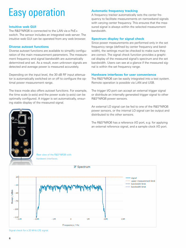
Rear view of the R&S®NRQ6 with
hardware interfaces.
NRQ6_bro_en_3607-1888-12_v0201.indd 6 08.05.2018 13:41:47
Rohde & Schwarz R&S®NRQ6 Frequency Selective Power Sensor 7
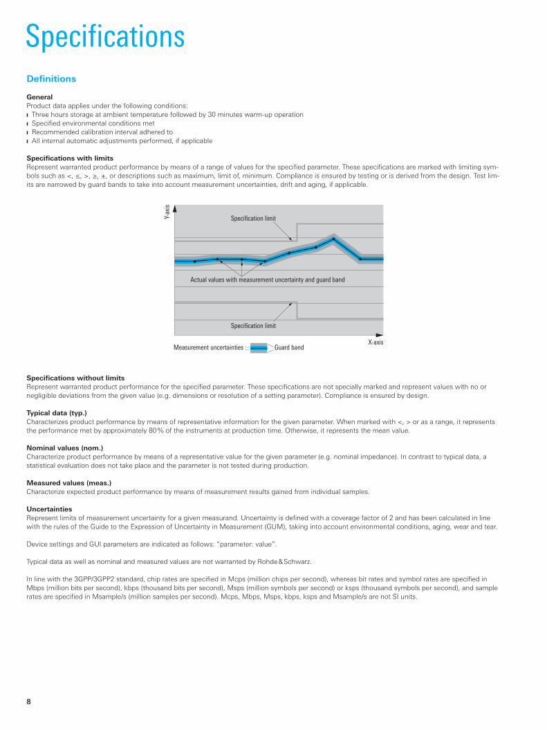
Applications Band-limited power measurements on multistandard radios (MSR)The R&S®NRQ6 can perform band-limited power mea-surements, i.e. it can measure the power on a selected transmission channel with a bandwidth up to 100 MHz, independent of neighboring channels. Band-limited power measurements can also be performed on base stations that support multiple mobile communications standards (MSR base stations), even if the user wants to measure only one standard.
TX power calibrationTo calibrate a DUT‘s transmit power, it is necessary to measure the frequency response at higher levels and the linearity down to minimum levels. The R&S®NRQ6 per-forms both measurements. The sensor not only stands out for its high-precision power measurements, it also features excellent linearity of 0.02 dB. The R&S®NRQ6 is a compact, single-device solution for calibrating transmit power. No additional instruments or components such as a splitter and spectrum analyzer are needed. The sensor can be directly connected to the DUT; no cable is required. This solution provides better stability, lower mismatch and higher accuracy.
Single-channel power measurement on an MSR signal.
NRQ6_bro_en_3607-1888-12_v0201.indd 7 08.05.2018 13:41:47
X-axis
Y-ax
is
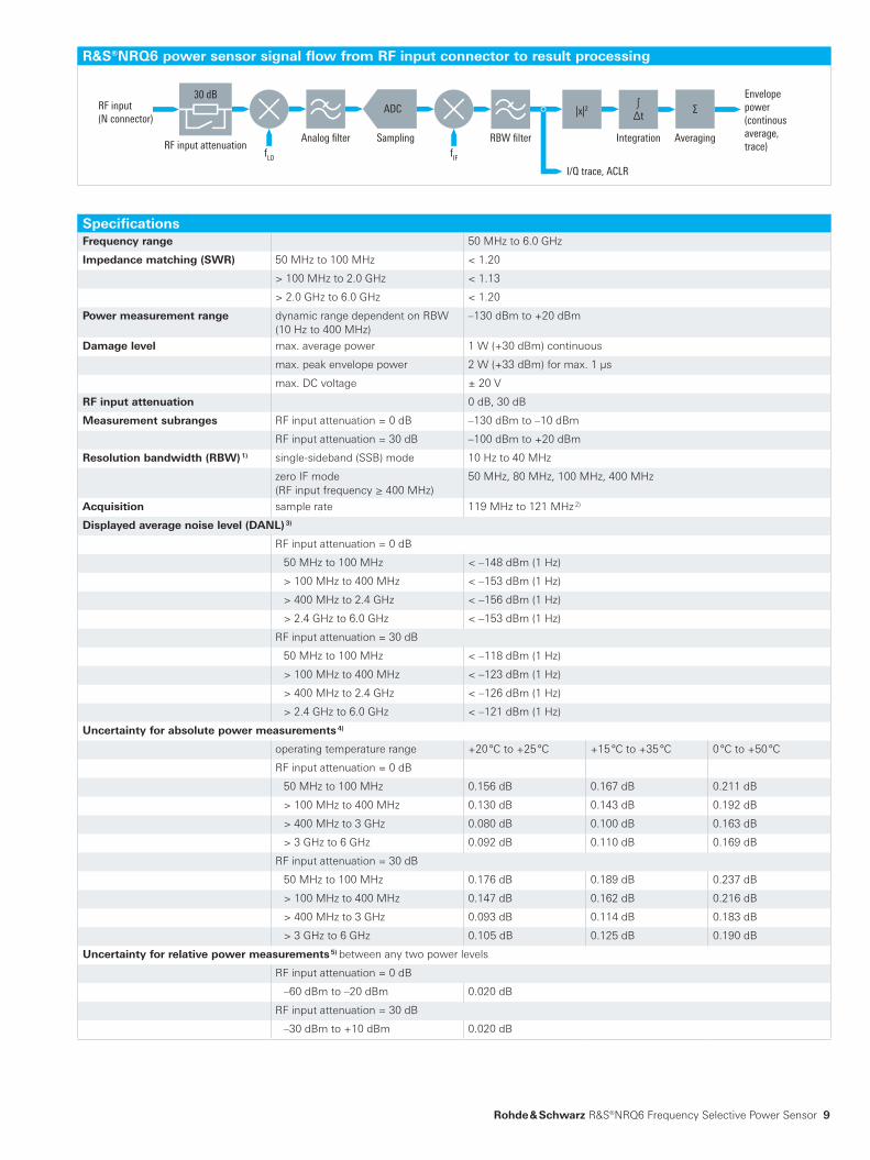
Specification limit
Actual values with measurement uncertainty and guard band
Specification limit
Measurement uncertainties Guard band
8
Definitions
GeneralProduct data applies under the following conditions: Three hours storage at ambient temperature followed by 30 minutes warm-up operation Specified environmental conditions met Recommended calibration interval adhered to All internal automatic adjustments performed, if applicable
Specifications with limitsRepresent warranted product performance by means of a range of values for the specified parameter. These specifications are marked with limiting sym-bols such as <, ≤, >, ≥, ±, or descriptions such as maximum, limit of, minimum. Compliance is ensured by testing or is derived from the design. Test lim-its are narrowed by guard bands to take into account measurement uncertainties, drift and aging, if applicable.
Specifications
Specifications without limitsRepresent warranted product performance for the specified parameter. These specifications are not specially marked and represent values with no or negligible deviations from the given value (e.g. dimensions or resolution of a setting parameter). Compliance is ensured by design.
Typical data (typ.) Characterizes product performance by means of representative information for the given parameter. When marked with <, > or as a range, it represents the performance met by approximately 80 % of the instruments at production time. Otherwise, it represents the mean value.
Nominal values (nom.)Characterize product performance by means of a representative value for the given parameter (e.g. nominal impedance). In contrast to typical data, a statistical evaluation does not take place and the parameter is not tested during production.
Measured values (meas.)Characterize expected product performance by means of measurement results gained from individual samples.
UncertaintiesRepresent limits of measurement uncertainty for a given measurand. Uncertainty is defined with a coverage factor of 2 and has been calculated in line with the rules of the Guide to the Expression of Uncertainty in Measurement (GUM), taking into account environmental conditions, aging, wear and tear.
Device settings and GUI parameters are indicated as follows: “parameter: value”.
Typical data as well as nominal and measured values are not warranted by Rohde & Schwarz.
In line with the 3GPP/3GPP2 standard, chip rates are specified in Mcps (million chips per second), whereas bit rates and symbol rates are specified in Mbps (million bits per second), kbps (thousand bits per second), Msps (million symbols per second) or ksps (thousand symbols per second), and sample rates are specified in Msample/s (million samples per second). Mcps, Mbps, Msps, kbps, ksps and Msample/s are not SI units.
NRQ6_bro_en_3607-1888-12_v0201.indd 8 08.05.2018 13:41:47
RF input(N connector)
Analog filter Sampling Averaging
I/Q trace, ACLR
30 dB
RBW filterRF input attenuation
Integration
Envelopepower (continousaverage, trace)
ADC
fLO fIF
|x|2 Σ∫∆t
Rohde & Schwarz R&S®NRQ6 Frequency Selective Power Sensor 9
SpecificationsFrequency range 50 MHz to 6.0 GHz
Impedance matching (SWR) 50 MHz to 100 MHz < 1.20
> 100 MHz to 2.0 GHz < 1.13
> 2.0 GHz to 6.0 GHz < 1.20
Power measurement range dynamic range dependent on RBW (10 Hz to 400 MHz)
–130 dBm to +20 dBm
Damage level max. average power 1 W (+30 dBm) continuous
max. peak envelope power 2 W (+33 dBm) for max. 1 µs
max. DC voltage ± 20 V
RF input attenuation 0 dB, 30 dB
Measurement subranges RF input attenuation = 0 dB –130 dBm to –10 dBm
RF input attenuation = 30 dB –100 dBm to +20 dBm
Resolution bandwidth (RBW) 1) single-sideband (SSB) mode 10 Hz to 40 MHz
zero IF mode (RF input frequency ≥ 400 MHz)
50 MHz, 80 MHz, 100 MHz, 400 MHz
Acquisition sample rate 119 MHz to 121 MHz 2)
Displayed average noise level (DANL) 3)
RF input attenuation = 0 dB
50 MHz to 100 MHz < –148 dBm (1 Hz)
> 100 MHz to 400 MHz < –153 dBm (1 Hz)
> 400 MHz to 2.4 GHz < –156 dBm (1 Hz)
> 2.4 GHz to 6.0 GHz < –153 dBm (1 Hz)
RF input attenuation = 30 dB
50 MHz to 100 MHz < –118 dBm (1 Hz)
> 100 MHz to 400 MHz < –123 dBm (1 Hz)
> 400 MHz to 2.4 GHz < –126 dBm (1 Hz)
> 2.4 GHz to 6.0 GHz < –121 dBm (1 Hz)
Uncertainty for absolute power measurements 4)
operating temperature range +20 °C to +25 °C +15 °C to +35 °C 0 °C to +50 °C
RF input attenuation = 0 dB
50 MHz to 100 MHz 0.156 dB 0.167 dB 0.211 dB
> 100 MHz to 400 MHz 0.130 dB 0.143 dB 0.192 dB
> 400 MHz to 3 GHz 0.080 dB 0.100 dB 0.163 dB
> 3 GHz to 6 GHz 0.092 dB 0.110 dB 0.169 dB
RF input attenuation = 30 dB
50 MHz to 100 MHz 0.176 dB 0.189 dB 0.237 dB
> 100 MHz to 400 MHz 0.147 dB 0.162 dB 0.216 dB
> 400 MHz to 3 GHz 0.093 dB 0.114 dB 0.183 dB
> 3 GHz to 6 GHz 0.105 dB 0.125 dB 0.190 dB
Uncertainty for relative power measurements 5) between any two power levels
RF input attenuation = 0 dB
–60 dBm to –20 dBm 0.020 dB
RF input attenuation = 30 dB
–30 dBm to +10 dBm 0.020 dB
R&S®NRQ6 power sensor signal flow from RF input connector to result processing
NRQ6_bro_en_3607-1888-12_v0201.indd 9 08.05.2018 13:41:47
10
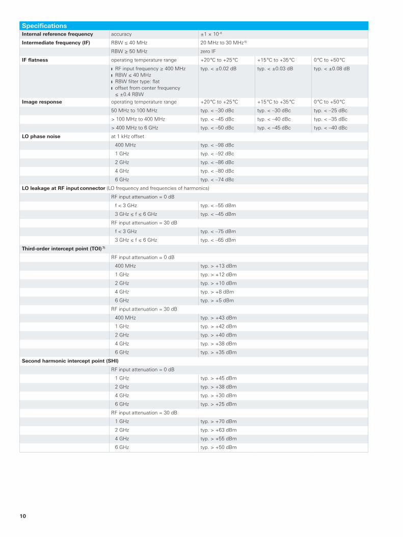
SpecificationsInternal reference frequency accuracy ±1 × 10⁻⁶
Intermediate frequency (IF) RBW ≤ 40 MHz 20 MHz to 30 MHz 6)
RBW ≥ 50 MHz zero IF
IF flatness operating temperature range +20 °C to +25 °C +15 °C to +35 °C 0 °C to +50 °C
RF input frequency ≥ 400 MHz RBW ≤ 40 MHz RBW filter type: flat offset from center frequency ≤ ±0.4 RBW
typ. < ±0.02 dB typ. < ±0.03 dB typ. < ±0.08 dB
Image response operating temperature range +20 °C to +25 °C +15 °C to +35 °C 0 °C to +50 °C
50 MHz to 100 MHz typ. < –30 dBc typ. < –30 dBc typ. < –25 dBc
> 100 MHz to 400 MHz typ. < –45 dBc typ. < –40 dBc typ. < –35 dBc
> 400 MHz to 6 GHz typ. < –50 dBc typ. < –45 dBc typ. < –40 dBc
LO phase noise at 1 kHz offset
400 MHz typ. < –98 dBc
1 GHz typ. < –92 dBc
2 GHz typ. < –86 dBc
4 GHz typ. < –80 dBc
6 GHz typ. < –74 dBc
LO leakage at RF input connector (LO frequency and frequencies of harmonics)
RF input attenuation = 0 dB
f < 3 GHz typ. < –55 dBm
3 GHz ≤ f ≤ 6 GHz typ. < –45 dBm
RF input attenuation = 30 dB
f < 3 GHz typ. < –75 dBm
3 GHz ≤ f ≤ 6 GHz typ. < –65 dBm
Third-order intercept point (TOI) 7)
RF input attenuation = 0 dB
400 MHz typ. > +13 dBm
1 GHz typ. > +12 dBm
2 GHz typ. > +10 dBm
4 GHz typ. > +8 dBm
6 GHz typ. > +5 dBm
RF input attenuation = 30 dB
400 MHz typ. > +43 dBm
1 GHz typ. > +42 dBm
2 GHz typ. > +40 dBm
4 GHz typ. > +38 dBm
6 GHz typ. > +35 dBm
Second harmonic intercept point (SHI)
RF input attenuation = 0 dB
1 GHz typ. > +45 dBm
2 GHz typ. > +38 dBm
4 GHz typ. > +30 dBm
6 GHz typ. > +25 dBm
RF input attenuation = 30 dB
1 GHz typ. > +70 dBm
2 GHz typ. > +63 dBm
4 GHz typ. > +55 dBm
6 GHz typ. > +50 dBm
NRQ6_bro_en_3607-1888-12_v0201.indd 10 08.05.2018 13:41:47
-70
-60
-50
-40
-30
-20
-10
0-50 -40 -30 -20 -10 0 10 20
Mea
sure
d AC
LR in
dBc
Average power level in dBm
RF input aenuator = 0 dBRF input aenuator = 30 dB
Rohde & Schwarz R&S®NRQ6 Frequency Selective Power Sensor 11
Other characteristicsMeasurand power of incident wave
power of source (DUT) into 50 Ω
RF input connector N (male)
Measurement functions continuous average trace adjacent channel leakage ratio (ACLR) I/Q trace
Continuous average function measurand average power over acquisition interval
aperture 8.3 ns to 30 s (depending on RBW)
duty cycle correction 8) 0.001 % to 100.0 %
capacity of measurement buffer 9) 1 reading to 8192 readings
Trace function measurand average power over pixel(s)
acquisition
length 8.3 ns to 30 s (depending on RBW)
start (referenced to delayed trigger) –15.0 s to +15.0 s (depending on RBW)
result
number of pixels 1 to 8192
resolution ≥ 8.3 ns (sample period depending on RBW)
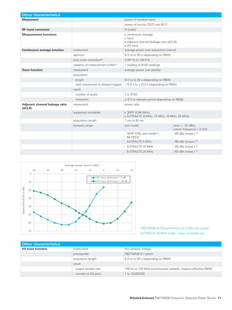
Adjacent channel leakage ratio (ACLR)
measurand power ratio
supported standards 3GPP (3.84 MHz) EUTRA/LTE (5 MHz, 10 MHz, 15 MHz, 20 MHz)
acquisition length 1 ms to 40 ms
dynamic range test model level = –20 dBm, carrier frequency = 2 GHz
3GPP FDD, test model 1, 64 DPCH
–69 dBc (meas.) 10)
EUTRA/LTE 5 MHz –68 dBc (meas.) 10)
EUTRA/LTE 10 MHz –65 dBc (meas.) 10)
EUTRA/LTE 20 MHz –63 dBc (meas.) 10)
Other characteristicsI/Q trace function measurand I/Q complex voltage
prerequisite R&S®NRQ6-K1 option
acquisition length 8.3 ns to 30 s (depending on RBW)
result
output sample rate 100 Hz to 120 MHz (continuously variable, impacts effective RBW)
number of I/Q pairs 1 to 15 000 000
R&S®NRQ6 ALCR performance at 2 GHz over power;
EUTRA/LTE 20 MHz (meas., noise correction on).
NRQ6_bro_en_3607-1888-12_v0201.indd 11 08.05.2018 13:41:47
12
Other characteristicsTriggering supported measurement functions continuous average, trace, I/Q trace
source INTernal: internal test signal EXTernal2: coaxial trigger I/O (SMA (f) jack) EXTernal[1]: host interface trigger signal (8-pin male M12 connector) BUS: remote control event (*trg)
dropout 0 s to 10 s (depending on RBW)
slope (external, internal) positive/negative
delay –5 s to +10 s 11) (depending on RBW)
hold-off 0 s to 10 s (depending on RBW)
resolution (delay, hold-off, dropout) ≥ 8.3 ns (depending on RBW)
INTernal trigger threshold level
range –110 dBm to +20 dBm
accuracy identical to uncertainty for absolute power measurements
hysteresis 0 dB to 10 dB
trigger jitter internal trigger: ≥ 8.3 ns (depending on RBW) external trigger: 8.3 ns
Averaging filter parameters
supported measurement functions continuous average, trace
averaging count 1 to 65 536
result output
moving mode continuous result output, independent of averaging count
repeat mode final result only
RF input attenuation correction function corrects the measurement result using a fixed factor (dB offset)
range –200 dB to +200 dB
Host interface (8-pin male M12 connector) USB interface to PC via R&S®NRP-ZKU interface cable (requires additional PoE+ power supply at LAN interface) USB interface to PC via R&S®NRP-ZK6 interface cable + R&S®NRP-Z5 USB sensor hub (requires additional PoE+ power supply at LAN interface)
mechanical 8-pin male M12 connector (A-coded)
power supply +5 V/0.1 A (USB low-power device; requires additional PoE+ power supply)
speed high-speed and full-speed mode in line with USB specification
remote control protocols USB test and measurement class (USBTMC)
trigger input EXTernal[1] differential (0 V/+3.3 V)
reference clock
signal level LVDS
input frequency 20 MHz
permissible total cable length ≤ 5 m
Ethernet interface (LAN PoE+) mechanical RJ-45 jack
power supply power over Ethernet (PoE+) class 4
speed 10/100/1000 Mbit/s
remote control protocols VXI-11, HiSLIP (high-speed LAN instrument protocol), SCPI-RAW (port 5025)
permissible cable length ≤ 100 m
Trigger 2 I/O (TRIG2) mechanical SMA (f) jack
impedance
input 10 kΩ or 50 Ω (software-controlled)
output 50 Ω
signal level
input compatible with 3 V or 5 V logic, max. –1 V to +6 V
output ≥ 2 V into 50 Ω load, max. 5.3 V
NRQ6_bro_en_3607-1888-12_v0201.indd 12 08.05.2018 13:41:48
Rohde & Schwarz R&S®NRQ6 Frequency Selective Power Sensor 13
Other characteristicsReference I/O (REF) mechanical SMA (f) jack
impedance
input/output 50 Ω
signal level
input ≥ –10 dBm
output ≥ +7 dBm
frequency
input 10 MHz to 60 MHz (10 MHz steps)
output 10 MHz
Clock I/O (CLK) mechanical SMA (f) jack
impedance
input/output 50 Ω
signal level
output ≥ –10 dBm
frequency
output 119 MHz to 121 MHz
Local oscillator I/O (LO) mechanical SMA (f) jack
impedance
input/output 50 Ω
signal level
input ≥ –5 dBm
output ≥ 0 dBm
frequency
input/output 70 MHz to 6.03 GHz
NRQ6_bro_en_3607-1888-12_v0201.indd 13 08.05.2018 13:41:48
14
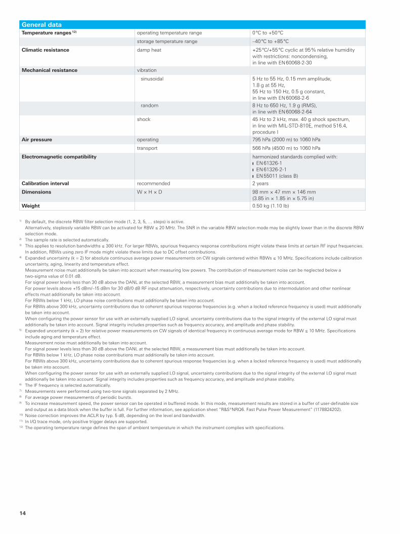
General dataTemperature ranges 12) operating temperature range 0 °C to +50 °C
storage temperature range –40 °C to +85 °C
Climatic resistance damp heat +25 °C/+55 °C cyclic at 95 % relative humidity with restrictions: noncondensing, in line with EN 60068-2-30
Mechanical resistance vibration
sinusoidal 5 Hz to 55 Hz, 0.15 mm amplitude, 1.8 g at 55 Hz, 55 Hz to 150 Hz, 0.5 g constant, in line with EN 60068-2-6
random 8 Hz to 650 Hz, 1.9 g (RMS), in line with EN 60068-2-64
shock 45 Hz to 2 kHz, max. 40 g shock spectrum, in line with MIL-STD-810E, method 516.4, procedure I
Air pressure operating 795 hPa (2000 m) to 1060 hPa
transport 566 hPa (4500 m) to 1060 hPa
Electromagnetic compatibility harmonized standards complied with: EN 61326-1 EN 61326-2-1 EN 55011 (class B)
Calibration interval recommended 2 years
Dimensions W × H × D 98 mm × 47 mm × 146 mm(3.85 in × 1.85 in × 5.75 in)
Weight 0.50 kg (1.10 lb)
1) By default, the discrete RBW filter selection mode (1, 2, 3, 5, … steps) is active. Alternatively, steplessly variable RBW can be activated for RBW ≤ 20 MHz. The SNR in the variable RBW selection mode may be slightly lower than in the discrete RBW selection mode.
2) The sample rate is selected automatically.3) This applies to resolution bandwidths ≤ 300 kHz. For larger RBWs, spurious frequency response contributions might violate these limits at certain RF input frequencies.
In addition, RBWs using zero IF mode might violate these limits due to DC offset contributions.4) Expanded uncertainty (k = 2) for absolute continuous average power measurements on CW signals centered within RBWs ≤ 10 MHz. Specifications include calibration
uncertainty, aging, linearity and temperature effect. Measurement noise must additionally be taken into account when measuring low powers. The contribution of measurement noise can be neglected below a
two- sigma value of 0.01 dB. For signal power levels less than 30 dB above the DANL at the selected RBW, a measurement bias must additionally be taken into account. For power levels above +15 dBm/–15 dBm for 30 dB/0 dB RF input attenuation, respectively, uncertainty contributions due to intermodulation and other nonlinear
effects must additionally be taken into account. For RBWs below 1 kHz, LO phase noise contributions must additionally be taken into account. For RBWs above 300 kHz, uncertainty contributions due to coherent spurious response frequencies (e.g. when a locked reference frequency is used) must additionally
be taken into account. When configuring the power sensor for use with an externally supplied LO signal, uncertainty contributions due to the signal integrity of the external LO signal must
additionally be taken into account. Signal integrity includes properties such as frequency accuracy, and amplitude and phase stability.5) Expanded uncertainty (k = 2) for relative power measurements on CW signals of identical frequency in continuous average mode for RBW ≤ 10 MHz. Specifications
include aging and temperature effect. Measurement noise must additionally be taken into account. For signal power levels less than 30 dB above the DANL at the selected RBW, a measurement bias must additionally be taken into account. For RBWs below 1 kHz, LO phase noise contributions must additionally be taken into account. For RBWs above 300 kHz, uncertainty contributions due to coherent spurious response frequencies (e.g. when a locked reference frequency is used) must additionally
be taken into account. When configuring the power sensor for use with an externally supplied LO signal, uncertainty contributions due to the signal integrity of the external LO signal must
additionally be taken into account. Signal integrity includes properties such as frequency accuracy, and amplitude and phase stability.6) The IF frequency is selected automatically.7) Measurements were performed using two-tone signals separated by 2 MHz.8) For average power measurements of periodic bursts.9) To increase measurement speed, the power sensor can be operated in buffered mode. In this mode, measurement results are stored in a buffer of user-definable size
and output as a data block when the buffer is full. For further information, see application sheet “R&S®NRQ6. Fast Pulse Power Measurement” (1178824202). 10) Noise correction improves the ACLR by typ. 5 dB, depending on the level and bandwidth.11) In I/Q trace mode, only positive trigger delays are supported.12) The operating temperature range defines the span of ambient temperature in which the instrument complies with specifications.
NRQ6_bro_en_3607-1888-12_v0201.indd 14 08.05.2018 13:41:48
Rohde & Schwarz R&S®NRQ6 Frequency Selective Power Sensor 15
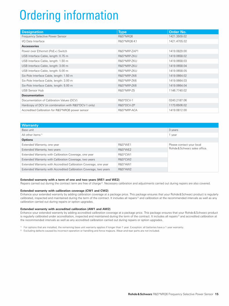
Ordering informationDesignation Type Order No.Frequency Selective Power Sensor R&S®NRQ6 1421.3509.02
I/Q Data Interface R&S®NRQ6-K1 1421.4705.02
Accessories
Power over Ethernet (PoE+) Switch R&S®NRP-ZAP1 1419.0829.00
USB Interface Cable, length: 0.75 m R&S®NRP-ZKU 1419.0658.02
USB Interface Cable, length: 1.50 m R&S®NRP-ZKU 1419.0658.03
USB Interface Cable, length: 3.00 m R&S®NRP-ZKU 1419.0658.04
USB Interface Cable, length: 5.00 m R&S®NRP-ZKU 1419.0658.05
Six-Pole Interface Cable, length: 1.50 m R&S®NRP-ZK6 1419.0664.02
Six-Pole Interface Cable, length: 3.00 m R&S®NRP-ZK6 1419.0664.03
Six-Pole Interface Cable, length: 5.00 m R&S®NRP-ZK6 1419.0664.04
USB Sensor Hub R&S®NRP-Z5 1146.7740.02
Documentation
Documentation of Calibration Values (DCV) R&S®DCV-1 0240.2187.06
Hardcopy of DCV (in combination with R&S®DCV-1 only) R&S®DCV-ZP 1173.6506.02
Accredited Calibration for R&S®NRQ6 power sensor R&S®NRP-ACA 1419.0812.00
WarrantyBase unit 3 years
All other items 1) 1 year
Options
Extended Warranty, one year R&S®WE1 Please contact your local Rohde & Schwarz sales office.Extended Warranty, two years R&S®WE2
Extended Warranty with Calibration Coverage, one year R&S®CW1
Extended Warranty with Calibration Coverage, two years R&S®CW2
Extended Warranty with Accredited Calibration Coverage, one year R&S®AW1
Extended Warranty with Accredited Calibration Coverage, two years R&S®AW2
Extended warranty with a term of one and two years (WE1 and WE2)Repairs carried out during the contract term are free of charge 2). Necessary calibration and adjustments carried out during repairs are also covered.
Extended warranty with calibration coverage (CW1 and CW2) Enhance your extended warranty by adding calibration coverage at a package price. This package ensures that your Rohde & Schwarz product is regularly calibrated, inspected and maintained during the term of the contract. It includes all repairs 2) and calibration at the recommended intervals as well as any calibration carried out during repairs or option upgrades.
Extended warranty with accredited calibration (AW1 and AW2) Enhance your extended warranty by adding accredited calibration coverage at a package price. This package ensures that your Rohde & Schwarz product is regularly calibrated under accreditation, inspected and maintained during the term of the contract. It includes all repairs 2) and accredited calibration at the recommended intervals as well as any accredited calibration carried out during repairs or option upgrades.
1) For options that are installed, the remaining base unit warranty applies if longer than 1 year. Exception: all batteries have a 1 year warranty.2) Excluding defects caused by incorrect operation or handling and force majeure. Wear-and-tear parts are not included.
NRQ6_bro_en_3607-1888-12_v0201.indd 15 08.05.2018 13:41:48
R&S® is a registered trademark of Rohde & Schwarz GmbH & Co. KG
Trade names are trademarks of the owners
PD 3607.1888.12 | Version 02.01 | May 2018 (sk)
R&S®NRQ6 Frequency Selective Power Sensor
Data without tolerance limits is not binding | Subject to change
© 2017 - 2018 Rohde & Schwarz GmbH & Co. KG | 81671 Munich, Germany
Service that adds value Worldwide Local and personalized Customized and flexible Uncompromising quality Long-term dependability
3607
.188
8.12
02.
01 P
DP
1 e
n
Rohde & SchwarzThe Rohde & Schwarz electronics group offers innovative solutions in the following business fields: test and mea-surement, broadcast and media, secure communications, cybersecurity, monitoring and network testing. Founded more than 80 years ago, the independent company which is headquartered in Munich, Germany, has an extensive sales and service network with locations in more than 70 countries.
Sustainable product design Environmental compatibility and eco-footprint Energy efficiency and low emissions Longevity and optimized total cost of ownership
Certified Environmental Management
ISO 14001Certified Quality Management
ISO 9001
Regional contact Europe, Africa, Middle East | +49 89 4129 12345 [email protected]
North America | 1 888 TEST RSA (1 888 837 87 72) [email protected]
Latin America | +1 410 910 79 88 [email protected]
Asia Pacific | +65 65 13 04 88 [email protected]
China | +86 800 810 82 28 | +86 400 650 58 96 [email protected]
Rohde & Schwarz GmbH & Co. KGwww.rohde-schwarz.com
Rohde & Schwarz trainingwww.training.rohde-schwarz.com
3607188812
NRQ6_bro_en_3607-1888-12_v0201.indd 16 08.05.2018 13:41:48