Embed Size (px)
Citation preview

- ..
DTICSLECTEU
MA 0 .W8
* Ocean Engineering~ '3fWSA,-PEAKI DIVISION
L.~~.j NAA FACILITIES ENGTNTLNRI;, WIJItWA.SHI M'TUN NAVY YARDI
--~~~~) 2~~rc7V~ F 0 j 7 4
IX :
Z2 07-

UnclassifiedSECURITY CLASSIFICATION OF THIS PAGE
RWPORT DOCUMNTATION PACEla. REPORT SECURITY CLASSIFICATION lb. RESTRICTIVE MARKINGSUnclassified
2a. SECURITY CLASSIFICATION AUTHORITY 3. DISTRIBUTION AVAILABILITY OF REP.Approved for public release;distribution is unlimited
2b. DECLASSIFICATION/DOWNGRADING SCHEDULE %
4. PERFORMING ORGANIZATION REPORT NUMBER 5. MONITORING ORGANIZATION REPORT # >FPO-1-84(1)
6a. NAME OF PERFORM. ORG. 6b. OFFICE SYM 7a. NAME OF MONITORING ORGANIZATIONOcean Engineering Nh.& ConstructionProject OfficeCHESNAVFACENGCOM
6c. ADDRESS (City, State, and Zip Code) 7b. ADDRESS (City, State, and Zip )BLDG. 212. Washington Navy YardWashington, D.C. 20374-21218a. NAME OF FUNDING ORG. 8b. OFFICE SYM 9. PROCUREMENT INSTRUMENT INDENT .
8c. ADDRESS (City. State & Zip) 10. SOURCE OF FUNDING NUMBERSPROGRAM PROJECT TASK WORK UNITELEMENT # # # ACCESS # B
I. TITLE (Including Security Classification)Project Execution Plan for the Installation of Two FORACS Targets at AUTEC andOne FORACS Target and One SSRNM Array at St. Croix UPR12. PERSONAL AUTHOR(S)
13a. TYPE OF REPORT 13b. TIME COVERED 14. DATE OF REP. (YYMMDD) 15. PAGESFROM TO 84-03 52
16. SUPPLEMENTARY NOTATION
17. COSATI CODES 18. SUBJECT TERMS (Continue on reverse if nec.)FIELD GROUP SUB-GROUP Arrays. Atlantic Undersea Test & Evaluation. _________Center. FORACS. St. Croix. Ranges
19. ABSTRACT (Continue on reverse if necessary & identify by block number)Naval Ocean Systems Center, (NOSd) has tasked Chesapeake Division. NavalFacilities Engineering Command,1 (CHESNAVFACENGCOM),with the installation oftwo FORACS (Fleet Operational Readiness Accuracy Check Site) Targets at theAtlantic Underwater Testing and Evaluation Center (AUTEC). & one FORACS-(Con't) 7Z,20. DISTRIBUTION/AVAILABILITY OF ABSTRACT 21. ABSTRACT SECURITY CLASSIFICATION "
SAME AS RPT.22a. NAME OF RESPONSIBLE INDIVIDUAL 22b. TELEPHONE 22c. OFFICE SYMBOLJacqueline B. Riley 202-433-3881DD FORM 1473. 84MAR SECURITY CLASSIFICATION OF THIS PAGE
. .,. .-

BLOCK 19 (Con't)/
.,,Target and one SSRNM (Surface Ship Radiated Noise Measurement~ rray at the St.Croix Underwater Tracking Range (UTR). The construction willb performedwith the Ocean Construction Platform BEACON and Underwater Construction TeamOne (UCT-1). . ..
IPOP
*%. Wi

- -~ PROJECT EXECUTION PLAN
FO TEINTLLT0NOTWO FRACSTARGES ATAUTE
*AND
PROJCT EECETIONPLA
AAND
T TERI T
Enclosure (1)
DT%S2 7DQ Am 1

.... % ... *J
TABLE OF CONTENTS .*-"
Paragraph Title Pace1.0 GENERAL 11.1 Background 11.2 Organizational Responsibilities 11.2.1 CHESNAVFACENGCOM 11.2.2 NOSC 11.2.3 Applied Physics Laboratory 21.2.4 UCT-1 21.2.5 AUTEC 21.2.6 St. Croix UTR 31.3 On Site Navigation 31.4 Weather Planning/Predictions 31.5 Project Schedule 4
2.0 MOBILIZATION 5
_ 3.0 OPERATIONS PLAN FOR AUTEC 73.1 Construction Operations 73.1.1 Site Preparation 7
S 3.1.1.1 Pre-arrival Preparation 73.1.1.2 Post-arrival Preparation 113.1.2 FORACS Target Installation 113.1.3 Cable Laying 123.1.4 Cable Shore Landing 123.2 Shallow Water Target Installation 143.3 Demobilization 14
4.0 TRANSITION TO ST. CROIX OPERATIONS 15
5.0 OPERATIONS PLAN FOR ST. CROIX 155.1 Construction Operations 155.1.1 Site Preparation is5.1.2 SSRNM Array Installation 175.1.2.1 Cable Shore Landing 175.1.2.2 Cable Laying 195.1.2.3 SSRNM Array Deployment 215.1.3 FORACS Target Installation 285.1.3.1 Site Preparation 285.1.3.2 Cable Laying 295.1.3.3 Cable Shore Landing 29 -5.1.3.4 Second FORACS Target Installation 30
6.0 DEMOBILIZATION 30
7.0 PROJECT DOCUMENTATION 30
Appendix A Navigation Operations and Transponder A-1
Locations
. Appendix B List of Equipment B-1

LIST OF FIGURES
Figure Title Egj1 SEACON Deck Plan 62 FORACS Target 83 Beach Set-Up 9: ::4 Land Set-Up 10 %10,5 SSRNM Array 166 Shore Set-Up 187 Array Installation Set-Up 20a Triangular Frame and Clump 229 Deployment of Triangular Frame and Clump 23
10 SSRNM Array Detail 24ila Kevlar/Wire Rope Transition 26llb Sub-Surface Buoy Preparation 26llc Deployment of Sub-Surface Buoy 27lld Wire Rope Cut-off 27
A-1 Site Plan for AUTEC Installations A-15A-2 Site Plan for St. Croix Installations A-16
Accesiori For
NTIS CRA&jDTIC TABUflaLnoinced
JUStificito'i
By.r.. Dist ibutionl
Availability Codes
Dist Avai Wdlor
A-Iia
*.. ... - * . ... ~ *.'~*% *...

1.0 GENERAL
1.1 Background
Naval Ocean Systems Center. (NOSC) has tasked ChesapeakeDivision. Naval Facilities Engineering Command. (CHESNAVFAC- -
ENGCOM) with the installation of two FORACS (Fleet OperationalReadiness Accuracy Check Site) Targets at the AtlanticUnderwater Testing and Evaluation Center (AUTEC). and oneFORACS Target and one SSRNM (Surface Ship Radiated NoiseMeasurement) Array at the St. Croix Underwater Tracking Range(UTR). The construction will be performed with the OceanConstruction Platform SEACON and Underwater Construction TeamOne (UCT-I).
1.2 Organizational Responsibilities
The following is a list of the major contributors toproject execution. Additional details as necessary may befound in the body of this Plan.
1.2.1 CHESNAVFACENGCOM
CHESNAVFACENGCOM will:
a. prepare a Project Execution Plan.g b. coordinate project execution with NOSC, AUTEC.
Atlantic Fleet Weapons Training Facility (AFWTF). St.Croix UTRo UCT-l. and APL.
c. provide SEACON and crew.d. provide winches and additional cable laying equipment.
- e. provide on site technical supervision and fieldengineering support.
f. provide project logistics including messing andberthing for all on-site project personnel.
g. set up and operate Mini-Ranger at AUTEC and St. CroixUTR.
h. provide all radios required for projectL.. communications.
i. provide hardware for attaching cables to existingstrain relief devices.
J. arrange for pier space at Roosevelt Roads. PR andFredriksted. St. Croix. USVI.
k. document construction operations.1. prepare a Project Completion Report and as-built
drawings.
1.2.2 NOSC
NOSC will be responsible to:
Sa. provide project funding.
.." . • . .

b. provide general coordination among CHESNAVFACENGCOM.AFWTF. AUTEC. St. Croix UTP. and APL.
c. provide cable. hydrophones and structures for SSRNMarray.
d. provide electronic specialists for SSRNM installation.e. assemble SSRNM junction boxes.f. provide all SSRNM electronic testing equipment.g. test SSRNM hydrophones and cable.
1.2.3 Applied Physics Laboratory
* APL will be responsible to: 4-
a. provide electronic specialists for FORACS target* installations.
b. assemble FORACS structures.-.- c. assemble FORACS junction boxes."- d. provide FORACS testing equipment.
e. test FORACS hydrophones and cable.f. supply final approval for FORACS target locations.
1.2.4 Underwater Construction Team One
UCT-1 will be responsible to:
a. provide Petty Officer in Charge (POIC) and personnelto perform in water/underwater construction tasks.
b. provide diving gear and small craft.c. provide for all diving safety including medical
evacuation and use of a recompression chamber.d. provide personnel for SEACON deck force.e. provide personnel for shore end operations.f. furnish input to operation tasks.
*-.. g. arrange for rough terrain forklift for shore landingat St. Croix.
1.2.5 AUTEC
AUTEC will be responsible to:
a. provide divers to locate and mark shallow water. FORACS site.
b. provide divers to locate and mark cable anchor.c. provide divers to locate and mark near shore location
for SEACON.d. mark centerline of reef for Mike boat path.e. clear cable trench.f. provide batteries for Mini-Ranger transponders.g. provide on site logistics.h. provide on site transportation of equipment and
L personnel.
2

.-', ..
i. provide work boat.j. provide range tracking as backup for Mini-Ranger.k. provide radios for communication between SEACON and
range.1. provide rough terrain forklift and bulldozer for
shore landing at AUTEC. '
1.2.6 St. Croix UTR
St. Croix UTR will be responsible to:
a. provide on site transportation of equipment andpersonnel.
b. provide on site logistics.c. provide range tracking as backup for Mini-Ranger.d. provide radios for communication between SEACON and OAK.
range.
1.3 On Site Navigation
The primary navigation system will be the MotorolaMini-Ranger system on board SEACON. System transponders willbe placed at selected shore sites for the cable installation.Appendix A details specific information regarding the system'soperation, specific site data and secondary back up navigationrequirements .
1.4 Weather Planning/Predictions
By consulting the SSMO's for the operation regions, the* following weather conditions should be expected:
AUTEC: Clear, visibility at least 10 NM. easterly to- southeasterly winds of approximately 10 knots throughout the
day, temperature of 750 F. 80% relative humidity. seas 1-2feet.
* St. Croix: Clear, visibility-at least 10 NM. easterlywinds of approximately 12 knots throughout the day, temperatureof 760 F. 75% relative humidity, seas 2-4 feet.
Additional daily weather forecasts will be obtained onboard SEACON as an aid to final planning and operations.
3
. . .. . .-. . ... ** . . .. . . . . .. . ,. . . .. • . .. .. .... . . . . ' '

1.5 Project Schedule
Date Action6 - 8 Fabruary Mobilize SEACON at CHESDIVSUPPFAC. St.
Juliens Creek. Portsmouth. VA.9 February Self-transit St. Juliens Creek to NAB
Little Creek. Norfolk. VA. UCT-1.10 - 12 February Mobilize SEACON for OP-TOW.13 - 18 February Transit Little Creek to Port Everglades.
FL.. under tow by USS PAPAGO. ATF-160.
18 Feb. - 30 March Mobilize SEACON at Port Everglades. FL.31 March - 1 April Self-transit Port Everglades. FL. to
AUTEC. Andros Island. Bahamas.2 - 3 April On site mobilization4 - 5 April Install FORACS Targets6 April On site demobilization7 April Weather contingency
8 - 15 April Transit to Fredriksted. St. Croix. USVIvia NAVSTA Roosevelt Roads. PR. undertow by USS PAIUTE. ATF-159.
. 16 - 17 April On site mobilization'- 18 April Install FORACS Target .-
19 April Install SSRNM Array20 April On site demobilization21 April Weather contingency22 - 28 April Transit to Port Everglades. FL via
Roosevelt Roads. PR. under tow by USSPAIUTE. ATF-159.
28 April - 3 May Demobilize SEACON at Port Everglades. FL
4....
%' .*
. .o- . .. . . . . . . .

2.0 MOBILIZATION
Equipment from the Ocean Construction Equipment Inventory(OCEI) will be loaded onboard the SEACON at St. Juliens CreekAnnex. Naval Amphibious Base. Portsmouth. VA. This equipmentwill include a Pengo winch, an l8k Skagit winch, a powered reelstand with power pack. spare Pengo reels, and sheaves, line.floats. etc.. needed to complete the assigned mission. A Pengoreel loaded with the FORACS cable for AUTEC operations willalso be loaded at St. Juliens Creek. A complete equipment listaccompanies this Plan as Appendix B. Tie down operations willbe under CHESNAVFACENGCOM supervision.
The platform will be rigged for tow in accordance withCHESNAVFACENGCOMINST 5321.1A. The Commanding Officer of theassigned tow vessel will inspect and approve all towing gear. :deck rigging, and loading prior to accepting the OCP SEACON fortow.
The OCP SEACON will be towed to Port Everglades. FL forprepositioning for the project. Final mobilization will takeplace at Tracor Marine. Inc.. Port Everglades. This activitywill include:
a. Receiving and onloading the SSRNM shore cable intothe OCP SEACON cable tank.
b. Receiving and onloading the SSRNM array.c. Receiving and onloading UCT-1 equipment (See
equipment list in Appendix B).d. Receiving FORACS targets.e. Providing staging area for assembly and test of
FORACS targets by Applied Physics Laboratory (APL)personnel.
f. Onloading FORACS targets.g. Connecting the FORACS cable to the transducer through
the junction chamber/strain relief assembly, testingthe assembly, and connecting the assembly to thetarc -. frame, for the first FORACS targetinstallation.
h. Completing OCP SEACON dack set-up for nperation (SeeDeck Plan. figure (1)).
CHESNAVFACENGCOM will arrange shipment of the Mini-Rangertransponders to AUTEC. These will be set-up byCHESNAVFACENGCOM prior to the arrival of the OCP SEACON atAUTEC.
,U .-.
5 "-°
2.'2 ""'""

* a - - ---- - - - - - - - - - - - - - - ..-
- I' --- wrF
-p -I--..-.- ,. --- .-. il
"A:'
I . - .
aE O Deck Pl1.igre(1

'° 3.0 OPERATIONS PLAN FOR AUTEC
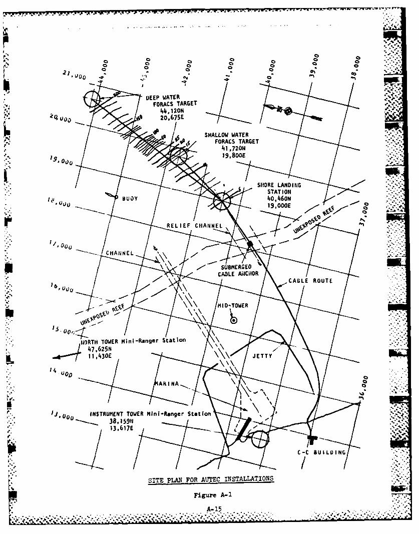
*This section describes the installation of two FORACSTargets at AUTEC. The proposed installation locations are -
detailed in Appendix A. The site plan is shown in thatappendix as figure (A-1).
3.1 Construction Operations
FORACS targets are installed by an ocean to shoretechnique. The target is lowered to the seafloor by thetransmission cable. Upon placement of the structure on thebottom, a cable laying procedure is executed. A FORACS targetis shown in figure (2). Two targets will be installed atAUTEC. Their intended implantation coordinates, and cable
VA- tracks are given in Appendix A. The installation scenario is -Cdetailed below.
3.1.1 Site Preparation
Site preparation will begin prior to the arrival of SEACONat AUTEC. The activity responsible for each step of this
. - set-up is specified below as appropriate.
3.1.1.1 Pre-arrival Preparation
Prior to the arrival of SEACON at AUTEC. AUTEC divers will- locate and mark by float the predetermined position of the
shallow water implant site. They will also mark the reefentrance point, the location of the cable anchor inside the
-. reef cut and the path the Mike boat will take while hauling thecable. (The deep water implant site will be located by
-- Mini-Ranger; see section 3.1.2).
AUTEC personnel will uncover the existing cable trench, andprepare a trench through the beach. These features aredetailed in figures (3) and (4). Further reference to thesefigures will be made in the body of this plan.
-- CHESNAVFACENGCOM personnel will set up the Mini-Ranger*transponders with support from AUTEC personnel. (These• * transponders had been shipped in advance to AUTEC: see section
2.0.) The selected sites are detailed in Appendix A.
UCT-1 personnel will rig the inflatable orange and Jim Buoyy floats for deployment during the landing operations.
7

E-ORACS Target
.%- *.~'Figure (2) N

SHORE-~~ LINEI~u
FOR LINE
CABLE~
WIT ROUGCHE TERRAINFO LLOZK LIFTH
HEVE
CABLE

311 311 12" 611
1 3/4"
TO BEACH
0
CABLE
CABLE IN
TRENCH SECTION AAil
EXISTING TRENCH
155' NEWTRENCHSECT ION
COILED EXCESSCABLE
COM4MAND CONTROL BUILDING
Land Set-Up Figure (4

3.1.1.2 Post-arrival Preparation
SEACON will self-transit to AUTEC. At first light on 2April 1984 (scheduled) she will be met by an AUTEC supplied __Mike boat at the sea buoy. The boat will bring radios out toSEACON for ship to shore communication during operations.
The Skagit winch, beach sheaves and other required beachequipment will be transferred from the SEACON to the Mike Boatusing the SEACON's crane. The equipment will be transferredfrom the Mike boat to a truck at the marina pier using a smallcrane. (As previously noted. all material handling equipmentwill be AUTEC supplied). The gear will be transferred to thebeach site by truck.
UCT-1 and AUTEC personnel will position the rough terrainforklift and a bulldozer and beach sheaves on the beach forhauling the cable ashore. This beach set-up is shown in figure(3). They will also rig 100 feet of line from the forklift andthrough the beach sheaves. UCT-1 and AUTEC personnel willposition the Skagit winch near the Command Control (CC)building as shown in figure (4). securing it to nearby treestumps. UCT-1 will mount several sheaves on the trees alongthe cable trench path.
CHESNAVFACENGCOM and the deck force will check out theMini-Ranger system, the Pengo winch and other on-boardequipment to assure operational status. The reel holding theAUTEC FORACS cable will be loaded on the Pengo winch by thedeck force. The deck force will hang a 42 inch diameter sheavefrom the padeye to the starboard of the ladder on the SEACONA-frame.
3.1.2 FORACS Target Installation
The FORACS cable for the first of the two AUTECinstallations will have been connected to the transducerthrough the junction chamber/strain relief assembly, and testedduring pre-departure mobilization at Ft. Lauderdale. asdescribed in section 2.0. In the event this connection was notmade prior to departure, the procedure described in section 3.2for the second FORACS installation should be followed.
Using the Liebherr crane, the deck force will lift thestructure by the bail and place it on the stern near thecenterline of the A-frame.
SEACON will steam to the deep water implant site and keep
station at that location. .
p... .,
11"-" "

The Pengo winch will be used to overboard the structure.The equipm,-nt operator must maintain a smooth increase in winchpull to avoid snap loading in the cable. Tag lines will behandled by the deck force to assure control of the structure asit lifts off the deck and through the A-frame. Oncestabilized, the structure will be lowered into the water andthe tag lines slipped off the structure.
Lowering the structure will continue until it is on thebottom. The observed tension should drop by 2200 pounds whenthis occurs. This tension drop is significant in all FORACSinstallation sequences.
APL will again test the system before cable layingoperations begin.
3.1.3 Cable Laying
The cable will be laid along a predetermined track at alaying speed of 0.75 knots (76 ft/min). The track lines aregiven in Appendix A.
3.1.4 Cable Shore Landing
SEACON will continue to lay cable until she is just outside
of the relief channel, in about thirty feet of water at thespot marked by the AUTEC divers. Holding this position.additional cable will be paid out until it is vertical in thewater. The Master will turn the SEACON 90 degrees, with thecable to the stern and off to one side. SEACON will stationkeep as the shore landing proceeds. The Mike boat will meetthe SEACON at this point.
A deckhand will stop off the cable at the stern to avoiduncontrolled running. APL personnel will again test the systemto assure proper operation before landing the cable. The deckforce will fake out 8500 feet of cable from the reel onto thedeck. This length will assure adequate cable is available tocomplete the connection at the CC building.
A deckhand will cut the cable with a carbide blade hacksawsupplied by APL, seal the cut end to prevent moisture intrusionand secure a PLP stopper to the shore end. A deckhand willslip the cable from the sheave on the A-frame. The deck forcewill stage 277 floats on the deck. These floats are of twotypes. The 128 Jim Buoy floats will be deployed first.followed by 149 inflatable orange float balloons. Using thisnumber of floats will utilize approximately 25 percent of thebuoyant capacity of the floats. In this way, should one ormore floats free themselves during deployment, a domino effectwill not sink the cable prematurely.
12 ie
. ,, _ _ _' " " . - , .*** "*'*' . ,. ' • '.'' '' * _c .

Deckhands will transfer the bitter end of the cable fromthe SEACON to the Mike boat. and secure the cable, via PLP 'stopper, to the boat with about 30 feet of line.
The Mike boat operator will then slowly proceed toward thebeach through the reef cut. (The cut had been previouslymarked by AUTEC divers). As the cable leaves the SEACON,deckhands will tie the floats using 4 foot lengths of 21
'• thread. The Jim Buoys will be tied every 30 feet and theballoon floats every 50 feet.
The Mike boat will continue hauling the cable shorewarduntil its draft precludes further advance. At this point aUCT-1 diver will swim the hauling line (previously rigged tothe forklift and through the sheaves on the bulldozer ; seesection 3.1.1.2) out to the Mike boat, and secure it to the PLPstopper on the cable. Once secured, the line stopping thecable to the Mike boat can be cut.
The forklift operator will begin hauling the remainingcable off the deck of SEACON. As floats reach the beach theshore party will remove them from the cable.
One unobstructed run should be sufficient to haul all the .-
. cable onto the beach. If the forklift reaches the limit of itsunobstructed haul-in run, the shore party will secure the cableto the bulldozer with a rope stopper. The forklift will returnto the bulldozer to pull the next bight of cable. To preventexceeding the cable's bending radius, two rope stoppers willsecure the cable to the forklift. If the cable length exceedsthe straight run length, the cable will be carefully faked outonto the beach at the location of the cable trench. Figure (4)shows the site plan.
When all the cable on the SEACON's deck has been hauled. onshore, the bulldozer with attached sheaves will be
repositioned at the cable trench. (The Skagit winch andsheaves had been previously placed at the CC building and along
. the trench path: see section 3.1.1.2). The shore party willsecure the winch hauling line to the cable end PLP stopper.The winch operator will use the gypsy head to haul the cabletoward the CC building. When the cable end reaches the winch,the hauling line will be pulled back along the cable for 400
* feet and resecured to the cable using a rope stopper. In this* manner the remaining cable will be hauled in along the trench~~path. ,-
The shore party will manually place the cable into the. existing trench. The cable remaining at the trench end will be
coiled and left for final testing by APL and eventualconnection to Control building electronics.
13
.• ... .... .... ........ .. . . . ..- .- ,..........-......................-........... . . **.. .,-- . . . - .-

UCT-1 divers will attach a PLP stopper to the cable in thevicinity of the underwater cable anchor previously marked andthen release the floats in the area. The cable will bemanhandled into position at this anchor and secured by PLPstopper and shackles. UCT-1 swimmers will then begin releasing . _floats. to be recovered by UCT-1 personnel in a ZODIACinflatable boat. Floats will be removed from the shoreoutward.
When the cable is completely submerged, divers will swimthe cable to assure it does not lie on any coral heads and thatno kinks exist.
3.2 Shallow Water Target Installation
The installation of the shallow water FORACS target will besimilar to that of the deep water target. The target sites andcable track are detailed in Appendix A. Differences betweenthis implant and the previous operation are described below.All other details remain unchanged.
The deck force will pull the bitter end of the FORACS cableoff the Pengo winch, reeve it through the sheave on theA-frame, and haul it back to the electronic work shop. There.APL personnel will connect the cable to the transducer throughthe junction chamber/strain relief assembly. They will testthe system, then attach the assembly to the target frame. Thisprocedure is similar to that which will be completed prior todeparture from Ft. Lauderdale for the first installation.
All beach equipment will be returned to the position itoccupied prior to the first cable landing.
The shallow water implant site is closer to the reef cut.and requires considerably less cable laying. The cable will belaid along a predetermined track at a laying speed of 1.5 knots(152 ft/min).
All other operational details remain unchanged.
3.3 Demobilization
Equipment and personnel will be returned to SEACON at thecompletion of the second target installation. AUTEC suppliedequipment will be returned to the responsible parties. Alldeck equipment will be rigged for the tow to St. Croix. viaNAVSTA Roosevelt Roads. PR, for the second phase of theoperation.
.-.. ..
S. . -' -
q-l %'
-1-4-
...........................- ..-.'."." .:--.".... .'.-.-*.';.. ...--.---,'-.-....'. '.-'. .-. ,.. ,,'..'',.. --.:.':.

4.0 TRANSITION TO ST. CROIX OPERATIONS
The SEACON will be towed by the USS PAIUTE. ATF-159. fromAUTEC to St. Croix via NAVSTA Roosevelt Roads.
At NAVSTA Roosevelt Roads additional equipment for the St.Croix phase will be onloaded. The 15.000 pound mooring clumpfor the SSRNM array. the FORACS cable and a NAVSTA RooseveltRoads supplied rough terrain forklift will be staged on deck inspace previously occupied by hardware installed at AUTEC. Theadded equipment will be rigged for tow to Fredriksted. St.Croix. USVI.
5.0 OPERATIONS PLAN FOR ST. CROIX
This section covers the installation of one SSRNM Array andone FORACS Target at the St. Croix Underwater Tracking Range.The proposed installation locations. station marks, track line :"°:and shore landing coordinates are detailed in Appendix A. Thesite plan is given in that Appendix as figure (A-2).
5.1 Construction Operations
The SSRNM array will be installed in a shore to seaconfiguration. From a position offshore the shore cable isbeached, followed by a seawarZ cable laying procedure. Thearray is then lowered at a predetermined location and depth.The SSRNM array is illustrated in figure (5). The site planand pertinent position coordinates are given in Appendix A.The installation scenario is detailed below in section 5.1.2.
Additionally, a FORACS target will be installed at St.Croix. The site plan, cable track and implant coordinates aregiven in Appendix A. The installation scenario is detailedbelow in section 5.1.3.
5.1.1 Site Preparation
Upon arrival at Fredriksted. St. Croix. USVI. the SEACONwill tie up at Fredriksted Pier. Pier space for the durationof construction operations has been prearranged with theappropriate command. A two day mobilization period has beenscheduled. The activity responsible for each step of thisset-up is detailed below.
CHESNAVFACENGCOM will install the Mini-Ranger transpondersat the locations detailed in Appendix A. CHESNAVFACENGCOM will .-. -also check out the Mini-Ranger hardware onboard SEACON. Thedeck force will check out the deck mounted equipment.
15-. . "
i .~
iJ, . • ° % .:P-1 °• ° " -o - .. * *- ** , . . ... . . . .- •°°- o ° • .

SUBSURFACE BUOY..
A HYDROPHONE 1130 ft (709 m)
HVDROPHONE #3
A "DRo'-4Dmr 94
JUNCTION BOXES SHORE CABLE
TERIIATION DEVICE
MOORING CLUMP
SSRNM Array
Figure(5
16
I%.

• , ,. " . o ."
The deck force will offload the Skagit winch, forklift.beach sheaves, polypropylene hauling line. screw anchors andother required hardware at Fredriksted Pier into a truck fortransit to the St. Croix UTR range station.
After offloading the shore based equipment, the deck forcewill prepare 80 float balloons for deployment during theinstallation. These floats had been rigged, deployed andrecovered during the AUTEC phase of the mission. Anyre-rigging required should be completed prior to beginning theinstallation.
The deck force will then complete deck preparation. Asecond sheave will be hung from the A-frame. to the port sideof the sheave previously installed. The Pengo reel holding the5/8 inch wire rope overlaid with the Kevlar strength member forthe SSRNM array will be mounted on the Pengo winch. Thepowered reel stand holding the pre-bundled hydrophone cableswill have been prepositioned during pre-operation mobilization;see section 2.0. ..
The shore party will prepare the beach landing site andcable hauling route as detailed in figure (6). The roughterrain forklift will be the primary hauling equipment. TheSkagit winch, not shown in figure (6). will be secured withscrew anchors near the position shown for the forklift in thefigure. but such that it does not interfere with the forklift
hauling route, as a backup to the forklift. The sheaves.secured to an existing beach deadman and concrete embeddedposts, act as fairleads for the cable haul from the beach. Thepolypropylene hauling line will be secured to the forklift. " "reeved through the sheaves and staged at the beach landing site.
5.1.2 SSRNM Array Installation
The SSRNM array installation will proceed in three phases:cable shore landing, cable laying and array deployment.
5.1.2.1 Cable Shore Landing
The deck force will deploy station keeping floats at twopoints in the vicinity of the location from which the SSRNMcable will be landed. This position is given in Appendix B.
Deckhands will attach a PLP stopper to the cable end. Thisend will be hauled from the cable tank, through the Pengo winchand over the stern roller. A hand will attach a swivel to thePLP stopper with a shackle.
UCT-1 personnel will overboard a ZODIAC and transit to thebeach landing site. They will return to SEACON pulling the ..
17.

RUHTERRAIN
FORK LIFT t
TRANSPONDER LOCAT IONA "SPRAT"
IESUPPORTIVA14SROT
TERM4 IVATNON
NOT SHEAVEAV/SRE
EXISTIG DEADEN/ UMER CABLES
~SHEAVE/STRAP
DEADMA14
TO SEACO4 SAN4DY BEACH
Shore Set-Up, Figure(6
18
. .... . ................ ...

hauling line with them. A deckhand will receive the line fromthe ZODIAC and secure it to the cable end stopper.
When the ready signal is received by the forklift operitor.(radios will be used to keep the shore party and the deck torce nowapprised of each other's status). he will begin hauling in thecable. Two deckhands will walk the cable out of the cable tankas it is drawn toward the beach. Deckhands will tie floats tothe cable at twenty foot intervals as it reaches the stern •
As the cable arrives on the beach the shore party willrelease the floats from the cable to allow it to pass throughthe beach sheaves.
When the forklift reaches the end of its unobstructed haul-in route, the shore party will signal the deck force of thepause in cable payout. The cable (or hauling line asappropriate) will be secured by rope stopper at the concretepad while the forklift returns to its origin to continue thehaul-in. When ready to haul in. the SEACON deckforce will be
"* signaled to again walk cable out of the cable hold.
When the cable has been hauled across the beach, up theslope, over the concrete pad and about 250 feet across thegrassy area serving as the forklift hauling route, the haul-in
"' procedure is complete. The deckforce will be signaled thatsufficient cable is onshore.
The shore party will attach a PLP stopper to the cable atthe location of the existing beach deadman. The stopper willbe shackled to the deadman.
UCT-I swimmers will release the floats from the shore out.for recovery with a ZODIAC.
5.1.2.2 Cable Laying
The cable will be laid seaward along a predetermined trackat a laying speed of 1.5 knots (152 ft/min). The track linesand other necessary information are given in Appendix B. Cablelaying will continue until a position 2500 feet up the track ofthe proposed final sensor location is reached. Cable payoutwill continue at this position until coming to the finaltermination. Deckhands will stop off the cable about 30 feetforward of the termination using both a sling to a deck padeyeand a working line to an auxiliary deck winch. The winchoperator will let out the working line until the load is takenby the sling. The cable end can then be brought out of thetank and removed from the Pengo winch bullwheels. Figure (7)illustrates this interim configuration as well as there(7following preparatory steps in the operation.
19
-7 ...
. . . ..

A-FRAM ~ WIT ,.
KEVLAR STRENGTHMEMBER WITH BUNDLED HYDROPHONE
STOPS AT 20 FT SIGNAL CABLESA- FRAME INTERVALS
SHEAVE FORBUNDLED CABLES POWERED .. ,.
" ! REEL STAND , ,
SHEAVE FORKEVLAR -., PENGO WITH
KL. SLING FRAME/CLUMP KEVLAR/ J"'--ASSEMBLY W/,.-.
-- C -O DEYE ".LN'NCABLES CONNECTEDCABLE TO~FO TESTING -'- -
SHORE A DECKi WORKING WINCH"" '-
FAKED OUT SHORE CABLE
PLAN VIEW SHOWING CA3LES ATTACHED FOR TESTING
ELEVATION SHOWING SHORE CABLE AROUND A-FRAME
BUNDLED HYDROPHONE SIGNAL CABLES
SH AVES --..---,"-
KEVLAR STRENGTH MEMBER NEW
TO PENGOSLING PADEYE .,TO POWERED REEL
ASSEMBLY ,..,
~~WORKING SEACON " ''..-....-TO AUX. WINCH " .'
STOPPER FAKED OUT SHORE LINE :i'
CABLE - I '
Array Installation Set-Up
Figure (7)
20 -'

5.1.2.3 SSRNM Array Deployment
The deck force will pass the Kevlar strength member fromthe Pengo reel through the sheave nearest the centerline of theA-frame. They will pass the p :e-bundled hydrophone signalcables from the powered reel stand through the second A-framesheave.
The deck force will attach a shackle between the triangularframe and the mooring clump, and shackle the Kevlar to thetriangular frame. These connections are detailed in figure
,+..+ (8)..> ,
NOSC personnel will attach the shore cable to the strainrelief on the frame, secure the junction boxes to the frame.and connect the shore cable pigtails and hydrophone signalcables to their respective mates. These connections will becarefully checked by NOSC personnel to assure each is properlycompleted before proceeding. NOSC personnel will then test thesystem. The deck force will bind the first 10 feet of bundledcables to the Kevlar line with nylon cable.ties.
The auxiliary winch operator will pull the stopper onto thedeck, relieving the load in the sling. A deckhand will removethe sling.
The deckforce will rig a working line from the Liebherrcrane, walk the frame/clump assembly aft and stage it at theSEACON stern under the A-frame. The Pengo winch operator willhaul in the Kevlar line to remove the slack in the line andtake up the frame/clump load. A deckhand will disconnect theworking line to the Liebherr crane.
The Pengo winch operator will continue to draw in theKevlar line until the frame/clump assembly lifts off the deckand hangs under the A-frame. Deckhands will handle tag linesto assure control of the assembly as it lifts off the deck.The auxiliary winch operator will lower the PLP stopper on theshore cable until that load is also taken by the Kevlarstrength member and the Pengo winch. A deckhand will cut theworking line to the stopper.The Pengo winch operator will beginlowering the array.
As the cable bundle is lowered, the deckforce will bind itto the Kevlar strength member at intervals of S to 10 feet. asshown in figures (9) and (10), taking care to place no strainon the sensor cables. While lowering the array. SEACON willproceed toward the final implant site. Forward progress alongthe track must correspond foot for foot to the length of Kevlarpaid out, so that the clump will touch down at the implant site.
21

TRIANGULAR -. HYDROPHONE
FRAME ..- SIGNAL
JUNCTION CABLESvBOXES (2)
SECTION A-A
SHORE CABLE
KEVLR -~ PIGTAILS
STRENGTH--MEMBER
HY OROPHONE
JUCTONSHORE CABLE !cl
TERMIATIOO
J ~ LPIGTAILS
SHORE CABLE
CLUMP
SEAFLOOR
Triangular Frame and Clump
Figure ().%
U 22

-- . - -- *77- T- T-..7.7. -
TO SHEAVES (2)
LIEBHERR
HYDROPHONE SIGNAL CABLES
KEVLARWORKING . STRENGTH
LINE MEMBER TO POWER REEL
TO PENGOBROW
S EAC ON
TRRIANGLAR FRAMEAND CLUMP
Deploym~ent of Triangular Frame and Clump
Figure (9)
23

TO LN* ~SWIVEL '4
AND BUOY
'-KEVLAR
STRENGTH NYLON CABLE
MEMBER TIESTOPPER
(EVERY 20 FT),bIkI
HYDROPHONESON MOUNTS
HY DRO0PH ONE S
ON MOUNTS
CONNECTORS(TO JUNCTION
BOXES)
SSRNt4 Array Detail
Figure (10) TINUA
FRAME
24

The hydrophone positions in the array will be clearlyindicated by the sensor cable terminal connectors for eachrespective instrument. As each such position is encountered.the Pengo winch operator will stop lowering while the deck --
force secures the hydrophone and hanger assembly to theKevlar. NOSC personnel will complete the sensor cableconnections and test each instrument before proceeding withlowering the array.
Approximately 500 feet of 5/8 inch wire rope underlays andis attached to the Kevlar strength member on the Pengo reel.When that junction passes through the sheave. a deckhand willstop off about 20 feet of the Kevlar to a deck padeye. ThePengo operator will gently ease down the array slowly reducingthe tension in the wire rope. This procedure is illustrated infigure (l-a).
A deckhand will disconnect the wire rope from the Kevlar.The Pengo winch operator will then back the wire rope out ofthe sheave, leaving enough wire rope on the deck to prepare the
* sub-surface buoy assembly.
Figure (11-b) illustrates the sub-surface buoypreparation. Deckhands will attach a swivel to the assembly'sbottom padeye and secure the Kevlar strength member to theswivel. They will shackle the wire rope to the top padeye ofthe assembly and then secure a working line to that shackle.They then will attach a hydraulic cable cutter and a pneumatichose with depth gauge to the wire rope at the shackle, bothwith 200 feet of hose. The cable cutter will allow remote
-. cutting of the wire rope, without sending divers to the designdepth of 100 to 115 feet. The pneumatic hose will allow remotedepth readings to verify the proper deployment depth has beenachieved.
The Liebherr crane operator will gently lift the assemblyby the working line as deckhands monitor the lift to assure nodamage is done to the buoy assembly. When the load in thestopper holding the Kevlar is relieved, a deckhand will releasethat stopper. The Liebherr crane operator will then lower theassembly until signaled by a monitor that the buoy is about 5feet below the surface. This deployment sequence isillustrated in figure (11-c). The Pengo winch operator willthen transfer the load onto the wire rope by hauling in anyexisting slack. A deckhand will cut the working line to theLiebherr crane, and the Pengo winch operator will continuelowering the array. When the clump rests on the bottom thetensiometer will indicate the large drop in tension in the wirerope.
25

TRANSITION---
STOPS @ KEVLAR STRAP TO PENGO20 FT INTERVALS PDY
TO ARRAY
Keviar/Wire Rope Transition Figure (11a)
TO LIEBIIERR
-WORKING LINE
SUB-SURFACE BUOY
WIRE ROPE TO PENGO
- TO VARRA
Sub-Surface Buoy Preparation Figure (11b)
26

TO LIESHERR
TO PENGO
CAPPROX)5 FT
SUB-SURFACE BUOY
Deployment of Sub-surface BUOY
Figure (1ic)
TO ARRAY
CUT POINT TO PENGO
TO ARRAY ANDSUB-SURFACE
BUOY
W'ire Rope Cut-off Figure (1id)
27
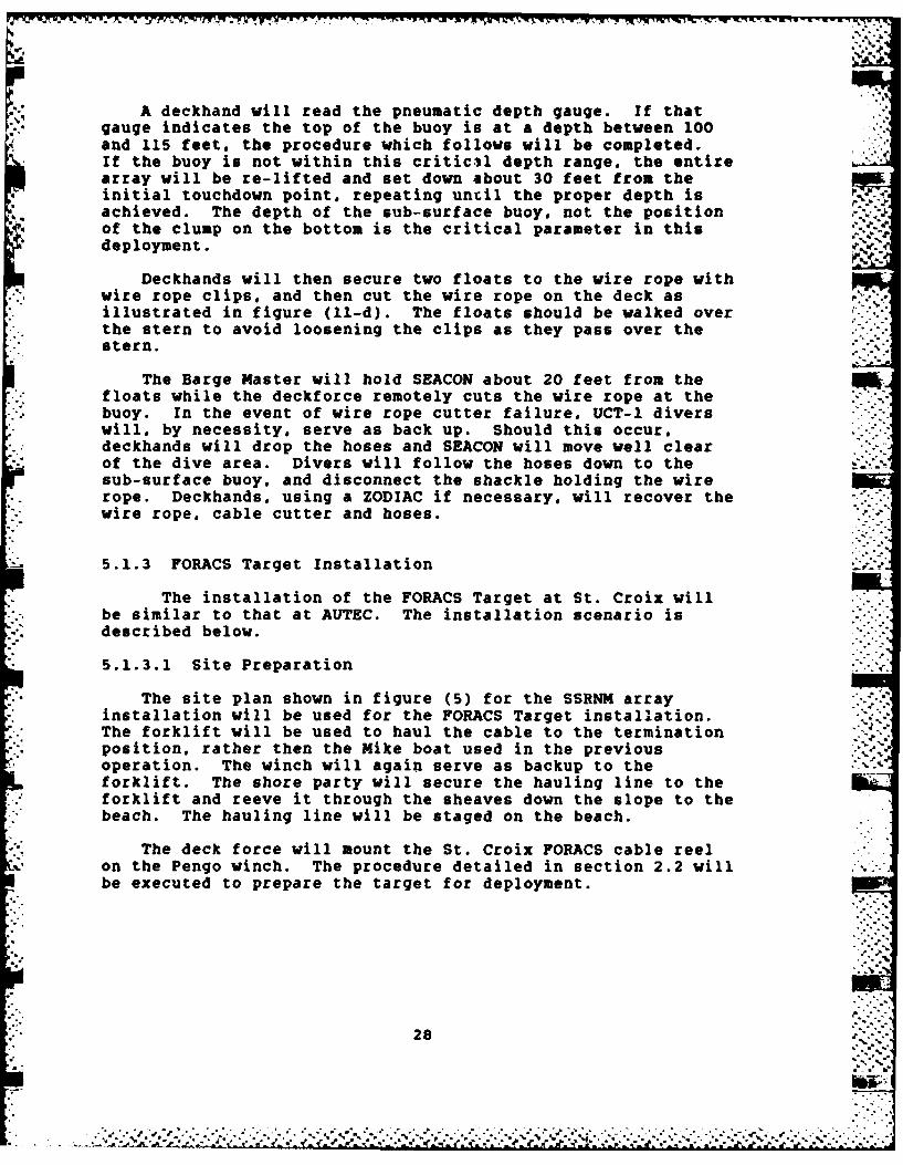
A deckhand will read the pneumatic depth gauge. If thatgauge indicates the top of the buoy is at a depth between 100and 115 feet. the procedure which follows will be completed.If the buoy is not within this critic3l depth range, the entirearray will be re-lifted and set down about 30 feet from theinitial touchdown point, repeating uncil the proper depth isachieved. The depth of the sub-surface buoy, not the position -'a..
* of the clump on the bottom is the critical parameter in thisdeployment..,, .
Deckhands will then secure two floats to the wire rope withwire rope clips, and then cut the wire rope on the deck asillustrated in figure (ll-d). The floats should be walked over
.* the stern to avoid loosening the clips as they pass over theSstern.
The Barge Master will hold SEACON about 20 feet from the-' floats while the deckforce remotely cuts the wire rope at the
buoy. In the event of wire rope cutter failure. UCT-1 diverswill. by necessity, serve as back up. Should this occur.deckhands will drop the hoses and SEACON will move well clearof the dive area. Divers will follow the hoses down to thesub-surface buoy. and disconnect the shackle holding the wirerope. Deckhands. using a ZODIAC if necessary, will recover thewire rope. cable cutter and hoses.
5.1.3 FORACS Target Installation
The installation of the FORACS Target at St. Croix willbe similar to that at AUTEC. The installation scenario isdescribed below.
5.1.3.1 Site Preparation
The site plan shown in figure (5) for the SSRNM arrayinstallation will be used for the FORACS Target installation.The forklift will be used to haul the cable to the terminationposition, rather then the Mike boat used in the previousoperation. The winch will again serve as backup to theforklift. The shore party will secure the hauling line to theforklift and reeve it through the sheaves down the slope to thebeach. The hauling line will be staged on the beach.
The deck force will mount the St. Croix FORACS cable reelon the Pengo winch. The procedure detailed in section 2.2 willbe executed to prepare the target for deployment.
28
a - -.::.::-

5.1.3.2 Cable Laying
After target deployment the cable will be laid along apredetermined track at a laying speed of 1.5 knots (1F2ft/min). The track lines are given in Appendix B. Cablelaying will continue until SEACON reaches a 30 foot waterdepth, approximately 1700 feet offshore.
5.1.3.3 Cable Shore Landing
Holding position in 30 feet of water, additional cable willbe paid out until it is vertical in the water. The BargeMaster will turn SEACON 90 degrees with the cable to the sternand to one side. SEACON will keep station as the shore landingproceeds.
A deckhand will stop off the cable at the stern to avoiduncontrolled running. APL personnel will test the systembefore landing the cable. The deck force will fake out 2000feet of cable from the reel onto the deck. This length willassure adequate cable is available to complete the connectionat the junction box. A deckhand will cut the cable with acarbide blade hacksaw supplied by APL, seal the cut end toprevent moisture intrusion and secure a PLP stopper to theshore end. A deckhand will slip the cable from the sheave onthe A-frame. The deckforce will stage 100 Jim Buoy floats onthe deck, re-rigging as necessary.
Using a ZODIAC. UCT-l personnel will bring the hauling linefrom the beach out to the SEACON. Deckhands will secure theline to the PLP stopper at the end of the cable. The forkliftoperator will be signaled to begin hauling cable toward thebeach. Deckhands will tie floats to the cable at 20 footintervals as it reaches the SEACON stern.
The forklift operator will continue the haul-in along the .-
route shown in figure (5). As cable reaches the beach, theshore party will release the floats.
When all the cable faked out on SEACON's deck has beenhauled shoreward. the deck monitor will signal the forkliftoperator to cease hauling. The shore party will attach a PLPstopper to the cable at the position of the existing beachdeadman. The stopper will be shackled to the deadman.
APL personnel will again test the system before the cableis sunk in place. Swimmers will release floats from the shoreout for recovery by ZODIAC. The cable will be connected at theFORACS Target junction box by St. Croix UTR personnel.
29
- . * .. .. . .

a- T- 'V "V ~-? . .-
5.1.3.4 Second FORACS Target Installation 2..-
L An additional FORACS Target, to be placed in shallow water.--
and sufficient cable to complete its installation will beonboard SEACON. Should the built-in contingency days leavesufficient time before the scheduled tow, this second FORACSTarget will be installed at St. Croix. The installationscenario will be identical to that for the FORACS Target -installation detailed above. Target position, track lines.etc. have been included in Appendix B for this secondinstallation.
* 6.0 DEMOBILIZATION
Upon completion of the FORACS Target installation, thebeach equipment will be returned to SEACON and rigged for tow.The SEACON will be towed to NAVSTA Roosevelt Roads for thereturn of borrowed equipment. The tow will continue to PortEverglades, FL, where demobilization will be completed.
7.0 PROJECT DOCUMENTATIONA completion report documenting the entire construction
operation will be completed by CHESNAVFACENGCOM and forwardedto all concerned commands within 90 days of demobilization.
30
. .. . . . . . .. . . . . - .. . .................................................... . . -.. :

.., .. .
I I I
APPENDIX A
NAVIGATION OPERATIONSAND
TRANSPONDER LOCATIONS
.,. .,4:
44
-.-.
&- 1 - '-"."
A- '11I I
* .. *,,.:,
.-.- -:. . ... .: : ,,-.,..-.'.-,'. '.'.'. : .. ,... , ., . *.-,.. , ,.. . ,.,. . ,,. . . . . . , .. . -.- . . .

NAVIGATION OPERATIONS
The Boat Positioning System (BPS) is designed to determineaccurately the position of a boat, ship, or any other mobilefloating unit. This position is determined by obtaining rangesfrom two transponder reference stations located at known, fixedpoints ashore. The BPS consists of a ranging system, amini-computer processor, various displays, a magnetic cartridgetape recorder, an X-Y plotter, and interconnecting cables. Theranging system used is a Motorola MRS III (Mini-Ranger)consisting of a shipboard receiver-transmitter assembly withspace diversity antennas, a range console, and two or moreshore-based transponders with individual antennas. It has an . ..accuracy of + 3 meters at up to a line of sight range of 40 NM.
The Motorola Data Processor provides the mathematicalcomputation and the data input/output controls. The processor
* accepts the operator inputs via the keyboard, a TexasInstruments TI-743 KRS Data Terminal, or Tektronic 4025 DataTerminal, and the dual ranges from the Mini-Ranger and converts
*. these into an X-Y coordinate system; it computes the deviationfrom an operator-defined track line. The data can be recordedand/or displayed on a variety of peripherals.
The Mini-Ranger displays the ranges (constantly updated)from the ship to the two shore-based transponders. The dataprocessor displays the system status via eight mnemonicallylabeled lights. Either Range-Range. X and Y. or the distancealong the track line and offset from one track line aredisplayed on the Data Terminal.
The BPS will be used as the primary navigation system forpositioning the SEACON during installations and for navigationalong the selected cable laying tracks. Range theodolite andacoustic tracking will backup the BPS. within limitations asrequired.
The Mini-Ranger shore stations, and FORACS Target and SSRNMArray implant site coordinates are given on the following pages.
The tables and charts which follow these data detail thecable laying tracks, ship speeds, and payout rates for each ofthe installations to be executed during this mission.
-.% " -.
A-2
??..',-:.
S...... .......... ..--.. :, .. ..... ,... .:... .. ,..,/.... ... ..... ,....,.. . :... •,.-...

-~~~~~~~W -- W- .' . -- - -- --
TABLE A-i AUTEC MINI-RANGER TRANSPONDER LOCATIONSAND FORACS TARGET IMPLANT COORDINAZ'ES
AUTEC TRANSPONDER LOCATIONS
Location Coordinates
North Tower 47625 N11430 E
Instrument Tower 38159 N13617 E
AUTEC DEEP WATER FORACS TARGET
Implant Site 44120 N20675 E
Shore Landing station 40460 NL19000 E
AUTEC SHALLOW WATER FORACS TARGET
Implant Site 41720 N19800 E
Shore Landing Station 40460 N19000 E
A- 3

TABLE A-2 ST. CROIX TRANSPONDER LOCATIONSSSRNM ARRAY AND FORACS TARGET IMPLANT COORDINATES
ST. CROIX TRANSPONDER LOCATIONS
Location UTR UTM PRD
Sandy Point 59272.9 X 1955343.62 N 17040'46.757" N15130.4 Y 298412.91 E 64054b00.959- W
" Sprat 61997.9 X 1962263.27 N 17044132.105"- N37859.1 Y 299312.80 E 64053132.789" W
UTR: Underwater Tracking Range Coordinate System (To be used)UTM: Universal Transverse Mercator
* PRD: Puerto Rican Datum
ST. CROIX SSRNM ARRAY
Location Coordinates
Implant Site 52986 X35029 Y
Holding Point 54692 X35390 Y
Turning Point 55450 X35550 Y
Landing Point 60400 X36975 Y
ST. CROIX DEEP WATER FORACS TARGET
Implant site 58302 X28774 Y
Landing point 60400 X36975 Y
ST. CROIX SHALLOW WATER FORACS TARGET
Implant site 60334 X ...-'-
34225 Y
Landing point 60400 X36975 Y
A-4
. ... .

' IUHESAPEAKE DIVISION PROJECT: AUTEC & ST. CROIX OPS
Naval Facilities Engineering Command NOW Station: _________________DISCIPLINE ____ _____ E S R: Contract: ___________
Caics made by: __ _______date: Calculations for: _______________Calcs ck'd by: date:______________ _________
AUTEC DEEP WATER FORACS TARGET
VESSEL HYDRO TOUCH DOWN BOTTOM PAYOUT CABLESPEED CONST ALPHA TRACK I Y SLOPE SLACK RATE OUTKTS DEGREE-KT RADIAN FT FT FT RADIAN % FT/MIN FT
DUMP 1920 FEET 200 200 1210 19200.75 63.1 1.47 500 365 1159 -0.31 5 61.27 21620.75 63.1 1.47 1000 893 990 -0.33 5 59.99 25560.75 63.1 1.47 1250 1155 960 -0.42 5 55.50 273B0.75 63.1 1.47 1500 1420 675 -0.61 5 46.19 29900.75 63.1 1.47 1750 1698 505 -0.57 5 48.23 30490.75 63.1 1.47 2000 1947 200 -0.97 5 35.02 31640.75 63.1 1.47 2250 2235 130 -0.24 5 64.97 33780.75 63.1 1.41 2500 2498 90 -0.20 5 67.46 36000.75 63.1 1.47 3000 2990 60 -0.04 5 77.11 41070.75 63.1 1.47 3500 3490 50 -0.02 5 79.44 46230.75 63.1 1.47 4000 3995 35 -0.03 5 77.79 5135DUMP 6650 FEET 11785
TABLE A-3 CABLE PAYOUT RATES
page -..... of
A- 5

CHESPEAK DIVSION PROJECT: AUTEC & ST. CROIX OPS-
Naval Faci~ties Engineering Command NOW Station:_________________DISCIPLINE E S A. - ContractCaics made by: __________ ste: - Calculations for:_______________
* Calcs ck'd by.: date: - ______________________
AUTEC DEEP MATER FORMCS TARSET
VESSEL HYDRD TOUC DMW BOTTON PAYOUT CAKE
SREED CONST ALPHA TRACK I Y SLOPE SLACK RATE OUT
KTS DE6REE-KT RADIAN FT FT FT RADIAN 2 FT/KIN FT
DUMNP 1920 FEET 200 200 1210 1920
0.75 63.1 1.47 500 365 1158 -0.31 10 65.07 2177
0.75 63.1 1.47 1000 993 980 -0.33 10 63.69 2596
0.75 63.1 1.47 1250 1155 860 -0.42 10 59.30 2791We
0.75 63.1 1.47 1500 1420 675 -0.61 10 49.99 29530.75 63.1 1.47 1750 1689 505 -0.57 10 52.03 3127
0.75 63.1 1.47 200 1947 200 -0.97 10 39.92 3254
0.75 63.1 1.47 2250 2235 130 -0.24 10 69.77 3480
0.75 63.1 1.47 2500 2489 00 -0.20 10 71.26 3715
0.75 63.1 1.47 3000 2990 40 -0.04 10 90.91 4247
0.75 63.1 1.47 3500 3490 30 -0.02 10 92.24 4789
0.75 63.1 1.47 4000 3995 35 -0.03 10 91.59 5325
DUNP 6650 FEET 11975
TABLE A-3 CABLE PAYOUT RATES
page - of -
A-6 -

CHESAPEAKE DIVISION PROJECT: AUTEC & ST. CROIX OPSNaval Facilities Engineering Command NOW Station:________________OICIsmdeh:_______ _lte E S R: ______Contract ___ ___Cac aeb:dt:Calculations for:_______________Caics ck'd by: date: ____ _____________________
AUTEC SHALLON MATER FORACS TARGET
*VESSEL HYDRO TOUCH NOII BOTTON PAYOUT CABLESPEED CUNST ALPHA TRACK I Y SLOPE SLACK RATE OUTKTS DEGREE-KT RADIAN FT FT FT RADIAN I FT/KIN FT
DUMRP 685 FEET 100 100 g0 685. 001 63.1 1.10 400 367 65 -0.06 5 102.16 989.9831 63.1 1.10 50 467 65 0.00 5 106.40 1094.131 63.1 1.10 600 570 60 -0.05 5 103.42 1196.901 63.1 1.10 700 672 57 -0.03 5 104.59 1300.11
1.5 63.1 0.73 1000 943 51 -0.02 5 158.31 1612.571.5 63.1 0.73 1100 1049 47 -0.04 5 157.39 1716.111.5 63.1 0.73 1200 1152 43 -0.04 5 157.36 1919.651.5 63.1 0.73 1300 1256 40 -0.03 5 157.92 1923.541.5 63.1 0.73 1400 1361 36 -0.04 5 157.39 2027.091.5 63.1 0.73 1500 1463 33 -0.03 5 157.09 2130.971.5 63.1 0.73 1563 1527 30 -0.05 5 156.88 2195.9 "~*
DURP 6650 FEET TOTAL CABLE OUT 8l45.9"
TABLE A-3 CABLE PAYOUT RATES
page -of -
A- 7
............................S - *.... .... ...

_ _ _ _ _ _ _ _ _ _ _ _ _ _ _ _ _ _ _ _ _ _ _ _ _ _ _ _ _ _ _ _ _ _;i:7 _ _ _ _ _ _ _ _ _ _ _ _ _ _ _ _ _ _ _ _ _
CHESAPEAKE DIVISION PROJECT: AUTEC & ST CROIX OPS> Naval Facilitis Engineering Command NOW Station:_________________
DISCILINE S R: Contract: -
Caics made by: __ _______date:Cacltosfr _______________
Calcs ck'd by: date: _ _ _ _ _ _ _ _ _ _ _ _ _ _ _ _ _ _ _ _ _
AUTEC SHALLOW MATER FORACS TARGET
VESSEL HYDRO TOUCH DOWN DOTTON PAYOUT CABLESPEED CONST ALPHA TRACK I Y SLOPE SLACK RATE OUT
KTS DE6REE-I(T RADIAN F7 FT FT RADIAN % FT/KIN FT
DUMP 695 FEET 100 100 so 485.001 63.1 1.20 600 57 60 -0.05 10 108.09 1224.901 63.1 1.10 400 467 65 -0.06 10 111.03 1004.31 63.1 1.10 500 470 65 0.00 10 111.49 121.93
1 63.1 1.10 700 672 57 -0.03 10 109.65 1330.111.5 63.1 0.73 1000 943 51 -0.02 10 165.91 1657.571.5 63.1 0.73 1100 1049 47 -0.04 10 164.98 I76.111.5 63.1 0.73 1200 1152 43 -0.04 10 164.96 1974.651.5 63.1 0.73 1300 1256 40 -0.03 10 165.52 199.541.5 63.1 0.73 1400 1361 36 -0.04 10 164.96 2092.091.5 63.1 0.73 1500 1463 3S -0.03 10 165.49 2200.971.5 63.1 0.73 1563 1527 30 -0.05 10 164.49 2269.14
DUKP 6650 FEET TOTAL CABLE OUT 8919.14 -
TABLE A-3 CABLE PAYOUT RATES
page - of -
*PC ast-elk
A- 8

3; CHESAPEAKE DIVISION PROJECT: AUTEC & ST CROIX OPS
Naval Facilliis Engineering Command NOW Station:________________DISCIPLINE E S R: Contract :_Caics made by: d________ ate: Calculations for:_______________Caics ck'd by: date:_____________ _________
ST. CROIX SSRNM ARRAY - CABLE PAYOUT TABLE
VESSEL HYDRO TOUCH DONN BOTTOM PAYOUT CABLESPEED CONST ALPHA TRACK I Y SLOPE SLACK RATE OUT
KTS DEGREE-KT RADIAN FT FT FT RADIAN I FT/MN FT 9W
1.5 65 0.756 150 1470 30 10 2000.001.5 65 0.756 2000 1960 40 0.020 10 169.43 2554.071.5 65 0.756 2500 2410 95 0.100 10 173.34 3124.291.5 b5 0.756 3000 2835 150 0.152 10 176.66 3705.431.5 65 0.756 3500 3075 395 0.796 10 229.12 4455.951.5 65 0.756 4000 3260 680 0.995 10 250.83 5280.961.5 65 0.756 4500 3525 990 0.670 10 215.99 5991.501.5 65 0.756 5000 3860 1015 0.357 10 1".69 6619.741.5 65 0.756 5500 4250 1130 0.297 10 195.69 7229.581.5 65 0.756 6000 4650 1215 0.209 10 190.44 7823.141.5 65 0.756 6500 5015 1340 0.330 10 188.72 8443.971.5 65 0.756 7000 5390 1460 0.310 10 197.29 9060.061.5 65 0.756 7500 5715 1620 0.457 10 198.19 9712.001.5 65 0.756 7900 5990 1725 0.567 10 206.96 10120.49
CABLE DUMnP 1 700FEET 7800 7800 2250 11820.49
TABLE A-3 CABLE PAYOUT RATES
spo~ As A9
A-9

CHESAPEAKE DIVISION PROJECT: AUTEC & ST CROIX OPS
Naval Facilities Engineering Command NOW Station:________________DISCIPLINE E S R: _ ____Contract _______
Caics made by: d________ ate: Calculations for: ______________
Caics ck'd by: dote: ___________________
ST. CROIX SSRN ARRAY - CABLE PAYOUT TABLE
VESSEL MYDRO TOUC O N B0UVTTON PAYOUT CABLE
SPEED COEST ALPHA TRACK I Y SLOPE SLACK RATE OUT
KTS DE6REE-KT RADIAN FT FT FT RADIAN % FT/N FT
1.5 65 0.756 1500 1470 30 5 2000.00
1.5 65 0.756 2000 1960 40 0.020 5 160.83 2529.07
1.5 65 0.756 2500 2410 65 0.100 5 165.74 3074. 20
1.5 65 0.756 300 2835 150 0.152 5 1b9.06 3630.43
1.5 65 0.756 3500 3075 395 0.796 5 220.52 4355.85
1.5 65 0.756 4000 3260 680 0.995 5 243.23 5155.96
1.5 65 0.756 4500 3525 890 0.670 5 208.40 5841.50
1.5 65 0.756 5000 3860 1015 0.357 5 183.08 6443.74
1.5 65 0.756 5500 4250 1130 0.297 5 179.09 7029.58
1.5 65 0.756 6000 4650 1215 0.209 5 172.84 7598.14
1.5 65 0.756 6500 5015 1340 0.330 5 191.12 9193.97
1.5 65 0.756 7000 5390 1460 0.310 5 179.69 9795.09
1.5 65 0.756 7500 5715 1620 0.457 5 190.58 9412.00
1.5 65 0.756 7800 5890 1725 0.567 5 199.36 9905.49
CABLE DURP 1700FEE7 7800 7900 2250 11505.49
TABLE A-3 CABLE PAYOUT RATES
page - of -
OPO assS.S
A-10
.................................................

~: CHESAPEAKE DIVISION PROJECT: AUTEC & ST CROIX OPS
Naval Facilities Engineering Command NOW Station:_________________DISCIPLINE~ ~~ _ _ _ _ _ _ _ _ _ _ ES 1: _ _ __Contract: _ _ _ _ _
Caics made by: Gate: ~~Calculations for:_______________Caics ck'd by: date:_____________ _________
* ST. CROIX DEEP MATER FORACS TARGET
VESSEL HYDRO TOUJCH DOW DOTTON PAYOUT CABLESPEED CONST ALPHA TRACK I y SLOPE SLACK RATE OUT
KTS DESREE-KT RADIAN FT FT FT RADIAN I FT/KIN FT
63.1 200 200 1290 5 1990.001 63.1 1.101 1000 380 1245 -0.192 5 9509 2740.66
1.5 63.1 0.734 2000 650 1220 -0.092 5 154.29 3755.75.r1.5 63.1 0.734 2500 1190 1190 -0.057 5 156.32 4269.99
1.5 63.1 0.734 300 1745 1160 -0.053 5 156.52 4794.81.5 63.1 0.734 3500 2290 1112 -0. 099 5 154.45 5292.971.5 63.1 0.734 4000 2970 1020 -0.155 5 150.30 5799.031.5 63.1 0.734 4500 3500 922 -0.154 5 150.12 6295.161.5 63.1 0.734 500 4120 793 -0.205 5 148.02 6772. 091.5 63.1 0.734 5500 4750 673 -0.189 5 149.95 7262.061.5 63.1 0.734 6000 5430 513 -0.231 5 146.61 7744.341.5 63.1 0.734 6500 609 373 -0.212 5 147.64 0230.011.5 63.1 0.734 7000 6700 273 -0.160 5 150.51 9725.121.5 63.1 0.734 7500 7350 144 -0.196 5 141.53 9213.711.5 63.1 0.734 9000 7990 104 -0.075 5 155.25 9724.421.5 63.1 0.734 9500 8440 74 -0.054 5 156.50 10239.231.5 63.1 0.734 900 9950 44 -0.059 5 156.20 10753.061.5 63.1 0.734 9300 9260 30 -0.045 5 156.99 11062.90
CABLE DUMP 1900 FEET TOTAL 9hiT12862.90
TABLE A-3 CABLE PAYOUT RATES
A-11

CHESAPEAKE DIVISION PROJECT: ATC&S RI P
Naval Facilities Engineering Conmnand NOW Station: _______________
DISCIPLINE E S R: ______Contract ______ -__
Caics made by: _________date: Calculations for:______________Caics ck'd by: date: - _____________________
ST. CROIX DEEP #ATER FORACS TARGET
VESSEL HYDRO) TOUCH DOW BOTTOM PAYOUT CABLESPEED COWS? ALPHA TRACK I Y SLOPE SLACK RATE OUTKT9 DEGREE-KI RADIAN FT F7 FT RADIAN % FT/KIN FT
63.1 200 200 1290 10 1990.001 63.2 1.101 1000 360 1245 -0.192 10 100.13 2780.66
1.5 63.1 0.734 2000 650 1220 -0.092 10 161.89 3845.751.5 63.1 0.734 2500 1180 1190 -0.057 10 163.9 4384.991.5 63.1 0.734 3000 1745 1160 -0.053 10 164.12 4924.8P1.5 63.1 0.734 3500 2280 1112 -0.089 10 162.05 5457.971.5 63.1 0.734 4000 2970 1020 -0.155 10 158.40 5979.031.5 63.1 0.734 4500 3500 922 -0.154 10 158.42 650.161.5 63.1 0.734 5000 4120 793 -0.205 10 155.62 7012.091.5 63.1 0.734 5500 4750 673 -0.180 10 156.55 7527.061.5 63.1 0.734 6000 5430 513 -0.231 10 154.21 9034.341.5 63.1 0.734 6500 6090 373 -0.212 10 155.24 9545.011.3 63.1 0.734 7000 6700 273 -0.160 10 158.11 9065.121.5 63.1 0.734 7500 7350 144 -0.196 10 156.13 9579.711.5 63.1 0.734 9000 7880 104 -0.075 10 162.95 10114.42 -
1.5 63.1 0.734 9500 9440 74 -0.054 10 164.10 10654.231.5 63.1 0.734 9000 9950 44 -0.059 10 163.90 11193.061.5 63.1 0.734 9300 9260 30 -0.045 10 164.59 11517.90
CABLE DUMP 1800 FEET TOTAL OUTI3317.90
TABLE A- 3 CABLE PAYOUT R~ATES
pagel of -
A- 12
CHESAPEAKE DIVISION PROJECT: AUTEC & ST CROIX OPS
Naval Facilities Engineering Command NOW Station: _______________
D ISCIPLINE C S K: Contract: ________
Clcs made by: ___ ______date: Calculations for:_______________Ca Ics ck'd by: dote: ____ _____________________
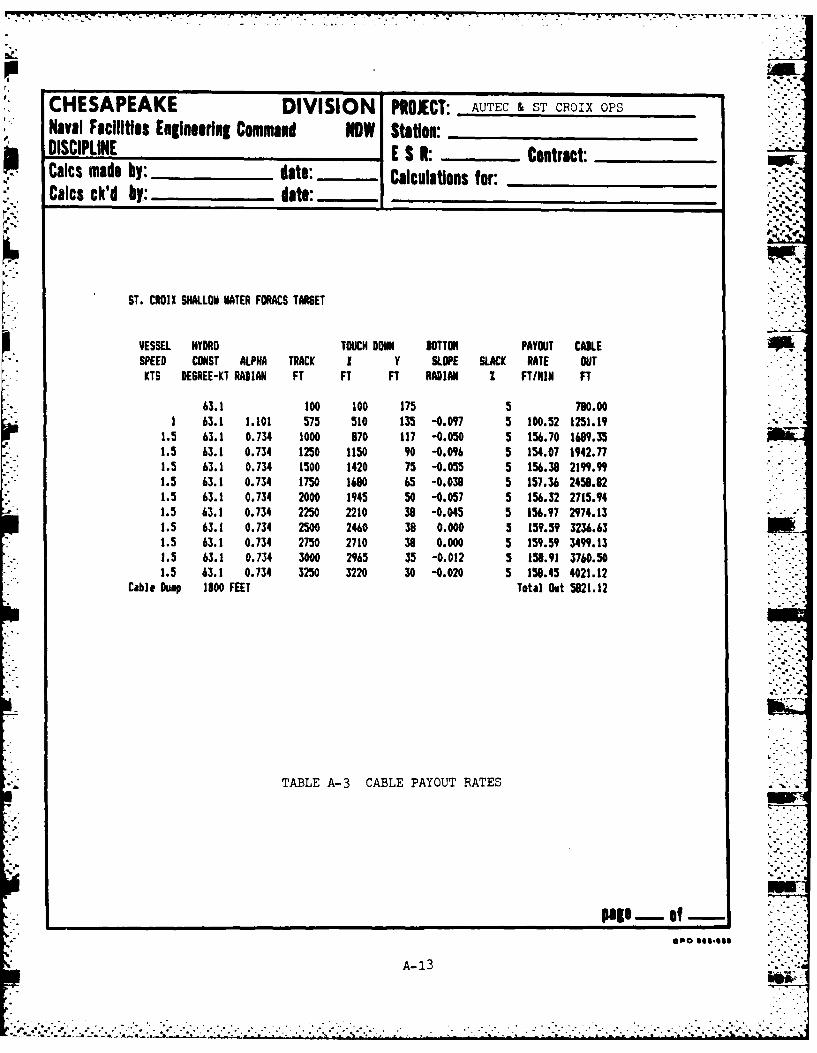
ST. CROIX SHALLOW WATER FOMS TARGET
VESSEL HYDRO TOUC DONN BUTTON PAYOUJT CABLESPEED CONST ALPHA TRACK I y SLOPE SLACK RATE OUT
KTS DESREE-KT RADIAN FT FT FT RADIAN I FT/NIN FT
63.1 100 100 175 5 790.001 63.1 1.101 575 510 135 -0.097 5 10.52 1251.19
1.5 63.1 0.734 1000 970 117 -0.050 5 156.70 1699.351.5 63.1 0.734 1250 1150 90 -0.096 5 154.07 1942.771.5 63.1 0.734 1500 1420 75 -0.055 5 156.38 219".9"1.5 63.1 0.734 1750 1690 65 -0.038 5 157.36 2459.821.5 63.1 0.734 2000 1945 50 -0.057 5 156.32 2715.941.5 63.1 0.734 2250 2210 38 -0.045 5 156.97 2974.131.5 63.1 0.734 2500 2460 38 0.000 5 159.5t 3236.631.5 63.1 0.734 2750 2710 38 0.000 5 159.59 3499.131.5 63.1 0.734 3000 2965 35 -0.012 5 158.91 3760.501.5 63.1 0.734 3250 3220 30 -0.020 5 158.45 4021.12
*Cable Dump 1800 FEET Total Out 5821.12
TABLE A-3 CABLE PAYOUT RATES
OPO see-*$*
A- 13

CHESAPEAKE DIVISION PROJECT: AUTEC & ST CROIX OPS
Naval Facilities Engineering Command NOW Station: _______________
DISCIPLINE E S A. _____ Contract ________
Calcs made by: __ _______dot': Calculations for: -
* Caics ck'd by: date: _______________________
ST. CR01 I SHALLOW MATER FO6ACS TARGET
VESSEL HYDRO TOUCH DowN BOTTOR PAYOUT CAKLESPEED CONST ALPHA TRACK I Y SLOPE SLACK RATE OUTKTS DEBREE-KT RADIAN FT FT FT RADIAN I FTIMN FT
63.1 100 100 175 10 780.001 63.1 1.101 575 510 135 -0.097 10 105.58 1274.94
1.5 63.1 0.734 1000 870 117 -0.050 10 164.30 1734.351.5 63.1 0.734 1250 1150 90 -0.096 10 161.67 2000.271.5 63.1 0.734 1500 1420 75 -0.055 10 163.99 2269.9"1.5 63.1 0.734 1750 1680 65 -0.039 10 14.96 2541.321.5 43.1 0.734 2000 1945 50 -0.057 10 163.92 2810.94
1.5 63.1 0.734 2250 2210 38 -0.045 10 164.57 3061.63
1.5 63.1 0.734 250 2440 39 0.000 10 147.19 3356.43
1.5 63.1 0.734 2750 2710 38 0.000 10 167.19 3631.63
1.5 43.1 0.734 3000 2965 35 -0.012 10 166.51 3905.501.5 63.1 0.734 3250 3220 30 -0.020 10 146.05 4178.62
Cable Dump 1900 FEET Total Out 5978.62
TABLE A-3 CABLE PAYOUT RATES
page - of -
A-14.
Q a
D)EEP WATERe
a,' FORACS TARGET
N.19 ,OOOE0E
~D0 0(
UU* -:OO
REIFCHNE
-p0 CHNE
ldOQ MNT~lN TOE ........ E.
1.4
00,
Ali I N
SITE PLAN~ FOR AUTEC INSTALLATIONS
* Figure A-iF' ~ ~~~A-15 ... ~rt

,*Q -o
o 8o
0 ? k
SRT X - 61997. 9'Y - 37859.1'
y ~~Y - 3539.5j 6950
3-0000
yTURNING POINT ST.D P ROIT
* ~~~~~ ~ FRC __T/ARGETTRETIXs972
X~~~~~ a 60323'4.01153058
I!~ a-23W4.7'
SITE PLAN~ FOR ST. CROIX INSTALLATIONS ..
Figure A-2
A-.16

% 4, .. 60
APPENDIX B
LIST OF EQUIPMENT
B-1

C. . . . . . . . . . .,....- . -. ' -.- . . . . . . . . . . .
N
LIST OF EOUIPMENT
CHESNAVFACENGCOM:
1. OCP SEACON and crew2. A-frame and stern brow C..'3 Powered reel stand with hydraulic power pack4. Two 126 inch. one 96 inch. Pengo reels5. 18k Skagit winch6. Pengo winch7. Wire rope clips8. Motorola Mini-Ranger onboard SEACON including
transponders and peripheral equipment _'_
9. Wire rope hardware for ten straps10. Eight Motorola Walkie Talkies1 T. Four 42 inch sheaves12. Two 35 inch sheaves13. Assorted shackles .14. Twelve PLP stoppers15. 149 inflatable float balloons, orange16. 128 Jim Buoy floats17. Three rolls 1 inch circumference polypropylene line1. 4'800 feet 1-1/2 inch circumference manila rope19. 600 feet 5/8 inch diameter wire rope20. Four screw anchors21. One pair jack stands
* UCT-1:
1. Dive gear2. Two ZODIAC inflatable boats3. Hydraulic cable cutter with 200 foot hose4. 200 foot pneumatic hose with depth gauge
NOSC:
1. Structures. cable. hydrophones and installationhardware for four FORACS Targets and one SSRNM Array
2. Assembled SSRNM junction boxes3. SSRNM electronic testing equipment
APL:
1. Assembled FORACS junction boxes2. FORACS electronic testing equipment
B-2
A JN

AUTEC:
1. Means for on site transportation of equipment andpersonnel
2. Batteries for Mini-Ranger transponders3. Equipment necessary to provide range tracking as backup -
for Mini-Ranger4. Work boat and operator
St. Croix UTR:
1. Means for on site transportation of equipment andpersonnel
2. Equipment necessary to provide range tracking as backup Ifor Mini-Ranger
.B. "..
j % ,
* * * *. . . . . . . .- .o


![[2009] [09] [10] Innovative ship design Naval Architecture & Ocean … · 2018. 1. 30. · Department of Naval Architecture and Ocean Engineering, Seoul National University of College](https://img.dokumen.tips/doc/110x75/61084308178c4026a909d1d7/2009-09-10-innovative-ship-design-naval-architecture-ocean-2018-1.jpg)