Embed Size (px)
Citation preview
.~)
HINTS AND TIPS BüÜKLETNo. 251.
CONTENT8.
Introduction .. . . .. ..CARBURETTER TUNING-GENERAL ..
FITTING CARBURETTERThe AMAL CarbureUer 1930:
l-IJI:)ck 5bowiag: Section View2-General de5cription ..3-Construction .. . .-1-How it works .. . .5---TuniGSDFreaer6--l\L:lÍn ten;¡,nce . . .' .
The BIIIKS CarbureUer 1930:I--Block s:howing Sc:ction \'i~'w
~-General c1escription ..3-Coll:;truction . . . .4-How i.: würks . . . . . .5---1uning the BJNKS C;¡,rhuretter6-).[.,jlL ttn.:mce . . . .
lhe AMAL Track Rac!ng Carbureth:r 1930 :1-B1ock showillg Outside Vie\\' _. . I
:!-General de:;cription " . . .. . .3-Tuning .. .. .. .. .. ..-i-~~[tings fúr Four-Strokes O.H.v. ..
Two-S;r"l~t" ~ote:, .. .. " .. .' ..Locatioll oC tn.mLle . . . . . . . . . . .'Settings for A"I.'\L éll\li HI~l(S Carburetters .. ..List of Jets wilh eqllivalent givillg flo\\' in e.es and Jet hole
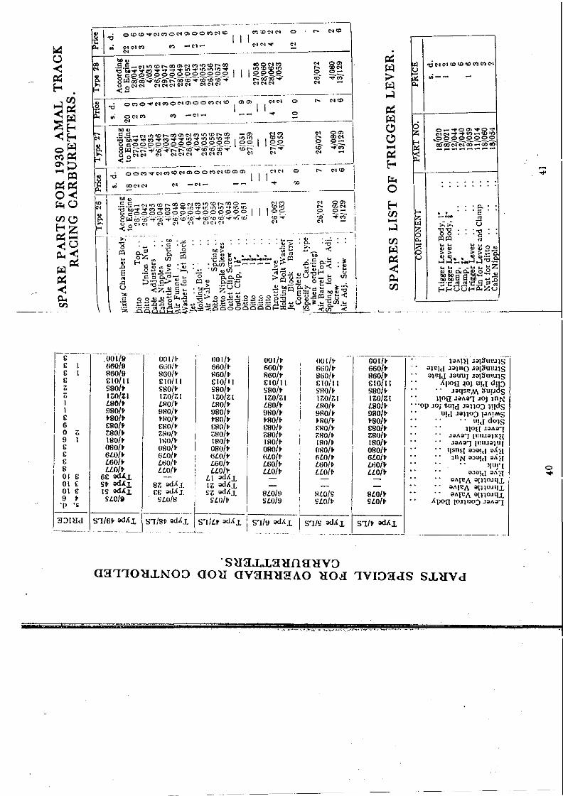
diallletees . . . . . . . . . . . . . .Cubic eapacitr oí Stand;.¡eu Engines at pre:5Cllt On the eDadApproxiulate Engine revolutions at different speeds ..Fuels .......•.•....AMAL Sen/ice .. . . . . . . . . . . . .How to ürder Spare Parts . . . . . . . • . .Spaee Part Illusteations ..•.. ., .. ..Spare Parts Price Lis t •• . . . . . . . . . .Float Needle Illustrations. .. .. ".." ..
Page34;
677~
913
15Hi1617I~
Hl
11111'123142527
2S293031323~
333;42
Telepbolles .. .. BIRMINGHAM EAST 1371·2.3·4·;Telegram, .. AMALCARB, PHOllE. BIRMINGHAM
,Codes: ABC (5th & 6th Editions), Western Union & BenUe}':;
Now Manufactured by
" . " -.;." .fimalgamated CarburettersLtd.;
Holford Works, 'Perry Barr,Birmingham..• -.~.__:T',._; ~; ...-- .
. ' . . .. ~ ....
1930 AMAL r "RBURETTER
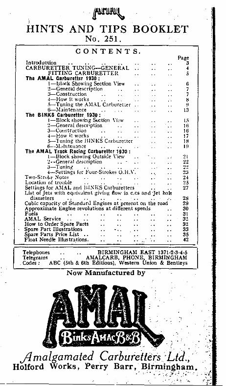
Outslde vlew of AMAL Carburetter wltbThrottle Stop.
~,.-t'_; ........• ~:
:0ít~.:::.,'t~.
,~-~
~I
~
CARBURETTERSfor 1930
INTRüDUCTlüN.
AMAL Carburetters for 1930 are being madeid three distinct types, which wi!l be asfollows:
l-THE AMAL CARBURETTER.This is an instrument with a needle controlledmain jet similar to the 1928 AMAC Carburetter
2-THE BINKS CARBURETTER.This is similar to the 1928 BINKS 2-jetCarburetter, but it has an improved form ofconstruction.
3-THE AMAL TRACK RACINGCARBURETTER.
It is the purpose of this Booklet to giveMotor Cyclists general hints concerning.Cuburetter tuning. and full instructionswith regard to tbe 1930 AMAL and BINKSCarburetters.
3

,
FITTING CARBURETTER (General).
1ich mix/ure."-General indications ¡-heavytllumpy running, emission 01 black smoke ,rom theexhaust, the inside of the carburetter becomes blackened,and as the throttle is opened, heavy "blow back" 01fuel is observed from the carburetter air intake." Weak mix/ure"-difficult starting, tendency for theengine to fire back through the carburetter, indicated byblue flame Irom the carburetter air intake. Carburetterbecomes sensitive to " drive," and constant use has to bemade 01 the air lever, engine knocks readily and runs hot,with loss 01 power. The electrode 01 the sparking plugsshows indications of intense heat, and the mica insulationbecomes white, polished exhaust pipes become rapidlyblued.(The aboye applies equally to the Ai\lAL or the BINKSCarburetter) .
5
It is essential that the carburetter is fitted vertically, andwith an air. tight union .10 the engine.
Petrol Pipes and Petrol Coeks. The Petrol Pipes and Cocksshould have a mínimum internal bore of ft in., and forracing purposes ! in. bore is necessary. Any bends inthe petrol pipe must run in a downward direction.
Controls. Cables must be fitted without acute bends,and care should be taken that the outer casing is nottrapped between the moving parts of the spring forkmechanism, nor lelt loose to touch the sparking plug.The Carburetter having been fitted and the cables clippedin Posi/ion, any back·lash in the cables shoul<i be takenup by means 01 the adjusting screws on the mixing chambertopo1f /he Throllle Valve fails /0 close comple/ely, /he ThrollleStop shotlld be tlnscr;wed un/il the valve sea/s, at,d againlocked in po;;ition.
The final adjustment 01 the Stop Screw is dealt with inthe instructions en tuning.
I
l
CARBURE'1fER TUNING(General).
l. Seleet earburetler with eorrect ehoke size by relerringto our list 01 recommended sizes, which inlormation coversaH ordinary requirements (see pages 27 and 28).\Vherc a carburetter is required lor exceptional conditions,such as Track Racing on alcohol luels, or, to quote theother extreme, lor stationary work, it is prelerable to askour advice.
2. Determine Main det size. GeneraHv the sizes recomomended in the 1ist mentioned aboye wilÍ give satislaction,but certain conditions necessitate a departure Iromstandard: prominent among these \Ve may nlentionexcessive heat or cold, due to climatic conrlitions, orradical departures lrom standard practice in the design01 the power unit.In any case the correct size 01 main jet is readilydetermined. The air lever should be set three-quartersopen, and a jet selected which gives the highest maximumspeed or the most power on full throttle.If maximum speed is the primary consideration, the jetsize should be selected with the air lever lully open.For touring conditíons, to determine whether the jet istoo large or too small, with throttie lully open, graduallyclose the air lever . If an increase in speed or power isnoticeable, then the jet is on the small size. If, however,when the air lever is opcned luHy, a definite increase inspeed or power is obtained, the jet is too large.
3. Determine Pilot "et Size and Set Throllle Stop forSlow Running. On the AMAL Carburetter, the PilotJet is fixed, and it is unnecessary to attempt any alterationto this. The slow running or idling on the AMAL isregulated by the combined adjustment 01 the ThrottleStop Screw (T.S.) and the Pilot Air Adjusting Screw (seeilIus.).On the BINKS Model a Pilot Jet must be selected whichgives the desired "idling" 01 the engine when in" neutral," and at the same time enables a correct blendbetween the Pilot Jet and the Main Jet.In connection with the loregoing, it is important toremember that the strength 01 the mixture can always beascertained by the use 01 the Air Va1ve. \Vith the Throttlein a definite posi~ion: if an incre~se in engine re,,:olutiOI!S .....•~.··..I...\results from closmg down the Alr Valve, the mlXture lS~~o }weak; and if on opening the Air Valve the engine revolu- ¡S;;- itions increase, then the mixture is rich.>;:"<;. '.
. 4 '::~!'

THE AMAL CARBURETTEP 1930.TYPES 4, 5 aud 6.
General Description. The design of this instrumentcombines the well-known features of both AMAC andBROWN & BARLOW Carburetters. The shaped adaptorgiving a clear gas passage of high volumetric efficiencyis retained.A constant mixture strength throughout-the full r:.nge ofthe throttle valve is obtained by a well-known ;nethod ofregulating the fue! supply by means of a suitably taptredneedle adjustably attached to the throttle valve.A metered jet is provided to regulate the maximumamount of fuel avaHable at full throttle.The idling system consists of Pilot Jet and By-pass,provision for adjusting the mixture being provided by thehorizon tal kn urled screw on the mixing chamber side ;the throttle stop screw providing a definite throttleopening for " idling " when the controllever is closed.The Carburctter can be supplied with a Double or SingleLever Control, which ma)' be cable operated, or forStationary Engines attach0d direct to the Carburettertopo The Single Lever pattern is normally fi tted with ahand-operatl'd air valve for starting.For standard Touring and Sportsconditions, the Carburetter sizes in the tables on pages 27 and 28 wiII giveevery satisfaction, and for special conditions, such asracing, our advice is always avaHable.
Constructicn 01 AMAL Carburelter. Rcferring to theSectional Diagram, which shows the constructionalarrangement, A is the Carburetter Body or Mixing Chamber, the upper part of which is fitted with-Throttle ValveB, with Taper Needle C attached by Needle Clip.The Throttle Valve regulates the quantity of mixturesupplied to the Engine. .Passing through the Throttle Valve is the Air Valve D,independently operated and serving the ,purpose ofobstructing thc main air passage for .. starting" and.. mixture regulation."Attached to the underside of the Mixing Chaniber, by theUnion Nut E, is the Jet Block F, and interposed betweenthem a fibre washer to ensure a petrol-tight joint.On the upper part of the Jet Block isthe Adaptor Body H,forming a clean through-way.Integral with the Jet Block is the Pilot Jet J, suppliedthroligh the Passage K.
1l'
j
""'. Ji.
N
;111
R~
j¡I~¡~."PETAOl~'AIA
PIIDT AIR SCREW
AMAL CARBU""sTTER (Section View).·
R
__________1.f 6"!f- 7tI" --_______ I

TOOPEN
9
TUNING THE AMAL CARBURETTER.
M""N de'.T (1)
NEEDLE P051T10N~
I ~ TH"!OTTLE CUTA"'A'( (~;), . FILOT Al"? AOelU5T "'IE'JT(2)
RANGE <¡¡:. 5EGluENCe; QF AOoJu5TMe;NT5
A.M.AL. CARBURETTER.
There are four ways in which the quality 01 the mixturesupplied by an AMAL Carburetter can be varied, andthese are given hereunder, in the order in which the adjustments should be made.1. Main Jet (t to full throttle).2. Pilot Air Adjustment (closed to /¡th-throttle).3. Throttle Valve Cut-away on the air intake side
(ith to i-throttle).4. Needle Position (i to i-throttle).
'he mixture 01 air and fuel is admitted tc 'le Enginethrough the Pilot Outlet M.The quantity 01 mixture capable 01 being passed by thePilot Outlet M is insufficient to run the Engine. Thismixture also carries excess 01 fuel. Consequently, belorea combustible mixture is admitted, Throttle Valve Bmust be slightly raised, admitting a further supply of airfrom the main air intake.The further the Throttle Valve is opened, the less will bethe depression on the Outlet M, but, in turn, a higherdepression wil! be created on the By-pass N, and the Pilotmixture wil! flow from this passage as well as from theOutlet M.The mixture provided by tile Pilot and By-pass system issupplemented at approximately tth throttle by fuel fromthe Main Jet system, the Throttle Vah'e cut-awaygoverning the mixture strength from here to i-throttle.Proceeding up the throttle range, mixture control by theposition 01 the needle takes place from i to t-throttle,and therealter the Main Jet is the only regulation.The Air Valve D, which is cable-operated ún the TwoLever Carburetter and Hand-operated on the SingleLever Carburetter, has the efiect of obstructing the mainthrough-way,and, in consequence,increasing the rlepressionon the Main Jet, enriching the mixture.
~ 1
\:¡.
I'j
HOW THE AMAL CARBURETTERWORKS.
The Petrol Tal' having been turned on, petrol wil! !lowpast the Needle Valve U until the quantity olpetrol inthe Chamber R is sufficient to raise the Float T, when theNeedle Valve U wil! prevent a lurther supply enteringthe Float Chamber.The action 01 the Float can readily be understood, lor,as the quantity of fuel in the Float Chamber is used, theFloat T wil! drop, carryingwith it the Needle U, and admitting a further supply. Thus, automatica!ly, thepetrol level is kept constant.In connection with the Float Chamber, it must be clearlyunderstood that any alteration to our Standard Level C'lr,only have detrimental results.The Float Chamber having fi!led to its correct level,luel passes along the passages, through the diagonal holesin the Jet Plug Q, when it wil! be in communication withthe Main Jet P and the Pilot Feed Hole K; the level inthese Jets being, obvious]y, the same as that maintainedin the Float Chamber.Imagine the Throttle Valve B very slightly open. As thepiston descends, a partial vacuum is created in the Carburetter, causing a rush 01 air through the Pilot AirHole L and drawing fuel from the Pilot Jet J.
8
The adjustable Pilot Air' ',ake L communicates with achamber, from which issue" the Pilot Outlet M and theBy-pass N.An adjusting screw (T.S.) is provided on the MixingChamber wall, by which the position of the ThrottleValve for "idling" is regulated independent of thecable adjustment.The Needle Jet O is screwed in the underside 01 the JetBlock. and carries at its bottom end the Main Jet P.Both these Jets are removable when the Jet Plug Q,which bolts the l\Iixing Chamber and the Fioat Chambertogether, is removed.The Float Chamber, whicl; can be supplied either Top orBottom Feecl, consists 01 a Cup R suitabl" mounted ona Platform S, containing the Float T anel the NeedleValve U attached by the Clip V.The Float Chamber Cover \V has a Lock Sere\\' X forsecurity on the large Float Chamber ollly.

The diagram on page • clearly indicates the part 01the throttle range over which each adjustment is eflective.The Carburetter having been carelully fitted as describedon page 5, the general tuning can be carried out. Thefollowing sequence must be observed.1. Obtain Main .Jet Size. (see pages 27 and 28).2. Pilot AdJ ustment.To weaken slow running mixture screw pilot air adjusteroutwards.To enrich slow running mixture screw pilot air adjusterinwards.Screw pilot air adjuster home in a clockwise direction.Place gear lever in " neutral."Slightly flood Float Chamber by gently depressing theTickler until fuel can be observed overflowing from theMixing Chamber.Set Magneto half-advance, Throttle approximately kthopen, close Air Lever, start the Engine and warm up.After warming up, reduce the Engine revolutions bygently closing the Throttle. The slow running mixturewill prove too rich unless air leaks are presentoVery gradually unscrew the Pilot Air adjuster.The engine speed will increase and must be again reducedby gently closing the Throttle until, by a combination 01Throttle positions and Air adjustment, the desired "idling"is secured.It is sometimes necessary to retard fully the magnetobefore good "idling" results, particularly when themagneto runs at engine speed, or when excessive valveoverlap and very early ignition timing is employed.Tnrottle Stop. lf it is desired that the engine shouldcontinue "idling" with the throttle lever closed,. theposition 01 the throttle valve must be set by means 01 theThrottle Stop Screw TS. the Throttle Lever being in the.. closed position .. during this adjustment. Altematively.if the screw TS is adjusted clear of the Throttle Valve.the engine will shut off in the normal way by the controlJever.Do not take the Throttle Stop Screw out completely.Failure to secure good " idling .. will probably be tracedto one of the following causes :-Air Leaks at the junction of the Carburetter an,d Engine,or through the Valve Guide, due to wom inlet valve stemand guide.Faulty Inlet and Exhaust Valve seatings.Sparking Plug. Points too close. Try a gap .025 in.Sparking Plug oily..Too much Ignition Advance.Magneto. Contacts dirty or too close.Examine Contact Breaker.
10
f
¡
)~1,•:!t.it
r.xamine Slip Ring for oil. ~ .!camine for Ca.rbón Brush .jammnig.,i.¡¡ holé or glazed
on contact face. . .,,,,,'!!}Examine for fractured Brush Holder... s
Examine for High Tension Cables for shorting.,.Magneto Insulation may be broken down, or lhe interior
mechanism wet.
3. Throttle Valve Cut-away. (see dia.gram on page 9).Given satislactory " idling," set the Magneto Control athalf-advance, Air Lever fully open.Very slowly open the Throttle Valve. when, if the Engineresponds regularly up to one-quarter throttle, the ValveCut-away is correctoA weak mixture is indicated by spitting back through theAir Intake, with blue flames, hesitation in picking up,which disappears when the Air Lever is closed down, andthis can be remedied by fitting a Throttle Valve with lesscut-away.A rich mixture is shown by black smoke from the ExhaustEngine stops, or nearly stops, when the Air Valve is closed.The remedy lor this is a Throttle Valve with more cut·away.Each AMAL Valve is stamped with two numbers, thefirst indicatingthe Type No. 01 the Carburetter, and thesecond figurethe amount of cut·away on the intake side01 the valve in sixteenths 01 an inch.Thus :-6(4 is a Type 6 Valve with 4/16 in. or t in. cutaway.The standard valve for Single Cylinder Engines is No. 5,and for Multi-cylinder Engines, No. 4.
4. Needle Position.Air full open.Open the Throttle half-way.Note if the Exhaust is crisp and the Engine lively.Close Air Valve slightly below throttle. exhaust Note andEngine Speed should then remainpracticallyunaltered.IVeak mixture. Raise needle in Throttle Valve. IFPopping back and spitting occur with blue flames fromCarburetter Intake.Test by lowering Air Valve gently. Engine revolutionswill rise when Air Valve is lowered slightly below theThrottle Valve.Rich Mixture. Lower Needle in Throttle Valve, IFEngine speed does not increase progressively as theThrottle is raised ; S.moky Exhaust and heavy labouredrunning ; On closing Air Valve slightly below ThrottleValve. tendency to mis-fire. and eight·stroke i5 prese!lt.
11
"l'[;
1
11il
1!1
I

The normal needle setting' 1Nith the Needle Clip in No, 3groove,Having found the correct Needle position, the CarburetterSetting is now complete, and it will be found that thedriving is practically automatic once the Engine iswarmed up,For a Semi-automatic Setting, where extreme economy isdesired, lower the Needle one groove further after carryingout this range of tests,For Speed Work the Main Jet may be increased by 10%.when the Air Lever should be fully open when on fullThrottle.
SOLO I SIDE,CI\ ...Engine I Gear Ratio I I Gear Ratio 1Capacity m.p.g. m.p.g.
'.
I I
250 ce. 6'1
If15·tOO
350 ce, 5.5/1 85·90 611 70
500 e.c 5 '1
ISO'85 5.5:1 65-70
600 ce. 4.71 iO-SO 5.5.... 1 6O·G5
750 ce. Twin -I
- 5.5/1
I55-60
1000 ce. Twin 41 55-60 5.'1 50-$5
AIR FILTERS. These figures are approximately correct for an averageroad speed 01 30 m,p,h.
CONSUMPTIONS.
fbe lollowing consumption figures should be readilyohtained IInder average louring cOlldilions, provided thepower IInit is in sound mechanical condition. the gearratio normal and the cycle parts are without unduefriction,
el¡l¡i: The Single. Lever Automatic Carburetter is 01 exactly the ,'1 same general design, but the Air Valve is operated by a
Rod Control fitted in the Mixing Chamber Top,There are two positions for this Valve: .. Closed" forstarting, and .. Fully Open " for all general running,Exactly the same tuning instructions apply for both theSingle and Double·Lever CarburetteL
For touring ,ye strongly recomnlend the fitting of anAMAL Air Filter, when it wil! be found that tlle l\lain Jet
,1 size may be advantageously reduced by 10, 15 or 20%,!! The former figure applying to Type 4 Carburetters, the
':, middle to Type ;j, and the latter to Type 6 Carburetters.!. Exactly the same procedure for checking the mixture as~I! detailed abO\'e can be carried out when the Air Filter is
11. fitted, ir any doubt exists in the customer's mind,
! HOTE.-Modificaliol! lo Carburetter Settings as suppliedI lo Manufacturas of Alolor Cycles is iJ.adl'isl¡[,le l/lIlessJ lhe Jlati,il:e i::>" required foJ' Sume specú..! purpose.
Periodical cleaning is necessary to maintain cfticientlunetioning 01 the Carburetter, and should be carried outin the following sequence:-1, Disconnect petrol pipe,2, Unscrew holding bolt Q. and remove Float Chambercomplete,3, With box or set spanner slacken the Mixing ChamberUnion Nut E,4, Mixing Chamber complete may now be removed fromEngine. either by unscrewing the clip ,pin, if outlet. orthe bolts if flange fitting,5, Unscrew Mixing Chamber Lock Ring, and pul! outThrottle Valve Needle and Air Valve,Remove Main Jet P and Needle Jet o.6, Mixing Chamber Union Nut E may then be removedand Jet Block complete pushed out, If this is obstinatetap gently. using a wooden stump inside tlle MixingChambeL7. Unscrew Float Chamber Cover \V and slackefi LockScrew X,8, Withdraw the Float by pinching the Clip V inwards,and at the same time pull gently upwards.9, Generally it is sufficient to wash all the parts in cleanpetrol, but if the Carburetter has had extended service,check the following. :-(a). Float Chamber Needle U. If a distinct shoulder isvisible on the point of seating, renew this as soon asconvenient.
I\1AINTENANCE OF THE Al\IALCARBURETTER.
4SINGLE LEVER.ITlt
1% 13
\¡
1
,11
t1:,
Iir
Ti
:¡J11!i11¡.
JI,
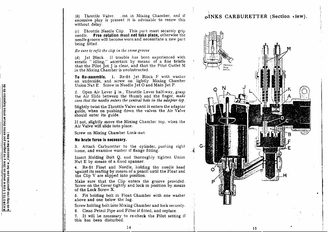
(b) Throttle Valve. .est in l\1ixing Chamber. and irexcessive play is present it is advisable to renew thiswithout delay.
(e) Throttle Needle Clip. This part must securely gripneedle. Free rota!ion must no! take place, otherwise theneedle groove will become worn and necessitate a new partbeing ti tted.
Be sure to rejit the clip in the same groo"e
(d) Jet Block. 1f trouble has been experienced witherratic .. idling." ascertain by means of a fine bristlethat the Pilot Jet J is cIear, and that the Pilot Outlet Min the Mixin¡;¡ Chamber is unobstructed
lo Re·assemble. 1. Re-fit Jet Block l' with washeron underside. and screw on lightly Mixing ChamberUnion Nut E Serew in Needle Jet O and Main Jet P.
2. Open Air Lever ¡'n.. Throttle Lever half-way, graspthe Air Slide between the thumb and the finger, makesure that the needle etlte1S th_ central hale in the adaptar topo
Slightly twist the Th1'ottJe Valve until it enters the adaptorguide, when on pushing down the valves the Air Valveshould enter its guide.
If not, slightry move the Mixing Chamber topo when theAir Valve will slide into place.
Screw on Mixing Chamber Loek-nut.
No brute force is necessary.3. Attach Carburetter to the cylinder, pushing righthome. and examine washer if f1ange fitting.
Insert Holding Bolt Q. all(1 thoroughly tighten UnionNut E by means 01 a lixed spanner.4. Re-tit Float and Needle, holding the Ileedle head'l.gainst its seating by means 01 a pencil until the Float andthe Clip Vare slipped into position.Make sure that the Clip enters the groove provided.Screw on the Cover tightly and lock in position by means01 the Lock Screw X.5. Fit holding bolt in Float Chamber with one washeraboye and one below the lug.Screw holding bolt ioto Mixing Chamber and loek securelv.
. .6. Clean Petrel Pipe and Filter il fitted, and replace.7. It will 1.>e necessary to re'check the Pilot setting ifthis has been distu1'bed.
14
4G
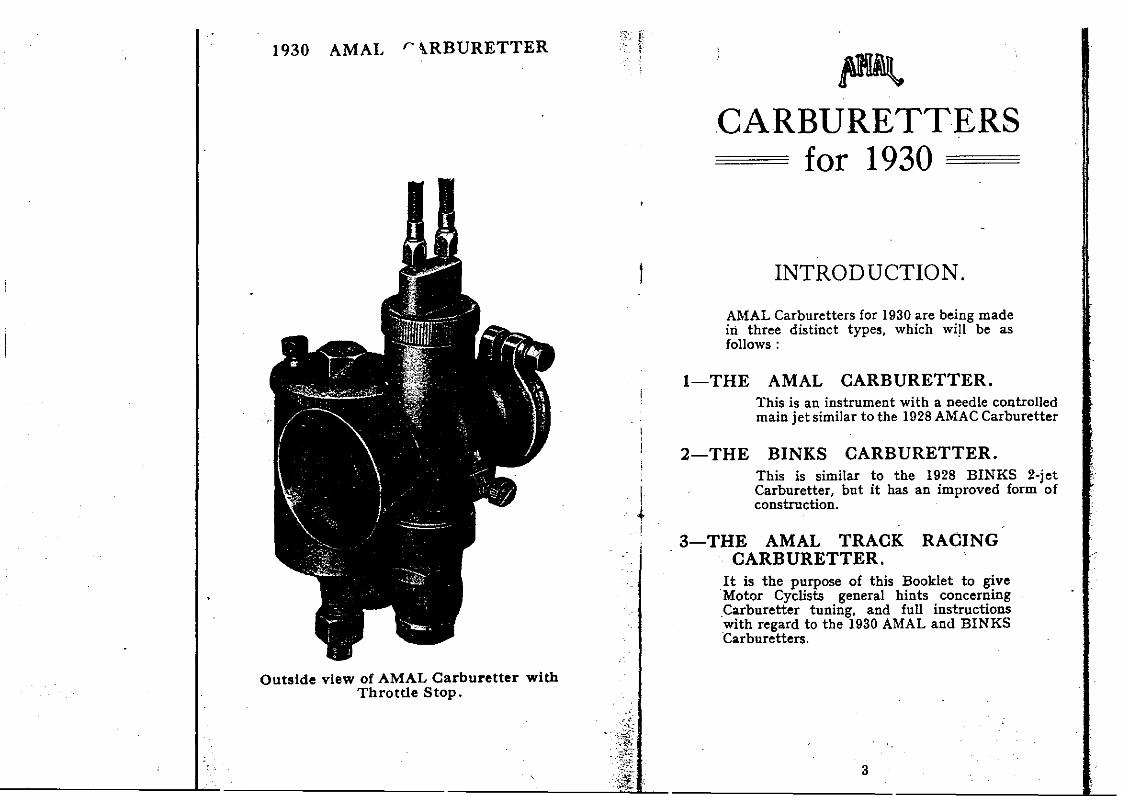
DINKS CARBURETTER (Section dew).
15
•
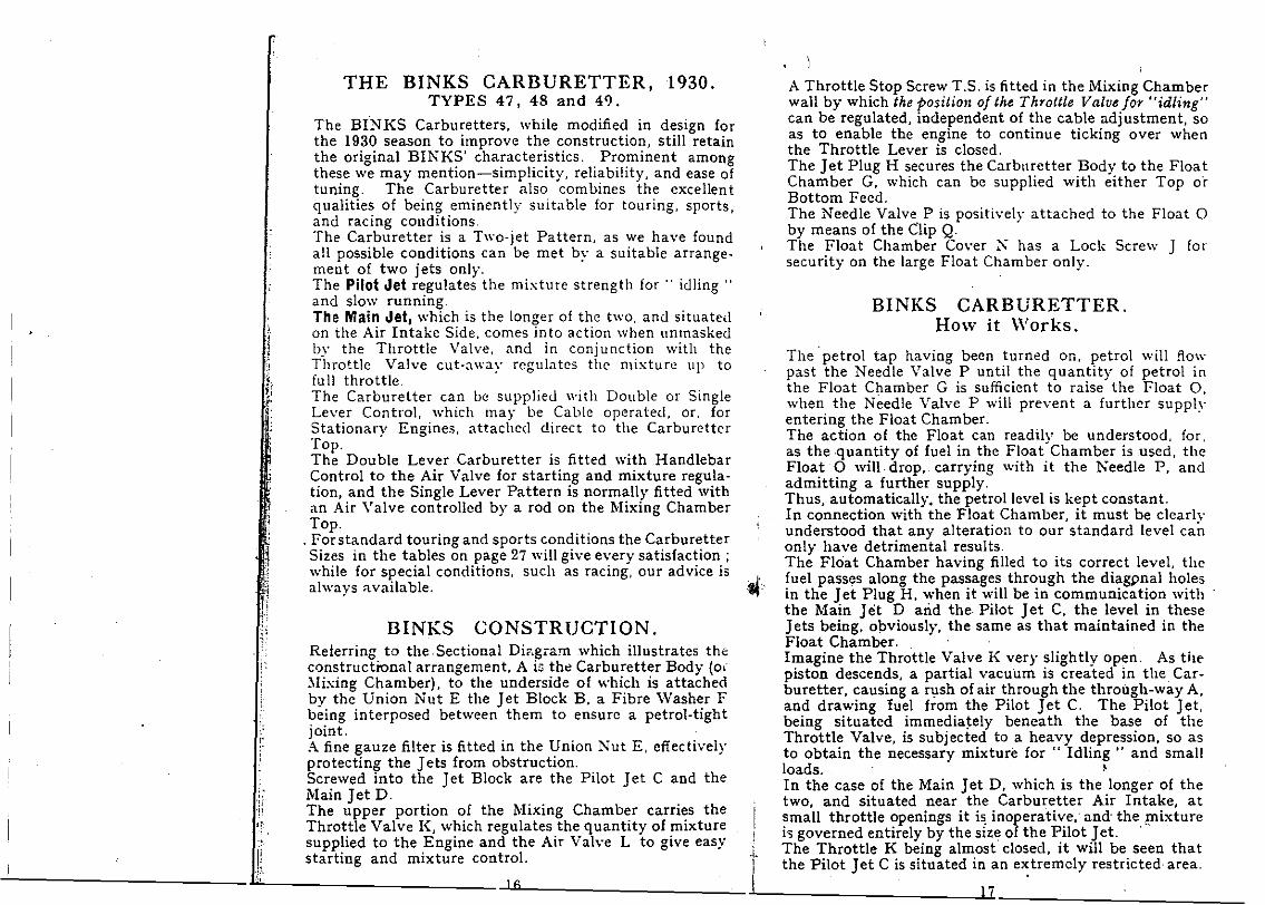
BINKS CARBURETTER.How it Works.
I
A Throttle Stop Screw T.S, is fitted in the Mixing ChamberwaU by which the positiolt of the Throttle Va/ve for "id/ing"can be regulated, independent of the cable adjustment, soas to enable the engine to continue ticking over whenthe Throttle Lever is closed.The Jet PIug H secures the Carburetter Body to the FloatChamber G, which can be supplied with either Top oÍ'Bottom Í'eed.The Needle Valve Pis positively attached to the Float °by means of the Clip Q.The Float Chamber Cover K has a Lock Screw J forsecurity on the large Float Chamber only.
THE BINKS CARBURETTER, 1930.TYPES 47, 48 and 49.
The BINKS Carburetters, while modified in design forthe 1930 season to improve the construction. still retainthe original BINKS' characteristics. Prominent amongthese we may mention-simplicity, reliability. and ease oftuning. The Carburetter also combines the exceUentgualities of being eminently suitable for touring. sports.and racing conditions.The Carburetter is a T,,"o-jet Pattern, as we have foundaU possible conditions can be met by a suitable arrangemeot of two jets only.The Pilot .Jet regulates the mixture strength for " idling "and slow running.The Main .Jet, which is the longer of the t""o, and situatedon the Air Intake Side, comes into action when unmaskedby the ThrottIe Val ve, and in conjunction with theThrottle Valve cut-away rcgulates thc mixture up tofuU throttle.The Carburetter can be supplied \\'ith Double or SingleLe,'er Control, which may be Cable operated, or, forStationary Engines, attached direct to the CarburettcrTop.The Double Lever Carburetter is fitted with HandlebarControl to the Air Valve for starting and mixture regulation, and the Single Lever Pattern is normaUy fitted withan Air Valve controUcd by a rod on the Mixing ChamberTop.
,Í'orstandard touring and sports conditions the CarburetterSizes in the tables on page 27 wiU give every satisfaction ;while for special conditions, such as racing, our advice isalways "vailable.
Ir~
.''.,,
li':~
J¡'t,
,
,.
".,¡l
'¡:¡
'i11;i·;I.j·
'j,¡: .
The petrol tap having beco turned on, petrol wiU flo,,"past the Needle Valve P until the guantity of petrol inthe Float Chamber G is sufficient to raise the Float 0,when the Needle Valve P wiU prevent a further suppIyentering the Float Chamber. .The action of the Float can readlly be understood, foroas the ·quantity of fuel in the Float Chamber is used, theFloat ° will. drop, carrying with it the Keedle P, ancladmitting a further supply.Thus, automatically. the petrollevel is kept constant.In connection with the Float Chamber, it must be clearlyunderstood that any alteration to our standard level canonly have detrimental results.The Float Chamber having filled to its correct level, the
.l fuel passes along the pas~age~ thr~ugh the di~~~al holes
.~ in the Jet PIug H, when lt '~IU be 10 commu01cat~onwlththe Main Jet D and the Pllot Jet C. the. lev~1 10. these
nINKS CONSTRUCTION. Jets being. Obviously, the same as that malOtalOed 10 theFloat Chamber.
Referring to theSectional Di<.gram which illustrates the Imagine the Throttle Valve K very slightly open. As theconstructional arrangement, A lo ~he Carbu:ett7r Body (oc piston descends, a partial vacuum is created in the Car-Mixing Chamber). to the underSlde of whl~h IS attached buretter. causing a r1,1sh of air through the through-way A,by the Union Nut E the Jet Block B, a Flbre Wash~r F and drawing fuel from the Pilot Jet C. The Pllot Jet,being interposed between them to ensure a petrol-tIght being situated immediately beneath the bas~ of thejoint. . Throttle Valve, is subjected to a heavy depresslOn. so asA fine gauze filter is fitted in the lInion Nut E. e!lechvel)' to obtain the necessary mixture for " Idling .. and smaUprotecting the J ets from obstructIon. . loads. 'Screwed into the Jet Block are the Pllot Jet C and the In the case of the Main Jet D, which is the longer of theMain Jet D. . . . two, and situated near the Carburetter Air Inta~e, atThe upper portion ~f the MlxlOg Chamber carn~s the I small throttle openings it i~ inoperati\-:e.. ando the !,uxtureThrot.tle Valve K, whlch regulatesthe. guanhty of :nlxtur~ ! io; governed entirely by the slze of the ~llot .Jet.
.' supphed to the Engme and the Alr Vah-e L to glve easy . The Throttle K beinO' almost closed, It wl11 be seen that!! starting and mixture control. '1- the Pilot Jet C is situ';.ted in an e~tremely restrictedarea.
...L 1ii J 6 .1 17
----------

l',....ir:
"li~ ,'J:(.1
i
In eonsequenee, the pa>. ,ge oí the air Irom the mainthrough-way wil! be restricted, and at the same time ahigh depression will exist on the Pilot C. At this positionof the Throttle. it will readily be seen that not only isthe Main Jet D shrouded by the Throttle Valve, but alsothe area oí the Mixing Chamber in which it is housed i5infinitely bigger than the area oí the through.way exposedto the suetion of the Engine, in consequence oí which noíuel is drawn from the Main Jet.
As the Throttle Valve K is raised, the arca immediatelvaboye the Pilot Jet C is increased, and in eonseqllenee thesuction or depression on this Jet diminishes, ancl at thesalOe time increases on the i\Iain Jet, so a balance betweenthe two Jets is obtained throllghout the wholc range,
TUNING THE BINKS CARBURETTER.
Assuming the correet size oí Carburetter has been fittedaeeording to instruetions on page 4, there are three waysin which the quality of the mixture can be varied on the1930 BINK5 Carburetter, and these are given hereunder inthe order in which the adjustments should be made.
1. Main Jet (affects the mixture from ~ in. to fullthrottle) ,
2. Pilot Jet (affeets the mixture from elosed to i throttle).3. Throttle Valve Cut-away (affeets mixture lrom i toi·throttle) .
The following diagram clearly indieates the part of the .throttle range over which eaeh adjustment is effeetive. ;1f
1. lIain ,Jet. The seleclion 01 the eorrect M r Jet i5dealt with on the opening page 01 our Boo1<Jet under.. General Carburetter Tuning," and it will be notedthat -for touring eonditions we advise this to be obtainedwith the Air Lever three-quarter open.
2, Pilot ,Jet. This affeets "slow running" and slo,,".pulling only, and the smallest size should be seleeted whiehgives the best .. Idling," At the same time. eare must·¡¡be taken not to reduce the size oí the Pilot Jet unduIy,otherwise difficulty will be experienced in obtaining acorrect blend with the Maio Jet,
Blend oi Main and Piloto If any. trou ble is experienced due .to a weak spot between the Pilot aod Main Jet, it canusually be cured by increasiog the Pilot Jet one size
3 Throttle Valve Cut-away. Richness at g to i throttlecan be rectified by fitting a Throttle Valve Cut-away Onthe Air Intake side, The standard cut-aways are from"O," which is /lat bottom, to No_ 5, which is cut away -&-in.
Starting Up. With a cold Engine, depress the CarburetterTickler, close Air Valve. open Throttle about one.eighth,ignition about three-quarter advanced, when, if the igni·tionsystem is in good order, no difficulty should beexperienced in obtaining an " easy start."
With a. waYm Engine it is unnecessary to /lood Carbllretter,but the Air Lwer should be closed.
11 the Float Chamber is unduly /looded, excessive richnessof mixture will prevent the Engine starting, Open Throttle
, fully and revolve Engine smartly uotil excess of fuel isexhausted; then proceed as before, without againf1ooding,
TOOPEN....... " .. "-1/> MAlN olET (1)r '..TH~TL-E VAL-VE(!)CUTAWAY
- PIL..OT dET(2)
RANGE ',,; 5EQUENCE OF AO.JU5TMENT5
BINK6 CARBURETTER.
18
¡jI
MAINTENANCE OF THE BINKSCARBURETTER.
The· Float Chamber should be periodieally cleaned out,having previously been detached Irom the Carburetter byuoscrewing the Jet Plug H.
Unscrew the Locknut J, when the Float Chamber Cover Nwil! be detaehed, By pressing the Bow Clip Q gentlyinwards, at the same Cme pulling upwards. the Float canbe withdrawn from the Chamber,
19
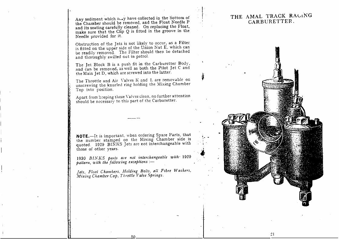
THE AMAL TRACK RA\"'lNGCARBURETTER.
*
II
..
.) 1, ~ ~_.I'-- -------?
Any sediment which n.~y have collected in the Dottom ofthe Chamber should be removed, and the Float Needle Pand its seating carefully cleaned. On replacing the Float,make sure that the Clip Q is fitted in the groove in theNeedle provided for it.
Obstruction of the Jets is not likely to occur, as a Filteris fitted on the upper side of the Union Nut E, which canbe readily removed. The Filter should then be detachedand thoroughly swil!ed out in petrol.
The Jet Block B is a push lit in the Carburetter Body.and ean be removed, as ",ell as both the Pilot Jet C andthe l\Iain Jet D, which are screwed into the latter.
The Throttle and Air \'alves 1\ and L are removable onunscrev,,-ing the knur1ed ring holding the :\Iixing ChamberTop into position.
Apart from l:ceping these \'alves c!ean, no further attentionshould be necessary to this part of the Carburetter.
1030 BIN]{S parts are not interchangeable with' 1929patteY1l, with the !ollo¡úng exceptions :-
Jets, Float Cha>nbers. Holding Bolts. all Fibre Was}¡ers,Mixi1lg Chamber Cap. Thl'ottle Valve Springs.
NOTE.-lt is important. when ordering Spare Parts, thatthe number stamped on the Mixing Chamber side is.quoted. 1029 BINKS Jets are not interchangeable withthose 0.1 other years.
¡.
í;~:¡
/,",!!
i1l··
1

AMAL TnACK RACINGCARBURETTER.
i,1;H
Ii
500
260
300
450
350
.,
,to three. icut·awa.y, ~the valve . i
!]
325
220
260
140
160
200
12
12
12
12
12
.81'
.875·
.93"
1.06'
1.0' I,
240 '1 400
260 450
1.12' 12 325 I 500 60U
1.18' 12 350 550 650,
1.25' 12 400 1 650 700 l
I
I I JET.I llore Valve 1
1' P.~¡.S.2 ' I
__• P.lroll~,~i
62
55
43
67
75
63
26
26
27
27
2i
250
3~0 {
5oo{~ 27
CarlJ. Type Nu.Engine. IType denoting
, No. Bote Síze
'{ISO I 26 36. 175 I. 26 42
APPROX. CHOKES AND SETTINGS., FOUR-STROKE O.H.V.
In the case of Multi-cylinder Engines. takecapadty of one cylinder.
2.1
Intermediate Running. From one-eighlquarter throttle is governed by the throttlewhich is indicated by a number stamped ontopoA No. 9 valve has fe- in. cut-away, and a No. 11 * in ..and so on. The greater the valve cut-away, the weakerwill the mixture be, but remember this has no effect onfull throttle.A No. 12 valve is the normal size for al! typcs of car·bur~tters, but due to variation in valve timing and enginedesigno this can sometimes be varied, giving improved¡¡.cceleration.
. Any hesitation and tendency to fire back through the
.carburetter is an indication that less cut-away shouldbe used.Heavy thumpy mnning indicates that more cut·away i,necessary.It is unnecessary to alter the valve cut·away when changing from petrol to disco!.We recommend the use of twin float chambers withalcohol fuels on engines of 350 C.C. and upwards. Fuel'pipllS should not be less than ! in. inside diameter.Care should be taken to see that the pipe line runs in adownward direction. as if continued in a horizontal planeair locks wil! be formed.
\
,I •!!,
,RACINGTHE AMAL TRACK
CARBURETTER.TUNING
General Description. This Carburetter has been primarilydesigned to meet the conditions imposed by track racingand the use of alcohol fuels. but it will at the same timegive very excellent results when used with petrol andpetrol-benzole mixtures. It is of the plain jet pattern. andincorporates a pilot and by-pass to ensure easy starting.The through-way is unobstructed. and designed to allowthe highest possible volumetric efliciency.An air valve situated on the side of the Carburetter Bodyafiords ample means of regulating the mixture strengthwithout causing any obstruction to the main gas passage,and will be found invaluable for tuning and for correcting
'" the mixture strength due to variations in altitude or" e1imatic conditions.
Atable of approximate choke sizes for engines of varying¡: capacities and of jet sizes fOr petrol and alcohol fuels isi shcwn on page 23.
'1
i
fII,I
1. 8elect Main "et 8ize which gives maximum powerand speed with the air and throttle full open. The correctsize is readily found by the use of the air lever.If when this is e10sed ha1f·way an increase in power isobtained. the jet is too small.Loss of power on e10sing the air slightly is an indicationof too large a jet.The condition of the sparking plug should be carefullyobserved eachtime a trial is mOlde: A dry baked appearance is an indication of weak mixture. or, alternativelv,of an unsuitable grade of plug. .Fifty per cent. increase in mixture strength is obtainableby means of the air control. thus-if intelligent use is
1'1' made of this. there is no chance of " cooking " the engine.i clue to weak mixture.
:,'I! 2. "Idling" a~d .8low Running !s gover.ned by a knurled'1 i screw on the mu"ng chamber slde. WblCh regulates the'¡: amount of air supplied to the pilot and by-pass jet.:[; Normally, for petrol fuel it should be unscrewed two and11' a haH turns. and for alcohol. haH a turno1: If the .. idling .. is weakened unduly. it is possible a weak
spot on the by.pass wil! be experienced.This will make a e1ean pick up and good accelerationimpossible. therefore. set the .. idling .. as rich as possiblebut maintaining good even four-stroking óf the engine..
??
25
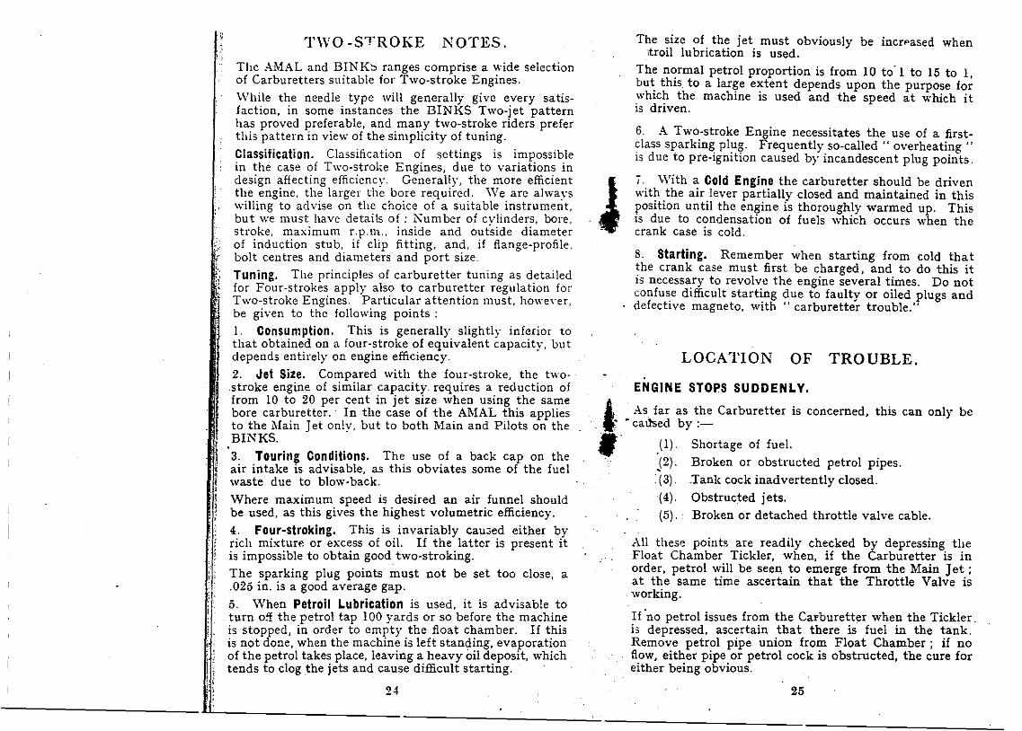
ENGINE STOPS SUDDENLY.
LOCATION OF TROUBLE.
concemed, this can only be
Shortage of fue!.Broken or obstructed petrol pipes.Tank cock inadvertently dosed.Obstructed jets.
Broken or detached throttle valve cable.
(1) .
P)·(3) .
(4) .
(5) ..
6. A Two-stroke Engine necessitates the use of a firstelass sparking plug. Frequently so-called " overheating "is due to pre-ignition caused by incandescent plug points.
í. With a Cold Engine the carburetter should be drivenwith the air lever partially dosed and maintained in thisposition until the engine is thoroughly warmed up. Thisis due to condensation of fuels which occurs when thecrank Case is cold.
The size of the jet must obviously be incrpased when,troil lubrication is used.
The normal petrol proportion is from 10 to'l to 15 to 1,but this to a large extent depends upon the purpose forwhich the machine is used and the speed at which itis driven.
8. Starting. Remember when starting from cold thatthe crank case must first be charged, and to do this itis necessary to revolve the engine several times. Do notconfuse difficult starting due to faulty or oiled plugs anddefective magneto, with " carburetter trouble."
Al! these points are readily checked by depressing theFloat Chamber Tickler. when, if the Carburetter is inorder, petrol will be seen, to emerge from the Mafn, Jet;at the same time ascertain that the Throttle Valve isworking.
If 'no petrol issues from the CarbureHer when the Tickler.is depressed. ascertain that there is fuel in the tank.Remove petrol pipe union from Float Chamber; if nofiow, either pipe or petrol cock is obstructed, the cure foreither being obvious.
J
i. As far as the Carburetter is.1" . catlsed by:-,
1'\\'0 -STROKE NOTES.
The AMAL and BINK~ ranges comprise a wide selectionof Carburetters suitable for Two-stroke Eng·ines.While the needle type will generally give every satisfaction, in some instances the BINK5 Two-jet patternhas proved preferable, and many two-stroke riders preferthis pattern in view of the simplicity of tuning.
Classification. Classification of settings is impossiblein the case of Two-stroke Engines, due to variations indesign affecting efficiency. Generally, the more efficientthe engine, the larger the bore requirecl. 'Ve are alwayswilling to advise on the choice of a suitable instrument,but we must have details of : Number of cvlinders, bore.stroke, maximum r.p.m., inside and out'side diameterof induction stub. if elip fitting, and, if fiange-profile,bolt centres and diameters and port size.Tuning. The principIes of carburetter tuning as detailedfor Four-strokes apply 0.150 to carburetter regulation forTwo-stroke Engines. Particular attention must, howe\·er.be given to the fol!owing points :l. Consumption. This is generally slightly inferior tothat obtained on a four-stroke of equivalent capacity, butdepends entirely on engine efficiency.2. Jet Size. Compared with the 'four-stroke, the twostroke engine of similar capacity requires a reduction offrom 10 to 20 per cent in jet size when using the samebore carburetter.· In the case of the AMAL this appliesto the Main Jet only, but to both Main and Pilots on theBINKS.
3. Touring Conditions. The use of a back cap on theair intake is advisable, as this obviates sorne of the fuelwaste due to blow-back.
Where maximum speed is desired an air funnel shouldbe used, as this gives the highest volumetric efficiency.4. Four-stroking. This is invariably cau~ed either byrich mixture or excess of oi!. If the lattcr is present itis impossible to obtain good two-stroking.The sparking plug points must not be set too elose, a.025 in. is a good average gap.5. When Petroil Lubrication is used, it is advisable toturn off the petrol tap 100 yards or so before the machineis stopped, in order to empty the float chamber. If thisis not done, when the machine is left standing, evaporationof the petrol takes place, leaving a heavy oil deposit, whichtends to elog the jets and cause difficult starting.
24
j,¡r;-I:'1.
{
.:.:
¡ji,'i¡

II t!lIS 15 In order, remove Float Chaml;>er Cover and seethat the Float Nee<" is not bent and is wórking smoothly.Withdraw the Floa...nd inspect Float Chamber for wateror foreign matter.
The passage in the Float Chambef11eck may also be testedfor obstruction.
AMAL CARBURETTERS, 1930,
Standard Settin~s 4 Stroke Single CylinderEngines,
27
, , NOTE.-Racing refers to Road Racing.. . <:~..-.~ .t :.' For Track Racing Settings, see page 23.
, .:,:...·::'<J;-.t~:.::: .•,:.. ._. __ :-:For Multi-cylinder Engines take tbe Ca acit oí cae ~ylinder only'. :'~""~,'-~~~.2~; f:.~~toSeleet Carbure <ter and use a Throttf. v.rve wltb one ,Cut.way
. __ '~"' __'y; __ .~.: ,.......smaller.• ~ ~l ." ~..;.-~ '1,,_._-;,'0;:",.' . .. ·-~~¿~;tÜ.. .
- . .: ·i~:-- ... ,,-
¿ ¿ I v -=-!---- Ó I o ~ tí ...ciZ ez ...: 1;::::.2!"s:!~ ..ciZ ~z .., -.¡ ~
ENGINE ~& s..~ ~ I'S:~i, c? :;& SCLl o .::: -;u>, -.~ zd¡:e> ".» .•!::: ::: ~ >b"' 0., '"1 Vl o. ::¡¡
____~-:. ' __,__ ---, __1_-
50-75 C.C,- : - - _: - l - 46 2B 20 i --.: '1 2/275 to 100 e,c. {r - - - l' -', - 46 3B 20, 20 3/2
,_ _ _ _, - 4G 7B 20! 25 7/2190 t.125 e,c,"'; - - - _. - 46 10B 25 '1 30 10/2150 to 175 C.C _, _ - - - - 4G 14B 25 40 14'2
175 C,C.- ' , 1 .
S.V. Touri..g 4 lí:\ 60 3 4/5 46 14B 25! 40 14/2O.H.V. Touring'..¡ 17:\ 60 3 4/5 47 17B 30 i 50 47/2O.H.V. Sports :.4 ~lA iD 3 4,15 47 21B SO! 60 47/2O.H.V. Racing:"¡ '25.\ 90 3 4/4 47 25B 30: so 47/2
250 C.C.- :S.V. Touring .¡ '2IA 70 3 4(5 47 2!B I 30 ¡ 60 i 47/2.O.H.\'. TOUrin g,..¡ 25A, SO I 3 4/5 47 2~B I 30 1 70 ¡ 47/2O.H.Y.Sports I -1 25.-\ 80 3 4!5 47 25B 30, 70 4712O.H.V. Racing: 5 2S,\ ¡100 3 414 48 28B 35 90 48/2O.H.V. Racing: 5 33'\: 120 I 3 4!4 48 33B 35 100 4812300 C.C,- i .S.V. Touring ! 4 21,\ 70 I 3 4!5 47 21B 30 60 47/2
350 C.C.- I¡ IS.V. Touring 4 2M 80, 3 4/5 47 25B 30 70 47/2O.H.V. Touring, 4 25,\ 60 i 3 4/5 47 25B 30 70 47/2
... ! O.H.V. Touring:'; 28A 95 I 3 5/5 48 28B 35 80 48{2 1
O.H.V. Sport' '1 5 33,\ 110 I 3 5/5 48 33B 35 90 48/2,O.H.V. Sports I 6 39.~ 130 3 G/S 49 39B 40 110 49/2 '[O.H.y. Racing 6 45,\ 160 3 6/4 49 45B 40 130 49/2
500 C.C,- ,S.V. Touríng I 5 33,\ 110 3 5/5 48 33B 35 lOO 48/21S.V. Touring 6 39.\ 130 3 6/5 49 39B 40 110 49/2O.H.V. TouriQg' 6 45A 140 3 6/5 49 45B 40 130 49/2O.H.V. Sports G 45A 140 3 6/5 49 45B 40 130 49/2 IO.H.V. Sport; 6 51A 160 3 6/5 49 51B 40 140 49/21
.,O.H.V. Racing 6 51A ISO 3 6{4 49 51B 40 150 49/2O.H.V. Rac:.ing 29 54:\ 200 3 29/4 LR 13~ 40 160 -
&00 c,o.- IS.V. Touring I 6 39.~ 130 3 6/5 49 39B 4G 110 '49/2S.V. Touring 6 45,\ 140 3 6/5 49 45B 40 130 49/2O.H.V. Touring, 6 45A_ 140 3 6/5 49 45B 40 130 49/2O.H.V. sports·I.6 SIA 160 3 r/4 49 51B 40 140 49/2O.H.V. R.eing 29 SSA 1200 3 2914 LR li" 40 190 -O.H.V. R,cing 29 6SA 220 3 29/4 - - - - -
BINKS/ .
AMAL
26:
If the foregoing are in order, it will be necessary to removethe Main Jet as described in our previous paragraph on.. Maintenance."
MIS·FIRING DUE ro EXCESS ORLACK OF FUEL.
.,
It is very seldom that the Carburetter is the cause 01 anEngine stopping suddenly, unless due to fue] shortage.
Excess 01 Fuer. Punctured Float, loreign matterbetween Needle Valve and Seating, Needle Clip out 01position, Maln Jet or Needle Jet unscrewed, Mbdng Chamber Uníon Nut loose, causing a leakage of petrol roundjet block.
The remedies for aboye are self-explanatory.
Lack o, Fue!. Partial obstruction 01 Fuel Sup!,ly;obstruction in Carburetter Passages or in J ets. If theobstruction is only due to water or small foreign bodiesin the ]ets, this can frequently be cured by placing thepalm of the hand over the Air Intake of the Carburetterwhen the Engine is running. at the same time openingthe Throttle Lever.
The Engine will cease to lire for a few seconds, and tlleu,if the obstruction is c1eared, will resume liring regularly.·If this is of no avail, the fuel line and Float Cham1.Jermust then be inspede'd; as directed in the paragraphdealing with " Engme Stops Suddenly." .
If this is unavailing, the only ·procedure is to remove the] ets and c1ear the obstruction.
'1
. ¡
11¡~Ii:~
iío. t
¡ji

NOTE.-1929 and 1930 AMAL and BINKS Jets are notinterchangeable with those of other years' manufacture.
28
¡¿:. ..¡h,
JETmQUVVALENTS LIST.1930 AMAL and BINKS Jet Numbers-Flow in e.c.'s.
Al! Jets are now known by their actual flow when measuredby RE.S.A. standards, and for the sake of clearness forthose who are used to think of them in sizec1 holes. theapproximate equiva1ent sizes are given below :
1
.;
~.
1,~
1349370293349400295349208348372386489490493496
. e.e.'s.
72 X 85.572 :< 9173 X 7074 X 8174 ·x 9374.5 X 687~ X 7976 X 65.576 X 7776 ,~82
76 X 8577 x 10579 X 10080 X 98
9 v 94
Mil!imetres.
29
c.e.'s.
44 X 44 6951 X 51 10451. X 57 11652 X 52 11054 X 75 17255 X 56 13355 X 60 14255 x 62 14755 x 90 21456 X 61 15059 x 98 26859 x 100 27360 X 60 17060 X 61 I 1-')1-
Millimetres.
In the case of Mu1ti-cylinder Engines, mu1tip1y by thenumber of cylinders.
60 X 7U UHS o
60 X 74 200 82 x 112 0\:1:::::
60 x 75 212 82 X 120 633
60 X 76 215 82.5 X 93 497
60 X 88 249 84 X 80 493
60 x 90 254 84 X 90 499
62 X 70 21I 84 X 100 555
62 X 90 272 84.5 X 88.9 499
I63 X 80 240 85 X 65 370
63 X 88 274 85 X 85 482
64 X 70 225 85 X 88 499
64 X 77 248 85 X 97 550
65' X 75 249 86 X 96 558
6'7 X 70 247 86.4 X 85 499
68 X 76 276 87 X 100 594
... 69 X 80 299 87 X 1I0 654
69 X 93 348 87.3 X 101 604
70 X 64.5 248 88 X 85 516
70 X 70 260 88 X 95 578
70 X 76 293 89 X 89 554
70 X 90 346 89 X 96 597
71 X 88 348 89 X 120 746
72 X 72 293 90 X 77.5 493
72 X 76 309 90 X 85 543
--------1----
loa e . s· . E' dl\CUl;.{; CAPA ITY of Standard Ize of ngmes a .f"'esenton the road :
'1II
Ij \
t II
.~
".)~
6
.'J
-
[)
8
111:l14151617181920212223242526
303132333536383D4041434547495153555759
.018"
.015-
.021"
.024-
026"
.028N
.030"
.032"
.034"
.035"
.037"
.038"
.040"
.041'
.043N
.044"
.045"
.048"
.050"
.052"
.055"
.057"
.059"
15·20._o3035404550556065707580859095
100110120130140150160170180200220240260280300325350
I I II A)IAL. B. & B. ! üLDI ML\L BINKS. Jet I AMAC i BINKS
Flow in C.C.'s Dia. ~~o.· Ko.
------1------ ------
I- O- 116 .)18102ú21232~.) -;)
26.)--1
2829
~ .
l.
1.. ~
.;"
:~
'1l'f:
Ii
1;;
", ,,. :~
_____- __ ~._. _;;;¡w;;¡o~__....,...,.__, __"_~~~~,__
......-t~
~i,'O'", ,
'!:~" ~l'~...,.-.,¡
~~'"00<;...••u
l·.............
~~-tg~&~~~
"....~"II!!I!!!!
":~",.~~~~ ~H
'_:'~..
.~
~imm
.~.~
t
O~',. ....o~~~~.-o",
.'.~~
"
./%ill
,~"":o
'(e
~'.t
'"'i~¡"\"~~fobl o er .... 'CI&.... I!::~~~;r. .....,.:.::.=- .--t
"
~..~ ..o.~o.o:t:> · ... A.t:,~ ~ ~.. :' t . ..:.;;0:;;
O", .é1'
.' ;··.•1"$
u~"'..
o~Su
Jt-t-.~~"o o ($lo'
, .'s-
N
:>~:>t"'
~~.
X~.
::sal>Q::rlO
3C'
'"'1."lO'1~
CA
o.'
~!-t..!.:!1::!ª
,.
es;:;:;¡........n~~~~
;1, '.~.'_.... 1): -"
. ~i~'
~...fI,¡¡,¡1~•••~~~81>1l;¡""'o.lI "
M' .,N ''~w ~'~~ .. '
~l
-'gN~
:~...
"O',
~.' t"~!(" .. ' ". ep..
'ib'''''. M:,".~~~~ "'-J '-.o". :;:~:;: , , ~
" l.-N"N ""t ~" ....O D"''j/ , l1l1IIII •'~:'" ,,'~~;D~" "ItiMmmm.
'" . N~'. .. ~ '. 'f.¡-'~~-;;: li1 rlammma¡¡¡: _, {_
.. too, < >'
'-t.m-: .'Iit" ," '~n~ , ·NNtoo.' .. " _+\ .....1, ~:"
",," 1#01
''''.;..ilC:;;¡h;;;;'·~.f<
""";;,':!~~~': '..... ::' .~'l:~,
al...z::-:00
~¡¡--::s
I~oc.Q::r
\ lO3C'
'"'1."lO'1~
<lO
jll
r '--,
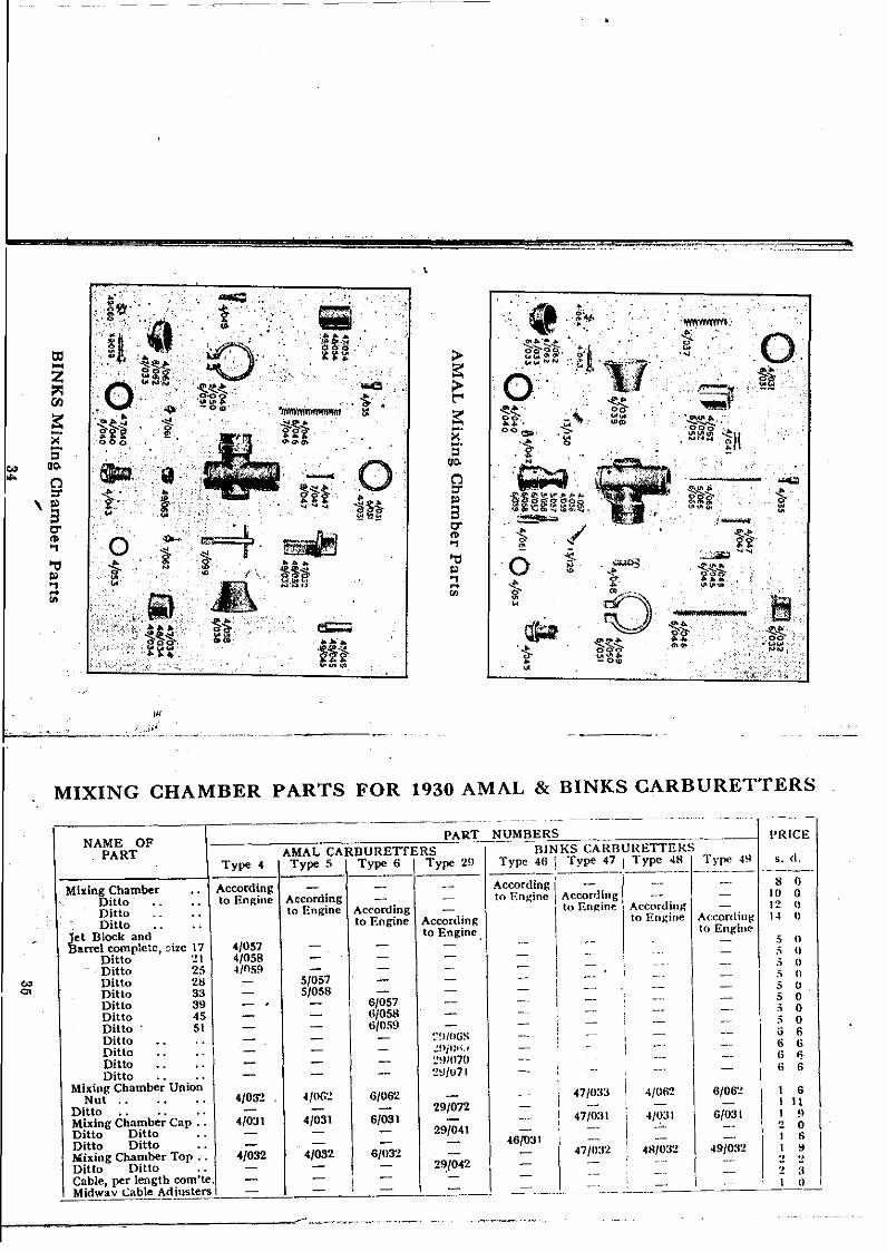
MIXING CHAMBER PARTS FOR 1930 AMAL & BINKS CARBURETTERS -
'1 :'111
611!l
'! O6
•:! '1
5 n:' tl.5 os n5 O5 O.5 O.5 OiJ 66 6G ~
6 6
s. d.
PR1CE
8 ()10 O12 l)
14 O
G/06'!
6/031
49/0:'1'1
"/062
4/031
481032
-,..-_._----
47/11:12
47/033
47/0:1I
46/031
BINKS CARBURETTEKSType ~6 I Type 47.1 Type 48 _I_:-~""~':.
According l' - _.- --to F.n~ine According ~ -
Ilo En~ine Acrordilll;" I --
to EIl~ille A(:cordill~to Engine
III
iI
NUMBERS
2~/042
29/072
29/041
::!I/lI(iS~!liIJ""':!~)/1I70
'1':J/u71
Accordinglo Engine
6/03~
H/062
6/031
6/057H/0586/059
Ac<'onlingto Rngine
4/032
4/031
../n6~
5/0575/058
4/032
4/03~
4/031
4/0574/0584/059
Type 4
Accordingto Engine 1AC'cording
lo Engine
I PARTAMAL CARBURETTERS
Type 5 \ Type 6 \ Type 29
NAME OFPART
Mixing ChamberDittoDittoDítto " ..
Jet Block andBarrel complete, ~·izc 17
Ditto ~1Ditto 25Ditto 28Ditto 33Ditto 39Ditto 4SDitto 51DittoDittoDittoDitto .. .,
Mixing Chamber UníonNut .,
Ditto •. " •.Mixing Chamber Cap ..Ditto DittoDitto DittoMixing Chamber Top ..Dittu Ditto ..Cable, per length com'te ..
~~~av Lab~~~justers 1 - I - -, - \ -"
1 I ------. -----
C»
""
I ~"._--,••._~ ....~-.'"

--"---"'~--" --".._----- -..._--_:~-:.:':.:.~..:---'
'-MIXING CHAl\1:BER PARTS-cont'd.
2
2423
:!: 6:1 U
4'! O2 6.¿ 9
3
PRICE
9/0-t7
411149
5/050
6/051
49/054
4/047
4/04M4{0495/050
4S'll.'i-l
24
"1 H1 92 3I 92 OI 4I 43 Il)
4 II'! 6
- __ o ~~ • I '!~!..-.-
7/047
4/04M4/U49
47/05-1
-t/II-IS
~G/040
..G/041
'l.B¡057-Ij/)4S
'!~)/tlH'!
27/U5M6{051
27/059 !
6/052
61047
4/04H4iO-l9$/050
6,051
5/05~
.IIU47
4/0494/Cl4HS/O:'iO
NAME O!'PART
_PA_R:~'_N~I~JM_rlE_,RS IAMAL CARUURE"ITERS I UINKS CARDURETrtms
. Typ" 4 I Type 5 I Tl'pe 6 Type 29. Type 46 I Type 47 Type 4H I TI'I'" 49 s. d.
I-c-ab-I-e-S-to-P-.-l-o-p-b-a-t-sh~a;;;\ 6/132' 6/132 (;/132 -' \--=--1--;;:'J~2- 611~2 -6i132-~'-Cable AdJuster ., 1~",i"~/03S 4/035 41035 4/0:15 4/n:15 4/U:t, 4!035 4/0:J5Cable Nipples .. ., \. '·'4/036 4/0:m 4/036 4/036 f 4jU:U; 4¡'O:W ·HU:!!i 4!(XhiThrottle Valve Sprin~ '4/037 410~7 4/0:J7 291047, 4/0:17 I 41046 4104(; (;/04(;Air Funnel 01'038 4/031:{ 6/o:n~ - I -- 4/fJ:iH 4!IKJS tl/1l3H
I - - - 2~)!04S, _. - -Washer (or Jet nIock 4}040 4/040 6.'040 29/050 I - I 47.'(HO -liO·U) H/O-IOSpring Clip (orNeedle 4/041 4/U41 4/041 4:041 - I - _. --Holding Bo1t .. . . 4/04:1 4/04:1 4/043 -1/0-1:1 I 4/0-1:1 I 4/0-13 -l/04:1 4/043Air Valve 4j045 5/0-15 6/045 -: - 47.1045 -iN¡'045 H/U45
- - - 29/05.) 1 - , -_. • -- -Air~wS~~ 4/(1-16 4/(146 ~O-l6 -1/046: - 14/1146 4/0-1(; 6:0-16Air oc Throttle Valve
Cuide 4¡U4701 Ditto .. _
Outlet Clip Scrcw I 4/U4HOutlet Clip, 1'" 4/U4~)
Ditto 11"Ditto 1'"Ditto 1i"
11 Ditto,. li'"Ditto .1'"Ditto r
i I Throttle Valve 1 4/0fl'2.DiUoDitto .35 hOlO .. '1 _.- L-'· I ~ I l· 4(;/0:12Ditto .41 bore '.'-- - .. . ~ __~ .~G'():tJ
'"O>
I '.MIXING CHAMBER PARTS-cont'd.
PRIeElURETTERS
Type 48 Type 49 s. d.,
- - 3 °- - 3 °- - 3 °4/053 4/053 2- - I 9- - 1 3- - 6- - 2
49/063 49/063 1 6- - 6
7/099 71099 1 O
- - 57/062 7/062 S7/061 7/061 5
49/059 49/059 649/060 49/060 2
- - 2- - 1 4
- - 1 °- - 1
rj- -- -- -
.. I
49/063.71°73 -7/0~H 7/0!J9
- -7j062 7/062?/O61 7/061
47/US949/060
46/03746/03946/0:19.9/066""6,042
_1<.U"'AE.BS --D1NKS CARI'
Typc 4fi I Type 47
4G/03446/0354"11l364/053 I 4i1l5~
NAME 01'PART
PART AMAL CARDURETTERS \Type 4 Type 5 I Type 6 \ Type 29
Throtlle Valvc .468 bore - - - I - IDitto .531 bore .. - - - -Ditto .60 bore ., - - - I -Holding Dolt Wa!;her 4/053 4/053 4/05:1
\41053
Needle let .. ' . 4/061 4/061 . 41°(;1 29/U76
Needle or Jet .. .. 41065 5/065
\
6/065 -Aír Adjusting Screw ·. 131129 13/129 131129 13/129
Spring for ditto ·. 13/130 131130 13)130 4/070
Filter •• o. ., - -\
- -Filter complete ·. - - - -
/;t l<ey .. .' - - I- -
ain Jet ., .. 4/0.2 4/042 4/042 4,04~
Ditto .. - - I - , -Pilot Jet ., .. - - 1 -Throttle Stop Screw 4/063 4/063" I 41063 , 4/063
Ditto ditto Lock Nut 4/064 4/064 , 4/064
I4/064
Split Cotter Pin for I
Throttle Valve ·. - - I - I4/060
Needle •• .. ., - - , - 291U75
Strangler Tbimble .. - -\
-\
-Strangler Inner Sleeve - - - -Strangler Lever .. - - i - -Valve Location Pcg .. - - - -Strane1er Spring .. - - ! - ! -
.....,

--- --"
.~. '""~ ,~"",,,,;,,,,",~-,,,,,,,,,,,,~,,~,,,,.,,-'...~.,,: .... ,,..,.;-,.,
FLOAT CHAMilER PARTS
c.>00
PART NUMBERS.LARGE SMALL
NAME 01' PART FLOAT CHAMBER FLOAT CHAMBER PRICEBottom Top Bottom Top
Fecd Feed Fccd Feeel s. el.---------- ------ -----
Float Chamber Body (Std. Bascj 14/001 14/002 - - 12 OFloat Chamber Bociy (Long Base) 14/003 14/004 - - 12 OFloat Chamber Body (Double) .. l4/00!l 14/010 - - 20 OFloat Chamber Body (Std. Base) - - 22/001 22/002 8 6Float Chamber Cover · . · . 14/0 II 14/012 22/011 22/012 4 3Float · . · . · . 14/01fi 14/017 22/01(; 22/016 2 6Cover Lock Scrcw · . · . 14/021 - - - 6Needle · . · . · . · . 14/02·1 14/0:1O 22/01:1 22/014 11Petrol Union Nnt · . · . 14/02" 14/02" 14/02" 14/02" 6Petrol Union Nipple · . · . 14/026 14/026 14/026 14/026 3Tickler · . · . · . · . 14/031 14/031 22/021 22/021 7Tickler Spring · . ·. ·. 14/032 14/032 14/032 14/032 2Cotter for Tickler ·. · . 14/03:1 14/0:1:1 14/033 14/033 1Double Float Chamber complete · . · . · . · . · . · . · . 33 OLarge Float Chamber complete · . · . · . · . · . · . · . 23 OSmall Float Chamber complete · . · . · . · . · . · . · . 17 O
-'--._ ... -._~ -_...•
PARTS SPECIAL FOR OVERHEAD ROD CONTROLLEDCARBURETTERS.
'~
._._---,---~
Type -l9ILD PRICE
s. d.6/088 4 6
Type 51 :1 10Type 45 3 lO"Type 39 :l 10
610~,) 84/097 ~J
4/081 1 ¡;4/0H2 2 o
I4/090 !l4'OS4 :"
\
4j0I3t) I4/01<7 14/091 ~
4/085 2_ 2 11
61092 2 3 I9Iu~t:1 2 f\
I - I
-liosu :: 1
\ 13/177 L!
N/UH:'
4/060l~l'l77
TI'PC-47;;:~;1 r;":C'I;;'9';-
4/088 4/0HHType 25 Type 3:\Type ~I Type 2H \Type 17 -
4¡OH9 4/0H94/01)7 4/0m I
4/0HI 4¡OH'4j082 4/0132-I,mm 4/0HO4/0H4 4/0H44/0H<; 4/0H<;4¡OH7 4/0H74/091 4/tjHl-lfOSS 4/U854/092 4!U~2
7/093i
4/0HO I13!l71 _
6/°t'lH-IfU~ll
-I/mU410M2"(OVU4/0H44/08<\4/0874/0914/0~5
ll/OH8ti/1l74
\
II
4/0H851°7·1
4'08~)
4Jom4/0HI4/0N'24/0904/0844/0R~4/0H74/0914/0H5
_,~ .. _ 4¡1l~~
r-----"- -.---
Type 4/LD TY~~LJ)\ Typc H!I..D
4!08H \4/074
Le ...·er Control BoclyThrottle Valve .,Tbrottle Valve ..Throttle Valve ..Eye Piece.. .. ., I 4¡Otl9Link for Throttle .. 4/097Internal Lever .. . . 4/081Extem:ll Lcver ., 4/082Lever 130lt . . . . 4!(blOStop Pio .. . . . . 4/0845wivel Caller Piro . . 4/0MI;Split Cotler Pins for do. 4¡Ot!7Nut fOf Lever Bolt 4,091Spring \\'ash~r \ -I'URo5Screwed Riug . . ,.,......)S<:rewed Ring . . ., l _ - (j/UH:!:Air Valve .. .' I 4/0g3 5,'OH:J Ú¡UV:iH.ivet far Air Valve .' 4/09-1 .f,09-1 6/09..Air Valve Exteusion Plale I 4JOUa 4/090 -I(mWSplit CaUer Pin for Hall 01/060 4/060 ·LOtiO
,-~~~~\~.-.J~~_T~~I'y_.:.. .' ¡ t3'\.7?_"_t_:~!l}7 .E!i!?_7__._
-~-----'---
c.><P
~ 'ti e-~ e-I tD tD U) M C') COI
~,,¡-- -
e gc:i:+~?6~~;7;~
~..!? e.e.e..e..e..gg
OOOOC'lNCO-(7:J«)--------
~l 'c.. • 's~
-.... -"l:.-.:.-. ug "8"8 :11"lO" ~
~~~ ~tO<lJ> > > > 9]<lJ IV IV·...
o-l o-l :.. :"'o-l~ -0._...... ~ ~ ...... ti Z~~88~.2-~bObo be .... .o·:::·c..!!i~·t:.g::::J ~f-of-oUUf-olJ,.,ZU
IX:¡.:¡>¡.:¡,..:¡
IX:¡.:¡c.:>c.:>....IX:¡....¡:,;"
o¡....Cf)-,..:¡Cf)¡.:¡IX:<Il..Cf)
"".
'" 00>.... '" ",o 0-¡¡¡- :¡O-COi"
'".... """
o. 00>.... "'"o 0-~~ ::¡;-Cfi""
" 00>.... "''''~.0-;'¡;-COi"
N
o .... "''''o
o
".c-:.:D~C"l
I I lo. o.'"
, .~ ~.,..,",',' ..,."., ~ ,,: , ,. "~ ~,.-" -., .. .•. ..•.

I11,
l'..'rr,
12'01312'"012
12'02712·001-2
1I'0!6
T.2'029
o12.
0320' 0'2•
03
\12-018 •
ia O q12-0:5,0 12-028 12-026
43
16·007 16·010 16-008 Ib-OI2
.~ l-!o ¡¡t m I ..~~ El \\! ~ti lJ. .'1;
--'~_ ...' l:"'16~pIS~
16"002.3 , .' == ....._~~ ..' .. ' .. 16
4
•••°...1.••6.••.....•.••...,., " .1~~OI?
I 'o"
..... .. .16'.005 .... ··C·". / .•. ,:;:"~~,,:;;~~ifri~~~~;j;-¿
el11;[-025 . . : i ""'1, " : 11'017.
,{;/Ij5lft:>.;
'".~",.a2
11'011
AMAL AND BINK8 CONTROLS SPAREPARTS.
BOTTOM FEED NEEDLE5'7\'~
-<l'!¡
~\.i...
l'..~<.;
~ ~
\5 ~(- ..
~ ~ ~.. -'l<!
~ IIIo.;
~ \5 :L
~ ~Z
'- ~ ¡jiu
'<; o~« ~ lOL .. lJ\
1fI« ~ 0004
~ CD..J (ll
Z cIl .« U N- « O'lm ro L :E ..i« « <!
10 !
'~III §IIIo r- <!"C'J o ~t'l o ~I
o~
..:::;:: I .,----- - ---,
e' h 7
22/014 ).\MAL (Small float Chamber)
Various AMAL Float Chamber Needles.
TOP FEED NEEDLE5
<"J • !. IOS/3 B & B (Enlield)
<Q Q 1
B 359 BINK5
4398 T,40. AMAC ({/I/raLi9h!wei91Jt)
<:;d' I
10S/1 B& B
<Q' !14/030 AMAL,I929 &.1930 BINK5 (LarqerlootCnamber)

1
AMAL TWIST GRIP PARTS(Standard Models).
STRAIGHT PULL TYPE.
LEVER CONTROL PARTS.
BINKS TWIST GRIP PARTS(Racing Type, Quick Action).
2
2
3
3
2
2
5
6
3
3
5
wu-<>:o.
1 10
2 6
2 6
66
"~7-
"•O
12{029
12{031
12;033
12{034
12{023
12{024
12/025
"~z"•O" -" ~> "" >.... ",.¡
" \ "~ ~
" "z zcii Vi
en enQ Q~ ~< <~ ~. ~
- QO
12/034
12{0291
12{031 !12{033
12{023
12{024
12{025
I12/0'22 I 12/022
12/003 I 12{004
12/014 12/015
121018 12{018-12/019 12{019
12{030
12{032
12[034
12{026
12/027
12{01812{019
12{028 \ 12{028
12i029 12/029
;:;-"
Control Cap.. .. 1 12{030
Spiing \Vashers ea.. 'Ii 12/032
Cable Nipple .. 12[034
Locking Was~er
Control Bolt
,; I ,;Q I Q~ , ~
< <~ ~. ~
- Q
" O• o;; , ~
~Il' ~O •O
,,1 -" ~> I "'" . ~,.¡ I ...." ""J I ..1 .
§ I 5 ío I o :Q i Q
12{001 1 12{002
Contro1 Lever (long) 12{013! 12(012 II
Control Lever (short) 12/0141 12/015
Handlebar clip, 1" .• 12/018Handlebar clip, ¡" .. 12{019
I Handlebar Clip Screw 12{0221 12;022
H'bar Clip Sclew Nut 12/023112/023
Handlebar Clip Rivet 12{024 12/024
Cable Ferru1.. ., 12{0251 12/025
Division Plate .. 12/026
Adjusting Nut .. 12{027
6
64~
~
1 6
3 3
3 3I 91 9
9~
33
62
1 63 O3 O
6424366444
6
(long 11{001 & 010'hort 11{002 & 010)(long 11;004 & 003)(short 11{005)
11;02211/00911/0111I{01211;01311;014
(Gr long 11{015)(5" ,hort 1I{016)
IIiOl7(long 11/018)(short 11/019)(61" long 11;030)(5'" shoet 11/031(t;¡" long 11{033)W'hort 11{03~)
I I {03211/03511 {036
16{001-316{002-3
(long 16{004)(,hort 16{(05)
16100616:00716{00816/00916{01016/01116/01216101316/01416/01516101616/017
Same as for Standardtype listed aboye
--r<ÜMBER pRICE._--s. d.
..
Inner Sleeve and.,Rear Clip
Outer 5leeve complete
Slide Strip, Key & Nipple CarrierRear Clip ......Cable Stop ..Spring o.Pin, for Rear ClipPin for Front ClipRubber Grip . • . .
Cable NippleLiner for Twíst Grip (fM bar ollly)
Dummy Grip, ¡"
Dummy Grip, ¡-
Dummy Grip End Cap, 1" gripDummy Grip End Cap, r grip ..Dummy Críe End Cap. closed cad I
PART
Inner Sleeye and Rotor (long)IDn~t Sleeve and Rotor (shoet)Grip .. .. ..
BodjL(1op hall) R.H. ..Body (bottom balf) R.H ...Friction Sprin~ . . . .Screw for frichan springLock-Nut for dittoCable Stop .,Screw for Body (2) ..Liner for Long Twist GripLiiJ:e~ for ~hort Twist GripEnd Cap (1' bar) .,End Cap (l' bar) .,End Cap wUh closed endDummy Grip
___~'\lIT=-~=_:':'=I_-=-~::'~~~~ \!::~~1
36! 3 6
.1
¡H 45

r-",
•• ' '. ',J ,., ,.,,""
SPARES LIST üF INVERTED LEVERS.
~
Inverted Lever Invertf'.o Lever Inverted Lever Inverted Lever In verted Lever18/007 for 18/004 (or 18/001 (or 18/013 (or 18/010 for
COMPONENT l' H'bar, 1'"' H'bar. 1" & l' H'bar. 1" D/Grip. 1" D/Grip PRICE
$. d.
Inverted Lever no<l y .. 18/007 18/004 18/001 18/013 18/010 2 9
Inverted Lever .. .. 18/051 18/051 18/051 lB/OSI 18/051 3 8
Pin lor Lever .. .. 18/052 18/052 18/052 18/052 18/052 3
N u t tor Lever .. .. 18/053 18/053 18/053 18/053 18/053 3
Pinch Pin (or Body .. 11/013 11/013 11/013 11/013 11/013 3
~~1?J~Ji!EP!e____._. .. 18/054 ISf054____.1Il/lJ54 __L __18¿0.54_ ~__~~4__~
....O>
PARTS SPECIAL FüR SINGLE LEVER MüDELS,
-- -..,.~¿;;~~N~N';::-' --I~r;-;~ ~'rpc 5/: si T)pc 6;' ~--.-- ._- -- - ----- "----Trpo 47/, S Typc 46/· S Type 49/- S s. d.
-----Air Valve .. .. .. 30/089 :lO/090 30jOHl aO/11.::; :1fI/11:I 30/114 2 6Air Valve Operaling R(}(I 30/n05 :Jfl/O(J() :W!OO7 :1O/0S:.! :IU/III)9 :to/O lO} 1 3Top for Rod .. .. 30/11HO :Wj(){,/, :WJ0¡;O :1lJ/OI~J :mjonO :UJ/OBOHo<1 Nipple .. .. :IO/UIlI :WjOlH :to/U(H :lOjUHI :JOjUHI :JO/OGI 2Clicl{ Sprill~ .. .. :JO/064 :10/(J{,-! :JU/OB4 :m/tlH4 :m/Ufl-l :iOjUH4 2Mi:<iuE;" Challlber 'fop .. :J%ó8 :W/05H :jIJJOll~ :W/llll :JU/117 :10/118 1 9Domeu Air FUlIllel ., :J0/003 30/003 :10/004 :10/00:1 :10/003 30/004 3 O
"
........
00l."lZt:'"'lO::t'tll'j00C)~-"C...;¡--<trlt-<-00...;¡
ZO
N
""00
z~rn> O >::r:tJ>-l()O>rn::r:c::'1j() ..... r'>-l::d ZtJOMM::d::2tJj>-l()OM¡;j;,. Z Ul'7, ..... c:: tJ~n
tJj::d:r:mM M w .....
()"OUl>-l~Z~>HO'1j Z ..... '"rj'r'M>-l..... r'MtJj::2><tJO ..... O. ... r' c::
<:r'::d
-00ZC)""3~>trl~:;;;trloo
gtl-C)~>trl~C)td"';¡e~Otrlz...;¡""3...;¡~O
'"rjM~>
:-'11I-<....o
nUl>"''''0:"' .......:;.lTlo7: 1
.....
~ ;:. ...." ~"
r'M'd~,.:o
"l " o~ M t'"">:0.. z"11I
~O::d,~ '"~t"o.... o:'" n. '"III
!!'l!:.......
M..,..,'"r¡:;:'"
00~t"4~I
ot"4~
>Z-ZO
>-:xl
~......t"4~~:xl
~
~
>s=>~
~
~
.........,