Embed Size (px)
Citation preview
OGAMI cable products listed in this brochure are mostly comprised of major products designed by current President of Mogami Wire & Cable Corp., Koichi Hirabayashi, as a result of his own inventions, compromises
and rediscoveries of past great works done by many predecessors step by step for 46years of his career while being tossed about with economic strife, who could achieve deeper understanding of science and practical production technologies being affected by many attractive and emotionally impressive scientists such as Richard P. Feynman in a country called Japan where manufacturing industries have rapidly developed, depending heavily on the huge and flourishing American market and technologies introduced after World War II when the industrial world was greatly developed in so-called Western Countries, being supported by rapidly developing technology in electronics and petroleum chemical industries.
These products not found in standardized goods may certainly embody a side of the present condition of Japanese manufacturing industries, because there are now few items from Japan which are still competitive in the world market after 2000.
Most of the products listed in this brochure are centered around the professional audio, video and digital interface market such as recording studios, broadcast stations, theatres, halls etc. The basic design idea puts importance on sound quality for audio applications and on economy for other applications. There are some items which are available only from MOGAMI, and a common design idea through the whole line lies in the flexibility of the cable, considering handiness and efficiency for wiring and installation.
2011
M
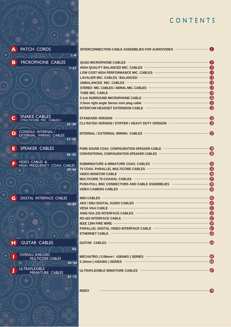
C O N T E N T S
INTERCONNECTION CABLE ASSEMBLIES FOR AUDIO/VIDEO
QUAD MICROPHONE CABLESHIGH QUALITY BALANCED MIC. CABLESLOW COST HIGH PERFORMANCE MIC. CABLESLAVALIER MIC. CABLES(BALANCED)UNBALANCED MIC. CABLES STEREO MIC. CABLES / AERIAL MIC. CABLES TUBE MIC. CABLE 5.1ch SURROUND MICROPHONE CABLE 3.5mm right angle Stereo mini plug cable INTERCOM HEADSET EXTENSION CABLE
1
7911131517
2019
STANDARD VERSION CL2 RATED VERSION / STIFFER + HEAVY DUTY VERSION
INTERNAL / EXTERNAL WIRING CABLES
PURE SOUND COAX. CONFIGURATION SPEAKER CABLE CONVENTIONAL CONFIGURATION SPEAKER CABLES
2122
2523
1~6
7~22
23~26
27
3029
27~28
64
29~32
SUBMINIATURE & MINIATURE COAX. CABLES 75 COAX. PARALLEL MULTICORE CABLES VIDEO MONITOR CABLE MULTICORE 75 COAXIAL CABLES PUSH-PULL BNC CONNECTORS AND CABLE ASSEMBLIESVIDEO CAMERA CABLES
GUITAR CABLES
ULTRAFLEXIBLE MINIATURE CABLES
3335
373943
33~4436
PATCH CORDS
MICROPHONE CABLES
SNAKE CABLES ( MULTICORE MIC. CABLES )
CONSOLE INTERNAL / EXTERNAL WIRING CABLES
SPEAKER CABLES
VIDEO CABLES & HIGH FREQUENCY COAX. CABLES
MIDI CABLES AES / EBU DIGITAL AUDIO CABLES VESA VGA CABLE ANSI / EIA 232 INTERFACE CABLES RS-422 INTERFACE CABLE IEEE 1394 FIRE WIRE PARALLEL DIGITAL VIDEO INTERFACE CABLEETHERNET CABLE
45475153
45~63
DIGITAL INTERFACE CABLES
57596163
MECHATRO ( 0.08mm2 / #28AWG ) SERIES 0.15mm2 ( #26AWG ) SERIES
6566
67
INDEX 74
65~66
OVERALL SHIELDED MULTICORE CABLES
64
GUITAR CABLES
67~72
ULTRAFLEXIBLE MINIATURE CABLES
A
B
C
D
E
F
G
H
I
J

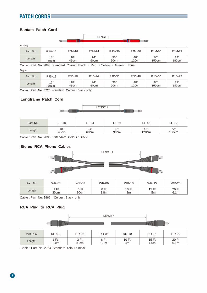
BANTAM TT PATCH CORDS
1
LONGFRAME PATCH CORDS
HIGH DEFINITION 75Ω AUDIOVIDEO PATCH CABLES AND
BALANCED 1/4" PLUG PATCH CORDS
PATCH CORDS
2
MOGAMI BANTAM AND LONGFRAME PATCH CORDS are the first high definition audio cables specifically designed for recording studio engineers and broadcast professionals, and offer the following outstanding features:
■ Super-flexible Quad-Balanced NEGLEX OFC wiring and Overall Served (Spiral) Shield provide maximum definition, detail and signal transparency in addition to giving excellent protection from electro-magnetic noise.
■ Both analog audio and digital audio patch cables are available.■ Maintenance free with durable nickel plated tip / ring / sleeve connector preventing from tarnishing. Degradation
of the sound quality caused by secular change becomes extremely low on account of it.■ Compact refined mold design permits use in high density jack fields. BANTAM PLUG : Overall Diameter 7.8mm ( 0.307" ) LONGFRAME PLUG : Overall Diameter 10.6mm (0.417" )■ Interchangeable colour rings for easy patch cord identification.■ Choice of five attractive colours for Bantam Patch Cord Only : Black・Red・Yellow・Green・Blue Available standard colour for longframe patch cord is Black only.■ Adaptor cable of bantam plug or longframe plug to other connector available to special order.■ Neglex OFC bulk cable also available in 50m (164Ft), 100m (328Ft) and 200m (656Ft) rolls : Analog cable : Part No.2893 Digital cable : Part No.3228
OTHER VARIATION OF AUDIO AND VIDEO PATCH CABLESSupplemented to TT Patch Cables, many other variation of audio and video patch cables are available in standard lengths. Available combination is RCA Plug, 2P and 3P 1/4" Phone Plug with original mold cover and one touc push-pull BNC connector. Used unbalanced audio cable Part No. 2964 is designed to be 75Ω coaxial cable comprised of OFC conductor so that it can be used for video signal as well as audio signal application with its low capacitance value of 65pF/m (19.8pF/Ft). Stereo cable Part No. 2965 is basically dual version of 2964 so that it can be also used for video signal.
PATCH CORDS
3
Stereo RCA Phono Cables
Part No.
Length
WR-01 WR-03 WR-06 WR-10 WR-15 WR-20
1 Ft30cm
3 Ft90cm
6 Ft1.8m
10 Ft3m
15 Ft4.5m
20 Ft6.1m
Cable : Part No. 2965 Colour : Black only
Bantam Patch Cord
Part No.
Length
PJM-12 PJM-18 PJM-24 PJM-36 PJM-48 PJM-72
12"30cm
18"45cm
24"60cm
36"90cm
48"120cm
60"150cm
Cable : Part No. 2893 standard Colour : Black ・ Red ・Yellow ・ Green・ Blue
Analog
Digital
Longframe Patch Cord
Part No.
Length
LF-18 LF-24 LF-36 LF-48 LF-72
18"45cm
24"60cm
36"90cm
48"120cm
72"180cm
Cable : Part No. 2893 Standard Colour : Black
PJM-60
72"180cm
Part No.
Length
PJD-12 PJD-18 PJD-24 PJD-36 PJD-48 PJD-72
12"30cm
18"45cm
24"60cm
36"90cm
48"120cm
60"150cm
Cable : Part No. 3228 standard Colour : Black only
PJD-60
72"180cm
RCA Plug to RCA Plug
Part No.
Length
RR-01 RR-03 RR-06 RR-10 RR-15 RR-20
1 Ft30cm
3 Ft90cm
6 Ft1.8m
10 Ft3m
15 Ft4.5m
20 Ft6.1m
Cable : Part No. 2964 Standard colour : Black
LENGTH
LENGTH
LENGTH
LENGTH
PATCH CORDS
4
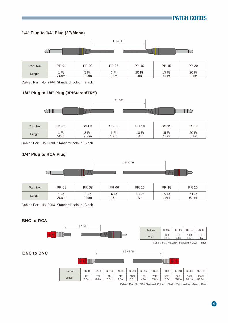
1/4" Plug to 1/4" Plug (2P/Mono)
1/4" Plug to RCA Plug
1/4" Plug to 1/4" Plug (3P/Stereo/TRS)
Cable : Part No .2964 Standard colour : Black
Cable : Part No .2893 Standard colour : Black
Cable : Part No .2964 Standard colour : Black
Part No.
Length
PP-01 PP-03 PP-06 PP-10 PP-15 PP-20
1 Ft30cm
3 Ft90cm
6 Ft1.8m
10 Ft3m
15 Ft4.5m
20 Ft6.1m
Part No.
Length
SS-01 SS-03 SS-06 SS-10 SS-15 SS-20
1 Ft30cm
3 Ft90cm
6 Ft1.8m
10 Ft3m
15 Ft4.5m
20 Ft6.1m
Part No.
Length
PR-01 PR-03 PR-06 PR-10 PR-15 PR-20
1 Ft30cm
3 Ft90cm
6 Ft1.8m
10 Ft3m
15 Ft4.5m
20 Ft6.1m
Part No.
Length
BB-01 BB-02 BB-06BB-03 BB-10 BB-16 BB-25 BB-33 BB-50 BB-66 BB-100
1Ft0.3m
2Ft0.6m
3Ft0.9m
6Ft1.8m
10Ft3.0m
16Ft4.8m
25Ft7.6m
33Ft10.0m
50Ft15.2m
66Ft20.1m
100Ft30.5m
LENGTHBNC to BNC
Cable : Part No. 2964 Standard Colour : Black・Red・Yellow・Green・Blue
BNC to RCALENGTH
LENGTH
LENGTH
LENGTH
Part No.
Length
BR-03 BR-06 BR-16BR-10
3Ft0.9m
6Ft1.8m
10Ft3.0m
16Ft4.8m
Cable : Part No. 2964 Standard Colour : Black

PATCH CORDS
5
CABLE SPECIFICATIONS
Part No. 2964 2965 2893No. of Conductor 1(Mono) 2×1(Dual) 4(Quad)
Conductor Details
Size(mm2)Ov. Dia.(mm)MaterialColours
Ov. Dia.(mm) Material Colours
Insulation
Served Shield
Jacket
Roll Sizes
Weight
0.226mm2 (#24 AWG)
2.65φ(0.104")XLCPE (Cross-Linked Cellular PE)
Clear
0.15mm2 (#26 AWG)1.0φ(0.039")
XLPEBlack/Red/Blue/Clear
4.8φ(0.189")Flexible PVC
Black/Red/Yellow/Green/Blue Black50m/100m/200m
(164 Ft /328Ft/656Ft)77m /153m
(250 Ft /500 Ft )50m/100m/200m
(164Ft/328Ft/656 Ft)
3.4kg/100m(328Ft) 8.9kg/153m(500Ft) 7.5kg/200m(656Ft)
ELECTRICAL & MECHANICAL CHARACTERISTICSPart No.
Capacitance at 1kHz,20℃
Inductance between conductors at 1kHz. 20℃Characteristic Impedance(10MHz)Attenuation(10MHz) Phase Constant(10MHz)
Electrostatic NoiseMicrophonics at 50KΩ LoadVoltage BreakdownInsulation ResistanceFlex LifeTensile StrengthEmigrationApplicable Temperature
Inner Cond.Shield
DC Resistance at20℃
2964 2965 28930.083Ω/m(0.025Ω/Ft)
0.012Ω/m(0.0037Ω/Ft) 0.025Ω/m(0.0076Ω/Ft)57pF/m(17.4pF/Ft)
0.4μH/m(0.12μH/Ft)
75Ω0.047dB/m(0.014db/Ft)
0.3 rad/m50m V Max.40m V Max.
Must withstand at DC 500V/15sec.105 M Ω・m Min. at DC 125V,20℃
16,000cycles274N
16,500cycles539N
26,000cycles500N
non–emigrant to ABS resin-20℃~ +70℃(-4°F~ +158°F)
0.13Ω/m(0.040Ω/Ft)0.023Ω/m(0.0070Ω/Ft)
Ref. Page 8.
0.5μH/m(0.15μH/Ft)
---
50m V Max.30m V Max.
(1)Attenuation 1 dB=0.1151 neper ( 1 neper=8.686 dB )(2)Using standard testing methods of Mogami Wire & Cable Corp.
Black/Red/Yellow/Green/Blue
High frequency characteristics of Part No.2964 and #2965.
Note : For digital audio cable Part No.3228 cable, see page48
*(1)
*(2)
*(2)
*(2)
Configuration
**
20/0.12 OFC 30/0.08 OFC
Double Served Shield Approx.66/0.12 OFC, Approx.72/0.12 OFC Approx.66/0.12 OFC Approx.72/ 0.12A
200
150
100
5010 100 1000 1e+04freq. KHZ
abs〔Z〕ohm0
-0.5
-110 100 1000 1e+04
freq. KHZ
arg〔Z〕rad0.006
0.004
0.002
010 100 1000 1e+04freq. KHZ
atten. nepar/m1
0.10.01
0.0010.0001
10 100 1000 1e+04freq. KHZ
phase rad/m
PATCH CORDS
6
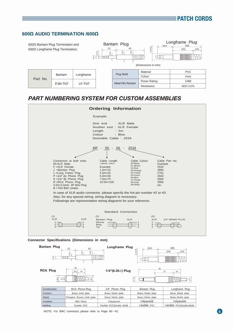
PART NUMBERING SYSTEM FOR CUSTOM ASSEMBLIES
In case of XLR audio connector, please specify the hot pin number #2 or #3.Also, for any special wiring, wiring diagram is necessary.Followings are representative wiring diagrams for your reference.
Ordering Information
One end : XLR MaleAnother end : XLR FemaleLength : 5mColour : BlueDesirable Cable : 2534
Part No.
Example
MF - 50 - 06 - 2534
Connectors at both endsM=XLR MaleF =XLR FemaleJ =Bantam PlugL =Long Frame PlugP =1/4" 2p Phone PlugS =1/4" 3p Phone PlugR =RCA Phono Plug3.5S=3.5mm 3P Mini PlugB =75Ω BNC (male)
Cable Length ( specify units )
Example1.0m=102.5m=255.0m=507.5m=7510.0m=100
Cable Colour00=Black01=Brown02=Red03=Orange04=Yellow05=Green06=Blue07=Purple08=Gray09=White
Cable Part No.Example253428932791255229642965etc.
Construction Contacts
Shield
Insulation
Molding
Brass, Gold plate
Phosphor Bronze, Gold plate
ABS Resin
Flexible PVC
RCA Phono Plug 1/4" Phone PlugBrass, Nickel plate
Brass, Nickel plate
Polystyrene
Flexible PVC(Double Mold)
Bantam PlugBrass, Nickel plate
Brass, Nickel plate
PolyacetalFlexible PVC
Longframe PlugBrass, Nickel plate
Brass, Nickel plate
PolyacetalFlexible PVC(Double Mold)
Connector Specifications (Dimensions in mm)
Bantam Plug
NOTE: For BNC connector, please refer to Page 40~42.
Longframe Plug
RCA Plug 1/4"(6.35φ) Plug
Bantam Plug (48)
(φ10
.6) 26.0
Longframe Plug(34) (14)
(Dimensions in mm)
22
4.4φ
3.17φ
4.4φ 7.6φ
7.8φ
43
(48)
(φ10
.6) 26.0
(34) (14)22
4.4φ
4.4φ 7.6φ
7.8φ
43
36
9.9 14
11φ
12φ
600Ω AUDIO TERMINATION /600Ω
600Ω Bantam Plug Termination and 600Ω Longframe Plug Termination.
Bantam Longframe
PJM-TNT LF-TNT
Standard Connection(3)XLRXLR 1/4" MONO PLUG132
123
123
(2)(1)Bantam PlugXLR XLRSleeveRingTip
132
12φ
11.7φ
37 1482
Plug Mold
Metal Film Resistor
Material Colour Power Rating
Resistance
PVC Ivory 1/4W
602Ω±1%
7
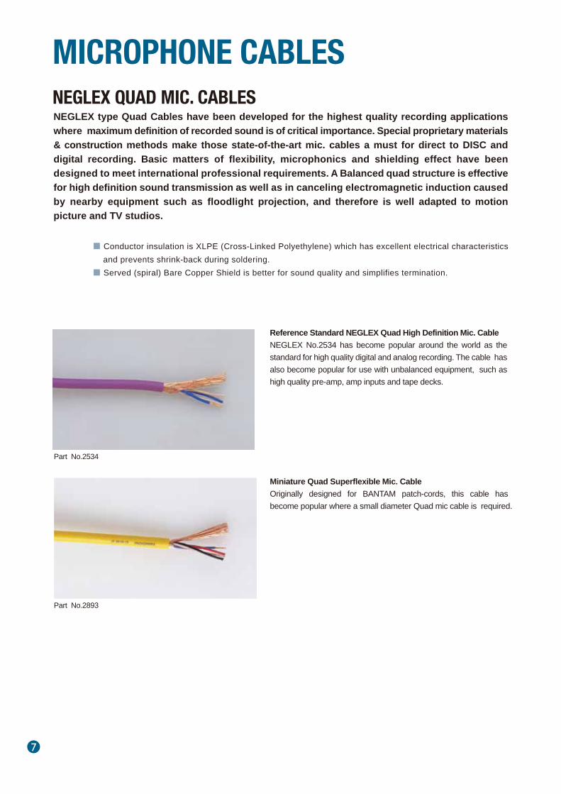
NEGLEX type Quad Cables have been developed for the highest quality recording applications where maximum definition of recorded sound is of critical importance. Special proprietary materials & construction methods make those state-of-the-art mic. cables a must for direct to DISC and digital recording. Basic matters of flexibility, microphonics and shielding effect have been designed to meet international professional requirements. A Balanced quad structure is effective for high definition sound transmission as well as in canceling electromagnetic induction caused by nearby equipment such as floodlight projection, and therefore is well adapted to motion picture and TV studios.
■ Conductor insulation is XLPE (Cross-Linked Polyethylene) which has excellent electrical characteristics and prevents shrink-back during soldering.
■ Served (spiral) Bare Copper Shield is better for sound quality and simplifies termination.
Reference Standard NEGLEX Quad High Definition Mic. Cable NEGLEX No.2534 has become popular around the world as the standard for high quality digital and analog recording. The cable has also become popular for use with unbalanced equipment, such as high quality pre-amp, amp inputs and tape decks.
Miniature Quad Superflexible Mic. CableOriginally designed for BANTAM patch-cords, this cable has become popular where a small diameter Quad mic cable is required.
NEGLEX QUAD MIC. CABLES
MICROPHONE CABLES
Part No.2534
Part No.2893
8
Part No.
Configuration
No. of Conductor
Details ConductorSize(mm2 ) Ov. Dia.(mm) Material Colours
Insulation
Served Shield
JacketOv. Dia.(mm) Material Colours
Roll Sizes
Weight per 200m Roll
2534 2893
20/0.12 OFC0.226mm2(#24AWG)
1.6φ(0.063")
Blue/Clear(Quad)Approx. 62/0.18A
30/0.08 OFC0.15mm2(#26AWG)
1.0φ(0.039")
Black/Red/Blue/ClearApprox. 72/0.12A
XLPE( Cross-Linked Polyethylene )
6.0φ(0.236")Flexible PVC
10 colours available
4.8φ(0.189")Flexible PVC
5 colours available50 m (164Ft)100m (328Ft)200m (656Ft)
50 m (164Ft)100m (328Ft)200m (656Ft)
4
11 kg 7.5kg
0.083Ω/m(0.025Ω/Ft)0.012Ω/m(0.0037Ω/Ft)
65pF/m(20 pF/Ft)13pF/m(4 pF/Ft)4pF/m(1.2 pF/Ft)
97pF/m(29.6 pF/Ft)110pF/m(33.6 pF/Ft)
74pF/m(23 pF/Ft)11pF/m(3.4 pF/Ft)3pF/m(0.9 pF/Ft)
131pF/m(40 pF/Ft)178pF/m(54 pF/Ft)
0.13Ω/m(0.040Ω/Ft)0.023Ω/m(0.0070Ω/Ft)
50 mV Max.0.15 mV Max.
0.4μH/m (0.12μH/Ft) 0.5μH/m(0.15μH/Ft)
50 mV Max.0.15 mV Max.30 mV Max.30 mV Max.
Must withstand at DC 500V/15 sec. 105 MΩ・m Min. at DC 125 V, 20℃
11,000 cycles686 N
26,000 cycles500 N
Non-Emigrant to ABS-20℃~ + 70℃ (-4 F゚~ + 158 F゚)
Part No.
Capacitance at 1kHz, 20℃ ( Partial C. Value )See below figure
Inner Cond. Shield
DC Resistanceat 20℃
*(1)
Balanced QuadConnection
K0
K1
K2
Cond.-Cond.Cond.-Shield.
Inductance betweenn conductorsat 1kHz, 20℃
Electrostatic Noise Electromagnetic Noise Microphonics at 50kΩ Load
*(2)
*(2)
*
Voltage BreakdownInsulation ResistanceFlex LifeTensile StrengthEmigrationApplicable Temperature
(2) Using standard testing methods of Mogami Wire & Cable Corp.
2534 2893
*(2)
*(2)
SPECIFICATIONS
NEGLEX QUAD MIC. CABLES
ELECTRICAL & MECHANICAL CHARACTERISTICS
K0 K0
K0
K0
K1
K1
K1
K2
K2
K1
(1) Partial Capacitance *
MICROPHONE CABLES
9
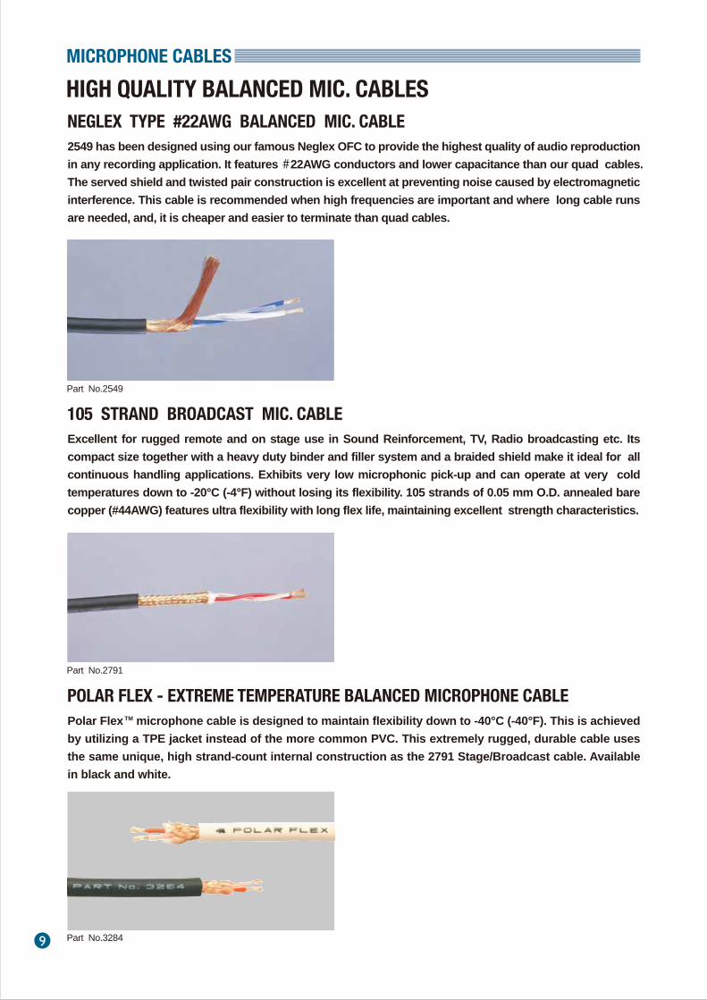
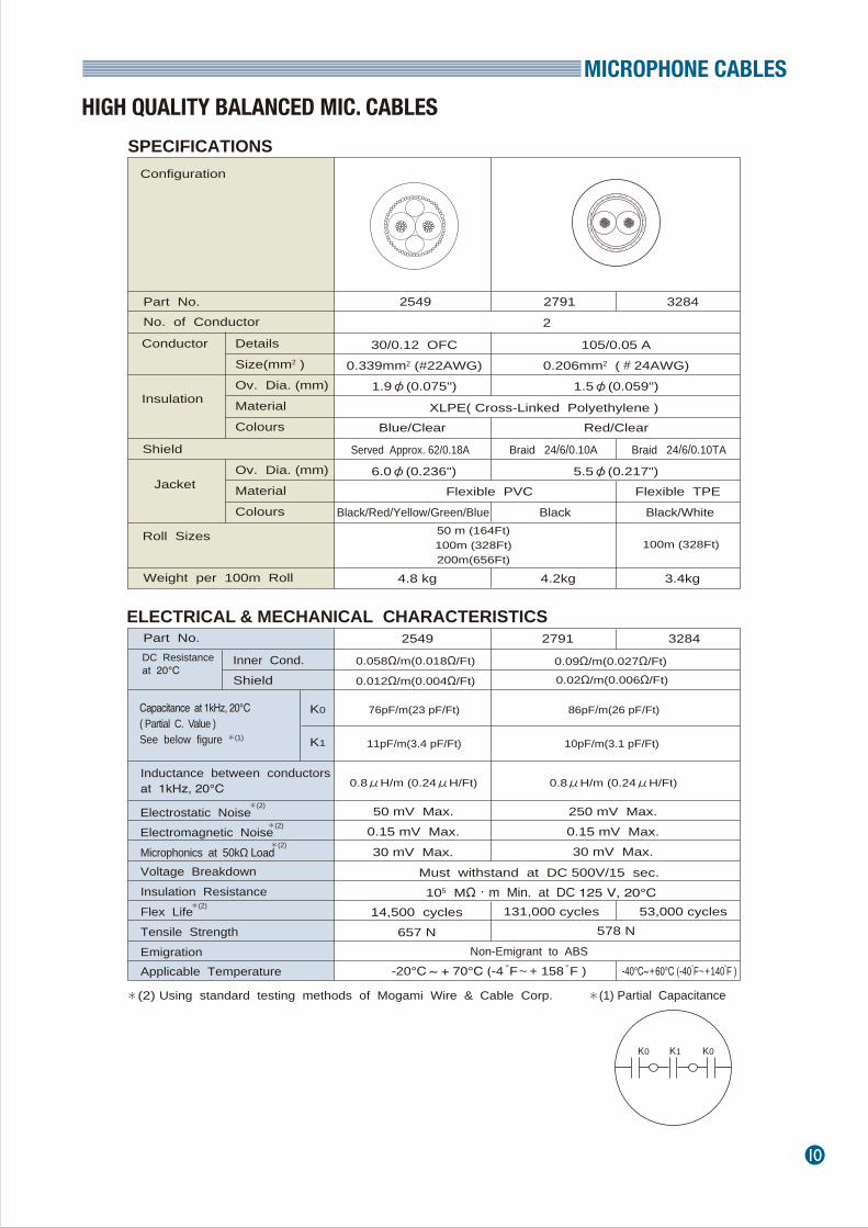
2549 has been designed using our famous Neglex OFC to provide the highest quality of audio reproduction in any recording application. It features #22AWG conductors and lower capacitance than our quad cables. The served shield and twisted pair construction is excellent at preventing noise caused by electromagnetic interference. This cable is recommended when high frequencies are important and where long cable runs are needed, and, it is cheaper and easier to terminate than quad cables.
HIGH QUALITY BALANCED MIC. CABLESNEGLEX TYPE #22AWG BALANCED MIC. CABLE
MICROPHONE CABLES
Part No.2549
Excellent for rugged remote and on stage use in Sound Reinforcement, TV, Radio broadcasting etc. Its compact size together with a heavy duty binder and filler system and a braided shield make it ideal for all continuous handling applications. Exhibits very low microphonic pick-up and can operate at very cold temperatures down to -20°C (-4°F) without losing its flexibility. 105 strands of 0.05 mm O.D. annealed bare copper (#44AWG) features ultra flexibility with long flex life, maintaining excellent strength characteristics.
105 STRAND BROADCAST MIC. CABLE
Part No.2791
Polar Flex TM microphone cable is designed to maintain flexibility down to -40°C (-40°F). This is achieved by utilizing a TPE jacket instead of the more common PVC. This extremely rugged, durable cable uses the same unique, high strand-count internal construction as the 2791 Stage/Broadcast cable. Available in black and white.
POLAR FLEX - EXTREME TEMPERATURE BALANCED MICROPHONE CABLE
Part No.3284
MICROPHONE CABLES
10
Part No. No. of Conductor
Details ConductorSize(mm2 ) Ov. Dia. (mm) Material Colours
Insulation
Shield
JacketOv. Dia. (mm) Material Colours
Roll Sizes
Weight per 100m Roll
2549 2791 3284
30/0.12 OFC0.339mm2 (#22AWG)
1.9φ(0.075")
Blue/Clear
105/0.05 A0.206mm2 (#24AWG)
1.5φ(0.059")
Red/ClearXLPE( Cross-Linked Polyethylene )
6.0φ(0.236") 5.5φ(0.217")
50 m (164Ft)100m (328Ft)200m(656Ft)
2
4.8 kg 4.2kg 3.4kg
0.058Ω/m(0.018Ω/Ft)
0.012Ω/m(0.004Ω/Ft)
86pF/m(26 pF/Ft)
0.09Ω/m(0.027Ω/Ft)
0.8μH/m (0.24μH/Ft)
250 mV Max.0.15 mV Max.30 mV Max.30 mV Max.
Must withstand at DC 500V/15 sec. 105 MΩ・m Min. at DC 125 V, 20℃
14,500 cycles657 N 578 N
Non-Emigrant to ABS-20℃ ~ + 70℃ (-4 F゚ ~ + 158 F゚ ) -40℃~ + 60℃ (-40 F゚ ~ + 140 F゚ )
Part No.
Capacitance at 1kHz, 20℃( Partial C. Value )See below figure
Inner Cond. Shield
DC Resistanceat 20℃
*(1)
K0
K1
Inductance between conductorsat 1kHz, 20℃
Electrostatic Noise Electromagnetic Noise Microphonics at 50kΩ Load
*(2)
*(2)
Voltage BreakdownInsulation ResistanceFlex LifeTensile StrengthEmigrationApplicable Temperature
(2) Using standard testing methods of Mogami Wire & Cable Corp.
2549 32842791
Served Approx. 62/0.18A
100m (328Ft)
0.02Ω/m(0.006Ω/Ft)
76pF/m(23 pF/Ft)
10pF/m(3.1 pF/Ft)11pF/m(3.4 pF/Ft)
0.8μH/m (0.24μH/Ft)
50 mV Max.0.15 mV Max.*(2)
* *
*(2)
SPECIFICATIONS
ELECTRICAL & MECHANICAL CHARACTERISTICS
Configuration
K0 K0K1
(1) Partial Capacitance
Braid 24/6/0.10A Braid 24/6/0.10TA
Black/Red/Yellow/Green/Blue Black/WhiteBlackFlexible PVC Flexible TPE
131,000 cycles 53,000 cycles
HIGH QUALITY BALANCED MIC. CABLES
11
A specially developed high performance yet economical series of low impedance balanced microphone cables. These cables are small in size and special rubber‐like PVC jacket is extremely flexible and exhibits good resistance to rough handling and abrasion.High grade insulation material is designed to minimize heat shrinkage during soldering which allows easy termination to XLR type connectors. Available in both overall and individually sheilded types.
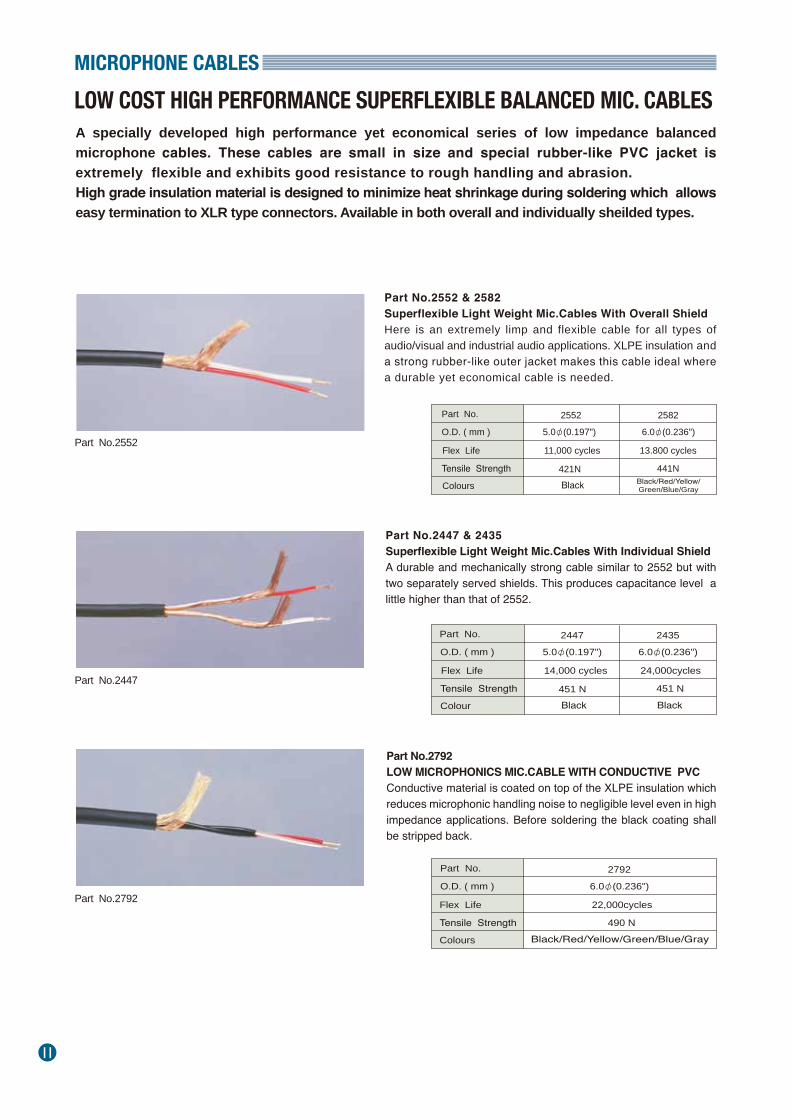
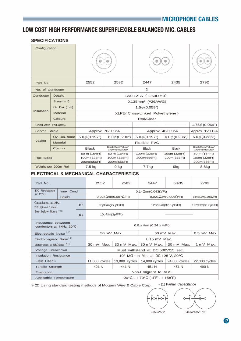
LOW COST HIGH PERFORMANCE SUPERFLEXIBLE BALANCED MIC. CABLES
MICROPHONE CABLES
Part No.2552
Part No.2552 & 2582Superflexible Light Weight Mic.Cables With Overall Shield Here is an extremely limp and flexible cable for all types of audio/visual and industrial audio applications. XLPE insulation and a strong rubber‐like outer jacket makes this cable ideal where a durable yet economical cable is needed.
Part No.2447
Part No.2447 & 2435Superflexible Light Weight Mic.Cables With Individual Shield A durable and mechanically strong cable similar to 2552 but with two separately served shields. This produces capacitance level a little higher than that of 2552.
Part No.2792
Part No.2792LOW MICROPHONICS MIC.CABLE WITH CONDUCTIVE PVC Conductive material is coated on top of the XLPE insulation which reduces microphonic handling noise to negligible level even in high impedance applications. Before soldering the black coating shall be stripped back.
Part No. 2552 2582
O.D. ( mm )
Flex Life
Tensile Strength
Colours
5.0φ(0.197")
11,000 cycles 13.800 cycles
421NBlack/Red/Yellow/Green/Blue/GrayBlack
441N
6.0φ(0.236")
Part No. 2447 2435
O.D. ( mm )
Flex Life
Tensile Strength
Colour
5.0φ(0.197")
14,000 cycles 24,000cycles
451 NBlack
451 N
6.0φ(0.236")
Black
Part No. 2792
O.D. ( mm )
Flex Life
Tensile Strength
Colours
22,000cycles
Black/Red/Yellow/Green/Blue/Gray490 N
6.0φ(0.236")
MICROPHONE CABLES
12
Part No.
Configuration
No. of Conductor
Details Conductor
Size(mm )
Ov. Dia. (mm)
Material
Colours
2
Insulation
Served Shield
Jacket
Roll Sizes
Weight per 200m Roll
2552 2582
12/0.12 A〈T250D*3〉0.135mm2 (#26AWG)
1.5φ(0.059")
Red/ClearXLPE( Cross-Linked Polyethylene )
5.0φ(0.197")
Black
6.0φ(0.236") 6.0φ(0.236")
Black50 m (164Ft)100m (328Ft)200m(656Ft)
2
7.5 kg 9kg 8.8kg
0.14Ω/m(0.043Ω/Ft)
127pF/m(38.7 pF/Ft)
50 mV Max. 0.5 mV Max.
1 mV Max.30 mV Max. 30 mV Max.Must withstand at DC 500V/15 sec. 105 MΩ・m Min. at DC 125 V, 20℃
11,000 cycles421 N
14,000 cycles451 N
24,000 cycles451 N
Non-Emigrant to ABS-20℃~ + 70℃ (-4 F゚~ + 158 F゚)
Part No.
Capacitance at 1kHz, 20℃ ( Partial C. Value )
See below figure
Inner Cond.
Shield
DC Resistanceat 20℃
*(1)
K0
K1
Inductance betweenn conductors at 1kHz, 20℃
Electrostatic Noise
Electromagnetic Noise
Microphonics at 50kΩ Load
*(2)
* *
*(2)
Voltage Breakdown
Insulation Resistance
Flex LifeTensile Strength
Emigration
Applicable Temperature
(2) Using standard testing methods of Mogami Wire & Cable Corp.
2552 2582 2792
Approx. 70/0.12A Approx. 40/0.12A
50 m (164Ft)100m (328Ft)200m(656Ft)
0.021Ω/m(0.006Ω/Ft) 0.018Ω/m(0.005Ω/Ft)
90pF/m(27 pF/Ft) 123pF/m(37.5 pF/Ft)
10pF/m(3pF/Ft)
0.8μH/m (0.24μH/Ft)
50 mV Max.
2447 2435
Conductive PVC(mm) 1.75φ(0.069")
Approx. 95/0.12A
5.0φ(0.197")Flexible PVC
BlackBlack/Red/Yellow/Green/Blue/Gray
Black/Red/Yellow/Green/Blue/Gray
6.0φ(0.236")
50 m (164Ft)100m (328Ft)200m(656Ft)
100m (328Ft)200m(656Ft)
100m (328Ft)200m(656Ft)
9 kg 7.7kg
2447 2435 2792
0.024Ω/m(0.007Ω/Ft)
30 mV Max. 30 mV Max.
13,800 cycles441 N
22,000 cycles490 N
*(2)
*(2)
SPECIFICATIONS
ELECTRICAL & MECHANICAL CHARACTERISTICS
(1) Partial Capacitance
2552/2582 2447/2435/2792
K0K0 K0K0K1
Ov. Dia. (mm)
Material
Colours
0.15 mV Max.
LOW COST HIGH PERFORMANCE SUPERFLEXIBLE BALANCED MIC. CABLES
13
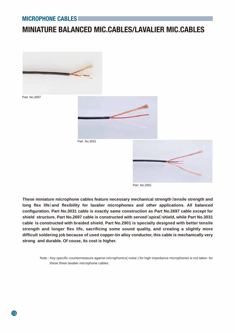
These miniature microphone cables feature necessary mechanical strength(tensile strength and long flex life)and flexibility for lavalier microphones and other applications. All balanced configuration. Part No.3031 cable is exactly same construction as Part No.2697 cable except for shield structure. Part No.2697 cable is constructed with served(spiral)shield, while Part No.3031 cable is constructed with braided shield. Part No.2901 is specially designed with better tensile strength and longer flex life, sacrificing some sound quality, and creating a slightly more difficult soldering job because of used copper-tin alloy conductor, this cable is mechanically very strong and durable. Of couse, its cost is higher.
MINIATURE BALANCED MIC.CABLES/LAVALIER MIC.CABLES
MICROPHONE CABLES
Part No.2697
Part No.3031
Part No.2901
Note : Any specific countermeasure against microphonics( noise ) for high impedance microphones is not taken for these three lavalier microphone cables.

MICROPHONE CABLES
14
SPECIFICATIONS
ELECTRICAL & MECHANICAL CHARACTERISTICS
Part No.
Configuration
No. of Conductor
Details Conductor
Size(mm2) Ov. Dia. (mm) Material Colours
Insulation
Shield
Filler Thread
JacketOv. Dia. (mm) Material Colours
Roll Sizes
Weight
2697
2.5φ(0.098") 2.8φ(0.110")
50 m (164Ft)100m (328Ft)200m (656Ft)
1.8kg/200m
290pF/m(88 pF/Ft)
0.063Ω/m(0.019Ω/Ft) 0.038Ω/m(0.0116Ω/Ft)
0.23Ω/m(0.070Ω/Ft)
0.8μH/m (0.24μH/Ft)
50 mV Max.
300mV Max.
200mV Max.0.15 mV Max.150mV Max.
1mV Max.
40mV Max.Must withstand at DC 500V/15 sec.
105MΩ・m Min. at DC 125 V, 20℃34,100 cycles 26,000 cycles 177,000 cycles
Non-Emigrant to ABS resin-20℃~ + 70℃ (-4 F゚~ + 158 F゚)
Part No.
Capacitance at 1kHz, 20℃( Partial C. Value )See below figure
Inner Cond. Shield
DC Resistanceat 20℃
*(1)
K0
K1
Inductance between conductorsat 1kHz, 20℃
Electrostatic Noise Electromagnetic Noise Microphonics at 50kΩ Load
*(2)
*(2)
* *
Voltage BreakdownInsulation ResistanceFlex LifeTensile StrengthEmigrationApplicable Temperature
(2) Using standard testing methods of Mogami Wire & Cable Corp. (1) Partial Capacitance
2697 29013031
29013031
2
16/0.08 A〈T1000D*1〉0.08mm2(#29AWG)
0.85φ(0.033")
Red/WhitePVC
70pF/m(21 pF/Ft)
176pF/m(54 pF/Ft)
0.07Ω/m(0.0214Ω/Ft)
0.41Ω/m(0.125Ω/Ft)
32pF/m(9.8 pF/Ft)
300pF/m(92pF/Ft)
57pF/m(17pF/Ft)
*(2)
*(2)
Served Shield Braided Shield Double Served Shield
200m (656Ft)(on spool)
16/6/0.08A Approx.36/0.08A, Approx.40/0.08AApprox.60/0.08A
2.5kg/200m
43/0.04 Cu-Sn
2.16φ(0.085")
Black
305 m (1000Ft)
2.6kg/305m
0.054mm2(#30AWG)
0.6φ(0.0236")
Black/RedPolyester
Polypropylene
Black Black/White
Flexible PVC
294 N 313 N 176 N
K0 K0K1
MINIATURE BALANCED MIC.CABLES/LAVALIER MIC.CABLES
15
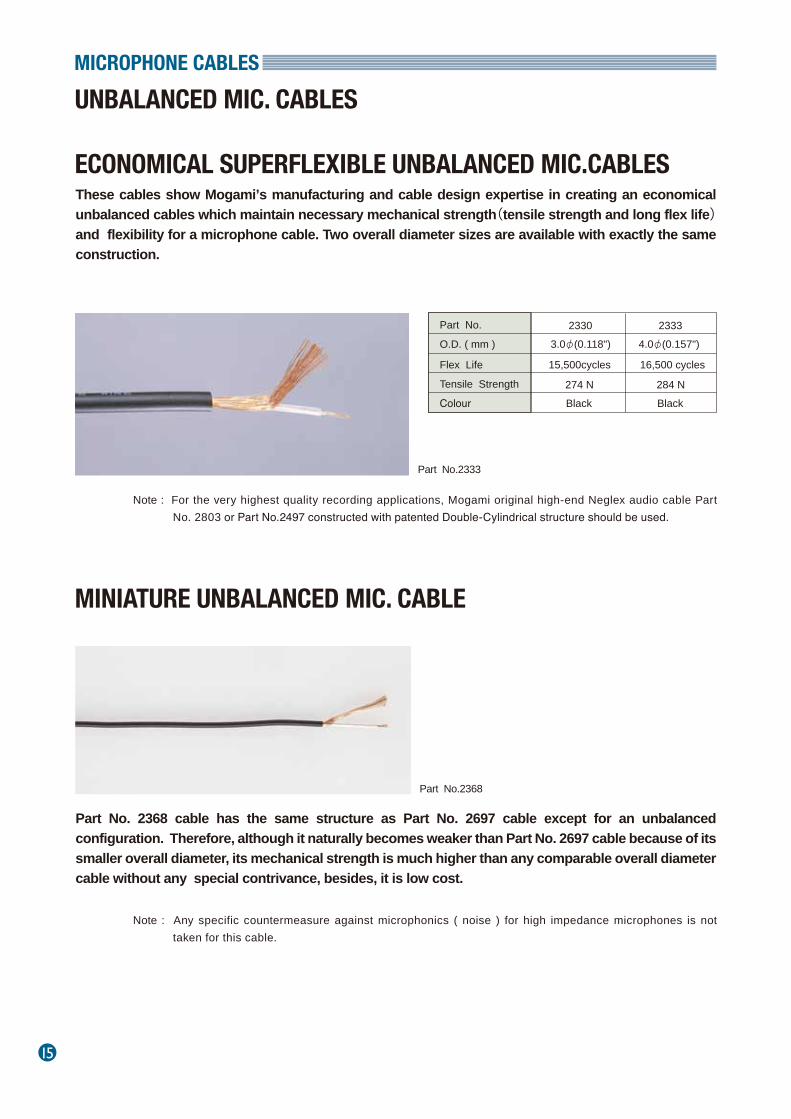
These cables show Mogami’s manufacturing and cable design expertise in creating an economical unbalanced cables which maintain necessary mechanical strength(tensile strength and long flex life)and flexibility for a microphone cable. Two overall diameter sizes are available with exactly the same construction.
UNBALANCED MIC. CABLES
MINIATURE UNBALANCED MIC. CABLE
ECONOMICAL SUPERFLEXIBLE UNBALANCED MIC.CABLES
MICROPHONE CABLES
Part No.2333
Part No.2368
Part No. 2368 cable has the same structure as Part No. 2697 cable except for an unbalanced configuration. Therefore, although it naturally becomes weaker than Part No. 2697 cable because of its smaller overall diameter, its mechanical strength is much higher than any comparable overall diameter cable without any special contrivance, besides, it is low cost.
Note : For the very highest quality recording applications, Mogami original high-end Neglex audio cable Part No. 2803 or Part No.2497 constructed with patented Double‐Cylindrical structure should be used.
Part No. 2330 2333O.D. ( mm )
Flex Life
Tensile Strength
Colour
3.0φ(0.118")
15,500cycles 16,500 cycles
274 N 284 NBlack
4.0φ(0.157")
Black
Note : Any specific countermeasure against microphonics ( noise ) for high impedance microphones is not taken for this cable.
MICROPHONE CABLES
16
SPECIFICATIONS
ELECTRICAL & MECHANICAL CHARACTERISTICS
UNBALANCED MIC. CABLES / LAVALIER MIC. CABLE
Part No.
Configuration
No. of Conductor
Details ConductorSize(mm ) Ov. Dia.(mm) Material Colour
2
Insulation
Served Shield
JacketOv. Dia.(mm)Material Colour
Roll Sizes
Weight per 200m Roll
2330 2333 2368
1.5φ(0.059")
ClearApprox. 40/0.12A
1.0φ(0.039")
WhiteApprox. 40/0.08A
XLPE( Cross‐Linked polyethylene )
3.0φ(0.118") 4.0φ(0.157")
Black
2.0φ(0.079")
100m (328Ft)200m(656Ft)
200 m (656Ft)(standard)
100 m (328Ft)200 m (656Ft)
1
2.5 kg 4.2kg 1.5kg
0.042Ω/m(0.013Ω/Ft)
350pF/m(107 pF/Ft)
0.23Ω/m(0.07Ω/Ft)
0.094Ω/m(0.029Ω/Ft)
50 mV Max.
0.05 mV Max.
0.3μH/m (0.092μH/Ft)
0.05 mV Max.1V Max.30 mV Max.
Must withstand at DC 500V/15 sec. 105MΩ・m Min. at DC 125 V, 20℃
15,500 cycles274 N
16,500 cycles284 N
43,000 cycles206 N
Non-Emigrant to ABS resin-20℃~ + 70℃ (-4 F゚~ + 158 F゚)
Part No.
Capacitance at 1kHz, 20℃See below figure
Inner Cond. Shield
DC Resistance at 20℃
*(1) K0
Inductance between conductorsat 1kHz, 20℃
Electrostatic Noise Electromagnetic Noise Microphonics at 50kΩ Load
*(2)
*(2)
Voltage BreakdownInsulation ResistanceFlex LifeTensile StrengthEmigrationApplicable Temperature
(2) Using standard testing methods of Mogami Wire & Cable Corp.
2330 2333 2368
16/0.08 A〈T1000D*1〉0.08mm2(#29AWG)
PVC
Flexible PVC
115pF/m(35 pF/Ft)
*(2)
*(2)
* * (1) Partial Capacitance
Ko
17
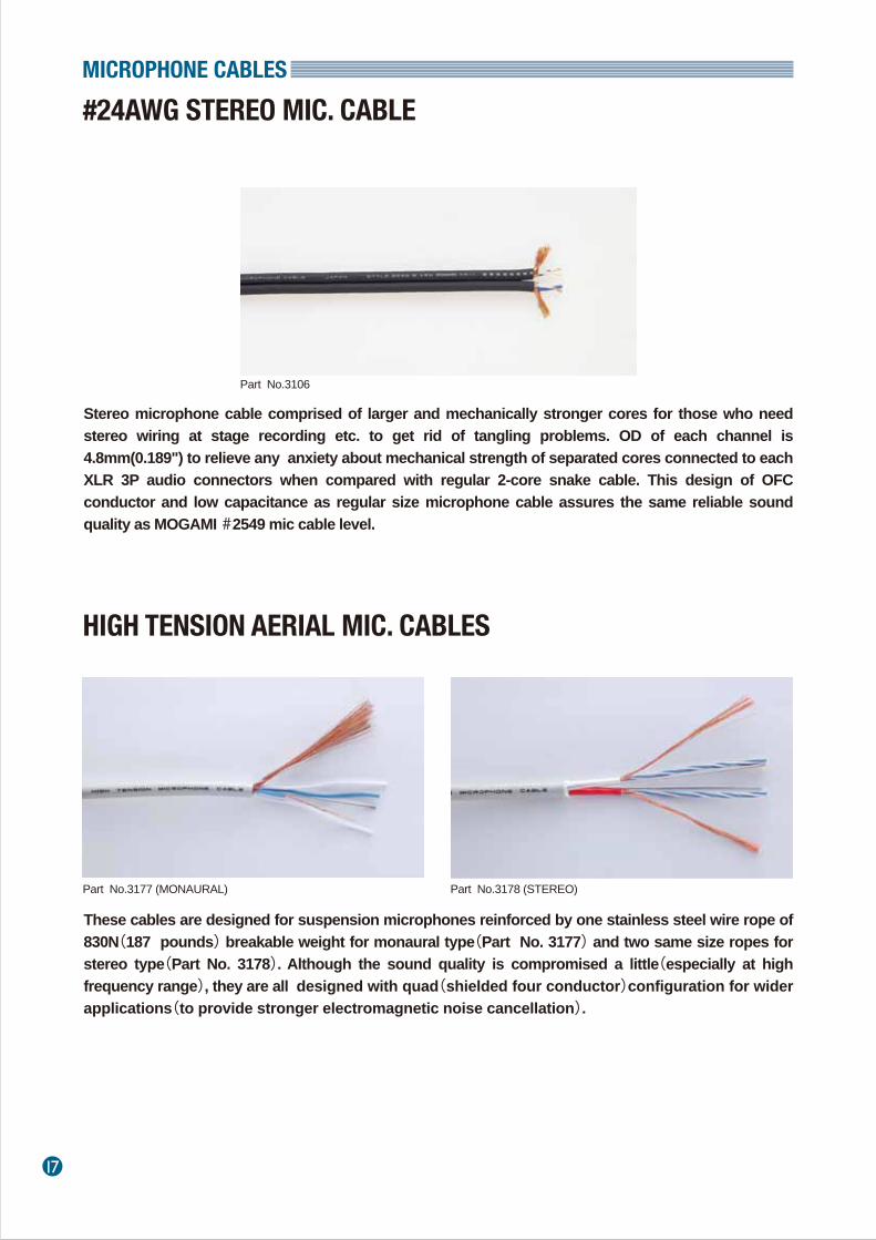
Stereo microphone cable comprised of larger and mechanically stronger cores for those who need stereo wiring at stage recording etc. to get rid of tangling problems. OD of each channel is 4.8mm(0.189") to relieve any anxiety about mechanical strength of separated cores connected to each XLR 3P audio connectors when compared with regular 2-core snake cable. This design of OFC conductor and low capacitance as regular size microphone cable assures the same reliable sound quality as MOGAMI #2549 mic cable level.
#24AWG STEREO MIC. CABLE
HIGH TENSION AERIAL MIC. CABLES
MICROPHONE CABLES
Part No.3106
Part No.3177 (MONAURAL) Part No.3178 (STEREO)
These cables are designed for suspension microphones reinforced by one stainless steel wire rope of 830N(187 pounds) breakable weight for monaural type(Part No. 3177) and two same size ropes for stereo type(Part No. 3178). Although the sound quality is compromised a little(especially at high frequency range), they are all designed with quad(shielded four conductor)configuration for wider applications(to provide stronger electromagnetic noise cancellation).
MICROPHONE CABLES
18
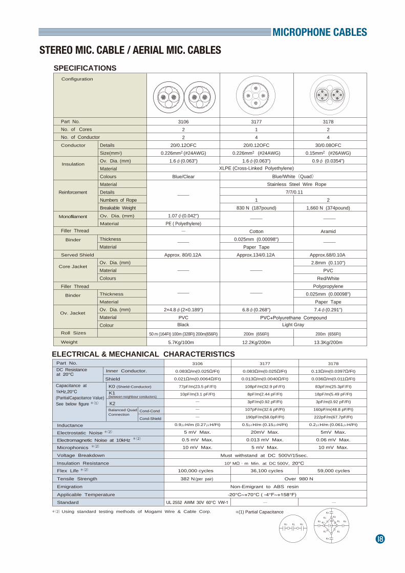
SPECIFICATIONS
ELECTRICAL & MECHANICAL CHARACTERISTICS
STEREO MIC. CABLE / AERIAL MIC. CABLES
Part No. No. of CoresNo. of Conductor
Configuration
DetailsSize(mm2)Ov. Dia. (mm)MaterialColoursMaterialDetailsNumbers of RopeBreakable WeightOv. Dia. (mm)
Material
Conductor
Insulation
Reinforcement
Served Shield
Core Jacket
Roll Sizes
Weight
Capacitance at 1kHz,20℃ (ParitialCapacitance Value)See below figure
Inner Conductor.
Shield
DC Resistanceat 20℃
K0 (Shield-Conductor)
Inductance Electrostatic Noise Electromagnetic Noise at 10kHz
310622
20/0.12OFC0.226mm2 (#24AWG)
1.6φ(0.063")
Blue/Clear
1.07φ(0.042")PE ( Polyethylene)
ー
Approx. 80/0.12A
2×4.8φ(2×0.189")PVC
50 m (164Ft) 100m (328Ft) 200m(656Ft)
5.7Kg/100m
317714
20/0.12OFC0.226mm2 (#24AWG)
1.6φ(0.063")
1830 N (187pound)
Cotton0.025mm (0.00098")
Paper TapeApprox.134/0.12A
6.8φ(0.268")
200m (656Ft)
12.2Kg/200m
317824
30/0.08OFC0.15mm2 (#26AWG)
0.9φ (0.0354")
21,660 N (374pound)
Aramid
Approx.68/0.10A 2.8mm (0.110")
PVCRed/White
Polypropylene0.025mm (0.00098")
Paper Tape7.4φ(0.291")
200m (656Ft) 13.3Kg/200m
Monofilament
K1(between neighbour conductors)
3106
0.083Ω/m(0.025Ω/Ft)
0.021Ω/m(0.0064Ω/Ft)
77pF/m(23.5 pF/Ft)
10pF/m(3.1 pF/Ft)
ー
ー
ー
0.9μH/m (0.27μH/Ft)
5 mV Max.0.5 mV Max.10 mV Max.
3177
0.083Ω/m(0.025Ω/Ft)
0.013Ω/m(0.0040Ω/Ft)
108pF/m(32.9 pF/Ft)
8pF/m(2.44 pF/Ft)
3pF/m(0.92 pF/Ft)
107pF/m(32.6 pF/Ft)
190pF/m(58.0pF/Ft)
0.5μH/m (0.15μH/Ft)
20mV Max.0.013 mV Max.
5 mV Max.
3178
0.13Ω/m(0.0397Ω/Ft)
0.036Ω/m(0.011Ω/Ft)
83pF/m(25.3pF/Ft)
18pF/m(5.49 pF/Ft)
3pF/m(0.92 pF/Ft)
160pF/m(48.8 pF/Ft)
222pF/m(67.7pF/Ft)
0.2μH/m (0.061μH/Ft)
5mV Max.0.06 mV Max.10 mV Max.
Binder
Binder
Ov. Jacket
Part No.
Microphonics
Voltage Breakdown
Insulation Resistance
Tensile Strength
Flex Life
Emigration
Applicable Temperature
Standard
Must withstand at DC 500V/15sec.
105 MΩ・m Min. at DC 500V, 20℃100,000 cycles
UL 2552 AWM 30V 60℃ VW-1
382 N
36,100 cycles 59,000 cycles
Over 980 N(per pair)
Non-Emigrant to ABS resin
-20℃~+70℃ ( -4°F~+158°F)
Using standard testing methods of Mogami Wire & Cable Corp.
*(1)
*(2)
*(2)
*(2)
*(2)
*(2)
Filler Thread
Filler Thread
Blue/White(Quad) Stainless Steel Wire Rope
7/7/0.11
PVC+Polyurethane Compound
ThicknessMaterial
Ov. Dia. (mm)MaterialColours
Thickness
Material
Ov. Dia. (mm)MaterialColour
Balanced QuadConnection
Cond-Cond
Cond-Shield
K2
(1) Partial Capacitance
K0 K0K0 K0
K0
K0
K1
K1
K1
K1
K2
K2
K1
ー ー
*
Black Light Gray
XLPE (Cross-Linked Polyethylene)
19
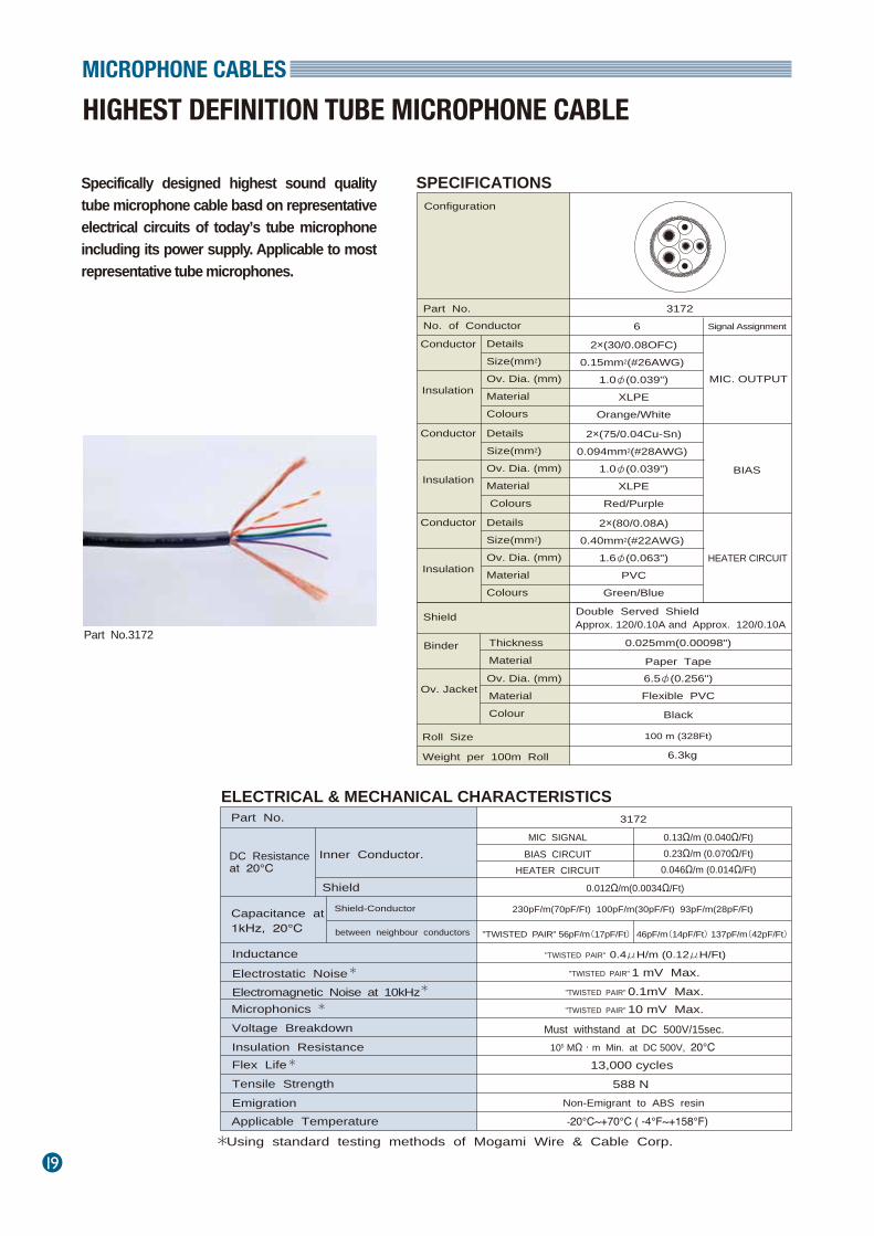
Specifically designed highest sound quality tube microphone cable basd on representative electrical circuits of today’s tube microphone including its power supply. Applicable to most representative tube microphones.
HIGHEST DEFINITION TUBE MICROPHONE CABLEMICROPHONE CABLES
Part No.3172
Part No.
Configuration
No. of Conductor
Details ConductorSize(mm2) Ov. Dia. (mm) Material Colours
Insulation
Details ConductorSize(mm2) Ov. Dia. (mm) Material Colours
Insulation
Details ConductorSize(mm2) Ov. Dia. (mm) Material Colours
Insulation
Shield
Roll Size
Weight per 100m Roll
Capacitance at 1kHz, 20℃
Inner Conductor.
Shield
DC Resistanceat 20℃
Shield-Conductor
Inductance
Electrostatic Noise Electromagnetic Noise at 10kHz
3172
"TWISTED PAIR" 0.4μH/m (0.12μH/Ft)
between neighbour conductors
0.13Ω/m (0.040Ω/Ft) 0.23Ω/m (0.070Ω/Ft) 0.046Ω/m (0.014Ω/Ft)
MIC SIGNALBIAS CIRCUIT
HEATER CIRCUIT
0.012Ω/m(0.0034Ω/Ft)
230pF/m(70pF/Ft) 100pF/m(30pF/Ft) 93pF/m(28pF/Ft)
"TWISTED PAIR" 56pF/m(17pF/Ft)46pF/m(14pF/Ft) 137pF/m(42pF/Ft)
Binder
Ov. Jacket
Thickness Material
Ov. Dia. (mm) Material Colour
Part No.
Microphonics Voltage Breakdown Insulation Resistance
Tensile Strength Flex Life
Emigration Applicable Temperature
2×(30/0.08OFC)0.15mm2(#26AWG)
1.0φ(0.039")XLPE
Orange/White
2×(75/0.04Cu-Sn)0.094mm2(#28AWG)
1.0φ(0.039")XLPE
Red/Purple
2×(80/0.08A)0.40mm2(#22AWG)
1.6φ(0.063")PVC
Green/Blue
6 Signal Assignment
MIC. OUTPUT
BIAS
HEATER CIRCUIT
Approx. 120/0.10A and Approx. 120/0.10A Double Served Shield
0.025mm(0.00098")
Paper Tape6.5φ(0.256")
100 m (328Ft)
6.3kg
Flexible PVC
Black
3172
"TWISTED PAIR" 1 mV Max."TWISTED PAIR" 0.1mV Max."TWISTED PAIR" 10 mV Max.
Must withstand at DC 500V/15sec.105 MΩ・m Min. at DC 500V, 20℃
13,000 cycles588 N
Non-Emigrant to ABS resin
-20℃~+70℃ ( -4°F~+158°F)
Using standard testing methods of Mogami Wire & Cable Corp.
*
*
*
*
*
SPECIFICATIONS
ELECTRICAL & MECHANICAL CHARACTERISTICS
MICROPHONE CABLES
20
SPECIFICATIONS
ELECTRICAL & MECHANICAL CHARACTERISTICS
5.1ch SURROUND MICR0PHONE CABLE
Part No.
Configuration
No. of Cores
Details ConductorSize(mm ) Ov. Dia.(mm) Material
2
Insulation
Core Jacket
Served Shield
0v. Jacket
Binder
Ov. Dia.(mm) Material
Material
Thickness
Colour
Ov. Dia.(mm) Material Colour
Roll Sizes Weight
3349
0.87mm(0.034")
Approx. 60/0.08A 2.4mm(0.094")
0.025mm(0.00098")
9.0mm(0.354")Paper Tape
PVC
Dark Gray
XLPE
PP(Polypropylene)
Black100m (328Ft)
6No. of Conductors
Filler Thread
2
8.9 kg/100m
0.21Ω/m(0.064Ω/Ft)
0.05Ω/m(0.015Ω/Ft)
2.5mV Max.
0.15mV Max.
0.7μH/m (0.21μH/Ft)
30mV Max.Must withstand at DC 500V/15 sec.
105MΩ・m Min. at DC 125 V, 20℃
27,000 cycles130 N
Non-Emigrant to ABS-20℃~ + 70℃ (-4 F゚~ + 158 F゚)
Part No.
Capacitance at 1kHz, 20℃(Partial C.Value)See below figure
Inner Cond. Shield
DC Resistance at 20℃
*(1)
K0
K1
Inductance between conductorsat 1kHz, 20℃
Electrostatic Noise Electromagnetic Noise Microphonics at 50kΩ Load
*(2)
*(2)
Voltage Breakdown
Insulation Resistance
Flex LifeTensile Strength of one pairEmigration
Applicable Temperature
(2) Using standard testing methods of Mogami Wire & Cable Corp.
3349
17/0.08 A0.085mm2(#28AWG)
PVC
90pF/m(27.5pF/Ft)
15pF/m(4.6pF/Ft)
*(2)
*(2)
* * (1) Partial Capacitance
Ko KoK1
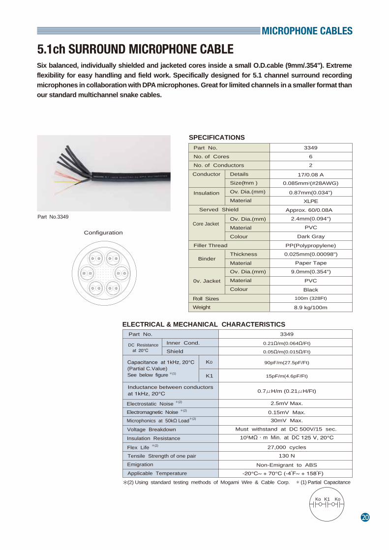
Six balanced, individually shielded and jacketed cores inside a small O.D.cable (9mm/.354"). Extreme flexibility for easy handling and field work. Specifically designed for 5.1 channel surround recording microphones in collaboration with DPA microphones. Great for limited channels in a smaller format than our standard multichannel snake cables.
Part No.3349
21
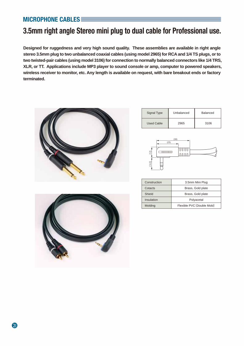
Designed for ruggedness and very high sound quality. These assemblies are available in right angle stereo 3.5mm plug to two unbalanced coaxial cables (using model 2965) for RCA and 1/4 TS plugs, or to two twisted-pair cables (using model 3106) for connection to normally balanced connectors like 1/4 TRS, XLR, or TT. Applications include MP3 player to sound console or amp, computer to powered speakers, wireless receiver to monitor, etc. Any length is available on request, with bare breakout ends or factory terminated.
3.5mm right angle Stereo mini plug to dual cable for Professional use.MICROPHONE CABLES
Construction
Cotacts
Shield
Insulation
Molding
3.5mm Mini Plug
Brass, Gold plate
Brass, Gold plate
Polyacetal
Flexible PVC(Double Mold)
Signal Type
Used Cable 2965 3106
Unbalanced Balanced
(38)(25)
(12)
(14.0)
MICROPHONE CABLES
22
Part No.
Details ConductorSize(mm2) Ov. Dia. (mm) Material Colours
Insulation
Served Shield
Nos. of Core
Roll Size Weight per 100m Roll
Capacitance at 1kHz, 20℃
Inner Conductor. Shield
DC Resistanceat 20℃
Inductance Characteristic Impedance at 10MHz
Ov. Dia. (mm) Material Colours
Jacket
Ov. Dia. (mm)
Material Colour
Nos.
Monofilament
0.22Ω/m(0.067Ω/Ft)0.12Ω/m(0.040Ω/Ft)135pF/m(41.2pF/Ft)0.3μH/m(0.09μH/Ft)
Binder
Sheath
Filler ThreadThickness Material Ov. Dia. (mm) Material Colour
3242-0075/0.04 Cu-Sn
(0.094mm2)(#28AWG)1.05φ(0.041")
XLPEClear
Approx. 36/0.08A1.6φ(0.063")
PVCYellow/Blue
21.07φ(0.042")
PVCWhite
2PP
0.025mm(0.00098")Paper Tape5.0φ(0.197")
PVCBlack
50m(164Ft)/100m(328Ft)/200m(656Ft)3.9 Kg
*
Attenuation at 10MHzPhase Constant at 10MHzElectrostatic NoiseElectromagnetic Noise at 10kHzMicrophonicsVoltage BreakdownInsulation ResistanceFlex LifeTensile StrengthEmigrationApplicable Temperature
*
*
Using standard testing methods of Mogami Wire & Cable Corp. *
*
46Ω ±5%0.25dB/m(0.076dB/Ft)
0.43rad/m50mV Max.
0.02mV Max.40mV Max.
Must withstand at DC 500V/15Sec.104 MΩ・m Min. at DC 250V, 20℃
50,000 cycles294 N
Non-Emigrant to ABS resin ABS
-10℃~+60℃ ( 10°F~+140°F)
Part No. IHE-03 IHE-05 IHE-10
Length3m
9.8 Ft5m
16.4 Ft10m
32.8 Ft
ConfigurationLENGTH
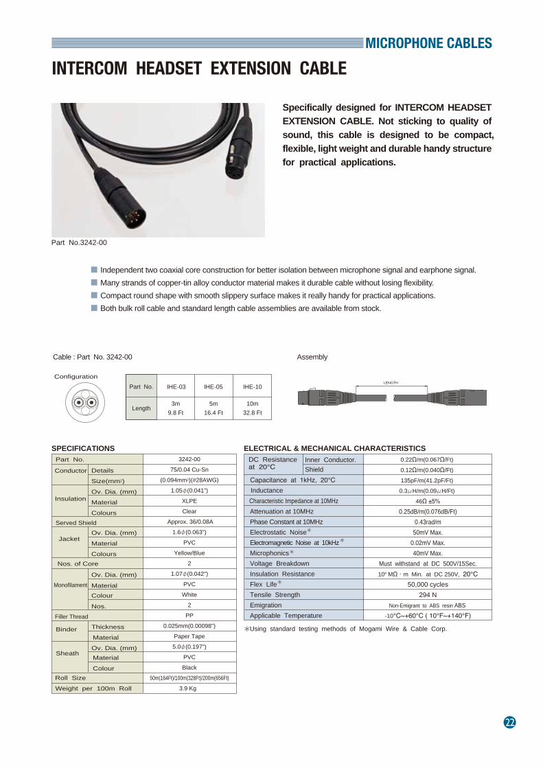
Specifically designed for INTERCOM HEADSET EXTENSION CABLE. Not sticking to quality of sound, this cable is designed to be compact, flexible, light weight and durable handy structure for practical applications.
INTERCOM HEADSET EXTENSION CABLE
Part No.3242-00
SPECIFICATIONS ELECTRICAL & MECHANICAL CHARACTERISTICS
■ Independent two coaxial core construction for better isolation between microphone signal and earphone signal.■ Many strands of copper-tin alloy conductor material makes it durable cable without losing flexibility.■ Compact round shape with smooth slippery surface makes it really handy for practical applications.■ Both bulk roll cable and standard length cable assemblies are available from stock.
Cable : Part No. 3242-00 Assembly
23
Mogami multicore cables are designed for the highest level of audio performance and feature superb electrical and mechanical characteristics while remaining compact, superflexible and easy to use.
■ CL2 rated version available. Conductor size of CL2 rated version is thicker #25AWG so that it is also recommended for rugged application and firm and easier crimp terminal connector wiring as well as NEC fire regulation requirement.
■ Individually twisted shielded pairs, available in 2 to 48 channels.■ Rugged and flexible construction that is easy to handle, even at temperatures down to -20˚C(-4˚F).■ Easy cable identification system: ※Channel numbers are printed and underlined on each core jacket to ensure correct identification, regardless
of which end is stripped. ※Outer jackets of each pair are colour coded by standard resistor colour code, allowing quick identification
of conductor pairs. ※Inner conductors are also colour coded based on the international standard resistor colour code. Each
pair is colour coded by jacket and conductor colour combination. ■ Each channel has a drain wire and served ( spiral ) bare copper shield. The drain wire simplify termination
and can be crimped by the same size contact as the inner conductor pair.■ XLPE (Cross Linked Polyethylene) insulation provides superb electrical characteristics and will not melt
or shrink back during soldering.
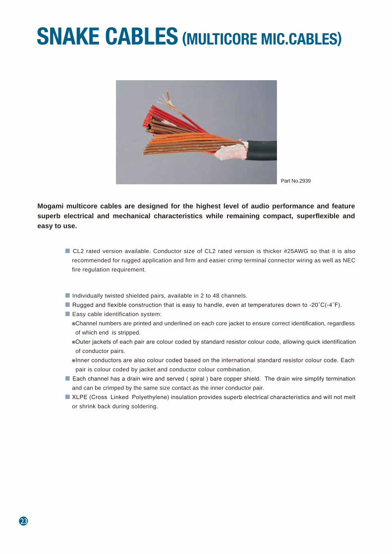
SNAKE CABLES (MULTICORE MIC.CABLES)
Part No.2939
SNAKE CABLES
24
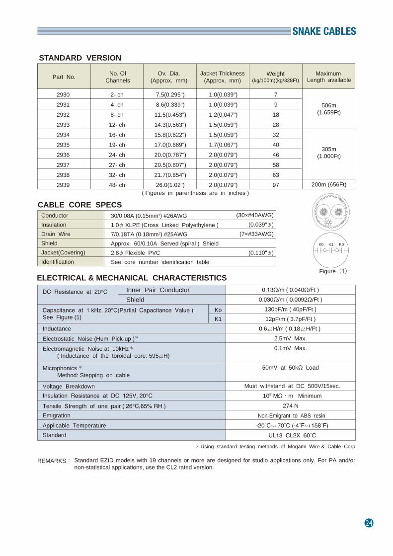
STANDARD VERSION
Part No. No. OfChannels
Ov. Dia.(Approx. mm)
Jacket Thickness(Approx. mm)
Weight(kg/100m)(kg/328Ft)
Maximum Length available
2930293129322933293429352936293729382939
2- ch4- ch8- ch12- ch16- ch19- ch24- ch27- ch32- ch48- ch
7.5(0.295")8.6(0.339")11.5(0.453")14.3(0.563")15.8(0.622")17.0(0.669")20.0(0.787")20.5(0.807")21.7(0.854")26.0(1.02")
1.0(0.039")1.0(0.039")1.2(0.047")1.5(0.059")1.5(0.059")1.7(0.067")2.0(0.079")2.0(0.079")2.0(0.079")2.0(0.079")
791828324046586397
506m(1.659Ft)
305m(1.000Ft)
200m (656Ft)( Figures in parenthesis are in inches )
CABLE CORE SPECS ConductorInsulationDrain WireShieldJacket(Covering) Identification
30/0.08A (0.15mm2) #26AWG 1.0φ XLPE (Cross Linked Polyethylene )7/0.18TA (0.18mm2) #25AWGApprox. 60/0.10A Served (spiral ) Shield2.8φ Flexible PVC See core number identification table
(30×#40AWG) (0.039"φ)
(7×#33AWG)
(0.110"φ)
ELECTRICAL & MECHANICAL CHARACTERISTICS DC Resistance at 20℃
Capacitance at 1 kHz, 20℃(Partial Capacitance Value )See Figure (1)
Inductance Electrostatic Noise (Hum Pick-up )Electromagnetic Noise at 10kHz ( Inductance of the toroidal core: 595μH)
Microphonics Method: Stepping on cable
Voltage BreakdownInsulation Resistance at DC 125V, 20℃Tensile Strength of one pair ( 26℃,65% RH )EmigrationApplicable TemperatureStandard
Inner Pair ConductorShield
KoK1
0.13Ω/m ( 0.040Ω/Ft )0.030Ω/m ( 0.0092Ω/Ft )
130pF/m ( 40pF/Ft )12pF/m ( 3.7pF/Ft )
0.6μH/m ( 0.18μH/Ft ) 2.5mV Max.0.1mV Max.
50mV at 50kΩ Load
Using standard testing methods of Mogami Wire & Cable Corp.
Figure(1)
K0 K0K1
Standard EZID models with 19 channels or more are designed for studio applications only. For PA and/or non-statistical applications, use the CL2 rated version.
REMARKS:
*
*
*
*
Must withstand at DC 500V/15sec.105 MΩ・m Minimum
274 N Non-Emigrant to ABS resin
-20˚C~+70˚C (-4˚F~+158˚F)UL13 CL2X 60˚C
25
SNAKE CABLES
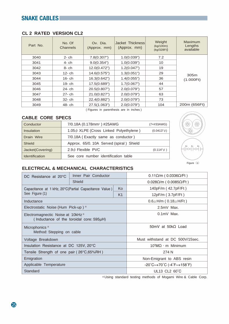
CL 2 RATED VERSION CL2
Part No. No. OfChannels
Ov. Dia.(Approx. mm)
Jacket Thickness(Approx. mm)
Weight(kg/100m)(kg/328Ft)
MaximumLengthsavailable
3040304130423043304430453046304730483049
2- ch4- ch8- ch12- ch16- ch19- ch24- ch27- ch32- ch48- ch
7.8(0.307")9.0(0.354")12.0(0.472")14.6(0.575")16.3(0.642")17.5(0.689")20.5(0.807")21.0(0.827")22.4(0.882")27.5(1.063")
1.0(0.039")1.0(0.039")1.2(0.047")1.3(0.051")1.4(0.055")1.7(0.067")2.0(0.079")2.0(0.079")2.0(0.079")2.0(0.079")
7.21019293644576373
104
305m(1.000Ft)
200m (656Ft)( Figures in parenthesis are in inches )
CABLE CORE SPECS Conductor
Insulation
Drain Wire
Shield
Jacket(Covering)
Identification
7/0.18A (0.178mm2 ) #25AWG 1.05φ XLPE (Cross Linked Polyethylene )7/0.18A ( Exactly same as conductor ) Approx. 65/0. 10A Served (spiral ) Shield2.9φ Flexible PVC See core number identification table
(7×#33AWG)
(0.0413"φ)
(0.114"φ )
ELECTRICAL & MECHANICAL CHARACTERISTICS DC Resistance at 20℃
Capacitance at 1 kHz, 20℃(Partial Capacitance Value )See Figure (1)
Inductance Electrostatic Noise (Hum Pick-up )
Electromagnectic Noise at 10kHz ( Inductance of the toroidal core: 595μH)
Microphonics Method: Stepping on cable
Voltage BreakdownInsulation Resistance at DC 125V, 20℃Tensile Strength of one pair ( 26℃,65%RH ) EmigrationApplicable TemperatureStandard
Inner Pair ConductorShield
KoK1
0.11Ω/m ( 0.0336Ω/Ft )0.028Ω/m ( 0.0085Ω/Ft )
140pF/m ( 42.7pF/Ft )12pF/m ( 3.7pF/Ft )
0.6μH/m ( 0.18μH/Ft ) 2.5mV Max.0.1mV Max.
50mV at 50kΩ Load
Must withstand at DC 500V/15sec.105MΩ・m Minimum
274 N
-20˚C~+70˚C (-4˚F~+158˚F)UL13 CL2 60˚C
Using standard testing methods of Mogami Wire & Cable Corp.
Non-Emigrant to ABS resin
Figure(1)
K0 K0K1
*
*
*
*

SNAKE CABLES
26
■ Colour identification is based on the resistor colour code. ■ Colours indicated in parenthesis indicate the number print colour on the core jacket.■ Insulation colour of other wire in all pairs is clear.■ Colour of outer cable jacket is black.
■ Customised connections and cable assemblies are available to special order.
■ Connection diagram and detailed specification sheet are necessary for all order.
■ Delivery : 4 weeks excluding shipping time.■ For details, consult your Mogami dealer.
■ How to read core jacket channel numbers.
■ Each number printed on the core jacket is underlined ( as shown below ) in order to prevent mis-reading of cable numbers.
123456789
10111213141516
CORE NUMBER IDENTIFICATION TABLE
BROWN
RED
ORANGE
YELLOW
GREEN
BLUE
PURPLE
GRAY
WHITE
BLACK
BROWN
RED
ORANGE
YELLOW
GREEN
BLUE
BLACK(WHITE)
BROWN(WHITE)
CORENO.
COLOUR OFONE OF THE PAIR
CORENO.
COREJACKETCOLOUR
17181920212223242526272829303132
COLOUR OFONE OF THE PAIR
PURPLE
GRAY
WHITE
BLACK
BROWN
RED
ORANGE
YELLOW
GREEN
BLUE
PURPLE
GRAY
WHITE
BLACK
BROWN
RED
COREJACKETCOLOUR
BROWN(WHITE)
RED(WHITE)
ORANGE(BLACK)
33343536373839404142434445464748
CORENO.
COLOUR OFONE OF THE PAIRORANGE
YELLOW
GREEN
BLUE
PURPLE
GRAY
WHITE
BLACK
BROWN
RED
ORANGE
YELLOW
GREEN
BLUE
PURPLE
GRAY
ORANGE(BLACK)
YELLOW(BLACK)
COREJACKETCOLOUR
EXAMPLE 1) 9 means SIX8 1 means EIGHTEEN, not EIGHTY-ONE
3)6 means NINE2)
ASSEMBLY OF SNAKE CABLE
27
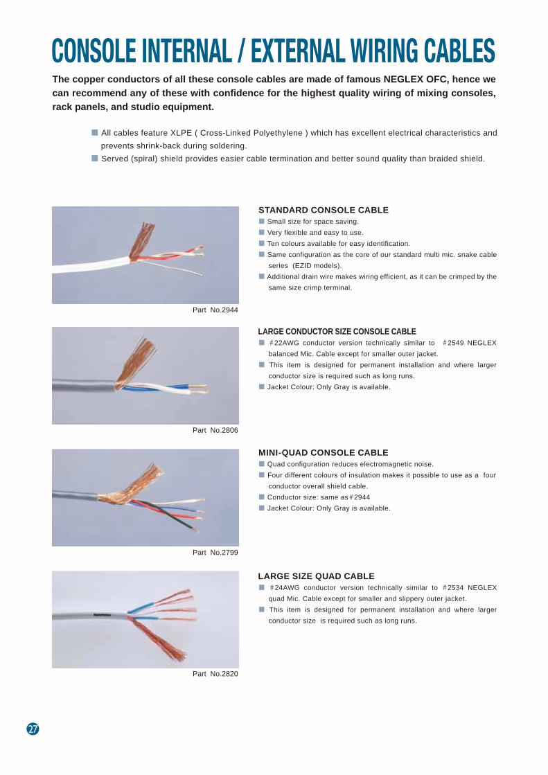
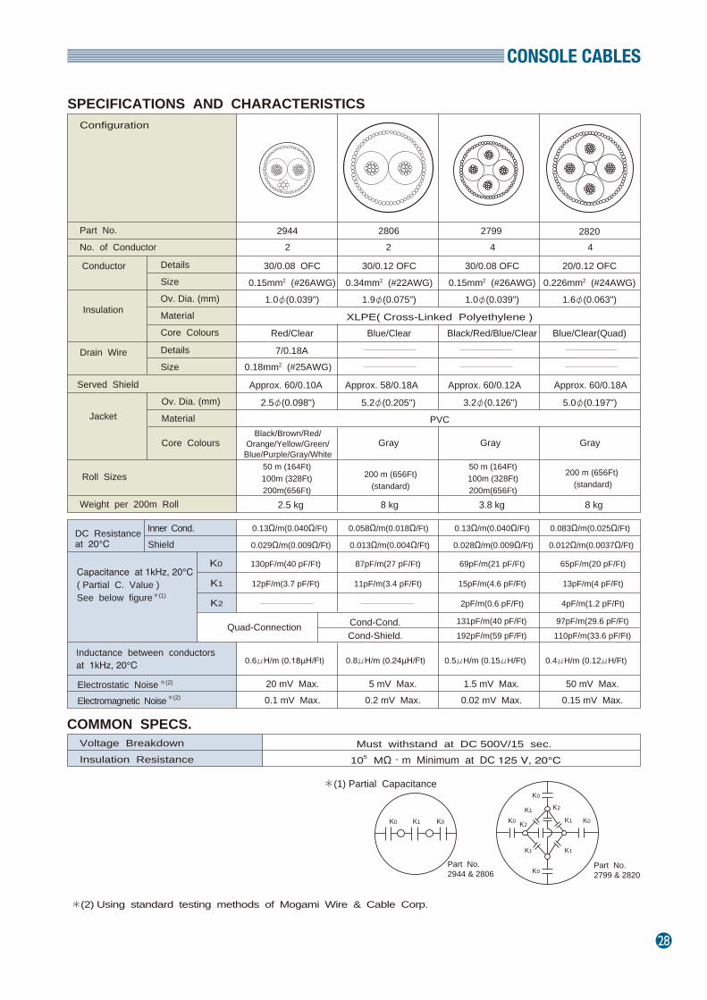
The copper conductors of all these console cables are made of famous NEGLEX OFC, hence we can recommend any of these with confidence for the highest quality wiring of mixing consoles, rack panels, and studio equipment.
■ All cables feature XLPE ( Cross-Linked Polyethylene ) which has excellent electrical characteristics and prevents shrink-back during soldering.
■ Served (spiral) shield provides easier cable termination and better sound quality than braided shield.
■ Small size for space saving.■ Very flexible and easy to use.■ Ten colours available for easy identification. ■ Same configuration as the core of our standard multi mic. snake cable
series (EZID models).■ Additional drain wire makes wiring efficient, as it can be crimped by the
same size crimp terminal.
CONSOLE INTERNAL / EXTERNAL WIRING CABLES
STANDARD CONSOLE CABLE
■ #22AWG conductor version technically similar to #2549 NEGLEX balanced Mic. Cable except for smaller outer jacket.
■ This item is designed for permanent installation and where larger conductor size is required such as long runs.
■ Jacket Colour: Only Gray is available.
LARGE CONDUCTOR SIZE CONSOLE CABLE
■ Quad configuration reduces electromagnetic noise.■ Four different colours of insulation makes it possible to use as a four
conductor overall shield cable.■ Conductor size: same as#2944■ Jacket Colour: Only Gray is available.
MINI-QUAD CONSOLE CABLE
■ #24AWG conductor version technically similar to #2534 NEGLEX quad Mic. Cable except for smaller and slippery outer jacket.
■ This item is designed for permanent installation and where larger conductor size is required such as long runs.
LARGE SIZE QUAD CABLE
Part No.2944
Part No.2806
Part No.2799
Part No.2820
CONSOLE CABLES
28
Part No.
Configuration
No. of Conductor
Details ConductorSize Ov. Dia. (mm) Material Core Colours
Insulation
Served Shield
JacketOv. Dia. (mm) Material
Core Colours
Roll Sizes
Weight per 200m Roll
30/0.08 OFC0.15mm2 (#26AWG)
1.0φ(0.039")
Red/Clear
30/0.08 OFC0.15mm2 (#26AWG)
1.0φ(0.039")
Black/Red/Blue/Clear
20/0.12 OFC0.226mm2 (#24AWG)
1.6φ(0.063")
Blue/Clear(Quad)XLPE( Cross-Linked Polyethylene )
2.5φ(0.098")
Black/Brown/Red/Orange/Yellow/Green/Blue/Purple/Gray/White
5.2φ(0.205")
Gray
3.2φ(0.126")
Gray
5.0φ(0.197")
Gray
50 m (164Ft)100m (328Ft)200m(656Ft)
200 m (656Ft)(standard)
2
2.5 kg 8 kg 3.8 kg
0.13Ω/m(0.040Ω/Ft)
5 mV Max.0.2 mV Max.
0.6μH/m (0.18μH/Ft)
Must withstand at DC 500V/15 sec. 105 MΩ・m Minimum at DC 125 V, 20℃
Capacitance at 1kHz, 20℃( Partial C. Value )See below figure
Inner Cond.Shield
DC Resistanceat 20℃
*(1)
K0
K1
Inductance between conductorsat 1kHz, 20℃
Electrostatic Noise Electromagnetic Noise
*(2)
*(2)
Voltage BreakdownInsulation Resistance
*(2) Using standard testing methods of Mogami Wire & Cable Corp.
2944 2806 2799
Approx. 60/0.10A Approx. 58/0.18A
50 m (164Ft)100m (328Ft)200m(656Ft)
200 m (656Ft) (standard)
0.028Ω/m(0.009Ω/Ft)
130pF/m(40 pF/Ft)
0.8μH/m (0.24μH/Ft) 0.5μH/m (0.15μH/Ft)
20 mV Max.0.1 mV Max.
Drain Wire Details Size
SPECIFICATIONS AND CHARACTERISTICS
K2
2 4 4
30/0.12 OFC0.34mm2 (#22AWG)
1.9φ(0.075")
Blue/Clear
7/0.18A0.18mm2 (#25AWG)
Approx. 60/0.12A Approx. 60/0.18A
0.13Ω/m(0.040Ω/Ft)
0.029Ω/m(0.009Ω/Ft)
0.058Ω/m(0.018Ω/Ft)
0.013Ω/m(0.004Ω/Ft)
12pF/m(3.7 pF/Ft)
87pF/m(27 pF/Ft)
11pF/m(3.4 pF/Ft)
69pF/m(21 pF/Ft)
15pF/m(4.6 pF/Ft)
2pF/m(0.6 pF/Ft)
Quad-Connection Cond-Cond.Cond-Shield.
131pF/m(40 pF/Ft)192pF/m(59 pF/Ft)
1.5 mV Max.0.02 mV Max.
8 kg
0.083Ω/m(0.025Ω/Ft)
0.012Ω/m(0.0037Ω/Ft)
0.4μH/m (0.12μH/Ft)
65pF/m(20 pF/Ft)
13pF/m(4 pF/Ft)
4pF/m(1.2 pF/Ft)
97pF/m(29.6 pF/Ft)110pF/m(33.6 pF/Ft)
50 mV Max.0.15 mV Max.
COMMON SPECS.
K0 K0
K0
K0
K1
K1
K1
K2
K2
K1
Part No. 2944 & 2806
Part No. 2799 & 2820
K0 K0K1
2820
PVC
*(1) Partial Capacitance
29
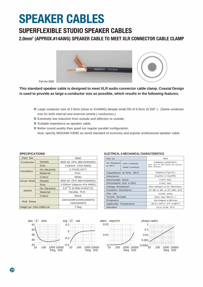
This standard speaker cable is designed to meet XLR audio connector cable clamp. Coaxial Design is used to provide as large a conductor size as possible, which results in the following features.
■ Large conductor size of 2.0mm (close to #14AWG) despite small OD of 6.5mm (0.256" ). (Same conductor size for both internal and external (shield ) conductors.)
■ Extremely low induction from outside and affection to outside.■ Suitable impedance as speaker cable.■ Better sound quality than quad nor regular parallel configuration. Now, specify MOGAMI #3082 as world standard of economy and popular professional speaker cable.
SUPERFLEXIBLE STUDIO SPEAKER CABLES2.0mm2 (APPROX.#14AWG) SPEAKER CABLE TO MEET XLR CONNECTOR CABLE CLAMP
SPEAKER CABLES
Part No.3082
Part No. Conductor Details
Size
Insulation Ov. Dia.(mm) Material Colour
Served Shield Details Size Ov. Dia.(mm) Material Colour
Jacket
Roll Sizes
Weight per 100m (328Ft) roll
308280/0.18 OFC (80×#33AWG)
2.03mm2 (#15 AWG)4.75φ(0.187")
PVC White
80/0.18 OFC (80×#33AWG)2.03mm2 (Approx.#14 AWG)
6.5 φ (0.256± 0.0197"φ)Flexible PVC
Black
7.5kg
100m(328Ft)/200m(656Ft)/153m(500Ft)
± 0.5
Part No.
Capacitance at 1kHz, 20℃
DC Resistanceat 20℃
Inner Conductor
Shield Conductor
Inductance
Electrostatic Noise Electromagnetic Noise at 10kHz
Voltage Breakdown Insulation Resistance Flex Life Tensile Strength Emigration Applicable Temperature Standard
3082
0.009Ω/m (0.0027Ω/Ft )Same value for both internal and outernal/shield conductor )
253pF/m (77pF /Ft )
0.4μH/m ( 0.12μH/Ft)
0.2mV Max.
0.2mV Max.
Must withstand at DC 500V/15sec.
105 MΩ・m Min. at DC 500V, 20℃
15,000 cycles
More than 980 N 以上
Non-Emigrant to ABS resin
-20℃~+70℃ ( -4°F~+158°F )
UL13 CL2X 75℃
SPECIFICATIONS ELECTRICAL & MECHANICAL CHARACTERISTICS
abs〔Z〕 ohm4240383634
10 100 1000 10000freq. KHZ
arg〔Z〕 rad0.2
0
-0.2
-0.410 100 1000 10000
freq. KHZ
atten. neper/m0.02
0.01
010 100 1000 10000
freq. KHZ
phase rad/m1
0.1
0.01
0.001
0.000110 100 1000 10000freq. KHZ
SPEAKER CABLES
30
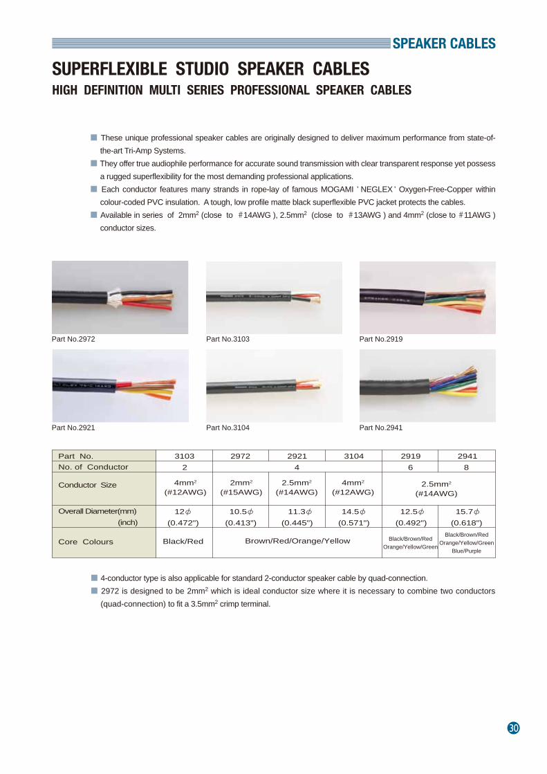
SUPERFLEXIBLE STUDIO SPEAKER CABLESHIGH DEFINITION MULTI SERIES PROFESSIONAL SPEAKER CABLES
■ These unique professional speaker cables are originally designed to deliver maximum performance from state-of- the-art Tri-Amp Systems.
■ They offer true audiophile performance for accurate sound transmission with clear transparent response yet possess a rugged superflexibility for the most demanding professional applications.
■ Each conductor features many strands in rope-lay of famous MOGAMI ’ NEGLEX ’ Oxygen-Free-Copper within colour-coded PVC insulation. A tough, low profile matte black superflexible PVC jacket protects the cables.
■ Available in series of 2mm2 (close to #14AWG ), 2.5mm2 (close to #13AWG ) and 4mm2 (close to #11AWG ) conductor sizes.
■ 4-conductor type is also applicable for standard 2-conductor speaker cable by quad-connection.■ 2972 is designed to be 2mm2 which is ideal conductor size where it is necessary to combine two conductors
(quad-connection) to fit a 3.5mm2 crimp terminal.
Part No.2972
Part No.2921
Part No.3103
Part No.3104
Part No.2919
Part No.2941
Part No. No. of Conductor
Conductor Size
3103 2972 2921 3104 2919 29412 4 6 8
4mm2
(#12AWG)2mm2
(#15AWG)2.5mm2
(#14AWG)4mm2
(#12AWG)2.5mm2
(#14AWG)
Overall Diameter(mm) (inch)
12φ 10.5φ 11.3φ 14.5φ 12.5φ 15.7φ(0.472") (0.413") (0.445") (0.571") (0.492") (0.618")
Core Colours Black/Red Brown/Red/Orange/Yellow Black/Brown/RedOrange/Yellow/Green
Black/Brown/RedOrange/Yellow/Green
Blue/Purple
31
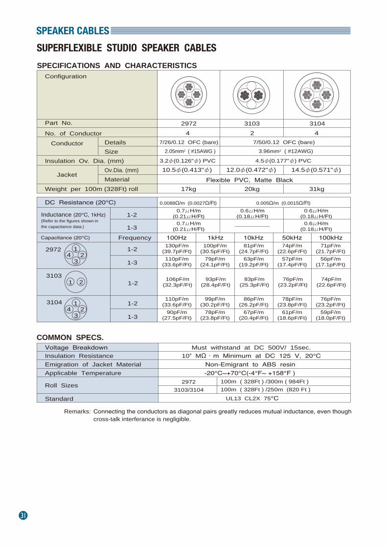
SPEAKER CABLES
SPECIFICATIONS AND CHARACTERISTICS
Part No. No. of Conductor
Conductor Details Size
Insulation Ov. Dia. (mm)
JacketOv.Dia. (mm) Material
Weight per 100m (328Ft) roll
DC Resistance (20℃)
Inductance (20℃, 1kHz) (Refer to the figures shown in the capacitance data.)
1-2
1-3
2972 3103 31044 2 4
7/26/0.12 OFC (bare)2.05mm2 ( #15AWG )
3.2φ(0.126"φ) PVC10.5φ(0.413"φ) 12.0φ(0.472"φ) 14.5φ(0.571"φ)
Flexible PVC, Matte Black 17kg 20kg 31kg
0.0088Ω/m (0.0027Ω/Ft) 0.7μH/m
(0.21μH/Ft)0.7μH/m
(0.21μH/Ft)
0.6μH/m(0.18μH/Ft)
0.6μH/m(0.18μH/Ft)
0.6μH/m(0.18μH/Ft)
Capacitance (20℃)
31031 2
Frequency 100Hz 1kHz 10kHz 50kHz 100kHz
1-2
1-3
110pF/m(33.6pF/Ft)
90pF/m(27.5pF/Ft)
99pF/m(30.2pF/Ft)
78pF/m(23.8pF/Ft)
86pF/m(26.2pF/Ft)
67pF/m(20.4pF/Ft)
78pF/m(23.8pF/Ft)
61pF/m(18.6pF/Ft)
76pF/m(23.2pF/Ft)
59pF/m(18.0pF/Ft)
COMMON SPECS. Voltage Breakdown
Emigration of Jacket Material Insulation Resistance
Applicable Temperature
Roll Sizes
Standard
Must withstand at DC 500V/ 15sec.
Non-Emigrant to ABS resin 104 MΩ・m Minimum at DC 125 V, 20℃
-20℃~+70℃(-4°F~ +158°F )100m ( 328Ft ) /300m ( 984Ft )
Connecting the conductors as diagonal pairs greatly reduces mutual inductance, even though cross-talk interferance is negligible.
Remarks:
7/50/0.12 OFC (bare)3.96mm2 ( #12AWG)
4.5φ(0.177"φ) PVC
0.005Ω/m (0.0015Ω/Ft)
1
34 2
29723103/3104 100m ( 328Ft ) /250m (820 Ft )
UL13 CL2X 75℃
Configuration
1-2106pF/m
(32.3pF/Ft)93pF/m
(28.4pF/Ft)83pF/m
(25.3pF/Ft)76pF/m
(23.2pF/Ft)74pF/m
(22.6pF/Ft)
1-2
1-3
130pF/m(39.7pF/Ft)110pF/m
(33.6pF/Ft)
100pF/m(30.5pF/Ft)
79pF/m(24.1pF/Ft)
81pF/m(24.7pF/Ft)
63pF/m(19.2pF/Ft)
74pF/m(22.6pF/Ft)
57pF/m(17.4pF/Ft)
71pF/m(21.7pF/Ft)
56pF/m(17.1pF/Ft)
3104
2972 1
34 2
SUPERFLEXIBLE STUDIO SPEAKER CABLES
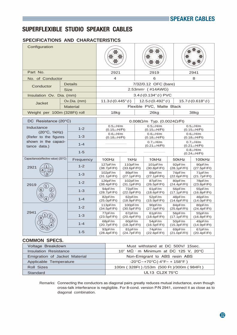
SPEAKER CABLES
32
SUPERFLEXIBLE STUDIO SPEAKER CABLES
SPECIFICATIONS AND CHARACTERISTICS
Part No. No. of Conductor
Conductor Details Size
Insulation Ov. Dia. (mm)
Jacket Ov.Dia. (mm) Material
Weight per 100m (328Ft) roll
DC Resistance (20℃)
Inductance (20℃, 1kHz) (Refer to the figuresshown in the capaci‐tance data.)
1-2
1-3
1-4
1-5
2921 2919 29414 6 8
7/32/0.12 OFC (bare)2.53mm2 ( #14AWG)
3.4φ(0.134"φ) PVC11.3φ(0.445"φ) 12.5φ(0.492"φ) 15.7φ(0.618"φ)
Flexible PVC, Matte Black 18kg 26kg 38kg
0.008Ω/m Typ. (0.0024Ω/Ft) 0.5μH/m
(0.15μH/Ft)0.6μH/m
(0.18μH/Ft)
0.5μH/m(0.15μH/Ft)
0.6μH/m(0.18μH/Ft)
0.5μH/m(0.15μH/Ft)
0.6μH/m(0.18μH/Ft)
0.7μH/m(0.21μH/Ft)
0.8μH/m(0.24μH/Ft)
0.7μH/m(0.21μH/Ft)
Capacitance(effective value) (20℃)
2921 1
34 2
32
456
12919
2941
Frequency 100Hz 1kHz 10kHz 50kHz 100kHz
1-2
1-3
1-2
1-3
1-4
1-2
1-3
1-4
1-5
127pF/m(38.7pF/Ft)102pF/m
(31.1pF/Ft)126pF/m
(38.4pF/Ft)94pF/m
(28.7pF/Ft)82pF/m
(25.0pF/Ft)113pF/m
(34.5pF/Ft)77pF/m
(23.5pF/Ft)68pF/m
(20.7pF/Ft)93pF/m
(28.4pF/Ft)
110pF/m(33.6pF/Ft)
89pF/m(27.1pF/Ft)102pF/m
(31.1pF/Ft)72pF/m
(22.0pF/Ft)62pF/m
(18.9pF/Ft)100pF/m
(30.5pF/Ft)67pF/m
(20.4pF/Ft)60pF/m
(18.3pF/Ft)81pF/m
(24.7pF/Ft)
101pF/m(30.8pF/Ft)
89pF/m(27.1pF/Ft)
87pF/m(26.5pF/Ft)
61pF/m(18.6pF/Ft)
52pF/m(15.9pF/Ft)
90pF/m(27.5pF/Ft)
61pF/m(18.6pF/Ft)
54pF/m(16.5pF/Ft)
74pF/m(22.6pF/Ft)
92pF/m(28.1pF/Ft)
74pF/m(22.6pF/Ft)
80pF/m(24.4pF/Ft)
56pF/m(17.1pF/Ft)
48pF/m(14.6pF/Ft)
84pF/m(25.6pF/Ft)
56pF/m(17.1pF/Ft)
50pF/m(15.3pF/Ft)
69pF/m(21.0pF/Ft)
90pF/m(27.5pF/Ft)
71pF/m(21.7pF/Ft)
78pF/m(23.8pF/Ft)
55pF/m(16.8pF/Ft)
46pF/m(14.0pF/Ft)
80pF/m(24.4pF/Ft)
55pF/m(16.8pF/Ft)
49pF/m(14.9pF/Ft)
67pF/m(20.4pF/Ft)
COMMON SPECS. Voltage Breakdown
Emigration of Jacket Material Insulation Resistance
Applicable Temperature Roll Sizes Standard
Must withstand at DC 500V/ 15sec.
Non-Emigrant to ABS resin ABS 104 MΩ・m Minimum at DC 125 V, 20℃
-20℃~+70℃ (-4°F~ + 158°F )100m ( 328Ft ) /153m (500 Ft )/300m ( 984Ft )
UL13 CL2X 75℃
Connecting the conductors as diagonal pairs greatly reduces mutual inductance, even thoughcross-talk interferance is negligible. For 8-cond. version P/N 2941, connect it as close as todiagonal combination.
Remarks:
Configuration
32
456
1
78
33
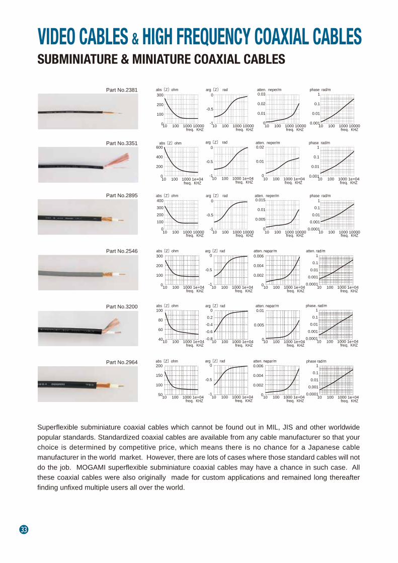
Superflexible subminiature coaxial cables which cannot be found out in MIL, JIS and other worldwide popular standards. Standardized coaxial cables are available from any cable manufacturer so that your choice is determined by competitive price, which means there is no chance for a Japanese cable manufacturer in the world market. However, there are lots of cases where those standard cables will not do the job. MOGAMI superflexible subminiature coaxial cables may have a chance in such case. All these coaxial cables were also originally made for custom applications and remained long thereafter finding unfixed multiple users all over the world.
VIDEO CABLES & HIGH FREQUENCY COAXIAL CABLES
300
200
100
010 100 1000 10000freq. KHZ
abs〔Z〕ohm0.03
0.02
0.01
010 100 1000 10000
freq. KHZ
atten. neper/m1
0.1
0.01
0.00110 100 1000 10000freq. KHZ
phase rad/m0
-0.5
-110 100 1000 10000freq. KHZ
arg〔Z〕 rad
400300200100
010 100 1000 10000
freq. KHZ
abs〔Z〕ohm0.015
0.01
0.005
010 100 1000 10000
freq. KHZ
atten. neper/m1
0.10.01
0.0010.0001
10 100 1000 10000freq. KHZ
phase rad/m0
-0.5
-110 100 1000 10000
freq. KHZ
arg〔Z〕 rad
SUBMINIATURE & MINIATURE COAXIAL CABLES
Part No.2381
Part No.3351
Part No.2895
Part No.2546
Part No.3200
Part No.2964
abs〔Z〕ohm600
400
200
010 100 1000 1e+04
freq. KHZ
0
-0.5
-110 100 1000 1e+04freq. KHZ
arg〔Z〕 rad0.02
0.01
010 100 1000 1e+04
freq. KHZ
atten. neper/m1
0.1
0.01
0.00110 100 1000 1e+04freq. KHZ
phase rad/m
300
200
100
010 100 1000 1e+04freq. KHZ
abs〔Z〕ohm0
-0.5
-110 100 1000 1e+04
freq. KHZ
arg〔Z〕rad0.006
0.004
0.002
010 100 1000 1e+04freq. KHZ
atten. nepar/m1
0.10.01
0.0010.0001
10 100 1000 1e+04freq. KHZ
atten. rad/m
100
80
60
4010 100 1000 1e+04freq. KHZ
abs〔Z〕ohm
10 100 1000 1e+04freq. KHZ
arg〔Z〕rad0
0.2-0.4-0.6-0.8
0.01
0.005
010 100 1000 1e+04freq. KHZ
atten. nepar/m1
0.10.01
0.0010.0001
10 100 1000 1e+04freq. KHZ
phase. rad/m
200
150
100
5010 100 1000 1e+04freq. KHZ
abs〔Z〕ohm0
-0.5
-110 100 1000 1e+04
freq. KHZ
arg〔Z〕rad0.006
0.004
0.002
010 100 1000 1e+04freq. KHZ
atten. nepar/m1
0.10.01
0.0010.0001
10 100 1000 1e+04freq. KHZ
phase rad/m

HIGH FREQUENCY COAXIAL CABLES
34
SUBMINIATURE & MINIATURE COAXIAL CABLES
CABLE SPECIFICATIONS Part No.
Conductor
Shield
Jacket
Roll SizesWeight Per 305m (1,000Ft ) Roll
Material
Ov. Dia . (mm)
Colour
2381
305m (1,000Ft )305m (1,000Ft ) 153m (500Ft )/305m (1,000Ft )
1.5kg 2.1kg
1.6φ(0.063") 2.0φ(0.0787")
ELECTRICAL & MECHANICAL CHARACTERISTICS
DC Resistance at 20℃
Capacitance at 1kHz, 20℃Characteristic Imperdance at 10MHz
Attenuation (10MHz )
110pF/m (33.6pF/ Ft )
50Ω±10%
0.15 dB /m (0.046 dB /Ft )
Inner Cond. Shield 0.079Ω/m (0.024Ω/Ft )
Phase Constant (10MHz ) 0.38rad / m
Electromagnetic Noise 0.1mV Max .
Voltage Breakdown Must withstand at DC 500V/15sec .
Insulation ResistanceFlex LifeTensile StrengthEmigrationApplicable TemperatureStandard
104 MΩ・m Min . at DC 250V , 20℃
21,000 cycles
68 N 95 N
Non-Emigrant to ABS resin
-20℃~ +60℃ (-4°F~+140°F )
Attenuation : 1 dB = 0.1151 neper (1 neper = 8.686 dB ) Using standard testing method of Mogami Wire & Cable Corp .
Part No. 2381 3351
Characteristic Impedance
Size 0.047mm2 (#32AWG) 0.0314mm2(#33AWG)
Insulation
Type
Details
Ov. Dia . (mm)
Details
Material
2895 2546 2964
50Ω 75Ω 75Ω 75Ω
1/0.10 Piano Wire6/0.10A Served Cond.
3351
75Ω
0.20mm Copper-Covered Steel Wire 17/0.08A 7/0.14A 20/0.12 OFC
0.085mm2 (#28AWG) 0.107mm2 (#27AWG)
3200
50Ω
50/0.12 OFC
0.565mm2 (#20AWG) 0.226mm2 (#24AWG)
0.9φ(0.035") 1.7φ(0.067")1.3φ(0.051") 1.95φ(0.077") 2.6φ(0.102") 2.65φ(0.104")XLPE XLCPE CPE XLCPE
SERVED BRAIDED Double Served Shield
Approx. 66/0.12 OFC, Approx. 72/0.12 OFCApprox. 30/0.10A Approx. 50/0.08A 16/5/0.10A 16/4/0.12A
3.0φ(0.118") 3.3φ(0.130") 4.8φ(0.189")
PVCBlackGrayBlack Black/Red/Yellow/
Green/Blue 50m (164Ft )/100m(328Ft)/200m(656Ft)
4.2kg 5.0kg 3.4kg
0.4Ω/m (0.12Ω/Ft )
68pF/m (20.7pF/ Ft )
75Ω±10%
0.11 dB /m (0.033 dB /Ft )
0.08Ω/m (0.024Ω/Ft )
0.33rad / m
1.6Ω/m (0.49Ω/Ft )
2895 2546 2964
0.035Ω/m (0.011Ω/Ft )
0.22Ω/m (0.067Ω/Ft )
0.03Ω/m (0.009Ω/Ft )
0.18Ω/m (0.055Ω/Ft )
0.012Ω/m(0.0037Ω/Ft )
0.083Ω/m(0.025Ω/Ft )
58pF/m (17.7pF/ Ft ) 62pF/m (18.9pF/ Ft ) 57pF/m(17.4pF/ Ft )
75Ω±10% 75Ω±10%
3200
0.012Ω/m(0.0037Ω/Ft )
0.035Ω/m(0.011Ω/Ft )
95pF/m(29.0pF/ Ft )
50Ω±10% 75Ω±10%
0.069 dB /m(0.021 dB /Ft )
0.051 dB /m(0.016 dB /Ft )
0.058dB /m(0.018 dB /Ft )
0.047 dB /m (0.014 dB /Ft )
0.28rad / m 0.30rad / m 0.31rad / m 0.3rad / m
UL 1354 AWM VW-1 30V 60℃ --- -
196 N 205 N 343 N 274 N
8,400 cycles14,000 cycles 8,600 cycles 12,000 cycles 16,000 cycles
/100m(328Ft)3.6kg /100m(328Ft)
*
*
*
35
HIGH FREQUENCY COAXIAL CABLES
CABLE SPECIFICATIONS
75Ω COAX. PARALLEL MULTICORE CABLES
The dual 75 ohm parallel "zip style" 2947 was originally devel-oped to maintain maximum video performance while fitting the very compact 4 pin mini-Din (S-video) connector. Success in this challenging project required Mogami's highly experienced design and extremely precise manufacturing technique. Because this small cable is excellent for audio and video, two (2947) three (3243) and four (3294) conductor versions of this cable are now available to meet market demands in home and industrial audio-video, law enforcement, medical imaging, and security environments.
Part No.
Configuration
Core ConfigurationConductor SizeShield Structure Jacket
Roll SizesWeight Per 153m ( 500Ft ) Roll
Part No.
MaterialOv. Dia . (mm) Colour
29472×75Ω Coax.
0.126mm2 ( #27AWG )
3243
2947 3243
3×75Ω Coax.
Served Shield
Flexible PVC
153m/305m (500Ft /1,000Ft ) 153m (500Ft )4kg 6.1kg
2×3.0φ(0.118") 3×3.0φ(0.118")Black
ELECTRICAL & MECHANICAL CHARACTERISTICS
DC Resistance at 20℃
Capacitance at 1kHz, 20℃
Characteristic Impedance at 10MHz
Attenuation (10MHz )
0.15Ω/ m (0.046Ω/ Ft )
59pF/ m (18.0 pF/ Ft )75Ω±5%
0.061dB / m (0.019 dB / Ft )
Inner Cond. Shield 0.035Ω/ m (0.011Ω/ Ft )
Phase Constant (10MHz ) 0.28 rad / mElectromagnetic Noise 0.1mV Max .Voltage Breakdown Must withstand at DC 500V/15sec .Insulation ResistanceFlex LifeTensile StrengthEmigrationApplicable Temperature
104MΩ・m Min . at DC 500V , 20℃24 ,000 cycles
392 N28 ,000 cycles
530 NNon-Emigrant to ABS resin
-20℃~ +70℃ (-4°F~ +158°F)
Attenuation : 1 dB =0.1151 neper (1 neper =8.686 dB ) Using standard testing method of Mogami Wire & Cable Corp .
*
*
*
Part No.2947
Part No.3243
300
200
100
010 100 1000 1e+04
abs〔Z〕ohm
freg. KHZ
0
-0.5
-110 100 1000 1e+04
arg〔Z〕rad
freg. KHZ
0.01
0.005
010 100 1000 1e+04
atten.neper/m
freg. KHZ10 100 1000 1e+04
phase rad/m
freg. KHZ
1
0.1
0.01
0.001
0.0001
HIGH FREQUENCY COAXIAL CABLES
36
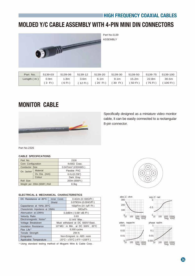
MOLDED Y/C CABLE ASSEMBLY WITH 4-PIN MINI DIN CONNECTORS
MONITOR CABLE
Part No.
Length ( m )
5139-03
0.9m( 3 Ft )
5139-06
1.8m( 6 Ft )
5139-12
3.6m( 12 Ft )
5139-20
6.1m( 20 Ft )
5139-30
9.1m( 30 Ft )
5139-50
15.2m( 50 Ft )
5139-75
22.8m( 75 Ft )
5139-100
30.5m( 100 Ft )
CABLE SPECIFICATIONS Part No.Core ConfigurationConductor Size
Ov. Jacket
Roll SizeWeight per 200m (656Ft ) Roll
MaterialOv. Dia . (mm) Colour
23264×50Ω Coax.
0.047mm2 (#32AWG )Flexible PVC
200m (656Ft )8.3kg
6.0φ(0.236”)Dark Gray
ELECTRICAL & MECHANICAL CHARACTERISTICSDC Resistance at 20℃
Capacitance at 1kHz, 20℃Characteristic Impedance at 10MHzAttenuation at 10MHz
0.4Ω/m (0.122Ω/Ft )
102pF/m (31.1pF/ Ft )50Ω±5%
0.2dB/m ( 0.061 dB /Ft )
Inner Cond. Shield 0.079Ω/m (0.024Ω/Ft )
Velocity Ratio 0.63Electromagnetic Noise 0.1mV Max .Voltage Breakdown Must withstand at DC 500V/15sec .Insulation ResistanceFlex LifeTensile StrengthEmigrationApplicable Temperature
104 MΩ・m Min . at DC 500V , 20℃6,500 cycles
294 NNon-Emigrant to ABS resin
-20℃ ~ +70℃ (-4°F~+158°F ) Using standard testing method of Mogami Wire & Cable Corp .
arg〔Z〕 rad
atten. neper/m phase rad/m
abs〔Z〕 ohm
freg. KHZ
300
200
100
010 100 1000 10000freg. KHZ
0
-0.5
-110 100 1000 10000
freg. KHZ
0.03
0.02
0.01
010 100 1000 10000freg. KHZ
1
0.1
0.01
0.00110 100 1000 10000
*
*
*
Specifically designed as a miniature video monitor cable, it can be easily connected to a rectangular 8-pin connector.
Part No.5139ASSEMBLY
Part No.2326
37
HIGH FREQUENCY COAXIAL CABLES
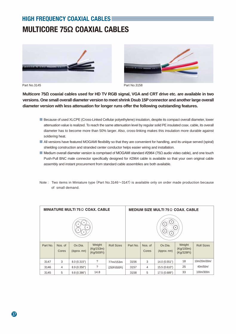
MULTICORE 75Ω COAXIAL CABLES
Multicore 75Ω coaxial cables used for HD TV RGB signal, VGA and CRT drive etc. are available in two versions. One small overall diameter version to meet shrink Dsub 15P connector and another large overall diameter version with less attenuation for longer runs offer the following outstanding features.
Part No.3145 Part No.3158
Part No.
3147
3146
3145
Nos. of
Cores
3
4
5
?
?
14.8
Weight(Kg/153m)(Kg/500Ft)
Weight(Kg/100m)(Kg/328Ft)
Ov.Dia.
(Approx. mm)
8.0 (0.315")
8.9 (0.350")
9.8 (0.386")
Roll Sizes
77m/153m
(250Ft/500Ft)
Part No.
3156
3157
3158
Nos. of
Cores
3
4
5
18
25
33
Ov.Dia.
(Approx. mm)
14.0 (0.551")
15.5 (0.610")
17.5 (0.689")
Roll Sizes
10m/20m/30m/
40m/50m/
100m/300m
■ Because of used XLCPE (Cross-Linked Cellular polyethylene) insulation, despite its compact overall diameter, lower attenuation value is realized. To reach the same attenuation level by regular solid PE insulated coax. cable, its overall diameter has to become more than 50% larger. Also, cross-linking makes this insulation more durable against soldering heat.
■ All versions have featured MOGAMI flexibility so that they are convenient for handling, and its unique served (spiral) shielding construction and stranded center conductor helps easier wiring and installation.
■ Medium overall diameter version is comprised of MOGAMI standard #2964 (75Ω audio video cable), and one touch Push-Pull BNC male connector specifically designed for #2964 cable is available so that your own original cable assembly and instant procurement from standard cable assemblies are both available.
Note : Two items in Miniature type(Part No.3146~3147)is available only on order made production because of small demand.
HIGH FREQUENCY COAXIAL CABLES
38
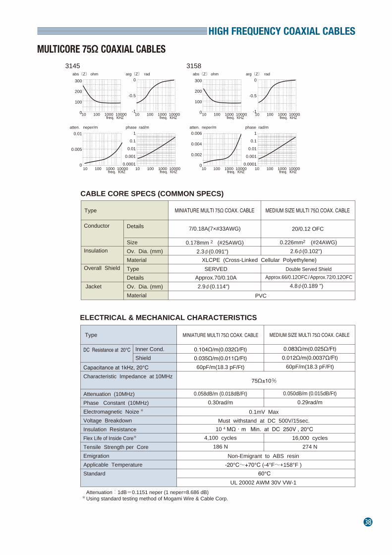
MULTICORE 75Ω COAXIAL CABLES
CABLE CORE SPECS (COMMON SPECS)
ELECTRICAL & MECHANICAL CHARACTERISTICS
Attenuation:1dB=0.1151 neper (1 neper=8.686 dB) Using standard testing method of Mogami Wire & Cable Corp.
Conductor 7/0.18A(7×#33AWG)
0.178mm 2 (#25AWG)2.3φ(0.091")
0.226mm2 (#24AWG)
2.6φ(0.102")
20/0.12 OFC
Insulation
Overall Shield
Jacket
XLCPE (Cross-Linked Cellular Polyethylene)SERVED Double Served Shield
PVC
Type
Approx.70/0.10A2.9φ(0.114")
Approx.66/0.12OFC /Approx.72/0.12OFC4.8φ(0.189 ")
Details
SizeOv. Dia. (mm)MaterialTypeDetailsOv. Dia. (mm)Material
MINIATURE MULTI 75Ω COAX. CABLE MEDIUM SIZE MULTI 75Ω COAX. CABLE
Type MINIATURE MULTI 75Ω COAX. CABLE
MEDIUM SIZE MULTI 75Ω COAX. CABLE
DC Resistance at 20℃ Capacitance at 1kHz, 20℃Characteristic Impedance at 10MHz Attenuation (10MHz)Phase Constant (10MHz)Electromagnetic NoizeVoltage Breakdown Insulation ResistanceFlex Life of Inside CoreTensile Strength per CoreEmigrationApplicable Temperature Standard
0.104Ω/m(0.032Ω/Ft)0.035Ω/m(0.011Ω/Ft)60pF/m(18.3 pF/Ft)
0.058dB/m (0.018dB/Ft)0.30rad/m
4,100 cycles186 N
0.083Ω/m(0.025Ω/Ft)0.012Ω/m(0.0037Ω/Ft)
60pF/m(18.3 pF/Ft)
0.050dB/m (0.015dB/Ft)0.29rad/m
16,000 cycles274 N
0.1mV MaxMust withstand at DC 500V/15sec.
Non-Emigrant to ABS resin-20℃~+70℃ (-4°F~+158°F )
UL 20002 AWM 30V VW-1
Inner Cond.Shield
75Ω±10%
3145 3158
300
200
100
010 100 1000 10000
abs〔Z〕 ohm
freq. KHZ
0
-0.5
-110 100 1000 10000
arg〔Z〕 rad
freq. KHZ
0.01
0.005
010 100 1000 10000
atten. neper/m
freq. KHZ
1
0.1
0.01
0.001
0.000110 100 1000 10000
phase rad/m
freq. KHZ
300
200
100
010 100 1000 10000
abs〔Z〕 ohm
freq. KHZ
0
-0.5
-110 100 1000 10000
arg〔Z〕 rad
freq. KHZ
0.006
0.004
0.002
010 100 1000 10000
atten. neper/m
freq. KHZ
1
0.1
0.01
0.001
0.000110 100 1000 10000
phase rad/m
freq. KHZ
*
*
*
10 4 MΩ・m Min. at DC 250V , 20℃
60℃
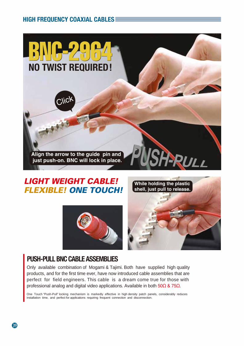
39
HIGH FREQUENCY COAXIAL CABLES
One Touch “Push-Pull” locking mechanism is markedly effective in high density patch panels, considerably reduces installation time, and perfect for applications requiring frequent connection and disconnection.
NO TWIST REQUIRED!
Only available combination of Mogami & Tajimi. Both have supplied high quality products, and for the first time ever, have now introduced cable assemblies that are perfect for field engineers. This cable is a dream come true for those with professional analog and digital video applications. Available in both 50Ω & 75Ω.
PUSH-PULL BNC CABLE ASSEMBLIES
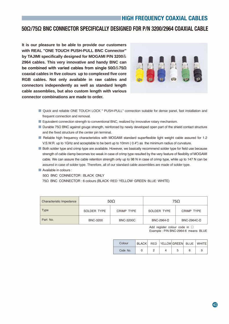
HIGH FREQUENCY COAXIAL CABLES
40
50Ω/75Ω BNC CONNECTOR SPECIFICALLY DESIGNED FOR P/N 3200/2964 COAXIAL CABLE
It is our pleasure to be able to provide our customers with REAL "ONE TOUCH PUSH-PULL BNC Connector" by TAJIMI specifically designed for MOGAMI P/N 3200&2964 cables. This very innovative and handy BNC can be combined with varied cables from single 50Ω&75Ω coaxial cables in five colours up to complexed five core RGB cables. Not only available in raw cables and connectors independently as well as standard length cable assemblies, but also custom length with various connector combinations are made to order.
■ Quick and reliable ONE TOUCH LOCK " PUSH-PULL" connection suitable for dense panel, fast installation and frequent connection and removal.
■ Equivalent connection strength to conventional BNC, realized by innovative rotary mechanism.■ Durable 75Ω BNC against gouge strength, reinforced by newly developed open part of the shield contact structure
and the fixed structure of the center pin terminal.■ Reliable high frequency characteristics with MOGAMI standard superflexible light weight cable assured for 1.2
V.S.W.R. up to 1GHz and acceptable to be bent up to 10mm ( 0.4") as the minimum radius of curvature.■ Both solder type and crimp type are available. However, we basically recommend solder type for field use because
strength of cable clamp becomes too weak in case of crimp type resulted by the very feature of flexiblity of MOGAMI cable. We can assure the cable retention strength only up to 98 N in case of crimp type, while up to 147 N can be assured in case of solder type. Therefore, all of our standard cable assemblies are made of solder type.
■ Available in colours : 50Ω BNC CONNECTOR : BLACK ONLY 75Ω BNC CONNECTOR : 6 colours (BLACK・RED・YELLOW・GREEN・BLUE・WHITE)
Add register colour code in □Example : P/N BNC-2964-6 means BLUE
Colour BLUE
6
GREEN
5
YELLOW
4
RED
2Code No.
WHITE
9
BLACK
0
Part No.
SOLDER TYPE CRIMP TYPE SOLDER TYPE CRIMP TYPE
BNC-2964-� BNC-2964C-�BNC-3200 BNC-3200C
Characteristic Impedance
Type
50Ω 75Ω
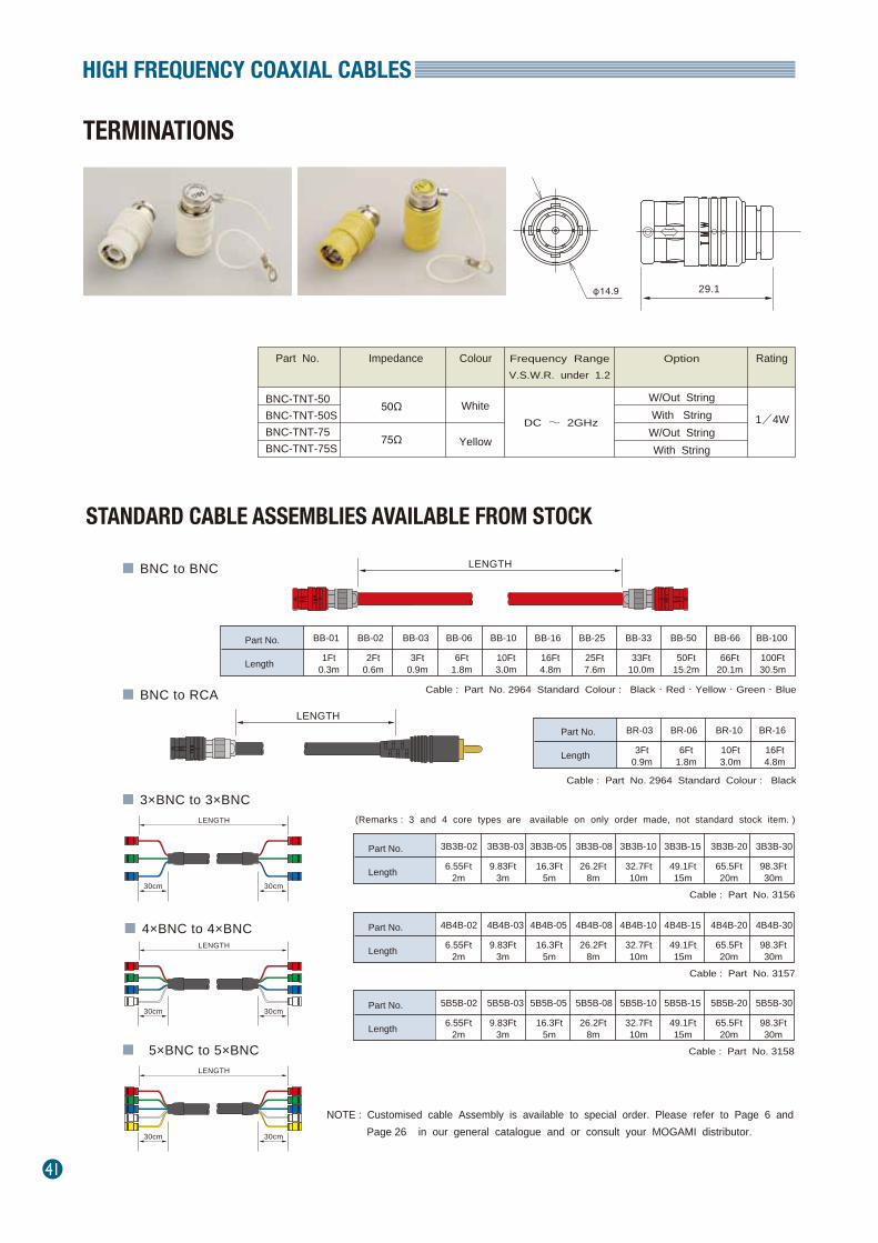
41
HIGH FREQUENCY COAXIAL CABLES
Part No.
Length
BB-01 BB-02 BB-06BB-03 BB-10 BB-16 BB-25 BB-33 BB-50 BB-66 BB-100
1Ft0.3m
2Ft0.6m
3Ft0.9m
6Ft1.8m
10Ft3.0m
16Ft4.8m
25Ft7.6m
33Ft10.0m
50Ft15.2m
66Ft20.1m
100Ft30.5m
LENGTH■ BNC to BNC
■ BNC to RCA
■ 4×BNC to 4×BNC
LENGTH
LENGTH
30cm30cm
■ 5×BNC to 5×BNCLENGTH
30cm30cm
■ 3×BNC to 3×BNCLENGTH
30cm30cm
Part No.
Length
4B4B-02 4B4B-03 4B4B-084B4B-05 4B4B-10 4B4B-15 4B4B-20 4B4B-30
6.55Ft2m
9.83Ft3m
16.3Ft5m
26.2Ft8m
32.7Ft10m
49.1Ft15m
65.5Ft20m
98.3Ft30m
Part No.
Length
BR-03 BR-06 BR-16BR-10
3Ft0.9m
6Ft1.8m
10Ft3.0m
16Ft4.8m
Cable : Part No. 2964 Standard Colour : Black・Red・Yellow・Green・Blue
(Remarks : 3 and 4 core types are available on only order made, not standard stock item. )
Cable : Part No. 2964 Standard Colour : Black
Cable : Part No. 3157
Part No.
Length
3B3B-02 3B3B-03 3B3B-083B3B-05 3B3B-10 3B3B-15 3B3B-20 3B3B-30
6.55Ft2m
9.83Ft3m
16.3Ft5m
26.2Ft8m
32.7Ft10m
49.1Ft15m
65.5Ft20m
98.3Ft30m
Cable : Part No. 3156
Part No.
Length
5B5B-02 5B5B-03 5B5B-085B5B-05 5B5B-10 5B5B-15 5B5B-20 5B5B-30
6.55Ft2m
9.83Ft3m
16.3Ft5m
26.2Ft8m
32.7Ft10m
49.1Ft15m
65.5Ft20m
98.3Ft30m
Cable : Part No. 3158
Frequency RangeV.S.W.R. under 1.2
Colour Option RatingPart No. Impedance
BNC-TNT-50BNC-TNT-50SBNC-TNT-75BNC-TNT-75S
W/Out StringWith StringW/Out StringWith String
50Ω
75Ω
White
YellowDC ~ 2GHz 1/4W
29.1φ14.9
NOTE : Customised cable Assembly is available to special order. Please refer to Page 6 and Page 26 in our general catalogue and or consult your MOGAMI distributor.
STANDARD CABLE ASSEMBLIES AVAILABLE FROM STOCK
TERMINATIONS
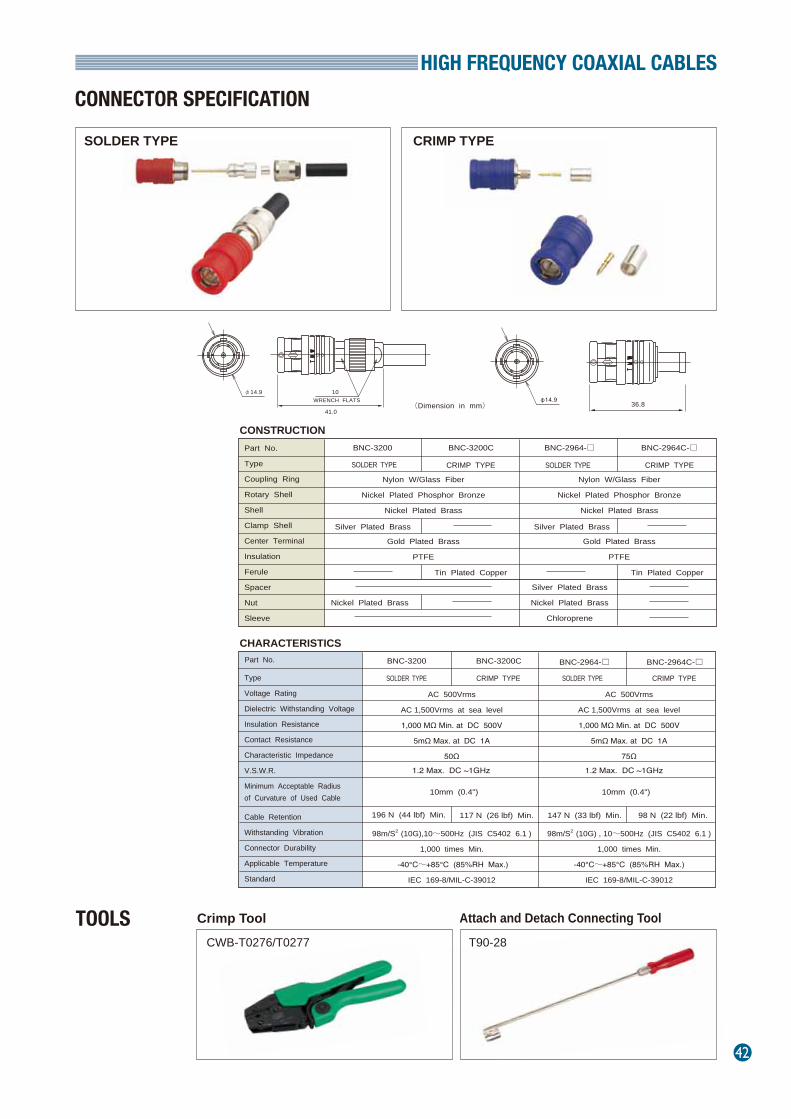
HIGH FREQUENCY COAXIAL CABLES
42
CONNECTOR SPECIFICATION
Crimp ToolCWB-T0276/T0277
Attach and Detach Connecting Tool
Part No.
Type
Coupling Ring
Rotary Shell
Shell
Clamp Shell
Center Terminal
Insulation
Ferule
Spacer
Nut
Sleeve
Nylon W/Glass Fiber
Nickel Plated Phosphor Bronze
Nickel Plated Brass
Gold Plated Brass
PTFE
Nylon W/Glass Fiber
Nickel Plated Phosphor Bronze
Nickel Plated Brass
Gold Plated Brass
PTFE
Type
Voltage Rating
Dielectric Withstanding Voltage
Insulation Resistance
Contact Resistance
Characteristic Impedance
V.S.W.R.
Minimum Acceptable Radiusof Curvature of Used Cable
Cable Retention
Withstanding Vibration
Connector Durability
Applicable Temperature
Standard
AC 500Vrms
AC 1,500Vrms at sea level
1,000 MΩ Min. at DC 500V
5mΩ Max. at DC 1A
75Ω
98m/S2 (10G) , 10~500Hz (JIS C5402 6.1 )
1,000 times Min.
-40℃~+85℃ (85%RH Max.)
IEC 169-8/MIL-C-39012
AC 500Vrms
AC 1,500Vrms at sea level
1,000 MΩ Min. at DC 500V
5mΩ Max. at DC 1A
50Ω
98m/S2 (10G),10~500Hz (JIS C5402 6.1 )
1,000 times Min.
-40℃~+85℃ (85%RH Max.)
IEC 169-8/MIL-C-39012
10φ14.9
41.0
WRENCH FLATS (Dimension in mm)
CONSTRUCTION
CHARACTERISTICS
TOOLS
Silver Plated Brass
BNC-2964-□
SOLDER TYPE CRIMP TYPESOLDER TYPE CRIMP TYPE
SOLDER TYPE CRIMP TYPESOLDER TYPE CRIMP TYPE
BNC-2964C-□BNC-3200 BNC-3200C
BNC-3200 BNC-3200C BNC-2964-□ BNC-2964C-□
Silver Plated Brass
Nickel Plated Brass
Chloroprene
Tin Plated Copper
Silver Plated Brass
Nickel Plated Brass
Tin Plated Copper
Part No.
10mm (0.4")
1.2 Max. DC ~1GHz
10mm (0.4")
1.2 Max. DC ~1GHz
147 N (33 lbf) Min. 98 N (22 lbf) Min.196 N (44 lbf) Min. 117 N (26 lbf) Min.
36.8φ14.9
SOLDER TYPE CRIMP TYPE
T90-28

43
VIDEO CABLES
COMPLEXED COAX. (VIDEO CAMERA) CABLES
Many variations of video camera cables which were originally developed for respective customers' requirements (as each camera needed a different specification) when the camera and the recorder were separated, these cables remained as a kind of standard stock item with some demand for maintenance and new and different applications in the international world wide market. Some video camera cables are of course applicable to professional cameras, and feature the same flexibility and compact size as other MOGAMI cables. Most of these cables are often comprised of 50Ω coaxial cable cores to make them as miniature as possible( of course it naturally becomes flexible), because the wave length of video signal is rather long ( 20m / 66Ft ) the reflection ( impedance mismatch ) problem does not become critical as long as it is used within this length( within one whole wave length) so that compactness and flexibility can be a benefit without any anxiety. However, for interconnection longer than 20m ( 66Ft ) or when attenuation is of importance, strictly adjusted 75Ω coaxial cable with larger conductor size must be used. Finally, video camera cables are destined to be discontinued as their demand decreases, therefore, please ask our distributor for its availability before you make a decision on its application.
Part No.2673 Part No.2537 Part No.2543
Part No.2859Part No.3027
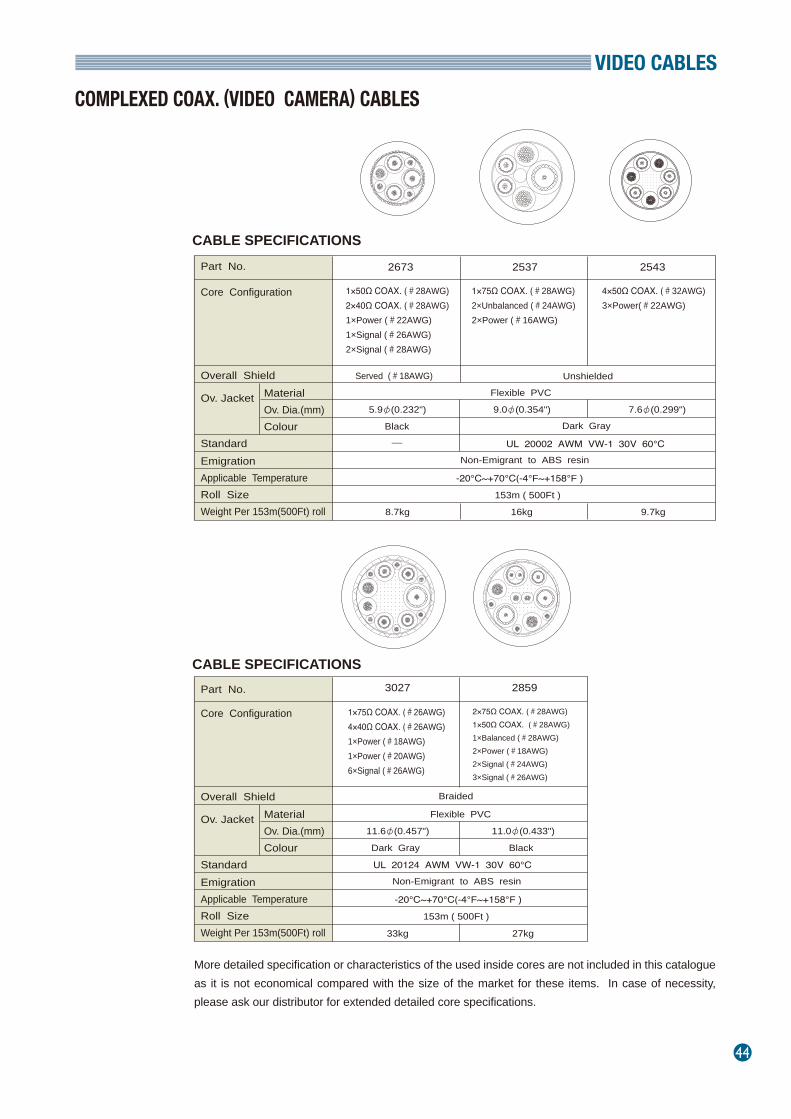
VIDEO CABLES
44
COMPLEXED COAX. (VIDEO CAMERA) CABLES
CABLE SPECIFICATIONS
Core Configuration
Part No.
Overall Shield
Ov. Jacket MaterialOv. Dia.(mm)Colour
StandardEmigrationApplicable TemperatureRoll SizeWeight Per 153m(500Ft) roll
2673 2537 2543
1×50Ω COAX. (#28AWG)2×40Ω COAX. (#28AWG)1×Power (#22AWG)1×Signal (#26AWG)2×Signal (#28AWG)
1×75Ω COAX. (#28AWG)2×Unbalanced (#24AWG)2×Power (#16AWG)
4×50Ω COAX. (#32AWG)3×Power(#22AWG)
Served (#18AWG) Unshielded
Flexible PVC
5.9φ(0.232") 9.0φ(0.354") 7.6φ(0.299")
Black Dark Gray
UL 20002 AWM VW-1 30V 60℃Non-Emigrant to ABS resin
-20℃~+70℃(-4°F~+158°F )
153m ( 500Ft )
8.7kg 16kg 9.7kg
More detailed specification or characteristics of the used inside cores are not included in this catalogue as it is not economical compared with the size of the market for these items. In case of necessity, please ask our distributor for extended detailed core specifications.
CABLE SPECIFICATIONS
Core Configuration
Part No.
Overall Shield
Ov. Jacket MaterialOv. Dia.(mm)Colour
StandardEmigrationApplicable TemperatureRoll SizeWeight Per 153m(500Ft) roll
Non-Emigrant to ABS resin
-20℃~+70℃(-4°F~+158°F )
153m ( 500Ft )
3027 2859
1×75Ω COAX. (#26AWG)4×40Ω COAX. (#26AWG)1×Power (#18AWG)1×Power (#20AWG)6×Signal (#26AWG)
2×75Ω COAX. (#28AWG)1×50Ω COAX. (#28AWG)1×Balanced (#28AWG)2×Power (#18AWG)2×Signal (#24AWG) 3×Signal (#26AWG)
Braided
Flexible PVC
11.6φ(0.457") 11.0φ(0.433")
Dark Gray
UL 20124 AWM VW-1 30V 60℃
33kg 27kg
Black
─
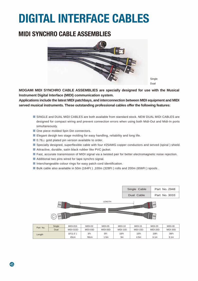
45
MOGAMI MIDI SYNCHRO CABLE ASSEMBLIES are specially designed for use with the Musical Instrument Digital Interface (MIDI) communication system.Applications include the latest MIDI patchbays, and interconnection between MIDI equipment and MIDI served musical instruments. These outstanding professional cables offer the following features:
■ SINGLE and DUAL MIDI CABLES are both available from standard stock. NEW DUAL MIDI CABLES are designed for compact wiring and prevent connection errors when using both Midi-Out and Midi-In ports simultaneously.
■ One piece molded 5pin Din connectors. ■ Elegant desigh two stage molding for easy handling, reliability and long life.■ 0.76μ gold plated pin version available to order.■ Specially designed, superflexible cable with four #25AWG copper conductors and served (spiral ) shield.■ Attractive, durable, satin black rubber like PVC jacket.■ Fast, accurate transmission of MIDI signal via a twisted pair for better electromagnetic noise rejection.■ Additional two pins wired for tape synchro signal.■ Interchangeable colour rings for easy patch cord identification.■ Bulk cable also available in 50m (164Ft ) ,100m (328Ft ) rolls and 200m (656Ft ) spools .
MIDI SYNCHRO CABLE ASSEMBLIES
DIGITAL INTERFACE CABLES
SingleDual
Part No. Single MIDI-015 MIDI-03 MIDI-05 MIDI-10 MIDI-15 MIDI-20 MIDI-30Dual MIDI-015D MIDI-03D MIDI-05D MIDI-10D MIDI-15D MIDI-20D MIDI-30D
18"(1.5' ) 3Ft 5Ft 10Ft 15Ft 20Ft 30Ft45cm 90cm 1.5m 3m 4.5m 6.1m 9.1m
Length
Single Cable Part No. 2948
Dual Cable Part No. 3033
LENGTH
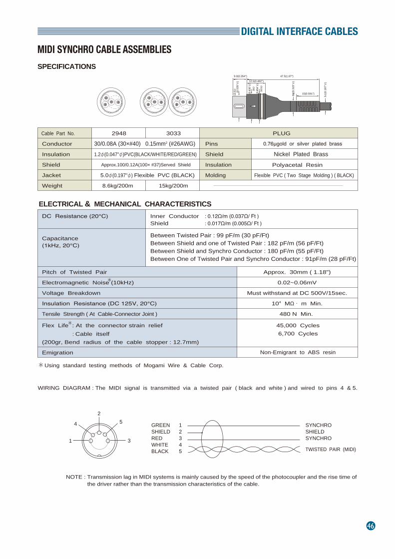
DIGITAL INTERFACE CABLES
46
MIDI SYNCHRO CABLE ASSEMBLIES
Cable Part No.
Conductor
Insulation
Shield
Jacket
Weight
2948 3033
30/0.08A (30×#40) 0.15mm2 (#26AWG)1.2φ(0.047"φ)PVC(BLACK/WHITE/RED/GREEN)
Approx.100/0.12A(100× #37)Served Shield
5.0φ(0.197"φ) Flexible PVC (BLACK)
8.6kg/200m 15kg/200m
Pins
Shield
Insulation
Molding
PLUG
0.76μgold or silver plated brass
Nickel Plated Brass
Polyacetal Resin
Flexible PVC ( Two Stage Molding ) ( BLACK)
Pitch of Twisted Pair
Electromagnetic Noise (10kHz)
Voltage Breakdown
Insulation Resistance (DC 125V, 20℃)
Tensile Strength ( At Cable-Connector Joint )
DC Resistance (20℃)
Capacitance(1kHz, 20℃)
Inner Conductor : 0.12Ω/m (0.037Ω/ Ft )Shield : 0.017Ω/m (0.005Ω/ Ft )
Between Twisted Pair : 99 pF/m (30 pF/Ft)Between Shield and one of Twisted Pair : 182 pF/m (56 pF/Ft)Between Shield and Synchro Conductor : 180 pF/m (55 pF/Ft)Between One of Twisted Pair and Synchro Conductor : 91pF/m (28 pF/Ft)
Flex Life : At the connector strain relief : Cable itself
(200gr, Bend radius of the cable stopper : 12.7mm)
45,000 Cycles 6,700 Cycles
Approx. 30mm ( 1.18")
0.02~0.06mV
Must withstand at DC 500V/15sec.
104 MΩ・ m Min.
480 N Min.
Emigration Non-Emigrant to ABS resin
Using standard testing methods of Mogami Wire & Cable Corp.
WIRING DIAGRAM : The MIDI signal is transmitted via a twisted pair ( black and white ) and wired to pins 4 & 5.
NOTE : Transmission lag in MIDI systems is mainly caused by the speed of the photocoupler and the rise time of the driver rather than the transmission characteristics of the cable.
SPECIFICATIONS
ELECTRICAL & MECHANICAL CHARACTERISTICS
9.0(0.354'')
12.5(0.492'')
47.5(1.87'')
15(0.591'')13.6φ
(0
.535
''φ)
8 φ(0
.315
''φ)
5 φ(0
.197
''φ)
(0.6
30''φ
)16φ
(0.6
54''φ
)16
.6φ
GREEN SHIELD RED WHITE BLACK
12345
SYNCHROSHIELDSYNCHRO
TWISTED PAIR (MIDI)1
4
25
3
*
*
*
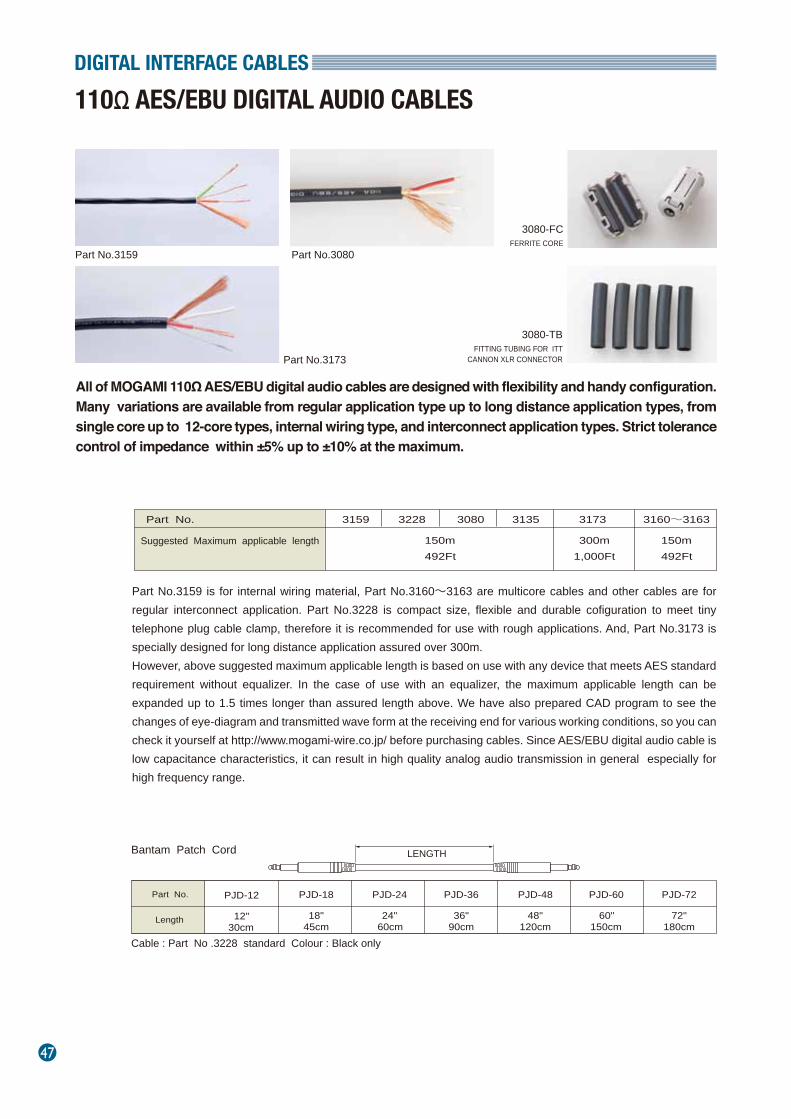
47
DIGITAL INTERFACE CABLES
110Ω AES/EBU DIGITAL AUDIO CABLES
All of MOGAMI 110Ω AES/EBU digital audio cables are designed with flexibility and handy configuration. Many variations are available from regular application type up to long distance application types, from single core up to 12-core types, internal wiring type, and interconnect application types. Strict tolerance control of impedance within ±5% up to ±10% at the maximum.
3080-FCFERRITE CORE
3080-TBFITTING TUBING FOR ITT
CANNON XLR CONNECTOR
Part No.3159 is for internal wiring material, Part No.3160~3163 are multicore cables and other cables are for regular interconnect application. Part No.3228 is compact size, flexible and durable cofiguration to meet tiny telephone plug cable clamp, therefore it is recommended for use with rough applications. And, Part No.3173 is specially designed for long distance application assured over 300m.However, above suggested maximum applicable length is based on use with any device that meets AES standard requirement without equalizer. In the case of use with an equalizer, the maximum applicable length can be expanded up to 1.5 times longer than assured length above. We have also prepared CAD program to see the changes of eye-diagram and transmitted wave form at the receiving end for various working conditions, so you can check it yourself at http://www.mogami-wire.co.jp/ before purchasing cables. Since AES/EBU digital audio cable is low capacitance characteristics, it can result in high quality analog audio transmission in general especially for high frequency range.
Part No.
Suggested Maximum applicable length
3159 3228 3080
150m492Ft
150m492Ft
300m1,000Ft
3135 3173 3160~3163
Bantam Patch Cord
Part No.
Length
PJD-12 PJD-18 PJD-24 PJD-36 PJD-48 PJD-72
12"30cm
18"45cm
24"60cm
36"90cm
48"120cm
60"150cm
Cable : Part No .3228 standard Colour : Black only
PJD-60
72"180cm
LENGTH
Part No.3159
Part No.3173
Part No.3080
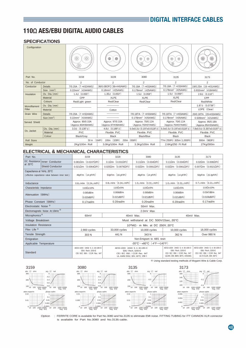
DIGITAL INTERFACE CABLES
48
110Ω AES/EBU DIGITAL AUDIO CABLES
SPECIFICATIONS
ELECTRICAL & MECHANICAL CHARACTERISTICS
Option : FERRITE CORE is available for Part No.3080 and No.3135 to eliminate EMI noise. FITTING TUBING for ITT CANNON XLR connector is available for Part No.3080 and No.3135 cable.
Part No.
Configuration
No. of Conductor Details Conductor
Insulation
MonofilamentFiller
Drain Wire
Served Shield
Size(mm2)
Details Size(mm2)
Material Colours
Roll Sizes Weight
36/0.08OFC(36×#40AWG)0.18mm2(#25AWG)
1.35φ(0.053")XLPE
Red/Clear
7/0.18TA(7 ×#33AWG)0.178mm2(#25AWG)
Approx. 70/0.12A(Approx.70/#37AWG)
5.0±0.3φ(0.197±0.0118"φ)Flexible PVC
Black
20/0.18TA(20×#33AWG)0.509mm2(#21AWG)
Approx. 95/0.18A(Approx.95/#33AWG)
7.8±0.5φ(0.307±0.0197"φ)Flexible PVC
Black
7/0.18A(7 ×#33AWG)0.178mm2(#25AWG)
1.5φ(0.059")XLPE
Red/Clear
19/0.25A(19 ×#31AWG)0.932mm2(#18AWG)
2.8φ(0.110")CPP
Red/White1.87φ(0.0736")
LDPE(Clear)
50 m (164Ft) 100m (328Ft) 200m(656Ft) 77m(250Ft) 305m(1,000Ft) 2.6Kg/250 Ft Roll
300m(983Ft) 27Kg/300m
Approx. 97/0.10A(Approx.97/#39AWG)
4.8φ(0.189"φ) Flexible PVC
Black
3.0Kg/100m Roll
3135 3173
Ov. Dia.(mm)
Material Ov. Dia.(mm)
Ov. Jacket
Ov. Dia.(mm) Material Colour
2
3228
2
Cotton
2
Capacitance at 1kHz, 20℃( effective capacitance value between inner twin )
Inner Conductor Shield Conductor
DC Resistanceat 20℃
Characteristic Impedance Inductance
Attenuation(6MHz)
46pF/m(14 pF/Ft)
1.0μH/m(0.31μH/Ft)110Ω±5%
0.069dB/m
(0.021dB/Ft)0.20rad/m
343 N
3080
0.11Ω/m(0.034Ω/Ft)0.02Ω/m(0.0061Ω/Ft)
53pF/m(16 pF/Ft)
0.8μH/m(0.24μH/Ft)110Ω±5%
0.069dB/m
(0.021dB/Ft)
0.20rad/m
33,000 cycles441 N
3228
0.1Ω/m(0.031Ω/Ft)0.025Ω/m(0.0076Ω/Ft)
46pF/m(14 pF/Ft)
1.0μH/m(0.31μH/Ft)110Ω±5%
0.069dB/m
(0.021dB/Ft)0.20rad/m
10,000 cycles362 N
3135
0.11Ω/m(0.034Ω/Ft)0.02Ω/m(0.0061Ω/Ft)
50pF/m(15.3pF/Ft)
0.7μH/m(0.21μH/Ft)110Ω±10%
0.0347dB/m
(0.0106dB/Ft)0.17rad/m
16,000 cyclesOver 980 N
3173
0.02Ω/m(0.006Ω/Ft)0.007Ω/m(0.0021Ω/Ft)
Part No.
Phase Constant(6MHz) Electrostatic Noise Electromagnetic Noise At 10kHz Microphonics
Voltage Breakdown
Tensile Strength Flex Life Insulation Resistance
Emigration Applicable Temperature
Standard
Must withstand at DC 500V/15sec, 20℃
104MΩ・m Min. at DC 250V, 20℃
-20℃~+60℃(-4°F~+140°F) Non-Emigrant to ABS resin
AES3-100X(ANSI S. 4. 40-199-X)EBU Rech, 3250-E
CEI / IEC 958 / CCIR Rec. 647UL AWM 2552, 30V, 60℃, VW-1
AES3-100X(ANSI S. 4. 40-199-X)EBU Rech, 3250-E
CEI / IEC 958 / CCIR Rec. 647UL444, CM, 300V, 60℃, #25AWG
AES3-100X(ANSI S. 4. 40-199-X)EBU Rech, 3250-E
CEI / IEC 958 / CCIR Rec. 647UL13 CL2X, 30V, 60℃
7/0.18A(7 ×#33AWG)0.178mm2(#25AWG)
1.5φ(0.059")XLPE
Red/Clear
7/0.18TA(7 ×#33AWG)0.178mm2(#25AWG)
Approx. 70/0.12A(Approx.70/#37AWG)
5.0±0.3φ(0.197±0.0118"φ)Flexible PVC
Black/Blue
3.3Kg/100m Roll
3080
2
7/0.20A(7 ×#32AWG)0.22mm2(#24AWG)
Approx. 90/0.10A(Approx.90/#39AWG)
3.3φ(0.130"φ) PVC
Black/Gray
7/0.20A(7 ×#32AWG)0.22mm2(#24AWG)
1.4φ(0.055")CPP
Red/Light green
2Kg/100m Roll
3159
2
arg〔Z〕 radabs〔Z〕 ohm
freg. KHZ
30803159 3135 3173300
200
100
0-0.2-0.4-0.6-0.8
10 100 1000 10000freg. KHZ
10 100 1000 10000
phase rad/matten.neper/m
freg. KHZ
0.01
0.005
0
10.1
0.010.001
0.000110 100 1000 10000
freg. KHZ10 100 1000 10000
arg〔Z〕 radabs〔Z〕 ohm
freg. KHZ
300
200
100
0
-0.5
-110 100 1000 10000
freg. KHZ10 100 1000 10000
phase rad/matten.neper/m
freg. KHZ
0.02
0.01
0
10.1
0.010.001
0.000110 100 1000 10000
freg. KHZ10 100 1000 10000
arg〔Z〕 radabs〔Z〕 ohm
freg. KHZ
160
140
120
100
0
-0.2
-0.410 100 1000 10000
freg. KHZ10 100 1000 10000
phase rad/matten.neper/m
freg. KHZ
0.006
0.004
0.002
0
10.1
0.010.001
0.000110 100 1000 10000
freg. KHZ10 100 1000 10000
arg〔Z〕 radabs〔Z〕 ohm
freg. KHZ
300
200
100
0-0.2-0.4-0.6-0.8
10 100 1000 10000freg. KHZ
10 100 1000 10000
phase rad/matten.neper/m
freg. KHZ
0.02
0.01
0
10.1
0.010.001
0.000110 100 1000 10000
freg. KHZ10 100 1000 10000
10,000 cycles
46pF/m(14 pF/Ft)
0.8μH/m(0.24μH/Ft)110Ω±10%
0.065dB/m
(0.020dB/Ft)0.17rad/m
60mV
303 N
3159
0.081Ω/m(0.0247Ω/Ft)0.021Ω/m(0.0064Ω/Ft)
AES3-100X(ANSI S. 4. 40-199-X)EBU Rech, 3250-E
CEI / IEC 958 / CCIR Rec. 647
2,900 cycles
**
*
*
Using standard testing methods of Mogami Wire & Cable Corp.*
40mV Max. 40mV Max.
50mV Max.2.0mV Max.
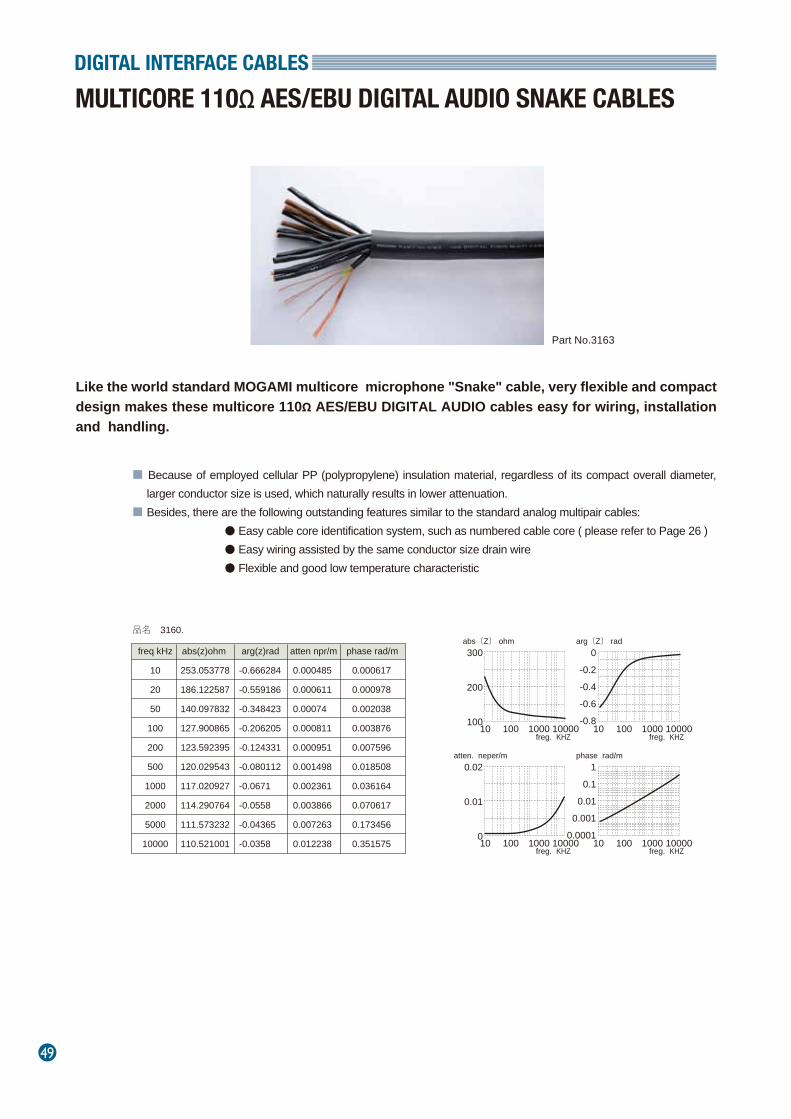
49
DIGITAL INTERFACE CABLES
MULTICORE 110Ω AES/EBU DIGITAL AUDIO SNAKE CABLES
Like the world standard MOGAMI multicore microphone "Snake" cable, very flexible and compact design makes these multicore 110Ω AES/EBU DIGITAL AUDIO cables easy for wiring, installation and handling.
■ Because of employed cellular PP (polypropylene) insulation material, regardless of its compact overall diameter, larger conductor size is used, which naturally results in lower attenuation.
■ Besides, there are the following outstanding features similar to the standard analog multipair cables: ● Easy cable core identification system, such as numbered cable core ( please refer to Page 26 ) ● Easy wiring assisted by the same conductor size drain wire ● Flexible and good low temperature characteristic
freq kHz abs(z)ohm arg(z)rad atten npr/m phase rad/m
10 253.053778 -0.666284 0.000485 0.000617
20 186.122587 -0.559186 0.000611 0.000978
50 140.097832 -0.348423 0.00074 0.002038
100 127.900865 -0.206205 0.000811 0.003876
200 123.592395 -0.124331 0.000951 0.007596
500 120.029543 -0.080112 0.001498 0.018508
1000 117.020927 -0.0671 0.002361 0.036164
2000 114.290764 -0.0558 0.003866 0.070617
5000 111.573232 -0.04365 0.007263 0.173456
10000 110.521001 -0.0358 0.012238 0.351575
品名 3160.abs〔Z〕 ohm
freg. KHZ
300
200
10010 100 1000 10000
arg〔Z〕 rad
freg. KHZ
0-0.2-0.4-0.6-0.8
10 100 1000 10000
atten. neper/m
freg. KHZ
0.02
0.01
010 100 1000 10000
phase rad/m
freg. KHZ
10.1
0.010.001
0.000110 100 1000 10000
Part No.3163
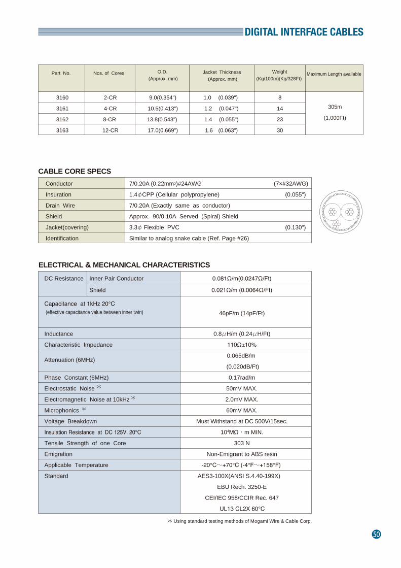
DIGITAL INTERFACE CABLES
50
ELECTRICAL & MECHANICAL CHARACTERISTICS
Part No.
Nos. of Cores.
O.D. (Approx. mm)
Jacket Thickness (Approx. mm)
Weight(Kg/100m)(Kg/328Ft)
Maximum Length available
3160 2-CR 9.0(0.354") 1.0 (0.039") 8
3161 4-CR 10.5(0.413") 1.2 (0.047") 14
3162 8-CR 13.8(0.543") 1.4 (0.055") 23
3163 12-CR 17.0(0.669") 1.6 (0.063") 30
305m
(1,000Ft)
CABLE CORE SPECS Conductor 7/0.20A (0.22mm2)#24AWG (7×#32AWG)
Insuration 1.4φCPP (Cellular polypropylene) (0.055")
Drain Wire 7/0.20A (Exactly same as conductor)
Shield Approx. 90/0.10A Served (Spiral) Shield
Jacket(covering) 3.3φ Flexible PVC (0.130")
Identification Similar to analog snake cable (Ref. Page #26)
DC Resistance Inner Pair Conductor 0.081Ω/m(0.0247Ω/Ft)
Shield 0.021Ω/m (0.0064Ω/Ft)
Capacitance at 1kHz 20℃ (effective capacitance value between inner twin)
46pF/m (14pF/Ft)
Inductance 0.8μH/m (0.24μH/Ft)
Characteristic Impedance 110Ω±10%
Attenuation (6MHz) 0.065dB/m
(0.020dB/Ft)
Phase Constant (6MHz) 0.17rad/m
Electrostatic Noise 50mV MAX.
Electromagnetic Noise at 10kHz 2.0mV MAX.
Microphonics 60mV MAX.
Voltage Breakdown Must Withstand at DC 500V/15sec.
Insulation Resistance at DC 125V. 20℃ 104MΩ・m MIN.
Tensile Strength of one Core 303 N
Emigration Non-Emigrant to ABS resin
Applicable Temperature -20℃~+70℃ (-4°F~+158°F)
Standard AES3-100X(ANSI S.4.40-199X)
EBU Rech. 3250-E
CEI/IEC 958/CCIR Rec. 647
UL13 CL2X 60℃
Using standard testing methods of Mogami Wire & Cable Corp.
*
*
*
*

51
DIGITAL INTERFACE CABLES
〈 FOR PLUG & PLAY 〉VESA VGA CABLE
MOGAMI Part No. 3206-08 is a specially designed cable to meet VESA standard for plug and play. Applicable up to 30 m (100 Ft) long, and possible to solder to a very small and troublesome Shrink Dsub 15P connector.
Part No.3206
Wiring Instruction When all 15 Pins're Wired
Shrink Dsub 15P Pin Assignment Pin No.
Centre Conductor of Red Coax.Centre Conductor of Green Coax.Centre Conductor of Blue Coax.Brown Lead Wire, #28 AWG, PVCOrange + Green Lead Wire, #28 AWG, XLCPEShield Conductor of Red Coax.Shield Conductor of Green Coax.Shield Conductor of Blue Coax.Black Lead Wire, #26AWG , PVCShield Conductor of White + Yellow Coax.Red Lead Wire, #28 AWG , PVCYellow Lead Wire, #28 AWG , XLCPECentre Conductor of White Coax.Centre Conductor of Yellow Coax.Blue Lead Wire, #28 AWG , XLCPE
1
2
3
4
5
6
7
8
9
10
11
12
13
14
15
12345678
9
101112131415
Pin No.
Test(ground)
No connection(mechanical key)
Monitor ID bit 1
Monitor ID bit 3
Data from display
Open
Red videoGreen videoBlue video
Sync. return
Horizontal sync.Vertical sync.
Data clock(SCL)
Optional
+5volt load(optional use)
Optional
Assigned Core
Standard VGA DDC1 Host DDC2B Host DDC2B+orDDC2AB Host DDC1/2 Display
Monitor ID bit 2Return
Red video returnGreen video returnBlue video return
+5volt supply(mandatory supply)
Monitor ID bit 0Bi-directional data (SDA)
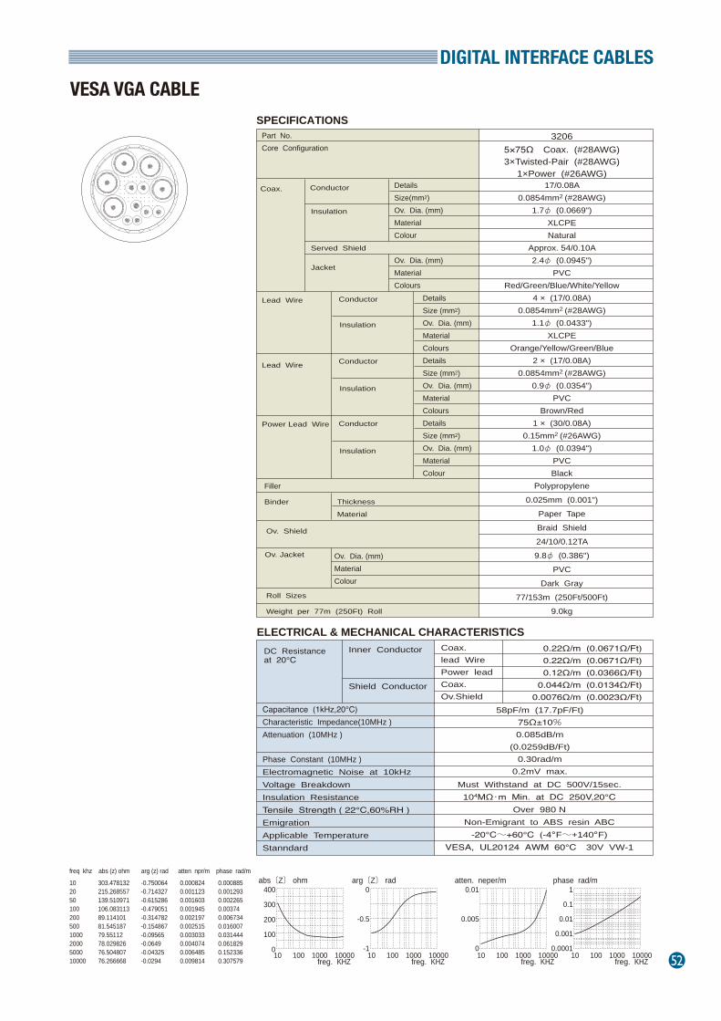
DIGITAL INTERFACE CABLES
52
Part No. Core Configuration
DetailsSize(mm2)Ov. Dia. (mm)MaterialColour
Ov. Dia. (mm)MaterialColours
Conductor
Conductor
Conductor
Coax.
Insulation
Insulation
Insulation
Conductor
Insulation
Jacket
Served Shield
Binder
Lead Wire
Ov. Shield
Roll Sizes
Weight per 77m (250Ft) Roll
Lead Wire
Power Lead Wire
Ov. Jacket
ELECTRICAL & MECHANICAL CHARACTERISTICS
Filler
DetailsSize (mm2)Ov. Dia. (mm)MaterialColoursDetailsSize (mm2)Ov. Dia. (mm)MaterialColoursDetailsSize (mm2)Ov. Dia. (mm)MaterialColour
Thickness
Material
Ov. Dia. (mm)MaterialColour
32065×75Ω Coax. (#28AWG)3×Twisted-Pair (#28AWG)
1×Power (#26AWG)17/0.08A
0.0854mm2 (#28AWG)1.7φ (0.0669")
XLCPENatural
Approx. 54/0.10A2.4φ (0.0945")
PVCRed/Green/Blue/White/Yellow
4 × (17/0.08A)0.0854mm2 (#28AWG)
1.1φ (0.0433")XLCPE
Orange/Yellow/Green/Blue2 × (17/0.08A)
0.0854mm2 (#28AWG)0.9φ (0.0354")
PVCBrown/Red
1 × (30/0.08A)0.15mm2 (#26AWG)
1.0φ (0.0394")PVCBlack
Polypropylene0.025mm (0.001")
Paper TapeBraid Shield24/10/0.12TA9.8φ (0.386")
PVCDark Gray
77/153m (250Ft/500Ft)9.0kg
Capacitance (1kHz,20℃)Characteristic Impedance(10MHz )Attenuation (10MHz )
Phase Constant (10MHz )Electromagnetic Noise at 10kHz Voltage BreakdownInsulation ResistanceTensile Strength ( 22℃,60%RH )EmigrationApplicable TemperatureStanndard
Inner Conductor Coax.lead WirePower leadCoax.Ov.Shield
0.22Ω/m (0.0671Ω/Ft)0.22Ω/m (0.0671Ω/Ft)0.12Ω/m (0.0366Ω/Ft)
0.044Ω/m (0.0134Ω/Ft)0.0076Ω/m (0.0023Ω/Ft)
58pF/m (17.7pF/Ft)75Ω±10%0.085dB/m
(0.0259dB/Ft)0.30rad/m
0.2mV max.Must Withstand at DC 500V/15sec.
104MΩ・m Min. at DC 250V,20℃Over 980 N
Non-Emigrant to ABS resin ABC-20℃~+60℃ (-4。F~+140。F)
VESA, UL20124 AWM 60℃ 30V VW-1
DC Resistanceat 20℃
Shield Conductor
SPECIFICATIONS
abs〔Z〕 ohm
freg. KHZ
arg〔Z〕 rad atten. neper/m phase rad/m400
300
200
100
010 100 1000 10000
freg. KHZ
0
-0.5
-110 100 1000 10000
freg. KHZ
0.01
0.005
010 100 1000 10000
freg. KHZ
1
0.1
0.01
0.001
0.000110 100 1000 10000
10205010020050010002000500010000
303.478132215.268557139.510971106.08311389.11410181.54518779.5511278.02982676.50480776.266668
-0.750064-0.714327-0.615286-0.479051-0.314782-0.154867-0.09565-0.0649-0.04325-0.0294
0.0008240.0011230.0016030.0019450.0021970.0025150.0030330.0040740.0064850.009814
0.0008850.0012930.0022650.003740.0067340.0160070.0314440.0618290.1523360.307579
freq khz abs (z) ohm arg (z) rad atten npr/m phase rad/m
VESA VGA CABLE
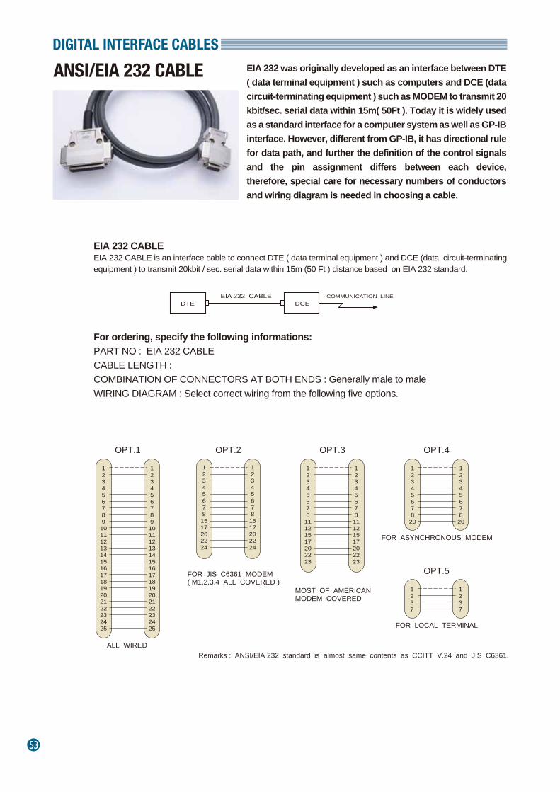
53
DIGITAL INTERFACE CABLES
ANSI/EIA 232 CABLE EIA 232 was originally developed as an interface between DTE ( data terminal equipment ) such as computers and DCE (data circuit-terminating equipment ) such as MODEM to transmit 20 kbit/sec. serial data within 15m( 50Ft ). Today it is widely used as a standard interface for a computer system as well as GP-IB interface. However, different from GP-IB, it has directional rule for data path, and further the definition of the control signals and the pin assignment differs between each device, therefore, special care for necessary numbers of conductors and wiring diagram is needed in choosing a cable.
EIA 232 CABLEEIA 232 CABLE is an interface cable to connect DTE ( data terminal equipment ) and DCE (data circuit-terminating equipment ) to transmit 20kbit / sec. serial data within 15m (50 Ft ) distance based on EIA 232 standard.
For ordering, specify the following informations:PART NO : EIA 232 CABLE CABLE LENGTH : COMBINATION OF CONNECTORS AT BOTH ENDS : Generally male to maleWIRING DIAGRAM : Select correct wiring from the following five options.
EIA 232 CABLE COMMUNICATION LINE
12345678910111213141516171819202122232425
OPT.1
ALL WIRED
123456789
10111213141516171819202122232425
12345678
1517202224
OPT.2
FOR JIS C6361 MODEM( M1,2,3,4 ALL COVERED )
1234567811121517202223
OPT.3
123456781517202224
1234567811121517202223
MOST OF AMERICAN MODEM COVERED
1234567820
OPT.4
1234567820
FOR ASYNCHRONOUS MODEM
1237
OPT.5
FOR LOCAL TERMINAL
1237
Remarks : ANSI/EIA 232 standard is almost same contents as CCITT V.24 and JIS C6361.
DTE DCE
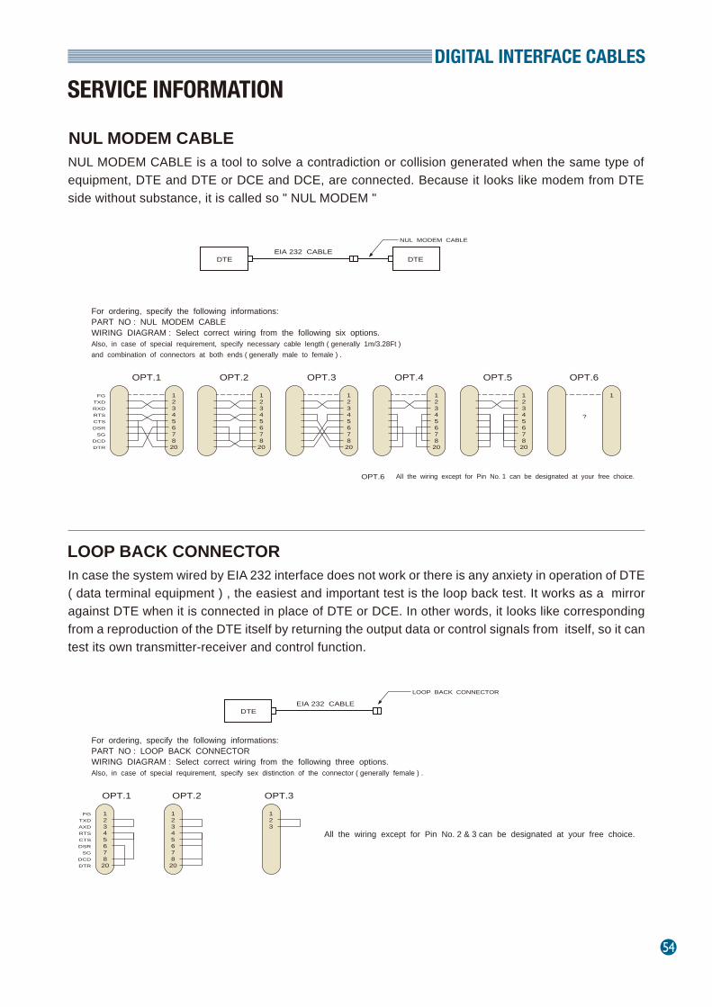
DIGITAL INTERFACE CABLES
54
NUL MODEM CABLE is a tool to solve a contradiction or collision generated when the same type of equipment, DTE and DTE or DCE and DCE, are connected. Because it looks like modem from DTE side without substance, it is called so " NUL MODEM "
NUL MODEM CABLE
In case the system wired by EIA 232 interface does not work or there is any anxiety in operation of DTE ( data terminal equipment ) , the easiest and important test is the loop back test. It works as a mirror against DTE when it is connected in place of DTE or DCE. In other words, it looks like corresponding from a reproduction of the DTE itself by returning the output data or control signals from itself, so it can test its own transmitter-receiver and control function.
LOOP BACK CONNECTOR
SERVICE INFORMATION
DTEEIA 232 CABLE
LOOP BACK CONNECTOR
For ordering, specify the following informations:PART NO : LOOP BACK CONNECTOR WIRING DIAGRAM : Select correct wiring from the following three options. Also, in case of special requirement, specify sex distinction of the connector ( generally female ) .
12345678
20
OPT.1
FGTXDAXDRTSCTSDSR
SGDCDDTR
OPT.2 OPT.3
12345678
20
123
All the wiring except for Pin No. 2 & 3 can be designated at your free choice.
DTEEIA 232 CABLE
For ordering, specify the following informations:PART NO : NUL MODEM CABLE WIRING DIAGRAM : Select correct wiring from the following six options. Also, in case of special requirement, specify necessary cable length ( generally 1m/3.28Ft )and combination of connectors at both ends ( generally male to female ) .
12345678
20
OPT.1
12345678
20
DTE
NUL MODEM CABLE
FGTXDRXDRTSCTSDSR
SGDCDDTR
12345678
20
OPT.2
12345678
20
12345678
20
OPT.3
12345678
20
12345678
20
OPT.4
12345678
20
12345678
20
12345678
20
1
OPT.6
1
OPT.5
?
All the wiring except for Pin No. 1 can be designated at your free choice.OPT.6
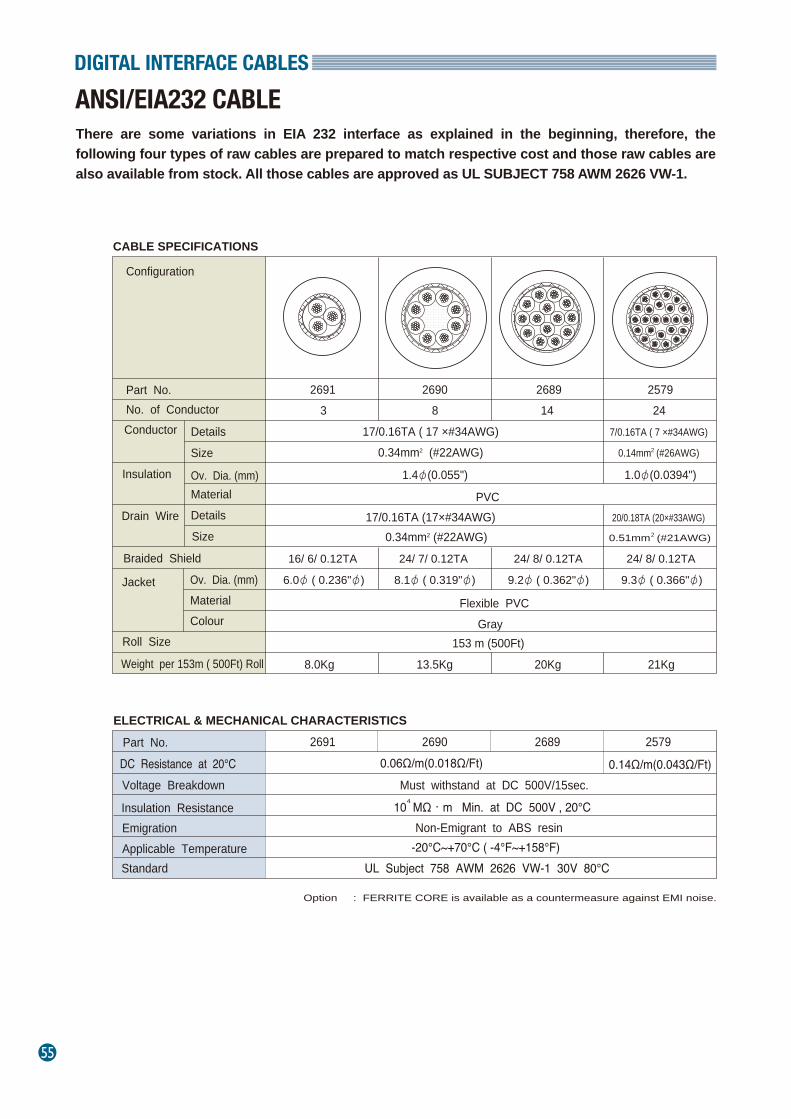
55
DIGITAL INTERFACE CABLES
ANSI/EIA232 CABLEThere are some variations in EIA 232 interface as explained in the beginning, therefore, the following four types of raw cables are prepared to match respective cost and those raw cables are also available from stock. All those cables are approved as UL SUBJECT 758 AWM 2626 VW-1.
Part No. No. of Conductor
Details Conductor
Size
Material
Roll Size
Weight per 153m ( 500Ft) Roll 153 m (500Ft)
8.0Kg
2691
Ov. Dia. (mm)
317/0.16TA ( 17 ×#34AWG)
0.34mm2 (#22AWG)
DC Resistance at 20℃ 2691
0.14Ω/m(0.043Ω/Ft)Part No.
Voltage Breakdown
Insulation Resistance Emigration Applicable Temperature
0.06Ω/m(0.018Ω/Ft)Must withstand at DC 500V/15sec.
Non-Emigrant to ABS resin
UL Subject 758 AWM 2626 VW-1 30V 80℃
Drain Wire
Insulation
Braided Shield
Details Size
1.4φ(0.055")
PVC17/0.16TA (17×#34AWG)
0.34mm2 (#22AWG)16/ 6/ 0.12TA
6.0φ ( 0.236"φ)
Standard
10 MΩ・m Min. at DC 500V , 20℃4
Option : FERRITE CORE is available as a countermeasure against EMI noise.
Jacket Ov. Dia. (mm) Material Colour
Flexible PVC Gray
2690 2689 25798 14 24
20/0.18TA (20×#33AWG)
24/ 7/ 0.12TA 24/ 8/ 0.12TA 24/ 8/ 0.12TA
8.1φ ( 0.319"φ) 9.2φ ( 0.362"φ) 9.3φ ( 0.366"φ)
13.5Kg 20Kg 21Kg
0.51mm (#21AWG)2
2690 2689 2579
-20℃~+70℃ ( -4°F~+158°F)
7/0.16TA ( 7 ×#34AWG)
0.14mm (#26AWG)2
1.0φ(0.0394")
Configuration
ELECTRICAL & MECHANICAL CHARACTERISTICS
CABLE SPECIFICATIONS
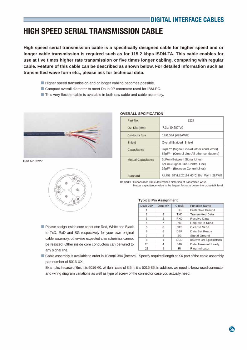
DIGITAL INTERFACE CABLES
56
High speed serial transmission cable is a specifically designed cable for higher speed and or longer cable transmission is required such as for 115.2 kbps ISDN-TA. This cable enables for use at five times higher rate transmission or five times longer cabling, comparing with regular cable. Feature of this cable can be described as shown below. For detailed information such as transmitted wave form etc., please ask for technical data.
HIGH SPEED SERIAL TRANSMISSION CABLE
■ Higher speed transmission and or longer cabling becomes possible.■ Compact overall diameter to meet Dsub 9P connector used for IBM-PC.■ This very flexible cable is available in both raw cable and cable assembly.
■ Please assign inside core conductor Red, White and Black to TxD, RxD and SG respectively for your own original cable assembly, otherwise expected characteristics cannot be realized. Other inside core conductors can be wired to any signal line.
■ Cable assembly is available to order in 10cm(0.394'')interval. Specify required length at XX part of the cable assembly part number of 5016-XX.
Example: In case of 6m, it is 5016-60, while in case of 8.5m, it is 5016-85. In addition, we need to know used connector and wiring diagram variations as well as type of screw of the connector case you actually need.
Ov. Dia.(mm)
Part No.
Conductor Size 17/0.08A (#28AWG)
Remarks : Capacitance value determines distortion of transmitted wave. Mutual capacitance value is the largest factor to determine cross-talk level.
Overall Braided Shield
37pF/m (Signal Line-All other conductors)87pF/m (Control Line-All other conductors)
3pF/m (Between Signal Lines)6pF/m (Signal Line-Control Line)32pF/m (Between Control Lines)
UL758 STYLE 20124 60℃ 30V VW-1 28AWG
Shield
Capacitance
Mutual Capacitance
Standard
7.3φ (0.287"φ)
3227
OVERALL SPCIFICATION
Dsub 25P123456782022
Dsub 9P─327865149
CircuitFG
TXDRXDRTSCTSDSRSG
DCDDTRRI
Function NameProtective GroundTransmitted DataReceive DataRequest to SendClear to SendData Set ReadySignal GroundReceived Line Signal DetectorData Terminal ReadyRing Indicator
Typical Pin Assignment
Part No.3227

57
DIGITAL INTERFACE CABLES
RS-422 BALANCED VOLTAGE DIGITAL INTERFACE CABLE
MOGAMI #2997 is designed to meet EIA Standard RS-422 general applications, with 2 balanced cores and 4 signal conductors. Overall diameter of 7mm (0.276") enables it to fit into most of the D-sub 9-pin connectors available. All the conductors are designed same the size (#25AWG) including the drain wire which can be crimped by the same size contact. Numbering print system on the balanced cores is the same as Mogami snake cables and serves as an efficient identification system together with colour coded remaining four signal conductors.
2997-FC FERRITE CORE
Part No.2997
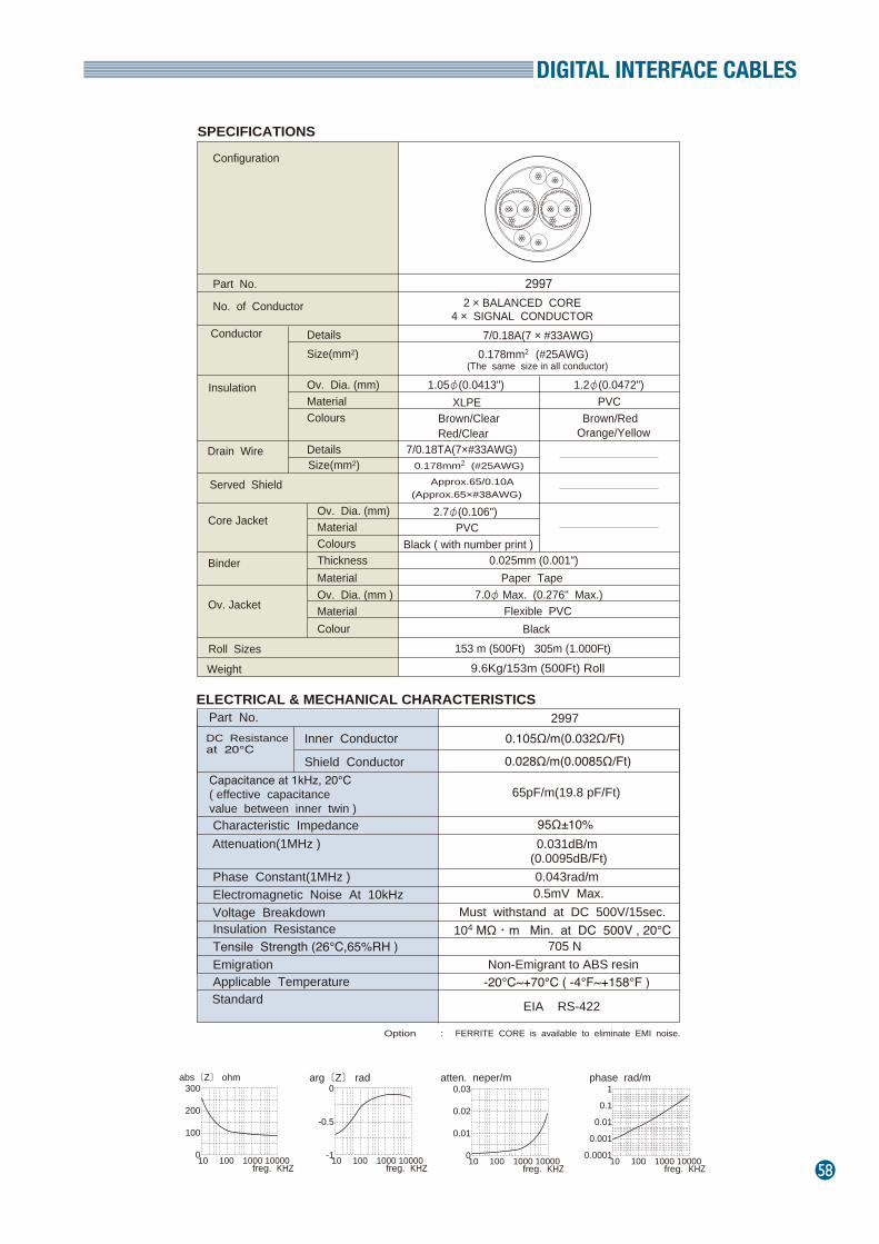
DIGITAL INTERFACE CABLES
58
Part No.
No. of Conductor
Details Conductor Size(mm2)
Material Colours
Core Jacket
Roll Sizes Weight
2997
7/0.18A(7 × #33AWG)
Ov. Dia. (mm)
Ov. Dia. (mm) Material
Binder
Ov. Jacket
Colours Thickness Material Ov. Dia. (mm ) Material Colour
2 × BALANCED CORE4 × SIGNAL CONDUCTOR
0.178mm2 (#25AWG)(The same size in all conductor)
Drain Wire
Insulation
Served Shield
Details Size(mm2)
1.05φ(0.0413") 1.2φ(0.0472") XLPE PVC
Brown/Clear Brown/RedRed/Clear Orange/Yellow
7/0.18TA(7×#33AWG)0.178mm2 (#25AWG)
Approx.65/0.10A(Approx.65×#38AWG)
2.7φ(0.106") PVC
Black ( with number print )0.025mm (0.001")
Paper Tape7.0φ Max. (0.276" Max.)
Flexible PVCBlack
153 m (500Ft) 305m (1.000Ft) 9.6Kg/153m (500Ft) Roll
SPECIFICATIONS
Configuration
Capacitance at 1kHz, 20℃( effective capacitance value between inner twin )
Inner Conductor
Shield Conductor
DC Resistanceat 20℃
Characteristic Impedance Attenuation(1MHz )
0.028Ω/m(0.0085Ω/Ft)
Part No.
Phase Constant(1MHz ) Electromagnetic Noise At 10kHz Voltage Breakdown
Tensile Strength (26℃,65%RH ) Insulation Resistance
Emigration Applicable Temperature
ELECTRICAL & MECHANICAL CHARACTERISTICS
Standard
0.105Ω/m(0.032Ω/Ft)2997
Must withstand at DC 500V/15sec.
Non-Emigrant to ABS resin -20℃~+70℃ ( -4°F~+158°F )
65pF/m(19.8 pF/Ft)
95Ω±10%0.031dB/m
(0.0095dB/Ft)0.043rad/m0.5mV Max.
104 MΩ・m Min. at DC 500V , 20℃
EIA RS-422
705 N
Option : FERRITE CORE is available to eliminate EMI noise.
arg〔Z〕 rad atten. neper/m phase rad/mabs〔Z〕 ohm
freg. KHZ
300
200
100
010 100 1000 10000freg. KHZ
0
-0.5
-110 100 1000 10000freg. KHZ
0.03
0.02
0.01
010 100 1000 10000freg. KHZ
1
0.1
0.01
0.001
0.000110 100 1000 10000
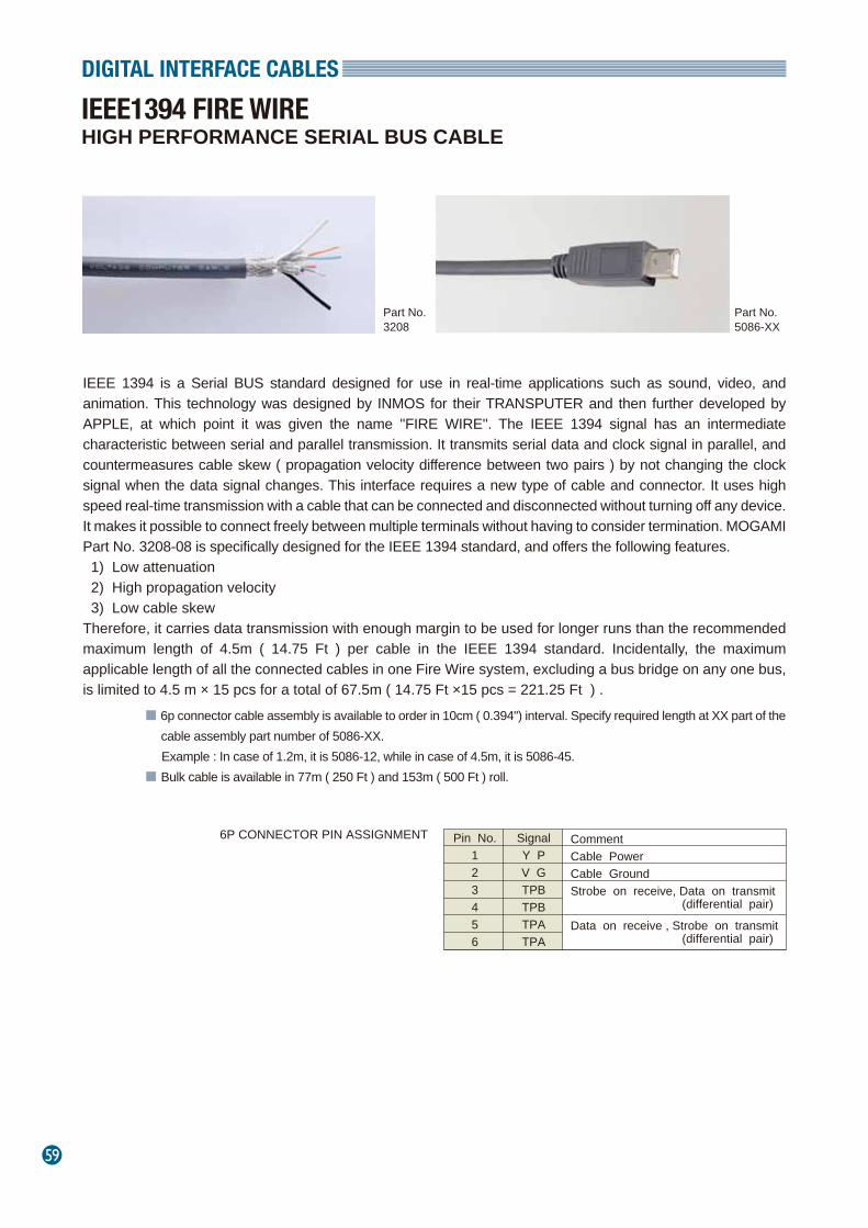
59
DIGITAL INTERFACE CABLES
HIGH PERFORMANCE SERIAL BUS CABLE IEEE1394 FIRE WIRE
■ 6p connector cable assembly is available to order in 10cm ( 0.394") interval. Specify required length at XX part of the cable assembly part number of 5086-XX.
Example : In case of 1.2m, it is 5086-12, while in case of 4.5m, it is 5086-45.■ Bulk cable is available in 77m ( 250 Ft ) and 153m ( 500 Ft ) roll.
Pin No.123456
6P CONNECTOR PIN ASSIGNMENT SignalY PV GTPBTPBTPATPA
CommentCable PowerCable GroundStrobe on receive, Data on transmit (differential pair)Data on receive , Strobe on transmit (differential pair)
Part No.3208
Part No.5086-XX
IEEE 1394 is a Serial BUS standard designed for use in real-time applications such as sound, video, and animation. This technology was designed by INMOS for their TRANSPUTER and then further developed by APPLE, at which point it was given the name ''FIRE WIRE''. The IEEE 1394 signal has an intermediate characteristic between serial and parallel transmission. It transmits serial data and clock signal in parallel, and countermeasures cable skew ( propagation velocity difference between two pairs ) by not changing the clock signal when the data signal changes. This interface requires a new type of cable and connector. It uses high speed real-time transmission with a cable that can be connected and disconnected without turning off any device. It makes it possible to connect freely between multiple terminals without having to consider termination. MOGAMI Part No. 3208-08 is specifically designed for the IEEE 1394 standard, and offers the following features. 1) Low attenuation 2) High propagation velocity 3) Low cable skewTherefore, it carries data transmission with enough margin to be used for longer runs than the recommended maximum length of 4.5m ( 14.75 Ft ) per cable in the IEEE 1394 standard. Incidentally, the maximum applicable length of all the connected cables in one Fire Wire system, excluding a bus bridge on any one bus, is limited to 4.5 m × 15 pcs for a total of 67.5m ( 14.75 Ft ×15 pcs = 221.25 Ft ) .
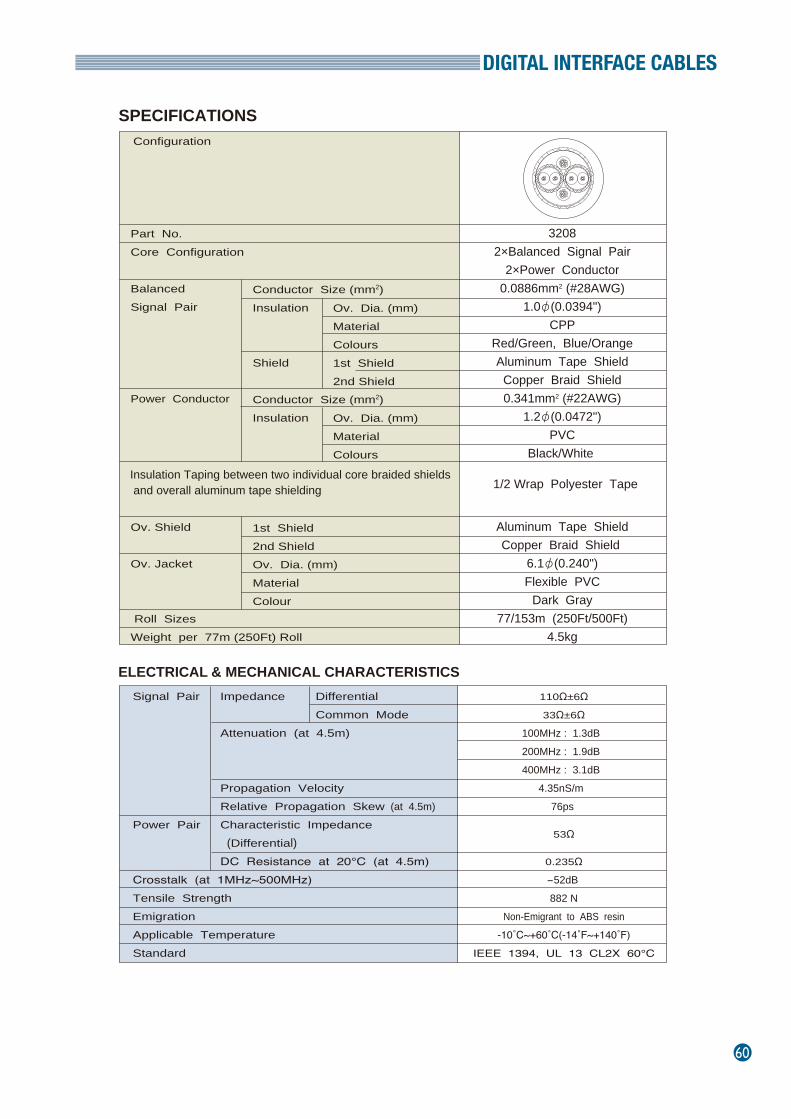
DIGITAL INTERFACE CABLES
60
Configuration
32082×Balanced Signal Pair
2×Power Conductor0.0886mm2 (#28AWG)
1.0φ(0.0394")CPP
Red/Green, Blue/OrangeAluminum Tape ShieldCopper Braid Shield0.341mm2 (#22AWG)
1.2φ(0.0472")PVC
Black/White
Aluminum Tape ShieldCopper Braid Shield
6.1φ(0.240")Flexible PVC
Dark Gray77/153m (250Ft/500Ft)
4.5kg
110Ω±6Ω33Ω±6Ω
100MHz : 1.3dB 200MHz : 1.9dB 400MHz : 3.1dB
4.35nS/m 76ps
53Ω
0.235Ω-52dB 882 N
Non-Emigrant to ABS resin-10˚C~+60˚C(-14˚F~+140˚F)
IEEE 1394, UL 13 CL2X 60℃
SPECIFICATIONS
ELECTRICAL & MECHANICAL CHARACTERISTICS
Ov. Dia. (mm) MaterialColours1st Shield2nd Shield
Ov. Dia. (mm) MaterialColours
Conductor Size (mm2) Insulation
Shield Conductor Size (mm2) Insulation
1st Shield2nd ShieldOv. Dia. (mm) MaterialColour
Signal Pair
Power Pair
Crosstalk (at 1MHz~500MHz)Tensile StrengthEmigrationApplicable TemperatureStandard
Impedance Attenuation (at 4.5m)
Propagation VelocityRelative Propagation Skew (at 4.5m) Characteristic Impedance (Differential)DC Resistance at 20℃ (at 4.5m)
DifferentialCommon Mode
Part No.Core Configuration
BalancedSignal Pair
Power Conductor
Ov. Shield Ov. Jacket
Roll SizesWeight per 77m (250Ft) Roll
Insulation Taping between two individual core braided shields and overall aluminum tape shielding 1/2 Wrap Polyester Tape
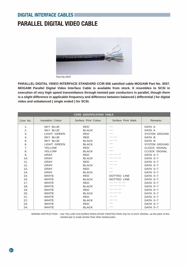
61
DIGITAL INTERFACE CABLES
PARALLEL DIGITAL VIDEO CABLE
Part No.3037
PARALLEL DIGITAL VIDEO INTERFACE STANDARD CCIR 656 satisfied cable MOGAMI Part No. 3037. MOGAMI Parallel Digital Video Interface Cable is available from stock. It resembles to SCSI in execution of very high speed transmittance through twisted pair conductors in parallel, though there is a slight difference in applicable frequency and difference between balanced ( differential ) for digital video and unbalanced ( single ended ) for SCSI.
WIRING INSTRUCTION : Use YELLOW COLOURED INSULATION TWISTED PAIR only for CLOCK SIGNAL, as the pitch of this
CORE IDENTIFICATION TABLE
Core No.
Insulation Colour
Surface Print Colour
Surface Print Mark
1.2.3.4.5.6.7.8.9.10.11.12.13.14.15.16.17.18.19.20.21.22.23.24.
SKY BLUESKY BLUELIGHT GREENSKY BLUESKY BLUELIGHT GREENYELLOWYELLOWGRAYGRAYGRAYGRAYGRAYGRAYWHITEWHITEWHITEWHITEWHITEWHITEWHITEWHITEWHITEWHITE
DOTTED LINEDOTTED LINE
Remarks
REDBLACKREDREDBLACKBLACKREDBLACKREDBLACKREDBLACKREDBLACKREDBLACKREDBLACKREDBLACKREDBLACKREDBLACK
DATA ADATA ASYSTEM GROUNDDATA BDATA BSYSTEM GROUNDCLOCK SIGNALCLOCK SIGNALDATA 0~7DATA 0~7DATA 0~7DATA 0~7DATA 0~7DATA 0~7DATA 0~7DATA 0~7DATA 0~7DATA 0~7DATA 0~7DATA 0~7DATA 0~7DATA 0~7DATA 0~7DATA 0~7
twisted pair is made shorter than other twisted pairs.
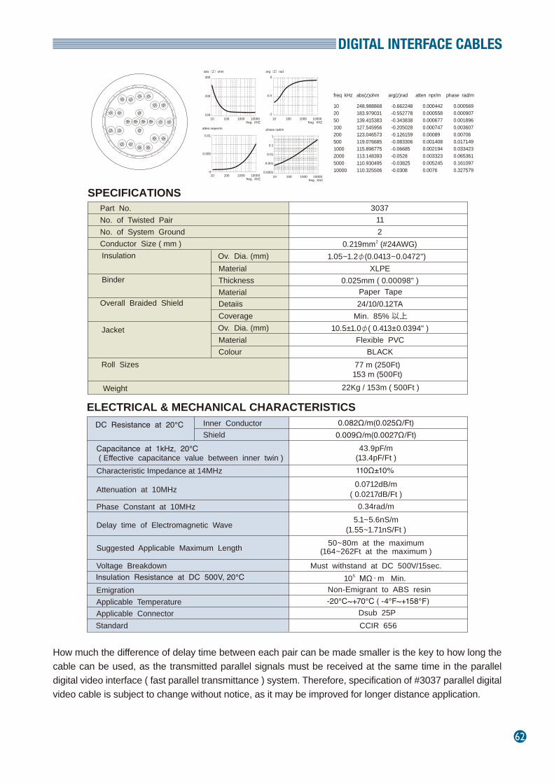
DIGITAL INTERFACE CABLES
62
SPECIFICATIONS
ELECTRICAL & MECHANICAL CHARACTERISTICS
Part No.No. of Twisted PairNo. of System GroundConductor Size ( mm )
Overall Braided Shield
Material
Roll Sizes
Weight
77 m (250Ft)
22Kg / 153m ( 500Ft )
3037
Ov. Dia. (mm)
11
DC Resistance at 20℃
Voltage Breakdown Insulation Resistance at DC 500V, 20℃ Emigration Applicable Temperature
0.082Ω/m(0.025Ω/Ft)
Must withstand at DC 500V/15sec.
Non-Emigrant to ABS resin
CCIR 656
Insulation
1.05~1.2φ(0.0413~0.0472") XLPE
0.025mm ( 0.00098" )Paper Tape24/10/0.12TA
Standard
105 MΩ・m Min.
JacketFlexible PVC
BLACK
-20℃~+70℃ ( -4°F~+158°F)
2
Binder
Thickness Material
Coverage
Material Colour
Ov. Dia. (mm)
Min. 85% 以上10.5±1.0φ( 0.413±0.0394" )
153 m (500Ft)
Capacitance at 1kHz, 20℃ ( Effective capacitance value between inner twin ) Characteristic Impedance at 14MHz
Attenuation at 10MHz
Phase Constant at 10MHz
Delay time of Electromagnetic Wave
Suggested Applicable Maximum Length
Applicable Connector Dsub 25P
Inner ConductorShield 0.009Ω/m(0.0027Ω/Ft)
43.9pF/m(13.4pF/Ft )110Ω±10% 0.0712dB/m
( 0.0217dB/Ft )0.34rad/m
5.1~5.6nS/m(1.55~1.71nS/Ft )
50~80m at the maximum(164~262Ft at the maximum )
Detaiis
10205010020050010002000500010000
248.988868183.979031139.415383127.545956123.046573119.076685115.898775113.148393110.930495110.325506
-0.662248-0.552778-0.343838-0.205028-0.126159-0.083306-0.06685-0.0528-0.03825-0.0308
0.0004420.0005580.0006770.0007470.000890.0014080.0021940.0033230.0052450.0076
0.0005690.0009070.0018960.0036070.007060.0171490.0334230.0653610.1610970.327579
freq kHz abs(z)ohm arg(z)rad atten npr/m phase rad/m
300
200
10010 100 1000 10000
abs〔Z〕ohm
freg. KHZ
0
-0.5
-110 100 1000 10000
arg〔Z〕rad
freg. KHZ
0.01
0.005
010 100 1000 10000
atten.neper/m
freg. KHZ 10 100 1000 10000
phase rad/m
freg. KHZ
1
0.1
0.01
0.001
0.0001
How much the difference of delay time between each pair can be made smaller is the key to how long the cable can be used, as the transmitted parallel signals must be received at the same time in the parallel digital video interface ( fast parallel transmittance ) system. Therefore, specification of #3037 parallel digital video cable is subject to change without notice, as it may be improved for longer distance application.
0.219mm2 (#24AWG)
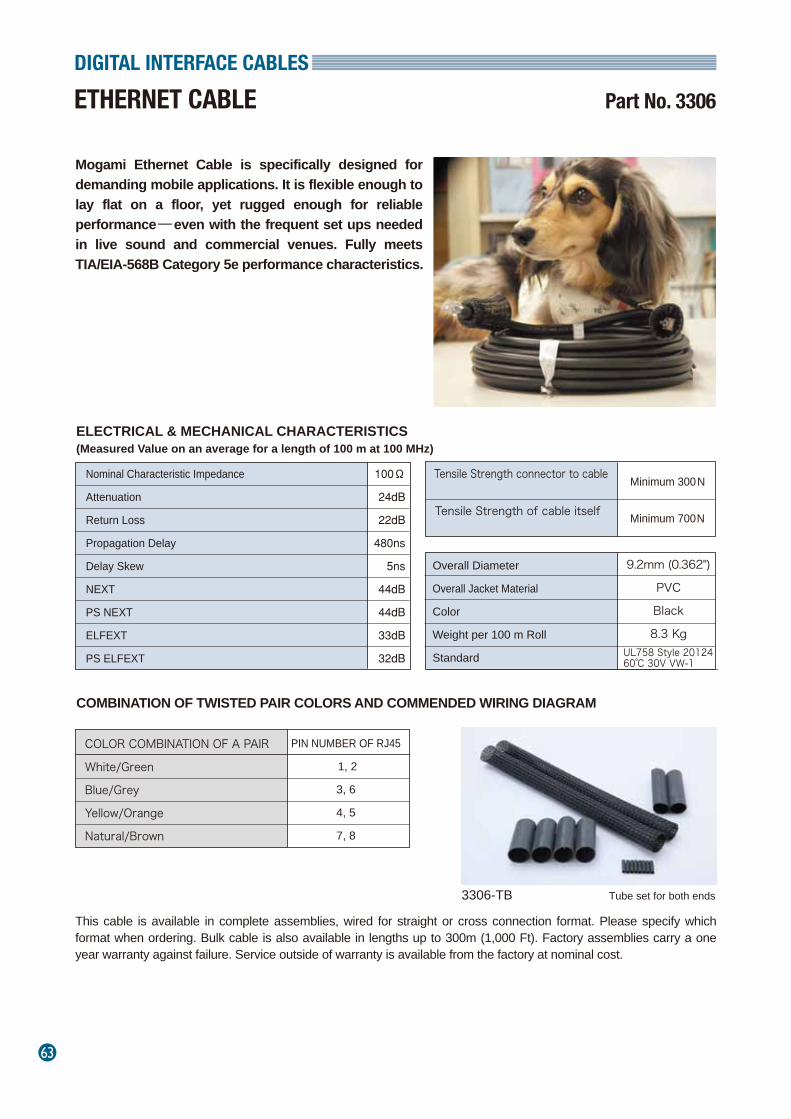
63
DIGITAL INTERFACE CABLES
ETHERNET CABLE Part No. 3306
Mogami Ethernet Cable is specifically designed for demanding mobile applications. It is flexible enough to lay flat on a floor, yet rugged enough for reliable performance─even with the frequent set ups needed in live sound and commercial venues. Fully meets TIA/EIA-568B Category 5e performance characteristics.
Tube set for both ends3306-TB
COMBINATION OF TWISTED PAIR COLORS AND COMMENDED WIRING DIAGRAM
Nominal Characteristic Impedance
Attenuation
Return Loss
Propagation Delay
Delay Skew
NEXT
PS NEXT
ELFEXT
PS ELFEXT
Tensile Strength connector to cable
Tensile Strength of cable itself
Overall Diameter
Overall Jacket Material
Color
Weight per 100 m Roll
Standard
COLOR COMBINATION OF A PAIR
White/Green
Blue/Grey
Yellow/Orange
Natural/Brown
100Ω
24dB
22dB
480ns
5ns
44dB
44dB
33dB
32dB
Minimum 300 N
9.2mm (0.362")
PVC
Black
8.3 Kg
Minimum 700 N
PIN NUMBER OF RJ45
1, 2
3, 6
4, 5
7, 8
ELECTRICAL & MECHANICAL CHARACTERISTICS(Measured Value on an average for a length of 100 m at 100 MHz)
UL758 Style 20124 60℃ 30V VW-1
This cable is available in complete assemblies, wired for straight or cross connection format. Please specify which format when ordering. Bulk cable is also available in lengths up to 300m (1,000 Ft). Factory assemblies carry a one year warranty against failure. Service outside of warranty is available from the factory at nominal cost.
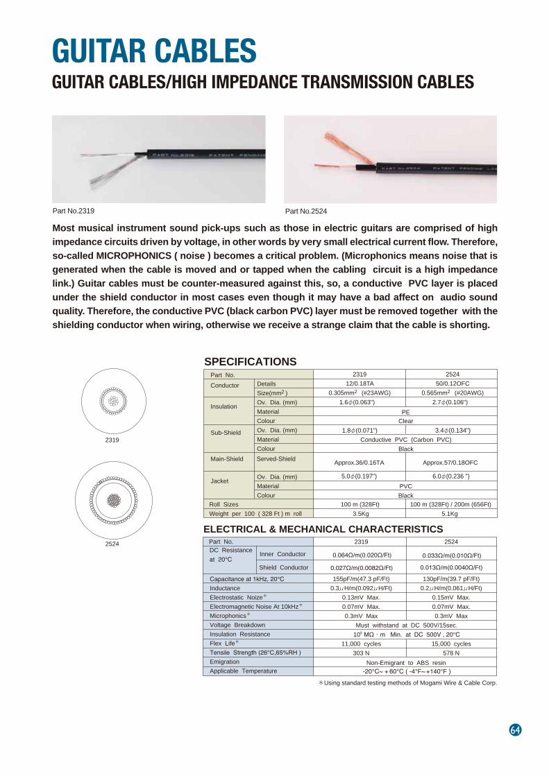
64
Most musical instrument sound pick-ups such as those in electric guitars are comprised of high impedance circuits driven by voltage, in other words by very small electrical current flow. Therefore, so-called MICROPHONICS ( noise ) becomes a critical problem. (Microphonics means noise that is generated when the cable is moved and or tapped when the cabling circuit is a high impedance link.) Guitar cables must be counter-measured against this, so, a conductive PVC layer is placed under the shield conductor in most cases even though it may have a bad affect on audio sound quality. Therefore, the conductive PVC (black carbon PVC) layer must be removed together with the shielding conductor when wiring, otherwise we receive a strange claim that the cable is shorting.
GUITAR CABLES/HIGH IMPEDANCE TRANSMISSION CABLESGUITAR CABLES
Part No.2319 Part No.2524
SPECIFICATIONS
ELECTRICAL & MECHANICAL CHARACTERISTICS
Part No. Conductor
231912/0.18TA
0.305mm2 (#23AWG)1.6φ(0.063")
2319
2524
252450/0.12OFC
0.565mm2 (#20AWG)2.7φ(0.106") Insulation
Sub-Shield
Main-Shield
Served-Shield
Jacket
1.8φ(0.071") 3.4φ(0.134")
5.0φ(0.197") 6.0φ(0.236 ")
Conductive PVC (Carbon PVC)Black
PEClear
PVC Black
100 m (328Ft) / 200m (656Ft) 5.1Kg
100 m (328Ft) 3.5Kg
Capacitance at 1kHz, 20℃InductanceElectrostatic Noize*
Electromagnetic Noise At 10kHz* Microphonics*
Voltage Breakdown Insulation ResistanceFlex Life*
Tensile Strength (26℃,65%RH )EmigrationApplicable Temperature
DC Resistanceat 20℃
2319
155pF/m(47.3 pF/Ft)0.3μH/m(0.092μH/Ft)
0.13mV Max.0.07mV Max.0.3mV Max
11,000 cycles303 N
2524
130pF/m(39.7 pF/Ft)0.2μH/m(0.061μH/Ft)
0.15mV Max.0.07mV Max.0.3mV Max
15,000 cycles578 N
Must withstand at DC 500V/15sec.105 MΩ・m Min. at DC 500V , 20℃
Non-Emigrant to ABS resin -20℃~ + 60℃ ( -4°F~ +140°F )
Approx.36/0.16TA Approx.57/0.18OFC
DetailsSize(mm2 )Ov. Dia. (mm)MaterialColourOv. Dia. (mm)MaterialColour
Ov. Dia. (mm)MaterialColour
Roll SizesWeight per 100 ( 328 Ft ) m roll
Part No.
Inner Conductor 0.064Ω/m(0.020Ω/Ft) 0.033Ω/m(0.010Ω/Ft)
Shield Conductor 0.027Ω/m(0.0082Ω/Ft) 0.013Ω/m(0.0040Ω/Ft)
*Using standard testing methods of Mogami Wire & Cable Corp.

65
Multi purpose #28AWG superflexble overall shielded cable available in twisted pair configuration for electromagnetic noise rejection as well as in economy and easy wiring general round configuration in compact gray jacket. All these cables are approved as UL SUBJECT 758 AWM 20002 VW-1.
MECHATRO OVERALL SHIELD CABLESMULTICORE CABLES
DC Resistance at 20℃Voltage Breakdown Insulation ResistanceChracteristic ImpedanceCable SkewDelay TimeVelocity RatioEmigrationApplicable TemperatureStandard
ELECTRICAL & MECHANICAL CHARACTERISTICS
0.21Ω/m( 0.064Ω/Ft )Must withstand at DC 500V/15sec.
104MΩ・m M in. at DC 500V , 20℃90~115Ω (at 10MHz )
0.517nS/m5.5~6.1nS/m
0.55~0.60Non-Emigrant to ABS resin
-20℃~ +70℃ (-4°F~+158°F ) UL 758 AWM 20002 VW-1 30V 80℃
7/0.127TA (7×#37AWG)
0.088mm2 (#28AWG)
*
*
*
*
*Data for Twisted Pair Type Only.
Part No .
No. ofConductor
Ov. Dia. ( mm )
Roll size and weight per roll
2861286228632835286428652866
7122430405064
5.2φ(0.205")6.4φ(0.252")8.4φ(0.331")9.0φ(0.354")
10.3φ(0.406")11.0φ(0.433")12.3φ(0.484")
6kg/153m ( 500Ft ) 9kg/153m ( 500Ft ) 15kg/153m ( 500Ft ) 17kg/153m ( 500Ft ) 20kg/153m ( 500Ft ) 25kg/153m ( 500Ft ) 30kg/153m ( 500Ft )
ROUND TYPE
Basical structure
Part No .
No. ofPair
Ov. Dia. ( mm )
Roll size and weight per roll
284028412842284328452847284828492851
5-PR 7-PR 8-PR10-PR13-PR18-PR20-PR25-PR32-PR
7.4φ(0.291") 7.8φ(0.307") 8.4φ(0.331") 9.5φ(0.374")10.0φ(0.394")11.5φ(0.453")11.8φ(0.465")13.0φ(0.512")14.5φ(0.571")
11kg/153m ( 500Ft ) 12kg/153m ( 500Ft )
13kg/153m ( 500Ft ) 17kg/153m ( 500Ft ) 19kg/153m ( 500Ft ) 24kg/153m ( 500Ft ) 26kg/153m ( 500Ft ) 15kg/77m ( 250Ft ) 19kg/77m ( 250Ft )
TWISTED PAIR TYPE
Basical structure
Option : FERRITE CORE is available as a countermeasure against EMI noise.
CABLE SPECIFICATIONSDetails Conductor
Size
Material Insulation
Overall Shield
0.95φ(0.0374")
PVC
Ov. Jacket Colour Dark Gray
Ov. Dia. (mm)
Coverage Minimum 85%
Braided shield
Flexible PVC
Type
Material
Part No.2863
Part No.2842
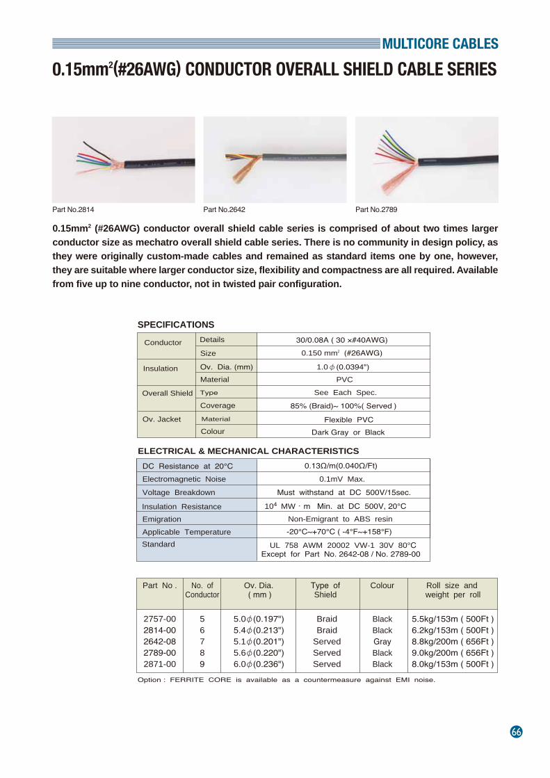
MULTICORE CABLES
66
0.15mm2 (#26AWG) conductor overall shield cable series is comprised of about two times larger conductor size as mechatro overall shield cable series. There is no community in design policy, as they were originally custom-made cables and remained as standard items one by one, however, they are suitable where larger conductor size, flexibility and compactness are all required. Available from five up to nine conductor, not in twisted pair configuration.
0.15mm2(#26AWG) CONDUCTOR OVERALL SHIELD CABLE SERIES
SPECIFICATIONS
ELECTRICAL & MECHANICAL CHARACTERISTICS DC Resistance at 20℃
Voltage Breakdown
Insulation Resistance Emigration Applicable Temperature
0.13Ω/m(0.040Ω/Ft)
Must withstand at DC 500V/15sec.
Non-Emigrant to ABS resin
UL 758 AWM 20002 VW-1 30V 80℃Except for Part No. 2642-08 / No. 2789-00
Standard
104 MW・m Min. at DC 500V, 20℃
-20℃~+70℃ ( -4°F~+158°F)
Details Conductor Size
Material
30/0.08A ( 30 ×#40AWG)0.150 mm2 (#26AWG)
Insulation
Overall Shield
1.0φ(0.0394") PVC
Ov. Jacket Colour Dark Gray or Black
Ov. Dia. (mm)
Coverage
Part No .
No. ofConductor
Ov. Dia. ( mm )
Roll size and weight per roll
2757-002814-002642-082789-002871-00
56789
5.0φ(0.197")5.4φ(0.213")5.1φ(0.201")5.6φ(0.220")6.0φ(0.236")
5.5kg/153m ( 500Ft ) 6.2kg/153m ( 500Ft ) 8.8kg/200m ( 656Ft ) 9.0kg/200m ( 656Ft ) 8.0kg/153m ( 500Ft )
See Each Spec.
85% (Braid)~ 100%( Served )
Flexible PVC
Electromagnetic Noise 0.1mV Max.
Type ofShield
Colour
Braid Braid
Served Served Served
Black Black Gray Black Black
Option : FERRITE CORE is available as a countermeasure against EMI noise.
Type
Material
Part No.2789Part No.2814 Part No.2642
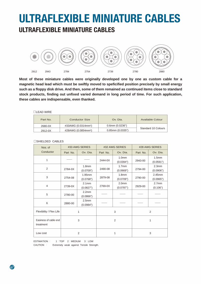
67
Most of these miniature cables were originally developed one by one as custom cable for a magnetic head lead which must be swiftly moved to speficified position precisely by small energy such as a floppy disk drive. And then, some of them remained as continued items close to standard stock products, finding out unfixed varied demand in long period of time. For such application, these cables are indispensable, even thanked.
ULTRAFLEXIBLE MINIATURE CABLESULTRAFLEXIBLE MINIATURE CABLES
□LEAD WIRE
□SHIELDED CABLES
Part No.
Conductor Size
Ov. Dia.
Available Colour
Standard 10 Colours
#33AWG (0.0314mm2)#28AWG (0.0854mm2)
#33 AWG SERIES
Part No.
Ov. Dia.
Nos. ofConductor
Flexibility / Flex Life Easiness of cable end treatment Low cost
ESTIMATION : 1:TOP 2:MEDIUM 3:LOW CAUTION : Extremely weak against Tensile Strength.
1
2
3
4
5
6
1
3
2
#32 AWG SERIES
Part No.
1.0mm
(0.0394")1.7mm
(0.0669")1.8mm
(0.0709")2.0mm
(0.0787")
Part No.
1.5mm
(0.0591")2.3mm
(0.0906")2.45mm(0.0965")2.7mm(0.106")
3
2
1
#28 AWG SERIES
2
1
3
2680-0X2912-0X
2784-0X
2754-08
2739-0X
2780-00
2880-00
1.8mm(0.0709")1.95mm(0.0768")2.1mm
(0.0827")2.2mm
(0.0866")2.5mm
(0.0984")
2444-0X
2490-08
2879-08
2769-0X
2943-00
2794-00
2790-00
2929-00
2912 2943 2784 2754 2739 2780 2880
0.6mm (0.0236")0.85mm (0.0335")
Ov. Dia. Ov. Dia.
ULTRAFLEXIBLE MINIATURE CABLES
68
Because of drastic changes in UL standards effective from May, 2008, two versions of each cable are now available; either the new UL rated version or non-approved original specification version.This is because the UL standard now requires a physical strength test on both the insulation and jacket materials, in addition to a fire protection property test. This physical strength test was not previously required for low voltage application cables. To pass the test the insulation and or jacket materials must be revised to more physically durable types in most cases. Since the diameter of the stronger materials is larger, they are slightly less flexible than the originals. Please carefully review the following comparison table between the original and new UL approved designs for the best match in your application.
Mogami Part No. Assignment for new UL version Ultraflexible Miniature Cable SeriesPart No. Part No. W/UL Approval Approved UL Style No. Structure Revised Part Past New
2680
2912
2444
2490
2879
2769
2943
2794
2790
2929
2784
2754
2739
2780
2880
3308
3309
3324
3314
3315
3316
3325
3311
3312
3313
3317
3318
3319
3320
3321
1571
1571
1682
2725
2725
2725
1571
2725
2725
2725
2725
2725
2725
2725
2725
#33AWG
#28AWG
1×#32AWG
2×#32AWG
3×#32AWG
4×#32AWG
1×#28AWG
2×#28AWG
3×#28AWG
4×#28AWG
2×#33AWG
3×#33AWG
4×#33AWG
5×#33AWG
6×#33AWG
Insulation Material.Insulation O.D.
Insulation Material.Insulation O.D.Insulation Material.Insulation O.D.Jacket O.D.Insulation Material.Insulation O.D.Jacket O.D.Insulation Material.Insulation O.D.Jacket O.D.Insulation Material.Insulation O.D.Jacket O.D.Insulation Material.Insulation O.D.Jacket O.D.Insulation Material.Insulation O.D.Jacket O.D.Insulation Material.Insulation O.D.Jacket O.D.Insulation Material.Insulation O.D.Jacket O.D.Insulation Material.Insulation O.D.Jacket O.D.Insulation Material.Insulation O.D.Jacket O.D.Insulation Material.Insulation O.D.Jacket O.D.Insulation Material.Insulation O.D.Jacket O.D.Insulation Material.Insulation O.D.Jacket O.D.
FB2010.6mm
FB201
0.55mm1,0mm
0.53mm1.7mm
0.53mm1.8mm
0.53mm2.0mmFB201
0.85mm1.5mmFB201
0.83mm2.3mmFB201
0.83mm2.45mm
FB2010.83mm2.7mmFB2010.6mm1.8mmFB2010.6mm
1.95mmFB2010.6mm2.1mmFB2010.6mm2.2mmFB2010.6mm2.5mm
No changeNo change
No change
No change
No change
M163A0.7mm
M163A
0.7mm1.5mm
0.75mm2.3mm
0.75mm2.45mm
0.75mm2.6mmM163A
0.85mm1.63mmM163A
0.90mm2.6mmM163A
0.90mm2.7mmM163A
0.85mm2.8mmM163A
0.75mm2.3mmM163A
0.75mm2.4mmM163A0.7mm2.5mmM163A0.7mm2.7mmM163A0.7mm2.9mm
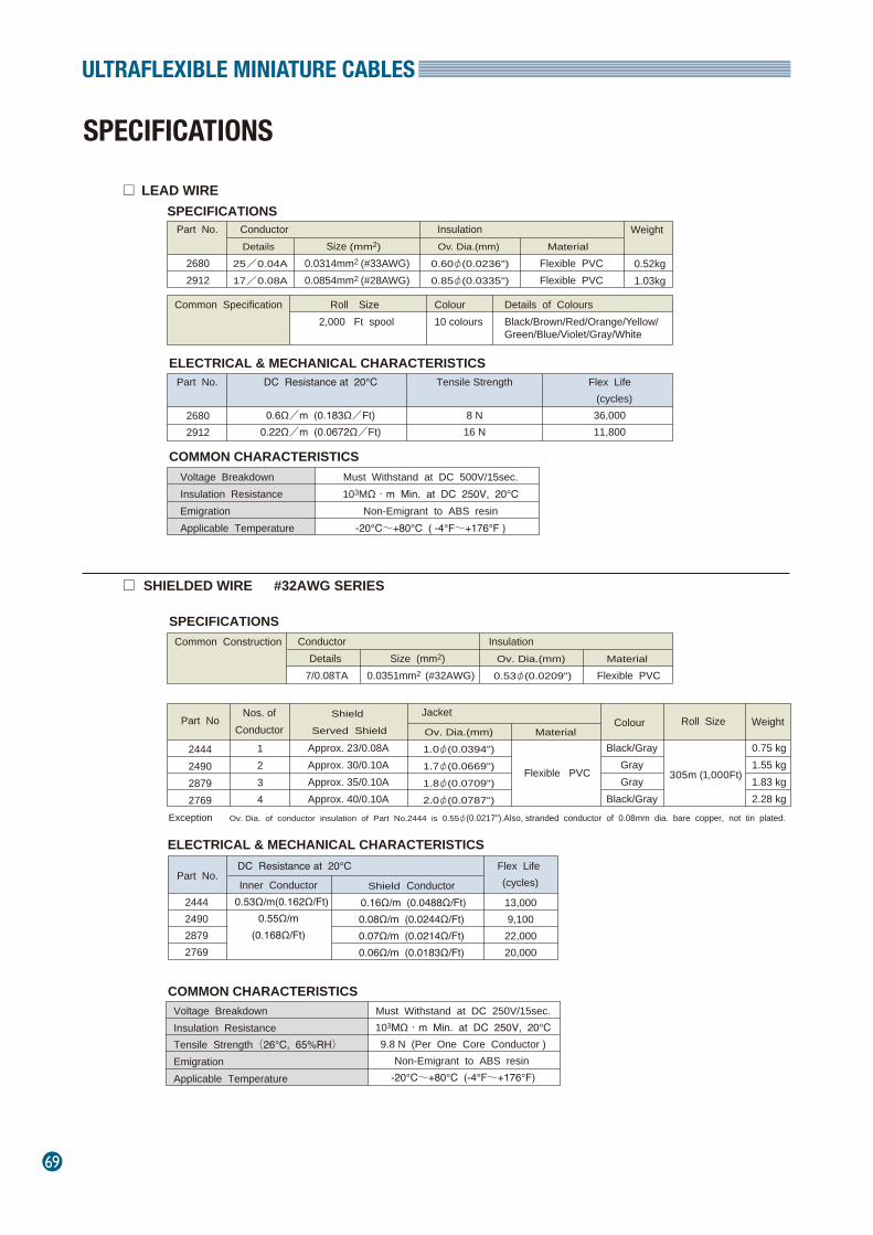
69
ULTRAFLEXIBLE MINIATURE CABLES
SPECIFICATIONS
Conductor
Common Specification Roll Size 2,000 Ft spool
Details
25/0.04A
17/0.08A
Size (mm2)
0.0314mm2 (#33AWG)0.0854mm2 (#28AWG)
Ov. Dia.(mm)
0.60φ(0.0236")
0.85φ(0.0335")
Details of Colours Black/Brown/Red/Orange/Yellow/Green/Blue/Violet/Gray/White
Colour 10 colours
Material
Flexible PVCFlexible PVC
Weight
0.52kg1.03kg
Part No. Insulation
26802912
Part No.
Voltage BreakdownInsulation ResistanceEmigrationApplicable Temperature
Must Withstand at DC 500V/15sec.103MΩ・m Min. at DC 250V, 20℃
Non-Emigrant to ABS resin-20℃~+80℃ ( -4°F~+176°F )
26802912
DC Resistance at 20℃
0.6Ω/m (0.183Ω/Ft)0.22Ω/m (0.0672Ω/Ft)
Tensile Strength
8 N16 N
Flex Life (cycles)
36,00011,800
LEAD WIRE
Conductor Common Construction Details
7/0.08TASize (mm2)
0.0351mm2 (#32AWG)Ov. Dia.(mm)
0.53φ(0.0209")
Material
Flexible PVC
Insulation
Black/GrayGrayGray
Black/Gray
Roll Size
Weight
0.75 kg1.55 kg1.83 kg2.28 kg
Approx. 23/0.08AApprox. 30/0.10AApprox. 35/0.10AApprox. 40/0.10A
Shield Conductor 0.16Ω/m (0.0488Ω/Ft)0.08Ω/m (0.0244Ω/Ft)0.07Ω/m (0.0214Ω/Ft)0.06Ω/m (0.0183Ω/Ft)
Ov. Dia.(mm)
1.0φ(0.0394")
1.7φ(0.0669")
1.8φ(0.0709")
2.0φ(0.0787")
Material
Flexible PVC
2444249028792769
Exception Ov. Dia. of conductor insulation of Part No.2444 is 0.55φ(0.0217").Also, stranded conductor of 0.08mm dia. bare copper, not tin plated.
1234
Jacket
SHIELDED WIRE #32AWG SERIES
ELECTRICAL & MECHANICAL CHARACTERISTICS
ELECTRICAL & MECHANICAL CHARACTERISTICS
COMMON CHARACTERISTICS
Part No.
13,0009,100
22,00020,000
DC Resistance at 20℃
Voltage BreakdownInsulation ResistanceTensile Strength(26℃, 65%RH)EmigrationApplicable Temperature
Must Withstand at DC 250V/15sec.103MΩ・m Min. at DC 250V, 20℃9.8 N (Per One Core Conductor )
Non-Emigrant to ABS resin -20℃~+80℃ (-4°F~+176°F)
2444249028792769
Inner Conductor 0.53Ω/m(0.162Ω/Ft)
0.55Ω/m(0.168Ω/Ft)
COMMON CHARACTERISTICS
□
□
SPECIFICATIONS
SPECIFICATIONS
305m (1,000Ft)
Colour Part NoNos. of
Conductor
Shield
Served Shield
Flex Life (cycles)
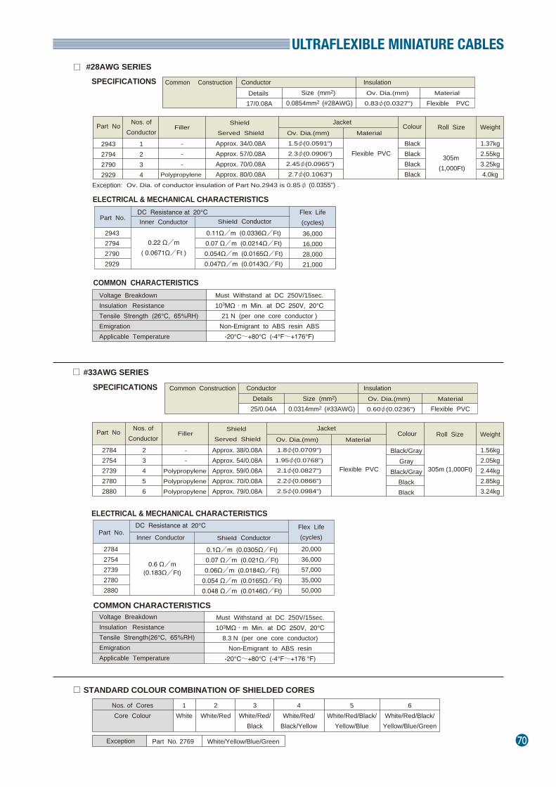
ULTRAFLEXIBLE MINIATURE CABLES
70
Conductor Common Construction Details
17/0.08ASize (mm2)
0.0854mm2 (#28AWG)Ov. Dia.(mm) 0.83φ(0.0327")
Material
Flexible PVC
Insulation
---
Polypropylene
BlackBlackBlackBlack
1.37kg2.55kg3.25kg4.0kg
Approx. 34/0.08AApprox. 57/0.08AApprox. 70/0.08AApprox. 80/0.08A
Shield Conductor
Ov. Dia.(mm) 1.5φ(0.0591")2.3φ(0.0906")
2.45φ(0.0965")2.7φ(0.1063")
Material
Flexible PVC
2943279427902929
Exception: Ov. Dia. of conductor insulation of Part No.2943 is 0.85φ (0.0355") .
1234
#28AWG SERIES
Part No.
36,00016,00028,00021,000
DC Resistance at 20℃
Must Withstand at DC 250V/15sec.103MΩ・m Min. at DC 250V, 20℃
21 N (per one core conductor )Non-Emigrant to ABS resin ABS
-20℃~+80℃ (-4°F~+176°F)
2943279427902929
Inner Conductor
0.22 Ω/m( 0.0671Ω/Ft )
ELECTRICAL & MECHANICAL CHARACTERISTICS
ELECTRICAL & MECHANICAL CHARACTERISTICS
COMMON CHARACTERISTICS
Conductor Common Construction Details
25/0.04ASize (mm2)
0.0314mm2 (#33AWG)Ov. Dia.(mm) 0.60φ(0.0236")
MaterialFlexible PVC
Insulation
--
Polypropylene Polypropylene Polypropylene
Black/GrayGray
Black/GrayBlackBlack
1.56kg2.05kg2.44kg2.85kg3.24kg
Approx. 38/0.08AApprox. 54/0.08AApprox. 59/0.08AApprox. 70/0.08AApprox. 79/0.08A
Shield Conductor
Ov. Dia.(mm) 1.8φ(0.0709")
1.95φ(0.0768")2.1φ(0.0827")2.2φ(0.0866")2.5φ(0.0984")
Material
27842754273927802880
23456
Jacket
#33AWG SERIES
Part No.
20,00036,00057,00035,00050,000
DC Resistance at 20℃
Must Withstand at DC 250V/15sec.103MΩ・m Min. at DC 250V, 20℃
8.3 N (per one core conductor)Non-Emigrant to ABS resin
-20℃~+80℃ (-4°F~+176 °F)
27842754273927802880
Inner Conductor
COMMON CHARACTERISTICS
STANDARD COLOUR COMBINATION OF SHIELDED CORES
Nos. of CoresCore Colour
Exception
1White
2White/Red
3White/Red/
Black
4White/Red/
Black/Yellow
5White/Red/Black/
Yellow/Blue
6White/Red/Black/
Yellow/Blue/Green
Part No. 2769 White/Yellow/Blue/Green
0.11Ω/m (0.0336Ω/Ft)0.07 Ω/m (0.0214Ω/Ft)0.054Ω/m (0.0165Ω/Ft)0.047Ω/m (0.0143Ω/Ft)
0.1Ω/m (0.0305Ω/Ft)0.07 Ω/m (0.021Ω/Ft)0.06Ω/m (0.0184Ω/Ft)
0.054 Ω/m (0.0165Ω/Ft)0.048 Ω/m (0.0146Ω/Ft)
□
□
□
Voltage BreakdownInsulation ResistanceTensile Strength (26℃, 65%RH)EmigrationApplicable Temperature
Voltage BreakdownInsulation ResistanceTensile Strength(26℃, 65%RH)EmigrationApplicable Temperature
SPECIFICATIONS
SPECIFICATIONS
305m (1,000Ft)
Flexible PVC 305m (1,000Ft)
0.6 Ω/m(0.183Ω/Ft)
Filler Roll Size
WeightShield
Served ShieldPart No Nos. of
Conductor
FillerShield
Served ShieldPart No Nos. of
Conductor
Jacket Colour
Roll Size
WeightColour
Flex Life(cycles)
Flex Life(cycles)
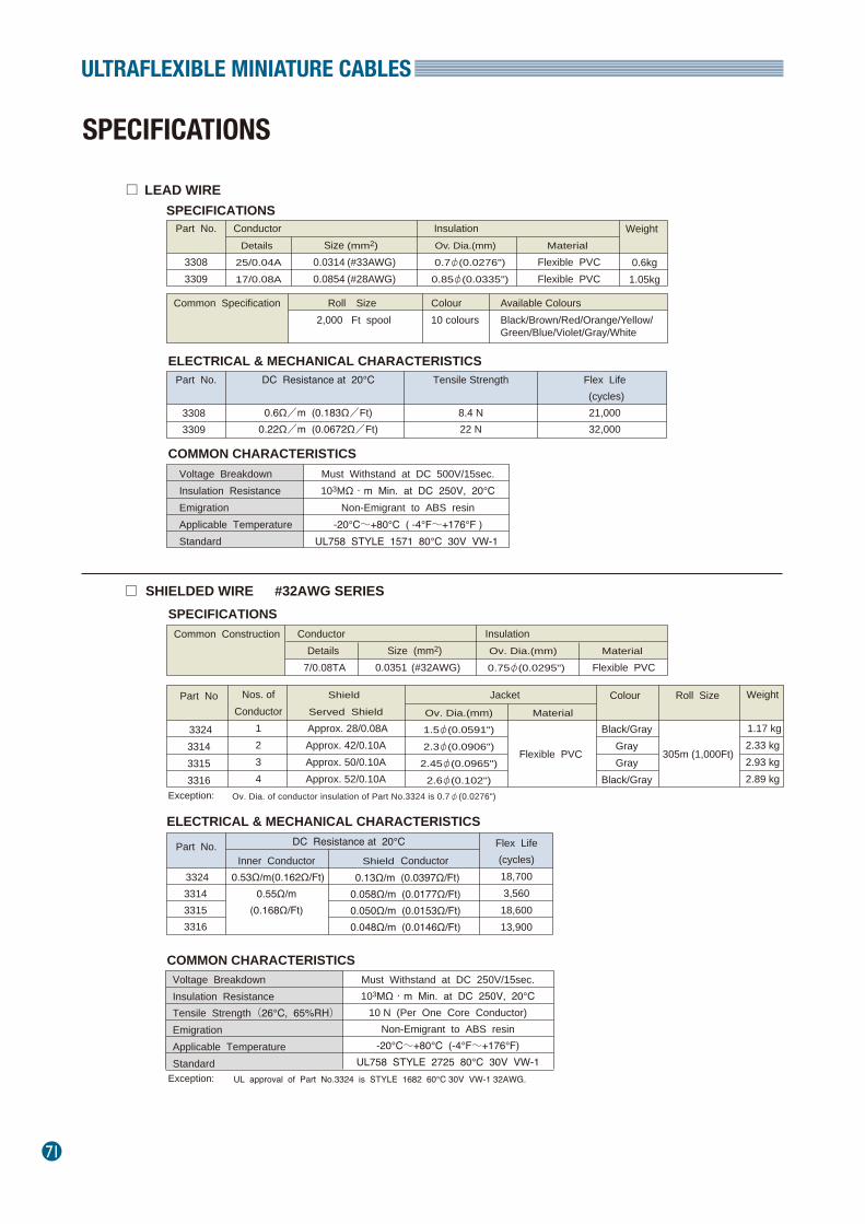
71
ULTRAFLEXIBLE MINIATURE CABLES
SPECIFICATIONS
LEAD WIRE
SHIELDED WIRE #32AWG SERIES
□
□
Conductor
Common Specification
Roll Size 2,000 Ft spool
Details
25/0.04A
17/0.08A
Size (mm2)
0.0314 (#33AWG)0.0854 (#28AWG)
Ov. Dia.(mm) 0.7φ(0.0276")
0.85φ(0.0335")
Available Colours Black/Brown/Red/Orange/Yellow/Green/Blue/Violet/Gray/White
Colour 10 colours
Material
Flexible PVCFlexible PVC
Weight
0.6kg1.05kg
Part No. Insulation
33083309
Part No.
Voltage BreakdownInsulation ResistanceEmigrationApplicable TemperatureStandard
Must Withstand at DC 500V/15sec.103MΩ・m Min. at DC 250V, 20℃
Non-Emigrant to ABS resin-20℃~+80℃ ( -4°F~+176°F )
UL758 STYLE 1571 80℃ 30V VW-1
33083309
DC Resistance at 20℃
0.6Ω/m (0.183Ω/Ft)0.22Ω/m (0.0672Ω/Ft)
Tensile Strength
8.4 N22 N
Flex Life (cycles)21,00032,000
Conductor Common Construction Details
7/0.08TASize (mm2)
0.0351 (#32AWG)Ov. Dia.(mm)
0.75φ(0.0295")
Material
Flexible PVC
Insulation
Colour
Black/GrayGrayGray
Black/Gray
Roll Size
Weight
1.17 kg2.33 kg2.93 kg2.89 kg
Shield
Served Shield
Approx. 28/0.08AApprox. 42/0.10AApprox. 50/0.10AApprox. 52/0.10A
Shield Conductor 0.13Ω/m (0.0397Ω/Ft)0.058Ω/m (0.0177Ω/Ft)0.050Ω/m (0.0153Ω/Ft)0.048Ω/m (0.0146Ω/Ft)
Ov. Dia.(mm)
1.5φ(0.0591")
2.3φ(0.0906")
2.45φ(0.0965")
2.6φ(0.102")
MaterialPart No
3324331433153316
Nos. ofConductor
1234
Jacket
ELECTRICAL & MECHANICAL CHARACTERISTICS
ELECTRICAL & MECHANICAL CHARACTERISTICS
COMMON CHARACTERISTICS
Part No. Flex Life(cycles)18,7003,560
18,60013,900
DC Resistance at 20℃
Voltage BreakdownInsulation ResistanceTensile Strength(26℃, 65%RH)EmigrationApplicable TemperatureStandard
Must Withstand at DC 250V/15sec.103MΩ・m Min. at DC 250V, 20℃
10 N (Per One Core Conductor)Non-Emigrant to ABS resin
-20℃~+80℃ (-4°F~+176°F)UL758 STYLE 2725 80℃ 30V VW-1
3324331433153316
Inner Conductor 0.53Ω/m(0.162Ω/Ft)
0.55Ω/m(0.168Ω/Ft)
COMMON CHARACTERISTICS
UL approval of Part No.3324 is STYLE 1682 60℃ 30V VW-1 32AWG.Exception:
Ov. Dia. of conductor insulation of Part No.3324 is 0.7φ(0.0276")
Exception:
SPECIFICATIONS
SPECIFICATIONS
Flexible PVC 305m (1,000Ft)
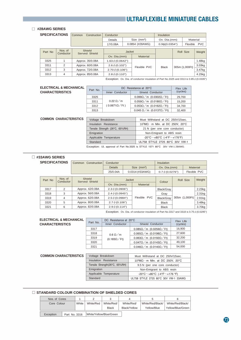
ULTRAFLEXIBLE MINIATURE CABLES
72
#28AWG SERIES□Conductor Common Construction
Details17/0.08A
Size (mm2)0.0854 (#28AWG)
Ov. Dia.(mm)0.9φ(0.0354")
Material
Flexible PVC
Insulation
Colour
Black
Roll Size Weight
1.48kg3.03kg3.47kg4.15kg
Weight
Approx. 35/0.08AApprox. 60/0.08AApprox. 72/0.08AApprox. 85/0.08A
Shield Conductor
Ov. Dia.(mm)1.63φ(0.0642")
2.6φ(0.102")2.70φ(0.106")2.8φ(0.110")
MaterialPart No
3325331133123313
Exception: UL approval of Part No.3325 is STYLE 1571 80℃ 30V VW-1 28AWG.
Exception: Ov. Dia. of conductor insulation of Part No.3317 and 3318 is 0.75φ(0.0295")
Exception: Ov. Dia. of conductor insulation of Part No.3325 and 3313 is 0.85φ(0.0335")
1234
Jacket
Part No.
29,70015,20034,70032,400
DC Resistance at 20℃
Must Withstand at DC 250V/15sec.103MΩ・m Min. at DC 250V, 20℃
21 N (per one core conductor)Non-Emigrant to ABS resin
-20℃~+80℃ (-4°F~+176°F)UL758 STYLE 2725 80℃ 30V VW-1
3325331133123313
0.22 Ω/m( 0.0671Ω/Ft )
ELECTRICAL & MECHANICALCHARACTERISTICS
ELECTRICAL & MECHANICALCHARACTERISTICS
COMMON CHARACTERISTICS
Conductor Common ConstructionDetails
25/0.04ASize (mm2)
0.0314 (#33AWG)Ov. Dia.(mm) 0.7φ(0.0276")
Material Flexible PVC
Insulation
Black/GrayGray
Black/GrayBlackBlack
Roll Size
2.23kg2.31kg2.91kg3.48kg3.70kg
Approx. 42/0.08AApprox. 56/0.08AApprox. 62/0.08AApprox. 80/0.08AApprox. 82/0.08A
Shield Conductor
Ov. Dia.(mm) 2.3φ(0.0906")2.4φ(0.0945")2.5φ(0.0984")2.7φ(0.106")2.9φ(0.114")
Material
33173318331933203321
23456
Jacket
#33AWG SERIES
Part No.
16,90027,60032,20049,10054,000
DC Resistance at 20℃
Must Withstand at DC 250V/15sec.103MΩ・m Min. at DC 250V, 20℃
9.5 N (per one core conductor)Non-Emigrant to ABS resin
-20℃~+80℃ (-4°F~+176 °F)UL758 STYLE 2725 80℃ 30V VW-1 33AWG
33173318331933203321
0.6 Ω/m(0.183Ω/Ft)
COMMON CHARACTERISTICS
STANDARD COLOUR COMBINATION OF SHIELDED CORES Nos. of Cores Core Colour
Exception
1White
2White/Red
3White/Red/
Black
4White/Red/
Black/Yellow
5White/Red/Black/
Yellow/Blue
6White/Red/Black/
Yellow/Blue/Green
Part No. 3316 White/Yellow/Blue/Green
0.099Ω/m (0.0302Ω/Ft)0.059Ω/m (0.0180Ω/Ft)0.053Ω/m (0.0162Ω/Ft)0.045 Ω/m (0.0137Ω/Ft)
0.085Ω/m (0.0259Ω/Ft)0.065Ω/m (0.0198Ω/Ft)0.063Ω/m (0.0192Ω/Ft)0.047Ω/m (0.0143Ω/Ft)0.046Ω/m (0.0140Ω/Ft)
□
□
Voltage BreakdownInsulation ResistanceTensile Strength (26℃, 65%RH)EmigrationApplicable TemperatureStandard
Voltage BreakdownInsulation ResistanceTensile Strength(26℃, 65%RH)EmigrationApplicable TemperatureStandard
SPECIFICATIONS
SPECIFICATIONS
305m (1,000Ft)Flexible PVC
305m (1,000Ft)Flexible PVC
Nos. ofConductor
Shield Served Shield
Part No
Nos. ofConductor
Shield Served Shield
Inner Conductor
Flex Life(cycles)
Inner Conductor
Flex Life(cycles)
73All given characteristic data provided in this brochure are typical values. Product specifications are subject to change without notice.
Cables are long term products, and cable failure often results in problems in which the original cause is extremely difficult to detect. Choosing a reliable, long life, and multiple application cable from the start, is the key to safety, efficiency, and getting the best value. Always select a quality product, and use it at great length to better coexist with our precious earth.
MIDI-05 45MIDI-05D 45MIDI-10 45MIDI-10D 45MIDI-15 45MIDI-15D 45MIDI-20 45MIDI-20D 45MIDI-30 45MIDI-30D 45PJD-12 3,47PJD-18 3,47PJD-24 3,47PJD-36 3,47PJD-48 3,47PJD-60 3,47PJD-72 3,47PJM-12 3PJM-18 3PJM-24 3PJM-36 3PJM-48 3PJM-60 3PJM-72 3PJM-TNT 6PP-01 4PP-03 4PP-06 4PP-10 4PP-15 4PP-20 4PR-01 4PR-03 4PR-06 4PR-10 4PR-15 4PR-20 4RR-01 3RR-03 3RR-06 3RR-10 3RR-15 3RR-20 3SS-01 4SS-03 4SS-06 4SS-10 4SS-15 4SS-20 4T90-28 42WR-01 3WR-03 3WR-06 3WR-10 3WR-15 3WR-20 3
2319-00 64 2326-08 362330-00 15,162333-00 15,162368-00 15,162381-00 33,342435-00 11,122444 67,68,692447-00 11,122490-08 67,68,692524-00 642534 6,7,82537-08 43,442543-08 43,442546-08 33,342549 9,102552-00 6,11,122579-08 552582 11,122642-08 6602673-00 43,442680 67,68,692689-08 552690-08 552691-08 552697-00 13,142739 67,68,702754-08 67,68,702757-00 662769 67,68,692780-00 67,68,702784 67,68,702789-00 6602790-00 67,68,702791-00 6,9,102792 11,122794-00 67,68,702799-08 27,282806-08 27,282814-00 6602820-08 27,282835-08 652840-08 652841-08 652842-08 652843-08 652845-08 652847-08 652848-08 652849-08 652851-08 652859-00 43,442861-08 652862-08 652863-08 652864-08 65
2865-08 652866-08 652871-00 662879-08 67,68,692880-00 67,68,702893 2,3,4,5,6,7,82895-00 33,342901-00 13,142912 67,68,692919-00 30,322921-00 30,322929-00 67,68,702930-00 242931-00 242932-00 242933-00 242934-00 242935-00 242936-00 242937-00 242938-00 242939-00 23,242941-00 30,322943-00 67,68,702944 27,282947-00 352948-00 45,462964 2,3,4,5,6,33,34,402965-00 2,3,5,6,212972-00 30,312997-00 57,582997-FC 573027-08 43,443031 13,143033-00 45,463037-00 61,623040-00 253041-00 253042-00 253043-00 253044-00 253045-00 253046-00 253047-00 253048-00 253049-00 253080 47,483080-FC 473080-TB 473082-00 293103-00 30,313104-00 30,313106-00 17,18,213135-00 47,483145-00 37,383146-00 37,38
3147-00 37,383156-00 37,383157-00 37,383158-00 37,383159 47,483160-00 47,49,503161-00 47,49,503162-00 47,49,503163-00 47,49,503172-00 193173-00 47,483177-18 17,183178-18 17,183200-00 33,34,403206-08 51,523208-08 59,603227-08 563228-00 2,3,47,483242-00 223243-00 353284 9,103306-00 613306-TB 613308 68,713309 68,713311-00 68,723312-00 68,723313-00 68,723314-08 68,713315-08 68,713316 68,713317 68,723318-08 68,723319 68,723320-00 68,723321-00 68,723324 68,713325-00 68,723349-00 203351-00 33,343.5mm Plug 213B3B-02 413B3B-03 413B3B-05 413B3B-08 413B3B-10 413B3B-15 413B3B-20 413B3B-30 414B4B-02 414B4B-03 414B4B-05 414B4B-08 414B4B-10 414B4B-15 414B4B-20 41
4B4B-30 415016XX 565086XX 595139-03 365139-06 365139-12 365139-20 365139-30 365139-50 365139-75 365139-100 365B5B-02 415B5B-03 415B5B-05 415B5B-08 415B5B-10 415B5B-15 415B5B-20 415B5B-30 41BB-01 4,41BB-02 4,41BB-03 4,41BB-06 4,41BB-10 4,41BB-16 4,41BB-25 4,41BB-33 4,41BB-50 4,41BB-66 4,41BB-100 4,41BNC-2964 39,40,42BNC-2964C 40,42BNC-3200 40,42BNC-3200C 40,42BNC-TNT-50 41BNC-TNT-50S 41BNC-TNT-75 41BNC-TNT-75S 41BR-03 4,41BR-06 4,41BR-10 4,41BR-16 4,41CWB-T0276/T0277 42IHE-03 22IHE-05 22IHE-10 22LF-18 3LF-24 3LF-36 3LF-48 3LF-72 3LF-TNT 6MIDI-015 45MIDI-015D 45MIDI-03 45MIDI-03D 45
Part No. Page Part No. Page Part No. Page Part No. Page Part No. Page
INDEX (PART NO.)
74

DIGIspyDIGITAL AUDIO TRANSMISSION ANALYZER
Analyze
Protocols of digital audio transmission lines
Audio Levels
Audio Signals
・・・We make digital audio transmission lines transparent
Display
Monitor
●
●
●
Display the most important parameters of digital audio transmission lines with the touch of a single key, anywhere and anytime-this is the basic idea of DIGIspy.DIGIspy combines an IEC 958 protocol analyzer, level meter, and vector oscilloscope in a single unit. A headphone monitor output is available as well.DIGIspy is capable of processing signals of any standardized sampling frequency up to 96 kHz. Its inputs accept symmetrical AES/EBU signals as well as S/P-DIF data streams (coaxial and optical ).Because of its compact and light-weight design, DIGIspy is ideally suited for doing measurements in the field. Its big LC display is back-lighted for improved readability even at bad lighting conditions. It can run more than 250 individual measurements without recharging.
IEC 958 AES/EBU or S/P-DIF,coaxial/optical, 32 to 96 kHz
LCD 60 × 80 mm, with back light
5-level quality indicator (influenced by error rate and eye diagram of the
input signal), error counter, error protocol with time stamp
Mode of channel status and user data, validity, emphasis, origin and
destination data, multi-channel format, copy protection, category code
Peak level meter according to IEC268-18, peak hold, clipping indicator
Two-dimensional display of stereo signal amplitude(Goniometer)
16-bit D/A converter, adjustable volume, selectable channel mapping
(output of left, right, or both channels)
NiMH AA accumulators × 2, power supply/charger, car adapter, dry cells
83 × 152 × 34mm3, 300g
Power supply/charger, soft leather case, XLR/Cinch adapter
Interface
Display
Transmission quality
indicators
Control data display
Level meter
Vector oscilloscope
Monitor output
Power supply
Dimensions and weight
Accessories included
Imported / Distributed Product in Japan
Features
Versatile
Powerful
Portable
Easy To Use
Affordable

Special thanks to:
Manabu Hirabayashi and Hajime Nakanishi, for providing specifications (technical and graphical data.) Yasuhiro Nakano, for providing numbers and measured data. Leonard Marshall, for a substantial business collaboration that made this possible. John Caldwell and Phil Tennison, for assistance in the composition of the English copy. Hiroaki Kobayashi, for overall catalog design. The many colleagues at MOGAMI, our vendors of raw materials and parts, and our global distributors, working with us today and throughout our past. All our customers around the world who have continued to support our lives.