Embed Size (px)
Citation preview
BASIS OF DESIGN AND EXPECTED PERFORMANCES FOR THE MESSINA STRAIT BRIDGE
BONTEMPI, Franco
University of Rome “La Sapienza” ITALY
Summary The purpose of this paper is to present from the scientific point of view the main ideas and the consequent logic which form the basis of the design and of the definition of the performances levels for the Messina Strait Bridge. With the general philosophy of design, one canalizes all the design activities toward specific goals. With the explicit definition of the performances one must reach a delicate balance between the demand for the construction of an appropriate, possibly outstandingly, structure, and the feasibility, both from the engineering and from the economic point of view. Together with the strategy necessary to originate the design of this exceptional bridge, the essential role of the structural analysis supporting the decisional process is enlightened. Keywords Basis of Design, Performance-based Design, Dependability, Suspension Bridges, Structural Analysis, Messina Strait Bridge 1. Introduction In the mid of April 2005, the Official Italian Gazette and the Official European Gazette published the tender notice for the General Contractor for the realization of the Messina Strait Bridge and the connected works. Following the evaluations of the Awarding Committee, the 12 October 2005 the group headed by Impregilo was appointed temporary winner of the tender for General Contractor, while the contract was signed in March 2006. Actually, the new Italian Government, elected at the end of April 2006, holds in stand by the overall project. The Messina Strait Bridge has a relatively long history. Probably the first design with the spirit of the modern engineering was developed by Mr. A. Carlo Navone for his Degree Thesis at the Polytechnic of Turin in 1870. At the end of the Sixties / beginning of the Seventies, the first technical proposals were compared after the conclusion of the international competition for a permanent link, compounded by highway and railway, between Sicily and Mainland. The designs of this competition, organized by ANAS (Italian National Administration for Highway) and Ferrovie dello Stato (Italian National Administration for Railway), nowadays appear dated, based on at the knowledge and on the technologies of those years, presenting ingenuities and inaccuracies. Specifically, there is a lack of scientific data and computational tools, which instead are today available. By the Law N. 1158 of December 17, 1971, Italy took the decision to create a public company for the design, construction, operation and management of the permanent link between Sicily and the Mainland, finalized with the constitution of the Stretto di Messina S.p.A. in 1981 [www.strettodimessina.it]. It is interesting to observe that in Japan, the Ministry of Construction started the investigation for bridges over the Akashi Straits as well as over the Naruto Straits in 1959, and the Honshu-Shikoku Bridge Authority was the founded on 1970. After this first phase, a second one started around 1986, when Stretto di Messina S.p.A. presented the feasibility study concerning different potential types of crossing: air, water, underwater ones. In 1988, ANAS and Ferrovie dello Stato, taking into account the observations of the Consiglio Superiore dei Lavori Pubblici (High Council of Public Works), choose to develop the air solution by a suspension

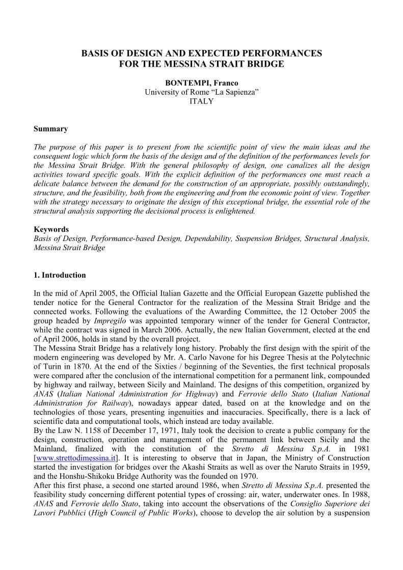
bridge. At the end of 1992, Stretto di Messina S.p.A. presented the so-called Progetto Preliminare (Preliminary Project) (PP92), on which ANAS and Ferrovie dello Stato gave their technical opinion on the project during 1994 and 1995. Furthermore, in 1999, in order to obtain further information for the final assessment, the Interministerial Committee for Economic Planning (CIPE) appointed two independent advisors: Steinman Int. - Parson Group for assessment of the technical aspects, and a joint venture, led by PricewaterhouseCoopers, for assessment of the territorial, environmental, economic and financial aspects. A third crucial phase started at the end of 2001, when a Technical Scientific Committee of the Italian Ministry for Transport and Infrastructures was appointed, with the duty to deeply review the Progetto Preliminare (PP92), following a strong political motivation to develop the design itself. After one year of work, at the end of 2002, this Committee summarized the suggestions for the project in the document Indirizzi progettuali e deliberazioni per il progetto preliminare (Design criteria and deliberations for the preliminary project) that led to the preparation of the Progetto Preliminare (PP03), approved by CIPE in August 2003, which defines the unavoidable geometrical properties and the mandatory performance requirements that had to be satisfied by any design proposals. Contemporaneously and after these administrative developments, the activities of the Scientific Committee, now inside the Stretto di Messina S.p.A., and of this company itself also with the aid of Italian and international advisors, were specifically devoted to fix the basis of design and the expected serviceability and safety performance levels. These points have been checked with reference to the Progetto Preliminare (PP03) leading to a reference bridge configuration (colloquially denoted as Progetto di Gara (PG04)) as the base for any improved design proposals that may be presented by the future Tenders. All these activities led at the end of 2004 to the document Fondamenti progettuali e prestazioni attese per l’opera di attraversamento (Basis of design and expected performance levels for the bridge) that defines the basis of design and establishes the expected performance levels for the bridge which shall be achieved and satisfied in all subsequent design development, in the construction phases and by the completed and tested bridge structure. In the following, one will remark, surely limited and biased by a personal witnessing, few main aspects, both from the scientific and the engineering points of view, which were considered, discussed and developed during the years 2001-2005 and laid the basis of design and expected performances for the Messina Strait Bridge. One thinks that these considerations may be of some interest for other such large bridge designs [CALZONA, 2005]. 2. Performance-based Design, Complexity, Systemic Approach The general framework for the design of an extraordinary structure like the Messina Strait Bridge can be set with reference to the scheme of Fig.1. Here are collected the phases necessary to find in a constructive approach the solution for the design problem:
a) definition of the structural domain, as bridge geometrical and material characteristics; b) definition of the design environment where the structure is immersed with specific attention
to the specifications of the i. natural actions (wind & temperature and soil & earthquake);
ii. antropic actions (related to highway & train traffic); c) assessment of the performances obtainable by the current structural design configuration,
resulting from accurate and extensive structural analysis developed on models, both analytically or experimentally based;
d) alignment of expert judgments and emergence of decision about the soundness of the design, first in qualitative terms then in quantitative terms;
e) negotiation and reframing of the expected performances, in comparison with what has been obtained by the analysis and by the knowledge acquired working on the problem.
This scheme is recognized as a Performance-based Design approach. It is worth to note two features:
1. the strongly affection by heuristics and experience of the problem formulation and of the recognition of the solution; particularly, the engineering deontology is the only capable to correctly address the interest of all the stakeholders;
2. the central role of the numerical modeling, as the unique knowledge engine able to connect all the details of the theory and of the experimentation in a truly comprehensive representation of the problem and of its solution.
DECISION
NEGOTIATION & REFRAMING
WIND & TEMPERATURE
EARTHQUAKE
AN
TRO
PIC A
CTIO
NS
(RA
ILWA
Y & H
IGH
WA
Y)
STRU
CTU
RA
L BEH
AVIO
R &
PERFO
RM
AN
CE A
SSESSMEN
T
a)b)
b)
b) c)
d)e) DECISION
NEGOTIATION & REFRAMING
WIND & TEMPERATUREWIND & TEMPERATURE
EARTHQUAKEEARTHQUAKE
AN
TRO
PIC A
CTIO
NS
(RA
ILWA
Y & H
IGH
WA
Y)A
NTR
OPIC
AC
TION
S(R
AILW
AY &
HIG
HW
AY)
STRU
CTU
RA
L BEH
AVIO
R &
PERFO
RM
AN
CE A
SSESSMEN
T
a)b)
b)
b) c)
d)e)
Fig.1 Performance-based Design of the Messina Strait Bridge
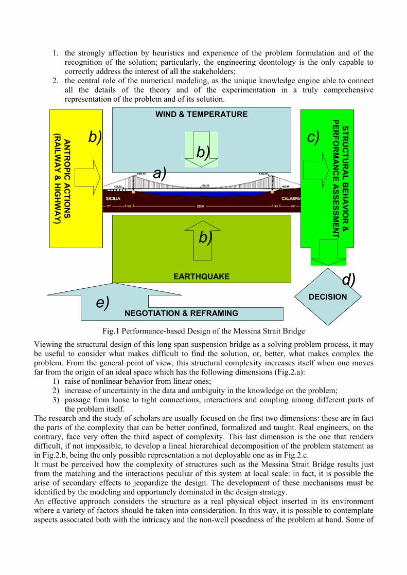
Viewing the structural design of this long span suspension bridge as a solving problem process, it may be useful to consider what makes difficult to find the solution, or, better, what makes complex the problem. From the general point of view, this structural complexity increases itself when one moves far from the origin of an ideal space which has the following dimensions (Fig.2.a):
1) raise of nonlinear behavior from linear ones; 2) increase of uncertainty in the data and ambiguity in the knowledge on the problem; 3) passage from loose to tight connections, interactions and coupling among different parts of
the problem itself. The research and the study of scholars are usually focused on the first two dimensions: these are in fact the parts of the complexity that can be better confined, formalized and taught. Real engineers, on the contrary, face very often the third aspect of complexity. This last dimension is the one that renders difficult, if not impossible, to develop a lineal hierarchical decomposition of the problem statement as in Fig.2.b, being the only possible representation a not deployable one as in Fig.2.c. It must be perceived how the complexity of structures such as the Messina Strait Bridge results just from the matching and the interactions peculiar of this system at local scale: in fact, it is possible the arise of secondary effects to jeopardize the design. The development of these mechanisms must be identified by the modeling and opportunely dominated in the design strategy. An effective approach considers the structure as a real physical object inserted in its environment where a variety of factors should be taken into consideration. In this way, it is possible to contemplate aspects associated both with the intricacy and the non-well posedness of the problem at hand. Some of
these aspects and it is worth to realize that these are the most important ones, belong to the economics or to the politics, i.e. to the social spheres. The fact that different points of view interact reciprocally, implicates that an eventual more or less substantial variation of any of these may change the characteristics of the system as a whole. Just these connections form one of the signs of complexity and an approach that doesn’t take into account this reality may be short-sighted. With these considerations, a structure is better defined as a physical entity having a unitary character that can be conceived of as an organization of positioned constituent elements in space in which the character of the whole dominates the interrelationship of the parts. This definition highlights that a modern approach in Structural Engineering has to evolve from the idea of “Structure”, as a simple device for channeling loads, to the idea of “Structural System”, as “a set of interrelated components which interact one with another in an organized fashion toward a common purpose” [NASA, 1995]: this Systemic Approach includes a set of activities which lead and control the overall design, implementation and integration of the complex set of interacting components.
(a)
(b)
(c) Fig.2 (a) Dimensions of complexity for a structural problem; hierarchically (b) lineal and (c) not
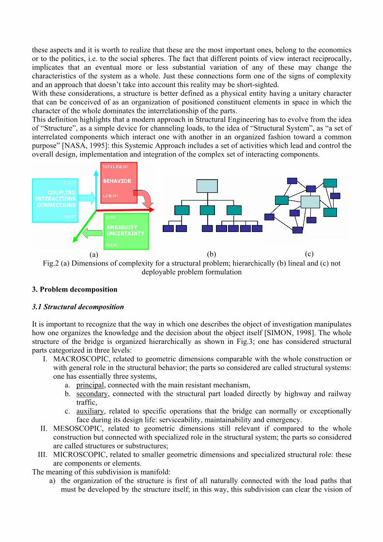
deployable problem formulation 3. Problem decomposition 3.1 Structural decomposition It is important to recognize that the way in which one describes the object of investigation manipulates how one organizes the knowledge and the decision about the object itself [SIMON, 1998]. The whole structure of the bridge is organized hierarchically as shown in Fig.3; one has considered structural parts categorized in three levels:
I. MACROSCOPIC, related to geometric dimensions comparable with the whole construction or with general role in the structural behavior; the parts so considered are called structural systems: one has essentially three systems,
a. principal, connected with the main resistant mechanism, b. secondary, connected with the structural part loaded directly by highway and railway
traffic, c. auxiliary, related to specific operations that the bridge can normally or exceptionally
face during its design life: serviceability, maintainability and emergency. II. MESOSCOPIC, related to geometric dimensions still relevant if compared to the whole
construction but connected with specialized role in the structural system; the parts so considered are called structures or substructures;
III. MICROSCOPIC, related to smaller geometric dimensions and specialized structural role: these are components or elements.
The meaning of this subdivision is manifold: a) the organization of the structure is first of all naturally connected with the load paths that
must be developed by the structure itself; in this way, this subdivision can clear the vision of
the design team about the duties of each part of the structure; this identification is essential in the Conceptual Design, and it is implicitly a precondition for the accomplishment of the Performance-based Design, where the importance of form is strongly emphasized, leading, for example, to concepts like integral bridges;
Fig.3 Structural decomposition of the bridge: left, macro-level, right meso-level
b) parts belonging to different levels of this organization require different reliability properties;
with regard to structural failure conditions, this decomposition allows single critical mechanisms to be ranked in order of risk and consequences of the failure mechanism: for example, in Fig.3 there are, indicated by yellow, orange and red frames, different level (decreasing) of permissible damage; these qualitatively assumed requirements can be quantitatively translated defining different levels of stress in the different bridge parts (see Tab.2 and Tab.3 in the following); all these considerations lead to the so-called crisis canalization;
c) there are strong relationships between life cycle and maintenance of the different parts: with reference to their structural function, the safety required levels and their reparability, structures and sub-structures are distinguished in primary components (critical, non-repairable or which require the bridge to be placed out of service for a consistent period in order for them to be repaired), and secondary components (repairable with minor restrictions on the operation of the bridge). As specific case, one can consider the whole hanger system,
which can be classified as a main structural component in relation to the global structural safety of the bridge, whereas a single hanger group can be considered a secondary component due to its reparability and/or replacement ability.
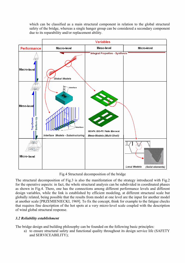
Fig.4 Structural decomposition of the bridge
The structural decomposition of Fig.3 is also the manifestation of the strategy introduced with Fig.2 for the operative aspects: in fact, the whole structural analysis can be subdivided in coordinated phases as shown in Fig.4. There, one has the connections among different performance levels and different design variables, while the link is established by efficient modeling, at different structural scale but globally related, being possible that the results from model at one level are the input for another model at another scale [PRZEMIENIECKI, 1969]. To fix the concept, think for example to the fatigue checks that requires fine description of the hot spots at a very micro-level scale coupled with the description of wind global structural response. 3.2 Reliability establishment The bridge design and building philosophy can be founded on the following basic principles:
a) to ensure structural safety and functional quality throughout its design service life (SAFETY and SERVICEABILITY);
b) to reduce, or at least not amplify, effects due to external disturbances (such as natural environmental or man-generated conditions) or internal disturbances (such as alteration of materials and components and variability due to the manufacturing and assembly processes), also thanks to the intrinsic ductility properties at the material, component and system levels (STRUCTURAL ROBUSTNESS);
c) to pursue a suitable structural configuration that will ensure (STRUCTURAL CONCEPTION): • to pursue access for inspection, so that possible lacks and defects may be monitored,
detected and promptly identified; • to guarantee maintainability and replaceability of the structural elements, via ordinary and
extraordinary maintenance works. In particular, point b) empathizes the role of the intrinsic quality of the bridge concerning the necessity to handle the uncertainties and the exceptionalities that can affect a so complex construction. So, the design basis will foster a strong proactive approach to the structural design that will go beyond the numerical verifications of usual limit states disequations or the local optimization of structural sections or element arrangements. Specifically, with a passive attitude, non conformable solutions of the structural problem (proposed/chosen by the Client) can be avoided; an active attitude leads to the same working way, but there is an attempt to improve the proposed solution, always inside the given definition of the structural problem; a proactive attitude can lead, if necessary and needed, to a change of the definition given by the client about the structural problem, showing new aspects and different viewpoints to obtain an excellent solution, even outside the given definition of the structural problem. Points b) and c) regard pervasively the overall logic of the design and of the structural configuration, assuring from the qualitative point of view the soundness of the bridge. Also regarding the methodologies and the design solutions proposed by the Tenders / General Contractor, these will be assessed, at each level, on the basis of their suitability, effectiveness, simplicity, robustness and reliability. The spreading out of the reliability basis of the bridge requires: a) the definition of the design life:
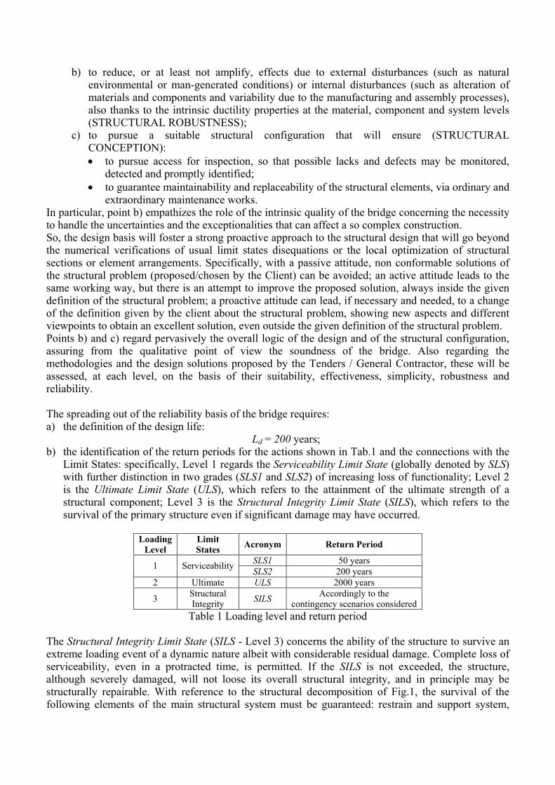
Ld = 200 years; b) the identification of the return periods for the actions shown in Tab.1 and the connections with the
Limit States: specifically, Level 1 regards the Serviceability Limit State (globally denoted by SLS) with further distinction in two grades (SLS1 and SLS2) of increasing loss of functionality; Level 2 is the Ultimate Limit State (ULS), which refers to the attainment of the ultimate strength of a structural component; Level 3 is the Structural Integrity Limit State (SILS), which refers to the survival of the primary structure even if significant damage may have occurred.
Loading
Level Limit States Acronym Return Period
SLS1 50 years 1 Serviceability SLS2 200 years 2 Ultimate ULS 2000 years
3 Structural Integrity SILS Accordingly to the
contingency scenarios considered Table 1 Loading level and return period
The Structural Integrity Limit State (SILS - Level 3) concerns the ability of the structure to survive an extreme loading event of a dynamic nature albeit with considerable residual damage. Complete loss of serviceability, even in a protracted time, is permitted. If the SILS is not exceeded, the structure, although severely damaged, will not loose its overall structural integrity, and in principle may be structurally repairable. With reference to the structural decomposition of Fig.1, the survival of the following elements of the main structural system must be guaranteed: restrain and support system,
main cables, saddles. Generally speaking, the SILS shall be considered under the following load combinations:
• permanent and extreme seismic loading, in presence of frequent traffic loading; • permanent and extreme wind load, in presence of frequent traffic loading; • permanent loads and accidental impact loads (ship impact, aircraft impact) and tornado loading,
in presence of frequent highway and railway traffic loading. Component capacities shall be determined as for the ULS. 3.3 Performance related to the structural safety The organization of the safety of such a complex structure cannot be defined only in quantitative terms. It is typical of real composite situations to express judgments by fuzzy terms instead of crisp ones. In this sense, the safety requirements are arranged by the following steps.
I. Definition of the increasing grades of damage levels of Tab.2.
Damage grades Acronym Description
1 NO DAMAGE ND
All structural elements and restraint systems retain their nominal performance capacity remaining in the elastic field and do not present any significant degradation due to fatigue.
2 DEGRADATION
DAMAGE DD
Degradation of mechanical properties of materials after an appropriate period of service due to environmental actions (corrosion) or cyclical actions (fatigue). These effects shall be allowed for the over sizing of structural sections and shall be eliminated or minimized through scheduled maintenance activities.
3 MINIMAL DAMAGE
MD Occurrence of localized slight inelastic behavior which does not alter the overall performance capacities of the bridge. This damage can be repaired by means of ordinary maintenance operations, guaranteeing the road and rail traffic.
4 REPAIRABLE
DAMAGE RD
Occurrence of localized inelastic behavior which alters the overall performance capacities of the bridge. This damage can be repaired by extraordinary maintenance operations, involving partial and temporary closures of the bridge.
5 SIGNIFICANT
DAMAGE SD
Occurrence of inelastic behavior which significantly alters the overall performance capacities of the bridge. It corresponds to a serious damage of the structure which may require the reconstruction of entire structural components. The damage can be repaired by significant extraordinary maintenance operations, which may involve prolonged closures of the bridge.
Table 2 Definition of damage grades
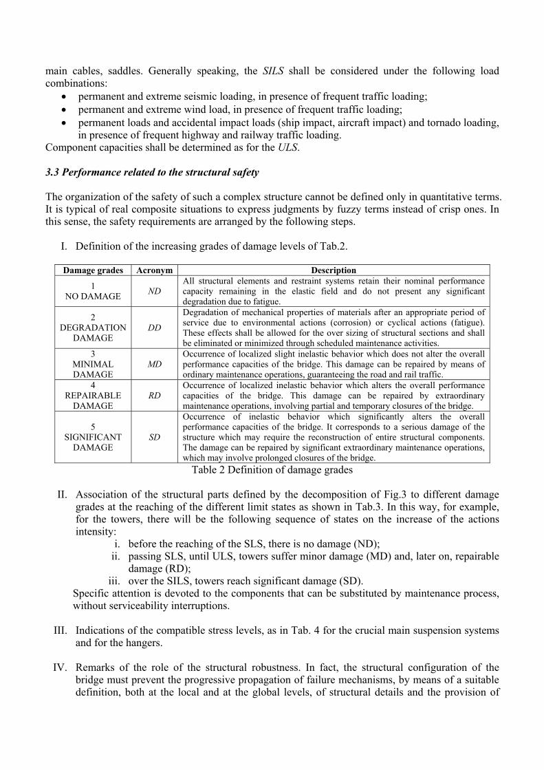
II. Association of the structural parts defined by the decomposition of Fig.3 to different damage grades at the reaching of the different limit states as shown in Tab.3. In this way, for example, for the towers, there will be the following sequence of states on the increase of the actions intensity:
i. before the reaching of the SLS, there is no damage (ND); ii. passing SLS, until ULS, towers suffer minor damage (MD) and, later on, repairable
damage (RD); iii. over the SILS, towers reach significant damage (SD).
Specific attention is devoted to the components that can be substituted by maintenance process, without serviceability interruptions.
III. Indications of the compatible stress levels, as in Tab. 4 for the crucial main suspension systems and for the hangers.
IV. Remarks of the role of the structural robustness. In fact, the structural configuration of the
bridge must prevent the progressive propagation of failure mechanisms, by means of a suitable definition, both at the local and at the global levels, of structural details and the provision of
appropriate lines of defense. A suitable structural compartimentation must therefore be sought, if necessary by means of an appropriate arrangement of connections. In particular, the local collapse of a section of the deck structure as a consequence of the failure of the corresponding hangers and cross beams shall not propagate along the whole deck.
Macro- Level
Meso- Level
Structural Systems Structures Sub-structures
SLS ULS SILS
Foundations of towers ND MD RD SD Anchor blocks ND MD RD SD Restraint / support
system Towers ND MD RD SD Main cables ND MD RD SD Main suspension
system Saddles ND MD RD SD Hangers system ND MD RD SD Secondary suspension
system Single hanger DD RD SD SD Cross girders ND MD SD SD Rail box girders ND MD SD SD Main standard deck Road box girders ND MD SD SD End restraint regions and expansion joints DD MD SD SD
Main
Special deck regions Internal restraint regions and Restraint devices DD MD SD SD
Table 3 Association between damage grades and limit states conditions for different structural parts of the bridge
Compatible stress levels Serviceability Limit States
(SLS) Ultimate Limit States
(ULS) Main cables Ultimate stress / 2.10 Ultimate stress / 1.67
Hangers Ultimate stress / 1.67 Ultimate stress / 1.40 Table 4 Definition of compatible stress levels for the main structural systems
3.4 Performance related to the structural serviceability The serviceability of the bridge is graded as in Tab.5 while the main different requirements are shown in Tab.6. The last column of this table shows also the connection of the various performance requirements to different kind of suitable and efficient modeling: as previously remarked, the structural analysis is a multilevel process and different representations should be used. Specific attention is devoted to the deck movements in relation with the design of expansion joints and restraint devices. One must establish the configuration of these landing zones of the deck considering the trade off among the:
• variations of the geometry of the structure and related dynamic effects; • restraint forces; • economy of construction and operation of the devices.
Generally speaking, the longitudinal and transversal movement of the deck at its ends and in proximity of the towers will have to be controlled by damping devices.
Serviceability levels Acronym Description Limit States
1 Complete functionality CF Roadway and railway runnability guaranteed SLS1
2 Railway functionality FF Only railway runnability guaranteed SLS2
3 Lack of functionality AF Neither roadway nor railway runnability guaranteed ULS / SILS
Table 5 Definition of serviceability performance levels
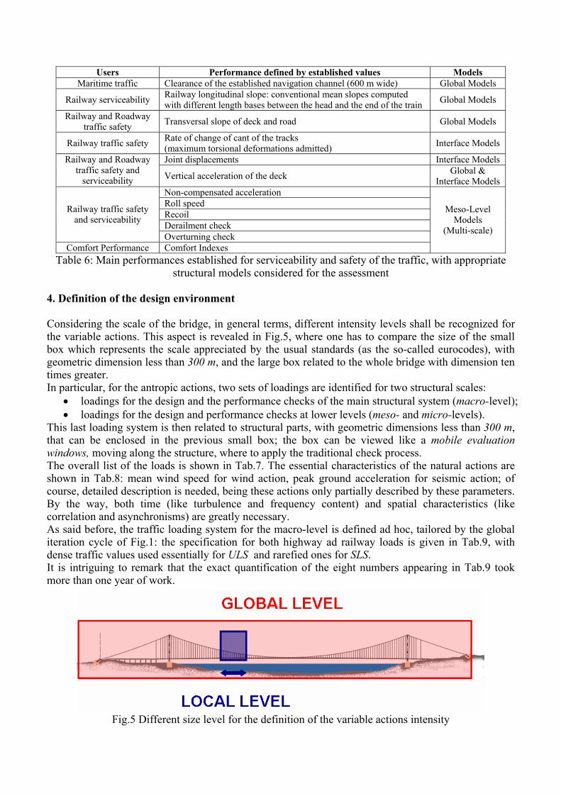
Users Performance defined by established values Models Maritime traffic Clearance of the established navigation channel (600 m wide) Global Models
Railway serviceability Railway longitudinal slope: conventional mean slopes computed with different length bases between the head and the end of the train Global Models
Railway and Roadway traffic safety Transversal slope of deck and road Global Models
Railway traffic safety Rate of change of cant of the tracks (maximum torsional deformations admitted) Interface Models
Joint displacements Interface Models Railway and Roadway traffic safety and
serviceability Vertical acceleration of the deck Global & Interface Models
Non-compensated acceleration Roll speed Recoil Derailment check
Railway traffic safety and serviceability
Overturning check Comfort Performance Comfort Indexes
Meso-Level Models
(Multi-scale)
Table 6: Main performances established for serviceability and safety of the traffic, with appropriate structural models considered for the assessment
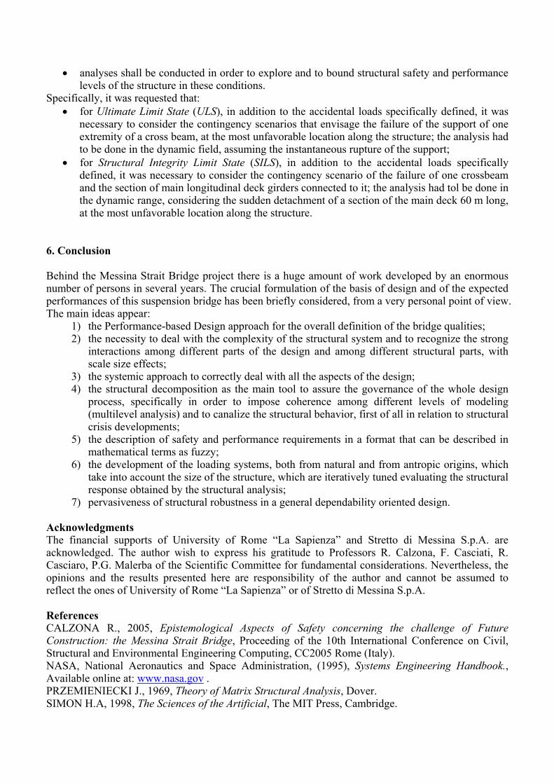
4. Definition of the design environment Considering the scale of the bridge, in general terms, different intensity levels shall be recognized for the variable actions. This aspect is revealed in Fig.5, where one has to compare the size of the small box which represents the scale appreciated by the usual standards (as the so-called eurocodes), with geometric dimension less than 300 m, and the large box related to the whole bridge with dimension ten times greater. In particular, for the antropic actions, two sets of loadings are identified for two structural scales:
• loadings for the design and the performance checks of the main structural system (macro-level); • loadings for the design and performance checks at lower levels (meso- and micro-levels).
This last loading system is then related to structural parts, with geometric dimensions less than 300 m, that can be enclosed in the previous small box; the box can be viewed like a mobile evaluation windows, moving along the structure, where to apply the traditional check process. The overall list of the loads is shown in Tab.7. The essential characteristics of the natural actions are shown in Tab.8: mean wind speed for wind action, peak ground acceleration for seismic action; of course, detailed description is needed, being these actions only partially described by these parameters. By the way, both time (like turbulence and frequency content) and spatial characteristics (like correlation and asynchronisms) are greatly necessary. As said before, the traffic loading system for the macro-level is defined ad hoc, tailored by the global iteration cycle of Fig.1: the specification for both highway ad railway loads is given in Tab.9, with dense traffic values used essentially for ULS and rarefied ones for SLS. It is intriguing to remark that the exact quantification of the eight numbers appearing in Tab.9 took more than one year of work.
Fig.5 Different size level for the definition of the variable actions intensity

Permanent actions (P) Structural self weight PP 1 Non structural self weight PN Antropic actions (Q) Actions for local sizing of the structural systems (strength and deformation at micro- and meso-level) QL
Dense variable load QA 2
Actions for global sizing of the structural system and for serviceability checks (strength and deformation at macro-level) Rarefied variable load QR Natural and environmental actions (V) Wind action VV Seismic action VS 3
Thermal action VT 4 Accidental actions (A)
Table 7 Definition of the design actions SLS1 SLS2 ULS SILS
Mean wind speed (at 70 m above sea level) 44 m/s 47 m/s 54 m/s 60 m/s Peak ground acceleration 1.2 m/s2 2.6 m/s2 5.7 m/s2 6.3 m/s2 Table 8 Natural actions intensity the different limit states
Dense variable load (QA)
Rarefied variableload (QR)
HIGHWAY Intensity of the distributed load line for the most heavily loaded lane 15 kN/m 3.75 kN/m Intensity of the distributed load line for the one of the other lane 5 kN/m 1.25 kN/m RAILWAY Number of 750 m long train loaded by 88 kN/m for each of the two railways 2 1
Table 9 Load definition for highway and railway traffic: dense loads for ULS, rarefied loads for SLS 5. Dependability The quality of such a large bridge is multifaceted. The holistic and comprehensive measure of the quality of this complex structure is called dependability. This concept can be synthetically defined as the grade of confidence on the safety and on the performance of a structural system. It is an integrative concept that, for a construction, encompasses the following attributes:
• availability: readiness for correct serviceability; • reliability: continuity of correct serviceability; • safety: absence of catastrophic consequences on the users and the environment; • security: absence of catastrophic consequences for illegitimate antropic actions; • integrity: absence of improper system state alterations; • maintainability: ability to undergo repairs and modifications.
The means to attain dependability can be summarized as: • fault prevention: how to prevent the occurrence or introduction of faults; • fault tolerance: how to deliver correct service in the presence of faults; • fault removal: how to reduce the number or severity of faults; • fault forecasting: how to estimate the present number, the future incidence, and the likely
consequences of faults. Absence of catastrophic consequences and fault tolerance are guaranteed by the structural robustness. This is the capacity of the construction to undergo only limited reductions in its performance level in the event of departures from the original design configuration as a result of a) local damage due to accidental loads, b) secondary structural elements, c) being out of service for maintenance purpose, d) degradation of their mechanical properties. In general terms, the following recommendations apply:
• appropriate contingency scenarios shall be identified, i.e. scenarios of possible damage together with suitable load scenarios, able to characterize the structural robustness in the various conditions of service;
• analyses shall be conducted in order to explore and to bound structural safety and performance levels of the structure in these conditions.
Specifically, it was requested that: • for Ultimate Limit State (ULS), in addition to the accidental loads specifically defined, it was
necessary to consider the contingency scenarios that envisage the failure of the support of one extremity of a cross beam, at the most unfavorable location along the structure; the analysis had to be done in the dynamic field, assuming the instantaneous rupture of the support;
• for Structural Integrity Limit State (SILS), in addition to the accidental loads specifically defined, it was necessary to consider the contingency scenario of the failure of one crossbeam and the section of main longitudinal deck girders connected to it; the analysis had tol be done in the dynamic range, considering the sudden detachment of a section of the main deck 60 m long, at the most unfavorable location along the structure.
6. Conclusion Behind the Messina Strait Bridge project there is a huge amount of work developed by an enormous number of persons in several years. The crucial formulation of the basis of design and of the expected performances of this suspension bridge has been briefly considered, from a very personal point of view. The main ideas appear:
1) the Performance-based Design approach for the overall definition of the bridge qualities; 2) the necessity to deal with the complexity of the structural system and to recognize the strong
interactions among different parts of the design and among different structural parts, with scale size effects;
3) the systemic approach to correctly deal with all the aspects of the design; 4) the structural decomposition as the main tool to assure the governance of the whole design
process, specifically in order to impose coherence among different levels of modeling (multilevel analysis) and to canalize the structural behavior, first of all in relation to structural crisis developments;
5) the description of safety and performance requirements in a format that can be described in mathematical terms as fuzzy;
6) the development of the loading systems, both from natural and from antropic origins, which take into account the size of the structure, which are iteratively tuned evaluating the structural response obtained by the structural analysis;
7) pervasiveness of structural robustness in a general dependability oriented design. Acknowledgments The financial supports of University of Rome “La Sapienza” and Stretto di Messina S.p.A. are acknowledged. The author wish to express his gratitude to Professors R. Calzona, F. Casciati, R. Casciaro, P.G. Malerba of the Scientific Committee for fundamental considerations. Nevertheless, the opinions and the results presented here are responsibility of the author and cannot be assumed to reflect the ones of University of Rome “La Sapienza” or of Stretto di Messina S.p.A. References CALZONA R., 2005, Epistemological Aspects of Safety concerning the challenge of Future Construction: the Messina Strait Bridge, Proceeding of the 10th International Conference on Civil, Structural and Environmental Engineering Computing, CC2005 Rome (Italy). NASA, National Aeronautics and Space Administration, (1995), Systems Engineering Handbook., Available online at: www.nasa.gov . PRZEMIENIECKI J., 1969, Theory of Matrix Structural Analysis, Dover. SIMON H.A, 1998, The Sciences of the Artificial, The MIT Press, Cambridge.

INTRODUCTIONThe International Conference on Bridge Engineering – Challenges in the 21st Century is aimed at providing a forumfor dissemination of technical advances as well as exchanges of experiences and ideas among engineers, architects,academics, researchers, developers, regulatory agents and project managers at an international level. A number ofkeynote lectures presented by world renowned experts and parallel sessions will be organised to address both therecent developments and experiences on a wide range of technical, social, environmental, financial and managementtopics in the bridge engineering and construction.
ORGANISED BYCivil Division,The Hong Kong Institution of Engineers
SUPPORTED BYHighways Department,The Government of the Hong Kong SAR, China
BRIDGEENGINEERING– Challenges in the 21st Century
International Conference on
1 - 3 November 2006, HONG KONG
REGISTRATION ANDPROGRAMMEANNOUNCEMENT
MAJOR SPONSORS
Gammon Construction Limited Maeda-Hitachi-Yokogawa-Hsin Chong Joint Venture VSL Hong Kong Limited
China Harbour Engineering Company Limited Chun Wo Holdings Limited Dragages Hong Kong Limited and Bouygues Travaux Publics
KEYNOTE SPEAKERSCONFERENCE THEME
The following topics of interest will be addressed at the Conference:
v Aestheticsv Bridge Management Systemsv Case Studies and Planning Projectsv Codification of Bridge Designv Condition Assessment and Health Monitoringv Design, Analysis and Modelingv Dynamics and Aerodynamicsv Environmental Impact Assessmentv High Performance Materials and Componentsv Inspection, Rehabilitation and Retrofittingv Maintenance and Evaluationv Procurement, Construction and Project
Managementv Reliability and Risk Managementv Safety and Serviceabilityv Security against Terrorist Attackv Seismic and Wind Designv Smart Structuresv Vehicle Bridge Interactionv Whole Life Costingv Others Themes
WHO SHOULD ATTEND
The Conference will be of interest to policy makers, governmentofficials, planners, engineers, contractors, developers, manufacturers,academics, financial specialists and environmental professionalsinvolved in business and development that will advance our abilitiesin bridge engineering development.
GUESTS OF HONOUR
Permanent Secretary forthe Environment, Transport and Works (Works)
The Government of the Hong Kong SAR, China
PresidentThe Hong Kong Institution of Engineers
Mr FENG Mao RunChief EngineerMinistry of CommunicationsThe People's Republic of China
Dr-Ing M. Michel VIRLOGEUXHonorary PresidentThe International Federation for StructuralConcrete (fib)France
Dr TANG Man ChungChairmanT. Y. Lin InternationalUSA
Ir Dipl.-Ing Holger S SVENSSONExecutive DirectorLeonhardt, Andra und Partner GmbttGermany
Ir Naeem HUSSAINDirectorOve Arup & PartnersUK
Prof Niels J GIMSINGBridge ConsultantGimsing & Madsen LtdDenmark
Prof Yozo FUJINOProfessorDepartment of Civil EngineeringThe University of TokyoJapan

OPTIONAL LOCAL TECHNICAL VISITS
The Conference will offer delegates the opportunity of visiting the following technical sites relating to bridge engineering development in HongKong. Delegates can participate in these visits at a seperate fee. A fee of HK$100 per person per visit will apply.
Visit A – Stonecutters BridgeThe new Stonecutters Bridge is an important part of the strategic east-west route linking ShaTin and the airport on Lantau Island in Hong Kong. It will straddle the Rambler Channel at theentrance to the busy Kwai Chung container port. The bridge has a main span of 1,018m. Whencompleted, it will become one of the longest spanning cable stayed bridges in the world. Itwill also be the first major bridge situated in the urban area of Hong Kong with Victoria Harbouras the backdrop. The design of the bridge contains a number of aesthetic features to make itblend with the spectacular Hong Kong skyline. It will become a new landmark in Hong Kong.
Visit B – Hong Kong – Shenzhen Western CorridorConstruction of the Hong Kong Section of Hong Kong-Shenzhen Western Corridor (HK-SWC)commenced on 1 August 2003. The HK$2.2 billion contract comprises the construction of a 3.5km long dual three-lane elevated viaduct with 3.2 km over water and 0.3 km on land, linking DeepBay Link at Ngau Hom Shek with the Shenzhen Section of HK-SWC at the boundary of the HKSARand Shenzhen at Deep Bay. Within the 3.5 km, a cable-stayed bridge with a single inclined-toweris being constructed to provide the necessary navigation clearance for marine traffic and to form alandmark over Deep Bay.
The work was substantially completed in end 2005. Upon commissioning, it will be the fourth vehicularboundary crossing to alleviate the three nearly saturated existing crossings and satisfy the futuredemand.
Remarks:- Pre-registration is necessary for all optional technical visits.- Final arrangements are subject to changes in schedule by the host of individual visits, weather / traffic conditions and whether the minimum
quota can be met.- Registration will be accepted on a first-come-first-served basis.
PRELIMINARY PROGRAMME
The Conference is tentatively planned as a full three-day programme from 1 to 3 November 2006. It will comprise keynote sessions, oralpaper presentations and discussions. The official language of the Conference is English. It will be adopted in all the publications andpresentations.
Time 1 November 2006 Time 2 November 2006 Time 3 November 2006(Wed) (Thu) (Fri)
08:30 - 09:00 Registration 08:30 - 09:00 Registration 08:30 - 09:00 Registration09:00 - 09:45 Opening Ceremony
09:00 - 10:30 Parallel Sessions Optional Local 09:00 - 10:30 Parallel Sessions09:45 - 10:15 Keynote Session Technical Visits10:15 - 10:45 Coffee Break 10:30 - 11:00 Coffee Break (08:45 - 13:00) 10:30 - 11:00 Coffee Break10:45 - 12:15 Keynote Session 11:00 - 12:30 Parallel Sessions 11:00 - 12:30 Parallel Sessions12:15 - 13:30 Lunch 12:30 - 13:45 Lunch 12:30 - 13:45 Lunch13:30 - 15:15 Parallel Sessions 13:45 - 15:30 Parallel Sessions Optional Local 13:45 - 15:15 Keynote Session15:15 - 15:45 Coffee Break 15:30 - 16:00 Coffee Break Technical Visits 15:15 - 15:30 Conclusion &15:45 - 17:15 Parallel Sessions 16:00 - 17:00 Parallel Sessions (13:45 - 18:00) Closing Remarks
19:30 - 21:30 Conference Dinner
REGISTRARION INFORMATION
Registration FeeAll registrations should be made via the online programme at the Conference wesbite: http://www.hkiecvd.org/BRIDGE2006.htm.Please note that the deadline for early bird registration is 31 August 2006.
Note: The Hong Kong dollar is pegged to the US dollar at a rate of US$1=HK$7.8.
Confirmation of Registration & Official Receipt- Registrant will receive an acknowledgement by email immediately if the online registration process is successfully completed.- An official receipt will be provided to all registered delegates upon receipt of the payment.- All payments should reach the Conference Secretariat within 2 weeks after the Registration Form has been submitted online. The Organiser
reserves the right to release and cancel the booking if the appropriate payment is not received on time.
Payment Methods- Payment can be made by crossed cheque, bank draft, telegraphic transfer or credit card (VISA / MasterCard).- A Credit Card Authorisation Form is available at the Conference website.- Crossed Cheque or Bank Draft made payable to “The Hong Kong Institution of Engineers” should be sent to the Conference Secretariat.
Letter of InvitationThe Conference Secretariat will send a letter of invitation upon request. The invitation is intended to facilitate participants’ travel and visaarrangement and does not imply the provision of any financial or other support.
Please read the important notes overleaf.
CONFERENCE SECRETARIAT
Conference & Function SectionThe Hong Kong Institution of Engineers9/F Island Beverley, 1 Great George StreetCauseway Bay, Hong KongTel (852) 2895 4446Fax (852) 2203 4133Email [email protected]
Registration FeeEntitlements
Category (per person) Full-day Conference, A Copy of Conference Dinner Optional Technical VisitRefreshments & Lunch Proceedings (1 November 2006)
Early BirdRegistration
HK$3,800(On or before31 August 2006)
1 – 3 November 2006 √ √HK$100
Normal per person for one visitRegistration
HK$4,200(After 31 August2006)
Photos CourtesyHighways Department, The Government of the Hong Kong SARHong Kong Tourism Board
Programme may be subject to change.Please visit the website for more updates:
http://www.hkiecvd.org/BRIDGE2006.htm
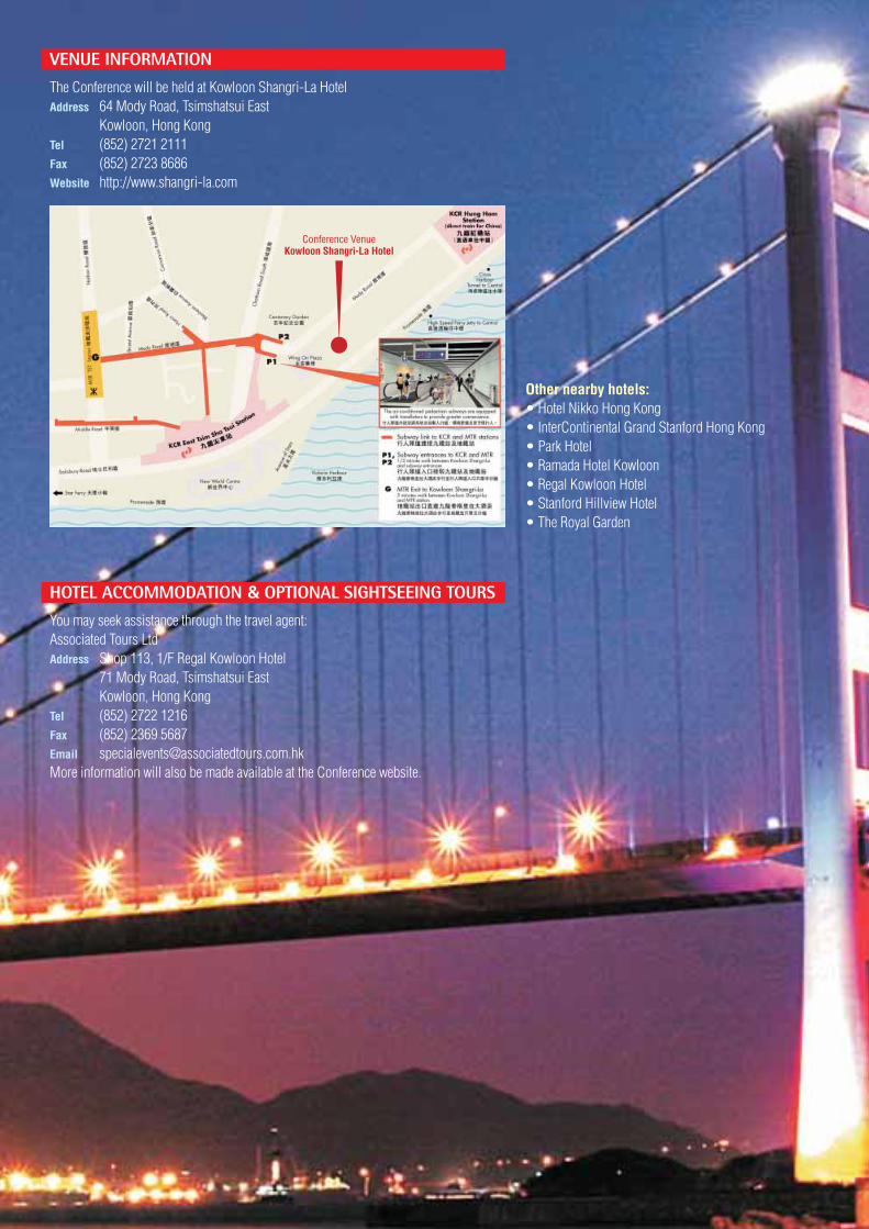
VENUE INFORMATION
The Conference will be held at Kowloon Shangri-La HotelAddress 64 Mody Road, Tsimshatsui East
Kowloon, Hong KongTel (852) 2721 2111Fax (852) 2723 8686Website http://www.shangri-la.com
Other nearby hotels:• Hotel Nikko Hong Kong• InterContinental Grand Stanford Hong Kong• Park Hotel• Ramada Hotel Kowloon• Regal Kowloon Hotel• Stanford Hillview Hotel• The Royal Garden
HOTEL ACCOMMODATION & OPTIONAL SIGHTSEEING TOURS
You may seek assistance through the travel agent:Associated Tours LtdAddress Shop 113, 1/F Regal Kowloon Hotel
71 Mody Road, Tsimshatsui EastKowloon, Hong Kong
Tel (852) 2722 1216Fax (852) 2369 5687Email [email protected] information will also be made available at the Conference website.
Conference VenueKowloon Shangri-La Hotel
HONG KONG INFORMATIONLocal Area Information• Area
Hong Kong can be divided into four distinctparts: Hong Kong Island, Kowloon Peninsula,New Territories and the outlying islands.
• LanguageCantonese is spoken by most people in HongKong, though Mandarin (Putonghua) isbecoming increasingly widespread. Englishis the language of international business.
• PopulationThe estimated population of Hong Kong is 7million. Almost 98% is Chinese.
• Time DifferenceGMT/UTC + 8 hrs
Entry VisaFor most nationalities, visitors not intending towork require only a valid passport for short visitsand no tourist visa is required. You may alsocheck with the Immigration Department of theHong Kong SAR Government as to the need forvisas prior to entry into Hong Kong.Address Immigration Department,
2/F Immigration Tower,7 Gloucester Road,Wan Chai, Hong Kong
Tel (852) 2824 6111Fax (852) 2877 7711Website http://www.immd.gov.hk/index.html
CurrencyThe Hong Kong dollar (HK$) is the official currency.It is pegged to the US dollar at HK$7.8 to US$1.00and is freely convertible. Travelers checks areeasily cashed and major credit cards are widelyaccepted. ATM (ETC) facilities are widespread.
Tipping10% service charge is added to hotels andrestaurants bills. It is also customary to leave asmall tip.
ClimateThe average temperature for the months fromOctober to December is 18°C to 28°C. Thehumidity will be around 72%.
During November there are pleasant breezes,plenty of sunshine and comfortable temperatures.
DressLight suits and dresses are appropriate for businessattire. A light clothing is recommended for theday, sweaters and light jackets for evening.
HealthYour temperature may be taken when you passthrough immigration upon arrival. Vaccinationcertificates are usually not required. However,as in other cities, health regulations are liableto change at short notice and it is alwaysadvisable to check current health regulationswith carriers when making reservations.Visitor in transit through HK should also checkhealth regulations for subsequent destinationsto ensure that all necessary valid certificateshave been obtained.
Electricity220 volts, 50 cycles. Three-rectangular pin plugsare the norm.
Mobile Phone NetworkGSM, PCS, CDMA, TDMA
TransportationMetered taxis, frequent bus, MTR (undergroundtrain) service provides fast, clean, air-conditionedtransport in Kowloon and on the Island. Combineall this with famous ferries, trams, trains and localtransportation in Hong Kong is both safe, easyand inexpensive.
Transportation To / From The AirportHong Kong International Airport is served by ahighly efficient and comprehensive transportationnetwork. The Airport Express is a dedicated airportrailway line providing fast and reliable serviceoperating daily from 0550 to 0115 hours at 12-minute intervals. The journey to or from downtownHong Kong takes approximately 24 minutes.Franchised buses also provide speedy transportto different parts of Hong Kong. Other modes oftransportation include taxis, tour coaches andhotel limousines. For details, please visithttp://www.hongkongairport.com/eng/index.html
Disclaimer: All information provided in this sectionis considered to be accurate and correct at thedate of print. We cannot be held responsibleshould the information change between the dateof print and the date of your arrival in Hong Kong.
If you are interested in knowing more about HongKong, please visithttp://www.DiscoverHongKong.com
Mr Chander ALIMCHANDANIChairman & Managing DirectorSTUP Consultants P. Ltd, India
Prof Dr Mourad M BAKHOUMProfessorStructural Engineering DepartmentCairo University, Egypt
Ir Andrew BEARDCommercial DirectorMott MacDonald Ltd, UK
Prof Sung-Pil CHANGProfessorSeoul National University, Korea
Ir Prof Moe M S CHEUNGProfessor and HeadDepartment of Civil Engineering,The Hong Kong University of Science andTechnology,Hong Kong SAR, China
Ir Prof CHEUNG Yau KaiSpecial Advisor to the Vice ChancellorThe University of Hong Kong, Hong Kong SAR,China
Dr Christian CREMONAHead of the Structures Durability UnitLaboratoire Central Des Ponts Et Chaussees, France
Mr Peter DEASONGlobal Director, Bridges & Civil StructuresHyder Consulting (UK) Ltd, UK
Mr Klaus FALBE-HANSENDirectorOve Arup & Partners, UK
Mr Ian FIRTHPartnerFlint & Neill Partnership, UK
Prof Yozo FUJINOProfessorDepartment of Civil EngineeringThe University of Tokyo, Japan
Prof Niels J GIMSINGBridge ConsultantGimsing & Madsen Ltd, Denmark
Dr Manabu ITOEmeritus ProfessorThe University of Tokyo, Japan
Prof Jun KANDAProfessorDepartment of Environment StudiesThe University of Tokyo, Japan
Ir Prof KO Jan MingVice PresidentThe Hong Kong Polytechnic University,Hong Kong SAR, China
Prof Dr Hyun-Moo KOHProfessor & DirectorSeoul National University &Korea Bridge Design & Engineering Research Center,Korea
Ir Dr Martin H C KWONGSenior AdvisorScott Wilson Ltd, Hong Kong SAR, China
Ir Prof LAU Ching KwongExecutive DirectorMaunsell China Engineering Services Ltd,Hong Kong SAR, China
Ir P K K LEEHead of DepartmentDepartment of Civil EngineeringThe University of Hong Kong, Hong Kong SAR,China
Ir Prof Andrew Y T LEUNGChair ProfessorDepartment of Building and ConstructionCity University of Hong Kong, Hong Kong SAR,China
Prof Dr J Y Richard LIEWAssociate ProfessorDepartment of Civil EngineeringNational University of Singapore, Singapore
Prof John MILESHead of Institute of Machines & StructuresCardiff School of EngineeringCardiff University, UK
Prof OU Jin PingProfessor & Vice PresidentHarbin Institute of Technology, China
Prof Dr sc. techn. Mike SCHLAICHProfessorThe Technical University of Berlin, Germany
Dr Juan A SOBRINODirectorPEDELTA, Spain
Prof Hakan SUNDQUISTProheadDepartment of Civil and Architectural EngineeringRoyal Institute of Technology Stockholm, Sweden
Ir Dipl.-Ing Holger S SVENSSONExecutive DirectorLeonhardt, Andra und Partner Gmbtt, Germany
Dr Gamil TADROSStructural ConsultantSPECO Engineering Ltd, Canada
Dr TANG Man ChungChairmanT. Y. Lin International, USA
Dr Jan A WIUMSenior LecturerDepartment of Civil EngineeringUniversity of Stellenbosch, South Africa
Prof XIANG Hai FanPresident & Consulting DeanCollege of Civil EngineeringTongji University, China
Prof YANG Yeong BinDeanCollege of EngineeringNational Taiwan University, China
Eur Ing Jeff YOUNGProject DirectorMott MacDonald Ltd, UK
SUPPORTING ORGANISATIONSThe Government of the Hong Kong SAR, China
Civil Engineering and DevelopmentDepartment
Environmental Protection DepartmentMarine DepartmentPlanning DepartmentTransport Department
American Society of Civil Engineers(Hong Kong Section)
City University of Hong Kong, Departmentof Building and Construction
Engineers Australia, Hong Kong ChapterHong Kong Institute of Environmental
Impact AssessmentHong Kong Institution of Highways and
TransportationHong Kong Tourism BoardInstitution of Civil Engineers, Hong Kong
AssociationThe Association of Consulting Engineers
of Hong KongThe Chartered Institute of Logistics and
Transport in Hong KongThe Hong Kong Construction AssociationThe Hong Kong Institute of ArchitectsThe Hong Kong Institute of PlannersThe Hong Kong Institute of SurveyorsThe Hong Kong Polytechnic University,
Department of Civil & Structural EngineeringThe Hong Kong University of Science and
Technology, Department of Civil EngineeringThe Institution of Highways &
Transportation Hong Kong BranchThe Joint Structural Division of the
Hong Kong Institution of Engineers andInstitution of Structural Engineers
The University of Hong Kong, Departmentof Civil Engineering
American Society of Civil Engineers, USAChina Civil Engineering Society, ChinaIndian Institution of Bridge Engineers, IndiaInstitution of Civil Engineers, UKInstitution of Engineers, SingaporeJapan Society of Civil Engineers, JapanKorean Society of Civil Engineers, KoreaThe Canadian Society for Civil Engineering,
CanadaThe Institution of Engineers, MalaysiaThe Institution of Highways & Transportation,
UKThe Institution of Professional Engineers,
New ZealandThe Institution of Structural Engineers, UKThe Macau Institution of Engineers,
Macau SAR, China
INTERNATIONAL ADVISORY COMMITTEE
IMPORTANT NOTES1. Registrations are subject to
acceptance on a first-come-first-served basis.
2. Each registrant should completea separate online registrationprocess.
3. The Conference Secretariat willconfirm the registration uponreceipt of the registration fee.Please do not send cash.
4. The programme is subject tochange without prior notice.
5. All cancellations must be madein writing to the ConferenceSecretariat. If a writtencancellation of registration isreceived by the ConferenceSecretariat on or before 30September 2006, a refund willbe made but a cancellationcharge of 25% of theregistration fee paid will bededucted. We regret that norefund will be made forcancellations after this date. Inthe latter case, the non-attending delegates will receivea copy of the ConferenceProceedings.
6. It is at the discretion ofdelegates to take out additionalcover to better protect theirliabilities. For the HKIEmembers, the Institution haseffected an insurance cover *to protect the legal liability ofmembers against property loss/ damage or bodily injury / deathof third party. (*Coverage issubject to terms and conditionsspecified in original policy.) Fornon-HKIE members, it is entirelythe participants’ responsibilityto take out insurance to covertheir participation in theConference. The Organiserassumes no financial, legal orany responsibility for any typeof claim whatsoever arisingfrom their participation.
ACKNOWLEDGEMENTSThe Organiser would like to thank the followingorganisations for their support and valuablecontributions to the Conference:
Platinum SponsorsChina Harbour Engineering Company LimitedChun Wo Holdings LimitedDragages Hong Kong Limited and
Bouygues Travaux PublicsGammon Construction LimitedMaeda-Hitachi-Yokogawa-Hsin Chong
Joint VentureVSL Hong Kong Limited
Gold Sponsors
China Road and Bridge CorporationChiu Hing Construction and Transportation
Company LimitedFuk Shing Engineering Company LimitedOve Arup and Partners Hong Kong LimitedWelcome Construction Company Limited
Sliver Sponsor
Hop Tai Construction Company Limited
ORGANISING COMMITTEEChairman
Ir Francis W C KUNGMembers
Ir George C W CHENGIr Dr CHENG Hon TungIr CHEUNG Tsz KingMr LAI Kwong HungIr Victor K Y LOIr Norman W P MAKIr Clement W T SIUIr Timothy K C SUENIr WONG Chiu YauIr Philco N K WONGIr YU Sai Yen
TECHNICAL SUB-COMMITTEEChairman
Ir Michael C H HUIMembers
Ir Dr Francis T K AUIr Eric K L CHANIr Prof CHANG Chih ChenIr George C W CHENGIr Prof CHUNG Kwok FaiMr LAI Kwong HungIr WONG Chiu Yau
FINANCE & SPONSORSHIPSUB-COMMITTEEChairman
Ir Philco N K WONGMembers
Ir Clement W T SIUIr WONG Chiu YauIr YU Sai Yen
Time 1 November 2006Wednesday
08:30 – 09:00 Registration09:00 – 09:45 Opening Ceremony09:45 – 10:15 Keynote Session 1
Prof Niels GIMSING, DenmarkTitle of Presentation
Evolution in Span Length of Cable-Stayed Bridges10:15 – 10:45 Coffee Break10:45 – 11:15 Keynote Session 2
Prof FENG Mao Run, ChinaTitle of Presentation
Technological Challenges for Bridge Construction in China in the Early 21st Century11:15 – 11:45 Keynote Session 3
Ir Dipl.Ing Holger S Svensson, GermanyTitle of Presentation
Protection of Bridge Piers against Ship Collision11:45 – 12:15 Keynote Session 4
Pro Yozo FUJINO, JapanTitle of Presentation
Lessons Learned from Health Monitoring of Instrumented Long-Span Bridges12:15 – 13:30 Lunch
Parallel Sessions
13:30 – 15:15
15:15 – 15:45 Coffee BreakParallel Sessions
15:45 – 17:15
19:30 – 21:30 Conference Dinner (Cocktail Reception will start at 18:45)
PROGRAMME DETAILS
Room-FanlingSession 1A
Stonecutters Bridge IStonecutters Bridge - International DesignCompetition and Reference SchemeReviewKlaus FALBE-HANSENStonecutters Bridge - Design for ExtremeEventsSteve KITEHigh Reynolds' Number Aerodynamicsof the Stonecutters Bridge DeckAllan LARSENDetailed Design of Stonecutters BridgeSuperstructureTina VEJRUMDetailed Design of Stonecutters BridgeTowersDon BERGMANErection Analysis and Geometry Controlfor Stonecutters BridgeS H Robin SHAMChallenges in Construction ofStonecutters Bridge and Progress UpdateMichael TAPLEY
Room-FanlingSession 2A
Stonecutters Bridge IIExamination of Aerodynamic Coefficientsof Inclined Cables with Different SurfaceConfigurationsKelvin C F KWOKStudies of Temperature Distribution andThermal Stress in Large Concrete Pourof Large Pile CapCarlos WONGStructural Verification of StonecuttersBridge by Spine-Beam ModelCHONG Kwok-waiCofferdams for Stonecutters BridgeFoundations - Design AspectsChris K W CHEUNGHighway Traffic Loads Monitoring inStonecutters BridgeWONG Kai YuenA Heavy Lift Scheme for the Erection ofthe Steel Deck of Stonecutters BridgeChristian VENETZ
Room-Tai PoSession 1B
DesignPC Box-Girder Bridges with Large Spansin ChinaFU Yu FangScenario of Expected Seismic Damageto Main Road Network in N.E. ItalyPaolo FRANCHETTIDesign of Mainland - Peljesac BridgeJure RADICWind Engineering of a Large Vertical LiftBridge in Rouen (France)Michel VIRLOGEUXThe Bridge of San Giuliano in Venice:The Design ProcessEnzo SIVIEROImprovements to San Tin InterchangeContract No. HY/2004/09 Contractor'sDesign for Precast Segmental ViaductsJon VARNDELLInnovations in the Zhoushan XihoumenBridge DesignSONG Hui
Room-Shek OSession 1C
ConstructionChongzun Expressway - The MountainChallengeMichael Z YUTheories and Practices for 30 YearsModern Cable-Stayed BridgeConstructions in ChinaLEI Jun QingThe Geometry Control of Sutong BridgeLAU Ching KwongDesign and Construction of a LaunchedFootbridgeBahman KERMANIDesign and Construction of Freezing andRow of Piles Method in South AnchorageFoundation Pit of Runyang Yangtze RiverBridgeFENG Zhao XiangDesign and Construction of the Lai ChiKok ViaductJames PENNYThe Challenge for the Construction of theLai Chi Kok Viaduct in Hong KongHenry LIU
Room-Tai PoSession 2B
DesignValue Engineering Design of T3 Viaductsin Hong KongBahman KERMANIFull 3D Finite Element Model for CriticalityAnalysis of Tsing Ma BridgeY F DUANIdentification and Prediction ofParameters Error in Construct Controlof Long Span Pre-Stressed ConcreteCable-stayed BridgeCHEN Chang SongImprovement of Low-Cycle FatigueStrength of Steel Bridge Piers by FatigueCrack ArresterTaro TONEGAWADesign Vessel Load for Ship CollisionImpact Analysis of Sea-Crossing BridgeLEE Seong LoTraffic Safety of Vehicles on Long Bridgesin Strong Wind Prone AreasCHEN Ai Rong
Room-Shek OSession 2C
OthersStructural and Aesthetical Challenges - AThree-Arch-Footbridge in ViennaGerald FOLLERPractical Solutions for ImprovingAerodynamic Stability During BridgeTower ConstructionXIE Ji MingToward More Realistic Predictions ofLong-Span Bridge FlutterXIE Ji MingAerodynamic Flutter Stabilization for theEast Sea BridgeYANG Yong-xinStability of Suspension Bridges duringEarly Construction StagesAnna BAGNARAMeasurement of Buffeting Mitigation fora Cable-Stayed Bridge in ConstructionKIM Ho Kyung
PROGRAMME DETAILS
Time 2 November 2006Thursday
08:30 – 09:00 Registration Optional LocalParallel Sessions Technical Visits A
09:00 – 10:30 (08:45 – 13:00)
A1 Stonecutters BridgeA2 Hong Kong -Shenzhen
Western Corridor
10:30 – 11:00 Coffee BreakParallel Sessions
11:00 – 12:30
12:30 – 13:45 Lunch
Room-FanlingSession 3A
Maintenance & ManagementDesign Approaches and Guidelines of HealthMonitoring Systems for Major BridgesLI HuiSVBS - An Assessment Tool for Bridges UnderSeismic LoadsPhilippe RENAULTCondition Assessment of Bridges UnderEarthquake LoadingX Y LITsing Ma Control Area Bridge Inspection andMaintenance IssuesJames GIBSONMonitoring and Evaluation of Shear CrackInitiation and Propagation in Webs of ConcreteBox-Girder SectionsRichard MALMExperimental Applications of a Structural HealthMonitoring MethodologySherif BESKHYROUN
Room-Tai PoSession 3B
DesignThe Shanghai Yangtze BridgeSHAO Chang YuDuctility of Partially Prestressed ConcreteStructures with External TendonsFrancis T K AUAssessment of the Seismic Performance of theSutong BridgeMasaaki YABEInnovative Composite Bridge Structure withConcrete Filled Steel Tube GirderKANG Jae YoonA New Concept for a Large Vertical Lift BridgeOver the River Seine in Rouen (France)Michel MOUSSARDDonghai BridgeSHAO Chang Yu
Room-FanlingSession 4A
Maintenance & ManagementResearch and Practice of Health Monitoringfor Major Bridges in the Mainland of ChinaOU Jin PingMeasurement of Bridge Cable Forces andDynamic Displacement Using Digital CamcorderJI Yun FengEvaluating the Cable Forces in Cable SupportedBridges Using the Ambient Vibration MethodAndreas ANDERSSONExperimental Investigation of Damping inCracked Concrete Beams Usable in Bridges(Beam-Slab)Alireza GHARIGHORANGeometry Control of Ching Chau (Min Jiang)Bridge Under Construction StageMAK Yu ManStatic and Dynamic Load Testing of the NewSvinesund Arch BridgeRaid KAROUMI
Room-Tai PoSession 4B
DesignTwin Off-Set Pylons Cable-Stayed Bridge inNingboJames PENNYThe Design and Analysis of Twin Skewed ArchBridges for Castle Peak Road, Hong KongAnthony M R PEARSONAn Analytical Study on the MechanicalCharacteristic of Joint System in PrestressedComposite Truss BridgeNatsuko KUDOConfining Steel Design of Bridge Columnsbased on Ductility Demand for Earthquake LoadLEE Jae HoonComparative Study on Ultimate Strength ofSuper Long-Span Self-Anchored and PartiallyEarth-Anchored Cable-Stayed BridgesMasatsugu NAGAIRecent Developments and Some TechnicalIssues about Precast Segmental Constructionin ChinaXU Dong
Continue on next page
PROGRAMME DETAILS
Time 2 November 2006Thursday
12:30 – 13:45 LunchParallel Sessions Optional Local
Technical Visits B13:45 – 15:30 (13:45 – 18:00)
B1 Stonecutters BridgeB2 Hong Kong -Shenzhen
Western Corridor
15:30 – 15:45 Coffee BreakParallel Sessions
15:45 – 17:15
Room-FanlingSession 5A
Maintenance & ManagementThe Integrated Operation of Bridge DesignDatabase Using the Open StandardsLEE Sang-HoCriticality and Vulnerability Analyses of TsingMa BridgeWONG Kai YuenOptimal Deployment of Sensors for Cable StressMonitoring in a Long-Span Cable-Stayed BridgeNI Yi QingStrategic Study on Structural Health Monitoringof Concrete Viaduct Bridges in Hong KongKenneth W Y CHANPrecast Segmental Concrete BridgeConstruction in Hong KongCHUNG Hak KongSevere Cracking in Insitu Concrete BridgeSubstructures Due to Delayed EttringiteFormation (DEF): Diagnosis, Assessment andRemediationRoger BUCKBYInsight of Durable and Cost-Effective CathodicProtection SystemsMiki FUNAHASHI
Room-Tai PoSession 5B
DesignPounding Analysis of Elevated BridgesSubjected to Earthquake Excitation by UsingExplicit Finite Ellement MethodA X GUODesign of Dampers for Mitigation of Stay CableVibrationsAllan LARSENA Numerical Study on the Damage Evaluationof Abutment by Pounding of Bridge GirderHiroki TAMAIA Bridge Over Birds' ParadiseStephen F L YIUElaso-Plastic Behaviors of Four Long-SpanContinuous Suspension Bridges and Selectionof Optimal Flexural Rigidity of Steel TowersAtsonori SOMEYAPlan and Design of Jeokgeum BridgeKIM Jae HongStudy of Vertical Seismic Response of Self-Anchored Suspension BridgesLIU Chun Cheng
Room-FanlingSession 6A
OthersThe Development of Cable-Supported Bridgesin Hong Kong- My Personal ExperienceLAU Ching KwongSteel Arches for Small and Medium SpanBridgesEnzo SIVIERODesign and Appearance of Bridge Structuresin KoreaHONG Namhee KimInnovations Driven by International DesignCompetitions in ChinaMark Z H WANGDesign Validation of Bus Containment BridgeParapetsLEE Ping KwanBasis of Design and Expected Performancesfor the Messina Strait BridgeFranco BONTEMPI
Room-Tai PoSession 6B
DesignConnecting Force Between Concrete Deck Slaband Steel Girder at Intermediate Cross Beamsin Composite Two-I-Girder BridgesYasutaka SASAKIPunching of Concrete Bridge Decks andFootings with a Special Reference to ScaleEffect and Uneven Moment DistributionHakan SUNDQUISTParametric Analysis of Steel Arch BridgesJure RADICThe Challenge of Super-Long Spans: Lessonsfrom MessinaIan FIRTHA Construction Method of Rumpiang ArchBridge in South Kalimantan of IndonesiaBambang MUSTAQIMAspects of Wind Buffeting Response and Non-Linear Structural Analysis for Cable StayedBridgesDorian JANJIC
Continued from previous page
Time 3 November 2006Friday
08:30 – 09:00 RegistrationParallel Sessions
09:00 – 10:30
10:30 – 11:00 Coffee BreakParallel Sessions
11:00 – 12:30
12:30 – 13:45 Lunch13:45 – 14:15 Keynote Sessions 5
Ir Naeem HUSSAIN, UKTitle of Presentation
Delivery of Quality Design and Construction for Bridge Projects14:15 – 14:45 Keynote Sessions 6
Dr TANG Man Chung, USATitle of Presentation
Why, Why Not, What If14:45 – 15:15 Keynote Sessions 7
Dr-Ing M. Michel VIRLOGEUX, FranceTitle of Presentation
Some Aspects of the Design of Stay-Cables15:15 – 15:30 Conclusion & Closing Remarks
PROGRAMME DETAILS
Room-FanlingSession 7A
Stonecutters Bridge III(Dynamics & Aerodynamics)
Experimental Investigation of PendulumMass Damper Performance for ReducingVibration of Long Span Cable-StayedBridge TowerDoris M S YAUBuffeting Response Reduction of LongSpan Cable-Stayed Bridge Tower DuringConstruction Using Pendulum MassDamperSimon C H LEUNGErection Stage Buffeting Analyses ofStonecutters BridgeGuido MORGENTHALWind Tunnel Investigations forStonecutters Bridge ConstructionS H Robin SHAMFlutter Analysis of Stonecutters BridgeUsing a Single-Parameter SearchingApproachMichael C H HUIBuffeting Analysis of Stonecutters BridgeBased on Experimentally DeterminedAerodynamic ParametersMichael C H HUI
Room-Tai PoSession 7B
DesignSeismic Capacity and PerformanceEvaluation of Taiwan High-Speed RailViaductsJeder HSEIHDesign Method for Sleeve Joints BetweenSteel Beams and Concrete-Filled SteelTubular ColumnsTeruhiko YODAThe Secret of Originality. A View onSignature BridgesPoul Ove JENSENA Multiple Span Cable Stayed Bridge toClose Antwerp Ring Over Canal Albertand Harbour DocksMichel MOUSSARDDesign and Construction of Bai ChayBridge- The World Longest Single PlanePC Cable Stayed BridgeKouji HAYASHIExperimental and Theoretical Researchon Real Behaviour of Composite BridgeStructuresJan BUJNAK
Room-Shek OSession 7C
OthersStability of Continuous Welded Rail onBridge Structures for Korean High-SpeedRailwayCHIN Won JongA Bridge of GlassPhilip TINDALLBridge Deck and Parapet Design by VehicleImpact SimulationYEUNG NgaiInfluence of Geometrical Nonlinearitieson Stability and Collapse Behaviour ofLong Span Cable Supported BridgesP.Giorgio MALERBAFinite Element Analysis of High TensionBolted JointsKIM Dong HyunSlab-Column Composite Structures withHPC/FRHPC Precast Members forSubways and Small BridgesAndrzej AJDUKIEWICZ
Room-FanlingSession 8A
Maintenance & ManagementDesign of Damper for Mitigating Vibrationof Long Stay CablesSUN Li MinStructural Health Monitoring OrientedFinite Element Model of Tsing Ma BridgeTowerC L NGConceptual Design of Bridge HealthMonitoring System Based on StructuralSeismic Vulnerability AnalysisSUN ZhiBridge Management - the Value ofImplementing an Asset ManagementPhilosophyDick FEASTCombating Corrosion Through NovelDe-Icing AgentsAlexandros KATSANOSSeismic Retrofit Design of Bridges Usinga Tuned Mass Damper AnalogyNam HOANG
Room-Tai PoSession 8B
Deep Bay Link/Shenzhen Western Corridor
Deep Bay Link - Design and Constructionof a Fast-Tracked ProjectCHOW Chun WahContractor's Challenges at Deep Bay LinkNorthern SectionRayland LEEDeep Bay Link - Construction of a CastIn-Situ Viaduct Using Balanced CantileverMethodDaniel John IPFast Track Implementation of Hong Kong-Shenzhen Western CorridorJoseph T K LEEDesign of Hong Kong-Shenzhen WesternCorridorCHAN Siu YuenConstruction of the Hong Kong-ShenzhenWestern Corridor Cable-Stayed BridgeAidan ROONEY
Room-Shek OSession 8C
OthersWavelet-Based Identification of ModalParameters of Akashi Kaikyo BridgeHiroshi KATSUCHIVulnerability of Long-Span Cable-StayedBridges Under Terrorist EventYAN DongChallenging the Open Sea – theCompendium of Innovative Technologiesin Donghai BridgeHUANG RongOptimising Packing Density for Productionof Flowing High-Performance ConcreteAlbert K H KWANResurfacing of Orthotropic Bridge Decksin the UK - Design and PracticeNeil MCFADYENThe Junk on Haihe RiverRocky TAY


![A CRITICAL ANALYSIS OF THE PROPOSED BRIDGE OVER THE STRAIT ... · PDF fileA CRITICAL ANALYSIS OF THE PROPOSED BRIDGE OVER THE STRAIT OF MESSINA ... Strait [4] with potential for](https://img.dokumen.tips/doc/110x75/5a9e3f637f8b9a2e688c83f3/a-critical-analysis-of-the-proposed-bridge-over-the-strait-critical-analysis.jpg)