Embed Size (px)
Citation preview

Universal IV Water Cut Meter (BS&W)With Density Compensation
Analytical Products

The Need For Density Compensation?
The Solution – Drexelbrook Universal IV Cut Monitor (BS&W) with Density Comp• The new Drexelbrook UIV CM utilizes system inputs from the Coriolis/PLC:
Temperature Flow Density
• And calculates the corrected value for true water content and maintains overall system accuracy.
The Problem• The density or API gravity of crude oil changes (temp, material, region or formation)
• Standard cut monitors (BS&W) mistakenly attribute these changes to water content
• It is commonly known that API can vary +10 API in a short amount of time
• Changes as small as 3 API can cause water cut errors of over .45% resulting in false diverts or personnel call outs.

Drexelbrook Water Cut Meter Family
Drexelbrook CM Standard(<2000)Perfect for applications with:• Minimal process flow
temperature changes • Non-varying oil source
with consistent range of API
• Minimal material changes
Temperature Compensated Universal IV CM (2014)Perfect for applications with:• Wide temperature changes
in the process flow• Single oil/water source• Non-varying oil source with
consistent range of API• Outdoor LACTs applications • Minimal material and API
changes
Density Compensated Universal IV CM (2016)Perfect for applications with:• Temperature and density
changes in the process oil flow
• Multiple oil sources• Changing environmental
conditions, frequent temp changes
• API changes handled in real time
Good Better Best
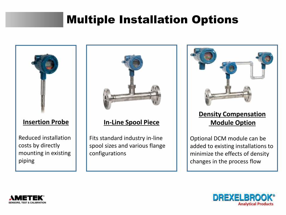
Multiple Installation Options
In-Line Spool Piece
Fits standard industry in-line spool sizes and various flange configurations
Density CompensationModule Option
Optional DCM module can be added to existing installations to minimize the effects of density changes in the process flow
Insertion Probe
Reduced installation costs by directly mounting in existing piping

Water Cut Monitor Applications
• LACT Skids (Lease Automatic Custody Transfer)• Pipeline Loading (Transfer of petroleum products from loading sites)• Truck Unloading Stations (Remote oil & water collection in upstream O&G)• Dehydration Equipment (Separators/Heater Treaters)• Lube Oil Systems (Bearing protection)• Pump Protection Systems
Heater Treater
LACT Skid
Oil-Water Separator
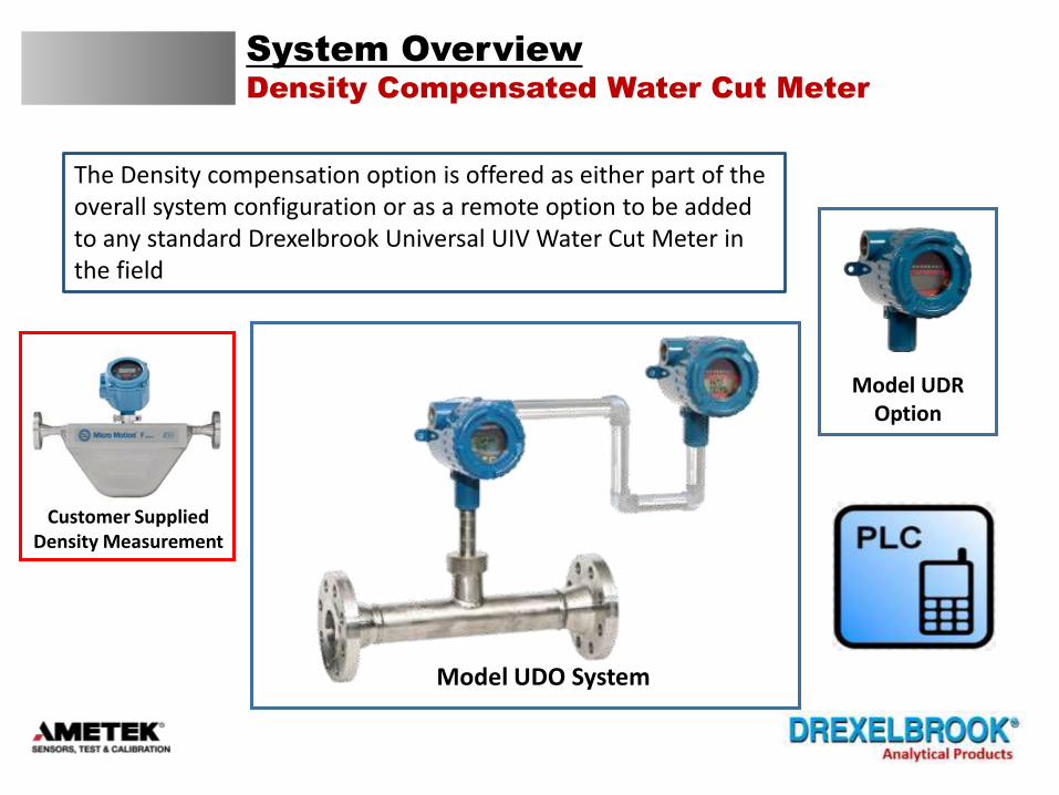
System Overview
Density Compensated Water Cut Meter
The Density compensation option is offered as either part of the overall system configuration or as a remote option to be added to any standard Drexelbrook Universal UIV Water Cut Meter in the field
Model UDO System
Model UDROption
Customer Supplied Density Measurement

Benefits of Temperature & Density
Compensation
• Minimizes the need to recalibrate the cut monitor between truck loads at remote collection sites Minimize Recalibrations Lower Downtime Faster Load/Unload Cycles
• More repeatable performance load to load insuring accuracy of the custody transfer
• Minimize diverts on LACT installations
• Stability of the measurement is guaranteed over a wide temperature range
• Up to 50% better measurement performance vs standard water cut monitors
Up to 50% Increase in Accuracy

Specifications UIV CM
Model UDO System or Model UDR Retrofit
Density Compensated Water Cut Meter
Technology RF Admittance / Capacitance
Supply Voltage 19-30VDC, 4-wire system
Output/Digital Protocol 4-20mA, HART Compatible with HART® 7
Accuracy and Resolution Water CutRange Variance % wc* Resolution** 0 to 1% +/- 0.03 0.0002 0 to 5% +/- 0.04 0.0009
Load Resistance Maximum 550 ohms at 24 VDC Minimum 250 ohms for HART protocol
Ambient Temperature -40°C to 75°C (-40°F to 167°F)
Process Temperature (Compensated)Up 232°C (450°F) – Transmitter will compensate for the effects of temperature when the water is in liquid state (Eg 0oC to 100oC at ambient pressure)
* The measurement accuracy of an inline, dynamic water cut measurement is dependent upon many process variables including: oil dielectric consistency, fluid velocity at the sample point, mounting geometry and homogeneity of the oil/water emulsion. The values above represent nominal water cut measurement variances for a properly installed sensor under consistent measurement point conditions. ** The smallest water cut step that the instrument can resolve
Process Pressure Up 103 bar (1,500 psi), probe dependent
Density (Compensated)Transmitter will compensate for the effects of changing density in the process flow
System or Module OptionThe density compensation module (DCM) is offered as part of the “UDO” System configuration or it can be purchased as a remote module option “UDR” to be added to any standard Drexelbrook water cut meter in the field
Relay OutputSPST Relay, 5A/30 VDC; 5A/250 VACMax Switching Capacity: 150W, 2000 VAMax Contact Load (DC): 100mA @ 12 VDC
Process Connection NPT, ANSI, and more upon request
Remote Configuration for UDR Retrofit ModuleConsult factory for max cable length for remote configuration
Response Time 350 msec nominal (no damping applied) 1-90 seconds programmable damping time
Supply Voltage Effect : 0.2% of full scale max
Start-Up Time : < 12 seconds
Configuration and Calibration Standard LCD display and keypad are built-in STExplorer™ PC-based software (free download)
Emission and Surge Protection Compliant with IEC6100-4.2, 3, 4, 6, 8 Compliant with CISPR11 Group I, Class B
Approvals Intrinsically Safe (IS) Explosion Proof (XP) without IS barrier FM, FMc, ATEX, IECExCE Mark

Ordering Information
Model UDO System
Density Compensated Water Cut Meter System
U
D0
1
0
9
A
B
3
4
5
0
1
0
1
0
1
000
XXX
ZZZ
0
A
B
F
G
Z
U DO 1 0 9 3 0 0 0 - XXX - A
IECEx d with Density Cut Monitor
Base Model Number
Universal IV Base Model
System Type
Density Cut Monitor model: 100 KHz, 0° Phase
Digital Protocols
Approvals
FM/FMc XP with Density Cut Monitor
ATEX d with Density Cut Monitor
4-20mA HART
Future Use
Future Use
Electrical Connection
Surge / Noise Suppression
Integral / Remote options
Dual Seal Option
Special Software
3/4" NPT without external ground with Density Cut Monitor
M20 with external ground / Equipotential Bonding with Density Cut Monitor
3/4" NPT with external ground / Equipotential Bonding with Density Cut Monitor
No additional filtering required
Signal RFI (Integral or Remote)
Remote configuration
Without Dual Seal Option
With Dual Seal Option
Remote system
Sensing Element
Part Number Example
Heavy Oil 0 to 1%
Heavy Oil 0 to 5%
Special Software
None
Integral
Consult Factory for All Probe Configuration Options
Special Sensing Element
Light Oil 0 to 1%
Light Oil 0 to 5%

Ordering Information
Model UDR Retrofit Module
Density Compensated Water Cut Meter Retrofit
Note: Cut monitor must be set to range 1 for all retrofit installations
U
DR
1
0
9
A
B
3
4
5
0
1
0
000
0
U DR 1 0 9 3 0 1 0 - 000 - 0
Base Model Number
Universal IV Base Model
System Type
DR=Density Cut Monitor model: 100 KHz, 0° Phase, Retrofit
Surge / Noise Suppression
Digital Protocols
Approvals
FM/FMc XP with Density Cut Monitor
ATEX d with Density Cut Monitor
IECEx d with Density Cut Monitor
Electrical Connection
3/4" NPT without external ground with Density Cut Monitor
M20 with external ground / Equipotential Bonding with Density Cut Monitor
3/4" NPT with external ground / Equipotential Bonding with Density Cut Monitor
4 Wire 4-20mA w/HART
Future Use
Future Use
Special Software
None
Sensing Element
None
No additional filtering required
Integral / Remote options
Remote Only for Retrofit Module
Dual Seal Option
None

Typical Installation of DCM System

Typical Wiring of DCM System
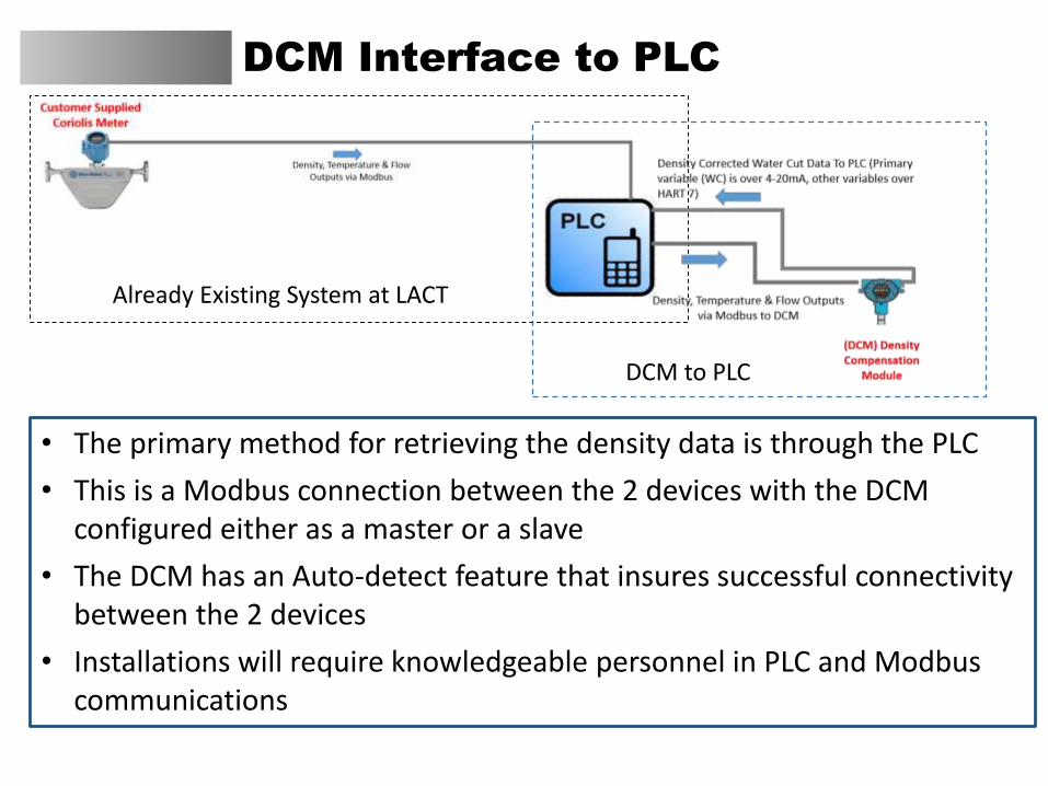
DCM Interface to PLC
• The primary method for retrieving the density data is through the PLC
• This is a Modbus connection between the 2 devices with the DCM configured either as a master or a slave
• The DCM has an Auto-detect feature that insures successful connectivity between the 2 devices
• Installations will require knowledgeable personnel in PLC and Modbus communications
Already Existing System at LACT
DCM to PLC

System Configuration
Keypad or STExplorerTM
(PC Utility Software)
There are two ways to configure and calibrate the Drexelbrook Cut Monitor system. Via the onboard display keypad or through the STExplorerTM PC software.
1. To use the onboard keypad customers must follow the instructions in the manual. The menu tree and configuration menu tables will guide you through display prompts to make changes.
2. STExplorerTM provides a simple way to configure and calibrate the Drexelbrook cut monitor system using a PC.
STExplorer
PC Utility Software
STExplorerTM is a free PC software utility designed by AMETEK to provide connectivity and configuration functionality for the Drexelbrook IV Cut Monitor with the Density Compensation Module (DCM). STExplorerTM is the successor to HRTWin. It will also be used for firmware updates to the DCM (Bootloader Capability).
Minimum Hardware RequirementsOperating System: Windows 7 or greaterCPU: Pentium Processor at 1 GHZRAM: 1 GBHard Drive: 25 MB available disk space
Download the Beta version of the STExplorerTM files from the Drexelbrook.com website. Follow the Software Download links and select STExplorerTM Installer Files. Once the files are relocated to your PC, run stexplorer.exe and follow the onscreen instructions.

STExplorer
Using the PC Software
Using the software is a simple 4 step process.
1. Add your device (provides a communication connection)
2. Select the Variable Handler Interface
3. Select & load the appropriate list for whatever functionality you want to perform
4. Read and write data into the DCM as required to measure, analyze, calibrate or configure the device

Universal IV (BS&W) with Density Comp
Value Proposition
• Density compensation in the water cut measurement improves ROI
• Improved accuracy: Up to 50% better measurement performance vs standard water cut monitors
Minimize Need for Re-calibration Lower Downtime Faster Load/Unload Cycles
• More repeatable performance load to load insuring accuracy of the custody transfer
• Minimize diverts on LACT installations
• No worries: The stability of the measurement is insured over a wide temperature and density range


