Embed Size (px)
Citation preview
Suranaree University of Technology Jan-Mar 2007
Rolling of metalsRolling of metals
• Introduction/objectives
• Rolling mills
• Classification of rolling processes
• Hot rolling
• Cold rolling
• Forces and geometry relationships in rolling
• Simplified analysis of rolling load: Rolling variables
• Problems and defects in rolled products
• Rolling-mill control
• Theories of cold rolling
• Theories of hot rolling
• Torque and power
Chapter 3
Subjects of interest
Tapany Udomphol

Suranaree University of Technology Jan-Mar 2007
ObjectivesObjectives
• This chapter provides information on different types of metal
rolling processes which can also be divided in to hot and cold
rolling process.
• Mathematical approaches are introduced for the
understanding of load calculation in rolling processes.
• Finally identification of defects occurring during and its
solutions are included.
Tapany Udomphol
Suranaree University of Technology Jan-Mar 2007
IntroductionIntroduction-- Definition of rolling processDefinition of rolling process
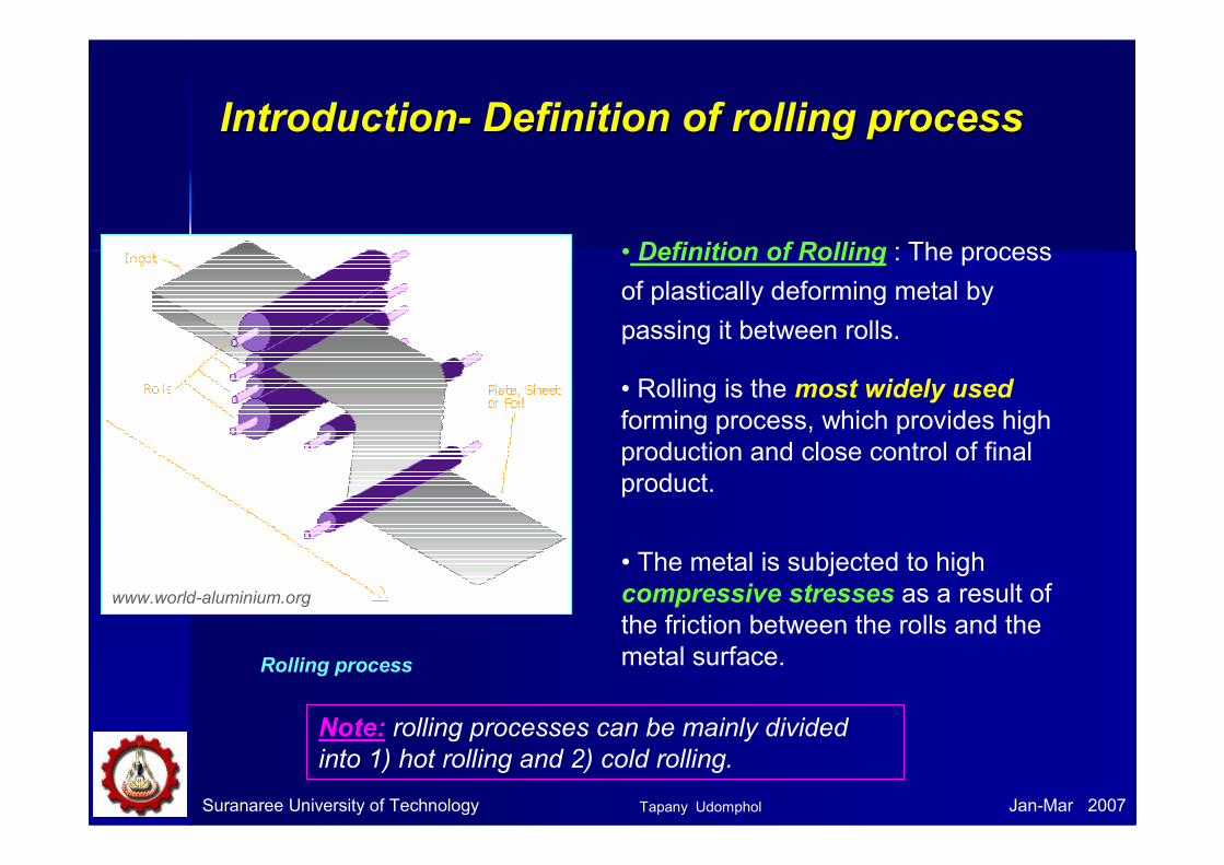
• Definition of Rolling : The process
of plastically deforming metal by
passing it between rolls.
• Rolling is the most widely used
forming process, which provides high
production and close control of final
product.
• The metal is subjected to high
compressive stresses as a result of
the friction between the rolls and the
metal surface. Rolling process
www.world-aluminium.org
Note: rolling processes can be mainly divided
into 1) hot rolling and 2) cold rolling.
Tapany Udomphol
Suranaree University of Technology Jan-Mar 2007
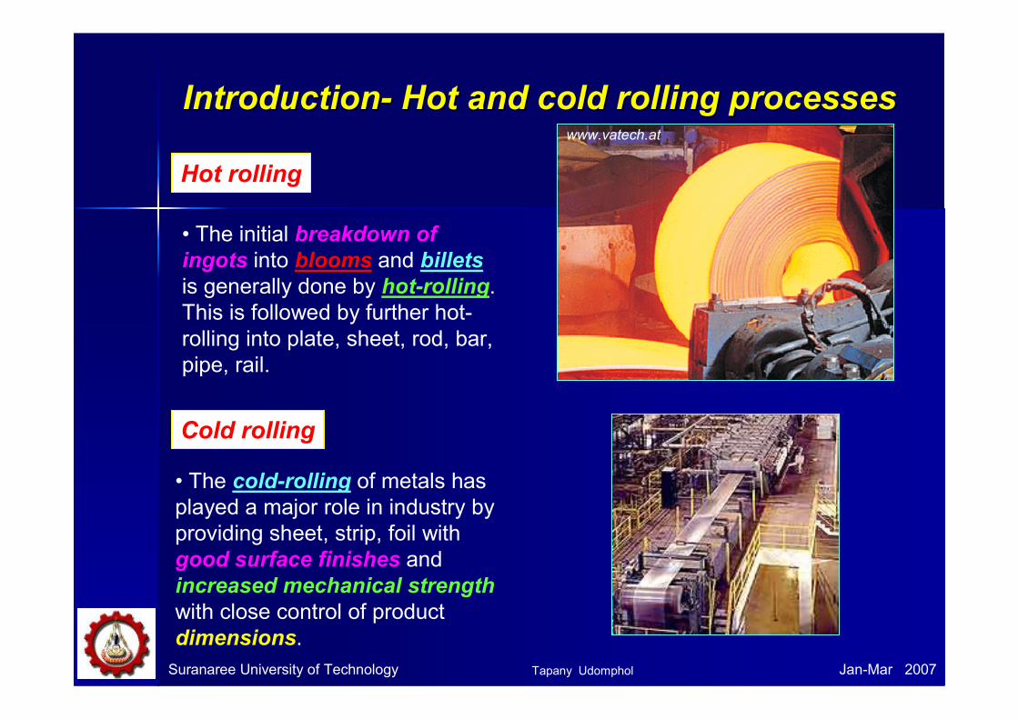
IntroductionIntroduction-- Hot and cold rolling processesHot and cold rolling processes
• The initial breakdown of
ingots into blooms and billets
is generally done by hot-rolling.
This is followed by further hot-
rolling into plate, sheet, rod, bar,
pipe, rail.
Hot rolling
Cold rolling
• The cold-rolling of metals has
played a major role in industry by
providing sheet, strip, foil with
good surface finishes and
increased mechanical strength
with close control of product
dimensions.
www.vatech.at
Tapany Udomphol

Suranaree University of Technology Jan-Mar 2007
Rollforming machine
Sheet rolling machines
Rolled strips
Tapany Udomphol

Suranaree University of Technology Jan-Mar 2007
Terminology
• Bloom is the product of first breakdown of ingot
(cross sectional area > 230 cm2).
• Billet is the product obtained from a further reduction by hot rolling
(cross sectional area > 40x40 mm2).
• Slab is the hot rolled ingot
(cross sectional area > 100 cm2 and with a width ≥≥≥≥ 2 x thickness).
Semi-
finished
products
• Plate is the product with a thickness > 6 mm.
• Sheet is the product with a thickness < 6 mm and width > 600 mm.
• Strip is the product with a thickness < 6 mm and width < 600 mm.
Mill
products
Further
rolling
steps
Bloom Billet Slap
Plate Sheet Strip
Tapany Udomphol

Mill rolls
Mill rolls
Rolls
Suranaree University of Technology Jan-Mar 2007Tapany Udomphol

Suranaree University of Technology Jan-Mar 2007
Cantilever mill roll Tube mill roll Universal roll
Ring rolls
• Ring rolls are used for tube rolling,
ring rolling.
• Ring rolls are made of spheroidized
graphite bainitic and pearlitic matrix or
alloy cast steel base.
Tapany Udomphol

Suranaree University of Technology Jan-Mar 2007
Typical arrangement of rollers for rolling mills
Two-high mill, pullover
Two-high mill, reversing
Three-high mill
Four-high mill
Cluster mill or
Sendzimir mill
The stock is
returned to the
entrance for
further reduction.
The work can be
passed back and forth
through the rolls by
reversing their
direction of rotation.
Consist of upper and
lower driven rolls and
a middle roll, which
rotates by friction.
Small-diameter rolls
(less strength &
rigidity) are
supported by
larger-diameter
backup rolls
Each of the work
rolls is supported
by two backing
rolls.
Tapany Udomphol

Suranaree University of Technology Jan-Mar 2007
Continuous rolling
• Use a series of rolling mill and
each set is called a stand.
• The strip will be moving at
different velocities at each
stage in the mill.
• The uncoiler and windup reel not only feed the stock into the rolls and coiling up
the final product but also provide back tension and front tension to the strip.
• The speed of each set of rolls is synchronised so that the input speed of
each stand is equal to the output speed of preceding stand.
A four stand continuous mill or tandem mil.
σσσσfσσσσb
Typical arrangement of rollers for rolling mills
Tapany Udomphol

Planetary mill• Consist of a pair of heavy backing rolls
surrounded by a large number of planetary rolls.
• Each planetary roll gives an almost constant
reduction to the slab as it sweeps out a circular
path between the backing rolls and the slab.
• As each pair of planetary rolls ceases to have
contact with the work piece, another pair of rolls
makes contact and repeat that reduction.
• The overall reduction is the summation of a
series of small reductions by each pair of rolls.
Therefore, the planetary mill can hot reduces a
slab directly to strip in one pass through the mill.
Suranaree University of Technology Jan-Mar 2007
• The operation requires feed rolls to introduce the
slab into the mill, and a pair of planishing rolls on
the exit to improve the surface finish.
Typical arrangement of rollers for rolling mills
Tapany Udomphol
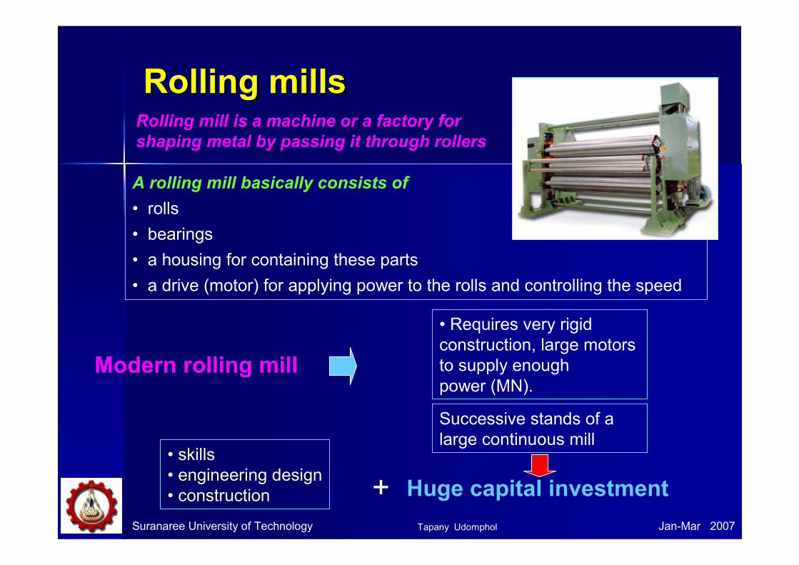
Rolling millsRolling mills
A rolling mill basically consists of
• rolls
• bearings
• a housing for containing these parts
• a drive (motor) for applying power to the rolls and controlling the speed
• Requires very rigid
construction, large motors
to supply enough
power (MN).
Successive stands of a
large continuous mill
Modern rolling mill
Huge capital investment+
• skills
• engineering design
• construction
Suranaree University of Technology Jan-Mar 2007
Rolling mill is a machine or a factory for
shaping metal by passing it through rollers
Tapany Udomphol

Suranaree University of Technology Jan-Mar 2007
Different types of rolling processes
• Continuous rolling
• Transverse rolling
• Shaped rolling or section rolling
• Ring rolling
• Powder rolling
• Continuous casting and hot rolling
• Thread rolling
There are different types of rolling processes as listed below;
Tapany Udomphol
Suranaree University of Technology Jan-Mar 2007
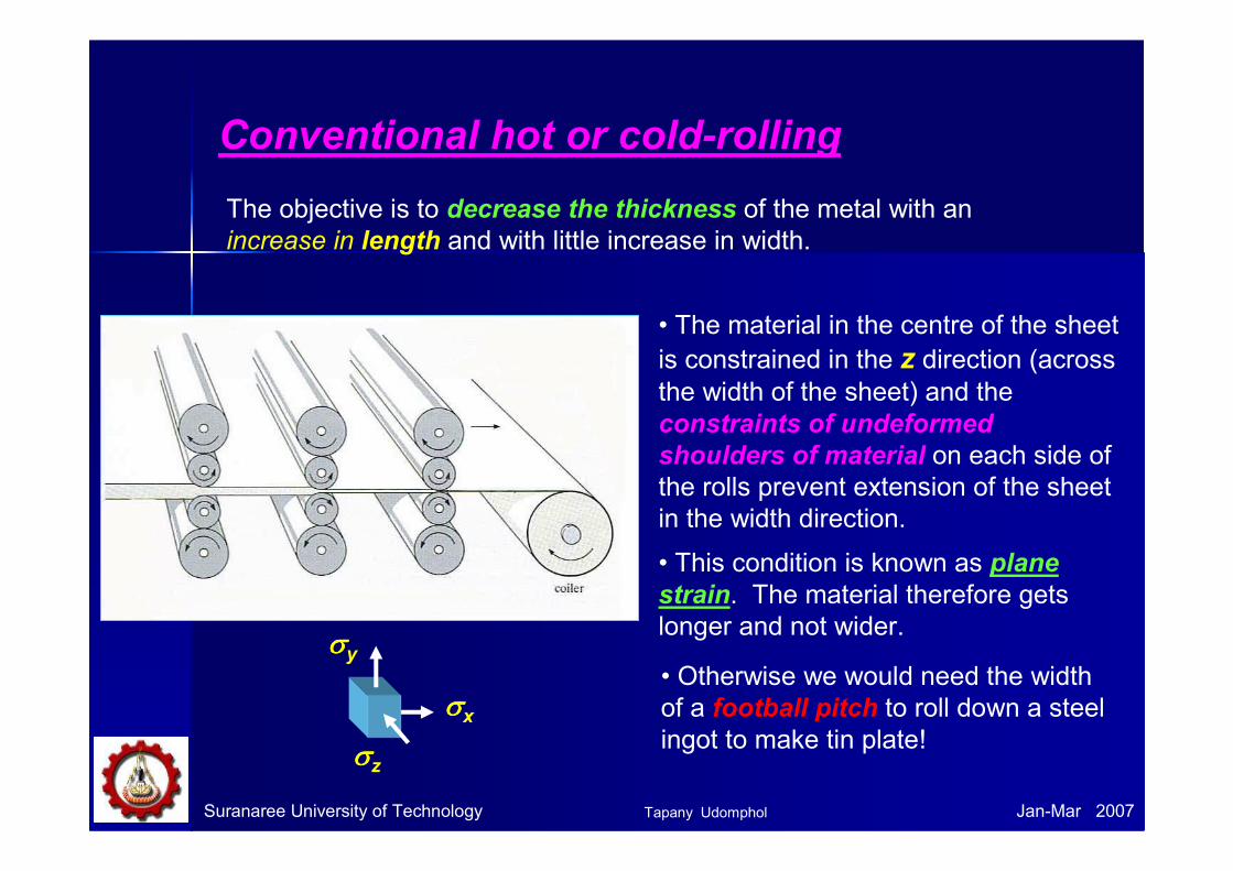
Conventional hot or cold-rolling
The objective is to decrease the thickness of the metal with an
increase in length and with little increase in width.
• The material in the centre of the sheet
is constrained in the z direction (across the width of the sheet) and the
constraints of undeformed
shoulders of material on each side of
the rolls prevent extension of the sheet
in the width direction.
• This condition is known as plane
strain. The material therefore gets
longer and not wider.
• Otherwise we would need the width
of a football pitch to roll down a steel
ingot to make tin plate!
σσσσy
σσσσz
σσσσx
Tapany Udomphol

Transverse rolling
• Using circular wedge rolls.
• Heated bar is cropped to length and
fed in transversely between rolls.
• Rolls are revolved in one direction.
Suranaree University of Technology Jan-Mar 2007Tapany Udomphol
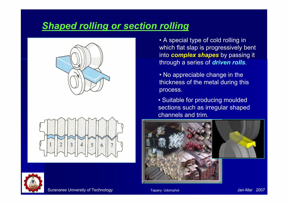
Shaped rolling or section rolling
Suranaree University of Technology Jan-Mar 2007
• A special type of cold rolling in
which flat slap is progressively bent
into complex shapes by passing it
through a series of driven rolls.
• No appreciable change in the
thickness of the metal during this
process.
• Suitable for producing moulded
sections such as irregular shaped
channels and trim.
Tapany Udomphol

Shaped rolling or section rolling
Suranaree University of Technology Jan-Mar 2007
A variety of sections can be produced by roll forming process using a
series of forming rollers in a continuous method to roll the metal sheet to
a specific shape
- construction materials,
- partition beam
- ceiling panel
- roofing panels.
- steel pipe
- automotive parts
- household appliances
- metal furniture,
- door and window frames
- other metal products.
Applications:
www.formtak.com
A variety of rolled sections
Tapany Udomphol
Suranaree University of Technology Jan-Mar 2007
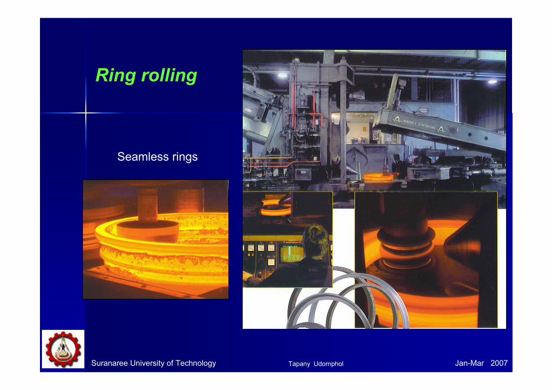
Seamless rings
Ring rolling
Tapany Udomphol
Suranaree University of Technology Jan-Mar 2007
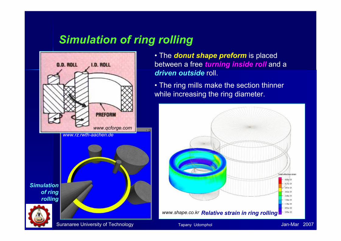
Simulation of ring rolling
www.rz.rwth-aachen.de
Simulation
of ring
rolling
Relative strain in ring rollingwww.shape.co.kr
• The donut shape preform is placed
between a free turning inside roll and a
driven outside roll.
• The ring mills make the section thinner
while increasing the ring diameter.
www.qcforge.com
Tapany Udomphol

Suranaree University of Technology Jan-Mar 2007
Seamless ring rolling
Tapany Udomphol

Suranaree University of Technology Jan-Mar 2007
Powder rollingMetal powder is introduced between the rolls and compacted into a
‘green strip’, which is subsequently sintered and subjected to further
hot-working and/or cold working and annealing cycles.
Advantage :
- Cut down the initial hot-ingot breakdown step (reduced capital investment).
- Economical - metal powder is cheaply produced during the extraction process.
- Minimise contamination in hot-rolling.
- Provide fine grain size with a minimum of preferred orientation.
Tapany Udomphol

Suranaree University of Technology Jan-Mar 2007
Continuous casting and hot rolling
• Metal is melted, cast and hot rolled continuously through a series of
rolling mills within the same process.
• Usually for steel sheet production.
Tapany Udomphol
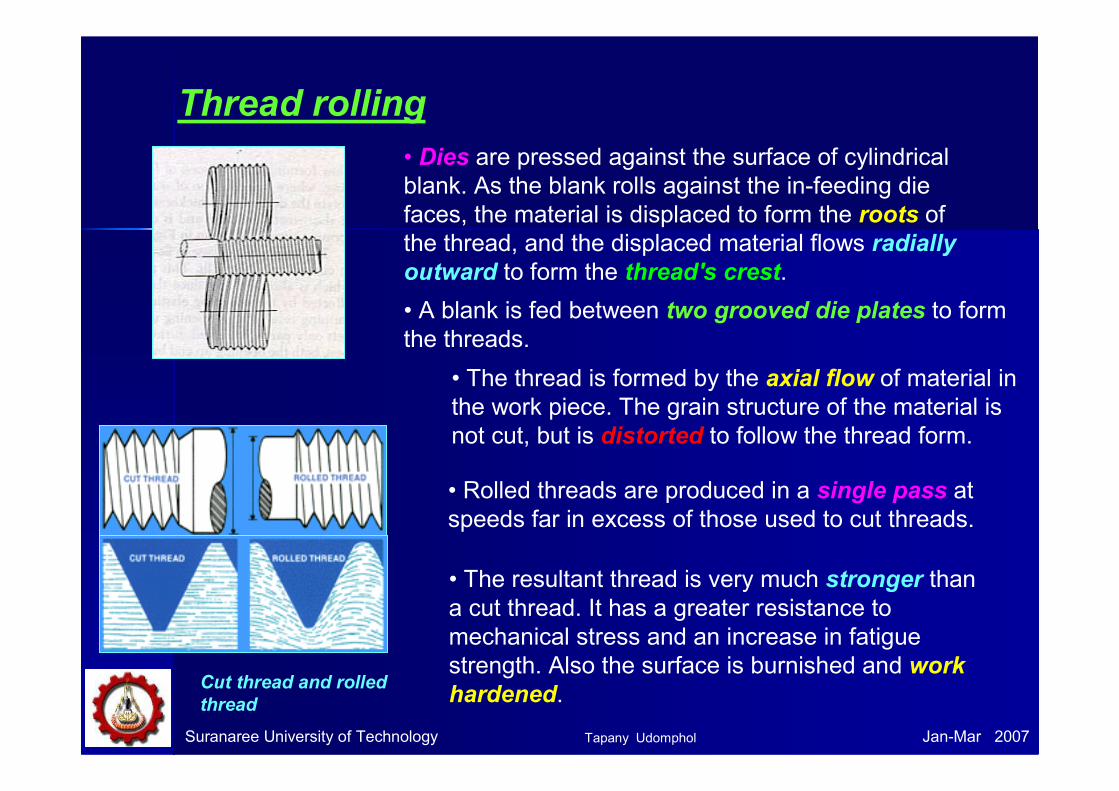
Thread rolling
• A blank is fed between two grooved die plates to form
the threads.
• The thread is formed by the axial flow of material in
the work piece. The grain structure of the material is
not cut, but is distorted to follow the thread form.
• Rolled threads are produced in a single pass at
speeds far in excess of those used to cut threads.
• The resultant thread is very much stronger than
a cut thread. It has a greater resistance to
mechanical stress and an increase in fatigue
strength. Also the surface is burnished and work
hardened.
Suranaree University of Technology Jan-Mar 2007
• Dies are pressed against the surface of cylindrical
blank. As the blank rolls against the in-feeding die
faces, the material is displaced to form the roots of
the thread, and the displaced material flows radially
outward to form the thread's crest.
Cut thread and rolled
thread
Tapany Udomphol

HotHot--rollingrolling
Suranaree University of Technology Jan-Mar 2007
• The first hot-working operation for
most steel products is done on the
primary roughing mill (blooming,
slabbing or cogging mills).
• These mills are normally two-high
reversing mills with 0.6-1.4 m diameter
rolls (designated by size).
• The objective is to breakdown the cast ingot into blooms or slabs for
subsequent finishing into bars, plate or sheet.
• In hot-rolling steel, the slabs are heated initially at 1100 -1300 oC. The
temperature in the last finishing stand varies from 700 - 900 oC, but should
be above the upper critical temperature to produce uniform equiaxed
ferrite grains.
Plate rolling
www.msm.cam.ac.uk
Tapany Udomphol

Example for hot strip mill process
Suranaree University of Technology Jan-Mar 2007
www.nzsteel.co.nz
Oxidation scale is
removed
Mill reverses after each pass (5 or 7)
and the roll gap is reduced each time
Slabs are organised
according to rolling
schedule
Red hot slab 210 mm
thick is ready for
rolling
Slab is reduced to a long strip
approx 25 mm thick
The strip is coiled and uncoiled
to make the tail end lead
Leading edge and tail
end are removedThe strip is progressively reduced
to the required thicknesses
Strip is coiled and up ended or
passed through if heavy plate
Coiled steel 1.8 to 12 mm thk
910 mm to 1550 mm wide
Plate 12 to 30 mm thick
Tapany Udomphol

Hot rolled coil produced
on strip mill
www.uksteel.org.uk
• Hot strip is coiled to reduce its
increasing length due to a reduction of
thickness.
• Reducing the complication of controlling
strips of different speeds due to
different thicknesses. (thinner section
moves faster)
• Flat plate of large thickness (10-50 mm) is
passed through different set of working
rolls, while each set consecutively reduces
thickness.
www.reverecopper.com
Suranaree University of Technology Jan-Mar 2007
Plate rolling
Tapany Udomphol

ColdCold--rollingrolling
Suranaree University of Technology Jan-Mar 2007
• The starting material for cold-rolled steel
sheet is pickled hot-rolled breakdown coil
from the continuous hot-strip mill.
• The total reduction achieved by cold-rolling generally will vary from about
50 to 90%.
• The reduction in each stand should be distributed uniformly without falling
much below the maximum reduction for each pass.
• Generally the lowest percentage reduction is taken place in the last pass
to permit better control of flatness, gage, and surface finish.
• Cold rolling is carried out under
recrystallisation temperature and
introduces work hardening.
www.williamsonir.com
Tapany Udomphol
Suranaree University of Technology Jan-Mar 2007
Cold rolling mill
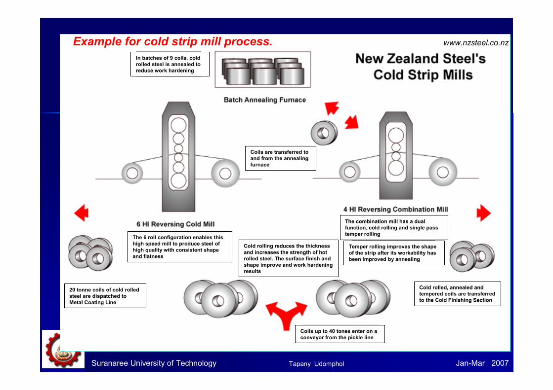
Example for cold strip mill process. www.nzsteel.co.nz
In batches of 9 coils, cold
rolled steel is annealed to
reduce work hardening
Coils are transferred to
and from the annealing
furnace
The 6 roll configuration enables this
high speed mill to produce steel of
high quality with consistent shape
and flatness
The combination mill has a dual
function, cold rolling and single pass
temper rolling
Temper rolling improves the shape
of the strip after its workability has
been improved by annealing
Cold rolled, annealed and
tempered coils are transferred
to the Cold Finishing Section
Cold rolling reduces the thickness
and increases the strength of hot
rolled steel. The surface finish and
shape improve and work hardening
results
Coils up to 40 tones enter on a
conveyor from the pickle line
20 tonne coils of cold rolled
steel are dispatched to
Metal Coating Line
Tapany Udomphol
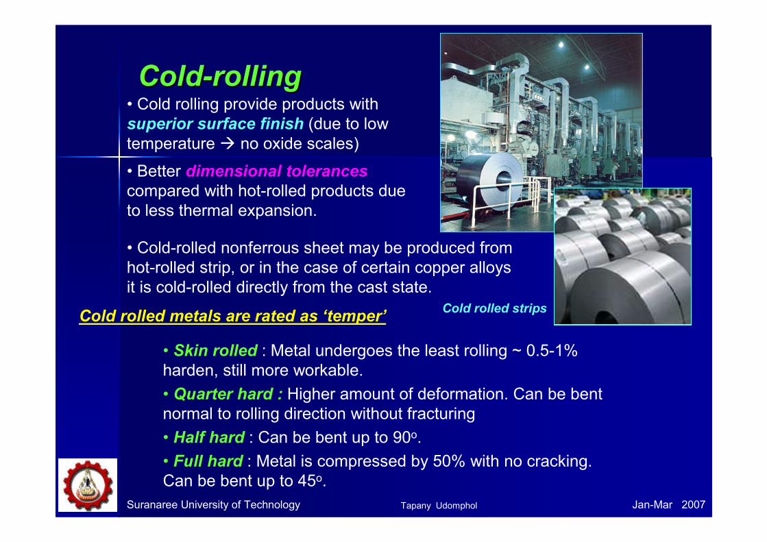
ColdCold--rollingrolling
Suranaree University of Technology Jan-Mar 2007
• Cold rolling provide products with
superior surface finish (due to low
temperature � no oxide scales)
• Better dimensional tolerances
compared with hot-rolled products due
to less thermal expansion.
• Cold-rolled nonferrous sheet may be produced from
hot-rolled strip, or in the case of certain copper alloys
it is cold-rolled directly from the cast state.
Cold rolled stripsCold rolled metals are rated as ‘temper’
• Skin rolled : Metal undergoes the least rolling ~ 0.5-1%
harden, still more workable.
• Quarter hard : Higher amount of deformation. Can be bent
normal to rolling direction without fracturing
• Half hard : Can be bent up to 90o.
• Full hard : Metal is compressed by 50% with no cracking.
Can be bent up to 45o.
Tapany Udomphol

Suranaree University of Technology Jan-Mar 2007
Fundamental concept of metal rolling1) The arc of contact between the rolls and the
metal is a part of a circle.
2) The coefficient of friction, µµµµ, is constant in theory, but in reality µµµµ varies along the arc of
contact.
3) The metal is considered to deform
plastically during rolling.
4) The volume of metal is constant before and
after rolling. In practical the volume might
decrease a little bit due to close-up of pores.
5) The velocity of the rolls is assumed to be
constant.
6) The metal only extends in the rolling direction
and no extension in the width of the
material.
7) The cross sectional area normal to the
rolling direction is not distorted.
Assumptions
hfhovo vf
Lp
Ro
o
αααα
x
x
y
y
Tapany Udomphol

Forces and geometrical relationships Forces and geometrical relationships
in rollingin rolling
Suranaree University of Technology Jan-Mar 2007
hfhovo vf
Lp
Ro
o
αααα
x
x
y
y
• A metal sheet with a thickness ho enters the rolls at the entrance plane xx with a
velocity vo.
• It passes through the roll gap and leaves
the exit plane yy with a reduced thickness
hf and at a velocity vf.
• Given that there is no increase in
width, the vertical compression of the
metal is translated into an elongation in
the rolling direction.
• Since there is no change in metal
volume at a given point per unit time
throughout the process, thereforeffoo vbhbhvvbh == …Eq.1
Where b is the width of the sheet
v is the velocity at any thickness h intermediate between ho and hf.
Tapany Udomphol
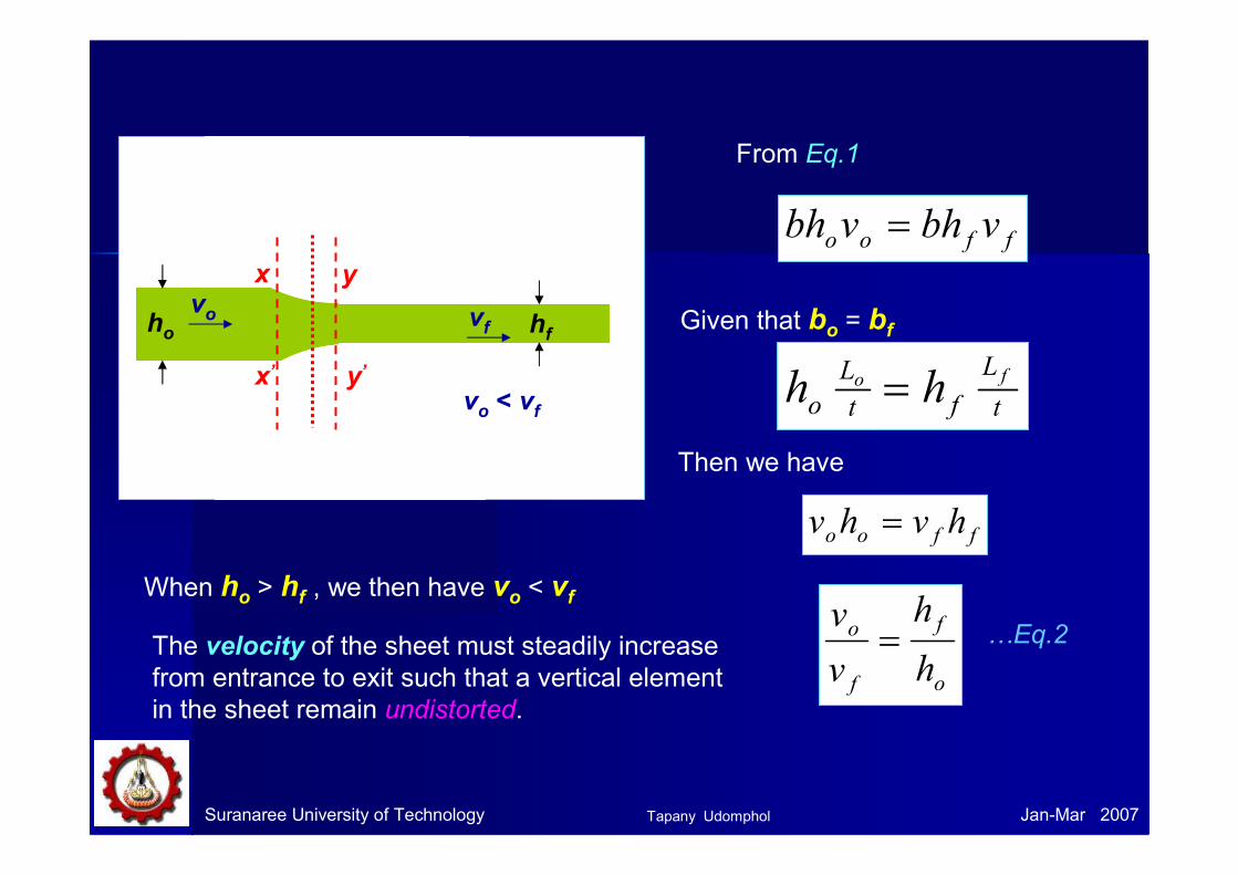
Suranaree University of Technology Jan-Mar 2007
hfhovo
R
x’
x y
y’
From Eq.1
ffoo vbhvbh =
Given that bo = bf
t
L
ft
L
o
fo hh =
Then we have
ffoo hvhv =
o
f
f
o
h
h
v
v= …Eq.2
vf
vo < vf
When ho > hf , we then have vo < vf
The velocity of the sheet must steadily increase
from entrance to exit such that a vertical element
in the sheet remain undistorted.
Tapany Udomphol

Suranaree University of Technology Jan-Mar 2007
• At only one point along the surface of contact between the roll and the
sheet, two forces act on the metal: 1) a radial force Pr and 2) a tangential
frictional force F.
• Between the entrance plane (xx) and the neutral point the sheet is
moving slower than the roll surface,
and the tangential frictional force,
F, act in the direction (see Fig) to
draw the metal into the roll.
• On the exit side (yy) of the neutral point, the sheet moves faster than
the roll surface. The direction of the
frictional fore is then reversed and
oppose the delivery of the sheet
from the rolls.
• If the surface velocity of the roll vr equal to the velocity of the sheet, this
point is called neutral point or no-slip point. For example, point N.
PrF
θθθθαααα
x
y
x y
N point : vroll = vsheet
N
ββββ Friction acts in
opposite directions
Tapany Udomphol

Pr is the radial force, with a vertical
component P (rolling load - the load with
which the rolls press against the metal).
The specific roll pressure, p, is the rolling
load divided by the contact area.
pbL
Pp = …Eq.3
Where b is the width of the sheet.
Lp is the projected length of the arc of contact.
( ) ( ) ( )[ ]
hRL
hhRhh
hhRL
p
fo
fo
fop
∆≈
−≈
−−−= 21
212
4…Eq.4
Suranaree University of Technology Jan-Mar 2007Tapany Udomphol

Suranaree University of Technology Jan-Mar 2007
• The distribution of roll pressure
along the arc of contact shows that the
pressure rises to a maximum at the
neutral point and then falls off.
• The pressure distribution does not
come to a sharp peak at the neutral
point, which indicates that the neutral
point is not really a line on the roll
surface but an area.
hfhovo
BA
p
N
R
Friction hill in rolling• The area under the curve is
proportional to the rolling load.
• The area in shade represents the
force required to overcome
frictional forces between the roll
and the sheet.
• The area under the dashed line
AB represents the force required to
deform the metal in plane
homogeneous compression.
Tapany Udomphol

Suranaree University of Technology Jan-Mar 2007
Roll bite condition For the workpiece to enter the throat
of the roll, the component of the
friction force must be equal to or
greater than the horizontal
component of the normal force.
αα sincos rPF ≥
ααα
tancos
sin≥≥
rP
F
But we know rPF µ=
αµ tan=Therefore
Prsineαααα
PrF
Fcosαααα
αααα
αααααααα
F is a tangential friction force
Pr is radial force
…Eq.5
• If tan αααα > µµµµ, the workpiece cannot be drawn.• If µµµµ = 0, rolling cannot occur.
The angle of
bite or the angle
of contact
Tapany Udomphol
Suranaree University of Technology Jan-Mar 2007
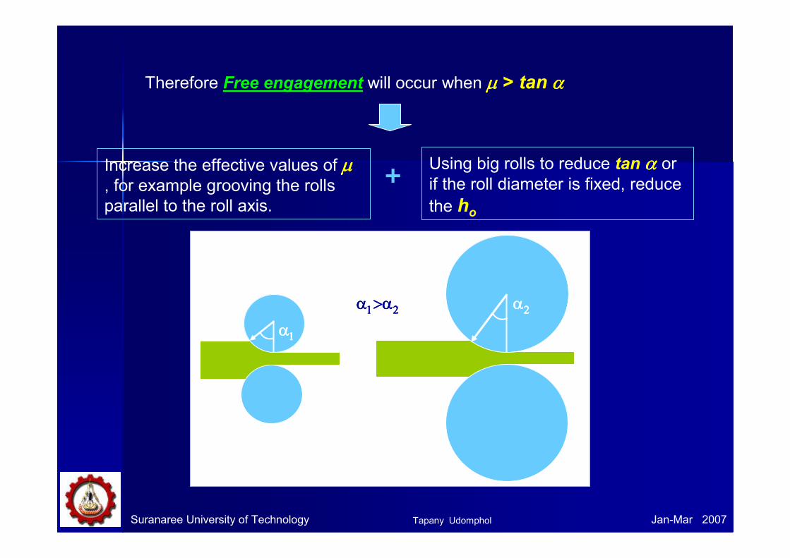
Therefore Free engagement will occur when µµµµ > tan αααα
Increase the effective values of µµµµ, for example grooving the rolls
parallel to the roll axis.
Using big rolls to reduce tan αααα or
if the roll diameter is fixed, reduce
the ho
+
αααα1111
αααα2222αααα1111>α>α>α>α2222
Tapany Udomphol
Suranaree University of Technology Jan-Mar 2007
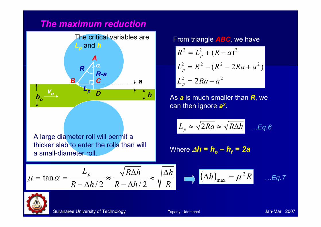
From triangle ABC, we have
22
2222
222
2
)2(
)(
aRaL
aRaRRL
aRLR
p
p
p
−=
+−−=
−+=
As a is much smaller than R, we
can then ignore a2.
hRRaLp ∆≈≈ 2
Where ∆∆∆∆h = ho – hf = 2a
…Eq.6
αααα
a
h
A
B CLp
RR-a
Dvoho
The critical variables are
Lp and h
A large diameter roll will permit a
thicker slab to enter the rolls than will
a small-diameter roll.
R
h
hR
hR
hR
Lp ∆≈
∆−∆
≈∆−
==2/2/
tanαµ …Eq.7( ) Rh 2
max µ=∆
The maximum reduction
Tapany Udomphol

Problem with roll flattening
When high forces generated in rolling are transmitted to the workpiece through
the rolls, there are two major types of elastic distortions:
1) The rolls tends to bend along their length because the workpiece tends to
separate them while they are restrained at their ends. � thickness
variation.
2) The rolls flatten in the region where they contact the workpiece. The radius
of the curvature is increased R ���� R’. (roll flattening)
According to analysis by Hitchcock,
−+=
)(1
''
fo hhb
CPRR
Where C = 16(1-νννν2)/πE = 2.16 x 10⁻¹¹ Pa-1 for steel rolls.
P’ = rolling load based on the deformed roll radius.
Suranaree University of Technology Jan-Mar 2007
R R ‘
Roll flattening
Rollling
Tapany Udomphol

Suranaree University of Technology Jan-Mar 2007
Example: Determine the maximum possible reduction for cold-
rolling a 300 mm-thick slab when µµµµ = 0.08 and the roll diameter is 600
mm. What is the maximum reduction on the same mill for hot rolling
when µµµµ = 0.5?
From Eq.7, ( ) Rh 2
max µ=∆
( ) ( ) ( ) mmh 92.130008.02
max ==∆For cold-rolling
For hot-rolling ( ) ( ) ( ) mmh 753005.02
max ==∆
Alternatively, we can use the relationship below
( )
mmh
R
hR
R
Lp
92.1
tan,sin 1
=∆
=∆
== − µαα
Tapany Udomphol
Suranaree University of Technology Jan-Mar 2007
Simplified analysis of rolling loadSimplified analysis of rolling load
The main variables in rolling are:
• The roll diameter.
• The deformation resistance of the metal as influenced by metallurgy,
temperature and strain rate.
• The friction between the rolls and the workpiece.
• The presence of the front tension and/or back tension in the plane of the
sheet.
We consider in three conditions:
1) No friction condition
2) Normal friction condition
3) Sticky friction condition
Tapany Udomphol

Suranaree University of Technology Jan-Mar 2007
In the case of no friction situation, the rolling load (P)
is given by the roll pressure (p) times the area of contact
between the metal and the rolls (bLp).
hRbpbLP op ∆== 'σ
Where the roll pressure (p) is the yield stress in plane strain
when there is no change in the width (b) of the sheet.
…Eq.8
1) No friction situation
Tapany Udomphol

( )11'_
_
−= Q
o
eQ
p
σ…Eq.9
From Eq.8,
pbLpP_
=
( )
∆−= hRbe
QP Q
o 11
3
2 _
σWe have …Eq.10
Suranaree University of Technology Jan-Mar 2007
Roll diameter Rolling load
In the normal case of friction situation in plane strain, the average
pressure p can be calculated as.
Where Q = µµµµLp/hh = the mean thickness between entry and exit from the rolls.
2) Normal friction situation
Tapany Udomphol
Suranaree University of Technology Jan-Mar 2007
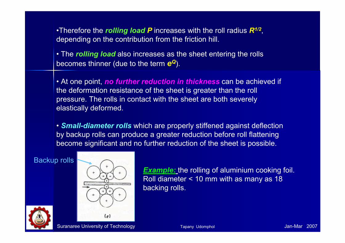
•Therefore the rolling load P increases with the roll radius R1/2,
depending on the contribution from the friction hill.
• The rolling load also increases as the sheet entering the rolls
becomes thinner (due to the term eQ).
• At one point, no further reduction in thickness can be achieved if
the deformation resistance of the sheet is greater than the roll
pressure. The rolls in contact with the sheet are both severely
elastically deformed.
• Small-diameter rolls which are properly stiffened against deflection
by backup rolls can produce a greater reduction before roll flattening
become significant and no further reduction of the sheet is possible.
Backup rolls
Example: the rolling of aluminium cooking foil.
Roll diameter < 10 mm with as many as 18
backing rolls.
Tapany Udomphol

Suranaree University of Technology Jan-Mar 2007
• Frictional force is needed to
pull the metal into the rolls and
responsible for a large portion
of the rolling load.
• High friction results in high rolling load, a steep friction hill and great
tendency for edge cracking.
• The friction varies from point to point along the contact arc of the roll.
However it is very difficult to measure this variation in µµµµ, all theory of rolling are forced to assume a constant coefficient of friction.
• For cold-rolling with lubricants, µµµµ ~ 0.05 – 0.10.
• For hot-rolling , µµµµ ~ 0.2 up to sticky condition.
Tapany Udomphol

Suranaree University of Technology Jan-Mar 2007
Example: Calculate the rolling load if steel sheet is hot rolled 30% from
a 40 mm-thick slab using a 900 mm-diameter roll. The slab is 760 mm wide.
Assume µµµµ = 0.30. The plane-strain flow stress is 140 MPa at entrance and
200 MPa at the exit from the roll gap due to the increasing velocity.
mmhhh
mmh
xh
xh
hh
fo
f
f
o
fo
12)28()40(
28
30100)40(
)()40(
%30100
=−=−=∆
=
=−
=−
mmhh
hfo
342
)28()40(
2
_
=+
=+
=
65.0)34(
12450)30.0(__
==∆
==x
h
hR
h
LQ
p µµ
MPaexitentrance
o 1702
200140
2
'''
=+
=+
=σσ
σ
( ) MNxeP
hRbeQ
P Q
o
4.13012.045.0)76.0(1)65.0(
1170
)1(1
65.0
'
=
−=
∆−= σ
From Eq.10
Tapany Udomphol

Suranaree University of Technology Jan-Mar 2007
What would be the rolling load if sticky friction occurs?
pbLpP_
=
From Eq.8,
Continuing the analogy with compression in plane strain
+=
+= 1
4
12 _
'
0
'_
h
L
h
ap
p
o σσ
MNP
xx
xP
hRb
h
hRP o
6.14
012.045.0)76.0(1034.04
012.045.0170
1
4_
'
=
+=
∆
+
∆= σ
3) Sticky friction situation
From example;
Tapany Udomphol
Suranaree University of Technology Jan-Mar 2007
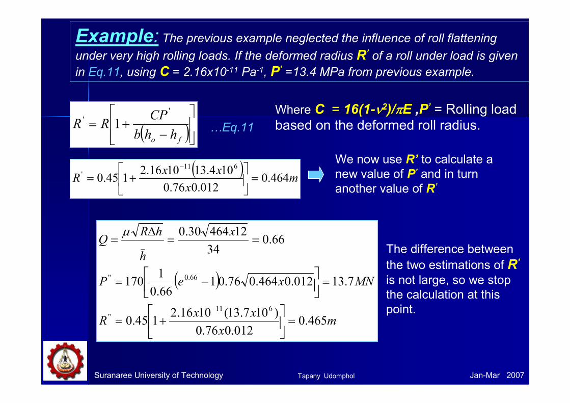
Example: The previous example neglected the influence of roll flattening
under very high rolling loads. If the deformed radius R’ of a roll under load is given
in Eq.11, using C = 2.16x10⁻¹¹ Pa-1, P’ =13.4 MPa from previous example.
( )
−+=
fo hhb
CPRR
'' 1 …Eq.11
Where C = 16(1-νννν2)/ππππE ,P’ = Rolling load
based on the deformed roll radius.
( )m
x
xxR 464.0
012.076.0
104.131016.2145.0
611' =
+=
−We now use R’ to calculate a
new value of P’ and in turn
another value of R’
( )
mx
xxR
MNxeP
x
h
hRQ
465.0012.076.0
)107.13(1016.2145.0
7.13012.0464.076.0166.0
1170
66.034
1246430.0
611''
66.0''
_
=
+=
=
−=
==∆
=
−
µThe difference between
the two estimations of R’
is not large, so we stop
the calculation at this
point.
Tapany Udomphol

Suranaree University of Technology Jan-Mar 2007
Relationship of µµµµ, rolling load and torque• We have known that the location of the neutral
point N is where the direction of the friction force
changes.
• If back tension is applied gradually to the sheet,
the neutral point N shifts toward the exit plane.
• The total rolling load P and torque MT (per unit
of width b) is given byPr
F N
θθθθαααα
ββββ
x
y
x y
N point : vroll = vsheet
Friction acts in
opposite
directions
( )
PR
M
thus
b
PRpdxRRpdx
b
M
pdxb
P
T
L
o
L
o
T
L
pp
p
=
===
=
∫∫
∫
µ
µµµ
0Where µµµµ is obtained by
measuring the torque and the
rolling load at constant roll speed
and reduction with the proper
back tension.
Lp
Tapany Udomphol

Suranaree University of Technology Jan-Mar 2007
Back and front tensions in sheetBack and front tensions in sheet• The presence of back and front
tensions in the plane of the sheet
reduces the rolling load.
• Back tension may be produced
by controlling the speed of the
uncoiler relative to the roll speed.
Back tension, σσσσb Front tension, σσσσf
σσσσ’o σσσσ’
o
σσσσ’o- σσσσb
σσσσ’o- σσσσf
p
Uncoiler Coiler
• Front tension may be created
by controlling the coiler.
• The effect of sheet tension on
reducing rolling pressure p can be
shown simply by
hohop σσσσ −=−=_
'
3
2…Eq.11
Where σσσσh = horizontal sheet tension.
• If a high enough back tension is applied,
the neutral point moves toward the roll exit
–> rolls are moving faster than the metal.
• If the front tension is used, the neutral
point will move toward the roll entrance.
• Back tension is ~ twice as
effective in reducing the rolling
load P as front tension.
Tapany Udomphol
Suranaree University of Technology Jan-Mar 2007
Problems and defects in rolled Problems and defects in rolled
productsproducts
Defects from cast ingot before rolling
• Porosity, cavity, blow hole occurred in the cast ingot will be closed up
during the rolling process.
• Longitudinal stringers of non-metallic inclusions or pearlite banding
are related to melting and solidification practices. In severe cases, these
defects can lead to laminations which drastically reduce the strength in the
thickness direction.
Defects other than cracks can result from defects introduced during the
ingot stage of production.
Tapany Udomphol
Suranaree University of Technology Jan-Mar 2007
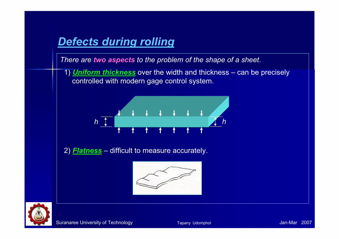
Defects during rolling
There are two aspects to the problem of the shape of a sheet.
1) Uniform thickness over the width and thickness – can be precisely
controlled with modern gage control system.
2) Flatness – difficult to measure accurately.
h h
Tapany Udomphol
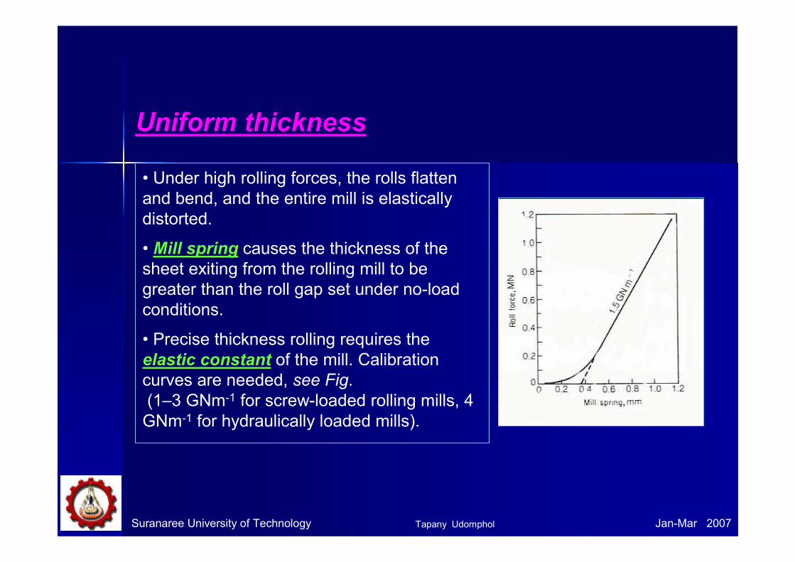
• Under high rolling forces, the rolls flatten
and bend, and the entire mill is elastically
distorted.
• Mill spring causes the thickness of the
sheet exiting from the rolling mill to be
greater than the roll gap set under no-load
conditions.
• Precise thickness rolling requires the
elastic constant of the mill. Calibration
curves are needed, see Fig.
(1–3 GNm-1 for screw-loaded rolling mills, 4
GNm-1 for hydraulically loaded mills).
Uniform thickness
Suranaree University of Technology Jan-Mar 2007Tapany Udomphol

Suranaree University of Technology Jan-Mar 2007
• Roll flattening increases the roll pressure and eventually causes
the rolls to deform more easily than the metal.
•The limiting thickness is nearly proportional to µµµµ, R, σσσσ’o but
inversely proportional to E.
For example in steel rolls the limiting thickness is given by
8.12
'_
min
oRh
σµ= …Eq.12
In general, problems with limiting gauge can be expected when the
sheet thickness is below 1/400 to 1/600 of the roll diameter.
Tapany Udomphol
Suranaree University of Technology Jan-Mar 2007
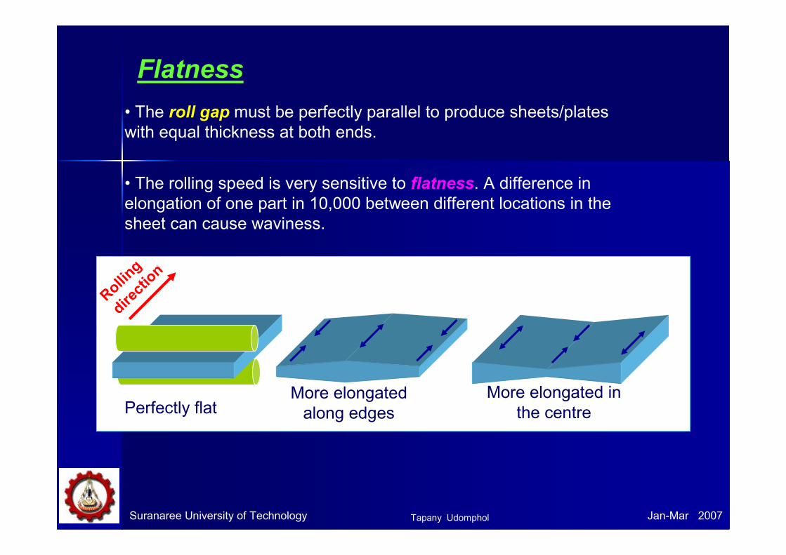
• The rolling speed is very sensitive to flatness. A difference in
elongation of one part in 10,000 between different locations in the
sheet can cause waviness.
Flatness
• The roll gap must be perfectly parallel to produce sheets/plates
with equal thickness at both ends.
Rolling
direction
Perfectly flatMore elongated
along edges
More elongated in
the centre
Tapany Udomphol
Suranaree University of Technology Jan-Mar 2007
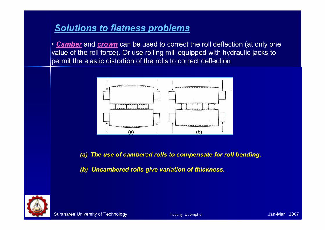
• Camber and crown can be used to correct the roll deflection (at only one
value of the roll force). Or use rolling mill equipped with hydraulic jacks to
permit the elastic distortion of the rolls to correct deflection.
(a) (b)
(a) The use of cambered rolls to compensate for roll bending.
(b) Uncambered rolls give variation of thickness.
Solutions to flatness problems
Tapany Udomphol

• Hot mill can be provided with
facilities for crown control to
improve the control of the
profile of hot strip mill.
• For example work roll
bending with continuous
variable crown and pair cross
mills.
•The roll cross angle of rolls incorporated
in a stand of each rolling mill is set at a
predetermined value beforehand.
• If there is a roll cross angle that will
enable a target sheet crown to be applied
to each sheet and the roll bender load of
each stand is adjusted on-line, thereby
effecting sheet crown control.
Suranaree University of Technology Jan-Mar 2007Tapany Udomphol
Suranaree University of Technology Jan-Mar 2007
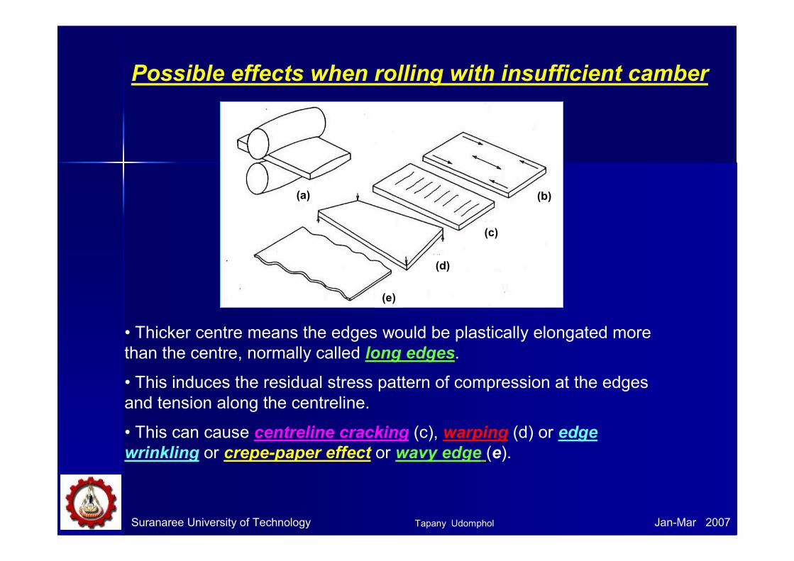
Possible effects when rolling with insufficient camber
• Thicker centre means the edges would be plastically elongated more
than the centre, normally called long edges.
• This induces the residual stress pattern of compression at the edges
and tension along the centreline.
• This can cause centreline cracking (c), warping (d) or edge
wrinkling or crepe-paper effect or wavy edge (e).
(a) (b)
(c)
(d)
(e)
Tapany Udomphol
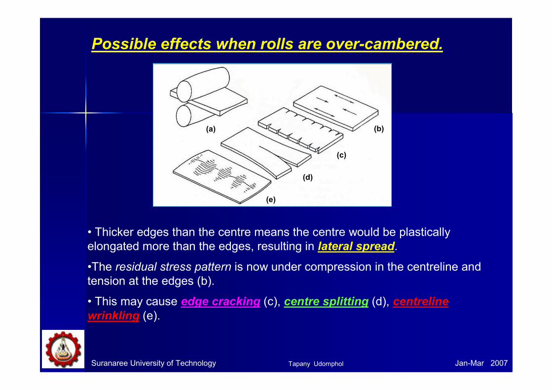
Possible effects when rolls are over-cambered.
• Thicker edges than the centre means the centre would be plastically
elongated more than the edges, resulting in lateral spread.
•The residual stress pattern is now under compression in the centreline and
tension at the edges (b).
• This may cause edge cracking (c), centre splitting (d), centreline
wrinkling (e).
(a) (b)
(c)
(d)
(e)
Suranaree University of Technology Jan-Mar 2007Tapany Udomphol

Suranaree University of Technology Jan-Mar 2007
• Shape problems are greatest when rolling in thin strip (<0.01 in)
because fractional errors in the roll gap profile increase with
decrease in thickness, producing larger internal stress.
• Thin sheet is also less resistant to buckling.
• Mild shape problems may be corrected by stretch levelling the
sheet in tension or by bend flexing the sheet in a roller-leveller,
see Fig.
two high
Material
flowwork rolls
adjustable
Roller-leveller
Tapany Udomphol

Suranaree University of Technology Jan-Mar 2007
• Edging can also be caused by inhomogeneous deformation in the
thickness direction.
• If only the surface of the workpiece is deformed (as in a light reduction on a
thick slab), the edges are concaved (a). The overhanging material is not
compressed in the subsequent step of rolling, causing this area under tensile
stress and leading to edge cracking. This has been observed in initial
breakdown of hot-rolling when h/Lp > 2
• With heavy reduction, the centre tends
to expand more laterally than the surface
to produced barrelled edges (b). This
causes secondary tensile stresses by
barrelling, which are susceptible to edge
cracking.
• Alligatoring (c) will occur when lateral
spread is greater in the centre than the
surface (surface in tension, centre in
compression) and with the presence of
metallurgical weakness along the
centreline.
Tapany Udomphol
Suranaree University of Technology Jan-Mar 2007
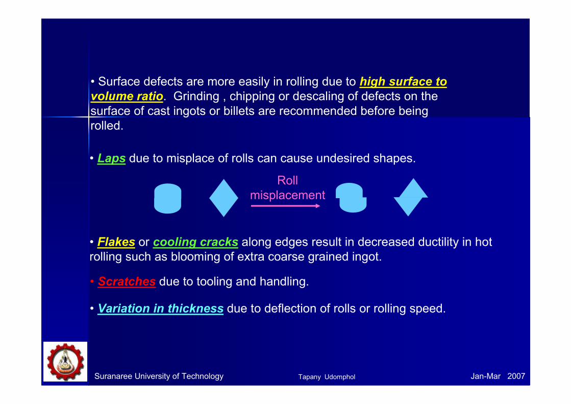
• Surface defects are more easily in rolling due to high surface to
volume ratio. Grinding , chipping or descaling of defects on the
surface of cast ingots or billets are recommended before being
rolled.
• Laps due to misplace of rolls can cause undesired shapes.
• Flakes or cooling cracks along edges result in decreased ductility in hot
rolling such as blooming of extra coarse grained ingot.
• Scratches due to tooling and handling.
• Variation in thickness due to deflection of rolls or rolling speed.
Roll
misplacement
Tapany Udomphol

Suranaree University of Technology Jan-Mar 2007
Rolling mill controlRolling mill control
• Modern continuous hot-strip and cold rolling mills operated under
automatic control provide high throughput and production rate.
• Of all the metal working processes, rolling is the best suited for the
adoption of automatic control because it is an essentially steady-state
process in which the tooling geometry (roll gap) may be changed readily
during the process.
• Automatic control in rolling such as the development of online sensors
to continuously measure sheet thickness. The most widely used
instruments are
1) flying micrometer
2) x-ray or isotope, gauges which measure thickness by monitoring
the amount of radiation transmitted through the sheet.
• More recently control procedures have been aimed at controlling strip
shape as well as thickness.
Tapany Udomphol
Suranaree University of Technology Jan-Mar 2007
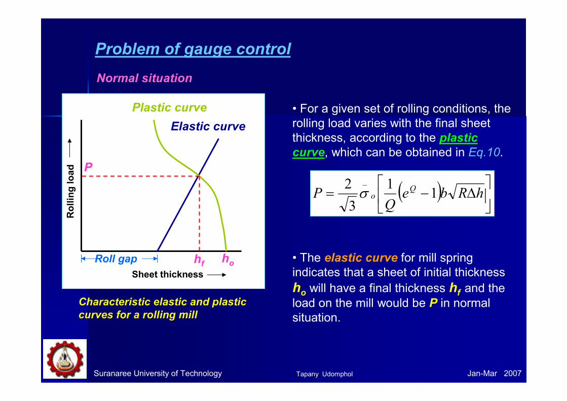
Problem of gauge control
Elastic curve
Plastic curve
P
Roll gap
Sheet thickness
Rolling load
hf ho
Characteristic elastic and plastic
curves for a rolling mill
• For a given set of rolling conditions, the
rolling load varies with the final sheet
thickness, according to the plastic
curve, which can be obtained in Eq.10.
( )
∆−= hRbe
QP Q
o 11
3
2 _
σ
• The elastic curve for mill spring
indicates that a sheet of initial thickness
ho will have a final thickness hf and the load on the mill would be P in normal
situation.
Normal situation
Tapany Udomphol
Suranaree University of Technology Jan-Mar 2007
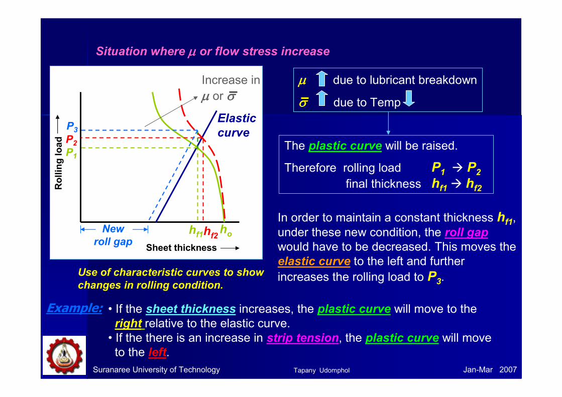
Situation where µµµµ or flow stress increase
Use of characteristic curves to show
changes in rolling condition.
The plastic curve will be raised.
Therefore rolling load P1 � P2
final thickness hf1 � hf2
µµµµ due to lubricant breakdown
σσσσ due to Temp
In order to maintain a constant thickness hf1, under these new condition, the roll gap
would have to be decreased. This moves the
elastic curve to the left and further
increases the rolling load to P3.
• If the sheet thickness increases, the plastic curve will move to the
right relative to the elastic curve.
• If the there is an increase in strip tension, the plastic curve will move
to the left.
Example:
Elastic
curve
P1
Sheet thickness
Rolling load
hf1 ho
P2
hf2New
roll gap
P3
Increase in
µµµµ or σσσσ
Tapany Udomphol

Suranaree University of Technology Jan-Mar 2007
• In a continuous hot mill, the strip thickness is measured indirectly
by measuring the rolling load and using the characteristic curve of
the mill to establish the thickness.
Thickness measurement in continuous hot mill
• The error signal is fedback to the rolling mill screws to reposition them
so as to minimise the error.
• An x-ray gauge is used after the last stand to provide an absolute
measurement of sheet gauge.
Tapany Udomphol

Suranaree University of Technology Jan-Mar 2007
Thickness measurement in continuous
cold strip mills
• Thickness is measured by x-ray
gauges while the error in the
thickness following the first stand is
usually fedback to adjust the gap
sitting on the first stand.
• Gauge control in subsequent stands
usually is achieved by controlling the
strip tension through controlling the
relative roll speed in successive stands
or the coiler speed.
• Gauge control through control of
strip tension has faster response
time than control through change in
roll setting.
sensors
Thickness gauging is achieved
by using two opposing
sensors with laser spots
aimed at opposite sides of a
target. The sensor readings
are subtracted from the sensor
separation distance to yield a
real-time thickness
measurement.
Tapany Udomphol

Suranaree University of Technology Jan-Mar 2007
Theory of cold rollingTheory of cold rollingA theory of rolling is aimed at expressing the external forces, such as
the rolling load and the rolling torque, in terms of the geometry of the
deformation and the strength properties of the material being rolled.
Assumptions
1) The arc of the contact is circular – no elastic deformation of the roll.
2) The coefficient of friction is constant at all points on the arc of contact.
3) There is no lateral spread, so that rolling can be considered a problem
in plain strain.
4) Plane vertical section remain plane: i.e., the deformation is
homogeneous.
5) The peripheral velocity of the rolls is constant
6) The elastic deformation of the sheet is negligible in comparison with the
plastic deformation.
7) The distortion-energy criterion of yielding, for plane strain, holds.
'
313
2oo σσσσ ==− Yield stress in plane
strain condition
Tapany Udomphol

Suranaree University of Technology Jan-Mar 2007
hfho
B
hh+dh
dθθθθθθθθ
o
σσσσx+dσσσσx σσσσx
θθθθ
Prcosθθ θθ
Prsinθθθθ
Pr
R dθθθθ
µµµµPrcosθθθθ
µµµµPr
µµ µµPrsin
θθ θθ
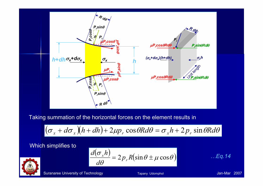
The stresses acting on an element of strip in the roll gap
• At any point of contact between the strip and the roll surface, designated
by the angle θθθθ, the stresses are the radial pressure pr and the tangential shearing stress ττττ = µµµµpr. These stresses are resolved into their horizontal and vertical components (b).
• The stress σσσσx is assumed to be uniformly distributed over the vertical
faces of the element.
Tapany Udomphol
Suranaree University of Technology Jan-Mar 2007
σσσσx+dσσσσx σσσσx
µµµµPr
µµ µµPrsin
θθ θθ
θθθθ
Prcosθθ θθ
Prsinθθθθ
Pr
R dθθθθ
µµµµPrcosθθθθ
µµ µµPr sin
θθ θθ
h+dh h
θθθθ
Prcosθθ θθ
Prsinθθθθ
Pr
R dθθθθ
µµµµPrcosθθθθ
σσσσxh
Unit length
(σσσσx+dσσσσx)(h+dh)
Pr
R dθθθθ
PrsinθθθθRdθθθθ
PrsinθθθθRdθθθθµµµµPrcosθθθθRdθθθθ
µµµµPrcosθθθθRdθθθθ
( )( ) θθσθθµσσ RdphRdpdhhd rxrxx sin2cos2 +=+++
( ) ( )θµθθ
σcossin2 ±= Rp
d
hdr
x
Taking summation of the horizontal forces on the element results in
Which simplifies to
…Eq.14
Tapany Udomphol

Suranaree University of Technology Jan-Mar 2007
( )θµ tan1mrpp =
The forces acting in the vertical direction are balanced by the specific roll
pressure p. Taking the equilibrium of forces in the vertical direction results in a relationship between the normal pressure and the radial pressure.
…Eq.14
The relationship between the normal pressure and the horizontal
compressive stress σσσσx is given by the distortion energy criterion of
yielding for plane strain.
'
313
2oo σσσσ ==−
'
oxp σσ =− …Eq.15
Where p is the greater of the two compressive principal stresses.
Tapany Udomphol
Suranaree University of Technology Jan-Mar 2007
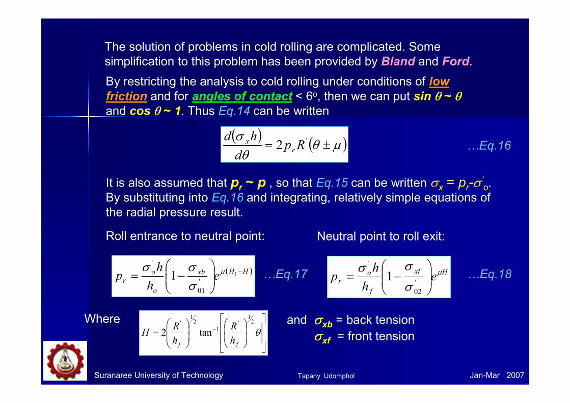
The solution of problems in cold rolling are complicated. Some
simplification to this problem has been provided by Bland and Ford.
By restricting the analysis to cold rolling under conditions of low
friction and for angles of contact < 6o, then we can put sin θθθθ ~ θθθθand cos θθθθ ~ 1. Thus Eq.14 can be written
( ) ( )µθθ
σ±= '2 Rp
d
hdr
x( ) ( )µθθ
σ±= '2 Rp
d
hdr
x…Eq.16
It is also assumed that pr ~ p , so that Eq.15 can be written σx = pr-σ’o.
By substituting into Eq.16 and integrating, relatively simple equations of
the radial pressure result.
Roll entrance to neutral point:
( )HHxb
o
or e
h
hp
−
−= 1
'
01
'
1µ
σσσ
…Eq.17
Neutral point to roll exit:
Hxf
f
o
r eh
hp µ
σ
σσ
−=
'
02
'
1 …Eq.18
Where
= − θ
21
'1
21
'
tan2ff h
R
h
RH
and σσσσxb = back tension
σσσσxf = front tension
Tapany Udomphol
Suranaree University of Technology Jan-Mar 2007
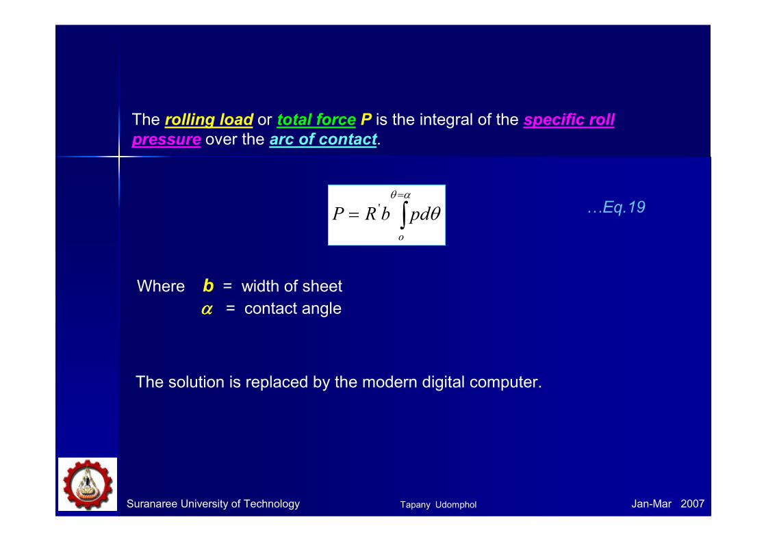
The rolling load or total force P is the integral of the specific roll
pressure over the arc of contact.
∫=
=αθ
θo
pdbRP ' …Eq.19
Where b = width of sheet
αααα = contact angle
The solution is replaced by the modern digital computer.
Tapany Udomphol

Suranaree University of Technology Jan-Mar 2007
Theory of hotTheory of hot--rollingrollingIn hot working processes, the flow stress for hot-rolling is a function of
both temperature and strain rate (speed of rolls)
Calculation of rolling load by Sims
( )[ ] pfoo QhhRbP 21' −= σ
Where Qp is a complex function of
the reduction in thickness and the
ratio R/hf. Values of Qp may be
obtained from
4lntan
4
2
1 ππ −
−
∆∆
= −
fo
n
ff
o
phh
h
h
R
h
h
h
hQ
…Eq.20
…Eq.21
Tapany Udomphol
Suranaree University of Technology Jan-Mar 2007
Torque and powerTorque and power
Torque is the measure of the force applied to a member to produce
rotational motion.
Power is applied to a rolling mill by applying a torque to the rolls and by
means of strip tension.
The power is spent principally in four ways
1) The energy needed to deform the metal.
2) The energy needed to overcome the frictional force.
3) The power lost in the pinions and power-transmission system.
4) Electrical losses in the various motors and generators.
Remarks: Losses in the windup reel and uncoiler must also be considered.
Tapany Udomphol

Suranaree University of Technology Jan-Mar 2007
hfho
R
a
P
MT = Pa
a
P
R
Schematic diagram illustrating roll torque
The total rolling load is distributed
over the arc of contact in the typical
friction-hill pressure distribution.
However the total rolling load can be
assumed to be concentrated at a
point along the act of contact at a
distance a from the line of centres of
the rolls.
The ratio of the moment arm a to the
projected length of the act of contact
Lp can be given as
hR
a
L
a
p ∆==λ …Eq.22
Where λλλλ is 0.5 for hot-rolling and 0.45 for cold-rolling.
Tapany Udomphol
Suranaree University of Technology Jan-Mar 2007
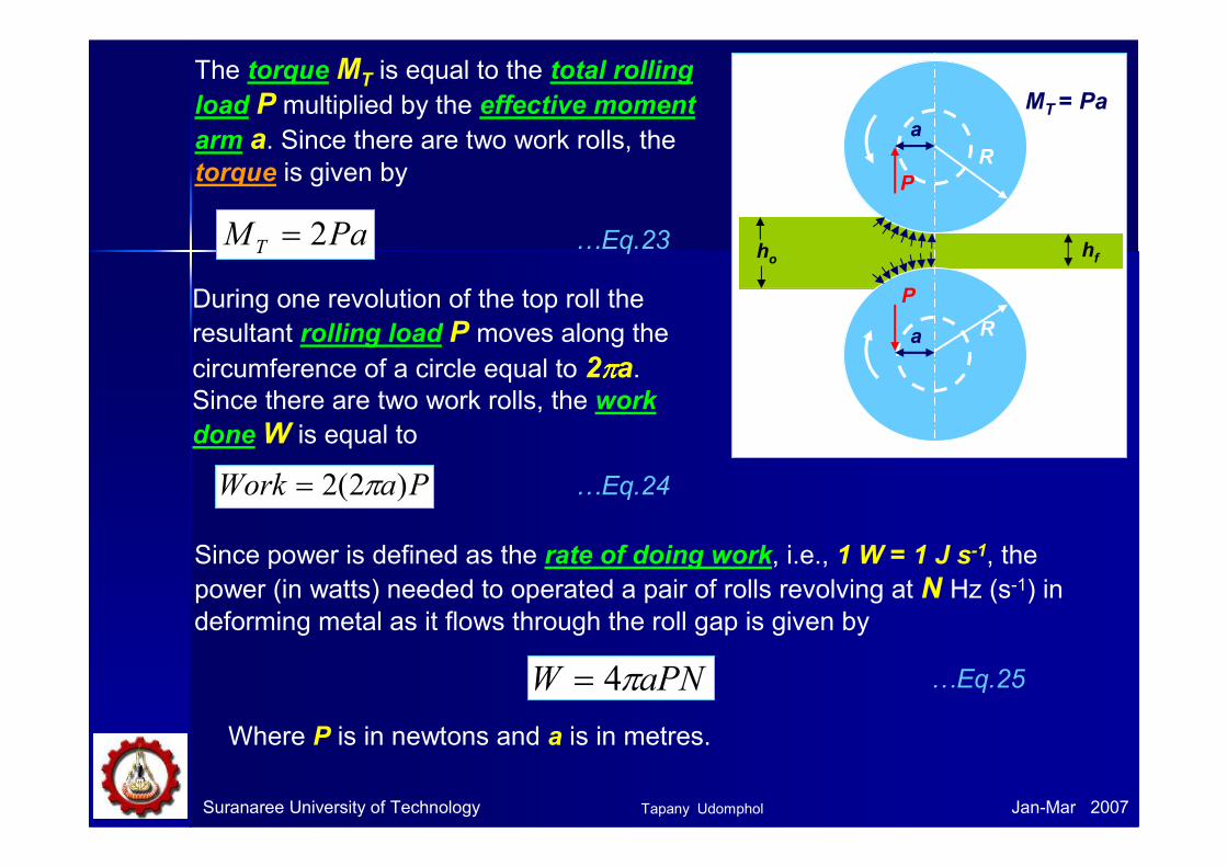
The torqueMT is equal to the total rolling
load P multiplied by the effective moment
arm a. Since there are two work rolls, the torque is given by
PaM T 2= …Eq.23 hfho
R
a
P
MT = Pa
a
P
R
During one revolution of the top roll the
resultant rolling load P moves along the
circumference of a circle equal to 2ππππa. Since there are two work rolls, the work
doneW is equal to
PaWork )2(2 π= …Eq.24
Since power is defined as the rate of doing work, i.e., 1 W = 1 J s-1, the
power (in watts) needed to operated a pair of rolls revolving at N Hz (s-1) in deforming metal as it flows through the roll gap is given by
Where P is in newtons and a is in metres.
aPNW π4= …Eq.25
Tapany Udomphol

Suranaree University of Technology Jan-Mar 2007
Example: A 300 mm-wide aluminium alloy strip is hot-rolled in thickness from
20 to 15 mm. The rolls are 1 m in diameter and operate at 100 rpm. The uniaxial
flow stress for aluminium alloy can be expressed as σσσσ = 140εεεε0.2 (MPa).
Determine the rolling load and the power required for this hot reduction.
From Eq.20 ( )[ ] pfoo QhhRbP 21' −= σ
b = 0.3 m, R = 0.5 m, ho = 0.02 m and hf= 0.015 m, we need to know σσσσ’
o and Qp.
3.3315
500
25.020
1520
288.015
20ln1
==
=−
=
=
=
fh
R
r
ε
( )MPa
n
k
n
kdk
o
n
o
n
o
n
o
912.1
288.0140
1)1(
2.0
'
1
1
1
1
' 1
1
==
+=
+==
+∫
σ
εε
εε
εεσ
ε
ε
[ ] ( ) MNP 36.25.1)015.0020.0(5.0)3.0)(91(3
221
=−=
Qp can be found
from graph(~1.5)
when reduction r and
R/hf are known.
( )( )( ) MWJsxW
sN
mxhRa
24.167.11036.2025.04
67.160/100
025.0005.05.05.05.0
16
1
==
==
==∆=
−−
−
π
Tapany Udomphol

Suranaree University of Technology Jan-Mar 2007
References
• Dieter, G.E., Mechanical metallurgy, 1988, SI metric edition,
McGraw-Hill, ISBN 0-07-100406-8.
• Edwards, L. and Endean, M., Manufacturing with materials, 1990,
Butterworth Heinemann, ISBN 0-7506-2754-9.
• Beddoes, J. and Bibbly M.J., Principles of metal manufacturing
process, 1999, Arnold, ISBN 0-470-35241-8.
• Lecture note, 2003.
• Firth Rixson leavelets.
• Metal forming processes, Prof Manas.
• Metal forming lecture, Ass Prof. P. Srichareonchai.
Tapany Udomphol