Embed Size (px)
Citation preview
1
ELECTRIC MOTOR CONTROLSOnce the proper motor is selected, understanding the many various control devices available andtheir uses and limitations becomes an important part related to reliable operation and protection ofthe motor and the personnel using the motor.
Motor Control Topics
There are four major motor control topics or categories to consider. Each of these has severalsubcategories and sometimes the subcategories overlap to some extent. Certain pieces of motorcontrol equipment can accomplish multiple functions from each of the topics or categories.
C The four categories include:
1) Starting the MotorDisconnecting MeansAcross the Line StartingReduced Voltage Starting
2) Motor ProtectionOvercurrent ProtectionOverload ProtectionOther Protection (voltage, phase, etc)Environment
3) Stopping the MotorCoastingElectrical BrakingMechanical Braking
4) Motor Operational ControlSpeed ControlReversingJoggingSequence Control
• An understanding of each of these areas is necessary to effectively apply motor controlprinciples and equipment to effectively operate and protect a motor.
2
MOTOR STARTING
All motors must have a control device to start and stop the motor called a “motor controller”.
Motor Controller
A motor controller is the actual device that energizes and de-energizes the circuit to the motor sothat it can start and stop.
• Motor controllers may include some or all of the following motor control functions:
S starting, stopping, over-current protection, overload protection, reversing, speedchanging, jogging, plugging, sequence control, and pilot light indication.
S Controllers range from simple to complex and can provide control for one motor,groups of motors, or auxiliary equipment such as brakes, clutches, solenoids, heaters,or other signals.
Motor Starter
The starting mechanism that energizes the circuit to an induction motor is called the “starter” andmust supply the motor with sufficient current to provide adequate starting torque under worst caseline voltage and load conditions when the motor is energized.
• There are several different types of equipment suitable for use as “motor starters” but onlytwo types of starting methods for induction motors:
1. Across the Line Starting2. Reduced Voltage Starting
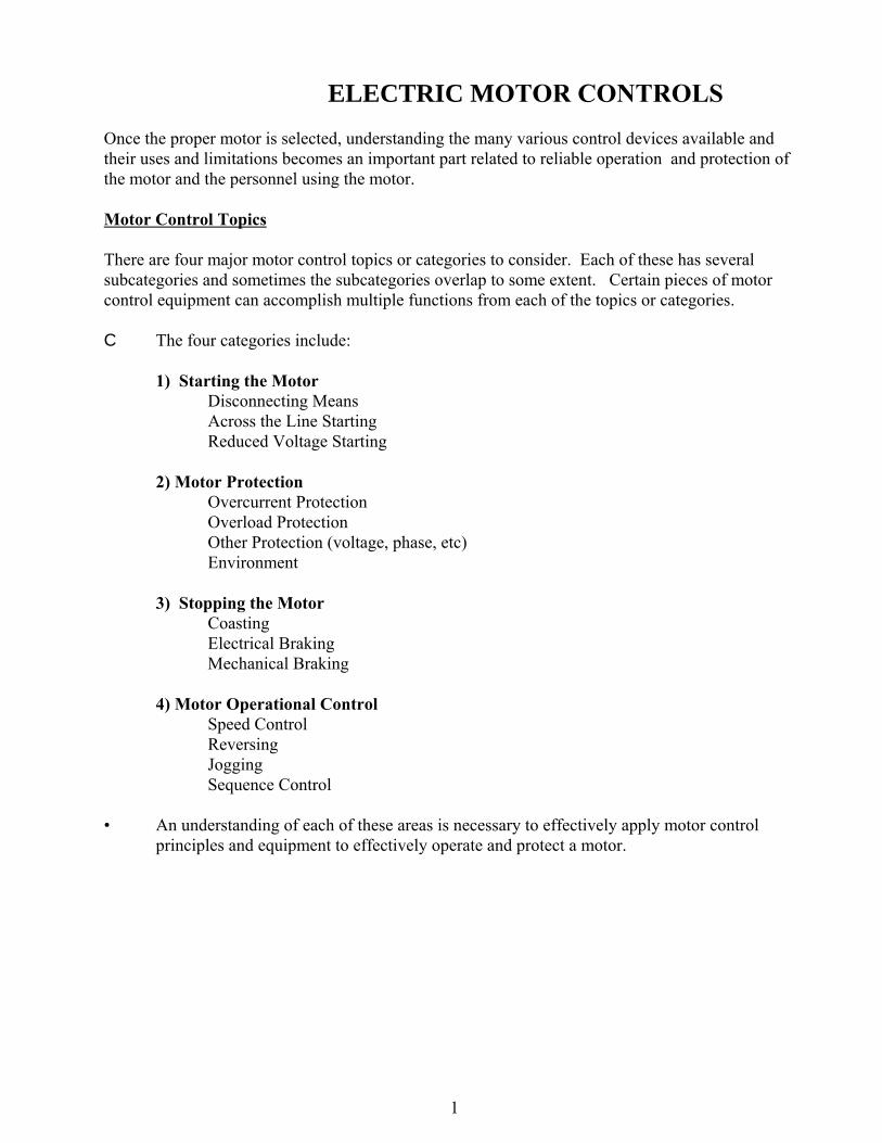
Across the Line Starting of Motors
Across the Line starting connects the motor windings/terminals directly to the circuit voltage “acrossthe line” for a “full voltage start”.
• This is the simplest method of starting amotor. (And usually the least expensive).
• Motors connected across the line are capableof drawing full in-rush current anddeveloping maximum starting torque toaccelerate the load to speed in the shortestpossible time.
• All NEMA induction motors up to 200horsepower, and many larger ones, can withstand full voltage starts. (The electricdistribution system or processing operation may not though, even if the motor will).
Across the Line Starters
3
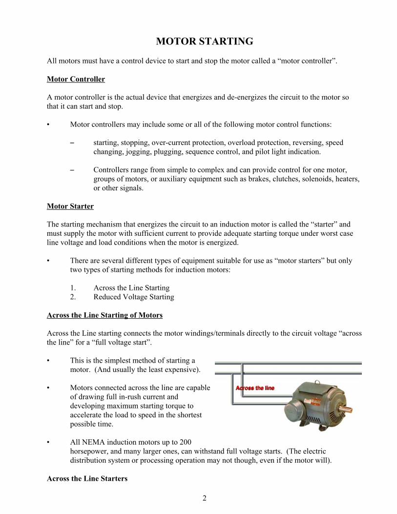
Figure 26. Manual Starter
There are two different types of common “across the line” starters including
1. Manual Motor Starters2. Magnetic Motor Starters
Manual Motor Starters
A manual motor starter is package consisting of a horsepower rated switch with one set of contactsfor each phase and corresponding thermal overload devices to provide motor overload protection.
• The main advantage of a manual motor starter is lower cost than a magnetic motor starterwith equivalent motor protection but less motor control capability.
• Manual motor starters are often used for smaller motors - typically fractional horsepowermotors but the National Electrical Code allows their use up to 10 Horsepower.
• Since the switch contacts remain closed if power is removed from the circuit withoutoperating the switch, the motor restarts when power is reapplied which can be a safetyconcern.
• They do not allow the use of remote control or auxiliary control equipment like a magneticstarter does.
Magnetic Motor Starters
A magnetic motor starter is a package consisting of a contactor capable of opening and closing a set
4
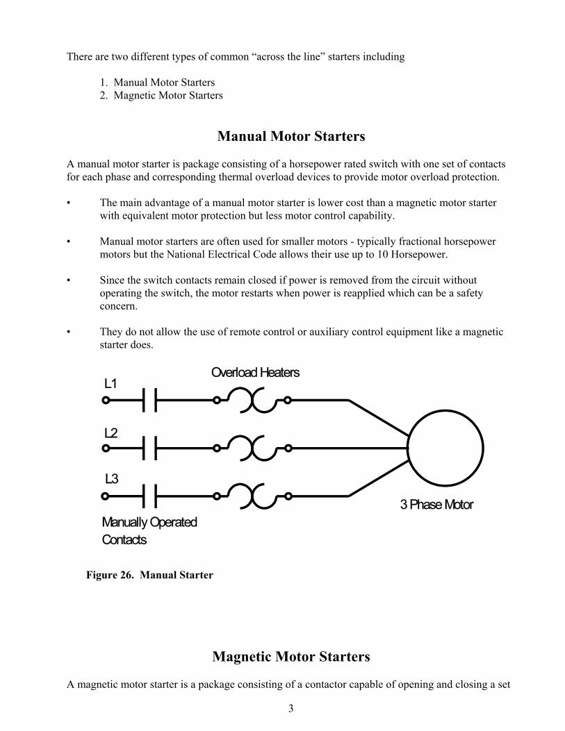
Figure 27. Magnetic Starter
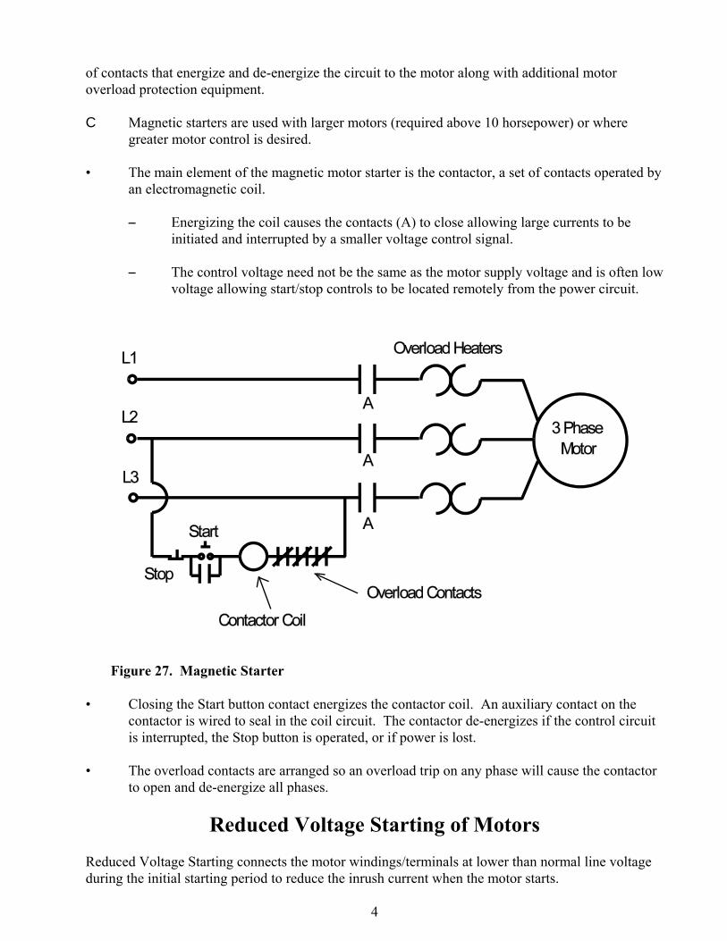
of contacts that energize and de-energize the circuit to the motor along with additional motoroverload protection equipment.
C Magnetic starters are used with larger motors (required above 10 horsepower) or wheregreater motor control is desired.
• The main element of the magnetic motor starter is the contactor, a set of contacts operated byan electromagnetic coil.
S Energizing the coil causes the contacts (A) to close allowing large currents to beinitiated and interrupted by a smaller voltage control signal.
S The control voltage need not be the same as the motor supply voltage and is often lowvoltage allowing start/stop controls to be located remotely from the power circuit.
• Closing the Start button contact energizes the contactor coil. An auxiliary contact on thecontactor is wired to seal in the coil circuit. The contactor de-energizes if the control circuitis interrupted, the Stop button is operated, or if power is lost.
• The overload contacts are arranged so an overload trip on any phase will cause the contactorto open and de-energize all phases.
Reduced Voltage Starting of MotorsReduced Voltage Starting connects the motor windings/terminals at lower than normal line voltageduring the initial starting period to reduce the inrush current when the motor starts.
5
• Reduced voltage starting may be required when:
S The current in-rush form the motor starting adversely affects the voltage drop on theelectrical system.
S needed to reduce the mechanical “starting shock” on drive-lines and equipment whenthe motor starts.
• Reducing the voltage reduces the current in-rush to the motor and also reduces the startingtorque available when the motor starts.
• All NEMA induction motors can will accept reduced voltage starting however it may notprovide enough starting torque in some situations to drive certain specific loads.
If the driven load or the power distribution system cannot accept a full voltage start, some type ofreduced voltage or "soft" starting scheme must be used.
• Typical reduced voltage starter types include:
1. Solid State (Electronic) Starters2. Primary Resistance Starters3. Autotransformer Starters4. Part Winding Starters5. Wye-Delta Starters
Reduced voltage starters can only be used where low starting torque is acceptable or a means existsto remove the load from the motor or application before it is stopped.

6
MOTOR PROTECTIONMotor protection safeguards the motor, the supply system and personnel from various operatingconditions of the driven load, the supply system or the motor itself.
C Motor protection categories include
S Overcurrent ProtectionS Overload ProtectionS Other Types of Protection.
• The National Electrical Code requires thatmotors and their conductors be protectedfrom both overcurrent and overloadconditions.
Overcurrent Protection
Overcurrent protection interrupts the electrical circuit to the motor upon excessive current demandon the supply system from either short circuits or ground faults.
• Overcurrent protection is required to protect personnel, the motor branch circuit conductors,control equipment, and motor from these high currents.
• Overcurrent protection is usually provided in the form of fuses or circuit breakers. Thesedevices operate when a short circuit, ground fault or an extremely heavy overload occurs.
S Most overcurrent sources produce extremely large currents very quickly.
7
0
100
200
300
400
500
600
Full
Load
Am
ps (%
)
0 1 2 3 4 5 6 7 8 9 10 11 12 Time (Minutes)
Motor Heating Curve
Motor Damage
Allowable Operation AreaA
mpe
rage
Time
Motor Current Draw
Motor Running Current
Starting In-Rush Current
Overload Protection
Overload protection is installed in the motor circuit and/or motor to protect the motor from damagefrom mechanical overload conditions when it is operating/running.
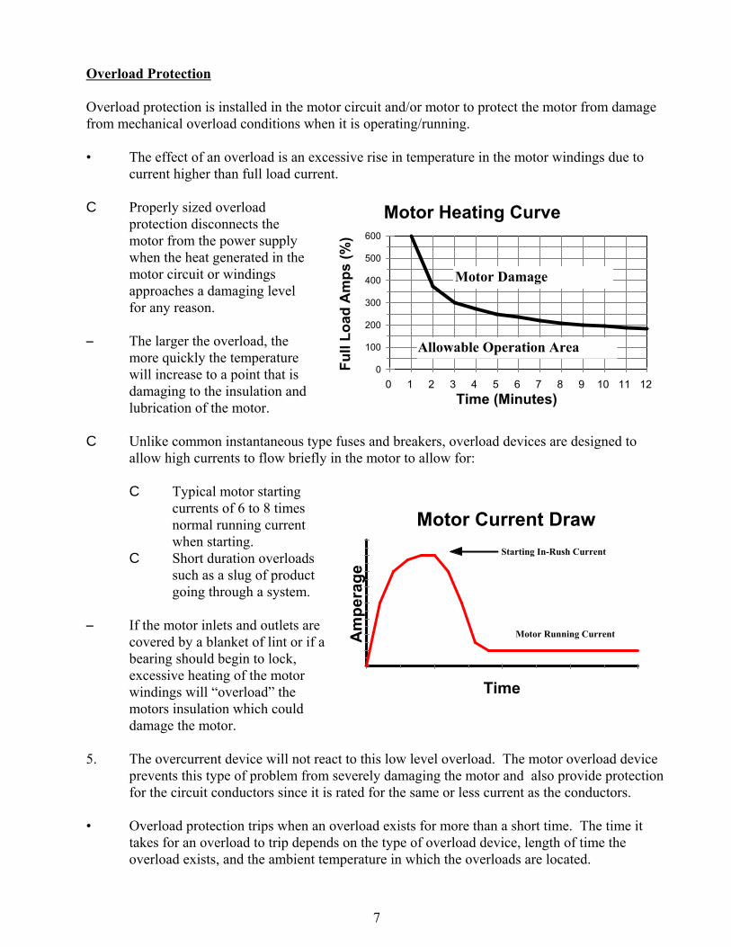
• The effect of an overload is an excessive rise in temperature in the motor windings due tocurrent higher than full load current.
C Properly sized overloadprotection disconnects themotor from the power supplywhen the heat generated in themotor circuit or windingsapproaches a damaging levelfor any reason.
S The larger the overload, themore quickly the temperaturewill increase to a point that isdamaging to the insulation andlubrication of the motor.
C Unlike common instantaneous type fuses and breakers, overload devices are designed toallow high currents to flow briefly in the motor to allow for:
C Typical motor startingcurrents of 6 to 8 timesnormal running currentwhen starting.
C Short duration overloadssuch as a slug of productgoing through a system.
S If the motor inlets and outlets arecovered by a blanket of lint or if abearing should begin to lock,excessive heating of the motorwindings will “overload” themotors insulation which coulddamage the motor.
5. The overcurrent device will not react to this low level overload. The motor overload deviceprevents this type of problem from severely damaging the motor and also provide protectionfor the circuit conductors since it is rated for the same or less current as the conductors.
• Overload protection trips when an overload exists for more than a short time. The time ittakes for an overload to trip depends on the type of overload device, length of time theoverload exists, and the ambient temperature in which the overloads are located.
8
Other Motor Protection Devices Low Voltage Protection
Low Voltage Disconnects - Protection device operates to disconnect the motor when the supplyvoltage drops below a preset value. The motor must be manually restarted upon resumption ofnormal supply voltage.
Low Voltage Release - Protection device interrupts the circuit when the supply voltage drops belowa preset value and re-establishes the circuit when the supply voltage returns to normal.
Phase Failure Protection
Interrupts the power in all phases of a three-phase circuit upon failure of any one phase.
C Normal fusing and overload protection may not adequately protect a polyphase motor fromdamaging single phase operation. Without this protection, the motor will continue to operateif one phase is lost.
C Large currents can be developed in the remaining stator circuits which eventually burn out.C Phase failure protection is the only effective way to protect a motor properly from single
phasing.
Phase Reversal Protection
Used where running a motor backwards (opposite direction from normal) would cause operational orsafety problems.
C Most three phase motors will run the opposite direction by switching the connections of anytwo of the three phases.
C The device interrupts the power to the motor upon detection of a phase reversal in the three-phase supply circuit.
C This type of protection is used in applications like elevators where it would be damaging ordangerous for the motor to inadvertently run in reverse.
Ground Fault Protection
C Operates when one phase of a motor shorts to ground preventing high currents fromdamaging the stator windings and the iron core.
Other Motor Protection Devices
Bearing Temperature Monitors & ProtectionWinding Temperature Monitors & Protection DevicesCurrent Differential Relays (Phase Unbalance)Vibration Monitors & Protection
Sizing Motor Overcurrent Protection
9
Circuit overcurrent protection devices must be sized to protect the branch-circuit conductors andalso allow the motor to start without the circuit opening due to the in-rush current of the motor.
National Electrical Code Procedures
Use the NEC motor current tables to find the design Full Load Current or FLA (adjusted for ServiceFactor) unless it is not available.
C For Single Phase Motors: Use NEC Table 430-148C For Three Phase Motors: Use NEC Table 430-150
• These values are about 10% higher than what a typical motor would draw at full load toallow for bearing wear in the motor and load, etc.
C The values in the NEC tables will allow for replacement of the motor in the future withouthaving to replace the circuit conductors or overcurrent devices.
Types of Overcurrent Devices - NEC TABLE 430-152
Selection of the size of the overcurrent protection device is made using NEC Table 430-152 whichlists information for four types of devices:
1) Standard (non-time delay) Fuses 2) Time-Delay (dual element) Fuses3) Instantaneous Trip Circuit Breaker 4) Inverse Time Circuit Breaker
• The table is used to size the device above normal starting current levels of most motorsallowing them to start and run without tripping the overcurrent protection device.
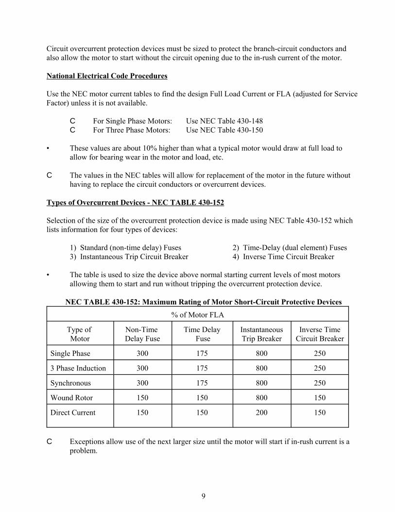
NEC TABLE 430-152: Maximum Rating of Motor Short-Circuit Protective Devices
% of Motor FLA
Type of Motor
Non-Time Delay Fuse
Time Delay Fuse
InstantaneousTrip Breaker
Inverse TimeCircuit Breaker
Single Phase 300 175 800 250
3 Phase Induction 300 175 800 250
Synchronous 300 175 800 250
Wound Rotor 150 150 800 150
Direct Current 150 150 200 150
C Exceptions allow use of the next larger size until the motor will start if in-rush current is aproblem.
10
0.01
0.1
1
10
Tim
e (s
econ
ds)
0 500 1000 1500 2000 Amp Rating (%)
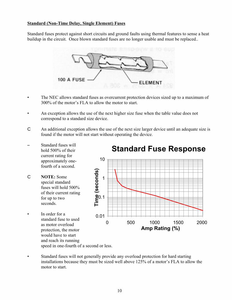
Standard Fuse Response
Standard (Non-Time Delay, Single Element) Fuses
Standard fuses protect against short circuits and ground faults using thermal features to sense a heatbuildup in the circuit. Once blown standard fuses are no longer usable and must be replaced..
• The NEC allows standard fuses as overcurrent protection devices sized up to a maximum of300% of the motor’s FLA to allow the motor to start.
• An exception allows the use of the next higher size fuse when the table value does notcorrespond to a standard size device.
C An additional exception allows the use of the next size larger device until an adequate size isfound if the motor will not start without operating the device.
S Standard fuses willhold 500% of theircurrent rating forapproximately one-fourth of a second.
C NOTE: Somespecial standardfuses will hold 500%of their current ratingfor up to twoseconds.
• In order for astandard fuse to usedas motor overloadprotection, the motorwould have to startand reach its runningspeed in one-fourth of a second or less.
• Standard fuses will not generally provide any overload protection for hard startinginstallations because they must be sized well above 125% of a motor’s FLA to allow themotor to start.
11
0.1
1.0
10.0
100.0
1000.0
Tim
e (s
econ
ds)
0 500 1000 1500 2000 Amp Rating (%)
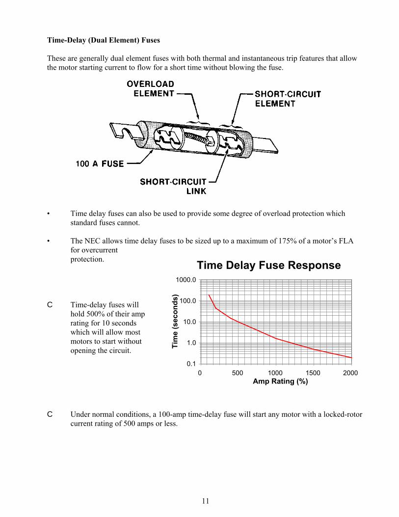
Time Delay Fuse Response
Time-Delay (Dual Element) Fuses
These are generally dual element fuses with both thermal and instantaneous trip features that allowthe motor starting current to flow for a short time without blowing the fuse.
• Time delay fuses can also be used to provide some degree of overload protection whichstandard fuses cannot.
• The NEC allows time delay fuses to be sized up to a maximum of 175% of a motor’s FLAfor overcurrentprotection.
C Time-delay fuses willhold 500% of their amprating for 10 secondswhich will allow mostmotors to start withoutopening the circuit.
C Under normal conditions, a 100-amp time-delay fuse will start any motor with a locked-rotorcurrent rating of 500 amps or less.

12
13
0.0
0.1
1.0
10.0
100.0
1000.0
10000.0
Tim
e (s
econ
ds)
0 100 200 300 400 500 600 Amp Rating (%)
Inverse CB Trip Curve
Thermal Action
Magnetic Action
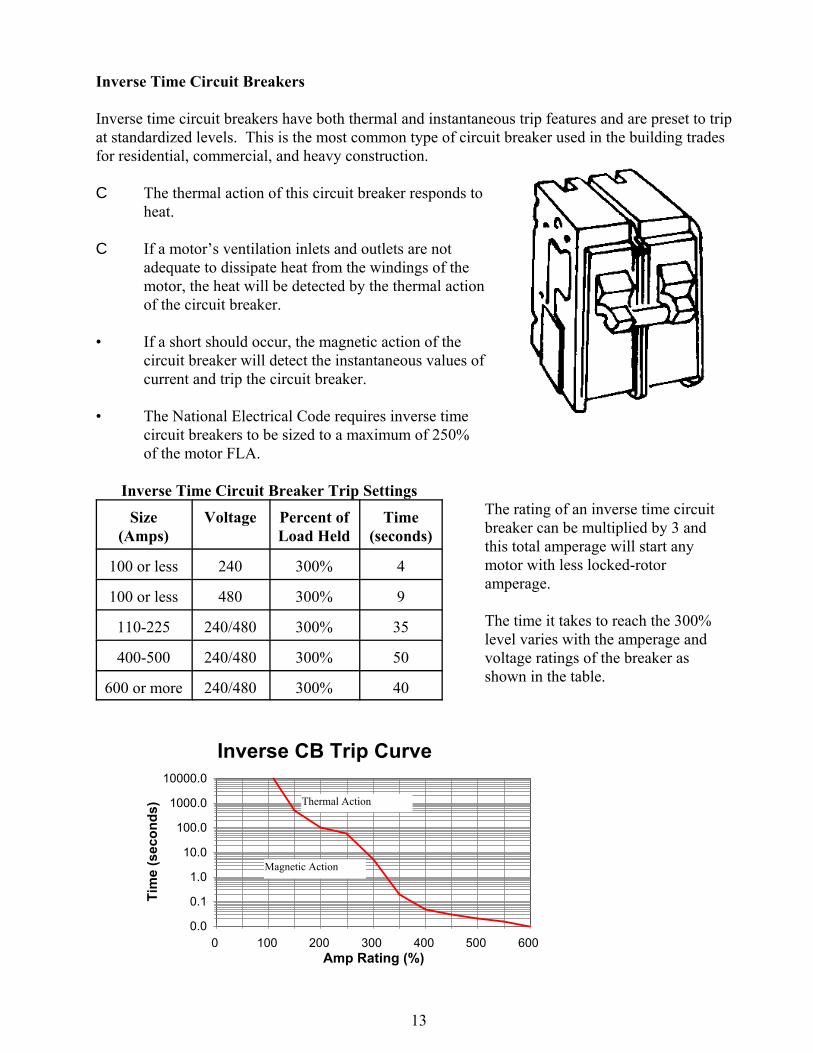
Inverse Time Circuit Breakers
Inverse time circuit breakers have both thermal and instantaneous trip features and are preset to tripat standardized levels. This is the most common type of circuit breaker used in the building tradesfor residential, commercial, and heavy construction.
C The thermal action of this circuit breaker responds toheat.
C If a motor’s ventilation inlets and outlets are notadequate to dissipate heat from the windings of themotor, the heat will be detected by the thermal actionof the circuit breaker.
• If a short should occur, the magnetic action of thecircuit breaker will detect the instantaneous values ofcurrent and trip the circuit breaker.
• The National Electrical Code requires inverse timecircuit breakers to be sized to a maximum of 250%of the motor FLA.
Inverse Time Circuit Breaker Trip Settings
Size(Amps)
Voltage Percent ofLoad Held
Time(seconds)
100 or less 240 300% 4
100 or less 480 300% 9
110-225 240/480 300% 35
400-500 240/480 300% 50
600 or more 240/480 300% 40
The rating of an inverse time circuitbreaker can be multiplied by 3 andthis total amperage will start anymotor with less locked-rotoramperage.
The time it takes to reach the 300%level varies with the amperage andvoltage ratings of the breaker asshown in the table.
14
0.01
0.1
1
10
Tim
e (s
econ
ds)
0 500 1000 1500 2000 Amp Rating (%)
Instantaneous Trip CB
10 X Rating3 X Rating
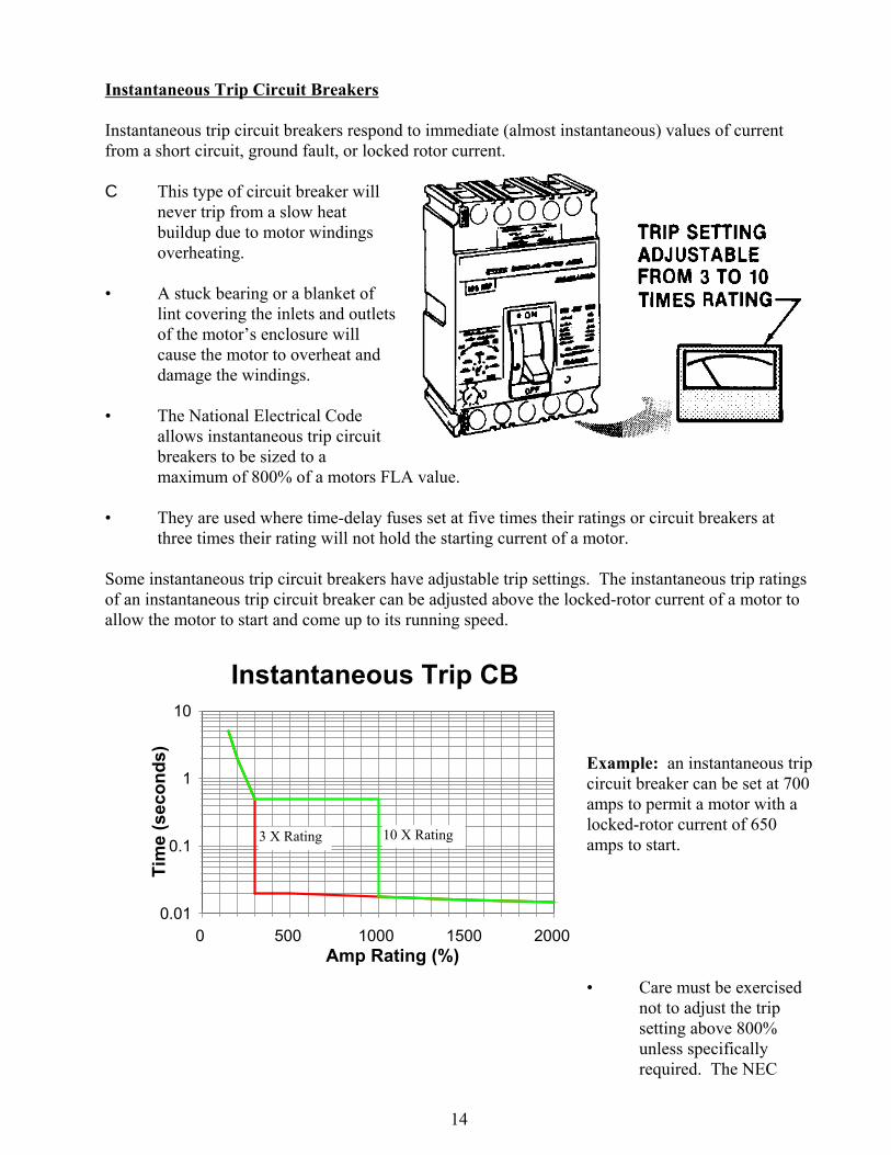
Instantaneous Trip Circuit Breakers
Instantaneous trip circuit breakers respond to immediate (almost instantaneous) values of currentfrom a short circuit, ground fault, or locked rotor current.
C This type of circuit breaker willnever trip from a slow heatbuildup due to motor windingsoverheating.
• A stuck bearing or a blanket oflint covering the inlets and outletsof the motor’s enclosure willcause the motor to overheat anddamage the windings.
• The National Electrical Codeallows instantaneous trip circuitbreakers to be sized to amaximum of 800% of a motors FLA value.
• They are used where time-delay fuses set at five times their ratings or circuit breakers atthree times their rating will not hold the starting current of a motor.
Some instantaneous trip circuit breakers have adjustable trip settings. The instantaneous trip ratingsof an instantaneous trip circuit breaker can be adjusted above the locked-rotor current of a motor toallow the motor to start and come up to its running speed.
Example: an instantaneous tripcircuit breaker can be set at 700amps to permit a motor with alocked-rotor current of 650amps to start.
• Care must be exercisednot to adjust the tripsetting above 800%unless specificallyrequired. The NEC

15
prohibits settings above800% if the motor willstart and run up to speedat or below a setting of800%.
16
Motor Overload Protection
Motors larger than 1 horsepower must be provided separate motor overload protection devices.
C The most common devices typically used include:
1) magnetic or thermal overload devices2) electronic overload relays3) fuses
Magnetic & Thermal Overloads
Overload devices are usually located in the motor’s starter and connected in series with the motorselectrical supply circuit and can be operated by either magnetic or thermal action.
C The same amount of current passes through the overload relay and the motor.
C If the current or heat through the overload device is higher than the device’s rating, it tripsand shuts down the electric power to the motor.
Magnetic Overload Relays
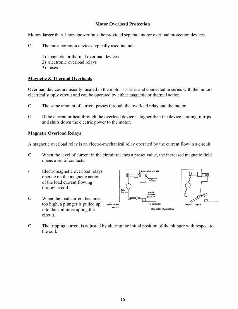
A magnetic overload relay is an electro-mechanical relay operated by the current flow in a circuit.
C When the level of current in the circuit reaches a preset value, the increased magnetic fieldopens a set of contacts.
• Electromagnetic overload relaysoperate on the magnetic actionof the load current flowingthrough a coil.
C When the load current becomestoo high, a plunger is pulled upinto the coil interrupting thecircuit.
C The tripping current is adjusted by altering the initial position of the plunger with respect tothe coil.
17
Thermal Overload Relays
A thermal overload relay is an electro-mechanical relay that is operated by heat developed in therelay.
C When the level of current in a circuit reaches a preset value, the increased temperature opensa set of contacts.
C The increased temperature opens the contacts through a bimetallic strip or by melting analloy that activates a mechanism that opens the contacts.
C Two types include melting alloy and the bi-metallic strip.
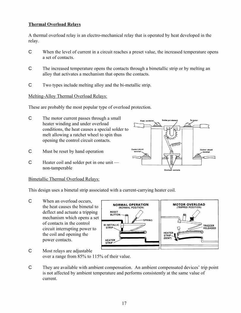
Melting-Alloy Thermal Overload Relays:
These are probably the most popular type of overload protection.
C The motor current passes through a smallheater winding and under overloadconditions, the heat causes a special solder tomelt allowing a ratchet wheel to spin thusopening the control circuit contacts.
C Must be reset by hand operation
C Heater coil and solder pot in one unit —non-tamperable
Bimetallic Thermal Overload Relays:
This design uses a bimetal strip associated with a current-carrying heater coil.
C When an overload occurs,the heat causes the bimetal todeflect and actuate a trippingmechanism which opens a setof contacts in the controlcircuit interrupting power tothe coil and opening thepower contacts.
C Most relays are adjustableover a range from 85% to 115% of their value.
C They are available with ambient compensation. An ambient compensated devices’ trip pointis not affected by ambient temperature and performs consistently at the same value ofcurrent.
18
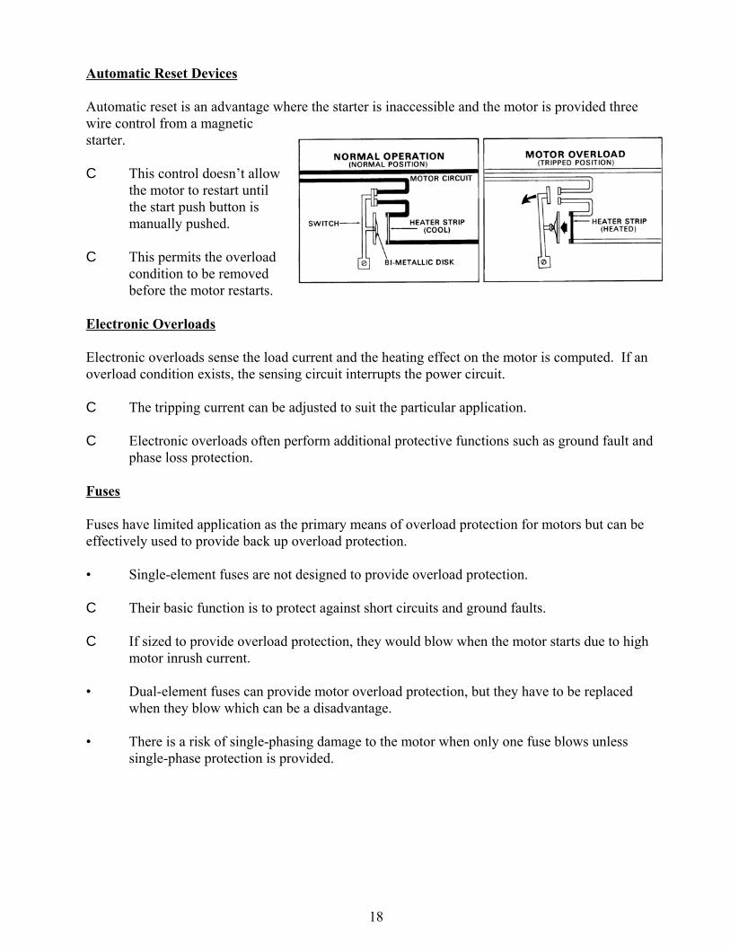
Automatic Reset Devices
Automatic reset is an advantage where the starter is inaccessible and the motor is provided threewire control from a magneticstarter.
C This control doesn’t allowthe motor to restart untilthe start push button ismanually pushed.
C This permits the overloadcondition to be removedbefore the motor restarts.
Electronic Overloads
Electronic overloads sense the load current and the heating effect on the motor is computed. If anoverload condition exists, the sensing circuit interrupts the power circuit.
C The tripping current can be adjusted to suit the particular application.
C Electronic overloads often perform additional protective functions such as ground fault andphase loss protection.
Fuses
Fuses have limited application as the primary means of overload protection for motors but can beeffectively used to provide back up overload protection.
• Single-element fuses are not designed to provide overload protection.
C Their basic function is to protect against short circuits and ground faults.
C If sized to provide overload protection, they would blow when the motor starts due to highmotor inrush current.
• Dual-element fuses can provide motor overload protection, but they have to be replacedwhen they blow which can be a disadvantage.
• There is a risk of single-phasing damage to the motor when only one fuse blows unlesssingle-phase protection is provided.
19
1
10
100
1000
Trip
Tim
e (S
econ
ds)
0 200 400 600 800 1000 1200 Rated Current (%)
Heater Trip Characteristics
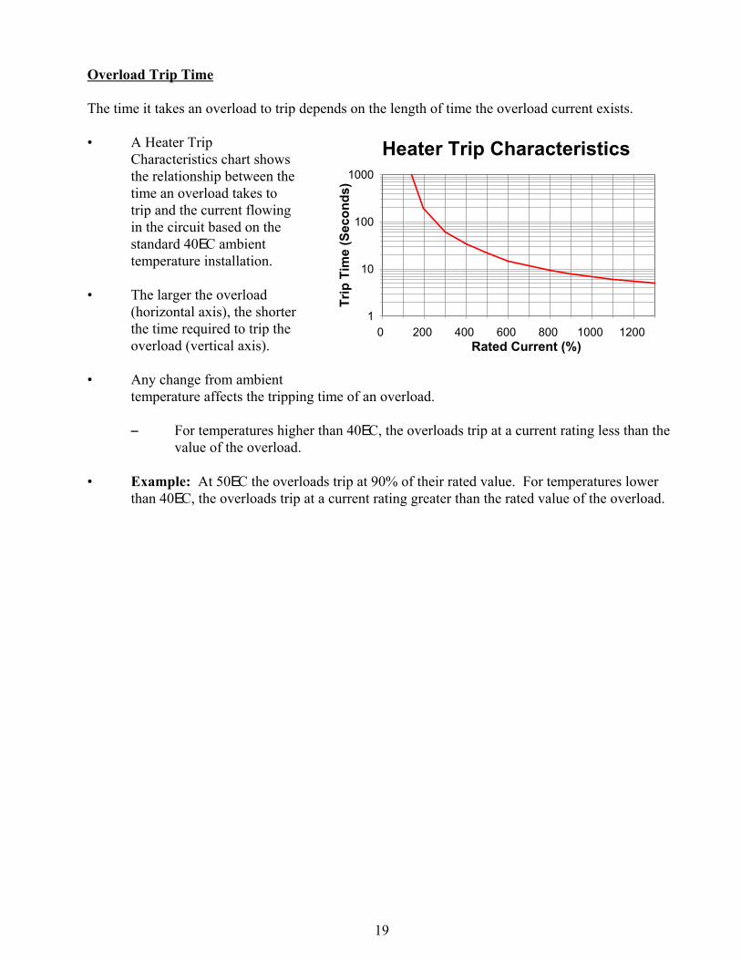
Overload Trip Time
The time it takes an overload to trip depends on the length of time the overload current exists.
• A Heater TripCharacteristics chart showsthe relationship between thetime an overload takes totrip and the current flowingin the circuit based on thestandard 40EC ambienttemperature installation.
• The larger the overload(horizontal axis), the shorterthe time required to trip theoverload (vertical axis).
• Any change from ambienttemperature affects the tripping time of an overload.
S For temperatures higher than 40EC, the overloads trip at a current rating less than thevalue of the overload.
• Example: At 50EC the overloads trip at 90% of their rated value. For temperatures lowerthan 40EC, the overloads trip at a current rating greater than the rated value of the overload.
20
Sizing Motor Overload Protection
There are several types of devices that can be used to provide overload protection and the sizingprocedure can vary depending on the type of device used.
C It is important to keep differences in the procedures separate and understood well so as not toinstall overloads that do not provide adequate protection to the motor.
• The simplest and most straightforward sizing procedures for motor overload protection areapplied when sizing overload relays using the cover of the motor starter, control center, ormanufacturer’s catalog.
• The National Electrical Code specifies methods to calculate the maximum size motoroverload protection for specific motors if a manufacturers chart is not available. Installationsrelying on fuses and circuit breakers as back-up overload protection must be calculated usingthe NEC method.
NEC Calculations
The NEC in general requires the maximum size overload device be set to open at 115% or 125% ofthe motor’s full-load current rating, depending upon the service factor and/or temperature rise of themotor. There are however, exceptions.
• For motors rated 40EC with a Service Factor of 1.15 or greater, 125% of the motors FLA isused to calculate the maximum size device for overload protection.
• For motors rated greater than 40EC or unmarked, 115% of the motors FLA is used tocalculate the maximum size device regardless of the motor’s Service Factor.
• If use of the previous size rules results in the motor tripping off line during starting, thedevice can be increased to a maximum of 140% of the motors FLA.
Example:
Find the maximum size overload device to provide overload protection to a 3 phase, 230 Volt, 10horsepower motor with FLA of 28 amps if:
Ambient Temp = 40EC, S.F.=1.15: 28 amps X 125% = 35 ampsAmbient Temp = 40EC, S.F.=1.00: 28 amps X 115% = 32.2 ampsAmbient Temp = 50EC, S.F.=1.15 28 amps X 115% = 32.2 ampsAmbient Temp = 50EC, S.F.=1.00 28 amps X 115% = 32.2 amps
If use of the size calculated results in the motor tripping off line when started, the overload devicemay be increased to a maximum of:
Maximum size allowable: 28 amps X 140% = 39.2 amps
Selecting Overloads From Starter Covers or Charts
21
The size overloads required to protect the windings of a motor can be determined by taking themotor’s full-load current rating and selecting the size overloads from the cover of a magnetic starter,a motor control center, or the manufacturer’s catalog.
C The following things should be kept in mind when using manufacturer’s charts.
• When the overload size is selected from the cover of a magnetic starter or controller, thenameplate full-load running current of the motor is used. The full-load running current isNOT increased by 125% when the overloads are selected in this manner.
• The charts are usually based on only the specific manufacturer’s equipment.
• Sizes from the charts may be different from those of calculated values from the NationalElectrical Code.
C Manufacturers charts often provide smaller rated devices than the NEC would allow as ameasure of extra protection.
• Manufacturers’ typically list the most common sizes in their charts. Certain sizes mayrequire calculations if the chart is not available from the manufacturer.
• If the motor will operate at/near service factor, the appropriate FLA of the motor at itsService Factor should be used to select the overload size from the manufacturer’s chart.
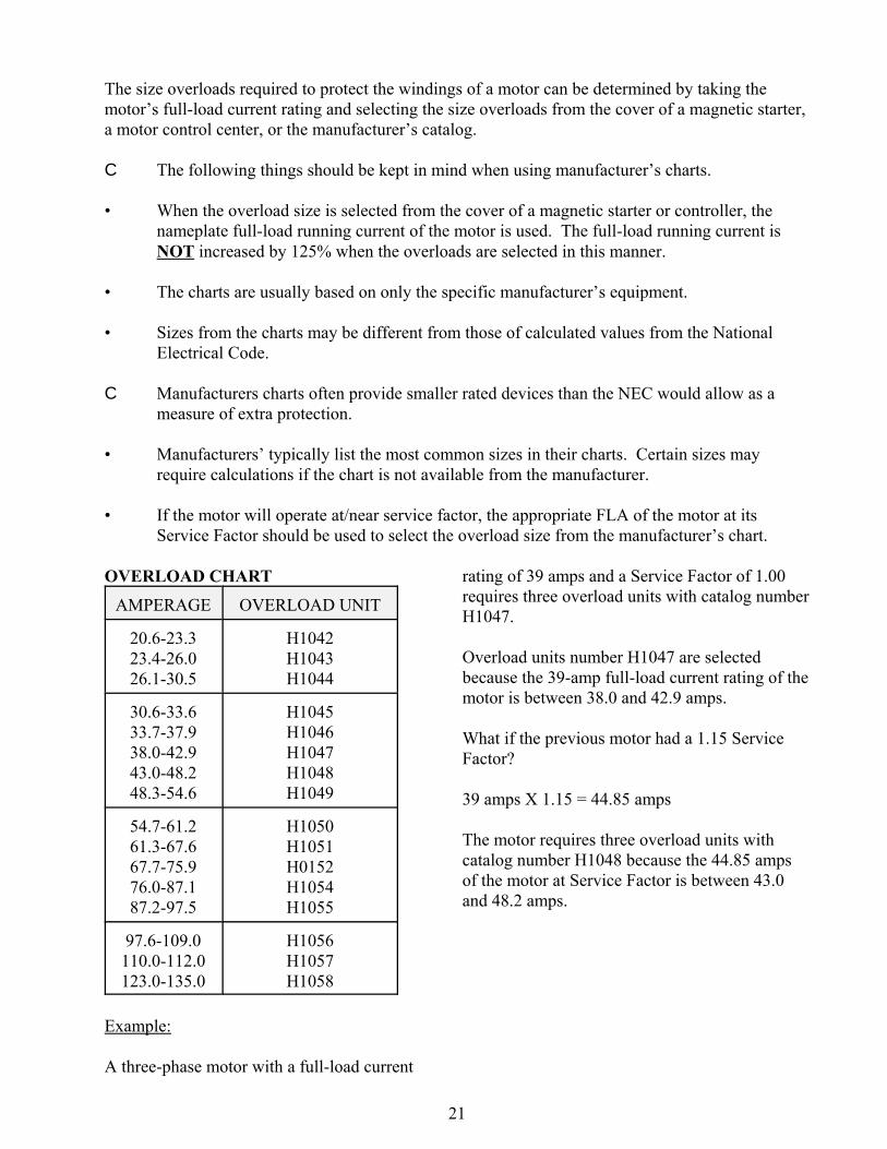
OVERLOAD CHART
AMPERAGE OVERLOAD UNIT
20.6-23.323.4-26.026.1-30.5
H1042H1043H1044
30.6-33.633.7-37.938.0-42.943.0-48.248.3-54.6
H1045H1046H1047H1048H1049
54.7-61.261.3-67.667.7-75.976.0-87.187.2-97.5
H1050H1051H0152H1054H1055
97.6-109.0110.0-112.0123.0-135.0
H1056H1057H1058
Example:
A three-phase motor with a full-load current
rating of 39 amps and a Service Factor of 1.00requires three overload units with catalog numberH1047.
Overload units number H1047 are selectedbecause the 39-amp full-load current rating of themotor is between 38.0 and 42.9 amps.
What if the previous motor had a 1.15 ServiceFactor?
39 amps X 1.15 = 44.85 amps
The motor requires three overload units withcatalog number H1048 because the 44.85 ampsof the motor at Service Factor is between 43.0and 48.2 amps.
22
60 70 80 90
100 110 120 130 140
Rat
ed C
urre
nt (%
)
20 40 60 80 100 120 140 160 Ambient Temperature (F)
Heater Ambient Temperature Correction
Standard Rating, 40 C
60 70 80 90
100 110 120 130 140
Rat
ed C
urre
nt (%
)
20 40 60 80 100 120 140 160 Ambient Temperature (F)
Ambient Temperature Correction
Standard Rating, 40 C
Non-Compensated
Compensated
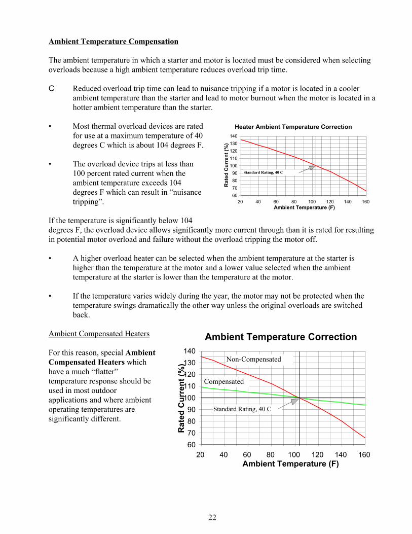
Ambient Temperature Compensation
The ambient temperature in which a starter and motor is located must be considered when selectingoverloads because a high ambient temperature reduces overload trip time.
C Reduced overload trip time can lead to nuisance tripping if a motor is located in a coolerambient temperature than the starter and lead to motor burnout when the motor is located in ahotter ambient temperature than the starter.
• Most thermal overload devices are ratedfor use at a maximum temperature of 40degrees C which is about 104 degrees F.
• The overload device trips at less than100 percent rated current when theambient temperature exceeds 104degrees F which can result in “nuisancetripping”.
If the temperature is significantly below 104degrees F, the overload device allows significantly more current through than it is rated for resultingin potential motor overload and failure without the overload tripping the motor off.
• A higher overload heater can be selected when the ambient temperature at the starter ishigher than the temperature at the motor and a lower value selected when the ambienttemperature at the starter is lower than the temperature at the motor.
• If the temperature varies widely during the year, the motor may not be protected when thetemperature swings dramatically the other way unless the original overloads are switchedback.
Ambient Compensated Heaters
For this reason, special AmbientCompensated Heaters whichhave a much “flatter”temperature response should beused in most outdoorapplications and where ambientoperating temperatures aresignificantly different.
23
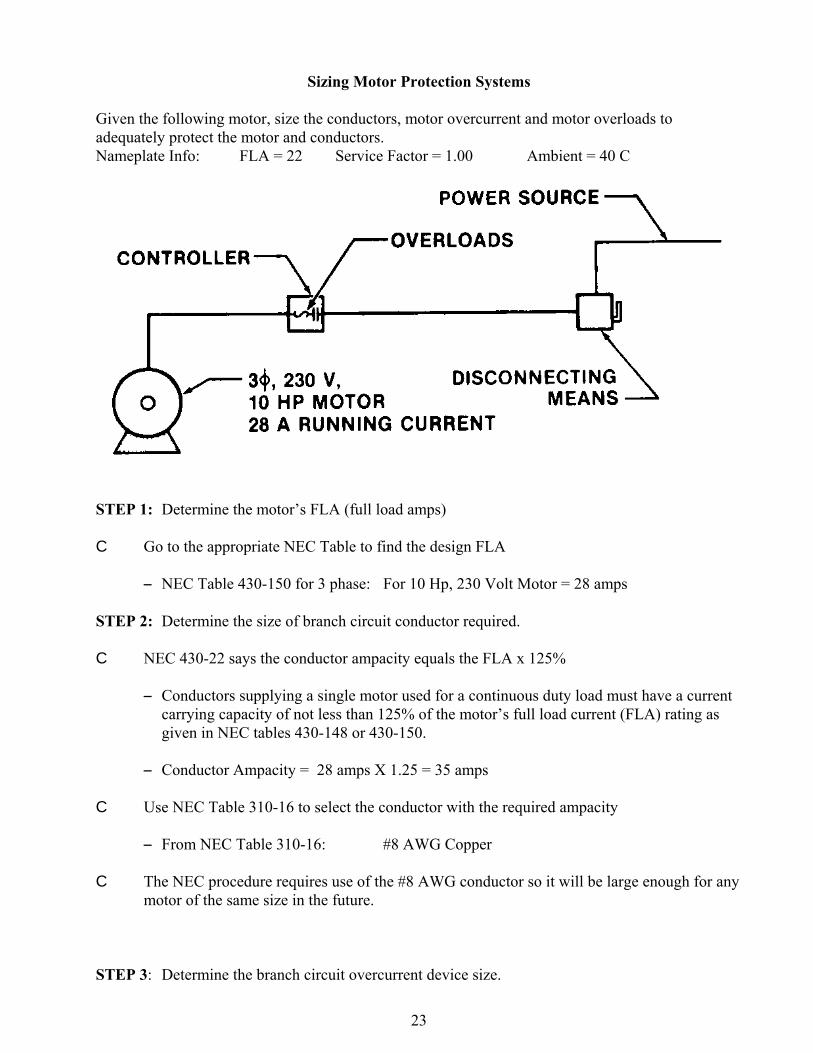
Sizing Motor Protection Systems
Given the following motor, size the conductors, motor overcurrent and motor overloads toadequately protect the motor and conductors.Nameplate Info: FLA = 22 Service Factor = 1.00 Ambient = 40 C
STEP 1: Determine the motor’s FLA (full load amps)
C Go to the appropriate NEC Table to find the design FLA
S NEC Table 430-150 for 3 phase: For 10 Hp, 230 Volt Motor = 28 amps
STEP 2: Determine the size of branch circuit conductor required.
C NEC 430-22 says the conductor ampacity equals the FLA x 125%
S Conductors supplying a single motor used for a continuous duty load must have a currentcarrying capacity of not less than 125% of the motor’s full load current (FLA) rating asgiven in NEC tables 430-148 or 430-150.
S Conductor Ampacity = 28 amps X 1.25 = 35 amps
C Use NEC Table 310-16 to select the conductor with the required ampacity
S From NEC Table 310-16: #8 AWG Copper
C The NEC procedure requires use of the #8 AWG conductor so it will be large enough for anymotor of the same size in the future.
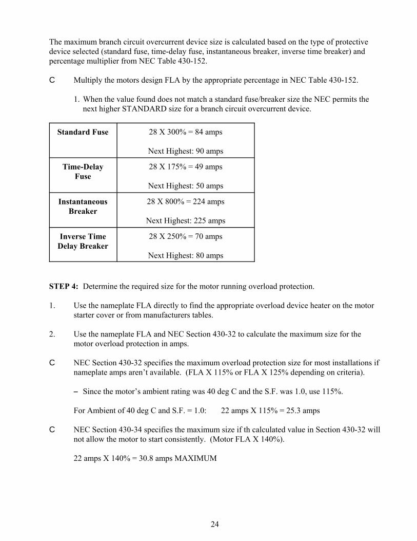
STEP 3: Determine the branch circuit overcurrent device size.
24
The maximum branch circuit overcurrent device size is calculated based on the type of protectivedevice selected (standard fuse, time-delay fuse, instantaneous breaker, inverse time breaker) andpercentage multiplier from NEC Table 430-152.
C Multiply the motors design FLA by the appropriate percentage in NEC Table 430-152.
1. When the value found does not match a standard fuse/breaker size the NEC permits thenext higher STANDARD size for a branch circuit overcurrent device.
Standard Fuse 28 X 300% = 84 amps
Next Highest: 90 amps
Time-DelayFuse
28 X 175% = 49 amps
Next Highest: 50 amps
InstantaneousBreaker
28 X 800% = 224 amps
Next Highest: 225 amps
Inverse TimeDelay Breaker
28 X 250% = 70 amps
Next Highest: 80 amps
STEP 4: Determine the required size for the motor running overload protection.
1. Use the nameplate FLA directly to find the appropriate overload device heater on the motorstarter cover or from manufacturers tables.
2. Use the nameplate FLA and NEC Section 430-32 to calculate the maximum size for themotor overload protection in amps.
C NEC Section 430-32 specifies the maximum overload protection size for most installations ifnameplate amps aren’t available. (FLA X 115% or FLA X 125% depending on criteria).
S Since the motor’s ambient rating was 40 deg C and the S.F. was 1.0, use 115%.
For Ambient of 40 deg C and S.F. = 1.0: 22 amps X 115% = 25.3 amps
C NEC Section 430-34 specifies the maximum size if th calculated value in Section 430-32 willnot allow the motor to start consistently. (Motor FLA X 140%).
22 amps X 140% = 30.8 amps MAXIMUM