Embed Size (px)
Citation preview
MGE MOTORS0.25 - 22 kW
0.25 - 22 kWGRUNDFOS MGE MOTORS
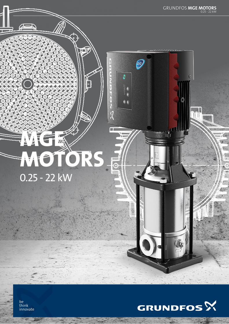
GRUNDFOS E-PUMPS – IN A CLASS OF THEIR OWN
As a world leading manufacturer of pumps and pump equipment, we make electrical motors of exceptional quality.
For decades, we have been manufacturing our own motors with integrated frequency converters that match the very high standard of our electronic controlled pumps (E-pumps) in building services, industry and water supply applications.
60%
65%
70%
75%
80%
85%
90%
95%
100%
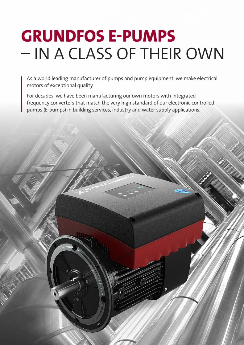
0.25 0.37 0.55 0.75 1.1 1.5 2.2 3.0 4.0 5.5 7.5 11 15 18.5 22
E�ci
ency
[%]
Output [kW]
MGEModel I/J
MGEModel G/F
Adjusting the speed of the pump based on demand, rather than throttling the system flow with a valve, results in:
• No excess pressure causing stress in the system and noise in the valve due to cavitation
• Reduced power consump-tion due to lower pump speed.
High efficiency components, variable speed control, lower energy consumption, compact design, and additional control features make integrated E-motors the right choice for your system.
ENERGY AND COST SAVINGS WITH OPTIMISED EFFICIENCYThe Grundfos MGE motors model H/I/J are the most energy efficient yet. These permanent magnet synchronous motors (PMSM) are designed especially for frequency converter operations and opti-mised for pump applications and high part-load efficiency. This results in lower energy and lifecycle costs and exceeds the IE4 level in IEC60034-30-1, even with frequency converter losses at medium speed range (2950-4000-RPM).
H
QP 1
Excess pressure in the system regulated by throttle valve
Constant pressure maintained with reduced speed of the pump
Reduced power consumption of 40-60% due to reduced speed
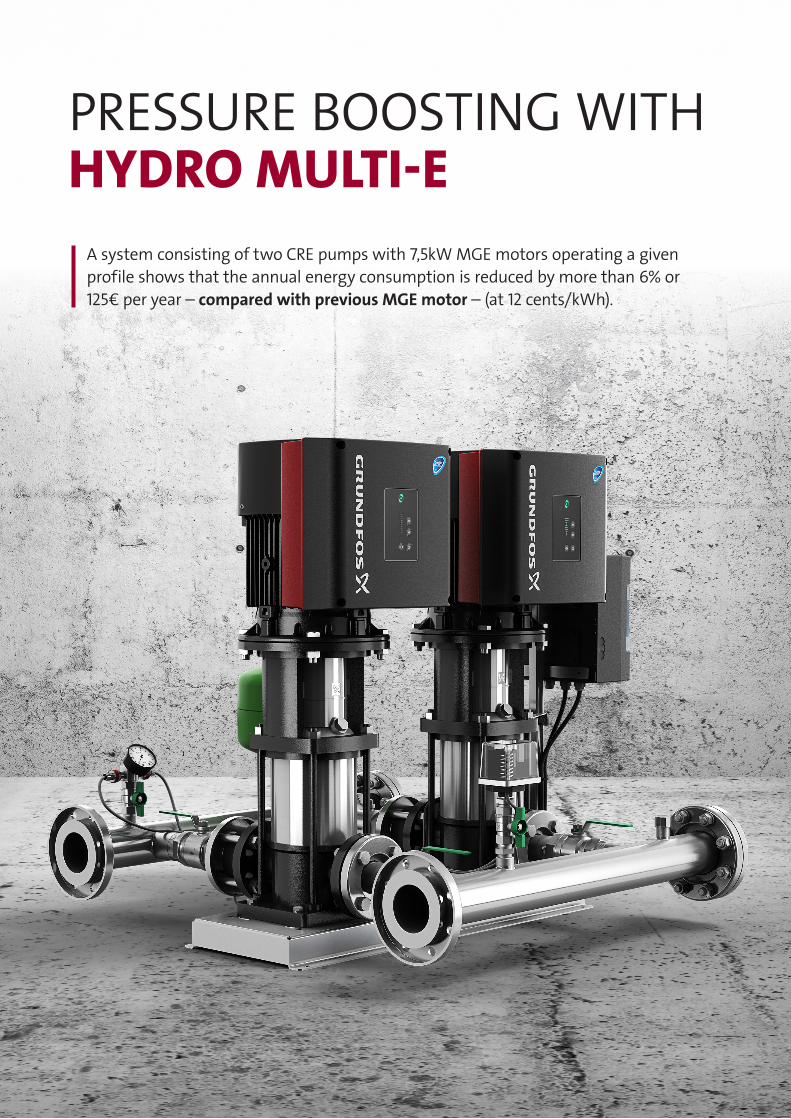
PRESSURE BOOSTING WITH HYDRO MULTI-E
A system consisting of two CRE pumps with 7,5kW MGE motors operating a given profile shows that the annual energy consumption is reduced by more than 6% or 125€ per year – compared with previous MGE motor – (at 12 cents/kWh).
0
1000
2000
3000
4000
5000
4533.7524.7515.755.4
[kW
h/Ye
ar]
Flow [m3/h]
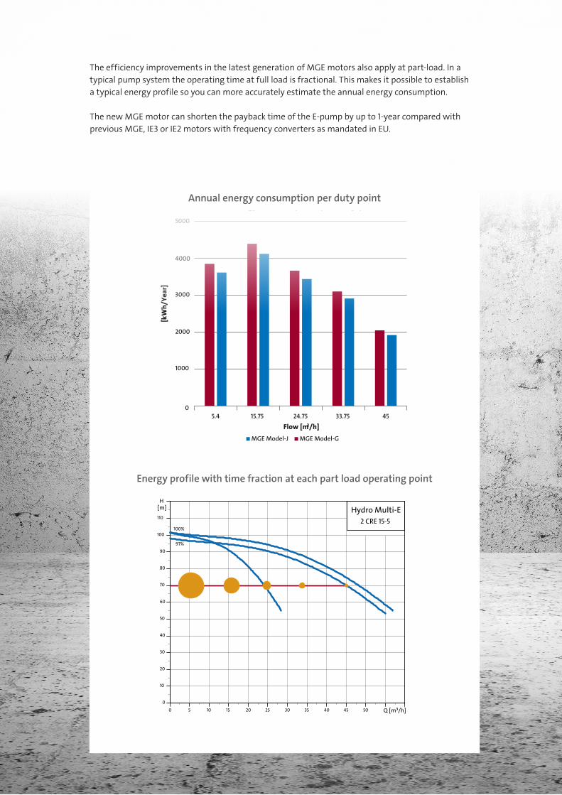
Annual energy consumption per duty point
MGE Model-J MGE Model-G
The efficiency improvements in the latest generation of MGE motors also apply at part-load. In a typical pump system the operating time at full load is fractional. This makes it possible to establish a typical energy profile so you can more accurately estimate the annual energy consumption.
The new MGE motor can shorten the payback time of the E-pump by up to 1-year compared with previous MGE, IE3 or IE2 motors with frequency converters as mandated in EU.
Energy profile with time fraction at each part load operating point
Annual energy consumption per duty point
5 15 25
H
Hydro Multi-E2 CRE 15-5
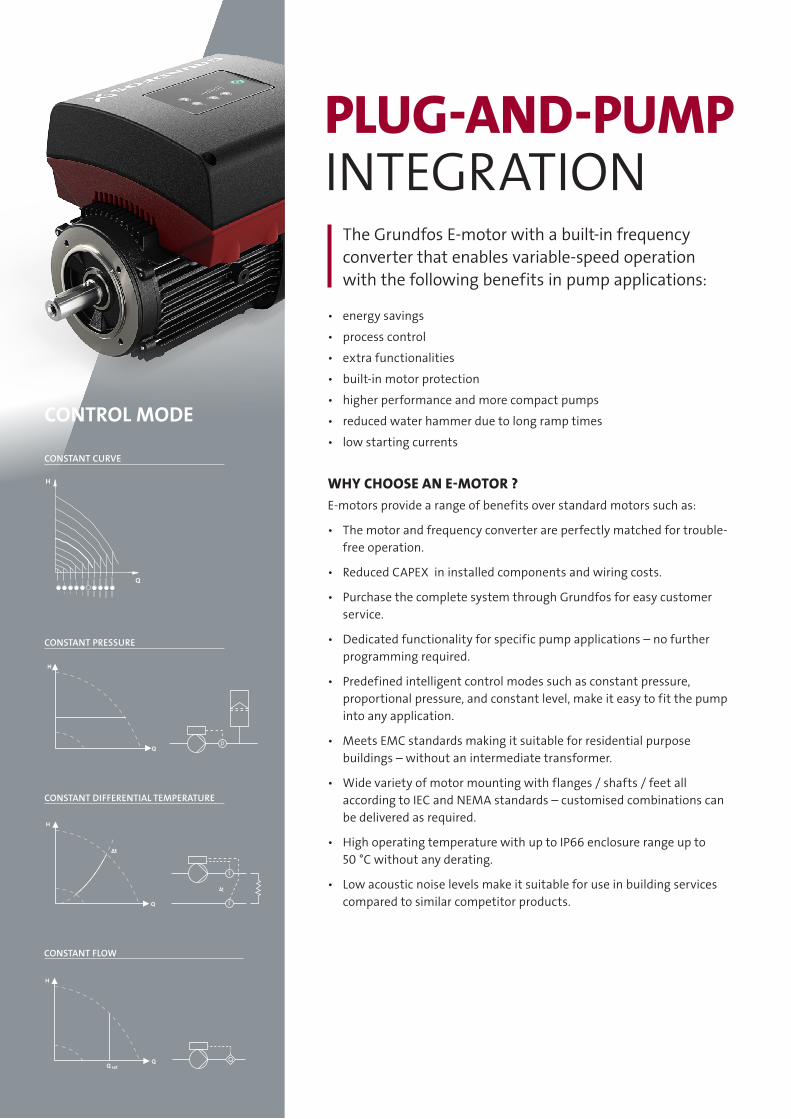
PLUG-AND-PUMP INTEGRATION
The Grundfos E-motor with a built-in frequency converter that enables variable-speed operation with the following benefits in pump applications:
• energy savings
• process control
• extra functionalities
• built-in motor protection
• higher performance and more compact pumps
• reduced water hammer due to long ramp times
• low starting currents
WHY CHOOSE AN E-MOTOR ?E-motors provide a range of benefits over standard motors such as:
• The motor and frequency converter are perfectly matched for trouble-free operation.
• Reduced CAPEX in installed components and wiring costs.
• Purchase the complete system through Grundfos for easy customer service.
• Dedicated functionality for specific pump applications – no further programming required.
• Predefined intelligent control modes such as constant pressure, proportional pressure, and constant level, make it easy to fit the pump into any application.
• Meets EMC standards making it suitable for residential purpose buildings – without an intermediate transformer.
• Wide variety of motor mounting with flanges / shafts / feet all according to IEC and NEMA standards – customised combinations can be delivered as required.
• High operating temperature with up to IP66 enclosure range up to 50 °C without any derating.
• Low acoustic noise levels make it suitable for use in building services compared to similar competitor products.
CONSTANT CURVE
CONSTANT PRESSURE
CONSTANT DIFFERENTIAL TEMPERATURE
CONSTANT FLOW
CONTROL MODE
H
Q
H
Qp
H
Q
∆t
t
t
t
H
QQ set
Q
PLUG-AND-PUMP INTEGRATION
DEDICATED FOR BUILDING SERVICESAUTOADAPT function
The AUTOADAPT function continuously adjusts the proportion-al pressure curve and automatically sets the most efficient curve. (only TPE3 pumps).
FLOWLIMIT function
The FLOWLIMIT function eliminates the need for a pump throttling valve, reducing pressure loss in the system. (only TPE3 pumps).
FLOWADAPT function
FLOWADAPT is a control mode that combines AUTOADAPT with the FLOWLIMIT function. (only TPE3)
Built-in Heat Energy Meter
Built-in heat energy meter that can monitor heat energy distribution and consumption. (only TPE3 pumps).
Advanced work log
TPE3 pumps with the new MGE/MLE motors have an advanced logging function that can record and display:
• Duty point over time: The 20 latest duty points with the highest power consumption are shown.
• 3D histograms (Flow, head, time), (Flow, temp., time), etc.
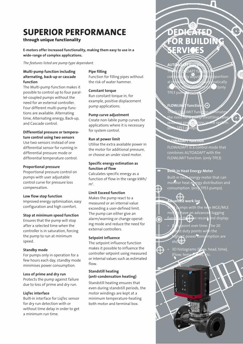
SUPERIOR PERFORMANCE through unique functionality
E-motors offer increased functionality, making them easy to use in a wide-range of complex applications.
The features listed are pump type dependant.
Multi-pump function including alternating, back-up or cascade functionThe Multi-pump function makes it possible to control up to four paral-lel-coupled pumps without the need for an external controller. Four different multi-pump func- tions are available: Alternating time, Alternating energy, Back-up, and Cascade control.
Differential pressure or tempera-ture control using two sensorsUse two sensors instead of one differential sensor for running in differential pressure mode or differential temperature control.
Proportional pressureProportional pressure control on pumps with user adjustable control curve for pressure loss compensation.
Low flow stop functionImproved energy optimisation, easy configuration and high comfort.
Stop at minimum speed functionEnsures that the pump will stop after a selected time when the controller is in saturation, forcing the pump to run at minimum speed.
Standby modeFor pumps only in operation for a few hours each day, standby mode minimises power consumption.
Loss of prime and dry runProtects the pump against failure due to loss of prime and dry run.
LiqTec interfaceBuilt-in interface for LiqTec sensor for dry run detection with or without time delay in order to get a minimum run time.
Pipe fillingFunction for filling pipes without the risk of water hammer.
Constant torqueRun constant torque in, for example, positive displacement pump applications.
Pump curve adjustmentCreate non-labile pump curves for applications where it is necessary for system control.
Run at power limitUtilise the extra available power in the motor for additional pressure, or choose an under sized motor.
Specific energy estimation as function of flowCalculates specific energy as a function of flow in the range kWh/m3.
Limit Exceed functionMakes the pump react to a measured or an internal value exceeding a user-defined limit. The pump can either give an alarm/warning or change operat-ing mode and reduce the need for external controllers.
Setpoint influenceThe setpoint influence function makes it possible to influence the controller setpoint using measured or internal values such as estimated flow.
Standstill heating (anti-condensation heating)
Standstill heating ensures that even during standstill periods, the motor windings are kept at a minimum temperature-heating both motor and terminal box.
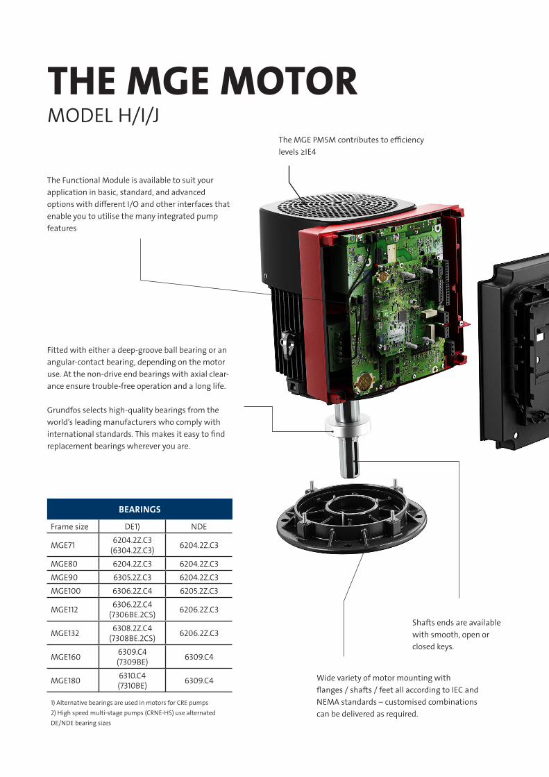
THE MGE MOTOR MODEL H/I/J
The MGE PMSM contributes to efficiency levels ≥IE4
Shafts ends are available with smooth, open or closed keys.
Wide variety of motor mounting with flanges / shafts / feet all according to IEC and NEMA standards – customised combinations can be delivered as required.
The Functional Module is available to suit your application in basic, standard, and advanced options with different I/O and other interfaces that enable you to utilise the many integrated pump features
Fitted with either a deep-groove ball bearing or an angular-contact bearing, depending on the motor use. At the non-drive end bearings with axial clear-ance ensure trouble-free operation and a long life.
Grundfos selects high-quality bearings from the world’s leading manufacturers who comply with international standards. This makes it easy to find replacement bearings wherever you are.
BEARINGS
Frame size DE1) NDE
MGE71 6204.2Z.C3(6304.2Z.C3) 6204.2Z.C3
MGE80 6204.2Z.C3 6204.2Z.C3
MGE90 6305.2Z.C3 6204.2Z.C3
MGE100 6306.2Z.C4 6205.2Z.C3
MGE112 6306.2Z.C4 (7306BE.2CS) 6206.2Z.C3
MGE132 6308.2Z.C4 (7308BE.2CS) 6206.2Z.C3
MGE160 6309.C4 (7309BE) 6309.C4
MGE180 6310.C4(7310BE) 6309.C4
1) Alternative bearings are used in motors for CRE pumps2) High speed multi-stage pumps (CRNE-HS) use alternated DE/NDE bearing sizes
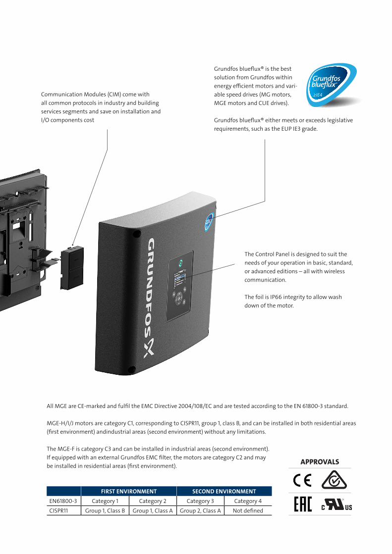
All MGE are CE-marked and fulfil the EMC Directive 2004/108/EC and are tested according to the EN 61800-3 standard.
MGE-H/I/J motors are category C1, corresponding to CISPR11, group 1, class B, and can be installed in both residential areas (first environment) andindustrial areas (second environment) without any limitations.
The MGE-F is category C3 and can be installed in industrial areas (second environment). If equipped with an external Grundfos EMC filter, the motors are category C2 and may be installed in residential areas (first environment).
Communication Modules (CIM) come with all common protocols in industry and building services segments and save on installation and I/O components cost
Grundfos blueflux® is the best solution from Grundfos within energy efficient motors and vari-able speed drives (MG motors, MGE motors and CUE drives).
Grundfos blueflux® either meets or exceeds legislative requirements, such as the EUP IE3 grade.
The Control Panel is designed to suit the needs of your operation in basic, standard, or advanced editions – all with wireless communication.
The foil is IP66 integrity to allow wash down of the motor.
FIRST ENVIRONMENT SECOND ENVIRONMENT
EN61800-3 Category 1 Category 2 Category 3 Category 4
CISPR11 Group 1, Class B Group 1, Class A Group 2, Class A Not defined
APPROVALS
≥IE4
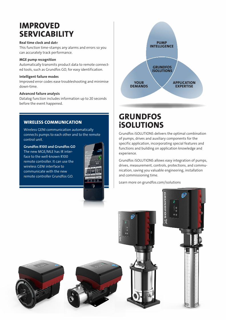
IMPROVED SERVICABILITYReal time clock and date This function time-stamps any alarms and errors so you can accurately track performance.
MGE pump recognition Automatically transmits product data to remote connect-ed tools, such as Grundfos GO, for easy identification.
Intelligent failure modes Improved error codes ease troubleshooting and minimise down-time.
Advanced failure analysis Datalog function includes information up to 20 seconds before the event happened.
GRUNDFOS iSOLUTIONSWIRELESS COMMUNICATION
Wireless GENI communication automatically connects pumps to each other and to the remote control unit.
Grundfos R100 and Grundfos GO The new MGE/MLE has IR inter-face to the well-known R100 remote controller. It can use the wireless GENI interface to communicate with the new remote controller Grundfos GO.
Grundfos iSOLUTIONS delivers the optimal combination of pumps, drives and auxiliary components for the specific application, incorporating special features and functions and building on application knowledge and experience.
Grundfos iSOLUTIONS allows easy integration of pumps, drives, measurement, controls, protections, and commu-nication, saving you valuable engineering, installation and commissioning time.
Learn more on grundfos.com/isolutions
YOUR DEMANDS
APPLICATION EXPERTISE
PUMP INTELLIGENCE
GRUNDFOSiSOLUTIONS
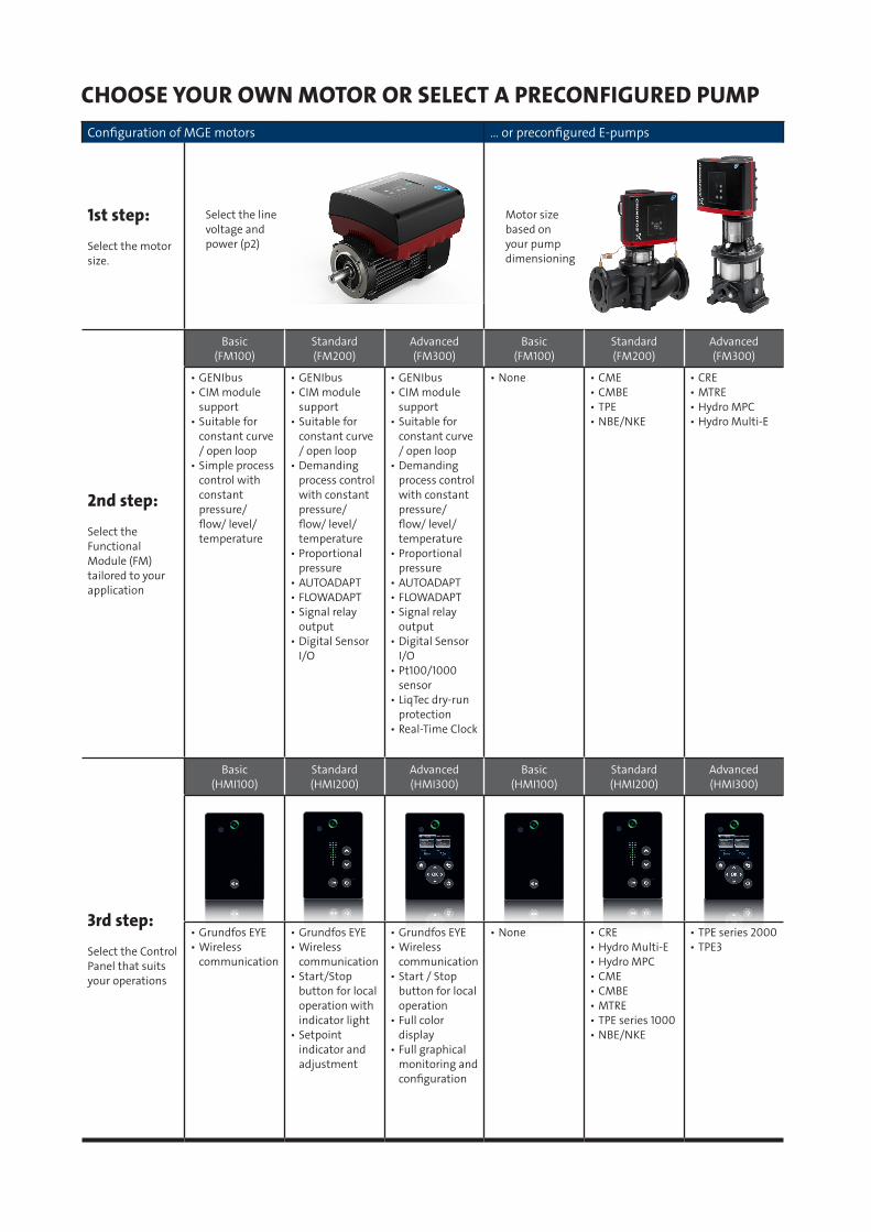
Configuration of MGE motors … or preconfigured E-pumps
1st step:
Select the motor size.
2nd step:
Select the Functional Module (FM) tailored to your application
Basic (FM100)
Standard(FM200)
Advanced(FM300)
Basic (FM100)
Standard(FM200)
Advanced(FM300)
• GENIbus• CIM module
support • Suitable for
constant curve / open loop
• Simple process control with constant pressure/ flow/ level/ temperature
• GENIbus• CIM module
support• Suitable for
constant curve / open loop
• Demanding process control with constant pressure/ flow/ level/ temperature
• Proportional pressure
• AUTOADAPT• FLOWADAPT• Signal relay
output • Digital Sensor
I/O
• GENIbus• CIM module
support• Suitable for
constant curve / open loop
• Demanding process control with constant pressure/ flow/ level/ temperature
• Proportional pressure
• AUTOADAPT• FLOWADAPT• Signal relay
output • Digital Sensor
I/O• Pt100/1000
sensor• LiqTec dry-run
protection• Real-Time Clock
• None • CME• CMBE• TPE• NBE/NKE
• CRE• MTRE• Hydro MPC• Hydro Multi-E
3rd step:
Select the Control Panel that suits your operations
Basic (HMI100)
Standard(HMI200)
Advanced(HMI300)
Basic (HMI100)
Standard(HMI200)
Advanced(HMI300)
• Grundfos EYE• Wireless
communication
• Grundfos EYE• Wireless
communication• Start/Stop
button for local operation with indicator light
• Setpoint indicator and adjustment
• Grundfos EYE• Wireless
communication• Start / Stop
button for local operation
• Full color display
• Full graphical monitoring and configuration
• None • CRE• Hydro Multi-E• Hydro MPC• CME• CMBE• MTRE• TPE series 1000• NBE/NKE
• TPE series 2000• TPE3
CHOOSE YOUR OWN MOTOR OR SELECT A PRECONFIGURED PUMP
Select the line voltage and power (p2)
Motor size based on your pump dimensioning
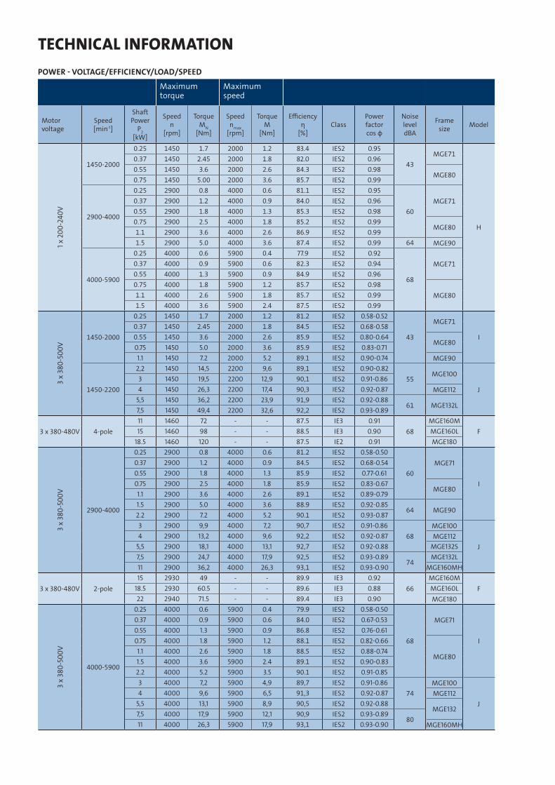
TECHNICAL INFORMATIONPOWER - VOLTAGE/EFFICIENCY/LOAD/SPEED
Maximum torque
Maximum speed
Motor voltage
Speed [min-1]
Shaft Power
P2 [kW]
Speed n
[rpm]
Torque MN
[Nm]
Speed nmax
[rpm]
Torque M
[Nm]
Efficiency η
[%]Class
Power factorcos φ
Noise level dBA
Frame size Model
1 x 2
00-2
40V
1450-2000
0.25 1450 1.7 2000 1.2 83.4 IES2 0.95
43MGE71
H
0.37 1450 2.45 2000 1.8 82.0 IES2 0.960.55 1450 3.6 2000 2.6 84.3 IES2 0.98
MGE800.75 1450 5.00 2000 3.6 85.7 IES2 0.99
2900-4000
0.25 2900 0.8 4000 0.6 81.1 IES2 0.95
60MGE710.37 2900 1.2 4000 0.9 84.0 IES2 0.96
0.55 2900 1.8 4000 1.3 85.3 IES2 0.980.75 2900 2.5 4000 1.8 85.2 IES2 0.99
MGE801.1 2900 3.6 4000 2.6 86.9 IES2 0.991.5 2900 5.0 4000 3.6 87.4 IES2 0.99 64 MGE90
4000-5900
0.25 4000 0.6 5900 0.4 77.9 IES2 0.92
68
MGE710.37 4000 0.9 5900 0.6 82.3 IES2 0.940.55 4000 1.3 5900 0.9 84.9 IES2 0.960.75 4000 1.8 5900 1.2 85.7 IES2 0.98
MGE801.1 4000 2.6 5900 1.8 85.7 IES2 0.991.5 4000 3.6 5900 2.4 87.5 IES2 0.99
3 x
380-
500V
1450-2000
0.25 1450 1.7 2000 1.2 81.2 IES2 0.58-0.52
43
MGE71
I0.37 1450 2.45 2000 1.8 84.5 IES2 0.68-0.580.55 1450 3.6 2000 2.6 85.9 IES2 0.80-0.64
MGE800.75 1450 5.0 2000 3.6 85.9 IES2 0.83-0.711.1 1450 7.2 2000 5.2 89.1 IES2 0.90-0.74 MGE90
1450-2200
2,2 1450 14,5 2200 9,6 89,1 IES2 0.90-0.8255
MGE100
J3 1450 19,5 2200 12,9 90,1 IES2 0.91-0.864 1450 26,3 2200 17,4 90,3 IES2 0.92-0.87 MGE112
5,5 1450 36,2 2200 23,9 91,9 IES2 0.92-0.8861 MGE132L
7,5 1450 49,4 2200 32,6 92,2 IES2 0.93-0.89
3 x 380-480V 4-pole11 1460 72 - - 87.5 IE3 0.91
68MGE160M
F15 1460 98 - - 88.5 IE3 0.90 MGE160L18.5 1460 120 - - 87.5 IE2 0.91 MGE180
3 x
380-
500V
2900-4000
0.25 2900 0.8 4000 0.6 81.2 IES2 0.58-0.50
60MGE71
I
0.37 2900 1.2 4000 0.9 84.5 IES2 0.68-0.540.55 2900 1.8 4000 1.3 85.9 IES2 0.77-0.610.75 2900 2.5 4000 1.8 85.9 IES2 0.83-0.67
MGE801.1 2900 3.6 4000 2.6 89.1 IES2 0.89-0.791.5 2900 5.0 4000 3.6 88.9 IES2 0.92-0.85
64 MGE902.2 2900 7.2 4000 5.2 90.1 IES2 0.93-0.873 2900 9,9 4000 7,2 90,7 IES2 0.91-0.86
68MGE100
J4 2900 13,2 4000 9,6 92,2 IES2 0.92-0.87 MGE112
5,5 2900 18,1 4000 13,1 92,7 IES2 0.92-0.88 MGE132S7,5 2900 24,7 4000 17,9 92,5 IES2 0.93-0.89
74MGE132L
11 2900 36,2 4000 26,3 93,1 IES2 0.93-0.90 MGE160MH
3 x 380-480V 2-pole15 2930 49 - - 89.9 IE3 0.92
66MGE160M
F18.5 2930 60.5 - - 89.6 IE3 0.88 MGE160L22 2940 71.5 - - 89.4 IE3 0.90 MGE180
3 x
380-
500V
4000-5900
0.25 4000 0.6 5900 0.4 79.9 IES2 0.58-0.50
68
MGE71
I
0.37 4000 0.9 5900 0.6 84.0 IES2 0.67-0.530.55 4000 1.3 5900 0.9 86.8 IES2 0.76-0.610.75 4000 1.8 5900 1.2 88.1 IES2 0.82-0.66
MGE801.1 4000 2.6 5900 1.8 88.5 IES2 0.88-0.741.5 4000 3.6 5900 2.4 89.1 IES2 0.90-0.832.2 4000 5.2 5900 3.5 90.1 IES2 0.91-0.853 4000 7,2 5900 4,9 89,7 IES2 0.91-0.86
74MGE100
J4 4000 9,6 5900 6,5 91,3 IES2 0.92-0.87 MGE112
5,5 4000 13,1 5900 8,9 90,5 IES2 0.92-0.88MGE132
7,5 4000 17,9 5900 12,1 90,9 IES2 0.93-0.8980
11 4000 26,3 5900 17,9 93,1 IES2 0.93-0.90 MGE160MH
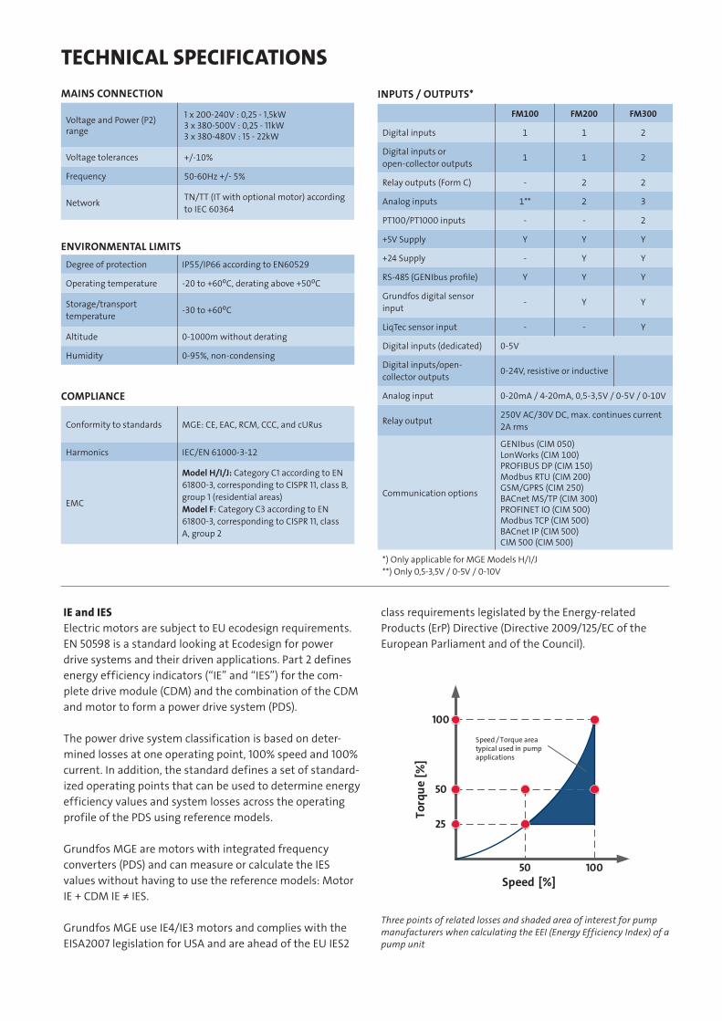
IE and IES Electric motors are subject to EU ecodesign requirements. EN 50598 is a standard looking at Ecodesign for power drive systems and their driven applications. Part 2 defines energy efficiency indicators (“IE” and “IES”) for the com-plete drive module (CDM) and the combination of the CDM and motor to form a power drive system (PDS).
The power drive system classification is based on deter-mined losses at one operating point, 100% speed and 100% current. In addition, the standard defines a set of standard-ized operating points that can be used to determine energy efficiency values and system losses across the operating profile of the PDS using reference models.
Grundfos MGE are motors with integrated frequency converters (PDS) and can measure or calculate the IES values without having to use the reference models: Motor IE + CDM IE ≠ IES.
Grundfos MGE use IE4/IE3 motors and complies with the EISA2007 legislation for USA and are ahead of the EU IES2
class requirements legislated by the Energy-related Products (ErP) Directive (Directive 2009/125/EC of the European Parliament and of the Council).
TECHNICAL SPECIFICATIONSMAINS CONNECTION
Voltage and Power (P2) range
1 x 200-240V : 0,25 - 1,5kW3 x 380-500V : 0,25 - 11kW3 x 380-480V : 15 - 22kW
Voltage tolerances +/-10%
Frequency 50-60Hz +/- 5%
Network TN/TT (IT with optional motor) according to IEC 60364
INPUTS / OUTPUTS*
FM100 FM200 FM300
Digital inputs 1 1 2
Digital inputs or open-collector outputs
1 1 2
Relay outputs (Form C) - 2 2
Analog inputs 1** 2 3
PT100/PT1000 inputs - - 2
+5V Supply Y Y Y
+24 Supply - Y Y
RS-485 (GENIbus profile) Y Y Y
Grundfos digital sensor input
- Y Y
LiqTec sensor input - - Y
Digital inputs (dedicated) 0-5V
Digital inputs/open- collector outputs
0-24V, resistive or inductive
Analog input 0-20mA / 4-20mA, 0,5-3,5V / 0-5V / 0-10V
Relay output250V AC/30V DC, max. continues current 2A rms
Communication options
GENIbus (CIM 050)LonWorks (CIM 100)PROFIBUS DP (CIM 150)Modbus RTU (CIM 200)GSM/GPRS (CIM 250)BACnet MS/TP (CIM 300)PROFINET IO (CIM 500)Modbus TCP (CIM 500)BACnet IP (CIM 500)CIM 500 (CIM 500)
*) Only applicable for MGE Models H/I/J**) Only 0,5-3,5V / 0-5V / 0-10V
ENVIRONMENTAL LIMITSDegree of protection IP55/IP66 according to EN60529
Operating temperature -20 to +60⁰C, derating above +50⁰C
Storage/transport temperature
-30 to +60⁰C
Altitude 0-1000m without derating
Humidity 0-95%, non-condensing
COMPLIANCE
Conformity to standards MGE: CE, EAC, RCM, CCC, and cURus
Harmonics IEC/EN 61000-3-12
EMC
Model H/I/J: Category C1 according to EN 61800-3, corresponding to CISPR 11, class B, group 1 (residential areas)Model F: Category C3 according to EN 61800-3, corresponding to CISPR 11, class A, group 2
Three points of related losses and shaded area of interest for pump manufacturers when calculating the EEI (Energy Efficiency Index) of a pump unit
Torq
ue [%
]
100
50
25
50 100Speed [%]
Speed / Torque area typical used in pump applications
Stator housing Shaft end Feet B3, B34, B35 Free-hole flange B35, B5/V1 Tapped-hole flange B34, B14/V18 Cable entry
VoltageFrame size4) AC AD AE AF LL D DB E EB F G GA L LB1) A AB B B′ BB C H HA HC HD K L LB1) LA M N P SxZ T L LB LA3) M N P SxZ T O
1 x
200-
240V
MGE71
122 158 106 106 192
14 M5 30 22 5 11 16 2442)
234
112 138 90
-
110 45 71
3
131 229 7 264
234
9 130 110 160 Ø10x4
3,5
244
214
1285 70 105
M6x4
2,5
4xM20MGE80 19 M6 40 32 6 15,5 21,5 2542) 125 158
100125 50 80 140 238 10 274 10
165 130 200 Ø12x4
254 100 80 120
3MGE90S24 M8 50 40 8 20 27 284 140 178 155 56 90 150 248 10,5 284 11 324 13 115 95 135
MGE90L - 125
3 x
380-
500V
MGE71
122 158 134 134 232
14 M5 30 22 5 11 16 304
274
112 138 90
-
110 45 71 131 229 7 304
274
9 130 110 160 Ø10x4 244254 12
85 70 105
M6x4
2,5
4xM20MGE80 19 M6 40 32 6 15,5 21,5 314 125 158
100125 50 80 140 238 10 314 10
165 130 200 Ø12x4
254 100 80 120
3MGE90S24 M8 50 40 8 20 27 324 140 178 155 56 90 150 248 10,5 324 11 324 274 13 115 95 135
MGE90L - 125
MGE100
191,3 201 145,5 145,5 28028 M10 60 50 8 24 31 394 334
160 200
140 -
173 63 100
5
197 301
12
394 334 10 215 180 250 Ø14,5x4
4
394 334 14,5 130 110 160 M8x4
3,5
1 x M25+ 4 x M20MGE112 190 230 180 70 112 209 313
MGE132S38 M12 80 70 10 33 41
445 365216 256 180 89 132
229 333 445 365
12
265 230 300 Ø15x4445 365
-
165 130 200 M10x41 x M32
+ 5 x M20MGE132L
255 237 173 173 317469 389 - 178 263 369 469 389 469 389
MGE160 MH
42M16 110
110
12 37 45
516 317
254
290210
-
250
108 160
291 397 14,5 516 406
300 250 350 Ø19x4 5 - - - - - - -
3 x
380-
480V MGE160M
314 308 210 210 40082
581
-287
239
8317
467 15
581 4711xM40
+1xM20 +4xM16
MGE160L 625 254 283 625 515
MGE180 48 100 14 43 51,5 651 279 312 241 279 308 121 180 337 651 541
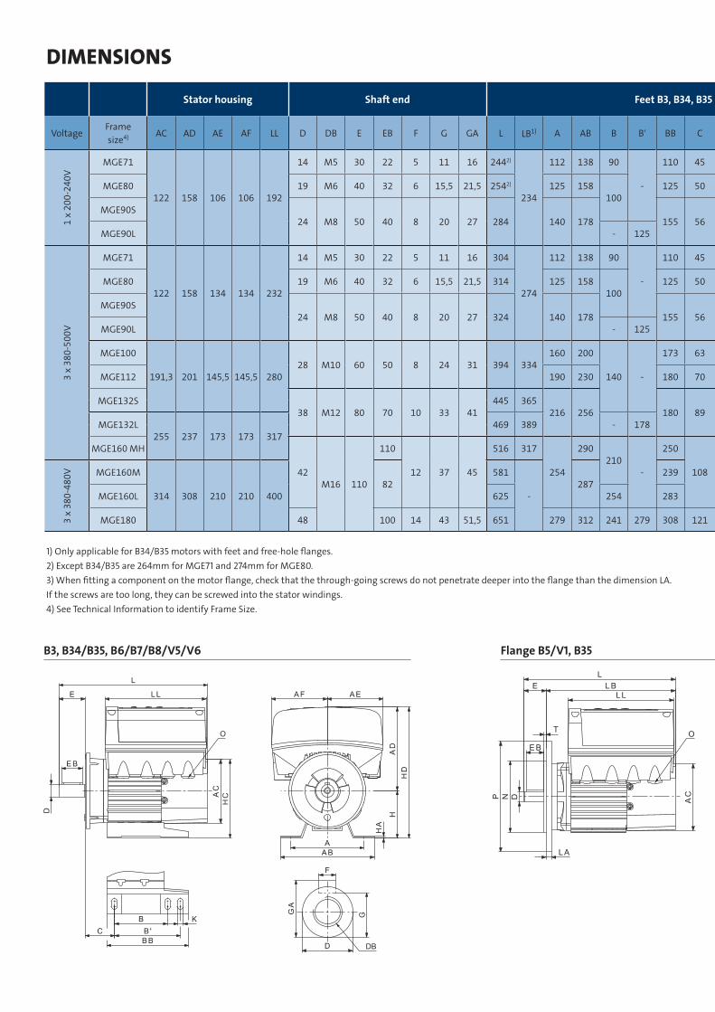
1) Only applicable for B34/B35 motors with feet and free-hole flanges.2) Except B34/B35 are 264mm for MGE71 and 274mm for MGE80.3) When fitting a component on the motor flange, check that the through-going screws do not penetrate deeper into the flange than the dimension LA. If the screws are too long, they can be screwed into the stator windings.4) See Technical Information to identify Frame Size.
B3, B34/B35, B6/B7/B8/V5/V6 Flange B5/V1, B35
DIMENSIONS
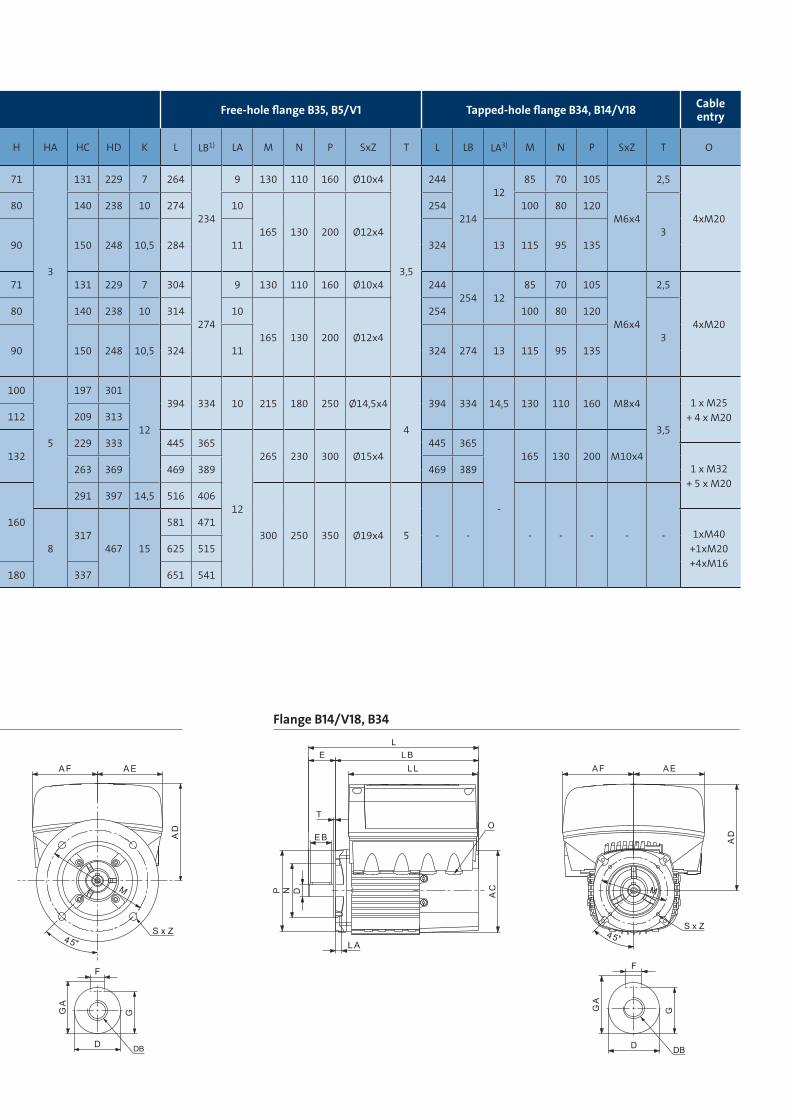
Stator housing Shaft end Feet B3, B34, B35 Free-hole flange B35, B5/V1 Tapped-hole flange B34, B14/V18 Cable entry
VoltageFrame size4) AC AD AE AF LL D DB E EB F G GA L LB1) A AB B B′ BB C H HA HC HD K L LB1) LA M N P SxZ T L LB LA3) M N P SxZ T O
1 x
200-
240V
MGE71
122 158 106 106 192
14 M5 30 22 5 11 16 2442)
234
112 138 90
-
110 45 71
3
131 229 7 264
234
9 130 110 160 Ø10x4
3,5
244
214
1285 70 105
M6x4
2,5
4xM20MGE80 19 M6 40 32 6 15,5 21,5 2542) 125 158
100125 50 80 140 238 10 274 10
165 130 200 Ø12x4
254 100 80 120
3MGE90S24 M8 50 40 8 20 27 284 140 178 155 56 90 150 248 10,5 284 11 324 13 115 95 135
MGE90L - 125
3 x
380-
500V
MGE71
122 158 134 134 232
14 M5 30 22 5 11 16 304
274
112 138 90
-
110 45 71 131 229 7 304
274
9 130 110 160 Ø10x4 244254 12
85 70 105
M6x4
2,5
4xM20MGE80 19 M6 40 32 6 15,5 21,5 314 125 158
100125 50 80 140 238 10 314 10
165 130 200 Ø12x4
254 100 80 120
3MGE90S24 M8 50 40 8 20 27 324 140 178 155 56 90 150 248 10,5 324 11 324 274 13 115 95 135
MGE90L - 125
MGE100
191,3 201 145,5 145,5 28028 M10 60 50 8 24 31 394 334
160 200
140 -
173 63 100
5
197 301
12
394 334 10 215 180 250 Ø14,5x4
4
394 334 14,5 130 110 160 M8x4
3,5
1 x M25+ 4 x M20MGE112 190 230 180 70 112 209 313
MGE132S38 M12 80 70 10 33 41
445 365216 256 180 89 132
229 333 445 365
12
265 230 300 Ø15x4445 365
-
165 130 200 M10x41 x M32
+ 5 x M20MGE132L
255 237 173 173 317469 389 - 178 263 369 469 389 469 389
MGE160 MH
42M16 110
110
12 37 45
516 317
254
290210
-
250
108 160
291 397 14,5 516 406
300 250 350 Ø19x4 5 - - - - - - -
3 x
380-
480V MGE160M
314 308 210 210 40082
581
-287
239
8317
467 15
581 4711xM40
+1xM20 +4xM16
MGE160L 625 254 283 625 515
MGE180 48 100 14 43 51,5 651 279 312 241 279 308 121 180 337 651 541
Flange B5/V1, B35 Flange B14/V18, B34

GRUNDFOS Holding A/SPoul Due Jensens Vej 7DK-8850 BjerringbroTel: +45 87 50 14 00www.grundfos.com
The
nam
e G
rund
fos,
the
Gru
ndfo
s log
o, a
nd b
e th
ink
inno
vate
are
regi
ster
ed tr
adem
arks
ow
ned
by G
rund
fos H
oldi
ng A
/S o
r Gru
ndfo
s A/S
, Den
mar
k. A
ll rig
hts r
eser
ved
wor
ldw
ide.
9913
7787
/091
6/IN
DU
STRY
/122
33-B
rand
Box